Embed Size (px)
Citation preview
Step motorsDC brushless motors Encoders & Gearboxes
Low
Loss
2015
WAR
RANTY
YEARS3
2
Contents
Coding table and combinations ................................................................................................................................... 3Available options chart .......................................................................................................................................................... 4Method of use and characteristics ............................................................................................................................... 5Connecting the motors ........................................................................................................................................................ 6Precision engineering and advanced materials to the basis of performance .................. 72-phases hybrid step motors : family code holding torque
- MT10AP 0,033 Nm ............................................................... 8- MT10AU 0,012 Nm ............................................................... 9- MT12FP from 0,059 to 0,117 Nm .... . . . . . . . . . . . . . . . . . . . . . . . . . . . . . . . . . . . . . . . . . . . . . . . . . . . . . . . . . 10- MT14AP 0,050 Nm ............................................................... 11- MT17AP from 0,157 to 0,610 Nm ............................................................... 12- MT23AK from 0,353 to 1,700 Nm ............................................................... 14- MT23FK from 0,539 to 1,852 Nm ............................................................... 16- MT23AL from 0,466 to 0,686 Nm ............................................................... 18- MT24FK from 1,100 to 3,500 Nm ............................................................... 20- MT34FN from 3,400 to 12,500 Nm ............................................................... 22- MT34FV from 3,400 to 12,500 Nm ............................................................... 24- MT34FH from 2,800 to 7,600 Nm ............................................................... 26- MT42FN from 11,500 to 30,000 Nm ............................................................... 28- MT42FV from 11,500 to 30,000 Nm ............................................................... 30
2-phases hybrid step linear actuator:- MT17HP .......................................................................................................................................................... 31
2-phases permanent magnet step motors :- MT12AX ........................................................................................................................................................ 32- MT14FJ ........................................................................................................................................................... 33- MT14AJ .......................................................................................................................................................... 34- MT17AJ .......................................................................................................................................................... 36
DC brushless motors :- MT17FB .......................................................................................................................................................... 38- MT23FB .......................................................................................................................................................... 39
DC brushless motors with driver :- LMED1 ............................................................................................................................................................. 40- LMED5 ............................................................................................................................................................. 41
Encoders :- SE46 .................................................................................................................................................................... 42
Planetary gearboxes :- RR17TE42 ...................................................................................................................................................... 44- RR23TE42 ...................................................................................................................................................... 45- RR23TE52 ...................................................................................................................................................... 46- RR23TE62 ...................................................................................................................................................... 47- RR34TE62 ...................................................................................................................................................... 48- RR34TE81 ...................................................................................................................................................... 49
3
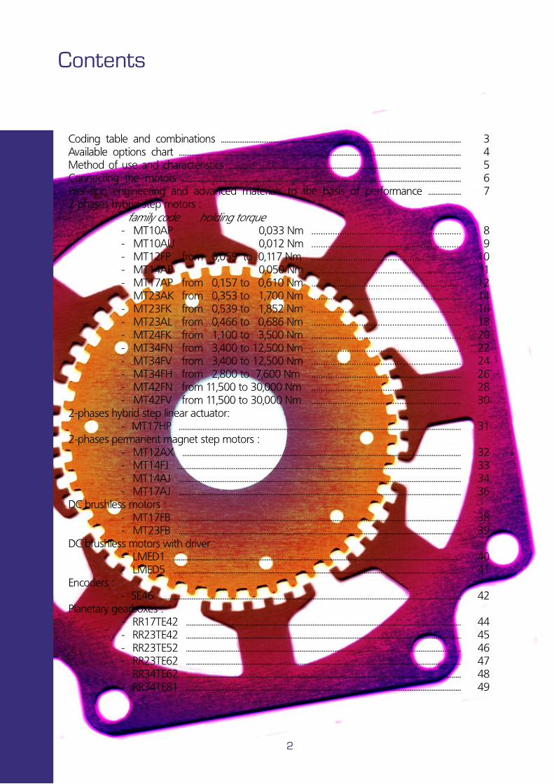
Motors coding and drive pairing
Suggested motor and drive pairings for best performances.
Standard NEMA flange ( incs. x 10 )
T or L
Motor type
Motor depth ( incs. x 10 ) or code of stages
Motor phase current ( A x 10 )
M=Single shaft B=Double shaft
Lead wires number or clamps number
Mx
Options and customized versions
Motor models Drive models M
T1
xA
x
MT1
2FP
MT2
3A
x
MT2
3FK
MT2
4FK
MT3
4Fx
(se
< 5
.0A)
MT3
4Fx
(se
> 5
.0A)
MT3
4FV
MT4
2FN
MT4
2FV
MT1
7FB
M
T2
3FB
LM
£D
1
LM
ED
5
LW 2014 (max 1.4Arms/ph) •
Inte
gra
ted
dri
ves
LW3 3032 LW 2042 SW 2142
(max 3.2Arms/ph)
(max 4.2Arms/ph)• • • •
LW 3050 (max 5.5Arms/ph) • • •
LW3 3070 LW 4085 SW 4080 SW 4185
(max 7.1Arms/ph)
(max 8.0Arms/ph)• • • • •
LW 9060 SW 9060 SW 9160
(max 6.0Arms/ph) • •
SDL 170 SDM 170 (max 8.0Arms/ph) • • • •
SDL 180 SDM 180 (max 5.0Arms/ph) • • • • •
M5A (max 6.0Apeack/ph) • • • •
DCM (max 0.5Apeack/ph) •
• = suggested pairing.
Quality of motors,
coding table and usage
2-phases hybrid step motors
NEMA 10 (25 mm)
2-phases hybrid step motors
NEMA 12 (28 mm) NEMA 14 (35 mm)
2-phases hybrid step motors
NEMA 17 (42 mm)
2-phases hybrid step motors
NEMA 23 (57 mm)
2-phases hybrid step motors
NEMA 24 (60 mm)
2-phases hybrid step motors
NEMA 34 (86 mm)
2-phases hybrid step motors
NEMA 42 (110 mm) Linear actuator
NEMA 17 (42 mm)
2-phases permanent
magnet step motors
NEMA 12 (25 mm) NEMA 14 (35 mm)
2-phases permanent
magnet step motors
NEMA 17 (42 mm)
DC brushless motors
NEMA 17 (42 mm) NEMA 23 (57 mm)
DC brushless motors with
integrated driver NEMA 17 (42 mm) NEMA 23 (57 mm)
Encoders
Planetary gearboxes
Company and
contacts
Application suited performances can be obtained from 8 leads motors with series or parallel bipolar connection to the suggested drive.
The performances of the resulting actuators are directly depending on the voltage bus ratings and motor phases driving method.
4
Available options
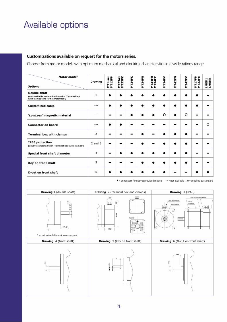
Choose from motor models with optimum mechanical and electrical characteristics in a wide ratings range.
• = on request for not yet provided models - = not available o = supplied as standard
Customizations available on request for the motors series.
Motor model Options
Drawing
MT1
xA
x
MT1
2FP
MT2
3A
x
MT2
3FK
MT2
4FK
MT3
4FN
MT3
4FH
M
T3
4FP
MT3
4FV
MT4
2FN
MT4
2FV
MT1
7FB
M
T2
3FB
LM
ED
1
LM
ED
5
Double shaft (not available in combination with ‘Terminal box with clamps’ and ‘IP65 protection’)
1 • • • • • • • • • -
Customized cable --- • • • • • • • • • -
‘LowLoss’ magnetic material --- - - • • • o • o - -
Connector on board --- • • - - - - - - - o
Terminal box with clamps 2 - - - • - • • • - -IP65 protection (always combined with ‘Terminal box with clamps’)
2 and 3 - - - • - • • • - -
Special front shaft diameter 4 - • • • • • • • - -
Key on front shaft 5 - - - • • • • • - -
D-cut on front shaft 6 • • • • • • - - • •
Drawing 1 (double shaft) Drawing 2 (terminal box and clamps) Drawing 3 (IP65)
Drawing 4 (front shaft) Drawing 5 (key on front shaft) Drawing 6 (D-cut on front shaft)
Ø 6
.35
*
17.5 *
0.01
3
* = customized dimensions on request
22
cmp
22
cma
M4 screw foreart ground
1
2
3
4
5
6
7
8
dmp
dml
dad
k
kl
Plasticprotection
Cable gland sealed
Sealed gasket
Glue and silicone gaskets
Method of use and characteristics
General tips for the best use of motors.
5
To increase the motor’s life, reliability and performances, you should follow these few common use tips:
- Fit and tighten the motor flange on a steel or aluminium surface with enough thickness in order to increase stability and improve heat dissipation.
- Do not exceed the maximum radial and axial loads shown in the tables of this catalog for each motor family: exceeding the permitted value results into a shorter bearings life, the only real motor components that are subject to wear.
- Connect the motor with a proper cable, as described in the drives manuals, to prevent failures, security problems and reliability.
- The motor should never be opened or re-assembled, otherwise it will not keep his magnetization with the consequence of a drastic performances loss.
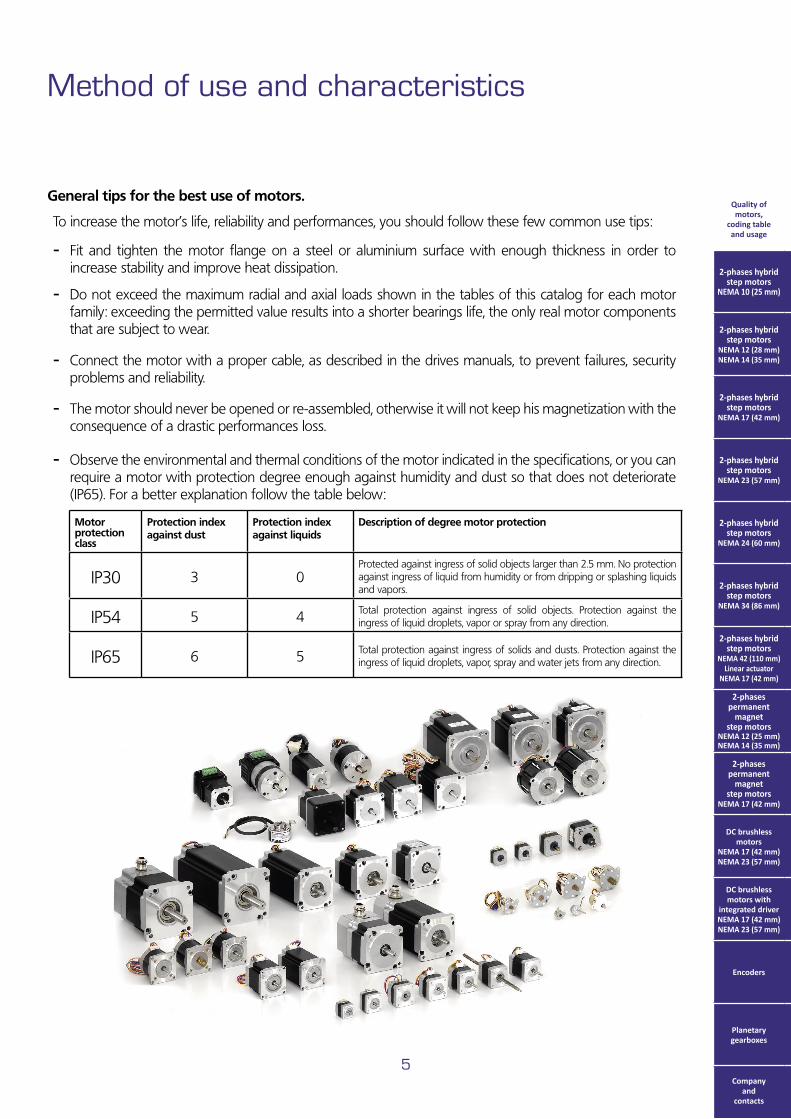
- Observe the environmental and thermal conditions of the motor indicated in the specifications, or you can require a motor with protection degree enough against humidity and dust so that does not deteriorate (IP65). For a better explanation follow the table below:
Quality of motors,
coding table and usage
2-phases hybrid step motors
NEMA 10 (25 mm)
2-phases hybrid step motors
NEMA 12 (28 mm) NEMA 14 (35 mm)
2-phases hybrid step motors
NEMA 17 (42 mm)
2-phases hybrid step motors
NEMA 23 (57 mm)
2-phases hybrid step motors
NEMA 24 (60 mm)
2-phases hybrid step motors
NEMA 34 (86 mm)
2-phases hybrid step motors
NEMA 42 (110 mm) Linear actuator
NEMA 17 (42 mm)
2-phases permanent
magnet step motors
NEMA 12 (25 mm) NEMA 14 (35 mm)
2-phases permanent
magnet step motors
NEMA 17 (42 mm)
DC brushless motors
NEMA 17 (42 mm) NEMA 23 (57 mm)
DC brushless motors with
integrated driver NEMA 17 (42 mm) NEMA 23 (57 mm)
Encoders
Planetary gearboxes
Company and
contacts
Motor protection class
Protection index against dust
Protection index against liquids
Description of degree motor protection
IP30 3 0Protected against ingress of solid objects larger than 2.5 mm. No protection against ingress of liquid from humidity or from dripping or splashing liquids and vapors.
IP54 5 4 Total protection against ingress of solid objects. Protection against the ingress of liquid droplets, vapor or spray from any direction.
IP65 6 5 Total protection against ingress of solids and dusts. Protection against the ingress of liquid droplets, vapor, spray and water jets from any direction.
6
Connecting the motors
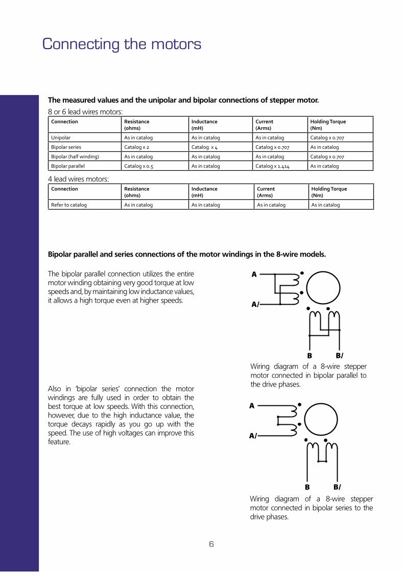
The bipolar parallel connection utilizes the entire motor winding obtaining very good torque at low speeds and, by maintaining low inductance values, it allows a high torque even at higher speeds.
Also in ‘bipolar series’ connection the motor windings are fully used in order to obtain the best torque at low speeds. With this connection, however, due to the high inductance value, the torque decays rapidly as you go up with the speed. The use of high voltages can improve this feature.
Bipolar parallel and series connections of the motor windings in the 8-wire models.
�
��
���
�
��
���
Wiring diagram of a 8-wire stepper motor connected in bipolar parallel to the drive phases.
Wiring diagram of a 8-wire stepper motor connected in bipolar series to the drive phases.
The measured values and the unipolar and bipolar connections of stepper motor.
Connection Resistance (ohms)
Inductance (mH)
Current (Arms)
Holding Torque (Nm)
Unipolar As in catalog As in catalog As in catalog Catalog x 0.707
Bipolar series Catalog x 2 Catalog x 4 Catalog x 0.707 As in catalog
Bipolar (half winding) As in catalog As in catalog As in catalog Catalog x 0.707
Bipolar parallel Catalog x 0.5 As in catalog Catalog x 1.414 As in catalog
8 or 6 lead wires motors:
Connection Resistance (ohms)
Inductance (mH)
Current (Arms)
Holding Torque (Nm)
Refer to catalog As in catalog As in catalog As in catalog As in catalog
4 lead wires motors:
7
Precision engineering and advanced materials to the basis of performance
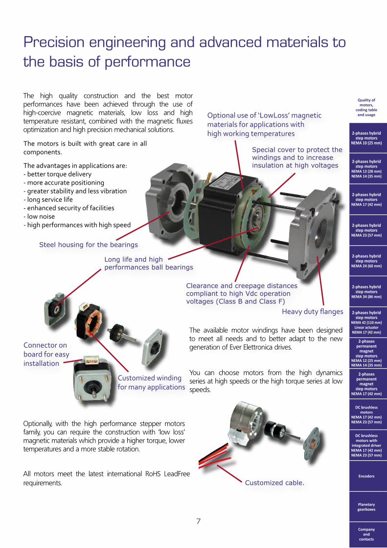
Connector on board for easy installation
The high quality construction and the best motor performances have been achieved through the use of high-coercive magnetic materials, low loss and high temperature resistant, combined with the magnetic fluxes optimization and high precision mechanical solutions.
Clearance and creepage distances compliant to high Vdc operation voltages (Class B and Class F)
Special cover to protect the windings and to increase insulation at high voltages
Long life and high performances ball bearings
The available motor windings have been designed to meet all needs and to better adapt to the new generation of Ever Elettronica drives.
Optionally, with the high performance stepper motors family, you can require the construction with ‘low loss’ magnetic materials which provide a higher torque, lower temperatures and a more stable rotation.
Heavy duty flanges
Optional use of ‘LowLoss’ magnetic materials for applications with high working temperatures
Customized winding for many applications
All motors meet the latest international RoHS LeadFree requirements. Customized cable.
The motors is built with great care in all components.
The advantages in applications are:- better torque delivery- more accurate positioning- greater stability and less vibration- long service life- enhanced security of facilities- low noise- high performances with high speed
You can choose motors from the high dynamics series at high speeds or the high torque series at low speeds.
Quality of motors,
coding table and usage
2-phases hybrid step motors
NEMA 10 (25 mm)
2-phases hybrid step motors
NEMA 12 (28 mm) NEMA 14 (35 mm)
2-phases hybrid step motors
NEMA 17 (42 mm)
2-phases hybrid step motors
NEMA 23 (57 mm)
2-phases hybrid step motors
NEMA 24 (60 mm)
2-phases hybrid step motors
NEMA 34 (86 mm)
2-phases hybrid step motors
NEMA 42 (110 mm) Linear actuator
NEMA 17 (42 mm)
2-phases permanent
magnet step motors
NEMA 12 (25 mm) NEMA 14 (35 mm)
2-phases permanent
magnet step motors
NEMA 17 (42 mm)
DC brushless motors
NEMA 17 (42 mm) NEMA 23 (57 mm)
DC brushless motors with
integrated driver NEMA 17 (42 mm) NEMA 23 (57 mm)
Encoders
Planetary gearboxes
Company and
contacts
Steel housing for the bearings
• Dimensions (Unit: mm)
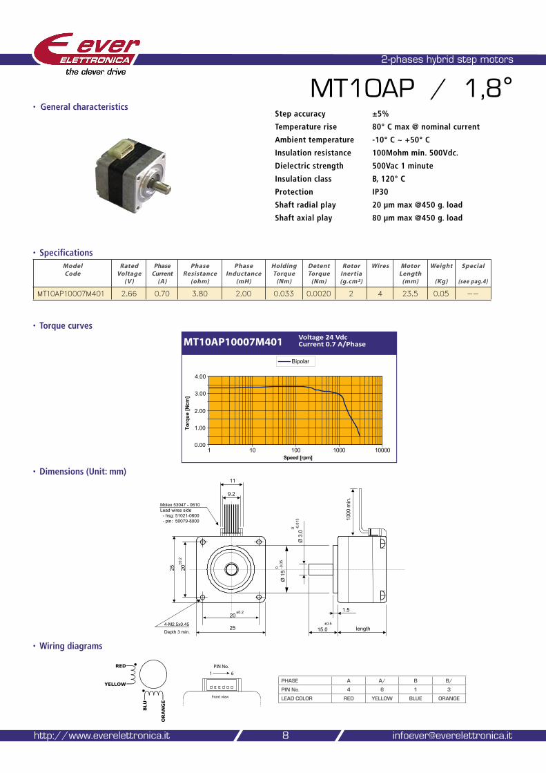
2-phases hybrid step motors
MT10AP / 1,8°
• Specifications
• Wiring diagrams
Model Code
Rated Voltage
( V )
Phase Current
(A)
Phase Resistance
(ohm)
Phase Inductance
(mH)
Holding Torque
(Nm)
Detent Torque
(Nm)
Rotor Inertia (g.cm²)
Wires Motor Length
(mm)
Weight
(Kg)
Special
(see pag.4)
MT10AP10007M401 2.66 0.70 3.80 2.00 0.033 0.0020 2 4 23.5 0.05 --
8
• General characteristicsStep accuracy ±5%
Temperature rise 80° C max @ nominal current
Ambient temperature -10° C ~ +50° C
Insulation resistance 100Mohm min. 500Vdc.
Dielectric strength 500Vac 1 minute
Insulation class B, 120° C
Protection IP30
Shaft radial play 20 µm max @450 g. load
Shaft axial play 80 µm max @450 g. load
http://www.everelettronica.it [email protected]
PHASE A A/ B B/
PIN No. 4 6 1 3
LEAD COLOR RED YELLOW BLUE ORANGE
BLU
ORANGE
RED
YELLOW
��������������������
�������
����������
20
25
25 20
Ø 1
50 -0
.05
Ø 3
.00 - 0
.013
15.0 length
±0.2
4-M2.5x0.45
±0.2
1000
min
.
11
9.2
±0.5
Depth 3 min.
Molex 53047 - 0610Lead wires side
- hsg: 51021-0600- pin: 50079-8000
1.5
• Torque curves
MT10AP10007M401 Voltage 24 Vdc Current 0.7 A/Phase
0.00
1.00
2.00
3.00
4.00
1 10 100 1000 10000
Torq
ue [N
cm]
Bipolar
Speed [rpm]
our solutions make yours easy
Ever Elettronica Motors and accessories catalog 9
• Dimensions (Unit: mm)
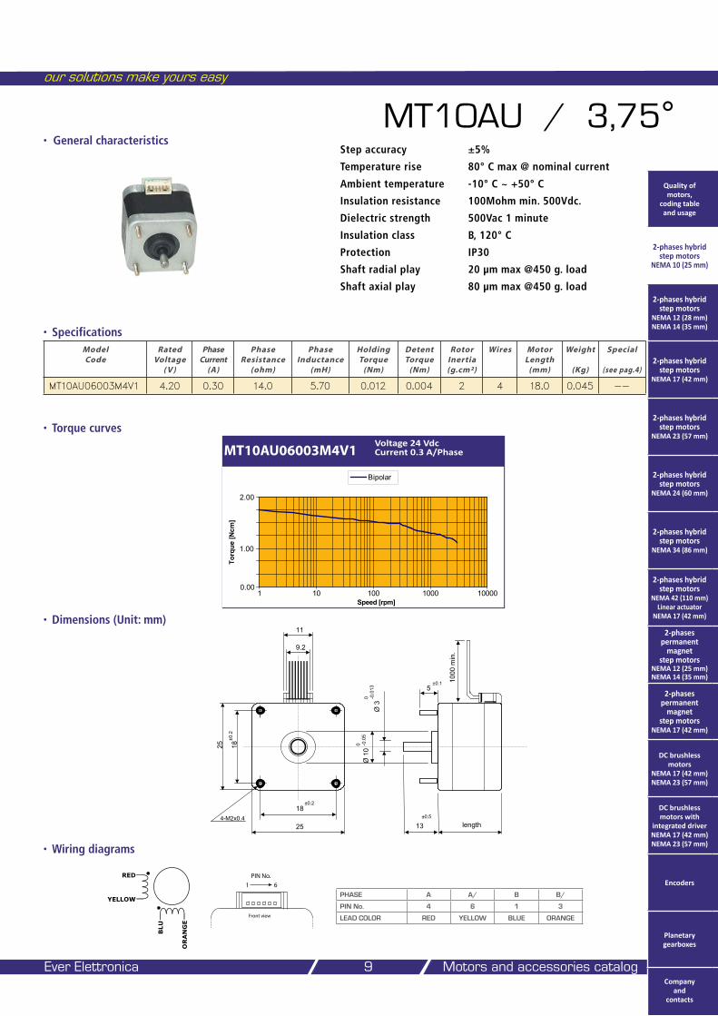
MT10AU / 3,75°
• Specifications
• Wiring diagrams
Model Code
Rated Voltage
( V )
Phase Current
(A)
Phase Resistance
(ohm)
Phase Inductance
(mH)
Holding Torque
(Nm)
Detent Torque
(Nm)
Rotor Inertia (g.cm²)
Wires Motor Length
(mm)
Weight
(Kg)
Special
(see pag.4)
MT10AU06003M4V1 4.20 0.30 14.0 5.70 0.012 0.004 2 4 18.0 0.045 --
• General characteristicsStep accuracy ±5%
Temperature rise 80° C max @ nominal current
Ambient temperature -10° C ~ +50° C
Insulation resistance 100Mohm min. 500Vdc.
Dielectric strength 500Vac 1 minute
Insulation class B, 120° C
Protection IP30
Shaft radial play 20 µm max @450 g. load
Shaft axial play 80 µm max @450 g. load
PHASE A A/ B B/
PIN No. 4 6 1 3
LEAD COLOR RED YELLOW BLUE ORANGE
BLU
ORANGE
RED
YELLOW
��������������������
�������
����������
18
25
25 18
Ø 1
00 -0
.05
Ø 3
0 -0.0
13
13 length
±0.2
4-M2x0.4
5
±0.2
±0.1 1000
min
.
11
9.2
±0.5
• Torque curves
MT10AU06003M4V1Voltage 24 Vdc Current 0.3 A/Phase
0.00
1.00
2.00
Bipolar
1 10 100 1000 10000
Torq
ue [N
cm]
Speed [rpm]
Quality of motors,
coding table and usage
2-phases hybrid step motors
NEMA 10 (25 mm)
2-phases hybrid step motors
NEMA 12 (28 mm) NEMA 14 (35 mm)
2-phases hybrid step motors
NEMA 17 (42 mm)
2-phases hybrid step motors
NEMA 23 (57 mm)
2-phases hybrid step motors
NEMA 24 (60 mm)
2-phases hybrid step motors
NEMA 34 (86 mm)
2-phases hybrid step motors
NEMA 42 (110 mm) Linear actuator
NEMA 17 (42 mm)
2-phases permanent
magnet step motors
NEMA 12 (25 mm) NEMA 14 (35 mm)
2-phases permanent
magnet step motors
NEMA 17 (42 mm)
DC brushless motors
NEMA 17 (42 mm) NEMA 23 (57 mm)
DC brushless motors with
integrated driver NEMA 17 (42 mm) NEMA 23 (57 mm)
Encoders
Planetary gearboxes
Company and
contacts
• Dimensions (Unit: mm)
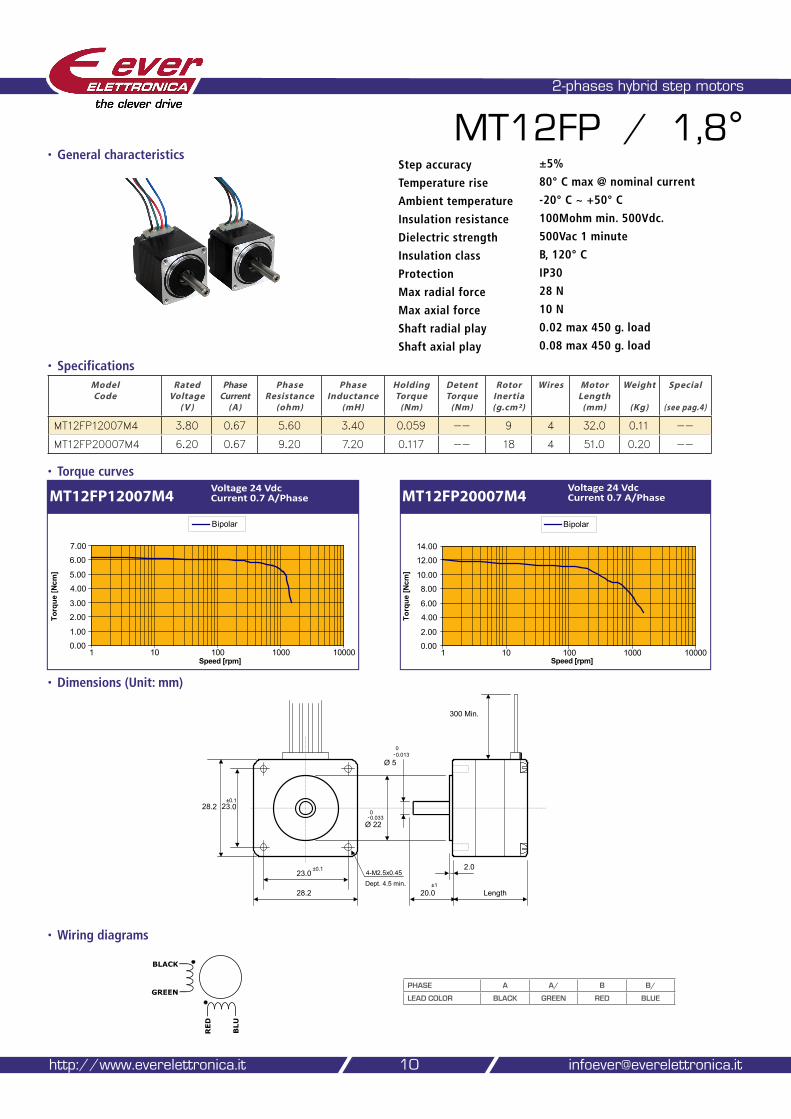
2-phases hybrid step motors
MT12FP / 1,8°
• Specifications
• Wiring diagrams
Model Code
Rated Voltage
( V )
Phase Current
(A)
Phase Resistance
(ohm)
Phase Inductance
(mH)
Holding Torque
(Nm)
Detent Torque
(Nm)
Rotor Inertia (g.cm²)
Wires Motor Length
(mm)
Weight
(Kg)
Special
(see pag.4)
MT12FP12007M4 3.80 0.67 5.60 3.40 0.059 -- 9 4 32.0 0.11 --
MT12FP20007M4 6.20 0.67 9.20 7.20 0.117 -- 18 4 51.0 0.20 --
10
• General characteristics
http://www.everelettronica.it [email protected]
• Torque curves
Step accuracy ±5%
Temperature rise 80° C max @ nominal current
Ambient temperature -20° C ~ +50° C
Insulation resistance 100Mohm min. 500Vdc.
Dielectric strength 500Vac 1 minute
Insulation class B, 120° C
Protection IP30
Max radial force 28 N
Max axial force 10 N
Shaft radial play 0.02 max 450 g. load
Shaft axial play 0.08 max 450 g. load
23.0
28.2
28.2 23.0
Ø 22
0-0.033
Ø 5
Length
2.0
300 Min.
±0.1
±0.1
±1
0-0.013
4-M2.5x0.45Dept. 4.5 min.
20.0
PHASE A A/ B B/
LEAD COLOR BLACK GREEN RED BLUE
RED
BLU
BLACK
GREEN
MT12FP12007M4Voltage 24 Vdc Current 0.7 A/Phase
0.00
1.00
2.00
3.00
4.00
5.00
6.00
7.00
Bipolar
1 10 100 1000 10000
Torq
ue [N
cm]
Speed [rpm]
MT12FP20007M4Voltage 24 Vdc Current 0.7 A/Phase
0.00
2.00
4.00
6.00
8.00
10.00
12.00
14.00
Bipolar
1 10 100 1000 10000
Torq
ue [N
cm]
Speed [rpm]
our solutions make yours easy
Ever Elettronica Motors and accessories catalog 11
• Dimensions (Unit: mm)
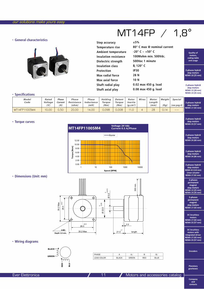
MT14FP / 1,8°
• Specifications
• Wiring diagrams
• General characteristics
MT14FP11005M4Voltage 24 Vdc Current 0.5 A/Phase
Model Code
Rated Voltage
( V )
Phase Current
(A)
Phase Resistance
(ohm)
Phase Inductance
(mH)
Holding Torque
(Nm)
Detent Torque
(Nm)
Rotor Inertia (g.cm²)
Wires Motor Length
(mm)
Weight
(Kg)
Special
(see pag.4)
MT14FP11005M4 10.00 0.50 20.00 14.00 0.098 0.008 11.0 4 28 0.14 --
• Torque curves
Step accuracy ±5%
Temperature rise 80° C max @ nominal current
Ambient temperature -20° C ~ +50° C
Insulation resistance 100Mohm min. 500Vdc.
Dielectric strength 500Vac 1 minute
Insulation class B, 120° C
Protection IP30
Max radial force 28 N
Max axial force 10 N
Shaft radial play 0.02 max 450 g. load
Shaft axial play 0.08 max 450 g. load
PHASE A A/ B B/
LEAD COLOR BLACK GREEN RED BLUE
RED
BLU
BLACK
GREEN
26.0
35.2 Max
35.2
Max
26.0
Ø 2
2.0
0 -0.0
5
Ø 5
.00 - 0
.013
21.0 length
±0.2
4-M3
±0.2
300
min
.
±1
Depth 3.0 min.
2.0
0.00
2.00
4.00
6.00
8.00
10.00
12.00
1 10 100 1000 10000
Speed [RPM]
Torq
ue [N
cm]
Bipolar
Quality of motors,
coding table and usage
2-phases hybrid step motors
NEMA 10 (25 mm)
2-phases hybrid step motors
NEMA 12 (28 mm) NEMA 14 (35 mm)
2-phases hybrid step motors
NEMA 17 (42 mm)
2-phases hybrid step motors
NEMA 23 (57 mm)
2-phases hybrid step motors
NEMA 24 (60 mm)
2-phases hybrid step motors
NEMA 34 (86 mm)
2-phases hybrid step motors
NEMA 42 (110 mm) Linear actuator
NEMA 17 (42 mm)
2-phases permanent
magnet step motors
NEMA 12 (25 mm) NEMA 14 (35 mm)
2-phases permanent
magnet step motors
NEMA 17 (42 mm)
DC brushless motors
NEMA 17 (42 mm) NEMA 23 (57 mm)
DC brushless motors with
integrated driver NEMA 17 (42 mm) NEMA 23 (57 mm)
Encoders
Planetary gearboxes
Company and
contacts
• Dimensions (Unit: mm)
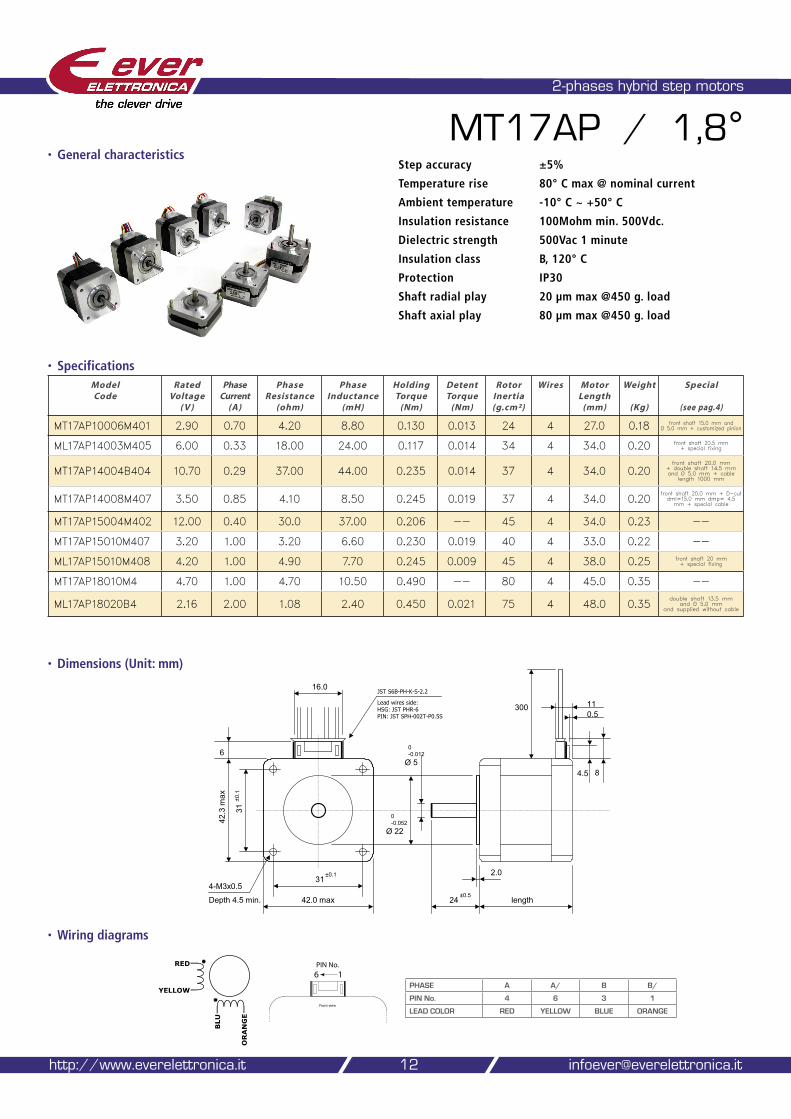
2-phases hybrid step motors
MT17AP / 1,8°
• Specifications
• Wiring diagrams
12
• General characteristicsStep accuracy ±5%
Temperature rise 80° C max @ nominal current
Ambient temperature -10° C ~ +50° C
Insulation resistance 100Mohm min. 500Vdc.
Dielectric strength 500Vac 1 minute
Insulation class B, 120° C
Protection IP30
Shaft radial play 20 µm max @450 g. load
Shaft axial play 80 µm max @450 g. load
http://www.everelettronica.it [email protected]
BLU
ORANGE
RED
YELLOWPHASE A A/ B B/
PIN No. 4 6 3 1
LEAD COLOR RED YELLOW BLUE ORANGE
31
42.0 max
42.3
max
31
4-M3x0.5
Ø 22
0-0.052
Ø 5
24 length
2.0
Depth 4.5 min.
4.5 8
110.5
6
±0.1
±0.1
±0.5
0-0.012
16.0
300
JST S6B-PH-K-S-2.2
Lead wires side:HSG: JST PHR-6PIN: JST SPH-002T-P0.5S
�������������������
����������
Model Code
Rated Voltage
( V )
Phase Current
(A)
Phase Resistance
(ohm)
Phase Inductance
(mH)
Holding Torque
(Nm)
Detent Torque
(Nm)
Rotor Inertia (g.cm²)
Wires Motor Length
(mm)
Weight
(Kg)
Special
(see pag.4)
MT17AP10006M401 2.90 0.70 4.20 8.80 0.130 0.013 24 4 27.0 0.18 front shaft 15.0 mm and Ø 5.0 mm + customized pinion
ML17AP14003M405 6.00 0.33 18.00 24.00 0.117 0.014 34 4 34.0 0.20 front shaft 20.5 mm + special fixing
MT17AP14004B404 10.70 0.29 37.00 44.00 0.235 0.014 37 4 34.0 0.20front shaft 20.0 mm
+ double shaft 14.5 mm and Ø 5.0 mm + cable
length 1000 mm
MT17AP14008M407 3.50 0.85 4.10 8.50 0.245 0.019 37 4 34.0 0.20front shaft 20.0 mm + D-cut dml=15.0 mm dmp= 4.5 mm + special cable
MT17AP15004M402 12.00 0.40 30.0 37.00 0.206 -- 45 4 34.0 0.23 --
MT17AP15010M407 3.20 1.00 3.20 6.60 0.230 0.019 40 4 33.0 0.22 --
ML17AP15010M408 4.20 1.00 4.90 7.70 0.245 0.009 45 4 38.0 0.25 front shaft 20 mm + special fixing
MT17AP18010M4 4.70 1.00 4.70 10.50 0.490 -- 80 4 45.0 0.35 --
ML17AP18020B4 2.16 2.00 1.08 2.40 0.450 0.021 75 4 48.0 0.35double shaft 13.5 mm
and Ø 5.0 mm and supplied without cable
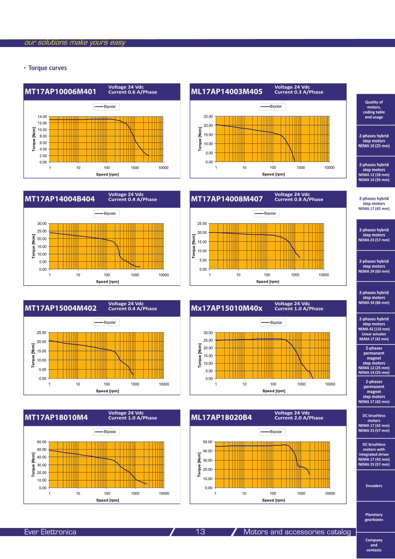
• Torque curves
our solutions make yours easy
Ever Elettronica Motors and accessories catalog 13
MT17AP10006M401Voltage 24 Vdc Current 0.6 A/Phase ML17AP14003M405
Voltage 24 Vdc Current 0.3 A/Phase
MT17AP14004B404Voltage 24 Vdc Current 0.4 A/Phase MT17AP14008M407
Voltage 24 Vdc Current 0.8 A/Phase
0.00
5.00
10.00
15.00
20.00
25.00
1 10 100 1000 10000
Speed [rpm]
Torq
ue [N
cm]
Bipolar
MT17AP15004M402Voltage 24 Vdc Current 0.4 A/Phase Mx17AP15010M40x
Voltage 24 Vdc Current 1.0 A/Phase
0.00
5.00
10.00
15.00
20.00
25.00
30.00
1 10 100 1000 10000
Speed [rpm]
Torq
ue [N
cm]
Bipolar
MT17AP18010M4Voltage 24 Vdc Current 1.0 A/Phase ML17AP18020B4
Voltage 24 Vdc Current 2.0 A/Phase
0.00
2.00
4.00
6.00
8.00
10.00
12.00
14.00
1 10 100 1000 10000
Speed [rpm]
Torq
ue [N
cm]
Bipolar
0.00
5.00
10.00
15.00
20.00
25.00
1 10 100 1000 10000
Speed [rpm]
Torq
ue [N
cm]
Bipolar
0.00
5.00
10.00
15.00
20.00
25.00
30.00
1 10 100 1000 10000
Speed [rpm]
Torq
ue [N
cm]
Bipolar
0.00
5.00
10.00
15.00
20.00
25.00
1 10 100 1000 10000
Speed [rpm]
Torq
ue [N
cm]
Bipolar
0.00
10.00
20.00
30.00
40.00
50.00
60.00
1 10 100 1000 10000
Speed [rpm]
Torq
ue [N
cm]
Bipolar
0.00
10.00
20.00
30.00
40.00
50.00
1 10 100 1000 10000
Speed [rpm]
Torq
ue [N
cm]
Bipolar
Quality of motors,
coding table and usage
2-phases hybrid step motors
NEMA 10 (25 mm)
2-phases hybrid step motors
NEMA 12 (28 mm) NEMA 14 (35 mm)
2-phases hybrid step motors
NEMA 17 (42 mm)
2-phases hybrid step motors
NEMA 23 (57 mm)
2-phases hybrid step motors
NEMA 24 (60 mm)
2-phases hybrid step motors
NEMA 34 (86 mm)
2-phases hybrid step motors
NEMA 42 (110 mm) Linear actuator
NEMA 17 (42 mm)
2-phases permanent
magnet step motors
NEMA 12 (25 mm) NEMA 14 (35 mm)
2-phases permanent
magnet step motors
NEMA 17 (42 mm)
DC brushless motors
NEMA 17 (42 mm) NEMA 23 (57 mm)
DC brushless motors with
integrated driver NEMA 17 (42 mm) NEMA 23 (57 mm)
Encoders
Planetary gearboxes
Company and
contacts
• Dimensions (Unit: mm)
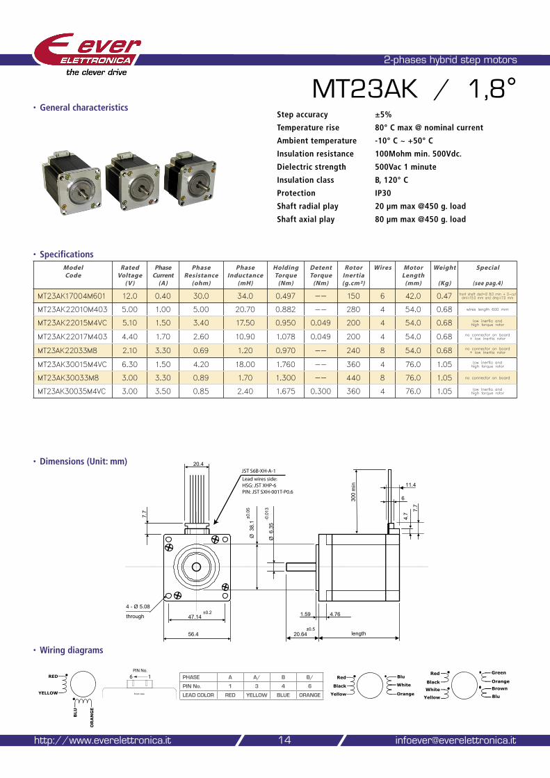
2-phases hybrid step motors
MT23AK / 1,8°
• Specifications
• Wiring diagrams
14
• General characteristicsStep accuracy ±5%
Temperature rise 80° C max @ nominal current
Ambient temperature -10° C ~ +50° C
Insulation resistance 100Mohm min. 500Vdc.
Dielectric strength 500Vac 1 minute
Insulation class B, 120° C
Protection IP30
Shaft radial play 20 µm max @450 g. load
Shaft axial play 80 µm max @450 g. load
http://www.everelettronica.it [email protected]
56.4
47.14 1.59 4.76
20.64 length
6
20.4
7.7
4.7
300
min
4 - Ø 5.08
through
Ø 6
.35
Ø 3
8.1
±0.2
±0.0
5
-0.0
13
±0.5
7.7
11.4
������������������������������������������������������������������
BLU
ORANGE
RED
YELLOW
PHASE A A/ B B/
PIN No. 1 3 4 6
LEAD COLOR RED YELLOW BLUE ORANGE
Red
Black
White
Yellow
Green
Orange
Brown
Blu
����������������������
����������
Model Code
Rated Voltage
( V )
Phase Current
(A)
Phase Resistance
(ohm)
Phase Inductance
(mH)
Holding Torque
(Nm)
Detent Torque
(Nm)
Rotor Inertia (g.cm²)
Wires Motor Length
(mm)
Weight
(Kg)
Special
(see pag.4)
MT23AK17004M601 12.0 0.40 30.0 34.0 0.497 -- 150 6 42.0 0.47 front shaft dad=Ø 8.0 mm + D-cut dml=15.0 mm and dmp=7.0 mm
MT23AK22010M403 5.00 1.00 5.00 20.70 0.882 -- 280 4 54.0 0.68 wires length 600 mm
MT23AK22015M4VC 5.10 1.50 3.40 17.50 0.950 0.049 200 4 54.0 0.68 low inertia and high torque rotor
MT23AK22017M403 4.40 1.70 2.60 10.90 1.078 0.049 200 4 54.0 0.68 no connector on board + low inertia rotor
MT23AK22033M8 2.10 3.30 0.69 1.20 0.970 -- 240 8 54.0 0.68 no connector on board + low inertia rotor
MT23AK30015M4VC 6.30 1.50 4.20 18.00 1.760 -- 360 4 76.0 1.05 low inertia and high torque rotor
MT23AK30033M8 3.00 3.30 0.89 1.70 1.300 -- 440 8 76.0 1.05 no connector on board
MT23AK30035M4VC 3.00 3.50 0.85 2.40 1.675 0.300 360 4 76.0 1.05 low inertia and high torque rotor
Red
Black
Yellow Orange
White
Blu
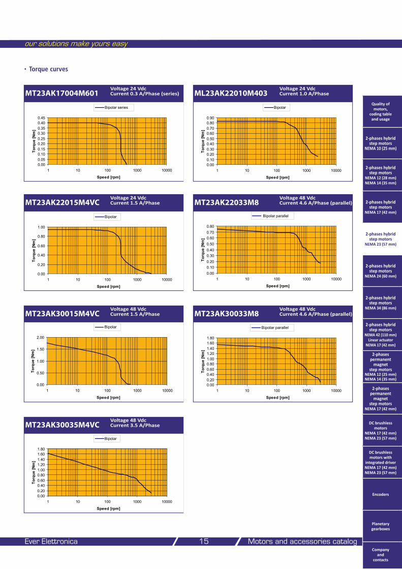
• Torque curves
our solutions make yours easy
Ever Elettronica Motors and accessories catalog 15
MT23AK17004M601Voltage 24 Vdc Current 0.3 A/Phase (series)
0.000.050.100.150.200.250.300.350.400.45
1 10 100 1000 10000
Speed [rpm]
Torq
ue [N
m]
Bipolar series
ML23AK22010M403Voltage 24 Vdc Current 1.0 A/Phase
0.000.100.200.300.400.500.600.700.800.90
1 10 100 1000 10000
Speed [rpm]
Torq
ue [N
m]
Bipolar
MT23AK22015M4VCVoltage 24 Vdc Current 1.5 A/Phase
0.00
0.20
0.40
0.60
0.80
1.00
1 10 100 1000 10000
Speed [rpm]
Torq
ue [N
m]
Bipolar
MT23AK22033M8Voltage 48 Vdc Current 4.6 A/Phase (parallel)
MT23AK30015M4VCVoltage 48 Vdc Current 1.5 A/Phase
0.000.100.200.300.400.500.600.700.80
1 10 100 1000 10000
Speed [rpm]
Torq
ue [N
m]
Bipolar parallel
MT23AK30033M8Voltage 48 Vdc Current 4.6 A/Phase (parallel)
MT23AK30035M4VCVoltage 48 Vdc Current 3.5 A/Phase
0.000.200.400.600.801.001.201.401.601.80
1 10 100 1000 10000
Speed [rpm]
Torq
ue [N
m]
Bipolar
Quality of motors,
coding table and usage
2-phases hybrid step motors
NEMA 10 (25 mm)
2-phases hybrid step motors
NEMA 12 (28 mm) NEMA 14 (35 mm)
2-phases hybrid step motors
NEMA 17 (42 mm)
2-phases hybrid step motors
NEMA 23 (57 mm)
2-phases hybrid step motors
NEMA 24 (60 mm)
2-phases hybrid step motors
NEMA 34 (86 mm)
2-phases hybrid step motors
NEMA 42 (110 mm) Linear actuator
NEMA 17 (42 mm)
2-phases permanent
magnet step motors
NEMA 12 (25 mm) NEMA 14 (35 mm)
2-phases permanent
magnet step motors
NEMA 17 (42 mm)
DC brushless motors
NEMA 17 (42 mm) NEMA 23 (57 mm)
DC brushless motors with
integrated driver NEMA 17 (42 mm) NEMA 23 (57 mm)
Encoders
Planetary gearboxes
Company and
contacts
0.000.200.400.600.801.001.201.401.601.80
1 10 100 1000 10000
Speed [rpm]
Torq
ue [N
m]
Bipolar parallel
0.00
0.50
1.00
1.50
2.00
1 10 100 1000 10000
Speed [rpm]
Torq
ue [N
m]
Bipolar
• Dimensions (Unit: mm)
2-phases hybrid step motors
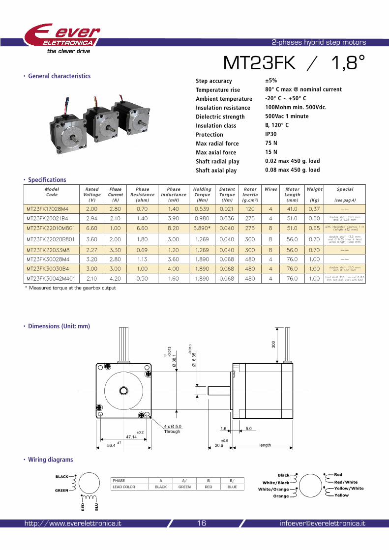
MT23FK / 1,8°
• Specifications
• Wiring diagrams
Model Code
Rated Voltage
( V )
Phase Current
(A)
Phase Resistance
(ohm)
Phase Inductance
(mH)
Holding Torque
(Nm)
Detent Torque
(Nm)
Rotor Inertia (g.cm²)
Wires Motor Length
(mm)
Weight
(Kg)
Special
(see pag.4)
MT23FK17028M4 2.00 2.80 0.70 1.40 0.539 0.021 120 4 41.0 0.37 --
MT23FK20021B4 2.94 2.10 1.40 3.90 0.980 0.036 275 4 51.0 0.50 double shaft 19.0 mm and Ø 6.35 mm
MT23FK22010M8G1 6.60 1.00 6.60 8.20 5.890* 0.040 275 8 51.0 0.65 with integrated gearbox 1:11 (length +32 mm)
MT23FK22020B801 3.60 2.00 1.80 3.00 1.269 0.040 300 8 56.0 0.70double shaft 13.5 mm and Ø 6.35 mm + lead wires length 1000 mm
MT23FK22033M8 2.27 3.30 0.69 1.20 1.269 0.040 300 8 56.0 0.70 --
MT23FK30028M4 3.20 2.80 1.13 3.60 1.890 0.068 480 4 76.0 1.00 --
MT23FK30030B4 3.00 3.00 1.00 4.00 1.890 0.068 480 4 76.0 1.00 double shaft 15.0 mm and Ø 6.35 mm
MT23FK30042M401 2.10 4.20 0.50 1.60 1.890 0.068 480 4 76.0 1.00 front shaft 30,0 mm and Ø 8.0 mm and lead wires with tube
16http://www.everelettronica.it [email protected]
Step accuracy ±5%
Temperature rise 80° C max @ nominal current
Ambient temperature -20° C ~ +50° C
Insulation resistance 100Mohm min. 500Vdc.
Dielectric strength 500Vac 1 minute
Insulation class B, 120° C
Protection IP30
Max radial force 75 N
Max axial force 15 N
Shaft radial play 0.02 max 450 g. load
Shaft axial play 0.08 max 450 g. load
5.0
length
Ø 6
.35-0
.013
Ø 3
8.10 -0
.013
1.6
56.4
47.14±1
±0.24 x Ø 5.0
300
±0.5
Through
20.6
Black
White/Black
White/Orange
Orange
Red
Red/White
Yellow/White
Yellow
RED
BLU
BLACK
GREEN
PHASE A A/ B B/
LEAD COLOR BLACK GREEN RED BLUE
• General characteristics
* Measured torque at the gearbox output
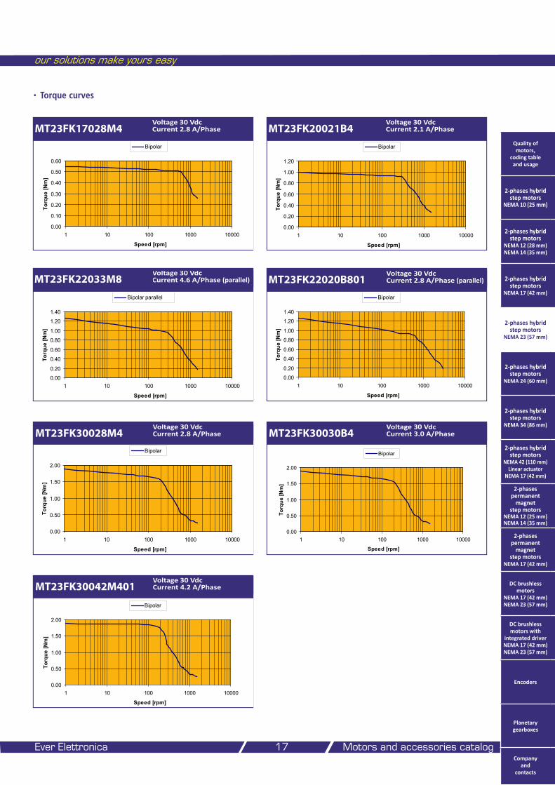
• Torque curves
our solutions make yours easy
Ever Elettronica Motors and accessories catalog 17
MT23FK17028M4Voltage 30 Vdc Current 2.8 A/Phase
0.00
0.10
0.20
0.30
0.40
0.50
0.60
1 10 100 1000 10000
Speed [rpm]
Torq
ue [N
m]
Bipolar
MT23FK20021B4Voltage 30 Vdc Current 2.1 A/Phase
0.00
0.20
0.40
0.60
0.80
1.00
1.20
1 10 100 1000 10000
Speed [rpm]
Torq
ue [N
m]
Bipolar
Voltage 30 Vdc Current 4.6 A/Phase (parallel)MT23FK22033M8
0.00
0.20
0.40
0.60
0.80
1.00
1.20
1.40
1 10 100 1000 10000
Speed [rpm]
Torq
ue [N
m]
Bipolar parallel
MT23FK30028M4Voltage 30 Vdc Current 2.8 A/Phase
0.00
0.50
1.00
1.50
2.00
1 10 100 1000 10000
Speed [rpm]
Torq
ue [N
m]
Bipolar
MT23FK30042M401Voltage 30 Vdc Current 4.2 A/Phase
0.00
0.50
1.00
1.50
2.00
1 10 100 1000 10000
Speed [rpm]
Torq
ue [N
m]
Bipolar
MT23FK30030B4Voltage 30 Vdc Current 3.0 A/Phase
0.00
0.50
1.00
1.50
2.00
1 10 100 1000 10000
Speed [rpm]
Torq
ue [N
m]
Bipolar
Quality of motors,
coding table and usage
2-phases hybrid step motors
NEMA 10 (25 mm)
2-phases hybrid step motors
NEMA 12 (28 mm) NEMA 14 (35 mm)
2-phases hybrid step motors
NEMA 17 (42 mm)
2-phases hybrid step motors
NEMA 23 (57 mm)
2-phases hybrid step motors
NEMA 24 (60 mm)
2-phases hybrid step motors
NEMA 34 (86 mm)
2-phases hybrid step motors
NEMA 42 (110 mm) Linear actuator
NEMA 17 (42 mm)
2-phases permanent
magnet step motors
NEMA 12 (25 mm) NEMA 14 (35 mm)
2-phases permanent
magnet step motors
NEMA 17 (42 mm)
DC brushless motors
NEMA 17 (42 mm) NEMA 23 (57 mm)
DC brushless motors with
integrated driver NEMA 17 (42 mm) NEMA 23 (57 mm)
Encoders
Planetary gearboxes
Company and
contacts
Voltage 30 Vdc Current 2.8 A/Phase (parallel)MT23FK22020B801
0.00
0.20
0.40
0.60
0.80
1.00
1.20
1.40
1 10 100 1000 10000
Speed [rpm]
Torq
ue [N
m]
Bipolar
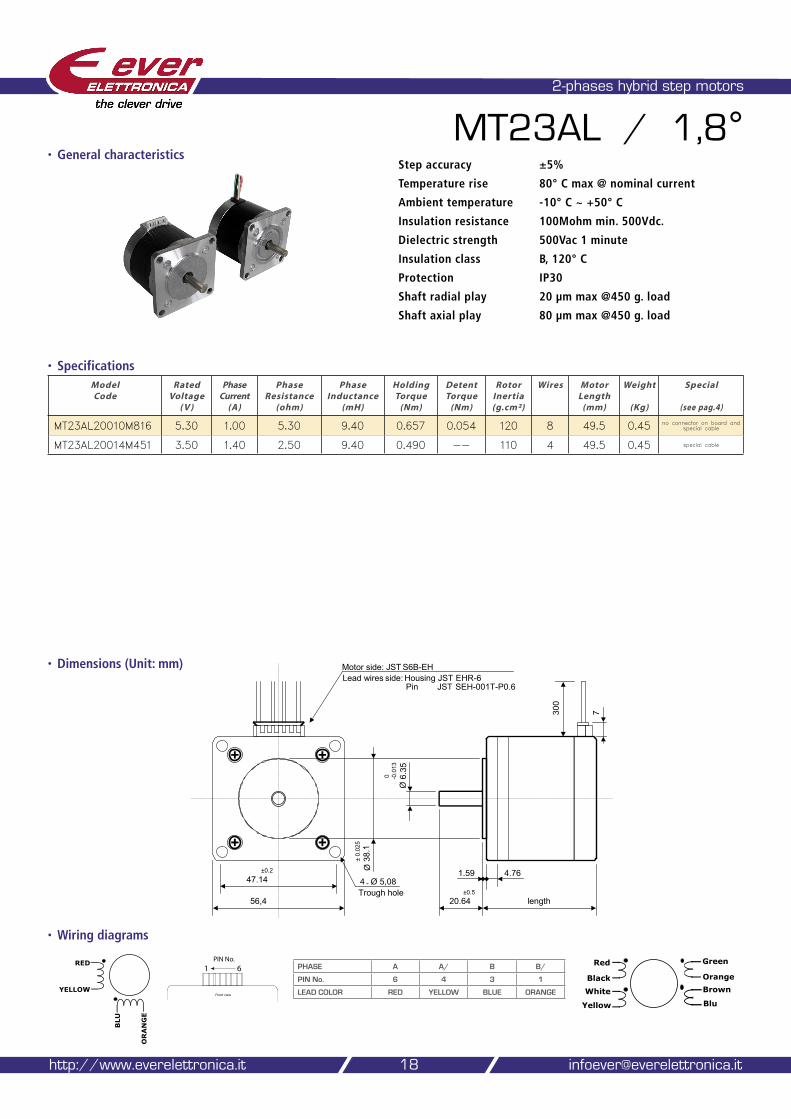
• Dimensions (Unit: mm)
2-phases hybrid step motors
MT23AL / 1,8°
• Specifications
• Wiring diagrams
Model Code
Rated Voltage
( V )
Phase Current
(A)
Phase Resistance
(ohm)
Phase Inductance
(mH)
Holding Torque
(Nm)
Detent Torque
(Nm)
Rotor Inertia (g.cm²)
Wires Motor Length
(mm)
Weight
(Kg)
Special
(see pag.4)
MT23AL20010M816 5.30 1.00 5.30 9.40 0.657 0.054 120 8 49.5 0.45 no connector on board and special cable
MT23AL20014M451 3.50 1.40 2.50 9.40 0.490 -- 110 4 49.5 0.45 special cable
18
Step accuracy ±5%
Temperature rise 80° C max @ nominal current
Ambient temperature -10° C ~ +50° C
Insulation resistance 100Mohm min. 500Vdc.
Dielectric strength 500Vac 1 minute
Insulation class B, 120° C
Protection IP30
Shaft radial play 20 µm max @450 g. load
Shaft axial play 80 µm max @450 g. load
http://www.everelettronica.it [email protected]
BLU
ORANGE
RED
YELLOW
Red
Black
White
Yellow
Green
Orange
Brown
Blu
Ø 3
8.1
4.761.5947.14
20.6456,4
4 - Ø 5,08
Ø 6
.35
± 0.
025
±0.5
0 -0.0
13
±0.2
length
7300
Trough hole
Motor side: JST S6B-EHLead wires side: Housing JST EHR-6
Pin JST SEH-001T-P0.6
PHASE A A/ B B/
PIN No. 6 4 3 1
LEAD COLOR RED YELLOW BLUE ORANGE
�������������������������
����������
• General characteristics
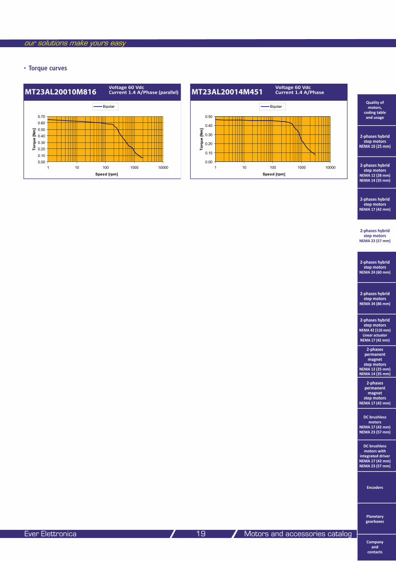
• Torque curves
our solutions make yours easy
Ever Elettronica Motors and accessories catalog 19
MT23AL20010M816Voltage 60 Vdc Current 1.4 A/Phase (parallel) MT23AL20014M451
Voltage 60 Vdc Current 1.4 A/Phase
0.00
0.10
0.20
0.30
0.40
0.50
1 10 100 1000 10000
Speed [rpm]
Torq
ue [N
m]
Bipolar
0.00
0.10
0.20
0.30
0.40
0.50
0.60
0.70
1 10 100 1000 10000
Speed [rpm]
Torq
ue [N
m]
BipolarQuality of motors,
coding table and usage
2-phases hybrid step motors
NEMA 10 (25 mm)
2-phases hybrid step motors
NEMA 12 (28 mm) NEMA 14 (35 mm)
2-phases hybrid step motors
NEMA 17 (42 mm)
2-phases hybrid step motors
NEMA 23 (57 mm)
2-phases hybrid step motors
NEMA 24 (60 mm)
2-phases hybrid step motors
NEMA 34 (86 mm)
2-phases hybrid step motors
NEMA 42 (110 mm) Linear actuator
NEMA 17 (42 mm)
2-phases permanent
magnet step motors
NEMA 12 (25 mm) NEMA 14 (35 mm)
2-phases permanent
magnet step motors
NEMA 17 (42 mm)
DC brushless motors
NEMA 17 (42 mm) NEMA 23 (57 mm)
DC brushless motors with
integrated driver NEMA 17 (42 mm) NEMA 23 (57 mm)
Encoders
Planetary gearboxes
Company and
contacts
• Dimensions (Unit: mm)
2-phases hybrid step motors
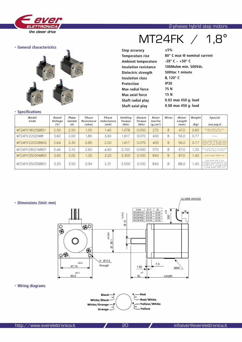
MT24FK / 1,8°
• Specifications
• Wiring diagrams
Model Code
Rated Voltage
( V )
Phase Current
(A)
Phase Resistance
(ohm)
Phase Inductance
(mH)
Holding Torque
(Nm)
Detent Torque
(Nm)
Rotor Inertia (g.cm²)
Wires Motor Length
(mm)
Weight
(Kg)
Special
(see pag.4)
MT24FK18025B801 2.50 2.50 1.00 1.40 1.078 0.050 275 8 47.0 0.60 double shaft 19.0 mm and Ø 6.35 mm
MT24FK22020M8 3.60 2.00 1.80 3.60 1.617 0.070 400 8 56.0 0.77 --
MT24FK22033B802 2.64 3.30 0.80 2.00 1.617 0.070 400 8 56.0 0.77front shaft 20.64 mm and Ø 6,35 mm + double shaft 19.0 mm and Ø 6.35 mm
MT24FK26021M801 5.46 2.10 2.60 4.60 2.150 0.090 570 8 67.0 1.20 front shaft with D-cut dml=20.0 mm and dmp= 7.5 mm
MT24FK35030M801 3.90 3.00 1.30 3.20 3.300 0.100 840 8 87.0 1.40 wires length 2000 mm
MT24FK35035B801 3.30 3.50 0.94 2.31 3.500 0.100 840 8 88.0 1.40front shaft with D-cut
dml=20.0 mm and dmp=7.5 mm + double shaft 17.5 mm and Ø 6.35 mm + encoder fixing + wires length 2000 mm
20
Step accuracy ±5%
Temperature rise 80° C max @ nominal current
Ambient temperature -20° C ~ +50° C
Insulation resistance 100Mohm min. 500Vdc.
Dielectric strength 500Vac 1 minute
Insulation class B, 120° C
Protection IP30
Max radial force 75 N
Max axial force 15 N
Shaft radial play 0.02 max 450 g. load
Shaft axial play 0.08 max 450 g. load
http://www.everelettronica.it [email protected]
60.0
47.14 1.607.0
SL Length
4 - Ø 4.5
through
Ø D
Ø 3
8.1
±0.2
±0.0
25
- 0.0
13
±1
label
±0.1
300
±10 16
UL3266 AWG20
Black
White/Black
White/Orange
Orange
Red
Red/White
Yellow/White
Yellow
Code Ø D SLMT24FK18 Ø 6.35 20.64MT24FK22 Ø 6.35 24.00MT24FK26 Ø 8.00 24.00MT24FK35 Ø 8.00 24.00
• General characteristics
• Torque curves
our solutions make yours easy
Ever Elettronica Motors and accessories catalog 21
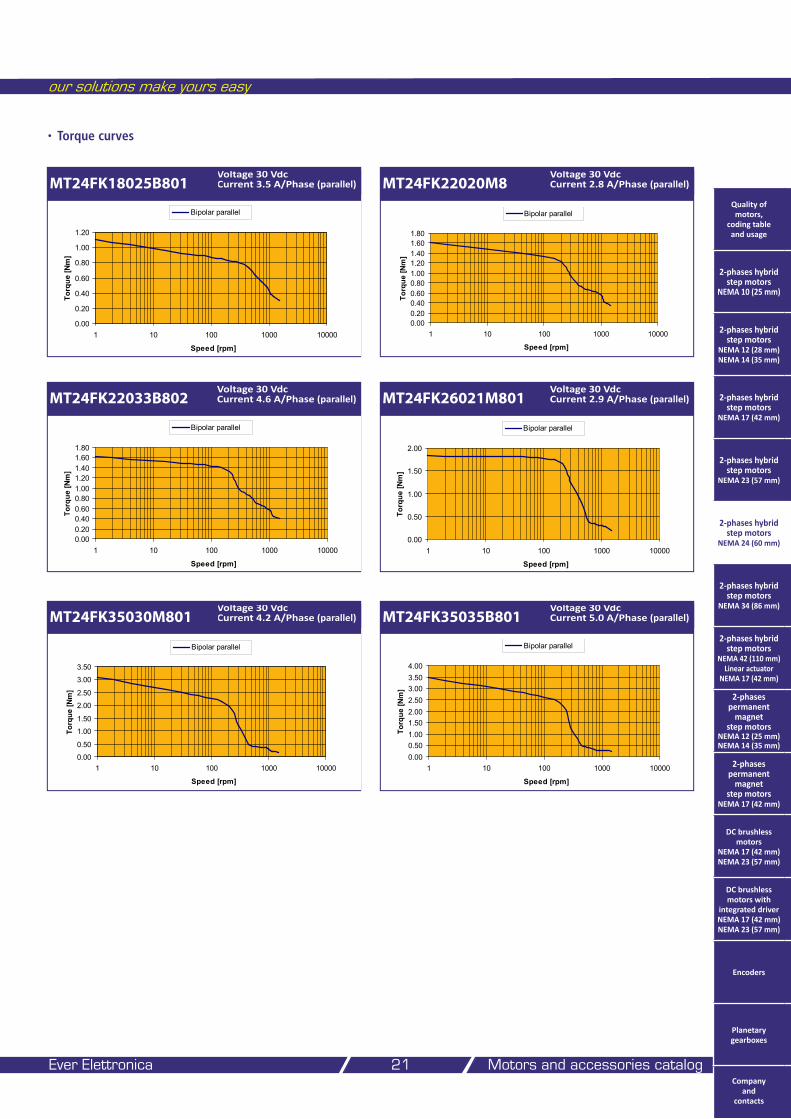
MT24FK18025B801Voltage 30 Vdc Current 3.5 A/Phase (parallel)
0.00
0.20
0.40
0.60
0.80
1.00
1.20
1 10 100 1000 10000
Speed [rpm]
Torq
ue [N
m]
Bipolar parallel
MT24FK22020M8Voltage 30 Vdc Current 2.8 A/Phase (parallel)
MT24FK22033B802Voltage 30 Vdc Current 4.6 A/Phase (parallel) MT24FK26021M801
Voltage 30 Vdc Current 2.9 A/Phase (parallel)
0.00
0.50
1.00
1.50
2.00
1 10 100 1000 10000
Speed [rpm]
Torq
ue [N
m]
Bipolar parallel
MT24FK35030M801Voltage 30 Vdc Current 4.2 A/Phase (parallel)
0.00
0.50
1.00
1.50
2.00
2.50
3.00
3.50
1 10 100 1000 10000
Speed [rpm]
Torq
ue [N
m]
Bipolar parallel
MT24FK35035B801Voltage 30 Vdc Current 5.0 A/Phase (parallel)
0.000.200.400.600.801.001.201.401.601.80
1 10 100 1000 10000
Speed [rpm]
Torq
ue [N
m]
Bipolar parallel
0.000.200.400.600.801.001.201.401.601.80
1 10 100 1000 10000
Speed [rpm]
Torq
ue [N
m]
Bipolar parallel
0.000.501.001.502.002.503.003.504.00
1 10 100 1000 10000
Speed [rpm]
Torq
ue [N
m]
Bipolar parallel
Quality of motors,
coding table and usage
2-phases hybrid step motors
NEMA 10 (25 mm)
2-phases hybrid step motors
NEMA 12 (28 mm) NEMA 14 (35 mm)
2-phases hybrid step motors
NEMA 17 (42 mm)
2-phases hybrid step motors
NEMA 23 (57 mm)
2-phases hybrid step motors
NEMA 24 (60 mm)
2-phases hybrid step motors
NEMA 34 (86 mm)
2-phases hybrid step motors
NEMA 42 (110 mm) Linear actuator
NEMA 17 (42 mm)
2-phases permanent
magnet step motors
NEMA 12 (25 mm) NEMA 14 (35 mm)
2-phases permanent
magnet step motors
NEMA 17 (42 mm)
DC brushless motors
NEMA 17 (42 mm) NEMA 23 (57 mm)
DC brushless motors with
integrated driver NEMA 17 (42 mm) NEMA 23 (57 mm)
Encoders
Planetary gearboxes
Company and
contacts
Model Code
Rated Voltage
( V )
Phase Current
(A)
Phase Resistance
(ohm)
Phase Inductance
(mH)
Holding Torque
(Nm)
Detent Torque
(Nm)
Rotor Inertia (g.cm²)
Wires Motor Length
(mm)
Weight
(Kg)
Special
(see pag.4)
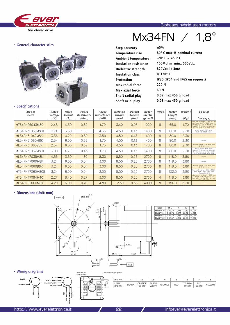
MT34FN26043M801 2.45 4.30 0.57 1.70 3.40 0.08 1000 8 65.0 1.70terminal clamps CMA= 85.85 mm and CMP= 34.0 mm + Protection IP65 + front shaft DAD=Ø 9.525 mm with key K=3.0 and KL= 22.0 mm
MT34FN31035M801 3.71 3.50 1.06 4.35 4.50 0.13 1400 8 80.0 2.30 front shaft 30,5 mm DAD=Ø 9.525 mm
ML34FN31042M8K 3.36 4.20 0.80 3.50 4.50 0.13 1400 8 80.0 2.30 --ML34FN31060M8K 2.34 6.00 0.39 1.70 4.50 0.13 1400 8 80.0 2.30 --ML34FN31060B8K 2.34 6.00 0.39 1.70 4.50 0.13 1400 8 80.0 2.30 double shaft 17.5 mm and
Ø 6.35 mm
MT34FN31067M801 3.00 6.70 0.45 1.70 4.50 0.13 1400 8 80.0 2.30front shaft 30,5 mm
DAD=Ø 9.525 mm with key K=3.0 mm and KL= 22.0 mm and cable with tube
ML34FN47035M8K 4.55 3.50 1.30 8.30 8.50 0.25 2700 8 118.0 3.80 --ML34FN47060M8K 3.24 6.00 0.54 3.00 8.50 0.25 2700 8 118.0 3.80 --
ML34FN47060B8K 3.24 6.00 0.54 3.00 8.50 0.25 2700 8 118.0 3.80 double shaft 17.5 mm and Ø 6.35 mm
MT34FN47060M808 3.24 6.00 0.54 3.00 8.50 0.25 2700 8 152.0 3.80terminal clamps CMA=85.85 mm and CMP= 34.0 mm
+ Protection IP65
MT34FN47084M401 2.27 8.40 0.27 3.00 8.50 0.25 2700 4 118.0 3.80tube on wires lenght 1000 mm + front shaft DAD=Ø 9.525
mm with key K= 3.0 mm and KL= 22.0 mm
ML34FN62060M8K 4.20 6.00 0.70 4.80 12.50 0.38 4000 8 156.0 5.30 --
• Dimensions (Unit: mm)
2-phases hybrid step motors
Mx34FN / 1,8°
• Specifications
• Wiring diagrams
22
Step accuracy ±5%
Temperature rise 80° C max @ nominal current
Ambient temperature -20° C ~ +50° C
Insulation resistance 100Mohm min., 500Vdc.
Dielectric strength 820Vac 1s 3mA
Insulation class B, 120° C
Protection IP30 (IP54 and IP65 on request)
Max radial force 220 N
Max axial force 60 N
Shaft radial play 0.02 max 450 g. load
Shaft axial play 0.08 max 450 g. load
http://www.everelettronica.it [email protected]
4 - Ø 5.5
85.85
1.528.38
length31.75
Ø 73.025
0 -0.0
13Ø
D
400
69.50±0.2
±0.05
K
KL±0.254
0 -0.0
508
KL K K
KEY
KF
+0.2-0.3
BLACK
BLACK/WHITE
ORANGE/WHITE
ORANGE
RED
YELLOW
RED/WHITE
YELLOW/WHITE
M4 screw forearth ground
2133
.3
�
�
�
�
�
�
�
�
BLACK
ORANGE
RED
YELLOW
PIN No. 1 2 3 4 5 6 7 8
LEAD COLOR
BLACKORANGE WHITE
BLACK WHITE
ORANGE REDYELLOW WHITE
RED WHITE
YELLOW
Terminal clamps option
Code Ø D K KL KFMx34FN26 Ø 12,70 3,175 22,52 14,097Mx34FN31 Ø 12,70 3,175 22,52 14,097Mx34FN47 Ø 12.70 3,175 22,52 14,097Mx34FN62 Ø 15.87 4,762 22,23 17,907
• General characteristics
• Torque curves
our solutions make yours easy
Ever Elettronica Motors and accessories catalog 23
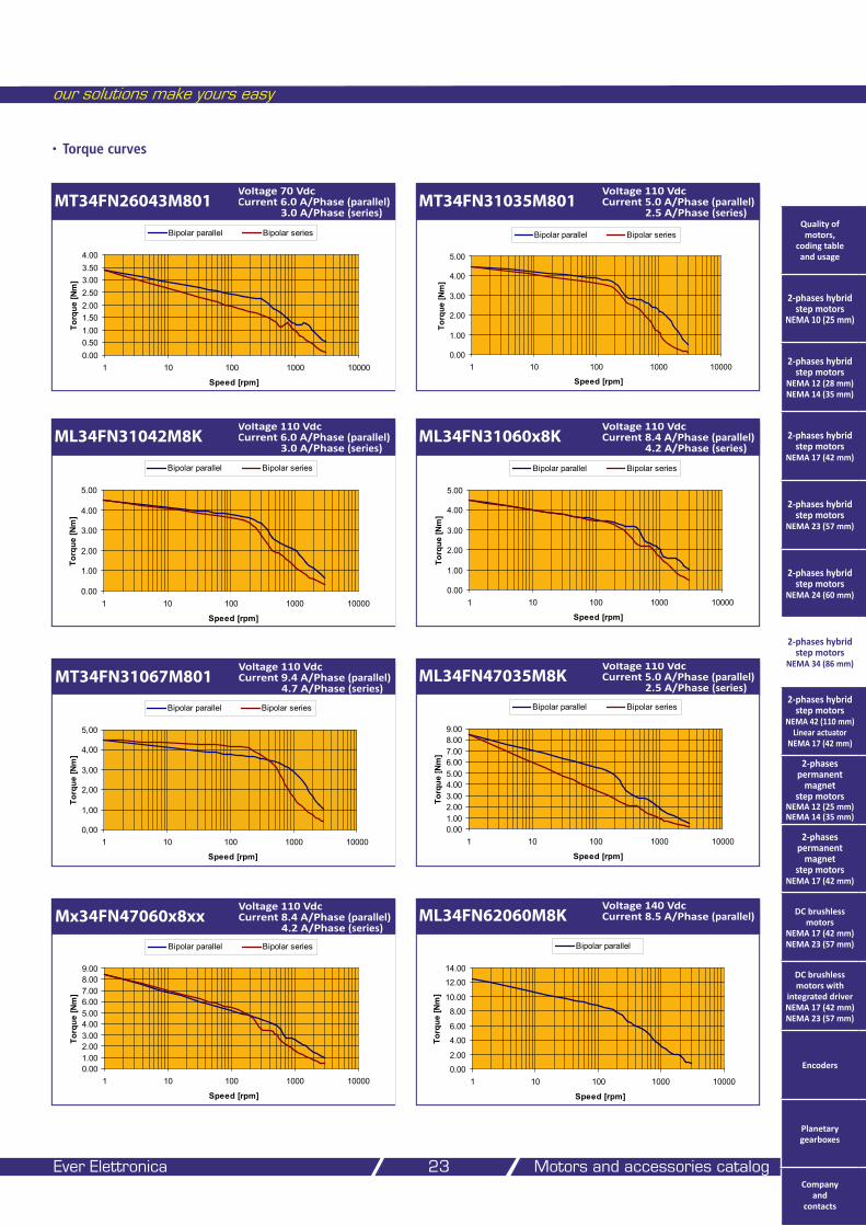
MT34FN26043M801Voltage 70 Vdc Current 6.0 A/Phase (parallel) 3.0 A/Phase (series)
0.000.501.001.502.002.503.003.504.00
1 10 100 1000 10000
Speed [rpm]
Torq
ue [N
m]
Bipolar parallel Bipolar series
MT34FN31035M801Voltage 110 Vdc Current 5.0 A/Phase (parallel) 2.5 A/Phase (series)
ML34FN31042M8KVoltage 110 Vdc Current 6.0 A/Phase (parallel) 3.0 A/Phase (series)
0.00
1.00
2.00
3.00
4.00
5.00
1 10 100 1000 10000
Speed [rpm]
Torq
ue [N
m]
Bipolar parallel Bipolar series
ML34FN31060x8KVoltage 110 Vdc Current 8.4 A/Phase (parallel) 4.2 A/Phase (series)
0.00
1.00
2.00
3.00
4.00
5.00
1 10 100 1000 10000
Speed [rpm]
Torq
ue [N
m]
Bipolar parallel Bipolar series
ML34FN47035M8KVoltage 110 Vdc Current 5.0 A/Phase (parallel) 2.5 A/Phase (series)
0.001.002.003.004.005.006.007.008.009.00
1 10 100 1000 10000
Speed [rpm]
Torq
ue [N
m]
Bipolar parallel Bipolar series
ML34FN62060M8KVoltage 140 Vdc Current 8.5 A/Phase (parallel)
0.00
2.00
4.00
6.00
8.00
10.00
12.00
14.00
1 10 100 1000 10000
Speed [rpm]
Torq
ue [N
m]
Bipolar parallel
0.00
1.00
2.00
3.00
4.00
5.00
1 10 100 1000 10000
Speed [rpm]
Torq
ue [N
m]
Bipolar parallel Bipolar seriesQuality of motors,
coding table and usage
2-phases hybrid step motors
NEMA 10 (25 mm)
2-phases hybrid step motors
NEMA 12 (28 mm) NEMA 14 (35 mm)
2-phases hybrid step motors
NEMA 17 (42 mm)
2-phases hybrid step motors
NEMA 23 (57 mm)
2-phases hybrid step motors
NEMA 24 (60 mm)
2-phases hybrid step motors
NEMA 34 (86 mm)
2-phases hybrid step motors
NEMA 42 (110 mm) Linear actuator
NEMA 17 (42 mm)
2-phases permanent
magnet step motors
NEMA 12 (25 mm) NEMA 14 (35 mm)
2-phases permanent
magnet step motors
NEMA 17 (42 mm)
DC brushless motors
NEMA 17 (42 mm) NEMA 23 (57 mm)
DC brushless motors with
integrated driver NEMA 17 (42 mm) NEMA 23 (57 mm)
Encoders
Planetary gearboxes
Company and
contacts
Mx34FN47060x8xxVoltage 110 Vdc Current 8.4 A/Phase (parallel) 4.2 A/Phase (series)
0.001.002.003.004.005.006.007.008.009.00
1 10 100 1000 10000
Speed [rpm]
Torq
ue [N
m]
Bipolar parallel Bipolar series
MT34FN31067M801Voltage 110 Vdc Current 9.4 A/Phase (parallel) 4.7 A/Phase (series)
0,00
1,00
2,00
3,00
4,00
5,00
1 10 100 1000 10000
Speed [rpm]
Torq
ue [N
m]
Bipolar parallel Bipolar series
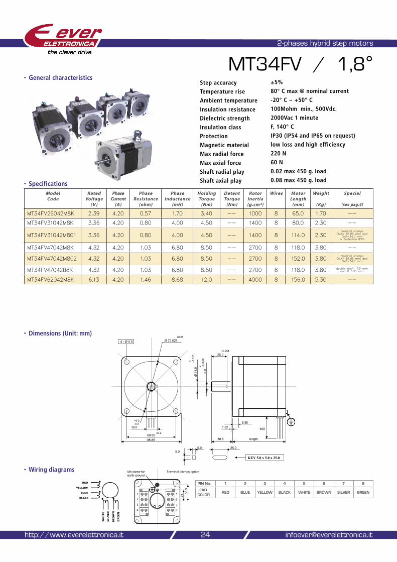
• Dimensions (Unit: mm)
2-phases hybrid step motors
MT34FV / 1,8°
• Specifications
• Wiring diagrams
Model Code
Rated Voltage
( V )
Phase Current
(A)
Phase Resistance
(ohm)
Phase Inductance
(mH)
Holding Torque
(Nm)
Detent Torque
(Nm)
Rotor Inertia (g.cm²)
Wires Motor Length
(mm)
Weight
(Kg)
Special
(see pag.4)
MT34FV26042M8K 2.39 4.20 0.57 1.70 3.40 -- 1000 8 65.0 1.70 --
MT34FV31042M8K 3.36 4.20 0.80 4.00 4.50 -- 1400 8 80.0 2.30 --
MT34FV31042M801 3.36 4.20 0.80 4.00 4.50 -- 1400 8 114.0 2.30terminal clamps
CMA= 85.85 mm and CMP=34.0 mm + Protection IP65
MT34FV47042M8K 4.32 4.20 1.03 6.80 8.50 -- 2700 8 118.0 3.80 --
MT34FV47042M802 4.32 4.20 1.03 6.80 8.50 -- 2700 8 152.0 3.80terminal clamps
CMA= 85,85 mm and CMP=34,0 mm
MT34FV47042B8K 4.32 4.20 1.03 6.80 8.50 -- 2700 8 118.0 3.80 double shaft 17.5 mm and Ø 6.35 mm
MT34FV62042M8K 6.13 4.20 1.46 8.68 12.0 -- 4000 8 156.0 5.30 --
24
Step accuracy ±5%
Temperature rise 80° C max @ nominal current
Ambient temperature -20° C ~ +50° C
Insulation resistance 100Mohm min., 500Vdc.
Dielectric strength 2000Vac 1 minute
Insulation class F, 140° C
Protection IP30 (IP54 and IP65 on request)
Magnetic material low loss and high efficiency
Max radial force 220 N
Max axial force 60 N
Shaft radial play 0.02 max 450 g. load
Shaft axial play 0.08 max 450 g. load
http://www.everelettronica.it [email protected]
4 - Ø 5.5
85.85
1.528.38
length30.5
Ø 73.025
0 -0.0
13Ø
14.
0
400
69.50±0.2
±0.05
5.0
25.0±0.254
0 -0.0
508
25.05.05.0
KEY 5.0 x 5.0 x 25.0
16.0
+0.2-0.3
RED
YELLOW
BLUE
BLACK
WHITE
GREEN
SILVER
BROWN
M4 screw forearth ground
2133
.3
�
�
�
�
�
�
�
�
PIN No. 1 2 3 4 5 6 7 8
LEAD COLOR
RED BLUE YELLOW BLACK WHITE BROWN SILVER GREEN
Terminal clamps option
• General characteristics
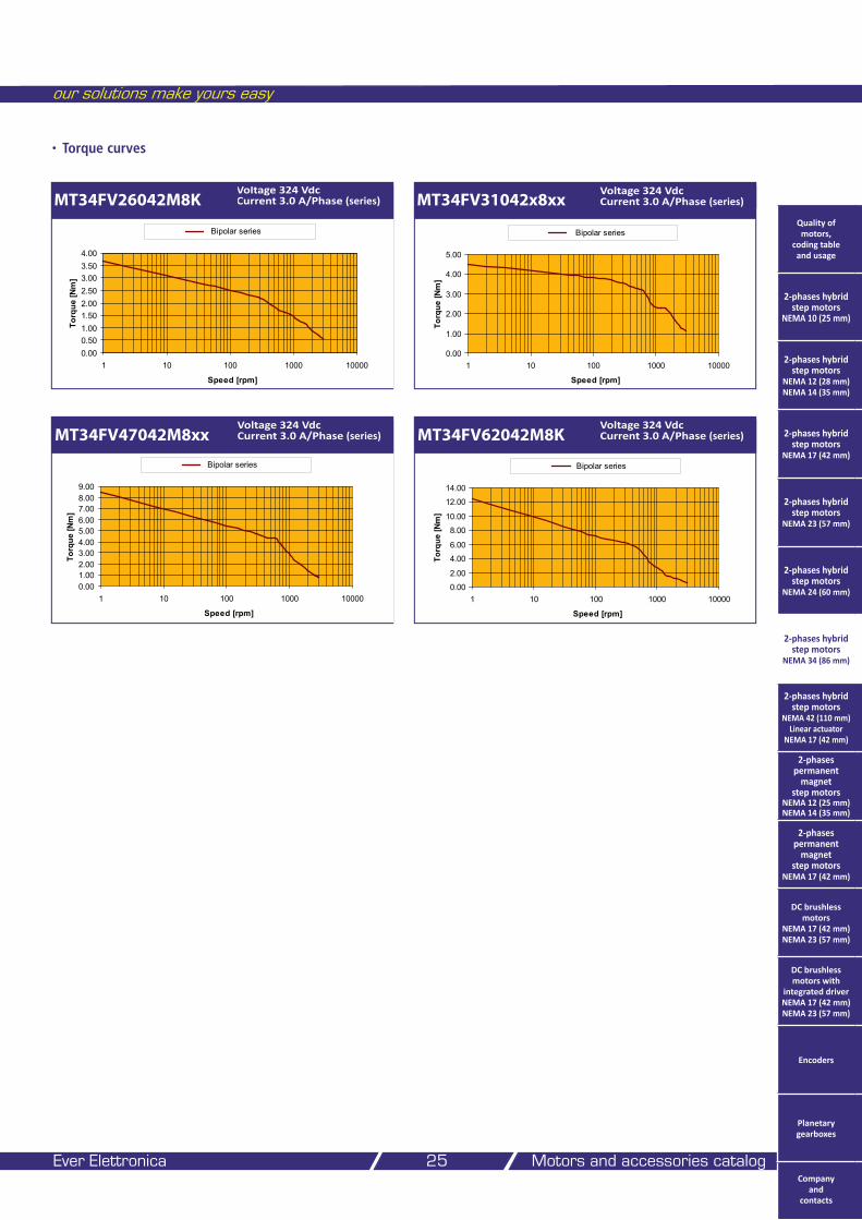
• Torque curves
our solutions make yours easy
Ever Elettronica Motors and accessories catalog 25
MT34FV26042M8KVoltage 324 Vdc Current 3.0 A/Phase (series)
0.000.501.001.502.002.503.003.504.00
1 10 100 1000 10000
Speed [rpm]
Torq
ue [N
m]
Bipolar series
MT34FV31042x8xxVoltage 324 Vdc Current 3.0 A/Phase (series)
0.00
1.00
2.00
3.00
4.00
5.00
1 10 100 1000 10000
Speed [rpm]
Torq
ue [N
m]
Bipolar series
MT34FV47042M8xxVoltage 324 Vdc Current 3.0 A/Phase (series)
0.001.002.003.004.005.006.007.008.009.00
1 10 100 1000 10000
Speed [rpm]
Torq
ue [N
m]
Bipolar series
MT34FV62042M8KVoltage 324 Vdc Current 3.0 A/Phase (series)
0.00
2.00
4.00
6.00
8.00
10.00
12.00
14.00
1 10 100 1000 10000
Speed [rpm]
Torq
ue [N
m]
Bipolar series
Quality of motors,
coding table and usage
2-phases hybrid step motors
NEMA 10 (25 mm)
2-phases hybrid step motors
NEMA 12 (28 mm) NEMA 14 (35 mm)
2-phases hybrid step motors
NEMA 17 (42 mm)
2-phases hybrid step motors
NEMA 23 (57 mm)
2-phases hybrid step motors
NEMA 24 (60 mm)
2-phases hybrid step motors
NEMA 34 (86 mm)
2-phases hybrid step motors
NEMA 42 (110 mm) Linear actuator
NEMA 17 (42 mm)
2-phases permanent
magnet step motors
NEMA 12 (25 mm) NEMA 14 (35 mm)
2-phases permanent
magnet step motors
NEMA 17 (42 mm)
DC brushless motors
NEMA 17 (42 mm) NEMA 23 (57 mm)
DC brushless motors with
integrated driver NEMA 17 (42 mm) NEMA 23 (57 mm)
Encoders
Planetary gearboxes
Company and
contacts
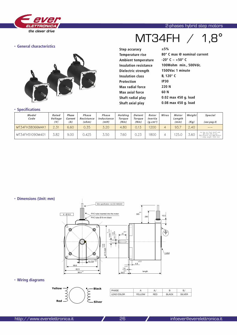
• Dimensions (Unit: mm)
2-phases hybrid step motors
MT34FH / 1,8°
• Specifications
• Wiring diagrams
Model Code
Rated Voltage
( V )
Phase Current
(A)
Phase Resistance
(ohm)
Phase Inductance
(mH)
Holding Torque
(Nm)
Detent Torque
(Nm)
Rotor Inertia (g.cm²)
Wires Motor Length
(mm)
Weight
(Kg)
Special
(see pag.4)
MT34FH38066M4K1 2.31 6.60 0.35 3.20 4.80 0.13 1200 4 93.7 2.40 --
MT34FH51090M401 3.82 9.00 0.425 3.50 7.60 0.23 1800 4 125.0 3.60no key on front shaft and
M4 hole with D-cut DML=25,0mm and DMP=8,5mm - wires length 1000 mm
26
Step accuracy ±5%
Temperature rise 80° C max @ nominal current
Ambient temperature -20° C ~ +50° C
Insulation resistance 100Mohm min., 500Vdc.
Dielectric strength 1500Vac 1 minute
Insulation class B, 120° C
Protection IP30
Max radial force 220 N
Max axial force 60 N
Shaft radial play 0.02 max 450 g. load
Shaft axial play 0.08 max 450 g. load
http://www.everelettronica.it [email protected]
4 - Ø 5.5
69.6
86.0
1.6
4.8
length30.0
.
PVC tube inserted into the motor
±1 ±0.5
+0.2- 0.3
Ø 7
3.02
5+0.0
50-0
.025
± 0.2
± 0.2
22±0.2
3.0
0.00
4-0
.002
9
9.52
50 -0
.013
305±10
280PVC tube Ø 8 mm black
Wire specification: UL1332 AWG18#
82.5
15.0
Label
10.725
Yellow
Red
Black
Silver
PHASE A A/ B B/
LEAD COLOR YELLOW RED BLACK SILVER
• General characteristics
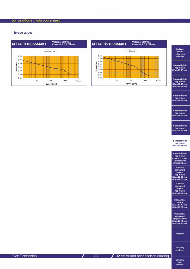
• Torque curves
our solutions make yours easy
Ever Elettronica Motors and accessories catalog 27
MT34FH38066M4K1Voltage 110 Vdc Current 6.6 A/Phase
0.00
1.00
2.00
3.00
4.00
5.00
6.00
1 10 100 1000 10000
Speed [rpm]
Torq
ue [N
m]
Bipolar
MT34FH51090M401Voltage 110 Vdc Current 9.0 A/Phase
0.001.002.003.004.005.006.007.008.00
1 10 100 1000 10000
Speed [rpm]
Torq
ue [N
m]
BipolarQuality of motors,
coding table and usage
2-phases hybrid step motors
NEMA 10 (25 mm)
2-phases hybrid step motors
NEMA 12 (28 mm) NEMA 14 (35 mm)
2-phases hybrid step motors
NEMA 17 (42 mm)
2-phases hybrid step motors
NEMA 23 (57 mm)
2-phases hybrid step motors
NEMA 24 (60 mm)
2-phases hybrid step motors
NEMA 34 (86 mm)
2-phases hybrid step motors
NEMA 42 (110 mm) Linear actuator
NEMA 17 (42 mm)
2-phases permanent
magnet step motors
NEMA 12 (25 mm) NEMA 14 (35 mm)
2-phases permanent
magnet step motors
NEMA 17 (42 mm)
DC brushless motors
NEMA 17 (42 mm) NEMA 23 (57 mm)
DC brushless motors with
integrated driver NEMA 17 (42 mm) NEMA 23 (57 mm)
Encoders
Planetary gearboxes
Company and
contacts
• Dimensions (Unit: mm)
2-phases hybrid step motors
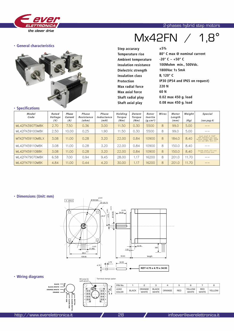
Mx42FN / 1,8°
• Specifications
• Wiring diagrams
28
Step accuracy ±5%
Temperature rise 80° C max @ nominal current
Ambient temperature -20° C ~ +50° C
Insulation resistance 100Mohm min., 500Vdc.
Dielectric strength 1800Vac 1s 5mA
Insulation class B, 120° C
Protection IP30 (IP54 and IP65 on request)
Max radial force 220 N
Max axial force 60 N
Shaft radial play 0.02 max 450 g. load
Shaft axial play 0.08 max 450 g. load
http://www.everelettronica.it [email protected]
Model Code
Rated Voltage
( V )
Phase Current
(A)
Phase Resistance
(ohm)
Phase Inductance
(mH)
Holding Torque
(Nm)
Detent Torque
(Nm)
Rotor Inertia (g.cm²)
Wires Motor Length
(mm)
Weight
(Kg)
Special
(see pag.4)
ML42FN39075M8K 2.70 7.50 0.36 3.00 11.50 0.30 5500 8 99.0 5.00 --
ML42FN39100M8K 2.50 10.00 0.25 1.90 11.50 0.30 5500 8 99.0 5.00 --
MT42FN59110M8LX 3.08 11.00 0.28 3.20 22.00 0.84 10900 8 184.0 8.40front shaft Ø 15.87
with standard key and terminal clamps CMA= 109.86 mm and CMP= 30.0 mm
ML42FN59110M8K 3.08 11.00 0.28 3.20 22.00 0.84 10900 8 150.0 8.40 --
ML42FN59110B8K 3.08 11.00 0.28 3.20 22.00 0.84 10900 8 150.0 8.40 double shaft 17.5 mm and Ø 6.35 mm
ML42FN79070M8K 6.58 7.00 0.94 9.45 28.00 1.17 16200 8 201.0 11.70 --
ML42FN79110M8K 4.84 11.00 0.44 4.20 30.00 1.17 16200 8 201.0 11.70 --
4 - Ø 8.5
109.85
1.52
12.19
length55.63
Ø 125.73Ø 55.524
45.0°
30021.082-0.432
±0.051
Ø 1
9.05 34.93
4.75
-0.0
51 - 0.0
13
KEY 4.75 x 4.75 x 34.934.75
34.93
89.0-0.2
4.75
±0.254
BLACK
BLACK/WHITE
ORANGE/WHITE
ORANGE
RED
YELLOW
RED/WHITE
YELLOW/WHITE
M4 screw forearth ground
2439
.5
�
�
�
�
�
�
�
�
Terminal clamps option
PIN No. 1 2 3 4 5 6 7 8
LEAD COLOR
BLACKORANGE WHITE
BLACK WHITE
ORANGE REDYELLOW WHITE
RED WHITE
YELLOW
• General characteristics
• Torque curves
our solutions make yours easy
Ever Elettronica Motors and accessories catalog 29
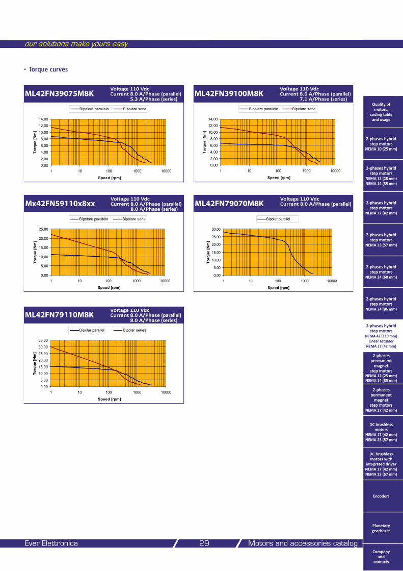
ML42FN39075M8KVoltage 110 Vdc Current 8.0 A/Phase (parallel) 5.3 A/Phase (series)
0,00
2,00
4,00
6,00
8,00
10,00
12,00
14,00
1 10 100 1000 10000
Speed [rpm]
Torq
ue [N
m]
Bipolare parallelo Bipolare serie
ML42FN39100M8KVoltage 110 Vdc Current 8.0 A/Phase (parallel) 7.1 A/Phase (series)
0,00
2,00
4,00
6,00
8,00
10,00
12,00
14,00
1 10 100 1000 10000
Speed [rpm]
Torq
ue [N
m]
Bipolare parallelo Bipolare serie
Mx42FN59110x8xxVoltage 110 Vdc Current 8.0 A/Phase (parallel) 8.0 A/Phase (series)
0,00
5,00
10,00
15,00
20,00
25,00
1 10 100 1000 10000
Speed [rpm]
Torq
ue [N
m]
Bipolare parallelo Bipolare serie
ML42FN79070M8KVoltage 110 Vdc Current 8.0 A/Phase (parallel)
ML42FN79110M8KVoltage 110 Vdc Current 8.0 A/Phase (parallel) 8.0 A/Phase (series)
0.00
5.00
10.00
15.00
20.00
25.00
30.00
35.00
1 10 100 1000 10000
Speed [rpm]
Torq
ue [N
m]
Bipolar parallel Bipolar series
0.00
5.00
10.00
15.00
20.00
25.00
30.00
1 10 100 1000 10000
Speed [rpm]
Torq
ue [N
m]
Bipolar parallel
Quality of motors,
coding table and usage
2-phases hybrid step motors
NEMA 10 (25 mm)
2-phases hybrid step motors
NEMA 12 (28 mm) NEMA 14 (35 mm)
2-phases hybrid step motors
NEMA 17 (42 mm)
2-phases hybrid step motors
NEMA 23 (57 mm)
2-phases hybrid step motors
NEMA 24 (60 mm)
2-phases hybrid step motors
NEMA 34 (86 mm)
2-phases hybrid step motors
NEMA 42 (110 mm) Linear actuator
NEMA 17 (42 mm)
2-phases permanent
magnet step motors
NEMA 12 (25 mm) NEMA 14 (35 mm)
2-phases permanent
magnet step motors
NEMA 17 (42 mm)
DC brushless motors
NEMA 17 (42 mm) NEMA 23 (57 mm)
DC brushless motors with
integrated driver NEMA 17 (42 mm) NEMA 23 (57 mm)
Encoders
Planetary gearboxes
Company and
contacts
• Torque curves
• Dimensions (Unit: mm)
2-phases hybrid step motors and 2-phases hybrid step linear actuator
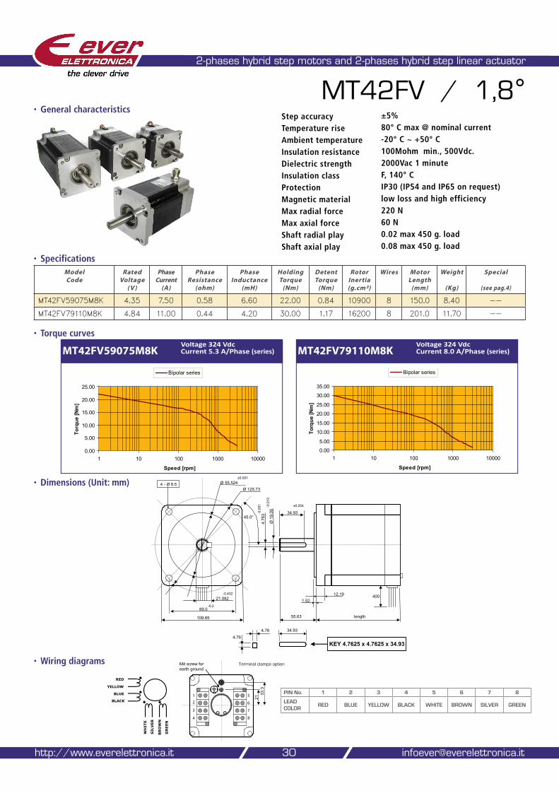
MT42FV / 1,8°
• Specifications
• Wiring diagrams
Model Code
Rated Voltage
( V )
Phase Current
(A)
Phase Resistance
(ohm)
Phase Inductance
(mH)
Holding Torque
(Nm)
Detent Torque
(Nm)
Rotor Inertia (g.cm²)
Wires Motor Length
(mm)
Weight
(Kg)
Special
(see pag.4)
MT42FV59075M8K 4.35 7.50 0.58 6.60 22.00 0.84 10900 8 150.0 8.40 --
MT42FV79110M8K 4.84 11.00 0.44 4.20 30.00 1.17 16200 8 201.0 11.70 --
30
Step accuracy ±5%
Temperature rise 80° C max @ nominal current
Ambient temperature -20° C ~ +50° C
Insulation resistance 100Mohm min., 500Vdc.
Dielectric strength 2000Vac 1 minute
Insulation class F, 140° C
Protection IP30 (IP54 and IP65 on request)
Magnetic material low loss and high efficiency
Max radial force 220 N
Max axial force 60 N
Shaft radial play 0.02 max 450 g. load
Shaft axial play 0.08 max 450 g. load
http://www.everelettronica.it [email protected]
4 - Ø 8.5
109.85
1.5212.19
length55.63
Ø 125.73Ø 55.524
45.0°
40021.082-0.432
±0.051
Ø 1
9.05 34.93
4.76
3-0.0
51 ±0.254-0.0
13
KEY 4.7625 x 4.7625 x 34.934.76
34.934.76
89.0-0.2
MT42FV59075M8KVoltage 324 Vdc Current 5.3 A/Phase (series) MT42FV79110M8K
Voltage 324 Vdc Current 8.0 A/Phase (series)
0.00
5.00
10.00
15.00
20.00
25.00
30.00
35.00
1 10 100 1000 10000
Speed [rpm]
Torq
ue [N
m]
Bipolar series
RED
YELLOW
BLUE
BLACK
WHITE
GREEN
SILVER
BROWN
M4 screw forearth ground
2133
.3
�
�
�
�
�
�
�
�
PIN No. 1 2 3 4 5 6 7 8
LEAD COLOR
RED BLUE YELLOW BLACK WHITE BROWN SILVER GREEN
0.00
5.00
10.00
15.00
20.00
25.00
1 10 100 1000 10000
Speed [rpm]
Torq
ue [N
m]
Bipolar series
• General characteristics
Terminal clamps option
our solutions make yours easy
Ever Elettronica Motors and accessories catalog 31
Quality of motors,
coding table and usage
2-phases hybrid step motors
NEMA 10 (25 mm)
2-phases hybrid step motors
NEMA 12 (28 mm) NEMA 14 (35 mm)
2-phases hybrid step motors
NEMA 17 (42 mm)
2-phases hybrid step motors
NEMA 23 (57 mm)
2-phases hybrid step motors
NEMA 24 (60 mm)
2-phases hybrid step motors
NEMA 34 (86 mm)
2-phases hybrid step motors
NEMA 42 (110 mm) Linear actuator
NEMA 17 (42 mm)
2-phases permanent
magnet step motors
NEMA 12 (25 mm) NEMA 14 (35 mm)
2-phases permanent
magnet step motors
NEMA 17 (42 mm)
DC brushless motors
NEMA 17 (42 mm) NEMA 23 (57 mm)
DC brushless motors with
integrated driver NEMA 17 (42 mm) NEMA 23 (57 mm)
Encoders
Planetary gearboxes
Company and
contacts
• Dimensions (Unit: mm)
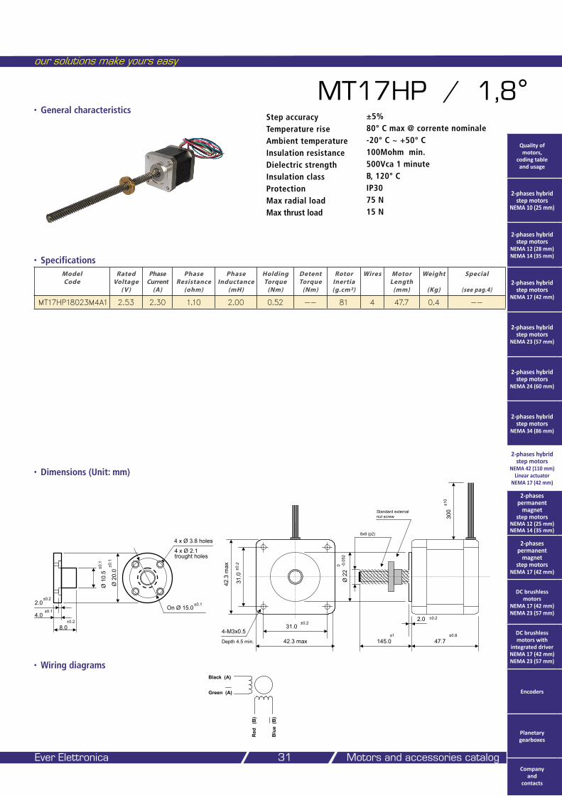
MT17HP / 1,8°
• Specifications
• Wiring diagrams
Model Code
Rated Voltage
( V )
Phase Current
(A)
Phase Resistance
(ohm)
Phase Inductance
(mH)
Holding Torque
(Nm)
Detent Torque
(Nm)
Rotor Inertia (g.cm²)
Wires Motor Length
(mm)
Weight
(Kg)
Special
(see pag.4)
MT17HP18023M4A1 2.53 2.30 1.10 2.00 0.52 -- 81 4 47.7 0.4 --
Step accuracy ±5%
Temperature rise 80° C max @ corrente nominale
Ambient temperature -20° C ~ +50° C
Insulation resistance 100Mohm min.
Dielectric strength 500Vca 1 minute
Insulation class B, 120° C
Protection IP30
Max radial load 75 N
Max thrust load 15 N
• General characteristics
31.0
42.3 max
42.3
max
31.0
4-M3x0.5
Ø 2
20 -0
.052
47.7
2.0
Depth 4.5 min.
±0.2
±0.2
145.0
8x8 (p2)
Standard externalnut screw
±1 ±0.8
±0.2
300
±10
Ø 2
0.0
Ø 1
0.5
4 x Ø 3.8 holes
±0.1
On Ø 15.0 ±0.1
4 x Ø 2.1 trought holes
±0.1
8.0±0.2
4.0±0.1
2.0±0.2
Black (A)
Green (A)
Blu
e (B
)
Red
(B
)
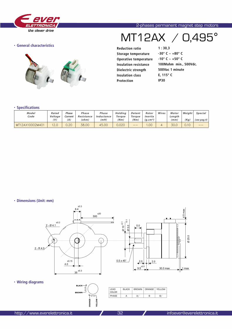
2-phases permanent magnet step motors
32http://www.everelettronica.it [email protected]
MT12AX / 0,495°Reduction ratio 1 : 30,3
Storage temperature -30° C ~ +80° C
Operative temperature -10° C ~ +50° C
Insulation resistance 100Mohm min., 500Vdc.
Dielectric strength 500Vac 1 minute
Insulation class E, 115° C
Protection IP30
• Dimensions (Unit: mm)
• Specifications
• Wiring diagrams
Model Code
Rated Voltage
( V )
Phase Current
(A)
Phase Resistance
(ohm)
Phase Inductance
(mH)
Holding Torque
(Nm)
Detent Torque
(Nm)
Rotor Inertia (g.cm²)
Wires Motor Length
(mm)
Weight
(Kg)
Special
(see pag.4)
MT12AX10002M401 12.0 0.20 38.00 45.00 0.020 -- 1.00 4 30.0 0.10 --
35±0.3
1 max30.0 max
Ø 2
5.0
2.0 2.0
9.5
Ø 1
0-0
.1
5.02 - Ø 4.1
500
Ø 5
.0-0
.1
4.0
±0.2
8.4
0.5 x 45°
4.5
max
����
±0.15
2 - R 4.0
±0.3
±20
ORANGE
YELLOW
BLACK
BROWN
LEAD COLOR
BLACK BROWN ORANGE YELLOW
PHASE A A/ B B/
• General characteristics
our solutions make yours easy
Ever Elettronica Motors and accessories catalog 33
• Dimensions (Unit: mm)
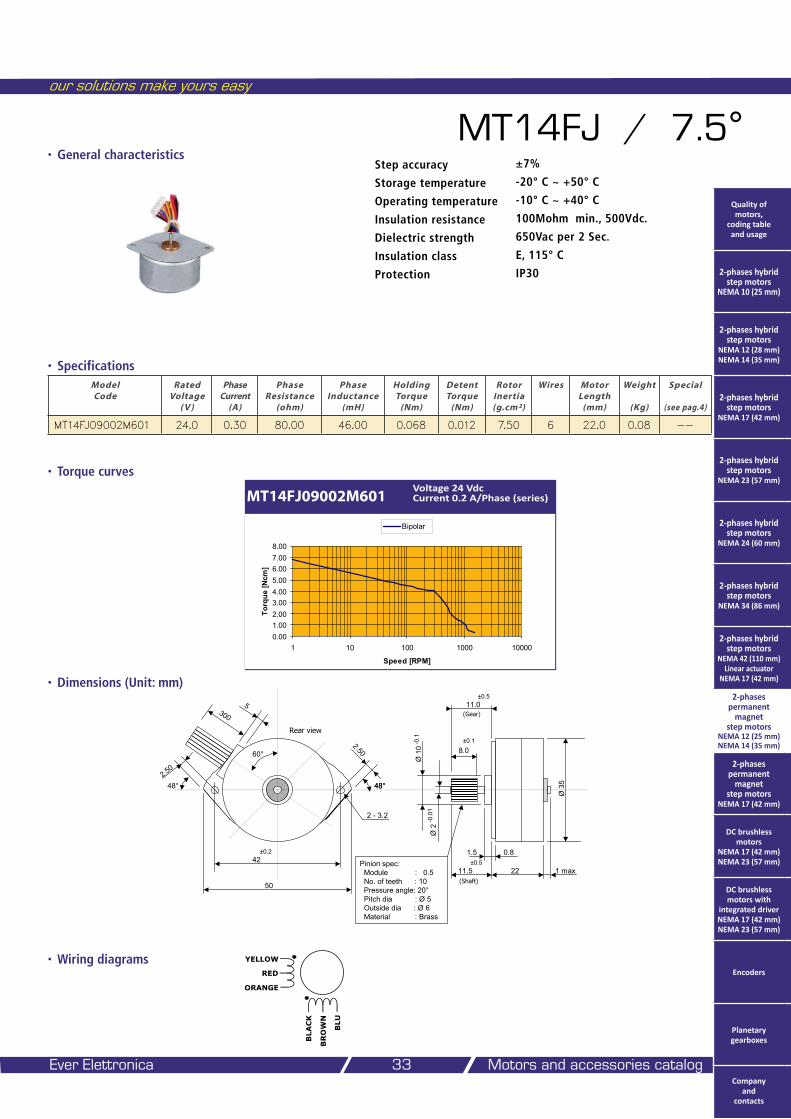
MT14FJ / 7.5°
• Specifications
• Wiring diagrams
Model Code
Rated Voltage
( V )
Phase Current
(A)
Phase Resistance
(ohm)
Phase Inductance
(mH)
Holding Torque
(Nm)
Detent Torque
(Nm)
Rotor Inertia (g.cm²)
Wires Motor Length
(mm)
Weight
(Kg)
Special
(see pag.4)
MT14FJ09002M601 24.0 0.30 80.00 46.00 0.068 0.012 7.50 6 22.0 0.08 --
• Torque curves
MT14FJ09002M601Voltage 24 Vdc Current 0.2 A/Phase (series)
Step accuracy ±7%
Storage temperature -20° C ~ +50° C
Operating temperature -10° C ~ +40° C
Insulation resistance 100Mohm min., 500Vdc.
Dielectric strength 650Vac per 2 Sec.
Insulation class E, 115° C
Protection IP30
50
42±0.2
1 max22
Ø 3
5
1.5 0.8
11.5
±0.1
Ø 2
Ø 1
0-0
.1
-0.0
1
Pinion spec:Module : 0.5No. of teeth : 10Pressure angle: 20°Pitch dia : Ø 5Outside dia : Ø 6 Material : Brass
8.0
11.0
2 - 3.2
±0.5
±0.5
300
(Shaft)
(Gear)
60°
Rear view
2.50
48°2.50
48° 48°
5
BLACK
BLU
YELLOW
ORANGE
RED
BROWN
0.001.002.003.004.005.006.007.008.00
1 10 100 1000 10000
Speed [RPM]
Torq
ue [N
cm]
Bipolar
• General characteristics
Quality of motors,
coding table and usage
2-phases hybrid step motors
NEMA 10 (25 mm)
2-phases hybrid step motors
NEMA 12 (28 mm) NEMA 14 (35 mm)
2-phases hybrid step motors
NEMA 17 (42 mm)
2-phases hybrid step motors
NEMA 23 (57 mm)
2-phases hybrid step motors
NEMA 24 (60 mm)
2-phases hybrid step motors
NEMA 34 (86 mm)
2-phases hybrid step motors
NEMA 42 (110 mm) Linear actuator
NEMA 17 (42 mm)
2-phases permanent
magnet step motors
NEMA 12 (25 mm) NEMA 14 (35 mm)
2-phases permanent
magnet step motors
NEMA 17 (42 mm)
DC brushless motors
NEMA 17 (42 mm) NEMA 23 (57 mm)
DC brushless motors with
integrated driver NEMA 17 (42 mm) NEMA 23 (57 mm)
Encoders
Planetary gearboxes
Company and
contacts
• Dimensions (Unit: mm)
2-phases permanent magnet step motors
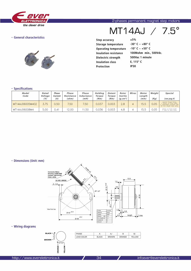
MT14AJ / 7.5°
• Specifications
• Wiring diagrams
34
Step accuracy ±5%
Storage temperature -30° C ~ +80° C
Operating temperature -10° C ~ +50° C
Insulation resistance 100Mohm min., 500Vdc.
Dielectric strength 500Vac 1 minute
Insulation class E, 115° C
Protection IP30
http://www.everelettronica.it [email protected]
Model Code
Rated Voltage
( V )
Phase Current
(A)
Phase Resistance
(ohm)
Phase Inductance
(mH)
Holding Torque
(Nm)
Detent Torque
(Nm)
Rotor Inertia (g.cm²)
Wires Motor Length
(mm)
Weight
(Kg)
Special
(see pag.4)
MT14AJ06005M402 3.75 0.50 7.50 7.50 0.037 0.003 2.8 4 15.5 0.05special flange fixing
+ pinion on front shaft + customized connector with 50 mm length lead wires
MT14AJ06008M4 5.00 0.41 12.00 11.50 0.036 0.003 4.8 4 15.5 0.05 pinion on front shaft + tube on lead wires
45° ±3°
1 maxlength
Ø 3
5
1.50.8
6.0±0.5
Ø 2
Ø 1
0-0
.05
-0.0
1
5.5
6.0
1.0
InvoluteProfile
7Pitch Ø
8Outside Ø
14Nr. of teeth (Z)
0.5Module (M)9GS"Quality
BrassMaterial
length ±5
Ø 49
Ø 42±0.2
View from top
±0.2
2 - 3.2
UL1430 AWG26
Connector MolexHousing: 51006-0400Contact: 50012-8100Color: white
16.3 13.9
ORANGE
YELLOW
BLACK
BROWN
PHASE A A/ B B/
LEAD COLOR BLACK BROWN ORANGE YELLOW
• General characteristics
• Torque curves
our solutions make yours easy
Ever Elettronica Motors and accessories catalog 35
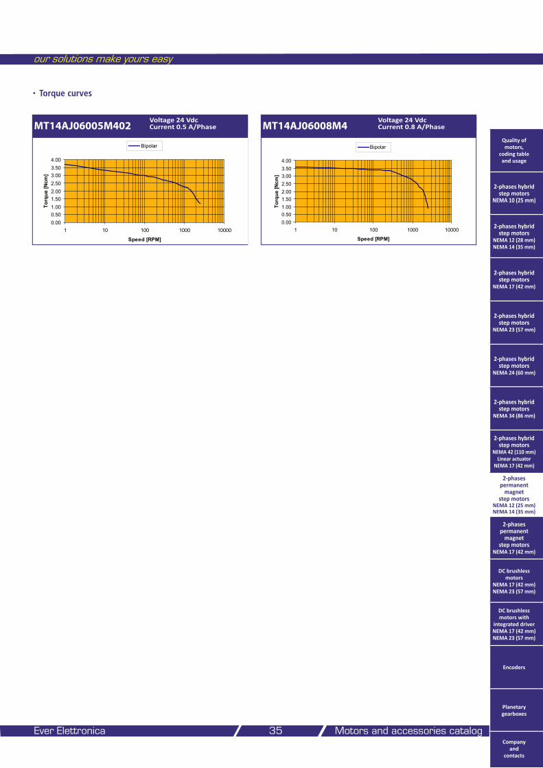
MT14AJ06005M402Voltage 24 Vdc Current 0.5 A/Phase MT14AJ06008M4
Voltage 24 Vdc Current 0.8 A/Phase
0.000.501.001.502.002.503.003.504.00
1 10 100 1000 10000
Speed [RPM]
Torq
ue [N
cm]
Bipolar
0.000.501.001.502.002.503.003.504.00
1 10 100 1000 10000
Speed [RPM]
Torq
ue [N
cm]
Bipolar Quality of motors,
coding table and usage
2-phases hybrid step motors
NEMA 10 (25 mm)
2-phases hybrid step motors
NEMA 12 (28 mm) NEMA 14 (35 mm)
2-phases hybrid step motors
NEMA 17 (42 mm)
2-phases hybrid step motors
NEMA 23 (57 mm)
2-phases hybrid step motors
NEMA 24 (60 mm)
2-phases hybrid step motors
NEMA 34 (86 mm)
2-phases hybrid step motors
NEMA 42 (110 mm) Linear actuator
NEMA 17 (42 mm)
2-phases permanent
magnet step motors
NEMA 12 (25 mm) NEMA 14 (35 mm)
2-phases permanent
magnet step motors
NEMA 17 (42 mm)
DC brushless motors
NEMA 17 (42 mm) NEMA 23 (57 mm)
DC brushless motors with
integrated driver NEMA 17 (42 mm) NEMA 23 (57 mm)
Encoders
Planetary gearboxes
Company and
contacts
2-phases permanent magnet step motors
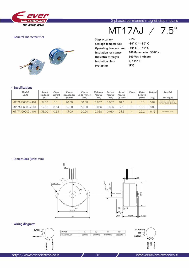
36http://www.everelettronica.it [email protected]
• Dimensions (Unit: mm)
MT17AJ / 7.5°
• Specifications
• Wiring diagrams
Step accuracy ±5%
Storage temperature -30° C ~ +80° C
Operating temperature -10° C ~ +50° C
Insulation resistance 100Mohm min., 500Vdc.
Dielectric strength 500 Vac 1 minute
Insulation class E, 115° C
Protection IP30
Model Code
Rated Voltage
( V )
Phase Current
(A)
Phase Resistance
(ohm)
Phase Inductance
(mH)
Holding Torque
(Nm)
Detent Torque
(Nm)
Rotor Inertia (g.cm²)
Wires Motor Length
(mm)
Weight
(Kg)
Special
(see pag.4)
MT17AJ06003M401 37.00 0.31 20.00 18.50 0.037 0.007 10.3 4 15.5 0.09pinion on front shaft + customized connector and 555 mm length lead wires
MT17AJ06003M601 12.00 0.34 35.00 16.00 0.056 0.006 7.3 6 15.5 0.09 --
MT17AJ09003M401 36.00 0.35 13.00 20.00 0.068 0.010 23.6 4 22.2 0.12 customized cable
ORANGE
YELLOW
BLACK
BROWN
RED
RED
PHASE A A/ B B/
LEAD COLOR BLACK BROWN ORANGE YELLOW
ORANGE
YELLOW
BLACK
BROWN
57
Ø 49.5
13
1 maxlength
Ø 4
2
0.8
10.0±0.5
Ø 3
Ø 1
0.0- 0
.05
-0.0
1
90°
5
2 - Ø 3,5
1.5
11
±0.2
150
• General characteristics
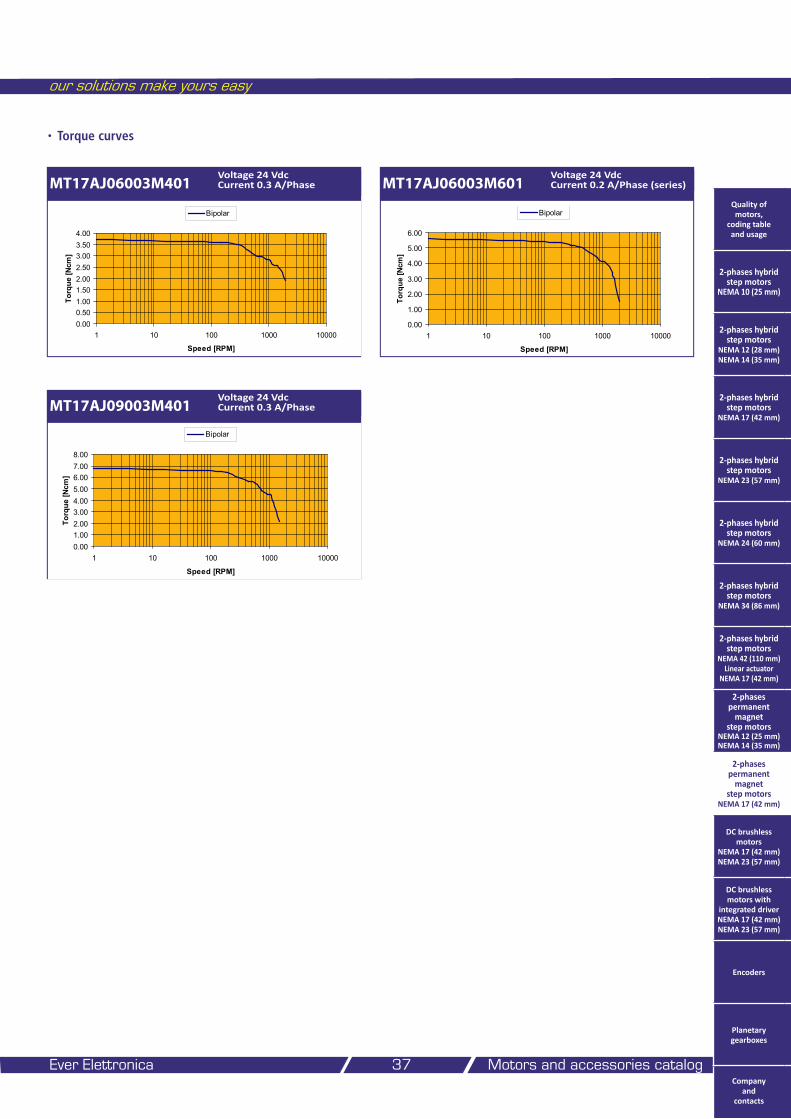
our solutions make yours easy
Ever Elettronica Motors and accessories catalog 37
• Torque curves
MT17AJ06003M401Voltage 24 Vdc Current 0.3 A/Phase MT17AJ06003M601
Voltage 24 Vdc Current 0.2 A/Phase (series)
MT17AJ09003M401Voltage 24 Vdc Current 0.3 A/Phase
0.000.501.001.502.002.503.003.504.00
1 10 100 1000 10000
Speed [RPM]
Torq
ue [N
cm]
Bipolar
0.00
1.00
2.00
3.00
4.00
5.00
6.00
1 10 100 1000 10000
Speed [RPM]
Torq
ue [N
cm]
Bipolar
0.001.002.003.004.005.006.007.008.00
1 10 100 1000 10000
Speed [RPM]
Torq
ue [N
cm]
Bipolar
Quality of motors,
coding table and usage
2-phases hybrid step motors
NEMA 10 (25 mm)
2-phases hybrid step motors
NEMA 12 (28 mm) NEMA 14 (35 mm)
2-phases hybrid step motors
NEMA 17 (42 mm)
2-phases hybrid step motors
NEMA 23 (57 mm)
2-phases hybrid step motors
NEMA 24 (60 mm)
2-phases hybrid step motors
NEMA 34 (86 mm)
2-phases hybrid step motors
NEMA 42 (110 mm) Linear actuator
NEMA 17 (42 mm)
2-phases permanent
magnet step motors
NEMA 12 (25 mm) NEMA 14 (35 mm)
2-phases permanent
magnet step motors
NEMA 17 (42 mm)
DC brushless motors
NEMA 17 (42 mm) NEMA 23 (57 mm)
DC brushless motors with
integrated driver NEMA 17 (42 mm) NEMA 23 (57 mm)
Encoders
Planetary gearboxes
Company and
contacts
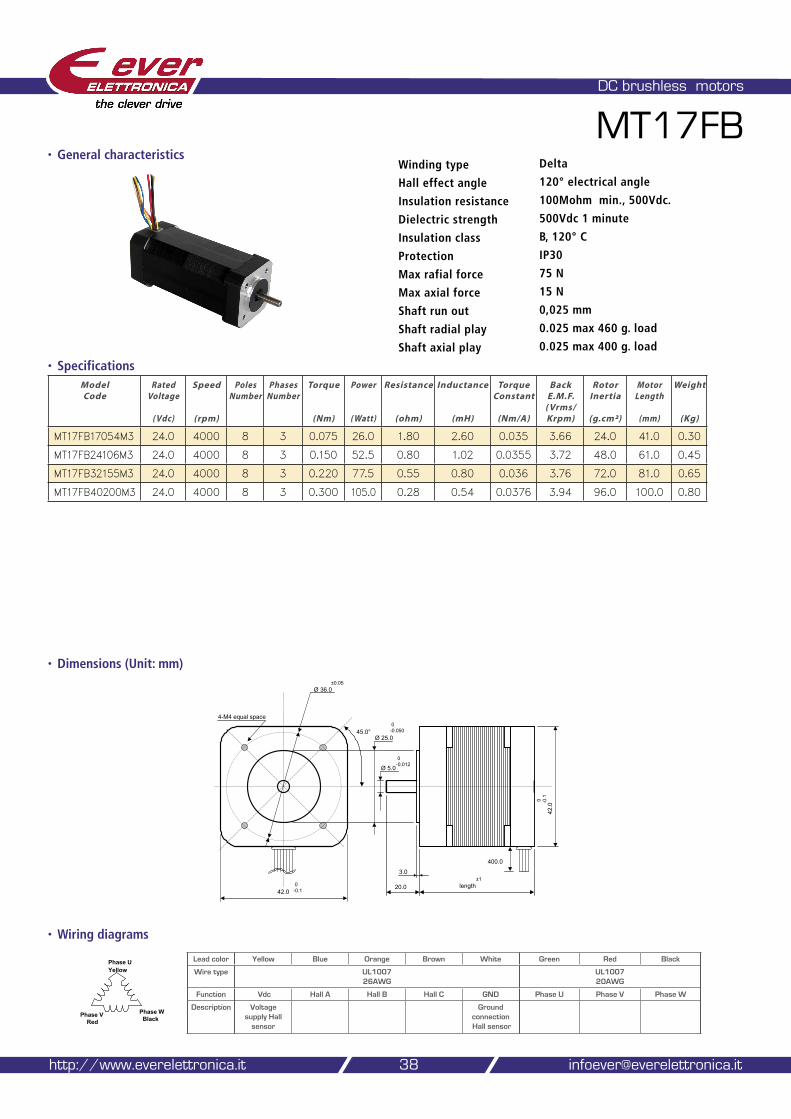
• Dimensions (Unit: mm)
DC brushless motors
MT17FB
• Specifications
• Wiring diagrams
38
Winding type Delta
Hall effect angle 120° electrical angle
Insulation resistance 100Mohm min., 500Vdc.
Dielectric strength 500Vdc 1 minute
Insulation class B, 120° C
Protection IP30
Max rafial force 75 N
Max axial force 15 N
Shaft run out 0,025 mm
Shaft radial play 0.025 max 460 g. load
Shaft axial play 0.025 max 400 g. load
http://www.everelettronica.it [email protected]
Phase U Yellow
Phase VRed
Phase WBlack
Lead color Yellow Blue Orange Brown White Green Red Black
Wire type UL1007 26AWG
UL1007 20AWG
Function Vdc Hall A Hall B Hall C GND Phase U Phase V Phase W
Description Voltage supply Hall
sensor
Ground connection Hall sensor
Model Code
Rated Voltage
( Vdc)
Speed
(rpm)
Poles Number
Phases Number
Torque
(Nm)
Power
( Watt)
Resistance
(ohm)
Inductance
(mH)
Torque Constant
(Nm/A)
Back E.M.F.
( Vrms/Krpm)
Rotor Inertia
(g.cm²)
Motor Length
(mm)
Weight
(Kg)
MT17FB17054M3 24.0 4000 8 3 0.075 26.0 1.80 2.60 0.035 3.66 24.0 41.0 0.30
MT17FB24106M3 24.0 4000 8 3 0.150 52.5 0.80 1.02 0.0355 3.72 48.0 61.0 0.45
MT17FB32155M3 24.0 4000 8 3 0.220 77.5 0.55 0.80 0.036 3.76 72.0 81.0 0.65
MT17FB40200M3 24.0 4000 8 3 0.300 105.0 0.28 0.54 0.0376 3.94 96.0 100.0 0.80
3.0
length20.0
45.0°
Ø 36.0
Ø 5.0
0-0.012
Ø 25.0
0-0.050
±0.05
400.0
4-M4 equal space
42.00-0.1
42.0
0 -0.1
±1
• General characteristics
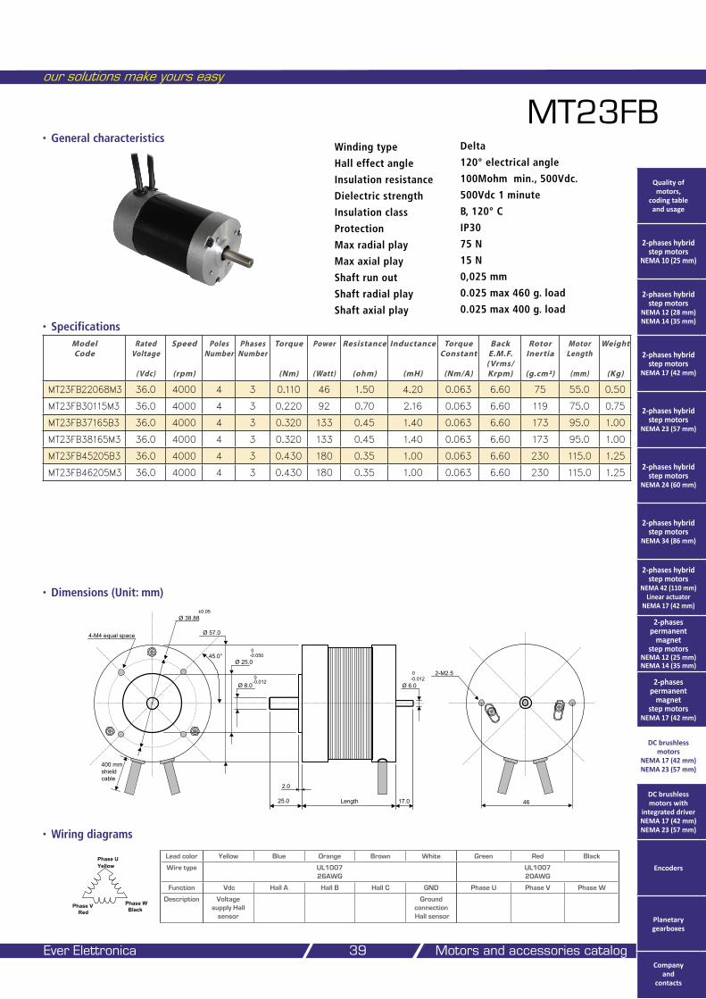
our solutions make yours easy
Ever Elettronica Motors and accessories catalog 39
• Dimensions (Unit: mm)
MT23FB
• Specifications
• Wiring diagrams
Winding type Delta
Hall effect angle 120° electrical angle
Insulation resistance 100Mohm min., 500Vdc.
Dielectric strength 500Vdc 1 minute
Insulation class B, 120° C
Protection IP30
Max radial play 75 N
Max axial play 15 N
Shaft run out 0,025 mm
Shaft radial play 0.025 max 460 g. load
Shaft axial play 0.025 max 400 g. load
Model Code
Rated Voltage
( Vdc)
Speed
(rpm)
Poles Number
Phases Number
Torque
(Nm)
Power
( Watt)
Resistance
(ohm)
Inductance
(mH)
Torque Constant
(Nm/A)
Back E.M.F.
( Vrms/Krpm)
Rotor Inertia
(g.cm²)
Motor Length
(mm)
Weight
(Kg)
MT23FB22068M3 36.0 4000 4 3 0.110 46 1.50 4.20 0.063 6.60 75 55.0 0.50
MT23FB30115M3 36.0 4000 4 3 0.220 92 0.70 2.16 0.063 6.60 119 75.0 0.75
MT23FB37165B3 36.0 4000 4 3 0.320 133 0.45 1.40 0.063 6.60 173 95.0 1.00
MT23FB38165M3 36.0 4000 4 3 0.320 133 0.45 1.40 0.063 6.60 173 95.0 1.00
MT23FB45205B3 36.0 4000 4 3 0.430 180 0.35 1.00 0.063 6.60 230 115.0 1.25
MT23FB46205M3 36.0 4000 4 3 0.430 180 0.35 1.00 0.063 6.60 230 115.0 1.25
2.0
Length25.0
45.0°
Ø 38.88
17.0
Ø 6.0
0-0.012
Ø 57.0
Ø 8.00-0.012
Ø 25.0
0-0.050
±0.05
4-M4 equal space
400 mmshield cable
46
2-M2.5
Phase U Yellow
Phase VRed
Phase WBlack
Lead color Yellow Blue Orange Brown White Green Red Black
Wire type UL1007 26AWG
UL1007 20AWG
Function Vdc Hall A Hall B Hall C GND Phase U Phase V Phase W
Description Voltage supply Hall
sensor
Ground connection Hall sensor
• General characteristics
Quality of motors,
coding table and usage
2-phases hybrid step motors
NEMA 10 (25 mm)
2-phases hybrid step motors
NEMA 12 (28 mm) NEMA 14 (35 mm)
2-phases hybrid step motors
NEMA 17 (42 mm)
2-phases hybrid step motors
NEMA 23 (57 mm)
2-phases hybrid step motors
NEMA 24 (60 mm)
2-phases hybrid step motors
NEMA 34 (86 mm)
2-phases hybrid step motors
NEMA 42 (110 mm) Linear actuator
NEMA 17 (42 mm)
2-phases permanent
magnet step motors
NEMA 12 (25 mm) NEMA 14 (35 mm)
2-phases permanent
magnet step motors
NEMA 17 (42 mm)
DC brushless motors
NEMA 17 (42 mm) NEMA 23 (57 mm)
DC brushless motors with
integrated driver NEMA 17 (42 mm) NEMA 23 (57 mm)
Encoders
Planetary gearboxes
Company and
contacts
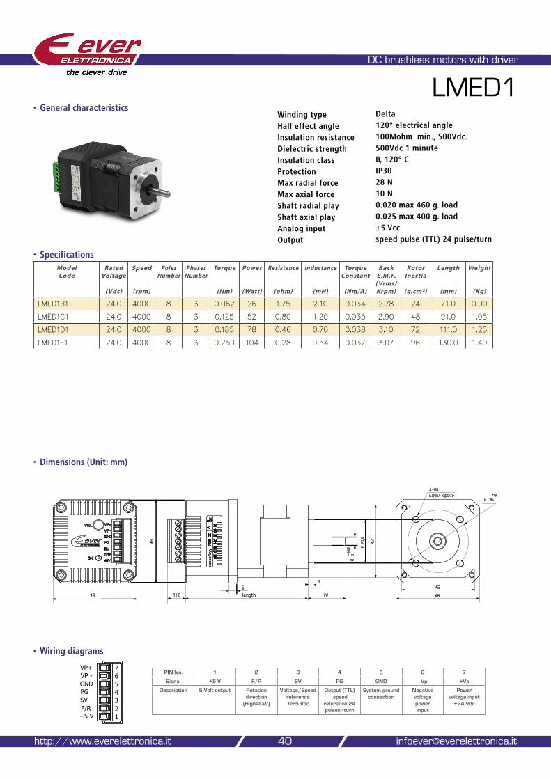
• Dimensions (Unit: mm)
DC brushless motors with driver
LMED1
• Specifications
• Wiring diagrams
40http://www.everelettronica.it [email protected]
Model Code
Rated Voltage
( Vdc)
Speed
(rpm)
Poles Number
Phases Number
Torque
(Nm)
Power
( Watt)
Resistance
(ohm)
Inductance
(mH)
Torque Constant
(Nm/A)
Back E.M.F.
( Vrms/Krpm)
Rotor Inertia
(g.cm²)
Length
(mm)
Weight
(Kg)
LMED1B1 24.0 4000 8 3 0.062 26 1.75 2.10 0.034 2.78 24 71.0 0.90
LMED1C1 24.0 4000 8 3 0.125 52 0.80 1.20 0.035 2.90 48 91.0 1.05
LMED1D1 24.0 4000 8 3 0.185 78 0.46 0.70 0.038 3.10 72 111.0 1.25
LMED1E1 24.0 4000 8 3 0.250 104 0.28 0.54 0.037 3.07 96 130.0 1.40
Winding type DeltaHall effect angle 120° electrical angleInsulation resistance 100Mohm min., 500Vdc.Dielectric strength 500Vdc 1 minuteInsulation class B, 120° CProtection IP30 Max radial force 28 NMax axial force 10 NShaft radial play 0.020 max 460 g. loadShaft axial play 0.025 max 400 g. loadAnalog input ±5 VccOutput speed pulse (TTL) 24 pulse/turn
PIN No. 1 2 3 4 5 6 7
Signal +5 V F/R SV PG GND - Vp +Vp
Description 5 Volt output Rotation direction
(High=CW)
Voltage/Speed reference 0÷5 Vdc
Output (TTL) speed
reference 24 pulses/turn
System ground connection
Negative voltage power Input
Power voltage input
+24 Vdc
• General characteristics
length
3
Ø 5
22
5
48
48
42
Ø 36
48
4-M4
10,2
Equal space ±0,05
-0,012
VP+VP -GNDPGSVF/R+5 V 1
234567
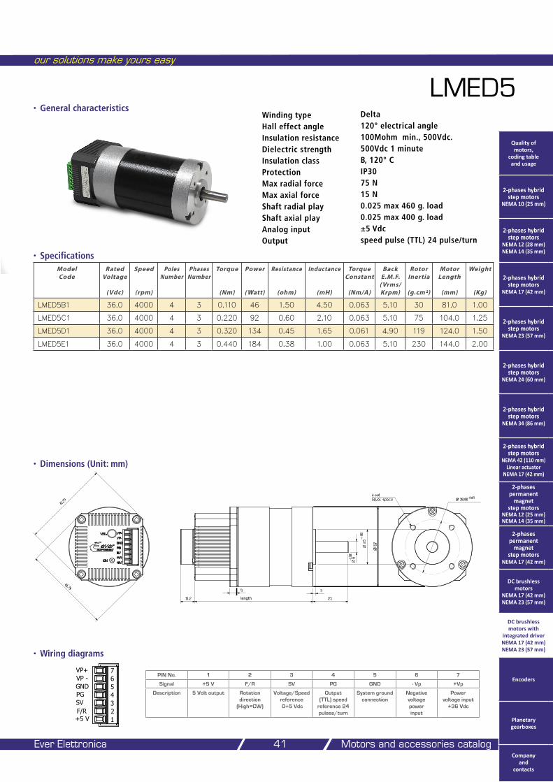
our solutions make yours easy
Ever Elettronica Motors and accessories catalog 41
• Dimensions (Unit: mm)
LMED5
• Specifications
• Wiring diagrams
Model Code
Rated Voltage
( Vdc)
Speed
(rpm)
Poles Number
Phases Number
Torque
(Nm)
Power
( Watt)
Resistance
(ohm)
Inductance
(mH)
Torque Constant
(Nm/A)
Back E.M.F.
( Vrms/Krpm)
Rotor Inertia
(g.cm²)
Motor Length
(mm)
Weight
(Kg)
LMED5B1 36.0 4000 4 3 0.110 46 1.50 4.50 0.063 5.10 30 81.0 1.00
LMED5C1 36.0 4000 4 3 0.220 92 0.60 2.10 0.063 5.10 75 104.0 1.25
LMED5D1 36.0 4000 4 3 0.320 134 0.45 1.65 0.061 4.90 119 124.0 1.50
LMED5E1 36.0 4000 4 3 0.440 184 0.38 1.00 0.063 5.10 230 144.0 2.00
Winding type DeltaHall effect angle 120° electrical angleInsulation resistance 100Mohm min., 500Vdc.Dielectric strength 500Vdc 1 minuteInsulation class B, 120° CProtection IP30 Max radial force 75 NMax axial force 15 NShaft radial play 0.025 max 460 g. loadShaft axial play 0.025 max 400 g. loadAnalog input ±5 VdcOutput speed pulse (TTL) 24 pulse/turn
PIN No. 1 2 3 4 5 6 7
Signal +5 V F/R SV PG GND - Vp +Vp
Description 5 Volt output Rotation direction
(High=CW)
Voltage/Speed reference 0÷5 Vdc
Output (TTL) speed
reference 24 pulses/turn
System ground connection
Negative voltage power input
Power voltage input
+36 Vdc
• General characteristics
VP+VP -GNDPGSVF/R+5 V 1
234567
Ø 38,88 ±0,05
61,79
61,79
Ø57
4-M4Equal space
Ø25
Ø8
-0,025
-0,012
length10,2
5
Quality of motors,
coding table and usage
2-phases hybrid step motors
NEMA 10 (25 mm)
2-phases hybrid step motors
NEMA 12 (28 mm) NEMA 14 (35 mm)
2-phases hybrid step motors
NEMA 17 (42 mm)
2-phases hybrid step motors
NEMA 23 (57 mm)
2-phases hybrid step motors
NEMA 24 (60 mm)
2-phases hybrid step motors
NEMA 34 (86 mm)
2-phases hybrid step motors
NEMA 42 (110 mm) Linear actuator
NEMA 17 (42 mm)
2-phases permanent
magnet step motors
NEMA 12 (25 mm) NEMA 14 (35 mm)
2-phases permanent
magnet step motors
NEMA 17 (42 mm)
DC brushless motors
NEMA 17 (42 mm) NEMA 23 (57 mm)
DC brushless motors with
integrated driver NEMA 17 (42 mm) NEMA 23 (57 mm)
Encoders
Planetary gearboxes
Company and
contacts
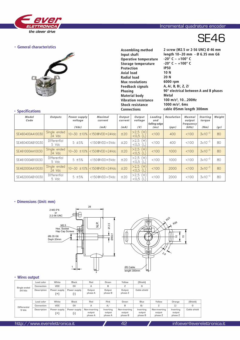
• Dimensions (Unit: mm)
Incremental quadrature encoder
SE46
• Specifications
42
Assembling method 2 screw (M2.5 or 2-56 UNC) Ø 46 mmInput shaft length 10~20 mm - Ø 6.35 mm G6Operative temperature -20° C ~ +100° CStorage temperature -20° C ~ +100° CProtection IP50Axial load 10 NRadial load 20 NMax revolutions 6000 rpmFeedback signals A, A/, B, B/, Z, Z/Phasing 90° electrical between A and B phasesMaterial body MetalVibration resistance 100 m/s², 10...200HzShock resistance 1000 m/s², 6msConnections cable Ø5mm length 300mm
http://www.everelettronica.it [email protected]
Model Code
Outputs Power supply voltage
( Vdc)
Maximal current
(mA)
Output current
(mA)
Output voltage
( V )
Leading and
falling edge (ms)
Resolution
(ppr)
Maxmal output
frequency (kHz)
Starting torque
(Nm)
Weight
(gr)
SE460400AA10030 Single ended 24 Vdc 10~30 ±10% <150@VDD=24Vdc ±20 >2,5 (H)
<0,5 (L) <100 400 <100 3x10⁻³ 80
SE460400AB10030 Differential 5 Vdc 5 ±5% <150@VDD=5Vdc ±20 >2,5 (H)
<0,5 (L) <100 400 <100 3x10⁻³ 80
SE461000AA10030 Single ended 24 Vdc 10~30 ±10% <150@VDD=24Vdc ±20 >2,5 (H)
<0,5 (L) <100 1000 <100 3x10⁻³ 80
SE461000AB10030 Differential 5 Vdc 5 ±5% <150@VDD=5Vdc ±20 >2,5 (H)
<0,5 (L) <100 1000 <100 3x10⁻³ 80
SE462000AA10030 Single ended 24 Vdc 10~30 ±10% <150@VDD=24Vdc ±20 >2,5 (H)
<0,5 (L) <100 2000 <100 3x10⁻³ 80
SE462000AB10030 Differential 5 Vdc 5 ±5% <150@VDD=5Vdc ±20 >2,5 (H)
<0,5 (L) <100 2000 <100 3x10⁻³ 80
R23
R26
1510
2.8
length 300mmØ5 Cable
Ø6.35 G6Deph 20mm Ø
40±1
M2.5
2-M2.5*628
or2-2-56 UNC
Hex. SocketHap Cap Screws
Ø 2
.5
1
N.P
.
• Wires output
Differential 5 Vdc
Lead color White Black Red Pink Green Blue Yellow Orange (Shield)
Connection VDC 0V A A/ B B/ Z Z/ G
Description Power supply
(+)Power supply
(-)Non-inverting
output phase A
Inverting output phase A
Non-inverting output
phase B
Inverting output phase B
Non-inverting output
phase Z
Inverting output phase Z
Cable shield
• General characteristics
Single ended 24 Vdc
Lead color White Black Red Green Yellow (Shield)
Connection VDC 0V A B Z G
Description Power supply
(+)Power supply
(-)Output phase A
Output phase B
Output phase Z
Cable shield
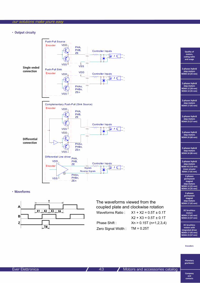
• Output circuity
our solutions make yours easy
Ever Elettronica Motors and accessories catalog 43
Differential Line driver
1
2
4
3
CN1.x
CN1.x
EncoderController Inputs
VSS
VDD
PHAn,PHBn,ZEn
PHA,PHB,ZE
SignalsReverse Signals
1
2
4
3
CN1.x
CN1.x
Controller Inputs
1
2
4
3
CN1.x
CN1.x
Controller Inputs
1
2
4
3
CN1.x
CN1.x
Controller Inputs
1 2
VDD
VDDVSS
VSS
PHAn,PHBn,ZEn
PHA,PHB,ZE
Encoder
VDD
VSS
VDD
PHAn,PHBn,ZEn
Encoder
VDD
VSSVSS
EncoderPHA,PHB,ZE
Push-Pull Source
Push-Pull Sink
Complementary Push-Pull (Sink Source)
• Waveforms
A
B
Z
X1 X2 X3 X4
T
TM
The waveforms viewed from thecoupled plate and clockwise rotationWaveforms Ratio :
Phase Shift :Zero Signal Width :
X2 + X3 = 0.5T ± 0.1TXn > 0.15T (n=1,2,3,4)
X1 + X2 = 0.5T ± 0.1T
TM = 0.25T
Quality of motors,
coding table and usage
2-phases hybrid step motors
NEMA 10 (25 mm)
2-phases hybrid step motors
NEMA 12 (28 mm) NEMA 14 (35 mm)
2-phases hybrid step motors
NEMA 17 (42 mm)
2-phases hybrid step motors
NEMA 23 (57 mm)
2-phases hybrid step motors
NEMA 24 (60 mm)
2-phases hybrid step motors
NEMA 34 (86 mm)
2-phases hybrid step motors
NEMA 42 (110 mm) Linear actuator
NEMA 17 (42 mm)
2-phases permanent
magnet step motors
NEMA 12 (25 mm) NEMA 14 (35 mm)
2-phases permanent
magnet step motors
NEMA 17 (42 mm)
DC brushless motors
NEMA 17 (42 mm) NEMA 23 (57 mm)
DC brushless motors with
integrated driver NEMA 17 (42 mm) NEMA 23 (57 mm)
Encoders
Planetary gearboxes
Company and
contacts
Single ended connection
Differential connection
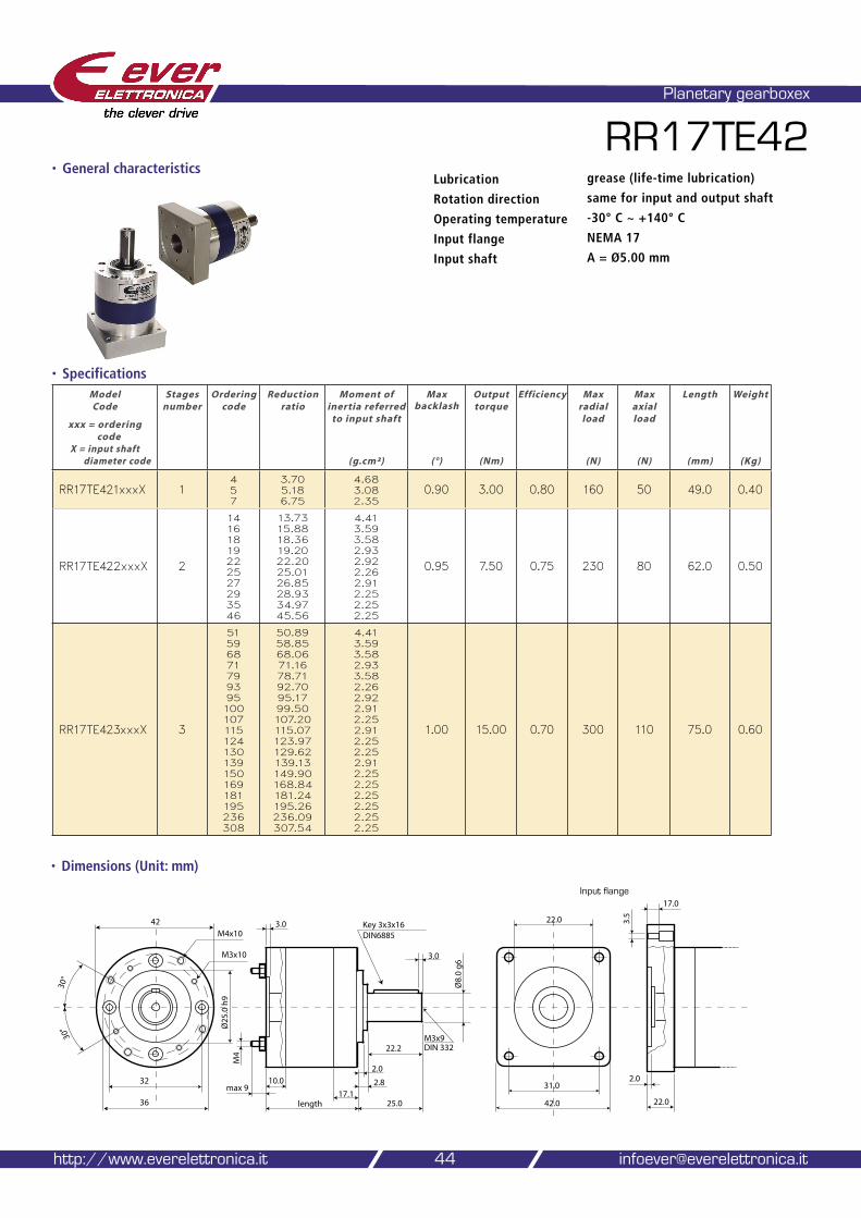
• Dimensions (Unit: mm)
Planetary gearboxex
RR17TE42
• Specifications
44
Lubrication grease (life-time lubrication)
Rotation direction same for input and output shaft
Operating temperature -30° C ~ +140° C
Input flange NEMA 17
Input shaft A = Ø5.00 mm
http://www.everelettronica.it [email protected]
Model Code
xxx = ordering
code X = input shaft
diameter code
Stages number
Ordering code
Reduction ratio
Moment of inertia referred
to input shaft
(g.cm²)
Max
backlash
(°)
Output torque
(Nm)
Efficiency Max radial load
(N)
Max axial load
(N)
Length
(mm)
Weight
(Kg)
RR17TE421xxxX 14 5 7
3.70 5.18 6.75
4.68 3.08 2.35
0.90 3.00 0.80 160 50 49.0 0.40
RR17TE422xxxX 2
14 16 18 19 22 25 27 29 35 46
13.73 15.8818.36 19.20 22.20 25.01 26.85 28.93 34.97 45.56
4.41 3.59 3.58 2.93 2.92 2.26 2.91 2.25 2.25 2.25
0.95 7.50 0.75 230 80 62.0 0.50
RR17TE423xxxX 3
51 59 68 71 79 93 95 100 107 115 124 130 139 150 169181 195 236 308
50.89 58.85 68.06 71.16 78.71 92.70 95.17 99.50 107.20 115.07 123.97 129.62 139.13 149.90 168.84 181.24 195.26 236.09 307.54
4.41 3.59 3.58 2.93 3.58 2.26 2.92 2.91 2.25 2.91 2.25 2.25 2.91 2.25 2.25 2.25 2.25 2.25 2.25
1.00 15.00 0.70 300 110 75.0 0.60
��
���
���
�����
�����
��
�� ���
���
����������
���������
����
����
���
���
�����������
�������
�����������������
��
���
�����
����
����
���
�������
����
����
Input flange
• General characteristics

our solutions make yours easy
Ever Elettronica Motors and accessories catalog 45
• Dimensions (Unit: mm)
RR23TE42Lubrication grease (life-time lubrication)
Rotation direction same for input and output shaft
Operating temperature -30° C ~ +140° C
Input flange NEMA 23 / NEMA 24
Input shaft B = Ø6.35 mm or G = Ø8.00 mm
Model Code
xxx = ordering
code X = input shaft
diameter code
Stages number
Ordering code
Reduction ratio
Moment of inertia referred
to input shaft
(g.cm²)
Max
backlash
(°)
Output torque
(Nm)
Efficiency
Max radial load
(N)
Max axial load
(N)
Length
(mm)
Weight
(Kg)
RR23TE421xxxX 14 5 7
3.70 5.18 6.75
4.68 3.08 2.35
0.90 3.00 0.80 160 50 49.0 0.40
RR23TE422xxxX 2
14 16 18 19 22 25 27 29 35 46
13.73 15.8818.36 19.20 22.20 25.01 26.85 28.93 34.97 45.56
4.41 3.59 3.58 2.93 2.92 2.26 2.91 2.25 2.25 2.25
0.95 7.50 0.75 230 80 62.0 0.50
RR23TE423xxxX 3
51 59 68 71 79 93 95 100 107 115 124 130 139 150 169181 195 236 308
50.89 58.85 68.06 71.16 78.71 92.70 95.17 99.50 107.20 115.07 123.97 129.62 139.13 149.90 168.84 181.24 195.26 236.09 307.54
4.41 3.59 3.58 2.93 3.58 2.26 2.92 2.91 2.25 2.91 2.25 2.25 2.91 2.25 2.25 2.25 2.25 2.25 2.25
1.00 15.00 0.70 300 110 75.0 0.60
• Specifications
��
���
���
�����
�����
��
�� ���
���
����������
���������
����
����
���
���
�����������
�������
�����������������
��
���
�����
�����
����
���
��
����
����
�����
• General characteristics
Input flange
Quality of motors,
coding table and usage
2-phases hybrid step motors
NEMA 10 (25 mm)
2-phases hybrid step motors
NEMA 12 (28 mm) NEMA 14 (35 mm)
2-phases hybrid step motors
NEMA 17 (42 mm)
2-phases hybrid step motors
NEMA 23 (57 mm)
2-phases hybrid step motors
NEMA 24 (60 mm)
2-phases hybrid step motors
NEMA 34 (86 mm)
2-phases hybrid step motors
NEMA 42 (110 mm) Linear actuator
NEMA 17 (42 mm)
2-phases permanent
magnet step motors
NEMA 12 (25 mm) NEMA 14 (35 mm)
2-phases permanent
magnet step motors
NEMA 17 (42 mm)
DC brushless motors
NEMA 17 (42 mm) NEMA 23 (57 mm)
DC brushless motors with
integrated driver NEMA 17 (42 mm) NEMA 23 (57 mm)
Encoders
Planetary gearboxes
Company and
contacts

• Dimensions (Unit: mm)
Planetary gearboxex
RR23TE52
• Specifications
46
Lubrication grease (life-time lubrication)
Rotation direction same for input and output shaft
Operating temperature -30° C ~ +140° C
Input flange NEMA 23 / NEMA 24
Input shaft B = Ø6.35 mm or G = Ø8.00 mm
http://www.everelettronica.it [email protected]
Model Code
xxx = ordering
code X = input shaft
diameter code
Stages number
Ordering code
Reduction ratio
Moment of inertia referred
to input shaft
(g.cm²)
Max
backlash
(°)
Output torque
(Nm)
Efficiency
Max radial load
(N)
Max axial load
(N)
Length
(mm)
Weight
(Kg)
RR23TE521xxxX 14 5 7
3.70 5.18 6.75
18.35 15.36 12.33 11.32
0.70 4.00 0.80 200 60 56.0 0.70
RR23TE522xxxX 2
14 16 18 19 22 25 27 29 35 46
13.73 15.8818.36 19.20 22.20 25.01 26.85 28.93 34.97 45.56
17.11 14.41 14.36 11.66 11.63 9.50 11.619.48 9.47 9.47
0.75 12.00 0.75 320 100 70.0 0.90
RR23TE523xxxX 3
51 59 68 71 79 93 95 100 107 115 124 130 139 150 169181 195 236 308
50.89 58.85 68.06 71.16 78.71 92.70 95.17 99.50 107.20 115.07 123.97 129.62 139.13 149.90 168.84 181.24 195.26 236.09 307.54
17.11 14.11 14.3611.66 14.36 11.61 14.36 11.61 9.48 11.61 9.48 9.47 11.61 9.47 9.47 9.47 9.47 9.47 9.47
0.80 25.00 0.70 450 150 84.0 1.10
�������
��
���
���
����������
���������
����
����
���
���
������������
���
������
�����������������
��
���
������
�����
����
���
�������
����
�����
Input flange
• General characteristics
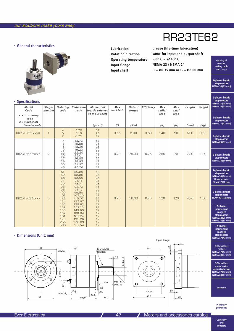
our solutions make yours easy
Ever Elettronica Motors and accessories catalog 47
• Dimensions (Unit: mm)
RR23TE62Lubrication grease (life-time lubrication)
Rotation direction same for input and output shaft
Operating temperature -30° C ~ +140° C
Input flange NEMA 23 / NEMA 24
Input shaft B = Ø6.35 mm or G = Ø8.00 mm
Model Code
xxx = ordering
code X = input shaft
diameter code
Stages number
Ordering code
Reduction ratio
Moment of inertia referred
to input shaft
(g.cm²)
Max
backlash
(°)
Output torque
(Nm)
Efficiency
Max radial load
(N)
Max axial load
(N)
Length
(mm)
Weight
(Kg)
RR23TE621xxxX 14 5 7
3.70 5.18 6.75
37 23 17
0.65 8.00 0.80 240 50 61.0 0.80
RR23TE622xxxX 2
14 16 18 19 22 25 27 29 35 46
13.73 15.8818.36 19.20 22.20 25.01 26.85 28.93 34.97 45.56
35 28 28 22 22 17 22 17 17 17
0.70 25.00 0.75 360 70 77.0 1.20
RR23TE623xxxX 3
51 59 68 71 79 93 95 100 107 115 124 130 139 150 169181 195 236 308
50.89 58.85 68.06 71.16 78.71 92.70 95.17 99.50 107.20 115.07 123.97 129.62 139.13 149.90 168.84 181.24 195.26 236.09 307.54
35 28 28 21 28 16 22 22 17 22 1717 22 17 17 17 17 17 17
0.75 50.00 0.70 520 120 93.0 1.60
• Specifications
�������
��
���
���
����������
����������
����
����
���
���
��������������
���
������
�����������������
��
���
������
�����
����
���
���
����
����
�����
• General characteristics
Input flange
Quality of motors,
coding table and usage
2-phases hybrid step motors
NEMA 10 (25 mm)
2-phases hybrid step motors
NEMA 12 (28 mm) NEMA 14 (35 mm)
2-phases hybrid step motors
NEMA 17 (42 mm)
2-phases hybrid step motors
NEMA 23 (57 mm)
2-phases hybrid step motors
NEMA 24 (60 mm)
2-phases hybrid step motors
NEMA 34 (86 mm) Linear actuator
NEMA 17 (42 mm)
2-phases hybrid step motors
NEMA 42 (110 mm)
2-phases permanent
magnet step motors
NEMA 12 (25 mm) NEMA 14 (35 mm)
2-phases permanent
magnet step motors
NEMA 17 (42 mm)
DC brushless motors
NEMA 17 (42 mm) NEMA 23 (57 mm)
DC brushless motors with
integrated driver NEMA 17 (42 mm) NEMA 23 (57 mm)
Encoders
Planetary gearboxes
Company and
contacts

• Dimensions (Unit: mm)
Planetary gearboxex
RR34TE62
• Specifications
48
Lubrication grease (life-time lubrication)
Rotation direction same for input and output shaft
Operating temperature -30° C ~ +140° C
Input flange NEMA 34
Input shaft C = Ø9.52 mm or E = Ø12.00 mm or D = Ø12.70 mm
http://www.everelettronica.it [email protected]
Model Code
xxx = ordering
code X = input shaft
diameter code
Stages number
Ordering code
Reduction ratio
Moment of inertia referred
to input shaft
(g.cm²)
Max
backlash
(°)
Output torque
(Nm)
Efficiency
Max radial load
(N)
Max axial load
(N)
Length
(mm)
Weight
(Kg)
RR34TE621xxxX 14 5 7
3.70 5.18 6.75
37 23 17
0.65 8.00 0.80 240 50 61.0 0.80
RR34TE622xxxX 2
14 16 18 19 22 25 27 29 35 46
13.73 15.8818.36 19.20 22.20 25.01 26.85 28.93 34.97 45.56
35 28 28 22 22 17 22 17 17 17
0.70 25.00 0.75 360 70 77.0 1.20
RR34TE623xxxX 3
51 59 68 71 79 93 95 100 107 115 124 130 139 150 169181 195 236 308
50.89 58.85 68.06 71.16 78.71 92.70 95.17 99.50 107.20 115.07 123.97 129.62 139.13 149.90 168.84 181.24 195.26 236.09 307.54
35 28 28 21 28 16 22 22 17 22 17 17 22 17 1717 17 17 17
0.75 50.00 0.70 520 120 93.0 1.60
�������
��
���
���
����������
����������
����
����
���
���
��������������
���
������
�����������������
��
���
������
�����
����
���
��
�����
����
�����
Input flange
• General characteristics
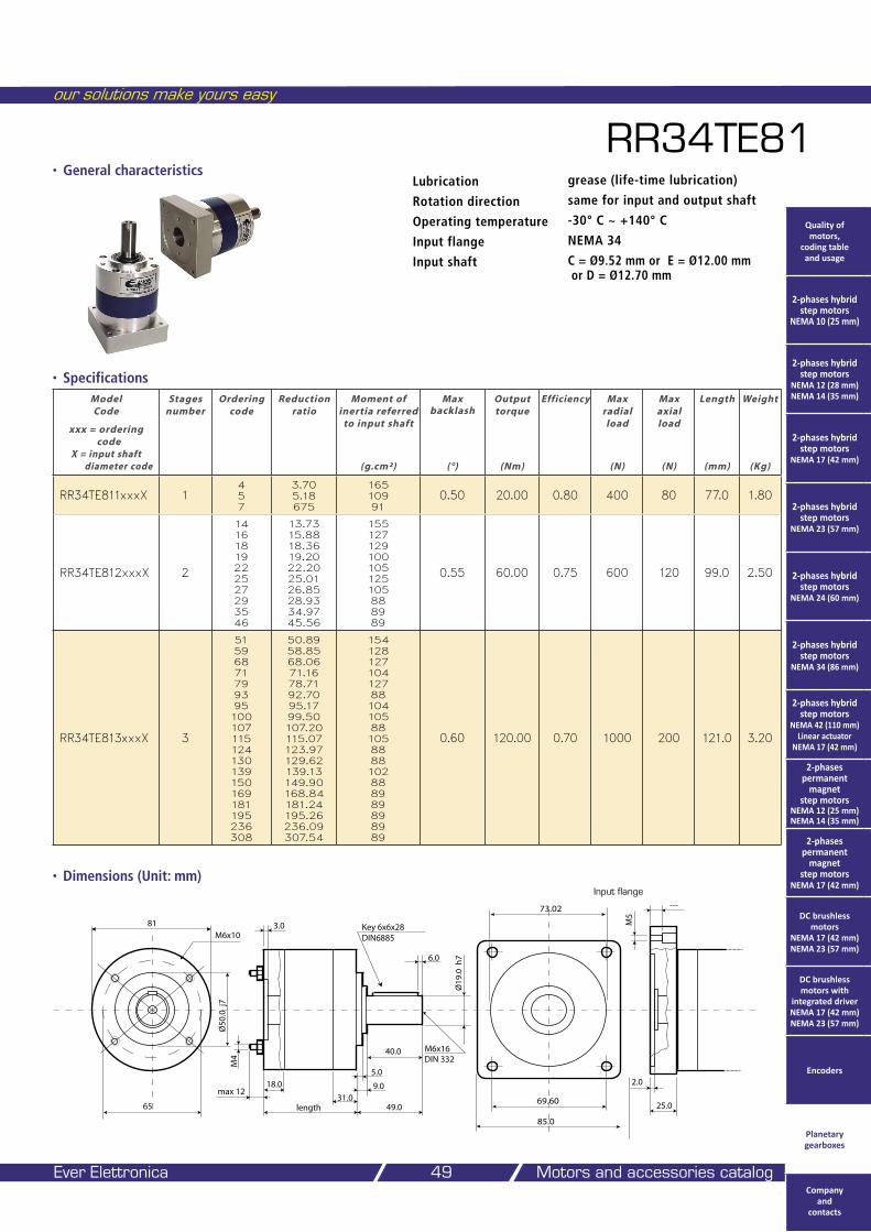
our solutions make yours easy
Ever Elettronica Motors and accessories catalog 49
• Dimensions (Unit: mm)
RR34TE81Lubrication grease (life-time lubrication)
Rotation direction same for input and output shaft
Operating temperature -30° C ~ +140° C
Input flange NEMA 34
Input shaft C = Ø9.52 mm or E = Ø12.00 mm or D = Ø12.70 mm
Model Code
xxx = ordering
code X = input shaft
diameter code
Stages number
Ordering code
Reduction ratio
Moment of inertia referred
to input shaft
(g.cm²)
Max
backlash
(°)
Output torque
(Nm)
Efficiency
Max radial load
(N)
Max axial load
(N)
Length
(mm)
Weight
(Kg)
RR34TE811xxxX 14 5 7
3.70 5.18 675
165 109 91
0.50 20.00 0.80 400 80 77.0 1.80
RR34TE812xxxX 2
14 16 18 19 22 25 27 29 35 46
13.73 15.8818.36 19.20 22.20 25.01 26.85 28.93 34.97 45.56
155 127 129 100 105 125 105 88 89 89
0.55 60.00 0.75 600 120 99.0 2.50
RR34TE813xxxX 3
51 59 68 71 79 93 95 100 107 115 124 130 139 150 169181 195 236 308
50.89 58.85 68.06 71.16 78.71 92.70 95.17 99.50 107.20 115.07 123.97 129.62 139.13 149.90 168.84 181.24 195.26 236.09 307.54
154 128 127 104 127 88 104 105 88 105 88 88 102 88 89 89 89 89 89
0.60 120.00 0.70 1000 200 121.0 3.20
• Specifications
�������
��
���
���
����������
����������
����
����
���
���
������������
���
������
�����������������
��
���
������
�����
����
���
��
�����
����
�����
• General characteristics
Input flange
Quality of motors,
coding table and usage
2-phases hybrid step motors
NEMA 10 (25 mm)
2-phases hybrid step motors
NEMA 12 (28 mm) NEMA 14 (35 mm)
2-phases hybrid step motors
NEMA 17 (42 mm)
2-phases hybrid step motors
NEMA 23 (57 mm)
2-phases hybrid step motors
NEMA 24 (60 mm)
2-phases hybrid step motors
NEMA 34 (86 mm)
2-phases hybrid step motors
NEMA 42 (110 mm) Linear actuator
NEMA 17 (42 mm)
2-phases permanent
magnet step motors
NEMA 12 (25 mm) NEMA 14 (35 mm)
2-phases permanent
magnet step motors
NEMA 17 (42 mm)
DC brushless motors
NEMA 17 (42 mm) NEMA 23 (57 mm)
DC brushless motors with
integrated driver NEMA 17 (42 mm) NEMA 23 (57 mm)
Encoders
Planetary gearboxes
Company and
contacts
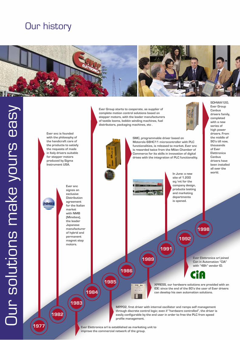
Our history
1977
1982
1983
1984
1985
1986
1989
1991
1992
1998
Our
sol
utio
ns m
ake
your
s ea
sy
Ever snc is founded with the philosophy of the handicraft care of the products to satisfy the requests of made in Italy drivers suitable for stepper motors produced by Sigma Instrument USA.
Ever snc signes an exclusive Distribution agreement for the Italian market with NMB (Minebea),the leader Japanese manufacturer of hybrid and permanent magnet step motors.
Ever Elettronica srl is extablished as marketing unit toimprove the commercial network of the group.
Ever Group starts to cooperate, as supplier of complete motion control solutions based on stepper motors, with the leader manufacturers of textile looms, bobbin winding machines, fuel distributors, packaging machines, etc .
MPP02, first driver with internal oscillator and ramps self management through discrete control logic; even if “hardware controlled”, the driver is easily configurable by the end user in order to free the PLC from speed profile management.
SMC, programmable driver based on Motorola 68HC11 microcontroller with PLC functionalities, is released to market. Ever snc is rewarded twice from the Milan Chamber of Commerce for its skills in innovation of digital drives with the integration of PLC functionality.
XPRESS, our hardware solutions are provided with an IDE: since the end of the 80’s the user of Ever drivers can develop his own automation solutions.
In June: a new site of 1.200 sq/mt for the company design, products testing and marketingdepartmentsis opened.
Ever Elettronica srl joined Can in Automation “CIA” with “4Bh” vendor ID.
SDHWA120, Ever Group Canbus drivers family, completed with a new series of high power drivers. From the middle of 90’s till now, thousands of Ever Elettronica Canbus drivers have been installed all over the world.
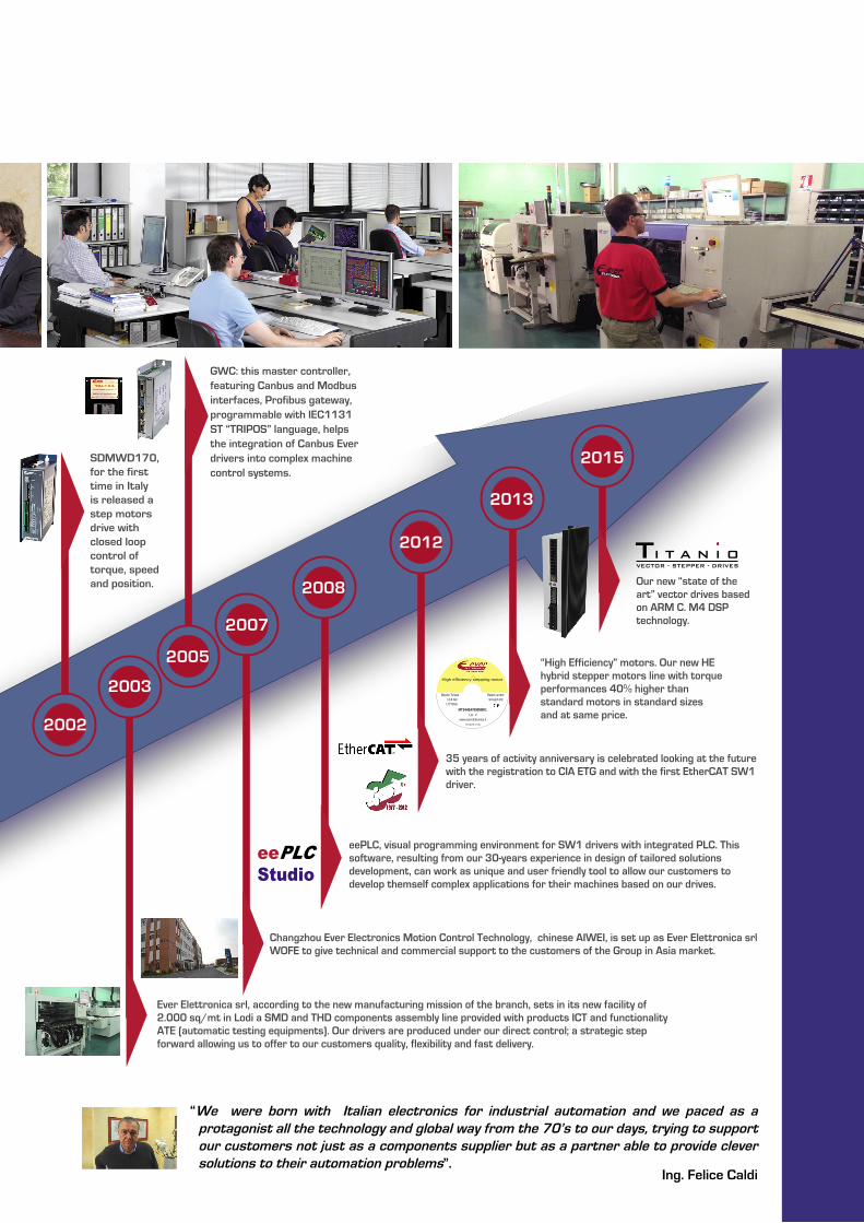
eePLC Studio
MT34HE47090M8K1
Bipolar Torque 11.8 Nm
Lot. #:www.everelettronica.it
Rated current 9.0 A/ph DC
High efficiency stepping motor
1.8°/Step
Designed in Italy2002
2003
2005
2007
2008
2012
2013
2015
I T A N I O TVECTOR - STEPPER - DRIVES
“We were born with Italian electronics for industrial automation and we paced as a protagonist all the technology and global way from the 70’s to our days, trying to support our customers not just as a components supplier but as a partner able to provide clever solutions to their automation problems”.
Ing. Felice Caldi
SDMWD170, for the first time in Italy is released a step motors drive with closed loop control of torque, speed and position.
Ever Elettronica srl, according to the new manufacturing mission of the branch, sets in its new facility of 2.000 sq/mt in Lodi a SMD and THD components assembly line provided with products ICT and functionality ATE (automatic testing equipments). Our drivers are produced under our direct control; a strategic step forward allowing us to offer to our customers quality, flexibility and fast delivery.
GWC: this master controller, featuring Canbus and Modbus interfaces, Profibus gateway, programmable with IEC1131 ST “TRIPOS” language, helps the integration of Canbus Ever drivers into complex machine control systems.
Changzhou Ever Electronics Motion Control Technology, chinese AIWEI, is set up as Ever Elettronica srl WOFE to give technical and commercial support to the customers of the Group in Asia market.
eePLC, visual programming environment for SW1 drivers with integrated PLC. This software, resulting from our 30-years experience in design of tailored solutions development, can work as unique and user friendly tool to allow our customers to develop themself complex applications for their machines based on our drives.
35 years of activity anniversary is celebrated looking at the future with the registration to CIA ETG and with the first EtherCAT SW1 driver.
“High Efficiency” motors. Our new HE hybrid stepper motors line with torque performances 40% higher than standard motors in standard sizes and at same price.
Our new “state of the art” vector drives based on ARM C. M4 DSP technology.
www.everelettronica.it
EVER snc
Headquarter Via del Commercio 2/4 - Z.I. San Grato 26900 – Lodi (LO) - ITALY Tel. ++39 0371 412318 Fax ++39 0371 412367 [email protected]
EVER Elettronica srl
Production Unit Via del Commercio, 9/11 - Z.I. San Grato 26900 – Lodi (LO) - ITALY Tel. ++39 0371 413260 Fax ++39 0371 412367
Printed in April 2015 - r.1.4