Embed Size (px)
Citation preview

Motors & BrakemotorsStandard, Energy and Premium Efficiency4 pole • 50 & 60Hz
Intelligent Drivesystems, Worldwide Services
PRODUCT OVERVIEWM7000
www.nord.com6000603 / 04.17
Waunakee, WI800 NORD DriveWaunakee, WI 53597Tel. 608.849.7300
Corona, CA1180 Railroad St.Corona, CA 92882Tel. 951.393.6565
Charlotte, NC300 Forsyth Hall Dr.Charlotte, NC 53597Tel. 980.215.7575
NORD Gear CorporationMEMBER OF THE NORD DRIVESYSTEMS GROUP
Brampton, ON41 West DriveBrampton, ON L6T4A1Tel. 800.668.4378
NORD Gear Limited - CanadaMEMBER OF THE NORD DRIVESYSTEMS GROUP
63-250 Frame NEMA & IEC Motors and BrakemotorsOrder Preassembled or Customized to Your Requirements
Global PresenceAllows for short lead times and quick response times throughout the world.
Innovative ProductsOur engineers are hard at work creating solutions to everyday problems.
Quality ManufacturingNORD produces maintenance free products that have a long life in order to save you money for the long haul.
Modular DesignMore than 20 million totally unique product combinations guarantees that you wont need to look anywhere else.
Dependable ServiceWith emergency service available 24/7 we can help you out when you need us most.
We Have you CoveredNORD provides Gear Drives, Motors & AC inverters in order to provide you with a complete Drivesystem solution.
NORD GEAR - MOTORS & BRAKEM
OTORSM
7000

Global Vision, Local SupportNORD makes its wide product range easily available through a global network that includes representation in over 60 countries. By providing all of our customers with prompt delivery, and expert support services, we are firmly committed to exceeding customer expectations and being responsive to the ideas and specifications of every customer, anywhere in the world.
HELICAL IN-LINE - Foot or Flange Mount - Torque up to 205,000 lb-in - Gear ratios – 1.82:1 to over 300,000:1 NORDBLOC®.1 HELICAL IN-LINE - Foot or Flange Mount - Torque up to 26,550 lb-in - Gear ratios – 1.88:1 to over 370:1 PARALLEL HELICAL CLINCHER™ - Shaft, Flange or Foot Mount - Torque up to 797,000 lb-in - Gear ratios – 4.26:1 to over 300,000:1 SCP SCREW CONVEYOR PACKAGE - Shaft, or Flange Mount - Torque up to 53,100 lb-in - Gear ratios – 4.32:1 to over 1500:1 RIGHT ANGLE HELICAL-BEVEL 2-STAGE - Foot, Flange or Shaft Mount - Torque up to 5,840 lb-in - Gear ratios – 4.1:1 to 70:1 RIGHT ANGLE HELICAL-BEVEL - Foot, Flange or Shaft Mount - Torque up to 283,000 lb-in - Gear ratios – 8.04:1 to over 300,000:1 RIGHT ANGLE HELICAL-WORM - Foot, Flange or Shaft Mount - Torque up to 27,585 lb-in - Gear ratios – 4.40:1 to over 300,000:1
UNICASE™ SPEED REDUCERS
NORDACAC VECTOR DRIVES
SK180E FAMILY- Distributed, simple speed control- 380-480V, 3-phase to 3.0 hp- 200-240V, 3-phase to 1.5 hp- 200-240V, 1-phase to 1.5 hp- 100-120V, 1-phase to 0.75 hp SK200E FAMILY- Distributed, high performance- 380-480V, 3-phase to 30 hp- 200-240V, 3-phase to 15 hp- 200-240V, 1-phase to 1.5 hp- 100-120V, 1-phase to 1 hp SK500E FAMILY- Compact, cabinet mount, high performance- 380-480V, 3-phase, to 125 hp- 200-240V, 3-phase, to 25 hp- 200-240V, 1-phase, to 3 hp- 100-120V, 1-phase, to 1.5 hp
MINICASE™ RIGHT ANGLE WORM - Foot, Flange or Shaft Mount - Torque up to 3,540 lb-in - Gear ratios – 5:1 to 500:1
FLEXBLOC™ WORM - Modular bolt-on options - Torque up to 4,683 lb-in - Gear ratios – 5:1 to 3,000:1 MAXXDRIVE™ LARGE INDUSTRIALGEAR UNITS PARALLEL HELICAL - Modular bolt-on options - Torque up to 2,027,000 lb-in - Gear ratios – 5:1 to 1,600:1 MAXXDRIVE™ LARGE INDUSTRIALGEAR UNITS HELICAL-BEVEL - Modular bolt-on options - Torque up to 2,027,000 lb-in - Gear ratios – 5:1 to 1,600:1
HIGH PERFORMANCEMOTORS & BRAKEMOTORS
INVERTER/VECTOR DUTY- Standard or Energy Efficient- Integral, NEMA or Metric IEC- 1/6 to 250 hp
UNICASE™ SPEED REDUCERS
NORD Motors & Brakemotors
NORD supplies electric motors in the power range from 0.16 hp to 250 hp. NORD motors are well suited for constant torque applications and will safely op-erate over a frequency range of 0Hz to 120Hz. Each motor can be supplied with a wide range of options to customize the motor for a wide range of applications and operating demands.
This catalog contains standard NORD manufactured induction motors and brakemotors from 0.16 to 75 hp. Included are motors with standard NEMA and IEC mounting dimensions. For motors with higher powers, hazardous location, and other enclosures please contact NORD.
NORD fulfils all of the current efficiency regulations and supplies a wide range of energy saving motors for the international market, with which operating costs can be considerably reduced. In addition to reduced energy consumption, all energy NORD motors feature a very durable, low maintenance design.
NORD develops its own motors and supplies them to all the major markets throughout the world. Our own developments ensure a high level of indepen-dence from external suppliers and therefore provides our customers with the decisive advantage of short and highly dependable delivery times.
Features and Benefits■ Threaded cable entry holes ■ Lip seals on both shaft ends■ Sealed and gasketed terminal boxes.■ Continuous Duty (S1) / Premium Efficient (IE3) / Non-ventilated (TENV).■ Common 50 Hz and 60 Hz voltages.■ Inverter/vector duty wiring and insulation.■ Rated for voltage spikes per NEMA MG1, section 31.4.4.2■ Moisture resistant varnished dipped windings.
Spanning the globeTo serve youSince 1965, NORD has become well established in the power transmission industry and grown to global propor-tions on the strength of product per-formance, superior customer service, and intelligent drive solutions. NORD is constantly improving and expanding its products to meet a never-ending va-riety of industrial challenges.
NORD designs and manufactures drive systems engineered for adaptability. NORD’s innovative drive solutions are specified and utilized for a range of applications in nearly every industry throughout the world.
NORD Drivesystems’ product portfolio is extensive and continuously evolving in order to meet the needs of today’s fast-changing markets. NORD’s range of drive equipment includes: helical in-line, helical shaft-mount, helical-bev-el, helical-worm and worm gear units with torques from 90 lb-in to 2,200,000 lb-in, readily available AC motors and from 1/6 HP to 250 HP, variable fre-quency drives up to 250 HP, and me-chanical variable speed drives.
But NORD does far more than manu-facture the world’s finest drive com-ponents. We provide our customers with optimum drive configurations for their specific purposes, providing each and every one with truly complete and efficient systems at a price/quality ra-tio unmatched in today’s competitive markets.
NORD makes its wide product range easily available through a global net-work that includes representation in over 60 countries. By providing all of our customers with prompt delivery, and expert support services, we are firmly committed to exceeding custom-er expectations and being responsive to the ideas and specifications of every customer, anywhere in the world.

GeneralIntroduction
www.nord.com 1M7000 – Subject to Change Without Notice
IntroTable Of Contents
Company Overview ...................................................................................................................4 Motor Ordering Guide ................................................................................................................6Assembled Motor Selection .............................................................................................................7 General Purpose Motors ...........................................................................................................8 230/460V 60Hz .................................................................................................................. 8 NEMA C-Face .......................................................................................................... 8 NEMA Footed (B3) .................................................................................................. 8 IEC B5 Flange .......................................................................................................... 9 IEC B14 Flange ........................................................................................................9 IEC Footed (B3) .....................................................................................................10 575V 60Hz ....................................................................................................................... 11 NEMA C-Face ........................................................................................................ 11 NEMA Footed (B3) ................................................................................................ 11 IEC B5 Flange ........................................................................................................ 12 IEC B14 Flange ......................................................................................................12 IEC Footed (B3) .....................................................................................................13 400V 50Hz ....................................................................................................................... 14 IEC B5 Flange ........................................................................................................ 14 IEC B14 Flange ......................................................................................................14 IEC Footed (B3) .....................................................................................................15 Inverter Duty Motors ................................................................................................................16 5:1 Constant Torque (VR) ....................................................................................................16 230/460V 60Hz ................................................................................................................ 16 NEMA C-Face ........................................................................................................ 16 NEMA Footed (B3) ................................................................................................16 IEC B5 Flange ........................................................................................................ 17 IEC B14 Flange ......................................................................................................17 IEC Footed (B3) .....................................................................................................18 575V 60Hz ....................................................................................................................... 19 NEMA C-Face ........................................................................................................ 19 NEMA Footed (B3) ................................................................................................19 IEC B5 Flange ........................................................................................................ 20 IEC B14 Flange ......................................................................................................20 IEC Footed (B3) .....................................................................................................21 10:1 Constant Torque (VN) ..................................................................................................22 230/460V 60Hz ................................................................................................................ 22 NEMA C-Face ........................................................................................................ 22 NEMA Footed (B3) ................................................................................................22 IEC B5 Flange ........................................................................................................ 23 IEC B14 Flange ......................................................................................................23 IEC Footed (B3) .....................................................................................................24 575V 60Hz ....................................................................................................................... 25 NEMA C-Face ........................................................................................................ 25 NEMA Footed (B3) ................................................................................................25 IEC B5 Flange ........................................................................................................ 26 IEC B14 Flange ......................................................................................................26 IEC Footed (B3) .....................................................................................................27

www.nord.com 2 M7000 – Subject to Change Without Notice
Intro
Table Of Contents
20:1 Constant Torque (VW) ..................................................................................................................................28 230/460V 60Hz ..................................................................................................................................................28 NEMA C-Face ..........................................................................................................................................28 NEMA Footed (B3) ..................................................................................................................................28 IEC B5 Flange ..........................................................................................................................................29 IEC B14 Flange ........................................................................................................................................30 IEC Footed (B3) .......................................................................................................................................30 575V 60Hz .........................................................................................................................................................31 NEMA C-Face ..........................................................................................................................................31 NEMA Footed (B3) ..................................................................................................................................31 IEC B5 Flange ..........................................................................................................................................32 IEC B14 Flange ........................................................................................................................................33 IEC Footed (B3) .......................................................................................................................................33 1000:1 Constant Torque (F VZ) .............................................................................................................................34 230/460V 60Hz ..................................................................................................................................................34 NEMA C-Face ..........................................................................................................................................34 NEMA Footed (B3) ..................................................................................................................................34 IEC B5 Flange ..........................................................................................................................................35 IEC B14 Flange ........................................................................................................................................35 IEC Footed (B3) .......................................................................................................................................36 575V 60Hz .........................................................................................................................................................37 NEMA C-Face ..........................................................................................................................................37 NEMA Footed (B3) ..................................................................................................................................37 IEC B5 Flange ..........................................................................................................................................38 IEC B14 Flange ........................................................................................................................................38 IEC Footed (B3) .......................................................................................................................................39 Brakemotors ...............................................................................................................................................................40 230/460V 60Hz ..................................................................................................................................................40 NEMA C-Face ..........................................................................................................................................40 NEMA Footed (B3) ..................................................................................................................................40 IEC B5 Flange ..........................................................................................................................................41 IEC B14 Flange ........................................................................................................................................41 IEC Footed (B3) .......................................................................................................................................42 575V 60Hz .........................................................................................................................................................43 NEMA C-Face ..........................................................................................................................................43 NEMA Footed (B3) ..................................................................................................................................43 IEC B5 Flange ..........................................................................................................................................44 IEC B14 Flange ........................................................................................................................................44 IEC Footed (B3) .......................................................................................................................................45 400V 50Hz .........................................................................................................................................................46 IEC B5 Flange ..........................................................................................................................................46 IEC B14 Flange ........................................................................................................................................46 IEC Footed (B3) .......................................................................................................................................47Engineering Section ..........................................................................................................................................................81 Global Standards ........................................................................................................................................................82 GlobalEfficiencyStandardsandRequirements .....................................................................................................83 Standard Design & Construction ..............................................................................................................................93 Inverter/Vector Duty Operation ...............................................................................................................................101 ATEX ..........................................................................................................................................................................105 Mounting Positions ..................................................................................................................................................109

www.nord.com 3M7000 – Subject to Change Without Notice
Intro
Table of Contents
Options Section ...............................................................................................................................................................113 Motor Options Overview ..........................................................................................................................................114 Thermal Options .......................................................................................................................................................115 Single Phase Motor Options ...................................................................................................................................117 Environmental Protection ........................................................................................................................................118 Motor Connection Options ......................................................................................................................................124 Encoder Options ......................................................................................................................................................126Brakes Section ................................................................................................................................................................131 General Introduction ................................................................................................................................................132 Brake Selection ........................................................................................................................................................133 Brake Torque Selection ...........................................................................................................................................134 Brake Times & Electrical Selection ........................................................................................................................136 Brake Options ...........................................................................................................................................................140 BrakeRectifierOverview .........................................................................................................................................145 Stopping Methods ....................................................................................................................................................146 Release Methods ......................................................................................................................................................149 AvailableRectifiers ..................................................................................................................................................150 Standard Brake Components ..................................................................................................................................157 Performance Data.....................................................................................................................................................158 Calculations ..............................................................................................................................................................159 Connection Diagrams ..............................................................................................................................................160Motor Ratings Section ....................................................................................................................................................171 230/460V 60Hz Motors..............................................................................................................................................173 230/460V 60Hz Inverter Duty Motors ......................................................................................................................175 230/460V 60Hz Multiple Pole Motors ......................................................................................................................182 115/230V 60Hz Single Phase Motors ......................................................................................................................186 575V 60Hz Motors.....................................................................................................................................................188 575V 60Hz Inverter Duty Motors .............................................................................................................................190 575V 60Hz Multiple Pole Motors .............................................................................................................................197 400V 50Hz Motors.....................................................................................................................................................200 400V 50Hz Multiple Pole Motors .............................................................................................................................201 230V 50Hz Single Phase Motors .............................................................................................................................204Dimensions Section ........................................................................................................................................................207 NEMA Footed Motors ...............................................................................................................................................208 NEMA Footed Motor Options ..................................................................................................................................209 NEMA Footed Brakemotors .....................................................................................................................................213 NEMA Footed Brakemotor Options ........................................................................................................................214 NEMA C-Face Motors ...............................................................................................................................................218 NEMA C-Face Motor Options ..................................................................................................................................220 NEMA C-Face Brakemotors .....................................................................................................................................224 NEMA C-Face Brakemotor Options ........................................................................................................................226 IEC B3 Motors ...........................................................................................................................................................230 IEC B3 Motor Options ..............................................................................................................................................232 IEC B3 Brakemotors.................................................................................................................................................236 IEC B3 Brakemotor Options ....................................................................................................................................238 IEC B5 Motors ...........................................................................................................................................................242 IEC B5 Motor Options ..............................................................................................................................................244 IEC B5 Brakemotors.................................................................................................................................................248 IEC B5 Brakemotor Options ....................................................................................................................................250 IEC B14 Motors .........................................................................................................................................................254 IEC B14 Motor Options ............................................................................................................................................256 IEC B14 Brakemotors...............................................................................................................................................260 IEC B14 Brakemotor Options ..................................................................................................................................262

www.nord.com 4 M7000 – Subject to Change Without Notice
Intro
NORD Gear
Company OverviewSince 1965, NORD has become well established in the power transmission in-dustry and grown to global proportions on the strength of product performance, superior customer service, and intelligent drive solutions.
NORD designs and manufactures drivesystems engineered for adaptability. NORD’s improving, expanded and innovative drive solutions are specified and utilized for a range of applications in nearly every industry throughout the world.
NORD Drivesystems’ product portfolio is extensive and continuously evolving in order to meet the needs of today’s fast-changing markets. NORD’s range of drive equipment includes: helical in-line, helical shaft-mount, helical-bevel, helical-worm and worm gear units with torques from 90 lb-in to 2,200,000 lb-in, readily available AC motors from 1/6 HP to 250 HP, variable frequency drives up to 250 HP, & mechanical variable speed drives.
NORD does far more than manufacture the world’s finest drive components. We provide our customers with optimum drive configurations for their specific purposes, providing each and every one with truly complete and efficient sys-tems at a price/quality ratio unmatched in today’s competitive markets.
Short, On-Time DeliveryAs a NORD customer, you can rest assured that your order will be delivered on time. Because NORD has both decentralized assembly and manufactur-ing operations and a linked global network, we offer our customers:
n Fast, reliable delivery n Greater product versatility n Shorter lead times n Timely shipping n Global Availability
Global AvailabilityNORD makes its wide product range easily available through a global network that includes representation in over 60 countries. Providing all customers with prompt delivery, and expert support services, we are firmly committed to ex-ceeding customer expectations and being totally responsive to the ideas and specifications of every customer, anywhere in the world.
Increased North American PresenceNORD covers North America with over 30 district offices and over 500 distribu-tor branches. NORD operates a manufacturing and assembly facility in Wau-nakee, WI, Charlotte, NC, Corona, CA, Brampton, ON, and Monterrey, Mexico, resulting in an ever-increasing capacity in the United States and Canada and giving our customers the shortest lead times in the industry.

www.nord.com 5M7000 – Subject to Change Without Notice
Intro
NORD Gear
ManufacturingNORD Gear continually invests in the latest research, manufacturing and auto-mation technology. This ensures our ability to provide you with the utmost qual-ity at an affordable price. Not only do we invest in our North American facilities, we invest in our factories throughout the world. We continually try to improve our practices to provide our customers with the most superior product available.
QualityQuality is assured at NORD assembly and manufacturing facilities, based on ISO 9000 standards — from careful inspection of incoming materials to closely monitored machining operations including gear cutting, turning, hardening & grinding as well as finishing and assembly.
Worldwide StandardsNORD products are designed and manufactured based on the latest North American and global standards.
C US
EnergyEfficiencyLowering your operating costs is one of our greatest goals! NORD research and development focuses on energy efficiency, with gearboxes, motors, and fre-quency inverters designed for lower energy consumption. Our fully diverse line of in-line or right-angle units and motors has been developed to suit your needs.
NORD 911Trouble? Just call 715-NORD-911 (in Canada, 905-796-3606). Emergency ser-vice is available 24 hours a day, 7 days a week. We’ll answer your call, ship the parts, or build a unit and have it shipped directly to you to provide what you need, when you need it.

www.nord.com 6 M7000 – Subject to Change Without Notice
Intro
MotorOrdering Guide
Frame Size Poles Mounting Motor Options Brake Size Brake Options
SKOR Part Number
Duty Enclosure Continuous S1 IP55 Time Rated S2 [min] IP65 Intermittant S3 [%] IP66
Voltage & Frequency Terminal Box Position Conduit Entry Location Hand Release PositionSingle Speed Motors Two Speed Motors TB1 TB2
TB1
TB4
TB3
CE I * CE III* CE II
CE IV
CE I*
HL1
HL
1
HL 2
HL 4
HL 3
230/460V-60Hz 460V-60Hz TB2 CE II HL2 208-230/460V-60Hz 230V-60Hz TB3 CE III * HL3 575V-60Hz 575V-60Hz TB4 CE IV HL4 400V-50Hz 400V-50Hz Other Other *Brakemotor
Motor Options Electrical Motor Optionsr TW - Thermostatr TF - Thermistorr SH - Space Heater (select voltage) 110 Volt 230 Volt 460 Voltr ISO H - Class H insulationr WU - High Resistance Rotor
AC Drive Related Motor Optionsr F - Blower Fan (200-575V 1 & 3 Phase)r FC - Blower Cooling Fan (115V, 1 Phase)r IG__ - Incremental Encoderr IG__P - Incremental Encoder with Plug IG & IG__P Options: Logic: TTL HTL Push-pull Supply: 4-6V 10-30V 5-30V PPR:1024 2048 4096r AG - Absolute Encoder AG Options: Turns Step AG Bus System: r MG - Magnetic Encoder PPR: 1 32 256
Environmental Motor Optionsr RD - Canopy Drip Coverr RDD - Double Fan Coverr KB - Condensation Drain Holes (plugged)r KBO - Condensation Drain Holes (open)r IP66 - IP66 Enclosure Protectionr KKV - Terminal Box Sealed with Resinr AICM - Additional Insulationr EP - Epoxy Dipped Windings
Additional Motor Optionsr OL - Totally Enclosed Non-Ventilated (TENV)r OL/H - (TENV) Without Fan Coverr WE - Second Shaft Extension (Fan Side)r HR - Hand Wheelr Z - High Inertia Cast Iron Fanr RLS - Motor Backstop (rotation viewing fan) Clockwise Counter-Clockwiser EKK - Small Terminal Boxr MS - Quick Power Plug Connector
Brake Options r HL - Hand Release Leverr FHL - Locking Hand Release Leverr HLH - Hand Release Lever with Hole r RG - Corrosion Protected Braker SR - Dust & Corrosion Protected Braker ADJ________________Nm - Brake Torque Adjustmentr BIP66 - IP66 Brake Enclosurer MIK - Micro-switchr BSH - Brake Heating/Bifilar Coilr NRB1 - Quiet Brake Releaser NRB2 - Quiet Brakemotor Operationr DBR - Double Braker G...P - High Performance Rectifier (See Rectifier Selection Below)r G...V - Sealed Rectifier (See Rectifier Selection Below)r IR - Current Sensing Relay
Mtg. Pos. M1 ShownMtg. Pos. M1 Shown
Paint Options Unpainted Aluminum Alloy Stainless Steel Paint NSD+ (gray) NSD+W (white) NSD-X3 (gray) NSD-X3W (white) Special _______
Rectifier SelectionRectifier Wiring Brake Supply Voltage Braking Method* Across the line 24 VDC 460 VAC Method 10 Method 35 (from terminal box) 115 VAC 500 VAC Method 15 Method 40 Separate power source 200 VAC 575 VAC Method 20 Method 45 (AC vector drive) 230 VAC Other _____ Method 25 Method 50 (Soft starter) 400 VAC Method 30 Method 55
* More info on page 146
Country of Use____________________________
Power________________________ [hp/kW]
Efficiency Class None Premium Efficient (PE/IE3) (P)
Standards North American [CUS]
International [IEC]
Other: ______________________
Inverter Duty Speed Range 5:1 (60-12Hz) (VR) 10:1 (60-6Hz) (VN) 20:1 (80-4Hz) (VW) 1000:1 (60-0Hz) (VZ-F)
Electrical Design 3-Phase Single Phase - ECR (60Hz) Single Phase - EAR1 (50Hz) Single Phase -EHB1 (50Hz) Single Phase - EST (50Hz)
Hazerdous Location None Class 1 Div 2 - Gas Class 2 Div 2 - Dust Global - ATEX
Brake Size
BRE 5 BRE 100
BRE 10 BRE 150
BRE 20 BRE 250
BRE 40 BRE 400
BRE 60 BRE 800
Poles Poles 60Hz [rpm] 50Hz [rpm]
4 1800 1500
2 3600 3000
6 1200 1000
4-2 1800/3600 1500/3000
8-2 1200/3600 1000/3000
Other
Size & Frame Combinations Available Mounting Combinations Frame Size NEMA Foot NEMA C-face IEC B3 IEC B5 IEC B14
63 S L - - - - 56C - - A140 C90 C105 C120 -71 S - - - 56 - 56C - B3-71S A160 C105 C120 C140 -71 L - - - 56 - 56C - B3-71L A160 C105 C120 C140 -80 S - - - 56 - 56C - B3-80S A200 C120 C140 C160 -80 L LP - - 56 143T 56C 143TC B3-80L A200 C120 C140 C160 -90 S SP - - 145T - 145TC - B3-90S A200 C120 C140 C160 -
100 L LP LA AP 182T - 182TC - B3-100L A250 C120 C140 C160 C200112 M MP - - 184T - 184TC - B3-112M A250 C140 C160 C200 -132 S SP - - 213T - 213TC - B3-132S A300 C160 C200 - -132 M MP - - 215T - 215TC - B3-132M A300 C160 C200 - -160 S SP - - - - 254TC - B3-160S A300 C200 - - -160 M MP - - - - 256TC - B3-160M A300 C200 - - -160 L LP - - - - 256TC - B3-160L A300 C200 - - -180 MX - - - - - 284TC - - A300 C200 - - -180 LX - - - - - 286TC - - A350 C200 - - -180 MP - - - - - 284TC - B3-180M A350 - - - -180 LP - - - - - 286TC - B3-180L A350 - - - -200 X - - - - - - - - A400 - - - -225 RP - - - - - - - - - - - - -225 SP MP - - - - - - B3-225 A450 - - - -250 WP - - - - - - - - - - - - -

www.nord.com 7M7000 – Subject to Change Without Notice
AssembledMotor Selection
General Purpose Motors ....................................................................................................8 230/460V 60Hz ..............................................................................................................8 575V 60Hz ...................................................................................................................11 400V 50Hz ...................................................................................................................14Inverter Duty Motors ........................................................................................................16 5:1 Constant Torque (VR) ..........................................................................................16 10:1 Constant Torque (VN) ........................................................................................22 20:1 Constant Torque (VW) .......................................................................................28 1000:1 Constant Torque (F VZ) .................................................................................34Brakemotors .....................................................................................................................40 230/460V 60Hz ............................................................................................................40 575V 60Hz ...................................................................................................................43 400V 50Hz ...................................................................................................................46Inverter Duty Brakemotors ..............................................................................................48 5:1 Constant Torque (VR) ..........................................................................................48 10:1 Constant Torque (VN) ........................................................................................54 20:1 Constant Torque (VW) .......................................................................................60 1000:1 Constant Torque (F VZ) .................................................................................6660 Minute Duty Motors .....................................................................................................72 230/460V 60Hz ............................................................................................................72 575V 60Hz ...................................................................................................................72 5:1 Constant Torque (VR) ..........................................................................................72 10:1 Constant Torque (VN) ........................................................................................73 20:1 Constant Torque (VW) .......................................................................................74 1000:1 Constant Torque (F VZ) .................................................................................7460 Minute Duty Brakemotors ...........................................................................................76 230/460V 60Hz ............................................................................................................76 575V 60Hz ...................................................................................................................76 5:1 Constant Torque (VR) ..........................................................................................76 10:1 Constant Torque (VN) ........................................................................................77 20:1 Constant Torque (VW) .......................................................................................78 1000:1 Constant Torque (F VZ) .................................................................................78

www.nord.com 8 M7000 – Subject to Change Without Notice
Motor S
election
B14 & NEMA C-Face
NEMA C-Face230/460V - 60Hz
B14 & NEMA C-Face
Power Speed Frame MotorPart Number
Class Voltage Full Load Amps
Therm. Prot.
Wgt. Model Type Perf.Data
Dim.Data
[hp] [kW] [rpm] [lb]
General Purpose Motors230/460V - 60Hz
0.16 0.12 1700 56C 31110012 - 230/460 0.88/0.44 - 7.9 63S/4-56C CUS 172 218
0.25 0.18 1680 56C 31610012 - 230/460 1.12/0.56 - 9.3 63L/4-56C CUS 172 218
0.33 0.25 1710 56C 32110012 - 230/460 1.56/0.78 - 12 71S/4-56C CUS 172 218
0.5 0.37 1720 56C 32610012 - 230/460 1.90/0.95 - 14 71L/4-56C CUS 172 218
0.75 0.55 1710 56C 33110012 - 230/460 2.7/1.35 - 18 80S/4-56C CUS 172 218
1 0.75 1730 56C 33610294 PE 230/460 3.14/1.57 TW 22 80LP/4-56C CUS TW 172 218
1 0.75 1730 143TC 33610292 PE 230/460 3.14/1.57 TW 22 80LP/4-143TC CUS TW 172 218
1.5 1.1 1740 145TC 34110292 PE 230/460 4.20/2.10 TW 33 90SP/4-145TC CUS TW 172 218
2 1.5 1730 145TC 34610292 PE 230/460 5.60/2.80 TW 37 90LP/4-145TC CUS TW 172 218
3 2.2 1770 182TC 35110292 PE 230/460 7.68/3.84 TW 56 100LP/4-182TC CUS TW 172 219
5 3.7 1755 184TC 36110292 PE 230/460 13.0/6.50 TW 78 112MP/4-184TC CUS TW 172 219
7.5 5.5 1770 213TC 36410292 PE 230/460 19.5/9.80 TW 121 132SP/4-213TC CUS TW 172 219
10 7.5 1765 215TC 36710292 PE 230/460 26.7/13.4 TW 137 132MP/4-215TC CUS TW 172 219
15 11 1770 254TC 37350292 PE 230/460 35.6/17.8 TW 205 160MP/4-254TC CUS TW 172 219
20 15 1775 256C 37550292 PE 230/460 47.6/23.8 TW 269 160LP/4-256C CUS TW 172 219
25 18.5 1780 286TC 37750272 PE 230/460 60.6/30.3 TW 342 180MP/4-286TC CUS TW 172 219
30 22 1780 286TC 38050272 PE 230/460 69.6/34.8 TW 342 180LP/4-286TC CUS TW 172 219
NEMA T Footed 230/460V - 60 Hz
Power Speed Frame MotorPart Number
Class Voltage Full Load Amps
Therm. Prot.
Wgt. Model Type Perf.Data
Dim.Data
[hp] [kW] [rpm] [lb]
0.33 0.25 1710 56 32110112 - 230/460 1.56/0.78 - 12 71S/4-56 CUS 172 208
0.5 0.37 1720 56 32610112 - 230/460 1.90/0.95 - 14 71L/4-56 CUS 172 208
0.75 0.55 1710 56 33110112 - 230/460 2.7/1.35 - 18 80S/4-56 CUS 172 208
1 0.75 1730 56 33610394 PE 230/460 3.14/1.57 TW 22 80LP/4-56 CUS TW 172 208
1 0.75 1730 143T 33610392 PE 230/460 3.14/1.57 TW 22 80LP/4-143T CUS TW 172 208
1.5 1.1 1740 145T 34110392 PE 230/460 4.20/2.10 TW 33 90SP/4-145T CUS TW 172 208
2 1.5 1730 145T 34610392 PE 230/460 5.60/2.80 TW 37 90LP/4-145T CUS TW 172 208
3 2.2 1770 182T 35110392 PE 230/460 7.68/3.84 TW 56 100LP/4-182T CUS TW 172 208
5 3.7 1755 184T 36110392 PE 230/460 13.0/6.50 TW 78 112MP/4-184T CUS TW 172 208
7.5 5.5 1770 213T 36410392 PE 230/460 19.5/9.80 TW 121 132SP/4-213T CUS TW 172 208
10 7.5 1765 215T 36710392 PE 230/460 26.7/13.4 TW 137 132MP/4-215T CUS TW 172 208

www.nord.com 9M7000 – Subject to Change Without Notice
Mot
or S
elec
tion
General Purpose Motors230/460V - 60Hz
IEC B5 Flange230/460V - 60 Hz
Power Speed Frame MotorPart Number
Class Voltage Full Load Amps
Therm. Prot.
Wgt. Model Type Perf.Data
Dim.Data
[hp] [kW] [rpm] [lb]
0.16 0.12 1700 B5 A140 31010002 - 230/460 0.88/0.44 - 7.9 63S/4-B5 A140 CUS 172 242
0.25 0.18 1680 B5 A140 31510002 - 230/460 1.12/0.56 - 9.3 63L/4-B5 A140 CUS 172 242
0.33 0.25 1710 B5 A160 32010002 - 230/460 1.56/0.78 - 12 71S/4-B5 A160 CUS 172 242
0.5 0.37 1720 B5 A160 32510002 - 230/460 1.90/0.95 - 14 71L/4-B5 A160 CUS 172 242
0.75 0.55 1710 B5 A200 33010002 - 230/460 2.7/1.35 - 18 80S/4-B5 A200 CUS 172 242
1 0.75 1730 B5 A200 33510072 PE 230/460 3.14/1.57 TW 22 80LP/4-B5 A200 CUS TW 172 242
1.5 1.1 1740 B5 A200 34010072 PE 230/460 4.20/2.10 TW 33 90SP/4-B5 A200 CUS TW 172 242
2 1.5 1730 B5 A200 34510072 PE 230/460 5.60/2.80 TW 37 90LP/4-B5 A200 CUS TW 172 242
3 2.2 1770 B5 A250 35010072 PE 230/460 7.68/3.84 TW 56 100LP/4-B5 A250 CUS TW 172 242
5 3.7 1755 B5 A250 36010072 PE 230/460 13.0/6.50 TW 78 112MP/4-B5 A250 CUS TW 172 242
7.5 5.5 1770 B5 A300 36310072 PE 230/460 19.5/9.80 TW 121 132SP/4-B5 A300 CUS TW 172 243
10 7.5 1765 B5 A300 36610072 PE 230/460 26.7/13.4 TW 137 132MP/4-B5 A300 CUS TW 172 243
15 11 1770 B5 A350 37150072 PE 230/460 35.6/17.8 TW 205 160MP/4-B5 A350 CUS TW 172 243
20 15 1775 B5 A350 37450072 PE 230/460 47.6/23.8 TW 269 160LP/4-B5 A350 CUS TW 172 243
25 18.5 1780 B5 A350 37750072 PE 230/460 60.6/30.3 TW 342 180MP/4-B5 A350 CUS TW 172 243
30 22 1780 B5 A350 38050072 PE 230/460 69.6/34.8 TW 342 180LP/4-B5 A350 CUS TW 172 243B14 & NEMA C-Face
IEC B14 Flange230/460V - 60Hz
B14 & NEMA C-Face
Power Speed Frame MotorPart Number
Class Voltage Full Load Amps
Therm. Prot.
Wgt. Model Type Perf.Data
Dim.Data
[hp] [kW] [rpm] [lb]
0.16 0.12 1700 B14 C90 31010022 - 230/460 0.88/0.44 - 7.9 63S/4-B14 C90 CUS 172 254
0.25 0.18 1680 B14 C90 31510022 - 230/460 1.12/0.56 - 9.3 63L/4-B14 C90 CUS 172 254
0.25 0.18 1680 B14 C120 31510012 - 230/460 1.12/0.56 - 9.3 63L/4-B14 C120 CUS 172 254
0.33 0.25 1710 B14 C105 32010053 - 230/460 1.56/0.78 - 12 71S/4-B14 C105 CUS 172 254
0.33 0.25 1710 B14 C140 32010012 - 230/460 1.56/0.78 - 12 71S/4-B14 C140 CUS 172 254
0.5 0.37 1720 B14 C105 32510022 - 230/460 1.90/0.95 - 14 71L/4-B14 C105 CUS 172 254
0.5 0.37 1720 B14 C140 32510012 - 230/460 1.90/0.95 - 14 71L/4-B14 C140 CUS 172 254
0.75 0.55 1710 B14 C120 33010022 - 230/460 2.7/1.35 - 18 80S/4-B14 C120 CUS 172 254
0.75 0.55 1710 B14 C160 33010012 - 230/460 2.7/1.35 - 18 80S/4-B14 C160 CUS 172 254
1 0.75 1730 B14 C120 33510096 PE 230/460 3.14/1.57 TW 22 80LP/4-B14 C120 CUS TW 172 254
1.5 1.1 1740 B14 C140 34010015 PE 230/460 4.20/2.10 TW 33 90SP/4-B14 C140 CUS TW 172 254
2 1.5 1730 B14 C140 34510015 PE 230/460 5.60/2.80 TW 37 90LP/4-B14 C140 CUS TW 172 254
3 2.2 1770 B14 C160 35010015 PE 230/460 7.68/3.84 TW 56 100LP/4-B14 C160 CUS TW 172 254
5 3.7 1755 B14 C160 36010015 PE 230/460 13.0/6.50 TW 78 112MP/4-B14 C160 CUS TW 172 254
7.5 5.5 1770 B14 C200 36310015 PE 230/460 19.5/9.80 TW 121 132SP/4-B14 C200 CUS TW 172 255
10 7.5 1765 B14 C200 36610015 PE 230/460 26.7/13.4 TW 137 132MP/4-B14 C200 CUS TW 172 255

www.nord.com 10 M7000 – Subject to Change Without Notice
Motor S
election
General Purpose Motors230/460V - 60Hz
IEC Footed (B3)230/460V - 60Hz
Power Speed Frame MotorPart Number
Class Voltage Full Load Amps
Therm. Prot.
Wgt. Model Type Perf.Data
Dim.Data
[hp] [kW] [rpm] [lb]
0.33 0.25 1710 B3-71 32010102 - 230/460 1.56/0.78 - 12 71S/4-B3 CUS 172 230
0.5 0.37 1720 B3-71 32510102 - 230/460 1.90/0.95 - 14 71L/4-B3 CUS 172 230
0.75 0.55 1710 B3-80 33010102 - 230/460 2.7/1.35 - 18 80S/4-B3 CUS 172 230
1 0.75 1730 B3-80 33510172 PE 230/460 3.14/1.57 TW 22 80LP/4-B3 CUS TW 172 230
1.5 1.1 1740 B3-90S 34010172 PE 230/460 4.20/2.10 TW 33 90SP/4-B3 CUS TW 172 230
2 1.5 1730 B3-90L 34510172 PE 230/460 5.60/2.80 TW 37 90LP/4-B3 CUS TW 172 230
3 2.2 1770 B3-100 35010172 PE 230/460 7.68/3.84 TW 56 100LP/4-B3 CUS TW 172 230
5 3.7 1755 B3-112 36010172 PE 230/460 13.0/6.50 TW 78 112MP/4-B3 CUS TW 172 230
7.5 5.5 1770 B3-132 36310172 PE 230/460 19.5/9.80 TW 121 132SP/4-B3 CUS TW 172 231
10 7.5 1765 B3-132 36610172 PE 230/460 26.7/13.4 TW 137 132MP/4-B3 CUS TW 172 231
15 11 1770 B3-160 37150172 PE 230/460 35.6/17.8 TW 205 160MP/4-B3 CUS TW 172 231
20 15 1775 B3-160 37450172 PE 230/460 47.6/23.8 TW 269 160LP/4-B3 CUS TW 172 231
25 18.5 1780 B3-180 37750172 PE 230/460 60.6/30.3 TW 342 180MP/4-B3 CUS TW 172 231
30 22 1780 B3-180 38050172 PE 230/460 69.6/34.8 TW 342 180LP/4-B3 CUS TW 172 231

www.nord.com 11M7000 – Subject to Change Without Notice
Mot
or S
elec
tion
Power Speed IECFrame
MotorP/N
Eff.Class
Voltage Full Load Amps
Therm. Prot.
Wgt. Model Type Perf.Data
Dim.Data
(hp) (kW) (rpm)
General Purpose Motors575V - 60Hz
B14 & NEMA C-Face
NEMA C-Face575V - 60Hz
B14 & NEMA C-Face
Power Speed Frame MotorPart Number
Class Voltage Full Load Amps
Therm. Prot.
Wgt. Model Type Perf.Data
Dim.Data
[hp] [kW] [rpm] [lb]
0.16 0.12 1700 56C 31110013 - 575 0.37 - 7.9 63S/4-56C CUS 187 218
0.25 0.18 1680 56C 31610013 - 575 0.46 - 9.3 63L/4-56C CUS 187 218
0.33 0.25 1710 56C 32110013 - 575 0.66 - 12 71S/4-56C CUS 187 218
0.5 0.37 1720 56C 32610013 - 575 0.80 - 14 71L/4-56C CUS 187 218
0.75 0.55 1710 56C 33110013 - 575 1.12 - 18 80S/4-56C CUS 187 218
1 0.75 1730 56C 33610295 PE 575 1.25 TW 22 80LP/4-56C CUS TW 187 218
1 0.75 1730 143TC 33610293 PE 575 1.25 TW 22 80LP/4-143TC CUS TW 187 218
1.5 1.1 1740 145TC 34110293 PE 575 1.68 TW 33 90SP/4-145TC CUS TW 187 218
2 1.5 1730 145TC 34610293 PE 575 2.24 TW 37 90LP/4-145TC CUS TW 187 218
3 2.2 1770 182TC 35110293 PE 575 3.07 TW 56 100LP/4-182TC CUS TW 187 219
5 3.7 1755 184TC 36110293 PE 575 5.20 TW 78 112MP/4-184TC CUS TW 187 219
7.5 5.5 1770 213TC 36410293 PE 575 7.80 TW 121 132SP/4-213TC CUS TW 187 219
10 7.5 1765 215TC 36710293 PE 575 10.7 TW 137 132MP/4-215TC CUS TW 187 219
15 11 1770 254TC 37350293 PE 575 14.2 TW 205 160MP/4-254TC CUS TW 187 219
20 15 1775 256C 37550293 PE 575 19.0 TW 269 160LP/4-256C CUS TW 187 219
25 18.5 1780 286TC 37750273 PE 575 24.2 TW 342 180MP/4-286TC CUS TW 187 219
30 22 1780 286TC 38050273 PE 575 27.8 TW 342 180LP/4-286TC CUS TW 187 219
NEMA T Footed 575V - 60 Hz
Power Speed Frame MotorPart Number
Class Voltage Full Load Amps
Therm. Prot.
Wgt. Model Type Perf.Data
Dim.Data
[hp] [kW] [rpm] [lb]
0.33 0.25 1710 56 32110113 - 575 0.66 - 12 71S/4-56 CUS 187 208
0.5 0.37 1720 56 32610113 - 575 0.80 - 14 71L/4-56 CUS 187 208
0.75 0.55 1710 56 33110113 - 575 1.12 - 18 80S/4-56 CUS 187 208
1 0.75 1730 56 33610395 PE 575 1.25 TW 22 80LP/4-56 CUS TW 187 208
1 0.75 1730 143T 33610393 PE 575 1.25 TW 22 80LP/4-143T CUS TW 187 208
1.5 1.1 1740 145T 34110393 PE 575 1.68 TW 33 90SP/4-145T CUS TW 187 208
2 1.5 1730 145T 34610393 PE 575 2.24 TW 37 90LP/4-145T CUS TW 187 208
3 2.2 1770 182T 35110393 PE 575 3.07 TW 56 100LP/4-182T CUS TW 187 208
5 3.7 1755 184T 36110393 PE 575 5.2 TW 78 112MP/4-184T CUS TW 187 208
7.5 5.5 1770 213T 36410393 PE 575 7.8 TW 121 132SP/4-213T CUS TW 187 208
10 7.5 1765 215T 36710393 PE 575 10.7 TW 137 132MP/4-215T CUS TW 187 208

www.nord.com 12 M7000 – Subject to Change Without Notice
Motor S
election
Power Speed IECFrame
MotorP/N
Eff.Class
Voltage Full Load Amps
Therm. Prot.
Wgt. Model Type Perf.Data
Dim.Data
(hp) (kW) (rpm)
General Purpose Motors575V - 60Hz
IEC B5 Flange575V - 60 Hz
Power Speed Frame MotorPart Number
Class Voltage Full Load Amps
Therm. Prot.
Wgt. Model Type Perf.Data
Dim.Data
[hp] [kW] [rpm] [lb]
0.16 0.12 1700 B5 A140 31010003 - 575 0.37 - 7.9 63S/4-B5 A140 CUS 187 242
0.25 0.18 1680 B5 A140 31510003 - 575 0.46 - 9.3 63L/4-B5 A140 CUS 187 242
0.33 0.25 1710 B5 A160 32010003 - 575 0.66 - 12 71S/4-B5 A160 CUS 187 242
0.5 0.37 1720 B5 A160 32510003 - 575 0.80 - 14 71L/4-B5 A160 CUS 187 242
0.75 0.55 1710 B5 A200 33010003 - 575 1.12 - 18 80S/4-B5 A200 CUS 187 242
1 0.75 1730 B5 A200 33510074 PE 575 1.25 TW 22 80LP/4-B5 A200 CUS TW 187 242
1.5 1.1 1740 B5 A200 34010073 PE 575 1.68 TW 33 90SP/4-B5 A200 CUS TW 187 242
2 1.5 1730 B5 A200 34510073 PE 575 2.24 TW 37 90LP/4-B5 A200 CUS TW 187 242
3 2.2 1770 B5 A250 35010073 PE 575 3.07 TW 56 100LP/4-B5 A250 CUS TW 187 242
5 3.7 1755 B5 A250 36010073 PE 575 5.2 TW 78 112MP/4-B5 A250 CUS TW 187 242
7.5 5.5 1770 B5 A300 36310073 PE 575 7.8 TW 121 132SP/4-B5 A300 CUS TW 187 243
10 7.5 1765 B5 A300 36610073 PE 575 10.7 TW 137 132MP/4-B5 A300 CUS TW 187 243
15 11 1770 B5 A350 37150073 PE 575 14.2 TW 205 160MP/4-B5 A350 CUS TW 187 243
20 15 1775 B5 A350 37450073 PE 575 19 TW 269 160LP/4-B5 A350 CUS TW 187 243
25 18.5 1780 B5 A350 37750073 PE 575 24.2 TW 342 180MP/4-B5 A350 CUS TW 187 243
30 22 1780 B5 A350 38050073 PE 575 27.8 TW 342 180LP/4-B5 A350 CUS TW 187 243B14 & NEMA C-Face
IEC B14 Flange575V - 60Hz
B14 & NEMA C-Face
Power Speed Frame MotorPart Number
Class Voltage Full Load Amps
Therm. Prot.
Wgt. Model Type Perf.Data
Dim.Data
[hp] [kW] [rpm] [lb]
0.16 0.12 1700 B14 C90 31010023 - 575 0.37 - 7.9 63S/4-B14 C90 CUS 187 254
0.25 0.18 1680 B14 C90 31510023 - 575 0.46 - 9.3 63L/4-B14 C90 CUS 187 254
0.33 0.25 1710 B14 C105 32010054 - 575 0.66 - 12 71S/4-B14 C105 CUS 187 254
0.5 0.37 1720 B14 C105 32510023 - 575 0.80 - 14 71L/4-B14 C105 CUS 187 254
0.75 0.55 1710 B14 C120 33010023 - 575 1.12 - 18 80S/4-B14 C120 CUS 187 254
1 0.75 1730 B14 C120 33510098 PE 575 1.25 TW 22 80LP/4-B14 C120 CUS TW 187 254
1.5 1.1 1740 B14 C140 34010016 PE 575 1.68 TW 33 90SP/4-B14 C140 CUS TW 187 254
2 1.5 1730 B14 C140 34510016 PE 575 2.24 TW 37 90LP/4-B14 C140 CUS TW 187 254
3 2.2 1770 B14 C160 35010016 PE 575 3.07 TW 56 100LP/4-B14 C160 CUS TW 187 254
5 3.7 1755 B14 C160 36010016 PE 575 5.2 TW 78 112MP/4-B14 C160 CUS TW 187 254
7.5 5.5 1770 B14 C200 36310016 PE 575 7.8 TW 121 132SP/4-B14 C200 CUS TW 187 255
10 7.5 1765 B14 C200 36610016 PE 575 10.7 TW 137 132MP/4-B14 C200 CUS TW 187 255

www.nord.com 13M7000 – Subject to Change Without Notice
Mot
or S
elec
tion
Power Speed IECFrame
MotorP/N
Eff.Class
Voltage Full Load Amps
Therm. Prot.
Wgt. Model Type Perf.Data
Dim.Data
(hp) (kW) (rpm)
General Purpose Motors575V - 60Hz
IEC Footed (B3)575V - 60Hz
Power Speed Frame MotorPart Number
Class Voltage Full Load Amps
Therm. Prot.
Wgt. Model Type Perf.Data
Dim.Data
[hp] [kW] [rpm] [lb]
0.33 0.25 1710 B3-71 32010103 - 575 0.66 - 12 71S/4-B3 CUS 187 230
0.5 0.37 1720 B3-71 32510103 - 575 0.80 - 14 71L/4-B3 CUS 187 230
0.75 0.55 1710 B3-80 33010103 - 575 1.12 - 18 80S/4-B3 CUS 187 230
1 0.75 1730 B3-80 33510173 PE 575 1.25 TW 22 80LP/4-B3 CUS TW 187 230
1.5 1.1 1740 B3-90S 34010173 PE 575 1.68 TW 33 90SP/4-B3 CUS TW 187 230
2 1.5 1730 B3-90L 34510173 PE 575 2.24 TW 37 90LP/4-B3 CUS TW 187 230
3 2.2 1770 B3-100 35010173 PE 575 3.07 TW 56 100LP/4-B3 CUS TW 187 230
5 3.7 1755 B3-112 36010173 PE 575 5.2 TW 78 112MP/4-B3 CUS TW 187 230
7.5 5.5 1770 B3-132 36310173 PE 575 7.8 TW 121 132SP/4-B3 CUS TW 187 231
10 7.5 1765 B3-132 36610173 PE 575 10.7 TW 137 132MP/4-B3 CUS TW 187 231
15 11 1770 B3-160 37150173 PE 575 14.2 TW 205 160MP/4-B3 CUS TW 187 231
20 15 1775 B3-160 37450173 PE 575 19 TW 269 160LP/4-B3 CUS TW 187 231
25 18.5 1780 B3-180 37750173 PE 575 24.2 TW 342 180MP/4-B3 CUS TW 187 231
30 22 1780 B3-180 38050173 PE 575 27.8 TW 342 180LP/4-B3 CUS TW 187 231

www.nord.com 14 M7000 – Subject to Change Without Notice
Motor S
election
General Purpose Motors400V - 50Hz
IEC B5 Flange400V - 50 Hz
Power Speed Frame MotorPart Number
Class Voltage Full Load Amps
Therm. Prot.
Wgt. Model Type Perf.Data
Dim.Data
[hp] [kW] [rpm] [lb]
0.16 0.12 1335 B5 A140 31010000 - 230/400 0.55 - 7.9 63S/4-B5 A140 200 242
0.25 0.18 1360 B5 A140 31510000 - 230/400 0.68 - 9.3 63L/4-B5 A140 200 242
0.33 0.25 1380 B5 A160 32010000 - 230/400 0.76 - 12 71S/4-B5 A160 200 242
0.5 0.37 1380 B5 A160 32510000 - 230/400 1.09 - 14 71L/4-B5 A160 200 242
0.75 0.55 1375 B5 A200 33010000 - 230/400 1.52 - 18 80S/4-B5 A200 200 242
1 0.75 1415 B5 A200 33510092 IE3 230/400 1.79 TF 22 80LP/4-B5 A200 TF 199 242
1.5 1.1 1430 B5 A200 34010094 IE3 230/400 2.38 TF 33 90SP/4-B5 A200 TF 199 242
2 1.5 1415 B5 A200 34510092 IE3 230/400 3.23 TF 37 90LP/4-B5 A200 TF 199 242
3 2.2 1465 B5 A250 35010092 IE3 230/400 4.27 TF 56 100LP/4-B5 A250 TF 199 242
4 3 1460 B5 A250 35010093 IE3 400/690 6.05 TF 62 100AP/4-B5 A250 TF 199 242
5.4 4 1440 B5 A250 36010092 IE3 400/690 7.85 TF 78 112MP/4-B5 A250 TF 199 242
7.5 5.5 1465 B5 A300 36310093 IE3 400/690 10.9 TF 121 132SP/4-B5 A300 TF 199 243
10 7.5 1460 B5 A300 36610094 IE3 400/690 15.7 TF 137 132MP/4-B5 A300 TF 199 243
15 11 1465 B5 A350 37150094 IE3 400/690 20.5 TF 205 160MP/4-B5 A350 TF 199 243
20 15 1465 B5 A350 37450095 IE3 400/690 27.9 TF 269 160LP/4-B5 A350 TF 199 243
25 18.5 1480 B5 A350 37750092 IE3 400/690 34.0 TF 342 180MP/4-B5 A350 TF 199 243
30 22 1475 B5 A350 38050092 IE3 400/690 39.3 TF 342 180LP/4-B5 A350 TF 199 243B14 & NEMA C-Face
IEC B14 Flange400V - 50Hz
B14 & NEMA C-Face
Power Speed Frame MotorPart Number
Class Voltage Full Load Amps
Therm. Prot.
Wgt. Model Type Perf.Data
Dim.Data
[hp] [kW] [rpm] [lb]
0.16 0.12 1335 B14 C90 31010020 - 230/400 0.55 - 7.9 63S/4-B14 C90 200 254
0.16 0.12 1335 B14 C120 31010010 - 230/400 0.55 - 7.9 63S/4-B14 C120 200 254
0.25 0.18 1360 B14 C90 31510020 - 230/400 0.68 - 9.3 63L/4-B14 C90 200 254
0.25 0.18 1360 B14 C120 31510010 - 230/400 0.68 - 9.3 63L/4-B14 C120 200 254
0.33 0.25 1380 B14 C105 32010020 - 230/400 0.76 - 12 71S/4-B14 C105 200 254
0.33 0.25 1380 B14 C140 32010010 - 230/400 0.76 - 12 71S/4-B14 C140 200 254
0.5 0.37 1380 B14 C105 32510020 - 230/400 1.09 - 14 71L/4-B14 C105 200 254
0.5 0.37 1380 B14 C140 32510010 - 230/400 1.09 - 14 71L/4-B14 C140 200 254
0.75 0.55 1375 B14 C120 33010020 - 230/400 1.52 - 18 80S/4-B14 C120 200 254
0.75 0.55 1375 B14 C160 33010010 - 230/400 1.52 - 18 80S/4-B14 C160 200 254
1 0.75 1415 B14 C120 33510086 IE3 230/400 1.79 TF 22 80LP/4-B14 C120 TF 199 254
1.5 1.1 1430 B14 C140 34010097 IE3 230/400 2.38 TF 33 90SP/4-B14 C140 TF 199 254
2 1.5 1415 B14 C140 34510085 IE3 230/400 3.23 TF 37 90LP/4-B14 C140 TF 199 254
3 2.2 1465 B14 C160 35010087 IE3 230/400 4.27 TF 56 100LP/4-B14 C160 TF 199 254
4 3 1460 B14 C160 35510093 IE3 400/690 6.05 TF 62 100AP/4-B14 C160 TF 199 254
5.4 4 1440 B14 C160 36010093 IE3 400/690 7.85 TF 78 112MP/4-B14 C160 TF 199 254
7.5 5.5 1465 B14 C200 36310092 IE3 400/690 10.9 TF 121 132SP/4-B14 C200 TF 199 255
10 7.5 1460 B14 C200 36610091 IE3 400/690 15.7 TF 137 132MP/4-B14 C200 TF 199 255
* Must be operated by a VFD in order to meet EU Efficiency standards.

www.nord.com 15M7000 – Subject to Change Without Notice
Mot
or S
elec
tion
IEC Footed (B3)400V - 50Hz
Power Speed Frame MotorPart Number
Class Voltage Full Load Amps
Therm. Prot.
Wgt. Model Type Perf.Data
Dim.Data
[hp] [kW] [rpm] [lb]
0.16 0.12 1335 B3-63 31010100 - 230/400 0.55 - 7.9 63S/4-B3 200 230
0.25 0.18 1360 B3-63 31510100 - 230/400 0.68 - 9.3 63L/4-B3 200 230
0.33 0.25 1380 B3-71 32010100 - 230/400 0.76 - 12 71S/4-B3 200 230
0.5 0.37 1380 B3-71 32510100 - 230/400 1.09 - 14 71L/4-B3 200 230
0.75 0.55 1375 B3-80 33010100 - 230/400 1.52 - 18 80S/4-B3 200 230
1 0.75 1415 B3-80 33510191 IE3 230/400 1.79 TF 22 80LP/4-B3 TF 199 230
1.5 1.1 1430 B3-90S 34010191 IE3 230/400 2.38 TF 33 90SP/4-B3 TF 199 230
2 1.5 1415 B3-90L 34510192 IE3 230/400 3.23 TF 37 90LP/4-B3 TF 199 230
3 2.2 1465 B3-100 35010192 IE3 230/400 4.27 TF 56 100LP/4-B3 TF 199 230
4 3 1460 B3-100 35010193 IE3 400/690 6.05 TF 62 100AP/4-B3 TF 199 230
5.4 4 1440 B3-112 36010194 IE3 400/690 7.85 TF 78 112MP/4-B3 TF 199 230
7.5 5.5 1465 B3-132 36310192 IE3 400/690 10.9 TF 121 132SP/4-B3 TF 199 231
10 7.5 1460 B3-132 36610193 IE3 400/690 15.7 TF 137 132MP/4-B3 TF 199 231
15 11 1465 B3-160 37150193 IE3 400/690 20.5 TF 205 160MP/4-B3 TF 199 231
20 15 1465 B3-160 37450193 IE3 400/690 27.9 TF 269 160LP/4-B3 TF 199 231
25 18.5 1480 B3-180 37750193 IE3 400/690 34 TF 342 180MP/4-B3 TF 199 231
30 22 1475 B3-180 38050193 IE3 400/690 39.3 TF 342 180LP/4-B3 TF 199 231
* Must be operated by a VFD in order to meet EU Efficiency standards.
General Purpose Motors400V - 50Hz

www.nord.com 16 M7000 – Subject to Change Without Notice
Motor S
election
Inverter Duty Motors5:1 Constant Torque (VR)230/460V 60-12Hz
B14 & NEMA C-Face
NEMA C-Face - 5:1 (VR)230/460V - 60-12Hz
B14 & NEMA C-Face
Power Speed Frame MotorPart Number
Class Voltage Full Load Amps
Therm. Prot.
Wgt. Model Type Perf.Data
Dim.Data60Hz 12Hz
[hp] [kW] [rpm] [rpm] [lb]
0.16 0.12 1700 340 56C 31110012-VR - 230/460 0.88/0.44 - 7.9 63S/4-56C CUS VR 174 218
0.25 0.18 1680 336 56C 31610012-VR - 230/460 1.12/0.56 - 9.3 63L/4-56C CUS VR 174 218
0.33 0.25 1710 342 56C 32110012-VR - 230/460 1.56/0.78 - 12 71S/4-56C CUS VR 174 218
0.5 0.37 1720 344 56C 32610012-VR - 230/460 1.90/0.95 - 14 71L/4-56C CUS VR 174 218
0.75 0.55 1710 342 56C 33110012-VR - 230/460 2.70/1.35 - 18 80S/4-56C CUS VR 174 218
1 0.75 1730 346 56C 33610294-VR PE 230/460 3.14/1.57 TW 22 80LP/4-56C CUS TW VR 174 218
1 0.75 1730 346 143TC 33610292-VR PE 230/460 3.14/1.57 TW 22 80LP/4-143TC CUS TW VR 174 218
1.5 1.1 1740 348 145TC 34110292-VR PE 230/460 4.20/2.10 TW 33 90SP/4-145TC CUS TW VR 174 218
2 1.5 1730 346 145TC 34610292-VR PE 230/460 5.60/2.80 TW 37 90LP/4-145TC CUS TW VR 174 218
3 2.2 1770 354 182TC 35110292-VR PE 230/460 7.68/3.84 TW 56 100LP/4-182TC CUS TW VR 174 219
5 3.7 1755 351 184TC 36110292-VR PE 230/460 13.0/6.50 TW 78 112MP/4-184TC CUS TW VR 174 219
7.5 5.5 1770 354 213TC 36410292-VR PE 230/460 19.5/9.75 TW 121 132SP/4-213TC CUS TW VR 174 219
10 7.5 1765 353 215TC 36710292-VR PE 230/460 26.7/13.4 TW 137 132MP/4-215TC CUS TW VR 174 219
15 11 1770 354 254TC 37350292-VR PE 230/460 35.6/17.8 TW 205 160MP/4-254TC CUS TW VR 174 219
20 15 1775 355 256C 37550292-VR PE 230/460 47.6/23.8 TW 269 160LP/4-256C CUS TW VR 174 219
25 18.5 1780 356 286TC 37750272-VR PE 230/460 60.6/30.3 TW 342 180MP/4-286TC CUS TW VR 174 219
30 22 1780 356 286TC 38050272-VR PE 230/460 69.6/34.8 TW 342 180LP/4-286TC CUS TW VR 174 219
NEMA T Footed - 5:1 (VR)230/460V - 60-12Hz
Power Speed Frame MotorPart Number
Class Voltage Full Load Amps
Therm. Prot.
Wgt. Model Type Perf.Data
Dim.Data60Hz 12Hz
[hp] [kW] [rpm] [rpm] [lb]
0.33 0.25 1710 342 56 32110112-VR - 230/460 1.56/0.78 - 12 71S/4-56 CUS VR 174 208
0.5 0.37 1720 344 56 32610112-VR - 230/460 1.90/0.95 - 14 71L/4-56 CUS VR 174 208
0.75 0.55 1710 342 56 33110112-VR - 230/460 2.7/1.35 - 18 80S/4-56 CUS VR 174 208
1 0.75 1730 346 56 33610394-VR PE 230/460 3.14/1.57 TW 22 80LP/4-56 CUS TW VR 174 208
1 0.75 1730 346 143T 33610392-VR PE 230/460 3.14/1.57 TW 22 80LP/4-143T CUS TW VR 174 208
1.5 1.1 1740 348 145T 34110392-VR PE 230/460 4.20/2.10 TW 33 90SP/4-145T CUS TW VR 174 208
2 1.5 1730 346 145T 34610392-VR PE 230/460 5.60/2.80 TW 37 90LP/4-145T CUS TW VR 174 208
3 2.2 1770 354 182T 35110392-VR PE 230/460 7.68/3.84 TW 56 100LP/4-182T CUS TW VR 174 208
5 3.7 1755 351 184T 36110392-VR PE 230/460 13.0/6.50 TW 78 112MP/4-184T CUS TW VR 174 208
7.5 5.5 1770 354 213T 36410392-VR PE 230/460 19.5/9.80 TW 121 132SP/4-213T CUS TW VR 174 208
10 7.5 1765 353 215T 36710392-VR PE 230/460 26.7/13.4 TW 137 132MP/4-215T CUS TW VR 174 208

www.nord.com 17M7000 – Subject to Change Without Notice
Mot
or S
elec
tion
B14 & NEMA C-Face
IEC B5 Flange - 5:1 (VR)230/460V - 60-12Hz
B14 & NEMA C-Face
Power Speed Frame MotorPart Number
Class Voltage Full Load Amps
Therm. Prot.
Wgt. Model Type Perf.Data
Dim.Data60Hz 12Hz
[hp] [kW] [rpm] [rpm] [lb]
0.16 0.12 1700 340 B5 A140 31010002-VR - 230/460 0.88/0.44 - 7.9 63S/4-B5 A140 CUS VR 174 242
0.25 0.18 1680 336 B5 A140 31510002-VR - 230/460 1.12/0.56 - 9.3 63L/4-B5 A140 CUS VR 174 242
0.33 0.25 1710 342 B5 A160 32010002-VR - 230/460 1.56/0.78 - 12 71S/4-B5 A160 CUS VR 174 242
0.5 0.37 1720 344 B5 A160 32510002-VR - 230/460 1.90/0.95 - 14 71L/4-B5 A160 CUS VR 174 242
0.75 0.55 1710 342 B5 A200 33010002-VR - 230/460 2.70/1.35 - 18 80S/4-B5 A200 CUS VR 174 242
1 0.75 1730 346 B5 A200 33510072-VR PE 230/460 3.14/1.57 TW 22 80LP/4-B5 A200 CUS TW VR 174 242
1.5 1.1 1740 348 B5 A200 34010072-VR PE 230/460 4.20/2.10 TW 33 90SP/4-B5 A200 CUS TW VR 174 242
2 1.5 1730 346 B5 A200 34510072-VR PE 230/460 5.60/2.80 TW 37 90LP/4-B5 A200 CUS TW VR 174 242
3 2.2 1770 354 B5 A250 35010072-VR PE 230/460 7.68/3.84 TW 56 100LP/4-B5 A250 CUS TW VR 174 242
5 3.7 1755 351 B5 A250 36010072-VR PE 230/460 13.0/6.50 TW 78 112MP/4-B5 A250 CUS TW VR 174 242
7.5 5.5 1770 354 B5 A300 36310072-VR PE 230/460 19.5/9.75 TW 121 132SP/4-B5 A300 CUS TW VR 174 243
10 7.5 1765 353 B5 A300 36610072-VR PE 230/460 26.7/13.4 TW 137 132MP/4-B5 A300 CUS TW VR 174 243
15 11 1770 354 B5 A350 37150072-VR PE 230/460 35.6/17.8 TW 205 160MP/4-B5 A350 CUS TW VR 174 243
20 15 1775 355 B5 A350 37450072-VR PE 230/460 47.6/23.8 TW 269 160LP/4-B5 A350 CUS TW VR 174 243
25 18.5 1780 356 B5 A350 37750072-VR PE 230/460 60.6/30.3 TW 342 180MP/4-B5 A350 CUS TW VR 174 243
30 22 1780 356 B5 A350 38050072-VR PE 230/460 69.6/34.8 TW 342 180LP/4-B5 A350 CUS TW VR 174 243B14 & NEMA C-Face
IEC B14 Flange - 5:1 (VR)230/460V - 60-12Hz
B14 & NEMA C-Face
Power Speed Frame MotorPart Number
Class Voltage Full Load Amps
Therm. Prot.
Wgt. Model Type Perf.Data
Dim.Data60Hz 12Hz
[hp] [kW] [rpm] [rpm] [lb]
0.16 0.12 1700 340 B14 C90 31010022-VR - 230/460 0.88/0.44 - 7.9 63S/4-B14 C90 CUS VR 174 254
0.25 0.18 1680 336 B14 C90 31510022-VR - 230/460 1.12/0.56 - 9.3 63L/4-B14 C90 CUS VR 174 254
0.25 0.18 1680 336 B14 C120 31510012-VR - 230/460 1.12/0.56 - 9.3 63L/4-B14 C120 CUS VR 174 254
0.33 0.25 1710 342 B14 C105 32010053-VR - 230/460 1.56/0.78 - 12 71S/4-B14 C105 CUS VR 174 254
0.33 0.25 1710 342 B14 C140 32010012-VR - 230/460 1.56/0.78 - 12 71S/4-B14 C140 CUS VR 174 254
0.5 0.37 1720 344 B14 C105 32510022-VR - 230/460 1.90/0.95 - 14 71L/4-B14 C105 CUS VR 174 254
0.5 0.37 1720 344 B14 C140 32510012-VR - 230/460 1.90/0.95 - 14 71L/4-B14 C140 CUS VR 174 254
0.75 0.55 1710 342 B14 C120 33010022-VR - 230/460 2.70/1.35 - 18 80S/4-B14 C120 CUS VR 174 254
0.75 0.55 1710 342 B14 C160 33010012-VR - 230/460 2.70/1.35 - 18 80S/4-B14 C160 CUS VR 174 254
1 0.75 1730 346 B14 C120 33510096-VR PE 230/460 3.14/1.57 TW 22 80LP/4-B14 C120 CUS TW VR 174 254
1.5 1.1 1740 348 B14 C140 34010015-VR PE 230/460 4.20/2.10 TW 33 90SP/4-B14 C140 CUS TW VR 174 254
2 1.5 1730 346 B14 C140 34510015-VR PE 230/460 5.60/2.80 TW 37 90LP/4-B14 C140 CUS TW VR 174 254
3 2.2 1770 354 B14 C160 35010015-VR PE 230/460 7.68/3.84 TW 56 100LP/4-B14 C160 CUS TW VR 174 254
5 3.7 1755 351 B14 C160 36010015-VR PE 230/460 13.0/6.50 TW 78 112MP/4-B14 C160 CUS TW VR 174 254
7.5 5.5 1770 354 B14 C200 36310015-VR PE 230/460 19.5/9.75 TW 121 132SP/4-B14 C200 CUS TW VR 174 255
10 7.5 1765 353 B14 C200 36610015-VR PE 230/460 26.7/13.4 TW 137 132MP/4-B14 C200 CUS TW VR 174 255
Inverter Duty Motors5:1 Constant Torque (VR)
230/460V 60-12Hz

www.nord.com 18 M7000 – Subject to Change Without Notice
Motor S
election
Inverter Duty Motors5:1 Constant Torque (VR)230/460V 60-12Hz
IEC Footed (B3) - 5:1 (VR)230/460V - 60-12Hz
Power Speed Frame MotorPart Number
Class Voltage Full Load Amps
Therm. Prot.
Wgt. Model Type Perf.Data
Dim.Data60Hz 12Hz
[hp] [kW] [rpm] [rpm] [lb]
0.33 0.25 1710 342 B3-71 32010102-VR - 230/460 1.56/0.78 - 12 71S/4-B3 CUS VR 174 230
0.5 0.37 1720 344 B3-71 32510102-VR - 230/460 1.90/0.95 - 14 71L/4-B3 CUS VR 174 230
0.75 0.55 1710 342 B3-80 33010102-VR - 230/460 2.70/1.35 - 18 80S/4-B3 CUS VR 174 230
1 0.75 1730 346 B3-80 33510172-VR PE 230/460 3.14/1.57 TW 22 80LP/4-B3 CUS TW VR 174 230
1.5 1.1 1740 348 B3-90S 34010172-VR PE 230/460 4.20/2.10 TW 33 90SP/4-B3 CUS TW VR 174 230
2 1.5 1730 346 B3-90L 34510172-VR PE 230/460 5.60/2.80 TW 37 90LP/4-B3 CUS TW VR 174 230
3 2.2 1770 354 B3-100 35010172-VR PE 230/460 7.68/3.84 TW 56 100LP/4-B3 CUS TW VR 174 230
5 3.7 1755 351 B3-112 36010172-VR PE 230/460 13.0/6.50 TW 78 112MP/4-B3 CUS TW VR 174 230
7.5 5.5 1770 354 B3-132 36310172-VR PE 230/460 19.5/9.75 TW 121 132SP/4-B3 CUS TW VR 174 231
10 7.5 1765 353 B3-132 36610172-VR PE 230/460 26.7/13.4 TW 137 132MP/4-B3 CUS TW VR 174 231
15 11 1770 354 B3-160 37150172-VR PE 230/460 35.6/17.8 TW 205 160MP/4-B3 CUS TW VR 174 231
20 15 1775 355 B3-160 37450172-VR PE 230/460 47.6/23.8 TW 269 160LP/4-B3 CUS TW VR 174 231
25 18.5 1780 356 B3-180 37750172-VR PE 230/460 60.6/30.3 TW 342 180MP/4-B3 CUS TW VR 174 231
30 22 1780 356 B3-180 38050172-VR PE 230/460 69.6/34.8 TW 342 180LP/4-B3 CUS TW VR 174 231

www.nord.com 19M7000 – Subject to Change Without Notice
Mot
or S
elec
tion
Inverter Duty Motors5:1 Constant Torque (VR)
575V 60-12HzB14 & NEMA C-Face
NEMA C-Face - 5:1 (VR)575V - 60-12Hz
B14 & NEMA C-Face
Power Speed Frame MotorPart Number
Class Voltage Full Load Amps
Therm. Prot.
Wgt. Model Type Perf.Data
Dim.Data60Hz 12Hz
[hp] [kW] [rpm] [rpm] [lb]
0.16 0.12 1700 340 56C 31110013-VR - 575 0.35 - 7.9 63S/4-56C CUS 189 218
0.25 0.18 1680 336 56C 31610013-VR - 575 0.45 - 9.3 63L/4-56C CUS 189 218
0.33 0.25 1710 342 56C 32110013-VR - 575 0.62 - 12 71S/4-56C CUS 189 218
0.5 0.37 1720 344 56C 32610013-VR - 575 0.76 - 14 71L/4-56C CUS 189 218
0.75 0.55 1710 342 56C 33110013-VR - 575 1.08 - 18 80S/4-56C CUS 189 218
1 0.75 1730 346 56C 33610295-VR PE 575 1.26 TW 22 80LP/4-56C CUS TW 189 218
1 0.75 1730 346 143TC 33610293-VR PE 575 1.26 TW 22 80LP/4-143TC CUS TW 189 218
1.5 1.1 1740 348 145TC 34110293-VR PE 575 1.68 TW 33 90SP/4-145TC CUS TW 189 218
2 1.5 1730 346 145TC 34610293-VR PE 575 2.24 TW 37 90LP/4-145TC CUS TW 189 218
3 2.2 1770 354 182TC 35110293-VR PE 575 3.07 TW 56 100LP/4-182TC CUS TW 189 219
5 3.7 1755 351 184TC 36110293-VR PE 575 5.20 TW 78 112MP/4-184TC CUS TW 189 219
7.5 5.5 1770 354 213TC 36410293-VR PE 575 7.80 TW 121 132SP/4-213TC CUS TW 189 219
10 7.5 1765 353 215TC 36710293-VR PE 575 10.7 TW 137 132MP/4-215TC CUS TW 189 219
15 11 1770 354 254TC 37350293-VR PE 575 14.2 TW 205 160MP/4-254TC CUS TW 189 219
20 15 1775 355 256C 37550293-VR PE 575 19.0 TW 269 160LP/4-256C CUS TW 189 219
25 18.5 1780 356 286TC 37750273-VR PE 575 24.2 TW 342 180MP/4-286TC CUS TW 189 219
30 22 1780 356 286TC 38050273-VR PE 575 27.8 TW 342 180LP/4-286TC CUS TW 189 219
NEMA T Footed - 5:1 (VR)575V - 60-12Hz
Power Speed Frame MotorPart Number
Class Voltage Full Load Amps
Therm. Prot.
Wgt. Model Type Perf.Data
Dim.Data60Hz 12Hz
[hp] [kW] [rpm] [rpm] [lb]
0.33 0.25 1710 342 56 32110113-VR - 575 0.62 - 12 71S/4-56 CUS 189 208
0.5 0.37 1720 344 56 32610113-VR - 575 0.76 - 14 71L/4-56 CUS 189 208
0.75 0.55 1710 342 56 33110113-VR - 575 1.08 - 18 80S/4-56 CUS 189 208
1 0.75 1730 346 56 33610395-VR PE 575 1.26 TW 22 80LP/4-56 CUS TW 189 208
1 0.75 1730 346 143T 33610393-VR PE 575 1.26 TW 22 80LP/4-143T CUS TW 189 208
1.5 1.1 1740 348 145T 34110393-VR PE 575 1.68 TW 33 90SP/4-145T CUS TW 189 208
2 1.5 1730 346 145T 34610393-VR PE 575 2.24 TW 37 90LP/4-145T CUS TW 189 208
3 2.2 1770 354 182T 35110393-VR PE 575 3.07 TW 56 100LP/4-182T CUS TW 189 208
5 3.7 1755 351 184T 36110393-VR PE 575 5.20 TW 78 112MP/4-184T CUS TW 189 208
7.5 5.5 1770 354 213T 36410393-VR PE 575 7.80 TW 121 132SP/4-213T CUS TW 189 208
10 7.5 1765 353 215T 36710393-VR PE 575 10.7 TW 137 132MP/4-215T CUS TW 189 208

www.nord.com 20 M7000 – Subject to Change Without Notice
Motor S
election
Inverter Duty Motors5:1 Constant Torque (VR)575V 60-12Hz
B14 & NEMA C-Face
IEC B5 Flange - 5:1 (VR)575V - 60-12Hz
B14 & NEMA C-Face
Power Speed Frame MotorPart Number
Class Voltage Full Load Amps
Therm. Prot.
Wgt. Model Type Perf.Data
Dim.Data60Hz 12Hz
[hp] [kW] [rpm] [rpm] [lb]
0.16 0.12 1700 340 B5 A140 31010003-VR - 575 0.35 - 7.9 63S/4-B5 A140 CUS 189 242
0.25 0.18 1680 336 B5 A140 31510003-VR - 575 0.45 - 9.3 63L/4-B5 A140 CUS 189 242
0.33 0.25 1710 342 B5 A160 32010003-VR - 575 0.62 - 12 71S/4-B5 A160 CUS 189 242
0.5 0.37 1720 344 B5 A160 32510003-VR - 575 0.76 - 14 71L/4-B5 A160 CUS 189 242
0.75 0.55 1710 342 B5 A200 33010003-VR - 575 1.08 - 18 80S/4-B5 A200 CUS 189 242
1 0.75 1730 346 B5 A200 33510074-VR PE 575 1.26 TW 22 80LP/4-B5 A200 CUS TW 189 242
1.5 1.1 1740 348 B5 A200 34010073-VR PE 575 1.68 TW 33 90SP/4-B5 A200 CUS TW 189 242
2 1.5 1730 346 B5 A200 34510073-VR PE 575 2.24 TW 37 90LP/4-B5 A200 CUS TW 189 242
3 2.2 1770 354 B5 A250 35010073-VR PE 575 3.07 TW 56 100LP/4-B5 A250 CUS TW 189 242
5 3.7 1755 351 B5 A250 36010073-VR PE 575 5.20 TW 78 112MP/4-B5 A250 CUS TW 189 242
7.5 5.5 1770 354 B5 A300 36310073-VR PE 575 7.80 TW 121 132SP/4-B5 A300 CUS TW 189 243
10 7.5 1765 353 B5 A300 36610073-VR PE 575 10.7 TW 137 132MP/4-B5 A300 CUS TW 189 243
15 11 1770 354 B5 A350 37150073-VR PE 575 14.2 TW 205 160MP/4-B5 A350 CUS TW 189 243
20 15 1775 355 B5 A350 37450073-VR PE 575 19.0 TW 269 160LP/4-B5 A350 CUS TW 189 243
25 18.5 1780 356 B5 A350 37750073-VR PE 575 24.2 TW 342 180MP/4-B5 A350 CUS TW 189 243
30 22 1780 356 B5 A350 38050073-VR PE 575 27.8 TW 342 180LP/4-B5 A350 CUS TW 189 243B14 & NEMA C-Face
IEC B14 Flange - 5:1 (VR)575V - 60-12Hz
B14 & NEMA C-Face
Power Speed Frame MotorPart Number
Class Voltage Full Load Amps
Therm. Prot.
Wgt. Model Type Perf.Data
Dim.Data60Hz 12Hz
[hp] [kW] [rpm] [rpm] [lb]
0.16 0.12 1700 340 B14 C90 31010023-VR - 575 0.35 - 7.9 63S/4-B14 C90 CUS 189 254
0.25 0.18 1680 336 B14 C90 31510023-VR - 575 0.45 - 9.3 63L/4-B14 C90 CUS 189 254
0.33 0.25 1710 342 B14 C105 32010054-VR - 575 0.62 - 12 71S/4-B14 C105 CUS 189 254
0.5 0.37 1720 344 B14 C105 32510023-VR - 575 0.76 - 14 71L/4-B14 C105 CUS 189 254
0.75 0.55 1710 342 B14 C120 33010023-VR - 575 1.08 - 18 80S/4-B14 C120 CUS 189 254
1 0.75 1730 346 B14 C120 33510098-VR PE 575 1.26 TW 22 80LP/4-B14 C120 CUS TW 189 254
1.5 1.1 1740 348 B14 C140 34010016-VR PE 575 1.68 TW 33 90SP/4-B14 C140 CUS TW 189 254
2 1.5 1730 346 B14 C140 34510016-VR PE 575 2.24 TW 37 90LP/4-B14 C140 CUS TW 189 254
3 2.2 1770 354 B14 C160 35010016-VR PE 575 3.07 TW 56 100LP/4-B14 C160 CUS TW 189 254
5 3.7 1755 351 B14 C160 36010016-VR PE 575 5.20 TW 78 112MP/4-B14 C160 CUS TW 189 254
7.5 5.5 1770 354 B14 C200 36310016-VR PE 575 7.80 TW 121 132SP/4-B14 C200 CUS TW 189 255
10 7.5 1765 353 B14 C200 36610016-VR PE 575 10.7 TW 137 132MP/4-B14 C200 CUS TW 189 255

www.nord.com 21M7000 – Subject to Change Without Notice
Mot
or S
elec
tion
Inverter Duty Motors5:1 Constant Torque (VR)
575V 60-12Hz
IEC Footed (B3) - 5:1 (VR)575V - 60-12Hz
Power Speed Frame MotorPart Number
Class Voltage Full Load Amps
Therm. Prot.
Wgt. Model Type Perf.Data
Dim.Data60Hz 12Hz
[hp] [kW] [rpm] [rpm] [lb]
0.33 0.25 1710 342 B3-71 32010103-VR - 575 0.62 - 12 71S/4-B3 CUS 189 230
0.5 0.37 1720 344 B3-71 32510103-VR - 575 0.76 - 14 71L/4-B3 CUS 189 230
0.75 0.55 1710 342 B3-80 33010103-VR - 575 1.08 - 18 80S/4-B3 CUS 189 230
1 0.75 1730 346 B3-80 33510173-VR PE 575 1.26 TW 22 80LP/4-B3 CUS TW 189 230
1.5 1.1 1740 348 B3-90S 34010173-VR PE 575 1.68 TW 33 90SP/4-B3 CUS TW 189 230
2 1.5 1730 346 B3-90L 34510173-VR PE 575 2.24 TW 37 90LP/4-B3 CUS TW 189 230
3 2.2 1770 354 B3-100 35010173-VR PE 575 3.07 TW 56 100LP/4-B3 CUS TW 189 230
5 3.7 1755 351 B3-112 36010173-VR PE 575 5.20 TW 78 112MP/4-B3 CUS TW 189 230
7.5 5.5 1770 354 B3-132 36310173-VR PE 575 7.80 TW 121 132SP/4-B3 CUS TW 189 231
10 7.5 1765 353 B3-132 36610173-VR PE 575 10.7 TW 137 132MP/4-B3 CUS TW 189 231
15 11 1770 354 B3-160 37150173-VR PE 575 14.2 TW 205 160MP/4-B3 CUS TW 189 231
20 15 1775 355 B3-160 37450173-VR PE 575 19.0 TW 269 160LP/4-B3 CUS TW 189 231
25 18.5 1780 356 B3-180 37750173-VR PE 575 24.2 TW 342 180MP/4-B3 CUS TW 189 231
30 22 1780 356 B3-180 38050173-VR PE 575 27.8 TW 342 180LP/4-B3 CUS TW 189 231

www.nord.com 22 M7000 – Subject to Change Without Notice
Motor S
election
Inverter Duty Motors10:1 Constant Torque (VN)230/460V 60-6Hz
B14 & NEMA C-Face
NEMA C-Face - 10:1 (VN)230/460V - 60-6Hz
B14 & NEMA C-Face
Power Speed Frame MotorPart Number
Class Voltage Full Load Amps
Therm. Prot.
Wgt. Model Type Perf.Data
Dim.Data60Hz 6Hz
[hp] [kW] [rpm] [rpm] [lb]
0.12 0.09 1720 172 56C 31110012-VN - 230/460 0.76/0.38 - 7.9 63S/4-56C CUS VN 176 218
0.18 0.12 1720 172 56C 31610012-VN - 230/460 0.90/0.45 - 9.3 63L/4-56C CUS VN 176 218
0.25 0.18 1740 174 56C 32110012-VN - 230/460 1.06/0.53 - 12 71S/4-56C CUS VN 176 218
0.33 0.25 1745 175 56C 32610012-VN - 230/460 1.48/0.74 - 14 71L/4-56C CUS VN 176 218
0.5 0.37 1745 175 56C 33110012-VN - 230/460 2.79/1.40 - 18 80S/4-56C CUS VN 176 218
0.75 0.55 1740 174 56C 33610022-VN - 230/460 3.84/1.92 - 20 80L/4-56C CUS VN 176 218
0.75 0.55 1750 175 56C 33610294-VN PE 230/460 2.32/1.16 TW 22 80LP/4-56C CUS TW VN 176 218
0.75 0.55 1750 175 143TC 33610292-VN PE 230/460 2.32/1.16 TW 22 80LP/4-143TC CUS TW VN 176 218
1 0.75 1760 176 145TC 34110292-VN PE 230/460 3.34/1.67 TW 33 90SP/4-145TC CUS TW VN 176 218
1.5 1.1 1755 176 145TC 34610292-VN PE 230/460 4.59/2.30 TW 37 90LP/4-145TC CUS TW VN 176 218
2 1.5 1780 178 182TC 35110292-VN PE 230/460 5.72/2.86 TW 56 100LP/4-182TC CUS TW VN 176 219
3 2.2 1775 178 184TC 36110292-VN PE 230/460 9.33/4.67 TW 78 112MP/4-184TC CUS TW VN 176 219
5 3.7 1780 178 213TC 36410292-VN PE 230/460 15.7/7.86 TW 121 132SP/4-213TC CUS TW VN 176 219
7.5 5.5 1775 178 215TC 36710292-VN PE 230/460 21.5/10.8 TW 137 132MP/4-215TC CUS TW VN 176 219
10 7.5 1780 178 254TC 37350292-VN PE 230/460 27.6/13.8 TW 205 160MP/4-254TC CUS TW VN 176 219
15 11 1780 178 256C 37550292-VN PE 230/460 38.4/19.2 TW 269 160LP/4-256C CUS TW VN 176 219
20 15 1785 179 286TC 37750272-VN PE 230/460 49.6/24.8 TW 342 180MP/4-286TC CUS TW VN 176 219
25 18.5 1785 179 286TC 38050272-VN PE 230/460 59.7/29.9 TW 342 180LP/4-286TC CUS TW VN 176 219
NEMA T Footed - 10:1 (VN)230/460V - 60-6Hz
Power Speed Frame MotorPart Number
Class Voltage Full Load Amps
Therm. Prot.
Wgt. Model Type Perf.Data
Dim.Data60Hz 6Hz
[hp] [kW] [rpm] [rpm] [lb]
0.25 0.18 1740 174 56C 32110112-VN - 230/460 1.06/0.53 - 12 71S/4-56 CUS VN 176 208
0.33 0.25 1745 175 56C 32610112-VN - 230/460 1.48/0.74 - 14 71L/4-56 CUS VN 176 208
0.5 0.37 1745 175 56C 33110112-VN - 230/460 2.79/1.40 - 18 80S/4-56 CUS VN 176 208
0.75 0.55 1740 174 56C 33610122-VN - 230/460 3.84/1.92 - 20 80L/4-56 CUS VN 176 208
0.75 0.55 1750 175 56C 33610394-VN PE 230/460 2.32/1.16 TW 22 80LP/4-56 CUS TW VN 176 208
0.75 0.55 1750 175 143TC 33610392-VN PE 230/460 2.32/1.16 TW 22 80LP/4-143T CUS TW VN 176 208
1 0.75 1760 176 145TC 34110392-VN PE 230/460 3.34/1.67 TW 33 90SP/4-145T CUS TW VN 176 208
1.5 1.1 1755 176 145TC 34610392-VN PE 230/460 4.59/2.30 TW 37 90LP/4-145T CUS TW VN 176 208
2 1.5 1780 178 182TC 35110392-VN PE 230/460 5.72/2.86 TW 56 100LP/4-182T CUS TW VN 176 208
3 2.2 1775 178 184TC 36110392-VN PE 230/460 9.33/4.67 TW 78 112MP/4-184T CUS TW VN 176 208
5 3.7 1780 178 213TC 36410392-VN PE 230/460 15.7/7.86 TW 121 132SP/4-213T CUS TW VN 176 208
7.5 5.5 1775 178 215TC 36710392-VN PE 230/460 21.5/10.8 TW 137 132MP/4-215T CUS TW VN 176 208

www.nord.com 23M7000 – Subject to Change Without Notice
Mot
or S
elec
tion
Inverter Duty Motors10:1 Constant Torque (VN)
230/460V 60-6HzB14 & NEMA C-Face
IEC B5 Flange - 10:1 (VN)230/460V - 60-6Hz
B14 & NEMA C-Face
Power Speed Frame MotorPart Number
Class Voltage Full Load Amps
Therm. Prot.
Wgt. Model Type Perf.Data
Dim.Data60Hz 6Hz
[hp] [kW] [rpm] [rpm] [lb]
0.12 0.09 1720 172 B5 A140 31010002-VN - 230/460 0.76/0.38 - 7.9 63S/4-B5 A140 CUS VN 176 242
0.18 0.12 1720 172 B5 A140 31510002-VN - 230/460 0.90/0.45 - 9.3 63L/4-B5 A140 CUS VN 176 242
0.25 0.18 1740 174 B5 A160 32010002-VN - 230/460 1.06/0.53 - 12 71S/4-B5 A160 CUS VN 176 242
0.33 0.25 1745 175 B5 A160 32510002-VN - 230/460 1.48/0.74 - 14 71L/4-B5 A160 CUS VN 176 242
0.5 0.37 1745 175 B5 A200 33010002-VN - 230/460 2.79/1.40 - 18 80S/4-B5 A200 CUS VN 176 242
0.75 0.55 1740 174 B5 A200 33510002-VN - 230/460 3.84/1.92 - 20 80L/4-B5 A200 CUS VN 176 242
0.75 0.55 1750 175 B5 A200 33510072-VN PE 230/460 2.32/1.16 TW 22 80LP/4-B5 A200 CUS TW VN 176 242
1 0.75 1760 176 B5 A200 34010072-VN PE 230/460 3.34/1.67 TW 33 90SP/4-B5 A200 CUS TW VN 176 242
1.5 1.1 1755 176 B5 A200 34510072-VN PE 230/460 4.59/2.30 TW 37 90LP/4-B5 A200 CUS TW VN 176 242
2 1.5 1780 178 B5 A250 35010072-VN PE 230/460 5.72/2.86 TW 56 100LP/4-B5 A250 CUS TW VN 176 242
3 2.2 1775 178 B5 A250 36010072-VN PE 230/460 9.33/4.67 TW 78 112MP/4-B5 A250 CUS TW VN 176 242
5 3.7 1780 178 B5 A300 36310072-VN PE 230/460 15.7/7.86 TW 121 132SP/4-B5 A300 CUS TW VN 176 243
7.5 5.5 1775 178 B5 A300 36610072-VN PE 230/460 21.5/10.8 TW 137 132MP/4-B5 A300 CUS TW VN 176 243
10 7.5 1780 178 B5 A350 37150072-VN PE 230/460 27.6/13.8 TW 205 160MP/4-B5 A350 CUS TW VN 176 243
15 11 1780 178 B5 A350 37450072-VN PE 230/460 38.4/19.2 TW 269 160LP/4-B5 A350 CUS TW VN 176 243
20 15 1785 179 B5 A350 37750072-VN PE 230/460 49.6/24.8 TW 342 180MP/4-B5 A350 CUS TW VN 176 243
25 18.5 1785 179 B5 A350 38050072-VN PE 230/460 59.7/29.9 TW 342 180LP/4-B5 A350 CUS TW VN 176 243B14 & NEMA C-Face
IEC B14 Flange - 10:1 (VN)230/460V - 60-6Hz
B14 & NEMA C-Face
Power Speed Frame MotorPart Number
Class Voltage Full Load Amps
Therm. Prot.
Wgt. Model Type Perf.Data
Dim.Data60Hz 6Hz
[hp] [kW] [rpm] [rpm] [lb]
0.12 0.09 1720 172 B14 C90 31010022-VN - 230/460 0.76/0.38 - 7.9 63S/4-B14 C90 CUS VN 176 254
0.18 0.12 1720 172 B14 C90 31510022-VN - 230/460 0.90/0.45 - 9.3 63L/4-B14 C90 CUS VN 176 254
0.18 0.12 1720 172 B14 C120 31510012-VN - 230/460 0.90/0.45 - 9.3 63L/4-B14 C120 CUS VN 176 254
0.25 0.18 1740 174 B14 C105 32010053-VN - 230/460 1.06/0.53 - 12 71S/4-B14 C105 CUS VN 176 254
0.25 0.18 1740 174 B14 C140 32010012-VN - 230/460 1.06/0.53 - 12 71S/4-B14 C140 CUS VN 176 254
0.33 0.25 1745 175 B14 C105 32510022-VN - 230/460 1.48/0.74 - 14 71L/4-B14 C105 CUS VN 176 254
0.33 0.25 1745 175 B14 C140 32510012-VN - 230/460 1.48/0.74 - 14 71L/4-B14 C140 CUS VN 176 254
0.5 0.37 1745 175 B14 C120 33010022-VN - 230/460 2.79/1.40 - 18 80S/4-B14 C120 CUS VN 176 254
0.5 0.37 1745 175 B14 C160 33010012-VN - 230/460 2.79/1.40 - 18 80S/4-B14 C160 CUS VN 176 254
0.75 0.55 1740 174 B14 C120 33510022-VN - 230/460 3.84/1.92 - 20 80L/4-B14 C120 CUS VN 176 254
0.75 0.55 1740 174 B14 C160 33510012-VN - 230/460 3.84/1.92 - 20 80L/4-B14 C160 CUS VN 176 254
0.75 0.55 1750 175 B14 C120 33510096-VN PE 230/460 2.32/1.16 TW 22 80LP/4-B14 C120 CUS TW VN 176 254
1 0.75 1760 176 B14 C140 34010015-VN PE 230/460 3.34/1.67 TW 33 90SP/4-B14 C140 CUS TW VN 176 254
1.5 1.1 1755 176 B14 C140 34510015-VN PE 230/460 4.59/2.30 TW 37 90LP/4-B14 C140 CUS TW VN 176 254
2 1.5 1780 178 B14 C160 35010015-VN PE 230/460 5.72/2.86 TW 56 100LP/4-B14 C160 CUS TW VN 176 254
3 2.2 1775 178 B14 C160 36010015-VN PE 230/460 9.33/4.67 TW 78 112MP/4-B14 C160 CUS TW VN 176 254
5 3.7 1780 178 B14 C200 36310015-VN PE 230/460 15.7/7.86 TW 121 132SP/4-B14 C200 CUS TW VN 176 255
7.5 5.5 1775 178 B14 C200 36610015-VN PE 230/460 21.5/10.8 TW 137 132MP/4-B14 C200 CUS TW VN 176 255

www.nord.com 24 M7000 – Subject to Change Without Notice
Motor S
election
IEC Footed (B3) - 10:1 (VN)230/460V - 60-6Hz
Power Speed Frame MotorPart Number
Class Voltage Full Load Amps
Therm. Prot.
Wgt. Model Type Perf.Data
Dim.Data60Hz 6Hz
[hp] [kW] [rpm] [rpm] [lb]
0.33 0.25 1745 175 B3-71 32010102-VN - 230/460 1.48/0.74 - 12 71L/4-B3 CUS VN 176 230
0.33 0.25 1745 175 B3-71 32510102-VN - 230/460 1.48/0.74 - 14 71L/4-B3 CUS VN 176 230
0.5 0.37 1745 175 B3-80 33010102-VN - 230/460 2.79/1.40 - 18 80S/4-B3 CUS VN 176 230
0.75 0.55 1740 174 B3-80 33510102-VN - 230/460 3.84/1.92 - 20 80L/4-B3 CUS VN 176 230
0.75 0.55 1750 175 B3-80 33510172-VN PE 230/460 2.32/1.16 TW 22 80LP/4-B3 CUS TW VN 176 230
1 0.75 1760 176 B3-90S 34010172-VN PE 230/460 3.34/1.67 TW 33 90SP/4-B3 CUS TW VN 176 230
1.5 1.1 1755 176 B3-90L 34510172-VN PE 230/460 4.59/2.30 TW 37 90LP/4-B3 CUS TW VN 176 230
2 1.5 1780 178 B3-100 35010172-VN PE 230/460 5.72/2.86 TW 56 100LP/4-B3 CUS TW VN 176 230
3 2.2 1775 178 B3-112 36010172-VN PE 230/460 9.33/4.67 TW 78 112MP/4-B3 CUS TW VN 176 230
5 3.7 1780 178 B3-132 36310172-VN PE 230/460 15.7/7.86 TW 121 132SP/4-B3 CUS TW VN 176 231
7.5 5.5 1775 178 B3-132 36610172-VN PE 230/460 21.5/10.8 TW 137 132MP/4-B3 CUS TW VN 176 231
10 7.5 1780 178 B3-160 37150172-VN PE 230/460 27.6/13.8 TW 205 160MP/4-B3 CUS TW VN 176 231
15 11 1780 178 B3-160 37450172-VN PE 230/460 38.4/19.2 TW 269 160LP/4-B3 CUS TW VN 176 231
20 15 1785 179 B3-180 37750172-VN PE 230/460 49.6/24.8 TW 342 180MP/4-B3 CUS TW VN 176 231
25 18.5 1785 179 B3-180 38050172-VN PE 230/460 59.7/29.9 TW 342 180LP/4-B3 CUS TW VN 176 231
Inverter Duty Motors10:1 Constant Torque (VN)230/460V 60-6Hz

www.nord.com 25M7000 – Subject to Change Without Notice
Mot
or S
elec
tion
Power Speed NEMAFrame
MotorP/N
Eff.Class
Voltage Full Load Amps
Therm. Prot.
Wgt. Model Type Perf.Data
Dim.Data
(hp) (kW) (rpm)
Inverter Duty Motors10:1 Constant Torque (VN)
575V 60-6HzB14 & NEMA C-Face
NEMA C-Face - 10:1 (VN)575V - 60-6Hz
B14 & NEMA C-Face
Power Speed Frame MotorPart Number
Class Voltage Full Load Amps
Therm. Prot.
Wgt. Model Type Perf.Data
Dim.Data60Hz 6Hz
[hp] [kW] [rpm] [rpm] [lb]
0.12 0.09 1720 172 56C 31110013-VN - 575 0.30 - 7.9 63S/4-56C CUS VN 191 218
0.18 0.12 1720 172 56C 31610013-VN - 575 0.36 - 9.3 63L/4-56C CUS VN 191 218
0.25 0.18 1740 174 56C 32110013-VN - 575 0.43 - 12 71S/4-56C CUS VN 191 218
0.33 0.25 1745 175 56C 32610013-VN - 575 0.59 - 14 71L/4-56C CUS VN 191 218
0.5 0.37 1745 175 56C 33110013-VN - 575 1.12 - 18 80S/4-56C CUS VN 191 218
0.75 0.55 1740 174 56C 33610023-VN - 575 1.54 - 20 80L/4-56C CUS VN 191 218
0.75 0.55 1750 175 56C 33610295-VN PE 575 0.93 TW 22 80LP/4-56C CUS TW VN 191 218
0.75 0.55 1750 175 143TC 33610293-VN PE 575 0.93 TW 22 80LP/4-143TC CUS TW VN 191 218
1 0.75 1760 176 145TC 34110293-VN PE 575 1.33 TW 33 90SP/4-145TC CUS TW VN 191 218
1.5 1.1 1755 176 145TC 34610293-VN PE 575 1.84 TW 37 90LP/4-145TC CUS TW VN 191 218
2 1.5 1780 178 182TC 35110293-VN PE 575 2.29 TW 56 100LP/4-182TC CUS TW VN 191 219
3 2.2 1775 178 184TC 36110293-VN PE 575 3.73 TW 78 112MP/4-184TC CUS TW VN 191 219
5 3.7 1780 178 213TC 36410293-VN PE 575 6.29 TW 121 132SP/4-213TC CUS TW VN 191 219
7.5 5.5 1775 178 215TC 36710293-VN PE 575 8.60 TW 137 132MP/4-215TC CUS TW VN 191 219
10 7.5 1780 178 254TC 37350293-VN PE 575 11.0 TW 205 160MP/4-254TC CUS TW VN 191 219
15 11 1780 178 256C 37550293-VN PE 575 15.4 TW 269 160LP/4-256C CUS TW VN 191 219
20 15 1785 179 286TC 37750273-VN PE 575 19.8 TW 342 180MP/4-286TC CUS TW VN 191 219
25 18.5 1785 179 286TC 38050273-VN PE 575 23.9 TW 342 180LP/4-286TC CUS TW VN 191 219
NEMA T Footed - 10:1 (VN)575V - 60-6Hz
Power Speed Frame MotorPart Number
Class Voltage Full Load Amps
Therm. Prot.
Wgt. Model Type Perf.Data
Dim.Data60Hz 6Hz
[hp] [kW] [rpm] [rpm] [lb]
0.25 0.18 1740 174 56 32110113-VN - 575 0.43 - 12 71S/4-56 CUS VN 191 208
0.33 0.25 1745 175 56 32610113-VN - 575 0.59 - 14 71L/4-56 CUS VN 191 208
0.5 0.37 1745 175 56 33110113-VN - 575 1.12 - 18 80S/4-56 CUS VN 191 208
0.75 0.55 1740 174 56 33610123-VN - 575 1.54 - 20 80L/4-56 CUS VN 191 208
0.75 0.55 1750 175 56 33610395-VN PE 575 0.93 TW 22 80LP/4-56 CUS TW VN 191 208
0.75 0.55 1750 175 143T 33610393-VN PE 575 0.93 TW 22 80LP/4-143T CUS TW VN 191 208
1 0.75 1760 176 145T 34110393-VN PE 575 1.33 TW 33 90SP/4-145T CUS TW VN 191 208
1.5 1.1 1755 176 145T 34610393-VN PE 575 1.84 TW 37 90LP/4-145T CUS TW VN 191 208
2 1.5 1780 178 182T 35110393-VN PE 575 2.29 TW 56 100LP/4-182T CUS TW VN 191 208
3 2.2 1775 178 184T 36110393-VN PE 575 3.73 TW 78 112MP/4-184T CUS TW VN 191 208
5 3.7 1780 178 213T 36410393-VN PE 575 6.29 TW 121 132SP/4-213T CUS TW VN 191 208
7.5 5.5 1775 178 215T 36710393-VN PE 575 8.60 TW 137 132MP/4-215T CUS TW VN 191 208

www.nord.com 26 M7000 – Subject to Change Without Notice
Motor S
election
Inverter Duty Motors10:1 Constant Torque (VN)575V 60-6Hz
B14 & NEMA C-Face
IEC B5 Flange - 10:1 (VN)575V - 60-6Hz
B14 & NEMA C-Face
Power Speed Frame MotorPart Number
Class Voltage Full Load Amps
Therm. Prot.
Wgt. Model Type Perf.Data
Dim.Data60Hz 6Hz
[hp] [kW] [rpm] [rpm] [lb]
0.12 0.09 1720 172 B5 A140 31010003-VN - 575 0.30 - 7.9 63S/4-B5 A140 CUS VN 191 242
0.18 0.12 1720 172 B5 A140 31510003-VN - 575 0.36 - 9.3 63L/4-B5 A140 CUS VN 191 242
0.25 0.18 1740 174 B5 A160 32010003-VN - 575 0.43 - 12 71S/4-B5 A160 CUS VN 191 242
0.33 0.25 1745 175 B5 A160 32510003-VN - 575 0.59 - 14 71L/4-B5 A160 CUS VN 191 242
0.5 0.37 1745 175 B5 A200 33010003-VN - 575 1.12 - 18 80S/4-B5 A200 CUS VN 191 242
0.75 0.55 1740 174 B5 A200 33510003-VN - 575 1.54 - 20 80L/4-B5 A200 CUS VN 191 242
0.75 0.55 1750 175 B5 A200 33510074-VN PE 575 0.93 TW 22 80LP/4-B5 A200 CUS TW VN 191 242
1 0.75 1760 176 B5 A200 34010073-VN PE 575 1.33 TW 33 90SP/4-B5 A200 CUS TW VN 191 242
1.5 1.1 1755 176 B5 A200 34510073-VN PE 575 1.84 TW 37 90LP/4-B5 A200 CUS TW VN 191 242
2 1.5 1780 178 B5 A250 35010073-VN PE 575 2.29 TW 56 100LP/4-B5 A250 CUS TW VN 191 242
3 2.2 1775 178 B5 A250 36010073-VN PE 575 3.73 TW 78 112MP/4-B5 A250 CUS TW VN 191 242
5 3.7 1780 178 B5 A300 36310073-VN PE 575 6.29 TW 121 132SP/4-B5 A300 CUS TW VN 191 243
7.5 5.5 1775 178 B5 A300 36610073-VN PE 575 8.60 TW 137 132MP/4-B5 A300 CUS TW VN 191 243
10 7.5 1780 178 B5 A350 37150073-VN PE 575 11.0 TW 205 160MP/4-B5 A350 CUS TW VN 191 243
15 11 1780 178 B5 A350 37450073-VN PE 575 15.4 TW 269 160LP/4-B5 A350 CUS TW VN 191 243
20 15 1785 179 B5 A350 37750073-VN PE 575 19.8 TW 342 180MP/4-B5 A350 CUS TW VN 191 243
25 18.5 1785 179 B5 A350 38050073-VN PE 575 23.9 TW 342 180LP/4-B5 A350 CUS TW VN 191 243B14 & NEMA C-Face
IEC B14 Flange - 10:1 (VN)575V - 60-6Hz
B14 & NEMA C-Face
Power Speed Frame MotorPart Number
Class Voltage Full Load Amps
Therm. Prot.
Wgt. Model Type Perf.Data
Dim.Data60Hz 6Hz
[hp] [kW] [rpm] [rpm] [lb]
0.12 0.09 1720 172 B14 C90 31010023-VN - 575 0.30 - 7.9 63S/4-B14 C90 CUS VN 191 254
0.18 0.12 1720 172 B14 C90 31510023-VN - 575 0.36 - 9.3 63L/4-B14 C90 CUS VN 191 254
0.25 0.18 1740 174 B14 C105 32010054-VN - 575 0.43 - 12 71S/4-B14 C105 CUS VN 191 254
0.33 0.25 1745 175 B14 C105 32510023-VN - 575 0.59 - 14 71L/4-B14 C105 CUS VN 191 254
0.5 0.37 1745 175 B14 C120 33010023-VN - 575 1.12 - 18 80S/4-B14 C120 CUS VN 191 254
0.75 0.55 1740 174 B14 C120 33510017-VN - 575 1.54 - 20 80L/4-B14 C120 CUS VN 191 254
0.75 0.55 1750 175 B14 C120 33510098-VN PE 575 0.93 TW 22 80LP/4-B14 C120 CUS TW VN 191 254
1 0.75 1760 176 B14 C140 34010016-VN PE 575 1.33 TW 33 90SP/4-B14 C140 CUS TW VN 191 254
1.5 1.1 1755 176 B14 C140 34510016-VN PE 575 1.84 TW 37 90LP/4-B14 C140 CUS TW VN 191 254
2 1.5 1780 178 B14 C160 35010016-VN PE 575 2.29 TW 56 100LP/4-B14 C160 CUS TW VN 191 254
3 2.2 1775 178 B14 C160 36010016-VN PE 575 3.73 TW 78 112MP/4-B14 C160 CUS TW VN 191 254
5 3.7 1780 178 B14 C200 36310016-VN PE 575 6.29 TW 121 132SP/4-B14 C200 CUS TW VN 191 255
7.5 5.5 1775 178 B14 C200 36610016-VN PE 575 8.60 TW 137 132MP/4-B14 C200 CUS TW VN 191 255

www.nord.com 27M7000 – Subject to Change Without Notice
Mot
or S
elec
tion
Power Speed NEMAFrame
MotorP/N
Eff.Class
Voltage Full Load Amps
Therm. Prot.
Wgt. Model Type Perf.Data
Dim.Data
(hp) (kW) (rpm)
Power Speed NEMAFrame
MotorP/N
Eff.Class
Voltage Full Load Amps
Therm. Prot.
Wgt. Model Type Perf.Data
Dim.Data60Hz 12Hz
(hp) (kW) (rpm) (rpm)
IEC Footed (B3) - 10:1 (VN)575V - 60-6Hz
Power Speed Frame MotorPart Number
Class Voltage Full Load Amps
Therm. Prot.
Wgt. Model Type Perf.Data
Dim.Data60Hz 6Hz
[hp] [kW] [rpm] [rpm] [lb]
0.25 0.18 1740 174 B3-71 32010103-VN - 575 0.43 - 12 71S/4-B3 CUS VN 191 230
0.33 0.25 1745 175 B3-71 32510103-VN - 575 0.59 - 14 71L/4-B3 CUS VN 191 230
0.5 0.37 1745 175 B3-80 33010103-VN - 575 1.12 - 18 80S/4-B3 CUS VN 191 230
0.75 0.55 1740 174 B3-80 33510103-VN - 575 1.54 - 20 80L/4-B3 CUS VN 191 230
0.75 0.55 1750 175 B3-80 33510173-VN PE 575 0.93 TW 22 80LP/4-B3 CUS TW VN 191 230
1 0.75 1760 176 B3-90S 34010173-VN PE 575 1.33 TW 33 90SP/4-B3 CUS TW VN 191 230
1.5 1.1 1755 176 B3-90L 34510173-VN PE 575 1.84 TW 37 90LP/4-B3 CUS TW VN 191 230
2 1.5 1780 178 B3-100 35010173-VN PE 575 2.29 TW 56 100LP/4-B3 CUS TW VN 191 230
3 2.2 1775 178 B3-112 36010173-VN PE 575 3.73 TW 78 112MP/4-B3 CUS TW VN 191 230
5 3.7 1780 178 B3-132 36310173-VN PE 575 6.29 TW 121 132SP/4-B3 CUS TW VN 191 231
7.5 5.5 1775 178 B3-132 36610173-VN PE 575 8.60 TW 137 132MP/4-B3 CUS TW VN 191 231
10 7.5 1780 178 B3-160 37150173-VN PE 575 11.0 TW 205 160MP/4-B3 CUS TW VN 191 231
15 11 1780 178 B3-160 37450173-VN PE 575 15.4 TW 269 160LP/4-B3 CUS TW VN 191 231
20 15 1785 179 B3-180 37750173-VN PE 575 19.8 TW 342 180MP/4-B3 CUS TW VN 191 231
25 18.5 1785 179 B3-180 38050173-VN PE 575 23.9 TW 342 180LP/4-B3 CUS TW VN 191 231
Inverter Duty Motors10:1 Constant Torque (VN)
575V 60-6Hz

www.nord.com 28 M7000 – Subject to Change Without Notice
Motor S
election
Power Speed NEMAFrame
MotorP/N
Eff.Class
Voltage Full Load Amps
Therm. Prot.
Wgt. Model Type Perf.Data
Dim.Data60Hz 12Hz
(hp) (kW) (rpm) (rpm)
Inverter Duty Motors20:1 Constant Torque (VW)230/460V 80-4Hz
B14 & NEMA C-Face
NEMA C-Face - 20:1 (VW)230/460V - 80-4Hz
B14 & NEMA C-Face
Power Speed Frame MotorPart Number
Class Voltage Full Load Amps
Therm. Prot.
Wgt. Model Type Perf.Data
Dim.Data80Hz 4Hz
[hp] [kW] [rpm] [rpm] [lb]
0.16 0.12 2250 113 56C 31110012-VW - 230/460 0.88/0.44 - 7.9 63S/4-56C CUS VW 178 218
0.25 0.18 2220 111 56C 31610012-VW - 230/460 1.12/0.56 - 9.3 63L/4-56C CUS VW 178 218
0.33 0.25 2285 114 56C 32110012-VW - 230/460 1.56/0.78 - 12 71S/4-56C CUS VW 178 218
0.5 0.37 2280 114 56C 32610012-VW - 230/460 1.90/0.95 - 14 71L/4-56C CUS VW 178 218
0.75 0.55 2285 114 56C 33110012-VW - 230/460 2.70/1.35 - 18 80S/4-56C CUS VW 178 218
1 0.75 2230 112 56C 33610294-VW PE 230/460 3.14/1.57 TW 22 80LP/4-56C CUS TW VW 178 218
1 0.75 2230 112 143TC 33610292-VW PE 230/460 3.14/1.57 TW 22 80LP/4-143TC CUS TW VW 178 218
1.5 1.1 2320 116 145TC 34110292-VW PE 230/460 4.20/2.10 TW 33 90SP/4-145TC CUS TW VW 178 218
2 1.5 2310 116 145TC 34610292-VW PE 230/460 5.60/2.80 TW 37 90LP/4-145TC CUS TW VW 178 218
3 2.2 2360 118 182TC 35110292-VW PE 230/460 7.68/3.84 TW 56 100LP/4-182TC CUS TW VW 178 219
5 3.7 2335 117 184TC 36110292-VW PE 230/460 13.0/6.50 TW 78 112MP/4-184TC CUS TW VW 178 219
7.5 5.5 2355 118 213TC 36410292-VW PE 230/460 19.5/9.75 TW 121 132SP/4-213TC CUS TW VW 178 219
10 7.5 2350 118 215TC 36710292-VW PE 230/460 26.7/13.4 TW 137 132MP/4-215TC CUS TW VW 178 219
15 11 2360 118 254TC 37350292-VW PE 230/460 35.6/17.8 TW 205 160MP/4-254TC CUS TW VW 178 219
20 15 2360 118 256C 37550292-VW PE 230/460 47.6/23.8 TW 269 160LP/4-256C CUS TW VW 178 219
25 18.5 2380 119 286TC 37750272-VW PE 230/460 60.6/30.3 TW 342 180MP/4-286TC CUS TW VW 178 219
30 22 2370 119 286TC 38050272-VW PE 230/460 69.6/34.8 TW 342 180LP/4-286TC CUS TW VW 178 219
NEMA T Footed - 20:1 (VW)230/460V - 80-4Hz
Power Speed Frame MotorPart Number
Class Voltage Full Load Amps
Therm. Prot.
Wgt. Model Type Perf.Data
Dim.Data80Hz 4Hz
[hp] [kW] [rpm] [rpm] [lb]
0.33 0.25 2285 114 56 32110112-VW - 230/460 1.56/0.78 - 12 71S/4-56 CUS VW 178 208
0.5 0.37 2280 114 56 32610112-VW - 230/460 1.90/0.95 - 14 71L/4-56 CUS VW 178 208
0.75 0.55 2285 114 56 33110112-VW - 230/460 2.70/1.35 - 18 80S/4-56 CUS VW 178 208
1 0.75 2230 112 56 33610394-VW PE 230/460 3.14/1.57 TW 22 80LP/4-56 CUS TW VW 178 208
1 0.75 2230 112 143T 33610392-VW PE 230/460 3.14/1.57 TW 22 80LP/4-143T CUS TW VW 178 208
1.5 1.1 2320 116 145T 34110392-VW PE 230/460 4.20/2.10 TW 33 90SP/4-145T CUS TW VW 178 208
2 1.5 2310 116 145T 34610392-VW PE 230/460 5.60/2.80 TW 37 90LP/4-145T CUS TW VW 178 208
3 2.2 2360 118 182T 35110392-VW PE 230/460 7.68/3.84 TW 56 100LP/4-182T CUS TW VW 178 208
5 3.7 2335 117 184T 36110392-VW PE 230/460 13.0/6.50 TW 78 112MP/4-184T CUS TW VW 178 208
7.5 5.5 2355 118 213T 36410392-VW PE 230/460 19.5/9.75 TW 121 132SP/4-213T CUS TW VW 178 208
10 7.5 2350 118 215T 36710392-VW PE 230/460 26.7/13.4 TW 137 132MP/4-215T CUS TW VW 178 208

www.nord.com 29M7000 – Subject to Change Without Notice
Mot
or S
elec
tion
B14 & NEMA C-Face
IEC B5 Flange - 20:1 (VW)230/460V - 80-4Hz
B14 & NEMA C-Face
Power Speed Frame MotorPart Number
Class Voltage Full Load Amps
Therm. Prot.
Wgt. Model Type Perf.Data
Dim.Data80Hz 4Hz
[hp] [kW] [rpm] [rpm] [lb]
0.16 0.12 2250 113 B5 A140 31010002-VW - 230/460 0.88/0.44 - 7.9 63S/4-B5 A140 CUS VW 178 242
0.25 0.18 2220 111 B5 A140 31510002-VW - 230/460 1.12/0.56 - 9.3 63L/4-B5 A140 CUS VW 178 242
0.33 0.25 2285 114 B5 A160 32010002-VW - 230/460 1.56/0.78 - 12 71S/4-B5 A160 CUS VW 178 242
0.5 0.37 2280 114 B5 A160 32510002-VW - 230/460 1.90/0.95 - 14 71L/4-B5 A160 CUS VW 178 242
0.75 0.55 2285 114 B5 A200 33010002-VW - 230/460 2.70/1.35 - 18 80S/4-B5 A200 CUS VW 178 242
1 0.75 2230 112 B5 A200 33510072-VW PE 230/460 3.14/1.57 TW 22 80LP/4-B5 A200 CUS TW VW 178 242
1.5 1.1 2320 116 B5 A200 34010072-VW PE 230/460 4.20/2.10 TW 33 90SP/4-B5 A200 CUS TW VW 178 242
2 1.5 2310 116 B5 A200 34510072-VW PE 230/460 5.60/2.80 TW 37 90LP/4-B5 A200 CUS TW VW 178 242
3 2.2 2360 118 B5 A250 35010072-VW PE 230/460 7.68/3.84 TW 56 100LP/4-B5 A250 CUS TW VW 178 242
5 3.7 2335 117 B5 A250 36010072-VW PE 230/460 13.0/6.50 TW 78 112MP/4-B5 A250 CUS TW VW 178 242
7.5 5.5 2355 118 B5 A300 36310072-VW PE 230/460 19.5/9.75 TW 121 132SP/4-B5 A300 CUS TW VW 178 243
10 7.5 2350 118 B5 A300 36610072-VW PE 230/460 26.7/13.4 TW 137 132MP/4-B5 A300 CUS TW VW 178 243
15 11 2360 118 B5 A350 37150072-VW PE 230/460 35.6/17.8 TW 205 160MP/4-B5 A350 CUS TW VW 178 243
20 15 2360 118 B5 A350 37450072-VW PE 230/460 47.6/23.8 TW 269 160LP/4-B5 A350 CUS TW VW 178 243
25 18.5 2380 119 B5 A350 37750072-VW PE 230/460 60.6/30.3 TW 342 180MP/4-B5 A350 CUS TW VW 178 243
30 22 2370 119 B5 A350 38050072-VW PE 230/460 69.6/34.8 TW 342 180LP/4-B5 A350 CUS TW VW 178 243B14 & NEMA C-Face
IEC B14 Flange - 20:1 (VW)230/460V - 80-4Hz
B14 & NEMA C-Face
Power Speed Frame MotorPart Number
Class Voltage Full Load Amps
Therm. Prot.
Wgt. Model Type Perf.Data
Dim.Data80Hz 4Hz
[hp] [kW] [rpm] [rpm] [lb]
0.16 0.12 2250 113 B14 C90 31010022-VW - 230/460 0.88/0.44 - 7.9 63S/4-B14 C90 CUS VW 178 254
0.25 0.18 2220 111 B14 C90 31510022-VW - 230/460 1.12/0.56 - 9.3 63L/4-B14 C90 CUS VW 178 254
0.25 0.18 2220 111 B14 C120 31510012-VW - 230/460 1.12/0.56 - 9.3 63L/4-B14 C120 CUS VW 178 254
0.33 0.25 2285 114 B14 C105 32010053-VW - 230/460 1.56/0.78 - 12 71S/4-B14 C105 CUS VW 178 254
0.33 0.25 2285 114 B14 C140 32010012-VW - 230/460 1.56/0.78 - 12 71S/4-B14 C140 CUS VW 178 254
0.5 0.37 2280 114 B14 C105 32510022-VW - 230/460 1.90/0.95 - 14 71L/4-B14 C105 CUS VW 178 254
0.5 0.37 2280 114 B14 C140 32510012-VW - 230/460 1.90/0.95 - 14 71L/4-B14 C140 CUS VW 178 254
0.75 0.55 2285 114 B14 C120 33010022-VW - 230/460 2.70/1.35 - 18 80S/4-B14 C120 CUS VW 178 254
0.75 0.55 2285 114 B14 C160 33010012-VW - 230/460 2.70/1.35 - 18 80S/4-B14 C160 CUS VW 178 254
1 0.75 2230 112 B14 C120 33510096-VW PE 230/460 3.14/1.57 TW 22 80LP/4-B14 C120 CUS TW VW 178 254
1.5 1.1 2320 116 B14 C140 34010015-VW PE 230/460 4.20/2.10 TW 33 90SP/4-B14 C140 CUS TW VW 178 254
2 1.5 2310 116 B14 C140 34510015-VW PE 230/460 5.60/2.80 TW 37 90LP/4-B14 C140 CUS TW VW 178 254
3 2.2 2360 118 B14 C160 35010015-VW PE 230/460 7.68/3.84 TW 56 100LP/4-B14 C160 CUS TW VW 178 254
5 3.7 2335 117 B14 C160 36010015-VW PE 230/460 13.0/6.50 TW 78 112MP/4-B14 C160 CUS TW VW 178 254
7.5 5.5 2355 118 B14 C200 36310015-VW PE 230/460 19.5/9.75 TW 121 132SP/4-B14 C200 CUS TW VW 178 255
10 7.5 2350 118 B14 C200 36610015-VW PE 230/460 26.7/13.4 TW 137 132MP/4-B14 C200 CUS TW VW 178 255
Inverter Duty Motors20:1 Constant Torque (VW)
230/460V 80-4Hz

www.nord.com 30 M7000 – Subject to Change Without Notice
Motor S
election
IEC Footed (B3) - 20:1 (VW)230/460V - 80-4Hz
Power Speed Frame MotorPart Number
Class Voltage Full Load Amps
Therm. Prot.
Wgt. Model Type Perf.Data
Dim.Data80Hz 4Hz
[hp] [kW] [rpm] [rpm] [lb]
0.33 0.25 2285 114 B3-71 32010102-VW - 230/460 1.56/0.78 - 12 71S/4-B3 CUS VW 178 230
0.5 0.37 2280 114 B3-71 32510102-VW - 230/460 1.90/0.95 - 14 71L/4-B3 CUS VW 178 230
0.75 0.55 2285 114 B3-80 33010102-VW - 230/460 2.70/1.35 - 18 80S/4-B3 CUS VW 178 230
1 0.75 2230 112 B3-80 33510172-VW PE 230/460 3.14/1.57 TW 22 80LP/4-B3 CUS TW VW 178 230
1.5 1.1 2320 116 B3-90S 34010172-VW PE 230/460 4.20/2.10 TW 33 90SP/4-B3 CUS TW VW 178 230
2 1.5 2310 116 B3-90L 34510172-VW PE 230/460 5.60/2.80 TW 37 90LP/4-B3 CUS TW VW 178 230
3 2.2 2360 118 B3-100 35010172-VW PE 230/460 7.68/3.84 TW 56 100LP/4-B3 CUS TW VW 178 230
5 3.7 2335 117 B3-112 36010172-VW PE 230/460 13.0/6.50 TW 78 112MP/4-B3 CUS TW VW 178 230
7.5 5.5 2355 118 B3-132 36310172-VW PE 230/460 19.5/9.75 TW 121 132SP/4-B3 CUS TW VW 178 231
10 7.5 2350 118 B3-132 36610172-VW PE 230/460 26.7/13.4 TW 137 132MP/4-B3 CUS TW VW 178 231
15 11 2360 118 B3-160 37150172-VW PE 230/460 35.6/17.8 TW 205 160MP/4-B3 CUS TW VW 178 231
20 15 2360 118 B3-160 37450172-VW PE 230/460 47.6/23.8 TW 269 160LP/4-B3 CUS TW VW 178 231
25 18.5 2380 119 B3-180 37750172-VW PE 230/460 60.6/30.3 TW 342 180MP/4-B3 CUS TW VW 178 231
30 22 2370 119 B3-180 38050172-VW PE 230/460 69.6/34.8 TW 342 180LP/4-B3 CUS TW VW 178 231
Inverter Duty Motors20:1 Constant Torque (VW)230/460V 80-4Hz

www.nord.com 31M7000 – Subject to Change Without Notice
Mot
or S
elec
tion
Inverter Duty Motors20:1 Constant Torque (VW)
575V 80-4HzB14 & NEMA C-Face
NEMA C-Face - 20:1 (VW)575V - 80-4Hz
B14 & NEMA C-Face
Power Speed Frame MotorPart Number
Class Voltage Full Load Amps
Therm. Prot.
Wgt. Model Type Perf.Data
Dim.Data80Hz 4Hz
[hp] [kW] [rpm] [rpm] [lb]
0.16 0.12 2250 113 56C 31110013-VW - 575 0.35 - 7.9 63S/4-56C CUS VW 193 218
0.25 0.18 2220 111 56C 31610013-VW - 575 0.45 - 9.3 63L/4-56C CUS VW 193 218
0.33 0.25 2284 114 56C 32110013-VW - 575 0.62 - 12 71S/4-56C CUS VW 193 218
0.5 0.37 2280 114 56C 32610013-VW - 575 0.76 - 14 71L/4-56C CUS VW 193 218
0.75 0.55 2285 114 56C 33110013-VW - 575 1.08 - 18 80S/4-56C CUS VW 193 218
1 0.75 2230 112 56C 33610295-VW PE 575 1.26 TW 22 80LP/4-56C CUS TW VW 193 218
1 0.75 2230 112 143TC 33610293-VW PE 575 1.26 TW 22 80LP/4-143TC CUS TW VW 193 218
1.5 1.1 2320 116 145TC 34110293-VW PE 575 1.68 TW 33 90SP/4-145TC CUS TW VW 193 218
2 1.5 2310 116 145TC 34610293-VW PE 575 2.24 TW 37 90LP/4-145TC CUS TW VW 193 218
3 2.2 2360 118 182TC 35110293-VW PE 575 3.07 TW 56 100LP/4-182TC CUS TW VW 193 219
5 3.7 2335 117 184TC 36110293-VW PE 575 5.20 TW 78 112MP/4-184TC CUS TW VW 193 219
7.5 5.5 2355 118 213TC 36410293-VW PE 575 7.80 TW 121 132SP/4-213TC CUS TW VW 193 219
10 7.5 2350 118 215TC 36710293-VW PE 575 10.7 TW 137 132MP/4-215TC CUS TW VW 193 219
15 11 2360 118 254TC 37350293-VW PE 575 14.2 TW 205 160MP/4-254TC CUS TW VW 193 219
20 15 2360 118 256C 37550293-VW PE 575 19.0 TW 269 160LP/4-256C CUS TW VW 193 219
25 18.5 2380 119 286TC 37750273-VW PE 575 24.2 TW 342 180MP/4-286TC CUS TW VW 193 219
30 22 2370 119 286TC 38050273-VW PE 575 27.8 TW 342 180LP/4-286TC CUS TW VW 193 219
NEMA T Footed - 20:1 (VW)575V - 80-4Hz
Power Speed Frame MotorPart Number
Class Voltage Full Load Amps
Therm. Prot.
Wgt. Model Type Perf.Data
Dim.Data80Hz 4Hz
[hp] [kW] [rpm] [rpm] [lb]
0.33 0.25 2284 114 56 32110113-VW - 575 0.62 - 12 71S/4-56 CUS VW 193 208
0.5 0.37 2280 114 56 32610113-VW - 575 0.76 - 14 71L/4-56 CUS VW 193 208
0.75 0.55 2285 114 56 33110113-VW - 575 1.08 - 18 80S/4-56 CUS VW 193 208
1 0.75 2230 112 56 33610395-VW PE 575 1.26 TW 22 80LP/4-56 CUS TW VW 193 208
1 0.75 2230 112 143T 33610393-VW PE 575 1.26 TW 22 80LP/4-143T CUS TW VW 193 208
1.5 1.1 2320 116 145T 34110393-VW PE 575 1.68 TW 33 90SP/4-145T CUS TW VW 193 208
2 1.5 2310 116 145T 34610393-VW PE 575 2.24 TW 37 90LP/4-145T CUS TW VW 193 208
3 2.2 2360 118 182T 35110393-VW PE 575 3.07 TW 56 100LP/4-182T CUS TW VW 193 208
5 3.7 2335 117 184T 36110393-VW PE 575 5.20 TW 78 112MP/4-184T CUS TW VW 193 208
7.5 5.5 2355 118 213T 36410393-VW PE 575 7.80 TW 121 132SP/4-213T CUS TW VW 193 208
10 7.5 2350 118 215T 36710393-VW PE 575 10.7 TW 137 132MP/4-215T CUS TW VW 193 208
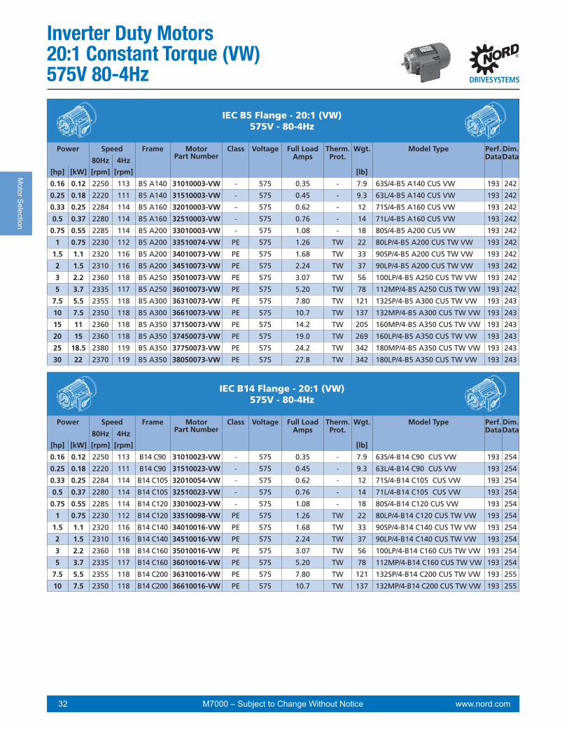
www.nord.com 32 M7000 – Subject to Change Without Notice
Motor S
election
B14 & NEMA C-Face
IEC B5 Flange - 20:1 (VW)575V - 80-4Hz
B14 & NEMA C-Face
Power Speed Frame MotorPart Number
Class Voltage Full Load Amps
Therm. Prot.
Wgt. Model Type Perf.Data
Dim.Data80Hz 4Hz
[hp] [kW] [rpm] [rpm] [lb]
0.16 0.12 2250 113 B5 A140 31010003-VW - 575 0.35 - 7.9 63S/4-B5 A140 CUS VW 193 242
0.25 0.18 2220 111 B5 A140 31510003-VW - 575 0.45 - 9.3 63L/4-B5 A140 CUS VW 193 242
0.33 0.25 2284 114 B5 A160 32010003-VW - 575 0.62 - 12 71S/4-B5 A160 CUS VW 193 242
0.5 0.37 2280 114 B5 A160 32510003-VW - 575 0.76 - 14 71L/4-B5 A160 CUS VW 193 242
0.75 0.55 2285 114 B5 A200 33010003-VW - 575 1.08 - 18 80S/4-B5 A200 CUS VW 193 242
1 0.75 2230 112 B5 A200 33510074-VW PE 575 1.26 TW 22 80LP/4-B5 A200 CUS TW VW 193 242
1.5 1.1 2320 116 B5 A200 34010073-VW PE 575 1.68 TW 33 90SP/4-B5 A200 CUS TW VW 193 242
2 1.5 2310 116 B5 A200 34510073-VW PE 575 2.24 TW 37 90LP/4-B5 A200 CUS TW VW 193 242
3 2.2 2360 118 B5 A250 35010073-VW PE 575 3.07 TW 56 100LP/4-B5 A250 CUS TW VW 193 242
5 3.7 2335 117 B5 A250 36010073-VW PE 575 5.20 TW 78 112MP/4-B5 A250 CUS TW VW 193 242
7.5 5.5 2355 118 B5 A300 36310073-VW PE 575 7.80 TW 121 132SP/4-B5 A300 CUS TW VW 193 243
10 7.5 2350 118 B5 A300 36610073-VW PE 575 10.7 TW 137 132MP/4-B5 A300 CUS TW VW 193 243
15 11 2360 118 B5 A350 37150073-VW PE 575 14.2 TW 205 160MP/4-B5 A350 CUS TW VW 193 243
20 15 2360 118 B5 A350 37450073-VW PE 575 19.0 TW 269 160LP/4-B5 A350 CUS TW VW 193 243
25 18.5 2380 119 B5 A350 37750073-VW PE 575 24.2 TW 342 180MP/4-B5 A350 CUS TW VW 193 243
30 22 2370 119 B5 A350 38050073-VW PE 575 27.8 TW 342 180LP/4-B5 A350 CUS TW VW 193 243B14 & NEMA C-Face
IEC B14 Flange - 20:1 (VW)575V - 80-4Hz
B14 & NEMA C-Face
Power Speed Frame MotorPart Number
Class Voltage Full Load Amps
Therm. Prot.
Wgt. Model Type Perf.Data
Dim.Data80Hz 4Hz
[hp] [kW] [rpm] [rpm] [lb]
0.16 0.12 2250 113 B14 C90 31010023-VW - 575 0.35 - 7.9 63S/4-B14 C90 CUS VW 193 254
0.25 0.18 2220 111 B14 C90 31510023-VW - 575 0.45 - 9.3 63L/4-B14 C90 CUS VW 193 254
0.33 0.25 2284 114 B14 C105 32010054-VW - 575 0.62 - 12 71S/4-B14 C105 CUS VW 193 254
0.5 0.37 2280 114 B14 C105 32510023-VW - 575 0.76 - 14 71L/4-B14 C105 CUS VW 193 254
0.75 0.55 2285 114 B14 C120 33010023-VW - 575 1.08 - 18 80S/4-B14 C120 CUS VW 193 254
1 0.75 2230 112 B14 C120 33510098-VW PE 575 1.26 TW 22 80LP/4-B14 C120 CUS TW VW 193 254
1.5 1.1 2320 116 B14 C140 34010016-VW PE 575 1.68 TW 33 90SP/4-B14 C140 CUS TW VW 193 254
2 1.5 2310 116 B14 C140 34510016-VW PE 575 2.24 TW 37 90LP/4-B14 C140 CUS TW VW 193 254
3 2.2 2360 118 B14 C160 35010016-VW PE 575 3.07 TW 56 100LP/4-B14 C160 CUS TW VW 193 254
5 3.7 2335 117 B14 C160 36010016-VW PE 575 5.20 TW 78 112MP/4-B14 C160 CUS TW VW 193 254
7.5 5.5 2355 118 B14 C200 36310016-VW PE 575 7.80 TW 121 132SP/4-B14 C200 CUS TW VW 193 255
10 7.5 2350 118 B14 C200 36610016-VW PE 575 10.7 TW 137 132MP/4-B14 C200 CUS TW VW 193 255
Inverter Duty Motors20:1 Constant Torque (VW)575V 80-4Hz

www.nord.com 33M7000 – Subject to Change Without Notice
Mot
or S
elec
tion
Inverter Duty Motors20:1 Constant Torque (VW)
575V 80-4Hz
IEC Footed (B3) - 20:1 (VW)575V - 80-4Hz
Power Speed Frame MotorPart Number
Class Voltage Full Load Amps
Therm. Prot.
Wgt. Model Type Perf.Data
Dim.Data80Hz 4Hz
[hp] [kW] [rpm] [rpm] [lb]
0.33 0.25 2284 114 B3-71 32010103-VW - 575 0.62 - 12 71S/4-B3 CUS VW 193 230
0.5 0.37 2280 114 B3-71 32510103-VW - 575 0.76 - 14 71L/4-B3 CUS VW 193 230
0.75 0.55 2285 114 B3-80 33010103-VW - 575 1.08 - 18 80S/4-B3 CUS VW 193 230
1 0.75 2230 112 B3-80 33510173-VW PE 575 1.26 TW 22 80LP/4-B3 CUS TW VW 193 230
1.5 1.1 2320 116 B3-90S 34010173-VW PE 575 1.68 TW 33 90SP/4-B3 CUS TW VW 193 230
2 1.5 2310 116 B3-90L 34510173-VW PE 575 2.24 TW 37 90LP/4-B3 CUS TW VW 193 230
3 2.2 2360 118 B3-100 35010173-VW PE 575 3.07 TW 56 100LP/4-B3 CUS TW VW 193 230
5 3.7 2335 117 B3-112 36010173-VW PE 575 5.20 TW 78 112MP/4-B3 CUS TW VW 193 230
7.5 5.5 2355 118 B3-132 36310173-VW PE 575 7.80 TW 121 132SP/4-B3 CUS TW VW 193 231
10 7.5 2350 118 B3-132 36610173-VW PE 575 10.7 TW 137 132MP/4-B3 CUS TW VW 193 231
15 11 2360 118 B3-160 37150173-VW PE 575 14.2 TW 205 160MP/4-B3 CUS TW VW 193 231
20 15 2360 118 B3-160 37450173-VW PE 575 19.0 TW 269 160LP/4-B3 CUS TW VW 193 231
25 18.5 2380 119 B3-180 37750173-VW PE 575 24.2 TW 342 180MP/4-B3 CUS TW VW 193 231
30 22 2370 119 B3-180 38050173-VW PE 575 27.8 TW 342 180LP/4-B3 CUS TW VW 193 231

www.nord.com 34 M7000 – Subject to Change Without Notice
Motor S
election
Inverter Duty Motors1000:1 Constant Torque (F VZ)230/460V 60-0Hz
B14 & NEMA C-Face
NEMA C-Face - 1000:1 (F VZ)230/460V - 60-0Hz
B14 & NEMA C-Face
Power Speed Frame MotorPart Number
Class Voltage Full Load Amps
Therm. Prot.
Wgt. Model Type Perf.Data
Dim.Data60Hz 0Hz
[hp] [kW] [rpm] [rpm] [lb]
0.16 0.12 1700 0 56C 31110012-F VZ - 230/460 0.88/0.44 - 7.9 63S/4-56C CUS F VZ 180 218
0.25 0.18 1680 0 56C 31610012-F VZ - 230/460 1.12/0.56 - 9.3 63L/4-56C CUS F VZ 180 218
0.33 0.25 1710 0 56C 32110012-F VZ - 230/460 1.56/0.78 - 12 71S/4-56C CUS F VZ 180 218
0.5 0.37 1720 0 56C 32610012-F VZ - 230/460 1.90/0.95 - 14 71L/4-56C CUS F VZ 180 218
0.75 0.55 1710 0 56C 33110012-F VZ - 230/460 2.70/1.35 - 18 80S/4-56C CUS F VZ 180 218
1 0.75 1730 0 56C 33610294-F VZ PE 230/460 3.14/1.57 TW 22 80LP/4-56C CUS TW F VZ 180 218
1 0.75 1730 0 143TC 33610292-F VZ PE 230/460 3.14/1.57 TW 22 80LP/4-143TC CUS TW F VZ 180 218
1.5 1.1 1740 0 145TC 34110292-F VZ PE 230/460 4.20/2.10 TW 33 90SP/4-145TC CUS TW F VZ 180 218
2 1.5 1730 0 145TC 34610292-F VZ PE 230/460 5.60/2.80 TW 37 90LP/4-145TC CUS TW F VZ 180 218
3 2.2 1770 0 182TC 35110292-F VZ PE 230/460 7.68/3.84 TW 56 100LP/4-182TC CUS TW F VZ 180 219
5 3.7 1755 0 184TC 36110292-F VZ PE 230/460 13.0/6.50 TW 78 112MP/4-184TC CUS TW F VZ 180 219
7.5 5.5 1770 0 213TC 36410292-F VZ PE 230/460 19.5/9.75 TW 121 132SP/4-213TC CUS TW F VZ 180 219
10 7.5 1765 0 215TC 36710292-F VZ PE 230/460 26.7/13.4 TW 137 132MP/4-215TC CUS TW F VZ 180 219
15 11 1770 0 254TC 37350292-F VZ PE 230/460 35.6/17.8 TW 205 160MP/4-254TC CUS TW F VZ 180 219
20 15 1775 0 256C 37550292-F VZ PE 230/460 47.6/23.8 TW 269 160LP/4-256C CUS TW F VZ 180 219
25 18.5 1780 0 286TC 37750272-F VZ PE 230/460 60.6/30.3 TW 342 180MP/4-286TC CUS TW F VZ 180 219
30 22 1780 0 286TC 38050272-F VZ PE 230/460 69.6/34.8 TW 342 180LP/4-286TC CUS TW F VZ 180 219
NEMA T Footed - 1000:1 (F VZ)230/460V - 60-0Hz
Power Speed Frame MotorPart Number
Class Voltage Full Load Amps
Therm. Prot.
Wgt. Model Type Perf.Data
Dim.Data60Hz 0Hz
[hp] [kW] [rpm] [rpm] [lb]
0.33 0.25 1710 0 56 32110112-F VZ - 230/460 1.56/0.78 - 12 71S/4-56 CUS F VZ 180 208
0.5 0.37 1720 0 56 32610112-F VZ - 230/460 1.90/0.95 - 14 71L/4-56 CUS F VZ 180 208
0.75 0.55 1710 0 56 33110112-F VZ - 230/460 2.70/1.35 - 18 80S/4-56 CUS F VZ 180 208
1 0.75 1730 0 56 33610394-F VZ PE 230/460 3.14/1.57 TW 22 80LP/4-56 CUS TW F VZ 180 208
1 0.75 1730 0 143T 33610392-F VZ PE 230/460 3.14/1.57 TW 22 80LP/4-143T CUS TW F VZ 180 208
1.5 1.1 1740 0 145T 34110392-F VZ PE 230/460 4.20/2.10 TW 33 90SP/4-145T CUS TW F VZ 180 208
2 1.5 1730 0 145T 34610392-F VZ PE 230/460 5.60/2.80 TW 37 90LP/4-145T CUS TW F VZ 180 208
3 2.2 1770 0 182T 35110392-F VZ PE 230/460 7.68/3.84 TW 56 100LP/4-182T CUS TW F VZ 180 208
5 3.7 1755 0 184T 36110392-F VZ PE 230/460 13.0/6.50 TW 78 112MP/4-184T CUS TW F VZ 180 208
7.5 5.5 1770 0 213T 36410392-F VZ PE 230/460 19.5/9.75 TW 121 132SP/4-213T CUS TW F VZ 180 208
10 7.5 1765 0 215T 36710392-F VZ PE 230/460 26.7/13.4 TW 137 132MP/4-215T CUS TW F VZ 180 208

www.nord.com 35M7000 – Subject to Change Without Notice
Mot
or S
elec
tion
Inverter Duty Motors1000:1 Constant Torque (F VZ)
230/460V 60-0HzB14 & NEMA C-Face
IEC B5 Flange - 1000:1 (F VZ)230/460V - 60-0Hz
B14 & NEMA C-Face
Power Speed Frame MotorPart Number
Class Voltage Full Load Amps
Therm. Prot.
Wgt. Model Type Perf.Data
Dim.Data60Hz 0Hz
[hp] [kW] [rpm] [rpm] [lb]
0.16 0.12 1700 0 B5 A140 31010002-F VZ - 230/460 0.88/0.44 - 7.9 63S/4-B5 A140 CUS F VZ 180 242
0.25 0.18 1680 0 B5 A140 31510002-F VZ - 230/460 1.12/0.56 - 9.3 63L/4-B5 A140 CUS F VZ 180 242
0.33 0.25 1710 0 B5 A160 32010002-F VZ - 230/460 1.56/0.78 - 12 71S/4-B5 A160 CUS F VZ 180 242
0.5 0.37 1720 0 B5 A160 32510002-F VZ - 230/460 1.90/0.95 - 14 71L/4-B5 A160 CUS F VZ 180 242
0.75 0.55 1710 0 B5 A200 33010002-F VZ - 230/460 2.70/1.35 - 18 80S/4-B5 A200 CUS F VZ 180 242
1 0.75 1730 0 B5 A200 33510072-F VZ PE 230/460 3.14/1.57 TW 22 80LP/4-B5 A200 CUS TW F VZ 180 242
1.5 1.1 1740 0 B5 A200 34010072-F VZ PE 230/460 4.20/2.10 TW 33 90SP/4-B5 A200 CUS TW F VZ 180 242
2 1.5 1730 0 B5 A200 34510072-F VZ PE 230/460 5.60/2.80 TW 37 90LP/4-B5 A200 CUS TW F VZ 180 242
3 2.2 1770 0 B5 A250 35010072-F VZ PE 230/460 7.68/3.84 TW 56 100LP/4-B5 A250 CUS TW F VZ 180 242
5 3.7 1755 0 B5 A250 36010072-F VZ PE 230/460 13.0/6.50 TW 78 112MP/4-B5 A250 CUS TW F VZ 180 242
7.5 5.5 1770 0 B5 A300 36310072-F VZ PE 230/460 19.5/9.75 TW 121 132SP/4-B5 A300 CUS TW F VZ 180 243
10 7.5 1765 0 B5 A300 36610072-F VZ PE 230/460 26.7/13.4 TW 137 132MP/4-B5 A300 CUS TW F VZ 180 243
15 11 1770 0 B5 A350 37150072-F VZ PE 230/460 35.6/17.8 TW 205 160MP/4-B5 A350 CUS TW F VZ 180 243
20 15 1775 0 B5 A350 37450072-F VZ PE 230/460 47.6/23.8 TW 269 160LP/4-B5 A350 CUS TW F VZ 180 243
25 18.5 1780 0 B5 A350 37750072-F VZ PE 230/460 60.6/30.3 TW 342 180MP/4-B5 A350 CUS TW F VZ 180 243
30 22 1780 0 B5 A350 38050072-F VZ PE 230/460 69.6/34.8 TW 342 180LP/4-B5 A350 CUS TW F VZ 180 243B14 & NEMA C-Face
IEC B14 Flange - 1000:1 (F VZ)230/460V - 60-0Hz
B14 & NEMA C-Face
Power Speed Frame MotorPart Number
Class Voltage Full Load Amps
Therm. Prot.
Wgt. Model Type Perf.Data
Dim.Data60Hz 0Hz
[hp] [kW] [rpm] [rpm] [lb]
0.16 0.12 1700 0 B14 C90 31010022-F VZ - 230/460 0.88/0.44 - 7.9 63S/4-B14 C90 CUS F VZ 180 254
0.25 0.18 1680 0 B14 C90 31510022-F VZ - 230/460 1.12/0.56 - 9.3 63L/4-B14 C90 CUS F VZ 180 254
0.25 0.18 1680 0 B14 C120 31510012-F VZ - 230/460 1.12/0.56 - 9.3 63L/4-B14 C120 CUS F VZ 180 254
0.33 0.25 1710 0 B14 C105 32010053-F VZ - 230/460 1.56/0.78 - 12 71S/4-B14 C105 CUS F VZ 180 254
0.33 0.25 1710 0 B14 C140 32010012-F VZ - 230/460 1.56/0.78 - 12 71S/4-B14 C140 CUS F VZ 180 254
0.5 0.37 1720 0 B14 C105 32510022-F VZ - 230/460 1.90/0.95 - 14 71L/4-B14 C105 CUS F VZ 180 254
0.5 0.37 1720 0 B14 C140 32510012-F VZ - 230/460 1.90/0.95 - 14 71L/4-B14 C140 CUS F VZ 180 254
0.75 0.55 1710 0 B14 C120 33010022-F VZ - 230/460 2.70/1.35 - 18 80S/4-B14 C120 CUS F VZ 180 254
0.75 0.55 1710 0 B14 C160 33010012-F VZ - 230/460 2.70/1.35 - 18 80S/4-B14 C160 CUS F VZ 180 254
1 0.75 1730 0 B14 C120 33510096-F VZ PE 230/460 3.14/1.57 TW 22 80LP/4-B14 C120 CUS TW F VZ 180 254
1.5 1.1 1740 0 B14 C140 34010015-F VZ PE 230/460 4.20/2.10 TW 33 90SP/4-B14 C140 CUS TW F VZ 180 254
2 1.5 1730 0 B14 C140 34510015-F VZ PE 230/460 5.60/2.80 TW 37 90LP/4-B14 C140 CUS TW F VZ 180 254
3 2.2 1770 0 B14 C160 35010015-F VZ PE 230/460 7.68/3.84 TW 56 100LP/4-B14 C160 CUS TW F VZ 180 254
5 3.7 1755 0 B14 C160 36010015-F VZ PE 230/460 13.0/6.50 TW 78 112MP/4-B14 C160 CUS TW F VZ 180 254
7.5 5.5 1770 0 B14 C200 36310015-F VZ PE 230/460 19.5/9.75 TW 121 132SP/4-B14 C200 CUS TW F VZ 180 255
10 7.5 1765 0 B14 C200 36610015-F VZ PE 230/460 26.7/13.4 TW 137 132MP/4-B14 C200 CUS TW F VZ 180 255

www.nord.com 36 M7000 – Subject to Change Without Notice
Motor S
election
Inverter Duty Motors1000:1 Constant Torque (F VZ)230/460V 60-0Hz
IEC Footed (B3) - 1000:1 (F VZ)230/460V - 60-0Hz
Power Speed Frame MotorPart Number
Class Voltage Full Load Amps
Therm. Prot.
Wgt. Model Type Perf.Data
Dim.Data60Hz 0Hz
[hp] [kW] [rpm] [rpm] [lb]
0.33 0.25 1710 0 B3-71 32010102-F VZ - 230/460 1.56/0.78 - 12 71S/4-B3 CUS F VZ 180 230
0.5 0.37 1720 0 B3-71 32510102-F VZ - 230/460 1.90/0.95 - 14 71L/4-B3 CUS F VZ 180 230
0.75 0.55 1710 0 B3-80 33010102-F VZ - 230/460 2.70/1.35 - 18 80S/4-B3 CUS F VZ 180 230
1 0.75 1730 0 B3-80 33510172-F VZ PE 230/460 3.14/1.57 TW 22 80LP/4-B3 CUS TW F VZ 180 230
1.5 1.1 1740 0 B3-90S 34010172-F VZ PE 230/460 4.20/2.10 TW 33 90SP/4-B3 CUS TW F VZ 180 230
2 1.5 1730 0 B3-90L 34510172-F VZ PE 230/460 5.60/2.80 TW 37 90LP/4-B3 CUS TW F VZ 180 230
3 2.2 1770 0 B3-100 35010172-F VZ PE 230/460 7.68/3.84 TW 56 100LP/4-B3 CUS TW F VZ 180 230
5 3.7 1755 0 B3-112 36010172-F VZ PE 230/460 13.0/6.50 TW 78 112MP/4-B3 CUS TW F VZ 180 230
7.5 5.5 1770 0 B3-132 36310172-F VZ PE 230/460 19.5/9.75 TW 121 132SP/4-B3 CUS TW F VZ 180 231
10 7.5 1765 0 B3-132 36610172-F VZ PE 230/460 26.7/13.4 TW 137 132MP/4-B3 CUS TW F VZ 180 231
15 11 1770 0 B3-160 37150172-F VZ PE 230/460 35.6/17.8 TW 205 160MP/4-B3 CUS TW F VZ 180 231
20 15 1775 0 B3-160 37450172-F VZ PE 230/460 47.6/23.8 TW 269 160LP/4-B3 CUS TW F VZ 180 231
25 18.5 1780 0 B3-180 37750172-F VZ PE 230/460 60.6/30.3 TW 342 180MP/4-B3 CUS TW F VZ 180 231
30 22 1780 0 B3-180 38050172-F VZ PE 230/460 69.6/34.8 TW 342 180LP/4-B3 CUS TW F VZ 180 231

www.nord.com 37M7000 – Subject to Change Without Notice
Mot
or S
elec
tion
Power Speed NEMAFrame
MotorP/N
Eff.Class
Voltage Full Load Amps
Therm. Prot.
Wgt. Model Type Perf.Data
Dim.Data
(hp) (kW) (rpm)
B14 & NEMA C-Face
NEMA C-Face - 1000:1 (F VZ)575V - 60-0Hz
B14 & NEMA C-Face
Power Speed Frame MotorPart
Number
Class Voltage Full Load Amps
Therm. Prot.
Wgt. Model Type Perf.Data
Dim.Data60Hz 0Hz
[hp] [kW] [rpm] [rpm] [lb]
0.16 0.12 1700 0 56C 31110013-F VZ - 575 0.35 - 7.9 63S/4-56C CUS F VZ 195 218
0.25 0.18 1680 0 56C 31610013-F VZ - 575 0.45 - 9.3 63L/4-56C CUS F VZ 195 218
0.33 0.25 1710 0 56C 32110013-F VZ - 575 0.62 - 12 71S/4-56C CUS F VZ 195 218
0.5 0.37 1720 0 56C 32610013-F VZ - 575 0.76 - 14 71L/4-56C CUS F VZ 195 218
0.75 0.55 1710 0 56C 33110013-F VZ - 575 1.08 - 18 80S/4-56C CUS F VZ 195 218
1 0.75 1730 0 56C 33610295-F VZ PE 575 1.26 TW 22 80LP/4-56C CUS TW F VZ 195 218
1 0.75 1730 0 143TC 33610293-F VZ PE 575 1.26 TW 22 80LP/4-143TC CUS TW F VZ 195 218
1.5 1.1 1740 0 145TC 34110293-F VZ PE 575 1.68 TW 33 90SP/4-145TC CUS TW F VZ 195 218
2 1.5 1730 0 145TC 34610293-F VZ PE 575 2.24 TW 37 90LP/4-145TC CUS TW F VZ 195 218
3 2.2 1770 0 182TC 35110293-F VZ PE 575 3.07 TW 56 100LP/4-182TC CUS TW F VZ 195 219
5 3.7 1755 0 184TC 36110293-F VZ PE 575 5.20 TW 78 112MP/4-184TC CUS TW F VZ 195 219
7.5 5.5 1770 0 213TC 36410293-F VZ PE 575 7.80 TW 121 132SP/4-213TC CUS TW F VZ 195 219
10 7.5 1765 0 215TC 36710293-F VZ PE 575 10.7 TW 137 132MP/4-215TC CUS TW F VZ 195 219
15 11 1770 0 254TC 37350293-F VZ PE 575 14.2 TW 205 160MP/4-254TC CUS TW F VZ 195 219
20 15 1775 0 256C 37550293-F VZ PE 575 19.0 TW 269 160LP/4-256C CUS TW F VZ 195 219
25 18.5 1780 0 286TC 37750273-F VZ PE 575 24.2 TW 342 180MP/4-286TC CUS TW F VZ 195 219
30 22 1780 0 286TC 38050273-F VZ PE 575 27.8 TW 342 180LP/4-286TC CUS TW F VZ 195 219
NEMA T Footed - 1000:1 (F VZ)575V - 60-0Hz
Power Speed Frame MotorPart
Number
Class Voltage Full Load Amps
Therm. Prot.
Wgt. Model Type Perf.Data
Dim.Data60Hz 0Hz
[hp] [kW] [rpm] [rpm] [lb]
0.33 0.25 1710 0 56 32110113-F VZ - 575 0.62 - 12 71S/4-56 CUS F VZ 195 208
0.5 0.37 1720 0 56 32610113-F VZ - 575 0.76 - 14 71L/4-56 CUS F VZ 195 208
0.75 0.55 1710 0 56 33110113-F VZ - 575 1.08 - 18 80S/4-56 CUS F VZ 195 208
1 0.75 1730 0 56 33610395-F VZ PE 575 1.26 TW 22 80LP/4-56 CUS TW F VZ 195 208
1 0.75 1730 0 143T 33610393-F VZ PE 575 1.26 TW 22 80LP/4-143T CUS TW F VZ 195 208
1.5 1.1 1740 0 145T 34110393-F VZ PE 575 1.68 TW 33 90SP/4-145T CUS TW F VZ 195 208
2 1.5 1730 0 145T 34610393-F VZ PE 575 2.24 TW 37 90LP/4-145T CUS TW F VZ 195 208
3 2.2 1770 0 182T 35110393-F VZ PE 575 3.07 TW 56 100LP/4-182T CUS TW F VZ 195 208
5 3.7 1755 0 184T 36110393-F VZ PE 575 5.20 TW 78 112MP/4-184T CUS TW F VZ 195 208
7.5 5.5 1770 0 213T 36410393-F VZ PE 575 7.80 TW 121 132SP/4-213T CUS TW F VZ 195 208
10 7.5 1765 0 215T 36710393-F VZ PE 575 10.7 TW 137 132MP/4-215T CUS TW F VZ 195 208
Inverter Duty Motors1000:1 Constant Torque (F VZ)
575V 60-0Hz

www.nord.com 38 M7000 – Subject to Change Without Notice
Motor S
election
Inverter Duty Motors1000:1 Constant Torque (F VZ)575V 60-0Hz
B14 & NEMA C-Face
IEC B5 Flange - 1000:1 (F VZ)575V - 60-0Hz
B14 & NEMA C-Face
Power Speed Frame MotorPart
Number
Class Voltage Full Load Amps
Therm. Prot.
Wgt. Model Type Perf.Data
Dim.Data60Hz 0Hz
[hp] [kW] [rpm] [rpm] [lb]
0.16 0.12 1700 0 B5 A140 31010003-F VZ - 575 0.35 - 7.9 63S/4-B5 A140 CUS F VZ 195 242
0.25 0.18 1680 0 B5 A140 31510003-F VZ - 575 0.45 - 9.3 63L/4-B5 A140 CUS F VZ 195 242
0.33 0.25 1710 0 B5 A160 32010003-F VZ - 575 0.62 - 12 71S/4-B5 A160 CUS F VZ 195 242
0.5 0.37 1720 0 B5 A160 32510003-F VZ - 575 0.76 - 14 71L/4-B5 A160 CUS F VZ 195 242
0.75 0.55 1710 0 B5 A200 33010003-F VZ - 575 1.08 - 18 80S/4-B5 A200 CUS F VZ 195 242
1 0.75 1730 0 B5 A200 33510074-F VZ PE 575 1.26 TW 22 80LP/4-B5 A200 CUS TW F VZ 195 242
1.5 1.1 1740 0 B5 A200 34010073-F VZ PE 575 1.68 TW 33 90SP/4-B5 A200 CUS TW F VZ 195 242
2 1.5 1730 0 B5 A200 34510073-F VZ PE 575 2.24 TW 37 90LP/4-B5 A200 CUS TW F VZ 195 242
3 2.2 1770 0 B5 A250 35010073-F VZ PE 575 3.07 TW 56 100LP/4-B5 A250 CUS TW F VZ 195 242
5 3.7 1755 0 B5 A250 36010073-F VZ PE 575 5.20 TW 78 112MP/4-B5 A250 CUS TW F VZ 195 242
7.5 5.5 1770 0 B5 A300 36310073-F VZ PE 575 7.80 TW 121 132SP/4-B5 A300 CUS TW F VZ 195 243
10 7.5 1765 0 B5 A300 36610073-F VZ PE 575 10.7 TW 137 132MP/4-B5 A300 CUS TW F VZ 195 243
15 11 1770 0 B5 A350 37150073-F VZ PE 575 14.2 TW 205 160MP/4-B5 A350 CUS TW F VZ 195 243
20 15 1775 0 B5 A350 37450073-F VZ PE 575 19.0 TW 269 160LP/4-B5 A350 CUS TW F VZ 195 243
25 18.5 1780 0 B5 A350 37750073-F VZ PE 575 24.2 TW 342 180MP/4-B5 A350 CUS TW F VZ 195 243
30 22 1780 0 B5 A350 38050073-F VZ PE 575 27.8 TW 342 180LP/4-B5 A350 CUS TW F VZ 195 243B14 & NEMA C-Face
IEC B14 Flange - 1000:1 (F VZ)575V - 60-0Hz
B14 & NEMA C-Face
Power Speed Frame MotorPart
Number
Class Voltage Full Load Amps
Therm. Prot.
Wgt. Model Type Perf.Data
Dim.Data60Hz 0Hz
[hp] [kW] [rpm] [rpm] [lb]
0.16 0.12 1700 0 B14 C90 31010023-F VZ - 575 0.35 - 7.9 63S/4-B14 C90 CUS F VZ 195 254
0.25 0.18 1680 0 B14 C90 31510023-F VZ - 575 0.45 - 9.3 63L/4-B14 C90 CUS F VZ 195 254
0.33 0.25 1710 0 B14 C105 32010054-F VZ - 575 0.62 - 12 71S/4-B14 C105 CUS F VZ 195 254
0.5 0.37 1720 0 B14 C105 32510023-F VZ - 575 0.76 - 14 71L/4-B14 C105 CUS F VZ 195 254
0.75 0.55 1710 0 B14 C120 33010023-F VZ - 575 1.08 - 18 80S/4-B14 C120 CUS F VZ 195 254
1 0.75 1730 0 B14 C120 33510098-F VZ PE 575 1.26 TW 22 80LP/4-B14 C120 CUS TW F VZ 195 254
1.5 1.1 1740 0 B14 C140 34010016-F VZ PE 575 1.68 TW 33 90SP/4-B14 C140 CUS TW F VZ 195 254
2 1.5 1730 0 B14 C140 34510016-F VZ PE 575 2.24 TW 37 90LP/4-B14 C140 CUS TW F VZ 195 254
3 2.2 1770 0 B14 C160 35010016-F VZ PE 575 3.07 TW 56 100LP/4-B14 C160 CUS TW F VZ 195 254
5 3.7 1755 0 B14 C160 36010016-F VZ PE 575 5.20 TW 78 112MP/4-B14 C160 CUS TW F VZ 195 254
7.5 5.5 1770 0 B14 C200 36310016-F VZ PE 575 7.80 TW 121 132SP/4-B14 C200 CUS TW F VZ 195 255
10 7.5 1765 0 B14 C200 36610016-F VZ PE 575 10.7 TW 137 132MP/4-B14 C200 CUS TW F VZ 195 255

www.nord.com 39M7000 – Subject to Change Without Notice
Mot
or S
elec
tion
Inverter Duty Motors1000:1 Constant Torque (F VZ)
575V 60-0Hz
IEC Footed (B3) - 1000:1 (F VZ)575V - 60-0Hz
Power Speed Frame MotorPart
Number
Class Voltage Full Load Amps
Therm. Prot.
Wgt. Model Type Perf.Data
Dim.Data60Hz 0Hz
[hp] [kW] [rpm] [rpm] [lb]
0.33 0.25 1710 0 B3-71 32010103-F VZ - 575 0.62 - 12 71S/4-B3 CUS F VZ 195 230
0.5 0.37 1720 0 B3-71 32510103-F VZ - 575 0.76 - 14 71L/4-B3 CUS F VZ 195 230
0.75 0.55 1710 0 B3-80 33010103-F VZ - 575 1.08 - 18 80S/4-B3 CUS F VZ 195 230
1 0.75 1730 0 B3-80 33510173-F VZ PE 575 1.26 TW 22 80LP/4-B3 CUS TW F VZ 195 230
1.5 1.1 1740 0 B3-90S 34010173-F VZ PE 575 1.68 TW 33 90SP/4-B3 CUS TW F VZ 195 230
2 1.5 1730 0 B3-90L 34510173-F VZ PE 575 2.24 TW 37 90LP/4-B3 CUS TW F VZ 195 230
3 2.2 1770 0 B3-100 35010173-F VZ PE 575 3.07 TW 56 100LP/4-B3 CUS TW F VZ 195 230
5 3.7 1755 0 B3-112 36010173-F VZ PE 575 5.20 TW 78 112MP/4-B3 CUS TW F VZ 195 230
7.5 5.5 1770 0 B3-132 36310173-F VZ PE 575 7.80 TW 121 132SP/4-B3 CUS TW F VZ 195 231
10 7.5 1765 0 B3-132 36610173-F VZ PE 575 10.7 TW 137 132MP/4-B3 CUS TW F VZ 195 231
15 11 1770 0 B3-160 37150173-F VZ PE 575 14.2 TW 205 160MP/4-B3 CUS TW F VZ 195 231
20 15 1775 0 B3-160 37450173-F VZ PE 575 19.0 TW 269 160LP/4-B3 CUS TW F VZ 195 231
25 18.5 1780 0 B3-180 37750173-F VZ PE 575 24.2 TW 342 180MP/4-B3 CUS TW F VZ 195 231
30 22 1780 0 B3-180 38050173-F VZ PE 575 27.8 TW 342 180LP/4-B3 CUS TW F VZ 195 231

www.nord.com 40 M7000 – Subject to Change Without Notice
Motor S
election
Brakemotors230/460V 60Hz
B14 & NEMA C-Face
NEMA C-Face230/460V - 60Hz
B14 & NEMA C-Face
Power Speed Frame MotorPart
Number
Class Voltage Full Load Amps
Therm. Prot.
Wgt. Model Type BrakeTorque
Perf.Data
Dim.Data
[hp] [kW] [rpm] [lb] [lb-ft]
0.16 0.12 1700 56C 31110034 - 230/460 0.88/0.44 - 12.3 63S/4-56C CUS BRE 5 HL 3.7 172 224
0.25 0.18 1680 56C 31610034 - 230/460 1.12/0.56 - 13.7 63L/4-56C CUS BRE 5 HL 3.7 172 224
0.33 0.25 1710 56C 32110034 - 230/460 1.56/0.78 - 16.4 71S/4-56C CUS BRE 5 HL 3.7 172 224
0.5 0.37 1720 56C 32610034 - 230/460 1.90/0.95 - 18.4 71L/4-56C CUS BRE 5 HL 3.7 172 224
0.75 0.55 1710 56C 33110034 - 230/460 2.7/1.35 - 24.6 80S/4-56C CUS BRE 10 HL 7.4 172 224
1 0.75 1730 56C 33610282 PE 230/460 3.14/1.57 TW 28.6 80LP/4-56C CUS BRE 10 HL TW 7.4 172 224
1 0.75 1730 143TC 33610284 PE 230/460 3.14/1.57 TW 28.6 80LP/4-143TC CUS BRE 10 HL TW 7.4 172 224
1.5 1.1 1740 145TC 34110284 PE 230/460 4.20/2.10 TW 45 90SP/4-145TC CUS BRE 20 HL TW 14.8 172 224
2 1.5 1730 145TC 34610284 PE 230/460 5.60/2.80 TW 49 90LP/4-145TC CUS BRE 20 HL TW 14.8 172 224
3 2.2 1770 182TC 35110284 PE 230/460 7.68/3.84 TW 71 100LP/4-182TC CUS BRE 40 HL TW 29.5 172 225
5 3.7 1755 184TC 36110284 PE 230/460 13.0/6.50 TW 93 112MP/4-184TC CUS BRE 40 HL TW 29.5 172 225
7.5 5.5 1770 213TC 36410284 PE 230/460 19.5/9.80 TW 144 132SP/4-213TC CUS BRE 60 HL TW 44.3 172 225
10 7.5 1765 215TC 36710284 PE 230/460 26.7/13.4 TW 173 132MP/4-215TC CUS BRE 100 HL TW 73.8 172 225
15 11 1770 254TC 37350284 PE 230/460 35.6/17.8 TW 256 160MP/4-254TC CUS BRE 150 HL TW 111 172 225
20 15 1775 256C 37550284 PE 230/460 47.6/23.8 TW 342 160LP/4-256C CUS BRE 250 HL TW 184 172 225
25 18.5 1780 286TC 37750232 PE 230/460 60.6/30.3 TW 415 180MP/4-286TC CUS BRE 250 HL TW 184 172 225
30 22 1780 286TC 38050232 PE 230/460 69.6/34.8 TW 415 180LP/4-286TC CUS BRE 250 HL TW 184 172 225
NEMA T Footed230/460V - 60Hz
Power Speed Frame MotorPart
Number
Class Voltage Full Load Amps
Therm. Prot.
Wgt. Model Type BrakeTorque
Perf.Data
Dim.Data
[hp] [kW] [rpm] [lb] [lb-ft]
0.33 0.25 1710 56 32110134 - 230/460 1.56/0.78 - 16.4 71S/4-56 CUS BRE 5 HL 3.7 172 213
0.5 0.37 1720 56 32610134 - 230/460 1.90/0.95 - 18.4 71L/4-56 CUS BRE 5 HL 3.7 172 213
0.75 0.55 1710 56 33110134 - 230/460 2.7/1.35 - 24.6 80S/4-56 CUS BRE 10 HL 7.4 172 213
1 0.75 1730 56 33610382 PE 230/460 3.14/1.57 TW 28.6 80LP/4-56 CUS BRE 10 HL TW 7.4 172 213
1 0.75 1730 143T 33610384 PE 230/460 3.14/1.57 TW 28.6 80LP/4-143T CUS BRE 10 HL TW 7.4 172 213
1.5 1.1 1740 145T 34110384 PE 230/460 4.20/2.10 TW 45 90SP/4-145T CUS BRE 20 HL TW 14.8 172 213
2 1.5 1730 145T 34610384 PE 230/460 5.60/2.80 TW 49 90LP/4-145T CUS BRE 20 HL TW 14.8 172 213
3 2.2 1770 182T 35110384 PE 230/460 7.68/3.84 TW 71 100LP/4-182T CUS BRE 40 HL TW 29.5 172 213
5 3.7 1755 184T 36110384 PE 230/460 13.0/6.50 TW 93 112MP/4-184T CUS BRE 40 HL TW 29.5 172 213
7.5 5.5 1770 213T 36410384 PE 230/460 19.5/9.80 TW 144 132SP/4-213T CUS BRE 60 HL TW 44.3 172 213
10 7.5 1765 215T 36710384 PE 230/460 26.7/13.4 TW 173 132MP/4-215T CUS BRE 100 HL TW 73.8 172 213
230/460 motors have brake systems supplied with 230VAC to a GVE20L rectifier that outputs 205VDC to the brake coil.

www.nord.com 41M7000 – Subject to Change Without Notice
Mot
or S
elec
tion
IEC B5 Flange230/460V - 60Hz
Power Speed Frame MotorPart
Number
Class Voltage Full Load Amps
Therm. Prot.
Wgt. Model Type BrakeTorque
Perf.Data
Dim.Data
[hp] [kW] [rpm] [lb] [lb-ft]
0.16 0.12 1700 B5 A140 31010019 - 230/460 0.88/0.44 - 12.3 63S/4-B5 A140 CUS BRE 5 HL 3.7 172 248
0.25 0.18 1680 B5 A140 31510019 - 230/460 1.12/0.56 - 12.3 63L/4-B5 A140 CUS BRE 5 HL 3.7 172 248
0.33 0.25 1710 B5 A160 32010019 - 230/460 1.56/0.78 - 16.4 71S/4-B5 A160 CUS BRE 5 HL 3.7 172 248
0.5 0.37 1720 B5 A160 32510019 - 230/460 1.90/0.95 - 18.4 71L/4-B5 A160 CUS BRE 5 HL 3.7 172 248
0.75 0.55 1710 B5 A200 33010019 - 230/460 2.7/1.35 - 24.6 80S/4-B5 A200 CUS BRE 10 HL 7.4 172 248
1 0.75 1730 B5 A200 33510032 PE 230/460 3.14/1.57 TW 28.6 80LP/4-B5 A200 CUS BRE 10 HL TW 7.4 172 248
1.5 1.1 1740 B5 A200 34010032 PE 230/460 4.20/2.10 TW 45 90SP/4-B5 A200 CUS BRE 20 HL TW 14.8 172 248
2 1.5 1730 B5 A200 34510032 PE 230/460 5.60/2.80 TW 49 90LP/4-B5 A200 CUS BRE 20 HL TW 14.8 172 248
3 2.2 1770 B5 A250 35010034 PE 230/460 7.68/3.84 TW 71 100LP/4-B5 A250 CUS BRE 40 HL TW 29.5 172 248
5 3.7 1755 B5 A250 36010032 PE 230/460 13.0/6.50 TW 93 112MP/4-B5 A250 CUS BRE 40 HL TW 29.5 172 248
7.5 5.5 1770 B5 A300 36310032 PE 230/460 19.5/9.80 TW 144 132SP/4-B5 A300 CUS BRE 60 HL TW 44.3 172 249
10 7.5 1765 B5 A300 36610032 PE 230/460 26.7/13.4 TW 173 132MP/4-B5 A300 CUS BRE 100 HL TW 73.8 172 249
15 11 1770 B5 A350 37150032 PE 230/460 35.6/17.8 TW 256 160MP/4-B5 A350 CUS BRE 150 HL TW 111 172 249
20 15 1775 B5 A350 37450032 PE 230/460 47.6/23.8 TW 342 160LP/4-B5 A350 CUS BRE 250 HL TW 184 172 249
25 18.5 1780 B5 A350 37750032 PE 230/460 60.6/30.3 TW 415 180MP/4-B5 A350 CUS BRE 250 HL TW 184 172 249
30 22 1780 B5 A350 38050032 PE 230/460 69.6/34.8 TW 415 180LP/4-B5 A350 CUS BRE 250 HL TW 184 172 249B14 & NEMA C-Face
IEC B14 Flange230/460V - 60Hz
B14 & NEMA C-Face
Power Speed Frame MotorPart
Number
Class Voltage Full Load Amps
Therm. Prot.
Wgt. Model Type BrakeTorque
Perf.Data
Dim.Data
[hp] [kW] [rpm] [lb] [lb-ft]
0.16 0.12 1700 B14 C90 31010046 - 230/460 0.88/0.44 - 12.3 63S/4-B14 C90 CUS BRE 5 HL 3.7 172 260
0.25 0.18 1680 B14 C90 31510045 - 230/460 1.12/0.56 - 13.7 63L/4-B14 C90 CUS BRE 5 HL 3.7 172 260
0.33 0.25 1710 B14 C105 32010045 - 230/460 1.56/0.78 - 16.4 71S/4-B14 C105 CUS BRE 5 HL 3.7 172 260
0.5 0.37 1720 B14 C105 32510046 - 230/460 1.90/0.95 - 18.4 71L/4-B14 C105 CUS BRE 5 HL 3.7 172 260
0.75 0.55 1710 B14 C120 33010047 - 230/460 2.7/1.35 - 24.6 80S/4-B14 C120 CUS BRE 10 HL 7.4 172 260
1 0.75 1730 B14 C120 33510041 PE 230/460 3.14/1.57 TW 28.6 80LP/4-B14 C120 CUS BRE 10 HL TW 7.4 172 260
1.5 1.1 1740 B14 C140 34010041 PE 230/460 4.20/2.10 TW 45 90SP/4-B14 C140 CUS BRE 20 HL TW 14.8 172 260
2 1.5 1730 B14 C140 34510041 PE 230/460 5.60/2.80 TW 49 90LP/4-B14 C140 CUS BRE 20 HL TW 14.8 172 260
3 2.2 1770 B14 C160 35010044 PE 230/460 7.68/3.84 TW 71 100LP/4-B14 C160 CUS BRE 40 HL TW 29.5 172 260
5 3.7 1755 B14 C160 36010044 PE 230/460 13.0/6.50 TW 93 112MP/4-B14 C160 CUS BRE 40 HL TW 29.5 172 260
7.5 5.5 1770 B14 C200 36310041 PE 230/460 19.5/9.80 TW 144 132SP/4-B14 C200 CUS BRE 60 HL TW 44.3 172 261
10 7.5 1765 B14 C200 36610041 PE 230/460 26.7/13.4 TW 173 132MP/4-B14 C200 CUS BRE 100 HL TW 73.8 172 261
Brakemotors230/460V 60Hz
230/460 motors have brake systems supplied with 230VAC to a GVE20L rectifier that outputs 205VDC to the brake coil.

www.nord.com 42 M7000 – Subject to Change Without Notice
Motor S
election
Brakemotors230/460V 60Hz
230/460 motors have brake systems supplied with 230VAC to a GVE20L rectifier that outputs 205VDC to the brake coil.
IEC Footed (B3)230/460V - 60Hz
Power Speed Frame MotorPart
Number
Class Voltage Full Load Amps
Therm. Prot.
Wgt. Model Type BrakeTorque
Perf.Data
Dim.Data
[hp] [kW] [rpm] [lb] [lb-ft]
0.33 0.25 1710 B3-71 32010120 - 230/460 1.56/0.78 - 16.4 71S/4-B3 CUS BRE 5 HL 3.7 172 236
0.5 0.37 1720 B3-71 32510120 - 230/460 1.90/0.95 - 18.4 71L/4-B3 CUS BRE 5 HL 3.7 172 236
0.75 0.55 1710 B3-80 33010120 - 230/460 2.7/1.35 - 24.6 80S/4-B3 CUS BRE 10 HL 7.4 172 236
1 0.75 1730 B3-80 33510132 PE 230/460 3.14/1.57 TW 28.6 80LP/4-B3 CUS BRE 10 HL TW 7.4 172 236
1.5 1.1 1740 B3-90S 34010132 PE 230/460 4.20/2.10 TW 45 90SP/4-B3 CUS BRE 20 HL TW 14.8 172 236
2 1.5 1730 B3-90L 34510132 PE 230/460 5.60/2.80 TW 49 90LP/4-B3 CUS BRE 20 HL TW 14.8 172 236
3 2.2 1770 B3-100 35010132 PE 230/460 7.68/3.84 TW 71 100LP/4-B3 CUS BRE 40 HL TW 29.5 172 236
5 3.7 1755 B3-112 36010132 PE 230/460 13.0/6.50 TW 93 112MP/4-B3 CUS BRE 40 HL TW 29.5 172 236
7.5 5.5 1770 B3-132 36310132 PE 230/460 19.5/9.80 TW 144 132SP/4-B3 CUS BRE 60 HL TW 44.3 172 237
10 7.5 1765 B3-132 36610132 PE 230/460 26.7/13.4 TW 173 132MP/4-B3 CUS BRE 100 HL TW 73.8 172 237
15 11 1770 B3-160 37150132 PE 230/460 35.6/17.8 TW 256 160MP/4-B3 CUS BRE 150 HL TW 111 172 237
20 15 1775 B3-160 37450132 PE 230/460 47.6/23.8 TW 342 160LP/4-B3 CUS BRE 250 HL TW 184 172 237
25 18.5 1780 B3-180 37750132 PE 230/460 60.6/30.3 TW 415 180MP/4-B3 CUS BRE 250 HL TW 184 172 237
30 22 1780 B3-180 38050132 PE 230/460 69.6/34.8 TW 415 180LP/4-B3 CUS BRE 250 HL TW 184 172 237

www.nord.com 43M7000 – Subject to Change Without Notice
Mot
or S
elec
tion
Brakemotors575V 60Hz
0.16 0.12 1700 56C 31110035 - 575 0.37 - 12.3 63S/4-56C CUS BRE 5 HL 3.7 187 224
0.25 0.18 1680 56C 31610035 - 575 0.46 - 13.7 63L/4-56C CUS BRE 5 HL 3.7 187 224
0.33 0.25 1710 56C 32110035 - 575 0.66 - 16.4 71S/4-56C CUS BRE 5 HL 3.7 187 224
0.5 0.37 1720 56C 32610035 - 575 0.80 - 18.4 71L/4-56C CUS BRE 5 HL 3.7 187 224
0.75 0.55 1710 56C 33110035 - 575 1.12 - 24.6 80S/4-56C CUS BRE 10 HL 7.4 187 224
1 0.75 1730 56C 33610283 PE 575 1.25 TW 28.6 80LP/4-56C CUS BRE 10 HL TW 7.4 187 224
1 0.75 1730 143TC 33610285 PE 575 1.25 TW 28.6 80LP/4-143TC CUS BRE 10 HL TW 7.4 187 224
1.5 1.1 1740 145TC 34110285 PE 575 1.68 TW 45 90SP/4-145TC CUS BRE 20 HL TW 14.8 187 224
2 1.5 1730 145TC 34610285 PE 575 2.24 TW 49 90LP/4-145TC CUS BRE 20 HL TW 14.8 187 224
3 2.2 1770 182TC 35110285 PE 575 3.07 TW 71 100LP/4-182TC CUS BRE 40 HL TW 29.5 187 225
5 3.7 1755 184TC 36110285 PE 575 5.2 TW 93 112MP/4-184TC CUS BRE 40 HL TW 29.5 187 225
7.5 5.5 1770 213TC 36410285 PE 575 7.8 TW 144 132SP/4-213TC CUS BRE 60 HL TW 44.3 187 225
10 7.5 1765 215TC 36710285 PE 575 10.7 TW 173 132MP/4-215TC CUS BRE 100 HL TW 73.8 187 225
15 11 1770 254TC 37350285 PE 575 14.2 TW 256 160MP/4-254TC CUS BRE 150 HL TW 111 187 225
20 15 1775 256C 37550285 PE 575 19 TW 342 160LP/4-256C CUS BRE 250 HL TW 184 187 225
25 18.5 1780 286TC 37750233 PE 575 24.2 TW 415 180MP/4-286TC CUS BRE 250 HL TW 184 187 225
30 22 1780 286TC 38050233 PE 575 27.8 TW 415 180LP/4-286TC CUS BRE 250 HL TW 184 187 225
NEMA T Footed575V - 60Hz
Power Speed Frame MotorPart
Number
Class Voltage Full Load Amps
Therm. Prot.
Wgt. Model Type BrakeTorque
Perf.Data
Dim.Data
[hp] [kW] [rpm] [lb] [lb-ft]
0.33 0.25 1710 56 32110135 - 575 0.66 - 16.4 71S/4-56 CUS BRE 5 HL 3.7 187 213
0.5 0.37 1720 56 32610135 - 575 0.80 - 18.4 71L/4-56 CUS BRE 5 HL 3.7 187 213
0.75 0.55 1710 56 33110135 - 575 1.12 - 24.6 80S/4-56 CUS BRE 10 HL 7.4 187 213
1 0.75 1730 56 33610383 PE 575 1.25 TW 28.6 80LP/4-56 CUS BRE 10 HL TW 7.4 187 213
1 0.75 1730 143T 33610385 PE 575 1.25 TW 28.6 80LP/4-143T CUS BRE 10 HL TW 7.4 187 213
1.5 1.1 1740 145T 34110385 PE 575 1.68 TW 45 90SP/4-145T CUS BRE 20 HL TW 14.8 187 213
2 1.5 1730 145T 34610385 PE 575 2.24 TW 49 90LP/4-145T CUS BRE 20 HL TW 14.8 187 213
3 2.2 1770 182T 35110385 PE 575 3.07 TW 71 100LP/4-182T CUS BRE 40 HL TW 29.5 187 213
5 3.7 1755 184T 36110385 PE 575 5.2 TW 93 112MP/4-184T CUS BRE 40 HL TW 29.5 187 213
7.5 5.5 1770 213T 36410385 PE 575 7.8 TW 144 132SP/4-213T CUS BRE 60 HL TW 44.3 187 213
10 7.5 1765 215T 36710385 PE 575 10.7 TW 173 132MP/4-215T CUS BRE 100 HL TW 73.8 187 213
B14 & NEMA C-Face
NEMA C-Face575V - 60Hz
B14 & NEMA C-Face
Power Speed Frame MotorPart
Number
Class Voltage Full Load Amps
Therm. Prot.
Wgt. Model Type BrakeTorque
Perf.Data
Dim.Data
[hp] [kW] [rpm] [lb] [lb-ft]
575V motors have brake systems supplied with 575VAC to a GHE50L rectifier that outputs 250VDC to the brake coil.

www.nord.com 44 M7000 – Subject to Change Without Notice
Motor S
election
IEC B5 Flange575V - 60Hz
Power Speed Frame MotorPart
Number
Class Voltage Full Load Amps
Therm. Prot.
Wgt. Model Type BrakeTorque
Perf.Data
Dim.Data
[hp] [kW] [rpm] [lb] [lb-ft]
0.16 0.12 1700 B5 A140 31010021 - 575 0.37 - 12.3 63S/4-B5 A140 CUS BRE 5 HL 3.7 187 248
0.25 0.18 1680 B5 A140 31510021 - 575 0.46 - 12.3 63L/4-B5 A140 CUS BRE 5 HL 3.7 187 248
0.33 0.25 1710 B5 A160 32010021 - 575 0.66 - 16.4 71S/4-B5 A160 CUS BRE 5 HL 3.7 187 2480.5 0.37 1720 B5 A160 32510021 - 575 0.80 - 18.4 71L/4-B5 A160 CUS BRE 5 HL 3.7 187 248
0.75 0.55 1710 B5 A200 33010021 - 575 1.12 - 24.6 80S/4-B5 A200 CUS BRE 10 HL 7.4 187 248
1 0.75 1730 B5 A200 33510033 PE 575 1.25 TW 28.6 80LP/4-B5 A200 CUS BRE 10 HL TW 7.4 187 248
1.5 1.1 1740 B5 A200 34010033 PE 575 1.68 TW 45 90SP/4-B5 A200 CUS BRE 20 HL TW 14.8 187 248
2 1.5 1730 B5 A200 34510033 PE 575 2.24 TW 49 90LP/4-B5 A200 CUS BRE 20 HL TW 14.8 187 248
3 2.2 1770 B5 A250 35010035 PE 575 3.07 TW 71 100LP/4-B5 A250 CUS BRE 40 HL TW 29.5 187 248
5 3.7 1755 B5 A250 36010033 PE 575 5.2 TW 93 112MP/4-B5 A250 CUS BRE 40 HL TW 29.5 187 248
7.5 5.5 1770 B5 A300 36310033 PE 575 7.8 TW 144 132SP/4-B5 A300 CUS BRE 60 HL TW 44.3 187 249
10 7.5 1765 B5 A300 36610033 PE 575 10.7 TW 173 132MP/4-B5 A300 CUS BRE 100 HL TW 73.8 187 249
15 11 1770 B5 A350 37150033 PE 575 14.2 TW 256 160MP/4-B5 A350 CUS BRE 150 HL TW 111 187 249
20 15 1775 B5 A350 37450033 PE 575 19 TW 342 160LP/4-B5 A350 CUS BRE 250 HL TW 184 187 249
25 18.5 1780 B5 A350 37750033 PE 575 24.2 TW 415 180MP/4-B5 A350 CUS BRE 250 HL TW 184 187 249
30 22 1780 B5 A350 38050033 PE 575 27.8 TW 415 180LP/4-B5 A350 CUS BRE 250 HL TW 184 187 249B14 & NEMA C-Face
IEC B14 Flange575V - 60Hz
B14 & NEMA C-Face
Power Speed Frame MotorPart
Number
Class Voltage Full Load Amps
Therm. Prot.
Wgt. Model Type BrakeTorque
Perf.Data
Dim.Data
[hp] [kW] [rpm] [lb] [lb-ft]
0.16 0.12 1700 B14 C90 31010047 - 575 0.37 - 12.3 63S/4-B14 C90 CUS BRE 5 HL 3.7 187 260
0.25 0.18 1680 B14 C90 31510046 - 575 0.46 - 13.7 63L/4-B14 C90 CUS BRE 5 HL 3.7 187 260
0.33 0.25 1710 B14 C105 32010046 - 575 0.66 - 16.4 71S/4-B14 C105 CUS BRE 5 HL 3.7 187 260
0.5 0.37 1720 B14 C105 32510043 - 575 0.80 - 18.4 71L/4-B14 C105 CUS BRE 5 HL 3.7 187 260
0.75 0.55 1710 B14 C120 33010049 - 575 1.12 - 24.6 80S/4-B14 C120 CUS BRE 10 HL 7.4 187 260
1 0.75 1730 B14 C120 33510042 PE 575 1.25 TW 28.6 80LP/4-B14 C120 CUS BRE 10 HL TW 7.4 187 260
1.5 1.1 1740 B14 C140 34010042 PE 575 1.68 TW 45 90SP/4-B14 C140 CUS BRE 20 HL TW 14.8 187 260
2 1.5 1730 B14 C140 34510042 PE 575 2.24 TW 49 90LP/4-B14 C140 CUS BRE 20 HL TW 14.8 187 260
3 2.2 1770 B14 C160 35010042 PE 575 3.07 TW 71 100LP/4-B14 C160 CUS BRE 40 HL TW 29.5 187 260
5 3.7 1755 B14 C160 36010042 PE 575 5.2 TW 93 112MP/4-B14 C160 CUS BRE 40 HL TW 29.5 187 260
7.5 5.5 1770 B14 C200 36310042 PE 575 7.8 TW 144 132SP/4-B14 C200 CUS BRE 60 HL TW 44.3 187 261
10 7.5 1765 B14 C200 36610042 PE 575 10.7 TW 173 132MP/4-B14 C200 CUS BRE 100 HL TW 73.8 187 261
Brakemotors575V 60Hz
575V motors have brake systems supplied with 575VAC to a GHE50L rectifier that outputs 250VDC to the brake coil.

www.nord.com 45M7000 – Subject to Change Without Notice
Mot
or S
elec
tion
IEC Footed (B3)575V - 60Hz
Power Speed Frame MotorPart
Number
Class Voltage Full Load Amps
Therm. Prot.
Wgt. Model Type BrakeTorque
Perf.Data
Dim.Data
[hp] [kW] [rpm] [lb] [lb-ft]
0.33 0.25 1710 B3-71 32010121 - 575 0.66 - 16.4 71S/4-B3 CUS BRE 5 HL 3.7 187 236
0.5 0.37 1720 B3-71 32510121 - 575 0.80 - 18.4 71L/4-B3 CUS BRE 5 HL 3.7 187 236
0.75 0.55 1710 B3-80 33010121 - 575 1.12 - 24.6 80S/4-B3 CUS BRE 10 HL 7.4 187 236
1 0.75 1730 B3-80 33510133 PE 575 1.25 TW 28.6 80LP/4-B3 CUS BRE 10 HL TW 7.4 187 236
1.5 1.1 1740 B3-90S 34010133 PE 575 1.68 TW 45 90SP/4-B3 CUS BRE 20 HL TW 14.8 187 236
2 1.5 1730 B3-90L 34510133 PE 575 2.24 TW 49 90LP/4-B3 CUS BRE 20 HL TW 14.8 187 236
3 2.2 1770 B3-100 35010133 PE 575 3.07 TW 71 100LP/4-B3 CUS BRE 40 HL TW 29.5 187 236
5 3.7 1755 B3-112 36010133 PE 575 5.2 TW 93 112MP/4-B3 CUS BRE 40 HL TW 29.5 187 236
7.5 5.5 1770 B3-132 36310133 PE 575 7.8 TW 144 132SP/4-B3 CUS BRE 60 HL TW 44.3 187 237
10 7.5 1765 B3-132 36610133 PE 575 10.7 TW 173 132MP/4-B3 CUS BRE 100 HL TW 73.8 187 237
15 11 1770 B3-160 37150133 PE 575 14.2 TW 256 160MP/4-B3 CUS BRE 150 HL TW 111 187 237
20 15 1775 B3-160 37450133 PE 575 19 TW 342 160LP/4-B3 CUS BRE 250 HL TW 184 187 237
25 18.5 1780 B3-180 37750133 PE 575 24.2 TW 415 180MP/4-B3 CUS BRE 250 HL TW 184 187 237
30 22 1780 B3-180 38050133 PE 575 27.8 TW 415 180LP/4-B3 CUS BRE 250 HL TW 184 187 237
Brakemotors575V 60Hz
575V motors have brake systems supplied with 575VAC to a GHE50L rectifier that outputs 250VDC to the brake coil.

www.nord.com 46 M7000 – Subject to Change Without Notice
Motor S
election
IEC B5 Flange400V - 50Hz
Power Speed Frame MotorPart
Number
Class Voltage Full Load Amps
Therm. Prot.
Wgt. Model Type BrakeTorque
Perf.Data
Dim.Data
[hp] [kW] [rpm] [lb] [lb-ft]
0.16 0.12 1335 B5 A140 31010035 - 230/400 0.55 - 12.3 63S/4-B5 A140 BRE 5 3.7 200 248
0.25 0.18 1360 B5 A140 31510035 - 230/400 0.68 - 13.7 63L/4-B5 A140 BRE 5 3.7 200 248
0.33 0.25 1380 B5 A160 32010035 - 230/400 0.76 - 16.4 71S/4-B5 A160 BRE 5 3.7 200 248
0.5 0.37 1380 B5 A160 32510035 - 230/400 1.09 - 18.4 71L/4-B5 A160 BRE 5 3.7 200 248
0.75 0.55 1375 B5 A200 33010036 - 230/400 1.52 - 24.6 80S/4-B5 A200 BRE 10 7.4 200 248
1 0.75 1415 B5 A200 33510029 IE3 230/400 1.79 TF 28.6 80LP/4-B5 A200 BRE 10 TF 7.4 199 248
1.5 1.1 1430 B5 A200 34010030 IE3 230/400 2.38 TF 45 90SP/4-B5 A200 BRE 20 TF 14.8 199 248
2 1.5 1415 B5 A200 34510028 IE3 230/400 3.23 TF 49 90LP/4-B5 A200 BRE 20 TF 14.8 199 248
3 2.2 1465 B5 A250 35010028 IE3 230/400 4.27 TF 71 100LP/4-B5 A250 BRE 40 TF 29.5 199 248
4 3 1460 B5 A250 35010029 IE3 400/690 6.05 TF 77 100AP/4-B5 A250 BRE 40 TF 29.5 199 248
5.4 4 1440 B5 A250 36010029 IE3 400/690 7.85 TF 93 112MP/4-B5 A250 BRE 40 TF 29.5 199 248
7.5 5.5 1465 B5 A300 36310029 IE3 400/690 10.9 TF 143 132SP/4-B5 A300 BRE 60 TF 44.3 199 249
10 7.5 1460 B5 A300 36610029 IE3 400/690 15.7 TF 172 132MP/4-B5 A300 BRE 100 TF 73.8 199 249
15 11 1465 B5 A350 37150029 IE3 400/690 20.5 TF 254 160MP/4-B5 A350 BRE 150 TF 111 199 249
20 15 1465 B5 A350 37450029 IE3 400/690 27.9 TF 340 160LP/4-B5 A350 BRE 250 TF 184 199 249
25 18.5 1480 B5 A350 37750029 IE3 400/690 34 TF 413 180MP/4-B5 A350 BRE 250 TF 184 199 249
30 22 1475 B5 A350 38050029 IE3 400/690 39.3 TF 413 180LP/4-B5 A350 BRE 250 TF 184 199 249B14 & NEMA C-Face
IEC B14 Flange400V - 50Hz
B14 & NEMA C-Face
Power Speed Frame MotorPart
Number
Class Voltage Full Load Amps
Therm. Prot.
Wgt. Model Type BrakeTorque
Perf.Data
Dim.Data
[hp] [kW] [rpm] [lb] [lb-ft]
0.16 0.12 1335 B14 C90 31010044 - 230/400 0.55 - 12.3 63S/4-B14 C90 BRE 5 3.7 200 260
0.16 0.12 1335 B14 C120 31010034 - 230/400 0.55 - 12.3 63S/4-B14 C120 BRE 5 3.7 200 260
0.25 0.18 1360 B14 C90 31510044 - 230/400 0.68 - 13.7 63L/4-B14 C90 BRE 5 3.7 200 260
0.25 0.18 1360 B14 C120 31510034 - 230/400 0.68 - 13.7 63L/4-B14 C120 BRE 5 3.7 200 260
0.33 0.25 1380 B14 C105 32010044 - 230/400 0.76 - 16.4 71S/4-B14 C105 BRE 5 3.7 200 260
0.33 0.25 1380 B14 C140 32010034 - 230/400 0.76 - 16.4 71S/4-B14 C140 BRE 5 3.7 200 260
0.5 0.37 1380 B14 C105 32510044 - 230/400 1.09 - 18.4 71L/4-B14 C105 BRE 5 3.7 200 260
0.5 0.37 1380 B14 C140 32510034 - 230/400 1.09 - 18.4 71L/4-B14 C140 BRE 5 3.7 200 260
0.75 0.55 1375 B14 C120 33010044 - 230/400 1.52 - 24.6 80S/4-B14 C120 BRE 10 7.4 200 260
0.75 0.55 1375 B14 C160 33010034 - 230/400 1.52 - 24.6 80S/4-B14 C160 BRE 10 7.4 200 260
1 0.75 1415 B14 C120 33510035 IE3 230/400 1.79 TF 28.6 80LP/4-B14 C120 BRE 10 TF 7.4 199 260
1 0.75 1375 B14 C160 33510034 IE1 230/400 2.1 - 26.6 80L/4-B14 C160 BRE 10 7.4 200 260
1.5 1.1 1430 B14 C140 34010035 IE3 230/400 2.38 TF 45 90SP/4-B14 C140 BRE 20 TF 14.8 199 260
2 1.5 1415 B14 C140 34510035 IE3 230/400 3.23 TF 49 90LP/4-B14 C140 BRE 20 TF 14.8 199 260
3 2.2 1465 B14 C160 35010036 IE3 230/400 4.27 TF 71 100LP/4-B14 C160 BRE 40 TF 29.5 199 260
4 3 1460 B14 C160 35510035 IE3 400/690 6.05 TF 77 100AP/4-B14 C160 BRE 40 TF 29.5 199 260
5.4 4 1440 B14 C160 36010035 IE3 400/690 7.85 TF 93 112MP/4-B14 C160 BRE 40 TF 29.5 199 260
7.5 5.5 1465 B14 C200 36310035 IE3 400/690 10.9 TF 143 132SP/4-B14 C200 BRE 60 TF 44.3 199 261
10 7.5 1460 B14 C200 36610035 IE3 400/690 15.7 TF 172 132MP/4-B14 C200 BRE 100 TF 73.8 199 261
Brakemotors400V 50Hz
230/400V motors have a brake system supplied with 230VAC including a GVE20L rectifier with a 205VDC brake coil. 400/690V motors have a brake system supplied with 400VAC including a GHE20L rectifier with a 180VDC brake coil.

www.nord.com 47M7000 – Subject to Change Without Notice
Mot
or S
elec
tion
IEC Footed (B3)400V - 50Hz
Power Speed Frame MotorPart
Number
Class Voltage Full Load Amps
Therm. Prot.
Wgt. Model Type BrakeTorque
Perf.Data
Dim.Data
[hp] [kW] [rpm] [lb-ft]
0.16 0.12 1335 B3-63 31010135 - 230/400 0.55 - 12.3 63S/4-B3 BRE 5 3.7 200 236
0.25 0.18 1360 B3-63 31510135 - 230/400 0.68 - 13.7 63L/4-B3 BRE 5 3.7 200 236
0.33 0.25 1380 B3-71 32010135 - 230/400 0.76 - 16.4 71S/4-B3 BRE 5 3.7 200 236
0.5 0.37 1380 B3-71 32510135 - 230/400 1.09 - 18.4 71L/4-B3 BRE 5 3.7 200 236
0.75 0.55 1375 B3-80 33010136 - 230/400 1.52 - 24.6 80S/4-B3 BRE 10 7.4 200 236
1 0.75 1375 B3-80 33510135 - 230/400 2.1 - 26.6 80L/4-B3 BRE 10 7.4 200 236
1 0.75 1415 B3-80 33510128 IE3 230/400 1.79 TF 28.6 80LP/4-B3 BRE 10 TF 7.4 199 236
1.5 1.1 1430 B3-90S 34010128 IE3 230/400 2.38 TF 45 90SP/4-B3 BRE 20 TF 14.8 199 236
2 1.5 1415 B3-90L 34510128 IE3 230/400 3.23 TF 49 90LP/4-B3 BRE 20 TF 14.8 199 236
3 2.2 1465 B3-100 35010128 IE3 230/400 4.27 TF 71 100LP/4-B3 BRE 40 TF 29.5 199 236
4 3 1460 B3-100 35010129 IE3 400/690 6.05 TF 77 100AP/4-B3 BRE 40 TF 29.5 199 236
5.4 4 1440 B3-112 36010129 IE3 400/690 7.85 TF 93 112MP/4-B3 BRE 40 TF 29.5 199 236
7.5 5.5 1465 B3-132 36310129 IE3 400/690 10.9 TF 143 132SP/4-B3 BRE 60 TF 44.3 199 237
10 7.5 1460 B3-132 36610129 IE3 400/690 15.7 TF 172 132MP/4-B3 BRE 100 TF 73.8 199 237
15 11 1465 B3-160 37150129 IE3 400/690 20.5 TF 254 160MP/4-B3 BRE 150 TF 111 199 237
20 15 1465 B3-160 37450129 IE3 400/690 27.9 TF 340 160LP/4-B3 BRE 250 TF 184 199 237
25 18.5 1480 B3-180 37750129 IE3 400/690 34 TF 413 180MP/4-B3 BRE 250 TF 184 199 237
30 22 1475 B3-180 38050129 IE3 400/690 39.3 TF 413 180LP/4-B3 BRE 250 TF 184 199 237
Brakemotors400V 50Hz
230/400V motors have a brake system supplied with 230VAC including a GVE20L rectifier with a 205VDC brake coil. 400/690V motors have a brake system supplied with 400VAC including a GHE20L rectifier with a 180VDC brake coil.

www.nord.com 48 M7000 – Subject to Change Without Notice
Motor S
election
Inverter Duty Brakemotors5:1 Constant Torque (VR)230/460V 60-12Hz
B14 & NEMA C-Face
NEMA C-Face - 5:1 (VR)230/460V - 60-12Hz
B14 & NEMA C-Face
Power Speed Frame MotorPart
Number
Class Voltage Full Load Amps
Therm. Prot.
Wgt. Model Type BrakeTorque
Perf.Data
Dim.Data60Hz 12Hz
[hp] [kW] [rpm] [rpm] [lb] [lb-ft]
0.16 0.12 1700 340 56C 31110034-VR - 230/460 0.88/0.44 - 12.3 63S/4-56C CUS BRE 5 HL VR 3.7 174 224
0.25 0.18 1680 336 56C 31610034-VR - 230/460 1.12/0.56 - 13.7 63L/4-56C CUS BRE 5 HL VR 3.7 174 224
0.33 0.25 1710 342 56C 32110034-VR - 230/460 1.56/0.78 - 16.4 71S/4-56C CUS BRE 5 HL VR 3.7 174 224
0.5 0.37 1720 344 56C 32610034-VR - 230/460 1.90/0.95 - 18.4 71L/4-56C CUS BRE 5 HL VR 3.7 174 224
0.75 0.55 1710 342 56C 33110034-VR - 230/460 2.7/1.35 - 24.6 80S/4-56C CUS BRE 10 HL VR 7.4 174 224
1 0.75 1730 346 56C 33610282-VR PE 230/460 3.14/1.57 TW 28.6 80LP/4-56C CUS BRE 10 HL TW VR 7.4 174 224
1 0.75 1730 346 143TC 33610284-VR PE 230/460 3.14/1.57 TW 28.6 80LP/4-143TC CUS BRE 10 HL TW VR 7.4 174 224
1.5 1.1 1740 348 145TC 34110284-VR PE 230/460 4.20/2.10 TW 45 90SP/4-145TC CUS BRE 20 HL TW VR 14.8 174 224
2 1.5 1730 346 145TC 34610284-VR PE 230/460 5.60/2.80 TW 49 90LP/4-145TC CUS BRE 20 HL TW VR 14.8 174 224
3 2.2 1770 354 182TC 35110284-VR PE 230/460 7.68/3.84 TW 71 100LP/4-182TC CUS BRE 40 HL TW VR 29.5 174 225
5 3.7 1755 351 184TC 36110284-VR PE 230/460 13.0/6.50 TW 93 112MP/4-184TC CUS BRE 40 HL TW VR 29.5 174 225
7.5 5.5 1770 354 213TC 36410284-VR PE 230/460 19.5/9.80 TW 144 132SP/4-213TC CUS BRE 60 HL TW VR 44.3 174 225
10 7.5 1765 353 215TC 36710284-VR PE 230/460 26.7/13.4 TW 173 132MP/4-215TC CUS BRE 100 HL TW VR 73.8 174 225
15 11 1770 354 254TC 37350284-VR PE 230/460 35.6/17.8 TW 256 160MP/4-254TC CUS BRE 150 HL TW VR 111 174 225
20 15 1775 355 256C 37550284-VR PE 230/460 47.6/23.8 TW 342 160LP/4-256C CUS BRE 250 HL TW VR 184 174 225
25 18.5 1780 356 286TC 37750232-VR PE 230/460 60.6/30.3 TW 415 180MP/4-286TC CUS BRE 250 HL TW VR 184 174 225
30 22 1780 356 286TC 38050232-VR PE 230/460 69.6/34.8 TW 415 180LP/4-286TC CUS BRE 250 HL TW VR 184 174 225
NEMA T Footed - 5:1 (VR)230/460V - 60-12Hz
Power Speed Frame MotorPart
Number
Class Voltage Full Load Amps
Therm. Prot.
Wgt. Model Type BrakeTorque
Perf.Data
Dim.Data60Hz 12Hz
[hp] [kW] [rpm] [rpm] [lb] [lb-ft]
0.33 0.25 1710 342 56 32110134-VR - 230/460 1.56/0.78 - 16.4 71S/4-56 CUS BRE 5 HL VR 3.7 174 213
0.5 0.37 1720 344 56 32610134-VR - 230/460 1.90/0.95 - 18.4 71L/4-56 CUS BRE 5 HL VR 3.7 174 213
0.75 0.55 1710 342 56 33110134-VR - 230/460 2.7/1.35 - 24.6 80S/4-56 CUS BRE 10 HL VR 7.4 174 213
1 0.75 1730 346 56 33610382-VR PE 230/460 3.14/1.57 TW 28.6 80LP/4-56 CUS BRE 10 HL TW VR 7.4 174 213
1 0.75 1730 346 143T 33610384-VR PE 230/460 3.14/1.57 TW 28.6 80LP/4-143T CUS BRE 10 HL TW VR 7.4 174 213
1.5 1.1 1740 348 145T 34110384-VR PE 230/460 4.20/2.10 TW 45 90SP/4-145T CUS BRE 20 HL TW VR 14.8 174 213
2 1.5 1730 346 145T 34610384-VR PE 230/460 5.60/2.80 TW 49 90LP/4-145T CUS BRE 20 HL TW VR 14.8 174 213
3 2.2 1770 354 182T 35110384-VR PE 230/460 7.68/3.84 TW 71 100LP/4-182T CUS BRE 40 HL TW VR 29.5 174 213
5 3.7 1755 351 184T 36110384-VR PE 230/460 13.0/6.50 TW 93 112MP/4-184T CUS BRE 40 HL TW VR 29.5 174 213
7.5 5.5 1770 354 213T 36410384-VR PE 230/460 19.5/9.80 TW 144 132SP/4-213T CUS BRE 60 HL TW VR 44.3 174 213
10 7.5 1765 353 215T 36710384-VR PE 230/460 26.7/13.4 TW 173 132MP/4-215T CUS BRE 100 HL TW VR 73.8 174 213
230/460 motors have brake systems supplied with 230VAC to a GVE20L rectifier that outputs 205VDC to the brake coil.

www.nord.com 49M7000 – Subject to Change Without Notice
Mot
or S
elec
tion
Inverter Duty Brakemotors5:1 Constant Torque (VR)
230/460V 60-12Hz
IEC B5 Flange - 5:1 (VR)230/460V - 60-12Hz
Power Speed Frame MotorPart
Number
Class Voltage Full Load Amps
Therm. Prot.
Wgt. Model Type BrakeTorque
Perf.Data
Dim.Data60Hz 12Hz
[hp] [kW] [rpm] [rpm] [lb] [lb-ft]
0.16 0.12 1700 340 B5 A140 31010019-VR - 230/460 0.88/0.44 - 12.3 63S/4-B5 A140 CUS BRE 5 HL VR 3.7 174 248
0.25 0.18 1680 336 B5 A140 31510019-VR - 230/460 1.12/0.56 - 12.3 63L/4-B5 A140 CUS BRE 5 HL VR 3.7 174 248
0.33 0.25 1710 342 B5 A160 32010019-VR - 230/460 1.56/0.78 - 16.4 71S/4-B5 A160 CUS BRE 5 HL VR 3.7 174 248
0.5 0.37 1720 344 B5 A160 32510019-VR - 230/460 1.90/0.95 - 18.4 71L/4-B5 A160 CUS BRE 5 HL VR 3.7 174 248
0.75 0.55 1710 342 B5 A200 33010019-VR - 230/460 2.7/1.35 - 24.6 80S/4-B5 A200 CUS BRE 10 HL VR 7.4 174 248
1 0.75 1730 346 B5 A200 33510032-VR PE 230/460 3.14/1.57 TW 28.6 80LP/4-B5 A200 CUS BRE 10 HL TW VR 7.4 174 248
1.5 1.1 1740 348 B5 A200 34010032-VR PE 230/460 4.20/2.10 TW 45 90SP/4-B5 A200 CUS BRE 20 HL TW VR 14.8 174 248
2 1.5 1730 346 B5 A200 34510032-VR PE 230/460 5.60/2.80 TW 49 90LP/4-B5 A200 CUS BRE 20 HL TW VR 14.8 174 248
3 2.2 1770 354 B5 A250 35010034-VR PE 230/460 7.68/3.84 TW 71 100LP/4-B5 A250 CUS BRE 40 HL TW VR 29.5 174 248
5 3.7 1755 351 B5 A250 36010032-VR PE 230/460 13.0/6.50 TW 93 112MP/4-B5 A250 CUS BRE 40 HL TW VR 29.5 174 248
7.5 5.5 1770 354 B5 A300 36310032-VR PE 230/460 19.5/9.80 TW 144 132SP/4-B5 A300 CUS BRE 60 HL TW VR 44.3 174 249
10 7.5 1765 353 B5 A300 36610032-VR PE 230/460 26.7/13.4 TW 173 132MP/4-B5 A300 CUS BRE 100 HL TW VR 73.8 174 249
15 11 1770 354 B5 A350 37150032-VR PE 230/460 35.6/17.8 TW 256 160MP/4-B5 A350 CUS BRE 150 HL TW VR 111 174 249
20 15 1775 355 B5 A350 37450032-VR PE 230/460 47.6/23.8 TW 342 160LP/4-B5 A350 CUS BRE 250 HL TW VR 184 174 249
25 18.5 1780 356 B5 A350 37750032-VR PE 230/460 60.6/30.3 TW 415 180MP/4-B5 A350 CUS BRE 250 HL TW VR 184 174 249
30 22 1780 356 B5 A350 38050032-VR PE 230/460 69.6/34.8 TW 415 180LP/4-B5 A350 CUS BRE 250 HL TW VR 184 174 249B14 & NEMA C-Face
IEC B14 Flange - 5:1 (VR)230/460V - 60-12Hz
B14 & NEMA C-Face
Power Speed Frame MotorPart
Number
Class Voltage Full Load Amps
Therm. Prot.
Wgt. Model Type BrakeTorque
Perf.Data
Dim.Data60Hz 12Hz
[hp] [kW] [rpm] [rpm] [lb] [lb-ft]
0.16 0.12 1700 340 B14 C90 31010046-VR - 230/460 0.88/0.44 - 12.3 63S/4-B14 C90 CUS BRE 5 HL VR 3.7 174 260
0.25 0.18 1680 336 B14 C90 31510045-VR - 230/460 1.12/0.56 - 13.7 63L/4-B14 C90 CUS BRE 5 HL VR 3.7 174 260
0.33 0.25 1710 342 B14 C105 32010045-VR - 230/460 1.56/0.78 - 16.4 71S/4-B14 C105 CUS BRE 5 HL VR 3.7 174 260
0.5 0.37 1720 344 B14 C105 32510046-VR - 230/460 1.90/0.95 - 18.4 71L/4-B14 C105 CUS BRE 5 HL VR 3.7 174 260
0.75 0.55 1710 342 B14 C120 33010047-VR - 230/460 2.7/1.35 - 24.6 80S/4-B14 C120 CUS BRE 10 HL VR 7.4 174 260
1 0.75 1730 346 B14 C120 33510041-VR PE 230/460 3.14/1.57 TW 28.6 80LP/4-B14 C120 CUS BRE 10 HL TW VR 7.4 174 260
1.5 1.1 1740 348 B14 C140 34010041-VR PE 230/460 4.20/2.10 TW 45 90SP/4-B14 C140 CUS BRE 20 HL TW VR 14.8 174 260
2 1.5 1730 346 B14 C140 34510041-VR PE 230/460 5.60/2.80 TW 49 90LP/4-B14 C140 CUS BRE 20 HL TW VR 14.8 174 260
3 2.2 1770 354 B14 C160 35010044-VR PE 230/460 7.68/3.84 TW 71 100LP/4-B14 C160 CUS BRE 40 HL TW VR 29.5 174 260
5 3.7 1755 351 B14 C160 36010044-VR PE 230/460 13.0/6.50 TW 93 112MP/4-B14 C160 CUS BRE 40 HL TW VR 29.5 174 260
7.5 5.5 1770 354 B14 C200 36310041-VR PE 230/460 19.5/9.80 TW 144 132SP/4-B14 C200 CUS BRE 60 HL TW VR 44.3 174 261
10 7.5 1765 353 B14 C200 36610041-VR PE 230/460 26.7/13.4 TW 173 132MP/4-B14 C200 CUS BRE 100 HL TW VR 73.8 174 261
230/460 motors have brake systems supplied with 230VAC to a GVE20L rectifier that outputs 205VDC to the brake coil.

www.nord.com 50 M7000 – Subject to Change Without Notice
Motor S
election
Inverter Duty Brakemotors5:1 Constant Torque (VR)230/460V 60-12Hz
IEC Footed (B3) - 5:1 (VR)230/460V - 60-12Hz
Power Speed Frame MotorPart
Number
Class Voltage Full Load Amps
Therm. Prot.
Wgt. Model Type BrakeTorque
Perf.Data
Dim.Data60Hz 12Hz
[hp] [kW] [rpm] [rpm] [lb] [lb-ft]
0.33 0.25 1710 342 B3-71 32010120-VR - 230/460 1.56/0.78 - 16.4 71S/4-B3 CUS BRE 5 HL VR 3.7 174 236
0.5 0.37 1720 344 B3-71 32510120-VR - 230/460 1.90/0.95 - 18.4 71L/4-B3 CUS BRE 5 HL VR 3.7 174 236
0.75 0.55 1710 342 B3-80 33010120-VR - 230/460 2.7/1.35 - 24.6 80S/4-B3 CUS BRE 10 HL VR 7.4 174 236
1 0.75 1730 346 B3-80 33510132-VR PE 230/460 3.14/1.57 TW 28.6 80LP/4-B3 CUS BRE 10 HL TW VR 7.4 174 236
1.5 1.1 1740 348 B3-90S 34010132-VR PE 230/460 4.20/2.10 TW 45 90SP/4-B3 CUS BRE 20 HL TW VR 14.8 174 236
2 1.5 1730 346 B3-90L 34510132-VR PE 230/460 5.60/2.80 TW 49 90LP/4-B3 CUS BRE 20 HL TW VR 14.8 174 236
3 2.2 1770 354 B3-100 35010132-VR PE 230/460 7.68/3.84 TW 71 100LP/4-B3 CUS BRE 40 HL TW VR 29.5 174 236
5 3.7 1755 351 B3-112 36010132-VR PE 230/460 13.0/6.50 TW 93 112MP/4-B3 CUS BRE 40 HL TW VR 29.5 174 236
7.5 5.5 1770 354 B3-132 36310132-VR PE 230/460 19.5/9.80 TW 144 132SP/4-B3 CUS BRE 60 HL TW VR 44.3 174 237
10 7.5 1765 353 B3-132 36610132-VR PE 230/460 26.7/13.4 TW 173 132MP/4-B3 CUS BRE 100 HL TW VR 73.8 174 237
15 11 1770 354 B3-160 37150132-VR PE 230/460 35.6/17.8 TW 256 160MP/4-B3 CUS BRE 150 HL TW VR 111 174 237
20 15 1775 355 B3-160 37450132-VR PE 230/460 47.6/23.8 TW 342 160LP/4-B3 CUS BRE 250 HL TW VR 184 174 237
25 18.5 1780 356 B3-180 37750132-VR PE 230/460 60.6/30.3 TW 415 180MP/4-B3 CUS BRE 250 HL TW VR 184 174 237
30 22 1780 356 B3-180 38050132-VR PE 230/460 69.6/34.8 TW 415 180LP/4-B3 CUS BRE 250 HL TW VR 184 174 237
230/460 motors have brake systems supplied with 230VAC to a GVE20L rectifier that outputs 205VDC to the brake coil.

www.nord.com 51M7000 – Subject to Change Without Notice
Mot
or S
elec
tion
Inverter Duty Brakemotors5:1 Constant Torque (VR)
575V 60-12HzB14 & NEMA C-Face
NEMA C-Face - 5:1 (VR)575V - 60-12Hz
B14 & NEMA C-Face
Power Speed Frame MotorPart
Number
Class Voltage Full Load Amps
Therm. Prot.
Wgt. Model Type BrakeTorque
Perf.Data
Dim.Data60Hz 12Hz
[hp] [kW] [rpm] [rpm] [lb] [lb-ft]
0.16 0.12 1700 340 56C 31110035-VR - 575 0.37 - 12.3 63S/4-56C CUS BRE 5 HL VR 3.7 189 224
0.25 0.18 1680 336 56C 31610035-VR - 575 0.46 - 13.7 63L/4-56C CUS BRE 5 HL VR 3.7 189 224
0.33 0.25 1710 342 56C 32110035-VR - 575 0.66 - 16.4 71S/4-56C CUS BRE 5 HL VR 3.7 189 224
0.5 0.37 1720 344 56C 32610035-VR - 575 0.80 - 18.4 71L/4-56C CUS BRE 5 HL VR 3.7 189 224
0.75 0.55 1710 342 56C 33110035-VR - 575 1.12 - 24.6 80S/4-56C CUS BRE 10 HL VR 7.4 189 224
1 0.75 1730 346 56C 33610283-VR PE 575 1.25 TW 28.6 80LP/4-56C CUS BRE 10 HL TW VR 7.4 189 224
1 0.75 1730 346 143TC 33610285-VR PE 575 1.25 TW 28.6 80LP/4-143TC CUS BRE 10 HL TW VR 7.4 189 224
1.5 1.1 1740 348 145TC 34110285-VR PE 575 1.68 TW 45 90SP/4-145TC CUS BRE 20 HL TW VR 14.8 189 224
2 1.5 1730 346 145TC 34610285-VR PE 575 2.24 TW 49 90LP/4-145TC CUS BRE 20 HL TW VR 14.8 189 224
3 2.2 1770 354 182TC 35110285-VR PE 575 3.07 TW 71 100LP/4-182TC CUS BRE 40 HL TW VR 29.5 189 225
5 3.7 1755 351 184TC 36110285-VR PE 575 5.2 TW 93 112MP/4-184TC CUS BRE 40 HL TW VR 29.5 189 225
7.5 5.5 1770 354 213TC 36410285-VR PE 575 7.8 TW 144 132SP/4-213TC CUS BRE 60 HL TW VR 44.3 189 225
10 7.5 1765 353 215TC 36710285-VR PE 575 10.7 TW 173 132MP/4-215TC CUS BRE 100 HL TW VR 73.8 189 225
15 11 1770 354 254TC 37350285-VR PE 575 14.2 TW 256 160MP/4-254TC CUS BRE 150 HL TW VR 111 189 225
20 15 1775 355 256C 37550285-VR PE 575 19 TW 342 160LP/4-256C CUS BRE 250 HL TW VR 184 189 225
25 18.5 1780 356 286TC 37750233-VR PE 575 24.2 TW 415 180MP/4-286TC CUS BRE 250 HL TW VR 184 189 225
30 22 1780 356 286TC 38050233-VR PE 575 27.8 TW 415 180LP/4-286TC CUS BRE 250 HL TW VR 184 189 225
NEMA T Footed - 5:1 (VR)575V - 60-12Hz
Power Speed Frame MotorPart
Number
Class Voltage Full Load Amps
Therm. Prot.
Wgt. Model Type BrakeTorque
Perf.Data
Dim.Data60Hz 12Hz
[hp] [kW] [rpm] [rpm] [lb] [lb-ft]
0.33 0.25 1710 342 56 32110135-VR - 575 0.66 - 16.4 71S/4-56 CUS BRE 5 HL VR 3.7 189 213
0.5 0.37 1720 344 56 32610135-VR - 575 0.80 - 18.4 71L/4-56 CUS BRE 5 HL VR 3.7 189 213
0.75 0.55 1710 342 56 33110135-VR - 575 1.12 - 24.6 80S/4-56 CUS BRE 10 HL VR 7.4 189 213
1 0.75 1730 346 56 33610383-VR PE 575 1.25 TW 28.6 80LP/4-56 CUS BRE 10 HL TW VR 7.4 189 213
1 0.75 1730 346 143T 33610385-VR PE 575 1.25 TW 28.6 80LP/4-143T CUS BRE 10 HL TW VR 7.4 189 213
1.5 1.1 1740 348 145T 34110385-VR PE 575 1.68 TW 45 90SP/4-145T CUS BRE 20 HL TW VR 14.8 189 213
2 1.5 1730 346 145T 34610385-VR PE 575 2.24 TW 49 90LP/4-145T CUS BRE 20 HL TW VR 14.8 189 213
3 2.2 1770 354 182T 35110385-VR PE 575 3.07 TW 71 100LP/4-182T CUS BRE 40 HL TW VR 29.5 189 213
5 3.7 1755 351 184T 36110385-VR PE 575 5.2 TW 93 112MP/4-184T CUS BRE 40 HL TW VR 29.5 189 213
7.5 5.5 1770 354 213T 36410385-VR PE 575 7.8 TW 144 132SP/4-213T CUS BRE 60 HL TW VR 44.3 189 213
10 7.5 1765 353 215T 36710385-VR PE 575 10.7 TW 173 132MP/4-215T CUS BRE 100 HL TW VR 73.8 189 213
575V motors have brake systems supplied with 575VAC to a GHE50L rectifier that outputs 250VDC to the brake coil.

www.nord.com 52 M7000 – Subject to Change Without Notice
Motor S
election
Inverter Duty Brakemotors5:1 Constant Torque (VR)575V 60-12Hz
IEC B5 Flange - 5:1 (VR)575V - 60-12Hz
Power Speed Frame MotorPart
Number
Class Voltage Full Load Amps
Therm. Prot.
Wgt. Model Type BrakeTorque
Perf.Data
Dim.Data60Hz 12Hz
[hp] [kW] [rpm] [rpm] [lb] [lb-ft]
0.16 0.12 1700 340 B5 A140 31010021-VR - 575 0.37 - 12.3 63S/4-B5 A140 CUS BRE 5 HL VR 3.7 189 248
0.25 0.18 1680 336 B5 A140 31510021-VR - 575 0.46 - 12.3 63L/4-B5 A140 CUS BRE 5 HL VR 3.7 189 248
0.33 0.25 1710 342 B5 A160 32010021-VR - 575 0.66 - 16.4 71S/4-B5 A160 CUS BRE 5 HL VR 3.7 189 248
0.5 0.37 1720 344 B5 A160 32510021-VR - 575 0.80 - 18.4 71L/4-B5 A160 CUS BRE 5 HL VR 3.7 189 248
0.75 0.55 1710 342 B5 A200 33010021-VR - 575 1.12 - 24.6 80S/4-B5 A200 CUS BRE 10 HL VR 7.4 189 248
1 0.75 1730 346 B5 A200 33510033-VR PE 575 1.25 TW 28.6 80LP/4-B5 A200 CUS BRE 10 HL TW VR 7.4 189 248
1.5 1.1 1740 348 B5 A200 34010033-VR PE 575 1.68 TW 45 90SP/4-B5 A200 CUS BRE 20 HL TW VR 14.8 189 248
2 1.5 1730 346 B5 A200 34510033-VR PE 575 2.24 TW 49 90LP/4-B5 A200 CUS BRE 20 HL TW VR 14.8 189 248
3 2.2 1770 354 B5 A250 35010035-VR PE 575 3.07 TW 71 100LP/4-B5 A250 CUS BRE 40 HL TW VR 29.5 189 248
5 3.7 1755 351 B5 A250 36010033-VR PE 575 5.2 TW 93 112MP/4-B5 A250 CUS BRE 40 HL TW VR 29.5 189 248
7.5 5.5 1770 354 B5 A300 36310033-VR PE 575 7.8 TW 144 132SP/4-B5 A300 CUS BRE 60 HL TW VR 44.3 189 249
10 7.5 1765 353 B5 A300 36610033-VR PE 575 10.7 TW 173 132MP/4-B5 A300 CUS BRE 100 HL TW VR 73.8 189 249
15 11 1770 354 B5 A350 37150033-VR PE 575 14.2 TW 256 160MP/4-B5 A350 CUS BRE 150 HL TW VR 111 189 249
20 15 1775 355 B5 A350 37450033-VR PE 575 19 TW 342 160LP/4-B5 A350 CUS BRE 250 HL TW VR 184 189 249
25 18.5 1780 356 B5 A350 37750033-VR PE 575 24.2 TW 415 180MP/4-B5 A350 CUS BRE 250 HL TW VR 184 189 249
30 22 1780 356 B5 A350 38050033-VR PE 575 27.8 TW 415 180LP/4-B5 A350 CUS BRE 250 HL TW VR 184 189 249B14 & NEMA C-Face
IEC B14 Flange - 5:1 (VR)575V - 60-12Hz
B14 & NEMA C-Face
Power Speed Frame MotorPart
Number
Class Voltage Full Load Amps
Therm. Prot.
Wgt. Model Type BrakeTorque
Perf.Data
Dim.Data60Hz 12Hz
[hp] [kW] [rpm] [rpm] [lb] [lb-ft]
0.16 0.12 1700 340 B14 C90 31010047-VR - 575 0.37 - 12.3 63S/4-B14 C90 CUS BRE 5 HL VR 3.7 189 260
0.25 0.18 1680 336 B14 C90 31510046-VR - 575 0.46 - 13.7 63L/4-B14 C90 CUS BRE 5 HL VR 3.7 189 260
0.33 0.25 1710 342 B14 C105 32010046-VR - 575 0.66 - 16.4 71S/4-B14 C105 CUS BRE 5 HL VR 3.7 189 260
0.5 0.37 1720 344 B14 C105 32510043-VR - 575 0.80 - 18.4 71L/4-B14 C105 CUS BRE 5 HL VR 3.7 189 260
0.75 0.55 1710 342 B14 C120 33010049-VR - 575 1.12 - 24.6 80S/4-B14 C120 CUS BRE 10 HL VR 7.4 189 260
1 0.75 1730 346 B14 C120 33510042-VR PE 575 1.25 TW 28.6 80LP/4-B14 C120 CUS BRE 10 HL TW VR 7.4 189 260
1.5 1.1 1740 348 B14 C140 34010042-VR PE 575 1.68 TW 45 90SP/4-B14 C140 CUS BRE 20 HL TW VR 14.8 189 260
2 1.5 1730 346 B14 C140 34510042-VR PE 575 2.24 TW 49 90LP/4-B14 C140 CUS BRE 20 HL TW VR 14.8 189 260
3 2.2 1770 354 B14 C160 35010042-VR PE 575 3.07 TW 71 100LP/4-B14 C160 CUS BRE 40 HL TW VR 29.5 189 260
5 3.7 1755 351 B14 C160 36010042-VR PE 575 5.2 TW 93 112MP/4-B14 C160 CUS BRE 40 HL TW VR 29.5 189 260
7.5 5.5 1770 354 B14 C200 36310042-VR PE 575 7.8 TW 144 132SP/4-B14 C200 CUS BRE 60 HL TW VR 44.3 189 261
10 7.5 1765 353 B14 C200 36610042-VR PE 575 10.7 TW 173 132MP/4-B14 C200 CUS BRE 100 HL TW VR 73.8 189 261
575V motors have brake systems supplied with 575VAC to a GHE50L rectifier that outputs 250VDC to the brake coil.

www.nord.com 53M7000 – Subject to Change Without Notice
Mot
or S
elec
tion
Inverter Duty Brakemotors5:1 Constant Torque (VR)
575V 60-12Hz
IEC Footed (B3) - 5:1 (VR)575V - 60-12Hz
Power Speed Frame MotorPart
Number
Class Voltage Full Load Amps
Therm. Prot.
Wgt. Model Type BrakeTorque
Perf.Data
Dim.Data60Hz 12Hz
[hp] [kW] [rpm] [rpm] [lb] [lb-ft]
0.33 0.25 1710 342 B3-71 32010121-VR - 575 0.66 - 16.4 71S/4-B3 CUS BRE 5 HL VR 3.7 189 236
0.5 0.37 1720 344 B3-71 32510121-VR - 575 0.80 - 18.4 71L/4-B3 CUS BRE 5 HL VR 3.7 189 236
0.75 0.55 1710 342 B3-80 33010121-VR - 575 1.12 - 24.6 80S/4-B3 CUS BRE 10 HL VR 7.4 189 236
1 0.75 1730 346 B3-80 33510133-VR PE 575 1.25 TW 28.6 80LP/4-B3 CUS BRE 10 HL TW VR 7.4 189 236
1.5 1.1 1740 348 B3-90S 34010133-VR PE 575 1.68 TW 45 90SP/4-B3 CUS BRE 20 HL TW VR 14.8 189 236
2 1.5 1730 346 B3-90L 34510133-VR PE 575 2.24 TW 49 90LP/4-B3 CUS BRE 20 HL TW VR 14.8 189 236
3 2.2 1770 354 B3-100 35010133-VR PE 575 3.07 TW 71 100LP/4-B3 CUS BRE 40 HL TW VR 29.5 189 236
5 3.7 1755 351 B3-112 36010133-VR PE 575 5.2 TW 93 112MP/4-B3 CUS BRE 40 HL TW VR 29.5 189 236
7.5 5.5 1770 354 B3-132 36310133-VR PE 575 7.8 TW 144 132SP/4-B3 CUS BRE 60 HL TW VR 44.3 189 237
10 7.5 1765 353 B3-132 36610133-VR PE 575 10.7 TW 173 132MP/4-B3 CUS BRE 100 HL TW VR 73.8 189 237
15 11 1770 354 B3-160 37150133-VR PE 575 14.2 TW 256 160MP/4-B3 CUS BRE 150 HL TW VR 111 189 237
20 15 1775 355 B3-160 37450133-VR PE 575 19 TW 342 160LP/4-B3 CUS BRE 250 HL TW VR 184 189 237
25 18.5 1780 356 B3-180 37750133-VR PE 575 24.2 TW 415 180MP/4-B3 CUS BRE 250 HL TW VR 184 189 237
30 22 1780 356 B3-180 38050133-VR PE 575 27.8 TW 415 180LP/4-B3 CUS BRE 250 HL TW VR 184 189 237
575V motors have brake systems supplied with 575VAC to a GHE50L rectifier that outputs 250VDC to the brake coil.

www.nord.com 54 M7000 – Subject to Change Without Notice
Motor S
election
Inverter Duty Brakemotors10:1 Constant Torque (VN)230/460V 60-6Hz
B14 & NEMA C-Face
NEMA C-Face - 10:1 (VN)230/460V - 60-6Hz
B14 & NEMA C-Face
Power Speed Frame MotorPart
Number
Class Voltage Full Load Amps
Therm. Prot.
Wgt. Model Type BrakeTorque
Perf.Data
Dim.Data60Hz 6Hz
[hp] [kW] [rpm] [rpm] [lb] [lb-ft]
0.12 0.09 1720 172 56C 31110034-VN - 230/460 0.76/0.38 - 12.3 63S/4-56C CUS BRE 5 HL 3.7 176 224
0.18 0.12 1720 172 56C 31610034-VN - 230/460 0.90/0.45 - 13.7 63L/4-56C CUS BRE 5 HL 3.7 176 224
0.25 0.18 1740 174 56C 32110034-VN - 230/460 1.06/0.53 - 16.4 71S/4-56C CUS BRE 5 HL 3.7 176 224
0.33 0.25 1745 175 56C 32610034-VN - 230/460 1.48/0.74 - 18.4 71L/4-56C CUS BRE 5 HL 3.7 176 224
0.5 0.37 1745 175 56C 33110034-VN - 230/460 2.79/1.40 - 24.6 80S/4-56C CUS BRE 10 HL 7.4 176 224
0.75 0.55 1740 174 56C 33610282-VN PE 230/460 3.84/1.92 TW 22 80LP/4-56C CUS TW BRE 10 HL 7.4 176 224
0.75 0.55 1750 175 143TC 33610284-VN PE 230/460 2.32/1.16 TW 22 80LP/4-143TC CUS TW BRE 10 HL 14.8 176 224
1 0.75 1760 176 145TC 34110284-VN PE 230/460 3.34/1.67 TW 33 90SP/4-145TC CUS TW BRE 20 HL 14.8 176 224
1.5 1.1 1755 176 145TC 34610284-VN PE 230/460 4.59/2.30 TW 37 90LP/4-145TC CUS TW BRE 20 HL 29.5 176 225
2 1.5 1780 178 182TC 35110284-VN PE 230/460 5.72/2.86 TW 56 100LP/4-182TC CUS TW BRE 40 HL 29.5 176 225
3 2.2 1775 178 184TC 36110284-VN PE 230/460 9.33/4.67 TW 78 112MP/4-184TC CUS TW BRE 40 HL 44.3 176 225
5 3.7 1780 178 213TC 36410284-VN PE 230/460 15.7/7.86 TW 121 132SP/4-213TC CUS TW BRE 60 HL 73.8 176 225
7.5 5.5 1775 178 215TC 36710284-VN PE 230/460 21.5/10.8 TW 137 132MP/4-215TC CUS TW BRE 100 HL 111 176 225
10 7.5 1780 178 254TC 37350284-VN PE 230/460 27.6/13.8 TW 205 160MP/4-254TC CUS TW BRE 150 HL 184 176 225
15 11 1780 178 256C 37550284-VN PE 230/460 38.4/19.2 TW 269 160LP/4-256C CUS TW BRE 250 HL 184 176 225
20 15 1785 179 286TC 37750232-VN PE 230/460 49.6/24.8 TW 342 180MP/4-286TC CUS TW BRE 250 HL 184 176 225
25 18.5 1785 179 286TC 38050232-VN PE 230/460 59.7/29.9 TW 342 180LP/4-286TC CUS TW BRE 250 HL 184 176 225
NEMA T Footed - 10:1 (VN)230/460V - 60-6Hz
Power Speed Frame MotorPart
Number
Class Voltage Full Load Amps
Therm. Prot.
Wgt. Model Type BrakeTorque
Perf.Data
Dim.Data60Hz 6Hz
[hp] [kW] [rpm] [rpm] [lb] [lb-ft]
0.25 0.18 1740 174 56C 32110134-VN - 230/460 1.06/0.53 - 16.4 71S/4-56C CUS BRE 5 HL 3.7 176 213
0.33 0.25 1745 175 56C 32610134-VN - 230/460 1.48/0.74 - 18.4 71L/4-56C CUS BRE 5 HL 3.7 176 213
0.5 0.37 1745 175 56C 33110134-VN - 230/460 2.79/1.40 - 24.6 80S/4-56C CUS BRE 10 HL 7.4 176 213
0.75 0.55 1740 174 56C 33610382-VN PE 230/460 3.84/1.92 TW 22 80LP/4-56C CUS TW BRE 10 HL 7.4 176 213
0.75 0.55 1750 175 143TC 33610384-VN PE 230/460 2.32/1.16 TW 22 80LP/4-143TC CUS TW BRE 10 HL 14.8 176 213
1 0.75 1760 176 145TC 34110384-VN PE 230/460 3.34/1.67 TW 33 90SP/4-145TC CUS TW BRE 20 HL 14.8 176 213
1.5 1.1 1755 176 145TC 34610384-VN PE 230/460 4.59/2.30 TW 37 90LP/4-145TC CUS TW BRE 20 HL 29.5 176 213
2 1.5 1780 178 182TC 35110384-VN PE 230/460 5.72/2.86 TW 56 100LP/4-182TC CUS TW BRE 40 HL 29.5 176 213
3 2.2 1775 178 184TC 36110384-VN PE 230/460 9.33/4.67 TW 78 112MP/4-184TC CUS TW BRE 40 HL 44.3 176 213
5 3.7 1780 178 213TC 36410384-VN PE 230/460 15.7/7.86 TW 121 132SP/4-213TC CUS TW BRE 60 HL 73.8 176 213
7.5 5.5 1775 178 215TC 36710384-VN PE 230/460 21.5/10.8 TW 137 132MP/4-215TC CUS TW BRE 100 HL 111 176 213
230/460 motors have brake systems supplied with 230VAC to a GVE20L rectifier that outputs 205VDC to the brake coil.

www.nord.com 55M7000 – Subject to Change Without Notice
Mot
or S
elec
tion
Inverter Duty Brakemotors10:1 Constant Torque (VN)
230/460V 60-6Hz
IEC B5 Flange - 10:1 (VN)230/460V - 60-6Hz
Power Speed Frame MotorPart
Number
Class Voltage Full Load Amps
Therm. Prot.
Wgt. Model Type BrakeTorque
Perf.Data
Dim.Data60Hz 6Hz
[hp] [kW] [rpm] [rpm] [lb] [lb-ft]
0.12 0.09 1720 172 B5 A140 31010019-VN - 230/460 0.76/0.38 - 12.3 63S/4-B5 A140 CUS BRE 5 HL VN 3.7 176 248
0.18 0.12 1720 172 B5 A140 31510019-VN - 230/460 0.90/0.45 - 13.7 63L/4-B5 A140 CUS BRE 5 HL VN 3.7 176 248
0.25 0.18 1740 174 B5 A160 32010019-VN - 230/460 1.06/0.53 - 16.4 71S/4-B5 A160 CUS BRE 5 HL VN 3.7 176 248
0.33 0.25 1745 175 B5 A160 32510019-VN - 230/460 1.48/0.74 - 18.4 71L/4-B5 A160 CUS BRE 5 HL VN 3.7 176 248
0.5 0.37 1745 175 B5 A200 33010019-VN - 230/460 2.79/1.40 - 24.6 80S/4-B5 A200 CUS BRE 10 HL VN 7.4 176 248
0.75 0.55 1750 175 B5 A200 33510032-VN PE 230/460 2.32/1.16 TW 22 80LP/4-B5 A200 CUS BRE 10 HL TW VN 7.4 176 248
1 0.75 1760 176 B5 A200 34010032-VN PE 230/460 3.34/1.67 TW 33 90SP/4-B5 A200 CUS BRE 20 HL TW VN 14.8 176 248
1.5 1.1 1755 176 B5 A200 34510032-VN PE 230/460 4.59/2.30 TW 37 90LP/4-B5 A200 CUS BRE 20 HL TW VN 14.8 176 248
2 1.5 1780 178 B5 A250 35010034-VN PE 230/460 5.72/2.86 TW 56 100LP/4-B5 A250 CUS BRE 40 HL TW VN 29.5 176 248
3 2.2 1775 178 B5 A250 36010032-VN PE 230/460 9.33/4.67 TW 78 112MP/4-B5 A250 CUS BRE 40 HL TW VN 29.5 176 248
5 3.7 1780 178 B5 A300 36310032-VN PE 230/460 15.7/7.86 TW 121 132SP/4-B5 A300 CUS BRE 60 HL TW VN 44.3 176 249
7.5 5.5 1775 178 B5 A300 36610032-VN PE 230/460 21.5/10.8 TW 137 132MP/4-B5 A300 CUS BRE 100 HL TW VN 73.8 176 249
10 7.5 1780 178 B5 A350 37150032-VN PE 230/460 27.6/13.8 TW 205 160MP/4-B5 A350 CUS BRE 150 HL TW VN 111 176 249
15 11 1780 178 B5 A350 37450032-VN PE 230/460 38.4/19.2 TW 269 160LP/4-B5 A350 CUS BRE 250 HL TW VN 184 176 249
20 15 1785 179 B5 A350 37750032-VN PE 230/460 49.6/24.8 TW 342 180MP/4-B5 A350 CUS BRE 250 HL TW VN 184 176 249
25 18.5 1785 179 B5 A350 38050032-VN PE 230/460 59.7/29.9 TW 342 180LP/4-B5 A350 CUS BRE 250 HL TW VN 184 176 249B14 & NEMA C-Face
IEC B14 Flange - 10:1 (VN)230/460V - 60-6Hz
B14 & NEMA C-Face
Power Speed Frame MotorPart
Number
Class Voltage Full Load Amps
Therm. Prot.
Wgt. Model Type BrakeTorque
Perf.Data
Dim.Data60Hz 6Hz
[hp] [kW] [rpm] [rpm] [lb] [lb-ft]
0.12 0.09 1720 172 B14 C90 31010046-VN - 230/460 0.76/0.38 - 12.3 63S/4-B14 C90 CUS BRE 5 HL VN 3.7 176 260
0.18 0.12 1720 172 B14 C90 31510045-VN - 230/460 0.90/0.45 - 13.7 63L/4-B14 C90 CUS BRE 5 HL VN 3.7 176 260
0.25 0.18 1740 174 B14 C105 32010045-VN - 230/460 1.06/0.53 - 16.4 71S/4-B14 C105 CUS BRE 5 HL VN 3.7 176 260
0.33 0.25 1745 175 B14 C105 32510046-VN - 230/460 1.48/0.74 - 18.4 71L/4-B14 C105 CUS BRE 5 HL VN 3.7 176 260
0.5 0.37 1745 175 B14 C120 33010047-VN - 230/460 2.79/1.40 - 24.6 80S/4-B14 C120 CUS BRE 10 HL VN 7.4 176 260
0.75 0.55 1750 175 B14 C120 33510041-VN PE 230/460 2.32/1.16 TW 28.6 80LP/4-B14 C120 CUS BRE 10 HL TW VN 7.4 176 260
1 0.75 1760 176 B14 C140 34010041-VN PE 230/460 3.34/1.67 TW 45 90SP/4-B14 C140 CUS BRE 20 HL TW VN 14.8 176 260
1.5 1.1 1755 176 B14 C140 34510041-VN PE 230/460 4.59/2.30 TW 49 90LP/4-B14 C140 CUS BRE 20 HL TW VN 14.8 176 260
2 1.5 1780 178 B14 C160 35010044-VN PE 230/460 5.72/2.86 TW 71 100LP/4-B14 C160 CUS BRE 40 HL TW VN 29.5 176 260
3 2.2 1775 178 B14 C160 36010044-VN PE 230/460 9.33/4.67 TW 93 112MP/4-B14 C160 CUS BRE 40 HL TW VN 29.5 176 260
5 3.7 1780 178 B14 C200 36310041-VN PE 230/460 15.7/7.86 TW 144 132SP/4-B14 C200 CUS BRE 60 HL TW VN 44.3 176 261
7.5 5.5 1775 178 B14 C200 36610041-VN PE 230/460 21.5/10.8 TW 173 132MP/4-B14 C200 CUS BRE 100 HL TW VN 73.8 176 261
230/460 motors have brake systems supplied with 230VAC to a GVE20L rectifier that outputs 205VDC to the brake coil.

www.nord.com 56 M7000 – Subject to Change Without Notice
Motor S
election
Inverter Duty Brakemotors10:1 Constant Torque (VN)230/460V 60-6Hz
IEC Footed (B3) - 10:1 (VN)230/460V - 60-6Hz
Power Speed Frame MotorPart
Number
Class Voltage Full Load Amps
Therm. Prot.
Wgt. Model Type BrakeTorque
Perf.Data
Dim.Data60Hz 6Hz
[hp] [kW] [rpm] [rpm] [lb] [lb-ft]
0.25 0.18 1745 175 B3-71 32010120-VN - 230/460 1.48/0.74 - 16.4 71S/4-B3 CUS BRE 5 HL VN 3.7 176 236
0.33 0.25 1745 175 B3-71 32510120-VN - 230/460 1.48/0.74 - 18.4 71L/4-B3 CUS BRE 5 HL VN 3.7 176 236
0.5 0.37 1745 175 B3-80 33010120-VN - 230/460 2.79/1.40 - 24.6 80S/4-B3 CUS BRE 10 HL VN 7.4 176 236
0.75 0.55 1750 175 B3-80 33510132-VN PE 230/460 2.32/1.16 TW 28.6 80LP/4-B3 CUS BRE 10 HL TW VN 7.4 176 236
1 0.75 1760 176 B3-90S 34010132-VN PE 230/460 3.34/1.67 TW 45 90SP/4-B3 CUS BRE 20 HL TW VN 14.8 176 236
1.5 1.1 1755 176 B3-90L 34510132-VN PE 230/460 4.59/2.30 TW 49 90LP/4-B3 CUS BRE 20 HL TW VN 14.8 176 236
2 1.5 1780 178 B3-100 35010132-VN PE 230/460 5.72/2.86 TW 71 100LP/4-B3 CUS BRE 40 HL TW VN 29.5 176 236
3 2.2 1775 178 B3-112 36010132-VN PE 230/460 9.33/4.67 TW 93 112MP/4-B3 CUS BRE 40 HL TW VN 29.5 176 236
5 3.7 1780 178 B3-132 36310132-VN PE 230/460 15.7/7.86 TW 144 132SP/4-B3 CUS BRE 60 HL TW VN 44.3 176 237
7.5 5.5 1775 178 B3-132 36610132-VN PE 230/460 21.5/10.8 TW 173 132MP/4-B3 CUS BRE 100 HL TW VN 73.8 176 237
10 7.5 1780 178 B3-160 37150132-VN PE 230/460 27.6/13.8 TW 256 160MP/4-B3 CUS BRE 150 HL TW VN 111 176 237
15 11 1780 178 B3-160 37450132-VN PE 230/460 38.4/19.2 TW 342 160LP/4-B3 CUS BRE 250 HL TW VN 184 176 237
20 15 1785 179 B3-180 37750132-VN PE 230/460 49.6/24.8 TW 415 180MP/4-B3 CUS BRE 250 HL TW VN 184 176 237
25 18.5 1785 179 B3-180 38050132-VN PE 230/460 59.7/29.9 TW 415 180LP/4-B3 CUS BRE 250 HL TW VN 184 176 237
230/460 motors have brake systems supplied with 230VAC to a GVE20L rectifier that outputs 205VDC to the brake coil.

www.nord.com 57M7000 – Subject to Change Without Notice
Mot
or S
elec
tion
Inverter Duty Brakemotors10:1 Constant Torque (VN)
575V 60-6HzB14 & NEMA C-Face
NEMA C-Face - 10:1 (VN)575V - 60-6Hz
B14 & NEMA C-Face
Power Speed Frame MotorPart
Number
Class Voltage Full Load Amps
Therm. Prot.
Wgt. Model Type BrakeTorque
Perf.Data
Dim.Data60Hz 6Hz
[hp] [kW] [rpm] [rpm] [lb] [lb-ft]
0.12 0.09 1720 172 56C 31110035-VN - 575 0.30 - 12.3 63S/4-56C CUS BRE 5 HL VN 3.7 191 224
0.18 0.12 1720 172 56C 31610035-VN - 575 0.36 - 13.7 63L/4-56C CUS BRE 5 HL VN 3.7 191 224
0.25 0.18 1740 174 56C 32110035-VN - 575 0.43 - 16.4 71S/4-56C CUS BRE 5 HL VN 3.7 191 224
0.33 0.25 1745 175 56C 32610035-VN - 575 0.59 - 18.4 71L/4-56C CUS BRE 5 HL VN 3.7 191 224
0.5 0.37 1745 175 56C 33110035-VN - 575 1.12 - 24.6 80S/4-56C CUS BRE 10 HL VN 7.4 191 224
0.75 0.55 1750 175 56C 33610283-VN PE 575 0.93 TW 28.6 80LP/4-56C CUS BRE 10 HL TW VN 7.4 191 224
0.75 0.55 1750 175 143TC 33610285-VN PE 575 0.93 TW 28.6 80LP/4-143TC CUS BRE 10 HL TW VN 7.4 191 224
1 0.75 1760 176 145TC 34110285-VN PE 575 1.33 TW 45 90SP/4-145TC CUS BRE 20 HL TW VN 14.8 191 224
1.5 1.1 1755 176 145TC 34610285-VN PE 575 1.84 TW 49 90LP/4-145TC CUS BRE 20 HL TW VN 14.8 191 224
2 1.5 1780 178 182TC 35110285-VN PE 575 2.29 TW 71 100LP/4-182TC CUS BRE 40 HL TW VN 29.5 191 225
3 2.2 1775 178 184TC 36110285-VN PE 575 3.73 TW 93 112MP/4-184TC CUS BRE 40 HL TW VN 29.5 191 225
5 3.7 1780 178 213TC 36410285-VN PE 575 6.29 TW 144 132SP/4-213TC CUS BRE 60 HL TW VN 44.3 191 225
7.5 5.5 1775 178 215TC 36710285-VN PE 575 8.60 TW 173 132MP/4-215TC CUS BRE 100 HL TW VN 73.8 191 225
10 7.5 1780 178 254TC 37350285-VN PE 575 11.0 TW 256 160MP/4-254TC CUS BRE 150 HL TW VN 111 191 225
15 11 1780 178 256C 37550285-VN PE 575 15.4 TW 342 160LP/4-256C CUS BRE 250 HL TW VN 184 191 225
20 15 1785 179 286TC 37750233-VN PE 575 19.8 TW 415 180MP/4-286TC CUS BRE 250 HL TW VN 184 191 225
25 18.5 1785 179 286TC 38050233-VN PE 575 23.9 TW 415 180LP/4-286TC CUS BRE 250 HL TW VN 184 191 225
NEMA T Footed - 10:1 (VN)575V - 60-6Hz
Power Speed Frame MotorPart
Number
Class Voltage Full Load Amps
Therm. Prot.
Wgt. Model Type BrakeTorque
Perf.Data
Dim.Data60Hz 6Hz
[hp] [kW] [rpm] [rpm] [lb] [lb-ft]
0.25 0.18 1740 174 56C 32110135-VN - 575 0.43 - 16.4 71S/4-56 CUS BRE 5 HL VN 3.7 191 213
0.33 0.25 1745 175 56C 32610135-VN - 575 0.59 - 18.4 71L/4-56 CUS BRE 5 HL VN 3.7 191 213
0.5 0.37 1745 175 56C 33110135-VN - 575 1.12 - 24.6 80S/4-56 CUS BRE 10 HL VN 7.4 191 213
0.75 0.55 1750 175 56C 33610383-VN PE 575 0.93 TW 28.6 80LP/4-56 CUS BRE 10 HL TW VN 7.4 191 213
0.75 0.55 1750 175 143TC 33610385-VN PE 575 0.93 TW 28.6 80LP/4-143T CUS BRE 10 HL TW VN 7.4 191 213
1 0.75 1760 176 145TC 34110385-VN PE 575 1.33 TW 45 90SP/4-145T CUS BRE 20 HL TW VN 14.8 191 213
1.5 1.1 1755 176 145TC 34610385-VN PE 575 1.84 TW 49 90LP/4-145T CUS BRE 20 HL TW VN 14.8 191 213
2 1.5 1780 178 182TC 35110385-VN PE 575 2.29 TW 71 100LP/4-182T CUS BRE 40 HL TW VN 29.5 191 213
3 2.2 1775 178 184TC 36110385-VN PE 575 3.73 TW 93 112MP/4-184T CUS BRE 40 HL TW VN 29.5 191 213
5 3.7 1780 178 213TC 36410385-VN PE 575 6.29 TW 144 132SP/4-213T CUS BRE 60 HL TW VN 44.3 191 213
7.5 5.5 1775 178 215TC 36710385-VN PE 575 8.60 TW 173 132MP/4-215T CUS BRE 100 HL TW VN 73.8 191 213
575V motors have brake systems supplied with 575VAC to a GHE50L rectifier that outputs 250VDC to the brake coil.

www.nord.com 58 M7000 – Subject to Change Without Notice
Motor S
election
Inverter Duty Brakemotors10:1 Constant Torque (VN)575V 60-6Hz
IEC B5 Flange - 10:1 (VN)575V - 60-6Hz
Power Speed Frame MotorPart
Number
Class Voltage Full Load Amps
Therm. Prot.
Wgt. Model Type BrakeTorque
Perf.Data
Dim.Data60Hz 6Hz
[hp] [kW] [rpm] [rpm] [lb] [lb-ft]
0.12 0.09 1720 172 B5 A140 31010021-VN - 575 0.30 - 12.3 63S/4-B5 A140 CUS BRE 5 HL VN 3.7 191 248
0.18 0.12 1720 172 B5 A140 31510021-VN - 575 0.36 - 12.3 63L/4-B5 A140 CUS BRE 5 HL VN 3.7 191 248
0.25 0.18 1740 174 B5 A160 32010021-VN - 575 0.43 - 16.4 71S/4-B5 A160 CUS BRE 5 HL VN 3.7 191 248
0.33 0.25 1745 175 B5 A160 32510021-VN - 575 0.59 - 18.4 71L/4-B5 A160 CUS BRE 5 HL VN 3.7 191 248
0.5 0.37 1745 175 B5 A200 33010021-VN - 575 1.12 - 24.6 80S/4-B5 A200 CUS BRE 10 HL VN 7.4 191 248
0.75 0.55 1750 175 B5 A200 33510033-VN PE 575 0.93 TW 28.6 80LP/4-B5 A200 CUS BRE 10 HL TW VN 7.4 191 248
1 0.75 1760 176 B5 A200 34010033-VN PE 575 1.33 TW 45 90SP/4-B5 A200 CUS BRE 20 HL TW VN 14.8 191 248
1.5 1.1 1755 176 B5 A200 34510033-VN PE 575 1.84 TW 49 90LP/4-B5 A200 CUS BRE 20 HL TW VN 14.8 191 248
2 1.5 1780 178 B5 A250 35010035-VN PE 575 2.29 TW 71 100LP/4-B5 A250 CUS BRE 40 HL TW VN 29.5 191 248
3 2.2 1775 178 B5 A250 36010033-VN PE 575 3.73 TW 93 112MP/4-B5 A250 CUS BRE 40 HL TW VN 29.5 191 248
5 3.7 1780 178 B5 A300 36310033-VN PE 575 6.29 TW 144 132SP/4-B5 A300 CUS BRE 60 HL TW VN 44.3 191 249
7.5 5.5 1775 178 B5 A300 36610033-VN PE 575 8.60 TW 173 132MP/4-B5 A300 CUS BRE 100 HL TW VN 73.8 191 249
10 7.5 1780 178 B5 A350 37150033-VN PE 575 11.0 TW 256 160MP/4-B5 A350 CUS BRE 150 HL TW VN 111 191 249
15 11 1780 178 B5 A350 37450033-VN PE 575 15.4 TW 342 160LP/4-B5 A350 CUS BRE 250 HL TW VN 184 191 249
20 15 1785 179 B5 A350 37750033-VN PE 575 19.8 TW 415 180MP/4-B5 A350 CUS BRE 250 HL TW VN 184 191 249
25 18.5 1785 179 B5 A350 38050033-VN PE 575 23.9 TW 415 180LP/4-B5 A350 CUS BRE 250 HL TW VN 184 191 249B14 & NEMA C-Face
IEC B14 Flange - 10:1 (VN)575V - 60-6Hz
B14 & NEMA C-Face
Power Speed Frame MotorPart
Number
Class Voltage Full Load Amps
Therm. Prot.
Wgt. Model Type BrakeTorque
Perf.Data
Dim.Data60Hz 6Hz
[hp] [kW] [rpm] [rpm] [lb] [lb-ft]
0.12 0.09 1720 172 B14 C90 31010047-VN - 575 0.30 - 12.3 63S/4-B14 C90 CUS BRE 5 HL VN 3.7 191 260
0.18 0.12 1720 172 B14 C90 31510046-VN - 575 0.36 - 13.7 63L/4-B14 C90 CUS BRE 5 HL VN 3.7 191 260
0.25 0.18 1740 174 B14 C105 32010046-VN - 575 0.43 - 16.4 71S/4-B14 C105 CUS BRE 5 HL VN 3.7 191 260
0.33 0.25 1745 175 B14 C105 32510043-VN - 575 0.59 - 18.4 71L/4-B14 C105 CUS BRE 5 HL VN 3.7 191 260
0.5 0.37 1745 175 B14 C120 33010049-VN - 575 1.12 - 24.6 80S/4-B14 C120 CUS BRE 10 HL VN 7.4 191 260
0.75 0.55 1750 175 B14 C120 33510042-VN PE 575 0.93 TW 28.6 80LP/4-B14 C120 CUS BRE 10 HL TW VN 7.4 191 260
1 0.75 1760 176 B14 C140 34010042-VN PE 575 1.33 TW 45 90SP/4-B14 C140 CUS BRE 20 HL TW VN 14.8 191 260
1.5 1.1 1755 176 B14 C140 34510042-VN PE 575 1.84 TW 49 90LP/4-B14 C140 CUS BRE 20 HL TW VN 14.8 191 260
2 1.5 1780 178 B14 C160 35010042-VN PE 575 2.29 TW 71 100LP/4-B14 C160 CUS BRE 40 HL TW VN 29.5 191 260
3 2.2 1775 178 B14 C160 36010042-VN PE 575 3.73 TW 93 112MP/4-B14 C160 CUS BRE 40 HL TW VN 29.5 191 260
5 3.7 1780 178 B14 C200 36310042-VN PE 575 6.29 TW 144 132SP/4-B14 C200 CUS BRE 60 HL TW VN 44.3 191 261
7.5 5.5 1775 178 B14 C200 36610042-VN PE 575 8.60 TW 173 132MP/4-B14 C200 CUS BRE 100 HL TW VN 73.8 191 261
575V motors have brake systems supplied with 575VAC to a GHE50L rectifier that outputs 250VDC to the brake coil.

www.nord.com 59M7000 – Subject to Change Without Notice
Mot
or S
elec
tion
Inverter Duty Brakemotors10:1 Constant Torque (VN)
575V 60-6Hz
IEC Footed (B3) - 10:1 (VN)575V - 60-6Hz
Power Speed Frame MotorPart
Number
Class Voltage Full Load Amps
Therm. Prot.
Wgt. Model Type BrakeTorque
Perf.Data
Dim.Data60Hz 6Hz
[hp] [kW] [rpm] [rpm] [lb] [lb-ft]
0.25 0.18 1740 174 B3-71 32010121-VN - 575 0.43 - 16.4 71S/4-B3 CUS BRE 5 HL VN 3.7 191 236
0.33 0.25 1745 175 B3-71 32510121-VN - 575 0.59 - 18.4 71L/4-B3 CUS BRE 5 HL VN 3.7 191 236
0.5 0.37 1745 175 B3-80 33010121-VN - 575 1.12 - 24.6 80S/4-B3 CUS BRE 10 HL VN 7.4 191 236
0.75 0.55 1750 175 B3-80 33510133-VN PE 575 0.93 TW 28.6 80LP/4-B3 CUS BRE 10 HL TW VN 7.4 191 236
1 0.75 1760 176 B3-90S 34010133-VN PE 575 1.33 TW 45 90SP/4-B3 CUS BRE 20 HL TW VN 14.8 191 236
1.5 1.1 1755 176 B3-90L 34510133-VN PE 575 1.84 TW 49 90LP/4-B3 CUS BRE 20 HL TW VN 14.8 191 236
2 1.5 1780 178 B3-100 35010133-VN PE 575 2.29 TW 71 100LP/4-B3 CUS BRE 40 HL TW VN 29.5 191 236
3 2.2 1775 178 B3-112 36010133-VN PE 575 3.73 TW 93 112MP/4-B3 CUS BRE 40 HL TW VN 29.5 191 236
5 3.7 1780 178 B3-132 36310133-VN PE 575 6.29 TW 144 132SP/4-B3 CUS BRE 60 HL TW VN 44.3 191 237
7.5 5.5 1775 178 B3-132 36610133-VN PE 575 8.60 TW 173 132MP/4-B3 CUS BRE 100 HL TW VN 73.8 191 237
10 7.5 1780 178 B3-160 37150133-VN PE 575 11.0 TW 256 160MP/4-B3 CUS BRE 150 HL TW VN 111 191 237
15 11 1780 178 B3-160 37450133-VN PE 575 15.4 TW 342 160LP/4-B3 CUS BRE 250 HL TW VN 184 191 237
20 15 1785 179 B3-180 37750133-VN PE 575 19.8 TW 415 180MP/4-B3 CUS BRE 250 HL TW VN 184 191 237
25 18.5 1785 179 B3-180 38050133-VN PE 575 23.9 TW 415 180LP/4-B3 CUS BRE 250 HL TW VN 184 191 237
575V motors have brake systems supplied with 575VAC to a GHE50L rectifier that outputs 250VDC to the brake coil.

www.nord.com 60 M7000 – Subject to Change Without Notice
Motor S
election
Inverter Duty Brakemotors20:1 Constant Torque (VW)230/460V 80-4Hz
B14 & NEMA C-Face
NEMA C-Face - 20:1 (VW)230/460V - 80-4Hz
B14 & NEMA C-Face
Power Speed Frame MotorPart
Number
Class Voltage Full Load Amps
Therm. Prot.
Wgt. Model Type BrakeTorque
Perf.Data
Dim.Data80Hz 4Hz
[hp] [kW] [rpm] [rpm] [lb] [lb-ft]
0.16 0.12 2250 113 56C 31110034-VW - 230/460 0.88/0.44 - 12.3 63S/4-56C CUS BRE 5 HL VW 3.7 178 224
0.25 0.18 2220 111 56C 31610034-VW - 230/460 1.12/0.56 - 13.7 63L/4-56C CUS BRE 5 HL VW 3.7 178 224
0.33 0.25 2285 114 56C 32110034-VW - 230/460 1.56/0.78 - 16.4 71S/4-56C CUS BRE 5 HL VW 3.7 178 224
0.5 0.37 2280 114 56C 32610034-VW - 230/460 1.90/0.95 - 18.4 71L/4-56C CUS BRE 5 HL VW 3.7 178 224
0.75 0.55 2285 114 56C 33110034-VW - 230/460 2.70/1.35 - 24.6 80S/4-56C CUS BRE 10 HL VW 7.4 178 224
1 0.75 2230 112 56C 33610282-VW PE 230/460 3.14/1.57 TW 28.6 80LP/4-56C CUS BRE 10 HL TW VW 7.4 178 224
1 0.75 2230 112 143TC 33610284-VW PE 230/460 3.14/1.57 TW 28.6 80LP/4-143TC CUS BRE 10 HL TW VW 7.4 178 224
1.5 1.1 2320 116 145TC 34110284-VW PE 230/460 4.20/2.10 TW 45 90SP/4-145TC CUS BRE 20 HL TW VW 14.8 178 224
2 1.5 2310 116 145TC 34610284-VW PE 230/460 5.60/2.80 TW 49 90LP/4-145TC CUS BRE 20 HL TW VW 14.8 178 224
3 2.2 2360 118 182TC 35110284-VW PE 230/460 7.68/3.84 TW 71 100LP/4-182TC CUS BRE 40 HL TW VW 29.5 178 225
5 3.7 2335 117 184TC 36110284-VW PE 230/460 13.0/6.50 TW 93 112MP/4-184TC CUS BRE 40 HL TW VW 29.5 178 225
7.5 5.5 2355 118 213TC 36410284-VW PE 230/460 19.5/9.75 TW 144 132SP/4-213TC CUS BRE 60 HL TW VW 44.3 178 225
10 7.5 2350 118 215TC 36710284-VW PE 230/460 26.7/13.4 TW 173 132MP/4-215TC CUS BRE 100 HL TW VW 73.8 178 225
15 11 2360 118 254TC 37350284-VW PE 230/460 35.6/17.8 TW 256 160MP/4-254TC CUS BRE 150 HL TW VW 111 178 225
20 15 2360 118 256TC 37550284-VW PE 230/460 47.6/23.8 TW 342 160LP/4-256C CUS BRE 250 HL TW VW 184 178 225
25 18.5 2380 119 286TC 37750232-VW PE 230/460 60.6/30.3 TW 415 180MP/4-286TC CUS BRE 250 HL TW VW 184 178 225
30 22 2370 119 286TC 38050232-VW PE 230/460 69.6/34.8 TW 415 180LP/4-286TC CUS BRE 250 HL TW VW 184 178 225
NEMA T Footed - 20:1 (VW)230/460V - 80-4Hz
Power Speed Frame MotorPart
Number
Class Voltage Full Load Amps
Therm. Prot.
Wgt. Model Type BrakeTorque
Perf.Data
Dim.Data80Hz 4Hz
[hp] [kW] [rpm] [rpm] [lb] [lb-ft]
0.33 0.25 2285 114 56 32110134-VW - 230/460 1.56/0.78 - 16.4 71S/4-56 CUS BRE 5 HL VW 3.7 178 213
0.5 0.37 2280 114 56 32610134-VW - 230/460 1.90/0.95 - 18.4 71L/4-56 CUS BRE 5 HL VW 3.7 178 213
0.75 0.55 2285 114 56 33110134-VW - 230/460 2.70/1.35 - 24.6 80S/4-56 CUS BRE 10 HL VW 7.4 178 213
1 0.75 2230 112 56 33610382-VW PE 230/460 3.14/1.57 TW 28.6 80LP/4-56 CUS BRE 10 HL TW VW 7.4 178 213
1 0.75 2230 112 143T 33610384-VW PE 230/460 3.14/1.57 TW 28.6 80LP/4-143T CUS BRE 10 HL TW VW 7.4 178 213
1.5 1.1 2320 116 145T 34110384-VW PE 230/460 4.20/2.10 TW 45 90SP/4-145T CUS BRE 20 HL TW VW 14.8 178 213
2 1.5 2310 116 145T 34610384-VW PE 230/460 5.60/2.80 TW 49 90LP/4-145T CUS BRE 20 HL TW VW 14.8 178 213
3 2.2 2360 118 182T 35110384-VW PE 230/460 7.68/3.84 TW 71 100LP/4-182T CUS BRE 40 HL TW VW 29.5 178 213
5 3.7 2335 117 184T 36110384-VW PE 230/460 13.0/6.50 TW 93 112MP/4-184T CUS BRE 40 HL TW VW 29.5 178 213
7.5 5.5 2355 118 213T 36410384-VW PE 230/460 19.5/9.75 TW 144 132SP/4-213T CUS BRE 60 HL TW VW 44.3 178 213
10 7.5 2350 118 215T 36710384-VW PE 230/460 26.7/13.4 TW 173 132MP/4-215T CUS BRE 100 HL TW VW 73.8 178 213
230/460 motors have brake systems supplied with 230VAC to a GVE20L rectifier that outputs 205VDC to the brake coil.

www.nord.com 61M7000 – Subject to Change Without Notice
Mot
or S
elec
tion
Inverter Duty Brakemotors20:1 Constant Torque (VW)
230/460V 80-4Hz
IEC B5 Flange - 20:1 (VW)230/460V - 80-4Hz
Power Speed Frame MotorPart
Number
Class Voltage Full Load Amps
Therm. Prot.
Wgt. Model Type BrakeTorque
Perf.Data
Dim.Data80Hz 4Hz
[hp] [kW] [rpm] [rpm] [lb] [lb-ft]
0.16 0.12 2250 113 B5 A140 31010019-VW - 230/460 0.88/0.44 - 12.3 63S/4-B5 A140 CUS BRE 5 HL VW 3.7 178 248
0.25 0.18 2220 111 B5 A140 31510019-VW - 230/460 1.12/0.56 - 12.3 63L/4-B5 A140 CUS BRE 5 HL VW 3.7 178 248
0.33 0.25 2285 114 B5 A160 32010019-VW - 230/460 1.56/0.78 - 16.4 71S/4-B5 A160 CUS BRE 5 HL VW 3.7 178 248
0.5 0.37 2280 114 B5 A160 32510019-VW - 230/460 1.90/0.95 - 18.4 71L/4-B5 A160 CUS BRE 5 HL VW 3.7 178 248
0.75 0.55 2285 114 B5 A200 33010019-VW - 230/460 2.70/1.35 - 24.6 80S/4-B5 A200 CUS BRE 10 HL VW 7.4 178 248
1 0.75 2230 112 B5 A200 33510032-VW PE 230/460 3.14/1.57 TW 28.6 80LP/4-B5 A200 CUS BRE 10 HL TW VW 7.4 178 248
1.5 1.1 2320 116 B5 A200 34010032-VW PE 230/460 4.20/2.10 TW 45 90SP/4-B5 A200 CUS BRE 20 HL TW VW 14.8 178 248
2 1.5 2310 116 B5 A200 34510032-VW PE 230/460 5.60/2.80 TW 49 90LP/4-B5 A200 CUS BRE 20 HL TW VW 14.8 178 248
3 2.2 2360 118 B5 A250 35010034-VW PE 230/460 7.68/3.84 TW 71 100LP/4-B5 A250 CUS BRE 40 HL TW VW 29.5 178 248
5 3.7 2335 117 B5 A250 36010032-VW PE 230/460 13.0/6.50 TW 93 112MP/4-B5 A250 CUS BRE 40 HL TW VW 29.5 178 248
7.5 5.5 2355 118 B5 A300 36310032-VW PE 230/460 19.5/9.75 TW 144 132SP/4-B5 A300 CUS BRE 60 HL TW VW 44.3 178 249
10 7.5 2350 118 B5 A300 36610032-VW PE 230/460 26.7/13.4 TW 173 132MP/4-B5 A300 CUS BRE 100 HL TW VW 73.8 178 249
15 11 2360 118 B5 A350 37150032-VW PE 230/460 35.6/17.8 TW 256 160MP/4-B5 A350 CUS BRE 150 HL TW VW 111 178 249
20 15 2360 118 B5 A350 37450032-VW PE 230/460 47.6/23.8 TW 342 160LP/4-B5 A350 CUS BRE 250 HL TW VW 184 178 249
25 18.5 2380 119 B5 A350 37750032-VW PE 230/460 60.6/30.3 TW 415 180MP/4-B5 A350 CUS BRE 250 HL TW VW 184 178 249
30 22 2370 119 B5 A350 38050032-VW PE 230/460 69.6/34.8 TW 415 180LP/4-B5 A350 CUS BRE 250 HL TW VW 184 178 249B14 & NEMA C-Face
IEC B14 Flange - 20:1 (VW)230/460V - 80-4Hz
B14 & NEMA C-Face
Power Speed Frame MotorPart
Number
Class Voltage Full Load Amps
Therm. Prot.
Wgt. Model Type BrakeTorque
Perf.Data
Dim.Data80Hz 4Hz
[hp] [kW] [rpm] [rpm] [lb] [lb-ft]
0.16 0.12 2250 113 B14 C90 31010046-VW - 230/460 0.88/0.44 - 12.3 63S/4-B14 C90 CUS BRE 5 HL VW 3.7 178 260
0.25 0.18 2220 111 B14 C90 31510045-VW - 230/460 1.12/0.56 - 13.7 63L/4-B14 C90 CUS BRE 5 HL VW 3.7 178 260
0.33 0.25 2285 114 B14 C105 32010045-VW - 230/460 1.56/0.78 - 16.4 71S/4-B14 C105 CUS BRE 5 HL VW 3.7 178 260
0.5 0.37 2280 114 B14 C105 32510046-VW - 230/460 1.90/0.95 - 18.4 71L/4-B14 C105 CUS BRE 5 HL VW 3.7 178 260
0.75 0.55 2285 114 B14 C120 33010047-VW - 230/460 2.70/1.35 - 24.6 80S/4-B14 C120 CUS BRE 10 HL VW 7.4 178 260
1 0.75 2230 112 B14 C120 33510041-VW PE 230/460 3.14/1.57 TW 28.6 80LP/4-B14 C120 CUS BRE 10 HL TW VW 7.4 178 260
1.5 1.1 2320 116 B14 C140 34010041-VW PE 230/460 4.20/2.10 TW 45 90SP/4-B14 C140 CUS BRE 20 HL TW VW 14.8 178 260
2 1.5 2310 116 B14 C140 34510041-VW PE 230/460 5.60/2.80 TW 49 90LP/4-B14 C140 CUS BRE 20 HL TW VW 14.8 178 260
3 2.2 2360 118 B14 C160 35010044-VW PE 230/460 7.68/3.84 TW 71 100LP/4-B14 C160 CUS BRE 40 HL TW VW 29.5 178 260
5 3.7 2335 117 B14 C160 36010044-VW PE 230/460 13.0/6.50 TW 93 112MP/4-B14 C160 CUS BRE 40 HL TW VW 29.5 178 260
7.5 5.5 2355 118 B14 C200 36310041-VW PE 230/460 19.5/9.75 TW 144 132SP/4-B14 C200 CUS BRE 60 HL TW VW 44.3 178 261
10 7.5 2350 118 B14 C200 36610041-VW PE 230/460 26.7/13.4 TW 173 132MP/4-B14 C200 CUS BRE 100 HL TW VW 73.8 178 261
230/460 motors have brake systems supplied with 230VAC to a GVE20L rectifier that outputs 205VDC to the brake coil.

www.nord.com 62 M7000 – Subject to Change Without Notice
Motor S
election
Inverter Duty Brakemotors20:1 Constant Torque (VW)230/460V 80-4Hz
IEC Footed (B3) - 20:1 (VW)230/460V - 80-4Hz
Power Speed Frame MotorPart
Number
Class Voltage Full Load Amps
Therm. Prot.
Wgt. Model Type BrakeTorque
Perf.Data
Dim.Data80Hz 4Hz
[hp] [kW] [rpm] [rpm] [lb] [lb-ft]
0.33 0.25 2285 114 B3-71 32010120-VW - 230/460 1.56/0.78 - 16.4 71S/4-B3 CUS BRE 5 HL VW 3.7 178 236
0.5 0.37 2280 114 B3-71 32510120-VW - 230/460 1.90/0.95 - 18.4 71L/4-B3 CUS BRE 5 HL VW 3.7 178 236
0.75 0.55 2285 114 B3-80 33010120-VW - 230/460 2.70/1.35 - 24.6 80S/4-B3 CUS BRE 10 HL VW 7.4 178 236
1 0.75 2230 112 B3-80 33510132-VW PE 230/460 3.14/1.57 TW 28.6 80LP/4-B3 CUS BRE 10 HL TW VW 7.4 178 236
1.5 1.1 2320 116 B3-90S 34010132-VW PE 230/460 4.20/2.10 TW 45 90SP/4-B3 CUS BRE 20 HL TW VW 14.8 178 236
2 1.5 2310 116 B3-90L 34510132-VW PE 230/460 5.60/2.80 TW 49 90LP/4-B3 CUS BRE 20 HL TW VW 14.8 178 236
3 2.2 2360 118 B3-100 35010132-VW PE 230/460 7.68/3.84 TW 71 100LP/4-B3 CUS BRE 40 HL TW VW 29.5 178 236
5 3.7 2335 117 B3-112 36010132-VW PE 230/460 13.0/6.50 TW 93 112MP/4-B3 CUS BRE 40 HL TW VW 29.5 178 236
7.5 5.5 2355 118 B3-132 36310132-VW PE 230/460 19.5/9.75 TW 144 132SP/4-B3 CUS BRE 60 HL TW VW 44.3 178 237
10 7.5 2350 118 B3-132 36610132-VW PE 230/460 26.7/13.4 TW 173 132MP/4-B3 CUS BRE 100 HL TW VW 73.8 178 237
15 11 2360 118 B3-160 37150132-VW PE 230/460 35.6/17.8 TW 256 160MP/4-B3 CUS BRE 150 HL TW VW 111 178 237
20 15 2360 118 B3-160 37450132-VW PE 230/460 47.6/23.8 TW 342 160LP/4-B3 CUS BRE 250 HL TW VW 184 178 237
25 18.5 2380 119 B3-180 37750132-VW PE 230/460 60.6/30.3 TW 415 180MP/4-B3 CUS BRE 250 HL TW VW 184 178 237
30 22 2370 119 B3-180 38050132-VW PE 230/460 69.6/34.8 TW 415 180LP/4-B3 CUS BRE 250 HL TW VW 184 178 237
230/460 motors have brake systems supplied with 230VAC to a GVE20L rectifier that outputs 205VDC to the brake coil.

www.nord.com 63M7000 – Subject to Change Without Notice
Mot
or S
elec
tion
Inverter Duty Brakemotors20:1 Constant Torque (VW)
575V 80-4HzB14 & NEMA C-Face
NEMA C-Face - 20:1 (VW)575V - 80-4Hz
B14 & NEMA C-Face
Power Speed Frame MotorPart
Number
Class Voltage Full Load Amps
Therm. Prot.
Wgt. Model Type BrakeTorque
Perf.Data
Dim.Data80Hz 4Hz
[hp] [kW] [rpm] [rpm] [lb] [lb-ft]
0.16 0.12 2250 113 56C 31110035-VW - 575 0.35 - 12.3 63S/4-56C CUS BRE 5 HL VW 3.7 193 224
0.25 0.18 2220 111 56C 31610035-VW - 575 0.45 - 13.7 63L/4-56C CUS BRE 5 HL VW 3.7 193 224
0.33 0.25 2284 114 56C 32110035-VW - 575 0.62 - 16.4 71S/4-56C CUS BRE 5 HL VW 3.7 193 224
0.5 0.37 2280 114 56C 32610035-VW - 575 0.76 - 18.4 71L/4-56C CUS BRE 5 HL VW 3.7 193 224
0.75 0.55 2285 114 56C 33110035-VW - 575 1.08 - 24.6 80S/4-56C CUS BRE 10 HL VW 7.4 193 224
1 0.75 2230 112 56C 33610283-VW PE 575 1.26 TW 28.6 80LP/4-56C CUS BRE 10 HL TW VW 7.4 193 224
1 0.75 2230 112 143TC 33610285-VW PE 575 1.26 TW 28.6 80LP/4-143TC CUS BRE 10 HL TW VW 7.4 193 224
1.5 1.1 2320 116 145TC 34110285-VW PE 575 1.68 TW 45 90SP/4-145TC CUS BRE 20 HL TW VW 14.8 193 224
2 1.5 2310 116 145TC 34610285-VW PE 575 2.24 TW 49 90LP/4-145TC CUS BRE 20 HL TW VW 14.8 193 224
3 2.2 2360 118 182TC 35110285-VW PE 575 3.07 TW 71 100LP/4-182TC CUS BRE 40 HL TW VW 29.5 193 225
5 3.7 2335 117 184TC 36110285-VW PE 575 5.20 TW 93 112MP/4-184TC CUS BRE 40 HL TW VW 29.5 193 225
7.5 5.5 2355 118 213TC 36410285-VW PE 575 7.80 TW 144 132SP/4-213TC CUS BRE 60 HL TW VW 44.3 193 225
10 7.5 2350 118 215TC 36710285-VW PE 575 10.7 TW 173 132MP/4-215TC CUS BRE 100 HL TW VW 73.8 193 225
15 11 2360 118 254TC 37350285-VW PE 575 14.2 TW 256 160MP/4-254TC CUS BRE 150 HL TW VW 111 193 225
20 15 2360 118 256C 37550285-VW PE 575 19.0 TW 342 160LP/4-256C CUS BRE 250 HL TW VW 184 193 225
25 18.5 2380 119 286TC 37750233-VW PE 575 24.2 TW 415 180MP/4-286TC CUS BRE 250 HL TW VW 184 193 225
30 22 2370 119 286TC 38050233-VW PE 575 27.8 TW 415 180LP/4-286TC CUS BRE 250 HL TW VW 184 193 225
NEMA T Footed - 20:1 (VW)575V - 80-4Hz
Power Speed Frame MotorPart
Number
Class Voltage Full Load Amps
Therm. Prot.
Wgt. Model Type BrakeTorque
Perf.Data
Dim.Data80Hz 4Hz
[hp] [kW] [rpm] [rpm] [lb] [lb-ft]
0.33 0.25 2284 114 56 32110135-VW - 575 0.62 - 16.4 71S/4-56 CUS BRE 5 HL VW 3.7 193 213
0.5 0.37 2280 114 56 32610135-VW - 575 0.76 - 18.4 71L/4-56 CUS BRE 5 HL VW 3.7 193 213
0.75 0.55 2285 114 56 33110135-VW - 575 1.08 - 24.6 80S/4-56 CUS BRE 10 HL VW 7.4 193 213
1 0.75 2230 112 56 33610383-VW PE 575 1.26 TW 28.6 80LP/4-56 CUS BRE 10 HL TW VW 7.4 193 213
1 0.75 2230 112 143T 33610385-VW PE 575 1.26 TW 28.6 80LP/4-143T CUS BRE 10 HL TW VW 7.4 193 213
1.5 1.1 2320 116 145T 34110385-VW PE 575 1.68 TW 45 90SP/4-145T CUS BRE 20 HL TW VW 14.8 193 213
2 1.5 2310 116 145T 34610385-VW PE 575 2.24 TW 49 90LP/4-145T CUS BRE 20 HL TW VW 14.8 193 213
3 2.2 2360 118 182T 35110385-VW PE 575 3.07 TW 71 100LP/4-182T CUS BRE 40 HL TW VW 29.5 193 213
5 3.7 2335 117 184T 36110385-VW PE 575 5.20 TW 93 112MP/4-184T CUS BRE 40 HL TW VW 29.5 193 213
7.5 5.5 2355 118 213T 36410385-VW PE 575 7.80 TW 144 132SP/4-213T CUS BRE 60 HL TW VW 44.3 193 213
10 7.5 2350 118 215T 36710385-VW PE 575 10.7 TW 173 132MP/4-215T CUS BRE 100 HL TW VW 73.8 193 213
575V motors have brake systems supplied with 575VAC to a GHE50L rectifier that outputs 250VDC to the brake coil.

www.nord.com 64 M7000 – Subject to Change Without Notice
Motor S
election
Inverter Duty Brakemotors20:1 Constant Torque (VW)575V 80-4Hz
IEC B5 Flange - 20:1 (VW)575V - 80-4Hz
Power Speed Frame MotorPart
Number
Class Voltage Full Load Amps
Therm. Prot.
Wgt. Model Type BrakeTorque
Perf.Data
Dim.Data80Hz 4Hz
[hp] [kW] [rpm] [rpm] [lb] [lb-ft]
0.16 0.12 2250 113 B5 A140 31010021-VW - 575 0.35 - 12.3 63S/4-B5 A140 CUS BRE 5 HL VW 3.7 193 248
0.25 0.18 2220 111 B5 A140 31510021-VW - 575 0.45 - 12.3 63L/4-B5 A140 CUS BRE 5 HL VW 3.7 193 248
0.33 0.25 2284 114 B5 A160 32010021-VW - 575 0.62 - 16.4 71S/4-B5 A160 CUS BRE 5 HL VW 3.7 193 248
0.5 0.37 2280 114 B5 A160 32510021-VW - 575 0.76 - 18.4 71L/4-B5 A160 CUS BRE 5 HL VW 3.7 193 248
0.75 0.55 2285 114 B5 A200 33010021-VW - 575 1.08 - 24.6 80S/4-B5 A200 CUS BRE 10 HL VW 7.4 193 248
1 0.75 2230 112 B5 A200 33510033-VW PE 575 1.26 TW 28.6 80LP/4-B5 A200 CUS BRE 10 HL TW VW 7.4 193 248
1.5 1.1 2320 116 B5 A200 34010033-VW PE 575 1.68 TW 45 90SP/4-B5 A200 CUS BRE 20 HL TW VW 14.8 193 248
2 1.5 2310 116 B5 A200 34510033-VW PE 575 2.24 TW 49 90LP/4-B5 A200 CUS BRE 20 HL TW VW 14.8 193 248
3 2.2 2360 118 B5 A250 35010035-VW PE 575 3.07 TW 71 100LP/4-B5 A250 CUS BRE 40 HL TW VW 29.5 193 248
5 3.7 2335 117 B5 A250 36010033-VW PE 575 5.20 TW 93 112MP/4-B5 A250 CUS BRE 40 HL TW VW 29.5 193 248
7.5 5.5 2355 118 B5 A300 36310033-VW PE 575 7.80 TW 144 132SP/4-B5 A300 CUS BRE 60 HL TW VW 44.3 193 249
10 7.5 2350 118 B5 A300 36610033-VW PE 575 10.7 TW 173 132MP/4-B5 A300 CUS BRE 100 HL TW VW 73.8 193 249
15 11 2360 118 B5 A350 37150033-VW PE 575 14.2 TW 256 160MP/4-B5 A350 CUS BRE 150 HL TW VW 111 193 249
20 15 2360 118 B5 A350 37450033-VW PE 575 19.0 TW 342 160LP/4-B5 A350 CUS BRE 250 HL TW VW 184 193 249
25 18.5 2380 119 B5 A350 37750033-VW PE 575 24.2 TW 415 180MP/4-B5 A350 CUS BRE 250 HL TW VW 184 193 249
30 22 2370 119 B5 A350 38050033-VW PE 575 27.8 TW 415 180LP/4-B5 A350 CUS BRE 250 HL TW VW 184 193 249B14 & NEMA C-Face
IEC B14 Flange - 20:1 (VW)575V - 80-4Hz
B14 & NEMA C-Face
Power Speed Frame MotorPart
Number
Class Voltage Full Load Amps
Therm. Prot.
Wgt. Model Type BrakeTorque
Perf.Data
Dim.Data80Hz 4Hz
[hp] [kW] [rpm] [rpm] [lb] [lb-ft]
0.16 0.12 2250 113 B14 C90 31010047-VW - 575 0.35 - 12.3 63S/4-B14 C90 CUS BRE 5 HL VW 3.7 193 260
0.25 0.18 2220 111 B14 C90 31510046-VW - 575 0.45 - 13.7 63L/4-B14 C90 CUS BRE 5 HL VW 3.7 193 260
0.33 0.25 2284 114 B14 C105 32010046-VW - 575 0.62 - 16.4 71S/4-B14 C105 CUS BRE 5 HL VW 3.7 193 260
0.5 0.37 2280 114 B14 C105 32510043-VW - 575 0.76 - 18.4 71L/4-B14 C105 CUS BRE 5 HL VW 3.7 193 260
0.75 0.55 2285 114 B14 C120 33010049-VW - 575 1.08 - 24.6 80S/4-B14 C120 CUS BRE 10 HL VW 7.4 193 260
1 0.75 2230 112 B14 C120 33510042-VW PE 575 1.26 TW 28.6 80LP/4-B14 C120 CUS BRE 10 HL TW VW 7.4 193 260
1.5 1.1 2320 116 B14 C140 34010042-VW PE 575 1.68 TW 45 90SP/4-B14 C140 CUS BRE 20 HL TW VW 14.8 193 260
2 1.5 2310 116 B14 C140 34510042-VW PE 575 2.24 TW 49 90LP/4-B14 C140 CUS BRE 20 HL TW VW 14.8 193 260
3 2.2 2360 118 B14 C160 35010042-VW PE 575 3.07 TW 71 100LP/4-B14 C160 CUS BRE 40 HL TW VW 29.5 193 260
5 3.7 2335 117 B14 C160 36010042-VW PE 575 5.20 TW 93 112MP/4-B14 C160 CUS BRE 40 HL TW VW 29.5 193 260
7.5 5.5 2355 118 B14 C200 36310042-VW PE 575 7.80 TW 144 132SP/4-B14 C200 CUS BRE 60 HL TW VW 44.3 193 261
10 7.5 2350 118 B14 C200 36610042-VW PE 575 10.7 TW 173 132MP/4-B14 C200 CUS BRE 100 HL TW VW 73.8 193 261
575V motors have brake systems supplied with 575VAC to a GHE50L rectifier that outputs 250VDC to the brake coil.

www.nord.com 65M7000 – Subject to Change Without Notice
Mot
or S
elec
tion
Inverter Duty Brakemotors20:1 Constant Torque (VW)
575V 80-4Hz
IEC Footed (B3) - 20:1 (VW)575V - 80-4Hz
Power Speed Frame MotorPart
Number
Class Voltage Full Load Amps
Therm. Prot.
Wgt. Model Type BrakeTorque
Perf.Data
Dim.Data80Hz 4Hz
[hp] [kW] [rpm] [rpm] [lb] [lb-ft]
0.33 0.25 2284 114 B3-71 32010121-VW - 575 0.62 - 16.4 71S/4-B3 CUS BRE 5 HL VW 3.7 193 236
0.5 0.37 2280 114 B3-71 32510121-VW - 575 0.76 - 18.4 71L/4-B3 CUS BRE 5 HL VW 3.7 193 236
0.75 0.55 2285 114 B3-80 33010121-VW - 575 1.08 - 24.6 80S/4-B3 CUS BRE 10 HL VW 7.4 193 236
1 0.75 2230 112 B3-80 33510133-VW PE 575 1.26 TW 28.6 80LP/4-B3 CUS BRE 10 HL TW VW 7.4 193 236
1.5 1.1 2320 116 B3-90S 34010133-VW PE 575 1.68 TW 45 90SP/4-B3 CUS BRE 20 HL TW VW 14.8 193 236
2 1.5 2310 116 B3-90L 34510133-VW PE 575 2.24 TW 49 90LP/4-B3 CUS BRE 20 HL TW VW 14.8 193 236
3 2.2 2360 118 B3-100 35010133-VW PE 575 3.07 TW 71 100LP/4-B3 CUS BRE 40 HL TW VW 29.5 193 236
5 3.7 2335 117 B3-112 36010133-VW PE 575 5.20 TW 93 112MP/4-B3 CUS BRE 40 HL TW VW 29.5 193 236
7.5 5.5 2355 118 B3-132 36310133-VW PE 575 7.80 TW 144 132SP/4-B3 CUS BRE 60 HL TW VW 44.3 193 237
10 7.5 2350 118 B3-132 36610133-VW PE 575 10.7 TW 173 132MP/4-B3 CUS BRE 100 HL TW VW 73.8 193 237
15 11 2360 118 B3-160 37150133-VW PE 575 14.2 TW 256 160MP/4-B3 CUS BRE 150 HL TW VW 111 193 237
20 15 2360 118 B3-160 37450133-VW PE 575 19.0 TW 342 160LP/4-B3 CUS BRE 250 HL TW VW 184 193 237
25 18.5 2380 119 B3-180 37750133-VW PE 575 24.2 TW 415 180MP/4-B3 CUS BRE 250 HL TW VW 184 193 237
30 22 2370 119 B3-180 38050133-VW PE 575 27.8 TW 415 180LP/4-B3 CUS BRE 250 HL TW VW 184 193 237
575V motors have brake systems supplied with 575VAC to a GHE50L rectifier that outputs 250VDC to the brake coil.

www.nord.com 66 M7000 – Subject to Change Without Notice
Motor S
election
Inverter Duty Brakemotors1000:1 Constant Torque (F VZ)230/460V 60-0Hz
B14 & NEMA C-Face
NEMA C-Face - 1000:1 (F VZ)230/460V - 60-0Hz
B14 & NEMA C-Face
Power Speed Frame MotorPart
Number
Class Voltage Full Load Amps
Therm. Prot.
Wgt. Model Type BrakeTorque
Perf.Data
Dim.Data60Hz 0Hz
[hp] [kW] [rpm] [rpm] [lb] [lb-ft]
0.16 0.12 1700 0 56C 31110034-F VZ - 230/460 0.88/0.44 - 12.3 63S/4-56C CUS BRE 5 HL F VZ 3.7 180 224
0.25 0.18 1680 0 56C 31610034-F VZ - 230/460 1.12/0.56 - 13.7 63L/4-56C CUS BRE 5 HL F VZ 3.7 180 224
0.33 0.25 1710 0 56C 32110034-F VZ - 230/460 1.56/0.78 - 16.4 71S/4-56C CUS BRE 5 HL F VZ 3.7 180 224
0.5 0.37 1720 0 56C 32610034-F VZ - 230/460 1.90/0.95 - 18.4 71L/4-56C CUS BRE 5 HL F VZ 3.7 180 224
0.75 0.55 1710 0 56C 33110034-F VZ - 230/460 2.7/1.35 - 24.6 80S/4-56C CUS BRE 10 HL F VZ 7.4 180 224
1 0.75 1730 0 56C 33610282-F VZ PE 230/460 3.14/1.57 TW 28.6 80LP/4-56C CUS BRE 10 HL TW F VZ 7.4 180 224
1 0.75 1730 0 143TC 33610284-F VZ PE 230/460 3.14/1.57 TW 28.6 80LP/4-143TC CUS BRE 10 HL TW F VZ 7.4 180 224
1.5 1.1 1740 0 145TC 34110284-F VZ PE 230/460 4.20/2.10 TW 45 90SP/4-145TC CUS BRE 20 HL TW F VZ 14.8 180 224
2 1.5 1730 0 145TC 34610284-F VZ PE 230/460 5.60/2.80 TW 49 90LP/4-145TC CUS BRE 20 HL TW F VZ 14.8 180 224
3 2.2 1770 0 182TC 35110284-F VZ PE 230/460 7.68/3.84 TW 71 100LP/4-182TC CUS BRE 40 HL TW F VZ 29.5 180 225
5 3.7 1755 0 184TC 36110284-F VZ PE 230/460 13.0/6.50 TW 93 112MP/4-184TC CUS BRE 40 HL TW F VZ 29.5 180 225
7.5 5.5 1770 0 213TC 36410284-F VZ PE 230/460 19.5/9.80 TW 144 132SP/4-213TC CUS BRE 60 HL TW F VZ 44.3 180 225
10 7.5 1765 0 215TC 36710284-F VZ PE 230/460 26.7/13.4 TW 173 132MP/4-215TC CUS BRE 100 HL TW F VZ 73.8 180 225
15 11 1770 0 254TC 37350284-F VZ PE 230/460 35.6/17.8 TW 256 160MP/4-254TC CUS BRE 150 HL TW F VZ 111 180 225
20 15 1775 0 256C 37550284-F VZ PE 230/460 47.6/23.8 TW 342 160LP/4-256C CUS BRE 250 HL TW F VZ 184 180 225
25 18.5 1780 0 286TC 37750232-F VZ PE 230/460 60.6/30.3 TW 415 180MP/4-286TC CUS BRE 250 HL TW F VZ 184 180 225
30 22 1780 0 286TC 38050232-F VZ PE 230/460 69.6/34.8 TW 415 180LP/4-286TC CUS BRE 250 HL TW F VZ 184 180 225
NEMA T Footed - 1000:1 (F VZ)230/460V - 60-0Hz
Power Speed Frame MotorPart
Number
Class Voltage Full Load Amps
Therm. Prot.
Wgt. Model Type BrakeTorque
Perf.Data
Dim.Data60Hz 0Hz
[hp] [kW] [rpm] [rpm] [lb] [lb-ft]
0.33 0.25 1710 0 56 32110134-F VZ - 230/460 1.56/0.78 - 16.4 71S/4-56 CUS BRE 5 HL F VZ 3.7 180 213
0.5 0.37 1720 0 56 32610134-F VZ - 230/460 1.90/0.95 - 18.4 71L/4-56 CUS BRE 5 HL F VZ 3.7 180 213
0.75 0.55 1710 0 56 33110134-F VZ - 230/460 2.7/1.35 - 24.6 80S/4-56 CUS BRE 10 HL F VZ 7.4 180 213
1 0.75 1730 0 56 33610382-F VZ PE 230/460 3.14/1.57 TW 28.6 80LP/4-56 CUS BRE 10 HL TW F VZ 7.4 180 213
1 0.75 1730 0 143T 33610384-F VZ PE 230/460 3.14/1.57 TW 28.6 80LP/4-143T CUS BRE 10 HL TW F VZ 7.4 180 213
1.5 1.1 1740 0 145T 34110384-F VZ PE 230/460 4.20/2.10 TW 45 90SP/4-145T CUS BRE 20 HL TW F VZ 14.8 180 213
2 1.5 1730 0 145T 34610384-F VZ PE 230/460 5.60/2.80 TW 49 90LP/4-145T CUS BRE 20 HL TW F VZ 14.8 180 213
3 2.2 1770 0 182T 35110384-F VZ PE 230/460 7.68/3.84 TW 71 100LP/4-182T CUS BRE 40 HL TW F VZ 29.5 180 213
5 3.7 1755 0 184T 36110384-F VZ PE 230/460 13.0/6.50 TW 93 112MP/4-184T CUS BRE 40 HL TW F VZ 29.5 180 213
7.5 5.5 1770 0 213T 36410384-F VZ PE 230/460 19.5/9.80 TW 144 132SP/4-213T CUS BRE 60 HL TW F VZ 44.3 180 213
10 7.5 1765 0 215T 36710384-F VZ PE 230/460 26.7/13.4 TW 173 132MP/4-215T CUS BRE 100 HL TW F VZ 73.8 180 213
230/460 motors have brake systems supplied with 230VAC to a GVE20L rectifier that outputs 205VDC to the brake coil.

www.nord.com 67M7000 – Subject to Change Without Notice
Mot
or S
elec
tion
Inverter Duty Brakemotors1000:1 Constant Torque (F VZ)
230/460V 60-0Hz
IEC B5 Flange - 1000:1 (F VZ)230/460V - 60-0Hz
Power Speed Frame MotorPart
Number
Class Voltage Full Load Amps
Therm. Prot.
Wgt. Model Type BrakeTorque
Perf.Data
Dim.Data60Hz 0Hz
[hp] [kW] [rpm] [rpm] [lb] [lb-ft]
0.16 0.12 1700 0 B5 A140 31010019-F VZ - 230/460 0.88/0.44 - 12.3 63S/4-B5 A140 CUS BRE 5 HL F VZ 3.7 180 248
0.25 0.18 1680 0 B5 A140 31510019-F VZ - 230/460 1.12/0.56 - 12.3 63L/4-B5 A140 CUS BRE 5 HL F VZ 3.7 180 248
0.33 0.25 1710 0 B5 A160 32010019-F VZ - 230/460 1.56/0.78 - 16.4 71S/4-B5 A160 CUS BRE 5 HL F VZ 3.7 180 248
0.5 0.37 1720 0 B5 A160 32510019-F VZ - 230/460 1.90/0.95 - 18.4 71L/4-B5 A160 CUS BRE 5 HL F VZ 3.7 180 248
0.75 0.55 1710 0 B5 A200 33010019-F VZ - 230/460 2.7/1.35 - 24.6 80S/4-B5 A200 CUS BRE 10 HL F VZ 7.4 180 248
1 0.75 1730 0 B5 A200 33510032-F VZ PE 230/460 3.14/1.57 TW 28.6 80LP/4-B5 A200 CUS BRE 10 HL TW F VZ 7.4 180 248
1.5 1.1 1740 0 B5 A200 34010032-F VZ PE 230/460 4.20/2.10 TW 45 90SP/4-B5 A200 CUS BRE 20 HL TW F VZ 14.8 180 248
2 1.5 1730 0 B5 A200 34510032-F VZ PE 230/460 5.60/2.80 TW 49 90LP/4-B5 A200 CUS BRE 20 HL TW F VZ 14.8 180 248
3 2.2 1770 0 B5 A250 35010034-F VZ PE 230/460 7.68/3.84 TW 71 100LP/4-B5 A250 CUS BRE 40 HL TW F VZ 29.5 180 248
5 3.7 1755 0 B5 A250 36010032-F VZ PE 230/460 13.0/6.50 TW 93 112MP/4-B5 A250 CUS BRE 40 HL TW F VZ 29.5 180 248
7.5 5.5 1770 0 B5 A300 36310032-F VZ PE 230/460 19.5/9.80 TW 144 132SP/4-B5 A300 CUS BRE 60 HL TW F VZ 44.3 180 249
10 7.5 1765 0 B5 A300 36610032-F VZ PE 230/460 26.7/13.4 TW 173 132MP/4-B5 A300 CUS BRE 100 HL TW F VZ 73.8 180 249
15 11 1770 0 B5 A350 37150032-F VZ PE 230/460 35.6/17.8 TW 256 160MP/4-B5 A350 CUS BRE 150 HL TW F VZ 111 180 249
20 15 1775 0 B5 A350 37450032-F VZ PE 230/460 47.6/23.8 TW 342 160LP/4-B5 A350 CUS BRE 250 HL TW F VZ 184 180 249
25 18.5 1780 0 B5 A350 37750032-F VZ PE 230/460 60.6/30.3 TW 415 180MP/4-B5 A350 CUS BRE 250 HL TW F VZ 184 180 249
30 22 1780 0 B5 A350 38050032-F VZ PE 230/460 69.6/34.8 TW 415 180LP/4-B5 A350 CUS BRE 250 HL TW F VZ 184 180 249B14 & NEMA C-Face
IEC B14 Flange - 1000:1 (F VZ)230/460V - 60-0Hz
B14 & NEMA C-Face
Power Speed Frame MotorPart
Number
Class Voltage Full Load Amps
Therm. Prot.
Wgt. Model Type BrakeTorque
Perf.Data
Dim.Data60Hz 0Hz
[hp] [kW] [rpm] [rpm] [lb] [lb-ft]
0.16 0.12 1700 0 B14 C90 31010046-F VZ - 230/460 0.88/0.44 - 12.3 63S/4-B14 C90 CUS BRE 5 HL F VZ 3.7 180 260
0.25 0.18 1680 0 B14 C90 31510045-F VZ - 230/460 1.12/0.56 - 13.7 63L/4-B14 C90 CUS BRE 5 HL F VZ 3.7 180 260
0.33 0.25 1710 0 B14 C105 32010045-F VZ - 230/460 1.56/0.78 - 16.4 71S/4-B14 C105 CUS BRE 5 HL F VZ 3.7 180 260
0.5 0.37 1720 0 B14 C105 32510046-F VZ - 230/460 1.90/0.95 - 18.4 71L/4-B14 C105 CUS BRE 5 HL F VZ 3.7 180 260
0.75 0.55 1710 0 B14 C120 33010047-F VZ - 230/460 2.7/1.35 - 24.6 80S/4-B14 C120 CUS BRE 10 HL F VZ 7.4 180 260
1 0.75 1730 0 B14 C120 33510041-F VZ PE 230/460 3.14/1.57 TW 28.6 80LP/4-B14 C120 CUS BRE 10 HL TW F VZ 7.4 180 260
1.5 1.1 1740 0 B14 C140 34010041-F VZ PE 230/460 4.20/2.10 TW 45 90SP/4-B14 C140 CUS BRE 20 HL TW F VZ 14.8 180 260
2 1.5 1730 0 B14 C140 34510041-F VZ PE 230/460 5.60/2.80 TW 49 90LP/4-B14 C140 CUS BRE 20 HL TW F VZ 14.8 180 260
3 2.2 1770 0 B14 C160 35010044-F VZ PE 230/460 7.68/3.84 TW 71 100LP/4-B14 C160 CUS BRE 40 HL TW F VZ 29.5 180 260
5 3.7 1755 0 B14 C160 36010044-F VZ PE 230/460 13.0/6.50 TW 93 112MP/4-B14 C160 CUS BRE 40 HL TW F VZ 29.5 180 260
7.5 5.5 1770 0 B14 C200 36310041-F VZ PE 230/460 19.5/9.80 TW 144 132SP/4-B14 C200 CUS BRE 60 HL TW F VZ 44.3 180 261
10 7.5 1765 0 B14 C200 36610041-F VZ PE 230/460 26.7/13.4 TW 173 132MP/4-B14 C200 CUS BRE 100 HL TW F VZ 73.8 180 261
230/460 motors have brake systems supplied with 230VAC to a GVE20L rectifier that outputs 205VDC to the brake coil.

www.nord.com 68 M7000 – Subject to Change Without Notice
Motor S
election
Inverter Duty Brakemotors1000:1 Constant Torque (F VZ)230/460V 60-0Hz
IEC Footed (B3) - 1000:1 (F VZ)230/460V - 60-0Hz
Power Speed Frame MotorPart
Number
Class Voltage Full Load Amps
Therm. Prot.
Wgt. Model Type BrakeTorque
Perf.Data
Dim.Data60Hz 0Hz
[hp] [kW] [rpm] [rpm] [lb] [lb-ft]
0.33 0.25 1710 0 B3-71 32010120-F VZ - 230/460 1.56/0.78 - 16.4 71S/4-B3 CUS BRE 5 HL F VZ 3.7 180 236
0.5 0.37 1720 0 B3-71 32510120-F VZ - 230/460 1.90/0.95 - 18.4 71L/4-B3 CUS BRE 5 HL F VZ 3.7 180 236
0.75 0.55 1710 0 B3-80 33010120-F VZ - 230/460 2.7/1.35 - 24.6 80S/4-B3 CUS BRE 10 HL F VZ 7.4 180 236
1 0.75 1730 0 B3-80 33510132-F VZ PE 230/460 3.14/1.57 TW 28.6 80LP/4-B3 CUS BRE 10 HL TW F VZ 7.4 180 236
1.5 1.1 1740 0 B3-90S 34010132-F VZ PE 230/460 4.20/2.10 TW 45 90SP/4-B3 CUS BRE 20 HL TW F VZ 14.8 180 236
2 1.5 1730 0 B3-90L 34510132-F VZ PE 230/460 5.60/2.80 TW 49 90LP/4-B3 CUS BRE 20 HL TW F VZ 14.8 180 236
3 2.2 1770 0 B3-100 35010132-F VZ PE 230/460 7.68/3.84 TW 71 100LP/4-B3 CUS BRE 40 HL TW F VZ 29.5 180 236
5 3.7 1755 0 B3-112 36010132-F VZ PE 230/460 13.0/6.50 TW 93 112MP/4-B3 CUS BRE 40 HL TW F VZ 29.5 180 236
7.5 5.5 1770 0 B3-132 36310132-F VZ PE 230/460 19.5/9.80 TW 144 132SP/4-B3 CUS BRE 60 HL TW F VZ 44.3 180 237
10 7.5 1765 0 B3-132 36610132-F VZ PE 230/460 26.7/13.4 TW 173 132MP/4-B3 CUS BRE 100 HL TW F VZ 73.8 180 237
15 11 1770 0 B3-160 37150132-F VZ PE 230/460 35.6/17.8 TW 256 160MP/4-B3 CUS BRE 150 HL TW F VZ 111 180 237
20 15 1775 0 B3-160 37450132-F VZ PE 230/460 47.6/23.8 TW 342 160LP/4-B3 CUS BRE 250 HL TW F VZ 184 180 237
25 18.5 1780 0 B3-180 37750132-F VZ PE 230/460 60.6/30.3 TW 415 180MP/4-B3 CUS BRE 250 HL TW F VZ 184 180 237
30 22 1780 0 B3-180 38050132-F VZ PE 230/460 69.6/34.8 TW 415 180LP/4-B3 CUS BRE 250 HL TW F VZ 184 180 237
230/460 motors have brake systems supplied with 230VAC to a GVE20L rectifier that outputs 205VDC to the brake coil.

www.nord.com 69M7000 – Subject to Change Without Notice
Mot
or S
elec
tion
Inverter Duty Brakemotors1000:1 Constant Torque (F VZ)
575V 60-0HzB14 & NEMA C-Face
NEMA C-Face - 1000:1 (F VZ)575V - 60-0Hz
B14 & NEMA C-Face
Power Speed Frame MotorPart
Number
Class Voltage Full Load Amps
Therm. Prot.
Wgt. Model Type BrakeTorque
Perf.Data
Dim.Data60Hz 0Hz
[hp] [kW] [rpm] [rpm] [lb] [lb-ft]
0.16 0.12 1700 0 56C 31110035-F VZ - 575 0.37 - 12.3 63S/4-56C CUS BRE 5 HL F VZ 3.7 195 224
0.25 0.18 1680 0 56C 31610035-F VZ - 575 0.46 - 13.7 63L/4-56C CUS BRE 5 HL F VZ 3.7 195 224
0.33 0.25 1710 0 56C 32110035-F VZ - 575 0.66 - 16.4 71S/4-56C CUS BRE 5 HL F VZ 3.7 195 224
0.5 0.37 1720 0 56C 32610035-F VZ - 575 0.80 - 18.4 71L/4-56C CUS BRE 5 HL F VZ 3.7 195 224
0.75 0.55 1710 0 56C 33110035-F VZ - 575 1.12 - 24.6 80S/4-56C CUS BRE 10 HL F VZ 7.4 195 224
1 0.75 1730 0 56C 33610283-F VZ PE 575 1.25 TW 28.6 80LP/4-56C CUS BRE 10 HL TW F VZ 7.4 195 224
1 0.75 1730 0 143TC 33610285-F VZ PE 575 1.25 TW 28.6 80LP/4-143TC CUS BRE 10 HL TW F VZ 7.4 195 224
1.5 1.1 1740 0 145TC 34110285-F VZ PE 575 1.68 TW 45 90SP/4-145TC CUS BRE 20 HL TW F VZ 14.8 195 224
2 1.5 1730 0 145TC 34610285-F VZ PE 575 2.24 TW 49 90LP/4-145TC CUS BRE 20 HL TW F VZ 14.8 195 224
3 2.2 1770 0 182TC 35110285-F VZ PE 575 3.07 TW 71 100LP/4-182TC CUS BRE 40 HL TW F VZ 29.5 195 225
5 3.7 1755 0 184TC 36110285-F VZ PE 575 5.2 TW 93 112MP/4-184TC CUS BRE 40 HL TW F VZ 29.5 195 225
7.5 5.5 1770 0 213TC 36410285-F VZ PE 575 7.8 TW 144 132SP/4-213TC CUS BRE 60 HL TW F VZ 44.3 195 225
10 7.5 1765 0 215TC 36710285-F VZ PE 575 10.7 TW 173 132MP/4-215TC CUS BRE 100 HL TW F VZ 73.8 195 225
15 11 1770 0 254TC 37350285-F VZ PE 575 14.2 TW 256 160MP/4-254TC CUS BRE 150 HL TW F VZ 111 195 225
20 15 1775 0 256C 37550285-F VZ PE 575 19 TW 342 160LP/4-256C CUS BRE 250 HL TW F VZ 184 195 225
25 18.5 1780 0 286TC 37750233-F VZ PE 575 24.2 TW 415 180MP/4-286TC CUS BRE 250 HL TW F VZ 184 195 225
30 22 1780 0 286TC 38050233-F VZ PE 575 27.8 TW 415 180LP/4-286TC CUS BRE 250 HL TW F VZ 184 195 225
NEMA T Footed - 1000:1 (F VZ)575V - 60-0Hz
Power Speed Frame MotorPart
Number
Class Voltage Full Load Amps
Therm. Prot.
Wgt. Model Type BrakeTorque
Perf.Data
Dim.Data60Hz 0Hz
[hp] [kW] [rpm] [rpm] [lb] [lb-ft]
0.33 0.25 1710 0 56 32110135-F VZ - 575 0.66 - 16.4 71S/4-56 CUS BRE 5 HL F VZ 3.7 195 213
0.5 0.37 1720 0 56 32610135-F VZ - 575 0.80 - 18.4 71L/4-56 CUS BRE 5 HL F VZ 3.7 195 213
0.75 0.55 1710 0 56 33110135-F VZ - 575 1.12 - 24.6 80S/4-56 CUS BRE 10 HL F VZ 7.4 195 213
1 0.75 1730 0 56 33610383-F VZ PE 575 1.25 TW 28.6 80LP/4-56 CUS BRE 10 HL TW F VZ 7.4 195 213
1 0.75 1730 0 143T 33610385-F VZ PE 575 1.25 TW 28.6 80LP/4-143T CUS BRE 10 HL TW F VZ 7.4 195 213
1.5 1.1 1740 0 145T 34110385-F VZ PE 575 1.68 TW 45 90SP/4-145T CUS BRE 20 HL TW F VZ 14.8 195 213
2 1.5 1730 0 145T 34610385-F VZ PE 575 2.24 TW 49 90LP/4-145T CUS BRE 20 HL TW F VZ 14.8 195 213
3 2.2 1770 0 182T 35110385-F VZ PE 575 3.07 TW 71 100LP/4-182T CUS BRE 40 HL TW F VZ 29.5 195 213
5 3.7 1755 0 184T 36110385-F VZ PE 575 5.2 TW 93 112MP/4-184T CUS BRE 40 HL TW F VZ 29.5 195 213
7.5 5.5 1770 0 213T 36410385-F VZ PE 575 7.8 TW 144 132SP/4-213T CUS BRE 60 HL TW F VZ 44.3 195 213
10 7.5 1765 0 215T 36710385-F VZ PE 575 10.7 TW 173 132MP/4-215T CUS BRE 100 HL TW F VZ 73.8 195 213
575V motors have brake systems supplied with 575VAC to a GHE50L rectifier that outputs 250VDC to the brake coil.

www.nord.com 70 M7000 – Subject to Change Without Notice
Motor S
election
Inverter Duty Brakemotors1000:1 Constant Torque (F VZ)575V 60-0Hz
IEC B5 Flange - 1000:1 (F VZ)575V - 60-0Hz
Power Speed Frame MotorPart
Number
Class Voltage Full Load Amps
Therm. Prot.
Wgt. Model Type BrakeTorque
Perf.Data
Dim.Data60Hz 0Hz
[hp] [kW] [rpm] [rpm] [lb] [lb-ft]
0.16 0.12 1700 0 B5 A140 31010021-F VZ - 575 0.37 - 12.3 63S/4-B5 A140 CUS BRE 5 HL F VZ 3.7 195 248
0.25 0.18 1680 0 B5 A140 31510021-F VZ - 575 0.46 - 12.3 63L/4-B5 A140 CUS BRE 5 HL F VZ 3.7 195 248
0.33 0.25 1710 0 B5 A160 32010021-F VZ - 575 0.66 - 16.4 71S/4-B5 A160 CUS BRE 5 HL F VZ 3.7 195 248
0.5 0.37 1720 0 B5 A160 32510021-F VZ - 575 0.80 - 18.4 71L/4-B5 A160 CUS BRE 5 HL F VZ 3.7 195 248
0.75 0.55 1710 0 B5 A200 33010021-F VZ - 575 1.12 - 24.6 80S/4-B5 A200 CUS BRE 10 HL F VZ 7.4 195 248
1 0.75 1730 0 B5 A200 33510033-F VZ PE 575 1.25 TW 28.6 80LP/4-B5 A200 CUS BRE 10 HL TW F VZ 7.4 195 248
1.5 1.1 1740 0 B5 A200 34010033-F VZ PE 575 1.68 TW 45 90SP/4-B5 A200 CUS BRE 20 HL TW F VZ 14.8 195 248
2 1.5 1730 0 B5 A200 34510033-F VZ PE 575 2.24 TW 49 90LP/4-B5 A200 CUS BRE 20 HL TW F VZ 14.8 195 248
3 2.2 1770 0 B5 A250 35010035-F VZ PE 575 3.07 TW 71 100LP/4-B5 A250 CUS BRE 40 HL TW F VZ 29.5 195 248
5 3.7 1755 0 B5 A250 36010033-F VZ PE 575 5.2 TW 93 112MP/4-B5 A250 CUS BRE 40 HL TW F VZ 29.5 195 248
7.5 5.5 1770 0 B5 A300 36310033-F VZ PE 575 7.8 TW 144 132SP/4-B5 A300 CUS BRE 60 HL TW F VZ 44.3 195 249
10 7.5 1765 0 B5 A300 36610033-F VZ PE 575 10.7 TW 173 132MP/4-B5 A300 CUS BRE 100 HL TW F VZ 73.8 195 249
15 11 1770 0 B5 A350 37150033-F VZ PE 575 14.2 TW 256 160MP/4-B5 A350 CUS BRE 150 HL TW F VZ 111 195 249
20 15 1775 0 B5 A350 37450033-F VZ PE 575 19 TW 342 160LP/4-B5 A350 CUS BRE 250 HL TW F VZ 184 195 249
25 18.5 1780 0 B5 A350 37750033-F VZ PE 575 24.2 TW 415 180MP/4-B5 A350 CUS BRE 250 HL TW F VZ 184 195 249
30 22 1780 0 B5 A350 38050033-F VZ PE 575 27.8 TW 415 180LP/4-B5 A350 CUS BRE 250 HL TW F VZ 184 195 249B14 & NEMA C-Face
IEC B14 Flange - 1000:1 (F VZ)575V - 60-0Hz
B14 & NEMA C-Face
Power Speed Frame MotorPart
Number
Class Voltage Full Load Amps
Therm. Prot.
Wgt. Model Type BrakeTorque
Perf.Data
Dim.Data60Hz 0Hz
[hp] [kW] [rpm] [rpm] [lb] [lb-ft]
0.16 0.12 1700 0 B14 C90 31010047-F VZ - 575 0.37 - 12.3 63S/4-B14 C90 CUS BRE 5 HL F VZ 3.7 195 260
0.25 0.18 1680 0 B14 C90 31510046-F VZ - 575 0.46 - 13.7 63L/4-B14 C90 CUS BRE 5 HL F VZ 3.7 195 260
0.33 0.25 1710 0 B14 C105 32010046-F VZ - 575 0.66 - 16.4 71S/4-B14 C105 CUS BRE 5 HL F VZ 3.7 195 260
0.5 0.37 1720 0 B14 C105 32510043-F VZ - 575 0.80 - 18.4 71L/4-B14 C105 CUS BRE 5 HL F VZ 3.7 195 260
0.75 0.55 1710 0 B14 C120 33010049-F VZ - 575 1.12 - 24.6 80S/4-B14 C120 CUS BRE 10 HL F VZ 7.4 195 260
1 0.75 1730 0 B14 C120 33510042-F VZ PE 575 1.25 TW 28.6 80LP/4-B14 C120 CUS BRE 10 HL TW F VZ 7.4 195 260
1.5 1.1 1740 0 B14 C140 34010042-F VZ PE 575 1.68 TW 45 90SP/4-B14 C140 CUS BRE 20 HL TW F VZ 14.8 195 260
2 1.5 1730 0 B14 C140 34510042-F VZ PE 575 2.24 TW 49 90LP/4-B14 C140 CUS BRE 20 HL TW F VZ 14.8 195 260
3 2.2 1770 0 B14 C160 35010042-F VZ PE 575 3.07 TW 71 100LP/4-B14 C160 CUS BRE 40 HL TW F VZ 29.5 195 260
5 3.7 1755 0 B14 C160 36010042-F VZ PE 575 5.2 TW 93 112MP/4-B14 C160 CUS BRE 40 HL TW F VZ 29.5 195 260
7.5 5.5 1770 0 B14 C200 36310042-F VZ PE 575 7.8 TW 144 132SP/4-B14 C200 CUS BRE 60 HL TW F VZ 44.3 195 261
10 7.5 1765 0 B14 C200 36610042-F VZ PE 575 10.7 TW 173 132MP/4-B14 C200 CUS BRE 100 HL TW F VZ 73.8 195 261
575V motors have brake systems supplied with 575VAC to a GHE50L rectifier that outputs 250VDC to the brake coil.

www.nord.com 71M7000 – Subject to Change Without Notice
Mot
or S
elec
tion
Inverter Duty Brakemotors1000:1 Constant Torque (F VZ)
575V 60-0Hz
IEC Footed (B3) - 1000:1 (F VZ)575V - 60-0Hz
Power Speed Frame MotorPart
Number
Class Voltage Full Load Amps
Therm. Prot.
Wgt. Model Type BrakeTorque
Perf.Data
Dim.Data60Hz 0Hz
[hp] [kW] [rpm] [rpm] [lb] [lb-ft]
0.33 0.25 1710 0 B3-71 32010121-F VZ - 575 0.66 - 16.4 71S/4-B3 CUS BRE 5 HL F VZ 3.7 195 236
0.5 0.37 1720 0 B3-71 32510121-F VZ - 575 0.80 - 18.4 71L/4-B3 CUS BRE 5 HL F VZ 3.7 195 236
0.75 0.55 1710 0 B3-80 33010121-F VZ - 575 1.12 - 24.6 80S/4-B3 CUS BRE 10 HL F VZ 7.4 195 236
1 0.75 1730 0 B3-80 33510133-F VZ PE 575 1.25 TW 28.6 80LP/4-B3 CUS BRE 10 HL TW F VZ 7.4 195 236
1.5 1.1 1740 0 B3-90S 34010133-F VZ PE 575 1.68 TW 45 90SP/4-B3 CUS BRE 20 HL TW F VZ 14.8 195 236
2 1.5 1730 0 B3-90L 34510133-F VZ PE 575 2.24 TW 49 90LP/4-B3 CUS BRE 20 HL TW F VZ 14.8 195 236
3 2.2 1770 0 B3-100 35010133-F VZ PE 575 3.07 TW 71 100LP/4-B3 CUS BRE 40 HL TW F VZ 29.5 195 236
5 3.7 1755 0 B3-112 36010133-F VZ PE 575 5.2 TW 93 112MP/4-B3 CUS BRE 40 HL TW F VZ 29.5 195 236
7.5 5.5 1770 0 B3-132 36310133-F VZ PE 575 7.8 TW 144 132SP/4-B3 CUS BRE 60 HL TW F VZ 44.3 195 237
10 7.5 1765 0 B3-132 36610133-F VZ PE 575 10.7 TW 173 132MP/4-B3 CUS BRE 100 HL TW F VZ 73.8 195 237
15 11 1770 0 B3-160 37150133-F VZ PE 575 14.2 TW 256 160MP/4-B3 CUS BRE 150 HL TW F VZ 111 195 237
20 15 1775 0 B3-160 37450133-F VZ PE 575 19 TW 342 160LP/4-B3 CUS BRE 250 HL TW F VZ 184 195 237
25 18.5 1780 0 B3-180 37750133-F VZ PE 575 24.2 TW 415 180MP/4-B3 CUS BRE 250 HL TW F VZ 184 195 237
30 22 1780 0 B3-180 38050133-F VZ PE 575 27.8 TW 415 180LP/4-B3 CUS BRE 250 HL TW F VZ 184 195 237
575V motors have brake systems supplied with 575VAC to a GHE50L rectifier that outputs 250VDC to the brake coil.

www.nord.com 72 M7000 – Subject to Change Without Notice
Motor S
election
60 Minute Duty Motors230/460V & 575V 60 Hz
60 Minute Duty NEMA C-Face - 5:1 (VR)230/460V - 60-12Hz
Power Speed Frame MotorPart
Number
Class Voltage Full Load Amps
Therm. Prot.
Wgt. Model Type Perf.Data
Dim.Data60Hz 12Hz
[hp] [kW] [rpm] [rpm] [lb]1.0 0.75 1650 330 143TC 33610012-VR 60/min 230/460 3.66/1.83 - 20.0 80L/4-56C VR 175 2241.5 1.1 1660 332 145TC 34110012-VR 60/min 230/460 4.84/2.42 - 26.5 90S/4-145TC VR 175 2242 1.5 1660 332 145TC 34610012-VR 60/min 230/460 6.34/3.17 - 30.9 90L/4-145TC VR 175 2243 2.2 1705 341 182TC 35110012-VR 60/min 230/460 9.00/4.50 - 39.7 100L/4-182TC VR 175 2255 3.7 1725 345 184TC 35610012-VR 60/min 230/460 15.2/7.62 - 46.3 100LA/4-184TC VR 175 225
7.5 5.5 1735 347 213TC 36410012-VR 60/min 230/460 19.80/9.9 - 97.0 132S/4-213TC VR 175 22510 7.5 1735 347 215TC 36710012-VR 60/min 230/460 25.8/12.9 - 121.3 132M/4-215TC VR 175 22515 11 1770 354 254TC 37350012-VR 60/min 230/460 38.4/19.2 TW 160.9 160M/4-254TC TW VR 175 22520 15 1765 353 256TC 37550012-VR 60/min 230/460 49.0/24.5 TW 178.6 160L/4-256TC TW VR 175 22525 18.5 1750 350 284TC 37650012-VR 60/min 230/460 60.0/30.0 TW 276.3 180MX/4-284TC TW VR 175 22530 22 1755 351 286TC 37850012-VR 60/min 230/460 71.0/35.5 TW 307.2 180LX/4-286TC TW VR 175 225
60 Minute Duty NEMA C-Face230/460V - 60Hz
Power Speed Frame MotorPart
Number
Class Voltage Full Load Amps
Therm. Prot.
Wgt. Model Type Perf.Data
Dim.Data
[hp] [kW] [rpm] [lb]1.0 0.75 1650 143TC 33610012 60/min 230/460 3.66/1.83 - 20.0 80L/4-56C 173 2241.5 1.1 1660 145TC 34110012 60/min 230/460 4.84/2.42 - 26.5 90S/4-145TC 173 2242 1.5 1660 145TC 34610012 60/min 230/460 6.34/3.17 - 30.9 90L/4-145TC 173 2243 2.2 1705 182TC 35110012 60/min 230/460 9.00/4.50 - 39.7 100L/4-182TC 173 2255 3.7 1725 184TC 35610012 60/min 230/460 15.2/7.62 - 46.3 100LA/4-184TC 173 225
7.5 5.5 1735 213TC 36410012 60/min 230/460 19.80/9.9 - 97.0 132S/4-213TC 173 22510 7.5 1735 215TC 36710012 60/min 230/460 25.8/12.9 - 121.3 132M/4-215TC 173 22515 11 1770 254TC 37350012 60/min 230/460 38.4/19.2 TW 160.9 160M/4-254TC TW 173 22520 15 1765 256TC 37550012 60/min 230/460 49.0/24.5 TW 178.6 160L/4-256TC TW 173 22525 18.5 1750 284TC 37650012 60/min 230/460 60.0/30.0 TW 276.3 180MX/4-284TC TW 173 22530 22 1755 286TC 37850012 60/min 230/460 71.0/35.5 TW 307.2 180LX/4-286TC TW 173 225
60 Minute Duty NEMA C-Face575V - 60Hz
Power Speed Frame MotorPart
Number
Class Voltage Full Load Amps
Therm. Prot.
Wgt. Model Type Perf.Data
Dim.Data
[hp] [kW] [rpm] [lb]1.0 0.75 1650 143TC 33610013 60/min 575 1.46 - 20.0 80L/4-56C 188 2241.5 1.1 1660 145TC 34110013 60/min 575 1.94 - 26.5 90S/4-145TC 188 2242 1.5 1660 145TC 34610013 60/min 575 2.54 - 30.9 90L/4-145TC 188 2243 2.2 1705 182TC 35110013 60/min 575 3.60 - 39.7 100L/4-182TC 188 2255 3.7 1725 184TC 35610013 60/min 575 6.10 - 46.3 100LA/4-184TC 188 225
7.5 5.5 1735 213TC 36410013 60/min 575 7.92 - 97.0 132S/4-213TC 188 22510 7.5 1735 215TC 36710013 60/min 575 10.3 - 121.3 132M/4-215TC 188 22515 11 1770 254TC 37350013 60/min 575 14.7 TW 160.9 160M/4-254TC TW 188 22520 15 1765 256TC 37550013 60/min 575 19.5 TW 178.6 160L/4-256TC TW 188 22525 18.5 1750 284TC 37650013 60/min 575 24.0 TW 276.3 180MX/4-284TC TW 188 22530 22 1755 286TC 37850013 60/min 575 28.4 TW 307.2 180LX/4-286TC TW 188 225
230/400V motors have a brake system supplied with 230VAC including a GVE20L rectifier with a 205VDC brake coil. 575V motors have brake systems supplied with 575VAC to a GHE50L rectifier that outputs 250VDC to the brake coil.

www.nord.com 73M7000 – Subject to Change Without Notice
Mot
or S
elec
tion
60 Minute Duty Motors230/460V & 575V 60 Hz
60 Minute Duty NEMA C-Face - 5:1 (VR)575V - 60-12Hz
Power Speed Frame MotorPart
Number
Class Voltage Full Load Amps
Therm. Prot.
Wgt. Model Type Perf.Data
Dim.Data60Hz 12Hz
[hp] [kW] [rpm] [rpm] [lb]1.0 0.75 1650 330 143TC 33610013-VR 60/min 575 1.46 - 20.0 80L/4-56C VR 190 2241.5 1.1 1660 332 145TC 34110013-VR 60/min 575 1.94 - 26.5 90S/4-145TC VR 190 2242 1.5 1660 332 145TC 34610013-VR 60/min 575 2.54 - 30.9 90L/4-145TC VR 190 2243 2.2 1705 341 182TC 35110013-VR 60/min 575 3.60 - 39.7 100L/4-182TC VR 190 2255 3.7 1725 345 184TC 35610013-VR 60/min 575 6.10 - 46.3 100LA/4-184TC 190 225
7.5 5.5 1735 347 213TC 36410013-VR 60/min 575 7.92 - 97.0 132S/4-213TC 190 22510 7.5 1735 347 215TC 36710013-VR 60/min 575 10.3 - 121.3 132M/4-215TC 190 22515 11 1770 354 254TC 37350013-VR 60/min 575 14.7 TW 160.9 160M/4-254TC TW 190 22520 15 1765 353 256TC 37550013-VR 60/min 575 19.5 TW 178.6 160L/4-256TC TW 190 22525 18.5 1750 350 284TC 37650013-VR 60/min 575 24.0 TW 276.3 180MX/4-284TC TW 190 22530 22 1755 351 286TC 37850013-VR 60/min 575 28.4 TW 307.2 180LX/4-286TC TW 190 225
60 Minute Duty NEMA C-Face - 10:1 (VN)230/460V - 60-6Hz
Power Speed Frame MotorPart
Number
Class Voltage Full Load Amps
Therm. Prot.
Wgt. Model Type Perf.Data
Dim.Data60Hz 6Hz
[hp] [kW] [rpm] [rpm] [lb]0.75 0.55 1740 174 143TC 33610012-VN 60/min 230/460 3.84/1.92 - 20.0 80L/4-56C VN 177 2241.0 0.75 1760 176 145TC 34110012-VN 60/min 230/460 3.90/1.95 - 26.5 90S/4-145TC VN 177 2241.5 1.1 1750 175 145TC 34610012-VN 60/min 230/460 4.86/2.43 - 30.9 90L/4-145TC VN 177 2242 1.5 1760 176 182TC 35110012-VN 60/min 230/460 7.26/3.63 - 39.7 100L/4-182TC VN 177 2253 2.2 1760 176 184TC 35610012-VN 60/min 230/460 13.0/6.48 - 46.3 100LA/4-184TC VN 177 2255 3.7 1775 178 213TC 36410012-VN 60/min 230/460 13.9/6.96 - 97.0 132S/4-213TC VN 177 225
7.5 5.5 1770 177 215TC 36710012-VN 60/min 230/460 20.5/10.2 - 121.3 132M/4-215TC VN 177 22510 7.5 1780 178 254TC 37350012-VN 60/min 230/460 26.9/13.4 TW 160.9 160M/4-254TC TW VN 177 22515 11 1775 178 256TC 37550012-VN 60/min 230/460 37.9/18.9 TW 178.6 160L/4-256TC TW VN 177 22520 15 1775 178 284TC 37650012-VN 60/min 230/460 51.1/25.6 TW 276.3 180MX/4-284TC TW VN 177 22525 18.5 1775 178 286TC 37850012-VN 60/min 230/460 69.1/34.5 TW 307.2 180LX/4-286TC TW VN 177 225
60 Minute Duty NEMA C-Face - 10:1 (VN)575V - 60-6Hz
Power Speed Frame MotorPart
Number
Class Voltage Full Load Amps
Therm. Prot.
Wgt. Model Type Perf.Data
Dim.Data60Hz 6Hz
[hp] [kW] [rpm] [rpm] [lb]0.75 0.55 1740 174 143TC 33610013-VN 60/min 575 1.54 - 20.0 80L/4-56C VN 192 2241.0 0.75 1760 176 145TC 34110013-VN 60/min 575 1.56 - 26.5 90S/4-145TC VN 192 2241.5 1.1 1750 175 145TC 34610013-VN 60/min 575 1.94 - 30.9 90L/4-145TC VN 192 2242 1.5 1760 176 182TC 35110013-VN 60/min 575 2.9 - 39.7 100L/4-182TC VN 192 2253 2.2 1760 176 184TC 35610013-VN 60/min 575 5.19 - 46.3 100LA/4-184TC VN 192 2255 3.7 1775 178 213TC 36410013-VN 60/min 575 5.57 - 97.0 132S/4-213TC VN 192 225
7.5 5.5 1770 177 215TC 36710013-VN 60/min 575 8.19 - 121.3 132M/4-215TC VN 192 22510 7.5 1780 178 254TC 37350013-VN 60/min 575 10.8 TW 160.9 160M/4-254TC TW VN 192 22515 11 1775 178 256TC 37550013-VN 60/min 575 15.2 TW 178.6 160L/4-256TC TW VN 192 22520 15 1775 178 284TC 37650013-VN 60/min 575 20.5 TW 276.3 180MX/4-284TC TW VN 192 22525 18.5 1775 178 286TC 37850013-VN 60/min 575 27.6 TW 307.2 180LX/4-286TC TW VN 192 225
230/400V motors have a brake system supplied with 230VAC including a GVE20L rectifier with a 205VDC brake coil. 575V motors have brake systems supplied with 575VAC to a GHE50L rectifier that outputs 250VDC to the brake coil.

www.nord.com 74 M7000 – Subject to Change Without Notice
Motor S
election
60 Minute Duty Motors230/460V & 575V 60 Hz
60 Minute Duty NEMA C-Face - 20:1 (VW)230/460V - 80-4Hz
Power Speed Frame MotorPart
Number
Class Voltage Full Load Amps
Therm. Prot.
Wgt. Model Type Perf.Data
Dim.Data80Hz 4Hz
[hp] [kW] [rpm] [rpm] [lb]1.0 0.75 2290 115 143TC 33610012-VW 60/min 230/460 3.66/1.83 - 20.0 80L/4-56C VR 179 2241.5 1.1 2310 116 145TC 34110012-VW 60/min 230/460 4.84/2.42 - 26.5 90S/4-145TC VW 179 2242 1.5 2305 115 145TC 34610012-VW 60/min 230/460 6.34/3.17 - 30.9 90L/4-145TC VW 179 2243 2.2 2310 116 182TC 35110012-VW 60/min 230/460 9.00/4.50 - 39.7 100L/4-182TC VW 179 2255 3.7 2295 115 184TC 35610012-VW 60/min 230/460 15.2/7.62 - 46.3 100LA/4-184TC VW 179 225
7.5 5.5 2340 117 213TC 36410012-VW 60/min 230/460 19.80/9.9 - 97.0 132S/4-213TC VW 179 22510 7.5 2340 117 215TC 36710012-VW 60/min 230/460 25.8/12.9 - 121.3 132M/4-215TC VW 179 22515 11 2350 118 254TC 37350012-VW 60/min 230/460 35.8/17.9 TW 160.9 160M/4-254TC TW VW 179 22520 15 2350 118 256TC 37550012-VW 60/min 230/460 48.4/24.2 TW 178.6 160L/4-256TC TW VW 179 22525 18.5 2354 118 284TC 37650012-VW 60/min 230/460 59.0/29.5 TW 276.3 180MX/4-284TC TW VW 179 22530 22 2360 118 286TC 37850012-VW 60/min 230/460 74.4/37.2 TW 307.2 180LX/4-286TC TW VW 179 225
60 Minute Duty NEMA C-Face - 20:1 (VW)575V - 80-4Hz
Power Speed Frame MotorPart
Number
Class Voltage Full Load Amps
Therm. Prot.
Wgt. Model Type Perf.Data
Dim.Data80Hz 4Hz
[hp] [kW] [rpm] [rpm] [lb]1.0 0.75 2290 115 143TC 33610013-VW 60/min 575 1.46 - 20.0 80L/4-56C VR 193 2241.5 1.1 2310 116 145TC 34110013-VW 60/min 575 1.94 - 26.5 90S/4-145TC VW 193 2242 1.5 2305 115 145TC 34610013-VW 60/min 575 2.54 - 30.9 90L/4-145TC VW 193 2243 2.2 2310 116 182TC 35110013-VW 60/min 575 3.60 - 39.7 100L/4-182TC VW 193 2255 3.7 2295 115 184TC 35610013-VW 60/min 575 6.10 - 46.3 100LA/4-184TC VW 193 225
7.5 5.5 2340 117 213TC 36410013-VW 60/min 575 7.92 - 97.0 132S/4-213TC VW 193 22510 7.5 2340 117 215TC 36710013-VW 60/min 575 10.3 - 121.3 132M/4-215TC VW 193 22515 11 2350 118 254TC 37350013-VW 60/min 575 14.3 TW 160.9 160M/4-254TC TW VW 193 22520 15 2350 118 256TC 37550013-VW 60/min 575 19.4 TW 178.6 160L/4-256TC TW VW 193 22525 18.5 2354 118 284TC 37650013-VW 60/min 575 23.6 TW 276.3 180MX/4-284TC TW VW 193 22530 22 2360 118 286TC 37850013-VW 60/min 575 29.8 TW 307.2 180LX/4-286TC TW VW 193 225
60 Minute Duty NEMA C-Face - 1000:1 (F VZ)230/460V - 60-0Hz
Power Speed Frame MotorPart
Number
Class Voltage Full Load Amps
Therm. Prot.
Wgt. Model Type Perf.Data
Dim.Data60Hz 0Hz
[hp] [kW] [rpm] [rpm] [lb]1.0 0.75 1650 0 143TC 33610012-F VZ 60/min 230/460 3.66/1.83 - 20.0 80L/4-56C VR 181 2241.5 1.1 1660 0 145TC 34110012-F VZ 60/min 230/460 4.84/2.42 - 26.5 90S/4-145TC F VZ 181 2242 1.5 1660 0 145TC 34610012-F VZ 60/min 230/460 6.34/3.17 - 30.9 90L/4-145TC F VZ 181 2243 2.2 1705 0 182TC 35110012-F VZ 60/min 230/460 9.00/4.50 - 39.7 100L/4-182TC F VZ 181 2255 3.7 1725 0 184TC 35610012-F VZ 60/min 230/460 15.2/7.62 - 46.3 100LA/4-184TC F VZ 181 225
7.5 5.5 1735 0 213TC 36410012-F VZ 60/min 230/460 19.80/9.9 - 97.0 132S/4-213TC F VZ 181 22510 7.5 1735 0 215TC 36710012-F VZ 60/min 230/460 25.8/12.9 - 121.3 132M/4-215TC F VZ 181 22515 11 1770 0 254TC 37350012-F VZ 60/min 230/460 38.4/19.2 TW 160.9 160M/4-254TC TW F VZ 181 22520 15 1760 0 256TC 37550012-F VZ 60/min 230/460 49.0/24.5 TW 178.6 160L/4-256TC TW F VZ 181 22525 18.5 1760 0 284TC 37650012-F VZ 60/min 230/460 60.0/30.0 TW 276.3 180MX/4-284TC TW F VZ 181 22530 22 1765 0 286TC 37850012-F VZ 60/min 230/460 71.0/35.5 TW 307.2 180LX/4-286TC TW F VZ 181 225
230/400V motors have a brake system supplied with 230VAC including a GVE20L rectifier with a 205VDC brake coil. 575V motors have brake systems supplied with 575VAC to a GHE50L rectifier that outputs 250VDC to the brake coil.

www.nord.com 75M7000 – Subject to Change Without Notice
Mot
or S
elec
tion
60 Minute Duty Motors230/460V & 575V 60 Hz
60 Minute Duty NEMA C-Face - 1000:1 (F VZ)575V - 60-0Hz
Power Speed Frame MotorPart
Number
Class Voltage Full Load Amps
Therm. Prot.
Wgt. Model Type Perf.Data
Dim.Data60Hz 0Hz
[hp] [kW] [rpm] [rpm] [lb]1.0 0.75 1650 0 143TC 33610013-F VZ 60/min 575 1.46 - 20.0 80L/4-56C VR 196 2241.5 1.1 1660 0 145TC 34110013-F VZ 60/min 575 1.94 - 26.5 90S/4-145TC F VZ 196 2242 1.5 1660 0 145TC 34610013-F VZ 60/min 575 2.54 - 30.9 90L/4-145TC F VZ 196 2243 2.2 1705 0 182TC 35110013-F VZ 60/min 575 3.60 - 39.7 100L/4-182TC F VZ 196 2255 3.7 1725 0 184TC 35610013-F VZ 60/min 575 6.10 - 46.3 100LA/4-184TC F VZ 196 225
7.5 5.5 1735 0 213TC 36410013-F VZ 60/min 575 7.92 - 97.0 132S/4-213TC F VZ 196 22510 7.5 1735 0 215TC 36710013-F VZ 60/min 575 10.3 - 121.3 132M/4-215TC F VZ 196 22515 11 1770 0 254TC 37310053-F VZ 60/min 575 14.7 TW 160.9 160M/4-254TC TW F VZ 196 22520 15 1760 0 256TC 37510053-F VZ 60/min 575 19.5 TW 178.6 160L/4-256TC TW F VZ 196 22525 18.5 1760 0 284TC 37610053-F VZ 60/min 575 24.0 TW 276.3 180MX/4-284TC TW F VZ 196 22530 22 1765 0 286TC 37810053-F VZ 60/min 575 28.4 TW 307.2 180LX/4-286TC TW F VZ 196 225
230/400V motors have a brake system supplied with 230VAC including a GVE20L rectifier with a 205VDC brake coil. 575V motors have brake systems supplied with 575VAC to a GHE50L rectifier that outputs 250VDC to the brake coil.

www.nord.com 76 M7000 – Subject to Change Without Notice
Motor S
election
60 Minute Duty Brakemotors230/460V & 575V 60 Hz
60 Minute Duty NEMA C-Face230/460V - 60Hz
Power Speed Frame MotorPart
Number
Class Voltage Full Load Amps
Therm. Prot.
Wgt. Model Type BrakeTorque
Perf.Data
Dim.Data
[hp] [kW] [rpm] [lb] [lb-ft]
1.0 0.75 1650 143TC 33610034 60/min 230/460 3.66/1.83 - 24 80L/4-56C BRE10 HL 7.4 173 224
1.5 1.1 1660 145TC 34110034 60/min 230/460 4.84/2.42 - 36 90S/4-145TC BRE20 HL 14.8 173 224
2 1.5 1660 145TC 34610034 60/min 230/460 6.34/3.17 - 41 90L/4-145TC BRE20 HL 14.8 173 224
3 2.2 1705 182TC 35110034 60/min 230/460 9.00/4.50 - 55 100L/4-182TC BRE40 HL 29.5 173 225
5 3.7 1725 184TC 35610034 60/min 230/460 15.2/7.62 - 62 100LA/4-184TC BRE40 HL 29.5 173 225
7.5 5.5 1735 213TC 36410034 60/min 230/460 19.80/9.9 - 124 132S/4-213TC BRE60 HL 44.3 173 225
10 7.5 1735 215TC 36710034 60/min 230/460 25.8/12.9 - 157 132M/4-215TC BRE100 HL 73.8 173 225
15 11 1770 254TC 37350034 60/min 230/460 38.4/19.2 TW 221 160M/4-254TC BRE 150 HL TW 110 173 225
20 15 1765 256TC 37550034 60/min 230/460 49.0/24.5 TW 243 160L/4-256TC BRE 250 HL TW 185 173 225
60 Minute Duty NEMA C-Face575V - 60Hz
Power Speed Frame MotorPart
Number
Class Voltage Full Load Amps
Therm. Prot.
Wgt. Model Type BrakeTorque
Perf.Data
Dim.Data
[hp] [kW] [rpm] [lb] [lb-ft]
1.0 0.75 1650 143TC 33610035 60/min 575 1.46 - 24 80L/4-56C BRE10 HL 7.4 188 224
1.5 1.1 1660 145TC 35110035 60/min 575 1.94 - 36 90S/4-145TC BRE20 HL 14.8 188 224
2 1.5 1660 145TC 35610035 60/min 575 2.54 - 41 90L/4-145TC BRE20 HL 14.8 188 224
3 2.2 1705 182TC 35110035 60/min 575 3.60 - 55 100L/4-182TC BRE40 HL 29.5 188 225
5 3.7 1725 184TC 35610035 60/min 575 6.10 - 62 100LA/4-184TC BRE40 HL 29.5 188 225
7.5 5.5 1735 213TC 36410035 60/min 575 7.92 - 124 132S/4-213TC BRE60 HL 44.3 188 225
10 7.5 1735 215TC 36710035 60/min 575 10.3 - 157 132M/4-215TC BRE100 HL 73.8 188 225
15 11 1770 254TC 37350035 60/min 575 14.7 TW 221 160M/4-254TC BRE 150 HL TW 110 188 225
20 15 1765 256TC 37550035 60/min 575 19.5 TW 243 160L/4-256TC BRE 250 HL TW 185 188 225
230/400V motors have a brake system supplied with 230VAC including a GVE20L rectifier with a 205VDC brake coil. 575V motors have brake systems supplied with 575VAC to a GHE50L rectifier that outputs 250VDC to the brake coil.
B14 & NEMA C-Face
60 Minute Duty NEMA C-Face - 5:1 (VR)230/460V - 60-12Hz
B14 & NEMA C-Face
Power Speed Frame MotorPart
Number
Class Voltage Full Load Amps
Therm. Prot.
Wgt. Model Type BrakeTorque
Perf.Data
Dim.Data60Hz 12Hz
[hp] [kW] [rpm] [rpm] [lb] [lb-ft]
1.0 0.75 1650 330 143TC 33610034-VR 60/min 230/460 3.66/1.83 - 24 80L/4-56C BRE10 HL VR 7.4 173 224
1.5 1.1 1660 332 145TC 34110034-VR 60/min 230/460 4.84/2.42 - 36 90S/4-145TC BRE20 HL VR 14.8 173 224
2 1.5 1660 332 145TC 34610034-VR 60/min 230/460 6.34/3.17 - 41 90L/4-145TC BRE20 HL VR 14.8 173 224
3 2.2 1705 341 182TC 35110034-VR 60/min 230/460 9.00/4.50 - 55 100L/4-182TC BRE40 HL VR 29.5 173 225
5 3.7 1725 345 184TC 35610034-VR 60/min 230/460 15.2/7.62 - 62 100LA/4-184TC BRE40 HL VR 29.5 173 225
7.5 5.5 1735 347 213TC 36410034-VR 60/min 230/460 19.80/9.9 - 124 132S/4-213TC BRE60 HL VR 44.3 173 225
10 7.5 1735 347 215TC 36710034-VR 60/min 230/460 25.8/12.9 - 157 132M/4-215TC BRE100 HL VR 73.8 173 225
15 11 1770 354 254TC 37350034-VR 60/min 230/460 38.4/19.2 TW 221 160M/4-254TC BRE 150 HL TW VR 110 173 225
20 15 1765 353 256TC 37550034-VR 60/min 230/460 49.0/24.5 TW 243 160L/4-256TC BRE 250 HL TW VR 185 173 225

www.nord.com 77M7000 – Subject to Change Without Notice
Mot
or S
elec
tion
60 Minute Duty Brakemotors230/460V & 575V 60 Hz
B14 & NEMA C-Face
60 Minute Duty NEMA C-Face - 5:1 (VR)575V - 60-12Hz
B14 & NEMA C-Face
Power Speed Frame MotorPart
Number
Class Voltage Full Load Amps
Therm. Prot.
Wgt. Model Type BrakeTorque
Perf.Data
Dim.Data60Hz 12Hz
[hp] [kW] [rpm] [rpm] [lb] [lb-ft]
1.0 0.75 1650 330 143TC 33610035-VR 60/min 575 1.46 - 24 80L/4-56C BRE10 HL VR 7.4 188 224
1.5 1.1 1660 332 145TC 35110035-VR 60/min 575 1.94 - 36 90S/4-145TC BRE20 HL VR 14.8 188 224
2 1.5 1660 332 145TC 35610035-VR 60/min 575 2.54 - 41 90L/4-145TC BRE20 HL VR 14.8 188 224
3 2.2 1705 341 182TC 35110035-VR 60/min 575 3.60 - 55 100L/4-182TC BRE40 HL VR 29.5 188 225
5 3.7 1725 345 184TC 35610035-VR 60/min 575 6.10 - 62 100LA/4-184TC BRE40 HL VR 29.5 188 225
7.5 5.5 1735 347 213TC 36410035-VR 60/min 575 7.92 - 124 132S/4-213TC BRE60 HL VR 44.3 188 225
10 7.5 1735 347 215TC 36710035-VR 60/min 575 10.3 - 157 132M/4-215TC BRE100 HL VR 73.8 188 225
15 11 1770 354 254TC 37350035-VR 60/min 575 14.7 TW 221 160M/4-254TC BRE 150 HL TW VR 110 188 225
20 15 1765 353 256TC 37550035-VR 60/min 575 19.5 TW 243 160L/4-256TC BRE 250 HL TW VR 185 188 225B14 & NEMA C-Face
60 Minute Duty NEMA C-Face - 10:1 (VN)230/460V - 60-6Hz
B14 & NEMA C-Face
Power Speed Frame MotorPart
Number
Class Voltage Full Load Amps
Therm. Prot.
Wgt. Model Type BrakeTorque
Perf.Data
Dim.Data60Hz 6Hz
[hp] [kW] [rpm] [rpm] [lb] [lb-ft]
0.75 0.55 1740 174 143TC 33610034-VN 60/min 230/460 3.84/1.92 - 24 80L/4-56C BRE10 HL VN 7.4 173 224
1.0 0.75 1760 176 145TC 34110034-VN 60/min 230/460 3.90/1.95 - 36 90S/4-145TC BRE20 HL VN 14.8 173 224
1.5 1.1 1750 175 145TC 34610034-VN 60/min 230/460 4.86/2.43 - 41 90L/4-145TC BRE20 HL VN 14.8 173 224
2 1.5 1760 176 182TC 35110034-VN 60/min 230/460 7.26/3.63 - 55 100L/4-182TC BRE40 HL VN 29.5 173 225
3 2.2 1760 176 184TC 35610034-VN 60/min 230/460 13.0/6.48 - 62 100LA/4-184TC BRE40 HL VN 29.5 173 225
5 3.7 1775 178 213TC 36410034-VN 60/min 230/460 13.9/6.96 - 124 132S/4-213TC BRE60 HL VN 44.3 173 225
7.5 5.5 1770 177 215TC 36710034-VN 60/min 230/460 20.5/10.2 - 157 132M/4-215TC BRE100 HL VN 73.8 173 225
10 7.5 1780 178 254TC 37350034-VN 60/min 230/460 26.9/13.4 TW 221 160M/4-254TC BRE 150 HL TW VN 110 173 225
15 11 1775 178 256TC 37550034-VN 60/min 230/460 37.9/18.9 TW 243 160L/4-256TC BRE 250 HL TW VN 185 173 225B14 & NEMA C-Face
60 Minute Duty NEMA C-Face - 10:1 (VN)575V - 60-6Hz
B14 & NEMA C-Face
Power Speed Frame MotorPart
Number
Class Voltage Full Load Amps
Therm. Prot.
Wgt. Model Type BrakeTorque
Perf.Data
Dim.Data60Hz 6Hz
[hp] [kW] [rpm] [rpm] [lb] [lb-ft]
0.75 0.55 1740 174 143TC 33610035-VN 60/min 575 1.54 - 24 80L/4-56C BRE10 HL VN 7.4 188 224
1.0 0.75 1760 176 145TC 35110035-VN 60/min 575 1.56 - 36 90S/4-145TC BRE20 HL VN 14.8 188 224
1.5 1.1 1750 175 145TC 35610035-VN 60/min 575 1.94 - 41 90L/4-145TC BRE20 HL VN 14.8 188 224
2 1.5 1760 176 182TC 35110035-VN 60/min 575 2.9 - 55 100L/4-182TC BRE40 HL VN 29.5 188 225
3 2.2 1760 176 184TC 35610035-VN 60/min 575 5.19 - 62 100LA/4-184TC BRE40 HL VN 29.5 188 225
5 3.7 1775 178 213TC 36410035-VN 60/min 575 5.57 - 124 132S/4-213TC BRE60 HL VN 44.3 188 225
7.5 5.5 1770 177 215TC 36710035-VN 60/min 575 8.19 - 157 132M/4-215TC BRE100 HL VN 73.8 188 225
10 7.5 1780 178 254TC 37350035-VN 60/min 575 10.8 TW 221 160M/4-254TC BRE 150 HL TW VN 110 188 225
15 11 1775 178 256TC 37550035-VN 60/min 575 15.2 TW 243 160L/4-256TC BRE 250 HL TW VN 185 188 225
230/400V motors have a brake system supplied with 230VAC including a GVE20L rectifier with a 205VDC brake coil. 575V motors have brake systems supplied with 575VAC to a GHE50L rectifier that outputs 250VDC to the brake coil.

www.nord.com 78 M7000 – Subject to Change Without Notice
Motor S
election
B14 & NEMA C-Face
60 Minute Duty NEMA C-Face - 20:1 (VW)230/460V - 80-4Hz
B14 & NEMA C-Face
Power Speed Frame MotorPart
Number
Class Voltage Full Load Amps
Therm. Prot.
Wgt. Model Type BrakeTorque
Perf.Data
Dim.Data80Hz 4Hz
[hp] [kW] [rpm] [rpm] [lb] [lb-ft]
1.0 0.75 2290 115 143TC 33610034-VW 60/min 230/460 3.66/1.83 - 24 80L/4-56C BRE10 HL VW 7.4 173 224
1.5 1.1 2310 116 145TC 34110034-VW 60/min 230/460 4.84/2.42 - 36 90S/4-145TC BRE20 HL VW 14.8 173 224
2 1.5 2305 115 145TC 34610034-VW 60/min 230/460 6.34/3.17 - 41 90L/4-145TC BRE20 HL VW 14.8 173 224
3 2.2 2310 116 182TC 35110034-VW 60/min 230/460 9.00/4.50 - 55 100L/4-182TC BRE40 HL VW 29.5 173 225
5 3.7 2295 115 184TC 35610034-VW 60/min 230/460 15.2/7.62 - 62 100LA/4-184TC BRE40 HL VW 29.5 173 225
7.5 5.5 2340 117 213TC 36410034-VW 60/min 230/460 19.80/9.9 - 124 132S/4-213TC BRE60 HL VW 44.3 173 225
10 7.5 2340 117 215TC 36710034-VW 60/min 230/460 25.8/12.9 - 157 132M/4-215TC BRE100 HL VW 73.8 173 225
15 11 2350 118 254TC 37350034-VW 60/min 230/460 35.8/17.9 TW 221 160M/4-254TC BRE 150 HL TW VW 110 173 225
20 15 2350 118 256TC 37550034-VW 60/min 230/460 48.4/24.2 TW 243 160L/4-256TC BRE 250 HL TW VW 185 173 225B14 & NEMA C-Face
60 Minute Duty NEMA C-Face - 20:1 (VW)575V - 80-4Hz
B14 & NEMA C-Face
Power Speed Frame MotorPart
Number
Class Voltage Full Load Amps
Therm. Prot.
Wgt. Model Type BrakeTorque
Perf.Data
Dim.Data80Hz 4Hz
[hp] [kW] [rpm] [rpm] [lb] [lb-ft]
1.0 0.75 2290 115 143TC 33610035-VW 60/min 575 1.46 - 24 80L/4-56C BRE10 HL VW 7.4 188 224
1.5 1.1 2310 116 145TC 35110035-VW 60/min 575 1.94 - 36 90S/4-145TC BRE20 HL VW 14.8 188 224
2 1.5 2305 115 145TC 35610035-VW 60/min 575 2.54 - 41 90L/4-145TC BRE20 HL VW 14.8 188 224
3 2.2 2310 116 182TC 35110035-VW 60/min 575 3.60 - 55 100L/4-182TC BRE40 HL VW 29.5 188 225
5 3.7 2295 115 184TC 35610035-VW 60/min 575 6.10 - 62 100LA/4-184TC BRE40 HL VW 29.5 188 225
7.5 5.5 2340 117 213TC 36410035-VW 60/min 575 7.92 - 124 132S/4-213TC BRE60 HL VW 44.3 188 225
10 7.5 2340 117 215TC 36710035-VW 60/min 575 10.3 - 157 132M/4-215TC BRE100 HL VW 73.8 188 225
15 11 2350 118 254TC 37350035-VW 60/min 575 14.3 TW 221 160M/4-254TC BRE 150 HL TW VW 110 188 225
20 15 2350 118 256TC 37550035-VW 60/min 575 19.4 TW 243 160L/4-256TC BRE 250 HL TW VW 185 188 225B14 & NEMA C-Face
60 Minute Duty NEMA C-Face - 1000:1 (F VZ)230/460V - 60-0Hz
B14 & NEMA C-Face
Power Speed Frame MotorPart
Number
Class Voltage Full Load Amps
Therm. Prot.
Wgt. Model Type BrakeTorque
Perf.Data
Dim.Data60Hz 6Hz
[hp] [kW] [rpm] [rpm] [lb] [lb-ft]
1.0 0.75 1650 330 143TC 33610034-F VZ 60/min 230/460 3.66/1.83 - 24 80L/4-56C BRE10 HL VR 7.4 173 224
1.5 1.1 1660 166 145TC 34110034-F VZ 60/min 230/460 4.84/2.42 - 36 90S/4-145TC BRE20 HL F VZ 14.8 173 224
2 1.5 1660 166 145TC 34610034-F VZ 60/min 230/460 6.34/3.17 - 41 90L/4-145TC BRE20 HL F VZ 14.8 173 224
3 2.2 1705 171 182TC 35110034-F VZ 60/min 230/460 9.00/4.50 - 55 100L/4-182TC BRE40 HL F VZ 29.5 173 225
5 3.7 1725 173 184TC 35610034-F VZ 60/min 230/460 15.2/7.62 - 62 100LA/4-184TC BRE40 HL F VZ 29.5 173 225
7.5 5.5 1735 174 213TC 36410034-F VZ 60/min 230/460 19.80/9.9 - 124 132S/4-213TC BRE60 HL F VZ 44.3 173 225
10 7.5 1735 174 215TC 36710034-F VZ 60/min 230/460 25.8/12.9 - 157 132M/4-215TC BRE100 HL F VZ 73.8 173 225
15 11 1770 177 254TC 37350034-F VZ 60/min 230/460 38.4/19.2 TW 221 160M/4-254TC BRE 150 HL TW F VZ 110 173 225
20 15 1765 177 256TC 37550034-F VZ 60/min 230/460 49.0/24.5 TW 243 160L/4-256TC BRE 250 HL TW F VZ 185 173 225
60 Minute Duty Brakemotors230/460V & 575V 60 Hz
230/400V motors have a brake system supplied with 230VAC including a GVE20L rectifier with a 205VDC brake coil. 575V motors have brake systems supplied with 575VAC to a GHE50L rectifier that outputs 250VDC to the brake coil.

www.nord.com 79M7000 – Subject to Change Without Notice
Mot
or S
elec
tion
B14 & NEMA C-Face
60 Minute Duty NEMA C-Face - 1000:1 (F VZ)575V - 60-0Hz
B14 & NEMA C-Face
Power Speed Frame MotorPart
Number
Class Voltage Full Load Amps
Therm. Prot.
Wgt. Model Type BrakeTorque
Perf.Data
Dim.Data60Hz 6Hz
[hp] [kW] [rpm] [rpm] [lb] [lb-ft]
1.0 0.75 1650 330 143TC 33610035-F VZ 60/min 575 1.46 - 24 80L/4-56C BRE10 HL VR 7.4 188 224
1.5 1.1 1660 166 145TC 35110035-F VZ 60/min 575 1.94 - 36 90S/4-145TC BRE20 HL F VZ 14.8 188 224
2 1.5 1660 166 145TC 35610035-F VZ 60/min 575 2.54 - 41 90L/4-145TC BRE20 HL F VZ 14.8 188 224
3 2.2 1705 171 182TC 35110035-F VZ 60/min 575 3.60 - 55 100L/4-182TC BRE40 HL F VZ 29.5 188 225
5 3.7 1725 173 184TC 35610035-F VZ 60/min 575 6.10 - 62 100LA/4-184TC BRE40 HL F VZ 29.5 188 225
7.5 5.5 1735 174 213TC 36410035-F VZ 60/min 575 7.92 - 124 132S/4-213TC BRE60 HL F VZ 44.3 188 225
10 7.5 1735 174 215TC 36710035-F VZ 60/min 575 10.3 - 157 132M/4-215TC BRE100 HL F VZ 73.8 188 225
15 11 1770 177 254TC 37350035-F VZ 60/min 575 14.7 TW 221 160M/4-254TC BRE 150 HL TW F VZ 110 188 225
20 15 1765 177 256TC 37550035-F VZ 60/min 575 19.5 TW 243 160L/4-256TC BRE 250 HL TW F VZ 185 188 225
60 Minute Duty Brakemotors230/460V & 575V 60 Hz
575V motors have brake systems supplied with 575VAC to a GHE50L rectifier that outputs 250VDC to the brake coil.

www.nord.com 80 M7000 – Subject to Change Without Notice
Motor S
election
Notes

www.nord.com 81M7000 – Subject to Change Without Notice
Global Standards ..............................................................................................................82Global Efficiency Standards and Requirements ...........................................................83 United States ..............................................................................................................85 Canada ........................................................................................................................86 Mexico .........................................................................................................................87 Europe .........................................................................................................................88 China ...........................................................................................................................89 Australia/New Zealand ...............................................................................................90 Brazil ...........................................................................................................................91 South Korea ................................................................................................................92Standard Design & Construction ....................................................................................93Inverter/Vector Duty Operation ......................................................................................101ATEX .................................................................................................................................105Mounting Positions .........................................................................................................109Motor & Motor Option Connection Diagrams ............................................................... 110
Engineering

www.nord.com 82 M7000 – Subject to Change Without Notice
Engineering
GlobalStandards
StandardsAll motors are in accordance with existing standards and regulations:
NEMA MG 1 - Motors and Generators:• Electrical performance• Motors for operation on variable AC vector drive
UL 1004 – Electric Motors
CSA C22.2 No. 100-04 - Motors and Generators:
Industrial Products IEC 60034 - parts 1, 5, 6, 8, 9, 11, 12 and 14. Part 1 – General rules Part 5 – Types of enclosures Part 6 – Types of cooling Part 8 – Terminal lead designations and sense of rotation Part 9 – Noise limits Part 11 – Integrated thermal protection Part 12 – Starting Performance Part 14 – Mechanical vibration
Inverter/Vector DutyNORD single–speed motors are Inverter/Vector Duty. The construction of the NORD motors insulating system takes into account the non-sinusoidal wave forms produced by variable frequency drives. NORD uses high grade insulating components and extra first turn protection as well as double coated wire to ensure long service life when connected to AC vector drives. NORD motors can produce full torque at zero speed if properly sized, selected and controlled.
IEC 60038 – Standard voltages
NORD motors carry the CE mark in accordance with the Low Voltage Directive and, if installed properly, the Electromagnetic Compatibility Directive (EMC). The CE mark is required for installation in European Union (EU) states.
Many NORD motors from frame size 63 to 315 are an Underwriters Laboratories Recognized component per UL standard 1004. File number E191510
C US
The Canadian Standards Association CUS mark indicates that CSA has tested and approved NORD motors according to both US and Canadian standards. It is equivalent to the Underwriters Laboratories RU recognition mark (UL standard 1004) and the CSA mark according to CSA Standard C22.2 No. 100-04 File number LR112560
M-3
NORD Energy Efficient motors up to frame 180 have been evaluated by the United States Department of Energy and recieved a Certificate of Compliance to certify the efficiency ratings.The certificate of compliance is CC 092B.
NORD Premium Efficient motors up to frame 180 have been evaluated by the United States Department of Energy and recieved a Certificate of Compliance to certify the efficiency ratings.The certificate of compliance is CC 092B.
energy verified
NORD energy efficient motors carry the CSA energy efficiency verification mark. This mark ensures that CSA has verified that NORD motors are designed and manufactured to meet energy efficiency requirements number EEV112560.
China Compulsory CertificationNr.: 200 701 040 125 842 9
GOST® certificate for the import of motors into Russia.

www.nord.com 83M7000 – Subject to Change Without Notice
Eng
inee
ring
Global EfficiencyStandards & Requirements
Global Standards and DirectivesThe following tables summarize the essential facts about energy efficient motors for the global market. Motors listed under the sub-heading “Exceptions” are those for which the use of energy efficient motors is not mandatory.
In addition, the regulations for energy efficiency only apply to motors which are operated in S1 mode (continuous operation). The reason for this is that frequent starting of motors is not energy-efficient.
All energy directive overviews may be found at on the NORD website.
This catalogue has been produced with the greatest care on the basis of the current most legislationHowever, NORD cannot accept liability for technical changes.

www.nord.com 84 M7000 – Subject to Change Without Notice
Engineering
United States of America - Effective June 1, 2016Efficiency Standard NEMA MG-1
Efficiency Regulations EISA 2007 + 2014 EISA Expansion Ruling (DOE Amendment 10 CFR Part 431)
Minimum Efficiency Level Premium Efficient (with few exceptions)
Applicable to
NEMA MG-1, Table 12-12(IEC 600034-30, Class IE3)
1-500 hp (0.75 – 375 kW)■ All voltages ≤ 600V■ 60 Hz (AC) line power■ Rated continuous duty (S1)■ Single-speed, induction motor■ 2, 4, 6, 8 pole■ Frames: NEMA 56 (IEC 80) and larger■ Design: NEMA design A, B or C or IEC Design N or H■ VFD rated motors that can also operate DOL■ Includes: integral gearmotors and brakemotors, partial electric motors, TENV designs, U-frame,■ NEMA or IEC Flange Mount
Standard Efficiency Motors [Exemptions]
■ Multi-speed motors■ Single-phase motors■ Motors labelled for intermittent or periodic duty (S2-S8)■ Motors designed for VFD operation (that cannot be line-powered)■ Submersible, and water-cooled motors
Required EfficiencyLabelling
CC092B Efficiency level must appear on nameplate
Future Additional rulings are expected to mandate higher efficiency requirements for motors in frame sizes NEMA 42-48-56 (IEC-63-71-80). Efficiency mandates already exists for small open drip- proof motors per DOE rule 10 CFR Part 31.
United States of America - Effective June 1, 2016
Global EfficiencyStandards & Requirements

www.nord.com 85M7000 – Subject to Change Without Notice
Eng
inee
ring
Global EfficiencyStandards & Requirements
United States of America - Current StandardsEfficiency Standard NEMA MG-1
Efficiency Regulations EISA 2007
Minimum Efficiency Level Premium Efficient [Subtype I Motors]Energy Efficient [Subtype II Motors]Standard Efficient – See Exceptions
Applicable to 1-500 hp (0.75 – 375 kW) as noted by [Subtype I] or [Subtype II]■ Rated continuous duty (S1)■ Single-speed, Induction motor■ VFD rated motors that can also be line-powered
Premium Efficient [Subtype I]
NEMA MG-1, Table 12-12(IEC 600034-30, Class IE3)
1-200 hp (0.75 - 150 kW)■ Is foot or foot/flange mounted■ 2, 4, 6 pole■ 230V, 460V, or 230/460V-60Hz■ Frames: NEMA 143 (or IEC Frame 90) and larger■ Design : NEMA A or B (IEC Design N)■ Includes: brakemotors
Energy Efficient [Subtype II]
NEMA MG-1, Table 12-11(IEC 600034-30, Class IE2)
201-500 hp (151 – 375 kW) / NEMA Design A or B (IEC Design N) …or…1-200 hp (0.75 – 150 kW) / NEMA Design C (IEC Design H) …and…
■ Like Subtype I motors configured in one or more of the following ways…■ Footless motors (includes brakemotors)■ NEMA or IEC flange-mount (includes brakemotors)■ 8 pole■ Other 60 Hz motors ≤ 600V (includes 208V and 575V)■ U-Frame motors■ Close coupled pump motors■ Fire-pump motors (1-500 hp)
Standard Efficiency Motors [Exemptions]
■ Integral gearmotors with or without integral brake (until 6/1/2016)■ Enclosed motors with NEMA 56 (IEC 80) frame and smaller■ Multi-speed motors■ Single-phase motors ■ TENV motors, TEAO motors and submersible motors■ Motors designed for VFD operation (that cannot be line-powered)■ Motors labelled for intermittent or periodic duty
Required EfficiencyLabelling
CC092B Efficiency level must appear on nameplate
Future EISA 2007 with 2014 EISA expansion ruling (Amendment 10CFR Part 431)Effective: July 28, 2014Full Compliance Required: June 1st, 2016Most EISA 2007 exceptions will be eliminated
United States of America - Previous Standards

www.nord.com 86 M7000 – Subject to Change Without Notice
Engineering
Global EfficiencyStandards & Requirements
CanadaEfficiency Standard CSA C390-10
Efficiency Regulations Energy Efficiency Regulations (EER 2017)
Minimum Efficiency Level Premium Efficient [IE3]
Applicable to 1-500 hp (0.75 – 375 kW)■ Rated continuous duty (S1)■ Single-speed, Induction motor■ VFD rated motors that can also be line-powered■ All voltages < 600V ■ 50/60 Hz (AC) line power■ Rated continuous duty (S1)
Premium Efficient
NEMA MG-1, Table 12-12(IEC 600034-30, Class IE3)
1-500 hp (0.75 - 375 kW)■ Is of a caged or squirrel caged design■ 2, 4, 6, or 8 pole■ Is a NEMA design A, B or C with a three or four digit frame number■ An enclosed NEMA design A, B or C with a NEMA frame number of 56 or■ An IEC design N or H with an IEC frame number or 80 or above■ Has an IP code from 00 to 67
Standard Efficiency Motors [Exemptions]
■ Multi-speed motors■ Single-phase motors■ Motors designed for VFD operation (that cannot be line-powered)■ Motors labelled for intermittent or periodic duty■ Intermittant operation and ratings
Required EfficiencyLabelling
energy verifiedC US189340
Efficiency level must appear on nameplate
Canada

www.nord.com 87M7000 – Subject to Change Without Notice
Eng
inee
ring
Global EfficiencyStandards & Requirements
MexicoEfficiency Standard NOM-016-ENER-2010 (3 phase motors)
Efficiency Regulations NOM-016-ENER-2010
Minimum Efficiency Level Premium Efficiency
Applicable to 1 to 500 hp (0.75 to 373 kW)■ 2, 4, 6 and 8 pole motors■ All voltages < 600 V■ Motors rated for continuous operation
Standard Efficiency Motors [Exemptions]
■ Gearmotors■ Brakemotors■ 2-speed motors■ Motors designed for inverter operation■ NEMA C design motors■ Motors labelled for intermittent duty
Required EfficiencyLabelling
Efficiency level must appear on nameplate.
Mexico

www.nord.com 88 M7000 – Subject to Change Without Notice
Engineering
Global EfficiencyStandards & Requirements
EuropeEfficiency Standard IEC 60034-30
Efficiency Regulations Directive 2009/125/EC Ecodesign DirectiveRegulation (EC) 640/2009Regulation (EU) 4/2014
Minimum Efficiency Level IE3 - 0.75 - 375 kWIE2 - 7.5 - 375 kW (controlled with VFD)
Applicable to 0.75 to 375 kW■ 2, 4 and 6 pole motors■ 50 to 1000 V■ 50 and 60 Hz■ Motors rated for continuous operation
Exception ■ Brakemotors■ 2-speed motors■ Single-phase motors■ Explosion proof motors■ Motors designed for inverter operation (that cannot be line-powered)■ Motors designed for ambient temperature < -30°C or > +60°C■ Motors designed for altitude > 4,000 meters above sea level
Required EfficiencyLabelling
CE mark and IE class on nameplate
Switzerland Also adopted Reg 640/2009 in its Energy Ordinances 730.01
Turkey Also adopted Reg 640/2009 in Gazette No. 28197
Europe

www.nord.com 89M7000 – Subject to Change Without Notice
Eng
inee
ring
Global EfficiencyStandards & Requirements
China
Efficiency Standard GB 18613-2012
Efficiency Regulations GB 18613-2012
Minimum Efficiency Level High Efficiency Grade 3 (IE2)
Applicable to 1 to 500 hp (0.75 to 150 kW)■ Up to 690V @ 50Hz■ 2, 4 and 6 pole motors■ Motors rated for continuous operation
Standard Efficiency Motors[Exemptions]
■ Brakemotors■ TENV and open motors■ 2-speed motors■ Single-phase motors■ Hazardous duty motors■ Submersible motors■ Motors designed for inverter operation (that cannot be line-started)■ Motors labelled for intermittent duty
Required EfficiencyLabelling Efficiency level must appear on nameplate
CCC label for 2 pole motors ≤ 2,2 kW, 4 pole motors ≤ 1,1 kW, 6 pole motors ≤ 0,75 kW and 8 pole motors ≤ 0,55 kW
China

www.nord.com 90 M7000 – Subject to Change Without Notice
Engineering
Global EfficiencyStandards & Requirements
Australia / New Zealand
Efficiency Standard AS/NZS 1359.5
Efficiency Regulations MEPS 2
Minimum Efficiency Level High Efficiency (IE2) / Market may specify Premium Efficiency (IE3)
Applicable to 0.73 to 185 kW■ Up to 1100V @ 50Hz■ 2, 4, 6 and 8 pole motors
Standard Efficiency Motors [Exemptions]
■ Duty Type S2■ Motors designed for inverter operation (that cannot be line-started)■ Motors labelled for intermittent duty■ 2-Speed motors■ Single-phase motors■ Submersible motors
Required EfficiencyLabelling
Efficiency level must appear on nameplateMotor must be listed on http://reg.energyrating.gov.au/comparator/product_types
Australia / New Zealand

www.nord.com 91M7000 – Subject to Change Without Notice
Eng
inee
ring
Global EfficiencyStandards & Requirements
Brazil
Efficiency Standard ABNT NBR 17094-1
Efficiency Regulations Lei No 10.295Decreto No 4.508Portaria No 553
Minimum Efficiency Level Alto Rendimento (IE2)
Applicable to 0.75 to 110 kW■ 0.75 to 185 kW (2 and 4 pole motors)■ 0.75 to 150 k (6 pole motors)■ 0.75 to 110 kW (8 pole motors)■ Up to 1000V @ 60Hz■ Continuous duty motors■ TEFC motors
Standard Efficiency Motors [Exemptions]
■ Brakemotors■ Intermittant duty■ 2-speed motors■ Single-phase motors■ Increased safety, explosion proof and hazardous duty motors■ Motors designed for inverter operation (that cannot be line-started)
Required EfficiencyLabelling
Brazil

www.nord.com 92 M7000 – Subject to Change Without Notice
Engineering
Global EfficiencyStandards & Requirements
South Korea
Efficiency Standard KS C 4202
Efficiency Regulations REELS 2010
Minimum Efficiency Level IE2 (0.75 to 375 kW)
Applicable to 0.75 to 375 kW ■ 2, 4, 6 and 8 pole motors
Standard Efficiency Motors [Ex-emptions]
■ Duty Type S2■ 2-speed motors■ Motors designed for inverter operation (that cannot be line-started)■ Non-ventilated motors (TENV, TEAO)
Required EfficiencyLabelling
South Korea

www.nord.com 93M7000 – Subject to Change Without Notice
Eng
inee
ring
Standard Design& Construction
Standard Motor ConstructionOur motors are an important part of our ability to provide a high quality, competitive, and complete drive system. NORD motors are designed for across the-line or inverter/vector duty operation. NORD motors are constructed with superior insulating methods to provide excellent moisture protection, low tempera-ture rise, and voltage spike resistance in accordance with NEMA MG1. Low rotor inertia and high start-ing torque allow peak performance in difficult applications involving high start/stop cycling rates or rapid acceleration/deceleration. Standard motors offer protection from the elements with many standard and optional design features.
Some of the standard design benefits include: Shaft lip seals on both ends of the motor shafts. Stator to endbell connections sealed to exclude moisture. Double coated magnetic wire insulation. Inverter/vector duty insulation system conforms to NEMA MG1, section 31.4 voltage spikes. Moisture resistant varnish dipped windings with improved varnish materials. Inorganic insulating components for tropical protection. Conduit box sealed with gaskets. Corrosion resistant alloy materials. Threaded cable entry holes.
Asynchronous Low Voltage MotorsThe motors listed in this catalogue are low voltage asynchronous motors, which can be used as gear motors or stand-alone motors.
The catalogue contains motors which NORD manufactures, in the power range from 0.16 to 40 hp. Infor-mation about motors with powers > 40hp as well as special motors such as explosion-protected motors, submersible motors or encapsulated motors can be supplied on request.
Non-Sparking FanThe standard NORD motor fan is a non-sparking design. The fan will also provide proper airflow in either direction of rotation.
Terminal BlockEach NORD motor uses a terminal block, which is a superior method of wire termination when compared to pigtail leads. A terminal block ensures long-term reliability of the power connections.
Inverter/Vector Duty – Voltage SpikesAll NORD motors are constructed with an insulating system designed to withstand the repeated voltage spikes generated by modern AC vector drives. The insulation system withstands the ratings in conformance with NEMA MG1 Section 31.4.4.2 Voltage Spikes.
Vpeak ≤ 3.1 × Vrated with a Rise time ≥ 0.1μs.
Insulation SystemThe NORD motor insulation system is designed to provide a superior degree of protection. NORD utilizes the following insulation components: Magnet wire – double coated insulation Phase paper & separators Varnish dip impregnation Top sticks Slot liners Wire sleeve connectorsOther motor manufacturers eliminate some of these insulating components for cost reduction which leads to less reliability.
Tropical Protection (Anti-fungal)As a standard the NORD motor insulation system is tropically protected. The insulating and construction components are made of inorganic materials that resist fungal growth.

www.nord.com 94 M7000 – Subject to Change Without Notice
Engineering
Low InertiaThe motor inertia in all NORD motors is extremely low which allows for an increased dynamic motor control capability. Low motor inertia is a significant advantage when using NORD motors with AC vector drives or controllers. NORD motors have the ability to cycle more frequently and require less mechani-cal energy to start than the standard NEMA frame motors. This leaves more energy to start the load.
High Starting TorqueNORD motors produce a higher starting torque than what is required by NEMA standards. This is achieved through improved motor winding, rotor design and construction.
Service FactorNORD standard motors that are rated 230/460V-60Hz and 332/575V-60Hz have a service factor of 1.15. All other motors have a service factor of 1.0 or as noted in the motor rating tables beginning on page 171.
Poles / speedsNORD offers a variety of single and two speed motors in addition to the standard 4 pole motor. NORD single speed motors are inverter/vector duty rated, however, it is not recommended to run a NORD two speed motor with an AC vector drive.
Number of Poles
Synchronous Speed at 60Hz
Synchronous Speed at 50Hz
Single Speed Motors4 1800 rpm 1500 rpm2 3600 rpm 3000 rpm6 1200 rpm 1000 rpmTwo Speed Motors4-2 - single winding 1800/3600 rpm 1500/3000 rpm8-2 - dual winding 900/3600 rpm 750/3000 rpmOther speeds available upon request.
Maximum motor speedsOur motor rotors are balanced to a minimum of 3600 rpm or 120Hz and have a standard maximum operation speed per the table below.
Frame Size Maximum speed [rpm]63 2500 71 250080 286090 3400100 3500112 3500132 3300160 3200180 3100200 3000225 3000
IMPORTANT NOTEWhen maximum speeds higher than those listed above are required, Fluoro elastomer (FKM) sealing rings are necessary on both the drive end & non drive end sides. All details relate to S1 operating mode (continuous operation). For short periods, the motors are able to deliver higher speeds without the need for modification.
Standard Design& Construction

www.nord.com 95M7000 – Subject to Change Without Notice
Eng
inee
ring
Standard Design& Construction
Voltage and Frequency VariationVoltage and frequency variations are based upon the assumption that the nameplate horsepower will not be exceeded and that the motor temperature may increase. Standard allowable deviations are based upon the type of motor labeling.
NEMA and CSA Labeled MotorsVariations are based upon the nominal utilization voltage, and not the service (supply) voltage as per ANSI C84.1. Voltage and frequency tolerances follow the guidelines set forth in NEMA MG-1.
Service Voltages
Utilization Voltages
Voltage Variation
Frequency Variation
Voltage/FrequencyVariation
120V 115V
+/- 10% +/- 5% +/- 5%208V 200V240V 230V480V 460V600V 575V
50Hz CE Labeled Motors
Standard NORD motors are designed in accordance with IEC 60034-1, It is common practice to display the rated voltage on the motor nameplate. Alternatively, the allowable voltage range may be displayed on the motor nameplate. Allowable voltage and frequency variations are as specified in the table below:
Motor Voltage Voltage Tolerance Allowable Voltage Range Frequency Variation230/400V +/- 5% 220-240 / 380-420V +/- 2%400/690V +/- 5% 380-420 / 660-725V +/- 2%
Voltage harmonization was introduced to the European Union in 1983, as part of IEC 60038 (formerly IEC 38). From 1995-2008 a transition period allowed motors to be labeled with the "harmonized voltage" however a reduced allowable voltage tolerance was permitted by the IEC 60038 standard as displayed in the table below:Previous Motor Voltage Harmonized Motor Voltage Voltage Tolerance220/380V 230/400V +6 / -10%
240/415V 230/400V +10 / -6%
380/660V 400/690V +6 / -10%
US and Canadian Standard (CUS)CUS motor construction defines that NORD motors are constructed in accordance to UL 1004 (electric motors) and CSA C22.2 No. 100-04 (motors and generators) guidelines. This option is standard for 208, 230, 460, and 575 Volt operation at 60 Hz.
Motors nameplated with the CUS option will be marked and indicating that the Underwriters Laboratories and CSA have tested and approved NORD motors according to both US and Canadian standards.
50 Hz NORD Motors 60 Hz NORD MotorsPoles Efficiency Motor Size Range Power Range Nominal Voltage Motor Size Range Power Range Nominal Voltage
4Standard (IE1)
63 S/4 - 100 L/4 0.12 - 2.2 kW 230/400 V ∆/Y63 S/4 - 200 LX/4 0.16 - 40 Hp
230/460 V YY/Y100 LA/4 - 200 LX/4 3 - 30 kW 400/690 V ∆/Y 332/575 V ∆/Y
Premium Efficient (IE3)
80 LP/4 - 100 LP/4 0.75 - 2.2 kW 230/400 V ∆/Y80 LP/4 - 250 WP/4 1 - 75 HP
230/460 V YY/YY100 AP/4 - 250 WP/4 3 - 55 kW 400/690 V ∆/Y 332/575 V ∆/Y
4-2Standard (IE1)
63 S/4-2 - 160L/4-2 0.10/0.15 - 13/17 kW 400 V ∆/YY 63 S/4-2 -
132 M/4-20.13/0.20 - 8.7/10.7 HP
230V or 460V or 575V ∆/YY
8-2 71 S/8-2 WU - 132 M/8-2 WU
0.045/0.22 - 1.4/5.5 kW 400 V Y/Y 71 S/8-2 WU -
132 M/8/2 WU0.06/0.3 - 1.9/7.4 HP
230V or 460V or 575V Y/Y
Voltage and FrequencyNORD motors are available in a number of voltage and frequency options. All standard voltages are commonly available. Optional voltages or voltage/frequency combinations may be possible, please consult NORD with your requirements.

www.nord.com 96 M7000 – Subject to Change Without Notice
Engineering
Permissible radial and axial forces for IEC / NEMA motorsThe listed values apply for a calculated bearing life of Lh = 20,000 hours, for 4-pole motors.
FR = permissible radial force with FA = 0FA = permissible axial force with FR = 0
E/2
FR
FA
E
Permissible radial and axial forces
Type FR [N] FA [N] FR [lb] FA [lb]
63 530 480 120 110
71 530 480 120 110
80 860 760 195 170
90 910 810 205 180
100 1300 1100 290 245
112 1950 1640 440 370
132 2790 2360 625 530
160 3500 3000 785 675
180 .X 3500 3000 785 675
180 5500 4000 1235 900
200 5500 4000 1235 900
225 8000 5500 1800 1235
250 8000 5500 1800 1235
IMPORTANT NOTE These values do not apply to the 2nd shaft end. Please ask about the power which can be transferred and the permissible radial force! Motors which are integrally mounted on the gear housing are subjected to radial and axial forces from the 1st gear stage and therefore may be equipped with reinforced bearings.
Insulation ClassNORD motors are constructed with a thermal class F insulating system. Theses motors are also de-signed for a class B temperature rise of up to 80°C. The use of class F insulation with a class B tem-perature rise provides increased operating life. Motors constructed with class H insulation are also available as an option.
Standard Design& Construction

www.nord.com 97M7000 – Subject to Change Without Notice
Eng
inee
ring
Standard Design& Construction
Ambient TemperatureNORD motors are designed to operate with a maximum ambient temperature of 40°C (104°F). If the motor’s operating environment exceeds 40°C, the motor’s nominal power Pn either needs to be de-rated (see table below) or upgraded insulation is required.
Ambient temp [°F] 113 122 131 140Ambient temp [°C] 45 50 55 60De-rate factor 0.96 0.92 0.87 0.82Motor Rated Power = [Pn x De-rate factor]
ElevationNORD motors are designed to operate at an elevation of up to 3300 ft (1000 m) above sea level. At higher elevations the air is thinner resulting in less cooling capacity. If the motor’s installation elevation exceeds 3300 ft (1000 m), the motor’s nominal power (Pn) either needs to be de-rated (see table below) or upgraded insulation systems need to be considered.
Altitude [ft] 5000 6500 8200 10000 11500 13000Altitude [m] 1500 2000 2500 3000 3500 4000De-rate Factor 0.97 0.94 0.90 0.86 0.83 0.80Motor Rated Power = [Pn x De-rate factor]
EnclosureThe NORD standard motors are provided with Totally Enclosed Fan-Cooled (TEFC) with an IP55 enclosure rating. Other enclosures are available, including Totally Enclosed Non-Ventilated (TENV), Totally Enclosed Blower-Cooled (TEBC), and IP66.
The motor integral cooling fan provides proper air flow in either direction of rotation. The IEC cooling classification is IC 411 according to IEC 60034-6.
1st digit Foreign body protection
2nd digitWater protection
0 No protection 0 No Protection
1 Protected against solid objects 50mm (2 in) in diameter and larger 1 Protected against
dripping water
2 Protected against solid objects 12 mm (1/2 in) in diameter and larger 2 Protected against dripping water
up to a 15 degree angle
3 Protected against solid objects 2.5 mm (0.1 in) in diameter and larger 3 Protection against
sprayed water
4 Protected against solid objects 1 mm (0.04 in) in diameter and larger 4 Protection against
splashed water
5 Protected against dust 5 Protection against water jets
6 Dust tight 6 Protection against high pressure water jets
7 -- 7 Protection against intermittent submersion in water
8 -- 8 Protection against continuous submersion in water

www.nord.com 98 M7000 – Subject to Change Without Notice
Engineering
Bearings and shaft sealingNORD motors have lubricated-for-life roller bearings. The non drive end bearing is a fixed bearing. Greased shaft sealing rings without springs are used on the drive end and non drive end. Oil-tight mo-tors with various flanges are available on request for direct mounting on the gear unit.
Replacement of roller bearings: see operating and maintenance manual B1091. When option AS66-Out-door installation is ordered then special sealed ball-bearings (2RSR) are fitted.
Motor Frame Drive End Bearing Non Drive End Bearing (fixed bearing)
63 6202.2Z 6202.2Z71 6202.2Z 6202.2Z80 6204.2Z 6204.2Z90 6205.2Z 6205.2Z100 6206.2Z 6206.2Z112 6306.2Z.C3 6306.2Z.C3132 6308.2Z.C3 6308.2Z.C3160 6309.2Z.C3 6309.2Z.C3180 .X 6309.2Z.C3 6309.2Z.C3180 6312.2Z.C3 6311.2Z.C3200 6312.2Z.C3 6311.2Z.C3225 6314.2Z.C3 6313.2Z.C3
Noise EmissionAccording to ISO 3745/44, the noise pressure level LPA is measured in an echo-free room with the test sample idling. The measurement area dimension Ls [dB] is calculated from the dimensions of the test sample. The sound power level LwA is determined by addition of the measurement surface dimension to the noise pressure level. A slightly increased noise level is to be expected with inverter operation due to magnetic hum or whistling. The fan noise increases at higher speeds with frequencies above 50Hz or 60 Hz. External fans are supplied directly from the mains. Their cooling effect and noise emission independ on the speed of the motor.
Sound pressure level measurement area and sound power level with mains operation.
Tolerance ± 3db(A)
Self-cooled with external fan50Hz 60Hz 50Hz 60Hz1500 rpm 1800 rpm
Type & Efficiency LPA LWA LPA LWA LPA LWA LPA LWA SE (IE1) PE (IE3) [dB(A)] [dB(A)]63 S/L - 40 52 44 56 47 59 50 6271 S/L - 45 57 49 57 51 63 53 6580 S80 L
-80 LP 47 59 51 63 56 68 59 71
90 S90 L
90 SP90 LP 49 61 53 65 61 73 65 77
100 L100 LA
100 LP100 AP 51 64 55 68 59 72 63 76
112 M 112 MP 54 66 58 70 61 74 64 77132 S - -
-132 MP
-60 73 64 77 57 70 60 73
-160 M160 L
160 SP160 MP160 LP
66 79 70 83 60 73 64 77
180 MX180 LX
-- 66 79 70 83 60 73 64 77
- -
180 MP180 LP 62 75 66 79 60 73 64 77
200 LX - 62 75 66 79 60 73 64 77 - - -
200 RP200 SP200 MP
66 80 70 84 66 80 71 85
- 250 WP 66 80 70 84 66 80 71 85
Standard Design& Construction

www.nord.com 99M7000 – Subject to Change Without Notice
Eng
inee
ring
Standard Design& Construction
Duty ClassesThe following duty types are defined in IEC 60034-1.
Duty Type Explanation ExcerptsS1 Continuous operation at a constant load, the motor reaches thermal equilibrium
S2Short-time operation at a constant load for a given time followed by a time of rest until the motor is completely cooled down to ambient temperature.Example: S2-10 minutesRecommended values for determination: 10, 30 min.
S3
Sequential intermittent operation, identical run and rest cycles with a constant load. Temperature equilibrium is never reached. Starting current has little effect on temperature rise. The cyclic duration factor (cdf) indicates the portion of operation time in relation to a complete duty cycle. The typical duty cycle time is 10 minutes, unless otherwise specified.Example: S3-40%Recommended values for determination: 25, 40, 60%
S6Continuous operation with intermittent load sequential, identical cycles of running with constant load and running with no load. No rest periods.Example: S6-40%Recommended values for determination: 25, 40, 60%
Power Increasing Factor for Short-term & Intermittent OperationMotor ratings in this catalog are based on continuous duty operation (S1). If a motor is designed for S1 duty, but is to be operated for short-time or intermittent operation it can be subjected to higher loads. The available motor power can be raised above the motor rated power by the “increasing factor” in the table below.
Duty Type Increasing Factor
S2 Operating time10 min 1.4030 min 1.15
S3 Cyclic duration factor (cdf)25% 1.3340% 1.1860% 1.08
S6 Cyclic duration factor (cdf)25% 1.45
40% 1.3560% 1.15
Motor Rated Power = [Pn x Increasing factor]

www.nord.com 100 M7000 – Subject to Change Without Notice
Engineering
Standard Design& Construction
Protective Features
All NORD Motors and Speed Reducers are constructed to provide a high degree of protection against wet and severe environments. NORD motors and speed reducers are sealed against moisture ingress and use corrosion and moisture resistant components. NORD has recently made many enhancements in the motor and gear units standard construction to provide improved environmental protection. Many of the standard protection features of the NORD units are only available at an additional cost from other motor and gear drive suppliers. NORD designs all gearmotors, speed reducers and motors for installation in harsh industrial, commercial and municipal installation environments.
Motors for Indoor Operation - Option CodesDry
ConditionsWet or Humid
ConditionsAmbient Temp. Fluctuation – KB, SH
Paint – NSD+
Vertical MotorMount
RD RDD
Motors for Outdoor Operation - Option CodesSheltered from the Elements
Exposed to the Elements
Ambient Temp.Fluctuation KB, SH KB, SH, KKV
Paint NSD+ NSDx3
Vertical MotorMount
RD RDD
Option Code KeyKB Condensation Drain Holes - Plugged 118SH Space Heater 116KKV Terminal Box Sealed with Resin 119NSD+ NORD Severe Duty Paint 118NSDx3 NORD Severe Extreme Duty X3 Paint 118RD Canopy Drip Cover 119RDD Double Fan Cover 119

www.nord.com 101M7000 – Subject to Change Without Notice
Eng
inee
ring
Inverter/Vector DutyOperation
Inverter/Vector DutyNORD single speed motors are Inverter/Vector Duty. The construction of the NORD motor insulating system takes into account the non-sinusoidal waveforms produced by variable frequency drives. NORD uses high grade insulating components and extra first turn protection as well as double coated wire to ensure long service life when connected to inverters. NORD motors can produce full torque at zero speed if properly sized, selected and controlled.
Inverter/Vector Duty – Voltage SpikesAll NORD motors are constructed with an insulating system designed to withstand the repeated voltage spikes generated by modern frequency inverters. The insulation system is in conformance with NEMA MG 1 Section 31.4.4.2 Voltage Spikes, which requires motors to withstand:
Vpeak = 3.1 × Vrated with a Rise time ≥ 0.1µs
Constant Torque Speed RangeNORD motors can be selected for a very wide speed range at constant torque. The selection of a motor for a given constant torque speed range must take into account the motor thermal cooling ability and its torque producing capacity. For most fan cooled motors operation at low frequencies is limited by the motor fan’s ability to provide cooling air. Operation at speeds, above base frequencies, is restricted by torque capacity and by the voltage limit of the frequency inverter. Consult the curves “Motor Performance Self Cooled – TEFC” and “Motor Performance Forced Cooled – TEBC” to properly select a speed range. Following the selection curves are motor ratings tables with four pre-selected frequency ranges, 5:1, 10:1, 20:1 and 1000+:1.
Maximum Motor Speed and FrequencyNORD 4-pole motors are designed for operation up to 3600 rpm with a maximum line frequency of 120 Hz.
Zero Speed OperationOperation of a NORD motor at zero speed is possible depending on the drive inverter control method and the motor cooling characteristics. To produce torque at zero speed, the motor must be sized sufficiently for adequate cooling (consult the curves “Motor Performance Self Cooled – TEFC” and “Motor Perfor-mance Forced Cooled – TEBC”). Also, the inverter or vector controller must be capable of producing torque at zero motor speed. This typically requires closed loop control with an encoder (NORD option IG) or other feedback device. Consult the AC drive manufacturer for details.
Thermal ProtectionIt is good practice to use motor thermal protection on motors used with frequency inverters or vector controllers. NORD offers thermostats (option TW) and thermistors (option TF) to provide motor thermal protection.
High Dynamic OperationNORD motors are designed to deliver extremely high dynamic performance with modern frequency inverters. A key design element is a low mass moment of inertia design. The low inertia design allows for higher cycling capacity, lower operating temperature and more motor torque delivered to the load in dynamic applications.

www.nord.com 102 M7000 – Subject to Change Without Notice
Engineering
Inverter/Vector DutyOperation
Motor Speed and TorqueWhen operating a motor on an inverter, the motor output speed is essentially proportional to the supply frequency. If the supply frequency is increased, the motor speed will also increase. If the supply frequency is decreased, the motor speed will also decrease.
Induction motors are constant slip devices. This will cause the proportional relationship between output speed and input frequency to vary slightly.
Most applications for gearmotors and variable frequency inverters require constant torque. This means that the required torque is constant-independent of output speed. NORD motors are well suited for these constant torque applications. Following is a typical operating characteristic chart for NORD motors used on constant torque inverters. This chart demonstrates the frequency range in which NORD motors can produce constant torque and constant power. This chart does not take into account any thermal limits of the motor at low frequencies. Thermal limits will be addressed later in this catalog.
0
10
20
30
40
50
60
70
80
90
100
110
0 10 20 30 40 50 60 70 80 90 100 110 120
Frequency [Hz]
Torq
ue R
atin
g [%
]
Pow
er R
atin
g [%
]
Motor Power
Motor
Pow
erMotor Torque
Motor Torque
Output speed based on variable frequency
Output SpeedHz (nHz) = 1800 rpm x fHz - Sliprpm
Power below 60Hz base speed (the power above base speed is constant at the rated power)
HPHz = Prated x fHZ
The output torque capacity of the motor can be calculated from the speed and power
THz = HPHZ x 63025
60Hz
60Hz
nHz

www.nord.com 103M7000 – Subject to Change Without Notice
Eng
inee
ring
Inverter/Vector DutyOperation
Totally Enclosed Fan Cooled Motors - TEFC
0
10
20
30
40
50
60
70
80
90
100
110
0 10 20 30 40 50 60 70 80 90 100 110 120
Frequency [Hz]
Torq
ueR
atin
g[%
]
NORD motors can safely operate over a frequency range of 0Hz to 120Hz.
The dark shaded zone indicates the safe continuous operating zone.
The lighter shaded zones indicates cautionary performance.
Below 5Hz, many AC inverter or Vector drives provide poor speed regulation. Consult the AC drive manufacturer for their recommendations. These performance limits are not due to the NORD motor but the control method of the AC drive.
Above 90Hz, a motor’s overload capacity is limited. This is due to the limited voltage generated by the AC drive. When a motor is operated above 60Hz, the overload capacity is reduced as a square function of the increased frequency. Typically above 90Hz, the overload capacity is reduced to below 150%, which can cause a problem for some applications.
The Gray dashed line indicates that below 12Hz, the NORD the motor provides reduced torque capabili-ties as compared to their 60Hz rating. This is due to reduced cooling by the motor fan at lower speeds. If constant torque is required down to zero speed, NORD can provide optional separately powered motor cooling fans (TEBC-operation). See the next page for the performance characteristic.

www.nord.com 104 M7000 – Subject to Change Without Notice
Engineering
Inverter/Vector DutyOperation
Totally Enclosed Blower Cooled Motors - TEBC
0
10
20
30
40
50
60
70
80
90
100
110
0 10 20 30 40 50 60 70 80 90 100 110 120
Frequency [Hz]
Torq
ueR
atin
g[%
]
NORD motors can safely operate over a frequency range of 0Hz to 120Hz.
The dark shaded zone indicates the safe continuous operating zone.
The lighter shaded zones indicates cautionary performance.
Below 5Hz, many AC inverter or Vector drives provide poor speed regulation. Consult the AC drive manufacturer for their recommendations. These performance limits are not due to the NORD motor but the control method of the AC drive.
Above 90Hz, a motor’s overload capacity is limited. This is due to the limited voltage generated by the AC drive. When a motor is operated above 60Hz, the overload capacity is reduced as a square function of the increased frequency. Typically above 90Hz, the overload capacity is reduced to below 150%, which can cause a problem for some applications.

www.nord.com 105M7000 – Subject to Change Without Notice
Eng
inee
ring
ATEXInformation
ATEX Explosion Protection For the EUThe term ATEX is derived from an old French directive titled “ATmospheres EXplosives” and is used to help protect people and equipment from potential explosive hazards. Explosive environments are usu-ally the product of oxygen mixing with ignitable gases or airborne or settled ignitable dust. Gear drive systems may operate in areas with potentially explosive gas-air and dust-air mixtures; therefore NORD manufactures drive systems with special explosion protection to safely operate in these potentially dangerous environments.
Integrated explosion protection indicates measures should be taken to:
n Prevent the development of potentially explosive environmentsn Avoiding ignition of potentially explosive environmentsn Limit the impact of an explosion to safe confines
In 1994 the European Parliament issued EU directive 94/9/EC commonly called the “equipment or product directive”, which regulates the legal requirements for equipment and protective systems in-tended for use in potentially explosive environments. Another directive was also created called the “worker protection directive” 1999/92/EC to protect workers and workplace property.
Some of the basic safety requirements met by this standard are listed below
Standards for electrical equipment:n DIN EN 60079-0 General Requirementsn DIN EN 60079-1 Flameproof enclosure “d”n DIN EN 60079-7 Increased safety “e”n DIN EN 60079-15 Non-sparking “n”n DIN EN 50281 Combustible dust
Standards for mechanical equipment:n EN 13463 Series of standardsn EN 13463-1 Basic methodn EN13463-5 Constructional safety
Product Directive 94/9/ECDefines the equipment and certification requirements of the equipment builder. Specifically equipment builders are required to label their products by categories according to ignition risks in a potentially explosive environment.
Workers Protection Directive 1999/92/ECDefines the duties of the end user. Specifically the end user has to specify hazardus areas within a plant or property called zones.
ATEX Directive94/9 EC, 1999/92/EC
Equipment and Worker Protection Directives
Group II (Surface Industry)Group I (Mines)
Category 1 - Zone 0 (Gas)Zone 20 (dust)
Hazard Presence Continuous
Category 2 - Zone 1 (Gas)Zone 21 (dust)
Hazard Presence Occasional
Category 3 - Zone 2 (gas)Zone 22 (dust)
Hazard Presence Abnormal
NORD drives are not available for these hazardous areas
NORD offers drives for these hazardous areas
Category M1 Category M2

www.nord.com 106 M7000 – Subject to Change Without Notice
Engineering
ATEXInformation
Comparison between ATEX and North American Explosion ProtectionATEX directive 94/9/EC for explosion proof application is a mandatory requirement throughout the European Union and many other countries have adopted the directive as well. The ATEX directive is not required for North American installations, which use the Class/Division standard set by NEC/CEC.
The two systems are not easily compared since they were developed independently, but they both have been proven to be effective safety systems for use in hazardous areas. The Class/Division sys-tem is more straightforward by leaving little interpretation to the classification and which electrical ma-terials can and cannot be used. The ATEX method allows for more application solutions because equipment is marked by its protection type and the user bears the responsibility to apply the proper equipment protection in each zone. ATEX also requires mechanical component protection like gear units, where the Class/Division system does not.
ATEX DefinitionsGroup
The ATEX directive distinguishes between two equipments groups. Group I applies to equipment in-tended for use in mines and Group II applies to all other areas or the surface industry. NORD offers drives for Group II.
Category
The equipment category distinguishes the level of equipment protection needed and if the protection is for gas-air or dust-air mixtures. ATEX distinguishes three category levels; 1, 2 and 3 based upon the duration of exposure to a potentially explosive atmosphere with category 1 being the most dangerous.
Following the category number is a letter G for gas or D for dust. If dust-air hazards are present, the dust must be classified as electrically conductive or electrically non-conductive. NORD offers drives for categories 2G, 2D, 3G and 3D for both conductive and non-conductive dust areas.
Zones
ATEX guideline 1999/92/EC requires plant operators and approved authorities to classify places at the workplace where explosive atmospheres may occur into hazardous or non-hazardous areas. Hazard-ous areas are further divided into zones. Atmospheres with gas-air mixtures are divided into zones 0, 1, and 2 with zone 0 being the most hazardous. Atmospheres with dust-air mixtures are divided into zones 20, 21, and 22 with zone 20 being the most hazardous.
The relationship between workplace Zones and equipment Categories is defined in the table below.
Zone (workplace)
Category (equipment)
Atmospheric Hazard
Definition Exposure (hours/year)
Does NORD offer drives?
0 1G Gas Explosive atmosphere is present continuously or frequently due to malfunctions.
> 1000 No20 1D Dust
1 2G Gas Explosive atmosphere is present occasionally or due to anticipated malfunctions.
10 … 1000 Yes21 2D Dust
2 3G Gas Explosive atmosphere is unlikely to occur in normal operation and if it does, it will be for a short time.
< 10 Yes22 3D Dust

www.nord.com 107M7000 – Subject to Change Without Notice
Eng
inee
ring
ATEXInformation
Production TypeFollowing the equipment category in the explosion protection declaration is the lower case letters that indicate the exact protection type of the equipment. Depending on the zone and equipment category different solutions are possible.
Motors:Flameproof enclosure dIncreased safety eNon-sparking n
Gear Units:Constructional safety cLiquid immersion k
Flameproof Enclosure “EEx d”Flameproof motors are designed with stronger walls and specific ignition gaps to prevent internal ex-plosions from transmitting to the surrounding atmosphere. Flameproof motors are frequently used for inverter operations, brakes, encoders and when a very high degree of safety is required. Specifically flameproof motors:
n Have housings that can withstand internal explosion pressuresn Have ignition gaps designed to dissipate the pressure arising from an internal explosionn Are designed so that generated hot gases are significantly cooled by the time they escape the motor body so they do not potentially ignite the potentially explosive environment
Increased Safety “EEx e”Increased safety motors are designed with higher quality insulation and larger clearances between rotating parts. This prevents sparking as well as high surface and internal temperatures even during motor malfunction. Increased safety motors are less expensive than flameproof motors, but use spe-cial windings that generally result in lower performance than flameproof motors.
Non-Sparking “EEx n”Non-sparking motors resemble increased safety “e” motors, but do not achieve the same protection level. They do however have the same power output of flameproof motors and can be used in conjunc-tion with approved inverters.
Constructional Safety “EEx c”Construction safety for gear units takes into account measures including ignition protection from hot surface temperatures, sparks, moving parts and adiabatic compression even under expected gear unit failures. NORD provides gear units with constructional safety protection.
Liquid Immersion “EEx k”Liquid immersion protection type “k” ensures partial or complete submersion in a protective fluid or constant wetting of a potentially combustible surface.

www.nord.com 108 M7000 – Subject to Change Without Notice
Engineering
ATEXInformation
ATEX Temperature SpecificationIn a dust-air mixture surface temperature is a critical thermal factor, therefore the maximum surface temperature is declared based upon the dust type that is present. The goal is to keep surface tem-peratures below the smoldering and ignition temperature of a dust-air mixture. NORD displays a maximum surface temperature on the reducer nameplate, typically 125ºC.
Gas-air mixtures are grouped into temperature classes. The following table shows the maximum sur-face temperature and temperature ignition ranges and the for each temperature class.
Temperature Class
Maximum Surface Temperature ºC
Ignition Temperature ºC
T1 450 > 450T2 300 300 … 450T3 200 200 … 300T4 135 135 … 200T5* 100 100 … 135T6* 85 85 … 100
* Not satisfied with AC gear drives
ATEX unit SelectionSince the selection of gear units for hazardous locations requiring ATEX certification can be somewhat confusing, NORD has simplified the process.
1. Select a gear unit based upon power, speed and service factor2. Contact NORD to request the ATEX inquiry form. The form is also available at www.nord.com.3. Fill in the ATEX inquiry formn Select the hazard, Gas or Dustn Select the zone n Select the temperature class (for gas) or select electrically conductive or non-conductive for dust hazards
Zone 1 (Category EEx II 2G)
Zone 2 (Category EEx II 3G)
Zone 21 (Category EEx II 2D)
Zone 22 (Category EEx II 3D)
T1, T2 (450ºC, 300ºC)
T3 (200ºC)
T4 (135ºC)
Non-conductive dust
Conductive dust
ATEX Gas
ATEX Dust
4. Return the completed ATEX inquiry form5. NORD engineers will review your selection to ensure it conforms to ATEX guidelines6. If you selection is approved, Customer Service will quote the unit. If not, NORD engineers will make a unit selection recommendation.
ATEX DocumentationATEX applications require more documentation than gear drive equipment used in non-hazardous lo-cations. Each ATEX certified NORD gear drive undergoes verification to ensure it will safely operate within the limits of the ATEX specification. NORD stores and supply this document to the customer upon request. In addition, ATEX specific operation & maintenance instructions are included with each equipment delivery in the language of the equipment builder and end user.
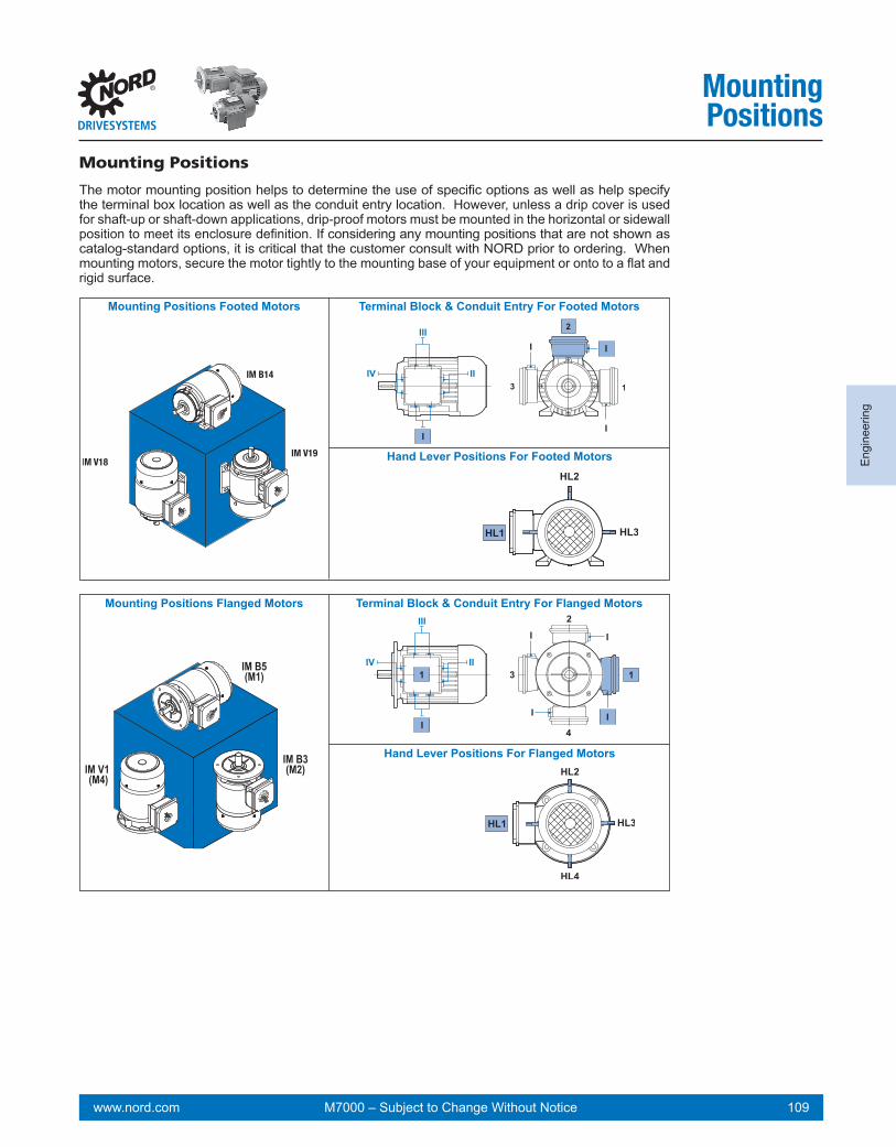
www.nord.com 109M7000 – Subject to Change Without Notice
Eng
inee
ring
MountingPositions
Mounting Positions
The motor mounting position helps to determine the use of specific options as well as help specify the terminal box location as well as the conduit entry location. However, unless a drip cover is used for shaft-up or shaft-down applications, drip-proof motors must be mounted in the horizontal or sidewall position to meet its enclosure definition. If considering any mounting positions that are not shown as catalog-standard options, it is critical that the customer consult with NORD prior to ordering. When mounting motors, secure the motor tightly to the mounting base of your equipment or onto to a flat and rigid surface.
Mounting Positions Footed Motors Terminal Block & Conduit Entry For Footed Motors
Hand Lever Positions For Footed Motors
IM V1 (M4)
IM B5(M1)
IM B3(M2)
Mounting Positions Flanged Motors Terminal Block & Conduit Entry For Flanged Motors
Hand Lever Positions For Flanged Motors

www.nord.com 110 M7000 – Subject to Change Without Notice
Engineering
Connection Diagrams
L3L1
V2 T5U2 T4W2 T6
high voltage
U1 T1 V1 T2
L2
W1 T3
Y
Y
V2 T5
W2 T6U2 T4
V5 T8U5 T7W5 T9
Ylow voltage
L1
L2
L3U1 T1 W1 T3
V5 T8U5 T7W5 T9
V1 T2
high voltage
low voltage
T1 T2 T3
T6 T4 T5
L1 L2 L3
T5V2
T3
T4T6
L3L2L1
W2 U2
T2T1
Y
W2 V2U2
W1V1U1
U1 V1 W1
WIRING DIAGRAM3 PHASE MOTOR
High Voltage
Low Voltage
T4
T1 T2 T3
T5 T6
T7 T8 T9
L1 L2 L3
T6
T9
T3
T5T4
L3L2L1
T7 T8
T2T1
Y
YY
NORD Frames 63-225230 / 460V, 60Hz, 3Ø 200 / 400V, 50Hz, 3Ø
NORD Mfg by Siemens - Frames 200+230 / 460V, 60Hz, 3Ø 200 / 400V, 50Hz, 3Ø190 / 380V, 60Hz, 3Ø
120094410
NORD Frames 63-225460 / 800V, 60Hz, 3Ø 230 / 400V, 50Hz, 3Ø208 / 360V, 60Hz, 3Ø 400 / 690V, 50Hz, 3Ø332 / 575V, 60Hz, 3Ø
NORD 2 - SPEED MOTORSSINGLE WINDING (4-2 & 8-4 POLE)
T42U
T52V
T62W
T1 1U T2 1V T3 1W
SIN
GLE
WIN
DIN
G2
- SPE
ED M
OTO
RS
T42U
T52V
T62W
T1 1U T2 1V T3 1W
HIGH SPEED
LOW SPEED
L1 L2 L3
L1 L2 L3Customer SuppliedStarter Contacts
NORD 2 - SPEED MOTORSDUAL WINDING (8-2 POLE)
T42U
T52V
T62W
HIGH SPEEDT11U
T21V
T31W
T42U
T52V
T62W
LOW SPEEDT11U
T21V
T31W
DU
AL W
IND
ING
2 - S
PEED
MO
TOR
S
L1 L2 L3
L1 L2 L3
“TF” OPTIONTHERMISTOR
“TW” OPTIONTHERMISTATS
“SH” OPTIONSPACE HEATER
“FC” OPTIONBLOWER COOLING FAN
“F” OPTIONBLOWER COOLING FAN
120095450120095250
120095240120095230
120095220
FROM MOTORWIRETERMINATION
TOCONTROLDEVICE
* MAX. OPERATING VOLTAGE 2.5V.* SWITCH TEMP. 155°C* RESPONSE TIME < 5 SECONDS
FROM MOTORWIRETERMINATION
TOCONTROLDEVICE
* NC (NORMALLY CLOSED)* CONTACTS RATED 1.6A AT 2.50 VAC* 6-500 VAC RANGE* AUTOMATIC RESET AT 30 ± 15°C TEMP. DROP
FROM MOTORWIRETERMINATION
TOCONTROLDEVICE
* CAPACITOR IS SUPPLIED
1 PHASE115V*50/60 Hz
* CAPACITOR IS SUPPLIED
230V50 / 60 Hz
OPTION “F” 1 PH OPTION “F” 3 PH
380-575V50 / 60 Hz
220-332V50 / 60 Hz
NORD Mfg by Siemens - Frames 200+230 / 460V, 60Hz, 3Ø 200 / 400V, 50Hz, 3Ø190 / 380V, 60Hz, 3Ø
WIRING DIAGRAM3 PHASE MOTOR
WIRING DIAGRAM3 PHASE MOTOR
T1 (U1)T2 (V1)
L2
T3 (W1)
T5 (V2)
T6 (W2)
T4 (U2)
T8 (V3)
T7 (U3)
T9 (W3)
T1 (U1) T3 (W1)T2 (V1)
T6 (W2)
T4 (U2)
T5 (V2)
T9 (W3)
T7 (U3)
T8 (V3)
YY
Y
L1 L3
L1 L2 L3
*JUMPER WIRES NEEDED
WIRING DIAGRAM3 PHASE MOTOR
high voltage
low voltage
Motor Connection Diagrams

www.nord.com 111M7000 – Subject to Change Without Notice
Eng
inee
ring
ConnectionDiagrams
Single Phase Motor Connection Diagrams
U2
U1
N
W2 U2 V2
U1L1
CB
CBV1 W1
W2 V2
V1 W1L1 N
L1
Z1 U2 Z2
U1
Z2
U1 CB
CB
2 3
4
CA
2 3
4
CA
N
SINGLE PHASEMOTOR EHB1
Clockwise
Counter Clockwise
Motor Frame Sizes 63-90230V, 50Hz, 1Ø
L1
N
Z1 U2 Z2
U1 CB
Z1 U2 Z2
U1 CBL1
N
Motor Frame Sizes 63-90230V, 50Hz, 1Ø
SINGLE PHASE MOTOREAR1
Clockwise
Starting Relay
Counter Clockwise
Starting RelayL1
N
SINGLE PHASEMOTOR - EST
Clockwise
Counter Clockwise
Motor Frame Sizes 63-90230V, 50Hz, 1Ø
SINGLE PHASE MOTOR WITH STANDARD RELAYECR - NEMA 115/230V
Motor Frame Sizes 63-90115 / 230, 60Hz, 1Ø
Clockwise Low Voltage
2 3
4
L1N
CA
CB
T4 T5 T1
T9
T2 T7 T6
T8 T3STARTING RELAY
2 3
4
L1N
CA
CB
T4 T5 T1
T9
T2 T7 T6
T8 T3
Clockwise High Voltage Counter Clockwise Low Voltage Counter Clockwise High Voltage
T4 T5 T1
T9
2 3
4
L1N
T2 T7 T6CA
CB
T8 T3
2 3
4
L1N
CA
CB
T4 T5 T1
T9
T2 T7 T6
T8 T3STARTING RELAY STARTING RELAY
SINGLE PHASE MOTOR WITH SINPAC RELAYECR - NEMA 115/230V
Clockwise Low Voltage Clockwise High Voltage Counter Clockwise Low Voltage Counter Clockwise High Voltage
Motor Frame Sizes 63-90115 / 230, 60Hz, 1Ø
08506980
L1N L1N L1N L1N

www.nord.com 112 M7000 – Subject to Change Without Notice
Engineering
Notes

www.nord.com 113M7000 – Subject to Change Without Notice
Motor Options Overview ................................................................................................. 114Thermal Options .............................................................................................................. 115Single Phase Motor Options ........................................................................................... 117Environmental Protection ............................................................................................... 118Motor Connection Options .............................................................................................124Encoder Options ..............................................................................................................126
Options

www.nord.com 114 M7000 – Subject to Change Without Notice
Options
Motor Options & ConstructionNORD motors are stocked in one of two ways. The first method is to stock a complete motor that is ready to be assembled to a gear reducer or shipped as a stand alone motor. The second method, the motor is assembled from component parts. The next to a motor option designates that the option can be added to a complete motor by simple modification. The next to a motor option indicates that the motor will need to be built from component parts in order to incorporate the motor option.
Motor OptionsAbbreviation Description Page
AG Absolute Encoder 129
AICM Additional Insulation 119
ECR Single Phase Motors, 60Hz 117
EKK Small Terminal Box 120
EP Epoxy Dipped Windings 119
F Blower Cooling Fan 122
FC Blower Cooling Fan 122
HR Hand Wheel 120
IG...P Incremental Encoder 128
ISO H Class H Insulation 116
KB Condensation Drain Holes - Plugged 118
KBO Condensation Drain Holes - Open 118
KKV Terminal Box Sealed with Resin 119
MG Magnetic Encoder 127
MS Quick Power Plug Connector 124
OL Totally Enclosed Non-Ventilated 120
OL/H Totally Enclosed Non Ventilated without Fan Cover 120
RD Canopy Drip Cover 119
RDD Double Fan Cover 119
RLS Motor Backstop 121
RS Round Motor Power Connectors 125
SH Space Heater 116
TF Thermistor 116
TW Thermostat 115
WE 2nd Shaft Extension on Fan Side 120
WU High Resistance Rotor 115
Z High Inertia Cast Iron Fan 121
- IP65 Enclosure Protection 119
- IP66 Enclosure Protection 119
- Paint Coatings 118
- Pre-Fabricated Motor Power Cable 125
MotorOptions

www.nord.com 115M7000 – Subject to Change Without Notice
Opt
ions
MotorOptions
Motor Overload ProtectionSelecting appropriate motor protection is a key factor in reliable motor operation. There are two com-mon classes of motor protection; current based and temperature based. Electrical installation codes require at least two types of protection in the motor circuit, both of which are normally current based. First is short-circuit protection, normally accomplished by fuses or circuit breakers. The Second is “mo-tor overload protection” and is normally a device called a “motor overload” or a “heater.” Current based protection is effective in some conditions. NORD can provide two different types of motor temperature based protection, a PTC thermistor (TF) or a bi-metallic thermostat (TW). Temperature based protec-tion is more effective motor protection in many situations, this is explained in the table below.
= Good protection ÅÆ = Limited protection = No protection
Fuses Motor Overloads
PTC Thermistor (TF)
Thermostat (TW & 2TW)
Over current up to 200% High inertia starting ÅÆ ÅÆFrequent motor starts ÅÆ Stalling ÅÆ ÅÆ ÅÆ ÅÆSingle phasing ÅÆ Supply voltage deviations Supply frequency deviations Inadequate motor cooling Bearing Damage
Thermostats (TW & 2TW) Motor thermostats or bi-metallic switches can be wired directly into the control circuit without a separate control module or tripping device. Thermostats operate on a relatively high control voltage so they are much less sensitive to voltage interference from the main power supply. One may often run thermostat leads and motor power leads next to each other when using the appropriate shielded cable. The in-staller is responsible for wiring the thermostats onto the motor control circuit. The leads may be labeled in a variety of ways as indicated.
Thermostat Standard connection Series connected, one per phaseContact NC (Normally Closed)/ Auto Re-settingResponse Temperature (Option TW) 311 °F (155 °C) Shut-Off DeviceResponse Temperature (Option 2TW) 311 °F (155 °C) Shut-Off Device + 266°F (130 °C) Alarm DeviceNominal Current 1.6 Amp at 250 VResistance < 50 mΩSwitch Rebound < 1msInsulation Rating 2000 VACCycles 10,000 maxLead Identification (inside terminal box) P1 and P2 or TB1 and TB2 / 2TB1 and 2TB2
WARNING
n Thermostats and Thermistors will automatically reset.n All wiring must be completed by qualified personal and adhere to all local installation codes.

www.nord.com 116 M7000 – Subject to Change Without Notice
Options
Thermistors (TF) With a separate control module or tripping device (ex. Kirwan INT69) thermistors are used to sense overload and temperature conditions by converting the critical operating temperature limit into inter-nal resistance changes. However many variable frequency drives are available to accept thermistors without requiring the seperate contol module. Due to their small size, heat sink construction, and high change in resistance value, minor resistance variations caused by relatively long lead runs may be tolerated. This feature also allows for one controller to be used for several temperature sensing loca-tions. Many variable frequency drives come with on-board thermistor inputs. NORD does not supply the thermistor control module. Thermistor Standard Connection Three devices, series connected, one per phaseType Positive temperature coefficient (PTC)Transition Temperature 150°C±5 °CResistance 20… 500Ω (below transition) or > 4 kΩ (above transition)Reed Current < 1mAMax Voltage 30VLead Identification(inside terminal box) P1 and P2 or TP1 and TP2
WARNING
n Thermostats and Thermistors will automatically reset.n All wiring must be completed by qualified personal and adhere to all local installation codes.
Space Heater (SH) Motors subject to extreme temperature fluctuations, severe climatic conditions or repeated heating or cooling cycles can be damaged by the formation of condensation. NORD can provide an anti-conden-sation space heater inside the motor to heat up the windings when the motor is not operating. This will prevent moisture from forming inside the motor. Space heaters are recommended when motors are installed in very damp or wet locations or where condensation is likely. The space heaters must not be switched on while the motor is running.
Space Heater Voltage Must Be Specified
? 115V – 50/60Hz 230V – 50/60Hz 460V – 50/60Hz other voltages available on request
Class H Insulation (ISO H) NORD motors can be manufactured with a class H insulation system. Standard NORD motors include double coated magnetic wire windings. When these windings are paired with a class H insulation it provides extra temperature capacity for the motor and will increase the motor’s life. Class H insulation rated motors are also an advantage in some severe applications such as:■ Increased ambient temperature installations above 40°C (104°F)■ Increased elevation installations – above 3300 ft (1000 m)■ Applications with a high number of starts per hour.■ A lower operating frequency such as when used with an AC vector drive■ For additional information on insulation class see page 96.
High Resistance Rotor (WU) Using Silumin rotor material, NORD offers a high resistance rotor to soften the motors operation and allow higher overload torques. Generally used in conveyor applications without an AC Vector Drive.
IMPORTANT NOTENot available with energy efficient (EE/IE2) or premium efficient (PE/IE3) motors.
MotorOptions

www.nord.com 117M7000 – Subject to Change Without Notice
Opt
ions
MotorOptions
Single Phase Motors, 60Hz (ECR) The ECR series single phase motor is intended for demanding operation on a 60 Hz power supply. The permissible voltage is ether 115V +/-10% or 230V+/-10%. The ECR motors contain both a run-capacitor as well as an additional start-capacitor which is switched off after start-up. The ECR motor is suitable for applications which demand higher starting torque and generally they have a 1.35 SF if the operated within the allowable voltage range (page 186).
Single Phase Motors, 50Hz (EHB, EAR, EST) EHB1 Motors
The EHB1 series motor is a single capacitor motor intended for operation on a 50 Hz power supply. The permissible voltage range is 220-240V. The EHB1 motor is most suited for simple demands and applications where there is no appreciable difference in the start-up and operational load. (page 203).
EAR1 Motors
The EAR1 series motor is single phase motor intended for more demanding operation on a 50 Hz power supply. The permissible voltage range is 220-240V. The EAR1 motors contain both a run-capacitor as well as an additional start-capacitor which is switched off after start-up and they are suitable for applications which demand higher starting torque (page "230V - 50Hz Single Phase" on page 204).
EST Motors
The EST series motor is a more cost-effective 50 Hz single phase motor variant that is construct-ed from a common three-phase motor winding which is operated with a single operating capacitor connected in a Steinmetz circuit. The permissible voltage range is 220-240V. The EST motor is most suited for simple demands and applications where there is no appreciable difference in the start-up and operational load (Page 205).

www.nord.com 118 M7000 – Subject to Change Without Notice
Options
MotorOptions
Paint Coatings, Surface Conversion, and Motor Surfaces NORD’s standard paint coating is a two component, aliphatic polyurethane finish contaning 316 stainless steel material. This gray stainless steel paint has excellent appearance and outstanding physical properties. It is suitable for both indoor and outdoor applications..
Paint free design Motors (63 frame - 200 frame motors)Our 63 to 200 frame motor housings are made from corrosion resistant die-cast aluminum alloy and feature a smooth body design. The smooth aluminum alloy surfaces have natural corrosion protection; therefore paint coatings are not required. Paint coatings may optionally be applied.
Cast Iron Motors (225 and larger frame motors)The 225 frame and larger motor housings are made from class 35 gray cast iron and are painted with NORD’s stainless steel paint. Additionally a variety of coating options are available including our severe duty coatings.
Improved corrosion protection for wet and outdoor environments starts by applying a primer undercoat over the primed cast-iron or base aluminum materials. The finish is then completed with our excep-tional strength stainless steel polyurethane top coat.
For more demanding environments our multi-layer corrosion protection starts with a primer undercoat over the base material and then adding our stainless steel polyurethane coating and a high-gloss topcoat.
Condensation Drain Holes NORD motors can be equipped with condensation drain holes. These drain holes are placed in the motor endbells at the lowest possible point. The drain holes are closed at the factory with plastic snap in plugs. They allow for condensation accumulation in the motor to drain after the closing plugs are removed.
The motor drain holes can be provided by NORD either open (KBO) or sealed with a closing plug (KB).
IMPORTANT NOTEThe motor must be installed in the mounting orientation specified on the nameplate or the drain holes will not function properly and may result with the motor filling with water.
Condensation Drain Holes, Plugged (KB) KB drain holes are plugged for shipment. In order for the holes to effectively drain moisture, the plugs must be removed before using the motor.
Condensation Drain Holes, Open (KBO) KBO drain holes are shipped open (not plugged).
NSD+ on Aluminum
NSDX3 on Cast Iron
NSD+ on Cast Iron
NSDX3 on Aluminum

www.nord.com 119M7000 – Subject to Change Without Notice
Opt
ions
MotorOptions
IP65 Enclosure Protection NORD motors can be provided with an IP65 enclosure protection. IP65 protection is suitable for wet, low-pressure wash down and extremely dusty environments.
IP 1 st digit - Foreign body protection IP 2nd digit - Water protection6 Dust tight 5 Protection against water jets
IP66 Enclosure Protection NORD motors can be provided with an IP66 enclosure protection. IP66 protection is suitable for wet, high-pressure wash down and extremely dusty environments, and includes all requirements included in IP65 enclosure protection.
IP 1 st digit - Foreign body protection IP 2nd digit - Water protection6 Dust tight 6 Protection against high pressure water jets
Terminal Box Sealed with Resin (KKV) Terminal boxes may be sealed with a flexible, electrically safe resin to ensure that contaminants, water, and moisture cannot pass through the terminal box into the stator body. This option is helpful in extremely dusty, wet and humid environments. Another environment where this option is helpful is in installations that have frequent large temperature swings where condensation may form.
For extreme wet environments it is possible to fill the terminal box full of resin. In these instances the motor must be supplied with a quick disconnect plug pre-wired for the proper voltage.
Additional Insulation (AICM) NORD can provide additional insulation inside the motor to provide additional electrical protection in extremely wet or corrosive environments. An electrically safe insulating material is applied internally in order to coat the stator windings and the rotor body.
Epoxy Dipped Windings (EP) In extremely wet environments, the motor windings are dipped in epoxy for improved moisture protec-tion. The motor can also be treated with a variety of protective coatings including NSD+ or NSDx3 for an even higher degree of protection.
Canopy Drip Cover (RD) For wet or dirty installations where the fan end of the motor is mounted up, NORD offers a canopy drip cover to block this falling water or debris, thus forcing water or debris to repel from the motor’s fan guard, .
Double Fan Cover (RDD) For wet or dirty installations where the fan end of the motor is mounted up, the NORD Double Fan Cover provides protection against falling or wind blown water, snow, dirt or debris from entering the back of the motor.

www.nord.com 120 M7000 – Subject to Change Without Notice
Options
MotorOptions
Totally Enclosed Non-Ventilated (OL) NORD can provide totally enclosed non-ventilated (TENV) motor enclosure. TENV motors provide benefits in certain operating environments; such as extremely dusty or dirty applications, where cooling fans may have material accumulation, which can be detrimental to the motor and the application. The OL series of motors are the standard fan cooled motor construction including the fan cover, but provided without the fan. TENV motors can also be used to reduce cooling fan noise on a standard motor.
A TENV motor requires either a larger motor frame size or a reduced power rating must be applied to the standard frame. A standard motor frame size can be allowed to operate as a TENV motor at full rated power provided that the duty cycle is intermittant at 50% ED or less.
Totally Enclosed Non-Ventilated, without Fan Cover (OL/H) The OL/H series of TENV motors are more compact in space than the OL series. They do not include the rotor shaft extension through the back bearing end bell or the fan cover.
2nd Shaft Extension on Fan Side (WE) NORD can provide a second shaft extension on the fan side of the motor that protrudes through the fan cover. This extension can be used as a power take-off or to mount customer supplied devices such as encoders and tachometers.
The shaft extension can be provided on motors with and without brakes. The shaft extension can not be used on motors with blower fans (F) or (FC). For dimensions see pages 208 - 254.
Hand Wheel (HR) Motors can be supplied with a hand wheel that is located on the second shaft extension. The hand wheel can be used for manual operation during power outages, or for machine positioning setup. This option is offered on metric WE shafts only.
WARNINGThe customer is required to provide appropriate safety guarding for the rotating hand wheel.
Small Terminal Box (EKK) The motor terminal box can be provided as a smaller, one-piece terminal box design. This option is valid for standard motors 0.16 - 10 hp (frame size 63-132).
Motor Size LL (Square) AB AA (metric) AA (NPT)LL
AA
AB
63 2.95 3.94 M16 x 1.5 1/2" NPT
71 2.95 4.29 M16 x 1.5 1/2" NPT
80 2.95 4.88 M20 x 1.5 1/2" NPT
90 3.62 5.08 M20 x 1.5 1/2" NPT
100 3.62 5.51 M20 x 1.5 1/2" NPT
112 3.62 5.91 M20 x 1.5 1/2" NPT
132 4.09 6.85 M25 x 1.5 3/4" NPT
WARNINGWhen supplied with a brakemotor, the brake rectifier must be located outside of the terminal box.

www.nord.com 121M7000 – Subject to Change Without Notice
Opt
ions
MotorOptions
High Inertia Cast Iron Fan (Z) An optional cast iron motor cooling fan is available. This fan is used as a mechanical soft start and/or soft stop. This fan adds inertia to the motor. The high inertia fan can also be used for a flywheel effect to store mechanical energy. This can be helpful in smoothing rapid load changes. The cast iron fan replaces the standard plastic motor fan. The motor length is the same as a brakemotor.
Motor Frame Fan Inertia Jz [lb-ft2]
63 0.022171 0.047580 0.11490 0.238100 0.268112 0.565132 0.950
Motor Backstop (RLS) NORD can provide backstops on many motor frames. A backstop will prevent the motor from rotating in one direction. A common use is to prevent a motor from allowing a load to move backwards when power is removed. A motor brake is an alternative that may be used for this same purpose. A backstop adds additional length to the motor. For the motor length extension, see the table below.
Motor Size Backstop Torque[lb-in]
Minimum Speed[rpm]
80 1150 86090 1150 860100 1150 860112 3270 750132 3270 750160 7880 670180MX/LX 7880 670180 9120 630200 9120 630
The Allowable Rotation Direction Must Be Specified
? Clockwise - Looking at back of motor
Counter Clockwise - Looking at back of motor
For all motor dimensions please see pages 208 - 254.
CW
CCW
WARNINGThe backstop may become worn or damaged if speeds during normal motor operation do not exceed the backstop lift-off speed. Avoid using the backstop when the motor has greater than 4-poles or if the motor is operated on a frequency drive.
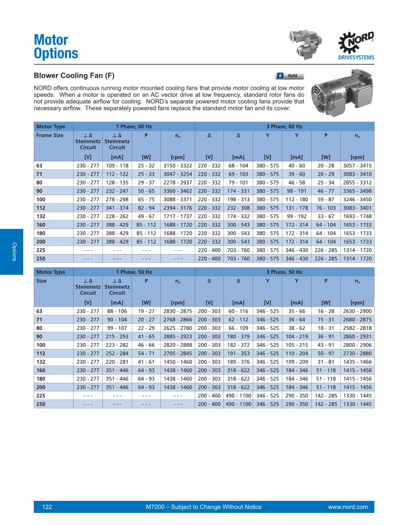
www.nord.com 122 M7000 – Subject to Change Without Notice
Options
MotorOptionsBlower Cooling Fan (F) NORD offers continuous running motor mounted cooling fans that provide motor cooling at low motor speeds. When a motor is operated on an AC vector drive at low frequency, standard rotor fans do not provide adequate airflow for cooling. NORD’s separate powered motor cooling fans provide that necessary airflow. These separately powered fans replace the standard motor fan and its cover.
Motor Type 1 Phase, 60 Hz 3 Phase, 60 Hz
Frame Size ┴ ∆Steinmetz
Circuit
┴ ∆Steinmetz
Circuit
P nn ∆ ∆ Y Y P nn
[V] [mA] [W] [rpm] [V] [mA] [V] [mA] [W] [rpm]
63 230 - 277 109 - 118 25 - 32 3150 - 3322 220 - 332 68 - 104 380 - 575 40 - 60 20 - 28 3057 - 3415
71 230 - 277 112 - 122 25 - 33 3047 - 3254 220 - 332 69 - 103 380 - 575 39 - 60 20 - 29 3083 - 3410
80 230 - 277 128 - 135 29 - 37 2278 - 2937 220 - 332 79 - 101 380 - 575 46 - 58 25 - 34 2855 - 3312
90 230 - 277 232 - 247 50 - 65 3360 - 3462 220 - 332 174 - 331 380 - 575 98 - 191 46 - 77 3365 - 3498
100 230 - 277 278 - 298 65 - 75 3088 - 3371 220 - 332 198 - 313 380 - 575 112 - 180 59 - 87 3246 - 3450
112 230 - 277 341 - 374 82 - 94 2394 - 3176 220 - 332 232 - 308 380 - 575 131 - 178 76 - 103 3083 - 3401
132 230 - 277 228 - 262 49 - 67 1717 - 1737 220 - 332 174 - 332 380 - 575 99 - 192 33 - 67 1693 - 1748
160 230 - 277 388 - 429 85 - 112 1688 - 1720 220 - 332 300 - 543 380 - 575 172 - 314 64 - 104 1653 - 1733
180 230 - 277 388 - 429 85 - 112 1688 - 1720 220 - 332 300 - 543 380 - 575 172 - 314 64 - 104 1653 - 1733
200 230 - 277 388 - 429 85 - 112 1688 - 1720 220 - 332 300 - 543 380 - 575 172 - 314 64 - 104 1653 - 1733
225 - - - - - - - - - - - - 220 - 400 703 - 760 380 - 575 346 - 430 226 - 285 1314 - 1720
250 - - - - - - - - - - - - 220 - 400 703 - 760 380 - 575 346 - 430 226 - 285 1314 - 1720
Motor Type 1 Phase, 50 Hz 3 Phase, 50 Hz
Size ┴ ∆Steinmetz
Circuit
┴ ∆Steinmetz
Circuit
P nn ∆ ∆ Y Y P nn
[V] [mA] [W] [rpm] [V] [mA] [V] [mA] [W] [rpm]
63 230 - 277 88 - 106 19 - 27 2830 - 2875 200 - 303 60 - 116 346 - 525 35 - 66 16 - 28 2630 - 2900
71 230 - 277 90 - 104 20 - 27 2768 - 2866 200 - 303 62 - 112 346 - 525 36 - 64 15 - 31 2680 - 2875
80 230 - 277 99 - 107 22 - 29 2625 - 2780 200 - 303 66 - 109 346 - 525 38 - 62 18 - 31 2582 - 2818
90 230 - 277 215 - 293 41 - 65 2885 - 2923 200 - 303 180 - 379 346 - 525 104 - 219 36 - 91 2860 - 2931
100 230 - 277 223 - 282 46 - 66 2820 - 2888 200 - 303 182 - 372 346 - 525 105 - 215 43 - 91 2800 - 2906
112 230 - 277 252 - 284 54 - 71 2705 - 2845 200 - 303 191 - 353 346 - 525 110 - 204 50 - 97 2730 - 2880
132 230 - 277 220 - 281 41 - 61 1450 - 1460 200 - 303 189 - 376 346 - 525 109 - 209 31 - 81 1435 - 1466
160 230 - 277 351 - 446 64 - 93 1438 - 1460 200 - 303 318 - 622 346 - 525 184 - 346 51 - 118 1415 - 1456
180 230 - 277 351 - 446 64 - 93 1438 - 1460 200 - 303 318 - 622 346 - 525 184 - 346 51 - 118 1415 - 1456
200 230 - 277 351 - 446 64 - 93 1438 - 1460 200 - 303 318 - 622 346 - 525 184 - 346 51 - 118 1415 - 1456
225 - - - - - - - - - - - - 200 - 400 490 - 1100 346 - 525 290 - 350 142 - 285 1330 - 1445
250 - - - - - - - - - - - - 200 - 400 490 - 1100 346 - 525 290 - 350 142 - 285 1330 - 1445

www.nord.com 123M7000 – Subject to Change Without Notice
Opt
ions
MotorOptions
Blower Cooling Fan (FC) NORD offers continuous running motor mounted cooling fans that provide motor cooling at low motor speeds. When a motor is operated on an AC vector drive at low frequency, standard rotor fans do not provide adequate airflow for cooling. NORD’s separate powered motor cooling fans provide that necessary airflow. These separately powered fans replace the standard motor fan and its cover.
Motor Type 1ph 115V 60 Hz 1ph 115V 50 Hz
Frame Size Voltage Current Power Voltage Current Power
[V] [A] [W] [V] [A] [W]Single Phase Connection - ⊥ (Delta)
63 100 – 135 0.23 42 100 – 135 0.3 4271 100 – 135 0.23 47 100 – 135 0.3 4480 100 – 135 0.27 57 100 – 135 0.3 4390 100 – 135 0.46 102 100 – 135 0.57 78100 100 – 135 0.53 105 100 – 135 0.54 78112 100 – 135 0.6 115 100 – 135 0.55 80
Wiring Diagrams for Blower Cooling Fans [F & FC]
Single phase operationSteinmetz circuit230V - 277V 50 + 60Hz
Three-phase operationDelta circuit 200V - 303V 50Hz220V - 332V 60Hz
Three-phase operationStar circuit Y 346V - 525V 50Hz380V - 575V 60Hz
Single phase operationSteinmetz circuit230V - 277V 50 + 60Hz
Three-phase operationDelta circuit 200V - 303V 50Hz220V - 332V 60Hz
Three-phase operationStar circuit Y 346V - 525V 50Hz380V - 575V 60Hz
Single phase operationSteinmetz circuit230V - 277V 50 + 60Hz
Three-phase operationDelta circuit 200V - 303V 50Hz220V - 332V 60Hz
Three-phase operationStar circuit Y 346V - 525V 50Hz380V - 575V 60Hz

www.nord.com 124 M7000 – Subject to Change Without Notice
Options
Motor Options
Quick Power Plug Connector (MS) The quick power plug connector (MS) is a simple and fast way to connect and disconnect a motor or brake motor. The MS connector is available on NORD three-phase motors from frame size 63 to 132. The motor connections are made by a modular power plug manfacturer by Harting. After the first instal-lation, the motor can be quickly changed by simply plugging and unplugging the electrical connections. This will ensure the new motor is properly wired. This is a significant advantage to equipment builders who fabricate machinery on site and then ship to another location. The motor with the MS connector can simply be plugged in during final installation.
NORD supplies the male connector half mounted on the motor conduit box. The customer must supply the female connector half mounted on the power wiring. NORD supplies a protective plastic cover on the motor male connector half to protect from dirt and damage prior to installation.
Quick Power Plug Connectors (MS)
Manufacturer Harting
ConnectorHAN 10 ES / HAN 10 ESS HAN 10 C-ModularCage Clamp Connectors Cage Clamp Connectors
Number of Pins 10-Male 9-MaleVoltage 600VAC per UL/CSA 690VAC per UL/CSACurrent 16A - Continuous 22A - Continuous
Advantages:nSimple motor wiring n Ideal for portable equipmentnAccurate wiring of motor at final job site n Faster motor changes reduce down timenAccurate wiring of replacement motor n Reduces required personnel for motor replacement
Quick Power Plug Connectors:Includes conduit box, mounting hardware & either of the two Harting motor plug options (MS). The power plug position must be specified when ordering.
P/N HAN 10 Plug Motor size P/N HAN 10 Plug Motor size11035350 10-Pin 63 + 71 16035350 10-Pin 11213035350 10-Pin 80 + 90 + 100 16335350 9-Pin 132
Power Plug Position Must Be Specified When ordering MS or kitted option
? I
II
III
IMPORTANT NOTEStandard configuration is : Terminal box - Position 1; MS Connector - Position II as shown above.

www.nord.com 125M7000 – Subject to Change Without Notice
Opt
ions
MotorOptions
Round Motor Power Connector (RS) NORD can provide a variety of motor power plug connectors that allow for a safe and quick connec-tion/disconnection of the motor’s main power supply. The following M23 plug options are stocked for NORD motors up to 5 HP and can be used with standard NORD AC motor and brake-motors ( pow-ered from the motor’s terminal block). The M23 plug provides three pins for line power and one pin for ground at the motor connection.
Technical DataNORD P/N 119555270 119555690Manufacturer Turck TurckType RSF46-0.3M/M20 RSF44-0.3M/M25Motor Interface M20 x 1.5 male thread M25 x 1.5 male threadCustomer Interface 7/8-16 UN male thread 7/8-16 UN male threadVoltage Rating 600V 600VCurrent Rating 10.0 A 15.0 APin Out 4-Pin Male 4-Pin Male
RS Connector Compatibility Motor Frame Terminal Box Thread Connector Part Number63-71 M20 11955527080-90 M25 119555690100-112 M32 119555690 + 18522326** M32 / M25 Adapter
Motor power plug connectors can reduce costs associated with drive installation and commission-ing time, help decreased labor costs compared to traditional conduit, and insure fast and accurate installation and change-out or replacement. The mating plug and chord set is typically supplied by the machine builder. Different motor power plug options can easily be configured by NORD to accom-modate accessories including brakes (requiring separate line power), thermal overload protection, space heaters, etc. It is possible to have more than one power plug adapter connected and wired to the motor’s terminal box.
Connector WiringMotor Terminal Marking Wire Color Number
1
2
4
3L1 (line power) Black 1L2 (line power) Red 3L3 (line power) White 2Ground Green 4
Pre-Fabricated Motor Power Cable NORD can provide Turck pre-fabricated motor power cables to mate with the M23 motor power plugs.
Pins Wire Size
Current Rating
Voltage Rating
Length Nord P/N Turck P/N
4 14 AWG 15 A 600 V 2 m 119555780 RKM 44-2M/S40005 m 119555790 RKM 44-5M/S400010 m 119555800 RKM 44-10M/S4000
Custom Order from Turck RKM 44-*M/S4000
Temperature rating: -40 to +105 ° C (-40 to +221 ° F)Protection rating: Meets IEC IP67 and NEMA 1, 3, 4, and 6P* indicates cable length in meters

www.nord.com 126 M7000 – Subject to Change Without Notice
Options
EncoderOptions
Encoder Overview In many of today’s drive applications encoders are needed when it necessary to monitor travel distance, position, or speed. Encoders use integrated electronics to convert sensor detected signals into a digital output format that is easily interfaced with programmable logic controllers (PLC’s) and computers.
NORD offers a variety of encoder solutions that will satisfy almost any application. NORD will also work closely with our customers to satisfy many specific encoder requirements or meet specifica-tions for a variety of protocols.
Incremental EncodersIncremental encoders can be used to monitor position or speed. Position is determined by counting pulses from a zero mark or home position. Speed or velocity data is generated by looking at the time interval between pulses or the number of pulses within a given time period
With incremental encoders it is necessary to reinitialize the system in order to return the system to the home position in the event of a power loss.
NORD offers two types of incremental encoders, magnetic and optical encoders.
Magnetic Encoders use a magnetized wheel spinning in relationship to a fixed magneto-resis-tive sensor. The wheel causes predictable responses in the sensor, based on the strength of the magnetic field.
n Magnetic Incremental Encoder (Page 127)
Optical Encoders use a spinning disk and a mask. The mask lets light pass through in predict-able patterns for interpretation by a photo-electric sensor. In both cases the sensor produces a digital output format that is easily interfaced by the PLC or computer.
n Optical Incremental Encoders (Page 128).
Types of Common Pulse Signals found in Incremental EncodersIncremental encoders can provide different pulse signals for each full rotation of the encoder.
Quadrature pulse signals are represented by two encoder output signals (A & B channel) phased 90° electrically apart; these signals help determine direction of rotation by monitoring the phase relationship between the two channels.
Differential signals are complimentary or mirror image [high (A & B) and low (A & B)] output signals that are generated in order to greatly reduce the encoder’s susceptibility to electrical in-terference or noise. When noise occurs during a given pulse, a mirror image does not result and that small portion of the total signal can be ignored.
A Marker Pulse or Index signal (Z channel) can be provided as one pulse per revolution signal for pulse count verification on the A and/or B channels. This pulse is sometimes used for error detection or re-homing the system after a power failure or fault condition.
Absolute Encoders [AG]Absolute encoders use a disc system with digital coding on concentric tracks. A unique pattern is assigned to every position. True position verification and reference to home is maintained offering optimal recovery from system and/or power failures. Absolute encoder’s also come in a variety of output protocols or interfaces. Additional incremental tracks are often specified to provide speed control along with accurate position monitoring.
n Absolute Encoders (Page 129). n Absolute Encoders for NORD Vector Drives (Page 130).

www.nord.com 127M7000 – Subject to Change Without Notice
Opt
ions
EncoderOptions
Magnetic-Incremental Encoder (MG) NORD offers a competitively priced magnetic encoder that is easily adaptable to the 63 to 180 frame NORD motors. The magnetic encoder utilizes a special screw installed to the motor’s rotor shaft in order to create a permanent rotating magnetic field.
A small [0.78 inch (20 mm)] sensor pick-up is mounted to the back of the motor fan shroud. The sensor converts the changing magnetic fields into HTL, push-pull output signals that can be read by a PLC or computer. Quadrature (2 channels, A and B) output signals are phased electrically apart by 90° in order to help determine the direction of rotation by monitoring the phase relationship between the two channels. Our design enables the encoder’s implementation near the vicinity of our electric brakes.
Advantagesn Cost effective, compact, and easy to mount (63– 180 frame motors).n Minimal dimensional change to back of motor (page 207).n Non-contacting measuring method using magnetics.n Accurate resolution, vibration and shock resistancy in order to increase durability.
Fan Cover
Motor Shaft withM6 or M8 thread
Magnetic Sensor
Fastening Plate
Rotating Magnetic Screw
Technical DataInterface HTL (push-pull) / QuadratureSupply Voltage 10-30 VDCCurrent 40 mA Max / < 30 mA (no load)Pulse Count 1 PPR, 32 PPR or 256 PPRSpeed Range 0-5000 rpmProtection Class IP 68Temp. -4 to 176ºF (-20 to 80ºC)
Wire Color Designation
Red (+) Supply VoltageBlack (-) Supply VoltageBrown Channel AOrange Channel BCable Size 0.19 in x 39 in LgWires 4Gauge 22 AWG
Pulse Count Connection Options (Supplier)01 = 1 PPR O = Open-end cable20 = 32 PPR M = M12 motor terminal box plug
(Lumberg Automation P/N RSFM4/0.5M)
45 = 256 PPR N = M12 male plug connector(Lumberg Automation P/N RSC4/9)
V = Coupling connector (18200999)(Phoenix Contact, Quickon P/N 1641879)
Connection Wiring
M12 Connectors (Option M or N)
Coupling Connector (Option V)
Pin Wire Color Pin Wire Color Designation1 Brown 1 Red (+) Supply Voltage
2 Black 2 Brown (-) Supply Voltage
3 White 3 Orange Channel A
4 Blue 4 Blue Channel B
Ordering Example
MG - 45 - M
Magnetic Encoder256 PPR (pulses per revolution)
M12 Connector Plug
Magnetic HTL encoder, with a 256 pulse count that is connected by a M12 connector plug
Encoder Type: MG - Pulse Count - Option

www.nord.com 128 M7000 – Subject to Change Without Notice
Options
EncoderOptions
Optical-Incremental Encoder (IG..P) NORD offers optical incremental encoders to monitor position or speed. These encoders are typically mounted to the back side of the electric motor shaft. Common interface logic types include: TTL, HTC and Line Driver. NORD will also work closely with our customers to provide specified encoder pulse counts or control logic.
Optical incremental encoders pass light from a light emitting diode (LED) through a partially masked rotating code disc onto a photo-electric receiver. The receiver converts light pulse signals into a square wave digital output format that is easily interfaced by programmable logic controllers (PLC’s) and computers.
With optical incremental encoders it is necessary to re-initialize the system and return the system to the home position in the event of power loss.
Advantagesn Quadrature, differential and marker pulse output signalsn Accurate resolution up to 5000 ppr.n Sturdy double bearing design offers high tolerance to shock and vibration.n Short-circuit proof outputs and reverse connection protection.n M12 (8-pin) male plug fixed to motor fan cover for easy wiring and adaptability.
NORD Encoder Type IG1 P IG2 P IG4 P IG11 P IG21 P IG41 P IG12 P IG22 P IG42 P IG13 P IG23 P IG43 PPart Number 19651500 19651510 19651520 19651502 19651512 19651522 19651501 19651511 19651521 19651503 19651513 19651523Interface TTL/RS422 (26C31) TTL/RS422 (26C31) HTL/Push-pull (IC-WE) Line Driver (7272)Pulse Count [PPR] 1024 2048 4096 1024 2048 4096 1024 2048 4096 1024 2048 4096Power Supply [VDC] 4-6 4-6 4-6 10-30 10-30 10-30 10-30 10-30 10-30 5-30 5-30 5-30Logic [VDC] 5 5 10-30 5-30Max Current Draw [mA] 100 150Max Frequency [kHz] 300Temperature Range -4°F to176°F (-20°C to 80°C)IP Rating IP67Cable M12 8-pin male plug
Length In-line Right-angleNORD P/N Turck P/N NORD P/N Turck P/N
2m 19551580 E-RKC 8T-264-2 19551584 E-WKC 8T-264-25m 19551581 E-RKC 8T-264-5 19551585 E-WKC 8T-264-510m 19551582 E-RKC 8T-264-10 19551586 E-WKC 8T-264-1015m 19551583 E-RKC 8T-264-15 19551587 E-WKC 8T-264-15Field Wireable Connector 19551588 CMB 8181-0 - -Custom order from Turck E-RKC 8T-264-* order from Turck E-WKC 8T-264-*
Pre-fabricated Encoder CablesNORD can provide Turck pre-fabricated encoder molded cordsets. (M12, 8-pin, shielded, twisted pair)
n The above encoder cables are provided with the shielding NOT connected thru the plug nut n Providing a conducting path thru the cable nut and attaching the shield to ground on both cable ends is a possible source of electrical noisen For applications where the cable requires a high degree of flexibility consult NORD or Turck.
Standard Motor with Encoder
Encoder withF Type Fan
Encoder withBrake Option
Brake Option, Blower Fan with Encoder
M12 Connector
21
7
65
4
3
8
1 2
3
4
5
6
7 8
Pin Color Signal1 0V WH2 +V BN3 A GN4 A\ YE5 B GY6 B\ PK7 Z BU8 Z\ RD

www.nord.com 129M7000 – Subject to Change Without Notice
Opt
ions
EncoderOptions
Absolute Encoder (AG) Absolute encoders do not lose position or home-position reference when power is removed. Absolute encoders provide a higher degree of safety than when using incremental encoders in applications where a loss of position could result in damage to the machinery or injury to the operator.
NORD absolute encoders are available with different data protocols or interfaces and many cases they can also be supplied with optional incremental tracks to provide accurate position and speed sensing feedback. We will also work closely with our customers to meet the specifications of the equipment builder or systems integrator.
NORD typically provides multi-turn absolute encoders mounted to the back side of the electric motor shaft. Multi-turn encoders provide turns counting in applications involving more than one revolution of the encoder shaft. Single-turn encoders can also be supplied and they are best suited for short travel, motion control applications where position verification is required within a single turn of the encoder shaft.
Kübler Absolute Encoders (AG)Kübler Type Kübler 8.F3683* Kübler 8.F3668* Kübler 8.5860 Kübler 8.5883Interface SSI or BiSS-C® CANopen® DeviceNet™ SSI or BiSS-C®
Supply Voltage 5 VDC or 10-30 VDC 10-30 VDC 10-30 VDC 5 VDC or 10-30 VDCSingle-turn Resolution 10, 12-14 & 17 bit 13 bit (default)
16 bit (max.)13 bit 10-14 & 17 bit
Multi-turn Resolution 12, 16 or 24 bit 12 bit 12 bit 12 bitIncremental Options TTL/RS 422 (2048 PPR) or
SinCos (2048 PPR)None None TTL/RS 422 (2048 PPR) or
SinCos (2048 PPR)Shaft Version Ø 8 mm hollow shaft Ø 8 x 14.5 mm blind
hollow shaftØ 12 x 30 mm blind
hollow shaftØ 12 mm hollow shaft
Temperature Range -40 to +194 ºF (-40 to +90 ºC)
-40 to +185 ºF(-40 to +85 ºC)
-4 to +176 ºF(-20 to +80 ºC)
-22 to +167 ºF(-30 to +75 ºC)
IP Rating IP 67 IP 67 IP 67 IP 67
Kübler Type Kübler 8.5888 Kübler 8.5888 Kübler 8.5888 Kübler 8.5888Interface CANopen® & EtherCAT® PROFIBUS® PROFINET®
Supply Voltage 10-30 VDC 10-30 VDC 10-30 VDC 10-30 VDCSingle-turn Resolution 13 bit (default)
16 bit (max.)13 bit (default) 16 bit (max.)
13 bit (default) 16 bit (max.)
13 bit (default) 16 bit (max.)
Multi-turn Resolution 12 bit 12 bit 12 bit 12 bitIncremental Options TTL/RS 422 (2048 PPR) None None NoneShaft Version Ø 12 mm
hollow shaftØ 12 x 30 mm
blind hollow shaftØ 12 x 30 mm
blind hollow shaftØ 12 x 30 mm
blind hollow shaftTemperature Range -22 to +167 ºF
(-30 to +75 ºC)-40 to +176 ºF (-40 to +80 ºC)
-40 to +176 ºF (-40 to +80 ºC)
-40 to +185 ºF (-40 to +85 ºC)
IP Rating IP 67 IP67 IP67 IP67
* Compact Encoder without Gears DeviceNet™ encoders are subject to magnet interference due to the hall-effect sensors used. Device specific CANopen® profile DS406 V3.2 is also available. CANopen® Lift© profile DS417 V1.1 is also available. Linedriver / RS485 is functionally integrated.
BiSS® is a registered trademark of iC-Haus GmbH.CANopen® is a registered trademark of the Controller Area Network (CAN) automation user’s group.CANopen® Lift© is copyright protected by the CAN in Automation (CiA) users group that specified the CANopen® application profile.DeviceNet™ is a trademark of the Open DeviceNet Vendor Association, Inc. (ODVA).EtherCAT® is a registered trademark of the EtherCat Technolgy Group (donated by Beckhoff Automation GmbH).EtherNET was a trademark of Xerox Corporation, which relinquished the trademark when it was standardized by 95 IEEE 802.3.PROFIBUS-DP® is a registered trademark of PROFIBUS User Organization and PROFIBUS International.PROFINET® is a registered trademark of PROFIBUS and PROFINET International (PI).

www.nord.com 130 M7000 – Subject to Change Without Notice
Options
EncoderOptions
Kübler Absolute Encoders (AG) - For NORD AC Vector Drives (Series 200E & 500E)Kübler Type(NORD P/N)
Kübler 8.5888 (19551883)
Kübler 8.5888 (19551891)
Kübler 8.5888 (19551881)
Kübler 8.5888 (19551886)
NORD AC VFD Type SK2xxE, SK53xE SK53xE SK53xE SK2xxEInterface CANopen® profile
DS406 V3.2 CANopen® profile
DS406 V3.2 CANopen® profile
DS406 V3.2 CANopen® profile
DS406 V3.2 Supply Voltage 10-30 VDC 10-30 VDC 10-30 VDC 10-30 VDCSingle-turn Resolution 13 bit (8192) 13 bit (8192) 13 bit (8192) 13 bit (8192)Multi-turn Resolution 12 bit (4096) 12 bit (4096) 12 bit (4096) 12 bit (4096)Node address/Baud rate (kbits/s)
51 / 125 (fixed/fixed)
51 / 125 (fixed/fixed)
51 / 125 (fixed/fixed)
33 / 250 (fixed/fixed)
Incremental Output None None TTL/RS 422 (2048 PPR) HTL/Push-Pull (2048 PPR)Shaft Version Ø 12 x 30 mm
blind hollow shaftØ 12 x 30 mm
blind hollow shaftØ 12 x 30 mm
blind hollow shaftØ 12 x 30 mm
blind hollow shaftTemperature Range -40 to +176 °F
(-40 to +80 °C)-22 to +167 °F (-30 to +75 °C)
-40 to +176 °F (-40 to +80 °C)
-40 to +176 °F (-40 to +80 °C)
IP Rating IP 67 IP 67 IP 67 IP 67Electrical Connection Removable Bus Cover
with Cable GlandsFixed Connection - (2m) Radial Cable
3 x M12 Connectors (Bus-in, TTL, Bus-out)
3 x M12 Connectors (Bus-in, HTL, Bus-out)
NORD AC Vector Drive Encoder CompatabilityNORD AC Vector Drive
Kübler Encoder Type(NORD Part Number)
Kübler 8.5888 (19551883)
Kübler 8.5888 (19551891)
Kübler 8.5888 (19551881)
Kübler 8.5888 (19551886)
SK530E SK200E SK210E SK220E SK230E SK205E SK215E SK225E SK235E
CANopen® profile DS406 V3.2 contains device specific add-ons to work with NORD AC Variable Frequency Drives Device specific CANopen® profile DS406 V3.2 is also available. CANopen® Lift© profile DS417 V1.1 is also available. Linedriver / RS485 is functionally integrated.
CANopen® is a registered trademark of the Controller Area Network (CAN) automation user's group
Absolute Encoder (AG) - For NORD AC Vector Drives Many NORD AC variable frequency drives have an on-board CANopen® interface allowing the user to implement vector-drive position control.
The encoders listed in the table below communicate using CANopen® profile DS406 V3.2; device specific add-ons allow parameterization of the absolute encoder directly from the NORD frequency inverter.
The table indicates which encoder options contain incremental tracks so that speed control can also be monitored.

www.nord.com 131M7000 – Subject to Change Without Notice
General Introduction ......................................................................................................132Brake Selection................................................................................................................133Brake Torque Selection ...................................................................................................134Brake Times and Electrical Selection ............................................................................136Brake Options ..................................................................................................................140Brake Rectifier Overview ................................................................................................145Stopping Methods ...........................................................................................................146Release Methods .............................................................................................................149Available Rectifiers .........................................................................................................150Standard Brake Components .........................................................................................157Performance Data ............................................................................................................158Calculations .....................................................................................................................159Connection Diagrams .....................................................................................................160
Brakes

www.nord.com 132 M7000 – Subject to Change Without Notice
Brakes
GeneralIntroduction
Motor Brake (Option BRE)The standard NORD motor brake is spring-set when power is removed from the BRE circuit (power-off). The brake coil utilizes a DC voltage supplied through a rectified power source.
AdvantagesnEach NORD motor frame size has a number of available brake sizes, each with different torque capacities.nBrake torque adjustments are possible by changing the brake spring combinations. In addition, brake sizes from 5-40 Nm (3.7-30 lb-ft) are typically supplied with an additional spanner-nut adjustment on the back of the brake.nNORD brakes provide a high degree of safety because when power is removed the brake will automatically set to hold the load.nThe brake rotor or brake disc is environmentally safe and asbestos-free.nThe connection between the rectifier and the brake coil is completed at the factory and the brake air-gap is factory-set but can be adjusted in the event of wear.
Basic Brake OperationThe standard NORD motor brake is “spring set”. When power is removed and the brake is de-en-ergized (power-off), the brake springs exert a force against the armature plate in turn preventing the brake rotor (or brake disc) from rotating. When the brake coil is energized (power-on), a magnetic field pulls the armature plate across the air gap to the brake casing, which releases the brake rotor and allows the motor shaft to rotate.
NORD brakes are DC voltage brakes and in most instances are supplied with a motor mounted brake rectifier for easy connections to AC power. AC power is taken directly form the power line or from the terminal block of the motor and converted to DC by the supplied rectifier.
IMPORTANT NOTEIf the motor is connected to a frequency inverter, soft start, or is a two-speed motor, the AC power must be supplied separately to the brake rectifier.

www.nord.com 133M7000 – Subject to Change Without Notice
Bra
kes
Brake Selection
Brake SelectionThe selection of a motor brake system is broken down into five phases. The selection of the braking torque, the selection of the braking times (release times and setting times), the selection of the electri-cal supply and connection, the selection of brake options, and the final phase is the verification of the permissible brake work.
Each NORD motor may be supplied with a number of brake torque sizes. Each brake may be adjusted to different brake torque values.
Selection steps1) Brake torque selection (page 134)2) Brake times & electrical selection (page 136)3) Electrical supply and connection (page 138 -page 139)4) Brake options (page 140)5) Brake work verification (page 159)

www.nord.com 134 M7000 – Subject to Change Without Notice
Brakes
Brake TorqueSelection
Brake Torque SelectionEach NORD motor size has a number of brake torque sizes available. The BRE value in the table below is the standard brake torque size for each motor.
Example for ordering: SK 32 - S/4 BRE10 (BRE 10 indicates a brake torque size of 10 Nm)
General Selection ConsiderationsNORD relies on the equipment builder to specify appropriate brake sizing for their application, while giving consideration to the following:
n For most applications, we advise sizing the brake to 1.5 - 2 times the motor rated torque.n For vertical applications, it may be advisable to size the brake size up to 3 times the motor rated torque.n For some applications, it may be necessary to specify a reduced brake torque setting to prevent excessive peak load conditions developed at the reducer output.n On travel drive applications, excessive brake torque may lead to wheel skid; in addition on crane applications excess hoist-cable swing can result.
Motor Size & Efficiency Brake Size and TorqueFrame SE PE BRE5 BRE10 BRE20 BRE40 BRE60 BRE100 BRE150 BRE250 BRE400 BRE800Size Nm 5 10 20 40 60 100 150 250 400 800
lb-in 44 89 177 354 531 885 1328 2213 3540 7080lb-ft 3.7 7.4 14.8 29.5 44.3 73.8 111 184 295 590
63 S/L - Std. Opt. * #71 S/L - Std. Opt. *80 S - Std. Opt. Opt. *80 L LP Opt. Std. Opt. *90 S SP Opt. Std. Opt.*90 L LP Opt. Std. Opt.*100 L LP Std. Opt. Opt. * #100 LA AP Opt. Std. Opt. * #112 M MP Opt. Opt. Std.132 S SP Std. Opt. Opt. *132 M MP Opt. Std. Opt. *132 MA - Opt. Opt. Std. *160 M MP Opt. Std. Opt.160 L LP Opt. Opt. Std.180 MX - Opt. Std.180 LX - Opt. Std.180 - MP Std. Opt.* #180 - LP Std. Opt.* #200 LX - Opt. Std.* #225 - RP Opt. Std.225 - SP Opt. Std.225 - MP Opt. Std.250 - WP Opt. Std.
Weightkg 2 3 5.5 7 10 16 22 32 50 53lb 4.4 6.6 12.1 15.4 22 35 49 71 110 117
Inertiakg-m2 x 10-3 0.015 0.045 0.153 0.45 0.86 1.22 2.85 6.65 19.5 39lb-ft2 x 10-3 0.356 1.068 3.63 10.68 20.4 29.0 67.6 158 463 926
* IP66 brake not possible 2) When used as a stopping brake, evaluation is essential. Std - Standard Offering# Manual brake release option not possible 3) Designed as a holding brake or emergency stop only. Opt - Optional Offering
CAUTIONBRE800 and BRE1200 brakes may only be controlled with a fast reaction rectifier (overexcitation), the maximum permissable nominal currents of the rectifier must be considered!

www.nord.com 135M7000 – Subject to Change Without Notice
Bra
kes
Brake TorqueSelection
Brake Torque Adjustment (ADJ)Brake torque adjustments are possible by changing the brake spring combinations or by removing springs.
Brake Torque Reduction - Spring Removal"Brake Size" 7 Springs 5 Springs 3 Springs
[Nm] [lb-ft] [Nm] [lb-ft] [Nm] [lb-ft]BRE 5 5 3.7 3.5 2.6 2 1.5BRE10 10 7.4 7 5.2 4 3.0BRE20 20 14.8 14 10.3 8 5.9BRE40 40 29.5 28 20.7 17 12.5BRE60 60 44.3 43 31.7 26 19.2BRE100 100 73.8 70 51.6 42 31.0BRE150 150 111 107 78.9 65 47.9"Brake Size" 8 Springs 6 Springs 4 Springs
[Nm] [lb-ft] [Nm] [lb-ft] [Nm] [lb-ft]BRE250 250 184 187 138 125 92BRE400 400 295 300 221 200 148BRE800 800 590 600 442 400 295
When adjusting the brake torque, start by removing the outer springs at opposite corners to prevent uneven brake wear.
On brake sizes 5-150 Nm (3.7-111 lb-ft) full brake torque is achieved with all (7) springs. The brake springs are placed in such a manner where there are (3) inner and (4) outer springs.
On brake sizes 250-1200 Nm (184-885 lb-ft) full brake torque is achieved with all (8) springs. The brake springs are placed in such a manner where there are (4) inner and (4) outer springs.Spanner Nut Adjustment
Spanner Nut Adjustment“Brake Size" Torque Reduction* Max. Turns Minimum Torque
[Nm] [lb-ft] [Nm] [lb-ft]BRE 5 0.2 0.15 6 0.8 0.59BRE10 0.2 0.15 12 1.6 1.18BRE20 0.3 0.22 12 4.4 3.25BRE40 1 0.74 9 8.0 5.90
With the minimum number of springs and maximum number of turns to the spanner nut.
* Per each turn of the spanner nut
In addition, brake sizes from 5-40 Nm (3.7-30 lb-ft) are typically supplied with a threaded adjustment nut or spanner nut. Additional fine torque adjustment can be made by unscrewing the spanner nut a number of turns or “clicks” with a spanner wrench.
CAUTIONS
• Brake torque - The brake torque is measured with a mean friction radius of the brake pad surface with a circumferential speed of 1m/sec (197 fpm).• Brake torque tolerance - For different applications and operating conditions, brake torque can vary from +40/-20% compared to the rated brake torque.• Hoisting (lifting/lowering) applications - must have the brake wired for fast response (DC-switching) • Initial operation & wear-in period - In new condition,the brake will have a reduced torque of up to 30%. In order to achieve full rated brake torque, a short run-in period is required. The run in time will vary depending on system loads. • The brake rotor or brake pad - must be protected against foreign matter, oil and grease. Contaminants of this type can greatly influence wear and reduce breaking torque.

www.nord.com 136 M7000 – Subject to Change Without Notice
Brakes
Brake Times &Electrical Selection
Brake Times & Electrical SelectionBrake timing performance is critical in selecting the optimal brake system. NORD brakes can provide exceptional performance in terms of the release (start) times and engagement (stop) times. Use the following guidelines in order to select the correct brake control components and connections.
1) Determine if the brake needs to be wired directly from the motor terminal block or powered by a separate source.
n If you are using a AC vector drive, soft-start or a two- speed motor you will need to supply the rectifier from a seperate power source. n If the motor is powered direct across-the-line the rectifier power can be supplied from the motor’s terminal block.
2) What type of performance do I need?
n Is the standard brake performance OK?
n Is a higher performance required for fast brake release or very fast brake stopping?
3) Determine the brake supply voltage and check the rectifier compatibility table on page 138.

www.nord.com 137M7000 – Subject to Change Without Notice
Bra
kes
Brake Times &Electrical Selection
Selection SugestionsWhen Fast or Very Fast Stopping is Recommended
Any applications that require quick stops and positive action at stand-still, as well as all vertically mounted applications.
Recommended Applicationsn conveyors and inclined conveyorsn hoists and liftsn bulk material handling equipment (bucket elevators, idler conveyor’s)
When Fast-Release is Recommended (Overexcitation)
Any application that is very high-cycling with frequent starts and stops. These applications require the brake to release very-quickly in order to avoid excessive heat build-up in the AC motor and brake coil.
Recommended Applicationsn Index conveyorsn Divertersn Storage and retrieval crane systems
CAUTIONHoisting (lifting/lowering) applications - must have the brake wired for fast brake engagement.
PowerSource
Brake Release (start)
Brake engagement (stop)
Braking Method *
Rectifier
MotorTerminalBlock
Standard Standard (AC switching) 10 GVE/GHE/GUE
Standard Fast (DC switching) 15 GVE/GHE/GUE
Standard Very Fast (Reduced power holding) 40 GPE/PMG
Fast (Overexcitation) Standard (AC switching) 30 GPE/PMG
Fast (Overexcitation) Fast (DC switching) 35 GPE/PMG
SeparatePowerSource
Standard Standard (AC switching) 20 GVE/GHE/GUE
Standard Fast (DC switching) 25 GVE/GHE/GUE
Standard Very Fast (Reduced power holding) 55 GPU/PMG
Fast (Overexcitation) Standard (AC switching) 45 GPU/PMG
Fast (Overexcitation) Fast (DC switching) 50 GPU/PMG
* Braking methods referenced in connection diagrams on pages 160 - 170
Rectifier StylesGV - Full Wave Rectifier (Bridge) GPE - Hybrid Rectifier, Full wave then switches to half wave.GH - Half Wave Rectifier PMG - Hybrid Rectifier, Full wave then switches to half wave.GU - Combination Rectifier, can be connected full or half wave
GPU - Hybrid Rectifier, Full wave, then switches to half wave. Has integrated DC Switching via voltage sensing.

www.nord.com 138 M7000 – Subject to Change Without Notice
Brakes
ElectricalSelectionBrake Rectifier Compatability
BrakeVoltage (VAC)
Coil Voltage (VDC)
Braking Method
Rectifier Type
Rectifier P/N
BR
E 5
BR
E 10
BR
E 20
BR
E 40
BR
E 60
BR
E 100
BR
E 150
BR
E 250
BR
E 400
BR
E 800
115(105-120)
105 20 GVE20 19141000 X X X X X X X
105 25 GVE20 19141000 X X X X X X X
208(200-208)
105 10 GHE40 19141010 X X X X X X X
180 10 GVE20 19141000 X X X X X X X X X
105 15 GHE40 19141010 X X X X X X X
180 15 GVE20 19141000 X X X X X X X X X
105 20 GHE40 19141010 X X X X X X X
180 20 GVE20 19141000 X X X X X X X X X
105 25 GHE40 19141010 X X X X X X X
180 25 GVE20 19141000 X X X X X X X X X
105 30 GPE20 19140230 X X X X
105 30 PMG500 19140200 X X X X X X
105 35 GPE20 19140230 X X X X
105 35 PMG500 19140200 X X X X X X
180 40 GPE20 19140230 X X X X X X X
180 40 PMG500 19140200 X X X
105 45 GPU20 19140090 X X X X
105 45 PMG500 19140200 X X X X X X
105 50 GPU20 19140090 X X X X
105 50 PMG500 19140200 X X X X X X
180 55 GPU20 19140090 X X X X X X X
180 55 PMG500 19140200 X X X
230(220-240)
105 10 GHE40 19141010 X X X X X X X
205 10 GVE20 19141000 X X X X X X X X X
105 15 GHE40 19141010 X X X X X X X
205 15 GVE20 19141000 X X X X X X X X X
105 20 GHE40 19141010 X X X X X X X
205 20 GUE40V 19140300 X X X X X X X
205 20 GVE20 19141000 X X X X X X X X X
105 25 GHE40 19141010 X X X X X X X
205 25 GUE40V 19140300 X X X X X X X
205 25 GVE20 19141000 X X X X X X X X X
105 30 GPE20 19140230 X X X X
105 30 PMG500 19140200 X X X X X X
105 35 GPE20 19140230 X X X X X X X
105 35 PMG500 19140200 X X X
205 40 GPE20 19140230 X X X X X X X
205 40 PMG500 19140200 X X X
105 45 GPU20 19140090 X X X X
105 45 PMG500 19140200 X X X X X X
105 50 GPU20 19140090 X X X X
105 50 PMG500 19140200 X X X X X X
205 55 GPU20 19140090 X X X X X X X
205 55 PMG500 19140200 X X X

www.nord.com 139M7000 – Subject to Change Without Notice
Bra
kes
ElectricalSelection
Brake Rectifier Compatability
BrakeVoltage (VAC)
Coil Voltage (VDC)
Braking Method
Rectifier Type
Rectifier P/N
BR
E 5
BR
E 10
BR
E 20
BR
E 40
BR
E 60
BR
E 100
BR
E 150
BR
E 250
BR
E 400
BR
E 800
332 180 30 GPE40 19140240 X X X X X X X
180 30 PMG500 19140200 X X X
180 35 GPE40 19140240 X X X X X X X
180 35 PMG500 19140200 X X X
180 45 GPU40 19140170 X X X X X X X
180 50 GPU40 19140170 X X X X X X X
400(380-415)
180 10 GHE40 19141010 X X X X X X X X X
180 15 GHE40 19141010 X X X X X X X X X
180 20 GHE40 19141010 X X X X X X X X X
180 25 GHE40 19141010 X X X X X X X X X
180 30 GPE40 19140240 X X X X X X X
180 30 PMG500 19140200 X X X
180 35 GPE40 19140240 X X X X X X X
180 35 PMG500 19140200 X X X
180 45 GPU40 19140090 X X X X X X X
180 45 PMG500 19140200 X X X
180 50 GPU40 19140090 X X X X X X X
180 50 PMG500 19140200 X X X
460(440-480)
205 10 GHE40 19141010 X X X X X X X X X
205 15 GHE40 19141010 X X X X X X X X X
205 20 GHE40 19141010 X X X X X X X X X
205 20 GUE40V 19140300 X X X X X X X
205 25 GHE40 19141010 X X X X X X X X X
205 25 GUE40V 19140300 X X X X X X X
205 30 GPE40 19140240 X X X X X X X
205 30 PMG500 19140200 X X X
205 35 GPE40 19140240 X X X X X X X
205 35 PMG500 19140200 X X X
205 45 GPU40 19140170 X X X X X X X
205 45 PMG500 19140200 X X X
205 50 GPU40 19140170 X X X X X X X
205 50 PMG500 19140200 X X X
575(550-600)
250 10 GHE50 19141020 X X X X X X X X X
250 15 GHE50 19141020 X X X X X X X X X
250 20 GHE50 19141020 X X X X X X X X X
250 25 GHE50 19141020 X X X X X X X X X

www.nord.com 140 M7000 – Subject to Change Without Notice
Brakes
BrakeOptions
Brake Nomenclature BRE – –
Brake
Brake Size/Torque Rating
Additional Brake Options
Ordering Examples BRE 100 HL RG IR
Brake
100 Nm Brake Torque
Hand Release Lever
Corrosion Protected Brake
Current Sensing Relay
Brake, 100 Nm with a hand release lever, corrosion protected brake, and a current sensing relay.
BRE 40 FHL SR
Brake
40 Nm Brake Torque
Locking Hand Release Lever
Dust & Corrosion Prot. Brake
Brake, 40 Nm with a locking hand release lever and dust & corrosion protected brake.
Brake OptionsAbbreviation Description Page
ADJ Torque Adjustment - Brake torque may be adjusted at the factory 135DBR Double Brake (2xBRE) - Double brakes are used for redundancy and additional safety 144FHL Locking Hand Release Lever - Lockable manual hand release lever 141HL Hand Release Lever - Manual hand release lever 141HLH Hand Release Lever with Hole - Hand lever with 5.5 mm hole 141IP66 IP66 Brake Enclosure - Brake with IP66 enclosure 141IR Current Sensing Relay - Fast brake engagement (stopping) without external control equipment 143MIK Micro-Switch - Brake fitted with a micro-switch for sensing the brake state (released or engaged) 142NRB1 Quiet Brake Release - An o-ring is placed between the coil body and the armature plate for noise reduction 142
NRB2 Quiet Brake Motor Operation - An o-ring is placed between the carrier hub & the armature plate to prevent clattering. 142
RG Corrosion Protected Brake - Corrosion protected brake 141SR Dust & Corrosion Protected Brake - Dust & corrosion protected brake 141
Rectifier OptionsAbbreviation Description Page
Rectifiers Most NORD brakes are provided with a rectifier that converts AC voltage to DC voltage. Rectifiers are used because most motors are AC powered, but brakes require DC power. 145
GHE Half Wave Rectifiers 151GPE Push Hybrid Rectifiers - External DC Switching 153GPU Push Hybrid Rectifiers - Integrated DC Switching 155GUE Dual Rectifier - Full/Half-Wave 152GVE Full Wave Rectifiers 150PMG Push Hybrid Rectifier - Integrated DC Switching 154EBGR Digital Input Dual Wave Rectifier 156

www.nord.com 141M7000 – Subject to Change Without Notice
Bra
kes
BrakeOptions
Hand Release Lever (HL) The hand release option allows the brake to be manually released without requiring that the brake be energized with voltage. The lever has a spring return that allows the brake to be hand released and returned automatically to its set position. The hand release lever can be unscrewed for easy removal.
Locking Hand Release Lever (FHL) This option allows the brake to be manually released and locked off without requiring voltage to the brake. The lock mechanism prevents the spring from returning the brake to a closed state without manual action by the user. The hand release lever can be unscrewed for easy removal.
Hand Release Lever With Hole (HLH) The hand release levers can be provided with a 5.5mm through hole. The hole can be used for attaching external pulling devices such as a cord to release the brake at a distance. This option is available for brake sizes BRE5 to BRE60.
Hand Release Lever Location is Required for HL, FHL and HLH Options
? Position 1
Position 1 Position 2 Position 3 Position 4
Position 2
Position 3
Position 4
Corrosion Protected Brake (RG) The brake is fitted with a stainless steel brake plate to provide additional corrosion protection in severe and wet environments.
Dust & Corrosion Protected Brake (SR) A rubber-sealing boot is installed on the brake to provide additional protection in dusty environ-ments. This feature includes the stainless steel brake plate (RG).
IP66 Brake Enclosure (IP66) A sealed brake with IP66 enclosure protection can also be provided. This brake has a different mechanical housing that provides a higher degree of protection against severe environments. Brake Heating Brakes can be provided with a number of different heating systems. Contact NORD to discuss the details of your application
Por Palanca de Liberación
Por Palanca de LiberaciónLiberación de manode mecanismo debloqueo
Hand Release Lever (HL) Locking Hand Release Lever (FHL)
Dust Boot
Stainless SteelBrake Plate

www.nord.com 142 M7000 – Subject to Change Without Notice
Brakes
Quiet Brake Release (NRB1) To reduce the noise of the brake release, an o-ring can be placed between the brake coil body and the armature plate (stationary disc). The o-ring dampens the impact caused by the armature plate hitting the brake coil body during the release process. When ordering NRB1, the SR (Dust Boot) option is required. The SR option also includes the RG stainless steel corrosion plate.
Quiet Brake Operation (NRB2) Noise due to vibration in the brake components is possible during motor operation particularly with variable frequency drive or single phase motor operation. To reduce this vibration the brake can be constructed with an o-ring between the brake carrier hub and the brake disc. This o-ring will prevent the clattering caused by the rapid micro speed changes in the motor caused by inverter or single phase operation.
Micro Switch (MIK) The micro switch monitors the release state of the brake and can be wired into external control circuitry to provide additional safety. The switch can also be used to detect certain brake service problems including excessive brake wear.
NRB1
Dust Boot (SR)Needed for NRB1
Corrosion Protection (RG)Included in SR
NRB2
BrakeOptions

www.nord.com 143M7000 – Subject to Change Without Notice
Bra
kes
Current Sensing Relay (IR)
The current sensing relay, is used to achieve a fast brake engagement (stopping) without the use of external control equipment or additional wiring. The relay is mounted directly on the conduit box, and is powered from the motor’s terminal block. The power leads for the relay replace one of the brass jumper bars on the terminal block of any single speed motor. The switch leads are connected to terminals 3 and 4 of the rectifier. When the power to the motor is shut off, the IR relay opens the brake circuit on the DC side which allows the brake to de-magnetize quickly.
CAUTIONSCurrent Sensing Relay Requirements
n Brake must be powered from the motor’s terminal block (not seperately powered)n Motor must be single speed and should not be powered by a frequency inverter or soft starter.
Part number 18556010 18556020Reissmann Part Number RSR 25-46 RSR 50-46Primary Current Rating (black/white wires) 25AAC 50 AAC
Maximum Primary Current (black/white wires) 75AAC 150 AAC
Maximum Time at Maximum Primary Current 0.2 s 0.2 sMaximum Cycles per hour 500 500Switching Voltage 42 - 550VDC 42 - 550VDC
Switching Current (red/blue wires) 1.0 ADC 1.0 ADC
Holding Current ˂ 0.7 AAC ˂ 0.7 AAC
Delay Time 18 ms 18 msEnclosure Rating IP65 IP65Ambient Temp. - 25 to 90 °C (- 40 to 167 °F) - 25 to 90 °C (- 40 to 167 °F) Relative to the distortion created by the magnetising current of the motor. Additional setting time delay added to the DC-setting time of the brake circuit.
IR Relay Wiring Diagram
REC
TIFICA
DO
RES
ADAPTER DE ROSCA
EL RELÉ
IR
Rectifier IR-Relay Wires to Rectifier
Model Type Part Number Design Red Blue
GVE20L 19141000 Full-wave 4 3
GHE40L 19141010 Half-wave 4 3
GHE50L 19141020 Half-wave 4 3
GPE20L 19140230 Push-hybrid 4 3
GPE40L 19140240 Push-hybrid 4 3
GUE40V 19140300 Dual Wave 4 3
Conduit Box Thread AdapterThread Motor Frame Part NumberM20 63-71 18542006*M25 80-90 18522253M32 100-132 18522320M40 160 18522400 + 18522253* Spacer
BrakeOptions

www.nord.com 144 M7000 – Subject to Change Without Notice
Brakes
Double Brakes (DBR) Some applications require two independent brakes to meet industry safety guidelines.
Double Brakes for Theatrical ApplicationsMany international standards for braking systems used on theatre hoists mandate the use of brakes that automatically set when power is removed. Redundancy is also required with the system brakes. If one brake fails, the other brake can still operate the system by running inde-pendently and parallel to each other. NORD DBR (2xBRE) brake systems are designed to meet these requirements. The NORD double brakes are also designed for quiet operation < 50dB(A).
Some safety standards require that the load brake hold 1.25 times the rated load at test. We recommend selecting the brake for approximately 1.6 to a maximum of 2.0 times the required operating torque for each brake.
The NORD double theatre brakes do not need to be worn-in and will achieve their full braking torque initially.
Two brake rectifiers are required for operating a double brake systems. These will be provided as loose parts and are normally mounted in the customers control panel.
The double brake option will add motor length compared to the single brake.
CAUTIONSNORD recommends delayed operation of one of the brakes. If the brakes are operated simultane-ously, the combined torques may result in excessive torque for the gear unit or other mechanical system elements. If the brakes are set at the same time even in an E-stop condition, the gear units must be sized to handle this increased torque.
Motor Brake 7 Springs 5 Springs 4 SpringsSE PE [Nm] [lb-ft] [Nm] [lb-ft] [Nm] [lb-ft]63S/L - DBR6 2 x 6 2 x 4.4 2 x 4 2 x 3 2 x 3.5 2 x 2.6
71S/L - DBR6 2 x 6 2 x 4.4 2 x 4 2 x 3 2 x 3.5 2 x 2.6
80S - DBR6 2 x 6 2 x 4.4 2 x 4 2 x 3 2 x 3.5 2 x 2.6
80L LP DBR12 2 x 12.5 2 x 9.2 2 x 8.5 2 x 6.3 2 x 7 2 x 5.2
90S SP DBR12 2 x 12.5 2 x 9.2 2 x 8.5 2 x 6.3 2 x 7 2 x 5.2
90L LP DBR25 2 x 25 2 x 18.4 2 x 17.5 2 x 12.9 2 x 14 2 x 10.3
100L LP DBR25 2 x 25 2 x 18.4 2 x 17.5 2 x 12.9 2 x 14 2 x 10.3
100LA/4 AP DBR50 2 x 50 2 x 37 2 x 35 2 x 26 2 x 28 2 x 20.7
112M - DBR50 2 x 50 2 x 37 2 x 35 2 x 26 2 x 28 2 x 20.7
- MP DBR75 2 x 75 2 x 55 2 x 52 2 x 38 2 x 42 2 x 31
132S SP DBR75 2 x 75 2 x 55 2 x 52 2 x 38 2 x 42 2 x 31
132M MP DBR125 2 x 125 2 x 92 2 x 89 2 x 66 2 x 70 2 x 52
160M MP DBR187 2 x 187 2 x 138 2 x 132 2 x 97 2 x 10⁷ 2 x 79
160L LP DBR187 2 x 187 2 x 138 2 x 132 2 x 97 2 x 10⁷ 2 x 79
180MX/LX MX/LX DBR300 2 x 300 2 x 221 2 x 225 2 x 166 2 x 150 2 x 111
200LX - DBR500 2 x 500 2 x 369 2 x 375 2 x 277 2 x 250 2 x 184
BrakeOptions

www.nord.com 145M7000 – Subject to Change Without Notice
Bra
kes
Brake RectifierOverview
Brake Control RectifiersNORD brake control rectifiers convert AC voltage to DC voltage. Rectifiers are used because in many instances AC voltage is used to power the motor, but DC voltage is required to power the brake, and DC power is not typically available. NORD brakemotors typically include a rectifier that is located inside the terminal box. NORD rectifiers can be powered by the motor terminal block, or by a separate power source.
Rectifier Advantagesn Individual power source for each brake.n Compact size, mounted inside the terminal box.n Multiple types, voltage options & release/engagement modes available.n Mountable in a separate control cabinet.n Integral protection against voltage spikes.
Rectifier ProtectionCoated Electronics (G...L)NORD standard rectifiers are provided with each brake motor (except 24 VDC brakes) unless a sealed or high performance rectifier is specified.Standard RectifiersNomenclature Part # Type ColorGVE20L 19141000 Full-wave BlackGHE40L 19141010 Half-wave YellowGHE50L 19141020 Half-wave Grey
Potted Electronics (G…V)
NORD offers rectifiers that are sealed with an electrically safe resin to ensure that water and moisture will not pass into the rectifier. Sealed rectifiers have the same brake performance ratings as the standard rectifier and can be beneficial if water is present in the motors terminal box.Sealed RectifiersNomenclature Part # Type ColorGVE20V 19141030 Full-wave BlackGHE40V 19141040 Half-wave YellowGHE50V 19141050 Half-wave GreyGUE40V 19140300 Full/Half-Wave Black
Rectifier TypesFull-wave rectifier: The DC output voltage is 90% of the applied input AC voltage.
Half-wave rectifier: The DC output voltage is 45% of the applied input AC voltage.
Dual Rectifier (Full/Half Wave): The GUE rectifier is a “dual” rectifier that is either a full-wave or a half-wave rectifier depending on how it is connected. An advantage for using this rectifier is when using it together with a 205 VDC brake coil, it is able to operate on either a 230 VAC or 460 VAC power connection.
Push-Hybrid rectifier (Full/Half Wave):These rectifiers are designed to switch from an initial full-wave mode to a final half-wave mode. They include GPE, GPU, and PMG rectifier types and are utilized to improve brake performance by providing faster stopping times or shorter brake release times.
Rectifier Terminals
Description
1, 1a, 1b & 2
Brake Supply AC Voltage
3 & 4 DC-Switching Contact or Jumper
5 & 6 Connection to Brake Coil
G H E 4 0 LElectronic ProtectionL = Varnish coatedV = Potted/ Resin Sealed
Components Current Rating0 = 0.5A (75°C)1 = 1.5A (75°C)
Voltage Range2 = up to 275VAC input4 = up to 480VAC input5 = up to 575VAC input
Type of DC SwitchingE = External DC-switching (contact)U = Internal DC-switching (voltage)
Type of RectifierH= Half-waveV = Full-wave (bridge)P = Push-Hybrid (full & half-wave)U = Combo (full & half-wave)
Rectifier
Rectifier Nomenclature

www.nord.com 146 M7000 – Subject to Change Without Notice
Brakes
Stopping Methods
Stopping MethodsNORD brake rectifiers have the ability to provide different stopping performance. The different performance is achieved by using a different rectifier and/or wiring the rectifier differently. The different methods include:
n Standard Stopping (AC Switching)n Fast Stopping (DC Switching)n Fast Stopping (DC Switching via Integrated Voltage Sensing)n Very Fast Stopping (Reduced Power Holding & DC Switching)n Very Fast Stopping (Reduced Power Holding & DC Switching via Integrated Voltage Sensing)
Standard Stopping (AC Switching)
The rectifier can be wired to operate by supplying and removing AC power, commonly called AC switching. The advantage to using AC switching is that the rectifier can be powered directly from the motor’s terminal block and no additional wiring is required. However, tapping into the motor’s terminal block gives the slower stopping time due to the de-energizing time of the motor’s magnetic field. The stopping time can be improved by wiring the rectifier from an external power supply.
Power Source
Brake Release (start)
Brake Engagement (stop)
Braking Method *
Rectifier
Motor Terminal Block
Standard Standard (AC switching) 10 GVE, GHE or GUE
Fast (Overexcitation) Standard (AC switching) 30 GPE or PMG 500
Seperate Power Source
Standard Standard (AC switching) 20 GVE, GHE or GUE
Fast (Overexcitation) Standard (AC switching) 45 GPU or PMG 500
* Braking methods referenced in connection diagrams on pages 160 - 170.
Fast Stopping (DC switching)
DC switching directly interrupts the current flow in the DC circuit of the rectifier. This provides much faster stopping, because you do not need to wait for the motor’s magnetic field to de-energize. To implement DC switching, a normally open relay must be installed between terminals 3 and 4 on the rectifier for rectifier types GVE, GHE, and GPE. For GPU type rectifiers simply remove the jumper between terminals 3 & 4 to activate DC switching.
Power Source
Brake Release (start)
Brake Engagement (stop)
Braking Method *
Rectifier
Motor Terminal Block
Standard Fast (DC switching) 15 GVE GHE or GUE
Fast (Overexcitation) Fast (DC switching) 35 GPE or PMG 500
Seperate Power Source
Standard Fast (DC switching) 25 GVE GHE or GUE
Fast (Overexcitation) Fast (DC switching) 50 GPU or PMG 500
* Braking methods referenced in connection diagrams on pages 160 - 170.
BRAKING METHOD
10 20or
BRAKING METHOD
10 20or
PMG 500
+
BRAKING METHOD
10 20or
H
P
GPU RECTIFIER
H
BRAKING METHOD
10 20or
BRAKING METHOD
10 20or
PMG 500
+
BRAKING METHOD
10 20or
H
P
GPU RECTIFIER
H
GPU
GVE/GHE/GPE
GVE RECTIFIER
AC BRAKEVOLTAGE
BRAKING METHOD
15 25or
GVE RECTIFIER
GHE RECTIFIER
GPE RECTIFIER
*
PMG 500
+
GPU RECTIFIER
GVE/GHE RECTIFIER
AC BRAKEVOLTAGE
BRAKING METHOD
15 25or
AC BRAKEVOLTAGE
*NORMALLY
OPEN CONTACT
AC BRAKEVOLTAGE
*NORMALLY
OPEN CONTACT
GVE/GHE/GPE
GVE RECTIFIER
AC BRAKEVOLTAGE
BRAKING METHOD
15 25or
GVE RECTIFIER
GHE RECTIFIER
GPE RECTIFIER
*
PMG 500
+
GPU RECTIFIER
GVE/GHE RECTIFIER
AC BRAKEVOLTAGE
BRAKING METHOD
15 25or
AC BRAKEVOLTAGE
*NORMALLY
OPEN CONTACT
AC BRAKEVOLTAGE
*NORMALLY
OPEN CONTACT

www.nord.com 147M7000 – Subject to Change Without Notice
Bra
kes
StoppingMethods
Fast Stopping (DC switching Via Integrated Voltage Sensing)
Our GPU rectifier’s integrate DC-Switching by sensing the AC voltage supplied to the rectifier. When no voltage is present the GPU rectifier automatically opens the DC circuit. The GPU rectifier is primarily designed for use with a separate brake power source, such as inverter powered motors, soft-start motors, and two-speed motors.
The GPU rectifier is primarily designed for use with a separate brake power source, such as inverter powered motors, soft-start motors, and two-speed motors.
Terminals 1 & 2 - Brake system connection to AC supply voltage
Terminals 3 & 4 - No jumper connectedTerminals 5 & 6 - DC Voltage connection to the
brake coil.
Power Source
Brake Release (start)
Brake engagement (stop)
Braking Method *
Rectifier
Seperate Power Source Fast (Overexcitation) Fast (DC switching) 50 GPU
* Braking methods referenced in connection diagrams on pages 160 - 170.
Very Fast Stopping (DC switching Via Reduced Power Holding)
In reduced power holding, the rectifier initially supplies the rated DC voltage to the brake coil. When voltage is first applied, the rectifier operates as a full-wave rectifier (90% of the applied AC voltage), releasing the brake in the standard time. After the brake is released, the rectifier switches to half-wave mode (45% of the applied DC voltage), weakening the brake’s magnetic field. The weaker field will allow the brake to stop more quickly when power is removed. In this method the brake coil is selected as if the brake system is powered by a full-wave rectifier. Therefore, the brake coil’s DC-voltage rating should be 90% of the AC voltage applied to the rectifier.
Terminals 1 & 2 - Brake system connection to AC supply voltage
Terminals 3 & 4 - Installed jumper for AC switching or switch contact (as shown) for DC switching
Terminals 5 & 6 - DC Voltage connection to thebrake coil.
* The normally open contact/s (NO) is not supplied by NORD. It must close at the same time power is supplied to the brake. The contact must be capable of switching inductive loads and/or be rated IEC AC3.
*
RAPID BRAKE REACTION TIME(DC SWITCHING)
PMG 500
+
Terminals ~ & ~ - Brake system connection to AC supply voltage
Terminals + & - - DC Voltage connection to thebrake coil.
Terminals & - Installed jumper for AC switching or switch contact (as shown) for DC switching
* The normally open contact/s (NO) is not supplied by NORD. It must close at the same time power is supplied to the brake. The contact must be capable of switching inductive loads and/or be rated IEC AC3.
Power Source
Brake Release (start)
Brake Engagement (stop)
Braking Method *
Rectifier
Motor Terminal Block Standard Very Fast
(Reduced Power Holding) 40 GPE or PMG 500
Seperate Power Source Standard Very Fast
(Reduced Power Holding) 55 GPU or PMG 500
* Braking methods referenced in connection diagrams on pages 160 - 170.

www.nord.com 148 M7000 – Subject to Change Without Notice
Brakes
StoppingMethods
Very Fast Stopping (DC switching Via Reduced Power Holding & Integrated Voltage Sensing)
In reduced power holding, the rectifier initially supplies the rated DC voltage to the brake coil. When voltage is first applied, the rectifier operates as a full-wave rectifier (90% of the applied AC voltage), releasing the brake in the standard time. After the brake is released, the rectifier switches to half-wave mode (45% of the applied DC voltage), weakening the brake’s magnetic field. The weaker field will allow the brake to stop more quickly when power is removed. In this method the brake coil is selected as if the brake system is powered by a full-wave rectifier. Therefore, the brake coil’s DC-voltage rating should be 90% of the AC voltage applied to the rectifier.
These GPU rectifier s integrate DC-Switching, which is triggered by sensing the AC voltage sup-plied to the rectifier. When no voltage is present the GPU rectifier automatically opens the DC circuit. The GPU rectifier is primarily designed for use with a separate brake power source, such as inverter powered motors, soft-start motors, and two-speed motors.
Terminals 1 & 2 - Brake system connection to AC supply voltage
Terminals 3 & 4 - No jumper connectedTerminals 5 & 6 - DC Voltage connection to the
brake coil.
Power Source Brake Release (start) Brake engagement (stop) Braking Method *
Rectifier
Seperate Power Source Standard Very Fast
(Reduced Power Holding) 55 GPU
* Braking methods referenced in connection diagrams on pages 160 - 170.

www.nord.com 149M7000 – Subject to Change Without Notice
Bra
kes
ReleaseMethods
Release Methods (Motor Starting)NORD brake rectifiers can provide different types of release performance. The difference in performance is achieved by using a different rectifier and/or wiring the rectifier differently. The different methods include:
n Standard Brake Release (Constant Voltage)n Fast Brake Release (Overexcitation)
Standard Brake Release (Constant Voltage)For the standard brake release method the DC Brake coil is supplied by a constant rated DC volt-age to magnetize the brake coil and release the brake. Typically the DC brake voltage is supplied via a brake rectifier. The brake rectifier converts AC supply voltage to DC output voltage to power the brake. NORD can supply rectifiers that are either full-wave or half-wave designs. The brake is released by supplying the rectifier with AC voltage which in turn supplies the brake coil with the needed DC voltage.
Standard Brake Release Example Full-Wave System voltage: ........................................................................................................... 230 VAC Brake coil: ................................................................................................................... 205 VDC
Half-Wave System voltage: ........................................................................................................... 460 VDC Brake coil: .................................................................................................................... 205 VDC
Fast Brake Release (Overexcitation)In overexcitation the rectifier initially over-voltages the brake coil. This overexcitation of the recti-fier produces a magnetic field in the brake coil that is stronger than normal, releasing the brake much more quickly. The rectifier is then switched over to a lower holding voltage so as not to thermally overload the brake coil. In this method the brake coil is selected as if the brake system is powered by a half-wave rectifier. Therefore, the brake coil’s DC-voltage rating should be 45% of the AC voltage applied to the rectifier. This type of brake control is also called “Voltage Forcing” and “Supercharging.”
Fast Brake Release Example System voltage: ........................................................................................................... 230 VAC Brake coil: ................................................................................................................... 105 VDC
Initial brake release voltage:........................................................................................ 205 VDC Holding brake voltage: ................................................................................................. 105 VDC

www.nord.com 150 M7000 – Subject to Change Without Notice
Brakes
Full-WaveRectifiers (GVE)Full-Wave Rectifiers (GVE)Our Full-Wave rectifiers’ DC output voltage is 90% of the applied input AC voltage.
IMPORTANT NOTEIf the motor is connected to a frequency inverter, soft start, or is a two-speed motor, the AC power must be supplied to the brake rectifier seperately from the motor power.
Ratings & Part NumbersModel Type GVE20L GVE20VPart Number 19141000 19141030Protection (electronics) Coated EncapsulatedColor BlackInput Voltage (VAC) 110-275 +/- 10% VAC
Output Voltage (VDC) (VDC =0.90 x VAC)Rated Current @ 40°C 1.5 ARated Current @ 75°C 1.0 ATemperature Range -20 °C to 75 °CDC-Switching via External Contact or IR Relay
Braking MethodBrakingMethod
Break Release (Start)
Brake Engage (Stop)
Power Source
10 Standard Standard (AC-Switching)
Motor Terminals
15 Standard Fast (DC-switching)
Motor Terminals
20 Standard Standard (AC-Switching)
Separate Power
25 Standard Fast (DC-switching)
Separate Power
STANDARD STOPPING AC-SWITCHING
BRAKING METHOD
10 20or
BRAKING METHOD
10 20or
PMG 500
+
BRAKING METHOD
10 20or
H
P
GPU RECTIFIER
H
1 & 2 3 & 4 5 & 6AC BRAKE VOLTAGE JUMPER DC BRAKE
BRAKING METHOD
10 20or
BRAKING METHOD
10 20or
PMG 500
+
BRAKING METHOD
10 20or
H
P
GPU RECTIFIER
H
FAST STOPPING DC-SWITCHING
GVE/GHE/GPE
GVE RECTIFIER
AC BRAKEVOLTAGE
BRAKING METHOD
15 25or
GVE RECTIFIER
GHE RECTIFIER
GPE RECTIFIER
*
PMG 500
+
GPU RECTIFIER
GVE/GHE RECTIFIER
AC BRAKEVOLTAGE
BRAKING METHOD
15 25or
AC BRAKEVOLTAGE
*NORMALLY
OPEN CONTACT
AC BRAKEVOLTAGE
*NORMALLY
OPEN CONTACT
1 & 2 3 & 4 5 & 6AC BRAKE VOLTAGE
NORMALLY OPEN CONTACT DC BRAKE
* The normally open contact/s (NO) is not supplied by NORD it must close at the same time power is supplied to the brake. The contact must be capable of switching inductive loads and/or be rated at IEC AC3.
GVE/GHE/GPE
GVE RECTIFIER
AC BRAKEVOLTAGE
BRAKING METHOD
15 25or
GVE RECTIFIER
GHE RECTIFIER
GPE RECTIFIER
*
PMG 500
+
GPU RECTIFIER
GVE/GHE RECTIFIER
AC BRAKEVOLTAGE
BRAKING METHOD
15 25or
AC BRAKEVOLTAGE
*NORMALLY
OPEN CONTACT
AC BRAKEVOLTAGE
*NORMALLY
OPEN CONTACT
1.89 in48.0 mm
1.46 in37.0 mm
1.06 in27.0 mm
1.50 in38.0 mm
0.14 in3.5 mm
0.20 in5.0 mm
0.14 in3.5 mm
0.16 in4.0 mm
0.24 in6.0 mm
GVE Rectifier Dimensions
Basic ConnectionThe GVE brake system can be connected for standard (AC-Switching) or fast stopping (DC-Switching).

www.nord.com 151M7000 – Subject to Change Without Notice
Bra
kes
Half-WaveRectifiers (GHE)
Half-Wave Rectifiers (GHE)Our GHE Half-Wave rectifiers’ DC output voltage is 45% of the applied input AC voltage.
IMPORTANT NOTEIf the motor is connected to a frequency inverter, soft start, or is a two-speed motor, the AC power must be supplied to the brake rectifier seperately from the motor power.
Ratings & Part NumbersModel Type GHE40L GHE40V GHE50L GHE50VPart Number 19141010 19141040 19141020 19141050Protection (electronics) Coated Encapsulated Coated EncapsulatedColor Yellow GreyInput Voltage (VAC) 200-480Vac +/- 10% 200-575Vac +/- 10%Output Voltage (VDC) (VDC =0.45 x VAC) (VDC =0.45 x VAC)Rated Current @ 40°C 2.0Adc 2.0Adc
Rated Current at 75°C 1.0Adc 1.0Adc
Temperature Range -20°C to 75°C -20°C to 75°CDC-Switching via External Contact or IR Relay External Contact or IR Relay
Braking MethodBrakingMethod
Break Release (Start)
Brake Engage (Stop)
Power Source
10 Standard Standard (AC-Switching)
Motor Terminals
15 Standard Fast (DC-switching)
Motor Terminals
20 Standard Standard (AC-Switching)
Separate Power
25 Standard Fast (DC-switching)
Separate Power
GHE Rectifier Dimensions
Basic ConnectionThe GHE brake system is able to be connected for standard (AC-Switching) or fast stopping (DC-Switching).
STANDARD STOPPING AC-SWITCHING
BRAKING METHOD
10 20or
BRAKING METHOD
10 20or
PMG 500
+
BRAKING METHOD
10 20or
H
P
GPU RECTIFIER
H
1 & 2 3 & 4 5 & 6AC BRAKE VOLTAGE JUMPER DC BRAKE
BRAKING METHOD
10 20or
BRAKING METHOD
10 20or
PMG 500
+
BRAKING METHOD
10 20or
H
P
GPU RECTIFIER
H
FAST STOPPING DC-SWITCHING
GVE/GHE/GPE
GVE RECTIFIER
AC BRAKEVOLTAGE
BRAKING METHOD
15 25or
GVE RECTIFIER
GHE RECTIFIER
GPE RECTIFIER
*
PMG 500
+
GPU RECTIFIER
GVE/GHE RECTIFIER
AC BRAKEVOLTAGE
BRAKING METHOD
15 25or
AC BRAKEVOLTAGE
*NORMALLY
OPEN CONTACT
AC BRAKEVOLTAGE
*NORMALLY
OPEN CONTACT
1 & 2 3 & 4 5 & 6
AC BRAKE VOLTAGE
NORMALLY OPEN CONTACT
DC BRAKE
* The normally open contact/s (NO) is not supplied by NORD it must close at the same time power is supplied to the brake. The contact must be capable of switching inductive loads and/or be rated at IEC AC3.
GVE/GHE/GPE
GVE RECTIFIER
AC BRAKEVOLTAGE
BRAKING METHOD
15 25or
GVE RECTIFIER
GHE RECTIFIER
GPE RECTIFIER
*
PMG 500
+
GPU RECTIFIER
GVE/GHE RECTIFIER
AC BRAKEVOLTAGE
BRAKING METHOD
15 25or
AC BRAKEVOLTAGE
*NORMALLY
OPEN CONTACT
AC BRAKEVOLTAGE
*NORMALLY
OPEN CONTACT
1.89 in48.0 mm
1.46 in37.0 mm
1.06 in27.0 mm
1.50 in38.0 mm
0.14 in3.5 mm
0.20 in5.0 mm
0.14 in3.5 mm
0.16 in4.0 mm
0.24 in6.0 mm

www.nord.com 152 M7000 – Subject to Change Without Notice
Brakes
Dual-WaveRectifiers (GUE)Dual-Wave Rectifiers (GUE)The GUE rectifier is a “dual” rectifier that is either a full-wave or a half-wave rectifier depending on how it is connected. An advantage for using this rectifier is when using it together with a 205 VDC brake coil, it is able to operate on either a 230 VAC or 460VAC power connection.
IMPORTANT NOTEIf the motor is connected to a frequency inverter, soft start, or is a two-speed motor, the AC power must be supplied to the brake rectifier seperately from the motor power.
Ratings & Part NumbersModel Type GUE40VPart Number 19140300Protection (electronics) CoatedColor BlackInput Voltage (VAC) 230 Vac +/- 10% 460 Vac +/- 10%Output Voltage (VDC) (VDC =0.90 x VAC)
As Full-Wave(VDC =0.45 x VAC)
As Half-WaveRated Current @ 40°C 0.7 ARated Current @ 75°C 0.5 ATemperature Range -20°C to 75°CDC-Switching via External Contact or IR Relay
Braking MethodBrakingMethod
Break Release (Start)
Brake Engage (Stop)
Power Source
10 Standard Standard (AC-Switching)
Motor Terminals
15 Standard Fast (DC-switching)
Motor Terminals
20 Standard Standard (AC-Switching)
Separate Power
25 Standard Fast (DC-switching)
Separate Power
FAST STOPPING DC-SWITCHING
460V~
230V~
OV~
205V=
or
1 & 2 3 & 4 5 & 6
AC BRAKE VOLTAGE
NORMALLY OPEN CONTACT DC BRAKE
* The normally open contact/s (NO) is not supplied by NORD it must close at the same time power is supplied to the brake. The contact must be capable of switching inductive loads and/or be rated at IEC AC3.
GUE Rectifier Dimensions
0.12 in3.0 mm
0.75 in19.0 mm
2.34 in59.5 mm
0.14 in3.5 mm
0.14 in3.5 mm
0.20 in5.0 mm
1.54 in39.0 mm
1.95 in49.5 mm
ab
Basic ConnectionThe GUE brake system can be connected for standard (AC-Switching) or fast stopping (DC-Switching).
STANDARD STOPPING AC-SWITCHING
460V~
230V~
OV~
205V=
or
1 & 2 3 & 4 5 & 6AC BRAKE VOLTAGE JUMPER DC BRAKE
BRAKING METHOD
10 20or
BRAKING METHOD
10 20or
PMG 500
+
BRAKING METHOD
10 20or
H
P
GPU RECTIFIER
H
GVE/GHE/GPE
GVE RECTIFIER
AC BRAKEVOLTAGE
BRAKING METHOD
15 25or
GVE RECTIFIER
GHE RECTIFIER
GPE RECTIFIER
*
PMG 500
+
GPU RECTIFIER
GVE/GHE RECTIFIER
AC BRAKEVOLTAGE
BRAKING METHOD
15 25or
AC BRAKEVOLTAGE
*NORMALLY
OPEN CONTACT
AC BRAKEVOLTAGE
*NORMALLY
OPEN CONTACT

www.nord.com 153M7000 – Subject to Change Without Notice
Bra
kes
Push-Hybrid RectifiersExternal DC Switching (GPE)
Push-Hybrid Rectifiers - External DC Switching (GPE)Like the standard NORD brake control rectifiers, NORD’s fast acting brake control rectifiers convert AC voltage to DC voltage. The “Fast Acting Brake Rectifiers”are utilized to improve brake performance and are often recom-mended in order to provide shorter brake release times or to provide faster stopping times.
All of the fast acting rectifiers are a two-stage “push” design. When power is first applied, these rectifiers operate like a full-wave rectifier and then after a relatively short period of time they act like a half-wave rectifier. For example, the GPE type rectifiers start out in full-wave mode when power is first applied and then after approximately 250 ms they act like a half-wave rectifiers.
GPE rectifiers were designed for external control of the brake’s DC-switching. Primarily used in across-the-line applications where the brake power is sup-plied by the motor terminals and may also be used in situations where the brake power is supplied separate from the motor.
There are two ways to apply the fast acting rectifiers:
nThe first method, known as “Overexcitation,” provides fast brake release. The brake coil is selected as a half-wave system (45% of the AC supply voltage).
nThe second method, known as “Reduced Power Holding,” provides very fast brake stopping. The brake coil is selected like a full-wave system (90% of the AC supply voltage).
IMPORTANT NOTEIf the motor is connected to a frequency inverter, soft start, or is a two-speed motor, the AC power must be supplied to the brake rectifier seperately from the motor power.
Ratings & Part NumbersModel Type GPE20L GPE40LPart Number 19140230 19140240Protection (electronics) Coated CoatedColor BlackInput Voltage (VAC) 200V-275V 380V-480V
Output Voltage (VDC)(VDC =0.45 x VAC) - As Half-Wave(VDC =0.90 x VAC) - As Full-Wave
Rated Current @ 40°C 0.7 A 0.7 ARated Current @ 75°C 0.5 A 0.5ATemperature Range -20°C to 75°CDC-Switching via External Contact or IR Relay
Braking MethodBrakingMethod
Break Release (Start)
Brake Engage (Stop) Power Source
40 Standard Very Fast(Reduced Power Holding)
Motor Terminals
30 Fast(Overexcitation)
Standard(AC Switching)
Motor Terminals
35 Fast(Overexcitation)
Fast(DC Switching)
MotorTerminals
FAST STOPPING DC-SWITCHING
GVE/GHE/GPE
AC BRAKEVOLTAGE
GVE RECTIFIER
AC BRAKEVOLTAGE
BRAKING METHOD
15 25or
GVE RECTIFIER
GHE RECTIFIER
GPE RECTIFIER
*
PMG 500
+
GPU RECTIFIER
1 & 2 3 & 4 5 & 6AC BRAKE VOLTAGE
NORMALLY OPEN CONTACT DC BRAKE
* The normally open contact/s (NO) is not supplied by NORD it must close at the same time power is supplied to the brake. The contact must be capable of switching inductive loads and/or be rated at IEC AC3.
GPE Rectifier Dimensions
0.12 in3.0 mm
0.75 in19.0 mm
2.34 in59.5 mm
0.14 in3.5 mm
0.14 in3.5 mm
0.20 in5.0 mm
1.54 in39.0 mm
1.95 in49.5 mm
Basic ConnectionThe GPE brake system can be connected for standard (AC-Switching), fast (DC-Switching) and very fast stopping (Reduced power holding & DC-Switching). Fast brake release can also be achieved by selecting a different brake coil combination.
STANDARD STOPPING AC-SWITCHING
BRAKING METHOD
10 20or
BRAKING METHOD
10 20or
PMG 500
+
H
P
GPU RECTIFIER
1 & 2 3 & 4 5 & 6AC BRAKE VOLTAGE JUMPER DC BRAKE
BRAKING METHOD
30
BRAKING METHOD
35 40or

www.nord.com 154 M7000 – Subject to Change Without Notice
Brakes
Push-Hybrid RectifiersExternal DC Switching (PMG)Push-Hybrid Rectifiers - External DC Switching (PMG)Like the standard NORD brake control rectifiers, NORD’s fast acting brake control rectifiers convert AC voltage to DC voltage. The “Fast Acting Brake Rectifiers”are utilized to improve brake performance and are often recom-mended in order to provide shorter brake release times or to provide faster stopping times.
All of the fast acting rectifiers are a two-stage “push” design meaning that when power is first applied these rectifiers operate like a full-wave rectifier and then after a relatively short period of time they act like a half-wave recti-fier. For example, the PMG type rectifiers start out in full-wave mode when power is first applied and after approximately 250 ms they act like a half-wave rectifiers.
PMG rectifiers were designed for external control of the brake’s DC-switching. Primarily used in across-the-line applications where the brake power is sup-plied by the motor terminals and may also be used in situations where the brake power is supplied separate from the motor.
There are two ways to apply the fast acting rectifiers:
nThe first method, known as “Overexcitation,” provides fast brake release. The brake coil is selected like a half-wave system (45% of the AC supply voltage).
nThe second method, known as “Reduced Power Holding,” provides very fast brake stopping. The brake coil is selected like a full-wave system (90% of the AC supply voltage).
IMPORTANT NOTEIf the motor is connected to a frequency inverter, soft start, or is a two-speed motor, the AC power must be supplied to the brake rectifier seperately from the motor power.
Ratings & Part NumbersModel Type PMG 500Part Number 19140200Protection (electronics) CoatedColor BlackInput Voltage (VAC) 200-500Vac +/- 10%Output Voltage (VDC) (VDC =0.45 x VAC) - As Half-Wave
(VDC =0.90 x VAC) - As Full-WaveRated Current @ 40°C 4.0 ARated Current @ 75°C 2.8 ATemperature Range -15°C to 80°CDC-Switching via External Contact
Braking MethodBrakingMethod
Break Release (Start)
Brake Engage (Stop)
Power Source
40 Standard Very Fast(Reduced Power Holding)
MotorTerminals
30 Fast(Overexcitation)
Standard(AC Switching)
MotorTerminals
35 Fast(Overexcitation)
Fast(DC Switching)
MotorTerminals
55 Standard Very Fast (Reduced Power Holding)
SeperatePower
45 Fast(Overexcitation)
Standard(AC Switching)
SeperatePower
50 Fast(Overexcitation)
Fast(DC Switching)
SeperatePower
Ø 0
.17
1.81
0.16
0.31
2.60
2.17
0.39
0.73
PMG Rectifier Dimensions
Basic ConnectionThe PMG brake system can be connected for standard (AC-Switching), fast (DC-Switching) and very fast stopping (Reduced power holding & DC-Switching). Fast brake release can also be achieved by selecting a different brake coil combination.
STANDARD STOPPING AC-SWITCHING
BRAKING METHOD
10 20or
BRAKING METHOD
10 20or
PMG 500
+
BRAKING METHOD
10 20or
H
P
GPU RECTIFIER
H
~ & ~ + & - & AC BRAKE VOLTAGE DC BRAKE JUMPER
BRAKING METHOD
30 45or
FAST STOPPING DC-SWITCHING
GVE/GHE/GPE
GVE RECTIFIER
AC BRAKEVOLTAGE
BRAKING METHOD
15 25or
GVE RECTIFIER
GHE RECTIFIER
GPE RECTIFIER
*
PMG 500
+
GPU RECTIFIER
GVE/GHE RECTIFIER
AC BRAKEVOLTAGE
BRAKING METHOD
15 25or
AC BRAKEVOLTAGE
*NORMALLY
OPEN CONTACT
AC BRAKEVOLTAGE
*NORMALLY
OPEN CONTACT
~ & ~ + & - &
AC BRAKE VOLTAGE DC BRAKE NORMALLY
OPEN CONTACT
* The normally open contact/s (NO) is not supplied by NORD it must close at the same time power is supplied to the brake. The contact must be capable of switching inductive loads and/or be rated at IEC AC3.
BRAKING METHOD
50 55or
35 40or

www.nord.com 155M7000 – Subject to Change Without Notice
Bra
kes
Push-Hybrid RectifiersIntegrated DC Switching (GPU)
Push-Hybrid Rectifiers - Integrated DC Switching (GPU)Like the standard NORD brake control rectifiers, NORD’s fast acting brake control rectifiers convert AC voltage to DC voltage. The “Fast Acting Brake Rectifiers”are utilized to improve brake performance and are often recom-mended in order to provide shorter brake release times or to provide faster stopping times.
The GPU fast acting rectifiers are a two-stage “push” design meaning that when power is first applied these rectifiers operate like a full-wave rectifier and then after a relatively short period of time they act like a half-wave rectifier. For example, the GPU type rectifiers start out in full-wave mode when power is first applied and then after approximately 250 ms they act like a half-wave rectifiers.
GPU rectifiers were designed for integrated control of the brake’s DC-switch-ing and for voltage sensing. Primarily used in applications where the brake power is supplied by the motor terminals and includes applications that involve two-speed motors and motors that are powered by an inverter or soft-starter.
There are two ways to apply the fast acting rectifiers:
nThe first method, known as “Overexcitation,” provides fast brake release. The brake coil is selected like a half-wave system. (45% of the AC supply voltage).
nThe second method, known as “Reduced Power Holding,” provides very fast brake stopping. The brake coil is selected like a full-wave system (90% of the AC supply voltage).
Ratings & Part NumbersModel Type GPU20L GPU40LPart Number 19140090 19140170Protection (electronics) Coated CoatedColor BlackInput Voltage (VAC) 200V-275V 380V-480VOutput Voltage (VDC) (VDC =0.45 x VAC) - As Half-Wave
(VDC =0.90 x VAC) - As Full-WaveRated Current @ 40°C 0.7 A 0.7 ARated Current @ 75°C 0.5 A 0.5 ATemperature Range -20°C to 75°CDC-Switching via Internal Activation
0.12 in3.0 mm
0.75 in19.0 mm
2.34 in59.5 mm
0.14 in3.5 mm
0.14 in3.5 mm
0.20 in5.0 mm
1.54 in39.0 mm
1.95 in49.5 mm
GPU Rectifier Dimensions
Braking MethodBrakingMethod
Break Release (Start)
Brake Engage (Stop) Power Source
55 Standard Very Fast (Reduced Power Holding)
Seperate Power
45 Fast (Overexcitation)
Standard (AC Switching)
Seperate Power
50 Fast (Overexcitation)
Fast (DC Switching)
Seperate Power
Basic Connection
FAST & VERY FAST STOPPING DC-SWITCHING
GVE/GHE/GPE
GVE RECTIFIER
AC BRAKEVOLTAGE
BRAKING METHOD
15 25or
GVE RECTIFIER
GHE RECTIFIER
GPE RECTIFIER
*
PMG 500
+
GPU RECTIFIER
GVE/GHE RECTIFIER
AC BRAKEVOLTAGE
BRAKING METHOD
15 25or
AC BRAKEVOLTAGE
*NORMALLY
OPEN CONTACT
AC BRAKEVOLTAGE
*NORMALLY
OPEN CONTACT
1 & 2 3 & 4 5 & 6
AC BRAKE VOLTAGE - DC BRAKE
BRAKING METHOD
50 55or
IMPORTANT NOTESn The GPU rectifier may also be utilizedfor across-the-line applications; however it must always be powered separate from the motor and have its own pair of contactors or starters. It is unadvisable to use the motor terminal block to supply the GPU rectifier’s AC power due to the motor’s slow energy dissipation when switched off.n If the motor is connected to a frequency inverter, soft start, or is a two-speed motor, the AC power must be supplied to the brake rectifier seperately from the motor power.
The GPU brake system can be connected for standard (AC-Switching), fast (DC-Switching) and very fast stopping (Reduced power holding & DC-Switching). Fast brake release can also be achieved by selecting a different brake coil combination.
STANDARD STOPPING AC-SWITCHING
BRAKING METHOD
10 20or
BRAKING METHOD
10 20or
PMG 500
+
BRAKING METHOD
10 20or
H
P
GPU RECTIFIER
H
1 & 2 3 & 4 5 & 6AC BRAKEVOLTAGE JUMPER DC
BRAKE
* The normally open contact/s (NO) is not supplied by NORD it must close at the same time power is supplied to the brake. The contact must be capable of switching inductive loads and/or be rated at IEC AC3.
BRAKING METHOD
45

www.nord.com 156 M7000 – Subject to Change Without Notice
Brakes
Digital InputDual Wave Rectifiers (EBGR)Digital Input Activated Dual, Full & Half Wave Rectifiers (EBGR)The EGBR-1 provides brake control by an internal 24VDC signal or contact closure. This allows the motor brake to be easily operated by an external controller like a PLC or an AC drive without the need for a piloting relay. The rectifier can be connected as either a full-wave or half-wave brake power source, similar to the GUE rectifier. The EBGR module also provides status notification to an external device like a PLC. The device is designed for DIN rail mounting.
The module must be supplied with 24VDC power connected to terminal 44 and control ground to terminal 40 for proper operation. The terminals 44 and 40 are bridged to terminal 44 and 40 on the opposite side of the rectifier. This power is the source for the digital output used as an acknowledgement to a supervisory device (PLC or Drive). The digital input controls both the on/off state of the brake coil power, acknowledging the digital output. In the event that the brake coil becomes detached the acknowledgement will not function, indicating a problem with the brake or wiring.
CAUTIONSBe sure not to connect higher voltage AC mains to the DC rated terminals as this will result in damage to the unit. AC terminals include numbers let-ters while the DC terminals are all numbers only. Follow UL standards for protection.
Ratings & Part NumbersModel Type EBGRPart Number 19140990Protection (electronics) IP20
Input Voltage (VAC)100-275V +/- 10% (Terminal L1B & N/L2)
380 - 500V +/- 10% (Terminal L1E & N/L2)
Output Voltage (VDC)(VDC =0.90 x VAC) (Full-Wave)(VDC =0.45 x VAC) (Half Wave)
Rated Current @ 40°C 0.7ARated Current @ 75°C 0.5ATemperature Range -20°C to 75°CDC-Switching Integrated
Braking MethodBrakingMethod
Break Release (Start)
Brake engage (Stop)
Power source
25 Standard Fast (DC-switching)
Separate Power
Neutral100~275V~380~500V~
44C540
L1EL1BN/L2
44B540
79
80
BrakeControl
ACInput
StatusNotification
DC BrakeOutput
+24VDC+24VDC DOCommon
+24VDC+24VDC DI
Common
Brake Coil
Description Terminal Position Description
24VDC power supply input bridged to output 44
1 Top LayerDigital input used to control DC brake coil C5
Common reference signal ground DC 40
AC main power Half-wave rectifier input 380-500VAC LE1
2 Top LayerAC main power Full-wave rectifier input 100-275VAC LB1
Neutral or line 2 common AC connection N/L2
Common 24VDC power supply from input side 44
3 Bottom LayerDigital output DC brake coil acknowledgement 85
Common DC reference signal ground 40
DC brake coil connection Plus + 79
4 Bottom LayerNo connect -
DC brake coil connection minus - 80
Terminals Screw type Terminal blocksCable cross section 0.2 to 2.5mm 12-30 AWG
PE connection Grounded through DIN rail
Snap on rail must be grounded.
Main Line Voltage
Brake Coil Voltage
Terminal Number
230 VAC 205 VDC LB1 + N/L2400 VAC 180 VDC LE1 + N/L2460 VAC 205 VDC LE1 + N/L2
EBGR Dimensions3.35
2.77
0.89
Basic ConnectionThe EBGR rectifiers can be wired for either standard engagement (AC-Switching) or fast engagement (DC-Switching) switching the AC power source (input) or the DC voltage supply (output).

www.nord.com 157M7000 – Subject to Change Without Notice
Bra
kes
StandardComponents
Standard brake components will be provided if no brake components are specified by the customer.
Motor Voltage 230/460V-60Hz (208-230/460V) (YY/Y)Brake Sizes BRE5-BRE400 BRE800-BRE1200Brake Coil Voltage 205VDC No standard – must be specifiedRectifier GVE20L – full-wave PMG500Brake AC Supply 230VAC No standard – must be specifiedNotes – The 230VAC standard brake can be used on either motor voltage connection (230V or 460V) when the motor is powered directly with line power and the brake voltage is provided by the motor terminals. When the brake is separately powered, like inverter operation, the brake AC voltage should match the motor connected voltage 230VAC or 460VAC. A 460VAC brake requires a different rectifier to be specified.
Motor Voltage 460/800V-60Hz (Δ/Y)Brake Sizes BRE5-BRE400 BRE800-BRE1200Brake Coil Voltage 205VDC 205VDCRectifier GHE40L – half-wave PMG500Brake AC Supply 460VAC 460VAC
Motor Voltage 332/575V-60Hz (Δ/Y)Brake Sizes BRE5-BRE400 BRE400-BRE1200Brake Coil Voltage 250VDC No standard – must be specifiedRectifier GHE50L – half-wave No standard – must be specifiedBrake AC Supply 575VAC No standard – must be specified
Motor Voltage 208/360V-60Hz (Δ/Y)Brake Sizes BRE5-BRE400 BRE800-BRE1200Brake Coil Voltage 180VDC No standard – must be specifiedRectifier GVE20L –full-wave PMG500Brake AC Supply 208VAC No standard – must be specified
Motor Voltage 230/400V-50Hz (220-240/380-420V) (Δ/Y)Brake Sizes BRE5-BRE400 BRE800-BRE1200Brake Coil Voltage 205VDC No standard – must be specifiedRectifier GVE20L – full-wave PMG500Brake AC Supply 230VAC No standard – must be specified
Motor Voltage 400/690-50Hz (380-420/660-720V) (Δ/Y)Brake Sizes BRE5-BRE400 BRE800-BRE1200Brake Coil Voltage 180VDC No standard – must be specifiedRectifier GHE40L – half-wave No standard – must be specifiedBrake AC Supply 400VAC No standard – must be specified
Standard Brake Components

www.nord.com 158 M7000 – Subject to Change Without Notice
Brakes
Brake Performance Data
BrakePerformance Data
Release timest1 – Brake release time - Standardt1-OE – Brake release time – Overexcitation (GP)
Set (stop) timest2-AC – Brake set time – AC switchingt2-DC – Brake set time – DC switchingt2-DCRP – Brake set time – DC switching reduced power t2-IR – Additional brake stopping of the IR relay
IMPORTANT NOTEAn increased air gap will alter the braking times listed above.
Brake Size BRE5 BRE10 BRE20 BRE40 BRE60 BRE100 BRE150 BRE250 BRE400 BRE800*
Brake torque – max
[lb-ft] 3.7 7.4 15 30 44 74 110 185 295 590[lb-in] 44 89 177 354 531 885 1330 2200 3500 7100[Nm] 5 10 20 40 60 100 150 250 400 800
Power coil P20 [W] 22 28 39 42 50 75 76 100 140 140
Nominal air gap[in] 0.008 0.008 0.008 0.012 0.012 0.016 0.020 0.020 0.020 0.024
[mm] 0.2 0.2 0.2 0.3 0.3 0.4 0.5 0.5 0.5 0.6
Maximum air gap (re-adjust) amax
[in] 0.024 0.028 0.031 0.035 0.039 0.043 0.043 0.047 0.047 0.047[mm] 0.6 0.7 0.8 0.9 1.0 1.1 1.1 1.2 1.2 1.2
Max brake pad wear - must be replaced
[in] 0.118 0.118 0.111 0.118 0.138 0.138 0.138 0.138 0.138 0.138[mm] 3 3 2.8 3 3.5 3.5 3.5 3.5 3.5 3.5
Minimum brake pad thickness
[in] 0.177 0.217 0.295 0.374 0.453 0.492 0.571 0.571 0.650 0.650[mm] 4.5 5.5 7.5 9.5 11.5 12.5 14.5 14.5 16.5 16.5
Max work per cycle Wrmax[J x 103] 3 6 12 25 35 50 75 105 150 112
[lb-ft x 103] 2.2 4.4 8.9 18.4 25.8 36.9 55.3 77.4 110.6 82.6
Work until re-adjust Wrn[J x 107] 5 12 20 35 60 125 200 340 420 420
[lb-ft x 107] 3.7 8.9 14.8 25.8 44.3 92.2 147.5 250.8 309.8 309.8
Heat load per cycle[J/s] 80 100 130 160 200 250 300 350 400 600
[lb-ft/s] 59.0 73.8 95.9 118.0 147.5 184.4 221.3 258.1 295.0 442.5Release time (start) t1 [ms] 35 45 70 80 120 160 200 220 230 400Release time (start) t1-OE [ms] 15 15 28 28 75 110 110 n/a n/a n/aSetting time (stop) t2-AC [ms] 70 95 140 175 210 280 350 500 800 1000Setting time (stop) t2-DC [ms] 30 45 30 75 90 120 150 180 200 250Setting time (stop) t2-DCRP [ms] 5 6 11 12 12 13 17 24 n/a n/aIR relay delay (stop) t2-IR [ms] 18 18 18 18 18 18 18 18 18 n/aCurrent – 250VDC coil [A] 0.09 0.11 0.14 0.18 0.19 0.31 0.31 0.4 0.6 0.6Current – 225VDC coil [A] 0.09 0.13 0.18 0.20 0.22 0.35 0.36 0.5 0.6 0.6Current – 205VDC coil [A] 0.11 0.13 0.15 0.24 0.28 0.44 0.45 0.5 0.7 0.7Current – 180VDC coil [A] 0.12 0.16 0.19 0.25 0.30 0.46 0.47 0.6 0.8 0.8Current – 105VDC coil [A] 0.21 0.32 0.39 0.46 0.60 0.88 0.89 1.1 1.3 1.3Current – 24VDC coil [A] 0.92 1.17 1.42 1.75 2.08 3.10 3.20 4.2 5.9 5.9
* Holding Brakes with emergency-stop properties - switched with fast acting brake rectifier

www.nord.com 159M7000 – Subject to Change Without Notice
Bra
kes
Brake Size CalculationTorque and inertias below are based on the motor speed. Load side torques must always be divided by the gear reduction ratio. Inertias must be divided by the square of the gear ratio. You must also consider any external reduction ratio outside the gearbox.
Selection for holding loads (static)
Treq = Tstat = Tload × K
Selection for stopping loads (static + dynamic)
Σ J = Jmotor + Jload
Typically other inertias, like the gearbox, can be ignored.
Tdyn = Σ J × n
Treq = (Tdyn + Tload ) × K
For driving loads use: –TloadFor overhauling loads use: +Tload
Brake Work Verification
W = Σ J × n 2× TB W < Wmax
For driving loads use: +TloadFor overhauling loads use: –Tload
The permissible values for Wmax (Friction work) depend on the stopping frequency. See diagram at right.
In applications where the brake is operated frequently, two brake work values should be evaluated to ensure adequate brake life: the braking work compared to the braking frequency and the maximum work limit for a single operation, such as an E-stop. Reviewing these two values will help determine the optimal solution and ensure long brake life.
Abbreviation Key
i 2
25.7 × t
5880 TB + Tload
c/h = Number of brakes per hour
J [lb-ft2] = Inertia
Jmotor [lb-ft2] = Motor inertia
i = System reduction ratio
K =
Safety factors. Based on application and according to industry rules and practicesHoisting >2Hoisting with people >2..3Travel drives 0.5 to 1.5
TB [lb-in] = Brake torque
Tdyn [lb-in] = Dynamic torque
Treq [lb-in] = Required brake torque
Tload [lb-in] = Load torque
Tstat [lb-in] = Static torque
n [rpm] = Motor speed
tr [sec] = Stopping time
W [lb-ft] = Brake work
Wmax [lb-ft] = Maximum brake work for one brake operations
Braking Frequency (Brakes/hr)
Bra
king
Wor
k (J
)
Brake Calculations

www.nord.com 160 M7000 – Subject to Change Without Notice
Brakes
GHE & GVE Connection Diagrams
ConnectionsGHE & GVE Rectifiers
10
JUMPER BRAKE COIL
230 VAC 230 VAC 205 VDC
Vmotor VB-AC VB-DC
VB-AC
VB-DC
Vmotor
BR101A
230YY/460Y
MOTOR RECTIFIER
GVE20
LOWVOLTAGE
MOTORSTARTER
HIGHVOLTAGE
MOTORSTARTER
10
JUMPER BRAKE COIL
460 VAC460 VAC
230 VAC230 VAC
205 VDC105 VDC
Vmotor VB-AC VB-DC
VB-AC
VB-DC
Vmotor
BR101B
230YY/460Y
230YY/460Y
MOTOR RECTIFIERGVE20GHE40
10
JUMPER BRAKE COIL
460 VAC 460 VAC 205 VDC
Vmotor VB-AC VB-DC
VB-AC
VB-DC
Vmotor
POWERED FROM MOTOR TERMINAL BLOCK
STANDARD RELEASENORMAL STOPPING (AC-SWITCHING)
BR101C
230YY/460Y
MOTOR RECTIFIERGHE40
HIGHVOLTAGE
MOTORSTARTER
POWERED FROM MOTOR TERMINAL BLOCK
STANDARD RELEASENORMAL STOPPING (AC-SWITCHING)
POWERED FROM MOTOR TERMINAL BLOCK
STANDARD RELEASENORMAL STOPPING (AC-SWITCHING)
10
JUMPER BRAKE COIL
208 VAC230 VAC400 VAC460 VAC
208 VAC230 VAC400 VAC460 VAC
180 VDC205 VDC180 VDC205 VDC
Vmotor VB-AC VB-DC
VB-AC
VB-DC
Vmotor
POWERED FROM MOTOR TERMINAL BLOCK
STANDARD RELEASENORMAL STOPPING (AC-SWITCHING)
BR601A
208/360Y
230/400Y
400/690Y
460/Y
MOTOR RECTIFIERGVE20GVE20GHE40GHE40
LOWVOLTAGE
MOTORSTARTER
W2 U2 V2
U1 V1 W1
10
JUMPER
BRAKE COIL
400 VAC 230 VAC 205 VDC
Vmotor VB-AC VB-DC
VB-AC
VB-DC
Vmotor
POWERED FROM MOTOR TERMINAL BLOCK
STANDARD RELEASENORMAL STOPPING (AC-SWITCHING)
BR601B
230/400Y
MOTOR RECTIFIERGVE20
MOTORSTARTER
W2 U2 V2
U1 V1 W1
HIGHVOLTAGE
10 15
BRAKE COIL
460 VAC 230 VAC 205 VDC
Vmotor VB-AC VB-DC
VB-AC
VB-DC
Vmotor
POWERED FROM MOTOR TERMINAL BLOCK
STANDARD RELEASEFAST STOPPING (DC-SWITCHING)
BR103B
230YY/460Y
MOTOR RECTIFIERGVE20
MOTORSTARTER
15
BRAKE COIL
460 VAC 460 VAC 205 VDC
Vmotor VB-AC VB-DC
VB-AC
VB-DC
Vmotor
POWERED FROM MOTOR TERMINAL BLOCK
STANDARD RELEASEFAST STOPPING (DC-SWITCHING)
BR103C
230YY/460Y
MOTOR RECTIFIERGHE40
MOTORSTARTER
15
BRAKE COIL
208 VAC230 VAC400 VAC460 VAC
208 VAC230 VAC400 VAC460 VAC
180 VDC205 VDC180 VDC205 VDC
Vmotor VB-AC VB-DC
VB-AC
VB-DC
Vmotor
POWERED FROM MOTOR TERMINAL BLOCK
STANDARD RELEASEFAST STOPPING (DC-SWITCHING)
BR603A
208/360Y
230/400Y
400/690Y
460/Y
MOTOR RECTIFIERGVE20GVE20GHE40GHE40
MOTORSTARTER
W2 U2 V2
U1 V1 W1
LOWVOLTAGE
15
BRAKE COIL
400 VAC 230 VAC 205 VDC
Vmotor VB-AC VB-DC
VB-AC
VB-DC
Vmotor
POWERED FROM MOTOR TERMINAL BLOCK
STANDARD RELEASEFAST STOPPING (DC-SWITCHING)
BR603B
230/400Y
MOTOR RECTIFIERGVE20
MOTORSTARTER
W2 U2 V2
U1 V1 W1
HIGHVOLTAGE
15 15
RECTIFIER RECTIFIERRECTIFIER
RECTIFIERRECTIFIER RECTIFIER RECTIFIER
208 VAC 230 VAC 205 VDC208-230YY/460Y GVE20
JUMPER
BRAKE COIL
400 VAC575 VAC
400 VAC575 VAC
180 VDC250 VDC
Vmotor VB-AC VB-DC
VB-AC
VB-DC
Vmotor
POWERED FROM MOTOR TERMINAL BLOCK
STANDARD RELEASENORMAL STOPPING (AC-SWITCHING)
BR601C
230/400Y
332/575Y
MOTOR RECTIFIERGHE40GHE50
MOTORSTARTER
W2 U2 V2
U1 V1 W1
HIGHVOLTAGE
RECTIFIER
BRAKE COIL
400 VAC575 VAC
400 VAC575 VAC
180 VDC250 VDC
Vmotor VB-AC VB-DC
VB-AC
VB-DC
Vmotor
POWERED FROM MOTOR TERMINAL BLOCK
STANDARD RELEASEFAST STOPPING (DC-SWITCHING)
BR603C
230/400Y
332/575Y
MOTOR RECTIFIERGHE40GHE50
MOTORSTARTER
W2 U2 V2
U1 V1 W1
HIGHVOLTAGE
RECTIFIER
BRAKE COIL
Vmotor VB-AC VB-DC
VB-AC
VB-DC
Vmotor
POWERED FROM MOTOR TERMINAL BLOCK
STANDARD RELEASEFAST STOPPING (DC-SWITCHING)
BR103A
MOTOR RECTIFIER
MOTORSTARTER
LOWVOLTAGE
HIGHVOLTAGE
HIGHVOLTAGE
RECTIFIER RECTIFIER RECTIFIER
230 VAC 230 VAC 105 VDC230YY/460Y GHE40
230 VAC 230 VAC 205 VDC230YY/460Y GVE20208 VAC 230 VAC 205 VDC208-230YY/460Y GVE20
230 VAC 230 VAC 105 VDC230YY/460Y GHE40
* The normally open contact/s (NO) is not supplied by NORD. It must close at the same time power is supplied to the brake. The contact must be capable of switching inductive loads and/or be rated IEC AC3. ___ = Braking Method

www.nord.com 161M7000 – Subject to Change Without Notice
Bra
kes
GHE & GVE Connection Diagrams
ConnectionsGHE & GVE Rectifiers
20 20 20 20
25 25 25 25
BRAKE COIL
Vmotor VB-AC VB-DC
VB-DC
Vmotor
BR102A
MOTOR RECTIFIER
MOTORSTARTER
230 VAC 230 VAC 205 VDC230YY/460Y GVE20
LOWVOLTAGE
SEPERATE POWER SOURCE
STANDARD RELEASENORMAL STOPPING (AC-SWITCHING)
JUMPER
VB-AC
BRAKE COIL
Vmotor VB-AC VB-DC
VB-DC
Vmotor
BR102B
MOTOR RECTIFIER
MOTORSTARTER
460 VAC 115 VAC 105 VDC230YY/460Y GVE20
HIGHVOLTAGE
SEPERATE POWER SOURCE
STANDARD RELEASENORMAL STOPPING (AC-SWITCHING)
JUMPER
VB-AC
Vmotor VB-AC VB-DC
BR104A
MOTOR RECTIFIER
SEPERATE POWER SOURCE
STANDARD RELEASE FAST STOPPING (DC-SWITCHING)
208 VAC230 VAC230 VAC
230 VAC115 VAC230 VAC
205 VDC105 VDC205 VDC
208-230YY/460Y
230YY/460Y
230YY/460Y
GVE20GVE20GVE20
RECTIFIER RECTIFIER
Vmotor VB-AC VB-DC
BR104B
MOTOR RECTIFIER
SEPERATE POWER SOURCE
STANDARD RELEASE FAST STOPPING (DC-SWITCHING)
460 VAC 460 VAC 205 VDC230YY/460Y GHE40
Vmotor VB-AC VB-DC
BR604A
MOTOR RECTIFIER
SEPERATE POWER SOURCE
STANDARD RELEASEFAST STOPPING (DC-SWITCHING)
W2 U2 V2
U1 W1V1
208 VAC230 VAC400 VAC460 VAC
208 VAC230 VAC400 VAC460 VAC
105 VDC105 VDC180 VDC205 VDC
208/360Y
230/400Y
400/690Y
460/Y
GHE20GHE20GHE40GHE40
Vmotor VB-AC VB-DC
BR604B
MOTOR RECTIFIER
SEPERATE POWER SOURCE
STANDARD RELEASEFAST STOPPING (DC-SWITCHING)
W2 U2 V2
U1 W1V1
400VAC400VAC400 VAC575 VAC
230 VAC230 VAC400 VAC575 VAC
105 VDC205VDC180 VDC250 VDC
230/400Y
230/400Y
230/400Y
332/575Y
GHE40GHE20GHE40GHE50
BRAKE COIL
Vmotor VB-AC VB-DC
VB-DC
Vmotor
BR602A
MOTOR RECTIFIER
MOTORSTARTER
SEPERATE POWER SOURCE
STANDARD RELEASENORMAL STOPPING (AC-SWITCHING)
JUMPER
VB-AC
LOWVOLTAGEW2 U2 V2
U1 W1V1
208 VAC230 VAC400 VAC460 VAC
208 VAC230 VAC400 VAC460 VAC
180 VDC205 VDC180 VDC205 VDC
208/360Y
230/400Y
400/690Y
460/Y
GVE20GVE20GHE40GHE40
BRAKE COIL
Vmotor VB-AC VB-DC
VB-DC
Vmotor
BR602B
MOTOR RECTIFIER
MOTORSTARTER
SEPERATE POWER SOURCE
STANDARD RELEASENORMAL STOPPING (AC-SWITCHING)
JUMPER
VB-AC
W2 U2 V2
U1 W1V1
400VAC400VAC400 VAC575 VAC
230 VAC230 VAC400 VAC575 VAC
105 VDC205VDC180 VDC250 VDC
230/400Y
230/400Y
230/400Y
332/575Y
GHE40GHE20GHE40GHE50
HIGHVOLTAGE
RECTIFIER RECTIFIER
208 VAC 230 VAC 205 VDC208-230YY/460Y GVE20
BRAKE COIL VB-DC
Vmotor
MOTORSTARTER
VB-AC
RECTIFIER
HIGHVOLTAGE
BRAKE COIL VB-DC
Vmotor
MOTORSTARTER
VB-AC
RECTIFIER
LOWVOLTAGE
BRAKE COIL VB-DC
Vmotor
MOTORSTARTER
VB-AC
RECTIFIER
HIGHVOLTAGE
BRAKE COIL VB-DC
Vmotor
MOTORSTARTER
VB-AC
RECTIFIER
LOWVOLTAGE
230 VAC 230 VAC 105 VDC230YY/460Y GHE40
230 VAC 230 VAC 105 VDC230YY/460Y GHE40
230 VAC 115 VAC 105 VDC230YY/460Y GVE20460 VAC 460 VAC 205 VDC230YY/460Y GHE40
460 VAC 115 VAC 105 VDC230YY/460Y GVE20
460 VAC 230 VAC 205 VDC230YY/460Y GVE20
460 VAC 230 VAC 205 VDC230YY/460Y GVE20
* The normally open contact/s (NO) is not supplied by NORD. It must close at the same time power is supplied to the brake. The contact must be capable of switching inductive loads and/or be rated IEC AC3. ___ = Braking Method

www.nord.com 162 M7000 – Subject to Change Without Notice
Brakes
10 10 15
20 20
Vmotor VB-AC VB-DC
GU101A
MOTOR RECTIFIER
230 VAC 230 VAC 205 VDC230YY/460Y GUE40V
POWERED FROM MOTOR TERMINAL BLOCK
STANDARD RELEASESTANDARD STOPPING (AC-SWITCHING)
Vmotor VB-AC VB-DC
GU101B
MOTOR RECTIFIER
460 VAC 460 VAC 205 VDC230YY/460Y GUE40V
POWERED FROM MOTOR TERMINAL BLOCK
STANDARD RELEASESTANDARD STOPPING (AC-SWITCHING)
Vmotor VB-AC VB-DC
GU102A
MOTOR RECTIFIER
SEPERATE POWER SOURCE
STANDARD RELEASE STANDARD STOPPING (AC-SWITCHING)
208 VAC230 VAC208 VAC230 VAC
230 VAC230 VAC115 VAC115 VAC
205 VDC205 VDC105 VDC105 VDC
208-230YY/460Y
230YY/460Y
208-230YY/460Y
230YY/460Y
GUE40VGUE40VGUE40VGUE40V
Vmotor VB-AC VB-DC
GU102B
MOTOR RECTIFIER
SEPERATE POWER SOURCE
STANDARD RELEASE STANDARD STOPPING (AC-SWITCHING)
Vmotor VB-AC VB-DCMOTOR RECTIFIER Vmotor VB-AC VB-DCMOTOR RECTIFIER
Vmotor VB-AC VB-DC
GU103A
MOTOR RECTIFIER
POWERED FROM MOTOR TERMINAL BLOCK
STANDARD RELEASEFAST STOPPING (DC-SWITCHING)
208 VAC 230 VAC 205 VDC208-230YY/460Y GUE40V
HIGHVOLTAGE
BRAKE COIL VB-DC
Vmotor
MOTORSTARTER
VB-AC
LOWVOLTAGE
BRAKE COIL VB-DC
Vmotor
MOTORSTARTER
LOWVOLTAGE
RECTIFIER
Vmotor
MOTORSTARTER
JUMPER
VB-AC
HIGHVOLTAGE
a b
RECTIFIERVB-ACa b
BRAKE COIL VB-DC
JUMPER
460 VAC 460 VAC 205 VDC208-230YY/460Y GUE40V
Vmotor
MOTORSTARTER
RECTIFIERVB-ACa b
BRAKE COIL VB-DC
230 VAC 230 VAC 205 VDC230YY/460Y GUE40V208 VAC 230 VAC 205 VDC208-230YY/460Y GUE40V
LOWVOLTAGE
GUE40V
RECTIFIERa b
JUMPER BRAKE COIL VB-DC
Vmotor
MOTORSTARTER
VB-AC
RECTIFIERa b
JUMPER
460 VAC 460 VAC 205 VDC230YY/460Y GUE40V460 VAC 460 VAC 205 VDC208-230YY/460Y GUE40V
10
Vmotor VB-AC VB-DC
GU101D
MOTOR RECTIFIER460 VAC 230 VAC 205 VDC230YY/460Y GUE40V
POWERED FROM MOTOR TERMINAL BLOCK
STANDARD RELEASESTANDARD STOPPING (AC-SWITCHING)
Vmotor
MOTORSTARTER
HIGHVOLTAGE
RECTIFIERVB-ACa b
BRAKE COIL VB-DC
JUMPER
15GU103D POWERED FROM
MOTOR TERMINAL BLOCKSTANDARD RELEASE
FAST STOPPING (DC-SWITCHING)
Vmotor
MOTORSTARTER
RECTIFIERVB-ACa b
BRAKE COIL VB-DC
HIGHVOLTAGE
460 VAC 230 VAC 205 VDC230YY/460Y GUE40V
15GU103B POWERED FROM
MOTOR TERMINAL BLOCKSTANDARD RELEASE
FAST STOPPING (DC-SWITCHING)
Vmotor
MOTORSTARTER
RECTIFIERVB-ACa b
BRAKE COIL VB-DC
HIGHVOLTAGE
460 VAC 460 VAC 205 VDC230YY/460Y
460 VAC 460 VAC 205 VDC208-230YY/460Y GUE40V
25 25GU104A
SEPERATE POWER SOURCESTANDARD RELEASE
FAST STOPPING (DC-SWITCHING)
GU104B SEPERATE POWER SOURCE
STANDARD RELEASEFAST STOPPING (DC-SWITCHING)
BRAKE COIL VB-DC
Vmotor
MOTORSTARTER
VB-AC
HIGHVOLTAGE
BRAKE COIL VB-DC
Vmotor
MOTORSTARTER
VB-AC
LOWVOLTAGE
RECTIFIERa b
RECTIFIERa b
460 VAC 460 VAC 205 VDC230YY/460Y GUE40V460 VAC 460 VAC 205 VDC208-230YY/460Y GUE40V208 VAC
230 VAC208 VAC230 VAC
230 VAC230 VAC115 VAC115 VAC
205 VDC205 VDC105 VDC105 VDC
208-230YY/460Y
230YY/460Y
208-230YY/460Y
230YY/460Y
GUE40VGUE40VGUE40VGUE40V
Vmotor VB-AC VB-DCMOTOR RECTIFIER Vmotor VB-AC VB-DCMOTOR RECTIFIER
GUE40V
Lorem ipsum
GUE Dual Rectifier - Connection Diagrams
ConnectionsGUE Rectifiers
* The normally open contact/s (NO) is not supplied by NORD. It must close at the same time power is supplied to the brake. The contact must be capable of switching inductive loads and/or be rated IEC AC3.
___ = Braking Method

www.nord.com 163M7000 – Subject to Change Without Notice
Bra
kes
GPE Rectifier - Connection Diagrams
ConnectionsGPE Rectifiers
30
JUMPER BRAKE COIL
230 VAC 230 VAC 105 VDC
Vmotor VB-AC VB-DC
VB-AC
VB-DC
Vmotor
GP101A
230YY/460Y
MOTOR RECTIFIERGPE20L
LOWVOLTAGE
MOTORSTARTER
HIGHVOLTAGE
MOTORSTARTER
30
JUMPER BRAKE COIL
460 VAC 230 VAC 105 VDC
Vmotor VB-AC VB-DC
VB-AC
VB-DC
Vmotor
GP101B
230YY/460Y
MOTOR RECTIFIERGPE20L
30
JUMPER BRAKE COIL
460 VAC 460 VAC 205 VDC
Vmotor VB-AC VB-DC
VB-AC
VB-DC
Vmotor
POWERED FROM MOTOR TERMINAL BLOCK
FAST-RELEASE (OVER EXCITATION)NORMAL STOPPING (AC-SWITCHING)
GP101C
230YY/460Y
MOTOR RECTIFIERGPE40L
HIGHVOLTAGE
MOTORSTARTER
POWERED FROM MOTOR TERMINAL BLOCK
FAST-RELEASE (OVER EXCITATION)NORMAL STOPPING (AC-SWITCHING)
POWERED FROM MOTOR TERMINAL BLOCK
FAST-RELEASE (OVER EXCITATION)NORMAL STOPPING (AC-SWITCHING)
30
JUMPER BRAKE COIL
208 VAC230 VAC400 VAC460 VAC
208 VAC230 VAC400 VAC460 VAC
105 VDC105 VDC180 VDC205 VDC
Vmotor VB-AC VB-DC
VB-AC
VB-DC
Vmotor
POWERED FROM MOTOR TERMINAL BLOCK
FAST-RELEASE (OVER EXCITATION)NORMAL STOPPING (AC-SWITCHING)
GP101D
208/360Y
230/400Y
400/690Y
460/Y
MOTOR RECTIFIERGPE20LGPE20LGPE40LGPE40L
LOWVOLTAGE
MOTORSTARTER
W2 U2 V2
U1 V1 W1
30
JUMPER
BRAKE COIL
400 VAC575 VAC
230 VAC332 VAC
105 VDC180 VDC
Vmotor VB-AC VB-DC
VB-AC
VB-DC
Vmotor
POWERED FROM MOTOR TERMINAL BLOCK
FAST-RELEASE (OVER EXCITATION)NORMAL STOPPING (AC-SWITCHING)
GP101E
230/400Y
332/575Y
MOTOR RECTIFIERGPE20LGPE40L
MOTORSTARTER
W2 U2 V2
U1 V1 W1
HIGHVOLTAGE
35
BRAKE COIL
230 VAC 230 VAC 105 VDC
Vmotor VB-AC VB-DC
VB-AC
VB-DC
Vmotor
POWERED FROM MOTOR TERMINAL BLOCK
FAST-RELEASE (OVER EXCITATION)FAST STOPPING (DC-SWITCHING)
GP102A
230YY/460Y
MOTOR RECTIFIERGPE20L
MOTORSTARTER
LOWVOLTAGE
35
BRAKE COIL
460 VAC 230 VAC 105 VDC
Vmotor VB-AC VB-DC
VB-AC
VB-DC
Vmotor
POWERED FROM MOTOR TERMINAL BLOCK
FAST-RELEASE (OVER EXCITATION)FAST STOPPING (DC-SWITCHING)
GP102B
230YY/460Y
MOTOR RECTIFIERGPE20L
MOTORSTARTER
HIGHVOLTAGE
35
BRAKE COIL
460 VAC 460 VAC 205 VDC
Vmotor VB-AC VB-DC
VB-AC
VB-DC
Vmotor
POWERED FROM MOTOR TERMINAL BLOCK
FAST-RELEASE (OVER EXCITATION)FAST STOPPING (DC-SWITCHING)
GP102C
230YY/460Y
MOTOR RECTIFIERGPE40L
MOTORSTARTER
HIGHVOLTAGE
35
BRAKE COIL
208 VAC230 VAC400 VAC460 VAC
208 VAC230 VAC400 VAC460 VAC
105 VDC105 VDC180 VDC205 VDC
Vmotor VB-AC VB-DC
VB-AC
VB-DC
Vmotor
POWERED FROM MOTOR TERMINAL BLOCK
FAST-RELEASE (OVER EXCITATION)FAST STOPPING (DC-SWITCHING)
GP102D
208/360Y
230/400Y
400/690Y
460/Y
MOTOR RECTIFIERGPE20LGPE20LGPE40LGPE40L
MOTORSTARTER
W2 U2 V2
U1 V1 W1
LOWVOLTAGE
35
BRAKE COIL
400 VAC575 VAC
230 VAC332 VAC
105 VDC180 VDC
Vmotor VB-AC VB-DC
VB-AC
VB-DC
Vmotor
POWERED FROM MOTOR TERMINAL BLOCK
FAST-RELEASE (OVER EXCITATION)FAST STOPPING (DC-SWITCHING)
GP102E
230/400Y
332/575Y
MOTOR RECTIFIERGPE20LGPE40L
MOTORSTARTER
W2 U2 V2
U1 V1 W1
HIGHVOLTAGE
40
BRAKE COIL
230 VAC 230 VAC 205 VDC
Vmotor VB-AC VB-DC
VB-AC
VB-DC
Vmotor
POWERED FROM MOTOR TERMINAL BLOCK
STANDARD RELEASEVERY FAST STOPPING
(DC-SWITCHING + REDUCED POWER HOLDING)
GP103A
230YY/460Y
MOTOR RECTIFIERGPE20L
MOTORSTARTER
LOWVOLTAGE
40
BRAKE COIL
460 VAC 230 VAC 205 VDC
Vmotor VB-AC VB-DC
VB-AC
VB-DC
Vmotor
POWERED FROM MOTOR TERMINAL BLOCK
STANDARD RELEASEVERY FAST STOPPING
(DC-SWITCHING + REDUCED POWER HOLDING)
GP103B
230YY/460Y
MOTOR RECTIFIERGPE20L
MOTORSTARTER
HIGHVOLTAGE
RECTIFIER RECTIFIER RECTIFIER RECTIFIER
RECTIFIERRECTIFIER RECTIFIER RECTIFIER
RECTIFIERRECTIFIER RECTIFIER RECTIFIER
___ = Braking Method* The normally open contact/s (NO) is not supplied by NORD. It must close at the same time power is supplied to the brake. The contact must be capable of switching inductive loads and/or be rated IEC AC3.

www.nord.com 164 M7000 – Subject to Change Without Notice
Brakes
ConnectionsGPE & GPU RectifiersGPE & GPU Rectifier - Connection Diagrams
40
BRAKE COIL
Vmotor VB-AC VB-DC
VB-DC
Vmotor
POWERED FROM MOTOR TERMINAL BLOCK
STANDARD RELEASEVERY FAST STOPPING
(DC-SWITCHING + REDUCED POWER HOLDING)
GP103C
MOTOR RECTIFIER
MOTORSTARTER
LOWVOLTAGEW2 U2 V2
U1 V1 W1
208 VAC230 VAC
208 VAC230 VAC
180 VDC205 VDC
208/360Y
230/400Y
GPE20LGPE20L
40
BRAKE COIL
Vmotor VB-AC VB-DC
VB-AC
VB-DC
Vmotor
POWERED FROM MOTOR TERMINAL BLOCK
STANDARD RELEASEVERY FAST STOPPING
(DC-SWITCHING + REDUCED POWER HOLDING)
GP103D
MOTOR RECTIFIER
MOTORSTARTER
W2 U2 V2
U1 V1 W1
400 VAC 230 VAC 205 VDC230/400Y GPE20L
HIGHVOLTAGE
45
BRAKE COIL
Vmotor VB-AC VB-DC
VB-DC
Vmotor
GP104A
MOTOR RECTIFIER
MOTORSTARTER
230 VAC 230 VAC 105 VDC230YY/460Y GPU20L
LOWVOLTAGE
SEPERATE POWER SOURCE
FAST-RELEASE (OVER EXCITATION)NORMAL STOPPING (AC-SWITCHING)
JUMPER
VB-AC
45
BRAKE COIL
Vmotor VB-AC VB-DC
VB-DC
Vmotor
GP104B
MOTOR RECTIFIER
MOTORSTARTER
460 VAC 230 VAC 105 VDC230YY/460Y GPU20L
HIGHVOLTAGE
SEPERATE POWER SOURCEFAST-RELEASE (OVER EXCITATION)
NORMAL STOPPING (AC-SWITCHING)
JUMPER
VB-AC
45
BRAKE COIL
Vmotor VB-AC VB-DC
VB-DC
Vmotor
GP104C
MOTOR RECTIFIER
MOTORSTARTER
460 VAC 460 VAC 205 VDC230YY/460Y GPU40L
HIGHVOLTAGE
SEPERATE POWER SOURCEFAST-RELEASE (OVER EXCITATION)
NORMAL STOPPING (AC-SWITCHING)
JUMPER
VB-AC
45
BRAKE COIL
Vmotor VB-AC VB-DC
VB-DC
Vmotor
GP104D
MOTOR RECTIFIER
MOTORSTARTER
SEPERATE POWER SOURCEFAST-RELEASE (OVER EXCITATION)
NORMAL STOPPING (AC-SWITCHING)
JUMPER
VB-AC
LOWVOLTAGEW2 U2 V2
U1 W1V1
208 VAC230 VAC400 VAC460 VAC
208 VAC230 VAC400 VAC460 VAC
105 VDC105 VDC180 VDC205 VDC
208/360Y
230/400Y
400/690Y
460/Y
GPU20LGPU20LGPU40LGPU40L
45
BRAKE COIL
Vmotor VB-AC VB-DC
VB-DC
Vmotor
GP104E
MOTOR RECTIFIER
MOTORSTARTER
SEPERATE POWER SOURCE
FAST-RELEASE (OVER EXCITATION)NORMAL STOPPING (AC-SWITCHING)
JUMPER
VB-AC
W2 U2 V2
U1 W1V1
400 VAC575 VAC
230 VAC332 VAC
105 VDC180 VDC
230/400Y
332/575Y
GPU20LGPU40L
HIGHVOLTAGE
50
BRAKE COIL
Vmotor VB-AC VB-DC
VB-DC
Vmotor
GP105A
MOTOR RECTIFIER
MOTORSTARTER
SEPERATE POWER SOURCE
FAST-RELEASE (OVER EXCITATION)FAST STOPPING (DC-SWITCHING)
VB-AC
230 VAC 230 VAC 105 VDC230YY/460Y GPU20L
LOWVOLTAGE
50
BRAKE COIL
Vmotor VB-AC VB-DC
VB-DC
Vmotor
GP105B
MOTOR RECTIFIER
MOTORSTARTER
SEPERATE POWER SOURCE
FAST-RELEASE (OVER EXCITATION)FAST STOPPING (DC-SWITCHING)
VB-AC
460 VAC 230 VAC 105 VDC230YY/460Y GPU20L
HIGHVOLTAGE
RECTIFIER
RECTIFIER RECTIFIER RECTIFIER RECTIFIER
RECTIFIER RECTIFIER RECTIFIER RECTIFIER
50
BRAKE COIL
Vmotor VB-AC VB-DC
VB-DC
Vmotor
GP105C
MOTOR RECTIFIER
MOTORSTARTER
SEPERATE POWER SOURCE
FAST-RELEASE (OVER EXCITATION)FAST STOPPING (DC-SWITCHING)
VB-AC
460 VAC 460 VAC 205 VDC230YY/460Y GPU40L
HIGHVOLTAGE
RECTIFIER
50
BRAKE COIL
Vmotor VB-AC VB-DC
VB-DC
Vmotor
GP105D
MOTOR RECTIFIER
MOTORSTARTER
SEPERATE POWER SOURCE
FAST-RELEASE (OVER EXCITATION)FAST STOPPING (DC-SWITCHING)
VB-AC
RECTIFIER
W2 U2 V2
U1 W1V1
LOWVOLTAGE
208 VAC230 VAC400 VAC460 VAC
208 VAC230 VAC400 VAC460 VAC
105 VDC105 VDC180 VDC205 VDC
208/360Y
230/400Y
400/690Y
460/Y
GPU20LGPU20LGPU40LGPU40L
50
BRAKE COIL
Vmotor VB-AC VB-DC
VB-DC
Vmotor
GP105E
MOTOR RECTIFIER
MOTORSTARTER
SEPERATE POWER SOURCE
FAST-RELEASE (OVER EXCITATION)FAST STOPPING (DC-SWITCHING)
VB-AC
RECTIFIER
W2 U2 V2
U1 W1V1
400 VAC575 VAC
230 VAC332 VAC
105 VDC180 VDC
230/400Y
332/575Y
GPU20LGPU40L
HIGHVOLTAGE
VB-AC
___ = Braking Method* The normally open contact/s (NO) is not supplied by NORD. It must close at the same time power is supplied to the brake. The contact must be capable of switching inductive loads and/or be rated IEC AC3.

www.nord.com 165M7000 – Subject to Change Without Notice
Bra
kes
ConnectionsGPU & PMG Rectifiers
GPU & PMG Rectifier - Connection Diagrams
55
BRAKE COIL
Vmotor VB-AC VB-DC
VB-DC
Vmotor
GP106A
MOTOR RECTIFIER
MOTORSTARTER
SEPERATE POWER SOURCESTANDARD RELEASE
VERY FAST STOPPING (DC-SWITCHING + REDUCED POWER HOLDING)
VB-AC
230 VAC 230 VAC 205 VDC230YY/460Y GPU20L
LOWVOLTAGE
RECTIFIER
55
BRAKE COIL
Vmotor VB-AC VB-DC
VB-DC
Vmotor
GP106B
MOTOR RECTIFIER
MOTORSTARTER
SEPERATE POWER SOURCESTANDARD RELEASE
VERY FAST STOPPING (DC-SWITCHING + REDUCED POWER HOLDING)
VB-AC
460 VAC 230 VAC 205 VDC230YY/460Y GPU20L
HIGHVOLTAGE
RECTIFIER
55
Vmotor VB-AC VB-DC
GP106C
MOTOR RECTIFIER
SEPERATE POWER SOURCESTANDARD RELEASE
VERY FAST STOPPING (DC-SWITCHING + REDUCED POWER HOLDING)
208 VAC230 VAC
208 VAC230 VAC
180 VDC205 VDC
208/360Y
230/400Y
GPU20LGPU20L
55
BRAKE COIL
Vmotor VB-AC VB-DC
VB-DC
Vmotor
GP106D
MOTOR RECTIFIER
MOTORSTARTER
SEPERATE POWER SOURCESTANDARD RELEASE
VERY FAST STOPPING (DC-SWITCHING + REDUCED POWER HOLDING)
VB-AC
RECTIFIER
W2 U2 V2
U1 W1V1
400 VAC 230 VAC 205 VDC230/400Y GPU20L
BRAKE COIL VB-DC
Vmotor
MOTORSTARTER
VB-AC
RECTIFIER
W2 U2 V2
U1 W1V1
LOWVOLTAGE
HIGHVOLTAGE
30
BRAKE COIL
Vmotor VB-AC VB-DC
VB-DC
Vmotor
PMG101A
MOTOR RECTIFIER
MOTORSTARTER
230 VAC 230 VAC 105 VDC230YY/460Y PMG500
LOWVOLTAGE
RECTIFIER
30
Vmotor VB-AC VB-DC
PMG101B
MOTOR RECTIFIER460 VAC 230 VAC 105 VDC230YY/460Y PMG500
30
Vmotor VB-AC VB-DC
PMG101C
MOTOR RECTIFIER460 VAC 460 VAC 205 VDC230YY/460Y PMG500
30
Vmotor VB-AC VB-DC
PMG101D
MOTOR RECTIFIER
POWERED FROM MOTOR TERMINAL BLOCK
FAST-RELEASE (OVER EXCITATION)NORMAL STOPPING (AC-SWITCHING)
POWERED FROM MOTOR TERMINAL BLOCK
FAST-RELEASE (OVER EXCITATION)NORMAL STOPPING (AC-SWITCHING)
POWERED FROM MOTOR TERMINAL BLOCK
FAST-RELEASE (OVER EXCITATION)NORMAL STOPPING (AC-SWITCHING)
POWERED FROM MOTOR TERMINAL BLOCK
FAST-RELEASE (OVER EXCITATION)NORMAL STOPPING (AC-SWITCHING)
BRAKE COIL VB-DC
Vmotor
MOTORSTARTER
RECTIFIER
JUMPER JUMPER
VB-AC VB-AC+ +
HIGHVOLTAGE
BRAKE COIL VB-DC
Vmotor
MOTORSTARTER
RECTIFIER
JUMPER
VB-AC+
HIGHVOLTAGE
BRAKE COIL VB-DC
Vmotor
MOTORSTARTER
RECTIFIER
JUMPER
VB-AC+
W2 U2 V2
U1 W1V1
LOWVOLTAGE
208 VAC230 VAC400 VAC460 VAC
208 VAC230 VAC400 VAC460 VAC
105 VDC105 VDC180 VDC205 VDC
208/360Y
230/400Y
400/690Y
460/Y
PMG500PMG500PMG500PMG500
30
Vmotor VB-AC VB-DC
PMG101E
MOTOR RECTIFIER
POWERED FROM MOTOR TERMINAL BLOCK
FAST-RELEASE (OVER EXCITATION)NORMAL STOPPING (AC-SWITCHING)
BRAKE COIL VB-DC
Vmotor
MOTORSTARTER
RECTIFIER
JUMPER
VB-AC+
W2 U2 V2
U1 W1V1
400 VAC 230 VAC 105 VDC230/400Y PMG500
HIGHVOLTAGE
35
BRAKE COIL
230 VAC 230 VAC 105 VDC
Vmotor VB-AC VB-DC
VB-AC
VB-DC
Vmotor
POWERED FROM MOTOR TERMINAL BLOCK
FAST-RELEASE (OVER EXCITATION)FAST STOPPING (DC-SWITCHING)
PMG102A
230YY/460Y
MOTOR RECTIFIERPMG500
MOTORSTARTER
LOWVOLTAGE
35
460 VAC 230 VAC 105 VDC
Vmotor VB-AC VB-DC
POWERED FROM MOTOR TERMINAL BLOCK
FAST-RELEASE (OVER EXCITATION)FAST STOPPING (DC-SWITCHING)
230YY/460Y
MOTOR RECTIFIERPMG500
35
BRAKE COIL
460 VAC 460 VAC 205 VDC
Vmotor VB-AC VB-DC
VB-AC
VB-DC
Vmotor
POWERED FROM MOTOR TERMINAL BLOCK
FAST-RELEASE (OVER EXCITATION)FAST STOPPING (DC-SWITCHING)
230YY/460Y
MOTOR RECTIFIERPMG500
MOTORSTARTER
HIGHVOLTAGE
RECTIFIER RECTIFIER
PMG102B PMG102C
BRAKE COIL VB-DC
Vmotor
MOTORSTARTER
RECTIFIER
HIGHVOLTAGE
VB-AC+ + +
___ = Braking Method* The normally open contact/s (NO) is not supplied by NORD. It must close at the same time power is supplied to the brake. The contact must be capable of switching inductive loads and/or be rated IEC AC3.

www.nord.com 166 M7000 – Subject to Change Without Notice
Brakes
ConnectionsPMG RectifiersPMG Rectifier - Connection Diagrams
35
BRAKE COIL
Vmotor VB-AC VB-DC
VB-AC
VB-DC
Vmotor
POWERED FROM MOTOR TERMINAL BLOCK
FAST-RELEASE (OVER EXCITATION)FAST STOPPING (DC-SWITCHING)
MOTOR RECTIFIER
MOTORSTARTER
RECTIFIER
PMG102D
+
W2 U2 V2
U1 W1V1
LOWVOLTAGE
208 VAC230 VAC400 VAC460 VAC
208 VAC230 VAC400 VAC460 VAC
105 VDC105 VDC180 VDC205 VDC
208/360Y
230/400Y
400/690Y
460/Y
PMG500PMG500PMG500PMG500
35
BRAKE COIL
Vmotor VB-AC
VB-AC
VB-DC
Vmotor
POWERED FROM MOTOR TERMINAL BLOCK
FAST-RELEASE (OVER EXCITATION)FAST STOPPING (DC-SWITCHING)
MOTOR RECTIFIER
MOTORSTARTER
RECTIFIER
PMG102E
+
W2 U2 V2
U1 W1V1
400 VAC 230 VAC 105 VDC230/400Y PMG500
VB-DC
HIGHVOLTAGE
40
BRAKE COIL
230 VAC 230 VAC 205 VDC
Vmotor VB-AC VB-DC
VB-AC
VB-DC
Vmotor
POWERED FROM MOTOR TERMINAL BLOCK
STANDARD RELEASEVERY FAST STOPPING
(DC-SWITCHING + REDUCED POWER HOLDING)
230YY/460Y
MOTOR RECTIFIERPMG500
MOTORSTARTER
LOWVOLTAGE
40
BRAKE COIL
460 VAC 230 VAC 205 VDC
Vmotor VB-AC VB-DC
VB-AC
VB-DC
Vmotor
POWERED FROM MOTOR TERMINAL BLOCK
STANDARD RELEASEVERY FAST STOPPING
(DC-SWITCHING + REDUCED POWER HOLDING)
230YY/460Y
MOTOR RECTIFIERPMG500
MOTORSTARTER
HIGHVOLTAGE
RECTIFIER RECTIFIER
PMG103A PMG103B
+ +
40
BRAKE COIL
Vmotor VB-AC VB-DC
VB-DC
Vmotor
POWERED FROM MOTOR TERMINAL BLOCK
STANDARD RELEASEVERY FAST STOPPING
(DC-SWITCHING + REDUCED POWER HOLDING)
MOTOR RECTIFIER
MOTORSTARTER
LOWVOLTAGEW2 U2 V2
U1 V1 W1
208 VAC230 VAC
208 VAC230 VAC
180 VDC205 VDC
208/360Y
230/400Y
PMG500PMG500
40
BRAKE COIL
Vmotor VB-AC VB-DC
VB-AC
VB-DC
Vmotor
POWERED FROM MOTOR TERMINAL BLOCK
STANDARD RELEASEVERY FAST STOPPING
(DC-SWITCHING + REDUCED POWER HOLDING)
MOTOR RECTIFIER
MOTORSTARTER
W2 U2 V2
U1 V1 W1
400 VAC 230 VAC 205 VDC230/400Y PMG500
HIGHVOLTAGE
45
BRAKE COIL
Vmotor VB-AC VB-DC
VB-DC
Vmotor
MOTOR RECTIFIER
MOTORSTARTER
230 VAC 230 VAC 105 VDC230YY/460Y PMG500
SEPERATE POWER SOURCE
FAST-RELEASE (OVER EXCITATION)NORMAL STOPPING (AC-SWITCHING)
JUMPER
VB-AC
45
BRAKE COIL
Vmotor VB-AC VB-DC
VB-DC
Vmotor
MOTOR RECTIFIER
MOTORSTARTER
460 VAC 230 VAC 105 VDC230YY/460Y PMG500
HIGHVOLTAGE
SEPERATE POWER SOURCEFAST-RELEASE (OVER EXCITATION)
NORMAL STOPPING (AC-SWITCHING)
JUMPER
VB-AC
RECTIFIER RECTIFIER RECTIFIER RECTIFIERVB-AC
PMG103C PMG103D PMG104A PMG104B
++ + +
LOWVOLTAGE
45
BRAKE COIL
Vmotor VB-AC VB-DC
VB-DC
Vmotor
MOTOR RECTIFIER
MOTORSTARTER
460 VAC 460 VAC 205 VDC230YY/460Y PMG500
HIGHVOLTAGE
SEPERATE POWER SOURCEFAST-RELEASE (OVER EXCITATION)
NORMAL STOPPING (AC-SWITCHING)
JUMPER
VB-AC
RECTIFIER
PMG104C
+
45
BRAKE COIL
Vmotor VB-AC VB-DC
VB-DC
Vmotor
MOTOR RECTIFIER
MOTORSTARTER
SEPERATE POWER SOURCEFAST-RELEASE (OVER EXCITATION)
NORMAL STOPPING (AC-SWITCHING)
JUMPER
VB-AC
RECTIFIER
PMG104D
+
LOWVOLTAGE
208 VAC230 VAC400 VAC460 VAC
208 VAC230 VAC400 VAC460 VAC
105 VDC105 VDC180 VDC205 VDC
208/360Y
230/400Y
400/690Y
460/Y
PMG500PMG500PMG500PMG500
45
BRAKE COIL
Vmotor VB-AC VB-DC
VB-DC
Vmotor
MOTOR RECTIFIER
MOTORSTARTER
SEPERATE POWER SOURCEFAST-RELEASE (OVER EXCITATION)
NORMAL STOPPING (AC-SWITCHING)
JUMPER
VB-AC
RECTIFIER
PMG104E
+
400 VAC 230 VAC 105 VDC230/400Y PMG500
HIGHVOLTAGE
Vmotor VB-AC VB-DCMOTOR RECTIFIER
PMG105A
230 VAC 230 VAC 105 VDC230YY/460Y PMG500
50
BRAKE COIL VB-DC
Vmotor
MOTORSTARTER
SEPERATE POWER SOURCE
FAST-RELEASE (OVER EXCITATION)FAST STOPPING (DC-SWITCHING)
VB-AC
LOWVOLTAGE
RECTIFIER+
W2 U2 V2
U1 V1 W1
W2 U2 V2
U1 V1 W1
___ = Braking Method* The normally open contact/s (NO) is not supplied by NORD. It must close at the same time power is supplied to the brake. The contact must be capable of switching inductive loads and/or be rated IEC AC3.

www.nord.com 167M7000 – Subject to Change Without Notice
Bra
kes
ConnectionsPMG Rectifiers
PMG Rectifier - Connection Diagrams
Vmotor VB-AC VB-DCMOTOR RECTIFIER
PMG105B
460 VAC 230 VAC 105 VDC230YY/460Y PMG500
50
BRAKE COIL VB-DC
Vmotor
MOTORSTARTER
SEPERATE POWER SOURCE
FAST-RELEASE (OVER EXCITATION)FAST STOPPING (DC-SWITCHING)
VB-AC
RECTIFIER
HIGHVOLTAGE
Vmotor VB-AC VB-DCMOTOR RECTIFIER
PMG105C
460 VAC 460 VAC 205 VDC230YY/460Y PMG500
50
BRAKE COIL VB-DC
Vmotor
MOTORSTARTER
SEPERATE POWER SOURCE
FAST-RELEASE (OVER EXCITATION)FAST STOPPING (DC-SWITCHING)
VB-AC
RECTIFIER
HIGHVOLTAGE
Vmotor VB-AC VB-DCMOTOR RECTIFIER
PMG105D
50
BRAKE COIL VB-DC
Vmotor
MOTORSTARTER
SEPERATE POWER SOURCE
FAST-RELEASE (OVER EXCITATION)FAST STOPPING (DC-SWITCHING)
VB-AC
RECTIFIER+ + +
LOWVOLTAGEW2 U2 V2
U1 V1 W1
208 VAC230 VAC400 VAC460 VAC
208 VAC230 VAC400 VAC460 VAC
105 VDC105 VDC180 VDC205 VDC
208/360Y
230/400Y
400/690Y
460/Y
PMG500PMG500PMG500PMG500
Vmotor VB-AC VB-DCMOTOR RECTIFIER
PMG105E
50
BRAKE COIL VB-DC
Vmotor
MOTORSTARTER
SEPERATE POWER SOURCE
FAST-RELEASE (OVER EXCITATION)FAST STOPPING (DC-SWITCHING)
VB-AC
RECTIFIER+
W2 U2 V2
U1 V1 W1
400 VAC 230 VAC 105 VDC230/400Y PMG500
HIGHVOLTAGE
55
Vmotor VB-AC VB-DCMOTOR RECTIFIER230 VAC 230 VAC 205 VDC230YY/460Y PMG500
55
Vmotor VB-AC VB-DCMOTOR RECTIFIER460 VAC 230 VAC 205 VDC230YY/460Y PMG500
55
Vmotor VB-AC VB-DCMOTOR RECTIFIER208 VAC230 VAC
208 VAC230 VAC
180 VDC205 VDC
208/360Y
230/400Y
PMG500PMG500
55
Vmotor VB-AC VB-DCMOTOR RECTIFIER400 VAC 230 VAC 205 VDC230/400Y PMG500
SEPERATE POWER SOURCESTANDARD RELEASE
VERY FAST STOPPING (DC-SWITCHING + REDUCED POWER HOLDING)
SEPERATE POWER SOURCESTANDARD RELEASE
VERY FAST STOPPING (DC-SWITCHING + REDUCED POWER HOLDING)
SEPERATE POWER SOURCESTANDARD RELEASE
VERY FAST STOPPING (DC-SWITCHING + REDUCED POWER HOLDING)
SEPERATE POWER SOURCESTANDARD RELEASE
VERY FAST STOPPING (DC-SWITCHING + REDUCED POWER HOLDING)
PMG106A PMG106B PMG106C PMG106D
BRAKE COIL VB-DC
Vmotor
MOTORSTARTER
VB-AC
LOWVOLTAGE
RECTIFIER+
BRAKE COIL VB-DC
Vmotor
MOTORSTARTER
VB-AC
RECTIFIER
HIGHVOLTAGE
+
BRAKE COIL VB-DC
Vmotor
MOTORSTARTER
VB-AC
RECTIFIER+
LOWVOLTAGEW2 U2 V2
U1 V1 W1
BRAKE COIL VB-DC
Vmotor
MOTORSTARTER
VB-AC
RECTIFIER+
W2 U2 V2
U1 V1 W1
HIGHVOLTAGE
___ = Braking Method* The normally open contact/s (NO) is not supplied by NORD. It must close at the same time power is supplied to the brake. The contact must be capable of switching inductive loads and/or be rated IEC AC3.

www.nord.com 168 M7000 – Subject to Change Without Notice
Brakes
ConnectionsIR RelaysIR Relay Typical Connection Diagrams
Requirements• Brake must be powered from the motor’s terminal block (not seperately powered) • Motor must be a single speed and should not be powered by a frequency inverter or soft starter.
CAUTIONS
15
BRAKE COIL
208VAC230 VAC
230 VAC230 VAC
205 VDC205 VDC
Vmotor VB-AC VB-DC
VB-AC
VB-DC
Vmotor
IR101A
208-230YY/460Y
230YY/460Y
MOTOR RECTIFIERGVE20GVE20
LOWVOLTAGE
MOTORSTARTER
15
460 VAC 230 VAC 205 VDC
Vmotor VB-AC VB-DC
IR101B
230YY/460Y
MOTOR RECTIFIERGVE20
15
Vmotor VB-AC VB-DC
POWERED FROM MOTOR TERMINAL BLOCK
STANDARD-RELEASEFAST STOPPING (DC-SWITCHING)
IR102A
MOTOR RECTIFIER
POWERED FROM MOTOR TERMINAL BLOCK
STANDARD-RELEASE FAST STOPPING (DC-SWITCHING)
POWERED FROM MOTOR TERMINAL BLOCK
STANDARD-RELEASE FAST STOPPING (DC-SWITCHING)
15
460 VAC 230 VAC 105 VDC
Vmotor VB-AC VB-DC
POWERED FROM MOTOR TERMINAL BLOCK
STANDARD-RELEASE FAST STOPPING (DC-SWITCHING)
IR102B
230YY/460Y
MOTOR RECTIFIERGHE40
15
460 VAC 460VAC 205 VDC
Vmotor VB-AC VB-DC
POWERED FROM MOTOR TERMINAL BLOCK
STANDARD-RELEASEFAST STOPPING (DC-SWITCHING)
IR103
230YY/460Y
MOTOR RECTIFIERGHE40
15
Vmotor VB-AC VB-DC
POWERED FROM MOTOR TERMINAL BLOCK
STANDARD-RELEASEFAST STOPPING (DC-SWITCHING)
IR301
MOTOR RECTIFIER
15
460 VAC 460 VAC 205 VDC
Vmotor VB-AC VB-DC
POWERED FROM MOTOR TERMINAL BLOCK
STANDARD-RELEASEFAST STOPPING (DC-SWITCHING)
IR401
460/800Y
MOTOR RECTIFIERGHE40
15
575 VAC 575 VAC 250 VDC
Vmotor VB-AC VB-DC
POWERED FROM MOTOR TERMINAL BLOCK
STANDARD-RELEASEFAST STOPPING (DC-SWITCHING)
IR501
332/575Y
MOTOR RECTIFIERGHE50
15
400 VAC400 VAC
230 VAC230 VAC
205 VDC105 VDC
Vmotor VB-AC VB-DC
POWERED FROM MOTOR TERMINAL BLOCK
STANDARD-RELEASEFAST STOPPING (DC-SWITCHING)
IR601
230/400Y
230/400Y
MOTOR RECTIFIERGVE20GHE40
15
400 VAC 400 VAC 180 VDC
Vmotor VB-AC VB-DC
POWERED FROM MOTOR TERMINAL BLOCK
STANDARD-RELEASEFAST STOPPING (DC-SWITCHING)
IR602
400/690Y
MOTOR RECTIFIERGHE40
RECTIFIER
IRRELAY
BlueRed
Wht/BlkWht/Blk
BRAKE COIL
VB-AC
VB-DC
Vmotor
HIGHVOLTAGE
MOTORSTARTER
RECTIFIER
IRRELAY
BlueRed
Wht/BlkWht/Blk
BRAKE COIL
208VAC230 VAC
230 VAC230 VAC
105 VDC105 VDC
VB-AC
VB-DC
Vmotor
208-230YY/460Y
230YY/460Y
GHE40GHE40
LOWVOLTAGE
MOTORSTARTER
RECTIFIER
IRRELAY
RedBlue
Wht/BlkWht/Blk
BRAKE COIL
VB-AC
VB-DC
Vmotor
HIGHVOLTAGE
MOTORSTARTER
RECTIFIER
IRRELAY
RedBlue
Wht/BlkWht/Blk
BRAKE COIL
VB-AC
VB-DC
Vmotor
HIGHVOLTAGE
MOTORSTARTER
RECTIFIER
IRRELAY
RedBlue
Wht/BlkWht/Blk
BRAKE COIL
VB-AC
VB-DC
Vmotor MOTORSTARTER
RECTIFIER
IRRELAY
BlueRed
Wht/BlkWht/Blk
W2 U2 V2
U1 V1 W1
LOWVOLTAGE
208 VAC230 VAC
208 VAC230 VAC
180 VDC205 VDC
208/360Y
230/400Y
GVE20GVE20
BRAKE COIL
VB-AC
VB-DC
Vmotor MOTORSTARTER
RECTIFIER
IRRELAY
RedBlue
Wht/BlkWht/Blk
W2 U2 V2
U1 V1 W1
LOWVOLTAGE
BRAKE COIL
VB-AC
VB-DC
Vmotor MOTORSTARTER
RECTIFIER
IRRELAY
RedBlue
Wht/BlkWht/Blk
W2 U2 V2
U1 V1 W1
HIGHVOLTAGE
BRAKE COIL
VB-AC
VB-DC
Vmotor MOTORSTARTER
RECTIFIER
IRRELAY
BlueRed
Wht/BlkWht/Blk
W2 U2 V2
U1 V1 W1
HIGHVOLTAGE
BRAKE COIL
VB-AC
VB-DC
Vmotor MOTORSTARTER
RECTIFIER
IRRELAY
RedBlue
Wht/BlkWht/Blk
W2 U2 V2
U1 V1 W1
LOWVOLTAGE
___ = Braking Method

www.nord.com 169M7000 – Subject to Change Without Notice
Bra
kes
Requirements• Brake must be powered from the motor’s terminal block (not seperately powered) • Motor must be a single speed and should not be powered by a frequency inverter or soft starter.
CAUTIONS
GPE Rectifier for External DC-Switching with IR Relay
ConnectionsIR Relays
35
BRAKE COIL
230 VAC 230 VAC 105 VDC
Vmotor VB-AC VB-DC
VB-AC
VB-DC
Vmotor
IR151A
230YY/460Y
MOTOR RECTIFIERGPE20L
LOWVOLTAGE
MOTORSTARTER
35
460 VAC 230 VAC 105 VDC
Vmotor VB-AC VB-DC
IR151B
230YY/460Y
MOTOR RECTIFIERGPE20L
40
Vmotor VB-AC VB-DC
POWERED FROM MOTOR TERMINAL BLOCK
STANDARD-RELEASEVERY FAST STOPPING
(REDUCED POWER HOLD)
IR152A
MOTOR RECTIFIER
POWERED FROM MOTOR TERMINAL BLOCK
STANDARD-RELEASEFAST STOPPING (DC-SWITCHING)
POWERED FROM MOTOR TERMINAL BLOCK
FAST RELEASE (OVER EXCITATION)FAST STOPPING (DC-SWITCHING)
40
460 VAC 230 VAC 205 VDC
Vmotor VB-AC VB-DC
IR152B
230YY/460Y
MOTOR RECTIFIERGPE20L
RECTIFIER
IRRELAY
RedBlue
Wht/BlkWht/Blk
BRAKE COIL
VB-AC
VB-DC
Vmotor
HIGHVOLTAGE
MOTORSTARTER
RECTIFIER
IRRELAY
RedBlue
Wht/BlkWht/Blk
BRAKE COIL
230 VAC 230 VAC 205 VDC
VB-AC
VB-DC
Vmotor
230YY/460Y GPE20L
LOWVOLTAGE
MOTORSTARTER
RECTIFIER
IRRELAY
RedBlue
Wht/BlkWht/Blk
BRAKE COIL
VB-AC
VB-DC
Vmotor
HIGHVOLTAGE
MOTORSTARTER
RECTIFIER
IRRELAY
RedBlue
Wht/BlkWht/Blk
POWERED FROM MOTOR TERMINAL BLOCK
STANDARD-RELEASEVERY FAST STOPPING
(REDUCED POWER HOLD)
15
Vmotor VB-AC VB-DC
IR153A
MOTOR RECTIFIER
POWERED FROM MOTOR TERMINAL BLOCK
STANDARD-RELEASEVERY FAST STOPPING
(REDUCED POWER HOLD)
BRAKE COIL
VB-AC
VB-DC
Vmotor MOTORSTARTER
RECTIFIER
IRRELAY
RedBlue
Wht/BlkWht/Blk
W2 U2 V2
U1 V1 W1
LOWVOLTAGE
208 VAC 208 VAC 180 VDC–––
208/360Y GPE20
___ = Braking Method
IR Relay with GUE40V Dual Wave Rectifier
208 VAC230 VAC
230 VAC230 VAC
205 VDC205 VDC
Vmotor VB-AC VB-DC208-230YY/460Y
230YY/460Y
MOTOR RECTIFIERGUE40VGUE40V
400 VAC 400 VAC 180 VDC
Vmotor VB-AC VB-DC230∆/400Y
MOTOR RECTIFIERGUE40V208 VAC
230 VAC208 VAC230 VAC
180 VDC205 VDC
Vmotor VB-AC VB-DC208∆/360Y
230∆/400Y
MOTOR RECTIFIERGUE40VGUE40V
460 VAC460 VAC
460 VAC460 VAC
205 VDC205 VDC
Vmotor VB-AC VB-DC208-230YY/460Y
230YY/460Y
MOTOR RECTIFIERGUE40VGUE40V
15IR701A
15IR701B
15POWERED FROM MOTOR TERMINAL BLOCK
STANDARD-RELEASEFAST STOPPING (DC-SWITCHING)
IR702APOWERED FROM
MOTOR TERMINAL BLOCKSTANDARD-RELEASE
FAST STOPPING (DC-SWITCHING)
POWERED FROM MOTOR TERMINAL BLOCK
STANDARD-RELEASE FAST STOPPING (DC-SWITCHING)
15POWERED FROM MOTOR TERMINAL BLOCK
STANDARD-RELEASE FAST STOPPING (DC-SWITCHING)
IR702B

www.nord.com 170 M7000 – Subject to Change Without Notice
Brakes
ConnectionsInvertersInverter Driven Brakemotors
Connection Guide for Brakes with AC-Switching
Connection Guide for Brakes with DC-Switching
VBR101 VBR102
230/460V, 60Hz, 3ØBRAKE WITH HALF-WAVE RECTIFIER
WIRED TO SEPERATE POWER SOURCEWITH INVERTER
230/460V, 60Hz, 3ØBRAKE WITH FULL WAVE RECTIFIER
WIRED TO SEPERATE POWER SOURCEWITH INVERTER
CONSULT INVERTER MANUFACTURERFOR RECOMMENDATION OF WIRING
POWER TO THE MOTOR & BRAKE
CONSULT INVERTER MANUFACTURERFOR RECOMMENDATION OF WIRING
POWER TO THE MOTOR & BRAKE
HIGHVOLTAGE
205VDCBRAKE
MOTORTERMINAL
BOX
TYPICALINVERTER
460 VAC 460 VAC
LOWVOLTAGE
205VDCBRAKE
MOTORTERMINAL
BOX
TYPICALINVERTER
230 VAC 230 VAC
VBR101 VBR102
230/460V, 60Hz, 3ØBRAKE WITH HALF-WAVE RECTIFIER
WIRED TO SEPERATE POWER SOURCEWITH INVERTER & FAST BRAKE RESPONSE
230/460V, 60Hz, 3ØBRAKE WITH FULL WAVE RECTIFIER
WIRED TO SEPERATE POWER SOURCEWITH INVERTER & FAST BRAKE RESPONSE
CONSULT INVERTER MANUFACTURERFOR RECOMMENDATION OF WIRING
POWER TO THE MOTOR & BRAKE
CONSULT INVERTER MANUFACTURERFOR RECOMMENDATION OF WIRING
POWER TO THE MOTOR & BRAKE
HIGHVOLTAGE
205VDCBRAKE
MOTORTERMINAL
BOX
TYPICALINVERTER
460 VAC 460 VAC
LOWVOLTAGE
205VDCBRAKE
MOTORTERMINAL
BOX
TYPICALINVERTER
230 VAC 230 VAC
VBR101 VBR102
230/460V, 60Hz, 3ØBRAKE WITH HALF-WAVE RECTIFIER
WIRED TO SEPERATE POWER SOURCEWITH INVERTER
230/460V, 60Hz, 3ØBRAKE WITH FULL WAVE RECTIFIER
WIRED TO SEPERATE POWER SOURCEWITH INVERTER
CONSULT INVERTER MANUFACTURERFOR RECOMMENDATION OF WIRING
POWER TO THE MOTOR & BRAKE
CONSULT INVERTER MANUFACTURERFOR RECOMMENDATION OF WIRING
POWER TO THE MOTOR & BRAKE
HIGHVOLTAGE
205VDCBRAKE
MOTORTERMINAL
BOX
TYPICALINVERTER
460 VAC 460 VAC
LOWVOLTAGE
205VDCBRAKE
MOTORTERMINAL
BOX
TYPICALINVERTER
230 VAC 230 VAC
VBR101 VBR102
230/460V, 60Hz, 3ØBRAKE WITH HALF-WAVE RECTIFIER
WIRED TO SEPERATE POWER SOURCEWITH INVERTER & FAST BRAKE RESPONSE
230/460V, 60Hz, 3ØBRAKE WITH FULL WAVE RECTIFIER
WIRED TO SEPERATE POWER SOURCEWITH INVERTER & FAST BRAKE RESPONSE
CONSULT INVERTER MANUFACTURERFOR RECOMMENDATION OF WIRING
POWER TO THE MOTOR & BRAKE
CONSULT INVERTER MANUFACTURERFOR RECOMMENDATION OF WIRING
POWER TO THE MOTOR & BRAKE
HIGHVOLTAGE
205VDCBRAKE
MOTORTERMINAL
BOX
TYPICALINVERTER
460 VAC 460 VAC
LOWVOLTAGE
205VDCBRAKE
MOTORTERMINAL
BOX
TYPICALINVERTER
230 VAC 230 VAC
VBR101 VBR102
230/460V, 60Hz, 3ØBRAKE WITH HALF-WAVE RECTIFIER
WIRED TO SEPERATE POWER SOURCEWITH INVERTER
230/460V, 60Hz, 3ØBRAKE WITH FULL WAVE RECTIFIER
WIRED TO SEPERATE POWER SOURCEWITH INVERTER
CONSULT INVERTER MANUFACTURERFOR RECOMMENDATION OF WIRING
POWER TO THE MOTOR & BRAKE
CONSULT INVERTER MANUFACTURERFOR RECOMMENDATION OF WIRING
POWER TO THE MOTOR & BRAKE
HIGHVOLTAGE
205VDCBRAKE
MOTORTERMINAL
BOX
TYPICALINVERTER
460 VAC 460 VAC
LOWVOLTAGE
205VDCBRAKE
MOTORTERMINAL
BOX
TYPICALINVERTER
230 VAC 230 VAC
VBR101 VBR102
230/460V, 60Hz, 3ØBRAKE WITH HALF-WAVE RECTIFIER
WIRED TO SEPERATE POWER SOURCEWITH INVERTER & FAST BRAKE RESPONSE
230/460V, 60Hz, 3ØBRAKE WITH FULL WAVE RECTIFIER
WIRED TO SEPERATE POWER SOURCEWITH INVERTER & FAST BRAKE RESPONSE
CONSULT INVERTER MANUFACTURERFOR RECOMMENDATION OF WIRING
POWER TO THE MOTOR & BRAKE
CONSULT INVERTER MANUFACTURERFOR RECOMMENDATION OF WIRING
POWER TO THE MOTOR & BRAKE
HIGHVOLTAGE
205VDCBRAKE
MOTORTERMINAL
BOX
TYPICALINVERTER
460 VAC 460 VAC
LOWVOLTAGE
205VDCBRAKE
MOTORTERMINAL
BOX
TYPICALINVERTER
230 VAC 230 VAC
VBR101 VBR102
230/460V, 60Hz, 3ØBRAKE WITH HALF-WAVE RECTIFIER
WIRED TO SEPERATE POWER SOURCEWITH INVERTER
230/460V, 60Hz, 3ØBRAKE WITH FULL WAVE RECTIFIER
WIRED TO SEPERATE POWER SOURCEWITH INVERTER
CONSULT INVERTER MANUFACTURERFOR RECOMMENDATION OF WIRING
POWER TO THE MOTOR & BRAKE
CONSULT INVERTER MANUFACTURERFOR RECOMMENDATION OF WIRING
POWER TO THE MOTOR & BRAKE
HIGHVOLTAGE
205VDCBRAKE
MOTORTERMINAL
BOX
TYPICALINVERTER
460 VAC 460 VAC
LOWVOLTAGE
205VDCBRAKE
MOTORTERMINAL
BOX
TYPICALINVERTER
230 VAC 230 VAC
VBR101 VBR102
230/460V, 60Hz, 3ØBRAKE WITH HALF-WAVE RECTIFIER
WIRED TO SEPERATE POWER SOURCEWITH INVERTER & FAST BRAKE RESPONSE
230/460V, 60Hz, 3ØBRAKE WITH FULL WAVE RECTIFIER
WIRED TO SEPERATE POWER SOURCEWITH INVERTER & FAST BRAKE RESPONSE
CONSULT INVERTER MANUFACTURERFOR RECOMMENDATION OF WIRING
POWER TO THE MOTOR & BRAKE
CONSULT INVERTER MANUFACTURERFOR RECOMMENDATION OF WIRING
POWER TO THE MOTOR & BRAKE
HIGHVOLTAGE
205VDCBRAKE
MOTORTERMINAL
BOX
TYPICALINVERTER
460 VAC 460 VAC
LOWVOLTAGE
205VDCBRAKE
MOTORTERMINAL
BOX
TYPICALINVERTER
230 VAC 230 VAC

www.nord.com 171M7000 – Subject to Change Without Notice
230/460V 60Hz Motors ........................................................................................172230/460V 60Hz Inverter Duty Motors.................................................................174230/460V 60Hz Multiple Pole Motors.................................................................182115/230V 60Hz Single Phase Motors.................................................................186575V 60Hz Motors ...............................................................................................187575V 60Hz Inverter Duty Motors........................................................................189575V 60Hz Multiple Pole Motors........................................................................197400V 50Hz Motors ...............................................................................................199400V 50Hz Multiple Pole Motors........................................................................200230V 50Hz Single Phase Motors .......................................................................203
Ratings

www.nord.com 172 M7000 – Subject to Change Without Notice
Motor R
atings
MotorType
Pn Full Load
PowerEff.
Class
nN Full-Load
Speed
InFull-Load Current
Ia/InLocked Rotor
Current Ratio
NEMACodeLetter
TnFull-Load
Torque
Ta/TnLockedRotor
TorqueRatio
Tk/TnBreakDown
TorqueRatio
pfPower Factor
ηFull Load Efficiency
JmRotor Inertia
Wt.Weight
230V 460V
[hp] [kW] [rpm] [A] [A] [%] [lb-in] [%] [lb-ft2] [lb]
Continuous Duty230/460V - 60HzInverter duty • Induction motor • TEFCSynchronous speed 1800rpm @ 60Hz • 4-pole • Three-phaseVoltages: 230/460V – 60Hz • 1.15 Service FactorContinuous Duty • 40°C Ambient • up to 3300ft ElevationClass B temperature rise • Class F insulation
63 S/4 0.16 0.12 - 1700 0.88 0.44 250% F 5.93 2.7 3.5 0.66 52.0% 0.0050 7.9
63 L/4 0.25 0.18 - 1680 1.12 0.56 270% E 9.38 2.3 2.5 0.71 57.0% 0.0066 9.3
71 S/4 0.33 0.25 - 1710 1.56 0.78 310% G 12.2 2.4 2.7 0.64 63.0% 0.017 12
71 L/4 0.5 0.37 - 1720 1.90 0.95 350% F 18.3 2.3 2.7 0.69 71.0% 0.020 14
80 S/4 0.75 0.55 - 1710 2.70 1.35 350% F 27.6 2.2 2.3 0.71 72.0% 0.026 18
80 LP/4 1 0.75 1730 3.14 1.57 650 K 36.4 3.5 3.8 0.70 86.1 0.045 22
90 SP/4 1.5 1.1 1740 4.20 2.10 840 L 54.3 4.2 4.9 0.76 86.9 0.081 33
90 LP/4 2 1.5 1730 5.60 2.80 760 K 72.9 3.9 4.3 0.78 87.0 0.093 37
100 LP/4 3 2.2 1770 7.68 3.84 920 L 107 3.0 4.5 0.79 90.0 0.192 62
112 MP/4 5 3.7 1755 13.0 6.50 950 L 180 4.1 4.6 0.80 90.3 0.332 78
132 SP/4 7.5 5.5 1770 19.5 9.75 1020 M 267 4.7 5.0 0.77 91.7 0.759 121
132 MP/4 10 7.5 1765 26.7 13.4 960 M 357 4.7 5.0 0.77 91.7 0.831 137
160 MP/4 15 11 1770 35.6 17.8 880 K 534 3.2 3.8 0.84 92.5 1.59 205
160 LP/4 20 15 1775 47.6 23.8 1080 M 710 4.3 4.7 0.85 93.0 2.18 269
180 MP/4 25 18.5 1780 60.6 30.3 1010 L 885 3.9 4.0 0.82 93.6 3.80 342
180 LP/4 30 22 1780 69.6 34.8 880 K 1062 3.3 3.4 0.85 93.6 3.80 342
225 RP/4 40 30 1785 - 49.5 890 K 1412 3.4 3.8 0.81 94.5 11.6 694
225 SP/4 50 37 1785 - 59.7 880 K 1765 3.0 3.7 0.82 94.6 12.8 728
225 MP/4 60 45 1785 - 72.0 910 K 2118 3.3 3.6 0.83 95.2 15.9 805
250 WP/4 75 55 1785 - 84.4 920 J 2648 2.9 3.2 0.86 95.4 19.5 882
CC092B energy verifiedC US

www.nord.com 173M7000 – Subject to Change Without Notice
Mot
or R
atin
gs
MotorType
Pn Full Load
Power
nN Full-Load
Speed
InFull-Load Current
Ia/InLocked Rotor
Current Ratio
NEMACodeLetter
TnFull-Load
Torque
Ta/TnLockedRotor
TorqueRatio
Tk/TnBreakDown
TorqueRatio
pfPower Factor
ηFull Load Efficiency
JmRotor Inertia
Wt.Weight
230V 460V
[hp] [kW] [rpm] [A] [A] [%] [lb-in] [%] [lb-ft2] [lb]
Intermittant Duty230/460V - 60Hz
Inverter duty • Induction motor • TEFCSynchronous speed 1800rpm @ 60Hz • 4-pole • Three-phaseVoltages: 230/460V – 60Hz • 1.15 Service Factor60 Minute Duty • 40°C Ambient • up to 3300ft ElevationClass B temperature rise • Class F insulation
80 L/4 1 0.75 1650 3.66 1.83 390% G 38.2 2.2 2.3 0.74 70.0% 0.034 20
90 S/4 1.5 1.1 1660 4.84 2.42 490% G 57.0 2.5 2.8 0.78 73.0% 0.056 26
90 L/4 2 1.5 1660 6.34 3.17 510% H 75.9 2.5 2.8 0.80 74.0% 0.074 31
100 L/4 3 2.2 1705 9.00 4.50 490% G 111 2.3 2.6 0.81 76.0% 0.107 40
100 LA/4 5 3.7 1725 15.2 7.60 510% G 183 2.7 3.1 0.75 81.0% 0.142 46
132 S/4 7.5 5.5 1735 19.8 9.90 540% G 272 2.4 2.7 0.82 85.0% 0.570 97
132 M/4 10 7.5 1735 25.8 12.9 630% H 363 2.9 3.2 0.84 87.0% 0.759 121
160 M/4 15 11 1770 35.8 17.9 820% J 534 2.9 3.8 0.85 90.7% 1.19 172
160 L/4 20 15 1760 48.4 24.2 850% K 716 2.9 3.9 0.87 89.4% 1.59 205
180 MX/4 25 18.5 1760 59.0 29.5 880% K 895 3.4 4.3 0.87 90.5% 1.90 236
180 LX/4 30 22 1765 74.4 37.2 890% K 1071 3.6 4.4 0.80 92.8% 2.18 269
200 LX/4 40 30 1770 98.6 49.3 690% H 1424 3.2 3.6 0.83 92.1% 3.80 342
C US

www.nord.com 174 M7000 – Subject to Change Without Notice
Motor R
atings
Inverter Duty - Continuous Duty5:1 Constant Torque (VR)230/460V - 60-12HzInverter duty • Induction motor • TEFCSynchronous speed 1800rpm @ 60Hz • 4-pole • Three-phaseVoltages: 230/460V – 60Hz • 1.0 Service FactorContinuous Duty • 40°C Ambient • up to 3300ft ElevationClass B temperature rise • Class F insulation
MotorType
Power Operating Range Motor Across the line dataPn n60 n12 T60-12 nN In Ia/In NEMA
Code Letter
Tn Ta/Tn Tk/Tn pf η Jm Wt.
WeightFull Load
PowerEff.
ClassFull
LoadSpeed
FullLoad
Speed
FullLoad
Torque
FullLoad
Speed
Full-LoadCurrent
Locked Rotor
CurrentRatio
FullLoad
Torque
LockedRotor
TorqueRatio
BreakDown
TorqueRatio
PowerFactor
FullLoadEff.
Rotor Inertia
60 Hz 12 Hz 60-12 Hz 60 Hz 230 V 460 V
[HP] [kW] [rpm] [rpm] [lb-in] [rpm] [A] [A] [%] [lb-in] [%] [lb-ft2] [lb]
63 S/4-VR 0.16 0.12 - 1700 340 5.93 1700 0.88 0.44 250 F 5.93 2.7 3.5 0.66 52.0 0.0050 7.9
63 L/4-VR 0.25 0.18 - 1680 336 9.38 1680 1.12 0.56 270 E 9.38 2.3 2.5 0.71 57.0 0.0066 9.3
71 S/4-VR 0.33 0.25 - 1710 342 12.2 1710 1.56 0.78 310 G 12.2 2.4 2.7 0.64 63.0 0.017 12
71 L/4-VR 0.5 0.37 - 1720 344 18.3 1720 1.90 0.95 350 F 18.3 2.3 2.7 0.69 71.0 0.020 14
80 S/4-VR 0.75 0.55 - 1710 342 27.6 1710 2.70 1.35 350 F 27.6 2.2 2.3 0.71 72.0 0.026 18
80 LP/4-VR 1 0.75 1730 346 36.4 1730 3.14 1.57 650 K 36.4 3.5 3.8 0.70 86.1 0.045 22
90 SP/4-VR 1.5 1.1 1740 348 54.3 1740 4.20 2.10 840 L 54.3 4.2 4.9 0.76 86.9 0.081 33
90 LP/4-VR 2 1.5 1730 346 72.9 1730 5.60 2.80 760 K 72.9 3.9 4.3 0.78 87.0 0.093 37
100 LP/4-VR 3 2.2 1770 354 107 1770 7.68 3.84 920 L 107 3.0 4.5 0.79 90.0 0.192 62
112 MP/4-VR 5 3.7 1755 351 180 1755 13 6.5 950 L 180 4.1 4.6 0.80 90.3 0.332 78
132 SP/4-VR 7.5 5.5 1770 354 267 1770 19.5 9.75 1020 M 267 4.7 5.0 0.77 91.7 0.759 121
132 MP/4-VR 10 7.5 1765 353 357 1765 26.7 13.4 960 M 357 4.7 5.0 0.77 91.7 0.831 137
160 MP/4-VR 15 11 1770 354 534 1770 35.6 17.8 880 K 534 3.2 3.8 0.84 92.5 1.59 205
160 LP/4-VR 20 15 1775 355 710 1775 47.6 23.8 1080 M 710 4.3 4.7 0.85 93.0 2.18 269
180 MP/4-VR 25 18.5 1780 356 885 1780 60.6 30.3 1010 L 885 3.9 4.0 0.82 93.6 3.80 342
180 LP/4-VR 30 22 1780 356 1062 1780 69.6 34.8 880 K 1062 3.3 3.4 0.85 93.6 3.80 342
225 RP/4-VR 40 30 1785 357 1412 1785 - 49.5 890 K 1412 3.4 3.8 0.81 94.5 11.6 694
225 SP/4-VR 50 37 1785 357 1765 1785 - 59.7 880 K 1765 3.0 3.7 0.82 94.6 12.8 728
225 MP/4-VR 60 45 1785 357 2118 1785 - 72.0 910 K 2118 3.3 3.6 0.83 95.2 15.9 805
250 WP/4-VR 75 55 1785 357 2648 1785 - 84.4 820 J 2648 2.9 3.2 0.86 95.4 19.5 882
CC092B energy verifiedC US

www.nord.com 175M7000 – Subject to Change Without Notice
Mot
or R
atin
gs
MotorType
Pn Full Load
PowerEff.
Class
nN Full-Load
Speed
InFull-Load Current
Ia/InLocked Rotor
Current Ratio
NEMACodeLetter
TnFull-Load
Torque
Ta/TnLockedRotor
TorqueRatio
Tk/TnBreakDown
TorqueRatio
pfPower Factor
ηFull Load Efficiency
JmRotor Inertia
Wt.Weight
230V 460V
[hp] [kW] [rpm] [A] [A] [%] [lb-in] [%] [lb-ft2] [lb]
MotorType
Power Operating Range Motor Across the line dataPn n60 n12 T60-12 nN In Ia/In NEMA
Code Letter
Tn Ta/Tn Tk/Tn pf η Jm Wt.
WeightFull Load
PowerFull
LoadSpeed
FullLoad
Speed
FullLoad
Torque
FullLoad
Speed
Full-LoadCurrent
Locked Rotor
CurrentRatio
FullLoad
Torque
LockedRotor
TorqueRatio
BreakDown
TorqueRatio
PowerFactor
FullLoadEff.
Rotor Inertia
60 Hz 12 Hz 60-12 Hz 60 Hz 230 V 460 V
[HP] [kW] [rpm] [rpm] [lb-in] [rpm] [A] [A] [%] [lb-in] [%] [lb-ft2] [lb]
Inverter Duty - Intermittant Duty5:1 Constant Torque (VR)
230/460V - 60-12HzInverter duty • Induction motor • TEFCSynchronous speed 1800rpm @ 60Hz • 4-pole • Three-phaseVoltages: 230/460V – 60Hz • 1.0 Service Factor60 Minute Duty • 40°C Ambient • up to 3300ft ElevationClass B temperature rise • Class F insulation
80 L/4-VR 1 0.75 1650 330 38.2 1650 3.66 1.83 390 G 38.2 2.2 2.3 0.74 70.0 0.034 20
90 S/4-VR 1.5 1.1 1660 332 57.0 1660 4.84 2.42 490 G 57.0 2.5 2.8 0.78 73.0 0.056 26
90 L/4-VR 2 1.5 1660 332 75.9 1660 6.34 3.17 510 H 75.9 2.5 2.8 0.80 74.0 0.074 31
100 L/4-VR 3 2.2 1705 341 111 1705 9.00 4.50 490 G 111 2.3 2.6 0.81 76.0 0.107 40
100 LA/4-VR 5 3.7 1725 345 183 1725 15.2 7.62 510 G 183 2.7 3.1 0.75 81.0 0.142 46
132 S/4-VR 7.5 5.5 1735 347 272 1735 19.8 9.90 540 G 272 2.4 2.7 0.82 85.0 0.570 97
132 M/4-VR 10 7.5 1735 347 363 1735 25.8 12.9 630 H 363 2.9 3.2 0.84 87.0 0.759 121
160 M/4-VR 15 11 1770 354 534 1770 35.8 17.9 820 J 534 2.9 3.8 0.85 90.7 1.19 172
160 L/4-VR 20 15 1760 352 716 1760 48.4 24.2 850 K 716 2.9 3.9 0.87 89.4 1.59 205
180 MX/4-VR 25 18.5 1760 352 895 1760 59.0 29.5 880 K 895 3.4 4.3 0.87 90.5 1.90 236
180 LX/4-VR 30 22 1765 353 1071 1765 74.4 37.2 890 K 1071 3.6 4.4 0.80 92.8 2.18 269
200 LX/4-VR 40 30 1770 354 1424 1770 98.6 49.3 690 H 1424 3.2 3.6 0.83 92.1 3.80 342
C US

www.nord.com 176 M7000 – Subject to Change Without Notice
Motor R
atings
Inverter Duty - Continuous Duty10:1 Constant Torque (VN)230/460V - 60-6HzInverter duty • Induction motor • TEFCSynchronous speed 1800rpm @ 60Hz • 4-pole • Three-phaseVoltages: 230/460V – 60Hz • 1.0 Service FactorContinuous Duty • 40°C Ambient • up to 3300ft ElevationClass B temperature rise • Class F insulation
MotorType
Power Operating Range Motor Across the line dataPn n60 n6 T60-6 nN In Ia/In NEMA
Code Letter
Tn Ta/Tn Tk/Tn pf η Jm Wt.
WeightFull Load
PowerEff.
ClassFull
LoadSpeed
FullLoad
Speed
FullLoad
Torque
FullLoad
Speed
Full-LoadCurrent
Locked Rotor
CurrentRatio
FullLoad
Torque
LockedRotor
TorqueRatio
BreakDown
TorqueRatio
PowerFactor
FullLoadEff.
Rotor Inertia
60 Hz 6 Hz 60-6 Hz 60 Hz 230 V 460 V
[HP] [kW] [rpm] [rpm] [lb-in] [rpm] [A] [A] [%] [lb-in] [%] [lb-ft2] [lb]
63 S/4-VN 0.12 0.09 - 1720 172 4.40 1720 0.76 0.38 290 J 4.40 3.6 4.7 0.57 52.0 0.005 7.9
63 L/4-VN 0.16 0.12 - 1720 172 5.86 1720 0.90 0.45 335 J 5.86 3.7 4.0 0.64 52.0 0.007 9.3
71 S/4-VN 0.25 0.18 - 1740 174 9.06 1740 1.06 0.53 454 J 9.06 3.2 3.6 0.70 63.0 0.017 11.9
71 L/4-VN 0.33 0.25 - 1745 175 11.9 1745 1.48 0.74 449 K 11.9 3.5 4.2 0.64 65.0 0.020 13.9
80 S/4-VN 0.50 0.37 - 1745 175 18.1 1745 2.79 1.40 338 J 18.1 3.4 3.5 0.46 73.0 0.026 17.6
80 LP/4-VN 0.75 0.55 1750 175 27.0 1750 2.32 1.16 881 M 27.0 4.7 5.1 0.71 85.6 0.045 22
90 SP/4-VN 1 0.75 1760 176 35.8 1760 3.34 1.67 1057 R 35.8 6.4 7.4 0.65 86.3 0.081 33
90 LP/4-VN 1.5 1.1 1755 176 53.9 1755 4.59 2.30 926 N 53.9 5.3 5.8 0.70 87.5 0.093 37
100 LP/4-VN 2 1.5 1780 178 70.8 1780 5.72 2.86 1234 R 70.8 4.5 6.8 0.73 89.9 0.18 56
112 MP/4-VN 3 2.2 1775 178 107 1775 9.33 4.67 1323 S 107 6.9 7.8 0.67 89.8 0.30 78
132 SP/4-VN 5 3.7 1780 178 177 1780 15.7 7.9 1265 R 177 7.1 7.5 0.65 91.7 0.75 121
132 MP/4-VN 7.5 5.5 1775 178 266 1775 21.5 10.8 1192 P 266 6.3 6.7 0.71 92.0 0.84 137
160 MP/4-VN 10 7.5 1780 178 354 1780 27.6 13.8 1134 N 354 4.8 5.7 0.73 92.4 1.59 205
160 LP/4-VN 15 11 1780 178 531 1780 38.4 19.2 1338 P 531 5.7 6.3 0.78 93.2 2.18 269
180 MP/4-VN 20 15 1785 179 706 1785 49.6 24.8 1234 N 706 4.9 5.0 0.81 93.6 3.08 302
180 LP/4-VN 25 18.5 1785 179 883 1785 59.7 29.9 1026 L 883 4.0 4.1 0.83 94.0 3.80 342
225 RP/4-VN 30 22 1790 179 1056 1790 - 40.0 1101 N 1056 4.5 5.1 0.74 94.5 11.6 694
225 SP/4-VN 40 30 1790 179 1408 1790 - 50.6 1038 M 1408 3.8 4.6 0.78 94.6 12.8 728
225 MP/4-VN 50 37 1790 179 1760 1790 - 62.1 1055 M 1760 4.0 4.3 0.79 95.2 15.9 805
250 WP/4-VN 60 45 1785 179 2118 1785 - 70.7 979 L 2118 3.6 4.0 0.83 95.4 19.5 882
CC092B energy verifiedC US

www.nord.com 177M7000 – Subject to Change Without Notice
Mot
or R
atin
gs
Inverter Duty - Intermittant Duty10:1 Constant Torque (VN)
230/460V - 60-6HzInverter duty • Induction motor • TEFCSynchronous speed 1800rpm @ 60Hz • 4-pole • Three-phaseVoltages: 230/460V – 60Hz • 1.0 Service Factor60 Minute Duty • 40°C Ambient • up to 3300ft ElevationClass B temperature rise • Class F insulation
MotorType
Power Operating Range Motor Across the line dataPn n60 n6 T60-6 nN In Ia/In NEMA
Code Letter
Tn Ta/Tn Tk/Tn pf η Jm Wt.
WeightFull Load
PowerFull
LoadSpeed
FullLoad
Speed
FullLoad
Torque
FullLoad
Speed
Full-LoadCurrent
Locked Rotor
CurrentRatio
FullLoad
Torque
LockedRotor
TorqueRatio
BreakDown
TorqueRatio
PowerFactor
FullLoadEff.
Rotor Inertia
60 Hz 6 Hz 60-6 Hz 60 Hz 230 V 460 V
[HP] [kW] [rpm] [rpm] [lb-in] [rpm] [A] [A] [%] [lb-in] [%] [lb-ft2] [lb]
80 L/4-VN 0.75 0.55 1740 174 27.2 1740 3.84 1.92 371 J 27.2 3.1 3.2 0.51 72.0 0.034 19.8
90 S/4-VN 1 0.75 1760 176 35.8 1760 3.90 1.95 609 L 35.8 4.0 4.5 0.65 74.0 0.056 26.5
90 L/4-VN 1.5 1.1 1750 175 54.0 1750 4.86 2.43 666 K 54.0 3.5 3.9 0.76 76.0 0.074 30.9
100 L/4-VN 2 1.5 1760 176 71.6 1760 7.26 3.63 608 K 71.6 3.6 4.0 0.68 76.0 0.11 39.7
100 LA/4-VN 3 2.2 1760 176 107 1760 13.0 6.48 598 M 107 4.6 5.3 0.50 86.0 0.14 46.3
132 S/4-VN 5 3.7 1775 178 178 1775 13.9 6.96 768 K 178 3.7 4.1 0.78 86.0 0.57 97.0
132 M/4-VN 7.5 5.5 1770 177 267 1770 20.5 10.2 794 K 267 3.9 4.4 0.78 88.0 0.76 121
160 M/4-VN 10 7.5 1780 178 354 1780 26.9 13.4 1092 N 354 4.4 5.7 0.77 90.4 1.19 172
160 L/4-VN 15 11 1775 178 533 1775 37.9 18.9 1085 M 533 3.9 5.2 0.81 91.2 1.59 205
180 MX/4-VN 20 15 1775 178 710 1775 51.1 25.6 1015 M 710 4.3 5.4 0.80 91.5 1.90 236
180 LX/4-VN 25 18.5 1775 178 888 1775 69.1 34.5 958 M 888 4.3 5.3 0.74 91.4 2.18 269
200 LX/4-VN 30 22 1785 179 1059 1785 85.0 42.5 801 L 1059 4.3 4.8 0.72 92.4 3.80 342
C US

www.nord.com 178 M7000 – Subject to Change Without Notice
Motor R
atings
Inverter Duty - Continuous Duty20:1 Constant Torque (VW)230/460V - 80-4HzInverter duty • Induction motor • TEBCSynchronous speed 1800rpm @ 80Hz • 4-pole • Three-phaseVoltages: 230/460V – 60Hz • 1.0 Service FactorContinuous Duty • 40°C Ambient • up to 3300ft ElevationClass B temperature rise • Class F insulation
MotorType
Power Operating Range Motor Across the line dataPn n80 n4 T80-4 nN In Ia/In NEMA
Code Letter
Tn Ta/Tn Tk/Tn pf η Jm Wt.
WeightFull Load
PowerEff.
ClassFull
LoadSpeed
FullLoad
Speed
FullLoad
Torque
FullLoad
Speed
Full-LoadCurrent
Locked Rotor
CurrentRatio
FullLoad
Torque
LockedRotor
TorqueRatio
BreakDown
TorqueRatio
PowerFactor
FullLoadEff.
Rotor Inertia
80 Hz 4 Hz 80-4 Hz 60 Hz 230 V 460 V
[HP] [kW] [rpm] [rpm] [lb-in] [rpm] [A] [A] [%] [lb-in] [%] [lb-ft2] [lb]
63 S/4-VW 0.16 0.12 - 2250 113 4.48 1700 0.88 0.44 250 F 5.93 2.7 3.5 0.66 52.0 0.0050 7.9
63 L/4-VW 0.25 0.18 - 2220 111 7.10 1680 1.12 0.56 270 E 9.38 2.3 2.5 0.71 57.0 0.0066 9.3
71 S/4-VW 0.33 0.25 - 2285 114 9.10 1710 1.56 0.78 310 G 12.2 2.4 2.7 0.64 63.0 0.017 12
71 L/4-VW 0.5 0.37 - 2280 114 13.8 1720 1.90 0.95 350 F 18.3 2.3 2.7 0.69 71.0 0.020 14
80 S/4-VW 0.75 0.55 - 2285 114 20.7 1710 2.70 1.35 350 F 27.6 2.2 2.3 0.71 72.0 0.026 18
80 LP/4-VW 1 0.75 2230 112 28.3 1730 3.14 1.57 650 K 36.4 3.5 3.8 0.70 86.1 0.045 22
90 SP/4-VW 1.5 1.1 2320 116 40.7 1740 4.20 2.10 840 L 54.3 4.2 4.9 0.76 86.9 0.081 33
90 LP/4-VW 2 1.5 2310 116 54.6 1730 5.60 2.80 760 K 72.9 3.9 4.3 0.78 87.0 0.093 37
100 LP/4-VW 3 2.2 2360 118 80.1 1770 7.68 3.84 920 L 107 3.0 4.5 0.79 90.0 0.192 62
112 MP/4-VW 5 3.7 2335 117 135 1755 13 6.5 950 L 180 4.1 4.6 0.80 90.3 0.332 78
132 SP/4-VW 7.5 5.5 2355 118 201 1770 19.5 9.75 1020 M 267 4.7 5.0 0.77 91.7 0.759 121
132 MP/4-VW 10 7.5 2350 118 268 1765 26.7 13.4 960 M 357 4.7 5.0 0.77 91.7 0.831 137
160 MP/4-VW 15 11 2360 118 401 1770 35.6 17.8 880 K 534 3.2 3.8 0.84 92.5 1.59 205
160 LP/4-VW 20 15 2360 118 534 1775 47.6 23.8 1080 M 710 4.3 4.7 0.85 93.0 2.18 269
180 MP/4-VW 25 18.5 2380 119 662 1780 60.6 30.3 1010 L 885 3.9 4.0 0.82 93.6 3.80 342
180 LP/4-VW 30 22 2370 119 798 1780 69.6 34.8 880 K 1062 3.3 3.4 0.85 93.6 3.80 342
225 RP/4-VW 40 30 2380 119 1059 1785 - 49.5 890 K 1412 3.4 3.8 0.81 94.5 11.6 694
225 SP/4-VW 50 37 2380 119 1324 1785 - 59.7 880 K 1765 3.0 3.7 0.82 94.6 12.8 728
225 MP/4-VW 60 45 2380 119 1589 1785 - 72.0 910 K 2118 3.3 3.6 0.83 95.2 15.9 805
250 WP/4-VW 75 55 2375 119 1990 1785 - 84.4 820 J 2648 2.9 3.2 0.86 95.4 19.5 882
CC092B energy verifiedC US

www.nord.com 179M7000 – Subject to Change Without Notice
Mot
or R
atin
gs
Inverter Duty - Intermittant Duty20:1 Constant Torque (VW)
230/460V - 80-4HzInverter duty • Induction motor • TEFCSynchronous speed 1800rpm @ 60Hz • 4-pole • Three-phaseVoltages: 230/460V – 80Hz • 1.0 Service Factor60 Minute Duty • 40°C Ambient • up to 3300ft ElevationClass B temperature rise • Class F insulation
MotorType
Power Operating Range Motor Across the line dataPn n80 n4 T80-4 nN In Ia/In NEMA
Code Letter
Tn Ta/Tn Tk/Tn pf η Jm Wt.
WeightFull Load
PowerFull
LoadSpeed
FullLoad
Speed
FullLoad
Torque
FullLoad
Speed
Full-LoadCurrent
Locked Rotor
CurrentRatio
FullLoad
Torque
LockedRotor
TorqueRatio
BreakDown
TorqueRatio
PowerFactor
FullLoadEff.
Rotor Inertia
80 Hz 4 Hz 80-4 Hz 60 Hz 230 V 460 V
[HP] [kW] [rpm] [rpm] [lb-in] [rpm] [A] [A] [%] [lb-in] [%] [lb-ft2] [lb]
80 L/4-VW 1 0.75 2290 115 27.5 1650 3.66 1.83 390 G 38.2 2.2 2.3 0.74 70.0 0.034 20
90 S/4-VW 1.5 1.1 2310 116 40.9 1660 4.84 2.42 490 G 57.0 2.5 2.8 0.78 73.0 0.056 26
90 L/4-VW 2 1.5 2305 115 54.7 1660 6.34 3.17 510 H 75.9 2.5 2.8 0.80 74.0 0.074 31
100 L/4-VW 3 2.2 2310 116 81.9 1705 9.00 4.50 490 G 111 2.3 2.6 0.81 76.0 0.11 40
100 LA/4-VW 5 3.7 2295 115 137 1725 15.2 7.6 510 G 183 2.7 3.1 0.75 81.0 0.14 46
132 S/4-VW 7.5 5.5 2340 117 202 1735 19.8 9.9 540 G 272 2.4 2.7 0.82 85.0 0.57 97
132 M/4-VW 10 7.5 2340 117 269 1735 25.8 12.9 630 H 363 2.9 3.2 0.84 87.0 0.76 121
160 M/4-VW 15 11 2350 118 402 1770 35.8 17.9 820 J 534 2.9 3.8 0.85 90.7 1.19 172
160 L/4-VW 20 15 2350 118 536 1760 48.4 24.2 850 K 716 2.9 3.9 0.87 89.4 1.59 205
180 MX/4-VW 25 18.5 2354 118 669 1760 59.0 29.5 880 K 895 3.4 4.3 0.87 90.5 1.90 236
180 LX/4-VW 30 22 2360 118 801 1765 74.4 37.2 890 K 1071 3.6 4.4 0.80 92.8 2.18 269
200 LX/4-VW 40 30 2370 119 1064 1770 98.6 49.3 690 H 1424 3.2 3.6 0.83 92.1 3.80 342
C US

www.nord.com 180 M7000 – Subject to Change Without Notice
Motor R
atings
Inverter Duty - Continuous Duty1000:1 Constant Torque (F VZ)230/460V - 60-0HzInverter duty • Induction motor • TEBCSynchronous speed 1800rpm @ 60Hz • 4-pole • Three-phaseVoltages: 230/460V – 60Hz • 1.0 Service FactorContinuous Duty • 40°C Ambient • up to 3300ft ElevationClass B temperature rise • Class F insulation
CC092B energy verifiedC US
MotorType
Power Operating Range Motor Across the line dataPn n60 n0 T60-0 nN In Ia/In NEMA
Code Letter
Tn Ta/Tn Tk/Tn pf η Jm Wt.
WeightFull Load
PowerEff.
ClassFull
LoadSpeed
FullLoad
Speed
FullLoad
Torque
FullLoad
Speed
Full-LoadCurrent
Locked Rotor
CurrentRatio
FullLoad
Torque
LockedRotor
TorqueRatio
BreakDown
TorqueRatio
PowerFactor
FullLoadEff.
Rotor Inertia
60 Hz 0 Hz 60-0 Hz 60 Hz 230 V 460 V
[HP] [kW] [rpm] [rpm] [lb-in] [rpm] [A] [A] [%] [lb-in] [%] [lb-ft2] [lb]
63 S/4-F VZ 0.16 0.12 - 1700 0 5.93 1700 0.88 0.44 250 F 5.93 2.7 3.5 0.66 52.0 0.005 7.9
63 L/4-F VZ 0.25 0.18 - 1680 0 9.38 1680 1.12 0.56 270 E 9.38 2.3 2.5 0.71 57.0 0.007 9.3
71 S/4-F VZ 0.33 0.25 - 1710 0 12.2 1710 1.56 0.78 310 G 12.2 2.4 2.7 0.64 63.0 0.017 12
71 L/4-F VZ 0.5 0.37 - 1720 0 18.3 1720 1.90 0.95 350 F 18.3 2.3 2.7 0.69 71.0 0.020 14
80 S/4-F VZ 0.75 0.55 - 1710 0 27.6 1710 2.70 1.35 350 F 27.6 2.2 2.3 0.71 72.0 0.026 18
80 LP/4-F VZ 1 0.75 1730 0 36.4 1730 3.14 1.57 650 K 36.4 3.5 3.8 0.70 86.1 0.045 22
90 SP/4-F VZ 1.5 1.1 1740 0 54.3 1740 4.20 2.10 840 L 54.3 4.2 4.9 0.76 86.9 0.081 33
90 LP/4-F VZ 2 1.5 1730 0 72.9 1730 5.60 2.80 760 K 72.9 3.9 4.3 0.78 87.0 0.093 37
100 LP/4-F VZ 3 2.2 1770 0 107 1770 7.68 3.84 920 L 107 3.0 4.5 0.79 90.0 0.192 62
112 MP/4-F VZ 5 3.7 1755 0 180 1755 13.0 6.50 950 L 180 4.1 4.6 0.80 90.3 0.332 78
132 SP/4-F VZ 7.5 5.5 1770 0 267 1770 19.5 9.75 1020 M 267 4.7 5.0 0.77 91.7 0.759 121
132 MP/4-F VZ 10 7.5 1765 0 357 1765 26.7 13.4 960 M 357 4.7 5.0 0.77 91.7 0.831 137
160 MP/4-F VZ 15 11 1770 0 534 1770 35.6 17.8 880 K 534 3.2 3.8 0.84 92.5 1.59 205
160 LP/4-F VZ 20 15 1775 0 710 1775 47.6 23.8 1080 M 710 4.3 4.7 0.85 93.0 2.18 269
180 MP/4-F VZ 25 18.5 1780 0 885 1780 60.6 30.3 1010 L 885 3.9 4.0 0.82 93.6 3.80 342
180 LP/4-F VZ 30 22 1780 0 1062 1780 69.6 34.8 880 K 1062 3.3 3.4 0.85 93.6 3.80 342
225 RP/4-F VZ 40 30 1785 0 1412 1785 - 49.5 890 K 1412 3.4 3.8 0.81 94.5 11.6 694
225 SP/4-F VZ 50 37 1785 0 1765 1785 - 59.7 880 K 1765 3.0 3.7 0.82 94.6 12.8 728
225 MP/4-F VZ 60 45 1785 0 2118 1785 - 72.0 910 K 2118 3.3 3.6 0.83 95.2 15.9 805
250 WP/4-F VZ 75 55 1785 0 2648 1785 - 84.4 820 J 2648 2.9 3.2 0.86 95.4 19.5 882

www.nord.com 181M7000 – Subject to Change Without Notice
Mot
or R
atin
gs
Inverter Duty - Intermittant Duty1000:1 Constant Torque (F VZ)
230/460V - 60-0HzInverter duty • Induction motor • TEBCSynchronous speed 1800rpm @ 60Hz • 4-pole • Three-phaseVoltages: 230/460V – 60Hz • 1.0 Service Factor60 Minute Duty • 40°C Ambient • up to 3300ft ElevationClass B temperature rise • Class F insulation
C US
MotorType
Power Operating Range Motor Across the line dataPn n60 n0 T60-0 nN In Ia/In NEMA
Code Letter
Tn Ta/Tn Tk/Tn pf η Jm Wt.
WeightFull Load
PowerFull
LoadSpeed
FullLoad
Speed
FullLoad
Torque
FullLoad
Speed
Full-LoadCurrent
Locked Rotor
CurrentRatio
FullLoad
Torque
LockedRotor
TorqueRatio
BreakDown
TorqueRatio
PowerFactor
FullLoadEff.
Rotor Inertia
60 Hz 0 Hz 60-0 Hz 60 Hz 230 V 460 V
[HP] [kW] [rpm] [rpm] [lb-in] [rpm] [A] [A] [%] [lb-in] [%] [lb-ft2] [lb]
80 L/4-F VZ 1 0.75 1650 0 38.2 1650 3.66 1.83 390 G 38.2 2.2 2.3 0.74 70.0 0.034 20
90 S/4-F VZ 1.5 1.1 1660 0 57.0 1660 4.84 2.42 490 G 57.0 2.5 2.8 0.78 73.0 0.056 26
90 L/4-F VZ 2 1.5 1660 0 75.9 1660 6.34 3.17 510 H 75.9 2.5 2.8 0.80 74.0 0.074 31
100 L/4-F VZ 3 2.2 1705 0 111 1705 9.00 4.50 490 G 111 2.3 2.6 0.81 76.0 0.107 40
100 LA/4-F VZ 5 3.7 1725 0 183 1725 15.2 7.6 510 G 183 2.7 3.1 0.75 81.0 0.142 46
132 S/4-F VZ 7.5 5.5 1735 0 272 1735 19.8 9.9 540 G 272 2.4 2.7 0.82 85.0 0.570 97
132 M/4-F VZ 10 7.5 1735 0 363 1735 25.8 12.9 630 H 363 2.9 3.2 0.84 87.0 0.759 121
160 M/4-F VZ 15 11 1770 0 534 1770 35.8 17.9 820 J 534 2.9 3.8 0.85 90.7 1.19 172
160 L/4-F VZ 20 15 1760 0 716 1760 48.4 24.2 850 K 716 2.9 3.9 0.87 89.4 1.59 205
180 MX/4-F VZ 25 18.5 1760 0 895 1760 59.0 29.5 880 K 895 3.4 4.3 0.87 90.5 1.90 236
180 LX/4-F VZ 30 22 1765 0 1071 1765 74.4 37.2 890 K 1071 3.6 4.4 0.80 92.8 2.18 269
200 LX/4-F VZ 40 30 1770 0 1424 1770 98.6 49.3 690 H 1424 3.2 3.6 0.83 92.1 3.80 342

www.nord.com 182 M7000 – Subject to Change Without Notice
Motor R
atings
MotorType
Pn Full Load
PowerEff.
Class
nN Full-Load
Speed
InFull-Load Current
Ia/InLocked Rotor
Current Ratio
NEMACodeLetter
TnFull-Load
Torque
Ta/TnLockedRotor
TorqueRatio
Tk/TnBreakDown
TorqueRatio
pfPower Factor
ηFull Load Efficiency
JmRotor Inertia
Wt.Weight
230V 460V
[hp] [kW] [rpm] [A] [A] [%] [lb-in] [%] [lb-ft2] [lb]
MotorType
Pn nN In Ia/In NEMA Code Letter
Tn Ta/Tn Tk/Tn pf η Jm Wt.
WeightFull Load
PowerFull
LoadSpeed
Full-LoadCurrent
Locked Rotor
CurrentRatio
FullLoad
Torque
LockedRotor
TorqueRatio
BreakDown
TorqueRatio
PowerFactor
FullLoadEff.
Rotor Inertia
60 Hz 230 V
[HP] [kW] [rpm] [A] [%] [lb-in] [%] [lb-ft2] [lb]
Induction motor • TEFCSynchronous speed 1800/3600rpm @ 60Hz • 4-2 Pole • Three-phaseVoltages: 230V – 60Hz • 1.0 Service FactorContinuous Duty • 40°C Ambient • up to 3300ft ElevationClass B temperature rise • Class F insulation
2-Speed Single-Winding4-2 Pole - 230V - 60Hz
63 S/4-2 CUS0.13 0.10 1700 1.28 240
J4.97 3.8 3.9 0.58 33.8
0.0050 7.90.20 0.15 3410 1.46 260 3.72 3.3 4.0 0.68 37.9
63 L/4-2 CUS0.20 0.15 1680 1.90 220
K7.55 3.3 3.4 0.57 34.8
0.0066 9.30.25 0.19 3420 1.90 290 4.70 3.6 4.3 0.66 38.0
71 S/4-2 CUS0.28 0.21 1690 1.32 350
G10.5 2.4 2.5 0.73 54.7
0.017 120.37 0.28 3335 1.60 360 6.99 2.8 3.0 0.86 51.1
71 L/4-2 CUS0.40 0.30 1660 1.96 320
G15.3 2.3 2.3 0.75 51.2
0.020 140.60 0.45 3260 2.60 330 11.7 1.7 2.0 0.88 49.4
80 S/4-2 CUS0.65 0.48 1670 2.60 310
G24.5 1.9 2.2 0.77 60.2
0.026 180.82 0.60 3340 3.32 350 15.5 2.2 2.2 0.82 55.3
80 L/4-2 CUS0.95 0.70 1625 3.68 310
G36.8 1.8 1.9 0.79 60.4
0.033 201.15 0.85 3325 4.68 350 21.8 2.2 2.3 0.80 57.0
90 S/4-2 CUS1.5 1.1 1680 5.36 390
G55.3 1.7 2.3 0.84 61.3
0.056 261.9 1.4 3335 7.00 390 35.5 1.8 2.3 0.88 57.1
90 L/4-2 CUS2.0 1.5 1655 7.00 370
G76.6 2.2 2.4 0.81 66.4
0.074 312.5 1.9 3330 9.40 400 48.2 2.6 2.5 0.82 61.9
100 L/4-2 CUS2.7 2.0 1680 9.20 350
G101 2.1 2.4 0.75 72.8
0.107 403.2 2.4 3395 11.0 440 59.7 2.4 2.6 0.85 64.4
100 LA/4-2 CUS3.5 2.6 1655 11.2 350
G133 1.8 2.1 0.87 66.7
0.142 464.2 3.1 3390 13.4 450 77.3 2.1 2.3 0.88 65.9
112 M/4-2 CUS5.0 3.7 1750 13.8 520
J179 2.0 2.7 0.82 82.1
0.261 715.9 4.4 3505 16.4 650 106 2.5 3.1 0.81 83.1
132 S/4-2 CUS6.3 4.7 1760 18.6 470
H226 2.1 2.8 0.84 75.5
0.570 977.9 5.9 3485 24 560 143 2.5 3.0 0.88 70.1
132 M/4-2 CUS8.7 6.5 1740 26 510
J316 2.4 2.9 0.83 75.6
0.759 12110.7 8.0 3500 36 590 193 3.2 5.9 0.79 70.6
C US

www.nord.com 183M7000 – Subject to Change Without Notice
Mot
or R
atin
gs
MotorType
Pn Full Load
PowerEff.
Class
nN Full-Load
Speed
InFull-Load Current
Ia/InLocked Rotor
Current Ratio
NEMACodeLetter
TnFull-Load
Torque
Ta/TnLockedRotor
TorqueRatio
Tk/TnBreakDown
TorqueRatio
pfPower Factor
ηFull Load Efficiency
JmRotor Inertia
Wt.Weight
230V 460V
[hp] [kW] [rpm] [A] [A] [%] [lb-in] [%] [lb-ft2] [lb]
MotorType
Pn nn In Ia/In NEMA Code Letter
Tn Ta/Tn Tk/Tn pf η Jm Wt.
WeightFull Load
PowerFull
LoadSpeed
Full-LoadCurrent
Locked Rotor
CurrentRatio
FullLoad
Torque
LockedRotor
TorqueRatio
BreakDown
TorqueRatio
PowerFactor
FullLoadEff.
Rotor Inertia
60 Hz 460 V
[HP] [kW] [rpm] [A] [%] [lb-in] [%] [lb-ft2] [lb]
Induction motor • TEFCSynchronous speed 1800/3600rpm @ 60Hz • 4-2 Pole • Three-phaseVoltages: 460V – 60Hz • 1.0 Service FactorContinuous Duty • 40°C Ambient • up to 3300ft ElevationClass B temperature rise • Class F insulation
2-Speed Single-Winding4-2 Pole - 460V - 60Hz
63 S/4-2 CUS0.13 0.10 1700 0.64 240
J4.97 3.8 3.9 0.58 33.8
0.005 7.90.20 0.15 3410 0.73 260 3.72 3.3 4.0 0.68 37.9
63 L/4-2 CUS0.20 0.15 1680 0.95 220
K7.55 3.3 3.4 0.57 34.8
0.007 9.30.25 0.19 3420 0.95 290 4.70 3.6 4.3 0.66 38.0
71 S/4-2 CUS0.28 0.21 1690 0.66 350
G10.5 2.4 2.5 0.73 54.7
0.017 120.37 0.28 3335 0.80 360 6.99 2.8 3.0 0.86 51.1
71 L/4-2 CUS0.40 0.30 1660 0.98 320
G15.3 2.3 2.3 0.75 51.2
0.020 140.60 0.45 3260 1.30 330 11.7 1.7 2.0 0.88 49.4
80 S/4-2 CUS0.65 0.48 1670 1.30 310
G24.5 1.9 2.2 0.77 60.2
0.026 180.82 0.60 3340 1.66 350 15.5 2.2 2.2 0.82 55.3
80 L/4-2 CUS0.95 0.70 1625 1.84 310
G36.8 1.8 1.9 0.79 60.4
0.033 201.15 0.85 3325 2.34 350 21.8 2.2 2.3 0.8 57.0
90 S/4-2 CUS1.5 1.1 1680 2.68 390
G55.3 1.7 2.3 0.84 61.3
0.056 261.9 1.4 3335 3.50 390 35.5 1.8 2.3 0.88 57.1
90 L/4-2 CUS2.0 1.5 1655 3.50 370
G76.6 2.2 2.4 0.81 66.4
0.074 312.5 1.9 3330 4.70 400 48.2 2.6 2.5 0.82 61.9
100 L/4-2 CUS2.7 2.0 1680 4.60 350
G101 2.1 2.4 0.75 72.8
0.107 403.2 2.4 3395 5.50 440 59.7 2.4 2.6 0.85 64.4
100 LA/4-2 CUS3.5 2.6 1655 5.60 350
G133 1.8 2.1 0.87 66.7
0.142 464.2 3.1 3390 6.70 450 77.3 2.1 2.3 0.88 65.9
112 M/4-2 CUS5.0 3.7 1750 6.90 520
J179 2.0 2.7 0.82 82.1
0.261 715.9 4.4 3505 8.20 650 106 2.5 3.1 0.81 83.1
132 S/4-2 CUS6.3 4.7 1760 9.30 470
H226 2.1 2.8 0.84 75.5
0.570 977.9 5.9 3485 12.0 560 143 2.5 3.0 0.88 70.1
132 M/4-2 CUS8.7 6.5 1740 13.0 510
J316 2.4 2.9 0.83 75.6
0.759 12110.7 8 3500 18.0 590 193 3.2 5.9 0.79 70.6
C US

www.nord.com 184 M7000 – Subject to Change Without Notice
Motor R
atings
MotorType
Pn Full Load
PowerEff.
Class
nN Full-Load
Speed
InFull-Load Current
Ia/InLocked Rotor
Current Ratio
NEMACodeLetter
TnFull-Load
Torque
Ta/TnLockedRotor
TorqueRatio
Tk/TnBreakDown
TorqueRatio
pfPower Factor
ηFull Load Efficiency
JmRotor Inertia
Wt.Weight
230V 460V
[hp] [kW] [rpm] [A] [A] [%] [lb-in] [%] [lb-ft2] [lb]
MotorType
Pn nN In Ia/In NEMA Code Letter
Tn Ta/Tn Tk/Tn pf η Jm Wt.
WeightFull Load
PowerFull
LoadSpeed
Full-LoadCurrent
Locked Rotor
CurrentRatio
FullLoad
Torque
LockedRotor
TorqueRatio
BreakDown
TorqueRatio
PowerFactor
FullLoadEff.
Rotor Inertia
60 Hz 230 V
[HP] [kW] [rpm] [A] [%] [lb-in] [%] [lb-ft2] [lb]
2-Speed Dual-Winding8-2 Pole - 230V - 60HzInduction motor • TEFCSynchronous speed 900/3600rpm @ 60Hz • 8-2 Pole • Three-phaseVoltages: 230V – 60Hz • 1.0 Service FactorS3-40% • 40°C Ambient • up to 3300ft ElevationClass B temperature rise • Class F insulation
71 S/8-2 WU 0.06 0.05 820 0.86 170
B4.64 2.3 2.2 0.52 25.3
0.017 120.30 0.22 3250 0.98 250 5.75 1.4 1.3 0.87 64.8
71 L/8-2 WU 0.08 0.06 820 1.00 190
D6.20 2.4 2.4 0.54 27.9
0.020 140.40 0.30 3260 1.36 300 7.79 2.0 2.1 0.89 62.3
80 S/8-2 WU 0.13 0.10 825 1.36 180
E10.3 1.7 1.5 0.50 37.0
0.026 180.60 0.45 3350 2.50 300 11.3 1.4 1.8 0.71 63.7
80 L/8-2 WU 0.17 0.13 650 1.52 180
G16.9 1.4 1.8 0.69 31.2
0.036 200.74 0.55 3110 2.66 400 15.0 2.0 1.8 0.88 59.1
90 S/8-2 WU 0.27 0.20 830 2.04 230
H20.4 2.2 2.2 0.50 49.3
0.055 261.1 0.80 3400 4.18 440 19.9 3.2 3.0 0.71 67.7
90 L/8-2 WU 0.40 0.30 815 2.42 180
F31.2 2.0 1.4 0.53 58.8
0.074 311.6 1.2 3410 5.30 420 29.7 3.3 2.5 0.76 74.9
100 L/8-2 WU 0.54 0.40 845 3.18 240
F40.0 1.8 2.1 0.51 62.0
0.107 402.1 1.6 3425 6.24 460 39.5 2.4 2.5 0.84 76.7
100 LA/8-2 WU 0.74 0.55 845 4.24 240
E55.1 1.5 1.9 0.49 66.5
0.142 463.0 2.2 3445 8.34 440 54.0 2.1 2.2 0.81 81.8
112 M/8-2 WU 1.0 0.75 850 5.70 330
G74.6 2.9 2.4 0.47 70.4
0.282 664.0 3.0 3495 10.9 570 72.6 2.5 3.3 0.82 84.7
132 S/8-2 WU 1.3 1.0 865 6.68 290
F97.7 2.6 2.3 0.53 71.0
0.553 975.4 4.0 3470 13.7 520 97.4 2.9 2.4 0.91 80.8
132 M/8-2 WU 1.9 1.4 860 9.16 360
E138 2.5 2.2 0.53 72.5
0.752 1217.4 5.5 3455 18.1 470 135 2.9 2.4 0.93 81.9
C US

www.nord.com 185M7000 – Subject to Change Without Notice
Mot
or R
atin
gs
MotorType
Pn Full Load
PowerEff.
Class
nN Full-Load
Speed
InFull-Load Current
Ia/InLocked Rotor
Current Ratio
NEMACodeLetter
TnFull-Load
Torque
Ta/TnLockedRotor
TorqueRatio
Tk/TnBreakDown
TorqueRatio
pfPower Factor
ηFull Load Efficiency
JmRotor Inertia
Wt.Weight
230V 460V
[hp] [kW] [rpm] [A] [A] [%] [lb-in] [%] [lb-ft2] [lb]
2-Speed Dual-Winding8-2 Pole - 460V - 60Hz
Induction motor • TEFCSynchronous speed 900/3600rpm @ 60Hz • 8-2 Pole • Three-phaseVoltages: 460V – 60Hz • 1.0 Service FactorS3-40% • 40°C Ambient • up to 3300ft ElevationClass B temperature rise • Class F insulation
71 S/8-2 WU 0.06 0.05 820 0.43 170
B4.64 2.3 2.2 0.52 25.3
0.017 120.30 0.22 3250 0.49 250 5.72 1.4 1.3 0.87 64.8
71 L/8-2 WU 0.08 0.06 820 0.5 190
D6.18 2.4 2.4 0.54 27.9
0.020 140.40 0.30 3260 0.68 300 7.78 2.0 2.1 0.89 62.3
80 S/8-2 WU 0.13 0.10 825 0.68 180
E10.2 1.7 1.5 0.50 37.0
0.026 180.60 0.45 3350 1.25 300 11.4 1.4 1.8 0.71 63.7
80 L/8-2 WU 0.17 0.13 650 0.76 180
G16.9 1.4 1.8 0.69 31.2
0.036 200.74 0.55 3110 1.33 400 14.9 2.0 1.8 0.88 59.1
90 S/8-2 WU 0.27 0.20 830 1.02 230
H20.4 2.2 2.2 0.50 49.3
0.055 261.1 0.80 3400 2.09 440 19.9 3.2 3.0 0.71 67.7
90 L/8-2 WU 0.40 0.30 815 1.21 180
F31.1 2.0 1.4 0.53 58.8
0.074 311.6 1.2 3410 2.65 420 29.7 3.3 2.5 0.76 74.9
100 L/8-2 WU 0.54 0.40 845 1.59 240
F40.0 1.8 2.1 0.51 62.0
0.107 402.1 1.6 3425 3.12 460 39.5 2.4 2.5 0.84 76.7
100 LA/8-2 WU 0.74 0.55 845 2.12 240
E55.0 1.5 1.9 0.49 66.5
0.142 463.0 2.2 3445 4.17 440 54.0 2.1 2.2 0.81 81.8
112 M/8-2 WU 1.0 0.75 850 2.85 330
G74.6 2.9 2.4 0.47 70.4
0.282 664.0 3.0 3495 5.43 570 72.5 2.5 3.3 0.82 84.7
132 S/8-2 WU 1.3 1.0 865 3.34 290
F97.7 2.6 2.3 0.53 71.0
0.553 975.4 4.0 3470 6.84 520 97.4 2.9 2.4 0.91 80.8
132 M/8-2 WU 1.9 1.4 860 4.58 360
E138 2.5 2.2 0.53 72.5
0.752 1217.4 5.5 3455 9.07 470 135 2.9 2.4 0.93 81.9
MotorType
Pn nn In Ia/In NEMA Code Letter
Tn Ta/Tn Tk/Tn pf η Jm Wt.
WeightFull Load
PowerFull
LoadSpeed
Full-LoadCurrent
Locked Rotor
CurrentRatio
FullLoad
Torque
LockedRotor
TorqueRatio
BreakDown
TorqueRatio
PowerFactor
FullLoadEff.
Rotor Inertia
60 Hz 460 V
[HP] [kW] [rpm] [A] [%] [lb-in] [%] [lb-ft2] [lb]
C US

www.nord.com 186 M7000 – Subject to Change Without Notice
Motor R
atings
MotorType
Pn Full Load
PowerEff.
Class
nN Full-Load
Speed
InFull-Load Current
Ia/InLocked Rotor
Current Ratio
NEMACodeLetter
TnFull-Load
Torque
Ta/TnLockedRotor
TorqueRatio
Tk/TnBreakDown
TorqueRatio
pfPower Factor
ηFull Load Efficiency
JmRotor Inertia
Wt.Weight
230V 460V
[hp] [kW] [rpm] [A] [A] [%] [lb-in] [%] [lb-ft2] [lb]
115/230V - 60Hz Single Phasewith Capacitor Start & Capacitor RunTEFCSynchronous speed 1800rpm @ 60Hz • 4-pole • Single-phaseVoltages: 115/230V – 60HzContinuous Duty • 40°C Ambient • up to 3300ft ElevationClass B temperature rise • Class F insulation
MotorType
115V Connection 230V Connection
Pn SF nn In Ia/In Tn Ta/Tn Tk/Tn cos φ nn In Ia/In Tn Ta/Tn Tk/Tn cos φ Jm
Full-Load Power
FullLoad
Speed
FullLoad
Current
LockedRotor
CurrentRatio
FullLoad
Torque
LockedRotorTorqRatio
BreakDownTorqRatio
PowerFactor
FullLoad
Speed
FullLoad
Current
LockedRotor
CurrentRatio
FullLoad
Torque
LockedRotorTorqRatio
BreakDownTorqRatio
Power Factor
Motor Inertia
Wt. Weight
[HP] [kW] [rpm] [A] [%] [lb-in] [rpm] [A] [%] [lb-in] [lb-ft2] [lb]
63 LA/4 ECR 0.16 0.12 1.35 1740 3.3 340 5.80 2.5 3.5 0.66 1740 1.57 360 5.80 2.5 3.6 0.70 0.0083 11
71 L/4 ECR 0.25 0.18 1.35 1760 3.46 450 8.95 2.1 3.3 0.89 1750 1.89 520 9.00 2.4 3.3 0.92 0.0204 15
71 LA/4 ECR 0.33 0.25 1.35 1750 5.4 450 11.9 2.1 3 0.69 1750 2.65 470 11.9 2.2 2.9 0.71 0.027 18
80 L/4 ECR 0.5 0.37 1.35 1765 6.55 560 17.9 2.4 3.4 0.8 1765 3.4 570 17.9 2.2 3.3 0.79 0.034 21
80 LA/4 ECR 0.75 0.55 1.35 1760 9.4 510 26.9 2.6 2.9 0.71 1760 4.7 520 26.9 2.7 2.8 0.72 0.046 23
90 L/4 ECR 1 0.75 1.35 1770 11.85 630 35.6 2.3 2.9 0.79 1770 5.94 680 35.6 2.3 3.1 0.78 0.074 32
90 LB/4 ECR 1.5 1.1 1.35 1765 15.25 570 53.6 2 2.8 0.85 1760 7.62 650 53.7 2.1 2.9 0.84 0.093 38
90 LX/4 ECR 2 1.5 1.20 - - - - - - - 1735 10.4 520 72.7 1.5 2.3 0.83 0.093 38
C US

www.nord.com 187M7000 – Subject to Change Without Notice
Mot
or R
atin
gs
Continuous Duty575V - 60Hz
Inverter duty • Induction motor • TEFCSynchronous speed 1800rpm @ 60Hz • 4-pole • Three-phaseVoltages: 332/575V – 60Hz • 1.15 Service FactorContinuous Duty • 40°C Ambient • up to 3300ft ElevationClass B temperature rise • Class F insulation
CC092B energy verifiedC US
MotorType
Pn Full Load
PowerEff.
Class
nN Full
LoadSpeed
InFull
Load Current
Ia/InLocked Rotor
CurrentRatio
NEMACodeLetter
TnFull
Load Torque
Ta/TnLockedRotor
TorqueRatio
Tk/TnBreakDown
TorqueRatio
pfPower Factor
Eff.Normal
Efficiency
JmRotorInertia
Wt.Weight
575V
[hp] [kW] [rpm] [A] [%] [lb-in] [%] [lb-ft2] [lb]
63 S/4 0.16 0.12 - 1700 0.37 250 G 5.93 2.7 3.5 0.66 52.0 0.0050 7.963 L/4 0.25 0.18 - 1680 0.46 270 E 9.38 2.3 2.5 0.71 57.0 0.0066 9.371 S/4 0.33 0.25 - 1710 0.66 310 G 12.2 2.4 2.7 0.64 63.0 0.017 1271 L/4 0.5 0.37 - 1720 0.80 350 F 18.3 2.3 2.7 0.69 71.0 0.020 1480 S/4 0.75 0.55 - 1710 1.12 350 F 27.6 2.2 2.3 0.71 72.0 0.026 1880 LP/4 1 0.75 1730 1.26 650 K 36.4 3.5 3.8 0.70 86.1 0.045 2290 SP/4 1.5 1.1 1740 1.68 840 L 54.3 4.2 4.9 0.76 86.9 0.081 3390 LP/4 2 1.5 1730 2.24 760 K 72.9 3.9 4.3 0.78 87.0 0.093 37100 LP/4 3 2.2 1770 3.07 920 L 107 3.0 4.5 0.79 90.0 0.19 62112 MP/4 5 3.7 1755 5.20 950 L 180 4.1 4.6 0.80 90.3 0.33 78132 SP/4 7.5 5.5 1770 7.80 1020 M 267 4.7 5.0 0.77 91.7 0.76 121132 MP/4 10 7.5 1765 10.7 960 M 357 4.7 5.0 0.77 91.7 0.83 137160 MP/4 15 11 1770 14.2 880 K 534 3.2 3.8 0.84 92.5 1.59 205160 LP/4 20 15 1775 19.0 1080 M 710 4.3 4.7 0.85 93.0 2.18 269180 MP/4 25 18.5 1780 24.2 1010 L 885 3.9 4.0 0.82 93.6 3.80 342180 LP/4 30 22 1780 27.8 880 K 1062 3.3 3.4 0.85 93.6 3.80 342225 RP/4 40 30 1785 39.6 890% K 1412 3.4 3.8 0.81 94.5 11.6 694225 SP/4 50 37 1785 47.8 880% K 1765 3.0 3.7 0.82 94.6 12.8 728225 MP/4 60 45 1785 57.6 910% K 2118 3.3 3.6 0.83 95.2 15.9 805250 WP/4 75 55 1785 67.5 920% J 2648 2.9 3.2 0.86 95.4 19.5 882

www.nord.com 188 M7000 – Subject to Change Without Notice
Motor R
atings
Intermittant Duty575V - 60Hz
C US
MotorType
Pn Full Load
Power
nN Full
LoadSpeed
InFull
Load Current
Ia/InLocked Rotor
CurrentRatio
NEMACodeLetter
TnFull
Load Torque
Ta/TnLockedRotor
TorqueRatio
Tk/TnBreakDown
TorqueRatio
pfPower Factor
Eff.Normal
Efficiency
JmRotorInertia
Wt.Weight
575V
[hp] [kW] [rpm] [A] [%] [lb-in] [%] [lb-ft2] [lb]
Inverter duty • Induction motor • TEFCSynchronous speed 1800rpm @ 60Hz • 4-pole • Three-phaseVoltages: 332/575V – 60Hz • 1.15 Service Factor60 Minute Duty • 40°C Ambient • up to 3300ft ElevationClass B temperature rise • Class F insulation
80 L/4 1 0.75 1650 1.46 390 G 38.2 2.2 2.3 0.74 70.0 0.034 2090 S/4 1.5 1.1 1660 1.94 490 H 57.0 2.5 2.8 0.78 73.0 0.056 2690 L/4 2 1.5 1660 2.54 510 H 75.9 2.5 2.8 0.80 74.0 0.074 31100 L/4 3 2.2 1705 3.63 490 G 111 2.3 2.6 0.81 76.0 0.11 40100 LA/4 5 3.7 1725 6.10 510 G 183 2.7 3.1 0.75 81.0 0.14 46132 S/4 7.5 5.5 1735 7.92 540 G 272 2.4 2.7 0.82 85.0 0.57 97132 M/4 10 7.5 1735 10.3 630 H 363 2.9 3.2 0.84 87.0 0.76 121160 M/4 15 11 1770 14.5 820 J 534 2.9 3.8 0.85 90.7 1.19 172160 L/4 20 15 1760 19.3 850 K 716 2.9 3.9 0.87 89.4 1.59 205180 MX/4 25 18.5 1760 23.6 880 K 895 3.4 4.3 0.87 90.5 1.90 236180 LX/4 30 22 1765 29.8 890 K 1071 3.6 4.4 0.80 92.8 2.18 269200 LX/4 40 30 1770 39.4 690 H 1424 3.2 3.6 0.83 92.1 3.80 342

www.nord.com 189M7000 – Subject to Change Without Notice
Mot
or R
atin
gs
Inverter Duty - Continuous Duty5:1 Constant Torque (VR)
575V - 60-12Hz
CC092B energy verifiedC US
MotorType
Power Operating Range Motor Across the line DataPn n60 n12 T60-12 nN In Ia/In NEMA
Code Letter
Tn Ta/Tn Tk/Tn pf η Jm Wt.
WeightFull Load
PowerEff.
ClassFull
LoadSpeed
FullLoad
Speed
FullLoad
Torque
FullLoad
Speed
Full-Load
Current
Locked Rotor
CurrentRatio
FullLoad
Torque
LockedRotor
TorqueRatio
BreakDown
TorqueRatio
Power Factor
FullLoadEff.
Rotor Inertia
60 Hz 12 Hz 60-12 Hz 60 Hz 575 V
[HP] [kW] [rpm] [rpm] [lb-in] [rpm] [A] [%] [lb-in] [%] [lb-ft2] [lb]
Inverter duty • Induction motor • TEFCSynchronous speed 1800rpm @ 60Hz • 4-pole • Three-phaseVoltages: 575V – 60Hz • 1.0 Service FactorContinuous Duty • 40°C Ambient • up to 3300ft ElevationClass B temperature rise • Class F insulation
63 S/4-VR 0.16 0.12 - 1700 340 5.93 1700 0.35 250 F 5.93 2.7 3.5 0.66 52.0 0.0050 7.9
63 L/4-VR 0.25 0.18 - 1680 336 9.38 1680 0.45 270 E 9.38 2.3 2.5 0.71 57.0 0.0066 9.3
71 S/4-VR 0.33 0.25 - 1710 342 12.2 1710 0.62 310 G 12.2 2.4 2.7 0.64 63.0 0.017 12
71 L/4-VR 0.5 0.37 - 1720 344 18.3 1720 0.76 350 F 18.3 2.3 2.7 0.69 71.0 0.020 14
80 S/4-VR 0.75 0.55 - 1710 342 27.6 1710 1.08 350 F 27.6 2.2 2.3 0.71 72.0 0.026 18
80 LP/4-VR 1 0.75 1730 346 36.4 1730 1.26 650 K 36.43 3.5 3.8 0.70 86.1 0.045 22
90 SP/4-VR 1.5 1.1 1740 348 54.3 1740 1.68 840 L 54.33 4.2 4.9 0.76 86.9 0.081 33
90 LP/4-VR 2 1.5 1730 346 72.9 1730 2.24 760 K 72.86 3.9 4.3 0.78 87.0 0.093 37
100 LP/4-VR 3 2.2 1770 354 107 1770 3.07 920 L 106.82 3.0 4.5 0.79 90.0 0.192 62
112 MP/4-VR 5 3.7 1755 351 180 1755 5.20 950 L 179.56 4.1 4.6 0.80 90.3 0.332 78
132 SP/4-VR 7.5 5.5 1770 354 267 1770 7.80 1020 M 267.06 4.7 5.0 0.77 91.7 0.759 121
132 MP/4-VR 10 7.5 1765 353 357 1765 10.7 960 M 357.08 4.7 5.0 0.77 91.7 0.831 137
160 MP/4-VR 15 11 1770 354 534 1770 14.2 880 K 534.11 3.2 3.8 0.84 92.5 1.59 205
160 LP/4-VR 20 15 1775 355 710 1775 19.0 1080 M 710.14 4.3 4.7 0.85 93.0 2.18 269
180 MP/4-VR 25 18.5 1780 356 885 1780 24.2 1010 L 885.19 3.9 4.0 0.82 93.6 3.80 342
180 LP/4-VR 30 22 1780 356 1062 1780 27.8 880 K 1062.23 3.3 3.4 0.85 93.6 3.80 342
225 RP/4-VR 40 30 1785 357 1412 1785 39.6 890 K 1412 3.4 3.8 0.81 94.5 11.6 694
225 SP/4-VR 50 37 1785 357 1765 1785 47.8 880 K 1765 3.0 3.7 0.82 94.6 12.8 728
225 MP/4-VR 60 45 1785 357 2118 1785 57.6 910 K 2118 3.3 3.6 0.83 95.2 15.9 805
250 WP/4-VR 75 55 1785 357 2648 1785 67.5 820 J 2648 2.9 3.2 0.86 95.4 19.5 882

www.nord.com 190 M7000 – Subject to Change Without Notice
Motor R
atings
C US
Inverter Duty - Intermittant Duty5:1 Constant Torque (VR)575V - 60-12Hz
MotorType
Power Operating Range Motor Across the line DataPn n60 n12 T60-12 nN In Ia/In NEMA
Code Letter
Tn Ta/Tn Tk/Tn pf η Jm Wt.
WeightFull Load
PowerFull
LoadSpeed
FullLoad
Speed
FullLoad
Torque
FullLoad
Speed
Full-Load
Current
Locked Rotor
CurrentRatio
FullLoad
Torque
LockedRotor
TorqueRatio
BreakDown
TorqueRatio
Power Factor
FullLoadEff.
Rotor Inertia
60 Hz 12 Hz 60-12 Hz 60 Hz 575 V
[HP] [kW] [rpm] [rpm] [lb-in] [rpm] [A] [%] [lb-in] [%] [lb-ft2] [lb]
Inverter duty • Induction motor • TEFCSynchronous speed 1800rpm @ 60Hz • 4-pole • Three-phaseVoltages: 575V – 60Hz • 1.0 Service Factor60 Minute Duty • 40°C Ambient • up to 3300ft ElevationClass B temperature rise • Class F insulation
80 L/4-VR 1 0.75 1650 330 38.2 1650 1.46 390 G 38.2 2.2 2.3 0.74 70.0 0.034 20
90 S/4-VR 1.5 1.1 1660 332 57.0 1660 1.94 490 G 57.0 2.5 2.8 0.78 73.0 0.056 26
90 L/4-VR 2 1.5 1660 332 75.9 1660 2.54 510 H 75.9 2.5 2.8 0.80 74.0 0.074 31
100 L/4-VR 3 2.2 1705 341 111 1705 3.60 490 G 111 2.3 2.6 0.81 76.0 0.107 40
100 LA/4-VR 5 3.7 1725 345 183 1725 6.08 510 G 183 2.7 3.1 0.75 81.0 0.142 46
132 S/4-VR 7.5 5.5 1735 347 272 1735 7.92 540 G 272 2.4 2.7 0.82 85.0 0.570 97
132 M/4-VR 10 7.5 1735 347 363 1735 10.3 630 H 363 2.9 3.2 0.84 87.0 0.759 121
160 M/4-VR 15 11 1770 354 534 1770 14.3 820 J 534 2.9 3.8 0.85 90.7 1.19 172
160 L/4-VR 20 15 1760 352 716 1760 19.4 850 K 716 2.9 3.9 0.87 89.4 1.59 205
180 MX/4-VR 25 18.5 1760 352 895 1760 23.6 880 K 895 3.4 4.3 0.87 90.5 1.90 236
180 LX/4-VR 30 22 1765 353 1071 1765 29.8 890 K 1071 3.6 4.4 0.80 92.8 2.18 269
200 LX/4-VR 40 30 1770 354 1424 1770 39.4 690 H 1424 3.2 3.6 0.83 92.1 3.80 342

www.nord.com 191M7000 – Subject to Change Without Notice
Mot
or R
atin
gs
Inverter Duty - Continuous Duty10:1 - Constant Torque (VN)
575V - 60-6Hz
CC092B energy verifiedC US
MotorType
Power Operating Range Motor Across the line dataPn n60 n6 T60-6 nN In Ia/In NEMA
Code Letter
Tn Ta/Tn Tk/Tn pf η Jm Wt.
WeightFull Load
PowerEff.
ClassFull
LoadSpeed
FullLoad
Speed
FullLoad
Torque
FullLoad
Speed
FullLoad
Current
Locked Rotor
CurrentRatio
FullLoad
Torque
LockedRotor
TorqueRatio
BreakDown
TorqueRatio
PowerFactor
FullLoadEff.
Rotor Inertia
60 Hz 6 Hz 60-6 Hz 60 Hz 575V
[HP] [kW] [rpm] [rpm] [lb-in] [rpm] [A] [%] [lb-in] [%] [lb-ft2] [lb]
Inverter duty • Induction motor • TEFCSynchronous speed 1800rpm @ 60Hz • 4-pole • Three-phaseVoltages: 575V – 60Hz • 1.0 Service FactorContinuous Duty • 40°C Ambient • up to 3300ft ElevationClass B temperature rise • Class F insulation
63 S/4-VN 0.12 0.09 - 1720 172 4.40 1720 0.30 290 J 4.40 3.6 4.7 0.57 52.0 0.005 7.9
63 L/4-VN 0.16 0.12 - 1720 172 5.86 1720 0.36 335 J 5.86 3.7 4.0 0.64 52.0 0.007 9.3
71 S/4-VN 0.25 0.18 - 1740 174 9.06 1740 0.43 454 J 9.06 3.2 3.6 0.70 63.0 0.017 11.9
71 L/4-VN 0.33 0.25 - 1745 175 11.9 1745 0.59 449 K 11.9 3.5 4.2 0.64 65.0 0.020 13.9
80 S/4-VN 0.50 0.37 - 1745 175 18.1 1745 1.12 338 J 18.1 3.4 3.5 0.46 73.0 0.026 17.6
80 LP/4-VN 0.75 0.55 1750 175 27.0 1750 0.93 881 M 27.0 4.7 5.1 0.71 85.6 0.045 22
90 SP/4-VN 1 0.75 1760 176 35.8 1760 1.33 1057 R 35.8 6.4 7.4 0.65 86.3 0.081 33
90 LP/4-VN 1.5 1.1 1755 176 53.9 1755 1.84 926 N 53.9 5.3 5.8 0.70 87.5 0.093 37
100 LP/4-VN 2 1.5 1780 178 70.8 1780 2.29 1234 R 70.8 4.5 6.8 0.73 89.9 0.18 56
112 MP/4-VN 3 2.2 1775 178 107 1775 3.73 1323 S 107 6.9 7.8 0.67 89.8 0.30 78
132 SP/4-VN 5 3.7 1780 178 177 1780 6.29 1265 R 177 7.1 7.5 0.65 91.7 0.75 121
132 MP/4-VN 7.5 5.5 1775 178 266 1775 8.6 1192 P 266 6.3 6.7 0.71 92.0 0.84 137
160 MP/4-VN 10 7.5 1780 178 354 1780 11.0 1134 N 354 4.8 5.7 0.73 92.4 1.59 205
160 LP/4-VN 15 11 1780 178 531 1780 15.4 1338 P 531 5.7 6.3 0.78 93.2 2.18 269
180 MP/4-VN 20 15 1785 179 706 1785 19.8 1234 N 706 4.9 5.0 0.81 93.6 3.08 302
180 LP/4-VN 25 18.5 1785 179 883 1785 23.9 1026 L 883 4.0 4.1 0.83 94.0 3.80 342
225 RP/4-VN 30 22 1790 179 1056 1790 32.0 1101 N 1056 4.5 5.1 0.74 94.5 11.6 694
225 SP/4-VN 40 30 1790 179 1408 1790 40.5 1038 M 1408 3.8 4.6 0.78 94.6 12.8 728
225 MP/4-VN 50 37 1790 179 1760 1790 49.7 1055 M 1760 4.0 4.3 0.79 95.2 15.9 805
250 WP/4-VN 60 45 1785 179 2118 1785 56.6 979 L 2118 3.6 4.0 0.83 95.4 19.5 882

www.nord.com 192 M7000 – Subject to Change Without Notice
Motor R
atings
Inverter Duty - Intermittant Duty10:1 Constant Torque (VN)575V - 60-6Hz
C US
MotorType
Power Operating Range Motor Across the line dataPn n60 n6 T60-6 nN In Ia/In NEMA
Code Letter
Tn Ta/Tn Tk/Tn pf η Jm Wt.
WeightFull Load
PowerFull
LoadSpeed
FullLoad
Speed
FullLoad
Torque
FullLoad
Speed
FullLoad
Current
Locked Rotor
CurrentRatio
FullLoad
Torque
LockedRotor
TorqueRatio
BreakDown
TorqueRatio
PowerFactor
FullLoadEff.
Rotor Inertia
60 Hz 6 Hz 60-6 Hz 60 Hz 575V
[HP] [kW] [rpm] [rpm] [lb-in] [rpm] [A] [%] [lb-in] [%] [lb-ft2] [lb]
Inverter duty • Induction motor • TEFCSynchronous speed 1800rpm @ 60Hz • 4-pole • Three-phaseVoltages: 575V – 60Hz • 1.0 Service Factor60 Minute Duty • 40°C Ambient • up to 3300ft ElevationClass B temperature rise • Class F insulation
80 L/4-VN 0.75 0.55 1740 174 27.2 1740 1.54 371 J 27.2 3.1 3.2 0.51 72.0 0.034 19.8
90 S/4-VN 1 0.75 1760 176 35.8 1760 1.56 609 L 35.8 4.0 4.5 0.65 74.0 0.056 26.5
90 L/4-VN 1.5 1.1 1750 175 54.0 1750 1.94 666 K 54.0 3.5 3.9 0.76 76.0 0.074 30.9
100 L/4-VN 2 1.5 1760 176 71.6 1760 2.90 608 K 71.6 3.6 4.0 0.68 76.0 0.11 39.7
100 LA/4-VN 3 2.2 1760 176 107 1760 5.19 598 M 107 4.6 5.3 0.50 86.0 0.14 46.3
132 S/4-VN 5 3.7 1775 178 178 1775 5.57 768 K 178 3.7 4.1 0.78 86.0 0.57 97.0
132 M/4-VN 7.5 5.5 1770 177 267 1770 8.19 794 K 267 3.9 4.4 0.78 88.0 0.76 121
160 M/4-VN 10 7.5 1780 178 354 1780 10.8 1092 N 354 4.4 5.7 0.77 90.4 1.19 172
160 L/4-VN 15 11 1775 178 533 1775 15.2 1085 M 533 3.9 5.2 0.81 91.2 1.59 205
180 MX/4-VN 20 15 1775 178 710 1775 20.5 1015 M 710 4.3 5.4 0.80 91.5 1.90 236
180 LX/4-VN 25 18.5 1775 178 888 1775 27.6 958 M 888 4.3 5.3 0.74 91.4 2.18 269
200 LX/4-VN 30 22 1785 179 1059 1785 34.0 801 L 1059 4.3 4.8 0.72 92.4 3.80 342

www.nord.com 193M7000 – Subject to Change Without Notice
Mot
or R
atin
gs
Inverter Duty - Continuous Duty20:1 Constant Torque (VW)
575V - 80-4Hz
CC092B energy verifiedC US
MotorType
Power Operating Range Motor Across the line dataPn n60 n6 T60-6 nN In Ia/In NEMA
Code Letter
Tn Ta/Tn Tk/Tn pf η Jm Wt.
WeightFull Load
PowerEff.
ClassFull
LoadSpeed
FullLoad
Speed
FullLoad
Torque
FullLoad
Speed
FullLoad
Current
Locked Rotor
CurrentRatio
FullLoad
Torque
LockedRotor
TorqueRatio
BreakDown
TorqueRatio
PowerFactor
FullLoadEff.
Rotor Inertia
80 Hz 4 Hz 80-4 Hz 60 Hz 575V
[HP] [kW] [rpm] [rpm] [lb-in] [rpm] [A] [%] [lb-in] [%] [lb-ft2] [lb]
Inverter duty • Induction motor • TEFCSynchronous speed 1800rpm @ 60Hz • 4-pole • Three-phaseVoltages: 575V – 60Hz • 1.0 Service FactorContinuous Duty • 40°C Ambient • up to 3300ft ElevationClass B temperature rise • Class F insulation
63 S/4-VW 0.16 0.12 - 2250 113 4.48 1700 0.35 250 F 5.93 2.7 3.5 0.66 52.0 0.0050 7.9
63 L/4-VW 0.25 0.18 - 2220 111 7.10 1680 0.45 270 E 9.38 2.3 2.5 0.71 57.0 0.0066 9.3
71 S/4-VW 0.33 0.25 - 2285 114 9.10 1710 0.62 310 G 12.2 2.4 2.7 0.64 63.0 0.017 12
71 L/4-VW 0.5 0.37 - 2280 114 13.8 1720 0.76 350 F 18.3 2.3 2.7 0.69 71.0 0.020 14
80 S/4-VW 0.75 0.55 - 2285 114 20.7 1710 1.08 350 F 27.6 2.2 2.3 0.71 72.0 0.026 18
80 LP/4-VW 1 0.75 2230 112 28.3 1730 1.26 650 K 36.4 3.5 3.8 0.70 86.1 0.045 22
90 SP/4-VW 1.5 1.1 2320 116 40.7 1740 1.68 840 L 54.3 4.2 4.9 0.76 86.9 0.081 33
90 LP/4-VW 2 1.5 2310 116 54.6 1730 2.24 760 K 72.9 3.9 4.3 0.78 87.0 0.093 37
100 LP/4-VW 3 2.2 2360 118 80.1 1770 3.07 920 L 107 3.0 4.5 0.79 90.0 0.192 62
112 MP/4-VW 5 3.7 2335 117 135 1755 5.20 950 L 180 4.1 4.6 0.80 90.3 0.332 78
132 SP/4-VW 7.5 5.5 2355 118 201 1770 7.80 1020 M 267 4.7 5.0 0.77 91.7 0.759 121
132 MP/4-VW 10 7.5 2350 118 268 1765 10.7 960 M 357 4.7 5.0 0.77 91.7 0.831 137
160 MP/4-VW 15 11 2360 118 401 1770 14.2 880 K 534 3.2 3.8 0.84 92.5 1.59 205
160 LP/4-VW 20 15 2360 118 534 1775 19.0 1080 M 710 4.3 4.7 0.85 93.0 2.18 269
180 MP/4-VW 25 18.5 2380 119 662 1780 24.2 1010 L 885 3.9 4.0 0.82 93.6 3.80 342
180 LP/4-VW 30 22 2370 119 798 1780 27.8 880 K 1062 3.3 3.4 0.85 93.6 3.80 342
225 RP/4-VW 40 30 2380 119 1059 1785 39.6 890 K 1412 3.4 3.8 0.81 94.5 11.6 694
225 SP/4-VW 50 37 2380 119 1324 1785 47.8 880 K 1765 3.0 3.7 0.82 94.6 12.8 728
225 MP/4-VW 60 45 2380 119 1589 1785 57.6 910 K 2118 3.3 3.6 0.83 95.2 15.9 805
250 WP/4-VW 75 55 2375 119 1990 1785 67.5 820 J 2648 2.9 3.2 0.86 95.4 19.5 882

www.nord.com 194 M7000 – Subject to Change Without Notice
Motor R
atings
Inverter Duty - Intermittant Duty20:1 Constant Torque (VW)575V - 80-4Hz
C US
MotorType
Power Operating Range Motor Across the line dataPn n60 n6 T60-6 nN In Ia/In NEMA
Code Letter
Tn Ta/Tn Tk/Tn pf η Jm Wt.
WeightFull Load
PowerFull
LoadSpeed
FullLoad
Speed
FullLoad
Torque
FullLoad
Speed
FullLoad
Current
Locked Rotor
CurrentRatio
FullLoad
Torque
LockedRotor
TorqueRatio
BreakDown
TorqueRatio
PowerFactor
FullLoadEff.
Rotor Inertia
80 Hz 4 Hz 80-4 Hz 60 Hz 575V
[HP] [kW] [rpm] [rpm] [lb-in] [rpm] [A] [%] [lb-in] [%] [lb-ft2] [lb]
Inverter duty • Induction motor • TEFCSynchronous speed 1800rpm @ 60Hz • 4-pole • Three-phaseVoltages: 575V – 60Hz • 1.0 Service Factor60 Minute Duty • 40°C Ambient • up to 3300ft ElevationClass B temperature rise • Class F insulation
80 L/4-VW 1 0.75 2290 115 27.5 1650 1.46 390 G 38.2 2.2 2.3 0.74 70.0 0.034 20
90 S/4-VW 1.5 1.1 2310 116 40.9 1660 1.94 490 G 57.0 2.5 2.8 0.78 73.0 0.056 26
90 L/4-VW 2 1.5 2305 115 54.7 1660 2.54 510 H 75.9 2.5 2.8 0.80 74.0 0.074 31
100 L/4-VW 3 2.2 2310 116 81.9 1705 3.60 490 G 111 2.3 2.6 0.81 76.0 0.11 40
100 LA/4-VW 5 3.7 2295 115 137 1725 6.08 510 G 183 2.7 3.1 0.75 81.0 0.14 46
132 S/4-VW 7.5 5.5 2340 117 202 1735 7.92 540 G 272 2.4 2.7 0.82 85.0 0.57 97
132 M/4-VW 10 7.5 2340 117 269 1735 10.32 630 H 363 2.9 3.2 0.84 87.0 0.76 121
160 M/4-VW 15 11 2350 118 402 1770 14.3 820 J 534 2.9 3.8 0.85 90.7 1.19 172
160 L/4-VW 20 15 2350 118 536 1760 19.4 850 K 716 2.9 3.9 0.87 89.4 1.59 205
180 MX/4-VW 25 18.5 2354 118 669 1760 23.6 880 K 895 3.4 4.3 0.87 90.5 1.90 236
180 LX/4-VW 30 22 2360 118 801 1765 29.8 890 K 1071 3.6 4.4 0.80 92.8 2.18 269
200 LX/4-VW 40 30 2370 119 1064 1770 39.4 690 H 1424 3.2 3.6 0.83 92.1 3.80 342

www.nord.com 195M7000 – Subject to Change Without Notice
Mot
or R
atin
gs
Inverter Duty - Continuous Duty1000:1 Constant Torque (F VZ)
575V - 60-0Hz
CC092B energy verifiedC US
MotorType
Power Operating Range Motor Across the line dataPn n60 n6 T60-6 nN In Ia/In NEMA
Code Letter
Tn Ta/Tn Tk/Tn pf η Jm Wt.
WeightFull Load
PowerEff.
ClassFull
LoadSpeed
FullLoad
Speed
FullLoad
Torque
FullLoad
Speed
FullLoad
Current
Locked Rotor
CurrentRatio
FullLoad
Torque
LockedRotor
TorqueRatio
BreakDown
TorqueRatio
PowerFactor
FullLoadEff.
Rotor Inertia
60 Hz 0 Hz 60-0 Hz 60 Hz 575V
[HP] [kW] [rpm] [rpm] [lb-in] [rpm] [A] [%] [lb-in] [%] [lb-ft2] [lb]
Inverter duty • Induction motor • TEBCSynchronous speed 1800rpm @ 60Hz • 4-pole • Three-phaseVoltages: 575V – 60Hz • 1.0 Service FactorContinuous Duty • 40°C Ambient • up to 3300ft ElevationClass B temperature rise • Class F insulation
63 S/4-F VZ 0.16 0.12 - 1700 0 5.93 1700 0.35 250 F 5.93 2.7 3.5 0.66 52.0 0.005 7.9
63 L/4-F VZ 0.25 0.18 - 1680 0 9.38 1680 0.45 270 E 9.38 2.3 2.5 0.71 57.0 0.007 9.3
71 S/4-F VZ 0.33 0.25 - 1710 0 12.2 1710 0.62 310 G 12.2 2.4 2.7 0.64 63.0 0.017 12
71 L/4-F VZ 0.5 0.37 - 1720 0 18.3 1720 0.76 350 F 18.3 2.3 2.7 0.69 71.0 0.020 14
80 S/4-F VZ 0.75 0.55 - 1710 0 27.6 1710 1.08 350 F 27.6 2.2 2.3 0.71 72.0 0.026 18
80 LP/4-F VZ 1 0.75 1730 0 36.4 1730 1.26 650 K 36.4 3.5 3.8 0.70 86.1 0.045 22
90 SP/4-F VZ 1.5 1.1 1740 0 54.3 1740 1.68 840 L 54.3 4.2 4.9 0.76 86.9 0.081 33
90 LP/4-F VZ 2 1.5 1730 0 72.9 1730 2.24 760 K 72.9 3.9 4.3 0.78 87.0 0.093 37
100 LP/4-F VZ 3 2.2 1770 0 107 1770 3.07 920 L 107 3.0 4.5 0.79 90.0 0.192 62
112 MP/4-F VZ 5 3.7 1755 0 180 1755 5.20 950 L 180 4.1 4.6 0.80 90.3 0.332 78
132 SP/4-F VZ 7.5 5.5 1770 0 267 1770 7.80 1020 M 267 4.7 5.0 0.77 91.7 0.759 121
132 MP/4-F VZ 10 7.5 1765 0 357 1765 10.7 960 M 357 4.7 5.0 0.77 91.7 0.831 137
160 MP/4-F VZ 15 11 1770 0 534 1770 14.2 880 K 534 3.2 3.8 0.84 92.5 1.59 205
160 LP/4-F VZ 20 15 1775 0 710 1775 19.0 1080 M 710 4.3 4.7 0.85 93.0 2.18 269
180 MP/4-F VZ 25 18.5 1780 0 885 1780 24.2 1010 L 885 3.9 4.0 0.82 93.6 3.80 342
180 LP/4-F VZ 30 22 1780 0 1062 1780 27.8 880 K 1062 3.3 3.4 0.85 93.6 3.80 342
225 RP/4-F VZ 40 30 1785 0 1412 1785 39.6 890 K 1412 3.4 3.8 0.81 94.5 11.6 694
225 SP/4-F VZ 50 37 1785 0 1765 1785 47.8 880 K 1765 3.0 3.7 0.82 94.6 12.8 728
225 MP/4-F VZ 60 45 1785 0 2118 1785 57.6 910 K 2118 3.3 3.6 0.83 95.2 15.9 805
250 WP/4-F VZ 75 55 1785 0 2648 1785 67.5 820 J 2648 2.9 3.2 0.86 95.4 19.5 882

www.nord.com 196 M7000 – Subject to Change Without Notice
Motor R
atings
Inverter Duty - Intermittant Duty1000:1 Constant Torque (F VZ)575V - 60-0Hz
C US
MotorType
Power Operating Range Motor Across the line dataPn n60 n6 T60-6 nN In Ia/In NEMA
Code Letter
Tn Ta/Tn Tk/Tn pf η Jm Wt.
WeightFull Load
PowerFull
LoadSpeed
FullLoad
Speed
FullLoad
Torque
FullLoad
Speed
FullLoad
Current
Locked Rotor
CurrentRatio
FullLoad
Torque
LockedRotor
TorqueRatio
BreakDown
TorqueRatio
PowerFactor
FullLoadEff.
Rotor Inertia
60 Hz 0 Hz 60-0 Hz 60 Hz 575V
[HP] [kW] [rpm] [rpm] [lb-in] [rpm] [A] [%] [lb-in] [%] [lb-ft2] [lb]
Inverter duty • Induction motor • TEBCSynchronous speed 1800rpm @ 60Hz • 4-pole • Three-phaseVoltages: 575V – 60Hz • 1.0 Service Factor60 Minute Duty • 40°C Ambient • up to 3300ft ElevationClass B temperature rise • Class F insulation
80 L/4-F VZ 1 0.75 1650 0 38.2 1650 1.46 390 G 38.2 2.2 2.3 0.74 70.0 0.034 20
90 S/4-F VZ 1.5 1.1 1660 0 57.0 1660 1.94 490 G 57.0 2.5 2.8 0.78 73.0 0.056 26
90 L/4-F VZ 2 1.5 1660 0 75.9 1660 2.54 510 H 75.9 2.5 2.8 0.80 74.0 0.074 31
100 L/4-F VZ 3 2.2 1705 0 111 1705 3.60 490 G 111 2.3 2.6 0.81 76.0 0.107 40
100 LA/4-F VZ 5 3.7 1725 0 183 1725 6.08 510 G 183 2.7 3.1 0.75 81.0 0.142 46
132 S/4-F VZ 7.5 5.5 1735 0 272 1735 7.92 540 G 272 2.4 2.7 0.82 85.0 0.570 97
132 M/4-F VZ 10 7.5 1735 0 363 1735 10.32 630 H 363 2.9 3.2 0.84 87.0 0.759 121
160 M/4-F VZ 15 11 1770 0 534 1770 14.3 820 J 534 2.9 3.8 0.85 90.7 1.19 172
160 L/4-F VZ 20 15 1760 0 716 1760 19.4 850 K 716 2.9 3.9 0.87 89.4 1.59 205
180 MX/4-F VZ 25 18.5 1760 0 895 1760 23.6 880 K 895 3.4 4.3 0.87 90.5 1.90 236
180 LX/4-F VZ 30 22 1765 0 1071 1765 29.8 890 K 1071 3.6 4.4 0.80 92.8 2.18 269
200 LX/4-F VZ 40 30 1770 0 1424 1770 39.4 690 H 1424 3.2 3.6 0.83 92.1 3.80 342

www.nord.com 197M7000 – Subject to Change Without Notice
Mot
or R
atin
gs
MotorType
Pn Full Load
PowerEff.
Class
nN Full-Load
Speed
InFull-Load Current
Ia/InLocked Rotor
Current Ratio
NEMACodeLetter
TnFull-Load
Torque
Ta/TnLockedRotor
TorqueRatio
Tk/TnBreakDown
TorqueRatio
pfPower Factor
ηFull Load Efficiency
JmRotor Inertia
Wt.Weight
230V 460V
[hp] [kW] [rpm] [A] [A] [%] [lb-in] [%] [lb-ft2] [lb]
MotorType
Pn nN In Ia/In NEMA Code Letter
Tn Ta/Tn Tk/Tn pf η Jm Wt.
WeightFull Load
PowerFull
LoadSpeed
Full-LoadCurrent
Locked Rotor
CurrentRatio
FullLoad
Torque
LockedRotor
TorqueRatio
BreakDown
TorqueRatio
PowerFactor
FullLoadEff.
Rotor Inertia
60 Hz 575 V
[HP] [kW] [rpm] [A] [%] [lb-in] [%] [lb-ft2] [lb]
2-Speed Single-Winding4-2 Pole - 575V - 60Hz
63 S/4-2 0.13 0.10 1700 0.53 240
J4.97 3.8 3.9 0.58 33.8
0.0050 7.90.20 0.15 3410 0.61 260 3.72 3.3 4.0 0.68 37.9
63 L/4-2 0.20 0.15 1680 0.76 220
K7.55 3.3 3.4 0.57 34.8
0.0066 9.30.25 0.19 3420 0.76 290 4.70 3.6 4.3 0.66 38.0
71 S/4-2 0.28 0.21 1690 0.55 350
H10.5 2.4 2.5 0.73 54.7
0.017 120.37 0.28 3335 0.67 360 6.99 2.8 3.0 0.86 51.1
71 L/4-2 0.40 0.30 1660 0.82 320
G15.3 2.3 2.3 0.75 51.2
0.020 140.60 0.45 3260 1.09 330 11.7 1.7 2.0 0.88 49.4
80 S/4-2 0.65 0.48 1670 1.09 310
G24.5 1.9 2.2 0.77 60.2
0.026 180.82 0.60 3340 1.39 350 15.5 2.2 2.2 0.82 55.3
80 L/4-2 0.95 0.70 1625 1.54 310
G36.8 1.8 1.9 0.79 60.4
0.033 201.15 0.85 3325 1.95 350 21.8 2.2 2.3 0.80 57.0
90 S/4-2 1.5 1.1 1680 2.24 390
G55.3 1.7 2.3 0.84 61.3
0.056 261.9 1.4 3335 2.92 390 35.5 1.8 2.3 0.88 57.1
90 L/4-2 2.0 1.5 1655 2.92 370
G76.6 2.2 2.4 0.81 66.4
0.074 312.5 1.9 3330 3.92 400 48.2 2.6 2.5 0.82 61.9
100 L/4-2 2.7 2.0 1680 3.85 350
G101 2.1 2.4 0.75 72.8
0.11 403.2 2.4 3395 4.60 440 59.7 2.4 2.6 0.85 64.4
100 LA/4-2 3.5 2.6 1655 4.70 350
G133 1.8 2.1 0.87 66.7
0.14 464.2 3.1 3390 5.60 450 77.3 2.1 2.3 0.88 65.9
112 M/4-2 5.0 3.7 1750 6.60 520
K179 2.0 2.7 0.82 82.1
0.26 715.9 4.4 3505 8.00 650 106 2.5 3.1 0.81 83.1
132 S/4-2 6.3 4.7 1760 7.80 470
H226 2.1 2.8 0.84 75.5
0.57 977.9 5.9 3485 10.0 560 143 2.5 3.0 0.88 70.1
132 M/4-2 8.7 6.5 1740 10.9 510
K316 2.4 2.9 0.83 75.6
0.76 12110.7 8.0 3500 15.0 590 193 3.2 5.9 0.79 70.6
Induction motor • TEFCSynchronous speed 1800/3600rpm @ 60Hz • 4-2 pole • Three-phaseVoltages: 575V – 60Hz • 1.0 Service FactorContinuous Duty • 40°C Ambient • up to 3300ft ElevationClass B temperature rise • Class F insulation
C US

www.nord.com 198 M7000 – Subject to Change Without Notice
Motor R
atings
MotorType
Pn Full Load
PowerEff.
Class
nN Full-Load
Speed
InFull-Load Current
Ia/InLocked Rotor
Current Ratio
NEMACodeLetter
TnFull-Load
Torque
Ta/TnLockedRotor
TorqueRatio
Tk/TnBreakDown
TorqueRatio
pfPower Factor
ηFull Load Efficiency
JmRotor Inertia
Wt.Weight
230V 460V
[hp] [kW] [rpm] [A] [A] [%] [lb-in] [%] [lb-ft2] [lb]
MotorType
Pn nN In Ia/In NEMA Code Letter
Tn Ta/Tn Tk/Tn pf η Jm Wt.
WeightFull Load
PowerFull
LoadSpeed
Full-LoadCurrent
Locked Rotor
CurrentRatio
FullLoad
Torque
LockedRotor
TorqueRatio
BreakDown
TorqueRatio
PowerFactor
FullLoadEff.
Rotor Inertia
60 Hz 575 V
[HP] [kW] [rpm] [A] [%] [lb-in] [%] [lb-ft2] [lb]
2-Speed Dual-Winding8-2 Pole - 575V - 60HzInduction motor • TEFCSynchronous speed 900/3600rpm @ 60Hz • 8-2-pole • Three-phaseVoltages: 230/460V – 60Hz • 1.0 Service FactorS3-40% • 40°C Ambient • up to 3300ft ElevationClass B temperature rise • Class F insulation
71 S/8-2 WU 0.06 0.05 820 0.36 170
B4.64 2.3 2.2 0.52 25.3
0.017 120.30 0.22 3250 0.40 250 5.72 1.4 1.3 0.87 64.8
71 L/8-2 WU 0.08 0.06 820 0.44 190
D6.18 2.4 2.4 0.54 27.9
0.020 140.40 0.30 3260 0.55 300 7.78 2.0 2.1 0.89 62.3
80 S/8-2 WU 0.13 0.10 825 0.59 180
F10.2 1.7 1.5 0.50 37.0
0.026 180.60 0.45 3350 1.12 300 11.4 1.4 1.8 0.71 63.7
80 L/8-2 WU 0.17 0.13 650 0.65 180
J16.9 1.4 1.8 0.69 31.2
0.036 200.74 0.55 3110 1.32 400 14.9 2.0 1.8 0.88 59.1
90 S/8-2 WU 0.27 0.20 830 0.88 230
J20.4 2.2 2.2 0.50 49.3
0.055 261.1 0.80 3400 1.90 440 19.9 3.2 3.0 0.71 67.7
90 L/8-2 WU 0.40 0.30 815 1.04 180
G31.1 2.0 1.4 0.53 58.8
0.074 311.6 1.2 3410 2.41 420 29.7 3.3 2.5 0.76 74.9
100 L/8-2 WU 0.54 0.40 845 1.40 240
G40.0 1.8 2.1 0.51 62.0
0.11 402.1 1.6 3425 2.70 460 39.5 2.4 2.5 0.84 76.7
100 LA/8-2 WU 0.74 0.55 845 1.83 240
F55.0 1.5 1.9 0.49 66.5
0.14 463.0 2.2 3445 3.64 440 54.0 2.1 2.2 0.81 81.8
112 M/8-2 WU 1.0 0.75 850 2.48 330
H74.6 2.9 2.4 0.47 70.4
0.28 664.0 3.0 3495 4.73 570 72.5 2.5 3.3 0.82 84.7
132 S/8-2 WU 1.3 1.0 865 2.87 290
F97.7 2.6 2.3 0.53 71.0
0.55 975.4 4.0 3470 5.61 520 97.4 2.9 2.4 0.91 80.8
132 M/8-2 WU 1.9 1.4 860 3.89 360
E138 2.5 2.2 0.53 72.5
0.75 1217.4 5.5 3455 7.33 470 135 2.9 2.4 0.93 81.9
C US

www.nord.com 199M7000 – Subject to Change Without Notice
Mot
or R
atin
gs
Continuous Duty 400V - 50Hz
Inverter Duty • Induction motor • TEFCSynchronous speed 1500rpm @ 50Hz • 4-pole • Three-phaseVoltages: 400V – 50Hz • 1.0 Service FactorContinuous Duty • 40°C Ambient • up to 3300ft ElevationClass B temperature rise • Class F insulation
63 S/4 0.16 0.12 - 1335 0.55 290 H 7.55 2.7 2.7 0.64 50.0 0.0050 7.9
63 L/4 0.25 0.18 - 1390 0.68 300 G 11.3 2.6 2.7 0.61 58.0 0.0066 9.3
71 S/4 0.33 0.25 - 1380 0.76 330 F 15.1 2.2 2.1 0.77 63.0 0.017 12
71 L/4 0.5 0.37 - 1380 1.09 360 F 22.8 2.0 2.4 0.71 67.0 0.020 14
80 S/4 0.75 0.55 - 1375 1.52 330 E 34.4 1.9 2.0 0.73 75.1 0.026 18
80 LP/4 1 0.75 1415 1.79 540 H 44.5 3.0 3.1 0.72 83.7 0.045 22
90 SP/4 1.5 1.1 1430 2.38 680 J 66.1 3.6 4.0 0.78 85.3 0.081 33
90 LP/4 2 1.5 1415 3.23 590 H 89.1 3.3 3.5 0.79 85.3 0.093 37
100 LP/4 3 2.2 1465 4.27 820 K 129 2.6 3.9 0.83 88.1 0.19 62
100 AP/4 4 3 1460 6.06 730 J 173 2.4 3.6 0.81 88.1 0.19 62
112 MP/4 5.4 4 1440 7.85 740 J 236 3.3 3.5 0.83 88.6 0.33 78
132 SP/4 7.5 5.5 1465 10.9 860 K 323 3.9 4.1 0.80 90.9 0.76 121
132 MP/4 10 7.5 1460 15.7 750 K 432 3.9 4.2 0.77 90.4 0.83 137
160 SP/4 12 9.2 1470 16.7 810 J 514 2.9 3.3 0.88 91.0 1.59 205
160 MP/4 15 11 1465 20.5 740 J 645 2.9 3.4 0.85 91.4 1.59 205
160 LP/4 20 15 1465 27.9 910 K 860 3.8 4.3 0.85 92.3 2.18 269
180 MP/4 25 18.5 1480 34.0 920 K 1065 3.4 3.8 0.84 93.1 3.80 342
180 LP/4 30 22 1475 39.3 800 J 1282 2.8 3.2 0.87 93.1 3.80 342
225 RP/4 40 30 1485 56.2 780 J 1707 3.0 3.4 0.82 94.1 11.63 694
225 SP/4 50 37 1485 68.2 770 J 2106 2.9 3.2 0.83 94.1 12.81 728
225 MP/4 60 45 1485 81.7 800 J 2561 3.0 3.4 0.83 94.6 15.90 805
250 WP/4 75 55 1480 96.1 700 H 3141 2.6 2.8 0.87 94.6 19.46 882
* Standard motors 10hp (7.5kw) and below are rated 230Δ / 400Y volts, while motors above 10hp (7.5kw) are rated 400Δ / 690Y volts.
MotorType
Pn Full Load
PowerEff.
Class
nN Full
LoadSpeed
InFull
Load Current
Ia/InLocked Rotor
CurrentRatio
NEMACodeLetter
TnFull
Load Torque
Ta/TnLockedRotor
TorqueRatio
Tk/TnBreakDown
TorqueRatio
pfPower Factor
η Full-Load Efficiency
JmRotor Inertia
Wt.Weight
400V*
[hp] [kW] [rpm] [A] [%] [lb-in] [%] [lb-ft2] [lb]

www.nord.com 200 M7000 – Subject to Change Without Notice
Motor R
atings
Intermittant Duty400V - 50HzInverter Duty • Induction motor • TEFCSynchronous speed 1500rpm @ 50Hz • 4-pole • Three-phaseVoltages: 400V – 50Hz • 1.0 Service Factor60 Minute Duty • 40°C Ambient • up to 3300ft ElevationClass B temperature rise • Class F insulation
MotorType
Pn Full Load
Power
nN Full
LoadSpeed
InFull
Load Current
Ia/InLocked Rotor
CurrentRatio
NEMACodeLetter
TnFull
Load Torque
Ta/TnLockedRotor
TorqueRatio
Tk/TnBreakDown
TorqueRatio
pfPower Factor
η Full-Load Efficiency
JmRotor Inertia
Wt.Weight
400V*
[hp] [kW] [rpm] [A] [%] [lb-in] [%] [lb-ft2] [lb]
80 L/4 1 0.75 1375 2.10 350% F 45.8 2.0 2.1 0.74 75.5% 0.033 20
90 S/4 1.5 1.1 1395 2.81 440% G 67.8 2.3 2.6 0.74 77.6% 0.056 26
90 L/4 2 1.5 1395 3.55 480% G 90.4 2.3 2.6 0.78 77.5% 0.074 31
100 L/4 3 2.2 1440 5.20 510% G 131 2.3 3.0 0.74 80.8% 0.11 40
100 LA/4 4 3 1415 6.52 540% G 178 2.5 2.9 0.76 83.3% 0.14 46
112 M/4 5.4 4 1445 8.31 540% G 236 2.3 2.9 0.80 85.1% 0.26 66
132 S/4 7.5 5.5 1445 11.4 550% G 327 2.1 2.7 0.81 87.9% 0.57 97
132 M/4 10 7.5 1445 14.8 550% G 436 2.5 2.8 0.84 87.7% 0.76 121
132 MA/4 12.3 9.2 1450 18.8 600% H 535 2.6 3.1 0.80 86.9% 0.83 137
160 M/4 15 11 1455 20.9 650% H 650 2.4 2.9 0.85 88.8% 1.19 172
160 L/4 20 15 1460 28.2 750% J 863 2.9 3.5 0.85 89.7% 1.59 205
180 MX/4 25 18.5 1460 35.4 750% J 1079 3.2 3.8 0.83 90.3% 1.90 236
180 LX/4 30 22 1460 42.6 750% J 1295 3.3 3.8 0.82 90.3% 2.18 269
200 LX/4 40 30 1470 57.6 690% H 1715 2.6 3.0 0.83 90.7% 3.80 342
* Standard motors 10hp (7.5kw) and below are rated 230Δ / 400Y volts, while motors above 10hp (7.5kw) are rated 400Δ / 690Y volts.

www.nord.com 201M7000 – Subject to Change Without Notice
Mot
or R
atin
gs
2-Speed Single Winding4-2 Pole - 400V - 50Hz
Induction motor • TEFCSynchronous speed 1500/3000rpm @ 50Hz • 4-2-pole • Three-phaseVoltages: 400V – 50Hz • 1.0 Service FactorContinuous Duty • 40°C Ambient • up to 3300ft ElevationClass B temperature rise • Class F insulation
63 S/4-20.13 0.10 1415 0.64 250%
H5.97 3.3 3.6 0.58 38.9%
0.0050 7.90.20 0.15 2840 0.73 280% 4.46 3.2 3.8 0.68 43.6%
63 L/4-20.20 0.15 1400 0.95 230%
J9.06 2.9 3.1 0.57 40.0%
0.0066 9.30.25 0.19 2850 0.95 300% 5.63 3.3 3.9 0.66 43.7%
71 S/4-20.28 0.21 1410 0.66 360%
G12.6 2.1 2.3 0.73 62.9%
0.017 120.38 0.28 2780 0.80 390% 8.51 2.5 2.7 0.86 58.7%
71 L/4-20.40 0.30 1385 0.98 330%
F18.3 2.1 2.1 0.75 58.9%
0.020 140.60 0.45 2715 1.30 340% 14.0 1.6 1.8 0.88 56.8%
80 S/4-20.64 0.48 1390 1.30 330%
F29.2 1.7 1.8 0.77 69.2%
0.026 180.80 0.60 2785 1.66 360% 18.2 1.8 2.0 0.82 63.6%
80 L/4-20.94 0.70 1355 1.84 330%
F43.7 1.6 1.7 0.79 69.5%
0.033 201.14 0.85 2770 2.34 360% 25.9 2.0 2.0 0.80 65.5%
90 S/4-21.5 1.1 1400 2.68 390%
F66.4 1.5 2.1 0.84 70.5%
0.056 261.9 1.4 2780 3.50 390% 42.6 1.6 2.1 0.88 65.6%
90 L/4-22.0 1.5 1380 3.50 390%
F91.9 2.0 2.1 0.81 76.4%
0.074 312.5 1.9 2775 4.70 420% 57.9 2.3 2.3 0.82 71.2%
100 L/4-22.7 2.0 1400 4.60 370%
F121 1.8 2.0 0.75 83.7%
0.11 403.2 2.4 2830 5.50 450% 71.7 2.0 2.2 0.85 74.1%
100 LA/4-23.5 2.6 1380 5.62 390%
F159 1.8 2.1 0.87 76.8%
0.14 464.2 3.1 2825 6.71 490% 92.7 2.1 2.2 0.88 75.8%
112 M/4-25.0 3.7 1435 7.90 490%
H218 2.0 2.6 0.84 80.5%
0.26 715.9 4.4 2905 9.60 600% 128 2.4 3.0 0.83 79.7%
112 MA/4-25.4 4.0 1455 8.72 570%
J232 2.5 3.2 0.78 84.9%
0.30 716.8 5.1 2900 11.9 640% 149 2.8 3.3 0.77 80.3%
132 S/4-26.3 4.7 1465 9.30 490%
G271 1.9 2.5 0.84 86.8%
0.57 977.9 5.9 2905 12.0 580% 172 2.3 2.7 0.88 80.6%
132 M/4-28.7 6.5 1450 13.0 540%
J379 2.2 2.6 0.83 87.0%
0.76 12110.7 8.0 2915 18.0 620% 232 2.6 2.9 0.79 81.2%
132 MA/4-29.8 7.3 1455 14.3 700%
K424 2.7 3.2 0.84 87.7%
0.83 13712.1 9.0 2930 18.7 760% 260 2.7 3.5 0.83 83.7%
160 M/4-212.5 9.3 1450 18.0 500%
G542 2.2 2.5 0.88 84.7%
1.19 17215.4 11.5 2935 22.4 620% 331 2.2 3.0 0.91 81.4%
160 L/4-217.4 13.0 1460 24.1 750%
H753 2.7 3.2 0.88 88.5%
1.59 20522.8 17.0 2945 31.1 740% 488 2.6 3.4 0.93 84.8%
MotorType
Pn nN In Ia/In NEMA Code Letter
Tn Ta/Tn Tk/Tn pf η Jm Wt.
WeightFull Load
PowerFull
LoadSpeed
Full-LoadCurrent
Locked Rotor
CurrentRatio
FullLoad
Torque
LockedRotor
TorqueRatio
BreakDown
TorqueRatio
PowerFactor
FullLoadEff.
Rotor Inertia
50 Hz 400 V
[HP] [kW] [rpm] [A] [%] [lb-in] [%] [lb-ft2] [lb]

www.nord.com 202 M7000 – Subject to Change Without Notice
Motor R
atings
MotorType
Pn Full Load
PowerEff.
Class
nN Full-Load
Speed
InFull-Load Current
Ia/InLocked Rotor
Current Ratio
NEMACodeLetter
TnFull-Load
Torque
Ta/TnLockedRotor
TorqueRatio
Tk/TnBreakDown
TorqueRatio
pfPower Factor
ηFull Load Efficiency
JmRotor Inertia
Wt.Weight
230V 460V
[hp] [kW] [rpm] [A] [A] [%] [lb-in] [%] [lb-ft2] [lb]
MotorType
Pn nN In Ia/In NEMA Code Letter
Tn Ta/Tn Tk/Tn pf η Jm Wt.
WeightFull Load
PowerFull
LoadSpeed
Full-LoadCurrent
Locked Rotor
CurrentRatio
FullLoad
Torque
LockedRotor
TorqueRatio
BreakDown
TorqueRatio
PowerFactor
FullLoadEff.
Rotor Inertia
50 Hz 400 V
[HP] [kW] [rpm] [A] [%] [lb-in] [%] [lb-ft2] [lb]
2-Speed Dual-Winding8-2 Pole - 400V - 50HzInduction motor • TEFCSynchronous speed 750/3000rpm @ 50Hz • 8-2-pole • Three-phaseVoltages: 400V – 50Hz • 1.0 Service FactorS3-40% • 40°C Ambient • up to 3300ft ElevationClass B temperature rise • Class F insulation
71 S/8-2 WU0.060 0.045 650 0.44 130
B5.85 2.6 2.6 0.58 25.5
0.017 120.30 0.22 2520 0.60 250 7.38 1.8 1.9 0.90 58.8
71 L/8-2 WU0.08 0.06 655 0.51 160
B7.74 2.3 2.3 0.61 27.8
0.020 140.40 0.30 2450 0.88 230 10.3 1.4 1.4 0.90 54.7
80 S/8-2 WU0.13 0.10 650 0.70 160
D13.0 2.0 2.0 0.57 36.2
0.026 180.60 0.45 2695 1.40 270 14.1 2.0 2.0 0.76 61.0
80 L/8-2 WU0.17 0.13 585 0.74 160
E18.8 1.4 1.5 0.70 36.2
0.033 200.74 0.55 2620 1.47 330 17.7 2.1 2.0 0.88 61.4
90 S/8-2 WU0.27 0.20 665 1.07 200
F25.4 2.1 2.2 0.57 47.3
0.056 261.07 0.80 2770 2.37 350 24.4 2.9 2.6 0.74 65.8
90 L/8-2 WU0.40 0.30 640 1.31 200
E39.6 1.9 1.9 0.60 55.1
0.074 311.6 1.2 2770 3.05 350 36.6 2.1 2.3 0.79 71.9
100 L/8-2 WU0.54 0.40 685 1.70 240
E49.4 1.1 2.2 0.58 58.6
0.11 402.1 1.6 2790 3.60 400 48.5 2.0 2.3 0.86 74.6
100 LA/8-2 WU0.74 0.55 680 2.28 250
F68.4 2.1 2.3 0.56 62.2
0.14 463.0 2.2 2810 4.87 460 66.2 2.5 2.6 0.83 78.6
112 M/8-2 WU1.0 0.75 695 3.05 280
G91.2 2.3 2.6 0.53 67.0
0.26 714.0 3.0 2875 6.37 560 88.2 2.3 3.3 0.83 81.9
132 S/8-2 WU1.3 1.0 630 4.00 260
F134 1.8 2.0 0.53 68.1
0.57 975.4 4.0 2710 8.55 480 125 2.3 2.3 0.93 72.6
132 M/8-2 WU1.9 1.4 700 5.10 280
F169 1.9 2.3 0.60 66.0
0.76 1217.4 5.5 2835 10.6 530 164 2.3 2.5 0.93 80.5
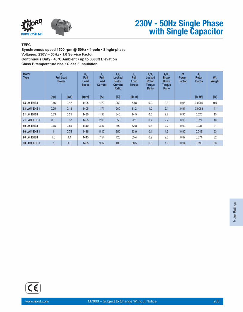
www.nord.com 203M7000 – Subject to Change Without Notice
Mot
or R
atin
gs
MotorType
Pn Full Load
Power
nN Full
LoadSpeed
InFull
Load Current
Ia/InLocked Rotor
CurrentRatio
TnFull
Load Torque
Ta/TnLockedRotor
TorqueRatio
Tk/TnBreakDown
TorqueRatio
pfPower Factor
JmRotorInertia
Wt.Weight
[hp] [kW] [rpm] [A] [%] [lb-in] [lb-ft2] [lb]
230V - 50Hz Single Phasewith Single Capacitor
TEFCSynchronous speed 1500 rpm @ 50Hz • 4-pole • Single-phaseVoltages: 230V – 50Hz • 1.0 Service FactorContinuous Duty • 40°C Ambient • up to 3300ft ElevationClass B temperature rise • Class F insulation
63 L/4 EHB1 0.16 0.12 1405 1.22 250 7.18 0.9 2.3 0.95 0.0066 9.9
63 LA/4 EHB1 0.25 0.18 1405 1.71 260 11.2 1.0 2.1 0.91 0.0083 11
71 L/4 EHB1 0.33 0.25 1430 1.96 340 14.5 0.6 2.2 0.95 0.020 15
71 LA/4 EHB1 0.5 0.37 1425 2.90 350 22.1 0.7 2.2 0.90 0.027 18
80 L/4 EHB1 0.75 0.55 1440 3.87 390 32.8 0.3 2.2 0.90 0.034 21
80 LA/4 EHB1 1 0.75 1435 5.10 350 43.9 0.4 1.9 0.90 0.046 23
90 L/4 EHB1 1.5 1.1 1445 7.54 420 65.4 0.2 2.0 0.87 0.074 32
90 LB/4 EHB1 2 1.5 1425 9.02 400 88.5 0.3 1.9 0.94 0.093 38

www.nord.com 204 M7000 – Subject to Change Without Notice
Motor R
atings
MotorType
Pn Full Load
Power
nN Full
LoadSpeed
InFull
Load Current
Ia/InLocked Rotor
CurrentRatio
TnFull
Load Torque
Ta/TnLockedRotor
TorqueRatio
Tk/TnBreakDown
TorqueRatio
pfPower Factor
JmRotorInertia
Wt.Weight
[hp] [kW] [rpm] [A] [%] [lb-in] [lb-ft2] [lb]
230V - 50Hz Single Phasewith Start & Run CapacitorsTEFCSynchronous speed 1500 rpm @ 50Hz • 4-pole • Single-phaseVoltages: 230V – 50Hz • 1.0 Service FactorContinuous Duty • 40°C Ambient • up to 3300ft ElevationClass B temperature rise • Class F insulation
63 L/4 EAR1 0.16 0.12 1405 1.22 320 7.18 2.3 2.3 0.95 0.0050 9.9
63 LA/4 EAR1 0.25 0.18 1405 1.71 320 11.2 2.4 2.1 0.91 0.0066 11
71 L/4 EAR1 0.33 0.25 1430 1.96 410 14.5 2.1 2.2 0.95 0.015 15
71 LA/4 EAR1 0.5 0.37 1425 2.90 460 22.1 2.1 2.2 0.90 0.018 18
80 L/4 EAR1 0.75 0.55 1440 3.87 430 32.8 2.1 2.2 0.90 0.030 21
80 LA/4 EAR1 1 0.75 1435 5.10 430 43.9 2.2 1.9 0.90 0.039 23
90 L/4 EAR1 1.5 1.1 1445 7.54 480 65.4 2.2 2.0 0.87 0.056 32
90 LB/4 EAR1 2 1.5 1425 9.02 530 88.5 2.2 1.9 0.94 0.074 38

www.nord.com 205M7000 – Subject to Change Without Notice
Mot
or R
atin
gs
MotorType
Pn Full Load
Power
nN Full
LoadSpeed
InFull
Load Current
Ia/InLocked Rotor
CurrentRatio
TnFull
Load Torque
Ta/TnLockedRotor
TorqueRatio
Tk/TnBreakDown
TorqueRatio
pfPower Factor
JmRotorInertia
Wt.Weight
[hp] [kW] [rpm] [A] [%] [lb-in] [lb-ft2] [lb]
230V - 50Hz Single Phasewith Steinmetz Circuit
TEFCSynchronous speed 1500 rpm @ 50Hz • 4-pole • Single-phaseVoltages: 230V – 50Hz • 1.0 Service FactorContinuous Duty • 40°C Ambient • up to 3300ft ElevationClass B temperature rise • Class F insulation
63 S/4 EST 0.12 0.09 1390 0.97 160 5.44 0.8 1.9 0.98 0.0050 8.6
63 L/4 EST 0.16 0.12 1405 1.19 190 7.18 0.7 2.2 0.98 0.0066 9.9
71 S/4 EST 0.25 0.18 1425 1.54 250 11.1 0.7 2.0 0.98 0.017 12.6
71 L/4 EST 0.33 0.25 1420 1.94 270 14.6 0.5 1.9 0.98 0.020 14.6
80 S/4 EST 0.5 0.37 1425 2.62 260 22.1 0.4 1.5 0.96 0.026 18.3
80 L/4 EST 0.75 0.55 1420 3.60 260 33.3 0.5 1.3 0.96 0.034 20.5
90 S/4 EST 1 0.75 1435 4.60 360 43.9 0.4 1.6 0.96 0.056 27.3
90 L/4 EST 1.5 1.1 1435 6.46 340 65.9 0.3 1.6 0.96 0.074 31.7

www.nord.com 206 M7000 – Subject to Change Without Notice
Motor R
atings
Notes

GeneralIntroduction
www.nord.com 207M7000 – Subject to Change Without Notice
NEMA Footed Motors .........................................................................................208NEMA Footed Motor Options ............................................................................209NEMA Footed Brakemotors ...............................................................................213NEMA Footed Brakemotor Options ..................................................................214NEMA C-Face Motors .........................................................................................218NEMA C-Face Motor Options ............................................................................220NEMA C-Face Brakemotors ...............................................................................224NEMA C-Face Brakemotor Options ..................................................................226IEC B3 Motors .....................................................................................................230IEC B3 Motor Options ........................................................................................232IEC B3 Brakemotors ...........................................................................................236IEC B3 Brakemotor Options ..............................................................................238IEC B5 Motors .....................................................................................................242IEC B5 Motor Options ........................................................................................244IEC B5 Brakemotors ...........................................................................................248IEC B5 Brakemotor Options ..............................................................................250IEC B14 Motors ...................................................................................................254IEC B14 Motor Options ......................................................................................256IEC B14 Brakemotors .........................................................................................260IEC B14 Brakemotor Options ............................................................................262
Dimensions

www.nord.com 208 M7000 – Subject to Change Without Notice
Dim
ensions
NEMA FootedMotorsStandard Motor
LL
C
HH
NW
ES
AA
ØUR
S
BA
K
2F
BØ
P
TW
AB
D
J
A
2E
H
AG
G
Efficiency Overall Feet
Motor Frame
SE PE NEMA Frame
C AG øP A B 2E 2F BA J K H G
71 S/L - 56 11.01 9.13 5.75 5.83 3.70 4.88 3.00 2.75 1.44 0.77 0.34 0.47
80 S SP 56 11.51 9.63 6.46 6.06 4.02 4.88 3.00 2.75 1.26 1.04 0.34 0.55
80 L - 56 11.51 9.63 6.46 6.06 4.02 4.88 3.00 2.75 1.26 1.04 0.34 0.55
80 - LP 143T 11.57 9.32 6.46 6.69 5.00 5.50 4.00 2.25 1.56 1.50 0.34 0.57
90 S/L SP/LP 145T 13.14 10.89 7.20 6.89 6.18 5.50 5.00 2.25 1.69 1.38 0.34 0.59
100 L LP 182T 14.82 12.07 7.91 8.78 6.81 7.50 4.50 2.75 2.07 2.68 0.41 0.59
100 LA AP 184T 14.82 12.07 7.91 8.78 6.81 7.50 5.50 2.75 2.07 2.68 0.41 0.59
112 M - 184T 15.45 12.70 8.90 9.02 6.69 7.50 5.50 2.75 1.79 1.30 0.41 0.67
112 - MP 184T 16.44 13.69 8.90 9.02 6.69 7.50 5.50 2.75 1.79 1.30 0.41 0.67
132 S - 213T 18.08 14.71 10.47 10.24 7.09 8.50 5.50 3.50 2.30 1.46 0.41 0.69
132 - SP 213T 19.58 16.20 10.47 10.24 7.09 8.50 5.50 3.50 2.30 1.46 0.41 0.69
132 M MP 215T 19.58 16.20 10.47 10.24 8.58 8.50 7.00 3.50 2.30 1.46 0.41 0.69
Efficiency Shaft Terminal Box
Motor Frame
SE PE NEMA Frame
U NW ES R S D AB HH LL TW AA (NPT)
AA (METRIC)
71 S/L - 56 0.625 +0.000 1.875 1.69 0.517 0.188 3.50 4.88 1.50 3.94 3.94 1/2” M20 x1.5-0.0005
80 S SP 56 0.625 +0.000 1.875 1.69 0.517 0.188 3.50 5.59 1.22 4.49 4.49 3/4” M25x1.5-0.0005
80 L - 56 0.625 +0.000 1.875 1.69 0.517 0.188 3.50 5.59 1.22 4.49 4.49 3/4” M25x1.5-0.0005
80 - LP 143T 0.875 +0.000 2.250 1.81 0.771 0.188 3.50 5.59 0.91 4.49 4.49 3/4” M25x1.5-0.0005
90 S/L SP/LP 145T 0.875 +0.000 2.250 1.81 0.771 0.188 3.50 5.79 1.06 4.49 4.49 3/4” M25x1.5-0.0005
100 L LP 182T 1.125 +0.000 2.750 2.25 0.986 0.250 4.50 6.65 1.30 4.49 4.49 1” M32x1.5-0.0005
100 LA AP 184T 1.125 +0.000 2.750 2.25 0.986 0.250 4.50 6.65 1.30 4.49 4.49 1” M32x1.5-0.0005
112 M - 184T 1.125 +0.000 2.750 2.25 0.986 0.250 4.50 7.05 1.26 4.49 4.49 1” M32x1.5-0.0005
112 - MP 184T 1.125 +0.000 2.750 2.25 0.986 0.250 4.50 7.05 1.26 4.49 4.49 1” M32x1.5-0.0005
132 S - 213T 1.375 +0.000 3.375 3.06 1.201 0.312 5.25 8.03 1.89 4.80 4.80 1” M32x1.5-0.0005
132 - SP 213T 1.375 +0.000 3.375 3.06 1.201 0.312 5.25 8.03 1.89 4.80 4.80 1” M32x1.5-0.0005
132 M MP 215T 1.375 +0.000 3.375 3.06 1.201 0.312 5.25 8.03 1.89 4.80 4.80 1” M32x1.5-0.0005
LL
C
HH
NW
ES
AA
ØUR
S
BA
K
2F
B
ØP
TWA
BD
J
A
2E
H
AG
G
LL
C
HH
NW
ES
AA
ØUR
S
BA
K
2F
B
ØP
TW
AB
D
J
A
2E
H
AG
G

www.nord.com 209M7000 – Subject to Change Without Notice
Dim
ensi
ons
NEMA FootedMotor Options
Option WE - 2nd Shaft Extension
Option RD - Canopy Drip Cover Option RDD - Double Fan Cover
ØFU
LC
FES
FVAG
FR
FS
LS
ØA
S
AG
LO
ØA
O
AG
Efficiency WE RD RDD
Motor Frame
SE PE NEMA Frame
AG LC øFU FS FR FV FES LS øAS LO øAO
71 S/L - 56 9.13 10.67 0.500 +0.000 flat 0.453 1.500 - 9.56 5.43 10.08 6.14-0.0005
80 S SP 56 9.63 11.63 0.625 +0.000 0.188 0.517 1.875 1.50 10.22 6.14 10.66 6.93-0.0005
80 L - 56 9.63 11.63 0.625 +0.000 0.188 0.517 1.875 1.50 10.22 6.14 10.66 6.93-0.0005
80 - LP 143T 9.32 11.31 0.625 +0.000 0.188 0.517 1.875 1.50 9.91 6.14 10.34 6.93-0.0005
90 S/L SP/LP 145T 10.89 13.04 0.625 +0.000 0.188 0.517 1.875 1.50 11.48 6.93 12.11 7.64-0.0005
100 L LP 182T 12.07 14.56 0.875 +0.000 0.188 0.771 2.250 1.63 12.67 7.64 13.18 8.58-0.0005
100 LA AP 184T 12.07 14.56 0.875 +0.000 0.188 0.771 2.250 1.63 12.67 7.64 13.18 8.58-0.0005
112 M - 184T 12.70 15.11 0.875 +0.000 0.188 0.771 2.250 1.63 13.30 8.58 14.20 10.16-0.0005
112 - MP 184T 13.69 16.10 0.875 +0.000 0.188 0.771 2.250 1.63 14.28 8.58 15.19 10.16-0.0005
132 S - 213T 14.71 18.16 1.125 +0.000 0.250 0.986 2.750 2.00 15.37 10.16 16.32 12.20-0.0005
132 - SP 213T 16.20 19.66 1.125 +0.000 0.250 0.986 2.750 2.00 16.87 10.16 17.82 12.20-0.0005
132 M MP 215T 16.20 19.66 1.125 +0.000 0.250 0.986 2.750 2.00 16.87 10.16 17.82 12.20-0.0005

www.nord.com 210 M7000 – Subject to Change Without Notice
Dim
ensions
IG-F + RD
Option IG - Incremental Encoder Option MG - Magnetic Encoder
Option F - Forced Cooling Fan
Option IG-F - Incremental Encoder & Forced Cooling Fan
F + RD
ML ML
Ø1.
89
ØA
S
hS
3.74
m
ML4.
13
1/2” NPT
ØA
S
hSAD
3.74
m
ML
4.13
1/2” NPT
ØA
S
hSAD
3.74
m
ML
4.13
1/2” NPT
ØA
S
hSAD
3.74
m
ML
4.13
1/2” NPT
ØA
S
hSAD
3.74
m
ML
4.13
1/2” NPT
ØA
S
hSAD
3.74
m
ML
4.13
1/2” NPTØ
AS
hSAD
NEMA FootedMotor Options
Efficiency IG MG MG & RD F F & RD IG F IGF & RD
Motor Frame
SE PE NEMA Frame
ML ML hS øAS ML m AD hs øAS ML m AD hs øAS
71 S/L - 56 11.34 9.58 0.43 5.43 12.64 4.21 4.84 1.46 5.91 14.80 4.21 4.84 1.46 5.91
80 S SP 56 12.04 10.03 0.35 6.14 13.18 4.21 5.20 1.57 6.69 15.15 4.21 5.20 1.57 6.69
80 L - 56 12.04 10.03 0.35 6.14 13.18 4.21 5.20 1.57 6.69 15.15 4.21 5.20 1.57 6.69
80 - LP 143T 11.72 9.71 0.35 6.14 12.86 4.21 5.20 1.57 6.69 14.83 4.21 5.20 1.57 6.69
90 S/L SP/LP 145T 13.73 11.44 0.35 6.93 14.99 4.61 5.59 1.18 7.40 16.76 4.61 5.59 1.18 7.40
100 L LP 182T 14.79 12.57 0.33 7.64 15.81 4.61 5.94 1.10 8.27 18.18 4.61 5.94 1.10 8.27
100 LA AP 184T 14.79 12.57 0.33 7.64 15.81 4.61 5.94 1.10 8.27 18.18 4.61 5.94 1.10 8.27
112 M - 184T 15.38 13.20 0.33 8.58 16.60 4.61 6.42 1.30 9.80 18.57 4.61 6.42 1.30 9.80
112 - MP 184T 16.37 14.16 0.33 8.58 17.59 4.61 6.42 1.30 9.80 19.56 4.61 6.42 1.30 9.80
132 S - 213T 17.19 15.10 0.43 10.12 19.23 5.00 7.20 0.98 11.81 20.81 5.00 7.20 0.98 11.81
132 - SP 213T 18.68 16.60 0.43 10.12 20.73 5.00 7.20 0.98 11.81 22.30 5.00 7.20 0.98 11.81
132 M MP 215T 18.68 16.60 0.43 10.12 20.73 5.00 7.20 0.98 11.81 22.30 5.00 7.20 0.98 11.81
ML
Ø1.
89
ØA
S
hS
MG + RD

www.nord.com 211M7000 – Subject to Change Without Notice
Dim
ensi
ons
NEMA FootedMotor Options
Option OL - Without Fan Option OL/H - Without Fan Cover
Option EKK - One Piece Terminal Box Option MS - Quick Power Plug Connector
AG AG
HH LL
AA
AB
HH LL
AB
1.81
Efficiency OL OL/H EKK MS
Motor Frame
SE PE NEMA Frame AG AG HH LL AB AA
(NPT)AA
(METRIC) HH LL AB
71 S/L - 56 9.13 7.95 1.57 2.95 4.29 1/2" M16 x 1.5 1.50 4.49 5.87
80 S SP 56 9.63 1.02 1.46 2.95 4.88 1/2" M20 x1.5 1.22 4.49 6.22
80 L - 56 9.63 8.06 1.46 3.62 4.88 1/2" M20 x1.5 1.22 4.49 6.22
80 - LP 143T 9.32 7.74 1.46 3.62 5.08 1/2" M20 x1.5 0.91 4.49 6.22
90 S/L SP/LP 145T 10.89 8.93 1.61 3.62 5.08 1/2" M20 x1.5 1.06 4.49 6.42
100 L LP 182T 12.07 9.71 1.85 3.62 5.51 1/2" M20 x1.5 1.30 4.49 6.85
100 LA AP 184T 12.07 9.71 1.85 3.62 5.51 1/2" M20 x1.5 1.30 4.49 6.85
112 M - 184T 12.70 10.34 2.36 3.62 5.91 1/2" M20 x1.5 1.26 4.49 7.24
112 - MP 184T 13.69 11.33 2.36 3.62 5.91 1/2" M20 x1.5 1.26 4.49 7.24
132 S - 213T 14.71 11.56 1.93 4.09 6.85 3/4" M25x1.5 1.89 4.80 8.03
132 - SP 213T 16.20 13.05 1.93 4.09 6.85 3/4" M25x1.5 1.89 4.80 8.03
132 M MP 215T 16.20 13.05 1.93 4.09 6.85 3/4" M25x1.5 1.89 4.80 8.03

www.nord.com 212 M7000 – Subject to Change Without Notice
Dim
ensions
NEMA FootedMotor OptionsECR - Single Phase Motor with Start-up & Run Capacitor
AB
2
TW2
AH
2LL
2
AB
3
TW3
AH
3LL
3
AD
AG
AA
LL
AB
2
TW2
AH
2LL
2
AB
3
TW3
AH
3LL
3
AD
AG
AA
LL
AB2
TW2
AH2LL2
AB3
TW3
AH3LL3
AD
AG
AA
LL
ECRMotorType
AD AG AB2 AB3 AH2 AH3 LL2 LL3 TW2 TW3 LL AA(NPT)
AA(metric)
71 L/LA 5.20 3.50 4.15 3.82 1.13 1.73 5.75 4.96 4.81 4.38 5.28 3/4 " M25 x 1.580 L/LA 5.59 4.25 4.45 4.27 1.57 2.36 5.75 4.96 5.03 4.83 6.02 3/4 " M25 x 1.590 L 5.79 4.25 4.65 4.47 2.99 3.78 5.75 4.96 5.03 4.83 6.02 3/4 " M25 x 1.590 LB/LX 5.79 4.25 4.65 4.65 2.99 2.99 5.75 5.75 5.03 4.83 6.02 3/4 " M25 x 1.5

www.nord.com 213M7000 – Subject to Change Without Notice
Dim
ensi
ons
NEMA FootedBrakemotors
Standard Brakemotor
LL
C
HH
NW
ES
AA
ØUR
S
BA
K
2F
BØ
P
TW
AB
D
J
A
2E
H
AG
GEfficiency Overall Feet
Motor type
SE PE NEMA Frame
BRE C AG P A B 2E 2F BA J K H G
71 S/L - 56 5 13.29 11.42 5.75 5.83 3.70 4.88 3.00 2.75 1.44 0.77 0.34 0.4780 S SP 56 5 14.03 12.15 6.46 6.06 4.02 4.88 3.00 2.75 1.26 1.04 0.34 0.5580 L - 56 10 14.03 12.15 6.46 6.06 4.02 4.88 3.00 2.75 1.26 1.04 0.34 0.5580 - LP 143T 10 14.09 11.84 6.46 6.69 5.00 5.50 4.00 2.25 1.56 1.50 0.34 0.5790 S/L SP/LP 145T 20 16.10 13.85 7.20 6.89 6.18 5.50 5.00 2.25 1.69 1.38 0.34 0.59100 L LP 182T 20 18.41 15.66 7.91 8.78 6.81 7.50 4.50 2.75 2.07 2.68 0.41 0.59100 LA AP 184T 40 18.41 15.66 7.91 8.78 6.81 7.50 5.50 2.75 2.07 2.68 0.41 0.59112 M - 184T 60 19.16 16.41 8.90 9.02 6.69 7.50 5.50 2.75 1.79 1.30 0.41 0.67112 - MP 184T 60 20.14 17.39 8.90 9.02 6.69 7.50 5.50 2.75 1.79 1.30 0.41 0.67132 S - 213T 60 22.29 18.92 10.47 10.24 7.09 8.50 5.50 3.50 2.30 1.46 0.41 0.69132 - SP 213T 60 23.79 20.41 10.47 10.24 7.09 8.50 5.50 3.50 2.30 1.46 0.41 0.69132 M MP 215T 100 23.79 20.41 10.47 10.24 8.58 8.50 7.00 3.50 2.30 1.46 0.41 0.69
Efficiency Shaft Terminal Box
Motor type
SE PE NEMA Frame
BREU NW ES R S D AB HH LL TW AA
(NPT)AA
(Metric)
71 S/L - 56 5 0.625 +0.000 1.875 1.69 0.517 0.188 3.50 5.20 1.06 5.28 3.50 1/2” M20 x1.5-0.0005
80 S SP 56 5 0.625 +0.000 1.875 1.69 0.517 0.188 3.50 5.59 1.02 6.02 4.25 3/4" M25x1.5-0.0005
80 L - 56 10 0.625 +0.000 1.875 1.69 0.517 0.188 3.50 5.59 1.02 6.02 4.25 3/4” M25x1.5-0.0005
80 - LP 143T 10 0.875 +0.000 2.250 1.81 0.771 0.188 3.50 5.59 1.02 6.02 4.25 3/4” M25x1.5-0.0005
90 S/L SP/LP 145T 20 0.875 +0.000 2.250 1.81 0.771 0.188 3.50 5.79 1.18 6.02 4.25 3/4" M25x1.5-0.0005
100 L LP 182T 20 1.125 +0.000 2.750 2.25 0.986 0.250 4.50 6.77 1.42 6.02 4.25 1" M32x1.5-0.0005
100 LA AP 184T 40 1.125 +0.000 2.750 2.25 0.986 0.250 4.50 6.77 1.42 6.02 4.25 1" M32x1.5-0.0005
112 M - 184T 60 1.125 +0.000 2.750 2.25 0.986 0.250 4.50 7.17 1.54 6.02 4.25 1" M32x1.5-0.0005
112 - MP 184T 60 1.125 +0.000 2.750 2.25 0.986 0.250 4.50 7.17 1.54 6.02 4.25 1" M32x1.5-0.0005
132 S - 213T 60 1.375 +0.000 3.375 3.06 1.201 0.312 5.25 7.91 1.57 7.28 5.47 1" M32x1.5-0.0005
132 - SP 213T 60 1.375 +0.000 3.375 3.06 1.201 0.312 5.25 7.91 1.57 7.28 5.47 1" M32x1.5-0.0005
132 M MP 215T 100 1.375 +0.000 3.375 3.06 1.201 0.312 5.25 7.91 1.57 7.28 5.47 1" M32x1.5-0.0005
LL
C
HH
NW
ES
AA
ØUR
S
BA
K
2F
B
ØP
TW
AB
D
J
A
2E
H
AG
G
LL
C
HH
NW
ES
AA
ØUR
S
BA
K
2F
B
ØP
TWA
BD
J
A
2E
H
AG
G

www.nord.com 214 M7000 – Subject to Change Without Notice
Dim
ensions
NEMA FootedBrakemotor OptionsOption WE - 2nd Shaft Extension
Option RD - Canopy Drip Cover Option RDD - Double Fan Cover
ØFU
LC
FES
FVAG
FR
FS
LS
ØA
S
AG
LO
ØA
O
AG
Efficiency WE RD RDD
Motor Frame
SE PE NEMA Frame
AG LC FU FS FR FV FES LS øAS LO øAO
71 S/L - 56 11.42 13.07 0.500 +0.000 flat 0.453 1.500 - 11.85 5.43 12.36 6.14-0.0005
80 S SP 56 12.15 14.19 0.625 +0.000 0.188 0.517 1.875 1.50 12.74 6.14 13.18 6.93-0.0005
80 L - 56 12.15 14.19 0.625 +0.000 0.188 0.517 1.875 1.50 12.74 6.14 13.18 6.93-0.0005
80 - LP 143T 11.84 13.87 0.625 +0.000 0.188 0.517 1.875 1.50 12.43 6.14 12.86 6.93-0.0005
90 S/L SP/LP 145T 13.85 16.04 0.625 +0.000 0.188 0.517 1.875 1.50 14.44 6.93 15.07 7.64-0.0005
100 L LP 182T 15.66 18.30 0.875 +0.000 0.188 0.771 2.250 1.63 16.25 7.64 16.76 8.58-0.0005
100 LA AP 184T 15.66 18.30 0.875 +0.000 0.188 0.771 2.250 1.63 16.25 7.64 16.76 8.58-0.0005
112 M - 184T 16.41 18.93 0.875 +0.000 0.188 0.771 2.250 1.63 17.00 8.58 17.90 10.16-0.0005
112 - MP 184T 17.39 19.92 0.875 +0.000 0.188 0.771 2.250 1.63 17.98 8.58 18.89 10.16-0.0005
132 S - 213T 18.92 22.06 1.125 +0.000 0.250 0.986 2.750 2.00 19.59 10.16 20.53 12.20-0.0005
132 - SP 213T 20.41 23.56 1.125 +0.000 0.250 0.986 2.750 2.00 21.08 10.16 22.03 12.20-0.0005
132 M MP 215T 20.41 23.56 1.125 +0.000 0.250 0.986 2.750 2.00 21.08 10.16 22.03 12.20-0.0005

www.nord.com 215M7000 – Subject to Change Without Notice
Dim
ensi
ons
NEMA FootedBrakemotor Options
IG-F + RD
Option IG - Incremental Encoder Option MG - Magnetic Encoder
Option F - Forced Cooling Fan
Option IG-F - Incremental Encoder & Forced Cooling Fan
F + RD
ML ML
Ø1.
89
ØA
S
hS
3.74
m
ML
4.13
1/2” NPT
ØA
S
hSAD
3.74
m
ML
4.13
1/2” NPTØ
AS
hSAD
3.74
m
ML
4.13
1/2” NPT
ØA
S
hSAD
3.74
m
ML
4.13
1/2” NPT
ØA
S
hSAD
3.74
m
ML
4.13
1/2” NPTØ
AS
hSAD
3.74
m
ML
4.13
1/2” NPT
ØA
S
hSAD
MG + RD
ML
Ø1.
89
ØA
S
hS
Efficiency IG MG MG & R5 F F & RD IG F IGF & RD
Motor Frame
SE PE NEMA Frame
ML ML hs øAS ML m AD hs øAS ML m AD hs øAS
71 S/L - 56 13.62 12.08 0.43 5.43 14.92 4.21 4.84 1.46 5.91 17.08 4.21 4.84 1.46 5.91
80 S SP 56 14.56 12.63 0.35 6.14 15.70 4.21 5.20 1.57 6.69 17.67 4.21 5.20 1.57 6.69
80 L - 56 14.56 12.63 0.35 6.14 15.70 4.21 5.20 1.57 6.69 17.67 4.21 5.20 1.57 6.69
80 - LP 143T 14.24 12.31 0.35 6.14 15.38 4.21 5.20 1.57 6.69 17.35 4.21 5.20 1.57 6.69
90 S/L SP/LP 145T 16.68 14.36 0.35 6.93 17.94 4.61 5.59 1.18 7.40 19.71 4.61 5.59 1.18 7.40
100 L LP 182T 18.37 16.17 0.33 7.64 19.40 4.61 5.94 1.10 8.27 21.76 4.61 5.94 1.10 8.27
100 LA AP 184T 18.37 16.17 0.33 7.64 19.40 4.61 5.94 1.10 8.27 21.76 4.61 5.94 1.10 8.27
112 M - 184T 19.08 16.90 0.35 8.58 20.30 4.61 6.42 1.30 9.80 22.27 4.61 6.42 1.30 9.80
112 - MP 184T 20.07 17.88 0.33 8.58 21.29 4.61 6.42 1.30 9.80 23.26 4.61 6.42 1.30 9.80
132 S - 213T 21.40 19.25 0.45 10.12 23.45 5.00 7.20 0.98 11.81 25.02 5.00 7.20 0.98 11.81
132 - SP 213T 22.89 20.75 0.45 10.12 24.94 5.00 7.20 0.98 11.81 26.52 5.00 7.20 0.98 11.81
132 M MP 215T 22.89 20.75 0.45 10.12 24.94 5.00 7.20 0.98 11.81 26.52 5.00 7.20 0.98 11.81

www.nord.com 216 M7000 – Subject to Change Without Notice
Dim
ensions
NEMA FootedBrakemotor OptionsOption OL - Without Fan
Option EKK - One Piece Terminal Box Option MS - Quick Power Plug Connector
AG
HH LL
AA
AB
HH LL
AB
1.81
Efficiency OL EKK MS
Motor Frame
SE PE NEMA Frame
AG HH LL AB AA (NPT)
AA (METRIC)
HH LL AB
71 S/L - 56 11.42 1.57 2.95 4.29 1/2" M16 x 1.5 1.06 4.49 5.87
80 S SP 56 12.15 1.46 2.95 4.88 1/2" M20 x1.5 1.02 4.49 6.22
80 L - 56 12.15 1.46 3.62 4.88 1/2" M20 x1.5 1.02 4.49 6.22
80 - LP 143T 11.84 1.46 3.62 5.08 1/2" M20 x1.5 1.02 4.49 6.22
90 S/L SP/LP 145T 13.85 1.61 3.62 5.08 1/2" M20 x1.5 1.18 4.49 6.42
100 L LP 182T 15.66 1.85 3.62 5.51 1/2" M20 x1.5 1.42 4.49 6.85
100 LA AP 184T 15.66 1.85 3.62 5.51 1/2" M20 x1.5 1.42 4.49 6.85
112 M - 184T 16.41 2.36 3.62 5.91 1/2" M20 x1.5 1.54 4.49 7.24
112 - MP 184T 17.39 2.36 3.62 5.91 1/2" M20 x1.5 1.54 4.49 7.24
132 S - 213T 18.92 1.93 4.09 6.85 3/4" M25x1.5 1.57 4.80 8.03
132 - SP 213T 20.41 1.93 4.09 6.85 3/4" M25x1.5 1.57 4.80 8.03
132 M MP 215T 20.41 1.93 4.09 6.85 3/4" M25x1.5 1.57 4.80 8.03

www.nord.com 217M7000 – Subject to Change Without Notice
Dim
ensi
ons
NEMA FootedBrakemotor Options
ECRMotorType
AD AG AB2 AB3 AH2 AH3 LL2 LL3 TW2 TW3 LL AA(NPT)
AA(metric)
71 L/LA 5.87 4.25 4.15 3.82 3.41 4.02 5.75 4.96 4.81 4.38 6.02 3/4 " M25 x 1.580 L/LA 5.59 4.25 4.45 4.27 4.09 4.88 5.75 4.96 5.03 4.83 6.02 3/4 " M25 x 1.590 L 5.79 4.25 4.65 4.47 5.95 6.73 5.75 4.96 5.03 4.83 6.02 3/4 " M25 x 1.590 LB/LX 5.79 4.25 4.65 4.65 5.95 5.95 5.75 5.75 5.03 4.83 6.02 3/4 " M25 x 1.5
ECR - Single Phase Motor with Start-up & Run CapacitorA
B2
TW2
AH
2LL
2
AB
3
TW3
AH
3LL
3
AD
AG
AA
LL
AB
2
TW2
AH
2LL
2
AB
3
TW3
AH
3LL
3
AD
AG
AA
LL
AB2
TW2
AH2LL2
AB3
TW3
AH3LL3
AD
AG
AA
LL

www.nord.com 218 M7000 – Subject to Change Without Notice
Dim
ensions
NEMA C-FaceMotors
R
S
AA
C
ØP
ØA
K
ØB
D
BB
NW
ES
ØU
AH
LLHH TW
AB
BF
AJ
AG
Efficiency Shaft Terminal Box
Motor Frame
SE PE NEMA Frame
U NW AH ES R S AB HH LL TW AA(NPT)
AA(METRIC)
63 S/L - 56C 0.625 +0.000 1.88 2.06 1.69 0.517 0.188 4.53 0.47 3.94 3.94 1/2" M20 x1.5-0.0005
71 S/L - 56C 0.625 +0.000 1.88 2.06 1.69 0.517 0.188 4.88 0.79 3.94 3.94 1/2" M20 x1.5-0.0005
80 S/L LP 56C 0.625 +0.000 1.88 2.06 1.69 0.517 0.188 5.59 1.02 4.49 4.49 3/4" M25x1.5-0.0005
80 L - 56C 0.625 +0.000 1.88 2.06 1.69 0.517 0.188 5.59 1.02 4.49 4.49 3/4" M25x1.5-0.0005
80 - LP 143TC 0.875 +0.000 2.25 2.12 1.81 0.771 0.188 5.59 1.02 4.49 4.49 3/4" M25x1.5-0.0005
90 S/L SP/LP 145TC 0.875 +0.000 2.25 2.12 1.81 0.771 0.188 5.79 1.18 4.49 4.49 3/4" M25x1.5-0.0005
Efficiency Overall Flange
Motor Frame
SE PE NEMA Frame
C AG P AJ AK BD BB BF
63 S/L - 56C 9.62 7.56 5.08 5.875 4.500 +0.000 6.50 0.16 3/8-16 x 0.71-0.003
71 S/L - 56C 10.49 8.43 5.75 5.875 4.500 +0.000 6.50 0.16 3/8-16 x 0.71-0.003
80 S/L LP 56C 11.51 9.45 6.46 5.875 4.500 +0.000 6.50 0.16 3/8-16 x 0.87-0.003
80 L - 56C 11.51 9.45 6.46 5.875 4.500 +0.000 6.50 0.16 3/8-16 x 0.87-0.003
80 - LP 143TC 11.57 9.45 6.46 5.875 4.500 +0.000 6.50 0.16 3/8-16 x 0.87-0.003
90 S/L SP/LP 145TC 13.15 11.02 7.20 5.875 4.500 +0.000 6.50 0.16 3/8-16 x 0.71-0.003
Standard Motor
R
S
AA
C
ØP
ØA
K
ØB
D
BB
NW
ES
ØU
AH
LLHH TW
AB
BF
AJ
AG
R
S
AA
C
ØP
ØA
K
ØB
D
BB
NW
ES
ØU
AH
LLHH TW
AB
BF
AJ
AG

www.nord.com 219M7000 – Subject to Change Without Notice
Dim
ensi
ons
NEMA C-FaceMotors
AANW
ES
LLHH TW
AB
BF
AJ
C
AG
R
S
ØA
K
ØB
D
BB
ØU
AH
ØP
Standard Motor
Efficiency Shaft Terminal Box
Motor Frame
SE PE NEMA Frame
U NW AH ES R S AB HH LL TW AA(NPT)
AA(METRIC)
100 L LP 182TC 1.125 +0.000 2.75 2.62 2.25 0.986 0.250 6.65 1.42 4.49 4.49 1" M32x1.5-0.0005
100 LA AP 184TC 1.125 +0.000 2.75 2.62 2.25 0.986 0.250 6.65 1.42 4.49 4.49 1" M32x1.5-0.0005
112 M - 184TC 1.125 +0.000 2.75 2.62 2.25 0.986 0.250 7.05 1.38 4.49 4.49 1" M32x1.5-0.0005
112 - MP 184TC 1.125 +0.000 2.75 2.62 2.25 0.986 0.250 7.05 1.38 4.49 4.49 1" M32x1.5-0.0005
132 S SP 213TC 1.375 +0.000 3.38 3.12 3.06 1.201 0.312 8.03 2.13 4.80 4.80 1" M32x1.5-0.0005
132 M MP 215TC 1.375 +0.000 3.38 3.12 3.06 1.201 0.312 8.03 2.13 4.80 4.80 1" M32x1.5-0.0005
160 M MP 254TC 1.625 +0.000 4.00 3.75 3.13 1.416 0.375 9.53 2.05 7.32 7.32 1" M40x1.5-0.001
160 L - 256TC 1.625 +0.000 4.00 3.75 3.13 1.416 0.375 9.53 2.05 7.32 7.32 1” M40x1.5-0.001
160 - LP 256TC 1.625 +0.000 4.00 3.75 3.13 1.416 0.375 9.53 2.05 7.32 7.32 1” M40x1.5-0.001
180 MX - 284TC 1.875 +0.000 4.62 4.38 4.00 1.591 0.500 10.20 2.29 7.32 7.32 1” M40x1.5-0.001
180 - MP 284TC 1.875 +0.000 4.62 4.38 4.00 1.591 0.500 10.20 2.37 7.32 7.32 1” M40x1.5-0.001
180 LX - 286TC 1.875 +0.000 4.62 4.38 4.00 1.591 0.500 10.20 2.29 7.32 7.32 1” M40x1.5-0.001
180 - LP 286TC 1.875 +0.000 4.62 4.38 4.00 1.591 0.500 10.20 2.37 7.32 7.32 1” M40x1.5-0.001
Efficiency Overall Flange
Motor Frame
SE PE NEMA Frame
C AG P AJ AK BD BB BF
100 L LP 182TC 14.83 12.20 7.91 7.250 8.500 +0.000 9.00 0.25 1/2-13x1.10-0.003
100 LA AP 184TC 14.83 12.20 7.91 7.250 8.500 +0.000 9.00 0.25 1/2-13x1.10-0.003
112 M - 184TC 15.46 12.83 8.90 7.250 8.500 +0.000 9.00 0.25 1/2-13x0.98-0.003
112 - MP 184TC 16.44 13.82 8.90 7.250 8.500 +0.000 9.00 0.25 1/2-13x0.98-0.003
132 S SP 213TC 19.58 16.46 10.47 7.250 8.500 +0.000 8.69 0.25 1/2-13x1.18-0.003
132 M MP 215TC 19.58 16.46 10.47 7.250 8.500 +0.000 8.69 0.25 1/2-13x1.18-0.003
160 M MP 254TC 23.12 19.37 12.56 7.250 8.500 +0.000 10.00 0.25 1/2-13x0.87-0.003
160 L - 256TC 23.12 19.37 12.56 7.250 8.500 +0.000 10.00 0.25 1/2-13x0.87-0.003
160 - LP 256TC 24.85 21.10 12.56 7.250 8.500 +0.000 10.00 0.25 1/2-13x0.87-0.003
180 MX - 284TC 23.12 19.37 12.56 9.000 10.500 +0.000 11.26 0.25 1/2-13x0.87-0.003
180 - MP 284TC 28.79 24.42 14.25 9.000 10.500 +0.000 11.26 0.25 1/2-13x0.87-0.003
180 LX - 286TC 24.85 21.10 12.56 9.000 10.500 +0.000 11.26 0.25 1/2-13x0.87-0.003
180 - LP 286TC 28.79 24.42 14.25 9.000 10.500 +0.000 11.26 0.25 1/2-13x0.87-0.003
AANW
ES
LLHH TW
AB
BF
AJ
C
AG
R
S
ØA
K
ØB
D
BB
ØU
AH
ØP
AANW
ES
LLHH TW
AB
BF
AJ
C
AG
R
S
ØA
K
ØB
D
BB
ØU
AH
ØP

www.nord.com 220 M7000 – Subject to Change Without Notice
Dim
ensions
NEMA C-FaceMotor Options
Efficiency WE RD RDD
Motor Frame
SE PE NEMA Frame
AG LC FU FS FR FV FES LS øAS LO øAO
63 S/L - 56C 7.56 9.06 0.500 +0.000 flat 0.453 1.500 - 7.99 4.84 8.58 5.43-0.0005
71 S/L - 56C 8.43 9.96 0.500 +0.000 flat 0.453 1.500 - 8.86 5.43 9.37 6.14-0.0005
80 S SP 56C 9.45 11.44 0.625 +0.000 0.188 0.517 1.875 1.50 10.04 6.14 10.47 6.93-0.0005
80 L LP 56C 9.45 11.44 0.625 +0.000 0.188 0.517 1.875 1.50 10.04 6.14 10.47 6.93-0.0005
80 - LP 143TC 9.45 11.44 0.625 +0.000 0.188 0.517 1.875 1.50 10.04 6.14 10.47 6.93-0.0005
90 S/L SP/LP 145TC 11.02 13.17 0.625 +0.000 0.188 0.517 1.875 1.50 11.61 6.93 12.24 7.64-0.0005
100 L LP 182TC 12.20 14.69 0.875 +0.000 0.188 0.771 2.250 1.63 12.80 7.64 13.31 8.58-0.0005
100 LA AP 184TC 12.20 14.69 0.875 +0.000 0.188 0.771 2.250 1.63 12.80 7.64 13.31 8.58-0.0005
112 M - 184TC 12.83 15.24 0.875 +0.000 0.188 0.771 2.250 1.63 13.43 8.58 14.33 10.16-0.0005
112 - MP 184TC 13.82 16.23 0.875 +0.000 0.188 0.771 2.250 1.63 14.41 8.58 15.31 10.16-0.0005
132 S SP 213TC 16.46 19.92 1.125 +0.000 0.250 0.986 2.750 2.00 17.13 10.12 18.07 12.20-0.0005
132 M MP 215TC 16.46 19.92 1.125 +0.000 0.250 0.986 2.750 2.00 17.13 10.12 18.07 12.20-0.0005
160 M MP 254TC 19.37 23.10 1.375 +0.000 0.313 1.201 3.380 2.75 20.04 12.20 21.14 14.45-0.0005
160 L - 256TC 19.37 23.10 1.375 +0.000 0.313 1.201 3.380 2.75 20.04 12.20 21.14 14.45-0.0005
160 - LP 256TC 21.10 24.84 1.375 +0.000 0.313 1.201 3.380 2.75 21.77 12.20 22.87 14.45-0.0005
180 MX - 284TC 19.37 23.72 1.625 +0.000 0.375 1.416 4.000 3.25 20.04 12.20 21.14 14.45-0.0001
180 - MP 284TC 24.42 28.77 1.625 +0.000 0.375 1.416 4.000 3.25 25.09 13.70 27.17 15.87-0.0001
180 LX - 286TC 21.10 25.46 1.625 +0.000 0.375 1.416 4.000 3.25 21.77 12.20 22.87 14.45-0.0001
180 - LP 286TC 24.42 28.77 1.625 +0.000 0.375 1.416 4.000 3.25 25.09 13.70 27.17 15.87-0.0001
Option WE - 2nd Shaft Extension
RD
LS
ØA
S
AG
RDD
LO
ØA
O
AG
Option RD - Canopy Drip Cover Option RDD - Double Fan Cover
www.nord.com 220 M7000 – Subject to Change Without Notice
Dim
ensions
NEMA C-FaceMotor Options
Efficiency WE RD RDD
Motor Frame
SE PE NEMA Frame
AG LC FU FS FR FV FES LS øAS LO øAO
63 S/L - 56C 7.56 9.06 0.500 +0.000 flat 0.453 1.500 - 7.99 4.84 8.58 5.43-0.0005
71 S/L - 56C 8.43 9.96 0.500 +0.000 flat 0.453 1.500 - 8.86 5.43 9.37 6.14-0.0005
80 S SP 56C 9.45 11.44 0.625 +0.000 0.188 0.517 1.875 1.50 10.04 6.14 10.47 6.93-0.0005
80 L - 56C 9.45 11.44 0.625 +0.000 0.188 0.517 1.875 1.50 10.04 6.14 10.47 6.93-0.0005
80 - LP 143TC 9.45 11.44 0.625 +0.000 0.188 0.517 1.875 1.50 10.04 6.14 10.47 6.93-0.0005
90 S/L SP/LP 145TC 11.02 13.17 0.625 +0.000 0.188 0.517 1.875 1.50 11.61 6.93 12.24 7.64-0.0005
100 L LP 182TC 12.20 14.69 0.875 +0.000 0.188 0.771 2.250 1.63 12.80 7.64 13.31 8.58-0.0005
100 LA AP 184TC 12.20 14.69 0.875 +0.000 0.188 0.771 2.250 1.63 12.80 7.64 13.31 8.58-0.0005
112 M - 184TC 12.83 15.24 0.875 +0.000 0.188 0.771 2.250 1.63 13.43 8.58 14.33 10.16-0.0005
112 - MP 184TC 13.82 16.23 0.875 +0.000 0.188 0.771 2.250 1.63 14.41 8.58 15.31 10.16-0.0005
132 S SP 213TC 16.46 19.92 1.125 +0.000 0.250 0.986 2.750 2.00 17.13 10.12 18.07 12.20-0.0005
132 M MP 215TC 16.46 19.92 1.125 +0.000 0.250 0.986 2.750 2.00 17.13 10.12 18.07 12.20-0.0005
160 M MP 254TC 19.37 23.10 1.375 +0.000 0.313 1.201 3.380 2.75 20.04 12.20 21.14 14.45-0.0005
160 L - 256TC 19.37 23.10 1.375 +0.000 0.313 1.201 3.380 2.75 20.04 12.20 21.14 14.45-0.0005
160 - LP 256TC 21.10 24.84 1.375 +0.000 0.313 1.201 3.380 2.75 21.77 12.20 22.87 14.45-0.0005
180 MX - 284TC 19.37 23.72 1.625 +0.000 0.375 1.416 4.000 3.25 20.04 12.20 21.14 14.45-0.0001
180 - MP 284TC 24.42 28.77 1.625 +0.000 0.375 1.416 4.000 3.25 25.09 13.70 27.17 15.87-0.0001
180 LX - 286TC 21.10 25.46 1.625 +0.000 0.375 1.416 4.000 3.25 21.77 12.20 22.87 14.45-0.0001
180 - LP 286TC 24.42 28.77 1.625 +0.000 0.375 1.416 4.000 3.25 25.09 13.70 27.17 15.87-0.0001
ØFU
LC
FES
FV
AG
FR
FS
Option WE - 2nd Shaft Extension
LS
ØA
S
AG
LO
ØA
O
AG
Option RD - Canopy Drip Cover Option RDD - Double Fan Cover

www.nord.com 221M7000 – Subject to Change Without Notice
Dim
ensi
ons
NEMA C-FaceMotor Options
ML
3.74
m
ML
4.13
1/2” NPT
ØA
S
hS AD
3.74
m
ML
F + RD
hS
ØA
S
4.13
1/2” NPT
AD
IG-F + RD
Option IG - Incremental Encoder Option MG - Magnetic Encoder
Option F - Forced Cooling Fan
Option IG-F - Incremental Encoder & Forced Cooling Fan
3.74
m
ML
4.13
1/2” NPT
ØA
S
hS AD
3.74
m
ML
4.13
1/2” NPT
ØA
S
hS AD
F + RD
3.74
m
ML
4.13
1/2” NPT
ØA
S
hS AD
3.74
m
ML
F + RD
hS
ØA
S
4.13
1/2” NPT
AD
Ø1.
89
MLMG + RD
ML
Ø1.
89
ØA
S
hS
Efficiency IG MG MG & RD F F & RD IG F IGF & RD
Motor Frame
SE PE NEMA Frame
ML ML hs øAS ML m AD hs øAS ML m AD hs øAS
63 S/L - 56C 9.72 7.97 0.43 4.84 11.02 4.21 4.84 1.46 5.91 13.78 4.21 4.84 1.46 5.9171 S/L - 56C 10.63 8.88 0.43 5.43 11.93 4.21 4.84 1.46 5.91 14.09 4.21 4.84 1.46 5.9180 S/L SP 56C 11.85 9.84 0.35 6.14 12.99 4.21 5.20 1.57 6.69 14.96 4.21 5.20 1.57 6.6980 - LP 143TC 11.85 9.84 0.35 6.14 12.99 4.21 5.20 1.57 6.69 14.96 4.21 5.20 1.57 6.6990 S/L SP/LP 145TC 13.86 11.57 0.35 6.93 15.12 4.61 5.59 1.18 7.40 16.89 4.61 5.59 1.18 7.40100 L LP 182TC 14.92 12.70 0.33 7.64 15.94 4.61 5.94 1.10 8.27 18.31 4.61 5.94 1.10 8.27100 LA AP 184TC 14.92 12.70 0.33 7.64 15.94 4.61 5.94 1.10 8.27 18.31 4.61 5.94 1.10 8.27112 M - 184TC 15.51 13.33 0.33 8.58 16.73 4.61 6.42 1.30 9.80 18.70 4.61 6.42 1.30 9.80112 - MP 184TC 16.50 14.29 0.33 8.58 17.72 4.61 6.42 1.30 9.80 19.69 4.61 6.42 1.30 9.80132 S SP 213TC 18.94 16.85 0.43 10.12 20.98 5.00 7.20 0.98 11.81 22.56 5.00 7.20 0.98 11.81132 M MP 215TC 18.94 16.85 0.43 10.12 20.98 5.00 7.20 0.98 11.81 22.56 5.00 7.20 0.98 11.81160 M MP 254TC 22.13 20.00 0.41 12.20 25.28 5.00 8.25 1.26 13.31 28.62 5.00 8.25 1.26 13.31160 L - 256TC 22.13 20.00 0.41 12.20 25.28 5.00 8.25 1.26 13.31 28.62 5.00 8.25 1.26 13.31160 - LP 256TC 23.86 21.73 0.41 12.20 26.81 5.00 8.25 1.26 13.31 30.35 5.00 8.25 1.26 13.31180 MX - 284TC 22.13 20.00 0.41 12.20 25.28 5.00 8.25 1.26 13.31 28.62 5.00 8.25 1.26 13.31180 - MP 284TC 27.17 24.93 0.41 13.70 30.32 5.00 8.25 1.26 13.31 33.67 5.00 8.25 1.26 13.31180 LX - 286TC 23.86 21.73 0.41 12.20 26.81 5.00 8.25 1.26 13.31 30.35 5.00 8.25 1.26 13.31180 - LP 286TC 27.17 24.93 0.41 13.70 30.44 5.00 8.25 1.26 13.31 33.59 5.00 8.25 1.26 13.31

www.nord.com 222 M7000 – Subject to Change Without Notice
Dim
ensions
NEMA C-FaceMotor Options
AG AG
HH LL
AA
AB
HH LL
AB
1.81
Option OL - Without Fan Option OL/H - Without Fan Cover
Option EKK - One Piece Terminal Box Option MS - Quick Power Plug Connector
Efficiency OL OL/H EKK MS
Motor Frame
SE PE NEMA Frame
AG AG HH LL AB AA (NPT)
AA METRIC)"
HH LL AB
63 S/L - 56C 7.56 6.65 0.98 2.95 4.29 1/2" M16 x 1.5 0.20 4.49 5.87
71 S/L - 56C 8.43 7.24 1.30 2.95 4.29 1/2" M16 x 1.5 0.51 4.49 5.87
80 S SP 56C 9.45 7.87 1.46 2.95 4.88 1/2" M20 x1.5 1.02 4.49 6.22
80 L - 56C 9.45 7.87 1.46 3.62 4.88 1/2" M20 x1.5 1.02 4.49 6.22
80 - LP 143TC 9.45 7.87 1.46 3.62 5.08 1/2" M20 x1.5 1.02 4.49 6.22
90 S/L SP/LP 145TC 11.02 9.06 1.61 3.62 5.08 1/2" M20 x1.5 1.18 4.49 6.42
100 L LP 182TC 12.20 9.84 1.85 3.62 5.51 1/2" M20 x1.5 1.42 4.49 6.85
100 LA AP 184TC 12.20 9.84 1.85 3.62 5.51 1/2" M20 x1.5 1.42 4.49 6.85
112 M - 184TC 12.83 10.47 2.20 3.62 5.91 1/2" M20 x1.5 1.77 4.49 7.24
112 - MP 184TC 13.82 11.46 2.20 3.62 5.91 1/2" M20 x1.5 1.77 4.49 7.24
132 S SP 213TC 16.46 13.31 2.48 4.09 6.85 3/4" M25x1.5 2.13 4.80 8.03
132 M MP 215TC 16.46 13.31 2.48 4.09 6.85 3/4" M25x1.5 2.13 4.80 8.03
160 M MP 254TC 19.37 15.04
160 L - 256TC 19.37 15.04
160 - LP 256TC 21.10 16.77
180 MX - 284TC 19.37 15.04
180 - MP 284TC 24.42 20.09
180 LX - 286TC 21.10 16.77
180 - LP 286TC 24.42 20.09

www.nord.com 223M7000 – Subject to Change Without Notice
Dim
ensi
ons
NEMA C-FaceMotor Options
ECR - Single Phase Motor with Start-up & Run CapacitorA
B2
TW3
AH
2LL
2
AB
3
TW2
AH
3LL
3
AA
AD
AG
LL
AB2
TW3
AH2LL2
AB3
TW2
AH3LL3
AA
AD
AG
LL
ECRMotorType
AD AG AB2 AB3 AH2 AH3 LL2 LL3 TW2 TW3 LL AA(NPT)
AA(metric)
63 LA 4.84 3.50 3.52 3.52 1.23 1.23 4.96 4.96 4.37 4.38 5.28 3/4 " M25 x 1.571 L/LA 5.20 3.50 4.15 3.82 1.13 1.73 5.75 4.96 4.81 4.38 5.28 3/4 " M25 x 1.580 L/LA 5.59 4.25 4.45 4.27 1.57 2.36 5.75 4.96 5.03 4.83 6.02 3/4 " M25 x 1.590 L 5.79 4.25 4.65 4.47 2.99 3.78 5.75 4.96 5.03 4.83 6.02 3/4 " M25 x 1.590 LB/LX 5.79 4.25 4.65 4.65 2.99 2.99 5.75 5.75 5.03 4.83 6.02 3/4 " M25 x 1.5
AB
2
TW3
AH
2LL
2
AB
3
TW2A
H3
LL3
AA
AD
AG
LL

www.nord.com 224 M7000 – Subject to Change Without Notice
Dim
ensions
NEMA C-FaceBrakemotors
R
S
AA
C
ØP
ØA
K
ØB
D
BB
NW
ES
ØU
AH
LLHH TW
AB
BF
AJ
AG
Standard Brakemotor
Efficiency Shaft Terminal Box
Motor Frame
SE PE NEMA Frame
BRE U NW AH ES R S AB HH LL TW AA(NPT)
AA(METRIC)
63 S/L - 56C 5 0.625 +0.000 1.88 2.06 1.69 0.517 0.188 4.84 0.75 5.28 3.50 1/2" M20 x1.5-0.0005
71 S/L - 56C 5 0.625 +0.000 1.88 2.06 1.69 0.517 0.188 5.20 1.06 5.28 3.50 1/2" M20 x1.5-0.0005
80 S/L LP 56C 5 0.625 +0.000 1.88 2.06 1.69 0.517 0.188 5.59 1.18 6.02 4.25 3/4" M25x1.5-0.0005
80 L - 56C 10 0.625 +0.000 1.88 2.06 1.69 0.517 0.188 5.59 1.18 6.02 4.25 3/4" M25x1.5-0.0005
80 - LP 143TC 10 0.875 +0.000 2.25 2.12 1.81 0.771 0.188 5.59 1.18 6.02 4.25 3/4" M25x1.5-0.0005
90 S/L SP/LP 145TC 20 0.875 +0.000 2.25 2.12 1.81 0.771 0.188 5.79 1.34 6.02 4.25 3/4" M25x1.5-0.0005
Efficiency Overall Flange
Motor Frame
SE PE NEMA Frame
BRE C AG P AJ AK BD BB BF
63 S/L - 56C 5 11.83 9.76 5.08 5.875 4.500 +0.000 6.50 0.16 3/8-16x0.71-0.003
71 S/L - 56C 5 12.77 10.71 5.75 5.875 4.500 +0.000 6.50 0.16 3/8-16x0.71-0.003
80 S/L LP 56C 5 14.03 11.97 6.46 5.875 4.500 +0.000 6.50 0.16 3/8-16x0.87-0.003
80 L - 56C 10 14.03 11.97 6.46 5.875 4.500 +0.000 6.50 0.16 3/8-16x0.87-0.003
80 - LP 143TC 10 14.53 12.40 6.46 5.875 4.500 +0.000 6.50 0.16 3/8-16x0.87-0.003
90 S/L SP/LP 145TC 20 16.73 14.61 7.20 5.875 4.500 +0.000 6.50 0.16 3/8-16x0.71-0.003
RS
AA
C
ØP
ØA
K
ØB
D
BB
NW
ES
ØU
AH
LLHH TW
AB
BF
AJ
AG
R
S
AA
C
ØP
ØA
K
ØB
D
BB
NW
ES
ØU
AH
LLHH TW
AB
BF
AJ
AG

www.nord.com 225M7000 – Subject to Change Without Notice
Dim
ensi
ons
NEMA C-FaceBrakemotors
AANW
ES
LLHH TW
AB
BF
AJ
C
AG
R
S
ØA
K
ØB
D
BB
ØU
AH
ØP
Standard Brakemotor
Efficiency Shaft Terminal Box
Motor Frame
SE PE NEMA Frame
BRE U NW AH ES R S AB HH LL TW AA(NPT)
AA(METRIC)
100 L LP 182TC 20 1.125 +0.000 2.75 2.62 2.25 0.986 0.250 6.77 1.57 6.02 4.25 1" M32x1.5-0.0005
100 LA AP 184TC 40 1.125 +0.000 2.75 2.62 2.25 0.986 0.250 6.77 1.57 6.02 4.25 1” M32x1.5-0.0005
112 M - 184TC 60 1.125 +0.000 2.75 2.62 2.25 0.986 0.250 7.17 1.54 6.02 4.25 1” M32x1.5-0.0005
112 - MP 184TC 60 1.125 +0.000 2.75 2.62 2.25 0.986 0.250 7.17 1.54 6.02 4.25 1” M32x1.5-0.0005
132 S SP 213TC 60 1.375 +0.000 3.38 3.12 3.06 1.201 0.312 7.91 1.85 7.28 5.47 1” M32x1.5-0.0005
132 M MP 215TC 100 1.375 +0.000 3.38 3.12 3.06 1.201 0.312 7.91 1.85 7.28 5.47 1” M32x1.5-0.0005
160 M MP 254TC 150 1.625 +0.000 4.00 3.75 3.13 1.416 0.375 9.53 2.05 7.32 7.32 1” M40x1.5-0.001
160 L - 256TC 250 1.625 +0.000 4.00 3.75 3.13 1.416 0.375 9.53 2.05 7.32 7.32 1” M40x1.5-0.001
160 - LP 256TC 250 1.625 +0.000 4.00 3.75 3.13 1.416 0.375 9.53 2.05 7.32 7.32 1” M40x1.5-0.001
180 MX - 284TC 250 1.875 +0.000 4.62 4.38 4.00 1.591 0.500 9.53 2.29 7.32 7.32 1” M40x1.5-0.001
180 - MP 284TC 250 1.875 +0.000 4.62 4.38 4.00 1.591 0.500 9.53 2.37 7.32 7.32 1” M40x1.5-0.001
180 LX - 286TC 250 1.875 +0.000 4.62 4.38 4.00 1.591 0.500 9.53 2.29 7.32 7.32 1” M40x1.5-0.001
180 - LP 286TC 250 1.875 +0.000 4.62 4.38 4.00 1.591 0.500 10.20 2.37 7.32 7.32 1” M40x1.5-0.001
Efficiency Overall Flange
Motor Frame
SE PE NEMA Frame
BRE C AG P AJ AK BD BB BF
100 L LP 182TC 20 18.41 15.79 7.91 7.250 8.500 +0.000 9.00 0.25 1/2-13x1.10-0.003
100 LA AP 184TC 40 18.53 15.91 7.91 7.250 8.500 +0.000 9.00 0.25 1/2-13x1.10-0.003
112 M - 184TC 60 19.16 16.54 8.90 7.250 8.500 +0.000 9.00 0.25 1/2-13x0.98-0.003
112 - MP 184TC 60 20.66 18.03 8.90 7.250 8.500 +0.000 9.00 0.25 1/2-13x0.98-0.003
132 S SP 213TC 60 23.79 20.67 10.47 7.250 8.500 +0.000 8.69 0.25 1/2-13x1.18-0.003
132 M MP 215TC 100 23.79 20.67 10.47 7.250 8.500 +0.000 8.69 0.25 1/2-13x1.18-0.003
160 M MP 254TC 150 28.44 24.69 12.56 7.250 8.500 +0.000 10.00 0.25 1/2-13x0.87-0.003
160 L - 256TC 250 28.44 24.69 12.56 7.250 8.500 +0.000 10.00 0.25 1/2-13x0.87-0.003
160 - LP 256TC 250 30.17 26.42 12.56 7.250 8.500 +0.000 10.00 0.25 1/2-13x0.87-0.003
180 MX - 284TC 250 28.44 24.69 12.56 9.000 10.500 +0.000 11.26 0.25 1/2-13x0.87-0.003
180 - MP 284TC 250 34.11 29.73 14.25 9.000 10.500 +0.000 11.26 0.25 1/2-13x0.87-0.003
180 LX - 286TC 250 29.85 26.10 12.56 9.000 10.500 +0.000 11.26 0.25 1/2-13x0.87-0.003
180 - LP 286TC 250 33.79 29.42 14.25 9.000 10.500 +0.000 11.26 0.25 1/2-13x0.87-0.003
AANW
ES
LLHH TW
AB
BF
AJ
C
AG
R
S
ØA
K
ØB
D
BB
ØU
AH
ØP
AANW
ES
LLHH TW
AB
BF
AJ
C
AG
RS
ØA
K
ØB
D
BBØ
UAH
ØP

www.nord.com 226 M7000 – Subject to Change Without Notice
Dim
ensions
NEMA C-FaceBrakemotor Options
WEØ
FU
LC
FES
FV
AG
FR
FS
M20 x 42 (1.65)
Option WE - 2nd Shaft Extension
RD
LS
ØA
S
AG
RDD
LO
ØA
O
AG
Option RD - Canopy Drip Cover Option RDD - Double Fan Cover
Efficiency WE RD RDD
Motor Frame
SE PE NEMA Frame
BRE AG LC FU FS FR FV FES LS øAS LO øAO
63 S/L - 56C 5 9.76 11.42 0.500 +0.000 flat 0.453 1.500 - 10.20 4.84 10.79 5.43-0.0005
71 S/L - 56C 5 10.71 12.37 0.500 +0.000 0.188 0.453 1.500 - 11.14 5.43 11.65 6.14-0.0005
80 S SP 56C 5 11.97 13.63 0.500 +0.000 0.188 0.517 1.875 1.25 12.56 6.14 12.99 6.93-0.0005
80 L - 56C 10 11.97 14.00 0.625 +0.000 0.188 0.517 1.875 1.50 12.56 6.14 12.99 6.93-0.0005
80 - LP 143TC 10 12.40 14.59 0.625 +0.000 0.188 0.517 1.875 1.50 12.99 6.14 13.43 6.93-0.0005
90 S/L SP/LP 145TC 20 14.61 16.88 0.625 +0.000 0.188 0.517 1.875 1.50 15.20 6.93 15.83 7.64-0.0005
100 L LP 182TC 20 15.79 18.43 0.875 +0.000 0.188 0.771 2.250 1.63 16.38 7.64 16.89 8.58-0.0005
100 LA AP 184TC 40 15.91 18.43 0.875 +0.000 0.188 0.771 2.250 1.63 16.50 7.64 17.01 8.58-0.0005
112 M - 184TC 60 16.54 19.06 0.875 +0.000 0.188 0.771 2.250 1.63 17.13 8.58 18.03 10.16-0.0005
112 - MP 184TC 60 18.03 20.68 0.875 +0.000 0.188 0.771 2.250 1.63 18.62 8.58 19.53 10.16-0.0005
132 S SP 213TC 60 20.67 23.81 1.125 +0.000 0.250 0.986 2.750 2.00 21.34 10.12 22.28 12.20-0.0005
132 M MP 215TC 100 20.67 23.81 1.125 +0.000 0.250 0.986 2.750 2.00 21.34 10.12 22.28 12.20-0.0005
160 M MP 254TC 150 24.69 28.41 1.375 +0.000 0.313 1.201 3.380 2.75 25.35 12.20 26.46 14.45-0.0005
160 L - 256TC 250 24.69 28.41 1.375 +0.000 0.313 1.201 3.380 2.75 25.35 12.20 26.46 14.45-0.0005
160 - LP 256TC 250 26.42 30.15 1.375 +0.000 0.313 1.201 3.380 2.75 27.09 12.20 28.19 14.45-0.0005
180 MX - 284TC 250 24.69 29.04 1.625 +0.000 0.375 1.416 4.000 3.25 25.35 12.20 26.46 14.45-0.0001
180 - MP 284TC 250 29.73 34.09 1.625 +0.000 0.375 1.416 4.000 3.25 30.40 13.70 32.49 15.87-0.0001
180 LX - 286TC 250 26.10 30.46 1.625 +0.000 0.375 1.416 4.000 3.25 26.77 12.20 27.87 14.45-0.0001
180 - LP 286TC 250 29.42 33.77 1.625 +0.000 0.375 1.416 4.000 3.25 30.09 13.70 32.17 15.87-0.0001

www.nord.com 227M7000 – Subject to Change Without Notice
Dim
ensi
ons
NEMA C-FaceBrakemotor Options
ML
3.74
m
ML
4.13
ØA
S
hS AD
1/2” NPT
3.74
m
ML
F + RD
hS
ØA
S
4.13
1/2” NPT
AD
IG-F + RD
Option IG - Incremental Encoder Option MG - Magnetic Encoder
Option F - Forced Cooling Fan
Option IG-F - Incremental Encoder & Forced Cooling Fan
F + RD
Ø1.
89
ML
ØA
S
hS
3.74
m
ML
4.13
ØA
S
hS AD
1/2” NPT3.74
m
ML
4.13
ØA
S
hS AD
1/2” NPT
3.74
m
ML
F + RD
hS
ØA
S
4.13
1/2” NPT
AD
3.74
m
ML
F + RD
hS
ØA
S
4.13
1/2” NPT
AD
Ø1.
89
ML
ØA
S
hSMG + RD
Efficiency IG MG MG & RD F F & RD IG F IGF & RD
Motor Frame
SE PE NEMA Frame
BRE ML ML hs øAS ML m AD hs øAS ML m AD hs øAS
63 S/L - 56C 5 12.20 10.33 0.43 4.84 13.31 4.21 4.84 1.46 5.91 14.69 4.21 4.84 1.46 5.9171 S/L - 56C 5 13.62 11.38 0.43 5.43 14.41 4.21 4.84 1.46 5.91 16.18 4.21 4.84 1.46 5.9180 S/L SP 56C 10 14.21 12.44 0.33 6.14 15.51 4.21 5.20 1.57 6.69 17.48 4.21 5.20 1.57 6.6980 - LP 143TC 10 15.16 12.87 0.33 6.14 16.34 4.21 5.20 1.57 6.69 18.11 4.21 5.20 1.57 6.6990 S/L SP/LP 145TC 20 17.36 15.12 0.35 6.93 18.74 4.61 5.59 1.18 7.40 20.12 4.61 5.59 1.18 7.40100 L LP 182TC 20 18.54 16.30 0.33 7.64 19.92 4.61 5.94 1.10 8.27 21.30 4.61 5.94 1.10 8.27100 LA AP 184TC 40 18.43 16.42 0.33 7.64 20.04 4.61 5.94 1.10 8.27 21.42 4.61 5.94 1.10 8.27112 M - 184TC 60 19.06 17.03 0.35 8.58 20.67 4.61 6.42 1.30 9.80 22.05 4.61 6.42 1.30 9.80112 - MP 184TC 60 20.59 18.52 0.33 8.58 22.95 4.61 6.42 1.30 9.80 24.13 4.61 6.42 1.30 9.80132 S SP 213TC 60 23.23 21.00 0.45 10.12 25.59 5.00 7.20 0.98 11.81 26.77 5.00 7.20 0.98 11.81132 M MP 215TC 100 23.23 21.00 0.45 10.12 25.59 5.00 7.20 0.98 11.81 26.77 5.00 7.20 0.98 11.81160 M MP 254TC 150 27.44 25.35 0.41 12.20 30.39 5.00 8.25 1.26 13.31 33.94 5.00 8.25 1.26 13.31160 L - 256TC 250 27.44 25.35 0.41 12.20 30.39 5.00 8.25 1.26 13.31 33.94 5.00 8.25 1.26 13.31160 - LP 256TC 250 29.17 27.09 0.41 12.20 32.13 5.00 8.25 1.26 13.31 35.67 5.00 8.25 1.26 13.31180 MX - 284TC 250 27.44 25.35 0.41 12.20 30.39 5.00 8.25 1.26 13.31 33.94 5.00 8.25 1.26 13.31180 - MP 284TC 250 32.49 30.44 0.41 13.70 35.44 5.00 8.25 1.26 13.31 38.98 5.00 8.25 1.26 13.31180 LX - 286TC 250 28.86 26.77 0.41 12.20 31.85 5.00 8.25 1.26 13.31 35.98 5.00 8.25 1.26 13.31180 - LP 286TC 250 32.17 30.13 0.41 13.70 35.17 5.00 8.25 1.26 13.31 39.30 5.00 8.25 1.26 13.31

www.nord.com 228 M7000 – Subject to Change Without Notice
Dim
ensions
NEMA C-FaceBrakemotor Options
AG
HH LL
AA
AB
HH LL
AB
1.81
Option OL - Without Fan
Option EKK - One Piece Terminal Box Option MS - Quick Power Plug Connector
Efficiency OL EKK MS
Motor Frame
SE PE NEMA Frame
BRE AG HH LL AB AA (NPT)
AA METRIC)"
HH LL AB
63 S/L - 56C 5 9.76 0.98 2.95 4.29 1/2" M16 x 1.5 0.20 4.49 5.87
71 S/L - 56C 5 10.71 1.30 2.95 4.29 1/2" M16 x 1.5 0.51 4.49 5.87
80 S SP 56C 5 11.97 1.46 2.95 4.88 1/2" M20 x1.5 1.02 4.49 6.22
80 L - 56C 10 11.97 1.46 3.62 4.88 1/2" M20 x1.5 1.02 4.49 6.22
80 - LP 143TC 10 12.40 1.46 3.62 5.08 1/2" M20 x1.5 1.02 4.49 6.22
90 S/L SP/LP 145TC 20 14.61 1.61 3.62 5.08 1/2" M20 x1.5 1.18 4.49 6.42
100 L LP 182TC 20 15.79 1.85 3.62 5.51 1/2" M20 x1.5 1.42 4.49 6.85
100 LA AP 184TC 40 15.91 1.85 3.62 5.51 1/2" M20 x1.5 1.42 4.49 6.85
112 M - 184TC 60 16.54 2.20 3.62 5.91 1/2" M20 x1.5 1.77 4.49 7.24
112 - MP 184TC 60 18.03 2.20 3.62 5.91 1/2" M20 x1.5 1.77 4.49 7.24
132 S SP 213TC 60 20.67 2.48 4.09 6.85 3/4" M25x1.5 2.13 4.80 8.03
132 M MP 215TC 100 20.67 2.48 4.09 6.85 3/4" M25x1.5 2.13 4.80 8.03
160 M MP 254TC 150 24.69
160 L - 256TC 250 24.69
160 - LP 256TC 250 26.42
180 MX - 284TC 250 24.69
180 - MP 284TC 250 29.73
180 LX - 286TC 250 26.10
180 - LP 286TC 250 29.42

www.nord.com 229M7000 – Subject to Change Without Notice
Dim
ensi
ons
NEMA C-FaceBrakemotor Options
ECR - Single Phase Motor with Start-up & Run CapacitorA
B2
TW3
AH
2LL
2
AB
3
TW2
AH
3LL
3
AA
AD
AG
LL
AB2
TW3
AH2LL2
AB3
TW2
AH3LL3
AA
AD
AG
LL
ECRMotorType
AD AG AB2 AB3 AH2 AH3 LL2 LL3 TW2 TW3 LL AA(NPT)
AA(metric)
63 LA 5.51 4.25 3.52 3.52 3.43 3.43 4.96 4.96 4.37 4.38 6.02 3/4” M25 x 1.571 L/LA 5.87 4.25 4.15 3.82 3.41 4.02 5.75 4.96 4.81 4.38 6.02 3/4 " M25 x 1.580 L/LA 5.59 4.25 4.45 4.27 4.09 4.88 5.75 4.96 5.03 4.83 6.02 3/4 " M25 x 1.590 L 5.79 4.25 4.65 4.47 5.95 6.73 5.75 4.96 5.03 4.83 6.02 3/4 " M25 x 1.590 LB/LX 5.79 4.25 4.65 4.65 5.95 5.95 5.75 5.75 5.03 4.83 6.02 3/4 " M25 x 1.5
AB
2
TW3
AH
2LL
2
AB
3
TW2A
H3
LL3
AA
AD
AG
LL

www.nord.com 230 M7000 – Subject to Change Without Notice
Dim
ensions
IEC B3 Footed Motors
LL
L
HH
E
EB
O
ØD
GA
F
DB
C
BA
B
BB
ØA
C
AGA
DH
k AA
AB
A
K
L2
HA
LL
L
HH
E
EB
O
ØD
GA
F
DB
C
BA
B
BB
ØA
C
AG
AD
H
k AA
AB
A
K
L2
HA
MotorFrame
Efficiency Shaft Terminal Box
IE1 IE3 ØD DB E EB GA F H AD HH LL AG O
63 S/L - 11 +0.008 M4 23 16 12.5 4 63 115 12 100 100 M20 x 1.5-0.003
71 S/L - 14 +0.008 M5 30 20 16.0 5 71 124 20 100 100 M20 x 1.5-0.003
80 S/L LP 19 +0.009 M6 40 32 21.5 6 80 142 22 114 114 M25 x 1.5-0.004
90 S -24 +0.009
-0.004 M8 50 40 27.0 8 90 147 26 114 114 M25 x 1.590 L SP
100 L/LA LP/AP 28 +0.009 M10 60 50 31.0 8 100 169 32 114 114 M32 x 1.5-0.004
112 M -28 +0.009
-0.004 M10 60 50 31.0 8 112 179 35 114 114 M32 x 1.5112 MP
MotorFrame
Efficiency Overall Feet
IE1 IE3 L L2 ØAC A B C AA BA AB BB k K HA
63 S/L - 215 192 129 100 80 40 21 27 120 105 12 7 9
71 S/L - 244 214 146 112 90 45 24 24 136 108 12 7 10
80 S/L LP 276 236 164 125 100 50 30 30 160 125 17 9 11
90 S - 301 251183 140 125 56 34 35 174 155 17 9 12
90 L SP/LP 326 276
100 L/LA LP/AP 366 306 201 160 140 63 37 30 192 175 22 12 15
112 - - 386 326226 190 140 70 40 34 224 175 22 12 15
112 M MP 411 351
Standard Motor
LL
L
HH
E
EB
O
ØD
GA
F
DB
C
BA
B
BB
ØA
C
AG
AD
H
k AA
AB
A
K
L2
HA

www.nord.com 231M7000 – Subject to Change Without Notice
Dim
ensi
ons
IEC B3 Footed Motors
MotorFrame
Efficiency Shaft Terminal Box
IE1 IE3 ØD DB E EB GA F H AD HH LL AG O
132 S -38 +0.018
+0.002 M12 80 70 41.0 10 132 204 47 122 122 M32 x 1.5132 M/MA SP/MP
160 M MP42 +0.018
+0.002 M16 110 90 45.0 12 160 242 52 186 186 M40 x 1.5160 L -
160 - LP 42 +0.018 M16 110 90 45.0 12 160 242 52 186 186 M40 x 1.5+0.002
180 - MP48 +0.021
+0.002 M16 110 100 51.5 14 180 259 54 186 186 M40 x 1.5180 - LP
225 - SP 60 +0.030+0.011 M20 140 125 64 18 225 347 94 245 245 M50 X 1.5
225 - MP 60 +0.030+0.011 M20 140 125 64 18 225 347 94 245 245 M50 X 1.5
MotorFrame
Efficiency Overall Feet
IE1 IE3 L L2 ØAC A B C AA BA AB BB k K HA
132 S - 453 373266 216 178 89 58 37 260 218 89 14 18
132 M/MA SP/MP 491 411
160 M MP602 492 319 254
210108 72 52 318
26430 14.5 25
160 L - 254 308
160 - LP 646 536 319 254 254 108 72 52 318 308 30 14.5 25
180 - MP724 614 362 279
241121 88.5 - 340
28130 14.5 27
180 - LP 279 319
225 - SP 882 742 443 356 286 149 79 66 443 359 25 20 20
225 - MP 882 742 443 356 311 149 79 66 443 359 25 20 20
Standard Motor
LL
L
HH
E
EB
O
ØD
GA
F
DB
C
BA
B
BB
ØA
C
AGA
DH
k AA
AB
A
K
L2
HA
LL
L
HH
E
EB
O
ØD
GA
F
DB
C
BA
B
BB
ØA
C
AG
AD
H
k AA
AB
A
K
L2
HA
LL
L
HH
E
EB
O
ØD
GA
F
DB
C
BA
B
BB
ØA
C
AG
AD
H
k AA
AB
A
K
L2
HA

www.nord.com 232 M7000 – Subject to Change Without Notice
Dim
ensions
IEC B3 FootedMotor Options
ØD
A
LC
EC
EA
DC
L2
GC
FA
LC
CHR
ØH
R
L2
LS
ØA
S
L2
LO
ØA
O
L2
Motor Efficiency WE HR RD RDD
Frame IE1 IE3 L2 LC DA EA EC DC GC FA LC ØHR CHR LS ØAS LO ØAO
63 S/L - 192 215 11 +0.008- 0.003 23 16 M4 12.5 4 231 100 39 203 123 218 138
71 S/L - 214 238 11 +0.008- 0.003 23 16 M4 12.5 4 254 100 40 225 138 238 156
80 S/L LP 236 269 14 +0.008- 0.003 30 20 M5 16.0 5 285 100 49 251 156 262 176
90 S - 251 29819 +0.009
- 0.004 40 32 M6 16.0 6318
160 67266
176282
19490 L SP/LP 276 323 343 291 307
100 L/LA LP/AP 306 362 24 +0.009- 0.004 50 40 M8 27.0 8 382 160 76 321 194 334 218
112 - - 326 38024 +0.009
- 0.004 50 40 M8 27.0 8400
160 74341
218364
258112 M MP 351 405 425 366 389
132 S - 373 47132 +0.011
- 0.005 80 70 M12 35.0 10492
200 119390
257414
310132 M/MA SP/MP 411 509 530 428 452
160 M/L MP 492 611 42 +0.018+0.002 110 90 M16 45.0 12 634 315 142 509 310 537 367
160 - LP 536 655 42 +0.018+0.002 110 90 M16 45.0 12 678 315 142 553 310 581 367
180 - MP/LP 614 733 48 +0.018+0.002 110 100 M16 51.5 14 756 315 142 631 348 684 403
225 - SP 742 862 55 +0.030 110 100 M20 59.3 16 - - - 828.5 348 826 519+0.011
225 - MP 742 862 55 +0.030 110 100 M20 59.3 16 - - - 828.5 348 826 519+0.011
Option WE - 2nd Shaft Extension Option HR - Hand Wheel
Option RD - Canopy Drip Cover Option RDD - Double Fan Cover

www.nord.com 233M7000 – Subject to Change Without Notice
Dim
ensi
ons
IEC B3 Footed Motor Options
IG-F + RD
Option IG - Incremental Encoder Option MG - Magnetic Encoder
Option F - Forced Cooling Fan
Option IG-F - Incremental Encoder & Forced Cooling Fan
F + RD
ML ML
Ø48
95
m
ML10
5
M16 x 1.5
ØA
S
hSAD
95
m
ML
105
M16 x 1.5
ØA
S
hSAD
95
m
ML
105
M16 x 1.5
ØA
S
hSAD
95
m
ML
105
M16 x 1.5
ØA
S
hSAD
Motor Efficiency IG MG MG + RD F F + RD IG-F IG-F + RD
Frame IE1 IE3 ML ML hs AS ML m AD hs AS ML m AD hs AS
63 S/L - 247 202.5 11.0 123 280 107 114 37 133 350 107 133 37 133
71 S/L - 270 225.5 11.0 138 303 107 123 37 150 358 107 150 37 150
80 S/L LP 297 246 9.0 156 326 107 132 40 170 376 107 170 40 170
90 S - 323 265 9.0 176 355 117 142 30 188 400 117 188 30 188
90 L SP/LP 348 290 9.0 176 380 117 142 30 188 425 117 188 30 188
100 L/LA LP/AP 375 318.5 8.5 194 401 117 151 28 210 461 117 210 28 210
112 M - 394 338.5 8.5 218 425 117 163 33 249 475 117 249 33 249
112 - MP 419 363 8.5 218 450 117 163 33 249 500 117 249 33 249
132 S - 436 383 11.0 257 488 127 183 25 300 528 127 300 25 300
132 M/MA SP/MP 474 421 11.0 257 526 127 183 25 300 566 127 300 25 300
160 M/L MP 562 508 10.5 310 642 127 209.5 32 338 727 127 338 32 338
160 - LP 606 552 10.5 310 681 127 209.5 32 338 771 127 338 32 338
180 - MP/LP 684 627 10.5 348 767 127 209.5 32 338 847 127 338 32 338
225 - SP 809 - - - 942.5 144 249.5 - - 1032.5 144 249.5 - -
225 - MP 809 - - - 942.5 144 249.5 - - 1032.5 144 249.5 - -
ML
Ø1.
89
ØA
S
hS
MG + RD

www.nord.com 234 M7000 – Subject to Change Without Notice
Dim
ensions
IEC B3 Footed Motor OptionsOption OL - Without Fan Option OLH - Without Fan Cover
Option EKK - One Piece Terminal Box Option MS - Quick Power Plug Connector
L2 L2
HH LL
O
AD
HH LL
AD
46
Motor Efficiency OL OLH EKK MS
Frame IE1 IE3 L2 L2 HH LL AD O HH LL AD
63 S/L - 192 160 25 75 100 M16 x 1.5 5 114 140
71 S/L - 214 177 33 75 109 M16 x 1.5 13 114 149
80 S/L LP 236 196 33 92 124 M20 x 1.5 22 114 158
90 S - 251 208 37 92 129 M20 x 1.5 26 114 163
90 L SP/LP 276 233 37 92 129 M20 x 1.5 26 114 163
100 L/LA LP/AP 306 262 43 92 140 M20 x 1.5 32 114 174
112 M - 326 276 56 92 150 M20 x 1.5 45 114 184
112 - MP 351 301 56 92 150 M20 x 1.5 45 114 184
132 S - 373 313 56 104 174 M25 x 1.5 47 122 204
132 M/MA SP/MP 411 351 56 104 174 M25 x 1.5 47 122 204
160 M/L MP 492 417
160 - LP 536 461
180 - MP/LP 614 539

www.nord.com 235M7000 – Subject to Change Without Notice
Dim
ensi
ons
IEC B3 Footed Motor Options
Option EAR1 - Single Phase with Start-up & Run CapacitorOption ECR - Single Phase with Start-up & Run Capacitor
B3 ECR Option
AB
2
TW2
AH
2LL
2
AB
3
TW3
AH
3LL
3
AG
AD
AA
LL
AB
2
AB
3
TW2 TW3
AH
2LL
2
AH
3LL
3
LLAG
AD
AA
B3 ECR Option
AB
2
TW2
AH
2LL
2
AB
3
TW3
AH
3LL
3
AG
AD
AA
LL
AB
2
AB
3
TW2 TW3
AH
2LL
2
AH
3LL
3
LLAG
AD
AA
AB2
AB3
TW2
TW3
AH2LL2
AH3LL3
LLA
G
AD
AA
Option EHB1 - Single Phase with Single Capcitor Option EST - Single Phase with Steinmetz Circuit
AB
2
TW2AH2LL2
AG
LL
AA
AD
AB
2
TW2AG
AD
AAAH2LL2
LL
AB
2
TW2AH2LL2
AG
LL
AA
AD
AB
2
TW2AG
AD
AAAH2LL2
LL
B3 EC
R O
ptio
n
AB2
TW2
AH2LL2
AB3
TW3
AH3LL3
AG
AD
AA
LL
Motor Type AD AG AB2 AB3 AH2 AH3 LL2 LL3 TW2 TW3 LL AA63 LA ECR 123 89 90 90 31 31 126 126 111 111 134 M25 x 1.571 L/LA ECR 132 89 106 97 29 44 146 126 122 111 134 M25 x 1.580 L/LA ECR 142 108 113 109 40 60 146 126 128 123 153 M25 x 1.590 L ECR 147 108 118 114 76 96 146 126 128 123 153 M25 x 1.590 LB/LX ECR 147 108 118 118 76 76 146 146 128 123 153 M25 x 1.5
63 L/LA EAR1 123 89 70 68 84 95 92 70 85 73 134 M25 x 1.571 L/LA EAR1 132 89 79 74 86 109 117 70 95 80 134 M25 x 1.580 L/LA EAR1 142 108 88 89 113 111 87 92 95 86 153 M25 x 1.590 L/LB EAR1 147 108 93 89 114 122 118 92 105 91 153 M25 x 1.5
63 L/LA EHB1 115 100 70 - 95 - 70 - 81 - 100 M20 x 1.571 L/LA EHB1 124 100 79 - 109 - 70 - 85 - 100 M20 x 1.580 L/LA EHB1 142 114 88 - 95 - 87 - 113 - 114 M25 x 1.590 L/LB EHB1 147 114 93 - 121 - 145 - 98 - 114 M25 x 1.5
63 S/L EST 115 100 70 - 95 - 70 - 85 - 100 M20 x 1.571 S/L EST 124 100 79 - 98 - 92 - 85 - 100 M20 x 1.580 S/L EST 142 114 88 - 97 - 120 - 98 - 114 M25 x 1.590 S/L EST 147 114 93 - 121 - 145 - 113 - 114 M25 x 1.5
A A VIEW AA A A VIEW AA
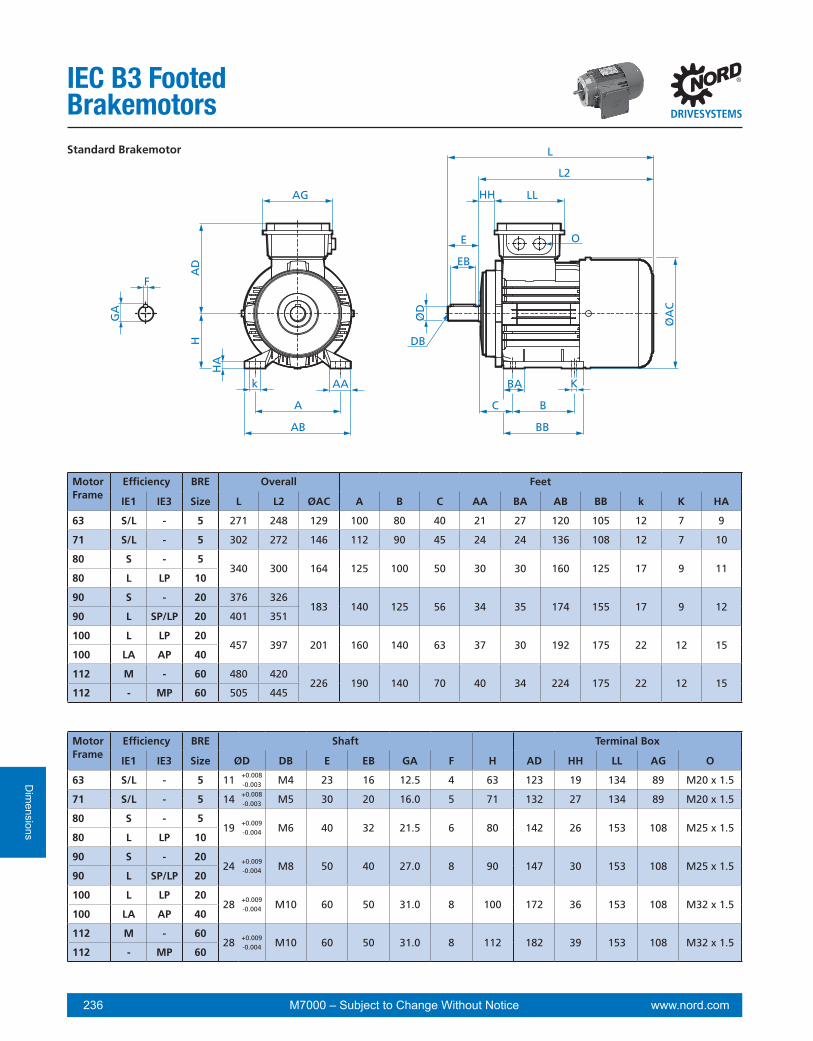
www.nord.com 236 M7000 – Subject to Change Without Notice
Dim
ensions
IEC B3 Footed Brakemotors
LL
L
HH
E
EB
O
ØD
GA
F
DB
C
BA
B
BBØ
AC
AG
AD
H
k AA
AB
A
K
L2
HA
LL
L
HH
E
EB
O
ØD
GA
F
DB
C
BA
B
BB
ØA
C
AGA
DH
k AA
AB
A
K
L2
HA
MotorFrame
Efficiency BRE Shaft Terminal Box
IE1 IE3 Size ØD DB E EB GA F H AD HH LL AG O
63 S/L - 5 11 +0.008 M4 23 16 12.5 4 63 123 19 134 89 M20 x 1.5-0.003
71 S/L - 5 14 +0.008 M5 30 20 16.0 5 71 132 27 134 89 M20 x 1.5-0.003
80 S - 519 +0.009
-0.004 M6 40 32 21.5 6 80 142 26 153 108 M25 x 1.580 L LP 10
90 S - 2024 +0.009
-0.004 M8 50 40 27.0 8 90 147 30 153 108 M25 x 1.590 L SP/LP 20
100 L LP 2028 +0.009
-0.004 M10 60 50 31.0 8 100 172 36 153 108 M32 x 1.5100 LA AP 40
112 M - 6028 +0.009
-0.004 M10 60 50 31.0 8 112 182 39 153 108 M32 x 1.5112 - MP 60
MotorFrame
Efficiency BRE Overall Feet
IE1 IE3 Size L L2 ØAC A B C AA BA AB BB k K HA
63 S/L - 5 271 248 129 100 80 40 21 27 120 105 12 7 9
71 S/L - 5 302 272 146 112 90 45 24 24 136 108 12 7 10
80 S - 5340 300 164 125 100 50 30 30 160 125 17 9 11
80 L LP 10
90 S - 20 376 326183 140 125 56 34 35 174 155 17 9 12
90 L SP/LP 20 401 351
100 L LP 20457 397 201 160 140 63 37 30 192 175 22 12 15
100 LA AP 40
112 M - 60 480 420226 190 140 70 40 34 224 175 22 12 15
112 - MP 60 505 445
Standard Brakemotor
LL
L
HH
E
EB
O
ØD
GA
F
DB
C
BA
B
BB
ØA
C
AG
AD
H
k AA
AB
A
K
L2
HA

www.nord.com 237M7000 – Subject to Change Without Notice
Dim
ensi
ons
IEC B3 Footed Brakemotors
LL
L
HH
E
EB
O
ØD
GA
F
DB
C
BA
B
BBØ
AC
AG
AD
H
k AA
AB
A
K
L2
HA
LL
L
HH
E
EB
O
ØD
GA
F
DB
C
BA
B
BB
ØA
C
AGA
DH
k AA
AB
A
K
L2
HA
MotorFrame
Efficiency BRE Shaft Terminal Box
IE1 IE3 Size ØD DB E EB GA F H AD HH LL AG O
132 S - 60
38 +0.018+0.002 M12 80 70 41.0 10 132 201 40 185 139 M32 x 1.5
132 SP 60
132 M MP 100
132 MA - 150
160 M MP 15042 +0.018
+0.002 M16 110 90 45.0 12 160 242 52 186 186 M40 x 1.5160 L - 250
160 - LP 250 42 +0.018 M16 110 90 45.0 12 160 242 52 186 186 M40 x 1.5+0.002
180 - MP 25048 +0.021
+0.002 M16 110 100 51.5 14 180 259 54 186 186 M40 x 1.5180 - LP 250
225 - SP 400 60 +0.030+0.011 M20 140 125 64 18 225 347 94 245 245 M50 X 1.5
225 - MP 400 60 +0.030+0.011 M20 140 125 64 18 225 347 94 245 245 M50 X 1.5
MotorFrame
Efficiency BRE Overall Feet
IE1 IE3 Size L L2 ØAC A B C AA BA AB BB k K HA
132 S - 60 560 480
266 216 178 89 58 37 260 218 30 14 18132 SP 60
598 518132 M MP 100
132 MA - 150
160 M MP 150737 627 319 254
210108 72 52 318
26430 14.5 25
160 L - 250 254 308
160 - LP 250 781 671 319 254 254 108 72 52 318 308 30 14.5 25
180 - MP 250851 741 348 279
241121 88.5 - 340
28130 14.5 27
180 - LP 250 279 319
225 - SP 400 1062 922 443 356 286 149 79 66 443 359 25 20 20
225 - MP 400 1062 922 443 356 311 149 79 66 443 359 25 20 20
Standard Brakemotor
LL
L
HH
E
EB
O
ØD
GA
F
DB
C
BA
B
BB
ØA
C
AG
AD
H
k AA
AB
A
K
L2
HA

www.nord.com 238 M7000 – Subject to Change Without Notice
Dim
ensions
IEC B3 FootedBrakemotor Options
ØD
A
LC
EC
EA
DC
L2
GC
FA
LC
CHR
ØH
R
L2
LS
ØA
S
L2
LO
ØA
O
L2
Option WE - 2nd Shaft Extension Option HR - Hand Wheel
Option RD - Canopy Drip Cover Option RDD - Double Fan Cover
Motor Efficiency WE HR RD RDD
Frame IE1 IE3 L2 LC DA EA EC DC GC FA LC ØHR CHR LS ØAS LO ØAO
63 S/L - 248 275 11 +0.008- 0.003 23 16 M4 12.5 4 291 100 43 259 123 274 138
71 S/L - 272 299 11 +0.008- 0.003 23 16 M4 12.5 4 315 100 43 283 138 296 156
80 S/L LP 300 334 14 +0.008- 0.003 30 20 M5 16.0 5 350 100 50 315 156 326 176
90 S - 326 36419 +0.009
- 0.004 40 32 M6 16.0 6384
160 58341
176356
19490 L SP/LP 351 389 409 366 381
100 L/LA LP/AP 397 457 24 +0.009- 0.004 50 40 M8 27.0 8 477 160 80 412 194 425 218
112 M - 420 47724 +0.009
- 0.004 50 40 M8 27.0 8497
160 77435
218458
258112 - MP 445 502 522 460 483
132 S - 480 57032 +0.011
- 0.005 80 70 M12 35.0 10591
200 111497
257516
310132 MA SP/MP 518 608 629 535 554
160 M/L MP 627 746 42 +0.018+0.002 110 90 M16 45.0 12 769 315 142 644 310 672 367
160 - LP 671 790 42 +0.018+0.002 110 90 M16 45.0 12 813 315 142 688 310 716 367
180 - MP/LP 741 860 48 +0.018+0.002 110 100 M16 51.5 14 883 315 142 758 348 811 403
225 - SP 922 1042 55 +0.030+0.011 110 100 M20 59 16 - - - 1008.5 348 1006 519
225 - MP 922 1042 55 +0.030+0.011 110 100 M20 59 16 - - - 1008.5 348 1006 519

www.nord.com 239M7000 – Subject to Change Without Notice
Dim
ensi
ons
IEC B3 Footed Brakemotor Options
IG-F + RD
Option IG - Incremental Encoder Option MG - Magnetic Encoder
Option F - Forced Cooling Fan
Option IG-F - Incremental Encoder & Forced Cooling Fan
F + RD
ML ML
Ø48
95
m
ML10
5
M16 x 1.5
ØA
S
hSAD
95
m
ML
105
M16 x 1.5
ØA
S
hSAD
95
m
ML
105
M16 x 1.5
ØA
S
hSAD
95
m
ML
105
M16 x 1.5
ØA
S
hSAD
Motor Efficiency IG MG MG + RD F F + RD IG-F IG-F + RD
Frame IE1 IE3 ML ML hs ØAS ML m AD hs ØAS ML m AD hs ØAS
63 S/L - 310 262.5 11.0 123 338 107 114 37 133 373 107 133 37 133
71 S/L - 346 289 11.0 138 366 107 123 37 150 411 107 150 37 150
80 S/L LP 357 312 9.0 156 390 107 132 40 170 440 107 170 40 170
90 S - 396 339 9.0 176 426 117 142 30 188 471 117 188 30 188
90 L SP/LP 421 364 9.0 176 451 117 142 30 188 496 117 188 30 188
100 L/LA LP/AP 467 410 8.5 194 502 117 151 28 210 537 117 210 28 210
112 M - 484 432.5 9.0 218 525 117 163 33 249 560 117 249 33 249
112 - MP 509 457.5 8.5 218 550 117 163 33 249 585 127 249 33 249
132 S - 545 488.5 11.5 257 605 127 183 25 300 635 127 300 25 300
132 - SP/MP 583 526.5 11.5 257 643 127 183 25 300 673 127 300 25 300
160 M/L MP 697 644 10.5 310 772 127 209.5 32 338 862 127 338 32 338
160 - LP 741 688 10.5 310 816 127 209.5 32 338 906 127 338 32 338
180 - MP/LP 811 759 10.5 348 887 127 209.5 32 338 992 127 338 32 338
225 - SP 989 - - - 1112.5 144 249.5 - - 1202.5 144 249.5 - -
225 - MP 989 - - - 1112.5 144 249.5 - - 1202.5 144 249.5 - -
ML
Ø1.
89
ØA
S
hS
MG + RD

www.nord.com 240 M7000 – Subject to Change Without Notice
Dim
ensions
IEC B3 Footed Brakemotor OptionsOption OL - Without Fan Option EKK - One Piece Terminal Box
Option MS - Quick Power Plug Connector
L2HH LL
O
AD
HH LL
AD
46
Motor Efficiency OL EKK MS
Frame IE1 IE3 L2 HH LL AD O HH LL AD
63 S/L - 248 25 75 100 M16 x 1.5 5 114 140
71 S/L - 272 33 75 109 M16 x 1.5 13 114 149
80 S/L LP 300 33 92 124 M20 x 1.5 22 114 158
90 S - 326 37 92 129 M20 x 1.5 26 114 163
90 L SP/LP 351 37 92 129 M20 x 1.5 26 114 163
100 L/LA LP/AP 397 43 92 140 M20 x 1.5 32 114 174
112 M - 420 56 92 150 M20 x 1.5 45 114 184
112 - MP 445 56 92 150 M20 x 1.5 45 114 184
132 S - 480 56 104 174 M25 x 1.5 47 122 204
132 M/MA SP/MP 518 56 104 174 M25 x 1.5 47 122 204
160 M/L MP 627
160 - LP 671
180 - MP/LP 741

www.nord.com 241M7000 – Subject to Change Without Notice
Dim
ensi
ons
IEC B3 Footed Brakemotor Options
Option EAR1 - Single Phase with Start-up & Run CapacitorOption ECR - Single Phase with Start-up & Run Capacitor
B3 ECR Option
AB
2
TW2
AH
2LL
2
AB
3
TW3
AH
3LL
3
AG
AD
AA
LL
AB
2
AB
3
TW2 TW3
AH
2LL
2
AH
3LL
3
LLAG
AD
AA
B3 ECR Option
AB
2
TW2
AH
2LL
2
AB
3
TW3
AH
3LL
3
AG
AD
AA
LL
AB
2
AB
3
TW2 TW3
AH
2LL
2
AH
3LL
3
LLAG
AD
AA
AB2
AB3
TW2
TW3
AH2LL2
AH3LL3
LLA
G
AD
AA
Option EHB1 - Single Phase with Single Capcitor Option EST - Single Phase with Steinmetz Circuit
AB
2
TW2AH2LL2
AG
LL
AA
AD
AB
2
TW2AG
AD
AAAH2LL2
LL
AB
2
TW2AH2LL2
AG
LL
AA
AD
AB
2
TW2AG
AD
AAAH2LL2
LL
B3 EC
R O
ptio
n
AB2
TW2
AH2LL2
AB3
TW3
AH3LL3
AG
AD
AA
LL
Motor Type AD AG AB2 AB3 AH2 AH3 LL2 LL3 TW2 TW3 LL AA63 LA ECR 140 108 90 90 87 87 126 126 111 111 153 M25 x 1.571 L/LA ECR 149 108 106 97 87 102 146 126 122 111 153 M25 x 1.580 L/LA ECR 142 108 113 109 104 124 146 126 128 123 153 M25 x 1.590 L ECR 147 108 118 114 151 171 146 126 128 123 153 M25 x 1.590 LB/LX ECR 147 108 118 118 151 151 146 146 128 123 153 M25 x 1.5
63 L/LA EAR1 140 108 70 68 140 151 92 70 85 73 153 M25 x 1.571 L/LA EAR1 149 108 79 74 144 167 117 70 95 80 153 M25 x 1.580 L/LA EAR1 142 108 88 89 177 175 87 92 95 86 153 M25 x 1.590 L/LB EAR1 147 108 93 89 189 197 118 92 105 91 153 M25 x 1.5
63 L/LA EHB1 123 89 70 - 151 - 70 - 81 - 134 M20 x 1.571 L/LA EHB1 132 89 79 - 167 - 70 - 85 - 134 M20 x 1.580 L/LA EHB1 142 108 88 - 159 - 87 - 113 - 153 M25 x 1.590 L/LB EHB1 147 108 93 - 196 - 145 - 98 - 153 M25 x 1.5
63 S/L EST 123 89 70 - 151 - 70 - 85 - 134 M20 x 1.571 S/L EST 132 89 79 - 156 - 92 - 85 - 134 M20 x 1.580 S/L EST 142 108 88 - 161 - 120 - 98 - 153 M25 x 1.590 S/L EST 147 108 93 - 196 - 145 - 113 - 153 M25 x 1.5
A A VIEW AA A A VIEW AA

www.nord.com 242 M7000 – Subject to Change Without Notice
Dim
ensions
IEC B5 Flanged Motors
GA
F
L
ØA
C
ØN
ØP
AG
AD
ØST
ØM
LE
O
LLHH
E
EB
ØD
DB
LA
L2
MotorFrame
Efficiency Flange Shaft Terminal Box
IE1 IE3 Size ØD DB E LE EB GA F AD HH LL AG O
63 S/L - A140 11 +0.008 M4 23 23 16 12.5 4 115 12 100 100 M20 x 1.5-0.003
71 S/L - A160 14 +0.008 M5 30 30 20 16.0 5 124 20 100 100 M20 x 1.5-0.003
80 S/L SP/LP A200 19 +0.009 M6 40 40 32 21.5 6 142 22 114 114 M25 x 1.5-0.004
90 S/L SP/LP A200 24 +0.009 M8 50 50 40 27.0 8 147 26 114 114 M25 x 1.5-0.004
100 L/LA LP/AP A250 28 +0.009 M10 60 60 50 31.0 8 169 32 114 114 M32 x 1.5-0.004
112 M A25028 +0.009
-0.004 M10 60 60 50 31.0 8 179 35 114 114 M32 x 1.5112 - MP A250
MotorFrame
Efficiency Flange Overall Mounting Flange
IE1 IE3 Size L L2 ØAC M N P LA T S
63 S/L - A140 215 192 129 115 95 +0.013 140 10 3.0 9-0.009
71 S/L - A160 244 214 146 130 110 +0.013 160 10 3.5 9-0.009
80 S/L SP/LP A200 276 236 164 165 130 +0.014 200 11 3.5 11-0.011
90 S/L SP/LP A200 326 276 183 165 130 +0.014 200 11 3.5 11-0.011
100 L/LA LP/AP A250 366 306 201 215 180 +0.014 250 15 4.0 13.5-0.011
112 M A250 386 326226 215 180 +0.014
-0.011 250 15 4.0 13112 - MP A250 411 351
Standard Motor
GA
F
L
ØA
C
ØN
ØP
AG
AD
ØST
ØM
LE
O
LLHH
E
EB
ØD
DB
LA
L2
GA
F
L
ØA
C
ØN
ØP
AG
AD
ØST
ØM
LE
O
LLHH
E
EB
ØD
DB
LA
L2

www.nord.com 243M7000 – Subject to Change Without Notice
Dim
ensi
ons
IEC B5 Flanged Motors
GA
F
L
ØA
C
ØN
ØP
AG
AD
ØST
ØM
LE
O
LLHH
E
EB
ØD
DB
LA
L2
MotorFrame
Efficiency Flange Shaft Terminal Box
IE1 IE3 Size ØD DB E LE EB GA F AD HH LL AG O
132 S/M/MA SP/MP A300 38 +0.018 M12 80 80 70 41.0 10 204 47 122 122 M32 x 1.5+0.002
160 M/L SP/MP A35042 +0.018
+0.002 M16 110 110 90 45.0 12 242 52 186 186 M40 x 1.5160 LP A350
180 MX A35048 +0.018
+0.002 M16 110 110 100 51.5 12 242 52 186 186 M40 x 1.5180 LX A350
180 MP/LP A350 48 +0.018 M16 110 110 100 51.5 14 259 54 186 186 M40 x 1.5+0.002
200 LX - A400 55 +0.021 M16 110 110 100 59.0 14 259 54 186 186 M40 x 1.5+0.002
225 - SP A450 60 +0.030 M20 140 140 125 64.0 18 347 94 245 245 M50 X 1.5+0.011
225 - MP A450 60 +0.030 M20 140 140 125 64.0 18 347 94 245 245 M50 X 1.5+0.011
MotorFrame
Efficiency Flange Overall Mounting Flange
IE1 IE3 Size L L2 ØAC M N P LA T S
132 S/M/MA SP/MP A300 491 411 266 265 230 +0.016 300 20 4.0 13.0-0.013
160 M/L SP/MP A350 602 492319 300 250 +0.016
-0.013 350 20 5.0 17.5160 LP A350 646 536
180 MX A350 602 492319 300 250 +0.016
-0.013 350 20 5.0 17.5180 LX A350 646 536
180 MP/LP A350 724 614 362 300 250 +0.016 350 14 5.0 17.5-0.013
200 LX - A400 724 614 362 350 300 +0.000 400 14 5.0 17.5-0.032
225 - SP A450 882 742 443 400 350 +0.000 450 20 5.0 17.5-0.036
225 - MP A450 882 742 443 400 350 +0.000 450 20 5.0 17.5-0.036
Standard Motor
GA
F
L
ØA
C
ØN
ØP
AG
AD
ØST
ØM
LE
O
LLHH
E
EB
ØD
DB
LA
L2
GA
F
L
ØA
C
ØN
ØP
AG
AD
ØST
ØM
LE
O
LLHH
E
EB
ØD
DB
LA
L2

www.nord.com 244 M7000 – Subject to Change Without Notice
Dim
ensions
IEC B5 Flanged Motor Options
Motor Efficiency WE HR RD RDD
Frame IE1 IE3 L2 LC ØDA EA EC DC GC FA LC ØHR CHR LS ØAS LO ØAO
63 S/L - 192 215 11 +0.008-0.003 23 16 M4 12.5 4 231 100 39 203 123 218 138
71 S/L - 214 238 11 +0.008-0.003 23 16 M4 12.5 4 254 100 40 225 138 238 156
80 S/L SP/LP 236 269 14 +0.008-0.003 30 20 M5 16.0 5 285 100 49 251 156 262 176
90 S/L SP/LP 276 323 19 +0.009-0.004 40 32 M6 21.5 6 343 160 67 291 176 307 194
100 L/LA LP/AP 306 362 24 +0.009-0.004 50 40 M8 27.0 8 382 160 76 321 194 334 218
112 M - 326 380 24 +0.009-0.004 50 40 M8 27.0 8 400 160 74 341 218 364 258
112 - MP 351 405 24 +0.009-0.004 50 40 M8 27.0 8 425 160 74 366 218 389 258
132 S/M SP/MP 411 509 32 +0.011-0.005 80 70 M12 35.0 10 530 200 119 428 257 452 310
160 M/L MP 492 611 42 +0.018+0.002 110 90 M16 45.0 12 634 315 142 509 310 537 367
160 - LP 536 655 42 +0.018+0.002 110 90 M16 45.0 12 678 315 142 553 310 581 367
180 MX - 492 611 42 +0.018+0.002 110 90 M16 49.0 12 634 315 142 509 310 537 367
180 LX - 536 655 42 +0.018+0.002 110 90 M16 49.0 12 678 315 142 553 310 581 367
180 - MP/LP 614 733 48 +0.018+0.002 110 100 M16 51.5 14 756 315 142 631 348 684 403
200 LX - 614 733 48 +0.018+0.002 110 100 M16 51.5 14 756 315 142 631 348 684 403
225 - SP 742 862 55 +0.030+0.011 110 100 M20 59.3 16 - - - 828.5 348 826 519
225 - MP 742 862 55 +0.030+0.011 110 100 M20 59.3 16 - - - 828.5 348 826 519
WEØ
DA
LC
EC
EA
L2
GC
FA
DC
HR
LC
CHR
ØH
R
L2
Option WE - 2nd Shaft Extension Option HR - Hand Wheel
RD
LS
ØA
S
L2
RDD
LO
ØA
O
L2
Option RD - Canopy Drip Cover Option RDD - Double Fan Cover

www.nord.com 245M7000 – Subject to Change Without Notice
Dim
ensi
ons
IEC B5 Flanged Motor Options
ML
95
m
ML
105
M16 x 1.5
ØA
S
hS AD
95
m
ML
F + RD
hS
ØA
S
105
M16 x 1.5
AD
IG-F + RD
Option IG - Incremental Encoder Option MG - Magnetic Encoder
Option F - Forced Cooling Fan
Option IG-F - Incremental Encoder & Forced Cooling Fan
95
m
ML
F + RD
hS
ØA
S
105
M16 x 1.5
AD
F + RD
3.74
m
ML
4.13
1/2” NPT
ØA
S
hS AD
3.74
m
ML
F + RD
hS
ØA
S
4.13
1/2” NPT
AD
Motor Efficiency IG MG MG + RD F F + RD IG-F IG-F + RD
Frame IE1 IE3 ML ML hs ØAS ML m AD hs ØAS ML m AD hs ØAS
63 S/L - 247 202.5 11.0 123 280 107 114 37 133 350 107 133 37 133
71 S/L - 270 225.5 11.0 138 303 107 123 37 150 358 107 150 37 150
80 S/L SP/LP 297 246 10.0 156 326 107 132 40 170 376 107 170 40 170
90 S/L SP/LP 348 290 14.0 176 380 117 142 30 188 425 117 188 30 188
100 L/LA LP/AP 375 318.5 12.5 194 401 117 151 28 210 461 117 210 28 210
112 M - 394 338.5 12.5 218 425 117 163 33 249 475 117 249 33 249
112 - MP 419 363 12.0 218 450 117 163 33 249 500 117 249 33 249
132 S/M SP/MP 474 421 10.0 257 526 127 183 25 300 566 127 300 25 300
160 M/L MP 562 508 10.5 310 642 127 209.5 32 338 727 127 338 32 338
160 - LP 606 552 10.5 310 681 127 209.5 32 338 771 127 338 32 338
180 MX 562 508 10.5 310 642 127 209.5 32 338 727 127 338 32 338
180 LX 606 552 10.5 310 681 127 209.5 32 338 771 127 338 32 338
180 MP/LP 684 627 10.5 348 767 127 209.5 32 338 847 127 338 32 338
200 LX - 684 627 10.5 348 767 127 209.5 32 338 847 127 338 32 338
225 - SP 809 - - - 942.5 144 249.5 - - 1032.5 144 249.5 - -
225 - MP 809 - - - 942.5 144 249.5 - - 1032.5 144 249.5 - -
Ø48
ML
95
m
ML
105
M16 x 1.5
ØA
S
hS AD
ML
Ø1.
89
ØA
S
hS
MG + RD

www.nord.com 246 M7000 – Subject to Change Without Notice
Dim
ensions
IEC B5 FlangedMotor Options
L2 L2
HH LL
AA
AD
HH LL
AD
46
Option OL - Without Fan Option OL/H - Without Fan Cover
Option EKK - One Piece Terminal Box Option MS - Quick Power Plug Connector
Motor Efficiency OL OL/H EKK MS
Frame IE1 IE3 L2 L2 HH LL AD AA HH LL AD
63 S/L - 192 160 25 75 100 M16 x 1.5 5 114 140
71 S/L - 214 177 33 75 109 M16 x 1.5 13 114 149
80 S/L SP/LP 236 196 33 92 124 M20 x 1.5 22 114 158
90 S/L SP/LP 276 233 37 92 129 M20 x 1.5 26 114 163
100 L/LA LP/AP 306 262 43 92 140 M20 x 1.5 32 114 174
112 M - 326 276 56 92 150 M20 x 1.5 45 114 184
112 - MP 351 301 56 92 150 M20 x 1.5 45 114 184
132 S/M SP/MP 411 351 56 104 174 M25 x 1.5 47 122 204
160 M/L MP 492 417
160 - LP 536 461
180 MX - 492 417
180 LX - 536 461
180 - MP/LP 614 509
200 LX - 614 509

www.nord.com 247M7000 – Subject to Change Without Notice
Dim
ensi
ons
IEC B5 FlangedMotor Options
Option EAR1 - Single Phase with Start-up & CapacitorOption ECR - Single Phase with Start-up & Capacitor
AB
2
AB
3
TW2 TW3
AH
2LL
2
AH
3LL
3
AD
AG
AA
LL
AB
2
TW3
AH
2LL
2
AB
3
TW2
AH
3LL
3
AA
AD
AG
LL
AB2
TW3
AH2LL2
AB3
TW2
AH3LL3
AA
AD
AG
LLAB
2
AB
3
TW2 TW3
AH
2LL
2
AH
3LL
3
AD
AG
AA
LL
Option EHB1 - Single Phase with Capcitor Option EST - Single Phase with Steinmetz Circuit
AB
2
TW2
AH
2LL
2
AD
AG
AA
LL AB
2
TW2
AH
2LL
2
AD
AG
LL
AA
AB2TW
2
AH2LL2
ADA
G
AA
LL
AB2
TW2
AH2LL2
AD
AG
LL
AA
AB
2
TW3
AH
2LL
2
AB
3
TW2
AH
3LL
3
AA
AD
AG
LL
AB2
AB3
TW2
TW3
AH2LL2
AH3LL3
ADA
G
AA
LL
A A VIEW AA A A VIEW AA
Motor Type AD AG AB2 AB3 AH2 AH3 LL2 LL3 TW2 TW3 LL AA63 LA ECR 123 89 90 90 31 31 126 126 111 111 134 M25 x 1.571 L/LA ECR 132 89 106 97 29 44 146 126 122 111 134 M25 x 1.580 L/LA ECR 142 108 113 109 40 60 146 126 128 123 153 M25 x 1.590 L ECR 147 108 118 114 76 96 146 126 128 123 153 M25 x 1.590 LB/LX ECR 147 108 118 118 76 76 146 146 128 123 153 M25 x 1.5
63 L/LA EAR1 123 89 70 68 84 95 92 70 85 73 134 M25 x 1.571 L/LA EAR1 132 89 79 74 86 109 117 70 95 80 134 M25 x 1.580 L/LA EAR1 142 108 88 89 113 111 87 92 95 86 153 M25 x 1.590 L/LB EAR1 147 108 93 89 114 122 118 92 105 91 153 M25 x 1.5
63 L/LA EHB1 115 100 70 - 95 - 70 - 81 - 100 M20 x 1.571 L/LA EHB1 124 100 79 - 109 - 70 - 85 - 100 M20 x 1.580 L/LA EHB1 142 114 88 - 95 - 87 - 113 - 114 M25 x 1.590 L/LB EHB1 147 114 93 - 121 - 145 - 98 - 114 M25 x 1.5
63 S/L EST 115 100 70 - 95 - 70 - 85 - 100 M20 x 1.571 S/L EST 124 100 79 - 98 - 92 - 85 - 100 M20 x 1.580 S/L EST 142 114 88 - 97 - 120 - 98 - 114 M25 x 1.590 S/L EST 147 114 93 - 121 - 145 - 113 - 114 M25 x 1.5

www.nord.com 248 M7000 – Subject to Change Without Notice
Dim
ensions
IEC B5 Flanged Brakemotors
GA
F
L
ØA
C
ØN
ØP
AG
AD
ØST
ØM
LE
O
LLHH
E
EB
ØD
DB
LA
L2
MotorFrame
Efficiency FlangeSize
BrakeSize
Shaft Terminal Box
IE1 IE3 ØD DB E LE EB GA F AD HH LL AG O
63 S/L - A140 5 11 +0.008 M4 23 23 16 12.5 4 123 19 134 89 M20 x 1.5-0.003
71 S/L - A160 5 14 +0.008 M5 30 30 20 16.0 5 132 27 134 89 M20 x 1.5-0.003
80 S SP A200 519 +0.009
-0.004 M6 40 40 32 21.5 6 142 26 153 108 M25 x 1.580 L LP A200 10
90 S/L SP/LP A200 20 24 +0.009 M8 50 50 40 27.0 8 147 30 153 108 M25 x 1.5-0.004
100 L LP A250 2028 +0.009
-0.004 M10 60 60 50 31.0 8 173 36 153 108 M32 x 1.5100 LA AP A250 40
112 M - A250 6028 +0.009
-0.004 M10 60 60 50 31.0 8 182 39 153 108 M32 x 1.5112 - MP A250 60
MotorFrame
Efficiency FlangeSize
BrakeSize
Overall Mounting Flange
IE1 IE3 L L2 ØAC M N P LA T S
63 S/L - A140 5 271 248 129 115 95 +0.013 140 10 3.0 9.0-0.009
71 S/L - A160 5 302 272 146 130 110 +0.013 160 10 3.5 9.0-0.009
80 S SP A200 5340 300 164 165 130
+0.014
200 11 3.5 11.080 L LP A200 10 -0.011
90 S/L SP/LP A200 20 401 351 183 165 130 +0.014 200 11 3.5 11.0-0.011
100 L LP A250 20457 397 201 215 180
+0.014
250 15 4.0 13.5100 LA AP A250 40 -0.011
112 M - A250 60 480 420226 215 180 +0.014
-0.011 250 15 4.0 13.0112 - MP A250 60 505 445
Standard Brakemotor
GA
F
L
ØA
C
ØN
ØP
AG
AD
ØST
ØM
LE
O
LLHH
E
EB
ØD
DB
LA
L2
GA
F
L
ØA
C
ØN
ØP
AG
AD
ØST
ØM
LE
O
LLHH
E
EB
ØD
DB
LA
L2

www.nord.com 249M7000 – Subject to Change Without Notice
Dim
ensi
ons
IEC B5 Flanged Brakemotors
GA
F
L
ØA
C
ØN
ØP
AG
AD
ØST
ØM
LE
O
LLHH
E
EB
ØD
DB
LA
L2
MotorFrame
Efficiency FlangeSize
BrakeSize
Shaft Terminal Box
IE1 IE3 ØD DB E LE EB GA F AD HH LL AG O
132 S SP A300 60
38 +0.018+0.002 M12 80 80 70 41.0 10 201 40 185 139 M32 x 1.5132 M MP A300 100
132 MA - A300 150
160 M MP A350 150
42 +0.018+0.002 M16 110 110 90 45.0 12 242 52 186 186 M40 x 1.5160 L - A350 250
160 - LP A350 250
180 MX - A350 250
48 +0.018+0.002 M16 110 110 100 51.5
12 242 52186 186 M40 x 1.5180 LX - A350 250
180 - MP/LP A350 250 14 259 54
200 LX - A400 400 55 +0.021+0.002 M16 110 110 100 59.0 14 259 54 186 186 M40 x 1.5
225 - SP A450 400 60 +0.030+0.011 M20 140 140 125 64.0 18 347 94 245 245 M50 X 1.5
225 - MP A450 400 60 +0.030+0.011 M20 140 140 125 64.0 18 347 94 245 245 M50 X 1.5
MotorFrame
Efficiency FlangeSize
BrakeSize
Overall Mounting Flange
IE1 IE3 L L2 ØAC M N P LA T S
132 S SP A300 60
598 518 266 265 230 +0.016-0.013 300 20 4.0 13.0132 M MP A300 100
132 MA - A300 150
160 M MP A350 150 737 627
319 300 250 +0.016-0.013 350 20 5.0 17.5160 L - A350 250 737 627
160 - LP A350 250 781 671
180 MX - A350 250 737 627319
300 250 +0.016-0.013 350
205.0 17.5180 LX - A350 250 781 671
180 - MP/LP A350 250 851 741 362 14
200 LX - A400 400 851 741 362 350 300 +0.000-0.032 400 14 5.0 17.5
225 - SP A450 400 1062 922 443 400 350 +0.000-0.036 450 20 5.0 17.5
225 - MP A450 400 1062 922 443 400 350 +0.000-0.036 450 20 5.0 17.5
Standard Brakemotor
GA
F
L
ØA
C
ØN
ØP
AG
AD
ØST
ØM
LE
O
LLHH
E
EB
ØD
DB
LA
L2
GA
F
L
ØA
C
ØN
ØP
AG
AD
ØST
ØM
LE
O
LLHH
E
EB
ØD
DB
LA
L2

www.nord.com 250 M7000 – Subject to Change Without Notice
Dim
ensions
IEC B5 Flanged Brakemotor Options
Motor Efficiency WE HR RD RDD
Frame IE1 IE3 L2 LC ØDA EA EC DC GC FA LC ØHR CHR LS ØAS LO ØAO
63 S/L - 248 275 11 +0.008-0.003 23 16 M4 12.5 4 291 100 43 259 123 274 138
71 S/L - 272 299 11 +0.008-0.003 23 16 M4 12.5 4 315 100 43 283 138 296 156
80 S/L SP/LP 300 334 14 +0.008-0.003 30 20 M5 16.0 5 350 100 50 315 156 326 176
90 S/L SP/LP 351 389 14 +0.009-0.004 30 20 M5 21.5 6 409 160 58 366 176 381 194
100 L/LA LP/AP 397 457 24 +0.009-0.004 50 40 M8 27.0 8 477 160 80 412 194 425 218
112 M - 420 47724 +0.009
-0.004 50 40 M8 27.0 8497
160 77435
218458
258112 - MP 445 502 522 460 483
132 S/M SP/MP 518 608 32 +0.011-0.005 80 70 M12 35.0 10 629 200 111 535 257 554 310
160 M/L MP 627 74642 +0.018
+0.002 110 90 M16 45.0 12769
315 142644
310672
367160 - LP 671 790 813 688 716
180 MX - 627 74642 +0.018
+0.002 110 90 M16 49.0 12769
315 142644
310672
367180 LX - 671 790 813 688 716
180 - MP/LP 741 860 48 +0.018+0.002 110 100 M16 51.5 14 883 315 142 758 348 811 403
200 LX - 741 860 48 +0.018+0.002 110 100 M16 51.5 14 883 315 142 758 348 811 403
225 - SP 922 1042 55 +0.030+0.011 110 100 M20 59.3 16 - - - 1008.5 348 1006 519
225 - MP 922 1042 55 +0.030+0.011 110 100 M20 59.3 16 - - - 1008.5 348 1006 519
WEØ
DA
LC
EC
EA
L2
GC
FA
DC
HR
LC
CHR
ØH
R
L2
Option WE - 2nd Shaft Extension Option HR - Hand Wheel
RD
LS
ØA
S
L2
RDD
LO
ØA
O
L2
Option RD - Canopy Drip Cover Option RDD - Double Fan Cover

www.nord.com 251M7000 – Subject to Change Without Notice
Dim
ensi
ons
IEC B5 Flanged Brakemotor Options
ML
95
m
ML
105
M16 x 1.5
ØA
S
hS AD
95
m
ML
F + RD
hS
ØA
S
105
1/2” NPT
AD
IG-F + RD
Option IG - Incremental Encoder Option MG - Magnetic Encoder
Option F - Forced Cooling Fan
Option IG-F - Incremental Encoder & Forced Cooling Fan
95
m
ML
105
M16 x 1.5
ØA
S
hS AD
F + RD
3.74
m
ML
4.13
1/2” NPT
ØA
S
hS AD
3.74
m
ML
F + RD
hS
ØA
S
4.13
1/2” NPT
AD
Motor Efficiency IG MG MG + RD F -F + RD IG-F IG-F + RD
Frame IE1 IE3 ML ML hs ØAS ML m AD hs AS ML m AD hs AS
63 S/L - 310 262.5 14.5 123 338 107 114 37 133 373 107 133 37 133
71 S/L - 346 289 17 138 366 107 123 37 150 411 107 150 37 150
80 S/L SP/LP 357 312 9.0 156 390 107 132 40 170 440 107 170 40 170
90 S/L SP/LP 421 364 9.0 176 451 117 142 30 188 496 117 188 30 188
100 L/LA LP/AP 467 410 8.5 194 502 117 151 28 210 537 117 210 28 210
112 M - 484 432.5 9.0 218 525117 163 33 249
560585
117 249 33 249112 - MP 509 457.5 8.5 218 550
132 S/M SP/MP 583 526.5 11.5 257 643 127 183 25 300 673 127 300 25 300
160 M/L MP 697 644 10.5 310 772127 209.5 32 338
862127 338 32 338
160 - LP 741 688 10.5 310 816 906
180 MX - 697 644 10.5 310 772
127 209.5 32 338
862
127 338 32 338180 LX - 741 688 10.5 310 816 906
180 - MP/LP 811 759 10.5 348 887 992
200 LX XP 811 759 10.5 348 887 127 209.5 32 338 992 127 338 32 338
225 - SP 989 - - - 1112.5 144 249.5 - - 1202.5 144 249.5 - -
225 - MP 989 - - - 1112.5 144 249.5 - - 1202.5 144 249.5 - -
Ø48
MLML
Ø1.
89
ØA
S
hSMG + RD
95
m
ML
105
M16 x 1.5
ØA
S
hS AD

www.nord.com 252 M7000 – Subject to Change Without Notice
Dim
ensions
IEC B5 FlangedBrakemotor Options
L2
HH LL
AD
46
Option OL - Without Fan
HH LL
AA
AD
Option EKK - One Piece Terminal Box
Option MS - Quick Power Plug Connector
Motor Efficiency OL EKK MS
Frame IE1 IE3 L2 HH LL AD AA HH LL AD
63 S/L - 248 25 75 100 M16 x 1.5 5 114 140
71 S/L - 272 33 75 109 M16 x 1.5 13 114 149
80 S/L SP/LP 300 33 92 124 M20 x 1.5 22 114 158
90 S/L SP/LP 351 37 92 129 M20 x 1.5 26 114 163
100 L/LA LP/AP 397 43 92 140 M20 x 1.5 32 114 174
112 M - 420 56 92 150 M20 x 1.5 45 114 184
112 - MP 445 56 92 150 M20 x 1.5 45 114 184
132 S/M SP/MP 518 56 104 174 M25 x 1.5 47 122 204
160 M/L MP 627
160 - LP 671
180 MX - 627
180 LX - 671
180 - MP/LP 741
200 LX - 741

www.nord.com 253M7000 – Subject to Change Without Notice
Dim
ensi
ons
IEC B5 FlangedBrakemotor Options
Option EAR1 - Single Phase with Start-up & CapacitorOption ECR - Single Phase with Start-up & Capacitor
AB
2
AB
3
TW2 TW3
AH
2LL
2
AH
3LL
3
AD
AG
AA
LL
AB
2
TW3
AH
2LL
2
AB
3
TW2
AH
3LL
3
AA
AD
AG
LL
AB2
TW3
AH2LL2
AB3
TW2
AH3LL3
AA
AD
AG
LLAB
2
AB
3
TW2 TW3
AH
2LL
2
AH
3LL
3
AD
AG
AA
LL
Option EHB1 - Single Phase with Capcitor Option EST - Single Phase with Steinmetz Circuit
AB
2
TW2
AH
2LL
2
AD
AG
AA
LL AB
2
TW2
AH
2LL
2
AD
AG
LL
AA
AB2TW
2
AH2LL2
ADA
G
AA
LL
AB2
TW2
AH2LL2
AD
AG
LL
AA
AB
2
TW3
AH
2LL
2
AB
3
TW2
AH
3LL
3
AA
AD
AG
LL
AB2
AB3
TW2
TW3
AH2LL2
AH3LL3
ADA
G
AA
LL
A A VIEW AA A A VIEW AA
Motor Type AD AG AB2 AB3 AH2 AH3 LL2 LL3 TW2 TW3 LL AA63 LA ECR 140 108 90 90 87 87 126 126 111 111 153 M25 x 1.571 L/LA ECR 149 108 106 97 87 102 146 126 122 111 153 M25 x 1.580 L/LA ECR 142 108 113 109 104 124 146 126 128 123 153 M25 x 1.590 L ECR 147 108 118 114 151 171 146 126 128 123 153 M25 x 1.590 LB/LX ECR 147 108 118 118 151 151 146 146 128 123 153 M25 x 1.5
63 L/LA EAR1 140 108 70 68 140 151 92 70 85 73 153 M25 x 1.571 L/LA EAR1 149 108 79 74 144 167 117 70 95 80 153 M25 x 1.580 L/LA EAR1 142 108 88 89 177 175 87 92 95 86 153 M25 x 1.590 L/LB EAR1 147 108 93 89 189 197 118 92 105 91 153 M25 x 1.5
63 L/LA EHB1 123 89 70 - 151 - 70 - 81 - 134 M20 x 1.571 L/LA EHB1 132 89 79 - 167 - 70 - 85 - 134 M20 x 1.580 L/LA EHB1 142 108 88 - 159 - 87 - 113 - 153 M25 x 1.590 L/LB EHB1 147 108 93 - 196 - 145 - 98 - 153 M25 x 1.5
63 S/L EST 123 89 70 - 151 - 70 - 85 - 134 M20 x 1.571 S/L EST 132 89 79 - 156 - 92 - 85 - 134 M20 x 1.580 S/L EST 142 108 88 - 161 - 120 - 98 - 153 M25 x 1.590 S/L EST 147 108 93 - 196 - 145 - 113 - 153 M25 x 1.5

www.nord.com 254 M7000 – Subject to Change Without Notice
Dim
ensions
IEC B14 Flanged Motors
GA
F
L
ØA
C
ØN
ØP
T
E
EB
ØD
DB
LE
LLHH
O
L2
AG
AD
ØS
ØM
GA
F
L
ØA
C
ØN
ØP
T
E
EB
ØD
DB
LE
LLHH
O
L2
AG
AD
ØS
ØM
MotorFrame
Efficiency FlangeSize
Shaft Terminal Box
IE1 IE3 ØD DB E LE EB GA F AD HH LL AG O
63 S/L - C90 11 +0.008 M4 23 23 16 12.5 4 115 12 100 100 M20 x 1.5-0.003
71 S/L - C105 14 +0.008 M5 30 30 20 16.0 5 124 20 100 100 M20 x 1.5-0.003
80 S/L SP/LP C120 19 +0.009 M6 40 40 32 21.5 6 142 22 114 114 M25 x 1.5-0.004
90 S/L SP/LP C140 24 +0.009 M8 50 50 40 27.0 8 147 26 114 114 M25 x 1.5-0.004
100 L/LA LP/AP C160 28 +0.009 M10 60 60 50 31.0 8 169 32 114 114 M32 x 1.5-0.004
112 M - C16028 +0.009
-0.004 M10 60 60 50 31.0 8 179 35 114 114 M32 x 1.5112 - MP C160
MotorFrame
Efficiency FlangeSize
Overall Mounting Flange
IE1 IE3 L L2 ØAC M N P T S
63 S/L - C90 215 192 129 75 60 +0.012 90 2.5 M5 x 8-0.007
71 S/L - C105 244 214 146 85 70 +0.012 105 2.5 M6 x 12-0.007
80 S/L SP/LP C120 276 236 164 100 80 +0.012 120 3.0 M6 x 12-0.007
90 S/L SP/LP C140 326 276 183 115 95 +0.013 140 3.0 M8 x 15-0.009
100 L/LA LP/AP C160 366 306 201 130 110 +0.013 160 3.5 M8 x 16-0.009
112 M - C160 386 326226 130 110 +0.013
-0.009 160 3.5 M8 x 12112 - MP C160 411 351
Standard Motor
GA
F
L
ØA
C
ØN
ØP
T
E
EB
ØD
DB
LE
LLHH
O
L2
AG
AD
ØS
ØM

www.nord.com 255M7000 – Subject to Change Without Notice
Dim
ensi
ons
IEC B14 Flanged Motors
GA
F
L
ØA
C
ØN
ØP
T
E
EB
ØD
DB
LE
LLHH
O
L2
AG
AD
ØS
ØM
GA
F
L
ØA
C
ØN
ØP
T
E
EB
ØD
DB
LE
LLHH
O
L2
AG
AD
ØS
ØM
MotorFrame
Efficiency FlangeSize
Shaft Terminal Box
IE1 IE3 ØD DB E LE EB GA F AD HH LL AG O
132 S/M/MA SP/MP C200 38 +0.018 M12 80 80 70 41.0 10 204 47 122 122 M32 x 1.5+0.002
160 M/L SP/MP C20042 +0.018
+0.002 M16 110 110 90 45.0 12 242 52 186 186 M40 x 1.5160 - LP C200
180 MX - C20048 +0.018
+0.002 M16 110 110 100 51.5 12 242 52 186 186 M40 x 1.5180 LX - C200
MotorFrame
Efficiency FlangeSize
Overall Mounting Flange
IE1 IE3 L L2 ØAC M N P T S
132 S/M/MA SP/MP C200 491 411 266 165 130 +0.014 200 3.5 M10 x 18-0.011
160 M/L SP/MP C200 602 492319 165 130 +0.014
-0.011 200 3.5 M10 x 20160 - LP C200 646 536
180 MX - C200 602 492319 165 130 +0.014
-0.011 200 3.5 M10 x 20180 LX - C200 646 536
Standard Motor
GA
F
L
ØA
C
ØN
ØP
T
E
EB
ØD
DB
LE
LLHH
O
L2
AG
AD
ØS
ØM

www.nord.com 256 M7000 – Subject to Change Without Notice
Dim
ensions
IEC B14 Flanged Motor OptionsOption WE - 2nd Shaft Extension Option HR - Hand Wheel
Option RD - Canopy Drip Cover Option RDD - Double Fan Cover
ØD
A
LC
EC
EA
DC
L2
GC
FA
LC
CHR
ØH
R
L2
LS
ØA
S
L2
LO
ØA
O
L2
MotorFrame
Efficiency WE HR RD RDD
IE1 IE3 L2 LC ØDA EA EC DC GC FA LC ØHR CHR LS ØAS LO ØAO
63 S/L - 192 215 11 +0.008-0.003 23 16 M4 12.5 4 231 100 39 203 123 218 138
71 S/L - 214 238 11 +0.008-0.003 23 16 M4 12.5 4 254 100 40 225 138 238 156
80 S/L SP/LP 236 269 14 +0.008-0.003 30 20 M5 16.0 5 285 100 49 251 156 262 176
90 S/L SP/LP 276 323 19 +0.009-0.004 40 32 M6 21.5 6 343 160 67 291 176 307 194
100 L/LA LP/AP 306 362 24 +0.009-0.004 50 40 M8 27.0 8 382 160 76 321 194 334 218
112 M - 326 380 24 +0.009-0.004 50 40 M8 27.0 8 400 160 74 341 218 364 258
112 - MP 351 405 24 +0.009-0.004 50 40 M8 27.0 8 425 160 74 366 218 389 258
132 S/M SP/MP 411 509 32 +0.011-0.005 80 70 M12 35.0 10 530 200 119 428 257 452 310
160 M/L MP 492 611 42 +0.018+0.002 110 90 M16 45.0 12 634 315 142 509 310 537 367
160 - LP 536 655 42 +0.018+0.002 110 90 M16 45.0 12 678 315 142 553 310 581 367
180 MX - 492 611 42 +0.018+0.002 110 90 M16 49.0 12 634 315 142 509 310 537 367
180 LX - 536 655 42 +0.018+0.002 110 90 M16 49.0 12 678 315 142 553 310 581 367

www.nord.com 257M7000 – Subject to Change Without Notice
Dim
ensi
ons
IEC B14 Flanged Motor Options
IG-F + RD
Option IG - Incremental Encoder Option MG - Magnetic Encoder
Option F - Forced Cooling Fan
Option IG-F - Incremental Encoder & Forced Cooling Fan
F + RD
ML ML
Ø48
95
m
ML10
5
M16 x 1.5
ØA
S
hSAD
95
m
ML
105
M16 x 1.5
ØA
S
hSAD
95
m
ML
105
M16 x 1.5
ØA
S
hSAD
95
m
ML
105
M16 x 1.5
ØA
S
hSAD
95
m
ML
105
M16 x 1.5
ØA
S
hSAD
95
m
ML
105
M16 x 1.5
ØA
S
hSAD
MotorFrame
Efficiency IG MG MG + RD F F + RD IG-F IG-F + RD
IE1 IE3 ML ML hs ØAS ML m AD hs ØAS ML m AD hs ØAS
63 S/L - 247 202.5 11.0 123 280 107 114 37 133 350 107 133 37 133
71 S/L - 270 225.5 11.0 138 303 107 123 37 150 358 107 150 37 150
80 S/L SP/LP 297 246 10.0 156 326 107 132 40 170 376 107 170 40 170
90 S/L SP/LP 348 290 14.0 176 380 117 142 30 188 425 117 188 30 188
100 L/LA LP/AP 375 318.5 12.5 194 401 117 151 28 210 461 117 210 28 210
112 M - 394 338.5 12.5 218 425 117 163 33 249 475 117 249 33 249
112 - MP 419 363 12.0 218 450 117 163 33 249 500 117 249 33 249
132 S/M SP/MP 474 421 10.0 257 526 127 183 25 300 566 127 300 25 300
160 M/L MP 562 508 10.5 310 642 127 209.5 32 338 727 127 338 32 338
160 - LP 606 552 10.5 310 681 127 209.5 32 338 771 127 338 32 338
180 MX - 562 508 10.5 310 642 127 209.5 32 338 727 127 338 32 338
180 LX - 606 552 10.5 310 681 127 209.5 32 338 771 127 338 32 338
ML
Ø1.
89
ØA
S
hS
MG + RD

www.nord.com 258 M7000 – Subject to Change Without Notice
Dim
ensions
IEC B14 FlangedMotor OptionsOption OL - Without Fan Option OLH - Without Fan Cover
Option EKK - One Piece Terminal Box Option MS - Quick Power Plug Connector
L2 L2
HH LL
AA
AD
HH LL
AD
46
MotorFrame
Efficiency OL OL/H EKK MS
IE1 IE3 L2 L2 HH LL AD AA HH LL AD
63 S/L - 192 160 25 75 100 M16 x 1.5 5 114 140
71 S/L - 214 177 33 75 109 M16 x 1.5 13 114 149
80 S/L SP/LP 236 196 33 92 124 M20 x 1.5 22 114 158
90 S/L SP/LP 276 233 37 92 129 M20 x 1.5 26 114 163
100 L/LA LP/AP 306 262 43 92 140 M20 x 1.5 32 114 174
112 M - 326 276 56 92 150 M20 x 1.5 45 114 184
112 - MP 351 301 56 92 150 M20 x 1.5 45 114 184
132 S/M SP/MP 411 351 56 104 174 M25 x 1.5 47 122 204
160 M/L MP 492 417
160 - LP 536 461
180 MX 492 417
180 LX MP/LP 536 461

www.nord.com 259M7000 – Subject to Change Without Notice
Dim
ensi
ons
IEC B14 FlangedMotor Options
Option EAR1 - Single Phase with Start-up & CapacitorOption ECR - Single Phase with Start-up & Capacitor
Option EHB1 - Single Phase with Capcitor Option EST - Single Phase with Steinmetz Circuit
AA
LL
AB
2
TW2
AH
2LL
2
AH
3LL
3
TW3
AB
3
AD
AG
AB
2
AB
3
TW3TW2
AH
2LL
2
AH
3LL
3
AD
AG
AA
LL
LL
AA
AB
2
TW2
AH
2LL
2AD
AG
AA
LL
AB
2
TW2
AH
2LL
2
AA
LL
AB
2
TW2
AH
2LL
2
AH
3LL
3
TW3
AB
3
AD
AG
AB
2
AB
3
TW3TW2
AH
2LL
2
AH
3LL
3
AD
AG
AA
LL
LL
AA
AB2
TW2
AH2LL2
AD
AG
AA
LL
AB2
TW2
AH2LL2
AA
LL
AB2
TW2
AH2LL2
AH3LL3
TW3
AB3
AD
AG
AB2
AB3
TW3
TW2
AH2LL2
AH3LL3
AD
AG
AA
LL
A A VIEW AA A A VIEW AA
Motor Type AD AG AB2 AB3 AH2 AH3 LL2 LL3 TW2 TW3 LL AA63 LA ECR 123 89 90 90 31 31 126 126 111 111 134 M25 x 1.571 L/LA ECR 132 89 106 97 29 44 146 126 122 111 134 M25 x 1.580 L/LA ECR 142 108 113 109 40 60 146 126 128 123 153 M25 x 1.590 L ECR 147 108 118 114 76 96 146 126 128 123 153 M25 x 1.590 LB/LX ECR 147 108 118 118 76 76 146 146 128 123 153 M25 x 1.5
63 L/LA EAR1 123 89 70 68 84 95 92 70 85 73 134 M25 x 1.571 L/LA EAR1 132 89 79 74 86 109 117 70 95 80 134 M25 x 1.580 L/LA EAR1 142 108 88 89 113 111 87 92 95 86 153 M25 x 1.590 L/LB EAR1 147 108 93 89 114 122 118 92 105 91 153 M25 x 1.5
63 L/LA EHB1 115 100 70 - 95 - 70 - 81 - 100 M20 x 1.571 L/LA EHB1 124 100 79 - 109 - 70 - 85 - 100 M20 x 1.580 L/LA EHB1 142 114 88 - 95 - 87 - 113 - 114 M25 x 1.590 L/LB EHB1 147 114 93 - 121 - 145 - 98 - 114 M25 x 1.5
63 S/L EST 115 100 70 - 95 - 70 - 85 - 100 M20 x 1.571 S/L EST 124 100 79 - 98 - 92 - 85 - 100 M20 x 1.580 S/L EST 142 114 88 - 97 - 120 - 98 - 114 M25 x 1.590 S/L EST 147 114 93 - 121 - 145 - 113 - 114 M25 x 1.5

www.nord.com 260 M7000 – Subject to Change Without Notice
Dim
ensions
IEC B14 Flanged Brakemotors
GA
F
L
ØA
C
LLHH
O
L2
ØN
ØP
T
E
EB
ØD
DB
LE
AG
AD
ØS
ØM
MotorFrame
Efficiency FlangeSize
BrakeSize
Shaft Terminal Box
IE1 IE3 ØD DB E LE EB GA F AD HH LL AG O
63 S/L - C90 5 11 +0.008 M4 23 23 16 12.5 4 123 19 134 89 M20 x 1.5-0.003
71 S/L - C105 5 14 +0.008 M5 30 30 20 16.0 5 132 27 134 89 M20 x 1.5-0.003
80 S SPC120
519 +0.009
-0.004 M6 40 40 32 21.5 6 142 26 153 108 M25 x 1.580 L LP 10
90 S/L SP/LP C140 20 24 +0.009 M8 50 50 40 27.0 8 147 30 153 108 M25 x 1.5-0.004
100 L LPC160
2028 +0.009
-0.004 M10 60 60 50 31.0 8 173 36 153 108 M32 x 1.5100 LA AP 40
112 M - C160 6028 +0.009-
0.004 M10 60 60 50 31.0 8 182 39 153 108 M32 x 1.5112 - MP C160 60
MotorFrame
Efficiency FlangeSize
BrakeSize
Overall Mounting Flange
IE1 IE3 L L2 ØAC M N P T S
63 S/L - C90 5 271 248 129 75 60 +0.012 90 2.5 M5 x 8-0.007
71 S/L - C105 5 302 272 146 85 70 +0.012 105 2.5 M6 x 12-0.007
80 S SPC120
5340 300 164 100 80 +0.012
-0.007 120 3.0 M6 x 1280 L LP 10
90 S/L SP/LP C140 20 401 351 183 115 95 +0.013 140 3.0 M8 x 15-0.009
100 L LPC160
20457 397 201 130 110 +0.013
-0.009 160 3.5 M8 x 16100 LA AP 40
112 M - C160 60 480 420226 130 110 +0.013
-0.009 160 3.5 M8 x 12112 - MP C160 60 505 445
Standard Brakemotor
GA
F
L
ØA
C
LLHH
O
L2
ØN
ØP
T
E
EB
ØD
DB
LE
AG
AD
ØS
ØM
GA
F
L
ØA
C
LLHH
O
L2
ØN
ØP
T
E
EB
ØD
DB
LE
AG
AD
ØS
ØM

www.nord.com 261M7000 – Subject to Change Without Notice
Dim
ensi
ons
IEC B14 Flanged Brakemotors
GA
F
L
ØA
C
LLHH
O
L2
ØN
ØP
T
E
EB
ØD
DB
LE
AG
AD
ØS
ØM
MotorFrame
Efficiency Flange Brake Shaft Terminal Box
IE1 IE3 Size Size D DB E LE EB GA F AD HH LL AG O
132 S SP C200 60
38 +0.018+0.002 M12 80 80 70 41.0 10 201 40 185 139 M32 x 1.5132 M MP C200 100
132 MA - C200 150
160 M/L SP/MP C200 150
42 +0.018+0.002 M16 110 110 90 45.0 12 242 52 186 186 M40 x 1.5160 L - C200 250
160 - LP C200 250
180 MX - C200 25048 +0.018
+0.002 M16 110 110 100 51.5 12 242 52 186 186 M40 x 1.5180 LX - C200 250
MotorFrame
Efficiency Flange Brake Overall Mounting Flange
IE1 IE3 Size Size L L2 AC M N P T S
132 S SP C200 60
598 518 266 165 130 +0.014-0.011 200 3.5 M10 x 18132 M MP C200 100
132 MA C200 150
160 M/L SP/MP C200 150737 627
319 165 130 +0.014-0.011 200 3.5 M10 x 20160 L - C200 250
160 - LP C200 250 781 671
180 MX - C200 250 737 627319 165 130 +0.014
-0.011 200 3.5 M10 x 20180 LX - C200 250 781 671
Standard Brakemotor
GA
F
L
ØA
C
LLHH
O
L2
ØN
ØP
T
E
EB
ØD
DB
LE
AG
AD
ØS
ØM
GA
F
L
ØA
C
LLHH
O
L2
ØN
ØP
T
E
EB
ØD
DB
LE
AG
AD
ØS
ØM

www.nord.com 262 M7000 – Subject to Change Without Notice
Dim
ensions
IEC B14 Flanged Brakemotor OptionsOption WE - 2nd Shaft Extension Option HR - Hand Wheel
Option RD - Canopy Drip Cover Option RDD - Double Fan Cover
ØD
A
LC
EC
EA
DC
L2
GC
FA
LC
CHR
ØH
R
L2
LS
ØA
S
L2
LO
ØA
O
L2
MotorFrame
Efficiency WE HR RD RDD
IE1 IE3 L2 LC ØDA EA EC DC GC FA LC2 ØHR CHR LS AS LO ØAO
63 S/L - 248 275 11 23 16 M4 12.5 4 291 100 43 259 123 274 138
71 S/L - 272 299 11 23 16 M4 12.5 4 315 100 43 283 138 296 156
80 S/L SP/LP 300 334 14 30 20 M5 16.0 5 350 100 50 315 156 326 176
90 S/L SP/LP 351 389 14 30 20 M5 16.0 6 409 160 58 366 176 381 194
100 L/LA LP/AP 397 457 24 50 40 M8 27.0 8 477 160 80 412 194 425 218
112 - - 420 47724 50 40 M8 27.0 8
497160 77
435218
458258
112 M MP 445 502 522 460 483
132 S/M SP/MP 518 608 32 80 70 M12 35.0 10 629 200 111 535 257 554 310
160 M/L MP 627 74642 110 90 M16 45.0 12
769315 142
644310
672367
160 - LP 671 790 813 688 716
180 MX - 627 74642 110 90 M16 49.0 12
769315 142
644310
672367
180 LX - 671 790 813 688 716

www.nord.com 263M7000 – Subject to Change Without Notice
Dim
ensi
ons
IEC B14 Flanged Brakemotor Options
IG-F + RD
Option IG - Incremental Encoder Option MG - Magnetic Encoder
Option F - Forced Cooling Fan
Option IG-F - Incremental Encoder & Forced Cooling Fan
F + RD
ML ML
Ø48
95
m
ML10
5
M16 x 1.5
ØA
S
hSAD
95
m
ML
105
M16 x 1.5
ØA
S
hSAD
95
m
ML
105
M16 x 1.5
ØA
S
hSAD
95
m
ML
105
M16 x 1.5
ØA
S
hSAD
95
m
ML
105
M16 x 1.5
ØA
S
hSAD
95
m
ML
105
M16 x 1.5
ØA
S
hSAD
MotorFrame
Efficiency IG MG MG + RD F F + RD IG-F IG-F + RD
IE1 IE3 ML ML hs ØAS ML m AD hs AS ML m AD hs AS
63 S/L - 310 262.5 14.5 123 338 107 114 37 133 373 107 133 37 133
71 S/L - 346 289 17.0 138 366 107 123 37 150 411 107 150 37 150
80 S/L SP/LP 357 312 9.0 156 390 107 132 40 170 440 107 170 40 170
90 S/L SP/LP 421 364 9.0 176 451 117 142 30 188 496 117 188 30 188
100 L/LA LP/AP 467 410 8.5 194 502 117 151 28 210 537 117 210 28 210
112 - - 484 432.5 9.0 218 525117 163 33 249
560585
117 249 33 249112 M MP 509 457.5 8.5 218 550
132 S/M SP/MP 583 526.5 11.5 257 643 127 183 25 300 673 127 300 25 300
160 M/L MP 697 644 10.5 310 772127 209.5 32 338
862127 338 32 338
160 - LP 741 688 10.5 310 816 906
180 MX - 697 644 10.5 310 627127 209.5 32 338
862127 338 32 338
180 LX - 741 688 10.5 310 816 906
ML
Ø1.
89
ØA
S
hS
MG + RD

www.nord.com 264 M7000 – Subject to Change Without Notice
Dim
ensions
IEC B14 FlangedBrakemotor OptionsOption OL - Without Fan Option EKK - One Piece Terminal Box
Option MS - Quick Power Plug Connector
L2
HH LL
AA
AD
HH LL
AD
46
MotorFrame
Efficiency OL EKK MS
IE1 IE3 L2 HH LL AD AA HH LL AD
63 S/L - 248 25 75 100 M16 x 1.5 5 114 140
71 S/L - 272 33 75 109 M16 x 1.5 13 114 149
80 S/L SP/LP 300 33 92 124 M20 x 1.5 22 114 158
90 S/L SP/LP 351 37 92 129 M20 x 1.5 26 114 163
100 L/LA LP/AP 397 43 92 140 M20 x 1.5 32 114 174
112 M - 420 56 92 150 M20 x 1.5 45 114 184
112 - MP 445 56 92 150 M20 x 1.5 45 114 184
132 S/M SP/MP 518 56 104 174 M25 x 1.5 47 122 204
160 M/L MP 627
160 - LP 671
180 MX - 627
180 LX - 671

www.nord.com 265M7000 – Subject to Change Without Notice
Dim
ensi
ons
IEC B14 FlangedBrakemotor Options
Option EAR1 - Single Phase with Start-up & CapacitorOption ECR - Single Phase with Start-up & Capacitor
Option EHB1 - Single Phase with Capcitor Option EST - Single Phase with Steinmetz Circuit
AA
LL
AB
2
TW2
AH
2LL
2
AH
3LL
3
TW3
AB
3
AD
AG
AB
2
AB
3
TW3TW2
AH
2LL
2
AH
3LL
3
AD
AG
AA
LL
LL
AA
AB
2
TW2
AH
2LL
2AD
AG
AA
LL
AB
2
TW2
AH
2LL
2
AA
LL
AB
2
TW2
AH
2LL
2
AH
3LL
3
TW3
AB
3
AD
AG
AB
2
AB
3
TW3TW2
AH
2LL
2
AH
3LL
3
AD
AG
AA
LL
LL
AA
AB2
TW2
AH2LL2
AD
AG
AA
LL
AB2
TW2
AH2LL2
AA
LL
AB2
TW2
AH2LL2
AH3LL3
TW3
AB3
AD
AG
AB2
AB3
TW3
TW2
AH2LL2
AH3LL3
AD
AG
AA
LL
A A VIEW AA A A VIEW AA
Motor Type AD AG AB2 AB3 AH2 AH3 LL2 LL3 TW2 TW3 LL AA63 LA ECR 140 108 90 90 87 87 126 126 111 111 153 M25 x 1.571 L/LA ECR 149 108 106 97 87 102 146 126 122 111 153 M25 x 1.580 L/LA ECR 142 108 113 109 104 124 146 126 128 123 153 M25 x 1.590 L ECR 147 108 118 114 151 171 146 126 128 123 153 M25 x 1.590 LB/LX ECR 147 108 118 118 151 151 146 146 128 123 153 M25 x 1.5
63 L/LA EAR1 140 108 70 68 140 151 92 70 85 73 153 M25 x 1.571 L/LA EAR1 149 108 79 74 144 167 117 70 95 80 153 M25 x 1.580 L/LA EAR1 142 108 88 89 177 175 87 92 95 86 153 M25 x 1.590 L/LB EAR1 147 108 93 89 189 197 118 92 105 91 153 M25 x 1.5
63 L/LA EHB1 123 89 70 - 151 - 70 - 81 - 134 M20 x 1.571 L/LA EHB1 132 89 79 - 167 - 70 - 85 - 134 M20 x 1.580 L/LA EHB1 142 108 88 - 159 - 87 - 113 - 153 M25 x 1.590 L/LB EHB1 147 108 93 - 196 - 145 - 98 - 153 M25 x 1.5
63 S/L EST 123 89 70 - 151 - 70 - 85 - 134 M20 x 1.571 S/L EST 132 89 79 - 156 - 92 - 85 - 134 M20 x 1.580 S/L EST 142 108 88 - 161 - 120 - 98 - 153 M25 x 1.590 S/L EST 147 108 93 - 196 - 145 - 113 - 153 M25 x 1.5

www.nord.com 266 M7000 – Subject to Change Without Notice
Dim
ensions
AA
AG
AB
LL
DimensionsConduit Box & Cable Entry
Motor Frame Size Motor Conduit Box & Cable Entry Dimensions60 Min. Prem. Eff. AB LL AG AA Conduit
(IE1) (IE3) inch mm inch mm inch mm Adapter63 S/L - 4.51 115 3.95 100 3.95 100 M20 x 1.5 1/2" NPT71 S/L - 4.86 124 3.95 100 3.95 100 M20 x 1.5 1/2" NPT80 S 80 LP 5.59 142 4.49 114 4.49 114 M25 x 1.5 3/4" NPT90 S/L 90 SP/LP 5.79 147 4.49 114 4.49 114 M32 x 1.5 1" NPT100 L/LA 100 LP/AP 6.65 169 4.49 114 4.49 114 M32 x 1.5 1" NPT112 M 112 MP 7.05 179 4.49 114 4.49 114 M40 x 1.5 1" NPT132 S/M 132 SP/MP 8.03 204 4.80 122 4.80 122 M40 x 1.5 1" NPT160 M/L 160 SP/MP/LP 9.53 242 7.32 186 7.32 186 M40 x 1.5 1" NPT180 MX/LX - 9.53 242 7.32 186 7.32 186 M40 x 1.5 1" NPT- 180 MP/LP 10.18 259 7.32 186 7.32 186 M40 x 1.5 1" NPT200 LX - 10.18 259 7.32 186 7.32 186 M40 x 1.5 1" NPT- 225 RP/SP/MP 13.68 348 9.65 245 9.65 245 M50 x 1.5 1-1/2" NPT- 250 WP 13.68 348 9.65 245 9.65 245 M50 x 1.5 1-1/2" NPT
Motor Frame Size Brakemotor Conduit Box & Cable Entry Dimensions60 Min. Prem. Eff. AB LL AG AA Conduit
(IE1) (IE3) inch mm inch mm inch mm Adapter63 S/L - 4.84 123 5.28 134 3.50 89 M20 x 1.5 1/2" NPT71 S/L - 5.24 133 5.28 134 3.50 89 M20 x 1.5 1/2" NPT80 S 80 LP 5.59 142 6.02 153 4.25 108 M25 x 1.5 3/4" NPT90 S/L 90 SP/LP 5.79 147 6.02 153 4.25 108 M32 x 1.5 1" NPT100 L/LA 100 LP/AP 6.77 172 6.02 153 4.25 108 M32 x 1.5 1" NPT112 M 112 MP 7.17 182 6.02 153 4.25 108 M40 x 1.5 1" NPT132 S/M 132 SP/MP 7.91 201 7.29 185 5.48 139 M40 x 1.5 1" NPT160 M/L 160 SP/MP/LP 9.53 242 7.32 186 7.32 186 M40 x 1.5 1" NPT180 MX/LX - 9.53 242 7.32 186 7.32 186 M40 x 1.5 1" NPT- 180 MP/LP 10.18 259 7.32 186 7.32 186 M40 x 1.5 1" NPT200 LX - 10.18 259 7.32 186 7.32 186 M40 x 1.5 1" NPT- 225 RP/SP/MP 13.68 348 9.65 245 9.65 245 M50 x 1.5 1-1/2" NPT- 250 WP 13.68 348 9.65 245 9.65 245 M50 x 1.5 1-1/2" NPT

www.nord.com 267M7000 – Subject to Change Without Notice
Contacts ...........................................................................................................................268NORD Locator Tool .........................................................................................................269Terms of Sale - NORD Gear Corporation .......................................................................270Terms of Sale - NORD Limited ........................................................................................271
Contact Information &Conditions of Sale

www.nord.com 268 M7000 – Subject to Change Without Notice
Contacts
ContactsNorth America
United States
NORD Gear Corporation - Midwest Headquarters 800 Nord Drive, P.O. 367 Waunakee, WI 53597
toll free: 1-888-314-6673phone: 1-608-849-7300
fax: 1-800-373-6673email: [email protected]
For Sales office or distributors please contact us or see our website at www.nord.com
NORD Gear Corporation - East 300-E Forsyth Hall Drive Charlotte, NC 28273
toll free: 1-888-314-6673phone: 1-608-849-0140
fax: 1-888-259-6673email: [email protected]
NORD Gear Corporation - West 1180 Railroad Street Corona, CA 92882
toll free: 1-888-314-6673phone: 1-608-849-0190
fax: 1-888-408-6673email: [email protected]
For Sales office or distributors please contact us or see our website at www.nord.com
Global Headquarters Germany
Getriebebau NORD GmbH & Co. KG Getriebebau-Nord-Straße 1 22941 Bargteheide Germany
phone: +49-4532-2890Fax: +49 4532-289-2253
eMail: [email protected]
For Sales office or distributors please contact us or see our website at www.nord.com
Canada NORD Gear Limited 41 West Drive Brampton, Ontario L6T 4A1
toll free: 1-800-668-4378phone: 1-905-796-3606
fax: 1-905-796-8130eMail: [email protected]
Engrenages NORD Limitée 1405 Trans-Canada Hwy. Suite 245 Dorval, Quebec H9P 2V9
toll free: 1-800-668-4378phone: 1-514-421-1044
fax: 1-514-421-3973eMail: [email protected]
For Sales office or distributors please contact us or see our website at www.nord.com
Mexico
Mexico NORD Drivesystems SA DE CV MexicoRegionalOffice Av. Lázaro Cárdenas 1007 Pte. San Pedro Garza Garcia, N.L. México, C.P. 66266
phone: +52-81-8220-9165fax: +52-81-8220-9044
eMail: [email protected]

www.nord.com 269M7000 – Subject to Change Without Notice
Con
tact
s
International ContactsNORD Locator Tool
Nord Locator ToolFor international contacts (outside of North America), NORD makes it easy for you to locate address and phone number of the sales contact or facility nearest you on our homepage or with the web address: www.locator.nord.com.
www.locator.nord.comwww.locator.nord.comIt is as easy as submitting your location and we provide you with a list of our nearest district managers, distributors and plant locations for your convenience.
phone: +49-4532-2890Fax: +49 4532-289-2253
eMail: [email protected]
phone: +52-81-8220-9165fax: +52-81-8220-9044
eMail: [email protected]

www.nord.com 270 M7000 – Subject to Change Without Notice
Contacts
1. CONTRACTAny contract between Nord Gear Corporation, hereinafter designated as Seller, and the Buyer is subject to the terms and conditions of sale hereinafter set forth. Any deviation from such terms and conditions must be specifically set forth in writing and consented to by Seller. Accordingly, the Buyer and Seller acknowledge and agree that the terms and conditions set forth below and on the face hereof shall govern Buyer’s purchase of the goods described on the face hereof and shall take precedence over and represents the final agreement between Buyer and Seller, notwithstanding any inconsistent, contradictory or other prior or further conditions contained in any oral or written request or purchase order issued by Buyer or any other document furnished by Buyer in connec-tion with its purchase of the Goods, regardless of whether such document or documents are exchanged simultaneously with this Invoice or prior or subsequent thereto. Any additional or different terms or conditions which may appear in any communicaiton, oral or written, from Seller, its officers, employees, agents or representatives, are hereby expressly rejected and shall not be effective or binding upon the Seller, unless specifically hereafter agreed to in writing by Seller and no such additional or different terms or conditions in any document submitted to Seller by Buyer shall become part of the contract between Buyer and Seller, unless such written acceptance by Seller specifically recognizes and assents to their inclusion. Any objection by Buyer to the terms and conditions hereof shall be ineffective unless Seller is advised in writing thereof within two (2) days of the date of this Invoice.2. CONFIRMATIONAn order shall be deemed accepted only when duly confirmed by Seller, at Nord Gear Corporation’s home office in Waunakee, Wisconsin, and upon such confirmation the order shall become a contract binding upon the parties hereto, their successors and assigns.3. PRICESPrices shown are list prices and may be subject to applicable discounts. Unless otherwise agreed upon in writing, prices are FOB factory Waunakee, Wisconsin. Prices and discounts are subject to change without notice until order is accepted. Seller’s prices do not include cost of any inspection permits required.4. LIMITED WARRANTYSeller warrants the goods sold hereunder to be free from defects in material and workmanship under normal use and service not arising from misuse, negligence, or accident, including but not limited to the use, installation, and transportation of the goods by the Buyer, its agents, servants, employees, or by carriers. Such obligations under this warranty are limited to remedying any deficiencies in the goods at Waunakee, Wisconsin, or at such place or places in the United States of America as may be designated by Seller. THIS WARRANTY SHALL PERTAIN TO ANY PART OR PARTS OF ANY GOODS TO WHICH BUYER OR ITS ASSIGNS HAS GIVEN WRITTEN NOTICE OF CLAIMED DEFECTS TO SELLER. NORD GEAR CORP. WARRANTS ITS PRODUCTS AGAINST DEFECTS IN MATERIAL AND WORKMANSHIP FOR A PERIOD OF 12 MONTHS FROM DATE OF INSTALLATION OR 18 MONTHS FROM DATE OF SHIPMENT WHICHEVER COMES FIRST ON ALL COMPONENTS. 36 MONTHS FROM DATE OF INVOICE OR 24 MONTHS FROM DATE OF INSTALLATION WHICHEVER COMES FIRST ON GEARS AND HOUSINGS ONLY. PARTS WHICH ARE SUBJECT TO OPERATIONAL WEAR AND TEAR, SUCH AS BELTS & TRACTION DISCS, ARE NOT COVERED BY THE LIMITED WARRANTY. Buyer shall be required to furnish Seller with details of such defects and this warranty shall be effective as to such goods which Seller’s examination shall disclose to its satisfaction to have been defective and which at Seller’s option shall promptly thereafter be returned to Seller or its nominees. THE LIMITED WARRANTY SET FORTH HEREIN IS IN LIEU OF ALL OTHER WARRANTIES, EXPRESS OR IMPLIED. EXCEPT FOR THE EXPRESS WARRANTIES SET FORTH HEREIN, SELLER HAS MADE AND MAKES NO OTHER WARRANTIES, EXPRESS OR IMPLIED, AS TO THE GOODS SOLD HEREUNDER, INCLUDING, BUT NOT LIMITED TO, THEIR MERCHANTABILITY OR FITNESS FOR ANY PARTICULAR PURPOSE. ANY DESCRIPTION OR MODEL OF THE GOODS IS FOR IDENTIFICATION OR ILLUSTRATIVE PURPOSES ONLY AND SHALL NOT BE DEEMED TO CREATE ANY WARRANTY, EXPRESS OR IMPLIED. SELLER MAKES NO REPRESENTATIONS AS TO THE CAPACITY OR PERFORMANCE OF THE GOODS SOLD HEREUNDER, EXCEPT AS SET FORTH IN THE INVOICE’S SPECIFICA-TIONS OR OTHER VALID AGREEMENT OR CONDITION AGREED TO BETWEEN THE PARTIES, AND ANY SUCH REPRESENTATIONS ARE EXPRESSLY CONDITIONED UPON THE CORRECTNESS OF THE DATA AND INFORMATION FURNISHED BY THE BUYER AND UPON THE GOODS BEING PROPERLY INSTALLED AND MAINTAINED. THE REMEDIES OF THE BUYER PROVIDED HEREUNDER ARE EXCLUSIVE. In no event shall the Seller be liable to the Buyer or to any other person for any loss or damage, direct or indirect, arising out of or caused by the use or operation of the goods, or for the loss of profits, business, or good will, or for any incidental, special or consequential damages. Seller shall in no event be liable to any person or firm (including any assignee or Buyer) except Buyer and its successors. Unless specifically authorized by Seller in writing, Seller shall not become responsible for any repair work done by Buyer or any other party on any goods sold. Any and all costs of the return to the Seller of such goods and all related costs to remove and re-install such goods, shall be borne by Buyer. Goods sold but not manufactured by the Seller are being warranted as to defects in material and workmanship consistent with the limited warranty policy of the original manufacturer of the goods and if there is not such a limited warranty policy, the warranty shall be limited to the provision of the preceding paragraph of Article 4 herein. Standards for the operating characteristics of the gearboxes and the gearmotors are in conformity with Seller’s tests.5. SHORTAGE AND NONCONFORMITYAny claim of shortage or that the goods do not conform with the specifications of the order or model must be made in writing within ten (10) days after delivery of the goods (as to which such claim is made) to Buyer or its nominees, but in no event shall the claim be later than within the time limit provided by the carrier or insurance company, otherwise such claim shall be deemed waived. Buyer may not return any goods claimed to be in non-conformity without Seller’s prior written authorization. Goods returned without permission will not be accepted, including for credit, and will be returned to Buyer, F.O.B. Sellter’s plant. Any claim based on the receipt of damaged Goods must be filed with the carrier which delivered the goods. The samples, measure-ments, dimensions and weights contained in the Seller’s catalogs, sales manuals, photographs and drawings constitute only an approximate guide. The Seller reserves the right to make any change which the Seller, in its absolute discretion, considers neces-sary. While the goods will be delivered principally according to specifications or standards or quantities agreed upon, insignificant deviations or insignificant changes in construction are permissible. The same applies to partial deliveries, In the event that Buyer has a verified claim of shortage or nonconformity of the goods to the specifications of the order or the model, and if such claim has been submitted within the required time limit as set forth above, the Seller shall, at its own expense, make up for the shortage of the goods, or replace or repair the goods, as the case may be, but in no event shall Seller be or become liable to Buyer or to any other person or persons for any loss in damage, direct or indirect, arising out of or caused by such incidents or for the loss of profits, business or good will. The liability of the Seller to Buyer, if any hereunder, for breach of warranty, contract, negligence or otherwise, shall in no event exceed the amount of the purchase price of the goods sold with respect to which any damages are claimed. Shipping dates are estimates unless parties expressly agree on time of the essence.6. FORCE MAJEUREThe obligation of the Seller shall be modified or excused, as the case may be, for reasons of Acts of God, war, governmental law regulations, strikes or lock-outs, fire, breakdown of machinery, whether in its own business enterprise, or if for any other cause beyond Seller’s control, the goods cannot be delivered or their delivery becomes delayed in whole or in part. In the above instances time for delivery shall be extended for the period of the delay caused, with the proviso, however, that either party may cancel in writing the undelivered portion of the order or contract if the delay exceeds six (6) months from the delivery date originally confirmed by Seller. In no event shall Seller become liable in the aforesaid instances to Buyer or any third party for consequential damages or business loss.7. SHIPMENT AS UNITEach shipment by Seller shall be treated as a separate and distinct unit with respect, but only with respect to forwarding, terms of payment, and the making of claims by the Buyer: provided, however, that if the Buyer defaults in the payment of any obligation to Seller or any installments thereof, under any agreement between Buyer and Seller, or if Buyer refuses to accept any goods when tendered for delivery, the Seller may, on fifteen (15) days written notice to the Buyer, without prejudice to Seller’s other lawful remedies, either defer further performance until the defaulted payments are made in full, or make future deliveries for cash in advance only, or treat the entire contract or contracts with Buyer as breached by the Buyer and pursue its remedies for breach. 8. BUYER’S REFUSAL OF DELIVERYIf Buyer refuses to accept delivery of any goods tendered for delivery, then Seller, without prejudice to Seller’s other lawful remedies, may either store or cause such goods to be stored in a warehouse, for buyer’s account and at Buyer’s cost, risk and expense, or sell such goods (without notice) to any purchases at public or private sale, and hold the Buyer liable for any difference between (a) the contract price of the goods, and (b) the price at which goods are resold less the costs and expense of such resale including brokerage commissions, or restocking charges.
9. GOODS IN TRANSITIf prior to delivery or while the goods are in transit, Buyer or Seller becomes bankrupt or insolvent, or any petition in bankruptcy or for the reorganization or for a state court receivership is filed against Buyer or Seller, as the case may be, then the other party hereto may forthwith terminate this contract by giving written notice of such termination. Such termination shall not affect any claim for damages available to the Buyer, provided that if Buyer is then indebted to Seller, the amount of any such damage claim shall be abated to the extent that the indebtedness of Buyer to Seller, as actually paid in money, is abated by any order of judgement entered or any plan adopted in any bankruptcy, reorganization, receivership, or similar proceeding. Such termination shall not prejudice the Seller’s rights to any amounts then due under the contract. If Buyer becomes bankrupt or insolvent or any petition in bankruptcy or for reorganizing or if a state court receivership is filed against Buyer, then, at its option Seller may take possession of any goods theretofore sold to Buyer, in connection with which the full purchase price has not been paid, analogous to the terns and provisions set forth in Paragraphs 11 and 12 hereinafter.10. DELIVERY(a) Any indicated dates of delivery are approximate only, but NORD Gear will attempt to meet them whenever possible. (b) NORD Gear will not be liable for any penalty clausess contained in any specifications or order submitted unless agreed to in writing by an authorized officer of NORD Gear Corporation. (c) Unless otherwise agreed, delivery of the goods to any carrier shall constitute delivery to the Buyer, and thereafter the risk of loss or damage to the goods shall be upon the Buyer. (d) If the Buyer does not give delivery instructions to the Seller at least (10) days prior to the delivery date ex factory confirmed by the Seller, the Seller may deliver the goods to a carrier of its own choosing, at Buyer’s cost and risk, or, at Seller’s option, may store the goods on the pier or any warehouse, at Buyer’s cost and risk. Any purchase price in such event becomes due and payable within ten (10) days of such storage.11. PAYMENT OF PURCHASE PRICETime of payment is of the essence under the contract. Unless otherwise provided, terms of payment are 30 days net from the date of invoice with a 1% discount if paid within 10 days of date of invoice. Upon default in any of the terms of the contract, or failure to comply with any of the conditions thereof, or upon seizure of the property under execution or other legal process, or if the Buyer becomes bankrupt or insolvent, or any petition for reorganization or for a state court receivership is filed against Buyer, or if the Buyer makes any assignment for the benefit of it’s creditors or otherwise sells, encumbers or disposes of the goods, or if for any other reason the Seller should deem itself insecure, the full amount of the purchase price then remaining unpaid shall at once become due and payable at the option of the Seller.12. BUYER’S DEFAULTUpon the Buyer’s default, the Seller may dispose of the merchandise in any manner that it deems fit and, if it desires to resell same, may do so at private or public sale, with or without notice, and with or without the property being at the place of sale, sub-ject, however, to applicable laws. The Seller or its assigns shall have the right to bid at such sale and may become the purchaser of the property. The proceeds of the sale shall first be applied to the expenses incurred in retaking, repairing, storing and selling the goods, reasonable attorney’s fees included, and then shall be applied to the payment of the balance due under the contract. Any surplus amount shall be paid to the Buyer. If a deficiency results after the resale, the Buyer agrees to pay such forthwith, together with reasonable attorney’s fees, for the recovery of the goods incurred by the Seller. If upon the Buyer’s default, the Seller elects not to resell any goods which it may repossess, then the cost of repossession, including reasonable attorney’s fees, shall forthwith be due and payable from Buyer to Seller. Buyer agrees to pay all reasonable costs and reasonable attorneys’ fees incurred by Seller in enforcing Seller’s rights against Buyer, including Seller’s right to payment of the purchase price of the goods and Buyer’s payment of all other amounts owing to Seller required under this Invoice and Conditions of Sale.13. SECURITY INTEREST AND TITLEIn states and localities which are governed by the Uniform Commercial Code, this contract shall serve as security agreement, reserving in Seller a security interest until full payment of purchase price. The provisions of the Uniform Commercial Code regarding security interest shall have preference and apply if inconsistent with other terms of the conditions of sale. In states and localities where the Uniform Commercial Code does not apply, title to the goods shall remain in the Seller or its assigns until full payment of the purchase price. Buyer agrees to execute forthwith any and all documents in such a way and form as Seller may need for filing or recording the security interest under the Uniform Commercial Code with the proper registers or offices, or for filing or recording the conditional sales contract.14. SALES AND USE TAXBuyer agrees to bear and pay any sales or use tax in connection with the purchase herein, and to hold the Seller harmless from payment. At the option the Seller, Buyer shall give evidence of payment or of exemption certificate.15. INSURANCEThe Buyer shall keep the goods insured against damage by fire, water or other casualty as required by Seller, with a company acceptable to Seller, with loss payable to Seller for the total purchase price until the Seller is fully paid. Seller, if it so elects, may place said insurance at Buyer’s expense; Seller may cancel such insurance at any time and without notice and may receive the return premium, if any.16. MODIFICATION BY SELLERAny contract may be assigned or transferred by the Seller, or the time for the making of any payment due by Buyer may be extended by Seller without derogation of any of the rights of the Seller or its assigns. Waiver by any party of any default shall not be deemed a waiver of any subsequent default.17. RETURNED GOODSNo goods will be accepted for return unless authorized in writing by Seller. In all cases, transportation and restocking charges will be borne by Buyer.18. PACKINGThe Buyer will be charged for export packaging or other special packing desired. Cost for cartage to ship or transfer express will be added to the invoice. No credit will be allowed if no packing is required.19. CHANGES/CANCELLATIONNORD Gear will not accept changes in specifications to a confirmed order unless such changes are requested in writing and confirmed back in writing. In addition, the purchaser must to agree to any additional charges that may arise from the change. Placing orders on hold or cancellation of orders require Seller’s written approval, and are subject to cancellation and/or restocking charges.20. BUYER’S RESPONSIBILITY AS TO MAINTENANCEBuyer shall use and shall require its employees and agents to use all safety devices and guards and shall maintain the same in proper working order. Buyer shall use and require its employees and agents to use safe operation procedures in operating the equipment and shall further obey and have its employees and agents obey safety instructions given by Seller. If Buyer fails to meet the obligations herein, Buyer agrees to defend, indemnify and save Seller harmless from any liability or obligation with regard to any personal injuries or property damages directly or indirectly connected with the operation of the equipment. Buyer further agrees to notify Seller promptly and in any event not later than ten (10) days after notice or knowledge of any accident or malfunction involving Seller’s equipment which has caused personal injury or property damages and to cooperate fully with Seller in investigating and determining the causes of such accident and malfunction. In the event that Buyer fails to give such notice to Seller or to cooperate with Seller, Buyer shall be obligated to defend, indemnify and save Seller harmless from any such claims arising from such accident.21. MISCELLANEOUS PROVISIONS(a) If for any reason a provision of a contract is legally invalid, then in such event the rest of the contract shall remain in full force and affect, except that the parties shall try to replace such invalid provision closest to their original mutual intentions. (b) This Invoice and these Conditions of Sale constitute the entire agreement between the parties regarding the subject matter hereof and supercedes all prior agreements, understandings and statements, whether oral or written, regarding such subject matter. No modification to, change in or departure from, the provisions of this Invoice and Conditions of Sale shall be valid or binding on Seller, unless approved in writing by Seller. No course of dealing or usage of trade shall be applicable unless expressly incorporated into this Invoice and Conditions of Sale. Any amendments to any contract or contracts between the parties shall be valid only upon the written consent of both parties. 22. NON ASSIGNMENT BY BUYERContract or contracts may not be assigned by the Buyer without prior written consent of the Seller.23. APPLICABLE LAW AND VENUEAll contracts and their interpretation are governed by the applicable, substantive laws of the State of Wisconsin. Any litigation brought by the Buyer regarding this Invoice or goods purchased hereunder may only be brought in the Circuit Court for Dane County, Wisconsin.
NORD GEAR CORPORATIONTerms andConditions of Sale
Nord Gear Company Terms 12/4/06

www.nord.com 271M7000 – Subject to Change Without Notice
Con
tact
s
1. CONTRACTAny contract between Nord Gear Limited, hereinafter designated as “Seller”, and the party or parties accepting these terms and conditions of sale and any agent, officer, servant, employee or subcontractor of such party or parties, hereinafter designated as “Buyer”, is subject to the terms and conditions of sale hereinafter set forth. Any deviation from such terms and conditions must be specifically set forth in writing and consented to by Seller.
2. CONFIRMATIONAn order shall be deemed accepted only when duly confirmed by Seller, at Nord Gear Limited’s home office in Brampton, Ontario, and upon such confirmation the orders shall become a contract binding upon the parties hereto, their successors and assigns.
3. PRICESPrices shown are list prices and may be subject to applicable discounts. Unless otherwise agreed upon in writing, prices are FOB factory Brampton, Ontario. Prices and discounts are subject to change without notice until the order is accepted. Seller’s prices do not include cost of any inspection permits required.
4. LIMITED WARRANTYSeller warrants the goods sold hereunder to be free from defects in material and workmanship under normal use and service not arising from misuse, negligence, or accident, including but not limited to the use, installation, and transportation of the goods by Buyer, its agents, servants, employees, or by carriers. This warranty shall pertain to any part or parts of any goods to which Buyer or its assigns has within one year from date of delivery given written notice of claimed defects to Seller. Buyer shall be required to furnish Seller with details of such defects and this warranty shall be effective as to such goods which Seller’s examination shall disclose to its satisfaction to have been defective and which at Seller’s option shall promptly thereafter be returned to Seller or its nominees. EXCEPT FOR THE EXPRESS WARRANTIES SET FORTH ABOVE, SELLER HAS MADE NO WARRANTIES, EXPRESS, IMPLIED OR STATUTORY, AS TO THE GOODS SOLD HEREUNDER, INCLUDING, BUT NOT LIMITED TO THEIR MERCHANTABILITY OR FITNESS FOR ANY PARTICULAR PURPOSE. ANY DESCRIPTION OR MODEL OF THE GOODS IS FOR IDENTIFICATION OR ILLUSTRATIVE PURPOSES ONLY AND SHALL NOT BE DEEMED TO CREATE AN EXPRESS WARRANTY. The Buyer’s exclusive remedy for claims arising from defective or nonconforming goods shall be limited to the repair or replacement thereof at the Seller’s sole option. THE SELLER SHALL NOT BE RESPONSIBLE OR LIABLE FOR CONSEQUENTIAL DAMAGES ARISING OUT OF OR IN CONNECTION WITH THE SALE, DELIVERY, USE, PERFORMANCE, OR SERVICE OF THE GOODS SOLD UNDER THIS AGREEMENT. SELLER SHALL NOT BE LIABLE FOR ANY LOST PROFITS OR FOR ANY CLAIM OR DEMAND AGAINST SELLER BY ANY PARTY. IN NO EVENT WILL SELLER BE LIABLE FOR SPECIAL, INDIRECT OR CONSEQUENTIAL DAMAGES, EVEN IF SELLER HAS BEEN ADVISED OF THE POSSIBILITY OF SUCH DAMAGES. SELLER’S AGGREGATE LIABILITY FOR DAMAGES UNDER THIS AGREEMENT, WHETHER ARISING FROM OR BASED UPON BREACH OF WARRANTY, BREACH OF CONTRACT, TORT OR OTHER CAUSE OF ACTION, SHALL IN NO CASE EXCEED THE PURCHASE PRICE THAT BUYER PAYS FOR THE PARTICULAR GOODS INVOLVED. Seller shall in no event be liable to any person or firm (including any assignee or Buyer) except Buyer and its successors. Unless specifically authorized by Seller in writing, Seller shall not become responsible for any repair work done by Buyer or any other party on any goods sold. Any costs of the return of such goods to Seller shall be borne by Buyer. Goods sold but not manufactured by Seller are being warranted as to defects in material and workmanship consistent with the limited warranty policy of the original manufacturer of the goods and if there is not such a limited warranty policy, the warranty shall be limited to the provisions of Article 4 herein. Standards for the operating characteristics of the gearboxes and the gear motors are in conformity with Seller’s tests. THIS WARRANTY IS IN LIEU OF ALL OTHER EXPRESS OR IMPLIED WARRANTIES, INCLUDING ANY IMPLIED WARRANTY OF MERCHANTABILITY OR FITNESS FOR ANY PARTICULAR PURPOSE SELLER DOES NOT ASSUME, NOR DOES IT AUTHORIZE ANY PERSON TO ASSUME, ON ITS BEHALF, ANY OTHER OBLIGATION OR LIABILITY.
5. SHORTAGE AND NONCONFORMITYAny claim of shortage or that the goods do not conform with the specifications of the order or model must be made in writing within ten (10) days after delivery of the goods (as to which such claim is made) to Buyer or its nominees, but in no event shall the claim be later than within the time limit provided by the carrier or insurance company, otherwise such claim shall be deemed waived. The samples, measurements, dimensions and weights contained in Seller’s catalogs, sales manuals, photographs and drawings constitute only an approximate guide. Seller reserves the right to make any changes which Seller, in its absolute discretion, considers necessary. While the goods will be delivered principally according to specifications of standards or quantities agreed upon, insignificant deviations or insignificant changes in construction are permissible. The same applies to partial deliveries. In the event that Buyer has a verified claim of shortage or nonconformity of the goods to the specifications of the order or the model, and if such claim has been submitted within the required time limit as set forth above, Seller shall, at its own expense, make up for the shortage of the goods, or replace or repair the goods, as the cause may be, but in no event shall Seller be or become liable to Buyer or to any other person or persons for any loss in damage, direct or indirect, arising out of or caused by such incidents or for the loss of profits, business of good will. Shipping dates are estimates unless parties expressly agree on time of the essence.
6. FORCE MAJEUREThe obligation of Seller shall be modified or excused, as the case may be, for reasons of Acts of God, war, governmental law regulations, strikes or lock-outs, fire, breakdown of machinery, whether in its own business enterprise, or if for any other cause beyond Seller’s control, the goods cannot be delivered or their delivery becomes delayed in whole or in part. In the above instances time for delivery shall be extended for the period of the delay caused, with the proviso, however, that either party may cancel in writing the undelivered portion of the order of contract if the delay exceeds six (6) months from the delivery date originally confirmed by Seller. In no event shall Seller become liable in the aforesaid instances to Buyer or any third party for consequential damages or business loss.
7. SHIPMENT AS UNITEach shipment by Seller shall be treated as a separate and distinct unit with respect, but only with respect to forwarding, terms of payment, and the making of claims by Buyer; provided, however, that if Buyer defaults in the payment of any obligation to Seller or any installments thereof, under any agreement between Buyer and Seller, or if Buyer refuses to accept any goods when tendered for delivery, Seller may, on fifteen (15) days written notice to Buyer, without prejudice to Seller’s other lawful remedies, either defer further performance until the defaulted payments are made in full, or make future deliveries for cash in advance only, or to treat the entire contract or contracts with Buyer as breached by Buyer and pursue its remedies for breach.
8. BUYER’S REFUSAL OF D ELIVERYIf Buyer refuses to accept delivery of any goods tendered for delivery, then Seller, without prejudice to Seller’s other lawful remedies, may either store or cause such goods to be stored in a warehouse, for Buyer’s account and at Buyer’s cost, risk and expense, or sell such goods (without notice) to any purchaser at public or private sale, and hold Buyer liable for any difference between (A) the contract price of the goods, and (B) the price at which goods are resold less the costs and expense of such resale including brokerage commissions, or restocking charges.
9. GOODS IN TRANSITIf prior to delivery or while the goods are in transit, Buyer or Seller becomes bankrupt or insolvent, or any petition in bankruptcy or for the reorganization or for appointment of a receiver is filed against Buyer or Seller, as the case may be, then the other party hereto may forthwith terminate this contract by giving written notice of such termination. Such termination shall not affect any claim for damages available to Buyer, to Seller, as actually paid in money, is abated by any order of judgment entered or any plan adopted in any bankruptcy, reorganization, receivership, or similar proceeding. Such termination shall not prejudice Seller’s rights to any amounts then due under the contract. If Buyer becomes bankrupt or insolvent or any petition in bankruptcy or for reorganization or if a state court receivership is filed against Buyer, then, at its option, Seller may take possession of any goods theretofore sold to Buyer, in connection with which the full purchase price has not been paid, analogous to the terms and provisions set forth in Paragraphs 11 and 12 hereinafter.
10.DELIVERY(A)Unless otherwise agreed, delivery of the goods to any carrier shall constitute delivery to Buyer, and thereafter the risk of loss or damage to the goods shall be upon Buyer. (B) If Buyer does not give delivery instructions to Seller at least ten (10) days prior to the delivery date ex factory confirmed by Seller, Seller may deliver the goods to a carrier of its own choosing, at Buyer’s cost and risk, or, at Seller’s option may store the goods on the pier or on any warehouse at Buyer’s cost and risk. Any purchase price in such event becomes due and payable within ten (10) days of such storage.
11. PAYMENT OF PURCHASE PRICETime of payment is of the essence under the contract. Upon default in any of the terms of the contract, or failure to comply with any of the conditions thereof, or upon seizure of the property under execution or other legal process, or if Buyer becomes bankrupt or insolvent, or any petitions for reorganization or for appointment of a receiver is filed against Buyer, or if Buyer makes any assignment for the benefit of its creditors or otherwise sells, encumbers or disposes of the goods, or if for any other reason Seller should deem itself insecure, the full amount of the purchase price then remaining unpaid shall at once become due and payable at the option of Seller. Interest on the delinquent payment from the due date thereof until paid shall be at a rate of two (2%) percent per month.
12. BUYER’S DEFAULTUpon Buyer’s default, Seller may dispose of the merchandise in any manner that it deems fit and, if it desires to resell same, may do so at private or public sale, with or without notice, and with or without the property being at the place of sale, subject, however, to applicable laws. Seller or its assigns shall have the right to bid at such sale and may become the purchaser of the property. The proceeds of the sale shall first be applied to the expenses incurred in retaking, repairing, storing and selling the goods; reasonable solicitor’s fees included, and then shall be applied to the payment of the balance due under the contract. Any surplus amount shall be paid to Buyer. If a deficiency results after the sale, Buyer agrees to pay such forthwith, together with reasonable solicitor’s fees, for the recovery of the goods incurred by Seller. If upon Buyer’s default, Seller elects not to resell any goods which it may repossess, then the cost of repossession, including reasonable solicitor’s fees, shall forthwith be due and payable from Buyer to Seller.
13. SECURITY INTEREST AND TITLEIn provinces which are governed by a Personal Property Security Act, this contract shall serve as a security agreement, reserving in Seller a security interest until full payment of the purchase price. The provisions of the Personal Property Security Act regarding security interest shall have preference and apply if inconsistent with other terms of the conditions of sale herein. In provinces where a Personal Property Security Act does not apply, title to the goods shall remain in the Seller or its assigns until full payment of the purchase price. Buyer agrees to execute forthwith any and all documents in such a way and form as Seller may need for filing or recording the security interest under a Personal Property Security Act with the proper registers or offices, or for filing or recording the Conditional Sales Contract herein.
14. SALES AND USE TAXSeller’s prices do not include sales, use, excise or other taxes payable to any governmental authority in respect of the sale of Seller’s goods. Buyer shall pay, in addition to Seller’s price, the amount of any such taxes or shall reimburse Seller for the amount thereof that Seller may be required to pay. At the option of Seller, Buyer shall give evidence of payment or of exemption certificate.
15. INSURANCEBuyer shall keep the goods insured against damage by fire, water or other casualty as required by Seller, with a company acceptable to Seller, with loss payable to Seller for the total purchase price until Seller is fully paid. Seller, if it so elects, may place said insurance at Buyer’s expense; Seller may cancel such insurance at any time and without notice and may receive the return premium, if any.
16. MODIFICATION BY SELLERAny contract may be assigned or transferred by Seller, or the time for the making of any payment due by Buyer may be extended by Seller without derogation of any of the rights of Seller or its assigns. Waiver by any party of any default shall not be deemed a waiver of any subsequent default.
17. RETURNED GOODSNo goods will be accepted for return unless authorized in writing by Seller. In all cases, transportation and restocking charges will be borne by Buyer.
18. PACKINGSeller does not charge for standard packaging for domestic shipment. Buyer will be charged, however, for export packaging or other special packing desired. Cost for cartage to ship or transfer express will be added to the invoice. No credit will be allowed if no packing is required.
19. EXPORT ORDERExport orders are to be accompanied by a confirmed irrevocable Letter of Credit in Seller’s favor, in Canadian currency, with an accredited Canadian bank, subject to Seller’s draft, with shipping documents attached.
20. CANCELLATIONPlacing orders on hold or cancellation of orders require Seller’s written approval, and are subject to cancellation and/or restocking charges.
21. BUYER’S RESPONSIBILITY AS TO MAINTENANCEBuyer shall use and shall require its employees and agents to use all safety devices and guards and shall maintain the same in proper working order. Buyer shall use and require its employees and agents to use safe operating procedures in operating the equipment and shall further obey and have its employees and agents obey safety instructions given by Seller. If Buyer fails to meet the obligations herein, Buyer agrees to indemnify and save Seller harmless from any liability or obligation with regard to any personal injuries or property damages directly or indirectly connected with the operation of the equipment. Buyer further agrees to notify Seller promptly and in any event not later than ten (10) days after notice or knowledge of any accident or malfunction involving Seller’s equipment which has caused personal injury or property damages and to cooperate fully with Seller in investigating and determining the causes of such accident and malfunction. In the event that Buyer fails to give such notice to Seller or to cooperate with Seller, Buyer shall be obligated to indemnify and save Seller harmless from any such claims arising from such accident.
22. MISCELLANOUS PROVISIONS(A)If for any reason a provision of a contract is legally invalid, then in such event the rest of the contract shall remain in full force and affect, except that the parties shall try to replace such invalid provision with a provision closest to their original mutual intentions. (B) Any amendments to any contract or contracts require the consent in writing by both parties. Headings in this document are for ease of reference only.
23. NON ASSIGNMENT BY BUYERContract or contracts may not be assigned by Buyer without prior written consent of Seller.
24. APPLICABLE LAWThis agreement shall be governed by the laws of the Province of Ontario and the applicable laws of Canada.Buyer and Seller agree that any judicial proceeding with respect to this agreement must be brought and maintained in the City of Toronto, In the Province of Ontario.
25. This instrument sets forth the entire understanding and agreement of the parties hereto in respect of the subject matter hereof, and all prior undertaking between the parties hereto, together with all representations and obligations of such parties in respect of such subject matter, shall be superseded by and merged into this instrument.
26. The provisions of this agreement shall bind and ensure to the benefit of the parties hereto and their respective heirs, executors, administrators, successors and (subject to any restrictions or assignment herein above set forth) assigns, as the case may be.
27. The parties acknowledge that they have requested this document and all notices or other documents relating thereto be drafted in the English language.
Les parties reconnaissent qu’ils ont requis que ce contrat et tous les avis ou autres documents qui s’y rapportent soient rédiges en langue anglaise.
“Terms and Conditions in French available upon request.”
NORD GEAR LIMITEDTerms and Conditions of Sale
NORD GEAR LIMITEDTerms andConditions of Sale

www.nord.com 272 M7000 – Subject to Change Without Notice
Contacts
Notes
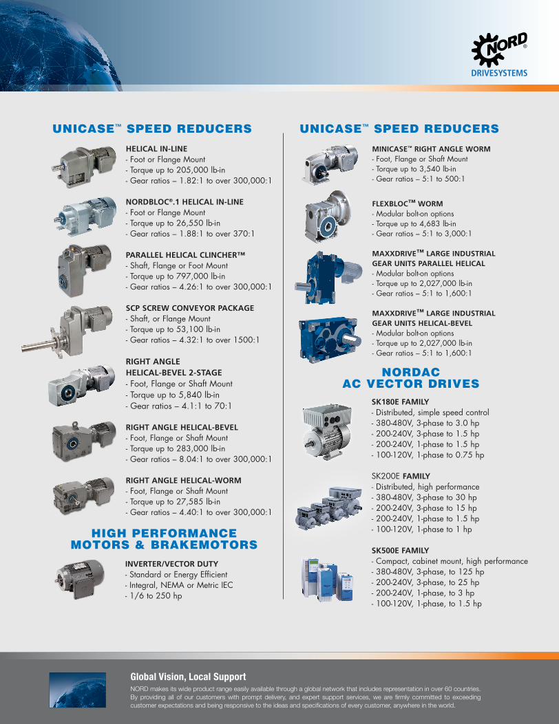
Global Vision, Local SupportNORD makes its wide product range easily available through a global network that includes representation in over 60 countries. By providing all of our customers with prompt delivery, and expert support services, we are firmly committed to exceeding customer expectations and being responsive to the ideas and specifications of every customer, anywhere in the world.
HELICAL IN-LINE - Foot or Flange Mount - Torque up to 205,000 lb-in - Gear ratios – 1.82:1 to over 300,000:1 NORDBLOC®.1 HELICAL IN-LINE - Foot or Flange Mount - Torque up to 26,550 lb-in - Gear ratios – 1.88:1 to over 370:1 PARALLEL HELICAL CLINCHER™ - Shaft, Flange or Foot Mount - Torque up to 797,000 lb-in - Gear ratios – 4.26:1 to over 300,000:1 SCP SCREW CONVEYOR PACKAGE - Shaft, or Flange Mount - Torque up to 53,100 lb-in - Gear ratios – 4.32:1 to over 1500:1 RIGHT ANGLE HELICAL-BEVEL 2-STAGE - Foot, Flange or Shaft Mount - Torque up to 5,840 lb-in - Gear ratios – 4.1:1 to 70:1 RIGHT ANGLE HELICAL-BEVEL - Foot, Flange or Shaft Mount - Torque up to 283,000 lb-in - Gear ratios – 8.04:1 to over 300,000:1 RIGHT ANGLE HELICAL-WORM - Foot, Flange or Shaft Mount - Torque up to 27,585 lb-in - Gear ratios – 4.40:1 to over 300,000:1
UNICASE™ SPEED REDUCERS
NORDACAC VECTOR DRIVES
SK180E FAMILY- Distributed, simple speed control- 380-480V, 3-phase to 3.0 hp- 200-240V, 3-phase to 1.5 hp- 200-240V, 1-phase to 1.5 hp- 100-120V, 1-phase to 0.75 hp SK200E FAMILY- Distributed, high performance- 380-480V, 3-phase to 30 hp- 200-240V, 3-phase to 15 hp- 200-240V, 1-phase to 1.5 hp- 100-120V, 1-phase to 1 hp SK500E FAMILY- Compact, cabinet mount, high performance- 380-480V, 3-phase, to 125 hp- 200-240V, 3-phase, to 25 hp- 200-240V, 1-phase, to 3 hp- 100-120V, 1-phase, to 1.5 hp
MINICASE™ RIGHT ANGLE WORM - Foot, Flange or Shaft Mount - Torque up to 3,540 lb-in - Gear ratios – 5:1 to 500:1
FLEXBLOC™ WORM - Modular bolt-on options - Torque up to 4,683 lb-in - Gear ratios – 5:1 to 3,000:1 MAXXDRIVE™ LARGE INDUSTRIALGEAR UNITS PARALLEL HELICAL - Modular bolt-on options - Torque up to 2,027,000 lb-in - Gear ratios – 5:1 to 1,600:1 MAXXDRIVE™ LARGE INDUSTRIALGEAR UNITS HELICAL-BEVEL - Modular bolt-on options - Torque up to 2,027,000 lb-in - Gear ratios – 5:1 to 1,600:1
HIGH PERFORMANCEMOTORS & BRAKEMOTORS
INVERTER/VECTOR DUTY- Standard or Energy Efficient- Integral, NEMA or Metric IEC- 1/6 to 250 hp
UNICASE™ SPEED REDUCERS
NORD Motors & Brakemotors
NORD supplies electric motors in the power range from 0.16 hp to 250 hp. NORD motors are well suited for constant torque applications and will safely op-erate over a frequency range of 0Hz to 120Hz. Each motor can be supplied with a wide range of options to customize the motor for a wide range of applications and operating demands.
This catalog contains standard NORD manufactured induction motors and brakemotors from 0.16 to 75 hp. Included are motors with standard NEMA and IEC mounting dimensions. For motors with higher powers, hazardous location, and other enclosures please contact NORD.
NORD fulfils all of the current efficiency regulations and supplies a wide range of energy saving motors for the international market, with which operating costs can be considerably reduced. In addition to reduced energy consumption, all energy NORD motors feature a very durable, low maintenance design.
NORD develops its own motors and supplies them to all the major markets throughout the world. Our own developments ensure a high level of indepen-dence from external suppliers and therefore provides our customers with the decisive advantage of short and highly dependable delivery times.
Features and Benefits■ Threaded cable entry holes ■ Lip seals on both shaft ends■ Sealed and gasketed terminal boxes.■ Continuous Duty (S1) / Premium Efficient (IE3) / Non-ventilated (TENV).■ Common 50 Hz and 60 Hz voltages.■ Inverter/vector duty wiring and insulation.■ Rated for voltage spikes per NEMA MG1, section 31.4.4.2■ Moisture resistant varnished dipped windings.
Spanning the globeTo serve youSince 1965, NORD has become well established in the power transmission industry and grown to global propor-tions on the strength of product per-formance, superior customer service, and intelligent drive solutions. NORD is constantly improving and expanding its products to meet a never-ending va-riety of industrial challenges.
NORD designs and manufactures drive systems engineered for adaptability. NORD’s innovative drive solutions are specified and utilized for a range of applications in nearly every industry throughout the world.
NORD Drivesystems’ product portfolio is extensive and continuously evolving in order to meet the needs of today’s fast-changing markets. NORD’s range of drive equipment includes: helical in-line, helical shaft-mount, helical-bev-el, helical-worm and worm gear units with torques from 90 lb-in to 2,200,000 lb-in, readily available AC motors and from 1/6 HP to 250 HP, variable fre-quency drives up to 250 HP, and me-chanical variable speed drives.
But NORD does far more than manu-facture the world’s finest drive com-ponents. We provide our customers with optimum drive configurations for their specific purposes, providing each and every one with truly complete and efficient systems at a price/quality ra-tio unmatched in today’s competitive markets.
NORD makes its wide product range easily available through a global net-work that includes representation in over 60 countries. By providing all of our customers with prompt delivery, and expert support services, we are firmly committed to exceeding custom-er expectations and being responsive to the ideas and specifications of every customer, anywhere in the world.

Motors & BrakemotorsStandard, Energy and Premium Efficiency4 pole • 50 & 60Hz
Intelligent Drivesystems, Worldwide Services
PRODUCT OVERVIEWM7000
www.nord.com6000603 / 2719
Waunakee, WI800 NORD DriveWaunakee, WI 53597Tel. 608.849.7300
Corona, CA1180 Railroad St.Corona, CA 92882Tel. 951.393.6565
Charlotte, NC300 Forsyth Hall Dr.Charlotte, NC 53597Tel. 980.215.7575
NORD Gear CorporationMEMBER OF THE NORD DRIVESYSTEMS GROUP
Brampton, ON41 West DriveBrampton, ON L6T4A1Tel. 800.668.4378
NORD Gear Limited - CanadaMEMBER OF THE NORD DRIVESYSTEMS GROUP
63-250 Frame NEMA & IEC Motors and BrakemotorsOrder Preassembled or Customized to Your Requirements
Global PresenceAllows for short lead times and quick response times throughout the world.
Innovative ProductsOur engineers are hard at work creating solutions to everyday problems.
Quality ManufacturingNORD produces maintenance free products that have a long life in order to save you money for the long haul.
Modular DesignMore than 20 million totally unique product combinations guarantees that you wont need to look anywhere else.
Dependable ServiceWith emergency service available 24/7 we can help you out when you need us most.
We Have you CoveredNORD provides Gear Drives, Motors & AC inverters in order to provide you with a complete Drivesystem solution.
NORD GEAR - MOTORS & BRAKEM
OTORSM
7000


