Embed Size (px)
Citation preview
®
THE JOURNAL OF GEAR MANUFACTURING
Clayton's Clockswww.geartechnology.com
TECHNICAL
ADDENDUM
SEP
1220IMTS 2012
EVENTS, CONFERENCES, FUN STUFFPREVIEW: CUTTING TOOLS, WORKHOLDING, ETC.
EXHIBITORS OF NOTE
Cutting Power Losses in Transmissions, Axles, Steering SystemsBearings Improve Gearbox By DesignAsk the Expert:
Refurbishing a Ball MillBevel Gears: Backlash/ContactPattern Optimization
Phone: 847-649-14505200 Prairie Stone Pkwy. • Ste. 100 • Hoffman Estates • IL 60192
Developed for dry or wet high speed cutting applications, the MAG H 400 hobbing machine runs small batches or mass-produces geared workpieces such as:
Spur and helical gears, crowned and tapered gears, worm gears, chain wheels, ring gears, shafts with multiple gears, pinions and special profi les
Star SU carries a complete line of MAG hobbers ranging in size from 80 mm to 2,300 mm. High speed direct drives, high precision hob heads, integrated chamfering/deburring solutions and various automation options are at your service. So are we.
Contact us today for more information.
Universal Gear Hobbingat your service
2012-08_Star-SU_MAG_Adv_2pages_us.indd 1 11.07.2012 18:57:53 Uhr
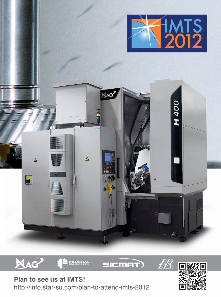
Plan to see us at IMTS!http://info.star-su.com/plan-to-attend-imts-2012
2012-08_Star-SU_MAG_Adv_2pages_us.indd 2 11.07.2012 18:57:57 Uhr
Vol. 29, No. 6 GEAR TECHNOLOGY, The Journal of Gear Manufacturing (ISSN 0743-6858) is published monthly, except in February, April, July and December by Randall Publications LLC, 1840 Jarvis Avenue, Elk Grove Vil-lage, IL 60007, (847) 437-6604. Cover price $7.00 U.S. Periodical postage paid at Arlington Heights, IL, and at additional mailing office (USPS No. 749-290). Randall Publications makes every effort to ensure that the processes described in GEAR TECHNOLOGY conform to sound engineering practice. Neither the authors nor the publisher can be held responsible for injuries sustained while following the procedures described. Postmaster: Send address changes to GEAR TECHNOLOGY, The Journal of Gear Manufacturing, 1840 Jarvis Avenue, Elk Grove Village, IL, 60007. Contents copyrighted ©2012 by RANDALL PUBLICATIONS LLC. No part of this publication may be reproduced or transmitted in any form or by any means, electronic or mechanical, including photocopying, recording, or by any information storage and retrieval system, without permission in writing from the publisher. Contents of ads are subject to Publisher’s approval. Canadian Agreement No. 40038760.
features
36
22
technical
50 Ask the ExpertRefurbishing a Ball Mill,Bevel Gears: Backlash/Contact Pattern Optimization
52 How Bearing Design Improves Gearbox PerformanceOptimized bearings improve reliability, energy cost and environmental impact.
58 Minimizing Power Losses in Transmissions, Axles and Steering SystemsSuper-finishing’s impact on micropitting: evaluation of gearbox/manufacturing process.
SEP
2012
42
2 GEAR TECHNOLOGY | September 2012 [www.geartechnology.com]2 GEAR TECHNOLOGY | September 2012
contents
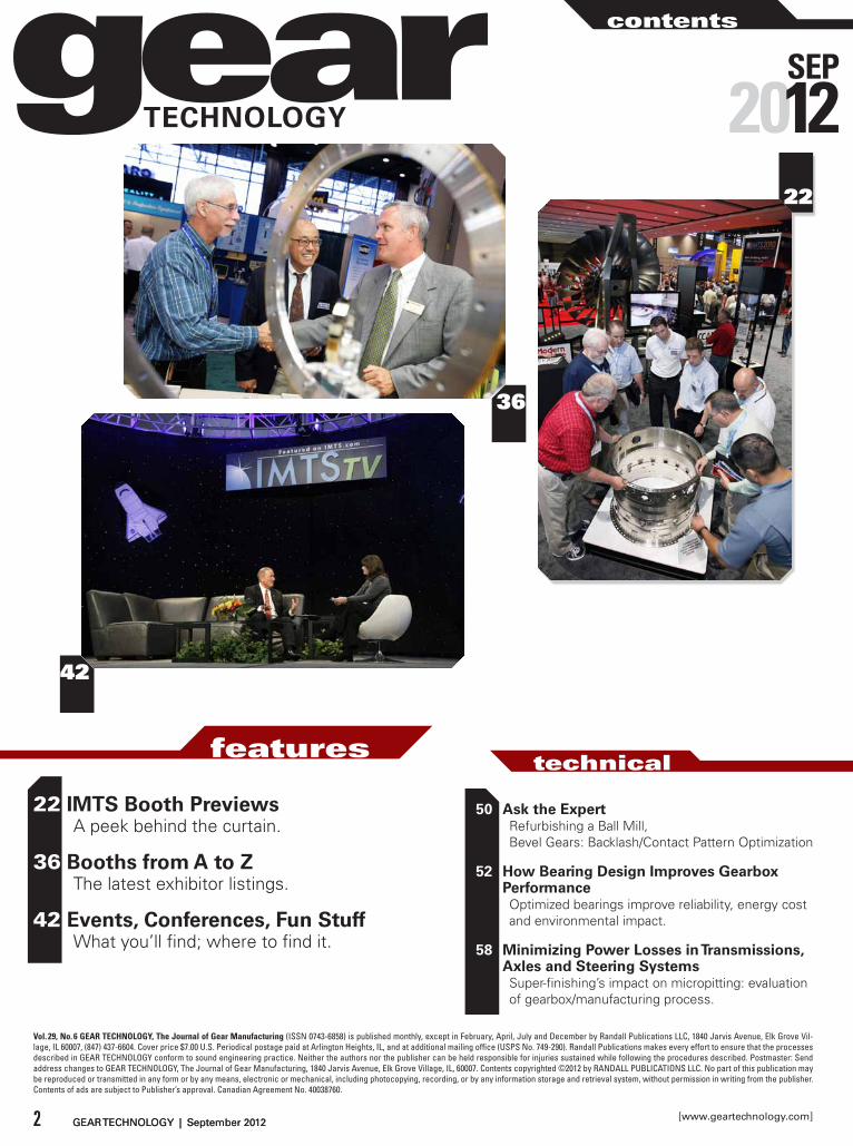
22 IMTS Booth PreviewsA peek behind the curtain.
36 Booths from A to ZThe latest exhibitor listings.
42 Events, Conferences, Fun StuffWhat you’ll find; where to find it.
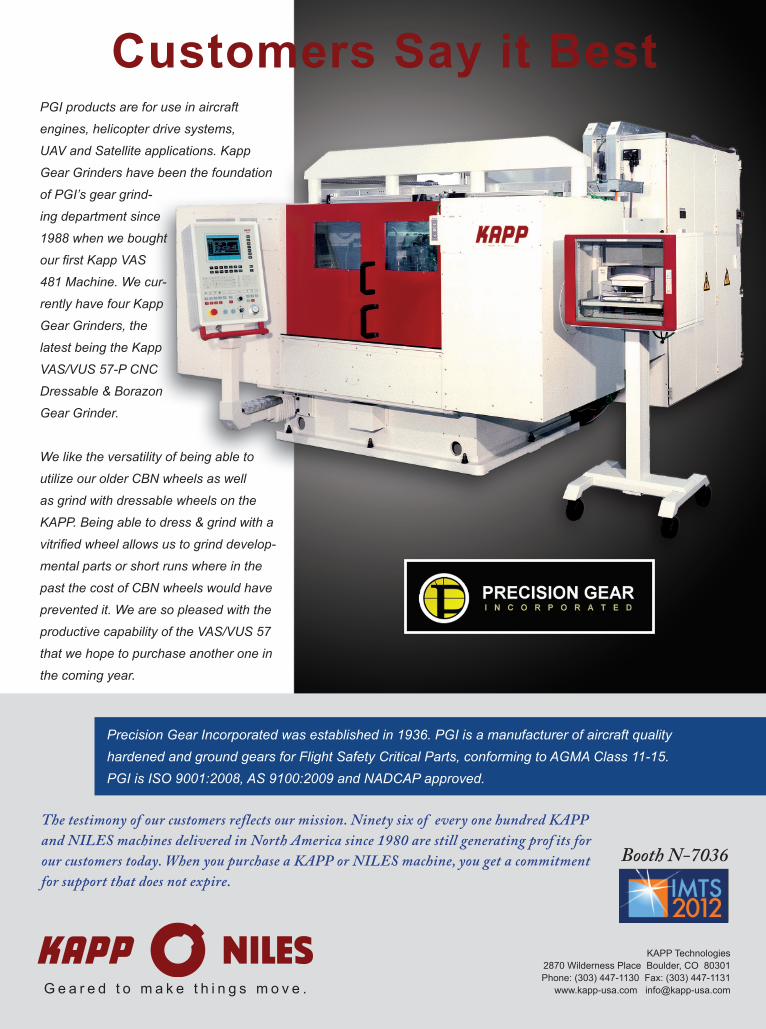
Customers Say it Best
KAPP Technologies2870 Wilderness Place Boulder, CO 80301Phone: (303) 447-1130 Fax: (303) 447-1131
www.kapp-usa.com [email protected] e a r e d t o m a k e t h i n g s m o v e .
Booth N-7036
The testimony of our customers reflects our mission. Ninety six of every one hundred KAPP and NILES machines delivered in North America since 1980 are still generating prof its for our customers today. When you purchase a KAPP or NILES machine, you get a commitment for support that does not expire.
Precision Gear Incorporated was established in 1936. PGI is a manufacturer of aircraft quality hardened and ground gears for Flight Safety Critical Parts, conforming to AGMA Class 11-15. PGI is ISO 9001:2008, AS 9100:2009 and NADCAP approved.
PGI products are for use in aircraft
engines, helicopter drive systems,
UAV and Satellite applications. Kapp
Gear Grinders have been the foundation
of PGI’s gear grind-
ing department since
1988 when we bought
our rst Kapp VAS
481 Machine. We cur-
rently have four Kapp
Gear Grinders, the
latest being the Kapp
VAS/VUS 57-P CNC
Dressable & Borazon
Gear Grinder.
We like the versatility of being able to
utilize our older CBN wheels as well
as grind with dressable wheels on the
KAPP. Being able to dress & grind with a
vitri ed wheel allows us to grind develop-
mental parts or short runs where in the
past the cost of CBN wheels would have
prevented it. We are so pleased with the
productive capability of the VAS/VUS 57
that we hope to purchase another one in
the coming year.
Vol. 29, No. 6
departments
®
THE JOURNAL OF GEAR MANUFACTURING
Clayton's Clockswww.geartechnology.com
TECHNICAL
ADDENDUM
SEP
1220IMTS 2012
EVENTS, CONFERENCES, FUN STUFFPREVIEW: CUTTING TOOLS, WORKHOLDING, ETC.
EXHIBITORS OF NOTE
Cutting Power Losses in Transmissions, Axles, Steering SystemsBearings Improve Gearbox By DesignAsk the Expert:
Refurbishing a Ball MillBevel Gears: Backlash/ContactPattern Optimization
4 GEAR TECHNOLOGY | September 2012 [www.geartechnology.com]4 GEAR TECHNOLOGY | September 2012
contents
09 Publisher’s PageAmerica Needs a Different Kind of Candidate
10 Product NewsThe latest in equipment and other industry offerings
68 Industry NewsWho’s news, trends of note, etc.
76 Events/CalendarWhere and when it’s happening.
77 SubscriptionsSign up or renew; it’s free
78 Advertiser IndexAdvertiser contact information
79 ClassifiedsOur products and services marketplace
80 AddendumClayton's Clocks
Photo courtesy of IMTS
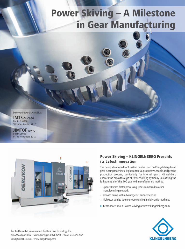
Power Skiving – KLINGELNBERG Presents its Latest Innovation The newly developed tool system can be used on Klingelnberg bevel gear cutting machines. It guarantees a productive, stable and precise production process, particularly for internal gears. Klingelnberg enables the breakthrough of Power Skiving by fi nally unleashing the full potential of this 100 year old manufacturing method.
- up to 10 times faster processing times compared to other manufacturing methods
- smooth fl anks with advantageous surface texture
- high gear quality due to precise tooling and dynamic machines
► Learn more about Power Skiving at www.klingelnberg.com
Discover Power Skiving Live:
IMTS CHICAGOBooth N-693010-15 September 2012
JIMTOF TOKYOBooth E504601-06 November 2012
Power Skiving – A Milestone in Gear Manufacturing
For the US-market please contact: Liebherr Gear Technology, Inc.
1465 Woodland Drive Saline, Michigan 48176-1259 Phone: 734-429-7225
[email protected] www.klingelnberg.com
EdITORIALPublisher & Editor-in-ChiefMichael [email protected]
Managing EditorWilliam R. [email protected]
Senior EditorJack [email protected]
Associate EditorMatthew [email protected]
Editorial ConsultantPaul R. Goldstein
Technical EditorsWilliam (Bill) BradleyRobert ErrichelloOctave Labath, P.E.Joseph MihelickCharles D. Schultz, P.E.Robert E. SmithDan Thurman
dESIGNArt DirectorDavid [email protected]
AdVERTISINGAdvertising Sales ManagerDave [email protected]
Materials CoordinatorDorothy [email protected]
CIRCULATIONCirculation ManagerCarol [email protected]
RANdALL STAFFPresidentMichael Goldstein
AccountingLuann Harrold
RANDALL PUBLICATIONS LLC1840 JARVIS AVENUEELk GROVE VILLAGE, IL 60007
(847) 437-6604FAx: (847) 437-6618
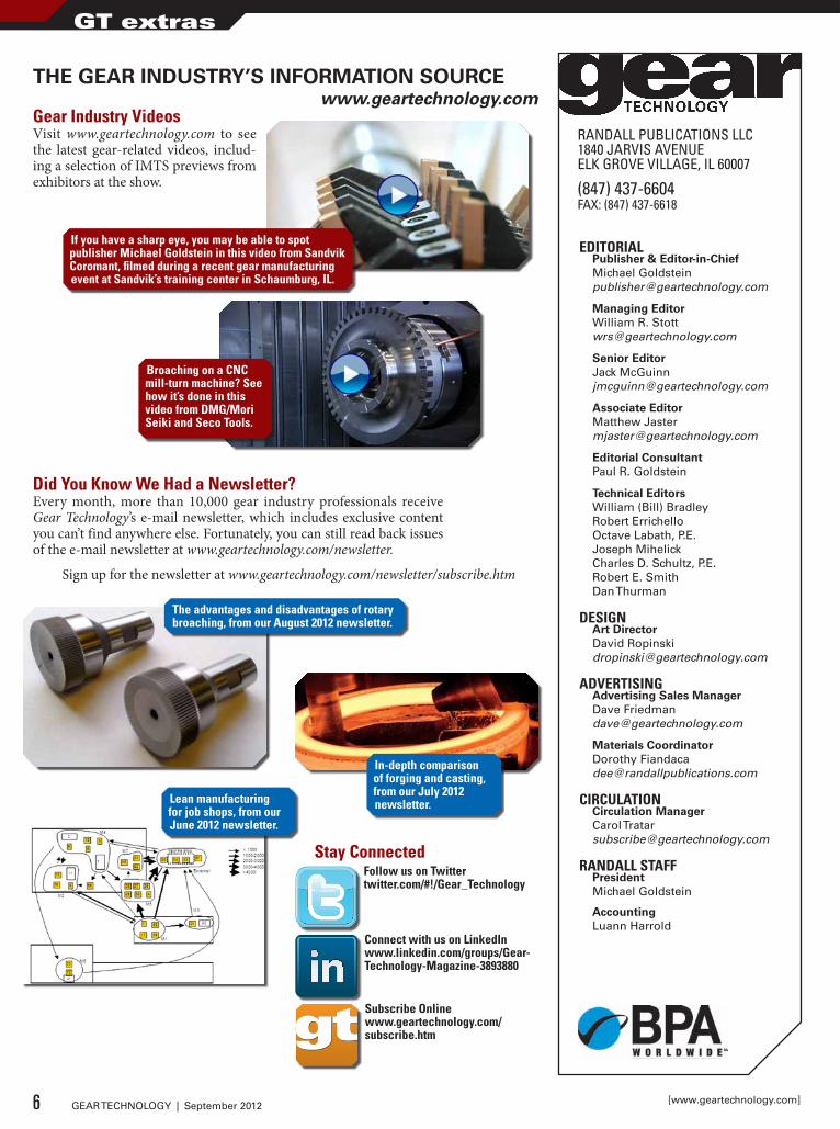
THE GEAR INDUSTRY’S INFORMATION SOURCEwww.geartechnology.com
Gear Industry VideosVisit www.geartechnology.com to see the latest gear-related videos, includ-ing a selection of IMTS previews from exhibitors at the show.
If you have a sharp eye, you may be able to spot publisher Michael Goldstein in this video from Sandvik Coromant, filmed during a recent gear manufacturing event at Sandvik’s training center in Schaumburg, IL.
Broaching on a CNC mill-turn machine? See how it’s done in this video from dMG/Mori Seiki and Seco Tools.
did You Know We Had a Newsletter?Every month, more than 10,000 gear industry professionals receive Gear Technology’s e-mail newsletter, which includes exclusive content you can’t find anywhere else. Fortunately, you can still read back issues of the e-mail newsletter at www.geartechnology.com/newsletter.
The advantages and disadvantages of rotary broaching, from our August 2012 newsletter.
Sign up for the newsletter at www.geartechnology.com/newsletter/subscribe.htm
In-depth comparison of forging and casting, from our July 2012 newsletter.Lean manufacturing
for job shops, from our June 2012 newsletter.
Subscribe Onlinewww.geartechnology.com/subscribe.htm
Stay ConnectedFollow us on Twittertwitter.com/#!/Gear_Technology
Connect with us on LinkedInwww.linkedin.com/groups/Gear-Technology-Magazine-3893880
6 GEAR TECHNOLOGY | September 2012 [www.geartechnology.com]
GT extras
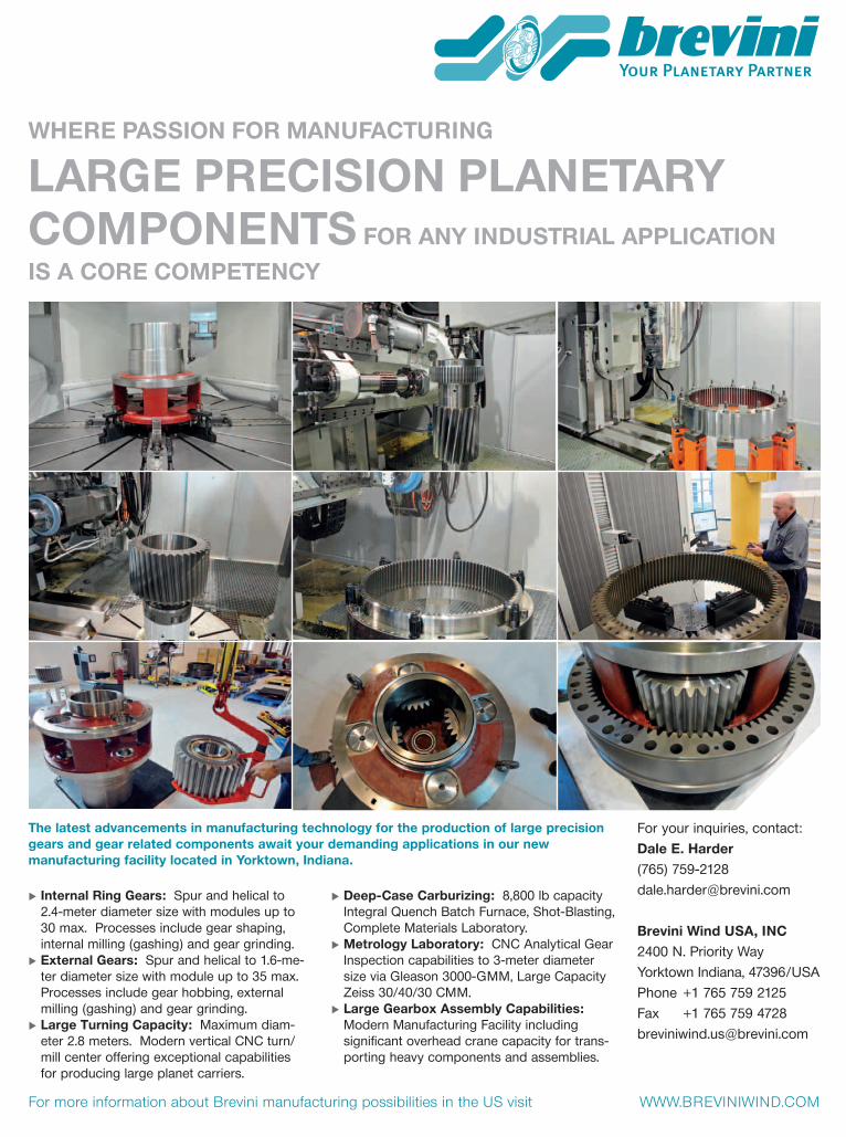
Where Passion for Manufacturing
Large Precision PLanetary coMPonents for any industriaL aPPLication is a core coMPetency
internal ring gears: Spur and helical to 2.4-meter diameter size with modules up to 30 max. Processes include gear shaping, internal milling (gashing) and gear grinding.
external gears: Spur and helical to 1.6-me-ter diameter size with module up to 35 max. Processes include gear hobbing, external milling (gashing) and gear grinding.
Large turning capacity: Maximum diam-eter 2.8 meters. Modern vertical CNC turn/mill center offering exceptional capabilities for producing large planet carriers.
deep-case carburizing: 8,800 lb capacity Integral Quench Batch Furnace, Shot-Blasting, Complete Materials Laboratory.
Metrology Laboratory: CNC Analytical Gear Inspection capabilities to 3-meter diameter size via Gleason 3000-GMM, Large Capacity Zeiss 30/40/30 CMM.
Large gearbox assembly capabilities: Modern Manufacturing Facility including significant overhead crane capacity for trans-porting heavy components and assemblies.
the latest advancements in manufacturing technology for the production of large precision gears and gear related components await your demanding applications in our new manufacturing facility located in yorktown, indiana.
For your inquiries, contact:dale e. harder (765) 759-2128 [email protected]
Brevini Wind usa, inc2400 N. Priority WayYorktown Indiana, 47396 / USAPhone +1 765 759 2125Fax +1 765 759 [email protected]
For more information about Brevini manufacturing possibilities in the US visit WWW.BREVINIWINd.COm
12-50-176 Brevini Anz.indd 1 16.08.12 11:49
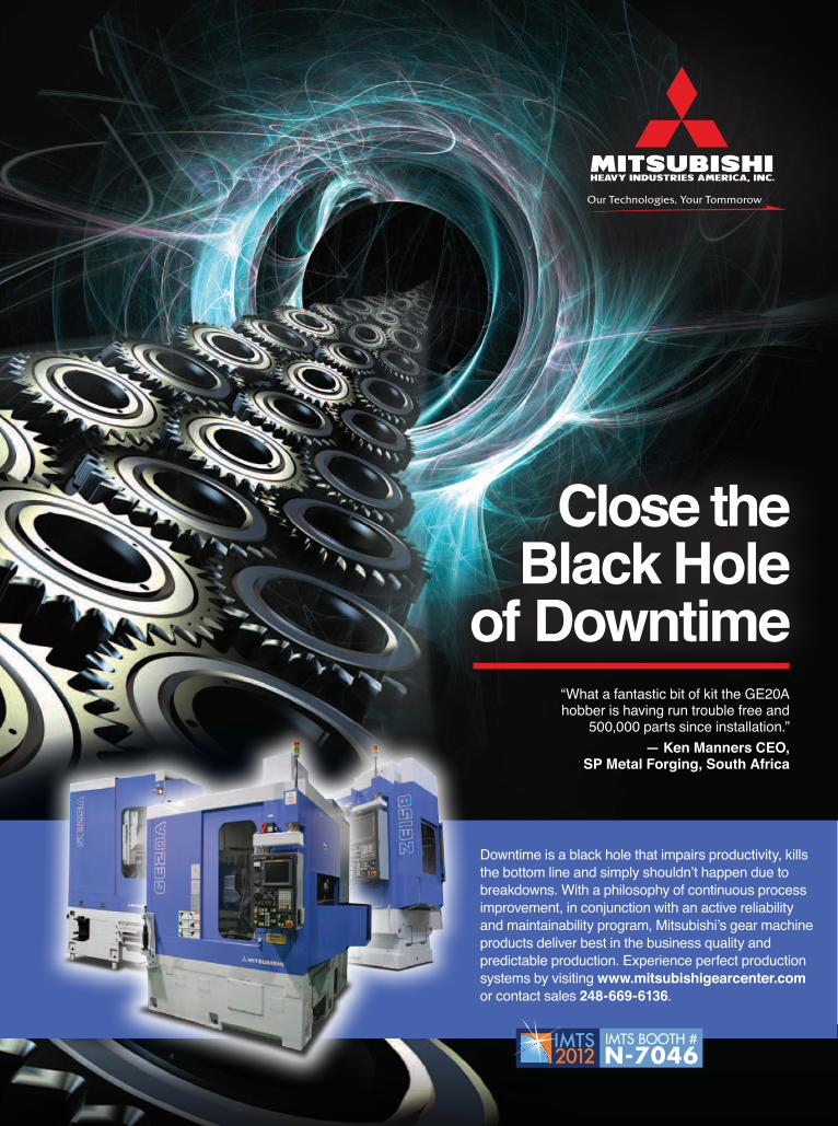
Our Technologies, Your Tommorow
Close the Black Hole
of Downtime“What a fantastic bit of kit the GE20A hobber is having run trouble free and
500,000 parts since installation.”— Ken Manners CEO,
SP Metal Forging, South Africa
Downtime is a black hole that impairs productivity, kills the bottom line and simply shouldn’t happen due to breakdowns. With a philosophy of continuous process improvement, in conjunction with an active reliability and maintainability program, Mitsubishi’s gear machine products deliver best in the business quality and predictable production. Experience perfect production systems by visiting www.mitsubishigearcenter.com or contact sales 248-669-6136.
IMTS BOOTH #N-7046
publisher's page
Publisher & Editor-in-ChiefMichael Goldstein
The two candidates in the upcoming presidential election offer two distinctly different approaches to solving America’s economic problems — neither of which is likely to be successful. One, trying to stay in office, increasingly looks to borrow even more money from our future in yet another effort to kick-start the economy. The other tells us that increasing taxes for the top 1% is not necessary, because if we leave them alone, they’ll invest their way to our prosperity (as if they have all their money sitting around in cash and are just waiting to figure out where and when to invest it).
While this ideological fight is going on, the manufac-turing community — although it’s enjoying a strong busi-ness climate — continues to suffer from a severe shortage of skilled labor. Our society encourages young people to go to college — and for many, this is the right choice. But for too long we’ve been turning out too many lawyers, finan-ciers and unneeded liberal arts majors. Parents need to get more involved and question the educational direction their kids are taking. Manufacturing isn’t often considered a via-ble vocation, despite the fact that today there are possibly 600,000 manufacturing jobs available to the right candidates (according to the Manufacturing Institute).
Time and time again I read about manufacturers strug-gling to hire good candidates to support their growth, let alone to replace their present aging workforce. A recent arti-cle focused on the hiring woes of manufacturers in Northeast Indiana, where 26% of the workforce is employed in manu-facturing. One hiring manager expects to go through 500 applicants just to get the 10 that he needs, and there’s no guarantee that those 10 hires will work out. Another hiring manager took 129 applications, which he screened down to 40. Of those 40, only four passed the basic skills test. All four were offered jobs, but only one accepted. Applicants are fail-ing drug tests and others decide they want to wait until their unemployment benefits run out before taking a factory job. Manufacturers hesitate to hire candidates with four-year col-lege degrees out of fear that those candidates will leave as soon as something else becomes available.
We don’t need better political candidates. We need better job candidates.
Just think of the economic benefits of 100,000 unemployed no longer drawing from the public coffers but each contrib-uting $35,000-$70,000 a year throughout their communities and into our economic system and you can quickly see that our economic problems can be solved from the ground up much more easily than from the government down.
The good news is that attention is finally being paid to the issue of the skilled manufacturing labor shortage. In addition to articles in the mainstream press, various organizations are getting involved. One example is AMT — The Association for Manufacturing Technology, the organizers of IMTS. At this year’s IMTS, there will be a special focus on the manu-facturing labor shortage. Booth W-200 will be home to the IMTS Jobs Center, where you can meet with professionals in manufacturing placement. In addition, the show will have the NIMS Student Skills Center, where all week long, students, educators and counselors will have a hands-on opportu-nity to explore careers in manufacturing. Finally, the show’s IMTSedu booth (N-6677) will host a town hall meeting about the workforce shortage on Tuesday, Sept. 11, at 11:00 a.m.
Solving our hiring problems might take the next decade, but you can solve some of your manufacturing problems within the next week or so by visiting IMTS in Chicago from September 10–15. It’s here at this show that you’ll find not only the latest machines and technologies but the most productive automation available to help you meet your potential demand for your products while you struggle with increasing or enhancing your workforce.
One of the best ways to reduce your dependence on hir-ing is to make the most of the labor you have. The key to that is highly effective manufacturing technology and automation, which is exactly what you’ll find at the show. Automation not only lessens the impact of our need for more employees, but it also reduces the labor content of our products and reduces the cost advantages of low-wage competitors. Despite our issues with finding skilled labor, American manufacturers remain competitive in the world because of their ingenuity, technology and innovation.
Needs a Different Kind of CandidateAMERICA
9September 2012 | GEAR TECHNOLOGY
SicmatUTiLizES NUM CNC SySTEM
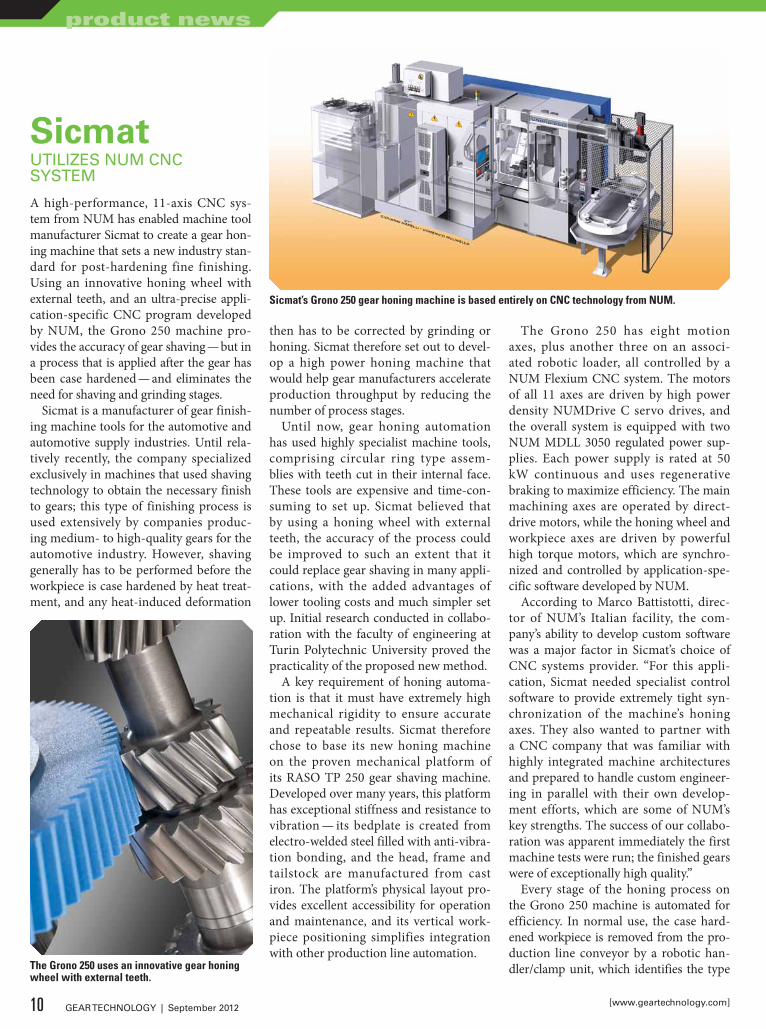
A high-performance, 11-axis CNC sys-tem from NUM has enabled machine tool manufacturer Sicmat to create a gear hon-ing machine that sets a new industry stan-dard for post-hardening fine finishing. Using an innovative honing wheel with external teeth, and an ultra-precise appli-cation-specific CNC program developed by NUM, the Grono 250 machine pro-vides the accuracy of gear shaving — but in a process that is applied after the gear has been case hardened — and eliminates the need for shaving and grinding stages.
Sicmat is a manufacturer of gear finish-ing machine tools for the automotive and automotive supply industries. Until rela-tively recently, the company specialized exclusively in machines that used shaving technology to obtain the necessary finish to gears; this type of finishing process is used extensively by companies produc-ing medium- to high-quality gears for the automotive industry. However, shaving generally has to be performed before the workpiece is case hardened by heat treat-ment, and any heat-induced deformation
then has to be corrected by grinding or honing. Sicmat therefore set out to devel-op a high power honing machine that would help gear manufacturers accelerate production throughput by reducing the number of process stages.
Until now, gear honing automation has used highly specialist machine tools, comprising circular ring type assem-blies with teeth cut in their internal face. These tools are expensive and time-con-suming to set up. Sicmat believed that by using a honing wheel with external teeth, the accuracy of the process could be improved to such an extent that it could replace gear shaving in many appli-cations, with the added advantages of lower tooling costs and much simpler set up. Initial research conducted in collabo-ration with the faculty of engineering at Turin Polytechnic University proved the practicality of the proposed new method.
A key requirement of honing automa-tion is that it must have extremely high mechanical rigidity to ensure accurate and repeatable results. Sicmat therefore chose to base its new honing machine on the proven mechanical platform of its RASO TP 250 gear shaving machine. Developed over many years, this platform has exceptional stiffness and resistance to vibration — its bedplate is created from electro-welded steel filled with anti-vibra-tion bonding, and the head, frame and tailstock are manufactured from cast iron. The platform’s physical layout pro-vides excellent accessibility for operation and maintenance, and its vertical work-piece positioning simplifies integration with other production line automation.
The Grono 250 has eight motion axes, plus another three on an associ-ated robotic loader, all controlled by a NUM Flexium CNC system. The motors of all 11 axes are driven by high power density NUMDrive C servo drives, and the overall system is equipped with two NUM MDLL 3050 regulated power sup-plies. Each power supply is rated at 50 kW continuous and uses regenerative braking to maximize efficiency. The main machining axes are operated by direct-drive motors, while the honing wheel and workpiece axes are driven by powerful high torque motors, which are synchro-nized and controlled by application-spe-cific software developed by NUM.
According to Marco Battistotti, direc-tor of NUM’s Italian facility, the com-pany’s ability to develop custom software was a major factor in Sicmat’s choice of CNC systems provider. “For this appli-cation, Sicmat needed specialist control software to provide extremely tight syn-chronization of the machine’s honing axes. They also wanted to partner with a CNC company that was familiar with highly integrated machine architectures and prepared to handle custom engineer-ing in parallel with their own develop-ment efforts, which are some of NUM’s key strengths. The success of our collabo-ration was apparent immediately the first machine tests were run; the finished gears were of exceptionally high quality.”
Every stage of the honing process on the Grono 250 machine is automated for efficiency. In normal use, the case hard-ened workpiece is removed from the pro-duction line conveyor by a robotic han-dler/clamp unit, which identifies the type The Grono 250 uses an innovative gear honing
wheel with external teeth.
Sicmat’s Grono 250 gear honing machine is based entirely on CNC technology from NUM.
10 GEAR TECHNOLOGY | September 2012 [www.geartechnology.com]
product news
of gear by checking its outside diameter before transferring it to an integral pre-process measurement station. Here, the workpiece is synchronized with a second-ary gear, then driven into mesh and rotat-ed through a complete revolution; dur-ing this time, the displacement between the two axes is measured continuously to ascertain how much stock material needs to be removed from the workpiece, and this data is fed to the Flexium CNC sys-tem.
After measurement, a further robotic handler transfers the workpiece to the honing stage, where it is initially indexed before being run up to speed and syn-chronized with the abrasive toothed honing wheel. The honing wheel is then driven progressively into mesh with the
workpiece. The two axes operate in a unique master-slave configuration that has zero delay of the slave axis, which required NUM to create a second mas-ter for the workpiece motor. Controlling the speeds of both these axes very pre-cisely, and fractionally varying one rela-tive to the other, facilitates fine adjust-ment of the honing process. Current-generation Grono 250 machines are capa-ble of spindle speeds of 7,000 rpm, and Sicmat is already developing a machine with spindle speeds of 10,000 rpm to pro-vide even tighter process control. As soon as the honing process is complete, the workpiece is disengaged from the honing
wheel, spun to remove coolant and then transferred back to the production line by the robotic handler.
Sicmat will be present at this year’s IMTS in Chicago in Star SU’s booth (N-6924) where engineers will be pleased to discuss the unique cost-saving advan-tages of the Grono 250 gear honing machine. NUM will also have a large booth (E-5135) at IMTS 2012, where the company will be highlighting its expertise in developing custom CNC software for OEMs and machine builders.
For more information:NUM Corporation603 East Diehl Road, Suite 115Naperville, IL 60563P: (630) 505-7722www.num-usa.comSicmatVia Torino, 3510044 Pianezza (TO), Turin, ItalyP: +(39) 011 9667348www.sicmat.comStar SU LLC.5200 Prairie Stone Parkway, Suite 100, Hoffman Estates, IL 60192P: (847) 649-1450www.star-su.com
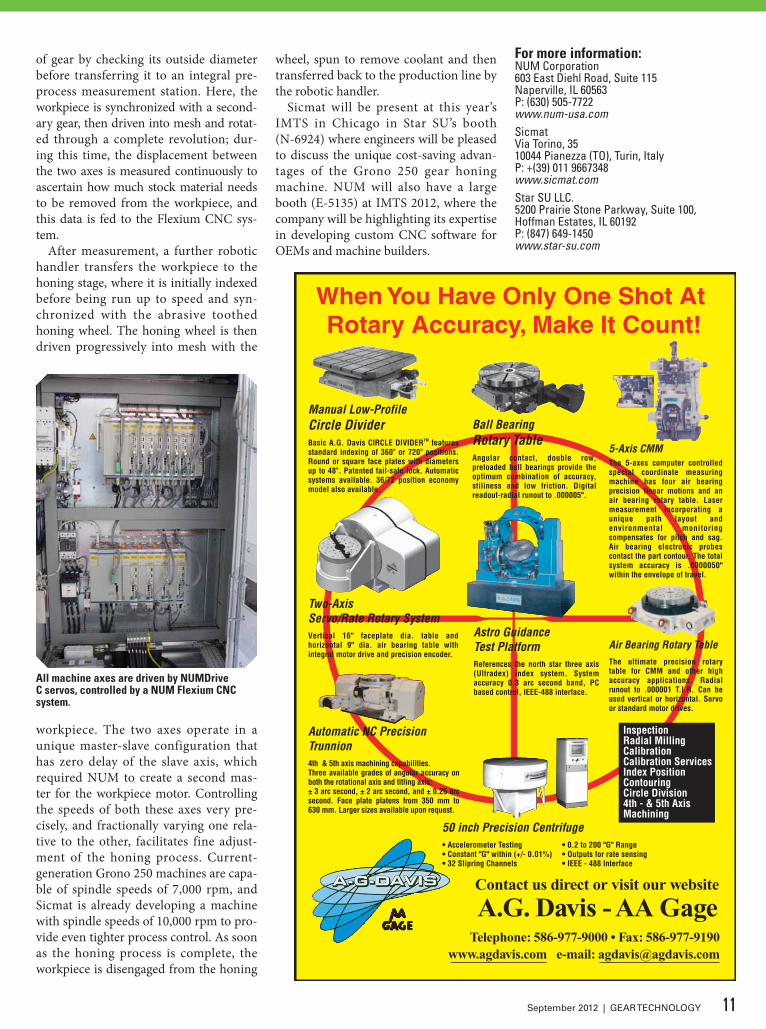
All machine axes are driven by NUMdrive C servos, controlled by a NUM Flexium CNC system.
11September 2012 | GEAR TECHNOLOGY
IngersolliNTRODUCES T-MiCRO SySTEM
Ingersoll Cutting Tools introduces the T-Micro system specifically designed for the machining of very small inter-nal diameters. The T-Micro system is a 2-piece design, consisting of a sleeve and replaceable carbide inserts. Applications include grooving, profiling, chamfer-ing, face grooving/deep face grooving,
threading, and back turning starting at .024" (0.6 mm). The inserts feature cool-ant thru capabilities and are available in grade TT9030, a submicron substrate with PVD-TiAlN coating. Inside the new T-Micro sleeve design is a locating pin to ensure repeatability when index-ing the inserts. This allows operators to return to machining without resetting the
tool. The locating pin also allows opera-tors to replace inserts without remov-ing the sleeve from the tool post. The T-Micro sleeve also features an angu-lar clamping design to avoid interfer-ence when replacing the insert, allow-ing simplified tool change on Swiss-type and other multi-spindle lathes. Ingersoll offers this sleeve in many shank sizes: 0.500", 0.625", 0.750" and 1.00", as well as 12 mm, 14 mm, 16 mm, 20 mm, 22 mm and 25 mm.For more information:Ingersoll Cutting Tools845 S. Lyford RoadRockford, IL 61108P: (815) 387-6600www.ingersoll-imc.com
IpsenSHiPS TURBOTREaTERS TO GLEaSON CUTTiNG TOOLS
Ip s e n h a s s h i p p e d t w o 6 b a r TurboTreaters to Gleason Cutting Tools Corporation located in Loves Park, Illinois. The units are designed for a max-imum operating temperature of 2,500ºF and are capable of quenching in nitrogen up to 6 bar absolute pressure. Standard features include a 2-inch-thick carbon composite/graphite felt hot zone. As the furnaces will be used for hardening and tempering, the units were purchased without a diffusion pump and will use convection assisted heating to 1,600ºF. The use of convection significantly reduces cycle times. These TurboTreaters are equipped with the newly standard-ized industrial VPN router, a modem installed so software support personnel can remotely perform diagnostics.
PERFORMANCE
© F
OTO
LIA
- ©
DA
NIE
L C
HA
SLER
IE
STARTS HEREErasteel PM and HSSThe best steels for premium tools
www.erasteel.com • Call 800.365.1152POWDER IN MOTION
12 GEAR TECHNOLOGY | September 2012 [www.geartechnology.com]
product news

50°
30°
.813
.985
A
A
www.precipart.com
Outside the box thinking. Inside the gearbox solutions.
Medical Technology • Aerospace • Homeland Security • Industrial Certifications: ISO9001, AS9100, ISO13485, ITAR
Precipart continues to be at the forefront of gear and technological innovation. We design and manufacture custom engineered mechanical and electro-mechanical assemblies for multiple industries and applications from drive systems for surgical hand tools and robotics to mechanisms for space exploration.
Your architect for custom motion control products
Enhancing lives through innovative solutions.SM
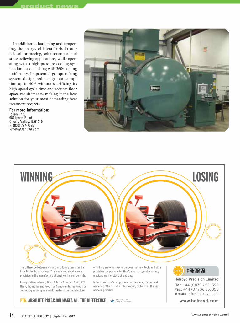
In addition to hardening and temper-ing, the energy-efficient TurboTreater is ideal for brazing, solution anneal and stress relieving applications, while oper-ating with a high-pressure cooling sys-tem for fast quenching with 360º cooling uniformity. Its patented gas quenching system design reduces gas consump-tion up to 40% without sacrificing its high-speed cycle time and reduces floor space requirements, making it the best solution for your most demanding heat treatment projects.For more information:Ipsen, Inc.984 Ipsen RoadCherry Valley, IL 61016P: (800) 727-7625www.ipsenusa.com
LOSINGWINNING
The difference between winning and losing can often be invisible to the naked eye. That’s why you need absolute precision in the manufacture of engineering components.
Incorporating Holroyd, Binns & Berry, Crawford Swift, PTG Heavy Industries and Precision Components, the Precision Technologies Group is a world leader in the manufacture
of milling systems, special purpose machine tools and ultra precision components for HVAC, aerospace, motor racing, medical, marine, steel, oil and gas.
In fact, precision’s not just our middle name; it’s our first name too. Which is why PTG is known, globally, as the first name in precision.
Holroyd Precision Limited
Tel: +44 (0)1706 526590Fax: +44 (0)1706 353350Email: [email protected]
www.holroyd.comPart of the CQME Group of CompaniesPTG. ABSOLUTE PRECISION MAKES ALL THE DIFFERENCE
121x178_PTG_Gear_Tech_Ad.indd 3 27/01/2012 12:1314 GEAR TECHNOLOGY | September 2012 [www.geartechnology.com]
product news
RenishawOFFERS MaCHiNE TOOL iNSPECTiON PROBiNG
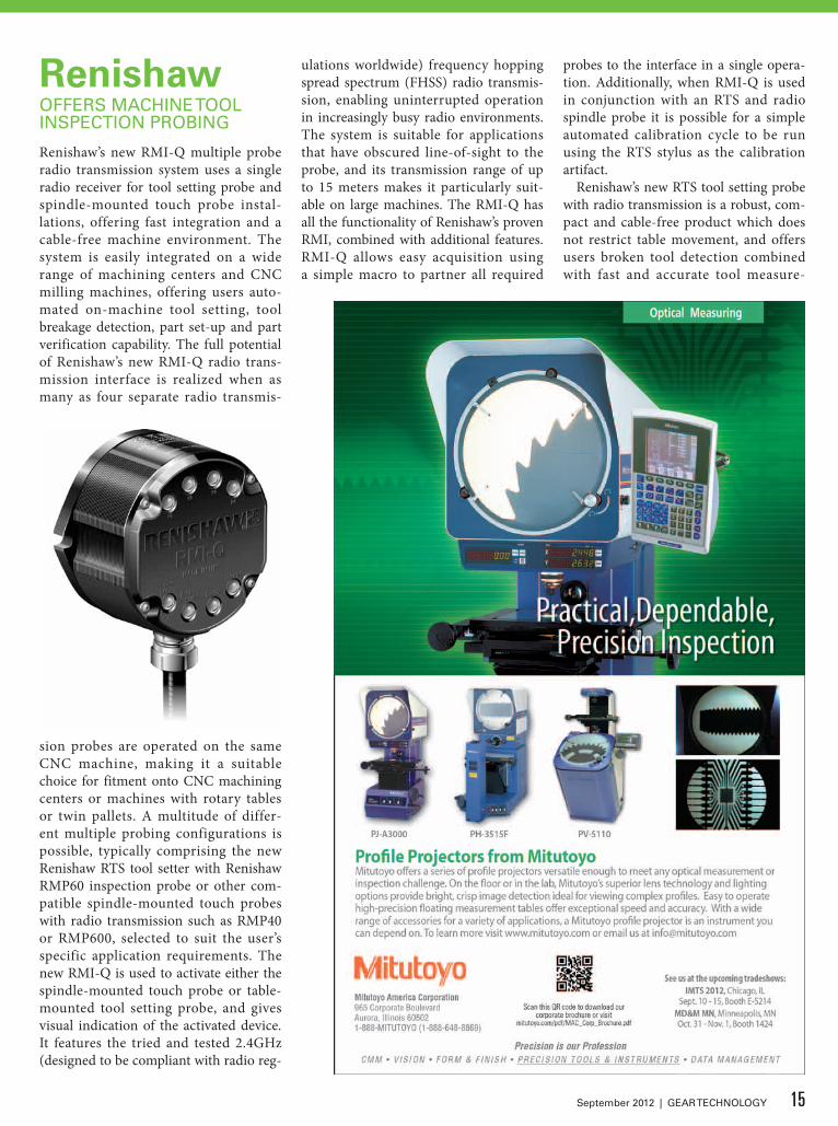
Renishaw’s new RMI-Q multiple probe radio transmission system uses a single radio receiver for tool setting probe and spindle-mounted touch probe instal-lations, offering fast integration and a cable-free machine environment. The system is easily integrated on a wide range of machining centers and CNC milling machines, offering users auto-mated on-machine tool setting, tool breakage detection, part set-up and part verification capability. The full potential of Renishaw’s new RMI-Q radio trans-mission interface is realized when as many as four separate radio transmis-
sion probes are operated on the same CNC machine, making it a suitable choice for fitment onto CNC machining centers or machines with rotary tables or twin pallets. A multitude of differ-ent multiple probing configurations is possible, typically comprising the new Renishaw RTS tool setter with Renishaw RMP60 inspection probe or other com-patible spindle-mounted touch probes with radio transmission such as RMP40 or RMP600, selected to suit the user’s specific application requirements. The new RMI-Q is used to activate either the spindle-mounted touch probe or table-mounted tool setting probe, and gives visual indication of the activated device. It features the tried and tested 2.4GHz (designed to be compliant with radio reg-
ulations worldwide) frequency hopping spread spectrum (FHSS) radio transmis-sion, enabling uninterrupted operation in increasingly busy radio environments. The system is suitable for applications that have obscured line-of-sight to the probe, and its transmission range of up to 15 meters makes it particularly suit-able on large machines. The RMI-Q has all the functionality of Renishaw’s proven RMI, combined with additional features. RMI-Q allows easy acquisition using a simple macro to partner all required
probes to the interface in a single opera-tion. Additionally, when RMI-Q is used in conjunction with an RTS and radio spindle probe it is possible for a simple automated calibration cycle to be run using the RTS stylus as the calibration artifact.
Renishaw’s new RTS tool setting probe with radio transmission is a robust, com-pact and cable-free product which does not restrict table movement, and offers users broken tool detection combined with fast and accurate tool measure-
15September 2012 | GEAR TECHNOLOGY
ment. Its design is particularly suitable for machines with twin pallets or rota-ry tables, which historically have prov-en challenging for installations of hard-wired tool setters.
The RTS is designed to be compliant with radio regulations worldwide, using frequency hopping spread spectrum (FHSS) transmission on the 2.4 GHz fre-quency band. The RTS can measure both tool length and diameter of milling cut-ters, twist drills and end mills. Powered by two standard AA batteries and ben-efiting from significantly extended bat-tery life, it is compatible with Renishaw’s RMP60 and RMP600 spindle probes. The RTS can be used in conjunction with up to three other radio probes using the RMI-Q and is also compatible with the current product, the RMI.For more information:Renishaw, Inc.5277 Trillium Blvd.Hoffman Estates, IL 60192P: (847) 286-9953www.renishaw.com
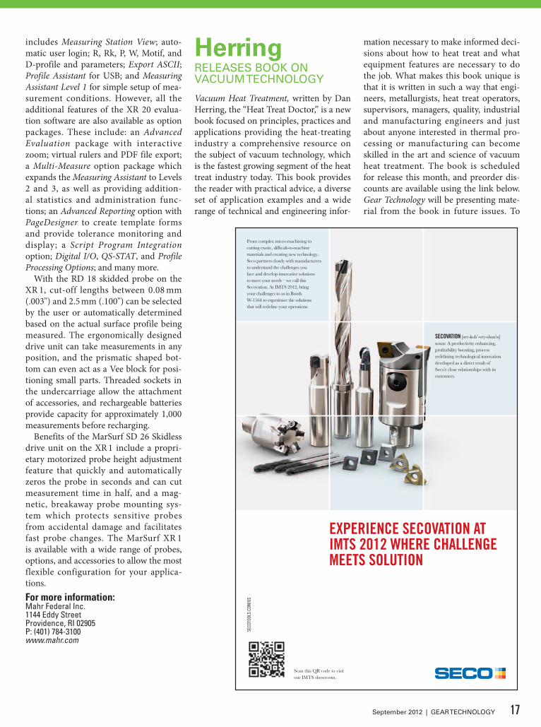
MahriNTRODUCES MaRSURF XR 1
With the introduction of the MarSurf XR 1 surface measuring system, Mahr has bridged the gap between portable sur-face measuring devices and larger, full-featured, PC-based surface measurement and evaluation systems. The MarSurf XR 1 combines the skidded and skidless drive units of Mahr’s portable M-Series
instruments, with its MarWin evalua-tion software. The new XR 1 provides an affordable entry into the world of mod-ern, PC-based measurement and evalua-tion systems, including compliance with all international standards, diverse eval-uation methods, extensive documenta-tion, large storage capacity, data export and import, as well as networking and other benefits. “The gap between por-table units and higher-end surface evalu-ation systems used to be quite large,” said Pat Nugent, vice president of metrology for Mahr Federal, a member of the Mahr Group. “The XR 1 sits squarely in that gap, offering users the benefits of both portability and fuller-featured evaluation in skidded and skidless measurements.”
The MarSurf XR 1 is suitable for use either in the measurement lab or on the shop floor, and provides over 80 param-eters for R, P, W profiles according to current DIN, ISO, JIS, ASME and Motif standards. The system can utilize both the MarSurf RD 18 drive unit with skid-ded probe and the MarSurf SD 26 drive unit with skidless probe, and virtually any number of drive units can be connected to the evaluation unit via Bluetooth or cable. Measuring units can be used alone in different orientations, in combination with various accessories, or mounted on measuring stands. Measurements can be initiated either by touch screen on a PC or manually on the drive units.
The MarSurf XR 1 comes standard with a basic version of Mahr’s leading MarWin surface evaluation software, which
Carbon, alloy &
stainless steel rings 4–144” oD.
mcinnesrolledrings.com
twiCe as big,just as fast.
2-3 weeK DeliVeries with materials in stock.
16 GEAR TECHNOLOGY | September 2012 [www.geartechnology.com]
product news
includes Measuring Station View; auto-matic user login; R, Rk, P, W, Motif, and D-profile and parameters; Export ASCII; Profile Assistant for USB; and Measuring Assistant Level 1 for simple setup of mea-surement conditions. However, all the additional features of the XR 20 evalua-tion software are also available as option packages. These include: an Advanced Evaluation package with interactive zoom; virtual rulers and PDF file export; a Multi-Measure option package which expands the Measuring Assistant to Levels 2 and 3, as well as providing addition-al statistics and administration func-tions; an Advanced Reporting option with PageDesigner to create template forms and provide tolerance monitoring and display; a Script Program Integration option; Digital I/O, QS-STAT, and Profile Processing Options; and many more.
With the RD 18 skidded probe on the XR 1, cut-off lengths between 0.08 mm (.003") and 2.5 mm (.100") can be selected by the user or automatically determined based on the actual surface profile being measured. The ergonomically designed drive unit can take measurements in any position, and the prismatic shaped bot-tom can even act as a Vee block for posi-tioning small parts. Threaded sockets in the undercarriage allow the attachment of accessories, and rechargeable batteries provide capacity for approximately 1,000 measurements before recharging.
Benefits of the MarSurf SD 26 Skidless drive unit on the XR 1 include a propri-etary motorized probe height adjustment feature that quickly and automatically zeros the probe in seconds and can cut measurement time in half, and a mag-netic, breakaway probe mounting sys-tem which protects sensitive probes from accidental damage and facilitates fast probe changes. The MarSurf XR 1 is available with a wide range of probes, options, and accessories to allow the most flexible configuration for your applica-tions.For more information:Mahr Federal Inc.1144 Eddy StreetProvidence, RI 02905P: (401) 784-3100www.mahr.com
HerringRELEaSES BOOk ON VaCUUM TECHNOLOGy
Vacuum Heat Treatment, written by Dan Herring, the “Heat Treat Doctor,” is a new book focused on principles, practices and applications providing the heat-treating industry a comprehensive resource on the subject of vacuum technology, which is the fastest growing segment of the heat treat industry today. This book provides the reader with practical advice, a diverse set of application examples and a wide range of technical and engineering infor-
mation necessary to make informed deci-sions about how to heat treat and what equipment features are necessary to do the job. What makes this book unique is that it is written in such a way that engi-neers, metallurgists, heat treat operators, supervisors, managers, quality, industrial and manufacturing engineers and just about anyone interested in thermal pro-cessing or manufacturing can become skilled in the art and science of vacuum heat treatment. The book is scheduled for release this month, and preorder dis-counts are available using the link below. Gear Technology will be presenting mate-rial from the book in future issues. To
SECO
TOOL
S.CO
M/U
S
Scan this QR code to visit our IMTS showroom.
EXPERIENCE SECOVATION AT IMTS 2012 WHERE CHALLENGE MEETS SOLUTION
From complex micro-machining to cutting exotic, diffi cult-to-machine materials and creating new technology, Seco partners closely with manufacturers to understand the challenges you face and develop innovative solutions to meet your needs – we call this Secovation. At IMTS 2012, bring your challenges to us in Booth W-1564 to experience the solutions that will redefi ne your operations.
SECOVATION [see-koh’-vey-shun’n]noun: A productivity enhancing, profi tability boosting, process redefi ning technological innovation developed as a direct result of Seco’s close relationships with its customers.
17September 2012 | GEAR TECHNOLOGY
place an order, visit http://store.bnpmedia.com/store/aec_online/hvac/index.html.For more information:The Herring Group, Inc.P.O. Box 884Elmhurst, IL 60126P: (630) 834-3017www.heat-treat-doctor.com
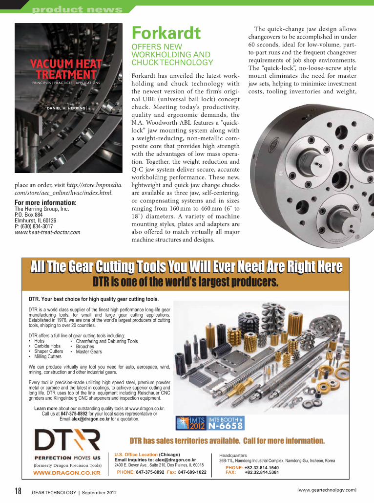
ForkardtOFFERS NEW WORkHOLDiNG aND CHUCk TECHNOLOGy
Forkardt has unveiled the latest work-holding and chuck technology with the newest version of the firm’s origi-nal UBL (universal ball lock) concept chuck. Meeting today’s productivity, quality and ergonomic demands, the N.A. Woodworth ABL features a “quick-lock” jaw mounting system along with a weight-reducing, non-metallic com-posite core that provides high strength with the advantages of low mass opera-tion. Together, the weight reduction and Q-C jaw system deliver secure, accurate workholding performance. These new, lightweight and quick jaw change chucks are available as three jaw, self-centering, or compensating systems and in sizes ranging from 160 mm to 460 mm (6" to 18") diameters. A variety of machine mounting styles, plates and adapters are also offered to match virtually all major machine structures and designs.
The quick-change jaw design allows changeovers to be accomplished in under 60 seconds, ideal for low-volume, part-to-part runs and the frequent changeover requirements of job shop environments. The “quick-lock”, no-loose-screw style mount eliminates the need for master jaw sets, helping to minimize investment costs, tooling inventories and weight,
U.S. Office Location (Chicago)Email inquiries to: [email protected] E. Devon Ave., Suite 210, Des Plaines, IL 60018 PHONE: 847-375-8892 Fax: 847-699-1022
DTR has sales territories available. Call for more information.
WWW.DRAGON.CO.KR(formerly Dragon Precision Tools)
DTR. Your best choice for high quality gear cutting tools.
DTR is a world class supplier of the finest high performance long-life gear manufacturing tools, for small and large gear cutting applications. Established in 1976, we are one of the world’s largest producers of cutting tools, shipping to over 20 countries.
DTR offers a full line of gear cutting tools including:• Hobs• Carbide Hobs• Shaper Cutters• Milling Cutters
We can produce virtually any tool you need for auto, aerospace, wind, mining, construction and other industrial gears.
Every tool is precision-made utilizing high speed steel, premium powder metal or carbide and the latest in coatings, to achieve superior cutting and long life. DTR uses top of the line equipment including Reischauer CNC grinders and Klingelnberg CNC sharpeners and inspection equipment.
Learn more about our outstanding quality tools at www.dragon.co.kr. Call us at 847-375-8892 for your local sales representative or
Email [email protected] for a quotation.
Headquarters36B-11L, Namdong Industrial Complex, Namdong-Gu, Incheon, Korea PHONE: +82.32.814.1540 FAX: +82.32.814.5381
All the Gear Cutting Tools You Will Ever Need are Right HereAll the Gear Cutting Tools You Will Ever Need are Right HereAll The Gear Cutting Tools You Will Ever Need Are Right HereAll The Gear Cutting Tools You Will Ever Need Are Right HereDTR is one of the world’s largest producers.
• Chamfering and Deburring Tools• Broaches• Master Gears
IMTS BOOTH #N-6658
VACUUM
HEAT TREATM
ENT
HE
RR
ING
Vacuum Heat Treatment – with its emphasis on principles, practices and applications – provides the heat-treating industry with its rst truly comprehensive resource on the subject of vacuum technology, which is the fastest growing segment of the market today. This book provides the reader with practical advice, a diverse set of application examples, and a wide range of technical and engineering information necessary to make informed decisions about how to heat treat and what equipment features are necessary to do the job.
What makes this book unique is that it is written in a way that engineers, metallurgists, heat-treat operators, supervisors, managers, quality and production engineers, and just about anyone interested in thermal processing or manufacturing can become skilled in the art and science of vacuum heat treatment.
VACUUM HEAT TREATMENTPRINCIPLES | PRACTICES | APPLICATIONS
IMPORTANCE OF VACUUM TECHNOLOGY IN THE HEAT TREATMENT INDUSTRY
“Vacuum processing, when performed properly, can cure the many ills that metallurgists face every day. Symptoms such as decarburization, hydrogen embrittlement, intergranular oxidation and alpha-case contamination are completely eliminated while the chances of acquiring distortion are greatly reduced.”
– ROBERT HILL JR., President,Solar Atmospheres of Western PA
“As an aerospace manufacturing company with a diverse range of materials and processes, vacuum heat treating provides us with a exible and reliable means of processing components in a highly controlled and repeatable manner.”
– STEVE CAREY, Sr. Divisional Manager/Corporate Materials Engineering,
New Hampshire Ball Bearings, Inc.
“Automotive companies are rapidly adopting vacuum carburizing (LPC) to better control distortion and avoid post-heat-treatment operations.”
– ROBERT PETERS, President, ALD Thermal Treatment
“Within these chapters Dan has captured the birth, history, applications and future direction of vacuum processing. The impetus this technology has given the metals and manufacturing community is truly fantastic.”
– FREDERICK J. OTTO, President, Midwest-Thermal Vac, Inc.
“The importance of this work by IH columnist Dan Herring cannot be overstated. Of all the recent advances in the thermal-processing industry, 9 of 10 are related to vacuum processing. It is the technology of tomorrow.”
– DOUG GLENN, Publisher, Industrial Heating
VACUUM HEATTREATMENT
PRINCIPLES | PRACTICES | APPLICATIONS
DANIEL H. HERRING
ABOUT THE AUTHOR
Professor Daniel H. Herring, “The Heat Treat Doctor,®” has been an active member of the materials and heat-treating
community for the past 40 years. A graduate of the University of Illinois, Dan has traveled around the world solving heat-treating problems and teaching others the art and science of heat treatment. His expertise spans both ferrous and nonferrous metallurgy, and he has operated, designed and maintained all types of vacuum, atmosphere and induction equipment.
A monthly columnist and consulting technical editor for Industrial Heating, he is the author of three other books and more than 500 technical articles. He also holds an Associate Research Professorship at the Illinois Institute of Technology/Thermal Processing Technology Center. Dan’s focus has always been on the practical side of his science, and as such he is uniquely quali ed to discuss vacuum heat treatment.
A native Chicagoan, Dan’s hobbies include amateur mathematics, writing poetry and spending quality time thinking about how science can improve the future of mankind.
Dan is President of The HERRING GROUP Inc., a business offering professional support services to industry since 1995. The company specializes in consulting services (heat treatment and metallurgy), technical services (industrial education/training and process/equipment assistance) and marketing services (marketing studies and new product launches) for the heat-treating and sintering industries.
THE
HEAT TREAT DOCTOR
In
dustrial Heating's
ttingg''ssIInn
dduussttss
VHT-DustJacket.indd 1 7/23/12 8:34 AM
18 GEAR TECHNOLOGY | September 2012 [www.geartechnology.com]
product news
yet is configured to provide high levels of precision, set-up ease, and excellent repeatability.
Second, the low-weight composite core construction — establishing an approxi-mate 40% weight reduction when com-pared to like capacity, conventional chucks — provides benefits in five dis-tinct areas, including reduced power consumption for lower utility costs and “green” operations. Because of the chuck’s diminished mass, spindle life will typi-cally improve as machine components
are exposed to minimized wear and tear — also resulting in reduced costs
for maintenance, repairs and replace-ment parts.
This new concept in workhold-ing design offers a unique benefit to the end user. The reduction in mass allows the operator to ramp up to speed much more quickly than with
conventional pull down chucks. This same benefit also holds true when
ramping down after cutting is com-plete. These two benefits provide true
savings in production environments.The new chuck permits operation
on lower horsepower machines, thus expanding the working capacity and range of the machines, yet keeping capi-tal investment and energy costs to lower budgeted levels.
The N.A. Woodworth ABL compos-ite-core body also provides a damping effect while machining. The core absorbs vibration during turning, which results in better part finishes. Depending on the part tolerances, this benefit may elimi-nate unnecessary grinding.
The quick-change jaw mounting design, with fewer parts, also contributes to lower weights and the low mass reduc-es centrifugal forces to help prevent jaw slippage, machining errors and increased spindle speeds. The new chucks are com-pletely sealed to prevent internal contam-ination while an innovative design pro-vides improved chip evacuation, allowing for more reliable and accurate workpiece positioning.For more information:The Forkardt GroupITW Workholding2155 Traversefield Dr.Traverse City, MI. 49686P: (800) [email protected]
OkumaHiGHLiGHTS CNC LaTHE aT iMTS
Okuma America Corporation recently announced that the new LT-3000EX, a high-powered CNC lathe, will be shown for the first time in the United States at IMTS 2012 (Okuma Booth S-8500). The LT-3000EX is now the largest in Okuma’s LT-EX series of horizontal lathe machines. This fully-loaded CNC lathe
is available in ether two- or three-tur-ret versions, with or without Y-axis, to provide optimum process balance, pro-duction throughput and integrated oper-ations. The LT-3000EX delivers preci-sion turning in any direction, and is well suited for high production environments such as the automotive industry. The LT-3000EX is available with 16 turret sta-tions to allow for redundant tooling in order to best utilize back-up tooling for lights-out manufacturing or high produc-tion runs. It offers very high feature utili-
19September 2012 | GEAR TECHNOLOGY
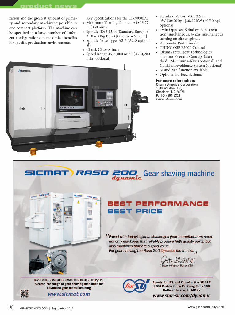
zation and the greatest amount of prima-ry and secondary machining possible in one compact platform. The machine can be specified in a large number of differ-ent configurations to maximize benefits for specific production environments.
Key Specifications for the LT-3000EX:• Maximum Turning Diameter: Ø 13.77
in (350 mm)• Spindle ID: 3.15 in (Standard Bore) or
3.58 in (Big Bore) [80 mm or 91 mm]• Spindle Nose Type: A2-6 (A2-8 option-
al)• Chuck Class: 8-inch• Speed Range 45~5,000 min-1 (45~4,200
min-1 optional)
• Standard Power: VAC 22/15 kW (30/20 hp) [30/22 kW (40/30 hp) optional]
• Twin Opposed Spindles: A-B opera-tion simultaneous, 4-axis simultaneous turning on either spindle
• Automatic Part Transfer• THINC OSP P300L Control• Okuma Intelligent Technologies:
Thermo-Friendly Concept (stan-dard), Machining-Navi (optional) and Collision Avoidance System (optional)
• M and MY function available• Optional Barfeed SystemsFor more information:Okuma America Corporation1900 Westhall Dr.,Charlotte, NC 28278P: (704) 504-6324www.okuma.com
20 GEAR TECHNOLOGY | September 2012 [www.geartechnology.com]
product news
A progressive gear manufacturer understands it needs to go above and beyond traditional expectations. Today’s customers demand – and deserve – the latest technology, a wide range of capabilities and an unrelenting commitment to prompt and effective customer service. When it comes to exceeding expectations, Schafer Gear is truly light years ahead. Our investment in the latest production equipment assures that we can provide gears for many industrial applications including transportation, medical, mining, gas and energy, agricultural equipment and many specialty applications. And every gear we make comes with one thing standard – the willingness to go to the ends of the earth to serve our customers well.
Find out more at www.schafergear.com or call us at 574-234-4116.
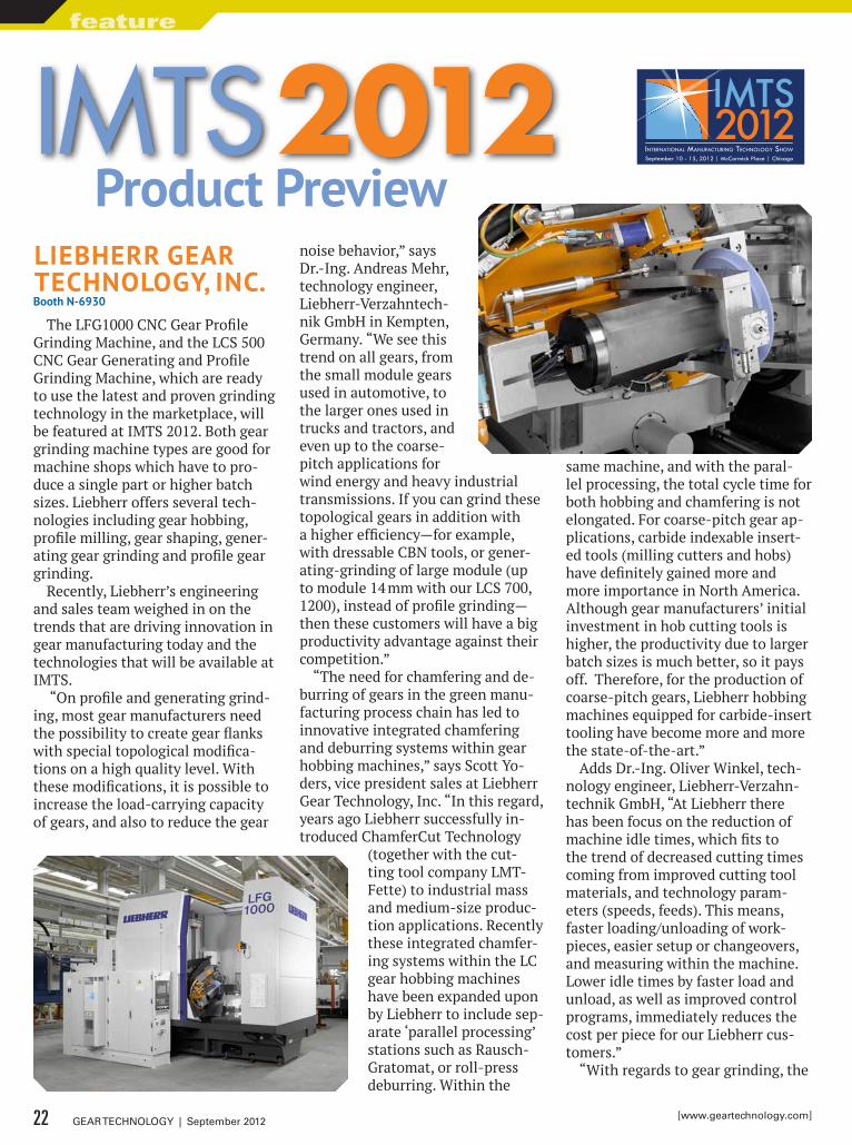
Liebherr GeAr TechnoLoGy, inc.booth n-6930
The LFG1000 CNC Gear Profile Grinding Machine, and the LCS 500 CNC Gear Generating and Profile Grinding Machine, which are ready to use the latest and proven grinding technology in the marketplace, will be featured at IMTS 2012. Both gear grinding machine types are good for machine shops which have to pro-duce a single part or higher batch sizes. Liebherr offers several tech-nologies including gear hobbing, profile milling, gear shaping, gener-ating gear grinding and profile gear grinding.
Recently, Liebherr’s engineering and sales team weighed in on the trends that are driving innovation in gear manufacturing today and the technologies that will be available at IMTS.
“On profile and generating grind-ing, most gear manufacturers need the possibility to create gear flanks with special topological modifica-tions on a high quality level. With these modifications, it is possible to increase the load-carrying capacity of gears, and also to reduce the gear
noise behavior,” says Dr.-Ing. Andreas Mehr, technology engineer, Liebherr-Verzahntech-nik GmbH in Kempten, Germany. “We see this trend on all gears, from the small module gears used in automotive, to the larger ones used in trucks and tractors, and even up to the coarse-pitch applications for wind energy and heavy industrial transmissions. If you can grind these topological gears in addition with a higher efficiency—for example, with dressable CBN tools, or gener-ating-grinding of large module (up to module 14 mm with our LCS 700, 1200), instead of profile grinding—then these customers will have a big productivity advantage against their competition.”
“The need for chamfering and de-burring of gears in the green manu-facturing process chain has led to innovative integrated chamfering and deburring systems within gear hobbing machines,” says Scott Yo-ders, vice president sales at Liebherr Gear Technology, Inc. “In this regard, years ago Liebherr successfully in-troduced ChamferCut Technology
(together with the cut-ting tool company LMT-Fette) to industrial mass and medium-size produc-tion applications. Recently these integrated chamfer-ing systems within the LC gear hobbing machines have been expanded upon by Liebherr to include sep-arate ‘parallel processing’ stations such as Rausch-Gratomat, or roll-press deburring. Within the
same machine, and with the paral-lel processing, the total cycle time for both hobbing and chamfering is not elongated. For coarse-pitch gear ap-plications, carbide indexable insert-ed tools (milling cutters and hobs) have definitely gained more and more importance in North America. Although gear manufacturers’ initial investment in hob cutting tools is higher, the productivity due to larger batch sizes is much better, so it pays off. Therefore, for the production of coarse-pitch gears, Liebherr hobbing machines equipped for carbide-insert tooling have become more and more the state-of-the-art.”
Adds Dr.-Ing. Oliver Winkel, tech-nology engineer, Liebherr-Verzahn-technik GmbH, “At Liebherr there has been focus on the reduction of machine idle times, which fits to the trend of decreased cutting times coming from improved cutting tool materials, and technology param-eters (speeds, feeds). This means, faster loading/unloading of work-pieces, easier setup or changeovers, and measuring within the machine. Lower idle times by faster load and unload, as well as improved control programs, immediately reduces the cost per piece for our Liebherr cus-tomers.”
“With regards to gear grinding, the
Product PreviewIMTS 2012
22 GEAR TECHNOLOGY | September 2012 [www.geartechnology.com]
feature
Gear Solutions From Drake
All Drake Gear Machines are shipped with the latest CNC controls, Gear Smart™ programming, fi eld support and guaranteed performance.
GS:G2 Gear Grinders• Grind 25mm to 350mm tip diameter• CNC contour diamond roll dressing• CNC direct drive torque motor work index• DIN 2-3 quality capable• User-friendly software
GS:TE-LM Worm Grinders• Part lengths up to 2m• Diameters up to 650mm• Auto load available• ZK, ZI, ZN, ZA to DIN 1-2 quality capable
GS:RM Rack Mills• Auto load in a cell• No pits or platforms• 10-minute cutter change• Compare to broaching
GS:H Gear Hobbers• Up to 1800mm diameter• Auto load & probe• Power helix
CS:R Control System Renewal• New CNC for “brain dead” good iron• Gear grinders, hobbing machines, thread and rack milling machines• Work done on your fl oor• Only 2 weeks downtime
Drake Manufacturing Services Co.Tel: [email protected]
Koepfer America LLCTel: [email protected]
Drake Gear MachinesRepresented in North America by:
Precision Machines for Threads & Gears
See us in Booth N-6918
DRAK-462GearTechAdUSrev.indd 1 7/9/12 11:23 AM
use of dressable CBN, or other pow-erful abrasives, will have a very im-portant impact, because the grinding time (which influences mainly the workpiece costs per part) is drasti-cally reduced,” Mehr says. “Where in the past you may have needed three machines to produce a specific quan-tity of gears per day, you now would need only one.”For more information:Liebherr Gear Technology, Inc.1465 Woodland DriveSaline, MI 48176P: (734) 429-7225www.liebherr.com
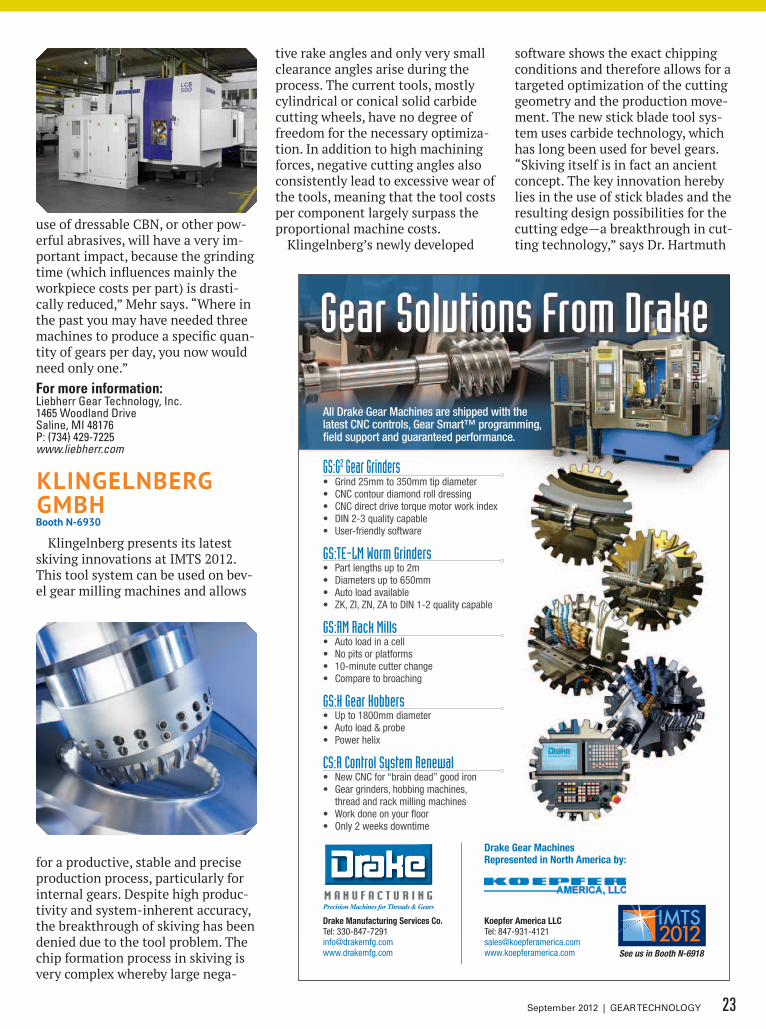
KLinGeLnberG Gmbhbooth n-6930
Klingelnberg presents its latest skiving innovations at IMTS 2012. This tool system can be used on bev-el gear milling machines and allows
for a productive, stable and precise production process, particularly for internal gears. Despite high produc-tivity and system-inherent accuracy, the breakthrough of skiving has been denied due to the tool problem. The chip formation process in skiving is very complex whereby large nega-
tive rake angles and only very small clearance angles arise during the process. The current tools, mostly cylindrical or conical solid carbide cutting wheels, have no degree of freedom for the necessary optimiza-tion. In addition to high machining forces, negative cutting angles also consistently lead to excessive wear of the tools, meaning that the tool costs per component largely surpass the proportional machine costs.
Klingelnberg’s newly developed
software shows the exact chipping conditions and therefore allows for a targeted optimization of the cutting geometry and the production move-ment. The new stick blade tool sys-tem uses carbide technology, which has long been used for bevel gears. “Skiving itself is in fact an ancient concept. The key innovation hereby lies in the use of stick blades and the resulting design possibilities for the cutting edge—a breakthrough in cut-ting technology,” says Dr. Hartmuth
23September 2012 | GEAR TECHNOLOGY
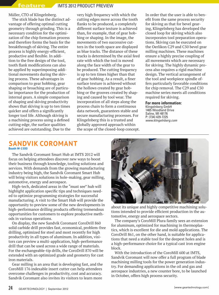
SAndviK coromAnTbooth W-1500
The Sandvik Coromant Smart Hub at IMTS 2012 will focus on helping attendees discover new ways to boost their business through knowledge, tooling solutions and services. With demands from the growing manufacturing industry being high, the Sandvik Coromant Smart Hub will bring visitors solutions in hole-making, gear milling, automotive, energy and aerospace.
High-tech, dedicated areas in the “must see” hub will highlight application specific tips and techniques need-ed to optimize programming strategies for successful manufacturing. A visit to the Smart Hub will provide the opportunity to preview some of the new developments in high-performance drilling products offering tremendous opportunities for customers to explore productive meth-ods in various operations.
On display, the new Sandvik Coromant CoroDrill 860 solid carbide drill provides fast, economical, problem-free drilling, optimized for steel and most recently for high productivity in all types of aluminum. In addition, visi-tors can preview a multi-application, high-performance drill that can be used across a wide range of materials. For the exchangeable-tip drills, the CoroDrill 870 will be extended with an optimized grade and geometry for cast iron materials.
Gear milling is an area that is developing fast, and the CoroMill 176 indexable insert cutter can help attendees overcome challenges in productivity, cost and accuracy. Sandvik Coromant also invites its visitors to learn more
about its unique and highly competitive machining solu-tions intended to provide efficient production in the au-tomotive, energy and aerospace sectors.
The company’s CoroMill Plura family sees an extension for aluminum, optimized for machining in thermoplas-tics, which is excellent for die and mold applications. The CoroDrill 861, on the other hand, is suitable for applica-tions that need a stable tool for the deepest holes and is a high-performance choice for a typical cast iron engine block.
With the introduction of the CoroMill 600 at IMTS, Sandvik Coromant will now offer a full program of blade machining milling tools for the power generation indus-try. For demanding applications in the oil and gas and aerospace industries, a new counter bore, to be launched in October, offers high process security.
Müller, CTO of Klingelnberg.The stick blade has the distinct ad-
vantage of offering optimal cutting geometry through grinding. This is a necessary condition for the optimi-zation of the chip formation process and therefore forms the basis for the breakthrough of skiving. The entire process is highly energy-efficient, productive and flexible. In addi-tion to the free design of the tool, tooth flank modifications can also be applied by superimposing addi-tional movements during the skiv-ing process. These advantages in comparison to gear hobbing, gear shaping or broaching are of particu-lar importance for the production of internal gears. A simple comparison of shaping and skiving productivity shows that skiving is up to ten times quicker and offers a significantly longer tool life. Although skiving is a machining process using a defined cutting edge, the surface qualities achieved are outstanding. Due to the
very high frequency with which the cutting edges move across the tooth flanks to be produced, a completely different surface texture is achieved than, for example, that of gear hob-bing or shaping. In the image, the movements of two successive cut-ters in the tooth space are displayed as blue tracks. The distance of these tracks is determined by the axial feed rate with which the tool is moved along the face width of the gear to be produced. The cutting frequency is up to ten times higher than that of gear hobbing. As a result, a finer surface texture is achieved without the hollows created by gear hob-bing or the grooves created by shap-ing and caused by tool wear. The incorporation of all steps along the process chain to form a continuous data network, guarantees stable and secure manufacturing processes. For Klingelnberg this is a trusted and globally approved approach within the scope of the closed-loop concept.
In order that the user is able to ben-efit from the same process security for skiving as that for bevel gear-ing, Klingelnberg has developed the closed loop for skiving which also incorporates tool preparation opera-tions. Skiving can be executed on the Oerlikon C29 and C50 bevel gear milling machines. These machines ensure a highly precise coupling of all movements which are necessary for skiving. The highly dynamic pro-cess also requires a rigid machine design. The vertical arrangement of the tool and workpiece spindle of-fers particularly favorable conditions for chip removal. The C29 and C50 machine series meets all conditions required for skiving.For more information:klingelnberg GmbH1465 Woodland DriveSaline, MI 48176P: (734) 429-7225www.klingelnberg.com
24 GEAR TECHNOLOGY | September 2012 [www.geartechnology.com]
feature IMTS 2012 PRODUCT PREVIEW
SPEED UNIFORMITY EFFICIENCY
Ipsen’s ATLAS® integral quench furnaces are highly engineered, sophisticated machines that are easy to operate and maintain, all while being extremely cost effective. ATLAS delivers top quality uniformity through cutting-edge technology and design:
• Intelligent controls, Carb-o-Prof®, provide you with your very own electronic metallurgist • SuperQuench with adjustable oil speed and four 40HP agitators • Muffle system for uniform temperature control • Safety – all ATLAS furnaces are water-free for maximum safety • 30% less gas consumption • Recon® burners – single ended recuperated tubes (SERT)
The unique HybridCarb® gassing system from Ipsen is an ultra-efficient gassing system designed to replace endothermic generators and other gassing systems. Its core strength is precision gas control. Instead of burning excess gas off, the process gas is reconditioned and reused, increasing efficiency up to 90%.
Other benefits of HybridCarb include: • Quick and easy hookup • Increased carburizing efficiency • Reduces CO2 emissions by 90% • Significantly less expensive to operate than endogenerators • Consumes significantly less gas • Environmentally friendly and cost efficient • Lowers heat output creating a more comfortable work environment • Powers up and down at anytime, quickly and easily
®
For more information please visit www.IpsenUSA.com
www.IpsenUSA.com
“As a market leader in the industry, Sandvik Coromant always strives to stay at the forefront of innovation by working directly with our customers to offer them the solutions they need to meet their demands,” said Jamie Price, president, Sandvik Coromant U.S. “We are looking forward to in-teracting with our customers and be-ing a part of this great event.”
To help visitors take full advantage of tooling solutions and technolo-gies, Sandvik Coromant will offer short technical seminars, presented by yellow coat experts. The “Discov-
ery Express” seminars will empha-size application techniques that can be used in various operations. Topics will range from effective chip thin-ning to pitfalls in reconditioning.For more information:Sandvik Coromant1702 Nevins RoadFair Lawn, NJ 07410P: (800) SANDVIkwww.sandvik.coromant.com/us
hexAGon meTroLoGy inc.booth e-5202
Hexagon Metrology Inc. will ex-hibit a full complement of metrology solutions with a spotlight on the new Cognitens WLS400A for automat-ed measurement applications and PC-DMIS 2012 inspection software. The company will also demonstrate recently released products: Romer portable arms, Optiv Vision 321, Sheffield and Brown & Sharpe 4.5.4 SF CMMs, and PC-DMIS software.
Hexagon will also showcase an official racecar from Hen-drick Motorsports, winner of a record 10 NASCAR Sprint Cup Series champion-ships. Hendrick Mo-torsports is a long-time user of Hexagon Metrology products for inspection and assembly of auto body, chassis and en-gine components for both pre-race adjust-ment and post-race evaluation.
At IMTS, Hexagon Metrology will debut the Cognitens WLS400A, de-signed for automated inspection ap-plications. The 3-D optical measure-ment solution can transform a robot into a high-accuracy metrology de-vice. Suitable for the motor vehicle or aerospace industries, the white light
26 GEAR TECHNOLOGY | September 2012 [www.geartechnology.com]
feature IMTS 2012 PRODUCT PREVIEW
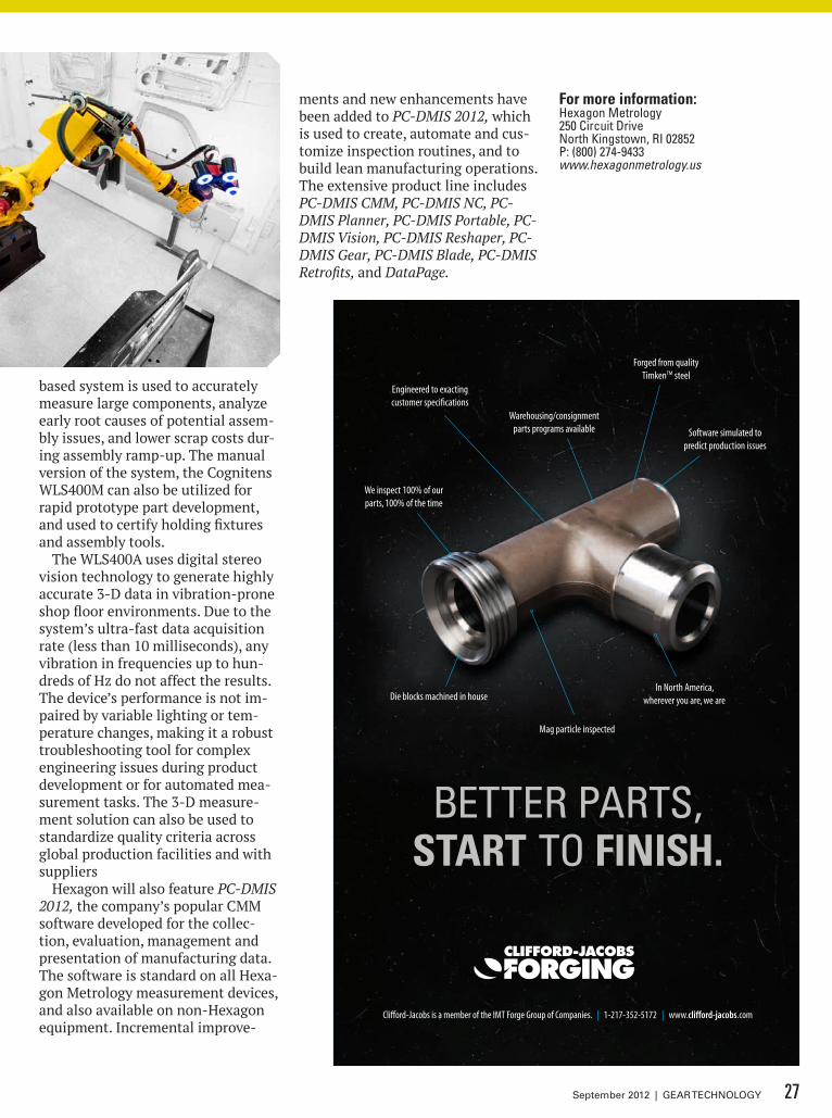
In North America, wherever you are, we are
Mag particle inspected
Engineered to exacting customer specifications
We inspect 100% of ourparts, 100% of the time
Die blocks machined in house
Warehousing/consignment parts programs available
Forged from quality Timken™ steel
Software simulated to predict production issues
Clifford-Jacobs is a member of the IMT Forge Group of Companies. | 1-217-352-5172 | www.clifford-jacobs.com
better parts, start to finish.
based system is used to accurately measure large components, analyze early root causes of potential assem-bly issues, and lower scrap costs dur-ing assembly ramp-up. The manual version of the system, the Cognitens WLS400M can also be utilized for rapid prototype part development, and used to certify holding fixtures and assembly tools.
The WLS400A uses digital stereo vision technology to generate highly accurate 3-D data in vibration-prone shop floor environments. Due to the system’s ultra-fast data acquisition rate (less than 10 milliseconds), any vibration in frequencies up to hun-dreds of Hz do not affect the results. The device’s performance is not im-paired by variable lighting or tem-perature changes, making it a robust troubleshooting tool for complex engineering issues during product development or for automated mea-surement tasks. The 3-D measure-ment solution can also be used to standardize quality criteria across global production facilities and with suppliers
Hexagon will also feature PC-DMIS 2012, the company’s popular CMM software developed for the collec-tion, evaluation, management and presentation of manufacturing data. The software is standard on all Hexa-gon Metrology measurement devices, and also available on non-Hexagon equipment. Incremental improve-
ments and new enhancements have been added to PC-DMIS 2012, which is used to create, automate and cus-tomize inspection routines, and to build lean manufacturing operations. The extensive product line includes PC-DMIS CMM, PC-DMIS NC, PC-DMIS Planner, PC-DMIS Portable, PC-DMIS Vision, PC-DMIS Reshaper, PC-DMIS Gear, PC-DMIS Blade, PC-DMIS Retrofits, and DataPage.
For more information:Hexagon Metrology250 Circuit DriveNorth kingstown, RI 02852P: (800) 274-9433www.hexagonmetrology.us
27September 2012 | GEAR TECHNOLOGY
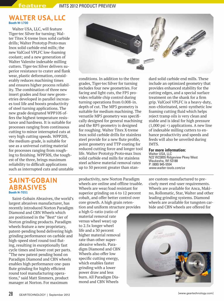
WALTer USA, LLcbooth W-1700
Walter USA, LLC, will feature Tiger·tec Silver for turning; Wal-ter Titex X·treme Inox solid carbide drills; Walter Prototyp Proto·max Inox solid carbide end mills; the new ValCool VPLFC low-foaming coolant; and a new generation of Walter Valenite indexable milling cutters. Tiger·tec Silver delivers su-perior resistance to crater and flank wear, plastic deformation, consid-erably reduces machining times and ensures higher process reliabil-ity. The combination of three new insert grades and four new geom-etries developed in parallel increas-es tool life and boosts productivity of steel turning applications. The new grade designated WPP10S of-fers the highest temperature resis-tance and hardness. It is suitable for processes ranging from continuous cutting to minor interrupted cuts at very high cutting speeds. WPP20S, the medium-grade, is suitable for use as a universal cutting material for processes ranging from rough-ing to finishing. WPP30S, the tough-est of the three, brings maximum reliability to difficult applications such as interrupted cuts and unstable
conditions. In addition to the three grades, Tiger·tec Silver for turning includes four new geometries. For facing and light cuts, the FP5 pro-vides reliable chip control during turning operations from 0.008-in. depth of cut. The MP3 geometry is suitable for medium machining. The versatile MP5 geometry was specifi-cally designed for general machining and the RP5 geometry is designed for roughing. Walter Titex X·treme Inox solid carbide drills for stainless steel provide for a new flute profile, point geometry and TTP coating for reduced cutting force and longer tool life. Walter Prototyp Proto·max Inox solid carbide end mills for stainless steel achieve material removal rates up to 50 percent greater than stan-
dard solid carbide end mills. These include an optimized geometry that provides enhanced stability for the cutting edges, and a special surface treatment on the shank for a firm grip. ValCool VPLFC is a heavy-duty, non-chlorinated, semi-synthetic low foaming cutting fluid which helps reject tramp oils is very clean and stable and is ideal for high pressure (1,000 psi +) applications. A new line of indexable milling cutters to en-hance productivity and speeds and feeds will also be unveiled during IMTS.For more information:Walter USA, LLCN22 W23855 Ridgeview Pkwy WestWaukesha, WI 53188P: (800) 945-5554www.walter-tools.com/us
SAinT-GobAin AbrASiveSbooth n-7051
Saint-Gobain Abrasives, the world’s largest abrasives manufacturer, has recently introduced Norton Paradigm Diamond and CBN Wheels which are positioned in the “Best” tier of Norton grinding products. Paradigm wheels feature a new proprietary, patent-pending bond delivering high grinding performance on carbide and high-speed steel round tool flut-ing, resulting in exceptionally fast cycle times and lower cost per parts. “The new patent pending bond on Paradigm Diamond and CBN wheels enables high performance one-pass flute grinding for highly efficient round tool manufacturing opera-tions,” said Matt Simmers, product manager at Norton. For maximum
productivity, new Norton Paradigm wheels are online and offline truable. Wheels are wear/load resistant for superior grinding on 6 to 12 percent cobalt, and offer better control over core growth. A high grain reten-tion and uniform structure provides a high G-ratio (ratio of material removal rate versus wheel wear) up to 2.5x longer wheel life and a 30 percent higher material removal rate than other super-abrasive wheels. Para-digm Diamond and CBN Wheels also offer low specific cutting energy, which enables faster grinding with a lower power draw and less burn. All Paradigm Dia-mond and CBN Wheels
are custom-manufactured to pre-cisely meet end-user requirements. Wheels are available for Anca, Maki-no, Rollomatic, Star, Walter and other leading grinding systems. Diamond wheels are available for tungsten car-bide and CBN wheels are offered for
28 GEAR TECHNOLOGY | September 2012 [www.geartechnology.com]
feature IMTS 2012 PRODUCT PREVIEW
29September 2012 | GEAR TECHNOLOGY
Vacuum Furnace InnovationsProviding Profitability Through Technology
Innovative vacuum furnace technologies available for every production requirement.ModulTherm®..... high volume production designed for incremental growth.
SyncroTherm®...high profits by synchronizing with machining centers.
DualTherm®........ high performance via separate heating and quenching chambers.
MonoTherm®...... high flexibility with a variety of processes and configurations.
www.ALD-Holcroft.com
ALD-Holcroft Vacuum Technologies 49630 Pontiac TrailWixom, MI 48393-2009 USAPh: 248.668.4130Fx: 248.624.3710E-mail: [email protected]
high-speed steel applications.Additionally, Norton Abrasives
will be featuring several Machine to Grind (MTG) solutions. For exam-ple, with Norton’s MTG analysis, a gear manufacturer eliminated rough cutting the gears through the use of formed cutters, broaching or hob-bing. They ground from solid to elim-inate the need for a cutting/milling machine and all the complementary tooling and equipment required to start and maintain the rough cutting
operation. Norton provided wheel specifications to create the flexibility to combine grinding in the soft state from solid to hard finishing with only one grinder.
Opportunities for the MTG solu-tions include small to medium job shops where there are two similar machining operations followed by grinding or where an antiquated cut-ting machine has caused the need for a rough machining process followed by a rough grind before the heat treat
and finally a finish grind. Other typi-cal industries for MTG include aero-space, land-based heavy, off-road truck gears (soft machine, hardened and finish grind). To learn much more about a case study including a key OEM who greatly benefited by applying a Norton MTG solution to grind large spiral bevel and pinion gear sets from a solid, visit the booth N-7051 at IMTS.For more information:Saint-Gobain AbrasivesOne New Bond StreetP.O. Box 15008Worcester, MA 01615-0008P: (508) 795-5000www.sgabrasives.com
donTyne SySTemSbooth n-6791
Dontyne Systems has developed a Gearbox Model to simulate de-flection of a fully coupled system of gear, shaft and bearing components including the housing. The tool can utilize FE data from 3rd party soft-ware. Deflection data can be passed directly to the tooth contact analysis module Gates to provide a substan-tial improvement for the existing customer base. Detailed component design can be called directly within the model. Further development will see planetary systems and NVH anal-ysis possible. Dontyne has integrated MESYS AG calculations for shafts and
bearings with a significant increase in the capability of the Gear Produc-tion Suite. MESYS bearing calculation considers the load distribution in the bearing and therefore can take into account operating clearance, tilting angle or moment load. The shaft cal-culation uses the resulting non-lin-ear bearing stiffness and is therefore
The target is clear when it comes to supplying the best value in gear inspection. Our mission is to offer the widest
selection of reliable, productive and precise Gear Inspection Machines. We aim to be at the pinnacle of design and through our global partnering with the finest manufacturing processes, materials and components, we deliver durable, robust machines with a high degree of up time.
• A huge range to inspect any size gear,• A Wear-free system design, and• Is built sturdy with Granite for stability, accuracy and reliability.
At Wenzel America we believe that when advanced German engineering meets American ingenuity we produce a product line with:
Wenzel America, Ltd. 46962 Liberty Drive Wixom, Michigan 48393Phone: 248 295-4300 www.wenzelamerica.com
find us on facebook
Geared on Value
Supplying the Best Value in CMM Gear Inspection 3D Imaging
Booth #E-5261
30 GEAR TECHNOLOGY | September 2012 [www.geartechnology.com]
feature IMTS 2012 PRODUCT PREVIEW
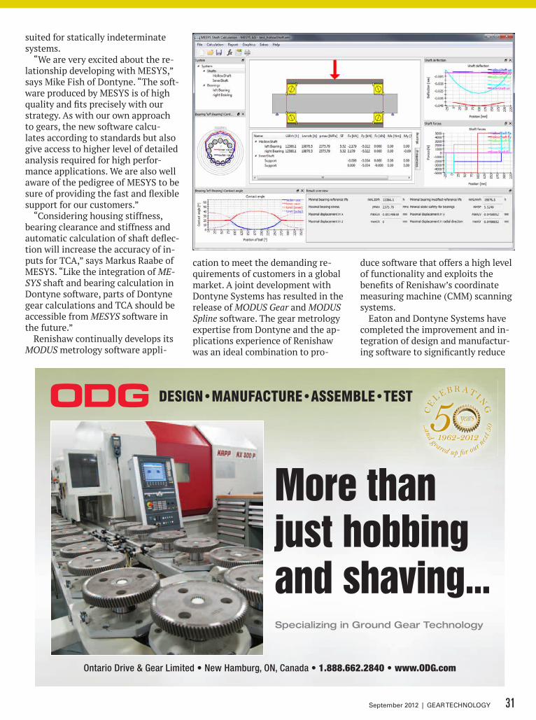
suited for statically indeterminate systems.
“We are very excited about the re-lationship developing with MESYS,” says Mike Fish of Dontyne. “The soft-ware produced by MESYS is of high quality and fits precisely with our strategy. As with our own approach to gears, the new software calcu-lates according to standards but also give access to higher level of detailed analysis required for high perfor-mance applications. We are also well aware of the pedigree of MESYS to be sure of providing the fast and flexible support for our customers.”
“Considering housing stiffness, bearing clearance and stiffness and automatic calculation of shaft deflec-tion will increase the accuracy of in-puts for TCA,” says Markus Raabe of MESYS. “Like the integration of ME-SYS shaft and bearing calculation in Dontyne software, parts of Dontyne gear calculations and TCA should be accessible from MESYS software in the future.”
Renishaw continually develops its MODUS metrology software appli-
cation to meet the demanding re-quirements of customers in a global market. A joint development with Dontyne Systems has resulted in the release of MODUS Gear and MODUS Spline software. The gear metrology expertise from Dontyne and the ap-plications experience of Renishaw was an ideal combination to pro-
duce software that offers a high level of functionality and exploits the benefits of Renishaw’s coordinate measuring machine (CMM) scanning systems.
Eaton and Dontyne Systems have completed the improvement and in-tegration of design and manufactur-ing software to significantly reduce
DESIGN•MANUFACTURE•ASSEMBLE•TEST
Ontario Drive & Gear Limited • New Hamburg, ON, Canada • 1.888.662.2840 • www.ODG.com
Specializing in Ground Gear Technology
More thanjust hobbing and shaving...
C
M
Y
CM
MY
CY
CMY
K
ODG-more than hobbing-7x475.pdf 1 12-04-03 3:08 PM
31September 2012 | GEAR TECHNOLOGY
product development time in the production of bevel gear systems. The dramatic improvements have demonstrated Dontyne’s ability to deliver complex development in a relatively short time frame. Tom Ri-ley of Eaton Corporation said of the collaboration, “Dontyne’s software brought us a huge improvement in productivity: reducing hours of work to seconds. The visual representa-tions make the software very intui-tive to use and understand, and the results are quite accurate. The en-deavor was so successful that more collaboration is inevitable.”
“We were delighted to work with Eaton on the recent project, and very happy to hear about the significant improvements in production en-abled by the development,” Fish said. “This has once again proven Don-tyne can deliver customer specific requirement to utilize a large inter-nal knowledge base of design and machining procedure, which can be developed as a stand-alone program or integrated to our off-the-shelf design and analysis tools in the Gear Production Suite if required.”
This and other developments at Don-tyne will be discussed during IMTS in Chicago.For more information:Dontyne SystemsRotterdam House116 QuaysideNewcastle Upon TyneEnglandP: +(44) 191 206 4021www.dontynesystems.com
SchUnKbooth W-2000
“Success in Manufacturing” will be Schunk’s theme for IMTS 2012. On a 4,000 sq ft booth, visitors will experi-ence the “Schunk Blueboard,” which presents straightforward stories of how manufacturers stay competitive. Each story compares a successful company with a non successful com-pany and asks the question, “What leads to success in manufacturing?” The “Schunk Blueboard” will give answers to this question. Each Blue-board station will be an interactive experience for the visitor, highlight-ing a different problem such as re-ducing part cost, increasing flex-ibility, and improving machine idle
times. Products highlighted include the electrically driven small parts gripper EGP. Compared with other electrically driven small parts grip-pers on the market, it scores points with respect to its high speed and simultaneous high gripping force. A powerful roller guide ensures high efficiency and makes the gripper highly dynamic, especially for de-manding pick and place applications.
Deep Groove Ball Bearings
Cylindrical Roller Bearings
Double-Row Spherical Roller
Bearings
WWW.NACHI.COM
DLC Taps AG Mills
Solenoid Valve and Custom Manifolds
Piston Pumps
High Efficiency Power Units
SG Drills Specialty Materials
SC 35 Robot
SRA 166/210 Robot
Nachi America Inc.715 Pushville Road
Greenwood, IN 46143(877) 622-4487
32 GEAR TECHNOLOGY | September 2012 [www.geartechnology.com]
feature IMTS 2012 PRODUCT PREVIEW
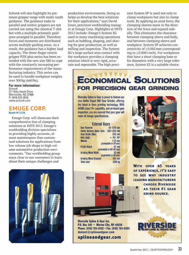
Schunk will also highlight its pre-mium gripper range with multi-tooth guidance. The guidance tasks in parallel and centric grippers are not carried out using the classical T-slot but with a multiple prismatic guid-ance arranged in parallel. Therefore forces and moments are distributed across multiple guiding areas. As a result, the guidance has a higher load capacity. The three-finger centric gripper PZN plus series has been ex-tended with the new size 380 to cope with the constantly increasing per-formance requirements of the manu-facturing industry. This series can be used to handle workpiece weights over 300 kg (660 lbs).For more information:Schunk211 kitty Hawk DriveMorrisville, NC 27560P: (919) 572-2818www.schunk.com
emUGe corP.booth W-1536
Emuge Corp. will showcase their comprehensive line of clamping solutions at IMTS 2012. Emuge’s workholding division specializes in providing highly accurate, al-most maintenance-free custom-ized solutions for applications from low volume job shops to high vol-ume automotive production envi-ronments. “Our workholding group stays close to our customers to learn about their unique challenges and
production environments. Doing so helps us develop the best solutions for their applications,” says David Jones, precision workholding manag-er at Emuge Corp. Highlights at IMTS 2012 include: Emuge’s System SG used in many machining operations such as hobbing, shaping, and shav-ing for gear production, as well as milling and inspection. The System SG’s large surface area contact with the workpiece provides a clamping solution which is very rigid, accu-rate and repeatable. The high preci-
sion System SP is used not only to clamp workpieces but also to clamp tools. By applying an axial force, the clamping sleeves move in the direc-tion of the force and expand radi-ally. This eliminates the clearance between clamping sleeve and body, and between clamping sleeve and workpiece. System SP achieves con-centricity of < 0.002 mm (correspond-ing to < 0.0001 inch). For workpieces that have a short clamping base or for diameters with a very large toler-ance, System SZ is a suitable choice.
33September 2012 | GEAR TECHNOLOGY
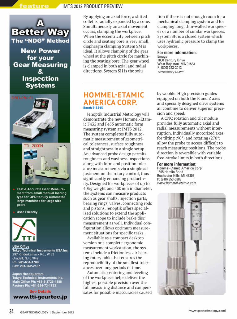
By applying an axial force, a slitted collet is radially expanded by a cone. Simultaneously an axial movement occurs, clamping the workpiece. When the eccentricity between pitch circle and seating bore is very small, diaphragm clamping System SM is ideal. It allows clamping of the gear wheel at the pitch circle for machin-ing the seating bore. The gear wheel is clamped in both axial and radial directions. System SH is the solu-
tion if there is not enough room for a mechanical clamping system and for clamping long, thin-walled workpiec-es or a number of similar workpieces. System SH is a closed system which uses hydraulic pressure to clamp the workpieces.For more information:Emuge1800 Century DriveWest Boylston. MA 01583P: (800) 323-3013www.emuge.com
New Power for your
Gear Measuring &
Inspection Systems
• Fast & Accurate Gear Measure- ment from small manual loading type for OPD to fully automated large machines for large size gears
• User Friendly
See Detailswww.tti-geartec.jp
The “NDG” Method
New Power for your
Gear Measuring
The “NDG” Methoddd
A Better Way
USA OfficeTokyo Technical Instruments USA Inc.297 Kinderkamack Rd., #133 Oradell, NJ 07649Ph: 201-634-1700 Fax: 201-262-2187
Japan HeadquartersTokyo Technical Instruments Inc.Main Office Ph: +81-3-3726-4188 Factory Ph: +81-284-73-1733
DBD-250 Ei
TTi - 2000N
hommeL-eTAmic AmericA corP.booth e-5545
Jenoptik Industrial Metrology will demonstrate the new Hommel-Etam-ic F435 and F455 automatic form measuring system at IMTS 2012. The system completes fully auto-matic measurement of geometri-cal tolerances, surface roughness and straightness in a single setup. An advanced probe design permits roughness and waviness inspections along with form and position toler-ance measurements via a simple ad-justment on the rotary control, thus significantly enhancing productiv-ity. Designed for workpieces of up to 40 kg weight and 430 mm in diameter, the systems can measure products such as gear shafts, injection parts, bearing rings, valves, connecting rods and pistons. Jenoptik offers special-ized solutions to extend the appli-cation scope to include brake disc measurement as well. Individual con-figuration allows optimum measure-ment situations for specific tasks.
Available as a compact desktop version or a complete ergonomic measurement workstation, the sys-tems include a frictionless air bear-ing rotary table that ensures the reproducibility of the smallest toler-ances over long periods of time.
Automatic centering and leveling of the workpiece helps deliver the highest possible precision over the full measuring distance and compen-sates for possible inaccuracies caused
by wobble. High precision guides equipped on both the R and Z axes and specially designed drive systems all combine to deliver superior preci-sion and speed.
A CNC rotation and tilt module provides fully automatic axial and radial measurements without inter-ruption. Individually motorized axes for tilting (90°) and rotating (270°) allow the probe to access difficult to reach measuring positions. The probe direction is reversible with variable free-stroke limits in both directions.For more information:Hommel-Etamic America Corp.1505 Hamlin RoadRochester Hills, MI 48309P: (248) 853-5888www.hommel-etamic.com
34 GEAR TECHNOLOGY | September 2012 [www.geartechnology.com]
feature IMTS 2012 PRODUCT PREVIEW
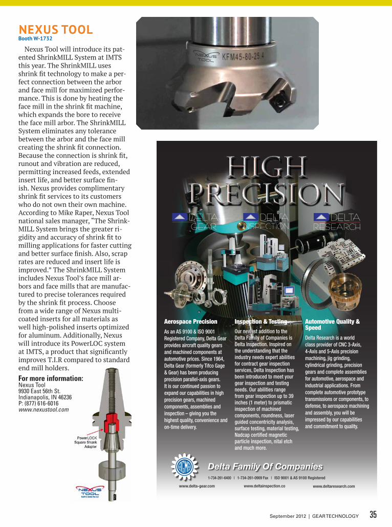
nexUS TooLbooth W-1732
Nexus Tool will introduce its pat-ented ShrinkMILL System at IMTS this year. The ShrinkMILL uses shrink fit technology to make a per-fect connection between the arbor and face mill for maximized perfor-mance. This is done by heating the face mill in the shrink fit machine, which expands the bore to receive the face mill arbor. The ShrinkMILL System eliminates any tolerance between the arbor and the face mill creating the shrink fit connection. Because the connection is shrink fit, runout and vibration are reduced, permitting increased feeds, extended insert life, and better surface fin-ish. Nexus provides complimentary shrink fit services to its customers who do not own their own machine. According to Mike Raper, Nexus Tool national sales manager, “The Shrink-MILL System brings the greater ri-gidity and accuracy of shrink fit to milling applications for faster cutting and better surface finish. Also, scrap rates are reduced and insert life is improved.” The ShrinkMILL System includes Nexus Tool’s face mill ar-bors and face mills that are manufac-tured to precise tolerances required by the shrink fit process. Choose from a wide range of Nexus multi-coated inserts for all materials as well high-polished inserts optimized for aluminum. Additionally, Nexus will introduce its PowerLOC system at IMTS, a product that significantly improves T.I.R compared to standard end mill holders.For more information:Nexus Tool9930 East 56th St.Indianapolis, IN 46236P: (877) 616-6016www.nexustool.com
1-734-525-8000 | 1-734-525-8400 Fax | ISO 9001 & AS 9100 Registered
Delta Family Of Companieswww.deltainspection.com1-734-261-6400 | 1-734-261-0909 Fax | ISO 9001 & AS 9100 Registered
www.delta-gear.com www.deltainspection.co www.deltaresearch.com
Aerospace Precision
As an AS 9100 & ISO 9001 Registered Company, Delta Gear provides aircraft quality gears and machined components at automotive prices. Since 1964, Delta Gear (formerly Tifco Gage & Gear) has been producing precision parallel-axis gears. It is our continued passion to expand our capabilities in high precision gears, machined components, assemblies and inspection – giving you the highest quality, convenience and on-time delivery.
Inspection & Testing
Our newest addition to the Delta Family of Companies is Delta Inspection. Inspired on the understanding that the industry needs expert abilities for contract gear inspection services, Delta Inspection has been introduced to meet your gear inspection and testing needs. Our abilities range from gear inspection up to 39 inches (1 meter) to prismatic inspection of machined components, roundness, laser guided concentricity analysis, surface testing, material testing, Nadcap certified magnetic particle inspection, nital etch and much more.
Automotive Quality & Speed
Delta Research is a world class provider of CNC 3-Axis, 4-Axis and 5-Axis precision machining, jig grinding, cylindrical grinding, precision gears and complete assemblies for automotive, aerospace and industrial applications. From complete automotive prototype transmissions or components, to defense, to aerospace machining and assembly, you will be impressed by our capabilities and commitment to quality.
Delta Family Of Companies
35September 2012 | GEAR TECHNOLOGY
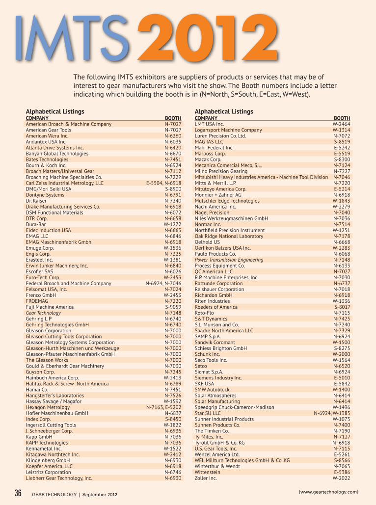
Alphabetical ListingscomPAny booThAmerican Broach & Machine Company N-7027American Gear Tools N-7027American Wera Inc. N-6260Andantex USA Inc. N-6035Atlanta Drive Systems Inc. N-6420Banyan Global Technologies N-6670Bates Technologies N-7451Bourn & Koch Inc. N-6924Broach Masters/Universal Gear N-7112Broaching Machine Specialties Co. N-7229Carl Zeiss Industrial Metrology, LLC E-5504, N-6918DMG/Mori Seiki USA S-8900Dontyne Systems N-6791Dr. Kaiser N-7240Drake Manufacturing Services Co. N-6918DSM Functional Materials N-6072DTR Corp. N-6658Dura-Bar W-1272Eldec Induction USA N-6663EMAG LLC N-6846EMAG Maschinenfabrik Gmbh N-6918Emuge Corp. W-1536Engis Corp. N-7325Erasteel Inc. W-1381Erwin Junker Machinery, Inc. N-6840Escofier SAS N-6026Euro-Tech Corp. W-2453Federal Broach and Machine Company N-6924, N-7046Felsomat USA, Inc. N-7024Frenco GmbH W-2453FROEMAG N-7220Fuji Machine America S-9059Gear Technology N-7148Gehring L P N-6740Gehring Technologies GmbH N-6740Gleason Corporation N-7000Gleason Cutting Tools Corporation N-7000Gleason Metrology Systems Corporation N-7000Gleason-Hurth Maschinen und Werkzeuge N-7000Gleason-Pfauter Maschinenfabrik GmbH N-7000The Gleason Works N-7000Gould & Eberhardt Gear Machinery N-7030Guyson Corp. N-7245Hainbuch America Corp. W-2413Halifax Rack & Screw -North America N-6789Hamai Co. N-7451Hangsterfer’s Laboratories N-7526Hassay Savage / Magafor W-1592Hexagon Metrology N-7163, E-5202Hofler Maschinenbau GmbH N-6837Index Corp. S-8450Ingersoll Cutting Tools W-1822J. Schneeberger Corp. N-6936Kapp GmbH N-7036KAPP Technologies N-7036Kennametal Inc. W-1522Kitagawa Northtech Inc. W-2412Klingelnberg GmbH N-6930Koepfer America, LLC N-6918Leistritz Corporation N-6746Liebherr Gear Technology, Inc. N-6930
Alphabetical ListingscomPAny booThLMT USA Inc. W-2464Logansport Machine Company W-1314Luren Precision Co. Ltd. N-7072MAG IAS LLC S-8519Mahr Federal Inc. E-5242Marposs Corp. E-5519Mazak Corp. S-8300Mecanica Comercial Meco, S.L. N-7124Mijno Precision Gearing N-7227Mitsubishi Heavy Industries America - Machine Tool Division N-7046Mitts & Merrill L.P. N-7220Mitutoyo America Corp. E-5214Monnier + Zahner AG N-6918Mutschler Edge Technologies W-1843Nachi America Inc. W-2279Nagel Precision N-7040Niles Werkzeugmaschinen GmbH N-7036Normac Inc. N-7514Northfield Precision Instrument W-1251Oak Ridge National Laboratory N-7178Oelheld US N-6668Oerlikon Balzers USA Inc. W-2283Paulo Products Co. N-6068Power Transmission Engineering N-7148Process Equipment Co. N-6133QC American LLC N-7027R.P. Machine Enterprises, Inc. N-7030Rattunde Corporation N-6737Reishauer Corporation N-7018Richardon GmbH N-6918Riten Industries W-1336Roeders of America S-8017Roto-Flo N-7115S&T Dynamics N-7425S.L. Munson and Co. N-7240Saacke North America LLC N-7329SAMP S.p.A. N-6924Sandvik Coromant W-1500Schiess Brighton GmbH S-8275Schunk Inc. W-2000Seco Tools Inc. W-1564Setco N-6520Sicmat S.p.A. N-6924Siemens Industry Inc. E-5010SKF USA E-5842SMW Autoblock W-1400Solar Atmospheres N-6414Solar Manufacturing N-6414Speedgrip Chuck-Cameron-Madison W-1496Star SU LLC N-6924, W-1385Suhner Industrial Products W-1073Sunnen Products Co. N-7400The Timken Co. N-7190Ty-Miles, Inc. N-7127Tyrolit GmbH & Co. KG N -6918U.S. Gear Tools, Inc. N-7115Wenzel America Ltd. E-5261WFL Millturn Technologies GmbH & Co. KG S-8566Winterthur & Wendt N-7063Wittenstein E-5386Zoller Inc. W-2022
The following IMTS exhibitors are suppliers of products or services that may be of interest to gear manufacturers who visit the show. The Booth numbers include a letter indicating which building the booth is in (N=North, S=South, E=East, W=West).
36 GEAR TECHNOLOGY | September 2012 [www.geartechnology.com]
IMTS 2012
Inductoheat, Inc. • Madison Heights, MI. USATel: +1 (248) 585-9393 • www.inductoheat.com
Inductoheat, Inc. is committed to finding efficient, effective and economic solutions for yourinduction heat treating needs. We continue to embrace break-through technologies and customer service in all that we do, and look forward to serving the metals and materials industry for 50 more.
Creating Valuable Partnerships Since 1962
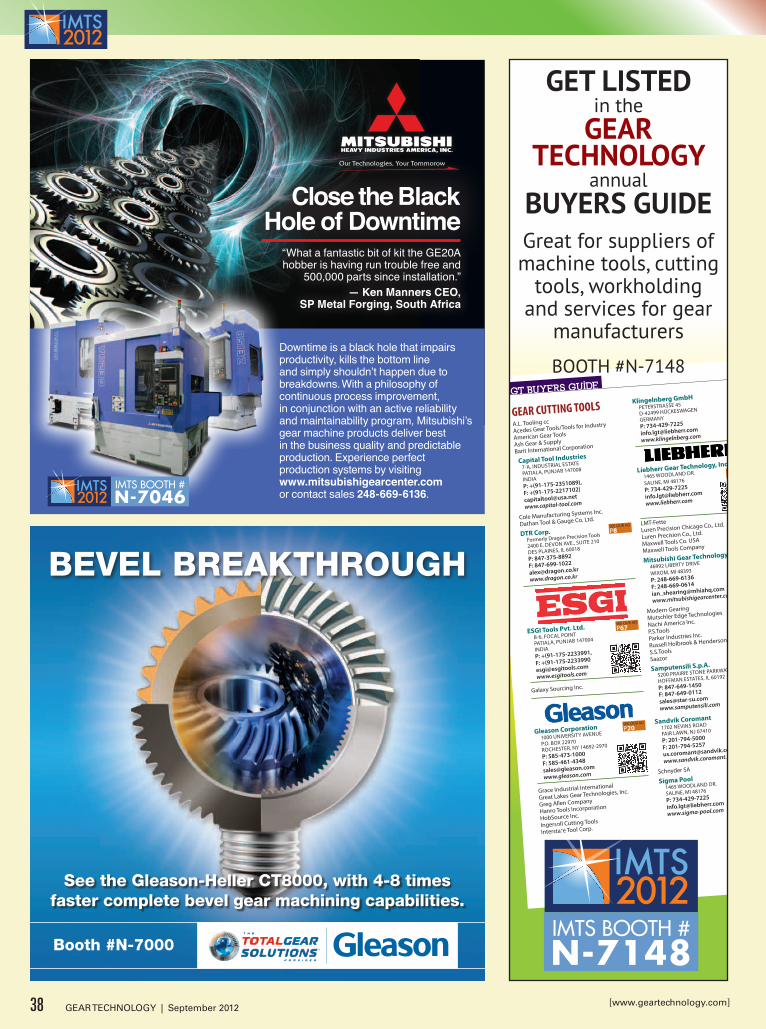
bevel breakthrough
See the gleason-heller Ct8000, with 4-8 timesfaster complete bevel gear machining capabilities.
booth #N-7000
GEAR CUTTING TOOLSA.L. Tooling ccAcedes Gear Tools/Tools for Industry
American Gear Tools
Ash Gear & Supply
Barit International Corporation
Capital Tool Industries7-A, INDUSTRIAL ESTATE
PATIALA, PUNJAB 147008
INDIAP: +(91-175-2351089),
F: +(91-175-2217102)
www.capital-tool.com
Cole Manufacturing Systems Inc.
Dathan Tool & Gauge Co. Ltd.
DTR Corp. SEE OUR AD
P8Formerly Dragon Precision Tools
2400 E. DEVON AVE., SUITE 210
DES PLAINES, IL 60018
P: 847-375-8892
F: 847-699-1022
www.dragon.co.kr
ESGI Tools Pvt. Ltd. SEE OUR AD
P67B-6, FOCAL POINT
PATIALA, PUNJAB 147004
INDIAP: +(91-175-2233991,
F: +(91-175-2233990
www.esgitools.com
Galaxy Sourcing Inc.
Gleason Corporation SEE OUR AD
P201000 UNIVERSITY AVENUE
P.O. BOX 22970
ROCHESTER, NY 14692-2970
P: 585-473-1000
F: 585-461-4348
www.gleason.com
Grace Industrial International
Great Lakes Gear Technologies, Inc.
Greg Allen Company
Hanro Tools Incorporation
HobSource Inc.
Ingersoll Cutting Tools
Interstate Tool Corp.
Klingelnberg GmbHPETERSTRASSE 45
D-42499 HÜCKESWAGEN
GERMANY
P: 734-429-7225
www.klingelnberg.com
Liebherr Gear Technology, Inc.
1465 WOODLAND DR.
SALINE, MI 48176 SEE OUR AD
P36
P: 734-429-7225
www.liebherr.com
LMT-FetteLuren Precision Chicago Co., Ltd.
Luren Precision Co., Ltd.
Maxwell Tools Co. USA
Maxwell Tools Company
Mitsubishi Gear Technology Center
46992 LIBERTY DRIVE
WIXOM, MI 48393 SEE OUR AD
P32
P: 248-669-6136
F: 248-669-0614
www.mitsubishigearcenter.com
Modern Gearing
Mutschler Edge Technologies
Nachi America Inc.
P.S.ToolsParker Industries Inc.
Russell Holbrook & Henderson
S.S.ToolsSaazor
Samputensili S.p.A. SEE OUR AD
P915200 PRAIRIE STONE PARKWAY
HOFFMAN ESTATES, IL 60192
P: 847-649-1450
F: 847-649-0112
www.samputensili.com
Sandvik Coromant SEE OUR AD
P211702 NEVINS ROAD
FAIR LAWN, NJ 07410
P: 201-794-5000
F: 201-794-5257
www.sandvik.coromant.com/us
Schnyder SA
Sigma Pool SEE OUR AD
P41465 WOODLAND DR.
SALINE, MI 48176
P: 734-429-7225
www.sigma-pool.com
Star Cutter Co.23461 INDUSTRIAL PARK DRIVE
FARMINGTON HILLS, MI 48335
P: 847-649-1450
F: 847-649-0112
www.star-su.com
Star-SU SEE OUR AD
P885200 PRAIRIE STONE PARKWAY
HOFFMAN ESTATES, IL 60192
P: 847-649-1450
F: 847-649-0112
www.star-su.com
Steelmans Broaches Pte. Ltd.
Steelmans Gear Cutters
SU America SEE OUR AD
P55200 PRAIRIE STONE PARKWAY
HOFFMAN ESTATES, IL 60192
P: 847-649-1450
F: 847-649-0112
www.star-su.com
See our ad on Page ##
Super Hobs & Broaches Pvt. Ltd.
Super Tools Corporation
Surindra Tools Industries
Tool Masters India
TSA America LLC
United Tool Company
Wolverine Broach Co., Inc.
Yash International
36 GEAR TECHNOLOGY | NOVEMBER/DECEMBER 2012
[www.geartechnology.com]
GT BUYERS GUIDE
SPLASH AD ($295)
Includes logo,
contact info and
QR Code
BOLD LISTING ($95)
Includes contact info
FREE LISTING
IMTS BOOTH #N-7148
GeT LiSTedin the
GeAr TechnoLoGy
annualbUyerS GUideGreat for suppliers of machine tools, cutting
tools, workholding and services for gear
manufacturers
BOOTH #N-7148
Our Technologies, Your Tommorow
Close the Black Hole of Downtime
“What a fantastic bit of kit the GE20A hobber is having run trouble free and
500,000 parts since installation.”— Ken Manners CEO,
SP Metal Forging, South Africa
Downtime is a black hole that impairs productivity, kills the bottom line and simply shouldn’t happen due to breakdowns. With a philosophy of continuous process improvement, in conjunction with an active reliability and maintainability program, Mitsubishi’s gear machine products deliver best in the business quality and predictable production. Experience perfect production systems by visiting www.mitsubishigearcenter.com or contact sales 248-669-6136.
IMTS BOOTH #N-7046
38 GEAR TECHNOLOGY | September 2012 [www.geartechnology.com]
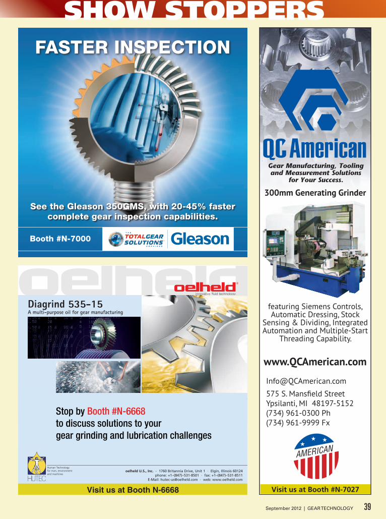
SHOW STOPPERS
Visit us at Booth N-6668
Stop by Booth #N-6668 to discuss solutions to your gear grinding and lubrication challenges
faSter iNSpeCtioN
See the gleason 350gMS, with 20-45% faster complete gear inspection capabilities.
booth #N-7000
featuring Siemens Controls, Automatic Dressing, Stock
Sensing & Dividing, Integrated Automation and Multiple-Start
Threading Capability.
575 S. Mansfield StreetYpsilanti, MI 48197-5152(734) 961-0300 Ph(734) 961-9999 Fx
www.QCAmerican.com
300mm Generating Grinder
Visit us at Booth #N-7027
39September 2012 | GEAR TECHNOLOGY

BRIGHT IDEAS, BRILLIANTSOLUTIONSAT IMTS ’12
✓Bevel Gear Solutions, Up to 2,500 mm
✓Cylindrical Gear Solutions, Up to 10,000 mm
✓Cutting Tools and Workholding Solutions, All Processes
✓Metrology Solutions, All Types of Gears, Gear Tools
✓Global Services, 250 Factory-Trained Personnel in 30 Countries Worldwide
For worldwide sales locations and additional information, visit: www.gleason.com • [email protected]
See us at Booth #N-7000Learn More
Scan To
We’re powering up a host of new gear
processing solutions at IMTS:
3 Genesis® 400H Vertical Gear
Hobbing Machine.
3 Gleason-Heller CT8000 5-Axis
Bevel Gear Machining Center.
3 350GMS Analytical Gear
Inspection System.
3 All types of gear cutting tools
and workholding solutions.
Your gear production future has never
looked brighter. Start with a visit to
www.gleason.com/IMTS.
SOLUTIONS FOR CYLINDRICAL AND BEVEL GEARS OF ALL TYPES AND SIZES, EVERY PROCESS
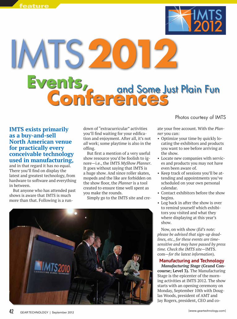
IMTS exists primarily as a buy-and-sell North American venue for practically every conceivable technology used in manufacturing, and in that regard it has no equal. There you’ll find on display the latest and greatest technology, from hardware to software and everything in between.
But anyone who has attended past shows is aware that IMTS is much more than that. Following is a run-
down of “extracurricular” activities you’ll find waiting for your edifica-tion and enjoyment. After all, it’s not all work; some playtime is also in the offing.
But first a mention of a very useful show resource you’d be foolish to ig-nore—i.e., the IMTS MyShow Planner. It goes without saying that IMTS is a huge show. And since roller skates, mopeds and the like are forbidden on the show floor, the Planner is a tool created to ensure time well spent as you make the rounds.
Simply go to the IMTS site and cre-
ate your free account. With the Plan-ner you can:• Optimize your time by quickly lo-
cating the exhibitors and products you want to see before arriving at the show.
• Locate new companies with servic-es and products you may not have even been aware of.
• Keep track of sessions you’ll be at-tending and appointments you’ve scheduled on your own personal calendar.
• Contact exhibitors before the show begins.
• Log back in after the show is over to remind yourself which exhibi-tors you visited and what they where displaying at this year’s show.
Now, on with show (Ed’s note: please be advised that sign-up dead-lines, etc., for these events are time-sensitive and may have passed by press time. Check the IMTS site—IMTS.com—for the latest information).
manufacturing and TechnologyManufacturing Stage (Grand Con-
course; Level 3). The Manufacturing Stage is the epicenter of the morn-ing activities at IMTS 2012. The show starts with an opening ceremony on Monday, September 10th with Doug-las Woods, president of AMT and Jay Rogers, president, CEO and co-
IMTS 2012and Some Just Plain FunEvents,
ConferencesPhotos courtesy of IMTS
42 GEAR TECHNOLOGY | September 2012 [www.geartechnology.com]
feature
founder of Local Motors, unveiling the newly built IMTS Rally Fighter, followed by a government represen-tative for the manufacturing indus-try. Tuesday, Thursday and Friday will feature Harry Moser, founder of the Re-Shoring Initiative, who will discuss his latest efforts in bringing manufacturing back to the U.S. Also, be sure to check the schedule on IMTS.com for updates and additions to the Manufacturing Stage.
Today’s Technology Center (Booth W–100; West Building). GIE Me-dia, Inc. brings an exciting line-up of aerospace, automotive, medical and power generation products to the To-day’s Technology Center booth in the West Building, including:• 1903 Wright Flyer—fly an exact
replica via simulator• Unmanned air vehicles (UAVs)• Buckeye Bullet—an electric race car
powered by fuel cells that has set international land-speed records of 303 mph
• SynDaver—a synthetic human body that bleeds, breathes and employs hundreds of replaceable muscles, bones, organs and vessels
• A vertical-axis wind turbine suit-able for installation on rooftops in urban areas
Advanced Manufacturing Center (Booth W–160; West Building). The Advanced Manufacturing Center is a must-visit. This technology-cen-tered display will feature the Boe-ing Fuel Cell Demonstrator Aircraft; a Lotus Formula 1 Race Car (as well as metal and carbo-fiber car compo-nents displayed by Lotus); the Vir-talis Virtual Reality Theater; multi-media displays from Modern Machine Shop; MoldMaking Technology; Pro-duction Machining; Automotive Design & Production; CompositesWorld; and TechSpex. Modern Machine Shop’s “The Shop” will offer networking and learning opportunities for attendees and exhibitors in a private, informal lounge environment. In addition to the hands-on, high-end technology on display, visitors can register to win one of four Kobalt 16-drawer, 53-inch stainless steel tool chests.
Emerging Technology Center (Booth–650; North Building). The
Emerging Technology Center (ETC) made its debut at IMTS 2004 as a place to educate, inform and excite the manufacturing community about groundbreaking innovations specific to the industry. The ETC has become a fixture at IMTS and is world-re-nowned for showcasing state-of-the-art and disruptive technologies that will impact manufacturing in the years to come. At IMTS 2012 the ETC will highlight four technologies: col-laborative manufacturing; additive
manufacturing; MTConnect applica-tions; and MTInsight.
For Job Seekers and Job FillersIMTS Job Center/Trillium CNC
(Booth W–200; West Building). Whether you are in search of top-lev-el talent for technical manufacturing positions or are a skilled machinist seeking your next career challenge, stop by the IMTS Job Center.
Looking for Top-Level Talent?The experts from Trillium CNC/
CNC Jobs, with over 28 years of ex-
© 2 0 1 1 , P r e s r i t e C o r p o r a t i o n
Presrite Corporation Phone: (216) 441-5990www.presrite.com
FORGED NET andNEAR-NET GEARS
• Save Time and Money
• Dedicated State-of-The-Art Net and Near-Net Gear Manufacturing Facility
• .008 - .060 Stock Allowance on Gear Flanks
• ISO 9001:2008
• TS 16949:2009
PRS-029 GearAd-GearTech2.indd 1 12/22/11 9:50 AM43September 2012 | GEAR TECHNOLOGY
perience in technical recruitment and staffing, will be on hand to offer advice on how to obtain, market to and secure top-level talent for tech-nical positions. As the battle to find skilled talent in manufacturing con-tinues, it is more important than ever to have access to the tools and ex-pertise that can help you attract and maintain a highly skilled workforce. Trillium CNC/CNC Jobs is a national leader in technical staffing, with over 5,000 clients nationwide.
How to prepare. Compile a list of positions that you are actively look-ing to fill or may need to ill in the near future, be sure to gather job de-scriptions and skill requirements as well.
What to bring. Job listings, job de-scriptions and a business card.
What to expect. The opportunity to speak with industry experts on the best ways to attract and screen the strongest candidates for your techni-cal manufacturing positions. Advice will be provided ranging from re-cruitment, advertising and screening to employee recognition.
Seeking Top Technical Manufacturing Careers?
Are you skilled in techni-cal manufacturing and look-ing to land a new career? Visit booth W-200 to meet with recruiters and head hunters who will be available for resume writing tips, in-terviewing advice, and career guidance. Whether you are looking to re-enter the work-force or upgrade from your current position, come receive the advice and tools needed to help you negotiate a competitive wage, ben-efit package, and land the job against other skilled candidates. Let’s face it, it’s not about finding a job; it’s about finding the right career for you.
How to prepare. Create a basic re-sume including previous work history and your contact information. Create a reference sheet including names and contact information for previ-ous supervisors. If you need immedi-ate career search assistance, register at www.trilliumjobs.com to view some opportunities.
What to bring. Your resume and reference sheet.
What to expect. The opportunity to speak with industry recruiting experts in regards to your career am-bitions, resume writing and inter-viewing techniques, and salary and benefits negotiation tips.
NIMS Student Skills Center (Hall C; North Building). The NIMS Stu-dent Skills Center is a free, week-long event at IMTS 2012 and is a one-of-a-kind opportunity for students, educators, school administrators and guidance counselors to gain a first-hand glimpse into in the world’s
44 GEAR TECHNOLOGY | September 2012 [www.geartechnology.com]
feature IMTS: EVENTS, CONFERENCES AND SOME JUST PLAIN FUN
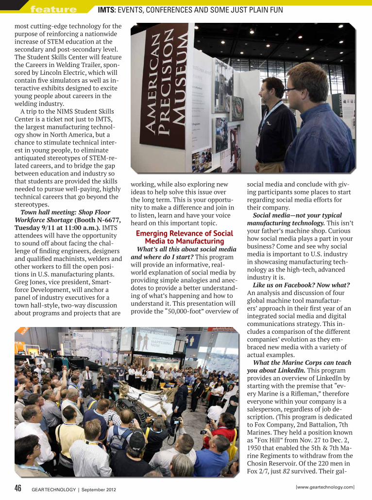
most cutting-edge technology for the purpose of reinforcing a nationwide increase of STEM education at the secondary and post-secondary level. The Student Skills Center will feature the Careers in Welding Trailer, spon-sored by Lincoln Electric, which will contain five simulators as well as in-teractive exhibits designed to excite young people about careers in the welding industry.
A trip to the NIMS Student Skills Center is a ticket not just to IMTS, the largest manufacturing technol-ogy show in North America, but a chance to stimulate technical inter-est in young people, to eliminate antiquated stereotypes of STEM-re-lated careers, and to bridge the gap between education and industry so that students are provided the skills needed to pursue well-paying, highly technical careers that go beyond the stereotypes.
Town hall meeting: Shop Floor Workforce Shortage (Booth N-6677, Tuesday 9/11 at 11:00 a.m.). IMTS attendees will have the opportunity to sound off about facing the chal-lenge of finding engineers, designers and qualified machinists, welders and other workers to fill the open posi-tions in U.S. manufacturing plants. Greg Jones, vice president, Smart-force Development, will anchor a panel of industry executives for a town hall-style, two-way discussion about programs and projects that are
working, while also exploring new ideas to help solve this issue over the long term. This is your opportu-nity to make a difference and join in to listen, learn and have your voice heard on this important topic.
emerging relevance of Social media to manufacturing
What’s all this about social media and where do I start? This program will provide an informative, real-world explanation of social media by providing simple analogies and anec-dotes to provide a better understand-ing of what’s happening and how to understand it. This presentation will provide the “50,000-foot” overview of
social media and conclude with giv-ing participants some places to start regarding social media efforts for their company.
Social media—not your typical manufacturing technology. This isn’t your father’s machine shop. Curious how social media plays a part in your business? Come and see why social media is important to U.S. industry in showcasing manufacturing tech-nology as the high-tech, advanced industry it is.
Like us on Facebook? Now what? An analysis and discussion of four global machine tool manufactur-ers’ approach in their first year of an integrated social media and digital communications strategy. This in-cludes a comparison of the different companies’ evolution as they em-braced new media with a variety of actual examples.
What the Marine Corps can teach you about LinkedIn. This program provides an overview of LinkedIn by starting with the premise that “ev-ery Marine is a Rifleman,” therefore everyone within your company is a salesperson, regardless of job de-scription. (This program is dedicated to Fox Company, 2nd Battalion, 7th Marines. They held a position known as “Fox Hill” from Nov. 27 to Dec. 2, 1950 that enabled the 5th & 7th Ma-rine Regiments to withdraw from the Chosin Reservoir. Of the 220 men in Fox 2/7, just 82 survived. Their gal-
46 GEAR TECHNOLOGY | September 2012 [www.geartechnology.com]
feature IMTS: EVENTS, CONFERENCES AND SOME JUST PLAIN FUN
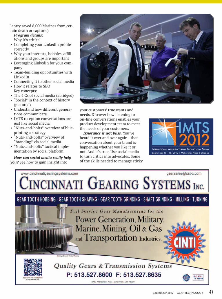
lantry saved 8,000 Marines from cer-tain death or capture.)
Program details:Why it’s critical
• Completing your LinkedIn profile correctly
• Why your interests, hobbies, affili-ations and groups are important
• Leveraging LinkedIn for your com-pany
• Team-building opportunities with LinkedIn
• Connecting it to other social media• How it relates to SEO
Key concepts:• The 4 Cs of social media (abridged)• “Social” in the context of history
(pictured)• Understand how different genera-
tions communicate• IMTS reception conversations are
just like social media• “Nuts-and-bolts” overview of blue-
printing a strategy• “Nuts-and-bolts” overview of
“branding” via social media• “Nuts-and-bolts” tactical imple-
mentation by social platform
How can social media really help you? See how to gain insight into
your customers’ true wants and needs. Discover how listening to on-line conversations enables your product development team to meet the needs of your customers.
Ignorance is not bliss. You’ve heard it over and over again—that conversation about your brand is happening whether you like it or not. And it’s true. Use social media to turn critics into advocates. Some of the skills needed to manage sticky
47September 2012 | GEAR TECHNOLOGY
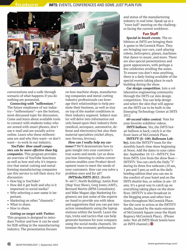
conversations and a walk-through scenario of what happens if you do nothing are presented.
Connecting with “millennium.” The future employees of our indus-try—“millenniums”—are the hottest, most discussed topic for discussion. Come and learn about available tools to connect with students today who are armed with smart phones, don’t use e-mail and are socially active online. Learn who these millenni-ums are and why they want—or don’t want— to work in our industry.
YouTube: How small compa-nies can be more effective than big companies. This program provides an overview of YouTube functions as well as how and why it’s impera-tive that metal-cutting and metal-forming manufacturing companies use this service to tell their story. For discussion:• How big is YouTube?• How did it get built and why is it
important to social media?• Why selecting a user name is im-
portant.• Marketing on other “channels.”• What to share.• How to share.
Getting on target with Twitter. This program is designed to intro-duce Twitter and how it can be used for B2B selling in the manufacturing industry. The presentation focuses
on how machine shops, manufactur-ing companies and metal-cutting industry professionals can lever-age their relationships to help pro-mote their business, as well as stay on top of the market conditions in their industry segment. Subject mat-ter will delve into information not only based upon their industry forte (medical, aerospace, automotive, de-fense and electronics) but also their material specialties (nickel alloys, non-ferrous, ferrous).
How can I really help my cus-tomer? We’ll demonstrate how to gain insight into your customer’s true wants and needs. Let us show you how listening to online conver-sations enables your Product devel-opment team to meet the needs of your customers. How can you solve a problem once and for all?
IMTSedu/IMTS 2012. (Booth N–6677; North Building). Justin Post (Map Your Show), Greg Jones (AMT), Bernard Martin (RPM Consultants) and Mike Magan (dgs Marketing En-gineers) are just some of the experts on-hand to provide you with ideas and suggestions that you can put into action immediately using the laptop stations within the booth. Learn the tips, tricks and tactics that can help generate business for your company using the social media channels. De-termine the economic performance
and status of the manufacturing industry in real time. Speak up at a “town hall” meeting on the challeng-es facing the current workforce.
Fun StuffSpecial in-booth events. The ex-
hibitors at IMTS are bringing their A-game to McCormick Place. They are bringing race cars, card-playing robots, helicopters, planes, machines that dance to music, and more. There are also special presentations and guest appearances, with perhaps a few celebrities strolling the aisles. To ensure you don’t miss anything, there is a daily listing available of the special events taking place in each building during the show.
Car design competition. Join a col-laborative engineering community through the IMTS car skin design competition. You can help design and select the skin that will appear on the IMTS car to be built in the Emerging Technology Center at IMTS 2012.
60-second video contest. Vote for your favorite exhibitor videos.
IMTS balloon. Yes, the IMTS hot-air balloon is back; catch it at the front lawn of McCormick Place.
IMTSTV (S–100; Ballroom Lob-by). Join the IMTSTV team for the monthly lunch-time show beginning at Noon. Add the dates to your calen-dar: September 10-15—IMTSTV, live from IMTS. Live from the show floor—IMTSTV. You can catch the Daily “I” during its three live webcasts (10 am, 1 pm and 5 pm) as well as the daily briefing edition that you can see in the comfort of your hotel and on the IMTS shuttle bus, or online (6 am–10 am). It’s a great way to catch up on everything taking place on the show floor. IMTSTV is also broadcast in the blogging areas and other loca-tions throughout McCormick Place. See the crew in action at the IMTSTV studio, located by the main entrance of McCormick Square (near the Hyatt Regency McCormick Place). (Please note: Not all IMTS Block hotels have an IMTS channel.)
48 GEAR TECHNOLOGY | September 2012 [www.geartechnology.com]
feature IMTS: EVENTS, CONFERENCES AND SOME JUST PLAIN FUN

Ask the Ticona Gearheads™
Great Minds!Put our polymer and application brainpower to work for you.
Ticona is the world leader in plastic gear technology. For over 30 years, our gearheads – better known as gear technology experts – have helped to dramatically reduce the cost, weight and noise of gear drives for countless applications.
Great Gears!n Reduce noisen Boost efficienciesn Lower costn Increase design flexibilityn Eliminate the need for lubricantsn Resist chemicals and corrosion
Great Polymers!Celanex® thermoplastic polyester (PBT)Hostaform® / Celcon® acetal copolymer (POM)Celstran® and Compel® long fiber reinforced thermoplastics (LFRT)Fortron® polyphenylene sulfide (PPS)GUR® ultra-high molecular weight polyethylene (UHMW-PE)Riteflex® thermoplastic polyester elastomer (TPC-ET)Vectra®/ Zenite® liquid crystal polymer (LCP)
Contact the Ticona Gearheads for the best polymer to fit your application at: 1.800.833.4882 www.ticona.com/gearheads
Ticona Engineering Polymers 8040 Dixie Highway, Florence, KY, USA 41042© 2012 Ticona Except as otherwise noted, trademarks are owned by Ticona or its affiliates. Fortron is a registered trademark of Fortron Industies LLC.
Ticona_Gearhead_GearTechAd.indd 1 7/6/12 1:26 PM
GOT A GEAR QUESTION?ask the Expert!
Assembling bevel gears by trial-and-error is exactly the wrong way to go!
Properly made bevel gears should have their backlash and mating teeth marked on them—as well as the mounting dis-tance each part has to be at—(in order) to obtain the backlash and no-load con-tact pattern. The mounting distances are meant to be used. You should measure your components and calculate the shims necessary to properly position each gear. Assemble the gears with the mating teeth engaged using the calculated shims. Only after doing that should you check back-lash; it should agree with the markings. If it does, you should be OK; if not, you have made a mistake.
Backlash must be measured the same way the manufacturer did. On straight bevels, that is at the pitch diameter in
the plane of rotation. But on spiral bevel and hypoids, the backlash is measured normal to the tooth surface. If you can do that directly on the gears, you can use the same number. If you have to do that outside of the gear box, you have to con-vert that number from the normal plane to the transverse plane—i.e., the plane of rotation. You will need to know the man-ufacturing cutter diameter and some of the gear geometry to do that.
That was the simplified answer.How do you calculate the shims? How
do you calculate the backlash in the plane of rotation? Both of these subjects have been carefully thought out and published by the AGMA Bevel Gearing Committee in ANSI/AGMA 2008-D11: Assembling Bevel Gears. There are photos and illus-trations for examples of the methods and
sample tooling used to assist in deter-mining proper values. Images of incor-rect patterns and the changes necessary to correct them are also included. There is even a detailed color photo annex with directions on how to take a contact pat-tern check if you really need to.
Far too much detail to be included in this limited description. You can pur-chase that document at: www.agma.org (AGMA members—$37; non-mem-bers—$74.)
Robert F. Wasilewskidesign engineering manager
Arrow Gear Company
Robert F. Wasilewski is design engineering manager at Arrow Gear Company, chairman of the AGMA Bevel Gearing Committee and a member of the AGMA Technical Division Executive Committee.
Welcome back to Gear Technology’s Ask the Expert—a regular feature intend-ed to help designers, specifiers, quality assurance and inspection personnel in addressing some of the more complex, troublesome gearing challenges that never cease to materialize—whether on the drafting table or the shop floor. Simply email your question—along with your name, job title and company name (if you wish to remain anonymous, no problem)—to: [email protected]; or, you can submit your question by visiting geartechnology.com.
refurbishing a ball millWe are refurbishing an Allis Chalmers ball mill. The herringbone
bull gears and pinion gears are worn. Can these gears be reversed?
QUESTION #1
Can herringbone gears be reversed?The answer is yes—but both pinion and
gear must be reversed.By reversing only one member, the set will
not match because the gear and pinion will have the apex running in the same direction.
Also, by reversing both members, we are assuming the set can be reversed from a dimensional standpoint.
I cannot tell you if dimensional issues will be a problem without seeing drawings.
Please feel free to call OCG if you have further questions. Once we see drawings and better understand the application, we can provide a more definitive answer.Frank Romans is vice president of sales &
marketing for Overton Chicago Gear. He can be contacted at (630) 543-9570, Ext. 305, or at [email protected].
bevel Gears: backlash/contact Pattern optimizationIt is very difficult to set by trial-and-error a pair of bevel gears for ideal back-
lash and contact pattern for regular, on-site gear technicians, as it involves lot of time for assembly. We have to bring in professionals—even after paying high charges for spares. Is there a faster/easier mode to arrive at an ideal combination?
QUESTION #2
50 GEAR TECHNOLOGY | September 2012 [www.geartechnology.com]
ask the expert
No room for error?
For gears they can rely on, partner with a heat treater that you can rely on.
www.solaratm.com 855-WE-HEAT-IT
Scan here for Quality
Guaranteed!
At Solar Atmospheres, your critical specs get the specialized expertise they deserve. From stress relief to case hardening, we’ll help assure that your gears can go the distance. Precise carbon control and aerospace-qualified pyrometry produce uncompromised quality. Harness our leading-edge vacuum technology to improve the uniformity of your
case depths, minimize distortion and enjoy clean parts with no IGO (intergranular oxidation). ISO 9001 / AS 9100, Nadcap accredited.
Vacuum HEAT TrEATIng | BrAzIng | CArBurIzIng | nITrIdIng
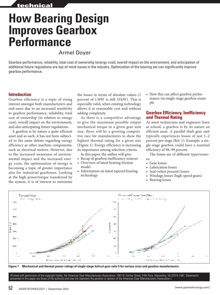
IntroductionGearbox efficiency is a topic of rising interest amongst both manufacturers and end-users due to an increased sensitivity to gearbox performance, reliability, total cost of ownership (in relation to energy cost), overall impact on the environment, and also anticipating future regulations.
A gearbox is by nature a quite efficient asset and as such, it has not been subject-ed to the same debate regarding energy efficiency as other machine components, such as electrical motors. However, due to the increased awareness of environ-mental impact and the increased ener-gy costs, the optimization of energy is becoming a topic of greater importance also for industrial gearboxes. Looking at the high power/torque transferred by the system, it is of interest to minimize
the losses in terms of absolute values (1 percent of 1 MW is still 10 kW). This is especially valid, when existing technology allows it at reasonable cost and without adding complexity.
As there is a competitive advantage to give the maximum possible output mechanical torque in a given gear unit size, there will be a growing competi-tive race for manufacturers to show the highest thermal rating for a given size (Figure 1). Energy efficiency is increasing its importance among selection criteria.
In this paper, the author will give:• Recap of gearbox inefficiency sources• Overview of latest bearing friction
model• Information on latest tapered bearing
technology
• How this can affect gearbox perfor-mance via single-stage gearbox exam-ple
Gearbox Efficiency, Inefficiency and Thermal RatingAs most technicians and engineers learn at school, a gearbox is by its nature an efficient asset. A parallel shaft gear unit typically experiences losses of just 1–2 percent per stage (Ref. 1). Example: a sin-gle-stage gearbox could have a nominal efficiency of 98–99 percent.
The losses are of different types/sourc-es:• Gear losses• Lubrication losses• Seal (when present) losses• Windage losses (high-speed gears)• Bearing losses
Gearbox performance, reliability, total cost of ownership (energy cost), overall impact on the environment, and anticipation of additional future regulations are top-of-mind issues in the industry. Optimization of the bearing set can significantly improve gearbox performance.
How Bearing design Improves Gearbox Performance
armel Doyer
(Printed with permission of the copyright holder, the American Gear Manufacturers Association, 1001 N. Fairfax Street, Fifth Floor, Alexandria, VA 22314-1587. Statements presented in this paper are those of the author(s) and may not represent the position or opinion of the American Gear Manufacturers Association.)
Figure 1 Mechanical and thermal power ratings of single-stage helical gear ratio 5 for various sizes and gearbox manufacturers.
52 GEAR TECHNOLOGY | September 2012 [www.geartechnology.com]
technical
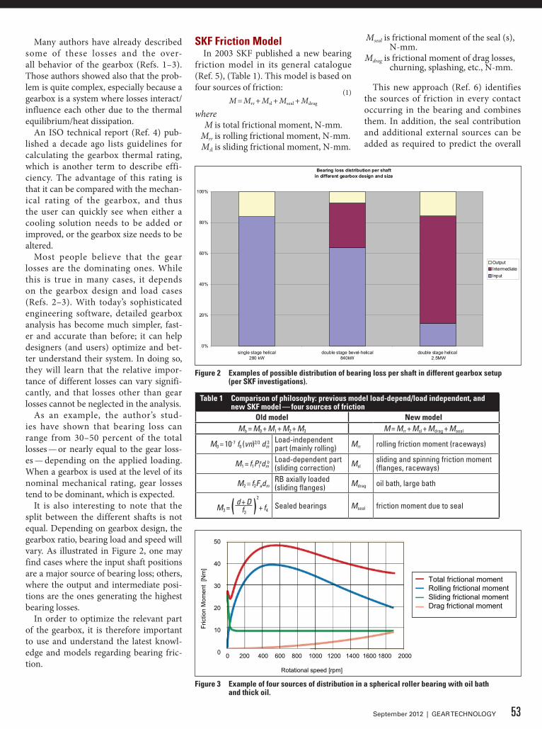
Many authors have already described some of these losses and the over-all behavior of the gearbox (Refs. 1–3). Those authors showed also that the prob-lem is quite complex, especially because a gearbox is a system where losses interact/influence each other due to the thermal equilibrium/heat dissipation.
An ISO technical report (Ref. 4) pub-lished a decade ago lists guidelines for calculating the gearbox thermal rating, which is another term to describe effi-ciency. The advantage of this rating is that it can be compared with the mechan-ical rating of the gearbox, and thus the user can quickly see when either a cooling solution needs to be added or improved, or the gearbox size needs to be altered.
Most people believe that the gear losses are the dominating ones. While this is true in many cases, it depends on the gearbox design and load cases (Refs. 2–3). With today’s sophisticated engineering software, detailed gearbox analysis has become much simpler, fast-er and accurate than before; it can help designers (and users) optimize and bet-ter understand their system. In doing so, they will learn that the relative impor-tance of different losses can vary signifi-cantly, and that losses other than gear losses cannot be neglected in the analysis.
As an example, the author’s stud-ies have shown that bearing loss can range from 30–50 percent of the total losses — or nearly equal to the gear loss-es — depending on the applied loading. When a gearbox is used at the level of its nominal mechanical rating, gear losses tend to be dominant, which is expected.
It is also interesting to note that the split between the different shafts is not equal. Depending on gearbox design, the gearbox ratio, bearing load and speed will vary. As illustrated in Figure 2, one may find cases where the input shaft positions are a major source of bearing loss; others, where the output and intermediate posi-tions are the ones generating the highest bearing losses.
In order to optimize the relevant part of the gearbox, it is therefore important to use and understand the latest knowl-edge and models regarding bearing fric-tion.
SKF Friction ModelIn 2003 SKF published a new bearing
friction model in its general catalogue (Ref. 5), (Table 1). This model is based on four sources of friction: (1)
M = Mrr + Msl + Mseal + Mdrag
where M is total frictional moment, N-mm. Mrr is rolling frictional moment, N-mm. Msl is sliding frictional moment, N-mm.
Mseal is frictional moment of the seal (s), N-mm.
Mdrag is frictional moment of drag losses, churning, splashing, etc., N-mm.
This new approach (Ref. 6) identifies the sources of friction in every contact occurring in the bearing and combines them. In addition, the seal contribution and additional external sources can be added as required to predict the overall
Table 1 Comparison of philosophy: previous model load-depend/load independent, and new SKF model — four sources of friction
Old model New modelMb = M0 + M1 + M2 + M3 M = Mrr + Msl + Mdrag + Mseal
M0 = 10-7 f0 (vn)2/3 dm3 Load-independent
part (mainly rolling) Mrr rolling friction moment (raceways)
M1 = f1P1adm
b Load-dependent part(sliding correction) Msl
sliding and spinning friction moment(flanges, raceways)
M2 = f2FadmRB axially loaded(sliding flanges) Mdrag oil bath, large bath
M3 = ( d + D )2
+ f4f3Sealed bearings Mseal friction moment due to seal
Figure 2 Examples of possible distribution of bearing loss per shaft in different gearbox setup (per SKF investigations).
Bearing loss distribution per shaft in different gearbox design and size
0%
20%
40%
60%
80%
100%
single stage helical280 kW
double stage bevel-helical840kW
double stage helical 2.5MW
OutputIntermediateInput
50
40
30
20
10
0
Total frictional momentRolling frictional momentSliding frictional momentDrag frictional moment
Rotational speed [rpm]
0 200 400 600 800 1000 1200 1400 1600 1800 2000
Fric
tion
Mom
ent
[Nm
]
Figure 3 Example of four sources of distribution in a spherical roller bearing with oil bath and thick oil.
53September 2012 | GEAR TECHNOLOGY
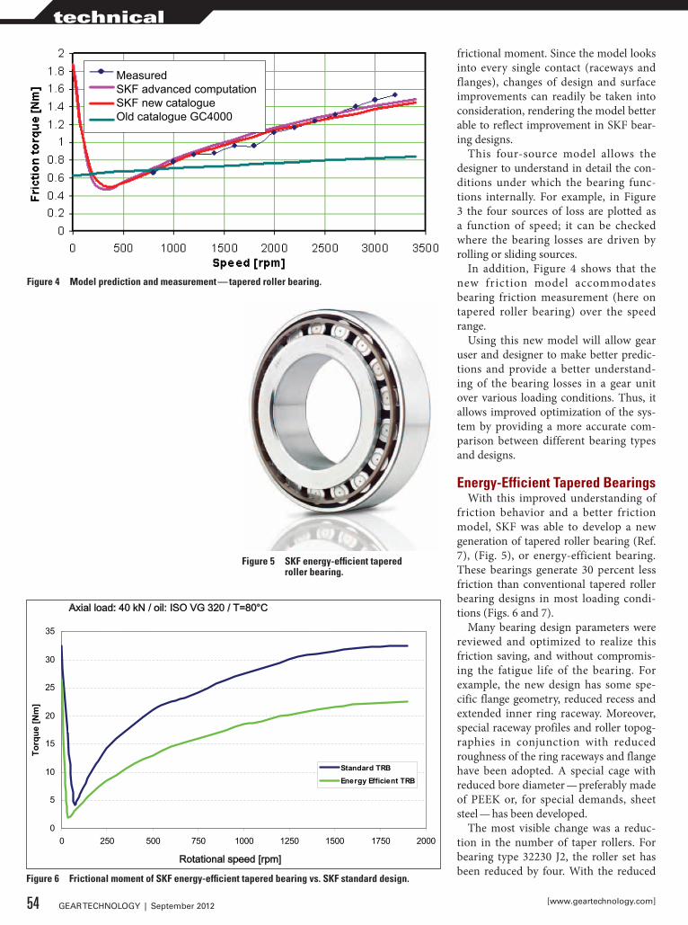
frictional moment. Since the model looks into every single contact (raceways and flanges), changes of design and surface improvements can readily be taken into consideration, rendering the model better able to reflect improvement in SKF bear-ing designs.
This four-source model allows the designer to understand in detail the con-ditions under which the bearing func-tions internally. For example, in Figure 3 the four sources of loss are plotted as a function of speed; it can be checked where the bearing losses are driven by rolling or sliding sources.
In addition, Figure 4 shows that the new friction model accommodates bearing friction measurement (here on tapered roller bearing) over the speed range.
Using this new model will allow gear user and designer to make better predic-tions and provide a better understand-ing of the bearing losses in a gear unit over various loading conditions. Thus, it allows improved optimization of the sys-tem by providing a more accurate com-parison between different bearing types and designs.
Energy-Efficient Tapered BearingsWith this improved understanding of
friction behavior and a better friction model, SKF was able to develop a new generation of tapered roller bearing (Ref. 7), (Fig. 5), or energy-efficient bearing. These bearings generate 30 percent less friction than conventional tapered roller bearing designs in most loading condi-tions (Figs. 6 and 7).
Many bearing design parameters were reviewed and optimized to realize this friction saving, and without compromis-ing the fatigue life of the bearing. For example, the new design has some spe-cific flange geometry, reduced recess and extended inner ring raceway. Moreover, special raceway profiles and roller topog-raphies in conjunction with reduced roughness of the ring raceways and flange have been adopted. A special cage with reduced bore diameter — preferably made of PEEK or, for special demands, sheet steel — has been developed.
The most visible change was a reduc-tion in the number of taper rollers. For bearing type 32230 J2, the roller set has been reduced by four. With the reduced
MeasuredSKF advanced computationSKF new catalogueOld catalogue GC4000
Figure 4 Model prediction and measurement — tapered roller bearing.
Figure 5 SKF energy-efficient tapered roller bearing.
Figure 6 Frictional moment of SKF energy-efficient tapered bearing vs. SKF standard design.
0
5
10
15
20
25
30
35
0 250 500 750 1000 1250 1500 1750 2000
IR speed [rpm]
Torq
ue [N
m]
Standard TRBEnergy Efficient TRB
Axial load: 40 kN / oil: ISO VG 320 / T=80°C
Rotational speed [rpm]
54 GEAR TECHNOLOGY | September 2012 [www.geartechnology.com]
technical
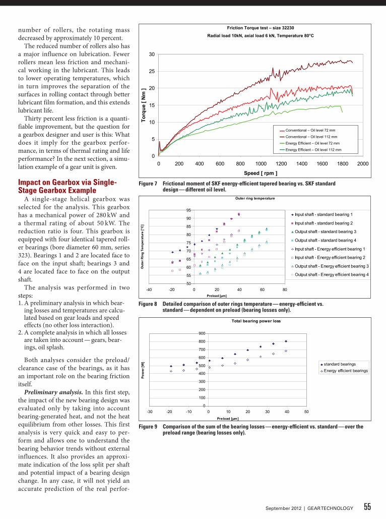
number of rollers, the rotating mass decreased by approximately 10 percent.
The reduced number of rollers also has a major influence on lubrication. Fewer rollers mean less friction and mechani-cal working in the lubricant. This leads to lower operating temperatures, which in turn improves the separation of the surfaces in rolling contact through better lubricant film formation, and this extends lubricant life.
Thirty percent less friction is a quanti-fiable improvement, but the question for a gearbox designer and user is this: What does it imply for the gearbox perfor-mance, in terms of thermal rating and life performance? In the next section, a simu-lation example of a gear unit is given.
Impact on Gearbox via Single-Stage Gearbox Example
A single-stage helical gearbox was selected for the analysis. This gearbox has a mechanical power of 280 kW and a thermal rating of about 50 kW. The reduction ratio is four. This gearbox is equipped with four identical tapered roll-er bearings (bore diameter 60 mm, series 323). Bearings 1 and 2 are located face to face on the input shaft; bearings 3 and 4 are located face to face on the output shaft.
The analysis was performed in two steps:1. A preliminary analysis in which bear-
ing losses and temperatures are calcu-lated based on gear loads and speed effects (no other loss interaction).
2. A complete analysis in which all losses are taken into account — gears, bear-ings, oil splash.
Both analyses consider the preload/clearance case of the bearings, as it has an important role on the bearing friction itself.
Preliminary analysis. In this first step, the impact of the new bearing design was evaluated only by taking into account bearing-generated heat, and not the heat equilibrium from other losses. This first analysis is very quick and easy to per-form and allows one to understand the bearing behavior trends without external influences. It also provides an approxi-mate indication of the loss split per shaft and potential impact of a bearing design change. In any case, it will not yield an accurate prediction of the real perfor-
Friction torque 32230 J2, E2.32230 TNHFr = 10 000 N; Fa = 6 000 N; T = 80 °C
0
5
10
15
20
25
30
0 200 400 600 800 1000 1200 1400 1600 1800 2000
Speed [ rpm ]
Torq
ue [
Nm
]
32230 J2 Oil level: 72 mm32230 J2 Oil level: 112 mmE2.32230 TNH Oil level: 72 mmE2.32230 TNH Oil level: 112 mm
Friction Torque test – size 32230
Radial load 10kN, axial load 6 kN, Temperature 80°C
Conventional – Oil level 72 mm
Conventional – Oil level 112 mm
Energy Efficient – Oil level 72 mm
Energy Efficient – Oil level 112 mm
Figure 7 Frictional moment of SKF energy-efficient tapered bearing vs. SKF standard design — different oil level.
Outer ring temperature
50
55
60
65
70
75
80
85
90
95
-40 -20 0 20 40 60 80Preload [µm]
Out
er R
ing
Tem
pera
ture
[°C
]
Input shaft - standard bearing 1
Input shaft - standard bearing 2
Output shaft - standard bearing 3
Output shaft - standard bearing 4
Input shaft - Energy efficient bearing 1
Input shaft - Energy efficient bearing 2
Output shaft - Energy efficient bearing 3
Output shaft - Energy efficient bearing 4
Figure 8 detailed comparison of outer rings temperature — energy-efficient vs. standard — dependent on preload (bearing losses only).
Total bearing power loss
0
100
200
300
400
500
600
700
800
900
-30 -20 -10 0 10 20 30 40 50Preload [µm]
Pow
er [W
] standard bearingsEnergy efficient bearings
Figure 9 Comparison of the sum of the bearing losses — energy-efficient vs. standard — over the preload range (bearing losses only).
55September 2012 | GEAR TECHNOLOGY
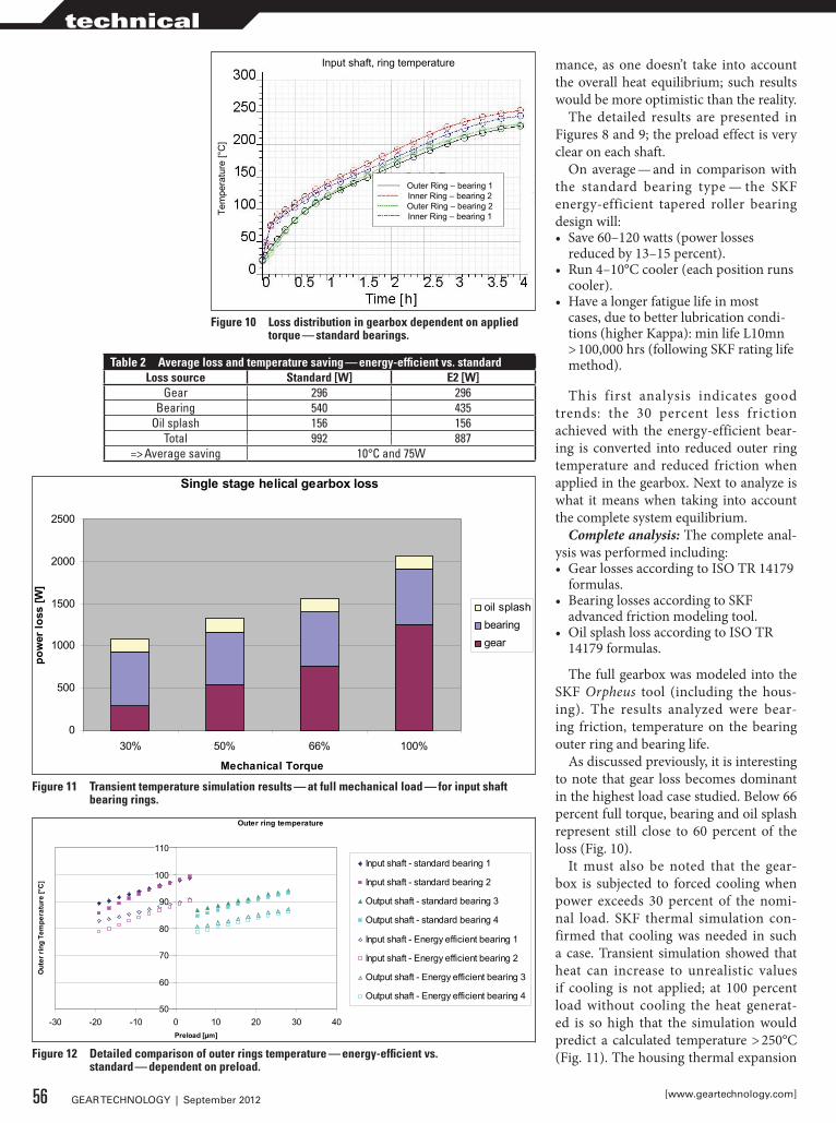
mance, as one doesn’t take into account the overall heat equilibrium; such results would be more optimistic than the reality.
The detailed results are presented in Figures 8 and 9; the preload effect is very clear on each shaft.
On average — and in comparison with the standard bearing type — the SKF energy-efficient tapered roller bearing design will:• Save 60–120 watts (power losses
reduced by 13–15 percent).• Run 4–10°C cooler (each position runs
cooler).• Have a longer fatigue life in most
cases, due to better lubrication condi-tions (higher Kappa): min life L10mn > 100,000 hrs (following SKF rating life method).
This first analysis indicates good trends: the 30 percent less friction achieved with the energy-efficient bear-ing is converted into reduced outer ring temperature and reduced friction when applied in the gearbox. Next to analyze is what it means when taking into account the complete system equilibrium.
Complete analysis: The complete anal-ysis was performed including:• Gear losses according to ISO TR 14179
formulas.• Bearing losses according to SKF
advanced friction modeling tool.• Oil splash loss according to ISO TR
14179 formulas.
The full gearbox was modeled into the SKF Orpheus tool (including the hous-ing). The results analyzed were bear-ing friction, temperature on the bearing outer ring and bearing life.
As discussed previously, it is interesting to note that gear loss becomes dominant in the highest load case studied. Below 66 percent full torque, bearing and oil splash represent still close to 60 percent of the loss (Fig. 10).
It must also be noted that the gear-box is subjected to forced cooling when power exceeds 30 percent of the nomi-nal load. SKF thermal simulation con-firmed that cooling was needed in such a case. Transient simulation showed that heat can increase to unrealistic values if cooling is not applied; at 100 percent load without cooling the heat generat-ed is so high that the simulation would predict a calculated temperature > 250°C (Fig. 11). The housing thermal expansion
Table 2 Average loss and temperature saving — energy-efficient vs. standardLoss source Standard [W] E2 [W]
Gear 296 296Bearing 540 435
Oil splash 156 156Total 992 887
=> Average saving 10°C and 75W
Outer Ring – bearing 1Inner Ring – bearing 2Outer Ring – bearing 2Inner Ring – bearing 1Te
mpe
ratu
re [°
C]
Input shaft, ring temperature
Figure 10 Loss distribution in gearbox dependent on applied torque — standard bearings.
Single stage helical gearbox loss
0
500
1000
1500
2000
2500
30% 50% 66% 100%
Mechanical Torque
pow
er lo
ss [W
]
oil splashbearinggear
Figure 11 Transient temperature simulation results — at full mechanical load — for input shaft bearing rings.
Outer ring temperature
50
60
70
80
90
100
110
-30 -20 -10 0 10 20 30 40Preload [µm]
Out
er ri
ng T
empe
ratu
re [°
C]
Input shaft - standard bearing 1
Input shaft - standard bearing 2
Output shaft - standard bearing 3
Output shaft - standard bearing 4
Input shaft - Energy efficient bearing 1
Input shaft - Energy efficient bearing 2
Output shaft - Energy efficient bearing 3
Output shaft - Energy efficient bearing 4
Figure 12 detailed comparison of outer rings temperature — energy-efficient vs. standard — dependent on preload.
56 GEAR TECHNOLOGY | September 2012 [www.geartechnology.com]
technical
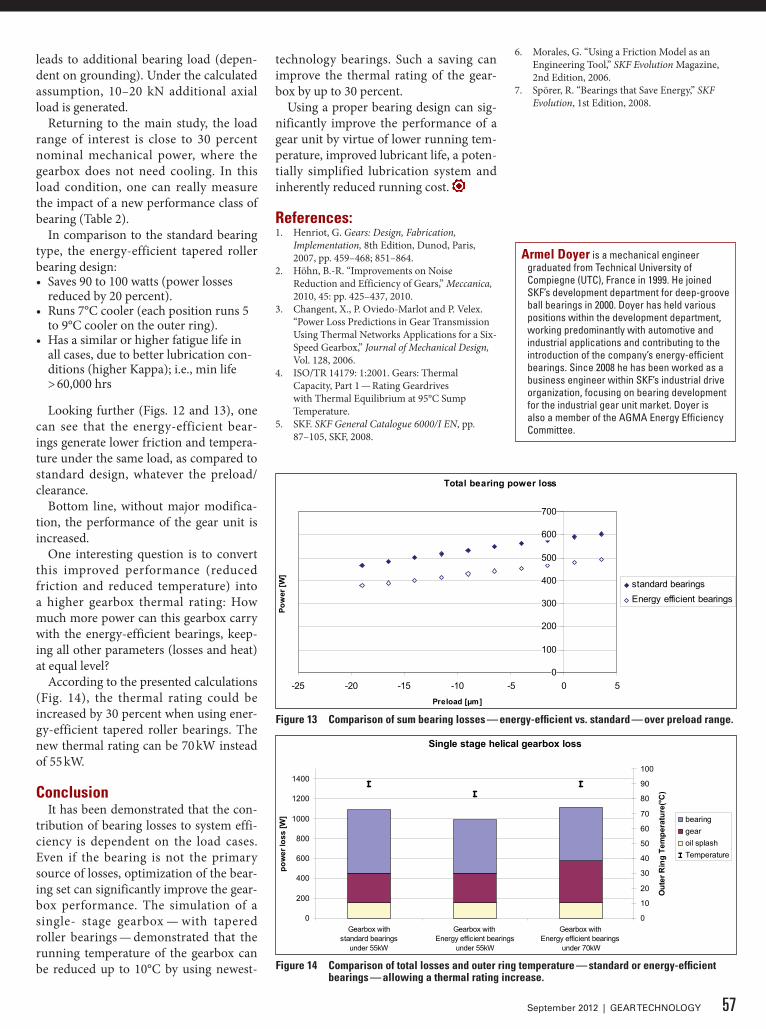
leads to additional bearing load (depen-dent on grounding). Under the calculated assumption, 10–20 kN additional axial load is generated.
Returning to the main study, the load range of interest is close to 30 percent nominal mechanical power, where the gearbox does not need cooling. In this load condition, one can really measure the impact of a new performance class of bearing (Table 2).
In comparison to the standard bearing type, the energy-efficient tapered roller bearing design:• Saves 90 to 100 watts (power losses
reduced by 20 percent).• Runs 7°C cooler (each position runs 5
to 9°C cooler on the outer ring).• Has a similar or higher fatigue life in
all cases, due to better lubrication con-ditions (higher Kappa); i.e., min life > 60,000 hrs
Looking further (Figs. 12 and 13), one can see that the energy-efficient bear-ings generate lower friction and tempera-ture under the same load, as compared to standard design, whatever the preload/clearance.
Bottom line, without major modifica-tion, the performance of the gear unit is increased.
One interesting question is to convert this improved performance (reduced friction and reduced temperature) into a higher gearbox thermal rating: How much more power can this gearbox carry with the energy-efficient bearings, keep-ing all other parameters (losses and heat) at equal level?
According to the presented calculations (Fig. 14), the thermal rating could be increased by 30 percent when using ener-gy-efficient tapered roller bearings. The new thermal rating can be 70 kW instead of 55 kW.
ConclusionIt has been demonstrated that the con-
tribution of bearing losses to system effi-ciency is dependent on the load cases. Even if the bearing is not the primary source of losses, optimization of the bear-ing set can significantly improve the gear-box performance. The simulation of a single- stage gearbox — with tapered roller bearings — demonstrated that the running temperature of the gearbox can be reduced up to 10°C by using newest-
technology bearings. Such a saving can improve the thermal rating of the gear-box by up to 30 percent.
Using a proper bearing design can sig-nificantly improve the performance of a gear unit by virtue of lower running tem-perature, improved lubricant life, a poten-tially simplified lubrication system and inherently reduced running cost.
References:1. Henriot, G. Gears: Design, Fabrication,
Implementation, 8th Edition, Dunod, Paris, 2007, pp. 459–468; 851–864.
2. Höhn, B.-R. “Improvements on Noise Reduction and Efficiency of Gears,” Meccanica, 2010, 45: pp. 425–437, 2010.
3. Changent, X., P. Oviedo-Marlot and P. Velex. “Power Loss Predictions in Gear Transmission Using Thermal Networks Applications for a Six-Speed Gearbox,” Journal of Mechanical Design, Vol. 128, 2006.
4. ISO/TR 14179: 1:2001. Gears: Thermal Capacity, Part 1 — Rating Geardrives with Thermal Equilibrium at 95°C Sump Temperature.
5. SKF. SKF General Catalogue 6000/I EN, pp. 87–105, SKF, 2008.
6. Morales, G. “Using a Friction Model as an Engineering Tool,” SKF Evolution Magazine, 2nd Edition, 2006.
7. Spörer, R. “Bearings that Save Energy,” SKF Evolution, 1st Edition, 2008.
Figure 14 Comparison of total losses and outer ring temperature — standard or energy-efficient bearings — allowing a thermal rating increase.
Single stage helical gearbox loss
0
200
400
600
800
1000
1200
1400
Gearbox withstandard bearings
under 55kW
Gearbox with Energy efficient bearings
under 55kW
Gearbox with Energy efficient bearings
under 70kW
pow
er lo
ss [W
]
0
10
20
30
40
50
60
70
80
90
100
Out
er R
ing
Tem
pera
ture
(°C)
bearinggearoil splashTemperature
Total bearing power loss
0
100
200
300
400
500
600
700
-25 -20 -15 -10 -5 0 5Preload [µm]
Pow
er [W
]
standard bearingsEnergy efficient bearings
Figure 13 Comparison of sum bearing losses — energy-efficient vs. standard — over preload range.
57September 2012 | GEAR TECHNOLOGY
Armel doyer is a mechanical engineer graduated from Technical University of Compiegne (UTC), France in 1999. He joined SkF’s development department for deep-groove ball bearings in 2000. Doyer has held various positions within the development department, working predominantly with automotive and industrial applications and contributing to the introduction of the company’s energy-efficient bearings. Since 2008 he has been worked as a business engineer within SkF’s industrial drive organization, focusing on bearing development for the industrial gear unit market. Doyer is also a member of the AGMA Energy Efficiency Committee.
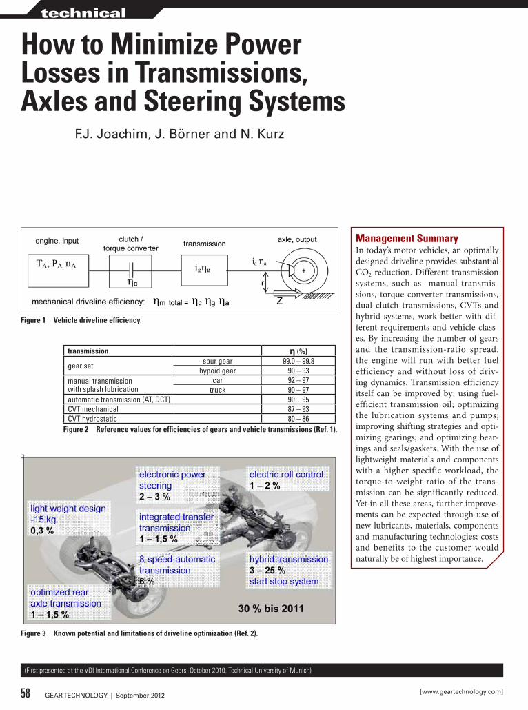
How to Minimize Power Losses in Transmissions, Axles and Steering Systems
F.J. Joachim, J. Börner and N. kurz
transmission η (%)
gear set spur gear 99.0 – 99.8hypoid gear 90 – 93
manual transmissionwith splash lubrication
car 92 – 97truck 90 – 97
automatic transmission (AT, DCT) 90 – 95CVT mechanical 87 – 93CVT hydrostatic 80 – 86
Figure 2 Reference values for efficiencies of gears and vehicle transmissions (Ref. 1).
Figure 1 Vehicle driveline efficiency.
Figure 3 Known potential and limitations of driveline optimization (Ref. 2).
Management SummaryIn today’s motor vehicles, an optimally designed driveline provides substantial CO2 reduction. Different transmission systems, such as manual transmis-sions, torque-converter transmissions, dual-clutch transmissions, CVTs and hybrid systems, work better with dif-ferent requirements and vehicle class-es. By increasing the number of gears and the transmission-ratio spread, the engine will run with better fuel efficiency and without loss of driv-ing dynamics. Transmission efficiency itself can be improved by: using fuel-efficient transmission oil; optimizing the lubrication systems and pumps; improving shifting strategies and opti-mizing gearings; and optimizing bear-ings and seals/gaskets. With the use of lightweight materials and components with a higher specific workload, the torque-to-weight ratio of the trans-mission can be significantly reduced. Yet in all these areas, further improve-ments can be expected through use of new lubricants, materials, components and manufacturing technologies; costs and benefits to the customer would naturally be of highest importance.
(First presented at the VDI International Conference on Gears, October 2010, Technical University of Munich)
58 GEAR TECHNOLOGY | September 2012 [www.geartechnology.com]
technical
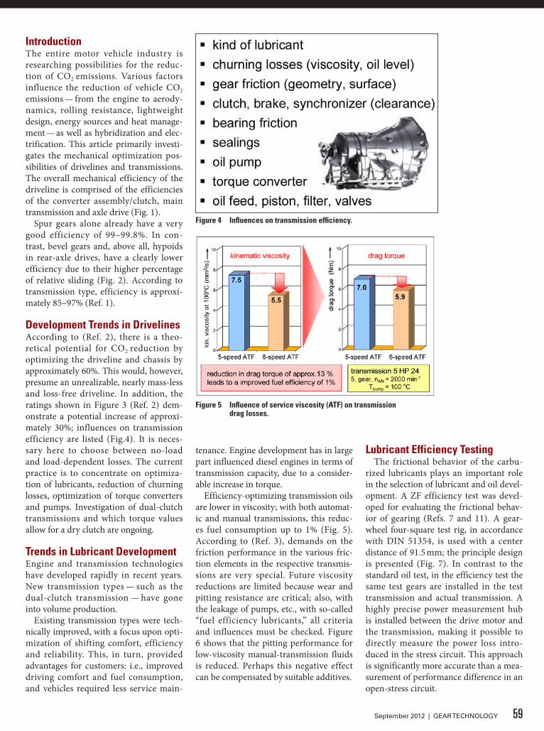
IntroductionThe entire motor vehicle industry is researching possibilities for the reduc-tion of CO2 emissions. Various factors influence the reduction of vehicle CO2 emissions — from the engine to aerody-namics, rolling resistance, lightweight design, energy sources and heat manage-ment — as well as hybridization and elec-trification. This article primarily investi-gates the mechanical optimization pos-sibilities of drivelines and transmissions. The overall mechanical efficiency of the driveline is comprised of the efficiencies of the converter assembly/clutch, main transmission and axle drive (Fig. 1).
Spur gears alone already have a very good efficiency of 99–99.8%. In con-trast, bevel gears and, above all, hypoids in rear-axle drives, have a clearly lower efficiency due to their higher percentage of relative sliding (Fig. 2). According to transmission type, efficiency is approxi-mately 85–97% (Ref. 1).
development Trends in drivelinesAccording to (Ref. 2), there is a theo-retical potential for CO2 reduction by optimizing the driveline and chassis by approximately 60%. This would, however, presume an unrealizable, nearly mass-less and loss-free driveline. In addition, the ratings shown in Figure 3 (Ref. 2) dem-onstrate a potential increase of approxi-mately 30%; influences on transmission efficiency are listed (Fig.4). It is neces-sary here to choose between no-load and load-dependent losses. The current practice is to concentrate on optimiza-tion of lubricants, reduction of churning losses, optimization of torque converters and pumps. Investigation of dual-clutch transmissions and which torque values allow for a dry clutch are ongoing.
Trends in Lubricant developmentEngine and transmission technologies have developed rapidly in recent years. New transmission types — such as the dual-clutch transmission — have gone into volume production.
Existing transmission types were tech-nically improved, with a focus upon opti-mization of shifting comfort, efficiency and reliability. This, in turn, provided advantages for customers: i.e., improved driving comfort and fuel consumption, and vehicles required less service main-
Figure 4 Influences on transmission efficiency.
Figure 5 Influence of service viscosity (ATF) on transmission drag losses.
tenance. Engine development has in large part influenced diesel engines in terms of transmission capacity, due to a consider-able increase in torque.
Efficiency-optimizing transmission oils are lower in viscosity; with both automat-ic and manual transmissions, this reduc-es fuel consumption up to 1% (Fig. 5). According to (Ref. 3), demands on the friction performance in the various fric-tion elements in the respective transmis-sions are very special. Future viscosity reductions are limited because wear and pitting resistance are critical; also, with the leakage of pumps, etc., with so-called “fuel efficiency lubricants,” all criteria and influences must be checked. Figure 6 shows that the pitting performance for low-viscosity manual-transmission fluids is reduced. Perhaps this negative effect can be compensated by suitable additives.
Lubricant Efficiency TestingThe frictional behavior of the carbu-
rized lubricants plays an important role in the selection of lubricant and oil devel-opment. A ZF efficiency test was devel-oped for evaluating the frictional behav-ior of gearing (Refs. 7 and 11). A gear-wheel four-square test rig, in accordance with DIN 51354, is used with a center distance of 91.5 mm; the principle design is presented (Fig. 7). In contrast to the standard oil test, in the efficiency test the same test gears are installed in the test transmission and actual transmission. A highly precise power measurement hub is installed between the drive motor and the transmission, making it possible to directly measure the power loss intro-duced in the stress circuit. This approach is significantly more accurate than a mea-surement of performance difference in an open-stress circuit.
59September 2012 | GEAR TECHNOLOGY
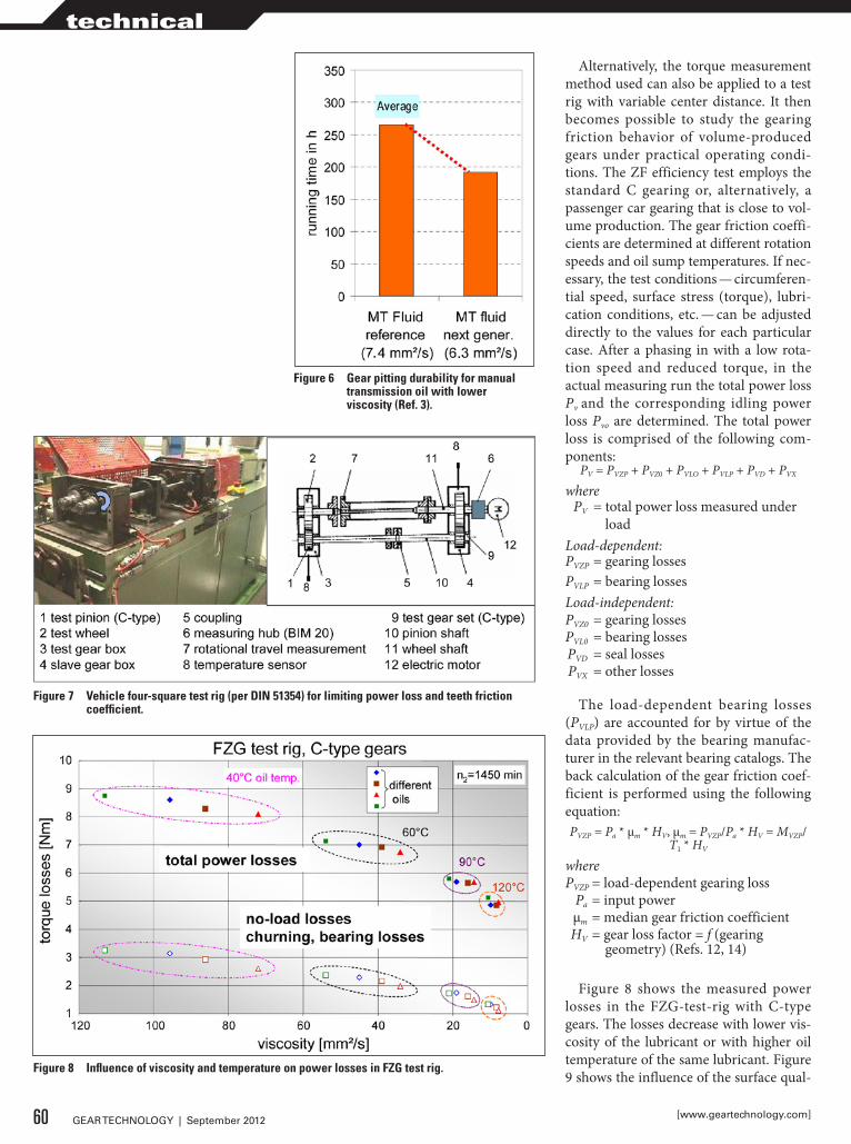
Alternatively, the torque measurement method used can also be applied to a test rig with variable center distance. It then becomes possible to study the gearing friction behavior of volume-produced gears under practical operating condi-tions. The ZF efficiency test employs the standard C gearing or, alternatively, a passenger car gearing that is close to vol-ume production. The gear friction coeffi-cients are determined at different rotation speeds and oil sump temperatures. If nec-essary, the test conditions — circumferen-tial speed, surface stress (torque), lubri-cation conditions, etc. — can be adjusted directly to the values for each particular case. After a phasing in with a low rota-tion speed and reduced torque, in the actual measuring run the total power loss Pv and the corresponding idling power loss Pvo are determined. The total power loss is comprised of the following com-ponents:
PV = PVZP + PVZ0 + PVLO + PVLP + PVD + PVX
where PV = total power loss measured under
loadLoad-dependent: PVZP = gearing losses PVLP = bearing lossesLoad-independent: PVZ0 = gearing losses PVL0 = bearing losses PVD = seal losses PVX = other losses
The load-dependent bearing losses (PVLP) are accounted for by virtue of the data provided by the bearing manufac-turer in the relevant bearing catalogs. The back calculation of the gear friction coef-ficient is performed using the following equation:PVZP = Pa * μm * HV, μm = PVZP/Pa * HV = MVZP/
T1 * HV
where PVZP = load-dependent gearing loss Pa = input power μm = median gear friction coefficient HV = gear loss factor = f (gearing
geometry) (Refs. 12, 14)
Figure 8 shows the measured power losses in the FZG-test-rig with C-type gears. The losses decrease with lower vis-cosity of the lubricant or with higher oil temperature of the same lubricant. Figure 9 shows the influence of the surface qual-
Figure 7 Vehicle four-square test rig (per dIN 51354) for limiting power loss and teeth friction coefficient.
Figure 8 Influence of viscosity and temperature on power losses in FZG test rig.
Figure 6 Gear pitting durability for manual transmission oil with lower viscosity (Ref. 3).
60 GEAR TECHNOLOGY | September 2012 [www.geartechnology.com]
technical
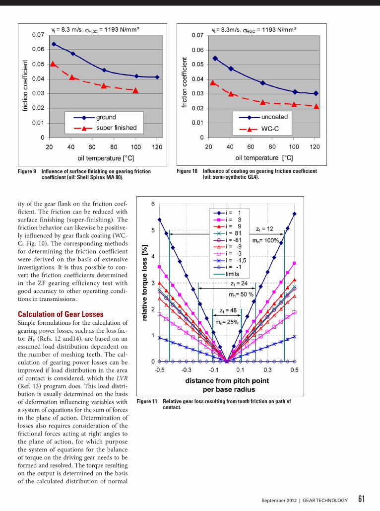
Figure 9 Influence of surface finishing on gearing friction coefficient (oil: Shell Spirax MA 80).
Figure 10 Influence of coating on gearing friction coefficient (oil: semi-synthetic GL4).
Figure 11 Relative gear loss resulting from tooth friction on path of contact.
ity of the gear flank on the friction coef-ficient. The friction can be reduced with surface finishing (super-finishing). The friction behavior can likewise be positive-ly influenced by gear flank coating (WC-C; Fig. 10). The corresponding methods for determining the friction coefficient were derived on the basis of extensive investigations. It is thus possible to con-vert the friction coefficients determined in the ZF gearing efficiency test with good accuracy to other operating condi-tions in transmissions.
Calculation of Gear LossesSimple formulations for the calculation of gearing power losses, such as the loss fac-tor HV (Refs. 12 and14), are based on an assumed load distribution dependent on the number of meshing teeth. The cal-culation of gearing power losses can be improved if load distribution in the area of contact is considered, which the LVR (Ref. 13) program does. This load distri-bution is usually determined on the basis of deformation influencing variables with a system of equations for the sum of forces in the plane of action. Determination of losses also requires consideration of the frictional forces acting at right angles to the plane of action, for which purpose the system of equations for the balance of torque on the driving gear needs to be formed and resolved. The torque resulting on the output is determined on the basis of the calculated distribution of normal
61September 2012 | GEAR TECHNOLOGY
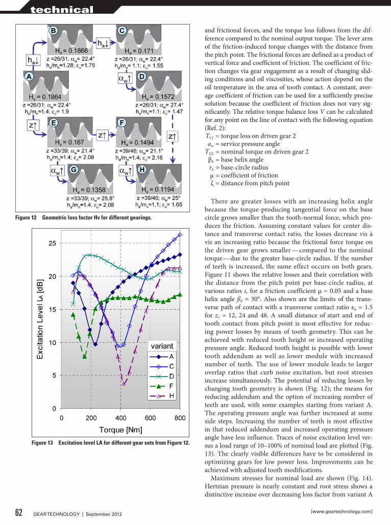
Figure 12 Geometric loss factor Hv for different gearings.
Figure 13 Excitation level LA for different gear sets from Figure 12.
and frictional forces, and the torque loss follows from the dif-ference compared to the nominal output torque. The lever arm of the friction-induced torque changes with the distance from the pitch point. The frictional forces are defined as a product of vertical force and coefficient of friction. The coefficient of fric-tion changes via gear engagement as a result of changing slid-ing conditions and oil viscosities, whose action depend on the oil temperature in the area of tooth contact. A constant, aver-age coefficient of friction can be used for a sufficiently precise solution because the coefficient of friction does not vary sig-nificantly. The relative torque balance loss V can be calculated for any point on the line of contact with the following equation (Ref. 2): TV2 = torque loss on driven gear 2 aw = service pressure angle TN2 = nominal torque on driven gear 2 βb = base helix angle rb = base-circle radius μ = coefficient of friction ζ = distance from pitch point
There are greater losses with an increasing helix angle because the torque-producing tangential force on the base circle grows smaller than the tooth-normal force, which pro-duces the friction. Assuming constant values for center dis-tance and transverse contact ratio, the losses decrease vis à vis an increasing ratio because the frictional force torque on the driven gear grows smaller — compared to the nominal torque — due to the greater base-circle radius. If the number of teeth is increased, the same effect occurs on both gears. Figure 11 shows the relative losses and their correlation with the distance from the pitch point per base-circle radius, at various ratios i, for a friction coefficient μ = 0.05 and a base helix angle ßb = 30°. Also shown are the limits of the trans-verse path of contact with a transverse contact ratio εα = 1.5 for z1 = 12, 24 and 48. A small distance of start and end of tooth contact from pitch point is most effective for reduc-ing power losses by means of tooth geometry. This can be achieved with reduced tooth height or increased operating pressure angle. Reduced tooth height is possible with lower tooth addendum as well as lower module with increased number of teeth. The use of lower module leads to larger overlap ratios that curb noise excitation, but root stresses increase simultaneously. The potential of reducing losses by changing tooth geometry is shown (Fig. 12); the means for reducing addendum and the option of increasing number of teeth are used, with some examples starting from variant A. The operating pressure angle was further increased at some side steps. Increasing the number of teeth is most effective in that reduced addendum and increased operating pressure angle have less influence. Traces of noise excitation level ver-sus a load range of 10–100% of nominal load are plotted (Fig. 13). The clearly visible differences have to be considered in optimizing gears for low power loss. Improvements can be achieved with adjusted tooth modifications.
Maximum stresses for nominal load are shown (Fig. 14). Hertzian pressure is nearly constant and root stress shows a distinctive increase over decreasing loss factor from variant A
62 GEAR TECHNOLOGY | September 2012 [www.geartechnology.com]
technical
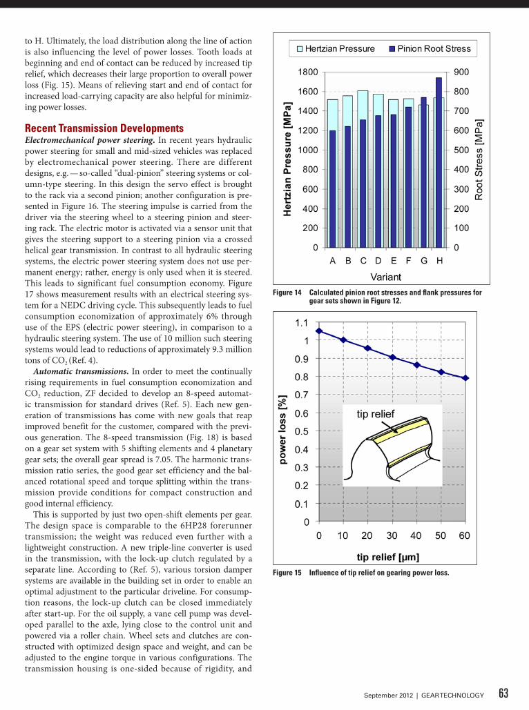
to H. Ultimately, the load distribution along the line of action is also influencing the level of power losses. Tooth loads at beginning and end of contact can be reduced by increased tip relief, which decreases their large proportion to overall power loss (Fig. 15). Means of relieving start and end of contact for increased load-carrying capacity are also helpful for minimiz-ing power losses.
Recent Transmission developmentsElectromechanical power steering. In recent years hydraulic power steering for small and mid-sized vehicles was replaced by electromechanical power steering. There are different designs, e.g. — so-called “dual-pinion” steering systems or col-umn-type steering. In this design the servo effect is brought to the rack via a second pinion; another configuration is pre-sented in Figure 16. The steering impulse is carried from the driver via the steering wheel to a steering pinion and steer-ing rack. The electric motor is activated via a sensor unit that gives the steering support to a steering pinion via a crossed helical gear transmission. In contrast to all hydraulic steering systems, the electric power steering system does not use per-manent energy; rather, energy is only used when it is steered. This leads to significant fuel consumption economy. Figure 17 shows measurement results with an electrical steering sys-tem for a NEDC driving cycle. This subsequently leads to fuel consumption economization of approximately 6% through use of the EPS (electric power steering), in comparison to a hydraulic steering system. The use of 10 million such steering systems would lead to reductions of approximately 9.3 million tons of CO2 (Ref. 4).
Automatic transmissions. In order to meet the continually rising requirements in fuel consumption economization and CO2 reduction, ZF decided to develop an 8-speed automat-ic transmission for standard drives (Ref. 5). Each new gen-eration of transmissions has come with new goals that reap improved benefit for the customer, compared with the previ-ous generation. The 8-speed transmission (Fig. 18) is based on a gear set system with 5 shifting elements and 4 planetary gear sets; the overall gear spread is 7.05. The harmonic trans-mission ratio series, the good gear set efficiency and the bal-anced rotational speed and torque splitting within the trans-mission provide conditions for compact construction and good internal efficiency.
This is supported by just two open-shift elements per gear. The design space is comparable to the 6HP28 forerunner transmission; the weight was reduced even further with a lightweight construction. A new triple-line converter is used in the transmission, with the lock-up clutch regulated by a separate line. According to (Ref. 5), various torsion damper systems are available in the building set in order to enable an optimal adjustment to the particular driveline. For consump-tion reasons, the lock-up clutch can be closed immediately after start-up. For the oil supply, a vane cell pump was devel-oped parallel to the axle, lying close to the control unit and powered via a roller chain. Wheel sets and clutches are con-structed with optimized design space and weight, and can be adjusted to the engine torque in various configurations. The transmission housing is one-sided because of rigidity, and
Figure 14 Calculated pinion root stresses and flank pressures for gear sets shown in Figure 12.
Figure 15 Influence of tip relief on gearing power loss.
63September 2012 | GEAR TECHNOLOGY
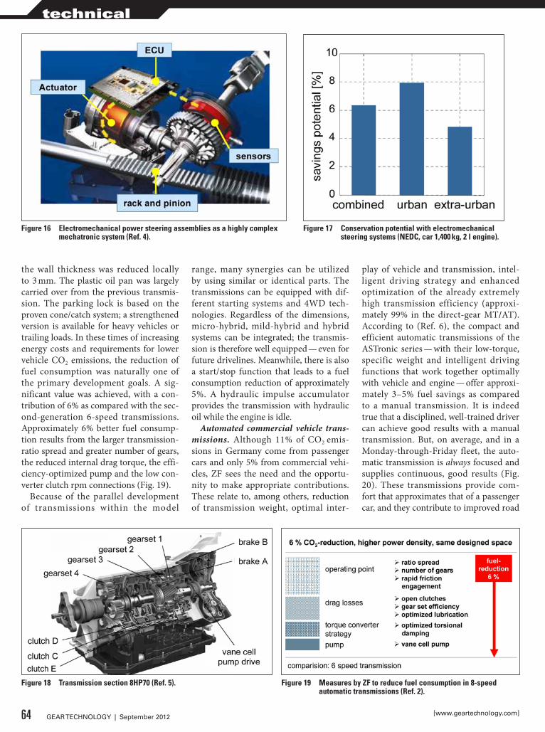
the wall thickness was reduced locally to 3 mm. The plastic oil pan was largely carried over from the previous transmis-sion. The parking lock is based on the proven cone/catch system; a strengthened version is available for heavy vehicles or trailing loads. In these times of increasing energy costs and requirements for lower vehicle CO2 emissions, the reduction of fuel consumption was naturally one of the primary development goals. A sig-nificant value was achieved, with a con-tribution of 6% as compared with the sec-ond-generation 6-speed transmissions. Approximately 6% better fuel consump-tion results from the larger transmission-ratio spread and greater number of gears, the reduced internal drag torque, the effi-ciency-optimized pump and the low con-verter clutch rpm connections (Fig. 19).
Because of the parallel development of transmissions within the model
range, many synergies can be utilized by using similar or identical parts. The transmissions can be equipped with dif-ferent starting systems and 4WD tech-nologies. Regardless of the dimensions, micro-hybrid, mild-hybrid and hybrid systems can be integrated; the transmis-sion is therefore well equipped — even for future drivelines. Meanwhile, there is also a start/stop function that leads to a fuel consumption reduction of approximately 5%. A hydraulic impulse accumulator provides the transmission with hydraulic oil while the engine is idle.
Automated commercial vehicle trans-missions. Although 11% of CO2 emis-sions in Germany come from passenger cars and only 5% from commercial vehi-cles, ZF sees the need and the opportu-nity to make appropriate contributions. These relate to, among others, reduction of transmission weight, optimal inter-
play of vehicle and transmission, intel-ligent driving strategy and enhanced optimization of the already extremely high transmission efficiency (approxi-mately 99% in the direct-gear MT/AT). According to (Ref. 6), the compact and efficient automatic transmissions of the ASTronic series — with their low-torque, specific weight and intelligent driving functions that work together optimally with vehicle and engine — offer approxi-mately 3–5% fuel savings as compared to a manual transmission. It is indeed true that a disciplined, well-trained driver can achieve good results with a manual transmission. But, on average, and in a Monday-through-Friday fleet, the auto-matic transmission is always focused and supplies continuous, good results (Fig. 20). These transmissions provide com-fort that approximates that of a passenger car, and they contribute to improved road
Figure 16 Electromechanical power steering assemblies as a highly complex mechatronic system (Ref. 4).
Figure 17 Conservation potential with electromechanical steering systems (NEdC, car 1,400 kg, 2 l engine).
Figure 18 Transmission section 8HP70 (Ref. 5). Figure 19 Measures by ZF to reduce fuel consumption in 8-speed automatic transmissions (Ref. 2).
64 GEAR TECHNOLOGY | September 2012 [www.geartechnology.com]
technical
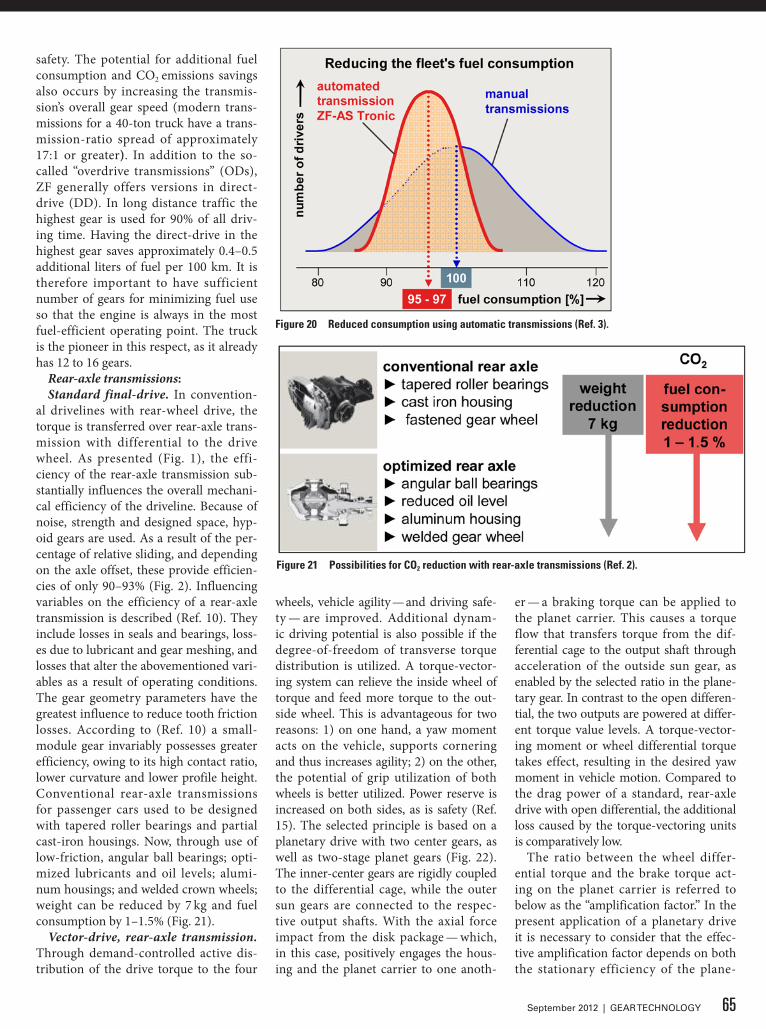
safety. The potential for additional fuel consumption and CO2 emissions savings also occurs by increasing the transmis-sion’s overall gear speed (modern trans-missions for a 40-ton truck have a trans-mission-ratio spread of approximately 17:1 or greater). In addition to the so-called “overdrive transmissions” (ODs), ZF generally offers versions in direct-drive (DD). In long distance traffic the highest gear is used for 90% of all driv-ing time. Having the direct-drive in the highest gear saves approximately 0.4–0.5 additional liters of fuel per 100 km. It is therefore important to have sufficient number of gears for minimizing fuel use so that the engine is always in the most fuel-efficient operating point. The truck is the pioneer in this respect, as it already has 12 to 16 gears.
Rear-axle transmissions:Standard final-drive. In convention-
al drivelines with rear-wheel drive, the torque is transferred over rear-axle trans-mission with differential to the drive wheel. As presented (Fig. 1), the effi-ciency of the rear-axle transmission sub-stantially influences the overall mechani-cal efficiency of the driveline. Because of noise, strength and designed space, hyp-oid gears are used. As a result of the per-centage of relative sliding, and depending on the axle offset, these provide efficien-cies of only 90–93% (Fig. 2). Influencing variables on the efficiency of a rear-axle transmission is described (Ref. 10). They include losses in seals and bearings, loss-es due to lubricant and gear meshing, and losses that alter the abovementioned vari-ables as a result of operating conditions. The gear geometry parameters have the greatest influence to reduce tooth friction losses. According to (Ref. 10) a small-module gear invariably possesses greater efficiency, owing to its high contact ratio, lower curvature and lower profile height. Conventional rear-axle transmissions for passenger cars used to be designed with tapered roller bearings and partial cast-iron housings. Now, through use of low-friction, angular ball bearings; opti-mized lubricants and oil levels; alumi-num housings; and welded crown wheels; weight can be reduced by 7 kg and fuel consumption by 1–1.5% (Fig. 21).
Vector-drive, rear-axle transmission. Through demand-controlled active dis-tribution of the drive torque to the four
wheels, vehicle agility — and driving safe-ty — are improved. Additional dynam-ic driving potential is also possible if the degree-of-freedom of transverse torque distribution is utilized. A torque-vector-ing system can relieve the inside wheel of torque and feed more torque to the out-side wheel. This is advantageous for two reasons: 1) on one hand, a yaw moment acts on the vehicle, supports cornering and thus increases agility; 2) on the other, the potential of grip utilization of both wheels is better utilized. Power reserve is increased on both sides, as is safety (Ref. 15). The selected principle is based on a planetary drive with two center gears, as well as two-stage planet gears (Fig. 22). The inner-center gears are rigidly coupled to the differential cage, while the outer sun gears are connected to the respec-tive output shafts. With the axial force impact from the disk package — which, in this case, positively engages the hous-ing and the planet carrier to one anoth-
er — a braking torque can be applied to the planet carrier. This causes a torque flow that transfers torque from the dif-ferential cage to the output shaft through acceleration of the outside sun gear, as enabled by the selected ratio in the plane-tary gear. In contrast to the open differen-tial, the two outputs are powered at differ-ent torque value levels. A torque-vector-ing moment or wheel differential torque takes effect, resulting in the desired yaw moment in vehicle motion. Compared to the drag power of a standard, rear-axle drive with open differential, the additional loss caused by the torque-vectoring units is comparatively low.
The ratio between the wheel differ-ential torque and the brake torque act-ing on the planet carrier is referred to below as the “amplification factor.” In the present application of a planetary drive it is necessary to consider that the effec-tive amplification factor depends on both the stationary efficiency of the plane-
Figure 20 Reduced consumption using automatic transmissions (Ref. 3).
Figure 21 Possibilities for CO2 reduction with rear-axle transmissions (Ref. 2).
65September 2012 | GEAR TECHNOLOGY
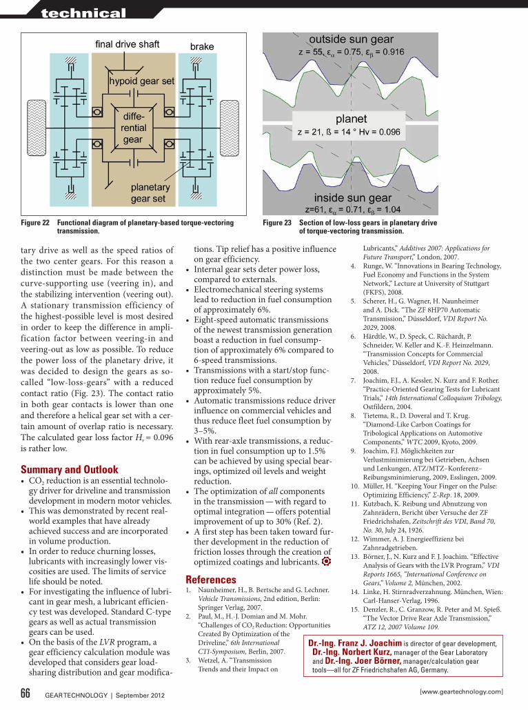
tary drive as well as the speed ratios of the two center gears. For this reason a distinction must be made between the curve-supporting use (veering in), and the stabilizing intervention (veering out). A stationary transmission efficiency of the highest-possible level is most desired in order to keep the difference in ampli-fication factor between veering-in and veering-out as low as possible. To reduce the power loss of the planetary drive, it was decided to design the gears as so-called “low-loss-gears” with a reduced contact ratio (Fig. 23). The contact ratio in both gear contacts is lower than one and therefore a helical gear set with a cer-tain amount of overlap ratio is necessary. The calculated gear loss factor Hv = 0.096 is rather low.
Summary and Outlook• CO2 reduction is an essential technolo-
gy driver for driveline and transmission development in modern motor vehicles.
• This was demonstrated by recent real-world examples that have already achieved success and are incorporated in volume production.
• In order to reduce churning losses, lubricants with increasingly lower vis-cosities are used. The limits of service life should be noted.
• For investigating the influence of lubri-cant in gear mesh, a lubricant efficien-cy test was developed. Standard C-type gears as well as actual transmission gears can be used.
• On the basis of the LVR program, a gear efficiency calculation module was developed that considers gear load-sharing distribution and gear modifica-
tions. Tip relief has a positive influence on gear efficiency.
• Internal gear sets deter power loss, compared to externals.
• Electromechanical steering systems lead to reduction in fuel consumption of approximately 6%.
• Eight-speed automatic transmissions of the newest transmission generation boast a reduction in fuel consump-tion of approximately 6% compared to 6-speed transmissions.
• Transmissions with a start/stop func-tion reduce fuel consumption by approximately 5%.
• Automatic transmissions reduce driver influence on commercial vehicles and thus reduce fleet fuel consumption by 3–5%.
• With rear-axle transmissions, a reduc-tion in fuel consumption up to 1.5% can be achieved by using special bear-ings, optimized oil levels and weight reduction.
• The optimization of all components in the transmission — with regard to optimal integration — offers potential improvement of up to 30% (Ref. 2).
• A first step has been taken toward fur-ther development in the reduction of friction losses through the creation of optimized coatings and lubricants.
References1. Naunheimer, H., B. Bertsche and G. Lechner.
Vehicle Transmissions, 2nd edition, Berlin: Springer Verlag, 2007.
2. Paul, M., H.-J. Domian and M. Mohr. “Challenges of CO2 Reduction: Opportunities Created By Optimization of the Driveline,” 6th International CTI-Symposium, Berlin, 2007.
3. Wetzel, A. “Transmission Trends and their Impact on
Lubricants,” Additives 2007: Applications for Future Transport,” London, 2007.
4. Runge, W. “Innovations in Bearing Technology, Fuel Economy and Functions in the System Network,” Lecture at University of Stuttgart (FKFS), 2008.
5. Scherer, H., G. Wagner, H. Naunheimer and A. Dick. “The ZF 8HP70 Automatic Transmission,” Düsseldorf, VDI Report No. 2029, 2008.
6. Härdtle, W., D. Speck, C. Rüchardt, P. Schneider, W. Keller and K.-F. Heinzelmann. “Transmission Concepts for Commercial Vehicles,” Düsseldorf, VDI Report No. 2029, 2008.
7. Joachim, F.J., A. Kessler, N. Kurz and F. Rother. “Practice-Oriented Gearing Tests for Lubricant Trials,” 14th International Colloquium Tribology, Ostfildern, 2004.
8. Tietema, R., D. Doveral and T. Krug. “Diamond-Like Carbon Coatings for Tribological Applications on Automotive Components,” WTC 2009, Kyoto, 2009.
9. Joachim, F.J. Möglichkeiten zur Verlustminimierung bei Getrieben, Achsen und Lenkungen, ATZ/MTZ–Konferenz–Reibungsminimierung, 2009, Esslingen, 2009.
10. Müller, H. “Keeping Your Finger on the Pulse: Optimizing Efficiency,” Σ-Rep. 18, 2009.
11. Kutzbach, K. Reibung und Abnutzung von Zahnrädern, Bericht über Versuche der ZF Friedrichshafen, Zeitschrift des VDI, Band 70, No. 30, July 24, 1926.
12. Wimmer, A. J. Energieeffizienz bei Zahnradgetrieben.
13. Börner, J., N. Kurz and F. J. Joachim. “Effective Analysis of Gears with the LVR Program,” VDI Reports 1665, “International Conference on Gears,” Volume 2, München, 2002.
14. Linke, H. Stirnradverzahnung. München, Wien: Carl-Hanser-Verlag, 1996.
15. Denzler, R., C. Granzow, R. Peter and M. Spieß. “The Vector Drive Rear Axle Transmission,” ATZ 12, 2007 Volume 109.
Figure 23 Section of low-loss gears in planetary drive of torque-vectoring transmission.
Figure 22 Functional diagram of planetary-based torque-vectoring transmission.
66 GEAR TECHNOLOGY | September 2012 [www.geartechnology.com]
technical
dr.-Ing. Franz J. Joachim is director of gear development, dr.-Ing. Norbert Kurz, manager of the Gear Laboratory and dr.-Ing. Joer Börner, manager/calculation gear tools—all for ZF Friedrichshafen AG, Germany.
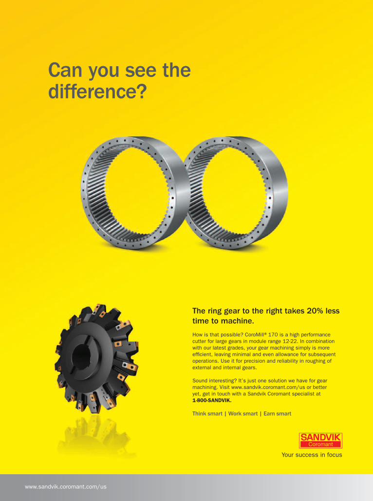
08-06-2012 Sandvik Can You See the Difference? Ad / Gear Technology 8.25” x 11”
www.sandvik.coromant.com/us
Think smart | Work smart | Earn smart
Can you see the difference?
The ring gear to the right takes 20% lesstime to machine.
How is that possible? CoroMill®170 is a high performancecutter for large gears in module range 12-22. In combinationwith our latest grades, your gear machining simply is moreefficient, leaving minimal and even allowance for subsequentoperations. Use it for precision and reliability in roughing ofexternal and internal gears.
Sound interesting? It’s just one solution we have for gearmachining. Visit www.sandvik.coromant.com/us or betteryet, get in touch with a Sandvik Coromant specialist at1-800-SANDVIK.
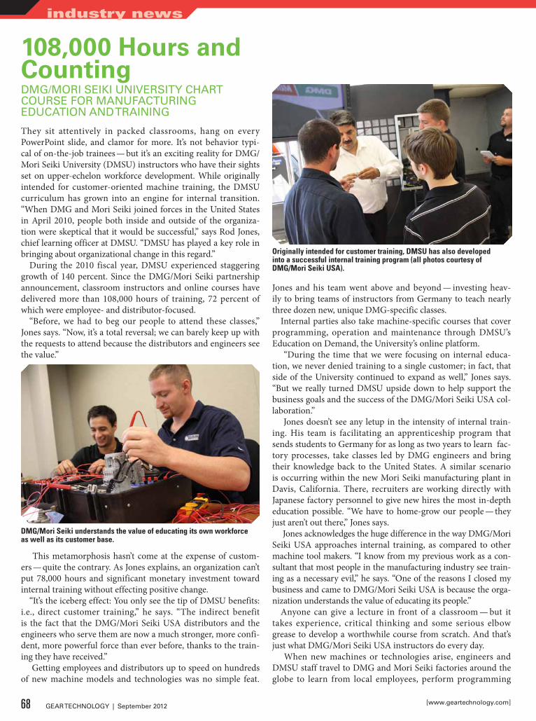
108,000 Hours and CountingDMG/MORi SEiki UNiVERSiTy CHaRT COURSE FOR MaNUFaCTURiNG EDUCaTiON aND TRaiNiNG
They sit attentively in packed classrooms, hang on every PowerPoint slide, and clamor for more. It’s not behavior typi-cal of on-the-job trainees — but it’s an exciting reality for DMG/Mori Seiki University (DMSU) instructors who have their sights set on upper-echelon workforce development. While originally intended for customer-oriented machine training, the DMSU curriculum has grown into an engine for internal transition. “When DMG and Mori Seiki joined forces in the United States in April 2010, people both inside and outside of the organiza-tion were skeptical that it would be successful,” says Rod Jones, chief learning officer at DMSU. “DMSU has played a key role in bringing about organizational change in this regard.”
During the 2010 fiscal year, DMSU experienced staggering growth of 140 percent. Since the DMG/Mori Seiki partnership announcement, classroom instructors and online courses have delivered more than 108,000 hours of training, 72 percent of which were employee- and distributor-focused.
“Before, we had to beg our people to attend these classes,” Jones says. “Now, it’s a total reversal; we can barely keep up with the requests to attend because the distributors and engineers see the value.”
This metamorphosis hasn’t come at the expense of custom-ers — quite the contrary. As Jones explains, an organization can’t put 78,000 hours and significant monetary investment toward internal training without effecting positive change.
“It’s the iceberg effect: You only see the tip of DMSU benefits: i.e., direct customer training,” he says. “The indirect benefit is the fact that the DMG/Mori Seiki USA distributors and the engineers who serve them are now a much stronger, more confi-dent, more powerful force than ever before, thanks to the train-ing they have received.”
Getting employees and distributors up to speed on hundreds of new machine models and technologies was no simple feat.
Jones and his team went above and beyond — investing heav-ily to bring teams of instructors from Germany to teach nearly three dozen new, unique DMG-specific classes.
Internal parties also take machine-specific courses that cover programming, operation and maintenance through DMSU’s Education on Demand, the University’s online platform.
“During the time that we were focusing on internal educa-tion, we never denied training to a single customer; in fact, that side of the University continued to expand as well,” Jones says. “But we really turned DMSU upside down to help support the business goals and the success of the DMG/Mori Seiki USA col-laboration.”
Jones doesn’t see any letup in the intensity of internal train-ing. His team is facilitating an apprenticeship program that sends students to Germany for as long as two years to learn fac-tory processes, take classes led by DMG engineers and bring their knowledge back to the United States. A similar scenario is occurring within the new Mori Seiki manufacturing plant in Davis, California. There, recruiters are working directly with Japanese factory personnel to give new hires the most in-depth education possible. “We have to home-grow our people — they just aren’t out there,” Jones says.
Jones acknowledges the huge difference in the way DMG/Mori Seiki USA approaches internal training, as compared to other machine tool makers. “I know from my previous work as a con-sultant that most people in the manufacturing industry see train-ing as a necessary evil,” he says. “One of the reasons I closed my business and came to DMG/Mori Seiki USA is because the orga-nization understands the value of educating its people.”
Anyone can give a lecture in front of a classroom — but it takes experience, critical thinking and some serious elbow grease to develop a worthwhile course from scratch. And that’s just what DMG/Mori Seiki USA instructors do every day.
When new machines or technologies arise, engineers and DMSU staff travel to DMG and Mori Seiki factories around the globe to learn from local employees, perform programming
dMG/Mori Seiki understands the value of educating its own workforce as well as its customer base.
Originally intended for customer training, dMSU has also developed into a successful internal training program (all photos courtesy of dMG/Mori Seiki USA).
68 GEAR TECHNOLOGY | September 2012 [www.geartechnology.com]
industry news
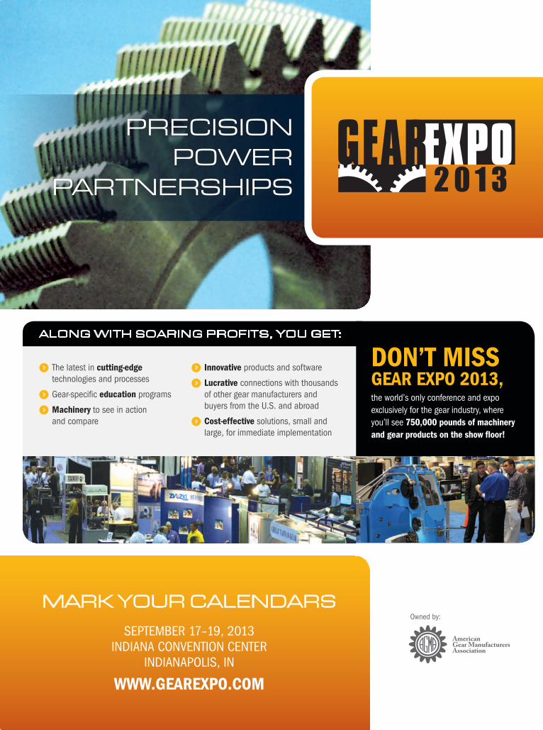
Mark Your Calendars
September 17–19, 2013 IndIana ConventIon Center
IndIanapolIS, In
www.Gearexpo.com
along with soaring profits, You get:
) the latest in cutting-edge technologies and processes
) Gear-specific education programs
) machinery to see in action and compare
) Innovative products and software
) Lucrative connections with thousands of other gear manufacturers and buyers from the U.S. and abroad
) cost-effective solutions, small and large, for immediate implementation
Don’t mIssGear expo 2013,the world’s only conference and expo exclusively for the gear industry, where you’ll see 750,000 pounds of machinery and gear products on the show floor!
preCision power
partnerships
owned by:
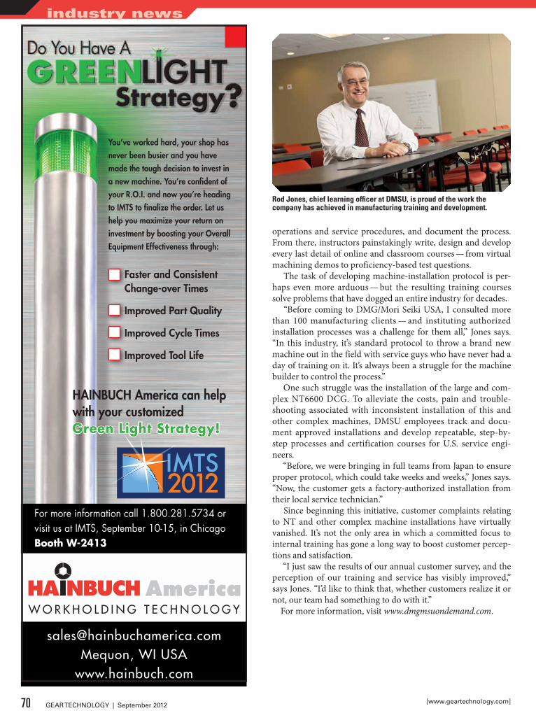
operations and service procedures, and document the process. From there, instructors painstakingly write, design and develop every last detail of online and classroom courses — from virtual machining demos to proficiency-based test questions.
The task of developing machine-installation protocol is per-haps even more arduous — but the resulting training courses solve problems that have dogged an entire industry for decades.
“Before coming to DMG/Mori Seiki USA, I consulted more than 100 manufacturing clients — and instituting authorized installation processes was a challenge for them all,” Jones says. “In this industry, it’s standard protocol to throw a brand new machine out in the field with service guys who have never had a day of training on it. It’s always been a struggle for the machine builder to control the process.”
One such struggle was the installation of the large and com-plex NT6600 DCG. To alleviate the costs, pain and trouble-shooting associated with inconsistent installation of this and other complex machines, DMSU employees track and docu-ment approved installations and develop repeatable, step-by-step processes and certification courses for U.S. service engi-neers.
“Before, we were bringing in full teams from Japan to ensure proper protocol, which could take weeks and weeks,” Jones says. “Now, the customer gets a factory-authorized installation from their local service technician.”
Since beginning this initiative, customer complaints relating to NT and other complex machine installations have virtually vanished. It’s not the only area in which a committed focus to internal training has gone a long way to boost customer percep-tions and satisfaction.
“I just saw the results of our annual customer survey, and the perception of our training and service has visibly improved,” says Jones. “I’d like to think that, whether customers realize it or not, our team had something to do with it.”
For more information, visit www.dmgmsuondemand.com.
You’ve worked hard, your shop has never been busier and you have made the tough decision to invest in a new machine. You’re confident of your R.O.I. and now you’re heading to IMTS to finalize the order. Let us help you maximize your return on investment by boosting your Overall Equipment Effectiveness through:
For more information call 1.800.281.5734 orvisit us at IMTS, September 10-15, in ChicagoBooth W-2413
Faster and Consistent Change-over Times
Improved Part Quality
Improved Cycle Times
Improved Tool Life
[email protected], WI USA
www.hainbuch.com
HAINBUCH America can helpwith your customizedGreen Light Strategy!
Rod Jones, chief learning officer at dMSU, is proud of the work the company has achieved in manufacturing training and development.
70 GEAR TECHNOLOGY | September 2012 [www.geartechnology.com]
industry news
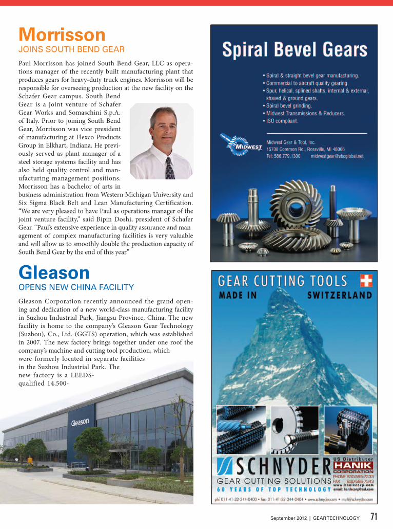
GEAR CUTT ING SOLUT IONS
MorrissonJOiNS SOUTH BEND GEaR
Paul Morrisson has joined South Bend Gear, LLC as opera-tions manager of the recently built manufacturing plant that produces gears for heavy-duty truck engines. Morrisson will be responsible for overseeing production at the new facility on the Schafer Gear campus. South Bend Gear is a joint venture of Schafer Gear Works and Somaschini S.p.A. of Italy. Prior to joining South Bend Gear, Morrisson was vice president of manufacturing at Flexco Products Group in Elkhart, Indiana. He previ-ously served as plant manager of a steel storage systems facility and has also held quality control and man-ufacturing management positions. Morrisson has a bachelor of arts in business administration from Western Michigan University and Six Sigma Black Belt and Lean Manufacturing Certification. “We are very pleased to have Paul as operations manager of the joint venture facility,” said Bipin Doshi, president of Schafer Gear. “Paul’s extensive experience in quality assurance and man-agement of complex manufacturing facilities is very valuable and will allow us to smoothly double the production capacity of South Bend Gear by the end of this year.”
GleasonOPENS NEW CHiNa FaCiLiTy
Gleason Corporation recently announced the grand open-ing and dedication of a new world-class manufacturing facility in Suzhou Industrial Park, Jiangsu Province, China. The new facility is home to the company’s Gleason Gear Technology (Suzhou), Co., Ltd. (GGTS) operation, which was established in 2007. The new factory brings together under one roof the company’s machine and cutting tool production, which were formerly located in separate facilities in the Suzhou Industrial Park. The new factory is a LEEDS-qualified 14,500-
71September 2012 | GEAR TECHNOLOGY
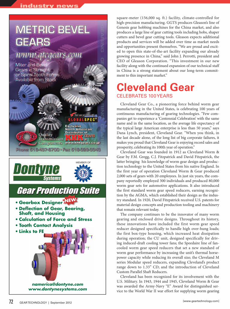
Gear Production SuiteGear Production Suite•GearboxDesigner•DeflectionofGear,Bearing,Shaft,andHousing
•CalculationofForceandStress•ToothContactAnalysis•LinkstoFE
MEMBER OF
square-meter (156,000 sq. ft.) facility, climate-controlled for high-precision manufacturing. GGTS produces Gleason’s line of Genesis gear hobbing machines for the China market, and also produces a large line of gear cutting tools including hobs, shaper cutters and bevel gear cutting tools. Gleason expects additional products and services will be added over time as market needs and opportunities present themselves. “We are proud and excit-ed to open this state-of-the-art facility expanding our already growing presence in China,” said John J. Perrotti, president and CEO of Gleason Corporation. “This investment in our new facility along with the continued expansion of our technical staff in China is a strong statement about our long-term commit-ment to this important market.”
Cleveland GearCELEBRaTES 100 yEaRS
Cleveland Gear Co., a pioneering force behind worm gear manufacturing in the United States, is celebrating 100 years of continuous manufacturing of gearing technologies. “Few com-panies get to experience a ‘Centennial Celebration’ with the same name and in the same location, as the average life expectancy of the typical large American enterprise is less than 50 years,” says Dana Lynch, president, Cleveland Gear. “When you think, in the last decade alone, of the long list of big corporate failures, it makes you proud that Cleveland Gear is enjoying record sales and prosperity, celebrating its 100th year of operation.”
Cleveland Gear was founded in 1912 as Cleveland Worm & Gear by F.M. Gregg, C.J. Fitzpatrick and David Fitzpatrick, the latter bringing his knowledge of worm gear design and produc-tion technology to the United States from his native England. In the first year of operation Cleveland Worm & Gear produced 2,000 sets of gears with 20 employees. In just six years, the com-pany reportedly employed 300 individuals and produced 80,000 worm gear sets for automotive applications. It also introduced the first standard worm gear speed reducers, earning recogni-tion by the AGMA, which established their design as the indus-try standard. In 1920, David Fitzpatrick received U.S. patents for material design concepts and production tooling and machinery that remain relevant today.
The company continues to be the innovator of many worm gearing and enclosed drive designs. Throughout its history, these innovations have included the first worm gear speed reducer designed specifically to handle high over-hung loads; the first box-type housing, which increased heat dissipation during operation; the CU unit, designed specifically for driv-ing induced-draft cooling tower fans; the Speedaire line of fan-cooled worm gear speed reducers that set a new standard of worm gear performance by increasing the unit’s thermal horse-power capacity while reducing its overall size; the Cleveland M series Modular speed reducers, expanding Cleveland’s product range down to 1.33” CD; and the introduction of Cleveland Custom Parallel Shaft Reducers.
Cleveland has been recognized for its involvement with the U.S. Military. In 1943, 1944 and 1945, Cleveland Worm & Gear was awarded the Army-Navy “E” Award for distinguished ser-vice to the World War II war effort for supplying worm gearing
72 GEAR TECHNOLOGY | September 2012 [www.geartechnology.com]
industry news
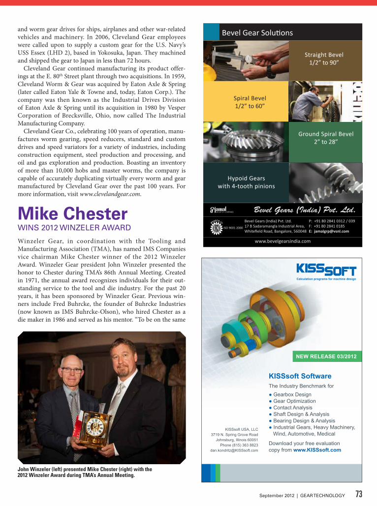
NEW RELEASE 03/2012
KISSsoft SoftwareThe Industry Benchmark for● Gearbox Design● Gear Optimization● Contact Analysis● Shaft Design & Analysis● Bearing Design & Analysis● Industrial Gears, Heavy Machinery, Wind, Automotive, Medical
Download your free evaluationcopy from www.KISSsoft.com
KISSsoft USA, LLC3719 N. Spring Grove Road
Johnsburg, Illinois 60051Phone (815) 363 8823
GearTech_KISSsoft_Rel_03_2012_86x121mm.indd 1 4/11/2012 10:49:22 AM
Bevel Gear Solutions
Bevel Gears (India) Pvt. Ltd.17 B Sadaramangla Industrial Area,Whitefield Road, Bangalore, 560048
P: +91 80 2841 0312 / 039 F: +91 80 2841 0185E: [email protected]
ISO 9001:2000
www.bevelgearsindia.com
Straight Bevel 1/2” to 90”
Ground Spiral Bevel 2” to 28”
Spiral Bevel 1/2” to 60”
Hypoid Gears with 4-tooth pinions
and worm gear drives for ships, airplanes and other war-related vehicles and machinery. In 2006, Cleveland Gear employees were called upon to supply a custom gear for the U.S. Navy’s USS Essex (LHD 2), based in Yokosuka, Japan. They machined and shipped the gear to Japan in less than 72 hours.
Cleveland Gear continued manufacturing its product offer-ings at the E. 80th Street plant through two acquisitions. In 1959, Cleveland Worm & Gear was acquired by Eaton Axle & Spring (later called Eaton Yale & Towne and, today, Eaton Corp.). The company was then known as the Industrial Drives Division of Eaton Axle & Spring until its acquisition in 1980 by Vesper Corporation of Brecksville, Ohio, now called The Industrial Manufacturing Company.
Cleveland Gear Co., celebrating 100 years of operation, manu-factures worm gearing, speed reducers, standard and custom drives and speed variators for a variety of industries, including construction equipment, steel production and processing, and oil and gas exploration and production. Boasting an inventory of more than 10,000 hobs and master worms, the company is capable of accurately duplicating virtually every worm and gear manufactured by Cleveland Gear over the past 100 years. For more information, visit www.clevelandgear.com.
Mike ChesterWiNS 2012 WiNzELER aWaRD
Winzeler Gear, in coordination with the Tooling and Manufacturing Association (TMA), has named IMS Companies vice chairman Mike Chester winner of the 2012 Winzeler Award. Winzeler Gear president John Winzeler presented the honor to Chester during TMA’s 86th Annual Meeting. Created in 1971, the annual award recognizes individuals for their out-standing service to the tool and die industry. For the past 20 years, it has been sponsored by Winzeler Gear. Previous win-ners include Fred Buhrcke, the founder of Buhrcke Industries (now known as IMS Buhrcke-Olson), who hired Chester as a die maker in 1986 and served as his mentor. “To be on the same
John Winzeler (left) presented Mike Chester (right) with the 2012 Winzeler Award during TMA’s Annual Meeting.
73September 2012 | GEAR TECHNOLOGY
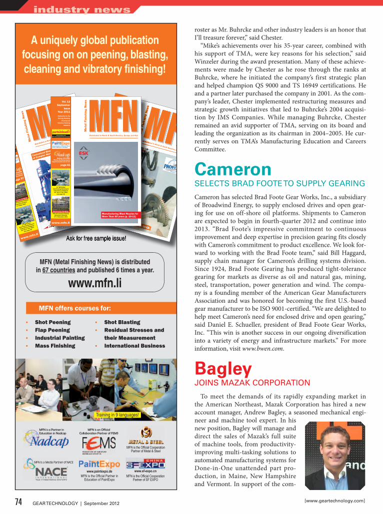
A uniquely global publication focusing on on peening, blasting, cleaning and vibratory finishing!
Ask for free sample issue!
MFN is an Official Collaboration Partner of FEMS
www.sf-expo.cnMFN is the Official Cooperation
Partner of SF EXPO
MFN is a Partner in Education in Nadcap
www.paintexpo.de MFN is the Official Partner in
Education of PaintExpo
MFN is a Media Partner of NACE
MFN offers courses for:
MFN (Metal Finishing News) is distributed in 67 countries and published 6 times a year.
www.mfn.li
Training in 9 languages!
Ask for free sample issue!
www.mfn.li
www.paintexpo.de - MFN is the Official
Partner in Education of PaintExpo
www.parts2clean.com
MFN is Official Cooperation Partner of parts2clean
Publication for the
Peening, Blasting,
Cleaning and
Vibratory Finishing
Industries
Vol. 12 May
Issue
Year 2011
Nadcap COLUMN:
How to promote your
Nadcap Accreditation
page 57
Customized Blasting Solutions for the Cleaning
of Complex Workpiece Confi gurations (p. 26-27)
11th MFN Asian
Shot Peening Workshop &
Trade Show in Singapore
31st Oct.-3rd Nov. 2011
(see page 29)
Sponsored by PaintExpo
MFN-JOT Industrial Painting
Workshop in Germany
4th of May, 2011
Ask for free sample issue!Ask for free sample issue!
www.mfn.li
www.paintexpo.de - MFN is the Official
Partner in Education of PaintExpo
www.parts2clean.com
MFN is Official Cooperation Partner of parts2clean
Publication for the Peening, Blasting, Cleaning and Vibratory Finishing Industries
Vol. 12 July
IssueYear 2011
Nadcap COLUMN:Audit Observationspage 55
11th MFN Asian Shot Peening Workshop &
Trade Show in Singapore31st Oct.-3rd Nov. 2011
(see page 23)
Sponsored by PaintExpoMFN-JOT Industrial Painting
Workshop in Germany 17th of November, 2011
Residual Stresses in Service (p. 10-12)
www.mfn.li
www.paintexpo.de - MFN is the Official
Partner in Education of PaintExpo
www.parts2clean.com
www.parts2clean.com
wMFN is Official Cooperation Partner of parts2clean
Publication for the Peening, Blasting, Cleaning and Vibratory Finishing Industries
Vol. 12 July
IssueYear 2011
Nadcap COLUMN:Audit Observationspage 55
11th11th11 MFN Asian Shot Peening Workshop &
Trade Show in Singapore31st Oct.-3rd Nov. 2011
(see page 23)
Sponsored by PaintExpoMFN-JOT Industrial Painting
Workshop in Germany 17th of November, 2011
Residual Stresses in Service (p. 10-12)
Customized Blasting Solutions for the Cleaning
of Complex Workpiece Confi gurations (p. 26-27)
Customized Blasting Solutions for the Cleaning
of Complex Workpiece Confi gurations (p. 26-27)
www.mfn.li
www.paintexpo.de - MFN is the Official Partner in Education of PaintExpo
www.parts2clean.comMFN is Official Cooperation Partner of parts2clean
Publication for the Peening, Blasting,
Cleaning and Vibratory Finishing
Industries
Vol. 12 September
IssueYear 2011
Nadcap COLUMN:What has the Nadcap Supplier
Support Committee done for me?
page 61
11th MFN Asian Shot Peening Workshop & Trade Show in Singapore31st Oct.-3rd Nov. 2011
(see page 12)
Sponsored by PaintExpoMFN-JOT Industrial Painting
Workshop in Germany 17th of November, 2011
Manufacturing Blast Nozzles for More Than 50 years (p. 10-11)
▪ Shot Peening ▪ Flap Peening ▪ Industrial Painting ▪ Mass Finishing
MFN is the Official Cooperation Partner of Metal & Steel
▪ Shot Blasting ▪ Residual Stresses and
their Measurement ▪ International Business
roster as Mr. Buhrcke and other industry leaders is an honor that I’ll treasure forever,” said Chester.
“Mike’s achievements over his 35-year career, combined with his support of TMA, were key reasons for his selection,” said Winzeler during the award presentation. Many of these achieve-ments were made by Chester as he rose through the ranks at Buhrcke, where he initiated the company’s first strategic plan and helped champion QS 9000 and TS 16949 certifications. He and a partner later purchased the company in 2001. As the com-pany’s leader, Chester implemented restructuring measures and strategic growth initiatives that led to Buhrcke’s 2004 acquisi-tion by IMS Companies. While managing Buhrcke, Chester remained an avid supporter of TMA, serving on its board and leading the organization as its chairman in 2004–2005. He cur-rently serves on TMA’s Manufacturing Education and Careers Committee.
CameronSELECTS BRaD FOOTE TO SUPPLy GEaRiNG
Cameron has selected Brad Foote Gear Works, Inc., a subsidiary of Broadwind Energy, to supply enclosed drives and open gear-ing for use on off-shore oil platforms. Shipments to Cameron are expected to begin in fourth-quarter 2012 and continue into 2013. “Brad Foote’s impressive commitment to continuous improvement and deep expertise in precision gearing fits closely with Cameron’s commitment to product excellence. We look for-ward to working with the Brad Foote team,” said Bill Haggard, supply chain manager for Cameron’s drilling systems division. Since 1924, Brad Foote Gearing has produced tight-tolerance gearing for markets as diverse as oil and natural gas, mining, steel, transportation, power generation and wind. The compa-ny is a founding member of the American Gear Manufacturers Association and was honored for becoming the first U.S.-based gear manufacturer to be ISO 9001-certified. “We are delighted to help meet Cameron’s need for enclosed drive and open gearing,” said Daniel E. Schueller, president of Brad Foote Gear Works, Inc. “This win is another success in our ongoing diversification into a variety of energy and infrastructure markets.” For more information, visit www.bwen.com.
BagleyJOiNS Mazak CORPORaTiON
To meet the demands of its rapidly expanding market in the American Northeast, Mazak Corporation has hired a new account manager, Andrew Bagley, a seasoned mechanical engi-neer and machine tool expert. In his new position, Bagley will manage and direct the sales of Mazak’s full suite of machine tools, from productivity-improving multi-tasking solutions to automated manufacturing systems for Done-in-One unattended part pro-duction, in Maine, New Hampshire and Vermont. In support of the com-
74 GEAR TECHNOLOGY | September 2012 [www.geartechnology.com]
industry news
pany’s ongoing commitment to customer education and sup-port, Bagley will also provide after-sale technical support and provide educational presentations about the technical features of Mazak machines. Bagley has extensive machine tool expe-rience, having previously worked as a service engineer and metrologist, and has been recognized for the development of lean manufacturing processes and educational and training efforts for several leading manufacturers. “Andrew has excel-lent experience in the industry and has proven to be a true team leader when it comes to customer service, training and support,” said Steve Wilkins, regional manager of the Northeast region for Mazak. “We’re excited to have him as a member of our team and another resource for our valued customers.” Bagley attended the University of New Haven where he studied mechanical engi-neering and has advanced in the field, from a machine techni-cian and designer to service engineer responsible for company-wide training and installation, repairs, customer support and part programming for ultra-precision equipment.
American WeraRENaMED GERMaN MaCHiNE TOOLS OF aMERiCa
American Wera is now officially renamed German Machine Tools Of America (GMTA) and continues to represent various top-quality German metalworking machine builders, including Profilator, Pittler, Praewema, WMZ and MAE. These machines are sold for gear and spline production, vertical turning, flex-ible machining solutions (blank to finish part solutions), as well as bar, pipe and tube straightening plus wheelset press-ing. The company’s target markets include automotive, off-highway, OCTG, rail, wind energy and other heavy equipment
manufacturing. This announcement was made jointly by GMTA President Walter Friedrich and Vice President of Sales Scott Knoy. “The reason for the name change is simply that the par-ent company wished to use a name that is more representative of all the lines we handle in North America,” said Knoy. Originally formed as the North American subsidiary for Wera in Germany, GMTA today provides application engineering, sales and service for a broad range of machine tools and metal fabricating equip-ment. GMTA has representatives throughout the U.S., Canada and Mexico. Other key company individuals include Claudia Hambleton, treasurer; Doug VanDeven, service/parts manag-er and Shawn Wilkin, senior service engineer. Joseph Kemple remains the dedicated product manager for the MAE line of straightening and wheelset presses.
ALWAYS FOCUSED,ALWAYS TIMELY
GEAR TECHNOLOGY's E-mail Newsletters•Exclusive original content•The latest gear industry news•Delivered monthly
Sign up at www.geartechnology.com/newsletter
75September 2012 | GEAR TECHNOLOGY
September 18–20 — SAe 2012 Aerospace manufacturing and Automated Fastening conference and exhibition. Fort Worth Convention Center, Fort Worth, Texas. The exhibition will provide a forum for the aerospace community to present and discuss current and future challenges, opportunities, and requirements of next-generation aircraft R&D, products, and systems. Technical ses-sions, lively panel discussions and keynote presentations will be the highlight of this event that is essential for engineers, scientists, designers, program managers and operators in indus-try as well as government and research facilities. Topics include: automated fastening/assembly and tooling, composites materi-als and processing, information technology, lean manufacturing and supply chain management, ferrous/nonferrous metals and processing, structures, automated manufacturing and sustain-ability. For more information, visit www.sae.org.
october 7–11 — materials Science & Technology conference & exhibition. Pittsburgh, Pennsylvania. MS&T brings together professionals from virtually every field of materials science: metals, polymers, ceramics and composites. Attendees will have the opportunity to reach potential customers in industries like automotive, aerospace, instrumentation, medical, oilfield and energy. The MS&T partnership of four leading materials societies — ACerS, AIST, ASM and TMS — brings together scientists, engineers, stu-dents, policy makers, suppliers and more to discuss current research and technical applications, and to shape the future of materials science and technology. Since corrosion remains a relevant topic to materials, NACE International will again co-sponsor MS&T. Areas of interest include biomaterials, iron and steel, ceramics, materials per-formance, nanotechnology and processing and product manufactur-ing. For more information, visit www.matscitech.org.
october 15–19 — Ame chicago 2012. Sheraton Chicago Hotel and Towers. The Association for Manufacturing Excellence (AME) has a long track record for finding and convincing some of the best manufacturing practitioners from around the world to share their lean practice experiences. More than 60 leading presenters will be on hand to discuss customer focus, process sustainment, continuous improvement, material flow and other lean practices and strategies. Manufacturing tours highlighting some of the best lean and six sigma operations in and around the Chicago area include Caterpillar, Bimba Manufacturing, Whiting Corporation, S&C Electric Company and Winzeler Gear. Workshop topics include maintenance management, lean behav-iors, training within industry, lean business simulation and lean tools for the office. Six keynote speakers will be featured at the conference including Mike Abrashoff and Jason Jennings. For reg-istration information, visit www.ameconference.org.
october 22–24 — 3rd Annual American manufacturing Strategies Summit 2012. McCormick Place, Chicago. The Manufacturers Alliance/MAPI Survey on the Business Outlook shows ongoing expansion of manufacturing in the United States, although the speed of growth could be slowing. As the American economy continues to recover, it is critical that manufacturers adopt new processes to enable more effective pro-duction and order fulfillment. Researched and validated by senior industry advisory board, AMS 2012 will provide leading case
studies, stimulating debate on the future of manufacturing, and valuable networking opportunities for you to share information and find future business partners. Event features include stream sessions, case studies, pre-scheduled one-to-one meetings, dis-cussion tables, workshops and networking opportunities. Topics include reshoring initiatives, retaining the skilled workforce, opti-mizing the global footprint of worldwide operations, improving performance, productivity, and profitability through operational excellence and lean programming, developing the leadership tools that drive success in new programs and seeking innovations in tools, tactics and technologies. For more information, visit www.manufacturing-summit.com.
october 28–30 — AGmA Fall Technical meeting. Hyatt Regency Dearborn, Dearborn, Michigan. The FTM high-lights the latest research in the industry from experts all over the world on topics including micropitting, gearbox design, materials and manufacturing. The conference is designed for attendees to listen to all the presentations and take home prac-tical information that may ultimately affect your company’s bottom line. In addition, the meeting provides invaluable net-working opportunities between sessions and in the evenings to interact with colleagues and meet new experts in the industry. Programs, as well as peer-reviewed technical papers, address lubrication and components, gear drive applications, manufac-turing and inspection, gear design issues and materials and heat treatment. For more information, visit www.agma.org.
november 13–15 — methods, Practices, Application and interpretation for the design engineer. Hard Rock Hotel and Casino, Las Vegas. Raymond Drago, chief engineer–gear technologist, Drive Systems Technology, Inc., will instruct attendees on the methods used to manufacture and inspect gears, including external and internal spur, single and double-helical gears, as well as bevel and worm gears. A description of each basic manufacturing and inspec-tion method is provided. Both the methodology and underlying theory are explained. The seminar also covers the methods of specifying the data required to control both the manufactur-ing and inspection processes on an engineering drawing and in a specification. This includes the data to be defined and its presentation on the engineering drawing. It is critical that the design engineer understand the manufacturing and inspection processes that will be employed so that the intent of the design can be successfully translated into practice. Most gear inspec-tion centers on gear tooth geometry; however, various nonde-structive and destructive tests (such as ultrasonic, magnetic particle, acid etch, etc.) are also required to ensure the quality of the basic gear material and the results of various heat treatment procedures. In this seminar the basics of a variety of these tests will be covered, including their underlying theory, application techniques and, most importantly, interpretation of the result-ant data. This seminar aims to narrow and possibly close the information gap by providing gear design engineers with a good foundation in both manufacturing and inspections processes and procedures. For more information, visit www.agma.org.
76 GEAR TECHNOLOGY | September 2012 [www.geartechnology.com]
calendar

Company Name:_________________________________________________Company address:_________________________________________________________________________________________________________________City:______________________________________________________________State/Province:____________________________________________________ziP/Postal Code:___________________________________________________Telephone:_________________________Fax:___________________________E-mail:____________________________________________________________Co. internet address:______________________________________________
5) Please tell us about your company: 7) How is THIS LOCATION involved in the gear industry? (Check all that apply) WE MakE GEaRS (or Splines, Sprockets, Worms, etc.) (20) WE BUy GEaRS (or Splines, Sprockets, Worms, etc.) (22) WE SELL NEW MaCHiNES, TOOLiNG OR SUPPLiES TO GEaR MaNUFaCTURERS (24) WE provide SERViCES to gear manufacturers (25)(please describe) ____________________________________________ WE distribute gears or gear products (including agents and sales reps.(26) WE are a USED MaCHiNE TOOL dealer (30) Other (please describe) ___________________________________ (32)
8) What is the principal product manufactured or service performed at THIS LOCATION?
9) How many employees are at THIS LOCATION (Check one) 1-19 20-49 50-99 100-499 500+
1) yES i want to receive/continue to receive Gear Technology FREE.
No thank you.
2) i want to receive the PRiNT version *DiGiTaL version *BOTH print and digital(*Please include your e-mail address for DiGiTaL or BOTH versions.) _______________________________________________
3) Name:___________________________________________JobTitle/Position: _______________________________
4) Signature _________________________________________________________ Date: _______________________
(Please print e-mail address)
(print)
Corporate Executives (B) Manufacturing Production
Management (C)Manufacturing Production
Department (D)Manufacturing Engineering
Management (E) Manufacturing Engineering
Department (F) Product Design, R&D
Management (H)
Product Design/ R&D Personnel (i)
Purchasing (L)Marketing & Sales,
Communications (M)Quality Control
Management (P)Quality Control
Department (Q)Other Qualifed
Personnel (N)
6) What is your primary job function responsibility? (Check one)
FAX TO 1-847-437-6618 orViSiT US ONLiNE aT
www.geartechnology.com/subscribe.htm
YES, I would like to receive Gear Technology's monthly e-mail newsletter
YES, I would like to receive Gear Technology's monthly e-mail Product Alerts
YES, I would like to receive 3rd-party e-mails from Gear Technology’s advertisers and partners
YES, I would like to receive subscription renewal notices by e-mail
No, I do not wish to be contacted by e-mail.
FREE SUBSCRIPTIONSTART YOUR
®
GEARMACHINERYEXCHANGE.COM
www.gearmachineryexchange.com
Sponsored by
MEMBER MEMBER
MACHINERY DEALERS
NA
TIONAL ASSOCIA
TION
MEMBER &LIFE FELLOW
EUR
OP
EA
N A
SSOCIATION OF MACHINE TOO
L MER
CH
AN
TS
Sell Your SurplusGear Machinery & Tooling
Send information [email protected]
(847) 437-6605
GEARMACHINERYEXCHANGE.COM
www.gearmachineryexchange.com
Sponsored by
MEMBER MEMBER
MACHINERY DEALERS
NA
TIONAL ASSOCIA
TION
MEMBER &LIFE FELLOW
EUR
OP
EA
N A
SSOCIATION OF MACHINE TOO
L MER
CH
AN
TS
DIRECT to END USERS
A.G. davis/AA Gage — page 11www.agdavis.com
AGMA — page 69www.gearexpo.com
ALd-Holcroft — page 29www.ald-holcroft.com
B&R Machine & Gear Corp. — IBCwww.brgear.com
Beavermatic — page 44www.beavermatic.com
Bevel Gears India Pvt. Ltd. — page 73www.bevelgearsindia.com
Brevini Wind USA — page 7www.breviniwind.com
Cincinnati Gearing Systems — page 47www.cincinnatigearingsystems.com
Circle Gear & Machine Co. — page 79www.circlegear.com
Clifford-Jacobs Forging Co. — page 27www.clifford-jacobs.com
delta Gear — page 35www.delta-gear.com
dontyne Systems — page 72www.dontynesystems.com
drake Manufacturing — page 23www.drakemfg.com
dTR Corp. — page 18www.dragon.co.kr
Erasteel — page 12www.erasteel.com
Gear Consulting Group — page 79www.gearconsultinggroup.com
Gear Expo — page 79www.gearexpo.com
Gear Motions Inc. — page 79www.gearmotions.com
The Gear Works—Seattle, Inc. — page 79www.thegearworks.com
Gleason Corp. — pages 38, 39, 40-41, 79www.gleason.com
Hainbuch America — page 70www.hainbuch.com
Hans-Jürgen Geiger Maschinen-Vertrieb — page 26
www.geiger-germany.comHöfler — OBC
www.hofler.comInductoheat — page 37
www.inductoheat.comIpsen International — page 25
www.ipsenusa.comKapp Technologies — page 3
www.kapp-usa.comKISSsoft — page 73
www.kisssoft.comKlingelnberg — page 5
www.klingelnberg.comMcInnes Rolled Rings — page 16
www.mcinnesrolledrings.com
Metal Finishing News — page 74www.mfn.li
Midwest Gear & Tool Inc. — page [email protected]
Mitsubishi — pages 8, 38www.mitsubishigearcenter.com
Mitutoyo — page 15www.mitutoyo.com
Nachi — page 32www.nachiamerica.com
Niagara Gear — 4www.niagaragear.com
Oelheld USA — 39www.oelheld.com
Ontario drive & Gear — page 31www.odg.com
Overton Chicago Gear — page 79www.oc-gear.com
Precipart Corp. — page 13www.precipart.com
Presrite Corp. — page 43www.presrite.com
Process Equipment — page 4www.gearinspection.com
Proto Manufacturing — page 19www.protoxrd.com
PTG Holroyd — page 14www.holroyd.com
QC American — page 39www.qcamerican.com
Quality Transmission Components — page 72www.qtcgears.com
Riverside Spline & Gear — page 33www.splineandgear.com
Sandvik Coromant — page 67www.coromant.sandvik.com/us
Schafer Gear — page 21www.schafergear.com
Schnyder S.A. — page 71www.hanikcorp.com
Seco Tools — page 17www.secotools.com/energy
Sicmat — page 20www.star-su.com
Solar Atmospheres — page 51www.solaratm.com
Star SU LLC — pages IFC–1, 20, 79www.star-su.com
Stock drive Products/ Sterling Instrument — page 75
www.sdp-si.com/e-storeTicona — page 49
www.ticona.com/gearheadsTokyo Technical Instruments USA — page 34
www.tti-geartec.jpToolink Engineering — page 45
www.toolink-eng.comWenzel America Ltd. — page 30
www.wenzelamerica.com
78 GEAR TECHNOLOGY | September 2012 [www.geartechnology.com]
ad index
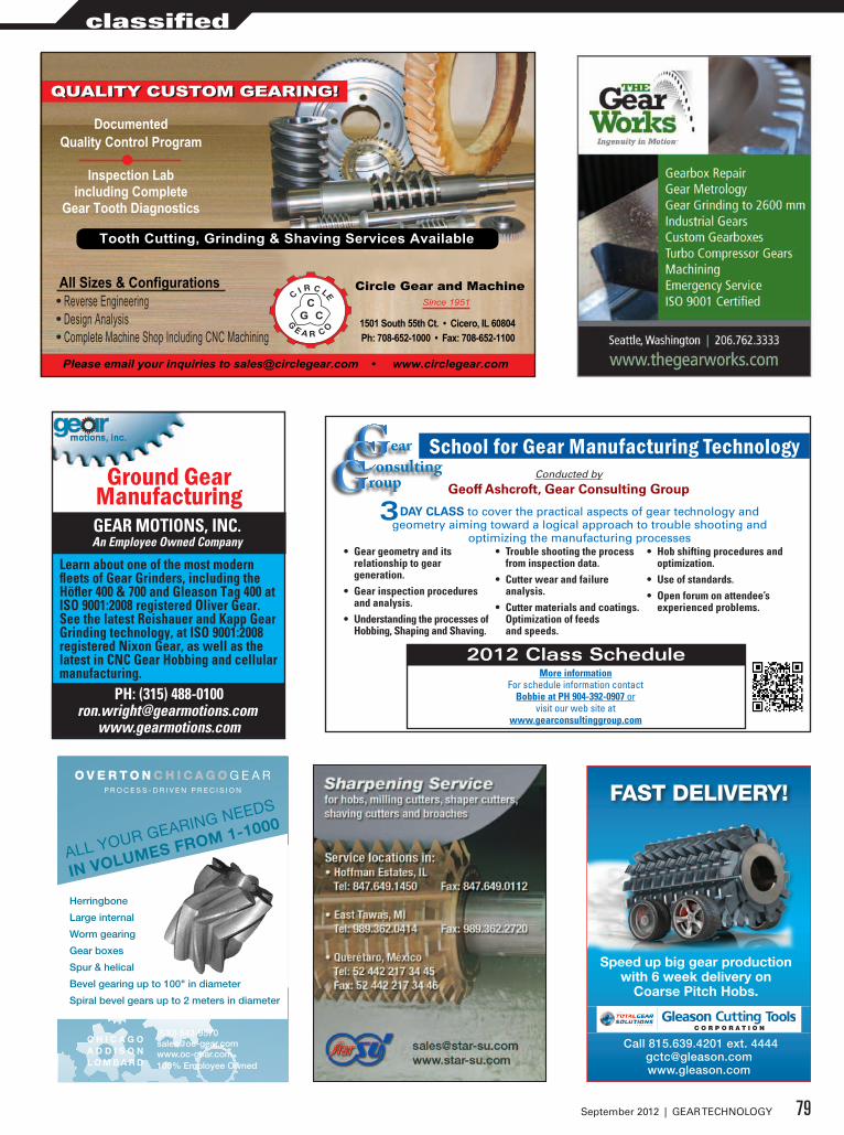
FAST DELIVERY!
Call 815.639.4201 ext. [email protected]
Speed up big gear production with 6 week delivery on
Coarse Pitch Hobs.
Circle Gear and Machine• Reverse Engineering• Design Analysis• Complete Machine Shop Including CNC Machining
Documented Quality Control Program
Inspection Lab including Complete
Gear Tooth Diagnostics
1501 South 55th Ct. • Cicero, IL 60804Ph: 708-652-1000 • Fax: 708-652-1100
Since 1951
Please email your inquiries to [email protected] • www.circlegear.com
Tooth Cutting, Grinding & Shaving Services Available
CG C
C I R C LE
G E A R C O
QUALITY CUSTOM GEARING!
All Sizes & Configurations
QUALITY CUSTOM GEARING!
School for Gear Manufacturing Technology
DAY CLASS to cover the practical aspects of gear technology and geometry aiming toward a logical approach to trouble shooting and
optimizing the manufacturing processes• Gear geometry and its
relationship to gear generation.
• Gear inspection procedures and analysis.
• Understanding the processes of Hobbing, Shaping and Shaving.
• Trouble shooting the process from inspection data.
• Cutter wear and failure analysis.
• Cutter materials and coatings. Optimization of feeds and speeds.
• Hob shifting procedures and optimization.
• Use of standards.• Open forum on attendee’s
experienced problems.
3
Conducted by
Geoff Ashcroft, Gear Consulting Group
2012 Class Schedule
Save this code to add it to your blogor your documents.
You can also use the code's permalink,or copy-paste the following HTML code:
<img src="http://qrcode.kaywa.com/img.php?s=12&d=http%3A%2F%2Fww
Q R - C O D E G E N E R A T O R
Content type:
URL Text Phone Number SMS
Content:
URL:http://www.gearconsultinggroup.com
Size: XL
Generate!
Version: 1.00 BETA | Non-Commercial Use Only KAYWA // TECHNOPARKSTRASSE 1 // 8005 ZUERICH // SWITZERLAND // SUPPORT
A DV ERT IS EMENT:
ID KAYWA READER FEED2MOBILE DATAMATRIX GENERATOR NEW: DOKODARE PHOTO LENDORFF KAYWA
QR-Code Generator http://qrcode.kaywa.com/
1 of 2 10/27/2011 10:02 AM
earonsultingroup
More informationFor schedule information contact
Bobbie at PH 904-392-0907 orvisit our web site at
www.gearconsultinggroup.com
PH: (315) 488-0100www.gearmotions.com
Gear Grinding and Cutting Services
Gear Motions’ two manufacturing locations are leading suppliers of custom cut and ground spur and
helical gears. Made complete or to your blanks.
GEAR MOTIONS, INC.An Employee Owned Company
PH: (315) [email protected]
www.gearmotions.com
Ground GearManufacturing
GEAR MOTIONS, INC.An Employee Owned Company
A
B
Learn about one of the most modern fleets of Gear Grinders, including the Höfler 400 & 700 and Gleason Tag 400 at ISO 9001:2008 registered Oliver Gear. See the latest Reishauer and Kapp Gear Grinding technology, at ISO 9001:2008 registered Nixon Gear, as well as the latest in CNC Gear Hobbing and cellular manufacturing.
Learn about one of the most modern fleets of Gear Grinders, including the Höfler 400 & 700 and Gleason Tag 400 at Oliver Gear. See the latest Reishauer and Kapp Gear Grinding technology, at ISO 9001- 2008 registered Nixon Gear, as well as the latest in CNC Gear Hobbing and cellular manufacturing.
ALL YOUR GEARING NEEDS
IN VOLUMES FROM 1-1000
Herringbone
Large internal
Worm gearing
Gear boxes
Spur & helical
Bevel gearing up to 100" in diameter
Spiral bevel gears up to 2 meters in diameter
C H I C A G O A D D I S O N L O M B A R D
(630) 543-9570 [email protected]% Employee Owned
79September 2012 | GEAR TECHNOLOGY
classified
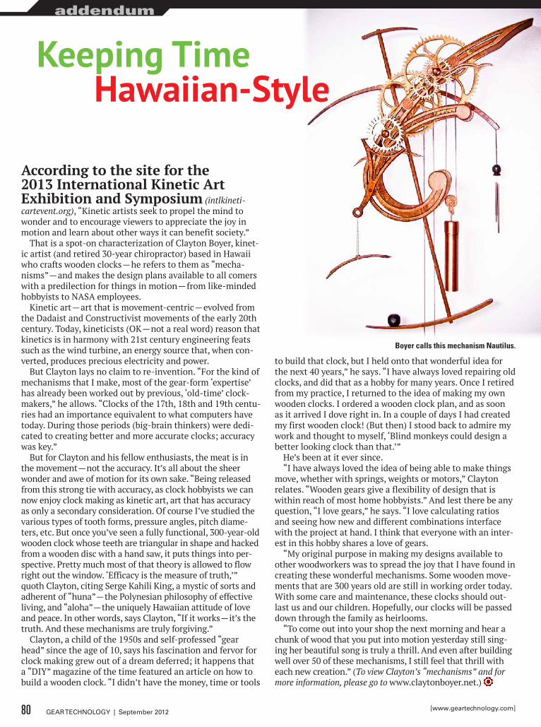
According to the site for the 2013 International Kinetic Art Exhibition and Symposium (intlkineti-cartevent.org), “Kinetic artists seek to propel the mind to wonder and to encourage viewers to appreciate the joy in motion and learn about other ways it can benefit society.”
That is a spot-on characterization of Clayton Boyer, kinet-ic artist (and retired 30-year chiropractor) based in Hawaii who crafts wooden clocks — he refers to them as “mecha-nisms” — and makes the design plans available to all comers with a predilection for things in motion — from like-minded hobbyists to NASA employees.
Kinetic art — art that is movement-centric — evolved from the Dadaist and Constructivist movements of the early 20th century. Today, kineticists (OK — not a real word) reason that kinetics is in harmony with 21st century engineering feats such as the wind turbine, an energy source that, when con-verted, produces precious electricity and power.
But Clayton lays no claim to re-invention. “For the kind of mechanisms that I make, most of the gear-form ‘expertise’ has already been worked out by previous, ‘old-time’ clock-makers,” he allows. “Clocks of the 17th, 18th and 19th centu-ries had an importance equivalent to what computers have today. During those periods (big-brain thinkers) were dedi-cated to creating better and more accurate clocks; accuracy was key.”
But for Clayton and his fellow enthusiasts, the meat is in the movement — not the accuracy. It’s all about the sheer wonder and awe of motion for its own sake. “Being released from this strong tie with accuracy, as clock hobbyists we can now enjoy clock making as kinetic art, art that has accuracy as only a secondary consideration. Of course I’ve studied the various types of tooth forms, pressure angles, pitch diame-ters, etc. But once you’ve seen a fully functional, 300-year-old wooden clock whose teeth are triangular in shape and hacked from a wooden disc with a hand saw, it puts things into per-spective. Pretty much most of that theory is allowed to flow right out the window. ‘Efficacy is the measure of truth,’” quoth Clayton, citing Serge Kahili King, a mystic of sorts and adherent of “huna” — the Polynesian philosophy of effective living, and “aloha” — the uniquely Hawaiian attitude of love and peace. In other words, says Clayton, “If it works — it’s the truth. And these mechanisms are truly forgiving.”
Clayton, a child of the 1950s and self-professed “gear head” since the age of 10, says his fascination and fervor for clock making grew out of a dream deferred; it happens that a “DIY” magazine of the time featured an article on how to build a wooden clock. “I didn’t have the money, time or tools
to build that clock, but I held onto that wonderful idea for the next 40 years,” he says. “I have always loved repairing old clocks, and did that as a hobby for many years. Once I retired from my practice, I returned to the idea of making my own wooden clocks. I ordered a wooden clock plan, and as soon as it arrived I dove right in. In a couple of days I had created my first wooden clock! (But then) I stood back to admire my work and thought to myself, ‘Blind monkeys could design a better looking clock than that.’”
He’s been at it ever since.“I have always loved the idea of being able to make things
move, whether with springs, weights or motors,” Clayton relates. “Wooden gears give a flexibility of design that is within reach of most home hobbyists.” And lest there be any question, “I love gears,” he says. “I love calculating ratios and seeing how new and different combinations interface with the project at hand. I think that everyone with an inter-est in this hobby shares a love of gears.
“My original purpose in making my designs available to other woodworkers was to spread the joy that I have found in creating these wonderful mechanisms. Some wooden move-ments that are 300 years old are still in working order today. With some care and maintenance, these clocks should out-last us and our children. Hopefully, our clocks will be passed down through the family as heirlooms.
“To come out into your shop the next morning and hear a chunk of wood that you put into motion yesterday still sing-ing her beautiful song is truly a thrill. And even after building well over 50 of these mechanisms, I still feel that thrill with each new creation.” (To view Clayton’s “mechanisms” and for more information, please go to www.claytonboyer.net.)
Keeping Timehawaiian-Style
Boyer calls this mechanism Nautilus.
80 GEAR TECHNOLOGY | September 2012 [www.geartechnology.com]
addendum
Machine and Gear Corporation
Toll Free: (800) [email protected] www.brgear.com
REVERSE ENGINEERING
BREAKDOWN SERVICES
SPIRAL BEVEL GEARS: 66" PDSTRAIGHT BEVEL GEARS: 80" PD
SPURS, HELICALS, SPLINE SHAFTSGEARBOX REPAIR/REBUILDS
IN-HOUSE STEEL MATERIAL WAREHOUSE
FULL HEAT TREATING SERVICES
EDM WIRE BURNING
C U S T O MBEVEL GEAR MANUFACTURING
Disclosing the Secret:Gear Grinding at its best
KLINGELNBERG GmbHIndustriestraße 19 p. +49 7243 599-0
D-76275 Ettlingen f. +49 7243 599-165
www.hofl er.com e. info@hofl er.com
www.klingelnberg.com
HOFLER America Corp.26 Sky Manor Road p. +1 908 442 4361
Pittstown, NJ 08867, USA f. +1 908 996 6977
e. usa.sales@hofl er.com
HÖFLER by Klingelnberg is very proud to introduce forthe fi rst time at the Chicago IMTS 2012, the completelynew and innovative RAPID 1250 W featuring both formgear and generating grinding technologies in one machine!
This new grinder enables our customers to apply the mosteconomic grinding method for any part application, usingeither or both grinding technologies without restrictions onworkpieces up to 1250 mm in diameter!
Based on the well-proven components of the RAPID machine series, a new rotary table and grinding head have been devel-oped that take into account all the requirements for the dress-ing and generating grinding of large or small tooth modules. Short setup times, high accuracies and fl exibility are the main features of this new grinder!
Once again – HÖFLER innovations for the reliability, accuracyand fl exibility that gear manufacturers expect and deserve!
GEAR MANUFACTURING SOLUTIONS up to ø 8000 mm [315“]
Sub
ject
to c
hang
esw
ww
.st3
60.d
e
NEXTFAIR: September 10-15, 2012
North Building, N6837
Mccormick PlaceChicago, USA
gear and generating grinding technologies in one machine!
This new grinder enables our customers to apply the mostNEXT
AZ-GT-3-2012-Wälzschleifen2.indd 1 16.08.12 13:50