Embed Size (px)
Citation preview
®
August 2012
www.geartechnology.com
THE GEAR INDUSTRY’S INFORMATION SOURCE
The Journal of Gear Manufacturing
Technical Articles•AsktheExpert:ProfileShift• 10YearsofP/MR&D:Findings• SurfaceDurability/Improved
SurfaceFinish
Addendum•HowGearsandMind
ControlMesh
IMTS 2012SHOW PREVIEW
BOOTH LISTINGSBOOTH PREVIEWS
Powder Metal MagicFEATURE
Phone: 847-649-14505200 Prairie Stone Pkwy. • Ste. 100 • Hoffman Estates • IL 60192
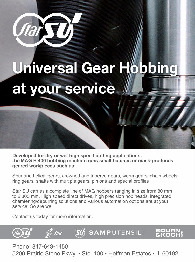
Developed for dry or wet high speed cutting applications, the MAG H 400 hobbing machine runs small batches or mass-produces geared workpieces such as:
Spur and helical gears, crowned and tapered gears, worm gears, chain wheels, ring gears, shafts with multiple gears, pinions and special profi les
Star SU carries a complete line of MAG hobbers ranging in size from 80 mm to 2,300 mm. High speed direct drives, high precision hob heads, integrated chamfering/deburring solutions and various automation options are at your service. So are we.
Contact us today for more information.
Universal Gear Hobbingat your service
2012-08_Star-SU_MAG_Adv_2pages_us.indd 1 11.07.2012 18:57:53 Uhr
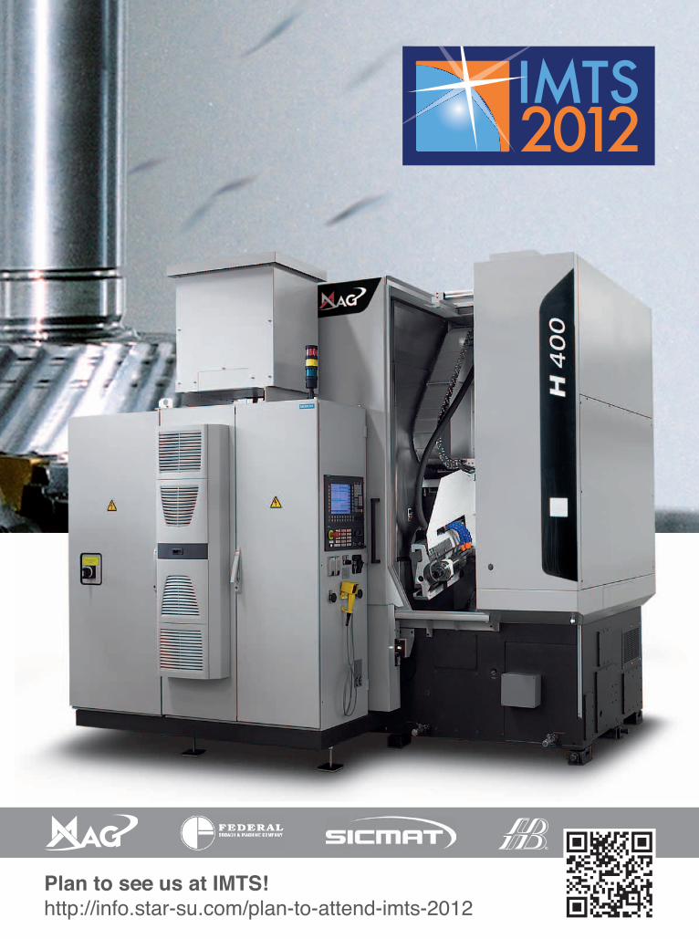
Plan to see us at IMTS!http://info.star-su.com/plan-to-attend-imts-2012
2012-08_Star-SU_MAG_Adv_2pages_us.indd 2 11.07.2012 18:57:57 Uhr
August 2012 C O N T E N T S
Vol. 29, No. 5 GEAR TECHNOLOGY, The Journal of Gear Manufacturing (ISSN 0743-6858) is published monthly, except in February, April, July and December by Randall Publications LLC, 1840 Jarvis Avenue, Elk Grove Village, IL 60007, (847) 437-6604. Cover price $7.00 U.S. Periodical postage paid at Arlington Heights, IL, and at additional mailing office (USPS No. 749-290). Randall Publications makes every effort to ensure that the processes described in GEAR TECHNOLOGY conform to sound engineering practice. Neither the authors nor the publisher can be held responsible for injuries sustained while following the procedures described. Postmaster: Send address changes to GEAR TECHNOLOGY, The Journal of Gear Manufacturing, 1840 Jarvis Avenue, Elk Grove Village, IL, 60007. Contents copyrighted ©2012 by RANDALL PUBLICATIONS LLC. No part of this publication may be reproduced or transmitted in any form or by any means, electronic or mechanical, including photocopying, recording, or by any information storage and retrieval system, without permission in writing from the publisher. Contents of ads are subject to Publisher’s approval. Canadian Agreement No. 40038760.
52
GEARTECHNOLOGY August 2012 www.geartechnology.com2
FEATURE52 PM Magic
Design innovations grow PM universe.
TECHNICAL ARTICLES46 Ask the Expert: Profile Shift
60 High-Performance Sintered-Steel Gears: A Critical Review
A decade’s R&D of high-performance, sintered-steel gear prototyping.
66 Case Study: Surface Durability and Improved Surface Finish
Super-finishing’s impact on micropitting: evaluation of gearbox/manufacturing process.
IMTS 2012COVERAGE
22 Show Preview
25 Show Listings
28 Booth Previews
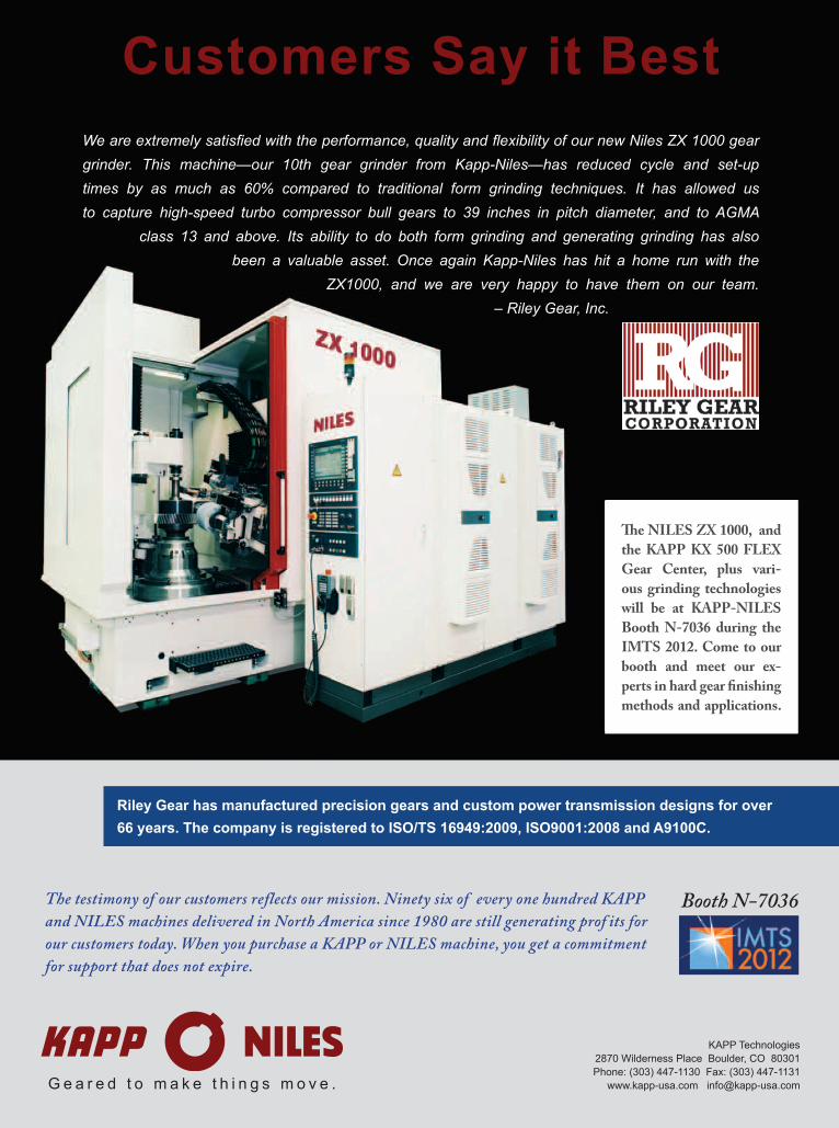
Customers Say it Best
KAPP Technologies2870 Wilderness Place Boulder, CO 80301Phone: (303) 447-1130 Fax: (303) 447-1131
www.kapp-usa.com [email protected] e a r e d t o m a k e t h i n g s m o v e .
Booth N-7036The testimony of our customers reflects our mission. Ninety six of every one hundred KAPP and NILES machines delivered in North America since 1980 are still generating prof its for our customers today. When you purchase a KAPP or NILES machine, you get a commitment for support that does not expire.
We are extremely satis ed with the performance, quality and exibility of our new Niles ZX 1000 gear grinder. This machine—our 10th gear grinder from Kapp-Niles—has reduced cycle and set-up times by as much as 60% compared to traditional form grinding techniques. It has allowed us to capture high-speed turbo compressor bull gears to 39 inches in pitch diameter, and to AGMA
class 13 and above. Its ability to do both form grinding and generating grinding has also been a valuable asset. Once again Kapp-Niles has hit a home run with the
ZX1000, and we are very happy to have them on our team.– Riley Gear, Inc.
Th e NILES ZX 1000, and the KAPP KX 500 FLEX Gear Center, plus vari-ous grinding technologies will be at KAPP-NILES Booth N-7036 during the IMTS 2012. Come to our booth and meet our ex-perts in hard gear fi nishing methods and applications.
Riley Gear has manufactured precision gears and custom power transmission designs for over 66 years. The company is registered to ISO/TS 16949:2009, ISO9001:2008 and A9100C.
C O N T E N T SAugust 2012
departments9 Publisher’s Page
Remembering James Cervinka
10 VoicesLean for high-mix, low-volume manufacturing
14 Product NewsGleason-K2 Plastics eliminates weld lines with no machining
76 Industry NewsKlingelnberg acquires Höfler
84 Events/CalendarWhere and when it’s happening
85 SubscriptionsSign up for free subscriptions here
86 Advertiser IndexContact information for companies in this issue
87 ClassifiedsOur products and services marketplace
88 Addendum“Technology Mash-Up”
•PowerTransmissionEngineeringSign up for a free subscription.
•NEWSThe latest products, industry news and calendar items.
•BUYERSGUIDESearch for power transmission products and services and communicate with the industry's leading suppliers
ON L I N E
www.geartechnology.com
•E-MAILNEWSLETTERSign up for our NEW monthly e-mail newsletter with exclusive gear-related articles and content at www.geartechnology.com/newsletter
www.powertransmission.com
PTEpowertransmissionengineering®
GEARTECHNOLOGY August 2012 www.geartechnology.com4
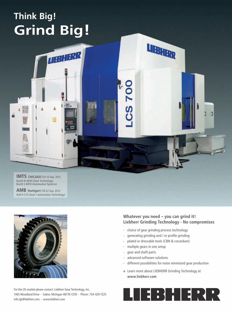
Think Big!
Grind Big!
IMTS CHICAGO (10-15 Sep. 2012Booth N-6930 (Gear Technology)Booth S-8974 (Automation Systems)
AMB Stuttgart (18-22 Sep. 2012Hall 9-C15 (Gear-/ Automation Technology)
Whatever you need – you can grind it!Liebherr Grinding Technology - No compromises
- choice of gear grinding process technology
- generating grinding and / or profi le grinding
- plated or dressable tools (CBN & corundum)
- multiple gears in one setup
- gear and shaft parts
- advanced software solutions
- different possibilities for noise minimized gear production
» Learn more about LIEBHERR Grinding Technology at
www.liebherr.com
For the US-market please contact: Liebherr Gear Technology, Inc.
1465 Woodland Drive - Saline, Michigan 48176-1259 - Phone: 734-429-7225
[email protected] - www.liebherr.com
EditorialPublisher & Editor-in-Chief Michael Goldstein [email protected]
Managing Editor William R. Stott [email protected]
Senior Editor Jack McGuinn [email protected]
Associate Editor Matthew Jaster [email protected]
Editorial Consultant Paul R. Goldstein
Technical Editors William (Bill) Bradley Robert Errichello Octave Labath, P.E. Joseph Mihelick Charles D. Schultz, P.E. Robert E. Smith Dan ThurmandEsignArt Director David Ropinski [email protected] Sales Manager Dave Friedman [email protected]
Materials Coordinator Dorothy Fiandaca [email protected] Manager Carol Tratar [email protected] staFFPresident Michael Goldstein
Accounting Luann Harrold
VOL. 29, NO. 5
randall PUbliCations llC1840 JarVis aVEnUEElk groVE VillagE, il 60007
847-437-6604Fax: (847) 437-6618
Photo of the MAG H 250 courtesy of Star SU.
®
August 2012
www.geartechnology.com
THE GEAR INDUSTRY’S INFORMATION SOURCE
The Journal of Gear Manufacturing
Technical Articles•AsktheExpert:ProfileShift• 10YearsofP/MR&D:Findings• SurfaceDurability/Improved
SurfaceFinish
Addendum•HowGearsandMind
ControlMesh
IMTS 2012SHOW PREVIEW
BOOTH LISTINGSBOOTH PREVIEWS
NoGutsNo
Glory
Toll Free: 800.727.6333Phone: 803.684.3133
www.ajaxring.com
Contact an AjaxRepresentative Today
The real work of any piece of equipment is produced under the skin.At Ajax, we understand that our products are the guts and must perform to the highest standards in the gear industry. Our glory comes from satisfied customers.
We’re readyto roll
when you are.
GEARTECHNOLOGY August 2012 www.geartechnology.com6
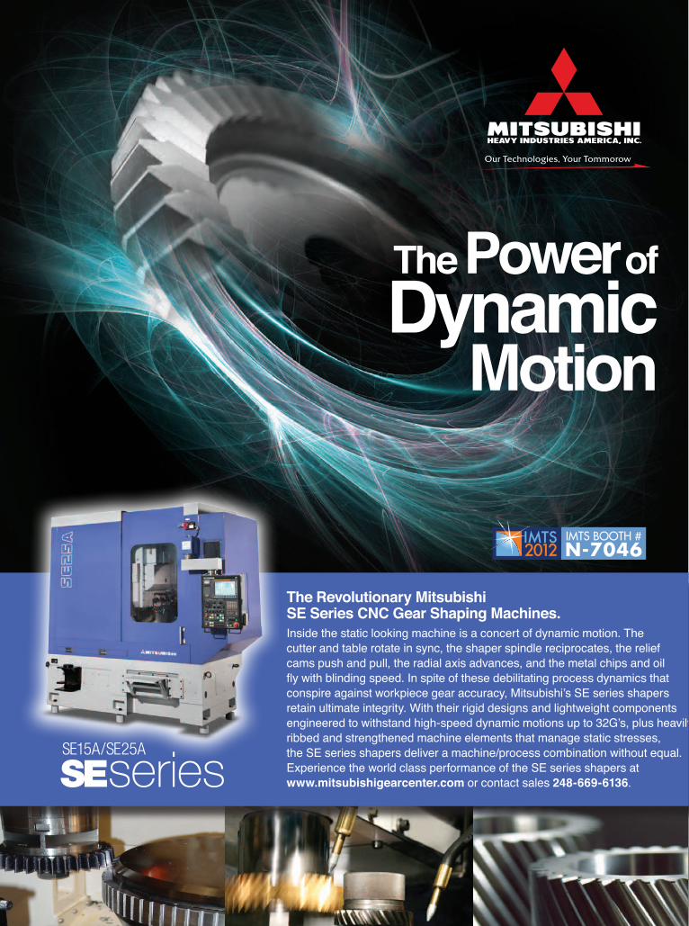
The Revolutionary Mitsubishi SE Series CNC Gear Shaping Machines.Inside the static looking machine is a concert of dynamic motion. The cutter and table rotate in sync, the shaper spindle reciprocates, the relief cams push and pull, the radial axis advances, and the metal chips and oil fly with blinding speed. In spite of these debilitating process dynamics that conspire against workpiece gear accuracy, Mitsubishi’s SE series shapers retain ultimate integrity. With their rigid designs and lightweight components engineered to withstand high-speed dynamic motions up to 32G’s, plus heavily ribbed and strengthened machine elements that manage static stresses, the SE series shapers deliver a machine/process combination without equal. Experience the world class performance of the SE series shapers at www.mitsubishigearcenter.com or contact sales 248-669-6136.SEseries
SE15A/SE25A
The Power of Dynamic
Motion
Our Technologies, Your Tommorow
IMTS BOOTH #N-7046
P u B L I S H E R ’ S P A G E
The gear industry lost one of its iconic figures in July when James Cervinka passed away at the age of 92. Jim was CEO and one of the founders of Arrow Gear. For 65 years, he was a gear man, and I can’t help but feeling that his absence shrinks the gear industry by far more than the loss of just one man.
As a U.S. Navy veteran who served in WWII, Jim typified what is often called “The Greatest Generation,” a differ-ent breed of men who were in many ways larger than life. Like many of his generation, he went off to war and faced situations where failure meant death. Jim, my father and much of that generation came back from World War II and applied that same “can do” attitude to their vocations, driv-ing America forward to heights never before seen.
He was a unique man, and a character who will be missed. One of Jim’s great loves was playing golf, and it is part of industry lore that Jim, every few years, had a new golf cart “enhanced” at Arrow Gear so that it drove more like a sports car than a puttering golf cart.
But I will miss Jim for far more than his personal legacy. I had known him for 48 years—my entire professional career, and—more importantly—his family and mine share a long history in the gear industry. When Jim started Arrow Gear in 1947, with his partner Frank E. Pielsticker and their extreme-ly talented associate Ernie Kauzlarich, it was with used machinery, much of it purchased from my father, Harold, who at the time worked for his father, Charlie, at Machinery & Electric Motors in Chicago. Jim always specialized in Gleason bevel gearing, which was the most difficult and complex type of gears manufactured. He built the business with very hard work, ingenuity and perseverance. My father always spoke with admiration for Jim and what he accom-plished professionally. This relationship between Jim and my family continued when my father started Cadillac Machinery in 1950, and continued up until his passing.
Over the last half dozen years or so, I’ve spent a lot of time over at Arrow Gear, whether as a machine tool dealer, as publisher of Gear Technology, or as a member of the board of directors for Citizens for American Manufacturing (CAM), which was started by Joe Arvin, Arrow’s president.
Whenever I visited Arrow, I always made a point of stopping by Jim’s office to say hello and to see how he was. Every time I saw him he would tell me how much he admired Gear Technology, and he would always thank me for the service we provide the industry. I guess, in many respects, we were a mutual admiration society of two.
I know that very late in his life, when most men are con-sidering taking their chips off the table, Jim was “all in” to help Arrow Gear by investing in the latest technology and staying on the leading edge by providing the finest aircraft gearing available in the world. He was not only proud of the quality of the gears Arrow produced, but was also very proud of contributing components to some of the most memorable military and civilian aircraft produced during his career.
While he, Frank and Ernie almost literally built their busi-ness with their bare hands, he had the foresight to bring in and turn over the presidency to Joe Arvin, who has been there for 40 years. Joe brought a different skill set to Arrow and he has been an important component of Arrow’s growth and success. Too often I’ve seen extremely talented, focused entrepreneurs drive their companies upward, only to crest and fall when they got beyond their own skills, talents and experience. This didn’t happen to Jim.
It was only 10 days before he passed away that I had the opportunity to poke my head into his office one last time, and true to form—he called me in to sit down again and thank me for what I’ve done with Gear Technology maga-zine. He was expansive in his interests, fiercely loyal to his family, his company and his employees and always generous with his compliments.
I was lucky enough to have been raised by a man who typified this generation, giving me his work ethic and values, but I am also grateful for the unusual and wonderful oppor-tunity I’ve had to work with many other individuals like Jim Cervinka. I know how sorely we will miss them in the future. Thank you Jim, and may you rest in peace.
Michael Goldstein,Publisher & Editor-in-Chief
REMEMBERING
P.S. Normally this editorial would have been written about IMTS, and we haven’t forgotten about this very important show. With the strong manufacturing environment we’ve experienced over the last several years, it’s more important than ever for you to consider attending IMTS (September 10–16 in Chicago). This opportunity comes only once every two years, so it’s important that you see the latest technology that can help increase your productivity, flexibility, competiveness and profitability in the coming years. For more information see our show coverage on pages 22–43.
James Cervinka
www.geartechnology.com August 2012 GEARTECHNOLOGY 9
V O I C E S
A customer has several choices when it comes to buying a service or prod-uct that he/she fancies. Boeing com-petes with Airbus, GM competes with Toyota and a host of other car manu-facturers, and so on. Then why expect every manufacturer to pursue continu-ous improvement by following just the “Toyota Way” using tools pioneered by Toyota for their assembly lines? Toyota is a low-mix, high-volume manufac-turer of only automobiles. They do not make refrigerators and bicycles on any of their assembly lines! Also, you will find that conveyors are the dominant material handling equipment used in their assembly facilities.
Now let’s turn our attention to high-mix, low- or high-volume (HMLV) manufacturers of components, and oftentimes, assemblies built from those components, such as: facilities that manufacture custom configurations of assemblies, remanufacturing facilities, repair and maintenance facilities, and job shops.
Without a doubt, like Toyota, most of the above HMLV small- and medium-size manufacturers with annual sales in the $5 million to $100 million range will surely benefit tremendously by
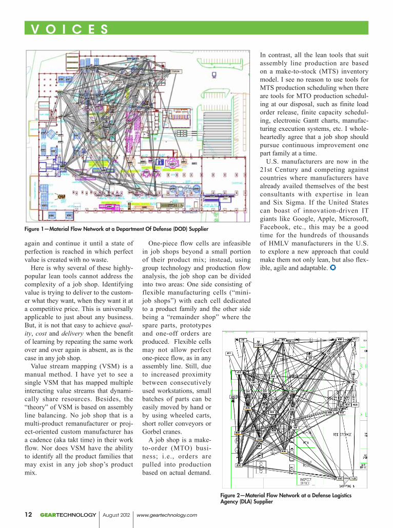
implementing lean, even though they make hundreds of different components or assemblies. There are savings to be gained by cutting the costs due to all forms of waste that exist in administra-tive and manufacturing processes. But, walk through these facilities and you will find that forklifts are the domi-nant material handling equipment in use. Why? Because these manufactur-ers have been advised (that) in order to be flexible, job shops should have process-focused facility layouts. That, unfortunately, condemns them to a batch-and-queue production system, which is the root cause of WIP, scrap, MRP-driven production control, etc. For example, Figures 1 and 2 depict the material flow in two forge shops that produce hundreds of different forg-ings for defense and aerospace cus-tomers. Both facilities scheduled their operations and suppliers using infi-nite-capacity Material Requirements Planning (MRP) software.
Numerous books have clearly explained the significant differenc-es that exist between the operating conditions of any assembly produc-tion system versus those for any job shop production system when they are
compared on various criteria, such as production volume, product variety, workforce skills, equipment flexibil-ity, supplier control, production con-trol and scheduling, etc. So, while it is imperative that HMLV manufacturers embrace lean as a philosophy, maybe they should not do it by following only what is best for an automobile manu-facturer.
Unlike any low-mix, high-volume manufacturer like Toyota, job shops have to deal with: considerable volatil-ity in demand; numerous changes in delivery dates forced upon them by customers; greater variety of manu-facturing routings; high variability in setup times and cycle times across the different products they make; a diverse customer base; limited resources for workforce training (let alone even one full-time employee devoted to continu-ous improvement); more complex pro-duction control and scheduling; and limited clout to influence the delivery dates set by their suppliers or custom-ers. Finally, these job shops also must deal with the tendency for their product mix to “migrate” as their customer base changes or they hire new sales and marketing staff who bring with them their past business contacts in different sectors of industry.
The popular saying is that a bad car-penter blames his tools. But what if his boss gave him bad tools that were ill-suited to the job that was assigned to him? This is exactly the case when HMLVs implement lean using only the
GEARTECHNOLOGY August 2012 www.geartechnology.com10
ADD YOUR THOUGHTS HEREDo you have a comment or additional information to share regarding one or more
articles in a recent issue of Gear Technology?Send your letters to:
The Editors, Gear Technology, 1840 Jarvis Ave., Elk Grove Village, IL 60007 USAPhone: (847) 437-6604, Fax: (847) 437-6618
Adapting Lean for High-Mix,Low-Volume Manufacturing Facilities
Dr. Shahrukh IraniDirector, IE Research
Hoerbiger Corporation of America, Inc.
V O I C E S
High precision gear grinding machines,diamond dressing tools, CBN tools and automation for hard finishing of gears.
Get in Gear.Gear Competence From One Source.
Reishauer Corporation • (847) 888-3828 • www.reishauer.com
Scan codeto sign upfor theadvanced gear demo
www.reishauertech.com
At Booth#N7018
popular lean tools, many of which are simply unsuitable, if not wrong, when used in non-assembly facilities.
Let’s discuss the lean tools that would surely work in job shops. Top-down leadership and employee involve-ment are essential in just about any business or manufacturing facility. Even job shops need standard work instructions to minimize the impact of variability and variety on setups, tool changes, material specs, etc., although it is a non-trivial problem to actually standardize the large number of pro-cess plans, setup procedures, tooling packages, etc., that they surely have! And I know of no business that has not profited by empowering and training equipment operators to control quality at source. Setup reduction is equally important in any workplace, kitchens included. Ever seen how smoothly the professional chefs on Food Network shows glide around their kitchens to get anything they need as soon as they need it?
Next let us discuss the lean tools that may not work in job shops. I will dis-cuss them in the context of the rel-evant steps of the lean thinking pro-cess pioneered by James Womack and Daniel Jones. They offered a powerful five-step thought process for guiding the implementation of lean techniques (that) is easy to remember but not always easy to achieve:
Identify value: Specify value from the standpoint of the end customer by product family.
Map the value stream: Identify all the steps in the value stream for each product family, eliminating whenever possible those steps that do not create value.
Create flow: Make the value-creat-ing steps occur in tight sequence so the product will flow smoothly toward the customer.
Establish pull: As flow is intro-duced, let customers pull value from the next upstream activity.
Seek perfection: As value is speci-fied, value streams are identified, wast-ed steps are removed, and flow and pull are introduced; begin the process
Tools that will work in any job shop Tools that may not work in most job shops5S Value Stream Mapping
TPM (Total Productive Maintenance) One-Piece Flow CellsSetup Reduction (SMED) Product-specific Kanbans
Error-Proofing (Poka-Yoke) FIFO Sequencing at WorkcentersQuality At Source Pacemaker Scheduling
Employee Involvement Inventory SupermarketsStrategic Planning Takt Time/Pitch/Level Loading (Heijunka)
Visual Controls/Visual Management Single-function Manual MachinesStandardardization of tools, processes, etc. Assembly Line Balancing
JidokaTop-Down LeadershipRight-sized Machines
Standard Work
www.geartechnology.com August 2012 GEARTECHNOLOGY 11
again and continue it until a state of perfection is reached in which perfect value is created with no waste.
Here is why several of these highly-popular lean tools cannot address the complexity of a job shop. Identifying value is trying to deliver to the custom-er what they want, when they want it at a competitive price. This is universally applicable to just about any business. But, it is not that easy to achieve qual-ity, cost and delivery when the benefit of learning by repeating the same work over and over again is absent, as is the case in any job shop.
Value stream mapping (VSM) is a manual method. I have yet to see a single VSM that has mapped multiple interacting value streams that dynami-cally share resources. Besides, the “theory” of VSM is based on assembly line balancing. No job shop that is a multi-product remanufacturer or proj-ect-oriented custom manufacturer has a cadence (aka takt time) in their work flow. Nor does VSM have the ability to identify all the product families that may exist in any job shop’s product mix.
One-piece flow cells are infeasible in job shops beyond a small portion of their product mix; instead, using group technology and production flow analysis, the job shop can be divided into two areas: One side consisting of flexible manufacturing cells (“mini-job shops”) with each cell dedicated to a product family and the other side being a “remainder shop” where the spare parts, prototypes and one-off orders are produced. Flexible cells may not allow perfect one-piece flow, as in any assembly line. Still, due to increased proximity between consecutively used workstations, small batches of parts can be easily moved by hand or by using wheeled carts, short roller conveyors or Gorbel cranes.
A job shop is a make-to-order (MTO) busi-ness; i.e., orders are pulled into production based on actual demand.
In contrast, all the lean tools that suit assembly line production are based on a make-to-stock (MTS) inventory model. I see no reason to use tools for MTS production scheduling when there are tools for MTO production schedul-ing at our disposal, such as finite load order release, finite capacity schedul-ing, electronic Gantt charts, manufac-turing execution systems, etc. I whole-heartedly agree that a job shop should pursue continuous improvement one part family at a time.
U.S. manufacturers are now in the 21st Century and competing against countries where manufacturers have already availed themselves of the best consultants with expertise in lean and Six Sigma. If the United States can boast of innovation-driven IT giants like Google, Apple, Microsoft, Facebook, etc., this may be a good time for the hundreds of thousands of HMLV manufacturers in the U.S. to explore a new approach that could make them not only lean, but also flex-ible, agile and adaptable.
V O I C E S
Figure 1—Material Flow Network at a Department Of Defense (DOD) Supplier
Figure 2—Material Flow Network at a Defense Logistics Agency (DLA) Supplier
GEARTECHNOLOGY August 2012 www.geartechnology.com12
SPEED UNIFORMITY EFFICIENCY
Ipsen’s ATLAS® integral quench furnaces are highly engineered, sophisticated machines that are easy to operate and maintain, all while being extremely cost effective. ATLAS delivers top quality uniformity through cutting-edge technology and design:
• Intelligent controls, Carb-o-Prof®, provide you with your very own electronic metallurgist • SuperQuench with adjustable oil speed and four 40HP agitators • Muffle system for uniform temperature control • Safety – all ATLAS furnaces are water-free for maximum safety • 30% less gas consumption • Recon® burners – single ended recuperated tubes (SERT)
The unique HybridCarb® gassing system from Ipsen is an ultra-efficient gassing system designed to replace endothermic generators and other gassing systems. Its core strength is precision gas control. Instead of burning excess gas off, the process gas is reconditioned and reused, increasing efficiency up to 90%.
Other benefits of HybridCarb include: • Quick and easy hookup • Increased carburizing efficiency • Reduces CO2 emissions by 90% • Significantly less expensive to operate than endogenerators • Consumes significantly less gas • Environmentally friendly and cost efficient • Lowers heat output creating a more comfortable work environment • Powers up and down at anytime, quickly and easily
®
For more information please visit www.IpsenUSA.com
www.IpsenUSA.com
With the acquisition of K2 Plastics, Gleason is now a source for strong, quiet thermoplastic gears containing no weld-lines, with a thru-hole and no secondary machining.
“Coupling Gleason’s arsenal of non-linear contact FEA and advanced gear design software, with the latest engi-neered thermoplastics, Gleason-K2 Plastics’ gears are a top choice for all demanding plastic gearing applica-tions,” says Klaus Kremmin, general manager of the Gleason-K2 Plastics division of The Gleason Works.
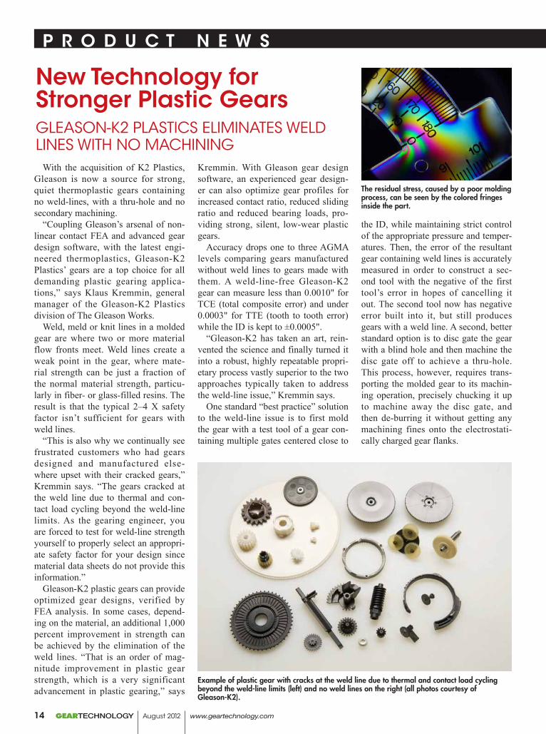
Weld, meld or knit lines in a molded gear are where two or more material flow fronts meet. Weld lines create a weak point in the gear, where mate-rial strength can be just a fraction of the normal material strength, particu-larly in fiber- or glass-filled resins. The result is that the typical 2–4 X safety factor isn’t sufficient for gears with weld lines.
“This is also why we continually see frustrated customers who had gears designed and manufactured else-where upset with their cracked gears,” Kremmin says. “The gears cracked at the weld line due to thermal and con-tact load cycling beyond the weld-line limits. As the gearing engineer, you are forced to test for weld-line strength yourself to properly select an appropri-ate safety factor for your design since material data sheets do not provide this information.”
Gleason-K2 plastic gears can provide optimized gear designs, verified by FEA analysis. In some cases, depend-ing on the material, an additional 1,000 percent improvement in strength can be achieved by the elimination of the weld lines. “That is an order of mag-nitude improvement in plastic gear strength, which is a very significant advancement in plastic gearing,” says
Kremmin. With Gleason gear design software, an experienced gear design-er can also optimize gear profiles for increased contact ratio, reduced sliding ratio and reduced bearing loads, pro-viding strong, silent, low-wear plastic gears.
Accuracy drops one to three AGMA levels comparing gears manufactured without weld lines to gears made with them. A weld-line-free Gleason-K2 gear can measure less than 0.0010" for TCE (total composite error) and under 0.0003" for TTE (tooth to tooth error) while the ID is kept to ±0.0005".
“Gleason-K2 has taken an art, rein-vented the science and finally turned it into a robust, highly repeatable propri-etary process vastly superior to the two approaches typically taken to address the weld-line issue,” Kremmin says.
One standard “best practice” solution to the weld-line issue is to first mold the gear with a test tool of a gear con-taining multiple gates centered close to
the ID, while maintaining strict control of the appropriate pressure and temper-atures. Then, the error of the resultant gear containing weld lines is accurately measured in order to construct a sec-ond tool with the negative of the first tool’s error in hopes of cancelling it out. The second tool now has negative error built into it, but still produces gears with a weld line. A second, better standard option is to disc gate the gear with a blind hole and then machine the disc gate off to achieve a thru-hole. This process, however, requires trans-porting the molded gear to its machin-ing operation, precisely chucking it up to machine away the disc gate, and then de-burring it without getting any machining fines onto the electrostati-cally charged gear flanks.
P R O D u C T N E W S
Example of plastic gear with cracks at the weld line due to thermal and contact load cycling beyond the weld-line limits (left) and no weld lines on the right (all photos courtesy of Gleason-K2).
The residual stress, caused by a poor molding process, can be seen by the colored fringes inside the part.
New Technology for Stronger Plastic GearsGLeASOn-K2 PLASTiCS eLiMinATeS WeLd LineS WiTH nO MACHininG
GEARTECHNOLOGY August 2012 www.geartechnology.com14
“Producing perfectly clean, ‘ding free’ and accurate gears, all at an eco-nomical price, from this process is very difficult,” according to Kremmin. “We’ve found both of these solutions to be highly inferior to Gleason’s no-weld-line solution. Gleason-K2’s solu-tion builds only one tool which molds plastic gears from any thermoplastic resin with a wide processing window without weld lines or any secondary machining. It does this while providing a gear with the least amount of residual stress of any competing gear molder.”
Reducing the impact of residual stress. Take a polarized lens and look at a molded part made of a clear resin. The residual stress can be seen by the colored fringes inside the part. The stress is caused by a poor molding pro-cess. Cooling the molded gear too soon or constraining it in the mold because of poorly calculated part shrinkage will induce residual stress. Residual stress is also caused by poor part geometry, gating and ejection. Kremmin says that residual stress becomes particularly apparent when a gear undergoes ther-mal cycling either by transport to the end user or by load cycling. The stress will want to relax, resulting in gear warpage. “I have found most molders do not consider the impact of residual stress in their parts,” Kremmin says. “They are having a hard enough time predicting shrink and achieving a part to print, let alone dealing with another layer of complexity to reduce the resid-ual stress in their moldings. As long as their parts meet the print, they are OK to ship. I’m sure residual stress will be talked about now.”
P R O D u C T N E W S
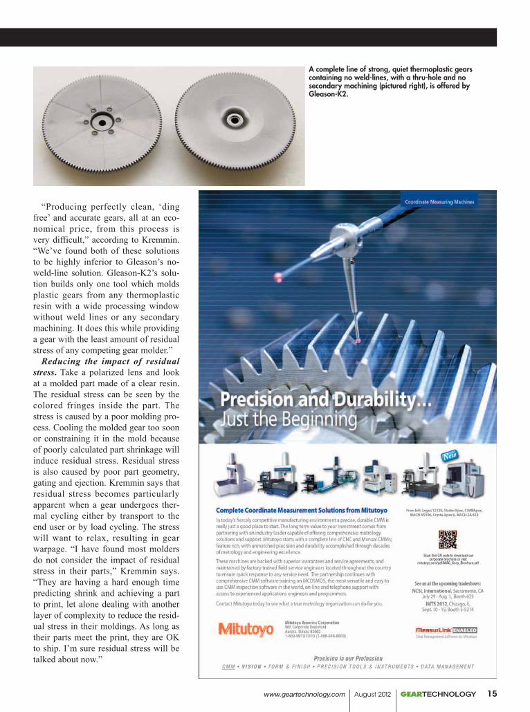
A complete line of strong, quiet thermoplastic gears containing no weld-lines, with a thru-hole and no secondary machining (pictured right), is offered by Gleason-K2.
www.geartechnology.com August 2012 GEARTECHNOLOGY 15
P R O D u C T N E W S P R O D u C T N E W S
Carbon, alloy &
stainless steel rings 4–144” oD.
mcinnesrolledrings.com
twiCe as big,just as fast.
2-3 weeK DeliVeries with materials in stock.
The no-weld-line process works for all thermoplastic resins including unfilled elastomers, acetal, nylon, ure-thane and filled polycarbonate, PPS, PEEK and ultra-exotic high tempera-ture materials with melt temperatures above 800°F and heat deflection tem-peratures greater than 600°F. “We can even insert-mold our gears onto metal bushings, tooth plates and hubs, still producing a gear with no weld lines and no secondary machining,” Kremmin adds.
Besides gears, pulleys, encoder wheels, tooth plates, bushings, sleeves, nozzles and tubes, any molded part with a hole through it that would nor-mally be produced with weld lines can now be made weld-line free with the proprietary Gleason-K2 process.
For more information:Gleason-K2 Plastics DivisionThe Gleason Works8210 Buffalo RoadBergen, NY 14416Phone: (585) 494-2470www.k2plasticsinc.com
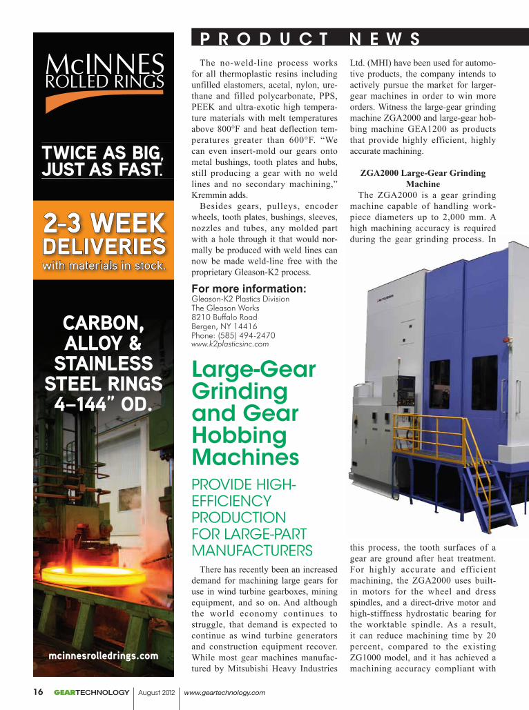
Large-Gear Grinding and Gear Hobbing MachinesPROvide HiGH-effiCienCy PROdUCTiOn fOR LARGe-PART MAnUfACTUReRS
There has recently been an increased demand for machining large gears for use in wind turbine gearboxes, mining equipment, and so on. And although the world economy continues to struggle, that demand is expected to continue as wind turbine generators and construction equipment recover. While most gear machines manufac-tured by Mitsubishi Heavy Industries
Ltd. (MHI) have been used for automo-tive products, the company intends to actively pursue the market for larger-gear machines in order to win more orders. Witness the large-gear grinding machine ZGA2000 and large-gear hob-bing machine GEA1200 as products that provide highly efficient, highly accurate machining.
ZGA2000 Large-Gear Grinding Machine
The ZGA2000 is a gear grinding machine capable of handling work-piece diameters up to 2,000 mm. A high machining accuracy is required during the gear grinding process. In
this process, the tooth surfaces of a gear are ground after heat treatment. For highly accurate and efficient machining, the ZGA2000 uses built-in motors for the wheel and dress spindles, and a direct-drive motor and high-stiffness hydrostatic bearing for the worktable spindle. As a result, it can reduce machining time by 20 percent, compared to the existing ZG1000 model, and it has achieved a machining accuracy compliant with
GEARTECHNOLOGY August 2012 www.geartechnology.com16
Class 1 or higher, according to the new Japanese Industrial Standards (JIS). Furthermore, to reduce downtime MHI strove to increase the speed and accu-racy of the on-machine gear inspection device. MHI succeeded in reducing the travel distance from the tooth root to the tip of a contact probe during tooth profile measurement, thereby improving the efficiency with which the machine can be controlled and checked.
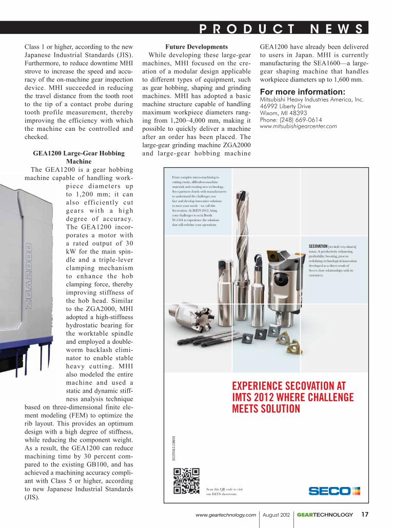
GEA1200 Large-Gear Hobbing Machine
The GEA1200 is a gear hobbing machine capable of handling work-
piece diameters up to 1,200 mm; it can also efficiently cut gears wi th a h igh degree of accuracy. The GEA1200 incor-porates a motor with a rated output of 30 kW for the main spin-dle and a triple-lever clamping mechanism to enhance the hob clamping force, thereby improving stiffness of the hob head. Similar to the ZGA2000, MHI adopted a high-stiffness hydrostatic bearing for the worktable spindle and employed a double-worm backlash elimi-nator to enable stable heavy cutting. MHI also modeled the entire machine and used a static and dynamic stiff-ness analysis technique
based on three-dimensional finite ele-ment modeling (FEM) to optimize the rib layout. This provides an optimum design with a high degree of stiffness, while reducing the component weight. As a result, the GEA1200 can reduce machining time by 30 percent com-pared to the existing GB100, and has achieved a machining accuracy compli-ant with Class 5 or higher, according to new Japanese Industrial Standards (JIS).
Future DevelopmentsWhile developing these large-gear
machines, MHI focused on the cre-ation of a modular design applicable to different types of equipment, such as gear hobbing, shaping and grinding machines. MHI has adopted a basic machine structure capable of handling maximum workpiece diameters rang-ing from 1,200–4,000 mm, making it possible to quickly deliver a machine after an order has been placed. The large-gear grinding machine ZGA2000 and large-gear hobbing machine
GEA1200 have already been delivered to users in Japan. MHI is currently manufacturing the SEA1600—a large-gear shaping machine that handles workpiece diameters up to 1,600 mm.
For more information:Mitsubishi Heavy Industries America, Inc.46992 Liberty DriveWixom, MI 48393Phone: (248) 669-0614www.mitsubishigearcenter.com
P R O D u C T N E W S P R O D u C T N E W S
SECO
TOOL
S.CO
M/U
S
Scan this QR code to visit our IMTS showroom.
EXPERIENCE SECOVATION AT IMTS 2012 WHERE CHALLENGE MEETS SOLUTION
From complex micro-machining to cutting exotic, diffi cult-to-machine materials and creating new technology, Seco partners closely with manufacturers to understand the challenges you face and develop innovative solutions to meet your needs – we call this Secovation. At IMTS 2012, bring your challenges to us in Booth W-1564 to experience the solutions that will redefi ne your operations.
SECOVATION [see-koh’-vey-shun’n]noun: A productivity enhancing, profi tability boosting, process redefi ning technological innovation developed as a direct result of Seco’s close relationships with its customers.
www.geartechnology.com August 2012 GEARTECHNOLOGY 17
Dudley’s Handbook of Practical Gear DesignnOW AvAiLAbLe in SeCOnd ediTiOn
The revised edition of Dudley’s Handbook of Practical Gear Design and Manufacture is now available to order. For more than 30 years, Practical Gear Design, later re-titled the Handbook of Practical Gear Design, has been the leading engineer-ing guide and reference on the sub-ject. The revised edition, by Johnson Control’s Stephen P. Radzevich, cov-ers the design of all types of gears involved in practical gear manufacture, applications and problem solving. The text is well-illustrated as evidenced by
the hundreds of photos and schemat-ics that clearly illustrate designs and uses; almost 200 tables provide refer-ence data. Selected chapters include: Gear Design Trends; Gear Types and Nomenclature; Gear Tooth Design; Preliminary Design Considerations; Design Formulas; Gear Materials; Gear Manufacturing Methods; Design of Tools to Make Gear Teeth; Kinds and Causes of Gear Failures; Special Design Problems; Gear Reactions and Mountings; Gear Vibration; Appendices; and References and Index.
Additionally, Theory of Gearing: Kinematics, Geometry and Synthesis is now available. This book systemati-cally presents and develops a scientific theory of gearing, specifically for those involved in gear design, analysis, and manufacture. The author begins with a few simple postulates that form the foundation of the theory of gearing. The postulated concepts are limited just to two entities, namely to (a) rota-tion vectors of the driving shaft and of
the driven shaft, and to (b) torque on the driving shaft.
For more information:CRC Press6000 Broken Sound Parkway NW, Suite 300Boca Raton, FL 33487Phone: (800) 272-7737www.crcpress.com
U.S. Office Location (Chicago)Email inquiries to: [email protected] E. Devon Ave., Suite 210, Des Plaines, IL 60018 PHONE: 847-375-8892 Fax: 847-699-1022
DTR has sales territories available. Call for more information.
WWW.DRAGON.CO.KR(formerly Dragon Precision Tools)
DTR. Your best choice for high quality gear cutting tools.
DTR is a world class supplier of the finest high performance long-life gear manufacturing tools, for small and large gear cutting applications. Established in 1976, we are one of the world’s largest producers of cutting tools, shipping to over 20 countries.
DTR offers a full line of gear cutting tools including:• Hobs• Carbide Hobs• Shaper Cutters• Milling Cutters
We can produce virtually any tool you need for auto, aerospace, wind, mining, construction and other industrial gears.
Every tool is precision-made utilizing high speed steel, premium powder metal or carbide and the latest in coatings, to achieve superior cutting and long life. DTR uses top of the line equipment including Reischauer CNC grinders and Klingelnberg CNC sharpeners and inspection equipment.
Learn more about our outstanding quality tools at www.dragon.co.kr. Call us at 847-375-8892 for your local sales representative or
Email [email protected] for a quotation.
Headquarters36B-11L, Namdong Industrial Complex, Namdong-Gu, Incheon, Korea PHONE: +82.32.814.1540 FAX: +82.32.814.5381
All the Gear Cutting Tools You Will Ever Need are Right HereAll the Gear Cutting Tools You Will Ever Need are Right HereAll The Gear Cutting Tools You Will Ever Need Are Right HereAll The Gear Cutting Tools You Will Ever Need Are Right HereDTR is one of the world’s largest producers.
• Chamfering and Deburring Tools• Broaches• Master Gears
IMTS BOOTH #N-6658
P R O D u C T N E W S
GEARTECHNOLOGY August 2012 www.geartechnology.com18
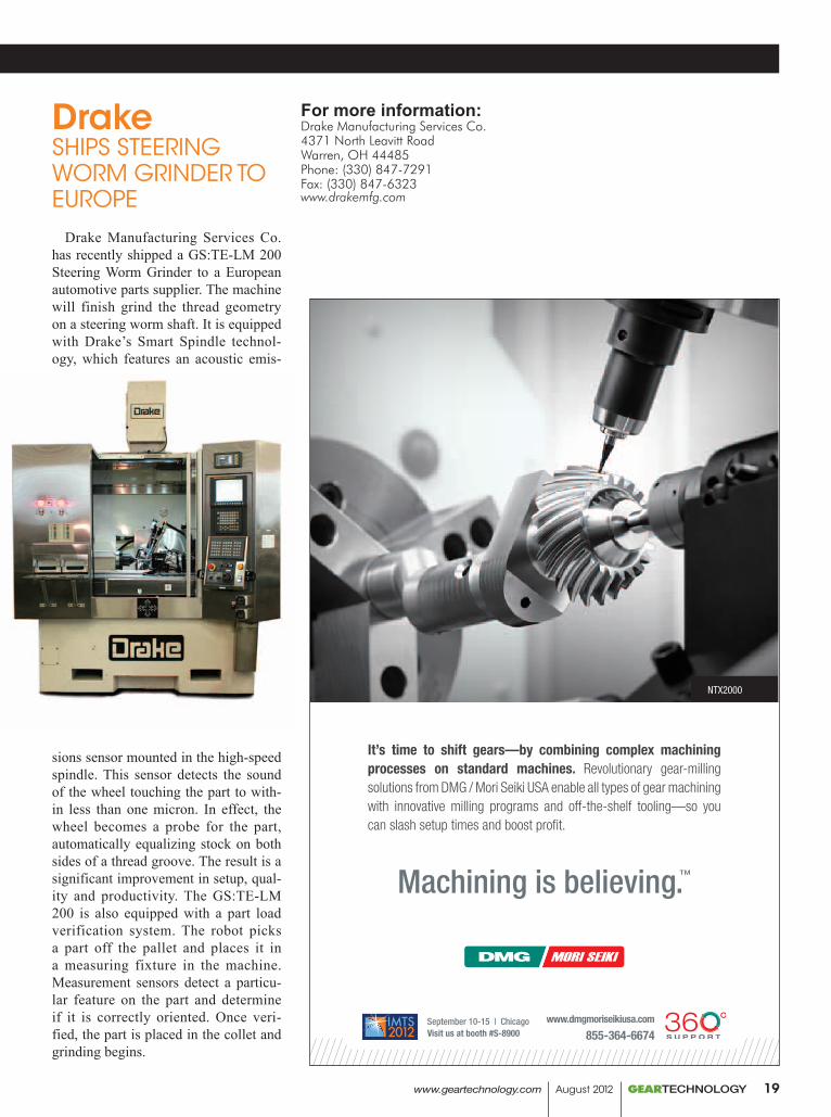
DrakeSHiPS STeeRinG WORM GRindeR TO eUROPe
Drake Manufacturing Services Co. has recently shipped a GS:TE-LM 200 Steering Worm Grinder to a European automotive parts supplier. The machine will finish grind the thread geometry on a steering worm shaft. It is equipped with Drake’s Smart Spindle technol-ogy, which features an acoustic emis-
sions sensor mounted in the high-speed spindle. This sensor detects the sound of the wheel touching the part to with-in less than one micron. In effect, the wheel becomes a probe for the part, automatically equalizing stock on both sides of a thread groove. The result is a significant improvement in setup, qual-ity and productivity. The GS:TE-LM 200 is also equipped with a part load verification system. The robot picks a part off the pallet and places it in a measuring fixture in the machine. Measurement sensors detect a particu-lar feature on the part and determine if it is correctly oriented. Once veri-fied, the part is placed in the collet and grinding begins.
For more information:Drake Manufacturing Services Co.4371 North Leavitt RoadWarren, OH 44485Phone: (330) 847-7291Fax: (330) 847-6323www.drakemfg.com
It’s time to shift gears—by combining complex machining processes on standard machines. Revolutionary gear-milling solutions from DMG / Mori Seiki USA enable all types of gear machining with innovative milling programs and off-the-shelf tooling—so you can slash setup times and boost profit.
Machining is believing.™
NTX2000
www.dmgmoriseikiusa.com
855-364-6674September 10-15 | ChicagoVisit us at booth #S-8900
dmori 1302-01 August Ads_GT_Vers2.indd 1 7/3/12 8:30 AM
P R O D u C T N E W S
www.geartechnology.com August 2012 GEARTECHNOLOGY 19
Leitz Gear Inspection. New ways of thinking.
High precision gear inspection
centers for gear diameters
up to 4500mm / 177” and shaft
lengths of up to 7000mm / 275”.
Any type of gear.
Any type of cutting tool.
And any gearbox, too!
Call it
a CMM if you like
www.leitz-metrology.com
P R O D u C T N E W S
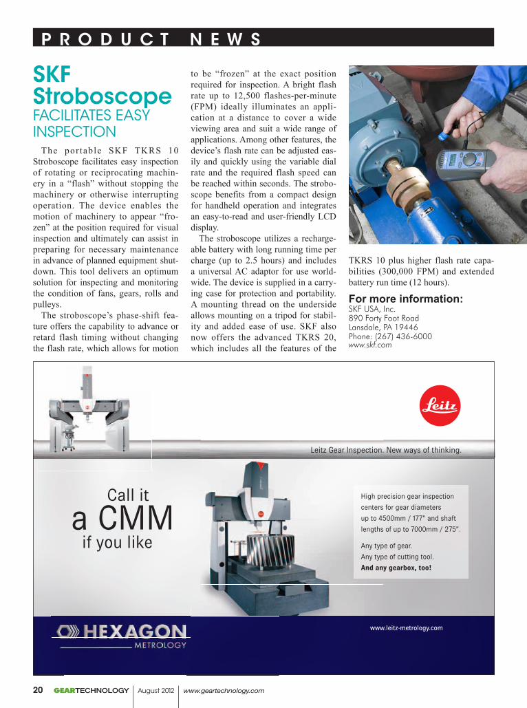
SKF StroboscopefACiLiTATeS eASy inSPeCTiOn
The por table SKF TKRS 10 Stroboscope facilitates easy inspection of rotating or reciprocating machin-ery in a “flash” without stopping the machinery or otherwise interrupting operation. The device enables the motion of machinery to appear “fro-zen” at the position required for visual inspection and ultimately can assist in preparing for necessary maintenance in advance of planned equipment shut-down. This tool delivers an optimum solution for inspecting and monitoring the condition of fans, gears, rolls and pulleys.
The stroboscope’s phase-shift fea-ture offers the capability to advance or retard flash timing without changing the flash rate, which allows for motion
to be “frozen” at the exact position required for inspection. A bright flash rate up to 12,500 flashes-per-minute (FPM) ideally illuminates an appli-cation at a distance to cover a wide viewing area and suit a wide range of applications. Among other features, the device’s flash rate can be adjusted eas-ily and quickly using the variable dial rate and the required flash speed can be reached within seconds. The strobo-scope benefits from a compact design for handheld operation and integrates an easy-to-read and user-friendly LCD display.
The stroboscope utilizes a recharge-able battery with long running time per charge (up to 2.5 hours) and includes a universal AC adaptor for use world-wide. The device is supplied in a carry-ing case for protection and portability. A mounting thread on the underside allows mounting on a tripod for stabil-ity and added ease of use. SKF also now offers the advanced TKRS 20, which includes all the features of the
TKRS 10 plus higher flash rate capa-bilities (300,000 FPM) and extended battery run time (12 hours).
For more information:SKF USA, Inc.890 Forty Foot RoadLansdale, PA 19446Phone: (267) 436-6000www.skf.com
GEARTECHNOLOGY August 2012 www.geartechnology.com20

Ask the Ticona Gearheads™
Great Minds!Put our polymer and application brainpower to work for you.
Ticona is the world leader in plastic gear technology. For over 30 years, our gearheads – better known as gear technology experts – have helped to dramatically reduce the cost, weight and noise of gear drives for countless applications.
Great Gears!n Reduce noisen Boost efficienciesn Lower costn Increase design flexibilityn Eliminate the need for lubricantsn Resist chemicals and corrosion
Great Polymers!Celanex® thermoplastic polyester (PBT)Hostaform® / Celcon® acetal copolymer (POM)Celstran® and Compel® long fiber reinforced thermoplastics (LFRT)Fortron® polyphenylene sulfide (PPS)GUR® ultra-high molecular weight polyethylene (UHMW-PE)Riteflex® thermoplastic polyester elastomer (TPC-ET)Vectra®/ Zenite® liquid crystal polymer (LCP)
Contact the Ticona Gearheads for the best polymer to fit your application at: 1.800.833.4882 www.ticona.com/gearheads
Ticona Engineering Polymers 8040 Dixie Highway, Florence, KY, USA 41042© 2012 Ticona Except as otherwise noted, trademarks are owned by Ticona or its affiliates. Fortron is a registered trademark of Fortron Industies LLC.
Ticona_Gearhead_GearTechAd.indd 1 7/6/12 1:26 PM
Accounts vary, but the trade show—or fair, exposition, exhibition—what-ever you call it—has been around since approximately 600 B.C. The Old Testament book of Ezekiel contains many references to merchants trad-ing, “in a multitude, riches with silver, iron, tin and lead (Source: “History of Trade Shows & Exhibitions,” by Karan Singh, articleinspector.com).” Since the 1960s, the article continues, trade shows and exhibitions have been “extensively used as a prominent part of marketing strategy. Larger amounts are spent each year on trade exhibitions than on magazine, radio and outdoor advertising.”
Some 2,600 years later, Ezekiel would be hard-pressed to recognize or understand what goes on at today’s shows. Trade shows—and how they are presented—continue to evolve: new technologies in graphics, sound and lighting, booth construction and much more continue to dazzle. And yet one thing has remained constant since those B.C. days—i.e., capturing the hearts and minds of new and existing custom-ers—and their wallets.
We talked with a number of major companies in the midst of their plan-ning and strategizing for IMTS 2012,
with the thought of determining just how much things have in fact changed for exhibitors regarding the trade show experience.
Take social media, for example. How influential is today’s texting and tweet-ing mania on trade show planning and execution? Are customers clamoring for it, as some media accounts report?
“Social media will not play a sig-nificant role in our 2012 IMTS exhi-bition,” says Al Finegan, Gleason Corp.’s director of marketing. “We are continuing to explore the use of social media in our marketing and promotion, but beyond our YouTube channel, the direction is not clear. And no, our cus-tomers are not clamoring for it.”
“Social media ‘apps’ are becom-ing more important each year and we believe will be a significant outlet along with web, print and direct mail,” Bill Miller, vice-president of sales at Kapp Technologies, allows.
And at Sandvik Coromant U.S., “Social media has been a part of (our) marketing and communications tools for the last several years,” says Rick Hern, Sandvik project manager. “We are constantly releasing valuable con-tent like application tips, events, new product news and app releases through
our social media channels. At IMTS this year, we will continue to provide our followers with the latest IMTS news.”
“We have not received a groundswell of requests from customers to com-municate via social media and as such we are taking a wait and see approach before making any major commitments in that regard,” says Sunnen’s Bob Davis, global communications man-ager. “However, we do have a YouTube channel so customers can view videos of our honing machines in operation and other informational videos we pro-duce.”
As for IMTS in particular—the greatest (manufacturing) show on earth?
Looking at it in a solely U.S.-based context, Gleason’s Finegan states that “I assume this is intended to get at the question of IMTS or Gear Expo. To say that one is more important than the other is like comparing apples to oranges. IMTS is the largest manufac-turing technology show in the western hemisphere, and even though the gear world is only a small part of manu-facturing technology, our customers expect the market leader to be there with a significant presence.
Jack McGuinn, Senior Editor
IMTSNorth America’s Show of Shows
GEARTECHNOLOGY August 2012 www.geartechnology.com22
“Gear Expo is of course very small but highly focused on gear manufac-turing. In addition, it has the unusual dynamic of the manufacturing technol-ogy suppliers like Gleason exhibiting alongside some of our customers. Both shows are very important to the market and to Gleason.”
“IMTS is the most significant show in North America for its size, qual-ity of attendees and the opportunity to discover new customers and applica-tions,” says Miller.
“IMTS is where customers, technol-ogy and industry partners merge on a bi-annual basis,” says Hern. “As an industry leader, Sandvik Coromant rec-ognizes that IMTS is the best-acknowl-edged manufacturing event in North America and continues to bring inno-vation and cutting tool solutions to cus-tomers attending the show.”
“By any standard, IMTS is the most important overall manufacturing show in North America, whether it is judged by size, number of exhibitors, num-ber of attendees, media coverage or newsworthiness,” Davis says. “Gear manufacturing is not done in a vacuum, so a broad-based show like IMTS is a very important event for gear manufac-turers as well. However, there is still an important place for smaller events such as Gear Expo, which highlight the technology, equipment and issues of concern to gear manufacturers and their suppliers.”
A show of such accepted signifi-cance is obviously no small matter in terms of cost, preparation and strategic goals. What does it take to make exhib-iting at IMTS a success?
“Any show, regardless of size and location, involves strategic planning,” Finegan says. “We carefully develop our global show plan on an annual basis, with strategy in mind. What are the right processes and products for the particular market? What are our competitors likely to exhibit? What message are we trying to impart to the audience at this show in this market at this time? And so on.”
“A significant expense such as IMTS certainly requires extensive planning and promotion,” Miller says. “The products we choose to display are selected to introduce the latest tech-
nology, and to best fit the anticipated growth markets at that time.”
And at Sandvik Coromant, “It is important to us to be able to provide a great learning environment and expe-rience to our customers and industry partners,” Hern says. “Throughout the entire year we work on planning and developing the ultimate experience for attendees visiting our booth and the student summit area.”
Sunnen’s Davis points out that “Much of the strategic planning that
goes into a large show such as IMTS is incremental from previous IMTS shows, so it is not an overwhelming task from year to year to develop our plan of attack. However, the implemen-tation of the plan cuts across nearly all departments in the company to some degree, and for a handful of individu-als it consumes nearly all of their time for several months leading up to the show.”
So once everything is in place and the show curtain rises, who do exhib-
Gear Solutions From Drake
All Drake Gear Machines are shipped with the latest CNC controls, Gear Smart™ programming, fi eld support and guaranteed performance.
GS:G2 Gear Grinders• Grind 25mm to 350mm tip diameter• CNC contour diamond roll dressing• CNC direct drive torque motor work index• DIN 2-3 quality capable• User-friendly software
GS:TE-LM Worm Grinders• Part lengths up to 2m• Diameters up to 650mm• Auto load available• ZK, ZI, ZN, ZA to DIN 1-2 quality capable
GS:RM Rack Mills• Auto load in a cell• No pits or platforms• 10-minute cutter change• Compare to broaching
GS:H Gear Hobbers• Up to 1800mm diameter• Auto load & probe• Power helix
CS:R Control System Renewal• New CNC for “brain dead” good iron• Gear grinders, hobbing machines, thread and rack milling machines• Work done on your fl oor• Only 2 weeks downtime
Drake Manufacturing Services Co.Tel: [email protected]
Koepfer America LLCTel: [email protected]
Drake Gear MachinesRepresented in North America by:
Precision Machines for Threads & Gears
See us in Booth N-6918
DRAK-462GearTechAdUSrev.indd 1 7/9/12 11:23 AMwww.geartechnology.com August 2012 GEARTECHNOLOGY 23
iting companies want stationed on the front lines? Which personnel are believed to be irreplaceable in the booth—sales or technical?
“Both sales and technical staff have an important role,” says Finegan. “Sales has the contacts and the deep relationships with customers, but the nature of the technology requires solid technical support at any show. Customers have questions and they expect to receive answers on the show
floor—answers to help their decision-making process.”
Likewise Kapp’s Miller—but for a different reason. “In fact, the most important personnel are management, who make it a priority to be in atten-dance to personally introduce them-selves and to greet customers.”
“Our IMTS staff is a true representa-tion of how Sandvik Coromant works together in order to provide custom-ers with the right answers,” says Hern. “We provide our staff with the neces-
sary knowledge, training and support to be able to provide answers to attendees when needed.”
And for Sunnen, “It is very impor-tant to have the right mix of sales staff and technical staff working in the booth at an important show such as IMTS,” Davis says. “The mix varies from company to company, but for the companies who are on the cutting edge of technology in their individual niche markets, such as Sunnen with the hon-ing equipment business, the mix must include more technical personnel than for companies who are selling products with older or more generally accept-ed technology. We normally have one technical person for every 3 or 4 sales people working in the booth at any given time.”
But at the end of the day—six days, to be precise—was it all worth it? And just how does a company determine that?
“We have a number of metrics for our shows that involve visitors, leads, sales and other things,” says Finegan. “I expect most exhibitors have similar metrics. We also perform a detailed internal survey of all staff and others who participated in the planning and execution of the show. We have a pret-ty good idea of our success by the end of the show—but also a strong post-mortem process to back it up.”
“Statistics can be compared shortly after a show,” Miller says, “but in most cases success of a specific show can only be quantified beyond six months.”
Sandvik’s Hern says that “Success at IMTS is measured in several ways—the direct sales lead for a specific prod-uct interest, the overall attendance at the show, and the support seen with the machine tool builders.”
“We generally know when we walk out of the show whether the show was good, bad or somewhere in between,” Davis says. “By ranking the trade show leads on a percentage chance of turn-ing into a sale we can come up with a rough idea of the actual short-term value of the show. However, it often takes months or even years for some show leads to turn into sales, so it is very difficult to get an exact dollar amount of the value of a show.” © 2 0 1 1 , P r e s r i t e C o r p o r a t i o n
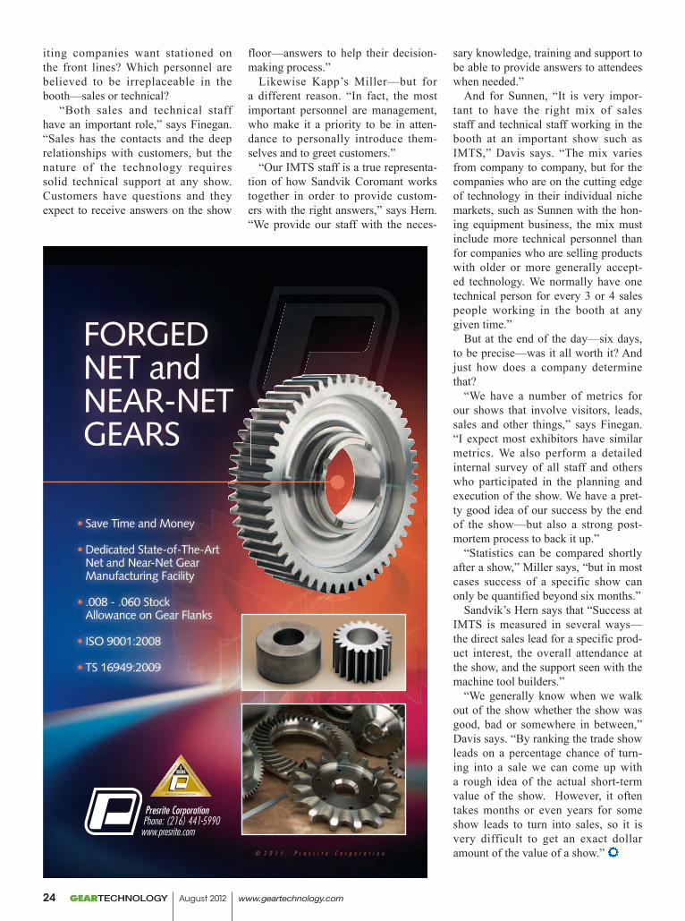
Presrite Corporation Phone: (216) 441-5990www.presrite.com
FORGED NET andNEAR-NET GEARS
• Save Time and Money
• Dedicated State-of-The-Art Net and Near-Net Gear Manufacturing Facility
• .008 - .060 Stock Allowance on Gear Flanks
• ISO 9001:2008
• TS 16949:2009
PRS-029 GearAd-GearTech2.indd 1 12/22/11 9:50 AMGEARTECHNOLOGY August 2012 www.geartechnology.com24
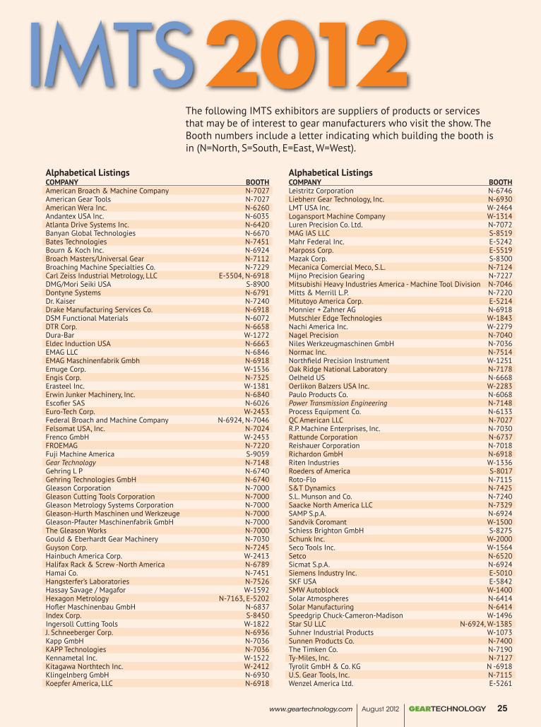
Alphabetical ListingsCOMPANY BOOTHAmerican Broach & Machine Company N-7027American Gear Tools N-7027American Wera Inc. N-6260Andantex USA Inc. N-6035Atlanta Drive Systems Inc. N-6420Banyan Global Technologies N-6670Bates Technologies N-7451Bourn & Koch Inc. N-6924Broach Masters/Universal Gear N-7112Broaching Machine Specialties Co. N-7229Carl Zeiss Industrial Metrology, LLC E-5504, N-6918DMG/Mori Seiki USA S-8900Dontyne Systems N-6791Dr. Kaiser N-7240Drake Manufacturing Services Co. N-6918DSM Functional Materials N-6072DTR Corp. N-6658Dura-Bar W-1272Eldec Induction USA N-6663EMAG LLC N-6846EMAG Maschinenfabrik Gmbh N-6918Emuge Corp. W-1536Engis Corp. N-7325Erasteel Inc. W-1381Erwin Junker Machinery, Inc. N-6840Escofier SAS N-6026Euro-Tech Corp. W-2453Federal Broach and Machine Company N-6924, N-7046Felsomat USA, Inc. N-7024Frenco GmbH W-2453FROEMAG N-7220Fuji Machine America S-9059Gear Technology N-7148Gehring L P N-6740Gehring Technologies GmbH N-6740Gleason Corporation N-7000Gleason Cutting Tools Corporation N-7000Gleason Metrology Systems Corporation N-7000Gleason-Hurth Maschinen und Werkzeuge N-7000Gleason-Pfauter Maschinenfabrik GmbH N-7000The Gleason Works N-7000Gould & Eberhardt Gear Machinery N-7030Guyson Corp. N-7245Hainbuch America Corp. W-2413Halifax Rack & Screw -North America N-6789Hamai Co. N-7451Hangsterfer’s Laboratories N-7526Hassay Savage / Magafor W-1592Hexagon Metrology N-7163, E-5202Hofler Maschinenbau GmbH N-6837Index Corp. S-8450Ingersoll Cutting Tools W-1822J. Schneeberger Corp. N-6936Kapp GmbH N-7036KAPP Technologies N-7036Kennametal Inc. W-1522Kitagawa Northtech Inc. W-2412Klingelnberg GmbH N-6930Koepfer America, LLC N-6918
Alphabetical ListingsCOMPANY BOOTHLeistritz Corporation N-6746Liebherr Gear Technology, Inc. N-6930LMT USA Inc. W-2464Logansport Machine Company W-1314Luren Precision Co. Ltd. N-7072MAG IAS LLC S-8519Mahr Federal Inc. E-5242Marposs Corp. E-5519Mazak Corp. S-8300Mecanica Comercial Meco, S.L. N-7124Mijno Precision Gearing N-7227Mitsubishi Heavy Industries America - Machine Tool Division N-7046Mitts & Merrill L.P. N-7220Mitutoyo America Corp. E-5214Monnier + Zahner AG N-6918Mutschler Edge Technologies W-1843Nachi America Inc. W-2279Nagel Precision N-7040Niles Werkzeugmaschinen GmbH N-7036Normac Inc. N-7514Northfield Precision Instrument W-1251Oak Ridge National Laboratory N-7178Oelheld US N-6668Oerlikon Balzers USA Inc. W-2283Paulo Products Co. N-6068Power Transmission Engineering N-7148Process Equipment Co. N-6133QC American LLC N-7027R.P. Machine Enterprises, Inc. N-7030Rattunde Corporation N-6737Reishauer Corporation N-7018Richardon GmbH N-6918Riten Industries W-1336Roeders of America S-8017Roto-Flo N-7115S&T Dynamics N-7425S.L. Munson and Co. N-7240Saacke North America LLC N-7329SAMP S.p.A. N-6924Sandvik Coromant W-1500Schiess Brighton GmbH S-8275Schunk Inc. W-2000Seco Tools Inc. W-1564Setco N-6520Sicmat S.p.A. N-6924Siemens Industry Inc. E-5010SKF USA E-5842SMW Autoblock W-1400Solar Atmospheres N-6414Solar Manufacturing N-6414Speedgrip Chuck-Cameron-Madison W-1496Star SU LLC N-6924, W-1385Suhner Industrial Products W-1073Sunnen Products Co. N-7400The Timken Co. N-7190Ty-Miles, Inc. N-7127Tyrolit GmbH & Co. KG N -6918U.S. Gear Tools, Inc. N-7115Wenzel America Ltd. E-5261
The following IMTS exhibitors are suppliers of products or services that may be of interest to gear manufacturers who visit the show. The Booth numbers include a letter indicating which building the booth is in (N=North, S=South, E=East, W=West).
www.geartechnology.com August 2012 GEARTECHNOLOGY 25
IMTS 2012
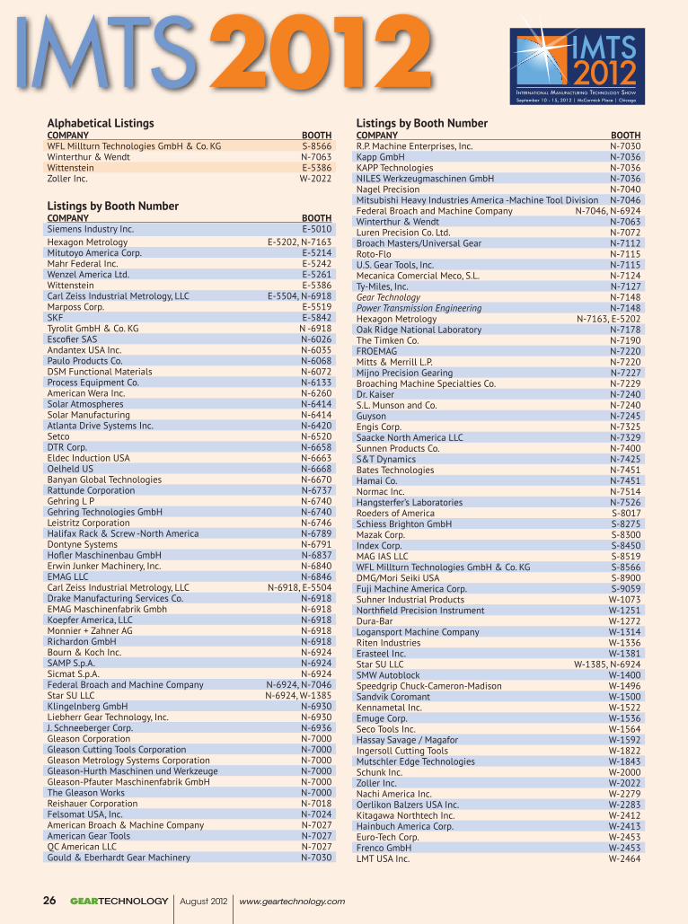
Alphabetical ListingsCOMPANY BOOTHWFL Millturn Technologies GmbH & Co. KG S-8566Winterthur & Wendt N-7063Wittenstein E-5386Zoller Inc. W-2022
Listings by Booth NumberCOMPANY BOOTHSiemens Industry Inc. E-5010Hexagon Metrology E-5202, N-7163Mitutoyo America Corp. E-5214Mahr Federal Inc. E-5242Wenzel America Ltd. E-5261Wittenstein E-5386Carl Zeiss Industrial Metrology, LLC E-5504, N-6918Marposs Corp. E-5519SKF E-5842Tyrolit GmbH & Co. KG N -6918Escofier SAS N-6026Andantex USA Inc. N-6035Paulo Products Co. N-6068DSM Functional Materials N-6072Process Equipment Co. N-6133American Wera Inc. N-6260Solar Atmospheres N-6414Solar Manufacturing N-6414Atlanta Drive Systems Inc. N-6420Setco N-6520DTR Corp. N-6658Eldec Induction USA N-6663Oelheld US N-6668Banyan Global Technologies N-6670Rattunde Corporation N-6737Gehring L P N-6740Gehring Technologies GmbH N-6740Leistritz Corporation N-6746Halifax Rack & Screw -North America N-6789Dontyne Systems N-6791Hofler Maschinenbau GmbH N-6837Erwin Junker Machinery, Inc. N-6840EMAG LLC N-6846Carl Zeiss Industrial Metrology, LLC N-6918, E-5504Drake Manufacturing Services Co. N-6918EMAG Maschinenfabrik Gmbh N-6918Koepfer America, LLC N-6918Monnier + Zahner AG N-6918Richardon GmbH N-6918Bourn & Koch Inc. N-6924SAMP S.p.A. N-6924Sicmat S.p.A. N-6924Federal Broach and Machine Company N-6924, N-7046Star SU LLC N-6924, W-1385Klingelnberg GmbH N-6930Liebherr Gear Technology, Inc. N-6930J. Schneeberger Corp. N-6936Gleason Corporation N-7000Gleason Cutting Tools Corporation N-7000Gleason Metrology Systems Corporation N-7000Gleason-Hurth Maschinen und Werkzeuge N-7000Gleason-Pfauter Maschinenfabrik GmbH N-7000The Gleason Works N-7000Reishauer Corporation N-7018Felsomat USA, Inc. N-7024American Broach & Machine Company N-7027American Gear Tools N-7027QC American LLC N-7027Gould & Eberhardt Gear Machinery N-7030
Listings by Booth NumberCOMPANY BOOTHR.P. Machine Enterprises, Inc. N-7030Kapp GmbH N-7036KAPP Technologies N-7036NILES Werkzeugmaschinen GmbH N-7036Nagel Precision N-7040Mitsubishi Heavy Industries America -Machine Tool Division N-7046Federal Broach and Machine Company N-7046, N-6924Winterthur & Wendt N-7063Luren Precision Co. Ltd. N-7072Broach Masters/Universal Gear N-7112Roto-Flo N-7115U.S. Gear Tools, Inc. N-7115Mecanica Comercial Meco, S.L. N-7124Ty-Miles, Inc. N-7127Gear Technology N-7148Power Transmission Engineering N-7148Hexagon Metrology N-7163, E-5202Oak Ridge National Laboratory N-7178The Timken Co. N-7190FROEMAG N-7220Mitts & Merrill L.P. N-7220Mijno Precision Gearing N-7227Broaching Machine Specialties Co. N-7229Dr. Kaiser N-7240S.L. Munson and Co. N-7240Guyson N-7245Engis Corp. N-7325Saacke North America LLC N-7329Sunnen Products Co. N-7400S&T Dynamics N-7425Bates Technologies N-7451Hamai Co. N-7451Normac Inc. N-7514Hangsterfer’s Laboratories N-7526Roeders of America S-8017Schiess Brighton GmbH S-8275Mazak Corp. S-8300Index Corp. S-8450MAG IAS LLC S-8519WFL Millturn Technologies GmbH & Co. KG S-8566DMG/Mori Seiki USA S-8900Fuji Machine America Corp. S-9059Suhner Industrial Products W-1073Northfield Precision Instrument W-1251Dura-Bar W-1272Logansport Machine Company W-1314Riten Industries W-1336Erasteel Inc. W-1381Star SU LLC W-1385, N-6924SMW Autoblock W-1400Speedgrip Chuck-Cameron-Madison W-1496Sandvik Coromant W-1500Kennametal Inc. W-1522Emuge Corp. W-1536Seco Tools Inc. W-1564Hassay Savage / Magafor W-1592Ingersoll Cutting Tools W-1822Mutschler Edge Technologies W-1843Schunk Inc. W-2000Zoller Inc. W-2022Nachi America Inc. W-2279Oerlikon Balzers USA Inc. W-2283Kitagawa Northtech Inc. W-2412Hainbuch America Corp. W-2413Euro-Tech Corp. W-2453Frenco GmbH W-2453LMT USA Inc. W-2464
GEARTECHNOLOGY August 2012 www.geartechnology.com26
IMTS 2012
Rev 07-17-2012 Sandvik Gear Ad / GearTechnology8.25x11
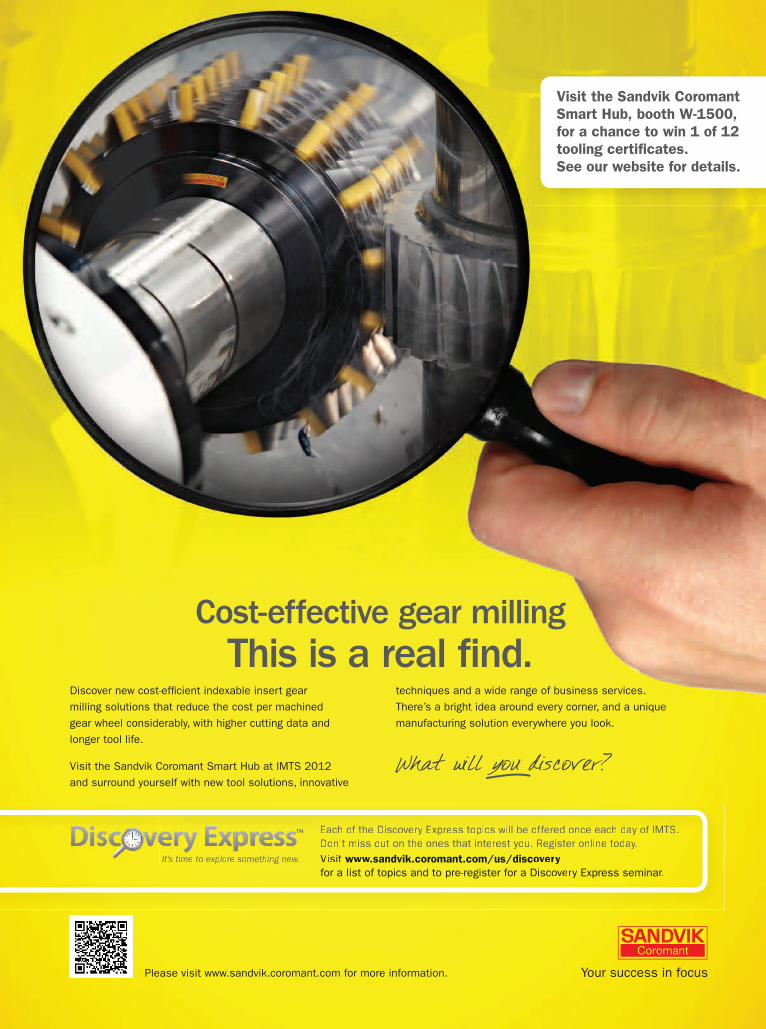
Cost-effective gear milling
milling solutions that reduce the cost per machinedgear wheel considerably, with higher cutting data andlonger tool life.
Visit the Sandvik Coromant Smart Hub at IMTS 2012 and surround yourself with new tool solutions, innovative
techniques and a wide range of business services.There’s a bright idea around every corner, and a unique manufacturing solution everywhere you look.
What will you discover?
Please visit www.sandvik.coromant.com for more information.
Visit the Sandvik Coromant Smart Hub, booth W-1500, for a chance to win 1 of 12 tooling certificates. See our website for details.
Visit www.sandvik.coromant.com/us/discovery for a list of topics and to pre-register for a Discovery Express seminar.
It’s time to explore something new.
Each of the Discovery Express topics will be offered once each day of IMTS. Don’t miss out on the ones that interest you. Register online today.Visit www.sandvik.coromant.com/us/discoveryyfor a list of topics and to pre-register for a Dissccovery Express seminar.rr
It’s ’’ time to expx lorerr something new.ww
EEachh off tthhe DDiiscovery EExpress ttopiics wiillll bbe offfferedd once eachh dday off IIMMTTSS. Don’t miss out on the ones that interest you. Register online today.
STAr SUBooth N-6924, W-1385
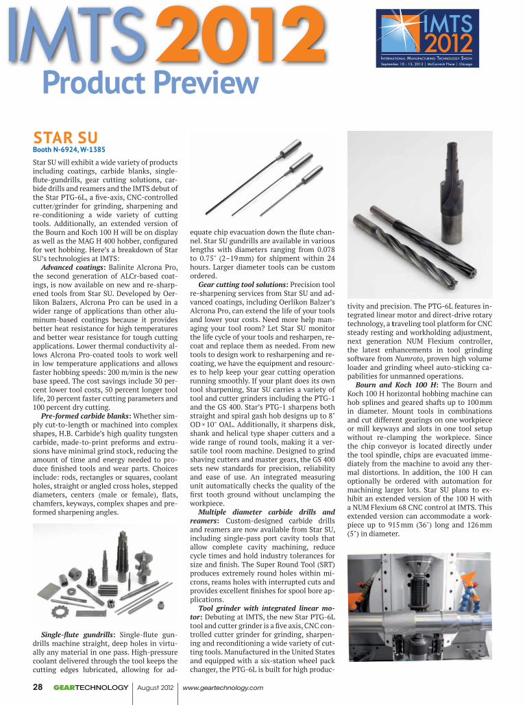
Star SU will exhibit a wide variety of products including coatings, carbide blanks, single-flute-gundrills, gear cutting solutions, car-bide drills and reamers and the IMTS debut of the Star PTG-6L, a five-axis, CNC-controlled cutter/grinder for grinding, sharpening and re-conditioning a wide variety of cutting tools. Additionally, an extended version of the Bourn and Koch 100 H will be on display as well as the MAG H 400 hobber, configured for wet hobbing. Here’s a breakdown of Star SU’s technologies at IMTS:
Advanced coatings: Balinite Alcrona Pro, the second generation of ALCr-based coat-ings, is now available on new and re-sharp-ened tools from Star SU. Developed by Oer-likon Balzers, Alcrona Pro can be used in a wider range of applications than other alu-minum-based coatings because it provides better heat resistance for high temperatures and better wear resistance for tough cutting applications. Lower thermal conductivity al-lows Alcrona Pro-coated tools to work well in low temperature applications and allows faster hobbing speeds: 200 m/min is the new base speed. The cost savings include 30 per-cent lower tool costs, 50 percent longer tool life, 20 percent faster cutting parameters and 100 percent dry cutting.
Pre-formed carbide blanks: Whether sim-ply cut-to-length or machined into complex shapes, H.B. Carbide’s high quality tungsten carbide, made-to-print preforms and extru-sions have minimal grind stock, reducing the amount of time and energy needed to pro-duce finished tools and wear parts. Choices include: rods, rectangles or squares, coolant holes, straight or angled cross holes, stepped diameters, centers (male or female), flats, chamfers, keyways, complex shapes and pre-formed sharpening angles.
Single-flute gundrills: Single-flute gun-drills machine straight, deep holes in virtu-ally any material in one pass. High-pressure coolant delivered through the tool keeps the cutting edges lubricated, allowing for ad-
equate chip evacuation down the flute chan-nel. Star SU gundrills are available in various lengths with diameters ranging from 0.078 to 0.75" (2–19 mm) for shipment within 24 hours. Larger diameter tools can be custom ordered.
Gear cutting tool solutions: Precision tool re-sharpening services from Star SU and ad-vanced coatings, including Oerlikon Balzer’s Alcrona Pro, can extend the life of your tools and lower your costs. Need more help man-aging your tool room? Let Star SU monitor the life cycle of your tools and resharpen, re-coat and replace them as needed. From new tools to design work to resharpening and re-coating, we have the equipment and resourc-es to help keep your gear cutting operation running smoothly. If your plant does its own tool sharpening, Star SU carries a variety of tool and cutter grinders including the PTG-1 and the GS 400. Star’s PTG-1 sharpens both straight and spiral gash hob designs up to 8" OD × 10" OAL. Additionally, it sharpens disk, shank and helical type shaper cutters and a wide range of round tools, making it a ver-satile tool room machine. Designed to grind shaving cutters and master gears, the GS 400 sets new standards for precision, reliability and ease of use. An integrated measuring unit automatically checks the quality of the first tooth ground without unclamping the workpiece.
Multiple diameter carbide drills and reamers: Custom-designed carbide drills and reamers are now available from Star SU, including single-pass port cavity tools that allow complete cavity machining, reduce cycle times and hold industry tolerances for size and finish. The Super Round Tool (SRT) produces extremely round holes within mi-crons, reams holes with interrupted cuts and provides excellent finishes for spool bore ap-plications.
Tool grinder with integrated linear mo-tor: Debuting at IMTS, the new Star PTG-6L tool and cutter grinder is a five axis, CNC con-trolled cutter grinder for grinding, sharpen-ing and reconditioning a wide variety of cut-ting tools. Manufactured in the United States and equipped with a six-station wheel pack changer, the PTG-6L is built for high produc-
tivity and precision. The PTG-6L features in-tegrated linear motor and direct-drive rotary technology, a traveling tool platform for CNC steady resting and workholding adjustment, next generation NUM Flexium controller, the latest enhancements in tool grinding software from Numroto, proven high volume loader and grinding wheel auto-sticking ca-pabilities for unmanned operations.
Bourn and Koch 100 H: The Bourn and Koch 100 H horizontal hobbing machine can hob splines and geared shafts up to 100 mm in diameter. Mount tools in combinations and cut different gearings on one workpiece or mill keyways and slots in one tool setup without re-clamping the workpiece. Since the chip conveyor is located directly under the tool spindle, chips are evacuated imme-diately from the machine to avoid any ther-mal distortions. In addition, the 100 H can optionally be ordered with automation for machining larger lots. Star SU plans to ex-hibit an extended version of the 100 H with a NUM Flexium 68 CNC control at IMTS. This extended version can accommodate a work-piece up to 915 mm (36") long and 126 mm (5") in diameter.
Product Preview
GEARTECHNOLOGY August 2012 www.geartechnology.com28
IMTS 2012
After September, 2012
this is your
spline rolling
rack
We’re about to make your existing spline rolling racks extinct.
Visit booth N-7115 at IMTS and see how we’re revolutionizing the way you
buy, manage, and use spline rolling tooling.
www.roto-flo.com www.usgeartools.comBooth N-7115
MAG H 400: Run small lots or mass pro-duce straight and helical gears; crowned and tapered gears; worm gears; chain sprockets and toothed belt discs; cluster gears and spe-cial profiles with MAG’s H 400 CNC hobbing machine. This machine can use standard hob or form milling technology, ranging from dry or wet machining with high capacity HSS or carbide tools to skive hobbing of heat-treated gears. The H 400 hobber includes: motorized hob head, direct drive table speed range of 400 rpm, maximum hob diameter of 175 mm, six CNC axes, Siemens control, aligning probe and MAG Modul dialogue soft-ware (metric or inches). Star SU will feature the H 400 hobber configured for wet hobbing.
For more information:Star SU LLC.5200 Prairie Stone Parkway,Suite 100Hoffman Estates, IL 60192Phone: (847) 649-1450www.star-su.com
GLeASON COrPOrATiONBooth N-7000
Gleason will introduce a host of advanced new machines, tooling and global customer support services at IMTS 2012, covering a
wide array of processes for the complete pro-duction and inspection of all types of bevel and cylindrical gears. Among the new tech-nologies exhibited at the show will be:
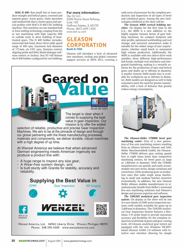
The Genesis 400H vertical hobbing ma-chine: On display for the first time in the U.S., the 400H is a new addition to the highly popular Genesis Series of gear hob-bing machines. Its compact footprint and slim profile, optimized workholding and tool change, and universal automation make it suitable for the widest range of user require-ments, whether small batch or automated high volume production. Additionally, the 400H is available with two direct-drive work spindles, three different high-performance hob heads, multiple tool interfaces and inte-grated chamfering, making it a versatile so-lution for the production of spur and helical gears and shafts up to 400 mm in diameter. A smaller Genesis 260H model also is avail-able for workpieces up to 260 mm in diame-ter. Both models are designed as well to help customers meet the need for greater sustain-ability, with a host of features that greatly reduce energy consumption.
The Gleason-Heller CT8000 bevel gear machining center: First of a new genera-tion of five-axis machining centers resulting from an alliance between Gleason and Gebr. Heller Maschinenfabrik GmbH, the Gleason-Heller CT8000 delivers gear cutting speeds four to eight times faster than competitive machining centers, for bevel gears as large as 1,800 mm in diameter. With the CT8000, manufacturers can quickly and easily accom-modate new part series, design variations and corrections, while producing gears at produc-tion rates that make single setup machin-ing in small and medium batches attractive economically. In addition, the new Gleason Heller alliance enables manufacturers to si-multaneously benefit from Heller’s renowned five-axis machining solutions and Gleason’s design and process expertise and software.
The 350GMS analytical gear inspection system: On display at the show will be one of a new family of GMS series inspection sys-tems (with models available for gears up to 3,000 mm in diameter). The 350GMS Analyti-cal Gear Inspection System features a Ren-ishaw 3-D probe head to provide maximum accuracy and flexibility for the complete in-spection of all kinds of gears and gear-cutting tools. All Gleason analytical gear testers are equipped with the new Windows VB.NET-based Gleason GAMA 2.0 software with in-tuitive user interface allowing for simple
The target is clear when it comes to supplying the best value in gear inspection. Our mission is to offer the widest
selection of reliable, productive and precise Gear Inspection Machines. We aim to be at the pinnacle of design and through our global partnering with the finest manufacturing processes, materials and components, we deliver durable, robust machines with a high degree of up time.
• A huge range to inspect any size gear,• A Wear-free system design, and• Is built sturdy with Granite for stability, accuracy and reliability.
At Wenzel America we believe that when advanced German engineering meets American ingenuity we produce a product line with:
Wenzel America, Ltd. 46962 Liberty Drive Wixom, Michigan 48393Phone: 248 295-4300 www.wenzelamerica.com
find us on facebook
Geared on Value
Supplying the Best Value in CMM Gear Inspection 3D Imaging
Booth #E-5261
GEARTECHNOLOGY August 2012 www.geartechnology.com30
input screens for programming of workpiece and cutting tool data. The GMS series is also equipped with new ergonomically mounted operator work stations and optional remote pendant controls—both designed to greatly improve the operator’s effectiveness at every stage of the inspection process.
Power skiving process: For these and other cylindrical gear applications, the newly de-veloped power skiving process is fast emerg-ing as a practical and highly productive al-ternative to typical gear shaping, forming, pressing, and broaching. Visitors to the Glea-son booth will learn more about how Gleason combines machine, tool and technology for power kiving of small- and medium-sized workpieces, with modules up to 2.0 mm.
A complete line of gear-cutting tools and workholding solutions: For the production of large cylindrical gears, Gleason offers the Opti-Cut family, which provides users with all the performance benefits of the latest re-placeable, indexable, carbide insert technol-ogy. Opti-Cut can reduce cost-per-part by as much as 50 percent as compared to conven-tional high speed steel cutters. The family is versatile too, including gear gashing, hob-bing and shaping products in a variety of cut-ter body sizes, insert types and geometries to meet a wide range of roughing and finishing, and internal and external gear production requirements.
Advanced workholding solutions: In ad-dition, Gleason designs and produces a complete series of quick-change, tool-less workholding equipment for both bevel gear and cylindrical gear, and non-gear produc-tion machines. These systems range from the Gleason X-Pandisk systems which auto-matically align workpieces weighing up to 2,000 kg to reduce changeover time by up to 70 percent, to Quick-Flex and a large variety of quick-change workholding solutions that significantly reduce change-over times for the production of both bevel and cylindrical gears. For inspection systems, Gleason offers the high-precision Gleason LeCount expand-ing mandrels line, renowned for accurate, easy, extremely rapid location of all types of bore parts.
Gleason Global Services. Gleason custom-ers can rely on 250 factory trained service professionals located in over 50 countries throughout the Americas, Europe, and Asia, working around the clock to support a full range of support requirements, including:
Services: Complete new offering of ser-
vice programs ranging from our simple Fast Check machine inspection to our extended service programs which provide “No Worry” guarantees.
Service parts: Globally stocked OEM re-pair parts to reduce downtime.
Training: The largest range of gear pro-cess and gear machinery operation and maintenance courses in our industry with training supported globally.
Application support: Programs to im-prove process quality, cycle times and reduce Total Cost of Ownership.
Equipment upgrades: Recontrols, re-builds, recondition and upgrades to ensure maximum machine production.
Gleason Connect: A new “remote service” technology enabling Gleason service special-ists from anywhere in the world to quickly and cost effectively identify, diagnose, repair and monitor products and minimize cost due to downtime.
For more information:Gleason Corporation1000 University AvenueP.O. Box 22970Rochester, NY 14692-2970Phone: (585) 473-1000Fax: (585) [email protected]
From simple keyways to multiple, special profi les, Leistritz Polymat and Polyjet machines have the features to improve quality, shorten cycle times and minimize set-ups.
Polymat series of CNC keyseating
machine
201 934-8262 www.leistritzcorp.comLeistritz Corp. 165 Chestnut Street, Allendale, NJ 07401
www.geartechnology.com August 2012 GEARTECHNOLOGY 31
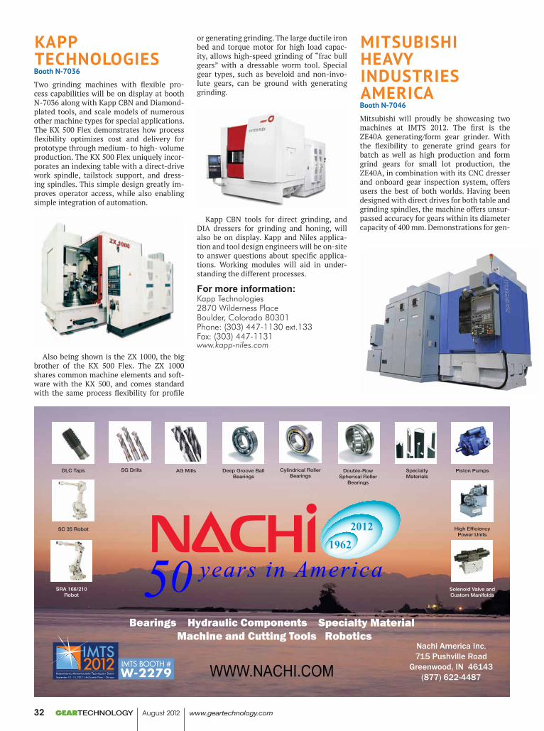
KAPP TeCHNOLOGieSBooth N-7036
Two grinding machines with flexible pro-cess capabilities will be on display at booth N-7036 along with Kapp CBN and Diamond-plated tools, and scale models of numerous other machine types for special applications. The KX 500 Flex demonstrates how process flexibility optimizes cost and delivery for prototype through medium- to high- volume production. The KX 500 Flex uniquely incor-porates an indexing table with a direct-drive work spindle, tailstock support, and dress-ing spindles. This simple design greatly im-proves operator access, while also enabling simple integration of automation.
Also being shown is the ZX 1000, the big brother of the KX 500 Flex. The ZX 1000 shares common machine elements and soft-ware with the KX 500, and comes standard with the same process flexibility for profile
or generating grinding. The large ductile iron bed and torque motor for high load capac-ity, allows high-speed grinding of “frac bull gears” with a dressable worm tool. Special gear types, such as beveloid and non-invo-lute gears, can be ground with generating grinding.
Kapp CBN tools for direct grinding, and DIA dressers for grinding and honing, will also be on display. Kapp and Niles applica-tion and tool design engineers will be on-site to answer questions about specific applica-tions. Working modules will aid in under-standing the different processes.
For more information:Kapp Technologies2870 Wilderness PlaceBoulder, Colorado 80301Phone: (303) 447-1130 ext.133Fax: (303) 447-1131www.kapp-niles.com
MiTSUBiSHi HeAvY iNdUSTrieS AMeriCABooth N-7046
Mitsubishi will proudly be showcasing two machines at IMTS 2012. The first is the ZE40A generating/form gear grinder. With the flexibility to generate grind gears for batch as well as high production and form grind gears for small lot production, the ZE40A, in combination with its CNC dresser and onboard gear inspection system, offers users the best of both worlds. Having been designed with direct drives for both table and grinding spindles, the machine offers unsur-passed accuracy for gears within its diameter capacity of 400 mm. Demonstrations for gen-
Deep Groove Ball Bearings
Cylindrical Roller Bearings
Double-Row Spherical Roller
Bearings
WWW.NACHI.COM
DLC Taps AG Mills
Solenoid Valve and Custom Manifolds
Piston Pumps
High Efficiency Power Units
SG Drills Specialty Materials
SC 35 Robot
SRA 166/210 Robot
Nachi America Inc.715 Pushville Road
Greenwood, IN 46143(877) 622-4487
IMTS BOOTH #W-2279
GEARTECHNOLOGY August 2012 www.geartechnology.com32
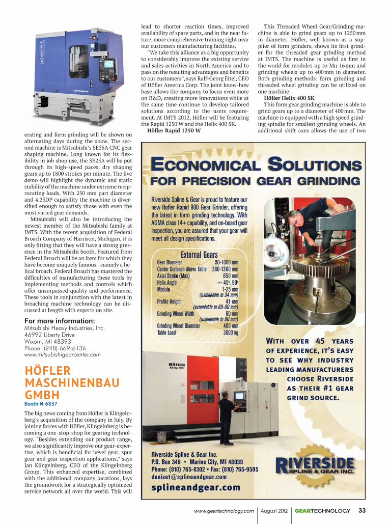
erating and form grinding will be shown on alternating days during the show. The sec-ond machine is Mitsubishi’s SE25A CNC gear shaping machine. Long known for its flex-ibility in job shop use, the SE25A will be put through its high-speed paces, dry shaping gears up to 1800 strokes per minute. The live demo will highlight the dynamic and static stability of the machine under extreme recip-rocating loads. With 250 mm part diameter and 4.23DP capability the machine is diver-sified enough to satisfy those with even the most varied gear demands.
Mitsubishi will also be introducing the newest member of the Mitsubishi family at IMTS. With the recent acquisition of Federal Broach Company of Harrison, Michigan, it is only fitting that they will have a strong pres-ence in the Mitsubishi booth. Featured from Federal Broach will be an item for which they have become uniquely famous—namely a he-lical broach. Federal Broach has mastered the difficulties of manufacturing these tools by implementing methods and controls which offer unsurpassed quality and performance. These tools in conjunction with the latest in broaching machine technology can be dis-cussed at length with experts on site.
For more information:Mitsubishi Heavy Industries, Inc.46992 Liberty DriveWixom, MI 48393Phone: (248) 669-6136www.mitsubishigearcenter.com
HöfLer MASCHiNeNBAU GMBHBooth N-6837
The big news coming from Höfler is Klingeln-berg‘s acquisition of the company in July. By joining forces with Höfler, Klingelnberg is be-coming a one-stop-shop for gearing technol-ogy. “Besides extending our product range, we also significantly improve our gear-exper-tise, which is beneficial for bevel gear, spur gear and gear inspection applications,” says Jan Klingelnberg, CEO of the Klingelnberg Group. This enhanced expertise, combined with the additional company locations, lays the groundwork for a strategically optimized service network all over the world. This will
lead to shorter reaction times, improved availability of spare parts, and in the near fu-ture, more comprehensive training right near our customers manufacturing facilities.
“We take this alliance as a big opportunity to considerably improve the existing service and sales activities in North America and to pass on the resulting advantages and benefits to our customers”, says Ralf-Georg Eitel, CEO of Höfler America Corp. The joint know-how base allows the company to focus even more on R&D, creating more innovations while at the same time continue to develop tailored solutions according to the users require-ment. At IMTS 2012, Höfler will be featuring the Rapid 1250 W and the Helix 400 SK.
Höfler Rapid 1250 W
This Threaded Wheel Gear/Grinding ma-chine is able to grind gears up to 1250 mm in diameter. Höfler, well known as a sup-plier of form grinders, shows its first grind-er for the threaded gear grinding method at IMTS. The machine is useful as first in the world for modules up to Mn 16 mm and grinding wheels up to 400 mm in diameter. Both grinding methods: form grinding and threaded wheel grinding can be utilized on one machine.
Höfler Helix 400 SKThis form gear grinding machine is able to
grind gears up to a diameter of 400 mm. The machine is equipped with a high speed grind-ing spindle for smallest grinding wheels. An additional shift axes allows the use of two
www.geartechnology.com August 2012 GEARTECHNOLOGY 33
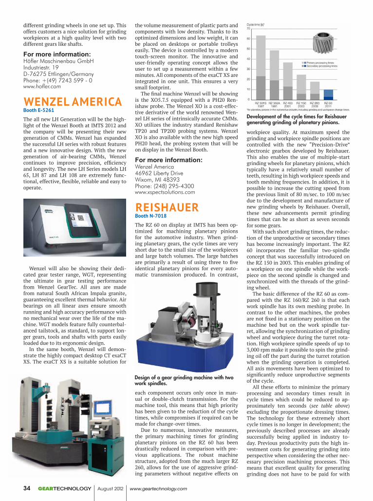
different grinding wheels in one set up. This offers customers a nice solution for grinding workpieces at a high quality level with two different gears like shafts.
For more information:Höfler Maschinenbau GmbHIndustriestr. 19D-76275 Ettlingen/GermanyPhone: +(49) 7243 599 - 0www.hofler.com
WeNzeL AMeriCABooth e-5261
The all new LH Generation will be the high-light of the Wenzel Booth at IMTS 2012 and the company will be presenting their new generation of CMMs. Wenzel has expanded the successful LH series with robust features and a new innovative design. With the new generation of air-bearing CMMs, Wenzel continues to improve precision, efficiency and longevity. The new LH Series models LH 65, LH 87 and LH 108 are extremely func-tional, effective, flexible, reliable and easy to operate.
Wenzel will also be showing their dedi-cated gear tester range, WGT, representing the ultimate in gear testing performance from Wenzel GearTec. All axes are made from natural South African Impala granite, guaranteeing excellent thermal behavior. Air bearings on all linear axes ensure smooth running and high accuracy performance with no mechanical wear over the life of the ma-chine. WGT models feature fully counterbal-anced tailstock, as standard, to support lon-ger gears, tools and shafts with parts easily loaded due to its ergonomic design.
In the same booth, Wenzel will demon-strate the highly compact desktop CT exaCT XS. The exaCT XS is a suitable solution for
the volume measurement of plastic parts and components with low density. Thanks to its optimized dimensions and low weight, it can be placed on desktops or portable trolleys easily. The device is controlled by a modern touch-screen monitor. The innovative and user-friendly operating concept allows the user to set up a measurement within a few minutes. All components of the exaCT XS are integrated in one unit. This ensures a very small footprint.
The final machine Wenzel will be showing is the XO5.7.5 equipped with a PH20 Ren-ishaw probe. The Wenzel XO is a cost-effec-tive derivative of the world renowned Wen-zel LH series of intrinsically accurate CMMs. XO utilizes the industry standard Renishaw TP20 and TP200 probing systems. Wenzel XO is also available with the new high speed PH20 head, the probing system that will be on display in the Wenzel Booth.
For more information:Wenzel America46962 Liberty DriveWixom, MI 48393Phone: (248) 295-4300www.xspectsolutions.com
reiSHAUerBooth N-7018
The RZ 60 on display at IMTS has been op-timized for machining planetary pinions for the automotive industry. When grind-ing planetary gears, the cycle times are very short due to the small size of the workpieces and large batch volumes. The large batches are primarily a result of using three to five identical planetary pinions for every auto-matic transmission produced. In contrast,
each component occurs only once in man-ual or double-clutch transmission. For the machine tool, this means that high priority has been given to the reduction of the cycle times, while compromises if required can be made for change-over times.
Due to numerous, innovative measures, the primary machining times for grinding planetary pinions on the RZ 60 has been drastically reduced in comparison with pre-vious applications. The robust machine structure, adopted from the much larger RZ 260, allows for the use of aggressive grind-ing parameters without negative effects on
workpiece quality. At maximum speed the grinding and workpiece spindle positions are controlled with the new “Precision-Drive” electronic gearbox developed by Reishauer. This also enables the use of multiple-start grinding wheels for planetary pinions, which typically have a relatively small number of teeth, resulting in high workpiece speeds and tooth meshing frequencies. In addition, it is possible to increase the cutting speed from the previous limit of 80 m/sec. to 100 m/sec due to the development and manufacture of new grinding wheels by Reishauer. Overall, these new advancements permit grinding times that can be as short as seven seconds for some gears.
With such short grinding times, the reduc-tion of the unproductive or secondary times has become increasingly important. The RZ 60 incorporates the familiar two-spindle concept that was successfully introduced on the RZ 150 in 2003. This enables grinding of a workpiece on one spindle while the work-piece on the second spindle is changed and synchronized with the threads of the grind-ing wheel.
The basic difference of the RZ 60 as com-pared with the RZ 160/RZ 260 is that each work spindle has its own meshing probe. In contrast to the other machines, the probes are not fixed in a stationary position on the machine bed but on the work spindle tur-ret, allowing the synchronization of grinding wheel and workpiece during the turret rota-tion. High workpiece spindle speeds of up to 3,000 rpm make it possible to spin the grind-ing oil off the part during the turret rotation when the grinding operation is completed. All axis movements have been optimized to significantly reduce unproductive segments of the cycle.
All these efforts to minimize the primary processing and secondary times result in cycle times which could be reduced to ap-proximately ten seconds (see table above) excluding the proportionate dressing times. The technology for these extremely short cycle times is no longer in development; the previously described processes are already successfully being applied in industry to-day. Previous productivity puts the high in-vestment costs for generating grinding into perspective when considering the other nec-essary precision machining processes. This means that excellent quality for generating grinding does not have to be paid for with
Design of a gear grinding machine with two work spindles.
Development of the cycle times for Reishauer generating grinding of planetary pinions.
GEARTECHNOLOGY August 2012 www.geartechnology.com34
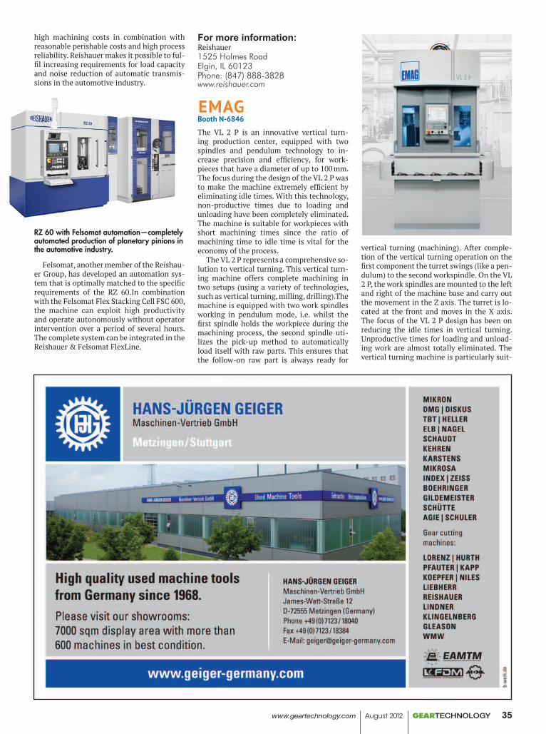
high machining costs in combination with reasonable perishable costs and high process reliability. Reishauer makes it possible to ful-fil increasing requirements for load capacity and noise reduction of automatic transmis-sions in the automotive industry.
Felsomat, another member of the Reishau-er Group, has developed an automation sys-tem that is optimally matched to the specific requirements of the RZ 60.In combination with the Felsomat Flex Stacking Cell FSC 600, the machine can exploit high productivity and operate autonomously without operator intervention over a period of several hours. The complete system can be integrated in the Reishauer & Felsomat FlexLine.
For more information:Reishauer1525 Holmes RoadElgin, IL 60123Phone: (847) 888-3828www.reishauer.com
eMAGBooth N-6846
The VL 2 P is an innovative vertical turn-ing production center, equipped with two spindles and pendulum technology to in-crease precision and efficiency, for work-pieces that have a diameter of up to 100 mm. The focus during the design of the VL 2 P was to make the machine extremely efficient by eliminating idle times. With this technology, non-productive times due to loading and unloading have been completely eliminated. The machine is suitable for workpieces with short machining times since the ratio of machining time to idle time is vital for the economy of the process.
The VL 2 P represents a comprehensive so-lution to vertical turning. This vertical turn-ing machine offers complete machining in two setups (using a variety of technologies, such as vertical turning, milling, drilling).The machine is equipped with two work spindles working in pendulum mode, i.e. whilst the first spindle holds the workpiece during the machining process, the second spindle uti-lizes the pick-up method to automatically load itself with raw parts. This ensures that the follow-on raw part is always ready for
vertical turning (machining). After comple-tion of the vertical turning operation on the first component the turret swings (like a pen-dulum) to the second workspindle. On the VL 2 P, the work spindles are mounted to the left and right of the machine base and carry out the movement in the Z axis. The turret is lo-cated at the front and moves in the X axis. The focus of the VL 2 P design has been on reducing the idle times in vertical turning. Unproductive times for loading and unload-ing work are almost totally eliminated. The vertical turning machine is particularly suit-
RZ 60 with Felsomat automation—completely automated production of planetary pinions in the automotive industry.
www.geartechnology.com August 2012 GEARTECHNOLOGY 35
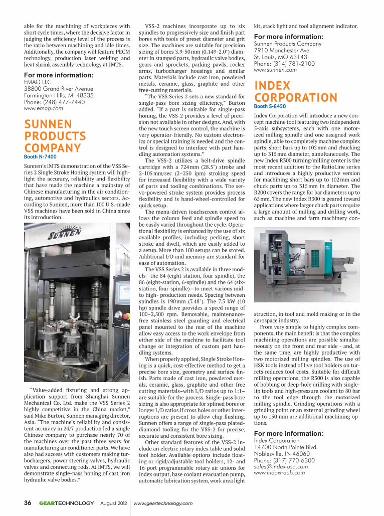
able for the machining of workpieces with short cycle times, where the decisive factor in judging the efficiency level of the process is the ratio between machining and idle times. Additionally, the company will feature PECM technology, production laser welding and heat shrink assembly technology at IMTS.
For more information:EMAG LLC38800 Grand River AvenueFarmington Hills, MI 48335Phone: (248) 477-7440www.emag.com
SUNNeN PrOdUCTS COMPANYBooth N-7400
Sunnen’s IMTS demonstration of the VSS Se-ries 2 Single Stroke Honing system will high-light the accuracy, reliability and flexibility that have made the machine a mainstay of Chinese manufacturing in the air condition-ing, automotive and hydraulics sectors. Ac-cording to Sunnen, more than 100 U.S.-made VSS machines have been sold in China since its introduction.
“Value-added fixturing and strong ap-plication support from Shanghai Sunnen Mechanical Co. Ltd. make the VSS Series 2 highly competitive in the China market,” said Mike Burton, Sunnen managing director, Asia. “The machine’s reliability and consis-tent accuracy in 24/7 production led a single Chinese company to purchase nearly 70 of the machines over the past three years for manufacturing air conditioner parts. We have also had success with customers making tur-bochargers, power steering valves, hydraulic valves and connecting rods. At IMTS, we will demonstrate single-pass honing of cast iron hydraulic valve bodies.”
VSS-2 machines incorporate up to six spindles to progressively size and finish part bores with tools of preset diameter and grit size. The machines are suitable for precision sizing of bores 3.9-50 mm (0.149-2.0") diam-eter in stamped parts, hydraulic valve bodies, gears and sprockets, parking pawls, rocker arms, turbocharger housings and similar parts. Materials include cast iron, powdered metals, ceramic, glass, graphite and other free-cutting materials.
“The VSS Series 2 sets a new standard for single-pass bore sizing efficiency,” Burton added. “If a part is suitable for single-pass honing, the VSS-2 provides a level of preci-sion not available in other designs. And, with the new touch screen control, the machine is very operator-friendly. No custom electron-ics or special training is needed and the con-trol is designed to interface with part han-dling automation systems.”
The VSS-2 utilizes a belt-drive spindle cartridge with a 724 mm (28.5") stroke and 2-105 mm/sec (2–250 ipm) stroking speed for increased flexibility with a wide variety of parts and tooling combinations. The ser-vo-powered stroke system provides process flexibility and is hand-wheel-controlled for quick setup.
The menu-driven touchscreen control al-lows the column feed and spindle speed to be easily varied throughout the cycle. Opera-tional flexibility is enhanced by the use of six available profiles, including pecking, short stroke and dwell, which are easily added to a setup. More than 100 setups can be stored. Additional I/O and memory are standard for ease of automation.
The VSS Series 2 is available in three mod-els—the 84 (eight-station, four-spindle), the 86 (eight-station, 6-spindle) and the 64 (six-station, four-spindle)—to meet various mid- to high- production needs. Spacing between spindles is 190 mm (7.48"). The 7.5 kW (10 hp) spindle drive provides a speed range of 100–2,500 rpm. Removable, maintenance-free stainless steel guarding and electrical panel mounted to the rear of the machine allow easy access to the work envelope from either side of the machine to facilitate tool change or integration of custom part han-dling systems.
When properly applied, Single Stroke Hon-ing is a quick, cost-effective method to get a precise bore size, geometry and surface fin-ish. Parts made of cast iron, powdered met-als, ceramic, glass, graphite and other free cutting materials–with L/D ratios up to 1:1–are suitable for the process. Single-pass bore sizing is also appropriate for splined bores or longer L/D ratios if cross holes or other inter-ruptions are present to allow chip flushing. Sunnen offers a range of single-pass plated-diamond tooling for the VSS-2 for precise, accurate and consistent bore sizing.
Other standard features of the VSS-2 in-clude an electric rotary index table and solid tool holder. Available options include float-ing or rigid/adjustable tool holders, 12- and 16-port programmable rotary air unions for index output, base coolant evacuation pump, automatic lubrication system, work area light
kit, stack light and tool alignment indicator.
For more information:Sunnen Products Company7910 Manchester Ave.St. Louis, MO 63143Phone: (314) 781-2100www.sunnen.com
iNdex COrPOrATiONBooth S-8450
Index Corporation will introduce a new con-cept machine tool featuring two independent 5-axis subsystems, each with one motor-ized milling spindle and one assigned work spindle, able to completely machine complex parts, short bars up to 102 mm and chucking up to 315 mm diameter, simultaneously. The new Index R300 turning/milling center is the most recent addition to the RatioLine series and introduces a highly productive version for machining short bars up to 102 mm and chuck parts up to 315 mm in diameter. The R200 covers the range for bar diameters up to 65 mm. The new Index R300 is geared toward applications where larger chuck parts require a large amount of milling and drilling work, such as machine and farm machinery con-
struction, in tool and mold making or in the aerospace industry.
From very simple to highly complex com-ponents, the main benefit is that the complex machining operations are possible simulta-neously on the front and rear side - and, at the same time, are highly productive with two motorized milling spindles. The use of HSK tools instead of live tool holders on tur-rets reduces tool costs. Suitable for difficult milling operations, the R300 is also capable of hobbing or deep-hole drilling with single-lip tools and high-pressure coolant to 80 bar to the tool edge through the motorized milling spindle. Grinding operations with a grinding point or an external grinding wheel up to 150 mm are additional machining op-tions.
For more information:Index Corporation14700 North Pointe Blvd.Noblesville, IN 46060Phone: (317) [email protected]
GEARTECHNOLOGY August 2012 www.geartechnology.com36
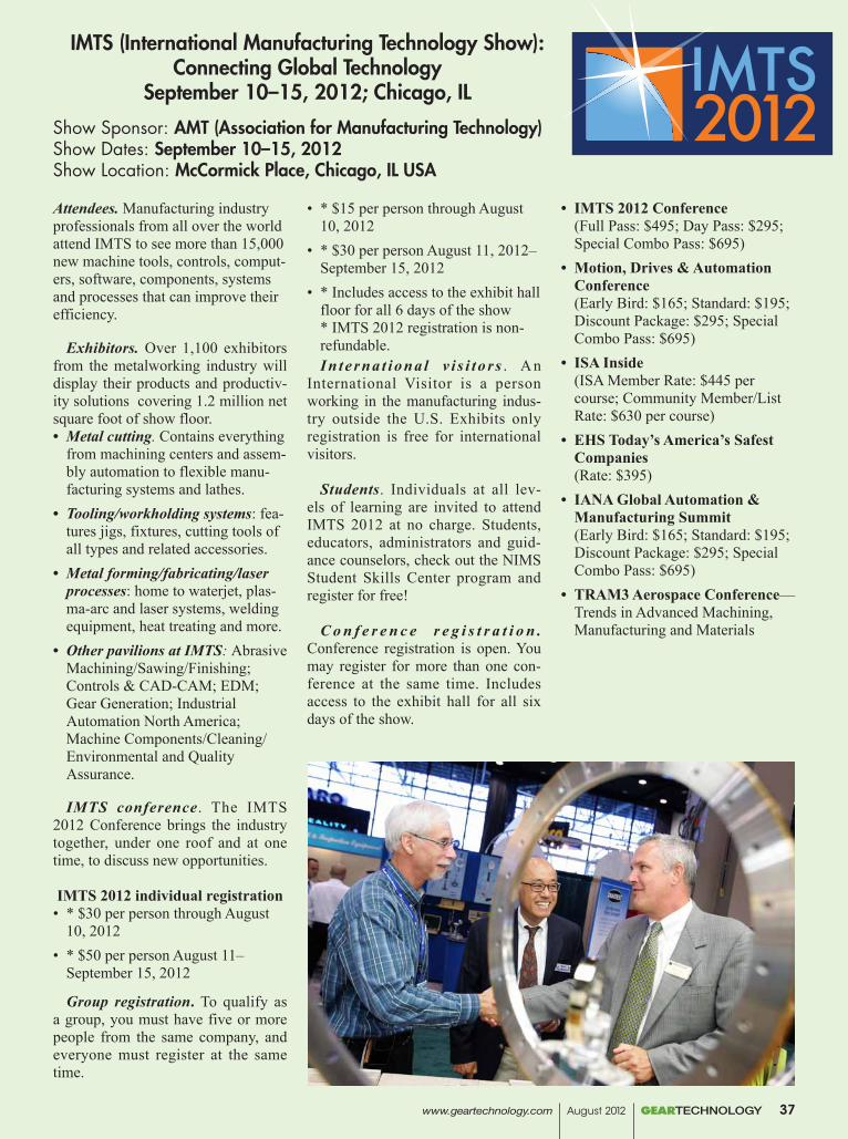
Attendees. Manufacturing industry professionals from all over the world attend IMTS to see more than 15,000 new machine tools, controls, comput-ers, software, components, systems and processes that can improve their efficiency.
Exhibitors. Over 1,100 exhibitors from the metalworking industry will display their products and productiv-ity solutions covering 1.2 million net square foot of show floor.• Metal cutting. Contains everything
from machining centers and assem-bly automation to flexible manu-facturing systems and lathes.
• Tooling/workholding systems: fea-tures jigs, fixtures, cutting tools of all types and related accessories.
• Metal forming/fabricating/laser processes: home to waterjet, plas-ma-arc and laser systems, welding equipment, heat treating and more.
• Other pavilions at IMTS: Abrasive Machining/Sawing/Finishing; Controls & CAD-CAM; EDM; Gear Generation; Industrial Automation North America; Machine Components/Cleaning/Environmental and Quality Assurance.
IMTS conference. The IMTS 2012 Conference brings the industry together, under one roof and at one time, to discuss new opportunities.
IMTS 2012 individual registration• * $30 per person through August
10, 2012• * $50 per person August 11–
September 15, 2012
Group registration. To qualify as a group, you must have five or more people from the same company, and everyone must register at the same time.
• * $15 per person through August 10, 2012
• * $30 per person August 11, 2012–September 15, 2012
• * Includes access to the exhibit hall floor for all 6 days of the show * IMTS 2012 registration is non-refundable.In t e rna t iona l v i s i t o r s . An
International Visitor is a person working in the manufacturing indus-try outside the U.S. Exhibits only registration is free for international visitors.
Students. Individuals at all lev-els of learning are invited to attend IMTS 2012 at no charge. Students, educators, administrators and guid-ance counselors, check out the NIMS Student Skills Center program and register for free!
C o n f e r e n c e r e g i s t r a t i o n . Conference registration is open. You may register for more than one con-ference at the same time. Includes access to the exhibit hall for all six days of the show.
• IMTS 2012 Conference (Full Pass: $495; Day Pass: $295; Special Combo Pass: $695)
• Motion, Drives & Automation Conference (Early Bird: $165; Standard: $195; Discount Package: $295; Special Combo Pass: $695)
• ISA Inside (ISA Member Rate: $445 per course; Community Member/List Rate: $630 per course)
• EHS Today’s America’s Safest Companies (Rate: $395)
• IANA Global Automation & Manufacturing Summit (Early Bird: $165; Standard: $195; Discount Package: $295; Special Combo Pass: $695)
• TRAM3 Aerospace Conference—Trends in Advanced Machining, Manufacturing and Materials
IMTS (International Manufacturing Technology Show):Connecting Global Technology
September 10–15, 2012; Chicago, IL
Show Sponsor: AMT (Association for Manufacturing Technology)Show Dates: September 10–15, 2012 Show Location: McCormick Place, Chicago, IL USA
www.geartechnology.com August 2012 GEARTECHNOLOGY 37

GEARTECHNOLOGY August 2012 www.geartechnology.com38
Drake Manufacturing Services Co.Tel: [email protected]
Koepfer America LLCTel: [email protected]
Drake Gear MachinesRepresented in North America by:
Precision Machines for Threads & Gears
See us in Booth N-6918
Represented in North America by:Represented in North America by:
See Drake’s newest External Thread Grinder at IMTS.
Drake Gear Machines
Our GS:TE-LM External Thread & Worm Grinder is the perfect machine for grinding high quality worms for steering, machine tool and other power transfer applications.
• High accuracy index worms • Rack piston worms • Automated production of DIN 2 worms in medium volume production cells
All Drake machines can be equipped with the latest automation packages.
DRAK-462ShowStopAd4_75x4_75GT.indd 1 7/13/12 3:46 PM
Our Technologies, Your Tommorow
Close the Black Hole of Downtime
“What a fantastic bit of kit the GE20A hobber is having run trouble free and
500,000 parts since installation.”— Ken Manners CEO,
SP Metal Forging, South Africa
Downtime is a black hole that impairs productivity, kills the bottom line and simply shouldn’t happen due to breakdowns. With a philosophy of continuous process improvement, in conjunction with an active reliability and maintainability program, Mitsubishi’s gear machine products deliver best in the business quality and predictable production. Experience perfect production systems by visiting www.mitsubishigearcenter.com or contact sales 248-669-6136.
IMTS BOOTH #N-7046
®
August 2012
www.geartechnology.com
THE GEAR INDUSTRY’S INFORMATION SOURCE
The Journal of Gear Manufacturing
Technical Articles
•AsktheE
xpert:Profil
eShift
• 10Yearso
fP/MR&D:
Findings
• SurfaceD
urability/Im
proved
SurfaceFinis
hAddendum
•HowGearsa
ndMind
ControlMesh
IMTS 2012SHOW PREVIEW
BOOTH LISTINGS
BOOTH PREVIEWS
IMTS BOOTH #N-7148
Stop byGEAR TECHNOLOGY
to WiNan iPAd®
Just stop by booth #N-7148, and enter for a chance to win an Apple iPAD®.
Copyright ©2012 Apple Inc. All rights reserved.
www.geartechnology.com August 2012 GEARTECHNOLOGY 39
SHOW STOPPERS
www.zoller-usa.com
Best In Class!Achieve record times in your production by full cost control, transparency
and maximum efficiency in production processes.
The compatible software packages of the ZOLLER TMS Tool Management
Solutions guarantee a smooth operation of your production processes.
Booth W-2022
With over 85 years of technological leadership in bore sizing and finishing, Sunnen Products Company has the solution you need for the precision honing of gears.Sunnen can provide a system for virtually any gear honing application—helical, pinion, worm, sprocket or spur—and in virtually any material from powdered metal to hardened steel.
Sunnen offers three different types of honing technologies, including conventional, single-pass or KROSSGRINDING®.Sunnen also offers the industry’s largest choice of honing machines… horizontal or vertical, single-spindle or multi-spindle, automated or manually operated. No matter what you require for precision honing of gears, Sunnen has the answer.Visit us at the IMTS Show Booth N-7400 to have your questions answered.
www.Sunnen.com
Visit us at Booth #N-7400IMTS BOOTH #N-7115
GEARTECHNOLOGY August 2012 www.geartechnology.com40
bevel breakthrough
See the gleason-heller Ct8000, with 4-8 timesfaster complete bevel gear machining capabilities.
booth #N-7000
Nachi America Inc.715 Pushville Road
Greenwood, Indiana 46143317-530-1001
www.NACHI.com
Broaching
Hobbing
Shaping
Roll Forming
Shaving
Discover What secovations can Do For You.
visit us in booth W-1564 to learn more.Scan this QR code to visit our IMTS showroom.
SECO
TOOL
S.CO
M/U
S
Visit us at Booth N-6668
Stop by Booth #N-6668 to discuss solutions to your gear grinding and lubrication challenges
www.geartechnology.com August 2012 GEARTECHNOLOGY 41
SHOW STOPPERS
h i g h t e c h i s o u r b u s i n e s s .
HigHlyPrecisegear Product ion
Further information atwww.roeders.de
Visit us at Booth #S-8017
®
August 2012
www.geartechnology.com
THE GEAR INDUSTRY’S INFORMATION SOURCE
The Journal of Gear Manufacturing
Technical Articles
•AsktheExpert:P
rofileShift
• 10YearsofP/MR&D:Find
ings
• SurfaceDurability
/Improved
SurfaceFinish
Addendum•HowGearsand
Mind
ControlMesh
IMTS 2012SHOW PREVIEW
BOOTH LISTINGS
BOOTH PREVIEWS
IMTS BOOTH #N-7148
Stop byGEAR TECHNOLOGYand meet the editors.• Nearly 80 years of
combined gear industry experience
• Learn more about contributing to GEAR TECHNOLOGY, POWER TRANSMISSION ENGINEERING or GEAR TECHNOLOGY INDIA.
• Find out how YOU could be featured in a future issue!
BOOTH # N-7148
GEARTECHNOLOGY August 2012 www.geartechnology.com42
More Than Machines,SOLUTIONSWhether your production requirements are 1000 or 1 million, BMS has a solution to meet your requirements and your budget.Including:• NEW AND REMANUFACTURED TURNKEY
BROACHING SYSTEMS• USED BROACHING MACHINES• PRODUCTION BROACHING SERVICES• PARTS AND SERVICE FOR ALL
BROACHING MACHINES• BROACH CUTTING TOOLS• TOOL SHARPENING AND
RECONDITIONING SERVICES
•BMS Electro-Mate
•Electric Drive Internal Table Up Broaching Machine
Visit us at Booth #N-7229
GEAR CUTTING TOOLSA.L. Tooling ccAcedes Gear Tools/Tools for Industry
American Gear Tools
Ash Gear & Supply
Barit International Corporation
Capital Tool Industries7-A, INDUSTRIAL ESTATE
PATIALA, PUNJAB 147008
INDIAP: +(91-175-2351089),
F: +(91-175-2217102)
www.capital-tool.com
Cole Manufacturing Systems Inc.
Dathan Tool & Gauge Co. Ltd.
DTR Corp. SEE OUR AD
P8Formerly Dragon Precision Tools
2400 E. DEVON AVE., SUITE 210
DES PLAINES, IL 60018
P: 847-375-8892
F: 847-699-1022
www.dragon.co.kr
ESGI Tools Pvt. Ltd. SEE OUR AD
P67B-6, FOCAL POINT
PATIALA, PUNJAB 147004
INDIAP: +(91-175-2233991,
F: +(91-175-2233990
www.esgitools.com
Galaxy Sourcing Inc.
Gleason Corporation SEE OUR AD
P201000 UNIVERSITY AVENUE
P.O. BOX 22970
ROCHESTER, NY 14692-2970
P: 585-473-1000
F: 585-461-4348
www.gleason.com
Grace Industrial International
Great Lakes Gear Technologies, Inc.
Greg Allen Company
Hanro Tools Incorporation
HobSource Inc.
Ingersoll Cutting Tools
Interstate Tool Corp.
Klingelnberg GmbHPETERSTRASSE 45
D-42499 HÜCKESWAGEN
GERMANY
P: 734-429-7225
www.klingelnberg.com
Liebherr Gear Technology, Inc.
1465 WOODLAND DR.
SALINE, MI 48176 SEE OUR AD
P36
P: 734-429-7225
www.liebherr.com
LMT-FetteLuren Precision Chicago Co., Ltd.
Luren Precision Co., Ltd.
Maxwell Tools Co. USA
Maxwell Tools Company
Mitsubishi Gear Technology Center
46992 LIBERTY DRIVE
WIXOM, MI 48393 SEE OUR AD
P32
P: 248-669-6136
F: 248-669-0614
www.mitsubishigearcenter.com
Modern Gearing
Mutschler Edge Technologies
Nachi America Inc.
P.S.ToolsParker Industries Inc.
Russell Holbrook & Henderson
S.S.ToolsSaazor
Samputensili S.p.A. SEE OUR AD
P915200 PRAIRIE STONE PARKWAY
HOFFMAN ESTATES, IL 60192
P: 847-649-1450
F: 847-649-0112
www.samputensili.com
Sandvik Coromant SEE OUR AD
P211702 NEVINS ROAD
FAIR LAWN, NJ 07410
P: 201-794-5000
F: 201-794-5257
www.sandvik.coromant.com/us
Schnyder SA
Sigma Pool SEE OUR AD
P41465 WOODLAND DR.
SALINE, MI 48176
P: 734-429-7225
www.sigma-pool.com
Star Cutter Co.23461 INDUSTRIAL PARK DRIVE
FARMINGTON HILLS, MI 48335
P: 847-649-1450
F: 847-649-0112
www.star-su.com
Star-SU SEE OUR AD
P885200 PRAIRIE STONE PARKWAY
HOFFMAN ESTATES, IL 60192
P: 847-649-1450
F: 847-649-0112
www.star-su.com
Steelmans Broaches Pte. Ltd.
Steelmans Gear Cutters
SU America SEE OUR AD
P55200 PRAIRIE STONE PARKWAY
HOFFMAN ESTATES, IL 60192
P: 847-649-1450
F: 847-649-0112
www.star-su.com
See our ad on Page ##
Super Hobs & Broaches Pvt. Ltd.
Super Tools Corporation
Surindra Tools Industries
Tool Masters India
TSA America LLC
United Tool Company
Wolverine Broach Co., Inc.
Yash International
36 GEAR TECHNOLOGY | NOVEMBER/DECEMBER 2012
[www.geartechnology.com]
GT BUYERS GUIDE
SPLASH AD ($295)
Includes logo,
contact info and
QR Code
BOLD LISTING ($95)
Includes contact info
FREE LISTING
IMTS BOOTH #N-7148
GeT LiSTedin the
GeAr TeCHNOLOGY
annualBUYerS GUideGreat for suppliers of machine tools, cutting
tools, workholding and services for gear
manufacturers
BOOTH #N-7148

www.geartechnology.com August 2012 GEARTECHNOLOGY 43
SHOW STOPPERSfaSter iNSpeCtioN
See the gleason 350gMS, with 20-45% faster complete gear inspection capabilities.
booth #N-7000
February 2012
w w w . p o w e r t r a n s mi s s i o n . c o
m
®
44
powertransmissionengine
ering
• Seizing Control of Your Motion System
• Open Gear Lubrication
• Small-Footprint Hydrostatic Drives
Features
• NASA’s Third Rock RadioPower Play
Green DesignSourcing and Manufacturing
• Energy and the
Environment: A
Delicate Balance
• Energy-Saving
Drive Systems
IMTS BOOTH #N-7148
Subscribe to
POWerTrANSMiSSiONeNGiNeeriNG
THE magazine for design engineers,
buyers and specifiers of power transmission
components.
Learn more about motors, bearings, couplings, clutches and brakes
BOOTH #N-7148
IMTS BOOTH #N-7148
dO YOU MAKe ANd SeLL GeArS?Sign up to be included in thePOWer TrANSMiSSiON
eNGiNeeriNGAnnual Buyers Guide
BOOTH # N-7148it's fast, easy and free

BRIGHT IDEAS, BRILLIANTSOLUTIONSAT IMTS ’12
✓Bevel Gear Solutions, Up to 2,500 mm
✓Cylindrical Gear Solutions, Up to 10,000 mm
✓Cutting Tools and Workholding Solutions, All Processes
✓Metrology Solutions, All Types of Gears, Gear Tools
✓Global Services, 250 Factory-Trained Personnel in 30 Countries Worldwide
For worldwide sales locations and additional information, visit: www.gleason.com • [email protected]
See us at Booth #N-7000
We’re powering up a host of new gear
processing solutions at IMTS:
3 Genesis® 400H Vertical Gear
Hobbing Machine.
3 Gleason-Heller CT8000 5-Axis
Bevel Gear Machining Center.
3 350GMS Analytical Gear
Inspection System.
3 All types of gear cutting tools
and workholding solutions.
Your gear production future has never
looked brighter. Start with a visit to
www.gleason.com/IMTS.
SOLUTIONS FOR CYLINDRICAL AND BEVEL GEARS OF ALL TYPES AND SIZES, EVERY PROCESS
Got a Gear Question?Ask the Expert!
A S K T H E E X P E R T
Dear David,
AGMA 913–A98—Method for Specifying the Geometry of Spur and Helical Gears—gives all the equations you need for calculating profile shift.
The reference pressure angle measured on the generating pitch diameter (the same as the standard pitch diameter or reference pitch diameter) is determined by the cutter pressure angle and is usually 20° for most gears. It is independent of profile shift. The operating pressure angle is determined by the operating center distance of the mating gears and is again independent of the profile shift.
You can think of profile shift as simply shifting the teeth outward or inward so that the active profile of the teeth uses a different sector of the same involute curve.
Profile shift does not require special cutters if straight-sided hobs are used (the usual case). The hob is simply shifted outward or inward to shift the profiles, and the outer diameters of the gears are changed to accommodate the pro-file shifts. Therefore, the advantages of profile shifting are achieved with no cost consequences. Only form cutting such as milling requires a different cutter for profile shifted gears. That’s because form-cutting or form-grinding require a cutter or grinding wheel with a profile that matches the shape of the tooth space. Since profile shifting changes the shape of the tooth space, the shape of the form cutter must change.
One of the most important parameters in any gear design is the number of teeth in the pinion, and profile shift has its greatest relevance when the pinion has a small number of teeth. In fact, the first use of profile shift was to avoid under-cut in pinions with less than 17 teeth. It was later realized that profile shift improves most aspects of gear operation, and today it is used for many reasons including:• Avoiding undercut• Avoiding narrow top-lands to avoid case/core separation in
carburized gears• Balancing specific sliding to maximize wear resistance and
Hertzian fatigue resistance• Balancing flash temperature to maximize scuffing resis-
tance• Balancing bending fatigue life to maximize bending
fatigue resistance
Gears with few teeth are more sensitive to profile shift, and their tooth shape changes more dramatically, whereas profile shift changes tooth shape only slightly for gears with a lot of teeth. In fact, the teeth of a rack (with theoretically infinite number of teeth) do not change shape as the teeth are profile shifted. These effects can be seen in Figure 4 of AGMA 918–A98. It’s best to design gear sets with pinions with at least 20 teeth—and preferably 25—in which case the
Welcome back to Gear Technology’s Ask the Expert—a regular feature intended to help designers, specifiers, quality assurance and inspection personnel in addressing some of the more complex, trouble-some gearing challenges that never cease to materialize—whether on the drafting table or the shop floor. Simply e-mail your question—along with your name, job title and company name (if you wish to remain anonymous, no problem)—to: [email protected]; or, you can submit your question by visiting geartechnology.com.
Profile ShiftRegarding profile shift: What kind of data must be considered when we grind a gear
with shift profile?A few days ago we received a series of gears that need to be corrected (profile shift).
Our engineering department had a question about this topic; they tell me that they do not know how to calculate the gears with profile shift and that they have big doubts over whether—with each profile shift factor—the pressure angle also changes.
A friend in Texas told me that you cannot make a profile shift gear with a cutter in a traditional way. For each correction factor, you require a cutter according to the modification. Is this is correct?
ing. david ruiz, production managerGrupo Meusnier S.A. de C.V.
QUESTION #1
GEARTECHNOLOGY August 2012 www.geartechnology.com46
www.stresstechgroup.com
For residual stress testing by X-ray diffractionXstress Robot • reaches hard-to-reach areas• handles complicated and large parts easily • provides maximum flexibility and easy positioning • is fast and precise
Gear Up Your Quality ControlRobot systems for quality control of surface treatment such as grinding and shot peening by Barkhausen Noise and X-ray stress measurements.
RoboScan system• automated inspection• all surfaces with one set-up• safe, fast and easy measuring, also on large and complicated parts • instant feedback• quantitative results for production control• environmentally friendly
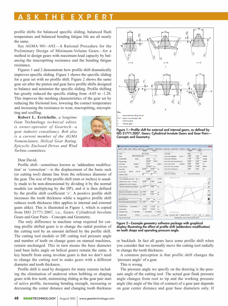
profile shifts for balanced specific sliding, balanced flash temperature and balanced bending fatigue life are all nearly the same.
See AGMA 901–A92—A Rational Procedure for the Preliminary Design of Minimum-Volume Gears—for a method to design gears with maximum-load capacity by bal-ancing the macropitting resistance and the bending fatigue resistance.
Figures 1 and 2 demonstrate how profile shift dramatically improves specific sliding. Figure 1 shows the specific sliding for a gear set with no profile shift. Figure 2 shows the same gear set after the pinion and gear have profile shifts designed to balance and minimize the specific sliding. Profile shifting has greatly reduced the specific sliding from -4.03 to -1.28. This improves the meshing characteristics of the gear set by reducing the frictional loss, lowering the contact temperature and increasing the resistance to wear, macropitting, micropit-ting and scuffing.
Robert L. Errichello, a longtime Gear Technology technical editor, is owner-operator of Geartech—a gear industry consultancy. Bob also is a current member of the AGMA Nomenclature, Helical Gear Rating, Epicyclic Enclosed Drives and Wind Turbine committees.
Dear David,Profile shift—sometimes known as ‘addendum modifica-
tion’ or ‘correction’—is the displacement of the basic rack (or cutting tool) datum line from the reference diameter of the gear. The size of the profile shift (mm or inches) is usual-ly made to be non-dimensional by dividing it by the normal module (or multiplying by the DP), and it is then defined by the profile shift coefficient ‘x’. A positive profile shift increases the tooth thickness while a negative profile shift reduces tooth thickness (this applies to internal and external gears alike). This is illustrated in Figure 1, which is copied from ISO 21771:2007, i.e., Gears: Cylindrical Involute Gears and Gear Pairs—Concepts and Geometry.
The only difference in machine setup required for cut-ting profile shifted gears is to change the radial position of the cutting tool by an amount defined by the profile shift. The cutting tool module or DP, cutting tool pressure angle and number of teeth on change gears on manual machines, remain unchanged. This in turn means the base diameter (and base helix angle on helical gears) remain the same. A key benefit from using involute gears is that we don’t need to change the cutting tool to make gears with a different diameter and tooth thickness.
Profile shift is used by designers for many reasons includ-ing the elimination of undercut when hobbing or shaping gears with few teeth, minimizing sliding at the gear pair start of active profile, increasing bending strength, increasing or decreasing the center distance and changing tooth thickness
or backlash. In fact all gears have some profile shift when you consider that we normally move the cutting tool radially to change the tooth thickness.
A common perception is that profile shift changes the ‘pressure angle’ of a gear.
This is wrong.The pressure angle we specify on the drawing is the pres-
sure angle of the cutting tool. The actual gear flank pressure angle changes from root to tip and the working pressure angle (the angle of the line of contact) of a gear pair depends on gear center distance and gear base diameters only. If
A S K T H E E X P E R T
Figure 2—Example geometry software package with graphical display illustrating the effect of profile shift (addendum modification) on tooth shape and operating pressure angle.
Figure 1—Profile shift for external and internal gears, as defined by ISO 21771:2007. Gears: Cylindrical Involute Gears and Gear Pairs—Concepts and Geometry.
GEARTECHNOLOGY August 2012 www.geartechnology.com48
the sum of the pinion and wheel profile shift is zero, the gears operate at the reference center distance. If this sum is negative the gears have smaller center distance and thus they have a smaller operating pressure angle, while a posi-tive sum requires a larger center distance increased operating pressure angle.
For further information on this subject I recommend a document published by British Standard PD 6457—Addendum Modification to Involute Spur and Helical Gears, and also ISO 21771:2007, published by ISO. These refer-ences contain the calculations and recommendations for minimum profile shift to avoid undercutting and maximum profile shift that can be applied before the tooth crest thick-ness become too thin. Most commercial software packages provide options for specifying profile shift; the effects can be demonstrated graphically and improvements in gear perfor-mance can be quantified, as seen in Figure 2.
Dr. Robert Frazer , a Gear Technology technical paper contrib-utor, heads the U.K. National Gear Metrology Laboratory and as such is responsible for gear design and anal-ysis within The Design Unit at the University of Newcastle-Upon-Tyne. Rob is also actively involved with delivering the British Gear Association (BGA) training semi-nar program and is an active member of the AGMA Gear Accuracy and Calibration committees.
Dear David,Profile shift, also known as x factor, is just a method for
specifying tooth thickness. If the gear drawing has a “mea-surement over pins” or “span over a given number of teeth” or other tooth thickness specification that you are familiar with, you can just grind the gear to meet the specified tooth thickness and safely ignore the profile shift.
Many of those familiar with profile shift find it very easy to use during the design of a gear pair. However, the result-ing gear is not fundamentally different from one designed by other methods. Cutters do not need to be modified to create gears with different amounts of profile shift.
The concept of profile shift is quite simple: as a gear cutter is shifted radially towards the center of an external gear, the tooth profile will of course also be shifted towards the gear center. At a given diameter, such a shift of the tooth profile results in the teeth appearing thinner. Since the actual pres-sure angle varies with diameter, a shift in the profile changes the pressure angle at a given diameter. But this change in pressure angle does not mean there was a change in tooling; it is the natural result of sinking a given tool deeper into the part.
The symbol for profile shift is x, and it is a coefficient; i.e., it is normalized so it is non-dimensional. The sign conven-tion for profile shift is that a positive profile shift results in thicker teeth. So shifting a cutter towards the center of an
A S K T H E E X P E R T
www.geartechnology.com August 2012 GEARTECHNOLOGY 49
external gear is a negative profile shift, since it makes the teeth thinner.
The profile shift usually used by gear designers is for a zero backlash gearset. To provide some backlash, some designers increase center distance while others reduce the profile shift. When you subtract an additional small shift as a backlash allowance from the non-dimensional zero backlash profile shift, and multiply by module to get millimeters, the result is called the “rack shift.”
In Europe, some gear designers specify only the zero backlash profile shift and the manufacturer will thin the teeth according to tables in the DIN standards. If you receive such a drawing that does not specify an actual measurement of the finished gear teeth, then you should discuss with your cus-tomer what is actually expected.
For more information, see AGMA 913–A98. This informa-tion sheet was written to introduce profile shift to engineers in the United States. There are also many computer pro-grams, such as AGMA’s Gear Rating Suite, that will allow you to easily convert from profile shift to other forms of tooth thickness specification.
John M. Rinaldo, senior develop-ment engineer at New York-located Atlas Copco Comptec LLC, is also a current member of the AGMA Computer Programming (vice-chair), Nomenclature, Gear Accuracy (vice-chair) and Helical Enclosed Drives High-Speed Units committees.
A S K T H E E X P E R T
GEAR CUTT ING SOLUT IONS
Send it to Jack McGuinn, senior editor, at [email protected], or visit www.geartechnology.com to post your question via our online form.
Do you have aGEAR-RELATED
QUESTION?
GEARTECHNOLOGY August 2012 www.geartechnology.com50
Winterthur Technologies is now part of 3MWinterthur Technologies Group is a worldwide leading supplier of precision abrasives for the Gear Industry. Its brands are used worldwide in the Gear, Cutting Tools, Oil and Gas, Automotive, Aerospace, and Precision Grinding Industries.
Together, 3M and Winterthur offer you today’s most innovative portfolio of advanced abrasive technologies—to help you achieve the next level of manufacturing precision and productivity.
www.winterthurtechnology.com3M.com/abrasives
See us at IMTS 2012Booth N-7063
3M is
a tr
adem
ark
of 3
M. ©
201
2, 3
M. A
ll Ri
ghts
Res
erve
d.
3
systemsabrasives and dressing
Precision
gear grindingfor
Now part of 3M
Powder Metal Magicdesign innovations in PM Applications
Matthew Jaster, Associate editor
Capstan Atlantic, located in Wrentham, Massachusetts, produces powder metal gears, sprockets and complex struc-tural components. The company has provided unique powder metal products in a variety of industries including automo-tive, business machines, appliances, lawn and garden equip-ment and recreational vehicles. The recent resurgence of the automotive industry has played a large role in increasing opportunities in powder metal, particularly in areas like sus-pension, powertrain, steering column and electronic power steering (EPS). Richard Slattery, vice president of engineer-ing at Capstan Atlantic, recently discussed some of the latest powder metal gear designs that are more cost effective com-pared to their cut steel alternatives.
GEARTECHNOLOGY August 2012 www.geartechnology.com52
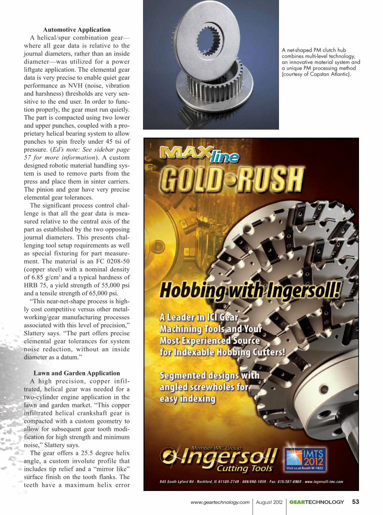
Automotive ApplicationA helical/spur combination gear—
where all gear data is relative to the journal diameters, rather than an inside diameter—was utilized for a power liftgate application. The elemental gear data is very precise to enable quiet gear performance as NVH (noise, vibration and harshness) thresholds are very sen-sitive to the end user. In order to func-tion properly, the gear must run quietly. The part is compacted using two lower and upper punches, coupled with a pro-prietary helical bearing system to allow punches to spin freely under 45 tsi of pressure. (Ed’s note: See sidebar page 57 for more information). A custom designed robotic material handling sys-tem is used to remove parts from the press and place them in sinter carriers. The pinion and gear have very precise elemental gear tolerances.
The significant process control chal-lenge is that all the gear data is mea-sured relative to the central axis of the part as established by the two opposing journal diameters. This presents chal-lenging tool setup requirements as well as special fixturing for part measure-ment. The material is an FC 0208-50 (copper steel) with a nominal density of 6.85 g/cm3 and a typical hardness of HRB 75, a yield strength of 55,000 psi and a tensile strength of 65,000 psi.
“This near-net-shape process is high-ly cost competitive versus other metal-working/gear manufacturing processes associated with this level of precision,” Slattery says. “The part offers precise elemental gear tolerances for system noise reduction, without an inside diameter as a datum.”
Lawn and Garden ApplicationA high precision, copper infil-
trated, helical gear was needed for a two-cylinder engine application in the lawn and garden market. “This copper infiltrated helical crankshaft gear is compacted with a custom geometry to allow for subsequent gear tooth modi-fication for high strength and minimum noise,” Slattery says.
The gear offers a 25.5 degree helix angle, a custom involute profile that includes tip relief and a “mirror like” surface finish on the tooth flanks. The teeth have a maximum helix error
A net-shaped PM clutch hub combines multi-level technology, an innovative material system and a unique PM processing method (courtesy of Capstan Atlantic).
www.geartechnology.com August 2012 GEARTECHNOLOGY 53
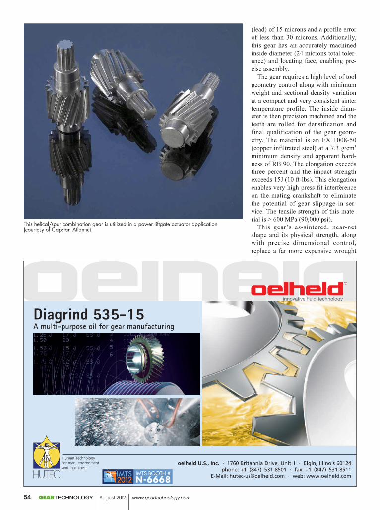
(lead) of 15 microns and a profile error of less than 30 microns. Additionally, this gear has an accurately machined inside diameter (24 microns total toler-ance) and locating face, enabling pre-cise assembly.
The gear requires a high level of tool geometry control along with minimum weight and sectional density variation at a compact and very consistent sinter temperature profile. The inside diam-eter is then precision machined and the teeth are rolled for densification and final qualification of the gear geom-etry. The material is an FX 1008-50 (copper infiltrated steel) at a 7.3 g/cm3 minimum density and apparent hard-ness of RB 90. The elongation exceeds three percent and the impact strength exceeds 15J (10 ft-lbs). This elongation enables very high press fit interference on the mating crankshaft to eliminate the potential of gear slippage in ser-vice. The tensile strength of this mate-rial is > 600 MPa (90,000 psi).
This gear’s as-sintered, near-net shape and its physical strength, along with precise dimensional control, replace a far more expensive wrought
IMTS BOOTH #N-6668
This helical/spur combination gear is utilized in a power liftgate actuator application (courtesy of Capstan Atlantic).
GEARTECHNOLOGY August 2012 www.geartechnology.com54
steel alternative, offering a 35 percent cost reduction. “This gear has success-fully passed all levels of endurance testing in this two-cylinder industrial engine application,” Slattery says. “It’s economically attractive, highly precise and costs almost fifty percent less than the cut steel alternative.”
Industrial Application A net-shaped PM clutch hub replac-
es a machined alternative that is more expensive. It combines multi-level technology, an innovative material system and a unique PM processing method. The part is compacted using four lower and a stepped single upper punch, coupled with an enhanced pow-der feed system to facilitate equalized local densities. Additional proprietary tool material and treatment systems are used to enable long, thin punches to withstand extreme tonnage. This is a complex, multi-level, higher dense component, capable of withstanding very high torque loads in service. The part is provided net shape, in the as-sintered/shot peened condition, replac-ing a previously machined version.
“The functionality of this hub requires very close relationships between the five diameters,” Slattery says. “The tooth run-out to the internal spline is less than 100 microns (0.1 mm).”
The process control of the part is the consistent dimensional change for all levels through the sintering operation. This control is maintained by achiev-ing sectional density variation within 0.05 g/cm3 at the compaction step in the process. The material is a hybrid Fe/Mo/Cu/C alloy with very good yield strength and as-sintered tensile properties. The flange of this compo-nent is subjected to repetitive bending fatigue in service. Therefore, the abil-ity to achieve the required strength, as well as the bending fatigue resistance, is the key to the field success of this component. “Simply put, this PM part offers precision, economic value and strength,” Slattery adds.
Appliance ApplicationA complex, off-center-loaded PM
rack has multiple lower levels, one of which is formed on the core rod
platen and a dual upper punch system. Special robotic automation is required to remove the part from the lower tool-ing, flip it 180 degrees and place it on a special conveying system. “This is a seven level part requiring six punches. The rack system incorporates a pro-gressive variable tooth space to com-pensate for system tooth engagement variation in service. The U slot den-sity is controlled through off standard power distribution by the dual upper punches,” Slattery says.
He continues, “This rack’s as-sin-tered, near-net shape and its physical strength along with precise dimension-al control, replace a far more expensive die cast alternative (a 38 percent cost reduction).”
The engineering properties include a highly controlled rack tooth pro-file and spacing characteristics. Perpendicularity of U slot to oppos-ing locating surface is critical along with the flatness of the locating sur-face. This part requires a high level
www.geartechnology.com August 2012 GEARTECHNOLOGY 55
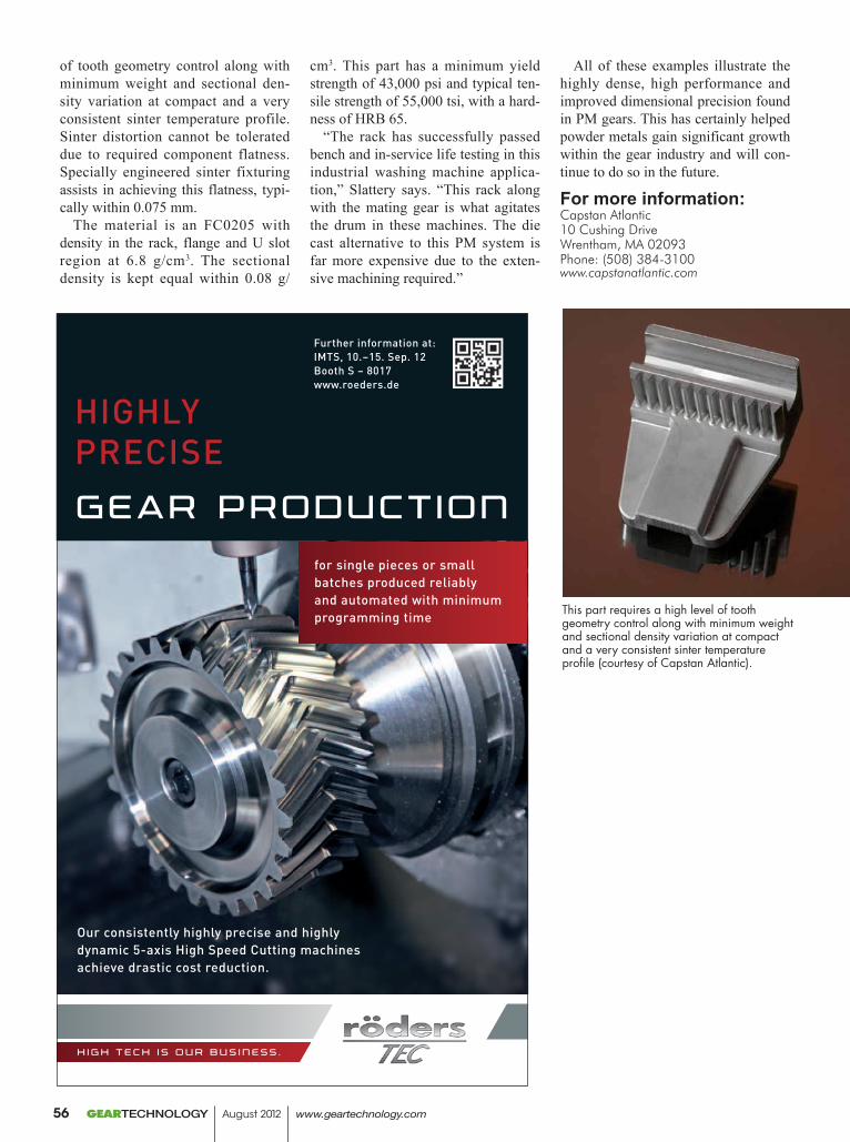
of tooth geometry control along with minimum weight and sectional den-sity variation at compact and a very consistent sinter temperature profile. Sinter distortion cannot be tolerated due to required component flatness. Specially engineered sinter fixturing assists in achieving this flatness, typi-cally within 0.075 mm.
The material is an FC0205 with density in the rack, flange and U slot region at 6.8 g/cm3. The sectional density is kept equal within 0.08 g/
cm3. This part has a minimum yield strength of 43,000 psi and typical ten-sile strength of 55,000 tsi, with a hard-ness of HRB 65.
“The rack has successfully passed bench and in-service life testing in this industrial washing machine applica-tion,” Slattery says. “This rack along with the mating gear is what agitates the drum in these machines. The die cast alternative to this PM system is far more expensive due to the exten-sive machining required.”
All of these examples illustrate the highly dense, high performance and improved dimensional precision found in PM gears. This has certainly helped powder metals gain significant growth within the gear industry and will con-tinue to do so in the future.
For more information:Capstan Atlantic10 Cushing DriveWrentham, MA 02093Phone: (508) 384-3100www.capstanatlantic.com
for single pieces or small batches produced reliably and automated with minimum programming time
HigHlyPreciseGear Product ion
Further information at:iMTs, 10.–15. sep. 12Booth s – 8017www.roeders.de
Our consistently highly precise and highly dynamic 5-axis High speed cutting machines achieve drastic cost reduction.
h i G h t e c h i s o u r b u s i n e s s .
This part requires a high level of tooth geometry control along with minimum weight and sectional density variation at compact and a very consistent sinter temperature profile (courtesy of Capstan Atlantic).
GEARTECHNOLOGY August 2012 www.geartechnology.com56
New PM Designs Highlight PowderMet2012
The 2012 Powder Metallurgy Design Excellence Awards (pre-sented during the 2012 International Conference on Powder Metallurgy & Particulate Materials in Nashville) exemplify PM’s special engineering benefits including net shape, preci-sion, innovative fabrication methods, production efficiency, energy and materials savings, and manufactur-ing cost reduction. These advantages continue to stir designers to choose PM for critical applications in auto engines and transmissions, electron-ics, medical devices, agricultural equipment, consumer products, mili-tary equipment and emergency appli-cations.
GKN Sinter Metals (located in Auburn Hills, Michigan) won the grand prize in the automotive engine category for a VVT rotor adapter assembly consisting of a PM steel rotor and adapter. The parts are joined by an adhesive, which joins them dur-ing machining cross holes and other features on the inside diameter, and seals the joint between them. GKN also won the grand prize in the auto-motive transmission category for a unitized one-way clutch (OWC) mod-ule made for the Chrysler Group. The module has four PM steel parts (powder-forged race and cam, and two pressed and sintered retainer plates) as well as 22 additional parts (clips, springs and roller elements).
Capstan Atlantic ( located in Wrentham, Massachusetts) was awarded the grand prize in the auto-motive chassis category for a complex PM steel two-stage helical gear and spur pinion used in a power lift gate actuator. The precise elemental gear data tolerances enable quiet gear per-formance and decreasing noise, vibra-tion and harshness.
FMS Corporation (located in Minneapolis, Minnesota) won the grand prize in the lawn and garden/off-highway category for a PM steel race gear used in the OnTrac2 GPS-assisted steering system made for Novariant Corporation in California. The system positions agricultural
planting and harvesting equipment to more accurately perform till-age, spraying and spreading as well as reducing skips and overlaps, thus reducing fuel consumption.
In the hardware/appliances cat-egory, ASCO Sintering (located in Commerce, California) won the grand prize for a copper-infiltrated PM steel inside deadbolt chassis for a commercial electronic lock system. Maintaining the density between the
hub and flange is especially critical in this application. The part has two PM posts manufactured and installed while maintaining true position and squareness.
FloMet LLC (located in Deland, Florida) won the grand prize in the aerospace/military category for a very complex 17-4 PH stainless steel rotor made by metal injection molding (MIM) and used in a hand-emplaced munitions device. The intricate design
www.geartechnology.com August 2012 GEARTECHNOLOGY 57
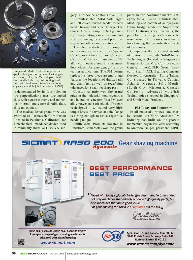
is demonstrated by its four holes on two perpendicular planes, two-angled slots with square corners, and numer-ous internal and external radii, flats, slots and cutouts.
The medical/dental grand prize was awarded to Parmatech Corporation (located in Petaluma, California) for a mechanical introducer device used in minimally invasive OB/GYN sur-
gery. The device contains five 17-4 PH stainless steel MIM parts, right and left cover, curved needle, curved needle linkage and center linkage. The covers have a complex 3-D geome-try incorporating assembly pins and slots for moving the internal parts that require smooth action for suturing.
The electrical/electronic compo-nents category was won by Capstan California ( located in Carson, California) for a soft magnetic PM alloy coil housing used in a magnetic door closer for emergency/fire pro-tection applications. The PM design replaced a three-piece assembly and features the locations of drafts, radii and chamfers, as well as redefining tolerances for a near-net shape part.
Capstan Atlantic won the grand prize in the industrial motors/controls and hydraulics category for a PM steel alloy power take-off clutch. The part is designed to withstand very high torque levels in service, and the flange is strong enough to resist repetitive bending fatigue.
Smith Metal Products (located in Lindstrom, Minnesota) won the grand
prize in the consumer market cat-egory for a 17-4 PH stainless steel MIM top and bottom of an eyeglass-frame bridge made for Superfocus LLC. Featuring very thin walls, the parts form the bridge section over the nose, which also houses an actuator for changing the magnification levels of the glasses.
Companies that accepted awards of distinction include SolidMicron Technologies (located in Singapore), Burgess Norton Mfg. Co. (located in Geneva, Illinois), PMG Group (locat-ed in Spain), ACL Bearing Company (located in Australia), Porite Taiwan Co. (located in Taiwan), Capstan Atlantic, Megamet Solid Metals, (Earth City, Missouri), Capstan California, Advanced Materials Technologies (located in Singapore) and Smith Metal Products.
PM Today and TomorrowIn all materials, process and mar-
ket sectors, the North American PM industry has built on the growth momentum begun last year, according to Matthew Bulger, president, MPIF.
Foreground: Medical introducer parts and eyeglass bridges. Second row: Helical gear and pinion, rotor, and VVT adapter. Third row: Deadbolt chassis, coil housing, and clutch hub. Back row: Gear-race and one-way clutch module (photo courtesy of MPIF).
GEARTECHNOLOGY August 2012 www.geartechnology.com58
Traditional press-and-sinter PM, metal injection molding (MIM), hot isostatic pressing (HIP), and other specialty PM technologies are thriving. PM is an interconnected technology that innovates and grows by leveraging its different sectors. Looking back at the past two years clearly suggests that the industry’s recovery is sustainable. Iron powder shipments soared in 2010 after a terrible previous year. Total iron powder shipments grew modestly in 2011 to 363,831 short tons, a three percent increase. This increase was also achieved despite the shutdown of a major powder supplier’s main plant for two months. Shipments of North American metal injection mold-ing (MIM)-grade powders, including imports, jumped nearly 40 percent in 2011. The MIM process continued to garner greater acceptance in the mate-rials marketplace. Some interesting R&D programs include developing MIM ultrasonic dentalscaler tips and endodontic tips, and titanium and cobalt–chromium alloys for medical-implant applications. The HIP busi-ness has also experienced robust growth in 2011 due to a general surge in manufacturing, and gains in the oil-and-gas, tool-steel, and aerospace markets. The HIPing of MIM parts continues to be a growing market.
Bulger noted that 2012 began on a very positive note, with rising confi-dence levels. First-quarter shipments of metal powders were up, as were volumes of PM parts and MIM parts. U.S. light-vehicle sales are expected to top 14 million units, up substantially from the 12.8 million units sold in 2011. Iron powder shipments through April this year rose by 11.25 percent to 134,925 short tons. Copper and copper-base and tin powder shipments have remained stable.
One of the key issues facing the entire industry is the serious need for experienced production work-ers and PM engineering profession-als. Industry-wide employee reduc-tions during 2008–09 have not been easy to reverse as the industry has rebounded. Another issue is capac-ity constraints: will the industry be ready to meet rising demands, par-ticularly driven by the automotive
industry, in the next several years? As was the case with staffs, rationaliza-tion moves during the same 2008–09 period included several plant closings and the scrapping of older equipment. Because it can take upwards of 10 to 12 months to build a high-end press and put it into production, Bulger cautioned, the equipment investment bandwagon must begin rolling sooner rather than later. Within the automo-tive sector, PM is approaching a sat-uration point in auto-engine content
with existing technology. The aver-age auto engine now contains up to 50 PM parts weighing more than 18 pounds, including connecting rods, bearing caps, valve-seat inserts, and VVT parts. With the average North America–built engine containing up to 170 individual parts, PM parts cur-rently represent about 30 percent of the content. Potential growth appears more likely in transfer-case and trans-mission applications. For more infor-mation, visit www.mpif.org.
www.geartechnology.com August 2012 GEARTECHNOLOGY 59
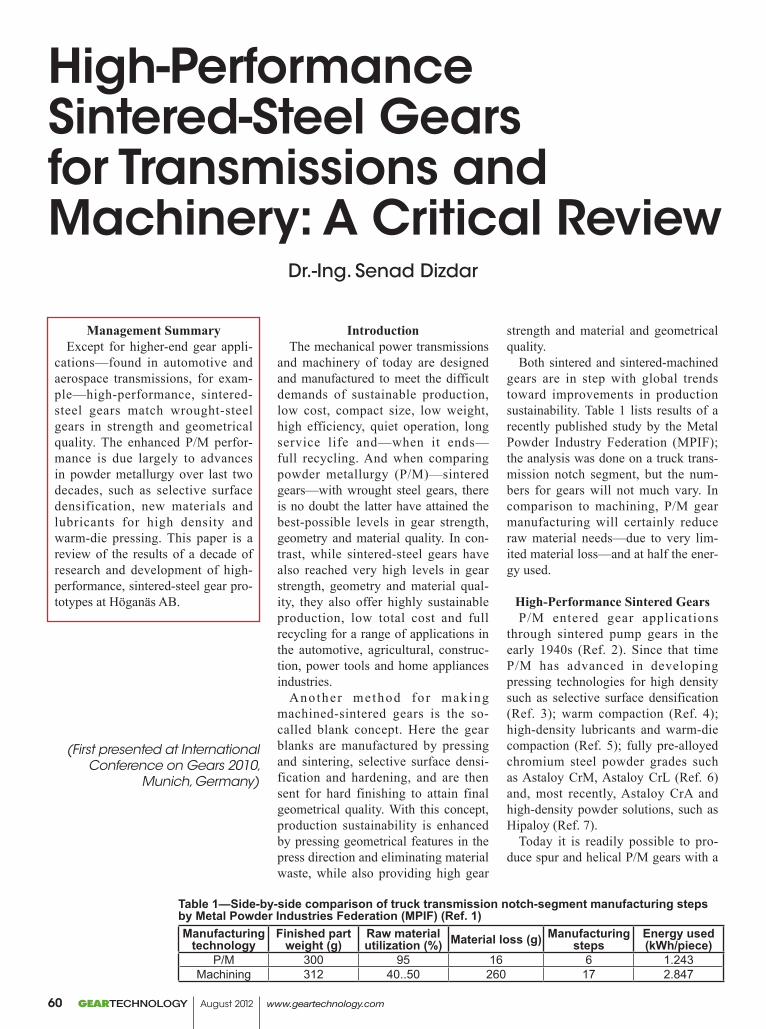
IntroductionThe mechanical power transmissions
and machinery of today are designed and manufactured to meet the difficult demands of sustainable production, low cost, compact size, low weight, high efficiency, quiet operation, long service life and—when it ends—full recycling. And when comparing powder metallurgy (P/M)—sintered gears—with wrought steel gears, there is no doubt the latter have attained the best-possible levels in gear strength, geometry and material quality. In con-trast, while sintered-steel gears have also reached very high levels in gear strength, geometry and material qual-ity, they also offer highly sustainable production, low total cost and full recycling for a range of applications in the automotive, agricultural, construc-tion, power tools and home appliances industries.
Another method for making machined-sintered gears is the so-called blank concept. Here the gear blanks are manufactured by pressing and sintering, selective surface densi-fication and hardening, and are then sent for hard finishing to attain final geometrical quality. With this concept, production sustainability is enhanced by pressing geometrical features in the press direction and eliminating material waste, while also providing high gear
strength and material and geometrical quality.
Both sintered and sintered-machined gears are in step with global trends toward improvements in production sustainability. Table 1 lists results of a recently published study by the Metal Powder Industry Federation (MPIF); the analysis was done on a truck trans-mission notch segment, but the num-bers for gears will not much vary. In comparison to machining, P/M gear manufacturing will certainly reduce raw material needs—due to very lim-ited material loss—and at half the ener-gy used.
High-Performance Sintered GearsP/M entered gear applications
through sintered pump gears in the early 1940s (Ref. 2). Since that time P/M has advanced in developing pressing technologies for high density such as selective surface densification (Ref. 3); warm compaction (Ref. 4); high-density lubricants and warm-die compaction (Ref. 5); fully pre-alloyed chromium steel powder grades such as Astaloy CrM, Astaloy CrL (Ref. 6) and, most recently, Astaloy CrA and high-density powder solutions, such as Hipaloy (Ref. 7).
Today it is readily possible to pro-duce spur and helical P/M gears with a
High-Performance Sintered-Steel Gears for Transmissions and Machinery: A Critical Review
Management SummaryExcept for higher-end gear appli-
cations—found in automotive and aerospace transmissions, for exam-ple—high-performance, sintered-steel gears match wrought-steel gears in strength and geometrical quality. The enhanced P/M perfor-mance is due largely to advances in powder metallurgy over last two decades, such as selective surface densification, new materials and lubricants for high density and warm-die pressing. This paper is a review of the results of a decade of research and development of high-performance, sintered-steel gear pro-totypes at Höganäs AB.
Table 1—Side-by-side comparison of truck transmission notch-segment manufacturing steps by Metal Powder Industries Federation (MPIF) (Ref. 1)Manufacturing
technologyFinished part
weight (g)Raw material utilization (%) Material loss (g) Manufacturing
stepsEnergy used(kWh/piece)
P/M 300 95 16 6 1.243Machining 312 40..50 260 17 2.847
(First presented at International Conference on Gears 2010,
Munich, Germany)
Dr.-Ing. Senad Dizdar
GEARTECHNOLOGY August 2012 www.geartechnology.com60
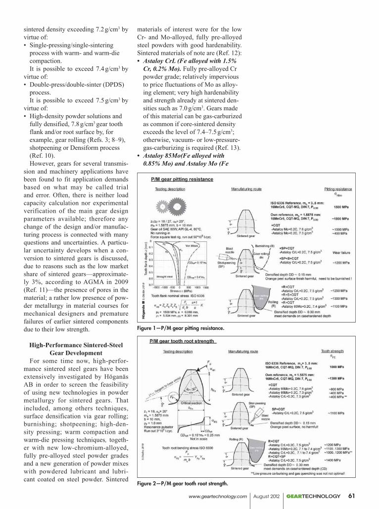
sintered density exceeding 7.2 g/cm3 by virtue of:• Single-pressing/single-sintering
process with warm- and warm-die compaction.It is possible to exceed 7.4 g/cm3 by
virtue of:• Double-press/double-sinter (DPDS)
process.It is possible to exceed 7.5 g/cm3 by
virtue of:• High-density powder solutions and
fully densified, 7.8 g/cm3 gear tooth flank and/or root surface by, for example, gear rolling (Refs. 3; 8–9), shotpeening or Densiform process (Ref. 10).However, gears for several transmis-
sion and machinery applications have been found to fit application demands based on what may be called trial and error. Often, there is neither load capacity calculation nor experimental verification of the main gear design parameters available; therefore any change of the design and/or manufac-turing process is connected with many questions and uncertainties. A particu-lar uncertainty develops when a con-version to sintered gears is discussed, due to reasons such as the low market share of sintered gears—approximate-ly 3%, according to AGMA in 2009 (Ref. 11)—the presence of pores in the material; a rather low presence of pow-der metallurgy in material courses for mechanical designers and premature failures of earlier sintered components due to their low strength.
High-Performance Sintered-Steel Gear Development
For some time now, high-perfor-mance sintered steel gears have been extensively investigated by Höganäs AB in order to screen the feasibility of using new technologies in powder metallurgy for sintered gears. That included, among others techniques, surface densification via gear rolling; burnishing; shotpeening; high-den-sity pressing; warm compaction and warm-die pressing techniques, togeth-er with new low-chromium-alloyed, fully pre-alloyed steel powder grades and a new generation of powder mixes with powdered lubricant and lubri-cant coated on steel powder. Sintered
materials of interest were for the low Cr- and Mo-alloyed, fully pre-alloyed steel powders with good hardenability. Sintered materials of note are (Ref. 12):• Astaloy CrL (Fe alloyed with 1.5%
Cr, 0.2% Mo). Fully pre-alloyed Cr powder grade; relatively impervious to price fluctuations of Mo as alloy-ing element; very high hardenability and strength already at sintered den-sities such as 7.0 g/cm3. Gears made of this material can be gas-carburized as common if core-sintered density exceeds the level of 7.4–7.5 g/cm3; otherwise, vacuum- or low-pressure-gas-carburizing is required (Ref. 13).
• Astaloy 85Mo(Fe alloyed with 0.85% Mo) and Astaloy Mo (Fe
Figure 1—P/M gear pitting resistance.
Figure 2—P/M gear tooth root strength.
www.geartechnology.com August 2012 GEARTECHNOLOGY 61
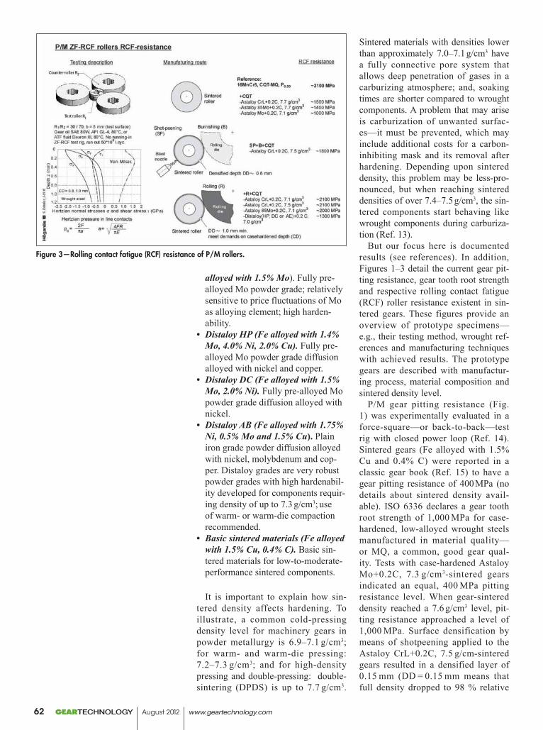
alloyed with 1.5% Mo). Fully pre-alloyed Mo powder grade; relatively sensitive to price fluctuations of Mo as alloying element; high harden-ability.
• Distaloy HP (Fe alloyed with 1.4% Mo, 4.0% Ni, 2.0% Cu). Fully pre-alloyed Mo powder grade diffusion alloyed with nickel and copper.
• Distaloy DC (Fe alloyed with 1.5% Mo, 2.0% Ni). Fully pre-alloyed Mo powder grade diffusion alloyed with nickel.
• Distaloy AB (Fe alloyed with 1.75% Ni, 0.5% Mo and 1.5% Cu). Plain iron grade powder diffusion alloyed with nickel, molybdenum and cop-per. Distaloy grades are very robust powder grades with high hardenabil-ity developed for components requir-ing density of up to 7.3 g/cm3; use of warm- or warm-die compaction recommended.
• Basic sintered materials (Fe alloyed with 1.5% Cu, 0.4% C). Basic sin-tered materials for low-to-moderate-performance sintered components.
It is important to explain how sin-tered density affects hardening. To illustrate, a common cold-pressing density level for machinery gears in powder metallurgy is 6.9–7.1 g/cm3;
for warm- and warm-die pressing: 7.2–7.3 g/cm3; and for high-density pressing and double-pressing: double-sintering (DPDS) is up to 7.7 g/cm3.
Sintered materials with densities lower than approximately 7.0–7.1 g/cm3 have a fully connective pore system that allows deep penetration of gases in a carburizing atmosphere; and, soaking times are shorter compared to wrought components. A problem that may arise is carburization of unwanted surfac-es—it must be prevented, which may include additional costs for a carbon-inhibiting mask and its removal after hardening. Depending upon sintered density, this problem may be less-pro-nounced, but when reaching sintered densities of over 7.4–7.5 g/cm3, the sin-tered components start behaving like wrought components during carburiza-tion (Ref. 13).
But our focus here is documented results (see references). In addition, Figures 1–3 detail the current gear pit-ting resistance, gear tooth root strength and respective rolling contact fatigue (RCF) roller resistance existent in sin-tered gears. These figures provide an overview of prototype specimens—e.g., their testing method, wrought ref-erences and manufacturing techniques with achieved results. The prototype gears are described with manufactur-ing process, material composition and sintered density level.
P/M gear pitting resistance (Fig. 1) was experimentally evaluated in a force-square—or back-to-back—test rig with closed power loop (Ref. 14). Sintered gears (Fe alloyed with 1.5% Cu and 0.4% C) were reported in a classic gear book (Ref. 15) to have a gear pitting resistance of 400 MPa (no details about sintered density avail-able). ISO 6336 declares a gear tooth root strength of 1,000 MPa for case-hardened, low-alloyed wrought steels manufactured in material quality—or MQ, a common, good gear qual-ity. Tests with case-hardened Astaloy Mo+0.2C, 7.3 g/cm3-sintered gears indicated an equal, 400 MPa pitting resistance level. When gear-sintered density reached a 7.6 g/cm3 level, pit-ting resistance approached a level of 1,000 MPa. Surface densification by means of shotpeening applied to the Astaloy CrL+0.2C, 7.5 g/cm-sintered gears resulted in a densified layer of 0.15 mm (DD = 0.15 mm means that full density dropped to 98 % relative
Figure 3—Rolling contact fatigue (RCF) resistance of P/M rollers.
GEARTECHNOLOGY August 2012 www.geartechnology.com62
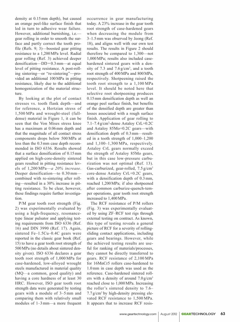
density at 0.15 mm depth), but caused an orange peel-like surface finish that led in turn to adhesive wear failure. However, additional burnishing, i.e.—gear rolling in order to smooth the sur-face and partly correct the tooth pro-file (Refs. 9; 3)—boosted gear pitting resistance to a 1,200 MPa level. Radial gear rolling (Ref. 3) achieved deeper densification—DD = 0.3 mm—at equal level of pitting resistance. A post-roll-ing sintering—or “re-sintering”—pro-vided an additional 100 MPa in pitting resistance, likely due to the additional homogenization of the material struc-ture.
By looking at the plot of contact stresses vs. tooth flank depth—and for reference, a Hertzian stress of 1,500 MPa and wrought-steel (full-dense) material in Figure 1, it can be seen that the Von Mises stress knee has a maximum at 0.06 mm depth and that the magnitude of all contact stress components drops below 500 MPa at less than the 0.3 mm case depth recom-mended in ISO 6336. Results showed that a surface densification of 0.15 mm applied on high-core-density sintered gears resulted in pitting resistance lev-els of 1,200 MPa—a 20% increase. Deeper densification—to 0.30 mm—combined with re-sintering after roll-ing—resulted in a 30% increase in pit-ting resistance. To be clear, however, these findings require further investiga-tion.
P/M gear tooth root strength (Fig. 2) was experimentally evaluated by using a high-frequency, resonance-type linear pulsator and applying test-ing requirements from ISO 6336 (Ref. 16) and DIN 3990 (Ref. 17). Again, sintered Fe–1.5Cu–0.4C gears were reported in the classic gear book (Ref. 15) to have a gear tooth root strength of 500 MPa (no details about sintered den-sity given). ISO 6336 declares a gear tooth root strength of 1,000 MPa for case-hardened, low-alloyed wrought steels manufactured in material quality (MQ—a common, good quality) and having a core hardness of at least 30 HRC. However, ISO gear tooth root strength data were generated by testing gears with a module of 3–5 mm and comparing them with relatively small modules of 1–3 mm—a more frequent
occurrence in gear manufacturing today. A 23% increase in the gear tooth root strength of case-hardened gears when decreasing the module from 3–1.5 mm was observed by Jeong (Ref. 18), and aligns well with our own test results. The results in Figure 2 should therefore be compared to 1,300—not 1,000 MPa; results also included case-hardened sintered gears with a den-sity of 7.3 and 7.6 g/cm3, and a tooth root strength of 400 MPa and 800 MPa, respectively. Shotpeening raised the tooth root strength to a 1,100 MPa level. It should be noted here that selective root shotpeening produces 0.15 mm densification depth as well an orange peel surface finish, but benefits of the densified depth are greater than losses associated with a rough surface finish. Application of gear rolling to 7.1–7.4 g/cm3-dense Astaloy CrL+0.2C and Astaloy 85Mo+0.2C gears—with densification depth of 0.3 mm—result-ed in a tooth strength of 1,000–1,200 and 1,100–1,300 MPa, respectively. Astaloy CrL gears normally exceed the strength of Astaloy 85Mo gears, but in this case low-pressure carbu-rization was not optimal (Ref. 13). Gas-carburized, gear-rolled, 7.5 g/cm3 core-dense Astaloy CrL+0.2C gears, with a densification depth of 0.3 mm, reached 1,200 MPa; if also shotpeened after common carburize-quench-tem-per operations, gear tooth root strength increased to 1,400 MPa.
The RCF resistance of P/M rollers (Fig. 3) was experimentally evaluat-ed by using ZF–RCF test rigs through external testing on contract. As known, this type of testing reveals a general picture of RCF for a severity of rolling-sliding contact applications, including gears and bearings. However, while the achieved testing results are use-ful for ranking of materials/processes, they cannot be directly transferred to gears. RCF resistance of 2,100 MPa for 16MnCr5 rollers case-hardened to 1.0 mm in case depth was used as the reference. Case-hardened sintered roll-ers with a density of around 7.0 g/cm3 reached close to 1,000 MPa. Increasing the roller’s sintered density to 7.6–7.7 g/cm3 by high-density pressing ele-vated RCF resistance to 1,500 MPa. It appears that to increase RCF resis-
www.geartechnology.com August 2012 GEARTECHNOLOGY 63
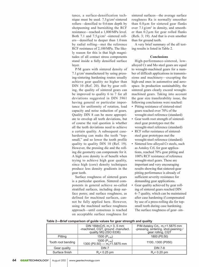
Table 2—Brief comparison of guide values for gear strength and qualityDIN 16MnCr5, mn= 3..5 mm
-machined, CQT, ground -manufact. quality MQ (ISO 6336)
P/M Astaloy CrL, mn=1.5875 mm -pressing, sintering, shot-peening /
gear rolling, CQTPitting 1500 (P0 99) 1800 (P0.50)
Tooth root bending 1000 (P0 99)1300 (P0.50) — mn=1.5875 mm 1100..1300 (P050)
Gear quality DIN 7 DIN 7-8Surface finish Ra< 0.25 pm Ra< 0.20 pm
tance, a surface-densification tech-nique must be used. 7.5 g/cm3-sintered rollers—densified to 0.6 mm depth by shotpeening and burnishing the RCF resistance—reached a 1,800 MPa level. Both 7.1 and 7.5 g/cm3 -sintered roll-ers—densified to deeper than 1.0 mm by radial rolling—met the reference RCF resistance of 2,100 MPa. The like-ly reason for this is that high magni-tudes of all contact stress components stand inside a fully densified surface layer.
P/M gears with sintered density of 7.1 g/cm3 manufactured by using press-ing-sintering hardening routes usually achieve gear quality no higher than DIN 10 (Ref. 20). But by gear roll-ing, the quality of sintered gears can be improved to quality 6 to 7 for all deviations suggested in DIN 3961 having general or particular impor-tance for uniformity of rotation, load capacity and noise reduction of gears. Quality DIN 8 can be more appropri-ate to envelop all teeth deviations, but of course the real question is whether all the teeth deviations need to achieve a certain quality. A subsequent case-hardening can make the teeth “top-small,” and so lower the tooth profile quality to quality DIN 10 (Ref. 19). However, the pressing die and the roll-ing die geometry can compensate for it. A high core density is of benefit when trying to achieve high gear quality, since high (core) density techniques produce less density gradients in the gear teeth.
Surface roughness of sintered gears is a particular question. Sintered com-ponents in general achieve so-called stratified surfaces, including deep sur-face pores; and surface roughness, as defined for machined surfaces, can-not be fully applied here. However, using the machined surface roughness approach—until consensus is reached on acceptable surface roughness for
sintered surfaces—the average surface roughness Ra is normally smoother than 0.8 mm for sintered gear flanks over 7.1 g/cm3 in density, and smooth-er than 0.2 mm for gear rolled flanks (Refs. 3; 19). And that is even smother than for ground teeth.
A very brief summary of the all test-ing results is listed in Table 2.
ConclusionsHigh-performance-sintered, low-
alloyed Cr and Mo steel gears are equal to wrought-machined gears for a num-ber of difficult applications in transmis-sions and machinery—excepting the high-end ones in automotive and aero-space. In production sustainability, the sintered gears clearly exceed wrought-machined gears. Taking into account the gear size transferability issue, the following conclusions were reached:• Pitting resistance of sintered-steel
gears reached over 70% of the wrought-steel reference (standard)
• Gear tooth root strength of sintered-steel gear prototypes met the wrought-steel reference (standard)
• RCF roller resistance of sintered-steel gear prototypes met the wrought-steel reference (standard)
• Sintered low-alloyed Cr steels, such as Astaloy CrL for gear applica-tions, reached 70% gear pitting and 100% RCF resistance of reference wrought-steel gears. These are important and very encouraging results showing that sintered-gear pitting performance is already of sufficient severity resistance for demanding gear applications.
• Gear quality achieved by gear roll-ing of sintered gears reached DIN 6–7 quality, which can be maintained after case hardening if compensated by use of a press-rolling die for top-small teeth during case hardening. The surface roughness of gear- sin-
GEARTECHNOLOGY August 2012 www.geartechnology.com64
tered rolled gears is even smoother than that of the ground gears.
• The key for achieving high-per-formance, sintered-steel gears is in making the surface densification depth equal to a required case-hard-ened depth, in combination with a properly high core density for a par-ticular gear application. An increase in core density positively affects case-hardening and, if exceeding 7.4–7.5 g/cm3, makes case-hardening of sintered steels as simple as case-hardening of wrought steels.
Acknowledgement. The author wish-es to thank Nandivada Nagarjuna and Ola Litström for their valuable discus-sions leading to the completion of this paper.
References1. “Powder Metallurgy: Intrinsically
Sustainable,” MPIF, 2010, www.mpif.org.2. Watson J., “Cold Casting: A Revolutionary
Process for Making Metal Parts from Powders,” Popular Science, Apr. 1941, pp. 98–102.
3. Kotthoff, G.A. “New Procedures for Load-Carrying Capacity Increase of Sintered Gear Wheels,” Ph.D. Thesis, WZL–RWTH, Aachen 2003.
4. Engström, U. “New High-Performance PM Applications by Warm Compaction of Densmix Powders,” EURO PM 2000, Munich.
5. Larsson, M., Å. Ahlin and K. Olsson. “High-Performance Mixes with New Lubricant System,” Euro PM 2009 Congress & Exhibition, Copenhagen.
6. Bergman, O. “Chromium-Alloyed PM Steels with Excellent Fatigue Properties Obtained by Different Process Routes,” EURO PM 2003 Congress & Exhibition, Valencia.
7. Dizdar, S., P. Johansson and I. Howe. “Precision Gears with Sintered Cr Materials,” SAE Paper No. 2008–32–0076.
8. Jones, P. K., K. Buckley-Golder, H. David, D. Sarafinchan, R. Shivanath and L. Yao. “Fatigue Properties of High-Density Powder Metal Alloy Steels for High-Performance Powertrain Applications,” Proceedings 1998 PM World Congress, pp. 155–166.
9. Dugas, J.P. “Gear Finishing by Shaving, Rolling and Honing,” Dudley’s Gear Handbook, Chapter 18, D. Townsend, Editor, McGraw-Hill, New York 1992.
10. Nigarura, S., R. Parameswaran and J.R.L. Trasorras. “Bending Fatigue of Surface- Densified Gears: Effect of Root Densification Depth and Tooth Loading Mode on Fatigue Life,” Adv. in Powder Metal & Particulate Mat., 2006.
11. AGMA 2009 Gear Survey. AGMA, Alexandria, VA.
12. Iron and Steel Powders for Sintered Components. Höganäs AB, Höganäs 2002.
13. Dizdar, S., P. Johansson and T. Jonsäter. “Powder Metal Materials for Gear Applications,” SAE Paper No. 2007–32–0062.
14. Dizdar, S. “Pitting Resistance of Sintered Gears,” to be published in Wear.
15. Nieman, G. and H. Winter. Machinenelemente, Springer-Verlag, Berlin 1989.
16. ISO 6336. Calculation of Load Capacity of Spur and Helical Gears.
17. DIN 3990. Calculation of Load Capacity of Cylindrical Gears.
18. Jeong, B., M. Kato, K. Inoue and N. Takatsu. “Bending Strength of Carburized Fine- Module Gear Teeth,” JSME Series III, Vol. 35, No. 1, pp. 136–141, 1992.
19. Dizdar, S., L. Fordén and D. Andersson. “Surface-Densified P/M Gears Made of Chromium Alloy Powder Reach Automotive Quality,” EURO PM2005 Congress, Prague 2005.
20. Bequette, T. A. and S.M. Clase. “Achieving AGMA 10 Quality Level for Automotive Gear Applications,” SAE PM Applications, SP–1447, pp. 9–14, 1999.
21. DIN 3961. Tolerances for Cylindrical Gear Teeth: Bases.
Senad Dizdar received his M.Sc. in Mech. Eng. (1989) from University “Dzemal Bijedic” in Mostar, Bosnia and Herzegovina, and worked there (1990–1992) as a research assis-tant. During the war in Bosnia, Dizdar became a war refugee and was granted asylum in Sweden in 1993. He did his doctoral study at KTH–The Royal Institute of Technol-ogy in Stockholm (1995–1999) and received his PhD in Machine Elements (1999), with a focus on tribology/boundary lubrication. Since then Dizdar has been with Höganäs AB as a researcher with a primary focus on pow-der compaction and lubrication (1999–2002), gear design and testing (2003–2010). Dizdar created a fundamen-tal characterization and ranking of gear tooth bending strength and pitting resistance of sintered, surface-den-sified-sintered and reference-wrought gears. Since 2010 Dizdar has concentrated on the tribology of thermally surfaced (hard-faced/overlay-welded) components, as well as sintered components in machinery.
www.geartechnology.com August 2012 GEARTECHNOLOGY 65
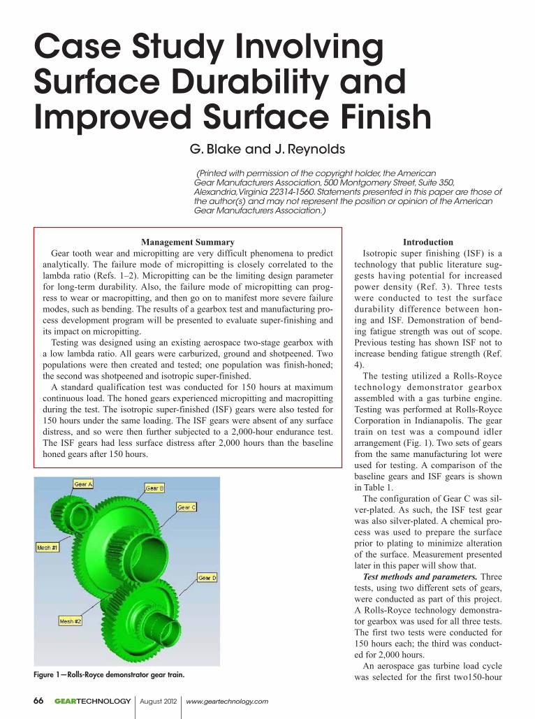
(Printed with permission of the copyright holder, the American Gear Manufacturers Association, 500 Montgomery Street, Suite 350, Alexandria,Virginia 22314-1560. Statements presented in this paper are those of the author(s) and may not represent the position or opinion of the American Gear Manufacturers Association.)
Case Study Involving Surface Durability and Improved Surface Finish
G. Blake and J. Reynolds
IntroductionIsotropic super finishing (ISF) is a
technology that public literature sug-gests having potential for increased power density (Ref. 3). Three tests were conducted to test the surface durability difference between hon-ing and ISF. Demonstration of bend-ing fatigue strength was out of scope. Previous testing has shown ISF not to increase bending fatigue strength (Ref. 4).
The testing utilized a Rolls-Royce technology demonstrator gearbox assembled with a gas turbine engine. Testing was performed at Rolls-Royce Corporation in Indianapolis. The gear train on test was a compound idler arrangement (Fig. 1). Two sets of gears from the same manufacturing lot were used for testing. A comparison of the baseline gears and ISF gears is shown in Table 1.
The configuration of Gear C was sil-ver-plated. As such, the ISF test gear was also silver-plated. A chemical pro-cess was used to prepare the surface prior to plating to minimize alteration of the surface. Measurement presented later in this paper will show that.
Test methods and parameters. Three tests, using two different sets of gears, were conducted as part of this project. A Rolls-Royce technology demonstra-tor gearbox was used for all three tests. The first two tests were conducted for 150 hours each; the third was conduct-ed for 2,000 hours.
An aerospace gas turbine load cycle was selected for the first two150-hour
Management SummaryGear tooth wear and micropitting are very difficult phenomena to predict
analytically. The failure mode of micropitting is closely correlated to the lambda ratio (Refs. 1–2). Micropitting can be the limiting design parameter for long-term durability. Also, the failure mode of micropitting can prog-ress to wear or macropitting, and then go on to manifest more severe failure modes, such as bending. The results of a gearbox test and manufacturing pro-cess development program will be presented to evaluate super-finishing and its impact on micropitting.
Testing was designed using an existing aerospace two-stage gearbox with a low lambda ratio. All gears were carburized, ground and shotpeened. Two populations were then created and tested; one population was finish-honed; the second was shotpeened and isotropic super-finished.
A standard qualification test was conducted for 150 hours at maximum continuous load. The honed gears experienced micropitting and macropitting during the test. The isotropic super-finished (ISF) gears were also tested for 150 hours under the same loading. The ISF gears were absent of any surface distress, and so were then further subjected to a 2,000-hour endurance test. The ISF gears had less surface distress after 2,000 hours than the baseline honed gears after 150 hours.
Figure 1—Rolls-Royce demonstrator gear train.
GEARTECHNOLOGY August 2012 www.geartechnology.com66
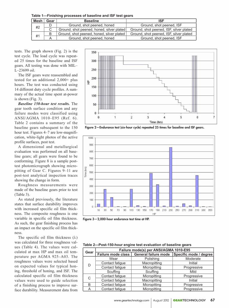
tests. The graph shown (Fig. 2) is the test cycle. The load cycle was repeat-ed 25 times for the baseline and ISF gears. All testing was done with MIL–L–23699 oil.
The ISF gears were reassembled and tested for an additional 2,000+ plus hours. The test was conducted using 14 different duty cycle profiles. A sum-mary of the actual time spent at-power is shown (Fig. 3).
Baseline 150-hour test results. The gear tooth surface condition and any failure modes were classified using ANSI/AGMA 1010–E95 (Ref. 6). Table 2 contains a summary of the baseline gears subsequent to the 150 hour test. Figures 4–7 are low-magnifi-cation, white-light photos of the active profile surfaces, post test.
A dimensional and metallurgical evaluation was performed on all base-line gears; all gears were found to be conforming. Figure 8 is a sample post-test photomicrograph showing micro-pitting of Gear C. Figures 9–11 are post-test analytical inspection traces showing the change in form.
Roughness measurements were made of the baseline gears prior to test (Table 3).
As stated previously, the literature states that surface durability improves with increased specific oil film thick-ness. The composite roughness is one variable in specific oil film thickness. As such, the gear finishing process has an impact on the specific oil film thick-ness.
The specific oil film thickness (l) was calculated for three roughness val-ues (Table 4). The values were cal-culated at max HP and max oil tem-perature per AGMA 925–A03. The roughness values were selected based on expected values for typical hon-ing, threshold of honing, and ISF. The calculated specific oil film thickness values were used to guide selection of a finishing process to improve sur-face durability. Measurement data from
Figure 2—Endurance test (six-hour cycle) repeated 25 times for baseline and ISF gears.
Figure 3—2,000-hour endurance test time at HP.
Table 1—Finishing processes of baseline and ISF test gearsMesh Gear Baseline ISF
#2 D Ground, shot peened, honed Ground, shot peened, ISFC Ground, shot peened, honed, silver plated Ground, shot peened, ISF, silver plated
#1 B Ground, shot peened, honed, silver plated Ground, shot peened, ISF, silver platedA Ground, shot peened, honed Ground, shot peened, ISF
Table 2—Post-150-hour engine test evaluation of baseline gears
Gear Failure mode(s) per ANSI/AGMA 1010-E95Failure mode class General failure mode Specific mode / degree
D
Wear Polishing ModerateContact fatigue Macropitting InitialContact fatigue Micropitting Progressive
Scuffing Scuffing Mild
C Contact fatigue Micropitting ProgressiveContact fatigue Macropitting Initial
B Contact fatigue Micropitting ProgressiveA Contact fatigue Micropitting Progressive
www.geartechnology.com August 2012 GEARTECHNOLOGY 67
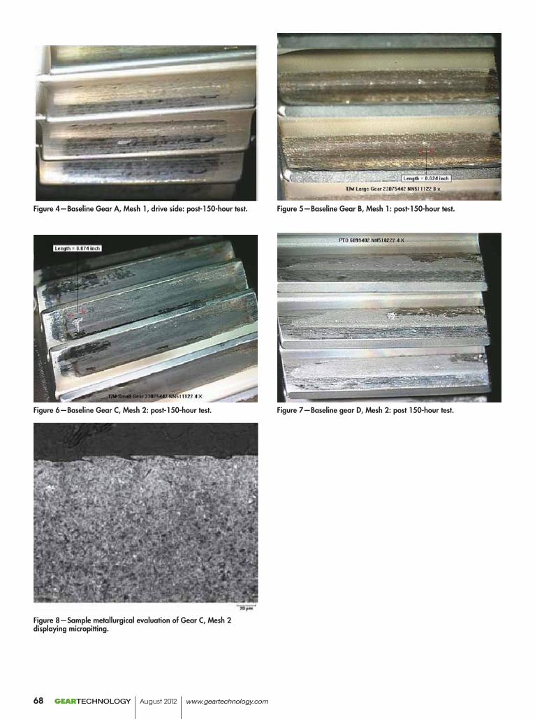
Figure 4—Baseline Gear A, Mesh 1, drive side: post-150-hour test. Figure 5—Baseline Gear B, Mesh 1: post-150-hour test.
Figure 6—Baseline Gear C, Mesh 2: post-150-hour test. Figure 7—Baseline gear D, Mesh 2: post 150-hour test.
Figure 8—Sample metallurgical evaluation of Gear C, Mesh 2 displaying micropitting.
GEARTECHNOLOGY August 2012 www.geartechnology.com68
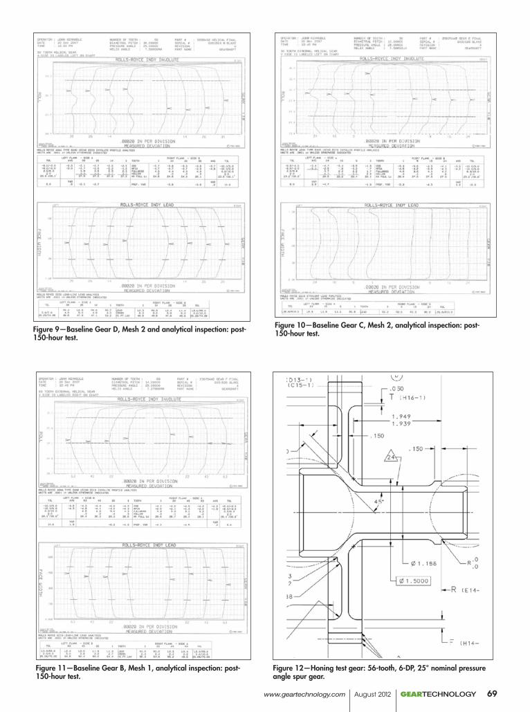
Figure 9—Baseline Gear D, Mesh 2 and analytical inspection: post-150-hour test.
Figure 10—Baseline Gear C, Mesh 2, analytical inspection: post-150-hour test.
Figure 11—Baseline Gear B, Mesh 1, analytical inspection: post-150-hour test.
Figure 12—Honing test gear: 56-tooth, 6-DP, 25° nominal pressure angle spur gear.
www.geartechnology.com August 2012 GEARTECHNOLOGY 69
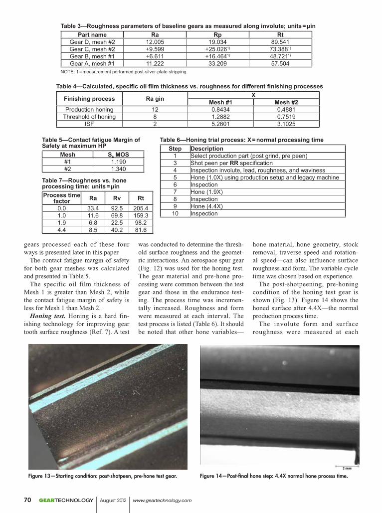
Table 6—Honing trial process: X = normal processing timeStep Description
1 Select production part (post grind, pre peen)3 Shot peen per RR specification4 Inspection involute, lead, roughness, and waviness5 Hone (1.0X) using production setup and legacy machine6 Inspection7 Hone (1.9X)8 Inspection9 Hone (4.4X)
10 Inspection
Table 7—Roughness vs. hone processing time: units = μinProcess time
factor Ra Rv Rt0.0 33.4 92.5 205.41.0 11.6 69.8 159.31.9 6.8 22.5 98.24.4 8.5 40.2 81.6
Figure 13—Starting condition: post-shotpeen, pre-hone test gear. Figure 14—Post-final hone step: 4.4X normal hone process time.
gears processed each of these four ways is presented later in this paper.
The contact fatigue margin of safety for both gear meshes was calculated and presented in Table 5.
The specific oil film thickness of Mesh 1 is greater than Mesh 2, while the contact fatigue margin of safety is less for Mesh 1 than Mesh 2.
Honing test. Honing is a hard fin-ishing technology for improving gear tooth surface roughness (Ref. 7). A test
was conducted to determine the thresh-old surface roughness and the geomet-ric interactions. An aerospace spur gear (Fig. 12) was used for the honing test. The gear material and pre-hone pro-cessing were common between the test gear and those in the endurance test-ing. The process time was incremen-tally increased. Roughness and form were measured at each interval. The test process is listed (Table 6). It should be noted that other hone variables—
hone material, hone geometry, stock removal, traverse speed and rotation-al speed—can also influence surface roughness and form. The variable cycle time was chosen based on experience.
The post-shotpeening, pre-honing condition of the honing test gear is shown (Fig. 13). Figure 14 shows the honed surface after 4.4X—the normal production process time.
The involute form and surface roughness were measured at each
Table 3—Roughness parameters of baseline gears as measured along involute; units = μinPart name Ra Rp Rt
Gear D, mesh #2 12.005 19.034 89.541Gear C, mesh #2 +9.599 +25.0261) 73.3881)
Gear B, mesh #1 +6.611 +16.4641) 48.7211)
Gear A, mesh #1 11.222 33.209 57.504NOTE: 1 = measurement performed post-silver-plate stripping.
Table 4—Calculated, specific oil film thickness vs. roughness for different finishing processes
Finishing process Ra gin XMesh #1 Mesh #2
Production honing 12 0.8434 0.4881Threshold of honing 8 1.2882 0.7519
ISF 2 5.2601 3.1025
Table 5—Contact fatigue Margin of Safety at maximum HP
Mesh Sc MOS#1 1.190#2 1.340
GEARTECHNOLOGY August 2012 www.geartechnology.com70
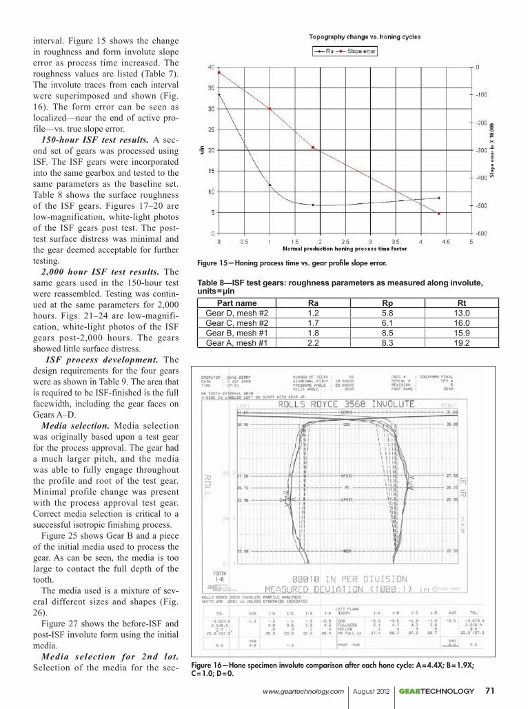
Table 8—ISF test gears: roughness parameters as measured along involute, units = μin
Part name Ra Rp RtGear D, mesh #2 1.2 5.8 13.0Gear C, mesh #2 1.7 6.1 16.0Gear B, mesh #1 1.8 8.5 15.9Gear A, mesh #1 2.2 8.3 19.2
interval. Figure 15 shows the change in roughness and form involute slope error as process time increased. The roughness values are listed (Table 7). The involute traces from each interval were superimposed and shown (Fig. 16). The form error can be seen as localized—near the end of active pro-file—vs. true slope error.
150-hour ISF test results. A sec-ond set of gears was processed using ISF. The ISF gears were incorporated into the same gearbox and tested to the same parameters as the baseline set. Table 8 shows the surface roughness of the ISF gears. Figures 17–20 are low-magnification, white-light photos of the ISF gears post test. The post-test surface distress was minimal and the gear deemed acceptable for further testing.
2,000 hour ISF test results. The same gears used in the 150-hour test were reassembled. Testing was contin-ued at the same parameters for 2,000 hours. Figs. 21–24 are low-magnifi-cation, white-light photos of the ISF gears post-2,000 hours. The gears showed little surface distress.
ISF process development. The design requirements for the four gears were as shown in Table 9. The area that is required to be ISF-finished is the full facewidth, including the gear faces on Gears A–D.
Media selection. Media selection was originally based upon a test gear for the process approval. The gear had a much larger pitch, and the media was able to fully engage throughout the profile and root of the test gear. Minimal profile change was present with the process approval test gear. Correct media selection is critical to a successful isotropic finishing process.
Figure 25 shows Gear B and a piece of the initial media used to process the gear. As can be seen, the media is too large to contact the full depth of the tooth.
The media used is a mixture of sev-eral different sizes and shapes (Fig. 26).
Figure 27 shows the before-ISF and post-ISF involute form using the initial media.
Media selection for 2nd lot . Selection of the media for the sec-
Figure 15—Honing process time vs. gear profile slope error.
Figure 16—Hone specimen involute comparison after each hone cycle: A = 4.4X; B = 1.9X; C = 1.0; D = 0.
www.geartechnology.com August 2012 GEARTECHNOLOGY 71
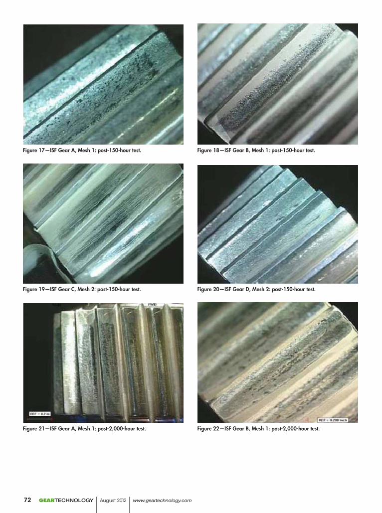
Figure 17—ISF Gear A, Mesh 1: post-150-hour test. Figure 18—ISF Gear B, Mesh 1: post-150-hour test.
Figure 19—ISF Gear C, Mesh 2: post-150-hour test. Figure 20—ISF Gear D, Mesh 2: post-150-hour test.
Figure 21—ISF Gear A, Mesh 1: post-2,000-hour test. Figure 22—ISF Gear B, Mesh 1: post-2,000-hour test.
GEARTECHNOLOGY August 2012 www.geartechnology.com72
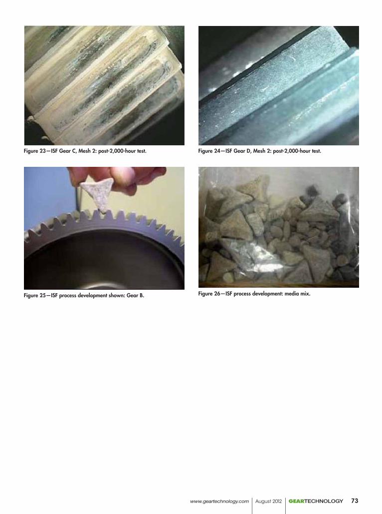
Figure 23—ISF Gear C, Mesh 2: post-2,000-hour test. Figure 24—ISF Gear D, Mesh 2: post-2,000-hour test.
Figure 25—ISF process development shown: Gear B. Figure 26—ISF process development: media mix.
www.geartechnology.com August 2012 GEARTECHNOLOGY 73
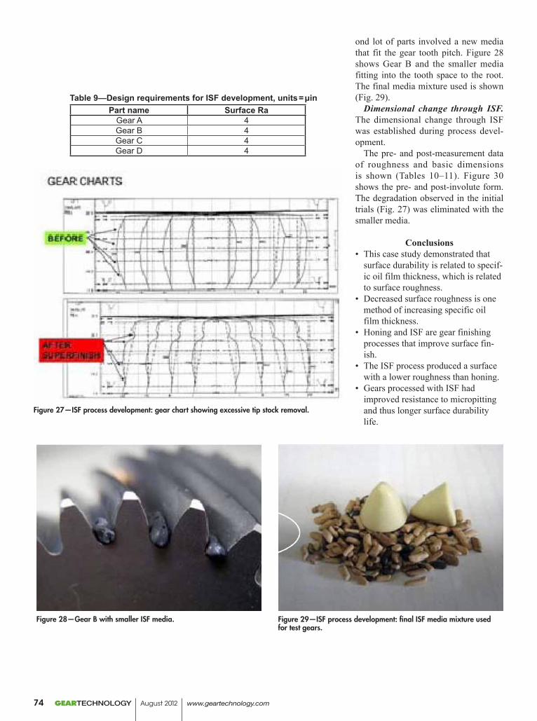
ond lot of parts involved a new media that fit the gear tooth pitch. Figure 28 shows Gear B and the smaller media fitting into the tooth space to the root. The final media mixture used is shown (Fig. 29).
Dimensional change through ISF. The dimensional change through ISF was established during process devel-opment.
The pre- and post-measurement data of roughness and basic dimensions is shown (Tables 10–11). Figure 30 shows the pre- and post-involute form. The degradation observed in the initial trials (Fig. 27) was eliminated with the smaller media.
Conclusions• This case study demonstrated that
surface durability is related to specif-ic oil film thickness, which is related to surface roughness.
• Decreased surface roughness is one method of increasing specific oil film thickness.
• Honing and ISF are gear finishing processes that improve surface fin-ish.
• The ISF process produced a surface with a lower roughness than honing.
• Gears processed with ISF had improved resistance to micropitting and thus longer surface durability life.
Figure 27—ISF process development: gear chart showing excessive tip stock removal.
Figure 28—Gear B with smaller ISF media. Figure 29—ISF process development: final ISF media mixture used for test gears.
Table 9—Design requirements for ISF development, units = μinPart name Surface Ra
Gear A 4Gear B 4Gear C 4Gear D 4
GEARTECHNOLOGY August 2012 www.geartechnology.com74
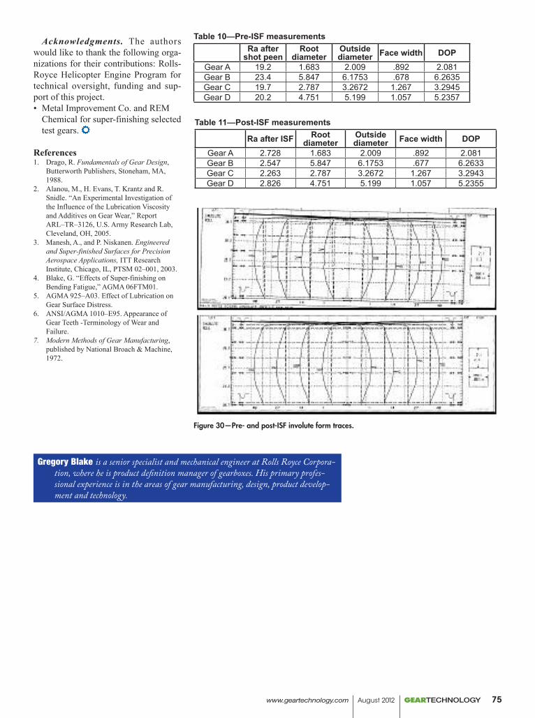
Table 10—Pre-ISF measurementsRa after
shot peenRoot
diameterOutside diameter Face width DOP
Gear A 19.2 1.683 2.009 .892 2.081Gear B 23.4 5.847 6.1753 .678 6.2635Gear C 19.7 2.787 3.2672 1.267 3.2945Gear D 20.2 4.751 5.199 1.057 5.2357
Table 11—Post-ISF measurements
Ra after ISF Rootdiameter
Outsidediameter Face width DOP
Gear A 2.728 1.683 2.009 .892 2.081Gear B 2.547 5.847 6.1753 .677 6.2633Gear C 2.263 2.787 3.2672 1.267 3.2943Gear D 2.826 4.751 5.199 1.057 5.2355
Figure 30—Pre- and post-ISF involute form traces.
Acknowledgments. The authors would like to thank the following orga-nizations for their contributions: Rolls-Royce Helicopter Engine Program for technical oversight, funding and sup-port of this project.• Metal Improvement Co. and REM
Chemical for super-finishing selected test gears.
References1. Drago, R. Fundamentals of Gear Design,
Butterworth Publishers, Stoneham, MA, 1988.
2. Alanou, M., H. Evans, T. Krantz and R. Snidle. “An Experimental Investigation of the Influence of the Lubrication Viscosity and Additives on Gear Wear,” Report ARL–TR–3126, U.S. Army Research Lab, Cleveland, OH, 2005.
3. Manesh, A., and P. Niskanen. Engineered and Super-finished Surfaces for Precision Aerospace Applications, ITT Research Institute, Chicago, IL, PTSM 02–001, 2003.
4. Blake, G. “Effects of Super-finishing on Bending Fatigue,” AGMA 06FTM01.
5. AGMA 925–A03. Effect of Lubrication on Gear Surface Distress.
6. ANSI/AGMA 1010–E95. Appearance of Gear Teeth -Terminology of Wear and Failure.
7. Modern Methods of Gear Manufacturing, published by National Broach & Machine, 1972.
Gregory Blake is a senior specialist and mechanical engineer at Rolls Royce Corpora-tion, where he is product definition manager of gearboxes. His primary profes-sional experience is in the areas of gear manufacturing, design, product develop-ment and technology.
www.geartechnology.com August 2012 GEARTECHNOLOGY 75
N E W S
In MemoriamJAMeS J. CeRvinKA
James J. Cervinka, 92, died July 12, 2012. Cervinka was CEO of Arrow Gear Co., located in Downers Grove, Illinois. He founded the company in 1947 with Frank E. Pielsticker. He was a Navy veteran, serving in World War II. Arrow Gear began in a modest industrial building in Worth, Illinois which was without heat or plumbing. Within a few years, they built a new facility in Lyons, Illinois, and as the company continued to grow, moved to the company’s final Downers Grove location in 1961. Today, Arrow Gear is among the most technologically advanced gear companies in the world, supplying precision gears to aerospace and com-mercial customers, employing 250.
Through the years, Cervinka was directly responsible for many innovations and new technologies introduced at Arrow Gear. In 2010, he spearheaded the move to expand Arrow’s size capability for the manufacture of spur gears. The signifi-cant investment for this upgrade resulted in Arrow’s ability to pursue a wider range of work–particularly in the helicop-ter field.
“Mr. Cervinka believed that the success of Arrow Gear was his greatest achievement. And the fact that he was able to provide good paying jobs for those in the community was always a source of pride for him. It should be noted that in the six decades since the company was started, nearly 2,000 people have been employed by Arrow Gear,” stated Joe Arvin, Arrow’s president.
Surviving family members include his wife Janet (Miller); sons, Michael Cervinka and John Cervinka; daughters, Mary Jo O’Brien and Lisa Mackey; stepson, Mark Karavakis; step-daughter, Marcie Karavakis; and two grandchildren. He was preceded in death by his first wife, Patricia (Sears) Cervinka; and daughter, Jane Chester. Memorial contributions may be made to M.D. Anderson Cancer Center, P.O. Box 4486, Houston, TX 77030 or Glenwood School for Boys, 500 W. 187th St., Glenwood IL 60425. Services: Services were on July 17 at Adolf Funeral Home and Cremation Services in Willowbrook Illinois. Burial was at Bronswood Cemetery in Oak Brook, Illinois.
KlingelnbergACqUiReS HöfLeR
Klingelnberg GmbH, the German subsidiary of the Switzerland based Klingelnberg AG, acquired the activ-ities of Höfler Maschinenbau GmbH from NDW Draht und Stahl GmbH, a member of the NDW Group. The relevant contracts were signed on July 11, 2012. Höfler Maschinenbau GmbH is a well established manufacturer
of gear grinding machines and gear hobbing machines. The machines are employed in the production of high-precision gears for use in the industry sectors of transport, ship-ping, mining, machine tools and renewable energies, e.g. wind turbines. The company generated revenues of EUR 83 million in 2011 with approximately 300 employees. The Klingelnberg Group is a world leader in the development, manufacture and sale of machines for the production of spi-ral bevel gears, measuring centers for axially symmetrical objects of all types, and the production of high-precision gear components made to customer orders. The Group recorded revenues of approximately EUR 200 m in 2011 with approximately 1,000 employees, and is renowned for product and service quality, absolute reliability and strict adherence to deadlines. The company demonstrates its capacity for innovation with some 230 R&D engineers around the globe, and made 90 successful patent applications over the last five years. “Höfler Maschinenbau’s technol-ogy is an excellent completion of the Klingelnberg Group’s existing product range of cutting and grinding machines, both in terms of application areas and the industries served” says Jan Klingelnberg, CEO of the Klingelnberg Group. “The installed base of over 1.550 machines worldwide is clear evidence of a well established clientele. The addition of Höfler Maschinenbau allows the Klingelnberg Group to advance significantly in reaching its strategic goal of being able to provide all gear technologies.”The sharehold-ers of the NDW-Group added: “We are pleased to pass Höfler Maschinenbau to a very competent strategic owner, who will secure the long term development of operations at its current location in Ettlingen. The disposal allows us to focus more closely on our core business.”The transaction was executed by way of an asset deal and includes the sub-sidiaries in the USA and in China.
CodinanAMed SAndviK MARKeTinG And COMMUniCATiOnS MAnAGeR
Sandv ik Coroman t i s pleased to announce the appointment of Ester Codina as the company’s new market-ing and communications man-ager, market area Americas. P r i o r t o h e r a p p o i n t -ment, Codina spent nine years within Sandvik Group, most recently as marketing and communications manager.
GEARTECHNOLOGY August 2012 www.geartechnology.com76
Mark Your Calendars
September 17–19, 2013 IndIana ConventIon Center
IndIanapolIS, In
www.Gearexpo.com
along with soaring profits, You get:
) the latest in cutting-edge technologies and processes
) Gear-specific education programs
) machinery to see in action and compare
) Innovative products and software
) Lucrative connections with thousands of other gear manufacturers and buyers from the U.S. and abroad
) cost-effective solutions, small and large, for immediate implementation
Don’t mIssGear expo 2013,the world’s only conference and expo exclusively for the gear industry, where you’ll see 750,000 pounds of machinery and gear products on the show floor!
preCision power
partnerships
owned by:
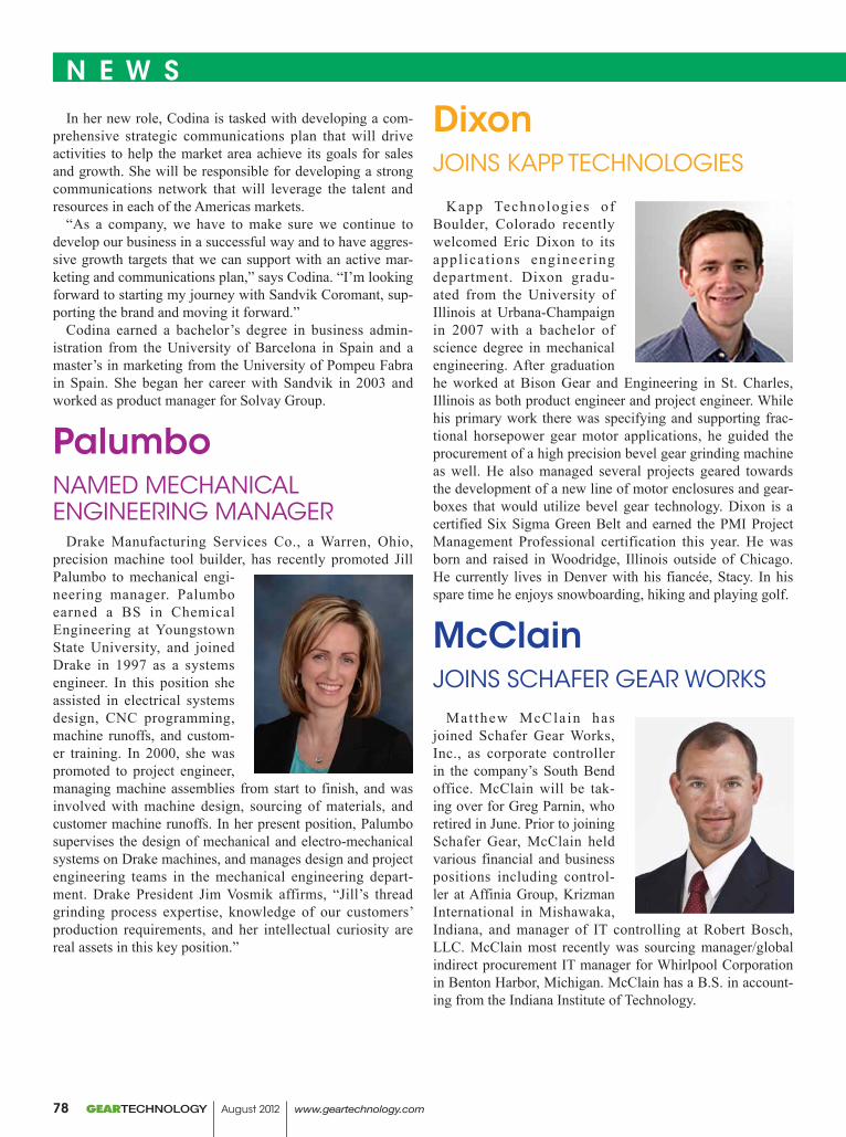
N E W S
In her new role, Codina is tasked with developing a com-prehensive strategic communications plan that will drive activities to help the market area achieve its goals for sales and growth. She will be responsible for developing a strong communications network that will leverage the talent and resources in each of the Americas markets.
“As a company, we have to make sure we continue to develop our business in a successful way and to have aggres-sive growth targets that we can support with an active mar-keting and communications plan,” says Codina. “I’m looking forward to starting my journey with Sandvik Coromant, sup-porting the brand and moving it forward.”
Codina earned a bachelor’s degree in business admin-istration from the University of Barcelona in Spain and a master’s in marketing from the University of Pompeu Fabra in Spain. She began her career with Sandvik in 2003 and worked as product manager for Solvay Group.
PalumbonAMed MeCHAniCAL enGineeRinG MAnAGeR
Drake Manufacturing Services Co., a Warren, Ohio, precision machine tool builder, has recently promoted Jill Palumbo to mechanical engi-neering manager. Palumbo earned a BS in Chemical Engineering at Youngstown State University, and joined Drake in 1997 as a systems engineer. In this position she assisted in electrical systems design, CNC programming, machine runoffs, and custom-er training. In 2000, she was promoted to project engineer, managing machine assemblies from start to finish, and was involved with machine design, sourcing of materials, and customer machine runoffs. In her present position, Palumbo supervises the design of mechanical and electro-mechanical systems on Drake machines, and manages design and project engineering teams in the mechanical engineering depart-ment. Drake President Jim Vosmik affirms, “Jill’s thread grinding process expertise, knowledge of our customers’ production requirements, and her intellectual curiosity are real assets in this key position.”
DixonJOinS KAPP TeCHnOLOGieS
Kapp Technologies of Boulder, Colorado recently welcomed Eric Dixon to its appl icat ions engineering department. Dixon gradu-ated from the University of Illinois at Urbana-Champaign in 2007 with a bachelor of science degree in mechanical engineering. After graduation he worked at Bison Gear and Engineering in St. Charles, Illinois as both product engineer and project engineer. While his primary work there was specifying and supporting frac-tional horsepower gear motor applications, he guided the procurement of a high precision bevel gear grinding machine as well. He also managed several projects geared towards the development of a new line of motor enclosures and gear-boxes that would utilize bevel gear technology. Dixon is a certified Six Sigma Green Belt and earned the PMI Project Management Professional certification this year. He was born and raised in Woodridge, Illinois outside of Chicago. He currently lives in Denver with his fiancée, Stacy. In his spare time he enjoys snowboarding, hiking and playing golf.
McClainJOinS SCHAfeR GeAR WORKS
Matthew McClain has joined Schafer Gear Works, Inc., as corporate controller in the company’s South Bend office. McClain will be tak-ing over for Greg Parnin, who retired in June. Prior to joining Schafer Gear, McClain held various financial and business positions including control-ler at Affinia Group, Krizman International in Mishawaka, Indiana, and manager of IT controlling at Robert Bosch, LLC. McClain most recently was sourcing manager/global indirect procurement IT manager for Whirlpool Corporation in Benton Harbor, Michigan. McClain has a B.S. in account-ing from the Indiana Institute of Technology.
GEARTECHNOLOGY August 2012 www.geartechnology.com78
N E W S
Polygon SolutionsJOinS SRMA
Polygon Solutions Inc. is joining the Southwest Regional Manufacturers Association (SRMA). One purpose of the SRMA is to bring manufacturers together to encourage the economic development of Southwest Florida through manu-facturing. Polygon’s growth in rotary broaching technology prompted the move. Polygon Solutions Inc. is a small Fort Myers, Florida manufacturer of industrial cutting tools. Polygon’s core business is focused on rotary broaching tools, which are used to make hexagon, square and other shaped holes in precision metal parts. Typical parts made using rotary broaching include bone screws, custom fasteners and small shafts with serrated or spline ends.
This year, Polygon was the recipient of the prestigious Manufacturing Leadership 100 Award for Innovative Enterprise. The Manufacturing Leadership 100 Awards, now in their eighth year, honor manufacturing companies and individual manufacturing leaders that are shaping the future of global manufacturing. Polygon hopes to join other manu-facturing leaders such as Arthrex and Structure Medical who are shaping the future of Southwest Florida.
“SRMA is pleased to accept Polygon Solutions, Inc. to our membership. They join an esteemed and inspired group of large and small manufacturers all interested in a better educated manufacturing-ready workforce, lobbying for more manufacturing support at the local, state and national levels and overall advocacy for manufacturers,” says Betsy Allen, executive director, SRMA.
“SRMA is committed to helping manufacturers of all sizes realize value through the association with tangible returns of time saved, money saved and networking with like-minded individuals.” Matt Chambers, president, SRMA.
Chartwell House, 67-69 Hounds Gate, Nottingham, NG1 6BB, UK SMT Worldwide: China, Korea, Portugal, UK, USA
www.smartmt.com [email protected] Tel: +44 (0)115 941 9839
> Cylindrical, bevel & hypoid gear design including planetary > Gear Macro & Micro Geometry Optimisation > Detailed shaft modelling > Durability analysis for gears, bearings, shafts & splines > Gear TE, root stress & contact patch calculations > Efficiency, power loss & NVH analysis > Import housing & shaft FE > Gear manufacturing design & simulation
for transmission design & analysis
Automotive • Wind Turbine • Industrial • Marine • Aerospace
www.geartechnology.com August 2012 GEARTECHNOLOGY 79
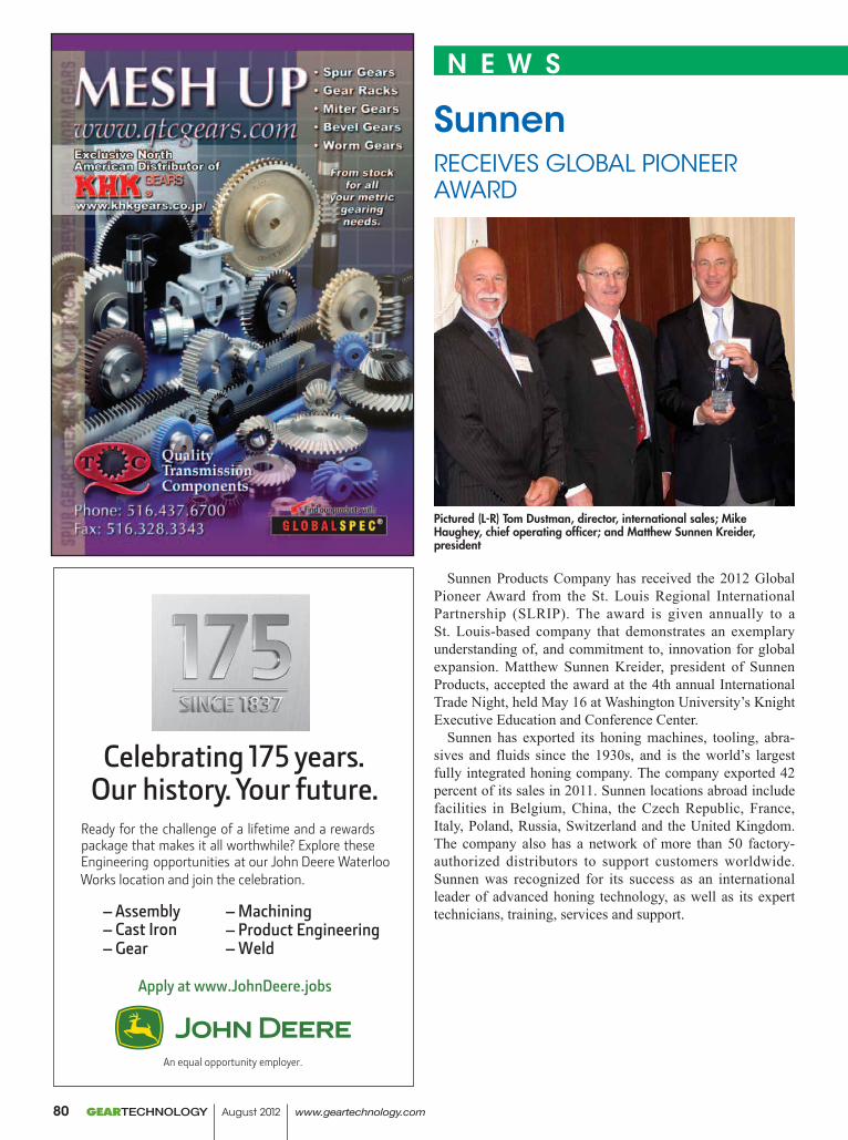
N E W S
SunnenReCeiveS GLObAL PiOneeR AWARd
Sunnen Products Company has received the 2012 Global Pioneer Award from the St. Louis Regional International Partnership (SLRIP). The award is given annually to a St. Louis-based company that demonstrates an exemplary understanding of, and commitment to, innovation for global expansion. Matthew Sunnen Kreider, president of Sunnen Products, accepted the award at the 4th annual International Trade Night, held May 16 at Washington University’s Knight Executive Education and Conference Center.
Sunnen has exported its honing machines, tooling, abra-sives and fluids since the 1930s, and is the world’s largest fully integrated honing company. The company exported 42 percent of its sales in 2011. Sunnen locations abroad include facilities in Belgium, China, the Czech Republic, France, Italy, Poland, Russia, Switzerland and the United Kingdom. The company also has a network of more than 50 factory-authorized distributors to support customers worldwide. Sunnen was recognized for its success as an international leader of advanced honing technology, as well as its expert technicians, training, services and support.
Pictured (L-R) Tom Dustman, director, international sales; Mike Haughey, chief operating officer; and Matthew Sunnen Kreider, president
GEARTECHNOLOGY August 2012 www.geartechnology.com80
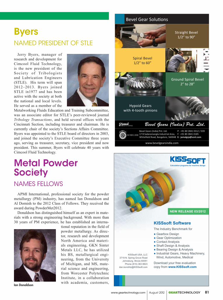
Bevel Gear Solutions
Bevel Gears (India) Pvt. Ltd.17 B Sadaramangla Industrial Area,Whitefield Road, Bangalore, 560048
P: +91 80 2841 0312 / 039 F: +91 80 2841 0185E: [email protected]
ISO 9001:2000
www.bevelgearsindia.com
Straight Bevel 1/2” to 90”
Ground Spiral Bevel 2” to 28”
Spiral Bevel 1/2” to 60”
Hypoid Gears with 4-tooth pinions
NEW RELEASE 03/2012
KISSsoft SoftwareThe Industry Benchmark for● Gearbox Design● Gear Optimization● Contact Analysis● Shaft Design & Analysis● Bearing Design & Analysis● Industrial Gears, Heavy Machinery, Wind, Automotive, Medical
Download your free evaluationcopy from www.KISSsoft.com
KISSsoft USA, LLC3719 N. Spring Grove Road
Johnsburg, Illinois 60051Phone (815) 363 8823
GearTech_KISSsoft_Rel_03_2012_86x121mm.indd 1 4/11/2012 10:49:22 AM
N E W S
ByersnAMed PReSidenT Of STLe
Jerry Byers, manager of research and development for Cimcool Fluid Technology, is the new president of the Soc ie ty o f Tr ibo log is t s and Lubrication Engineers (STLE). His term will span 2012–2013. Byers joined STLE in1977 and has been active with the society at both the national and local levels. He served as a member of the Metalworking Fluids Education and Training Subcommittee, was an associate editor for STLE’s peer-reviewed journal Tribology Transactions, and held several offices with the Cincinnati Section, including treasurer and chairman. He is currently chair of the society’s Sections Affairs Committee. Byers was appointed to the STLE board of directors in 2003, and joined the society’s Executive Committee three years ago, serving as treasurer, secretary, vice president and now president. This summer, Byers will celebrate 40 years with Cimcool Fluid Technology.
Metal Powder SocietynAMeS feLLOWS
APMI International, professional society for the powder metallurgy (PM) industry, has named Ian Donaldson and Al Dornish to the 2012 Class of Fellows. They received the award during PowderMet2012.
Donaldson has distinguished himself as an expert in mate-rials with a strong engineering background. With more than 30 years of PM experience, he has established an interna-
tional reputation in the field of powder metallurgy. As direc-tor, research and development North America and materi-als engineering, GKN Sinter Metals LLC, he has utilized his BS, metallurgical engi-neering, from the University of Michigan, and MS, mate-rial science and engineering, from Worcester Polytechnic Institute, in a collaboration with academia, customers,
Ian Donaldson
www.geartechnology.com August 2012 GEARTECHNOLOGY 81
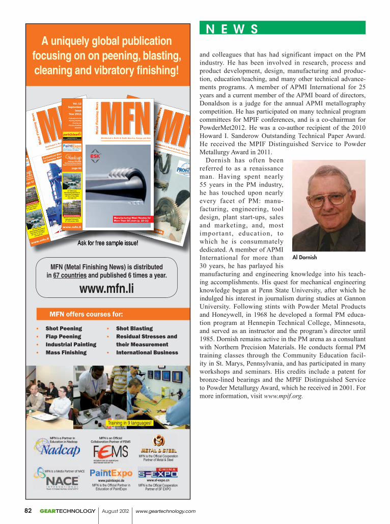
A uniquely global publication focusing on on peening, blasting, cleaning and vibratory finishing!
Ask for free sample issue!
MFN is an Official Collaboration Partner of FEMS
www.sf-expo.cnMFN is the Official Cooperation
Partner of SF EXPO
MFN is a Partner in Education in Nadcap
www.paintexpo.de MFN is the Official Partner in
Education of PaintExpo
MFN is a Media Partner of NACE
MFN offers courses for:
MFN (Metal Finishing News) is distributed in 67 countries and published 6 times a year.
www.mfn.li
Training in 9 languages!
Ask for free sample issue!
www.mfn.li
www.paintexpo.de - MFN is the Official
Partner in Education of PaintExpo
www.parts2clean.com
MFN is Official Cooperation Partner of parts2clean
Publication for the
Peening, Blasting,
Cleaning and
Vibratory Finishing
Industries
Vol. 12 May
Issue
Year 2011
Nadcap COLUMN:
How to promote your
Nadcap Accreditation
page 57
Customized Blasting Solutions for the Cleaning
of Complex Workpiece Confi gurations (p. 26-27)
11th MFN Asian
Shot Peening Workshop &
Trade Show in Singapore
31st Oct.-3rd Nov. 2011
(see page 29)
Sponsored by PaintExpo
MFN-JOT Industrial Painting
Workshop in Germany
4th of May, 2011
Ask for free sample issue!Ask for free sample issue!
www.mfn.li
www.paintexpo.de - MFN is the Official
Partner in Education of PaintExpo
www.parts2clean.com
MFN is Official Cooperation Partner of parts2clean
Publication for the Peening, Blasting, Cleaning and Vibratory Finishing Industries
Vol. 12 July
IssueYear 2011
Nadcap COLUMN:Audit Observationspage 55
11th MFN Asian Shot Peening Workshop &
Trade Show in Singapore31st Oct.-3rd Nov. 2011
(see page 23)
Sponsored by PaintExpoMFN-JOT Industrial Painting
Workshop in Germany 17th of November, 2011
Residual Stresses in Service (p. 10-12)
www.mfn.li
www.paintexpo.de - MFN is the Official
Partner in Education of PaintExpo
www.parts2clean.com
www.parts2clean.com
wMFN is Official Cooperation Partner of parts2clean
Publication for the Peening, Blasting, Cleaning and Vibratory Finishing Industries
Vol. 12 July
IssueYear 2011
Nadcap COLUMN:Audit Observationspage 55
11th11th11 MFN Asian Shot Peening Workshop &
Trade Show in Singapore31st Oct.-3rd Nov. 2011
(see page 23)
Sponsored by PaintExpoMFN-JOT Industrial Painting
Workshop in Germany 17th of November, 2011
Residual Stresses in Service (p. 10-12)
Customized Blasting Solutions for the Cleaning
of Complex Workpiece Confi gurations (p. 26-27)
Customized Blasting Solutions for the Cleaning
of Complex Workpiece Confi gurations (p. 26-27)
www.mfn.li
www.paintexpo.de - MFN is the Official Partner in Education of PaintExpo
www.parts2clean.comMFN is Official Cooperation Partner of parts2clean
Publication for the Peening, Blasting,
Cleaning and Vibratory Finishing
Industries
Vol. 12 September
IssueYear 2011
Nadcap COLUMN:What has the Nadcap Supplier
Support Committee done for me?
page 61
11th MFN Asian Shot Peening Workshop & Trade Show in Singapore31st Oct.-3rd Nov. 2011
(see page 12)
Sponsored by PaintExpoMFN-JOT Industrial Painting
Workshop in Germany 17th of November, 2011
Manufacturing Blast Nozzles for More Than 50 years (p. 10-11)
▪ Shot Peening ▪ Flap Peening ▪ Industrial Painting ▪ Mass Finishing
MFN is the Official Cooperation Partner of Metal & Steel
▪ Shot Blasting ▪ Residual Stresses and
their Measurement ▪ International Business
N E W S
and colleagues that has had significant impact on the PM industry. He has been involved in research, process and product development, design, manufacturing and produc-tion, education/teaching, and many other technical advance-ments programs. A member of APMI International for 25 years and a current member of the APMI board of directors, Donaldson is a judge for the annual APMI metallography competition. He has participated on many technical program committees for MPIF conferences, and is a co-chairman for PowderMet2012. He was a co-author recipient of the 2010 Howard I. Sanderow Outstanding Technical Paper Award. He received the MPIF Distinguished Service to Powder Metallurgy Award in 2011.
Dornish has often been referred to as a renaissance man. Having spent nearly 55 years in the PM industry, he has touched upon nearly every facet of PM: manu-facturing, engineering, tool design, plant start-ups, sales and marketing, and, most important , education, to which he is consummately dedicated. A member of APMI International for more than 30 years, he has parlayed his manufacturing and engineering knowledge into his teach-ing accomplishments. His quest for mechanical engineering knowledge began at Penn State University, after which he indulged his interest in journalism during studies at Gannon University. Following stints with Powder Metal Products and Honeywell, in 1968 he developed a formal PM educa-tion program at Hennepin Technical College, Minnesota, and served as an instructor and the program’s director until 1985. Dornish remains active in the PM arena as a consultant with Northern Precision Materials. He conducts formal PM training classes through the Community Education facil-ity in St. Marys, Pennsylvania, and has participated in many workshops and seminars. His credits include a patent for bronze-lined bearings and the MPIF Distinguished Service to Powder Metallurgy Award, which he received in 2001. For more information, visit www.mpif.org.
Al Dornish
GEARTECHNOLOGY August 2012 www.geartechnology.com82
C A L E N D A R
September 10–15—IMTS 2012. McCormick Place, Chicago. The 29th edition of the manufacturing tech-nology show boasts more than 1,100 exhibiting com-panies that will occupy 1.1 million net square feet of exhibit space. The show attracts 82,000 buyers and sellers from more than 116 countries. Leading manu-facturers will display their equipment in pavilions includ-ing Metal Cutting, Tooling and Workholding Systems, Metal forming and fabricating/Laser Processes, Gear Generation, industrial Automation and many more. The iMTS 2012 Conference brings the industry together, under one roof and at one time, to discuss technolo-gies, business development and optimization, plus workforce efficiency and productivity. Special emphasis will be placed on maintaining focus on short- and long-term goals during a tough economic environment. for more information, visit www.imts.com.
September 11–13—International Conference on Manufacturing Research 2012. Aston University. for over two decades it has been the main manufacturing research conference organized in the U.K., success-fully bringing researchers, academics and industrialists together to share their knowledge and experiences. initiated as a national Conference by the Consortium of U.K. University Manufacturing engineering (COMeH) it became an international Conference in 2003. COMeH is an independent body established in 1978. its main aim is to promote manufacturing engineering educa-tion, training and research. Keynote speakers for the event include Hamid Mughal, executive vice presi-dent, manufacturing, Rolls-Royce Plc.; professor Sir Mike Gregory, institute for Manufacturing, Cambridge University; John Ladbrook, european simulation special-ist, ford Motor Company and Professor Jay Lee, direc-tor of the Center for intelligent Maintenance Systems, University of Cincinnati. for more information, visit www1.aston.ac.uk/icmr2012.
September 18–19—Human Error Prevention Seminar. fogelman executive Conference Center, Memphis, Tennessee. The principles and practices of human error prevention are universally applicable regardless of the type of industrial, commercial or governmental enter-prise, and regardless of the type of function performed within the enterprise. This seminar is truly unique and up to date with the latest developments in human error prevention. ben Marguglio’s new taxonomy of human error causal factors and his human error-related mod-els demonstrate his leadership in this subject. examples and case studies amply reinforce the human error prevention principles and practices. This seminar cov-ers: classifications of human error; quality and safety culture and the quality- and safety-conscious work envi-ronment; leadership responsibilities; the total quality and safety function and much more. for more informa-tion, contact ben Marguglio at (845) 265-0123 or e-mail [email protected].
September 20–21—Root Cause Analysis Seminar. fogelman executive Conference Center, Memphis, Tennessee. This seminar covers all of the elements of a problem/condition reporting, root cause analysis and corrective action system with emphasis on the follow-ing root cause analysis techniques: failure mode and effects analysis for hardware problems and hazard-bar-rier-effects analysis for management and technical pro-cess problems. This seminar will also cover a modified hazard-barrier-effects analysis technique that allows the root cause analysis resource expenditure to be pro-portional to the significance of the problem, while still enabling the analyst to identify human performance root causes. Persons who are responsible for identify-ing and reporting off-normal conditions, evaluating the conditions and their effects, identifying causal factors, recommending various types of corrective actions, tracking the implementation of corrective actions, and managing the overall system should consider attend-ing this seminar. for more information, contact ben Marguglio at (845) 265-0123 or e-mail [email protected].
October 15–19—AME Chicago 2012. Sheraton Chicago Hotel and Towers. The Association for Manufacturing excellence (AMe) has a long track record for finding and convincing some of the best manufacturing practitioners from around the world to share their lean practice experiences. More than 60 leading presenters will be on hand to discuss customer focus, process sustainment, continuous improvement, material flow and other lean practices and strategies. Manufacturing tours highlighting some of the best lean and six sigma operations in and around the Chicago area include Caterpillar, bimba Manufacturing, Whiting Corporation, S&C electric Company and Winzeler Gear. Workshop topics include maintenance management, lean behaviors, training within industry, lean business simulation and lean tools for the office. Six keynote speakers will be featured at the conference including Mike Abrashoff and Jason Jennings. for registration information, visit www.ameconference.org.
October 28–30—AGMA Fall Technical Meeting. Hyatt Regency dearborn, dearborn, Michigan. The fTM high-lights the latest research in the industry from experts all over the world on topics including micropitting, gear-box design, materials and manufacturing. The confer-ence is designed for attendees to listen to all the pres-entations and take home practical information that may ultimately affect your company’s bottom line. in addition, the meeting is designed to provide invaluable networking time between sessions and in the evenings to interact with colleagues and meet new experts in the industry. Programs include lubrication and com-ponents, gear drive applications, manufacturing and inspection, gear design issues and materials and heat treatment. for more information, visit www.agma.org.
GEARTECHNOLOGY August 2012 www.geartechnology.com84

Sign Up for YOUR
Free SubscriptionGear Technology offers free electronic subscriptions anywhere in the world,
and free printed subscriptions in the USA, Canada and Mexico.
FAX TO 1-847-437-6618 OR VISIT US ONLINE AT
WWW.GEARTECHNOLOGY.COM
If you want the printed version, but your mailing
address is outside the USA, Canada or Mexico, please visit our subscription page
online atwww.geartechnology.com/
subscribe.htm
YES, I would like to receive Gear Technology’s monthly e-mail newsletter YES, I would like to receive 3rd-party e-mails from Gear Technology’s advertisers and partners
YES, I would like to receive subscription renewal notices by e-mail No, I do not wish to be contacted by e-mail.
®
®
Company Name:_________________________________________________Company Address:_________________________________________________________________________________________________________________City:______________________________________________________________ State/Province:____________________________________________________ZIP/Postal Code:___________________________________________________Telephone:_________________________Fax:___________________________E-mail:____________________________________________________________Co. Internet Address:______________________________________________
5) Please tell us about your company:
9) What is the principal product manufactured or service performed at THIS LOCATION?7) How is THIS LOCATION involved in the gear industry? (Check all that apply) WE MAKE GEARS (or Splines, Sprockets, Worms, etc.) (20) WE BUY GEARS (or Splines, Sprockets, Worms, etc.) (22) WE SELL NEW MACHINES, TOOLING OR SUPPLIES TO GEAR MANUFACTURERS (24)
8) Which of the following products and services do you personally specify, recommend or purchase? (Check all that apply)
Machine Tools Gear Hobbing Machines (50) Gear Shaping Machines (51) Gear Shaving Machines (52) Gear Honing Machines (53) Gear Grinding Machines (54) Gear Inspection Equipment (55) Bevel Gear Machines (56) Gear/Spline Roll-Forming Equipment (57) Broaching Machines (58) Heat Treat Equipment (59) Deburring Equipment (60) Non-Gear Machine Tools Turning, Milling, etc.) (61)
Tooling & Supplies Functional Gages (62) Workholding (63) Toolholding (64) Cutting Tools (65) Grinding Wheels (66) Gear Blanks (67) Lubricants/Cutting Fluids (77)
Service & Software Heat Treat Services (69) Gear Consulting (70) Tool Coating (71) Tool Sharpening (72) Gear Design Software (73) Gear Manufacturing Software (74)
Power Transmission Components Gears (75) Gear Drives (76) Bearings (78) Motors (79)
10) How many employees are at THIS LOCATION (Check one) 1-19 20-49 50-99 100-499 500+
1) YES I want to receive/continue to receive Gear Technology FREE.
No thank you.
2) I want to receive the PRINT version *DIGITAL version *BOTH print and digital (*Please include your e-mail address for DIGITAL or BOTH versions.) ________________________________________________
3) Name:___________________________________________Job Title/Position: _______________________________
4) Signature _________________________________________________________ Date: ________________________
(Please print e-mail address)
(print)
WE provide SERVICES to gear manufacturers (25)(please describe) ____________________________________________ WE distribute gears or gear products (including agents and sales reps. (26) WE are a USED MACHINE TOOL dealer (30) Other (please describe) ___________________________________ (32)
Corporate Executives (B) Manufacturing Production Management (C)Manufacturing Production Department (D) Manufacturing Engineering Management (E) Manufacturing Engineering Department (F) Product Design, R&D Management (H)
Product Design/ R&D Personnel (I) Purchasing (L) Marketing & Sales, Communications (M) Quality Control Management (P) Quality Control Department (Q) Other (N)
____________________________
6) What is your primary job function responsibility? (Check one)
A D V E R T I S E R S I N D E XADVERTISER PAGE PHONE E-MAIL WEB SITE
AGMA 77 (703) 684-0211 [email protected] www.gearexpo.comAjax Rolled Ring 6 (800) 727-6333 www.ajaxring.com
B&R Machine & Gear Corp. IBC (731) 456-2636, (800) 238-0651 [email protected] www.brgear.com
Bevel Gears India Pvt. Ltd. 81 + (91) 80-2841-0312 [email protected] www.bevelgearsindia.comBroaching Machine Specialties 42 (248) 471-4500 [email protected] www.broachingmachine.comCircle Gear & Machine Co. 87 (708) 652-1000 www.circlegear.comDMG/Mori Seiki 19 (855) 364-6674 www.dmgmoriseikiusa.comDrake Manufacturing 23, 38 (330) 847-7291 [email protected] www.drakemfg.com
DTR Corp. 18 + (82) 32-814-1540, (847) 375-8892, [email protected], [email protected] www.dragon.co.kr
ESGI Tools Pvt. Ltd. 4 + (91) 175-223-3991 [email protected] www.esgitools.comForest City Gear 7 (815) 623-2168 [email protected] www.forestcitygear.comGear Consulting Group 87 (269) 623-4993 [email protected] www.gearconsultinggroup.comGear Expo 77 (703) 684-0211 [email protected] www.gearexpo.comGear Motions Inc. 50 (315) 488-0100 [email protected] www.gearmotions.comThe Gear Works—Seattle, Inc. 87 (206) 762-3333 [email protected] www.thegearworks.comGleason Corp. 40, 43, 44-45, 87 (585) 473-1000 [email protected] www.gleason.comHans-Jürgen Geiger Maschinen-Vertrieb 35 + (49) 7123-18040 [email protected] www.geiger-germany.comHexagon Metrology 20 (401) 886-2422 www.leitz-metrology.comHöfler OBC (734) 416-9300 [email protected] www.hofler.comIndex Technologies 87 (440) 331-0038 www.gallenco.comIngersoll Cutting Tools 53, 55, 57, 59 (815) 387-6600 [email protected] www.ingersoll-imc.comIpsen International 13 (800) 727-7625 www.ipsenusa.comJohn Deere 80 www.johndeere.jobsKapp Technologies 3 (303) 447-1130 [email protected] www.kapp-usa.comKISSsoft 81 (815) 363-8823 [email protected] www.kisssoft.comLeistritz Corp. 31 (201) 934-8262 www.leistritzcorp.comLiebherr 5 (734) 429-7225 [email protected] www.liebherr.comMcInnes Rolled Rings 16 (800) 569-1420 [email protected] www.mcinnesrolledrings.comMetal Finishing News 82 www.mfn.liMidwest Gear & Tool Inc. 79 (586) 779-1300 [email protected] 8, 38 (248) 669-0614 www.mitsubishigearcenter.comMitutoyo 15 (888) 648-8869 www.mitutoyo.comNachi 32, 40 (317) 530-1001 [email protected] www.nachiamerica.comNiagara Gear 4 (800) 447-2392 [email protected] www.niagaragear.comOelheld USA 41, 54 (847) 531-8501 [email protected] www.oelheld.comPresrite Corp. 24 (216) 441-5990 www.presrite.comProcess Equipment 49 (800) 998-4191 www.gearinspection.comQuality Transmission Components 80 (516) 437-6700 [email protected] www.qtcgears.comReishauer 11 (847) 888-3828 www.reishauer.comRiverside Spline & Gear 33 (810) 765-8302 [email protected] www.splineandgear.comRöders GmbH 41, 56 (845) 680-7020 [email protected] www.roeders.deRoto-Flo/U.S. Gear Tools 29, 39 [email protected] www.roto-flo.comSandvik Coromant 27 (800) 726-3845 www.coromant.sandvik.com/usSchnyder S.A. 50 (630) 595-7333 [email protected] www.hanikcorp.comSeco Tools 17, 40 (248) 528-5200 [email protected] www.secotools.com/energySicmat 58 (847) 649-1450 [email protected] www.star-su.comSMT—Smart Manufacturing Technology 79 +(44) 115-941-9839 [email protected] www.smartmt.comStar SU LLC IFC–1, 58, 87 (847) 649-1450 [email protected] www.star-su.com Stock Drive Products/Sterling Instrument 49 (516) 328-3300 [email protected] www.sdp-si.com/e-storeStresstech Oy 47 (412) 784-8400 [email protected] www.astresstech.comSunnen Products Co. 39 (314) 781-2100 www.sunnen.comTicona 21 (859) 372-3244 www.ticona.com/gearheadsToolink Engineering Inc. 83 (303) 776-6212 www.toolink-eng.comU.S. Gear Tools/Roto-Flo 29, 39 (828) 686-5486 [email protected] www.usgeartools.comWenzel America Ltd. 30 (248) 295-4300 www.wenzelamerica.comWinterthur/Wendt 42, 51 (508) 949-1061 [email protected] www.winterthurtechnology.comYager Gear Enterprise Ltd. 87 +(886) 4-2407-6223, ext. 30 [email protected] www.yagergear.comZoller Inc. 39 (734) 332-4851 [email protected] www.zoller-usa.com
GEARTECHNOLOGY August 2012 www.geartechnology.com86
C L A S S I F I E D S E C T I O N
216.642.5900 216.642.8837
5755 CANAL ROAD · VALLEY VIEW, OH 44125
Call 815.639.4201 ext. [email protected]
MORE ‘APPS’!
Shorter lead times, more performance...there’s an ‘app’
for that, at:
THIN FILMCOATINGS
CBN & DIAMONDWHEEL PLATING
HEAT TREAT
PICK UP & DELIVERY
TOOL SHARPENING
METALLURGICAL LABORATORY
Circle Gear and Machine• Reverse Engineering• Design Analysis• Complete Machine Shop Including CNC Machining
Documented Quality Control Program
Inspection Lab including Complete
Gear Tooth Diagnostics
1501 South 55th Ct. • Cicero, IL 60804Ph: 708-652-1000 • Fax: 708-652-1100
Since 1951
Please email your inquiries to [email protected] • www.circlegear.com
Tooth Cutting, Grinding & Shaving Services Available
CG C
C I R C LE
G E A R C O
QUALITY CUSTOM GEARING!
All Sizes & Configurations
QUALITY CUSTOM GEARING!
School for Gear Manufacturing Technology
DAY CLASS to cover the practical aspects of gear technology and geometry aiming toward a logical approach to trouble shooting and
optimizing the manufacturing processes• gear geometry and its
relationship to gear generation.
• gear inspection procedures and analysis.
• Understanding the processes of Hobbing, shaping and shaving.
• trouble shooting the process from inspection data.
• Cutter wear and failure analysis.
• Cutter materials and coaings. optimization of feeds and speeds.
• Hob shifting procedures and optimization.
• Use of standards.• open forum on attendee’s
experienced problems.
september 5–7 / addison, il
3
Conducted by
Geoff Ashcroft, Gear Consulting Group
More information:http://www.gearconsultinggroup.com
Contact bobbie ph: [email protected]
2012 Class Schedule
Save this code to add it to your blogor your documents.
You can also use the code's permalink,or copy-paste the following HTML code:
<img src="http://qrcode.kaywa.com/img.php?s=12&d=http%3A%2F%2Fww
Q R - C O D E G E N E R A T O R
Content type:
URL Text Phone Number SMS
Content:
URL:http://www.gearconsultinggroup.com
Size: XL
Generate!
Version: 1.00 BETA | Non-Commercial Use Only KAYWA // TECHNOPARKSTRASSE 1 // 8005 ZUERICH // SWITZERLAND // SUPPORT
A DV ERT IS EMENT:
ID KAYWA READER FEED2MOBILE DATAMATRIX GENERATOR NEW: DOKODARE PHOTO LENDORFF KAYWA
QR-Code Generator http://qrcode.kaywa.com/
1 of 2 10/27/2011 10:02 AM
earonsultingroup
for Electric and Pneumatic Tools, Machine Tools, Agricultural Machinery and Automobiles
Spiral Bevel Gears
Gear Grinding for CouplingGear DA Turret
Yager Gear Enterprise Co., Ltd.No. 57, Shigu Ln., Guozhong Rd., Dali Dist., Taichung City 412, TaiwanTel: +886-4-24076223 EXT. 30Fax: +886-4-24076218E-mail: [email protected]://www.yagergear.com
ISO 9001:2008
www.geartechnology.com August 2012 GEARTECHNOLOGY 87
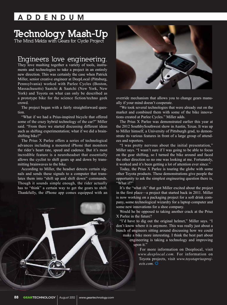
A D D E N D u M
Technology Mash-UpThe Mind Melds with Gears for Cycle Project
Engineers love engineering. They love mashing together a variety of tools, instru-ments and technologies to take a project in an entirely new direction. This was certainly the case when Patrick Miller, senior creative engineer at DeepLocal (Pittsburg, Pennsylvania) worked with Parlee Cycles (Boston, Massachusetts) Saatchi & Saatchi (New York, New York) and Toyota on what can only be described as a prototype bike for the science fiction/techno geek crowd.
The project began with a fairly straightforward ques-tion.
“What if we had a Prius-inspired bicycle that offered some of the crazy hybrid technology of the car?” Miller said. “From there we started discussing different ideas such as shifting experimentation; what if we did a brain-shifting bike?”
The Prius X Parlee offers a series of technological advances including a mounted iPhone that monitors the rider’s heart rate, speed and cadence. But it’s most incredible feature is a neuroheadset that essentially allows the cyclist to shift gears up and down by trans-mitting brainwaves to the bike.
According to Miller, the headset detects certain sig-nals and sends these signals to a computer that trans-lates them into “shift up and shift down” commands. Though it sounds simple enough, the rider actually has to “think” a certain way to get the gears to shift. Thankfully, the iPhone app comes equipped with an
override mechanism that allows you to change gears manu-ally if your mind doesn’t cooperate.
“We took several technologies that were already out on the market and combined them with some of the bike innova-tions created at Parlee Cycles.” Miller adds.
The Prius X Parlee was demonstrated earlier this year at the 2012 SouthbySouthwest show in Austin, Texas. It was up to Miller himself, a University of Pittsburgh grad, to demon-strate its various features in front of a large group of attend-ees and reporters.
“I was pretty nervous about the initial presentation,” Miller says. “I wasn’t sure if I was going to be able to focus on the gear shifting, so I turned the bike around and faced the other direction so no one was looking at me. Fortunately, it worked and it’s been getting a lot of attention ever since.”
Today, the Prius X Parlee is touring the globe with some other Toyota products. These demonstrations give people the opportunity to ask the simplest engineering question there is, “What if?”
It’s the “what ifs” that got Miller excited about the project in the first place—a project that started back in 2011. Miller is now working on a packaging project for a soft drink com-pany, some technological wizardry for a laptop computer and some new innovations for a shoe company.
Would he be opposed to taking another crack at the Prius X Parlee in the future?
“I’d have to dig out the original helmet,” Miller says. “I don’t know where it is anymore. This was really just about a bunch of engineers sitting around discussing how we could
make a bike more interesting. I think the best part about engineering is taking a technology and improving
upon it.”For more information on Deeplocal, visit
www.deeplocal.com. For information on Toyota projects, visit www.toyotapriusproj-ects.com.
GEARTECHNOLOGY August 2012 www.geartechnology.com88
Machine and Gear Corporation
Toll Free: (800) [email protected] www.brgear.com
REVERSE ENGINEERING
BREAKDOWN SERVICES
SPIRAL BEVEL GEARS: 66" PDSTRAIGHT BEVEL GEARS: 80" PD
SPURS, HELICALS, SPLINE SHAFTSGEARBOX REPAIR/REBUILDS
IN-HOUSE STEEL MATERIAL WAREHOUSE
FULL HEAT TREATING SERVICES
EDM WIRE BURNING
C U S T O MBEVEL GEAR MANUFACTURING
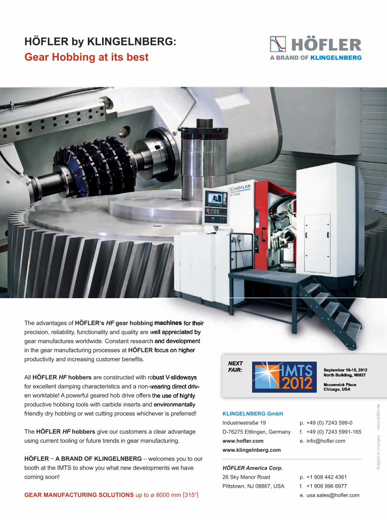
HÖFLER by KLINGELNBERG:Gear Hobbing at its best
KLINGELNBERG GmbHIndustriestraße 19 p. +49 (0) 7243 599-0
D-76275 Ettlingen, Germany f. +49 (0) 7243 5991-165
www.hofl er.com e. info@hofl er.com
www.klingelnberg.com
HÖFLER America Corp.26 Sky Manor Road p. +1 908 442 4361
Pittstown, NJ 08867, USA f. +1 908 996 6977
e. usa.sales@hofl er.com
The advantages of HÖFLER‘s HF gear hobbing machines for their precision, reliability, functionality and quality are well appreciated by gear manufactures worldwide. Constant research and development in the gear manufacturing processes at HÖFLER focus on higher productivity and increasing customer benefi ts.
All HÖFLER HF hobbers are constructed with robust V-slideways for excellent damping characteristics and a non-wearing direct driv-en worktable! A powerful geared hob drive offers the use of highly productive hobbing tools with carbide inserts and environmentally friendly dry hobbing or wet cutting process whichever is preferred!
The HÖFLER HF hobbers give our customers a clear advantage using current tooling or future trends in gear manufacturing.
HÖFLER – A BRAND OF KLINGELNBERG – welcomes you to our booth at the IMTS to show you what new developments we have coming soon!
GEAR MANUFACTURING SOLUTIONS up to ø 8000 mm [315“]
Sub
ject
to c
hang
esw
ww
.st3
60.d
e
NEXTFAIR: September 10-15, 2012
North Building, N6837
Mccormick PlaceChicago, USA
gear hobbing machines for their precision, reliability, functionality and quality are well appreciated by gear manufactures worldwide. Constant research and development
HÖFLER focus on higher HÖFLER focus on higher HÖFLER
are constructed with robust V-slideways for excellent damping characteristics and a non-wearing direct driv-en worktable! A powerful geared hob drive offers the use of highly productive hobbing tools with carbide inserts and environmentally
ww
w.s
t360
.de
NEXTFAIR: September 10-15, 2012
North Building, N6837
Mccormick PlaceChicago, USA
AZ-GT-3-2012-Wälzfräsen.indd 1 26.07.12 21:39