Embed Size (px)
Citation preview

Your Resource for Machines, Services, and Tooling for the Gear Industry
AUGUST 2018gearsolutions.com
THE EFFECTS OF SHROUDING ON REDUCING
MESHED SPUR GEAR POWER LOSS
IMTS Show Preview
WENZEL AMERICA
ISSUE FOCUS
COMPANYPROFILE
GEAR SOLU
TION
S MAGAZIN
E TH
E EFFECTS OF SH
ROU
DIN
G ON
REDU
CING M
ESHED
SPUR GEAR PO
WER LO
SS AU
GUST 20
18

CHUCKS - ARBORS - MANDRELS - COLLETS - FIXTURES
With 70 years of experience, we can handle all your custom workholding needs. Drewco Corporation is a family run business led by a team of engineers and machinists. We are backed by original patents, years of experience, and proven effective designs.
3745 Nicholson RdFranksville,WI 53126Office (262) [email protected]
www.drewco.com
LEADERSin GEAR WORKHOLDING
An Expert In Design and Build

www.toolink-eng.com
303-776-6212
Whatever your needs, we’ve got you covered!
We’re all g-EARS
2 gearsolutions.com
Gleason non-contact laser scanning is revolutionizing gear
inspection. Use the GMSL to speed new gear development, or take countless hours out of in-process, high volume gear inspection with the GRSL. All
supported with precision tooling, Closed Loop networking, and
application expertise.
www.gleason.com/laser
Smart.
© Gleason Corporation. All rights reserved.
N-237000 5-C15

August 2018 3
THE EFFECTS OF SHROUDING ON REDUCING MESHED SPUR GEAR POWER LOSS
Insights from NASA aeronautics rotorcraft research aimed at propulsion technologies that improve efficiency while minimizing vehicle weight.
By I.R. DELGADO and M.J. HURRELL
34
42AREAL EVALUATION OF INVOLUTE GEAR FLANKS WITH 3D SURFACE DATAAn explanation of how examinations of involute gear flanks using areal, three-dimensional surface data provides in-depth, holistic information about the gears.
By YUE PENG, KANG NI, and DR. GERT GOCH
FEATURES
52MODULAR SEALING SOLUTION IDEAL FOR AUTOMATION
An innovative sealing system has been developed especially for industrial applications where robustness and long lifespans of gears
are in demand, including robots and automation.
By MARCEL SANTOS and BENJAMIN KOHL
A GLOBAL COMPANY WITH A LOCAL FEELCOMPANY PROFILE Wenzel America is an innovative provider of customized metrology solutions, built on a solid foundation of German precision engineering and strong partnerships as a family-owned company.
By GEAR SOLUTIONS
56

4 gearsolutions.com
1605 Industrial DriveAuburn, CA 95603Phone: (530) 885-1939Fax: (530) 885-8157
and Universal Gear Company
Manufacturers of:
Booth N-237106
August 2018 5
MARK MICHAUD
THE STATE OF THE ART OF WIND TURBINE GEARBOXESRegularly scheduled maintenance keeps turbines spinning, and the proper lubricants can extend the period between checkups.
New products, trends, services, and developments in the gear industry.
BRIAN DENGEL
A PRIMER ON BACKLASH, ITS PURPOSE IN GEAR DESIGNSMinimizing backlash can create issues with lubrication and encourage excessive tooth mesh, which can then cause premature failure.
Gear Solutions (ISSN 1933 - 7507) is published monthly by Media Solutions, Inc., 266D Yeager Parkway, Pelham, AL 35124. Phone (205) 380-1573 Fax (205) 380-1580 International subscription rates: $72.00 per year. Periodicals Postage Paid at Pelham AL and at additional mailing offices. Printed in the USA. POSTMASTER: Send address changes to Gear Solutions magazine, P.O. Box 1210, Pelham, AL 35124. Publications mail agreement No. 41395015 return undeliverable Canadian addresses to P.O. Box 503 RPO West Beaver Creek, Richmond Hill, ON L4B4R6. Copyright ©2006 by Media Solutions, Inc. All rights reserved.
No part of this publication may be reproduced or transmitted in any form or by any means, electronic or mechanical, including photocopy, recording, or any information storage-and-retrieval system without permission in writing from the publisher. The views expressed by those not on the staff on Gear Solutions magazine, or who are not specifically employed by Media Solutions, Inc., are purely their own. All “Industry News” material has either been submitted by the subject company or pulled directly from their corporate website, which is assumed to be cleared for release. Comments and submissions are welcome, and can be submitted to [email protected].
MARC VONDERLAGE
Regional Sales Representative at Wickert
MATERIALS MATTER28
PRODUCT SHOWCASE60
HOT SEAT32
INDUSTRY NEWS8
Q&A72
RESOURCESMARKETPLACE70
ADVERTISER INDEX71
TOOTH TIPS30
D. SCOTT MACKENZIE
HEAT TREATMENT OF POWDER METALLURGY PARTSUnderstanding the differences that porosity/density can cause with heat-up times, and increased drag-out of quenchants when processing P/M parts can reduce the headaches occurring in the heat treat shop.
AUGUST 2018 • VOLUME 16, NUMBER 8
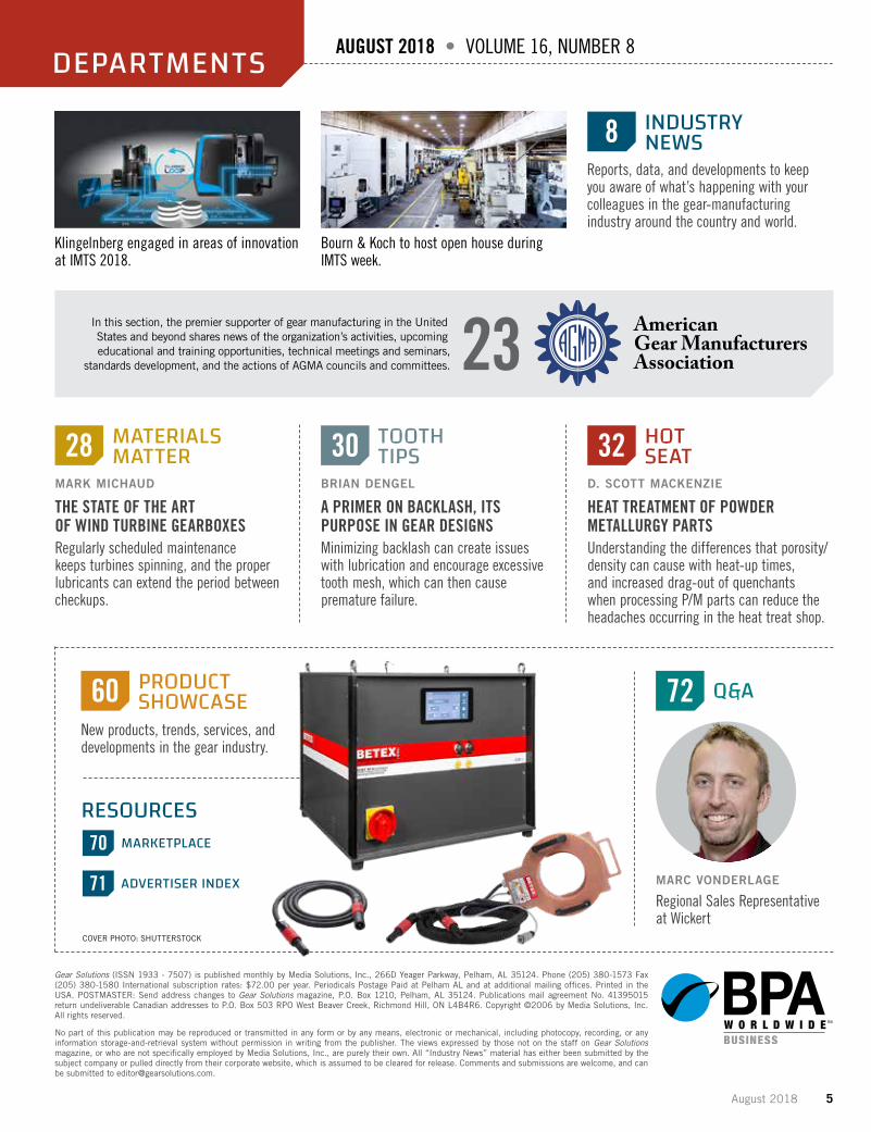
Klingelnberg engaged in areas of innovation at IMTS 2018.
Bourn & Koch to host open house during IMTS week.
Reports, data, and developments to keep you aware of what’s happening with your colleagues in the gear-manufacturing industry around the country and world.
DEPARTMENTS
American Gear ManufacturersAssociation
In this section, the premier supporter of gear manufacturing in the United States and beyond shares news of the organization’s activities, upcoming educational and training opportunities, technical meetings and seminars,
standards development, and the actions of AGMA councils and committees. 23
COVER PHOTO: SHUTTERSTOCK
6 gearsolutions.com
KENNETH CARTER, editor
Gear Solutions [email protected](800) 366-2185 x204
This issue marks our countdown to IMTS 2018, America’s largest manufacturing show.From September 10–15, manufacturing industry professionals from all across the
globe will be able to see more than 15,000 new machine tools, controls, computers, soft-ware, components, systems, and processes designed to improve efficiency in practically every aspect of the industry. More than 2,400 exhibitors are scheduled to display their products and solutions.
And speaking of solutions, Gear Solutions will be right there in the thick of it.We like to keep our finger on the pulse of the industry, and there’s no better way to do
that than to be on hand to talk to you about the advantages your business can offer and how we can share that with our readers.
Inside this issue, you’ll find a lot of products and services in our Industry News and Products sections that will be on display at IMTS.
But in addition to that, we have several interesting articles to help get you in the mood for IMTS as well.
An article from I.R. Delgado and M.J. Hurrell discusses insights about NASA aeronau-tics rotorcraft research aimed at propulsion technologies that improve efficiency while minimizing vehicle weight.
Yue Peng, Kang Ni, and Dr. Gert Goch from the University of North Carolina at Charlotte have written an interesting piece titled “Areal Evaluation of Involute Gear Flanks with Three-Dimensional Surface Data.”
And Marcel Santos and Benjamin Kohl share their expertise about an innovative seal-ing system developed especially for industrial applications where robustness and long lifespans of gears are in demand.
In this issue, you’ll also hear from some of our regular columnists, and for our two IMTS show issues, the knowledgeable experts from REM Surface Engineering have agreed to pen our Materials Matter feature.
The IMTS clock is counting down, and the show will be here before you know it. I hope to see you there. I’m excited about seeing old friends and making some new ones.
As always, thanks for reading!
IMTS: Bringing the industry together
FROM THEEDITOR David C. Cooper
PUBLISHER
Chad MorrisonASSOCIATE PUBLISHER
EDITORIAL
Kenneth CarterEDITOR
Russ WillcuttCONTRIBUTING EDITOR
Jennifer JacobsonASSOCIATE EDITOR
SALES
Chad MorrisonASSOCIATE PUBLISHER
Dave GomezREGIONAL SALES MANAGER
CIRCULATION
Teresa CooperMANAGER
Jamie WillettASSISTANT
Cole MorrisonASSISTANT
DESIGN
Rick FrenneaCREATIVE DIRECTOR
Michele HallGRAPHIC DESIGNER
CONTRIBUTING
WRITERSI.R. DELGADOGERT GOCH
M.J. HURRELL BENJAMIN KOHL
KANG NI YUE PENG
MARCEL SANTOSD. SCOTT MACKENZIE
BRIAN DENGELMARK MICHAUDMATT CROSON
PUBLISHED BY MEDIA SOLUTIONS, INC.P. O. Box 1987 • Pelham, AL 35124
(800) 366-2185 • (205) 380-1580 fax
David C. CooperPRESIDENT
Chad MorrisonVICE PRESIDENT
Coop wants to use this one for the website
Vertical Logo Horizontal Logo
Teresa CooperOPERATIONS
August 2018 7
860-223-7778www.NewEnglandGear.com
REMANUFACTUREDRETROFITTING
CUSTOM MACHINES
We have the world’s largest stock of used late-model Fellows Gear Shapers.
WE OWN WHAT WE SELL, AND WE KNOW WHAT WE’RE SELLING!
FELLOWS 50-8/50-12 GEAR SHAPERSHYDROSTROKE SHAPERS • REMANUFACTURED IN 2017
343 JOHN DOWNEY DRIVE • NEW BRITAIN, CT 06051-2907 • PHONE 860-223-7778 • FAX 860-223-7776 • [email protected]
Yeah, we’ve got that!
8 gearsolutions.com
INDUSTRYNEWS NEW TRENDS, SERVICES & DEVELOPMENTS
SEND US YOUR NEWS Companies wishing to submit materials for inclusion in Industry News should contact the editor, Kenneth Carter, at [email protected]. Releases accompanied by color images will be given first consideration.
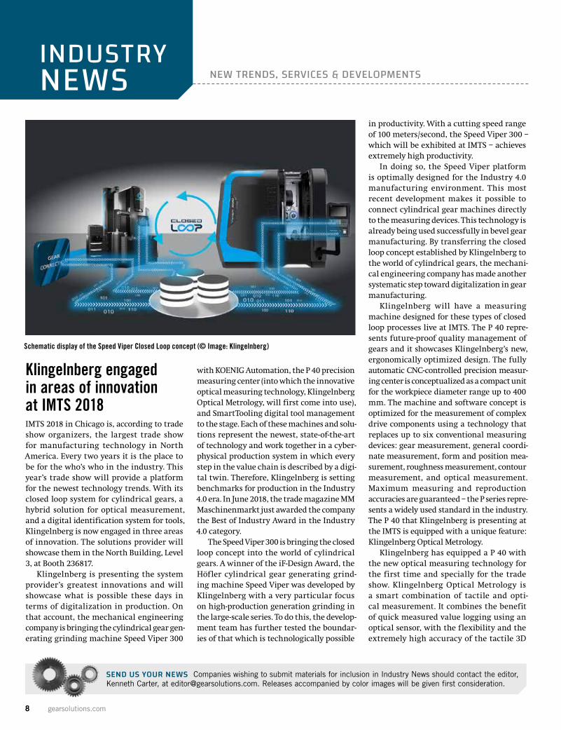
Klingelnberg engaged in areas of innovation at IMTS 2018IMTS 2018 in Chicago is, according to trade show organizers, the largest trade show for manufacturing technology in North America. Every two years it is the place to be for the who’s who in the industry. This year’s trade show will provide a platform for the newest technology trends. With its closed loop system for cylindrical gears, a hybrid solution for optical measurement, and a digital identification system for tools, Klingelnberg is now engaged in three areas of innovation. The solutions provider will showcase them in the North Building, Level 3, at Booth 236817.
Klingelnberg is presenting the system provider’s greatest innovations and will showcase what is possible these days in terms of digitalization in production. On that account, the mechanical engineering company is bringing the cylindrical gear gen-erating grinding machine Speed Viper 300
with KOENIG Automation, the P 40 precision measuring center (into which the innovative optical measuring technology, Klingelnberg Optical Metrology, will first come into use), and SmartTooling digital tool management to the stage. Each of these machines and solu-tions represent the newest, state-of-the-art of technology and work together in a cyber-physical production system in which every step in the value chain is described by a digi-tal twin. Therefore, Klingelnberg is setting benchmarks for production in the Industry 4.0 era. In June 2018, the trade magazine MM Maschinenmarkt just awarded the company the Best of Industry Award in the Industry 4.0 category.
The Speed Viper 300 is bringing the closed loop concept into the world of cylindrical gears. A winner of the iF-Design Award, the Höfler cylindrical gear generating grind-ing machine Speed Viper was developed by Klingelnberg with a very particular focus on high-production generation grinding in the large-scale series. To do this, the develop-ment team has further tested the boundar-ies of that which is technologically possible
in productivity. With a cutting speed range of 100 meters/second, the Speed Viper 300 – which will be exhibited at IMTS – achieves extremely high productivity.
In doing so, the Speed Viper platform is optimally designed for the Industry 4.0 manufacturing environment. This most recent development makes it possible to connect cylindrical gear machines directly to the measuring devices. This technology is already being used successfully in bevel gear manufacturing. By transferring the closed loop concept established by Klingelnberg to the world of cylindrical gears, the mechani-cal engineering company has made another systematic step toward digitalization in gear manufacturing.
Klingelnberg will have a measuring machine designed for these types of closed loop processes live at IMTS. The P 40 repre-sents future-proof quality management of gears and it showcases Klingelnberg’s new, ergonomically optimized design. The fully automatic CNC-controlled precision measur-ing center is conceptualized as a compact unit for the workpiece diameter range up to 400 mm. The machine and software concept is optimized for the measurement of complex drive components using a technology that replaces up to six conventional measuring devices: gear measurement, general coordi-nate measurement, form and position mea-surement, roughness measurement, contour measurement, and optical measurement. Maximum measuring and reproduction accuracies are guaranteed – the P series repre-sents a widely used standard in the industry. The P 40 that Klingelnberg is presenting at the IMTS is equipped with a unique feature: Klingelnberg Optical Metrology.
Klingelnberg has equipped a P 40 with the new optical measuring technology for the first time and specially for the trade show. Klingelnberg Optical Metrology is a smart combination of tactile and opti-cal measurement. It combines the benefit of quick measured value logging using an optical sensor, with the flexibility and the extremely high accuracy of the tactile 3D
Schematic display of the Speed Viper Closed Loop concept (© Image: Klingelnberg)
August 2018 9
NANOSCAN sensor system. In this way, the hybrid system distinguishes itself through its extremely rapid changeover from the tac-tile to the optical system and is designed so that the optical sensors can be adapted in a number of ways. In addition to this combina-tion, optical measured value logging alone is also possible, of course. The measuring result then takes the form of a high-resolution 3D point cloud, which can be further processed and evaluated as a CAD file. The optical measurement is a new, extremely efficient option for the precision measuring centers of the P 26, P 40, P 65, P 100 and P 100L series. At the IMTS, visitors can see the advantages of the P 40 demonstrated live.
Also in the company’s “trade show suit-case”: Digital identification processing with SmartTooling. With SmartTooling, Klingelnberg is introducing a digital identi-fication system for tools and clamping tools, and is consistently further incorporating the bevel gear cutting machine into the Industry 4.0 subject area. With a look toward an extensive cyber-physical production sys-tem, it is a case of designing processes that are currently still carried out manually to be more efficient using software support and of establishing the basis for automation. SmartTooling facilitates traceability and with it, a 360-degree view of the production equipment. The additional data that is cur-rently available also provides a good basis for the identification of optimization potential in process improvement. The goal is to sup-port customers both in reducing costs and in increasing production quality.
MORE INFO www.klingelnberg.com
AIMS to showcase advanced CMM technology at IMTSDemand for 100 percent part inspection and the ability to process big data and measure complex features in a smart factory envi-ronment is affecting mainstream manufac-turing. Advanced Industrial Measurement Systems (AIMS) has engineered coordinate measurement machines (CMMs) that can perform fast, accurate inspections and gather intelligence.
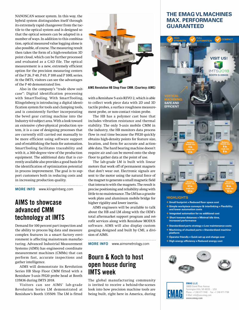
AIMS will demonstrate its Revolution Series HB Shop Floor CMM fitted with a Renishaw 5-axis PH20 probe head at Booth 135836 during IMTS 2018.
Visitors can see AIMS’ lab -grade Revolution Series LM demonstrated at Renishaw’s Booth 135509. The LM is fitted
with a Renishaw 5-axis REVO 2, which is able to collect work piece data with 2D and 3D tactile probes, a surface roughness measure-ment probe, or non-contact vision probe.
The HB has a polymer cast base that includes vibration resistance and thermal stability. The only 5-axis mobile CMM in the industry, the HB monitors data process flow in real time because the PH20 quickly obtains high-density points for feature size, location, and form for accurate and action-able data. The hard bearing machine doesn’t require air and can be moved onto the shop floor to gather data at the point of use.
The lab-grade LM is built with linear motors that work off of permanent magnets that don’t wear out. Electronic signals are sent to the motor using the natural force of the magnet to generate a small magnetic field that interacts with the magnets. The result is precise positioning and reliability along with little to no maintenance. The LM has a granite work plate and aluminum mobile bridge for higher rigidity and lower inertia.
AIMS engineers will be available to talk about the HB and LM along with the OEM’s total aftermarket support program and ret-rofit services along with Renishaw MODUS software. AIMS will also display custom gauging designed and built by CMI, a divi-sion of AIMS.
MORE INFO www.aimsmetrology.com
Bourn & Koch to host open house during IMTS weekThe global manufacturing community is invited to receive a behind-the-scenes look into how precision machine tools are being built, right here in America, during
AIMS Revolution HB Shop Floor CMM. (Courtesy: AIMS)
Workpiece diameter, max.
16 in.Length, max.
12 in.
Workpiece diameter, max.
12 in.Length, max.
10 in.
Workpiece diameter, max.
8 in.Length, max.
8 in.
Workpiece diameter, max.
4 in.Length, max.
6 in.
HIGHLIGHTS + �Small�footprint�=�Reduced�floor�space�cost + Simple workpiece conveyor & interlinking = Flexibility and�lower�automation�costs
+ I�ntegrated�automation�for�no�additional�cost+ �Short�traverse�distances�=�Minimal�idle�time,�increased�performance
+ �Standardized�parts�strategy�=�Low�maintenance�costs + �Machining�of�chucked�parts�=�Standardized�machine�platform + Operator�friendly�=�Quick�set-up�and�change-over + High�energy�efficiency�=�Reduced�energy�cost
VERTICAL MACHINING:SAFE AND EFFICIENT
THE�EMAG�VL MACHINES MAX. PERFORMANCE�GUARANTEED
HIGH STRENGTH
FULL� AUTOMATION COMPACT
VISIT�US!�
EMAG L.L.C. 38800 Grand River Avenue Farmington Hills, MI 48335 · USAPhone: +1 248 477-7440 · Fax: +1 248 477-7784 E-Mail: [email protected]
BOOTH S-339436
10 gearsolutions.com
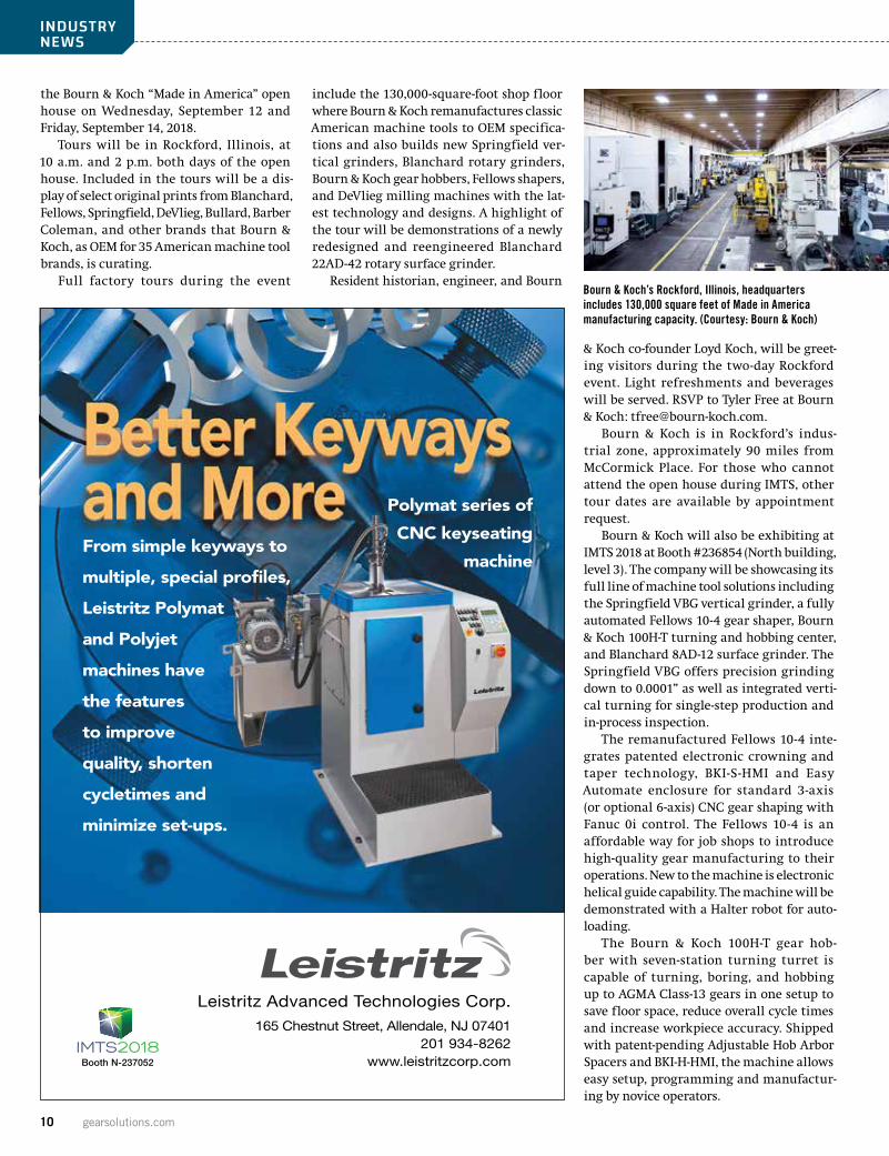
the Bourn & Koch “Made in America” open house on Wednesday, September 12 and Friday, September 14, 2018.
Tours will be in Rockford, Illinois, at 10 a.m. and 2 p.m. both days of the open house. Included in the tours will be a dis-play of select original prints from Blanchard, Fellows, Springfield, DeVlieg, Bullard, Barber Coleman, and other brands that Bourn & Koch, as OEM for 35 American machine tool brands, is curating.
Full factory tours during the event
include the 130,000-square-foot shop floor where Bourn & Koch remanufactures classic American machine tools to OEM specifica-tions and also builds new Springfield ver-tical grinders, Blanchard rotary grinders, Bourn & Koch gear hobbers, Fellows shapers, and DeVlieg milling machines with the lat-est technology and designs. A highlight of the tour will be demonstrations of a newly redesigned and reengineered Blanchard 22AD-42 rotary surface grinder.
Resident historian, engineer, and Bourn
& Koch co-founder Loyd Koch, will be greet-ing visitors during the two-day Rockford event. Light refreshments and beverages will be served. RSVP to Tyler Free at Bourn & Koch: [email protected].
Bourn & Koch is in Rockford’s indus-trial zone, approximately 90 miles from McCormick Place. For those who cannot attend the open house during IMTS, other tour dates are available by appointment request.
Bourn & Koch will also be exhibiting at IMTS 2018 at Booth #236854 (North building, level 3). The company will be showcasing its full line of machine tool solutions including the Springfield VBG vertical grinder, a fully automated Fellows 10-4 gear shaper, Bourn & Koch 100H-T turning and hobbing center, and Blanchard 8AD-12 surface grinder. The Springfield VBG offers precision grinding down to 0.0001” as well as integrated verti-cal turning for single-step production and in-process inspection.
The remanufactured Fellows 10-4 inte-grates patented electronic crowning and taper technology, BKI-S-HMI and Easy Automate enclosure for standard 3-axis (or optional 6-axis) CNC gear shaping with Fanuc 0i control. The Fellows 10-4 is an affordable way for job shops to introduce high-quality gear manufacturing to their operations. New to the machine is electronic helical guide capability. The machine will be demonstrated with a Halter robot for auto-loading.
The Bourn & Koch 100H-T gear hob-ber with seven-station turning turret is capable of turning, boring, and hobbing up to AGMA Class-13 gears in one setup to save floor space, reduce overall cycle times and increase workpiece accuracy. Shipped with patent-pending Adjustable Hob Arbor Spacers and BKI-H-HMI, the machine allows easy setup, programming and manufactur-ing by novice operators.
INDUSTRY NEWS
Bourn & Koch’s Rockford, Illinois, headquarters includes 130,000 square feet of Made in America manufacturing capacity. (Courtesy: Bourn & Koch)
From simple keyways to
multiple, special profiles,
Leistritz Polymat
and Polyjet
machines have
the features
to improve
quality, shorten
cycletimes and
minimize set-ups.
Polymat series of
CNC keyseating
machine
Leistritz Advanced Technologies Corp.
165 Chestnut Street, Allendale, NJ 07401 201 934-8262
www.leistritzcorp.com Booth N-237052
August 2018 11
The Blanchard 8AD-12 surface grinder is an iconic machine tool, producing the characteristic “Blanchard Grind” synony-mous with quality ground parts. Like the Blanchard 22AD-42 being demonstrated at the “Made in America” Rockford open house, the smaller Blanchard 8AD-12 in the Bourn & Koch booth at IMTS is re-imagined and re-engineered to meet today’s manufacturing challenges.
MORE INFO www.bourn-koch.com
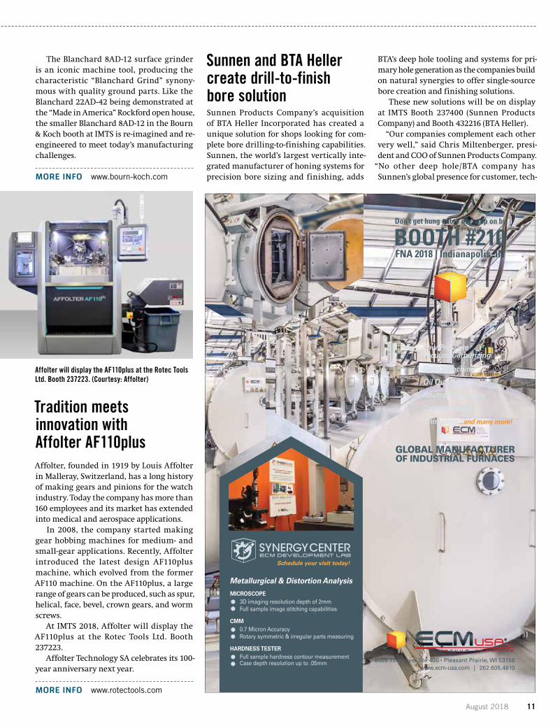
Tradition meets innovation with Affolter AF110plusAffolter, founded in 1919 by Louis Affolter in Malleray, Switzerland, has a long history of making gears and pinions for the watch industry. Today the company has more than 160 employees and its market has extended into medical and aerospace applications.
In 2008, the company started making gear hobbing machines for medium- and small-gear applications. Recently, Affolter introduced the latest design AF110plus machine, which evolved from the former AF110 machine. On the AF110plus, a large range of gears can be produced, such as spur, helical, face, bevel, crown gears, and worm screws.
At IMTS 2018, Affolter will display the AF110plus at the Rotec Tools Ltd. Booth 237223.
Affolter Technology SA celebrates its 100-year anniversary next year.
MORE INFO www.rotectools.com
Sunnen and BTA Heller create drill-to-finish bore solutionSunnen Products Company’s acquisition of BTA Heller Incorporated has created a unique solution for shops looking for com-plete bore drilling-to-finishing capabilities. Sunnen, the world’s largest vertically inte-grated manufacturer of honing systems for precision bore sizing and finishing, adds
BTA’s deep hole tooling and systems for pri-mary hole generation as the companies build on natural synergies to offer single-source bore creation and finishing solutions.
These new solutions will be on display at IMTS Booth 237400 (Sunnen Products Company) and Booth 432216 (BTA Heller).
“Our companies complement each other very well,” said Chris Miltenberger, presi-dent and COO of Sunnen Products Company.
“No other deep hole/BTA company has Sunnen’s global presence for customer, tech-
Affolter will display the AF110plus at the Rotec Tools Ltd. Booth 237223. (Courtesy: Affolter)
12 gearsolutions.com
nical and post-sale support. The transfer of knowledge between the two companies will create a unique value proposition, and Sunnen’s financial stability and strong sales and service network will deliver this exper-tise to our customers.”
Sunnen’s core technical competencies include automated and manual honing systems, custom system development and integration, abrasives, tooling, cutting flu-ids and gaging. The acquisition expands Sunnen’s industry-leading honing expertise
to include tooling for initial hole creation and other complementary bore sizing and finishing processes such as trepanning, counterboring and form boring. The BTA Heller product mix includes accessories for those processes including pressure heads, vibration dampeners and boring bars. Sunnen recently introduced the new SHD series skiving and roller burnishing system with tooling engineered and supplied by BTA Heller. Sunnen will also be entering the market with a deep hole drilling and boring
machine with tooling engineered and sup-plied by BTA Heller.
“We have developed various tools and sys-tems for creating intricate internal profiled deep hole drilling from 0.5 in. to 36 in. diam-eter,” said Mark Sollich, director of Sunnen’s BTA Heller division. “To combine forces with Sunnen and its bore geometry expertise cre-ates a company not found anywhere else in our industry. No one company can provide a total bore solution from the creation of the primary hole to the final bore finish speci-fications like we can.”
As Sunnen enters the skiving/roller burnishing sector, it brings its unique approach of providing support to custom-ers also using non-Sunnen equipment, a key advantage to shops using a variety of machine types and/or manufacturers for bore creation and finishing.
“We are able to take an unbiased approach to achieving high-quality bores,” said Miltenberger. “We offer solutions based on drilling, honing, skiving, roller burnishing, trepanning, or any combination of those. With our increased product lines and capa-bilities, however holes need to be made, we can make them.”
MORE INFO www.sunnen.com
Mitsubishi brings gear cutting, grinding technology to IMTSAt IMTS 2018, Mitsubishi Heavy Industries America, Inc. will be displaying gear cutting and gear grinding technology designed for high productivity at Booth N-237036. Using Super Dry hobbing, the model GE15A gear hobbing machine can also be equipped with an on-board chamfering station providing
INDUSTRY NEWS
Sunnen/BTA Heller offers an indexable, adjustable drill head, the Hellerdex, for use in BTA-style deep hole drilling. (Courtesy: Sunnen BTA Heller)
LXRDWIDEBODY
LXRDSTANDARD
LXRDMODULAR MAPPING
iXRDSTANDARD
mXRDULTRA PORTABLE
LXRDWIDEBODY
LXRDSTANDARD
LXRDMODULAR MAPPING
iXRDSTANDARD
mXRDULTRA PORTABLE
Choose from one of our portable or laboratory systems, or utilize our ISO 170 5 laboratories for accurate and effi cient contract measurement services.
For more information contact us at [email protected] or 1-313-965-2900
August 2018 13
multiple processes. Additionally, MHIA will display the
ZE24B generative gear grinder. Designed for mass production, the ZE24B has an auto-matic parts loader and can perform gear tooth polishing with a single setup using a compound grinding/polishing wheel.
Both the GE15A hobbing machine and the ZE24B gear grinder represent Mitsubishi’s Legendary Reliability in gear manufacturing.
Mitsubishi Heavy Industries America will display the ZE24B generative gear grinder at IMTS.
MORE INFO www.mitsubishigearcenter.com
Glebar gears up for IMTS with innovations in grinding technologyAs it enters its 66th year in business, Glebar is excited to be returning as an exhibitor at IMTS 2018, North America’s largest manufac-turers exposition, at Booth 237307.
Representatives will display Glebar’s lat-est innovations in precision turnkey grind-ing technology, with a focus on custom-automated solutions designed and built for the automotive, medical, metal, and other markets. From manual to fully automated, Glebar’s modular GT-610 Series of Infeed/Thrufeed Centerless Grinders are able to remove more material faster, and with better surface finishes, than competing machines. Configurable modular platforms and customizable software give it the versa-
tility to design and deliver turnkey solutions tailored to customers’ pecific needs.
You can view Glebar machines and take a virtual BoothTour at www.glebar.com; click on the IMTS 2018 information box.
Also, attendees can register for a VIP booth appointment where they will be able to speak one-on-one with a Glebar grinding specialist to discuss specific application needs.
MORE INFO www.glebar.com
Gleason USA offers five days of KISSsoft and KISSsys trainingFrom August 27–31, 2018, Gleason USA hosts a 4.5 day comprehensive KISSsoft and KISSsys training which is split into two parts:
BASIC KISSSOFT TRAINING (2 DAYS)August 27–28, 2018
This Basic KISSsoft Training covers shaft and gears and focuses on the usage of the software and exercises executed by the par-ticipants. After an introduction to general settings and some basic theory to develop an understanding of the technical terms, par-ticipants will learn about shaft and bearing functionalities as well as gear design and optimization strategies including optimal load distribution and noise reduction.
KISSSYS GEARBOX TRAINING (2.5 DAYS)August 29–31, 2018
Participants will design a KISSsys model of an existing bevel-cylindrical-planetary transmission of 450kW and optimizing the gears, analyzing the strength of shafts and lifetimes of bearings as well as efficiency and contact analysis calculation. Part 1 will focus on modeling the kinematic structure of the transmission in KISSsys, part 2 on dimensioning and optimization by modifi-cation of the gears, shafts, and bearings.
These courses are suitable for engineers working in the field of gearbox and trans-mission calculations and manufacturing. No advanced KISSsoft software knowledge is required. Participants may ask for a 30-day valid test version in order to familiarize themselves with KISSsoft/KISSsys.
The training will take place at The Gleason Works Facility in Rochester, New York. Don’t miss this opportunity and register now.
MORE INFO www.kisssoft.com
The Mitsubishi Heavy Industries America model GE15A gear hobbing machine will be on display at IMTS 2018. (Courtesy: Mitsubishi Heavy Industries America)
14 gearsolutions.com
INDUSTRY NEWS
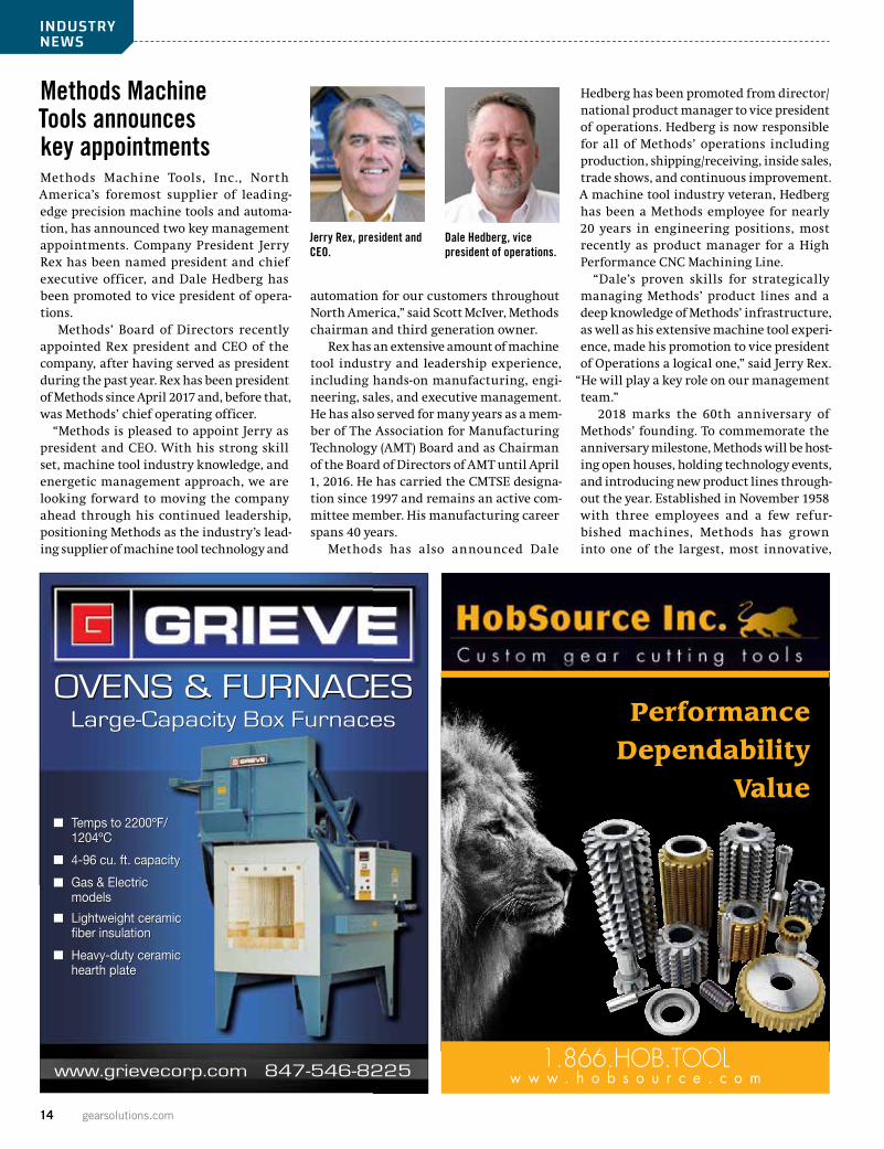
Methods Machine Tools announces key appointmentsMethods Machine Tools, Inc., North America’s foremost supplier of leading-edge precision machine tools and automa-tion, has announced two key management appointments. Company President Jerry Rex has been named president and chief executive officer, and Dale Hedberg has been promoted to vice president of opera-tions.
Methods’ Board of Directors recently appointed Rex president and CEO of the company, after having served as president during the past year. Rex has been president of Methods since April 2017 and, before that, was Methods’ chief operating officer.
“Methods is pleased to appoint Jerry as president and CEO. With his strong skill set, machine tool industry knowledge, and energetic management approach, we are looking forward to moving the company ahead through his continued leadership, positioning Methods as the industry’s lead-ing supplier of machine tool technology and
automation for our customers throughout North America,” said Scott McIver, Methods chairman and third generation owner.
Rex has an extensive amount of machine tool industry and leadership experience, including hands-on manufacturing, engi-neering, sales, and executive management. He has also served for many years as a mem-ber of The Association for Manufacturing Technology (AMT) Board and as Chairman of the Board of Directors of AMT until April 1, 2016. He has carried the CMTSE designa-tion since 1997 and remains an active com-mittee member. His manufacturing career spans 40 years.
Methods has also announced Dale
Hedberg has been promoted from director/national product manager to vice president of operations. Hedberg is now responsible for all of Methods’ operations including production, shipping/receiving, inside sales, trade shows, and continuous improvement. A machine tool industry veteran, Hedberg has been a Methods employee for nearly 20 years in engineering positions, most recently as product manager for a High Performance CNC Machining Line.
“Dale’s proven skills for strategically managing Methods’ product lines and a deep knowledge of Methods’ infrastructure, as well as his extensive machine tool experi-ence, made his promotion to vice president of Operations a logical one,” said Jerry Rex.
“He will play a key role on our management team.”
2018 marks the 60th anniversary of Methods’ founding. To commemorate the anniversary milestone, Methods will be host-ing open houses, holding technology events, and introducing new product lines through-out the year. Established in November 1958 with three employees and a few refur-bished machines, Methods has grown into one of the largest, most innovative,
Jerry Rex, president and CEO.
Dale Hedberg, vice president of operations.
OVENS & FURNACESOVENS & FURNACES
www.grievecorp.com 847-546-8225
GRIEVE CORPORATION AD4393j Color
Large-Capacity Box Furnaces
Temps to 2200ºF/1204ºC 4-96 cu. ft. capacity Gas & Electric models Lightweight ceramic fiber insulation Heavy-duty ceramic hearth plate
Large-Capacity Box Furnaces
Temps to 2200ºF/1204ºC 4-96 cu. ft. capacity Gas & Electric models Lightweight ceramic fiber insulation Heavy-duty ceramic hearth plate
PerformanceDependability
Value
1.866.HOB.TOOLw w w . h o b s o u r c e . c o m

August 2018 15
ACHIEVE PEAK PERFORMANCE INGEAR GRINDING TECHNOLOGY
Reishauer Corporation • (847) 888-3828 • www.reishauer.com1525 Holmes Road | 60123 Elgin IL, USA | 847.888.3828www.reishauer.com | [email protected]
Reishauer sets the standard of technology for continuous generating gear grinding. Our “Circle Of Competence” encompasses all aspects of your gear manufacturing success...machines, automation, tooling, technology & service. Only one company delivers the peak performance demanded from today’s competitive gear industry...Reishauer.
16 gearsolutions.com
high-precision machine tool suppliers in North America.
Methods today has about 350 employ-ees, eight sales and technology centers, and more than 35,000 machines installed throughout North America, ranging from EDM machines to sophisticated 5-Axis CNC Machining Centers to the latest in robotics and automation. Methods provides exten-sive applications engineering support, installation, parts, service, and training through a network of large state-of-the-art technology centers and dealers in North America.
MORE INFO www.methodsmachine.com
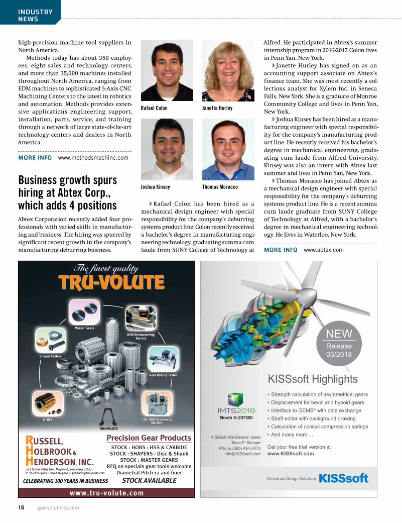
Business growth spurs hiring at Abtex Corp., which adds 4 positionsAbtex Corporation recently added four pro-fessionals with varied skills in manufactur-ing and business. The hiring was spurred by significant recent growth in the company’s manufacturing deburring business.
�� Rafael Colon has been hired as a mechanical design engineer with special responsibility for the company’s deburring systems product line. Colon recently received a bachelor’s degree in manufacturing engi-neering technology, graduating summa cum laude from SUNY College of Technology at
Alfred. He participated in Abtex’s summer internship program in 2016-2017. Colon lives in Penn Yan, New York.
�� Janette Hurley has signed on as an accounting support associate on Abtex’s finance team. She was most recently a col-lections analyst for Xylem Inc. in Seneca Falls, New York. She is a graduate of Monroe Community College and lives in Penn Yan, New York.
�� Joshua Kinsey has been hired as a manu-facturing engineer with special responsibil-ity for the company’s manufacturing prod-uct line. He recently received his bachelor’s degree in mechanical engineering, gradu-ating cum laude from Alfred University. Kinsey was also an intern with Abtex last summer and lives in Penn Yan, New York.
�� Thomas Moracco has joined Abtex as a mechanical design engineer with special responsibility for the company’s deburring systems product line. He is a recent summa cum laude graduate from SUNY College of Technology at Alfred, with a bachelor’s degree in mechanical engineering technol-ogy. He lives in Waterloo, New York.
MORE INFO www.abtex.com
INDUSTRY NEWS
Rafael Colon Janette Hurley
Joshua Kinsey Thomas Moracco
www.tru-volute.com
Precision Gear ProductsSTOCK : HOBS : HSS & CARBIDE
STOCK : SHAPERS : Disc & ShankSTOCK : MASTER GEARS
RFQ on specials gear tools welcomeDiametral Pitch 12 and finer
STOCK AVAILABLE
RUSSELL,HOLBROOK&HENDERSON, INC.25 E Spring Valley Ave., Maywood, New Jersey 07607P: 201-226-9000 F: 201-226-9004 E: [email protected]
CELEBRATING 100 YEARS IN BUSINESS
Get your free trial version atwww.KISSsoft.com
Strength calculation of asymmetrical gearsDisplacement for bevel and hypoid gearsInterface to GEMS® with data exchangeShaft editor with background drawing Calculation of conical compression springsAnd many more ...
▪▪▪▪▪▪
KISSsoft Highlights
KISSsoft AG/Gleason SalesBrian P. Stringer
Phone (585) [email protected]
Release 03/2018
NEW
GearTech_KISSsoft_Release2018_89x120_5mm.indd 1 26.04.2018 13:09:42
Booth N-237000
August 2018 17
Abtex Corp. promotes VP of sales/marketing Jason Saner to presidentAbtex Corp., the world’s leading manufac-turer of machine/brush deburring solutions, has named Jason Saner as president. He will
report to Mark Fultz, Abtex CEO.
Saner joined Abtex in June 2013. He began as market development man-ager, was promoted to lead the Systems Group in 2014, and named vice presi-
dent of sales and mar-keting in 2015. He holds an MBA from the University of Rochester’s Simon School and a bachelor’s degree from LeMoyne College. He and his family live in Penn Yan, New York.
MORE INFO www.abtex.com
Jerry Uplinger joins Gasbarre Tooling Group as design leadGasbarre Products, Inc. has announced the hiring of Jerry Uplinger, tool design engi-neer, as the newest member of its Tooling Group team. He will be the team lead for
tool design efforts at McKee Carbide Tool.
Uplinger comes to Gasbarre with many years of expe-rience in the pow-der metal indus-try, including his most recent posi-tion as tool design
engineer with Metal Powder Products in Ridgway, Pennsylvania, a position he held for 16 years.
Kevin Snyder, general manager for Gasbarre Tooling Group, said, “The addition of Jerry allows the Gasbarre Tooling Group to better serve our customers by providing new tool design. Customers in need of this service can rely on Jerry’s 30 years of experi-ence to have a tool set designed around their part print.”
MORE INFO www.gasbarre.com
FMS Corporation design takes award in MPIF contestThe winners in the 2018 Powder Metallurgy (PM) Design Excellence Awards competition, sponsored by the Metal Powder Industries Federation (MPIF), demonstrate outstanding examples of PM’s diversity.
The grand prize in the Hand Tools/Recreation category was won by FMS Corporation for three sinter-hardened steel parts made for Graco, Inc.: an eccentric gear, a combination gear, and a connecting rod that incorporates a bronze bearing. The parts com-prise an assembly that drives a piston pump within a paint sprayer. The complex eccentric gear, which is compacted using cored holes on one side to balance the moment of iner-tia around the center shaft, features AGMA class 6 gear quality. The combination gear is complex as well, combining a helical gear and a spur gear. The bronze bearing is com-pacted, sintered, and sized in place inside the connecting rod, then oil impregnated. The combination gear and connecting rod are manufactured completely net-shape.
Winners of the Design Excellence Awards Competition were announced at the POWDERMET2018 International Conference on Powder Metallurgy & Particulate Materials.
MORE INFO www.mpif.org
Motion Industries distribution center opens near SeattleMotion Industries, Inc., a leading distribu-tor of maintenance, repair, and operation replacement parts and a wholly owned subsidiary of Genuine Parts Company, has opened the doors for business at its new dis-tribution center (DC) in Auburn, Washington. The facility is managed by Ryan Mort.
The DC’s strategically chosen location fea-tures easy connections to Interstates 5, 405, and 90. It is also conveniently situated 15 minutes from Sea-Tac International Airport. Covering just over 62,000 square feet, the DC stocks and ships a broad range of indus-trial parts and supplies including bearings, power transmission products, fluid power components, electrical parts, safety sup-plies, and more. The new distribution cen-ter serves 24 area Motion Industries branch locations daily, as well as the entire Motion
Jason Saner
Jerry Uplinger
MI cuts gears to 250 inches in diameter andgrinds gears to102 inches indiameter.
MI provides fullservice gearboxrepair & testingfor dependableoverhaul andenhancement ofgear drives.
Machinists Inc.
800 / 244.4130www.machinistsinc.com
ISO 9001 certified
From singleparts to complete
manufacturingsystems
Call us about your project
18 gearsolutions.com
INDUSTRY NEWS
Industries North American footprint (550+ locations) as needed.
Joe Limbaugh, Motion Industries VP of Operations/Distribution/Properties said,
“This is something that our customers have asked for so we’re happy and excited that we’re able to fulfill their request.” Limbaugh said additional enhancements will come down the road, and looks forward to fulfill-ing plans for growth.
Motion Industries President & CEO, Tim Breen, said, “Opening the new DC’s doors
also means opportunity for our customers in the region to receive their orders even quicker. We’re looking forward to deliver-ing a positive business impact on industry in the Pacific Northwest.”
The new facility complements Motion’s primary North American distribution centers in Birmingham, Alabama; Tracy, California; Chicago; Baltimore; Dallas; Edmonton, Alberta; and Lachine, Quebec.
MORE INFO www.motionindustries.com
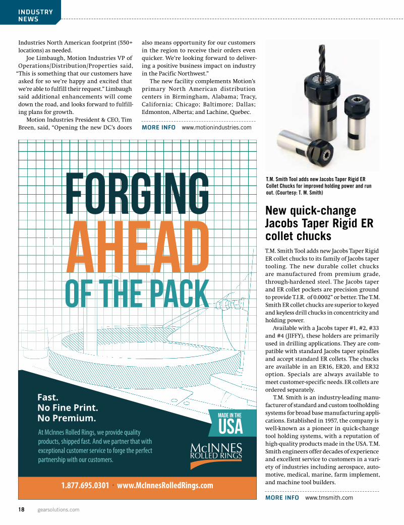
New quick-change Jacobs Taper Rigid ER collet chucksT.M. Smith Tool adds new Jacobs Taper Rigid ER collet chucks to its family of Jacobs taper tooling. The new durable collet chucks are manufactured from premium grade, through-hardened steel. The Jacobs taper and ER collet pockets are precision ground to provide T.I.R. of 0.0002” or better. The T.M. Smith ER collet chucks are superior to keyed and keyless drill chucks in concentricity and holding power.
Available with a Jacobs taper #1, #2, #33 and #4 (JIFFY), these holders are primarily used in drilling applications. They are com-patible with standard Jacobs taper spindles and accept standard ER collets. The chucks are available in an ER16, ER20, and ER32 option. Specials are always available to meet customer-specific needs. ER collets are ordered separately.
T.M. Smith is an industry-leading manu-facturer of standard and custom toolholding systems for broad base manufacturing appli-cations. Established in 1957, the company is well-known as a pioneer in quick-change tool holding systems, with a reputation of high-quality products made in the USA. T.M. Smith engineers offer decades of experience and excellent service to customers in a vari-ety of industries including aerospace, auto-motive, medical, marine, farm implement, and machine tool builders.
MORE INFO www.tmsmith.com
T.M. Smith Tool adds new Jacobs Taper Rigid ER Collet Chucks for improved holding power and run out. (Courtesy: T. M. Smith)FORGING
AHEADOF THE PACK
Fast.No Fine Print.No Premium. At McInnes Rolled Rings, we provide quality products, shipped fast. And we partner that with exceptional customer service to forge the perfect partnership with our customers.
1.877.695.0301 www.McInnesRolledRings.com
August 2018 19
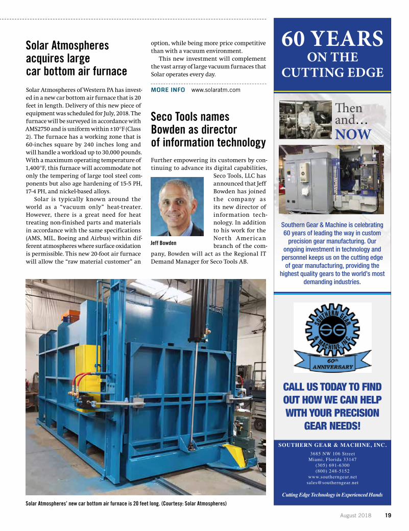
Solar Atmospheres acquires large car bottom air furnaceSolar Atmospheres of Western PA has invest-ed in a new car bottom air furnace that is 20 feet in length. Delivery of this new piece of equipment was scheduled for July, 2018. The furnace will be surveyed in accordance with AMS2750 and is uniform within ±10°F (Class 2). The furnace has a working zone that is 60-inches square by 240 inches long and will handle a workload up to 30,000 pounds. With a maximum operating temperature of 1,400°F, this furnace will accommodate not only the tempering of large tool steel com-ponents but also age hardening of 15-5 PH, 17-4 PH, and nickel-based alloys.
Solar is typically known around the world as a “vacuum only” heat-treater. However, there is a great need for heat treating non-finished parts and materials in accordance with the same specifications (AMS, MIL, Boeing and Airbus) within dif-ferent atmospheres where surface oxidation is permissible. This new 20-foot air furnace will allow the “raw material customer” an
option, while being more price competitive than with a vacuum environment.
This new investment will complement the vast array of large vacuum furnaces that Solar operates every day.
MORE INFO www.solaratm.com
Seco Tools names Bowden as director of information technologyFurther empowering its customers by con-tinuing to advance its digital capabilities,
Seco Tools, LLC has announced that Jeff Bowden has joined the company as its new director of information tech-nology. In addition to his work for the North American branch of the com-
pany, Bowden will act as the Regional IT Demand Manager for Seco Tools AB.
Jeff Bowden
Solar Atmospheres’ new car bottom air furnace is 20 feet long. (Courtesy: Solar Atmospheres)
60 Years on the Cutt ing Edge
Southern GearThen and ... NOW
SOUTHERN GEAR & MACHINE, INC.3685 NW 106 Street
Miami, Florida 33147(305) 691-6300(800) 248-5152
Cutting Edge Technology in Experienced Hands
Southern Gear & Machine is celebrating 60 years of leading the way in custom precision gear manufacturing. Our ongoing investment in technology and personnel keeps us on the cutting edge of gear manufacturing, providing the highest quality gears to the world’s most demanding industries.
CALL US TODAY TO FIND OUT HOW WE CAN HELP WITH YOUR PRECISION GEAR NEEDS!
SoGearMarch2017GearSolutions.indd 1 2/20/17 8:52:41 AM
CALL US TODAY TO FIND OUT HOW WE CAN HELP WITH YOUR PRECISION
GEAR NEEDS!
60 YEARS ON THE
CUTTING EDGE
Southern Gear & Machine is celebrating 60 years of leading the way in custom
precision gear manufacturing. Our ongoing investment in technology and
personnel keeps us on the cutting edge of gear manufacturing, providing the
highest quality gears to the world’s most demanding industries.
Then and…NOW
20 gearsolutions.com
INDUSTRY NEWS
“I am very pleased to welcome Jeff Bowden as part of my management team,” said Rob Keenan, president of Seco Tools. “I look for-ward to helping him further integrate IT into our business strategy as we develop a true regional hub to support our internal and external customers.”
Bowden plans to emphasize the impor-tance of technological growth as demand for tooling grows in the era of autonomous manufacturing environments. “Seco Tools is committed to advancing our capability
and capacity in this area while we strive to be on the leading edge of advancements in technology for the good of the industry and our customers,” said Bowden. “IT will act as a partner to all areas of the business, providing technical expertise and modern tools that will enable all departments to work more effectively and efficiently.”
Before joining Seco, Bowden served as the director for information technology, strat-egy, processes, and operations for Dassault Systems. In this role, he spent 16 years
setting the strategic direction for the IT organization while managing business rela-tionships to ensure IT direction remained aligned with corporate objectives and vision.
Bowden earned his bachelor’s degree in management information systems from Oakland University before going on to receive his MBA at Michigan State University’s Eli Broad College of Business.
MORE INFO www.secotools.com
KISSsys and GEMS® working together in common interfaceThe GEMS® and KISSsoft programs are now linked by a single, common interface that exchanges gear tooth and system design information between the two software pack-ages. This data exchange process enables users to evaluate and optimize all kinds of bevel and hypoid gears in a realistic way and with a closed loop between the design pro-cess and the production software.
KISSsys now also has a new template, which determines the bevel gear displace-ments under load. It can be used together with the interface to GEMS, Gleason’s bevel gear calculation software platform. Misalignments are determined on the prin-ciple of the perpendicular line between the two shaft axes (pinion and wheel) and can be displayed with either the E/P/G/Sigma or the V/H/J/Sigma parameters.
MORE INFO www.kisssoft.ag
Suhner’s redesigned BEX15 machining unit picks up more speedSuhner introduces a new and redesigned version of its BEX15 machining unit, capable of allowing a spindle speed increase from 18,000 rpm to 23,000 rpm.
Chip-producing machining operations with modern tools today demand progres-sively higher cutting speeds, specifically for metals with high cutting speed rates or small diameter hole drilling applications. The Suhner machining unit type BEX15, proven in thousands of installations, pro-vides new speed options, reliably up to the maximum speed limit. With an increase of 25 percent up to a permissible maximum
2710 West Caro Rd.Caro, MI 48723Phone: (989) 673-8733
1307 E. Maple Rd., Suite “G”Troy, MI 48083Phone: (248) 619-1616
ETC Engineered Tools Corporation
Complete line of Bevel Gear ToolingCutter Body Reconditioning to O.E.M. Specifications Cutter Body Maintenance ProgramPrecise Wire EDM Forms for Stick Blades
engineeredtools.com
Choose the stick that works, cause work doesn’t stop!
Why ETC?
Customer Service, Speed, Quality, & Value
NEW and RECONDITIONED CUTTER BODIES for Sale.
August 2018 21
spindle speed of 23,000 rpm, operations requiring higher spindle speeds can be accomplished more easily.
This improvement is the result of a com-plete redesign of drive and spindle bearing components. A new style timing belt drive multiplies the motor speed up to 13,050 rpm spindle speed. An AC-inverter drive is used to increase the spindle speed up to 23,000 rpm at 87Hz.
The BEX15 can be applied in axial and radial orientation, directly mounted to a Suhner slide assembly type UA15-PH or UA15-CNC. In this combination, numerous machining operations such as milling or demanding drilling cycles including jump or peck feed can be easily accomplished.
Four optional tool holder systems (Collet ER25, ISO30, HSK50 and Weldon), standard air purge connections for spindle and belt housing including a number of additional options (for example, coolant through the spindle or automated tool change features) make this machining unit adaptable and an optimal choice for demanding and specific machining requirements.
MORE INFO www.suhner.com
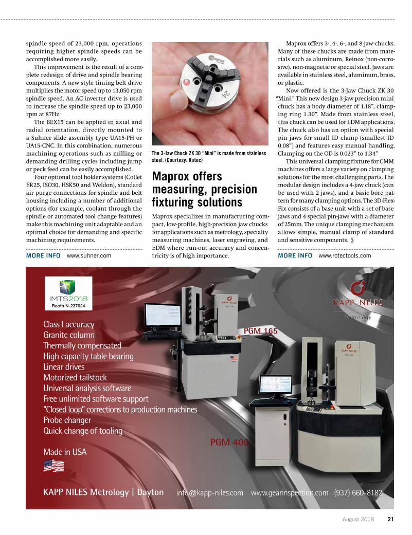
Maprox offers measuring, precision fixturing solutionsMaprox specializes in manufacturing com-pact, low-profile, high-precision jaw chucks for applications such as metrology, specialty measuring machines, laser engraving, and EDM where run-out accuracy and concen-tricity is of high importance.
Maprox offers 3-, 4-, 6-, and 8-jaw-chucks. Many of these chucks are made from mate-rials such as aluminum, Reinox (non-corro-sive), non-magnetic or special steel. Jaws are available in stainless steel, aluminum, brass, or plastic.
Now offered is the 3-Jaw Chuck ZK 30 “Mini.” This new design 3-jaw precision mini chuck has a body diameter of 1.18”, clamp-ing ring 1.30”. Made from stainless steel, this chuck can be used for EDM applications. The chuck also has an option with special pin jaws for small ID clamp (smallest ID 0.08”) and features easy manual handling. Clamping on the OD is 0.023” to 1.34”
This universal clamping fixture for CMM machines offers a large variety on clamping solutions for the most challenging parts. The modular design includes a 4-jaw chuck (can be used with 2 jaws), and a basic bore pat-tern for many clamping options. The 3D-Flex-Fix consists of a base unit with a set of base jaws and 4 special pin-jaws with a diameter of 25mm. The unique clamping mechanism allows simple, manual clamp of standard and sensitive components.
MORE INFO www.rotectools.com
The 3-Jaw Chuck ZK 30 “Mini” is made from stainless steel. (Courtesy: Rotec)
KAPP NILES Metrology | Dayton [email protected] www.gearinspection.com (937) 660-8182
PGM 400
Class I accuracyGranite columnThermally compensatedHigh capacity table bearingLinear drivesMotorized tailstockUniversal analysis softwareFree unlimited software support“Closed loop” corrections to production machinesProbe changerQuick change of tooling
Made in USA
PGM 165
Booth N-237024

22 gearsolutions.com
Atmosphere Refractory Relines
IpsenUSA.comwww.IpsenUSA.com
Are you having difficulty maintaining temperature uniformity in your atmosphere furnace? Have you noticed the paint peeling on the outer walls of your furnace? Is your refractory cracking, sagging, or falling apart? If so, it may be time for a refractory reline. Let Ipsen’s experienced atmosphere team help you evaluate your current refractory conditions and plan your next refractory reline.
With decades of experience, our professional technicians have the knowledge and resources to ensure the use of proper refractory materials to restore your furnace back to its original condition. Once the reline is complete, Ipsen can help you reintroduce your furnace to production.
Contact us for your free refractory evaluation: go.IpsenUSA.com/Retrofits
Are you going to FNA? Visit us at booth 301.
August 2018 23
American Gear ManufacturersAssociation
Jenny BlackfordVice President of CommunicationsAGMA
Solving ‘The People Impact’: How can AGMA help?
I recently completed my 70th tour of a member company, during which I spent time with AGMA Board Members Michael Engesser of Reischauer, Cory Ooyen of Global Gear, and Mike McKernin of Circle Gear. Additionally, I was able to visit with the Meritor engi-
neering team and talk shop with Joe Arvin from Arvin Global Services, who is an AGMA Distinguished Service Award Winner.
Member tours are great opportunities to hear challenges and oppor-tunities facing our industry in a direct setting where you can capture core issues and values quickly and effortlessly since it’s just the two of you talking one-on-one.
I’m hearing capacity is our issue — companies are giving 110 per-cent to meet customer expectations as the demand curve swings almost violently from the extreme downturn of 2014-2016, to a strong uptick in 2018. It’s not unheard of to tell a customer you need 11 to 12 weeks over the timeframe they are used to receiving a gear in … and, I’m hear-ing of three shifts and companies ask-ing for capacity help from other local AGMA members to make gears and com-ponents for larger systems.
I’m hearing employment is another issue — finding and retaining operators, technicians, and other floor personnel is becoming the priority for AGMA mem-bers. In fact, in a recent survey conducted on behalf of the AGMA Foundation, find-ing and retaining technicians was the primary challenge facing our industry. In the survey, it didn’t matter what type of company you were — suppliers, manufacturers, and end users all listed “people” as the primary challenge facing their companies.
We are on the brink of a major crisis for our industry that I call “The People Impact,” which is hitting all 482 AGMA member companies.
How many technicians are going to retire in the next five years from your company?
How many other technician and operator level employees do you currently need, or forecast to need in the next 18 months?
What is your plan to retain any new employees you hire over the next year?
How will AGMA help me with this?The first three questions are yours to answer, but the last one,
AGMA has the following solutions in the works:�� AGMA and the AGMA Foundation are committing resources to
develop the Employee Recruitment Toolkit. This marketing kit will highlight and promote the great things this industry does and pro-
vide your company with materials to use when promoting jobs in our industry. Materials will include a PowerPoint Presentation, a video, posters, a brochure, and advertisements that you can add your logo to.
�� The materials are designed to be used by your company and high-light jobs you might have. But it also can be used by AGMA staff when speaking to technical students that will ultimately lead them to our jobs board on our website. Your membership with AGMA and your con-tribution to the AGMA Foundation are helping to ensure our industry gets the employees it needs.
�� By 2019, AGMA will have developed five new operator level cours-es. These courses could be part of your internal retention program by supporting your team members with great training you can’t find just anywhere. These courses will be at Daley College in Chicago,
making it easy to attend by a majority of AGMA members — and by sending your employees to these classes demonstrates your support in their professional devel-opment. This is a powerful retention tool for all companies.
These programs were also developed by AGMA and the AGMA Foundation. This is the first time we have developed programs for operators and is a direct response to the industry challenges com-municated by each organization.
Big Picture: AGMA and its Foundation are allocating money directly toward the
industry’s primary challenges, as described by 467 individuals who participated in our survey in 2017 and approved by both the AGMA and AGMA Foundation boards.
Small Picture: AGMA and its Foundation are developing tools that can be leveraged by the industry to both attract new employees and to retain the ones you’ve hired.
What’s in it for me? Picture: Your direct support of AGMA and its Foundation means you have tools to help your company grow and be sustainable.
These new programs add value to the existing 13 different face-to-face engineering level classes, the Fall Technical Meeting, the Annual Meeting, and other events AGMA holds during the year. All of them are designed to keep your team up-to-date on emerging technologies, industry trends, and the latest news, and your active participation in each event ensures you are getting to network with the right people.
AGMA is here to help the industry thrive, and working closely with our members, we are on a path that directly responds to current indus-try challenges.
Matthew CrosonAGMA president

24 gearsolutions.com
American Gear ManufacturersAssociation
2018 Fall Technical Meeting
For more than 30 years, AGMA has been hosting a technical conference to high-light the newest emerging technology in the gear industry. The Fall Technical Meeting (FTM) is the top place to learn about the latest research in the gear indus-try from the researchers directly. Each year, the FTM provides an outstanding
opportunity to share ideas with others in the gear industry on design, analysis, manu-facturing, and application of gears, gear drives, and related products, as well as associ-ated processes and procedures. Attendees get a chance to be on the cutting edge of gear research and network with other engineers.
Each speaker will present the content of his or her technical paper that has gone through a double-blind peer review of three industry topic experts. All papers presented at FTM will be indexed in Scopus, the international database of peer-reviewed literature.
Come see why this popular event is growing year after year and be a part of a technical community that is always striving to improve and grow the gear industry.
NEW EVENT AT FTM: BOWLING & BOCCE NETWORKING RECEPTIONAGMA has added an extra evening of networking and fun to the FTM. Sponsored by Scot Forge, FTM attendees who purchase a ticket for $50 can attend an evening full of bowl-ing, bocce, and great conversation with their gear-industry peers. Dinner and open bar is included with your ticket at the Pinstripes in Oak Brook. Please visit the Pinstripes website to get a look at what to expect.
PRICING DETAILS
EARLY BIRD REGISTRATION (JUNE 5–AUGUST 24)Member: $950.00 | Non-Member: $1,250
REGULAR REGISTRATION (AUGUST 25–SEPTEMBER 23)Member: $1,050 | Non-Member: $1,350
ONSITE REGISTRATIONMember: $1,100 | Non-Member: $1,400
SINGLE SESSION Member: $295 | Non-Member: $395
BOWLING & BOCCE NETWORKING RECEPTIONMember & Non-Member: $50
Attendees at the 2017 FTM.

August 2018 251001 N. Fairfax Street | Suite 500 | Alexandria, VA 22314 | (703) 684-0211 | www.agma.org
AGMA has over 1,000 Twitter followers! Join the conversation @agma
Upcoming CoursesDon’t forget! AGMA education courses are IACET accredited. This means the courses you take through AGMA will earn you continuing education units. Choose gear education that does more for you!
BASIC TRAINING FOR GEAR MANUFACTURING (2.67 CEUS)SEPTEMBER 11-14, 2018 | CHICAGO, ILLINOIS
Learn the fundamentals of gear manufacturing in this hands-on course. Gain an understanding of gearing and nomenclature, prin-ciples of inspection, gear manufacturing methods, hobbing and shap-ing. Using manual machines, develop a deeper breadth of perspec-tive and understanding of the process and physics of making a gear, as well as the ability to apply this knowledge in working with CNC equipment commonly in use.
FUNDAMENTALS OF WORM & CROSSED AXIAL HELICAL GEARING (1.3 CEUS)SEPTEMBER 20-21, 2018 | ALEXANDRIA, VIRGINIA (COME TO AGMA HEADQUARTERS)
Provides an introduction and emphasizes the differences between parallel (the experience base) axis and worm and crossed axis helical gears. Describe the basics of worm and crossed axis helical gears,
their fundamental design principals, application guidelines and rec-ommendations, lubrication requirement, a discussion of accuracy and quality, and summarize with a brief review of common failure modes.
EPICYCLIC GEAR SYSTEMS: APPLICATION, DESIGN & ANALYSIS (2.0 CEUS)SEPTEMBER 27-29, 2018 | ROSEMONT, ILLINOIS
Learn and define the concept of epicyclic gearing, including some basic history and the differences among simple planetary gear systems, compound planetary gear systems, and star drive gear systems. Cover concepts on the arrangement of the individual components, including the carrier, sun, planet, ring, and star gears and the rigid requirements for the system to perform properly. Critical factors such as load sharing among the planet or star gears, sequential loading, equal planet/star spacing, relations among the numbers of teeth on each element, and calculation of the maximum and optimum number of planet/star gears for a specific system will be covered. Provides an in-depth discussion of the methodology by which noise and vibration may be optimized for such systems and load sharing guidelines for planet load sharing.
Location of the Bowling & Bocce Networking Reception in Oak Brook. Attendees at the 2017 FTM.

26 gearsolutions.com
EX
EC
UTI
VE C
OM
MIT
TEE
STA
FF
AGMA LEADERSHIP
CALENDAR OF EVENTSWhether you’re looking for technical education, networking opportunities, or a way for your voice to be heard in the standards process, AGMA has something to offer you. If you would like more information on any of the following events, visit www.agma.org or send an email to [email protected].
BO
AR
D O
F D
IRE
CTO
RS
Matt Croson: President
Amir Aboutaleb: Vice President, Technical Division
Jenny Blackford: Vice President, Marketing
Jill Johnson: Director, Member Services
Casandra D. Blassingame: Director, Education
General requests: [email protected] | Membership questions: [email protected] | Trade show information: [email protected]
Technical/Standards information: [email protected] | AGMA Foundation: [email protected]
Jim Bregi: ChairmanDoppler Gear Company
John Cross: TreasurerASI Technologies Inc.
Greg Schulte: Chairman, BMECBonfiglioli USA.
Todd Praneis: Chairman, TDECCotta Transmission Company, LLC
Dean Burrows: Chairman EmeritusGear Motions Inc.
Michael Engesser: Reishauer Corporation
Bent Hervard: CFT
David Long: Chalmers & Kubeck Inc.
Michael McKernin: Circle Gear and Machine Company
Scott Miller: Caterpillar, Inc.
Gary Neidig: ITAMCO
Shawn O’Brien: McInnes Rolled Rings
Cory Ooyen: Global Gear & Machining, LLC
Carl D. Rapp: The Timken Company
Tania Sabados: Rapid Gear
George Thomas: Bison Gear & Engineering Corporation
Hastings Wyman: Klingelnberg America, Inc.
AU
GU
ST
SE
PTE
MB
ER
OC
TOB
ER
August 10 — Emerging Technology Committee Meeting — WebExAugust 10 — Plastics Committee — WebExAugust 14 — Helical Gear Rating Committee — WebEx
September 4 — Wind Turbine Gear Committee — WebExSeptember 5 — Nomenclature Committee — WebExSeptember 6 — Lubrication Committee Meeting — WebExSeptember 7 — Flexible Couplings Committee — WebExSeptember 11 — Helical Gear Rating Committee — WebExSeptember 13 — Metallurgy and Materials Committee — WebExSeptember 14 — Fine-Pitch Gearing Committee Meeting — WebExSeptember 18 — Gear Accuracy Committee — WebExSeptember 20 — Wormgearing Committee — WebEx
October 3 — Nomenclature Committee — WebExOctober 4 — Lubrication Committee Meeting — WebExOctober 18 — Fine-Pitch Gearing Committee Meeting — WebExOctober 30 — Gear Accuracy Committee — WebEx
August 2018 27
August 10 — Emerging Technology Committee Meeting — WebExAugust 10 — Plastics Committee — WebExAugust 14 — Helical Gear Rating Committee — WebEx
September 4 — Wind Turbine Gear Committee — WebExSeptember 5 — Nomenclature Committee — WebExSeptember 6 — Lubrication Committee Meeting — WebExSeptember 7 — Flexible Couplings Committee — WebExSeptember 11 — Helical Gear Rating Committee — WebExSeptember 13 — Metallurgy and Materials Committee — WebExSeptember 14 — Fine-Pitch Gearing Committee Meeting — WebExSeptember 18 — Gear Accuracy Committee — WebExSeptember 20 — Wormgearing Committee — WebEx
October 3 — Nomenclature Committee — WebExOctober 4 — Lubrication Committee Meeting — WebExOctober 18 — Fine-Pitch Gearing Committee Meeting — WebExOctober 30 — Gear Accuracy Committee — WebEx
we’re getting ready for IMTS2018 and can’t wait to see you at our booth!
Revolutionary, Robust and Rewarding Solutions!
Booth #237024North, level 3
ZE 800 profile grinding
KNe3G generating grinding
KNM 2X analytical gear inspection
KAPP Technologies kapp-niles.com [email protected] (303) 447-1130
082018_KappAd_IMTS_FullPage_GS.indd 1 7/20/2018 2:36:39 PM
28 gearsolutions.com
MARK MICHAUDTECHNICAL FELLOW REM SURFACE ENGINEERING
MATERIALSMATTER
The state of the art of wind turbine gearboxes
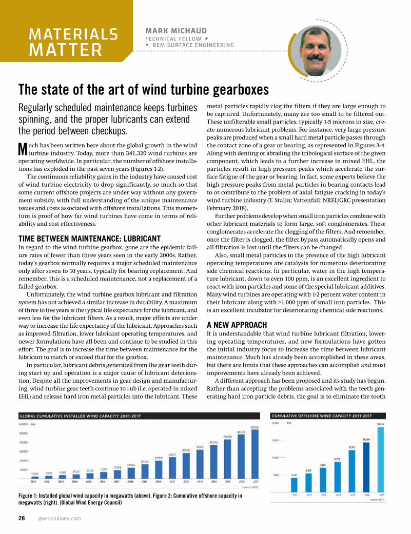
Much has been written here about the global growth in the wind turbine industry. Today, more than 341,320 wind turbines are
operating worldwide. In particular, the number of offshore installa-tions has exploded in the past seven years (Figures 1-2).
The continuous reliability gains in the industry have caused cost of wind turbine electricity to drop significantly, so much so that some current offshore projects are under way without any govern-ment subsidy, with full understanding of the unique maintenance issues and costs associated with offshore installations. This momen-tum is proof of how far wind turbines have come in terms of reli-ability and cost effectiveness.
TIME BETWEEN MAINTENANCE: LUBRICANTIn regard to the wind turbine gearbox, gone are the epidemic fail-ure rates of fewer than three years seen in the early 2000s. Rather, today’s gearbox normally requires a major scheduled maintenance only after seven to 10 years, typically for bearing replacement. And remember, this is a scheduled maintenance, not a replacement of a failed gearbox.
Unfortunately, the wind turbine gearbox lubricant and filtration system has not achieved a similar increase in durability. A maximum of three to five years is the typical life expectancy for the lubricant, and even less for the lubricant filters. As a result, major efforts are under way to increase the life expectancy of the lubricant. Approaches such as improved filtration, lower lubricant operating temperatures, and newer formulations have all been and continue to be studied in this effort. The goal is to increase the time between maintenance for the lubricant to match or exceed that for the gearbox.
In particular, lubricant debris generated from the gear teeth dur-ing start up and operation is a major cause of lubricant deteriora-tion. Despite all the improvements in gear design and manufactur-ing, wind turbine gear teeth continue to rub (i.e. operated in mixed EHL) and release hard iron metal particles into the lubricant. These
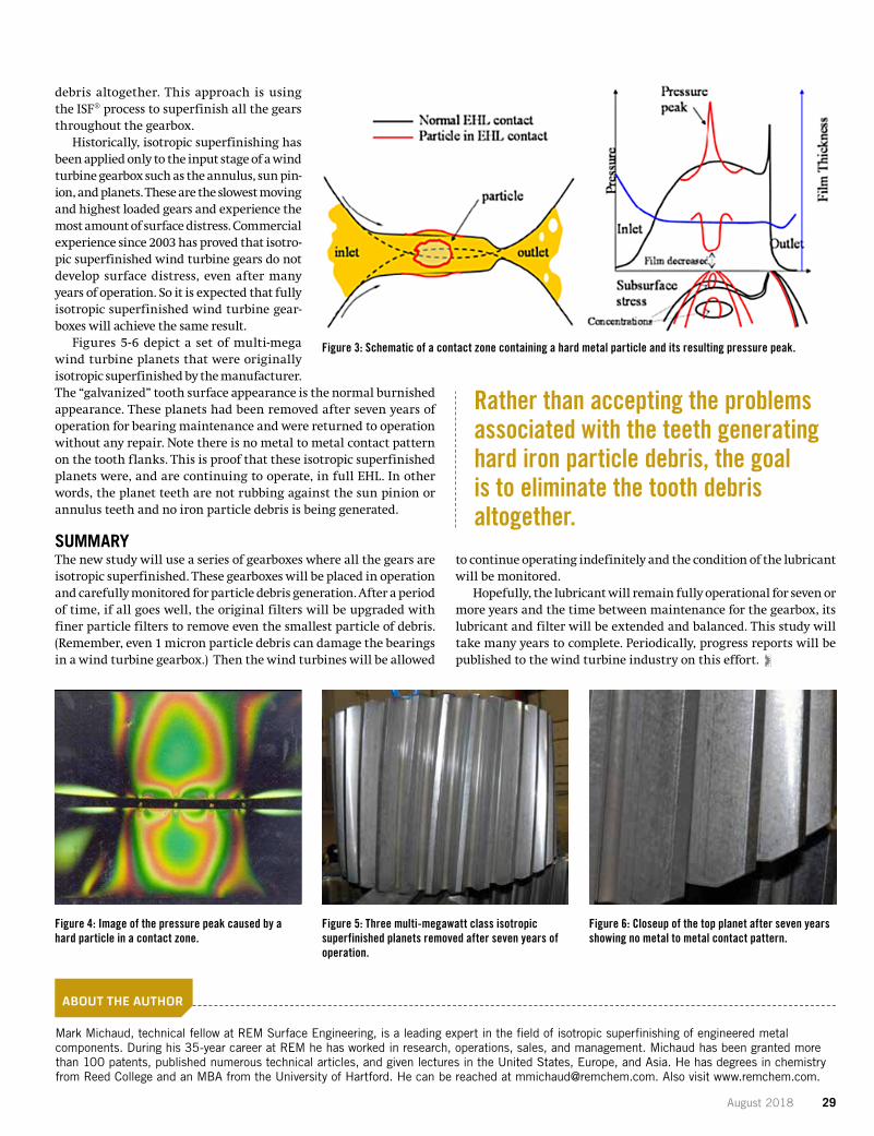
metal particles rapidly clog the filters if they are large enough to be captured. Unfortunately, many are too small to be filtered out. These unfilterable small particles, typically 1-5 microns in size, cre-ate numerous lubricant problems. For instance, very large pressure peaks are produced when a small hard metal particle passes through the contact zone of a gear or bearing, as represented in Figures 3-4. Along with denting or abrading the tribological surface of the given component, which leads to a further increase in mixed EHL, the particles result in high pressure peaks which accelerate the sur-face fatigue of the gear or bearing. In fact, some experts believe the high pressure peaks from metal particles in bearing contacts lead to or contribute to the problem of axial fatigue cracking in today’s wind turbine industry (T. Stalin; Vattenfall; NREL/GRC presentation February 2018).
Further problems develop when small iron particles combine with other lubricant materials to form large, soft conglomerates. These conglomerates accelerate the clogging of the filters. And remember, once the filter is clogged, the filter bypass automatically opens and all filtration is lost until the filters can be changed.
Also, small metal particles in the presence of the high lubricant operating temperatures are catalysts for numerous deteriorating side chemical reactions. In particular, water in the high tempera-ture lubricant, down to even 100 ppm, is an excellent ingredient to react with iron particles and some of the special lubricant additives. Many wind turbines are operating with 1-2 percent water content in their lubricant along with >1,000 ppm of small iron particles. This is an excellent incubator for deteriorating chemical side reactions.
A NEW APPROACHIt is understandable that wind turbine lubricant filtration, lower-ing operating temperatures, and new formulations have gotten the initial industry focus to increase the time between lubricant maintenance. Much has already been accomplished in these areas, but there are limits that these approaches can accomplish and most improvements have already been achieved.
A different approach has been proposed and its study has begun. Rather than accepting the problems associated with the teeth gen-erating hard iron particle debris, the goal is to eliminate the tooth
Regularly scheduled maintenance keeps turbines spinning, and the proper lubricants can extend the period between checkups.
Figure 1: Installed global wind capacity in megawatts (above). Figure 2: Cumulative offshore capacity in megawatts (right). (Global Wind Energy Council)
August 2018 29
debris altogether. This approach is using the ISF® process to superfinish all the gears throughout the gearbox.
Historically, isotropic superfinishing has been applied only to the input stage of a wind turbine gearbox such as the annulus, sun pin-ion, and planets. These are the slowest moving and highest loaded gears and experience the most amount of surface distress. Commercial experience since 2003 has proved that isotro-pic superfinished wind turbine gears do not develop surface distress, even after many years of operation. So it is expected that fully isotropic superfinished wind turbine gear-boxes will achieve the same result.
Figures 5-6 depict a set of multi-mega wind turbine planets that were originally isotropic superfinished by the manufacturer. The “galvanized” tooth surface appearance is the normal burnished appearance. These planets had been removed after seven years of operation for bearing maintenance and were returned to operation without any repair. Note there is no metal to metal contact pattern on the tooth flanks. This is proof that these isotropic superfinished planets were, and are continuing to operate, in full EHL. In other words, the planet teeth are not rubbing against the sun pinion or annulus teeth and no iron particle debris is being generated.
SUMMARYThe new study will use a series of gearboxes where all the gears are isotropic superfinished. These gearboxes will be placed in operation and carefully monitored for particle debris generation. After a period of time, if all goes well, the original filters will be upgraded with finer particle filters to remove even the smallest particle of debris. (Remember, even 1 micron particle debris can damage the bearings in a wind turbine gearbox.) Then the wind turbines will be allowed
to continue operating indefinitely and the condition of the lubricant will be monitored.
Hopefully, the lubricant will remain fully operational for seven or more years and the time between maintenance for the gearbox, its lubricant and filter will be extended and balanced. This study will take many years to complete. Periodically, progress reports will be published to the wind turbine industry on this effort.
ABOUT THE AUTHOR
Mark Michaud, technical fellow at REM Surface Engineering, is a leading expert in the field of isotropic superfinishing of engineered metal components. During his 35-year career at REM he has worked in research, operations, sales, and management. Michaud has been granted more than 100 patents, published numerous technical articles, and given lectures in the United States, Europe, and Asia. He has degrees in chemistry from Reed College and an MBA from the University of Hartford. He can be reached at [email protected]. Also visit www.remchem.com.
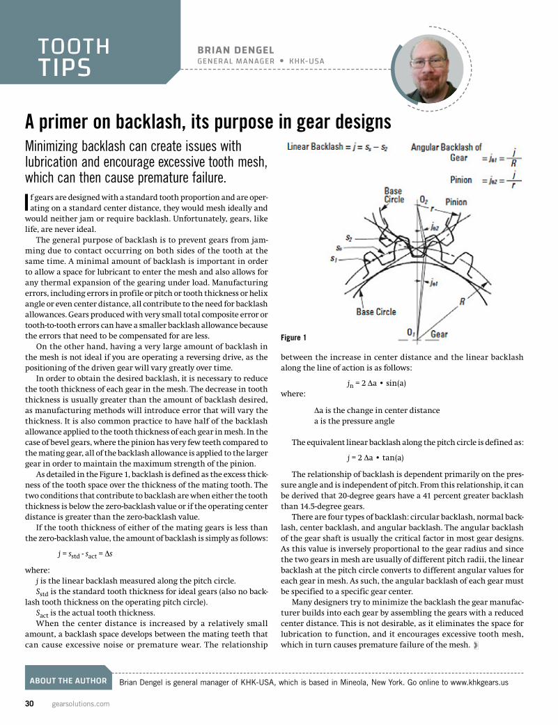
Figure 4: Image of the pressure peak caused by a hard particle in a contact zone.
Figure 5: Three multi-megawatt class isotropic superfinished planets removed after seven years of operation.
Figure 6: Closeup of the top planet after seven years showing no metal to metal contact pattern.
Figure 3: Schematic of a contact zone containing a hard metal particle and its resulting pressure peak.
Rather than accepting the problems associated with the teeth generating hard iron particle debris, the goal is to eliminate the tooth debris altogether.
30 gearsolutions.com
ABOUT THE AUTHOR Brian Dengel is general manager of KHK-USA, which is based in Mineola, New York. Go online to www.khkgears.us
A primer on backlash, its purpose in gear designs
would neither jam or require backlash. Unfortunately, gears, like life, are never ideal.
The general purpose of backlash is to prevent gears from jam-ming due to contact occurring on both sides of the tooth at the same time. A minimal amount of backlash is important in order to allow a space for lubricant to enter the mesh and also allows for any thermal expansion of the gearing under load. Manufacturing errors, including errors in profile or pitch or tooth thickness or helix angle or even center distance, all contribute to the need for backlash allowances. Gears produced with very small total composite error or tooth-to-tooth errors can have a smaller backlash allowance because the errors that need to be compensated for are less.
On the other hand, having a very large amount of backlash in the mesh is not ideal if you are operating a reversing drive, as the positioning of the driven gear will vary greatly over time.
In order to obtain the desired backlash, it is necessary to reduce the tooth thickness of each gear in the mesh. The decrease in tooth thickness is usually greater than the amount of backlash desired, as manufacturing methods will introduce error that will vary the thickness. It is also common practice to have half of the backlash allowance applied to the tooth thickness of each gear in mesh. In the case of bevel gears, where the pinion has very few teeth compared to the mating gear, all of the backlash allowance is applied to the larger gear in order to maintain the maximum strength of the pinion.
As detailed in the Figure 1, backlash is defined as the excess thick-ness of the tooth space over the thickness of the mating tooth. The two conditions that contribute to backlash are when either the tooth thickness is below the zero-backlash value or if the operating center distance is greater than the zero-backlash value.
If the tooth thickness of either of the mating gears is less than the zero-backlash value, the amount of backlash is simply as follows:
j = sstd - sact = Ds
where:j is the linear backlash measured along the pitch circle.Sstd is the standard tooth thickness for ideal gears (also no back-
lash tooth thickness on the operating pitch circle). Sact is the actual tooth thickness.When the center distance is increased by a relatively small
amount, a backlash space develops between the mating teeth that can cause excessive noise or premature wear. The relationship
between the increase in center distance and the linear backlash along the line of action is as follows:
jn = 2 Da • sin(a)where:
Da is the change in center distance a is the pressure angle
The equivalent linear backlash along the pitch circle is defined as:
j = 2 Da • tan(a)
The relationship of backlash is dependent primarily on the pres-sure angle and is independent of pitch. From this relationship, it can be derived that 20-degree gears have a 41 percent greater backlash than 14.5-degree gears.
There are four types of backlash: circular backlash, normal back-lash, center backlash, and angular backlash. The angular backlash of the gear shaft is usually the critical factor in most gear designs. As this value is inversely proportional to the gear radius and since the two gears in mesh are usually of different pitch radii, the linear backlash at the pitch circle converts to different angular values for each gear in mesh. As such, the angular backlash of each gear must be specified to a specific gear center.
Many designers try to minimize the backlash the gear manufac-turer builds into each gear by assembling the gears with a reduced center distance. This is not desirable, as it eliminates the space for lubrication to function, and it encourages excessive tooth mesh, which in turn causes premature failure of the mesh.
Minimizing backlash can create issues with lubrication and encourage excessive tooth mesh, which can then cause premature failure.
If gears are designed with a standard tooth proportion and are oper-ating on a standard center distance, they would mesh ideally and
BRIAN DENGELGENERAL MANAGER KHK-USA
TOOTHTIPS
Figure 1

August 2018 31
Gear Technology and Automation Systems.
Liebherr Gear Technology, Inc.1465 Woodland DriveSaline, Michigan 48176-1259Phone.: +1 734 429 72 25E-mail: [email protected]
Connecting systems for intelligent production!Gear Shaping Machine LS 400 EM: Maximum flexible shaping machine Enlarged workpiece diameter up to 400 mm Moveable and electronic shaping head
Gear Grinding Machine LGG 400 M: Generating, profile and internal grinding Extended work area for shaft-applications Grinding Head with adaptable internal grinding arm
Bin Picking Work Station: With new camera-based vison system Turnkey solution – cell, robots with additional 7/8-axis, grippers, vision system, and software Three different vision systems are available to optimize your application: fast, accurate and robust
Robot Application: Flexible robot cell Cost-effective cell for multi-purpose part handling Modular design for expedited engineering
Visit us at:
IMTS 2018September 12 - 17 Chicago, USANorth Hall, Booth 236914
Liebherr-LinkedInhttps://go.liebherr.com/4Dk433
Liebherr-Twitterhttps://go.liebherr.com/T92xu7
Liebherr-Youtubehttps://go.liebherr.com/QDydxV
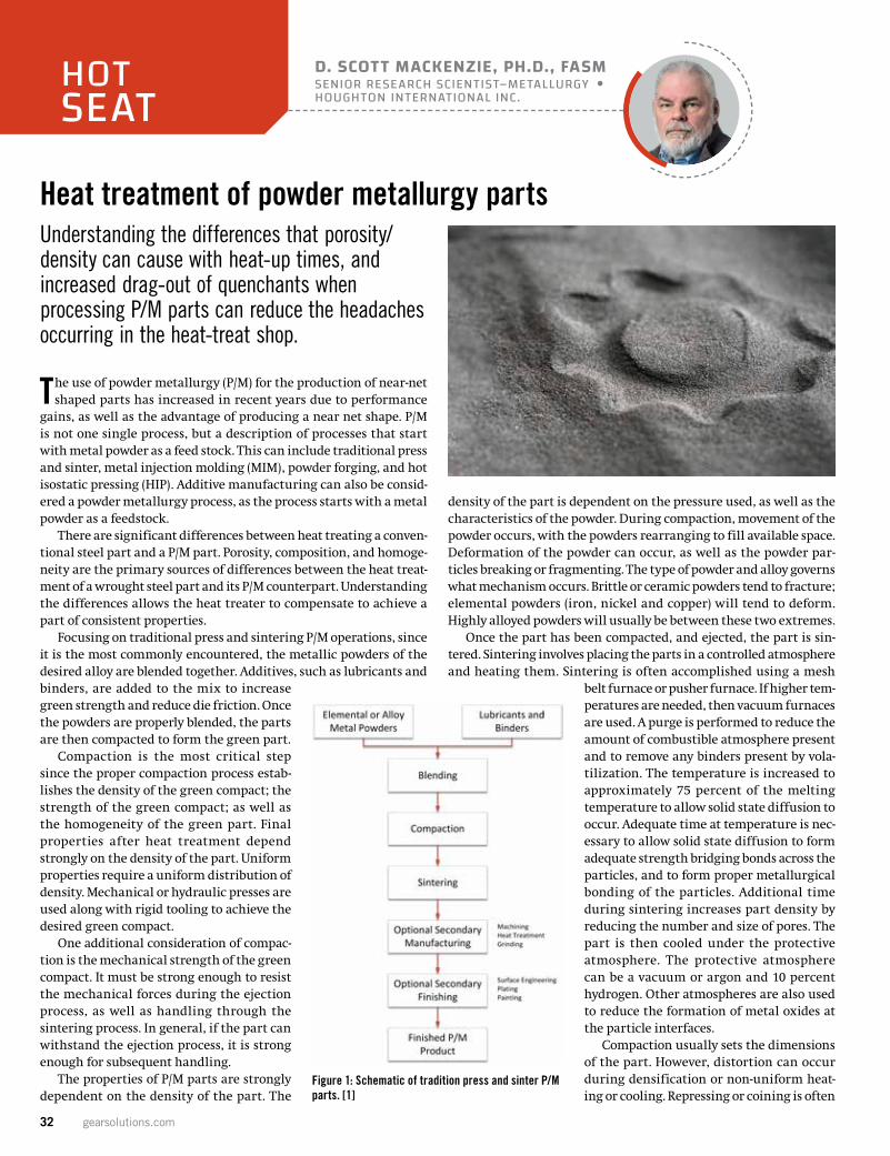
32 gearsolutions.com
Heat treatment of powder metallurgy parts
The use of powder metallurgy (P/M) for the production of near-net shaped parts has increased in recent years due to performance
gains, as well as the advantage of producing a near net shape. P/M is not one single process, but a description of processes that start with metal powder as a feed stock. This can include traditional press and sinter, metal injection molding (MIM), powder forging, and hot isostatic pressing (HIP). Additive manufacturing can also be consid-ered a powder metallurgy process, as the process starts with a metal powder as a feedstock.
There are significant differences between heat treating a conven-tional steel part and a P/M part. Porosity, composition, and homoge-neity are the primary sources of differences between the heat treat-ment of a wrought steel part and its P/M counterpart. Understanding the differences allows the heat treater to compensate to achieve a part of consistent properties.
Focusing on traditional press and sintering P/M operations, since it is the most commonly encountered, the metallic powders of the desired alloy are blended together. Additives, such as lubricants and binders, are added to the mix to increase green strength and reduce die friction. Once the powders are properly blended, the parts are then compacted to form the green part.
Compaction is the most critical step since the proper compaction process estab-lishes the density of the green compact; the strength of the green compact; as well as the homogeneity of the green part. Final properties after heat treatment depend strongly on the density of the part. Uniform properties require a uniform distribution of density. Mechanical or hydraulic presses are used along with rigid tooling to achieve the desired green compact.
One additional consideration of compac-tion is the mechanical strength of the green compact. It must be strong enough to resist the mechanical forces during the ejection process, as well as handling through the sintering process. In general, if the part can withstand the ejection process, it is strong enough for subsequent handling.
The properties of P/M parts are strongly dependent on the density of the part. The
density of the part is dependent on the pressure used, as well as the characteristics of the powder. During compaction, movement of the powder occurs, with the powders rearranging to fill available space. Deformation of the powder can occur, as well as the powder par-ticles breaking or fragmenting. The type of powder and alloy governs what mechanism occurs. Brittle or ceramic powders tend to fracture; elemental powders (iron, nickel and copper) will tend to deform. Highly alloyed powders will usually be between these two extremes.
Once the part has been compacted, and ejected, the part is sin-tered. Sintering involves placing the parts in a controlled atmosphere and heating them. Sintering is often accomplished using a mesh
belt furnace or pusher furnace. If higher tem-peratures are needed, then vacuum furnaces are used. A purge is performed to reduce the amount of combustible atmosphere present and to remove any binders present by vola-tilization. The temperature is increased to approximately 75 percent of the melting temperature to allow solid state diffusion to occur. Adequate time at temperature is nec-essary to allow solid state diffusion to form adequate strength bridging bonds across the particles, and to form proper metallurgical bonding of the particles. Additional time during sintering increases part density by reducing the number and size of pores. The part is then cooled under the protective atmosphere. The protective atmosphere can be a vacuum or argon and 10 percent hydrogen. Other atmospheres are also used to reduce the formation of metal oxides at the particle interfaces.
Compaction usually sets the dimensions of the part. However, distortion can occur during densification or non-uniform heat-ing or cooling. Repressing or coining is often
Understanding the differences that porosity/density can cause with heat-up times, and increased drag-out of quenchants when processing P/M parts can reduce the headaches occurring in the heat-treat shop.
D. SCOTT MACKENZIE, PH.D., FASMSENIOR RESEARCH SCIENTIST–METALLURGY HOUGHTON INTERNATIONAL INC.
HOTSEAT
Figure 1: Schematic of tradition press and sinter P/M parts. [1]
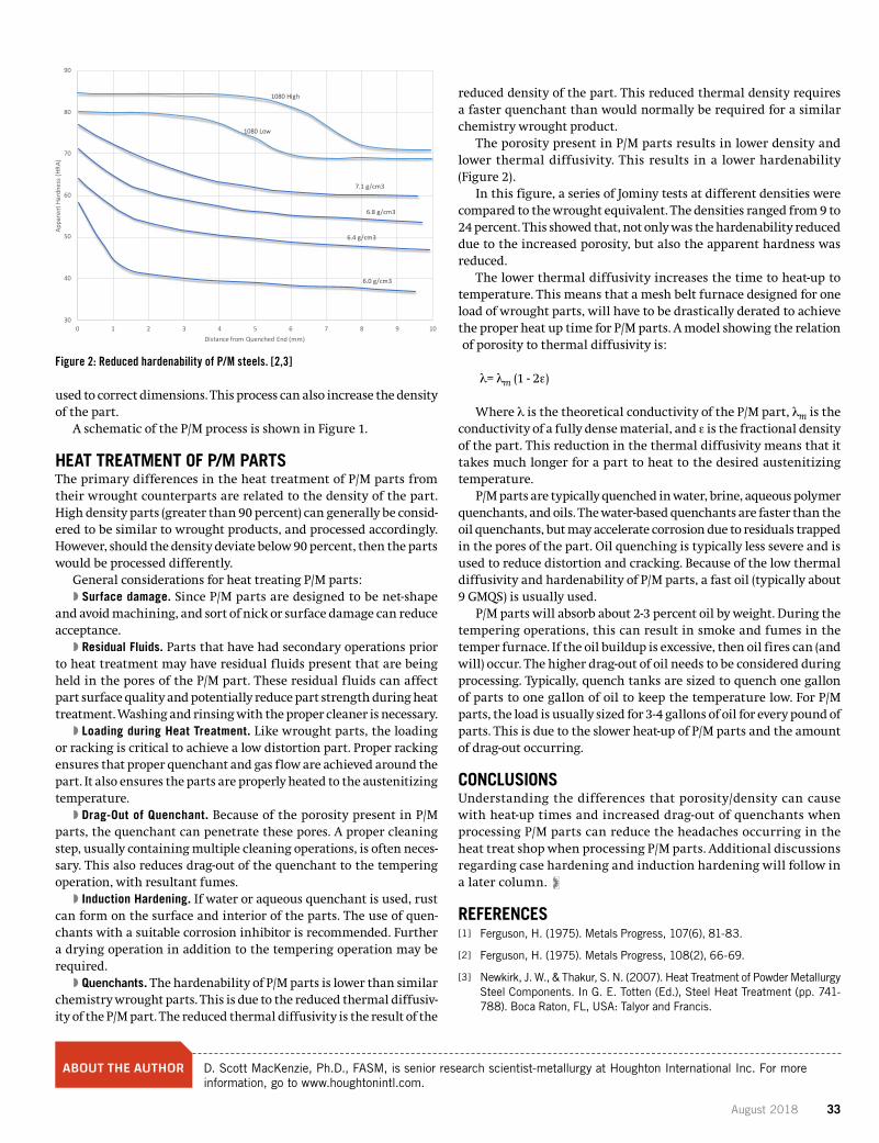
August 2018 33
used to correct dimensions. This process can also increase the density of the part.
A schematic of the P/M process is shown in Figure 1.
HEAT TREATMENT OF P/M PARTSThe primary differences in the heat treatment of P/M parts from their wrought counterparts are related to the density of the part. High density parts (greater than 90 percent) can generally be consid-ered to be similar to wrought products, and processed accordingly. However, should the density deviate below 90 percent, then the parts would be processed differently.
General considerations for heat treating P/M parts:�� Surface damage. Since P/M parts are designed to be net-shape
and avoid machining, and sort of nick or surface damage can reduce acceptance.
�� Residual Fluids. Parts that have had secondary operations prior to heat treatment may have residual fluids present that are being held in the pores of the P/M part. These residual fluids can affect part surface quality and potentially reduce part strength during heat treatment. Washing and rinsing with the proper cleaner is necessary.
�� Loading during Heat Treatment. Like wrought parts, the loading or racking is critical to achieve a low distortion part. Proper racking ensures that proper quenchant and gas flow are achieved around the part. It also ensures the parts are properly heated to the austenitizing temperature.
�� Drag-Out of Quenchant. Because of the porosity present in P/M parts, the quenchant can penetrate these pores. A proper cleaning step, usually containing multiple cleaning operations, is often neces-sary. This also reduces drag-out of the quenchant to the tempering operation, with resultant fumes.
�� Induction Hardening. If water or aqueous quenchant is used, rust can form on the surface and interior of the parts. The use of quen-chants with a suitable corrosion inhibitor is recommended. Further a drying operation in addition to the tempering operation may be required.
�� Quenchants. The hardenability of P/M parts is lower than similar chemistry wrought parts. This is due to the reduced thermal diffusiv-ity of the P/M part. The reduced thermal diffusivity is the result of the
reduced density of the part. This reduced thermal density requires a faster quenchant than would normally be required for a similar chemistry wrought product.
The porosity present in P/M parts results in lower density and lower thermal diffusivity. This results in a lower hardenability (Figure 2).
In this figure, a series of Jominy tests at different densities were compared to the wrought equivalent. The densities ranged from 9 to 24 percent. This showed that, not only was the hardenability reduced due to the increased porosity, but also the apparent hardness was reduced.
The lower thermal diffusivity increases the time to heat-up to temperature. This means that a mesh belt furnace designed for one load of wrought parts, will have to be drastically derated to achieve the proper heat up time for P/M parts. A model showing the relation of porosity to thermal diffusivity is:
l= lm (1 - 2e)
Where l is the theoretical conductivity of the P/M part, lm is the conductivity of a fully dense material, and e is the fractional density of the part. This reduction in the thermal diffusivity means that it takes much longer for a part to heat to the desired austenitizing temperature.
P/M parts are typically quenched in water, brine, aqueous polymer quenchants, and oils. The water-based quenchants are faster than the oil quenchants, but may accelerate corrosion due to residuals trapped in the pores of the part. Oil quenching is typically less severe and is used to reduce distortion and cracking. Because of the low thermal diffusivity and hardenability of P/M parts, a fast oil (typically about 9 GMQS) is usually used.
P/M parts will absorb about 2-3 percent oil by weight. During the tempering operations, this can result in smoke and fumes in the temper furnace. If the oil buildup is excessive, then oil fires can (and will) occur. The higher drag-out of oil needs to be considered during processing. Typically, quench tanks are sized to quench one gallon of parts to one gallon of oil to keep the temperature low. For P/M parts, the load is usually sized for 3-4 gallons of oil for every pound of parts. This is due to the slower heat-up of P/M parts and the amount of drag-out occurring.
CONCLUSIONSUnderstanding the differences that porosity/density can cause with heat-up times and increased drag-out of quenchants when processing P/M parts can reduce the headaches occurring in the heat treat shop when processing P/M parts. Additional discussions regarding case hardening and induction hardening will follow in a later column.
REFERENCES[ 1 ] Ferguson, H. (1975). Metals Progress, 107(6), 81-83.
[ 2 ] Ferguson, H. (1975). Metals Progress, 108(2), 66-69.
[ 3 ] Newkirk, J. W., & Thakur, S. N. (2007). Heat Treatment of Powder Metallurgy Steel Components. In G. E. Totten (Ed.), Steel Heat Treatment (pp. 741-788). Boca Raton, FL, USA: Talyor and Francis.
ABOUT THE AUTHOR D. Scott MacKenzie, Ph.D., FASM, is senior research scientist-metallurgy at Houghton International Inc. For more information, go to www.houghtonintl.com.
1080 High
1080 Low
7.1 g/cm3
6.8 g/cm3
6.4 g/cm3
6.0 g/cm3
30
40
50
60
70
80
90
0 1 2 3 4 5 6 7 8 9 10
Appa
rent
Har
dnes
s (H
RA)
Distance from Quenched End (mm)
Figure 2: Reduced hardenability of P/M steels. [2,3]
34 gearsolutions.com
IMTS SHOW PREVIEW
THE EFFECTS OF SHROUDING ON REDUCING MESHED SPUR GEAR POWER LOSS
ISSUEFOCUS
Printed with permission of the copyright holder, the American Gear Manufacturers Association, 1001 N. Fairfax Street, Suite 500, Alexandria, Virginia 22314. Statements presented in this paper are those of the authors and may not represent the position or opinion of the American Gear Manufacturers Association. (AGMA) This paper was presented October 2017 at the AGMA Fall Technical Meeting in Columbus, Ohio. 17FTM04
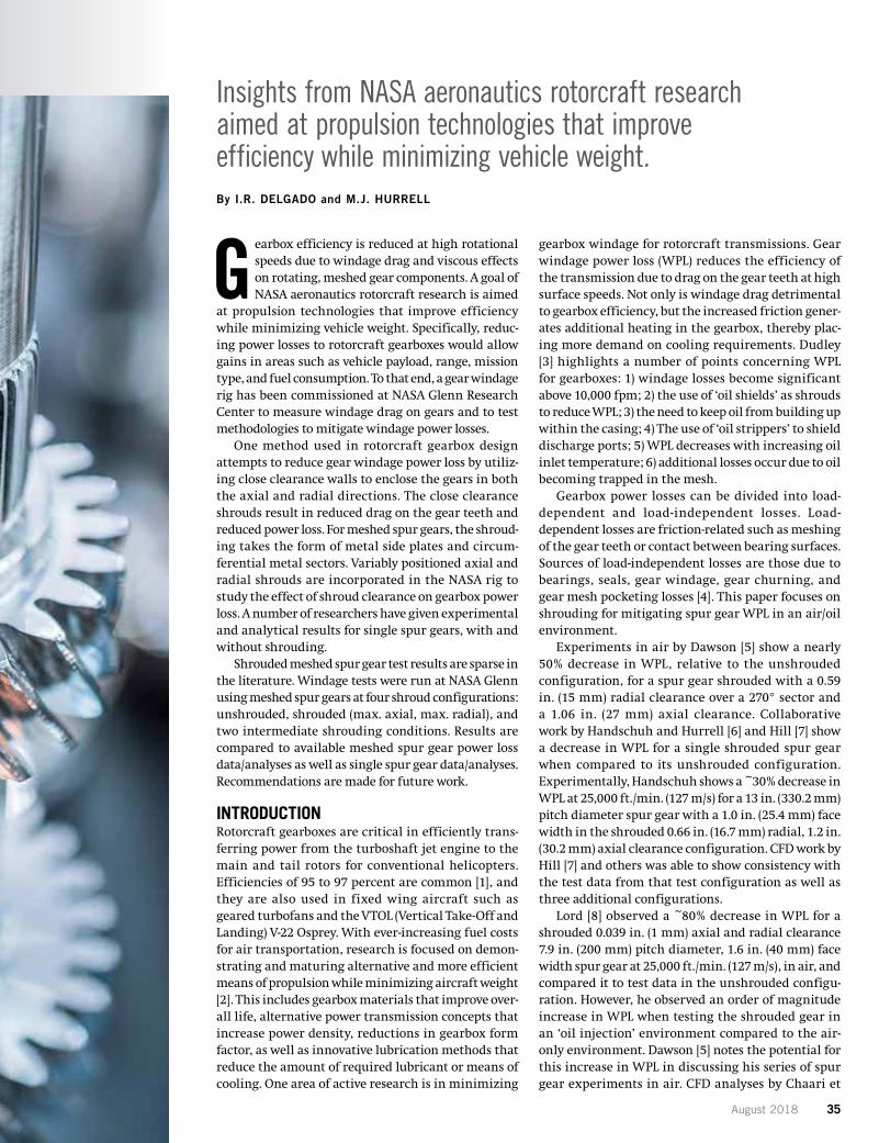
August 2018 35
Insights from NASA aeronautics rotorcraft research aimed at propulsion technologies that improve efficiency while minimizing vehicle weight.By I.R. DELGADO and M.J. HURRELL
Gearbox efficiency is reduced at high rotational speeds due to windage drag and viscous effects on rotating, meshed gear components. A goal of NASA aeronautics rotorcraft research is aimed
at propulsion technologies that improve efficiency while minimizing vehicle weight. Specifically, reduc-ing power losses to rotorcraft gearboxes would allow gains in areas such as vehicle payload, range, mission type, and fuel consumption. To that end, a gear windage rig has been commissioned at NASA Glenn Research Center to measure windage drag on gears and to test methodologies to mitigate windage power losses.
One method used in rotorcraft gearbox design attempts to reduce gear windage power loss by utiliz-ing close clearance walls to enclose the gears in both the axial and radial directions. The close clearance shrouds result in reduced drag on the gear teeth and reduced power loss. For meshed spur gears, the shroud-ing takes the form of metal side plates and circum-ferential metal sectors. Variably positioned axial and radial shrouds are incorporated in the NASA rig to study the effect of shroud clearance on gearbox power loss. A number of researchers have given experimental and analytical results for single spur gears, with and without shrouding.
Shrouded meshed spur gear test results are sparse in the literature. Windage tests were run at NASA Glenn using meshed spur gears at four shroud configurations: unshrouded, shrouded (max. axial, max. radial), and two intermediate shrouding conditions. Results are compared to available meshed spur gear power loss data/analyses as well as single spur gear data/analyses. Recommendations are made for future work.
INTRODUCTION Rotorcraft gearboxes are critical in efficiently trans-ferring power from the turboshaft jet engine to the main and tail rotors for conventional helicopters. Efficiencies of 95 to 97 percent are common [1], and they are also used in fixed wing aircraft such as geared turbofans and the VTOL (Vertical Take-Off and Landing) V-22 Osprey. With ever-increasing fuel costs for air transportation, research is focused on demon-strating and maturing alternative and more efficient means of propulsion while minimizing aircraft weight [2]. This includes gearbox materials that improve over-all life, alternative power transmission concepts that increase power density, reductions in gearbox form factor, as well as innovative lubrication methods that reduce the amount of required lubricant or means of cooling. One area of active research is in minimizing
gearbox windage for rotorcraft transmissions. Gear windage power loss (WPL) reduces the efficiency of the transmission due to drag on the gear teeth at high surface speeds. Not only is windage drag detrimental to gearbox efficiency, but the increased friction gener-ates additional heating in the gearbox, thereby plac-ing more demand on cooling requirements. Dudley [3] highlights a number of points concerning WPL for gearboxes: 1) windage losses become significant above 10,000 fpm; 2) the use of ‘oil shields’ as shrouds to reduce WPL; 3) the need to keep oil from building up within the casing; 4) The use of ‘oil strippers’ to shield discharge ports; 5) WPL decreases with increasing oil inlet temperature; 6) additional losses occur due to oil becoming trapped in the mesh.
Gearbox power losses can be divided into load-dependent and load-independent losses. Load-dependent losses are friction-related such as meshing of the gear teeth or contact between bearing surfaces. Sources of load-independent losses are those due to bearings, seals, gear windage, gear churning, and gear mesh pocketing losses [4]. This paper focuses on shrouding for mitigating spur gear WPL in an air/oil environment.
Experiments in air by Dawson [5] show a nearly 50% decrease in WPL, relative to the unshrouded configuration, for a spur gear shrouded with a 0.59 in. (15 mm) radial clearance over a 270° sector and a 1.06 in. (27 mm) axial clearance. Collaborative work by Handschuh and Hurrell [6] and Hill [7] show a decrease in WPL for a single shrouded spur gear when compared to its unshrouded configuration. Experimentally, Handschuh shows a ~30% decrease in WPL at 25,000 ft./min. (127 m/s) for a 13 in. (330.2 mm) pitch diameter spur gear with a 1.0 in. (25.4 mm) face width in the shrouded 0.66 in. (16.7 mm) radial, 1.2 in. (30.2 mm) axial clearance configuration. CFD work by Hill [7] and others was able to show consistency with the test data from that test configuration as well as three additional configurations.
Lord [8] observed a ~80% decrease in WPL for a shrouded 0.039 in. (1 mm) axial and radial clearance 7.9 in. (200 mm) pitch diameter, 1.6 in. (40 mm) face width spur gear at 25,000 ft./min. (127 m/s), in air, and compared it to test data in the unshrouded configu-ration. However, he observed an order of magnitude increase in WPL when testing the shrouded gear in an ‘oil injection’ environment compared to the air-only environment. Dawson [5] notes the potential for this increase in WPL in discussing his series of spur gear experiments in air. CFD analyses by Chaari et
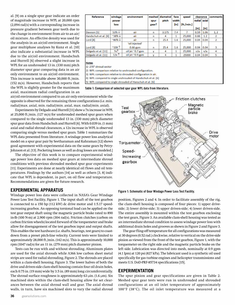
36 gearsolutions.com
al. [9] on a single spur gear indicate an order of magnitude increase in WPL at 20,000 rpm (2,094 rad/s) with a corresponding increase in pressure gradient between gear teeth due to the change in environment from air to an air/oil mixture. An effective density was used for the analysis in an air/oil environment. Single gear multiphase analyses by Kunz et al. [10] also indicate a substantial increase in WPL due to the air/oil environment. Handschuh and Hurrell [6] observed a slight increase in WPL for an unshrouded 13 in. (330 mm) pitch diameter spur gear comparing data in an air only environment to an air/oil environment. This increase is notable above 30,000 ft./min. (152 m/s). However, Handschuh reports that the WPL is slightly greater for the maximum axial, maximum radial configuration in an air/oil environment compared to an air only environment while the opposite is observed for the remaining three configurations (i.e. min. radial/max. axial, min. radial/min. axial, max. radial/min. axial).
Experiments by Delgado and Hurrell [11] show a 7x increase in WPL at 25,000 ft./min. (127 m/s) for unshrouded meshed spur gears when compared to the single unshrouded 13 in. (330 mm) pitch diameter spur gear data from Handschuh and Hurrell [6]. With 0.039 in. (1 mm) axial and radial shroud clearances, a 12x increase in WPL is observed comparing single versus meshed spur gears. Table 1 summarizes the WPL data presented from literature. A windage power loss analytical model on a spur gear pair by Seetharaman and Kahraman [12] shows good agreement with experimental data on the same gears by Petry-Johnson et al. [13]. Pocketing losses as well as drag losses are modeled.]
The objective of this work is to compare experimental wind-age power loss data on meshed spur gears at intermediate shroud conditions with previous shrouded meshed spur gear experiments [11]. Experiments are done at nearly identical oil flows and oil tem-peratures. Findings by the authors [14] as well as others [3, 8] indi-cate that WPL is dependent, in part, on oil flow and temperature. Recommendations are given for future research.
EXPERIMENTAL APPARATUS Windage power loss data were collected in NASA’s Gear Windage Power Loss Test Facility, Figure 1. The input shaft of the test gearbox is connected to a 150 hp (112 kW) dc drive motor and 1:5.17 speed- increasing gearbox. An opposing torsional load can be applied on the test gear output shaft using the magnetic particle brake rated to 890 in-lb (100 N-m) at 2,900 rpm (304 rad/s). Friction clutches (carbon on carbon friction wheels) located forward of the torquemeter and brake allow for disengagement of the test gearbox input and output shafts. This enables the test hardware (i.e. shafts, bearings, test gears) to coast-down from a preset pitch-line velocity. Current tests were limited to approximately 28,000 ft./min. (142 m/s). This is approximately 10,000 rpm (1047 rad/s) for an 11 in. (279 mm) pitch diameter pinion.
Tests can be run with and without shrouding. Aluminum plates are used for the axial shrouds while A366 low carbon sheet metal strips are used for radial shrouding, Figure 2. The shrouds are placed within a clam-shell housing, Figure 3. The lower halves of both the drive and driven-side clam-shell housing contain four oil drain holes, each 0.75 in. (19 mm) wide by 3.5 in. (89 mm) long circumferentially. The shroud surface roughness is approximately 63 μin. (1.6 μm). Six machined slots within the clam-shell housing allow for set clear-ances between the axial shroud wall and gear. The axial shroud walls, in turn, have six machined slots to vary the radial shroud
position, Figures 2 and 4. In order to facilitate assembly of the rig, the clam-shell housing is composed of four pieces: 1) upper drive-side; 2) lower drive-side; 3) upper driven-side; 4) lower driven-side. The entire assembly is mounted within the test gearbox enclosing the test gears, Figure 3. An available clam-shell housing was tested as an intermediate shroud condition to assess windage power loss with additional drain holes and grooves as shown in Figure 2 and Figure 3.
The gear fling-off temperature for all configurations was measured at 30 degrees (0.52 rad.) clockwise, relative to vertical on the drive-side pinion as viewed from the front of the test gearbox, Figure 1, with the torquemeter on the right side and the magnetic particle brake on the left side. Lubrication was directed into mesh, nominally at 0.9 gpm (4.1 lpm) at 120 psi (827 kPa). The lubricant used is a synthetic oil used specifically for gas turbine engines and helicopter transmissions and meets U.S. DoD-PRF-85734 specifications [15].
EXPERIMENTATION The spur pinion and gear specifications are given in Table 2. Meshed spur gear tests were run in unshrouded and shrouded configurations at an oil inlet temperature of approximately 100°F (38°C). The oil inlet temperature was measured at a
3 17FTM04
Seetharaman and Kahraman [12] shows good agreement with experimental data on the same gears by Petry-Johnson et al. [13]. Pocketing losses as well as drag losses are modeled.
Table 1 – Comparison of selected spur gear WPL data from literature.
The objective of this work is to compare experimental windage power loss data on meshed spur gears at intermediate shroud conditions with previous shrouded meshed spur gear experiments [11]. Experiments are done at nearly identical oil flows and oil temperatures. Findings by the authors [14] as well as others [3, 8] indicate that WPL is dependent, in part, on oil flow and temperature. Recommendations are given for future research.
Experimental ApparatusWindage power loss data were collected in NASAʼs Gear Windage Power Loss Test Facility, Figure 1. The input shaft of the test gearbox is connected to a 150 hp (112 kW) dc drive motor and 1:5.17 speed-increasing gearbox. An opposing torsional load can be applied on the test gear output shaft using the magnetic particle brake rated to 890 in-lb (100 N-m) at 2900 rpm (304 rad/s). Friction clutches (carbon on carbon friction wheels) located forward of the torquemeter and brake allow for disengagement of the test gearbox input and output shafts. This enables the test hardware (i.e. shafts, bearings, test gears) to coast-down from a preset pitch-line velocity. Current tests were limited to approximately 28,000 ft./min. (142 m/s). This is approximately 10,000 rpm (1047 rad/s) for an 11 in. (279 mm) pitch diameter pinion.Tests can be run with and without shrouding. Aluminum plates are used for the axial shrouds while A366 low carbon sheet metal strips are used for radial shrouding, Figure 2. The shrouds are placed within a clam-shell housing, Figure 3. The lower halves of both the drive- and driven-side clam-shell housing contain four oil drain holes, each 0.75 in. (19 mm) wide by 3.5 in. (89 mm) long circumferentially. The shroud surface roughness is approximately 63 µin. (1.6 µm). Six machined slots within the clam-shell housing allow for set clearances between the axial shroud wall and gear. The axial shroud walls, in turn, have six machined slots to vary the radial shroud position, Figures 2 and 4. In order to facilitate assembly of the rig, the clam-shell housing is composed of four pieces: 1) upper drive-side; 2) lower drive-side; 3) upper driven-side; 4) lower driven-side. The entire assembly is mounted within the test gearbox enclosing the test gears, Figure 3. An available clam-shell housing was tested as an intermediate shroud condition to assess windage power loss with additional drain holes and grooves as shown in Figure 2 and Figure 3.The gear fling-off temperature for all configurations was measured at 30 degrees (0.52 rad.) clockwise,relative to vertical on the drive-side pinion as viewed from the front of the test gearbox, Figure 1, with the torquemeter on the right side and the magnetic particle brake on the left side. Lubrication was directed into mesh, nominally at 0.9 gpm (4.1 lpm) at 120 psi (827 kPa). The lubricant used is a synthetic oil used specifically for gas turbine engines and helicopter transmissions and meets U.S. DoD-PRF-85734 specifications [15].
4 17FTM04
Figure 1 – Schematic of Gear Windage Power Loss Test Facility.
Figure 2 – Configuration of radial and axial shrouding. Axial shrouds are 0.25 in. (6.35 mm) thick.
Figure 1: Schematic of Gear Windage Power Loss Test Facility.
Table 1: Comparison of selected spur gear WPL data from literature.
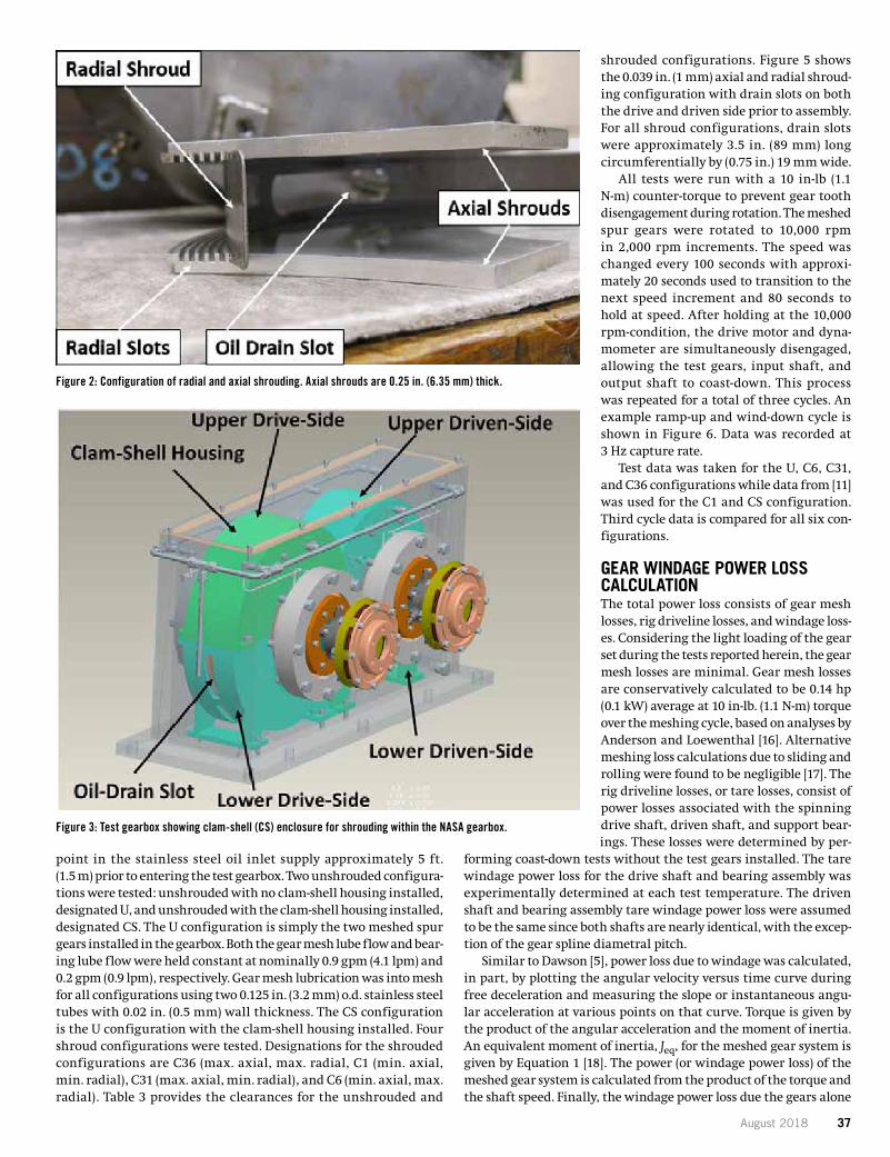
August 2018 37
point in the stainless steel oil inlet supply approximately 5 ft. (1.5 m) prior to entering the test gearbox. Two unshrouded configura-tions were tested: unshrouded with no clam-shell housing installed, designated U, and unshrouded with the clam-shell housing installed, designated CS. The U configuration is simply the two meshed spur gears installed in the gearbox. Both the gear mesh lube flow and bear-ing lube flow were held constant at nominally 0.9 gpm (4.1 lpm) and 0.2 gpm (0.9 lpm), respectively. Gear mesh lubrication was into mesh for all configurations using two 0.125 in. (3.2 mm) o.d. stainless steel tubes with 0.02 in. (0.5 mm) wall thickness. The CS configuration is the U configuration with the clam-shell housing installed. Four shroud configurations were tested. Designations for the shrouded configurations are C36 (max. axial, max. radial, C1 (min. axial, min. radial), C31 (max. axial, min. radial), and C6 (min. axial, max. radial). Table 3 provides the clearances for the unshrouded and
shrouded configurations. Figure 5 shows the 0.039 in. (1 mm) axial and radial shroud-ing configuration with drain slots on both the drive and driven side prior to assembly. For all shroud configurations, drain slots were approximately 3.5 in. (89 mm) long circumferentially by (0.75 in.) 19 mm wide.
All tests were run with a 10 in-lb (1.1 N-m) counter-torque to prevent gear tooth disengagement during rotation. The meshed spur gears were rotated to 10,000 rpm in 2,000 rpm increments. The speed was changed every 100 seconds with approxi-mately 20 seconds used to transition to the next speed increment and 80 seconds to hold at speed. After holding at the 10,000 rpm-condition, the drive motor and dyna-mometer are simultaneously disengaged, allowing the test gears, input shaft, and output shaft to coast-down. This process was repeated for a total of three cycles. An example ramp-up and wind-down cycle is shown in Figure 6. Data was recorded at 3 Hz capture rate.
Test data was taken for the U, C6, C31, and C36 configurations while data from [11] was used for the C1 and CS configuration. Third cycle data is compared for all six con-figurations.
GEAR WINDAGE POWER LOSS CALCULATION The total power loss consists of gear mesh losses, rig driveline losses, and windage loss-es. Considering the light loading of the gear set during the tests reported herein, the gear mesh losses are minimal. Gear mesh losses are conservatively calculated to be 0.14 hp (0.1 kW) average at 10 in-lb. (1.1 N-m) torque over the meshing cycle, based on analyses by Anderson and Loewenthal [16]. Alternative meshing loss calculations due to sliding and rolling were found to be negligible [17]. The rig driveline losses, or tare losses, consist of power losses associated with the spinning drive shaft, driven shaft, and support bear-ings. These losses were determined by per-
forming coast-down tests without the test gears installed. The tare windage power loss for the drive shaft and bearing assembly was experimentally determined at each test temperature. The driven shaft and bearing assembly tare windage power loss were assumed to be the same since both shafts are nearly identical, with the excep-tion of the gear spline diametral pitch.
Similar to Dawson [5], power loss due to windage was calculated, in part, by plotting the angular velocity versus time curve during free deceleration and measuring the slope or instantaneous angu-lar acceleration at various points on that curve. Torque is given by the product of the angular acceleration and the moment of inertia. An equivalent moment of inertia, Jeq, for the meshed gear system is given by Equation 1 [18]. The power (or windage power loss) of the meshed gear system is calculated from the product of the torque and the shaft speed. Finally, the windage power loss due the gears alone
Figure 2: Configuration of radial and axial shrouding. Axial shrouds are 0.25 in. (6.35 mm) thick.
Figure 3: Test gearbox showing clam-shell (CS) enclosure for shrouding within the NASA gearbox.
4 17FTM04
Figure 1 – Schematic of Gear Windage Power Loss Test Facility.
Figure 2 – Configuration of radial and axial shrouding. Axial shrouds are 0.25 in. (6.35 mm) thick.
5 17FTM04
Figure 3 – Test gearbox showing clam-shell (CS) enclosure for shrouding within the NASA Gearbox.
Figure 4 – Configuration of axial and radial shrouding using machined slots.Axial shrouds are 0.25 in. (6.35 mm) thick.
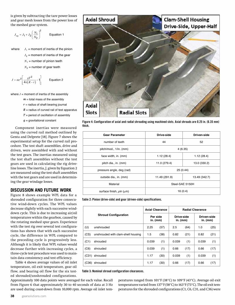
38 gearsolutions.com
is given by subtracting the tare power losses and gear mesh losses from the power loss of the meshed gear system.
Component inertias were measured using the curved rail method outlined by Genta and Delprete [18]. Figure 7 shows the experimental setup for the curved rail pro-cedure. The test shaft assemblies, drive and driven, were assembled with and without the test gears. The inertias measured using the test shaft assemblies without the test gears are used in calculating the rig drive-line losses. The inertia, J, given by Equation 2 are measured using the test shaft assemblies with the test gears and are used in determin-ing the gear windage losses.
DISCUSSION AND FUTURE WORK Figure 8 shows example WPL data for a shrouded configuration for three consecu-tive wind-down cycles. The WPL values decrease slightly with each successive wind-down cycle. This is due to increasing air/oil temperatures within the gearbox, caused by the rotating meshed spur gears. Experience with the test rig over several test configura-tions has shown that with each successive cycle, the difference in WPL compared to the preceding cycle is progressively less. Although it is likely that WPL values would decrease further with increasing cycles, a three-cycle test procedure was used to main-tain data consistency and test efficiency.
Table 4 shows average values of oil inlet temperature, oil exit temperature, gear oil flow, and bearing oil flow for the six test-ed shrouded/unshrouded configurations. Approximately 100 data points were averaged for each value. Recall from Figure 6 that approximately 30 to 40 seconds of data at 3 Hz are used during coast-down from 10,000 rpm. Average oil inlet tem-
peratures ranged from 101°F (38°C) to 109°F (43°C). Average oil exit temperatures varied from 137°F (58°C) to 163°F (73°C). The oil exit tem-peratures for the shrouded configurations (C1, C6, C31, and C36) were
Figure 4: Configuration of axial and radial shrouding using machined slots. Axial shrouds are 0.25 in. (6.35 mm) thick.
Table 2: Pinion (drive-side) and gear (driven-side) specifications.
Table 3: Nominal shroud configuration clearances.
5 17FTM04
Figure 3 – Test gearbox showing clam-shell (CS) enclosure for shrouding within the NASA Gearbox.
Figure 4 – Configuration of axial and radial shrouding using machined slots.Axial shrouds are 0.25 in. (6.35 mm) thick.
6 17FTM04
ExperimentationThe spur pinion and gear specifications are given in Table 2. Meshed spur gear tests were run in unshrouded and shrouded configurations at an oil inlet temperature of approximately 100°F (38°C). The oil inlet temperature was measured at a point in the stainless steel oil inlet supply approximately 5 ft. (1.5 m) prior to entering the test gearbox. Two unshrouded configurations were tested: unshrouded with no clam-shell housing installed, designated U, and unshrouded with the clam-shell housing installed,designated CS. The U configuration is simply the two meshed spur gears installed in the gearbox. Both the gear mesh lube flow and bearing lube flow were held constant at nominally 0.9 gpm (4.1 lpm) and0.2 gpm (0.9 lpm), respectively. Gear mesh lubrication was into mesh for all configurations using two 0.125 in. (3.2 mm) o.d. stainless steel tubes with 0.02 in. (0.5 mm) wall thickness. The CS configuration is the U configuration with the clam-shell housing installed. Four shroud configurations were tested.Designations for the shrouded configurations are C36 (max. axial, max. radial, C1 (min. axial, min. radial), C31 (max. axial, min. radial), and C6 (min. axial, max. radial). Table 3 provides the clearances for the unshrouded and shrouded configurations. Figure 5 shows the 0.039 in. (1 mm) axial and radial shrouding configuration with drain slots on both the drive and driven side prior to assembly. For all shroud configurations, drain slots were approximately 3.5 in. (89 mm) long circumferentially by (0.75 in.) 19 mmwide.All tests were run with a 10 in-lb (1.1 N-m) counter-torque to prevent gear tooth disengagement during rotation. The meshed spur gears were rotated to 10,000 rpm in 2000 rpm increments. The speed was changed every 100 seconds with approximately 20 seconds used to transition to the next speed increment and 80 seconds to hold at speed. After holding at the 10,000 rpm-condition, the drive motor and dynamometer are simultaneously disengaged allowing the test gears, input shaft, and output shaft to coast-down. This process was repeated for a total of three cycles. An example ramp-up and wind-down cycle is shown in Figure 6. Data was recorded at 3 Hz, capture rate.Test data was taken for the U, C6, C31, and C36 configurations while data from [11] was used for the C1 and CS configuration. Third cycle data is compared for all six configurations.
Table 2 – Pinion (drive-side) and gear (driven-side) specifications.
Gear Parameter Drive-side Driven-side
number of teeth 44 52
pitch/mod., 1/in. (mm) 4 (6.35)
face width, in. (mm) 1.12 (28.4) 1.12 (28.4)
pitch dia., in. (mm) 11.0 (279.4) 13.0 (330.2)
pressure angle, deg (rad) 25 (0.44)
outside dia., in. (mm) 11.49 (291.9) 13.49 (342.7)
Material Steel-SAE 5150H
surface finish, µin (µm) 16 (0.4)
7 17FTM04
Table 3 – Nominal shroud configuration clearances.
Shroud ConfigurationAxial Clearance Radial Clearance
Per sidein. (mm)
Drive-sidein. (mm)
Driven-sidein. (mm)
(U) unshrouded 2.25 (57) 2.5 (64) 1.0 (25)
(CS) unshrouded with clam-shell housing 1.5 (38) 0.82 (21) 0.82 (21)
(C1) shrouded 0.039 (1) 0.039 (1) 0.039 (1)
(C6) shrouded 0.039 (1) 0.66 (17) 0.66 (17)
(C31) shrouded 1.17 (30) 0.039 (1) 0.039 (1)
(C36) shrouded 1.17 (30) 0.66 (17) 0.66 (17)
Figure 5 – C1 shroud configuration with drain slots.
8 17FTM04
Figure 6 – Example windage test ramp-up and wind-down cycle.
Gear Windage Power Loss CalculationThe total power loss consists of gear mesh losses, rig driveline losses, and windage losses. Considering the light loading of the gear set during the tests reported herein, the gear mesh losses are minimal. Gear mesh losses are conservatively calculated to be 0.14 hp (0.1 kW) average at 10 in-lb. (1.1 N-m) torque over the meshing cycle, based on analyses by Anderson and Loewenthal [16]. Alternative meshing losscalculations due to sliding and rolling were found to be negligible [17]. The rig driveline losses, or tare losses, consist of power losses associated with the spinning drive shaft, driven shaft, and support bearings. These losses were determined by performing coast-down tests without the test gears installed. The tare windage power loss for the drive shaft and bearing assembly was experimentally determined at each test temperature. The driven shaft and bearing assembly tare windage power loss were assumed to be the same since both shafts are nearly identical, with the exception of the gear spline diametral pitch.Similar to Dawson [5], power loss due to windage was calculated, in part, by plotting the angular velocity versus time curve during free deceleration and measuring the slope or instantaneous angular acceleration at various points on that curve. Torque is given by the product of the angular acceleration and the moment of inertia. An equivalent moment of inertia, Jeq, for the meshed gear system is given by Equation 1 [Ref. 18]. The power (or windage power loss) of the meshed gear system is calculated from the product of the torque and the shaft speed. Finally, the windage power loss due the gears alone is given by subtracting the tare power losses and gear mesh losses from the power loss of the meshed gear system.
21
1 22
eqN
J J JN
= +
Equation 1
where J1 = moment of inertia of the pinion
J2 = moment of inertia of the gear
N1 = number of pinion teeth
N2 = number of gear teeth
9 17FTM04
Component inertias were measured using the curved rail method outlined by Genta and Delprete [18].Figure 7 shows the experimental setup for the curved rail procedure. The test shaft assemblies, drive and driven, were assembled with and without the test gears. The inertias measured using the test shaft assemblies without the test gears are used in calculating the rig driveline losses. The inertia, J, given by Equation 2 are measured using the test shaft assemblies with the test gears and are used in determining the gear windage losses.
( )2
2 14
gTJ mrR r
= −
π − Equation 2
where J = moment of inertia of the assembly= total mass of the assembly
= radius of shaft bearing journal
= radius of curved rail of test apparatus
= period of oscillation of assembly
= gravitational constant
Figure 7 – Example experimental setup for tare loss calculation using curved rail method.
Discussion and Future WorkFigure 8 shows example WPL data for a shrouded configuration for three consecutive wind-down cycles.The WPL values decrease slightly with each successive wind-down cycle. This is due to increasing air/oil temperatures within the gearbox, caused by the rotating meshed spur gears. Experience with the test rig over several test configurations has shown that with each successive cycle, the difference in WPL compared to the preceding cycle is progressively less. Although it is likely that WPL values would decrease further with increasing cycles, a three-cycle test procedure was used to maintain data consistency and test efficiency. Table 4 shows average values of oil inlet temperature, oil exit temperature, gear oil flow and bearing oil flow for the six tested shrouded/unshrouded configurations. Approximately 100 data points were averaged for each value. Recall from Figure 6 that approximately 30 to 40 seconds of data at 3 Hz are used during coast-down from 10,000 rpm. Average oil inlet temperatures ranged from 101°F (38°C) to
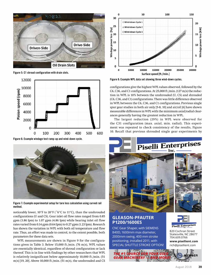
August 2018 39
noticeably lower, 10°F to 20°F (~6°C to 11°C), than the unshrouded configurations (U and CS). Gear inlet oil flow rates ranged from 0.85 gpm (3.86 lpm) to 1.07 gpm (4.86 lpm) while bearing inlet oil flow rates varied from 0.14 gpm (0.64 lpm) to 0.27 gpm (1.23 lpm). Research has shown the variation in WPL with both oil temperature and flow rate. Thus, an effort was made to control, to the extent possible, both parameters for these data sets.
WPL measurements are shown in Figure 9 for the configura-tions given in Table 3. Below 15,000 ft./min. (76 m/s), WPL values are essentially identical, regardless of shroud configuration or lack thereof. This is in line with findings by other researchers that WPL is relatively insignificant below approximately 10,000 ft./min. (51 m/s) [19, 20]. Above 10,000 ft./min. (51 m/s), the unshrouded and CS
configurations give the highest WPL values observed, followed by the C6, C36, and C1 configurations. At 25,000 ft./min. (127 m/s) the reduc-tion in WPL is 10% between the unshrouded (U, CS) and shrouded (C6, C36, and C1) configurations. There was little difference observed in WPL between the C6, C36, and C1 configurations. Previous single spur gear studies in both air only [5-8, 10] and air/oil [6] have shown measurable differences in WPL with the minimum axial/radial clear-ances generally having the greatest reduction in WPL.
The largest reduction (29%) in WPL were observed for the C31 configuration (max. axial, min. radial). This experi-ment was repeated to check consistency of the results, Figure 10. Recall that previous shrouded single gear experiments by
7 17FTM04
Table 3 – Nominal shroud configuration clearances.
Shroud ConfigurationAxial Clearance Radial Clearance
Per sidein. (mm)
Drive-sidein. (mm)
Driven-sidein. (mm)
(U) unshrouded 2.25 (57) 2.5 (64) 1.0 (25)
(CS) unshrouded with clam-shell housing 1.5 (38) 0.82 (21) 0.82 (21)
(C1) shrouded 0.039 (1) 0.039 (1) 0.039 (1)
(C6) shrouded 0.039 (1) 0.66 (17) 0.66 (17)
(C31) shrouded 1.17 (30) 0.039 (1) 0.039 (1)
(C36) shrouded 1.17 (30) 0.66 (17) 0.66 (17)
Figure 5 – C1 shroud configuration with drain slots.
8 17FTM04
Figure 6 – Example windage test ramp-up and wind-down cycle.
Gear Windage Power Loss CalculationThe total power loss consists of gear mesh losses, rig driveline losses, and windage losses. Considering the light loading of the gear set during the tests reported herein, the gear mesh losses are minimal. Gear mesh losses are conservatively calculated to be 0.14 hp (0.1 kW) average at 10 in-lb. (1.1 N-m) torque over the meshing cycle, based on analyses by Anderson and Loewenthal [16]. Alternative meshing losscalculations due to sliding and rolling were found to be negligible [17]. The rig driveline losses, or tare losses, consist of power losses associated with the spinning drive shaft, driven shaft, and support bearings. These losses were determined by performing coast-down tests without the test gears installed. The tare windage power loss for the drive shaft and bearing assembly was experimentally determined at each test temperature. The driven shaft and bearing assembly tare windage power loss were assumed to be the same since both shafts are nearly identical, with the exception of the gear spline diametral pitch.Similar to Dawson [5], power loss due to windage was calculated, in part, by plotting the angular velocity versus time curve during free deceleration and measuring the slope or instantaneous angular acceleration at various points on that curve. Torque is given by the product of the angular acceleration and the moment of inertia. An equivalent moment of inertia, Jeq, for the meshed gear system is given by Equation 1 [Ref. 18]. The power (or windage power loss) of the meshed gear system is calculated from the product of the torque and the shaft speed. Finally, the windage power loss due the gears alone is given by subtracting the tare power losses and gear mesh losses from the power loss of the meshed gear system.
21
1 22
eqN
J J JN
= +
Equation 1
where J1 = moment of inertia of the pinion
J2 = moment of inertia of the gear
N1 = number of pinion teeth
N2 = number of gear teeth
9 17FTM04
Component inertias were measured using the curved rail method outlined by Genta and Delprete [18].Figure 7 shows the experimental setup for the curved rail procedure. The test shaft assemblies, drive and driven, were assembled with and without the test gears. The inertias measured using the test shaft assemblies without the test gears are used in calculating the rig driveline losses. The inertia, J, given by Equation 2 are measured using the test shaft assemblies with the test gears and are used in determining the gear windage losses.
( )2
2 14
gTJ mrR r
= −
π − Equation 2
where J = moment of inertia of the assembly= total mass of the assembly
= radius of shaft bearing journal
= radius of curved rail of test apparatus
= period of oscillation of assembly
= gravitational constant
Figure 7 – Example experimental setup for tare loss calculation using curved rail method.
Discussion and Future WorkFigure 8 shows example WPL data for a shrouded configuration for three consecutive wind-down cycles.The WPL values decrease slightly with each successive wind-down cycle. This is due to increasing air/oil temperatures within the gearbox, caused by the rotating meshed spur gears. Experience with the test rig over several test configurations has shown that with each successive cycle, the difference in WPL compared to the preceding cycle is progressively less. Although it is likely that WPL values would decrease further with increasing cycles, a three-cycle test procedure was used to maintain data consistency and test efficiency. Table 4 shows average values of oil inlet temperature, oil exit temperature, gear oil flow and bearing oil flow for the six tested shrouded/unshrouded configurations. Approximately 100 data points were averaged for each value. Recall from Figure 6 that approximately 30 to 40 seconds of data at 3 Hz are used during coast-down from 10,000 rpm. Average oil inlet temperatures ranged from 101°F (38°C) to
Figure 5: C1 shroud configuration with drain slots.
Figure 6: Example windage test ramp-up and wind-down cycle.
Figure 7: Example experimental setup for tare loss calculation using curved rail method.
10 17FTM04
109°F (43°C). Average oil exit temperatures varied from 137°F (58°C) to 163°F (73°C). The oil exit temperatures for the shrouded configurations (C1, C6, C31, and C36) were noticeably lower, 10°F to 20°F (~6°C to 11°C), than the unshrouded configurations (U and CS). Gear inlet oil flow rates ranged from 0.85 gpm (3.86 lpm) to 1.07 gpm (4.86 lpm) while bearing inlet oil flow rates varied from 0.14 gpm (0.64 lpm) to 0.27 gpm (1.23 lpm). Research has shown the variation in WPL with both oil temperature and flow rate. Thus, an effort was made to control, to the extent possible, both parameters for these data sets.
Figure 8 – Example WPL data set showing three wind-down cycles.
Table 4 – Average ʻCycle 3 wind-downʼ oil temperatures and flows for various shroud configurations.
Shroud Configurationoil inlet temp.
°F (°C)
oil exittemp.
°F (°C)
gear inletoil-flow
gpm (lpm)
bearing inletoil-flow
gpm (lpm)
(U) unshrouded 107 (41) 163 (73) 0.91 (4.1) 0.27 (1.2)
(CS) unshrouded with clam-shell housing 102 (39) 162 (72) 0.90 (4.1) 0.14 (0.6)
(C1) shrouded 109 (43) 143 (62) 0.91 (4.1) 0.18 (0.8)
(C6) shrouded 107 (41) 151 (66) 0.91 (4.1) 0.19 (0.9)
(C31) shrouded 101 (38) 137 (58) 1.07 (4.9) 0.18 (0.8)
(C36) shrouded 101 (38) 144 (62) 0.85 (3.9) 0.19 (0.9)
WPL measurements are shown in Figure 9 for the configurations given in Table 3. Below 15,000 ft./min. (76 m/s), WPL values are essentially identical, regardless of shroud configuration or lack thereof. This is in line with findings by other researchers that WPL is relatively insignificant below approximately 10,000 ft./min. (51 m/s) [19, 20]. Above 10,000 ft./min. (51 m/s), the unshrouded and CS configurations give the highest WPL values observed, followed by the C6, C36, and C1 configurations. At 25,000 ft./min. (127 m/s) the reduction in WPL is 10% between the unshrouded (U, CS) and shrouded (C6, C36, and C1) configurations. There was little difference observed in WPL between the C6, C36, and C1 configurations. Previous single spur gear studies in both air only [5-8, 10] and air/oil [6] have shown measurable
Figure 8: Example WPL data set showing three wind-down cycles.
GLEASON-PFAUTER P1200/1600ES CNC Gear Shaper, with SIEMENS 840D, 1600mm max diameter, 2000mm swing, 400 mm stroke positioning, installed 2011, with SPECIAL SHUTTLE STROKE OPTION!
THE #1 SOURCE FOR YOUR USED GEAR MACHINERY — AND MORE!
820 Cochran StreetStatesville, NC [email protected]
MEMBER
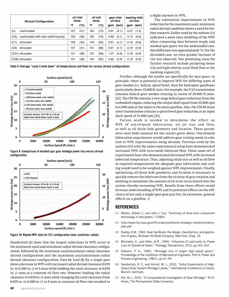
40 gearsolutions.com
Handschuh [6] show that the largest reductions in WPL occur at the minimum axial and minimum radial shroud clearance configu-ration, followed by the minimum axial/maximum radial clearance shroud configuration and the maximum axial/minimum radial shroud clearance configuration. Data by Lord [8] for a single gear show a decrease in WPL with increased radial shroud clearance 0.039 in. to 0.200 in. (1 to 5 mm) while holding the axial clearance at 0.039 in. (1 mm) at a constant oil flow rate. However, holding the radial clearance at 0.039 in. (1 mm) while changing the axial clearance from 0.039 in. to 0.200 in. (1 to 5 mm) at constant oil flow rate resulted in
a slight increase in WPL.The substantial improvement in WPL
reduction for the maximum axial, minimum radial shroud condition shows a need for fur-ther research. Earlier work by the authors [11] indicated a more than doubling of the WPL when comparing data between single and meshed spur gears. For the unshrouded case, this difference was approximately 7x. For the shrouded case, an even greater increase of 12x was observed. Two promising areas for further research include pocketing losses [12] and high velocity axial fluid flow at the meshing region [21].
Further, although the results are specifically for spur gears, in principle, there is potential to improve WPL for differing types of gear meshes (i.e. helical, spiral bevel, face) for helicopter gearboxes particularly above 15,000 ft./min. For example, the V-22 transmission contains helical gear meshes rotating in excess of 20,000 ft./min. [22]. The OH-58 contains a two-stage helical gear reduction from the turboshaft engine, reducing the output shaft speed from 35,000 rpm to 6,000 rpm at the input to the main gearbox. Also, the UH-60 main rotor transmission contains a spiral bevel gear reduction at an input shaft speed of 21,000 rpm [23].
Future work is needed to determine the effect on WPL of out-of-mesh lubrication, oil jet size and f low, as well as oil drain hole geometry and location. These param-eters were held constant for the results given above. Out-of-mesh lubrication experiments would address gear cooling needs in rela-tion to WPL improvements using shrouds. Previous work by the authors [14] with the same experimental setup have demonstrated increased WPL with in-to-mesh lubricant flow. Those same set of experiments have also demonstrated decreased WPL with increased lubricant temperature. Thus, adjusting oil jet size as well as oil flow at required temperatures for adequate gear lubrication and cool-ing would need to be weighed against WPL improvements. Finally, optimizing oil drain hole geometry and location is necessary to quickly remove the lubricant from the vicinity of gear rotation and meshing to minimize the amount of oil to be recirculated into the system thereby increasing WPL. Results from these efforts would increase understanding of WPL and its potential effects on the effi-ciency of not only a single spur gear pair but, by extension, general effects on a gearbox.
REFERENCES[ 1 ] Weden, Gilbert J., and John J. Coy. “Summary of drive-train component
technology in helicopters.” (1984).
[ 2 ] http://www.hq.nasa.gov/office/aero/pdf/armd-strategic-implementation- plan.pdf
[ 3 ] Dudley, D.W., 1962, Gear handbook: the design, manufacture, and applica-tion of gears, McGraw Hill Book Company, New York, Chap. 14.
[ 4 ] Michaelis, K., and Höhn, B-R., 1994, “Influence of Lubricants on Power Loss of Cylindrical Gears,” Tribology Transactions, 37(1), pp.161–167.
[ 5 ] Dawson, P. H., 1984, “Windage loss in larger high-speed gears,” Proceedings of the Institution of Mechanical Engineers, Part A: Power and Process Engineering, 198(1), pp.51–59.
[ 6 ] Handschuh, R. F., and Hurrell, M. J., 2010, “Initial Experiments of High-Speed Drive System Windage Losses,” International Conference on Gears, Munich, Germany.
[ 7 ] Hill, M.J., 2010, “A Computational Investigation of Gear Windage,” Ph.D. thesis, The Pennsylvania State University.
Table 4: Average “cycle 3 wind-down” oil temperatures and flows for various shroud configurations.
Figure 10: Repeat WPL data for C31 configuration (max. axial/min. radial).
10 17FTM04
109°F (43°C). Average oil exit temperatures varied from 137°F (58°C) to 163°F (73°C). The oil exit temperatures for the shrouded configurations (C1, C6, C31, and C36) were noticeably lower, 10°F to 20°F (~6°C to 11°C), than the unshrouded configurations (U and CS). Gear inlet oil flow rates ranged from 0.85 gpm (3.86 lpm) to 1.07 gpm (4.86 lpm) while bearing inlet oil flow rates varied from 0.14 gpm (0.64 lpm) to 0.27 gpm (1.23 lpm). Research has shown the variation in WPL with both oil temperature and flow rate. Thus, an effort was made to control, to the extent possible, both parameters for these data sets.
Figure 8 – Example WPL data set showing three wind-down cycles.
Table 4 – Average ʻCycle 3 wind-downʼ oil temperatures and flows for various shroud configurations.
Shroud Configurationoil inlet temp.
°F (°C)
oil exittemp.
°F (°C)
gear inletoil-flow
gpm (lpm)
bearing inletoil-flow
gpm (lpm)
(U) unshrouded 107 (41) 163 (73) 0.91 (4.1) 0.27 (1.2)
(CS) unshrouded with clam-shell housing 102 (39) 162 (72) 0.90 (4.1) 0.14 (0.6)
(C1) shrouded 109 (43) 143 (62) 0.91 (4.1) 0.18 (0.8)
(C6) shrouded 107 (41) 151 (66) 0.91 (4.1) 0.19 (0.9)
(C31) shrouded 101 (38) 137 (58) 1.07 (4.9) 0.18 (0.8)
(C36) shrouded 101 (38) 144 (62) 0.85 (3.9) 0.19 (0.9)
WPL measurements are shown in Figure 9 for the configurations given in Table 3. Below 15,000 ft./min. (76 m/s), WPL values are essentially identical, regardless of shroud configuration or lack thereof. This is in line with findings by other researchers that WPL is relatively insignificant below approximately 10,000 ft./min. (51 m/s) [19, 20]. Above 10,000 ft./min. (51 m/s), the unshrouded and CS configurations give the highest WPL values observed, followed by the C6, C36, and C1 configurations. At 25,000 ft./min. (127 m/s) the reduction in WPL is 10% between the unshrouded (U, CS) and shrouded (C6, C36, and C1) configurations. There was little difference observed in WPL between the C6, C36, and C1 configurations. Previous single spur gear studies in both air only [5-8, 10] and air/oil [6] have shown measurable
12 17FTM04
Figure 10 – Repeat WPL data for C31 configuration (max. axial/min. radial).
The substantial improvement in WPL reduction for the maximum axial, minimum radial shroud condition shows a need for further research. Earlier work by the authors [11] indicated a more than doubling of the WPL when comparing data between single and meshed spur gears. For the unshrouded case, this difference was approximately 7x. For the shrouded case, an even greater increase of 12x was observed. Two promising areas for further research include pocketing losses [12] and high velocity axial fluid flow at the meshing region [21].Further, although the results are specifically for spur gears, in principle, there is potential to improve WPL for differing types of gear meshes (i.e. helical, spiral bevel, face) for helicopter gearboxes particularly above 15,000 ft./min. For example, the V-22 transmission contains helical gear meshes rotating in excess of 20,000 ft./min. [22]. The OH-58 contains a two-stage helical gear reduction from the turboshaft engine,reducing the output shaft speed from 35,000 rpm to 6000 rpm at the input to the main gearbox. Also, the UH-60 main rotor transmission contains a spiral bevel gear reduction at an input shaft speed of 21,000 rpm [23].Future work is needed to determine the effect on WPL of out-of-mesh lubrication, oil jet size and flow, as well as oil drain hole geometry and location. These parameters were held constant for the results given above. Out-of-mesh lubrication experiments would address gear cooling needs in relation to WPL improvements using shrouds. Previous work by the authors [14] with the same experimental setup have demonstrated increased WPL with in-to-mesh lubricant flow. Those same set of experiments have also demonstrated decreased WPL with increased lubricant temperature. Thus, adjusting oil jet size as well as oil flow at required temperatures for adequate gear lubrication and cooling would need to be weighed against WPL improvements. Finally, optimizing oil drain hole geometry and location is necessary toquickly remove the lubricant from the vicinity of gear rotation and meshing to minimize the amount of oil to be recirculated into the system thereby increasing WPL. Results from these efforts would increase understanding of WPL and its potential effects on the efficiency of not only a single spur gear pair but, by extension, general effects on a gearbox.
AcknowledgementsThe authors acknowledge the support of the NASA Revolutionary Vertical Lift Technology Project and also to Sigurds Lauge (HX5 Sierra LLC) for technical test support.
Figure 9: Comparison of meshed spur gear windage power loss versus shroud configuration.
11 17FTM04
differences in WPL with the minimum axial/radial clearances generally having the greatest reduction in WPL. The largest reduction (29%) in WPL were observed for the C31 configuration (max. axial, min. radial). This experiment was repeated to check consistency of the results, Figure 10. Recall that previous shrouded single gear experiments by Handschuh [6] show that the largest reductions in WPL occur at the minimum axial and minimum radial shroud clearance configuration, followed by the minimum axial/maximum radial clearance shroud configuration and the maximum axial/minimum radial shroud clearance configuration. Data by Lord [8] for a single gear show a decrease in WPL with increased radial shroud clearance 0.039 in. to 0.200 in. (1 to 5 mm) while holding the axial clearance at 0.039 in. (1 mm)at a constant oil flow rate. However, holding the radial clearance at 0.039 in. (1 mm) while changing the axial clearance from 0.039 in. to 0.200 in. (1 to 5 mm) at constant oil flow rate resulted in a slight increase in WPL.
Figure 9 – Comparison of meshed spur gear windage power loss versus shroud configuration.
August 2018 41
[ 8 ] Lord, A. A., 1998, “Experimental investigation of geometric and oil flow effects on gear windage and meshing losses,” Ph.D. thesis, University of Wales Swansea.
[ 9 ] Chaari, F., Romdhane, M.B., Baccar, W., Fakhfakh, T., and Haddar, M., 2012, “Windage power loss in spur gear sets,” Wseas transactions on applied and theoretical mechanics, 7(2), pp.159–168.
[ 10 ] Kunz, R. F., Hill, M. J., Schmehl, K. J., McIntyre, S. M., 2012, “Computational Study of the Roles of Shrouds and Multiphase Flow in High Speed Gear Windage Loss,” AHS International 68th Annual Forum and Technology Display, Ft. Worth, Texas.
[ 11 ] Delgado, I., and Hurrell, M., 2017, “Experimental Investigation of Shrouding on Meshed Spur Gear Windage Power Loss,” AHS International 73rd Annual Forum and Technology Display, Ft. Worth, Texas.
[ 12 ] Seetharaman, S., Kahraman, A., 2010, “A windage power loss model for spur gear pairs,” Tribology Transactions, 53(4), pp.473–484.
[ 13 ] Petry-Johnson, T.T.,Kahraman, A., Anderson, N.E., and Chase, D.R., 2008, “An experimental investigation of spur gear efficiency,” Journal of Mechanical Design, 130(6), pp.062601-1 to -10.
[ 14 ] Delgado, I, and Hurrell, M., 2017, “Baseline Experimental Results on the Effect of Oil Temperature on Shrouded Meshed Spur Gear Windage Power Loss,” Proceedings of the ASME 2017 International Design Engineering Technical Conferences & Computers and Information in Engineering Conference, Cleveland, Ohio.
[ 15 ] Anderol Specialty Lubricants, “Anderol Product Data Sheet – Royco 555,”
DoD-PRF-85734, from < http://qclubricants.com/msds/PDS/Royco555.pdf>.
[ 16 ] Anderson, N. E., and Loewenthal, S. H., 1981, “Effect of geometry and operating conditions on spur gear system power loss,” Journal of Mechanical Design, 103(1), pp.151–159.
[ 17 ] Windows LDP 4.8.0. Computer Program, GearLab, The Ohio State University, 2017.
[ 18 ] Genta , G ., and Delp re te , C ., 1994, “Some cons id - e r a t ions on the expe r imenta l de te rmina t ion o f mo - ments of inertia.” Meccanica, 29(2), pp.125–141.
[ 19 ] Dudley, D. W., 1991, Dudley’s Gear Handbook. Ed. Dennis P. Townsend. Tata McGraw-Hill Education, Chap. 12.
[ 20 ] Diab Y.Y., Ville F.F., Velex P.P., Changenet C.C., 2004, “Windage Losses in High Speed Gears— Preliminary Experimental and Theoretical Results,” Journal of Mechanical Design, 126(5), pp. 903– 908.
[ 21 ] Pechersky, M. J., Wittbrodt, M.J., 1989, “An analysis of fluid flow between meshing spur gear teeth.” 1989 International Power Transmission and Gearing Conference, 5th, Chicago, IL.
[ 22 ] Kilmain, C. J., Murray, R., Huffman, C., 1995, “V-22 Drive System Description and Design Technologies,” AHS International 51st Annual Forum and Technology Display, Ft. Worth, Texas.
[ 23 ] Weden, G. J., Coy, J. J., 1984, “Summary of Drive-Train Component Technology in Helicopters,” NATO-AGARD PEP 64th Symposium on Gears and Power Transmissions for Helicopters and Turboprops, Lisbon, Portugal.
ABOUT THE AUTHORS
I.R. Delgado is with NASA, and M.J. Hurrell is with HX5 Sierra LLC. Learn more at www.nasa.gov and www.tfome.com. The authors acknowledge the support of the NASA Revolutionary Vertical Lift Technology Project and also to Sigurds Lauge (HX5 Sierra LLC) for technical test support. Copyright© 2017, American Gear Manufacturers Association, ISBN: 978-1-55589-547-1, 17FTM04. The statements and opinions contained herein are those of the authors and should not be construed as an official action or opinion of the AGMA. Go to www.agma.org.
42 gearsolutions.com
AREAL EVALUATIONOF INVOLUTE GEAR FLANKSWITH 3D SURFACE DATA
Printed with permission of the copyright holder, the American Gear Manufacturers Association, 1001 N. Fairfax Street, Suite 500, Alexandria, Virginia 22314. Statements presented in this paper are those of the authors and may not represent the position or opinion of the American Gear Manufacturers Association. (AGMA) This paper was presented October 2017 at the AGMA Fall Technical Meeting in Columbus, Ohio. 17FTM08
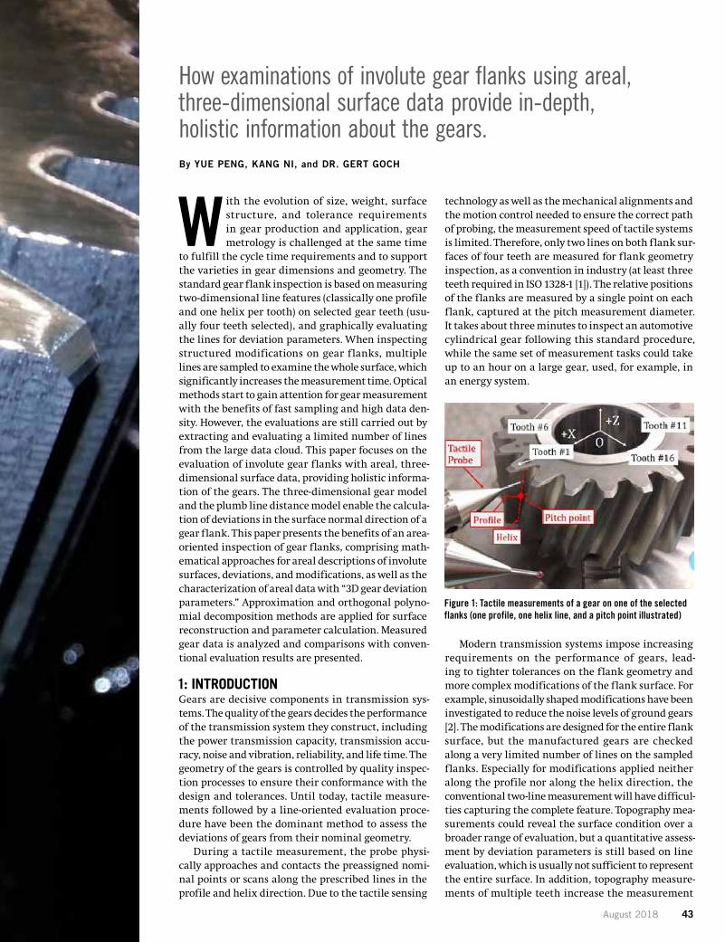
August 2018 43
How examinations of involute gear flanks using areal, three-dimensional surface data provide in-depth, holistic information about the gears. By YUE PENG, KANG NI, and DR. GERT GOCH
With the evolution of size, weight, surface structure, and tolerance requirements in gear production and application, gear metrology is challenged at the same time
to fulfill the cycle time requirements and to support the varieties in gear dimensions and geometry. The standard gear flank inspection is based on measuring two-dimensional line features (classically one profile and one helix per tooth) on selected gear teeth (usu-ally four teeth selected), and graphically evaluating the lines for deviation parameters. When inspecting structured modifications on gear flanks, multiple lines are sampled to examine the whole surface, which significantly increases the measurement time. Optical methods start to gain attention for gear measurement with the benefits of fast sampling and high data den-sity. However, the evaluations are still carried out by extracting and evaluating a limited number of lines from the large data cloud. This paper focuses on the evaluation of involute gear flanks with areal, three-dimensional surface data, providing holistic informa-tion of the gears. The three-dimensional gear model and the plumb line distance model enable the calcula-tion of deviations in the surface normal direction of a gear flank. This paper presents the benefits of an area-oriented inspection of gear flanks, comprising math-ematical approaches for areal descriptions of involute surfaces, deviations, and modifications, as well as the characterization of areal data with “3D gear deviation parameters.” Approximation and orthogonal polyno-mial decomposition methods are applied for surface reconstruction and parameter calculation. Measured gear data is analyzed and comparisons with conven-tional evaluation results are presented.
1: INTRODUCTION Gears are decisive components in transmission sys-tems. The quality of the gears decides the performance of the transmission system they construct, including the power transmission capacity, transmission accu-racy, noise and vibration, reliability, and life time. The geometry of the gears is controlled by quality inspec-tion processes to ensure their conformance with the design and tolerances. Until today, tactile measure-ments followed by a line-oriented evaluation proce-dure have been the dominant method to assess the deviations of gears from their nominal geometry.
During a tactile measurement, the probe physi-cally approaches and contacts the preassigned nomi-nal points or scans along the prescribed lines in the profile and helix direction. Due to the tactile sensing
technology as well as the mechanical alignments and the motion control needed to ensure the correct path of probing, the measurement speed of tactile systems is limited. Therefore, only two lines on both flank sur-faces of four teeth are measured for flank geometry inspection, as a convention in industry (at least three teeth required in ISO 1328-1 [1]). The relative positions of the flanks are measured by a single point on each flank, captured at the pitch measurement diameter. It takes about three minutes to inspect an automotive cylindrical gear following this standard procedure, while the same set of measurement tasks could take up to an hour on a large gear, used, for example, in an energy system.
Modern transmission systems impose increasing requirements on the performance of gears, lead-ing to tighter tolerances on the flank geometry and more complex modifications of the flank surface. For example, sinusoidally shaped modifications have been investigated to reduce the noise levels of ground gears [2]. The modifications are designed for the entire flank surface, but the manufactured gears are checked along a very limited number of lines on the sampled flanks. Especially for modifications applied neither along the profile nor along the helix direction, the conventional two-line measurement will have difficul-ties capturing the complete feature. Topography mea-surements could reveal the surface condition over a broader range of evaluation, but a quantitative assess-ment by deviation parameters is still based on line evaluation, which is usually not sufficient to represent the entire surface. In addition, topography measure-ments of multiple teeth increase the measurement
2 17FTM08
Areal Evaluation of Involute Gear Flanks with Three-Dimensional Surface Data
Yue PengUniversity of North Carolina at Charlotte
Kang NiUniversity of North Carolina at Charlotte
Dr. Gert GochUniversity of North Carolina at Charlotte
1 Introduction
Gears are decisive components in transmission systems. The quality of the gears decides the performance of the transmission system they construct, including the power transmission capacity, transmission accuracy, noise and vibration, reliability, and life time. The geometry of the gears iscontrolled by quality inspection processes to ensure their conformance with the design and tolerances.Until today, tactile measurements followed by a line-oriented evaluation procedure have been the dominant method to assess the deviations of gears from their nominal geometry.
During a tactile measurement, the probe physically approaches and contacts the preassigned nominal points or scans along the prescribed lines in the profile and helix direction. Due to the tactile sensing technology as well as the mechanical alignments and the motion control needed to ensure the correct path of probing, the measurement speed of tactile systems is limited. Therefore, only two lines on both flank surfaces of four teeth are measured for flank geometry inspection, as a convention in industry (at least three teeth required in ISO 1328-1 [1]). The relative positions of the flanks are measured by a singlepoint on each flank, captured at the pitch measurement diameter. It takes about three minutes to inspect an automotive cylindrical gear following this standard procedure, while the same set of measurement tasks could take up to an hour on a large gear, used, for example, in an energy system.
Figure 1 – Tactile measurements of a gear on one of the selected flanks(one profile, one helix line, and a pitch point illustrated)
Modern transmission systems impose increasing requirements on the performance of gears, leading to tighter tolerances on the flank geometry and more complex modifications of the flank surface. For example, sinusoidally shaped modifications have been investigated to reduce the noise levels of ground gears [2]. The modifications are designed for the entire flank surface, but the manufactured gears are checked along a very limited number of lines on the sampled flanks. Especially for modifications applied neither along the profile nor along the helix direction, the conventional two-line measurement will have
Figure 1: Tactile measurements of a gear on one of the selected flanks (one profile, one helix line, and a pitch point illustrated)
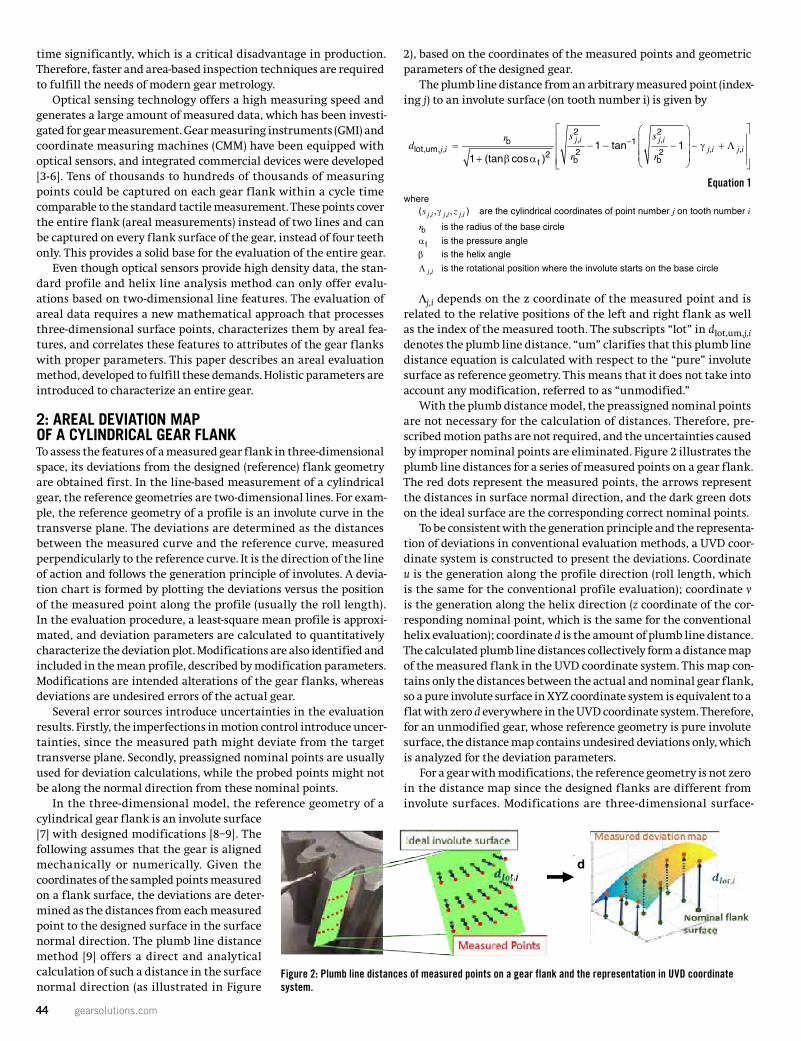
44 gearsolutions.com
time significantly, which is a critical disadvantage in production. Therefore, faster and area-based inspection techniques are required to fulfill the needs of modern gear metrology.
Optical sensing technology offers a high measuring speed and generates a large amount of measured data, which has been investi-gated for gear measurement. Gear measuring instruments (GMI) and coordinate measuring machines (CMM) have been equipped with optical sensors, and integrated commercial devices were developed [3-6]. Tens of thousands to hundreds of thousands of measuring points could be captured on each gear flank within a cycle time comparable to the standard tactile measurement. These points cover the entire flank (areal measurements) instead of two lines and can be captured on every flank surface of the gear, instead of four teeth only. This provides a solid base for the evaluation of the entire gear.
Even though optical sensors provide high density data, the stan-dard profile and helix line analysis method can only offer evalu-ations based on two-dimensional line features. The evaluation of areal data requires a new mathematical approach that processes three-dimensional surface points, characterizes them by areal fea-tures, and correlates these features to attributes of the gear flanks with proper parameters. This paper describes an areal evaluation method, developed to fulfill these demands. Holistic parameters are introduced to characterize an entire gear.
2: AREAL DEVIATION MAP OF A CYLINDRICAL GEAR FLANK To assess the features of a measured gear flank in three-dimensional space, its deviations from the designed (reference) flank geometry are obtained first. In the line-based measurement of a cylindrical gear, the reference geometries are two-dimensional lines. For exam-ple, the reference geometry of a profile is an involute curve in the transverse plane. The deviations are determined as the distances between the measured curve and the reference curve, measured perpendicularly to the reference curve. It is the direction of the line of action and follows the generation principle of involutes. A devia-tion chart is formed by plotting the deviations versus the position of the measured point along the profile (usually the roll length). In the evaluation procedure, a least-square mean profile is approxi-mated, and deviation parameters are calculated to quantitatively characterize the deviation plot. Modifications are also identified and included in the mean profile, described by modification parameters. Modifications are intended alterations of the gear flanks, whereas deviations are undesired errors of the actual gear.
Several error sources introduce uncertainties in the evaluation results. Firstly, the imperfections in motion control introduce uncer-tainties, since the measured path might deviate from the target transverse plane. Secondly, preassigned nominal points are usually used for deviation calculations, while the probed points might not be along the normal direction from these nominal points.
In the three-dimensional model, the reference geometry of a cylindrical gear flank is an involute surface [7] with designed modifications [8–9]. The following assumes that the gear is aligned mechanically or numerically. Given the coordinates of the sampled points measured on a flank surface, the deviations are deter-mined as the distances from each measured point to the designed surface in the surface normal direction. The plumb line distance method [9] offers a direct and analytical calculation of such a distance in the surface normal direction (as illustrated in Figure
2), based on the coordinates of the measured points and geometric parameters of the designed gear.
The plumb line distance from an arbitrary measured point (index-ing j) to an involute surface (on tooth number i) is given by
Lj,i depends on the z coordinate of the measured point and is related to the relative positions of the left and right flank as well as the index of the measured tooth. The subscripts “lot” in dlot,um,j,i denotes the plumb line distance. “um” clarifies that this plumb line distance equation is calculated with respect to the “pure” involute surface as reference geometry. This means that it does not take into account any modification, referred to as “unmodified.”
With the plumb distance model, the preassigned nominal points are not necessary for the calculation of distances. Therefore, pre-scribed motion paths are not required, and the uncertainties caused by improper nominal points are eliminated. Figure 2 illustrates the plumb line distances for a series of measured points on a gear flank. The red dots represent the measured points, the arrows represent the distances in surface normal direction, and the dark green dots on the ideal surface are the corresponding correct nominal points.
To be consistent with the generation principle and the representa-tion of deviations in conventional evaluation methods, a UVD coor-dinate system is constructed to present the deviations. Coordinate u is the generation along the profile direction (roll length, which is the same for the conventional profile evaluation); coordinate v is the generation along the helix direction (z coordinate of the cor-responding nominal point, which is the same for the conventional helix evaluation); coordinate d is the amount of plumb line distance. The calculated plumb line distances collectively form a distance map of the measured flank in the UVD coordinate system. This map con-tains only the distances between the actual and nominal gear flank, so a pure involute surface in XYZ coordinate system is equivalent to a flat with zero d everywhere in the UVD coordinate system. Therefore, for an unmodified gear, whose reference geometry is pure involute surface, the distance map contains undesired deviations only, which is analyzed for the deviation parameters.
For a gear with modifications, the reference geometry is not zero in the distance map since the designed flanks are different from involute surfaces. Modifications are three-dimensional surface-
4 17FTM08
whereγ, , ,( , , )j i j i j is z are the cylindrical coordinates of point number j on tooth number i
rb is the radius of the base circleαt is the pressure angleβ is the helix angleΛ ,j i is the rotational position where the involute starts on the base circle
Λ ,j i depends on the z coordinate of the measured point and is related to the relative positions of the left and right flank as well as the index of the measured tooth. The subscripts “lot” in lot,um, ,j id denotes theplumb line distance. “um” clarifies that this plumb line distance equation is calculated with respect to the “pure” involute surface as reference geometry. This means that it does not take into account anymodification, referred to as “unmodified.”
With the plumb distance model, the preassigned nominal points are not necessary for the calculation of distances. Therefore, prescribed motion paths are not required and the uncertainties caused by improper nominal points are eliminated. Figure 2 illustrates the plumb line distances for a series of measured pointson a gear flank. The red dots represent the measured points, the arrows represent the distances in surface normal direction, and the dark green dots on the ideal surface are the corresponding correct nominal points.
Figure 2 – Plumb line distances of measured points on a gear flankand the representation in UVD coordinate system
To be consistent with the generation principle and the representation of deviations in conventionalevaluation methods, a UVD coordinate system is constructed to present the deviations. Coordinateu is the generation along the profile direction (roll length, which is the same for the conventional profile evaluation); coordinate v is the generation along the helix direction (z coordinate of the corresponding nominal point, which is the same for the conventional helix evaluation); coordinate d is the amount of plumb line distance. The calculated plumb line distances collectively form a distance map of the measured flank in the UVD coordinate system. This map contains only the distances between the actual and nominal gear flank, so a pure involute surface in XYZ coordinate system is equivalent to a flat with zero d everywhere in the UVD coordinate system. Therefore, for an unmodified gear, whose reference geometry is pure involute surface, the distance map contains undesired deviations only, which is analyzed for the deviation parameters.
For a gear with modifications, the reference geometry is not zero in the distance map, since the designed flanks are different from involute surfaces. Modifications are three-dimensional surface-based features, sotheir definitions should be extended from two-dimensional features to areal features as well. In addition, the modification features should be specified in the surface normal direction for three advantages: firstly,it agrees with the direction of force transmission; secondly, adding modifications does not change the surface normal directions; thirdly, different modifications superimpose in the surface normal direction, so that they can be linearly combined to construct a designed surface. As a result, each modification is a
vu
d
Figure 2: Plumb line distances of measured points on a gear flank and the representation in UVD coordinate system.
3 17FTM08
difficulties capturing the complete feature. Topography measurements could reveal the surface condition over a broader range of evaluation, but a quantitative assessment by deviation parameters is still based on line evaluation, which is usually not sufficient to represent the entire surface. In addition, topography measurements of multiple teeth increase the measurement time significantly, which is a critical disadvantage in production. Therefore, faster and area-based inspection techniques are required to fulfil the needs of modern gear metrology.
Optical sensing technology offers a high measuring speed and generates a large amount of measured data, which has been investigated for gear measurement. Gear measuring instruments (GMI) andcoordinate measuring machines (CMM) have been equipped with optical sensors, and integrated commercial devices were developed [3-6]. Tens of thousands to hundreds of thousands of measuringpoints could be captured on each gear flank within a cycle time comparable to the standard tactile measurement. These points cover the entire flank (areal measurements) instead of two lines and can be captured on every flank surface of the gear, instead of four teeth only. This provides a solid base for theevaluation of the entire gear.
Even though optical sensors provide high density data, the standard profile and helix line analysis methodcan only offer evaluations based on two-dimensional line features. The evaluation of areal data requires a new mathematical approach that processes three-dimensional surface points, characterizes them by areal features, and correlates these features to attributes of the gear flanks with proper parameters. This paper describes an areal evaluation method, developed to fulfil these demands. Holistic parameters are introduced to characterize an entire gear.
2 Areal Deviation Map of a Cylindrical Gear FlankTo assess the features of a measured gear flank in three-dimensional space, its deviations from the designed (reference) flank geometry are obtained first. In the line-based measurement of a cylindrical gear, the reference geometries are two-dimensional lines. For example, the reference geometry of aprofile is an involute curve in the transverse plane. The deviations are determined as the distancesbetween the measured curve and the reference curve, measured perpendicularly to the reference curve.It is the direction of the line of action and follows the generation principle of involutes. A deviation chart is formed by plotting the deviations versus the position of the measured point along the profile (usually the roll length). In the evaluation procedure, a least-square mean profile is approximated, and deviation parameters are calculated to quantitatively characterize the deviation plot. Modifications are also identified and included in the mean profile, described by modification parameters. Modifications are intended alterations of the gear flanks, whereas deviations are undesired errors of the actual gear.
Several error sources introduce uncertainties in the evaluation results. Firstly, the imperfections in motion control introduce uncertainties, since the measured path might deviate from the target transverse plane. Secondly, preassigned nominal points are usually used for deviation calculations, while the probed points might not be along the normal direction from these nominal points.
In the three-dimensional model, the reference geometry of a cylindrical gear flank is an involute surface [7] with designed modifications [8–9]. The following assumes that the gear is aligned mechanically or numerically. Given the coordinates of the sampled points measured on a flank surface, the deviations are determined as the distances from each measured point to the designed surface in the surface normal direction. The plumb line distance method [9] offers a direct and analytical calculation of such a distance in the surface normal direction (as illustrated in Figure 2), based on the coordinates of the measured points and geometric parameters of the designed gear.
The plumb line distance from an arbitrary measured point (indexing j) to an involute surface (on tooth number i) is given by
, ,blot,um, , , ,
2 21
2 2 2bt b
1 tan 11 (tan )cos
i ij i
jj i j i
js srd
r r− γ Λ
β α
= − − − − + +
(1)
4 17FTM08
whereγ, , ,( , , )j i j i j is z are the cylindrical coordinates of point number j on tooth number i
rb is the radius of the base circleαt is the pressure angleβ is the helix angleΛ ,j i is the rotational position where the involute starts on the base circle
Λ ,j i depends on the z coordinate of the measured point and is related to the relative positions of the left and right flank as well as the index of the measured tooth. The subscripts “lot” in lot,um, ,j id denotes theplumb line distance. “um” clarifies that this plumb line distance equation is calculated with respect to the “pure” involute surface as reference geometry. This means that it does not take into account anymodification, referred to as “unmodified.”
With the plumb distance model, the preassigned nominal points are not necessary for the calculation of distances. Therefore, prescribed motion paths are not required and the uncertainties caused by improper nominal points are eliminated. Figure 2 illustrates the plumb line distances for a series of measured pointson a gear flank. The red dots represent the measured points, the arrows represent the distances in surface normal direction, and the dark green dots on the ideal surface are the corresponding correct nominal points.
Figure 2 – Plumb line distances of measured points on a gear flankand the representation in UVD coordinate system
To be consistent with the generation principle and the representation of deviations in conventionalevaluation methods, a UVD coordinate system is constructed to present the deviations. Coordinateu is the generation along the profile direction (roll length, which is the same for the conventional profile evaluation); coordinate v is the generation along the helix direction (z coordinate of the corresponding nominal point, which is the same for the conventional helix evaluation); coordinate d is the amount of plumb line distance. The calculated plumb line distances collectively form a distance map of the measured flank in the UVD coordinate system. This map contains only the distances between the actual and nominal gear flank, so a pure involute surface in XYZ coordinate system is equivalent to a flat with zero d everywhere in the UVD coordinate system. Therefore, for an unmodified gear, whose reference geometry is pure involute surface, the distance map contains undesired deviations only, which is analyzed for the deviation parameters.
For a gear with modifications, the reference geometry is not zero in the distance map, since the designed flanks are different from involute surfaces. Modifications are three-dimensional surface-based features, sotheir definitions should be extended from two-dimensional features to areal features as well. In addition, the modification features should be specified in the surface normal direction for three advantages: firstly,it agrees with the direction of force transmission; secondly, adding modifications does not change the surface normal directions; thirdly, different modifications superimpose in the surface normal direction, so that they can be linearly combined to construct a designed surface. As a result, each modification is a
vu
d
Equation 1
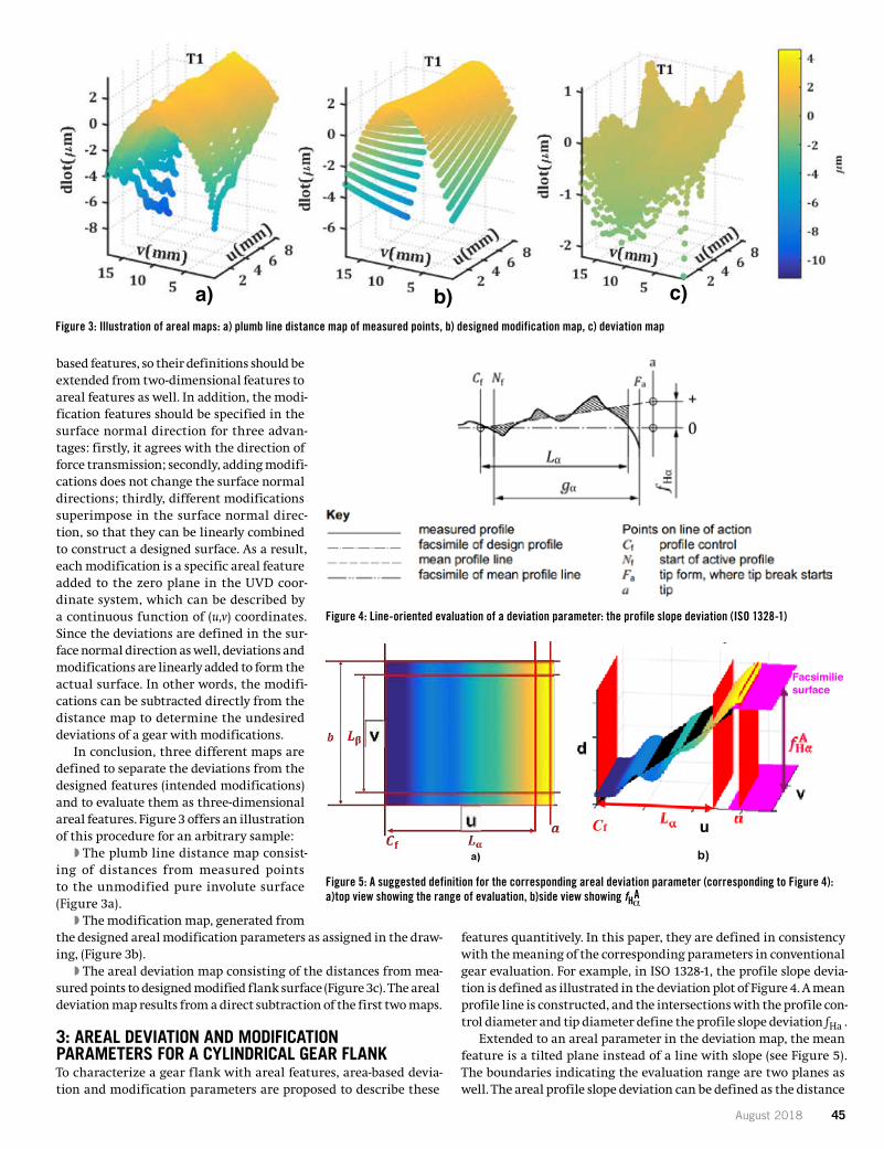
August 2018 45
based features, so their definitions should be extended from two-dimensional features to areal features as well. In addition, the modi-fication features should be specified in the surface normal direction for three advan-tages: firstly, it agrees with the direction of force transmission; secondly, adding modifi-cations does not change the surface normal directions; thirdly, different modifications superimpose in the surface normal direc-tion, so that they can be linearly combined to construct a designed surface. As a result, each modification is a specific areal feature added to the zero plane in the UVD coor-dinate system, which can be described by a continuous function of (u,v) coordinates. Since the deviations are defined in the sur-face normal direction as well, deviations and modifications are linearly added to form the actual surface. In other words, the modifi-cations can be subtracted directly from the distance map to determine the undesired deviations of a gear with modifications.
In conclusion, three different maps are defined to separate the deviations from the designed features (intended modifications) and to evaluate them as three-dimensional areal features. Figure 3 offers an illustration of this procedure for an arbitrary sample:
�� The plumb line distance map consist-ing of distances from measured points to the unmodified pure involute surface (Figure 3a).
�� The modification map, generated from the designed areal modification parameters as assigned in the draw-ing, (Figure 3b).
�� The areal deviation map consisting of the distances from mea-sured points to designed modified flank surface (Figure 3c). The areal deviation map results from a direct subtraction of the first two maps.
3: AREAL DEVIATION AND MODIFICATION PARAMETERS FOR A CYLINDRICAL GEAR FLANK To characterize a gear flank with areal features, area-based devia-tion and modification parameters are proposed to describe these
features quantitively. In this paper, they are defined in consistency with the meaning of the corresponding parameters in conventional gear evaluation. For example, in ISO 1328-1, the profile slope devia-tion is defined as illustrated in the deviation plot of Figure 4. A mean profile line is constructed, and the intersections with the profile con-trol diameter and tip diameter define the profile slope deviation fHa .
Extended to an areal parameter in the deviation map, the mean feature is a tilted plane instead of a line with slope (see Figure 5). The boundaries indicating the evaluation range are two planes as well. The areal profile slope deviation can be defined as the distance
Figure 4: Line-oriented evaluation of a deviation parameter: the profile slope deviation (ISO 1328-1)
Figure 5: A suggested definition for the corresponding areal deviation parameter (corresponding to Figure 4): a)top view showing the range of evaluation, b)side view showing fHa
A
Figure 3: Illustration of areal maps: a) plumb line distance map of measured points, b) designed modification map, c) deviation map
5 17FTM08
specific areal feature added to the zero plane in the UVD coordinate system, which can be described bya continuous function of u v( , ) coordinates. Since the deviations are defined in the surface normal direction as well, deviations and modifications are linearly added to form the actual surface. In other words, the modifications can be subtracted directly from the distance map to determine the undesired deviations of agear with modifications.
In conclusion, three different maps are defined to separate the deviations from the designed features (intended modifications) and to evaluate them as three-dimensional areal features. Figure 3 offers an illustration of this procedure for an arbitrary sample:
– The plumb line distance map consisting of distances from measured points to the unmodified pure involute surface (Figure 3a),
– The modification map, generated from the designed areal modification parameters as assigned in the drawing, (Figure 3b)
– The areal deviation map consisting of the distances from measured points to designed modified flank surface (Figure 3c). The areal deviation map results from a direct subtraction of the first two maps.
Figure 3 – Illustration of areal maps: a) plumb line distance map of measured points, b) designed modification map, c) deviation map
3 Areal Deviation and Modification Parameters for a Cylindrical Gear FlankTo characterize a gear flank with areal features, area-based deviation and modification parameters are proposed to describe these features quantitively. In this paper, they are defined in consistency with the meaning of the corresponding parameters in conventional gear evaluation. For example, in ISO 1328-1,the profile slope deviation is defined as illustrated in the deviation plot of Figure 4. A mean profile line is constructed, and the intersections with the profile control diameter and tip diameter define the profile slope deviation Hαf .
Extended to an areal parameter in the deviation map, the mean feature is a tilted plane instead of a line with slope (see Figure 5). The boundaries indicating the evaluation range are two planes as well. The areal profile slope deviation can be defined as the distance between two facsimiles of the designed surface, which are intersected by the mean surface at the profile control diameter and the tip diameter.The illustrations in Figure 5 are based on a deviation map with profile deviations only. The deviation map is a three-dimensional surface. The black colored plane is the mean surface and is extrapolated to the plane, indicating tip diameter, datum face, and non-datum face. The facsimiles of the designed surfaceintersecting the mean surface are displayed. The areal profile slope deviation is marked in Figure 5b) as fHα
A , with a superscript ʻAʼ denoting the areal parameters.
a) b) c)
6 17FTM08
Figure 4 – Line-oriented evaluation of a deviation parameter:the profile slope deviation (ISO 1328-1)
Figure 5 – A suggested definition for the corresponding areal deviation parameter (corresponding to Figure 4): a) top view showing the range of evaluation, b) side view showing fHα
A
The similar definition can be applied to areal helix slope deviation that it is also a plane, but tilted in the helix direction. Since all deviation features are defined in the surface normal direction and can be linearly superimposed and decomposed, a measured surface with both profile and helix slope deviations can be represented as the superposition of two tilted planes. Other than first order features, higher order and more complex features contained in the measured surface could be described independently in similar manners, and then combined to depict the measured data.
Since in the conventional evaluation, the profile and helix lines are analyzed separately, there are cases where different line-based parameters essentially represent the same feature when they are referred tothe flank surface. For example, in conventional line evaluation, twist is defined by two separate parameters in profile and helix direction. In the profile direction, it is obtained by measuring one profile near the datum face and another one near the non-datum face. The difference between the slopes of these two profiles is defined as the twist in the profile direction. A similar procedure is applied for the twist in helix direction. Due to the arbitrary choice of measuring positions, it is common to see an unequal twist measured in profile and helix direction. However, one parameter could represent this twist feature in the areal evaluation, since it describes a single second order surface, as illustrated in Figure 6. Face I is the datum face and II is the non-datum face.
uCf
Facsimiliesurface
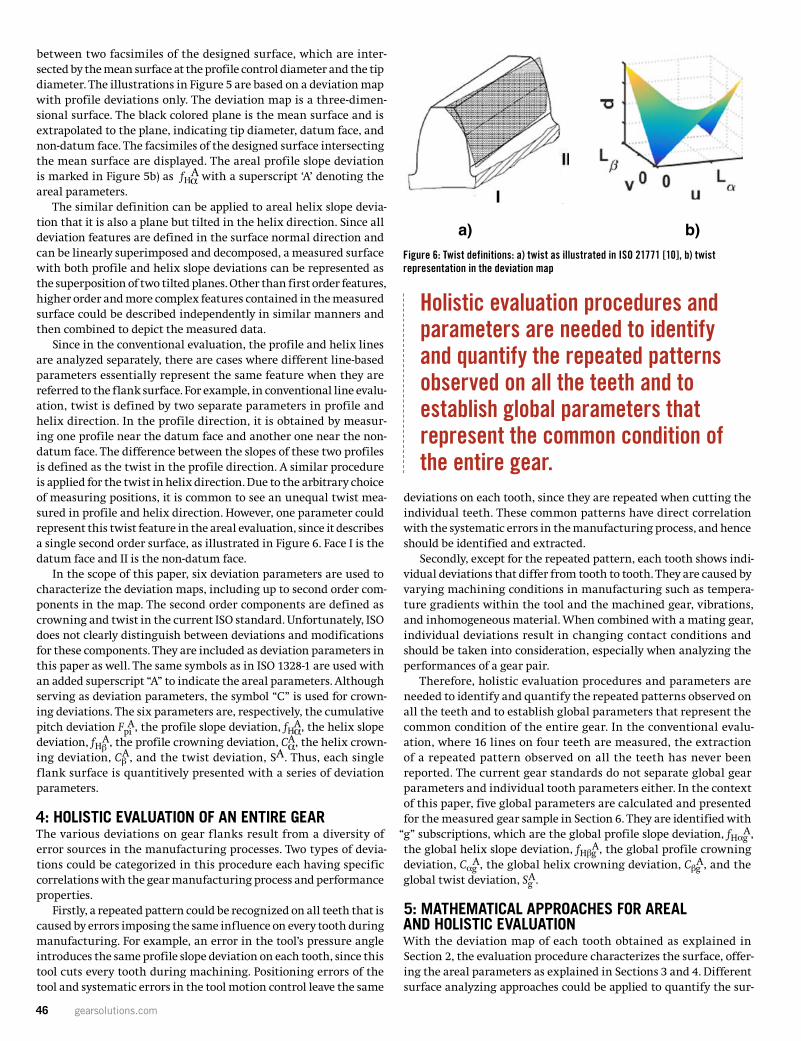
46 gearsolutions.com
between two facsimiles of the designed surface, which are inter-sected by the mean surface at the profile control diameter and the tip diameter. The illustrations in Figure 5 are based on a deviation map with profile deviations only. The deviation map is a three-dimen-sional surface. The black colored plane is the mean surface and is extrapolated to the plane, indicating tip diameter, datum face, and non-datum face. The facsimiles of the designed surface intersecting the mean surface are displayed. The areal profile slope deviation is marked in Figure 5b) as fHa
A with a superscript ‘A’ denoting the
areal parameters. The similar definition can be applied to areal helix slope devia-
tion that it is also a plane but tilted in the helix direction. Since all deviation features are defined in the surface normal direction and can be linearly superimposed and decomposed, a measured surface with both profile and helix slope deviations can be represented as the superposition of two tilted planes. Other than first order features, higher order and more complex features contained in the measured surface could be described independently in similar manners and then combined to depict the measured data.
Since in the conventional evaluation, the profile and helix lines are analyzed separately, there are cases where different line-based parameters essentially represent the same feature when they are referred to the flank surface. For example, in conventional line evalu-ation, twist is defined by two separate parameters in profile and helix direction. In the profile direction, it is obtained by measur-ing one profile near the datum face and another one near the non-datum face. The difference between the slopes of these two profiles is defined as the twist in the profile direction. A similar procedure is applied for the twist in helix direction. Due to the arbitrary choice of measuring positions, it is common to see an unequal twist mea-sured in profile and helix direction. However, one parameter could represent this twist feature in the areal evaluation, since it describes a single second order surface, as illustrated in Figure 6. Face I is the datum face and II is the non-datum face.
In the scope of this paper, six deviation parameters are used to characterize the deviation maps, including up to second order com-ponents in the map. The second order components are defined as crowning and twist in the current ISO standard. Unfortunately, ISO does not clearly distinguish between deviations and modifications for these components. They are included as deviation parameters in this paper as well. The same symbols as in ISO 1328-1 are used with an added superscript “A” to indicate the areal parameters. Although serving as deviation parameters, the symbol “C” is used for crown-ing deviations. The six parameters are, respectively, the cumulative pitch deviation Fpi
A, the profile slope deviation, fHaA, the helix slope
deviation, fHbA, the profile crowning deviation, Ca
A, the helix crown-ing deviation, Cb
A, and the twist deviation, SA. Thus, each single flank surface is quantitively presented with a series of deviation parameters.
4: HOLISTIC EVALUATION OF AN ENTIRE GEAR The various deviations on gear flanks result from a diversity of error sources in the manufacturing processes. Two types of devia-tions could be categorized in this procedure each having specific correlations with the gear manufacturing process and performance properties.
Firstly, a repeated pattern could be recognized on all teeth that is caused by errors imposing the same influence on every tooth during manufacturing. For example, an error in the tool’s pressure angle introduces the same profile slope deviation on each tooth, since this tool cuts every tooth during machining. Positioning errors of the tool and systematic errors in the tool motion control leave the same
deviations on each tooth, since they are repeated when cutting the individual teeth. These common patterns have direct correlation with the systematic errors in the manufacturing process, and hence should be identified and extracted.
Secondly, except for the repeated pattern, each tooth shows indi-vidual deviations that differ from tooth to tooth. They are caused by varying machining conditions in manufacturing such as tempera-ture gradients within the tool and the machined gear, vibrations, and inhomogeneous material. When combined with a mating gear, individual deviations result in changing contact conditions and should be taken into consideration, especially when analyzing the performances of a gear pair.
Therefore, holistic evaluation procedures and parameters are needed to identify and quantify the repeated patterns observed on all the teeth and to establish global parameters that represent the common condition of the entire gear. In the conventional evalu-ation, where 16 lines on four teeth are measured, the extraction of a repeated pattern observed on all the teeth has never been reported. The current gear standards do not separate global gear parameters and individual tooth parameters either. In the context of this paper, five global parameters are calculated and presented for the measured gear sample in Section 6. They are identified with
“g” subscriptions, which are the global profile slope deviation, fHagA,
the global helix slope deviation, fHbgA, the global profile crowning
deviation, CagA, the global helix crowning deviation, Cbg
A, and the global twist deviation, Sg
A.
5: MATHEMATICAL APPROACHES FOR AREAL AND HOLISTIC EVALUATION With the deviation map of each tooth obtained as explained in Section 2, the evaluation procedure characterizes the surface, offer-ing the areal parameters as explained in Sections 3 and 4. Different surface analyzing approaches could be applied to quantify the sur-
7 17FTM08
a) b)Figure 6 – Twist definitions: a) twist as illustrated in ISO 21771 [10],
b) twist representation in the deviation map
In the scope of this paper, six deviation parameters are used to characterize the deviation maps,including up to second order components in the map. The second order components are defined as crowning and twist in the current ISO standard. Unfortunately, ISO does not clearly distinguish between deviations and modifications for these components. They are included as deviation parameters in this paper as well. The same symbols as in ISO 1328-1 are used with an added superscript “A” to indicate the areal parameters. Although serving as deviation parameters, the symbol “C” is used for crowning deviations. The six parameters are, respectively, the cumulative pitch deviation, A
piF , the profile slope deviation, A
Hαf , the helix slope deviation, AHβf , the profile crowning deviation, A
αC , the helix crowning deviation, A
βC , and the twist deviation, AS .Thus, each single flank surface is quantitively presented witha series of deviation parameters.
4 Holistic Evaluation of an Entire GearThe various deviations on gear flanks result from a diversity of error sources in the manufacturing processes. Two types of deviations could be categorized in this procedure each having specific correlations with the gear manufacturing process and performance properties.
Firstly, a repeated pattern could be recognized on all teeth that is caused by errors imposing the same influence on every tooth during manufacturing. For example, an error in the toolʼs pressure angleintroduces the same profile slope deviation on each tooth, since this tool cuts every tooth duringmachining. Positioning errors of the tool and systematic errors in the tool motion control leave the same deviations on each tooth, since they are repeated when cutting the individual teeth. These common patterns have direct correlation with the systematic errors in the manufacturing process, and hence should be identified and extracted.
Secondly, except for the repeated pattern, each tooth shows individual deviations that differ from tooth to tooth. They are caused by varying machining conditions in manufacturing such as temperature gradients within the tool and the machined gear, vibrations, and inhomogeneous material. When combined with a mating gear, individual deviations result in changing contact conditions and should be taken into consideration, especially when analyzing the performances of a gear pair.
Therefore, holistic evaluation procedures and parameters are needed to identify and quantify the repeated patterns observed on all the teeth and to establish global parameters that represent the common condition of the entire gear. In the conventional evaluation, where 16 lines on four teeth are measured, the extraction of a repeated pattern observed on all the teeth has never been reported. The current gear standards do not separate global gear parameters and individual tooth parameters either. In the context of this paper, five global parameters are calculated and presented for the measured gear
Figure 6: Twist definitions: a) twist as illustrated in ISO 21771 [10], b) twist representation in the deviation map
Holistic evaluation procedures and parameters are needed to identify and quantify the repeated patterns observed on all the teeth and to establish global parameters that represent the common condition of the entire gear.
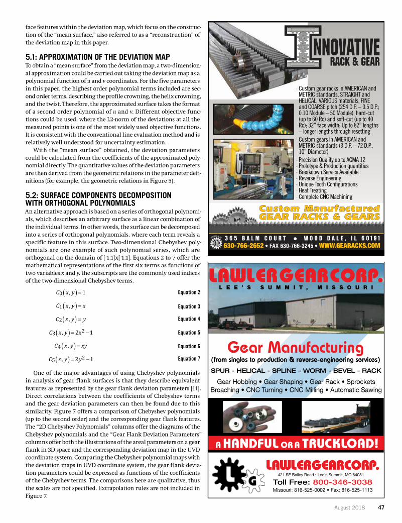
August 2018 47
face features within the deviation map, which focus on the construc-tion of the “mean surface,” also referred to as a “reconstruction” of the deviation map in this paper.
5.1: APPROXIMATION OF THE DEVIATION MAP To obtain a “mean surface” from the deviation map, a two-dimension-al approximation could be carried out taking the deviation map as a polynomial function of u and v coordinates. For the five parameters in this paper, the highest order polynomial terms included are sec-ond order terms, describing the profile crowning, the helix crowning, and the twist. Therefore, the approximated surface takes the format of a second order polynomial of u and v. Different objective func-tions could be used, where the L2-norm of the deviations at all the measured points is one of the most widely used objective functions. It is consistent with the conventional line evaluation method and is relatively well understood for uncertainty estimation.
With the “mean surface” obtained, the deviation parameters could be calculated from the coefficients of the approximated poly-nomial directly. The quantitative values of the deviation parameters are then derived from the geometric relations in the parameter defi-nitions (for example, the geometric relations in Figure 5).
5.2: SURFACE COMPONENTS DECOMPOSITION WITH ORTHOGONAL POLYNOMIALS An alternative approach is based on a series of orthogonal polynomi-als, which describes an arbitrary surface as a linear combination of the individual terms. In other words, the surface can be decomposed into a series of orthogonal polynomials, where each term reveals a specific feature in this surface. Two-dimensional Chebyshev poly-nomials are one example of such polynomial series, which are orthogonal on the domain of [-1,1]x[-1,1]. Equations 2 to 7 offer the mathematical representations of the first six terms as functions of two variables x and y. the subscripts are the commonly used indices of the two-dimensional Chebyshev terms.
One of the major advantages of using Chebyshev polynomials in analysis of gear flank surfaces is that they describe equivalent features as represented by the gear flank deviation parameters [11]. Direct correlations between the coefficients of Chebyshev terms and the gear deviation parameters can then be found due to this similarity. Figure 7 offers a comparison of Chebyshev polynomials (up to the second order) and the corresponding gear flank features. The “2D Chebyshev Polynomials” columns offer the diagrams of the Chebyshev polynomials and the “Gear Flank Deviation Parameters” columns offer both the illustrations of the areal parameters on a gear flank in 3D space and the corresponding deviation map in the UVD coordinate system. Comparing the Chebyshev polynomial maps with the deviation maps in UVD coordinate system, the gear flank devia-tion parameters could be expressed as functions of the coefficients of the Chebyshev terms. The comparisons here are qualitative, thus the scales are not specified. Extrapolation rules are not included in Figure 7.
8 17FTM08
sample in Section 6. They are identified with “g” subscriptions, which are the global profile slope deviation, A
Hαgf , the global helix slope deviation, AHβgf , the global profile crowning deviation, A
αgC , the global helix
crowning deviation, AβgC , and the global twist deviation, A
gS .
5 Mathematical Approaches for Areal and Holistic Evaluation With the deviation map of each tooth obtained as explained in Section 2, the evaluation procedure characterizes the surface, offering the areal parameters as explained in Section 3 and 4. Different surface analyzing approaches could be applied to quantify the surface features within the deviation map, whichfocus on the construction of the “mean surface”, also referred to as a “reconstruction” of the deviationmap in this paper.
5.1 Approximation of the Deviation MapTo obtain a “mean surface” from the deviation map, a two-dimensional approximation could be carried outtaking the deviation map as a polynomial function of u and v coordinates. For the five parameters in this paper, the highest order polynomial terms included are second order terms, describing the profile crowning, the helix crowning, and the twist. Therefore, the approximated surface takes the format of a second order polynomial of u and v . Different objective functions could be used, where the L2-norm of the deviations at all the measured points is one of the most widely used objective functions. It is consistent with the conventional line evaluation method and is relatively well understood for uncertainty estimation.
With the “mean surface” obtained, the deviation parameters could be calculated from the coefficients of the approximated polynomial directly. The quantitative values of the deviation parameters are then derived from the geometric relations in the parameter definitions (for example, the geometric relations in Figure 5).
5.2 Surface Components Decomposition with Orthogonal PolynomialsAn alternative approach is based on a series of orthogonal polynomials, which describes an arbitrary surface as a linear combination of the individual terms. In other words, the surface can be decomposed into a series of orthogonal polynomials, where each term reveals a specific feature in this surface. Two-dimensional Chebyshev polynomials are one example of such polynomial series, which are orthogonal on the domain of − × − 1,1 1,1 . Equations 2 to 7 offer the mathematical representations of the first six termsas functions of two variables x and y . The subscripts are the commonly used indices of the two-dimensional Chebyshev terms.
( )0 , 1C x y = (2)
( )1 ,C x y x= (3)
( )2 ,C x y y= (4)
( ) 23 2, 1C x y x= − (5)
( )4 ,C x y xy= (6)
( ) 25 , 2 1C x y y= − (7)
One of the major advantages of using Chebyshev polynomials in analysis of gear flank surfaces is that they describe equivalent features as represented by the gear flank deviation parameters [11]. Direct correlations between the coefficients of Chebyshev terms and the gear deviation parameters can then be found due to this similarity. Figure 7 offers a comparison of Chebyshev polynomials (up to the second order) and the corresponding gear flank features. The “2D Chebyshev Polynomials” columns offer the diagrams of the Chebyshev polynomials and the “Gear Flank Deviation Parameters” columns offer both the illustrations of the areal parameters on a gear flank in 3D space and the corresponding deviation map
Equation 2
Equation 3
Equation 4
Equation 5
Equation 6
Equation 7
421 SE Bailey Road • Lee's Summit, MO 64081
· Custom gear racks in AMERICAN and METRIC standards, STRAIGHT and HELICAL, VARIOUS materials, FINE and COARSE pitch (254 D.P. – 0.5 D.P.; 0.10 Module – 50 Module); hard-cut (up to 60 Rc) and soft-cut (up to 40 Rc); 32” face width; Up to 82” lengths – longer lengths through resetting
· Custom gears in AMERICAN and METRIC standards (3 D.P. – 72 D.P., 10” Diameter)
· Precision Quality up to AGMA 12· Prototype & Production quantities· Breakdown Service Available· Reverse Engineering · Unique Tooth Configurations· Heat Treating· Complete CNC Machining
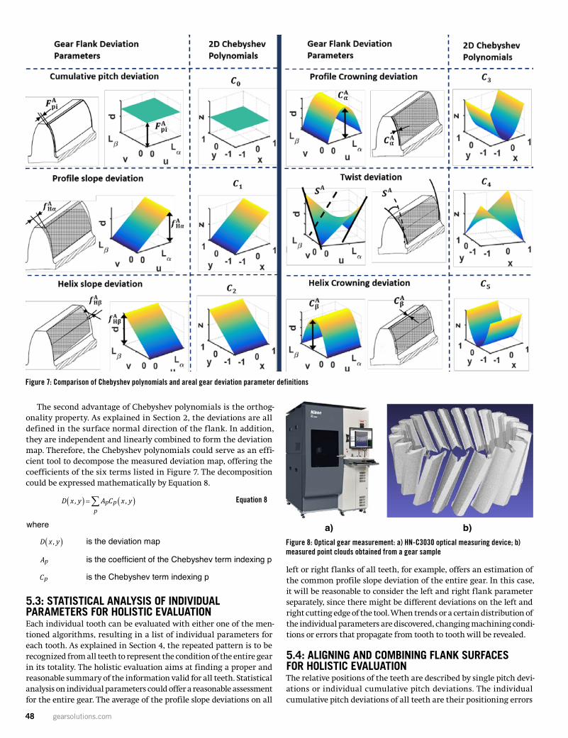
48 gearsolutions.com
The second advantage of Chebyshev polynomials is the orthog-onality property. As explained in Section 2, the deviations are all defined in the surface normal direction of the flank. In addition, they are independent and linearly combined to form the deviation map. Therefore, the Chebyshev polynomials could serve as an effi-cient tool to decompose the measured deviation map, offering the coefficients of the six terms listed in Figure 7. The decomposition could be expressed mathematically by Equation 8.
5.3: STATISTICAL ANALYSIS OF INDIVIDUAL PARAMETERS FOR HOLISTIC EVALUATION Each individual tooth can be evaluated with either one of the men-tioned algorithms, resulting in a list of individual parameters for each tooth. As explained in Section 4, the repeated pattern is to be recognized from all teeth to represent the condition of the entire gear in its totality. The holistic evaluation aims at finding a proper and reasonable summary of the information valid for all teeth. Statistical analysis on individual parameters could offer a reasonable assessment for the entire gear. The average of the profile slope deviations on all
left or right flanks of all teeth, for example, offers an estimation of the common profile slope deviation of the entire gear. In this case, it will be reasonable to consider the left and right flank parameter separately, since there might be different deviations on the left and right cutting edge of the tool. When trends or a certain distribution of the individual parameters are discovered, changing machining condi-tions or errors that propagate from tooth to tooth will be revealed.
5.4: ALIGNING AND COMBINING FLANK SURFACES FOR HOLISTIC EVALUATION The relative positions of the teeth are described by single pitch devi-ations or individual cumulative pitch deviations. The individual cumulative pitch deviations of all teeth are their positioning errors
9 17FTM08
in the UVD coordinate system. Comparing the Chebyshev polynomial maps with the deviation maps in UVD coordinate system, the gear flank deviation parameters could be expressed as functions of the coefficients of the Chebyshev terms. The comparisons here are qualitative, thus the scales are not specified. Extrapolation rules are not included in Figure 7.
Figure 7 – Comparison of Chebyshev polynomials and areal gear deviation parameter definitions
The second advantage of Chebyshev polynomials is the orthogonality property. As explained in Section 2, the deviations are all defined in the surface normal direction of the flank. In addition, they are independent and linearly combined to form the deviation map. Therefore, the Chebyshev polynomials could serve as an efficient tool to decompose the measured deviation map, offering the coefficients of the six terms listed in Figure 7. The decomposition could be expressed mathematically by Equation 8.
( ) ( ), ,p
p pD x y A C x y=∑ (8)
where
( ),D x y is the deviation map
pA is the coefficient of the Chebyshev term indexing p
pC is the Chebyshev term indexing p
5.3 Statistical Analysis of Individual Parameters for Holistic EvaluationEach individual tooth can be evaluated with either one of the mentioned algorithms, resulting in a list of individual parameters for each tooth. As explained in Section 4, the repeated pattern is to be recognized from all teeth to represent the condition of the entire gear in its totality. The holistic evaluation aims at finding a proper and reasonable summary of the information valid for all teeth.
Figure 7: Comparison of Chebyshev polynomials and areal gear deviation parameter definitions
Figure 8: Optical gear measurement: a) HN-C3030 optical measuring device; b) measured point clouds obtained from a gear sample
11 17FTM08
a) b)Figure 8 – Optical gear measurement: a) HN-C3030 optical measuring device;
b) measured point clouds obtained from a gear sample
An areal measurement on all teeth was conducted on a CMM to compare the results with the optical measurements. 51 profile lines across the flank surface were measured on each flank of all teeth.
Figure 9 – Deviation maps of the first 7 teeth obtained by tactile measurement, original deviation map and repeated pattern
Figure 9 shows the evaluation results of the tactile areal data. The dots with color gradients show the original deviation maps of the first 7 teeth. An obvious common pattern of crowning in the helix direction could be recognized. The red surfaces show the “mean surface”, which are the reconstructed repeated pattern determined with Chebyshev method. It could also be noticed that the repeated pattern hasdifferent offsets from the original deviation map except the first tooth. This misalignment is caused by the cumulative pitch deviation of each tooth as explained in Section 5.4, which is not included in the repeated pattern since they are individual deviations of each flank. The areal deviation parameters calculated with the holistic evaluation procedure described in Section 5.2 and 5.3 are also listed in Table 1.
Conventional line-oriented measurements and evaluations were also carried out using both GMIs andCMMs to compare the results with areal evaluations. The deviation parameters from one of the standard measurements are listed in Table 1. Four teeth were measured with a profile line and a helix line on each flank for the slope and crowning parameters. Two profile lines and two helix lines were measured on each flank of the first tooth to calculate the twist. The average of four profile slope deviations of the right flanks are taken as the global profile slope deviation to compare with those calculated from the areal data. Only right flanks are used here, since the areal evaluations are conducted on all right flanks for the results
9 17FTM08
in the UVD coordinate system. Comparing the Chebyshev polynomial maps with the deviation maps in UVD coordinate system, the gear flank deviation parameters could be expressed as functions of the coefficients of the Chebyshev terms. The comparisons here are qualitative, thus the scales are not specified. Extrapolation rules are not included in Figure 7.
Figure 7 – Comparison of Chebyshev polynomials and areal gear deviation parameter definitions
The second advantage of Chebyshev polynomials is the orthogonality property. As explained in Section 2, the deviations are all defined in the surface normal direction of the flank. In addition, they are independent and linearly combined to form the deviation map. Therefore, the Chebyshev polynomials could serve as an efficient tool to decompose the measured deviation map, offering the coefficients of the six terms listed in Figure 7. The decomposition could be expressed mathematically by Equation 8.
( ) ( ), ,p
p pD x y A C x y=∑ (8)
where
( ),D x y is the deviation map
pA is the coefficient of the Chebyshev term indexing p
pC is the Chebyshev term indexing p
5.3 Statistical Analysis of Individual Parameters for Holistic EvaluationEach individual tooth can be evaluated with either one of the mentioned algorithms, resulting in a list of individual parameters for each tooth. As explained in Section 4, the repeated pattern is to be recognized from all teeth to represent the condition of the entire gear in its totality. The holistic evaluation aims at finding a proper and reasonable summary of the information valid for all teeth.
Equation 8
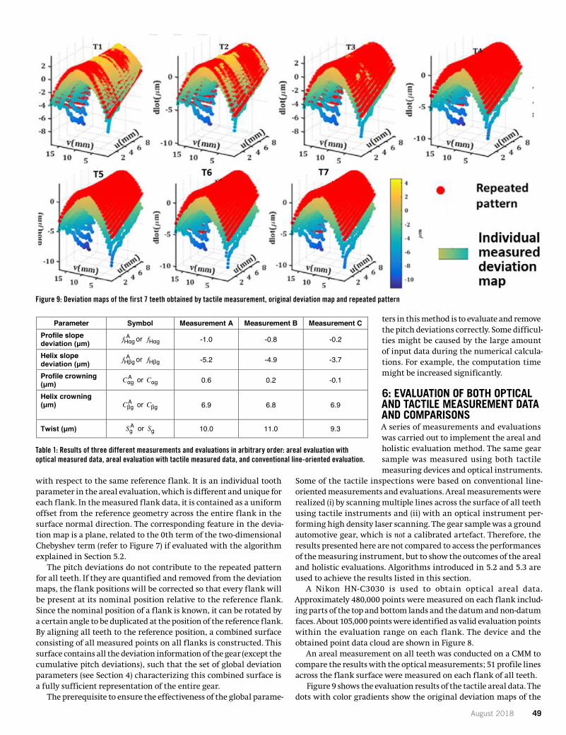
August 2018 49
with respect to the same reference flank. It is an individual tooth parameter in the areal evaluation, which is different and unique for each flank. In the measured flank data, it is contained as a uniform offset from the reference geometry across the entire flank in the surface normal direction. The corresponding feature in the devia-tion map is a plane, related to the 0th term of the two-dimensional Chebyshev term (refer to Figure 7) if evaluated with the algorithm explained in Section 5.2.
The pitch deviations do not contribute to the repeated pattern for all teeth. If they are quantified and removed from the deviation maps, the flank positions will be corrected so that every flank will be present at its nominal position relative to the reference flank. Since the nominal position of a flank is known, it can be rotated by a certain angle to be duplicated at the position of the reference flank. By aligning all teeth to the reference position, a combined surface consisting of all measured points on all flanks is constructed. This surface contains all the deviation information of the gear (except the cumulative pitch deviations), such that the set of global deviation parameters (see Section 4) characterizing this combined surface is a fully sufficient representation of the entire gear.
The prerequisite to ensure the effectiveness of the global parame-
ters in this method is to evaluate and remove the pitch deviations correctly. Some difficul-ties might be caused by the large amount of input data during the numerical calcula-tions. For example, the computation time might be increased significantly.
6: EVALUATION OF BOTH OPTICAL AND TACTILE MEASUREMENT DATA AND COMPARISONS A series of measurements and evaluations was carried out to implement the areal and holistic evaluation method. The same gear sample was measured using both tactile measuring devices and optical instruments.
Some of the tactile inspections were based on conventional line-oriented measurements and evaluations. Areal measurements were realized (i) by scanning multiple lines across the surface of all teeth using tactile instruments and (ii) with an optical instrument per-forming high density laser scanning. The gear sample was a ground automotive gear, which is not a calibrated artefact. Therefore, the results presented here are not compared to access the performances of the measuring instrument, but to show the outcomes of the areal and holistic evaluations. Algorithms introduced in 5.2 and 5.3 are used to achieve the results listed in this section.
A Nikon HN-C3030 is used to obtain optical areal data. Approximately 480,000 points were measured on each flank includ-ing parts of the top and bottom lands and the datum and non-datum faces. About 105,000 points were identified as valid evaluation points within the evaluation range on each flank. The device and the obtained point data cloud are shown in Figure 8.
An areal measurement on all teeth was conducted on a CMM to compare the results with the optical measurements; 51 profile lines across the flank surface were measured on each flank of all teeth.
Figure 9 shows the evaluation results of the tactile areal data. The dots with color gradients show the original deviation maps of the
Figure 9: Deviation maps of the first 7 teeth obtained by tactile measurement, original deviation map and repeated pattern
Table 1: Results of three different measurements and evaluations in arbitrary order: areal evaluation with optical measured data, areal evaluation with tactile measured data, and conventional line-oriented evaluation.
11 17FTM08
a) b)Figure 8 – Optical gear measurement: a) HN-C3030 optical measuring device;
b) measured point clouds obtained from a gear sample
An areal measurement on all teeth was conducted on a CMM to compare the results with the optical measurements. 51 profile lines across the flank surface were measured on each flank of all teeth.
Figure 9 – Deviation maps of the first 7 teeth obtained by tactile measurement, original deviation map and repeated pattern
Figure 9 shows the evaluation results of the tactile areal data. The dots with color gradients show the original deviation maps of the first 7 teeth. An obvious common pattern of crowning in the helix direction could be recognized. The red surfaces show the “mean surface”, which are the reconstructed repeated pattern determined with Chebyshev method. It could also be noticed that the repeated pattern hasdifferent offsets from the original deviation map except the first tooth. This misalignment is caused by the cumulative pitch deviation of each tooth as explained in Section 5.4, which is not included in the repeated pattern since they are individual deviations of each flank. The areal deviation parameters calculated with the holistic evaluation procedure described in Section 5.2 and 5.3 are also listed in Table 1.
Conventional line-oriented measurements and evaluations were also carried out using both GMIs andCMMs to compare the results with areal evaluations. The deviation parameters from one of the standard measurements are listed in Table 1. Four teeth were measured with a profile line and a helix line on each flank for the slope and crowning parameters. Two profile lines and two helix lines were measured on each flank of the first tooth to calculate the twist. The average of four profile slope deviations of the right flanks are taken as the global profile slope deviation to compare with those calculated from the areal data. Only right flanks are used here, since the areal evaluations are conducted on all right flanks for the results
12 17FTM08
displayed in Table 1. The same procedure was applied for the other three global parameters. The average value of the two twist parameters calculated in profile and helix direction is taken as the global twist value.
Table 1 – Results of three different measurements and evaluations in arbitrary order: areal evaluation with optical measured data, areal evaluation with tactile measured data, and
conventional line-oriented evaluation
Parameter Symbol Measurement A Measurement B Measurement CProfile slope deviation (μm) fHαg
A or fHαg -1.0 -0.8 -0.2
Helix slope deviation (μm) fHβg
A or fHβg -5.2 -4.9 -3.7
Profile crowning (μm) Cαg
A or Cαg 0.6 0.2 -0.1
Helix crowning (μm) Cβg
A or Cβg 6.9 6.8 6.9
Twist (μm) S Ag or Sg 10.0 11.0 9.3
Table 1 consists of results of three different measurement and evaluation processes. One of them represents the result of a conventional line-oriented inspection procedure. The other two are based on areal measurements and evaluations, one of them based on tactilely probed data and the other on optically measured data. It could be discovered that the three different measurements and evaluation methods result in variations of the deviation parameters. For the experiments reported here, the five investigated parameters vary within 2 μm. The differences might result from:
– Different sampling conditions: the line evaluation is based on samples in one profile or helix line on the surface, whereas the areal evaluation is based on a larger number of points covering the entire area of each flank, all teeth involved.
– Different definitions of area-based and line-based deviations: For example, the conventionalprofile deviations are defined in the transverse plane perpendicular to the involute curve, whereas the areal deviations are defined on the entire surface in the surface normal direction.
– Different approximation methods: the line-oriented parameters are evaluated based on least-square profile or helix lines, whereas the areal evaluation is based on Chebyshev orthogonalpolynomials.
– Different measurement conditions: the gear was measured on different instruments by different operators under different lab conditions.
7 Conclusions and Future WorkModern gear production requires advancements in inspection techniques: a faster and morecomprehensive measurement as well as an improved evaluation. The shift of perspective to three-dimensional design and modeling, areal measurement, and holistic evaluation are some of the most significant improvements in gear metrology. They form the basis for innovative solutions of datainterpretation, including improved manufacturing process assessment, and functional performance investigation. This paper presented:
– Definitions of deviations in a three-dimensional gear model and the construction of areal deviation maps,
– Suggestions to define extended deviation and modification parameters, covering also areal measurements and evaluations, and their meaning in terms of surface features,
50 gearsolutions.com
first seven teeth. An obvious common pattern of crowning in the helix direction could be recognized. The red surfaces show the “mean surface,” which are the reconstructed repeated pattern determined with Chebyshev method. It could also be noticed that the repeated pattern has different offsets from the original deviation map except the first tooth. This misalignment is caused by the cumulative pitch deviation of each tooth as explained in Section 5.4, which is not included in the repeated pattern since they are individual deviations of each flank. The areal deviation parameters calculated with the holistic evaluation procedure described in Sections 5.2 and 5.3 are also listed in Table 1.
Conventional line-oriented measurements and evaluations were also carried out using both GMIs and CMMs to compare the results with areal evaluations. The deviation parameters from one of the standard measurements are listed in Table 1. Four teeth were mea-sured with a profile line and a helix line on each flank for the slope and crowning parameters. Two profile lines and two helix lines were measured on each flank of the first tooth to calculate the twist. The average of four profile slope deviations of the right flanks are taken as the global profile slope deviation to compare with those calculated from the areal data. Only right flanks are used here, since the areal evaluations are conducted on all right flanks for the results displayed in Table 1. The same procedure was applied for the other three global parameters. The average value of the two twist parameters calculated in profile and helix direction is taken as the global twist value.
Table 1 consists of results of three different measurement and evaluation processes. One of them represents the result of a conven-tional line-oriented inspection procedure. The other two are based on areal measurements and evaluations, one of them based on tac-tilely probed data and the other on optically measured data. It could be discovered that the three different measurements and evaluation methods result in variations of the deviation parameters. For the experiments reported here, the five investigated parameters vary within 2 μm. The differences might result from:
�� Different sampling conditions: the line evaluation is based on samples in one profile or helix line on the surface, whereas the areal evaluation is based on a larger number of points covering the entire area of each flank, all teeth involved.
�� Different definitions of area-based and line-based deviations: For example, the conventional profile deviations are defined in the transverse plane perpendicular to the involute curve, whereas the areal deviations are defined on the entire surface in the surface nor-mal direction.
�� Different approximation methods: the line-oriented parameters are evaluated based on least- square profile or helix lines, whereas the areal evaluation is based on Chebyshev orthogonal polynomials.
�� Different measurement conditions: the gear was measured on different instruments by different operators under different lab conditions.
CONCLUSIONS AND FUTURE WORK Modern gear production requires advancements in inspection tech-niques: a faster and more comprehensive measurement as well as an improved evaluation. The shift of perspective to three-dimensional design and modeling, areal measurement, and holistic evaluation are some of the most significant improvements in gear metrology. They form the basis for innovative solutions of data interpretation, including improved manufacturing process assessment, and func-tional performance investigation. This paper presented:
�� Definitions of deviations in a three-dimensional gear model and the construction of areal deviation maps.
KAPP Technologies
kapp-niles.com [email protected] (303) 447-1130
Speed up your productivity
with our trio wheels!
072018_halfpage_TrioWheels_1.indd 1 6/22/2018 2:34:36 PM
Booth N-237024
August 2018 51
�� Suggestions to define extended deviation and modification parameters, covering also areal measurements and evaluations, and their meaning in terms of surface features.
�� Holistic evaluations of entire gears as an integration of informa-tion obtained from all teeth.
�� Effective algorithms to conduct areal and holistic evaluations.�� Comparisons of different evaluation processes on a gear sample
to show the capability of the current algorithms.The scope of future research work will comprise:��Measurements and evaluations of a calibrated artefact using
different instruments leading to traceable assessments of the mea-suring devices and algorithms.
��Additional surface analyses, approximation, and reconstruction algorithms.
��Modeling of complex modifications, correlation of parameters to manufacturing processes, and interaction between tooth flanks at meshing based on areal gear flank data.
REFERENCES[ 1 ] ISO, 2013, “Cylindrical gears – ISO system of flank tolerance classification
– Part 1: Definitions and allowable values of deviations relevant to flanks of gear teeth,”, ISO 1328-1.
[ 2 ] Mehr, A. E., Yoder, S., 2016, “Efficient Hard Finishing of Asymetric Tooth Profiles and Topological Modifications by Generating Grinding,” AGMA Fall Technical Meeting, American Gear Manufacturers Association, Pittsburg (PA), USA
[ 3 ] Nikon HN-C3030, “Non-contact sensor 3D measuring system,” from <http://www.nikon.com/products/industrial-metrology/lineup/3d_metrology/3d-coordinate- metrology/hnc3030/>
[ 4 ] Gleason, “300GMSL Multi-Sensor Inspection System,” from <http://www.gleason.com/products/3984/354/300gmsl>
[ 5 ] MS3D, “3D Inspection of Gear,” from <http://www.ms3d.eu/en/our-machines/3d-inspection-of-gear- gearinspection/>
[ 6 ] Hexagon Metrology, “Optical Sensor HP-O,” from <http://www.hexagonmi.com/- /media/Hexagon%20MI%20Legacy/hxmt/Leitz/general/brochures/HP-O%20with%20Leitz%20PMM- C%20Brochure_en.ashx.>
[ 7 ] W. Lotze, F. Haertig, 2001, “3D Gear Measurement by CMM,” Fifth International Conference of Laser Metrology and Machine Performance (LAMDAMAP), WIT Press, pp.333–344.
[ 8 ] Pfeifer T., Napierala A., Mandt D., 2002, “Functional Orientated Evaluation of Modified Tooth Flanks,” VDI-BERICHTE NR. 1665, 769–783.
[ 9 ] Goch, G.; Günther, A., 2006, “Areal gear flank description as a requirement for optical gear metrology,”. Towards Synthesis of Micro /Nano-Systems, The 11th International Conference on Precision Engineering (ICPE) August 16–18, 2006, Tokyo, Japan, pp. 47–52.
[ 10 ] ISO, 2007, “Gears – Cylindrical involute gears and gear pairs – Concepts and geometry,” ISO 21771.
[ 11 ] Ni, K., Peng, Y., Goch, G., 2016, “Characterization and evaluation of invo-lute gear flank data using an areal model,” 31st ASPE Annual Meeting, American Society for Precision Engineering, Portland, 2016, pp. 184–189.
ABOUT THE AUTHOR
Yue Peng, Kang Ni and Dr. Gert Goch are on the faculty of the University of North Carolina at Charlotte. Visit www.uncc.edu. Copyright© 2017 American Gear Manufacturers Association, ISBN: 978-1-55589-578-5, 17FTM08. The statements and opinions contained herein are those of the authors and should not be construed as an official action or opinion of the AGMA. Go to www.agma.org.
KAPP Technologies kapp-niles.com [email protected] (303) 447-1130
Find out more at
Booth #237024North, level 3
082018 KappAd_IMTS_HalfPage_GS.indd 1 7/20/2018 3:49:51 PM

52 gearsolutions.com
MODULAR SEALING SOLUTION IDEAL FOR AUTOMATION
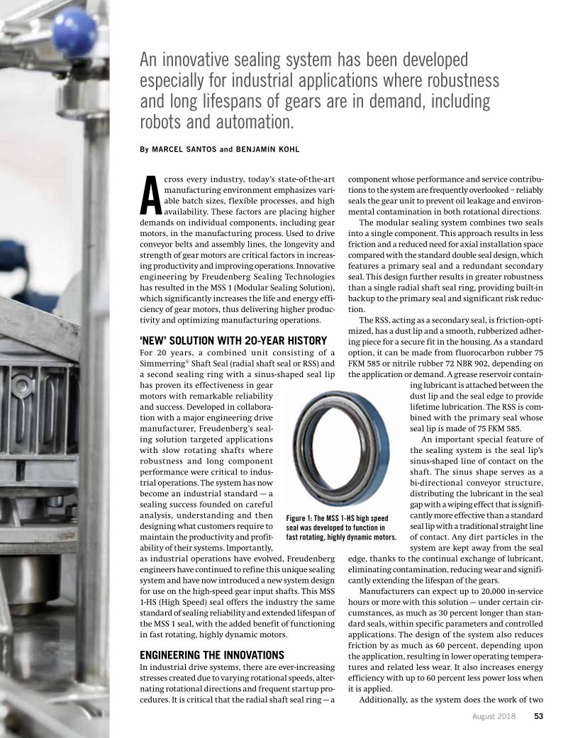
August 2018 53
An innovative sealing system has been developed especially for industrial applications where robustness and long lifespans of gears are in demand, including robots and automation.By MARCEL SANTOS and BENJAMIN KOHL
Across every industry, today’s state-of-the-art manufacturing environment emphasizes vari-able batch sizes, flexible processes, and high availability. These factors are placing higher
demands on individual components, including gear motors, in the manufacturing process. Used to drive conveyor belts and assembly lines, the longevity and strength of gear motors are critical factors in increas-ing productivity and improving operations. Innovative engineering by Freudenberg Sealing Technologies has resulted in the MSS 1 (Modular Sealing Solution), which significantly increases the life and energy effi-ciency of gear motors, thus delivering higher produc-tivity and optimizing manufacturing operations.
‘NEW’ SOLUTION WITH 20-YEAR HISTORYFor 20 years, a combined unit consisting of a Simmerring® Shaft Seal (radial shaft seal or RSS) and a second sealing ring with a sinus-shaped seal lip has proven its effectiveness in gear motors with remarkable reliability and success. Developed in collabora-tion with a major engineering drive manufacturer, Freudenberg’s seal-ing solution targeted applications with slow rotating shafts where robustness and long component performance were critical to indus-trial operations. The system has now become an industrial standard — a sealing success founded on careful analysis, understanding and then designing what customers require to maintain the productivity and profit-ability of their systems. Importantly, as industrial operations have evolved, Freudenberg engineers have continued to refine this unique sealing system and have now introduced a new system design for use on the high-speed gear input shafts. This MSS 1-HS (High Speed) seal offers the industry the same standard of sealing reliability and extended lifespan of the MSS 1 seal, with the added benefit of functioning in fast rotating, highly dynamic motors.
ENGINEERING THE INNOVATIONSIn industrial drive systems, there are ever-increasing stresses created due to varying rotational speeds, alter-nating rotational directions and frequent startup pro-cedures. It is critical that the radial shaft seal ring — a
component whose performance and service contribu-tions to the system are frequently overlooked – reliably seals the gear unit to prevent oil leakage and environ-mental contamination in both rotational directions.
The modular sealing system combines two seals into a single component. This approach results in less friction and a reduced need for axial installation space compared with the standard double seal design, which features a primary seal and a redundant secondary seal. This design further results in greater robustness than a single radial shaft seal ring, providing built-in backup to the primary seal and significant risk reduc-tion.
The RSS, acting as a secondary seal, is friction-opti-mized, has a dust lip and a smooth, rubberized adher-ing piece for a secure fit in the housing. As a standard option, it can be made from fluorocarbon rubber 75 FKM 585 or nitrile rubber 72 NBR 902, depending on the application or demand. A grease reservoir contain-
ing lubricant is attached between the dust lip and the seal edge to provide lifetime lubrication. The RSS is com-bined with the primary seal whose seal lip is made of 75 FKM 585.
An important special feature of the sealing system is the seal lip’s sinus-shaped line of contact on the shaft. The sinus shape serves as a bi-directional conveyor structure, distributing the lubricant in the seal gap with a wiping effect that is signifi-cantly more effective than a standard seal lip with a traditional straight line of contact. Any dirt particles in the system are kept away from the seal
edge, thanks to the continual exchange of lubricant, eliminating contamination, reducing wear and signifi-cantly extending the lifespan of the gears.
Manufacturers can expect up to 20,000 in-service hours or more with this solution — under certain cir-cumstances, as much as 30 percent longer than stan-dard seals, within specific parameters and controlled applications. The design of the system also reduces friction by as much as 60 percent, depending upon the application, resulting in lower operating tempera-tures and related less wear. It also increases energy efficiency with up to 60 percent less power loss when it is applied.
Additionally, as the system does the work of two
Figure 1: The MSS 1-HS high speed seal was developed to function in fast rotating, highly dynamic motors.
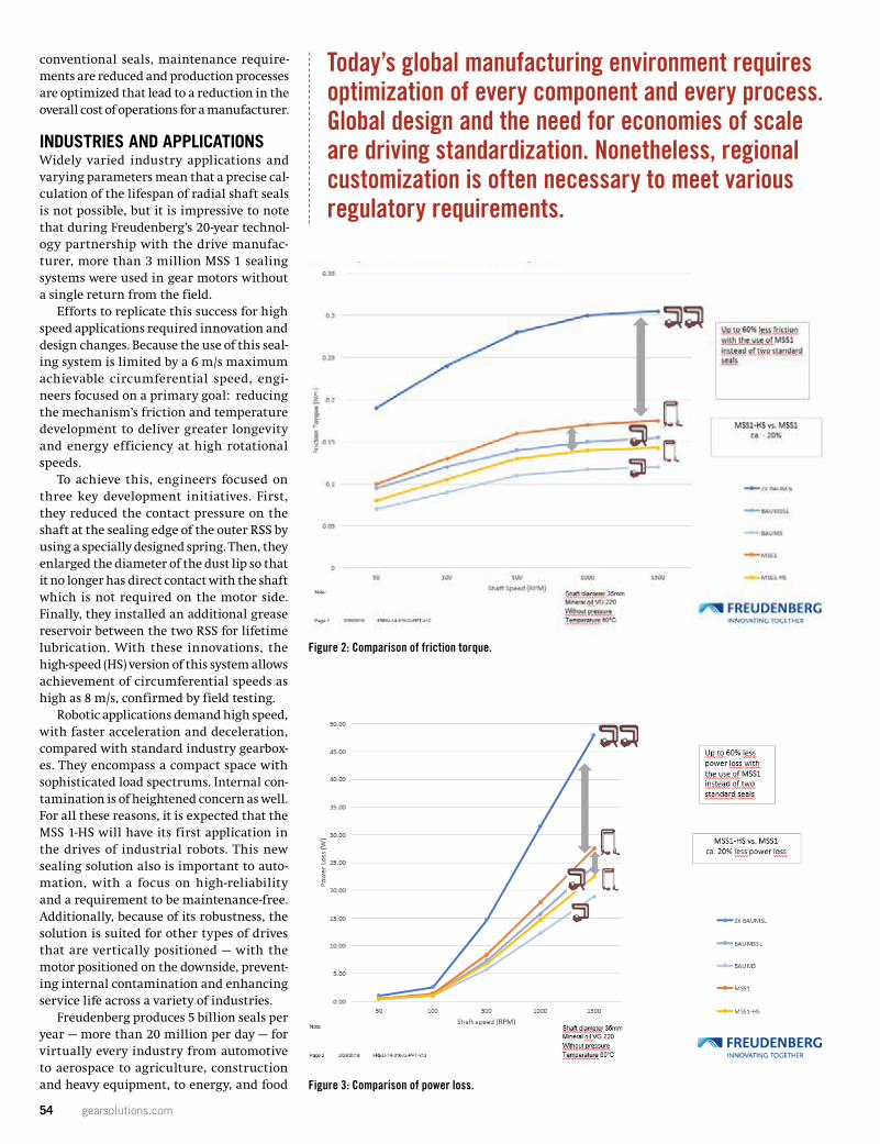
54 gearsolutions.com
conventional seals, maintenance require-ments are reduced and production processes are optimized that lead to a reduction in the overall cost of operations for a manufacturer.
INDUSTRIES AND APPLICATIONSWidely varied industry applications and varying parameters mean that a precise cal-culation of the lifespan of radial shaft seals is not possible, but it is impressive to note that during Freudenberg’s 20-year technol-ogy partnership with the drive manufac-turer, more than 3 million MSS 1 sealing systems were used in gear motors without a single return from the field.
Efforts to replicate this success for high speed applications required innovation and design changes. Because the use of this seal-ing system is limited by a 6 m/s maximum achievable circumferential speed, engi-neers focused on a primary goal: reducing the mechanism’s friction and temperature development to deliver greater longevity and energy efficiency at high rotational speeds.
To achieve this, engineers focused on three key development initiatives. First, they reduced the contact pressure on the shaft at the sealing edge of the outer RSS by using a specially designed spring. Then, they enlarged the diameter of the dust lip so that it no longer has direct contact with the shaft which is not required on the motor side. Finally, they installed an additional grease reservoir between the two RSS for lifetime lubrication. With these innovations, the high-speed (HS) version of this system allows achievement of circumferential speeds as high as 8 m/s, confirmed by field testing.
Robotic applications demand high speed, with faster acceleration and deceleration, compared with standard industry gearbox-es. They encompass a compact space with sophisticated load spectrums. Internal con-tamination is of heightened concern as well. For all these reasons, it is expected that the MSS 1-HS will have its first application in the drives of industrial robots. This new sealing solution also is important to auto-mation, with a focus on high-reliability and a requirement to be maintenance-free. Additionally, because of its robustness, the solution is suited for other types of drives that are vertically positioned — with the motor positioned on the downside, prevent-ing internal contamination and enhancing service life across a variety of industries.
Freudenberg produces 5 billion seals per year — more than 20 million per day — for virtually every industry from automotive to aerospace to agriculture, construction and heavy equipment, to energy, and food
Modular Sealing Solution: Graphics
Fig. 1: The MSS 1-HS high speed seal was developed to function in fast rotating, highly
dynamic motors.
Fig. 2:
Fig. 3:
Figure 2: Comparison of friction torque.
Figure 3: Comparison of power loss.
Today’s global manufacturing environment requires optimization of every component and every process. Global design and the need for economies of scale are driving standardization. Nonetheless, regional customization is often necessary to meet various regulatory requirements.
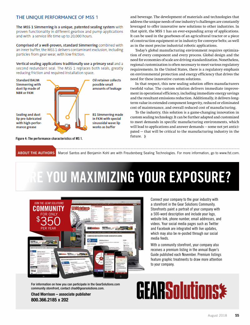
August 2018 55
and beverage. The development of materials and technologies that address the unique needs of one industry’s challenges are constantly leveraged to offer innovative new solutions to other industries. In that spirit, the MSS 1 has an ever-expanding array of applications. It can be used in the gearboxes of an agricultural tractor or a piece of construction equipment or in industry for conveyor belts; as well as in the most precise industrial robotic applications.
Today’s global manufacturing environment requires optimiza-tion of every component and every process. Global design and the need for economies of scale are driving standardization. Nonetheless, regional customization is often necessary to meet various regulatory requirements. In the United States, there is a regulatory emphasis on environmental protection and energy efficiency that drives the need for these innovative custom solutions.
In that respect, this new sealing solution offers manufacturers twofold value. The custom solution delivers immediate improve-ment in operational efficiency, including immediate energy savings and the resultant emissions reduction. Additionally, it delivers long-term value in extended component longevity, reduced or eliminated cost of maintenance, and overall reduced cost of manufacturing.
To the industry, this solution is a game-changing innovation in custom sealing technology. It can be further adapted and customized to meet demands in specific manufacturing environments, which will lead to applications and answer demands — some not yet antici-pated — that will be critical to the manufacturing industry in the future.
ABOUT THE AUTHORS Marcel Santos and Benjamin Kohl are with Freudenberg Sealing Technologies. For more information, go to www.fst.com.
Fig. 4:
Fig. 4:
Figure 4: The performance characteristics of MS 1.
Connect your company to the gear industry with a storefront in the Gear Solutions Community. Storefronts paint a portrait of your company with a 500-word description and include your logo, website link, phone number, email addresses, and videos. Your social media pages such as Twitter and Facebook are integrated with live updates, which may also be re-posted through our social media feeds.
With a community storefront, your company also receives a premium listing in the annual Buyer’s Guide published each November. Premium listings feature graphic treatments to draw more attention to your company.
For information on how you can participate in the GearSolutions.com community storefront, contact [email protected].
Chad Morrison – associate publisher 800.366.2185 x 202
ARE YOU MAXIMIZING YOUR EXPOSURE?
FOR ONLYCOMMUNITY$350
PER YEAR
JOIN THE GEAR SOLUTIONS

56 gearsolutions.com
COMPANYPROFILE WENZEL AMERICA
The SF 87 Shopfloor machine. (Courtesy: Wenzel America)
A GLOBAL COMPANY WITH A LOCAL FEEL
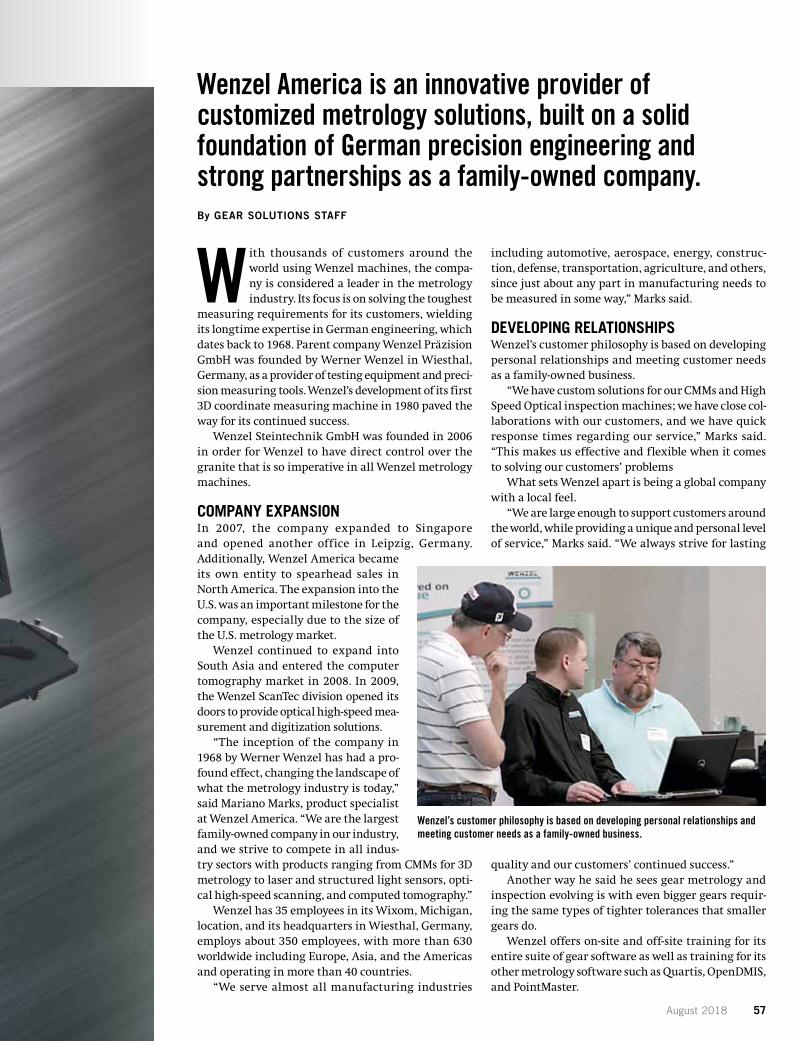
August 2018 57
Wenzel America is an innovative provider of customized metrology solutions, built on a solid foundation of German precision engineering and strong partnerships as a family-owned company.By GEAR SOLUTIONS STAFF
With thousands of customers around the world using Wenzel machines, the compa-ny is considered a leader in the metrology industry. Its focus is on solving the toughest
measuring requirements for its customers, wielding its longtime expertise in German engineering, which dates back to 1968. Parent company Wenzel Präzision GmbH was founded by Werner Wenzel in Wiesthal, Germany, as a provider of testing equipment and preci-sion measuring tools. Wenzel’s development of its first 3D coordinate measuring machine in 1980 paved the way for its continued success.
Wenzel Steintechnik GmbH was founded in 2006 in order for Wenzel to have direct control over the granite that is so imperative in all Wenzel metrology machines.
COMPANY EXPANSIONIn 2007, the company expanded to Singapore and opened another office in Leipzig, Germany. Additionally, Wenzel America became its own entity to spearhead sales in North America. The expansion into the U.S. was an important milestone for the company, especially due to the size of the U.S. metrology market.
Wenzel continued to expand into South Asia and entered the computer tomography market in 2008. In 2009, the Wenzel ScanTec division opened its doors to provide optical high-speed mea-surement and digitization solutions.
“The inception of the company in 1968 by Werner Wenzel has had a pro-found effect, changing the landscape of what the metrology industry is today,” said Mariano Marks, product specialist at Wenzel America. “We are the largest family-owned company in our industry, and we strive to compete in all indus-try sectors with products ranging from CMMs for 3D metrology to laser and structured light sensors, opti-cal high-speed scanning, and computed tomography.”
Wenzel has 35 employees in its Wixom, Michigan, location, and its headquarters in Wiesthal, Germany, employs about 350 employees, with more than 630 worldwide including Europe, Asia, and the Americas and operating in more than 40 countries.
“We serve almost all manufacturing industries
including automotive, aerospace, energy, construc-tion, defense, transportation, agriculture, and others, since just about any part in manufacturing needs to be measured in some way,” Marks said.
DEVELOPING RELATIONSHIPSWenzel’s customer philosophy is based on developing personal relationships and meeting customer needs as a family-owned business.
“We have custom solutions for our CMMs and High Speed Optical inspection machines; we have close col-laborations with our customers, and we have quick response times regarding our service,” Marks said. “This makes us effective and flexible when it comes to solving our customers’ problems
What sets Wenzel apart is being a global company with a local feel.
“We are large enough to support customers around the world, while providing a unique and personal level of service,” Marks said. “We always strive for lasting
quality and our customers’ continued success.”Another way he said he sees gear metrology and
inspection evolving is with even bigger gears requir-ing the same types of tighter tolerances that smaller gears do.
Wenzel offers on-site and off-site training for its entire suite of gear software as well as training for its other metrology software such as Quartis, OpenDMIS, and PointMaster.
Wenzel’s customer philosophy is based on developing personal relationships and meeting customer needs as a family-owned business.
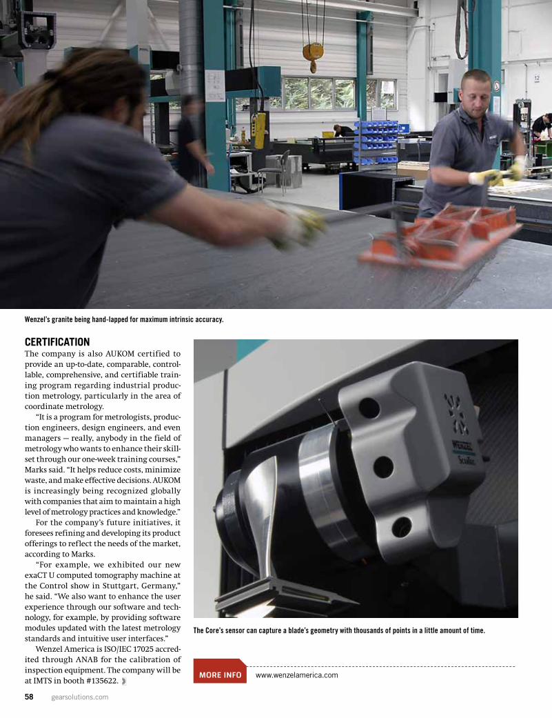
58 gearsolutions.com
CERTIFICATIONThe company is also AUKOM certified to provide an up-to-date, comparable, control-lable, comprehensive, and certifiable train-ing program regarding industrial produc-tion metrology, particularly in the area of coordinate metrology.
“It is a program for metrologists, produc-tion engineers, design engineers, and even managers — really, anybody in the field of metrology who wants to enhance their skill-set through our one-week training courses,” Marks said. “It helps reduce costs, minimize waste, and make effective decisions. AUKOM is increasingly being recognized globally with companies that aim to maintain a high level of metrology practices and knowledge.”
For the company’s future initiatives, it foresees refining and developing its product offerings to reflect the needs of the market, according to Marks.
“For example, we exhibited our new exaCT U computed tomography machine at the Control show in Stuttgart, Germany,” he said. “We also want to enhance the user experience through our software and tech-nology, for example, by providing software modules updated with the latest metrology standards and intuitive user interfaces.”
Wenzel America is ISO/IEC 17025 accred-ited through ANAB for the calibration of inspection equipment. The company will be at IMTS in booth #135622.
MORE INFO www.wenzelamerica.com
Wenzel’s granite being hand-lapped for maximum intrinsic accuracy.
The Core’s sensor can capture a blade’s geometry with thousands of points in a little amount of time.
ALD Thermal Treatment, Inc.
Global Service Centers
Limbach-Oberfrohna Germany
Port Huron, Michigan USA
Ramos Arizpe, Coahuila Mexico
www.aldtt.net
ALD is a subsidiary of AMG Advanced Metallurgical Group N.V.
High Tech is our Business
ALD is a leader in vacuum process technology and Heat treatment services. LEADERS IN THE CONTROL OF DISTORTION + Low Pressure Carburizing + High pressure gas quenching + Gas Nitriding + Ferritic Nitro-Carburizing + Plasma Carburizing + Normalizing + Hardening + Annealing + Brazing + Cryogenic Treatments + Engineering services and
process development + Prototype and trials
Enrique Lopez – Sales and Marketing Email: [email protected] Phone +1 (810) 357-0685 ALD Thermal Treatment, Inc. 2656 24th Street Port Huron, MI 48060, USA

August 2018 59
ALD Thermal Treatment, Inc.
Global Service Centers
Limbach-Oberfrohna Germany
Port Huron, Michigan USA
Ramos Arizpe, Coahuila Mexico
www.aldtt.net
ALD is a subsidiary of AMG Advanced Metallurgical Group N.V.
High Tech is our Business
ALD is a leader in vacuum process technology and Heat treatment services. LEADERS IN THE CONTROL OF DISTORTION + Low Pressure Carburizing + High pressure gas quenching + Gas Nitriding + Ferritic Nitro-Carburizing + Plasma Carburizing + Normalizing + Hardening + Annealing + Brazing + Cryogenic Treatments + Engineering services and
process development + Prototype and trials
Enrique Lopez – Sales and Marketing Email: [email protected] Phone +1 (810) 357-0685 ALD Thermal Treatment, Inc. 2656 24th Street Port Huron, MI 48060, USA
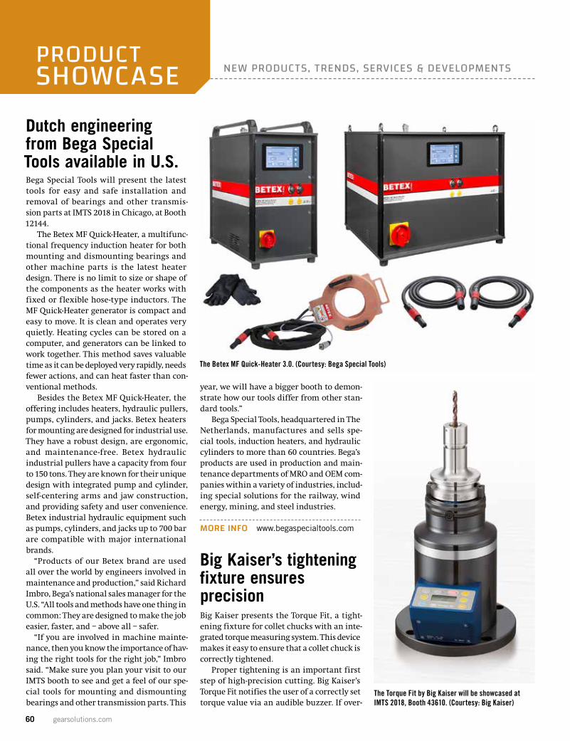
60 gearsolutions.com
NEW PRODUCTS, TRENDS, SERVICES & DEVELOPMENTSPRODUCTSHOWCASE
Dutch engineering from Bega Special Tools available in U.S.Bega Special Tools will present the latest tools for easy and safe installation and removal of bearings and other transmis-sion parts at IMTS 2018 in Chicago, at Booth 12144.
The Betex MF Quick-Heater, a multifunc-tional frequency induction heater for both mounting and dismounting bearings and other machine parts is the latest heater design. There is no limit to size or shape of the components as the heater works with fixed or flexible hose-type inductors. The MF Quick-Heater generator is compact and easy to move. It is clean and operates very quietly. Heating cycles can be stored on a computer, and generators can be linked to work together. This method saves valuable time as it can be deployed very rapidly, needs fewer actions, and can heat faster than con-ventional methods.
Besides the Betex MF Quick-Heater, the offering includes heaters, hydraulic pullers, pumps, cylinders, and jacks. Betex heaters for mounting are designed for industrial use. They have a robust design, are ergonomic, and maintenance-free. Betex hydraulic industrial pullers have a capacity from four to 150 tons. They are known for their unique design with integrated pump and cylinder, self-centering arms and jaw construction, and providing safety and user convenience. Betex industrial hydraulic equipment such as pumps, cylinders, and jacks up to 700 bar are compatible with major international brands.
“Products of our Betex brand are used all over the world by engineers involved in maintenance and production,” said Richard Imbro, Bega’s national sales manager for the U.S. “All tools and methods have one thing in common: They are designed to make the job easier, faster, and – above all – safer.
“If you are involved in machine mainte-nance, then you know the importance of hav-ing the right tools for the right job,” Imbro said. “Make sure you plan your visit to our IMTS booth to see and get a feel of our spe-cial tools for mounting and dismounting bearings and other transmission parts. This
year, we will have a bigger booth to demon-strate how our tools differ from other stan-dard tools.”
Bega Special Tools, headquartered in The Netherlands, manufactures and sells spe-cial tools, induction heaters, and hydraulic cylinders to more than 60 countries. Bega’s products are used in production and main-tenance departments of MRO and OEM com-panies within a variety of industries, includ-ing special solutions for the railway, wind energy, mining, and steel industries.
MORE INFO www.begaspecialtools.com
Big Kaiser’s tightening fixture ensures precisionBig Kaiser presents the Torque Fit, a tight-ening fixture for collet chucks with an inte-grated torque measuring system. This device makes it easy to ensure that a collet chuck is correctly tightened.
Proper tightening is an important first step of high-precision cutting. Big Kaiser’s Torque Fit notifies the user of a correctly set torque value via an audible buzzer. If over-
The Betex MF Quick-Heater 3.0. (Courtesy: Bega Special Tools)
The Torque Fit by Big Kaiser will be showcased at IMTS 2018, Booth 43610. (Courtesy: Big Kaiser)
August 2018 61
tightening occurs, the error LED light will flash.
The Torque Fit was developed to replace multiple torque wrenches and has adapt-ers available for all common machine tool interfaces such as CAT, BT, SK, HSK, and BIG CAPTO, making it an economical invest-ment. For maximum convenience, torque values for all Big Kaiser-made collet chucks are preset. The operator can, however, use a generic setting to tighten any collet chuck with a torque value up to 80 Nm (60 ft-lbs).
Big Kaiser, a global leader in premium high-precision tooling systems and solu-tions for the metalworking industries, will be showcasing the Torque Fit at IMTS 2018 Booth 431610, along with several other inno-vative products.
MORE INFO www.bigkaiser.com
EMAG to present variety of new machines at IMTSEMAG, a worldwide leader in manufacturing systems for precision metal components, will debut four machines to the North American
market at IMTS this year, while showcasing several others. IMTS is September 10-15, 2018, in Chicago. EMAG will be in the South Hall Booth 339436.
New to North America are the VLC 200 GT, HLC 150 H, VLC 50 TWIN, and the CI 400. Other machines featured will include
the VL 3 DUO, VT 4, and the Eldec MIND-M 250. In addition, EMAG will have a display of its industry 4.0 options. Details on the machines to be displayed are:
�� The VLC 200 GT turning/grinding machine for chucked components is espe-cially designed for precise, process-reliable,
The EMAG HLC 150 H will debut to the North American market at IMTS Booth 339436.
ISO Certified / ITAR Registered / Trace Certified
[email protected] | [email protected] | (203) 775-4877
Nordex.com
62 gearsolutions.com
and cost-effective manufacturing in medi-um- and large-scale production. Typical workpieces machined on the VLC 200 GT include gears, sprockets, sliding sleeves, and parts for CVT gears. The machine combines the benefits of vertical hard turning with those of grinding on a single machine and in a single clamping operation.
�� The HLC 150 H offers high-performance technology and the capability to produce a wide variety of workpieces, from gear shafts and armature, to pinions and planetary
gears, with a maximum length of up to 500 millimeters (20 inches).
�� The VLC 50 TWIN offers simultaneous machining for highly productive manu-facturing. Featuring two main spindles in one machining area, it can simultaneously machine two identical workpieces, allowing for a significant increase in output quanti-ties and a lower cost/piece. The diameter and length of both components can be corrected independently of one another. The machine also has a direct position measuring system
and a linear motor in the X-axis to ensure the highest machining quality and maxi-mum productivity.
�� The CI 400 is a well-suited solution for the electro-chemical machining of rotor car-riers. Rotor carriers are components of elec-tric motor housings for hybrid vehicles and are being produced in increasing numbers. Electro-chemical machining offers decisive benefits for the production of these parts.
�� The VL 3 DUO turning machines com-bine the technological developments of recent years, including pick-up automation and the TrackMotion automation system, to the modular basic design of the CNC machine. This creates an extremely efficient production system offering maximum pro-ductivity with minimal space requirements. Like every EMAG modular turning machine, the VL 3 DUO multi-spindle machines are equipped with their own parts storage unit and a pick-up spindle for each work area.
�� VT 4 lathes offer maximum efficiency in shaft production. They feature short cycle times, high precision, and safe processing, among other attributes of shaft machining on the running machines of the VT series. These lathes literally stand the classical hori-zontal machining process on its head.
�� The Eldec MIND-M 250 is a compact hardening system for basic heat treatment of checked parts and shafts, provided by EMAG eldec. Heat-treatment tasks are performed at 30kW in high-frequency applications and 100kW in medium frequency.
MORE INFO www.emag.com
Emuge to demonstrate new Punch Tap technology at IMTSEmuge Punch Tap technology, also called helical cold-forming of threads, constitutes the fourth method for the production of internal threads besides tapping, cold-form-ing of threads, and thread milling. This patented method was developed in coopera-tion between Audi AG and Emuge and is now available in North America.
The Punch Tap was developed to signifi-cantly reduce the cycle time associated with threading aluminum castings. Emuge not only created a new type of tool for helical thread-forming but also a completely new technology for machining threads. Thanks to entirely new kinematics with a signifi-cantly shorter tool path, the new process pro-
PRODUCT SHOWCASE
The Power of One2
Your Objective: One face in perfect alignment with another. For infinity.
Spiral and Straight Bevel Gears (Cut, Ground or Lapped) • Spur Gears • Helical Gears • Long Shafts • Herringbone Gears • Involute and Straight Sided Splines • Internal Gears •
Worm and Worm Gears • Racks • Sprockets • ISO Certified
No problems. No distress. No delays.That’s the same objective you have for choosing your gear producer. Circle Gear’s objective is to engage with every customer’s objectives.
One to 1000 gears Customer designed or reverse engineered Gearbox repair, rebuild or redesign OEM or end-users ISO 9001:2015 Certified
Partnering with QualityReducer to provide Gearbox repair, rebuilding and reverse-engineering.
1501 S. 55th Court, Cicero, IL 60804(800) 637-9335 (708) 652-1000 / Fax: (708) [email protected]
Circle-Gear-ad-2017-Gear-Solutions-4.75x7.25.indd 1 1/17/17 1:13 PM
August 2018 63
duces internal threads at a reduced energy consumption and is faster by approximately 75 percent compared to the conventional threading technology. See this new technol-ogy in action at IMTS 2018, Booth 431536.
MORE INFO www.emuge.com
Emuge to display full range of workholding solutions at IMTSAt IMTS this year, Emuge Corp. will showcase its comprehensive line of clamping solutions at Booth 431536. Emuge’s workholding divi-sion specializes in providing highly accurate, almost maintenance-free customized solu-tions for applications from low-volume job shops to high-volume automotive produc-tion environments.
“Our workholding group stays close to our customers to learn about their unique challenges and production environments. Doing so helps us develop the best solutions for their applications,” said David Jones, pre-cision workholding manager at Emuge Corp.
The precision workholding lineup on dis-play will include:
��With its expanding-bush design, Emuge’s System SG is used in many machin-ing operations such as hobbing, shaping, and shaving for gear production, as well as mill-ing and inspection. The System SG’s large surface area contact with the workpiece provides a clamping solution which is very rigid, accurate, and repeatable.
�� The high precision System SP is used not
only to clamp workpieces but also to clamp tools. By applying an axial force, the clamp-ing sleeves move in the direction of the force and expand radially. This eliminates the clearance between clamping sleeve and body, and between clamping sleeve and workpiece. System SP achieves concentricity of < 0.002 mm (corresponding to < 0.0001 inch).
�� For workpieces that have a short clamp-ing base or for diameters with a very large tolerance, System SZ is the best choice. By applying an axial force, a slitted collet is radi-
ally expanded by a cone. Simultaneously an axial movement occurs, clamping the work-piece.
��When the eccentricity between pitch circle and seating bore is very small, dia-phragm clamping System SM is ideal. It allows clamping of the gear wheel at the pitch circle for machining the seating bore. The gear wheel is clamped in both axial and radial directions.
MORE INFO www.emuge.com
Emuge’s Punch Tap features a revolutionary design for helical thread-forming. See it at IMTS booth 431536. (Courtesy: Emuge)
Reliability begins with a cup of coffee.
olonial isn’t typical in the CUTTING TOOL INDUSTRY-our main focus is to establish customer relationships that are a perfect fit with our decades of service providing cutting tools
to international companies looking for experience and reliability.
The solutions we provide delivers the highest quality in theworld at a reliable Lowest Cost Per Piece, GUARANTEED! An industry first. What do you take in your coffee?
Relationships are built by taking the time to sit downwith you, & discovering what keeps you awake at night.
United States • Canada • Mexico • 1-866-611-5119 • [email protected]• www.actsadvantage.com
C
The solutions we provide delivers the highest quality in the world at a reliable Lowest Cost Per Piece, GUARANTEED! An industry first. What do you take in your coffee?
64 gearsolutions.com
Supfina expands line of fine-grinding machinesSupfina Machine Company, Inc. has expand-ed its line of fine-grinding machines to include the Spiro F5 and the Spiro F12, each of which make its North American debut at IMTS 2018 in Chicago. Along with the Spiro F7, the three machines provide customized solutions for the “batch mode” processing
of a wide variety of gears, among numerous other parts. At IMTS, Supfina will be in the North Building, Booth 236949.
From aluminum to steel, soft plastics to hard ceramics – no matter the material, the Spiro series can achieve highly precise plane parallelism (≤ 1.0 μm). Such precision is cru-cial for gearboxes and other gear applica-tions. And because gears can be machined up to 20 times faster than lapping and with more precision than double-disk grinding, costs per unit are reduced substantially.
Depending on the gear’s material, dimen-sions, starting surface finish, and removal requirements, a single Spiro can fine-grind several thousand per hour.
For plane-parallel fine grinding on both sides, gears are loosely placed in carriers that have teeth on the outside diameter. An inner pin ring rotates the carriers as they shift on a stationary outer pin ring in an orbiting manner. Machining takes place between two rotating grinding wheels (lower and upper). The optimal machining force is applied by the upper wheel.
The smaller F5 can process gears with diameters of 4 mm to 150 mm and thick-nesses of 0.3 mm to 50 mm, while the larger F12 can accommodate gears with diameters of 6 mm to 420 mm and thicknesses of 1 mm to 100 mm. (The midsize F7 is suitable for gears with diameters and thicknesses of 5 mm to 220 mm and 0.6 mm to 80 mm, respectively.)
“We’re bringing to fine grinding the same process know-how — decades of research and development — that we’ve mastered in the field of superfinishing,” said Andrew Corsini, president and chief executive of Supfina’s North Kingstown, Rhode Island, manufac-turing facility. (Supfina also has a plant in Wolfach, Germany.) “With the Spiro line we can offer reliable, economical machines that provide all of the best features for the fine-grinding, batch-mode process.”
Regarding maintenance, because the Spiro eliminates water from the cooling process, there’s no chance of contamina-tion — thus drastically cutting costs (the coolant is also recycled). The machines’ sturdy bases keep vibration to a minimum, greatly reducing tool wear, while their mod-ular, ergonomic design allows quick tooling changes and easy accessibility. For example, the upper part of the machine swivels com-
PRODUCT SHOWCASE
Parts to be finished are loosely placed in “carriers” that pins rotate in an orbiting manner. Machining takes place between two grinding wheels (diamond or CBN). (Courtesy: Supfina)
GEARING AHEAD TO MEET INDUSTRY'S DEMAND FOR PRECISION
PRECISION GEAR PRODUCTS (up to AGMA Q14)
Spur Gears, Helical Gears, Worm Gears, Anti-Backlash Gears, Cluster Gears, Clutch Gears, Face Gears, Planetary Gears, Gear Assemblies, Gear Boxes, Bevel Gears, Miter Gears,
Metric Gears, Internal Gears, Idler Gears, Gear Rack & Pinion, Worms, Wormshafts, Splines, Spline Shafts, Serrated Shafts.
STD Precision Gear & Instrument, Inc. 318 Manley St. • W. Bridgewater, MA 02379
(888) STD-GEAR or (508) 580-0035 Fax (888) FAX-4STD or (508) 580-0071
E-mail [email protected] • Web site: www.stdgear.com
Aircraft • Aerospace • ActuationInstrumentation • OpticRobotics • Radar • MedicalMarine • Defense • ExperimentalPrototype • ProductionHi-Performance Automotive
SERVING:
CNC Thread Grinding
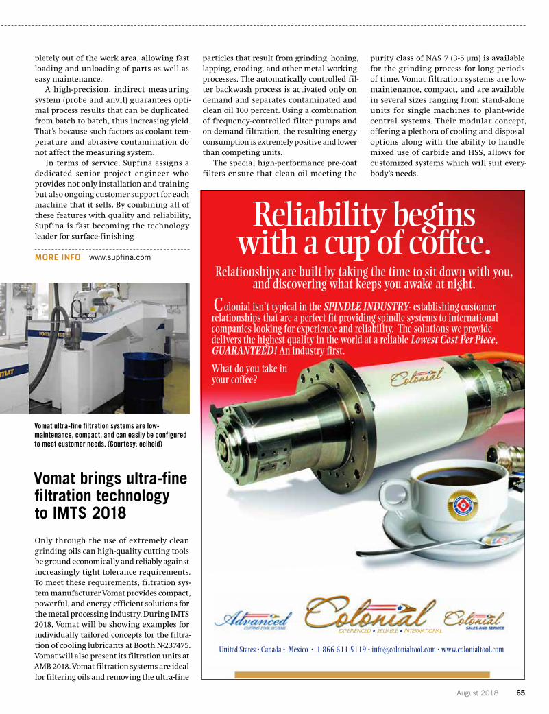
August 2018 65
pletely out of the work area, allowing fast loading and unloading of parts as well as easy maintenance.
A high-precision, indirect measuring system (probe and anvil) guarantees opti-mal process results that can be duplicated from batch to batch, thus increasing yield. That’s because such factors as coolant tem-perature and abrasive contamination do not affect the measuring system.
In terms of service, Supfina assigns a dedicated senior project engineer who provides not only installation and training but also ongoing customer support for each machine that it sells. By combining all of these features with quality and reliability, Supfina is fast becoming the technology leader for surface-finishing
MORE INFO www.supfina.com
Vomat brings ultra-fine filtration technology to IMTS 2018
Only through the use of extremely clean grinding oils can high-quality cutting tools be ground economically and reliably against increasingly tight tolerance requirements. To meet these requirements, filtration sys-tem manufacturer Vomat provides compact, powerful, and energy-efficient solutions for the metal processing industry. During IMTS 2018, Vomat will be showing examples for individually tailored concepts for the filtra-tion of cooling lubricants at Booth N-237475. Vomat will also present its filtration units at AMB 2018. Vomat filtration systems are ideal for filtering oils and removing the ultra-fine
particles that result from grinding, honing, lapping, eroding, and other metal working processes. The automatically controlled fil-ter backwash process is activated only on demand and separates contaminated and clean oil 100 percent. Using a combination of frequency-controlled filter pumps and on-demand filtration, the resulting energy consumption is extremely positive and lower than competing units.
The special high-performance pre-coat filters ensure that clean oil meeting the
purity class of NAS 7 (3-5 μm) is available for the grinding process for long periods of time. Vomat filtration systems are low-maintenance, compact, and are available in several sizes ranging from stand-alone units for single machines to plant-wide central systems. Their modular concept, offering a plethora of cooling and disposal options along with the ability to handle mixed use of carbide and HSS, allows for customized systems which will suit every-body’s needs.
Vomat ultra-fine filtration systems are low-maintenance, compact, and can easily be configured to meet customer needs. (Courtesy: oelheld)
Reliability begins with a cup of coffee.
olonial isn’t typical in the SPINDLE INDUSTRY- establishing customer relationships that are a perfect fit providing spindle systems to internationalcompanies looking for experience and reliability. The solutions we provide delivers the highest quality in the world at a reliable Lowest Cost Per Piece,GUARANTEED! An industry first.
What do you take in your coffee?
Relationships are built by taking the time to sit down with you,and discovering what keeps you awake at night.
United States • Canada • Mexico • 1-866-611-5119 • [email protected] • www.colonialtool.com
EXPERIENCED • RELIABLE • INTERNATIONAL
C Reliability begins with a cup of coffee.
olonial isn’t typical in the SPINDLE INDUSTRY- establishing customer relationships that are a perfect fit providing spindle systems to internationalcompanies looking for experience and reliability. The solutions we provide delivers the highest quality in the world at a reliable Lowest Cost Per Piece,GUARANTEED! An industry first.
What do you take in your coffee?
Relationships are built by taking the time to sit down with you,and discovering what keeps you awake at night.
United States • Canada • Mexico • 1-866-611-5119 • [email protected] • www.colonialtool.com
EXPERIENCED • RELIABLE • INTERNATIONAL
C
Reliability begins with a cup of coffee.
olonial isn’t typical in the SPINDLE INDUSTRY- establishing customer relationships that are a perfect fit providing spindle systems to internationalcompanies looking for experience and reliability. The solutions we provide delivers the highest quality in the world at a reliable Lowest Cost Per Piece,GUARANTEED! An industry first.
What do you take in your coffee?
Relationships are built by taking the time to sit down with you,and discovering what keeps you awake at night.
United States • Canada • Mexico • 1-866-611-5119 • [email protected] • www.colonialtool.com
EXPERIENCED • RELIABLE • INTERNATIONAL
C
66 gearsolutions.com
Besides the compact stand-alone units of the FA series (70- to 1,200-liter flow rate/min-ute), the new Vomat vacuum belt filter UBF will be a focus of the fair. With a filtration fineness of 3 to 25 μm, it is ideally suited for filtering oils and emulsions contaminated with steel, HSS, binders, and grinding wheel particles.
According to Vomat, the UBF filter requires about 70 percent less space while delivering 100 percent of the performance when compared to conventional systems
offered in the market place.Vomat’s sales manager Steffen Strobel
said, “Efficient, space- and energy-saving filtration is becoming increasingly impor-tant. Choosing the right filtration system will have a positive impact on production costs. Thanks to Vomat technology, a lot of money can be saved in production.”
oelheld is the exclusive Vomat distributor in North America.
MORE INFO www.oelheld.com
Exsys offers range of precision planetary gearbox solutionsExsys Tool, Inc. has expanded its line of Eppinger high-precision industrial gearbox-es to include planetary-type gearboxes. The planetary range provides excellent energy efficiency, minimal heat generation and extremely smooth motion for a wide variety of applications and industries.
Standard planetary gearboxes are avail-able in PE (planetary eco) and PP (planetary precision) styles for applications that require low backlash, high efficiency, shock resis-tance, and a high-torque-to-weight ratio. With a modular design that combines ground gears and precision gear compo-nents, these gearboxes ensure performance efficiency and maximum uptime. They also use less energy and easily mount to a variety of motors through a flexible flange system.
The present range of planetary gearboxes comprises five sizes, with each size offered as a single-, dual-, or triple-stage design. Each gearbox variant is also available as a preci-sion design with reduced backlash. The wide assortment of sizes and designs allows users to achieve overall transmission ratios from i
= 3:1 to i = 512:1 in a variety of applications.Servo planetary gearboxes in PT-style are
also available for easy installation of all com-mon servo motors with all sizes of the gear-boxes. PT-style gearboxes feature a unique design by which all ring gears, planet gears, and sun pinions are case hardened and ground to guaranteed high stiffness, reliable transmission, and allow precise positioning tasks.
MORE INFO www.exsys-tool.com
PRODUCT SHOWCASE
Exsys planetary gearbox provides excellent energy efficiency, minimal heat generation. (Courtesy: Exsys Tool, Inc.)
Consistent Quality
Broad Capability & Capacity
Exceptional People
On-time Delivery
ISO 9001 and TS 16949 registered. Presses up to 8800T and volumes up to 750K/year. Supported by in-house heat treat and an ISO 17025 metallurgical lab.
walkerforge.com | 414.223.2000
Sourcing Made Simple
Trusted Gear Blank Supplier Since 1950
ISO 9001 and TS 16949 registered. Presses up to 4000T and volumes up to 750K/year. Supported by in-house heat treat and an ISO 17025 metallurgical lab.
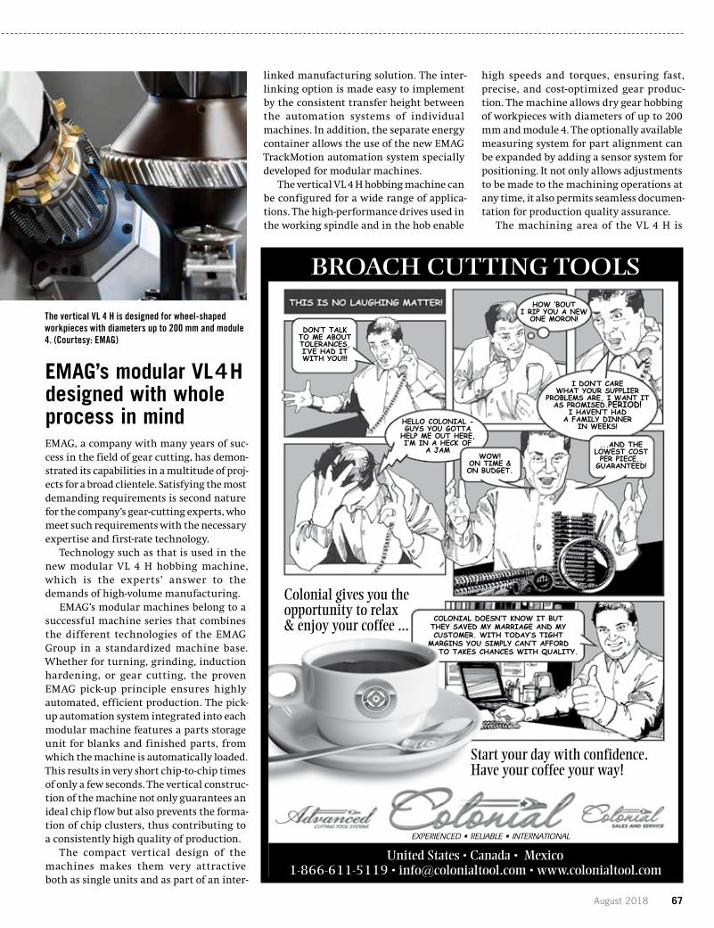
August 2018 67
EMAG’s modular VL 4 H designed with whole process in mind EMAG, a company with many years of suc-cess in the field of gear cutting, has demon-strated its capabilities in a multitude of proj-ects for a broad clientele. Satisfying the most demanding requirements is second nature for the company’s gear-cutting experts, who meet such requirements with the necessary expertise and first-rate technology.
Technology such as that is used in the new modular VL 4 H hobbing machine, which is the experts’ answer to the demands of high-volume manufacturing.
EMAG’s modular machines belong to a successful machine series that combines the different technologies of the EMAG Group in a standardized machine base. Whether for turning, grinding, induction hardening, or gear cutting, the proven EMAG pick-up principle ensures highly automated, efficient production. The pick-up automation system integrated into each modular machine features a parts storage unit for blanks and finished parts, from which the machine is automatically loaded. This results in very short chip-to-chip times of only a few seconds. The vertical construc-tion of the machine not only guarantees an ideal chip flow but also prevents the forma-tion of chip clusters, thus contributing to a consistently high quality of production.
The compact vertical design of the machines makes them very attractive both as single units and as part of an inter-
linked manufacturing solution. The inter-linking option is made easy to implement by the consistent transfer height between the automation systems of individual machines. In addition, the separate energy container allows the use of the new EMAG TrackMotion automation system specially developed for modular machines.
The vertical VL 4 H hobbing machine can be configured for a wide range of applica-tions. The high-performance drives used in the working spindle and in the hob enable
high speeds and torques, ensuring fast, precise, and cost-optimized gear produc-tion. The machine allows dry gear hobbing of workpieces with diameters of up to 200 mm and module 4. The optionally available measuring system for part alignment can be expanded by adding a sensor system for positioning. It not only allows adjustments to be made to the machining operations at any time, it also permits seamless documen-tation for production quality assurance.
The machining area of the VL 4 H is
The vertical VL 4 H is designed for wheel-shaped workpieces with diameters up to 200 mm and module 4. (Courtesy: EMAG)
United States • Canada • Mexico 1-866-611-5119 • [email protected] • www.colonialtool.com
EXPERIENCED • RELIABLE • INTERNATIONAL
Colonial gives you the opportunity to relax & enjoy your coffee ...
Start your day with confidence.Have your coffee your way!
DON’T TALKTO ME ABOUTTOLERANCES,I’VE HAD ITWITH YOU!!!
HELLO COLONIAL -GUYS YOU GOTTA
HELP ME OUT HERE, I’M IN A HECK OF
A JAM
HOW ‘BOUTI RIP YOU A NEW
ONE MORON!
I DON’T CARE WHAT YOUR SUPPLIER
PROBLEMS ARE, I WANT ITAS PROMISED.PERIOD!
I HAVEN’T HAD A FAMILY DINNER
IN WEEKS!
WOW! ON TIME &ON BUDGET.
...AND THE LOWEST COSTPER PIECE..
GUARANTEED!
COLONIAL DOESN’T KNOW IT BUT THEY SAVED MY MARRIAGE AND MY CUSTOMER. WITH TODAY’S TIGHT
MARGINS YOU SIMPLY CAN’T AFFORDTO TAKES CHANCES WITH QUALITY.
BROACH CUTTING TOOLS

68 gearsolutions.com
perfectly accessible through the large front door, allowing rapid set-up times and creating an ergonomic work environ-ment for the operator. The combination of powerful drives, a working spindle that can be controlled with absolute precision, tool clamping, and the generously dimen-sioned machining area allows various dif-ferent gear cutting methods to be used on the machine. For instance, the chamfer cut method can be used to chamfer the work-pieces directly after hobbing, with a single
clamping operation. To do so, the chamfer cut tool is mounted on the hob arbor of the cutter in addition to the hob. The chamfer cut method, developed by Fette, is ideal for precise and low-cost chamfering processes.
“As this method does not produce any sec-ondary burr and does not warp the mate-rial, it is especially suitable for gear teeth that are honed after hardening,” said Peter Loetzner, president & CEO of EMAG L.L.C. The workpiece does have to have a suit-able shape, however. “We have successfully
tested this machining combination in the manufacture of gears. The wheel-shaped workpieces have hardly any interfering contours, so that chamfering with cham-fer-cut is possible. The machining combina-tion of hobbing and chamfering in a single clamping operation on one machine is of course a very cost-effective solution for the user, as two manufacturing processes can be performed at the same time with just one machine, and the workpiece handling between the processing steps is also elimi-nated. That lets you reduce your floor to floor times and get workpieces to the next production step faster,” Loetzner said.
The new VL 4 H from EMAG offers users a multitude of possibilities. As shown in the example, it can be used as a standalone machine for gear cutting, or for combined hobbing/chamfering, or as part of a pro-duction line, which is relatively easy to do thanks to the advantages of EMAG’s modular machines. In all cases, the user benefits from the many possibilities that the machine offers.
MORE INFO www.emag.com
All Metals & Forge Group promotes cost, quality benefitsAll Metals & Forge Group manufactures high quality seamless rolled rings with excellent tensile and yield properties for gear, bear-ing, and heavy machinery applications. It can produce forged rings in diameters up to 108 inches for steel alloys and up to 80 inches for other metals, with wall thickness ranging from 2 inches and up. All parts are rough machined and 100 percent UT tested (ASTM388).
Other forged shaft shapes produced include flanged shafts, round bars, spindles, and hubs.
All Metals offers these high-quality forged shafts in ferrous and non-ferrous metals including carbon steel, alloy steel, stainless steel, titanium, nickel, aluminum, and tool steel.
All Metals & Forge Group, an ISO reg-istered forging manufacturer, has a vast inventory (300 alloys and grades) on the floor which will aid customers in the quick-est deliveries, high quality, and extremely competitive products.
MORE INFO www.steelforge.com
PRODUCT SHOWCASE
www.awea.org
MAKE PLANS TO ATTEND TOP-RATED CONFERENCES IN 2018
Wind Resource & Project Assessment ConferenceSeptember 11 – 12 | Austin, TXwww.windpower.org/wra
Wind Energy Finance & Investment Conference – EastOctober 1 – 2 | New York, NYwww.awea.org/financeeast
Wind Energy Finance & Investment Conference – WestOctober 5 | San Francisco, CAwww.awea.org/financewest
Offshore WINDPOWER Conference & ExhibitionOctober 16 – 17 | Washington, DCwww.offshorewindexpo.org
Wind Energy Fall SymposiumNovember 13 – 15 | Colorado Springs, COwww.awea.org/symposium
www.awea.org
MAKE PLANS TO ATTEND TOP-RATED CONFERENCES IN 2018
Operations & Maintenance and Safety ConferenceFebruary 27 – 28 | San Diego, CAwww.awea.org/oms
Siting & Environmental Compliance ConferenceMarch 20 – 21 | Memphis, TNwww.awea.org/siting
WINDPOWER Conference & ExhibitionMay 7 – 10 | Chicago, ILwww.windpowerexpo.org
Regional Wind Energy Conference – NortheastJune 26 – 27 | Portland, MEwww.windpower.org/northeast
Wind Resource & Project Assessment ConferenceSeptember 11 – 12 | Austin, TXwww.windpower.org/wra
Wind Energy Finance & Investment Conference – EastOctober 1 – 2 | New York, NYwww.awea.org/financeeast
Wind Energy Finance & Investment Conference – WestOctober 5 | San Francisco, CAwww.awea.org/financewest
Offshore WINDPOWER Conference & ExhibitionOctober 16 – 17 | Washington, DCwww.offshorewindexpo.org
Wind Energy Fall SymposiumNovember 13 – 15 | Colorado Springs, COwww.awea.org/symposium

70 gearsolutions.com
MARKETPLACEContact Gear Solutions at 800-366-2185 to feature your business in the Marketplace!
KORO for Quality Hob Sharpening Service
Quick Turnaround 2 Day Service Spur Shaper Cutter Sharpening HSS & Carbide Hob with center hole
Koro Sharpen ing Ser vice 95 30 85 t h Ave Nor th
Ma ple Grove , MN 55369 76 3 -425 -5247
i n fo@k oroind.c om
and straight flutes Thin Film Coatings Length up to 7 inches
Diameter up to 5 Inches Precise rake and spacing guaranteed to AGMA standards RUSH SERVICE AVAILABLE
North, level 3
Booth #237024
see you there!
082018_KappAd_IMTS_NinthPage_GS.indd 1 7/20/2018 3:19:58 PM
If your atmosphere furnace is in need of a refractory reline,
let Ipsen’s experienced atmosphere team help you
restore your furnace back to its original condition.
go.IpsenUSA.com/Retrofits
AtmosphereRefractory Relines
· Custom gear racks in AMERICAN and METRIC standards, STRAIGHT and HELICAL, VARIOUS materials, FINE and COARSE pitch (254 D.P. – 0.5 D.P.; 0.10 Module – 50 Module); hard-cut (up to 60 Rc) and soft-cut (up to 40 Rc); 32” face width; Up to 82” lengths – longer lengths through resetting
· Custom gears in AMERICAN and METRIC standards (3 D.P. – 72 D.P., 10” Diameter)
· Precision Quality up to AGMA 12· Prototype & Production quantities· Breakdown Service Available· Reverse Engineering · Unique Tooth Configurations· Heat Treating· Complete CNC Machining
FASTERMASTERSGet hardened and precision ground master gears in as little as two to three weeks from receipt of order, thanks to the complete machining resources available on-site at Forest City Gear.
For more information visit:www.forestcitygear.com
VL 3 DUO MULTI-SPINDLE TURNING MACHINE
PRODUCTIVE PRECISE COMPACT
264 sq ft FOOTPRINT
www.emag.com
PerformanceDependability
Value
1.866.HOB.TOOLw w w . h o b s o u r c e . c o m
August 2018 71
CONTENTS PAGE NO.Advent Tool & Manufacturing ........................................................... 41
ALD Thermal Treatment Inc ............................................................. 59
All Metals & Forge Group ................................................................. 13
American Precision Gear Co ............................................................. 71
AWEA (American Wind Energy Association) ....................................... 68
Circle Gear & Machine Co Inc .......................................................... 62
Colonial Tool Group .............................................................63, 65, 67
Design2Part Shows ......................................................................... 61
Drewco .......................................................................................... IFC
ECM-USA ....................................................................................... 11
EMAG ........................................................................................9, 70
Engineered Tools Corporation ........................................................... 20
Forest City Gear .............................................................................. 70
Gleason ............................................................................................ 2
Grieve............................................................................................. 14
Hobsource Inc...........................................................................14, 70
IMTS .............................................................................................. 69
Innovative Rack & Gear .............................................................47, 70
Ipsen ........................................................................................22, 70
KAPP Technologies ........................................................27, 50, 51, 70
KISSsoft AG/Gleason ....................................................................... 16
Koro Sharpening Service .................................................................. 70
Lawler Gear Corporation ................................................................... 47
Leistritz .......................................................................................... 10
Liebherr .......................................................................................... 31
Lucifer Furnaces ............................................................................. 70
Machinists Inc. ............................................................................... 17
McInnes Rolled Rings ...................................................................... 18
Mitsubishi Heavy Industries America Inc ...........................................BC
New England Gear ............................................................................. 7
NORDEX ......................................................................................... 61
Penta Gear Metrology LLC................................................................ 21
Piselli Enterprises ........................................................................... 39
Proto Manufacturing Ltd .................................................................. 12
Reishauer ....................................................................................... 15
Russell Holbrook & Henderson Inc ................................................... 16
Solar Atmospheres .........................................................................IBC
Southern Gear & Machine ................................................................ 19
STD Precision Gear & Instruments Inc. ............................................. 64
The Broach Masters Inc. .................................................................... 4
Toolink Engineering Inc. .................................................................... 1
United Tool Supply .......................................................................... 71
Walker Forge ................................................................................... 66
ADVERTISERINDEX
UNITE-A-MATICTM
TRUE DIMENSION GEAR INSPECTION
OD / ID INSPECTION DATA COLLECTION CUSTOM TOOLING MITUTOYO DISTRIBUTOR
www.unite-a-matic.com
CUSTOM FIXTURES& GAUGES
AVAILABLE
20181973 45thAN NI VERSARY
WWW.AMGEAR.COM
MEDICAL DEVICES
CONTROLS
AEROSPACE/DEFENSE
CUSTOM PRECISION GEARSISO2015, AS9100, DDTC
[email protected] CITY, CA800-554-3150
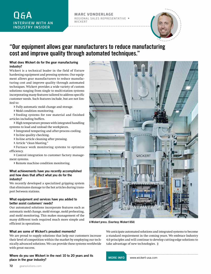
72 gearsolutions.com
What does Wickert do for the gear manufacturing industry?Wickert is a technical leader in the field of fixture hardening equipment and pressing systems. Our equip-ment allows gear manufacturers to reduce manufac-turing cost and improve quality through automated techniques. Wickert provides a wide variety of custom solutions ranging from single to multi-station systems incorporating many features tailored to address specific customer needs. Such features include, but are not lim-ited to:
�� Fully automatic mold change and storage.��Mold condition monitoring.�� Feeding systems for raw material and finished
articles including buffers.��High temperature presses with integrated handling
systems to load and unload the workpieces.�� Integrated tempering and after-process cooling.�� In-line quality checking.�� In-line article cleaning after pressing.�� Article “clean blasting.”�� Furnace work monitoring systems to optimize
efficiency.�� Control integration to customer factory manage-
ment systems.�� Remote machine condition monitoring.
What achievements have you recently accomplished and how does that affect what you do for the industry?We recently developed a specialized gripping system that eliminates damage to the hot articles during trans-port between stations.
What equipment and services have you added to better assist customers’ needs?Our automated solutions incorporate features such as automatic mold change, mold storage, mold preheating, and mold monitoring. This makes management of the many different tools required much more simple and efficient in operations.
What are some of Wickert’s proudest moments?We are proud to supply solutions that help our customers increase their level of competition within the market by employing our tech-nically advanced solutions. We can provide these systems worldwide with great success.
Where do you see Wickert in the next 10 to 20 years and its place in the gear industry?
We anticipate automated solutions and integrated systems to become a standard requirement in the coming years. We embrace Industry 4.0 principles and will continue to develop cutting-edge solutions to take advantage of new technologies.
MORE INFO www.wickert-usa.com
Q&AINTERVIEW WITH AN INDUSTRY INSIDER
MARC VONDERLAGEREGIONAL SALES REPRESENTATIVE WICKERT
“Our equipment allows gear manufacturers to reduce manufacturing cost and improve quality through automated techniques.”
A Wickert press. (Courtesy: Wickert USA)

We know high quality gears and components are vital to performance. Our leading edge vacuum technology and expertise provides precise control and repeatability for consistently superior parts.
. . .because quality is critical
• Low Pressure Vacuum Carburizing (LPVC)• High Pressure Gas Quenching (HPGQ)• Vacuum Stress Relieving
• Uniformity of case depths• Minimized distortion• No IGO (Intergranular Oxidation)• Parts returned clean, free of soot – eliminating
downstream cleaning processes
Advantages
For more information or a quote, call 1-855-WE-HEAT-ITor visit solaratm.com
Nadcap Accredited for Nondestructive Testing at our Hermitage, PA facility only.
VACUUM PROCESSING Heat Treating • Brazing • Carburizing • NitridingEastern PA Western PA
California South Carolina
Vacuum Heat Treating Services
SA GearSol Mil-Helo FPg.indd 1 3/12/2018 10:45:23 AM

Maximize Production and Profits With Mitsubishi’s Fast and Accurate ZE Series Generative Grinding Machines. When you improve productivity you reduce costs. With that in mind Mitsubishi developed its ZE Series of generative gear grinders. It’s simply more efficient with automatic part loading and grinding and polishing with one setup. To learn how you can leverage all the possibilities of Mass Production, visit www.mitsubishigearcenter.com or contact sales at 248-669-6136.
Our Technologies, Your Tomorrow
ZE24BLEGENDARY RELIABILITY
The Powerof Mass
Production
VISIT US AT BOOTH N-237036