Embed Size (px)
Citation preview
ISSN 1345-3041
Environmental Technology Edition
VOL. 96/DEC. 2001

● Vol. 96/December 2001 Mitsubishi Electric ADVANCE
A Quarterly Survey of New Products, Systems, and Technology
R & D PROGRESS REPORTSEnvironmental Technologies for Sustainable Development ............. 1by Susumu Hoshinouchi
A Review of R&D in Environmental Issues ....................................... 2by Fumiaki Baba
Technology for Recycling Plastic Materials ...................................... 6by Osamu Murakami
Photoresist Removal for LCD Production Using High OzoneConcentrations ................................................................................. 10by Hideo Horibe and Seiji Noda
Ground-Water Purification by the Ozone-HydrogenPeroxide Method ............................................................................... 14by Seiji Furukawa and Nozomu Yasunaga
TECHNICAL REPORTSEnvironmentally Friendly Product Strategies .................................. 17by Tetsuya Takahashi, Atsuhiro Yabu and Yasuto Iseki
Design-for-Recycling of Household AppliancesUsing a Simple Design-for-Disassembly Method ............................ 22by Hideaki Nagatomo
Approaches to Design for theEnvironment with Practical Examples ............................................. 25by Toshiro Oyama and Etsuko Hirose
NEW TECHNOLOGIES A Novel Fabrication Process for PolycrystallineSilicon Solar Cells ............................................................................. 28
Integrated Environmental Information Systems ............................. 28
CONTENTS
Mitsubishi Electric Advance is published online quarterly (in March, June, September,and December) by Mitsubishi ElectricCorporation.Copyright © 2001 by Mitsubishi ElectricCorporation; all rights reserved.Printed in Japan.
Cover StoryOur cover features the symbol mark for theenvironmental activities of the MitsubishiElectric Group that was created in 1993. Ituses the leaf to represent nature within theenvironment of the world.
Kiyoshi Ide
Haruki NakamuraKoji KuwaharaKeizo HamaKatsuto NakajimaMasao HatayaHiroshi MuramatsuMasaki YasufukuMasatoshi ArakiHiroaki KawachiHiroshi YamakiTakao YoshiharaOsamu MatsumotoKazuharu Nishitani
Takashi Yoshida
Keizo HamaCorporate Total Productivity Management& Environmental ProgramsMitsubishi Electric Corporation2-2-3 MarunouchiChiyoda-ku, Tokyo 100-8310, JapanFax 03-3218-2465
Yasuhiko KaseGlobal Strategic Planning Dept.Corporate Marketing GroupMitsubishi Electric Corporation2-2-3 MarunouchiChiyoda-ku, Tokyo 100-8310, JapanFax 03-3218-3455
Editor-in-Chief
Editorial Advisors
Vol. 96 Feature Articles Editor
Editorial Inquiries
Product Inquiries
Environmental Technology Edition

· 1Decenber 2001
TECHNICAL REPORTS
*Susumu Hoshinouchi is with the Corporate Environmental Management Planning Department.
OverviewEnvironmental Technologies for Sustainable Development
by Susumu Hoshinouchi*
The century of the environment has dawned. In Japan, the newcentury began with enactment of the Basic Law for Establishingthe Recycling-Based Society and the Law for Promotion of Effec-tive Utilization of Resources. These represent policies intended tolead to an environmentally responsible society and express the in-ternational concern for sustainable development. As such, theynecessarily involve us in the major reforms required to create anew social system.
Enterprises, too, must undergo a process of renewal that willchange corporate frameworks and processes into forms compat-ible with the environment in the recycling-based society. This willrequire not only the consistent implementation of new basic envi-ronmental technologies but also revolutionary reforms and ad-vances. Here, we recognize the need to go beyond the conventionalapproach of making piecemeal improvements to each of the indi-vidual processes involved, and to adopt instead a holistic, integratedor systematic approach. Mitsubishi Electric uses the acronym METas a keyword in its efforts to develop comprehensive environmen-tal technologies, adopting a two-pronged approach embracing bothproducts and manufacturing processes. MET stands for materials(the effective use of material resources), energy (the efficient useof energy resources) and toxicity (eliminating the threat posed tothe environment by toxic substances).
In the first year of the new century, the Mitsubishi ElectricGroup’s corporate statement is “Changes for the Better.” Thegroup’s commitment is to exploit its outstanding technologies andcreative strengths to make a wonderful future. ❑

R & D P R O G R E S S R E P O R T
Mitsubishi Electric ADVANCE2 ·
Sustainable development is essential for therecycling-based society of the 21st century, inwhich resource and energy conservation are carriedout on an unprecedented scale. The MitsubishiElectric Corporation is conducting research anddevelopment in the four areas of environmentalcreation, environmental support, environmentalharmony and recycling, aimed at “co-creating” [1]
the recycling-based society at the heart of thecompany’s environmental philosophy. Highlightsof these R&D activities are introduced here.
Environmental CreationPromoting energy saving and introducing cleanenergy are important ways of reducing so-calledgreenhouse-gas emissions in order to preventglobal warming. At COP3, the conference onglobal warming held in Kyoto in December 1997,Japan made an international commitment toreduce carbon dioxide emissions by the year 2010to six percent below 1990 levels. Systems thatgenerate electrical power from new energysources and energy load-leveling systems holdout the promise of providing stable energy sup-plies while they protect the environment. Clean-energy fuel cells, using hydrogen fuel andproducing no harmful waste material, along withpower-storage systems using rechargeablebatteries that charge and discharge with highefficiency, will be important as decentralizedpower supplies, and are the object of intensiveR&D by Mitsubishi Electric. The use of thesedecentralized power supplies will have a majoreffect on reducing carbon dioxide emissions byimproving the efficiency of electric power gen-eration and transmission. Batteries for powerstorage use make it possible to implementdemand-side management, investing in powergenerating facilities based on average demand,and operating the facilities at fixed output levelsregardless of load fluctuations.
*Fumiaki Baba is with the Advanced Technology R&D Center.
by Fumiaki Baba*
A Review of R&Din EnvironmentalIssues
Fuel cells have great potential as decentral-ized power supplies serving the local commu-nity, as household power supplies, and forpowering electrical automobiles. Among themost promising of these are polymer electrolytefuel cells (PEFC), which are well on the way toachieving practical applicability for use in smallbuildings, homes, and electric vehicles. In fiscal1996, the corporation began development of a10kW portable generator fueled by methanol, andin 2000 produced a prototype 10kW portablegeneration system and tested it in automobiles.As a household PEFC the company developedan original 1kW fuel cell with natural gasreformer. This is now in test operation inpreparation for a practical household PEFCsystem (see Fig. 1).
In the area of rechargeable batteries, MitsubishiElectric is developing batteries for use on themove, targeted specifically at electric vehicles.R&D is aimed at developing the key coretechnologies to achieving practical use of large-scale lithium-ion batteries, including improvedsafety, new electrode materials, and at simulat-ing battery characteristics. Already, a 3kWhmodule has been developed with energy densityof 140Wh/kg and power density of 770W/kg.
In R&D aimed at energy saving, MitsubishiElectric is carrying out comprehensive deve-lopment of new materials applications, invertertechnology, sensing and control technology, reduc-ing standby power use, high-efficiency motors andother core technologies. The goal is to develop totalenergy-saving systems.
Environmental Support (environmentaltechnology for the 21st century)Public infrastructure systems and productionsystems in the 21st century are destined fortransformation to a recycling-based society andzero emissions, as illustrated in Fig. 2.Environmental R&D at Mitsubishi Electric is fo-cusing on technologies that will make possiblea new kind of society, one that is able to supportan abundant and convenient lifestyle whilepreserving the environment, as well as technolo-gies for building zero-emission clean factoriesin harmony with the environment.
An important theme for the 21st century ishow to maintain a sound water environment.Taking advantage of the strong oxidizing powerof ozone, the corporation’s researchers aredeveloping technologies and equipment for gen-erating high concentrations of ozone to removetoxins, odors and coloration from water andwastewater and to break down endocrinedisrupters into harmless substances. Using hy-drogen peroxide in addition to ozone, they are

R & D P R O G R E S S R E P O R T
· 3December 2001
also developing ways of promoting oxidation todecompose harmful substances that havehitherto resisted breakdown. This technology isapplicable to water recycling systems thatremove organic substances from wastewater.
The problem of eutrophication, caused by ni-trogen and phosphorus in wastewater treatmentplants, is being tackled by developing highly
Fig. 1 Installation of a home PEFC power supply
Fig. 2 Recycling-based society of the 21st century
accurate techniques for monitoring ammoniaand phosphate levels. The corporation has alsodeveloped algorithms that are able to calculatecontrol settings precisely, using neural net-works, to implement systems that operate onthe minimum necessary energy. To combat airpollution, our researchers are developingtechnology that makes use of nitrogen radicals
PRODUCTION
USE,CONSUMPTION
CIRCULATION
PROCESS
NATURE,EARTH
ResourcesEnergy
Product
Waste waterGarbage
CO2H2O
VeinArtery
Reuse
Recycle
ResourcesEnergy
Establishing the recycling-based society
Creating metabolizing and recirculating urban systemsTransforming from mass production and over-consumptionConstructing urban veins to avoid environmental problemsRestructuring the arterial lines corresponding to the veins.
Hot Water Heating
Hot w
ater tank
P
E
F
C
City gas
Commercial electricpower line
ElectricPower
After
Burner

R & D P R O G R E S S R E P O R T
Mitsubishi Electric ADVANCE4 ·
to break down concentrated oxides of nitrogeninto nitrogen and oxygen.
Environmental HarmonyA major part of creating a recycling-based so-ciety consists of developing products specificallywith environmental and resource conservationin mind. The Mitsubishi Electric Group iscarrying out environmental planning, settingtargets for environmental activities on the basictheme of MET (Material: using resources effec-tively; Energy: using energy efficiently; Toxic:preventing pollution due to the release ofharmful materials). To realize zero-emissionfactories, on-going R&D is being directed atachieving loss-free and waste-free manufacturingprocesses.
In semiconductor production, processes suchas washing, photoresist removal, developmentand surface improving typically involve the useof strong chemicals such as organic solvents,concentrated acids and highly alkaline solutions.Some processes today also use substances suchas fluorides and heavy metal aqueous solutions,which impose a heavy burden on the environ-ment.
The corporation has developed a system thatuses ozone water in place of toxic substancesin processes that require chemical solutions,and has applied this technology to equipmentthat removes photoresist from liquid crystal dis-play elements, expanding environmentallyfriendly wet processes in the semiconductorindustry. In addition to resist removal, ozonewater is applicable to processes like thoseshown in Fig. 3, replacing harmful chemicalsnow used to wash high-precision parts or forsurface improvement, etc.
Semiconductor manufacturing processes alsomake heavy use of perfluorocarbons (PFCs) suchas CF4 and C2F6. Mitsubishi Electric is developingequipment that uses high-pressure plasma to breakdown PFCs into hydrofluoric acid (recoverable) and
CO2 in order to protect the ozone layer from furtherdestruction by these substances.
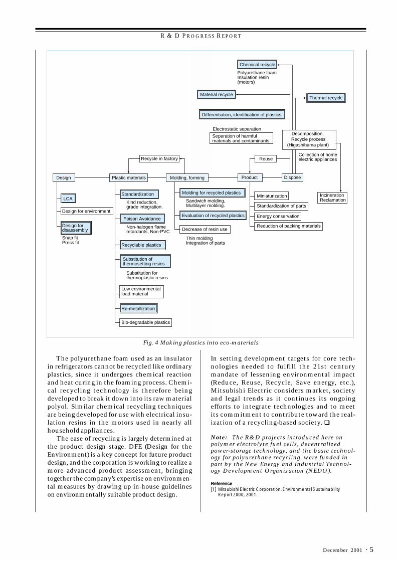
Fig. 4 shows how Mitsubishi Electric is work-ing to make plastics into eco-materials. Apply-ing life cycle assessment (LCA), the corporationis obtaining quantitative measurements of en-vironmental impact throughout the life cycle ofproducts, from manufacturing through transpor-tation, use and disposal, and is promotingactivities to minimize this impact over the entirelife cycle.
Since the corporation’s electrical products areused all over the world, they must conform toregulations on toxic substances not just in Japanbut also in each country where they are sold.
Alternative technologies are being developedto reduce the use of lead and other heavy met-als and of halogen flame retardants. In order toavoid toxicity, it is important to be able to ana-lyze very small trace amounts. The corporationis developing technologies that will makepossible ultra-trace analysis, at sensitivitieshigher than those required for analyzing veryminute amounts. To this end, the concentrationtechniques and contamination-free analysistechniques used in clean rooms are being applied.
RecyclingA new law mandating the recycling of specifiedhome appliances took effect in Japan in April2001. It requires the recycling (removing partsand materials and reusing) of refrigerators, airconditioners, TVs and washing machines.Mitsubishi Electric is currently recyclingmaterials such as metal and glass, for whichrecycling technology has already been es-tablished. As the regulations become stricter inthe future, the law is expected to apply to a widerrange of products and to require a higherrecycling ratio. This means it is important todevelop technologies for recycling the plasticmaterials used so widely in home appliances,especially general-purpose plastics such aspolypropylene, high-impact polystyrene, and ABSresin (acrylonitrile-butadiene styrene ter-poly-mer).
Even with the most careful selection of re-cycled materials, however, it is difficult to avoidthe presence of small amounts of contaminants.Mitsubishi Electric is carrying out developmentalong two main fronts to counter this problem.One is in the area of materials improvementthrough compounding, such as by mixing in newmaterial to offset the expected effects ofcontaminants, or by adding impact modifiers. Theother is the development of sandwich moldingtechniques, using new material for the skin layerand recycled materials as the core.
LCD substratecleaning
Application areafor ozone water
Removing resist
Semiconductorwafer cleaning
Removing oil fromprecision parts
Improving surfaces
Printed wiring board cleaning
Surface oxidationof Si wafer
Fig. 3 Applications of ozone water
R & D P R O G R E S S R E P O R T
· 5December 2001
The polyurethane foam used as an insulatorin refrigerators cannot be recycled like ordinaryplastics, since it undergoes chemical reactionand heat curing in the foaming process. Chemi-cal recycling technology is therefore beingdeveloped to break it down into its raw materialpolyol. Similar chemical recycling techniquesare being developed for use with electrical insu-lation resins in the motors used in nearly allhousehold appliances. The ease of recycling is largely determined atthe product design stage. DFE (Design for theEnvironment) is a key concept for future productdesign, and the corporation is working to realize amore advanced product assessment, bringingtogether the company’s expertise on environmen-tal measures by drawing up in-house guidelineson environmentally suitable product design.
Fig. 4 Making plastics into eco-materials
In setting development targets for core tech-nologies needed to fulfill the 21st centurymandate of lessening environmental impact(Reduce, Reuse, Recycle, Save energy, etc.),Mitsubishi Electric considers market, societyand legal trends as it continues its ongoingefforts to integrate technologies and to meetits commitment to contribute toward the real-ization of a recycling-based society. ❑
Note: The R&D projects introduced here onpolymer electrolyte fuel cells, decentralizedpower-storage technology, and the basic technol-ogy for polyurethane recycling, were funded inpart by the New Energy and Industrial Technol-ogy Development Organization (NEDO).
Reference[1] Mitsubishi Electric Corporation, Environmental Sustainability
Report 2000, 2001.
Plastic materials
Bio-degradable plastics
Kind reduction, grade integration.
Low environmental load material
Poison Avoidance
Non-halogen flame retardants, Non-PVC
Recyclable plastics
Substitution of thermosetting resins
Substitution for thermoplastic resins
Molding, forming
Evaluation of recycled plastics
Decrease of resin use
Molding for recycled plastics
Thin molding Integration of parts
Product
Miniaturization
Standardization of parts
Energy conservation
Reduction of packing materials
Recycle in factory
Material recycle
Differentiation, identification of plastics
Chemical recycle
Polyurethane foam Insulation resin (motors)
Decomposition, Recycle process
(Higashihama plant)
Re-metallization
Standardization
Separation of harmful materials and contaminants
Reuse
Sandwich molding, Multilayer molding.
Electrostatic separation
Design
LCA
Design for environment
Design for disassembly
Snap fitPress fit
IncinerationReclamation
Collection of home electric appliances
Thermal recycle
Dispose

R & D P R O G R E S S R E P O R T
Mitsubishi Electric ADVANCE6 ·
A sandwich injection-molding processstacking new and recycled materials is beingdeveloped in order to establish plastic materialrecycling technology. The thicker the core ofthe “sandwich,” made of recycled material, thelarger the amount of recycled material that canbe used with this method. A key to success iscontrolling the viscosity of the new and recycledmaterial in the molding process.
Difficulties with Recycling PlasticsMethods of recycling plastic, summarized inTable 1, can be classified broadly into materialsrecycling, chemical recycling, thermal recycling,or feedstock recycling. Thermal and feedstockrecycling are consumptive processes (i.e., theyturn the recycled material into energy ratherthan into usable materials), and thus do notconform to the reuse-ratio requirement of theJapanese law on recycling appliances. Materialsrecycling and chemical recycling, on the otherhand, are closer to the ideal in that they producematerials that can be reused. Of the two,materials recycling is especially effectivebecause it uses less energy and has a smallerenvironmental impact than chemical recycling.
The issues affecting increases in the amountof recycled material used are the properties ofthe recycled material, the presence of contami-nants, the properties of mixed waste plastics,and process development.
The appliances to which the present recyclinglaw applies have the material composition shownin Fig. 1, while Fig. 2 shows their typical plasticmaterials composition. Refrigerators and washingmachines tend to use a high percentage of plasticmaterials, over 20 percent of the total composition.By type of plastic used, washing machines usepolypropylene (PP), air conditioners use PP andpolystyrene (PS), and TVs use PS and PVC (polyvi-nyl chloride). Refrigerators use more different types
*Osamu Murakami is with the Advanced Technology R&D Center
by Osamu Murakami*
Technology forRecycling PlasticMaterials
0
20
40
60
80
100
Refrig
erat
or
Was
hing
mac
hine
Air co
nditio
ner
Televis
ion
Wei
ght(
%)
OthersCircuit boardPlasticGlassAluminumCopperSteel
Fig. 1 Material composition of home electricalappliances
05
10
15202530
3540
Refrig
erat
or
Was
hing
mac
hine
Air co
nditio
ner
Televis
ion
Wei
ght (
%)
PolyurethanePolyvinyl chloride
PolystyrenePolyethylenePolypropylene
ABS
Fig. 2 Plastic materials composition of homeelectrical applicances
of plastics than other appliances, including PS,acrylonitrile butadiene styrene (ABS) resins, andPVC in addition to polyurethane foam. The lastmakes up around half of the plastic used inrefrigerators but is not suitable for materialsrecycling, making it important to achieve a highdegree of accuracy in disassembling refrigeratorsand separating their materials. A chemicalrecycling method that can reduce polyurethanefoam to its raw material is being developed incooperation with materials manufacturers.
sdohtemgnilcyceR noitpircseD
gnilcycerslairetaM warehtsacitsalpdedracsidgnisU.sgnidlomwenroflairetam
gnilcycerlamrehT dnacitsalpetsawgninruB.ygrenelamrehtehtgnirevocer
gnilcycerkcotsdeeFcitsalpetsawnwodgnikaerB
saesurofyllacimehcroyllamreht.cte,tnatcuderecanruftsalb
gnilcycerlacimehCcitsalpetsawnwodgnikaerB
saesurofyllacimehcroyllamreht.slairetamwarlacimehcortep
Table 1 Recycling Methods for Waste Plastics

R & D P R O G R E S S R E P O R T
· 7December 2001
Table 2 compares the mechanical propertiesof injection-molded parts, made of recycledmaterial recovered from an electrical appliancedisposed of after actual use in a household anddisassembled, separated, washed and pulverized,with those of similar parts made of all-newmaterials. The mechanical strength of the partsmade from recycled material, with the excep-tion of impact-absorption energy, is not muchbelow that of the new materials and undergoeslittle deterioration with time.
The polystyrene recovered from an air condi-tioner is contaminated by printing over its entiresurface, and has only around a tenth of theimpact absorption energy of its new counterpart.Many of the recycled plastics used up to nowhave been waste materials discarded by thefactory as leftovers, etc., from the molding pro-cess, which are clean and of a uniform qualitygrade. In contrast, the poorer impact strength ofrecycled materials recovered from actual pulver-ized household appliances is due not so muchto any degradation of the materials themselvesas to the presence of contaminants.
An effective way of improving the quality ofrecycled materials contaminated by otheradmixtured materials is by compounding themwith new materials. Fig. 3 shows the change inimpact strength when polystyrene with printedmaterial on it from a room air conditioner is com-pounded with new material. If the percentageof recycled material in the mix is no more than30 percent, degradation of impact strengthceases to be a problem.
Because of the different types of plastic usedin household appliances, techniques for accu-rately separating the different materials recov-ered from appliances are important. It will besome time, however, before such technologybecomes practical. In the meantime, ways of re-cycling various plastic mixtures are needed. Thecompatibility of different mixtures of plastics is
htgnertselisneT)aPM(
gnidneB)aPM(htgnerts
gnidneB)aPG(suludom
tcapmInoitprosba)J(ygrene
renoitidnocriA enerytsyloP
lairetamelcyceR)detnirP(
8.23 7.27 47.2 3.0
weNlairetam
9.03 8.46 45.2 8.3
rotaregirfeR enelyporpyloP
elcyceRlairetam
8.72 3.84 90.2 2.41
weNlairetam
8.72 1.74 50.2 3.61
noisiveleT enerytsyloP
elcyceRlairetam
6.62 6.85 64.2 5.4
weNlairetam
6.42 0.15 73.2 6.4
0
1
2
3
4
0 20 40 60 80 100
Content of recycled plastics (%)
Impa
ct a
bsor
ptio
n en
ergy
(J)
Fig. 3 Impact strength of injection moldings madefrom new polystyrene mixed with recycledpolystyrene (recovered from air conditionerand including printing materials)
shown in Table 3, where it is clear that somecombinations are quite incompatible. In Fig. 4,different ratios of ABS resin and polystyrene inrecycled material recovered and processed at therecycling plant of Green Cycle Systems Cor-poration vary in impact strength as shown.
When just five percent polystyrene is mixedwith ABS, whether in recycled or new material,the impact strength drops to one half; and at a
PP SP SBA CVPPP O O X XSP O O X XSBA X X O OCVP X X O O
Ο: Good compatibility, X: Poor compatibility
Table 3 Compatibility of Plastics
level of 10 percent the strength degrades sharplyto one tenth that of the original. A transmissionelectron microscopy (TEM) photomicrograph ofa cross-section of this material (10% PS) in Fig. 5
Table 2 Mechanical Properties of Waste Plastics

R & D P R O G R E S S R E P O R T
Mitsubishi Electric ADVANCE8 ·
shows that the ABS and PS completely fail toblend, with the PS itself acting as a contaminantand causing cracks to appear between the ABSand PS layers that result in poor impact strength.
molding materials with different properties. Itenvelops the recycled material in new material,forming a three-layer structure consisting of skin(new)/core (recycled)/skin (new) as in Fig. 6.Since the skin of new material completelyencapsulates the recycled material, the estheticproblems caused by contaminating materials ordirt and discoloration are solved.
0
2
4
6
8
10
12
0 20 40 60 80 100
Content of PS in the mixture injection moldings of ABS and PSWeight (%)
Impa
ct a
bsor
ptio
n en
ergy
(J)
Recycled materials
New materials
Fig. 4 Polystyrene content of mixed injectionmoldings made of ABS resin andpolystyrene
1µm
P S phase
A B S phase
Fig. 5 Cross-sectional TEM photo of ABS 90wt%/PS 10wt% mixed injection molding
Technology for Recycling Plastic WasteMaterials
A SANDWICH INJECTION-MOLDING PROCESSUSING WASTE PLASTIC. Materials modificationis one approach to expanding the use of recycledmaterials, but also important is process devel-opment. One promising method of the latter typeis multi-layering. Sandwich injection molding isa multi-layering technique applied to one of themost common ways of producing plastic parts,injection molding.
Sandwich injection molding forms a multi-layer structure by simultaneously injection
Skin materials(New materials)
Core materials(Recycled materials)
Fig. 6 Cross-sectional schematic drawing ofsandwich molding
An example of the molding process is shownin Fig. 7. Using an injection-molding machinewith two cylinders converging within one nozzle,first the skin material, then the core materialand finally once again the skin material areinjected into the mold cavity in rapid successionto form the three layers.
Recycled materials(core)
New materials (skin)
1. Injection of new materials
3. Injection of new materials
2. Injection of recycled materials
Fig. 7 Process of sandwich injection molding
To increase the amount of recycled materialused, it is important that the core be made thickand constitute as large a percentage of the totalas practical. At the same time, application toelectrical products requires a thin sandwichstructure with a plate thickness of around 2mm.The layer structure of sandwich-molded partsdepends on several factors, including thematerial properties, the molding conditions, andthe shape of the part.
The biggest factor affecting the amount of corematerial content is the viscosity of the core andskin materials. Fig. 8 shows the relation betweenthe thickness and content of the core material

R & D P R O G R E S S R E P O R T
· 9December 2001
and the viscosity ratio of the skin and core ma-terials (skin material viscosity/core materialviscosity). By controlling this factor so that theskin material viscosity is lower than the corematerial viscosity, the core layer can be madethick and the skin layer thin, with a corematerial content of 40 percent or more.
MATERIAL MODIFICATION TECHNOLOGY. By us-ing a functional material as the skin layer withthe sandwich injection-molding method, moldedplastic parts using recycled material can beproduced with high added value. For example,using a recycled material combining ABS andPS with relatively poor impact strength as thecore, with a new ABS material with high im-pact strength as the skin layer, the resulting parthas much higher impact strength as well as amore pleasing appearance than an ordinarymolded part using only recycled material. Impactstrength can be improved even further by theuse of an additive designed to raise the impactstrength of compound recycled materials (seeFig. 9).
0
10
20
30
40
50
60
70
80
0 1 2 3 4
Viscosity ratio between the skin and core materials
Thi
ckne
ss fr
actio
n of
the
core
laye
r (%
)
0
10
20
30
40
50
60
70
80
Con
tent
of t
he c
ore
mat
eria
ls (
%)
0
1
2
3
45
6
7
8
9
Nonadditive
Nonadditive
Additive A Additive B
Impa
ct a
bsor
ptio
n en
ergy
(J) Sandwich injection moldingsNormal
injectionmoldings
(10wt%) (10wt%)
180175
B
A
Unit:mm
A
B
Fig. 8 Relationship between the thickness andcontent of the core materials and viscosityratio (difference of viscosity between skinand core materials)
Fig. 10 shows a prototype sandwich injectionmolding 2mm thick, and a close-up cross-sec-tional photo of the layers. The core layer in-cludes complex portions of the object as well asthe corner areas and makes up more than 60percent of the thickness.
Fig. 9 Impact stength of injection moldingscontaining additives
The remaining issues to be resolved for practi-cal implementation of this technology arereductions in the product cost and obtaining astable supply of recycled materials. ❑
Fig. 10 Sandwich injection molding using recycledmaterials for the core (appearance andcross-section view)

R & D P R O G R E S S R E P O R T
Mitsubishi Electric ADVANCE10 ·
*Hideo Horibe and Seiji Noda are with Advanced Technology R&D Center.
PhotoresistRemoval for LCDProduction UsingHigh OzoneConcentrations
by Hideo Horibe & Seiji Noda
We have developed photoresist removalequipment that uses high concentrations ofozone and controls the amount of water sup-plied with the ozone to achieve a removal rateapproximately an order of magnitude faster thanwith conventional ozone-based technology. En-vironmental impact is reduced to less than onetenth, and running costs to less than one fifth ofthe conventional methods that use costly chemi-cal solvents harmful to the environment. Theozone water also cleans the substrate, eliminat-ing the need for a separate substrate washingprocess and reducing the equipment footprintby half.
Cost and Environmental Issues with CurrentPhotoresist Removal TechnologiesThe removal of photoresist material from sub-strates in the semiconductor manufacturingprocess conventionally makes use of single-substrate oxygen plasma ashing[1] or a batchprocess using sulfuric acid/hydrogen peroxide/deionized water (SPM). In LCD production, thesubstrate size is larger than that in semicon-ductor manufacturing and too large for uniformresist removal to be achieved with ashing,making it necessary to use chemical stripping.A chemical solvent commonly used for LCDresist removal is called solution 106 (mono-ethanol amine + dimethyl sulfoxide).[2] The mainissues here are the amount of resist removalliquid used and the removal of resist that hasgone through the dry etching process. The firstof these is a major issue not only because of thehigh running cost of using expensive chemicalsbut also from the standpoint of working-environment safety. The second issue is ofgrowing importance now that facilities using
RIE (reactive ion etching) as the dry etchingmethod are on the increase. RIE causes the resistsurface to become less malleable, requiring somemeans of making the resist more easilyremovable. Using ozone water instead of chemical sol-vents for resist removal has the advantage ofreducing environmental impact as well as theamount of water necessary for chemical wash-ing.[3] Using a high ozone concentration at orbelow a processing temperature of 100°C, aremoval rate of 0.1µm/minute is achieved.[3] Byfurther rotating the processed substrate at highspeed (250 to 1,000 rpm), the dispersion rate ofthe ozone (in water) supplied to the substrate isimproved, further doubling the removal rate.[4]
This is still not fast enough, however, to meetthe throughput needs of today’s LCD productionlines. Moreover, the large size of the LCDsubstrate requires a special mechanism for high-speed rotation, adding to the complexity of theequipment structure.
Development of a Photoresist RemovalMethod Using Moist Ozone Gas
CONDITIONS FOR EVALUATING RESIST REMOVALBY MOIST OZONE GAS. Our research team builtprototype resist removal equipment that trans-ports single LCD substrates and we studied itsperformance. We used two samples for the tests,one consisting of cresol novolac positivephotoresist applied to the entire surface of a glasssubstrate (520 by 410mm) at an initial thicknessof 1.45µm, and the other an actual devicesubstrate (with an initial thickness of 1.2µm andcoating ratio of around three percent).
The resist removal equipment (7,000 by 1,500by 1,800mm high) consists of a loader section,hot-air chamber, ozone-processing section,rinsing and drying section, and unloading sec-tion. The substrate is fed in at the loader endand heated in the hot-air chamber to the re-quired temperature. In the ozone-processingsection, ozone gas moisturized by steam flowsonto the resist on the substrate. In the rinsingsection, the resist is removed by a hot-watershower (50°C) and then air-dried. After thisseries of processes had been repeated severaltimes, the resist film thickness was measuredat between three and six places on the substratesurface with a contact-type surface profiler(Dektak 3030) to determine the resist removalrate. The transport speed of the substrate wascontrolled at 1.5m/minute, and the substratewas kept in the ozone-processing section for aperiod of one minute.
R & D P R O G R E S S R E P O R T
· 11December 2001
1.4
1.2
1
0.8
0.6
0.4
0.2
040 1 2 3
Res
ist t
hick
ness
(µm
)
Ozone processing time (min)
Avge. resist removal rate 0.47µm/min
Fig. 1 Relationship of resist thickness to ozoneprocessing time with initial thickness ofthe resist 1.45µm, substrate temperature53.5°C, ozone concentration 230g/m 3, andozone flow rate 12.5 liters/min.
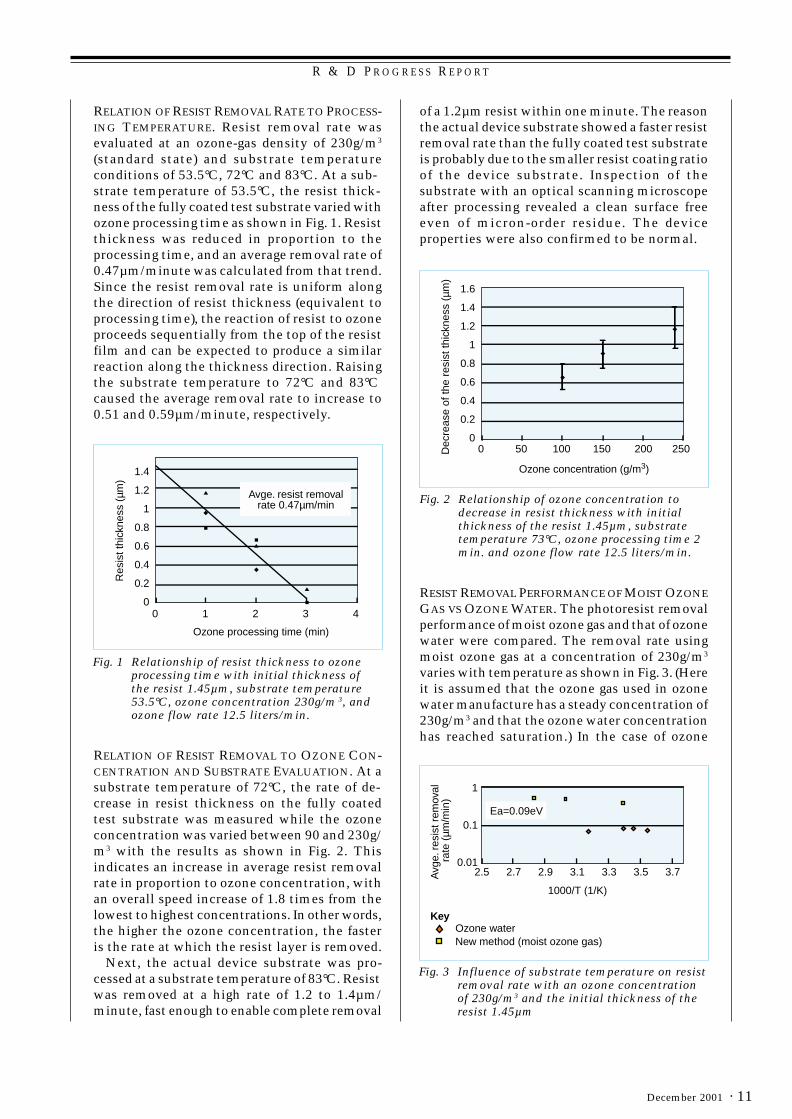
RELATION OF RESIST REMOVAL RATE TO PROCESS-ING TEMPERATURE. Resist removal rate wasevaluated at an ozone-gas density of 230g/m3
(standard state) and substrate temperatureconditions of 53.5°C, 72°C and 83°C. At a sub-strate temperature of 53.5°C, the resist thick-ness of the fully coated test substrate varied withozone processing time as shown in Fig. 1. Resistthickness was reduced in proportion to theprocessing time, and an average removal rate of0.47µm/minute was calculated from that trend.Since the resist removal rate is uniform alongthe direction of resist thickness (equivalent toprocessing time), the reaction of resist to ozoneproceeds sequentially from the top of the resistfilm and can be expected to produce a similarreaction along the thickness direction. Raisingthe substrate temperature to 72°C and 83°Ccaused the average removal rate to increase to0.51 and 0.59µm/minute, respectively.
of a 1.2µm resist within one minute. The reasonthe actual device substrate showed a faster resistremoval rate than the fully coated test substrateis probably due to the smaller resist coating ratioof the device substrate. Inspection of thesubstrate with an optical scanning microscopeafter processing revealed a clean surface freeeven of micron-order residue. The deviceproperties were also confirmed to be normal.
RELATION OF RESIST REMOVAL TO OZONE CON-CENTRATION AND SUBSTRATE EVALUATION. At asubstrate temperature of 72°C, the rate of de-crease in resist thickness on the fully coatedtest substrate was measured while the ozoneconcentration was varied between 90 and 230g/m3 with the results as shown in Fig. 2. Thisindicates an increase in average resist removalrate in proportion to ozone concentration, withan overall speed increase of 1.8 times from thelowest to highest concentrations. In other words,the higher the ozone concentration, the fasteris the rate at which the resist layer is removed.
Next, the actual device substrate was pro-cessed at a substrate temperature of 83°C. Resistwas removed at a high rate of 1.2 to 1.4µm/minute, fast enough to enable complete removal
1.6
1.4
1.2
1
0.8
0.6
0.4
0.2
02500 50 100 150Dec
reas
e of
the
resi
st th
ickn
ess
(µm
)
Ozone concentration (g/m3)
200
Fig. 2 Relationship of ozone concentration todecrease in resist thickness with initialthickness of the resist 1.45µm, substratetemperature 73°C, ozone processing time 2min. and ozone flow rate 12.5 liters/min.
RESIST REMOVAL PERFORMANCE OF MOIST OZONEGAS VS OZONE WATER. The photoresist removalperformance of moist ozone gas and that of ozonewater were compared. The removal rate usingmoist ozone gas at a concentration of 230g/m3
varies with temperature as shown in Fig. 3. (Hereit is assumed that the ozone gas used in ozonewater manufacture has a steady concentration of230g/m3 and that the ozone water concentrationhas reached saturation.) In the case of ozone
1
0.1
0.013.5 3.72.5 2.7 2.9 3.1A
vge.
res
ist r
emov
al
rate
(µm
/min
)
3.3
1000/T (1/K)
Ea=0.09eV
KeyOzone waterNew method (moist ozone gas)
Fig. 3 Influence of substrate temperature on resistremoval rate with an ozone concentrationof 230g/m3 and the initial thickness of theresist 1.45µm

R & D P R O G R E S S R E P O R T
Mitsubishi Electric ADVANCE12 ·
water, the reaction between ozone and resistincreases with a rise in temperature, but at thesame time the solubility of ozone gas in waterdecreases, causing the resist removal rate to peakat 0.1µm/minute. Using moist ozone gas, on theother hand, a speed more than four times that ofozone water is achieved. Moreover, based on theArrhenius activation law, the apparent activeenergy is approximately 0.09eV, with a loosedependency on temperature.
Normally ozone gas does not dissolve readilyin water (dispersion coefficient of 0.25 at roomtemperature) and disperses slowly in water (itsdispersion coefficient in liquid is approximately10-5 that in gas). The reason for the fast resistremoval rate by the moist ozone gas method isfirst of all that the ozone gas does not dissolvein water and is fed to the substrate without adrop in concentration. Second, the water contentof moist ozone gas is small and the rate of ozonegas dispersion on the substrate surface isrelatively fast. With ozone gas alone, on the otherhand, it has already been reported that near roomtemperature the oxidizing reaction of the resistdoes not progress and it is not broken down.[5]
Accordingly, water is required for oxidizationof the resist by ozone. In this moist ozone gasmethod, it was possible to raise the rate of resistremoval by supplying a small amount of wateralong with the ozone gas.[6]
Performance of the Resist RemovalEequipment
RUNNING COSTS. Around 80 percent of the run-ning cost of conventional equipment for remov-ing photoresist used in LCD production (for asubstrate size of 520 by 410mm) is the cost ofthe chemical solvents. The resist removalequipment developed in this project (Fig. 4) doesnot require expensive chemicals and thereforereduces the running cost to approximately onefifth that of conventional equipment (Fig. 5).Generating ozone from oxygen does incur newrunning costs for gas and electricity, but theseare much lower than the cost of the liquidchemicals used conventionally, resulting in asubstantial cost reduction overall.
ENVIRONMENTAL IMPACT. As an indicator of en-vironmental impact we looked at the total or-ganic carbon (TOC) content of waste liquid. Inthe case of resist removal using chemical sol-vents, potential sources of TOC are first, theresist removal chemicals, and second, the pho-toresist itself. Of these, the resist removalchemicals account for 93 percent of the TOC.
Since the newly developed equipment breaksdown the photoresist without using chemicalsolvents, the only source of TOC in the wasteliquid is the dissolved photoresist. Accordingly,the environmental impact is reduced to approxi-mately a tenth of that from conventional pro-cessing.
Fig. 5 Comparison of the running costs of ozoneand conventional processes
Waste liquid
Gas
Electric power
Chemicals
Conventional process Ozone process
Reduction to one fifth
EQUIPMENT FOOTPRINT. Resist removal usingchemical solvents tends to leave small amountsof organic residue on the substrate, requiringadditional equipment for washing and treatmentwith ultraviolet light (Fig. 6). Ozone has powerfuloxidizing ability, and ozonated water is arecognized substitute for SPM as an agent forremoving organic residues.[7] When ozone is usedfor resist removal in the moist ozone gas method,it has the same washing effectiveness as ozona-ted water, eliminating the need for separate
Fig. 4 Equipment using high-concentration ozonefor resist removal in LCD production

R & D P R O G R E S S R E P O R T
· 13December 2001
Conventional process
Loading Chemical resist removal Process water washing Drying Resist removal process
New process: Integration of substrate washing process with resist removal process
Loading Resist removal by ozone Drying Unloading
Substrate washing processUV Water washing Drying Unloading
Water washing
Fig. 6 Comparison of the conventional process with the newly developed process
washing equipment to clean the substrate afterprocessing. As a result, the equipment footprint isreduced by half.
In the future we plan to apply this technologynot only to the LCD production process but alsoto resist removal in semiconductor manufactur-ing and to the wafer-washing process. ❑
References1. S. Saito and M. Minato, “Ashing Equipment,” Semiconductor
World (Monthly), 64 (July 1993). [in Japanese]2. M. Ishibe and M. Takemori, “Development of equipment for single-
substrate resist removal,” Shimada Rika Giho, No. 11-12 (1999).[in Japanese]
3. I. Ohka et al., “Resist removal using high-concentration ozonewater,” Japan Ozone Association 8th annual research papers, 14(1999). [in Japanese]
4. N. Narayanswami and S. Nelson, “Dynamics of Mass Transfer on aWafer Surface in Ozonated Water Processing for Photo-resistRemoval,” UCPSS, 66 (1998).
5. M. Miyamoto et al., “Resist removal technique using high-concentration ozone gas: the ozone-resist reaction mechanism,”48th Conference of the Japan Society of Applied Physics, 29-D1(2001). [in Japanese]
6. S. Noda et al., “Resist removal technology and equipment usinghigh-concentration ozone gas,” Japan Ozone Association 10thannual research papers, 106 (2000). [in Japanese]
7. H. Kawana, Semiconductor World (Monthly), 76 (Oct. 1998). [inJapanese]

R & D P R O G R E S S R E P O R T
Mitsubishi Electric ADVANCE14 ·
*Seiji Furukawa and Nozomu Yasunaga are with the Advanced R&D Center, Environmental Technology and SystemsDepartment.
by Seiji Furukawa and NozomuYasunaga*
Ground-WaterPurification by theOzone-HydrogenPeroxide Method
Mitsubishi Electric Corporation has devel-oped a high-speed, highly-efficient reactor to in-stantaneously decompose organic chlorides inground water using the powerful oxidation effectof OH radicals generated from hydrogen peroxideand ozone. This article describes the results ofcomputer simulation analyses and of validationtests performed at a contaminated site andreports on the effectiveness of a ground-waterpurification device incorporating the reactor.
High-Speed/High-Efficiency Reactor for anOzone-Hydrogen Peroxide ProcessBecause trichloroethylene and cis-1,2-dichloro-ethylene and other organic chlorides are not onlyextremely toxic but are difficult to removebiologically, once these compounds have seepedinto ground water, the contamination enduresfor extended periods of time. Despite the ban ondischarging these substances into the groundthat has been in effect since 1989 in Japan,contamination of the order of one mg/L to tensof mg/L of these organic chlorides is still reportedevery year.
Until now, the process used to purify groundwater has been typically to aerate the groundwater and absorb the aerated organic chloridesusing activated carbon. However, in this methodnot only is it necessary to regenerate theactivated carbon after use, but the aerationprocess produces a great deal of noise, makingit less-than-ideal for a contaminated site.
The corporation has developed a high-speed,highly efficient reactor for instantaneouslydecomposing organic chlorides in ground waterusing the strong oxidizing effect of OH radicalsgenerated from hydrogen peroxide and ozone. Thisejector-type reactor, as shown in Fig. 1, generateslarge volumes of high-density OH radicals throughthe injection of ozone. This makes it possible to
decompose organic chlorides extremely quickly,in the order of seconds.
The mechanisms for generating and reactingthe OH radicals are extremely complex, and inthe series of reactions the OH radicals tend todecompose compounds other than those usefulin processing materials, such as ozone and otherradicals. The corporation is also engaged indeveloping new reactors that will reduce thiskind of inefficiency. [1]
Ozone Gas
H2O2
Organic ChloridesTreatedWater
CO2
H2O
Cl-
O3+H2O2 OH
(Generation of OH radical)Decompositionby OH radical
Fig. 1 Ejector-type reactor for the ozone-hydrogenperoxide method
Simulation Analysis of TrichloroethyleneDecompositionA computer simulation was used to investigate theoperating conditions that would decompose themaximum amount of trichloroethylene whilesuppressing, as much as possible, the amount thatis stripped. In the simulation, modeling assumedthat the trichloroethylene stripping process wasincorporated into the existing reaction model forthe ozone-hydrogen peroxide method previouslyreported.[2] The distribution coefficient establishedby V. Linek et al[3] was used. The transfer speedconstant from the liquid phase to the gas phasewas found experimentally using batch experi-ments based on oxygen stripping. Table 1 showsthe simulation conditions.
m/g(noitartnecnocsagenozO 3) 001~0
)nim/L(etarwolfsaG 4.0~10.0
)nim/L(etarwolfdiuqiL 4.0
)L/gm(enelyhteorolhcirtlaitinI 01
)L/gm(egasodedixorepnegordyH 5.2~52.1
)L(emulovrotcaeR 1
Table 1 Simulation Conditions

R & D P R O G R E S S R E P O R T
· 15December 2001
Fig. 2 shows the results of the simulations.Fig. 2 (a) shows the amount of trichloroethylenedecomposed, the amount of trichloroethylenestripped, and the concentration of the trichloro-ethylene in the processed water as a function ofthe ozone injection rate. The ratio of gas flow tofluid flow (G/L) was set at 0.5, and the ozoneinjection rate was varied by adjusting the ozoneconcentration.
We established that the amount of trichloro-ethylene decomposed could be increased, whilesuppressing the amount that was stripped, byincreasing the ozone injection rate. In particu-lar, with an ozone injection rate of 10mg/L (anozone concentration of 20g/m3), not only was thetrichloroethylene in the influent completelydecomposed but the amount stripped from theliquid phase to the gas phase was zero. In otherwords, even though the G/L ratio was large,increasing the concentration of the ozonesupplied made it possible to decompose thetrichloroethylene faster than it was stripped.
The implication of having to inject ozone at10mg/L in order to completely decomposetrichloroethylene at 10mg/L is that the trichlo-roethylene can be completely decomposed by theOH radicals as long as the ozone that is injectedhas at least the same concentration as thetrichloroethylene in the untreated water.
On the other hand, Fig. 2 (b) shows the resultsof simulations when the ozone injection rate washeld constant at 2.5mg/L and the G/L and suppliedozone concentration were varied. Here, thehorizontal axis shows the gas/liquid (G/L) ratio.
Note that lower G/L ratios correspond withhigher ozone concentrations and vice versa.
It is evident that when the ozone injection rateis small in comparison with the trichloro-ethylene concentration in the untreated water, in-creasing the G/L ratio only increased the amountof trichloroethylene that was stripped withoutincreasing the amount that was decomposed. Thisis because the rate at which trichloroethylene isstripped increases as the gas flow is increased,stripping any trichloroethylene not decomposed.From this, we conclude that the amount oftrichloroethylene decomposed can be increased,while suppressing the amount stripped, by usinghigh-concentration ozone with a low G/L ratio.
Validation Tests at a Contaminated SiteValidation tests were performed using purifica-tion equipment incorporating an ejector-stylereactor at a contaminated site. Three wells withdepths ranging between 3 and 18m were used todraw a total flow of 3m3/h of water, which wassupplied to the purification equipment. Table 2shows the main operating conditions.
m(etarwolfnI 3 )h/ 0.3
m/g(noitartnecnocsagenozO 3) 051
)nim/L(etarwolfsaG 4.0
)L/gm(etarnoitcejnienozO 02
)L/gm(egasodedixorepnegordyH 7.5
Table 2 Operating Conditions
0
2
4
6
8
10
0 2 4 6 8 10
0
1
2
3
4
5
6
0 0.5 1 1.5 2
(a) (b)
Tric
hlor
oeth
ylen
e [m
g/L]
Tric
hlor
oeth
ylen
e [m
g/L]
G/L: 0.5Initial concentration: 10mg/L
Ozone injection rate: 2.5mg/LInitial concentration: 10mg/L
Ozone injection rate [mg/L] G/L[-]
Decomposed Stripped Effluent
Fig. 2 Relationship between the amount of trichloroethylene decomposed and the amount stripped.

R & D P R O G R E S S R E P O R T
Mitsubishi Electric ADVANCE16 ·
Fig. 3 is a graph of the densities of cis-1,2-dichloroethylene and of trichloroethylene in thewater before and after treatment as a function oftime. Initially, the untreated water contained2.2mg/L of cis-1,2-dichloroethylene and 0.65mg/L of trichloroethylene; however, it was seen thatthese densities gradually declined during thepurification process. After five months, the cis-1,2-dichloroethylene was reduced to 0.79mg/L,and the trichloroethylene was reduced to 0.2mg/L, about one third of their initial densities.Additionally, their densities in the treated waterwere lower than the environmental standards(0.04mg/L for cis-1,2-dichloroethylene and 0.03mg/L for trichloroethylene) throughout the periodof the experiment.
0.00
0.01
0.10
1.00
10.00
0 1 2 3 4 5 6
Con
cent
ratio
n [m
g/L]
Time [months]
: Influent Dichloroethylene : Influent Trichloroethylene
: Effluent Dichloroethylene: Effluent Trichloroethylene
Fig. 3 Changes in the concentrations of di- andtrichloroethylene
This purification equipment is extremely wellsuited as a future technology for groundwaterpurification. Mitsubishi Electric will be activelypursuing these possibilities in further developmentwork. ❑
References1. Y. Kawaai, J. Hirotsuji, A. Ikeda and S. Nakayama: New Approach
for Optimization of Ozone-Hydrogen Peroxide Combination System,Proceedings of 12th Ozone World Congress, 279-290 (1995)
2. N. Yasunaga, S. Furukawa, Y. Kawaai and J. Hirotsuji;Investigation of Radical Reactions for Efficiency Improvement inOzone-Hydrogen Peroxide Treatment, Water Science andTechnology, 43, 2, 205-212 (2001)
3. V. Linek, J. Sinkule and V. Janda: Design of Packed AerationTowers to Strip Volatile Organic Contaminants from Water, WaterResearch, 32, 4, 1264-1270 (1998)

T E C H N I C A L R E P O R T S
· 17December 2001
*Tetsuya Takahashi is with the Environmental Protection Department and Atsuhiro Yabu and Yasuto Iseki are with theHome Appliances Recycling Business Development Office.
by Tetsuya Takahashi, Atsuhiro Yabu and Yasuto Iseki*
Environmentally FriendlyProduct Strategies
DFE GuidelinesUsing the opportunity presented by the enact-ment of the 1991 Law for Promotion of Utili-zation of Recyclable Resources, the corporationis implementing product assessments in all prod-uct categories. It is determined to accelerate en-vironmental protection measures for productswithin a framework of implementing life cycleassessments (LCAs), using green procurement,etc., as set out in the corporation’s Third Envi-ronmental Plan for the Environment announced
This article introduces the various guidelinesapplied consistently throughout MitsubishiElectric Corporation in the design, develop-ment, manufacture and recycling of products.
Mitsubishi Electric Group
Business ActivitiesProducts
Production Materials
Non-productionMaterials
I. Reduced impact on the environment through company-wide efforts.
Delivery
Design
Manufacturing
Distribution
Use
Collection
Reuse
Recycling
Disposal
Related Party
Delivery of non-production materials with minimal environmental impact (office
supplies and consumables, etc.) (Green purchasing).
Delivery of production materials with minimal environmental impact
(materials, parts, etc.) (Green procurement).
Disclosure of product environmental information (selection of products
with minimal environmental impact)
Minimizing of the production of waste (promotion of reuse, recycling, etc.)
II Reduction of impact on the environment in partnership with others.
Reduction in total impact in the environment
MaterialEnergy
Toxicity
Fig. 1 The fundamental philosophy of DFE in the Mitsubishi Electric Group
in 1999, and in doing so has established funda-mental guidelines for design for the environment(DFE), see Fig. 1.
The guidelines establish partnerships withgovernment, green consumers, and other par-ties. These are as indispensable as thecorporation’s own efforts if a sustainable soci-ety is to be achieved. The corporation has es-tablished DFE and other activities for structuringa sustainable society by reducing the impact onthe environment throughout entire productlifecycles.
To flesh out the concept, DFE guidelineswere established in March 2000, and have beendeployed and fully established throughout thecorporation. These guidelines are intended to

T E C H N I C A L R E P O R T S
Mitsubishi Electric ADVANCE18 ·
move from the assessments that were performedin the past, which focused on avoiding thegeneration of waste, to a next-generationassessment that evaluates quantitatively thethree indices. Known as MET, they stand forMaterials - the effective use of materials; En-ergy - the efficient use of energy; and Toxicity -the avoidance of releasing materials that pose arisk to the environment, and they apply to entireproduct lifecycles. There are 12 major categoriesof items evaluated in the assessments, extend-ing to 45 mid-level evaluation topics.
Fig. 2 Process flow in the Higashihama Recycling Center
Environmental EOL (End of Life)ConsiderationsHere we introduce Mitsubishi Electric’s home-appliance recycling technology, particularly theprocessing performed at the corporation’sHigashihama Recycling Center. As shown inFig. 2, the flow at this plant begins with manualdisassembly to separate critical parts in ad-vance, followed by pulverization and recoveryof marketable materials through a combina-tion of mechanical and chemical separationprocesses. The kinds of parts subject to manual
Manual disassembly
Equipment for recovering fluorocarbons in the refrigerator insulation
Urethane pulverizing equipment
UrethaneUrethane air-jet separation equipment
Primary pulverizing equipment
Manual disassemblyprocess
- Removal of reusable components, etc.- Removal of plastic components (material recycling measures)- Removal of toxic materials and materials that are hard to pulverize
Secondary pulverizing equipment
Rod/tube mill
Heater
Cooler
Non-magnetic metals (copper, aluminum, etc.)
Iron Diamagnetic materials
(stainless steel, etc.)
Plastic Dust
Non-ferrous metals (copper)
Iron Plastic Non-ferrous metals (aluminum)
Dust collector
Dust
Iron
Activated carbon chamber
Atmosphere
Dust collector
Cyclone
Primary pulverization equipment
Air-jet separator
Magnetic separator Grading equipment
Eddy current separator
Eddy current separator
Specific gravity separator
Magnetic separator
Air-jet separator
Refrigerators
Refrigerant fluorocarbons
Cooling oilCompressors
Fluorocarbons for insulation
Pulverized material from the refrigerators
Fans, air con- ditioners, television sets
- Recovery of the fluorocarbon coolant from air conditioners- Removal of the compressors from air conditioners- Removal of the motors from fans- Removal of the cathode ray tubes from television sets
Copy machines, personal computers, fax machines, printers

T E C H N I C A L R E P O R T S
· 19December 2001
disassembly, and the reasons for their selection,are as follows: ● Hard materials impervious to impact pul-
verization: for example, motors and compres-sors.
● Components having recoverable value: forexample, cathode ray tubes, compressors, andmotors.
● Components that are removed for environ-mental considerations: for example, fluoro-carbon refrigerants and printed circuitboards.
● Components that would be damaging in sub-sequent processes: for example, oil, rubbermagnets, glass, salt water.
The remaining materials after the manualdisassembly process are fed into an impact-type pulverizer. The pulverized pieces are firstsubjected to magnetic sorting to recover large
pieces of iron, and then the pieces are graded bysize. Afterwards, the materials are separated intoiron, copper, aluminum, plastic, diamagneticmaterials, and dust, with the materials recoveredin density separators, eddy current separators,magnetic separators, etc. There are no inci-neration or scrubbing processes in the pul-verization/separation processes, but rather allprocesses take the environment into consi-deration, such as the equipment provided forrecovering fluorocarbons in insulation fromrefrigerators, as discussed below.
The plastic recovered at this stage is a mix-ture of various types of plastic, copper wire,pulverized circuit boards and metal plating,and polyvinyl chlorides (from the electricalinsulation on wires), and is thus unusable. Thecorporation, however, has developed a technol-ogy for removing metals and PVC by grindingthe plastics into grains measuring several
PVC
Granularity: 20 to 100mm
Raw materials
Preprocessequipment
Removal of materials that are difficult to pulverize
Pulverizing equipment
Grain size: Several mm or less
Dry specificgravity
separator
Metals
Static electrical separator for removing metal
High voltage DC powersupply
High voltage DC powersupply
High voltage DC powersupply
Fine metal particlesStatic electrical separator for removing PVC
Friction charge device
Plastic (not including PVC)
Fig. 3 Removal of PVC and metals from residual plastics
T E C H N I C A L R E P O R T S
Mitsubishi Electric ADVANCE20 ·
millimeters and then using density separationand static electrical separation, as shown in Fig.3. These plastics can be used as the basereducing materials in blast furnaces and themetal components can be used as a source ofcopper.
In the refrigerator recycling system, two setsof cutting-type pulverizing mills process therefrigerator units and send the scrap to a finecutting mill. Next, any urethane foam attachedto the iron plate or plastic inner panels is strippedthrough an impact process, and the urethanefoam and the metals are separated using an air-jet separator. The light urethane foam is thenbroken down more finely and the fluorocarbonsthat had been used as the foaming agents areabsorbed by activated carbon. After heating theactivated carbon chamber, the fluorocarbons thatare out-gassed are recovered through liquefactionby a cooling process and then are disposed of byan outside contractor.
In order to protect the ozone layer, cyclo-pentane has been replacing fluorocarbons asthe foaming agent in thermal insulation sincethe late 1990s. As a result, refrigerators that usethe new thermal insulators have gradually begunto come into the plant, so the corporation hasinstalled equipment that is able to process boththe new and old refrigerants.
Case Study of Design for the EnvironmentTaking MET Into Consideration
EFFECTIVE USE OF MATERIALS. When the indicesfor resource recovery, ease of product pulveriza-tion processing, and ease of product dismantlingwere established, the Higashihama RecyclingCenter had knowhow concerning the issues ofmanual disassembly operations, pulverization/separation processes, and recycling. Given this,knowledge of how to increase the efficiency ofoperations within the plant and how to improveyields was fed back into the assessment tool,and topics to be evaluated as part of the assess-ment were established. These focus on whetherthe product can be recycled given the existinginfrastructure within the industry as a wholeand, in particular, whether the product can
actually be recycled in the HigashahamaRecycling Center.
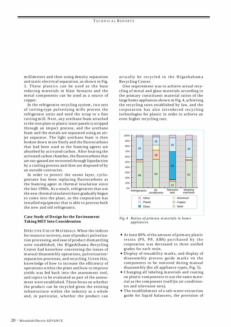
One requirement was to achieve actual recy-cling of metal and glass materials according tothe primary constituent material ratios of thelarge home appliances shown in Fig. 4, achievingthe recycling rates established by law, and thecorporation has also introduced recyclingtechnologies for plastic in order to achieve aneven higher recycling rate.
54
12
52
43
1626
33
49
18
53
0%
10%
20%
30%
40%
50%
60%
70%
80%
90%
100%
Refrigerators Air conditioners
Televisionsets
Washingmachines
Other
Plastic
Glass
Aluminum
Copper
Steel
Fig. 4 Ratios of primary materials in homeappliances
● At least 80% of the amount of primary plasticresins (PS, PP, ABS) purchased by thecorporation was decreased to three unifiedgrades for each resin.
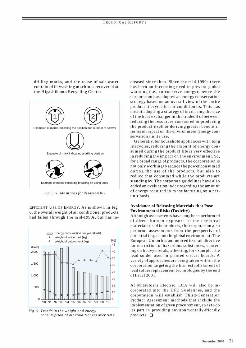
● Display of reusability marks, and display ofdisassembly process guide marks on thecomponents to be removed during manualdisassembly (for all appliance types, Fig. 5).
● Changing all labeling materials and coatingon plastic components to use the same mate-rial as the component itself (in air condition-ers and television sets).
● The establishment of a salt-water extractionguide for liquid balancers, the provision of
T E C H N I C A L R E P O R T S
· 21December 2001
drilling marks, and the reuse of salt-watercontained in washing machines recovered atthe Higashihama Recycling Center.
1 2
Examples of marks indicating the position and number of screws
Example of mark indicating a drilling position
Example of marks indicating breaking off using tools
Fig. 5 Guide marks for disassembly
45
40
35
30
25
20
15
10
5
2,000
1,500
1,000
500
0'90 '91 '92 '93 '94 '95 '96 '97 '98 '99 '00 '01
Energy consumption per year (kWh)Weight of indoor unit (kg)Weight of outdoor unit (kg)
(kWh)
(kg)
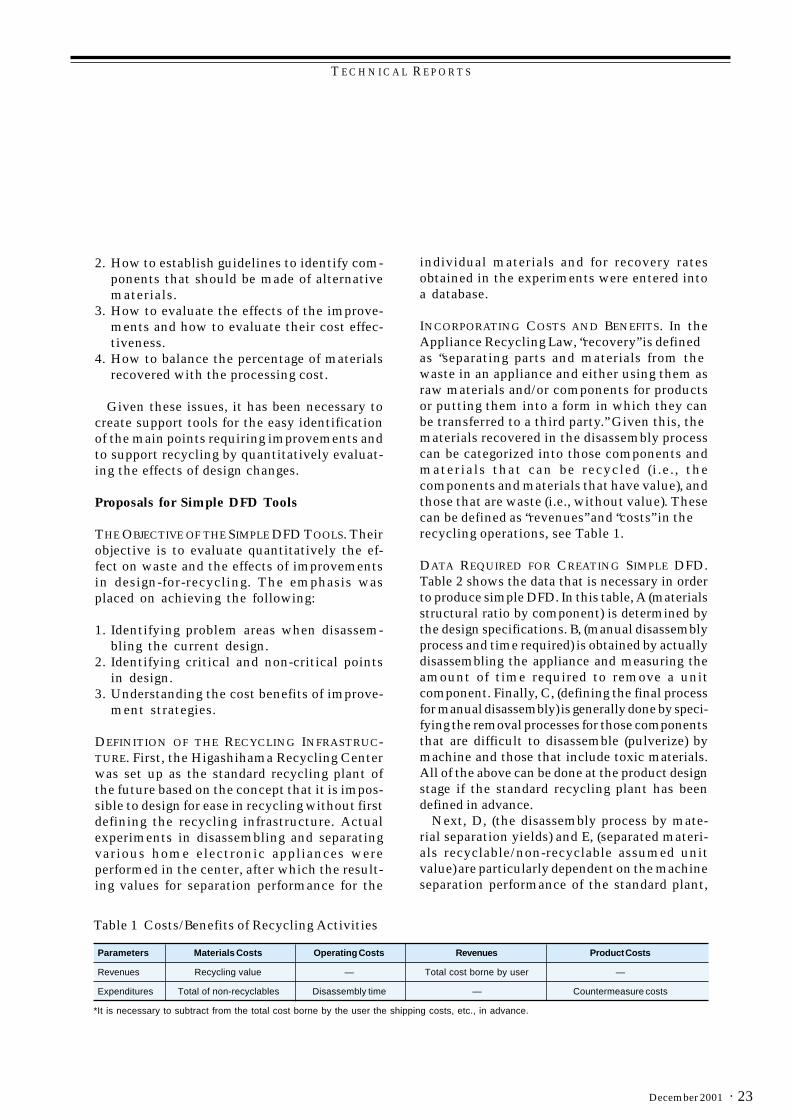
Fig. 6 Trends in the weight and energyconsumption of air conditioners over time.
creased since then. Since the mid-1990s therehas been an increasing need to prevent globalwarming (i.e., to conserve energy); hence thecorporation has adopted an energy conservationstrategy based on an overall view of the entireproduct lifecycle for air conditioners. This hasmeant adopting a strategy of increasing the sizeof the heat exchanger in the tradeoff of betweenreducing the resources consumed in producingthe product itself or deriving greater benefit interms of impact on the environment (energy con-servation) in its use.
Generally, for household appliances with longlifecycles, reducing the amount of energy con-sumed during the product life is very effectivein reducing the impact on the environment. So,for a broad range of products, the corporation isnot only working to reduce the power consumedduring the use of the products, but also toreduce that consumed while the products arestanding by. The corporate guidelines have alsoadded an evaluation index regarding the amountof energy required in manufacturing on a per-unit basis.
Avoidance of Releasing Materials that PoseEnvironmental Risks (Toxicity).Although assessments have long been performedof direct human exposure to the chemicalmaterials used in products, the corporation alsoperforms assessments from the perspective ofpotential impact on the global environment. TheEuropean Union has announced its draft directivefor restriction of hazardous substances, center-ing on heavy metals, affecting, for example, thelead solder used in printed circuit boards. Avariety of approaches are being taken within thecorporation targeting the firm establishment oflead solder replacement technologies by the endof fiscal 2001.
At Mitsubishi Electric, LCA will also be in-corporated into the DFE Guidelines, and thecorporation will establish Third-GenerationProduct Assessment methods that include theimplementation of green procurement, so as to doits part in providing environmentally-friendlyproducts. ❑
EFFICIENT USE OF ENERGY. As is shown in Fig.6, the overall weight of air conditioner productshad fallen through the mid-1990s, but has in-

T E C H N I C A L R E P O R T S
Mitsubishi Electric ADVANCE22 ·
*Hideaki Nagatomo is with Shizuoka Works.
by Hideaki Nagatomo*
Design-for-Recycling of HouseholdAppliances Using a Simple
Design-for-Disassembly Method
Since the full implementation of the HouseholdAppliances Recycling Law in April 2001, themanufacturers of home appliances have had tobecome involved in recycling used home appli-ance products. They also have to incorporatetechnologies into products being developed todayso as to achieve future increases in the percentageof components and materials that can berecovered for recycling from discarded appliances.In this situation, a simple design-for-disassembly(DFD) method has been introduced to analyzeand evaluate the appropriateness of recycling-friendly design in the design engineering office,and to analyze the effectiveness of disassemblyoperations in the recycling plant.
Recycling Plant OperationsIn May 1999, Mitsubishi Electric Corporationstarted to operate the Higashihama RecyclingCenter at Higashihama in Kawa City, Chiba Pre-fecture, making it the first plant in Japan com-patible with the Japanese Appliance RecyclingLaw (The Law for Recycling of Specified Kinds ofHome Appliances). The recycling center has beenable to recycle electrical appliances while strikinga balance between materials recovery rate,economics, and environmental friendliness in the
manual disassembly (i.e., the removal ofcomponents through manual operations), andmachine separation (the separation of materialsthrough pulverization), see Fig. 1.
Of these, manual disassembly plays a criticalrole in high-efficiency recycling, with the ob-jective being to remove, before machine separa-tion, any parts that fulfill the following threecriteria:
1. Parts or materials requiring specialized pro-cessing (such as toxic materials),
2. Parts whose recovery value would be reducedsubstantially by machine separation, and
3. Parts that cannot be physically/mechani-cally processed in machine separation.
Problems in the Design Office and theRecycling PlantWhen research was done into the actual prob-lems that are faced in design offices and recyclingplants in research into actually increasing thelevel of environmental friendliness, the follow-ing issues were discovered:
1. How to identify the design criteria for ease ofdisassembly.
Hyper Cycle Inc.
Green Cycle Ltd.Pulverization Separation Sell
Mechanical disassembly
Sell
Sell
Motor
Discard
Manual disassembly
Plastic pulverization
Manualdisassembly
Destroy
Useable parts
TVsWashingmachine
Air conditioners
Refrigerant recovery CRT
Office equipment Refrigerators
Compressor
Recovery of insulation &
hydrocarbons
Parts
Fig. 1 Higashihama Recycling Center process flow
T E C H N I C A L R E P O R T S
· 23December 2001
2. How to establish guidelines to identify com-ponents that should be made of alternativematerials.
3. How to evaluate the effects of the improve-ments and how to evaluate their cost effec-tiveness.
4. How to balance the percentage of materialsrecovered with the processing cost.
Given these issues, it has been necessary tocreate support tools for the easy identificationof the main points requiring improvements andto support recycling by quantitatively evaluat-ing the effects of design changes.
Proposals for Simple DFD Tools
THE OBJECTIVE OF THE SIMPLE DFD TOOLS. Theirobjective is to evaluate quantitatively the ef-fect on waste and the effects of improvementsin design-for-recycling. The emphasis wasplaced on achieving the following:
1. Identifying problem areas when disassem-bling the current design.
2. Identifying critical and non-critical pointsin design.
3. Understanding the cost benefits of improve-ment strategies.
DEFINITION OF THE RECYCLING INFRASTRUC-TURE. First, the Higashihama Recycling Centerwas set up as the standard recycling plant ofthe future based on the concept that it is impos-sible to design for ease in recycling without firstdefining the recycling infrastructure. Actualexperiments in disassembling and separatingvarious home electronic appliances wereperformed in the center, after which the result-ing values for separation performance for the
individual materials and for recovery ratesobtained in the experiments were entered intoa database.
INCORPORATING COSTS AND BENEFITS. In theAppliance Recycling Law, “recovery” is definedas “separating parts and materials from thewaste in an appliance and either using them asraw materials and/or components for productsor putting them into a form in which they canbe transferred to a third party.” Given this, thematerials recovered in the disassembly processcan be categorized into those components andmaterials that can be recycled (i.e., thecomponents and materials that have value), andthose that are waste (i.e., without value). Thesecan be defined as “revenues” and “costs” in therecycling operations, see Table 1.
DATA REQUIRED FOR CREATING SIMPLE DFD.Table 2 shows the data that is necessary in orderto produce simple DFD. In this table, A (materialsstructural ratio by component) is determined bythe design specifications. B, (manual disassemblyprocess and time required) is obtained by actuallydisassembling the appliance and measuring theamount of time required to remove a unitcomponent. Finally, C, (defining the final processfor manual disassembly) is generally done by speci-fying the removal processes for those componentsthat are difficult to disassemble (pulverize) bymachine and those that include toxic materials.All of the above can be done at the product designstage if the standard recycling plant has beendefined in advance.
Next, D, (the disassembly process by mate-rial separation yields) and E, (separated materi-als recyclable/non-recyclable assumed unitvalue) are particularly dependent on the machineseparation performance of the standard plant,
Table 1 Costs/Benefits of Recycling Activities
Parameters Materials Costs Operating Costs Revenues Product Costs
Revenues Recycling value — Total cost borne by user —
Expenditures Total of non-recyclables Disassembly time — Countermeasure costs
*It is necessary to subtract from the total cost borne by the user the shipping costs, etc., in advance.
T E C H N I C A L R E P O R T S
Mitsubishi Electric ADVANCE24 ·
while F, (the unit value per labor hour in disas-sembly) is the labor cost and equipment operat-ing cost for performing the manual disassemblyand machine separation. Values D through F canbe loaded into a database from the actualoperations of the recycling plant.
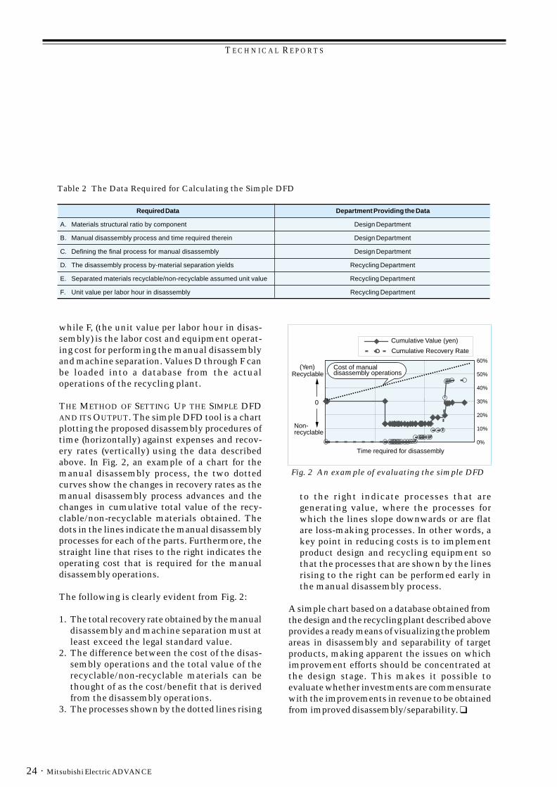
THE METHOD OF SETTING UP THE SIMPLE DFDAND ITS OUTPUT. The simple DFD tool is a chartplotting the proposed disassembly procedures oftime (horizontally) against expenses and recov-ery rates (vertically) using the data describedabove. In Fig. 2, an example of a chart for themanual disassembly process, the two dottedcurves show the changes in recovery rates as themanual disassembly process advances and thechanges in cumulative total value of the recy-clable/non-recyclable materials obtained. Thedots in the lines indicate the manual disassemblyprocesses for each of the parts. Furthermore, thestraight line that rises to the right indicates theoperating cost that is required for the manualdisassembly operations.
The following is clearly evident from Fig. 2:
1. The total recovery rate obtained by the manualdisassembly and machine separation must atleast exceed the legal standard value.
2. The difference between the cost of the disas-sembly operations and the total value of therecyclable/non-recyclable materials can bethought of as the cost/benefit that is derivedfrom the disassembly operations.
3. The processes shown by the dotted lines rising
to the right indicate processes that aregenerating value, where the processes forwhich the lines slope downwards or are flatare loss-making processes. In other words, akey point in reducing costs is to implementproduct design and recycling equipment sothat the processes that are shown by the linesrising to the right can be performed early inthe manual disassembly process.
A simple chart based on a database obtained fromthe design and the recycling plant described aboveprovides a ready means of visualizing the problemareas in disassembly and separability of targetproducts, making apparent the issues on whichimprovement efforts should be concentrated atthe design stage. This makes it possible toevaluate whether investments are commensuratewith the improvements in revenue to be obtainedfrom improved disassembly/separability. ❑
0%
10%
20%
30%
40%
50%
60%
Cumulative Value (yen)
Cumulative Recovery Rate
0
(Yen)Recyclable
Non-recyclable
Cost of manual disassembly operations
Time required for disassembly
Fig. 2 An example of evaluating the simple DFD
Table 2 The Data Required for Calculating the Simple DFD
Required Data Department Providing the Data
A. Materials structural ratio by component Design Department
B. Manual disassembly process and time required therein Design Department
C. Defining the final process for manual disassembly Design Department
D. The disassembly process by-material separation yields Recycling Department
E. Separated materials recyclable/non-recyclable assumed unit value Recycling Department
F. Unit value per labor hour in disassembly Recycling Department

TECHNICAL REPORTS
· 25December 2001
*Toshiro Oyama is with Nagoya Works and Etsuko Hirose is with the Advanced Technology R&D Center.
by Toshiro Oyama & Etsuko Hirose*
Approaches to Design for theEnvironment with Practical Examples
The Nagoya Works of Mitsubishi Electric Corpo-ration has 5,000 employees (including those ofon-site contractors). The plant has been involvedin various environmental protection activities forover two decades, including, for example, therecycling of scrap printed circuit boards. As aresult, the plant is approaching the zero-emissionlevel (zero-waste level), with just five percent-age points of waste reductions required to reachthat goal and further reductions already planned.As well as reducing waste and scrap, the plant isalso working to conserve energy and to reducepaper consumption and toxic chemicals amongother on-going environmental protection activi-ties. This article discusses the rules of productdesign for the environment (DFE) in such practi-cal activities.
Environmental Protection Activities inProductsNagoya Works, as a business unit that producesfactory automation equipment, handles thedevelopment and manufacturing of products inmore than ten major product categories,including sequencers, inverters, AC servounits, programmable controllers, robots, lasernumerical processing machines, electrical-discharge machines, and other electrome-chanical equipment, motors, transformers, andelectromagnetic switches, as shown in Fig. 1.
When developing these products, attempts aremade to reduce the burden on the environmentin harmony with the corporation’s fundamental
philosophy for environmentally friendly design.Product-design activities take the environ-ment into consideration, particular from theperspectives of effective utilization of resources,efficient use of energy, and avoiding con-tamination by environmentally threateningmaterials. These design activities are subsumedunder “design for the environment” (DFE).
The DFE Evaluation MethodEach time a product is developed or improved,the degree of environmental improvement of thenew product over the previous product isevaluated. This evaluation uses a product as-sessment based on completing a check sheetfor the improvements made in each of severalcategories. These categories include any moveto renewable resources, ease of disassembly, re-duction in the volume of resources consumed,durability, energy conservation, safety, informa-tion disclosure and packaging improvements.The method of evaluation was established in July1997 by the Product Assessment Expert Com-mittee, whose members were drawn from thedevelopment and design departments, and fromthe environmental protection departmentsestablished when the environmental mana-gement system was established. Evaluations areperformed in all product development andimprovement activities in the Nagoya Works.
Product Assessment ActivitiesWhen new products are developed, the productdesign process passes through a series of stepsincluding a conceptual design review, a drawingdesign review, and a shipping design review.The evaluation based on the above productassessment is performed by the Design De-partment before the conceptual design reviewat the product planning stage, and is repeatedby the Quality Assurance Department prior tothe shipping design review in order to confirmthe results of the evaluation performed by theDesign Department.
Reviewing the Product Assessment SheetBecause product assessments are effective inenvironmental improvements at the product
Programmablecontrollers Inverters Numerical controllers
Electrical-discharge machines Motors Transformers
Fig. 1 Key products developed and manufacturedat the Nagoya Works

TECHNICAL REPORTS
Mitsubishi Electric ADVANCE26 ·
development stage, the DFE committee estab-lished DFE guidelines in March 2000. Themembers of this committee come from alldivisions in the corporation that perform productassessments. These company-wide guidelineseliminate a source of inconsistency in productassessments.
The product assessment sheet used in theNagoya Works has been reviewed based on theseguidelines, see Fig. 2 and Table 1.
DFE EducationTo make designers thoroughly familiar with thebasic concepts of DFE, the corporation’s Envi-
ronmental Protection Promotion Group hassponsored three-day DFE engineering seminarsand sent the instructors from these seminars tothe Nagoya Works to hold one-day seminars.The design departments have encouragedparticipation in these seminars.
The three-day seminars cover topics such asDFE trends in Japan and overseas, product as-sessment evaluation methods, policies andguidelines for selecting ecologically-friendlymaterials, and life-cycle assessment (LCA)theory, with hands-on investigations of environ-mental improvement issues by actually dis-assembling products. The one-day seminarsfeature lectures on the classroom learning partof the seminars.
Examples of Using Product AssessmentsBecause items of factory automation equipmenthave comparatively long product life cycles, DFEwork focuses on topics such as product energyconservation, miniaturization, longer life expect-ancy (to contribute to reduced resource con-sumption and less waste), labeling of plasticmaterials (for renewable resources), etc., withreliability and improved functionality. Below, wediscuss an example of the results of this productassessment.
Table 1 Product Assessment Sheet (guidelines)
Standard Evaluation Points���
�
points�
points�
points�
points ��
points
Possible ResourceRecovery
Percent usage ofrecoverable materials (Weight of recyclable materials/Total weight) x 100% 3 �80% �50% �20% �0% None
Material UniformityPercent reduction in thenumber of plastic parts [1-(New product/reference product)] ×100% 3 �30% �20% �10% �0% �0%
Percent reduction in thenumber of metal parts [1-(New product/reference product)] ×100% 3 �30% �20% �10% �0% �0%
Percent reduction in thenumber of other parts [1-(New product/reference product)] ×100% 3 �30% �20% �10% �0% �0%
Percentage of plasticparts that are recyclable (Number of recyclable parts/total parts)×100% 3 �80% �50% �20% �0% None
Percentage of metal partsthat are recyclable (Number of recyclable parts/total parts)×100% 3 �80% �50% �20% �0% None
Percentage of other partsthat are recyclable (Number of recyclable parts/total parts)×100% 3 �80% �50% �20% �0% None
Use of RecyclableMaterials
Percentage of materialsused that are recycled (Total mass that can be recycled/total mass)×100% 3 �50% �30% �20% �0% None
Promotion ofRecoverableResources
Percentage reduction inthe number of compoundmaterials.
[1-(New product/reference product)]×100% 3 �30% �20% �10% �0% �0%
Evaluation MethodWeighting
��
Res
ourc
e R
ecov
ery
Mat
eria
ls
Evaluation StandardEvaluation Item
Fig. 2 Categories of DFE guidelines
Manufacturing process Logistics
Energy conservation/
Expendablematerials
conservation
Packaging
Safety
Crushing process potentialInformationdisclosure
Resourcereuse
Increased service life
Weight reduction
Disassemblypotential
Recovery/ TransportProduct

TECHNICAL REPORTS
· 27December 2001
MORE EFFICIENT INDUCTION MOTORS. In recentyears, demand has risen for energy-saving/high-efficiency equipment. In response, thecorporation has developed the Super Line Ecoseries of energy-saving induction motors,including three-phase motors. Large improve-ments in energy consumption and increased lifeexpectancy have resulted, winning the 1999Japan Machinery Federation Chairman’s Award.
Key points in product assessments include notonly power conservation (to prevent globalwarming) but also extended useful product life(to reduce the burden on waste-processing fa-cilities), and compatibility with standard motors(so that the products can be used in existingequipment). The technologies that weredeveloped and used are shown in Table 2.
LCA EVALUATIONS. With the cooperation of theMitsubishi Advanced Technology R&D Center,a life-cycle assessment (LCA) evaluation wasperformed for a standard induction motor in orderto evaluate the effect on the environment of thepower-saving “Eco” induction motor.
Conventionally, data for LCA is gathered ineach of the processes from materials to manu-facturing, distribution, use, and disposal/recy-cling; however, in this evaluation the LCA waslimited to materials, manufacturing, and use(assuming ten years of operation and eight-hourdays at 100% loads of 0.75 kW). SimaPro soft-ware (from the Pre-Consultants Companyin the Netherlands) was used, using databasesof the National Research Institute Resourcesand Environment for materials and manu-facturing. Note that the environmental impactwas calculated using “Eco-indicator 95”, seeFig. 3.
0
1
2
3
4
5
Summer smog
Winter smog
Carcinogenic substances
Heavy metals
Eutrophication
Acidification
Ozone layer depletion
Standard motor Eco motor
Env
ironm
enta
l im
pact
(po
ints
/uni
t)
Greenhouse effect
Fig. 3 Results of LCA (as environmentalimpacts)
The result is that even though the Eco Motoris slightly heavier than a conventional motor,the effects of energy conservation give the Ecomotor an environmental impact superior to thatof a standard motor. We confirmed that the EcoMotor, when used over an extended period oftime, achieves effective environmental im-provements due to the reduction in powerconsumption.
Nagoya Works is committed to providing a con-tinuous succession of environmentally awareproducts, and the plant is continuing its efforts todevelop products with enhanced energy conser-vation and extended life cycles. ❑
tnemevorpmI ygolonhcetdetpodarodepoleveD ssenevitceffE
eromstcudorpgnikaMtneiciffe-ygrene
ssolegadniwdecuderrofnafgniloocrellamS-ssolreppocdecuderrofliocrotomweN-ssolerocdecuderroflairetamerocweN-
yletamixorppaybderewolssolnoitareneGtnecrep52
efilregnoL depolevedesaerggniraebweN- deveihcaemitefilregnoL
ezisrellamS emarfetalpleetsfonoitpodA-snoisnemiddradnatssaemasehteziS
deveihca
Table 2 Technologies Developed or Adopted for Better Environmental Performance
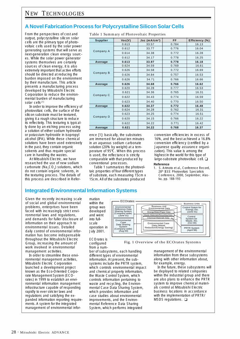
Mitsubishi Electric ADVANCE28 ·
NEW TECHNOLOGIES
A Novel Fabrication Process for Polycrystalline Silicon Solar CellsFrom the perspectives of cost andoutput, polycrystalline silicon solarcells are the primary type of photo-voltaic cells used by the solar powergenerating systems that will serve asnext-generation clean energy sourc-es. While the solar power generatorsystems themselves are certainlysources of clean energy, it is alsoextremely important that active effortsshould be directed at reducing theburden imposed on the environmentby their manufacture. This articlepresents a manufacturing processdeveloped by Mitsubishi ElectricCorporation to reduce the environ-mental burden of manufacturingsolar cells.[1]
In order to improve the efficiency ofphotovoltaic cells, the surface of thesilicon substrate must be textured,giving it a rough structure to reduceits reflectivity. This texturing is typical-ly done by an etching process usinga solution of either sodium hydroxideor potassium hydroxide in isopropylalcohol (IPA). While these chemicalsolutions have been used extensivelyin the past, they contain organicsolvents and thus require specialcare in handling the wastes. At Mitsubishi Electric, we haveresearched the use of new sodiumcarbonate (Na2CO3) solutions, whichdo not contain organic solvents, inthe texturing process. The details ofthis process are described in Refer-
Reference1. S. Arimoto et al., Conference Record,
28th IEEE Photovoltaic SpecialistsConference, 2000, September, Alas-ka, pp. 188-193
Supplier Voc(V) Jsc (mA/cm 2) FF Efficiency (%)
Company A
0.613 33.57 0.784 16.13
0.612 33.77 0.776 16.04
0.614 34.38 0.772 16.28
0.612 34.17 0.778 16.25
Average 0.613 33.97 0.778 16.18
Company B
0.624 34.59 0.769 16.61
0.626 34.58 0.772 16.69
0.626 34.84 0.757 16.53
0.626 34.71 0.766 16.66
Average 0.626 34.68 0.766 16.62
Company C
0.620 34.28 0.777 16.53
0.621 34.36 0.765 16.31
0.622 34.43 0.774 16.59
0.623 34.40 0.770 16.50
Average 0.622 34.37 0.772 16.48
Company D
0.624 34.28 0.762 16.31
0.623 34.25 0.774 16.51
0.620 34.15 0.766 16.22
0.622 34.22 0.771 16.42
Average 0.621 34.22 0.768 16.37
ence [1]: basically, the substratesare immersed for about ten minutesin an aqueous sodium carbonatesolution (20% by weight) at a tem-perature of 95°C. When this processis used, the reflectance is strictlycomparable with that produced byconventional processes. Table 1 summarizes the photovol-taic properties of four different typesof substrate, each measuring 15cm x15cm. All of the substrates produced
conversion efficiencies in excess of16%, and the best achieved a 16.8%conversion efficiency (certified by aJapanese quality assurance organi-zation). This value is among thehighest in the world for this type oflarge-substrate photovoltaic cell. ❑
Table 1 Summary of Photovoltaic Properties
Given the recently increasing scaleof social and global environmentalproblems, enterprises have beenfaced with increasingly strict envi-ronmental laws and regulations,and demands for fuller disclosure ofinformation on their approach toenvironmental issues. Detaileddaily control of environmental infor-mation has become indispensablethroughout the Mitsubishi ElectricGroup, increasing the amount ofwork involved in environmentalmanagement activities.
In order to streamline these envi-ronmental management activities,Mitsubishi Electric Corporationlaunched a development projectknown as the Eco-Oriented Corpo-rate Management System (ECO-rates) in 1999 to establish an envi-ronmental information managementinfrastructure capable of respondingrapidly to ever stricter laws andregulations and satisfying the ex-panded information reporting require-ments. A system for the integratedmanagement of environmental infor-
mationwithin thegroup wasdevelopedand wentinto full-scaleoperation inJuly 2001.
ECOrates isconfiguredfrom a num-ber of subsystems, each handlingdifferent types of environmentalinformation. At present, the sub-systems include the PRTR system,which controls environmental impactand chemical property information,the Waste Control System, whichcontrols information pertaining towaste and recycling, the Environ-mental Case Data Sharing System,which provides information andcase studies about environmentalimprovements, and the Environ-mental Reference Data SharingSystem, which performs integrated
management of the environmentalinformation from these subsystemsalong with other information about,for example, energy.
In the future, these subsystems willbe deployed to related companieswithin the industrial group and thereare also plans to enhance the PRTRsystem to improve chemical materi-als control at Mitsubishi Electricbusiness locations in accordancewith the implementation of PRTR/MSDS regulations. ❑
ECOrates
Environmental Reference Data Sharing System (Company-wide)
(June 01)
Environmental Case
Data Sharing System
(Company-wide) (Aug 00)
Business Unit Environmental Data
Energy/Water/Paper Data
Waste Materials/Recycling Data
Chemical Materials Data
Environmental Case Data (Waste
Reduction/Energy Saving)
Business Units
Control Sytem for Energy, Etc.
(June 01)
Control System for Waste, Etc.
(Oct 00)
PRTR System (April 99)
Fig. 1 Overview of the ECOrates Systems
Integrated Environmental Information Systems

MITSUBISHI ELECTRIC CORPORATIONHEAD OFFICE: MITSUBISHI DENKI BLDG., MARUNOUCHI, TOKYO 100-8310, FAX 03-3218-3455


