Embed Size (px)
Citation preview
DATA USERS GUIDES
1: Digital Line Graphs from 1 :24,000-Scale Maps 2: Digital Line Graphs from 1:100,000-Scale Maps 3: Digital Line Graphs from 1 :2,000,000-Scale Maps 4: Land Use and Land Cover Digital Data from 1:250,000- and 1: 100,000-Scale Maps 5: Digital Elevation Models 6: Geographic Names Information System 7: Alaska Interim Land Cover Mapping Program
Data Users Guides 1-7 generally replace the Geological SuiVey Circular 895.
Questions regarding availability and ordering of US GeoData (all types of digital cartographic and geographic data produced and distributed by the U.S. Geological SuiVey) should be addressed to:
Earth Science Infonnation Center U.S. Geological SuiVey 507 National Center Reston, Virginia 22092 (703)860-6045
Technical questions and comments should be addressed to:
Branch of Technical Management U.S. Geological SuiVey 510 National Center Reston, Virginia 22092
UNITED STATES DEP ARTJ\.ffiNT OF THE INTERIOR
U.S. GEOLOGICAL SURVEY
DIGITAL LINE GRAPHS FROM 1 :2,000,000-SCALE MAPS
Data Users Guide 3
Reston, Virginia 1990
First printing, 1986 Second printing (revised), 1990
ii
CONTENTS
Page
Introduction . . . . . . . . . . . . . . . . . . . . . . . . . . . . . . . . . . . . . . . . . . . . . . . . . 1 Data content . . . . . . . . . . . . . . . . . . . . . . . . . . . . . . . . . . . . . . . . . . . . . . . . . 2 Data" structure . . . . . . . . . . . . . . . . . . . . . . . . . . . . . . . . . . . . . . . . . . . . . . . . 2
Levels of structuring . . . . . . . . . . . . . . . . . . . . . . . . . . . . . . . . . . . . . . . 2 Topology .............................................. 2 Topological elements . . . . . . . . . . . . . . . . . . . . . . . . . . . . . . . . . . . . . . . 3
Attribute codes . . . . . . . . . . . . . . . . . . . . . . . . . . . . . . . . . . . . . . . . . . . . . . . 3 Major attribute codes . . . . . . . . . . . . . . . . . . . . . . . . . . . . . . . . . . . . . . . 5 Minor attribute codes . . . . . . . . . . . . . . . . . . . . . . . . . . . . . . . . . . . . . . . 5
Sample line graph structure . . . . . . . . . . . . . . . . . . . . . . . . . . . . . . . . . . . . . . . . 7 Graph theory in DLG data . . . . . . . . . . . . . . . . . . . . . . . . . . . . . . . . . . . . . . . 12 Distribution fonnats . . . . . . . . . . . . . . . . . . . . . . . . . . . . . . . . . . . . . . . . . . . 17 Source materials . . . . . . . . . . . . . . . . . . . . . . . . . . . . . . . . . . . . . . . . . . . . . . 18 Cell size and file extent . . . . . . . . . . . . . . . . . . . . . . . . . . . . . . . . . . . . . . . . . 18 Coordinate systems . . . . . . . . . . . . . . . . . . . . . . . . . . . . . . . . . . . . . . . . . . . . 18
Standard distribution fonnat . . . . . . . . . . . . . . . . . . . . . . . . . . . . . . . . . 18 Optional distribution fonnat . . . . . . . . . . . . . . . . . . . . . . . . . . . . . . . . . 20 Graphic distribution fonnat . . . . . . . . . . . . . . . . . . . . . . . . . . . . . . . . . . 20
Data validation . . . . . . . . . . . . . . . . . . . . . . . . . . . . . . . . . . . . . . . . . . . . . . 20 Appendix A. Standard DLG distribution fonnat (record contents) . . . . . . . . . . . . . . 25
B. Optional DLG distribution fonnat (record contents) . . . . . . . . . . . . . . 36 C. Graphic fonnat ..................................... 47 D. Map projection parameters . . . . . . . . . . . . . . . . . . . . . . . . . . . . . . 48 E. DLG attribute codes . . . . . . . . . . . . . . . . . . . . . . . . . . . . . . . . . . 49 F. Coordinate conversion . . . . . . . . . . . . . . . . . . . . . . . . . . . . . . . . . 58 G. Sample DLG data file (standard distribution format) . . . . . . . . . . . . . . 59 H. Sample DLG data file (optional distribution fonnat) . . . . . . . . . . . . . . 65 I. Data sources and currency . . . . . . . . . . . . . . . . . . . . . . . . . . . . . . 70
ILLUSTRATIONS
Page
Figure 1. Map elements showing roads, railroads, buildings, streams, lake and forest areas . . . . . . . . . . . . . . . . . . . . . . . . . . . . . 4
2a. Pecos River, Southeastern New Mexico Scale 1 :2,000,000 . . . . . . . . . . . . . . . . . . . . . . . . . . . . . . . . . . . . . . 8
2b. Rivers and water bodies, New Mexico Scale 1 :5,000,000 . . . . . . . . . . . . . . . . . . . . . . . . . . . . . . . . . . . . . . 9
2c. Rivers and water bodies, New Mexico Scale 1: 10,000,000 . . . . . . . . . . . . . . . . . . . . . . . . . . . . . . . . . . . . . 9
iii
ILLUSTRATIONS--continued
Page
Figure 3. Sample line graph . . . . . . . . . . . . . . . . . . . . . . . . . . . . . . . . . . . . . . 10 4. Window from the Arizona-New Mexico, 1 :2,000,000-scale
sectional map of the National Atlas of the United States of America . . . . . . . . . . . . . . . . . . . . . . . . . . . . . . . .. . . . . 14
5. Sample topology, Catron County, New Mexico . . . . . . . . . . . . . . . . . . . 15 6. Multistate cells used for Digital Line Graphs ·
from 1:2,000,000-scale maps . . . . . . . . . . . . . . . . . . . . . . . . . . . . . . 19 7. Location of origin of file reference coordinates . . . . . . . . . . ·. . . . . . . . . . 20
TABLES
Page
Table 1. Major codes used for DLG base categories . . . . . . . . . . . . . . . . . . . . . . . 5 2. Description of the topological elements and
relationships of a sample line graph . . . . . . . . . . . . . . . . . . . . . . . . . . 11 3. Selected sample of standard format DLG-3 records
of Catron County, New Mexico [N, node; A, area; L, line] . . . . . . . . . 16 4. Standard, optional, and graphic DLG format . . . . . . . . . . . . . . . . . . . . . . 17
iv
DIGITAL LINE GRAPHS FROM 1:2,000,000-SCALE MAPS
INTRODUCTION
The Earth Science Information Centers (ESIC) distribute digital cartographic/geographic data files produced by the U.S. Geological Survey (USGS) as part of the National Mapping Program. Digital cartographic data files may be grouped into four basic types. The first of these, called. a Digital Line Graph (DLG), is line map information in digital form. These data files include information on planimetric base categories, such as transportation, hydrography, and boundaries. The second type, called a Digital Elevation Model (DEM), consists of a sampled array of elevations for a number of ground positions that are usually at regularly spaced intervals. The third type is Land Use and Land Cover digital data, which provides information on nine major classes of land use such as urban, agricultural, or forest as well as associated map data such as political units and Federal land ownership. The fourth type, the Geographic Names Information System, provides primary information for all known places, features, and areas in the United States identified by a proper name.
The digital cartographic data files from selected sources currently available from ESIC include the following:
Digital Line Graphs (DLG) --1 :24,000-scale --1 :62,500-scale --1:63,360-scale --1: 1 00,000-scale --1 :2,000,000-scale
• Digital Elevation Models (DEM) --7.5-minute --15-minute --30-minute --1-degree
Land Use and Land Cover digital data --1:250,000- and 1:100,000-scale Land Use and Land Cover and associated maps --1 :250,000-scale Alaska Interim Land Cover
Geographic Names
The digital data are useful for the production of cartographic products such as plotting base maps and for various kinds of spatial analysis. A major use of these digital cartographic/geographic data is to combine them with other geographically referenced data enabling scientists to conduct automated analyses in support of various decisionmaking processes.
Any use of trade, product, or firm names in this publication is for descriptive purposes only and does not imply endorsement by the U.S. Government. Manuscript approved for publication September 4, 1986.
This document describes DLG's prepared from the 1:2,000,000-scale sectional maps (U.S. regions) of the National Atlas of the United States of America.
DATA CONTENT
The DLG data files derived from the 1 :2,000,000-scale maps contain selected base categories of cartographic data in digital form. The data ftles are derived from the sectional maps of the 1970 National Atlas of the United States of America. The following categories are included in current 1 :2,000,000-scale DLG files:
• Boundaries -- This category of data includes boundary information collected in two separate subcategories: (1) Political Boundaries and (2) Administrative Boundaries.
• Hydrography -- This category of data includes features collected in three separate subcategories: (1) Streams, (2) Water Bodies, and (3) Hypsography (Continental Divide only).
• Transportation -- This category of data includes major transportation systems collected in three separate subcategories: (1) Roads and Trails, (2) Railroads, and (3) Cultural Features (airports and Alaska pipeline).
DATA STRUCTURE
Levels of Structuring
The term DLG is employed by the USGS to describe a digital map data set in vector form. Originally, three levels of DLG data (DLG-1, DLG-2, and DLG-3) were proposed; these levels were differentiated by their positional accuracy, level of attribute coding, and relational spatial information. It was found, however, that the widest user-community would be served by producing DLG-3 data, which have the full range of attribute codes and are fully topologically structured. These two properties are required by users whose work includes both graphic and analytic applications. Therefore, all DLG data in the National Digital Cartographic Data Base are level 3.
Topology
Data collection from 1 :2,000,000-scale maps was exclusively directed toward producing fully topologically structured level-3 DLG data referred to as DLG-3. The DLG-3 concept is based on graph theory in which a two-dimensional diagram is expressed as a set of nodes (points in space) and links (line segments connecting nodes) in a manner that explicitly expresses logical relationships. Applied to a map, this concept is used to encode the digital data with the spatial relationships among map elements that are obvious when the map is examined visually. The spatial relationships include such concepts as adjacency and connectivity between features on the map. The abstraction of the map data according to the rules of graph theory preserves the spatial relationships inherent in the map graphic and creates a logical and consistent data file structure for computer processing. A digital file of cartographic or geographic data that maintains the spatial relationships inherent in the map is called a topologically structured data file. A topologically
2
structured data file can support simple graphic applications, such as plotting streams and roads for base maps, as well as more advanced applications, such as computations involving areas and lines and their spatial relationships.
Topological Elements
A DLG-3 fJ.le is composed of three separate, but related, types of elements: nodes, lines, and areas. Nodes define the location of the end-points of every line, and a single node may mark the start or end of one or more lines. Intersections of linear features and significant points on linear features are marked by nodes because at that point the liriear feature is subdivided into line segments.
A line is an ordered set of points that describes the position and shape of a linear feature on the map. Each line starts at a node and ends at a node and, thus, has both an explicit direction and a left-right connotation. The direction of the line is arbitrarily chosen at the time of digitizing. Lines connect to each other at nodes, and, by this definition, a line does not cross itself or any other line. A line may describe the boundary between two map features, such as counties, or may defme a map feature by itself, such as a road. A special line, called a degenerate line, is used to defme features symbolized as independent points on a map. A degenerate line starts and ends at the same node, has two identical coordinate pairs, has zero length, and is totally enclosed inside one map area.
An area is a portion of the map bounded by lines. All portions of the map must be assigned to some area. Each area is identified in a DLG-3 data fJ.le by an arbitrary point chosen to represent the characteristics of the area; the point is not required to be inside the area it represents. Every DLG data file will have at least two areas identified: one representing the area covered by the file and the other representing the area outside the coverage of the fJ.le. Additional areas will be defmed as necessary to subdivide the area covered by the file. Polygons as unique features are not defmed explicitly in a standard DLG file. However, polygons can be constructed using line-area linkages built into the DLG data structure.
ATIRIBUTE CODES
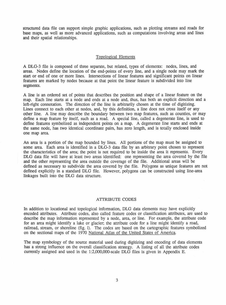
In addition to locational and topological infonnation, DLG data elements may have explicitly encoded attributes. Attribute codes, also called feature codes or classification attributes, are used to describe the map infonnation represented by a node, area, or line. For example, the attribute code for an area might identify a lake or glacier, the attribute code for a line might identify a road, railroad, stream, or shoreline (fig. 1). The codes are based on the cartographic features symbolized on the sectional maps of the 1970 National Atlas of the United States of America.
The map symbology of the source material used during digitizing and encoding of data elements has a strong influence on the overall classification strategy. A listing of all the attribute codes currently assigned and used in the 1 :2,000,000-scale DLG files is given in Appendix E.
3
Figure 1.--Map elements showing roads, railroads, buildings, streams, lake, and forest areas.
Each attribute code identifies the major category to which a data element belongs, as well as the specific nature of the element. Codes also may provide additional descriptive information. Most elements are uniquely described by a single attribute code. Others, however, may require two or more codes for a complete description. If multiple attributes are needed to describe an element, the order is not significant. Allowing for a variable number of attribute codes creates an open-ended structure to which information may be added at any time. It is not necessary for each element to have associated attributes; in general, attribute codes are not assigned to an element if the attributes can be derived based on relationships to adjacent elements.
In conventional DLG data files, features are described as they are symbolized or labeled on the source map. For the 1 :2,000,000-scale data, however, additional information about the map features is included through a special attribute coding scheme. These codes not only describe the digitized features in a generic sense, but provide a means of selecting map features based on some indices of the significance of the features. These special attribute codes are provided to assist the user in selecting the features to be displayed on maps of various scales and themes. Because of the varying nature of the themes of data digitized, the indices of feature "significance" differs between data overlays.
A DLG attribute code is composed of two distinct numeric fields: a three-digit major code, and a four-digit minor code. In the digital file, the major and minor attributes are encoded in two integer fields of six digits, flush right with leading blanks (FORTRAN 216 format). In this document, major codes are presented as three digits, and minor codes are presented as four digits. Leading zeros are shown for clarity; for example: 090 0104.
4
Major Attribute Codes
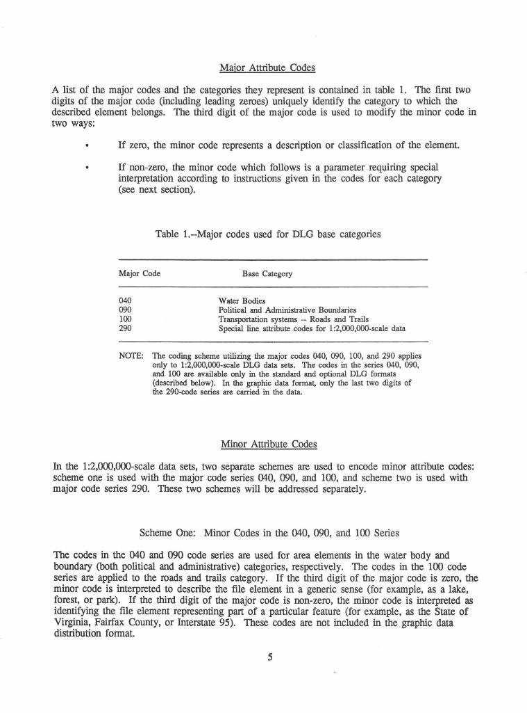
A list of the major codes and the categories they represent is contained in table 1. The first two digits of the major code (including leading zeroes) uniquely identify the category to which the described element belongs. The third digit of the major code is used to modify the minor code in two ways:
If zero, the minor code represents a description or classification of the element.
• If non-zero, the minor code which follows is a parameter requiring special interpretation according to instructions given in the codes for each category (see next section).
Table 1.--Major codes used for DLG base categories
Major Code Base Category
040 090 100 290
Water Bodies Political and Administrative Boundaries Transportation systems -- Roads and Trails Special line attribute codes for 1:2,000,000-scale data
NOTE: The coding scheme utilizing the major codes 040, 090, 100, and 290 applies only to 1:2,000,000-scale DLG data sets. The codes in the series 040, 090, and 100 are available only in the standard and optional DLG formats (described below). In the graphic data format, only the last two digits of the 290-code series are carried in the data.
Minor Attribute Codes
In the 1 :2,000,000-scale data sets, two separate schemes are used to encode minor attribute codes: scheme one is used with the major code series 040, 090, and 100, and scheme two is used with major code series 290. These two schemes will be addressed separately.
Scheme One: Minor Codes in the 040, 090, and 100 Series
The codes in the 040 and 090 code series are used for area elements in the water body and boundary (both political and administrative) categories, respectively. The codes in the 100 code series are applied to the roads and trails category. If the third digit of the major code is zero, the minor code is interpreted to describe the file element in a generic sense (for example, as a lake, forest, or park). If the third digit of the major code is non-zero, the minor code is interpreted as identifying the file element representing part of a particular feature (for example, as the State of Virginia, Fairfax County, or Interstate 95). These codes are not included in the graphic data distribution fonnat.
5
Examples of these attribute codes include:
040 0100
090 0104
091 0051, 092 0059
102 0095
The major code 040 indicates the water body category. The minor code 0100 identifies the feature as a perennial lake or pond.
The major code 090 indicates one of the boundary categories. The minor code 0104 identifies the feature as a national forest or grassland.
The major code 091 indicates a State in the boundary category. Because the last digit of the major code is non-zero, the minor code is a parameter. The minor code 005 1 is the Federal lnfonnation Processing Standards (FIPS) code for the State of Virginia. Similarly, the major code 092 indicates a county in the boundary category. The minor code 0059 is the PIPS code for Fairfax County.
The major code 102 indicates an interstate highway in the roads and trails category. Because the last digit of the major code is non-zero, the minor code is interpreted as a parameter code. The minor code 0095 indicates that the element with which this code is associated is part of Interstate 95.
Scheme Two: Minor Codes in the 290 Series
During the planning of the 1 :2,000,000-scale data sets, it was decided that the data should support the generation of a variety of maps of different scales and themes. During the process of making different maps, it is necessary to change the amount of data displayed to support the theme or scale of the map. One of these changes is to control the selection of features to be displayed based on some indices of significance or importance.
The 290-code series represents an attempt to encode selected indices of significance or importance in the data. By careful selection of features through the use of these attribute codes, one can control the amount of infonnation displayed.
The minor codes in the 290 series are composed of four digits. The first digit indicates the category of data. The second digit is always zero. The last two digits both identify the feature in a generic sense and contain some index of significance. A description of the minor codes for each numeric series follows:
2000-2099:
3000-3099:
4000-4099:
Hypsography. The only feature currently stored is the Continental Divide.
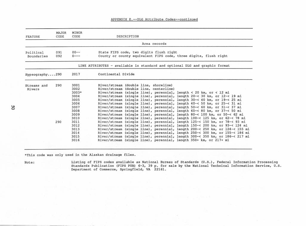
Streams. Examples of the features encoded include perennial, intennittent, and braided streams, and canals. In addition to the generic description, each feature is further categorized based on an approximate measure of overall feature length. In estimating the length of a feature, the path of a stream was detennined by following the named (labeled) channel as far as possible, and then following the longest tributary.
Water Bodies. Examples of these features include perennial, intennittent, and dry lakes. Each feature is further classified by length along the longest dimension of the feature.
6
5000-5069:
5070-5080:
6000-6019:
6020-6099:
7000-7099:
Roads and Trails. Examples of these features include Interstate, U.S., and State highways. Each feature is further classified by such characteristics as length, access type (limited or non-limited access), proximity to a parallel route of a higher class, and as serving as a connector in a network of highways of a higher class.
Railroads. Railroads are classified based on a U.S. Department of Transportation classification scheme.
Political Boundaries. Classification is based on a hierarchical scheme of national, State, and county boundaries. Maritime boundary areas are usually closed by unattributed arbitrary extension lines and do not follow the shoreline.
Administrative Boundaries. Examples of these features include national parks, forests, wilderness areas, and Indian reservations. Each feature is further classified by length along the longest dimension of the feature.
Cultural Features (also referred to as Miscellaneous Transportation). Includes civilian and military airports and the Alaskan pipeline. Airports are only available in the standard and optional data distribution formats (refer to the Distribution format section).
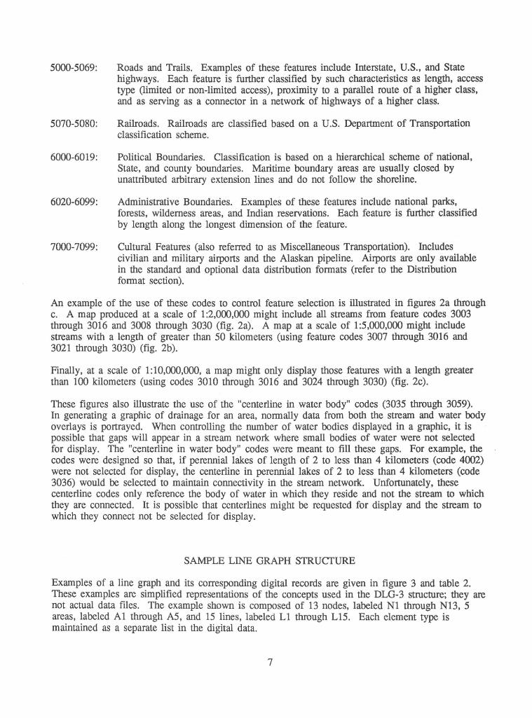
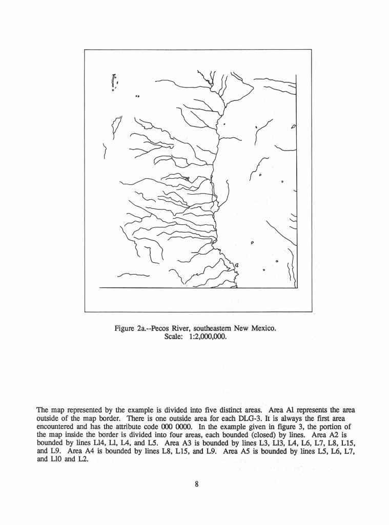
An example of the use of these codes to control feature selection is illustrated in figures 2a through c. A map produced at a scale of 1 :2,000,000 might include all streams from feature codes 3003 through 3016 and 3008 through 3030 (fig. 2a). A map at a scale of 1:5,000,000 might include streams with a length of greater than 50 kilometers (using feature codes 3007 through 3016 and 3021 through 3030) (fig. 2b ).
Finally, at a scale of 1:10,000,000, a map might only display those features with a length greater than 100 kilometers (using codes 3010 through 3016 and 3024 through 3030) (fig. 2c).
These figures also illustrate the use of the "centerline in water body" codes (3035 through 3059). In generating a graphic of drainage for an area, normally data from both the stream and water body overlays is portrayed. When controlling the number of water bodies displayed in a graphic, it is possible that gaps will appear in a stream network where small bodies of water were not selected for display. The "centerline in water body" codes were meant to fill these gaps. For example, the codes were designed so that, if perennial lakes of length of 2 to less than 4 kilometers (code 4002) were not selected for display, the centerline in perennial lakes of 2 to less than 4 kilometers (code 3036) would be selected to maintain connectivity in the stream network. Unfortunately, these centerline codes only reference the body of water in which they reside and not the stream to which they are connected. It is possible that centerlines might be requested for display and the stream to which they connect not be selected for display.
SAMPLE LINE GRAPH STRUCTURE
Examples of a line graph and its corresponding digital records are given in figure 3 and table 2. These examples are simplified representations of the concepts used in the DLG-3 structure; they are not actual data files. The example shown is composed of 13 nodes, labeled Nl through Nl3, 5 areas, labeled Al through AS, and 15 lines, labeled Ll through L15. Each element type is maintained as a separate list in the digital data.
7
(•, o'
Figure 2a.--Pecos River, southeastern New Mexico. Scale: 1 :2,000,000.
The map represented by the example is divided into five distinct areas. Area Al represents the area outside of the map border. There is one outside area for each DLG-3. It is always the first area encountered and has the attribute code 000 0000. In the example given in figure 3, the portion of the map inside the border is divided into four areas, each bounded (closed) by lines. Area A2 is bounded by lines Ll4, Ll, L4, and L5. Area A3 is bounded by lines L3, Ll3, L4, L6, L7, L8, Ll5, and L9. Area A4 is bounded by lines L8, Ll5, and L9. Area AS is bounded by lines L5, L6, L7, and LlO and L2.
8
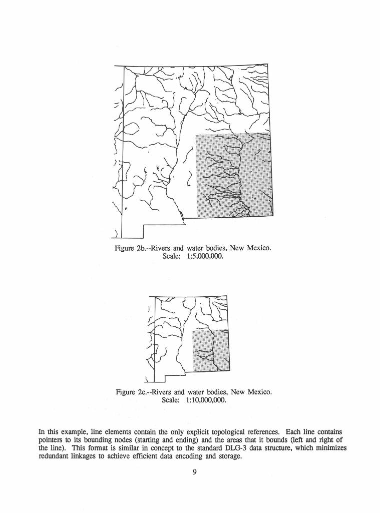
Figure 2b.--Rivers and water bodies, New Mexico. Scale: 1:5,000,000.
Figure 2c.--Rivers and water bodies, New Mexico. Scale: 1:10,000,000.
In this example, line elements contain the only explicit topological references. Each line contains pointers to its bounding nodes (starting and ending) and the areas that it bounds (left and right of the line). This fonnat is similar in concept to the standard DLG-3 data structure, which minimizes redundant linkages to achieve efficient data encoding and storage.
9
The lines in figure 3 are labeled L1 through L15. The lines can be identified by their starting node number, ending node number, number of the area to the left of the direction of travel, number of the area to the right of the direction of travel, and string of coordinates describing the alignment of the line. In this example, only two pairs of coordinates are shown; however, in an actual file, an irregular line would have a variable number of coordinate pairs up to a limit of 1 ,500 coordinate pairs. The direction of travel of the line is arbitrarily determined during the digitizing operation. In this example, L1 is encoded as proceeding clockwise around area A2. Thus line L1 starts at node N1, ends at node N3, has area A1 to the left of the direction of travel, and has area A2 to the right of the direction of travel. The coordinate string describing the alignment of the line will start with the same coordinate values as that of node N1 and will end with the same coordinate values as that of node N3. Because the area to the left of its direction of travel, A1, is different from the area to the right of its direction of travel, A2, the line is known to be a boundary between the two areas. ·
28 L1 N1 N3
27 --26
25
24 EBA2 N9
23 e L12 L2
22"
21 ...,.
20 ::i
19
18 . L4 17 ~
16 z 15
y 14 EBAS 13
12
11 -- C') CD N6 10 ::i EBA3 _J
9 N13
8
7 --6 N5
5·
4 -- ,.....
3 _J
2
1 N12 N10
EB L3 N4 L10
A1
~~ Nl Ml ..,.,~,co~~~~~~~~~~~~~~~~ ~1~1~1=1~1~1~1 ~~ ~~ X
Figure 3.--Sample line graph.
10
Internal Id Number
N1 N2 N3 N4 N5 N6 N7 N8 N9 N10 N11 N12 N13
Number
L1 L2 L3 lA L5 L6 L7 L8 L9 L10 L11 L12 L13 L14 L15
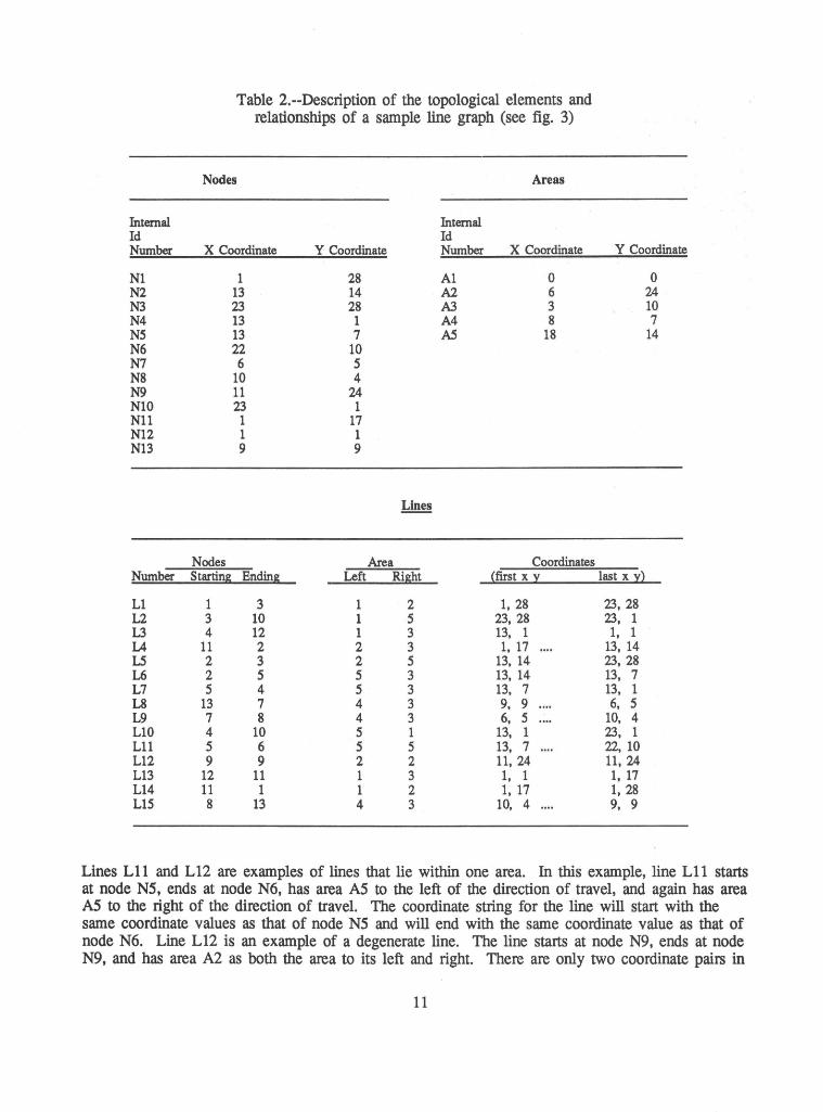
Table 2.--Description of the topological elements and relationships of a sample line graph (see fig. 3)
Nodes Areas
Internal Id
X Coordinate Y Coordinate Number X Coordinate
1 28 A1 0 13 14 A2 6 23 28 A3 3 13 1 A4 8 13 7 AS 18 22 10 6 5
10 4 11 24 23 1 1 17 1 1 9 9
Lines
Nodes Area Coordinates Starting Ending Left Right (first x y
1 3 1 2 1, 28 3 10 1 5 23, 28 4 12 1 3 13, 1
11 2 2 3 1, 17 2 3 2 5 13, 14 2 5 5 3 13, 14 5 4 5 3 13, 7
13 7 4 3 9, 9 7 8 4 3 6, 5 4 10 5 1 13, 1 5 6 5 5 13, 7 9 9 2 2 11, 24
12 11 1 3 1, 1 11 1 1 2 1, 17 8 13 4 3 10, 4
Y Coordinate
0 24 10 7
14
last x y)
23, 28 23, 1 1, 1
13, 14 23, 28 13, 7 13, 1 6, 5
10, 4 23, 1 22, 10 11, 24 1, 17 1, 28 9, 9
Lines Lll and L12 are examples of lines that lie within one area. In this example, line Lll starts at node N5, ends at node N6, has area AS to the left of the direction of travel, and again has area AS to the right of the direction of travel. The coordinate string for the line will start with the same coordinate values as that of node NS and will end with the same coordinate value as that of node N6. Line L12 is an example of a degenerate line. The line starts at node N9, ends at node N9, and has area A2 as both the area to its left and right. There are only two coordinate pairs in
11
the string defining the line: both points have the same coordinate values as node N9; thus, the two points are the same and the line has zero length.
The line graph concept allows all of the points on the map to be described as a member of a line graph element (node, area, or line) with minimal redundancy. The relationships between the various elements are indicated by the structure. Note that in this example the x and y coordinates are numbered from the lower left comer to simplify the drawing. In an actual DLG-3 file, the origin is the center of the map and the internal ftle coordinates are numbered plus or minus 1 to 32,767 expressed in thousandths of inches. See the section labeled "Coordinate Systems" for more detail.
GRAPH THEORY IN DLG DATA
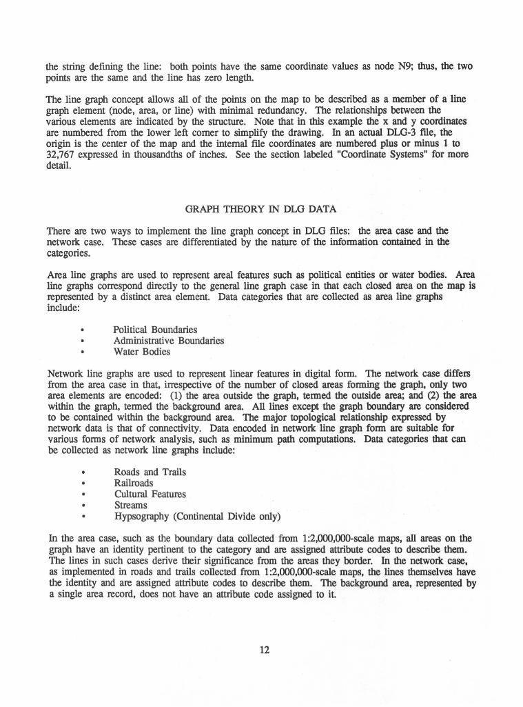
There are two ways to implement the line graph concept in DLG files: the area case and the network case. These cases are differentiated by the nature of the infonnation contained in the categories.
Area line graphs are used to represent areal features such as political entities or water bodies. Area line graphs correspond directly to the general line graph case in that each closed area on the map is represented by a distinct area element. Data categories that are collected as area line graphs include:
• Political Boundaries • Administrative Boundaries • Water Bodies
Network line graphs are used to represent linear features in digital fonn. The network case differs from the area case in that, irrespective of the number of closed areas fonning the graph, only two area elements are encoded: (1) the area outside the graph, tenned the outside area; and (2) the area within the graph, tenned the background area. All lines except the graph boundary are considered to be contained within the background area. The major topological relationship expressed by network data is that of connectivity. Data encoded in network line graph fonn are suitable for various fonns of network analysis, such as minimum path computations. Data categories that can be collected as network line graphs include:
• Roads and Trails • Railroads • Cultural Features • Streams • Hypsography (Continental Divide only)
In the area case, such as the boundary data collected from 1 :2,000,000-scale maps, all areas on the graph have an identity pertinent to the category and are assigned attribute codes to describe them. The lines in such cases derive their significance from the areas they border. In the network case, as implemented in roads and trails collected from 1 :2,000,000-scale maps, the lines themselves have the identity and are assigned attribute codes to describe them. The background area, represented by a single area record, does not have an attribute code assigned to it
12
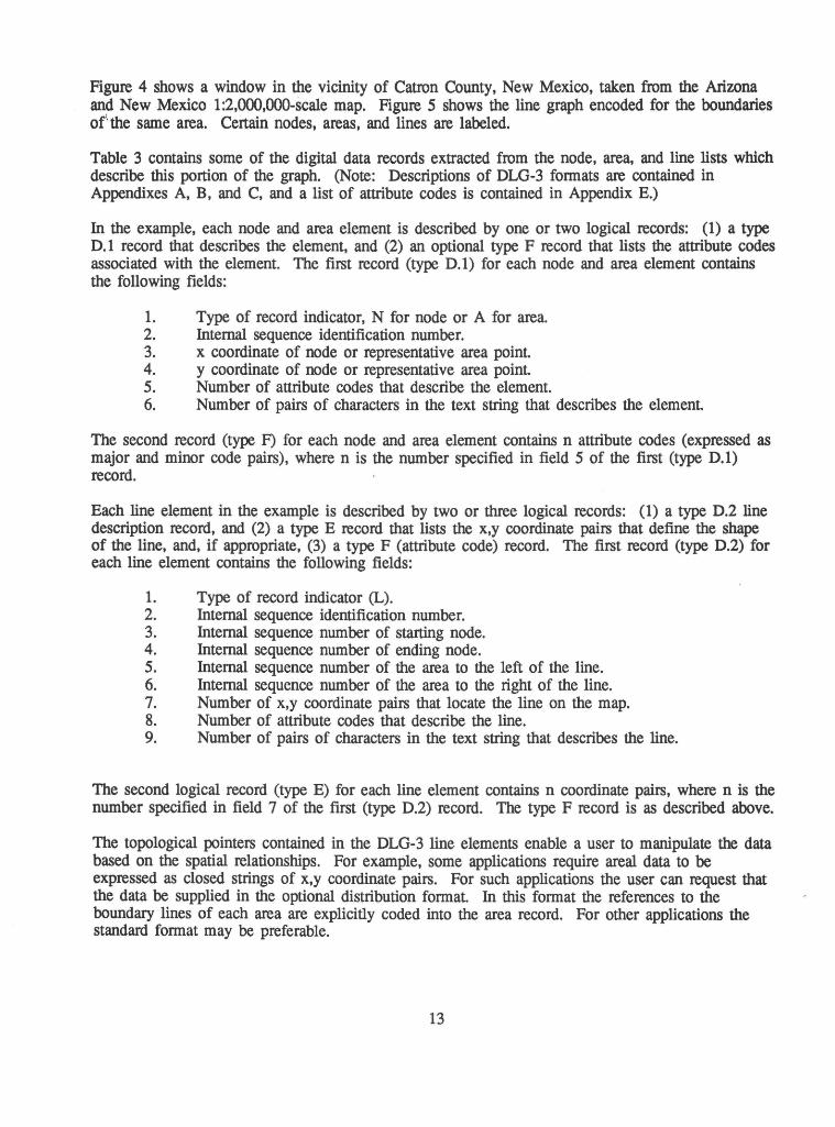
Figure 4 shows a window in the vicinity of Catron County, New Mexico, taken from the Arizona and New Mexico 1 :2,000,000-scale map. Figure 5 shows the line graph encoded for the boundaries of' the same area. Certain nodes, areas, and lines are labeled.
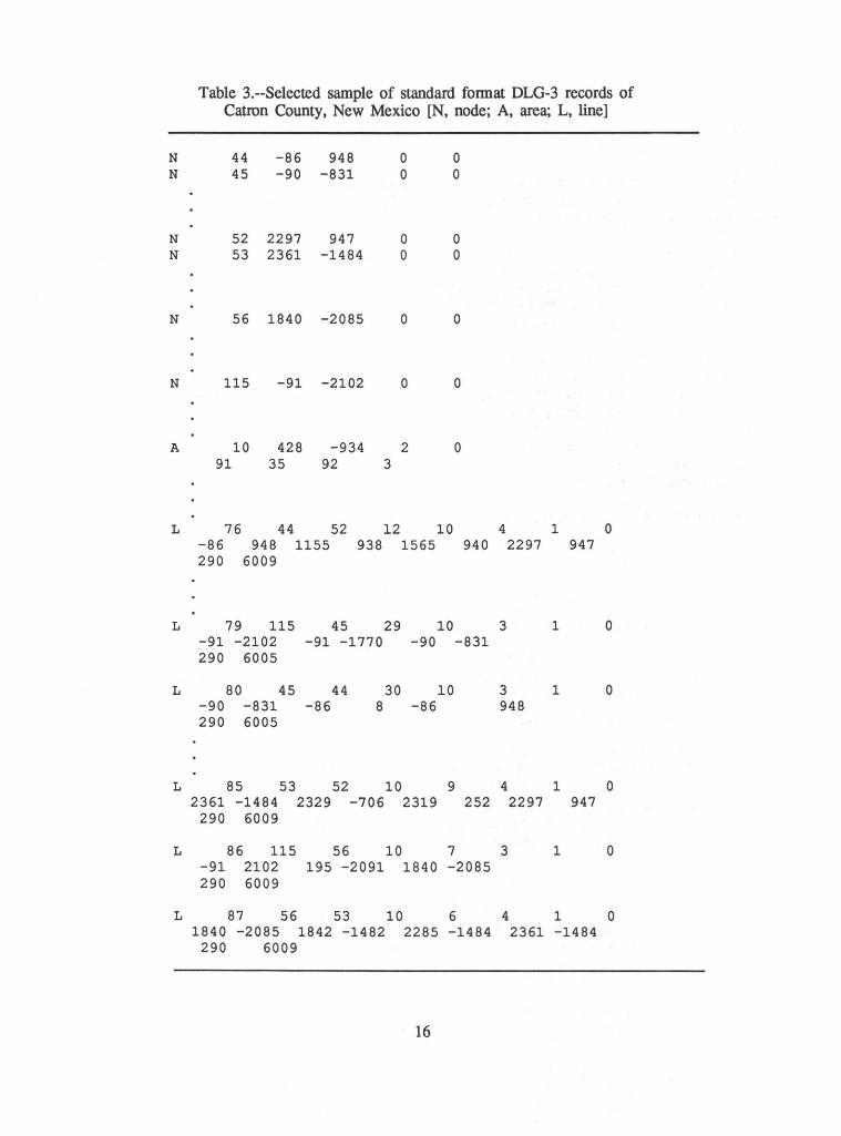
Table 3 contains some of the digital data records extracted from the node, area, and line lists which describe this portion of the graph. (Note: Descriptions of DLG-3 formats are contained in Appendixes A, B, and C, and a list of attribute codes is contained in Appendix E.)
In the example, each node and area element is described by one or two logical records: (1) a type 0.1 record that describes the element, and (2) an optional type F record that lists the attribute codes associated with the element. The first record (type 0.1) for each node and area element contains the following fields:
1. Type of record indicator, N for node or A for area. 2. Internal sequence identification number. 3. x coordinate of node or representative area point. 4. y coordinate of node or representative area point. 5. Number of attribute codes that describe the element. 6. Number of pairs of characters in the text string that describes the element.
The second record (type F) for each node and area element contains n attribute codes (expressed as major and minor code pairs), where n is the number specified in field 5 of the first (type 0.1) record.
Each line element in the example is described by two or three logical records: (1) a type 0.2 line description record, and (2) a type E record that lists the x,y coordinate pairs that define the shape of the line, and, if appropriate, (3) a type F (attribute code) record. The first record (type 0.2) for each line element contains the following fields:
1. Type of record indicator (L). 2. Internal sequence identification number. 3. Internal sequence number of starting node. 4. Internal sequence number of ending node. 5. Internal sequence number of the area to the left of the line. 6. Internal sequence number of the area to the right of the line. 7. Number of x,y coordinate pairs that locate the line on the map. 8. Number of attribute codes that describe the line. 9. Number of pairs of characters in the text string that describes the line.
The second logical record (type E) for each line element contains n coordinate pairs, where n is the number specified in field 7 of the first (type 0.2) record. The type F record is as described above.
The topological pointers contained in the DLG-3 line elements enable a user to manipulate the data based on the spatial relationships. For example, some applications require areal data to be expressed as closed strings of x,y coordinate pairs. For such applications the user can request that the data be supplied in the optional distribution format. In this format the references to the boundary lines of each area are explicitly coded into the area record. For other applications the standard format may be preferable.
13
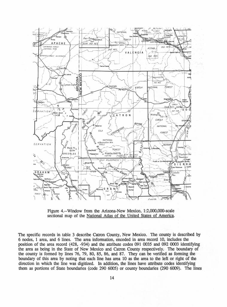
Figure 4.--Window from the Arizona-New Mexico, 1 :2,000,000-scale sectional map of the National Atlas of the United States of America.
The specific records in table 3 describe Catron County, New Mexico. The county is described by 6 nodes, 1 area, and 6 lines. The area information, encoded in area record 10, includes the position of the area record (428, -934) and the attribute codes 091 0035 and 092 0003 identifying the area as being in the State of New Mexico and Catron County respectively. The boundary of the county is formed by lines 76, 79, 80, 85, 86, and 87. They can be verified as forming the boundary of this area by noting that each line has area 10 as the area to the left or right of the direction in which the line was digitized. In addition, the lines have attribute codes identifying them as portions of State boundaries (code 290 6005) or county boundaries (290 6009). The lines
14
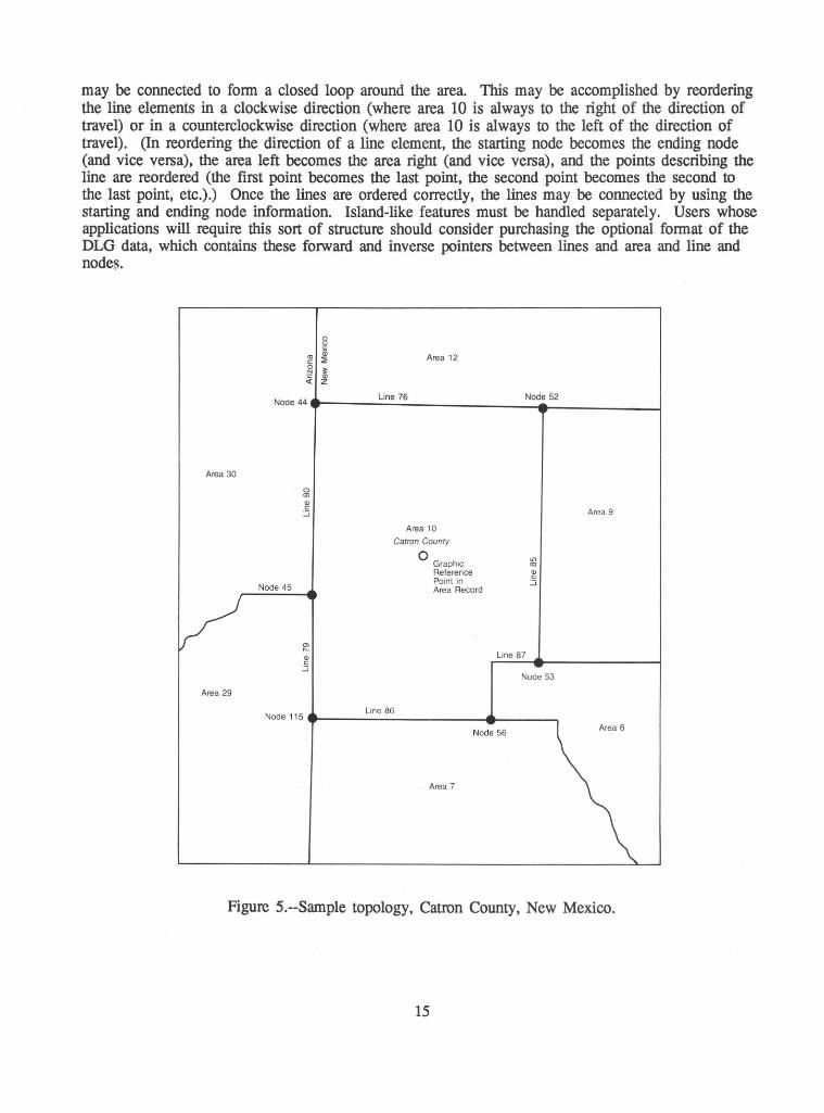
may be connected to fonn a closed loop around the area. This may be accomplished by reordering the line elements in a clockwise direction (where area 10 is always to the right of the direction of travel) or in a counterclockwise direction (where area 10 is always to the left of the direction of travel). (In reordering the direction of a line element, the starting node becomes the ending node (and vice versa), the area left becomes the area right (and vice versa), and the points describing the line are reordered (the first point becomes the last point, the second point becomes the second to the last point, etc.).) Once the lines are ordered correctly, the lines may be connected by using the starting and ending node information. Island-like features must be handled separately. Users whose applications will require this sort of structure should consider purchasing the optional fonnat of the DLG data, which contains these forward and inverse pointers between lines and area and line and node~.
"' Area 12 c: 0 N
~
Node 44 Line 76 Node 52
Area 30
0 co Q) c:
Area 9 :.:J
Area 10
Catron County
0 . 11)
Graphic co Reference ~
Node 45 Point in :.:J Area Record v en
1'-Line 87
~ .:J
Node 53
Area 29
Node 115 Line 86
Node 56 Area 6
Area 7
Figure 5.--Sample topology, Catron County, New Mexico.
15
N N
N N
N
N
A
L
L
L
L
L
L
Table 3.--Selected sample of standard fonnat DLG-3 records of Catron County, New Mexico [N, node; A, area; L, line]
44 -86 948 45 -90 -831
52 2297 947 53 2361 -1484
56 1840 -2085
115 -91 -2102
0 0
0 0
0
0
10 428 -934 2 91 35 92 3
0 0
0 0
0
0
0
76 -86 290
44 948
6009
52 1155
12 10 938 1565 940
79 115 45 29 10 -91 -2102 -91 -1770 -90 -831 290 6005
80 45 44 30 10 -90 -831 -86 8 -86 290 6005
85 53 52 10 9 2361 -1484 2329 -706 2319 252
290 6009
86 115 56 10 7 -91 2102 195 -2091 1840 -2085 290 6009
87 56 53 10 6 1840 -2085 1842 -1482 2285 -1484
290 6009
16
4 2297
3
3 948
4 2297
3
4 2361
1 0 947
1 0
1 0
1 0 947
1 0
1 0 -1484
DISTRIBUTION FORMATS
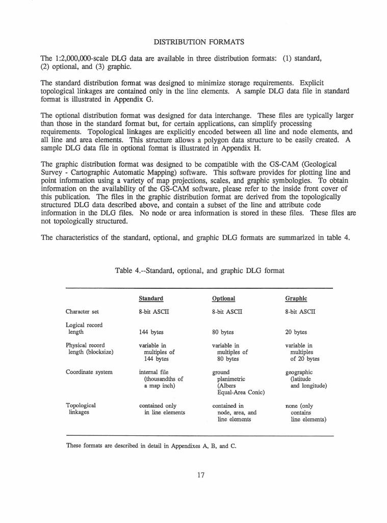
The 1 :2,000,000-scale DLG data are available in three distribution fonnats: (1) standard, (2) optional, and (3) graphic.
The standard distribution fonnat was designed to minimize storage requirements. Explicit topological linkages are contained only in the line elements. A sample DLG data file in standard fonnat is illustrated in Appendix G.
The optional distribution fonnat was designed for data interchange. These files are typically larger than those in the standard fonnat but, for certain applications, can simplify processing requirements. Topological linkages are explicitly encoded between all line and node elements, and all line and area elements. This structure allows a polygon data structure to be easily created. A sample DLG data file in optional fonnat is illustrated in Appendix H.
The graphic distribution fonnat was designed to be compatible with the GS-CAM (Geological Survey - Cartographic Automatic Mapping) software. This software provides for plotting line and point infonnation using a variety of map projections, scales, and graphic symbologies. To obtain infonnation on the availability of the GS-CAM software, please refer to the inside front cover of this publication. The files in the graphic distribution fonnat are derived from the topologically structured DLG data described above, and contain a subset of the line and attribute code infonnation in the DLG ftles. No node or area infonnation is stored in these files. These files are not topologically structured.
The characteristics of the standard, optional, and graphic DLG fonnats are summarized in table 4.
Character set
Logical record length
Physical record length (blocksize)
Coordinate system
Topological linkages
Table 4.--Standard, optional, and graphic DLG format
Standard Optional
8-bit ASCTI 8-bit ASCTI
144 bytes 80 bytes
variable in variable in multiples of multiples of 144 bytes 80 bytes
internal file ground (thousandths of planimetric a map inch) (Albers
Equal-Area Conic)
contained only contained in in line elements node, area, and
line elements
These formats are described in detail in Appendixes A, B, and C.
17
Graphic
8-bit ASCTI
20 bytes
variable in multiples of 20 bytes
geographic (latitude and longitude)
none (only contains line elements)
SOURCE MATERIALS
The data described in this document are derived from USGS 1:2,000,000-scale reference maps from The National Atlas of the United States of America. Selective updating of the maps was done prior to digitizing. Data source and currency infonnation may be found in Appendix I.
The data for the contenninous United States and Hawaii were collected from 1 :2,000,000-scale map manuscripts. For Alaska, the boundary and transportation data were digitized from 1 :2,000,000-scale source documents; the hydrographic data were digitized from 1: 1 ,000,000-scale source documents. The scale of the source materials used to generate a DLG is contained in the file header. The scale is also reflected in the resolution field, which states the ground length in meters of the smallest data collection unit 0.001 inch (50.8 meters for 1 :2,000,000-scale data; 25.4 meters for 1: 1 ,000,000-scale data).
CELL SIZE AND FILE EXTENT
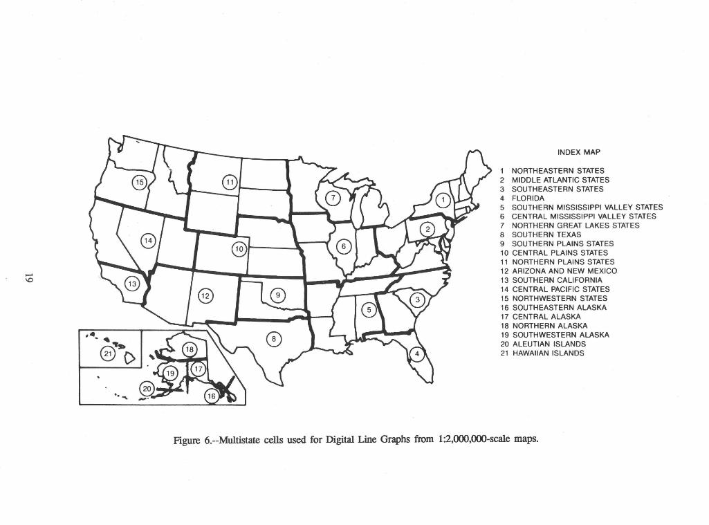
The DLG's are distributed predominantly in multistate cells (fig. 6). There are a total of 21 cells for the United States: 15 for the contenninous United States, 5 for Alaska, and 1 for Hawaii. In general, States are not divided between cells. Three States (California, Texas, and Montana) are divided between two cells along county boundaries. Alaska is divided among five cells along arcs of longitude and/or latitude.
The data for each cell are encoded in multiple thematic categories (Political Boundaries, Administrative Boundaries, Roads and Trails, Railroads, Cultural Features, Streams, Water Bodies, and (where appropriate) Hypsography). Nonnally, there is one file per category. Due to software limitations at the time of digitizing, however, some categories with a large number of elements may be encoded in several files. Files are not horizontally integrated (edge joined) between cells.
COORDINATE SYSTEMS
The positional descriptions for DLG data elements are expressed in one of three coordinate systems, dependent upon the distribution fonnat selected. These distribution fonnats - standard, optional, and graphic - are described below.
Standard Distribution Fonnat
The DLG data in the standard distribution fonnat are encoded using an . internal file coordinate system to minimize storage requirements. The characteristics of this system are as follows:
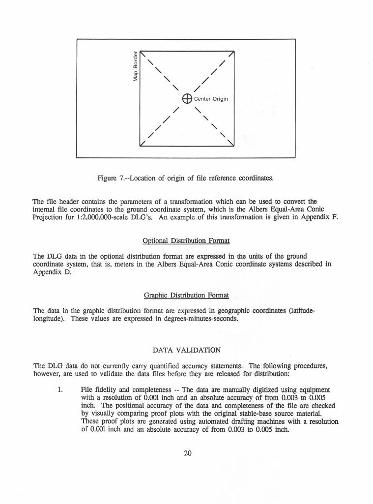
1. The coordinate system is Cartesian. 2. The origin (x=O, y=O) is at the center of the cell (fig. 7). 3. The x-axis of the coordinate system is parallel to a theoretical straight line
connecting the southwest and southeast registration points of the cell, y-axis is perpendicular to that line.
4. One unit is equal to 0.001-inch at map scale. 5. The coordinate domain is limited to the range -32768 to +32767.
18
..... \0
,._ . -t.
@(>
.. "'
INDEX MAP
1 NORTHEASTERN STATES 2 MIDDLE ATLANTIC STATES 3 SOUTHEASTERN STATES 4 FLORIDA 5 SOUTHERN MISSISSIPPI VALLEY STATES 6 CENTRAL MISSISSIPPI VALLEY STATES 7 NORTHERN GREAT LAKES STATES 8 SOUTHERN TEXAS 9 SOUTHERN PLAINS STATES 10 CENTRAL PLAINS STATES 11 NORTHERN PLAINS STATES 12 ARIZONA AND NEW MEXICO 13 SOUTHERN CALIFORNIA 14 CENTRAL PACIFIC STATES 15 NORTHWESTERN STATES 16 SOUTHEASTERN ALASKA 17 CENTRAL ALASKA 18 NORTHERN ALASKA 19 SOUTHWESTERN ALASKA 20 ALEUTIAN ISLANDS 21 HAWAIIAN ISLANDS
Figure 6.--Multistate cells used for Digital Line Graphs from 1:2,000,000-scal.e maps.
['. /
' /
' /
' /
' / Ef) Center Origin
/ ' / ' / ' / ' l/ ' Figure ?.--Location of origin of ftle reference coordinates.
The ftle header contains the parameters of a transfonnation which can be used to convert the internal file coordinates to the ground coordinate system, which is the Albers Equal-Area Conic Projection for 1:2,000,000-scale DLG's. An example of this transformation is given in Appendix F.
Optional Distribution Format
The DLG data in the optional distribution format are expressed in the units of the ground coordinate system, that is, meters in the Albers Equal-Area Conic coordinate systems described in Appendix D.
Graphic Distribution Fonnat
The data in the graphic distribution fonnat are expressed in geographic coordinates (latitudelongitude). These values are expressed in degrees-minutes-seconds.
DATA VALIDATION
The DLG data do not currently carry quantified accuracy statements. The following procedures, however, are used to validate the data files before they are released for distribution:
1. File fidelity and completeness -- The data are manually digitized using equipment with a resolution of 0.001 inch and an absolute accuracy of from 0.003 to 0.005 inch. The positional accuracy of the data and completeness of the file are checked by visually comparing proof plots with the original stable-base source material. These proof plots are generated using automated drafting machines with a resolution of 0.001 inch and an absolute accuracy of from 0.003 to 0.005 inch.
20
2. Attribute accuracy -- Validating the codes for correct application is currently a manual process involving the correlation of fonnatted listings with proof plots.
3. Topological fidelity -- The topological structure of each DLG file is fully validated by software. There are no extraneous intersections; that is, a line does not join or cross another line, or itself, except at a node. No line extends through a node. Polygon (area) adjacency is also validated; that is, area left and right topological attributes of lines are consistent throughout the file. The neatline is free of gaps. Validation of DLG data is perfonned for each category within a ftle.
[Note: A deficiency in the topological validation software was discovered after the data were processed. For some graphic representations the software did not check the topology of island-like features correctly; some features of this type may have incorrect topology in the ftles.]
21


APPENDIXES

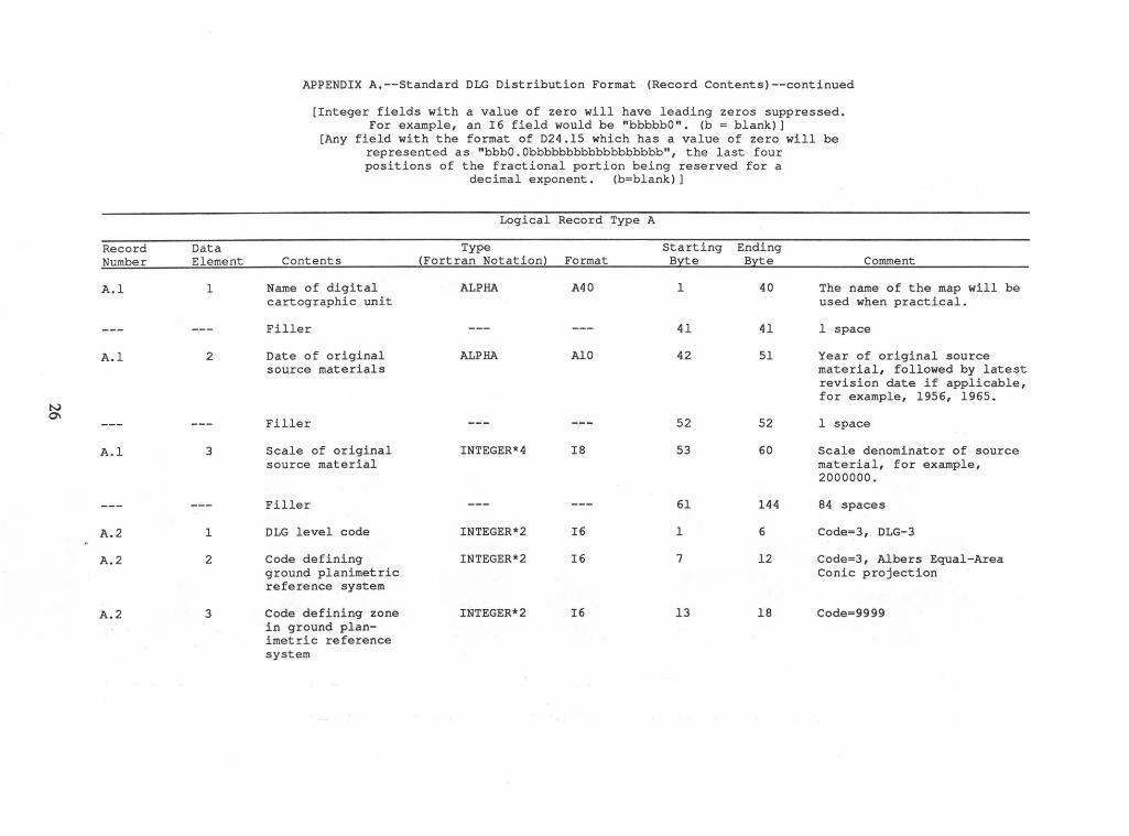
APPENDIX A.--Standard DLG Distribution Format (Record Contents)
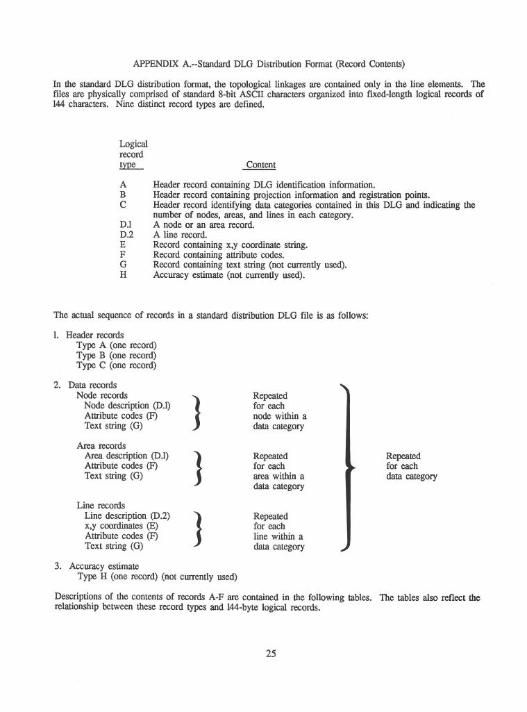
In the standard DLG distribution format, the topological linkages are contained only in the line elements. The files are physically comprised of standard 8-bit ASCII characters organized into fixed-length logical records of 144 characters. Nine distinct record types are defined.
Logical record !YillL_ Content
A Header record containing DLG identification information. B Header record containing projection information and registration points. C Header record identifying data categories contained in this DLG and indicating the
number of nodes, areas, and lines in each category. D.l A node or an area record. D.2 A line record. E Record containing x,y coordinate string. F Record containing attribute codes. G Record containing text string (not currently used). H Accuracy estimate (not currently used).
The actual sequence of records in a standard distribution DLG file is as follows:
l. Header records . Type A (one record) Type B (one record) Type C (one record)
2. Data records Node records
} Repeated
Node description (D.l) for each Attribute codes (F) node within a Text string (G) data category
Area records Area description (D.l) } Repeated Repeated Attribute codes (F) for each for each Text string (G) area within a data category
data category
Line records Line description (0.2) } Repeated x,y coordinates (E) for each Attribute codes (F) line within a Text string (G) data category
3. Accuracy estimate Type H (one record) (not currently used)
Descriptions of the contents of records A-F are contained in the following tables. The tables also reflect the relationship between these record types and 144-byte logical records.
25
Record Data Number Element
A.l 1
A.l 2
N 0\
A.l 3
A.2 1
A.2 2
A.2 3
APPENDIX A.--Standard DLG Distribution Format (Record Contents)--continued
[Integer fields with a value of zero will have leading zeros suppressed. For example, an I6 field would be "bbbbbO". (b =blank)]
[Any field with the format of D24.15 which has a value of zero will be represented as "bbbO.Obbbbbbbbbbbbbbbbbb", the last four positions of the fractional portion being reserved for a
decimal exponent. (b=blank)]
Logical Record Type A
Type Starting Ending Contents (Fortran Notation) Format Byte Byte Comment
Name of digital ALPHA A40 1 40 The name of the map will be cartographic unit used when practical.
Filler --- --- 41 41 1 space
Date of original ALPHA AlO 42 51 Year of original source source materials material, followed by latest
revision date if applicable, for example, 1956, 1965.
Filler --- --- 52 52 1 space
Scale of original INTEGER*4 I8 53 60 Scale denominator of source source material material, for example,
2000000.
Filler --- --- 61 144 84 spaces
DLG level code INTEGER*2 I6 1 6 Code=3, DLG-3
Code defining INTEGER*2 I6 7 12 Code=3, Albers Equal-Area ground planimetric Conic projection reference system
Code defining zone INTEGER*2 I6 13 18 Code=9999 in ground plan-imetric reference system
N -...l
Record Number
A.2
A.3
A.4
A.4
A.4
Data Element
4
1
1
2
3
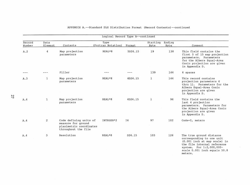
APPENDIX A.--Standard DLG Distribution Format (Record Contents)--continued
Logical Record Type A--continued
Type Contents (Fortran Notation) Format
Map projection parameters
Filler
Map projection parameters
Map projection parameters
Code defining units of measure for ground planimetric coordinates throughout the file
Resolution
REAL*8 5D24.15
REAL*8 6D24.15
REAL*8 4D24.15
INTEGER*2 I6
REAL*8 D24.15
Starting Ending Byte Byte
19 138
139 144
1 144
1 96
97 102
103 126
Comment
This field contains the first 5 of 15 map projection parameters. Parameters for the Albers Equal-Area Conic projection are given in Appendix D.
6 spaces
This record contains projection parameters 6 thru 11. Parameters for the Albers Equal-Area Conic projection are given in Appendix D.
This field contains the last 4 projection parameters. Parameters for the Albers Equal-Area Conic projection are given in Appendix D.
Code=2, meters
The true ground distance corresponding to one unit (0.001 inch at map scale) in the file internal reference system. For 1:2,000,000-scale 0.001 inch equals 50.8 meters.
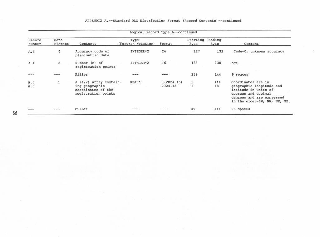
APPENDIX A.--Standard DLG Distribution Format (Record Contents)--continued
Logical Record Type A--continued
Record Data Type Starting Ending Number Element Contents (Fortran Notation) Format B:ite Byte Comment
A.4 4 Accuracy code of INTEGER*2 I6 127 132 Code=O, unknown accuracy planimetric data
A.4 5 Number (n) of INTEGER*2 I6 133 138 n=4 registration points
Filler --- --- 139 144 6 spaces
A.S 1 A (4,2) array contain- REAL*8 3(2D24.15) 1 144 Coordinates are in A.6 ing geographic 2D24.15 1 48 geographic longitude and
coordinates of the latitude in units of registration points degrees and decimal
degrees and are expressed in the order=SW, NW, NE, SE.
Filler --- --- 49 144 96 spaces N 00
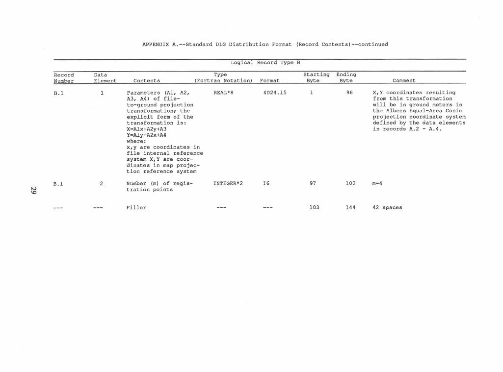
APPENDIX A.--Standard DLG Distribution Format (Record Contents)--continued
Logical Record Type B
Record Data Type Starting Ending Number Element Contents (Fortran Notation~ Format Byte Byte Comment
B.l 1 Parameters (Al, A2, REAL*8 4D24.15 1 96 X,Y coordinates resulting A3, A4) of file- from this transformation to-ground projection will be in ground meters in transformation; the the Albers Equal-Area Conic explicit form of the projection coordinate system transformation is: defined by the data elements X=Alx+A2y+A3 in records A.2 - A.4. Y=Aly-A2x+A4 where: x,y are coordinates in file internal reference system X,Y are coor-dinates in map projec-tion reference system
B.l 2 Number (m) of regis- INTEGER*2 I6 97 102 m=4 N tration points \0
Filler --- --- 103 144 42 spaces
w 0
Record Number
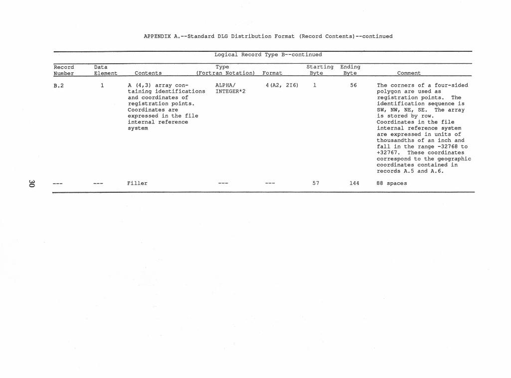
B.2
Data Element
1
APPENDIX A.--Standard DLG Distribution Format (Record Contents)--continued
Logical Record Type B--continued
Type Starting Ending Contents (Fortran Notation) Format Byte Byte
A (4,3) array containing identifications and coordinates of registration points. Coordinates are expressed in the file internal reference system
Filler
ALPHA/ INTEGER*2
4 (A2, 2I6) 1 56
57 144
Comment
The corners of a four-sided polygon are used as registration points. The identification sequence is SW, NW, NE, SE. The array is stored by row. Coordinates in the file internal reference system are expressed in units of thousandths of an inch and fall in the range -32768 to +32767. These coordinates correspond to the geographic coordinates contained in records A.5 and A.6.
88 spaces
{j.) ......
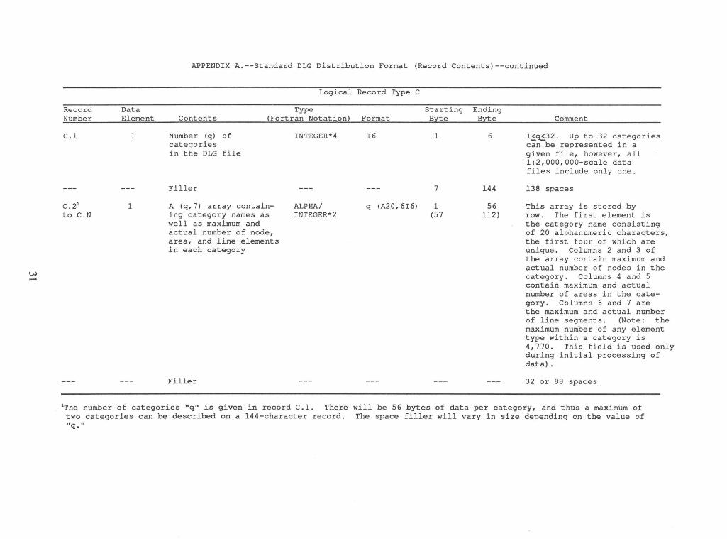
Record Number
C.l
c. 21
to C.N
Data Element
1
1
APPENDIX A.--Standard DLG Distribution Format (Record Contents)--continued
Logical Record Type C
Type Starting Ending Contents (Fortran Notation) Format Byte Byte
Number (q) of categories in the DLG file
Filler
A (q,7) array containing category names as well as maximum and actual number of node, area, and line elements in each category
Filler
INTEGER*4
ALPHA/ INTEGER*2
I6
q (A20, 6I6)
1
7
1 (57
6
144
56 112)
Comment
1~~32 . Up to 32 categories can be represented in a given file, however, all 1:2,000,000-scale data files include only one.
138 spaces
This array is stored by row. The first element is the category name consisting of 20 alphanumeric characters, the first four of which are unique. Columns 2 and 3 of the array contain maximum and actual number of nodes in the category. Columns 4 and 5 contain maximum and actual number of areas in the category. Columns 6 and 7 are the maximum and actual number of line segments. (Note: the maximum number of any element type within a category is 4,770. This field is used only during initial processing of data) .
32 or 88 spaces
1The number of categories "q" is given in record C.1. There will be 56 bytes of data per category, and thus a maximum of two categories can be described on a 144-character record. The space filler will vary in size depending on the value of "q."
w N
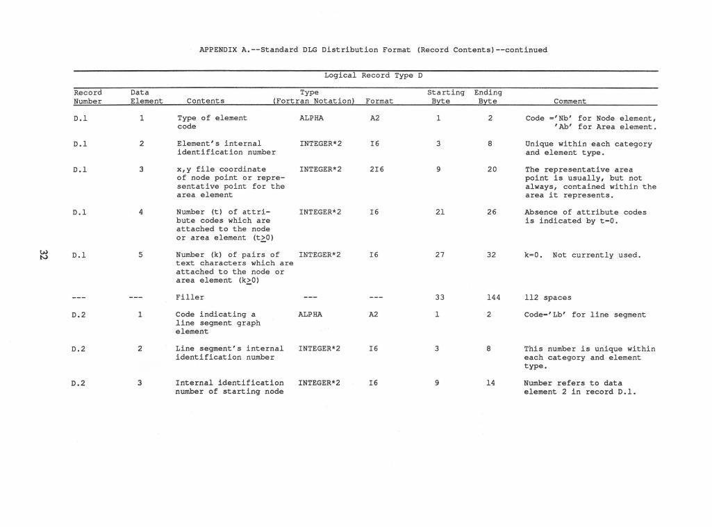
Record Number
D.l
D.l
D.l
D.l
D.l
D.2
D.2
D.2
Data Element
1
2
3
4
5
1
2
3
APPENDIX A.--Standard DLG Distribution Format (Record Contents)--continued
Logical Record Type D
Type starting Ending Contents (Fortran Notation) Format Byte Byte
Type of element code
Element's internal identification number
x,y file coordinate of node point or representative point for the area element
Number (t) of attribute codes which are attached to the node or area element (t~O)
ALPHA
INTEGER*2
INTEGER*2
INTEGER*2
Number (k) of pairs of INTEGER*2 text characters which are attached to the node or area element (k~O)
Filler
Code indicating a line segment graph element
Line segment's internal identification number
Internal identification number of starting node
ALPHA
INTEGER*2
INTEGER*2
A2 1 2
I6 3 8
2I6 9 20
I6 21 26
I6 27 32
33 144
A2 1 2
I6 3 8
I6 9 14
Comment
Code ='Nb' for Node element, 'Ab' for Area element.
Unique within each category and element type.
The representative area point is usually, but not always, contained within the area it represents.
Absence of attribute codes is indicated by t=O.
k=O. Not currently used.
112 spaces
Code='Lb' for line segment
This number is unique within each category and element type.
Number refers to data element 2 in record D.l.
w w
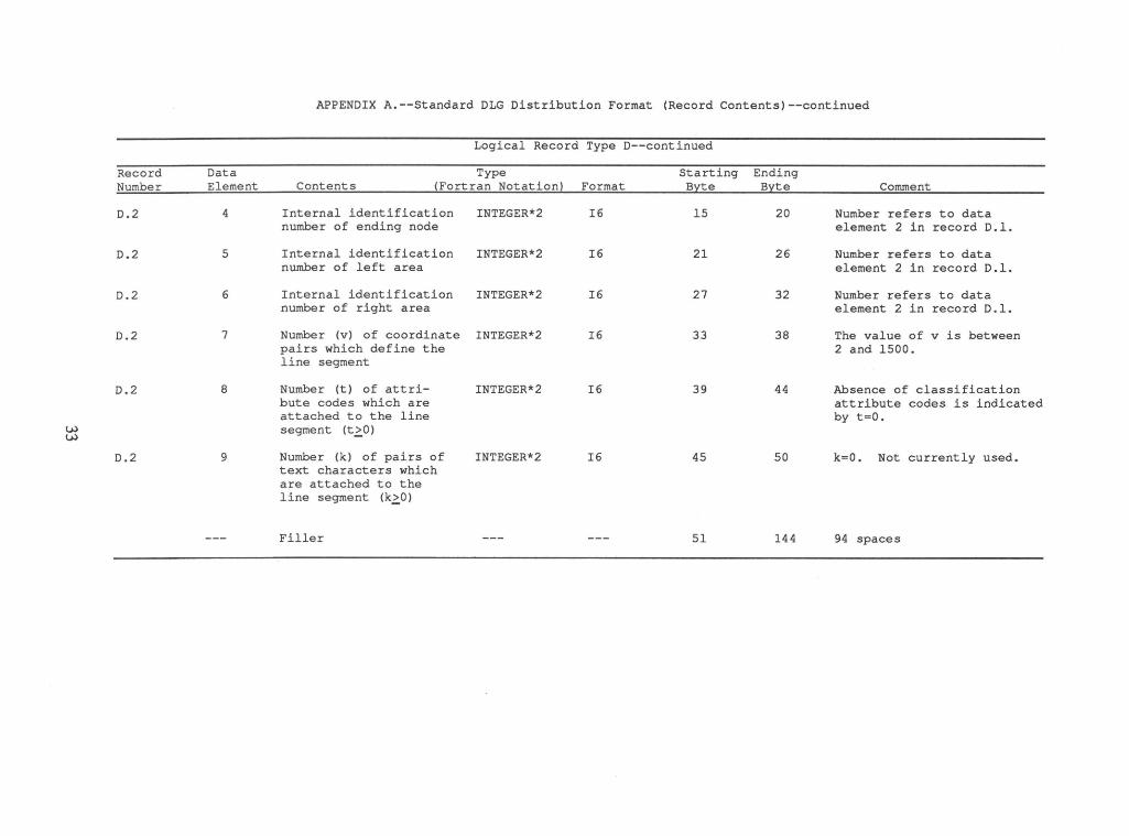
Record Number
D.2
D.2
D.2
0.2
0.2
0.2
Data Element
4
5
6
7
8
9
APPENDIX A.--Standard DLG Distribution Format (Record Contents)--continued
Logical Record Type D--continued
Type Starting Ending Contents (Fortran Notation) Format Byte Byte
Internal identification INTEGER*2 number of ending node
Internal identification INTEGER*2 number of left area
Internal identification INTEGER*2 number of right area
Number (v) of coordinate INTEGER*2 pairs which define the line segment
Number (t) of attribute codes which are attached to the line segment (t~O)
Number (k) of pairs of text characters which are attached to the line segment <kzO>
Filler
INTEGER*2
INTEGER*2
I6
I6
I6
I6
I6
I6
15 20
21 26
27 32
33 38
39 44
45 50
51 144
Comment
Number refers to data element 2 in record D.l.
Number refers to data element 2 in record D.l.
Number refers to data element 2 in record D.l.
The value of v is between 2 and 1500.
Absence of classification attribute codes is indicated by t=O.
k=O. Not currently used.
94 spaces
w .J::a.
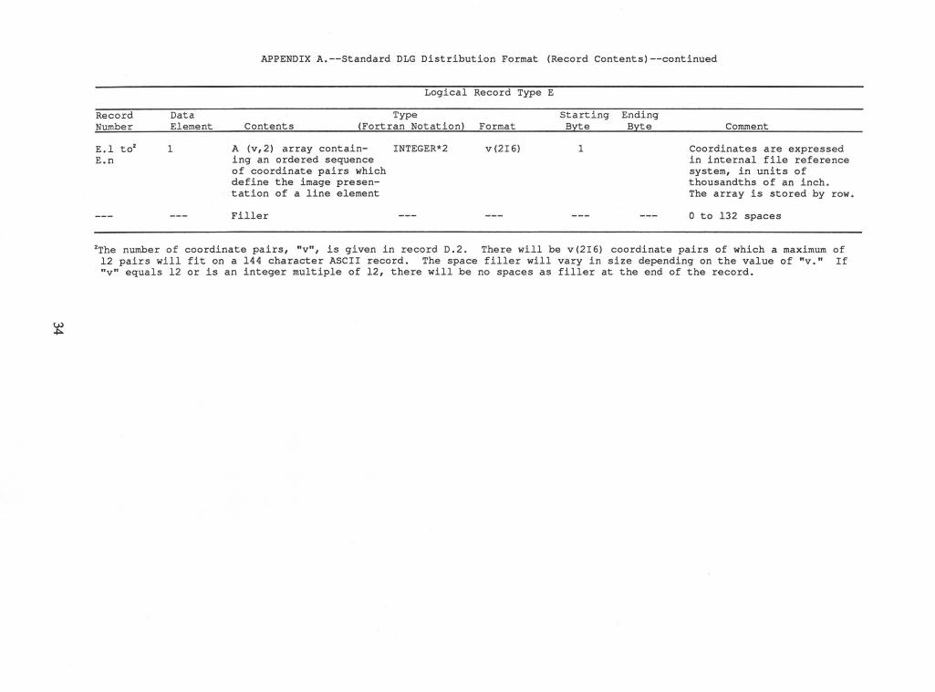
Record Number
E.l to2
E.n
Data Element
1
APPENDIX A.--Standard DLG Distribution Format (Record Contents)--continued
Logical Record Type E
Type Contents (Fortran Notation) Format
A (v,2) array contain- INTEGER*2 v(2I6) ing an ordered sequence of coordinate pairs which define the image presen-tation of a line element
Filler
Starting Ending Byte Byte
1
Comment
Coordinates are expressed in internal file reference system, in units of thousandths of an inch. The array is stored by row.
0 to 132 spaces
2The number of coordinate pairs, "v", is given in record 0.2. There will be v(2I6) coordinate pairs of which a maximum of 12 pairs will fit on a 144 character ASCII record. The space filler will vary in size depending on the value of "v." If "v" equals 12 or is an integer multiple of 12, there will be no spaces as filler at the end of the record.
u,) Ul
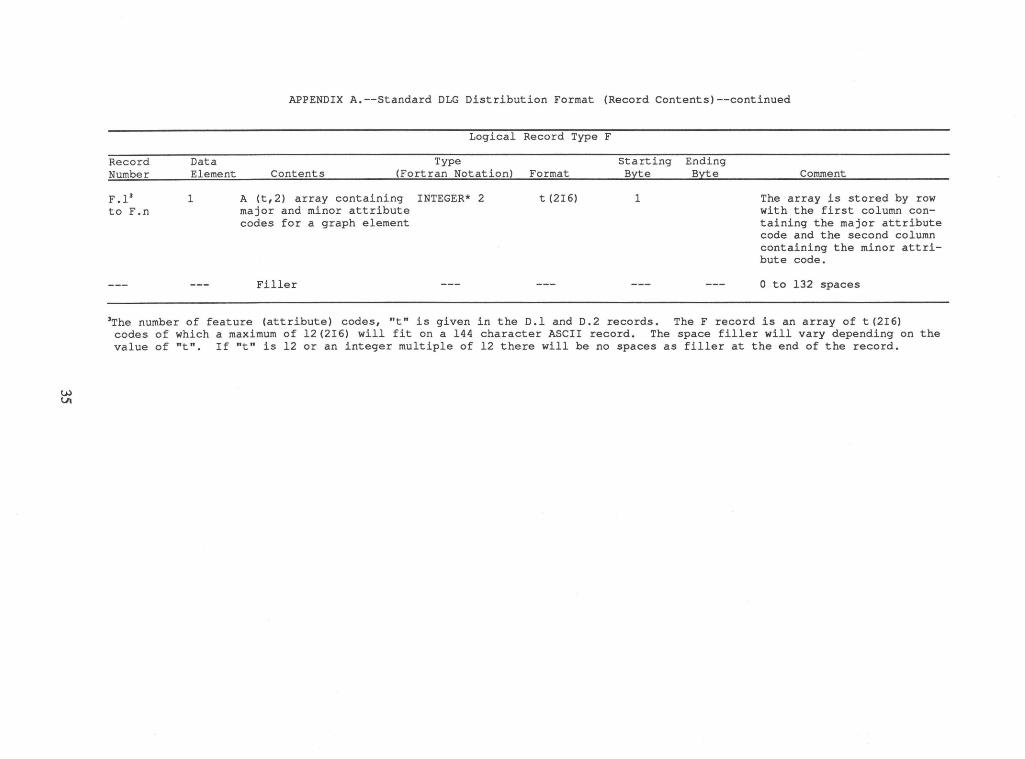
Record Number
F .13
to F.n
Data Element
1
APPENDIX A.--Standard DLG Distribution Format (Record Contents)--continued
Logical Record Type F
Type Contents (Fortran Notation) Format
A (t,2) array containing INTEGER* 2 major and minor attribute codes for a graph element
Filler
t (2I6)
Starting Ending Byte Byte
1
Comment
The array is stored by row with the first column containing the major attribute code and the second column containing the minor attribute code.
0 to 132 spaces
3The number of feature (attribute) codes, "t" is given in the D.l and D.2 records. The F record is an array of t(2I6) codes of which a maximum of 12(2I6) will fit on a 144 character ASCII record. The space filler will vary depending on the value of "t". If "t" is 12 or an integer multiple of 12 there will be no spaces as filler at the end of the record.
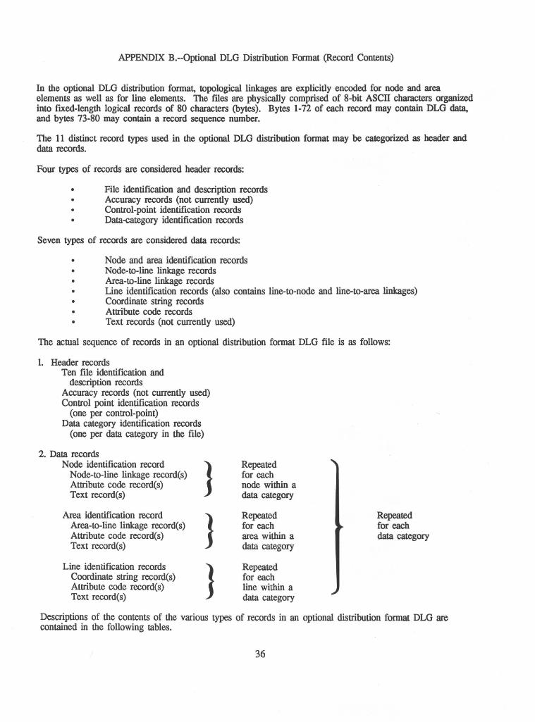
APPENDIX B.--Optional DLG Distribution Fonnat (Record Contents)
In the optional DLG distribution fonnat, topological linkages are explicitly encoded for node and area elements as well as for line elements. The files are physically comprised of 8-bit ASCII characters organized into ftxed-length logical records of 80 characters (bytes). Bytes 1-72 of each record may contain DLG data, and bytes 73-80 may contain a record sequence number.
The 11 distinct record types used in the optional DLG distribution fonnat may be categorized as header and data records.
Four types of records are considered header records:
• File identification and description records • Accuracy records (not currently used)
Control-point identification records Data-category identification records
Seven types of records are considered data records:
• Node and area identification records Node-to-line linkage records
• Area-to-line linkage records Line identification records (also contains line-to-node and line-to-area linkages)
• Coordinate string records Attribute code records
• Text records (not currently used)
The actual sequence of records in an optional distribution fonnat DLG file is as follows:
1. Header records Ten file identification and
description records Accuracy records (not currently used) Control point identification records
(one per control-point) Data category identification records
(one per data category in the file)
2. Data records Node identification record
Node-to-line linkage record(s) Attribute code record(s) Text record(s)
Area identification record Area-to-line linkage record(s) Attribute code record(s) Text record(s)
Line identification records Coordinate string record(s) Attribute code record(s) Text record(s)
J
J J
Repeated for each node within a data category
Repeated for each area within a data category
Repeated for each line within a data category
Repeated for each data category
Descriptions of the contents of the various types of records in an optional distribution fonnat DLG are contained in the following tables.
36
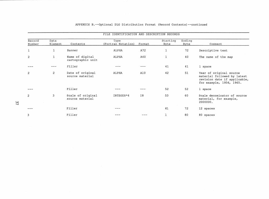
APPENDIX B.--Optional DLG Distribution Format (Record Contents)--continued
FILE IDENTIFICATION AND DESCRIPTION RECORDS
Record Data Type Starting Ending Number Element Contents ~Fortran Notation) Format Byte Byte Comment
1 1 Banner ALPHA A72 1 72 Descriptive text
2 1 Name of digital ALPHA A40 1 40 The name of the map cartographic unit
Filler --- --- 41 41 1 space
2 2 Date of original ALPHA AlO 42 51 Year of original source source material material followed by latest
revision date if applicable, for example, 1956, 1965.
Filler --- --- 52 52 1 space
2 3 Scale of original INTEGER*4 I8 53 60 Scale denominator of source source material material, for example,
w 2000000. ...._J
Filler --- 61 72 12 spaces
3 Filler --- --- 1 80 80 spaces
APPENDIX B.--Optional DLG Distribution Format (Record Contents)--continued
FILE IDENTIFICATION AND DESCRIPTION RECORDS--continued
Record Data Type Starting Ending Number Element Contents ~Fortran Notation) Format Byte Byte Comment
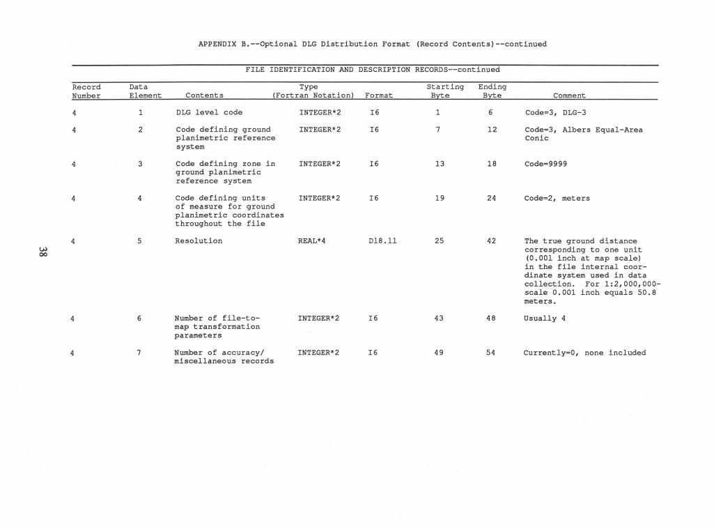
4 1 DLG level code INTEGER*2 I6 1 6 Code=3, DLG-3
4 2 Code defining ground INTEGER*2 I6 7 12 Code=3, Albers Equal-Area planimetric reference Conic system
4 3 Code defining zone in INTEGER*2 I6 13 18 Code=9999 ground planimetric reference system
4 4 Code defining units INTEGER*2 I6 19 24 Code=2, meters of measure for ground planimetric coordinates throughout the file
4 5 Resolution REAL*4 Dl8.11 25 42 The true ground distance w corresponding to one unit 00 (0.001 inch at map scale)
in the file internal coor-dinate system used in data collection. For 1:2,000,000-scale 0.001 inch equals 50.8 meters.
4 6 Number of file-to- INTEGER*2 I6 43 48 Usually 4 map transformation parameters
4 7 Number of accuracy/ INTEGER*2 I6 49 54 Currently=O, none included miscellaneous records
w \0
Record Number
4
4
5-9
10
Data Element
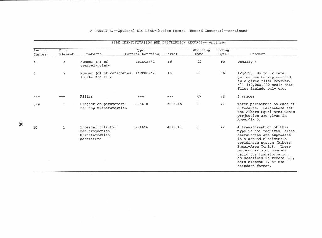
8
9
1
1
APPENDIX B.--Optional DLG Distribution Format (Record Contents)--continued
FILE IDENTIFICATION AND DESCRIPTION RECORDS--continued
Type Contents (Fortran Notation) Format
Number (n) of INTEGER*2 control-points
Number (q) of categories INTEGER*2 in the DLG file
Filler ---Projection parameters REAL*8 for map transformation
Internal file-to- REAL*4 map projection transformation parameters
I6
I6
---
3D24.15
4Dl8.11
Starting Ending Byte Byte
55 60
61 66
67 72
1 72
1 72
Comment
Usually 4
1~~32. Up to 32 categories can be represented in a given file; however, all 1:2,000,000-scale data files include only one.
6 spaces
Three parameters on each of 5 records. Parameters for the Albers Equal-Area Conic projection are given in Appendix D.
A transformation of this type is not required, since coordinates are expressed in a ground planimetric coordinate system (Albers Equal-Area Conic) . These parameters are, however, valid for transformation as described in record B.1, data element 1, of the standard format.
APPENDIX B.--Optional DLG Distribution Format (Record Contents)--continued
CONTROL-POINT IDENTIFICATION RECORDS
Record Data Type Starting Ending Number Element Contents (Fortran Notation~ Format B!lte B!lte Comment
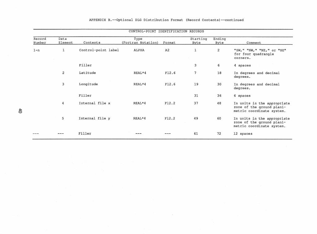
1-n 1 Control-point label ALPHA A2 1 2 "SW," "NW," "NE," or "SE" for four quadrangle corners.
Filler 3 6 4 spaces
2 Latitude REAL*4 Fl2.6 7 18 In degrees and decimal degrees.
3 Longitude REAL*4 Fl2.6 19 30 In degrees and decimal degrees.
Filler 31 36 6 spaces
4 Internal file x REAL*4 Fl2.2 37 48 In units in the appropriate
~ zone of the ground plani-
0 metric coordinate system.
5 Internal file y REAL*4 Fl2.2 49 60 In units in the appropriate zone of the ground plani-metric coordinate system.
Filler --- --- 61 72 12 spaces
~ ~
Record · Number
1-q
Data Element
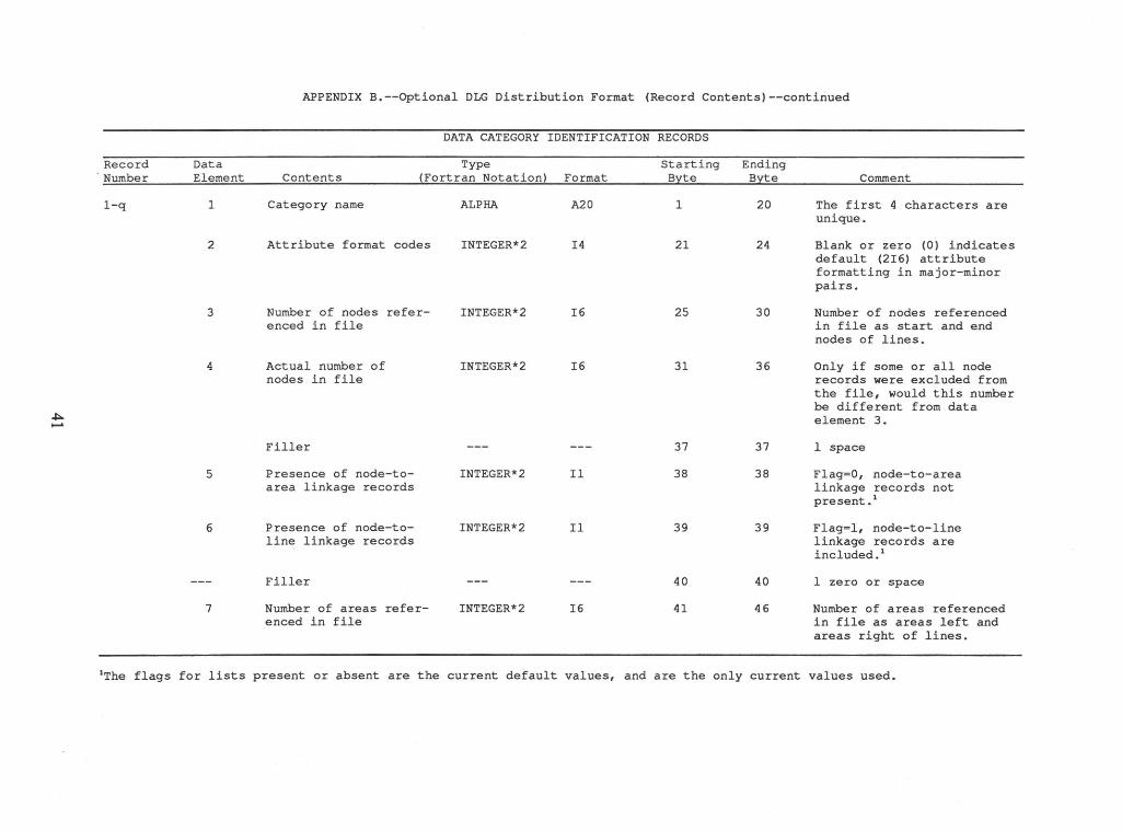
1
2
3
4
5
6
7
APPENDIX B.--Optional DLG Distribution Format (Record Contents)--continued
DATA CATEGORY IDENTIFICATION RECORDS
Type Contents (Fortran Notation) Format
Category name
Attribute format codes
Number of nodes referenced in file
Actual number of nodes in file
Filler
Presence of node-toarea linkage records
Presence of node-toline linkage records
Filler
Number of areas referenced in file
ALPHA A20
INTEGER*2 I4
INTEGER*2 I6
INTEGER*2 I6
INTEGER*2 Il
INTEGER*2 Il
INTEGER*2 I6
Starting Ending Byte Byte
1 20
21 24
25 30
31 36
37 37
38 38
39 39
40 40
41 46
Comment
The first 4 characters are unique.
Blank or zero (0) indicates default (2I6) attribute formatting in major-minor pairs.
Number of nodes referenced in file as start and end nodes of lines.
Only if some or all node records were excluded from the file, would this number be different from data element 3.
1 space
Flag=O, node-to-area linkage records not present . 1
Flag=l, node-to-line linkage records are included. 1
1 zero or space
Number of areas referenced in file as areas left and areas right of lines.
1The flags for lists present or absent are the current default values, and are the only current values used.
~ N
Record Number
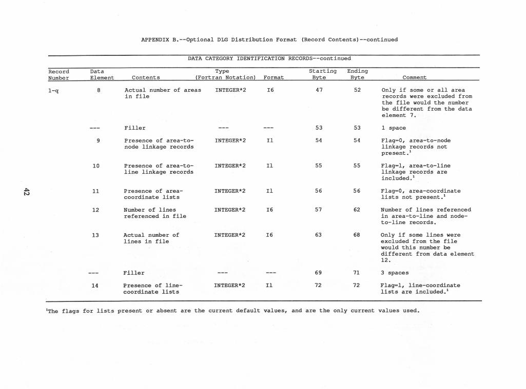
1-q
Data Element
8
9
10
11
12
13
14
APPENDIX B.--Optional DLG Distribution Format (Record Contents)--continued
DATA CATEGORY IDENTIFICATION RECORDS--continued
Type Contents (Fortran Notation) Format
Actual number of areas in file
Filler
Presence of area-tonode linkage records
Presence of area-toline linkage records
Presence of areacoordinate lists
Number of lines referenced in file
Actual number of lines in file
Filler
Presence of linecoordinate lists
INTEGER*2 I6
INTEGER*2 Il
INTEGER*2 Il
INTEGER*2 Il
INTEGER*2 I6
INTEGER*2 I6
INTEGER*2 Il
Starting Ending Byte Byte
47 52
53 53
54 54
55 55
56 56
57 62
63 68
69 71
72 72
Comment
Only if some or all area records were excluded from the file would the number be different from the data element 7.
1 space
Flag=O, area-to-node linkage records not present • 1
Flag=l, area-to-line linkage records are included. 1
Flag=O, area-coordinate lists not present. 1
Number of lines referenced in area-to-line and nodeto-line records.
Only if some lines were excluded from the file would this number be different from data element 12.
3 spaces
Flag=l, line-coordinate lists are included. 1
1The flags for lists present or absent are the current default values, and are the only current values used.
APPENDIX B.--Optional DLG Distribution Format (Record Contents)--continued
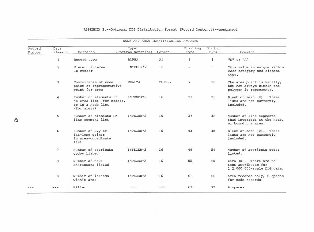
NODE AND AREA IDENTIFICATION RECORDS
Record Data Type Starting Ending Number Element Contents (Fortran Notation) Format Byte Byte Comment
1 Record type ALPHA Al 1 1 "N" or "A"
2 Element internal INTEGER*2 I5 2 6 This value is unique within ID number each category and element
type.
3 Coordinates of node REAL*4 2Fl2.2 7 30 The area point is usually, point or representative but not always within the point for area polygon it represents.
4 Number of elements in INTEGER*2 I6 31 36 Blank or zero (0). These an area list (for nodes) , lists are not currently or in a node list included. (for areas)
5 Number of elements in INTEGER*2 I6 37 42 Number of line segments .,J::.. line segment list that intersect at the node, t.J..)
or bound the area.
6 Number of x,y or INTEGER*2 I6 43 48 Blank or zero (0). These lat-long points lists are not currently in area-coordinate included. list
7 Number of attribute INTEGER*2 I6 49 54 Number of attribute codes codes listed listed.
8 Number of text INTEGER*2 I6 55 60 Zero (0). There are no characters listed text attributes for
1:2,000,000-scale DLG data.
9 Number of islands INTEGER*2 I6 61 66 Area records only, 6 spaces within area for node records.
Filler --- --- 67 72 6 spaces
t
APPENDIX B.--Optional DLG Distribution Format (Record Contents)--continued
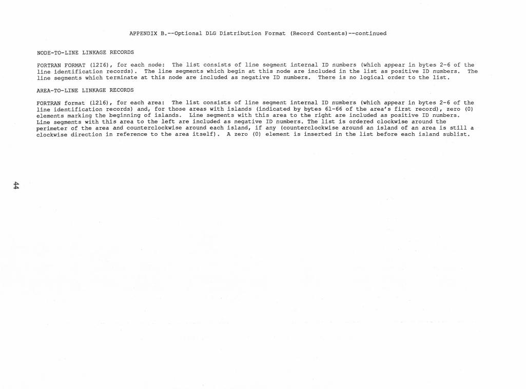
NODE-TO-LINE LINKAGE RECORDS
FORTRAN FORMAT (12I6), for each node: The list consists of line segment internal ID numbers (which appear in bytes 2-6 of the line identification records). The line segments which begin at this node are included in the list as positive ID numbers. The line segments which terminate at this node are included as negative ID numbers. There is no logical order to the list.
AREA-TO-LINE LINKAGE RECORDS
FORTRAN format (1216), for each area: The list consists of line segment internal ID numbers (which appear in bytes 2-6 of the line identification records) and, for those areas with islands (indicated by bytes 61-66 of the area's first record), zero (0) elements marking the beginning of islands. Line segments with this area to the right are included as positive ID numbers. Line segments with this area to the left are included as negative ID numbers. The list is ordered clockwise around the perimeter of the area and counterclockwise around each island, if any (counterclockwise around an island of an area is still a clockwise direction in reference to the area itself). A zero (0) element is inserted in the list before each island sublist.
APPENDIX B.--Optional DLG Distribution Format (Record Contents)--continued
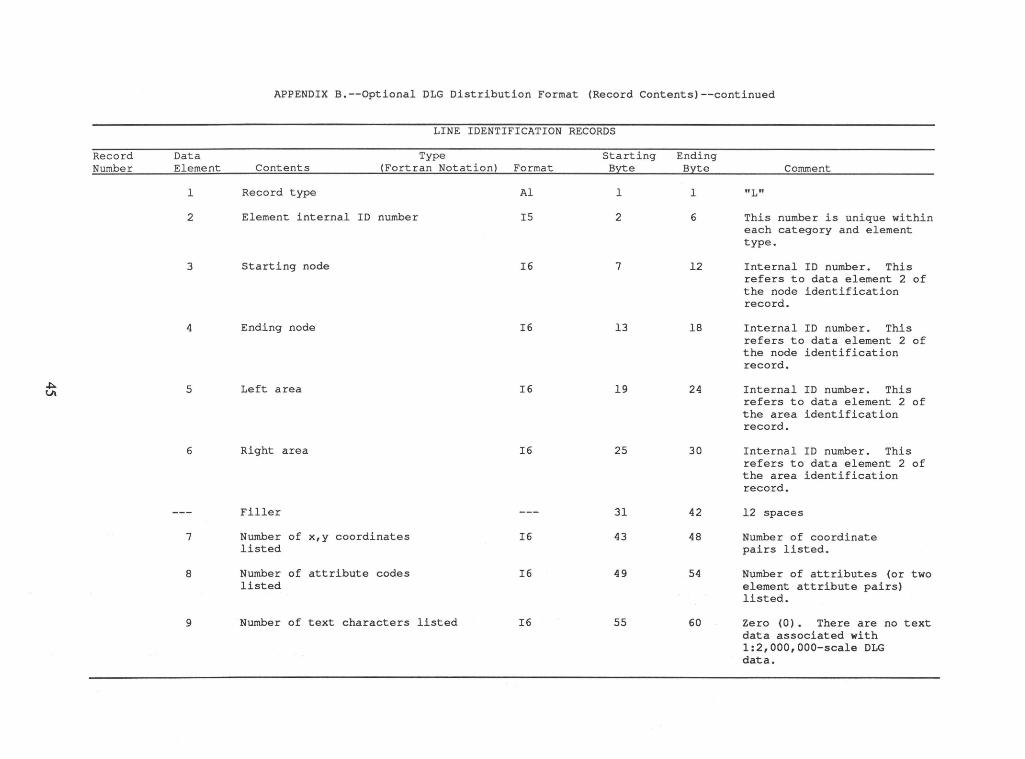
LINE IDENTIFICATION RECORDS
Record Data Type Starting Ending Number Element Contents (Fortran Notation) Format Byte Byte Comment
1 Record type Al 1 1 "L"
2 Element internal ID number IS 2 6 This number is unique within each category and element type.
3 Starting node 16 7 12 Internal ID number. This refers to data element 2 of the node identification record.
4 Ending node I6 13 18 Internal ID number. This refers to data element 2 of the node identification record.
~ 5 Left area I6 19 24 Internal ID number. This Ul refers to data element 2 of the area identification record.
6 Right area I6 25 30 Internal ID number. This refers to data element 2 of the area identification record.
Filler --- 31 42 12 spaces
7 Number of x,y coordinates I6 43 48 Number of coordinate listed pairs listed.
8 Number of attribute codes I6 49 54 Number of attributes (or two listed element attribute pairs)
listed.
9 Number of text characters listed 16 55 60 Zero (0) • There are no text data associated with 1:2,000,000-scale DLG data.
~ 0\
APPENDIX B.--Optional DLG Distribution Format (Record Contents)--continued
COORDINATE STRING RECORDS
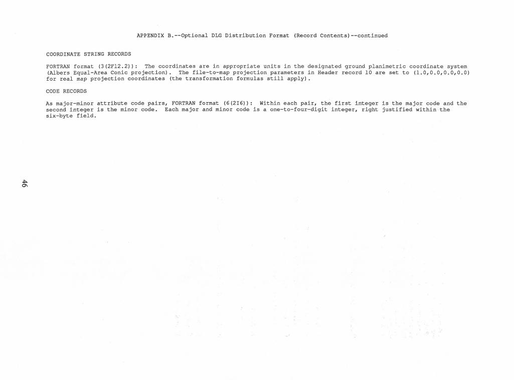
FORTRAN format (3(2Fl2.2)): The coordinates are in appropriate units in the designated ground planimetric coordinate system (Albers Equal-Area Conic projection). The file-to-map projection parameters in Header record 10 are set to (1.0,0.0,0.0,0.0) for real map projection coordinates (the transformation formulas still apply) •
CODE RECORDS
As major-minor attribute code pairs, FORTRAN format (6(2I6)): Within each pair, the first integer is the major code and the second integer is the minor code. Each major and minor code is a one-to-four-digit integer, right justified within the six-byte field.
APPENDIX C.--Graphic Format
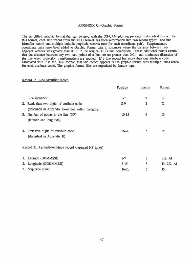
The simplified, graphic format that can be used with the OS-CAM plotting package is described below. In this format, each line record from the DLG format has been reformatted into two record types: one line identifier record and multiple latitude-longitude records (one for each coordinate pair). Supplementary coordinate pairs have been added to Graphic Format data in instances where the distance between two adjacent vertices was greater than 0.01" in the original DLG line description. These additional points assure that the distance between any two data points of a line are no greater than 0.01" and minimizes distortion of the line when projection transformations are applied. If a line record has more than one attribute code associated with it in the DLG format, that line record appears in the graphic format files multiple times (once for each attribute code). The graphic format files are organized by feature type.
Record 1: Line identifier record
Position Length Format
1. Line identifier 1-7 7 I7
2. Rank (last two digits of attribute code 8-9 2 I2
(described in Appendix E--unique within category)
3. Number of points in the line (NP) 10-1S 6 I6
(latitude and longitude)
4. First five digits of attribute code 16-20 s IS
(described in Appendix E)
Record 2: Latitude-longitude record (repeated NP times)
1. Latitude (DDMMSSI) 1-7 7 3I2, AI
2. Longitude (DDDMMSSI) 8-1S 8 I3, 2I2, AI
3. Sequence count 16-20 s IS
47
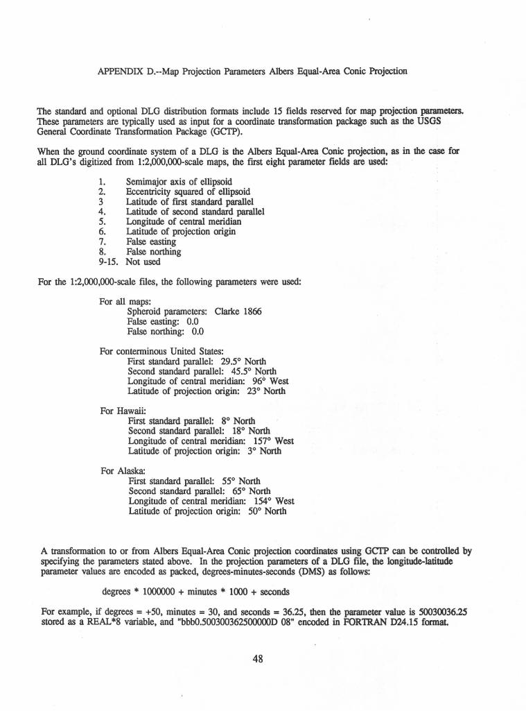
APPENDIX D.--Map Projection Parameters Albers Equal-Area Conic Projection
The standard and optional DLG distribution formats include 15 fields reserved for map projection parameters. These parameters are typically used as input for a coordinate transformation package such as the USGS General Coordinate Transformation Package (GCTP).
When the ground coordinate system of a DLG is the Albers Equal-Area Conic projection, as in the case for all DLG's digitized from 1:2,000,000-scale maps, the first eight parameter fields are used:
1. Semimajor axis of ellipsoid 2. Eccentricity squared of ellipsoid 3 Latitude of frrst standard parallel 4. Latitude of second standard parallel 5. Longitude of central meridian 6. Latitude of projection origin 7. False easting 8. False northing 9-15. Not used
For the 1 :2,000,000-scale files, the following parameters were used:
For all maps: Spheroid parameters: Clarke 1866 False easting: 0.0 False northing: 0.0
For conterminous United States: First standard parallel: 29.5° North Second standard parallel: 45.5° N9rth Longitude of central meridian: 96° West Latitude of projection origin: 23° North
For Hawaii: First standard parallel: 8° North Second standard parallel: 18° North Longitude of central meridian: 157° West Latitude of projection origin: 3° North
For Alaska: First standard parallel: 55° North Second standard parallel: 65° North Longitude of central meridian: 154 ° West Latitude of projection origin: 50° North
A transformation to or from Albers Equal-Area Conic projection coordinates using GCTP can be controlled by specifying the parameters stated above. In the projection parameters of a DLG file, the longitude-latitude parameter values are encoded as packed, degrees-minutes-seconds (DMS) as follows:
degrees * 1000000 + minutes * 1000 + seconds
For example, if degrees= +50, minutes = 30, and seconds = 36.25, then the parameter value is 50030036.25 stored as a REAL *8 variable, and "bbb0.500300362500000D 08" encoded in FOR1RAN 024.15 format.
48
~ \0
FEATURE MAJOR CODE
Water Bodies ... 040
Political 090 Boundaries
Administrative 090 Boundaries
Roads and Trails
102 103 104
MINOR CODE
0100 0102 0104 0105 0106 0107 0110 0150 0199
0100 0101 0197 0198 0199
0103 0104 0105 0106 0107 0108
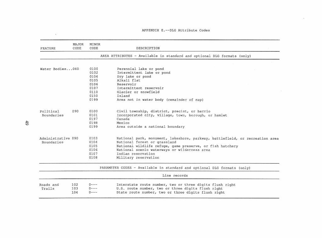
APPENDIX E.--DLG Attribute Codes
DESCRIPTION
AREA ATTRIBUTES - Available in standard and optional DLG formats (only)
Perennial lake or pond Intermittent lake or pond Dry lake or pond Alkali flat Reservoir Intermittent reservoir Glacier or snowfield Island Area not in water body (remainder of map)
Civil township, district, precint, or barrio Incorporated city, village, town, borough, or hamlet Canada Mexico Area outside a national boundary
National park, monument, lakeshore, parkway, battlefield, or recreation area National forest or grassland National wildlife refuge, game preserve, or fish hatchery National scenic waterways or wilderness area Indian reservation Military reservation
PARAMETER CODES - Available in standard and optional DLG formats (only)
0---0---0---
Line records
Interstate route number, two or three digits flush right U.S. route number, two or three digits flush right State route number, two or three digits flush right
Ol 0
FEATURE
Political Boundaries
MAJOR CODE
091 092
Hypsography .••• 290
Streams and 290 Rivers
290
MINOR CODE
00-o---
APPENDIX E.--DLG Attribute Codes--continued
DESCRIPTION
Area records
State FIPS code, two digits flush right County or county equivalent FIPS code, three digits, flush right
LINE ATTRIBUTES - available in standard and optional DLG and graphic format
2017 Continental Divide
3001 River/stream (double line, shoreline) 3002 River/stream (double line, centerline) 3003* River/stream (single line), perennial, length < 20 km, or < 12 mi 3004 River/stream (single line), perennial, length 20-< 30 km, or 12-< 19 mi 3005 River/stream (single line), perennial, length 30-< 40 km, or 19-< 25 mi 3006 River/stream (single line), perennial, length 40-< 50 km, or 25-< 31 mi 3007 River/stream (single line), perennial, length 50-< 60 km, or 31-< 37 mi 3008 River/stream (single line), perennial, length 60-< 80 km, or 37-< 50 mi 3009 River/stream (single line), perennial, length 80-< 100 km, or 50-< 62 mi 3010 River/stream (single line), perennial, length 100-< 125 km, or 62-< 78 mi 3011 River/stream (single line), perennial, length 125-< 150 km, or 78-< 93 mi 3012 River/stream (single line), perennial, length 150-< 200 km, or 93-< 124 mi 3013 River/stream (single line), perennial, length 200-< 250 km, or 124-< 155 mi 3014 River/stream (single line), perennial, length 250-< 300 km, or 155-< 186 mi 3015 River I stream (single line), perennial, length 300-< 350 km, or 186-< 217 mi 3016 River/stream (single line), perennial, length 350+ km, or 217+ mi
*This code was only used in the Alaskan drainage files.
Note: Listing of FIPS codes available as National Bureau of Standards (U.S.), Federal Information Processing Standards Publication (FIPS PUB) 6-3, 39 p. for sale by the National Technical Information Service, u.s. Department of Commerce, Springfield, VA 22161.
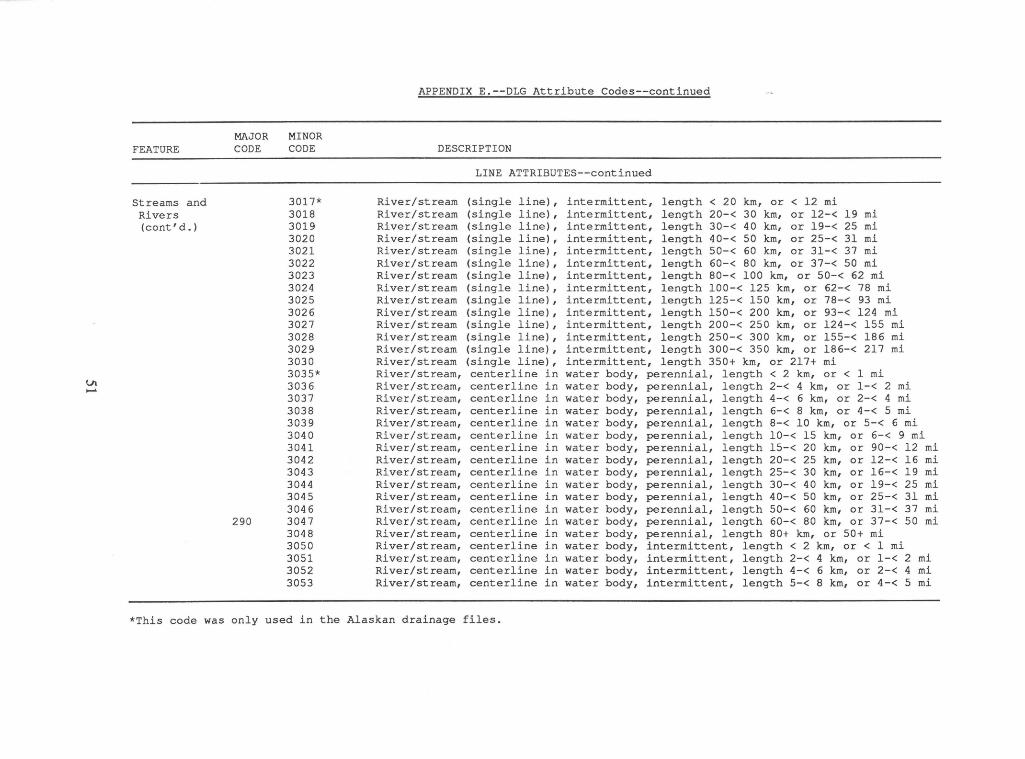
APPENDIX E.--DLG Attribute Codes--continued
MAJOR MINOR FEATURE CODE CODE DESCRIPTION
LINE ATTRIBUTES--continued
Streams and 3017* River/stream (single line), intermittent, length < 20 km, or < 12 mi Rivers 3018 River/stream (single line) , intermittent, length 20-< 30 km, or 12-< 19 mi (cont' d.) 3019 River/stream (single line), intermittent, length 30-< 40 km, or 19-< 25 mi
3020 River/stream (single line), intermittent, length 40-< 50 km, or 25-< 31 mi 3021 River/stream (single line), intermittent, length 50-< 60 km, or 31-< 37 mi 3022 River/stream (single line), intermittent, length 60-< 80 km, or 37-< 50 mi 3023 River/stream (single line) , intermittent, length 80-< 100 km, or 50-< 62 mi 3024 River/stream (single line) , intermittent, length 100-< 125 km, or 62-< 78 mi 3025 River/stream (single line), intermittent, length 125-< 150 km, or 78-< 93 mi 3026 River/stream (single line), intermittent, length 150-< 200 km, or 93-< 124 mi 3027 River/stream (single line) , intermittent, length 200-< 250 km, or 124-< 155 mi 3028 River/stream (single line) , intermittent, length 250-< 300 km, or 155-< 186 mi 3029 River/stream (single line), intermittent, length 300-< 350 km, or 186-< 217 mi 3030 River/stream (single line), intermittent, length 350+ km, or 217+ mi 3035* River/stream, centerline in water body, perennial, length < 2 km, or < 1 mi
V\ 3036 River/stream, centerline in water body, perennial, length 2-< 4 km, or 1-< 2 mi ...... 3037 River/stream, centerline in water body, perennial, length 4-< 6 km, or 2-< 4 mi 3038 River/stream, centerline in water body, perennial, length 6-< 8 km, or 4-< 5 mi 3039 River/stream, centerline in water body, perennial, length 8-< 10 km, or 5-< 6 mi 3040 River I stream, centerline in water body, perennial, length 10-< 15 km, or 6-< 9 mi 3041 River/stream, centerline in water body, perennial, length 15-< 20 km, or 90-< 12 mi 3042 River/stream, centerline in water body, perennial, length 20-< 25 km, or 12-< 16 mi 3043 River/stream, centerline in water body, perennial, length 25-< 30 km, or 16-< 19 mi 3044 River/stream, centerline in water body, perennial, length 30-< 40 km, or 19-< 25 mi 3045 River/stream, centerline in water body, perennial, length 40-< 50 km, or 25-< 31 mi 304 6 River/stream, centerline in water body, perennial, length 50-< 60 km, or 31-< 37 mi
290 3047 River I stream, centerline in water body, perennial, length 60-< 80 km, or 37-< 50 mi 3048 River I stream, centerline in water body, perennial, length 80+ km, or 50+ mi 3050 River/stream, centerline in water body, intermittent, length < 2 km, or < 1 mi 3051 River/stream, centerline in water body, intermittent, length 2-< 4 km, or 1-< 2 mi 3052 River I stream, centerline in water body, intermittent, length 4-< 6 km, or 2-< 4 mi 3053 River/stream, centerline in water body, intermittent, length 5-< 8 km, or 4-< 5 mi
*This code was only used in the Alaskan drainage files.
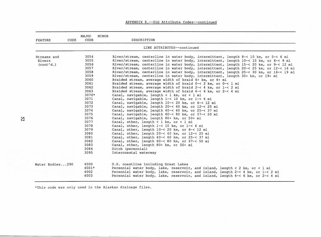
(Jl N
MAJOr, MINOR FEATURE CODE CODE
Streams and Rivers (cont' d.)
Water Bodies ... 290
3054 3055 3056 3057 3058 3059 3060 3061 3062 3063 3070* 3071 3072 3073 3074 3075 3076 3077 3078 3079 3080 3081 3082 3083 3086 3095
4000 4001* 4002 4003
APPENDIX E.--DLG Attribute Codes--continued
DESCRIPTION
LINE ATTRIBUTES--continued
River/stream, centerline in water body, intermittent, length 8-< 10 km, or 5-< 6 mi Ri ver/stream, centerline in water body, intermittent, length 10-< 15 km, or 6-< 9 mi River/stream, centerline in water body, intermittent, length 15-< 20 km, or 9-< 12 mi River/stream, centerline in water body, intermittent, length 20-< 25 km, or 12-< 16 mi River/stream, centerline in water body, intermittent, length 25-< 30 km, or 16-< 19 mi River/stream, centerline in water body, intermittent, length 30+ km, or 19+ mi Braided stream, average width of braid 6+ km, or 4+ mi Braided stream, average width of braid 0-< 2 km, or 0-< 1 mi Braided stream, average width of braid 2-< 4 km, or 1-< 2 mi Braided stream, average width of braid 4-< 6 km, or 2-< 4 mi Canal, navigable, length < 1 km, or < 1 mi Canal, navigable, length 1-< 10 km, or 1-< 6 mi Canal, navigable, length 10-< 20 km, or 6-< 12 mi Canal, navigable, length 20-< 40 km, or 12-< 25 mi Canal, navigable, length 40-< 60 km, or 25-< 37 mi Canal, navigable, length 60-< 80 km, or 37-< 50 mi Canal, navigable, length 80+ km, or 50+ mi Canal, other, length < 1 km, or < 1 mi Canal, · other, length 1-< 10 km, or 1-< 6 mi Canal, other, length 10-< 20 km, or 6-< 12 mi Canal, other, length 20-< 40 km, or 12-< 25 mi Canal, other, length 40-< 60 km, or 25-< 37 mi Canal, other, length 60-< 80 km, or 37-< 50 mi Canal, other, length 80+ km, or 50+ mi Ditch (perennial) Intercoastal waterway
u.s. coastline including Great Lakes Perennial water body, lake, reservoir, and island, length < 2 km, or < 1 mi Perennial water body, lake, reservoir, and island, length 2-< 4 km, or 1-< 2 mi Perennial water body, lake, reservoir, and island, length 4-< 6 km, or 2-< 4 mi
*This code was only used in the Alaskan drainage files .
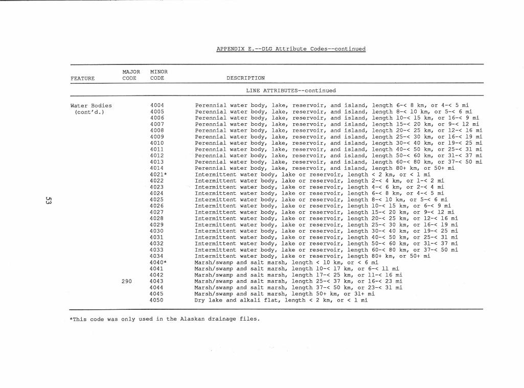
Lll w
FEATURE
Water Bodies (cont'd.)
MAJOR CODE
290
MINOR CODE
4004 4005 4006 4007 4008 4009 4010 4011 4012 4013 4014 4021* 4022 4023 4024 4025 4026 4027 4028 4029 4030 4031 4032 4033 4034 4040* 4041 4042 4043 4044 4045 4050
APPENDIX E.--DLG Attribute Codes--continued
DESCRIPTION
LINE ATTRIBUTES--continued
Perennial water body, lake, reservoir, and island, length 6-< 8 km, or 4-< 5 mi Perennial water body, lake, reservoir, and island, length 8-< 10 km, or 5-< 6 mi Perennial water body, lake, reservoir, and island, length 10-< 15 km, or 16-< 9 mi Perennial water body, lake, reservoir, and island, length 15-< 20 km, or 9-< 12 mi Perennial water body, lake, reservoir, and island, length 20-< 25 km, or 12-< 16 mi Perennial water body, lake, reservoir, and island, length 25-< 30 km, or 16-< 19 mi Perennial water body, lake, reservoir, and island, length 30-< 40 km, or 19-< 25 mi Perennial water body, lake, reservoir, and island, length 40-< 50 km, or 25-< 31 mi Perennial water body, lake, reservoir, and island, length 50-< 60 km, or 31-< 37 mi Perennial water body, lake, reservoir, and island, length 60-< 80 km, or 37-< 50 mi Perennial water body, lake, reservoir, and island, length 80+ km, or 50+ mi Intermittent water body, lake or reservoir, length < 2 km, or < 1 mi Intermittent water body, lake or reservoir, length 2-< 4 km, or 1-< 2 mi Intermittent water body, lake o:t reservoir, length 4-< 6 km, or 2-< 4 mi Intermittent water body, lake or reservoir, length 6-< 8 km, or 4-< 5 mi Intermittent water body, lake or reservoir, length 8-< 10 km, or 5-< 6 mi Intermittent water body, lake or reservoir, length 10-< 15 km, or 6-< 9 mi Intermittent water body, lake or reservoir, length 15-< 20 km, or 9-< 12 mi Intermittent water body, lake or reservoir, length 20-< 25 km, or 12-< 16 mi Intermittent water body, lake or reservoir, length 25-< 30 km, or 16-< 19 mi Intermittent water body, lake or reservoir, length 30-< 40 km, or 19-< 25 mi Intermittent water body, lake or reservoir, length 40-< 50 km, or 25-< 31 mi Intermittent water body, lake or reservoir, length 50-< 60 km, or 31-< 37 mi Intermittent water body, lake or reservoir, length 60-< 80 km, or 37-< 50 mi Intermittent water body, lake or reservoir, length 80+ km, or 50+ mi Marsh/swamp and salt marsh, length < 10 km, or < 6 mi Marsh/swamp and salt marsh, length 10-< 17 km, or 6-< 11 mi Marsh/swamp and salt marsh, length 17-< 25 km, or 11-< 16 mi Marsh/swamp and salt marsh, length 25-< 37 km, or 16-< 23 mi Marsh/swamp and salt marsh, length 37-< 50 km, or 23-< 31 mi Marsh/swamp and salt marsh, length 50+ km, or 31+ mi Dry lake and alkali flat, length < 2 km, or < 1 mi
*This code was only used in the Alaskan drainage files.
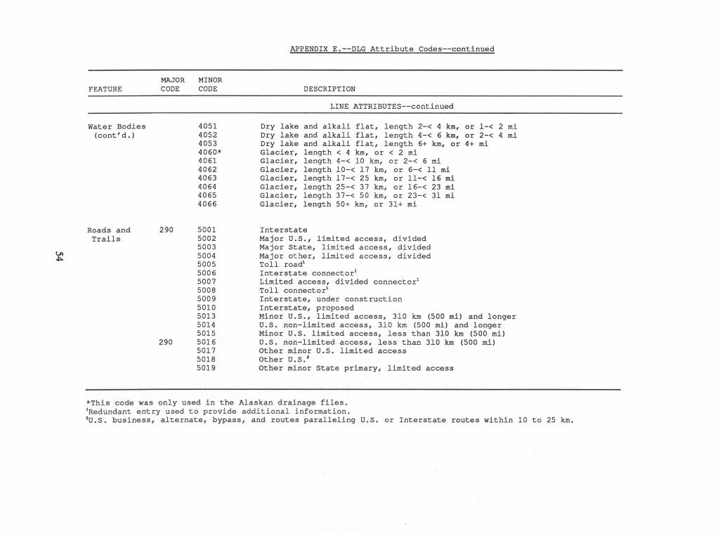
Vl ~
FEATURE
Water Bodies (cont' d.)
Roads and Trails
MAJOR CODE
290
290
MINOR CODE
4051 4052 4053 4060* 4061 4062 4063 4064 4065 4066
5001 5002 5003 5004 5005 5006 5007 5008 5009 5010 5013 5014 5015 5016 5017 5018 5019
APPENDIX E.--DLG Attribute Codes--continued
DESCRIPTION
LINE ATTRIBUTES--continued
Dry lake and alkali flat, length 2-< 4 km, or 1-< 2 mi Dry lake and alkali flat, length 4-< 6 km, or 2-< 4 mi Dry lake and alkali flat, length 6+ km, or 4+ mi Glacier, length < 4 km, or < 2 mi Glacier, length 4-< 10 km, or 2-< 6 mi Glacier, length 10-< 17 km, or 6-< 11 mi Glacier, length 17-< 25 km, or 11-< 16 mi Glacier, length 25-< 37 km, or 16-< 23 mi Glacier, length 37-< 50 km, or 23-< 31 mi Glacier, length 50+ km, or 31+ mi
Interstate Major U.S., limited access, divided Major State, limited access, divided Major other, limited access, divided Toll road1
Interstate connector1
Limited access, divided connector1
Toll connector1
Interstate, under construction Interstate, proposed Minor u.s., limited access, 310 km (500 mi) and longer U.S. non-limited access, 310 km (500 mi) and longer Minor U.S. limited access, less than 310 km (500 mi) U.S. non-limited access, less than 310 km (500 mi) Other minor U.S. limited access Other U.S. 2
Other minor State primary, limited access
*This code was only used in the Alaskan drainage files. 1Redundant entry used to provide additional information. 2U.S. business, alternate, bypass, and routes paralleling U.S. or Interstate routes within 10 to 25 km.
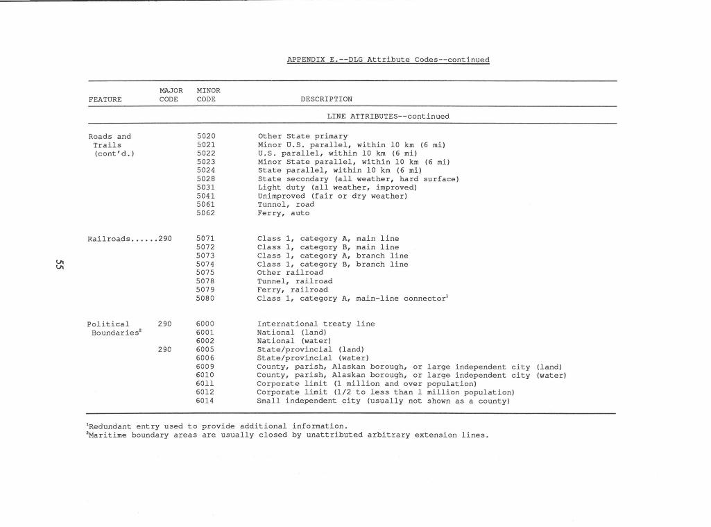
Ut Ut
FEATURE
Roads and Trails (cont' d.)
MAJOR CODE
Railroads ...... 290
Political Boundar ies2
290
290
MINOR CODE
5020 5021 5022 5023 5024 5028 5031 5041 5061 5062
5071 5072 5073 5074 5075 5078 5079 5080
6000 6001 6002 6005 6006 6009 6010 6011 6012 6014
APPENDIX E.--DLG Attribute Codes--continued
DESCRIPTION
LINE ATTRIBUTES--continued
Other State primary Minor U.S. parallel, within 10 km (6 mi) U.S. parallel, within 10 km (6 mi) Minor State parallel, within 10 km (6 mi) State parallel, within 10 km (6 mi) State secondary (all weather, hard surface) Light duty (all weather, improved) Unimproved (fair or dry weather) Tunnel, road Ferry, auto
Class 1, category A, Class 1, category B, Class 1, category A, Class 1, category B, Other railroad Tunnel, railroad Ferry, railroad
main line main line branch line branch line
Class 1, category A, main-line connector1
International treaty line National (land) National (water) State/provincial (land) State/provincial (water) County, parish, Alaskan borough, or large independent city (land) County, parish, Alaskan borough, or large independent city (water) Corporate limit (1 million and over population) Corporate limit (1/2 to less than 1 million population) Small independent city (usually not shown as a county)
1Redundant entry used to provide additional information. 2Maritime boundary areas are usually closed by unattributed arbitrary extension lines.
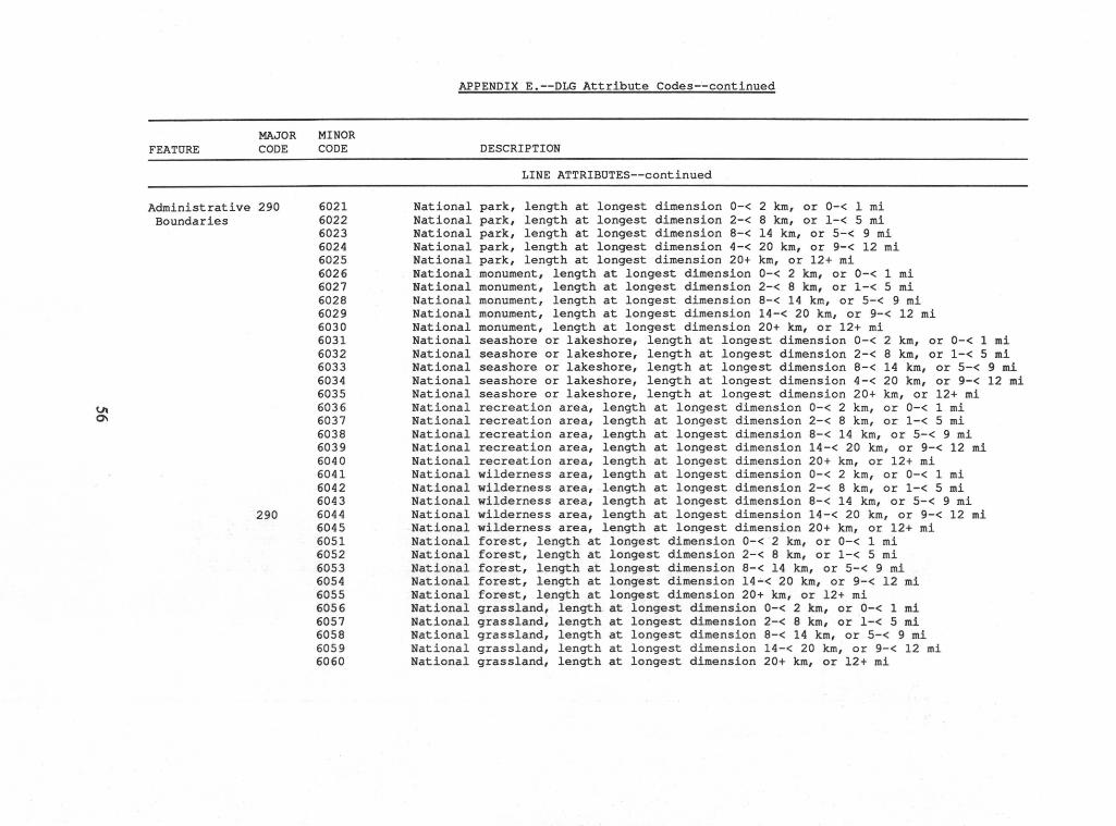
Vl 0\
FEATURE MAJOR CODE
Administrative 290 Boundaries
290
MINOR CODE
6021 6022 6023 6024 6025 6026 6027 6028 6029 6030 6031 6032 6033 6034 6035 6036 6037 6038 6039 6040 6041 6042 6043 6044 6045 6051 6052 6053 6054 6055 6056 6057 6058 6059 6060
APPENDIX E.--DLG Attribute Codes--continued
DESCRIPTION
LINE ATTRIBUTES--continued
National park, length at longest dimension 0-< 2 km, or 0-< 1 mi National park, length at longest dimension 2-< 8 km, or 1-< 5 mi National park, length at longest dimension 8-< 14 km, or 5-< 9 mi National park, length at longest dimension 4-< 20 km, or 9-< 12 mi National park, length at longest dimension 20+ km, or 12+ mi National monument, length at longest dimension 0-< 2 km, or 0-< 1 mi National monument, length at longest dimension 2-< 8 km, or 1-< 5 mi National monument, length at longest dimension 8-< 14 km, or 5-< 9 mi National monument, length at longest dimension 14-< 20 km, or 9-< 12 mi National monument, length at longest dimension 20+ km, or 12+ mi National seashore or lakeshore, length at longest dimension 0-< 2 km, or 0-< 1 mi National seashore or lakeshore, length at longest dimension 2-< 8 km, or 1-< 5 mi National seashore or lakeshore, length at longest dimension 8-< 14 km, or 5-< 9 mi National seashore or lakeshore, length at longest dimension 4-< 20 km, or 9-< 12 mi National seashore or lakeshore, length at longest dimension 20+ km, or 12+ mi National recreation area, length at longest dimension 0-< 2 km, or 0-< 1 mi National recreation area, length at longest dimension 2-< 8 km, or 1-< 5 mi National recreation area, length at longest dimension 8-< 14 km, or 5-< 9 mi National recreation area, length at longest dimension 14-< 20 km, or 9-< 12 mi National recreation area, length at longest dimension 20+ km, or 12+ mi National wilderness area, length at longest dimension 0-< 2 km, or 0-< 1 mi National wilderness area, length at longest dimension 2-< 8 km, or 1-< 5 mi National wilderness area, length at longest dimension 8-< 14 km, or 5-< 9 mi National wilderness area, length at longest dimension 14-< 20 km, or 9-< 12 mi National wilderness area, length at longest dimension 20+ km, or 12+ mi National forest, length at longest dimension 0-< 2 km, or 0-< 1 mi National forest, length at longest dimension 2-< 8 km, or 1-< 5 mi National forest, length at longest dimension 8-< 14 km, or 5-< 9 mi National forest, length at longest dimension 14~< 20 km, or 9-< 12 mi National forest, length at longest dimension 20+ km, or 12+ mi National grassland, length at longest dimension 0-< 2 km, or 0-< 1 mi National grassland, length at longest dimension 2-< 8 km, or 1-< 5 mi National grassland, length at longest dimension 8-< 14 km, or 5-< 9 mi National grassland, length at longest dimension 14-< 20 km, or 9-< 12 mi National grassland, length at longest dimension 20+ km, or 12+ mi
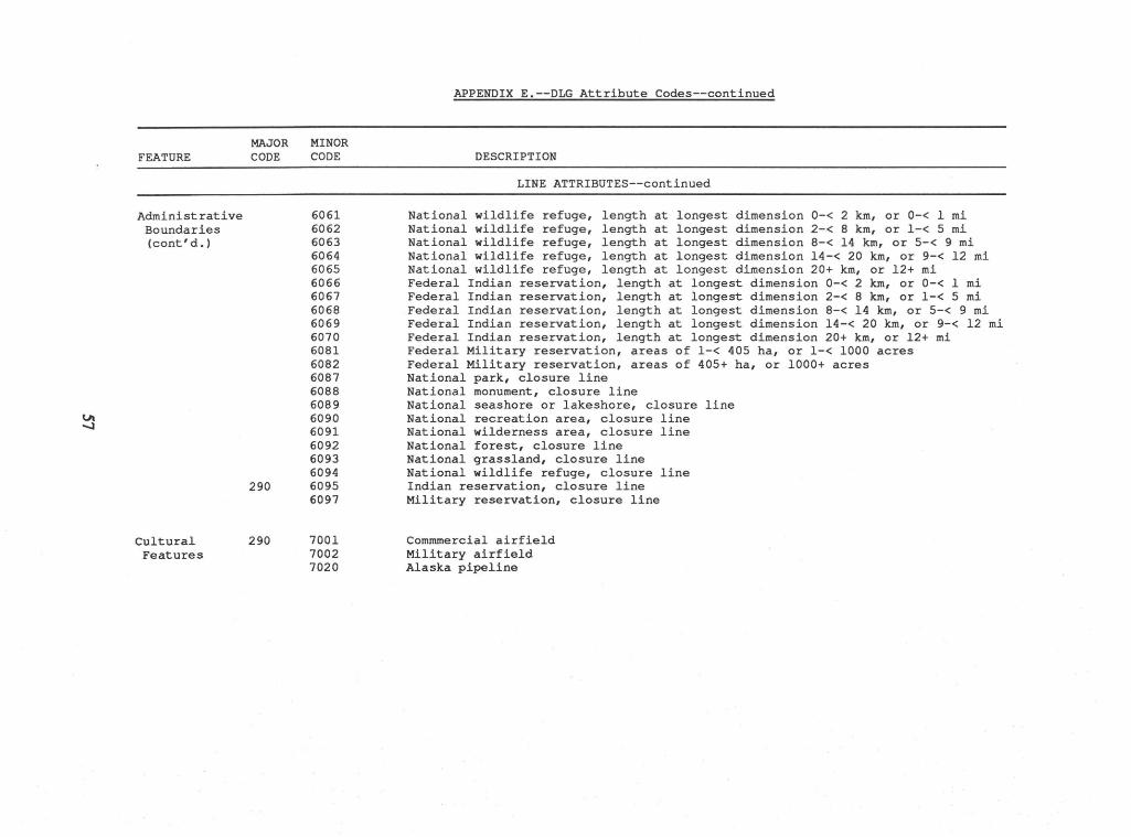
Ut -....J
FEATURE
Administrative Boundaries (cont' d.)
Cultural Features
MAJOR CODE
290
290
MINOR CODE
6061 6062 6063 6064 6065 6066 6067 6068 6069 6070 6081 6082 6087 6088 6089 6090 6091 6092 6093 6094 6095 6097
7001 7002 7020
APPENDIX E.--DLG Attribute Codes--continued
DESCRIPTION
LINE ATTRIBUTES--continued
National wildlife refuge, length at longest dimension 0-< 2 km, or 0-< 1 mi National wildlife refuge, length at longest dimension 2-< 8 km, or 1-< 5 mi National wildlife refuge, length at longest dimension 8-< 14 km, or 5-< 9 mi National wildlife refuge, length at longest dimension 14-< 20 km, or 9-< 12 mi National wildlife refuge, length at longest dimension 20+ km, or 12+ mi Federal Indian reservation, length at longest dimension 0-< 2 km, or 0-< 1 mi Federal Indian reservation, length at longest dimension 2-< 8 km, or 1-< 5 mi Federal Indian reservation, length at longest dimension 8-< 14 km, or 5-< 9 mi Federal Indian reservation, length at longest dimension 14-< 20 km, or 9-< 12 mi Federal Indian reservation, length at longest dimension 20+ km, or 12+ mi Federal Military reservation, areas of 1-< 405 ha, or 1-< 1000 acres Federal Military reservation, areas of 405+ ha, or 1000+ acres National park, closure line National monument, closure line National seashore or lakeshore, closure line National recreation area, closure line National wilderness area, closure line National forest, closure line National grassland, closure line National wildlife refuge, closure line Indian reservation, closure line Military reservation, closure line
Cornrnrnercial airfield Military airfield Alaska pipeline
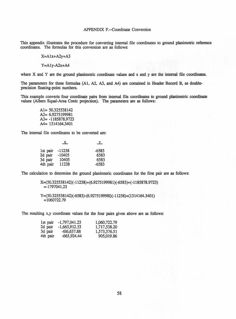
APPENDIX F.--Coordinate Conversion
This appendix illustrates the procedure for converting internal file coordinates to ground planimetric reference coordinates. The formulas for this conversion are as follows:
X=Alx+A2y+A3
Y =Aly-A2x+A4
where X and Y are the ground planimetric coordinate values and x and y are the internal ftle coordinates.
The parameters for these formulas {Al, A2, A3, and A4) are contained in Header Record B, as doubleprecision floating-point numbers.
This example converts four coordinate pairs from internal file coordinates to ground planimetric coordinate values (Albers Equal-Area Conic projection). The parameters are as follows:
Al= 50.325538142 A2= 6.9275199981 A3= -1185878.9723 A4= 1314164.3401
The internal file coordinates to be converted are:
1st pair -11238 2d pair -10405 3d pair 10405 4th pair 11238
..:L
-6583 6583 6583
-6583
The calculation to determine the ground planimteric coordinates for the ftrst pair are as follows:
X=(50.325538142)(-11238)+(6.9275199981)(-6583)+(-1185878.9723) =-1797041.23
y =(50.325538142)( -6583)-(6.9275199981)( -11238)+(1314164.3401) =1060722.79
The resulting x,y coordinate values for the four pairs given above are as follows:
1st pair -1,797,041.23 2d pair -1,663,912.33 3d pair -616,637.88 4th pair -665,924.44
1,060,722. 79 1,717,538.20 1,573,376.51
905,019.86
58
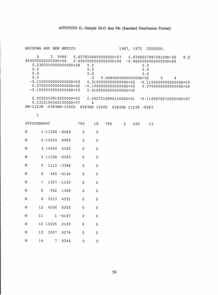
APPENDIX G.--Sample DLG data file (Standard Distribution Format)
ARIZONA AND NEW MEXICO 1967, 1972 2000000.
3 3 9999 0.637820640000000D+07 0.6768657997291090-02 0.2 903000000000000+08 0.4503000000000000+08 -0.960000000000000D+08
0.230000000000000D+08 0.0 0.0 0.0 0.0 0.0 0.0 0.0 0.0 0.0 2 0.508000000000000D+02 0 4
-0.115000000000000D+03 0.3100000000000000+02 -0.115000000000000D+03 0.3700000000000000+02 -0.103000000000000D+03 0.370000000000000D+02
-0.103000000000000D+03 0.310000000000000D+02
0.503255381420000D+02 0.6927519998100000+01 -0.1185878972300000+07 0.1314164340100000+07 4
SW-11238 -6583NW-10405 6583NE 10405 6583SE 11238 -6583
1
HYPSOGRAPHY 795 18 795 2 530 13
N 1-11238 -6583 0 0
N 2-10405 6583 0 0
N 3 10405 6583 0 0
N 4 11238 -6583 0 0
N 5 1115 -3388 0 0
N 6 465 -6194 0 0
N 7 1307 -1163 0 0
N 8 932 1388 0 0
N 9 3513 4531 0 0
N 10 4036 6283 0 0
N 11 1 -6187 0 0
N 12 10635 2183 0 0
N 13 5207 6274 0 0
N 14 7 6246 0 0
59
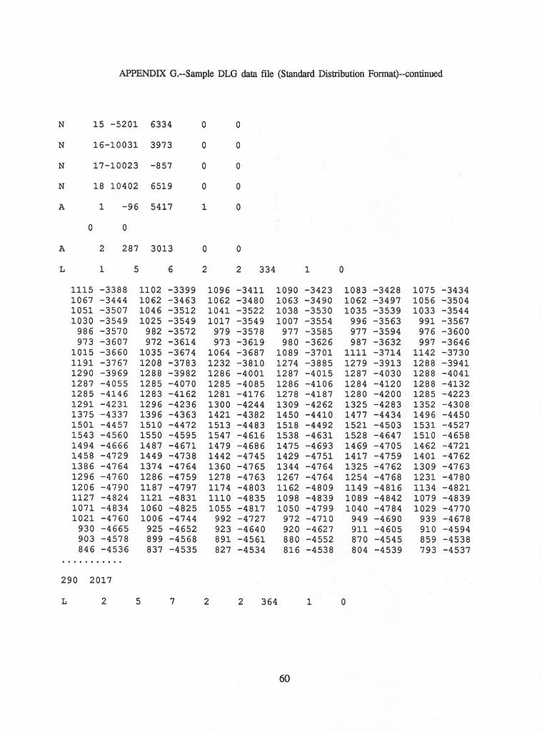
APPENDIX G.--Sample DLG data file (Standard Distribution Format)--continued
N 15 -5201 6334 0 0
N 16-10031 3973 0 0
N 17-10023 -857 0 0
N 18 10402 6519 0 0
A 1 -96 5417 1 0
0 0
A 2 287 3013 0 0
L 1 5 6 2 2 334 1 0
1115 -3388 1102 -3399 1096 -3411 1090 -3423 1083 -3428 1075 -3434 1067 -3444 1062 -3463 1062 -3480 1063 -3490 1062 -3497 1056 -3504 1051 -3507 1046 -3512 1041 -3522 1038 -3530 1035 -3539 1033 -3544 1030 -3549 1025 -3549 1017 -3549 1007 -3554 996 -3563 991 -3567
986 -3570 982 -3572 979 -3578 977 -3585 977 -3594 976 -3600 973 -3607 972 -3614 973 -3619 980 -3626 987 -3632 997 -3646
1015 -3660 1035 -3674 1064 -3687 1089 -3701 1111 -3714 1142 -3730 1191 -3767 1208 -3783 1232 -3810 1274 -3885 1279 -3913 1288 -3941 1290 -3969 1288 -3982 1286 -4001 1287 -4015 1287 -4030 1288 -4041 1287 -4055 1285 -4070 1285 -4085 1286 -4106 1284 -4120 1288 -4132 1285 -4146 1283 -4162 1281 -4176 1278 -4187 1280 -4200 1285 -4223 1291 -4231 1296 -4236 1300 -4244 1309 -4262 1325 -4283 1352 -4308 1375 -4337 1396 -4363 1421 -4382 1450 -4410 1477 -4434 1496 -4450 1501 -4457 1510 -4472 1513 -4483 1518 -4492 1521 -4503 1531 -4527 1543 -4560 1550 -4595 1547 -4616 1538 -4631 1528 -4647 1510 -4658 1494 -4666 1487 -4671 1479 -4686 1475 -4693 1469 -4705 1462 -4721 1458 -4729 1449 -4738 1442 -4745 1.429 -4751 1417 -4759 1401 -4762 1386 -4764 1374 -4764 1360 -4765 1344 -4764 1325 -4762 1309 -4763 1296 -4760 1286 -4759 1278 -4763 1267 -4764 1254 -4768 1231 -4780 1206 -4790 1187 -4797 1174 -4803 1162 -4809 1149 -4816 1134 -4821 1127 -4824 1121 -4831 1110 -4835 1098 -4839 1089 -4842 1079 -4839 1071 -4834 1060 -4825 1055 -4817 1050 -4799 1040 -4784 1029 -4770 1021 -4760 1006 -4744 992 -4727 972 -4710 949 -4690 939 -4678
930 -4665 925 -4652 923 -4640 920 -4627 911 -4605 910 -4594 903 -4578 899 -4568 891 -4561 880 -4552 870 -4545 859 -4538 846 -4536 837 -4535 827 -4534 816 -4538 804 -4539 793 -4537
........... 290 2017
L 2 5 7 2 2 364 1 0
60
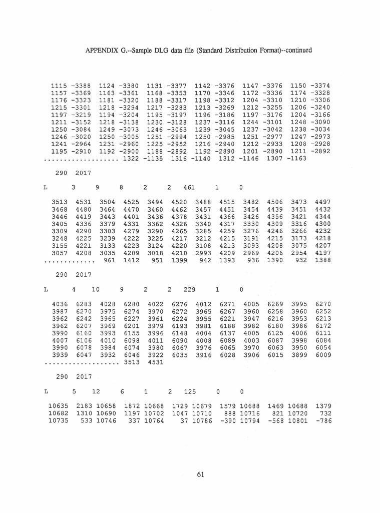
APPENDIX G.--Sample DLG data file (Standard Distribution Fonnat)--continued
1115 -3388 1124 -3380 1131 -3377 1142 -3376 1147 -3376 1150 -3374 1157 -3369 1163 -3361 1168 -3353 1170 -3346 1172 -3336 1174 -3328 1176 -3323 1181 -3320 1188 -3317 1198 -3312 1204 -3310 1210 -3306 1215 -3301 1218 -3294 1217 -3283 1213 -3269 1212 -3255 1206 -3240 1197 -3219 1194 -3204 1195 -3197 1196 -3186 1197 -3176 1204 -3166 1211 -3152 1218 -3138 1230 -3128 1237 -3116 1244 -3101 1248 -3090 1250 -3084 1249 -3073 1246 -3063 1239 -3045 1237 -3042 1238 -3034 1246 -3020 1250 -3005 1251 -2994 1250 -2985 1251 -2977 1247 -2973 1241 -2964 1231 -2960 1225 -2952 1216 -2940 1212 -2933 1208 -2928 1195 -2910 1192 -2900 1188 -2892 1192 -2890 1201 -2890 1211 -2892
................... 1322 -1135 1316 -1140 1312 -1146 1307 -1163
290 2017
L 3 9 8 2 2 461 1 0
3513 4531 3504 4525 3494 4520 3488 4515 3482 4506 3473 4497 3468 4480 3464 4470 3460 4462 3457 4451 3454 4439 3451 4432 3446 4419 3443 4401 3436 4378 3431 4366 3426 4356 3421 4344 3405 4336 3379 4331 3362 4326 3340 4317 3330 4309 3316 4300 3309 4290 3303 4279 3290 4265 3285 4259 3276 4246 3266 4232 3248 4225 3239 4222 3225 4217 3212 4215 3191 4215 3173 4218 3155 4221 3133 4223 3124 4220 3108 4213 3093 4208 3075 4207 3057 4208 3035 4209 3018 4210 2993 4209 2969 4206 2954 4197
............. 961 1412 951 1399 942 1393 936 1390 932 1388
290 2017
L 4 10 9 2 2 229 1 0
4036 6283 4028 6280 4022 6276 4012 6271 4005 6269 3995 6270 3987 6270 3975 6274 3970 6272 3965 6267 3960 6258 3960 6252 3962 6242 3965 6227 3961 6224 3955 6221 3947 6216 3953 6213 3962 6207 3969 6201 3979 6193 3981 6188 3982 6180 3986 6172 3990 6160 3993 6155 3996 6148 4004 6137 4005 6125 4006 6111 4007 6106 4010 6098 4011 6090 4008 6089 4003 6087 3998 6084 3990 6078 3984 6074 3980 6067 3976 6065 3970 6063 3950 6054 3939 6047 3932 6046 3922 6035 3916 6028 3906 6015 3899 6009
................... 3513 4531
290 2017
L 5 12 6 1 2 125 0 0
10635 2183 10658 1872 10668 1729 10679 1579 10688 1469 10688 1379 10682 1310 10690 1197 10702 1047 10710 888 10716 821 10720 732 10735 533 10746 337 10764 37 10786 -390 10794 -568 10801 -786
61
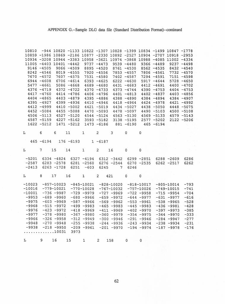
APPENDIX G.--Sample DLG data file (Standard Distribution Fonnat)--continued
10810 -944 10820 -1133 10822 -1307 10828 -1399 10834 -1499 10847 -1778 10859 -1986 10869 -2186 10877 -2330 10892 -2527 10904 -2707 10918 -2953 10934 -3208 10944 -3383 10958 -3621 10974 -3868 10988 -4085 11002 -4334 11005 -4403 10401 -4442 9737 -4473 9539 -4480 9366 -4489 9237 -4498
9146 -4505 9066 -4509 8895 -4520 8761 -4530 8562 -4535 8432 -4540 8242 -4546 8019 -4555 7920 -4556 7853 -4557 7806 -4561 7732 -4570 7670 -4572 7607 -4575 7531 -4580 7402 -4587 7294 -4591 7151 -4598 6944 -4608 6706 -4614 6393 -4625 6222 -4630 5917 -4644 5728 -4650 5477 -4661 5086 -4668 4689 -4680 4431 -4683 4412 -4691 4400 -4702 4376 -4719 4372 -4722 4370 -4733 4373 -4744 4390 -4753 4404 -4753 4417 -4760 4414 -4786 4406 -4796 4401 -4813 4402 -4837 4403 -4856 4404 -4865 4403 -4879 4395 -4886 4388 -4890 4384 -4894 4384 -4907 4395 -4927 4399 -4936 4410 -4946 4418 -4964 4424 -4978 4421 -4992 4412 -4999 4410 -5002 4421 -5019 4434 -5027 4438 -5050 4448 -5075 4452 -5084 4455 -5088 4470 -5093 4478 -5097 4490 -5103 4500 -5108 4506 -5113 4527 -5120 4544 -5124 4563 -5130 4569 -5133 4579 -5143 4587 -5159 4227 -5162 3593 -5182 3138 -5195 2577 -5202 2122 -5206 1622 -5212 1471 -5212 1473 -6186 881 -6190 465 -6194
L 6 6 11 1 2 3 0 0
465 -6194 176 -6193 1 -6187
L 7 15 14 1 2 16 0 0
-5201 6334 -4824 6327 -4194 6312 -3442 6299 -2851 6288 -2609 6286 -2587 6283 -2578 6281 -2560 6276 -2544 6270 -2535 6262 -2517 6262 -2413 6263 -1728 6251 -603 6245 7 6246
L 8 17 16 1 2 421 0 0
-10023 -857-10023 -845-10021 -828-10020 -818-10017 -805-10014 -793 -10016 -779-10021 -770-10028 -767-10032 -757-10026 -749-10015 -741 -10001 -736 -9987 -729 -9979 -727 -9969 -722 -9958 -715 -9954 -704
-9953 -689 -9960 -680 -9966 -659 -9972 -644 -9977 -631 -9977 -616 -9975 -603 -9969 -587 -9966 -569 -9962 -553 -9961 -538 -9965 -528 -9968 -515 -9972 -499 -9983 -465 -9983 -445 -9983 -436 -9981 -428 -9976 -423 -9972 -418 -9969 -411 -9969 -402 -9970 -397 -9973 -385 -9977 -378 -9980 -367 -9980 -360 -9979 -354 -9975 -344 -9970 -333 -9966 -326 -9958 -312 -9949 -300 -9946 -291 -9946 -284 -9947 -277 -9948 -270 -9948 -255 -9938 -244 -9936 -243 -9934 -238 -9934 -231 -9938 -218 -9950 -209 -9961 -201 -9970 -194 -9974 -187 -9978 -176
............. 10031 3973
L 9 16 15 1 2 158 0 0
62
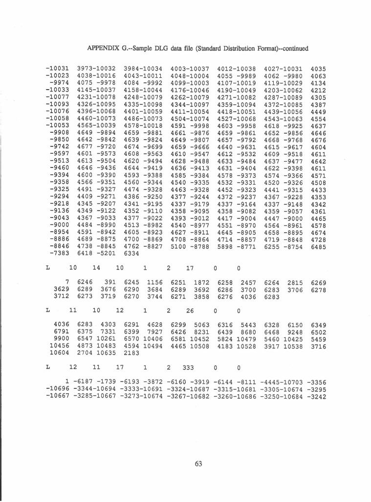
APPENDIX G.--Sample DLG data file (Standard Distribution Format)--continued
-10031 -10023
-9974 -10033 -10077 -10093 -10076 .:..10058 -10053
L
L
-9908 -9850 -9742 -9597 -9513 -9460 -9394 -9358 -9325 -9294 -9218 -9136 -9043 -9000 -8954 -8886 -8846 -7383
7 3629 3712
10
11
3973-10032 4038-10016 4075 -9978 4145-10037 4231-10078 4326-10095 4396-10068 4460-10073 4565-10039 4649 -9894 4642 -9842 4677 -9720 4601 -9573 4613 -9504 4646 -9436 4600 -9390 4566 -9351 4491 -9327 4409 -9271 4345 -9207 4349 -9122 4367 -9033 4484 -8990 4591 -8942 4689 -8875 4738 -8845 6418 -5201
14
6246 391 6289 3676 6273 3719
10
10
12
3984-10034 4043-10011 4084 -9992 4158-10044 4248-10079 4335-10098 4401-10059 4486-10073 4578-10018 4659 -9881 4639 -9824 4674 -9699 4608 -9563 4620 -9494 4644 -9419 4593 -9388 4560 -9344 4474 -9328 4386 -9250 4341 -9195 4352 -9110 4377 -9022 4513 -8982 4605 -8923 4700 -8869 4762 -8827 6334
6245 6290 6270
1
1
1156 3684 3744
4036 6283 4303 6291 4628 6791 6375 7331 6399 7927 9900 6547 10261 6570 10406
L
10456 4873 10483 4594 10494 10604 2704 10635 2183
12 11 17 1
2
2
4003-10037 4048-10004 4099-10003 4176-10046 4262-10079 4344-10097 4411-10054 4504-10074 4591 -9998 4661 -9876 4649 -9807 4659 -9666 4610 -9547 4628 -9488 4636 -9413 4585 -9384 4540 -9335 4463 -9328 4377 -9244 4337 -9179 4358 -9095 4393 -9012 4540 -8977 4627 -8911 4708 -8864 5100 -8788
6251 6289 6271
17
26
1872 3692 3858
6299 5063 6426 8231 6581 10452 4465 10508
2 333
0
0
0
4012-10038 4055 -9989 4107-10019 4190-10049 4271-10082 4359-10094 4418-10051 4527-10068 4603 -9958 4659 -9861 4657 -9792 4640 -9631 4612 -9532 4633 -9484 4631 -9404 4578 -9373 4532 -9331 4452 -9323 4372 -9237 4337 -9164 4358 -9082 4417 -9004 4551 -8970 4645 -8905 4714 -8857 5898 -8771
0
6258 2457 6286 3700 6276 4036
0
6316 5443 6439 8680 5824 10479 4183 10528
0
4027-10031 4062 -9980 4119-10029 4203-10062 4287-10089 4372-10085 4439-10056 4543-10063 4618 -9925 4652 -9856 4668 -9768 4615 -9617 4609 -9518 4637 -9477 4622 -9398 4574 -9366 4520 -9326 4441 -9315 4367 -9228 4337 -9148 4359 -9057 4447 -9000 4564 -8961 4658 -8895 4719 -8848 6255 -8754
6264 2815 6283 3706 6283
6328 6150 6468 9248 5460 10425 3917 10538
4035 4063 4134 4212 4305 4387 4449 4554 4637 4646 4676 4604 4611 4642 4611 4571 4508 4433 4353 4342 4361 4465 4578 4674 4728 6485
6269 6278
6349 6502 5459 3716
1 -6187 -1739 -6193 -3872 -6160 -3919 -6144 -8111 -4445-10703 -3356 -10696 -3344-10694 -3333-10691 -3324-10687 -3315-10681 -3305-10674 -3295 -10667 -3285-10667 -3273-10674 -3267-10682 -3260-10686 -3250-10684 -3242
63
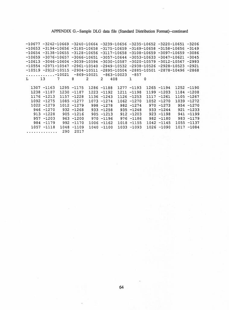
APPENDIX G.--Sample DLG data file (Standard Distribution Format)--continued
-10677 -3242-10669 -3240-10664 -3239-10656 -3235-10652 -3220-10651 -3206 -10653 -3194-10656 -3185-10658 -3175-10659 -3169-10658 -3158-10656 -3149 -10654 -3138-10655 -3128-10656 -3117-10658 -3108-10659 -3097-10659 -3086 -10659 -3076-10657 -3066-10651 -3057-10644 -3053-10633 -3047-10621 -3045 -10613 -3046-10604 -3039-10594 -3030-10587 -3020-10579 -3012-10567 -2993 -10554 -2971-10547 -2961-10540 -2949-10532 -2938-10526 -2928-10523 -2921 -10519 -29~2-10515 -2904-10511 -2895-10504 -2885-10501 -2878-10496 -2868 ............ -10021 -869-10021 -863-10023 -857 L 13 7 8 2 2 408 1 0
1307 -1163 1295 -1175 1286 -1188 1277 -1193 1265 -1194 1252 -1190 1238 -1187 1230 -1187 1223 -1192 1211 -1198 1199 -1203 1184 -1208 1176 -1213 1157 -1228 1136 -1243 1126 -1253 1117 -1261 1105 -1267 1092 -1275 1085 -1277 1073 -1274 1062 -1270 1052 -1270 1039 -1272 1022 -1279 1012 -1279 998 -1278 982 -1274 970 -1273 954 -1270
946 -1270 932 -1268 933 -1258 935 -1248 933 -1244 921 -1233 913 -1228 905 -1216 905 -1213 912 -1203 923 -1198 941 -1199 957 -1203 963 -1200 970 -1196 976 -1186 982 -1180 983 -1179 984 -1179 992 -1170 1006 -1162 1018 -1155 1042 -1145 1055 -1137
1057 -1118 1048 -1109 1040 -1100 1033 -1093 1026 -1090 1017 -1084 ............. 290 2017
64
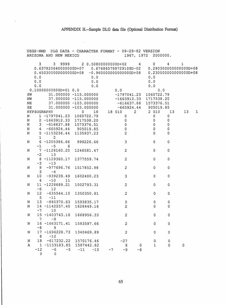
APPENDIX H.--Sample DLG data file (Optional Distribution Format)
USGS-NMD DLG DATA - CHARACTER FORMAT - 09-29-82 VERSION ARIZONA AND NEW MEXICO 1967, 1972 2000000.
3 3 9999 2 0.50800000000D+02 4 0.637820640000000D+07 0.450300000000000D+08 0.0
0.676865799729109D-02 -0.960000000000000D+08
0.0 0.0 0.0
0.10000000000D+01 sw 31.000000 NW 37.000000 NE 37.000000 SE 31.000000 HYPSOGRAPHY N 1 -1797041.23 N 2 -1663912.33 N 3 -616637.88 N 4 -665924.44 N 5 -1153236.44
N
N
N
N
1 2 6 -1205386.66
-1 -5 6 7 -1128160.20
-2 13 8 -1129360.17
-3 -13 9 -977696.76 3 -4
N 10 -939239.49 4 -10 11
N 11 -1228689.21 -6 12
N 12 -635544.10 5 -11
N 13 -880370.63 N 14 -1142257.40
-7 10 N 15 -1403743.18
7 -9 N 16 -1663171.41
-8 9 N 17 -1696228.73
8 -12 N 18 -617232.22 A 1 -1153183.85
-12 -6 -5 0 0
0 . 0 0.0
0.0 -115.000000 -115.000000 -103.000000 -103.000000
0 18 1060722.79 1717538.20 1573376.51
905019.85 1135937.23
999226.66
1246581.47
1377559.74
1517852.98
1602400.23
1002793.31
1350350.81
1593835.17 1628449.16
1668956.33
1583597.66
1340469.89
1570176.46 1587442.82
-11 -10
0.0 -1797041.23 -1663912.33
-616637.88 -665924.44
18 010 2
-7
0 0 0 0 2
3
2
2
2
3
2
2
0 2
2
2
2
-27 8
-9
65
0 -8
0 4 1 0.290300000000000D+08 0.230000000000000D+08 0.0 0.0 0.0
0.0 1060722.79 1717538.20 1573376.51
905019.85 2 010 13
0 0 0 0 0 0 0 0 0 0
0 0
0 0
0 0
0 0
0 0
0 0
0 0
0 0 0 0
0 0
0 0
0 0
0 1
0 0
13 1
0
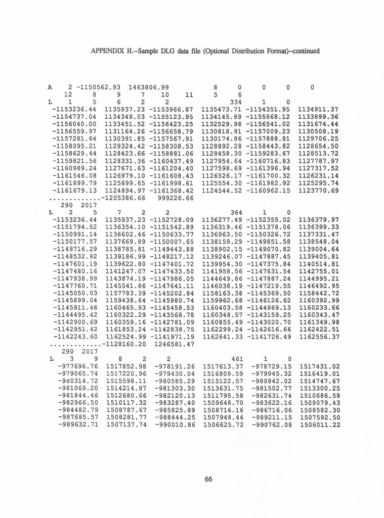
APPENDIX H.--Sample DLG data file (Optional Distribution Format)--continued
A 2 -1150562.93 1463806.99 8 0 0 0 0 12 8 9 7 10 11 5 6
L 1 5 6 2 2 334 1 0 -1153236.44 1135937.23 -1153966.87 1135473.71 -1154351.95 1134911.37 -1154737.04 1134349.03 -1155123.95 1134145.89 -1155568.12 1133899.36 -1156040.00 1133451.52 -1156423.25 1132529.98 -1156541.02 1131674.44 -1156559.97 1131164.26 -1156658.79 1130818.91 -1157009.23 1130508.19 -1157281.64 1130391.85 -1157567.91 1130174.86 -1157888.81 1129706.25 -1158095.21 1129324.42 -1158308.53 1128892.28 -1158443.82 1128654.50 -1158629.44 1128423.66 -1158881.06 1128458.30 -1159283.67 1128513.72 -1159821.56 1128331.36 -1160437.49 1127954.64 -1160716.83 1127787.97 -1160989.24 1127671.63 -1161204.40 1127598.69 -1161396.94 1127317.52 -1161546.08 1126979.10 -1161608.43 1126526.17 -1161700.32 1126231.14 -1161899.79 1125899.65 -1161998.61 1125554.30 -1161982.92 1125295.74 -1161679.13 1124894.97 -1161368.42 1124544.52 -1160962.15 1123770.69
............. -1205386.66 999226.66 290 2017
L 2 5 7 2 2 364 1 0 -1153236.44 1135937.23 -1152728.09 1136277.49 -1152355.02 1136379.97 -1151794.52 1136354.10 -1151542.89 1136319.46 -1151378.06 1136399.33 -1150991.14 1136602.46 -1150633.77 1136963.50 -1150326.72 1137331.47 -1150177.57 1137669.89 -1150007.65 1138159.29 -1149851.58 11385.48. 04 -1149716.29 1138785.81 -1149443.88 1138902.15 -1149070.82 1139004.64 -1148532.92 1139186.99 -1148217.12 1139246.07 -1147887.45 1139405.81 -1147601.19 1139622.80 -1147401.72 1139954.30 -1147375.84 1140514.81 -1147480.16 1141247.07 -1147433.50 1141958.56 -1147631.54 1142755.01 -1147938.99 1143874.19 -1147986.05 1144649.86 -1147887.24 1144995.21 -1147760.71 1145541.86 -1147641.11 1146038.19 -1147219.55 1146492.95 -1145050.03 1157783.39 -1145202.84 1158163.38 -1145369.50 1158442.72 -1145899.04 1159438.64 -1145980.74 1159962.68 -1146126.62 1160392.99 -1145911.46 1160465.93 -1145458.53 1160403.58 -1144969.13 1160233.66 -1144495.42 1160322.29 -1143568.78 1160348.57 -1143159.25 1160343.47 -1142900.69 1160359.16 -1142781.09 1160855.49 -1143020.70 1161349.98 -1142951.42 1161853.24 -1142838.75 1162299.24 -1142616.66 1162422.51 -1142243.60 1162524.99 -1141971.19 1162641.33 -1141726.49 1162556.37
............. -1128160.20 1246581.47 290 2017
L 3 9 8 2 2 461 1 0 -977696.76 1517852.98 -978191.26 1517613.37 -978729.15 1517431.02 -979065.74 1517220.96 -979430.04 1516809.59 -979945.32 1516419.01 -980314.72 1515598.11 -980585.29 1515122.57 -980842.02 1514747.67 -981069.20 1514214.87 -981303.30 1513631.75 -981502.77 1513300.25 -981844.46 1512680.66 -982120.13 1511795.58 -982631.74 1510686.59 -982966.50 1510117.32 -983287.40 1509648.70 -983622.16 1509079.43 -984482.79 1508787.67 -985825.89 1508716.16 -986716.06 1508582.30 -987885.57 1508281.77 -988444.25 1507948.44 -989211.15 1507592.50 -989632.71 1507137.74 -990010.86 1506625.72 -990762.08 1506011.22
66
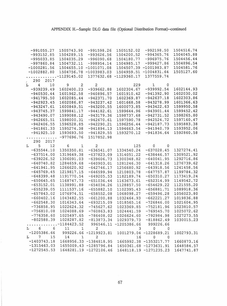
APPENDIX H.--Sample DLG data file (Optional Distribution Format)--continued
-991055.27 1505743.90 -991598.26 1505152.02 -992198.50 1504516.74 -993152.85 1504289.15 -993626.56 1504200.52 -994365.76 1504045.88 -995033.85 1504035.29 -996090.68 1504180.77 -996975.76 1504456.44 -997860.84 1504732.11 -998954.14 1504985.17 -999427.86 1504896.54
-1000281.56 1504655.10 -1001071.08 1504507.39 -1001983.87 1504581.76 -1002882.80 1504756.78 -1003983.03 1504959.51 -1004831.64 1505127.60
............. -1129145. 02 1377632.68 -1129360.17 1377559.74 } 290 2017 L 4 10 9 2 2 229 1 0
-939239.49 1602400.23 -939662.88 1602304.67 -939992.54 1602144.93 -940530.44 1601962.58 -940896.57 1601910.42 -941392.90 1602030.02 -941795.50 1602085.44 -942371.70 1602369.87 -942637.18 1602303.86 -942923.45 1602086.87 -943237.42 1601668.58 -943278.99 1601366.63 -943247.61 1600849.51 -943200.55 1600073.85 -943422.63 1599950.58 -943745.37 1599841.17 -944182.61 1599644.96 -943901.44 1599452.42 -943490.07 1599088.12 -943179.36 1598737.68 -942731.52 1598265.80 -942665.51 1598000.31 -942670.61 1597590.78 -942524.72 1597160.47 -942406.55 1596528.85 -942290.21 1596256.44 -942187.73 1595883.38 -941861.33 1595274.38 -941894.13 1594663.54 -941940.79 1593952.06 -941925.10 1593693.50 -941829.55 1593270.12 -941834.64 1592860.58
............. -977696.76 1517852.98 290 2017
L 5 12 6 1 2 125 0 0 -635544.10 1350350.81 -636541.07 1334540.24 -637028.45 1327274.41 -637514.00 1319649.38 -637823.09 1314051.22 -638446.57 1309521.92 -639226.52 1306091.03 -639606.73 1300348.82 -640041.95 1292716.86 -640740.82 1284659.68 -640903.01 1281246.30 -641318.26 1276739.62 -641941.95 1266620.92 -642746.17 1256680.92 -643918.56 1241458.56 -645769.45 1219817.15 -646599.94 1210803.78 -647757.87 1199784.32 -648399.48 1191770.54 -649205.53 1182189.74 -650310.27 1173419.24 -650645.65 1168747.73 -651036.44 1163673.61 -652314.99 1149542.72 -653152.01 1138991.88 -654034.26 1128857.50 -654629.22 1121555.20 -655239.05 1111537.16 -655882.10 1102395.43 -656881.71 1089918.36 -657843.02 1076974.51 -658552.08 1068098.27 -659496.28 1056023.80 -660402.16 1043482.55 -661200.88 1032464.93 -662221.27 1019836.88 -662548.30 1016343.64 -693215.09 1018565.16 -726846.00 1021604.95 -736858.95 1022624.32 -745627.62 1023369.85 -752181.96 1023810.57 -756810.08 1024088.69 -760863.83 1024441.59 -769545.70 1025072.62 -776358.60 1025497.65 -786408.02 1026624.60 -792984.98 1027273.55 -802588.39 1028287.82 -813873.34 1029379.73 -818862.49 1030015.23
............. -1184423.52 996546.11 -1205386.66 999226.66 L 6 6 11 1 2 3 0 0
-1205386.66 999226.66 -1219923.81 1001279.04 -1228689.21 1002793.31 L 7 15 14 1 2 16 0 0
-1403743.18 1668956.33 -1384818.95 1665992.38 -1353217.77 1660873.16 -1315463.03 1655009.43 -1285796.84 1650361.68 -1273631.91 1648584.57 -1272545.53 1648281.19 -1272106.46 1648118.19 -1271235.23 1647741.87
67
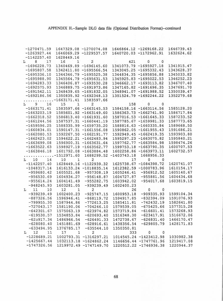
APPENDIX H.--Sample DLG data file (Optional Distribution Format)--continued
-1270471.59 1647329.08 -1270074.08 1646864.12 -1269168.22 1646739.43 -1263927.44 1646069·. 29 -1229537.57 1640720.03 -1172962.91 1632624.62 -1142257.40 1628449.16
L 8 17 16 1 2 421 0 0 -1696228.73 1340469.89 -1696145.60 1341073.79 -1695927.18 1341915.47 -1695807.58 1342411.80 -1695566.54 1343045.25 -1695332.43 1343628.37 -1695336.10 1344346.79 -1695525.38 1344834.35 -169585.6.88 1345033.82 -1695988.90 1345564.79 -1695631.53 1345925.83 -1695022.53 1346252.23 -1694283.33 1346406.87 -1693530.28 1346662.17 -1693113~82 1346707.40 -1692575.93 1346889.75 -1691973.86 1347165.82 -1691696.35 1347691.70 -1691542.11 1348439.65 -1691832.05 1348941.07 -1691988.52 1350039.47 -1692186.56 13.50835. 92 -1692348.13 1351524.79 -1692244.22 1352279.68
............. -1663171.41 1583597.66 L 9 16 15 1 2 158 0 0
-1663171.41 1583597.66 -1663145.53 1584158.16 -1663114.56 1585128.20 -1663203.19 1585601.92 -1663149.60 1586363.73 -1662741.90 1586717.84 -1662318.52 1586813.40 -1661931.60 1587016.53 -1661645.33 1587233.52 -1661244.56 1587537.31 -1660441.19 1587785.67 -1659981.33 1587773.65 -1659596.25 1588335.99 -1659735.20 1588816.63 -1660335.84 1589668.50 -1660834.01 1590147.31 -1661556.08 1590862.05 -1661955.43 1591686.21 -1662080.53 1592267.50 -1662191.77 1592949.45 -1662419.35 1593903.80 -1662423.02 1594622.21 -1662483.94 1595297.23 -1663075.82 1595840.21 -1663699.08 1596900.31 -1663631.64 1597762.77 -1663584.98 1598474.26 -1663522.63 1598927.19 -1663562.77 1599753.18 -1663790.35 1600707.53 -1663846.18 1601792.08 -1663884.48 1602258.86 -1663973.11 1602732.57
............. -1512971.60 1688299.52 -1403743.18 1668956.33 L 10 14 10 1 2 17 0 0
-1142257.40 1628449.16 -1122939.32 1625738.67 -1084398.72 1620741.07 -1048317.14 1616133.24 -1018835.14 1612382.59 -1000783.96 1610154.17
-959680.42 1605521.68 -957308.19 1605246.41 -956912.52 1605140.67 -956530.69 1604934.27 -956148.87 1604727.87 -955881.56 1604434.68 -955614.24 1604141.49 -955282.75 1603942.02 -954017.68 1603819.15 -948245.93 1603281.05 -939239.49 1602400.23
L 11 10 12 1 2 26 0 0 -939239.49 1602400.23 -925747.15 1600953.18 -909335.93 1599104.34 -887326.56 1596946.41 -868119.72 1594917.85 -832394.09 1591076.93 -799955.30 1587944.86 -772613.25 1585411.81 -742432.19 1582641.80 -727043.17 1581190.06 -704246.10 1579539.05 -675425.66 1577315.28 -642301.67 1575063.19 -623974.82 1573719.84 -616601.41 1573268.93 -619530.57 1534853.84 -620693.40 1516348.30 -623417.91 1516672.06 -625917.34 1486966.54 -626491.33 1472738.67 -626831.40 1466170.47 -628080.40 1451881.69 -628916.61 1438356.54 -629805.79 1428171.83 -633494.95 1376785.17 -635544.10 1350350.81
L 12 11 17 1 2 333 0 0 -1228689.21 1002793.31 -1316297.21 1014545.24 -1423412.98 1030982.38 -1425667.44 1032113.18 -1624862.24 1146656.44 -1747761.96 1219417.08 -1747326.56 1219972.49 -1747149.70 1220512.22 -1746936.38 1220944.37
68
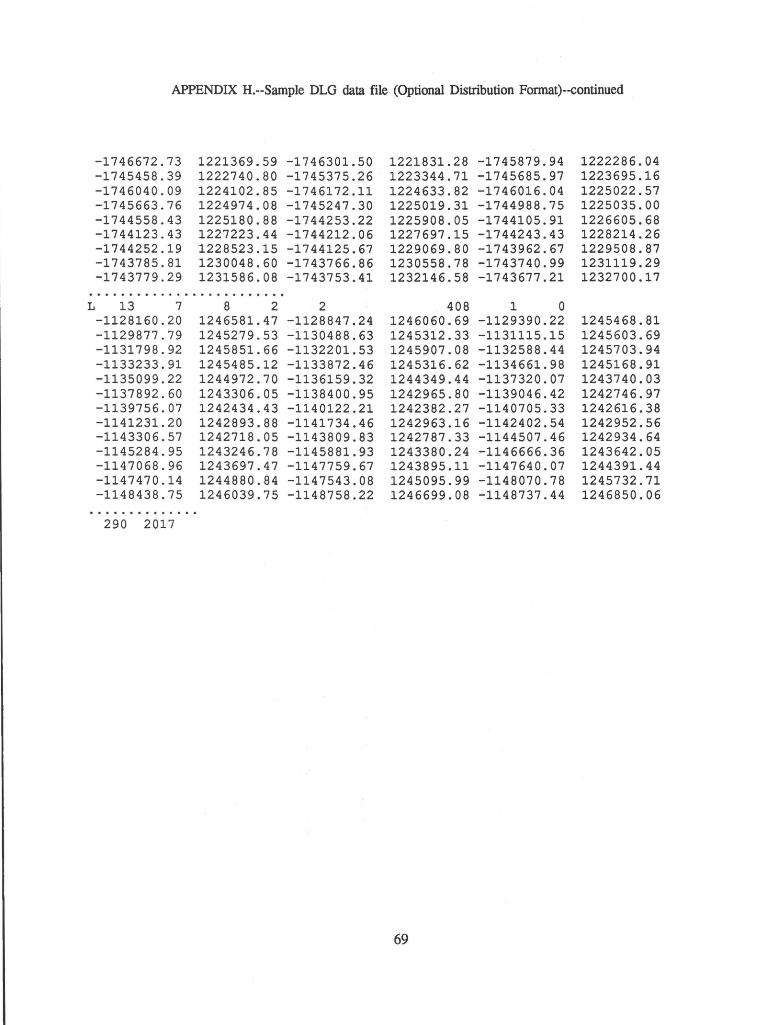
APPENDIX H.--Sample DLG data file (Optional Distribution Format)--continued
-1746672.73 1221369.59 -1746301.50 1221831.28 -1745879.94 1222286.04 -1745458.39 1222740.80 -1745375.26 1223344.71 -1745685.97 1223695.16 -1746040.09 1224102.85 -1746172.11 1224633.82 -1746016.04 1225022.57 -1745663.76 1224974.08 -1745247.30 1225019.31 -1744988.75 1225035.00 -1744558.43 1225180.88 -1744253.22 1225908.05 -1744105.91 1226605.68 -1744123.43 1227223.44 -1744212.06 1227697.15 -1744243.43 1228214.26 -1744252.19 1228523.15 -1744125.67 1229069.80 -1743962.67 1229508.87 -1743785.81 1230048.60 -1743766.86 1230558.78 -1743740.99 1231119.29 -1743779.29 1231586.08 -1743753.41 1232146.58 -1743677.21 1232700.17
......................... L 13 7 8 2 2 408 1 0
-1128160.20 1246581.47 -1128847.24 1246060.69 -1129390.22 1245468.81 -1129877.79 1245279.53 -1130488.63 1245312.33 -1131115.15 1245603.69 -1131798.92 1245851.66 -1132201.53 1245907.08 -1132588.44 1245703.94 -1133233.91 1245485.12 -1133872.46 1245316.62 -1134661.98 1245168.91 -1135099.22 1244972.70 -1136159.32 1244349.44 -1137320.07 1243740.03 -1137892.60 1243306.05 -1138400.95 1242965.80 -1139046.42 1242746.97 -1139756.07 1242434.43 -1140122.21 1242382.27 -1140705.33 1242616.38 -1141231.20 1242893.88 -1141734.46 1242963.16 -1142402.54 1242952.56 -1143306.57 1242718.05 -1143809.83 1242787.33 -1144507.46 1242934.64 -1145284.95 1243246.78 -1145881.93 1243380.24 -1146666.36 1243642.05 -1147068.96 1243697.47 -1147759.67 1243895.11 -1147640.07 1244391.44 -1147470.14 1244880.84 -1147543.08 1245095.99 -1148070.78 1245732.71 -1148438.75 1246039.75 -1148758.22 1246699.08 -1148737.44 1246850.06
.............. 290 2017
69
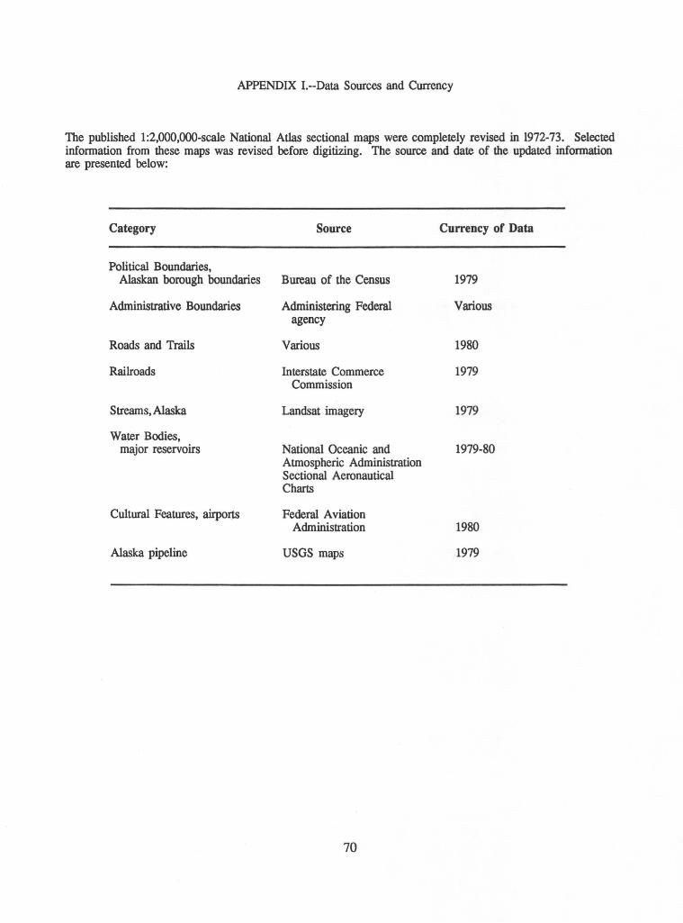
APPENDIX I.--Data Sources and Currency
The published 1:2,000,000-scale National Atlas sectional maps were completely revised in 1972-73. Selected information from these maps was revised before digitizing. The source and date of the updated information are presented below:
Category Source Currency of Data
Political Boundaries, Alaskan borough boundaries Bureau of the Census 1979
Administrative Boundaries Administering Federal Various agency
Roads and Trails Various 1980
Railroads Interstate Commerce 1979 Commission
Streams, Alaska Landsat imagery 1979
Water Bodies, major reservoirs National Oceanic and 1979-80
Atmospheric Administration Sectional Aeronautical Charts
Cultural Features, airports Federal Aviation Administration 1980
Alaska pipeline USGS maps 1979
70


