Embed Size (px)
Citation preview
PLEASE NOTE THAT THIS IS A WORK IN PROGRESS
THERE WILL BE NUMEROUS CHANGES AND ADDITIONS BEFORE THIS HANDBOOK IS COMPLETED
TABLE OF CONTENTS
SECTION 1 ..................................................................................................................................... 2 WATER AND WASTEWATER SYSTEMS ................................................................................. 2
1.01 PURPOSE............................................................................................................................................. 2 1.02 DUTIES OF THE COUNTY .......................................................................................................... 2 1.03 DEFINITIONS ....................................................................................................................................3 1.04 CRITERIA OF REVIEW ............................................................................................................... 10 1.05 GENERAL INFORMATION ....................................................................................................... 11 1.06 PLANS AND SPECIFICATIONS .............................................................................................. 12 1.07 ADMINISTRATIVE PROCEDURES ....................................................................................... 13 1.08 LIST OF MATERIALS AND APPROVED MANUFACTURERS ................................. 15 1.09 PERSON TO CONT ACT .............................................................................................................. 15 1.10 PROCEDURE FOR OBTAINING CAPACITY ..................................................................... 15 1.11 PAYMENT OF FEES ..................................................................................................................... 16 1.12 REGULATORY PERMITS .......................................................................................................... 16 1.13 ALLOCATION FACTORS AND LIMITATIONS ................................................................ 17 1.14 CAPACITY RESERVATION OR ALLOCATION RECAPTURE ................................. 17 1.15 FEES SUBJECT TO CHANGE................................................................................................... 18 1.16 SEPTIC TANK POLICY ............................................................................................................... 18 1.17 SYSTEM EXTENSION POLICY ............................................................................................... 18 1.18 BACKFLOW PREVENTION POLICY .................................................................................... 18 1.19 OIL & GREASE POLICY ............................................................................................................. 18
WATER AND WASTEWATER SYSTEMS HANDBOOK 1-1
SECTION 1
WATER AND WASTEWATER SYSTEMS
1.01 PURPOSE
The COLUMBIA COUNTY BOARD OF COUNTY COMMISSIONERS (hereinafter referred to as the County) was formed to plan for and establish management of water and wastewater treatment facilities, transmission, collection, and distribution systems within the Utility Service Area in order to accomplish the following goals:
A. To plan for and better accommodate water and wastewater users.
B. To delineate user procedures.
C. To provide a mechanism allowing service commitment for major capacity requests.
D. To establish a reserve capacity fee for unused services.
E. To delineate user service policies.
F. To establish minimum technical specifications and standards for approval of water and wastewater facilities, transmission, collection, and distribution systems to he constructed within the Utility Service Arca.
1.02 DUTIES OF THE COUNTY
The County is authorized and empowered:
A. To adopt such rules and regulations as the County may deem necessary in transacting its business.
B. To construct, acquire, improve, maintain and operate water or wastewater systems within the Utility Service Arca and the environs thereof, and to acquire by gift, purchase, grant-in-aid of planning, construction, reconstruction or financing, franchises, water or wastewater systems or portions thereof, land, rights or interests of any nature whatsoever in land or water rights connected therewith, and any of the property, real, personal, and tangible or intangible, necessary for such water or wastewater systems.
WATER AND WASTEWATER SYSTEMS HANDBOOK 1-2
C. To operate and maintain such water or wastewater system or systems for its own use and for the use and benefit of the inhabitants and of persons, firms, corporations, political subdivisions or other public agencies or parties located within the Utility Service Area or the environs thereto, who shall use the facilities and services of such system or systems and to enter into contracts for the supply and distribution or receiving of water with any such persons, firms, corporation, municipalities, special districts, political subdivisions or other public agencies or parties.
D. To employ and to enter into agreements or contracts with consultants, advisors, engineers, attorneys or fiscal, financial, or other experts for the planning, preparation, supervision, operation and financing of such water or wastewater system or systems, or any part thereof, upon such terms and conditions as to compensation and otherwise as the County shall deem desirable and proper.
E. To fix and collect fees, rentals or other charges (hereinafter sometimes referred to as "revenues") determined on an equitable basis for the use of the County water and/or wastewater facilities and services.
1.03 DEFINITIONS
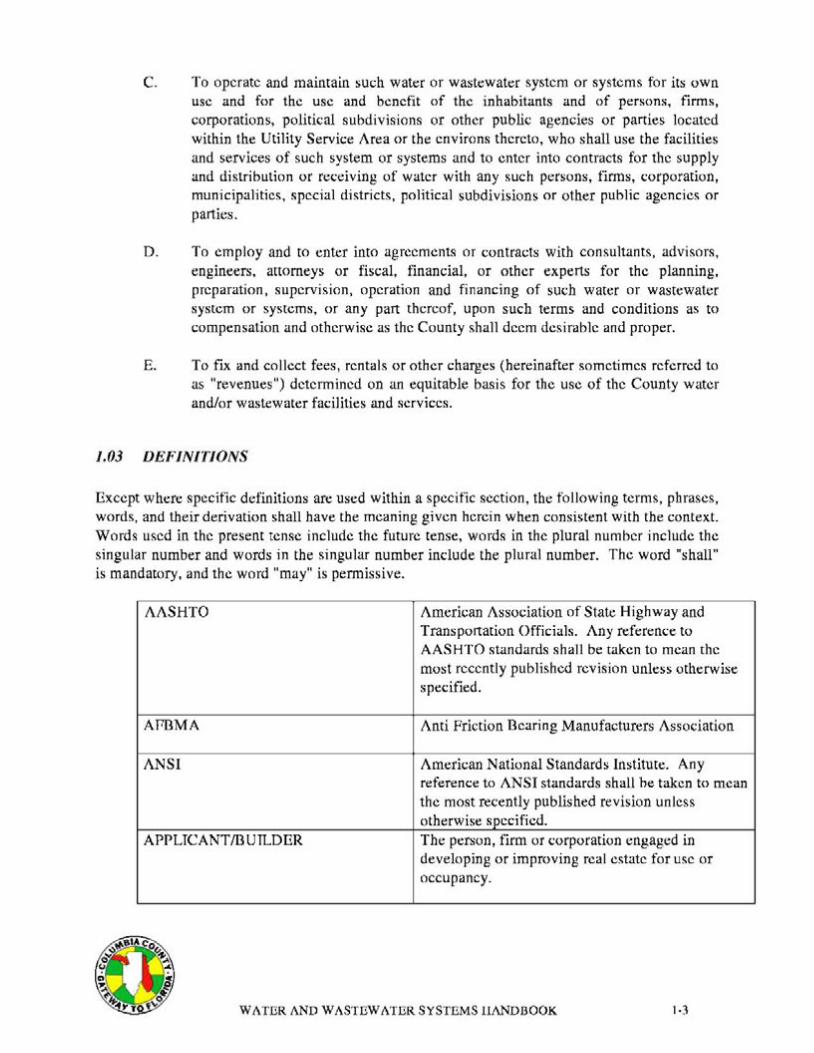
Except where specific definitions are used within a specific section, the following terms, phrases, words, and their derivation shall have the meaning given herein when consistent with the context. Words used in the present tense include the future tense, words in the plural number include the singular number and words in the singular number include the plural number. The word "shall" is mandatory. and the word "may" is permissive.
AASHTO American Association of State Highway and Transportation Officials. Any reference to AASHTO standards sha11 be taken to mean the most recently published revision unless otherwise specified.
AR3MA Anti Friction Dearing Manufacturers Association
ANSI American National Standards Institute. Any reference to ANSI standards shall he taken to mean the most recently published revision unless otherwise specified.
APPLTCANT/DUTLDER The person, firm or corporation engaged in developing or improving real estate for use or occupancy.
1.3WATER AND WASTEWATER SYSTEMS HANDBOOK
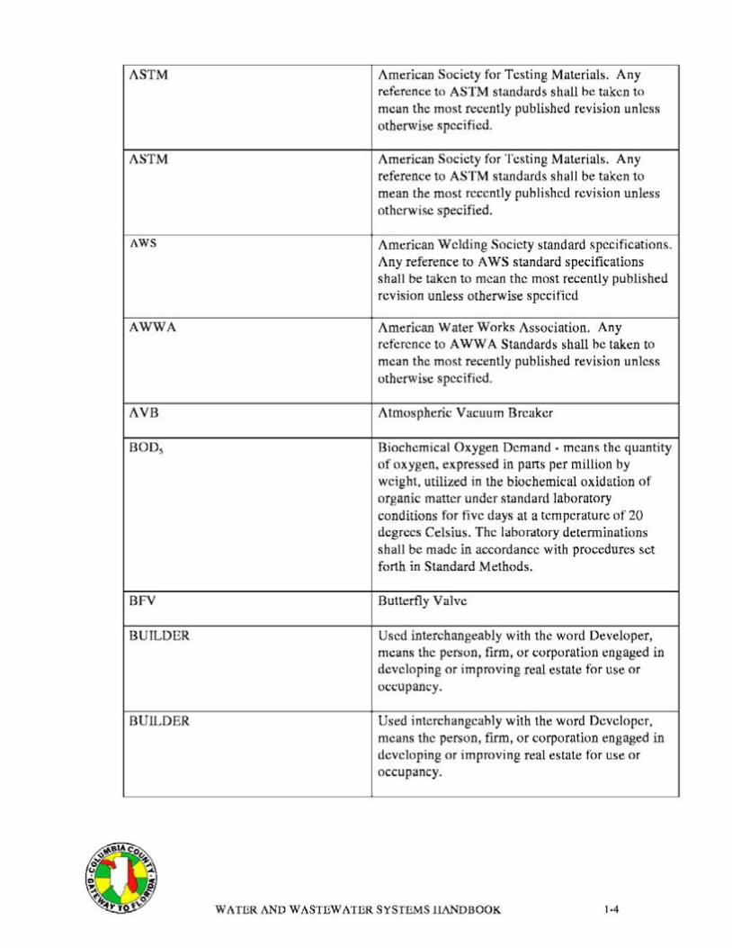
ASTM American Society for Testing Materials. Any reference to ASTM standards shall be taken to mean the most recently published revision unless otherwise specified.
ASTM American Society for Testing Materials. Any reference to ASTM standards shall be taken to mean the most recently published revision unless otherwise specified.
AWS American Welding Society standard specifications. Any reference to A WS standard specifications sha11 be taken to mean the most recently published revision unless otherwise specified
AWWA American Water Works Association. Any reference to A WWA Standards shall he taken to mean the most recently published revision unless otherwise specified.
AVB Atmospheric Vacuum Breaker
BOD5 Biochemical Oxygen Demand • means the quantity of oxygen, expressed in pans per million by weight, utilized in the biochemical oxidation of organic matter under standard laboratory conditions for five days at a temperature of 20 degrees Celsius. The laboratory detenninations shall be made in accordance with procedures set forth in Standard Methods.
BFV Butterfly Valve
BUILDER Used interchangeably with the word Developer, means the person, firm, or corporation engaged in developing or improving real estate for use or occupancy.
BUILDER Used interchangeably with the word Developer, means the person, firm, or corporation engaged in developing or improving real estate for use or occupancy.
WATER AND WASTEWATER SYSTEMS HANDBOOK 1-4
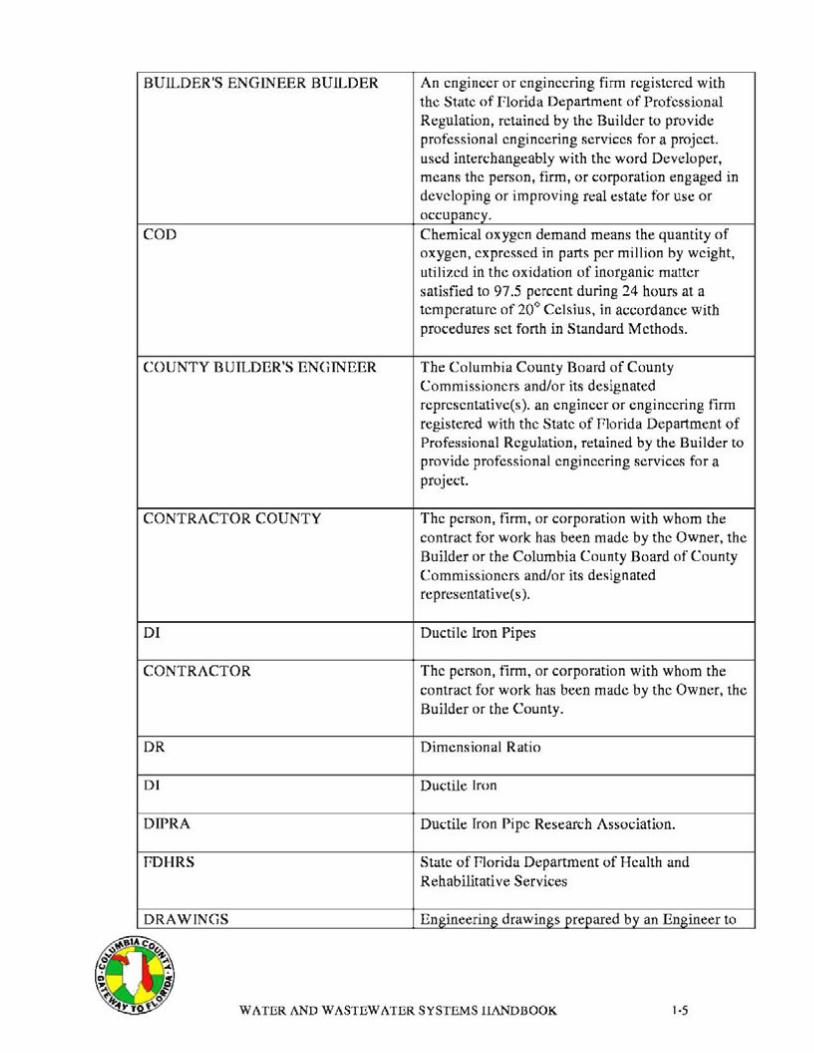
BUILDER'S ENGINEER BUILDER
COD
COUNTY BUILDER'S ENGINEER
CONTRACTOR COUNTY
DI
CONTRACTOR
DR
DI
DIPRA
PDHRS
DRAWINGS
An engineer or engineering firm registered with the State of florida Department of Professional Regulation, retained by the Builder to provide professional engineering services for a project. used interchangeably with the word Developer, means the person, firm, or corporation engaged in developing or improving real estate for use or occupancy. Chemical oxygen demand means the quantity of oxygen, expressed in parts per million by weight, utilized in the oxidation of inorganic matter satisfied to 97.5 percent during 24 hours at a temperature of 20° Celsius, in accordance with procedures set forth in Standard Methods.
The Columbia County Board of County Commissioners and/or its designated representative(s). an engineer or engineering firm registered with the State of Plorida Department of Professional Regulation, retained by the Builder to provide professional engineering services for a project.
The person, firm, or corporation with whom the contract for work has been made by the Owner, the Builder or the Columbia County Board of County Commissioners and/or its designated representative( s ).
Ductile Iron Pipes
The person, firm, or corporation with whom the contract for work has been made by the Owner, the Builder or the County.
Dimensional Ratio
Ductile Iron
Ductile Iron Pipe Research Association.
State of Plorida Department of Health and Rehabilitative Services
Engineering drawings prepared by an Engineer to
WATER AND WASTEWATER SYSTEMS HANDBOOK 1·5

show the proposed construction.
ERUs Equivalent Residential Units
ENGINEER An engineer or engineering firm registered with the State of florida Department of Professional Regulation
FDOT The State of Plorida, Department of Transportation
FDEP Plorida Department of Environmental Protection.
FPS Feet Per Second
GPD Gallons Per Day
GV Gate Valve
GEOTECHNICAUSOTLS ENGINEER A Registered florida Engineer who provides services related to terrain evaluation and site selection, subsurface exploration and sampling, determination of soil and rock properties, foundation engineering, settlement and seepage analysis, design of earth and earth retaining structures, the design of subsurface drainage systems and the improvement of soil properties and foundation conditions, and testing and evaluation of construction materials.
HP Horsepower
HANDBOOK This Columbia County Water and Wastewater Systems Document.
IBEE Institute of Electrical and Electronic Engineers
ID Inside Diameter
KW Killowatt
MG/L Milligram Per Liter
MANUAL ON UNIFORM TRAFFIC The United States Department of Transportation CONTROL DEVICES Manual on Traffic Control Devices, latest edition
&IA C
WATER AND WASTEWATER SYSTEMS HANDBOOK 1·6
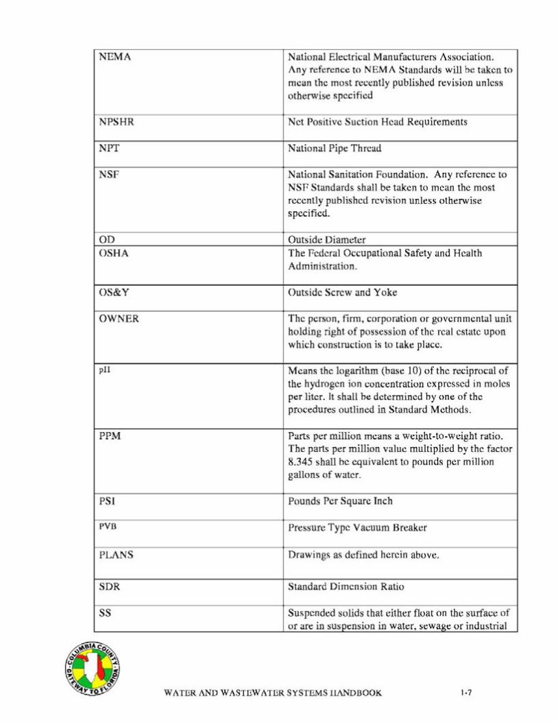
NEMA National Electrical Manufacturers Association. Any reference to NEMA Standards will be taken to mean the most recently published revision unless otherwise specified
NPSHR Net Positive Suction Head Requirements
NPT National Pipe Thread
NSF National Sanitation Foundation. Any reference to NSP Standards shall be taken to mean the most recently published revision unless otherwise specified.
OD OSHA
Outside Diameter The Pedcral Occupational Safety and Health Administration.
OS&Y Outside Screw and Yoke
OWNER The person, firm, corporation or governmental unit holding right of possession of the real estate upon which construction is to take place.
pll Means the logarithm (base 10) of the reciprocal of the hydrogen ion concentration expressed in moles per liter. It shall he determined hy one of the procedures outlined in Standard Methods.
PPM Parts per million means a weight-to-weight ratio. The parts per million value multiplied by the factor 8.345 shall be equivalent to pounds per million gallons of water.
PSI Pounds Per Square Inch
PVB Pressure Type Vacuum Breaker
PLANS Drawings as defined herein above.
SDR Standard Dimension Ratio
ss Suspended solids that either float on the surface of or are in suspension in water, sewage or industrial
WATER AND WASTEWATER SYSTEMS HANDBOOK J.7
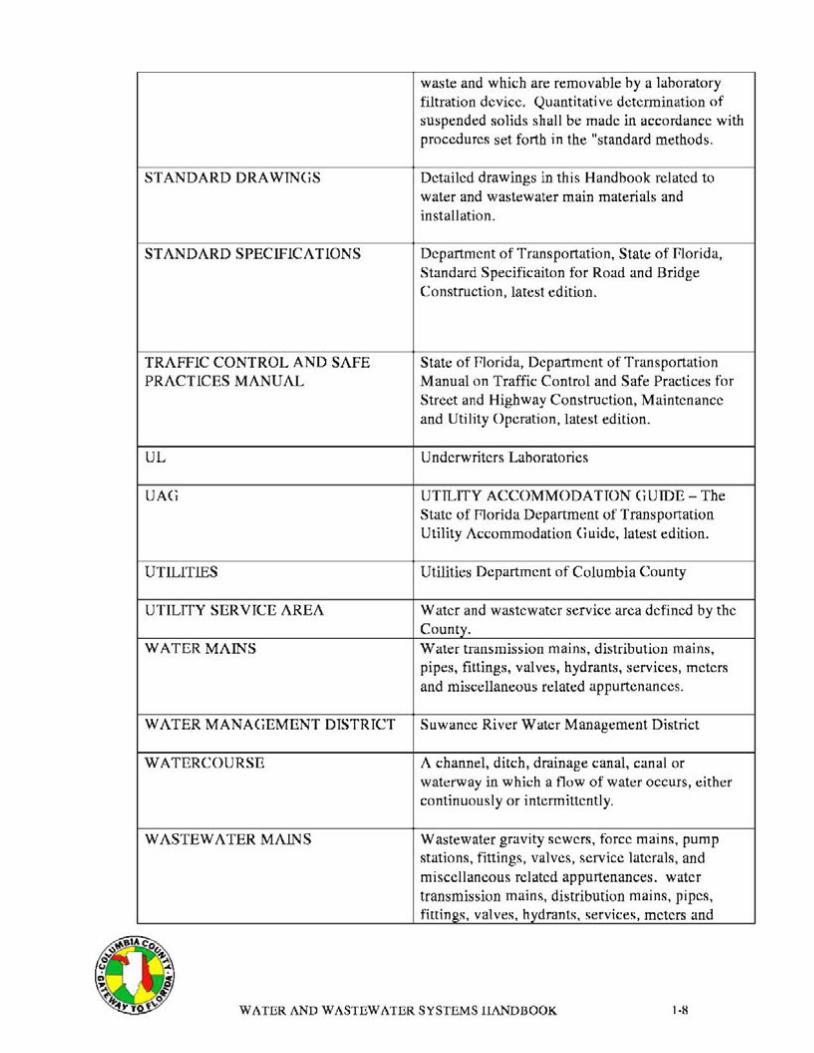
STANDA RD ORA WINGS
STANDARD SPECIFICATIONS
TRAFFIC CONTROL AND SAFE PRACTICES MANUAL
UL
UAG
UTILITIES
UTILITY SERVICE AREA
WATER MAINS
WATER MANAGEMENT DISTRICT
WATERCOURSE
WASTEWATER MAINS
waste and which are removable by a laboratory filtration device. Quantitative determination of suspended solids shall be made in accordance with procedures set forth in the "standard methods.
Detailed drawings in this Handbook related to water and wastewater main materials and installation.
Department of Transportation, State of Plorida, Standard Specificaiton for Road and Bridge Construction, latest edition.
State of Plorida, Department of Transportation Manual on Traffic Control and Safe Practices for Street and Highway Construction, Maintenance and Utility Operation, latest edition.
Underwriters Laboratories
UTILITY ACCOMMODATION GUIDE - The State of r:torida Department of Transportation Utility Accommodation Guide, latest edition.
Utilities Department of Columbia County
Water and wastewater service area defined by the County. Water transmission mains, distribution mains, pipes, fittings, valves, hydrants, services, meters and miscellaneous related appurtenances.
Suwanee River Water Management District
A channel, ditch, drainage canal, canal or waterway in which a flow of water occurs, either continuously or intermittently.
Wastewater gravity sewers, force mains, pump stations, fittings, valves, service laterals, and miscellaneous related appurtenances. water transmission mains, distribution mains, pipes, fittings, valves, hydrants, services, meters and
WATER AND WASTEWATER SYSTEMS HANDBOOK 1·8
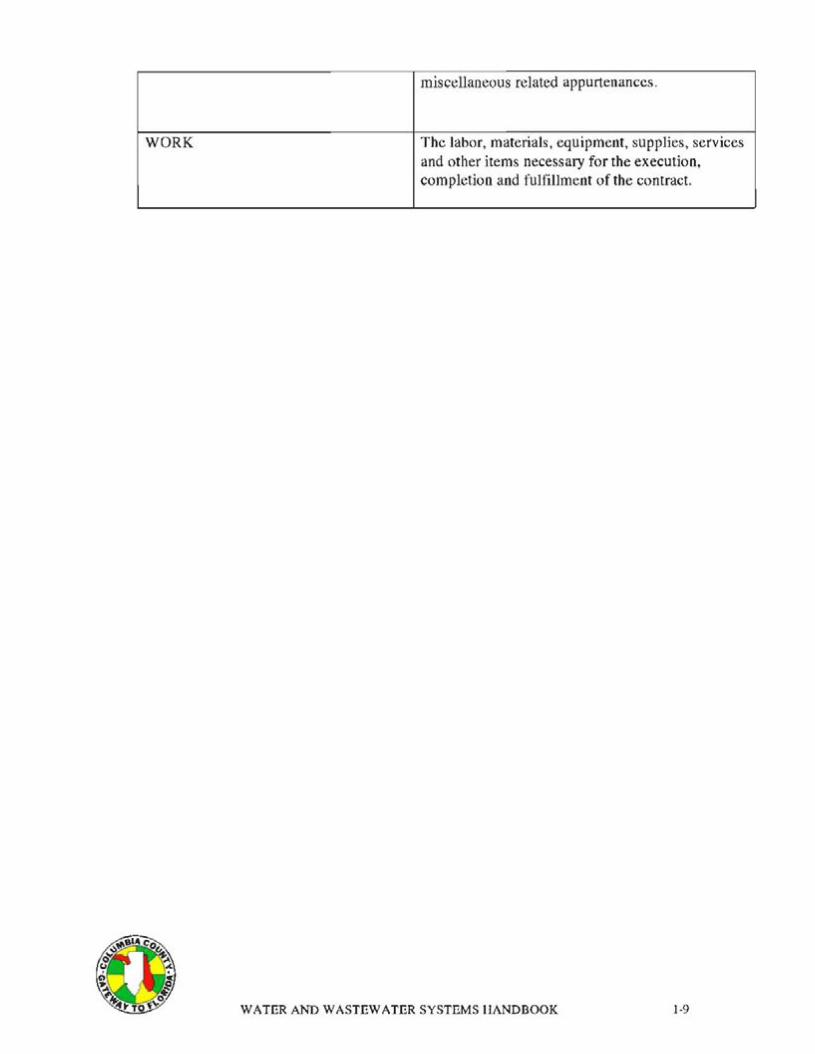
miscellaneous related appurtenances.
WORK The labor, materials, equipment, supplies, services and other items necessary for the execution, completion and fulfillment of the contract.
WATER AND WASTEWATER SYSTEMS HANDBOOK 1-9
1.04 CRITERIA OF REVIEW
No water or wastewater facility or associated transm1ss1on and distribution lines may be constructed in the Utility Service Area without obtaining prior County approval. The County evaluates applications for approval to construct facilities or associated lines based upon the following criteria:
A. Compliance to the procedures and technical specifications of County, as contained within this Handbook.
B. Compliance with County zoning regulations where applicable.
C. Compliance with the Comprehensive Plan as amended.
D. Compliance and securing of County, Water Management District, POOT and FDEP permits are required for each project.
E. No application for approval shall be granted which fails to comply with the above criteria.
WATER AND WASTEWATER SYSTEMS HANDBOOK 1 • IO

I.OS GENERAL INFORMA TJON
A. The information set forth in this document is intended to provide mtmmum standards for approving design and construction of water and wastewater facilities, transmission, collection and distribution systems.
B. It shall he the responsibility of the Applicant to secure proper existing utility information, and prepare drawings (including plan and profile sheets) in accordance with these minimum standards. It remains the right of the Applicant to exceed these standards.
C. Construction drawings sha11 contain County approved plan and profile sheets showing all utilities and stonn drains. No changes shall he made on approved drawings without approval of the County and construction sha11 not begin prior to plan approval by County.
D. Construction drawings submitted to the County to be the latest revmon. Contractor must have a County approved set of Drawings and Specifications on the project site. This set will be the only official reference set for construction.
E. Contractor shall use accurately marked piping and covers (manholes, valves, etc.) for any piping projects.
P. Applicant shall furnish three (3) copies of shop drawings plus any copies required by Applicant to the County for approval prior to construction on a11 materials incorporated in a project.
WATER AND WASTEWATER SYSTEMS HANDBOOK 1•11
1.06 PLANS AND SPECIFICATIONS
A. All submitted plans shall be standard size sheet (30-inchcs by 42-inchcs, 24-inches by 36-inches or 11-inches by 17-inches) with title block. Graphic scale(s) shall be provided on each sheet and all lettering shall he 1/8-inch or larger to permit photographic reproduction. Submittal of specifications will only be required when special facilities outside the scope of this Handbook arc proposed. All plans sheets and the title page of submitted specifications must be signed, scaled and dated hy the Builder's Engineer.
B. Whenever possible, the entire water and wastewater systems shall he shown on a single Master Plan. The Master Plan shall indicate the general locations of all mains, manholes, valves, hydrants, services and service laterals with respect to the proposed development improvements and the existing water and wastewater systems. Main sizes shall be indicated on the Master Plan.
C. All gravity sewers, all wastewater force mains, and off-site water mains shall be drawn in plan and profile. On-site water mains may be shown in plan view only.
Whenever possible, on-site water and wastewater systems shall he shown on the same plans sheet. As a minimum, the plan and profile drawings shall include the following information.
1. General information such as north arrow, names of designer and engineer, revision block with dates, graphic scale(s) and sheet numhcr.
2. Profile with elevations at I 00-foot interval, or more frequently if required by good design practice.
3. Development layout with horizontal and vertical controls.
4. All conflicts with other utility and drainage systems.
5. All manhole locations and rim elevations for manholes outside of paved areas.
6. Pipe data including size, lengths, material, and slopes.
7. Size, type, and locations of fittings, valves, hydrants, air release/vacuum relief, and other related appurtenances.
8. Limits of pipe deflection.
9. Limits of special exterior coatings.
I 0. Limits of special bedding requirements.
WATER AND WASTEWATER SYSTEMS HANDBOOK 1-12
11. Pipe restraint requirements.
12. Details of connection to existing systems.
13. Location(s) and general layout of wastewater pumping stations.
14. Construction notes regarding cover, horizontal and vertical control, special construction requirements, and references to standard and special details.
D. The plans shall include all applicable Standard Drawings as shown in this Handbook. Special details shall be prepared by the Builder's Engineer for aerial and underwater crossings of rivers, streams, canals and ditches. Other special details shall be prepared by the Builder's Engineer as required.
E. The master plan shall he prepared at a scale not to exceed 1-inch to 200-feet. Plan and profile sheets shall not exceed a scale of 1-inch to 50-feet. Special details shall be of sufficiently large scale to show pertinent construction information.
1.07 ADMINISTRATIVE PROCEDURES
A. This section covers all water and wastewater improvements that are to he dedicated to the County. Such water and wastewater improvements shall be designed, reviewed, constructed and accepted in accordance with the criteria established herein.
B. Design of water and wastewater improvements shall be in compliance with the design standards and the specifications outlined in this Handbook. Plans will he reviewed and approved by the County as part of the site plan review process. The review process consists of the following steps:
1. Site plan review application/plans/fee submittal.
2. Application/plans review by County.
3. Comments returned to Builder.
4. Final plan submittal and payment of County fees.
C. The Builder shall provide daily inspection of the project work as needed for FDEP Certification of Completion by the Builder's Engineer. The County shall make periodic inspections of the construction for general conformance to these standards and specifications.
D. The County may require that the Builder post a perfonnance hond for the project. If a bond is required it shall be executed by a company authorized to do husiness
WATER AND WASTEWATER SYSTEMS HANDBOOK 1-13

in the State of Florida that is satisfactory to the County, payahlc to the County in the amount of 100 per cent of the estimated construction cost of all required water and wastewater improvements to be owned and maintained by the County. Such bond shall guarantee maintenance of all improvements intended to be owned and maintained by the County for a one (1) year period, and the materials, workmanship and structural integrity of water and wastewater systems, and miscellaneous related facilities, excluding mechanical equipment for a one (I) year period, commencing after Notice of Clearance by the FDEP. The manufacturer's warranty will he acceptahlc for mechanical equipment. As an alternative to the provision of a surety hond, the Builder may provide for the deposit of cash in an escrow account or a letter of credit acceptable to the County.
E. The Builder shall be responsible for completing all documentation to certify completion of the project and clearance for use from the regulatory agencies. Copies of all documents shall he provided to the County. Service will he actuated only upon receipt by the County of the completion documents.
WATER AND WASTEWATER SYSTEMS HANDBOOK 1•14
1.08 LIST OF MATERIALS AND APPROVED MANUFACTURERS
A list of Materials and Approved Manufacturers for the various products specified in this Handbook is included in Appendix A. It is the intent of the County to review and update Appendix A as appropriate to ensure efficient operation of the services and facilities under the jurisdiction of this Handbook. For this purpose, the County sha11 evaluate technical submittals from interested manufacturers or suppliers at least once every three (3) years.
1.09 PERSON TO CONTACT
Key persons to contact concerning this Handbook are as follows:
Dale Williams, County Manager COLUMBIA COUNTY BOARD OF COUNTY COMMISSIONERS PO Box 1529 Lake City, FL 32056-1529 (386) 755-4100
1.10 PROCEDURE FOR OBTAINING CAPACITY
Applications for wastewater or water capacity shall be submitted to the County. Applications shall consist of appropriate fonns and documentation as delineated in Section 2 and shall be available from the County. Applications will be given a preliminary screening when submitted and any incomplete or incorrect applications will be returned to the applicant for necessary revisions. Accepted applications shall be entered on a categorical Pending Wastewater or Water Capacity List. Applications will be classified by the following categories:
A. Subdivision Single Family: Applicants desiring to build multiple single family residences.
B. Large Multi-Family: Applicants desiring to build multiple multi-family residential units.
C. Large Commercial/Industrial/Institutional: Applicants for commercial development whose requested capacity a11ocation is in excess of 3,375 GPD.
D. Agricultural: Applicants requiring irrigation water for agricultural purposes.
Placement on a list will serve to confirm receipt of a valid application and insure an equitable "First Come - First Served" processing of applications. Applicants will be notified by certified mail that capacity is available for allocation for their specific project and advised as to any additional infonnation or documentation required to facilitate review of their application.
WATER AND WASTEWATER SYSTEMS HANDBOOK 1-15
Applicants will be required to provide such information or otherwise perfect a pending application within thirty (30) calendar days from notification hy the County. Pailure to provide requested information within this time will result in removal of the application from the appropriate Pending Wastewater Capacity or Pending Water Capacity List.
Following review, processing, and approval of the application and Standard Developer's Agreement by the County, the Wastewater and/or Water Pees will be calculated for the project. Payment of the Wastewater and/or Water Fees shall constitute a reservation of capacity and will remain as such, subject to complete compliance with other provisions of the policy.
To obtain wastewater and/or water capacity allocations, the property for which capacity application is made must he appropriately zoned and platted to support the proposed development.
In cases of applications for capacity allocations for non-residential developments, the applicant shall provide sufficient information to facilitate a reasonable estimate of capacity needs and determination of the Wastewater and/or Water Fees. Capacity will be reserved based on this estimate and payment of the prescribed Pees; however, upon completion of final building plans, the plans shall be submitted for re-evaluation of capacity needs and re-computation of the Fees.
1.11 PAYMENT OF FEES
Fees as adopted hy the County shall he applied in conjunction with each application. Fees shall consist of all applicable connection and impact fees and contributions-in-aid-of-construction for the system connection. Payment of the Pees will be as follows:
A. At the time of application for capacity, and following Fee determination, the applicant will he required to pay I 00-percent of the fees as a condition of capacity reservation. Pailure to make payment within the specified time frame will result in removal of the application from the appropriate Pending Capacity List.
1.12 REGULATORY PERMITS
All permits required from any federal, state and local government entity having jurisdiction over the facilities proposed to be installed shall be obtained by the applicant. Any application which fails to meet the requirements of a11 federal, state and local governing bodies will be deemed incomplete hy the County.
WATER AND WASTEWATER SYSTEMS HANDBOOK 1-16
1.13 ALLOCATION FACTORS AND LIMITATIONS
Evaluations of the County's Utility System have resulted in Equivalent Residential Unit (ER U) flows of 350 GPO for water and 250 GPO for wastewater. In reserving and allocating capacity for applications submitted to the County the ERV factor method or one of the methods outlined in Section 2 shall be used. The method selected shall be approved by the County.
ERU's may be amended from time to time based on evaluations of the County's Utility System.
1.14 CAPACITY RESERVATION OR ALLOCATION RECAPTURE
Having obtained a wastewater and/or water capacity reservation or allocation, the reservation or allocation shall be used and applied only with respect to the property for which the application for wastewater and/or water capacity has been made and approved. The reservation or allocation shall inure to the property, subject to the provisions of this policy. The applicant is not otherwise pennitted to sell, lease, sublet, assign, lend or transfer a capacity reservation or allocation without the prior notification and approval of County. To insure maximum beneficial utilization of the available wastewater and/or water capacity, County reserves the right to recapture capacity reservations or allocations, or pa1ts thereof, for failure of the applicant to meet the condition of authorization, or to responsibly and timely prosecute the development of the project for which capacity was obtained. County's sole responsibility in recapturing previously reserved or allocated capacity, or parts thereof, will be to refund the Wastewater and/or Water Pees, or portions thereof, paid by the applicant for said capacity without interest.
County may institute the recapture of reserved or allocated wastewater or water capacity under the following circumstances:
A. Violation of the prohibition against transfer of a capacity reservation or allocation, or failure to provide requisite notification to the County of any change in ownership of the property for which a reservation or allocation has been obtained.
B. failure of those applicants who have previously obtained capacity allocations in the existing system to pay outstanding Wastewater or Water Fees and complete actions leading to utilization of such capacity allocation.
C. Failure to comply with the requirements of the County, as from time to time amended.
County shall give the applicant, or successor in interest according to County records, thirty (30) calendar day's written notice of its intent to recapture reserved or allocated wastewater or water capacity as provided ahove. The notice shall contain the hasis for the intended recapture and
WATER AND WASTEWATER SYSTEMS HANDBOOK 1-17
state what corrective action is required to preserve the capacity reservation or allocation. During the thirty (30) day period, the applicant may take corrective action to come into compliance with the requirements of the policy. Any recapture of capacity, as provided in this policy is subject to review hy the County.
I.JS FEES SUBJECT TO CHANGE
fees may be changed at any time, suhject to approval hy the County. Applicants who have secured capacity reservations or allocations under this policy will not he suhject to such changes provided that they arc in compliance with the provisions of this policy. Applications made subsequent to changes in the Wastewater or Water fees will he suhject to such changes.
1.16 SEPTIC TANK POLICY
ln addressing the wastewater treatment capacity needs of the County, it is recognized that properly designed, constructed and maintained septic tank systems can be of significant benefit. Accordingly, applicants for service will he advised that, should they desire, County may permit septic tank construction within County, in lieu of connection to public wastewater systems, subject to an appropriately documented request certified by a Professional Engineer registered in the State of Plorida and the approval of local and state regulatory agencies.
1.17 SYSTEM EXTENSION POLICY
For water service, if a request is made beyond the limits of the present distribution system, County may install a main to the property line, in accordance with applicahlc County Rules and Regulations. Where the length of the extension is longer than the maximum allowed under applicable Rules and Regulations, the water depanment shall make determination as to whether or not to provide service based on economic, public health and system integrity consideration. In the event the application is determined to be economically unfeasible, service may still be provided if the persons requesting such service will pay all costs in connection therewith.
1.18 BACKFLOW PREVENTION POLICY
Applications for water/wastewater service shall comply with the County's Backflow Prevention Policy as presented in Appendix D of this Handbook.
1.19 OIL & GREASE POLICY
WATER AND WASTEWATER SYSTEMS HANDBOOK 1•18
Applications for water/wastewater service shall comply with the County's Oil & Grease Policy as presented in Appendix C of this Handbook..
1.19WATER AND WASTEWATER SYSTEMS HANDBOOK
WORK IN PROGRESS DRAFT COPY ONLY
TABLE OF CONTENTS
SECTION 2 ..................................................................................................................................... 2 CAPACITY ALLOCATION .......................................................................................................... 2
2.01 GENERAL .................................................................................................................... 2 2.02 POTABLE WATER CAPACITY ALLOCATION ...................................................... 2 2.03 IRRIG AT ION WATER CAPACITY ALLOCATION ................................................. 4 2.04 WASTEWATER CAPACITY ALLOCATIONS ......................................................... 5 2.05 CONNECTION PROCEDURES AND APPLICATION FORMS .............................. 5
2-1
SECTION 2.
CAPACITY ALLOCATION
2.01 GENERAL
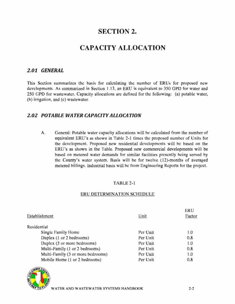
This Section summarizes the hasis for calculating the numher of ERUs for proposed new developments. As summarized in Section 1.13, an ERU is equivalent to 350 GPD for water and 250 GPD for wastewater. Capacity allocations arc defined for the following: (a) potable water, (h) irrigation, and (c) wastewater.
2.02 POTABLE WATER CAPACITY ALLOCATION
A. General: Potable water capacity allocations will be calculated from the number of equivalent ERU's as shown in Table 2-1 times the proposed number of Units for the development. Proposed new residential developments will be based on the ERU's as shown in the Table. Proposed new commercial developments will be based on metered water demands for similar facilities presently heing served hy the County's water system. Basis wilt be for twelve (12)-months of averaged metered billings. Industrial basis will be from Engineering Reports for the project.
TABLE 2-1
ERU DETERMINATION SCHEDULE
ERU Establishment Unit Pactor
Residential Single Pamity Home Per Unit 1.0 Duplex (1 or 2 bedrooms) Per Unit 0.8 Duplex (3 or more bedrooms) Per Unit 1.0 Multi-Family (1 or 2 bedrooms) Per Unit 0.8 Multi-Pamity (3 or more bedrooms) Per Unit 1.0 Mobile Home (1 or 2 bedrooms) Per Unit 0.8
2-2
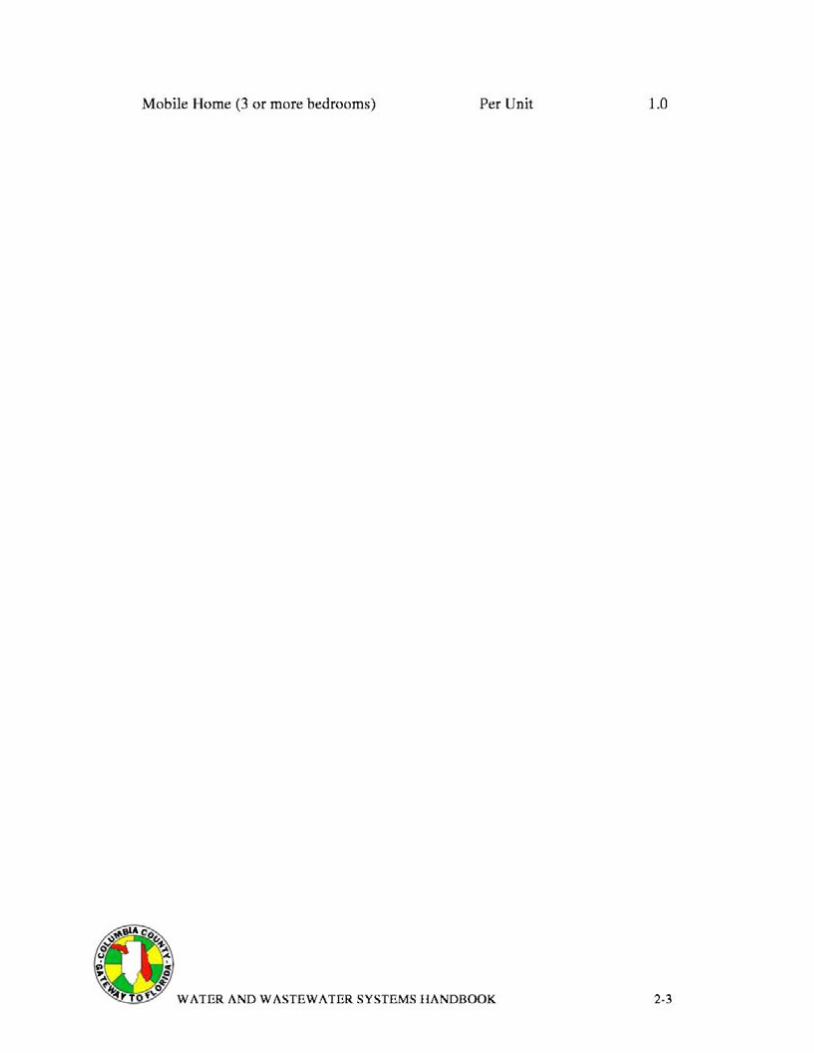
Mobile Home (3 or more bedrooms) Per Unit 1.0
2-3
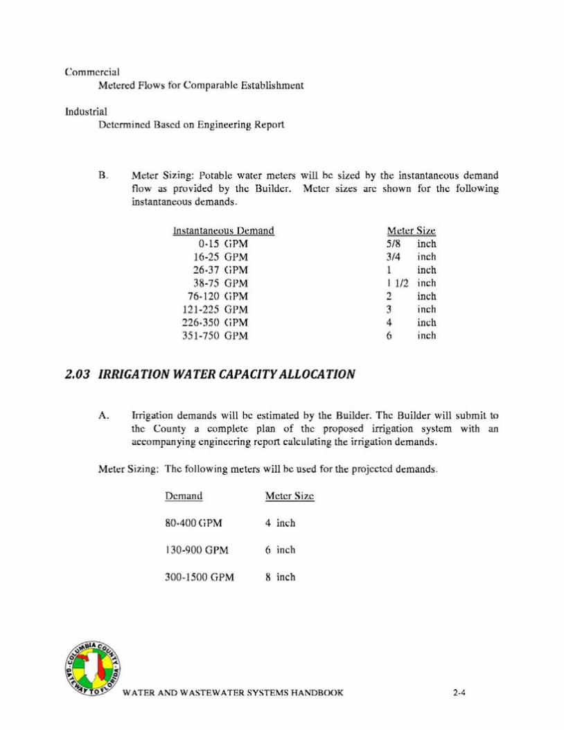
Commercial Metered Flows for Comparable Establishment
Industrial Determined Based on Engineering Report
B. Meter Sizing: Potable water meters will be sized hy the instantaneous demand flow as provided by the Builder. Meter sizes arc shown for the following instantaneous demands.
Instantaneous Demand Meter Size 0-15 GPM 5/8 inch
16-25 GPM 3/4 inch 26-37 GPM 1 inch 38-75 GPM 1 1/2 inch
76-120 GPM 2 inch 121-225 GPM 3 inch 226-350 GPM 4 inch 351-750 GPM 6 inch
2.03 IRRIGATION WATER CAPACITYALLOCATION
A. Irrigation demands will be estimated by the Builder. The Builder will submit to the County a complete plan of the proposed irrigation system with an accompanying engineering report calculating the irrigation demands.
Meter Sizing: The following meters will he used for the projected demands.
Demand Meter Size
80-400 (iPM 4 inch
130-900 GPM 6 inch
300-1500 GPM 8 inch
2-4
2.04 WASTEWATER CAPACITY ALLOCATIONS
A. General: Wastewater Capacity allocations will be based on the unit cquivalcncics as shown in Table 2-1 times 250 GPD/ERU.
2.05 CONNECTION PROCEDURES AND APPL/CATION FORMS
A. Stepwise Connection Procedure
L Applicant shall obtain a copy of this Handbook for his\her use.
2. Applicant reviews and becomes familiar with the information containcd-hercin.
3. Applicant submits Capacity Application Porms as provided hy the County.
4. Applications and Capacity submittal reviewed hy the County.
5. The County notifies applicant concerning connection fees and Capacity allocation requirements.
6. All required estimated connection fees and the administrative fee due to the County will be paid by the applicant upon execution of the Developer Agreement at the time of closing.
7. Applicant completes final plans and specifications for improvements.
8. Applicant submits final plans and specifications to the County and regulatory agencies as described elsewhere in this Handbook for review and approval.
9. Pinal plans and specifications reviewed by the County and, if required, adjustments made to required connection fees and Capacity allocation.
10. All required adjustments to connection fees due to the County will be paid prior to construction.
2-5

11. Applicant provides the County with construction schedule.
12. After receipt of regulatory pennits and copies delivered to the County, construction forces may begin work.
13. County construction forces will make required connections, tie-ins, set required meters and notify Applicant immediately upon completion.
~6'Ac0 0 ~"" u .c.
lg ~ ,AI', 4' ~
~ WATER AND WASTEWATER SYSTEMS HANDBOOK 2-6

WORK IN PROGRESS DRAFT COPY ONLY
TABLE OF CONTENTS
SECTION 3 ...................................................................................................................................................... 2 GENERAL CONSTRUCTION REQUIREMENTS ....................................................................................... 2
3.01 GENERAL ....................................................................................................................................... 2 3.02 GRADES, SURVEY LINES, AND PROTECTION OF MONUMENTS ...................................... 2 3.03 UTILITY COORDINATION .......................................................................................................... 3 3.04 MAINTENANCE OR TRAFFIC AND CLOSING OF STREETS ................................................. 3 3.05 PROTECTION OF PUBLIC AND PROPERTY............................................................................ .4 3.06 ACCESS TO THE PUBLIC SERVICE ........................................................................................... 5 3.07 PUBLIC NUISANCE ...................................................................................................................... 6 3.08 CONSTRUCTION HOURS ............................................................................................................ 6 3.09 CONSTRUCTION IN EASEMENTS AND RIGHTS-OF-WAY ................................................... 6 3.10 SUSPENSION OF WORK DUE TO WEATHER ..........................................................................7 3.11 USE OF CHEMICALS ....................................................................................................................7 3.12 COOPERATION WITH OTHER BUILDERS AND FORCES ......................................................7 3.13 SUBSURFACE EXPLORATION ...................................................................................................7 3.14 CLEANING .....................................................................................................................................7 3.15 SALVAGE ....................................................................................................................................... 8 3.16 SHOP DRAWINGS AND SAMPLES ............................................................................................ 8 3.17 CLEARING AND GRUBBING ...................................................................................................... 8 3.18 EXCAVATION, BACKFILL, COMPACTION AND GRADING .................................................9
WATER AND WASTEWATER SYSTEMS HANDBOOK 3-1
SECTION 3
GENERAL CONSTRUCTION REQUIREMENTS
3.01 GENERAL
A. This Section sets forth the general requirements for construction and installation of water and wastewater utility facilities.
3.02 GRADES, SURVEY LINES, AND PROTECTION OF MONUMENTS
A. Grades: All Work shall be constructed in accordance with the lines and grades shown on the Plans. The full responsibility for keeping alignment and grade shall rest upon the Builder.
Bench marks and base line controlling points shall be established prior to beginning Work. Reference marks for lines and grades as the Work progresses will he located to cause as little inconvenience to the prosecution of the Work as possible. The Builder shall so place excavation and other materials as to cause no inconvenience in the use of the reference marks provided. Builder shall remove any ohstructions placed contrary to this provision.
B. Surveys: The Builder shall furnish and maintain, at his own expense, stakes and other such materials, and give such assistance, including qualified helpers, for setting reference marks to the satisfaction of the the County and the Engineer. The Builder shall check such reference marks by such means as he may deem necessary and, hefore using this, shall call the County's attention to any inaccuracies. The Builder shall, at his/her own expense, establish all Working or construction lines and grades as required from the reference marks, and shall he solely responsihle for the accuracy thereof. The Builder shall, however, be subject to the check and review of the County.
C. Monument Preservation: Property comers and survey monuments shall he preserved using care not to disturh or destroy them. If a property corner or survey monument is disturbed or destroyed during construction, whether hy accident, careless Work, or required to be disturhed or destroyed by the construction Work, said property corner or survey monument shall he restored by a land surveyor registered in the State of florida. All cost~ for this Work shall be paid for by the Builder.
3-2
3.03 UTILITY COORDINATION
A. Location of Utilities: Prior to proceeding with trench excavation the Builder shall contact all utility companies in the area to aid in locating their underground services. lt shall be the Builder's responsibility to contact utility companies at least three (3) normal working days before starting construction. The Builder shall proceed with caution in the excavation and preparation of the trench so that the exact location of underground utilities may he determined.
The Builder shall take all reasonable precautions against damage to extstmg utilities. However, in the event of a hrcak in an existing water main, gas main, sewer or underground cable, the Builder shall immediately notify the responsible official of the organization operating the interrupted utility. The Builder shall lend all possible assistance in restoring services and shall assume all cost, charges, or claims connected with the interruption and repair of such services.
B. Deviations Occasioned by Structures or Utilities: Wherever obstructions arc encountered during the progress of the Work and interfere to such an extent that an alteration in the Plans is required, the Builder shall effect a resolution of the conflict with their Engineer. The resolution will he reviewed and approved by the County prior to proceeding with the Work.
C. Test Pits: Test pits for the purpose of locating underground pipeline, utilities, or structures in advance of the construction shall he excavated and backfilled hy the Builder. Test pits shall be backfilled immediately after their purpose has been satisfied and maintained in a manner satisfactory to the County. The costs for such test pits shall be borne by the Builder.
3.04 MAINTENANCE OR TRAFFIC AND CLOSING OF STREETS
A. The Builder shall carry on the Work in a manner which will cause a minimum of interruption to traffic. Where traffic must cross open trenches, the Builder shall provide suitable bridges at street intersections and driveways. The Builder shall post suitable signs indicating that a street is closed and necessary detour signs for the proper maintenance of traffic. Prior to closing of any streets the Builder shall notify and ohtain the approval of responsible authorities and the County.
Unless permission to close a street is received in writing from the proper authority (County, fDOT, etc.), all excavated material shall he placed so that vehicular and pedestrian traffic may be maintained at all times. If the Builder's operations cause traffic hazards, he shall repair the road surface, provide temporary ways, erect wheel guards or fences, or take other measures for safety satisfactory to the County.
3.3
Detours around construction will be subject to the approval of the authority having jurisdiction and the County. Where detours arc permitted, the Builder shall provide all necessary barricades and signs as required to divert the flow of traffic. While traffic is detoured the Builder shall expedite construction operations. Ancillary costs associated with the detour will be the responsibility of the Builder.
It shall he the sole responsibility of the Builder to take precautions to prevent injury to the public due to open trenches. Night watchmen may be required or police protection provided while Work is in progress. The Builder shall be fully responsible for damage or injuries whether or not police protection has been provided.
3.05 PROTECTION OF PUBLIC AND PROPERTY
A. Barricades, Guards and Safety Provisions: The Builder shall be solely responsible for adhering to the rules and regulations of OSHA and appropriate authorities regarding safety provisions. To protect persons from injury and to avoid property damage, adequate barricades, construction signs, lights and guards as required shall be placed and maintained by the Builder at his/her expense during the progress of the Work and until it is safe for traffic to use the roads and streets. All material piles, equipment and pipe which may serve as obstructions to traffic shall be enclosed hy fences or barricades and shall he protected hy proper lights when the visibility is poor. All signage and barricades shall be in accordance with FDOT's Manual on Uniform Traffic Control Devices and the Traffic Control and Safe Practices Manual.
B. Protection of Utility Structures: Temporary support, adequate protection and maintenance of all underground and surface utility structures including drains, sewers, manholes, hydrants, valves, valve covers, power poles and miscellaneous other utility structures encountered in the progress of the Work shall be furnished by the Builder at his/her expense. Any such structures which may have been disturbed shall be restored upon completion of the Work.
C. Open Excavation: All open excavations shall he adequately safeguarded hy providing temporary barricades, caution signs, lights and other means to prevent accidents to persons and damage to property. The Builder shall, at his/her own expense, provide suitable and safe bridges with hand railings and other crossings for accommodating travel hy pedestrians and workmen. Bridges provided for access to private property during construction shall be removed when no longer required. The length of open trench will be controlled hy the particular surrounding conditions, but shall be limited to 300-tcct unless otherwise approved by the County. If the excavation becomes a hazard, or if it excessively restricts traffic at
3.4
any point, the County may require special construction procedures such as limiting the length of open trench, fencing, prohibiting excavated material in the street and requiring that the trench shall not remain open overnight. The Builder shall take precautions to prevent injury to the public due to open trenches. All trenches, excavated material, equipment or other obstacles which could be dangerous to the puhlic shall he well lighted at night.
D. Protection of Trees and Shrubs: All trees and shrubs not shown to be removed on the Plans shall be protected by the Builder at his/her expense. No excavated materials shall he placed so as to injure such trees or shrubs. Trees or shrubs destroyed by negligence of the Builder or his employees shall be replaced by him with new stock of similar size and age at the sole expense of the Builder.
E. Protection of Lawn Areas: Lawn areas shall he left in as good or better condition as before staning of the Work. Where sod is to be removed it shall be carefully restored with new sod of the same type.
P. Restoration of Fences: Any fence, or part thereof, that is damaged or removed during the course of the Work shall be replaced or repaired by the Builder and shall he left in as good a condition as before the stan of the Work. The manner in which the fence is repaired or replaced and the materials used shall be subject to the approval of the County.
G. Protection Against Siltation and Bank Erosion: The Builder shall arrange his operations to minimize siltation and bank erosion on construction sites and on existing or proposed water courses and drainage ditches. The Builder, at his own expense, shall remove any siltation deposits and restore to original grade.
3.06 ACCESS TO THE PUBLIC SERVICES
A. Neither the materials excavated nor the materials or equipment used in the construction of the Work shall he so placed as to prevent free access to puhlic services. All excavated material shall be piled in a manner that will not endanger the Work and that will avoid obstructing streets, sidewalks and driveways. Excavated material suitable for backfilling shall be stockpiled separately on the site. No material shall he placed closer than 2-feet from the edge of an excavation. fire hydrants under pressure, valve pit covers, valve boxes, curb stop boxes, or other utility controls shall he left unobstructed and accessible until the Work is completed. Gutters shall be kept clear or other satisfactory provisions made for street drainage. Natural water courses shall not be obstructed or polluted. Surplus material and excavated material unsuitable for backfilling shall be transported and disposed of off the site in disposal areas obtained hy the Builder.
3.5
3.07 PUBLIC NUISANCE
A. The Builder shall not create a public nuisance including hut not limited to encroachment on adjacent lands, flooding of adjacent lands, or excessive noise or dust. The Builder shall eliminate noise to as great an extent as practicable at all times.
3.08 CONSTRUCT/ON HOURS
A. No Work shall be done between the hours of 7:00 p.m. and 7:00 a.m., or on Saturdays and Sundays unless the proper and efficient prosecution of the Work requires operations during the night or weekend. Written notification for doing the Work shall he provided to the County a minimum twenty four (24) hours before starting such items of the Work.
3.09 CONSTRUCT/ON IN EASEMENTS AND RIGHTS-OF-WAY
A. Construction Easements: In easements across private property, the Builder shall confine all operations within the casement area and shall be responsible and liahlc for all damage outside of the easement area. Trees, fences, shrubbery or other type of surface improvements located in casements will require protection during construction. Precautions shall he taken by adequate sheeting or other approved method to prevent any cave-in or subsidence beyond the casement limits or damage to improvements within the easement. In general, the easement area is intended to provide reasonable access and working area for efficient operation by the Builder. Where easement space for efficient operation is not provided, the Builder shall he responsible for organizing operations to perform within the restrictions shown on the Plans.
B. Construction in an FDOT Right-of-Way: The Builder shall strictly adhere to the requirements of the fDOT where construction Work is in a right-of-way under the jurisdiction of the State of florida, and shall take care to avoid any unreasonable traffic conflicts due to the Work in road right-of-way.
C. Construction in the County Right-of-Way: Work shall be governed by the County Regulations as amended.
3-6
3.10 SUSPENSION OF WORK DUE TO WEATHER
A. During inclement weather, all Work which might be damaged or rendered inferior hy such weather conditions shall he suspended. During suspension of the Work from any cause, the Work shall be suitably covered and protected so as to preserve it from injury hy the weather or otherwise.
3.11 USE OF CHEMICALS
A. All chemicals used during project construction or furnished for project operation, whether herbicide, pesticide, disinfectant, polymer, reactant, or of other classification, must show approval of either United States Environmental Protection Agency (USEPA) or United States Department of Agriculture (USDA). Use of all such chemicals and disposal of residues shall be in strict conformance with lahel instructions.
3.12 COOPERATION WITH OTHER BUILDERS AND FORCES
A. During construction progress, in the unlikely event that it becomes necessary for other contractors and persons employed by the County to Work in or about the site, such Work will be coordinated hetween the County and the Builder prior to proceeding with the Work.
3.13 SUBSURFACE EXPLORATION
A. The Builder shall make such subsurface explorations as necessary to perform the Work.
3.14 CLEANING
A. During Construction: During construction the Builder shall, at all times, keep the construction site and adjacent premises as free from material, debris and rubbish as is practicable and shall remove the same from any portion of the site if, in the opinion of the County, such material, debris, or rubbish constitutes a nuisance or is objectionable.
B. Pinal Cleaning: At the conclusion of the Work, all tools, temporary structures and materials belonging to the Builder shall be promptly taken away. The Builder shall remove and promptly dispose of all water, dirt, rubhish or any other foreign substances.
3.7
3.15 SALVAGE
A. Any existing County owned equipment or material including but not limited to valves, pipes, fittings, couplings, etc., which is removed or replaced as a result of construction may be designated as salvage by the County, and if so, shall be carefully excavated if necessary and delivered to the County at a location within the County.
3.16 SHOP DRAWINGS AND SAMPLES
A. If requested by the County, prior to construction the Builder shall submit three (3) copies of the shop drawings, signed by the Builder's Engineer, to the County. The data shown on the shop drawings shall be complete with respect to dimensions, design criteria, materials of construction and the like to enable review of the information as required. The Builder shall, if requested by the County, furnish certificates, affidavits of compliance, test reports, or samples for check analysis for any of the materials specified in this Handbook.
3.17 CLEARING AND GRUBBING
A. The Builder shall clear and grub all of the area within the limits of construction as shown on the Plans and approved by the County prior to the beginning any Work. All site Work shall conform to the applicable site clearing ordinance and landscaping and tree ordinances of the County.
B. Clearing: The surface of the ground for the area to be cleared and grubbed shall be completely cleared of all timber, brush, stumps, roots, grass, weeds, rubbish and all other objectionable obstructions resting on or protruding through the surface of the ground. However, trees and shrubs shall be preserved as specified in Section 3.050. Clearing operations shall be conducted so as to prevent, damage to existing structures and installations and to those under construction, and so as to provide for the safety of employees and others.
C. Grubbing: Grubbing shall consist of the complete removal of all stumps, roots larger than l 1/2-inches in diameter, matted roots, brush, timber, logs and any other organic or metallic debris not suitable for foundation purposes, resting on, under or protruding through the surface of the ground to a depth of 18 inches below the subgrade. All depressions excavated below the original ground surface for or by the removal of such objects shall be refilled with suitable materials and compacted to a density confonning to the surrounding ground surface.
3.g
D. Stripping: In areas so designated, top soil shall be stripped and stockpiled. Topsoil so stockpiled shall he protected until it is placed as specified. Any topsoil remaining after all Work is in place shall be properly disposed of by the Builder.
3.18 EXCAVATION, BACKFILL, COMPACTION AND GRADING
A. The Builder shall furnish all labor, materials, equipment and incidentals necessary to perfonn all excavation, backfill, fill, compaction, grading and slope protection required to complete the Work shown on the Plans and specified herein. The Work shall include, hut not necessarily be limited to: pump stations, manholes, vaults, conduit, pipe, roadways and paving; all hackfilling, fill and required borrow; grading; disposal of surplus and unsuitable materials; and all related Work such as sheeting, bracing and water handling.
B. The Builder shall examine the site and undertake subsurface investigations including soil borings before commencing the Work. The County will not be rcsponsihlc for presumed or existing soil conditions in the Work area.
C. Builder shall locate existing utilities in the areas of Work. If utilities are to remain in place, the Builder shall provide adequate means of protection during earthwork operations. Should uncharted or incorrectly charted piping or other utilities he encountered during excavation, the Builder shall consult the owner of such piping or utility immediately for directions. Payment for damage and repair to such piping or utilities is the Builder's responsibility. Refer to Section 3.03 for utility coordination rcquiremenK The County shall not he rcsponsihlc for uncharted or incorrectly charted water and wastewater mains or other utilities. It is the Builder's rcsponsihility to ensure that such facilities exist at the presumed point prior to commencing construction.
D. Materials for use as bedding and backfill, whether insitu or borrow, shall be as described under this section. The Builder shall upon request by the County, make an appropriate sample of this material available for testing by the County or its designated representative.
1. Materials for structural fill shall be hcdding rock or select common fill as specified herein or other suitahlc material as approved by the County.
2. Common fill shall consist of mineral soil, substantially free of clay, organic material, loam, wood, trash and other objectionable material which may he comprcssihlc or which cannot be compacted properly. Common fill shall not contain stones larger than one inch in any dimension, asphalt, hrokcn concrete, masonry, rubhlc, or other
3.9
similar materials. lt shall have physical properties such that it can be readily spread and compacted during filling. Additionally common fill shall be no more than ten (10) percent by weight finer than the No. 200 mesh sieve unless finer material is approved for use in a specific location by the County.
Material falling within the ahove specifications, encountered during the excavation may be stored in segregated stockpiles for reuse. All material which, in the opinion of the County, is not suitable for reuse, shall be spoiled as specified herein for disposal of unsuitable materials.
3. Select common fill shall be as specified ahove from common fill, except that the material shall contain no stones larger then 1/2-inches in largest dimension, and shall be no more than five (5) percent by weight finer than the No. 200 mesh sieve.
4. Bedding rock shall he 3/16-inch to 3/4-inch washed and graded stone (FDOT #57). This stone shall be graded so that ninety to one hundred (90-100) percent will pass a 3/4-inch screen and 95-100 percent will be retained on a No. 8 screen. No stones larger then one inch in any dimension shall be accepted.
E. Sheeting and Bracing in Excavations: If required to support the sides of excavations, to prevent any movement which could in any way diminish the width of the excavation below that necessary for proper construction and to protect adjacent strucmres, existing piping and/or foundation material from disturbance, undermining or other damage, the Builder shall construct, brace and maintain cofferdams consisting of sheeting and bracing. Care shall be taken to prevent voids outside of the sheeting, but if voids are formed, they shall he immediately filled and rammed.
For trench sheeting for pipes, no sheeting is to be withdrawn if driven below mid-diameter of any pipe and no wood sheeting shall be cut off at a level lower than one foot above the top of any pipe unless otherwise directed by the County. lf during the progress of the Work, the County decides that additional wood sheeting should be left in place, it may direct the Builder to do so. lf steel sheeting is used for trench sheeting, removal shall he as specified above, unless written approval is given by the County for an alternate method of removal. All sheeting and bracing not left in place shall be carefully removed in such a manner as not to endanger the construction of other structures, utilities, existing piping or property. Unless otherwise approved or indicated on the Drawings or in the Specifications, all
3-to
sheeting and bracing shall be removed after completion of the suhstructure. All voids left or caused by withdrawal of sheeting shall he immediately refilled with sand by ramming with tools specially adapted to that purpose, by watering or otherwise as may he directed.
The right of the County to order sheeting and hracing left in place shall not he construed as creating any obligation on its part to issue such orders and its failure to exercise its right to do so shall not relieve the Builder from liability for damages to persons or property occurring from or upon the Work occasioned by negligence or otherwise, growing out of a failure on the pan of the Builder to leave in place sufficient sheeting and bracing to prevent any caving or moving of the ground.
The Builder shall construct the cofferdams and sheeting outside the neat lines of the foundation unless indicated otherwise to the extent he deems it desirable for his method of operation. Sheeting shall be plumb and securely hraced and tied in pos1t10n. Sheeting, bracing and cofferdams shall he adequate to withstand all pressures to which the structure will be subjected. Pumping, bracing and other Work within the cofferdam shall he done in a manner to avoid disturbing any construction already performed. Any movement or bulging which may occur shall he corrected hy the Builder at his/her own expense so as to provide the necessary clearances and dimensions.
F. Dewatering, Drainage and flotation: The Builder shall excavate, construct and place all pipelines, concrete work, fill, and bedding rock, in-the-dry. In addition, the Builder shall not make the final 24-inches of excavation until the water level is a minimum of one foot below proposed bottom of excavation. for purposes of these specifications, "in-the-dry" is defined to be within 2-percent of the optimum moisture content of the soil.
Discharge from dewatering shall he in accordance with Chapter 62-621.300(2) P.A.C. and disposed of in such a manner that it will not interfere with the normal drainage of the area, create a puhlic nuisance, or form ponding. The operations shall not cause injury to any portion of the Work completed, or in progress, or to the surface of streets, or to private property. Additionally, where private property will be involved, advance permission shall be ohtained by the Builder.
The Builder shall, at all times during construction, provide and maintain proper equipment and facilities to remove promptly and dispose of properly all water entering excavations and keep such excavations dry so as to obtain a satisfactory undisturbed suhgrade foundation condition until the fill, structure, or pipes to he huilt thereon have been completed to such extent that they will not be floated or otherwise damaged hy allowing water levels to return to natural elevations.
3-11
Dewatering shall at all times be conducted in such a manner as to preserve the natural undisturbed bearing capacity of the subgrade soils at proposed bottom of excavation.
It is expected that wellpoints will be required for predrainage of the soils prior to final excavation for some of the deeper in-ground structures, or piping and for maintaining the lowered groundwater level until construction has been completed to such an extent that the structure, pipeline or fill will not be floated or otherwise damaged. Wellpoints shall be surrounded by suitable filter sand and negligible fines shall be removed by pumping.
The Builder shall furnish all materials and equipment and perform all Work required to install and maintain the drainage systems for handling groundwater and surface water encountered during construction of structures, pipelines and compacted fills.
G. Excavation: Excavation consists of removal, storage and disposal of material encountered when establishing required grade elevations and in accordance with the notes shown in the Plans. Authorized earth excavation includes removal and disposal of pavements and other obstructions visible on ground surface, underground structures and utilities indicated to be demolished and removed, and other materials encountered that are not classified as rock excavation or unauthorized excavation. Unauthorized excavation consists of removal of material beyond the limits needed to establish required grade and subgrade elevations.
Sloped sides of excavations shall comply with local codes and ordinances and with OSHA requirements. Builder sha11 shore and brace where sloping is not possible due to space restrictions or stability of the material excavated. Sides and slopes shall be maintained in a safe condition until completion of backfilling.
Builder shall stockpile satisfactory excavated materials at a location approved by the County until required for backfill or fill. When needed in the Work, material shall be located and graded at the direction of a Geotechnical/Soils Engineer.
Stockpiles shall be placed and graded for proper drainage. All soil materials shall be located away from the edge of excavations. All surplus and/or unsuitable excavated material shall be legally disposed of by the Builder. Any pennits required for the hauling and disposing of this material shall be obtained by the Builder prior to commencing hauling operations.
3-12
L Excavation for Structures: All such excavations shall confonn to the elevations and dimensions shown on drawing within a tolerance of plus or minus 0. 10-feet and extending a sufficient distance from footings and foundations to permit placing and removing formwork, installation of services and other construction, inspection or as shown on the Drawings. In excavating for footings and foundations, care shall be exercised not to disturh the bottom of the excavation. Bottoms shall he trimmed to required lines and grades to leave a solid hase to receive concrete.
Trench Excavation: Excavation for all trenches required for the installation of utility pipes shall he made to the depths indicated on the Drawings and in such manner and to such widths as will give suitable room for laying the pipe within the trenches, for bracing and supporting and for pumping and drainage facilities. The hottom of the excavations shall he firm and dry in all respects.
H. Bedding and Backfill: Material placed in fill areas under and around structures and pipelines shall be deposited within the lines and to the grades shown on the Plans making due allowance for settlement of the material. Pill shall he placed only on properly prepared surfaces. lf sufficient select common or common fill material is not available from excavation on site, the Builder shall provide fill as may he required.
Fill shall be brought up in substantially level lifts starting in the deepest portion of the fill. The entire surface of the Work shall he maintained free from ruts and in such condition that construction equipment can readily travel over any section.
Fill shall be placed and spread in layers by a backhoe or other approved method, unless otherwise specified. Prior to the process of placing and spreading, all materials not meeting those specified under Section 3.l7D shall be removed from the fill areas. The Builder shall assign a sufficient number of men to this Work to ensure satisfactory compliance with these requirements.
All fill materials shall be placed and compacted "in-the-dry". The Builder shall dewater excavated areas as required to perform the Work and in such manner as to preserve the undisturbed state of the natural inorganic soils.
Prior to filling, the ground surface shall be prepared by removing vegetation, debris, unsatisfactory soil materials, obstructions and deleterious materials. Builder shall plow strip or break up sloped surfaces steeper than one (1) vertical to four ( 4) horizontal so that fill material will bond with the existing surface. When existing
3.13
ground surface has a density less than that specified under Section 3.171 for the particular area classification, Builder shall break up the ground surface, pulverize, moisture-condition to the optimum moisture content and compact to required depth and percentage of maximum density.
Before compaction, material shall be moistened or aerated as necessary to provide the optimum moisture content. Material which is too wet shall be spread on the fill area and permitted to dry, assisted by harrowing if necessary, until the moisture content is reduced to allowable limits. If added moisture is required, water shall be applied by sprinkler tanks or other sprinkler systems, which will insure uniform distribution of the water over the area to be treated and give complete and accurate control of the amount of water to be used. If too much water is added, the area shall be permitted to dry before compaction is continued. The Builder shall supply all hose, piping, valves, sprinklers, pumps, sprinkler tanks, hauling equipment and all other materials and equipment necessary to place water in the fill in the manner specified. Builder shall compact each layer to required percentage of maximum dry density or relative dry density in accordance with Section 3.171. Backfill or fill material shall not be placed on surfaces that are muddy, frozen or contain frost or tee.
I. Bedding and Backfill for Structures: Bedding rock shall be used for bedding under all structures as indicated on the Standard Drawings. The Builder shall take all precautions necessary to maintain the bedding in a compacted state and to prevent washing, erosion or loosening of this bed. Structural fill shall be used as backfill against the exterior walls of the structures.
Backfilling shall be carried up evenly on all walls of an individual structure. No backfill shall be allowed against walls until the walls and their supporting slabs, if applicable, have attained sufficient strength.
In locations where pipes pass through building walls, the Builder shall take precautions to consolidate the fill up to an elevation of at least 1-foot above the bottom of the pipes. Structural fill in such areas shall be placed for a distance of not less than 3-feet either side of the center line of the pipe in level layers not exceeding 8-inches in depth.
2. Bedding and Backfill for Pipes: Bedding for pipe shall be as shown on the Plans and detailed on the Standard Drawings. The Builder shall take all precautions necessary to maintain the bedding in a
3-14
compacted state and to prevent washing, erosion or loosening of this bed.
Backfilling over and around pipes shall begin as soon as practicable after the pipe has been laid, jointed and inspected. All backfilling shall he prosecuted expeditiously and as detailed on the Standard Drawings.
Any space remaining between the pipe and sides of the trench shall he carefully backfilled and spread by hand or approved mechanical device and thoroughly compacted with a tamper as fast as placed, up to a level of 1-foot above the top of the pipe. The filling shall he carried up evenly on both sides.
I. Compaction: The Builder shall control soil compaction during construction to provide the percentage of maximum density specified. The Builder shall provide the County copies of all soils testing repons, prepared by a Geotechnical/Soils Engineer, demonstrating compliance with these Specifications.
1. Percentage of Maximum Density Requirements
a. Pill or undisturbed soil from the bottom of the pipe trench to 1-foot above the pipe shall be densified to a mmtmum density of 95-percent of the maximum dry density as determined by AASHTO T-180.
b. Backfill from 1-foot above utility pipes to grade shall be densified to a minimum density of 95-percent of the maximum dry density as determined by AASHTO T-180.
Fill under and around structures, and to the extent of the excavation shall he densified to a minimum density of 95-percent of the maximum dry density as determined by AASHTO T-180.
2. Compaction Tests: Compaction tests may he necessary as reasonable to confirm density requirements as set forth above. The cost of these tests will he at the Builders expense.
3. If based on Geotechnical/Soils Engineer testing reports and inspection, fill which has been placed is helow specified density,
3-15
L
Builder shall provide additional compaction and testing prior to commencing further construction.
J. Grading: All areas within the limits of construction, including transition areas, shall be uniformly graded to produce a smooth uniform surface. Areas adjacent to structures or paved surfaces shall he graded to drain away from structures and pavement. Ponding shall be prevented. After grading, the area shall be compacted to the specified depth and percentage of maximum density. No grading shall he done in areas where there arc existing pipelines that may be uncovered or damaged until such lines have been relocated.
K. Maintenance: Builder shall protect newly graded areas from traffic and erosion and keep them free of trash and dchris. Builder shall repair and recstahlish grades in settled, eroded and rutted areas. Where completed compacted areas are disturbed by subsequent construction operations or adverse weather, Builder shall scarify surface, and reshape and compact to required density prior to further construction.
Inspection and Quality Assurance: Builder shall examine the areas and conditions under which excavating, filling, and grading arc to be performed and not proceed with the Work until unsatisfactory conditions have been corrected. Builder shall examine existing grade prior to commencement of Work and report to the County if elevations of existing grade vary from elevations shown on Plans.
3·16
WORK IN PROGRESS DRAFT COPY ONLY
TABLE OF CONTENTS
SECTION 4 .................................................................................................................................. ... 2 MATERIALS .................................................................................................................................. 2
4.01 GENERAL .................................................................................................................... 2 4.02 PIPE AND FITTINGS .................................................................................................. 2 4.03 VALVES ....................................................................................................................... 8 4.04 INSTALLATION ........................................................................................................ 13
SECTION 4
MATERIALS
4.01 GENERAL
This Section includes the material and installation standards for pipe, fittings, valves and appurtenances, as applicable to wastewater, water and effluent reuse installations. The data included herein are to be used as the standards for approved materials indicated under specific facility installations as set forth in other Sections.
Materials referred to by brand name in this Section and Appendix A of this Handbook represent specific requirements of the County. If desired, requests for substitutions of specified materials shall be made in writing to the County prior to construction. Determination of the equality of substitute materials will be at the sole discretion of the County. All equipment to be installed shall be new and unused.
When a standard is specified by reference (i.e., AWWA, ANSI, ASTM, etc.), it refers to the latest edition thereof.
Required specialty items not included under this Section shall be high quality and consistent with approved standards of the industry for the approved materials indicated under specific facility installations, as set forth in other Sections.
4.02 PIPE AND FITTINGS
A. General: All pipe and fittings for water and wastewater service shall be clearly marked with the name or trademark of the manufacturer, the batch number, the location of the plant and the strength designation, as applicable.
B. Ductile Iron (DI):
1. Ductile Iron: Pipe shall be in accordance with ANSI Standards A21.50 and A21.51, minimum thickness Class 50, unless heavier class is required for design conditions.
2. Fittings: Ductile iron pipe fittings shall conform to ANSI Standard A21.10 or A21.53 and a 250 PSI minimum pressure rating.
3. Joints:
a. "Push-On" and mechanical type joints shall be in accordance with ANSI Standard A21.11.
b. Restrained joint assemblies (with mechanical joint pipe) shall be ductile iron mechanical joint retainer glands. Bolts and nuts for restrained joints shall be Carten, low alloy, high strength steel.
c. Flexible type joints shall be of the boltless type, with a joint deflection of up to 15 degrees, and shall be specifically designed for flexible joint use.
d. Flanged connections shall be in accordance with ANSI Standard B16.1, 125 lb. standard and shall have full faced type rubber gaskets 1/8-inch thick. Bolts and nuts shall be Grade B conforming to the ASTM Designation A307, for Steel Machine Bolts and Nuts and Tap Bolts.
4. Coating and Linings:
a. Ductile iron pipe and fittings for underground wastewater service shall receive an exterior bituminous coating of coal tar varnish or asphalt base paint, 1.0-mil film thickness in accordance with ANSI/AWWA A21.51/C-151.
b. Exposed ductile iron pipe and fittings for wastewater service shall receive a factory applied exterior coating of a universal rust-inhibitive primer, 2.0-mils dry film thickness. This coating shall be followed by field painting of an intermediate and final field coats of Alkyd applied in accordance with the paint manufacturer's recommendations.
Exposed ductile iron pipe and fittings for wastewater service final color shall be:
blue for potable water, brown for treated wastewater, green for raw water, gray for raw wastewater and purple for reclaimed reuse water
unless otherwise approved by the County.
c. Ductile iron pipe and fittings for wastewater service shall receive a factory applied interior coal tar epoxy coating with a minimum dry thickness of 30-mils in accordance with ANSI A21.4.
d. Ductile iron pipe and fittings for water and reuse service shall receive an exterior coating as specified above under paragraphs 4.02B.4.a. or 4.02B.4.B and shall be cement mortar lined and bituminous sealed in accordance with ANSI A21.4.
e. Machined surfaces shall be cleaned and coated with a suitable rust preventive coating at the shop immediately after being machined.
f. Special Protective Interior Linings:
(1) General - The pipe lining material shall be either a coal tar epoxy or virgin polyethylene. Pipe coating shall be factory applied at the rate and in the manner specified by the coating manufacturer. The lining shall extend from the plain end of the pipe to the gasket set of the bell socket. Not less than 5-percent of the pipe shall be checked for dry mil thickness, with compliance certification submitted to the County.
(2) Coal tar epoxy shall be applied with total thickness of the dry coating, a minimum of 20-mils.
(3) Polyethylene lining material shall comply with ASTM Designation D1248. The polyethylene shall be fused to the interior of the pipe by heat forming a tightly bonded lining, with minimum 30-mils dry thickness.
C. Polyvinyl Chloride (PVC):
1. Potable water and effluent reuse pipe shall be manufactured from clean virgin Type I, Grade I rigid unplasticized polyvinyl chloride resin conforming to ASTM Designation Dl 784. Potable water and reuse pipe shall have the National Sanitation Foundation (NSF) seal, shall conform to AWWA C-900, and shall have a dimension ratio (DR) of not more than 18. PVC pipe for wastewater force mains shall have a DR of not more than 25, or less if design considerations require. The PVC pipe shall have integral bell push on type joints conforming to ASTM D3139.
Pipe used for reuse mains shall be 1. purple (pantone 522C) for reuse mains, 2. blue for water mains and 3. green for wastewater.
2. Connections for pipe 2-inches in diameter and larger shall be rubber compression ring type. Pipe shall be extruded
with integral thickened bell walls without increase in DR. Rubber ring gaskets shall consist of synthetic compounds meeting the requirements of ASTM Designation D 1869, and suitable for the designated service. Other connections shall be solvent cemented joints.
3. Gravity wastewater PVC pipe and fittings shall be manufactured from polyvinyl chloride resin conforming to ASTM Designation Dl 784. Pipe and fittings of this material shall conform to ASTM Designation D3034 and F679, "Standard Specifications for Type PSM Polyvinyl Chloride Sewer Pipe and Fittings." All pipe and fittings shall have a Standard Dimension Ratio (SDR) of not more than 35.
4. PVC pipe for gravity sewers shall be supplied in standard lengths not to exceed 20-feet, and be furnished with integrally formed bell joints.
5. All PVC pipe and accessories less than two (2) inches in diameter shall be Schedule 80 and be of rigid normal impact polyvinyl chloride. The pipe and accessories shall conform to ASTM Specification Dl 785 and Product Standard PS21-70. All materials to be furnished complete to perform the work, including solvent cement, etc.
6. Connections: Connection of PVC gravity sewer lines to manholes shall be made by using a PVC manhole coupling adapter connecting piece manufactured from a two (2) foot piece of PVC pipe with a water stop or rubber boot. The connection shall provide flexibility and a watertight connection at the structure.
D. Service Pipe:
1. Water Service Pipe: All potable water service lines shall be I-inch, 1 Y2-inches or 2-inches polyethylene tubing conforming to A WWA C-800 and C-901.
2. Wastewater Service Lateral: All wastewater service laterals shall be PVC and have a minimum diameter of 6-inches and shall conform to ASTM D3034, SDR 35.
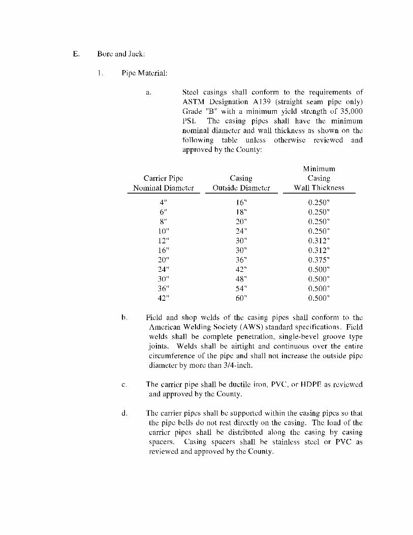
E. Bore and Jack:
1. Pipe Material:
a. Steel casings shall conform to the requirements of ASTM Designation Al39 (straight seam pipe only) Grade "B" with a minimum yield strength of 35,000 PSI. The casing pipes shall have the minimum nominal diameter and wall thickness as shown on the following table unless otherwise reviewed and approved by the County:
Minimum Carrier Pipe Casing Casing
Nominal Diameter Outside Diameter Wall Thickness
4" 16" 0.250" 6" 18" 0.250" 8" 20" 0.250" 10" 24" 0.250" 12" 30" 0.312" 16" 30" 0.312" 20" 36" 0.375" 24" 42" 0.500" 30" 48" 0.500" 36" 54" 0.500" 42" 60" 0.500"
b. Field and shop welds of the casing pipes shall conform to the American Welding Society (A WS) standard specifications. Field welds shall be complete penetration, single-bevel groove type joints. Welds shall be airtight and continuous over the entire circumference of the pipe and shall not increase the outside pipe diameter by more than 3/4-inch.
c. The carrier pipe shall be ductile iron, PVC, or HDPE as reviewed and approved by the County.
d. The carrier pipes shall be supported within the casing pipes so that the pipe bells do not rest directly on the casing. The load of the carrier pipes shall be distributed along the casing by casing spacers. Casing spacers shall be stainless steel or PVC as reviewed and approved by the County.
F. Pressure Pipe Restraints:
1. Pressure pipe fittings shall be restrained with restraint glands and devices as approved by the County. Concrete thrust blocks are not acceptable for pipe restraint unless prior approval has been given by the County for limited applications.
2. The minimum number of restrained joints required for resisting forces at fittings and changes in direction of pipe shall be determined from the length of restrained pipe on each side of fittings and changes in direction necessary to develop adequate resisting friction with the soil. The required lengths of restrained joint ductile iron pipe shall be determined by the Engineer.
G. Special Items:
1. Expansion Joints: Pipe expansion joints shall be suitable for the applicable service with a minimum 150 PSI working pressure.
2. Flanged Coupling Adapters: Units shall be compatible with ANSI Standard B16.1, 125 lb. flanges.
3. Cast Iron Sleeves and Wall Pipes: Units shall have integral annular ring water-stops, and also conform to other requirements for cast iron fittings specified in this Section. Sleeves and wall pipes are to have laying length and ends required for proper installation.
4. Tapping Saddles: Units shall be fabricated of ductile iron and suitable for either wet or dry installation. The sealing gasket shall be the "0-Ring type suitable for the applicable service. Outlet flange shall be ANSI B16.1, 125 lb. standard. Tie straps and bolts shall be a corrosion resistant alloy steel.
5. Tapping Sleeves: Units shall be of the mechanical joint type or fabricated steel type sleeves for pressure connections 4-inches and larger. All pressure connections to asbestos cement pipe and all "size on size" tap shall utilized mechanical joint sleeves.
a. Mechanical Joint Sleeves: Sleeves shall be cast of gray-iron or ductile iron and have an outlet flange with the dimensions of the Class 125 flanges as shown in ANSI Bl6.l properly recessed for tapping valve. Glands shall be gray-iron or ductile iron. Gaskets shall be vulcanized natural or synthetic rubber. Bolts and nuts
shall comply with ANSI/ A WWA C-111/ A.21.11. Sleeves shall be capable of withstanding a 200 PSI working pressure.
b. Steel Tapping Sleeve: Sleeves shall be fabricated of minimum 3/8-inch carbon steel meeting ASTM A285, Grade C. Outlet flange shall meet AWWA C-207, Class D, ANSI 150 lb. drilling and be properly recessed for the tapping valve. Bolts and nuts shall be high strength low alloy steel to ANSI/A WWA A21.ll/C-111. Gasket shall be vulcanized natural or synthetic rubber. Sleeve shall have manufacturer applied fusion bonded epoxy coating, minimum 12-mil thickness.
6. Service Saddles: Saddles for ductile iron pipe shall be double strap, anchored by a minimum four ( 4) bolt pattern on a ductile iron saddle body. Service saddles for PVC pipe shall have a double strap sized exactly to the pipe outside diameter. Sealing gaskets shall be suitable for the applicable service and straps shall be corrosion resistant alloy steel. The County may require a stainless steel strap and fusion epoxy or nylon coated ductile iron body with stainless steel hardware in areas designated as corrosive.
7. Polyethylene Encasement: Encasement shall have a minimum thickness of 8- mils and comply with the applicable provisions of ANSI/AWWA C-105/A21.5, "Polyethylene Encasement for Gray and Ductile Iron Piping for Water and Other Liquids."
4.03 VALVES
A. General: The valve type, size, rating, flow direction arrow, if applicable, and manufacturer shall be clearly marked on each unit. Valves shall open left (counterclockwise); with an arrow cast-in the metal of operating handwheels and nuts indicating the direction of opening.
B. Gate Valves (GV):
1. General: All gate valves shall be resilient seat gate valves and shall be resilient seated, manufactured to meet or exceed the requirements of AWWA C-509. The valve body, bonnet, and bonnet cover shall be cast iron and comply with ASTM A126, Class B Standards. The valves shall be non-rising stem with the stem made of cast, forged, or rolled bronze as specified in A WWA C-509. Two (2) stem seals shall be provided and shall be 0-Ring type. The stem must be independent of the gate. The resilient sealing mechanism shall provide zero leakage at the system working pressure when installed with the line flow in either direction. All ferrous surface inside and outside shall have a fusion-bonded epoxy
coating. All nuts, bolts, washers and springs shall be made of 316 stainless steel. The valves shall have an unobstructed waterway equal to or greater than the full nominal diameter of the valve.
2. Underground Service: Valves shall be iron body, bronze mounted, conforming to A WWA C-509, resilient seat, non-rising stem type, bolted bonnet, mechanical joint, and shall be equipped with 2-inch square cast iron wrench nuts.
3. Aboveground Service: Valves shall be iron body, bronze mounted gate valves, bolted bonnet, flanged, conforming to C-509, resilient seat, with the exception that valves shall be outside screw and yoke (OS&Y), rising stem type. Valves shall have cast iron handwheels or chain operators with galvanized steel chains, as required.
4. Tapping Valves: Valves shall conform to the specifications set forth under paragraphs 4.03B.l and 2, for the applicable service conditions. Additionally, units shall be compatible with the connecting sleeve or saddle and specially designed for wet tapping installation operations.
5. Valves 2-inches and Smaller: Valves shall be bronze, wedge disc, 150 PSI minimum working pressure, equipped with wrought steel or cast iron operating handwheels.
6. Actuators: Valves sixteen (16) inches and larger shall be equipped with approved gearing actuators, with sealed enclosures for buried or submerged service, and shall be furnished by the valve manufacturer. Position indicators shall be furnished as required.
7. Horizontal Installation: Valves 16-inches in diameter or larger, to be installed horizontally, shall be additionally equipped as specified under the applicable Section of AWWA C-500 and as follows:
a. Installed in vertical pipe with horizontal stem shall be fitted with approved slides, tracks and shoes to assist the travel of the gate assembly.
b. Installed in horizontal pipe with horizontal stem shall be equipped with approved rollers, tracks and scrapers to assist the travel of the gate assembly and to clear the track of obstructions.
C. Check Valves (CV):
1. General Service: Valves shall be iron body, bronze mounted, stainless steel hinge pin, outside lever and spring operated, single disc swing non-slam type, and equipped with removable inspection covers and shall meet the requirements of AWWA C-500. Ends shall be 125 lb ANSI Bl6.l flanges. Units shall be rated for 175 PSI minimum working pressure and shall permit full flow area equal to that of the connecting pipe. Valves shall be constructed to allow disc and body seat to be easily removed and replaced without removing valve from the line. Valves shall be fitted with an extended hinge arm with outside lever and weight. If pump shutoff exceeds 77-feet, then an air cushioned assembly shall be installed. All exposed nuts, bolts, washers and springs on buried and on above ground outdoor service valves shall be 316 stainless steel.
2. Valves two (2) inches and Smaller: Valves shall be bronze body and disc, swing check type, with removable inspection covers, and rated 150 PSI minimum working pressure.
D. Plug Valves (PV):
1. Eccentric plug valves 4-inches and larger shall be of the non-lubricated type and comply with A WWA C-504 and C-507. Minimum pressure rating of valves 4-inches through 12-inches shall be 175 PSI, valves 14-inches through 72-inches shall be 150 PSI. Valve bodies shall be cast iron ASTM A 126, Class B, in compliance with AWWA C 504 and C-507. Unless otherwise noted, port areas for all valves shall be 100 percent of full pipe area. Resilient plug facings shall be of Hycar, Nitrile Butadiene Rubber or Neoprene.
Valve ends shall be flanged (or grooved end couplings) or mechanical joint for above ground and underground installation, respectively. Valve body seats shall have a welded-in overlay of not less than 90-percent nickel for all parts which comes in contact with the plug face. Packing shall be safely adjustable and replaceable without removing the valve from service, with the body pressurized to its full rated pressure. Bearings shall be permanently lubricated 316 stainless steel in both upper and lower journals in accordance with A WWA Standard C-507. The valve supplied shall have drip tight shut off with flow in either direction at the full pressure rating of the valves. All exposed nuts, bolts, springs and washers on buried and on above ground outdoor service valves shall be 316 stainless steel.
2. All body, bonnet and flange thickness shall be designed and rated in accordance with the specified valve pressure rating and ANSI B16.1, per AWWA Standards C-504 and C-507. Mechanical joint ends shall be to the AWWA Standard C-111, Class B. Screwed ends shall be to the NPT standard.
3. Valves shall be furnished with permanently lubricated stainless steel or oil-impregnated bronze upper and lower plug stem bushings. These bearings shall comply with A WWA C-504 and C-507. Valve shaft seals shall be adjustable and comply with AWWA Standard C-507.
4. Operation of all valves 10-inches or larger; and smaller sizes in exposed locations, which require handwheels or chainwheels, shall be by approved gear actuators, equipped with position indicator and stop, and shall be furnished by the valve manufacturer. Gear actuators for buried or submerged installations shall be furnished with sealed enclosures. Valves shall be equipped with actuating nuts, cast iron handwheels or chain operators, with galvanized steel chains, as appropriate for the installation and type of operator.
E. Butterfly Valves (BFV): Valves shall be cast or ductile iron body that conforms to ASTM A26, Class B. All retaining segments and adjusting devices shall be of corrosion resistant material. The valves shall have bonded or mechanically restrained seats as outlined in AWWA C-504. Valve seats shall be a natural rubber or synthetic rubber compound. The valve shaft shall be turned, ground and polished constructed 18-8 stainless steel, and designed for both torsional and shearing stresses when the valve is operated under its greatest dynamic or seating torque. The shaft shall be a one (1) piece unit extending full size through the valve disc. The valves shall be of either a short or long body type, with the valve class, shaft size and other special requirements selected in accordance with the specific design, and shall comply with the provisions of AWWA C-504, "Rubber Seated Butterfly Valves". Valve operation shall be by approved gear actuators, with sealed enclosures for buried or submerged service. Position indicators shall be furnished, as required. Units shall be equipped with actuating nuts, cast iron handwheels or chain operators, with galvanized steel chains, as appropriate for the installation. All exposed nuts, bolts, springs and washers on buried and on above ground outdoor service valves shall be 316 stainless steel. Appurtenances shall be furnished by the valve manufacturer.
F. PVC Ball Valves: PVC ball valves shall be provided, as required, for chemical service installations and shall be full port area.
G. Corporation Stops and Curb Stops: Units shall be 1-inch, 1 1/2-inch, or 2-inches brass, equipped with connections compatible with the connecting service pipe type, threaded in accordance with AWWA Standard C-800 and C-901. Curb stop shall be sized to match the meter size and conform to AWWA C-800 and C-901. Fittings shall be brass, cast and machined in accordance with A WWA C-800 and C-901, with compatible polyethylene tubing connections.
H. Backflow Preventers: The assembly shall be of the type approved by the County based on the type of service and shall comply with the applicable provisions of AWWA Standards and County regulations. Reference is made to Appendix B of this Handbook for further discussion on Backflow Preventers and Control Plan.
I. Air and Vacuum Release Valves:
1. Wastewater Service Air/Vacuum Release Valve: Valves shall be specially adapted for raw wastewater service. Valves shall be of the long body design and be constructed of cast iron ASTM A126-B, Class 35 with stainless steel Type 304 stem, float guide and float and Buna-N seat. Valves shall have an upper and lower float separated by a hexagonal float guide to prevent fouling and shall have a pressure rating of 150 PSI. Valves shall have standard 2-inch NPT inlets and outlets, and be equipped with accessories for backwashing.
2. Wastewater Service Air Release Value: The valve body and cover shall be cast iron construction, ASTM A126-B, and all internal parts shall be of stainless steel Type 304. The vertiny orifice shall be 3/8-inch in diameter and the seating material shall be of Viton.
3. Water Service: The valve shall be a heavy-duty combination air release and vacuum type for 150 PSI working pressure, tested to 300 PSI. Body, cover and baffle shall be cast iron. All internal parts shall be stainless steel and inside of valve shall be coated with a rust inhibitor. The valves shall be provided with a vacuum check to prevent air from reentering the line. All valves shall comply with A WWA C-512.
J. Special Items:
1. Water Meters: 5/8-inch through 1 1/2-inch meters shall be AWWA approved Sealed Register Displacement Type Meters. The water meters that have 2-inches and larger meters shall be AWWA Approved Turbo-Meters. Meters 6-inches and larger are to be equipped with strainers.
2. Floor Stands: Units shall be cast iron, equipped with convenient grease fittings for all lubrication points, and suitable for the applicable operation. Stem guides shall be cast iron, adjustable, with bronze bushings.
3. Valve Boxes: Units shall be adjustable, cast iron, mm1mum interior diameter of 5-inches with covers cast with the applicable inscription in legible lettering on the top: "SEWER", "EFF WATER" or "WATER".
Boxes shall be suitable for the applicable surface loading, valve size and be painted the following colors:.
1. SEWER COVERS shall be painted green, 2. EFF WATER shall be painted purple (Pantone 522C) and 3. WATER shall be painted blue.
4. Meter Boxes: Meter boxes shall be prestressed concrete, ductile iron or FDOT approved plastic units of a size comparable with the meter.
5. Service Boxes: Service boxes for reuse connections shall be plastic with a jam lock cover. Boxes shall be purple (Pantone 522C) in color.
4.04 INSTALLATION
A. Potable Water, Wastewater Force Main and Effluent Reuse Pipe:
1. Piping, fittings, valves and appurtenances shall be installed in accordance with these Standards, including the attached "Standard Details" all applicable AWWA standards, and with the manufacturer's recommendations for the applicable service.
2. All types of pipe shall be handled in such a manner as will prevent damage to the pipe or coating. Accidental damage to the pipe or coating shall be repaired to the satisfaction of the County or be removed from the job site. When not being handled, the pipe shall be supported on timber cradles or on properly prepared ground, graded to eliminate all rock points and to provide uniform support along the full length. When being transported, the pipe shall be supported at all times in a manner which will not permit distortion or damage to the lining or coating. Any unit of pipe that, in the opinion of the County, is damaged beyond repair by the Contractor shall be removed from the site of the work and replaced with another unit. Joint gaskets shall be stored in a clean, dark, dry location until immediately before use.
Dirt or other foreign material shall be prevented from entering the pipe or pipe joint during handling or laying operations and any pipe or fitting that has been installed with dirt or foreign material in it shall be removed, cleaned and re-laid. At all times when the pipe laying is in progress, the open ends of the pipe shall be closed by a water-tight plug or
by other means approved by the County to ensure absolute cleanliness inside the pipe.
3. Water mains that are laid in the vicinity of pipe lines designated to carry raw wastewater, reclaimed reuse or wastewater effluent shall meet the requirements outlined in Section 6.03.G.
4. Piping shall be installed along straight line and grade between fittings, manholes, or other defined points, unless definite lines of alignment deflection or, grade change have been established. Modification to approved alignment or grade during construction shall receive prior approval from the County, and all resulting design considerations shall be resolved by the Builder.
5. Materials shall be cleaned and maintained clean, with all coatings protected from damage. The interior of the pipe shall be free of dirt and debris, and when work is not in progress; all open ends shall be plugged. Also, materials for potable water systems including tops, repairs, etc., shall be disinfected in compliance with A WWA C-651.
6. Pipe, valves, fittings, or other items shall be inspected prior to installation, and any items showing a fracture or other defect shall be rejected. Additionally, any pipe or fitting which has received a severe blow that may have caused an incipient fracture, even though not visible, shall also be rejected. However, ductile iron pipe showing an end crack, with no fracture indicated beyond that visible, may be salvaged by cutting off the damaged section 12-inches past, providing the remaining pipe is sound.
7. The Contractor shall prevent water from entering the trench during excavation and pipe laying operations to the extent required to properly grade the bottom of the trench and allow for proper compaction of the backfill. Pipe shall not be laid in water and Specifications outlined in Section 3.17 shall apply.
8. Pipe shall be laid to the lines and grades shown on the Plans. The Contractor shall provide line and grade stakes at 100-foot maximum spacing and at all line and/or grade change locations. The Contractor shall provide temporary bench marks at maximum 1,000-foot intervals. The minimum pipe depth shall be 3-feet below finished grade surface of 3-feet below the edge of pavement of road surface whichever is greater.
9. Long radius curves, either horizontal or vertical, may be laid with standard pipe deflections at the joints. The maximum deflections at pipe joints and laying radius for the various pipe lengths shall be as recommended by the pipe manufacturer.
10. Underground piping shall not be driven to grade by striking it with an unyielding object. When the pipe has been properly bedded, enough compacted backfill shall be placed to hold the utility in correct alignment. If necessary, precaution shall be taken to prevent flotation.
11. The installation of casing pipe underneath existing roadways shall be by the method of boring and jacking and shall meet the requirements outlined in Section 4.04D.
12. Jointing shall be by an approved method and shall not require undue force to accomplish full satisfactory seating and assembly. Connections at structures shall be cut accurately and worked into place without forcing and shall align with the connecting point. Flanged joints shall be made up tight, but with care taken to prevent undue strain upon equipment or other items. Suitable flange filler rings shall be installed where required to provide suitable joints. The installation shall be permanently watertight, with no visible leakage at joints or connections with structures. Any joint that does not remain completely seated and/or watertight shall be rejected.
13. Requirements for bedding and backfill for the pipes are outlined in Section 3.17.
14. Exposed systems shall be supported as necessary to hold the piping and appurtenances in a firm, substantial manner to the required lines and grades indicated, with no undue piping stresses transmitted to equipment or other items. Piping within buildings shall be adequately supported from floors, walls, ceilings or beams. Supports from the floor shall be by suitable saddle stands or piers. Piping along walls shall be supported by satisfactory wall brackets, or saddles, or by wall brackets with adjustable hanger rods. For piping supported from the ceiling, approved rod hangers of a type capable of screw adjustment after erection of the piping shall be used. Pipe above ground outside of buildings shall be supported on concrete supports.
15. Proper provision for pipe expansion or contraction shall be provided by installation of expansion joints or other suitable methods. Additionally, flexible connections shall be provided to expedite equipment or piping system removal.
16. Ductile Iron Pipe: Installation shall be performed in accordance with the applicable provisions of AWWA Standard C-600. The opening cut in the pipe wall for installation of tapping saddles and sleeves shall be made by a special tapping machine designed for this specific service; however, for dry installations on ductile iron (only), the opening may be made with a
cutting torch, as prior approved by the County, with edges ground smooth. All pipe cutting shall be accomplished by power operated abrasive wheel or saw cutters, or other methods approved by the pipe manufacturer. Where required, polyethylene encasement shall be installed as set forth previously in this section.
17. Polyvinyl Chloride Pipe: All PVC pipe shall be installed in accordance with the Standards set forth in the UNI-BELL "Handbook of PVC Pipe Design and Construction", unless such standards conflict with this Handbook in which case this Handbook shall apply. Lubrication and/or solvent used for pipe and fitting joints shall be non-toxic (NSF Approved for potable water). Following making, solvent type joints shall not be disturbed for five (5) minutes and shall not have internal pressure applied for twenty four ( 24) hours, or as recommended by the pipe manufacturer.
18. Testing of piping systems shall be performed by the Builder in accordance with the specifications set forth under the Standard for the applicable service, said prior testing procedures shall be in accordance with A WWA standards. Prior to testing procedures, all piping shall be thoroughly cleaned and flushed with clean water to clear the lines of all foreign matter. This work shall be done with care to avoid damage to any inside coating.
19. Disinfecting of all potable water and reuse pipes shall be accomplished by the Builder, following approved pressure testing. Unless alternate procedures are set forth under the applicable service Standard, said disinfecting procedures shall be in accordance with A WWA Standard C-651 and as required by the appropriate local approval agency.
20. All connections to existing pressure pipes shall be made by the Contractor only after the connection, procedure and work schedule has been reviewed and approved by the County a minimum of 5-working days prior to scheduling the connection(s). The Contractor shall outline the following:
a. Points of connection, fittings to be used, and method of flushing and disinfection, if applicable, such as a temporary jumper connection (detail in Figure D-501A in Appendix D of this handbook) ..
b. Estimated construction time for the connection(s).
The County shall review the submittal within three (3) working days after receiving it and inform the Contractor regarding approval or denial of the request. If the request is rejected by the County, the Contractor shall resubmit the request by modifying it in a manner acceptable to the County.
All connections shall only be made on the agreed upon date and time. If the Contractor does not initiate and complete the connection work in the agreed upon manner, the Contractor shall be required to reschedule the said connection by following the procedure outlined above. The Contractor shall not have operated any valves in the system.
During the construction sufficient length of main shall be exposed to allow for the installation of the tapping sleeve and valve and the operation of the tapping machinery. The main shall be supported on concrete pedestals or bedding rock at sufficient intervals to properly carry its own weight, plus the weight of the tapping sleeve and machinery. Any damage to the pipe due to improper or insufficient supports shall be repaired at the Contractor's expense.
The inside of the tapping sleeve and valve, the outside of the main, and the tapping machine shall be cleaned and swabbed, or sprayed with IO-percent liquid chlorine prior to beginning installation for water system pressure connections.
After the tapping sleeve has been mounted on the pipe, the tapping valve shall be bolted to the outlet flange, making a pressure tight connection. Prior to beginning the tapping operation, the sleeve and valve shall be pressure tested at 150 PSI to ensure that no leakage will occur.
For pressure connections 12-inches in diameter or less the minimum diameter cut shall be 1/2-inch less than the nominal diameter of the pipe to be attached. For pipes 14-inches through 20-inches in diameter, the minimum diameter shall be 1-1/2-inches less; for larger taps the allowable minimum diameter shall be 2 to 3-inches less than the nominal diameter of the pipe being attached. After the tapping procedure is complete the Contractor shall submit the coupon to the County.
For pressure connections to wastewater force mains, the tapping valve shall be placed horizontally. After the tapping procedure is complete a plug valve shall be attached to the tapping valve. The tapping valve shall be left in the open position prior to backfilling.
Adequate poured concrete thrust blocks or restrained joint fittings shall be provided to prevent movement of the installation when test pressure is applied. The pipe restraints shall meet the requirements of Section 4.02F.
B. Gravity Sewers
1. The Contractor shall set temporary bench marks at a maximum of 500-foot intervals. The Contractor shall constantly check line and grade of the pipe by laser beam method. In the event line and grade do not meet specified limits described hereinafter, the Work shall be immediately stopped, the County notified, and the cause remedied before proceeding with the Work.
2. All pipe shall be inspected and handled as specified under Sections 4.04A.2 and 4.04A.5.
3. Laying of gravity sewer pipe shall be accomplished to line and grade in the trench only after it had been dewatered and the trench has been prepared in accordance with Sections 3.17. Mud, silt, gravel and other foreign material shall be kept out of the pipe and off the jointing surface. All pipe laid shall be retained in position so as to maintain alignment and joint closure until sufficient backfill has been completed to adequately hold the pipe in place. All pipes shall be laid to conform to the line and grade shown on the Plans.
Variance from the established line and grade, at any point along the length of the pipe, shall not be greater than 1/32-inch per inch of pipe diameter and not to exceed 1/2-inch, provided that any such variation does not result in a level or reverse sloping invert.
The gravity sewer pipe, unless otherwise approved by the County, shall be laid up grade from point of connection on the existing gravity sewer or from a designated starting point. The gravity sewer pipe shall be installed with the bell end forward or upgrade. When pipe laying is not in progress the open end of the pipe shall be kept tightly closed with an approved temporary plug.
4. All PVC pipe shall be installed in accordance with the Standards set forth in the Uni-Bell "Handbook of PVC Pipe Design and Construction".
5. Laying of ductile iron pipe shall conform to the specifications outlined in Section 4.04A.18.
6. All applicable provisions of Section 3.17 shall apply with regards to trench excavation, dewatering, bedding material, backfill, compaction, fill and grading.
7. The Contractor shall hand-grade bedding to proper grade ahead of pipe laying operation. Bedding shall provide a firm, unyielding support along the entire pipe length. If without direction from the County, the trench has been excavated below the required depth for pipe bedding material placement, the Contractor shall fill the excess depth with pipe bedding material to the proper grade. The Contractor shall excavate bell holes at each joint to permit proper assembly and inspection of the entire joint.
8. The Contractor shall provide bedding material in accordance with the Standard Drawings.
9. Gravity sewers that are laid in the vicinity of pipe lines designated to carry potable water shall meet the requirements set forth in Sections 4.04A.3 and 6.03G.
10. Plugs for pipe branches, stubs or other open ends which are not to be immediately connected shall be made of an approved material and shall be secured in place with a joint comparable to the main line joint.
11. The type of joint shall conform to the requirements outlined in Section 4.02B.3.A and 4.02.C.3 of this handbook.
C. Manholes and Precast Structures
1. Base sections shall be placed on bedding rock conforming to the requirements outlined in Section 3.l 7H.l. The bedding rock shall be firmly tamped and made smooth and level to assure uniform contact and support of the pre-cast element in accordance with Section 3 .171.
2. The cast-in-place bases shall be utilized only when specifically approved by the County. Unless otherwise specified, cast-in-place bases shall be at least 8-inches in thickness and shall extend at least 6-inches radially outside of the outside dimension of the structure. Reinforcement and connection to the riser sections shall be designed by the Builders Engineer and submitted to the County for approval.
3. A pre-cast base section shall be carefully placed on the prepared bedding so as to be fully and uniformly supported in true alignment and making sure that all entering pipes can be inserted on proper grade. Pre-cast manhole and lift station sections shall be handled by lift rings or non-penetrating lift holes. Such holes shall be filled with non-shrink grout after installation of the structure. The first pre-cast section shall be place and carefully adjusted to true grade and alignment. All inlet pipes shall be properly installed so as to form an integral watertight unit. The sections shall be uniformly supported by the base structure, and shall not bear directly on any of the pipes.
Pre-cast sections shall be placed and aligned to provide vertical alignment with a 1/4-inch maximum tolerance per 5-feet of depth. The completed manhole shall be rigid, true to dimensions, and watertight.
4. The excavation and backfilling shall conform to the requirements outlined in Section 3.17.
5. Castings for manholes shall be fully bedded in mortar with adjustment brick courses placed between the frame and manhole. Bricks shall be
minimum two (2) and four (4) courses. Mortar shall conform to ASTM C-270, type M, and the bricks shall be clay and conform to ASTM C-216, grade SW, and have the following dimensions of 3 1/2 inches wide by 8 inches long and 2 1/4 inches high.
The top of the manhole castings that are located in pavement, shouldered areas, and sidewalks shall be flush with the finished grade. The top of manhole castings that are located outside of these areas shall be placed 2-inches above the finished grade.
6. Manhole flow channels shall be as shown on the Standard Drawings, with smooth and carefully shaped bottoms, built up sides and benching constructed using cement and brick with no voids. Channels shall conform to the dimension of the adjacent pipe and provide changes in size, grade and alignment evenly. Cement shall be Portland Cement Type II only.
7. Special care shall be taken to see that the openings through which pipes enter the structure are provided with watertight connections. For ductile iron and PVC pipe, connections shall conform with ASTM C-923. Drop manhole connections shall conform in all respects to details shown on the Standard Drawings.
8. All newly constructed manhole and lift stations shall be cleaned of any accumulation of silt, debris, or foreign matter of any kind, and shall be free from such accumulations at the time of final inspection.
D. Bore and Jack:
1. General: Applicable prov1S1ons of Sections 6, 8, and 10 shall apply concurrently with these specifications. Boring and jacking operations shall be performed within the right-of-way and/or easements shown on the Plans.
a. All casing pipe to be installed may be inspected at the site of manufacture for compliance with these Specifications by an independent laboratory selected and paid for by the County. The manufacturer's cooperation shall be required in these inspections. All casing pipe shall be subjected to a careful inspection prior to being installed. If the pipe fails to meet the specifications it shall be removed and replaced with a satisfactory replacement at no additional expense to the County.
b. Pipe Handling: Care shall be taken in loading, transporting, and unloading to prevent injury to the pipe or coatings. Pipe shall not
be dropped. All pipe shall be examined before laying, and no piece shall be installed which is found to be defective. Any damage to the pipe or coatings shall be repaired to the satisfaction of the County.
c. Work Coordination: It shall be the Builder's responsibility to perform the boring and jacking work in strict conformance with the requirements of the agency in whose right of way or easement the work is being performed. Any special requirements of the agency such as insurance, flagmen, etc., shall be strictly adhered to during the performance of Work. The special requirements shall be performed by the Builder at no additional cost to the County.
d. Dewatering through the casing during construction shall not be permitted. All dewatering methods shall be approved by the County before construction work begins.
e. Excavation adjacent to the roads shall be performed in a manner to adequately support the roads. Bracing, shoring, sheeting or other supports shall be installed as needed. Builder shall install suitable reaction blocks for the jacks as required. Jacking operations shall be continuous and precautions shall be taken to avoid interruptions which might cause the casing to "freeze" in place. Upon completion of jacking operations, the reaction blocks, braces, and all other associated construction materials shall be completely removed from the site.
f. Correct line and grade shall be carefully maintained. Earth within the casing shall not be removed too close to the cutting edge in order to prevent the formation of voids outside the casing. If voids are formed, they shall be satisfactorily filled with grout by pumping.
g. The sections of steel casing shall be field welded in accordance with the applicable portions of AWWA C-206 and ASTM D7.0 for field welded pipe joints. Builder shall wire brush the welded joints and paint with Inertol Quick-Drying Primer 626 by Koppers Company or approved equal. After completion of jacking, Builder shall clean the interior of the casing of all excess material.
E. Valves:
1. General: Valves shall be carefully inspected, opened wide, and then tightly closed, and all the various nuts and bolts thereon shall be tested for tightness. Special care shall be taken to prevent joint materials, stones or other substances from becoming lodged in the valve seat. Valves, unless otherwise required, shall be set with their stems vertically above the center line of the pipe. Any valve that does not operate correctly shall be adjusted to operate properly or removed and replaced.
2. Buried valves shall be installed vertically where depth of cover permits. Where depth of cover does not permit, the valves shall be mounted horizontally. Extension stems shall be provided on all buried valves when the operating nut is deeper than 4-feet below the final grade, with sufficient stem extension to place the nut not more than 4-feet below grade. Where extension stems are required within valve boxes, approved insert stem guides shall be provided.
3. Valve boxes shall be carefully centered over the operating nuts of underground valves to permit a valve wrench to be easily fitted to the nut. The tops of valve boxes shall be set to the required grade. The valve box shall not transmit surface loads directly to either the pipe or valve. Care shall be taken to prevent earth and other material from entering the valve boxes. A concrete support collar shall be provided for the valve box.
4. Where floor stands and/or extension stems are required, for exposed valves, adjustable wall brackets and extension stems shall be furnished. Generally, brackets shall not be more than 6-feet apart, with floorstands and guides set so that the stems shall run smoothly and in true alignment. Stands and guides shall be firmly anchored to the concrete.
5. After installation, all valves shall be subjected to the field test for piping as outlined in Sections 6, 8 and 10 of this Handbook. Should any defects in materials or workmanship appear during these tests, the Contractor shall correct such defects to the satisfaction of the County.
6. All flanged and mechanical joints shall be made with stainless steel nuts, bolts and washers.
WORK IN PROGRESS DRAFT COPY ONLY
TABLE OF CONTENTS
SECTION 5 ..................................................................................................................................... 2 WATER DISTRIBUTION SYSTEMS ........................................................................................... 2
5.01 GENERAL .............................................................................................................. 2 5.02 DESIGN STANDARDS ......................................................................................... 2 5.03 STANDARD REQUIREMENTS ........................................................................... 3 5.04 INSTALLATION .................................................................................................... 9 5.05 TESTING ................................................................................................................ 9 5.06 DISINFECTION ................................................................................................... 10
5-1 02/10/2010
SECTION 5
WATER DISTRIBUTION SYSTEMS
5.01 GENERAL
A. This Section sets forth the general requirements for design and installation of water distribution systems for potable water and irrigation service. Pipe used in water distribution or irrigation systems shall be either PVC or DI pipe as specified in Section 4 of this Handbook.
The Contractor shall be responsible for all materials furnished and storage of same, until the date of substantial completion. The Contractor shall replace at the Contractors expense all material found to be damaged or defective in handling or storage. The Contractor shall, if requested by the County, furnish certificates, affidavits of compliance, test reports, or samples for check analysis for any of the materials specified in this Handbook as it relates to water and irrigation systems. All pipe delivered to the project site for installation is subject to random testing for compliance with the designated specifications.
5.02 DESIGN STANDARDS
A. Required Reference: The Builder shall comply with the design and installation requirements as established by the FDEP and additional specific requirements stated in this handbook. The criteria set forth in the most recent edition of "Recommended Standards for Water Works (Ten States Standards)" and Insurance Services Office should be used as a design guide, if not in conflict with State, County or other regulatory agency requirements.
B. Water mains shall be located in dedicated rights-of-way or utility easements. When installed in rights-of-way, water mains shall, in general, maintain a consistent alignment with respect to the centerline of the road. All water mains located outside of dedicated rights-of-way shall require a 20-foot easement or as required by the County. Water mains shall not be located beneath permanent structures. Placement of a water main along side or rear lot line may be allowed on a case by case basis if such a water main configuration results in efficient placement and utilization of the water distribution system. Easement widths shall be on a case by case basis and shall provide sufficient width to provide for access by heavy equipment for repair and maintenance of lines.
5-2 02/10/2010
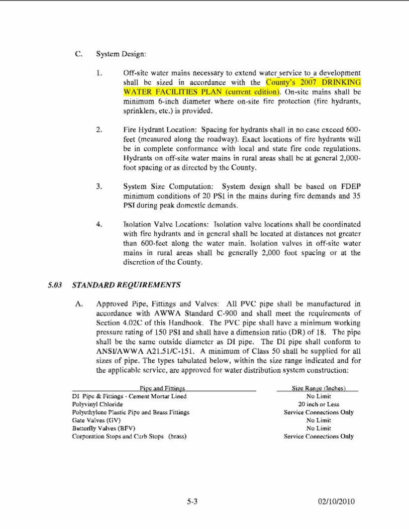
L
C. System Design:
Off-site water mains necessary to extend water_service to_ a de_yelopment shall be sized in accordance with the County's 2007 DRINKING
ATER FAC1LITJES PLAN (current edition). On-site mains shall be minimum 6-inch diameter where on-site fire protection (fire hydrants, sprinklers, etc.) is provided.
2. Fire Hydrant Location: Spacing for hydrants shall in no case exceed 600-feet (measured along the roadway). Exact locations of fire hydrants will be in complete conformance with local and state fire code regulations. Hydrants on off-site water mains in rural areas shall be at general 2,000-foot spacing or as directed by the County.
3. System Size Computation: System design shall be based on FDEP minimum conditions of 20 PSI in the mains during fire demands and 35 PSI during peak domestic demands.
4. Isolation Valve Locations: Isolation valve locations shall be coordinated with fire hydrants and in general shall he located at distances not greater than 600-fcet along the water main. Isolation valves in off-site water mains in rural areas shall he generally 2,000 foot spacing or at the discretion of the County.
5.03 STANDARD REQUIREMENTS
A. Approved Pipe, Fittings and Valves: All PVC pipe shall be manufactured in accordance with A WWA Standard C-900 and shall meet the requirements of Section 4.02C of this Handbook. The PVC pipe shall have a minimum working pressure rating of 150 PSI and shall have a dimension ratio (DR) of 18. The pipe shall be the same outside diameter as DI pipe. The DI pipe shall conform to ANSI/AWWA A21.51/C-151. A minimum of Class 50 shall he supplied for all sizes of pipe. The types tabulated below, within the size range indicated and for the applicable service, are approved for water distribution system construction:
Pj pe and Fittings Si1.e Ran ge (Inches) DI Pipe & Fittings· Cement Mortar Lined No Limit Polyvinyl Chloride 20 inch or Less Polyethylene Plastic Pipe and Brass fillings Service Connections Only Ciate Valves (CiV) No Limit Butterfly Valves (BfV) No Limit Corporation Stops and Curb Slops (brass) Service Connections Only
5.3 02/10/2010
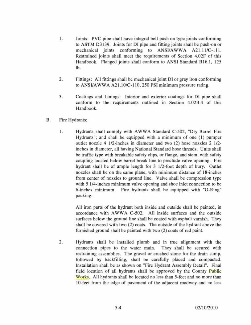
1. Joints: PVC pipe shall have integral bell push on type joints conforming to ASTM 03139. Joints for DI pipe and fitting joints shall be push-on or mechanical Jomts conforming to ANSI/AWWA A21.ll/C-ll 1. Restrained joints shall meet the requirements of Section 4.02F of this Handbook. Flanged joints shall conform to ANSI Standard B16.1, 125 lb.
2. Fittings: All fittings shall be mechanical joint DI or gray iron conforming to ANSI/AWWA A21.10/C-110, 250 PSI minimum pressure rating.
3. Coatings and Linings: Interior and exterior coatings for DI pipe shall conform to the requirements outlined in Section 4.02B.4 of this Handbook.
B. Fire Hydrants:
1. Hydrants shall comply with AWWA Standard C-502, "Dry Barrel Fire Hydrants"; and shall be equipped with a minimum of one (1) pumper outlet nozzle 4 1/2-inches in diameter and two (2) hose nozzles 2 1/2-inches in diameter, all having National Standard hose threads. Units shall be traffic type with breakable safety clips, or flange, and stem, with safety coupling located below barrel break line to preclude valve opening. Fire hydrant shall be of ample length for 3 1/2-foot depth of bury. Outlet nozzles shall be on the same plane, with minimum distance of 18-inches from center of nozzles to ground line. Valve shall be compression type with 5 1/4-inches minimum valve opening and shoe inlet connection to be 6-inches mm1mum. Fire hydrants shall be equipped with "0-Ring" packing.
All iron parts of the hydrant both inside and outside shall be painted, in accordance with AWWA C-502. All inside surfaces and the outside surfaces below the ground line shall be coated with asphalt varnish. They shall be covered with two (2) coats. The outside of the hydrant above the furnished ground shall be painted with two (2) coats of red paint.
2. Hydrants shall be installed plumb and in true alignment with the connection pipes to the water main. They shall be secured with restraining assemblies. The gravel or crushed stone for the drain sump, followed by backfilling, shall be carefully placed and compacted. Installation shall be as shown on "Fire Hydrant Assembly Detail". Final field location of all hydrants shall be approved by the County Public Works. All hydrants shall be located no less than 5-feet and no more than 10-feet from the edge of pavement of the adjacent roadway and no less
5-4 02/10/2010
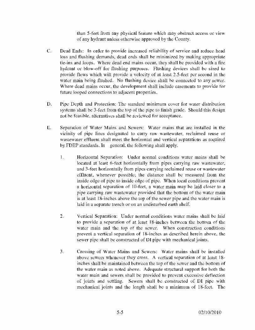
than 5-feet from any physical feature which may obstruct access or view of any hydrant unless otherwise approved by the County.
C. Dead Ends: In order to provide increased reliability of service and reduce head loss and flushing demands, dead ends shall be minimized by making appropriate tie-ins and loops. Where dead end mains occur, they shall be provided with a fire hydrant or blow-off for flushing purposes. Flushing devices shall be sized to provide flows which will provide a velocity of at least 2.5-feet per second in the water main being flushed. No flushing device shall be connected to any sewer. Where dead mains occur, the development shall include easements to provide for future looped connections to adjacent properties.
D. Pipe Depth and Protection: The standard minimum cover for water distribution systems shall be 3-feet from the top of the pipe to finish grade. Should this design not be feasible, alternatives shall be reviewed for acceptance.
E. Separation of Water Mains and Sewers: Water mains that are installed in the vicinity of pipe lines designated to carry raw wastewater, reclaimed reuse or wastewater effluent shall meet the horizontal and vertical separations as required by FDEP standards. In general, the following shall apply.
1. Horizontal Separation: Under normal conditions water mains shall be located at least 6-feet horizontally from pipes carrying raw wastewater, and 3-feet horizontally from pipes carrying reclaimed reuse or wastewater effluent, whenever possible; the distance shall be measured from the inside edge of pipe to inside edge of pipe. When local conditions prevent a horizontal separation of 10-feet, a water main may be laid closer to a pipe carrying raw wastewater provided that the bottom of the water main is at least 18-inches above the top of the sewer pipe and the water main is laid in a separate trench or on an undisturbed earth shelf.
2. Vertical Separation: Under normal conditions water mains shall be laid to provide a separation of at least 18-inches between the bottom of the water main and the top of the sewer. When construction conditions prevent a vertical separation of 18-inches as described herein above, the sewer pipe shall be constructed of DI pipe with mechanical joints.
3. Crossing of Water Mains and Sewers: Water mains shall be installed above sewers whenever they cross. A vertical separation of at least 18-inches shall be maintained between the top of the sewer and the bottom of the water main as noted above. Adequate structural support for both the water main and sewers shall be provided to prevent excessive deflection of joints and settling. Sewers shall be constructed of DI pipe with mechanical joints and the length shall be a minimum of 18-feet. The
5-5 02/10/2010
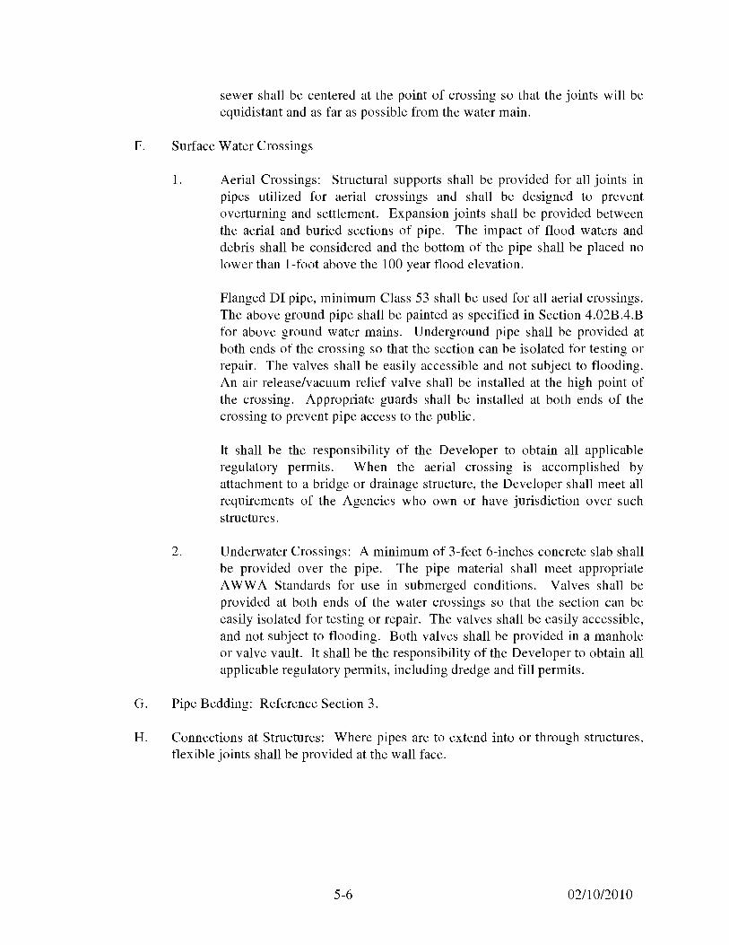
sewer shall be centered at the point of crossing so that the joints will be equidistant and as far as possible from the water main.
F. Surface Water Crossings
1. Aerial Crossings: Structural supports shall be provided for all joints in pipes utilized for aerial crossings and shall be designed to prevent overturning and settlement. Expansion joints shall be provided between the aerial and buried sections of pipe. The impact of flood waters and debris shall be considered and the bottom of the pipe shall be placed no lower than I-foot above the 100 year flood elevation.
Flanged DI pipe, minimum Class 53 shall be used for all aerial crossings. The above ground pipe shall be painted as specified in Section 4.02B.4.B for above ground water mains. Underground pipe shall be provided at both ends of the crossing so that the section can be isolated for testing or repair. The valves shall be easily accessible and not subject to flooding. An air release/vacuum relief valve shall be installed at the high point of the crossing. Appropriate guards shall be installed at both ends of the crossing to prevent pipe access to the public.
It shall be the responsibility of the Developer to obtain all applicable regulatory permits. When the aerial crossing is accomplished by attachment to a bridge or drainage structure, the Developer shall meet all requirements of the Agencies who own or have jurisdiction over such structures.
2. Underwater Crossings: A minimum of 3-feet 6-inches concrete slab shall be provided over the pipe. The pipe material shall meet appropriate AWWA Standards for use in submerged conditions. Valves shall be provided at both ends of the water crossings so that the section can be easily isolated for testing or repair. The valves shall be easily accessible, and not subject to flooding. Both valves shall be provided in a manhole or valve vault. It shall be the responsibility of the Developer to obtain all applicable regulatory permits, including dredge and fill permits.
G. Pipe Bedding: Reference Section 3.
H. Connections at Structures: Where pipes are to extend into or through structures, flexible joints shall be provided at the wall face.
5-6 02/10/2010
I. Special Exterior Protection for Corrosion: Extra protection shall be provided for underground DI pipe and fittings within areas of severe corrosive conditions. This shall be accomplished by the installation of polyethylene encasement, as specified in A WWA C-105, through the area of concern. The soil-test evaluation to determine the necessity for extra protection in suspect areas shall be as set forth in ANSI Standard A21.5. Additionally, where other existing utilities are known to be cathodically protected, DI pipe crossing said utility shall be protected for a distance of 20-feet to each side, and when installed parallel to and within 10-feet of, protection shall also be provided.
J. Air Venting and Blow-Offs: Where the water main profile is such that air pockets or entrapment could occur, resulting in flow blockage, methods for air release shall be provided. Air venting capabilities shall be provided for distribution mains by appropriately placing fire hydrants, blow-offs or other manual devices. At critical points on major mains, automatic air release assemblies shall be installed. All dead-end water mains, temporary or permanent, shall be equipped with a manually operated blow-off at the terminus.
K. Service Connections:
1. All service lines shall be 3/4-inch, 1-inch, 1 1/2-inch or 2-inch polyethylene tubing conforming to the specifications in A WWA C-800 and C-901.
2. Connections to existing water mains shall be accomplished by the County.
3. No water service lateral shall parallel adjoining lots, run between neighboring property lines or come through the rear of the property's lot line in order to provide utility service, unless otherwise approved by the County.
4. Corporation stops shall be 1-inch, 1 1/2-inch or 2-inch brass, equipped with connections compatible with the polyethylene tubing and threaded in accordance with specifications in A WWA C-901. Curb stops shall be sized to match the meter size and conform to A WWA C-800 and A WWA C-901.
5. Fittings shall be brass, cast and machined in accordance with specifications in AWWA C-800 and AWWA C-901, with compatible polyethylene tubing connections.
6. Service saddles shall be for service line taps and conform to the requirements outlined in Section 4.0 of this Handbook.
5-7 02/10/2010
L. Water Metering: All water service connections shall be metered. In general, the method of metering will follow the guidelines listed below. However, the Builder's Engineer must obtain approval before finalizing the design of the metering system.
1. Single Family, Duplex, and Multi-Family Subdivisions with Public Rights-of-Way: Each unit shall be individually metered. Single and double services shall be installed at the property lines as indicated by the Standard Drawings.
2. Single Family and Duplex Subdivisions with Private Streets: Individual meters may be permitted in accordance with Section L (1) if the private streets are designed to County standards and easements are dedicated over the entire private street common areas. In addition, sufficient area must be available to locate water mains, services, and meters. If the above criteria cannot be met, the subdivision shall be metered pursuant to Section L (4).
3. Commercial, Industrial, and Institutional Projects without Private Fire Lines: In general, each building shall be individually metered. Meter(s) shall be located in the public rights-of-way at the property line.
4. Commercial, Industrial, Institutional, Multi-Family with Private Streets, Apartments, and Condominium Projects with Private Fire Lines: In general, all such projects shall require installation of a backflow preventer with a flow monitoring meter.
5. Meter Installation: All meters will be installed by the County after payment of applicable fees and charges. All meters less than 2-inches in size will be installed underground in an approved meter box. Meters 2-inches and larger shall be placed in a buried vault.
6. Meter Sizing: The size of all meters shall be determined by County. The Builder's Engineer shall provide sufficient information on estimated peak flows and low flows so that a meter size can be determined.
0. Backflow Prevention: Reference Appendix B of this Handbook
P. Identification Wire and Tape: Locating wire shall be installed directly on top of the pipe. Locating tape shall be installed 1-foot below final grade over the centerline of the pipe. The tape installed 1-foot below final grade shall be the detectable type; the tape installed directly on top of the pipe may be detectable or non-detectable. The tape shall be laid continuously without gaps between ends over all installed piping. The tape shall have the words "Caution, Water Line Buried Below" printed continuously along its length.
5-8 02/10/2010
5.04 INSTALLATION
A. All water mains, valves and appurtenances shall be installed in accordance with Sections 3 and 4 of this Handbook.
5.05 TESTING
A. The Builder shall perform hydrostatic testing of all water distribution systems, as set forth in the following, and shall conduct said tests in the presence of representatives from the County with two (2) days advance notice provided. Hydrostatic tests shall be conducted on all newly laid pressure pipes, joints and valves including all service lines to the curb stops. Air testing of pressure pipe will not be permitted under any circumstance. The Contractor shall furnish all necessary equipment and material, make all taps, and furnish all closure pieces in the pipe as required.
1. Piping and appurtenances to be tested shall be within sections between valves, unless alternate methods have received prior approval. Testing shall not proceed until restraint is in place. All piping shall be thoroughly cleaned and flushed prior to testing to clear the lines of all foreign matter. While the piping is being filled with water, care shall be exercised to permit the escape of air from extremities of the test section, with additional release cocks provided if required. Flushing shall be at full flow conditions and at least 2.5-feet per second flow rate.
2. Hydrostatic testing shall be performed at 150 PSI pressure for a period of not less than 2-hours. A successful test will be completed if the pressure drop is less than 5 PSI during this 2-hour test. If during the test the integrity of the tested line is in question, the County may require a 6 hour pressure test. Testing shall be in accordance with the applicable provisions as set forth in Section 4 of AWWA Standard C-600. The Contractor may conduct hydrostatic tests after the trench has been partially backfilled with the joints left exposed for inspection for the Contractors informational purposes only. The hydrostatic tests for acceptance shall only be conducted after the trenches have been completely backfilled and compacted as specified.
If the County requires additional leakage requirements, the leakage test will be conducted as follows. The procedure for conducting the test will be that each section of pipe to be tested will be slowly filled with water and the specified test pressure shall be applied by means of a pump connected to the pipe in a satisfactory manner. Before applying the specified test pressure, all air shall be expelled from the pipe. To
5-9 02/10/2010
accomplish this taps shall be made, and appropriate valves installed to ensure bleeding of all air from the main. If defective pipes, fittings, valves, or hydrants are discovered in consequence of this pressure test, all such items shall be removed and replaced by the Contractor with sound material and the test repeated until satisfactory results are obtained. The allowable rate of leakage for DI piping shall be less than the number of gallons per hour determined by the following formula:
SD(P)112 L=----
133,200
L = allowable leakage in gallons per hour
S = length of pipe tested, in feet
D = nominal diameter of the pipe in inches
P= average test pressure maintained during the leakage test in pounds per square inch gauge, (minimum 150 PSI)
The allowable leakage for PVC piping shall be 90-percent of the value calculated above.
3. The testing procedure shall include the continued application of the specified pressure to the test system, for the two (2) hour period, by way of a pump taking supply from a container suitable for measuring water loss. The amount of loss shall be determined by measuring the volume displaced from said container. Should the test fail, necessary repairs shall be accomplished by the Builder and the test repeated until within the established limits. The Builder shall furnish the necessary labor, water, pumps, gauges and all other items required to conduct the required water distribution system testing and perform necessary repairs.
5.06 DISINFECTION
A. Following pressure testing, the Builder shall disinfect all sections of the water distribution system, and receive approval thereof from the appropriate agencies, prior to placing in service. In addition, any part of the County's water system which has direct contact with finished water and has been out of service for repair, alteration, or replacement shall be disinfected. Two (2) days advance notice shall be provided to the County before disinfecting procedures start. The disinfection shall be accomplished in accordance with the applicable provisions of AWWA Standard C-651, "Disinfecting Water Mains", and all appropriate approval agencies.
5-10 02/10/2010
B. Sections of pipe to be disinfected shall first be flushed (full diameter) at the minimum rate of 2.5 feet per second (FPS) to remove any solids or contaminated material that may have become lodged in the pipe. All taps required for chlorination or flushing purposes or for the temporary or permanent release of air shall be provided for by the Contractor as a part of the construction of water mains, all such taps shall be sealed to the satisfaction of the County.
Before being placed into service, all new mains and repaired portions of, or extensions to existing mains shall be chlorinated so that the initial chlorine residual is not less than 50 mg/1 and that a chlorine residual of not less than 25 mg/1 remains in the water after 24 hours in the pipe. Chlorine may be applied as a liquid chlorine (gas-water mixture), or a mixture of water and high-test calcium hypochlorite. The Contractor shall assume the responsibility for safe handling of chlorine and shall meet the requirements of OSHA and other regulatory agencies for safe handling of chlorine.
The preferred point of application of the chlorinating agent shall be at the beginning of the pipe line extension or any valved section of it, and through a corporation stop inserted in the pipe. The water injector for delivering the chlorine-bearing water into the pipe should be supplied from a tap made on the pressure side of the gate valve controlling the flow into the pipe line extension. Alternate points of applications may be used when approved by the County.
Following initial chlorination, all treated water shall be thoroughly flushed from the newly laid pipe at its extremity until the replacement water throughout its lengths shows upon test, a free chlorine residual not in excess of that normally carried in the system. After flushing, two (2) water samples shall be collected six (6) hours apart on two (2) successive days from the treated piping systems, as directed by State Law and shall show acceptable bacteriological results. All bacteriological testing shall be performed by the Developer or Contractor, and must be performed by a laboratory certified by the State of Florida. In addition, proper chain of custody procedures must be followed and samples shall only be collected by certified personnel in the presence of County personnel. Copies of testing results and all related correspondence with the FDHRS, Columbia County Public Health Unit) and FDEP shall be submitted to the County.
C. Should the initial treatment result in an unsatisfactory bacterial test, the original chlorination procedure shall be repeated by the Contractor until satisfactory results are obtained.
5-11 02/10/2010
WORK IN PROGRESS DRAFT COPY ONLY
TABLE OF CONTENTS
SECTION 6 ................................................................................................................................. 2 SANITARY GRAVITY SEWERS ................................................................................................. 2
6.01 GENERAL .............................................................................................................. 2 6.02 DESIGN ST AND ARDS ......................................................................................... 2 6.03 STANDARD REQUIREMENTS ........................................................................... 4 6.04 INSTALLATION .................................................................................................... 7 6.05 TESTING....................................................................................................................................... 8
6-1 02/10/2010
SECTION 6
SANITARY GRAVITY SEWERS
6.01 GENERAL
This Section includes general technical criteria for the design and installation of sanitary gravity wastewater systems.
6.02 DESIGN STANDARDS
A. Required Reference: The Builder shall comply with the applicable requirements as established by the FDEP. Additionally, the criteria set forth in the most recent edition of "Recommended Standards for Wastewater Facilities (Ten States Standards)", may generally be used as a design guide, if not in conflict with State, County or other regulatory agency requirements.
B. Gravity sewers shall be located in dedicated rights-of-way or utility easements. Whenever possible, sewers shall be located under pavement in dedicated rights-of-way. All sewers located outside of dedicated rights-of-way shall require a minimum 20-foot easement with a 30-foot easement perferred. If a gravity sewer is located adjacent to a road right-of-way, a minimum 10-foot easement shall be provided. Additional easement widths shall be provided when the pipe size or depth of cover so dictates in both cases. No gravity sewers shall be placed under retention ponds or drainage ditches, tennis courts, or other structures. In general, gravity sewers shall not be located along side or rear lot lines. Placement of a gravity sewer along side or rear lot line may be allowed on a case by case basis if such a sewer configuration results in efficient placement and utilization of the sewer system, and must be approved by the County. In addition, no manholes shall be placed along side or rear lot lines.
6-2 02/10/2010
C. System Design:
1. Diameter: On-site gravity sewers shall be 8-inch diameter on mm1mum slope per FDEP standards (0.4% based on n=0.013 for v=2 fps). Larger diameter gravity mains shall be considered regional mains and sized by the County based on area-wide wastewater flow projections.
2. Design Considerations:
a. Sewers shall be installed with straight alignment and grade between manholes, with manhole spacing not to exceed 350-feet for all sewers; however, special provisions may be considered for sizes 30-inches and larger.
b. All sanitary sewers shall initiate and terminate at manholes (4-ft m diameter).
c. Sewers of diverse sizes shall always join at manholes, with no size conversions between manholes. Where different sizes join, the pipes shall be placed at elevations where the 0.8 depth points are equal. If the entrance pipe elevation exceeds 2.0-feet above the effluent sewer, drop manhole connections shall be provided.
d. Flow direction changes in excess of 900 shall not be included in sewer alignments without special consideration.
e. Where design velocities greater than IO-feet per second are attained, due to topography or other reasons, special provisions shall be provided for sewer protection.
f. The minimum cover over gravity sewers shall be no less than 3-feet calculated from the finished grade.
g. All sewer extensions for future connections shall terminate at a manhole.
h. Main drain and backwash systems for pools and spas, and storm drain systems shall not connect to the gravity system.
1. The Engineer shall submit signed, sealed and dated design calculations in accordance with FDEP (10 State) requirements.
6-3 02/10/2010
6.03 STANDARD REQUIREMENTS
A. Approved pipe and fittings: All gravity sewer pipes shall be PVC pipe unless otherwise approved by the County. Pipe 15-inches in diameter and less shall meet the requirements for ASTM D3034, SDR 35. Pipe 18-inches and larger shall meet ASTM F679, SDR 35. The joints shall be integral bell elastometric gasket joints manufactured in accordance with ASTM D3212 and ASTM F477. Pipe wall thickness shall be based on minimum safe loads for depths of installation. Unless otherwise specified, wye branches shall be provided in the gravity sewer main for service lateral connections. Wyes shall be 6-inches inside diameter, unless otherwise approved by County. All fittings shall be the same material as the pipe. Plugs for stub outs shall be of the same material as the pipe, and gasketed with the same gasket material as the pipe joint.
B. Sanitary Sewer Manholes:
1. Manholes shall be precast concrete, as detailed herein. Alternate manhole materials and designs shall receive prior approval. The minimum inside diameter of manholes shall be 48-inches for sewer sizes to 24-inches in diameter or less. For sewers between 24-inches and 36-inches the minimum inside diameter shall be 60-inches. A minimum access cover diameter of 24-inches shall be provided. Installation of manholes shall be as shown on "Gravity Sewer Detail". All pipe openings shall be supplied with rubber boots for pipe connections.
2. Precast reinforced manholes shall be in accordance with ASTM Designation C478, with performed flexible plastic joint sealer conforming to Federal Specification SS-S-0021 (GSA-FSS).
3. The minimum wall thickness shall be 5-inches. Precast manholes shall be constructed with a precast monolithic base structure as shown on the Standard Drawings. The minimum thickness shall be 8-inches.
4. Manhole frames and covers shall be gray cast iron conforming to ASTM Designation A48, Class 30. Castings shall be true to pattern in form and dimensions and free from pouring faults and other defects which would impair their strength, or otherwise make them unfit for service intended. The seating surfaces between frames and covers shall be machined to fit true. No plugging or filling will be allowed. Lifting or pick holes shall be provided.
5. Casting patterns shall conform to those shown or indicated on the Standard Drawings. Covers shall have no perforations and shall be marked with the word "SANITARY". Frames and covers shall be fully bedded in mortar to the correct finish grade elevation, with adjustment
6-4 02/10/2010
brick courses placed below, for precast manholes. Frames shall be suitable for the future addition of cast iron rings for upward adjustment of top elevation. All manhole frames and covers shall be traffic bearing to meet AASHTO H-20 loadings.
6. Manhole flow channels shall be smooth with carefully shaped bottoms, built up sides and benching constrncted from concrete (minimum 2500 PSI). Channels shall conform to the dimension of the adjacent pipe and provide changes in size, grade and alignment evenly. Flow directional changes of greater than 90° shall not be included in sewer alignments without special consideration.
7. The interior surfaces of all manholes shall be protected by the application of two (2) coats of epoxy coal tar coating with a minimum dry film thickness of 16-mils. Exterior surfaces shall receive two (2) coats of epoxy coal tar coating with a minimum dry film thickness of 9-mils. Surface preparation and paint application shall comply with the manufacturer's recommendations.
8. Where additional pipe connections or modification of existing factory made openings are required on new or existing precast concrete manholes, all cutting relative thereto shall be performed only by a power driven abrasive wheel or saw. It is specifically noted that such connections to existing manholes shall be caulked watertight with non-shrinking grout.
9. An outside drop pipe shall be provided for a sewer entering a manhole where its invert elevation is 24-inches or more above the manhole invert. Where the difference in elevation between the incoming sewer and the manhole invert is less than 24-inches, the manhole invert shall be filleted to prevent solids deposition.
10. Concrete for manholes shall be Type II, 4,000 PSI at 28 days. Barrel, top and base sections shall have tongue and groove joints. All jointing material shall be cold adhesive performed gaskets, conforming to FOOT Article 942-2.
11. Manhole sections shall be cured by an approved method for at least twenty eight (28) days prior to painting and shall not be shipped until at least two (2) days after having been painted.
12. Lift rings or non-penetrating lift holes shall be provided for handling precast manhole sections. Non-penetrating lift holes shall be filled with non-shrink grout after installation of the manhole sections.
C. Pipe Depth and Protection: The minimum allowable cover for gravity sewers shall be 3-feet from the top of the pipe to finish grade. Where mains cross beneath ditches and waterways, the mains shall be encased in concrete to a distance of 10-
6-5 02/10/2010
feet each side of the bottom. Additionally, approved utility crossing signs shall be placed on the pipe alignment at each side of any waterway crossed.
D. Pipe Bedding: Special care shall be exercised in design and installation to provide adequate bedding for the type of pipe used, taking into consideration trench width and depth, superimposed loadings above grade and the material below trench grade. Pipe loading capabilities shall be computed in accordance with established design criteria and special supporting bedding or facilities shall be provided as required.
E. Connections at Structures: Where sanitary sewers connect to structures, pipe joints shall be provided at the wall face. Alignment of gravity sewers through storm sewers and other conflict structures shall be avoided. When it is necessary to extend sewers through conflict structures, the design and pipe material shall be evaluated on a case by case basis.
F. Transition Connections: Where pipes of alternate materials (PVC to DI, etc.) are to be connected between manholes, suitable approved transition couplings shall be installed. Couplings shall be "C-T Adapters". Special designed units may be submitted for approval; however, concrete collars are not acceptable.
G. Service Connections: Installation shall be as shown on "Service Lateral Details"; including the wye branches installed in the sewer main at the point of connection, and the service pipe and required fittings extended to the property line, perpendicular to said line, terminating with stoppered ends or fittings, as indicated. The minimum service pipe size shall be 6-inches in diameter and not more than 50-feet in length for single or double connections. Service laterals shall have a minimum slope of 1/8-inch per foot. Locations shall be marked with locator balls or other methods approved by County.
No wastewater service lateral shall parallel adjoining lots, run between neighboring property lines or come through the rear of the property's lot line in order to provide utility service, unless otherwise approved by County.
H. Protection of Water Systems: The horizontal separation between sanitary sewers and existing or proposed water mains shall not be less than 10-feet. However, should the stipulated horizontal separation not be possible, the sewer pipe shall be completely encased (6-inches minimum) in concrete or protected by other methods as approved. Unless sewer pipes cross below water mains with a vertical separation of 18-inches between the bottom of the water pipe and the top of the sewer, special protection shall be provided. Said protection shall consist of completely encasing (6-inches minimum) the sewer pipe in concrete for a minimum distance of 10-feet each side of the water main, or installation of pressure-tight joint of ductile iron pipe for the some dimension.
6-6 02/10/2010
I. Grease Traps and Interceptors: All Food Preparation/Service Establishments shall have outside grease traps sized as discussed herein. All wastewater flow from the kitchen areas of these establishments must flow through approved grease traps prior to entering the wastewater collection. All grease traps and interceptors must be sized and constructed in accordance with the latest version of the Florida Building Code.
6.04 INSTALLATION
A. All gravity sewer pipe, manholes and appurtenances shall be installed in accordance with Section 4 of this Handbook.
6-7 02/10/2010
6.05 TESTING
A. The Builder shall perform testing of all sanitary gravity sewers, as set forth in the following, and shall conduct said tests in the presence of representatives from the County with two (2) days advance notice provided.
B. The installed sewers shall be "lamped" between manholes, or other structures in order to ascertain that they are clear and to correct alignment. The concentricity of the lamp image received shall be such that the diameter of said image shall have no vertical reduction from that of the pipe inside diameter and not more than 20 percent horizontal reduction.
C. Sanitary sewers to be tested shall be within sections as previously approved. Testing shall not proceed until all facilities are complete, in place and concrete cured. All piping shall be thoroughly cleaned prior to testing to clear the lines of all foreign matter.
D. Leakage testing shall be conducted in accordance with FDEP (Ten State) Standards.
E. Should the test fail, necessary repairs shall be accomplished by the Builder and the test repeated until the results are within the established limits. The Builder shall furnish the necessary labor, water and all other items required to conduct the required testing and shall perform the necessary system repairs required to comply with the specified test.
F. Maximum ring deflection of PVC pipe under load shall be limited to 5 percent of the vertical internal pipe diameter. County may require builder to demonstrate acceptance to minimal deflection requirements by passing of a mandrel (pig).
G. The results of all testing shall be provided to the County in legible form by the Builder.
6-8 02/10/2010
WORK IN PROGRESS DRAFT COPY ONLY
TABLE OF CONTENTS
SECTION 7 ................................. .. ... .. ............................................... .. ... .. .................................... ... 2 WASTEWATER FORCE MAINS ................................................................................................. 2
7.01 GENERAL .............................................................................................................. 2 7 .02 DESIGN ST AND ARDS ......................................................................................... 2 7 .03 STANDARD REQUIREMENTS ........................................................................... 3 7.04 INSTALLATION .................................................................................................... 6 7 .05 TESTING ................................................................................................................ 6
7-1 02/10/2010

SECTI0N7
WASTEWATER FORCE MAINS
7.01 GENERAL
This Section includes the general requirements for design and installation of force main systems servicing wastewater pumping stations.
7.02 DESIGN STANDARDS
A. Required Reference: The Builder shall comply with the applicable design and installation requirements as established by the FDEP and the most recent edition of "Recommended Standards for Wastewater Facilities (Ten States Standards)."
B. System Design: Force main systems shall be of adequate size to efficiently transmit the total ultimate peak operational flows, applied by the connected sewage pumping station(s), to the effluent point. Consideration should be given to possible future connecting pumping stations and this probability shall be reviewed by the County representatives. Capacity computations shall be coordinated with the proposed pumping system(s) along with any future flow requirements, if applicable. Force main flow velocity shall not be less than 2-feet per second.
The force main and fittings, including all restrained joint fittings and thrust blocking, shall be designed to withstand pump operating pressures and pressure surges, but not less than
100 PSI.
Force mains shall not terminate directly into a gravity sewer line. Force mains should enter the manhole at a point not more than I-foot above the flow line of the receiving manhole.
Design Calculations: The Builder's Engineer shall submit signed, sealed and dated design calculations for all wastewater force main projects. The calculations shall show that the force main will have sufficient hydraulic capacity to transport all design flows.
7-2 02/10/2010

Location: Force mains shall be located in dedicated rights-of-way or utility easements. When installed in rights-of-way, force mains shall maintain a consistent alignment with respect to the centerline of the road. All force mains located outside of dedicated rights-of-way shall require a minimum 20-foot easement.
7.03 STANDARD REQUIREMENTS
A. Approved Pipe, Fittings and Valves: Pipe used for force main systems shall be PVC unless otherwise approved by the County. PVC pipe shall be green pipe manufactured in accordance with A WWA standard C-900. The PVC pipe shall have a minimum working pressure of 100 PSI and a DR of 25. All DI pipe shall conform to ANSI/A WWA A21.51/C-151. Force main shall be a minimum of 4-inches in diameter.
B. Joints: All PVC pipe shall have integral bell push on type joints conforming to ASTM D3139. Joints for DI pipe and fittings shall be push on or mechanical type joints conforming to ANSI/ A WWA A21. ll/C- ll 1, unless otherwise required by County. Flanged joints, if required, shall conform to ANSI B 16.1-125 lb.
C. Joint Restraining: Pressure piping fittings and other items requiring restraint, shall be braced with restraining assemblies. Said restraining devices shall conform to Section 4.02F of this Handbook.
D. Pipe Depth and Protection: The standard minimum cover for wastewater force main systems shall be 3-feet from the top of the pipe to finished grade. Where waterways, canals, ditches or other cuts are crossed, protective concrete slabs shall also be installed across and to 10-feet-each side of the bottom. Additionally, approved utility crossing signs shall be placed on the pipe alignment at each side of the canal, etc.
7-3 02/10/2010
E. Separation of Water Mains and Sewers: Wastewater force mains that are installed in the vicinity of pipe lines designated to carry potable water shall meet the horizontal and vertical separations specified herein.
1. Horizontal Separation: Under normal conditions wastewater force mains shall be located at least 10-feet horizontally from pipes carrying potable water, whenever possible; the distance shall be measured from the inside edge of pipe to inside edge of pipe. When local conditions prevent a horizontal separation of 10-feet, a wastewater force main may be laid closer to a pipe carrying potable water provided that the bottom of the water main is at least 18-inches above the top of the wastewater force main, and the water main is laid in a separate trench or on an undisturbed earth shelf.
2. Vertical Separation: Under normal conditions wastewater force mains shall be laid to provide a separation of at least 18-inches between the top of the wastewater main and the bottom of the water main. When construction conditions prevent a vertical separation of 18-inches or above the water line, the wastewater force main pipe shall be encased in steel pipe and extended 10-feet on both sides of water line.
F. Connections at Structures: Where pipes are to extend into or through structures, flexible joints shall be provided at the wall face.
G. Air and Vacuum Venting: Where the force main profile is such that air pockets or entrapment could occur, resulting in flow blockage, provisions for air release shall be provided. The air and vacuum release valves shall conform to the requirements outlined in Section 4.031 of this Handbook. Manually operated vent valves shall be provided along minor force mains where continual problems are not anticipated. Automatic air release assemblies shall be installed, where venting is required, on all major force mains and at critical points on lesser mains. At profile break points on major force mains, such as tops of hills, etc., where free flow will occur during operation or after pumping stops, combined air release and vacuum valve assemblies shall be provided. Air and vacuum valves shall be suitably housed in a properly vented underground chamber. Installation shall be as shown on "air or combination air/vacuum release valve detail", or offset air or combination air/vacuum release valve."
I. Valves: Force main valves shall be either epoxy coated gate valves or eccentric type plug valves.
J. Valve Locations: Valves shall be installed on all subsidiary force mains at the point of connection to the major main, in order to isolate said pipeline for maintenance. Where force mains are to be extended, valves shall be placed at the
7-4 02/10/2010
future connection point, to preclude line shut-down at the time of extension. At future connection branches or ends, the valves shall be restrained in order to facilitate said connection without system shut-down. On straight runs of force mains, valve spacing shall not exceed 2,500 feet.
K. Branch Connections: Branch connections shall be made with tee fitting connections or tapping saddles.
M. Clean-Out Connections: Clean-outs shall be installed in a dedicated easement at 90° bends and at areas susceptible to sedimentation clogging, as created by depressed crossings or extended low flow (velocity) periods.
N. Terminal Discharge: Force mains shall enter the terminal facility (gravity sewer manhole, pumping station wet well or other) at a point equal to or above the operational water level of said receiving unit. In the case of manholes, the termination point shall not be more than I-foot above the flow line of the receiving manhole.
0. Identification Wire and Tape: Insulated locating wire shall be installed directly on top of the pipe and locating tape 1-foot below final grade over the centerline of the pipe. The tape shall have the words "Caution: Sewer Line Buried Below" painted continuously along its length.
7-5 02/10/2010
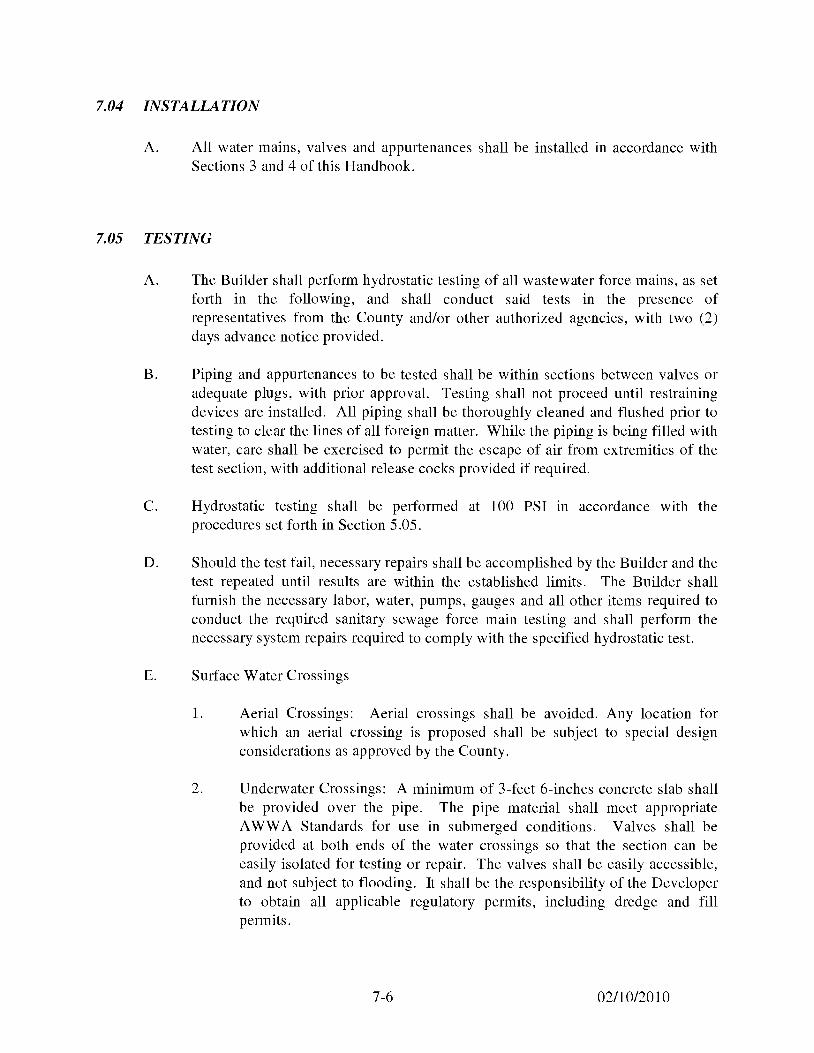
7.04 INSTALLATION
A. All water mains, valves and appurtenances shall be installed in accordance with Sections 3 and 4 of this Handbook.
7.05 TESTING
A. The Builder shall perform hydrostatic testing of all wastewater force mains, as set forth in the following, and shall conduct said tests in the presence of representatives from the County and/or other authorized agencies, with two (2) days advance notice provided.
B. Piping and appurtenances to be tested shall be within sections between valves or adequate plugs, with prior approval. Testing shall not proceed until restraining devices are installed. All piping shall be thoroughly cleaned and flushed prior to testing to clear the lines of all foreign matter. While the piping is being filled with water, care shall be exercised to permit the escape of air from extremities of the test section, with additional release cocks provided if required.
C. Hydrostatic testing shall be performed at 100 PSI in accordance with the procedures set forth in Section 5 .05.
D. Should the test fail, necessary repairs shall be accomplished by the Builder and the test repeated until results are within the established limits. The Builder shall furnish the necessary labor, water, pumps, gauges and all other items required to conduct the required sanitary sewage force main testing and shall perform the necessary system repairs required to comply with the specified hydrostatic test.
E. Surface Water Crossings
1. Aerial Crossings: Aerial crossings shall be avoided. Any location for which an aerial crossing is proposed shall be subject to special design considerations as approved by the County.
2. Underwater Crossings: A minimum of 3-feet 6-inches concrete slab shall be provided over the pipe. The pipe material shall meet appropriate AWWA Standards for use in submerged conditions. Valves shall be provided at both ends of the water crossings so that the section can be easily isolated for testing or repair. The valves shall be easily accessible, and not subject to flooding. It shall be the responsibility of the Developer to obtain all applicable regulatory permits, including dredge and fill permits.
7-6 02/10/2010
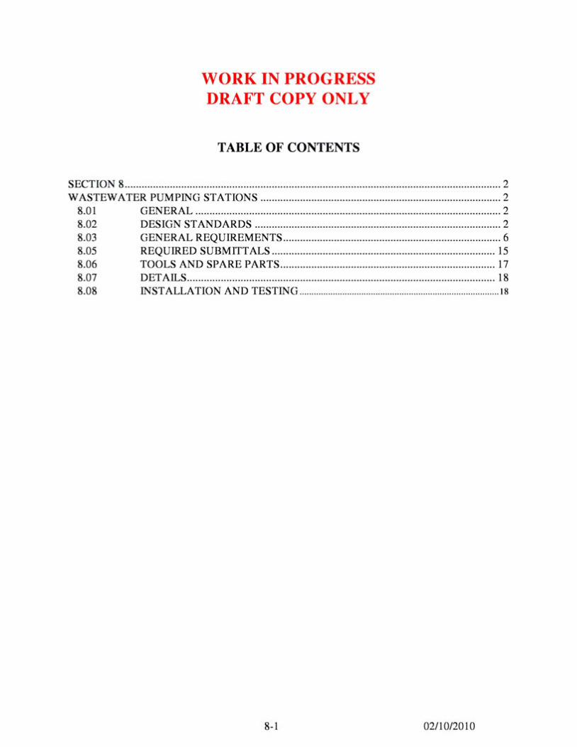
WORK IN PROGRESS DRAFT COPY ONLY
TABLE OF CONTENTS
SECTION 8 .. ............................... ... .. ............................................................................................... 2 WASTEWATER PUMPING STATIONS ..................................................................................... 2
8.01 GENERAL ............................................................................................................ 2 8.02 DESIGN ST AND ARDS ....................................................................................... 2 8.03 GENERAL REQUIREMENTS ............................................................................. 6 8.05 REQUIRED SUBMITTALS ............................................................................... 15 8.06 TOOLS AND SPARE PARTS ............................................................................ 17 8.07 DETAILS............................................................................................................. 18 8.08 INSTALLATION AND TESTING .................................................................................... 18
8-1 02/10/2010
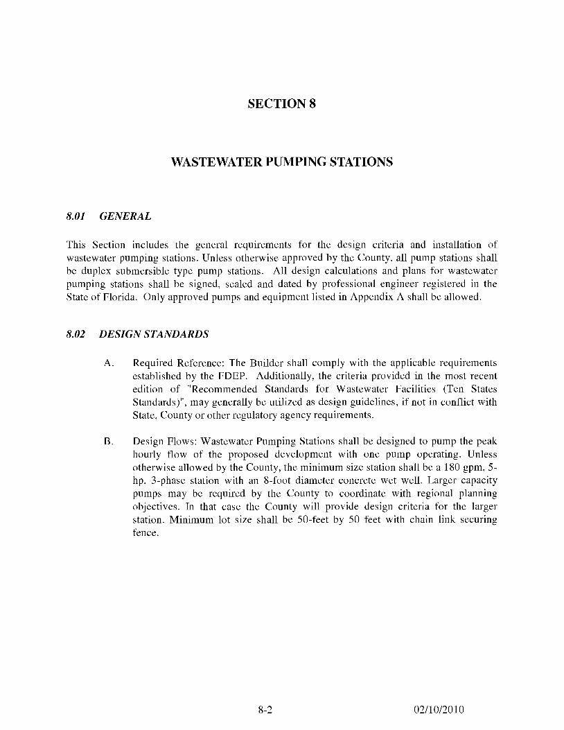
SECTION 8
WASTEWATER PUMPING STATIONS
8.01 GENERAL
This Section includes the general requirements for the design criteria and installation of wastewater pumping stations. Unless otherwise approved by the County, all pump stations shall be duplex submersible type pump stations. All design calculations and plans for wastewater pumping stations shall be signed, sealed and dated by professional engineer registered in the State of Florida. Only approved pumps and equipment listed in Appendix A shall be allowed.
8.02 DESIGN STANDARDS
A. Required Reference: The Builder shall comply with the applicable requirements established by the FDEP. Additionally, the criteria provided in the most recent edition of "Recommended Standards for Wastewater Facilities (Ten States Standards)", may generally be utilized as design guidelines, if not in conflict with State, County or other regulatory agency requirements.
B. Design Flows: Wastewater Pumping Stations shall be designed to pump the peak hourly flow of the proposed development with one pump operating. Unless otherwise allowed by the County, the minimum size station shall be a 180 gpm, 5-hp, 3-phase station with an 8-foot diameter concrete wet well. Larger capacity pumps may be required by the County to coordinate with regional planning objectives. In that case the County will provide design criteria for the larger station. Minimum lot size shall be 50-feet by 50 feet with chain link securing fence.
8-2 02/10/2010
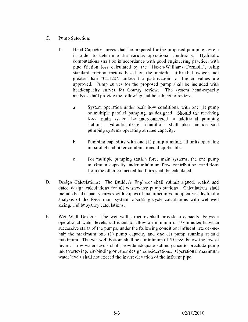
C. Pump Selection:
1. Head-Capacity curves shall be prepared for the proposed pumping system in order to determine the various operational conditions. Hydraulic computations shall be in accordance with good engineering practice, with pipe friction loss calculated by the "Hazen-Williams Formula", using standard friction factors based on the material utilized; however, not greater than "C=l20", unless the justification for higher values are approved. Pump curves for the proposed pump shall be included with head-capacity curves for County review. The system head-capacity analysis shall provide the following and be subject to review.
a. System operation under peak flow conditions, with one (1) pump or multiple parallel pumping, as designed. Should the receiving force main system be interconnected to additional pumping stations, hydraulic design conditions shall also include said pumping systems operating at rated capacity.
b. Pumping capability with one (1) pump running, all units operating in parallel and other combinations, if applicable.
c. For multiple pumping station force main systems, the one pump maximum capacity under minimum flow contribution conditions from the other connected facilities shall be calculated.
D. Design Calculations: The Builder's Engineer shall submit signed, sealed and dated design calculations for all wastewater pump stations. Calculations shall include head capacity curves with copies of manufacturers pump curves, hydraulic analysis of the force main system, operating cycle calculations with wet well sizing, and buoyancy calculations.
E. Wet Well Design: The wet well structure shall provide a capacity, between operational water levels, sufficient to allow a minimum of IO-minutes between successive starts of the pumps, under the following condition: Influent rate of one-half the maximum one (1) pump capacity and one (l) pump running at said maximum. The wet well bottom shall be a minimum of 5.0-feet below the lowest invert. Low water levels shall provide adequate submergence to preclude pump inlet vortexing, air-binding or other design considerations. Operational maximum water levels shall not exceed the invert elevation of the influent pipe.
8-3 02/10/2010
In general, the normal operational water level shall provide a positive suction head for the sewage pumps. Operational maximum or high water levels shall not exceed the inven elevation of the lower influent pipe, with hi ,h wat~r alarm no higher than .8 point of said Qi e. No interior ladders shall be permitted in the wet well. Only one ( 1) inlet connection shall he permitted to a wet well, unless approved by the County.
Buoyancy calculations verifying that adequate provmons have been made to prevent wet well floatation shall be submitted to the County. These calculations shall assume that the wet well is empty.
F. Vcntilation: Wct wells for suhmcrsihle installations or others, without free access, shall be ventilated with not less than one ( 1) 4-inch diameter open vent pipe.
G. Water System: The wastewater pump stations shall be provided with a water system with adequate capacity and pressure for station wash down and other requirements. The station water system shall he completely separated from the potable water supply by means of a reduced pressure backtlow preventer or other County approved system.
H. Emergency Operation: All pump stations shall be provided with emergency power receptacles as specified herein.
I. Site: Pumping stations shall be installed on off-the-right-of-way, readily accessible sites, and shall he a minimum dimension of 50-feet by 50-feet. The site shall be readily accessihle by maintenance vehicles during all weather conditions. The wastewater pumping station structures and electrical and mechanical equipment shall be protected from physical damage by the 100 year flood. The wastewater pumping stations should remain fully operational and accessible during 100 year flood events. Regulations of the County, State and Pedcral agencies regarding flood plain obstructions shall he considered.
The pump station sites shall he sized and dedicated easements shall also be required around the site as delineated on the "Pump Station Site Plan" in the Standard Drawings. The Builder shall dedicate the pump station site hy warranty deed or plat to the County. All pump station sites shall be fenced unless otherwise approved hy County.
8-4 02/10/2010
J. General: A site plan must be provided indicating the following:
1. The station must be referenced to the nearest street.
2. Adequate access.
3. Drainage provisions.
4.. Auxiliary power plug or the generator location and automatic power transfer switch.
5. The power pole location.
6. The water meter with backflow prevention and hose bib location.
7. The pumping station site plan must indicate what landscaping the developer will provide.
8. Pump and pump station specifications and performance data must be provided. This should include:
a. An operator's manual.
b. Attached to the control panel a layout block diagram showing location of different components.
c. The performance curves for the pump submitted must show that it will operate generally in the center part of the curve and not approach either upper or lower extreme.
d. An electrical schematic and wiring diagram including a parts schedule containing information on type, model and rating of components.
e. Motor controls should include backspin motor protection.
8-5 02/10/2010
9. Emergency alarm system circuitry must be installed.
10. All wiring must be copper.
11. All outside enclosures must be Nema 3R (stainless steel).
12. The electric meter should face the fence so that it can be easily read from the outside fence.
8.03 GENERAL REQUIREMENTS
A. Piping Systems:
1. Approved Pipe, Fittings and Valves: The following material or item shall be suitable for the indicated operational service:
a. Gravity Sewer and Force Main Influent Pipe, and Fittings: All influent piping to the wet well shall meet the requirements of Sections 4, 7 and 8 of this Handbook.
b. Wastewater Pressure Pipe and Fittings: Discharge piping from the pump station through the valve vault shall be bituminous coated DI pipe meeting the requirements of Section 7 and 8.
c. Wastewater Service Valves: Plug valves with operators for underground or exposed service and check valves shall meet the requirements outlined in Sections 4.03C and 4.03D of this Handbook.
d. Potable or Non-Potable Water: PVC pipe and fittings, with appropriate gate valves.
2. Wall Pipes, Boots or Sleeves: For pipes passing through structural walls, wall pipes or boots shall be installed where the location is below the surface of the ground or at any point where water levels will exceed the installed pipe elevation. Sleeves with watertight caulking shall be suitable at other locations.
8-6 02/10/2010
B. Valves:
1. Check Valves: Check valves for DI pipelines shall be swing type and shall meet the requirements of AWWA C-500 and Section 4.03C of this Handbook.
2. Plug Valves: Plug valves for DI pipelines shall be swing type and shall meet the requirements of AWWA C-504 and C-507, and Section 4.03D of this Handbook.
C. Pressure Gauges: Gauges shall be provided on each wastewater pump discharge pipe, as well as other locations where pressure sensing is desirable.
D. Emergency Valving Connections: Emergency valving connections shall be provided for within the valve box as shown on the drawing details (Figure 301) in Appendix D of this handbook.
E. Surge Control: Surge control valves, or other approved systems shall be provided for all wastewater pumping stations where hydraulic conditions indicate the necessity.
F. Wastewater Pumps and Motors:
1. General: The wastewater pumping units shall be capable of handling raw, unscreened wastewater and shall be capable of passing a sphere of at least 3-inches in diameter. Pumps shall be electric motor driven and of a proven design that has been in sewage service under similar conditions for at least five (5) years. Pumps shall provide the required peak design performance requirements and be suitable for operation within the total hydraulic range of operation.
2. Submersible Pumps: The pump design shall provide easy removal and replacement for inspection or maintenance purposes, without bolts or other fastenings to be removed. The units shall be non-clog, mechanical seal, and submersible sewage pumps.
3. Shaft: The pump shaft shall be of Series 300 or 400 stainless steel or carbon steel. When a carbon steel shaft is provided, the manufacturer shall demonstrate that any part of the shaft which will normally come in contact with the wastewater has proven to be corrosion resistant in this application. The shaft and bearings shall be adequately designed to meet the maximum torque required for start-up or operating condition and to minimize vibration and shaft deflection. As a minimum, the pump shaft shall rotate on two (2) permanently lubricated bearings. The upper bearing
8-7 02/10/2010
shall be a single row ball bearing. The lower ball bearing shall be a two (2) row angular contact ball bearing, if required to minimize vibration and provide maximum bearing life.
4. Impeller: The impeller shall be constructed of gray cast iron, ASTM A48, Class 30. Each pump shall be provided with a replaceable metallic wear ring system to maintain pump efficiency. As a minimum one (1) stationary wear ring provided in the pump volute or one (1) rotating wear ring provide on the pump impeller shall be required. In addition, a two (2) part system is acceptable.
5. Mechanical Seal: Each pump shall be provided with a tandem double mechanical seal running in an oil reservoir, composed of two (2) separate lapped face seals, each consisting of one (1) stationary and one (1) tungsten carbide ring with each pair held in contact by a separate spring, so that the outside pressure assists spring compression in preventing the seal faces from opening. The compression spring shall be protected against exposure to the wastewater. Silicone carbide may be used in place of tungsten carbide for the lower seal. The pumped liquid shall be sealed from the oil reservoir by one ( 1) face seal and the oil reservoir from the air-filled motor chamber by the other. The seals shall require neither maintenance nor adjustment, and shall be easily replaced. Conventional double mechanical seals with a single spring between the rotating faces, requiring constant differential pressure to effect sealing and subject to openings and penetration by pumping forces shall not be considered equal to tandem seal specified and required.
6. Guides: A sliding bracket shall be an integral part of the pump casing and shall have a machined connecting flange to connect with the cast iron discharge connection, which shall be bolted to the floor of the wet well with stainless steel anchor bolts and so designed as to receive the pump discharge flange without the need of any bolts or nuts. Sealing of the pumps to the discharge connection shall be accomplished by a simple linear downward motion of the pump with the entire weight of the pumping unit guided by no less than two (2) Type 316 seamless tubular stainless steel guides which will press it tightly against the discharge connection. No portion of the pump shall bear directly on the floor of the wet well and no rotary motion of the pump shall be required for sealing. Sealing at the discharge connection by means of a diaphragm or similar method of sealing shall not be accepted as an equal to a metal to metal contact of the pump discharge and mating discharge connection specified and required. Approved pump manufacturers, if necessary to meet the above specification, shall provide a sliding guide bracket adapter. The design shall be such that the pumps shall be automatically connected to the discharge piping when lowered into place on the discharge connection.
8-8 02/10/2010
The pumps shall be easily removable for inspection or service, requiring no bolts, nuts, or fastenings to be removed for this purpose, and no need for personnel to enter the wet well. Each pump shall be fitted with a Type 304 stainless steel, wire rope of adequate strength. A stainless steel cable, air craft rating, shall be provided between the cable holder and the lifting chain.
7. Pump Motors: All motors shall be built in accordance with the latest NEMA, ANSI, IEEE and AFBMA standards where applicable. Pump motors shall be housed in an air-filled, water tight casing and shall have Class F insulated windings which shall be moisture resistant. Motors shall be NEMA Design B, rated 155 degrees Celsius maximum. Pump motors shall have cooling characteristics suitable to permit continuous operation, in a totally, partially or non-submerged conditions. The pump shall be capable of running continuously in a non-submerged condition under full load without damage, for extended periods. The motor shall be capable or a minimum of 10 starts per hour. If required by the County, before final acceptance, a field running test demonstrating this ability, with 24 hours of continuous operation under the above conditions, shall be performed for all pumps being supplied. Motors less than 30 horsepower shall be 230/460 volt, 3-phase. Motors 30 horsepower and greater shall be 460 volt, 3-phase. All pump motors shall be designed with a 1.15 service factor and shall not be less than 5-horsepower (hp) unless approved. Pumps shall be capable of meeting all pump curve conditions without exceeding the motor's rated horsepower.
Two (2) or more normally closed heat sensing miniature switches connected in series and embedded within the motor windings shall be provided. In addition, the motor shall incorporate one (l) motor sensing device. These protective devices shall be wired into the pump controls in such a way that if excessive temperature or moisture is detected the pump will shut down. These devices shall be self-resetting.
Cables shall be designed specifically for submersible pump applications and shall be properly sealed. A type CGB water-tight connector with a neoprene gland shall be furnished with each pump to seal the cable entry at the control panel. The pump cable entry seal design shall preclude specific torque requirements to insure a water-tight and submersible seal. The cable entry shall be comprised of a single cylindrical elastomer grommet, flanked by washers, all having a close tolerance fit against the cable outside diameter and the entry inside diameter and compressed by the entry body containing a strain relief function, separate from the function of sealing the cable. The assembly shall bear against a shoulder in the pump top. The cable entry junction chamber and motor shall be separated by a stator lead sealing gland or terminal board, which shall isolate the motor
8-9 02/10/2010
interior from foreign material gammg access through the pump top. Secondary sealing systems utilizing epoxy potting compounds may be used. When this type of sealing systems is used the manufacturers shall supply a cable cap as part of the spare parts for each pump. All cables shall be continuous, without splices from the motor to the control panel. The junction chamber, containing the terminal board, shall be perfectly leak proof.
G. Pump Control Panel:
1. The control panel shall respond to liquid level float switches to automatically start and stop pumps, as well as sound an alarm upon high or low wet well levels. The control panel shall operate two (2) electrical submersible pumps at the power characteristics stipulated. The control function shall provide for the operation of the lead pump under normal conditions. If the incoming flow exceeds the pumping capacity of the lead pump, the lag pump shall automatically start to handle this increased flow. As the flow decreases, the pumps shall be cutoff at the specified elevation. The pumps shall alternate positions as lead pump at the end of each cycle. A failure of the alternator shall not disable the pumping system. The alternator shall include a safe, convenient method of manual alternation and also have provisions to prevent automatic alternation without disturbing any wiring. Should the "pump off" regulator fail, the system shall keep the station in operation and provide a visual indication of the regulator failure.
The control panel shall consist of main circuit breakers and generator breaker with mechanical interlock, an emergency power receptacle, a circuit breaker and magnetic starter for each pump motor, and 15 ampere, 120 volt circuit breakers as required. All pump control operations shall be accomplished by a float type liquid level control system with all control components mounted in one (l) common enclosure. Control switches shall provide means to operate each pump manually or automatically. When operated in the automatic mode, the control assembly shall provide means to manually select or automatically alternate the position of the "lead" and "lag" pumps after each pumping cycle. A float type liquid level control system shall continuously monitor wet well liquid level and control operation of the low-level cutoff for the pumps and shall operate off a 24 volt circuit.
2. Panel Construction: The panel shall be housed in a NEMA 3R, Type 304, 14 gauge stainless steel enclosure with 30 percent extra mounting space for additional equipment. The enclosure shall use a three point door latch and have provisions for padlocking the door and a dead front inner door unit for mounting controls. All exterior hardware and hinges shall be
8-10 02/10/2010
stainless steel. In addition, there shall be permanently affixed to the interior side of the exterior door both a nameplate and a 10-inch by 12-inch pocket for log sheet storage. The nameplate shall contain the following information, voltage, phase, rated horsepower, speed, date manufactured, and pump and control panel manufacturer's name, address and telephone number, pump data, including impeller data, operating point and head, KW input, and amps at the operating point and at least two (2) other points on the pump curve.
3. Power Supply and Main Disconnect: The power supply to the control panel shall be 240 volt, 3-phase, 4 wire or 480 volt, 3-phase, 4 wire. Minimum service shall be 200 amps. Single phase power shall not be accepted. Nonfusible safety service main disconnects shall be installed at all stations. In all 240 or 480 volt systems, disconnects should be installed between the meter and the panel. LED power available indicators shall be supplied on all legs.
4. Circuit Breakers:
a. Main Breakers: The panel shall have an inter-lock system between the normal power main breaker and the emergency breaker to ensure only one (1) breaker in the "on" position at a time. Both breakers shall be equal in size.
b. Circuit Breakers: All circuit breakers shall be heavy duty molded case breakers. The handle on the circuit breakers shall be operational through the inner door.
5. Motor Circuit Protectors: Each pump shall be protected by a 3-pole motor circuit protector. The motor circuit protector shall be operated by a toggle-type handle and shall have a quick-make, quick-break over-center switching mechanism that is mechanically trip-free from the handle so that the contacts cannot be held closed against a short circuit and abnormal currents which cause the motor circuit breaker to trip. Tripping shall be clearly indicated by the handle automatically assuming a position midway between the normal "on" and "off" positions. All latch surfaces shall be ground and polished. All poles shall be so constructed so that they open, close, and trip simultaneously. Motor circuit protector must be completely enclosed in a high-strength glass polyester molded case. Ampere ratings shall be clearly visible. Contacts shall be of non-welding silver alloy. Arc extinction must be accomplished by means of arc chutes. A manual push-to-trip button shall be provided for manual exercising of the trip mechanism. Each pole of these motor circuit protector's shall provide instantaneous short circuit protection by means of an adjustable magnetic-only element.
8-11 02/10/2010
6. Motor Starter and Selector Switches: The panel shall contain two (2) motor starters. The motor starter shall be across the line magnetic starter with individual overload protection on each lower leg with reset installed through the inner door unit. Selector switches shall be installed on the face of the inner door unit. Selector switch shall be a heavy duty oil tight "Hand-Off-Automatic" three (3) position switch to control the operation mode of each pump motor starter.
7. Pump Alternator: An eight (8) pin plug-in solid state alternator shall be provided to change the pump starting sequence on each pumping cycle. A three ( 3) position alternator test switch shall be provided to control the alternation operation. Switch positions to include the "Auto" to provide normal automatic sequence, "Off" position to disable alternator, and "Test" position with a spring return to allow the alternating of the pump sequence to check alternator operation.
8. Lights and Alarms:
a. Indicator Lights: There shall be installed on the face of the inner door unit, heavy duty oil tight indicator lights as shown on the Standard Drawings.
b. High Level Alarm: A vapor proof red light and horn shall be mounted on the top of the panel for high level alarm. In addition, there shall be an alarm silence push-button on the exterior right hand side of the panel and a silence relay which will silence the horn and automatically reset when these signals are restored to normal. The push-button shall be heavy duty oil tight. The red globe shall be the screw-on type.
9. Emergency Power Receptacle: The control panel shall have an external mounted generator receptacle of the required size and type as indicated in Appendix A.
8-12 02/10/2010
10. Additional Requirements:
a. All power wires shall be THW or THWN 75° Celsius insulated stranded copper conductors and shall be appropriately sized for the given load application. All control circuit wire shall be type THW, Size 14, stranded wire type. All wiring within the enclosure shall be neatly routed by the use of slotted wiring duct with snap on type covers. Wiring on the rear of the inner door shall be neatly bundled with nylon ties and include sufficient loop across the hinges to prevent wire damage, with each end of the conductor marked as indicated below:
(l) 24 volt: red. (2) Neutral: white. (3) 120 volt: black.
b. Terminal points of all terminal strips shall be permanently identified. All terminal numbers and identifying nomenclature shall correspond to and be shown on the electrical diagrams. All wiring shall be permanently shown on the electrical drawings.
c. All circuit breakers, control switches, indicator pilot lights and other control devices shall be identified with permanently affixed legend plates and lamicoid-type engraved nameplates.
d. A surge protector shall be included and wired to protect motors and control equipment from lightning induced line surges. All surge protectors shall be Underwriter's Laboratories (UL) approved and installed per the respective power company requirements and manufacturer's specifications, surge protectors shall be attached to the main disconnects.
e. Elapsed time meters shall be 115 volt not-reset type and shall totalize pump running time in hours and tenths of hours to 99999 .9 hours.
f. On the face of the inner door unit, there shall be installed a 15 amp, 120 volt, duplex convenience receptacle. It shall be provided with it's own single pole, 15 amp circuit breaker for protection. Ground fault interrupt type shall be required.
8-13 02/10/2010
g. Control terminal blocks shall be of the clamp screw type, rated for 600 volts. Amperage rating shall accommodate the control circuit amperage. An additional 30 space terminal strip shall be installed in the cabinet for future use, with R TU equipment.
h. There shall be a control power transformer with a minimum size of 500V A to provide 120V A power for: coils for starters, 15A duplex receptacle, indicator pilot lights, alarm horn, alarm light, pump alternator, elapsed time meters, etc. The secondary side shall have one (l) leg fused and the other grounded. This control power transformer is required only on 480 volt control panels. The signal required by the float switches and relays shall be 24V AC. This shall be provided by a 24V AC control power transformer properly sized with a fused secondary.
H. Fencing:
1. The builder shall furnish and erect the chain link fence and gate around the pump station site as shown on the pump station site plan. The fabric, posts, fastenings, fittings, and other accessories for chain link fence shall meet the requirements of AASHTO M 181 with the following revisions:
a. The weight of coating of wire fabric shall be 1.2 ounces of zinc per square foot (Class B).
b. The galvanizing of steel materials shall be hot-dipped galvanized.
c. The weight of the coating on posts and braces shall be 1.8 ounces of zinc per square foot, both inside and outside to meet the requirements of AASHTO M 111.
2. The base metal of the fabric shall be a good commercial quality 9 Gage Steel wire. The fabric shall be of uniform quality, and shall be 6-feet high with a 2-inch mesh size.
8-14 02/10/2010
3. All posts and rails shall be in accordance with the following schedule:
a. End, corner and pull posts: 2-3/8-inches outside diameter (OD), Schedule 40.
b. Line posts and gate frames: 2-inches OD, Schedule 40.
c. Gate posts: 3-inches OD, Schedule 40.
d. Post braces and top rail: 1-5/8-inches OD, Schedule 20.
4. Tension wire shall be 0.177-inch coiled spring wire tensioned along the bottom of the fabric and shall be coated similarly to the wire fabric.
5. Miscellaneous fittings and hardware shall be zinc coated commercial quality or better steel or zinc coated cast or malleable iron as appropriate.
6. Post caps, designed to provide a drive fit over the top of the tubular post to exclude moisture, shall be provided.
7. Barb wire along top of fence (3 strands @ 45° angled out).
8.05 REQUIRED SUBMITTALS
8-15 02/10/2010
A. The Builder shall provide to the County in triplicate in the English language the following information regarding the wastewater pumping equipment:
1. Shop and erection drawings showing all important details of construction, dimensions and anchor bolt locations.
2. Descriptive literature, bulletins, and/or catalogs of the equipment.
3. Data on the characteristics and performance of each pump. Data shall include guaranteed performance curves, based on actual shop tests of similar units, which show that they meet the specified requirements for head, capacity, efficiency, NPSHR, submergence and horsepower. Curves shall be submitted on 8 1/2-inch by 11-inch sheets, at as large a scale as is practical. Curves shall be plotted from no flow at shut off head to maximum manufacturer recommended pump capacity. Catalog sheets showing a family of curves will not be acceptable.
4. Complete layouts, wiring diagrams, elementary or control schematics, including coordination with other electrical control devices operating in conjunction with the pump control system. Suitable outline drawings shall be furnished for approval before proceeding with the manufacture of any equipment. Standard preprinted sheets or drawings simply marked to indicate applicability will not be accepted.
5. A drawing showing the layout of the pump control panel shall be furnished. The layout shall indicate all devices mounted on the door and in the panel shall be completely identified.
6. The weight of each pump.
8-16 02/10/2010
7. Complete motor data shall be submitted including:
a. Nameplate identification.
b. No-load current.
C. Full load current.
d. Full load efficiency.
e. Locked rotor current.
f. High potential test data.
g. Bearing inspection report.
8.06 TOOLS AND SPARE PARTS
A. One (l) set of all special tools required for normal operation and maintenance shall be provided. All such tools shall be furnished in a suitable steel tool chest complete with lock and duplicate keys.
B. Spare parts shall be properly packaged and labeled for easy identification without opening the packaging and suitably protected for long term storage under humid conditions. The manufacturer shall furnish the following spare parts for each pump supplied:
1. One (1) upper bearing.
2. One (1) lower bearing.
3. One (1) set of upper and lower shaft seals.
4. One (1) set of "0-Rings" or gaskets required for replacement of bearings and seals.
5. One (1) impeller wear ring.
6. One (1) shaft sleeve, if applicable.
7. One (1) cable cap, if applicable.
8-17 02/10/2010
8.07 DETAILS
Pump station details shall be as set forth in this Handbook.
8.08 INSTALLATION AND TESTING
A. The pump station, pumps, controls, electrical, p1pmg, valves and associated appurtenances shall be installed in accordance with Sections 3 and 4 of this Handbook.
B. A factory representative knowledgeable in pump operation and maintenance shall inspect and supervise a test run at the pumping station. A minimum of one working day shall be provided for the inspections. Additional time made necessary by faulty or incomplete work or equipment malfunctions shall be provided as necessary to meet the requirements in this Handbook at no additional cost to the County. Upon satisfactory completion of the test run, the factory representative shall issue the required manufacturer's certificate.
The test run shall demonstrate that all items of this Handbook have been met by the equipment as installed and shall include, but not limited to, the following tests:
1. That all units have been properly installed.
2. That the units operate without overheating or overloading any parts and without objectionable vibration.
3. That there are no mechanical defects in any of the parts.
4. That the pumps can deliver the specified pressure and quantity.
5. That the pumps are capable of pumping the specified material.
6. That the pump controls perform satisfactorily.
8-18 02/10/2010
C. Warranty and Service:
1. Warranty: The products shall be guaranteed to be free from defects in material and workmanship under normal use and service for a period of one year after start-up.
2. Service: Service shall be available for insitu repair of the products. Manufacturer's repair personnel shall be based in Florida to insure a reasonable response time of not more than two working days.
8-19 02/10/2010
WC)RK IN PRC)GRESS DRAFT CC)PY ONLY
SECTION 9
REUSE DISTRIBUTION SYSTEMS
9.01 GENERAL
A. This Section sets forth the general requirements for design and installation of public access reuse irrigation systems. Pipe used in reclaimed water irrigation systems shall be PVC pipe as specified in Section 4 of this Handbook.
The Contractor shall be responsible for all materials furnished and storage of same, until the date of substantial completion. The Contractor shall replace at the Contractors expense all material found to be damaged or defective in handling or storage. The Contractor shall, if requested by the County, furnish certificates, affidavits of compliance, test reports, or samples for check analysis for any of the materials specified in this Handbook as it relates to reclaimed water irrigation systems. All pipe delivered to the project site for installation is subject to random testing for compliance with the designated specifications.
9.02 DESIGN STANDARDS
A. Required Reference: The Builder shall comply with the design and installation requirements as established by the FDEP and additional specific requirements stated in this Handbook.
B. System Design:
1. Normal Flow Demands: Irrigation demands shall be determined using the method described previously in this Handbook.
2. System Size Computation: The allowable minimum service pressure under said design condition shall not be less than 30 PSI. Design computation shall be by the "Hardy Cross" procedure, or other applicable methods, as dictated by the system configuration. Design flows and method of computation shall be subject to review and approval. These calculations shall be signed, sealed and dated by a professional engineer registered in the State of Florida.
9-1 02/10/2010
3. Valve Locations: Valves shall be provided for all branch connections, main ends, fire hydrant stubs or other locations, as required to provide an operable, easily maintained and repaired distribution system. Valves are to be placed so that the maximum allowable length of reuse main required to be shut-down for repair work shall be 500-feet in commercial, industrial or high density residential districts, or 1000-feet in other areas.
C. Location: Reclaimed water reuse mains shall be located in dedicated rights-of-way or utility easements. When installed in rights-of-way, reuse mains shall maintain a consistent alignment with respect to the centerline of the road. All reuse mains located outside of dedicated rights-of-way shall require a minimum 20-foot wide easement. Water mains shall be located in dedicated rights-of-way or utility easements. When installed in rights-of-way, water mains shall, in general, maintain a consistent alignment with respect to the centerline of the road. If a potable water main is located adjacent to road rights-of-way, a minimum 10-foot easement shall be provided. Additional easement widths shall be provided when the pipe size or depth of cover so dictates. No reclaimed water reuse mains shall be placed under retention ponds or drainage ditches, tennis courts, or other structures. In general, water mains shall not be located along side or rear lot lines. Placement of a reclaimed water reuse main along side or rear lot line may be allowed on a case by case basis if such a reclaimed reuse water main configuration results in efficient placement and utilization of the water distribution system.
D. The Builder's Engineer shall submit signed, sealed and dated design calculations with the Drawings for all reclaimed water reuse irrigation projects. The calculations shall show that the reclaimed water reuse distribution mains will have sufficient hydraulic capacity to transport peak hourly flows and the combination of maximum daily flows while meeting a minimum pressure of not less than 30 PSI. Head losses through meters and backflow devices shall also be included in the calculations. Design computations shall be by the "Hardy-Cross" procedure, or other applicable methods, as dictated by the system configuration.
9.03 STANDARD REQUIREMENTS
A. Approved Pipe, Fittings and Valves: All PVC pipe of nominal diameter of 4-inches through 16-inches shall be manufactured in accordance with AWWA Standard C-900 and shall meet the requirements of Section 4.02C of this Handbook. The PVC pipe shall be purple in color (per FDEP standard) and have a minimum working pressure rating of 150 PSI. Pipe shall have a dimension ratio of 18. The pipe shall be the same outside diameter as DI pipe.
1. Joints: PVC pipe shall have integral bell push on type Jomts conforming to ASTM D3139. Joints for DI pipe and fitting joints shall be push-on or mechanical joints conforming to ANSI/ A WWA A21. ll/C- ll 1. Where called for by County restrained or flanged joints will be required. Restrained joints shall
9-2 02/10/2010
meet the requirements of Section 4.02F of this Handbook. Flanged joints shall conform to ANSI Standard B16.1, 125 lb.
2. Fittings: All fittings shall be mechanical joint DI or gray iron conforming to ANSI/AWWA A21.10/C-110, 250 PSI minimum pressure rating.
B. Joint Restraining: Pressure piping fittings and other items requiring restraint, shall be braced with restraining assemblies, as specified under Section 4. Said restraining devices shall be designed for the maximum pressure condition (testing).
C. Pipe Depth and Protection: The standard minimum cover for reclaimed water reuse distribution systems shall be 3-feet from the top of the pipe to finish grade. Should this design not be feasible, alternatives shall be reviewed for acceptance.
D. Pipe Bedding: Special care shall be exercised in design and installation to provide adequate bedding for the type of pipe used, taking into consideration trench width and depth, superimposed loadings above grade and the material below trench grade. Pipe loading capabilities shall be computed in accordance with established design criteria and special supporting bedding or facilities shall be provided as required.
E. Air Venting and Blow-Offs: Where the reuse main profile is such that air pockets or entrapment could occur, resulting in flow blockage, methods for air release shall be provided. Air venting capabilities shall be provided for distribution mains by appropriately placing fire hydrants, blow-offs or other manual devices. At critical points on major mains, automatic air release assemblies shall be installed. All dead-end reuse mains, temporary or permanent, shall be equipped with a manually operated blow-off at the terminus.
F. Service Connections: All service lines shall be 1-inch, 1 1/2-inch or 2-inch polyethylene tubing conforming to the specifications in A WWA C-800 and C-901. Connections to reclaimed water reuse mains (other than DI), of 4-inches and larger, shall be made by the drilling of the appropriate size hole and the installation of service saddles. Services to smaller size mains shall be accomplished by in-line fittings. A corporation stop shall be placed at the saddle or fitting, with the service line extended perpendicular to said line. Services shall consist of hose bibs. Hose bibs shall be located in below grade jam-lock services boxes which shall be clearly labeled as not of potable water quality. No water service lateral shall parallel adjoining lots, run between neighboring property lines or come through the rear of the property's lot line in order to provide utility service, unless otherwise approved by the County.
G. Identification Tape: Locating tape shall be installed at two depths; directly on top of the pipe and one foot below final grade over the centerline of the pipe. The tape installed one foot below final grade shall be the detectable type; the tape installed directly on top of the
9-3 02/10/2010
pipe may be detectable or nondetectable. The tape shall be laid continuously without gaps between ends over all installed piping. The tape shall have the words "Caution, Reclaimed Water Line Buried Below" printed continuously along its length.
K. Separation of Reclaimed Water Mains from Water Mains and Sewers: Reclaimed reuse water mains that are installed in the vicinity of pipe lines designated to carry potable water and raw wastewater shall meet the horizontal and vertical separations specified herein.
1. Horizontal Separation: Under normal conditions reclaimed reuse water mains shall be located at least 5-feet horizontally from pipes carrying potable water and raw wastewater; the distance shall be measured from the inside edge of pipe to inside edge of pipe. When local conditions prevent a horizontal separation of 5-feet, a water main may be laid closer to a pipe carrying reclaimed water provided that the bottom of the water main is at least 18-inches above the top of the reclaimed water reuse pipe and the water main is laid in a separate trench or on an undisturbed earth shelf.
2. Vertical Separation: Under normal conditions reclaimed water reuse mains shall be laid to provide a separation of at least 18-inches between the bottom of the water main and the top of the reclaimed water reuse main. When construction conditions prevent a vertical separation of 18-inches as described herein above, the reclaimed water pipe shall be constructed of DI pipe with mechanical joints.
3. Crossing of Water Mains and Sewers: Reclaimed water reuse mains shall be installed above sewers whenever they cross. A vertical separation of at least 18-inches shall be maintained between the top of the sewer and the bottom of the reclaimed water reuse main. Adequate structural support for both the reclaimed water reuse main and sewers shall be provided to prevent excessive deflection of joints and settling. Sewers shall be constructed of DI pipe with mechanical joints and the length shall be a minimum of 18-feet. The sewer shall be centered at the point of crossing so that the joints will be equidistant and as far as possible from the reclaimed water reuse main.
L. Surface Water Crossings
1. Aerial Crossings: Aerial Crossings shall be avoided. If an aerial crossing 1s proposed it shall be approved in concept by the County prior to design.
2. Underwater Crossings: A minimum of 3-feet 6-inches concrete slab shall be provided over the pipe. The pipe material shall meet appropriate A WWA Standards for use in submerged conditions. Valves shall be provided at both ends of the water crossings so that the section can be easily isolated for testing or repair. The valves shall be easily accessible, and not subject to flooding. Both valves shall be provided in a manhole or valve vault. It shall be the responsibility
9-4 02/10/2010
of the Developer to obtain all applicable regulatory permits, including dredge and fill permits.
9.04 INSTALLATION
A. All reclaimed water reuse mains, valves and appurtenances shall be installed in accordance with Sections 3 and 4 of this Handbook.
9.05 TESTING
A. The Builder shall perform hydrostatic testing of all reclaimed water reuse distribution systems, as set forth in the following, and shall conduct said tests in the presence of representatives from County or other authorized agencies, with two (2) days advance notice provided. Hydrostatic tests shall be conducted on all newly laid pressure pipes, joints and valves including all service lines to the curb stops. Air testing of pressure pipe will not be permitted under any circumstance. The Contractor shall furnish all necessary equipment and material, make all taps, and furnish all closure pieces in the pipe as required.
1. Piping and appurtenances to be tested shall be within sections between valves, unless alternate methods have received prior approval. Testing shall not proceed until concrete thrust blocks are in place and cured, or other restraining devices installed. All piping shall be thoroughly cleaned and flushed prior to testing to clear the lines of all foreign matter. While the piping is being filled with water, care shall be exercised to permit the escape of air from extremities of the test section, with additional release cocks provided if required. Flushing shall be at full flow conditions and at least 2.5-feet per second flow rate.
2. Hydrostatic testing shall be performed at 150 PSI pressure as described for the testing of potable water mains (Section 5).
9.06 DISINFECTION
A. Following pressure testing, the Builder shall disinfect all sections of the reclaimed water reuse distribution system, and receive approval thereof from the appropriate agencies, prior to placing in service. In addition, any part of the County's reclaimed water reuse system which has direct contact with reclaimed water reuse and has been out of service for repair, alteration, or replacement shall be disinfected. Two (2) days advance notice shall be provided to County before disinfecting procedures start. The disinfection shall be accomplished in accordance with the applicable provisions of AWWA Standard C-651, "Disinfecting Water Mains", and all appropriate approval agencies.
B. Sections of pipe to be disinfected shall first be flushed (full diameter) to remove any solids or contaminated material that may have become lodged in the pipe. All taps
9-5 02/10/2010
required for chlorination or flushing purposes, or for the temporary or permanent release of air shall be provided for by the Contractor as a part of the construction of water mains, all such taps shall be sealed to the satisfaction of the County.
Before being placed into service, all new mains and repaired portions of, or extensions to existing mains shall be chlorinated so that the initial chlorine residual is not less than 50 mg/1 and that a chlorine residual of not less than 25 mg/1 remains in the water after 24 hours in the pipe. Chlorine may be applied as a liquid chlorine (gas-water mixture), or a mixture of water and high-test calcium hypochlorite. The Contractor shall assume the responsibility for safe handling of chlorine and shall meet the requirements of OSHA and other regulatory agencies for safe handling of chlorine.
The preferred point of application of the chlorinating agent shall be at the beginning of the pipe line extension or any valved section of it, and through a corporation stop inserted in the pipe. The water injector for delivering the chlorine-bearing water into the pipe should be supplied from a tap made on the pressure side of the gate valve controlling the flow into the pipe line extension. Alternate points of applications may be used when approved by the County.
Following chlorination, all treated water shall be thoroughly flushed from the newly laid pipe at its extremity until the replacement water throughout its lengths shows upon test, a free chlorine residual not in excess of that normally carried in the system. After flushing, water samples shall be collected on two (2) successive days from the treated piping systems, as directed by the County, shall show acceptable bacteriological results. All bacteriological testing shall be performed by the Developer or Contractor, and must be performed by a laboratory certified by the State of Florida. In addition, proper chain of custody procedures must be followed and samples shall only be collected by certified personnel in the presence of County personnel. Copies of testing results and all related correspondence with the FDSHRS and FDEP shall be submitted to the County.
C. Should the initial treatment result in an unsatisfactory bacterial test, the original chlorination procedure shall be repeated by the Contractor until satisfactory results are obtained.
9-6 02/10/2010
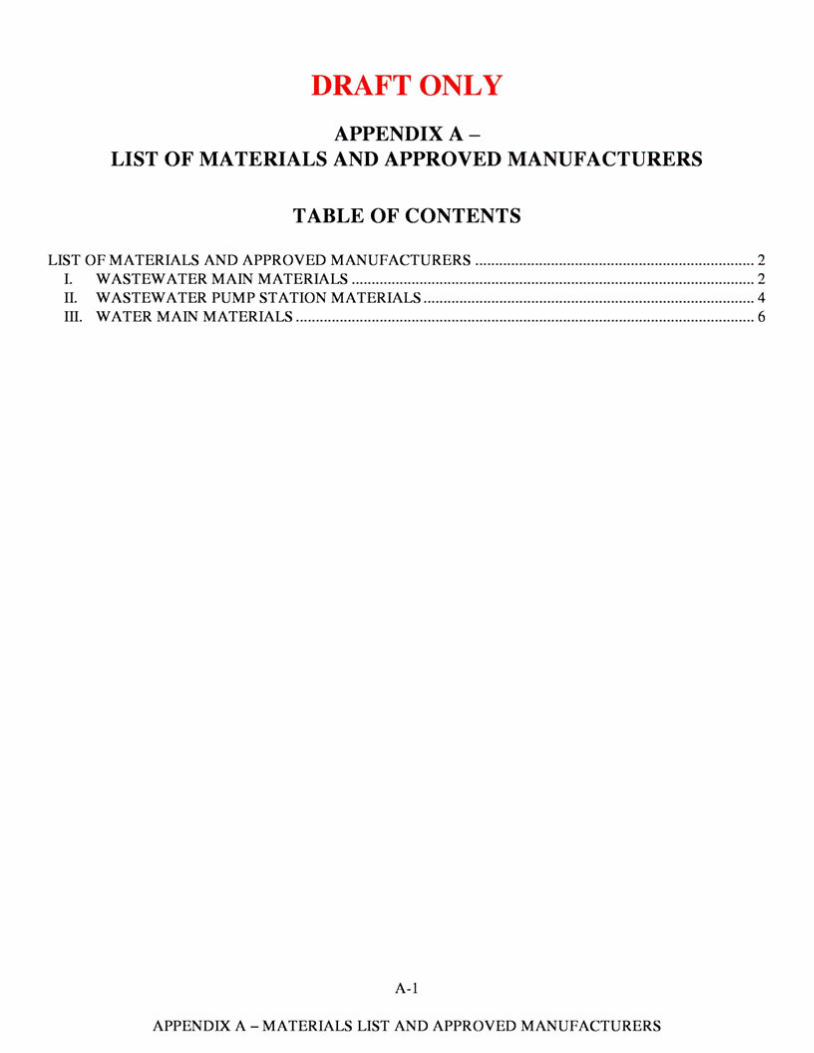
DRAFT ONLY APPENDIXA-
LIST OF MATERIALS AND APPROVED MANUFACTURERS
TABLE OF CONTENTS
LIST OF MATERIALS AND APPROVED MANUFACTURERS ...................................................................... 2 I. WASTEWATER MAIN MATERIALS ..................................................................................................... 2 IL WASTEWATER PUMP ST A TION MATERIALS ................................................................................... 4 III. WATER MAIN MATERIALS ................................................................................................................... 6
A -1
APPENDIX A-MATERIALS LIST AND APPROVED MANUFACTURERS
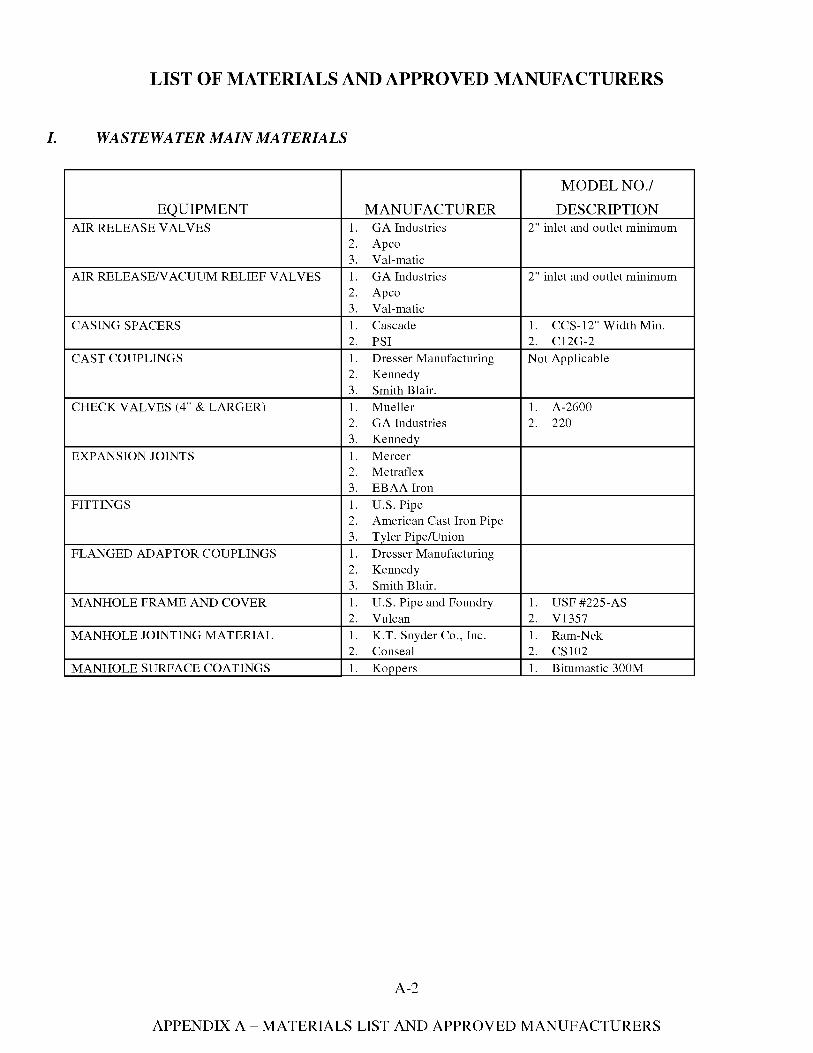
LIST OF MATERIALS AND APPROVED MANUFACTURERS
I. WASTEWATER MAIN MATERIALS
EQUIPMENT AIR RELEASE VALYES 1.
2. 3.
AIR RELEASE/VACUUM RELIEF VALYES 1. 2. 3.
CASING SPACERS 1. 2.
CAST COUPLINGS 1. 2. 3.
CHECK VALVES (4" & LARGER) 1. 2. 3.
EXPANSION JOINTS 1. 2. 3.
FITTINGS 1. 2. 3.
FLANGED ADAPTOR COUPLINGS 1. 2. 3.
MANHOLE FRAME AND COVER 1. 2.
MANHOLE JOINTING MATERIAL 1. 2.
MANHOLE SURFACE COATINGS 1.
MANUFACTURER GA Industries Apco Val-matic GA Industries Apco Val-matic Cascade PSI Dresser Manufacturing Kennedy Smith Blair. Mueller GA Industries Kennedy Mercer Metraflex EBAAiron U.S. Pipe American Cast Iron Pipe Tyler Pipe/Union Dresser Manufacturing Kennedy Smith Blair. U.S. Pipe and Foundry Vulcan K.T. Snyder Co., Inc. Conseal Koppers
MODEL NO./ DESCRIPTION
2" inlet and outlet minimum
2" inlet and outlet minimum
1. CCS-12" Width Min. 2. C12G-2 Not Applicable
1. A-2600 2. 220
1. USF #225-AS 2. Vl357 1. Ram-Nek 2. CS102 1. Bitumastic 300M
A-2
APPENDIX A-MATERIALS LIST AND APPROVED MANUFACTURERS
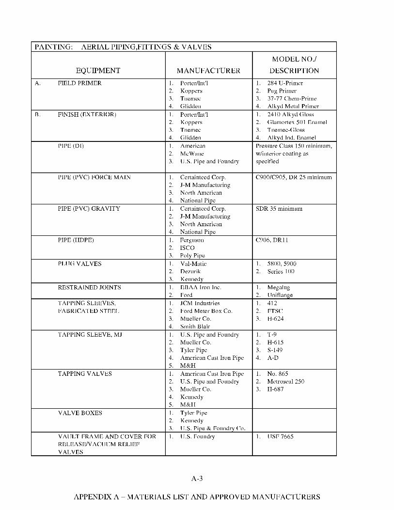
PAINTING: AERIAL PIPING ,FITTINGS & VALVES
MODEL NO./ EQUIPMENT MANUFACTURER DESCRIPTION
A. FIELD PRIMER 1. Porter/Int'l 1. 284 U-Primer 2. Koppers 2. Pug Primer 3. Tnemec 3. 37-77 Chem-Prime 4. Glidden 4. Alkyd Metal Primer
B. FINISH (EXTERIOR) 1. Porter/Int'l 1. 2410 Alkyd Gloss 2. Koppers 2. Glamortex 501 Enamel 3. Tnemec 3. Tnemec-Gloss 4. Glidden 4. Alkyd Ind. Enamel
PIPE (DI) 1. American Pressure Class 150 minimum, 2. McWane w/interior coating as 3. U.S. Pipe and Foundry specified
PIPE (PVC) FORCE MAIN 1. Certainteed Corp. C900/C905, DR 25 minimum 2. J-M Manufacturing 3. North American 4. National Pipe
PIPE (PVC) GRAVITY 1. Certainteed Corp. SDR 35 minimum 2. J-M Manufacturing 3. North American 4. National Pipe
PIPE (HDPE) 1. Ferguson C906, DRll 2. ISCO 3. Poly Pipe
PLUG VALVES 1. Val-Matic 1. 5800,5900 2. Dezurik 2. Series 100 3. Kennedy
RESTRAINED JOINTS 1. EBAA Iron Inc. 1. Megalug 2. Ford 2. Uniflange
TAPPING SLEEVES, 1. JCM Industries 1. 412 FABRICATED STEEL 2. Ford Meter Box Co. 2. FTSC
3. Mueller Co. 3. H-624 4. Smith Blair
TAPPING SLEEVE, MJ 1. U.S. Pipe and Foundry 1. T-9 2. Mueller Co. 2. H-615 3. Tyler Pipe 3. S-149 4. American Cast Iron Pipe 4. A-D 5. M&H
TAPPING VALYES 1. American Cast Iron Pipe 1. No. 865 2. U.S. Pipe and Foundry 2. Metroseal 250 3. Mueller Co. 3. H-687 4. Kennedy 5. M&H
VALVE BOXES 1. Tyler Pipe 2. Kennedy 3. U.S. Pipe & Foundry Co.
VAULT FRAME AND COVER FOR 1. U.S. Foundry 1. USF 7665 RELEASE/VACUUM RELIEF VALVES
A-3
APPENDIX A-MATERIALS LIST AND APPROVED MANUFACTURERS
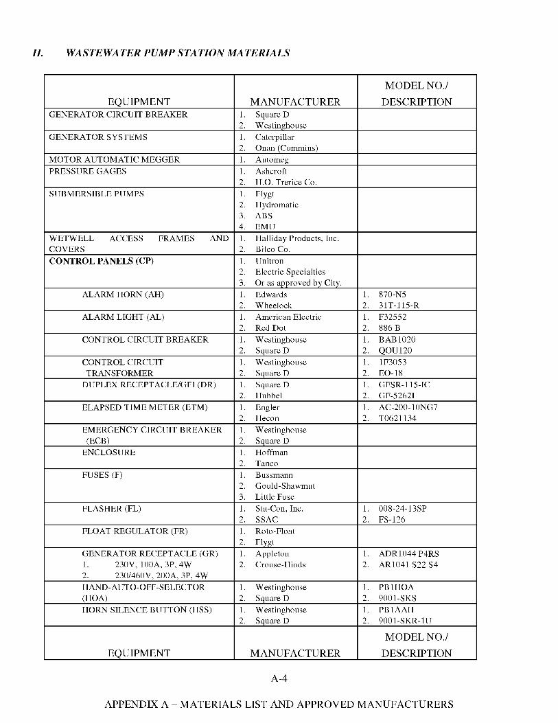
II. WASTEWATER PUMP STATION MATERIALS
EQUIPMENT GENERATOR CIRCUIT BREAKER
GENERATOR SYSTEMS
MOTOR AUTOMATIC MEGGER PRESSURE GAGES
SUBMERSIBLE PUMPS
WETWELL ACCESS FRAMES AND COVERS CONTROL PANELS (CP)
ALARM HORN (AH)
ALARM LIGHT (AL)
CONTROL CIRCUIT BREAKER
CONTROL CIRCUIT TRANSFORMER
DUPLEX RECEPTACLE/GFI (DR)
ELAPSED TIME METER (ETM)
EMERGENCY CIRCUIT BREAKER (ECB)
ENCLOSURE
FUSES (F)
FLASHER (FL)
FLOAT REGULATOR (FR)
GENERATOR RECEPTACLE (GR) 1. 230V, 100A, 3P, 4W 2. 230/460V, 200A, 3P, 4W HAND-AUTO-OFF-SELECTOR (HOA) HORN SILENCE BUTTON (HSS)
EQUIPMENT
MANUFACTURER 1. Square D 2. Westinghouse 1. Caterpillar 2. Onan (Cummins) 1. Automeg 1. Ashcroft 2. H.O. Trerice Co. 1. Flygt 2. Hydromatic 3. ABS 4. EMU 1. Halliday Products, Inc. 2. Biko Co. 1. Unitron 2. Electric Specialties 3. Or as approved by City. 1. Edwards 2. Wheelock 1. American Electric 2. Red Dot 1. Westinghouse 2. Square D 1. Westinghouse 2. Square D 1. Square D 2. Hubbel 1. Engler 2. Hecon 1. Westinghouse 2. Square D 1. Hoffman 2. Tanco 1. Bussmann 2. Gould-Shawmut 3. Little Fuse 1. Sta-Con, Inc. 2. SSAC 1. Roto-Float 2. Flygt 1. Appleton 2. Crouse-Hinds
1. Westinghouse 2. Square D 1. Westinghouse 2. Square D
MANUFACTURER
A-4
MODEL NO./ DESCRIPTION
1. 870-NS 2. 31T-115-R 1. F32552 2. 886 B 1. BAB1020 2. QOU120 1. 1F3053 2. E0-18 1. GFSR-115-IC 2. GF-5262I 1. AC-200-10NG7 2. T0621134
1. 008-24-13SP 2. FS-126
1. ADR1044 P4RS 2. AR1041 S22 S4
1. PBlHOA 2. 9001-SKS 1. PBlAAH 2. 9001-SKR-1 U
MODEL NO./ DESCRIPTION
APPENDIX A-MATERIALS LIST AND APPROVED MANUFACTURERS
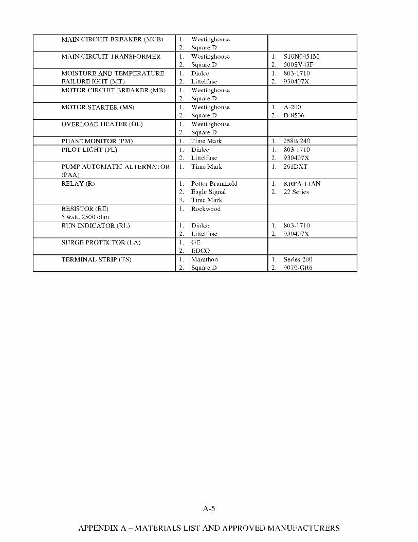
MAIN CIRCUIT BREAKER (MCB)
MAIN CIRCUIT TRANSFORMER
MOISTURE AND TEMPERATURE FAILURE IGHT (MT) MOTOR CIRCUIT BREAKER (MB)
MOTOR STARTER (MS)
OVERLOAD HEATER (OL)
PHASE MONITOR (PM) PILOT LIGHT (PL)
PUMP AUTOMATIC ALTERNATOR (PAA) RELAY (R)
RESISTOR (RE) 5 watt, 2500 ohm RUN INDICATOR (RL)
SURGE PROTECTOR (LA)
TERMINAL STRIP (TS)
1. Westinghouse 2. Square D 1. Westinghouse 2. Square D 1. Dialco 2. Littelfuse 1. Westinghouse 2. Square D 1. Westinghouse 2. Square D 1. Westinghouse 2. Square D 1. Time Mark 1. Dialco 2. Littelfuse 1. Time Mark
1. Potter Brumfield 2. Eagle Signal 3. Time Mark 1. Rockwood
1. Dialco 2. Littelfuse 1. GE 2. EDCO 1. Marathon 2. Square D
1. SlON0451M 2. 500SV43F 1. 803-1710 2. 930407X
1. A-200 2. D-8536
1. 258B 240 1. 803-1710 2. 930407X 1. 261DXT
1. KRPA-llAN 2. 22 Series
1. 803-1710 2. 930407X
1. Series 200 2. 9070-GR6
A-5
APPENDIX A-MATERIALS LIST AND APPROVED MANUFACTURERS
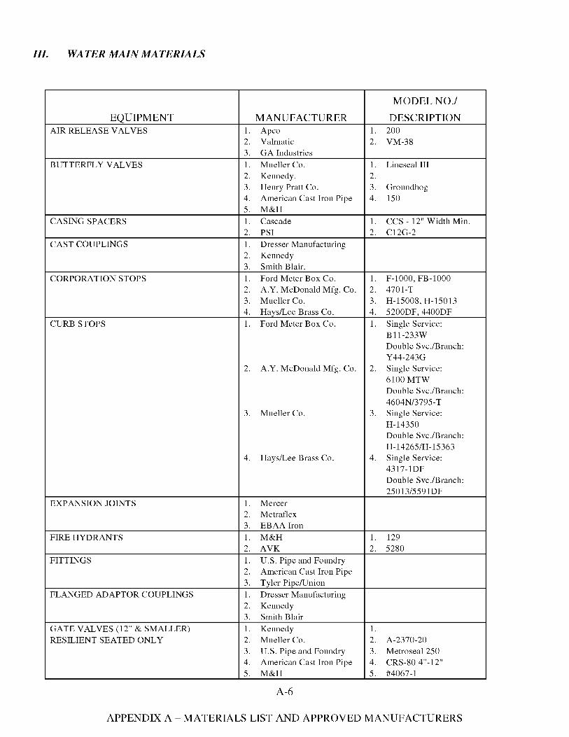
III. WATER MAIN MATERIALS
MODEL NO./ EQUIPMENT MANUFACTURER DESCRIPTION
AIR RELEASE VALYES 1. Apco 1. 200 2. Valmatic 2. VM-38 3. GA Industries
BUTTERFLY VALYES 1. Mueller Co. 1. Lineseal III 2. Kennedy. 2. 3. Henry Pratt Co. 3. Groundhog 4. American Cast Iron Pipe 4. 150 5. M&H
CASING SPACERS 1. Cascade 1. CCS - 12" Width Min. 2. PSI 2. C12G-2
CAST COUPLINGS 1. Dresser Manufacturing 2. Kennedy 3. Smith Blair.
CORPORATION STOPS 1. Ford Meter Box Co. 1. F-1000, FB-1000 2. A.Y. McDonald Mfg. Co. 2. 4701-T 3. Mueller Co. 3. H-15008, H-15013 4. Hays/Lee Brass Co. 4. 5200DF, 4400DF
CURB STOPS 1. Ford Meter Box Co. 1. Single Service: Bll-233W Double Svc./Branch: Y44-243G
2. A.Y. McDonald Mfg. Co. 2. Single Service: 6100MTW Double Svc./Branch: 4604N/3795-T
3. Mueller Co. 3. Single Service: H-14350 Double Svc./Branch: H-14265/H-15363
4. Hays/Lee Brass Co. 4. Single Service: 4317-lDF Double Svc./Branch: 25013/559 lDF
EXPANSION JOINTS 1. Mercer 2. Metraflex 3. EBAAiron
FIRE HYDRANTS 1. M&H 1. 129 2. AVK 2. 5280
FITTINGS 1. U.S. Pipe and Foundry 2. American Cast Iron Pipe 3. Tyler Pipe/Union
FLANGED ADAPTOR COUPLINGS 1. Dresser Manufacturing 2. Kennedy 3. Smith Blair
GATE VALVES (12" & SMALLER) 1. Kennedy 1. RESILIENT SEATED ONLY 2. Mueller Co. 2. A-2370-20
3. U.S. Pipe and Foundry 3. Metroseal 250 4. American Cast Iron Pipe 4. CRS-80 4"-12" 5. M&H 5. #4067-1
A-6
APPENDIX A-MATERIALS LIST AND APPROVED MANUFACTURERS
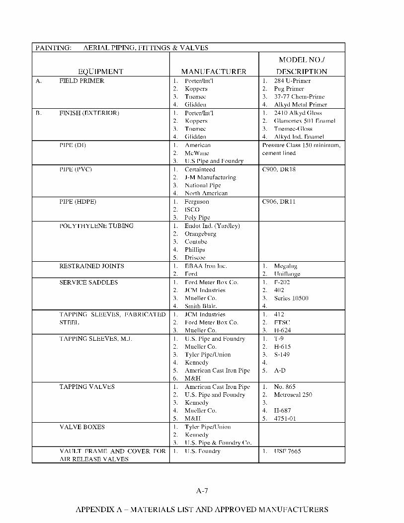
PAINTING: AERIAL PIPING, FITTINGS & VALYES
EQUIPMENT A. FIELD PRIMER
B. FINISH (EXTERIOR)
PIPE (DI)
PIPE (PVC)
PIPE (HDPE)
POLYTHYLENE TUBING
RESTRAINED JOINTS
SERVICE SADDLES
TAPPING SLEEVES, FABRICATED STEEL
TAPPING SLEEVES, M.J.
TAPPING VALYES
VALVE BOXES
VAULT FRAME AND COVER FOR AIR RELEASE VALYES
MANUFACTURER 1. Porter/Int'l 2. Koppers 3. Tnemec 4. Glidden 1. Porter/Int'l 2. Koppers 3. Tnemec 4. Glidden 1. American 2. McWane 3. U.S Pipe and Foundry 1. Certainteed 2. J-M Manufacturing 3. National Pipe 4. North American 1. Ferguson 2. ISCO 3. Poly Pipe 1. Endot Ind. (Yardley) 2. Orangeburg 3. Contube 4. Phillips 5. Driscoe 1. EBAA Iron Inc. 2. Ford 1. Ford Meter Box Co. 2. JCM Industries 3. Mueller Co. 4. Smith Blair. 1. JCM Industries 2. Ford Meter Box Co. 3. Mueller Co. 1. U.S. Pipe and Foundry 2. Mueller Co. 3. Tyler Pipe/Union 4. Kennedy 5. American Cast Iron Pipe 6. M&H 1. American Cast Iron Pipe 2. U.S. Pipe and Foundry 3. Kennedy 4. Mueller Co. 5. M&H 1. Tyler Pipe/Union 2. Kennedy 3. U.S. Pipe & Foundry Co. 1. U.S. Foundry
MODEL NO./ DESCRIPTION
1. 284 U-Primer 2. Pug Primer 3. 37-77 Chem-Prime 4. Alkyd Metal Primer 1. 2410 Alkyd Gloss 2. Glamortex 501 Enamel 3. Tnemec-Gloss 4. Alkyd Ind. Enamel Pressure Class 150 minimum, cement lined
C900, DR18
C906, DRll
1. Megalug 2. Uniflange 1. F-202 2. 402 3. Series 10500 4. 1. 412 2. FTSC 3. H-624 1. T-9 2. H-615 3. S-149 4. 5. A-D
1. No. 865 2. Metroseal 250 3. 4. H-687 5. 4751-01
1. USF 7665
A-7
APPENDIX A-MATERIALS LIST AND APPROVED MANUFACTURERS
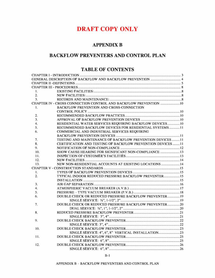
DRAFT COPY ONLY
APPENDIXB
BACKFLOW PREVENTERS AND CONTROL PLAN
TABLE OF CONTENTS CHAPTER I - INTRODUCTION .................................................................................................................. 3 GENERAL DESCRIPTION OF BACKFLOW AND BACKFLOW PREVENTION .................................. 4 CHAPTER II -DEFINITIONS ....................................................................................................................... 5 CHAPTER III - PROCEDURES .................................................................................................................... 8
1. EXISTING FACILITIES: .................................................................................................. . 8 2. NEW FACILITIES: ........................................................................................................... . 8 3. RECORDS AND MAINTENANCE: ................................................................................ . 8
CHAPTER IV - CROSS CONNECTION CONTROL AND BACKFLOW PREVENTION ...................... 10 1. BACKFLOW PREVENTION AND CROSS-CONNECTION
CONTROL POLICY ........................................................................................................ 10 2. RECOMMENDED BACKFLOW PRACTICES.............................................................. 10 3. APPROVAL OF BACKFLOW PREVENTION DEVICES ............................................ 10 4. RESIDENTIAL WATER SERVICES REQUIRING BACKFLOW DEVICES .............. 10 5. RECOMMENDED BACKFLOW DEVICES FOR RESIDENTIAL SYSTEMS ............ 11 6. COMMERCIAL AND INDUSTRIAL SERVICES REQUIRING
BACKFLOW PREVENTION DEVICES ........................................................................ 11 7. TESTING AND MAINTENANCE OF BACKFLOW PREVENTION DEVICES ......... 11 8. CERTIFICATION AND TESTING OF BACKFLOW PREVENTION DEVICES ........ 11 9. NOTIFICATION OF NON-COMPLIANCE ................................................................... 12 10. SHOW CAUSE HEARING FOR SIGNIFICANT NON-COMPLIANCE ...................... 13 11. INSPECTION OF CUSTOMER'S FACILITIES ............................................................. 13 12. NEW FACILITIES ........................................................................................................... 14 13. NEW NON-RESIDENTIAL ACCOUNTS AT EXISTING LOCATIONS ..................... 14
CHAPTER V - CONSTRUCTION STANDARDS ...................................................................................... 15 1. TYPES OF BACKFLOW PREVENTION DEVICES ..................................................... 15 2. TYPICAL INDOOR REDUCED PRESSURE BACKFLOW PREVENTER.................. 15
INSTALLATION ............................................................................................................. 15 3. AIR GAP SEPARATION ................................................................................................. 16 4. ATMOSPHERIC VACUUM BREAKER (A.V.B.) ......................................................... 17 5. PRESSURE - TYPE VACUUM BREAKER (P.V.B.) .................................................... 18 6. DOUBLE CHECK OR REDUCED PRESSURE BACKFLOW PREVENTER.............. 19
SINGLE SERVICE: :W', 1-1/2", 2" ................................................................... 19 7. DOUBLE CHECK OR REDUCED PRESSURE BACKFLOW PREVENTER.............. 20
DUAL SERVICE: :W', l ", 1-1/2", 2" ................................................................ 20 8. REDUCED PRESSURE BACKFLOW PREVENTER.................................................... 21
SINGLE SERVICE: 3", 4" ................................................................................ 21 9. DOUBLE CHECK BACKFLOW PREVENTER............................................................. 22
SINGLE SERVICE: 3", 4"................................................................................. 22 10. DOUBLE CHECK BACKFLOW PREVENTER............................................................. 23
SINGLE SERVICE: 4", 6", 8" VERTICAL INSTALLATION........................ 23 11. DOUBLE CHECK BACKFLOW PREVENTER............................................................. 25
SINGLE SERVICE: 6", 8" ................................................................................ 25 12. DOUBLE CHECK BACKFLOW PREVENTER............................................................. 26
SINGLE SERVICE: 6", 8" ................................................................................ 26
B-1
APPENDIX B - BACKFLOW PREVENTERS AND CONTROL PLAN
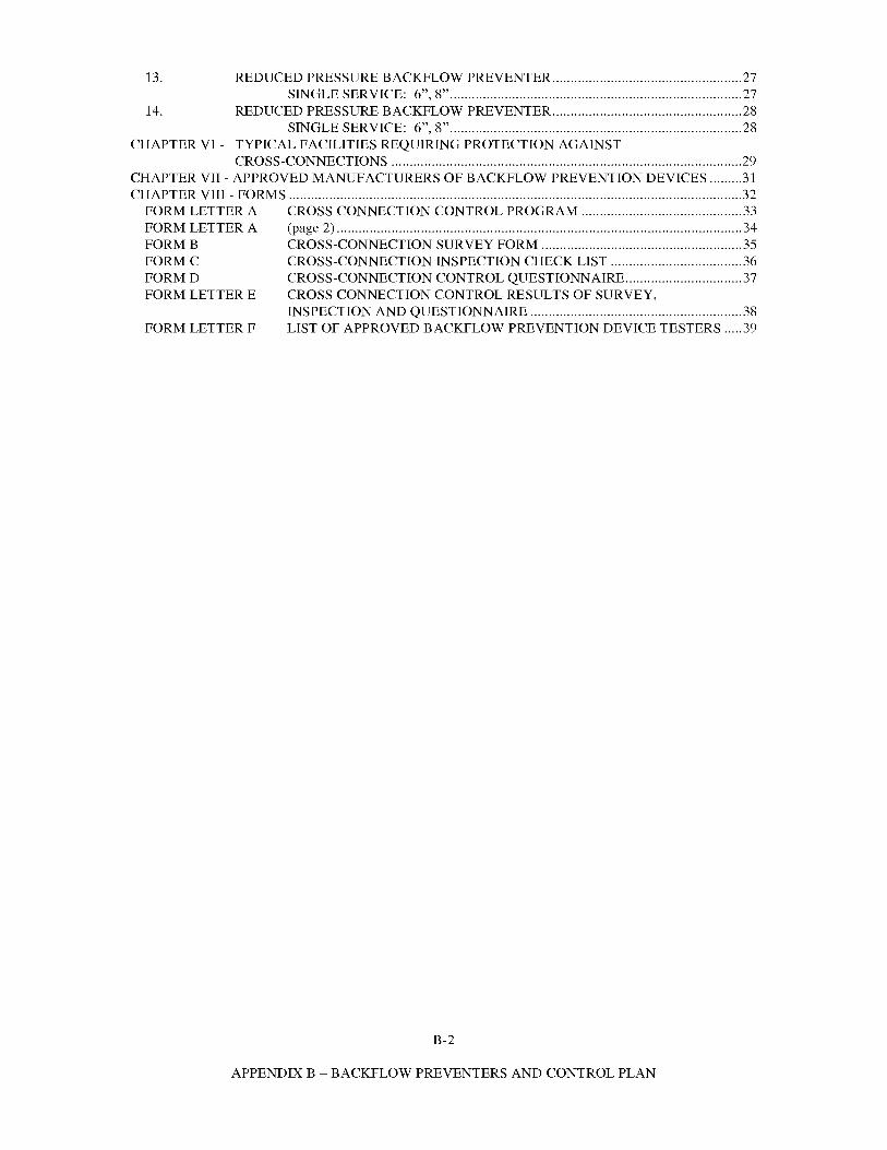
13. REDUCED PRESSURE BACKFLOW PREVENTER.................................................... 27 SINGLE SERVICE: 6", 8" ................................................................................ 27
14. REDUCED PRESSURE BACKFLOW PREVENTER.................................................... 28
CHAPTER VI - TYPICAL FACILITIES REQUIRING PROTECTION AGAINST
FORM LETTER E CROSS CONNECTION CONTROL RESULTS OF SURVEY,
SINGLE SERVICE: 6", 8" ................................................................................ 28
CROSS-CONNECTIONS ................................................................................................29 CHAPTER VII - APPROVED MANUFACTURERS OF BACKFLOW PREVENTION DEVICES .........31 CHAPTER VIII - FORMS ............................................................................................................................32
FORM LETTER A CROSS CONNECTION CONTROL PROGRAM ............................................ 33 FORM LETTER A (page 2) ............................................................................................................... 34 FORMB CROSS-CONNECTION SURVEY FORM ....................................................... 35 FORMC CROSS-CONNECTION INSPECTION CHECK LIST .................................... 36 FORMD CROSS-CONNECTION CONTROL QUESTIONNAIRE................................ 37
INSPECTION AND QUESTIONNAIRE .......................................................... 38 FORM LETTER F LIST OF APPROVED BACKFLOW PREVENTION DEVICE TESTERS ..... 39
B-2
APPENDIX B - BACKFLOW PREVENTERS AND CONTROL PLAN
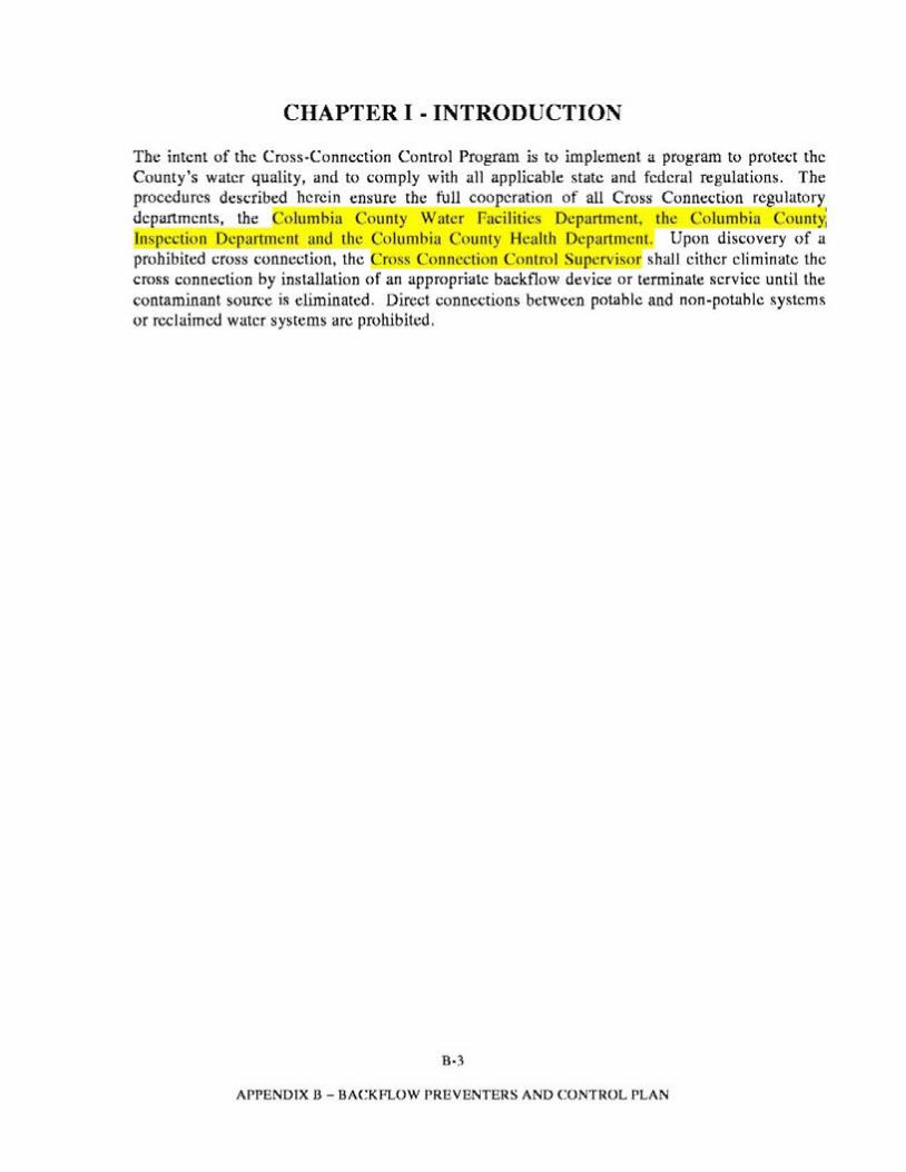
CHAPTER I - INTRODUCTION
The intent of the Cross-Connection Control Program is to implement a program to protect the County's water quality, and to comply with all applicable state and federal regulations. The procedures described herein ensure the full cooperation of all Cross Connection regulatory 2E.Partments, the Columbia County Water Facilities Department, the Columbia Count~ [nsr.ection De artment and the Columbia County Health Department. Upon discovery of a prohibited cross connection, the Cross Connection Control Su crvisor shall either eliminate the cross connection by installation of an appropriate backflow device or terminate service until the contaminant source is eliminated. Direct connections between potable and non-potable systems or reclaimed water systems arc prohibited.
B-3
APPENDIX B - BACKFLOW PREVENTERS AND CONTROL PLAN
GENERAL DESCRIPTION OF BACKFLOW AND BACKFLOW PREVENTION
Water distribution systems are designed with the intention of the water flowing in a certain direction from the distribution system to the consumer. However, hydraulic conditions within the system may deviate from the "normal" conditions, causing the water to flow in the opposite direction. Therefore, it is possible (and common) for the water to flow in the opposite direction in an unprotected system. This is called Backflow.
Backflow occurs when the pressure in the distribution system drops, siphoning water from unknown quality sources into the distribution system. This would also siphon any substance which may be in contact with the water system through a cross-connection. This type of backflow is called Backsiphonage and may occur when there is an unusually high use of water or undersized piping in an area.
For example, during fire fighting, or when a main water line breaks, water is "sucked" to the point of high usage, possibly drawing non-potable substances with it, filling the water line with these substances. Backsiphonage may occur through cross-connections such as a hose from a maintenance sink in a mop bucket, or a below-the-rim water inlet to a tank containing a toxic solution and improper plumbing installations.
Some water customers have non-potable materials on the premises under pressure. When an unprotected water line is attached to the container or pipes holding the pressurized material, the material may be "pumped" back into the potable water system. This type of backflow is called Backpressure. Backpressure may occur through a cross-connection such as a make-up water line which is connected to a recirculating system containing soap, acid, antifreeze or any non-potable substance (e.g., a well containing non-treated water). Because of these potential dangers to the water consumer, it is necessary to control cross-connections. There are several types of mechanical assembles which serve as Backflow Preventers. Different types of backflow preventers are designed to work under backsiphonage or backpressure conditions. Some are acceptable for high-hazard conditions while others are only acceptable for low-hazard (or non-health hazard) conditions.
This manual provides guidelines for the proper use of Backflow Prevention Devices, within the Columbia County service area.
B-4
APPENDIX B - BACKFLOW PREVENTERS AND CONTROL PLAN
CHAPTER II -DEFINITIONS
1. Approved: Accepted by the Columbia County Water Treatment Facilities Manager, or Building and Zoning Department Representative.
2. Auxiliary Water Supply: Any water supply on or available to the premises other than the purveyor's approved public potable water supply. These auxiliary waters may include water from another purveyor's public potable water or any natural source(s) such as well, spring, river, stream, harbor, etc., or "used waters" or "individual fluids." These waters may be polluted or contaminated or they may be objectionable and constitute an unacceptable water source over which the water purveyor does not have sanitary control.
3. Backflow: The flow of water or other liquids, mixtures ore substances under pressure into the distributing pipes of a potable water supply system from any source or sources other than its intended source.
4. Back-Siphonage: The flow of water or other liquids, mixtures or substances into the distributing pipes of a potable water supply system from any source other than its intended source caused by the sudden reduction of pressure in the potable water supply system.
5. Backflow Preventer: A device or means designed to prevent backflow or backsiphonage.
a) Air-Gap: The unobstructed vertical distance through the free atmosphere between the lowest opening from any pipe or faucet supplying water to a tank, reservoir, vessel, plumbing fixture, or other device and the flood level rim of said vessel. An approved air-gap shall be at least double the diameter of the supply pipe, measured vertically, above the top of the rim of the vessel; and, in no case less than one inch. When an air-gap is used at the service connection to prevent the contamination or pollution of the public potable water system, an emergency by-pass shall be installed around the air-gap system and an approved reduced pressure principle device shall be installed on the by-pass system.
b) Reduced Pressure Principle Assembly: An assembly of two independently operating approved check valves with an automatically operating differential relief valve between the two check valves, tightly closing shut-off valves on either side of the check valves, plus properly located test cocks for the testing of the check and relief valves. The entire assembly shall meet the design and performance specifications and approval of a recognized and County approved testing agency for backflow prevention assemblies. The device shall operate to maintain the pressure in the zone between the two check valves at a level less than the pressure on the public water supply side of the device. At cessation of normal flow the pressure between the two check valves shall be less than the
B-5
APPENDIX B - BACKFLOW PREVENTERS AND CONTROL PLAN
pressure on the public water supply side of the device. In case of leakage of either of the check valves the differential relief valve shall operate to maintain the reduced pressure in the zone between the check valves by discharging to the atmosphere. When the inlet pressure is two pounds per square inch or less, the relief valve shall open to the atmosphere. To be approved, these devices must be readily accessible for in-line maintenance and testing and be installed in a location where no part of the device will be submerged.
c) Double Check Valve Assembly: An assembly of two independently operating approved check valves with tightly shut off valves on each side of the check valves, plus properly located test cocks for the testing of each check valve. The entire assembly shall meet the design and performance specifications and approval of a recognized and Countyapproved testing agency for backflow prevention devices. To be approved, these devices must be readily accessible for in-line maintenance and testing.
6. Backflow Tester: Person certified in the testing of backflow prevention devices.
7. Contamination: Means an impairment of the quality of the potable water provided by the Columbia County Distribution System.
8. Cross-Connection: Any physical connection or arrangement of piping or fixtures between the otherwise separate piping systems one of which contains potable water and the other non-potable water or industrial fluids of questionable safety, through which, or because of which, backflow or back-siphonage may occur into the potable water distribution system and a customer's water distribution system which is cross-connected to a contaminated supply of auxiliary water system, constitutes one type of cross-connection. Other types of cross-connections include connectors such as swing connections, removable sections, four way valves, spools, dummy sections of pipe, swivel or change-over devices, sliding multiport tube, solid connections, etc.
9. Cross-Connections-Controlled: A connection between a potable water system and a non-potable water system with an approved backflow prevention device properly installed that will continuously afford the protection commensurate with the degree of hazard.
10. Industrial Fluids System: Any system containing fluid or solution which may be chemically, biologically or otherwise contaminated or polluted in a form or concentration such as would constitute a health system, pollutional or plumbing hazard if introduced into an approved water supply. This may include, but not be limited to: polluted or contaminated waters; all types of process waters and "used waters" originating from the public potable water system which may have deteriorated in sanitary quality; chemicals in fluid form; plating acids and alkalies, circulated cooling waters connected to an open treated or stabilized with toxic substances; contaminated natural waters such as from wells, springs, streams, rivers, bays, harbors, seas, irrigation canals or systems, etc.; oils, gases, glycerine, paraffins, caustic and acid solutions and other liquids and gaseous fluids used in industrial or other purposes or for fire-fighting purposes.
B-6
APPENDIX B - BACKFLOW PREVENTERS AND CONTROL PLAN
11. Pollution:_ Means the presence of any foreign substance (organic, inorganic, or biological) in water which tends to degrade its quality so as to constitute a hazard or impair the usefulness or quality of the water to a degree which does not create an actual hazard to the public health hut which docs adversely and unreasonably affect such waters for domestic use.
12. Water Potable: Any water which, according to recognized standards is safe for human consumption.
13. Water-Nonpotable: Water which is not safe for human consumption or which is of qucstionahlc potahility.
14. Water Purveyor: The term water purveyor shall mean the owner or operator of the public potable water system supplying an approved water sup_Qly to t~ uhlic. As used herein, the tenns water purveyor and Columbia County Water Treatment Facilities may be used synonymously.
15. Water - Service Connections: The terminal end of a service connection from the public potable water system; i.e., where the Water Purveyor loses jurisdiction and sanitary control over the water at its point of delivery to the customer's water system. lf a meter is installed at the end of the service connection, then the service connection shall mean the downstream end of the meter. There should he no unprotected takeoffs from the service tine ahead of any meter or backflow prevention device located at the point of delivery to the customer's water system. Service connections shall also include water service connections from a fire hydrant and all other temporary or emergency water service connections from the public potahlc water systems.
16. Water - Used: Any water supplied by a Water Purveyor from a public potable water system to a consumer's water system after it has passed through the point of delivery and is no longer under the sanitary control of the Water Purveyor.
17. Any person(s) installing and inspecting any hackflow system must be certified in the prevention of hacktlow devices.
B-7
APPENDIX B - BACKFLOW PREVENTERS AND CONTROL PLAN
CHAPTER III - PROCEDURES
1. Existing Facilities:
a) Premises of the type where cross-connections are re uired, shall be surveyed by representatives or designees from the C lumbia Count Water Trl.!atml.!nt Facilities,or Building and Zoning Department, to determine if a cross connection exists.
b) The owners of the premises shall be notified in writing thirty (30) days in advance to secure an appointment for inspection of the premises. (See Appendix). The owner or his authorized representative may be required to accompany the inspector during the tour of the premises.
c) An inspection form will be completed by the inspector. (See Appendix). The owner shall be made aware of any corrective measures that may be required.
d) All official letters of notification shall be sent to the owner indicating what corrective measures must be taken. (See Appendix).
e) Upon conformance of the requirements in the notification letter, the owner shall immediately notify representatives or designees from the Water Treatment Facilities or Building and Zoning Department, to schedule a date for reinspection.
2. New Facilities:
a) Each applicant desiring water service will be required to complete a cross connection control questionnaire (See Appendix ).
b) Should a cross connection control device be required, Building and Zoning Department will notify the new customer in writing and arrange a meeting to discuss the requirements for backflow prevention. Procedures for inspection of the device will be discussed at this meeting. The customer will be required to provide construction drawings of his proposed facilities.
3. Records and Maintenance:
a) The owner of a backflow prevention device shall be required to keep records of maintenance of cross connection control devices.
b) Attached to the aforementioned notification letter shall be a test and maintenance form which must be completed by the owner or his designated backflow prevention tester. Backflow prevention devices larger than 3/4" in diameter or as specified in writing by olumbia Count Water Treatment Facilitie. , shall be tested annually. The testing shall be the responsibility of the customer.
B-8
APPENDIX B - BACKFLOW PRE VENTERS AND CONTROL PLAN
Columbia County Water Treatment Facilities shall notify the owner of the maintenance requirement 30 days in advance of the maintenance due date.
B-9
APPENDIX B - BACKFLOW PREVENTERS AND CONTROL PLAN

CHAPTER IV - CROSS CONNECTION CONTROL AND BACKFLOW PREVENTION
I. Backflow Prevention and Cross-Connection Control Policy
Columbia Count Water Treatment r acilities Mana e reserves the right to require backflow prevention devices where, in Columbia County Water Treatment Facilities' judgment, a water service connection presents a reasonable and identifiable risk to potentially contaminate the public water system.
Such policies and procedures shall comply with Columbia County and state guidelines.
2. Recommended Backflow Practices
Backflow prevention devices shall he specified by Columbia County Water Treatment Facilities in accordance with the A WWA Manual of Practices # 14, Recommended Management Practices for Cross Connection Control, current version.
3. Approval ofBackjlow Prevention Devices
Columbia County Building Department shall review all new service connections to determine the contamination risk. Based on the risk assessment, the Building Department shall recommend or require the appropriate backflow prevention devices. The devices shall be installed by the person requesting service prior to the Countymaking the water service connection.
4. Residetitial Water Services Requiring Backjlow Devices
Residential water services require hacktlow prevention devices when the following conditions arise:
a) A residence utilizes an irrigation system.
b) A residence is provided with reclaimed water for irrigation purposes.
c) A residence is using a well for irrigation purposes physically separated from the public water service which is used for domestic purposes.
d) Operations arc being conducted at the residence which arc similar to the commercial listings of section 6.
e) In the judgment of the Water Treatment Facilities Manager, a customer's installation has the potential to contaminate the public water system.
B·lO
APPENDIX 13 - BACKFLOW PREVENTERS AND CONTROL PLAN
5. Recommended Backflow Devices for Residential Systems
Columbia County Water Treatment Facilities shall make recommendations on backflow prevention devices with regard to residential water services not covered in section 4.
6. Commercial and Industrial Services Requiring Backflow Prevention Devices
a) Backflow prevention devices shall be required for the types of facilities and plumbing fixtures listed for water. For facilities not listed, Columbia County Water Treatment Facilities Manager shall have the sole right to require backflow prevention devices where it deems necessary to protect the public water system from contamination.
b) All required backflow prevention devices shall be tested and maintained in accordance with the provisions herein. Columbia County Water Treatment Facilities shall make recommendations concerning backflow devices for commercial irrigation systems which are not fitted with chemical feed systems.
7. Testing and Maintenance ofBackflow Prevention Devices
a) Columbia County Water Treatment Facilities shall require testing and maintenance of backflow devices, which have been specifically required by Columbia County Water Treatment Facilities or Building and Zoning Department.
b) Maintenance and Testing of backflow devices recommended shall be the responsibility of the customer.
c) Testing of required and recommended devices shall be performed in accordance with the recommended procedures found in A WWA Manual of Practice 14.
d) Responsibility for the testing and maintenance of required and recommended backflow prevention devices, including the payment of any testing fees, past the point of connection at the water meter, shall be the responsibility of the customer.
f) Testing and Maintenance requirements shall be performed as specified by The Columbia County at no cost to The Columbia County.
8. Certification and Testing ofBackflow Prevention Devices
a) For required backflow devices, Columbia County Water Treatment Facilities shall provide a Test Maintenance Form to customers to ensure compliance with its tests and maintenance procedures. Upon completion
B-11
APPENDIX B - BACKFLOW PREVENTERS AND CONTROL PLAN
of the test, a completed and signed form shall be furnished to Columbia County Water Treatment Facilities. Failure on the part of a customer to provide a completed form shall be treated as non-compliance.
b) Testing and Maintenance on required devices shall be performed by a certified backflow prevention tester or other individual with equivalent training acceptable to Columbia County Water Treatment Facilities and State of Florida as approved in writing.
c) Information concerning testing and maintenance of recommended backflow prevention devices shall be provided to customers as deemed appropriate by Columbia County Water Treatment Facilities.
d) A customer may request the services of Columbia County Water Treatment Facilities to perform required testing and maintenance procedures. Columbia CountyWater Treatment Facilities will inform the requesting party as to its ability to provide services. Columbia CountyWater Treatment Facilities may provide such services in consideration of its workload or subcontract such work to a qualified contractor. Such services shall be paid for by the customer. Labor, materials, equipment and other typical charges, including Columbia CountyWater Treatment Facilities usual overhead, shall be charged. In instances of non-payment, Columbia County Water Treatment Facilities may assess appropriate charges against the customer's utility bill.
9. Notification ofNon-Compliance
a) Columbia County Water Treatment Facilities shall maintain records of testing and maintenance on required backflow prevention devices. Customers operating and maintaining such devices shall be notified as to the required testing frequency by Columbia County Water Treatment Facilities. The customer shall have 30 days to complete the required testing.
b) Should a customer fail to test or maintain a required backflow prevention device within the specified time, Columbia County Water Treatment Facilities shall issue, by certified mail, a non-compliance notice. The customer shall have 10 days to:
1) Provide Columbia County Water Treatment Facilities with a completed test results form which indicates acceptable performance of the backflow prevention unit.
2) Provide Columbia County Water Treatment Facilities with a written convincing reason why the device has not been tested which is acceptable to Columbia County Water Treatment Facilities.
B-12
APPENDIX B - BACKFLOW PREVENTERS AND CONTROL PLAN
3) Provide Columbia County Water Treatment Facilities with conformation that the customer will attend a Show Cause Hearing on the date specified in the non-compliance notice. The date of the Show Cause Hearing shall be scheduled to allow Columbia County Water Treatment Facilities compliance with section 11.
10. Show Cause Hearing for Significant Non-Compliance
a) Should a customer in non-compliance fail to take satisfactory corrective measures under sections 9(a) or (b), the customer shall be expected to attend a Show Cause Hearing before the Columbia County Water Treatment Facilities Manager, or his designee, at the date and time specified in the non-compliance notice to show cause why the customer service shall not be disconnected for causing or suffering violation of the policy, or other applicable law or regulation. If Columbia County Water Treatment Facilities seeks to suspend service, Columbia County Water Treatment Facilities shall notify the customer of the nature of the violation for which suspension of service is sought with sufficient specificity as to the character of the violation, and the dates at which such violation occurred to enable the customer to prepare his defense. Such notice shall be sent to the customer by certified mail, return receipt request, or personally delivered at least 10 days prior to the scheduled hearing date.
b) Following review of the hearing proceedings and evidence submitted, the Columbia County Water Treatment Facilities Manager, or his designee, may issue an order to the customer, indicating a specified time which is dependent on the severity of the violation, when water service may be discontinued unless satisfactory corrective action to permanently remove the offending connection from the public water system is taken by the customer.
c) Any customer aggrieved by such an order may appeal it to a court of competent jurisdiction within ten (10) days from the date the order is delivered by certified mail unless such connection is in the opinion of Colkumbia County Water Treatment Facilities a direct threat to public health, welfare or safety. In such case, Columbia County Water Treatment Facilities shall retain the right to immediately discontinue service.
11. Inspection of Customer's Facilities
If in the opinion of Columbia County Water Treatment Facilities the customer's facilities constitute a possible risk to contaminate the public water system, Columbia County Water Treatment Facilities shall retain the right to make inspection. Appropriate notice shall be given. Refusal of a customer to provide reasonable access to his premise by Columbia County Water Treatment Facilities shall be treated as non-compliance.
B-13
APPENDIX B - BACKFLOW PREVENTERS AND CONTROL PLAN
12. New Facilities
Building and Zoning Department shall review all new connections and identify backflow prevention requirements and/or make backflow prevention recommendations.
13. New Non-Residential Accounts at Existing Locations
Columbia County Water Treatment Facilities or Building and Zoning Department, reserves the right to require appropriate backflow prevention devices on new non-residential accounts at existing locations prior to providing water service.
B-14
APPENDIX B - BACKFLOW PREVENTERS AND CONTROL PLAN
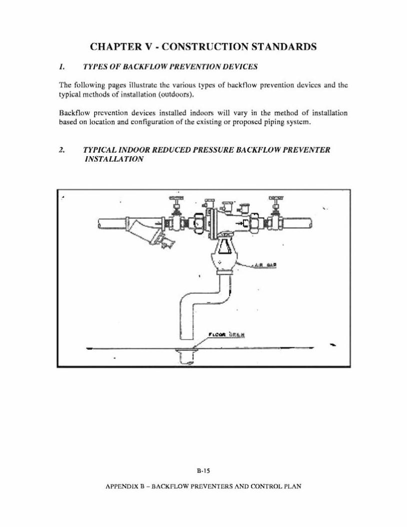
CHAPTER V - CONSTRUCTION STANDARDS
1. TYPES OF BACKFLOW PREVENTION DEVICES
The following pages illustrate the various types of backtlow prevention devices and the typical methods of installation (outdoors).
Backflow prevention devices installed indoors will vary in the method of installation based on location and configuration of the existing or proposed piping system.
2. TYPICAL INDOOR REDUCED PRESSURE BACKFLOW PREVENTER INSTALLATION
... ' .
..LCM u«II!
--------=1~===5,-r-·-------------=
B·1S
APPENDIX B - BACKPLOW PREVENTERS AND CONTROL PLAN
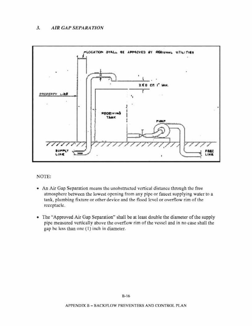
3. AIR GAP SEPARATION
U(D Cl'! I .. ...H.
r '•
I.-. i~..,,.~ T.l,lluC I ........
///.,/ , _____1 ,rec~~="T t - J ......_ LINa
NOTE:
• An Air Gap Separation means the unobstructed vertical distance through the free atmosphere between the lowest opening from any pipe or faucet supplying water to a tank, plumbing fixrure or other device and the flood level or overflow rim of the receptacle.
• The "Approved Air Gap Separation" shall be at least double the diameter of the supply pipe measured vertically above the overflow rim of the vessel and in no case shall the gap he less than one ( 1) inch in diameter.
B·16
APPENDIX B - BACKFLOW PREVENTERS AND CONTROL PLAN
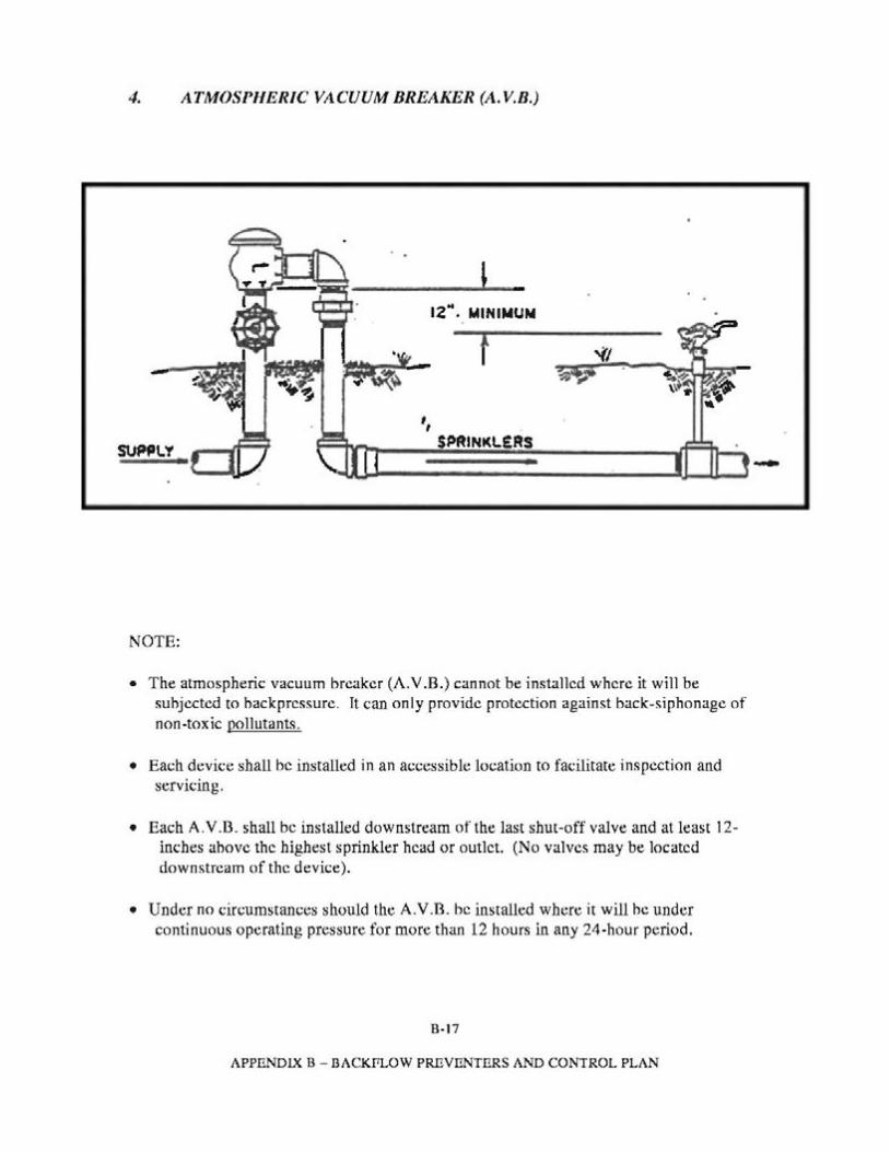
4. ATMOSPHERIC VACUUM BREAKER (A.V.B.)
12 ... MINIMUM
', SPASNKL£RSSUPP1..'f .......
NOTE:
• The atmospheric vacuum breaker (A.V.B.) cannot be installed where it will be subjected to hackpressure. It can only provide protection against back-siphonage of non-toxic pollutants.
• Each device shall be installed in an accessible location to facilitate inspection and servicing.
• Each A.V.D. shall be installed downstream of the last shut-off valve and at least 12-inches ahove the highest sprinkler head or outlet. (No valves may be located downstream of the device).
• Under no circumstances should the A.V.D. be installed where it will he under continuous operating pressure for more than 12 hours in any 24-hour period.
B-17
APPENDIX B - I3ACKf1L0W PREVENTERS AND CONTROL PLAN
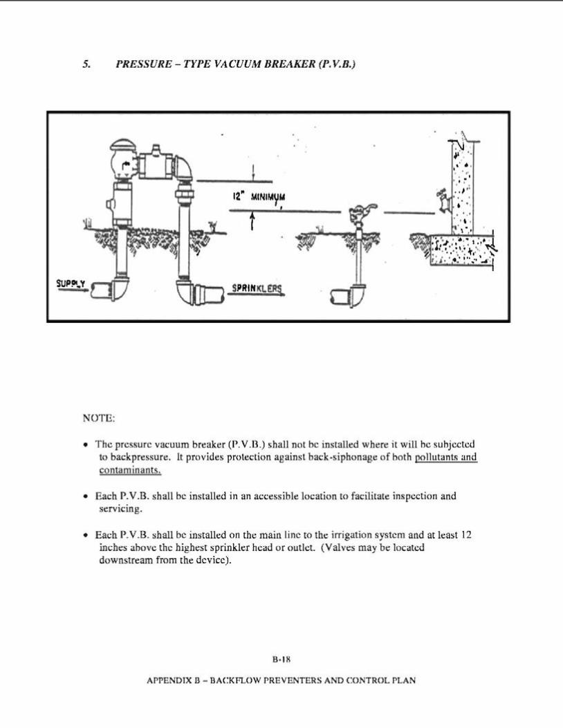
5. PRESSURE -TYPE VACUUM BREAKER (P. V.B.)
7.'J .,·· .. ..•.~.. I . .f :i. . ' ..,......
f . ' .•t ..' . ,·\ ·..
• • •. • ~ . • • • I.r',i., . 1,, ~ ~ ,.,!.,1,: • • .• , • i. ••. ~ z.. . ···...·.·.......-,..
\ .\. I• J , .. ~ ..,·• ..4.•.
SPRttfKl£R\.
NOTE:
• The pressure vacuum breaker (P. V.B.) shall not be installed where it will he subjected to backpressure. lt provides protection against back-siphonage of both pollutants and contaminants.~
• Each P. V .B. shall be installed in an accessible location to facilitate inspection and servicing.
• Each P. V .B. shall be installed on the main line to the irrigation system and at least 12 inches ahove the highest sprinkler head or outlet. (Valves may be located downstream from the device).
B-18
APPENDIX B - BACKFLOW PREVENTERS AND CONTROL PLAN
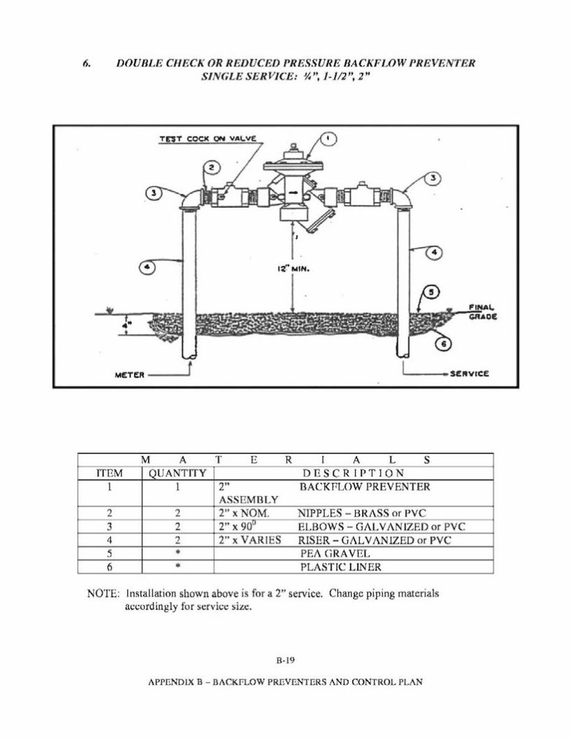
6. DOUBLE CHECK OR REDUCED PRESSURE BACKFLOW PREVENTER SINGLE SERVICE: ~", 1-112", 2''
TEST COO< ON VALVE
2
4
FINAL GRAOE...
METEA ---r ---•SERVICE
M A T E R I A L s ITEM QUANTITY DESCRIPTION
1 1 2" DACKPLOW PREVENTER ASSEMBLY
2 2 2" x NOM. NIPPLES - BRASS or PVC 3 2 2" X 9Qu ELBOWS - GALVAN!ZED or PVC 4 2 2" x VARIES RISER-GALVANIZED or PVC 5 PEA GRAVEL* 6 PLASTIC LIN ER *
NOTE: Installation shown above is for a 2" service. Change piping materials accordingly for service size.
8·19
APPENDIX B - BACKFLOW PREVENTERS AND CONTROL PLAN
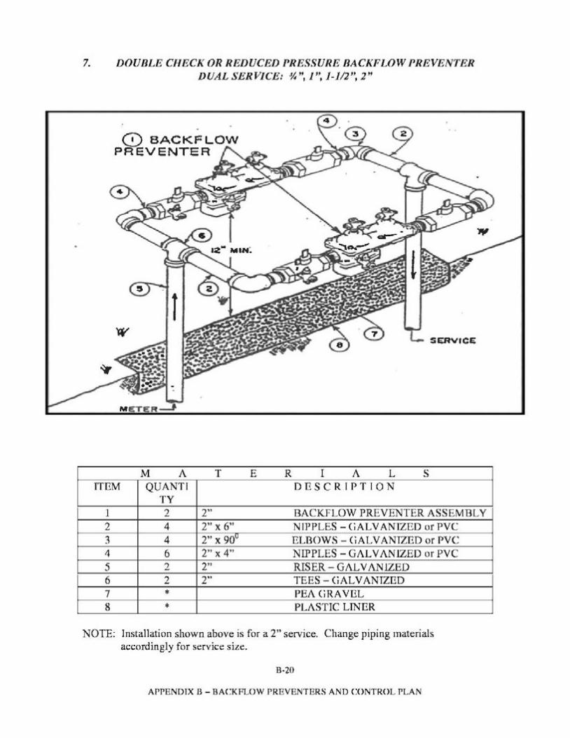
7. DOUBLE CHECK OR REDUCED PRESSURE BACKFLOW PREVENTER DUAL SERVICE: ~'', I", 1-112", 2''
(0 BACKFLOW PREVENTER
SERVfCE
M E:'T R_J
M A T E R I A L s ITEM QUANT! DESCRIPTION
TY 1 2 2" BACKFLOW PREVENTER ASSEMBLY 2 4 2" X 6" NIPPLES -GALVANIZED or PVC 3 4 2" X 90° ELBOWS -GALVANIZED or PVC 4 6 2" X 4" NIPPLES-GALVANIZED or PVC 5 2 2" RISER - GALVANlZED 6 2 2" TEES -GALVANIZED 7 PEA GRAVEL* 8 PLASTIC LINER*
NOTE: Installation shown above is for a 2" service. Change piping materials accordingly for service size.
B·20
APPENDIX B - BACKFLOW PREVENTERS AND CONTROL PLAN
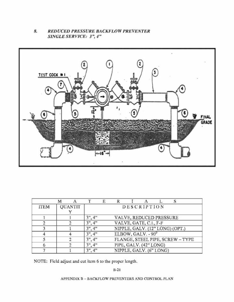
8. REDUCED PRESSURE BACKFLOW PREVENTER SINGLE SERVICE: 3", 4''
M A T E R I A L s ITEM QUANTIT DESCRIPTION
y 1 I 3",4" VAL VE, REDUCED PRESSURE 2 2 3", 4" VALVE, GATE, C.I., F -F 3 1 3", 4" NIPPLE, GALV. (12" LONG) (OPT.) 4 4 3", 4" ELBOW, GALV .• 90u 5 2 3",4" FLANGE, STEEL PIPE, SCREW -TYPE 6 2 3",4" PIPE, GALV. (42" LONG) 7 1 3", 4" NIPPLE, GALV. (6" LONG)
NOTE: field adjust and cut item 6 to the proper length.
B·21
APPENDIX B - BACKFLOW PREVENTERS AND CONTROL PLAN
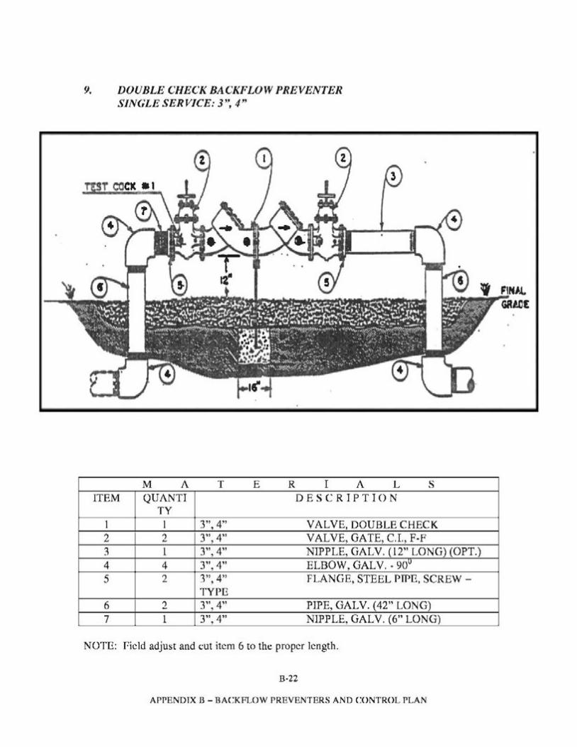
9. DOUBLE CHECK BACKFLOW PREVENTER SINGLE SERVICE: 3'', 4"
M A T E R I A L s ITEM QUANTI DESCRIPTION
TY 1 I 3",4" VALVE, DOUBLE CHECK 2 2 3", 4" VALVE, GATE, C.I., F-F 3 1 3", 4" NIPPLE, GALV. (12" LONG) (OPT.) 4 4 3", 4" ELBOW, GALV.• 90u 5 2 3",4" FLANGE, STEEL PWE, SCREW -
TYPE 6 2 3", 4" PIPE, GALV. (42" LONG) 7 1 3", 4" NIPPLE, GALV. (6" LONG)
NOTE: field adjust and cut item 6 to the proper length.
B·22
APPENDIX B - BACKFLOW PREVENTERS AND CONTROL PLAN
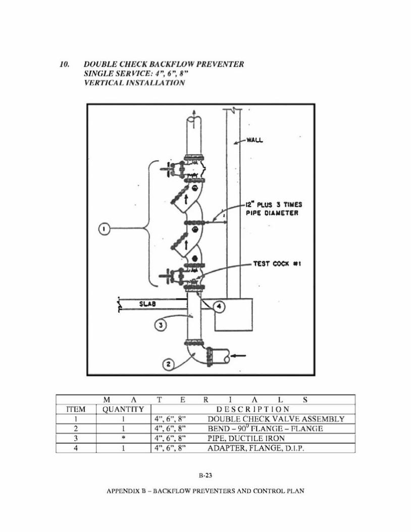
10. DOUBLE CHECK BACKFLOW PREVENTER SINGLE SERVICE: 4", 6", 8'' VERTICAL INSTALLATION
WA.U.
12.. Pt.US 3 TIMES PIPE DIAMETER
\. sueF·---..
3
M A T E R I A L s ITEM QUANTITY DESCRIPTION
1 I 4", 6", 8" DOUBLE CHECK VALVE ASSEMBLY 2 1 4", 6", 8" BEND - 90u fLANCiE - PLANCiE 3 * 4", 6", 8" PIPE, DUCTILE IRON 4 1 4", 6", 8" ADAPTER, FLANGE, D.I.P.
8·23
APPENDIX B - BACKFLOW PREVENTERS AND CONTROL PLAN
NOTE: Min. clearance around device - 12" + 3 times pipe diameter. This type of construction is designed for limited working area. (Fire Sprinkler Systems)
B-24
APPENDIX B - BACKFLOW PREVENTERS AND CONTROL PLAN
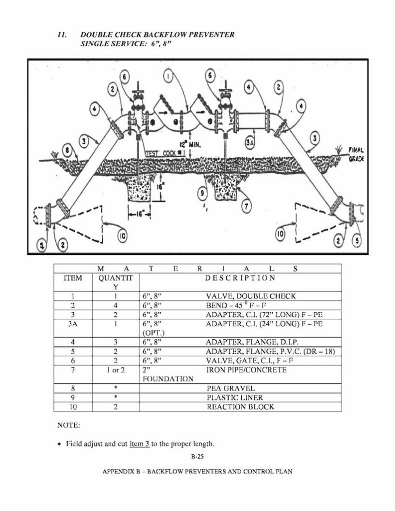
11. DOUBLE CHECK BACKFLOW PREVENTER SINGLE SERVICE: 6'', 8"
M A T E R I A L s ITEM QUANTIT DESCRIPTION
y 1 1 6", 8" VALVE, DOUDLECHECK 2 4 6", 8" BEND - 45 u P - P 3 2 6", 8" ADAPTER, C.l. (72" LONG) F- PE
3A 1 6", 8" ADAPTER, C.I. (24" LONG) F - PE (OPT.)
4 3 6", 8" ADAPTER, FLANGE, D.LP. 5 2 6", 8" ADAPTER, FLANGE, P.V.C. (DR-18) 6 2 6", 8" VALVE, GATE, C.l., F- P 7 1 or 2 2" IRON PIPE/CONCRETE
FOUNDATION 8 PEA GRAVEL* 9 PLASTIC LINER* 10 2 REACTION DLOCK
NOTE:
• field adjust and cut Item 3 to the proper length.
B,25
APPENDIX B - BACKFLOW PREVENTERS AND CONTROL PLAN
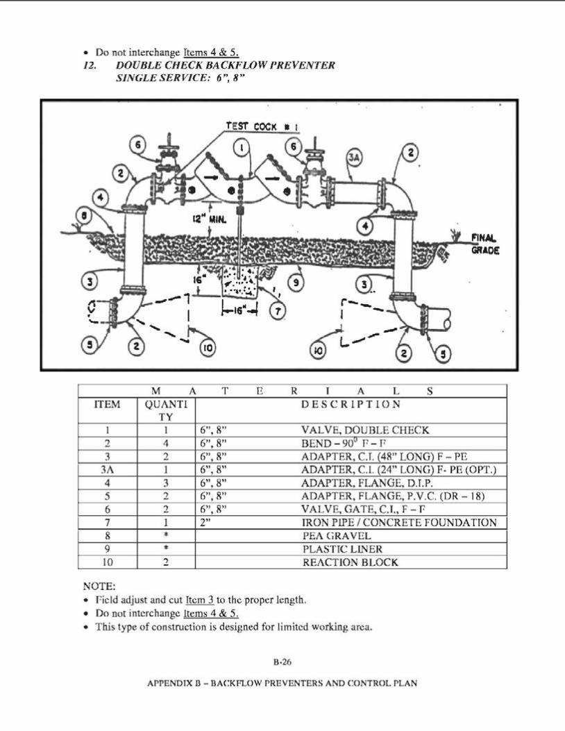
• Do not interchange Items 4 & 5._ 12. DOUBLE CHECK BACKFLOW PREVENTER
SINGLE SERVICE: 6", 8''
16. _..,,,.., t
-Nil""""""- ' I 2 ...............~
M A T ITEM QUANT!
TY 1 1 6", 8" 2 4 6", 8" 3 2 6", 8"
3A 1 6", 8" 4 3 6", 8" 5 2 6", 8" 6 2 6", 8" 7 1 2" 8 * 9 * 10 2
NOTE:
E R I A L s DESCRIPTION
VALVE, DOUBLE CHECK BEND - 90u P - P ADAPTER, CJ. (48" LONG) F - PE ADAPTER, C.l. (24" LONG) F- PE (OPT.) ADAPTER, FLANGE, D.J.P. ADAPTER, FLANGE, P.V.C. (DR - 18) VALVE, GATE, CJ., F- f IRON PIPE I CONCRETE FOUNDATJON PEA GRAVEL PLASTIC LINER REACTION BLOCK
• field adjust and cut Item 3 to the proper length. • Do not interchange Items 4 & 5. • This type of construction is designed for limited working area.
B-26
APPENDIX B - BACKFLOW PREVENTERS AND CONTROL PLAN
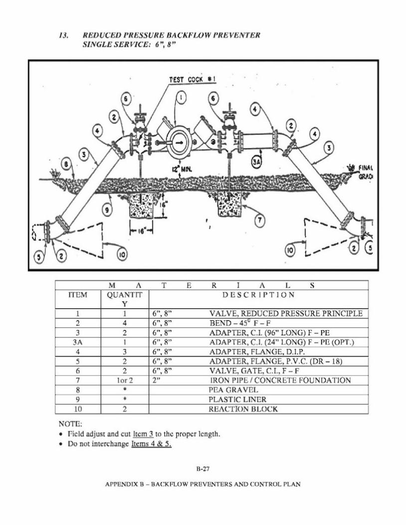
13. REDUCED PRESSURE BACKFLOW PREVENTER SINGLE SERVICE: 6'', 8"
M A T E R I A L s ITEM QUANTIT DESCRIPTION
y 1 1 6", 8" VALVE, REDUCED PRESSURE PRINCIPLE 2 4 6", 8" BEND - 45v F - F 3 2 6", 8" ADAPTER, C.I. (96" LONG) F - PE
3A 1 6", 8" ADAPTER, C.l. (24" LONG) F - PE (OPT.) 4 3 6", 8" ADAPTER, FLANGE, D.l.P. 5 2 6", 8" ADAPTER, FLANGE, P.V.C. (DR- 18) 6 2 6", 8" VALVE, GATE, C.I., F - F 7 tor 2 2" IRON PIPE/ CONCRETE FOUNDATION 8 PEA GRAVEL* 9 PLASTIC LINER* 10 2 REACTION BLOCK
NOTE: • field adjust and cut Item 3 to the proper length. • Do not interchange Items 4 & 5._
B-27
APPENDIX B - BACKFLOW PREVENTERS AND CONTROL PLAN
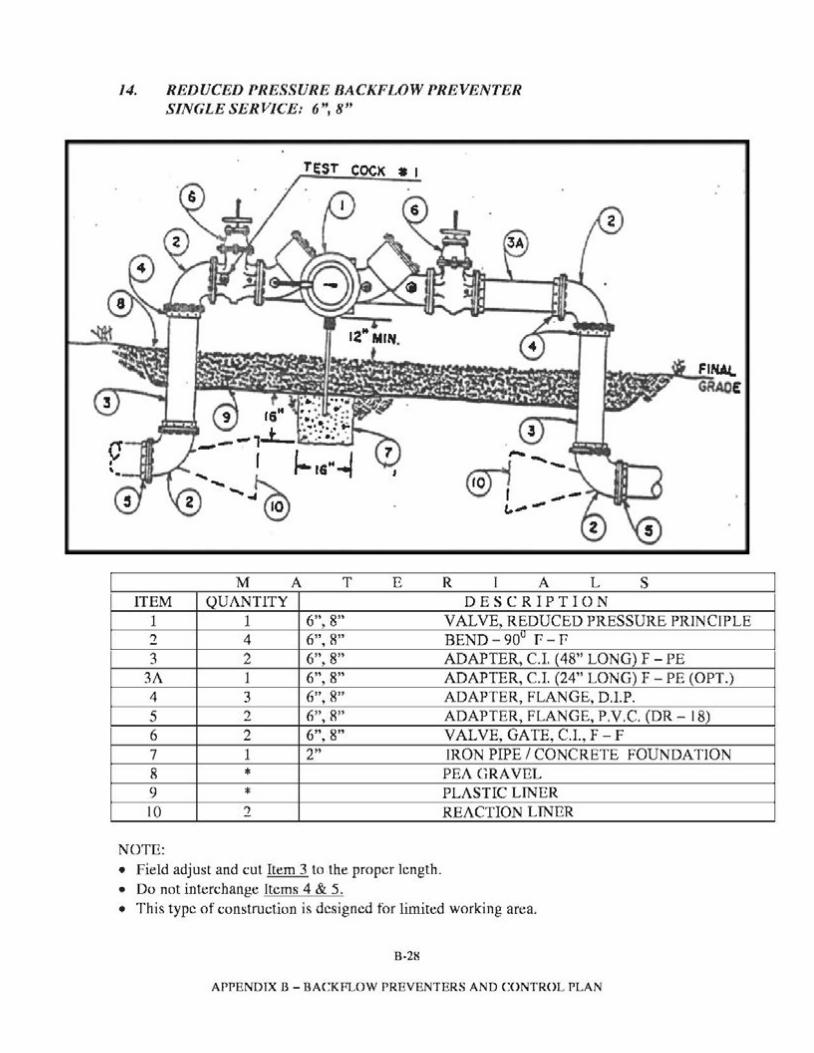
14. REDUCED PRESSURE BACKFLOW PREVENTER SINGLE SERVICE: 6'', 8"
TEST COCK a I
Fl~ GRACE
M A T E R I A L s ITEM QUANTITY DESCRIPTION
1 1 6", 8" VALVE, REDUCED PRESSURE PRINCIPLE 2 4 6", 8" BEND-90u f-P 3 2 6", 8" ADAPTER, C.I. (48" LONG) F - PE
3A 1 6", 8" ADAPTER, C.I. (24" LONG) F - PE (OPT.) 4 3 6", 8" ADAPTER, FLANGE, D.I.P. 5 2 6", 8" ADAPTER, FLANGE, P.V.C. (DR - 18) 6 2 6", 8" VALVE, GATE, C.I., F - F 7 1 2" IRON PIPE/ CONCRETE FOUNDATION 8 PEA GRAVEL* 9 PLASTIC LINER* 10 2 REACTION LINER
NOTE: • Field adjust and cut Item 3 to the proper length. • Do not interchange Items 4 & 5. • This type of construction is designed for limited working area.
B,28
APPENDIX B - BACKFLOW PREVENTERS AND CONTROL PLAN
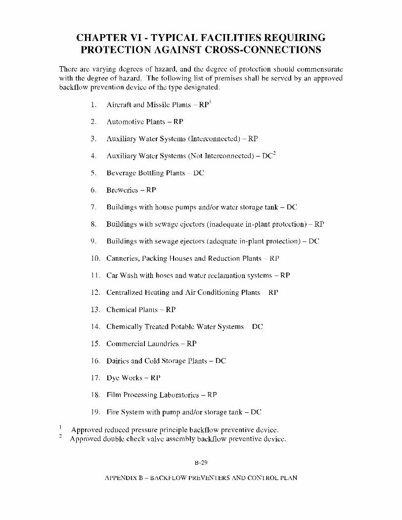
CHAPTER VI - TYPICAL FACILITIES REQUIRING PROTECTION AGAINST CROSS-CONNECTIONS
There are varying degrees of hazard, and the degree of protection should commensurate with the degree of hazard. The following list of premises shall be served by an approved backflow prevention device of the type designated.
1. Aircraft and Missile Plants - RP1
2. Automotive Plants - RP
3. Auxiliary Water Systems (Interconnected) - RP
4. Auxiliary Water Systems (Not Interconnected) - DC2
5. Beverage Bottling Plants - DC
6. Breweries - RP
7. Buildings with house pumps and/or water storage tank - DC
8. Buildings with sewage ejectors (inadequate in-plant protection) - RP
9. Buildings with sewage ejectors (adequate in-plant protection) - DC
10. Canneries, Packing Houses and Reduction Plants - RP
11. Car Wash with hoses and water reclamation systems - RP
12. Centralized Heating and Air Conditioning Plants - RP
13. Chemical Plants - RP
14. Chemically Treated Potable Water Systems - DC
15. Commercial Laundries - RP
16. Dairies and Cold Storage Plants - DC
17. Dye Works - RP
18. Film Processing Laboratories - RP
19. Fire System with pump and/or storage tank- DC
Approved reduced pressure principle backflow preventive device. Approved double check valve assembly backflow preventive device.
B-29
APPENDIX B - BACKFLOW PREVENTERS AND CONTROL PLAN
2
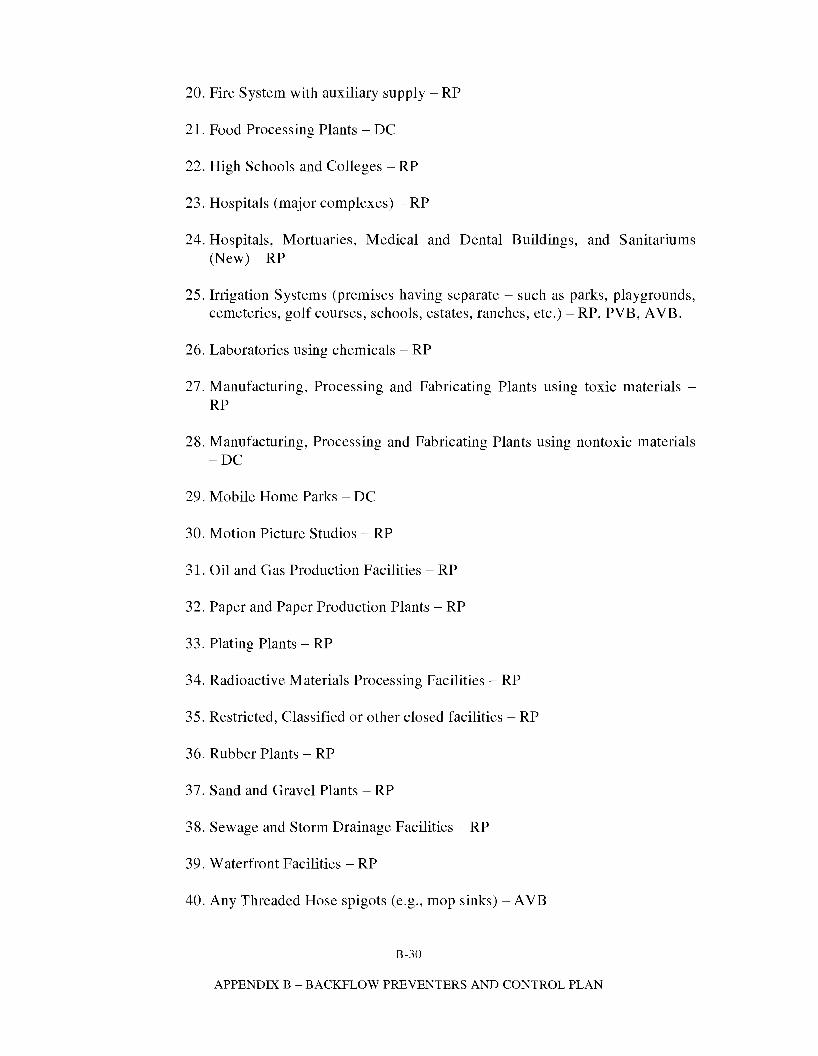
20. Fire System with auxiliary supply - RP
21. Food Processing Plants - DC
22. High Schools and Colleges - RP
23. Hospitals (major complexes) - RP
24. Hospitals, Mortuaries, Medical and Dental Buildings, and Sanitariums (New)-RP
25. Irrigation Systems (premises having separate - such as parks, playgrounds, cemeteries, golf courses, schools, estates, ranches, etc.) - RP, PVB, A VB.
26. Laboratories using chemicals - RP
27. Manufacturing, Processing and Fabricating Plants using toxic materials -RP
28. Manufacturing, Processing and Fabricating Plants using nontoxic materials -DC
29. Mobile Home Parks - DC
30. Motion Picture Studios - RP
31. Oil and Gas Production Facilities - RP
32. Paper and Paper Production Plants - RP
33. Plating Plants - RP
34. Radioactive Materials Processing Facilities - RP
35. Restricted, Classified or other closed facilities - RP
36. Rubber Plants - RP
37. Sand and Gravel Plants - RP
38. Sewage and Storm Drainage Facilities - RP
39. Waterfront Facilities - RP
40. Any Threaded Hose spigots (e.g., mop sinks) -AVB
B-30
APPENDIX B - BACKFLOW PREVENTERS AND CONTROL PLAN
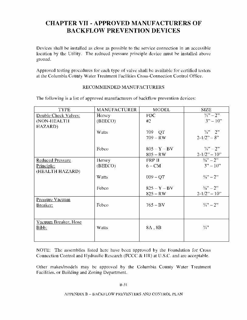
CHAPTER VII -APPROVED MANUFACTURERS OF BACKFLOW PREVENTION DEVICES
Devices shall be installed as close as possible to the service connection in an accessible location by the Utility. The reduced pressure principle device must be installed above ground.
Approved testing procedures for each type of valve shall be available for certified testers at the Columbia County Water Treatment Facilities Cross-Connection Control Office.
RECOMMENDED MANUFACTURERS
The following is a list of approved manufacturers of backflow prevention devices:
TYPE MANUFACTURER MODEL SIZE 3Double Check Valves: Hersey FDC 14" - 2"
(NON-HEALTH (BEECO) #2 3" - 10" HAZARD)
3Watts 709 -QT 14" - 2" 709-RW 2-1/2" - 8"
3Febco 805 - Y -BV 14" - 2" 805-RW 2-1/2"-10"
3Reduced Pressure Hersey FRP II 14" - 2" Principle: (BEECO) 6-CM 3" - 10" (HEALTH HAZARD)
3Watts 009 -QT 14" - 2"
3Febco 825 - Y -BV 14" - 2" 825-RW 2-1/2"-10"
Pressure Vacuum 3Breaker: Febco 765 -BV 14" - 2"
Vacuum Breaker, Hose Bibb: Watts 8A, 8B 314"
NOTE: The assemblies listed here have been approved by the Foundation for Cross Connection Control and Hydraulic Research (FCCC & HR) at U.S.C. and are acceptable.
Other makes/models may be approved by the Columbia County Water Treatment Facilities, or Building and Zoning Department.
B-31
APPENDIX B - BACKFLOW PREVENTERS AND CONTROL PLAN
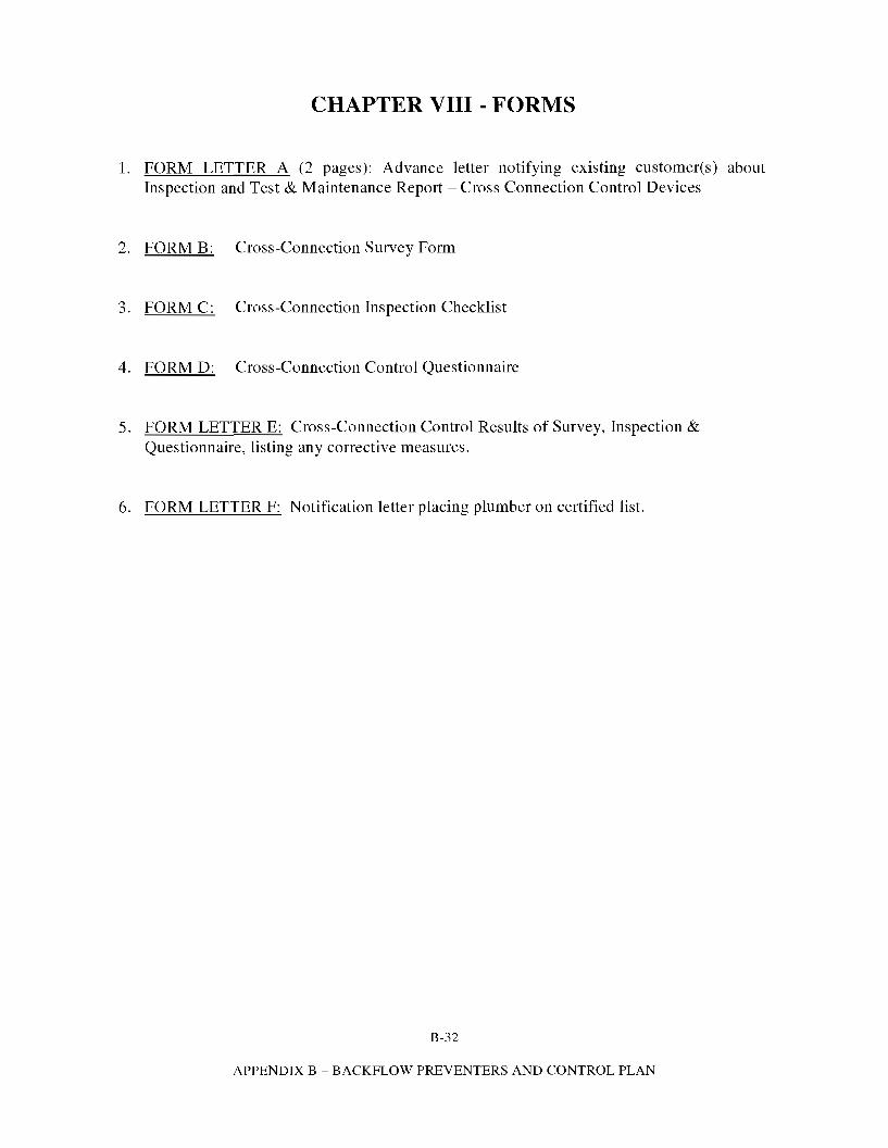
CHAPTER VIII - FORMS
1. FORM LETTER A (2 pages): Advance letter notifying existing customer(s) about Inspection and Test & Maintenance Report - Cross Connection Control Devices
2. FORM B: Cross-Connection Survey Form
3. FORM C: Cross-Connection Inspection Checklist
4. FORM D: Cross-Connection Control Questionnaire
5. FORM LETTER E: Cross-Connection Control Results of Survey, Inspection & Questionnaire, listing any corrective measures.
6. FORM LETTER F: Notification letter placing plumber on certified list.
B-32
APPENDIX B - BACKFLOW PREVENTERS AND CONTROL PLAN
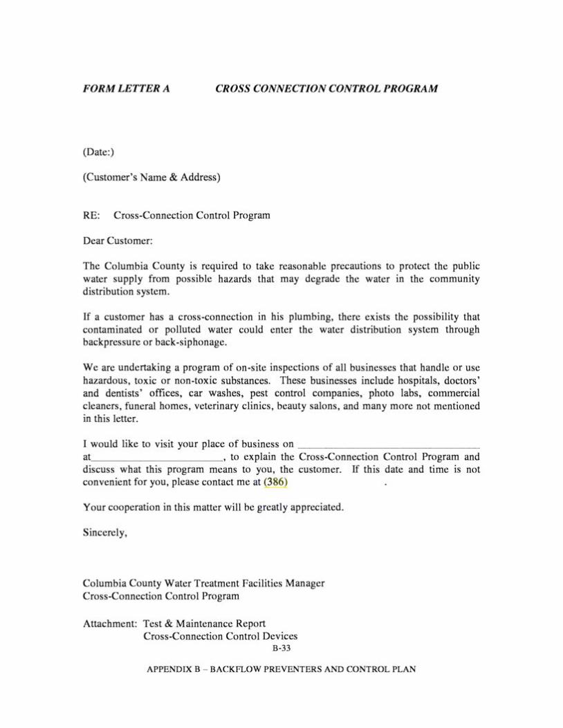
FORM LETTER A CROSS CONNECTION CONTROL PROGRAM
(Date:)
(Customer's Name & Address)
RE: Cross-Connection Control Program
Dear Customer:
The Columbia County is required to take reasonable precautions to protect the public water supply from possible hazards that may degrade the water in the community distribution system.
If a customer has a cross-connection in his plumbing, there exists the possibility that contaminated or polluted water could enter the water distribution system through backpressure or back-siphonage.
We are undertaking a program of on-site inspections of all businesses that handle or use hazardous, toxic or non-toxic substances. These businesses include hospitals, doctors' and dentists' offices, car washes, pest control companies, photo labs, commercial cleaners, funeral homes, veterinary clinics, beauty salons, and many more not mentioned in this letter.
I would like to visit your place of business on ________________ at , to explain the Cross-Connection Control Program and discuss what this program means to you, the customer. If this date and time is not convenient for you, please contact me at 386
Your cooperation in this matter will be greatly appreciated.
Sincerely,
Columbia County Water Treatment Facilities Manager Cross-Connection Control Program
Attachment: Test & Maintenance Report Cross-Connection Control Devices
B-33
APPENDIX B - BACKFLOW PREVENTERS AND CONTROL PLAN

FORM LETTER A (page 2)
TEST & MAINTENANCE REPORT CROSS CONNECTION CONTROL DEVICES
NAME OF PREMISE:____________________________________________ STREET ADDRESS:____________________________________________ LOCATION OF DEVICE:_________________________________________
TYPE OF DEVICE: RP ( ) D.C. ( ) PVB () SIZE:__________ MANUFACTURER:____________________________________________ MODEL NUMBER: SERIAL NUMBER:
PRESSURE DROP ACROSS FIRST CHECK VALVE ________________ PSI
CHECK VAL VE #1 CHECK VAL VE #2 DIFFERENTIAL PRESSURE PRESSURE VACUUM RELIEF VAL VE BREAKER
INITIAL TEST AIR INLET
1. LEAKED () 1. LEAKED () OPENED AT __LBS. OPENED AT PSI
'.'.. CLOSED TIGHT () '.'.. CLOSED TIGHT () DID NOT OPEN () DID NOT OPEN ()
REPAIRS CLEANED () REPLACED: RUBBER PARTS KIT () C.V. ASSEMBLY ()
CLEANED REPLACED: RUBBER PARTS KIT C.V. ASSEMBLY
OR
()
() ()
CLEANED () REPLACED: RUBBER PARTS KIT () C.V. ASSEMBLY ()
OR
CHECK VALVE: LEAKED () CLOSED TIGHT ( )
CLEANED () REPLACED:
OR DISC 0-RINGS SEAT SPRING STEM/GUIDE RETAINER LOCK NUTS OTHER
() () () () () () () ()
DISC 0-RINGS SEAT SPRING STEM/GUIDE RETAINER LOCK NUTS OTHER
() () () () () () () ()
DISC 0-RINGS SEAT SPRING STEM/GUIDE RETAINER LOCK NUTS OTHER
() () () () () () () ()
C.V. ASSEMBLY ( ) DISC. AIR INLET ( ) DISC. C.V. () SPRING () RETAINER () GUIDE () 0-RING () OTHER ()
FINAL TEST OPEN AT LBS.
CLOSED TIGHT () CLOSED TIGHT () REDUCED PRESSURE SATISFACTORY ()
NOTE: ALL REPAIRS/REPLACEMENT SHALL BE COMPLETED WITHIN TEN (10) DAYS. REMARKS: ___________________________________________________________________
I HEREBY CERTIFY THAT THIS DATA IS ACCURATE AND REFLECTS THE PROPER OPERATION AND MAINTENANCE OF THE UNIT.
CERTIFIED TESTING COMPANY ----------------------------------------------------INITIAL TEST BY CERTIFIED TESTER NO. DATE REPAIRED BY DATE FINAL TEST BY CERTIFIED TESTER NO. DATE
WHITE: TO COLUMBIA COUNTY WATER TREATMENT FACILITIES YELLOW: TO TESTER BLUE: TO OWNER
B-34
APPENDIX B - BACKFLOW PREVENTERS AND CONTROL PLAN
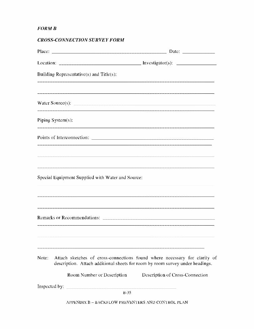
FORMB
CROSS-CONNECTION SURVEY FORM
Place: Date:
Location: --------------------------------- Investigator( s):
Building Representative(s) and Title(s):
Water Source( s ): ---------------------------------------------------------
Piping System( s ): --------------------------------------------------------
Points of Interconnection:
Special Equipment Supplied with Water and Source:
Remarks or Recommendations:
Note: Attach sketches of cross-connections found where necessary for clarity of description. Attach additional sheets for room by room survey under headings.
Room Number or Description Description of Cross-Connection
Inspected by: B-35
APPENDIX B - BACKFLOW PREVENTERS AND CONTROL PLAN
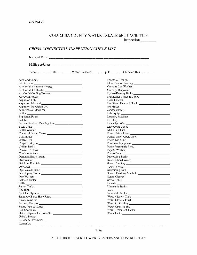
____________________________________________________________________ _
FORMC
COLUMBIA COUNTY WATER TREATMENT FACILITIES Inspection _______ _
CROSS-CONNECTION INSPECTION CHECK LIST
Name of Firm: ___________________________________________________
Mailing Address: -------------------------------------------------
Time: _______ Date: _______Water Pressure:
Air Conditioning Air Washers ________________ Air Con'd. Condenser Water __________ Air Con'd. Chill water ____________ Air Con'd Cooling Towers __________ Air Compressors ______________ Aspirator, Lab _______________ Aspirator, Medical _____________ Aspirator Weedicide Ect. ___________ Autoclave & Sterilizer ____________ Boiler __________________ Baptismal Fount ______________ Bathtub _________________ Bedpan Washer. Flushing Rim __________ Brine Tank ________________ Bottle Washer _______________ Chemical Feeder Tanks ___________ Chlorinator ________________ Coffee Urn ________________ Cuspidor (Gym) ______________ Chiller Tanks _______________ Cooking Kettles ______________ Condensate tank ______________ Demineralizer System ____________ Dishwasher ________________ Drinking Fountain _____________ Dye Jiggs _________________ Dye Vats & Tanks _____________ Developing Tanks----------· Dye Washers _______________ Bathing Tanks _______________ Stills __________________ Starch Tanks ________________ Sitz Bath _________________ Sprinkler System ______________ Shampoo Basin Hose Rinse __________ Sinks, Wash-up ______________ Se1rnted Faucets ______________ Sizing Vats & Cones ____________ Solution Tanks _______________ Urinal. Siphon Jet Blow-Out _________ Urinal. Trough _______________ Fountain, Ornamental ____________ Remarks:
_____ pH: ______Chlorine Res.
Fountain, Trough ______________ Floor Drains Flushing ____________ Garbage Can Washer ____________ Garbage Disposers _____________ Hydro-Therapy Baths ____________ Humidifier Tanks & Boxes __________ Hose Faucets _______________ Hot Water Heater & Tanks ___________ Ice Maker _________________ Janitor Closets _______________ Lab Equip. ________________ Laundry Machine ______________ Lavatory _________________ Lawn Sprinkler _______________ Line Color Coded ______________ Make -up Tank ______________ Pump. Prime Lines _____________ Pump. Water Oper. Eject ___________ Photo Lab Sinks _______________ Photostat Equipment ____________ Pump Pneumatic Eject ____________ Pipette Washer _______________ Potato Peeler _______________ Processing Tanks ______________ Re-circulated Water _____________ Sewer. Sanitary ______________ Sewer. Storm _______________ Swimming Pool ______________ Sewer. Flushing Manhole __________ Steam Cleaner _______________ Steam Table ________________ Urinals __________________ Ultrasonic Baths ______________ Vats __________________ Vegetable Peeler ______________ Water Closets, Tank ____________ Water Closets, Flush ____________ Water for Cooling _____________ Water Oper. Equip. _____________ Water Treatment Tanks ___________ Wash Tanks ________________
B-36
APPENDIX B - BACKFLOW PREVENTERS AND CONTROL PLAN
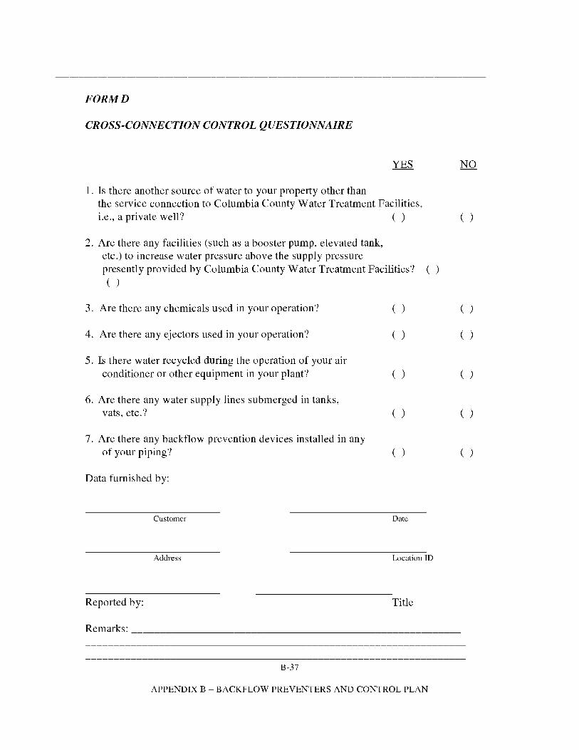
FORMD
CROSS-CONNECTION CONTROL QUESTIONNAIRE
1. Is there another source of water to your property other than the service connection to Columbia County Water Treatment Facilities, i.e., a private well? ( ) ( )
2. Are there any facilities (such as a booster pump, elevated tank, etc.) to increase water pressure above the supply pressure presently provided by Columbia County Water Treatment Facilities? ( )
( )
3. Are there any chemicals used in your operation? ( ) ( )
4. Are there any ejectors used in your operation? ( ) ( )
5. Is there water recycled during the operation of your air conditioner or other equipment in your plant? ( ) ( )
6. Are there any water supply lines submerged in tanks, vats, etc.? ( ) ( )
7. Are there any backflow prevention devices installed in any of your piping? ( ) ( )
Data furnished by:
Customer Date
Address Location ID
Reported by: Title
Remarks: __~--------------~-------------------------------~-----
B-37
APPENDIX B - BACKFLOW PREVENTERS AND CONTROL PLAN
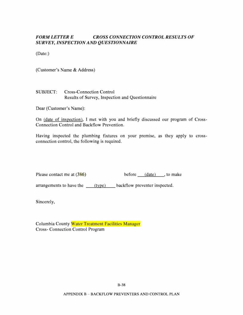
FORM LETTER E CROSS CONNECTION CONTROL RESULTS OF SURVEY, INSPECTION AND QUESTIONNAIRE
(Date:)
(Customer's Name & Address)
SUBJECT: Cross-Connection Control Results of Survey, Inspection and Questionnaire
Dear (Customer's Name):
On (date of inspection), I met with you and briefly discussed our program of Cross-Connection Control and Backflow Prevention.
Having inspected the plumbing fixtures on your premise, as they apply to cross-connection control, the following is required.
Please contact me at (386) before _ _,(""'"d""""at'""'e.....)__,, to make
arrangements to have the -~(t_..y___p_e)~_backflow preventer inspected.
Sincerely,
Columbia County ater Treatment Facilities Mana er Cross- Connection Control Program
B-38
APPENDIX B - BACKFLOW PREVENTERS AND CONTROL PLAN
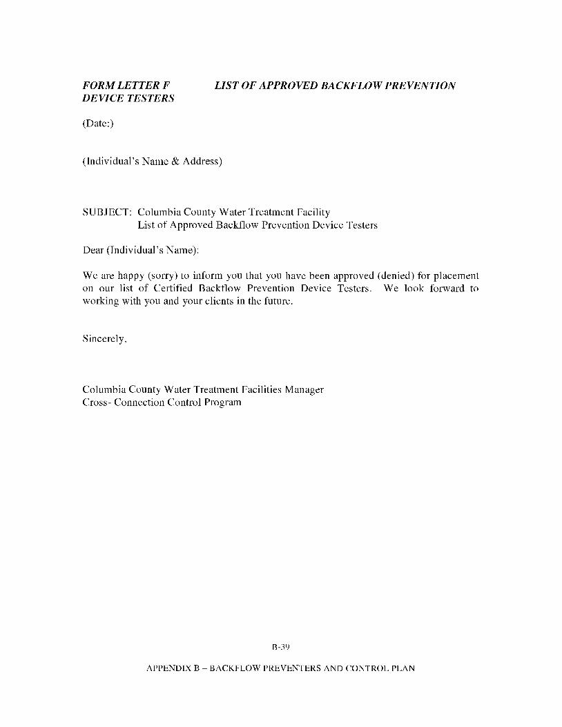
FORM LETTER F LIST OF APPROVED BACKFLOW PREVENTION DEVICE TESTERS
(Date:)
(Individual's Name & Address)
SUBJECT: Columbia County Water Treatment Facility List of Approved Backflow Prevention Device Testers
Dear (Individual's Name):
We are happy (sorry) to inform you that you have been approved (denied) for placement on our list of Certified Backflow Prevention Device Testers. We look forward to working with you and your clients in the future.
Sincerely,
Columbia County Water Treatment Facilities Manager Cross- Connection Control Program
B-39
APPENDIX B - BACKFLOW PREVENTERS AND CONTROL PLAN
DRAFT COPY ONLY
APPENDIXC
OIL AND GREASE MANAGEMENT AND SURCHARGE PROGRAMS
TABLE OF CONTENTS
CHAPTER I OIL AND GREASE MANAGEMENT PROGRAM .............................. 2 PURPOSE AND INTENT .......................................................................................... 2 DEFINITIONS............................................................................................................ 3
CHAPTER 2 OIL AND GREASE PREVENTION PROGRAM .................................. 4 A. GENERAL CRITERIA ........................................................................... 4 B. DESIGN................................................................................................... 6 C. CAPACITY.............................................................................................. 6 D. INSTALLATION .................................................................................... 6 E. EXTENSIONS ......................................................................................... 7 F. MAINTENANCE .................................................................................... 7 G. USER IDENTIFICATION...................................................................... 8 H. ADMINISTRATIVE PROCEDURES .................................................... 9 I. ENFORCEMENT .................................................................................. 10 J. PERMITS ............................................................................................... 11 K. OIL AND GREASE MANAGEMENT ENFORCEMENT; COST ........ .
RECOVERY CHARGES ...................................................................... 12 L. INJUNCTIVE RELIEF.......................................................................... 12 M. CIVIL PENALTIES ............................................................................... 12 N. REMEDIES NONEXCLUSIVE............................................................ 13
C-1
APPENDIX C-OIL AND GREASE POLICY
CHAPTER I OIL AND GREASE MANAGEMENT PROGRAM
Purpose and Intent
The purpose of this Article VIII is to provide for an Oil and Grease Management Program and for its implementation and which shall be referred to as the "County Oil and Grease Management Program". The objective of the County Oil and Grease Management Program is to minimize the introduction of fat-soluble wastes to the County wastewater collection and treatment system and to provide enforcement procedures and cost recovery charges from users receiving and treating abnormally high-strength compatible wastes, such as carbonatious biochemical oxygen demand (CBOD) and total suspended solids (TSS).
C-2
APPENDIX C - OIL AND GREASE POLICY
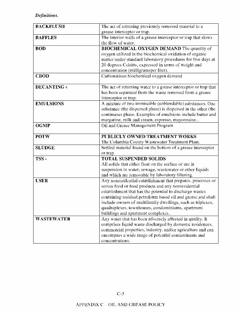
Definitions.
BACKFLUSH The act of returning previously removed material to a grease interceptor or trap.
BAFFLES The interior walls of a grease interceptor or trap that slows the flow of water.
BOD BIOCHEMICAL OXYGEN DEMAND The quantity of oxygen utilized in the biochemical oxidation of organic matter under standard laboratory procedures for five days at 20 degrees Celsius, expressed in terms of weight and concentration (milligramsper liter).
CBOD Carbonatious biochemical oxygen demand
DECANTINGs The act of returning water to a grease interceptor or trap that has been separated from the waste removed from a grease interceptor or trap.
EMULSIONS A mixture of two immiscible (unblendable) substances. One substance (the dispersed phase) is dispersed in the other (the continuous phase. Examples of emulsions include butter and margarine, milk and cream, espresso, mayonnaise ...
OGMP Oil and Grease Management Program
POTW PUBLICLY OWNED TREATMENT WORKS The Columbia County Wastewater Treatment Plant.
SLUDGE Settled material found on the bottom of a grease interceptor or trap.
TSS - TOTAL SUSPENDED SOLIDS All solids that either float on the surface or are in suspension in water, sewage, wastewater or other liquids and which are removable by laboratory filtering.
USER Any nonresidential establishment that prepares, processes or serves food or food products and any nonresidential establishment that has the potential to discharge wastes containing residual petroleum based oil and grease and shall include owners of multifamily dwellings, such as triplexes, quadraplexes, townhouses, condominiums, apartment buildings and apartment complexes.
WASTEWATER Any water that has been adversely affected in quality. It comprises liquid waste discharged by domestic residences, commercial properties, industry, and/or agriculture and can encompass a wide range of potential contaminants and concentrations.
C-3
APPENDIX C - OIL AND GREASE POLICY
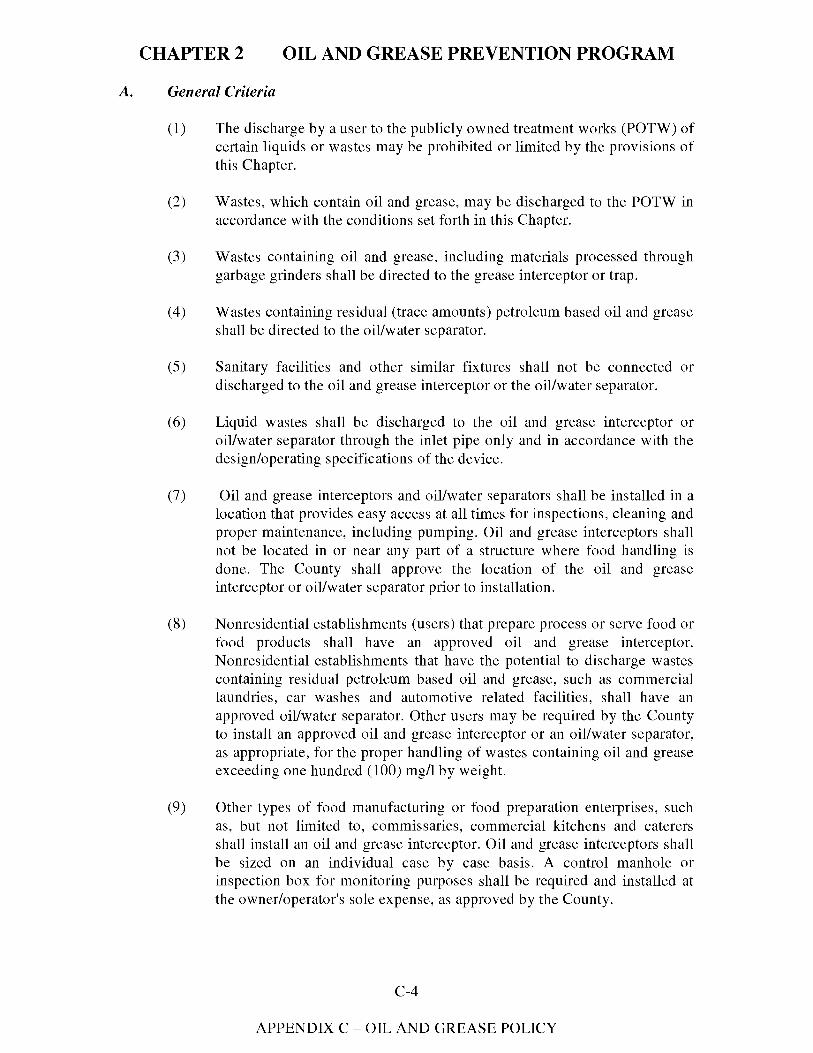
CHAPTER2 OIL AND GREASE PREVENTION PROGRAM
A. General Criteria
(l) The discharge by a user to the publicly owned treatment works (POTW) of certain liquids or wastes may be prohibited or limited by the provisions of this Chapter.
(2) Wastes, which contain oil and grease, may be discharged to the POTW in accordance with the conditions set forth in this Chapter.
(3) Wastes containing oil and grease, including materials processed through garbage grinders shall be directed to the grease interceptor or trap.
(4) Wastes containing residual (trace amounts) petroleum based oil and grease shall be directed to the oil/water separator.
(5) Sanitary facilities and other similar fixtures shall not be connected or discharged to the oil and grease interceptor or the oil/water separator.
(6) Liquid wastes shall be discharged to the oil and grease interceptor or oil/water separator through the inlet pipe only and in accordance with the design/operating specifications of the device.
(7) Oil and grease interceptors and oil/water separators shall be installed in a location that provides easy access at all times for inspections, cleaning and proper maintenance, including pumping. Oil and grease interceptors shall not be located in or near any part of a structure where food handling is done. The County shall approve the location of the oil and grease interceptor or oil/water separator prior to installation.
(8) Nonresidential establishments (users) that prepare process or serve food or food products shall have an approved oil and grease interceptor. Nonresidential establishments that have the potential to discharge wastes containing residual petroleum based oil and grease, such as commercial laundries, car washes and automotive related facilities, shall have an approved oil/water separator. Other users may be required by the County to install an approved oil and grease interceptor or an oil/water separator, as appropriate, for the proper handling of wastes containing oil and grease exceeding one hundred (100) mg/1 by weight.
(9) Other types of food manufacturing or food preparation enterprises, such as, but not limited to, commissaries, commercial kitchens and caterers shall install an oil and grease interceptor. Oil and grease interceptors shall be sized on an individual case by case basis. A control manhole or inspection box for monitoring purposes shall be required and installed at the owner/operator's sole expense, as approved by the County.
C-4
APPENDIX C - OIL AND GREASE POLICY
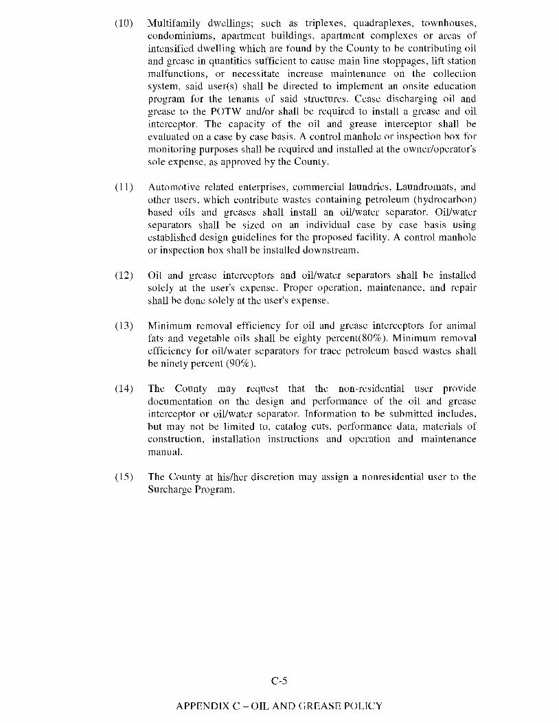
(10) Multifamily dwellings; such as triplexes, quadraplexes, townhouses, condominiums, apartment buildings, apartment complexes or areas of intensified dwelling which are found by the County to be contributing oil and grease in quantities sufficient to cause main line stoppages, lift station malfunctions, or necessitate increase maintenance on the collection system, said user(s) shall be directed to implement an onsite education program for the tenants of said structures. Cease discharging oil and grease to the POTW and/or shall be required to install a grease and oil interceptor. The capacity of the oil and grease interceptor shall be evaluated on a case by case basis. A control manhole or inspection box for monitoring purposes shall be required and installed at the owner/operator's sole expense, as approved by the County.
(11) Automotive related enterprises, commercial laundries, Laundromats, and other users, which contribute wastes containing petroleum (hydrocarbon) based oils and greases shall install an oil/water separator. Oil/water separators shall be sized on an individual case by case basis using established design guidelines for the proposed facility. A control manhole or inspection box shall be installed downstream.
(12) Oil and grease interceptors and oil/water separators shall be installed solely at the user's expense. Proper operation, maintenance, and repair shall be done solely at the user's expense.
(13) Minimum removal efficiency for oil and grease interceptors for animal fats and vegetable oils shall be eighty percent(80% ). Minimum removal efficiency for oil/water separators for trace petroleum based wastes shall be ninety percent (90% ).
(14) The County may request that the non-residential user provide documentation on the design and performance of the oil and grease interceptor or oil/water separator. Information to be submitted includes, but may not be limited to, catalog cuts, performance data, materials of construction, installation instructions and operation and maintenance manual.
(15) The County at his/her discretion may assign a nonresidential user to the Surcharge Program.
C-5
APPENDIX C - OIL AND GREASE POLICY
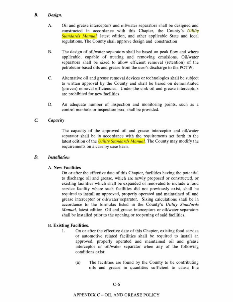
B. Design.
A. Oil and grease interceptors and oil/water separators shall be designed and constructed in accordance with this Chapter, the County's Utility, 'randards Ma111w/, latest edition, and other applicable State and local
regulations. The County shall approve design and construction
B. The design of oil/water separators shall be based on peak flow and where applicable, capable of treating and removing emulsions. Oil/water separators shall be sized to allow efficient removal (retention) of the petroleum-based oils and grease from the user's discharge to the POTW.
C. Alternative oil and grease removal devices or technologies shall be subject to written approval by the County and shall be based on demonstrated (proven) removal efficiencies. Under-the-sink oil and grease interceptors are prohibited for new facilities.
D. An adequate number of inspection and monitoring points, such as a control manhole or inspection box, shall be provided.
C. Capacity
The capacity of the approved oil and grease interceptor and oil/water separator shall be in accordance with the requirements set forth in the latest edition of the Uri/it Standards Manua . The County may modify the requirements on a case by case basis.
D. Installation
A. New Facilities On or after the effective date of this Chapter, facilities having the potential to discharge oil and grease, which are newly proposed or constructed, or existing facilities which shall be expanded or renovated to include a food service facility where such facilities did not previously exist, shall be required to install an approved, properly operated and maintained oil and grease interceptor or oil/water separator. Sizing calculations shall be in accordance to the formulas listed in the County's Utility Standards Manual, latest edition. Oil and grease interceptors or oil/water separators shall be installed prior to the opening or reopening of said facilities.
B. Existing Facilities. 1. On or after the effective date of this Chapter, existing food service
or automotive related facilities shall be required to install an approved, properly operated and maintained oil and grease interceptor or oil/water separator when any of the following conditions exist:
(a) The facilities are found by the County to be contributing oils and grease in quantities sufficient to cause line
C-6
APPENDIX C-OIL AND GREASE POLICY
stoppages or necessitate increased maintenance on the collection system.
(b) Remodeling of the food preparation or kitchen waste plumbing facilities that are subject to a permit that is issued by the Building Department.
(c) Remodeling of an automotive related enterprise, commercial laundry or other users that potentially may contribute wastes with petroleum based oils and greases.
2. The County shall determine the compliance date under this Subsection.
E. Extensions
Any requests for extensions to the required installation dates must be made in writing to the County, at least fifteen (15) days in advance of the compliance date. The written request shall include the reasons for the user's failure or inability to comply with the compliance date set forth, the additional time needed to complete the remaining work, and the steps to be taken to avoid future delays.
F. Maintenance
A. The user shall perform cleaning and maintenance. Cleaning shall include the complete removal of all contents, including floating materials, wastewater, and bottom sludge and solids.
B. Decanting, backflushing or discharging of removed wastes back into the oil and grease interceptor or oil/water separator from which the waste was removed or any other oil and grease interceptor or oil/water separator, for the purpose of reducing the volume to be hauled and disposed is prohibited.
C. Oil and grease interceptors and oil/water separators shall be pumped out completely at a minimum frequency of once every ninety (90) days, or more frequently as needed to prevent carry over of oil and grease into the collection system. Under the sink oil and grease traps shall be cleaned at a minimum frequency of once per week, or more often as necessary to prevent pass through of grease and other food solids to the collection system. Cleaning and maintenance shall include removal of materials from the tank walls, baffles, cross pipes, inlets and outlets.
D. Pumping frequency shall be determined by the County based on flows, quantity of oil and grease in the discharge, volume of business, hours of operations and seasonal variations. In no case shall the pumping frequency exceed ninety (90) days. The user shall be responsible for maintaining the oil and grease interceptor or oil/water separator in such a condition for efficient operation. An interceptor shall be considered to be out of
C-7
APPENDIX C - OIL AND GREASE POLICY
compliance if the grease layer on top exceeds six (6) inches and the solids layer on the bottom exceeds twelve (12) inches or if removal efficiencies as determined through sampling and analysis indicate less than eighty percent (80%) .
E. Wastes removed from each oil and grease interceptor or oil/water separator shall be disposed at a permitted facility to receive such wastes or a location designated by the County for such purposes, in accordance with the provisions of this Chapter. In no way shall the pumpage be returned to any private or public portion of the collection system or the treatment plants.
F. Additives placed into the oil and grease interceptor, oil/water separator or building discharge line system on a constant, regular or scheduled basis shall be reported to the County in writing at least five (5) days prior to use. Such additives shall include, but not be limited to, emulsifiers, enzymes, commercially available bacteria, or other additives designed to absorb, purge, consume, treat, or otherwise eliminate grease and oils. The County prior to introduction into the wastestream, interceptor, or separator shall approve any use of additives in writing. The use of additives in no way shall be considered, as a substitution to the maintenance procedures required herein.
G. Flushing the oil and grease interceptor or oil/water separator with water having a temperature in excess of 140° F shall be strictly prohibited.
H. All maintenance of oil and grease management devices, including proper disposal, shall be performed by the user at the user's sole expense.
G. User Identification.
A. It is unlawful for any facility producing oil and grease waste to discharge into the County's collection system without authorization from the County. Authorization shall be given in the form of an oil and grease discharge certificate. Application for a certificate shall be made to the County. If, after examining the information contained in the oil and grease registration certificate application, it is determined by the County that the proposed facility does not conflict with the provisions of the Chapter, a certificate shall be issued allowing the discharge of such wastes into the collection system. Each oil and grease registration certificate shall be issued for a time not longer than five years from the date of the certificate. The user shall apply for certificate re-issuance a minimum of sixty (60) days prior to the expiration of the user's existing certificate. The terms and conditions of the certificate may be subject to modification by the County during the term of the certificate as limitations or requirements as identified in this Chapter are modified or other just causes exist. The user shall be informed of any proposed changes in the issued certificate at least sixty days prior to the effective date of the change(s). Any changes or new conditions in the certificate shall include a reasonable schedule for compliance.
C-8
APPENDIX C - OIL AND GREASE POLICY
B. As a condition precedent to the granting of an oil and grease registration certificate, the recipient under this section shall agree to hold hannless the County and the County's employees from any liabilities arising from the user's operations under this certificate.
C. The County shall establish a schedule of charges for issuance and renewal of the oil and grease registration certificates. The charges shall be established to insure full cost recovery in the enforcement of this ordinance, and shall include, but shall not be limited to, the cost of field, administrative, engineering and clerical expenses involved. The schedule of charges shall be on file at the Office of the Director of Utilities and shall be available to the public.
H. Administrative Procedures
A manifest that confinns pumping, hauling, and disposal of waste shall track pumpage from oil and grease interceptors and oil/water separators. This manifest shall contain the following information:
Generator information: -Name -Contact Person -Address -Telephone Number -Volume Pumped -Date and Time of pumping -Name and Signature of generator verifying generator information.
Transporter information: -Company Name -Address -Telephone Number -Volume Pumped -Date and Time of pumping -Driver Name and Signature of transporter verifying transporter
infonnation and service Destination Information Disposal Site or Facility:
-Company Name/ Permit Number(s) -Contact Person(s) -Address -Telephone Number -Location of Disposal Site/Facility -Volume Treated -Date and Time of Delivery -Driver Name, Signature and Vehicle No. -Name and Signature of operator verifying disposal site and
facility infonnation.
B. The user shall maintain a log of pumping act1v1t1es for the previous twelve- (12) months. The user shall post the log of pumping activities in a
C-9
APPENDIX C - OIL AND GREASE POLICY
conspicuous location for immediate access. The log shall include the date, time, volume pumped, hauler's name and license number and hauler's signature. The user shall repon pumping activities within forty-eight (48) hours to the County on the form so designated hy the County for such purposes.
C. The user shall maintain a file on site of the records and other documents pertaining to the facility's oil and grease interceptor or oil/water separator. The file contents shall include, but is not limited to, the record (as-huilt) drawings, record of inspections, log of pumping activities and receipts, log of maintenance activities, hauler information, disposal information and monitoring data. The file shall he available at all times for inspection and review hy the County. Documents in the file shall be retained and preserved in accordance with Sl!ction I 02-3 12 of this Chapter.
D. The County may require the user to provide, operate and maintain at the user's expense, appropriate monitoring facilities, such as a control manhole, that arc safe and accessible at all times, for observation, inspection, sample collection and flow measurement of the user's discharge to the POTW. The County may impose additional limitations and monitoring requirements for the discharge to the POTW in accordance with the provisions set forth in this Chapter.
I. Enforcement
A. A Notice of Violation shall be issued to a user for failure to:
1. Report pumping activities;
2. Properly maintain (dean-out or pump) the interceptor or separator in accordance with the provisions of the oil and grease discharge cenificate;
3. Maintain and post the log of pumping activities;
4. Maintain a file of records on site at all times;
5. Provide logs, files, records, or access for inspection or monitoring activities;
6. Obtain or renew the oil and grease discharge cenificate registration; or
7. Pay program fees.
B. The County may serve any user a written notice stating the nature of violation. The user shall have seventy-two (72) hours to complete corrective action and submit evidence of compliance to the County.
C-10
APPENDIX C - OIL AND GREASE POLICY
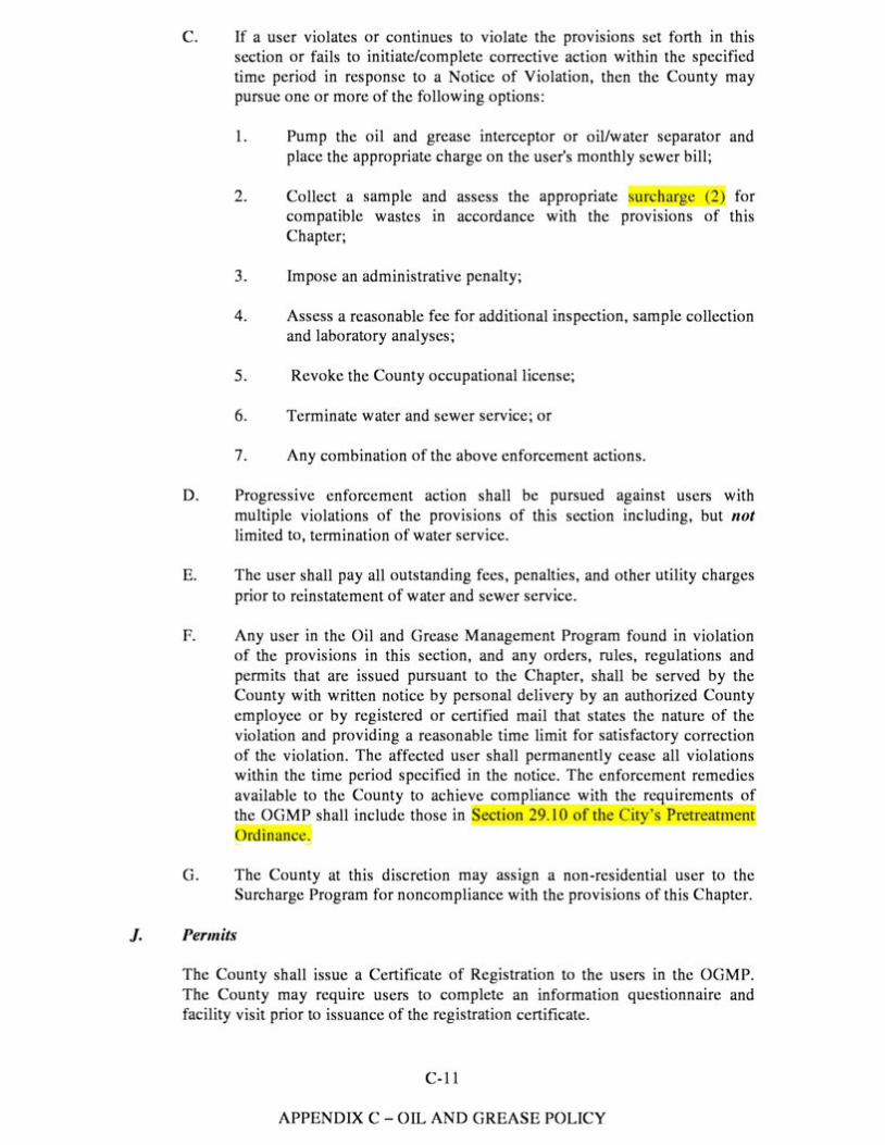
C. If a user violates or continues to violate the provisions set forth in this section or fails to initiate/complete corrective action within the specified time period in response to a Notice of Violation, then the County may pursue one or more of the following options:
1. Pump the oil and grease interceptor or oil/water separator and place the appropriate charge on the user's monthly sewer bill;
2. Collect a sample and assess the appropriate urchar 1e (2) for compatible wastes in accordance with the provisions of this Chapter;
3. Impose an administrative penalty;
4. Assess a reasonable fee for additional inspection, sample collection and laboratory analyses;
5. Revoke the County occupational license;
6. Terminate water and sewer service; or
7. Any combination of the above enforcement actions.
D. Progressive enforcement action shall be pursued against users with multiple violations of the provisions of this section including, but not limited to, termination of water service.
E. The user shall pay all outstanding fees, penalties, and other utility charges prior to reinstatement of water and sewer service.
F. Any user in the Oil and Grease Management Program found in violation of the provisions in this section, and any orders, rules, regulations and permits that are issued pursuant to the Chapter, shall be served by the County with written notice by personal delivery by an authorized County employee or by registered or certified mail that states the nature of the violation and providing a reasonable time limit for satisfactory correction of the violation. The affected user shall permanently cease all violations within the time period specified in the notice. The enforcement remedies available to the County to achieve compliance with the requirements of the OGMP shall include those in ection 29. JO of the Ci 's Pretreatment
·uinaru·
G. The County at this discretion may assign a non-residential user to the Surcharge Program for noncompliance with the provisions of this Chapter.
J. Permits
The County shall issue a Certificate of Registration to the users in the OGMP. The County may require users to complete an information questionnaire and facility visit prior to issuance of the registration certificate.
C-11
APPENDIX C-OIL AND GREASE POLICY
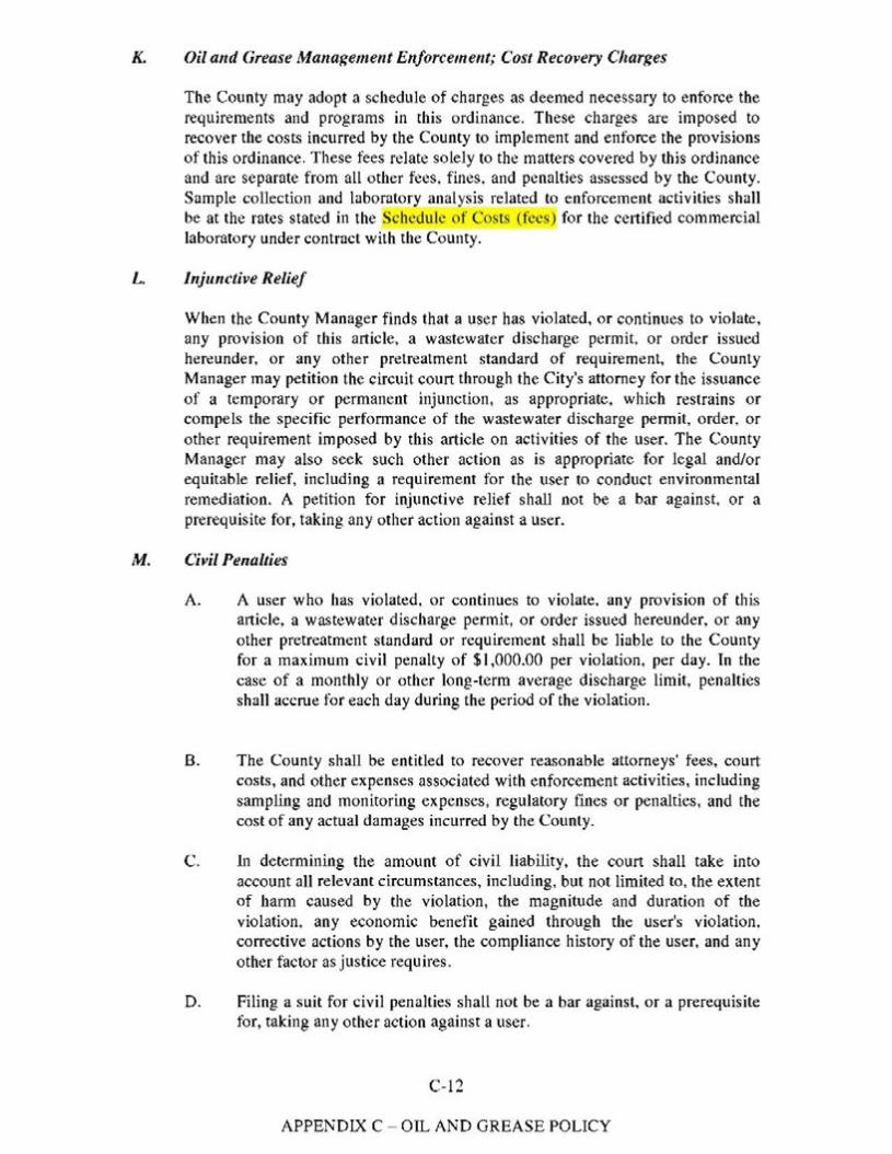
K. Oil alld Grease Mallage,nent Elljorcement; Cost Recovery Charges
The County may adopt a schedule of charges as deemed necessary to enforce the requirements and programs in this ordinance. These charges are imposed to recover the costs incurred by the County to implement and enforce the provisions of this ordinance. These fees relate solely to the matters covered by this ordinance and are separate from all other fees, fines, and penalties assessed by the County. Sample collection and laboratory analysis related to enforcement activities shall be at the rates stated in the Schedule of Costs (fees) for the certified commercial laboratory under contract with the County.
L. Injunctive Relief
When the County Manager finds that a user has violated, or continues to violate, any provision of this article, a wastewater discharge permit, or order issued hereunder, or any other pretreatment standard of requirement, the County Manager may petition the circuit court through the City's attorney for the issuance of a temporary or permanent injunction, as appropriate, which restrains or compels the specific perfonnance of the wastewater discharge pennit, order, or other requirement imposed by this article on activities of the user. The County Manager may also seek such other action as is appropriate for legal and/or equitable relief, including a requirement for the user to conduct environmental remediation. A petition for injunctive relief shall not be a bar against, or a prerequisite for, taking any other action against a user.
M. Civil Penalties
A. A user who has violated, or continues to violate, any provision of this article, a wastewater discharge permit, or order issued hereunder, or any other pretreatment standard or requirement shall be liable to the County for a maximum civil penalty of $1,000.00 per violation, per day. In the case of a monthly or other long-term average discharge limit. penalties shall accrue for each day during the period of the violation.
8. The County shall be entitled to recover reasonable attorneys' fees. court costs, and other expenses associated with enforcement activities, including sampling and monitoring expenses, regulatory fines or penalties, and the cost of any actual damages incurred by the County.
C. In determining the amount of civil liability, the court shall take into account all relevant circumstances, including, but not limited to, the extent of harm caused by the violation, the magnitude and duration of the violation, any economic benefit gained through the user's violation, corrective actions by the user, the compliance history of the user, and any other factor as justice requires.
D. Filing a suit for civil penalties shall not be a bar against, or a prerequisite for, taking any other action against a user.
C-12
APPENDIX C - OIL AND GREASE POLICY
N. Remedies Nonexclusive
The remedies provided for in this article are not exclusive. The County Manager or his designee may take any, all, or any combination of these actions against a noncompliant user. Enforcement of pretreatment violations will generally be in accordance with the County's enforcement response plan. However, the County Manager or his designee may take other action against any user when the circumstances warrant. Further, the County Manager or his designee is empowered to take more than one enforcement action against any noncompliant user.
C-13
APPENDIX C - OIL AND GREASE POLICY
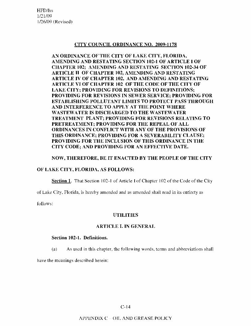
HFD/lss 1/21/09 1/26/09 (Revised)
CITY COUNCIL ORDINANCE NO. 2009-1178
AN ORDINANCE OF THE CITY OF LAKE CITY, FLORIDA, AMENDING AND RESTATING SECTION 102-1 OF ARTICLE I OF CHAPTER 102; AMENDING AND RESTATING SECTION 102-34 OF ARTICLE II OF CHAPTER 102, AMENDING AND RESTATING ARTICLE IV OF CHAPTER 102, AND AMENDING AND RESTATING ARTICLE VI OF CHAPTER 102 OF THE CODE OF THE CITY OF LAKE CITY; PROVIDING FOR REVISIONS TO DEFINITIONS; PROVIDING FOR REVISIONS IN SEWER SERVICE; PROVIDING FOR ESTABLISHING POLLUTANT LIMITS TO PROTECT PASS THROUGH AND INTERFERENCE TO APPLY AT THE POINT WHERE WASTEWATER IS DISCHARGED TO THE WASTEWATER TREATMENT PLANT; PROVIDING FOR REVISIONS RELATING TO PRETREATMENT; PROVIDING FOR THE REPEAL OF ALL ORDINANCES IN CONFLICT WITH ANY OF THE PROVISIONS OF THIS ORDINANCE; PROVIDING FOR A SEVERABILITY CLAUSE; PROVIDING FOR THE INCLUSION OF THIS ORDINANCE IN THE CITY CODE; AND PROVIDING FOR AN EFFECTIVE DATE.
NOW, THEREFORE, BE IT ENACTED BY THE PEOPLE OF THE CITY
OF LAKE CITY, FLORIDA, AS FOLLOWS:
Section 1. That Section 102-1 of Article I of Chapter 102 of the Code of the City
of Lake City, Florida, is hereby amended and as amended shall read in its entirety as
follows:
UTILITIES
ARTICLE I. IN GENERAL
Section 102-1. Definitions.
(a) As used in this chapter, the following words, terms and abbreviations shall
have the meanings described herein:
C-14
APPENDIX C - OIL AND GREASE POLICY
Applicant means the person, organization or corporation who signs an application
form requesting water or sewer service be made available at a specific location and
thereby agrees to pay for all such services at that location.
Biochemical oxygen demand (abbreviated BOD5) shall mean the quantity of
oxygen, expressed in parts per million by weight, utilized in the biochemical oxidation of
organic matter under standard laboratory conditions for five (5) days at a temperature of
twenty (20) degrees Celsius. The laboratory determinations shall be made in accordance
with procedures set forth in "Standard Methods for the Examination of Water, Sewage,
and Industrial Wastes," published jointly by the American Public Health Association, the
American Waterworks Association and the Water Pollution Control Federation
(hereinafter "standard methods").
City means the City of Lake City, Florida.
City Council means the duly elected members of the City Council of Lake City.
Commercial Consumer, commercial, commercial user, or non-residential user, as
used herein shall all mean any consumer other than a residential user or residential unit.
Consumer means the person or persons who actually receive and utilize water
service at a specific location and/or who contribute, cause or permit the contribution of
wastewater into the city sewer system.
County means Columbia County, Florida.
Developer shall mean any person engaged in the business of making
improvements to or subdividing real property to which water and/or sewer services to be
rendered by the city. The term shall also include, where applicable, any individual or
C-15
APPENDIX C - OIL AND GREASE POLICY
legal entity that as owner or legally constituted agent for the owner of such real property,
applies for the provision of water or wastewater facilities in order to serve said property.
Dwelling means a living unit, house, mobile home, apartment or building used
primarily for human habitation. The word "dwelling" shall not include hotels, motels,
tourist courts or other accommodations for transients, nor shall it include dormitories,
fraternities, sororities, rooming houses, business or industrial facilities.
(l) Single-family: A building containing not more than on e(l) living unit o a
single lot or living unit of a multiple-family dwelling where each living
unit is constructed on a separate lot. Mobile homes containing one (1)
living unit not in approved mobile home parks are considered single-
family dwellings.
(2) Multifamily: A building which contains two (2) or more living units.
Equivalent residential unit (ERU) means the average estimated daily water
demand for a residential dwelling unit, as set out in the Florida Administrative Code 64E-
6.008, Table II, for estimated domestic sewage flows, as may, from time to time, be
amended. Presently, one (1) ERU equals two hundred fifty (250) gallons per day.
General Manager means the General Manager of the Lake City Regional Utilities
which are also referred to as LCRU.
Impact fees means the charges provided for in section 102.36 of the Code and are
those fees imposed and collected to provide for expansion of the utility system necessary
to provide service to additional utility consumers.
C-16
APPENDIX C - OIL AND GREASE POLICY
LCRU means the Lake City Regional Utilities consisting of a water supply and
distribution system, a wastewater treatment collection and disposal system, a reuse water
distribution system and a natural gas distribution system, including the necessary
production and treatment plants, facilities, fixtures, land, and other apparatus appurtenant
to and a part of such systems which is operated, maintained and administered as one
comprehensive system.
Lake City Regional Utilities means the Lake City Regional Utilities consisting of
a water supply and distribution system, a wastewater treatment collection and disposal
system, a reuse water distribution system and a natural gas distribution system, including
the necessary production and treatment plants, facilities, fixtures, land, and other
apparatus appurtenant to and a part of such systems and which utility systems are
operated, maintained and administered as one comprehensive system.
Lake City Regional Utilities Board or Board means the advisory board to the
Lake City Regional Utilities created and established by ordinance of the City Council.
Lot means a part of a subdivision or any other parcel of land intended as a unit for
building, development or transfer of ownership or both. Parcels of land less than one (l)
acre for commercial projects or multifamily dwellings and parcels of land for each single-
family dwelling shall be considered lots.
Meter (water) means the measuring device owned and installed by the city on a
service line for the purpose of accurately measuring water use by a consumer.
Mobile home means a detached residential dwelling designed for long-term
occupancy and intended to be transported after fabrication on streets and highways on its
C-17
APPENDIX C - OIL AND GREASE POLICY

own wheels or on a flatbed or other trailer and arriving at the site where it is to be
occupied as a dwelling complete and ready for occupancy, except for minor and
incidental unpacking and assembly operations, location on jacks or permanent
foundation, connection to utilities and the like.
Mobile home park means a parcel of property zoned under the provisions of the
applicable city or county regulations, whose allowed and recognized use is the business
of renting spaces or lots upon which mobile homes are placed and occupied as single-
family dwellings and shall include any associated and allowed laundry and recreational
and common facilities and incidental thereto.
Motel means "motor hotel," "tourist court" and "transient accommodations"
primarily for those persons traveling by automotive vehicles and consisting of two (2) or
more units or buildings designed to provide sleeping accommodations and with
customary accessory uses.
Off-site facilities means those components of the utility system located outside the
consumer's property.
On-site facilities means those components of the utility system located upon the
consumer's property.
Person means any and all persons, natural or artificial, including any individual,
firm, company, municipal or private corporation, association, society, institution,
enterprise, governmental agency, partnership or group or other entity.
C-18
APPENDIX C - OIL AND GREASE POLICY
Property means the land or improvements upon land which the applicant or
consumer is owner, or over which applicant or consumer has legal authority to control
sufficiently to authorize the applicant or the consumer to make application for service.
Residence, residential dwelling or residential unit means any property, structure,
building, improvement, or premise used by a consumer as the consumer's principal
separate independent dwelling or housekeeping unit, whether owned, rented or leased,
and containing sleeping, kitchen and sanitary facilities. For the purpose of this section,
each apartment and/or mobile home so used constitutes a residence or residential unit.
Service means the readiness and ability on the part of the city to furnish water or
sewer service to the consumer on demand. Thus, the maintenance of water pressure at
the point of delivery or presence of a wastewater service lateral shall constitute the
rendering of service irrespective of whether the consumer makes any use thereof.
Suspended solids (abbreviated SS) means solids that either float on the surface of
or are in suspension in water, sewage or industrial waste and which are removable by a
laboratory filtration device. Quantitative determination of suspended solids shall be
made in accordance with procedures set forth in the "standard methods."
Utility Director or Executive Director of Utilities means the General Manager of
the Lake City Regional Utilities.
Utility system means the Lake City Regional Utilities.
C-19
APPENDIX C - OIL AND GREASE POLICY
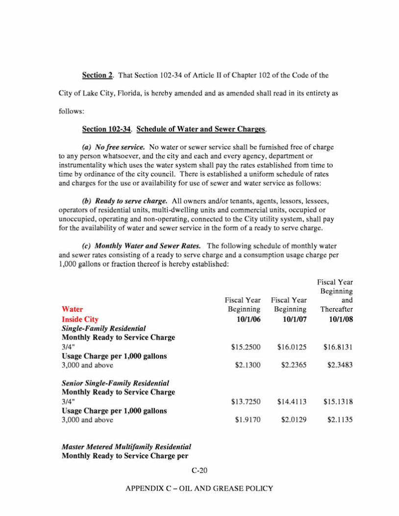
Section 2. That Section 102-34 of Article II of Chapter 102 of the Code of the
City of Lake City, Florida, is hereby amended and as amended shall read in its entirety as
follows:
Section 102-34. Schedule of Water and Sewer Charges.
(a) No free service. No water or sewer service shall be furnished free of charge to any person whatsoever, and the city and each and every agency, department or instrumentality which uses the water system shall pay the rates established from time to time by ordinance of the city council. There is established a uniform schedule of rates and charges for the use or availability for use of sewer and water service as follows:
(b) Ready to serve charge. All owners and/or tenants, agents, lessors, lessees, operators of residential units, multi-dwelling units and commercial units, occupied or unoccupied, operating and non-operating, connected to the City utility system, shall pay for the availability of water and sewer service in the form of a ready to serve charge.
(c) Monthly Water and Sewer Rates. The following schedule of monthly water and sewer rates consisting of a ready to serve charge and a consumption usage charge per 1,000 gallons or fraction thereof is hereby established:
Fiscal Year Beginning
Fiscal Year Fiscal Year and Water Beginning Beginning Thereafter Inside City 10/1/06 10/1/07 10/1/08 Single-Family Residential Monthly Ready to Service Charge 3/4" $15.2500 $16.0125 $16.8131 Usage Charge per 1,000 gallons 3,000 and above $2.1300 $2.2365 $2.3483
Senior Single-Family Residential Monthly Ready to Service Charge 3/4" $13.7250 $14.4113 $15.1318 Usage Charge per 1,000 gallons 3,000 and above $1.9170 $2.0129 $2.1135
Master Metered Multifamily Residential Monthly Ready to Service Charge per
C-20
APPENDIX C-OIL AND GREASE POLICY
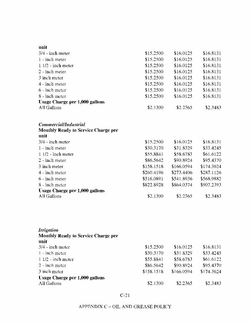
unit 3/4 - inch meter 1 - inch meter 1 1/2 - inch meter 2 - inch meter 3 inch meter 4 - inch meter 6 - inch meter 8 - inch meter Usage Charge per 1,000 gallons All Gallons
Commercial/Industrial Monthly Ready to Service Charge per unit 3/4 - inch meter 1 - inch meter 1 1/2 - inch meter 2 - inch meter 3 inch meter 4 - inch meter 6 - inch meter 8 - inch meter Usage Charge per 1,000 gallons All Gallons
Irrigation Monthly Ready to Service Charge per unit 3/4 - inch meter 1 - inch meter 1 1/2 - inch meter 2 - inch meter 3 inch meter Usage Charge per 1,000 gallons All Gallons
$15.2500 $15.2500 $15.2500 $15.2500 $15.2500 $15.2500 $15.2500 $15.2500
$2.1300
$15.2500 $30.3170 $55.8841 $86.5642
$158.1518 $260.4196 $516.0891 $822.8928
$2.1300
$15.2500 $30.3170 $55.8841 $86.5642
$158.1518
$2.1300
$16.0125 $16.0125 $16.0125 $16.0125 $16.0125 $16.0125 $16.0125 $16.0125
$2.2365
$16.0125 $31.8329 $58.6783 $90.8924
$166.0594 $273.4406 $541.8936 $864.0374
$2.2365
$16.0125 $31.8329 $58.6783 $90.8924
$166.0594
$2.2365
$16.8131 $16.8131 $16.8131 $16.8131 $16.8131 $16.8131 $16.8131 $16.8131
$2.3483
$16.8131 $33.4245 $61.6122 $95.4370
$174.3624 $287.1126 $568.9882 $907.2393
$2.3483
$16.8131 $33.4245 $61.6122 $95.4370
$174.3624
$2.3483
C-21
APPENDIX C - OIL AND GREASE POLICY
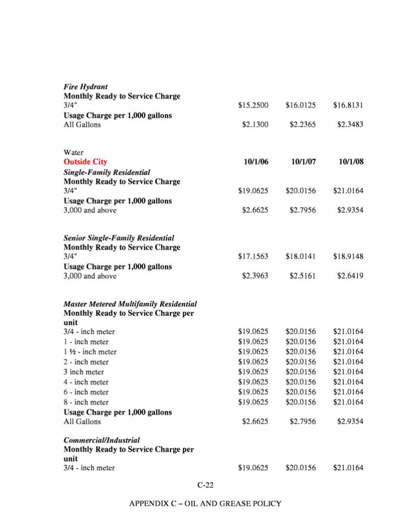
Fire Hydrant Monthly Ready to Service Charge 3/4" Usage Charge per 1,000 gallons All Gallons
Water Outside City Single-Family Residential Monthly Ready to Service Charge 3/4" Usage Charge per 1,000 gallons 3,000 and above
Senior Single-Family Residential Monthly Ready to Service Charge 3/4" Usage Charge per 1,000 gallons 3,000 and above
Master Metered Multifamily Residential Monthly Ready to Service Charge per unit 3/4 - inch meter 1 - inch meter 1 Y2 - inch meter 2 - inch meter 3 inch meter 4 - inch meter 6 - inch meter 8 - inch meter Usage Charge per 1,000 gallons All Gallons
Commercial/Industrial Monthly Ready to Service Charge per unit 3/4 - inch meter
C-22
$15.2500
$2.1300
10/1/06
$19.0625
$2.6625
$17.1563
$2.3963
$19.0625 $19.0625 $19.0625 $19.0625 $19.0625 $19.0625 $19.0625 $19.0625
$2.6625
$19.0625
$16.0125
$2.2365
10/1/07
$20.0156
$2.7956
$18.0141
$2.5161
$20.0156 $20.0156 $20.0156 $20.0156 $20.0156 $20.0156 $20.0156 $20.0156
$2.7956
$20.0156
$16.8131
$2.3483
10/1/08
$21.0164
$2.9354
$18.9148
$2.6419
$21.0164 $21.0164 $21.0164 $21.0164 $21.0164 $21.0164 $21.0164 $21.0164
$2.9354
$21.0164
APPENDIX C-OIL AND GREASE POLICY
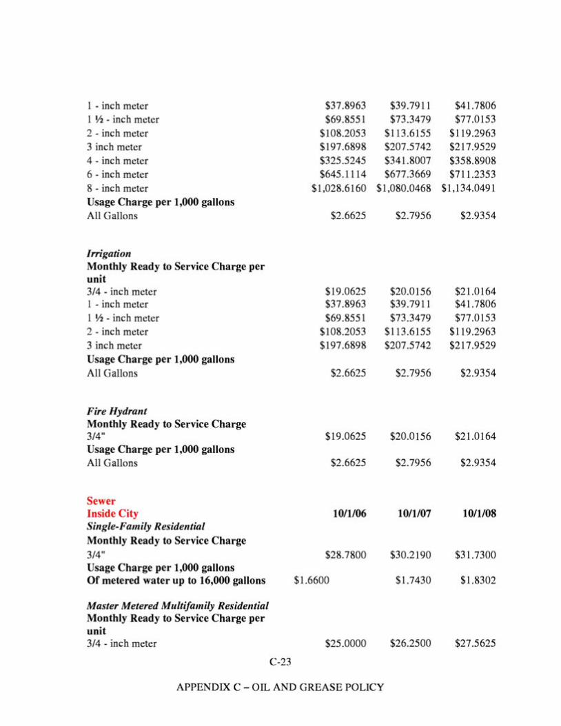
1 - inch meter $37.8963 1 Y2 - inch meter $69.8551 2 - inch meter $108.2053 3 inch meter $197.6898 4 - inch meter $325.5245 6 - inch meter $645.1114 8 - inch meter $1,028.6160 Usage Charge per 1,000 gallons All Gallons $2.6625
Irrigation Monthly Ready to Service Charge per unit 3/4 - inch meter $19.0625 1 - inch meter $37.8963 1 Y2 - inch meter $69.8551 2 - inch meter $108.2053 3 inch meter $197.6898 Usage Charge per 1,000 gallons All Gallons $2.6625
Fire Hydrant Monthly Ready to Service Charge 3/4" $19.0625 Usage Charge per 1,000 gallons All Gallons $2.6625
Sewer Inside City 10/1/06 Single-Family Residential Monthly Ready to Service Charge 3/4" $28.7800 Usage Charge per 1,000 gallons Of metered water up to 16,000 gallons $1.6600
Master Metered Multifamily Residential Monthly Ready to Service Charge per unit 3/4 - inch meter $25.0000
C-23
$39.7911 $73.3479
$113.6155 $207.5742 $341.8007 $677.3669
$1,080.0468
$2.7956
$20.0156 $39.7911 $73.3479
$113.6155 $207.5742
$2.7956
$20.0156
$2.7956
10/1/07
$30.2190
$1.7430
$26.2500
$41.7806 $77.0153
$119.2963 $217.9529 $358.8908 $711.2353
$1,134.0491
$2.9354
$21.0164 $41.7806 $77.0153
$119.2963 $217.9529
$2.9354
$21.0164
$2.9354
10/1/08
$31.7300
$1.8302
$27.5625
APPENDIX C-OIL AND GREASE POLICY
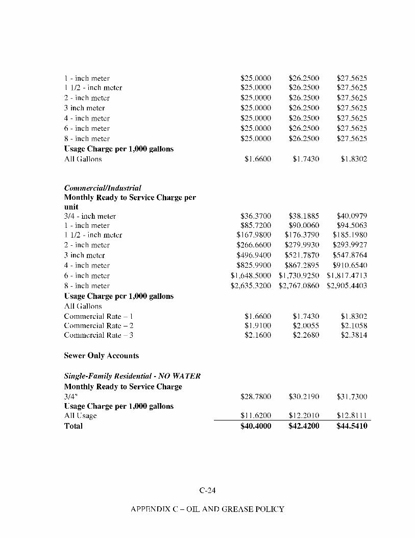
1 - inch meter 1 1/2 - inch meter 2 - inch meter 3 inch meter 4 - inch meter 6 - inch meter 8 - inch meter Usage Charge per 1,000 gallons All Gallons
Commercial/Industrial Monthly Ready to Service Charge per unit 3/4 - inch meter 1 - inch meter 1 1/2 - inch meter 2 - inch meter 3 inch meter 4 - inch meter 6 - inch meter 8 - inch meter Usage Charge per 1,000 gallons All Gallons Commercial Rate - 1 Commercial Rate - 2 Commercial Rate - 3
Sewer Only Accounts
Single-Family Residential - NO WATER Monthly Ready to Service Charge 3/4" Usage Charge per 1,000 gallons All Usage Total
$25.0000 $25.0000 $25.0000 $25.0000 $25.0000 $25.0000 $25.0000
$1.6600
$36.3700 $85.7200
$167.9800 $266.6600 $496.9400 $825.9900
$1,648.5000 $2,635.3200
$1.6600 $1.9100 $2.1600
$28.7800
$11.6200 $40.4000
$26.2500 $27.5625 $26.2500 $27.5625 $26.2500 $27.5625 $26.2500 $27.5625 $26.2500 $27.5625 $26.2500 $27.5625 $26.2500 $27.5625
$1.7430 $1.8302
$38.1885 $40.0979 $90.0060 $94.5063
$176.3790 $185.1980 $279.9930 $293.9927 $521.7870 $547.8764 $867.2895 $910.6540
$1,730.9250 $1,817.4713 $2,767.0860 $2,905.4403
$1.7430 $1.8302 $2.0055 $2.1058 $2.2680 $2.3814
$30.2190 $31.7300
$12.2010 $12.8111 $42.4200 $44.5410
C-24
APPENDIX C - OIL AND GREASE POLICY
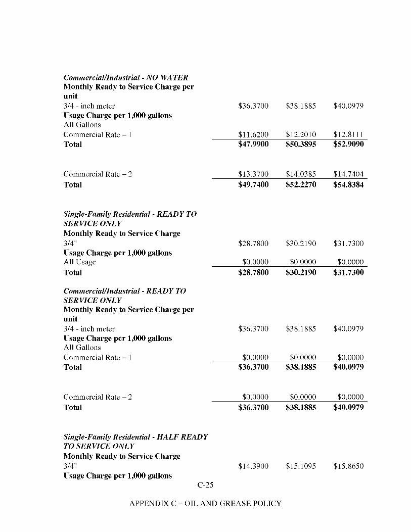
Commercial/Industrial - NO WATER Monthly Ready to Service Charge per unit 3/4 - inch meter Usage Charge per 1,000 gallons All Gallons Commercial Rate - 1 Total
Commercial Rate - 2 Total
Single-Family Residential - READY TO SERVICE ONLY Monthly Ready to Service Charge 3/4" Usage Charge per 1,000 gallons All Usage Total
Commercial/Industrial -READY TO SERVICE ONLY Monthly Ready to Service Charge per unit 3/4 - inch meter Usage Charge per 1,000 gallons All Gallons Commercial Rate - 1 Total
Commercial Rate - 2 Total
Single-Family Residential - HALF READY TO SERVICE ONLY Monthly Ready to Service Charge 3/4" Usage Charge per 1,000 gallons
C-25
$36.3700
$11.6200 $47.9900
$13.3700 $49.7400
$28.7800
$0.0000 $28.7800
$36.3700
$0.0000 $36.3700
$0.0000 $36.3700
$14.3900
$38.1885 $40.0979
$12.2010 $12.8111 $50.3895 $52.9090
$14.0385 $14.7404 $52.2270 $54.8384
$30.2190 $31.7300
$0.0000 $0.0000 $30.2190 $31.7300
$38.1885 $40.0979
$0.0000 $0.0000 $38.1885 $40.0979
$0.0000 $0.0000 $38.1885 $40.0979
$15.1095 $15.8650
APPENDIX C - OIL AND GREASE POLICY
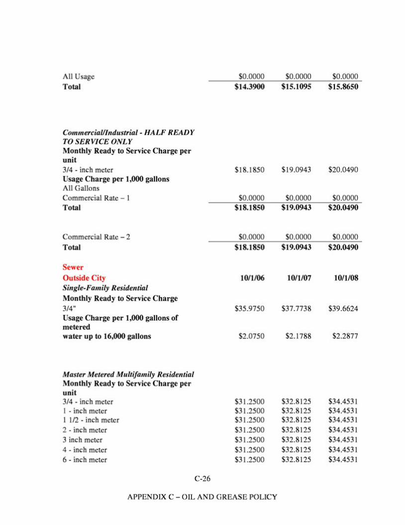
All Usage Total
Commercial/Industrial - HALF READY TO SERVICE ONLY Monthly Ready to Service Charge per unit 3/4 - inch meter Usage Charge per 1,000 gallons All Gallons Commercial Rate - 1 Total
Commercial Rate - 2 Total
Sewer Outside City Single-Family Residential Monthly Ready to Service Charge 3/4" Usage Charge per 1,000 gallons of metered water up to 16,000 gallons
Master Metered Multifamily Residential Monthly Ready to Service Charge per unit 3/4 - inch meter 1 - inch meter 1 1/2 - inch meter 2 - inch meter 3 inch meter 4 - inch meter 6 - inch meter
C-26
$0.0000 $14.3900
$18.1850
$0.0000 $18.1850
$0.0000 $18.1850
10/1/06
$35.9750
$2.0750
$31.2500 $31.2500 $31.2500 $31.2500 $31.2500 $31.2500 $31.2500
$0.0000 $15.1095
$19.0943
$0.0000 $19.0943
$0.0000 $19.0943
10/1/07
$37.7738
$2.1788
$32.8125 $32.8125 $32.8125 $32.8125 $32.8125 $32.8125 $32.8125
$0.0000 $15.8650
$20.0490
$0.0000 $20.0490
$0.0000 $20.0490
10/1/08
$39.6624
$2.2877
$34.4531 $34.4531 $34.4531 $34.4531 $34.4531 $34.4531 $34.4531
APPENDIX C-OIL AND GREASE POLICY
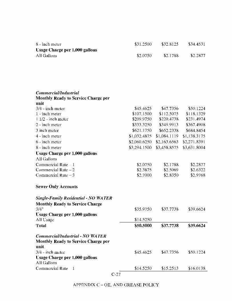
8 - inch meter $31.2500 $32.8125 $34.4531 Usage Charge per 1,000 gallons All Gallons $2.0750 $2.1788 $2.2877
Commercial/Industrial Monthly Ready to Service Charge per unit 3/4 - inch meter 1 - inch meter 1 1/2 - inch meter 2 - inch meter 3 inch meter 4 - inch meter 6 - inch meter 8 - inch meter Usage Charge per 1,000 gallons All Gallons Commercial Rate - 1 Commercial Rate - 2 Commercial Rate - 3
Sewer Only Accounts
Single-Family Residential - NO WATER Monthly Ready to Service Charge 3/4" Usage Charge per 1,000 gallons All Usage Total
Commercial/Industrial - NO WATER Monthly Ready to Service Charge per unit 3/4 - inch meter Usage Charge per 1,000 gallons All Gallons Commercial Rate - 1
C-27
$45.4625 $107.1500 $209.9750 $333.3250 $621.1750
$1,032.4875 $2,060.6250 $3,294.1500
$2.0750 $2.3875 $2.7000
$35.9750
$14.5250 $50.5000
$45.4625
$14.5250
$47.7356 $112.5075 $220.4738 $349.9913 $652.2338
$1,084.1119 $2,163.6563 $3,458.8575
$2.1788 $2.5069 $2.8350
$37.7738
$37.7738
$47.7356
$15.2513
$50.1224 $118.1329 $231.4974 $367.4908 $684.8454
$1,138.3175 $2,271.8391 $3,631.8004
$2.2877 $2.6322 $2.9768
$39.6624
$39.6624
$50.1224
$16.0138
APPENDIX C - OIL AND GREASE POLICY
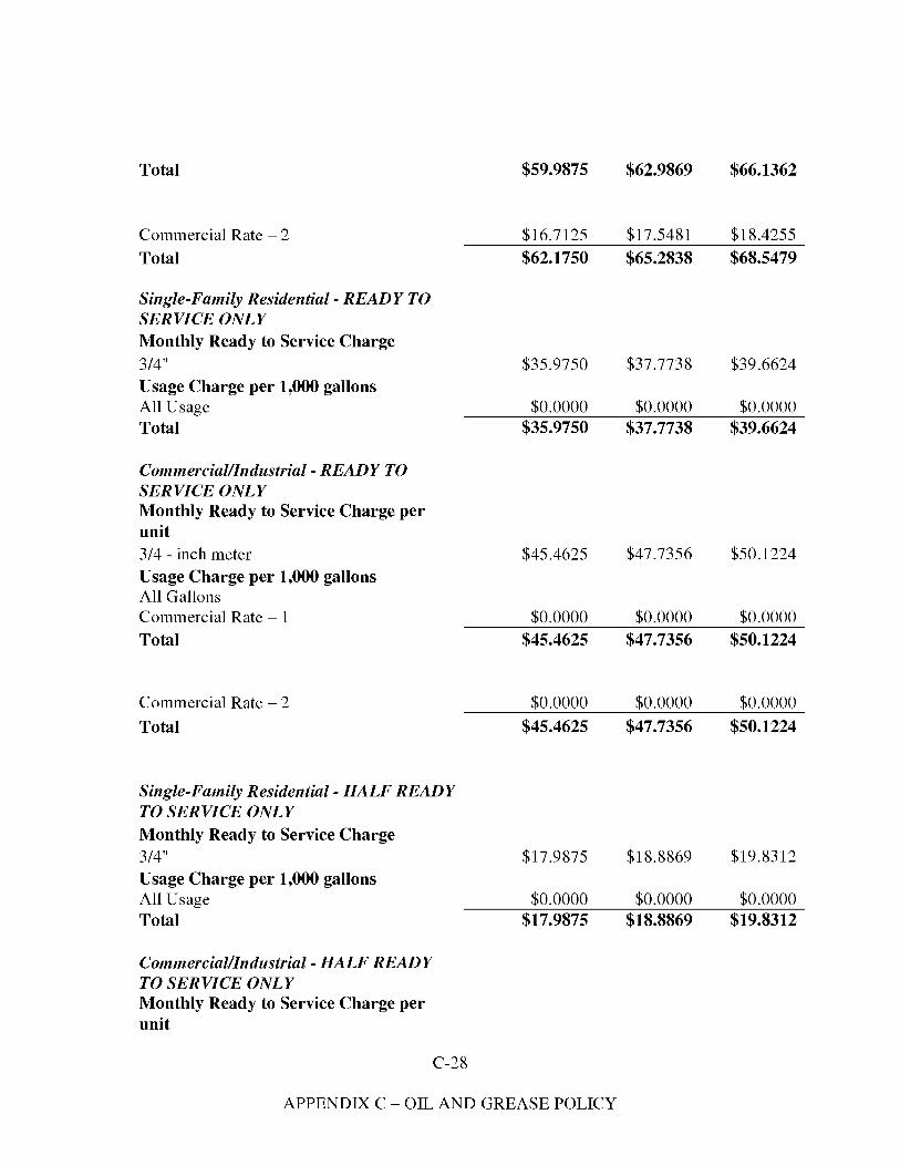
Total
Commercial Rate - 2 Total
Single-Family Residential- READY TO SERVICE ONLY Monthly Ready to Service Charge 3/4" Usage Charge per 1,000 gallons All Usage Total
Commercial/Industrial -READY TO SERVICE ONLY Monthly Ready to Service Charge per unit 3/4 - inch meter Usage Charge per 1,000 gallons All Gallons Commercial Rate - 1 Total
Commercial Rate - 2 Total
Single-Family Residential - HALF READY TO SERVICE ONLY Monthly Ready to Service Charge 3/4" Usage Charge per 1,000 gallons All Usage Total
Commercial/Industrial - HALF READY TO SERVICE ONLY Monthly Ready to Service Charge per unit
C-28
$59.9875
$16.7125 $62.1750
$35.9750
$0.0000 $35.9750
$45.4625
$0.0000 $45.4625
$0.0000 $45.4625
$17.9875
$0.0000 $17.9875
$62.9869
$17.5481 $65.2838
$37.7738
$0.0000 $37.7738
$47.7356
$0.0000 $47.7356
$0.0000 $47.7356
$18.8869
$0.0000 $18.8869
$66.1362
$18.4255 $68.5479
$39.6624
$0.0000 $39.6624
$50.1224
$0.0000 $50.1224
$0.0000 $50.1224
$19.8312
$0.0000 $19.8312
APPENDIX C - OIL AND GREASE POLICY
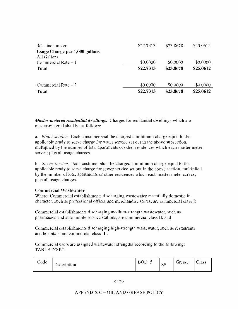
3/4 - inch meter Usage Charge per 1,000 gallons All Gallons
$22.7313 $23.8678 $25.0612
Commercial Rate - 1 $0.0000 $0.0000 $0.0000 Total $22.7313 $23.8678 $25.0612
Commercial Rate - 2 $0.0000 $0.0000 $0.0000 Total $22.7313 $23.8678 $25.0612
Master-metered residential dwellings. Charges for residential dwellings which are master-metered shall be as follows:
a. Water service. Each consumer shall be charged a minimum charge equal to the applicable ready to serve charge for water service set out in the above subsection, multiplied by the number of lots, apartments or other residences which each master meter serves; plus all usage charges.
b. Sewer service. Each customer shall be charged a minimum charge equal to the applicable ready to serve charge for sewer service set out in the above section, multiplied by the number of lots, apartments or other residences which each master meter serves, plus all usage charges.
Commercial Wastewater Where: Commercial establishments discharging wastewater essentially domestic in character, such as professional offices and merchandise stores, are commercial class I;
Commercial establishments discharging medium-strength wastewater, such as pharmacies and automobile service stations, are commercial class II; and
Commercial establishments discharging high-strength wastewater, such as restaurants and hospitals, are commercial class III.
Commercial users are assigned wastewater strengths according to the following: TABLE INSET:
Code IDescription 1Il0D 5 IGrease IClass
C-29
APPENDIX C - OIL AND GREASE POLICY
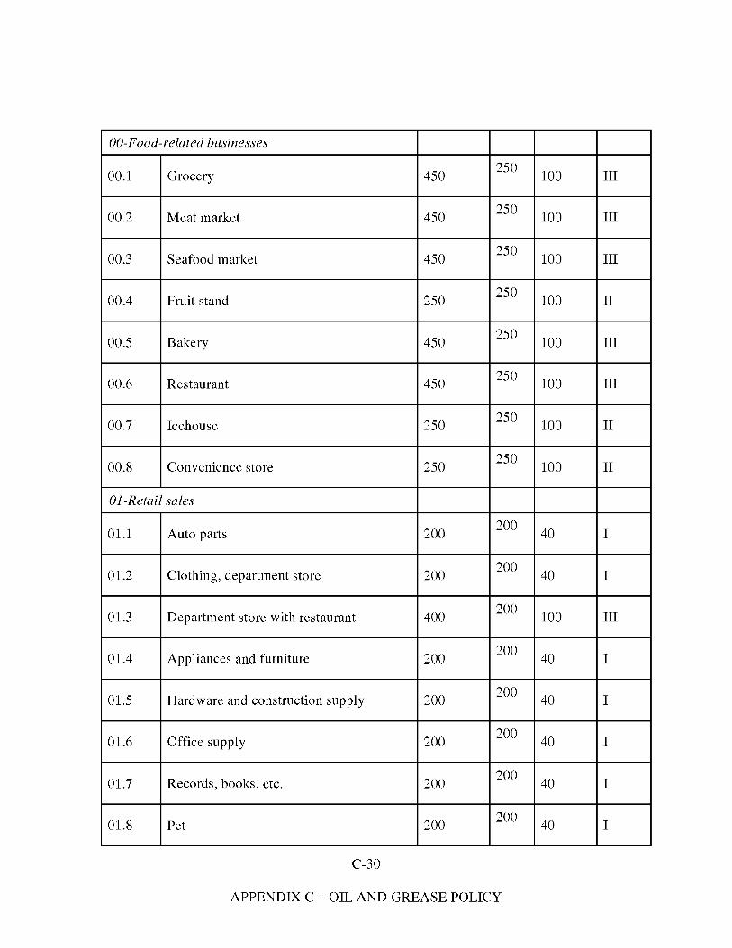
GO-Food-related businesses
00.1 Grocery 450 250 100 III
00.2 Meat market 450 250 100 III
00.3 Seafood market 450 250 100 III
00.4 Fruit stand 250 250 100 II
00.5 Bakery 450 250 100 III
00.6 Restaurant 450 250 100 III
00.7 Icehouse 250 250 100 II
00.8 Convenience store 250 250 100 II
OJ-Retail sales
01.1 Auto parts 200 200 40 I
01.2 Clothing, department store 200 200 40 I
01.3 Department store with restaurant 400 200 100 III
01.4 Appliances and furniture 200 200 40 I
01.5 Hardware and construction supply 200 200 40 I
01.6 Office supply 200 200 40 I
01.7 Records, books, etc. 200 200 40 I
01.8 Pet 200 200 40 I
C-30
APPENDIX C - OIL AND GREASE POLICY

01.9 Garden supply, plants 200 200 40 I
01.10 Commercial printing 200 200 40 I
01.11 Other retail sales 200 200 40 I
02-Health services
02.1 Hospital 300 250 100 III
02.2 Medical and dental laboratories 300 250 100 III
02.3 Research laboratory 300 250 100 III
02.4 Office of physician 300 250 100 III
02.5 Office of dentist 300 250 100 III
02.6 Office of osteopathic physician 250 250 100 II
02.7 Office of other health practitioner 250 250 100 II
02.8 Office of veterinarian 400 250 100 III
02.9 Nursing home 300 250 100 III
02.10 Pharmacy 250 250 100 II
OJ-Professional services
03.1 Banking institutions 200 200 40 I
03.2 Office of attorney 200 200 40 I
03.3 Office of engineers and surveyors 200 200 40 I
C-31
APPENDIX C - OIL AND GREASE POLICY
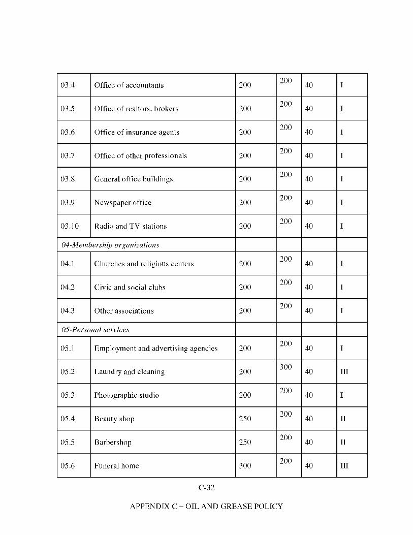
03.4 Office of accountants 200 200 40 I
03.5 Office of realtors, brokers 200 200 40 I
03.6 Office of insurance agents 200 200 40 I
03.7 Office of other professionals 200 200 40 I
03.8 General office buildings 200 200 40 I
03.9 Newspaper office 200 200 40 I
03.10 Radio and TV stations 200 200 40 I
04-Membership organizations
04.1 Churches and religious centers 200 200 40 I
04.2 Civic and social clubs 200 200 40 I
04.3 Other associations 200 200 40 I
05-Personal services
05.1 Employment and advertising agencies 200 200 40 I
05.2 Laundry and cleaning 200 300 40 III
05.3 Photographic studio 200 200 40 I
05.4 Beauty shop 250 200 40 II
05.5 Barbershop 250 200 40 II
05.6 Funeral home 300 200 40 III
C-32
APPENDIX C - OIL AND GREASE POLICY
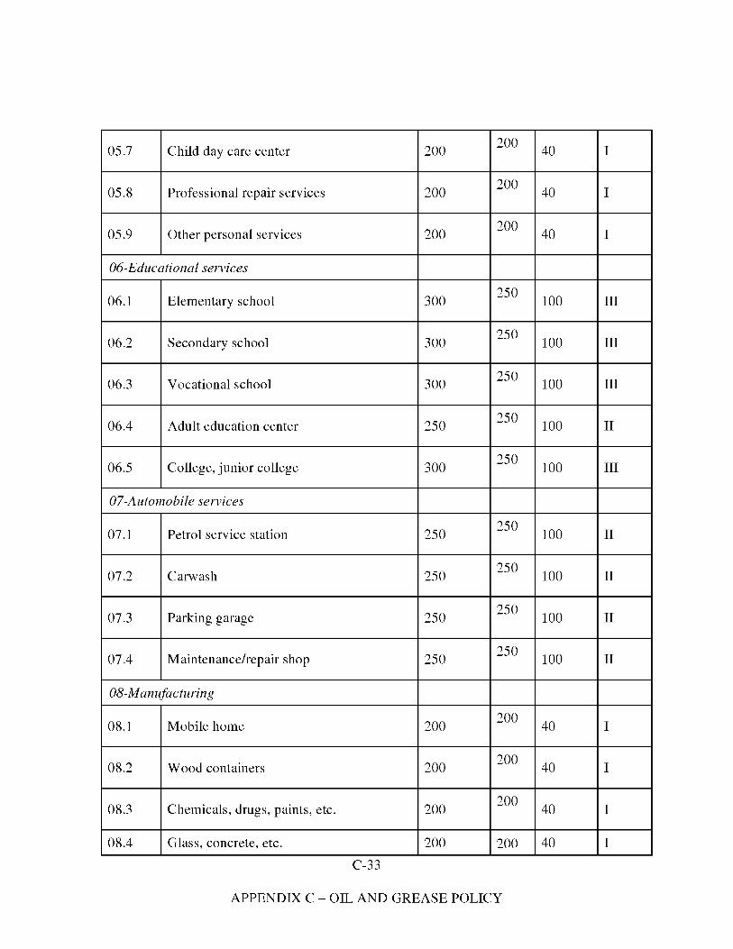
05.7
05.8
Child day care center
Professional repair services
200
200
200
200
40
40
I
I
05.9 Other personal services 200 200 40 I
06-Educational services
06.1 Elementary school 300 250 100 III
06.2 Secondary school 300 250 100 III
06.3 Vocational school 300 250 100 III
06.4 Adult education center 250 250 100 II
06.5 College, junior college 300 250 100 III
07-Automobile services
07.1 Petrol service station 250 250 100 II
07.2 Carwash 250 250 100 II
07.3 Parking garage 250 250 100 II
07.4 Maintenance/repair shop 250 250 100 II
08-M anufacturing
08.1 Mobile home 200 200 40 I
08.2 Wood containers 200 200 40 I
08.3
08.4
Chemicals, drugs, paints, etc.
Glass, concrete, etc.
C-33
200
200
200
200
40
40
I
I
APPENDIX C - OIL AND GREASE POLICY
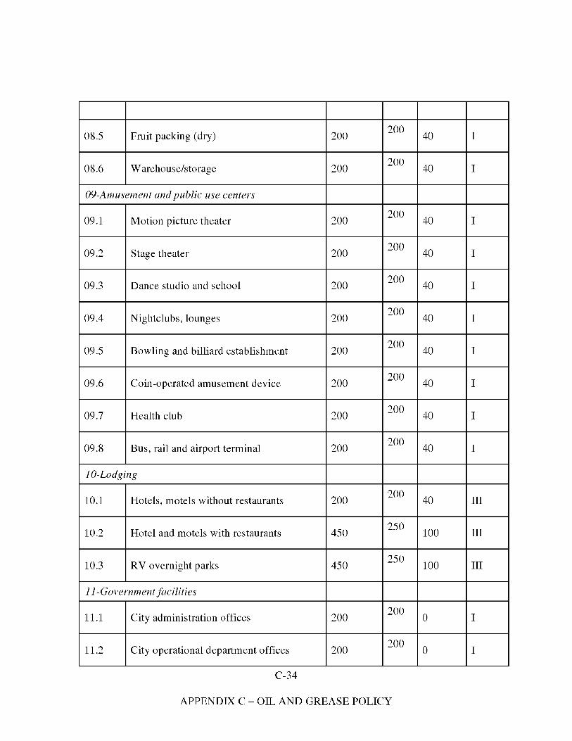
08.5 Fruit packing (dry) 200 200 40 I
08.6 Warehouse/storage 200 200 40 I
09-Amusement and public use centers
09.1 Motion picture theater 200 200 40 I
09.2 Stage theater 200 200 40 I
09.3 Dance studio and school 200 200 40 I
09.4 Nightclubs, lounges 200 200 40 I
09.5 Bowling and billiard establishment 200 200 40 I
09.6 Coin-operated amusement device 200 200 40 I
09.7 Health club 200 200 40 I
09.8 Bus, rail and airport terminal 200 200 40 I
10-Lodging
10.1 Hotels, motels without restaurants 200 200 40 III
10.2 Hotel and motels with restaurants 450 250 100 III
10.3 RV overnight parks 450 250 100 III
I I-Government facilities
11.1 City administration offices 200 200 0 I
11.2 City operational department offices 200 200 0 I
C-34
APPENDIX C - OIL AND GREASE POLICY
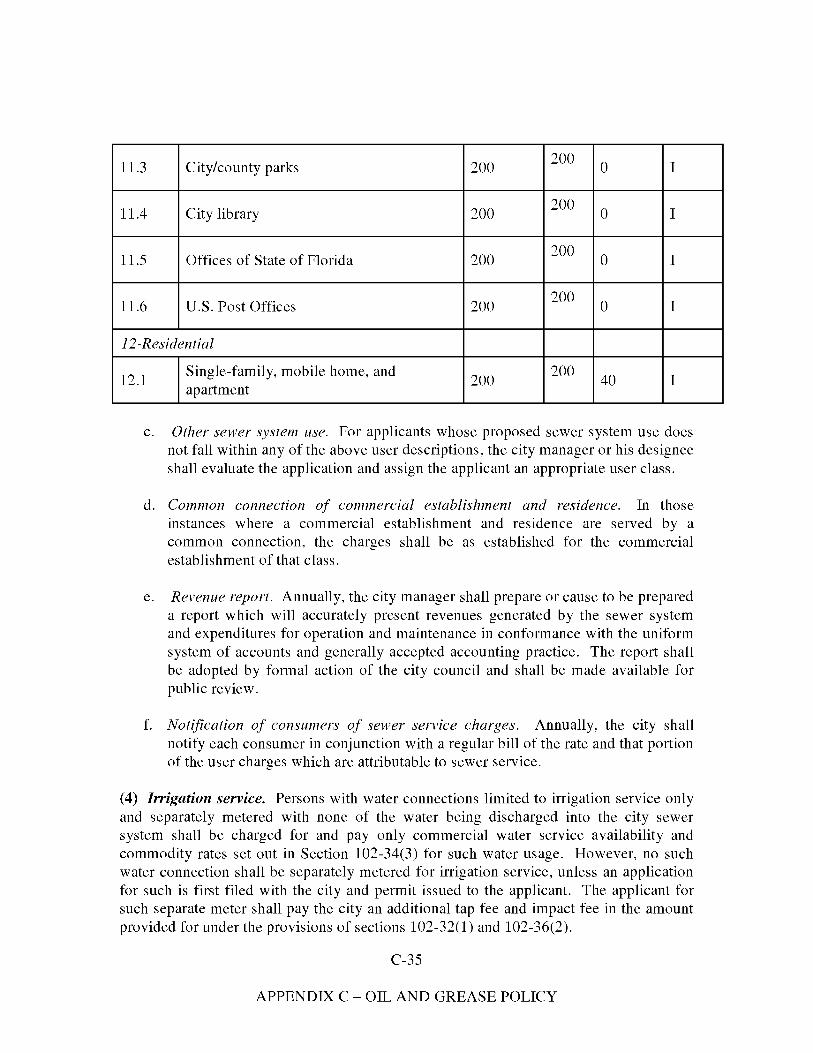
20011.3 City/county parks 200 0 I
20011.4 City library 200 0 I
20011.5 Offices of State of Florida 200 0 I
20011.6 U.S. Post Offices 200 0 I
12-Residential
Single-family, mobile home, and 20012.1 200 40 Iapartment
c. Other sewer system use. For applicants whose proposed sewer system use does not fall within any of the above user descriptions, the city manager or his designee shall evaluate the application and assign the applicant an appropriate user class.
d. Common connection of commercial establishment and residence. In those instances where a commercial establishment and residence are served by a common connection, the charges shall be as established for the commercial establishment of that class.
e. Revenue report. Annually, the city manager shall prepare or cause to be prepared a report which will accurately present revenues generated by the sewer system and expenditures for operation and maintenance in conformance with the uniform system of accounts and generally accepted accounting practice. The report shall be adopted by formal action of the city council and shall be made available for public review.
f. Notification of consumers of sewer service charges. Annually, the city shall notify each consumer in conjunction with a regular bill of the rate and that portion of the user charges which are attributable to sewer service.
(4) Irrigation service. Persons with water connections limited to irrigation service only and separately metered with none of the water being discharged into the city sewer system shall be charged for and pay only commercial water service availability and commodity rates set out in Section 102-34(3) for such water usage. However, no such water connection shall be separately metered for irrigation service, unless an application for such is first filed with the city and permit issued to the applicant. The applicant for such separate meter shall pay the city an additional tap fee and impact fee in the amount provided for under the provisions of sections 102-32(1) and 102-36(2).
C-35
APPENDIX C - OIL AND GREASE POLICY
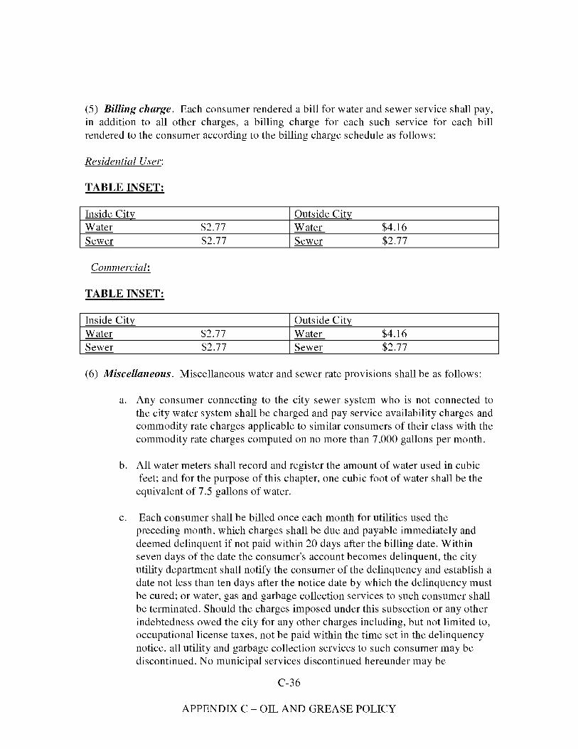
(5) Billing charge. Each consumer rendered a bill for water and sewer service shall pay, in addition to all other charges, a billing charge for each such service for each bill rendered to the consumer according to the billing charge schedule as follows:
Residential User:
TABLE INSET:
Inside City Outside City Water $2.77 Water $4.16 Sewer $2.77 Sewer $2.77
Commercial:
TABLE INSET:
Inside City Outside City Water $2.77 Water $4.16 Sewer $2.77 Sewer $2.77
(6) Miscellaneous. Miscellaneous water and sewer rate provisions shall be as follows:
a. Any consumer connecting to the city sewer system who is not connected to the city water system shall be charged and pay service availability charges and commodity rate charges applicable to similar consumers of their class with the commodity rate charges computed on no more than 7,000 gallons per month.
b. All water meters shall record and register the amount of water used in cubic feet; and for the purpose of this chapter, one cubic foot of water shall be the
equivalent of 7.5 gallons of water.
c. Each consumer shall be billed once each month for utilities used the preceding month, which charges shall be due and payable immediately and deemed delinquent if not paid within 20 days after the billing date. Within seven days of the date the consumer's account becomes delinquent, the city utility department shall notify the consumer of the delinquency and establish a date not less than ten days after the notice date by which the delinquency must be cured; or water, gas and garbage collection services to such consumer shall be terminated. Should the charges imposed under this subsection or any other indebtedness owed the city for any other charges including, but not limited to, occupational license taxes, not be paid within the time set in the delinquency notice, all utility and garbage collection services to such consumer may be discontinued. No municipal services discontinued hereunder may be
C-36
APPENDIX C - OIL AND GREASE POLICY

reconnected or reinstated until all past due charges owed the city are paid. In addition to any other penalties provided in this section, there is hereby imposed upon each delinquent consumer a delinquency fee equal to the greater amount of five percent of such delinquent consumer's total utility charges for all services, or $4.00. The city clerk may, upon approval of city council, remove from the books of the city any utility receivable that, as of August 1 of each year, is 180 days or more delinquent.
d. Each water and sewer customer whose water and sewer bill greatly fluctuates during months of each annual billing cycle shall, upon application to the city, be permitted to pay water and sewer bills in 11 monthly increments equal to 1/12 of the estimated annual cost of water and sewer to be used by such customer with a 12th payment at the end of each annual billing cycle for the then remaining unpaid balance, if any, actually owed of all water and sewer charges used by the customer for each 12-month billing cycle. The monthly payment which shall be paid by each customer under the provisions of this subsection shall be determined and established solely by the city.
e. During those periods of time that the city, in the exercise of its sole discretion, has excess available wastewater treatment plant capacity, any properly licensed operator or owner of a septic tank service business, having a physical place of business within the county, may dispose of that domestic waste which it collects from its customers who are located within the county which is acceptable to the city for disposal and treatment into the city's wastewater treatment facilities established for such waste disposal, provided that such owner or operator of any septic tank disposal service:
1. Is fully licensed by the city and all other regulatory agencies;
2. Makes proper application to the city for such service and pays an annual city license fee of $250.00 to the city;
3. Enters into a written agreement with the city covering such disposal service on such terms and conditions as may from time to time be required by the city;
4. Indemnifies and holds the city harmless from any and all damages arising out of injury to person or property, including any damage to the city's wastewater treatment plant facilities;
5. Provides the city with general public liability insurance in the amount acceptable to city and with the city as a named insured;
C-37
APPENDIX C - OIL AND GREASE POLICY
6. Pays the city $40.00 per thousand gallons, or fraction thereof, for all domestic waste it discharges into the city's wastewater treatment plant facilities;
7. Ensures that each discharge contains a minimum volume of 200 gallons;
8. Maintains a deposit of $400.00 with the city; and
9. Pays a full-tank charge for each vehicle unless the tank is equipped with a proper and accurately calibrated-type gauge, acceptable to city, which accurately measures the volume of waste contained in each tank at the time it is discharged. The city, in its sole and absolute discretion, shall have the right to reject and prevent any waste of any kind from being disposed into the city's wastewater treatment disposal facility. The amount of the annual license fee and the rates charged per thousand gallons for waste discharged into the city's wastewater treatment plant, as provided for in this subsection may be increased or decreased from time to time by a resolution properly adopted by the city council.
f. Upon proper application to the city, any owner of property may connect a fire water line to the city's main water line to provide such property with water for fire suppression purposes, provided that such owner of property pay the required water tap fee and any and all costs for materials and installation of the water fire line. The water tap fee shall be based upon the size of the line and shall be the same amount as is required in this chapter for regular tap fees. No fire water line tap shall require a meter. All fire water lines shall be installed in accordance with the standards and requirements of the city and shall comply with the provisions of section 102-118.
(7) Consumer price index adjustments. Commencing October 1, 1998, and each October 1 thereafter, the rates charged for water and sewer service provided for in section 102-34, and elsewhere herein, shall be adjusted and increased by an amount equal to the percentage of increase, if any, in the Consumer Price Index-U.S. Cities Average-All Urban Consumers-All Items (1997=100), as published by the United States Department of Labor, Bureau of Labor Statistics, referred to in this subsection as the "index" between the index number of the index of July 1, 1997, which is herein referred to as the "base index number," and the index number of the index on each July 1 of each year thereafter, referred to herein as the "current index number." If the current index number on July 1 of each year beginning July 1, 1998, is greater than the base index number, then the rates charged for water and sewer services as provided for in section 102-34, and elsewhere herein, for the next 12-month period starting October 1, 1998, and on October 1 of each succeeding year thereafter, shall be increased by an amount by which the current index
C-38
APPENDIX C - OIL AND GREASE POLICY
number exceeds the current index number on July 1 of the preceding July 1. In no event shall the increase exceed ten percent in any one year.
Section 3. That Article IV of Chapter 102 of the Code of the City of Lake City,
Florida, is hereby amended and as amended shall read in its entirety as follows:
ARTICLE IV. SEWER SERVICE
Sec. 102-106. Definitions.
The following words, terms and phrases, when used in this article, shall have the meanings ascribed to them in this section, except where the context clearly indicates a different meaning:
Approving authority means the city council, city manager, or other designated official of the city.
Biochemical oxygen demand (BOD) means the quantity of oxygen, expressed in parts per million by weight, utilized in the biochemical oxidation of organic matter under standard laboratory conditions for five days at a temperature of 20 degrees Celsius. The laboratory determinations shall be made in accordance with procedures set forth in Standard Methods.
Building sewer means the horizontal pipe extending from the end of a sewer connection constructed by the city to the building or house on private property. Characteristics means, but shall not be limited to, BOD, COD, pH, suspended solids, settleable solids, total solids, fixed solids, chlorine demand, and objectionable items described in this article.
Chemical oxygen demand (COD) means the quantity of oxygen, expressed in parts per million by weight, utilized in the oxidation of inorganic matter satisfied to 97 .5 percent during 24 hours at a temperature of 20 degrees Celsius, in accordance with procedures set forth in Standard Methods.
Chlorine requirement means the amount of chlorine, in parts per million by weight, which must be added to sewage and/or industrial waste to produce a specified residual chlorine content, or to meet the requirements of some other objective, in accordance with procedures set forth in Standard Methods.
Control effluent structure means a permanent structure installed in the building sewer for the purpose of screening, measuring and sampling industrial waste.
C-39
APPENDIX C - OIL AND GREASE POLICY
Cooling water means the clean wastewater from air conditioning, industrial cooling, condensing and similar apparatus and from hydraulically powered equipment. In general, cooling water will include only water which is sufficiently clean and unpolluted to admit of being discharged, without treatment or purification, into any natural open stream or watercourse without offense.
Fixed solids means residue remaining after burning off volatile solids at 1,200 degrees Fahrenheit.
Force main means a pipeline on the discharge of a pump carrying sewage flow under pressure.
Garbage means the residue from the preparation and dispensing of food, and from the handling, storage and sale of food products and produce.
Ground garbage means the residue from the preparation, cooling and dispensing of food for commercial or industrial purposes.
Industrial wastes means the liquid or water-carried wastes of any business or commercial operation or industrial process not clearly included within the definitions of sanitary sewage, stormwater, cooling water or subsoil drainage.
pH means the logarithm (base 10) of the reciprocal of the hydrogen ion concentration expressed in moles per liter. It shall be determined by one of the procedures outlined in Standard Methods.
Parts per million (ppm) means a weight-to-weight ratio. The parts per million value multiplied by the factor 8.345 shall be equivalent to pounds per million gallons of water.
Person means any and all persons, natural or artificial, including any individual, firm, company, municipal or private corporation, association, society, institution, enterprise, governmental agency, partnership or group, or other entity.
Property owner, or owner ofproperty, or owner means both the owner of fee in any real estate and also all tenants, lessees or others in control or possession and use of the property in question, or any interest therein, and his, her, its or their agents or representatives as the interest, duties, powers or liabilities of each may be.
Pumping stations means a structure housing pumps and appurtenances to lift sewage from a low level to a higher level sewer and/or waste treatment facilities.
C-40
APPENDIX C - OIL AND GREASE POLICY
Regulator facility means a structure, and related appurtenances whose function is to limit the flow and/or slugs to a sewer and/or waste treatment facilities to a predetermined waste strength.
Scavenger waste means putrid or offensive matter, the contents of privies, septic tanks and cesspools.
Sewage disposal system, private, means any privately owned facility or system used for the treatment and disposal of sewage and/or industrial waste.
Sewage, normal means a combination of the water-carried wastes from residences, business buildings, institutions, and industrial establishments, having the following limiting chemical characteristics:
(l) BOD five-day 20 degrees Celsius: 200 ppm (maximum 450 ppm).
(2) Suspended solids: 200 ppm (maximum 350 ppm).
(3) Hydrogen ion concentration: pH 5.0 to 9.5.
(4) Chlorine demand: (30 minutes room temperature) 25 ppm.
(5) Grease: 100 ppm.
Sewage, sanitary means sewage, which is derived principally from dwellings, business buildings, and institutions, excluding stormwater and surface water and industrial wastes.
Sewage treatment works (waste treatment facilities, pollution control project) means any arrangement of devices and structures for treating sewage, industrial wastes and sludge.
Sewer means a pipe or conduit for conveying sewage or any other waste liquids, including stormwater, surface water and groundwater drainage to the systems designed to carry this waste.
Sewer combined means a sewer receiving a mixture of stormwater and sanitary sewage with or without industrial wastes.
Sewer connection means the connecting sewer pipe installed by the city from the sanitary sewer in the street, alley, or right-of-way to the point of connection with the building sewer.
C-41
APPENDIX C - OIL AND GREASE POLICY
Sewer main means that part of the sewer system intended to serve more than one sewer connection and located within public space, public right-of-way or public easement.
Sewer, private means a sewer, either in private property or in a public street, which has not been constructed by a public agency.
Sewer, public means a sewer provided by or subject to the jurisdiction of the city. It shall also include sewers within or outside the boundaries that serve one or more persons and ultimately discharge into the city sanitary or combined sewer system, even though these sewers may not have been constructed with city funds.
Sewer, sanitary means a sewer that conveys sewage or industrial wastes or a combination of both, and into which storm water, surface water and groundwater, or unpolluted industrial wastes are not admitted.
Sewer, storm means a sewer that carries stormwater, surface water and groundwater drainage and cooling water from air conditioning systems, but excludes sewage and polluted industrial wastes.
Sewer system means all facilities owned by the city for collecting, pumping, treating, and disposing of sewage and industrial wastes.
Slug means any discharge of water, sewage, or industrial waste which in concentration of any given constituent or in quantity of flow exceeds for any period of duration longer than 15 minutes more than five times the average 24-hour concentration or flows during normal operation.
Standard Methods means the examination and analytical procedures set forth in the most recent edition of "Standard Methods for the Examination of Water, Sewage, and Industrial Wastes," published jointly by the American Public Health Association, the American Water Works Association and the Water Pollution Control Federation.
Stormwater runoff means that portion of the rainfall that is drained into the storm sewers.
Street means streets, avenues, drives, boulevards, roads, alleys, lanes, viaducts and all other public highways in the city.
Suspended solids (SS) means solids that either float on the surface of, or are in suspension in water, sewage or industrial waste, and which are removable by a laboratory filtration device. Quantitative determination of suspended solids shall be made in accordance with procedures set forth in Standard Methods.
C-42
APPENDIX C - OIL AND GREASE POLICY
Unpolluted water or liquids means any water or liquid containing none of the following: free of emulsified grease or oil; acids or alkalis; substances that may impart taste and odor or color characteristics; toxic or poisonous substances in suspension, colloidal state or solution; odorous or otherwise obnoxious gases. It shall contain no more parts per million by weight of dissolved solids, and no more parts per million each of suspended solids or biochemical oxygen demand than the raw water supply. Analytical determinations shall be made in accordance with procedures set forth in Standard Methods.
Watercourse means a channel, ditch, drainage canal, canal or waterway in which a flow of water occurs, either continuously or intermittently.
Sec. 102-107. Purpose of article.
The intent and purpose of this article is to:
(l) Prohibit the discharge of sewage and wastes into the sewer systems in excess of their carrying capacity;
(2) Prohibit or regulate discharge of sewage, industrial waste, or other wastes which may cause maintenance and/or operating difficulties of the sewers, force mains, pumping stations and other structures appurtenant to the sewerage systems, and the waste treatment facilities;
(3) Require the treatment, before introduction into the sewer systems, of such waste as may otherwise impair the strength and/or durability of the structures appurtenant to the system by direct or indirect chemical action or which may adversely affect normal treatment processes at waste treatment facilities;
(4) Establish the characteristics of sewage and industrial wastes that are prohibited from discharge into the public sewers.
Sec. 102-108. Penalties for violation of article.
(a) Any person found to be violating any provision of this article, except sections 102-116 and 102-117, shall be served by the city with written notice stating the nature of the violation and providing a reasonable time limit for the satisfactory correction thereof. The offender shall, within the period of time stated in such notice, permanently cease all violations.
(b) Any person who shall violate the provisions of sections 102-116 and 102-11 7, or shall continue any other violation beyond the time limit provided for in section
C-43
APPENDIX C - OIL AND GREASE POLICY
102-108(a) shall be guilty of an offense against the city and, upon conviction, shall be punished as provided in section 1-11. Each day in which any such violation shall continue shall be deemed a separate offense.
(c) Any person violating any of the provisions of this article shall become liable to the city for any expense, loss, or damage occasioned the city by reason of such violation.
Sec. 102-109. City manager's responsibilities.
The city manager, or his designee, shall have charge of construction, inspection, extension, connections, operation, maintenance and repairs of all physical facilities comprising the sewer and drainage systems including sanitary sewers, sewer connections, storm drains, outfalls, manholes, catch basins, culverts, pumping stations and waste treatment facilities in public streets, alleys, dedicated public easements or on city property. He shall also have charge of controlling volume, strength, characteristics, screening and pretreatment of all liquid and other waste materials originating on private property and discharged into sanitary sewers, storm drains or ditches. He shall approve design, constructions, operation, and maintenance of control, effluent structures, regulator tanks, metering devices, screening and pretreatment equipment and processes located on private property, with the approval of the state department of health and rehabilitative services.
Sec. 102-110. Executive Director of Utilities responsibilities.
The Executive Director of Utilities shall have charge of original installation and subsequent additions, alterations, changes in construction or materials of all physical facilities on private property, except those specifically mentioned in section 102-109 handling water, sanitary sewage, business, processing, commercial, manufacturing or industrial waste. He shall also have charge of all grease traps, sand traps, and catch basins on private property as defined in the city plumbing code.
Sec. 102-111. Use of public sewers.
(a) Placement ofanimal excrement or other objectionable waste. It shall be unlawful for any person to place, deposit, or permit to be deposited in an unsanitary manner upon public or private property within the city, any human or animal excrement, garbage, or other objectionable waste.
(b) Discharge ofpolluted waters. It shall be unlawful to discharge to any natural outlet within the city, any sanitary sewage, industrial wastes, or other polluted waters, except
C-44
APPENDIX C - OIL AND GREASE POLICY
where suitable treatment has been provided in accordance with subsequent provisions of this article.
(c) Private sewage disposal systems. Except as provided in this division, it shall be unlawful to construct or maintain any privy, privy vault, septic tank, cesspool, or other facility intended or used for the disposal of sewage.
(d) Installation ofsanitmy facilities. The owner of any buildings or properties, used for human occupancy, employment, recreation or other purposes, situated within the city, abutting any street, alley or right-of-way in which there is now located or may in the future be located a public sanitary sewer of the city is hereby required at his expense to install sanitary facilities in accordance with the city plumbing and building codes and connect such facilities directly with the proper public sewer, in accordance with the provisions of this article, within 24 months after the date of the official notice of availability of service; provided, however, that such public sewer is within 100 feet of the property line.
(e) Service availability charges. Every building located upon land within the city abutting a sewer lateral of the city sewer system, or any land within the city so abutting, within or upon which plumbing fixtures are installed shall have a connection to the city sewer system. The owner of every building located upon land within the city abutting a sewer lateral of the city sewer system within which plumbing fixtures are installed shall pay monthly sewer service availability charges, as provided for in article II of this chapter, whether connected or not connected to the city sewer system. Every building connected to the city water supply and distribution system, presently or hereafter located upon land outside the city, abutting a sewer lateral of the city sewer system, or any land outside the city so abutting, within or upon which plumbing fixtures are installed, shall have a connection to the city sewer system within 24 months of the official notice of the availability of service. The owner or occupant of every building connected to the water and distribution system of the city, presently or hereafter located upon land outside the city abutting a sewer lateral of the city sewer system within which plumbing fixtures are installed, shall be charged and pay the applicable monthly sewer service availability charges as provided for in article II of this chapter, whether connected or not connected to the city sewer system. Any owner or occupant failing to connect to the city sewer system or to pay the monthly sewer service availability charges as provided for in article II of this chapter shall not be permitted to connect to the water supply and distribution system of the city, and the water services to any owner or occupant of any building outside the city presently connected to the water and supply distribution system of the city, failing to comply with the provisions of this section, shall be discontinued and terminated. If the water service to any owner or occupant of a building outside the city is terminated as provided in this section, water service shall not be reinstated until such owner or occupant has paid the monthly sewer service availability charges provided for in article II of this chapter from the date of termination to the date water services are restored,
C-45
APPENDIX C - OIL AND GREASE POLICY
together with an additional service charge of $5.00. Any owner or occupant not connected to the city sewer system upon whom sewer service availability charges are imposed under this section shall be required to pay only one-half of the applicable monthly sewer service availability charges for the first 24 months after official notice of the availability of service. For the 25th month and every month thereafter, the owner shall be charged and pay the full amount of the applicable sewer service availability charge.
(f) Creation ofarea or zone. Pursuant to the provisions of F.S. § 180.02(3), there is hereby created the following described area or zone in which connection to any city sewer system constructed therein may be required: All lands outside the corporate limits of the city within a five-mile radius of the intersection of the centerlines of U.S. Highway 90 (Duval Street) and U.S. Highway 441 (Marion Avenue), except any portion thereof which is excluded there from under the provisions of F.S. § 180.06, by reason of being now actually served with a similar utility system by any private company as provided by and defined in F.S. §§ 180.05 and 180.06.
(g) Connection required when available. All persons or corporations living or doing business within the area created by subsection (f) of this section shall connect, when available, to any sewer system constructed, erected or operated by the city.
(h) Regulations and charges. All connections to the city sewer system or any other city utility system within the area created by subsection (f) of this section shall be in accordance with and subject to prevailing regulations and ordinances of the city applicable to similar connections.
(i) For plat or subdivision approval. No plat or subdivision of land within the city shall be approved until the subdivider or owner shall comply with the following:
(l) Install sewer laterals to each separate lot which connect with the city sewage collection and disposal system.
(2) Install water mains and laterals to each separate lot which connect with the city water supply and distribution system.
Sec. 102-112. Private sewage disposal.
(a) Where a public sanitary or combined sewer is not available under the provisions of section 102-111 ( d ), the building sewer shall be connected to a private sewer disposal system complying with the provisions of this section.
(b) Before commencement of the construction of a private disposal system, the owner shall first obtain the approval of the county health unit for the manner of disposal of sewage, industrial waste or other polluted waters and also the approval of the city
C-46
APPENDIX C - OIL AND GREASE POLICY
manager for the discharge of treated wastewater or unpolluted water into any storm drain, ditch or watercourse.
(c) The type, capacities, location, and layout of a private sewage disposal system shall comply with all recommendations of the state board of health. No permits shall be issued for any private sewage disposal system employing subsurface soil absorption facilities where the area of the lot is less than 6,000 square feet. No septic tank shall be permitted to discharge to any public sewer, ditch or natural outlet.
(d) At such time as a public sewer becomes available to a property served by a private sewage disposal system, as provided in section 102-111 ( d ), a direct connection shall be made to the public sewer in compliance with this article, and any septic tanks or similarly private sewage disposal facilities shall be abandoned and filled with suitable material.
(e) The owner shall operate and maintain the private sewage disposal facilities in a sanitary manner at all times, at no expense to the city.
(f) No provision contained in this article shall be construed to interfere with any additional requirements that may be imposed by the state board of health.
Sec. 102-113. Sewer connections and building sewers.
(a) Permit reqzdred for work. No unauthorized person shall uncover, make any connections with or opening into, use, alter, or disturb any public sewer, sewer connection or appurtenance thereof without first obtaining a written permit from the city manager.
(b) Sewer connection fee. There shall be paid to the water and sewer department at the time of application for a sewer connection a fee which shall be determined by the city council.
(c) Location of connections. The connection into the public sewer shall be made at the Y-branch or prepared connection where provided and/or directed by the city manager or his designee.
(d) Guarding ofexcavations; restoration ofpublic property. All excavations for building sewer installation shall be adequately guarded with barricades and lights so as to protect the public from hazards. Street, sidewalks, parkways and other public property disturbed in the course of the work shall be restored in a manner satisfactory to the city.
(e) Cleanouts. All drainage lines located on property which connect to the city sewage collection and disposal system shall have cleanouts installed every 50 feet or at each change of direction of the drain greater than 45 degrees. Cleanouts on underground drains
C-47
APPENDIX C - OIL AND GREASE POLICY
shall connect at not more than a 45 degree angle, and shall be extended to or about the finished grade level directly above the place where the cleanout is installed. Every cleanout shall be installed so that the cleanout opens in a direction opposite to the flow of the drainage line. Each cleanout shall be closed with a plug.
(f) Separate, independent building sewer per building. A separate and independent building sewer shall be provided for every building, except where one building stands at the rear of another on an interior lot and no private sewer is available or can be constructed to the rear building through an adjoining alley, court, yard, or driveway, the building sewer from the front building may be extended to the rear building and the whole considered as two building sewers.
(g) Old building sewers; use. Old building sewers may be used in connection with new buildings only when they are found, on examination and tested by the city, to meet all requirements of this article.
(h) Size, slope, alignment; materials and methods. The size, slope, alignment, materials of construction of a building sewer, and the methods to be used in excavating, placing the pipe, jointing, testing, and backfilling the trench, shall all conform to the requirements of the building and plumbing codes or other applicable rules and regulations of the city. In the absence of code provisions or in amplification thereof, the materials and procedures set forth in appropriate specifications of the ASTM and W.P.C.F. Manual of Practice No. 9 shall apply.
(i) Lifting of sewage. Whenever possible, the building sewer shall be brought to the building at an elevation below the basement floor. In all buildings in which any building drain is too low to permit gravity flow to the public sewer, sanitary sewage carried by such building drain shall be lifted by an approved means and discharged to the building sewer.
U) Connection ofbuilding sewer to public sewer. The connection of the building sewer into the public sewer shall conform to the requirements of the building and plumbing code or other applicable rules and regulations of the city, or the procedures set forth in appropriate specifications of the ASTM and W.P.C.F. Manual of Practice No. 9. All such connections shall be made gastight and watertight. Any deviation from the prescribed procedures and materials must be approved by the city before installation.
Sec. 102-114. Regulation of public sewer use.
(a) Discharge ofunpolluted water. No person shall discharge or cause to be discharged any stormwater, surface water, groundwater, roof runoff, subsurface drainage, cooling water or unpolluted industrial process waters to any sanitary sewer.
C-48
APPENDIX C - OIL AND GREASE POLICY

(b) Use ofstorm sewers. Storm water, cooling water and all other unpolluted waters shall be discharged to such sewers as are specifically designated as storm sewers, or to a natural outlet approved by the city manager.
(c) Prohibited discharges. No person shall discharge or permit the infiltration or cause to be discharged any of the following described waters or wastes to any public sewer:
(l) Any liquid or vapor having a temperature higher than 150 degrees Fahrenheit.
(2) Any water or waste which may contain more than 100 parts per million, by weight, of fat, oil, or grease from food preparation or processing.
(3) Any gasoline, benzene, naphtha, fuel oil, or other flammable or explosive liquid, solid or gas or any other petroleum product.
(4) Any commercial garbage or refuse, whether shredded or un-shredded, and the installation of garbage grinders for the purpose of grinding or shredding commercial or industrial garbage into the sewer system is expressly prohibited.
(5) Any ashes, cinders, sand, mud, straw, shavings, metal, glass, rags, feathers, tar, plastics, wood, paunch manure, or any other solid or viscous substance capable of causing obstruction to the flow in sewers or other interference with the proper operation of the sewer system.
(6) Any waters or wastes having a pH lower than 5.0 or higher than 9.5 having any other corrosive property capable of causing damage or hazard to structures, sewer mains, equipment, and personnel of the sewer system or waste treatment facilities.
(7) Any waters or wastes containing a toxic or poisonous substance in sufficient quantity to injure or interfere with any sewage treatment process, constitute a hazard to humans or animals, or create any hazard in the receiving sewer.
(8) Any waters or wastes containing suspended solids of such character and quantity that unusual attention or expense is required to handle such materials at the waste treatment facilities except as provided in this article.
(9) Any noxious or malodorous gas or substance capable of creating a public nuisance.
(10) Any water or waste which may contain greases, oil and oil sludges, from garages, service stations, repair shops, machine shops, industrial and other establishments.
C-49
APPENDIX C - OIL AND GREASE POLICY
(11) Waters or wastes containing substances which are not amenable to treatment or reduction by the sewage treatment processes employed, or are amenable to treatment only to such degree that the sewage treatment plan effluent cannot meet the requirements of other agencies having jurisdiction over discharge to the receiving waters.
(12) Paints and waste products from paint manufacturing.
(13) Radioactive material. Any institution or industry using radioactive material or fission products must be registered with the city manager as well as such other control agencies as the law requires. The active elements and their local concentration permitted to be discharged into the sewers shall be based upon the latest knowledge available to this technology.
(14) Any waters or wastes containing substances which are not amenable to treatment or reduction by the sewage treatment processes employed, or are amenable to treatment only to such degree that the sewage treatment plan effluent cannot meet the requirements of other government agencies having jurisdiction over discharge to the receiving waters.
(d) Grease, oil and sand interceptors. Grease, oil, and sand interceptors shall be provided in accordance with the city plumbing code.
(e) Property owner's responsibility for maintenance offree flow. The property owner shall be responsible for maintaining at his expense the condition and free flow in the building sewer and sewer connection to the sewer main.
(f) Conditions requiring pretreatment; authority ofcity manager. When in the opinion of the city manager, or his designee, the admission into the public sewers of any waters or waste having a five-day biochemical oxygen demand of greater than 450 parts per million by weight, or containing more than 350 parts per million by weight of suspended solids or containing any quantity of substance having the characteristics described in subsection (c) of this section, causes any operational difficulty in the public sewers and/or waste treatment facilities, pretreatment or treatment shall be required.
(l) The city manager, or his designee, shall have the right to refuse a sewer connection to any person whose quantity of waste or rate of discharge would exceed the carrying capacity of the public sewer. He shall have the right to require at any time that permanent arrangements be provided for screening and measuring continuously industrial waste contributed to the sewer system. Where necessary a regulator facility may be required to reduce the maximum rates of discharge to such percentage of the average 24-hour rate, as may be directed by the city manager or his designee.
C-50
APPENDIX C - OIL AND GREASE POLICY

a. If the city manager requires the pretreatment or equalization of waste flows, the design and installation of the plants and equipment shall be subject to the review and approval of the city manager, and subject to the requirements of all applicable codes, ordinances and laws.
b. All industrial wastes, if determined necessary by the city manager, shall be screened by automatic screening devices with a maximum screen opening of three-quarters of a square inch and/or a permanently installed (replaceable) bar screen with a maximum distance of one inch between bars before entering a public sewer.
c. A regulator facility shall be provided by the industry or owner for waste with over 450 ppm BOD to maintain uniform and/or diluted waste strength at a level below 450 ppm BOD. A regulator facility shall also be provided by the industry or owner to prevent the discharge of slugs.
(2) All business, commercial and industrial users discharging or proposing to discharge into the public sewers shall file with the city manager, or his designee, on forms furnished by the city manager, or his designee, an application showing the volume, strength, and characteristics of waste discharged or to be discharged to the public sewer. Analyses of a representative sampling report shall be made by an approved independent laboratory and submitted with the application to the city manager, or his designee. Any change in use of the premises or change which causes a change in water use or waste volume, strength or characteristics shall require a new application to be filed with the city manager, or his designee, prior to making the change or alteration.
(3) All persons using the public sewers carrying waste to the waste treatment facilities shall comply with all provisions of this article at the time of connection and all persons using the existing public sewer system at the time this article is passed shall comply within one year.
(g) Private, preliminmy treatment facilities; maintenance. Where private preliminary treatment facilities are provided for any waters or wastes, they shall be maintained continuously in satisfactory and effective operation, by the owner at his expense.
(h) Control structure, meters and appurtenances for observation, sampling and measurement ofwaste; installation and maintenance. The owner of any property served by a sewer connection carrying industrial wastes shall install a suitable control effluent structure together with such necessary meters and other appurtenances in the building sewer to facilitate observation, sampling and measurement of the wastes. Such structure shall be accessibly and safely located, and shall be constructed in accordance with approved plans. The structure, meter and other appurtenances shall be installed by the owner at his expense, and shall be continually maintained by him so as to be safe and
C-51
APPENDIX C - OIL AND GREASE POLICY
accessible at all times. The owner shall keep meters in operating condition and accurately calibrated.
(i) Tests and analyses. All tests and analyses of the characteristics of waters and wastes to which reference is made in subsections (c) and (f) of this section shall be determined in accordance with Standard Methods upon suitable samples taken at control effluent structure provided for in subsection (h) of this section. All flow measurements shall be determined at control effluent structure except where practical water meter readings shall be used to determine quantity of waste discharged. All persons using a private well or water supply shall install a water meter on supply line at their own expense. If no control effluent structure has been required, the control shall be considered to be the nearest downstream manhole in the public sewer to the point at which the building sewer is connected.
U) Special agreements with city. No provision contained in this article shall be construed as preventing any written special agreement between the city council and any industrial concern whereby an industrial waste or unusual strength or character may be accepted by the city for treatment, subject to payment therefore by the industrial concern. Such written agreement shall be filed with the city manager and/or his designee.
(k) Discharge ofwastewater in storm sewers. No person, without exception, shall discharge sanitary sewer wastewater into the storm sewer system.
(l) Dilution ofwastewater. Commercial customers shall not dilute wastewater with uncontaminated water.
Sec. 102-115. Wastes measurement procedure.
(a) All measurements, tests, and analyses of the characteristics of waters and wastes to which reference is made in this article shall be determined in accordance with the latest edition of Standard Methods, and shall be determined at the control effluent structure. Sampling shall be carried out by customarily accepted methods to reflect the effect of constituents upon the waste treatment facilities and to determine the existence of hazards to life, limb, and property.
(b) The total volume of waste discharged by an industry shall be measured by a magnetic flow meter, parshall flume, v-notch weir or other approved device which will totalize and record the actual flows from the plant. Meters will be read once a month by the city's personnel in the presence of the plant's representative, if such representative is provided by the plant. The owner may request a maximum of four meter readings per month, or as required by a wastewater discharge permit.
Sec. 102-116. Removal; transportation and disposition of scavenger wastes.
C-52
APPENDIX C - OIL AND GREASE POLICY
The discharge of scavenger wastes into the public sewer or treatment plant will not be permitted. Scavenger wastes shall mean putrid or offensive matter and the contents of all privies, septic tanks and cesspools. All other materials and substances, chemicals or chemical compounds and/or industrial waste will not be permitted to be discharged into the public sewer system, except as provided in this article.
Sec. 102-117. Protection from damage.
It shall be unlawful and a violation of this article for any person to maliciously, willfully, or negligently break, damage, destroy, uncover, deface or tamper with any pipe, structure, appurtenance, or equipment which is a part of the sewer or drainage systems or the waste treatment facilities.
Sec. 102-118. Water system; cutoff valves; fire main flow detection devices and backflow preventers.
All property connected to the city water system shall have a backflow preventer and cutoff valve within five feet from the water meter, and all fire mains connected to the city water system shall have flow detection devices and backflow preventers installed.
Sec.102-119. Powers and authority of inspectors.
The city manager, or his designee, and other duly authorized employees of the city bearing proper credentials and identification shall be permitted to enter upon all properties for the purposes of inspection, observation, measurement, sampling, and testing, in accordance with the provisions of this article.
Section 4. That Article VI of Chapter 102 of the Code of the City of Lake City,
Florida, is hereby amended and as amended shall read in its entirety as follows:
ARTICLE VI. PRETREATMENT
DIVISION 1. GENERALLY
Sec. 102-201. Purpose and policy.
This article sets forth uniform requirements for users of the publicly owned treatment works for the city and enables the city to comply with all applicable state and federal laws, including the Clean Water Act (33 U.S.C. § 1251 et seq.), and Rule 62-625, FAC. The objectives of this article are:
C-53
APPENDIX C - OIL AND GREASE POLICY
(l) To prevent the introduction of pollutants into the publicly owned treatment works that will interfere with its operation;
(2) To prevent the introduction of pollutants into the publicly owned treatment works that will pass through the publicly owned treatment works, inadequately treated, into receiving waters, or otherwise be incompatible with the publicly owned treatment works;
(3) To protect both publicly owned treatment works personnel who may be affected by wastewater and sludge in the course of their employment and the general public:
(4) To promote reuse and recycling of industrial wastewater and sludge from the publicly owned treatment works;
(5) To provide for fees for the equitable distribution of the cost of operation, maintenance, and improvement of the publicly owned treatment works; and
(6) To enable the city to comply with its national pollutant discharge elimination system and Florida Department of Environmental Protection permit conditions, sludge use and disposal requirements, and any other federal or state laws to which the publicly owned treatment works is subject.
This article shall apply to all users of the publicly owned treatment works. The article authorizes the issuance of wastewater discharge permits; provides for monitoring, compliance, and enforcement activities; establishes administrative review procedures; requires user reporting; and provides for the setting of fees for the equitable distribution of costs resulting from the program established herein.
Sec. 102-202. Administration.
Except as otherwise provided herein, the Executive Director of Utilities shall administer, implement, and enforce the provisions of this article. Any powers granted to or duties imposed upon the utilities director may be delegated by the utilities director to other city personnel.
Sec. 102-203. Abbreviations.
The following abbreviations, when used in this article, shall have the designated meanmgs:
TABLE INSET:
C-54
APPENDIX C - OIL AND GREASE POLICY
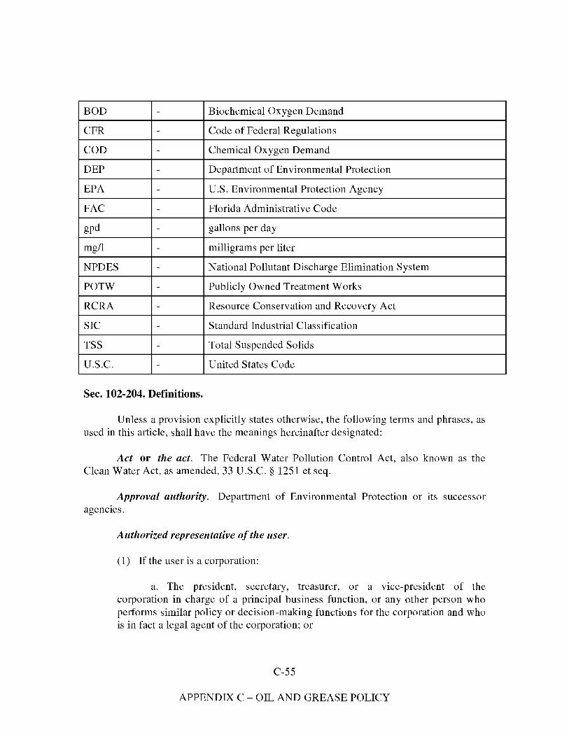
BOD - Biochemical Oxygen Demand
CFR - Code of Federal Regulations
COD - Chemical Oxygen Demand
DEP - Department of Environmental Protection
EPA - U.S. Environmental Protection Agency
FAC - Florida Administrative Code
gpd - gallons per day
mg/1 - milligrams per liter
NPDES - National Pollutant Discharge Elimination System
POTW - Publicly Owned Treatment Works
RCRA - Resource Conservation and Recovery Act
SIC - Standard Industrial Classification
TSS - Total Suspended Solids
U.S.C. - United States Code
Sec. 102-204. Definitions.
Unless a provision explicitly states otherwise, the following terms and phrases, as used in this article, shall have the meanings hereinafter designated:
Act or the act. The Federal Water Pollution Control Act, also known as the Clean Water Act, as amended, 33 U.S.C. § 1251 et seq.
Approval authority. Department of Environmental Protection or its successor agencies.
Authorized representative of the user.
(l) If the user is a corporation:
a. The president, secretary, treasurer, or a vice-president of the corporation in charge of a principal business function, or any other person who performs similar policy or decision-making functions for the corporation and who is in fact a legal agent of the corporation; or
C-55
APPENDIX C - OIL AND GREASE POLICY
b. The manager of one or more manufacturing, production, or operation facilities employing more than 250 persons or having gross annual sales or expenditures exceeding $25,000,000.00, if authority to sign documents has been assigned or delegated to the manager in accordance with corporate procedures.
(2) If the user is a partnership or sole proprietorship: a general partner or proprietor, respectively.
(3) If the user is a federal, state, or local governmental facility: a director or highest official appointed or designated to oversee the operation and performance of the activities of the government facility, or their designee.
(4) The individuals described in paragraphs (l) through (3), above, may designate another authorized representative if the authorization is in writing, the authorization specifies the individual or position responsible for the overall operation of the facility from which the discharge originates or having overall responsibility for environmental matters for the company, and the written authorization is submitted to the city.
Biochemical oxygen demand or BOD. The quantity of oxygen utilized in the biochemical oxidation of organic matter under standard laboratory procedures for five days at 200 degrees centigrade, usually expressed as a concentration (e.g., mg/1).
Categorical pretreatment standard or categorical standard. Any regulation containing pollutant discharge limits promulgated by EPA in accordance with 40 CFR Chapter 1, Subchapter N, and adopted by reference in Rule 62-660, FAC.
Control authority. The City of Lake City.
Environmental protection agency or EPA. The U.S. Environmental Protection Agency or, where appropriate, the regional water management division director, or other duly authorized official of said agency.
Executive Director of Utilities. The person designated by the city to supervise the operation of the POTW, and who is charged with certain duties and responsibilities by this article, or a duly authorized representative.
Existing source. Any source of discharge, the construction or operation of which commenced prior to the publication by DEP of proposed categorical pretreatment standards, which will be applicable to such source if the standard is thereafter promulgated in accordance with Rule 62-625, FAC.
Grab sample. A sample which is taken from a wastestream without regard to the flow in the wastestream and over a period of time not to exceed 15 minutes.
C-56
APPENDIX C - OIL AND GREASE POLICY
Indirect discharge or discharge. The introduction of pollutants into the POTW from any nondomestic source regulated under Section 307(b), (c), or (d) of the act.
Instantaneous maximum allowable discharge limit. The maximum concentration of a pollutant allowed to be discharged at any time, determined from the analysis of any discrete or composite sample collected, independent of the industrial flow rate and the duration of the sampling event.
Interference. A discharge which, alone or in conjunction with a discharge or discharges from other sources, inhibits or disrupts the POTW, its treatment processes or operations or its sludge processes, use or disposal; and therefore, is a cause of a violation of the city's DEP and/or NPDES permit or of the prevention of sewage sludge use or disposal in compliance with any of the following statutory/regulatory provisions or permits issued thereunder, or any more stringent state regulations: Section 405 of the act; the Solid Waste Disposal Act, including Title 11 commonly referred to as the Resource Conservation and Recovery Act (RCRA); any state regulations contained in any state sludge management plan prepared pursuant to Subtitle D of the Solid Waste Disposal Act; the Clean Air Act; the Toxic Substances Control Act; and the Marine Protection, Research, and Sanctuaries Act.
Medical waste. Isolation wastes, infectious agents, human blood and blood products, pathological wastes, sharps, body parts, contaminated bedding, surgical wastes, potentially contaminated laboratory wastes, and dialysis wastes.
New source.
(l) Any building, structure, facility, or installation from which there is (or may be) a discharge of pollutants, the construction of which commenced after the publication of proposed pretreatment standards under Section 307(c) of the act which will be applicable to such source if such standards are thereafter promulgated in accordance with that section, provided that:
a. The building, structure, facility, or installation is constructed at a site at which no other source is located; or
b. The building, structure, facility, or installation totally replaces the process or production equipment that causes the discharge of pollutants at an existing source; or
c. The production or wastewater generating processes of the building, structure, facility, or installation are substantially independent of an existing source at the same site. In determining whether these are substantially independent, factors such as the extent to which the new facility is integrated with the existing plant, and the extent to which the
C-57
APPENDIX C - OIL AND GREASE POLICY
new facility is engaged in the same general type of activity as the existing source, shall be considered.
(2) Construction on a site at which an existing source is located results in a modification rather than a new source if the construction does not create a new building, structure, facility, or installation meeting the criteria of subsection (l)b. or c. above but otherwise alters, replaces, or adds to existing process or production equipment.
(3) Construction of a new source as defined under this paragraph has commenced if the owner or operator has:
a. Begun, or caused to begin, as part of a continuous onsite construction program:
1. Any placement, assembly, or installation of facilities or equipment; or
2. Significant site preparation work including clearing, excavation, or removal of existing buildings, structures, or facilities which is necessary for the placement, assembly, or installation of new source facilities or equipment; or
b. Entered into a binding contractual obligation for the purchase of facilities or equipment which is intended to be used in its operation. Options to purchase or contracts which can be terminated or modified without substantial loss, and contracts for feasibility, engineering, and design studies do not constitute a contractual obligation under this paragraph.
Noncontact cooling water. Water used for cooling which does not come into direct contact with any raw material, intermediate product, waste product, finished product, or to which the only pollutant added is heat.
Pass through. A discharge which exits the POTW into waters of the United States in quantities or concentrations which, alone or in conjunction with a discharge or discharges from other sources, is a cause of a violation of any requirement of the city's FDEP and/or NPDES permit, including an increase in the magnitude or duration of a violation.
Person. Any individual, partnership, co-partnership, firm, company, corporation, association, joint stock company, trust, estate, governmental entity, or any other legal entity; or their legal representatives, agents, or assigns. This definition includes all federal, state, and local governmental entities.
C-58
APPENDIX C - OIL AND GREASE POLICY
pH. A measure of the acidity or alkalinity of a solution, expressed in standard units.
Pollutant. Dredged spoil, solid waste, incinerator residue, filter backwash, sewage, garbage, sewage sludge, munitions, medical wastes, chemical wastes, biological materials, radioactive materials, heat, wrecked or discarded equipment, rock, sand, cellar dirt, municipal, agricultural and industrial wastes, and certain characteristics of wastewater (e.g., pH, temperature, TSS, turbidity, color, BOD, COD, toxicity, or odor).
Pretreatment. The reduction of the amount of pollutants, the elimination of pollutants, or the alteration of the nature of pollutant properties in wastewater prior to, or in lieu of, introducing such pollutants into the POTW. This reduction or alteration can be obtained by physical, chemical, or biological processes; by process changes; or by other means, except by diluting the concentration of the pollutants unless allowed by an applicable pretreatment standard or as prohibited by Rule 62-625.410(5), FAC.
Pretreatment requirements. Any substantive or procedural requirement related to pretreatment imposed on a user, other than a pretreatment standard.
Pretreatment standards or standards. Pretreatment standards shall mean prohibited discharge standards, and categorical pretreatment standards by DEP established in Rule 62-625.400, FAC.
Prohibited discharge standards or prohibited discharges. Absolute prohibitions against the discharge of certain substances; established by Rule 62-625 .400, FAC.
Publicly owned treatment works or POTW. A "treatment works," as defined by Section 212 of the act (33 U.S.C. § 1292) which is owned by the city. This definition includes any devices or systems used in the collection, storage, treatment, recycling, and reclamation of sewage or industrial wastes of a liquid nature and any conveyances which convey wastewater to a treatment plant.
Septic tank waste. Any sewage from holding tanks such as vessels, chemical toilets, campers, trailers, and septic tanks.
Sewage. Human excrement and gray water (household showers, dishwashing operations, etc.).
Significant industrial user.
C-59
APPENDIX C - OIL AND GREASE POLICY
(l) A user subject to categorical pretreatment standards; under Rule 62-625.410, FAC, and 40 CFR Chapter 1, Subchapter N which has been adopted by reference in Rule 62-660, FAC.
(2) A user that:
a. Discharges an average of 25,000 gpd or more of process wastewater to the POTW (excluding sanitary, non-contact cooling, and boiler blow-down wastewater);
b. Contributes a process wastestream which makes up five percent or more of the average dry weather hydraulic or organic capacity of the POTW treatment plant: or
c. Is designated as such by the city on the basis that it has a reasonable potential for adversely affecting the POTW's operation or for violating any pretreatment standard or requirement.
(3) Upon a finding that a user meeting the criteria in subsection (2) has no reasonable potential for adversely affecting the POTW's operation or for violating any pretreatment standard or requirement, the city may at any time, on its own initiative or in response to a petition received from a user, and in accordance with procedures in Rule 62-625.500(2)(e), FAC, determine that such user should not be considered a significant industrial user.
Slug load or slug. Any discharge of a non routine, episodic nature at a flow rate or concentration which could cause a violation of the prohibited discharge standards.
Standard industrial classification (SIC) code. A classification pursuant to the Standard Industrial Classification Manual issued by the United States Office of Management and Budget.
Stormwater. Any flow occurring during or following any form of natural precipitation, and resulting from such precipitation, including snowmelt.
Suspended solids. The total suspended matter that floats on the surface of, or is suspended in, water, wastewater, or other liquid, and which is removable by laboratory filtering.
User or industrial user. A source of indirect discharge.
Wastewater. Liquid and water-carried industrial wastes and sewage from residential dwellings, commercial buildings, industrial and manufacturing facilities, and institutions, whether treated or untreated, which are contributed to the POTW.
C-60
APPENDIX C - OIL AND GREASE POLICY
Wastewater treatment plant or treatment plant. That portion of the POTW which is designed to provide treatment of municipal sewage and industrial waste.
Sec. 102-205. Wastewater treatment rates.
The rates charged users for qualified pretreatment industrial wastewater which is discharged into the POTW is hereby established at $40.00 per thousand gallons, to be paid monthly, which charges shall be in addition to all other charges or fees provided for in other sections of this article. The rates hereby established may, from time to time, be adjusted upward or downward by resolution adopted by the city council at any regular meeting.
Sec. 102-206. Pretreatment charges and fees.
The city may adopt reasonable fees for reimbursement of costs of setting up and operating the city's pretreatment program which may include:
(l) Fees for wastewater discharge permit applications including the cost of processing such applications;
(2) Fees for monitoring, inspection, and surveillance procedures including the cost of collection and analyzing a user's discharge, and reviewing monitoring reports submitted by users;
(3) Fees for reviewing and responding to accidental discharge procedures and construction;
(4) Fees for filing appeals; and
(5) Other fees as the city may deem necessary to carry out the requirements contained herein. These fees relate solely to the matters covered by this article and are separate from all other fees, fines, and penalties chargeable by the city.
DIVISION 2. GENERAL SEWER USE REQUIREMENTS
Sec. 102-221. Prohibited discharge standards.
(a) General prohibitions. No user shall introduce or cause to be introduced into the POTW any pollutant or wastewater which causes pass through or interference. These general prohibitions apply to all users of the POTW, whether or not they are subject to
C-61
APPENDIX C - OIL AND GREASE POLICY
categorical pretreatment standards or any other national, state, or local pretreatment standards or requirements.
(b) Specific prohibitions. No user shall introduce or cause to be introduced into the POTW the following pollutants, substances, or wastewater:
(l) Pollutants which create a fire or explosive hazard;
(2) Wastewater which will cause corrosive structural damage to the POTW or equipment; but in no case discharges with pH lower than 5 .0 or higher than 9 .5.
(3) Solid or viscous substances in amounts which will cause obstruction of the flow in the POTW resulting in interference;
(4) Pollutants, including oxygen-demanding pollutants (BOD, etc.), released in a discharge at a flow rate and/or pollutant concentration which, either singly or by interaction with other pollutants, will cause interference with the POTW;
(5) Heat in amounts which will inhibit biological activity in the treatment plant resulting in interference, but in no case wastewater which causes the temperature at the introduction into the treatment plant to exceed 104 degrees Fahrenheit ( 40 degrees centigrade);
(6) Petroleum oil, non-biodegradable cutting oil, or products of mineral oil origin, in amounts that will cause interference or pass through;
(7) Pollutants which result in the presence of toxic gases, vapors, or fumes within the POTW in a quantity that may cause acute worker health and safety problems;
(8) Trucked or hauled pollutants, except at discharge points designated by the Executive Director of Utilities in accordance with section 102-244 of this article;
(9) Noxious or malodorous liquids, gases, solids, or other wastewater which, either singly or by interaction with other wastes, are sufficient to create a public nuisance or a hazard to life, or to prevent entry into the sewers for maintenance or repair;
(10) Wastewater which imparts color which cannot be removed by the treatment process, such as, but not limited to, dye wastes and vegetable tanning solutions, which consequently imparts color to the treatment plant's effluent, thereby violating the city's DEP and/or NPDES permit;
(11) Wastewater containing any radioactive wastes or isotopes except in compliance with applicable state or federal regulations;
C-62
APPENDIX C - OIL AND GREASE POLICY
(12) Stormwater, surface water, groundwater, artesian well water, roof runoff, subsurface drainage, swimming pool drainage, condensate, de-ionized water, non-contact cooling water, and unpolluted wastewater, unless specifically authorized by the Executive Director of Utilities;
(13) Sludges, screenings, or other residues from the pretreatment of industrial wastes;
(14) Medical wastes, except as specifically authorized by the Executive Director of Utilities in a wastewater discharge permit;
(15) Wastewater causing, alone or in conjunction with other sources, the treatment plant's effluent to fail a toxicity test or primary inorganic or secondary drinking water standards;
(16) Detergents, surface-active agents, or other substances which may cause excessive foaming in the POTW;
(17) Fats, oils, or greases of animal or vegetable origin in concentrations greater than 100 mg/1; whether emulsified or not, in excess of 100 mg/1 with floatable oil not to exceed 20 mg/1 or containing substances which may solidify or become viscous at temperatures between 32 and 140 degrees Fahrenheit (0 to 60 degrees Celsius);
(18) Wastewater causing two readings on an explosion hazard meter at the point of discharge into the POTW, or at any point in the POTW, of more than five percent or any single reading over ten percent of the lower explosive limit of the meter;
(19) Any garbage that has not been ground by household type or other suitable garbage grinder.
(20) Hazardous waste that would be classified as hazardous waste under Chapter 62-730, F.A.C.
Pollutants, substances, or wastewater prohibited by this section shall not be processed or stored in such a manner that they could be discharged to the POTW.
Sec. 102-222. National categorical pretreatment standards.
The categorical pretreatment standards found in 40 CFR Chapter 1, Subchapter N, Parts 405-471 are hereby incorporated.
C-63
APPENDIX C - OIL AND GREASE POLICY
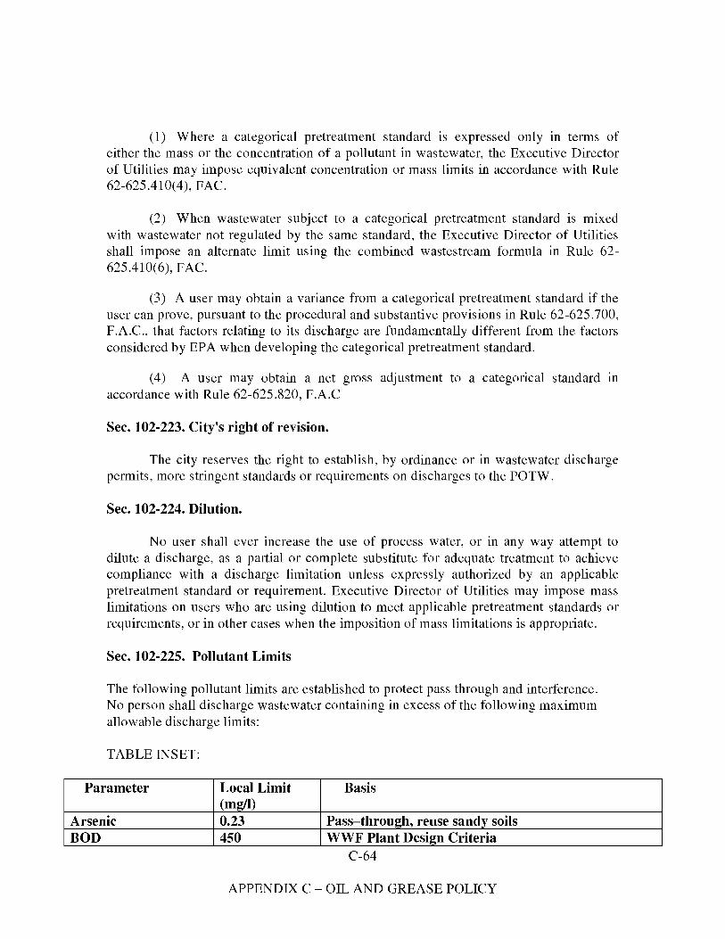
(l) Where a categorical pretreatment standard is expressed only in terms of either the mass or the concentration of a pollutant in wastewater, the Executive Director of Utilities may impose equivalent concentration or mass limits in accordance with Rule 62-625.410(4), FAC.
(2) When wastewater subject to a categorical pretreatment standard is mixed with wastewater not regulated by the same standard, the Executive Director of Utilities shall impose an alternate limit using the combined wastestream formula in Rule 62-625 .410( 6), FAC.
(3) A user may obtain a variance from a categorical pretreatment standard if the user can prove, pursuant to the procedural and substantive provisions in Rule 62-625.700, F.A.C., that factors relating to its discharge are fundamentally different from the factors considered by EPA when developing the categorical pretreatment standard.
(4) A user may obtain a net gross adjustment to a categorical standard m accordance with Rule 62-625.820, F.A.C
Sec. 102-223. City's right of revision.
The city reserves the right to establish, by ordinance or in wastewater discharge permits, more stringent standards or requirements on discharges to the POTW.
Sec. 102-224. Dilution.
No user shall ever increase the use of process water, or in any way attempt to dilute a discharge, as a partial or complete substitute for adequate treatment to achieve compliance with a discharge limitation unless expressly authorized by an applicable pretreatment standard or requirement. Executive Director of Utilities may impose mass limitations on users who are using dilution to meet applicable pretreatment standards or requirements, or in other cases when the imposition of mass limitations is appropriate.
Sec. 102-225. Pollutant Limits
The following pollutant limits are established to protect pass through and interference. No person shall discharge wastewater containing in excess of the following maximum allowable discharge limits:
TABLE INSET:
Parameter Local Limit Basis (mg/I)
Arsenic 0.23 Pass-through, reuse sandy soils BOD 450 WWF Plant Design Criteria
C-64
APPENDIX C - OIL AND GREASE POLICY
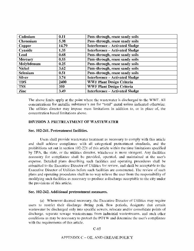
Cadmium 0.11 Pass-through, reuse sandy soils Chromium 5.38 Pass-through, reuse sandy soils Copper 14.79 Interference - Activated Sludge Cyanide 1.35 Interference - Activated Sludge Lead 0.68 Pass-through, reuse sandy soils Mercury 0.55 Pass-through, reuse sandy soils Molybdenum 0.25 Pass-through, reuse sandy soils Nickel 3.62 Pass-through, reuse sandy soils Selenium 0.51 Pass-through, reuse sandy soils Silver 3.74 Interference - Activated Sludge TDS 2400 WWF Plant Design Criteria TSS 350 WWF Plant Design Criteria Zinc 3.49 Interference - Activated Sludge
The above limits apply at the point where the wastewater is discharged to the WWF. All concentrations for metallic substance's are for "total" metal unless indicated otherwise. The utilities director may impose mass limitations in addition to, or in place of, the concentration based limitations above.
DIVISION 3. PRETREATMENT OF WASTEWATER
Sec. 102-241. Pretreatment facilities.
Users shall provide wastewater treatment as necessary to comply with this article and shall achieve compliance with all categorical pretreatment standards, and the prohibitions set out in section 102-221 of this article within the time limitations specified by EPA, the state, or the utilities director, whichever is more stringent. Any facilities necessary for compliance shall be provided, operated, and maintained at the user's expense. Detailed plans describing such facilities and operating procedures shall be submitted to the Executive Director of Utilities for review, and shall be acceptable to the Executive Director of Utilities before such facilities are constructed. The review of such plans and operating procedures shall in no way relieve the user from the responsibility of modifying such facilities as necessary to produce a discharge acceptable to the city under the provisions of this article.
Sec. 102-242. Additional pretreatment measures.
(a) Whenever deemed necessary, the Executive Director of Utilities may require users to restrict their discharge during peak flow periods, designate that certain wastewater be discharged only into specific sewers, relocate and/or consolidate points of discharge, separate sewage wastestreams from industrial wastestreams, and such other conditions as may be necessary to protect the POTW and determine the user's compliance with the requirements of this article.
C-65
APPENDIX C - OIL AND GREASE POLICY
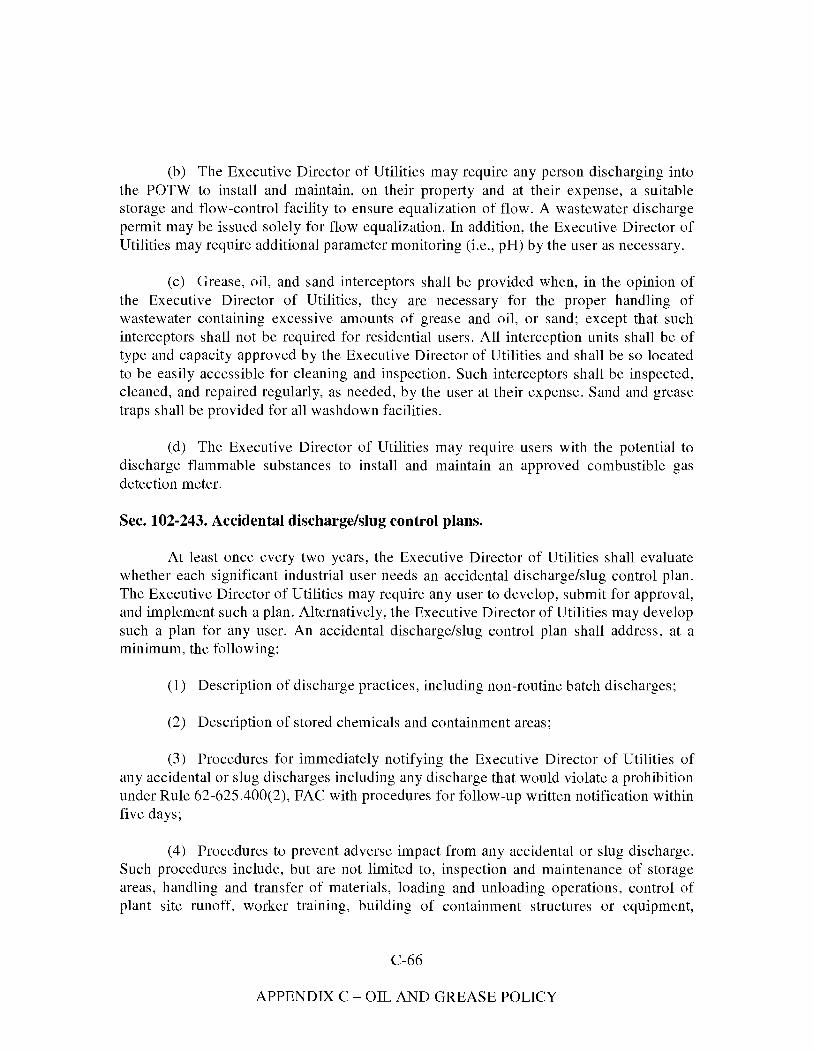
(b) The Executive Director of Utilities may require any person discharging into the POTW to install and maintain, on their property and at their expense, a suitable storage and flow-control facility to ensure equalization of flow. A wastewater discharge permit may be issued solely for flow equalization. In addition, the Executive Director of Utilities may require additional parameter monitoring (i.e., pH) by the user as necessary.
(c) Grease, oil, and sand interceptors shall be provided when, in the opinion of the Executive Director of Utilities, they are necessary for the proper handling of wastewater containing excessive amounts of grease and oil, or sand; except that such interceptors shall not be required for residential users. All interception units shall be of type and capacity approved by the Executive Director of Utilities and shall be so located to be easily accessible for cleaning and inspection. Such interceptors shall be inspected, cleaned, and repaired regularly, as needed, by the user at their expense. Sand and grease traps shall be provided for all washdown facilities.
(d) The Executive Director of Utilities may require users with the potential to discharge flammable substances to install and maintain an approved combustible gas detection meter.
Sec. 102-243. Accidental discharge/slug control plans.
At least once every two years, the Executive Director of Utilities shall evaluate whether each significant industrial user needs an accidental discharge/slug control plan. The Executive Director of Utilities may require any user to develop, submit for approval, and implement such a plan. Alternatively, the Executive Director of Utilities may develop such a plan for any user. An accidental discharge/slug control plan shall address, at a minimum, the following:
(l) Description of discharge practices, including non-routine batch discharges;
(2) Description of stored chemicals and containment areas;
(3) Procedures for immediately notifying the Executive Director of Utilities of any accidental or slug discharges including any discharge that would violate a prohibition under Rule 62-625.400(2), FAC with procedures for follow-up written notification within five days;
(4) Procedures to prevent adverse impact from any accidental or slug discharge. Such procedures include, but are not limited to, inspection and maintenance of storage areas, handling and transfer of materials, loading and unloading operations, control of plant site runoff, worker training, building of containment structures or equipment,
C-66
APPENDIX C - OIL AND GREASE POLICY
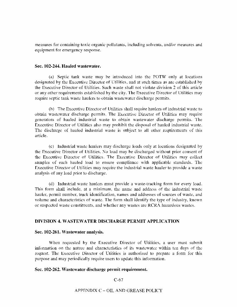
measures for containing toxic organic pollutants, including solvents, and/or measures and equipment for emergency response.
Sec. 102-244. Hauled wastewater.
(a) Septic tank waste may be introduced into the POTW only at locations designated by the Executive Director of Utilities, and at such times as are established by the Executive Director of Utilities. Such waste shall not violate division 2 of this article or any other requirements established by the city. The Executive Director of Utilities may require septic tank waste haulers to obtain wastewater discharge permits.
(b) The Executive Director of Utilities shall require haulers of industrial waste to obtain wastewater discharge permits. The Executive Director of Utilities may require generators of hauled industrial waste to obtain wastewater discharge permits. The Executive Director of Utilities also may prohibit the disposal of hauled industrial waste. The discharge of hauled industrial waste is subject to all other requirements of this article.
(c) Industrial waste haulers may discharge loads only at locations designated by the Executive Director of Utilities. No load may be discharged without prior consent of the Executive Director of Utilities. The Executive Director of Utilities may collect samples of each hauled load to ensure compliance with applicable standards. The Executive Director of Utilities may require the industrial waste hauler to provide a waste analysis of any load prior to discharge.
(d) Industrial waste haulers must provide a waste-tracking form for every load. This form shall include, at a minimum, the name and address of the industrial waste hauler, permit number, truck identification, names and addresses of sources of waste, and volume and characteristics of waste. The form shall identify the type of industry, known or suspected waste constituents, and whether any wastes are RCRA hazardous wastes.
DIVISION 4. WASTEWATER DISCHARGE PERMIT APPLICATION
Sec. 102-261. Wastewater analysis.
When requested by the Executive Director of Utilities, a user must submit information on the nature and characteristics of its wastewater within ten days of the request. The Executive Director of Utilities is authorized to prepare a form for this purpose and may periodically require users to update this information.
Sec. 102-262. Wastewater discharge permit requirement.
C-67
APPENDIX C - OIL AND GREASE POLICY
(a) No significant industrial user shall discharge wastewater into the POTW without first obtaining a wastewater discharge permit from the Executive Director of Utilities, except that a significant industrial user that has filed a timely application pursuant to section 102-263 of this article may continue to discharge for the time period specified therein.
(b) The Executive Director of Utilities may require other users to obtain wastewater discharge permits as necessary to carry out the purposes of this article.
(c) Any violation of the terms and conditions of a wastewater discharge permit shall be deemed a violation of this article and subjects the wastewater discharge permittee to the sanctions set out in sections 102-351 through 102-405 of this article. Obtaining a wastewater discharge permit does not relieve a permittee of its obligation to comply with all federal and state pretreatment standards or requirements or with any other requirements of federal, state, and local law.
Sec. 102-263. Wastewater discharge permitting--Existing connections. Any user required to obtain a wastewater discharge permit who was discharging
wastewater into the POTW prior to the effective date of this article and who wishes to continue such discharges in the future, shall, within 30 days after such date, apply to the Executive Director of Utilities for a wastewater discharge permit in accordance with section 102-265 of this article, and shall not cause or allow discharges to the POTW to continue after 90 days of the effective date of this article except in accordance with a wastewater discharge permit issued by the Executive Director of Utilities.
Sec. 102-264. Same--New connections.
Any user required to obtain a wastewater discharge permit who proposes to begin or recommence discharging into the POTW must obtain such permit prior to the beginning or recommencing of such discharge. An application for this wastewater discharge permit, in accordance with section 102-265 of this article, must be filed at least 90 days prior to the date upon which any discharge will begin or recommence.
Sec. 102-265. Wastewater discharge permit application contents.
All users required to obtain a wastewater discharge permit must submit a permit application. The Executive Director of Utilities may require all users to submit as part of an application the following information:
(1) All information required by section 102-301 (b) of this article;
C-68
APPENDIX C - OIL AND GREASE POLICY
(2) Description of activities, facilities, and plant processes on the premises, including a list of all raw materials and chemicals used or stored at the facility which are, or could accidentally or intentionally be, discharged to the POTW;
(3) Number and type of employees, hours of operation, and proposed or actual hours of operation;
(4) Each product produced by type, amount, process or processes, and rate of production;
(5) Type and amount of raw materials processed (average and maximum per day);
(6) Site plans, floor plans, mechanical and plumbing plans, and details to show all sewers, floor drains, and appurtenances by size, location, and elevation, and all points of discharge;
(7) Time and duration of discharges: and
(8) Any other information as may be deemed necessary by the Executive Director of Utilities to evaluate the wastewater discharge permit application.
Incomplete or inaccurate applications will not be processed and will be returned to the user for revision.
Sec. 102-266. Application signatories and certification.
All wastewater discharge permit applications and user reports must be signed by an authorized representative of the user and contain the following certification statement: "I certify under penalty of law that this document and all attachments were prepared under my direction or supervision in accordance with a system designed to assure that qualified personnel properly gather and evaluate the information submitted. Based on my inquiry of the person or persons who manage the system, or those persons directly responsible for gathering the information, the information submitted is, to the best of my knowledge and belief, true, accurate, and complete. I am aware that there are significant penalties for submitting false information, including the possibility of fine and imprisonment for knowing violations."
Sec. 102-267. Wastewater discharge permit decisions.
The Executive Director of Utilities will evaluate the data furnished by the user and may require additional information. The Executive Director of Utilities will determine whether or not to issue a wastewater discharge permit within 30 days of receipt
C-69
APPENDIX C - OIL AND GREASE POLICY
of a complete wastewater discharge permit application. The Executive Director of Utilities may deny any application for a wastewater discharge permit.
DIVISION 5. WASTEWATER DISCHARGE PERMIT ISSUANCE PROCESS
Sec. 102-281. Wastewater discharge permit--Duration.
A wastewater discharge permit shall be issued for a specified time period, not to exceed five years from the effective date of the permit. A wastewater discharge permit may be issued for a period less than five years, at the discretion of the Executive Director of Utilities. Each wastewater discharge permit will indicate a specific date upon which it will expire.
Sec. 102-282. Same--Contents.
A wastewater discharge permit shall include such conditions as are deemed reasonably necessary by the Executive Director of Utilities to prevent pass through or interference, protect the quality of the water body receiving the treatment plant's effluent, protect worker health and safety, facilitate sludge management and disposal, and protect against damage to the POTW.
(1) Wastewater discharge permits must contain:
a. A statement that indicates wastewater discharge permit duration, which in no event shall exceed five years;
b. A statement that the wastewater discharge permit is nontransferable without prior notification to the city in accordance with section 102-285 of this article, and provisions for furnishing the new owner or operator with a copy of the existing wastewater discharge permit;
c. Effluent limits based on applicable general pretreatment standards, categorical pretreatment standards, and state and local law;
d. Self-monitoring, sampling, reporting, notification, and recordkeeping requirements. These requirements shall include an identification of pollutants to be monitored, sampling location, sampling frequency, and sample type based on federal, state, and local law; and
e. A statement of applicable civil and criminal penalties for violation of pretreatment standards and requirements, and any applicable compliance
C-70
APPENDIX C - OIL AND GREASE POLICY
schedule. Such schedule may not extend the time for compliance beyond that required by applicable federal, state, or local law.
(2) Wastewater discharge permits may contain, but need not be limited to, the following conditions:
a. Limits on the average and/or maximum rate of discharge, time of discharge, and/or requirements for flow regulation and equalization;
b. Requirements for the installation of pretreatment technology, pollution control, or construction of appropriate containment devices, designed to reduce, eliminate, or prevent the introduction of pollutants into the treatment works;
c. Requirements for the development and implementation of spill control plans or other special conditions including management practices necessary to adequately prevent accidental, unanticipated, or non-routine discharges;
d. Development and implementation of waste minimization plans to reduce the amount of pollutants discharged to the POTW;
e. The unit charge or schedule of user charges and fees for the management of the wastewater discharged to the POTW;
f. Requirements for installation and maintenance of inspection and sampling facilities and equipment;
g. A statement that compliance with the wastewater discharge permit does not relieve the permittee of responsibility for compliance with all applicable federal and state pretreatment standards, including those which become effective during the term of the wastewater discharge permit; and
h. Other conditions as deemed appropriate by the Executive Director of Utilities to ensure compliance with this article, and state and federal laws, rules, and regulations.
Sec. 102-283. Same--Appeals.
The Executive Director of Utilities shall provide public notice of the issuance of a wastewater discharge permit. Any person, including the user, may petition the Executive Director of Utilities to reconsider the terms of a wastewater discharge permit within 30 days of notice of its issuance.
C-71
APPENDIX C - OIL AND GREASE POLICY
(l) Failure to submit a timely petition for review shall be deemed to be a waiver of the administrative appeal.
(2) In its petition, the appealing party must indicate the wastewater discharge permit provisions objected to, the reasons for this objection, and the alternative condition, if any, it seeks to place in the wastewater discharge permit.
(3) The effectiveness of the wastewater discharge permit shall not be stayed pending the appeal.
(4) If the Executive Director of Utilities fails to act within 30 days, a request for reconsideration shall be deemed to be denied. Decisions not to reconsider a wastewater discharge permit, not to issue a wastewater discharge permit, or not to modify a wastewater discharge permit shall be considered final administrative actions for purposes of judicial review.
(5) Aggrieved parties seeking judicial review of the final administrative wastewater discharge permit decision may do so by filing a complaint with the appropriate district court of appeal for proper jurisdiction.
Sec. 102-284. Same--Modification.
The Executive Director of Utilities may modify a wastewater discharge permit for good cause, including, but not limited to, the following reasons:
(l) To incorporate any new or revised federal, state, or local pretreatment standards or requirements;
(2) To address significant alterations or additions to the user's operation, processes, or wastewater volume or character since the time of wastewater discharge permit issuance;
(3) A change in the POTW that requires either a temporary or permanent reduction or elimination of the authorized discharge;
(4) Information indicating that the permitted discharge poses a threat to the city's POTW, city personnel, or the receiving waters;
(5) Violation of any terms or conditions of the wastewater discharge permit;
(6) Misrepresentations or failure to fully disclose all relevant facts in the wastewater discharge permit application or in any required reporting;
C-72
APPENDIX C - OIL AND GREASE POLICY
(7) Revision of or a grant of variance from categorical pretreatment standards pursuant to Rule 62-625.700, FAC;
(8) To correct typographical or other errors in the wastewater discharge permit; or
(9) To reflect a transfer of the facility ownership or operation to a new owner or operator.
Sec. 102-285. Same--Transfer.
Wastewater discharge permits may be transferred to a new owner or operator only if the permittee gives at least 30 days advance notice to the Executive Director of Utilities and the Executive Director of Utilities approves the wastewater discharge permit transfer. The notice to the Executive Director of Utilities must include a written certification by the new owner or operator which:
(l) States that the new owner and/or operator has no immediate intent to change the facility's operations and processes;
(2) Identifies the specific date on which the transfer is to occur; and
(3) Acknowledges full responsibility for complying with the existing wastewater discharge permit.
Failure to provide advance notice of a transfer renders the wastewater discharge permit void as of the date of facility transfer.
Sec. 102-286. Same--Revocation.
The Executive Director of Utilities may revoke a wastewater discharge permit for good cause, including, but not limited to, the following reasons:
(1) Failure to notify the Executive Director of Utilities of significant changes to the wastewater prior to the changed discharge;
(2) Failure to provide prior notification to the Executive Director of Utilities of changed conditions pursuant to section 102-305 of this article;
(3) Misrepresentation or failure to fully disclose all relevant facts in the wastewater discharge permit application;
(4) Falsifying self-monitoring reports;
C-73
APPENDIX C - OIL AND GREASE POLICY
(5) Tampering with monitoring equipment;
(6) Refusing to allow the Executive Director of Utilities timely access to the facility premises and records;
(7) Failure to meet effluent limitations;
(8) Failure to pay fines;
(9) Failure to pay sewer charges;
(10) Failure to meet compliance schedules;
(11) Failure to complete a wastewater survey or the wastewater discharge permit application;
(12) Failure to provide advance notice of the transfer of business ownership of a permitted facility; or
(13) Violation of any pretreatment standard or requirement, or any terms of the wastewater discharge permit or this article.
Wastewater discharge permits shall be voidable upon cessation of operations or transfer of business ownership. All wastewater discharge permits issued to a particular user are void upon the issuance of a new wastewater discharge permit to that user.
Sec. 102-287. Same--Reissuance.
A user with an expiring wastewater discharge permit shall apply for wastewater discharge permit re-issuance by submitting a complete permit application, in accordance with section 102-265 of this article, a minimum of 90 days prior to the expiration of the user's existing wastewater discharge permit.
Sec. 102-288. Regulation of waste received from other jurisdictions.
(a) If another municipality, or user located within another municipality, contributes wastewater to the POTW, the city manager shall enter into an inter-municipal agreement with the contributing municipality.
(b) Prior to entering into an agreement required by paragraph (a), above, the Executive Director of Utilities shall request the following information from the contributing municipality:
C-74
APPENDIX C - OIL AND GREASE POLICY
(l) A description of the quality and volume of wastewater discharged to the POTW by the contributing municipality;
(2) An inventory of all users located within the contributing municipality that are discharging to the POTW; and
(3) Such other information as the Executive Director of Utilities may deem necessary.
(c) An inter-municipal agreement, as required by paragraph (a) above, shall contain the following conditions:
(l) A requirement for the contributing municipality to adopt a sewer use ordinance which is at least as stringent as this article. The requirement shall specify that such ordinance must be revised as necessary to reflect changes made to the city's ordinance;
(2) A requirement for the contributing municipality to submit a revised user inventory on at least an annual basis;
(3) A provision specifying which pretreatment implementation activities, including wastewater discharge permit issuance, inspection and sampling, and enforcement, will be conducted by the contributing municipality; which of these activities will be conducted by the Executive Director of Utilities; and which of these activities will be conducted jointly by the contributing municipality and the Executive Director of Utilities;
(4) A requirement for the contributing municipality to provide the utilities director with access to all information that the contributing municipality obtains as part of its pretreatment activities;
(5) Limits on the nature, quality, and volume of the contributing municipality's wastewater at the point where it discharges to the POTW;
(6) Requirements for monitoring the contributing municipality's discharge;
(7) A provision ensuring the Executive Director of Utilities access to the facilities of users located within the contributing municipality's jurisdictional boundaries for the purpose of inspection, sampling, and any other duties deemed necessary by the Executive Director of Utilities; and
C-75
APPENDIX C - OIL AND GREASE POLICY
(8) A provision specifying remedies available for breach of the terms of the inter-municipal agreement.
DIVISION 6. REPORTING REQUIREMENTS
Sec. 102-301. Baseline monitoring reports.
(a) Within either 180 days after the effective date of a categorical pretreatment standard, or the final administrative decision on a category determination under Rule 62-625.410(2), FAC, whichever is later, existing categorical users currently discharging to or scheduled to discharge to the POTW shall submit to the Executive Director of Utilities a report which contains the information listed in paragraph (b) below. At least 90 days prior to commencement of their discharge, new sources, and sources that become categorical users subsequent to the promulgation of an applicable categorical standard, shall submit to the Executive Director of Utilities a report which contains the information listed in paragraph (b ), below. A new source shall report the method of pretreatment it intends to use to meet applicable categorical standards. A new source also shall give estimates of its anticipated flow and quantity of pollutants to be discharged.
(b) Users described above shall submit the information set forth below:
(l) Identifying information. The name and address of the facility, including the name of the operator and owner.
(2) Environmental permits. A list of any environmental control permits held by or for the facility.
(3) Description of operations. A brief description of the nature, average rate of production, and standard industrial classifications of the operation(s) carried out by such user. This description should include a schematic process diagram which indicates points of discharge to the POTW from the regulated processes.
(4) Flow measurement. Information showing the measured average daily and maximum daily flow, in gallons per day, to the POTW from regulated process streams and other streams, as necessary, to allow use of the combined wastestream formula set out in Rule 62-625.410(6), FAC.
(5) Measurement ofpollutants.
a. The categorical pretreatment standards applicable to each regulated process.
C-76
APPENDIX C - OIL AND GREASE POLICY
b. The results of sampling and analysis identifying the nature and concentration, and/or mass, where required by the standard or by the Executive Director of Utilities, of regulated pollutants in the discharge from each regulated process. Instantaneous, daily maximum, and long-term average concentrations, or mass, where required, shall be reported. The sample shall be representative of daily operations and shall be analyzed in accordance with procedures set out in Rule 62-160, FAC and shall be conducted under the requirements of Rule 62-160.300(5), FAC, Category 2A.
c. Sampling must be performed in accordance with procedures set out in Rule 62-625.600(l)e, FAC.
(6) Certification. A statement, reviewed by the user's authorized representative and certified by a qualified professional (professional engineer registered in the State of Florida), indicating whether pretreatment standards are being met on a consistent basis, and, if not, whether additional operation and maintenance (O&M) and/or additional pretreatment is required to meet the pretreatment standards and requirements.
(7) Compliance schedule. If additional pretreatment and/or O&M will be required to meet the pretreatment standards, the shortest schedule by which the user will provide such additional pretreatment and/or O&M. The completion date in this schedule shall not be later than the compliance date established for the applicable pretreatment standard. A compliance schedule pursuant to this section must meet the requirements set out in section 102-302 of this article.
(8) Signature and certification. All baseline monitoring reports must be signed and certified in accordance with section 102-266 of this article.
Sec. 102-302. Compliance schedule progress reports.
The following conditions shall apply to the compliance schedule required by section 102-301 (b )(7) of this article:
(l) The schedule shall contain progress increments in the form of dates for the commencement and completion of major events leading to the construction and operation of additional pretreatment required for the user to meet the applicable pretreatment standards (such events include, but are not limited to, hiring an engineer, completing preliminary and final plans, executing contracts for major components, commencing and completing construction, and beginning and conducting routine operation);
C-77
APPENDIX C - OIL AND GREASE POLICY
(2) No increment referred to above shall exceed nine months;
(3) The user shall submit a progress report to the Executive Director of Utilities no later than 14 days following each date in the schedule and the final date of compliance including, as a minimum, whether or not it complied with the increment of progress, the reason for any delay, and, if appropriate, the steps being taken by the user to return to the established schedule; and
(4) In no event shall more than nine months elapse between such progress reports to the Executive Director of Utilities.
Sec. 102-303. Reports on compliance with categorical pretreatment standard deadline.
Within 90 days following the date for final compliance with applicable categorical pretreatment standards, or in the case of a new source following commencement of the introduction of wastewater into the POTW, any user subject to such pretreatment standards and requirements shall submit to the Executive Director of Utilities a report containing the information described in section 102-30l(b)(4) through (6) of this article. For users subject to equivalent mass or concentration limits established in accordance with the procedures in Rule 62-625.410(4)(c), FAC, this report shall contain a reasonable measure of the user's long-term production rate. For all other users subject to categorical pretreatment standards expressed in terms of allowable pollutant discharge per unit of production (or other measure of operation), this report shall include the user's actual production during the appropriate sampling period. All compliance reports must be signed and certified in accordance with section 102-266 of this article.
Sec. 102-304. Periodic compliance reports.
(a) All significant industrial users shall, at a frequency determined by the Executive Director of Utilities but in no case less than twice per year (in June and December), submit a report indicating the nature and concentration of pollutants in the discharge which are limited by pretreatment standards and the measured or estimated average and maximum daily flows and other parameters (i.e., pH) for the reporting period. All periodic compliance reports must be signed and certified in accordance with section 102-266 of this article.
(b) All wastewater samples must be representative of the user's discharge. Wastewater monitoring and flow measurement facilities shall be properly operated, kept clean, and maintained in good working order at all times. The failure of a user to keep its
C-78
APPENDIX C - OIL AND GREASE POLICY
monitoring facility in good working order shall not be grounds for the user to claim that sample results are unrepresentative of its discharge.
(c) If a user subject to the reporting requirement in this section monitors any pollutant more frequently than required by the Executive Director of Utilities, using the procedures prescribed in section 102-310 of this article, the results of this monitoring shall be included in the report.
Sec. 102-305. Reports of changed conditions.
Each user must notify the Executive Director of Utilities of any planned significant changes to the user's operations or system which might alter the nature, quality, or volume of its wastewater at least 90 days before the change.
(l) The Executive Director of Utilities may require the user to submit such information as may be deemed necessary to evaluate the changed condition, including the submission of a wastewater discharge permit application under section 102-265 of this article.
(2) The Executive Director of Utilities may issue a wastewater discharge permit under section 102-267 of this article or modify an existing wastewater discharge permit under section 102-284 of this article in response to changed conditions or anticipated changed conditions.
(3) For purposes of this requirement, significant changes include, but are not limited to, flow increases of 20 percent or greater, and the discharge of any previously unreported pollutants.
Sec. 102-306. Reports of potential problems.
(a) In the case of any discharge, including, but not limited to, accidental discharges, discharges of a non-routine, episodic nature, a non-customary batch discharge, or a slug load, the user shall telephone and notify the Executive Director of Utilities of the incident within 24 hours. This notification shall include the location of the discharge, type of waste, concentration and volume, if known, and corrective actions taken by the user.
(b) Within five days following such discharge, the user shall, unless waived by the Executive Director of Utilities, submit a detailed written report describing the cause(s) of the discharge and the measures to be taken by the user to prevent similar future occurrences. Such notification shall not relieve the user of any expense, loss, damage, or other liability which may be incurred as a result of physical or process (treatment) damage to the POTW, natural resources, or any other damage to person or
C-79
APPENDIX C - OIL AND GREASE POLICY
property; nor shall such notification relieve the user of any costs incurred by the city, including fines, penalties, or other liability which may be imposed pursuant to this article.
(c) A notice shall be permanently posted on the user's bulletin board or other prominent place advising employees whom to call in the event of a discharge described in paragraph (a) above. Employers shall ensure that all employees, who may cause such a discharge to occur, are advised of the emergency notification procedure.
Sec. 102-307. Reports from unpermitted users.
All users not required to obtain a wastewater discharge permit shall provide appropriate reports to the Executive Director of Utilities as the Executive Director of Utilities may require.
Sec. 102-308. Notice of violation/repeat sampling and reporting.
If sampling performed by a user indicates a violation, the user must notify the Executive Director of Utilities within 24 hours of becoming aware of the violation. The user shall also repeat the sampling and analysis and submit the results of the repeat analysis to the Executive Director of Utilities within 30 days after becoming aware of the violation. The user is not required to resample if the Executive Director of Utilities monitors at the user's facility at least once a month, or if the Executive Director of Utilities samples between the time the user's initial sampling and when the user receives the results of this sampling.
Sec. 102-309. Analytical requirements.
All pollutant analyses, including sampling techniques, to be submitted as part of a wastewater discharge permit application or report shall be performed in accordance with the techniques prescribed in Rule 62-160, FAC, unless otherwise specified in an applicable categorical pretreatment standard. All sampling and analyses shall conform to procedures specified in "The Department of Environmental Protection Standard Operating Procedures for Field Activities" (DEP-SOP-001/01), SOP dated March 31, 2008. If Rule 62-160, FAC, does not contain sampling or analytical techniques for the pollutant in question, sampling and analyses must be performed in accordance with procedures approved by DEP.
Sec. 102-310. Sample collection.
Samples shall be collected per Rule 62-625.600(l)(e), FAC, and shall conform to the department's SOP.
Sec. 102-311. Timing.
C-80
APPENDIX C - OIL AND GREASE POLICY
Written reports will be deemed to have been submitted on the date postmarked. For reports which are not mailed, postage prepaid, into a mail facility serviced by the United States Postal Service, the date of receipt of the report shall govern.
Sec. 102-312. Recordkeeping.
Users subject to the reporting requirements of this article shall retain, and make available for inspection and copying, all records of information obtained pursuant to any monitoring activities required by this article and any additional records of information obtained pursuant to monitoring activities undertaken by the user independent of such requirements. Records shall include the date, exact place, method, and time of sampling, and the name of the person(s) taking the samples; the dates analyses were performed; who performed the analyses; the analytical techniques or methods used; and the results of such analyses. These records shall remain available for a period of at least three years. This period shall be automatically extended for the duration of any litigation concerning the user or the city, or where the user has been specifically notified of a longer retention period by the Executive Director of Utilities.
DIVISION 7. COMPLIANCE MONITORING
Sec. 102-331. Right of entry; inspection and sampling.
The Executive Director of Utilities or his designee shall have the right to enter the premises of any user to determine whether the user is complying with all requirements of this article and any wastewater discharge permit or order issued hereunder. Users shall allow the Executive Director of Utilities or his designee ready access at any time to all parts of the premises for the purposes of inspection, sampling, records examination and copying, and the performance of any additional duties.
(l) Where a user has security measures in force which require proper identification and clearance before entry into its premises, the user shall make necessary arrangements with its security guards so that, upon presentation of suitable identification, the Executive Director of Utilities will be permitted to enter without delay for the purposes of performing specific responsibilities.
(2) The Executive Director of Utilities, or his designee, shall have the right to set up on the user's property, or require installation of, such devices as are necessary to conduct sampling and/or metering of the user's operations.
(3) The Executive Director of Utilities may require the user to install monitoring equipment as necessary. The facility's sampling and monitoring equipment shall be maintained at all times in a safe and proper operating condition by the user at its own
C-81
APPENDIX C - OIL AND GREASE POLICY
expense. All devices used to measure wastewater flow and quality shall be calibrated annually to ensure their accuracy.
(4) Any temporary or permanent obstruction to safe and easy access to the facility to be inspected and/or sampled shall be promptly removed by the user at the written or verbal request of the Executive Director of Utilities and shall not be replaced. The costs of clearing such access shall be borne by the user.
(5) Unreasonable delays in allowing the Executive Director of Utilities or his designee access to the user's premises shall be a violation of this article.
Sec. 102-332. Search warrants.
If the Executive Director of Utilities has been refused access to a building, structure, or property, or any part thereof, and is able to demonstrate probable cause to believe that there may be a violation of this article, or that there is a need to inspect and/or sample as part of an inspection and/or sampling program of the city designed to verify compliance with this article or any permit or order issued hereunder, or to protect the overall public health, safety and welfare of the community, then the Executive Director of Utilities, may seek issuance of a search warrant from the district court of the city.
Sec. 102-333. Confidential information.
Information and data on a user obtained from reports, surveys, wastewater discharge permit applications, wastewater discharge permits, and monitoring programs, and from the Executive Director of Utilities inspection and sampling activities, shall be available to the public without restriction, unless the user specifically requests, and is able to demonstrate to the satisfaction of the Executive Director of Utilities, that the release of such information would divulge information, processes, or methods of production entitled to protection as trade secrets under applicable state law. Any such request must be asserted at the time of submission of the information or data. When requested and demonstrated by the user furnishing a report that such information should be held confidential, the portions of a report which might disclose trade secrets or secret processes shall not be made available for inspection by the public, but shall be made available immediately upon request to governmental agencies for uses related to the NPDES program or pretreatment program, and in enforcement proceedings involving the person furnishing the report. Wastewater constituents and characteristics and other "effluent data" as defined by Rule 62-625, FAC, will not be recognized as confidential information and will be available to the public without restriction.
Sec. 102-334. Publication of users in significant noncompliance.
C-82
APPENDIX C - OIL AND GREASE POLICY
The Executive Director of Utilities shall publish annually, in the largest daily newspaper published in the municipality where the POTW is located, a list of the users which, during the previous 12 months, were in significant noncompliance with applicable pretreatment standards and requirements. The term significant noncompliance shall mean:
(l) Chronic violations of wastewater discharge limits, defined here as those in which 66 percent or more of wastewater measurements taken during a six-month period exceed the daily maximum limit or average limit for the same pollutant parameter;
(2) Technical review criteria (TRC) violations, defined here as those in which 33 percent or more of wastewater measurements taken for each pollutant parameter during a six-month period equals or exceeds the product of the daily maximum limit or the average limit multiplied by the applicable criteria (1.4 for BOD, TSS, fats, oils and grease, and 1.2 for all other pollutants except pH);
(3) Any other discharge violation that the Executive Director of Utilities believes has caused, alone or in combination with other discharges, interference or pass through, including endangering the health of POTW personnel or the general public;
(4) Any discharge of pollutants that has caused imminent endangerment to the public or to the environment, or has resulted in the Executive Director of Utilities exercise of its emergency authority to halt or prevent such a discharge;
(5) Failure to meet, within 90 days of the scheduled date, a compliance schedule milestone contained in a wastewater discharge permit or enforcement order for starting construction, completing construction, or attaining final compliance;
(6) Failure to provide within 30 days after the due date, any required reports, including baseline monitoring reports, reports on compliance with categorical pretreatment standard deadlines, periodic self-monitoring reports, and reports on compliance with compliance schedules;
(7) Failure to accurately report noncompliance; or
(8) Any other violation(s) which the Executive Director of Utilities determines will adversely affect the operation or implementation of the local pretreatment program.
DIVISION 8. ADMINISTRATIVE ENFORCEMENT REMEDIES
Sec. 102-351. Notification of violation.
C-83
APPENDIX C - OIL AND GREASE POLICY
When the Executive Director of Utilities finds that a user has violated, or continues to violate, any provision of this article, a wastewater discharge permit or order issued hereunder, or any other pretreatment standard or requirement, the Executive Director of Utilities may serve upon that user a written notice of violation. Within ten days of the receipt of this notice, an explanation of the violation and a plan for the satisfactory correction and prevention thereof, to include specific required actions, shall be submitted in writing by the user to the Executive Director of Utilities. Submission of this plan in no way relieves the user of liability for any violations occurring before or after receipt of the notice of violation. Nothing in this section shall limit the authority of the Executive Director of Utilities to take any action, including emergency actions or any other enforcement action, without first issuing a notice of violation.
Sec. 102-352. Consent orders.
The Executive Director of Utilities may enter into consent orders, assurances of voluntary compliance, or other similar documents establishing an agreement with any user responsible for noncompliance. Such documents will include specific action to be taken by the user to correct the noncompliance within a time period specified by the document. Such documents shall have the same force and effect as the administrative orders issued pursuant to sections 102-354 and 102-355 of this article and shall be judicially enforceable.
Sec. 102-353. Show cause hearing.
The Executive Director of Utilities may order a user which has violated, or continues to violate, any provision of this article, a wastewater discharge permit or order issued hereunder, or any other pretreatment standard or requirement, to appear before the city manager and show cause why the proposed enforcement action should not be taken. Notice shall be served on the user specifying the time and place for the meeting, the proposed enforcement action, the reasons for such action, and a request that the user show cause why the proposed enforcement action should not be taken. The notice of the meeting shall be served personally or by registered or certified mail (return receipt requested) at least ten days prior to the hearing. Such notice may be served on any authorized representative of the user. A show cause hearing shall not be a bar against, or prerequisite for, taking any other action against the user.
Sec. 102-354. Compliance orders.
When the Executive Director of Utilities finds that a user has violated, or continues to violate, any provision of this article, a wastewater discharge permit or order issued hereunder, or any other pretreatment standard or requirement, the Executive Director of Utilities may issue an order to the user responsible for the discharge directing that the user come into compliance within a specified time. If the user does not come into
C-84
APPENDIX C - OIL AND GREASE POLICY
compliance within the time provided, sewer service may be discontinued unless adequate treatment facilities, devices, or other related appurtenances are installed and properly operated. Compliance orders also may contain other requirements to address the noncompliance, including additional self-monitoring and management practices designed to minimize the amount of pollutants discharged to the sewer. A compliance order may not extend the deadline for compliance established for a pretreatment standard or requirement, nor does a compliance order relieve the user of liability for any violation, including any continuing violation. Issuance of a compliance order shall not be a bar against, or a prerequisite for, taking any other action against the user.
Sec. 102-355. Cease and desist orders.
When the Executive Director of Utilities finds that a user has violated, or continues to violate, any provision of this article, a wastewater discharge permit or order issued hereunder, or any other pretreatment standard or requirement, or that the user's past violations are likely to recur, the Executive Director of Utilities may issue an order to the user directing it to cease and desist all such violations and directing the user to:
(l) Immediately comply with all requirements; and
(2) Take such appropriate remedial or preventive action as may be needed to properly address a continuing or threatened violation, including halting operations and/or terminating the discharge.
Issuance of a cease and desist order shall not be a bar against, or a prerequisite for, taking any other action against the user.
Sec. 102-356. Administrative fines.
(a) When the city manager finds that a user has violated, or continues to violate, any provision of this article, a wastewater discharge permit or order issued hereunder, or any other pretreatment standard or requirement, the city manager may fine such user in an amount not to exceed $1,000.00. Such fines shall be assessed on a per violation, per day basis. In the case of monthly or other long-term average discharge limits, fines shall be assessed for each day during the period of violation.
(b) Unpaid charges, fines, and penalties shall, after 30 calendar days, be assessed an additional penalty of 1.5 percent of the unpaid balance, and interest shall accrue thereafter at a rate of 1.5 percent per month. A lien against the user's property will be imposed for unpaid charges, fines, and penalties, with a notice of such lien being filed in the public records of the county.
C-85
APPENDIX C - OIL AND GREASE POLICY
(c) Users desiring to dispute such fines must file a written request for the city manager to reconsider the fine along with full payment of the fine amount within 30 days of being notified of the fine. Where a request has merit, the city manager may convene a hearing on the matter. In the event the user's appeal is successful, the payment, together with any interest accruing thereto, shall be returned to the user. The city manager may add the costs of preparing administrative enforcement actions, such as notices and orders, to the fine.
(d) Issuance of an administrative fine shall not be a bar against, or a prerequisite for, taking any other action against the user, including an imposition of criminal sanctions.
Sec. 102-357. Emergency suspensions.
The Executive Director of Utilities may immediately suspend a user's discharge, after informal notice to the user, whenever such suspension is necessary to stop an actual or threatened discharge which reasonably appears to present or cause an imminent or substantial endangerment to the health or welfare of persons. The Executive Director of Utilities may also immediately suspend a user's discharge, after notice and opportunity to respond, that threatens to interfere with the operation of the POTW, or which presents, or may present, an endangerment to the environment.
(l) Any user notified of a suspension of its discharge shall immediately stop or eliminate its contribution. In the event of a user's failure to immediately comply voluntarily with the suspension order, the Executive Director of Utilities may take such steps as deemed necessary, including immediate severance of the sewer connection, to prevent or minimize damage to the POTW, its receiving stream, or endangerment to any individuals. The Executive Director of Utilities may allow the user to recommence its discharge when the user has demonstrated to the satisfaction of the Executive Director of Utilities that the period of endangerment has passed, unless the termination proceedings in section 102-358 of this article are initiated against the user.
(2) A user that is responsible, in whole or in part, for any discharge presenting imminent endangerment shall submit a detailed written statement, describing the causes of the harmful contribution and the measures taken to prevent any future occurrence, to the Executive Director of Utilities prior to the date of any show cause or termination hearing under sections 102-353 or 102-35 8 of this article.
Nothing in this section shall be interpreted as requmng a hearing prior to any emergency suspension under this section.
Sec. 102-358. Termination of discharge.
C-86
APPENDIX C - OIL AND GREASE POLICY
In addition to the prov1S1ons in section 102-286 of this article, any user who violates the following conditions is subject to discharge termination:
(l) Violation of wastewater discharge permit conditions;
(2) Failure to accurately report the wastewater constituents and characteristics of its discharge;
(3) Failure to report significant changes in operations or wastewater volume, constituents, and characteristics prior to discharge;
(4) Refusal of reasonable access to the user's premises for the purpose of inspection, monitoring, or sampling; or
(5) Violation of the pretreatment standards in division 2 of this article.
Such user will be notified of the proposed termination of its discharge and be offered an opportunity to show cause under section 102-353 of this article why the proposed action should not be taken. Exercise of this option by the city manager shall not be a bar to, or a prerequisite for, taking any other action against the user.
DIVISION 9. JUDICIAL ENFORCEMENT REMEDIES
Sec. 102-371. Injunctive relief.
When the city manager finds that a user has violated, or continues to violate, any provision of this article, a wastewater discharge permit, or order issued hereunder, or any other pretreatment standard or requirement, the city manager may petition the circuit court through the city's attorney for the issuance of a temporary or permanent injunction, as appropriate, which restrains or compels the specific performance of the wastewater discharge permit, order, or other requirement imposed by this article on activities of the user. The city manager may also seek such other action as is appropriate for legal and/or equitable relief, including a requirement for the user to conduct environmental remediation. A petition for injunctive relief shall not be a bar against, or a prerequisite for, taking any other action against a user.
Sec. 102-372. Civil penalties.
(a) A user who has violated, or continues to violate, any provision of this article, a wastewater discharge permit, or order issued hereunder, or any other pretreatment standard or requirement shall be liable to the city for a maximum civil penalty of
C-87
APPENDIX C - OIL AND GREASE POLICY
$1,000.00 per violation, per day. In the case of a monthly or other long-term average discharge limit, penalties shall accrue for each day during the period of the violation.
(b) The city shall be entitled to recover reasonable attorneys' fees, court costs, and other expenses associated with enforcement activities, including sampling and monitoring expenses, regulatory fines or penalties, and the cost of any actual damages incurred by the city.
(c) In determining the amount of civil liability, the court shall take into account all relevant circumstances, including, but not limited to, the extent of harm caused by the violation, the magnitude and duration of the violation, any economic benefit gained through the user's violation, corrective actions by the user, the compliance history of the user, and any other factor as justice requires.
(d) Filing a suit for civil penalties shall not be a bar against, or a prerequisite for, taking any other action against a user.
Sec. 102-373. Criminal prosecution.
(a) A user who willfully or negligently violates any provision of this article, a wastewater discharge permit, or order issued hereunder, or any other pretreatment standard or requirement shall, upon conviction, be guilty of a misdemeanor, punishable by a fine of not more than $1,000.00 per violation, per day, or imprisonment for not more than 60 days, or both, as provided in Florida Statutes.
(b) A user who willfully or negligently introduces any substance into the POTW which causes personal injury or property damage shall, upon conviction, be guilty of a misdemeanor and be subject to a penalty of at least $1,000.00 or be subject to imprisonment for not more than 60 days, or both. This penalty shall be in addition to any other cause of action for personal injury or property damage available under state law.
(c) A user who knowingly makes any false statements, representations, or certifications in any application, record, report, plan, or other documentation filed, or required to be maintained, pursuant to this article, wastewater discharge permit, or order issued hereunder, or who falsifies, tampers with, or knowingly renders inaccurate any monitoring device or method required under this article shall, upon conviction, be punished by a fine of not more than $1,000.00 per violation, per day, or imprisonment for not more than 60 days, or both.
(d) In the event of a second conviction, a user shall be punished by a fine of not more than $1,000.00 per violation, per day, or imprisonment for not more than one year, or both.
C-88
APPENDIX C - OIL AND GREASE POLICY
Sec. 102-374. Remedies nonexclusive.
The remedies provided for in this article are not exclusive. The city manager or his designee may take any, all, or any combination of these actions against a noncompliant user. Enforcement of pretreatment violations will generally be in accordance with the city's enforcement response plan. However, the city manager or his designee may take other action against any user when the circumstances warrant. Further, the city manager or his designee is empowered to take more than one enforcement action against any noncompliant user.
DIVISION 10. SUPPLEMENTAL ENFORCEMENT ACTION
Sec. 102-401. Performance bonds.
The Executive Director of Utilities may decline to issue or reissue a wastewater discharge permit to any user who has failed to comply with any provision of this article, a previous wastewater discharge permit, or order issued hereunder, or any other pretreatment standard or requirement, unless such user first files a satisfactory bond, payable to the city, in a sum not to exceed a value determined by the city manager to be necessary to achieve consistent compliance.
Sec. 102-402. Liability insurance.
The Executive Director of Utilities may decline to issue or reissue a wastewater discharge permit to any user who has failed to comply with any provision of this article, a previous wastewater discharge permit, or order issued hereunder, or any other pretreatment standard or requirement, unless the user first submits proof that it has obtained financial assurances sufficient to restore or repair damage to the POTW caused by its discharge.
Sec. 102-403. Water supply severance.
Whenever a user has violated or continues to violate any provision of this article, a wastewater discharge permit, or order issued hereunder, or any other pretreatment standard or requirement, water service to the user may be severed. Service will only recommence, at the user's expense, after it has satisfactorily demonstrated its ability to comply.
Sec. 102-404. Public nuisances.
A violation of any provision of this article, a wastewater discharge permit, or order issued hereunder, or any other pretreatment standard or requirement is hereby
C-89
APPENDIX C - OIL AND GREASE POLICY
declared a public nuisance and shall be corrected or abated as directed by the city manager. Any person(s) creating a public nuisance shall be subject to the provisions of sections 42-66 et seq. of this Code governing such nuisances, including reimbursing the city for any costs incurred in removing, abating, or remedying such nuisance.
Sec. 102-405. Contractor listing.
Users which have not achieved compliance with applicable pretreatment standards and requirements are not eligible to receive a contractual award for the sale of goods or services to the city. Existing contracts for the sale of goods or services to the city held by a user found to be in significant noncompliance with pretreatment standards or requirements may be terminated at the discretion of the city manager.
DIVISION 11. AFFIRMATIVE DEFENSES TO DISCHARGE VIOLATIONS
Sec. 102-421. Upset.
(a) For the purposes of this section, "upset" means an exceptional incident in which there is unintentional and temporary noncompliance with categorical pretreatment standards because of factors beyond the reasonable control of the user. An upset does not include noncompliance to the extent caused by operational error, improperly designed treatment facilities, inadequate treatment facilities, lack of preventive maintenance, or careless or improper operation.
(b) An upset shall constitute an affirmative defense to an action brought for noncompliance with categorical pretreatment standards if the requirements of paragraph (c), below, are met.
(c) A user who wishes to establish the affirmative defense of upset shall demonstrate, through properly signed, contemporaneous operating logs, or other relevant evidence that:
(l) An upset occurred and the user can identify the cause(s) of the upset;
(2) The facility was at the time being operated in a prudent and workmanlike manner and in compliance with applicable operation and maintenance procedures; and
(3) The user has submitted the following information to the Executive Director of Utilities within 24 hours of becoming aware of the upset. If this information is provided orally, a written submission must be provided within five days:
C-90
APPENDIX C - OIL AND GREASE POLICY
a. A description of the indirect discharge and cause of noncompliance;
b. The period of noncompliance, including exact dates and times or, if not corrected, the anticipated time the noncompliance is expected to continue; and
c. Steps being taken and/or planned to reduce, eliminate, and prevent recurrence of the noncompliance.
(d) In any enforcement proceeding, the user seeking to establish the occurrence of an upset shall have the burden of proof.
(e) Users will have the opportunity for a judicial determination on any claim of upset only in an enforcement action brought for noncompliance with categorical pretreatment standards.
(f) Users shall control production of all discharges to the extent necessary to maintain compliance with categorical pretreatment standards upon reduction, loss, or failure of its treatment facility until the facility is restored or an alternative method of treatment is provided. This requirement applies in the situation where, among other things, the primary source of power of the treatment facility is reduced, lost, or fails.
Sec. 102-422. Prohibited discharge standards.
A user shall have an affirmative defense to an enforcement action brought against it for noncompliance with the general prohibitions in section 102-22l(a) of this article or the specific prohibitions in 102-22l(b)(3) through (19), except 102-22l(b)(8), of this article if it can prove that it did not know, or have reason to know, that its discharge, alone or in conjunction with discharges from other sources, would cause pass through or interference and that no local limit exists, but the discharge did not change substantially in nature or constituents from the user's prior discharge when the city was regularly in compliance with its DEP and/or NPDES permit, and in the case of interference, was in compliance with applicable sludge use or disposal requirements.
Sec. 102-423. Bypass.
(a) For the purposes of this section:
(l) "Bypass" means the intentional diversion of wastestreams from any portion of a user's treatment facility.
C-91
APPENDIX C - OIL AND GREASE POLICY
(2) "Severe property damage" means substantial physical damage to property, damage to the treatment facilities which causes them to become inoperable, or substantial and permanent loss of natural resources which can reasonably be expected to occur in the absence of a bypass. Severe property damage does not mean economic loss caused by delays in production.
(b) A user may allow any bypass to occur which does not cause pretreatment standards or requirements to be violated, but only if it also is for essential maintenance to assure efficient operation. These bypasses are not subject to the provision of paragraphs (c) and (d) of this section.
(c) (1) If a user knows in advance of the need for a bypass, it shall submit prior notice to the Executive Director of Utilities, at least ten days before the date of the bypass, if possible or immediately upon knowledge of the need for the bypass.
(2) A user shall submit oral notice to the Executive Director of Utilities of an unanticipated bypass that exceeds applicable pretreatment standards within 24 hours from the time it becomes aware of the bypass. A written submission shall also be provided within five days of the time the user becomes aware of the bypass. The written submission shall contain a description of the bypass and its cause; the duration of the bypass, including exact dates and times, and, if the bypass has not been corrected, the anticipated time it is expected to continue; and steps taken or planned to reduce, eliminate, and prevent reoccurrence of the bypass. The Executive Director of Utilities may waive the written report on a case-by-case basis if the oral report has been received within 24 hours.
(d) (1) Bypass is prohibited, and the city manager or his designee may take an enforcement action against a user for a bypass, unless:
a. Bypass was unavoidable to prevent loss of life, personal injury, or severe property damage;
b. There were no technically feasible alternatives to the bypass, such as the use of auxiliary treatment facilities, retention of untreated wastes, or maintenance during normal periods of equipment downtime. This condition is not satisfied if adequate backup equipment should have been installed in the exercise of reasonable engineering judgment to prevent a bypass which occurred during normal periods of equipment downtime or preventive maintenance; and
c. The user submitted notices as required under paragraph (c) of this section.
C-92
APPENDIX C - OIL AND GREASE POLICY
(2) The Executive Director of Utilities shall approve an anticipated bypass, after considering its adverse effects, if the Executive Director of Utilities determines that it will meet the three conditions listed in paragraph (d)(l) of this section.
Section 5. All ordinances of parts of ordinances in conflict herewith be and the
same are hereby repealed.
Section 6. If any section, subsection, sentence, clause, phrase of this ordinance,
or the particular application thereof shall be held invalid by any court, administrative
agency, or any other body with appropriate jurisdiction, the remaining section,
subsection, sentence, clause, or phrase under application shall not be affected hereby.
Section 7. It is the intention of the City Council of the City of Lake City, Florida,
that the provisions of this ordinance shall become and be made a part of the Code of the
City of Lake City, Florida, and that the sections of this ordinance may be renumbered or
re-lettered and the word ordinance may be changed to "section", "article", or such other
appropriate word or phrase in order to accomplish such intentions.
Section 8. This ordinance shall become effective upon its adoption.
PASSED AND ADOPTED upon first reading the ______ day of ____________,
2009.
NOTICE PUBLISHED on the ____ day of _____________ , 2009.
C-93
APPENDIX C - OIL AND GREASE POLICY
PASSED AND ADOPTED upon second and final reading this ____ day of
____________,2009.
Mayor-Councilman
ATTEST:
City Clerk
APPROVED AS TO FORM AND LEGALITY:
By: HERBERT F. DARBY City Attorney
C-94
APPENDIX C - OIL AND GREASE POLICY
Record of Vote On First Reading
For Against Absent Abstain
Mayor Witt
Councilmember Hill
Councilmember Jefferson
Councilmember Moses
Councilmember Ward
Certification
I, Audrey E. Sikes, City Clerk for the City of Lake City, Florida, hereby certify that the above record vote is an accurate and correct record of the votes taken on this Ordinance by the City Council of the City of Lake City, Florida.
AUDREY E. SIKES City Clerk
C-95
APPENDIX C - OIL AND GREASE POLICY

Record of Vote on Second and Final Reading
For Against Absent Abstain
Mayor Witt ------ ------ ------ ------
Councilmember Hill ------ ------ ------ ------
Councilmember Jefferson ------ ------ ------ ------
Councilmember Lee ------ ------ ------ ------
Councilmember Ward ------ ------ ------ ------
Certification
I, Audrey E. Sikes, City Clerk for the City of Lake City, Florida, hereby certify that the above record vote is an accurate and correct record of the votes taken on this Ordinance by the City Council of the City of Lake City, Florida.
AUDREY E. SIKES City Clerk
C-96
APPENDIX C - OIL AND GREASE POLICY
Add IN
ARTICLE VIII. OIL AND GREASE MANAGEMENT PROGRAM*
*Editor's note: Ord. No. 2008-1169, § 1, adopted Mar. 2, 2009, adopted provisions intended for use as Art. VIII, §§ 102-4 72--102-102-487. To preserve the style of this Code, and at the discretion of the editor, said provisions have been redesignated as Art. VIII,§§ 102-502--102-517.
Sec. 102-502. Purpose and intent. The purpose of this article is to provide for an oil and grease management program and for its implementation and which shall be referred to as the "city oil and grease management program". The objective of the city oil and grease management program is to minimize the introduction of fat-soluble wastes to the city wastewater collection and treatment system and to provide enforcement procedures and cost recovery charges from users receiving and treating abnormally high-strength compatible wastes, such as CBOD and TSS. (Ord. No. 2008-1169, § 1(102-472), 3-2-09)
Sec. 102-503. Definitions. Backflush shall mean the act of returning previously removed material to a grease interceptor or trap. Baffles shall mean the interior walls of a grease interceptor or trap that slows the flow of water. Biochemical oxygen demand (BOD) shall mean the quantity of oxygen utilized in the biochemical oxidation of organic matter under standard laboratory procedures for five days at 20 degrees Celsius, expressed in terms of weight and concentration (milligrams per liter). Decanting shall mean the act of returning water to a grease interceptor or trap that has been separated from the waste removed from a grease interceptor or trap. Emulsions shall mean a mixture of two immiscible (unblendable) substances. One substance (the dispersed phase) is dispersed in the other (the continuous phase. Examples of emulsions include butter and margarine, milk and cream, espresso, mayonnaise. OGMP shall mean oil and grease management program. Publicly owned treatment works (POTW) shall mean the city wastewater treatment plant. Sludge shall mean settled material found on the bottom of a grease interceptor or trap.
C-97
APPENDIX C - OIL AND GREASE POLICY
Total suspended solids (TSS) shall mean all solids that either float on the surface or are in suspension in water, sewage, wastewater or other liquids and which are removable by laboratory filtering. User shall mean any nonresidential establishment that prepares, processes or serves food or food products and any nonresidential establishment that has the potential to discharge wastes containing residual petroleum based oil and grease and shall include owners of multifamily dwellings, such as triplexes, quadraplexes, townhouses, condominiums, apartment buildings and apartment complexes. Wastewater shall mean any water that has been adversely affected in quality. It comprises liquid waste discharged by domestic residences, commercial properties, industry, and/or agriculture and can encompass a wide range of potential contaminants and concentrations. (Ord. No. 2008-1169, § 1(102-473), 3-2-09)
Sec. 102-504. Oil and grease prevention program. (a) General criteria. (1) The discharge by a user to the POTW of certain liquids or wastes may be prohibited or limited by the provisions of this chapter. (2) Wastes, which contain oil and grease, may be discharged to the POTW in accordance with the conditions set forth in this chapter. (3) Wastes containing oil and grease, including materials processed through garbage grinders shall be directed to the grease interceptor or trap. (4) Wastes containing residual ( trace amounts) petroleum based oil and grease shall be directed to the oil/water separator. (5) Sanitary facilities and other similar fixtures shall not be connected or discharged to the oil and grease interceptor or the oil/water separator. (6) Liquid wastes shall be discharged to the oil and grease interceptor or oil/water separator through the inlet pipe only and in accordance with the design/operating specifications of the device. (7) Oil and grease interceptors and oil/water separators shall be installed in a location that provides easy access at all times for inspections, cleaning and proper maintenance, including pumping. Oil and grease interceptors shall not be located in or near any part of a structure where food handling is done. The city shall approve the location of the oil and grease interceptor or oil/water separator prior to installation. (8) Nonresidential establishments (users) that prepare process or serve food or food products shall have an approved oil and grease interceptor. Nonresidential establishments that have the potential to discharge wastes containing residual petroleum based oil and grease, such as commercial laundries, car washes and automotive related facilities, shall have an approved oil/water separator. Other users may be required by the city to install an approved oil and grease interceptor or an oil/water separator, as appropriate, for the proper handling of wastes containing oil and grease exceeding 100 mg/1 by weight. (9) Other types of food manufacturing or food preparation enterprises, such as, but not limited to, commissaries, commercial kitchens and caterers shall install an oil and grease
C-98
APPENDIX C - OIL AND GREASE POLICY
interceptor. Oil and grease interceptors shall be sized on an individual case by case basis. A control manhole or inspection box for monitoring purposes shall be required and installed at the owner/operator's sole expense, as approved by the city. (10) Multifamily dwellings; such as triplexes, quadraplexes, townhouses, condominiums, apartment buildings, apartment complexes or areas of intensified dwelling which are found by the city to be contributing oil and grease in quantities sufficient to cause main line stoppages, lift station malfunctions, or necessitate increase maintenance on the collection system, said user(s) shall be directed to implement an onsite education program for the tenants of said structures. Cease discharging oil and grease to the POTW and/or shall be required to install a grease and oil interceptor. The capacity of the oil and grease interceptor shall be evaluated on a case by case basis. A control manhole or inspection box for monitoring purposes shall be required and installed at the owner/operator's sole expense, as approved by the city. (11) Automotive related enterprises, commercial laundries, laundromats, and other users, which contribute wastes containing petroleum (hydrocarbon) based oils and greases shall install an oil/water separator. Oil/water separators shall be sized on an individual case by case basis using established design guidelines for the proposed facility. A control manhole or inspection box shall be installed downstream. (12) Oil and grease interceptors and oil/water separators shall be installed solely at the user's expense. Proper operation, maintenance, and repair shall be done solely at the user's expense. (13) Minimum removal efficiency for oil and grease interceptors for animal fats and vegetable oils shall be 80 percent. Minimum removal efficiency for oil/water separators for trace petroleum based wastes shall be 90 percent. (14) The city may request that the nonresidential user provide documentation on the design and performance of the oil and grease interceptor or oil/water separator. Information to be submitted includes, but may not be limited to, catalog cuts, performance data, materials of construction, installation instructions and operation and maintenance manual. (15) The city at his/her discretion may assign a nonresidential user to the surcharge program. (Ord. No. 2008-1169, § 1(102-474), 3-2-09)
Sec. 102-505. Design. (a) Oil and grease interceptors and oil/water separators shall be designed and constructed in accordance with this chapter, the city's utility standards manual, latest edition, and other applicable state and local regulations. The city shall approve design and construction. (b) The design of oil/water separators shall be based on peak flow and where applicable, capable of treating and removing emulsions. Oil/water separators shall be sized to allow efficient removal (retention) of the petroleum-based oils and grease from the user's discharge to the POTW.
C-99
APPENDIX C - OIL AND GREASE POLICY
(c) Alternative oil and grease removal devices or technologies shall be subject to written approval by the city and shall be based on demonstrated (proven) removal efficiencies. Under-the-sink oil and grease interceptors are prohibited for new facilities. (d) An adequate number of inspection and monitoring points, such as a control manhole or inspection box, shall be provided. (Ord. No. 2008-1169, § 1(102-475), 3-2-09)
Sec. 102-506. Capacity. The capacity of the approved oil and grease interceptor and oil/water separator shall be in accordance with the requirements set forth in the latest edition of the utility standards manual. The city may modify the requirements on a case by case basis. (Ord. No. 2008-1169, § 1(102-476), 3-2-09)
Sec. 102-507. Installation. (a) New facilities. On or after the effective date of this [article], facilities having the potential to discharge oil and grease, which are newly proposed or constructed, or existing facilities which shall be expanded or renovated to include a food service facility where such facilities did not previously exist, shall be required to install an approved, properly operated and maintained oil and grease interceptor or oil/water separator. Sizing calculations shall be in accordance to the formulas listed in the city's utility standards manual, latest edition. Oil and grease interceptors or oil/water separators shall be installed prior to the opening or reopening of said facilities. (b) Existing facilities. (1) On or after the effective date of this [article], existing food service or automotive related facilities shall be required to install an approved, properly operated and maintained oil and grease interceptor or oil/water separator when any of the following conditions exist: a. The facilities are found by the city to be contributing oils and grease in quantities sufficient to cause line stoppages or necessitate increased maintenance on the collection system. b. Remodeling of the food preparation or kitchen waste plumbing facilities that are subject to a permit that is issued by the building department. c. Remodeling of an automotive related enterprise, commercial laundry or other users that potentially may contribute wastes with petroleum based oils and greases. (2) The city shall determine the compliance date under this subsection. (Ord. No. 2008-1169, § 1(102-477), 3-2-09)
Sec. 102-508. Extensions. Any requests for extensions to the required installation dates must be made in writing to the city, at least 15 days in advance of the compliance date. The written request shall include the reasons for the user's failure or inability to comply with the compliance date set forth, the additional time needed to complete the remaining work, and the steps to be taken to avoid future delays.
C-100
APPENDIX C - OIL AND GREASE POLICY
(Ord. No. 2008-1169, § 1(102-478), 3-2-09)
Sec. 102-509. Maintenance. (a) The user shall perform cleaning and maintenance. Cleaning shall include the complete removal of all contents, including floating materials, wastewater, and bottom sludge and solids. (b) Decanting, backflushing or discharging of removed wastes back into the oil and grease interceptor or oil/water separator from which the waste was removed or any other oil and grease interceptor or oil/water separator, for the purpose of reducing the volume to be hauled and disposed is prohibited. (c) Oil and grease interceptors and oil/water separators shall be pumped out completely at a minimum frequency of once every 90 days, or more frequently as needed to prevent carry over of oil and grease into the collection system. Under-the-sink oil and grease traps shall be cleaned at a minimum frequency of once per week, or more often as necessary to prevent pass through of grease and other food solids to the collection system. Cleaning and maintenance shall include removal of materials from the tank walls, baffles, cross pipes, inlets and outlets. (d) Pumping frequency shall be determined by the city based on flows, quantity of oil and grease in the discharge, volume of business, hours of operations and seasonal variations. In no case shall the pumping frequency exceed 90 days. The user shall be responsible for maintaining the oil and grease interceptor or oil/water separator in such a condition for efficient operation. An interceptor shall be considered to be out of compliance if the grease layer on top exceeds six inches and the solids layer on the bottom exceeds 12 inches or if removal efficiencies as determined through sampling and analysis indicate less than 80 percent. (e) Wastes removed from each oil and grease interceptor or oil/water separator shall be disposed at a permitted facility to receive such wastes or a location designated by the city for such purposes, in accordance with the provisions of this chapter. In no way shall the pumpage be returned to any private or public portion of the collection system or the treatment plants. (f) Additives placed into the oil and grease interceptor, oil/water separator or building discharge line system on a constant, regular or scheduled basis shall be reported to the city in writing at least five days prior to use. Such additives shall include, but not be limited to, emulsifiers, enzymes, commercially available bacteria, or other additives designed to absorb, purge, consume, treat, or otherwise eliminate grease and oils. The city prior to introduction into the wastestream, interceptor, or separator shall approve any use of additives in writing. The use of additives in no way shall be considered, as a substitution to the maintenance procedures required herein. (g) Flushing the oil and grease interceptor or oil/water separator with water having a temperature in excess of 140 degrees shall be strictly prohibited. (h) All maintenance of oil and grease management devices, including proper disposal, shall be performed by the user at the user's sole expense. (Ord. No. 2008-1169, § 1(102-479), 3-2-09)
C-101
APPENDIX C - OIL AND GREASE POLICY
Sec. 102-510. User identification. (a) It is unlawful for any facility producing oil and grease waste to discharge into the city's collection system without authorization from the city. Authorization shall be given in the form of an oil and grease discharge certificate. Application for a certificate shall be made to the city. If, after examining the information contained in the oil and grease registration certificate application, it is determined by the city that the proposed facility does not conflict with the provisions of the chapter, a certificate shall be issued allowing the discharge of such wastes into the collection system. Each oil and grease registration certificate shall be issued for a time not longer than five years from the date of the certificate. The user shall apply for certificate re-issuance a minimum of 60 days prior to the expiration of the user's existing certificate. The terms and conditions of the certificate may be subject to modification by the city during the term of the certificate as limitations or requirements as identified in this chapter are modified or other just causes exist. The user shall be informed of any proposed changes in the issued certificate at least 60 days prior to the effective date of the change(s). Any changes or new conditions in the certificate shall include a reasonable schedule for compliance. (b) As a condition precedent to the granting of an oil and grease registration certificate, the recipient under this section shall agree to hold harmless the city and the city's employees from any liabilities arising from the user's operations under this certificate. (c) The city shall establish a schedule of charges for issuance and renewal of the oil and grease registration certificates. The charges shall be established to insure full cost recovery in the enforcement of this article, and shall include, but shall not be limited to, the cost of field, administrative, engineering and clerical expenses involved. The schedule of charges shall be on file at the office of the director of utilities and shall be available to the public. (Ord. No. 2008-1169, § 1(102-480), 3-2-09)
Sec. 102-511. Administrative procedures. (a) A manifest that confirms pumping, hauling, and disposal of waste shall track pumpage from oil and grease interceptors and oil/water separators. This manifest shall contain the following information: Generator information: Name Contact person Address Telephone number Volume pumped Date and time of pumping Name and signature of generator verifying generator information. Transporter information: Company name Address
C-102
APPENDIX C - OIL AND GREASE POLICY

Telephone number Volume pumped Date and time of pumping Driver name and signature of transporter verifying transporter information and service Destination information disposal site or facility: Company name/permit number(s) Contact person( s) Address Telephone number Location of disposal site/facility Volume treated Date and time of delivery Driver name, signature and vehicle no. Name and signature of operator verifying disposal site and facility information. (b) The user shall maintain a log of pumping activities for the previous 12 months. The user shall post the log of pumping activities in a conspicuous location for immediate access. The log shall include the date, time, volume pumped, hauler's name and license number and hauler's signature. The user shall report pumping activities within 48 hours to the city on the form so designated by the city for such purposes. (c) The user shall maintain a file on site of the records and other documents pertaining to the facility's oil and grease interceptor or oil/water separator. The file contents shall include, but is not limited to, the record (as-built) drawings, record of inspections, log of pumping activities and receipts, log of maintenance activities, hauler information, disposal information and monitoring data. The file shall be available at all times for inspection and review by the city. Documents in the file shall be retained and preserved in accordance with section 102-312 of this chapter. (d) The city may require the user to provide, operate and maintain at the user's expense, appropriate monitoring facilities, such as a control manhole, that are safe and accessible at all times, for observation, inspection, sample collection and flow measurement of the user's discharge to the POTW. The city may impose additional limitations and monitoring requirements for the discharge to the POTW in accordance with the provisions set forth in this chapter. (Ord. No. 2008-1169, § 1(102-481), 3-2-09)
Sec. 102-512. Enforcement. (a) A notice of violation shall be issued to a user for failure to: (l) Report pumping activities; (2) Properly maintain (clean-out or pump) the interceptor or separator in accordance with the provisions of the oil and grease discharge certificate; (3) Maintain and post the log of pumping activities; (4) Maintain a file of records on site at all times; (5) Provide logs, files, records, or access for inspection or monitoring activities; (6) Obtain or renew the oil and grease discharge certificate registration; or
C-103
APPENDIX C - OIL AND GREASE POLICY
(7) Pay program fees. (b) The city may serve any user a written notice stating the nature of violation. The user shall have 72 hours to complete corrective action and submit evidence of compliance to the city. (c) If a user violates or continues to violate the provisions set forth in this section or fails to initiate/complete corrective action within the specified time period in response to a notice of violation, then the city may pursue one or more of the following options: (l) Pump the oil and grease interceptor or oil/water separator and place the appropriate charge on the user's monthly sewer bill; (2) Collect a sample and assess the appropriate [surcharge] for compatible wastes in accordance with the provisions of this chapter; (3) Impose an administrative penalty; (4) Assess a reasonable fee for additional inspection, sample collection and laboratory analyses; (5) Revoke the city occupational license; (6) Terminate water and sewer service; or (7) Any combination of the above enforcement actions. (d) Progressive enforcement action shall be pursued against users with multiple violations of the provisions of this section including, but not limited to, termination of water service. (e) The user shall pay all outstanding fees, penalties, and other utility charges prior to reinstatement of water and sewer service. (f) Any user in the oil and grease management program found in violation of the provisions in this section, and any orders, rules, regulations and permits that are issued pursuant to the chapter, shall be served by the city with written notice by personal delivery by an authorized city employee or by registered or certified mail that states the nature of the violation and providing a reasonable time limit for satisfactory correction of the violation. The affected user shall permanently cease all violations within the time period specified in the notice. The enforcement remedies available to the city to achieve compliance with the requirements of the OGMP shall include those in the city's pretreatment ordinance. (g) The city at this discretion may assign a nonresidential user to the surcharge program for noncompliance with the provisions of this chapter. (Ord. No. 2008-1169, § 1(102-482), 3-2-09)
Sec. 102-513. Permits. The city shall issue a certificate of registration to the users in the OGMP. The city may require users to complete an information questionnaire and facility visit prior to issuance of the registration certificate. (Ord. No. 2008-1169, § 1(102-483), 3-2-09)
Sec. 102-514. Oil and grease management enforcement; cost recovery charges.
C-104
APPENDIX C - OIL AND GREASE POLICY
The city may adopt a schedule of charges as deemed necessary to enforce the requirements and programs in this article. These charges are imposed to recover the costs incurred by the city to implement and enforce the provisions of this article. These fees relate solely to the matters covered by this article and are separate from all other fees, fines, and penalties assessed by the city. Sample collection and laboratory analysis related to enforcement activities shall be at the rates stated in the schedule of costs (fees) for the certified commercial laboratory under contract with the city. (Ord. No. 2008-1169, § 1(102-484), 3-2-09)
Sec. 102-515. Injunctive relief. When the city manager finds that a user has violated, or continues to violate, any provision of this article, a wastewater discharge permit, or order issued hereunder, or any other pretreatment standard of requirement, the city manager may petition the circuit court through the city's attorney for the issuance of a temporary or permanent injunction, as appropriate, which restrains or compels the specific performance of the wastewater discharge permit, order, or other requirement imposed by this article on activities of the user. The city manager may also seek such other action as is appropriate for legal and/or equitable relief, including a requirement for the user to conduct environmental remediation. A petition for injunctive relief shall not be a bar against, or a prerequisite for, taking any other action against a user. (Ord. No. 2008-1169, § 1(102-485), 3-2-09)
Sec. 102-516. Civil penalties. (a) A user who has violated, or continues to violate, any provision of this article, a wastewater discharge permit, or order issued hereunder, or any other pretreatment standard or requirement shall be liable to the city for a maximum civil penalty of $1,000.00 per violation, per day. In the case of a monthly or other long-term average discharge limit, penalties shall accrue for each day during the period of the violation. (b) The city shall be entitled to recover reasonable attorneys' fees, court costs, and other expenses associated with enforcement activities, including sampling and monitoring expenses, regulatory fines or penalties, and the cost of any actual damages incurred by the city. (c) In determining the amount of civil liability, the court shall take into account all relevant circumstances, including, but not limited to, the extent of harm caused by the violation, the magnitude and duration of the violation, any economic benefit gained through the user's violation, corrective actions by the user, the compliance history of the user, and any other factor as justice requires. (d) Filing a suit for civil penalties shall not be a bar against, or a prerequisite for, taking any other action against a user. (Ord. No. 2008-1169, § 1(102-486), 3-2-09)
Sec. 102-517. Remedies nonexclusive.
C-105
APPENDIX C - OIL AND GREASE POLICY
The remedies provided for in this article are not exclusive. The city manager or his designee may take any, all, or any combination of these actions against a noncom pliant user. Enforcement of pretreatment violations will generally be in accordance with the city's enforcement response plan. However, the city manager or his designee may take other action against any user when the circumstances warrant. Further, the city manager or his designee is empowered to take more than one enforcement action against any noncompliant user. (Ord. No. 2008-1169, § 1(102-487), 3-2-09) Secs. 102-518--102-530. Reserved.
C-106
APPENDIX C - OIL AND GREASE POLICY
DRAFT COPY ONLY
APPENDIX D - DRAWINGS
TABLE OF CONTENTS
LECTRONlC COPLES OF CAD DR/\WlNGS WlLL BE J\ VJ\lLJ\BLE PO EQUEST TO THE COUNTY DEPARTMENT.
FIGURE D-100 TYPE B BEDDING AND TRENCHING DETAIL. .................................. 3
FIGURE D-101 TYPE A BEDDING AND TRENCHING DETAIL .................................. 4
FIGURE D-102 CONCRETE ARCH AND ENCASEMENT DETAILS ............................ 5
FIGURE D-104 RESTRAINED PIPE DETAIL ................................................................... 7
FIGURE D-105 WATER MAIN THRUST COLLAR DETAIL. ......................................... 8
FIGURE D-106 BORING AND JACKING DETAIL .......................................................... 9
FIGURE D-107 VAL VE COLLAR DET AIL. ..................... Error! Bookmark not defined. FIGURE D-109 AIR OR COMBINATION AIR/VACUUM RELEASE ............................ .
VALVE DETAIL ...................................................................................... 12
FIGURE D-110 OFFSET AIR OR COMBINATION AIRNACUUM
VACUUM RELEASE VALVE DETAIL ................................................ 13
FIGURE D-200 PRECAST MANHOLE DETAIL. ............................................................ 14
FIGURE D-201 MANHOLE CONNECTION DETAILS .................................................. 15
FIGURE D-202 SANITARY MANHOLE COVER ........................................................... 16
FIGURE D-203 PLUG VALVE AND BOX DETAIL ....................................................... 17
FIGURE D-204 SANITARY SERVICE DETAIL ............................................................. 18
FIGURE D-300 WASTEWATER PUMP STATION SITE PLAN .................................... 19
FIGURE D-303 DUPLEX CONTROL PANEL ENCLOSURE ........................................ 22
DEAD FRONT LAYOUT ........................................................................ 22
FIGURE D-304 DUPLEX CONTROL PANEL ENCLOSURE ........................................ 23
SUBPANEL LAYOUT ............................................................................ 23
FIGURE D-305A DUPLEX CONTROL SCHEMATIC PAGE l OF 2 ............................... 24
FIGURE D-305B DUPLEX CONTROL SCHEMATIC PAGE 2 OF 2 ................................ 25
D-1 APPENDIX D - DRAWINGS
FIGURE D-307
FIGURE D-400
FIGURE D-401
FIGURE D-402
FIGURE D-403
FIGURE D-404
FIGURE D-405
FIGURE D-501
FIGURE D-502
CHAIN LINK FENCE DETAIL .............................................................. 27
GATE VALVE AND BOX DETAIL ....................................................... 28
BUTTERFLY VALVE AND BOX DETAIL .......................................... 29
FIRE HYDRANT ASSEMBLY DETAIL. ............................................... 30
BLOW OFF VALVE DETAIL ................................................................ 31
WATER SERVICE LOCATION DETAIL .............................................. 32
WATER SERVICE CONNECTION DETAILS ...................................... 33
REDUCED PRESSURE BACKFLOW PREVENTER ........................... 34
FIRE LINE MASTER METER ASSEMBLY .......................................... 36
D-2 APPENDIX D - DRAWINGS
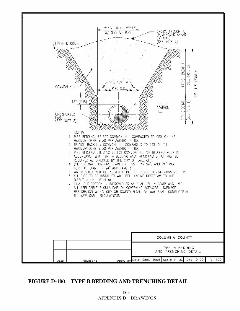
TRENCH WIDTH VARIES CROWN TRENCH INW/ SIZE Or PIPE ~ UNIMPROVED AREAS (3" MIN.)(SEE NOTE 7)r I NISH ED GRADE
_J _J
G:: °N'""u Lu ::,;c<I: f- ::::,m Cl ::,;cz
X= u Lu <I: z Lu ::,;cLu VJ 0-- VJ
J SEE NOTE 4.'.. f-COMMON ~
t:;::/' PIPE O.D '* _J
= N
(_'.)
SELECT z ~
= f-COMMON = Lu
Lu Cl r ILL m z UNDISTURBED Lu Lu
Q_ LuEARTH Q_ ~(SEE NOTE 3)
NOTES: 1. PIPE BEDDING: SELECT COMMON rill COMPACTED TO 95% Or THE
MAXIMUM DENSITY AS PER AASHTO T-180. 2. TRENCH BACKrlLL: COMMON rill COMPACTED TO 95% Or THE
MAXIMUM DENSITY AS PER AASHTO T-180. 3. PIPE BEDDING UTILIZING SELECT COMMON rill OR BEDDING ROCK IN
ACCORDANCE WITH TYPE A BEDDING AND TRENCHING DETAIL MAY BE REQUIRED AS DIRECTED BY THE CITY Or LAKE CITY.
4. (*): 15" MAX. rOR PIPE DIAMETER LESS THAN 24", AND 24" MAX. rOR PIPE DIAMETER 24" AND LARGER.
5. WATER SHALL NOT BE PERMITTED IN THE TRENCH DURING CONSTRUCTION. 6. ALL PIPE TO BE INSTALLED WITH BELL rACING UPSTREAM TO THE
DIRECTION Or THE rLOW. 7. rlNAL RESTORATION IN IMPROVED AREAS SHALL BE IN COMPLIANCE WITH
ALL APPLICABLE REGULATIONS Or GOVERNING AGENCIES. SURrACE RESTORATION WITHIN CITY OR COUNTY RIGHT-Or-WAY SHALL COMPLY WITH THE APPLICABLE REGULATIONS.
COLUMBIA COUNTY
TYPE B BEDDING AND TRENCHING DETAIL
Date Revisions Appr. b Date: Sept. 1996 Scale: N.T.S. Dwg: 0100 Fig: 100
FIGURE D-100 TYPE B BEDDING AND TRENCHING DETAIL
D-3 APPENDIX D - DRAWINGS
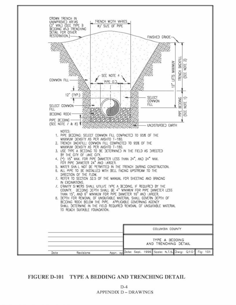
CROWN TRENCH IN UNIMPROVEJ ARFAS 1 T~ENCH WIJTH VA~IES (3" 'v11N.) (SEE TYPE 3 W/ SILE OF PIPE eEDDINC Af...D TRENCHING DETAIL FOR OTHER RESTORATION.)~--.,,--
.r SEE NOTE '- ·\· , .. ·p1:,E. OJ ·. · . r N
o-;z ~ 25 Lu
8 'o ------~ O"I z
Lu Lu a... Lu a: ~
NOTES: 1. PIPE BEDJING: SELECT COMMON FILL COMPACTEJ TO 95% OF THE
MAXIWU!v' DENSITY /IS PER MSHTO T-1 BO. 2. TRENCH 3ACKFILL: COWMON FILL COMPACTED TO 95% OF THE
MAXIWUW DENS11Y AS PER AASHTO T-1 BO. 3. USE 'TYPE A 3EDNG TO 3E JETER'v11NEJ IN THE FIELD AS JIRECTED
BY THE CITY OF LAKE CITY. '-. (•): 15" WAX. FOR PIPE DIAWETE~ LESS THAN 21.·, AN) 21.· VAX.
FO i Pl PE Jl/1\ffTER 24" AND l ARGE~. 5. WATE~ SH/\. L NOT BE :,E~WITIED IN THE TRENCH DURING CONSBUCTI ON. 6. /ILL PIPE TO 3E INSTALLED WITH BELL FACING UPSTREAM TO THE
DIRECTION OF THE FLOW. 7. REFE~ TO SECTION 32.5 OF THE MANUAL FO~ SHEETING AND BRACING
IN EXCAVATIONS. /. G~YITY SI WERS SHALL UTILI/E IYPE I\ 3EJDING, IF REQUliEJ BY TH E
COUNTY. 3EJJING J[::>fH SHALL BE I." 'v11Nl'v1U'v1 FOR PI PE DINJETE~ LESS THAN 15", AND 6" MINl'v1U'v1 FOR PIPE DINJETER 16" ANJ LAi GER.
B. DE:,TH FO~ REMOVAL OF UNSUITABLE VATE~IAL SHALL GOVE~N DEPTH OF BEJJING iOCK BELOW THE PIPE. A=>PUCABLE GOVERNI NG AGENCY SHALL DETERMINE IN THE FIELD REQUIRED ~E'v10VAL OF UNSUITABLE MATERIAL TO REACH SUITA3LE FOUNDATION.
COLU~BIA COUNTY
TYPE A BEDDI NG AN D TRENCHI NG DETAIL
1996 Scole : N.T.S. D wg: Q 1 D Fig: 1D1Dote Revisions
FIGURE D-101 TYPE A BEDDING AND TRENCHING DETAIL
D-4 APPEN DIX D - ORAWINGS
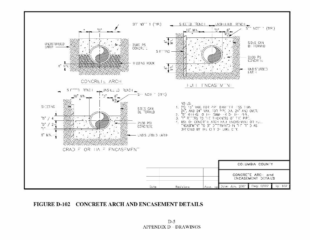
SEE NOTE 1 (TYP.) SHEETED TRENCH NOTE 1 (TYP.)* I -
10" MIN. *
EARTH ~
SHEETING
:z'_ :,SC SIDES CAN
BE FORMED
4" BEDDING ROCK
~ :z'_ :,SC
2500 PSI CONCRETE
6" MIN.
-CONCRETE ARCH
SHEETED TRENCH i°"' UNSHEETED TRENCH .,,, 1o" MIN. "D" 5" SEE NOTE 1 (TYP.)
* MkN
-~- SIDES CAN BE FORMED
-----~- 2500 PSI CONCRETE
EARTH
FULL ENCASEMENT
NOTES: 1. (*): 15" MAX. FOR PIPE DIAMETER LESS THAN
24", AND 24" MAX. FOR PIPE DIA. 24" AND OVER. 2. "D" REFERS TO THE DIAMETER OF THE PIPE. 3. "T'' REFERS TO THE THICKNESS OF THE PIPE. 4. USE OF CONCRETE ARCH HALF ENCASEMENT OR FULL
ENCASEMENT TO BE DETERMINED IN THE FIELD AS DIRECTED BY THE CITY OF LAKE CITY.
COLUMBIA COUNTY
CONCRETE ARCH and ENCASEMENT DETAILS
Date Revisions Date: Jan. 2001 Dwg: Q102 Fig: 102
FIGURE D-102 CONCRETE ARCH AND ENCASEMENT DETAILS
D-5 APPENDIX D - DRAWINGS
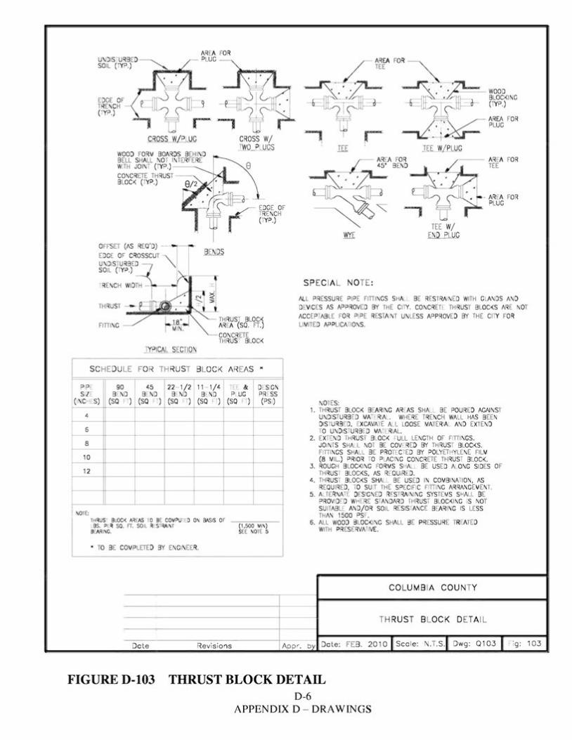
AREA FO R - PLUG AREA FOR
TEE
EDGE OF TRENCH -(TYP.)
CROSS W/ PLUG CROSS W/ TWO PLUGS
WOOD FO RM BOARDS BEH IND BELL SHALL NO r INTERFERE WITH JOIN.,. (1YP.)---...... CONCRETE TH RUST BLOCK (TYP.)
OFFSET (AS REQ' D) - ----EDGE OF CROSSCUT '\. UNDISTU RB ED "\ SOIL (TYP.)
TH RUSJ BLOCK FITII NG AREA (SQ. FT.)
CONCR ETE TH RUST BLOCK
TYPICAL SECTI ON
SC HED ULE FO R TH RUST BLOCK AREAS *
PIPE 90 45 22- 1/2 11 - 1/4 TEE & DESIGN SIZE BEND BEND BEND BEND PLUG PR ESS
(INC HES) (SQ FT) (SQ FT) (SQ FT) (SQ FT) (SQ FT) (PSI)
4
6
8
10
12
NOTE: THRUST BLOCK AREAS l O BE COMPUTED ON BASIS OF LBS. PER SQ. FT. SOIL RES RAINT (1,500 MIN)BEAR ING. SEE NOTE 5
• TO BE COMPLETED BY ENGINEER.
- --- WOOD BLOCKING (1YP.)
AREA FOR PLUG
- AREA FOR PLUG
TEE W/ END PLUG
SP ECIA L NOTE :
ALL PRESSURE PIPE FITIINGS SHALL BE RESTRA NED WITH GLANDS AND DEVICES AS APPROVED BY THE CITY. CONCRETE TH RUST BLOCKS ARE NOT ACCEPTAB LE FOR 0 JPE RESTAINT UNLESS APPROVED BY THE Cl1Y FOR LIMITED APPLICM IONS.
NOTES: 1. THRUST BLOCK BEARING AREAS SHALL BE POURED AGAINST
UNDISTU RB ED MATER AL. WHERE TRENCH WALL HAS BEEN DIS rURBr D, LXCAVATE ALL LOOSE MATER AL AND EXTEND TO UND1s·uRB[D MArERIAL.
2. EX-END TH RUS 1 Bl OCK FULL LENGTH OF FITII NGS. J01NTS SHALL NOT BE COVERED BY TH RUS T BLOCKS. FITIINGS SHALL BE PROTEC rED BY POLYETHYLENE FILM (8 MIL.) PRIOR TO PLACING CONCRETE THRUS BLOCK.
3. ROUGH BLOCKING FORMS S ALL BE USED ALONG SIDES OF TH RUS r BLOCKS, AS Rr. QU ,Rt. D.
4. THRUS r BLOCKS SHALL BE USED IN COMBINATI ON , AS REQUIRED, TO SU IT THE SPECIFI C FITTI NG ARRANGEMENT.
5. ALTE RNAf Df SIGNED R• STRAINING SYSTE MS Sl-'AU BE PROV1DED WHF. RE Sl ANDARD TH RUS , BLOCKING ,S NOT SU llABLE AND/OR SOIL RESISl ANCE BEARING IS LESS TH AN 1500 PS .
6. ALL WOOD BLOCKING SHALL BE PRESSURE TREATED WITH PR ESERVATIVE.
CO LUMB IA COUN TY
TH RUS T BLOCK DETA IL
Dote Revisions App r. b Date: FEB. 2010 Sca le: N.T.S. Dwg: Q103 Fig: 103
FIGURE D-103 THRUST BLOCK DETAIL D-6
APPENDIX D - DRAWINGS
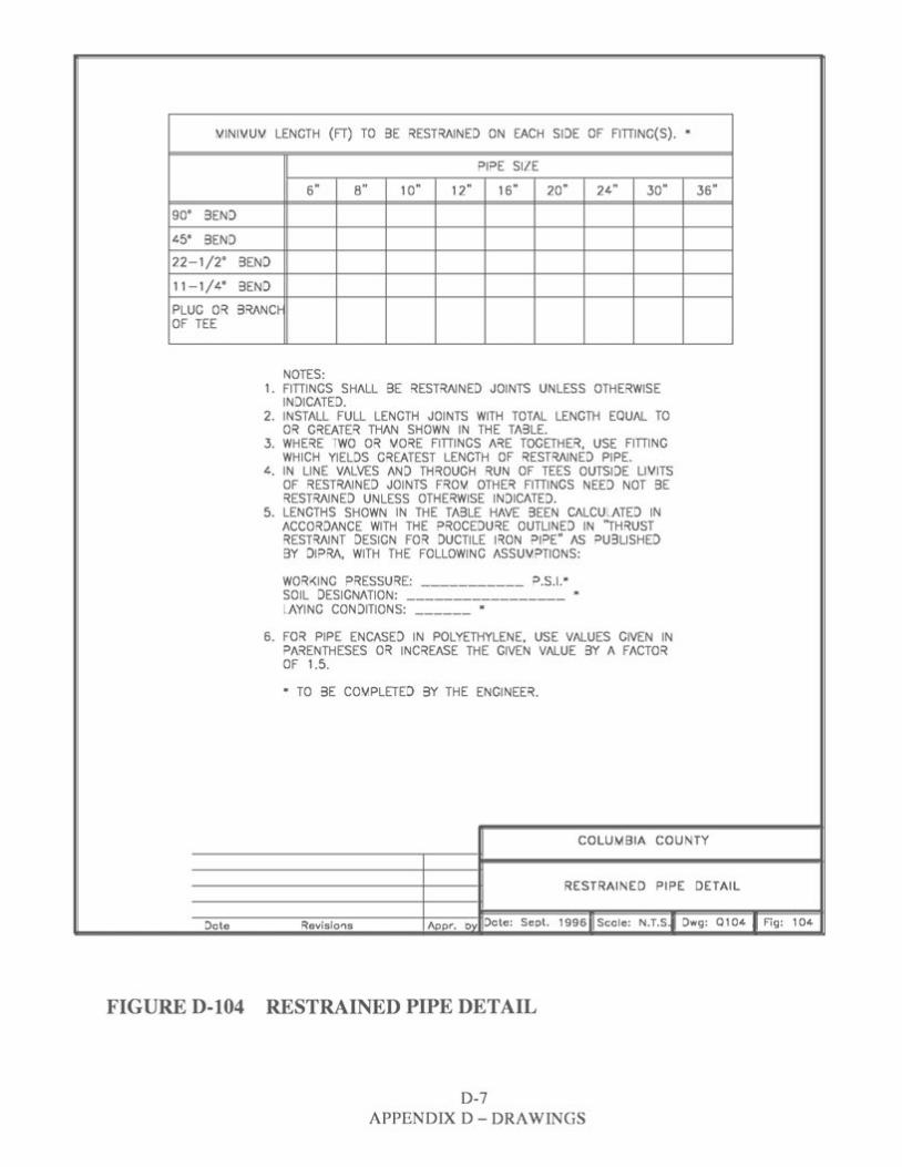
MINIMUM LENGTH (FT) TO BE RESTRAINED ON EACH SIDE OF FITIING(S). *
PIPE SIZE
6" 8" 10" 12" 16" 20" 24" 30" 36"
90" BEND
45" BEND
22-1/2" BEND
11-1/4" BEND
PLUG OR BRANCt-OF TEE
NOTES: 1. FITIINGS SHALL BE RESTRAINED JOINTS UNLESS OTHERWISE
INDICATED. 2. INSTALL FULL LENGTH JOINTS WITH TOTAL LENGTH EQUAL TO
OR GREATER THAN SHOWN IN THE TABLE. 3. WHERE TWO OR MORE FITIINGS ARE TOGETHER, USE FITIING
WHICH YIELDS GREATEST LENGTH OF RESTRAINED PIPE. 4. IN LINE VALVES AND THROUGH RUN OF TEES OUTSIDE LIMITS
OF RESTRAINED JOINTS FROM OTHER FITIINGS NEED NOT BE RESTRAINED UNLESS OTHERWISE INDICATED.
5. LENGTHS SHOWN IN THE TABLE HAVE BEEN CALCULATED IN ACCORDANCE WITH THE PROCEDURE OUTLINED IN ''THRUST RESTRAINT DESIGN FOR DUCTILE IRON PIPE" AS PUBLISHED BY DIPRA, WITH THE FOLLOWING ASSUMPTIONS:
WORKING PRESSURE: ___________ P.S.I.* SOIL DESIGNATION: ----------------- * LAYING CONDITIONS: ______ *
6. FOR PIPE ENCASED IN POLYETHYLENE, USE VALUES GIVEN IN PARENTHESES OR INCREASE THE GIVEN VALUE BY A FACTOR OF 1.5.
* TO BE COMPLETED BY THE ENGINEER.
COLUMBIA COUNTY
RESTRAINED PIPE DETAIL
Revisions Acor, by Dote: Sept. 1996 ii Scale: N.T.s.il Dwg: Q 104 II Fig: 104Dote
FIGURE D-104 RESTRAINED PIPE DETAIL
D-7 APPENDIX D - ORAWINGS
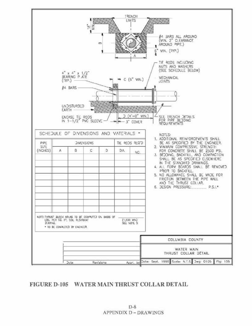
T~ENCH Ll'v11TS
I #L 3ARS ALL AROUND (tv11N. 2" CLEARANCE
CD AROUND ::>(PE.)
6" VIN. (lYP.) I A II .... •
TIE ~ODS INCLU)INC NUTS AND WASHERS (SEE SCHEDULE BELOW)4" X L" X 1/2"
3EARINC P ATE \AECHANICAL(lYP.) -~~ C (6" \AIN.) JOINTS
64 BA~S --------;:::,,,__,~~========~=fl~--____,._
UN)ISTU~3EDEARTH --~.,..~;,::,
) (4'-0" WIN.) '~E TRENCH )ETl'JLSENCASE TIE RODS IN 1-1/2" PVC SLEEVE - ~ 3" COVE~ 1 FOR PIPE 3DDINC
~EQUl~E'v1ENTS
SCHE)ULE OF DIVENSIONS AND VATE~IALS "' NOTES: 1. AOOITION/\L REINFORCE\iENTS SHALL
PIPE )IMENSIONS TIE ~O)S ~EO'O 3E AS SPECIFID BY THE ENCINEE~. S17E 2. VINIWU'-1 COWPRESSIVE STRENGTH
(INCHES) A B C D DIA. FO~ CONCRETE SHALL BE 2500 PSI.NO 3. 3D)INC, BACKFILL, AND COW.PACTION
SHALL BE AS SPECIFID ELSEWHERE IN THE STAN)/\~) )RAWINCS.
4. ALL FORV 80/\RJS SHALL BE ~E'v10VD ::>~10~ TO BAC-<FILL.
5. NO ALLOWANCE SHALL BE WAJE FO~ FRICTION 3ETWEEN THE PIPE W/\LL AN) THE THRUST COLI AR.
6. JESIGN PRESSURE: ______ P.S.1.*
NOTE: TH~ST 3LOC-< AR:AS TO 8E COIJ:>\JTD 01\ BASIS Of LBS. PE~ SQ. FT. SOIL R::.STRANT (1,500 ',/It\) 3rA~lt\G. SEE t\01( 5 • TO SE CO\l~ETEO 3Y ENCINEER.
COLUMBIA COUNTY
WATER MAIN THRUST COLLAR DETAIL
1996 Scale: N.T.S. )wg: 0105 Fig: 105::>cte Revisions
FIGURE D-105 WATER MAIN THRUST COLLAR DETAIL
D-8 APPENDIX D- DRAWINGS
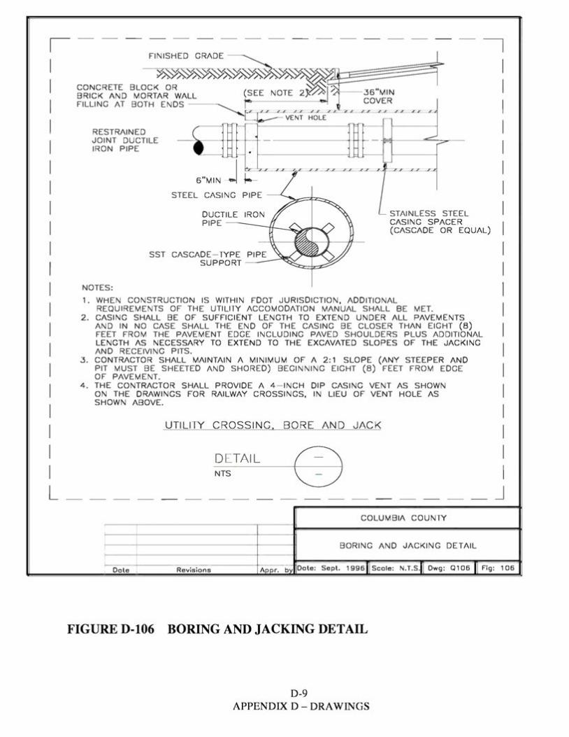
, -- - - - - --- - -- - -- - - ,FINISHED GRADE
VENT HOLE
RESTRAINED JOINT DUCTILE IRON PIPE
6 "MIN _j -t-,- ~=====i=::'z============
STEEL CASING
STAINLESS STEEL CASING SPACER (CASCADE OR EQUAL)
NOTES : 1 . WHEN CONSTRUCTION IS WITHIN FOOT JURISDICTION , ADDITIONAL
REQUIREMENTS OF THE UTILITY ACCOMODATION MANUAL SHALL BE MET. 2. CASING SHALL BE OF SUFFICIENT LENGTH TO EXTEND UNDER ALL PAVEMENTS
AND IN NO CASE SHALL THE END OF THE CASING BE CLOSER THAN EIGHT (8) FEET FROM THE PAVEMENT EDGE INCLUDING PAVED SHOULDERS PLUS ADDITIONAL LENGTH AS NECESSARY TO EXTEND TO THE EXCAVATED SLOPES OF THE JACKING AND RECEIVING PITS.
3. CONTRACTOR SHALL MAINTAIN A MINIMUM OF A 2: 1 SLOPE (ANY STEEPER AND PIT MUST BE SHEETED AND SHORED) BEGINNING EIGHT (8) FEET FROM EDGE OF PAVEMENT.
4. THE CONTRACTOR SHALL PROVIDE A 4 - INCH DIP CASING VENT AS SHOWN ON THE DRAWINGS FOR RAILWAY CROSSINGS, IN LIEU OF VENT HOLE AS SHOWN ABOVE.
UTILITY CROSSING . BORE AND JACK
DETAIL NTS CDL ____ _ _ _J
COLUMBIA COUNTY
BORING AND JACKING DETAIL
Sept. 1996 Scale: N.T.S. Owg: Q106 Fig: 106, Date , Revisions
FIGURE D-106 BORING AND JACKING DETAIL
D-9 APPENDIX D - ORAWINGS
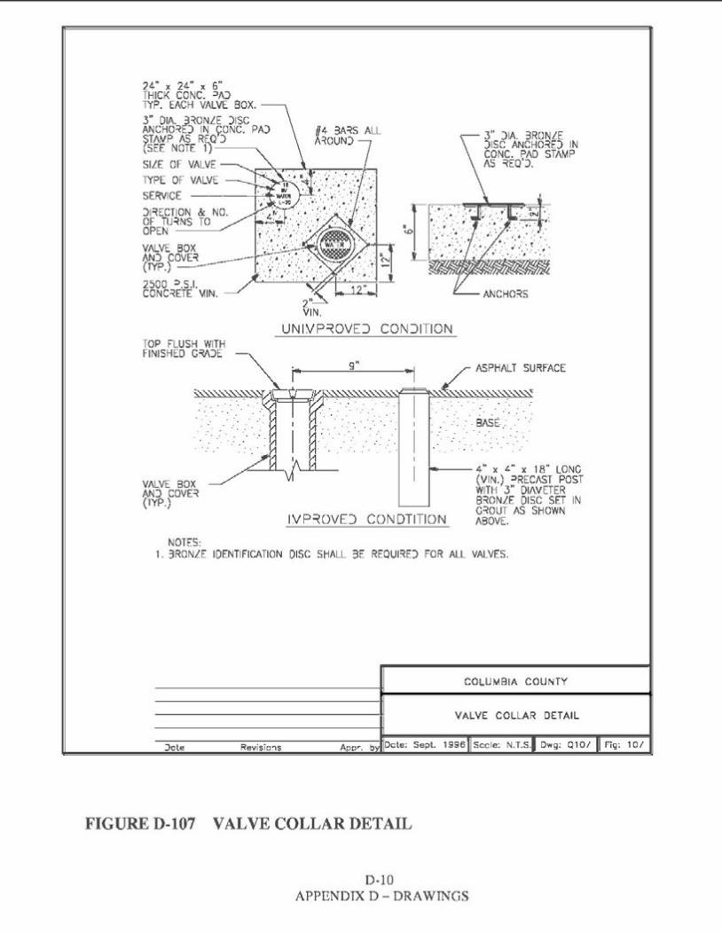
24" X 24" X 6" THICK CONC. =>A)TYP. EACH VALVE BOX. 3" DIA. 3~0NLE )ISC ANCHO~E) IN ~ONC. PA)$TNJ.P AS RE..Q )(SEE NOTE 1)--~ SILE OF VALVE
3" )IA. 3RONLE )ISC ANCHO~E) IN CONC. PAD STAMP AS ~EQ').
TYPE OF VALVE SERVICE )l~ECTIONOF TU~NS OPEN
& NO. TO
VALVE BOX AN) COVE~(TYP.) -2soo =>.s.1. CONC~ETE 'vHN.
2" VIN.
UNIVP~OVEJ CONJITION TOP FLUSH WITH FINISHED G~)E
ASPHALT SURFACE
.. . ...,': .·.BASE-.... :, .,' . .. . . .. : . . . ..
. . . . .... ·. ·.
---- 4" x t." x 18" LONC (VIN.) =>RECAST POST WITH 3" OIAVETER B~ONLE DISC SET IN C~OUT AS SHOWN
IVP~OVE) CONDTITION ABOVE.
NOTES: 1. 3RONLE IDENTIFICATION DISC SHALL 3E REQUl~E) FOR ALL VALVES.
COLUMBIA COUNTY
VALVE COLLAR DETAIL
1996 Sec le: N. T.S. Dwg: Q 10/ Fig: 10 / Jote Revisio~s
FIGURE D-107 VALVE COLLAR DETAIL
D-10 APPENDIX D - DRAWINGS
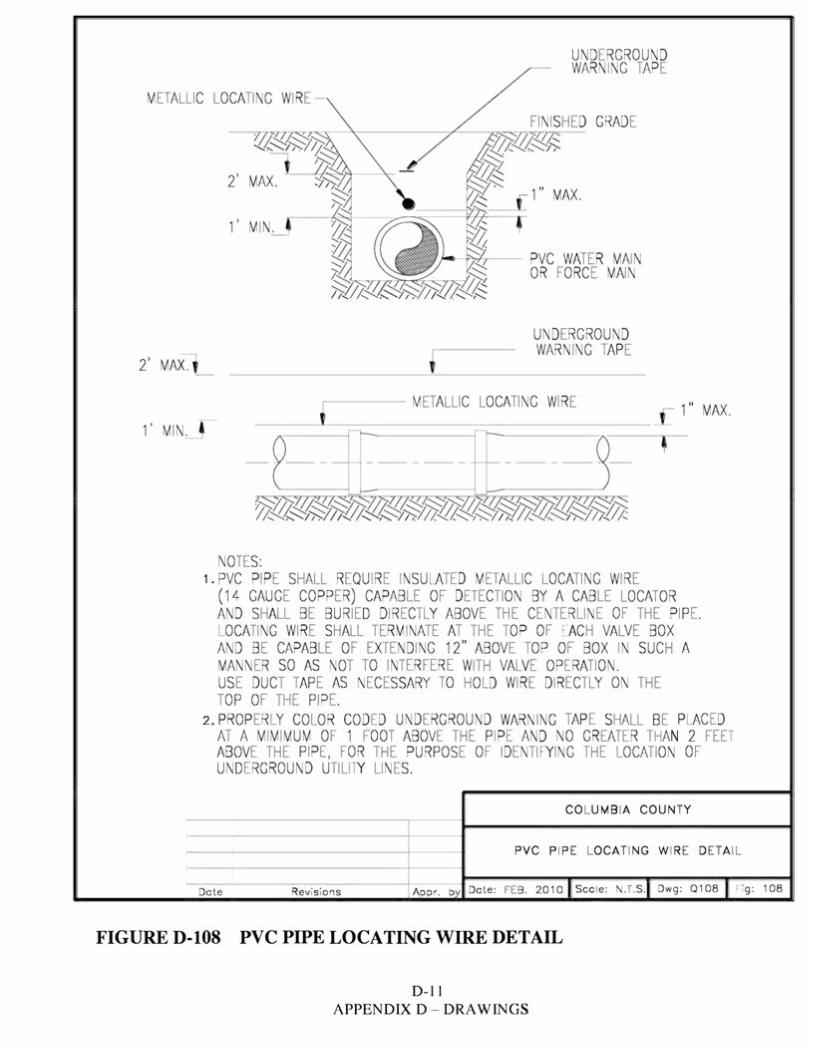
UNDERGROUND WARN ING TAPE
METALLIC LOCATI NG WIRE
2' MAX. ~ 1" MAX.
1' MIN~
,__~ -- PVC WATER MAIN OR FO RCE MAIN
UND ER GROUND WARN ING TAPE
2' MAxl_ ' ---- METALLIC LOCATI NG WIRE 1" MAX.
1' MIN~
NOTE S: 1. PVC PIPE SHALL REQU IRE INSULATED METALLIC LOCATI NG WIRE
(14 GAUGE COPPER) CAPABLE OF DETECTI ON BY A CAB LE LOCATOR /\ND SHALL BE BURIED DIRECTLY /\BOVE THE CENTER LI NE OF THE PIPE. LOCATI NG WIRE SHALL TERMINATE AT THE TOP OF EACH VALVE BOX /\ND BE CAPABLE OF EXTE NDING 12" ABOVE TOP OF BOX IN SUCH A MANN ER SO AS NOT TO INTER FER E WITH VALVE OPERATI ON . USE DUCT TAPE AS NECESSARY TO HOLD WIRE DIRECTLY ON THE TOP OF THE PIPE.
2. PROP ERLY COLOR CODED UNDERGROUND WARN ING TAPE SHALL BE PLAC ED /\T /\ MIMIMUM OF 1 FOOT ABOVE THE PIPE /\ND NO GREATER THAN 2 FEET ABOVE THE PIPE, FOR THE PURPOSE OF IDENTI FYING THE LOCATI ON OF UNDERGROUND UTILITY LINES.
CO LUMB IA COUN TY
PVC PIPE LOCATI NG WIRE DE TA IL
Date Revisions Appr. b Date: FEB. 2010 Sco le: N.T.s. 1Dwg: 0108 Fig: 108
FIGURE D-108 PVC PIPE LOCATING WIRE DETAIL
D-11 APPENDIX D - DRAWINGS
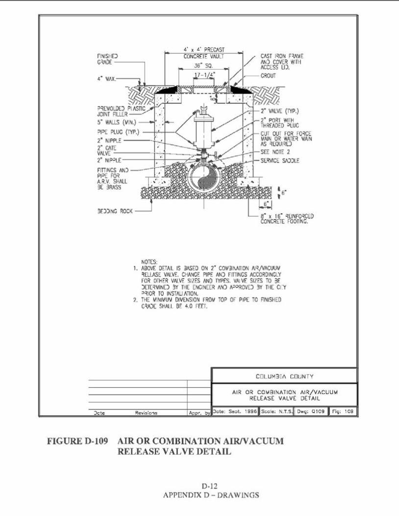
4' x t.' PRECAST FINISHD CONCRETE VAULTG~DE ~~~
3£:>)ING ROCK s· x 1s· ~EINFO~CED CONCRETE FOOTING.
NOTES: 1. ABOVE DETAIL IS 3ASED ON 2" COl/31f\ATION Al~/VACUUV
~Ell.ASE VALVE. CHANGE PIPE AN) FIITINGS ACCORDINGLY FOR OTHER VALVE SIZES ANO TYPES. VAi VE SIZES TO 3E )ETE~\IIND 3Y THE ENGINEER AN) t,,=>=>ROVD 3Y THE C1:Y =>~IOR TO INSTALi ATION.
2. THE 1/INIWU\i OIVENSION FROI.' TOP OF PIPE TO FINISHED CWE SHALL BE 4.0 FEET.
COLUM3I/\ COUNTY
AIR OR COMBINATION AIR/VACUUMRELEASE VALVE DETAIL
::>cte Revisio'\s A pr. b ::>ote: Se:>t. 1996 Scole; N.T.S. Dwg: 0109 Fig: 109
FIGURE D-109 AIR OR COMBINATION AIR/VACUUM RELEASE VALVE DETAIL
D-12 APPENDIX D- DRAWINGS
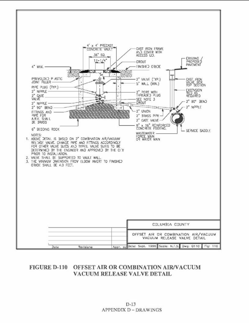
I EXISTING /~~0::,0SE0PAVEMENT4" MAX.-----...
P~EVOLDD P ASTIC ,,--+-+----2" VALVE (".YP.) 1-1-,.._-CAST l~ONJOINT FILLER ____. VALVE BOX----5" WA_L (MIN.) TOP SECTIONPPE :,LUG (TYP.)-----<:::.r EXTENSION
2" NPPL£ -------- ----1-'---- 2" ::,O~T WITH 2" CATE --------t-.i-------'.IJ: TH~EADEJ :,LUC ~~dufrn VALVE SEE NOTE 3 2" 90° 3EN)2" NP::,L£ -------r: CROUT
2" N1::>::>LE2" 90" BEND ----FITTINGS AND 2" UNION ::,IPE FOR 2" 3::w5S Pl::>E A.R.V. SHAI L 2" GATE VALVE3E 3RASS
..____ 8" x 16" REINFORCED 6" BED)ING ROCK CONC~ETE FOOTINC.
SE=MCE SADDLEWASTEWATE~ -----' NOTES: FORCE VAIN
1. ABOVE )ETI\IL IS 3ASED ON 2" COW31'JATION I\IR/VACUUIJ. 0~ WATER WAIN REL::ASE VALVE. CHANCE ::,IPE ANO FITTINGS ACCORDINGLY FO~ OTHB VALVE SILES A\) TYPES. VALVE SILES TO BE OETE~~IND 3Y THE ENGINEE~ AND APPROVE) 3Y THE Cl'.Y P~IOR TO INS TAJ ATION.
2. VAf..VE SHALL BE SUP::>ORTED TO VAULT WALL. 3. THE VINl~UV )IMENSION FROV EL30W INVERT TO FINISH£)
G~OE SHALL 3E t..O FEET.
COLUMBIA COUNTY
OFFSET AIR OR COMBINATION AIR/VACUUMVACUUM RELEASE VALVE DETAIL
)ale ~evisio'\S Ocle: Sepl. 1996 Sccle: N.T.S. Owg: 0110 Fig: 110
FIGURE D-110 OFFSET AIR OR COMBINATION AIR/VACUUM VACUUM RELEASE VALVE DETAIL
D-13 APPENDIX D- DRAWINGS
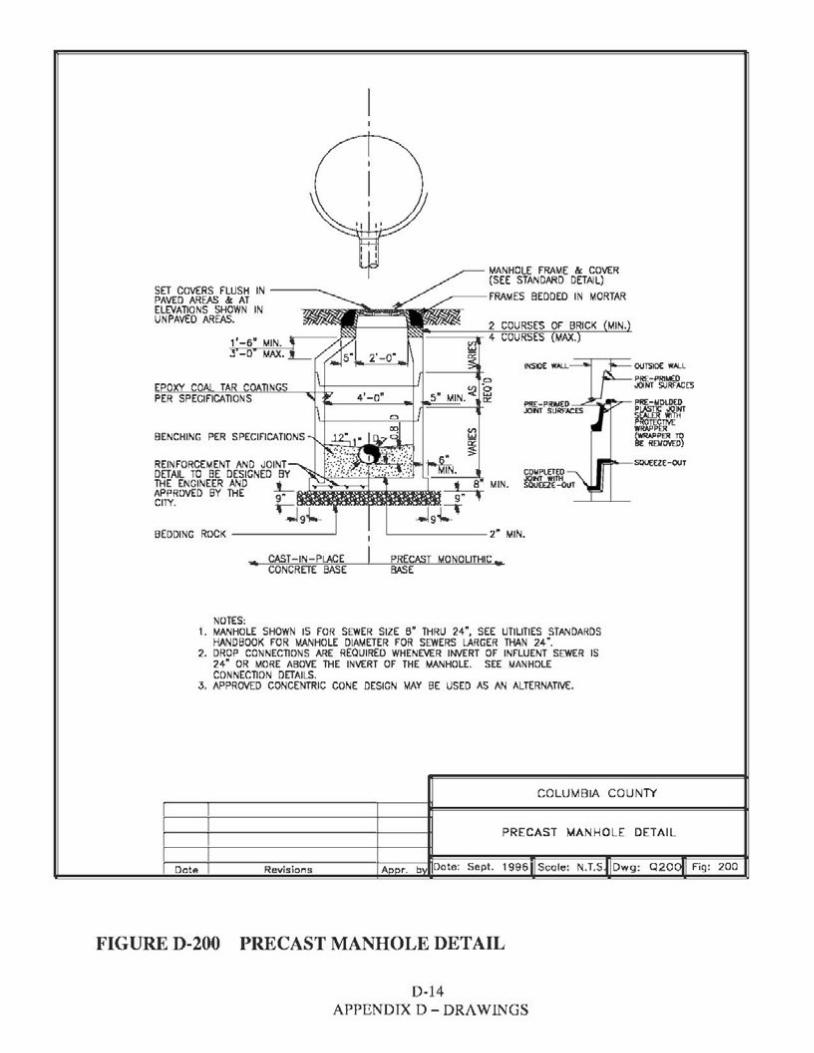
MANHOLE FRAME & COVER (SEE STANDARD DETAIL)
SET COVERS FLUSH IN -----. ---FRAMES BEDDED IN MORTARPAVED AREAS &: AT ELEVATIONS SHOWN IN UNPAVED AREAS. 2 COURSES OF BRICK MIN.
INSIOE WALL ours10€ WALL
EPOXY COAL TAR COATINGS PRE-PRIMO)JOINT SURf"ACE'S
PER SPECIFICATIONS
BENCHING PER SPECIFICATIONS
REINFORCEMENT AND JOINT SQUEEZE-OUT DETAIL TO BE DESIGNED BY THE ENGINEER AND .1_APPROVED BY THE 9• CITY. r
.J9i-BEDDINC ROCK -------'
.,. CAST-IN-PLACE PRECAST MONOLITHIC,..CONCRETE BASE BASE
NOTES: 1. MANHOLE SHOWN IS FOR SEWER SIZE s• THRU 24", SEE UTILITIES STANDARDS
HANDBOOK FOR MANHOLE DIAMETER FOR SEWERS LARGER THAN 24". 2. DROP CONNECTIONS ARE REQUIRED WHENEVER INVERT OF INFLUENT SEWER IS
24" OR MORE ABOVE THE INVERT OF THE MANHOLE. SEE MANHOLE CONNECTION DETAILS.
3. APPROVED CONCENTRIC CONE DESIGN MAY BE USED AS AN ALTERNATIVE.
COLUMBIA COUNTY
?RECAST MANHOLE DETAIL
Fig: 200Dote Revisions
FIGURE D-200 PRECAST MANHOLE DETAIL
D-14 APPENDIX D- DRAWINGS
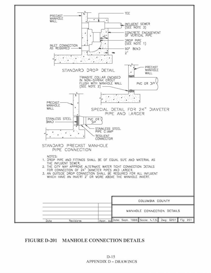
PRECAST--~-MANHOLE WALL
INFLUENT SEWER SEE NOTE 3)
,.._--CONC~ETE ENCASEVENT OF VERTICAL PIPE
i,a.....,-+--- DROP PIPE (SEE NOTE 1)INLET CONNECTION
/\S REQUIRED ---i ,,..,_,'----'-,-+----- 9 0° BEN) 2"... . . -
. . .. : . . . .. ~ .. ,. . . . .. .. •· .· ".· ... ·.,· .·
PREC/1.ST ST/\ND/\RJ D~Q:> DETAIL MANHO LE
WALL B/\NSITE COLL/\R ENCASED IN NON-SH~IN-< CROUT FLUSH WITH MANHOLE W/\LL(SEE NOTE 2) ----
: .. . . ..· : .
. . .P~ECAST-MANHOLE WALL SPECIAL DETAIL FD~ 24" JIAVETER
Pl PE AND LA~GER STI\INLESS3AN) ------1-'-
• • ~ESILIENT CONNECTOR
ST/\NJ/\RJ P~ECAST MANHOLE PIPE CONNECTION
NOTES: 1. D~OP PIPE AND FITTINGS SHALL BE OF EQU/\L S17E /\ND MATERIAL AS
THE INFLUENT SEWE~. 2. THE CllY MAY APPROVE J\LTE~N/1.TE WATER TIGHT CONN ECTION )ET/\ILS
FOR CONNECTION OF 24" DIAMETE~ :>1PES AND LA~CE~. 3. AN OUTSIDE DROP CONNECTION SHALL BE REQUIRED FOR ALL INFLUENT
WHICH HAVE /\N INVE~T 2' OR MORE ABOVE THE M/\NHOLE INVERT.
COLUMBIA COUNTY
MANHOLE CONNECTION DETAILS
)ate: Sept. 1996 Sccle: I\.T.S. Owg: Q201 Fig: 201Dcte ~evisio'ls
FIGURE D-201 MANHOLE CONNECTION DETAILS
D-15 APPENDIX D - DRAWINGS
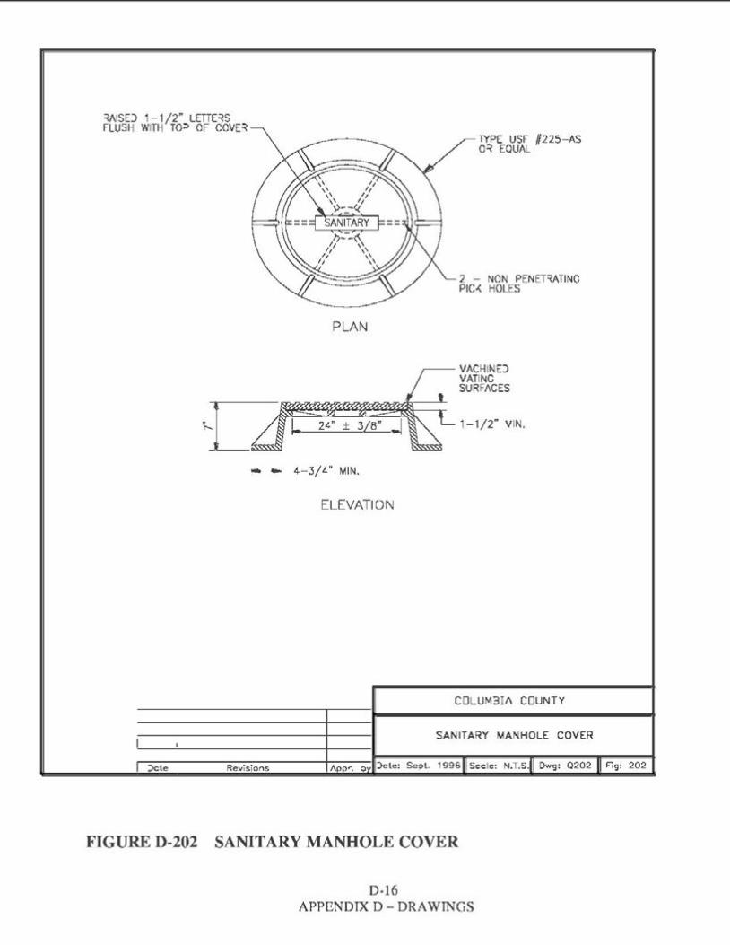
~ISD 1-1 /2" LETTE~S FLUSH WITH TO=> OF COVE~
TYPE USF #225-AS 0~ EQUAL
2 - NON PENEHATINC PIC~ HOLES
PLAN
VACHIND VATINC SURFACES
1-1/2" VIN.
- - 4-3/'-" MIN.
ELEVATION
.:>cte Revisions
COLUM3If\ COUNTY
SANITARY MANHOLE COVER
jcte: Se:>t. 1996 Sccle: N.T.S. Dwg: 0202 Fig: 202
FIGURE D-202 SANITARY MANHOLE COVER
D-16 APPENDIX D - DRAWINGS

SET TOP OF VALVE BOX TO FINISHED GRADE
~-- CONCRETE COLLAR l,N UNPAVED AREAS
FINISHED GRADE (SEE NOTE 3)
SEE NOTE 2
6" BEDDING
NOTES: 1. PVC EXTENSIONS SHALL NOT BE USED ON VALVE BOX INSTALLATION. 2. THE ACTUATING NUT FOR DEEPER VALVES SHALL BE EXTENDED TO
COME UP TO 4 FOOT DEPTH BELOW FINISHED GRADE. 3. VALVE COLLAR SHALL BE 18"X18"X6" CONCRETE
COLLAR W/4 - #4 BARS.
COLUMBIA COUNTY
PLUG VALVE AND BOX DETAIL
Date: Sept. 1996 Scale: N.T.S. Dwg: Q203 Fig: 203Date Revisions
FIGURE D-203 PLUG VALVE AND BOX DETAIL
D-17 APPENDIX D - DRAWINGS
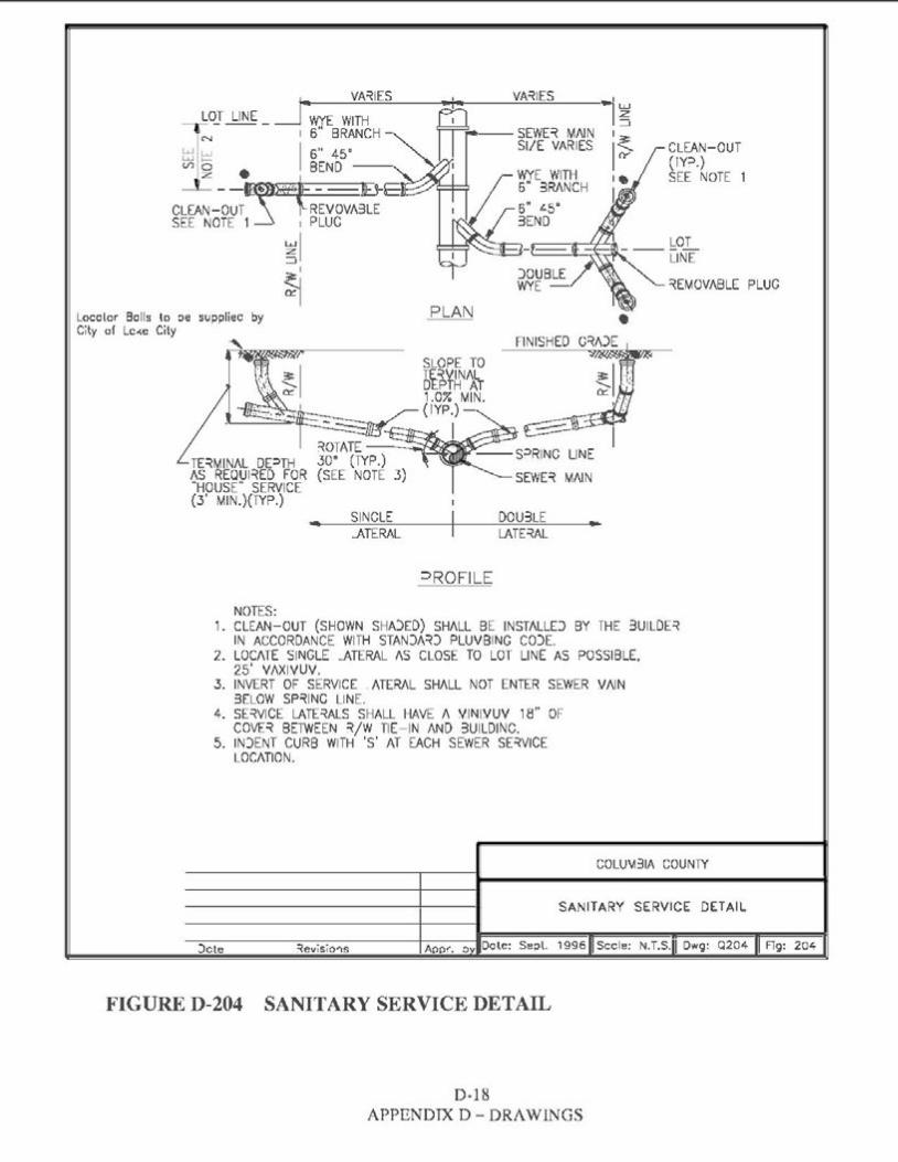
i. VA~IES VA~IES _ LO_T LINE _ __fWYE WITH
N 1 6" BRANCH - --SEWE~ MAINSI/E VARIES CLEAN-OUT w w I 6" 45·b=l o BEND~~ (IY:l.)
z • I WYE WITH SEE NOTE 16" 3RANCH
CLEAN--OUT~R-E~~E SEE NOTE 1 ~ 1 PLUC
~1_J
~[MOVABLE PLUG~ PLAN •Locolor Bolls lo oe suppliec by
City of Lc«e City
TE~MINJ\L D[:lTHAS REQUl~ED FOR "HOUSE" SERVICE (3' MIN.)(TYP.)
SINGLE DOU3LE ..- .ATERAL LATE~AL
=>RO FILE
NOTES: 1. CLEAN-OUT (SHOWN SHA)ED) SHALL BE INSTALLD BY THE 3UILDE~
IN ACCORDANCE WITH STAN)/\~) PLUVBING CO)E. 2. LOCATE SINGLE .ATERAL AS CLOSE TO LOT LINE AS POSSIBLE,
25' VAXIVUV. 3. INVERT OF SERVICE . ATERAL SHALL NOT ENTER SEWER VAIN
3ELOW SP~INC LINE. 4. SE~VICE LATE~ALS SHALL HAVE A VINIVUV 18" OF
COVE~ BE1WEEN ':?./W TIE-IN AND 3U1LD1NC. 5. IN)ENT CURB WITH 'S' AT EACH SEWER SE~VICE
LOCATION.
COLU~31A COUNTY
SANITARY SERVICE DETAIL
::>cte ~evisio'"ls Appr. 0 Dole: Se::,l. 1996 Sccle: N.T.S. I Dwg: Q204 Fig: 204
FIGURE D-204 SANITARY SERVICE DETAIL
D-18 APPENDIX D- DRAWINGS
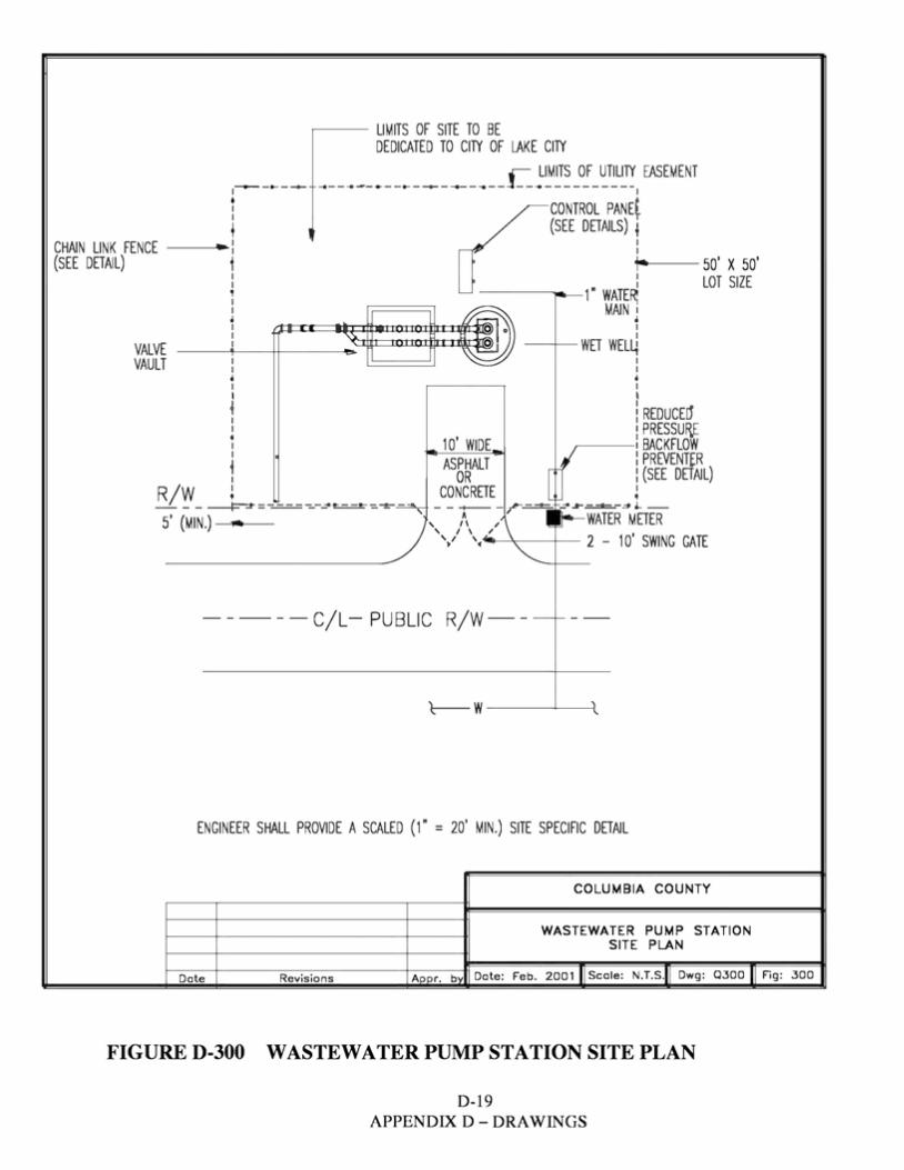
• •
~- LIMITS OF SITE TO BE DEDICATED TO CITY OF lAKE CITY
L LIMITS OF UTILITY EASEMENT ,~ -... - ~ ..... ------------~------- -- -- -- ----------,•I
L CONTROL PANE~ I
1 (SEE DETAILS) , CHAIN LINK FENCE -~•-: : ' (SEE DETAIL) 1 _,......___ 50' X 50'
: : LOT SIZE1 - ~ 1" WATER: l L~ MAIN!
----~f-----+~1:::t-·~::·: _=1_1t._"~'"':zlll:lln:t:ocUO:ttltt::t:r/i. ·~ WET WEL~· 0,~~;J[@VALVE VAULT I I
I I
t REDUCED' I PRESSURi,E ~ 1O' WIDE BACKFLOW
R W j ;~~ (rffiLJ[r • _j_- -----F"~ =-=-===-=--~ ==--=-~.=.::!!>..,- - - -+-- - ~ --- ~~=.::I::...-~,._ -5' (MIN.) .,., ' , /, ,, " I IJ--WATER METER
' I \ " \V ,....... ~ 2 - 10' SWING GATE
----- C/L- PUBLIC R/W-- - ~--
't----- w---+------J;_
ENGINEER SHALL PROVIDE A SCALED (1" = 20' MIN.) SITE SPECIFIC DETAIL
COLUMBIA COUNTY
WASTEWATER PUMP STATION SITE PLAN
Aoor. bv Date: Feb. 2001 IIScale: N.T.s.11Dwg: Q300 II Fig: 300Date Revisions
FIGURE D-300 WASTEWATER PUMP STATION SITE PLAN
D-19 APPENDIX D - ORAWINGS

D-20 APPENDIX D - DRAWINGS

D-21 APPENDIX D - DRAWINGS

36't I·o AL 0
LEVEL BREA<ERS ,-- LIGHTS TEST
ALARM! b' ~ I\LI\RMHORN:,__ , ' GENERATORSELECTOR SW.b' ~ LAG RECEPTACLE , ' 0
b' ~ LEAD I\MMETER I '
b' ~ OFF [8 I '
36'§ B COUNTER
b' RUN L!GHTb' , 'I '3 PT. LATCH e e ETM
4) 4) HO/\ tll M2 ASB
GFI RESETIGGI 0 0
0
NOTES: 1. OUTE~ 30X SIZE SHALL 3E A MINIMU\-1 OF 36"W X 36"H X 1 O"D OR AS
AP=>ROVE) 3Y THE CITY. 2. FOR STATIONS WITH PUV.:,S ~ATED 20 H:> 0~ GREATER, OUTE~ 30X SIZE
SHALL BE 36"W X 42"H X 1 O"D AND SHALL HAVE 2 I ATCHES ON THE DEAD F~ONT.
3. D~AWINGS SHALL 3E REVISED FOR STATIONS WITH Puv=is ~TED C~EATE~ THAN 50 HP AN) SU3MITTD TO THE CITY FO~ APPROVAL.
COLUMBIA COUNTY
DUPLEX CONTROL PANEL ENCLOSURE DEAD FRONT LAYOUT
Dcte: Dec. 2000 Sccle: ~.T.S. Owg: 0303 Fig: 303::>ote =tevisio'ls
FIGURE D-303 DUPLEX CONTROL PANEL ENCLOSURE DEAD FRONT LAYOUT
D-22 APPENDIX D- DRAWINGS
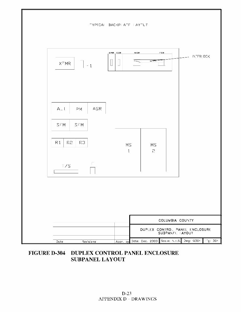
TYPICAL BACKPLATE LAYOUT
DRB CCB MC8 EC8
~~--bl=~~--t---1--- INTERLOCK
D D Q o-aJFl n,1 I
ALT PM ASR I I I I
SFM SFM I I I
I I IR 1 I R2 R3 MS MS 1 2
FT/S I I D
COLUMBIA COUNTY
DUPLEX CONTROL PANEL ENCLOSURE SUBPANEL LAYOUT
Dote Revisions Aoor. bv Dote: Dec. 2000 II Scale: N.T.s.11 Dwg: Q304 II Fig: 304
FIGURE D-304 DUPLEX CONTROL PANEL ENCLOSURE SUBPANEL LAYOUT
D-23 APPENDIX D - DRAWINGS
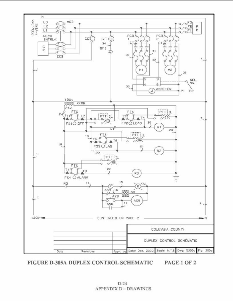
N J: n L3 0::-u-M_C_3_....,._________________.!'----------'I~MW
• Cl! >- L2 0-,-,-.o---.--+---------------'lt--t------•--1-a._L 1 I I0::>: ---01L>-----+--+--____,,,.______..._____----1------------1----<AC") I
l'\J..r- MECH ! INTRL< ; CC3) GFrc'ii)
34 ?6:: O::<r---' GFI I 0--<>----'
30ECB 7
31
9 -------r--<\ ~EL.6 \w. AMMETER Pl Pc
120v
7
18
R3 141
l------11------,r,,----t
r I 120v..-.---------- CONTINUED ON PAGE 2 ------------ N
COLUV31/\ COUNTY
DUPLEX CONTROL SCHEMATIC
Dcte ~evisions Dote: )ec. 2000 Sccle: N.T.S. Dwg: 0305c Fig: 305c
FIGURE D-305A DUPLEX CONTROL SCHEMATIC PAGE 1 OF2
D-24 APPENDIX D - ORAWINGS
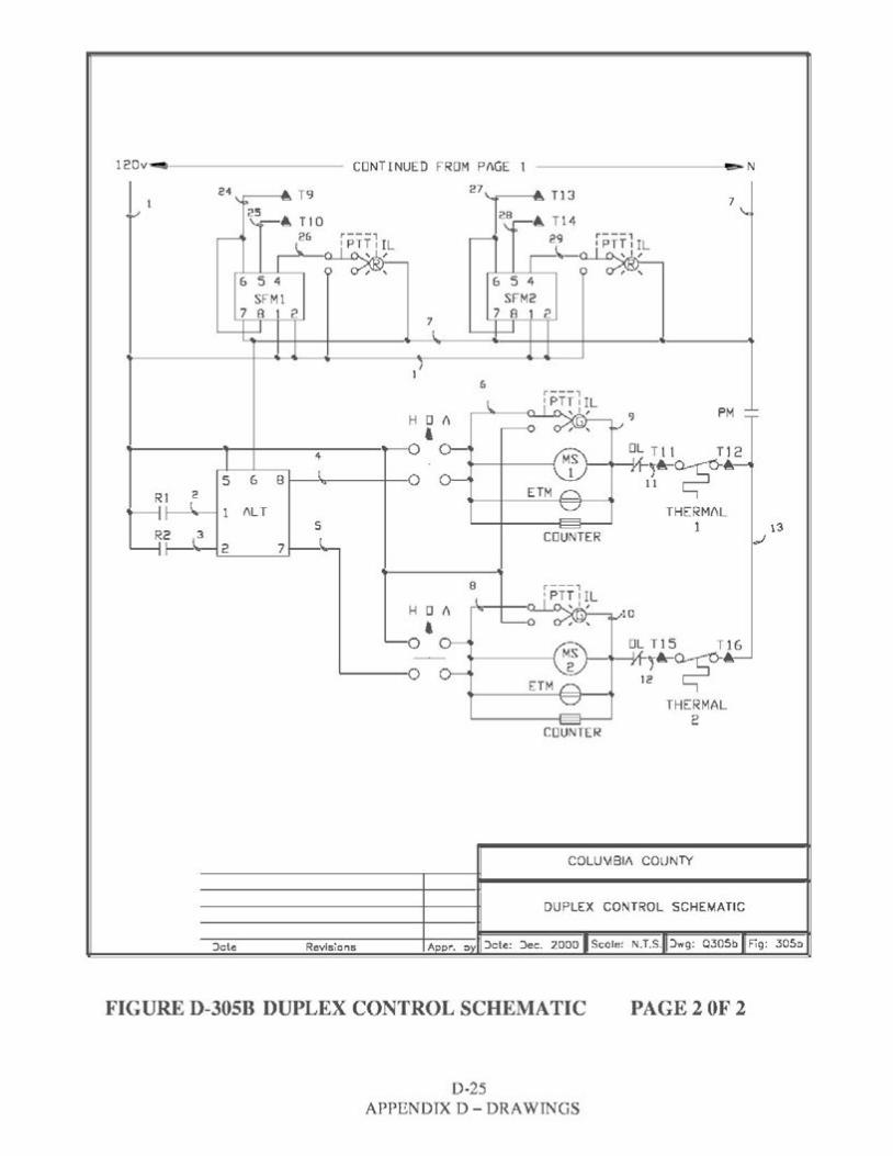
120v-.i CONTINUED FROM P/\GE 1 e,.,. N
T9I 24 2711 "T13 7 25 28-• TIO r-.. T14
26
' ' 6 S 4 6 S 4 ·~r1SFMl SFM2
7 B I 2 7 8 1 2 7
6
PM
• 9H 0 I\
0 DL Tl l Tl 2 4
5 6 B 0 11!~~ 2 ETMRl
ALT THERMAL s 1 13COUNTER .,.Iw~, 2 7
B
H 0 I\ 10
0 • DL Tl 5 Tl6
ETM ,-~~0 12
THERMAL 2
COUNTER
COLU~BI/\ COUNTY
DUPLEX CONTROL SCHEMATIC
:>cte Revisions :>cte: :>ec. 2000 Scole: N.T.S. :>wg: Q.305b Fig: .305::>
FIGURE D-305B DUPLEX CONTROL SCHEMATIC PAGE20F2
D-25 APPENDIX D - ORAWINGS

D-26 APPENDIX D - DRAWINGS
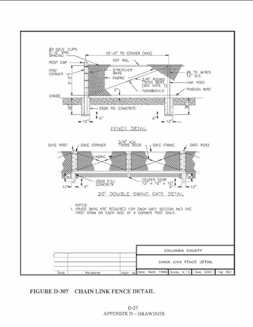
H~ G.(ILV. CLIPS ~ -0 V./\X. 1 O' -0" TO CENTER (VAX)SPACING ------------c
TOP ~ILPOST CAP ---•,-..,
POST #9 TIE Wl~ESCO~NE~ ·12" o.c. ---LINE ?OST
TENSION WIRE
t
FENCE DETAIL
3/8" A)J.GATE CORNER T~USS RO)S CATE F~AVE CATE POST
CENTER STOP t 12" X 12" X 12"&6"---l k12"
20' D0U3LE SWING GATE DETAIL
NOTES: 1. TRUSS 3A~S N~E REQUl~D FO~ EACH CATE SECTION AN) THE
FIRST SPAN ON EACH SIDE OF A CORNER =>OST ONLY.
COLUMBIA COUNTY
CHAIN LINK FENCE DETAIL
:>cte RevisiO!'IS 1996 Sccle: N.T.S. Owg: 030/ Fig: 30/
FIGURE D-307 CHAIN LINK FENCE DETAIL
D-27 APPENDIX D- DRAWINGS
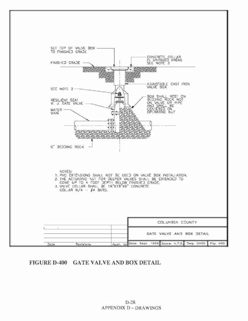
SET TO=> OF VALVE BOX ITO FINISHD GRA)E
FINISHED CRAJE --------
~ESILIENT SEAT V. J. GATE VALVE
WATE~ VAIN
6" 3ED)INC ~QC,<:
NOTES: 1. PVC EXTE,SIONS SHALL NOT 3E USD ON VALVE BOX INSTALIATION. 2. THE ACTUATING ,uT FO~ DEEPER VALVES SHALL BE EXTEN)ED TO
C0\.1E u=> TO t.. FOOT JEPTH BELOW FINISHEJ G~ADE. 3. VALVE COLLAR SHALL 3E 18"X1 B"X6" CONCRETE
COLAR W/4 - #4 BA~S.
COLUM3I/\ COUNTY
GATE VALVE AND BOX DETAIL
::>cle Revision,:; A:.>:.>r. ::, Oote: Sept. 1996 Sccle: 1'.T.S. I ::>wg: Q.LOO Fig: .LOO
FIGURE D-400 GATE VALVE AND BOX DETAIL
D-28 APPENDIX D - DRAWINGS
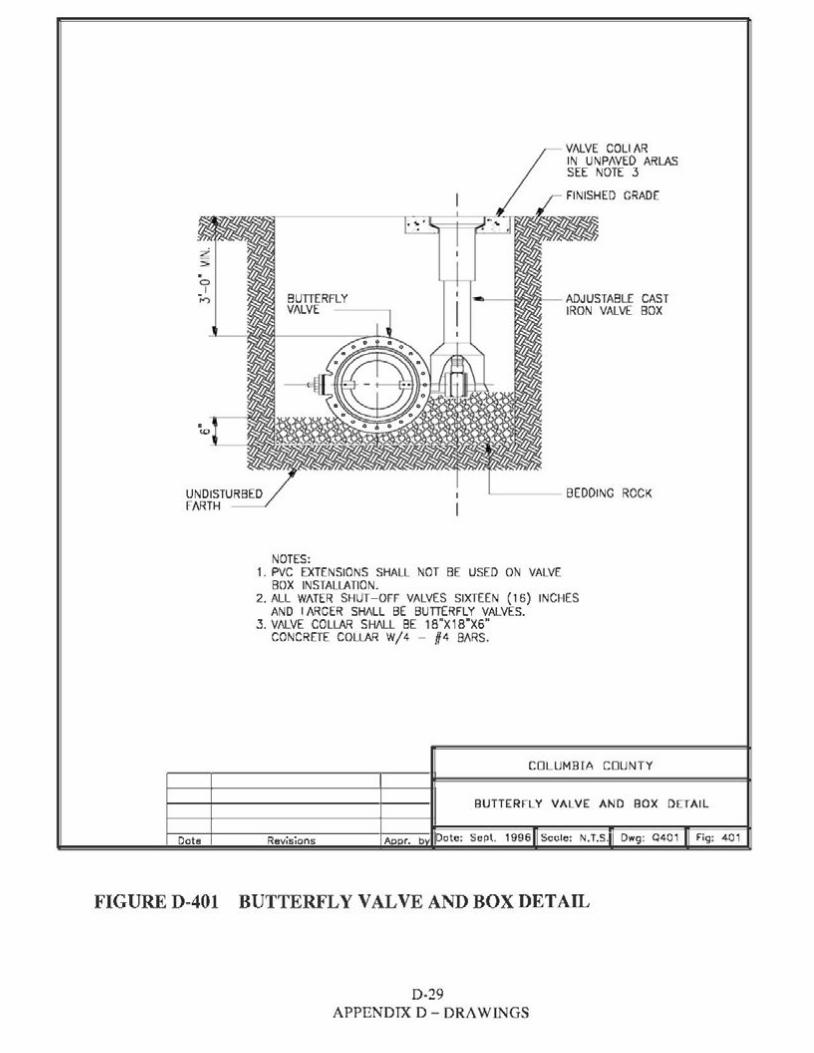
t 0
I I"') BUTTERFLY
VALVE --~
NOTES:
VALVE COLI AR IN UNPAVED ARL.AS SEE NOTE 3
,- ~~- ADJUSTABLE CAST IRON VALVE BOX
~--- BEDDING ROCK
1. PVC EXTENSIONS SHALL NOT BE USED ON VALVE BOX INSTALLATION.
2. ALL WATER SHUT-OFF VALVES SIXTEEN ( 16) INCHES AND I J\RCER SHALL BE BUTTERFLY VALVES.
3. VALVE COLL.AR SHALL BE 18"X18"X6" CONCRETE COLLAR W/4 - #4 BARS.
COLUMBIA COUNTY
BUTTERFLY VALVE AND BOX DETAIL
Dote: Sept. 1996 Scole: N.T.S. Dwg: 0401 Fig: 401Dote Revisions
FIGURE D-401 BUTTERFLY VAL VE AND BOX DETAIL
D-29 APPENDIX D - DRAWINGS
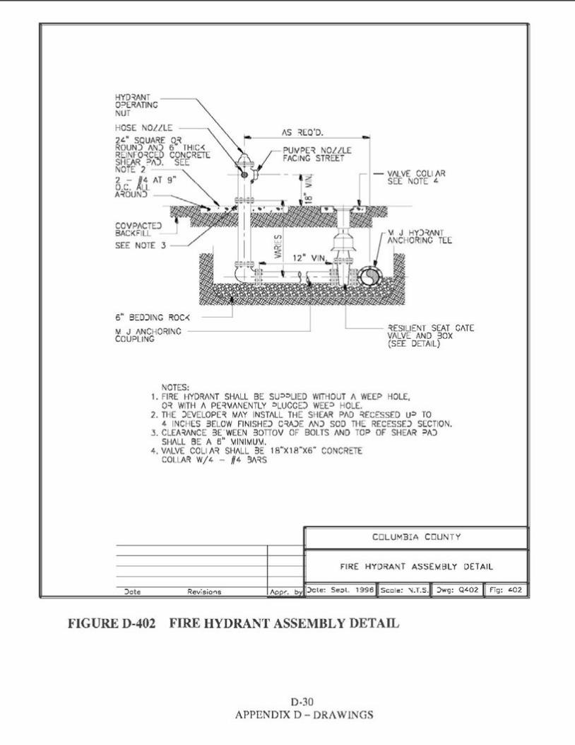
HYD~NT O=>ERATING NUT
HOSE NOLLLE ~-~
~ci~JfU,fNRf ~~ THIC-< REINFO~CED CONCRETE SHEAR '.='/\J. SEENOTE 2 --~ 2 - #4 AT 9" O.C. ~LL A~OUNJ
/\S ~EQ'D.
PUWPE~ NOLLLE FACING STREET
- VN..VE COLI AR SEE NOTE ~
COVPACTD BACKFILL SEE NOTE 3
6" BEDJING ROC-< M J /\NCHORINC __________, ..____ ~ESIUENT SEAT G/\TE
VALVE At-.lD 30XCOUPLING (SEE DETAIL)
NOTES: 1. FIRE HYDRANT SHALL BE su=>::>UED WITHOUT A WEEP HOLE,
0~ WITH A PE~\iANENTLY ::>LUCGD WEE=> HOLE. 2. THE )EVELOPE~ MAY INSTALL THE SHEAR PAD ~ECESSED u::i TO
4 INCHES 3ELOW FINISHD C~JE /\NJ SOD THE RECESSD SECTION. 3. CLEA~/\NCE 3E.WEEN 30TIOV OF BOLTS /\ND TOP OF SHEAR =>AJ
SHALL BE A 6" \11NIMU\t 4. V/\LVE COLIN~ SHALL 3E 18"X18"X6" CONCRETE
COLLAR W/4 - #4 3/\~S
COLUMBIA COUNTY
FIRE HYDRANT ASSEMBLY DETAIL
:>ote Revisio~s Aoo!'. b Jcle: Se;)l. 1996 Scole: 'IJ.T.S. )wg: Q-'02 Fig: t.02
FIGURE D-402 FIRE HYDRANT ASSEMBLY DETAIL
D-30 APPENDIX D- DRAWINGS
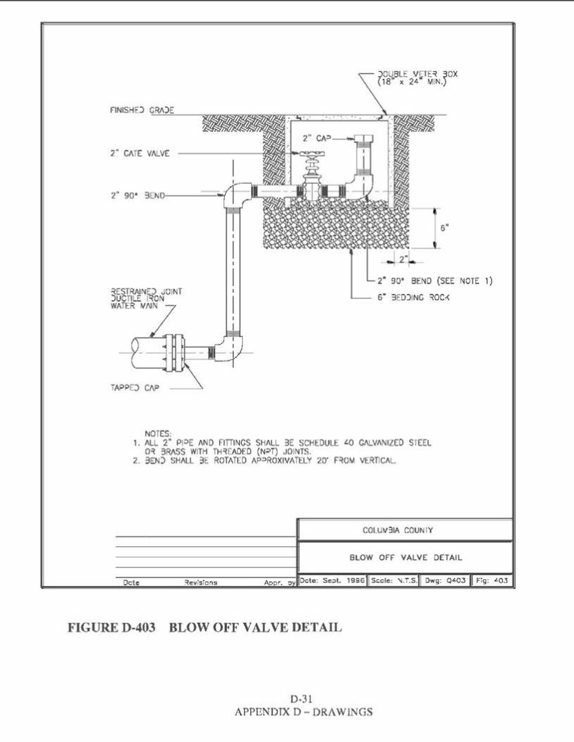
:;>DUBLE VETE~ ;JOX( 18" x 24" MIN.)
2" C/\TE V/\LVE
] 6" -~4 -
2" 90° BEND (SEE NOTE 1) ~ESTRAIND JOINTJUCTILE l~ON 6" 3ED)ING ~QC,<WATER WNN -
NOTES: 1. /\LL 2" Pl:>E /\ND FITTINGS SH/\LL 3E SCHEDULE LO G/\LV/\NIZED STEEL
0~ 3RASS WITH TH~EADED (N=>T) JOINTS. 2. 3EN) SHALL 3E ROTATED AP=>ROXIVATELY 20' F~OM VERTICAL.
COLUW31A COUN IY
BLOW OFF VALVE DETAIL
1996 Scale: 'I.T.S. Owg: Qt.03 Fig: LQ3Dcte ~evisions
FIGURE D-403 BLOW OFF VAL VE DETAIL
D-31 APPENDIX D- DRAWINGS
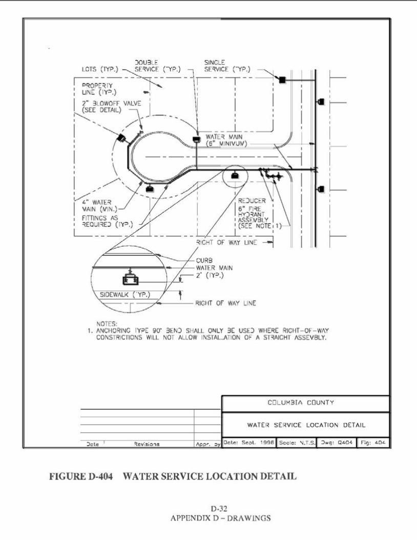
)OU3LE SINGLE
~s- ~TYP.) ~c~ _(-YP.) __ r==~v~~~-~ II I O~OPE~IY I II" r I LINE (IY::>.) -I I I
I 2" 3LOWOFF VALVE II I I 11 I ~EE DETAIL) \~ - _ _
I , /~ ' I _J1
I --~/ __ _l_ __ II 1--
I
LI
RDUCER 6" Fl~E 1I I IIHY)~ANT
I I ASSEWBLY 1 1 (SEE NOTE,1 I
- - -- - - ~HT- OF~ ~l~E~ I
NOTES: 1. ANCHORING IY::>E 90' 3EN) SHALL ONLY 3E USD WHERE RIGHT-OF-WAY
CONSTRICTIONS WILL NOT ALLOW INSTAL...ATION OF A SBAICHT ASSEVBLY.
COLUMBIA COUNTY
WATER SERVICE LOCATION DETAIL
:>ote ~evisio'.ls Dcte: Se;>l. 1996 Secle: \I.T.S. ::>wg: Q404 ] Fig: 40L
FIGURE D-404 WATER SERVICE LOCATION DETAIL
D-32 APPENDIX D- DRAWINGS
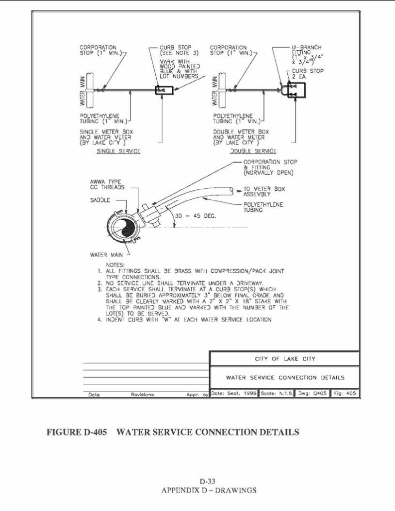
CORPO~TION CURB STOP CO~PORATION U-B~ANCH STO::> (1" tilN.) (SEE NOTE 3) STOP ( 1" vllN.) FIT.,TINC
~13/4•f411
CUR3 STOP 2 EA.
=>OLYErHYLENE POLYETHYLENE TU31NC (1" tilN.) TUBINC ( 1" VIN.)
SINGLE METER 30X DOUBLE tiETER BOX AN) WATER VErE~ AND WATE~ METER (BY LA,<E CI-Y ) (3Y LAKE CITY )
SINGLE SE~VICE )OU3LE SERVICE
CO~::>QRATION STOP & FITIINC (NORVALLY OPEN)
AWWA TYPE CC THREADS
45 DEG.
NOTES: 1. ALL FITIINGS SHALL 3E 3RASS WITH C0\-1::>~ESSION/::>AC-< JOINT
fY::>E CONNECTIONS. 2. NO SE~VICE LINE SHALL TERVINATE UNDER A )RIVEWAY.3. EACH SE~VICE SHALL TERVINATE AT A CUR3 STOP(S) WHICH
SH/\LL 3E BURID A::>PROXIM/\TELY 3" BELOW FINAL C~DE AND SHALL 3E CLEA~LY \.11\~KED WITH A 2" X 2" X 18" STME WITH THE TOP ::>AINTD BLUE AN) VA~,<D WITH THE NU\.13E~ OF THE LOT(S) TO BE SE~VD.
4. IN)ENT CUR3 WITH "W" AT EACH WATER SERVICE LOCATION
CITY OF LAKE CITY
WATER SERVICE CONNECTION DETAILS
Dcte Revisio,-is ADP'"· 0 Dcte: Seot. 1996 Secle: I\.T.S. )wg: QLOS Fig: 405
FIGURE D-405 WATER SERVICE CONNECTION DETAILS
D-33 APPENDIX D- DRAWINGS
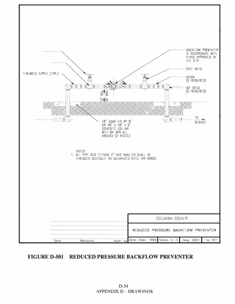
~--- BACK FLOW PREVENTER IN ACCORDANCE WITH PLANS APPROVED BY THE CTY
~ --- GATE VALVE TH READED NIPPLE (TYP .)
--- UNION (2 REQUIRED)
i----- 90" BEND (2 REQUIRED)
18" DIAM ETER BY 6" OR 18" x 18" x 6" CONCR ETE COLLAR WITH #4 BAR ALL AROUND (2 REQ 'D.)
NOTES: 1. ALL PIPE AND FITTI NGS 2" AND SMALLER SHALL BE
TH READ ED SCHEDULE 40 GALVANIZED STEEL OR BRASS.
COLUMBIA COUN1Y
REDUCED PR ESSURE BACK FLOW PREVENTER
Dote Revis ions Dote: Sept. 1996 Sca le : N.T.S. Dwg: Q501 Fig: 501
FIGURE D-501 REDUCED PRESSURE BACKFLOW PREVENTER
D-34 APPENDIX D - DRAWINGS

D-35 APPENDIX D - DRAWINGS
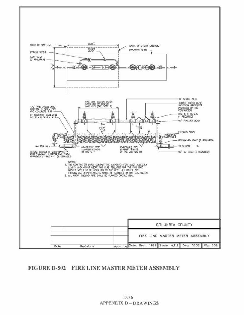
.., VA'<IES ._.RIGHT OF WAY LII\E U\IIIS Of unulY f A&lolEM----L--------------------~: St~< CO\CR£1[ SIMIIBYPASS \IETE'I -(ii.TE V>J.V'i. (2 REOUl'<EO) -
I I
~--r--------------------~ I I '
.....------------12·S:>OOL :l!ECE FIRE U'i.E IAASTER tJETt:R ~------- )OU8LE CHECK VA..Vf.I\S-ALEO CITY OF :W:KflOW ~ME'ILAKE CIIY SO: ><OTE 1 l'<STAUEO 8Y THE
CONTRACTOR
RfSTRAJ\ED JOINT (2 REWRfD)
-1T'm-----fr--'L__ TO S~RVCE .,..
l)lRUSI COLLAR I~ ACCMOA'<CE '----9o' \IJ 3ENJ (2 REQUIRED)WITH STA\OA'O 0-lAWI\G o\\O !>LA\S N>P//$N"J) '5f l)lE CIY (2 R[OUl~D)
NOICS: 1. THE c~·oR SHALL CCIMN:T TH[ 11\s:>ECT~ FOR 'XACT ASSE!/3.Y
LENGTH A\0 HElGiT ~ THE SLA8 R(QUl~EO ~OR THE FIRE LINE !/ASTE~ lolETE'I 10 BE 1\ST"-1.EO 8'I' THE Ci:Y. A..L OTliE~ P1:>E,Flnl\GS o\\0 o\~PUm:M\C:S SHAU 8£ 11\STAl..l.£0 8Y THE COi\~RJ.CTO't
2. 1-J L A80VI- GROU'IO PIP£ S~ 3( f\.ANC€0 Ol.CTILC IRO\.
CDLUM3IA COUNTY
FIRE LINE MASTER METER ASSEMBLY
Dcte Revisio"ls A o~. ::> Dote: Sepl. l 996 Scale: N.T.S. Dwg: 0502 Fig: 502
FIGURE D-502 FIRE LINE MASTER METER ASSEMBLY
D-36 APPENDIX D - DRAWINGS
APPENDIXE
Ordinance No. 2010-1
EXHIBIT A
EXHIBIT A-1
Ordinance No. 2010-2
Ordinance No. 2010-6
Ordinance No. 2010-13
Ordinance No. 2010-14
COLUMBIA COUNTY ORDINANCES AND MAP
TABLE OF CONTENTS
Columbia County Water and Wastewater Service Area ........................... 2
MAP OF ELLISVILLE UTILITY WATER SERVICE AREA ................................ 10
MAP OF ELLISVILLE UTILITY WATER SERVICE AREA-STREET DETAILS •• 11
Establishing Regulations for Connection to the County Public Water, Wastewater and Reclaimed Water Utility Systems ................................ 12
Rules for the Provision of Main Extensions for Water, Wastewater and Reclaimed Water••..••..••..••..••..••..••..••..••..••..••..••..••..••..•43
Implementing Oil and Grease Management and Prevention ................. 64
Amendment to Ordinance 2010-2, Article II, Section 2.03 ..................... 76
APPENDIX E -ORDINANCES, MAPS & FEE SCHEDULE WATER AND WASTEWATER SYSTEMS HANDBOOK
E-1
I
Ordinance No. 2010-1 Columbia County Water and Wastewater Service Area
ORDINANCE NO. 2010- 1 ~-.: ;--:':°-': "'Yl
AN ORDINANCE OF COLUMBIA COUNTY, FLORIDA <....REGULATING THE CONSTRUCTION. USE AND PROVISION ~ ..
OF WATER AND WASTEWATER FACILITIES AND 8; ;..-:,SERVICES WITHIN THE UNINCORPORATED AREAS OF • .· · ;"::_'jCOLUMBIA COUNTY, FLORJDA, DESIGNATES A SHORT TITLE. STATES THE COUNTY'S JURISDICTION, STATES THE COUNTY'S AUTHORITY TO ACT, MAKES CERTAIN FINDINGS, DESIGNATES CERTAlN UNINCORPORATED AREAS OF THE COUNTY AS EXCLUSIVE COUNTY WATER AND WASTEWATER SERVICE AREAS AND OTHER AREAS AS DESIGNATED WATER AND WASTEWATER SERVICE AREAS, PROHIBITS WATER AND WASTEWATER CONSTRUCTION AND SERVICE BY OTHER (NONCOUNTY) WATER AND WASTEWATER UTILITIES IN THE EXCLUSIVE COUNTY WATER AND WASTEWATER SERVICE AREAS, PROHIBITS WATER AND WASTEWATER CONSTRUCTION AND SERVICE BY OTHER (NONCOUNTY) WATER AND WASTEWATER UTILITIES IN THE DESIGNATED WATER AND WASTEWATER SERVICE AREAS WITHOUT THE COUNTY'S PRIOR WRITTEN CONSENT, REQUIRES MANDATORY CONNECTION PURSUANT TO COUNTY ORDINANCE 2010-2, CONTAINS A SEVERABILITY CLAUSE, RESERVES POWERS TO THE COUNTY, SETS FORTH ENFORCEMENT AND PENALTY PROVISIONS AND PROVIDES AN EFFECTIVE DATE.
BE IT ORDAINED BY THE BOA.RD OF COUNTY COMMISSIONERS OF
COLUMBIA COUNTY. FLORIDA, as follows:
SECTION l. SHORT TITLE. This Ordinance shall be known and cited as the Columbia
County Wa1er and Wastewater Service Area Ordinance.
SECTION 2. JURISDICTION. This Ordinance shall apply in the unincorporated areas
ofColumbia County, Florida. as such area exists on the date this Ordinance is enacted.
SECTION 3. AUTHORITY. Pursuant to Article Vlll. § l(t), florida Constitution, and
§125.01(1 )(k), Florida Statutes, and other applicahle general and special Jaws. excluding
APPENDIX E - ORDINANCES, MAPS & FEE SCHEDULE E-2 WATER AND WASTEWATER SYSTEMS HANDBOOK
specifically Chapter 153, Florida Statutes, the Board of County Commissioners is authorized to
provide, regulate, purchase, construct, improve, extend, enlarge and reconstruct water and
wastewater facilities; and to operate, manage and control water and wastewater facilities within
the County.
SECTION 4. FINDINGS. The Board of County Commissioners of Columbia County,
Florida finds, determines and declares the following:
1. The County is projected to experience large population increases within the next
twenty years.
2. As the population increases, the demand for central water and wastewater services
will also increase.
3. To protect the health, safety and welfare of its citizens, it is necessary and
appropriate that the Board of County Commissioners coordinate and regulate the provision of
water and wastewater infrastructure that is necessary for development within the unincorporated
areas of the County. To that end the County currently plans to construct water and wastewater
systems serving the area known as the Ellisville area Additional plans for water and wastewater
system construction are under consideration and are anticipated in the future.
4. To protect the health. safety and welfare of its citizens, it is also necessary and
appropriate that the County operate its existing and future water and wastewater facilities as cost·
effectively and efficiently as possible and that it effectively and efficiently coordinate its services
with such other water and wastewater services providers in the unincorporated areas of the
County as arc necessary and appropriate lo provide competent, safe and efficient and economical
water and wastewater services to the citizens of the County.
S. To accomplish these goals. the County deems it necessary to enact this water and
2
APPENDIX E-ORDINANCES, MAPS & FEE SCHEDULE WATER AND WASTEWATER SYSTEMS HANDBOOK
E-3
wastewater service area regulatory ordinance.
SECTION 5. CREATION OF SERVICE AREA. There is hereby created the Columbia
County Water and Wastewater Service Area (hereinafter referred to as the Service Area)
consisting of all unincorporated areas of the County as such areas exist on the date this
Ordinance is enacted. The Service Area consisls of areas hereby designated as either Exclusive
Service Area or Designated Service Area.
SECTION 6. SERVICE AREA BOUNDARIES.
1. The Board of County Commissioners hereby establishes the County's Exclusive
Service Area consisting of the area described in Exhibit "A.. attached hereto and incorporated
into this Ordinance exclusive of; (a) those areas certified for water and/or wastewater service by
the Florida Public Service Commission (FPSC) prior to the date that this Ordinance was enacted,
for as long a,; such certification remains in effect. (h) those areas certificated for water and/or
wastewater service by the Board ofCounty Commissioners on the date this Ordinance is enacted,
for as long as such cenification remains in effect, (c) those areas currently being provided water
and/or wastewater services by municipalities on the date this Ordinance is enacted, for as long as
such services are provided, (d) those areas served or scheduled to be served with water and/or
wastewater services within community development districts hy such districts as have heen
lawfully created prior to the enactment of thii; Ordinance, and (e) those areas served or to be
served with water and/or wastewater services by a municipality pursuant to a territorial
agreement between the County and a municipality for so Ion~ as the agreement remains in effect.
The Roard of County Commissioners may enlarge or reduce the County's Exclusive Service
Area by resolution(s). The County shall. and is obligate<l to, provide water and/or v,·astewat~r
service to all persons and entities who request such service within the Exclusive Service Area in
J
APPENDIX E -ORDINANCES, MAPS & FEE SCHEDULE WATER AND WASTEWATER SYSTEMS HANDBOOK
E-4
accordance with applicable County ordinances and rules and regulations.
2. The Board of County Commissioners hereby establishes the County's Designated
Service Area consisting of the Service Area described in Section 5, less {a) the County's
Exclusive Service Area, (b) those areas certified for water and/or wastewater service by the
Florida Public Service Commission (FPSC) prior to the date that this Ordinance was enacted, for
as long as such certification remains in effect, {c) those areas certificated for water and/or
wastewater service by the Board ofCounty Commissioners on the date this Ordinance is enacted,
for as long as such certification remains in effect, (d) those areas currently being provided water
and/or wastewater services by municipa\ities on the date this Ordinance is enacted. for as long as
such setvices are provided, (e} those areas served or scheduled to be served with water and/or
wastewater services vvithin community development districts by such districts as have been
lawfully created prior to the enactment of this Ordinance, and (f) those areas served or to be
served with water and/or wastewater services by a municipality pursuant to a territorial
agreement between the County and a municipality for so long as the agreement remains in effect.
The Board of County Commissioners may enlarge or reduce the County's Designated Service
Area by resolution(s}
SECTION 7. OTHER UTILITIES OF SIMILAR CHARACTER PROHIBITED.
I. )'.;o person or entity other than the County and/or its designees shall provide water
or wastewater services (other than bottled water) to any person or location within the County's
Exclusive Service Area or Dcsigna1cd Service Area without the County's express written
permission. No person or entity other than the County and/or its designee shall construct or us~
water and/or wastewater transmission lines, pipes. mains, pumping stations or the like on or
within established rights of way for the purpose of providing water and/or wastewater servic~ to
4
APPENDIX E - ORDINANCES, MAPS & FEE SCHEDULE E·S WATER AND WASTEWATER SYSTEMS HANDBOOK
land located within the County's Exclusive Service Area or Designated Service Area. These
prohibitions shall not be deemed to prohibit private water wells and/or septic tanks for individual
structures ifmandatory connection is not required under Ordinance [to come 1/5/10], as amended
from time to time.
2. When cost effective and in the best interests of the County's citizens, the County
may (a) issue a franchise to artother water and/or wastewater utility that meets County standards
set forth in Ordinance [private utility regulatory ordinance] to operate within portions of the
County's Designated Water and Wastewater Service Area or (b) enter a tenitorial agreement
with a municipality or municipalities providing for such entity or entities to provide water and/or
wastewater service within portions of the County's Designated Water and Wastewater Service
Area.
SECTION 8. COMPREHENSIVE PLAN.
Nothing contained in this Ordinance shall be construed to allow the County or its
designees to provide water and/or wastewater service to any area within the County's Exclusive
Service Area or Designated Service Areas if providing such service(s) would be inconsistent
with the County's Comprehensive Plan.
SECTION 9. CONNECTION TO WATER AND WASTEWATER SYSTEMS.
Mandatory connection to County water and wastewater facilities shall be required in
accord with the provisions ofCounty Ordinance Ito come l/S/101, as amended from time to lime.
SECTION I 0. SEVERABILITY.
If any section, subsection, sentence, clause, phrase, or portion of this Ordinance is tor
any reason held to be invalid or unconstitutional "Y any court of competent jurisdiction, such
prn1ion shall he deemed a separate. distinct and indcpl'ndent provision and such holding shall not
APPENDIX E - ORDINANCES, MAPS & FEE SCHEDULE WATER AND WASTEWATER SYSTEMS HANDBOOK
E-6
affect the validity of the remaining portions thereof.
SECTION J1. FLORlDA PUBLIC SERVICE COMMISSION.
Nothing contained in this Ordinance is intended to affect or amend the existing service
territories of water and wastewater utilities previously regulated by the Florida Public Service
Commission pursuant to Chapter 367. Florida Statutes, now regulated by the County pursuant to
[private utility regulatory ordinance).
SECTION 12. COLUMBIA COUNTY UTILITY AUTHORITY MATIERS.
Nothing contained in this Ordinance is intended to affect or amend the existing service
territories of water and wastewater utilities regulated by the Board of County Commissioners
pursuant to Columbia County Ordinance [private utility regulatory ordinance], as amended, nor
shall this Ordinance be construed to affect the powers of the Board of County Commissioners
with regard to processing and conducting certification proceedings for new utilities or for
extensions ofexisting water and/or wastewater service territories located outside of the County's
Exclusive Service Area.
SECTION 13. CODE ENFORCEMENT. This Ordinance may be enforced by any
method prescribed by law. including injunctive relief and the provisions of Chapter 162, Florida
Statutes and ordinances enacted thereunder.
SECTION 14. PENALTIES. Any person or entity violating any of the provisions of this
Ordinance shall be prosecuted in the same manner as misdemeanors are prosecuted. Such
violation shall be prosecuted in rhe name of the State of Florida in a court haYing ,iurisdktion of
misdemeanors by the prosecuting attornt!y thereof and. upo11 conviction the violator shall be
punished for each violation by a fine not to exceed $500 or by imprisonment in the County jail
not to exc~ed 60 days or by both such fine: and imprisonment. Each incident or separate
6
APPENDIX E - ORDINANCES, MAPS & FEE SCHEDULE WATER AND WASTEWATER SYSTEMS HANDBOOK
E-7
occurrence that violates this Ordinance shall be deemed a separate offense. Each day that an
offense or violation of lhis Ordinance continues shall be deemed a separate offense.
S~CTlON 15. EFFECTIVE DATE.
'Jltis Ordinance shaH lake efiect upon a certified copy thereof being filed with the Florida
Department ofState.
PASSED AND ENACTED by the Board ofCounty Commissioners ofColumbia County.
State ofFlorida. this..!.!!!., day of March •2010.
BOARD OF COUNTY COMMISSIONERS OF COLUMBIA COUNTY, FLORIDA BY; ~ _ _,._::=:tc::::
R~ainnan
ATTEST: P. DeWit:t Cason , CLERK
BY: 6~~ Clerk
7
APPENDIX E - ORDINANCES, MAPS & FEE SCHEDULE WATER AND WASTEWATER SYSTEMS HANDBOOK
E-8

EXHIBIT
"A"
APPENDIX E - ORDINANCES, MAPS & FEE SCHEDULE WATER AND WASTEWATER SYSTEMS HANDBOOK
E-9
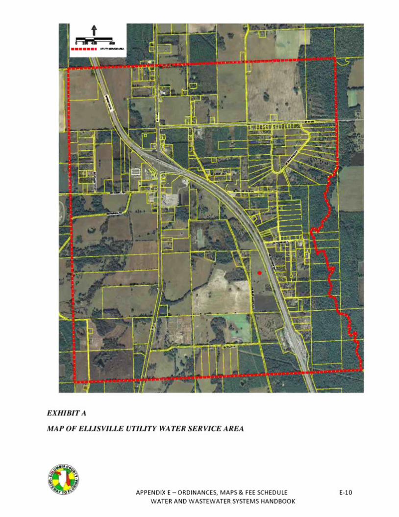
EXHIBIT A
MAP OF ELLISVILLE UTILITY WATER SERVICE AREA
APPENDIX E - ORDINANCES, MAPS & FEE SCHEDULE E-10 WATER AND WASTEWATER SYSTEMS HANDBOOK
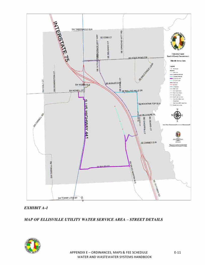
SW TABER CLE GLN
,..,... - f._1111111Jill~
- f_......PRIN'
- t__6cM',t:zw,QWI'
f._-(M'P
- us._,_.
--c-w,,-- "-'<lr....,1y~
-Dllr....,lboi,,
-a,m1 - c.,-.- -dFu1--
l
EXHIBITA-1
MAP OF ELLISVILLE UTILITY WATER SERVICE AREA -STREET DETAILS
APPENDIX E - ORDINANCES, MAPS & FEE SCHEDULE E-11 WATER AND WASTEWATER SYSTEMS HANDBOOK
Ordinance No. 2010-2 Establishing Regulations for Connection to the County Public Water, Wastewatl and Reclaimed Water Utility Systems
COLUMBIA COUNTY. FLORIDA
WATER ANO WASTEWATER CONNECTIONS ORDINANCE
ADOPTED March 25, 2010
APPENDIX E - ORDINANCES, MAPS & FEE SCHEDULE E-12 WATER AND WASTEWATER SYSTEMS HANDBOOK
TABLE OF CONTENTS
Page No.
APPENDIX E - ORDINANCES, MAPS & FEE SCHEDULE WATER AND WASTEWATER SYSTEMS HANDBOOK
E-13
OROINANCE NO. 2010·2 -
AN ORDINANCE OF THE BOARD OF COUNTY :._: COMMISSIONERS OF COLUMBIA COUNTY, FLORfOA, ENACTING AND ESTABLfSHING REGULATIONS FOR
<: ~-: .j
~- 1
.t\ . ·-
. ,.CONNECTION TO THE COUNTY PUBLIC WATER, ~, ·~ ' ' ,~WASTEWATER, AND RECLAIMED WATER UTILITY ....J SYSTEMS; PROVIDING A GENERAL PURPOSE AND . . SHORT TITLE; PROVIDING FOR MANDATORY .. . ·;~ CONNECTION TO PUBLrC UTILITIES; PROVIDING v . REQUIREMENTS FOR SERVICE APPLICATION; PROVIDING FOR CONSTRUCTION OF PERMANENT, TRANSITIONAL AND COMMUNITY FACILITIES;PROVIDING FOR SEVERABILITY; ANO PROVIDING AN EFFECTIVE OATE AND APPLICABILITY.
WHEREAS, the standards and requirements set forth herein for connection to public water, wastewater, and reclaimed water utility systems are necessary for the preservation and protection of the public health, safety, and general welfare; and
WHEREAS, the County intends to ensure that the development of any land within Columbia County subject to this Ordinance shall include the installation of such water, wastewater, and reclaimed water facilities as will reasonably protect the citizens and taxpayers from having to bear the cost resulting from the haphazard construction of such facilities; and
WHEREAS. the construction of public water, wastewater, and reclaimed water infrastructure is an element of community development which impacts other public facilities, roadways and adjacent lands, and the prosecution of such construction in a proper and orderly fashion is in the best interest of the public health, safety, and welfare; and
WHEREAS, the standards and requirements set forth herein are necessary for the health, safety and welfare of the citizens of Columbia County and the protection of its environment and natural resources: and
WHEREAS. the standards and requirements set forth herein are intended to benefit the public by ensuring that property owners enjoy a reasonable, beneficial, and economic use of property; and
WHEREAS, the Board of County Commissioners recognizes that the provision of water. wastewater, and reclaimed water utility services is an essential public service and is in the best interest of the public health, safety, and welfare.
APPENDIX E - ORDINANCES, MAPS & FEE SCHEDULE E-14 WATER AND WASTEWATER SYSTEMS HANDBOOK
NOW, THEREFORE, be it ordained by the Board of County Commissioners of Columbia County, Florida, this 25th day of March, 2010, that the following regulations be established.
APPENDIX E -ORDINANCES, MAPS & FEE SCHEDULE E-15 WATER AND WASTEWATER SYSTEMS HANDBOOK
ARTICLE I
GENERAL PURPOSE ANO SHORT TITLE
SECTION 1.01. PURPOSE AND SHORT TITLE. This Ordinance establishes requirements for utility connections to the County's potable water, wastewater and reclaimed water utility systems, when and where available. This Ordinance shall be known and may be cited or referred to as the 'Water and Wastewater Connections Ordinance."
SECTION 1.02. OVERVIEW. This Ordinance is organized into six Articles. Article I provides general applicability, including purpose, overview, policy, administration, jurisdiction and enforcement for utility connections. Article II provides for those utility connections that are mandatory. Article Ill provides for applications for utility connections (availability determinations), reservations of capacity, line extensions. and conditions of service. Article IV provides alternatives for construction of permanent, transitional and community facilities. Article V provides abbreviations and definitions used in this Ordinance and sets out rules for language construction. Article VI provides for severability and an effective date and applicability.
SECTION 1.03. POLICY FOR LANO DEVELOPMENT. No subdivision of real property or any act of development within the unincorporated area of the County that falls within the jurisdiction of this Ordinance (pursuant to Section 1.08 of this Ordinance) shall occur without first requesting utility service for potable water, wastewater, and reclaimed water from the County. The County shall determine the utility provider for the service area where such development is proposed. All such developments must be connected to public utility facilities. in accordance with the County's Comprehensive plan. and the owners of such properties shall pay all fees and charges prescribed for the services provided.
SECTION 1.04. AGREEMENT FOR TEMPORARY SERVICE. Connections within the County's Service Area to any public utility facility other than County Public Utility facilities must be pursuant to an agreement to provide temporary service between the public utility and the County.
SECTION 1.05. POLICY FOR PERMANENT COUNTY FACILITIES. The Coun1y shall make every reasonable effort to provide permanent potable water. wastewater and reclaimed water treatment and conveyance facilities within the County Service Area. in accordance with the County's Comprehensive Plan, Water and Wastewater Service Area Ordinance and Utility Master Plan.
SECTION 1.06. DEBT OR PLEDGE. Nothing in this Ordinance shall be construed to create a debt or general obligation of the County or a pledge of the full faith and credit or taxing power of the County.
APPENDIX E - ORDINANCES, MAPS & FEE SCHEDULE WATER AND WASTEWATER SYSTEMS HANDBOOK
E-16
SECTION 1.07. AOMINtSTRATION. The County Manager shall administer this Ordinance. The County Manager is responsible for the development and promulgation of the necessary rules, policies, regulations, procedures and manuals that will be needed to assist County staff and Applicants with connections to County Public Utility facilities. All such rules. policies, regulations, procedures. construction and technical standards and other manuals shall be made a part of the administration of this Ordinance.
SECTION 1.08. JURISDICTION OF UNINCORPORATED COUNTY SERVICE AREAS. The County connection requirements of this Ordinance shall apply to the unincorporated areas of Columbia County identified in the County's Water and Wastewater Service Area Ordinance, Ordinance No. 2010-1, other than municipal service areas or areas served by private utilities pursuant to certificates of authority issued by the County as provided for in Ordinance No. 2007· 15.
SECTION 1.09. JURISDICTION OF OTHER SERVICE AREAS. Public Utility connection requirements of the City of Lake City, Fort White or.appropriate private franchisees shall apply to those areas served by those entities. Construction and technical standards established in any service area granted by the County to a private utility shall meet or exceed County standards. Within a municipal service area, construction and technical standards shall meet or exceed the standards established by that municipality.
SECTION 1.10. ENFORCEMENT.
(A) Violations. It shall be a violation of this Ordinance to fail to fully comply with any provision of this Ordinance, or to conduct, commence. or maintain any activity and/or facility prohibited by this Ordinance. Each violation shall constitute a separate offense.
(B) Code Enforcement Board. The County Manager may refer violations of this Ordinance to the County's Code Enforcement Board for enforcement action. Upon such referral. the Code Enforcement Board shall levy such fines and/or other remedies within its powers to remedy the violations of the provisions of this Ordinance.
(C) Other Legal Penalties and Remedies. Nothing herein shall preclude the County from seeking all other remedies available under general law, including without limitation:
(1) Civil actions pursuant to Chapter 403, Florida Statutes.
(2) Criminal prosecution pursuant to section 125.69, Florida Statutes, such that a Violator shall be subject to prosecution in the name of the State of Florida in the same manner as misdemeanors are prosecuted and, upon conviction, such Violator shall be punished by a fine not to exceed $500.00 or by imprisonment in the County Jail not to exceed sixty (SO) days or by both such fine and imprisonment for each such
4
APPENDIX E -ORDINANCES, MAPS & FEE SCHEDULE WATER AND WASTEWATER SYSTEMS HANDBOOK
E-17
conviction. Each day that the violation remains outstanding shall be considered a separate violation.
(3) Any other injunctive relief available to the County through appropriate legal or equitable relief actions in a court of competent jurisdiction to enforce the provisions of this Ordinance.
SECTION 1.11. LIABlLITY FOR COSTS. A Violator shall be liable for all costs. including attorney's fees, attributable to any violation of this Ordinance or related policies, rules or regulations and for the costs of correcting damages due to such violations. However, payment of these costs shall not relieve the offending person from other civil or criminal penalties that may be applicable.
SECTlON 1.12. PROHIBITION OF UNAUTHORIZED WORK ON COUNTY UTILlTY FACILITIES.
(A) County Utility Facilities. Unless expressly authorized in writing by the County Manager. or during a County recognized emergency, no individual or organization shall tamper with. work on, or in any way alter or damage any County Utility facility; or cut into or make any connection with or alter the operation of any County Utility facility.
(B) .Private Facilities. Whenever the private (Customer's) side of a utility service connection requires repair. the Customer shall request that the County Utility make adjustments to the County's side of the utility service connection if required to accommodate the repair. Such adjustments by the County shall be paid for by the Customer.
SECTION 1.13. INSPECTIONS.
(A} County Manager Reserves Rights. In order to ascertain and ensure compliance, the County Manager reserves the right to inspect, secure, and/or disconnect any and all devices, wherever located. which connect to or control any County Public Utility facility.
(B} With Reasonable Cause of Violation. Inspections by the County Manager where there is reasonable cause to believe that this Ordinance or any related ordinance, policy, rule or regulation is being violated shall be at such times and with such frequency as the County Manager deems necessary.
(C} Without Reasonable Cause of Violation. Inspections by the County Manager without reasonable cause to believe that this Ordinance or any related ordinance, policy, rule or regulation is being violated shall be conducted only during normal working hours.
:'
APPENDIX E - ORDINANCES, MAPS & FEE SCHEDULE WATER AND WASTEWATER SYSTEMS HANDBOOK
E-18
(D) Consent and Ent(y. Upon signing an application for service, the Customer is deemed to have consented to entry by the County Manager upon the property described in the application for the purpose of conducting any inspection permitted pursuant to this Ordinance and the Customer waives the right to receive any further notice from the County Manager for inspections conducted pursuant to this Ordinance.
(E) Denial of Access. If a Customer denies a~ss by the County Manager to any property receiving County utility service for the purpose of conducting any inspection permitted under this Ordinance such denial will constitute a violation of this Ordinance and may be grounds for immediate discontinuance of any and all County supplied utility service to the subject premises.
SECTION 1.14. EMERGENCY ACTS.
(A) Interruption. The County Manager may interrupt the delivery of County Utility service to any property for or upon which a violation of this Ordinance or any related ordinance. rule. policy, or regulation has occurred. Any such interruption will continue until restoration of County Utility service is deemed appropriate by the County Manager.
(B) Emergency Action. The County Manager may take whatever emergency action is deemed necessary and appropriate to protect persons or property from any injury, loss. or damage which may reasonably be expected to result from each specific violation of this Ordinance or of any related ordinance, rule. policy, or regulation. The Customer or other Violator shall be responsible for all costs incurred by the County for any emergency measures performed by or at the request of the County Manager as a result of such a violation attributed to the Customer or other Violator.
SECTION 1.15. NOTICES. All notices from the County, required under this Ordinance shall be in writing, and delivered by first class U.S. Mail or delivered and presented by the County Manager. All notices to the County required under this Ordinance shall be in writing and delivered by first class U.S. Mail or delivered and presented to the County Manager.
SECTrON 1.16. COMPREHENSIVE PLAN. The provisions of this Ordinance are intended to be in full compliance with the Comprehensive Plan. In the event an alleged conflict arises between the provisions of this Ordinance and the Comprehensive Plan. the Board of County Commissioners shall resolve the conflict.
APPENDIX E -ORDINANCES, MAPS & FEE SCHEDULE WATER AND WASTEWATER SYSTEMS HANDBOOK
E-19
ARTICLE U
MANDATORY CONNECTION TO PUBLIC UTILITIES
SECTION 2.01. PURPOSE. The requirement for mandatory connection to a Public Utility facility is to protect the public health, welfare, safety. and environment, to promote water resource conservation; to eliminate inferior treatment processes, and to create economies of scale for treatment processes and conveyance operations.
SECTION 2.02. PROPOSED DEVELOPMENT. Pursuant to Section 1.03, it shall be mandatory for all proposed developments to request Public Utility services, and for all proposed developments within the County Service Area to connect to County Public Utility facilities in accordance with the County's Comprehensive Plan and this Ordinance.
SECTfON 2.03. CONNECTIONS WfTH WATER ANO SEWER SYSTEMS. Where service is available. the owner of every lot or parcel of land within the County adopted Service Area shall connect or cause the plumbing of any building or buildings thereon to be connected with the County Water System and/or County Sewer System within six (6) months of notice of availability by the County and shall use the facilities of such systems. All such connections shall be made in accordance with the County Water and Wastewater Technical Manual and rules and regulations which shall be adopted from time to time by the Board, which rules and regulations shall provide for a charge for making connections in such reasonable amount as the Board may establish. Nothing herein shall affect liability for service charges as provided in this Ordinance or in other County ordinances. The County shall notify the owner of any affected improved lot or parcel of the availability of the central water and/or sewer service. Owners of existing buildings shall have the option of paying the amortized value of required Capacity Fees in equal monthly installments over a period not to exceed ten (10) years from the date of the initial notification of present or anticipated availability. For purposes of this subsection, "available" water and/or wastewater service shall mean, subject only to a determination by the County that supply, treatment and/or conveyance capacity exists or Connection is otherwise practicable with respect to any Connection. the following:
(A) For residential or commercial subdivisions and for areas zoned or used for an industrial manufacturing purpose or its equivalent. or a single family residence or establishment any of which has an estimated sewage flow of 1,000 gallons per day or more, if the County Water System or County Sewer System is located within 1,320 feet of the development: or
(B) A single-family residence or establishment any of which has an estimated sewage flow of 1,000 gallons per day or less, if the County Water System or County Sewer System is located within 100 feet of a Potential Customer's lot-line.
APPENDIX E - ORDINANCES, MAPS & FEE SCHEDULE WATER AND WASTEWATER SYSTEMS HANDBOOK
E-20
(C) "Establishment" means any buildings or properties used for human occupancy, employment, recreation or other purposes.
SECTION 2.04. TIMING OF CONNECTION. Developments served by private wastewater treatment plants operating pursuant to authority from the County that are operating out of compliance with FOEP operating permits must be connected to available County wastewater facilities within 180 days after the notice to connect is received by the development owner.
APPENDIX E -ORDINANCES, MAPS & FEE SCHEDULE WATER AND WASTEWATER SYSTEMS HANDBOOK
E-21
ARTICLE Ill
APPUCATION FOR SERVICE
SECTION 3.01. SERVICE REVIEW. Each Applicant seeking to develop property located within the unincorporated County but outside the service areas of municipalities shall apply for potable water, wastewater, and reclaimed water service from the County. The County Manager shall review such applications and determine whether service is available for the development. Each review shall review such applications and characterize the development by one or more of the following criteria:
(A) Permanent Service Is Available. The proposed development is in the County Service Area, and the County is currently able to provide permanent service or will be able to provide service in time to meet the Applicant's building schedule.
(B) Permanent Service Is Not Available But ls Planned. The proposed development is in the County Service Area, the County is not able to provide permanent service in time to meet the Applicant's building schedule, but future service is planned in the County's Utility Master Plan.
(C) Permanent Service Is Not Available But Transitional F acilitles May be Appropri~e. The proposed development is in the County Service Area, the County is not able to provide permanent service due to its location or infrastructure limitations, but Transitional Facilities may be an appropriate alternative under Article IV.
(0) Permanent Service Is Available but DevelO[ml~ Is Outside CouD,!y Service Area. The proposed development is not in the County Service Area, but the County is currently able to provide permanent service if permitted to do so under the provisions of the County's Comprehensive Plan.
{E) Permanent Service Is Not Available. The proposed development is not in the County Service Area and the County is not able to provide permanent service to the development.
(F) Permanent Service Will Be Subject to Special Conditions. The provision of permanent service to the proposed development will be subject to specific utility conditions established by rezoning, Utility Master Plan approval. Developer's Agreement, and/or the Development of Regional Impact process.
SECTION 3.02. SERVICE AVAILABILITY. Service shall be deemed available if the proposed connection to County Utility facilities conforms to the provisions of the Comprehensive Plan and successfully passes the tests described in this Section for system sufficiency and operational feasibility. Development within the County Service Area shall be deemed to have passed such tests and shall proceed with connection to County Utility facilities unless the County Manager approves a variance providing otheiwise in compliance with established County procedures.
APPENDIX E - ORDINANCES, MAPS & FEE SCHEDULE WATER AND WASTEWATER SYSTEMS HANDBOOK
E-22
SECT&ON 3.03. TEST ONE - SYSTEM CAPACITY DETERMINATION. The County Manager shall verify that sufficient capacity in the County's Public Utility facilities exists to accommodate each proposed connection thereto before the connection is authorized. The sufficiency of capacity for connection of any development shall be detennined through an engineering analysis of the capacity in an appropriate treatment plant and in the transmission system between that plant and a reasonable point-of-connection for the development.
(A) Sufficient Capacity for Proposed Development. Capacity for any Utility Service shall be deemed sufficient for any such connection if excess treatment and transmission capacity is available to provide the quality and quantity of service necessary to meet the service demands of the development pursuant to the County's conditional approval of the connection to its Public Utility facilities.
(8) Allocation of Unpermitted Treatment Capacity. The County may allocate treatment capacity for a development in excess of the permitted capacity of the Wastewater Treatment Plant that will serve it. provided that additional treatment capacity in the plant becomes available before actual annual average daily flow exceeds the plant's permitted capacity and the County is otherwise compliant with the plant's regulatory permit. Any such allocation shall require the County Manager to monitor actual plant flows; proiect the time at which the capacity of the facility will be exceeded; and plan, design, construct and place in operation any required capacity expansion pursuant to Rule 62-600.4()5, Florida Administrative Code.
(C} Building Permits and Connections Depend upon Treatment Capacity. Upon written notification from the FDEP or its designee to the County Manager that the monthly average of the actual daily flow for three consecutive months through a County Wastewater Treatment Plant has reached or exceeded 100% of its permitted average daily flow capacity. the County Manager shall suspend the issuance of Building Permits for either the construction of any structure which would be served by the plant or the connection of any development to the plant. Upon receipt of FDEP's written acknowledgement to the County Manager that the actual flow through the County Wastewater Treatment Plant no longer exceeds its permitted capacity. the County Manager may recommence issuing Building Permits and/or allowing utility connections.
SECTION 3.04. TEST TWO ~ OPERATIONAL FEASIBILITY. The County Manager shall determine that each proposed new connection to the County's Public Utility facilities is operationally feasible before the connection is authorized. A proposed connection shall be deemed operationally feasible if the Utility Master Plan transmission lines needed to serve the development are in service or will be in service in time to meet the Applicant's building schedule. In the event that a new connection is not operationally feasible on the basis stated above. the connection nevertheless shall be deemed operationally feasible if:
APPENDIX E - ORDINANCES, MAPS & FEE SCHEDULE E-23 WATER AND WASTEWATER SYSTEMS HANDBOOK
(A) The development is within a feasible distance of the point-of-connection pursuant to the applicable distance criteria specified in the Columbia County Water and Wastewater Technical Manual for similar connections.
(B) The Applicant signs a developer agreement pursuant to which Applicant agrees to fund the connection, including necessary off-site facilities. as determined by the County Manager.
(C) No existing or potential hydraulic condition or severe operations, maintenance, construction or other condition related to the proposed connection have been identified by the County Manager which would render the connection impractical or undesirable.
(D) The County Manager has not granted a lawful variance that allows the development to proceed without connection to County Public Utility facilities.
SECTION 3.05. EXTENSION OF TRANSMISSION FACILITIES. The County or Developers, pursuant to developer agreements with the County, shall construct all transmission facilities identified in the County's Utility Master Plan. Utility Master Plan transmission lines are the core facilities needed to provide service throughout the County Service Area.
SECTION 3.06. REVIEW OF UTILITY MASTER PLAN ANO 5-YEAR CAPITAL tMPROVEMENTS PLAN ("CIP"), Upon request of an Applicant. the County shall review the approved Utility Master Plan and its current 5-year CIP to consider incorporation of the Applicant's requested line extension project. If the County determines it is appropriate to amend the Utility Master Plan and its 5-year CIP to include the Applicant's line extension project. the County may construct the line extension project. If the Applicant desires to accelerate the line extension project to meet the construction schedule for a planned development, the Applicant may construct the line extension project by entering into a line extension agreement with the County, as further described in Section 3.08.
SECTION 3.07. DEVELOPER RESPONSIBLE FOR CONNECTOR TRANSMISSION LINES. Depending on the location of any development, additional connector transmission lines may be needed to connect the development to the Utility Master Plan transmission lines. The Developer is responsible for the full cost for the design and construction of all connector lines from a development to a point-of-connection with the Utility Master Plan transmission facilities. The Developer shall not be entitled to reimbursement from the County for the construction of any connector transmission line unless it was oversized at the request of the County Manager or as otherwise may be provided by County ordinance. policy or rule.
SECTION 3.08. LINE EXTENSION AGREEMENTS. A line Extension Agreement shall be required whenever an Applicant meets the conditions described in Section 3.06 and elects to construct any Utility Master Plan transmission facilities. Such
11
APPENDIX E -ORDINANCES, MAPS & FEE SCHEDULE WATER AND WASTEWATER SYSTEMS HANDBOOK
E-24
an Agreement shall provide that the Applicant is responsible for the full cost of design, construction and inspection of any Utility Master Plan transmission lines ("actual cost of construction"). as certified by the Applicant's engineer and approved by the County Manager. However, if the County Manager requires an oversizing of these Utility Master Plan transmission lines. the Applicant may be reimbursed for the oversizing costs in the manner provided by applicable County ordinance, policy or rule.
SECTION 3.09. RESERVATION OF CAPACITY. To reserve capacity in the County's Public Utility System, the Applicant must first submit an application for utility service and receive preliminary plat or preliminary plan approval for the development. The Applicant must then prepare and submit construction plans for the development or for the initial phase of the development and otherwise comply with applicable County ordinances. When construction plans are approved. the Applicant must then pay the non-refundable Accrued Guaranteed Revenue Fees ("AGRF") for the capacity that the Applicant seeks to reserve for the two (2) year capacity reservation period. The minimum amount of capacity that can be reserved is the capacity defined in the general distribution and/or collection system permits, as applicable, for the Applicant's initial phase of development. Developer shall pay AGRF for each successive phase of development.
SECTION 3.10. PRELIMINARY REVIEW. When the preliminary plat or the preliminary plan is approved. the County Manager will issue a preliminary review letter, including a Concurrency Certificate of Capacity. The Certificate of Capacity shall be valid for a period of six months or until the construction plans are approved, whichever occurs first. During 1hat six-month period, the Applicant must complete and submit .construction plans for the development or for that phase of development for which a capacity reservation is requested. If construction plans have been submitted but not approved, the County Manager may grant a three-month extension of the Certificate of Capacity.
SECTION 3.11. COMMITMENT LETTER. As required by Section 3.09, the Applicant must pay the AGRF when notified that the County Manager has approved construction plans. When the County receives the AGRF from the Applicant, the County Manager will issue a Commitment Letter and a Certificate of Capacity to reserve capacity for a two year period. Master Plan review of the entire development may be required by the County; however, the capacity reservation will be limited to the permitted capacity in the distribution and/or collection system for which construction plans were submitted.
SECTION 3.12. PAYMENT ELECTION. After the Applicant receives all required regulatory and permit approvals and prior to beginning const<uction of the development, the Applicant shall either: (a) elect not to go forward with the project. or (b) elect to go forward with the project.
{A) If the Applicant elects not to go forward with the project. all commitments tor a reservation of capacity will be voided.
APPENDIX E - ORDINANCES, MAPS & FEE SCHEDULE WATER AND WASTEWATER SYSTEMS HANDBOOK
E-25
(B) If the Applicant elects to go forward with the project, the Applicant must enter into a Developer's Agreement with the County, specifying the terms for construction, and including warranty of the improvements required for the development.
SECTION 3.13. TRANSITfONAL FACILITIES. If the County is unable to provide permanent service to meet the Applicant's building schedule. the Applicant may elect to enter into an agreement with the County to construct transitional facilities pursuant to the provisions of Article IV.
SECTfON 3.14. CONTRACT. Acceptance by the Applicant of the conditions of service enumerated in the Developer Agreement shall bind the Applicant to pay for the services rendered at the rates and charges prescribed by the County's Rate Resolution, and to comply with all applicable rules and regulations. Such rates and charges shall accrue and be a lien against the property to which service is provided and available, regardless of whether the property served is disconnected from service later. Once connected to the County Utility System, the Applicant agrees for itself and its successors and assigns that the County shall have the sole and exclusive right and privilege to provide potable water, wastewater and reclaimed water service to the property and to the occupants of each residence, building or unit constructed on the property to the exclusion of alf other service providers, including service from on-site utility systems.
SECTION 3.15. USE OF SERVICE. Use of the County's potable water, wastewater. and/or reclaimed water service shall constitute acknowledgement and acceptance of all State and local laws, ordinances, rufes, regulations and conditions applicable to the provision of such services by the County.
13
APPENDIX E-ORDINANCES, MAPS & FEE SCHEDULE WATER AND WASTEWATER SYSTEMS HANDBOOK
E-26
ARTICLE IV
CONSTRUCTION OF PERMANENT, TRANSITIONAL ANO COMMUNITY FACILITIES
SECTION 4.01. GENERAL.
(A) Conditions. After the determination that service for a proposed development is available at one or more Points of Connection ("POCs"), the Applicant's responsibilities for construction of permanent utility facilities must be determined. The facilities are in two major categories, ''on-site" and "off-site" and each may include "oversizing." When utility sefVice is not currently available in the County Service Area but is found to be available within the timeframe of the Utility Master Plan, an Applicant may request to use transitional facilities. When Utility service is not currently available and is not available within the timeframe of the Utility Master Plan, the Applicant may request the use of community faci!ities. This Article IV sets out the responsibilities for funding, design and construction of these types of facilities.
(B) Technical Basis. Design and construction of permanent, transitional and community utility facilities shall be in accordance with sound engineering practices, the appropriate County policies, the Columbia County Water and Wastewater Technical Manual, County standards and specifications. and all other applicable standards. The capacities of utility facilities are to be sized based upon the Columbia County Water and Wastewater Technical Manual and other applicable County engineering standards.
SECTION 4.02. OWNERSHIP.
(A) Conveyance. All pennanent utility facilities constructed by an Applicant shall be conveyed to the County in accordance with the procedures for acceptance of the utility facility described in the current Columbia County Water and Wastewater Technical Manual and the Applicant's specific Developer's Agreement. All transitional and community utility facilities constructed by an Applicant shall be conveyed to the County in accordance with the procedures for acceptance of permanent utility facilities and in accordance with any special conditions described in this Article IV.
(B) Acceptance. The County shall not accept permanent utility facilities constructed by the Applicant until the County Manager determines that: the facilities are either in a public right-of-way, in a County-accepted utility easement. or on property deeded to the County for a public purpose; the facilities have been inspected and approved by the County Manager: the Applicant's Engineer-of-Record has certified that the facilities were designed and constructed in accordance with sound engineering practices, the appropriate County policies. the Columbia County Water and Wastewater Technical Manual and all other applicable standards and specifications; all approvals and clearances have been obtained by Developer from FOEP and other applicable agencies; and the Applicant has complied with the requirements of the Applicant's specific Developer's Agreement.
APPENDIX E - ORDINANCES, MAPS & FEE SCHEDULE E-27 WATER AND WASTEWATER SYSTEMS HANDBOOK
SECTION 4.03. APPLICANT-INSTALLEO PERMANENT PUBLIC FACtLITIES.
(A) Responsibility. The Applicant shall be solely responsible for the construction of all on-site and off-site permanent utility facilities to the point~of-connection required for connection of the Applicant's development to the County's Utility facilities, and for all costs associated with such construction.
(B) Facility Oversizing by Applicant. The County Manager shall determine through engineering analysis if oversizing beyond the minimum technical standards is required for a facility, and the Applicant shall be so advised and shall perform such oversizing as a condition of proceeding with the proposed development.
(C) Facility Oversizing Financing by Applicant. All costs associated with oversi.zing the utility facilities shall be tota!fy the responsibility of the Applicant and may only be recovered by the Applicant by such means as may be provided by Ordinance, policy or rule of the County.
(D) Additional Project Costs. The Applicant shall be totally responsible. at the Applicant's cost, for any improvements to the County's Utility facilities required as a condition of rezoning. Utility Master Plan or Development of Regional Impact approval, and/or as stated in any Developer Agreement or other agreement with the County.
(E) County Shall Connect. When the County Manager detelTT'lines that permanent service is available at the designated point-of-connection for a development with transitional or community facilities, the County shall provide for disconnecting the development and connecting it to the County Utility facilities, except that the County shall not be responsible for removal or restoration required to connect individual on-site septic systems to County Utility facilities.
(F) .Time for Completion. All off-site facilities needed for this transfer shall be installed and connected to the point-of-connection within 365 days (unless otherwise specified by an Agreement) after written notification that permanent County utility service is available for the development.
SECTION 4.04. APPLICANT -1 NSTALLED TRANSITIONAL PUBLIC UTILITY FACIUTIES.
(A) General. In the event that the County Manager determines that transitional facilities are an appropriate altemative for a development in accordance with the County's Comprehensive Plan. the Applicant may, with the approval of the County, install transitional on-site potable water. wastewater, and reclaimed water facilities. The Applicant shall install all on-site and off-site facilities required by this Ordinance for permanent service in addition to any transitional facilities required as a result of the
15
APPENDIX E - ORDINANCES, MAPS & FEE SCHEDULE WATER AND WASTEWATER SYSTEMS HANDBOOK
E-28
Applicant's election to provide transitional service to the development until permanent service is available, unless waived by the County Manager.
(8) Transitional Facilities. The Applicant shall be totally responsible for all costs to design, permit and construct all transitional facilities. The transitional Public Utility facilities may ~onsist of the following:
{1) Potable Water Facilities. These shall consist of transitional potable water supply well(s), storage, treatment and pumping facilities required so the Applicant's permanent distribution facilities can be used during the transition period.
(2) Reclaimed Water Facilities. For those areas identified by the County Manager as feasible for reclaimed water service but for which reclaimed water service is not yet available, the Applicant may be required to install permanent reclaimed water distribution facilities provided that County and regulatory agency approvals are obtained.
(3) Wastewater Treatment Facilities. These facilities shall be constructed in accordance with Sections 4.05 and 4.06, as applicable.
(4) Individual On-Site Wastewater Disposal Facilities. This type of transitional wastewater service shaU be provided by treatment in septic tanks with the disposal of the effluent by absorption fields. All permanent on-site and off-site conveyance facilities required to connect the development to permanent County Public Utility facilities shall be constructed and permitted as dry-line facilities. The installation of the electrical and pumping equipment in a pump station may be deferred until permanent County wastewater service is available provided, however, that concurrent with conveyance of the off-site facilities, the Applicant escrows the funds necessary for the purchase and installation of the deferred equipment.
SECTION 4.05. TRANSITIONAL WASTEWATER TREATMENT PLANTS (TWWTP).
(A) General. ll is the County's policy to discourage the construction of transitional wastewater treatment plants and the County Manager shall evaluate each case individually for a recommendation to the Board of County Commissioners.
(B} Purpose of TWWTP Requirements. The use of a TWVVTP may be approved by the Board of County Commissioners when the Applicant requests wastewater treatment and disposal services within the County Service Area. and when permanent wastewater service is not currently available to the project but will be available to a project by completion of a capital improvement project in the County's Utility Master Plan.
APPENDIX E - ORDINANCES, MAPS & FEE SCHEDULE WATER AND WASTEWATER SYSTEMS HANDBOOK
E-29
(C) Transitional Plant Agreements. The use of a TWWTP to provide service to one or more developments shall be approved only by written agreement between the Applicant(s) and the County, in accordance with the provisions of Article IV.
(D} Applicant's Performance Bonds. The Applicant may acquire the TWWTP by purchase or lease, but in either case, shall protect the County by providing proper bond. or other acceptable security, to assure performance under the TWWTP Agreement. The Applicant shall bear the cost of such performance bond.
(E) Applicant Provides Effluent Disposal. Reclaimed water use shall be the preferred method of effluent disposal utilized to meet the needs of the TVWvrP's pennitted capacity however, the Applicant may provide for other efficient disposal methods which comply with applicable State laws and this ordinance in such cases where reclaimed water use is not feasible, as shall be determined by the County Manager. If actual performance of the effluent disposal system is insufficient to properly dispose of the plant's effluent, the Applicant shall provide additional disposal capacity. The County may suspend issuance of building permits and certificates of occupancy until sufficient capacity is provided.
(F) Treatment Process Requirements. An advanced wastewater treatment ("AWT") process using extended aeration shall be the preferred treatment process, however. the Applicant may provide for other treatment processes which comply with applicable State law and this Ordinance in such cases where AWT is not feasible, as shall be determined by the County Manager.
(G) Plant Plans and Construction Reviewed. The Applicant shall submit the 'TVWvTP design and construction plans to the County Manager for review and approval before applying for building pennits. The TWVVTP shall meet the specifications for 'TVWvTPs in the Columbia County Water and Wastewater Technical Manual and shall comply with all related FDEP regulations. The County Manager shaU have the right to review and monitor construction of the TVVVVTP. The Applicant shall remedy all construction deficiencies reported by the County Manager to the Applicant.
(H) Phased Build-Out and Permitting. The Applicant shall provide a development phasing or build-out schedule to the County Manager. If the County is unable to provide off-site treatment by the time the TWWTP is at capacity. the Applicant may elect to expand the TWWTP capacity according to the provisions of this Ordinance in effect at the time of the request. The Applicant shall coordinate any such construction or expansion to avoid disruption of any operation of the TWWTP by the County. Any construction or expansion of a TWI/VTP beyond the capacity stated in a TWWTP agreement shall require a modification to the TVW.JTP agreement.
~7
APPENDIX E -ORDINANCES, MAPS & FEE SCHEDULE WATER AND WASTEWATER SYSTEMS HANDBOOK
E-30

(l) Off-Site Improvements to Pennanent Point-of-Connection. The construction of off-site facilities shall be completed and found acceptable in the opinion of the County for connection at the designated point-of-connection within 365 days after written notification to the Applicant that permanent County wastewater treatment and conveyance service is available for the project. The Applicant is responsible for the design. permitting, construction and all associated costs of all off-site improvements to the point-of-connection. The County may suspend issuance of building permits until connection of the off-site facilities is made.
(J) Start Construction in 24 Months. Construction of the T'MNTP shall begin within 24 months from the date of the TWWTP agreement; otherwise, the agreement shall expire. A TVWvTP agreement that meets the provisions of this Article IV and receives approval from the Board of County Commissioners may be extended upon the written consent of the parties thereto. The County Manager is authorized to consent for the County.
(K) Authorized Connections to TWWTP. The County Manager will authorize all connections to the TWVVTP in accordance with standard County acceptance and approval practices for connection to County Utility facilities provided, however. that:
(1} The Applicant's Engineer of Record has certified that the TVWVTP has been constructed in accordance with County standards and specifications.
(2) The County Manager has determined that the TWVvTP is substantially complete and acceptable for use.
(3) The Applicant has provided the County with proper bond and all other documentation and payments required by the TWWTP agreement for approval of such connections.
(4) The T'WWTP is operating within regulatory requirements.
(L) Connections Not Authorized to T\NV\/TP. Unless otherwise provided pursuant to an agreement between the Applicant and FDEP or between the County and FDEP, no authorization shall be granted for any connection to a TWVVTP where such connection would result in the TWWTP exceeding its permitted capacity.
{M) Removal of TVWvTP. The County shall at its own expense, remove the TWWTP and restore the site within 120 days after the development served by the TWWTP has been connected to a permanent County Utility facility.
{N) Operation and Maintenance. The Applicant shall be responsible for the TVVVI/TP operation and maintenance. for regulatory agency compliance. and for all costs associated therewith until the TWVI/TP operating permit is transferred to the County and the TWWTP is accepted by lhe County. After acceptance, the County will
APPENDIX E - ORDINANCES, MAPS & FEE SCHEDULE WATER AND WASTEWATER SYSTEMS HANDBOOK
E-31
be responsible for all such costs until the TWWTP is taken out of service and all projects served by the TVI/WTP are connected to permanent County Utility facilities.
APPENDIX E -ORDINANCES, MAPS & FEE SCHEDULE WATER AND WASTEWATER SYSTEMS HANDBOOK
E-32
SECTION 4.06. COMMUNITY WASTEWATER TREATMENT PLANTS (CWWTP).
(A) General. It is the County's policy to discourage the construction of community wastewater treatment plants and the County Manager shall evaluate each case individually for recommendation to the Board of County Commissioners.
(B} Purpose of the CWWTP Requirements. A CWWTP may only be used to provide service if that use is permitted in the Comprehensive Plan. Then. the use of a CVVWTP may be approved by the Board of County Commissioners if the applicant requests wastewater treatment and disposal services in the County Service Area, pennanent wastewater service is not currently available, and permanent service will not be available even after the build-out of all Public Utility facilities identified in the County's current Utility Master Plan. The use of a C'IJWIITP requires that the Board of County Commissioners determine that special circumstances warrant using a CWWTP. This determination may be made when utilization of a CWWTP is the only reasonable alternative available to the Applicant for the development; and the Board of County Commissioners determines that it is in the County interest for the development to proceed prior to the availability of permanent County wastewater service. The Board of County Commissioners will use the following criteria In its evaluation of a project's benefit and value when making its determination of "public interesr:
(1) The proposed action is found to have a substantial benefit to the public of the County.
(2) Reasonable alternatives to the proposed action have been presented to and fully considered by the BOCC.
(3) Alternatives to the proposed action are found unacceptable, including for reasons related to the substantially greater costs to the public of such alternatives.
(4) Environmental impacts of the proposed action have been presented to and considered by the Board of County Commissioners.
(5) Potentially adverse environmental impacts of the proposed action have been minimized to the greatest extent feasible.
(6) The proposed action complies with all applicable federal. state and local environmental laws.
{7) The proposed action is found not to adversely affect the property of others or the public health, safety, and welfare.
(C) Application for Service and Determination Not In County's Utility Master Plan. Before proceeding with a request to use a CVVV\/TP. the Applicant must receive
?·..,- )
APPENDIX E - ORDINANCES, MAPS & FEE SCHEDULE WATER AND WASTEWATER SYSTEMS HANDBOOK
E-33
written notification from the County that permanent wastewater treatment is not available in time to meet the Applicant's building schedule and will not be available in the future when the County builds-out its then current Utility Master Plan.
(D) Request to County for Use of CVVWTP. At the written request of the Applicant, the County Manager shall submit the Applicant's request for the use of a CVVWTP to the Board of County Commissioners. This request shall include the following information at a minimum:
(1) The size and type of the wastewater treatment and effluent disposal facilities proposed by the Applicant.
(2) The length of time before permanent service is to become available.
(3) An assessment of current transmission and treatment plant capacity and all Utility Master Plan projects that will make capacity available from the County Utility facilities to provide permanent service to the Applicant's project.
(4) An assessment of the feasibility of the use of a community wastewater facility compared to the extension of permanent wastewater transmission facilities by the Applicant.
(5) A staff recommendation for approval or denial of the CWWfP.
(E) Approved C\IINJTP Requirements. Upon approval of the use of a CWWTP, the Applicant may submit a request for a CViM/TP Agreement to the County Manager. CVWI/TP agreements shall be subject to the same requirements as provide<f in Section 4.05 for the use of TWWTPs.
(F) Permanent Service Available Within 5-Year CIP. At the time permanent service to the development is programmed in the current 5-Year CIP, the County Manager shall reevaluate the development's status in regard to the provisions of this Ordinance. The County Manager will determine improvements that can be made to connect the development to County Utility facilities.
SECTION 4.08. FINANCING OF FACILITIES.
(A) Agreements. Financial conditions relating to a development's requirements shall be specified in a written agreement between the Applicant and the County.
(8) Applicant-Installed Public Utility Facilities. The Applicant shall be required to pay all of the costs to design, permit, and construct the on-site and off-site Public Utility facilities necessary to serve the development as well as any improvements
'°'1L,
APPENDIX E - ORDINANCES, MAPS & FEE SCHEDULE WATER AND WASTEWATER SYSTEMS HANDBOOK
E-34
necessary to the County's Utility facilities due to the impact of the development on existing or proposed County Utility facilities.
(C) Funds for Development Needs. The Applicant is required to fund the cost of all on-site and off-site Public Utility facilities required for the development, including utility easements and rights-of-way.
(D) Funds for Oversizing. The Applicant is required to fund the costs of oversizing all Public Utility facilities, as determined by the engineering analysis performed by the County Manager pursuant to Section 4.03.
(E) Oversizing Reimbursement Agreement. The County Manager shall consider and recommend to the Board of County Commissioners whether the Applicant may be reimbursed for oversizing costs pursuant to an agreement between the Applicant and the County.
(F} County-Installed Off-Site Facilities. The County Manager may elect to construct oversized facilities to serve a project to prompt the cost-effective, efficient and/or timely provision of services. If the County Manager detennines that the public interest will best be served through County construction of such oversized facilities. the County Manager shall provide notice of such determination for the development.
(G) Applicant Pays Fees. The Applicant shall pay all Capacity Fees, AGRF, meter installation fees and other applicable fees and charges set forth in the Rate Resolution.
(H) Special Assessments. When the County Manager determines that constructing a line extension is feasible and that the use of a special assessment is an appropriate mechanism for funding the design and construction of the line extension, a special assessment district comprised of all the benefited properties may be established by the County in accordance with applicable County ordinances, as may be amended from lime to time, and all other applicable State and local laws, ordinances and regulations.
(I) Capacity Fees. Capacity Fees shall be paid prior to connecting to the County's Utility facilities. Development using special assessments to pay for line extensions wilt be required to pay Capacity Fees. ff approved by the Board of County Commissioners, Capacity Fees may be included in a special assessment.
22
APPENDIX E-ORDINANCES, MAPS & FEE SCHEDULE E-35 WATER AND WASTEWATER SYSTEMS HANDBOOK
SECTION 5.01. GENERAL. This Article V includes words, terms and phrases with defined and specific uses unique to this Ordinance.
SECTION 5.02. RULES OF LANGUAGE CONSTRUCTION. All provisions, terms, phrases and expressions contained in this Ordinance shall be liberally construed in order that the true intent and meaning of the Board of County Commissioners may be fully carried out. Terms used in this Ordinance, unless otherwise specifically defined in this Ordinance, shall have the meanings prescribed by the statutes of this State.
SECTION 5.03. ABBREVIATIONS.
AGRF: Accrued Guaranteed Revenue Fee(s)AWT: Advanced Wastewater Treatment BOCC: Board of County Commissioners CO: Certificate of OccupancyCIP: Capital Jmprovement Program CVWVTP: Community Wastewater Treatment Plant FDEP: Florida Department of Environmental Protection ORI: Development of Regional Impact ERC: Equivalent Residential Connection FAC: Florida Administration Code TVWVTP: Transitional Wastewater Treatment Plant POC: Point-of-Connection
SECTION 5.04. DEFINITIONS.
"Accrued Guaranteed Revenue Fee (AGRF)" means the fee established by the Board of County Commissioners in a Utility Rate Resolution to reimburse the costs of reserving, operating and maintaining unused water and wastewater capacity in the County Utility System for a prudent investment period of up to two (2) years.
"Act" or "The Act" means the Federal Water Pollution Control Act. also known as the Clean Water Act, as amended, 33 U.S.C. 1251. et seq.
"Applicant" means a property owner or a duly authorized representative of the property owner, or occupants of said property, who applies for utility service to and for certain property, either voluntarily or through the mandatory connection procedures, and who can be bound to all legal obligations related to utility services.
"Builder Payment" means the minimum amount due from a builder prior to issuance of a certificate of occupancy, as established by the Board of County Commissioners in the Utility Rate Resolution, to pay the Accrued Guaranteed Revenue Fees and all or a portion of the Capacity Fees.
APPENDIX E - ORDINANCES, MAPS & FEE SCHEDULE WATER AND WASTEWATER SYSTEMS HANDBOOK
E-36
"Capacity Fee" means the fee established by the Board of County Commissioners in the Utility Rate Resolution to fund the capital cost of water and wastewater facilities attributable to a service connection.
"Certificate of Capacity (CA)" means a certification of a Determination of Capacity issued by the County Manager upon approval of subdivision construction plan, site development plan, DRI Development Order, Building Permit, or Development Agreement and payment of the reservation fee.
"Certificate of Occupancy (CO)" means a document issued by an authorized official setting forth that land, a building or structure legally complies with the Columbia County Building Code, the Land Development Code and other pertinent state and local requirements, and that the same may be used for the purpose therein.
"Commitment Letter" means a document issued by the County Manager to advise an applicant that their construction plans have been approved, the AGRF has been paid, and that capacity will be reserved for up to two (2) years, as may be extended in two year increments, provided Applicant remains in compliance with all County requirements and requests extensions of their Certificate of Capacity before it expires.
"Community Wastewater Treattnent Plant" means a wastewater treatment plant, its collection system, appurtenant effluent disposal/reciaimed water reuse facilities, and sludge treatment and disposal facilities, that is authorized for use by the County.
"Comprehensive Plan or Comp Plan" means the Columbia County Comprehensive Plan, as may be amended from time to time.
"County" means a political subdivision of the State of Florida known as Columbia County as governed by the Board of County Commissioners (BOCC) and as administered by the County Manager.
"County Manager" means the Columbia County Manager, or the Columbia County Manager's designee, or such other person as may be designated by the Board of County Commissioners.
"Customer" means an Applicant who has contracted to receive utility services from a Utility and is financially responsible for the payment of all charges legally assessed by the Utility with respect to that particular Utility connection. The term "Customer" also shall include the actual user of utility services .
.. Developer" means a property owner or an agent of the owner of land proposed for development.
24
APPENDIX E - ORDINANCES, MAPS & FEE SCHEDULE WATER AND WASTEWATER SYSTEMS HANDBOOK
E-37
"Developer Agreement" means an agreement between the County and a developer used with new developments to describe the conditions under which improvements can be constructed and warranted before the improvements can be accepted by the County.
"Development of Regional Impact'' means any development which, because of its character, magnitude, or location. would have a substantial effect upon the health, safety, or welfare of the citizens of more than one county, as more fully defined in Section 380.06, Florida Statutes.
"Dry·line facilities" means utility facilities that are permanent in nature. that have been installed, but are not useable until other permanent facilities are available.
"Effluent" means water. after some degree of wastewater treatment, flowing out of any treatment facility.
"Equivalent Residential Connection" means a unit of potable water, reclaimed water. or wastewater capacity which is equivalent to the annual average number of gallons per day of service that is attributable to a detached single family residence, as such number is established from time to time by the County Manager.
"Establishment" means any buildings or properties used for human occupancy, employment. recreation or other purposes.
"Line Ex.tension" means any utility transmission system improvements needed to provide service to an existing or future development.
"Off-Site Facilities" means utility facilities that are not located within an Applicant's property limits.
"On-site Facifitiea" means utility facilities that are located within an Applicant's property limits.
"On-Site Wastewater Treatment and Disposal FacilitJes (or Systems)" means the facilities used for the treatment of wastewater in septic tanks and the disposal of the effluent by absorption fields.
"Oversized Facilities" means utility facilities sized beyond the needs of the development for which the facilities were initially installed or are to be installed to provide service.
"Point-of.Connection" means the point where the Applicant's on-site improvements and any required off-site improvements will connect into the CountyUtility facilities. generally at an existing pump station or transmission line.
25
APPENDIX E - ORDINANCES, MAPS & FEE SCHEDULE WATER AND WASTEWATER SYSTEMS HANDBOOK
E-38
"Potable Water Facilities" means all facilities required for the production, treatment, storage. transmission. distribution and delivery of potable water.
"Potable Water Distribution Facilities" means those pipes, fire hydrants, valves, fittings, service connections and appurtenances. sized in accordance with County engineering standards, used to convey potable water from a transmission system to a customer.
"Rate Resolution" means a resolution, approved at a properly advertised public hearing. and amended from time to time by the Board of County Commissioners, that authorizes the fees and charges that support the general administration, operation and maintenance of the County Utility facilities. and that enables the County to provide potable water, wastewater and reclaimed water services to its customers.
"Reclaimed Water" means domestic wastewater that has received at least the required levels of treatment defined by the FDEP, and is then stored. pumped and distributed to customers for use in a beneficial manner as an alternative to potable water.
'"Reclaimed Water Facilities" means all facilities required for the storage, transmission, and distribution of reclaimed water.
"Reclaimed Water Service Connection" means the reclaimed water connection from a reclaimed water distribution facility to the point of delivery to a Customer. For a residential Customer, this point of delivery is the downstream side of the valve box, meter box or meter installation, generally located at the Customer's property line. For a non-residential Customer, the actual point of delivery may be at a location other than the property line, to be determined by the County Manager in coordination with the Customer.
"Reuse" means the deliberate application of reclaimed water for a beneficial pu,pose that reduces the use of water of a higher quality.
"Reuse Facilities" means those facilities located downstream of the Reclaimed Water Service Connection for the purpose of practicing reuse.
"Service Area" means the parcel(s) of land. collectively, to which a utility is legally entitled to provide utility services.
"Service Availability" means the result of determining through engineering analysis, cost feasibility and operational feasibility studies, if utility service is available to an Applicant for property that has existing development or is proposed for development.
"Transitional Facilities" means temporary County Utility facilities that are designed to be used until permanent facilities are available to a development. Generally, such facilities are expected to be used for less than 20 years.
26
APPENDIX E - ORDINANCES, MAPS & FEE SCHEDULE E-39 WATER AND WASTEWATER SYSTEMS HANDBOOK
"Transi1ional Wastewater Treatment Plant'' means a wastewater treatment facility that is authorized for use in the County Service Area under a Transitional Wastewater Treatment Plant Agreement with the County, and is scheduled to be removed from service when permanent County Utility facilities are available to the development.
"Utility Master Plan" means the County's Utility Master Plan. as amended from time to time by the Board of County Commissioners, that describes County Utility facilities which the County plans to build for up to the next 20 years to provide adequate potable water, wastewater and reclaimed water services to planned development within the County Service Area.
"Violator" means a person or persons who violate any provision of this Ordinance.
"Wastewater" means the liquid and water-carried domestic or industrial wastes from dwellings, commercial buildings, industrial facilities, and institutions, together with any groundwater, surface water, and stormwater that may be present. whether treated or untreated.
"Wastewater Facilities" means all facilities required for the collection, transmission. treatment and disposal of wastewater.
"Wastewater Collection Facilities" means a system of laterals, pipes and manholes used to collect wastewater and convey it to a pumping station or treatment plant.
"Wastewater Service Connection" means that point of discharge from a customer's wastewater line to a wastewater collection facility. For a residential customer. this point of delivery is the point where the customer's wastewater line discharges into the service lateral, and is generally located at the Customer's property line. For a nonresidential customer. the actual point of delivery may be the discharge side of a wastewater pump station and may be at a location other than the property line, to be determined by the County Manager in coordination with the customer.
"Wastewater Service Lateral" means a small pipe, usually 4" or 6" in diameter that is connected to the Customer's wastewater line at the property line and branches from the Customer's property line to the closest wastewater collection line in the public right·Of·way thereby providing a point of discharge from the Customer's property into the County's collection facility.
"Wastewater Treatment Plant" means those facilities used to receive, store. and treat wastewater and to dispose of effluent and sludge, including but not limited to. headworks. aerators, digesters, clarifiers, filters, storage tanks. percolation-evaporation ponds. spray irrigation fields and direct discharge pipes.
27
APPENDIX E-ORDINANCES, MAPS & FEE SCHEDULE E·40 WATER AND WASTEWATER SYSTEMS HANDBOOK
"Well.. means the physical structure, facility or device. at and below the land surface, from or through which groundwater flows or is pumped from subsurface, water-bearing formations.
''Wellfield" means an area containing one or more wells contributing water to a public potable water system as defined in Rule 17~550.200, Florida Administrative Code.
APPENDIX E- ORDINANCES, MAPS & FEE SCHEDULE E-41 WATER AND WASTEWATER SYSTEMS HANDBOOK
ARTICLE VI
MISCELLANEOUS PROVISIONS
SECTION 6.01. SEVERABILITY. If any article. section, subsection, paragraph. phrase. or word of this Ordinance for any reason is held to be unconstitutional or invalid, such holdings shall not affect the remaining portions hereof and it shall be construed to have the legislative intent to pass this Ordinance without such unconstitutional or invalid part.
SECTION 6.02. EFFECTIVE DATE AND APPLICABILITY. This Ordinance shall take effect on Karch 25 • 2010 or upon filing with the Secretary of State. whichever occurs later. Except as specifically provided otherwise herein, this Ordinance shall supersede all other ordinances of Columbia County to the extent such other ordinances are in conflict herewith.
DULY ADOPTED this ...nililay of _.tsa-.....u:....h..__ _,. 2010.
BOARD OF COUNTY COMMISSIONERS OF COLUMBIA COUNTY. FLORIDA
By:~Chairman
ATTEST:
~ Clerk of Court
APPENDIX E - ORDINANCES, MAPS & FEE SCHEDULE E-42 WATER AND WASTEWATER SYSTEMS HANDBOOK
Ordinance No. 2010-6 Rules for the Provision ofMain Extensions for Water, Wastewater and Reclaimed Water
ORDINANCE NO. 2010·6 \
AN ORDINANCE OF THE BOARD OF COUNTY ;)COMMISSIONERS OF COlUMBIA COUNTY, FLORIDA: RELATING TO RULES FOR THE PROVISION OF MAIN EXTENSIONS FOR WATER, WASTEWATER AND RECLAIMED WATER SERVICES AND FACILITIES; AUTHORIZING THE IMPOSITION AND COLLECTION OF MAIN EXTENSlON PARCEL CONTRIBUTIONS 1NCLUDING MAIN EXTENSION SPECIAL ASSESSMENTS AGAINST PROPERTY; PROVIDING FOR DEFINITIONS; ESTABllSHING A PROCEDURE FOR IMPOSING MAIN EXTENSION SPECIAL ASSESSMENTS; PROVIDING THAT MAIN EXTENSION SPECIAL ASSESSMENTS CONSTITUTE A LIEN ON ASSESSED PROPERTY UPON ADOPTION OF ASSESSMENT RESOLUTION; PROVIDING THAT THE LIEN FOR A MAIN EXTENSION SPECIAL ASSESSMENT SHALL ATTACH TO THE PROPERTY ON THE DATE OF THE ADOPTION OF AN ASSESSMENT RESOLUTION; PROVIDING THAT A PERFECTED LIEN SHALL BE EQUAL IN RANK AND DIGNITY WITH THE LIENS OF ALL STATE, COUNTY, DISTRICT, OR MUNICIPAC TAXES AND ASSESSMENTS AND SUPERIOR IN DIGNITY TO ALL OTHER PRIOR LIEN$, MORTGAGE$, TITLES, AND CLAIMS; PROVIDING FOR SEVERABlLITY; AND PROVIDING AN EFFECTIVE DATE.
BE IT ENACTED BY THE BOARD OF COUNTY COMMISSIONERS OF COLUMBIA COUNTY, FLORIDA:
ARTICLE I
eNTROOUCTION
SECTION 1. INTENT. It is the intent of the County to establish
procedures to facilitate the orderly expansion of the County's water and wastewater
systems, including a reclaimed water system. and provlde alternatives for funding such
expansion by those benefiting thereby. Where there are no existing Mains or other
facilities available to provide water. wastewater or reclaimed water service to a
Developer's property located within or outside of the County's boundaries. the County
APPENDIX E -ORDINANCES, MAPS & FEE SCHEDULE WATER AND WASTEWATER SYSTEMS HANDBOOK
E-43
may authorize, pursuant to the provisions of this Ordinance, an extension of a County
Main and construction of other facilities as may be necessary to provide service
provided that the Devefoper has first flied an application for service and entered into a
Developer's Agreement or Refundable Advance Agreement with the County. as may be
required by the County.
SECTION 2. DEFINITIONS. As used in this Ordinance. the following
words and terms shall have the following meanings, unless the context clearly
otherwise requires:
0 Ae•e••able Coats.. means the total cost of the Off-Site Facilities assessed to
Benefited Parcels, plus costs incurred by the County in the structure. imposition,
collection. and enforcement of the Main Extension Special Assessments.
''Aaae•sment Reaolution.. means the resolution adopted by the County
imposing a Main Extension Special Assessment and adopted in conformity with Article
IV of this Ordinance.
••eeneflted Parcels .. means all Tax Parcels that are benefited by the provision of
potential utility access from the construction of the Off-Site Facilities as provided in the
Refundable Advar,ce Agreement other than Tax Parcels owned by the Developer that is
a party to such Agreement.
"Board of County Commlaaionara.. means the Board of County
Commissioners of Columbia County, Frorida.
"County0 shall mean Columbia County, Florida .
..Developer" means any individual. partnership. corporation, owner. subdivider,
or any other entity who proposes or undertakes the construction of water, wastewater or
2
APPENDIX E - ORDINANCES, MAPS & FEE SCHEDULE WATER AND WASTEWATER SYSTEMS HANDBOOK
E-44
reclaimed water facilities to provide service for any property or properties, area,
development or subdivision in which the water, wastewater or reclaimed water facilities
are to be extended from. co,inected to or ultimately become part of the water,
wastewater or reclaimed water system of the County.
"Developer's Agreement" means a written agreement setting forth in detail the
terms and conditions under which the County will render services to a Developer's
property.
"Main" means a water, wastewater, or recraimed water pipe, conduit or facility
which conveys utility service to ir,dividual service lines or to other Mains.
'*Main Extension Capacity Fee" means a charge other than a Main Extension
$pedal Assessment as may be identified in a Refundable Advance Agreement and
calculated in the manner provided in such Agreement or otherwise established by the
Board of County Commissioners.
"Main Extension Parcel Contribution" means the prorata share of the cost of
the Off-Site Facilities attributable to each Benefited Parcel determined under the
method of apportionment adopted by the County or as may be established in the
Assessment Resolution Of' by the method of calculation of the Main Extension Capacity
Fee provided in the applicable Developer Agreement or Refundable Advance
Agreement.
·•Main Extension Spacial Assessment" means a special assessme,it levied
and imposed by the County on Benefited Parcels to recover Assessable Costs and
which may be refunded to a Developer pursuant to a Refundable Advance Agreement.
3
APPENDIX E -ORDINANCES, MAPS & FEE SCHEDULE WATER AND WASTEWATER SYSTEMS HANDBOOK
E-45
''Main Extension Special Aases•ment Area" means those Tax Parcels
identified by the County as benefiting from the construction of Off-Site Facilities which
permit the County to provide water. wastewater or reclaimed water service to such
parcels.
•off..Site FacUitJea• means the water transmission and distribution Mains and
facilities to be constructed either to provide water service, including reclaimed water
service, or to collect wastewater from prq,erties served or to be served by the County
and which may be described in a Refundable Advance Agreement, including, but not
limited to, (a) wells, storage and pumping facilities and the wastewater collection trunk
Mains and facilities; (b) manholes, waslewater force Mains. lift stations, and reclaimed
water Mains; and (c) storage and pumping fadities, the purpose of which are either to
provide water service, including reclaimed water service, to properties or to collect
wastewater received from properties served or to be served by the County.
"On-Site Facilities" means the portion of the water treatment and distribution
system, lhe wastewater collection and treatment system or the reclaimed water system
that has been, or is to be, located wholly within the property to which seNice is to be
extended, excluding water service tines located downstream of the County's meter and
wastewater collection lines and reclaimed water lines located on individual lots and not
conveyed to the County.
"Retundabre Advance" means property transferred to the County by a
Developer in order to receive water, wastewater or reclaimed water service. The
advance is made so that the proposed extension may be rendered economically
feasible and so that service may be obtained from the County by the Developer. As
4
APPENDIX E -ORDINANCES, MAPS & FEE SCHEDULE WATER AND WASTEWATER SYSTEMS HANDBOOK
E-46

Benefited Parcels connect to the water, wastewater or redaimed water system, portions
of the: advance. without interest, may be retumed to the Developer over a specified
period of time in accordance with a Refundable Advance Agreement. tn no event shall
a Developer recover an amount greater than the difference between the cost of Off-Site
Facilities transferred to the County and the Developer's own proportionate share of such
costs, without interest, as determined by the County.
"Refundable Advance Agreement" or "Agreement• means a Oevelopel's
Agreement containing a provision by which the County agrees to repay the Developer
for a portion of Off-Site Facilities constructed by Developer and transferred to the
County in the manner set forth in such agreement. In no event shall a Developer
recover an amount greater than the difference between the cost of Off-Site Facilities
transferred to the County and the Developer's own proportionate share of such costs,
without interest, as determined by the County.
"Tax Parcel" means a parcel of property to which the Property Appraiser has
assigned a distinct ad valorem property tax identification number.
'Water Equival-.rt Reaidentlal Connection" or ''Water ERC" means (a) 350
gallons per day, (b) the m.mber of gallons the County demonstrates is the average daily
flow for a single residential unit, or (c) the number of gallons which has been approved
by the Depal'1ment of Environmental Protection tor a single residential unit.
"Wastewater Equivalent Reaidential Connection.. or "Waatewater ERC"
means (a) 350 gallons per day, {b) the number of gallons the County demonstrates is
the average daily flow for a single residential unit. or (c) the number of gallons which
APPENDIX E - ORDINANCES, MAPS & FEE SCHEDULE WATER AND WASTEWATER SYSTEMS HANDBOOK
E-47
has been approved by lhe Department of Environmental Protection for a single
residential unit.
SECTION 3. GENERAL FINDINGS. It is hereby ascertained,
determined, and declared lhat:
(A) Pursuant to Articte VIII, section 1, Florida Constitution, and sections
125.01 and 125.66, Florida Statutes, the Soard has all powers of local sett.government
to perform county functions and to render county seNices except when prohibited by
law. and such power may be exet<;ised by Che enactment of legislation in the tonn of
County ordinam;es.
(8) The purpose of this Ordinance is to: (1) provide procedures and standards
for the imposition of Main Extension Parcel Contributions under the general home rule
powers of a county and specifically to authorize the imposition of Main Extension
Special Assessments; (2) authorjze a procedure for the funding of water, wastewater
and reclaimed water $eNices. tac:ilities, or programs providing special benefits to
property through Main Extension Pat<;el Contributions and specifically through Main
Extension Spe<::ial Assessments; and (3) legislatively determine the special benefit
provided to Benefited Parcels from the provision of water, wastewater and reclaimed
water seNices by the County.
SECT10N4. LEGISLATIVE DETERMINATIONS OF SPECIAL BENEFIT.
It is hereby ascertained and declared that the water, wastewater and reclaimed water
services and facilities comprising the Assessable Costs provide a special benefit to
property because water. wastewater and reclaimed water serviees and facilities
possess a logical relationship to the use and enjoyment of improved property by: (1)
6
APPENDIX E -ORDINANCES, MAPS & FEE SCHEDULE WATER AND WASTEWATER SYSTEMS HANDBOOK
E-48
facilitating the development of property and increasing the use and enjoyment thereof;
(2) positively affecting the marketability and market value of the property by the
presence of central water treatment and supply, and central sewage collection,
treatment and disposal including the provision of reclaimed water services; (3) providing
safe and sufficient supplies of water for improved property; (4) property and safely
disposing of sewage generated from improved property; and (5) enhancing improved
property through the environmentally responsible use and enjoyment of the property.
ARTICLE II
MAIN EXTENSION RULES
SECTION 5. DECLARATION OF MAIN EXTENSION RULES. Whenever
an extension to water, wastewater or reclaimed water Mains is required to provide
sen,ice to a Developer's property and the Board of County Commissioners makes a
determination that the Off.Site Facilities are to be advance funded by the Developer as
a condition of development approval. the Main extension shall be constructed by the
Developer in accordance with the rules and procedures provided in this Ordinance.
SECTION 6. CONDITIONS FOR APPROVAL OF REFUNDABLE
ADVANCE AGREEMENT.
(A) The County shall consider the approval of a Refundable Advance
Agreement at the time of the Developer's request for service as a spe<:ial funding
arrangement available within its discretion to defray the ~ost of any Off-Site Facilities
necessary to provide service to the Developer's property under the following
circumstances:
1
APPENDIX E - ORDINANCES, MAPS & FEE SCHEDULE WATER AND WASTEWATER SYSTEMS HANDBOOK
E-49
(1) the Main extension and ottier Off-Site Facilities will enable the
County to serve properties in addition to the Developer's property~
{2) the County determines that an extension to the Oeveloper4s
property is economically justified or is appropriate to improve system reliability or
efficiency;
(3) the location. size or proposed density of the Developer's property
make adequacy of service to such property dependent upon the construction of Off-Site
Facilities which will also benefit future customers of the County;
(4) tt,e County believes tt is prudent to expedite the installation of Off-
Site Facilities based on flows expected from ttie Developer's property and adjacent
properties:
(5) the County has plans for Mains or Off-Site Facilities that are larger
than necessary to serve the Developer's property and the County requires th~ the Off.
Site Facilities be oversized to enable service to be provided to such additional territory;
or
(6) such other facts exist which render it fair and reasonable for the
County and the Developer to enter a Refundable Advance Agreement within the
discretion ot the Board of County Commissioners.
(B) Basis of Refundabl& Advance. The amount of the Refundable Advance
will be based on the actual cost of the Off-Site Facilities less the Oevelope(s
proportionate share of such costs. No interest shall accrue to the Developer on any
Refundable Advance at any time.
a
APPENDIX E - ORDINANCES, MAPS & FEE SCHEDULE WATER AND WASTEWATER SYSTEMS HANDBOOK
E-50
(C) Limits on refund. Notwithstanding any other provisions of this Ordinance,
the term of the Refundable Advance Agreement shall be as provided in the Agreement
and such term shall not exceed five (5) years, after which time no further refund shall be
made to the Developer. Main Extension Special Assessments or Main Extension
Capacity Fees which may be collected by the County after expiration of a Refundable
Advance Agreement will be retained by the County and such Refundable Advance
Agreement will be canceled. rn no event shall a Developer recover an amount greaCer
than 1he difference between the cost of Off~Site Facilities transferred to the County and
the Developer's own proportionate share of such costs, as detennined by the County.
Any Main Extension Special Assessments or Main Extension Capacity Fees collected
by the County and not refunded to a Developer pursuant to a Refundable Advance
Agreement shall be placed in a separate capital improvement fund and shall be used for
the construction, acquisition, addition, extension, renewal and replacement to water,
wastewater and reclaimed water facilities of the County, as appropriated from time to
time by the Board of County Commissioners, or for such other utility purpose as may be
approved by the Commission. provided also that the earnings of the sums placed into
such fund also shall be retained in the fund. If funds are collected by the County
through a Main Extension Special Assessment, such funds, and earnings thereon, shalt
be used to construct. acquire. add, extend. renew or replace water. wastewater or
reclaimed water facilities providing a benefit to Benefited Parcels or for such other utility
purpose as may be approved by the Commission.
SECTION 7. APPLICATION FOR MAIN EXTENSIONS. The Developer
shall submit to the County an application for service containing information regarding
g
APPENDIX E -ORDINANCES, MAPS & FEE SCHEDULE WATER AND WASTEWATER SYSTEMS HANDBOOK
E-51

the specific Main extension and other On-Site Facilities and Off.Site Facilities to be
constructed by the Developer. The application shall indude, at a minimum, the
folfowing information. if applicable;
(A) A legal description of the property to be served including reference to
section, townstip and range.
{B) A drawing of the property showing its boundaries.
(C) The present zoning classification of the property.
(0) A plat map.
(E) Three sets of a site and utility plan (and ffoor plan for commercial
developments).
(F) The intended land use of the development. including densities and types
of use.
(G) The name and address of the person or entity making the application for
service.
(H) The nature of the Developer's tide to or interest in the described property.
{I) E5timated number of Water Equivalent Residential Connections and
Wastewater Equivalent Residential Connections to be served by the proposed Main
extension.
(J) The date. or estimated date. lhat service wiG be needed.
(K) An identification by maps, engineering drawings. plans or list of proJected
project elements of the Off-Site Facilities and On-Site Facilities proposed to be
constructed by the Developer.
lO
APPENDIX E - ORDINANCES, MAPS & FEE SCHEDULE WATER AND WASTEWATER SYSTEMS HANDBOOK
SECTION 8. RULES FOR EXTENDING MAINS TO DEVELOPER. The
extension of a Main or construction of other facilities determined by lhe County to be
necessary to provide service shall be constructed by Developer and may be
constructed pursuant to lhe lem,s and conditions of a Developer Agreement or
Refundable Advance Agreement. The Developer shall design, permit, construe!, install
and pay for lhe required Main extension and other On-Site and Off-Site Facilities. All
Developer Agreements °' Refundable Advance Agreements are subject lo the approval
of the County at the discretion of the Board of County Commissioners and shall be
proposed in accordance wilh the following:
(A) The Developer shall be responsible for the planning, design, permitting,
and development of construction drawings needed to serve the proposed development.
All designs and construction shall be in accordance with the requirements set forth in
the County's Water and Wastewater Technical Manual. By way of further explanation.
th~ Developer will be responsible for the follo""1ng:
(1) Design of new facilities. The Developer will retain the seNices of a
registered professional engineer to prepare all plans and specifications for On-Site
Facilities and Off-Site Faciflties necessary to connect to the County's system at points
designated by the County. The plans and specifications must be reviewed and
approved by the County prior lo submission to any ,egutato,y agency. The Developer
also shall r.simbufse the County for an costs associated with the performance of these
reviews. Main extensions shall be extended across the full property frontage to
facilitate future connections and extensions.
11
APPENDIX E - ORDINANCES, MAPS & FEE SCHEDULE WATER AND WASTEWATER SYSTEMS HANDBOOK
E-53
(2) Approvals and permits. The Developer shall be required to obtain
all necessary approvals and permits for construction of the On-Site Facilities and Off-
Site Facilities from the appropriate regulatory agencies.
(3) Construction of facilities. The Developer will. at its own expense.
construct and install all On-Site Facilities and Off-Site Facilities in accordance with the
plans and specifications as approved by the County. Additionally, the Developer shall
be responsible for certifying to the appropriate regulatory agency that the On-Site
Facilities and Off-Site Facilities have been installed and tested in accordance with the
plans and specifications prepared by the engineer for Developer and approved by the
County.
(4} Wananly on workmanship. The Developer shall warrant all On-Site
Facilities and Off-Site Facilities against defect In materials and workmanship for a
period of one year and 30 days from the date of acceptance of the On-Site Facilities
and Off-Site Facilities by the County.
(5) ln~ion of facilitie$. The County shall have the right to inspect
the construction of all Developer facilities including On·Site Facilities and Off-Site
Facilities. Additionally, within sixty (60) days after the completion, certification and
conveyance to the County of the On-Site Facilities and Off-Site Facilities. the County
may perform an inspection of the On-Site Facilities and Off-Site Facilities to ensure
compliance with the plans and specifications previously approved by the County and
the Couoty's Waler and Wastewater Technical Manual. The Developer shall complete
any changes required by the County to acNeve such compliance. at the Developer's
12
APPENDIX E - ORDINANCES, MAPS & FEE SCHEDULE E-54 WATER AND WASTEWATER SYSTEMS HANDBOOK
cost. The Developer also shall reimburse the County for all costs associated with the
penormance of these inspections.
(6) Conditions precedent to acceptance of title. Prior to a letter of
acceptance of title to the On-Site Facilities and Off-Site Facilities being issued by the
County, and before the County shall accept the responsibility for operation and
maintenance of the On-Site Facilities and Off-Site Faellttiet, the Oeveloper shall
provide. without charge to the County, the following information:
(a) Cost Report • which shall detail, as provided for under
Generally Accepted Accounting Principles as pronounced by the Govemmentaf
Aceounung Standards Board, all costs incurred in the construction of lhe On•Site
Facilities and Off-Site FacUities, including engineering, inspection, and administrative
costs and which specifically shaH include, but not be limited to. a breakdown of costs by
pipe size and utittty service. indicating pipe size, pipe type. installed footage and cost;
(b) "As-Built-Plans" - such plans $hall be signed and sealed by a
professional engineer (three signed paper copies), provided In electronic fonnat using
the latest version of AutoCad then available as MIi as a copy on 24"x38" Mylar, must
show precise location of all lines and appurtenances tied to 1988 state plane
coordinates and be consistent with the As-Bum requirements set forth in the County's
Water and Wastewater Technical Manual;
(c) Easements · as required;
{d) Contractor's waiver and release of lien;
(e) Contractor's letter of warranty or Developer's contract bond;
{f) Bill of Sale; and
13
APPENDIX E - ORDINANCES, MAPS & FEE SCHEDULE WATER AND WASTEWATER SYSTEMS HANDBOOK
E-55
(g) All required fees and charges.
(7) Conveyance of title. Developer shall convey title to the On-Site
Facilities and Off-Site Facilities to. the County immediate\y upon issuance of the
County's letter of ac~ptance ofsuch facilities .
. ARTICLE Ul
COLLECTION OF A CHARGE, FEE OR SPECIAL ASSESSMENT FROM BENEFITED PARCELS
SECTION 9. MAIN EXTENSION CHARGE, FEE OR SPECIAL
ASSESSMENT. In areas where OfMite Facilities are installed, lhe County shall have
the right and power to charge Benefrted Parcels a Main Extension Special Assessment
or a Main Extension Capacity Fee as a cond~ion to the issuance of a building permit as
provided in Sections 12 or 13 of this Ominance. whichever section is applicable. The
Main Extension Special Assessment or the Main Extension Capacity Fee shall be in
addition to any other fee or charge collected by the County. Upon collection, the Main
Extension Special Assessment or the Main Extension Capacity Fee shall be disbursed
in the manner provided in the Developer Agreement or Refundable Advance
Agreement.
ARTICLE IV
IMPOSITION ANO COLLECTION OF MAIN EXTENSION SPECIAL ASSESSMENT OR MAIN EXTENSION CAPACITY FEE
SECTION 10. SPECIAL ASSESSMENT OPTION. At the option of the
County. the mechanism to provide payment of a Main E,ctension Parcel Contribution
APPENDIX E - ORDINANCES, MAPS & FEE SCHEDULE WATER AND WASTEWATER SYSTEMS HANDBOOK
E-56
imposed against Benefited Parcels may be the imposition of a Main Extension Spe<.:ial
Assessment. The election of such assessment collection option shall be documented
by the adoption by the County of an Assessment Resolution providing: (1) a description
of the Main Extension Special Assessment Area by a listing or enumeration of the Tax
Parcels found to be benefited by the On-Site Facilities; (2) a description of the Off-Site
Facilities to be constructed and the Assessable Costs of such facilities; (3) a reference
to the applicable Refundable Advance Agreement, if any; (4) the method of
apportionment of the Assessable Costs among the Benefited Parcels within each Main
Extension Special Assessment Area which method of apportionment may include: (a) a
division of the area of a Benefited Parcel by the total area of all Benefited Par<;els within
the Main Extension Special Assessment Area and multiplying the product by the
Assessable Costs; (b) a division of the projected Water or Wastewater ERCs projected
for each Benefited Parcel by the total Water or Wastewater ERCs to be served by the
proposed Main extension and multiplying the product by the Assessable Costs; or {c)
any other method of apportionment approved by the County; (5) approval of a Main
Extension Special Assessment Roll containing: (a) a listing of all Benefited Parcels to
be assessed a Main Extension Special Assessment within each Main Extension Special
Assessment Area; and (b) the amount of the Main Extension Special Assessment
imposed against each Benefited Parcel; and (6) approval of the form of the final Main
Extension Assessment Notice to be recorded in the official records of the County. which
notice form shak contain: (a) a legal description of the Benefited Parcel included on the
Main Extension Special Assessment Roll and the tax identification number contained
and assigned in the real property assessment roll maintained by the County Property
i5
APPENDIX E-ORDINANCES, MAPS & FEE SCHEDULE WATER AND WASTEWATER SYSTEMS HANDBOOK
E-57
Appraiser; (b) the amount of the Main Extension Special Assessment imposed again&t
each Benefited Parcel; (c) a reference to the applicable Assessment Resol1.1tion; (d) a
reference to the applicable Refundable Advance Agreement. if any; and (e) a statement
that the payment of the Main Extension Special Assessment i$ a condition to the
platting of property, issuance of a building permit requiring connection to the utility
system or the date of actual connection to the County's utility system, whichever event
occurs first.
SECTION 11. NOTICE OF ADOPTION OF THE ASSESSMENT
RESOLUTION. The Assessment Resolution imposing a Main Extension Special
Assessment as a method of collection of a Main Extension Parcel Contribution shall be
adopted at a public heanng. At least twenty (20) days prior to the public hearing. a
notice of the time. date and place of the public hearing shall be published and the nottce
shall generally describe the Off-Site Facilities to be constructed. the estimated
Assessable Costs and a geographic description of the Main Extension Special
As&f)ssment Area. In lieu of the publication of such notice, an individual notice of the
pub lie hearing to be held to adopt the Assessment Resolution may be provided by filst
class United States mai1 to the owner of each Benefit~d Parcel as reftected on the real
property assessment rot! maintained by the Coonty Property Appraiser. which notice
shalJ contain the inforMation required to be included in the Main Exten~ion Assessment
Notice as set forth in Section 1 O ot this Ordinance.
SECTlON 12. PAYMENT OF MAIN EXTENSION SPECIAL
ASSESSMENT AS A CONDITION OF THE PLATifNG OF PROPERTY, THE
ISSUANCE OF A BUILDING PERMIT OR CONNECTION TO THE COUNTY'S
16
APPENDIX E - ORDINANCES, MAPS & FEE SCHEDULE WATER AND WASTEWATER SYSTEMS HANDBOOK
E-58
WASTEWATER FACILITIES. Payment of the Main Extension Special Assessment
imposed against any Benefited Parcel shall be a condition to the platting of p,operty, the
issuance of a buitding permit requiring connection of the Benefited Parcel to the
County's utility system or the date of actual connection to the County's utility system,
whichever-event occurs first.
SECTION 13. PAYMENT Of MAIN EXTENSlON CAPACITY FEE OR
FEE AS A CONDITION OF THE ISSUANCE OF A BUILDING PERMIT. In the event
the payment of a Main Extension Capacity Fee or other fee is selected by the County as
the mechanism for payment by Benefited Parcels of a Main Extension Parcel
Contribution, prorated share of the cost cf Off-Site Facitities, payment of such Main
Extension Capacity Fee shall be a condition to the platting of property, the issuance of a
building permit requlrlng connection of the Benefited Parcel to the County's utility
system or the date of actual connection to the County utihty system, whichever event
occurs firSt.
SECTION 1 ... ALLOCATION OF MAfN EXTENSION SPECIAL
ASSESSMENTS UPON SUBDIVISION.
(A) In the event any Benefited Parcel that is subject to a Main Extension
Speclat Assessment is subsequently subdivided. the Main Extension Special
Assessment shall be reallocated among the subdi"ision parcels upon application of the
owner of the Benefited Parcel to the County requesting the reatlocation which
application shall contain the following: (1) a recorded ptat, approved site plan or
comparabfe document sufficient in detail to describe adequately the location of the
original Benefited Parcel and the new individual parcels within the Benefited Parcel and
APPENDIX E - ORDINANCES, MAPS & FEE SCHEDULE WATER AND WASTEWATER SYSTEMS HANDBOOK
E-59
the acreage of each parcel in the proposed subdivision and (2) proof that the County
Property Appraiser has assigned distinct ad valorem property lax identification numbers
to each individual subdivided parcel or committed in writing to assign such numbers
prior to the next enstiing August 1 or any later date approved by the County.
(B) Upon such application. the County by resolution shall take all necessary
steps to reallocate the Main Extension Special Assessment to each subdivided Tax
Parcel within the original Benefited Parcel follaMng the same allocation method used in
the initial Assessment Resolution and, as nearly as practicable, the provisions for
notice, recording of notice and other provisions of this Ordinance as may apply to Main
Extension Special Assessments.
SECTION 1S. LIEN OF MAIN EXTENSION SPECIAL ASSESSMENTS.
Al Main Extension Special Assessments shall constitute a lien against Benefited
Parcels equal in rank and dignity with the liens of all state, county, district, or municipal
taxes and special assessments. Except as otherwise provided by law, such lien shall
be superior in dignity to all other prior liens. mortgages, titles. and claims. until paid.
The lien for a Main Extension Special Assessment shall be deemed perfected upon the
Commission's adoption of the Assessment Resolution. The lien for a Main Extension
Special Assessment shall attach to the Benefited Parcel on lhe date of adoption of the
Assessment Resolution.
SECTION 16. REVISIONS TO MAIN EXTENSION SPECIAL
ASSESSMENTS. If any Main Extension Special Assessment made under the
provisions of this Ordinance is either in whole or in part annulled, vacated. or set aside
by the judgment of any court, or if the Commission is satisfied that any such Main
18
APPENDIX E -ORDINANCES, MAPS & FEE SCHEDULE WATER AND WASTEWATER SYSTEMS HANDBOOK
E-60
Extension Speeial Assessment is so irregular or defective that the same cannot be
enforced or collected, or if the Commission has failed to include or omitted any
Benefited Parcel which property should have been included in the Main Extension
Special Assessment Area. or It circumstances change conceming a Benefited Parcel
such that the Main Extension Parcel Contribution of a Benefited Parcel should be
changed, the Commission may take al necessary steps to impose a new Main
Extension Special Assessment against sudt Benefited Parcel, following as nearly as
may be practicable. the provisions of this Ordinance and in case such second Main
Extension Special Assessment is annulled, vacated, or set aside, the Commission may
obtain and impose other Main Extension Special Assessments until a valid Main
Extension Special Assessment is imposed.
SECTION 17. PROCEDURAL IRREGULARITIES. Any informality or
irregularity in the proceedings in connection with the le"Y of any Main Extension Special
Assessment under the provisions of tt,,s Ordinance shall not affect the validity of the
same after the approval thereof, and any Main Extension Special Assessment as finally
approved shall be competent and sufficienl evidence that such Main Extension Special
Assessment was duly levied, that the Main Extension Special Assessment was dlJly
made and adopted, and that all other proceedings adequate to sudi Main Extension
Special Assessment were duly had, taken, and pefformed as required by this
Ordinance; and no \lariance from the directions hereunder shall be held material unless
it be clearly shown that the party objecting was materially injured thereby.
SECTION 18. CORRECTION OF ERRORS ANO OMISSIONS. When it
appears that any Main Extensi~n Special Assessment should have been imposed under
19
APPENDIX E - ORDINANCES, MAPS & FEE SCHEDULE WATER AND WASTEWATER SYSTEMS HANDBOOK
E-61
this Ordinance against a parcel of property specially benefited by the provision of water,
wastewater or reclaimed water services. facilities. or programs. but that such property
was omitted from the Assessment Resolution; or such property was erroneously
assessed; or was not fisted on the Tax Roll as an individual parcel of property as of the
effective date of the Assessment Resolution. the Commission may, upon provision of a
notice by mait provided to the Owner of the omitted or erroneously assessed parcel,
impose the applicable Main Extension Special Assessment.
ARTICLEV
GENERAL PROVISIONS
SECTION 19. SEVERABILITY. The provisions of this Ordinance are
severable; and if any section, subsection. sentence, clause or provision is held invalid
by any court of competent jurisdiction, the remaining provisions of this Ordinance shalt
not be affected thereby.
SECTION 20. DEVELOPER OBLIGATIONS. Nothing contained In lhis
Ordinance shall affect or alter the obligations of a Developer to construct and convey lo
the County any On•Site Facilities as a condition of development approval in stich
manner as may be required by applicable County ordinances. policies or rules
including. but not limited to. the County's Water and Wastewater Technical Manual.
SECTION 21. EFFECTJVE DATE AND APPLICABILITY. This Ordinance
shall take affect on July 20 1 • 2010, or upon filing with the Secretary ot State.
whichever occurs later. Except as specifically provided otherwise herein. this
20
APPENDIX E - ORDINANCES, MAPS & FEE SCHEDULE WATER AND WASTEWATER SYSTEMS HANDBOOK
E-62
Ordinance shalt $upersede all other ordinances of Columbia County to the extent such
other ordinances are in conff1ct herewith.
DUlY ADOPTED THIS ~~AY OF _J_ul_y_ ___, 2010.
BOARD OF COUNTY COMMISSIONERS OF COLUMBIA COUNTY. FLORIDA
Ronald W. Williams Chair
ATTEST:
al~Clerk
Approved as to form and correctness:
County Attorney
21
APPENDIX E - ORDINANCES, MAPS & FEE SCHEDULE WATER AND WASTEWATER SYSTEMS HANDBOOK
E-63
Ordinance No. 2010-13 Implementing Oil and Grease Management and Prevention
ORDINANCE NO. 2010·13
AN ORDINANCE OF THE BOARD OF COUNTY COMMISSIONERS OF COLUMBIA COUNTY. FLORIDA IMPLEMENTING AN OIL AND GREASE MANAGEMENT AND PREVENTION PROGRAM INCLUDING PRO"ISIONS FOR ADMINISTRATIVE PROCEDURES, ENFORCEMENT, PENALT1ES AND INJUNCTIVE RELIEF; PROVIDING FOR SEVERABIUTY; AND PROVIDING AN EFFECTIVE DATE AND APPLICABILITY.
,
NOW. THEREFORE, BE IT ORDAINED BY THE BOARD OF COMMISSIONERS OF COLUMBIA COUNTY, FlOAfOA, AS FOLLOWS:
COUNTY
ARTICLE I OIL AND GREASE MANAGEMENT PROGRAM
SECTION 1.1. PURPOSE AND INTENT. The purpose of this Ordinance is for impfementation of an Oil and Grease Management Program which shaA be referred to as the ..County Oil and Grease Management Program". The objective of the County Oil and Grease Management Program is to minimize the inlroductton of fat-soluble wastes to the County wastewater collection and treatment system and to provide enforcement procedure& and cost recovery chargea from users receiving and treating abnormally hlgh·Sltength compatible wastes, such as carbonatious biochemical oxygen demand (CBOD) and total suspended solids (TSS).
SECTION 1.2. DEFINITIONS.
"Backftueh" meanS the act of returning previously removed materiat to a grease interceptor or trap.
"Baffle•" mean& the interior waits of a grease interceptor or trap lhat slows the flow of water.
"BOD" or ''BIOCHEMICAL OXYGEN DEMAND" means the quantity of oxygenutilized in the biochemical O)(idation of organic matter under standard laboratory procedures for five days at 20 degrees Celsius. e'l<pressed in terms of weight and concentration (milligrams per liter}.
"CBOO .. means Carbonatious Biochemical Oxygen Demand.
"Decanting" means lhe act of retuming water to a grease interceptor or lrap that has been separated from the waste removed from a grease interceptor or trap.
Page 1 of 12
APPENDIX E - ORDINANCES, MAPS & FEE SCHEDULE WATER AND WASTEWATER SYSTEMS HANDBOOK
E-64
"Emulsions" means a mixture of two immiscible (unblendable) substances. One substance (the dispersed phase) is dispetsed in the other (the continuous phaff. Examples of emulsions include butter and margarine. m~k and cream, espresso, mayonnaise, etc.
"OGMP" means the Oil and Grease Management Pfogram.
"POTW' means the Publicly Owned Treatment Works of the Columbia County Wastewater Treatment Plant.
"Sludge" means Mttled material found on the bottom of a grease interceptor or trap.
"TSS" or "Total Suspended Solien" means all solids that either float on the surface or are in suspension in water, sewage, wastewater or other liquids and which are removable by laboratory filtering.
"Us•r" means any nonresidential establishment that prepares, processes or serves food or food products and any nonresidential establishment that has the potential to discharge wastes containing residual petroleum b§ed oil and grease and shall include owners of multifamlly dwellings, such as triplexes, quadraplexes, townhouses, condominiums, apartment buildings and apartment complew:es.
"WHtewater' means any water that has been adversely affected in quality. It comprises liquid waste discharged by domestic residences, commercial properties, industry, and/or agriculture and can encompass a wide range of potential contaminants and concentrations.
ARTICLE2 Oil AND GREASE PREVENTION PROGRAM
SECTION 2.01. GENERAL CRITERIA.
(A) The discharge by a user to the publicly owned treatment works (POTW) of certain liquids or wastes may be prohibited or limited by the provisions of this Ordinance.
(B) Wastes. which contain oil and grease. may be discharged to the POlW in accordance with the conditions set forth in this Ordinance.
(C) wastes containing oil and grease, including materials processed through garbage grinders shall be directed to the grease interceptor or trap.
(O} Wastes containing residual (trace amounls) petroleum based oil and grease shall be directed to the oil/water separator.
Page 2 of 12
APPENDIX E - ORDINANCES, MAPS & FEE SCHEDULE WATER AND WASTEWATER SYSTEMS HANDBOOK
E-65
{E) Sanitary facilities and other similar fixtures shall not be connected or discharged to the oil and grease interceptor or the oil/water separator.
(f) Liquid wastes shall be discharged to lhe oil and grease interceptor or oil/water separator through the inlet pipe only and In accordance with the design/operating specifications of lhe device.
(G} 0~ and grease interceptOfS and oil/water separators shall be installed in a location that provides easy access at all times for inspections, cleaning and proper maintenanoe. including pumping. Oil and grease interceptors shall not be located in or near any part of a structure where food handling is done. The County shall approve the location of the oil and grease interceptor or oilfwater separator prior to installation.
. {H) Nonresidential establishments (users) that prepare process or serve food or food products shall have an approved oil and grease Interceptor. Nonresidential establishments that have the potential to discharge wastes containing residual petroleum based oil and grease, such as commercial laundries, car washes and automotive related facilities, shall have an approved oil/water separator. Other users may be required by the County to install an approved oil and grease interceptor or an oil/water separator, as appropriate. for the proper hand~ng of wastes containing oil and grease exceeding one hundred (100} mg/I by weight.
(I) Other types of food manufacturing or food preparation enterprise&, such as. but not limited to, commissaries, commercial kitchens and caterers shall install an Oil and grease interceptor. Oil and grease interceptotS shall be sized on an individual case by case basis. A control manhole or inspection box for monitoring purposes shall be required and installed at the ownar/operato(s sole expense, as approved by the County.
(J) Multifamily dwellings; such as triplexes. quadraplexes. townhouses, condominiums. apartment buildings, apartment complexes or areas of intensified dwelling which are found by the County to be contributing oil and grease in quantities sufficient to cause main line stoppages, lift station malfunctions, or necessitate inaease maintenance on lhe colledion system, said user(s) shall be directed 10 implement an onsite education program for the tenants of said structures. Cease discharging oil and grease to the P01'W and/or shall be required to install a grease and oil interceptor. The capacity of the oil and grease interceptor shall be evaluated on a case by case basis. A control manhole or inspection box. for monitoring purposes shall be required and installed at the owner/operator's sole expense, as approved by the County.
(K) Automotive related enterprises, commercial laundries, Laundromats, and other users, which contribute wastes containing petroleum (hydrocarbon) based oils and greases shall install an oil/water separator. Oil/Water separators shall be sized on an individual case by case basis using established design guidelines for the proposed facility. A control manhole or inspection box shall be installed dolM"lstream.
Page 3 of 12
APPENDIX E - ORDINANCES, MAPS & FEE SCHEDULE WATER AND WASTEWATER SYSTEMS HANDBOOK
E-66
(L) Oil and grease interceptors and oil/water separators shal be installed solely at the user's expense. Proper operation, maintenance, and repair shall be done solely at lhe user's expense.
(M) Minimum removal efficiency for oil and grease interceptors for animaJ fats and vegetable oils shall be eighty percent (80%). Minimum removal efficiency for oil/water separators for trace petroleum based wastes shall be ninety percent (90%).
(N) The County may request that the non-residential user provide documentation on the design and performance of the oil and grease interceptor or oil/water separator. Information to be submitted includes. but may not be limited to, catalog cuts, performance data. materials of construction, installation instructions and operation and maintenance manual.
(0) The County may assign a nonresidential user to the Surcharge Program.
SECTION 2.02. DESIGN.
(A) Oil and grease interceptors and oiVwater separators shaH be designed and constructed in accordance with this Ordinance, the County·s ·Columbia County Water and Wastewater Technical Manual·. latest edition, and other applicable State and local regulations. The County shall approve design and construction
(B) The design of oil/water separators shall be based on peak flow and where applicable, capable of treating and removing emulsions. Oil/water separators shall be sized to allow efficient removal (retention) of the petroleum~based oils and grease from the user's discharge to the POlW.
(C) Alternative oil and grease removal devices or technologies shall be subject to written approval by the County and shall be based on demonstrated (proven) removal efficiencies. Under-the-sink oil and grease interceptors are prohibited for new facilities.
(0) An adequate number of inspection and monitoring points, such as a control manhole or inspection box, shall be provided.
SECTION 2.03. CAPACITY. The capacity of lhe approved oil and grease interceptor and oil/water separator shall be in accordance with the requirements set forth in the latest edition of the "Columbia County Water and Wastewater Technical Manual". The County may modify the requirements on a case by case basis.
Page 4 of 12
APPENDIX E-ORDINANCES, MAPS & FEE SCHEDULE WATER AND WASTEWATER SYSTEMS HANDBOOK
E-67

SECTION 2.04. INSTALLATION.
(A) New Facilities. On or after the effective date of this Ordinance, facilities having the potential to discharge oil and grease, which are newly proposed or constructed, or existing facilities which shall be expanded or renovated to include a food service facility where such facilities did not previously exist. shall be required to install an approved. properly operated and maintained oil and grease interceptor or oiVwater separator. Sizing calculations shall be in accordance to the formulas listed in the County's Columbia County Water and Wastewater Technical Manual, latest edition. Oil and grease Interceptors or oil/water separators shall be installed prior to the opening or reopening of said facUities.
(B) Existing Facilities.
1. On or after the effective date of this Ordinance. existing food service or automotive related facilities shall be required to install an approved, properlv operated and maintained oif and grease Interceptor or oil/water separator when any of the following conditions exist:
{a) The facilities are found by the County to be contributing oils and grease in quantities sufficient to cause line stoppages or necessitate increased maintenance on the collection system.
{b) Remodeling of the food preparation or kitchen waste plumbing facilities that are subject to a permit that is issued by the Buikfing Department.
(c} Remodeling of an automotive related enterprise, commercial laundry or other user'$ that potentially may contribute wastes with petroleum baaed oils and greases.
2. The County shall determine the compliance date under this Subsection.
SECTION 2.05. EXTENSIONS. Any requests for extensions to the requited installation dates must be made in writing to the County. at least fifteen (15) days in advance of the compliance date. The written request shall incrude the reasons fer the user's failure or inability to comply with the compliance date set forth, the additional time needed to complete the remaining wort<, and the steps to be taken to avoid future delays.
SECTION 2.0&. MAINTENANCE.
(A) The user shall perform cleaning and maintenance. Cleaning shall inch.Jda the complete removal of alf contents. including floating materials. wastewater, and bottom sludge and solids.
Page 5 of 12
APPENDIX E - ORDINANCES, MAPS & FEE SCHEDULE WATER AND WASTEWATER SYSTEMS HANDBOOK
E-68
(8) Decanting, backflushing ()( discharging of removed wastes back into the oil and grease inlerceptor or oil/water separator from which the waste was removed or any other oil and grease interceptor or oil/water separator, for the purpose of reducing the volume to be hauled and disposed is prohibited.
(C} Oil and grease interceptors and oil/water separators shall be pumped out completely at a minimum frequency of once every ninety (90) days, or more frequently as needed to prevent carry over of oil and grease into the collection system. Under the sink oil and grease trap& shall be cleaned at a minimum frequency of once per week, or more often as necessary to prevent pass through of grease and other food solids to the collection system. Cleaning and maintenance shall Include removal of materials from the tank walls. baffles. cross pipes. inlets and outlets.
(D) Pumping frequency shall be determined by the County based on nows. quantity of oil and grease in the discharge, volume of business, hours of operations and seasonal variations. In no case shall the pumping frequency eicceed ninety (90) days. 11,e user shall be responsible for maintaining the oil and grease interceptor or oil/water separator In such a condition for efficient operation. An interceptor shall be considered to be out of compliance if the gn1tase layer on tap e"ceeds sii< (e) inches and the solids layer on the bottom e)(ceed$ twelve (12) inches or if removal efficiencies as determined through sampHng and analysis indicate less than eighty percent (80%) .
(E) Wastes removed from each oil and grease interceptor or oillwater separalor shall be disposed at a permitted faci~ty to receive such wastes or a location designated by the County for such purposes, in accordance with the provisions of this Ordinance. 1n no way shall the pt.mpage be returned to any private or public portion of the collection system ()( lhe treatment plants.
(F) Additives placed into the ell and grease interceptor, oil/water separator or building discharge line system on a constant, regular or scheduled basis shall be reported to the County in writing at least five (5) days prior to use. Such additives shall include, but not be limited to, emulsifie,s, enzymes. commercially available bacteria, or other additives designed to absorb, purge, consume. treat, or othe1Wise eliminate grease and oils. The County prior to introduction into the waste stream. interceptor, or separator shall approve any use of additives in writing. The use of additives in no way shall be considered, as a substitution to the maintenance pr~dures required herein.
(G) Flushing the oil and grease interceptor or oit/water separator with water having a temperature in e,ccess of 140° F shall be strictly prohibited.
(H) All maintenance of oil and grease management devices, including proper disposal, shall be performed by the user at the user's sole expense.
Page 6 of 12
APPENDIX E -ORDINANCES, MAPS & FEE SCHEDULE WATER AND WASTEWATER SYSTEMS HANDBOOK
E-69
SECTION 2.07. USER IDENTIFICATION.
(A) It is unlawful for any facility producing oil and grease waste to discharge into the County's collection system without authorization from the County. Authorization shall be given in the form of an oil and grease discharge certificate. Application for a certificate shall be made to the County. If. after examining the information contained In the oil and grease registration cer1ificate application, it is determined by the County that the proposed facility does not conflict with the provisions of the Ordinance, a certificate shall be Issued allowing the discharge of such wastes into the collection system. Each oil and grease registration certificate shall be Issued for a time not longer than five years from the date of the certificate. The user shall apply for certificate re-issuance a minimum of sixty (60) days prior to the e)(piration of the user's el(isling certificate. The terms and conditions of the certificate may be subject to modification by the County during the term of lhe certificate as limitations °' requirements as identified in this Ordinance are modified or other just causes e,cist The user shall be informed of any proposed changes in the issued certificate at least sixty days prior to the effective date of the change(s). Any changes or new conditions in the certificate shall include a reasonable schedule for compliance.
(8) As a condition precedent to the granting of an oil and grease registration certificate. the recipient under this sedion shall agree to hold harmless the County and the County's employees from any liabilities arising from the user's operations under this certificate.
(C) The County shall establish a schedule of charges for issuance and renewal of the oil and grease registration certificates. The charges shall be established to insure fuU cost recovery in the enforcement of this ordinance, and shall include. but shall n0t be limited to, the cost of field, administrative, engineering and clerical expenses involved. The schedule of charges shall be on file at the Office of the County Manager or his designee and shall be available to the public.
SECTION 2.08. ADMINISTRATIVE PROCEDURES.
(A) A manifest that confirms pumping, hauling, and disposal of waste shall be kept by user to track pumpage from oil and grease interceptors and oil/water separators. This manifest shall contain the following information:
1. Generator information: - Name
Contact Person Address Telephone Number Volume Pumped Oate and Time of pumping
Page 7 of 12
APPENDIX E - ORDINANCES, MAPS & FEE SCHEDULE WATER AND WASTEWATER SYSTEMS HANDBOOK
E-70
- Name and Signature of generator verifying generator information.
2. Transporter information: - Company Name
Address Telephone Number Volume Pumped Date and Time of pumping Driver Name and Signature of transporter verifying transporter information and service Destination Information Disposal Site or Facility: Company Name I Permit Number(a} Contact Person(s) Address Telephone Number location of Disposal Site/Facility Volume Treated Date and Time of Oelive,y Driver Name. Signature and Vehicle No. Name and Signature of operator verifying disposal site and facility information.
(8) The user shall maintain a log of pumping activities for the previous twelve (12} months. The user shall post the log of pumping aclvities in a conspicuous location for immediate access. The log shall include the date, time, volume pumped. hauler's name and license number and hauler's signature. The user shall report pumping activities within forty-~ght (48) hours to the County on the form so designated by the County for such purposes.
(C) The user shalt maintain a file on site of the records and other documents pertaining to lhe facility's oil and grease interceptor or oil/water separator. The file contents shall include, but is not limited to, the record (as-built) drawings, record of inspections, log of pumping activities and receipts, log of maintenance activities, hauler information. disposal informalion and monitoring data. The file shall be available at all times for inspection and review by the County.
(0) The County may require the user to provide. operate and maintain at the user's expense, appropriate monitoring facilities. such as a control manhole, that are safe and accessible at all times, for observation, inspection, sample collection and flow measurement of the user's discharge to the POTW. The County may impose addllional limitations and monitoring requirements for the discharge to the POlW in accordance with the provisions set forth in this Ordinance.
Page aof 12
APPENDIX E - ORDINANCES, MAPS & FEE SCHEDULE WATER AND WASTEWATER SYSTEMS HANDBOOK
E-71
SECTION 2.09. ENFORCEMENT.
(A) A Notice of Veolation shall be issued to a user for failure to:
1. Report pumping activities;
2. Properly maintain (clean-<>ut or pump) the interceptor or separator in accordance with the provisions of the oil and grease discharge certificate;
3. Maintain and post the log of pumping activities;
4. Maintain a file of records on site at all times;
5. Provide logs, flies, records, or access for inspection or monitoring activities;
8. Obtain or renew the oil and grease discharge certif1Cate registration; or
7. Pay program feet..
(8) ihe County. may serve any us8f a written notice stating the natore of violation. The user shall have seventy-two (72) hours to complete corrective action and submit evidence of compliance to the County.
(C) If a user violates or continues to violate the provisions set forth in this section or fails to initiate/complete corrective action within the specified time period In response to a Notice of Violation, then the County may pursue one or more of the following options:
1. Pump the oil and grease interceptor or oil/water separator and place the appropriate charge on the user•s monthly sewer bill;
2. Collect a sample and assess the appropriate surcharge (2) for compatible wastes Sn accordance with the provisions of this Ordinance;
3. Impose an administrative penalty;
4. Assess a reasonable fee for additional inspection, sample collection and laboratory analyses;
5. Revoke the County occupational license:
6. Terminate water and sewer service; or
Page 9 of 12
APPENDIX E-ORDINANCES, MAPS & FEE SCHEDULE WATER AND WASTEWATER SYSTEMS HANDBOOK
E-72
7. Any combination of the above enforcement actions.
(0) Progressive enforcement action shall be pursued against users with multiple violations of the provisions of this section Including, bul not limited to. termination of water service.
{E) The user shall pay all outstanding fees. penalties, and other utility charges prior to reinstatement of water and sewer seniice.
(F) Any user in lhe Oil and Grease Management Program found in violation of the provisions in this Ordinance. and any orders. rules. regulations and permits that are issued pur$uant to this Ordinance. shall be served by the County with written notice by personal delivery by an authorized County employee or by registered or certified mail that slates the nature of the violation and providing a reasonable time limit for satisfactory correct,on of the violation. The affeded user shall permanently cease all violations within the time period specified in the notice. The enforcement remedies available to the County to achieve compltance with the requirements of the OGMP shall include those in Ordinance 2010-1 and any Ordinance as may be enacted to address wastewater pretreatment requtremenls.
(G) The County may assign a non-residential user Co the Surcharge Program for noncompliance with the provisions of this Ordinance.
SECTlON 2.10. PERMITS. The County shall issue a Certificate of Registration to the users in the OGMP. The County may require users to complete an information questionnaire and facility visit prior to issuance of the regjstration certificate.
SECTION 2.11. OIL AND GREASE MANAGEMENT Enforcement; COST RECOVERY CHA.ROES. The County may adopt a schedule of charges as deemed necessary to enforce the requirements and programs in this ordinance. These charges are imposed to recover the costs incurred by the County to implement and enforce lhe provisions of this ordinance. These fees relate solely to the matters covered by this ordinance and are separate from all other fees. fines, and penalties assessed by the County.
SECTION 2.12. INJUNCTIVE RELIEF. When the County Manager finds that a user has violated, or continues to violate, any provision of this Ordinance. a wastewater discharge permit. or order issued hereunder, or any other pretrea1ment standard of requirement, the County Manager may petition the circuit coun through the City's attorney for the issuance of a tempora,y or permanent injunction. as appropriate. which restrains or compels the specific performance of the wastewater discharge permit. order, or other requirement imposed by this Ordinance on activities of the user. The County Manager may also seek such other action as is appropriate for legal and/or equitable relief, including a requirement for the user to conduct environmental
. Page 10 of 12
APPENDIX E - ORDINANCES, MAPS & FEE SCHEDULE WATER AND WASTEWATER SYSTEMS HANDBOOK
E-73

remediation. A petition for injunctive relief shall not be a bar against. or a prerequisite for, taking any other action against a user.
SECTION 2.13. CIVIL PENALTIES.
(A) A user who has violated, or continues to violate, any provision of this Ordinance, a wastewater d.scharge permit. or order issued hereunder, or any other pretreatment standard or requirement shall be liable to the County for a maximum civil penalty of $1,000.00 per violation. per day. In the case of a monthly or other long-term average discharge limit, penalties shall accrue for each day during the period of the violation.
(B) The County shall be entitled to recover reasonable attorneys' fees, court costs, and other expenses associated with enforcement activities, including sampling and monitoring expenses, regulatory fines or penalties, and the cost of any actual damages incurred by the County.
(C). In determining the amount of clvil liability, the court shall take Into account all relevant circumstances. including, but not limited to, the extent of harm caused by the violation. the magnitude and duration of the violation. any economic benefit gained through the user's violation, corrective actions by the user, the compliance history of the user, and any other factor as justice requires.
(0) Filing a suit for civil penalties shall not be a bar against. or a prerequisite for. taking any othet action against a user.
SECTION 2.14. REMEDtES NONEXCLUSIVE. The remedles provided for in this article Ordinance are not exclusive. The County Manager or his designee may lake any, all. or any combination of these actions against a noncompliant user. Enforcement of pretreatment violations will generally be in accordance with the County's enforcement response plan. However, the County Manager or his designee may take other action against any user When the circumstances warrant. Further, the County Manager or his designee is empowered to take more than one enforcement action against any noncompllant user.
Page 11 of 12
APPENDIX E - ORDINANCES, MAPS & FEE SCHEDULE WATER AND WASTEWATER SYSTEMS HANDBOOK
E-74
ARTICLE Ill MISCEUANEOUS PROVISIONS
SECTION 3.01. SEVERABIUTY. If any article, section. subsection, paragraph, phrase, or 'NOrd of this Ordinance for any reason is held to be unconstitutional or invalid, such holdings shall not affect the remaining portion5 hereof and this Ordinance shall be construed to have the legislative intent to pass this Ordinance without such unconstitutional or invalid part.
SECTION 3.02. EFFECTIVE DATE AND APPLICABILITY. This Ordinance shatl take effect upon filing with the Secretary of State. Except as specifically provided otherwise herein. this Ordinance shall supersede all other ordinances of Columbia County to the extent such other ordinances are in conflict herewith.
DULY ADOPTED this 20tbday of _ .J_u_l_Y___ 2010.
BOARD OF COUNTY COMMISSIONERS OF COLUMBIA COUNTY. FLORIDA
av:~ Chairman
ATTEST:
Page 12 of 12
APPENDIX E -ORDINANCES, MAPS & FEE SCHEDULE WATER AND WASTEWATER SYSTEMS HANDBOOK
E-75
Ordinance No. 2010-14 Amendment to Ordinance 2010-2, Article II, Section 2.03
ORDINANCE NO. 2010•-14
AN ORDINANCE OF THE BOARD OF COUNTY COMMISSIONERS OF COLUMBIA COUNTY, FLORIDA AMENDING ORDINANCE NO. 2010..2 OF COLUMBIA . ;
COUNTY AMENDING ARTICLE U, SECTION 2.03 TO PROVIDE THAT THE OWNERS OF LOTS OR PARCELS OF LAND SOLELY WITHIN EXCLUSIVE SERVICE AREAS
. )
")
.. ... OF THE COUNTY IDENTIFIED PURSUANT TO - ~ -, /
ORDINANCE 2010.-1 SHALL BE REQUIRED TO .... CONNECT TO COUNTY WATER AND SEWER SYSTEMS ONLY UPON THE OCCURRENCE OF CERTAIN CIRCUMSTANCES DESIGNATED IN THIS ORDINANCE; PROVIDING FOR DEFINITIONS; PROVIDING FOR SEVERABILITY; AND PROVIDING AN EFFECTIVE DATE AND APPLICABILITY.
WHEREAS. the County currently is in the process of constructing water and sewer systems, including water transmission and service lines and wastewater collection lines, in the unincorporated area of the County known as the Ellisville area; and
WHEREAS, it is the Intent of Cl'le County to provide water and wastewater services promptly and effteienUy to customers located in areas of the unincorporated County designated now or hereafter as a County "Exclusive Service Area" pursuant to Ordinance No. 2010.1, which Exclusive Service Area currently Includes only the Ellisville area; and
WHEREAS, the County adopted Ordinance No. 2010-2 at a duly noticed public meeting on March 25, 201 O which, in part, provides in Artide U, Section 2.03 that it shall be mandatory for every owner of a lot or pa,cel in the Ellisville area, constituting the only County Exclusive Service Area at the time of this amendment, within cer1ain proximities of the County Water System and County Sewer System to connect the plumbing of any building or bui1dings ttlereon to such Systems: and
WHEREAS, the Board of County Commissioners desires to amenc:I Article II, Section 2.03 of Ordinance No. 2010-2 to exclude parcels or lots in the County's Exclusive Service Area. currently only the Ellisville area. upon which a residential building or structure exists as of the effective date of this Ordinance from the mandatory connection requirement of Ordinance 2010-2 and to require such mandatory connection only upon the occurrence of certain events expressly identified in this Ordinance.
NOW. THEREFORE, BE IT ORDAlNED BY THE BOARD OF COUNTY COMMISSlO~ERS OF COLUMBIA COUNTY, FLORIDA, AS FOLLOWS:
Page 1 of 4
APPENDIX E - ORDINANCES, MAPS & FEE SCHEDULE WATER AND WASTEWATER SYSTEMS HANDBOOK
E-76

ARTICLE I
AMENDMENT TO ORDINANCE 2010·2
SECTION 1.1. AMENDMENT TO ARTICLE II, SECTION 2.03 OF ORDINANCE 2010·2. Article II. Section 2.03 of Ordinance 2010-2 is hereby amended and restated to read in its entirety as follows:
SECTION 2.03. CONNECTIONS WITH WATER AND SEWER SYSTEMS. If the County Water System or County Sewer System is available to a lot or parcel of land in !he County's Exclusive Service Area and a residential building or structure \ocated on that property on the effective date of this amending Ordinance is connected to an individual well. then that residential building or structure will be required to be connected to the County Water System only if (a} the well fails. (b} the well becomes contaminated or experiences a dry well condition. (c) a permit is requested from the County, State or other appropriate authority ror a replacement well, (d) a change of ownership of the lot or parcel occurs other than by inheritance. or (e) the County otherwise makes a finding that a public health concern exists relating specifically to an identified lot or parcel. It the County Sewer System is a\Jallable to a lot or parcel of land in the County's Exdusive Service A,ea, and a residential building or structure located on that property on the effective date of this Amendment is connected to a septic lank system. then that residential building o, structure will be required to be connected to the County Sewer System only if (a) the septic tank fails. (b) a permit is requested from the County. State or other appropriate authority for a septic tank or drainfleld raplacement. (c) a change of ownership of the lot or parcel occurs other than by Inheritance, or (d) the County makes a finding that a public health concern eKists relating specifically to an identified lot or parcel. If a non· residential building or structure exists on a lot or parcel or if no buildtng or structure is located on a lot or parcel at the time that the County Water System or County Sewer System is available but a building or structure. including a residential building or structure. Is built subsequent to the effective date of this Ordinance. such building or structure will be required to be connected to the County Water System and/or County Sewer System and application therefore shall be made to the County by the owner of Che lot or parcel before a building permit or other appropriate permit shall be issued by the County. All such connections shall be made in accordance
Page 2 cf 4
APPENDIX E - ORDINANCES, MAPS & FEE SCHEDULE E·77 WATER AND WASTEWATER SYSTEMS HANDBOOK
with the County Water and Wastewater Technical Manual and rules and regulations which shall be adopted from time to time by the Board. which rules and regulations shall provide for a charge for making connections in such reasonable amount as the Board may establish. Nothing herein shaH affect liability for service charges as provided in this Ordinance or in other County ordinances. The County shall notify the owner of any affected improved lot or parcel of the availability of the central water and/or sewer service. For purposes of this subsection, "available· water and/or wastewater service shall mean, subject only to a determination by the County that supply, treatment and/or conveyance capacity exists or Connection is otherwise practicable with respect to any Connection, the following:
(A) For proposed residential or commercial subdivisions and for areas zoned or used for an industrial manufacturing purpose or its equivalent. or a single family residence or establishment any of which has an estimated sewage ftow of 1,000 gallons per day or more. if the County Water System or County Sewer System is located within 1,320 feet of the development; or
(B) A single-family residence or establishment any of which has an estimated sewage flow of 1 ,000 gallons per day or les~. if the County Water System or County Sewer System is located within 100 feet of a Potentiaf Customer's lot-line.
(C) "Establishment0 means any buildings or properties used for human occupancy, employment. recreation or other purposes. subject to the exclusions relating to residential buildings or structures existing on the effective date of this amending Ordinance, as provided in this Section.
Page 3 of 4
APPENDIX E -ORDINANCES, MAPS & FEE SCHEDULE WATER AND WASTEWATER SYSTEMS HANDBOOK
E-78
ARTICLE U
MISCELLANEOUS PROVISIONS
SECTION 2.1. DEFINITIONS. Terms used in this Ordinance shall have the meaning provided In Section 5.04 of Ordinance 201()..2 unless modified or otherwise stated herein.
SECTION 2.2. SEVER.ABILITY. If any articte, section. subsection, paragraph. phrase, or word of Uiis Ordinance for any reason is held to be unconstitutional or invalid, such holdings shall not affect the remaining portions hereof and this Ordinance shall be construed to have the legtslative intent to pass this Ordinance without such unconstitutional or invalid part.
SECTION 2.3. EFFECTIVE DATE AND APPUCA81LITY. This Ordinance sh all take effect upon filing with the Secretary of State. except as speclficany provided otherwise herein, this Ordinance shall supersede all other ordinances of Columbia County to the extent such other ordinances are in conflict herewith.
DULY ADOPTED this 20tbday of __,J=ul=-y....___, 2010.
BOARO OF COUNTY COMMISSIONERS OF COLUMBIA COUNTY. FLORIDA
8y: £---'chairman
ATTEST:
Clerk of Court
F:!Oene,al O.a!alWPOATA\PROJECTS\Collimbi.tCo..rrty\0!>192 • cot.riy ordinat"eilOrdin.11~0 Amending Ordinance 2010·2_6·18·•o
APPENDIX E -ORDINANCES, MAPS & FEE SCHEDULE WATER AND WASTEWATER SYSTEMS HANDBOOK
E-79


