Embed Size (px)
Citation preview

IRRIGATION AND DRAINAGE
Misr J. Ag. Eng., January 2010 151
CALIBRATION OF THREE COMMON FLOW
MEASUREMENT DEVICES FOR
OPEN CHANNELS
M.Y. El-Ansary1 M.A. Awad
2 A.A. Nassar
3 A.A. Farag
4
ABSTRACT
The aim of this research was to test and calibrate some water flow
measurement devices, which were appropriate for on-farm management
in Egypt. To fulfill this purpose, three of the common water- flow
measurement devices (v-notch, rectangular weir and cutthroat flume)
were calibrated in the Laboratory of Hydraulics Research Institute in
Qanater City (Egypt, القناطر). The calibration was carried out using an
ultrasonic flow- meter.
Results of this study showed that under low discharges, i.e. 5 and 10 Ls-1
,
the most accurate device was the v-notch, under high discharges 15, 20,
25, 30 and 35 L s-1
, the most accurate one was the rectangular weir.
Increasing discharge rate from 5 to 35 L s-1
resulted in increases in error
percentage in the readings of the v-notch. On the other hand, the
corresponding error percentages in readings of both the rectangular weir
and the cutthroat flume were obviously decreased. The decreases seemed
inversely related to the increase in rate of discharge. Effect of time
interval on error percentage seemed to be irregular. From the
aforementioned results, it could be deduced that the v-notch weir is
preferable for measuring the discharge at a rate ranging from 5 to 10 L
s-1
, beyond which the rectangular weir, as well as the cutthroat flume,
would be preferable.
INTRODUCTION
he ultimate goal of water measurement is to conserve water
through improving management of distribution and application.
Attention to measurement, management, and maintenance will
take advantage of the farmer's water and help prevent reduced yields and
other crop damage caused by under or over watering ( Pugh, 2001).
1;2;4 Resp. Prof. Emt.; Assoc. Prof.; and Teaching Assist., Ag. Eng. Dept., Fac. Ag.,
Benha U., and
3 Assoc.Prof. Water Mang. And Irrig. Sy. Res. Ins., WMISRI , MWRI.
T
Misr J. Ag. Eng., 27 (1): 151- 169

IRRIGATION AND DRAINAGE
Misr J. Ag. Eng., January 2010 152
Flow measuring devices are commonly classified into those that sense
velocity and those that measure pressure or head. The head or velocity is
measured, and then charts, tables, or equations are used to obtain the
discharge. Some water measuring devices use measurement of head, h, or
pressure, p, to determine discharge, Q, including weirs, flumes, orifices,
and venturis and take measurement on a flat "weir stick". Head, h, or
depth is used for the open channel devices such as flumes and weirs.
Pressure, p, or head, h, is used with tube-type flow meters such as
venturi. Some devices actually measure velocities, v, including: float and
stopwatch, current and propeller meters and vane deflection meters
(USBR, 2001).
1a: Weirs
The weir is a notch of a specific shape through which water may flow. It
requires enough slope in the ditch to allow the water to be partially held
back and spill over the weir. Air space is necessary under the falling
sheet of water for accurate flow measurement (Replogel, 1998).
1b: Flumes
The cutthroat flume with its level floor and simple inlet and exit is easy
to construct and install in almost any field situation. Fabrication errors
are not serious as the ratings are easily adjusted.
The flumes are designed to cause enough pounding to avoid the
submerged-flow range. On existing canals already running to capacity, this
pounding would require increasing the up-stream freeboard ( Replogle, 1971).
Flumes and weirs with submerged (non-modular or drowned) flows are not
recommended for measuring discharge. The principal requirement for either the
weirs or flumes is that the constricted section be sufficiently long that the
streamlines become parallel. Then, theory can be used to predict the free flow
discharge within ±5% error (Bos, et al., 1985).
The rectangular weir is the most commonly used thin plate. Weirs are
typically installed in open channels such as streams to determine
discharge (flow rate). The basic principle is that discharge is directly
related to the water depth (h) above the crest. Rectangular weirs can be
"suppressed," "partially contracted," or "fully contracted." Suppressed
means that there are no contractions. A suppressed weir's notch width (b)
is equal to the channel width. Thus, there really is no notch - the weir is

IRRIGATION AND DRAINAGE
Misr J. Ag. Eng., January 2010 153
flat all the way along the top. Weir contractions cause the water flow
lines to converge through the notch (USBR, 2001).
Free flow occurs when a hydraulic jump is visible at the throat; that is,
when the downstream head is significantly less than the upstream head.
(LMNO Engineering, 2001).
The objectives of this research were evaluating water flow measurement
devices appropriate for on-farm irrigation management in Egypt. To
achieve these objectives, three different devices were tested in the
Hydraulic Research Institute, NWRC, MWRI, at EL-Qanater (القناطر),
Egypt during 2005-2006.
MATERIALS AND METHODS.
2a: Water flow measuring devices.
Three different devices (v-notch, rectangular weir and cutthroat flume)
were tested and calibrated to select the most appropriate one. Open
channel for testing was built from masonry and lined by mortar, with
dimensions of 10 m (length) ×0.72 m (width) ×0. 45 m (depth) as shown
in Fig (1). (Farag,2007)
Horizontal centrifugal pump was used to deliver different flow rates
under different heads (35 L/s, 11.19 kW, at 1485 rpm). The required
discharge was controlled by 4" (10 cm) gate valve.
Figure (1): Schematic diagram of open channel measurement
station.

IRRIGATION AND DRAINAGE
Misr J. Ag. Eng., January 2010 154
2b: V-notch
The notch was made of wood and painted to protect weir from water. The
specifecations of weir are as follows: the angel of notch is 90 degrees, the
top of the crest is 1.5 mm to 2 mm. The thickness was chamfered in the
downstream edge of the crest and sides to an angle of 45 degrees, the
height of crest is 16.5 cm above floor, height of weir shoulder is 43.5 cm,
and floor width is 71.5 cm, as shown in Figures (2) and (3).
Figure (2): V-notch weir.
Figures (3): Diagram of v-notch weir
The Kindsvater-Shen equation was used for fully constricted notches of
any angle between 25 degrees and 100 degrees (Kulin and Compton,
1975).
The equation which includes the angle as a variable is written as:
2
5
lee h 2
tan C 121.0
Q (5)
Where:
IRRIGATION AND DRAINAGE
Misr J. Ag. Eng., January 2010 155
Q = discharge over weir in m3/s,
Ce = effective discharge coefficient (0.578 m1/2
s-1
),
h1 = head on the weir in m,
h1e = h1 + kh in m,
= angle of v-notch,
kh =The head correction factor (0.001 m). (USBR, 2001) and
ASTM ( 2003).
v-notch weir was fixed at distance 3 m from the pump delivery pipe as
shown in Figure (1). Spirit level was used to make the v-notch weir
vertical with flow direction and floor of the channel.
Upstream head gauge was fixed at a distance of 120 cm from v-notch
weir. Spirit level was used to make gauge vertical. The head gauge was
not used in downstream because the flow was free.
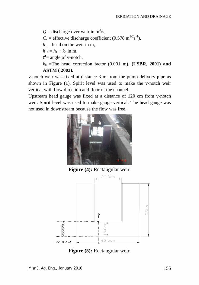
Figure (4): Rectangular weir.
Figure (5): Rectangular weir.
A
A Sec. at A-A

IRRIGATION AND DRAINAGE
Misr J. Ag. Eng., January 2010 156
2c: Rectangular weir
The weir was made of wood and painted against water. The
specifications of this weir were: height 53 cm, height of crest 15.6 cm,
the crest width 26.8 cm, and width of weir is 63.5cm as shown in Figures
(4 and 5).
The basic equation of the Kindsvater-Carter (USBR, 2001) and (ASTM,
2003):
(6)
Where:
Q = discharge (m3/s)
e = a subscript denoting "effective"
Ce = effective coefficient of discharge, m1/2
/s
Ce =C1(h1/p)+C2 C1=0.008 , C2=0.294
Le = L + kb h1e = h1 + kh
In these relationships:
kb = a correction factor to obtain effective weir length (0.003)
L = measured length of weir crest
B = average width of approach channel, m
h1 = head measured above the weir crest, m
kh = a correction factor with a value of 0.001 m
A rectangular weir was fixed at a distance of 3 m from the delivery pipe
as shown in Figure (1). Spirit level was used to make rectangular weir
vertical on flow direction and floor of the channel as shown in Figure (6).
Figure (6): Rectangular weir in vertical direction.

IRRIGATION AND DRAINAGE
Misr J. Ag. Eng., January 2010 157
Upstream head gauge was fixed at a distance of 120 cm from the
rectangular weir as shown in Fig. (1). Spirit level was used to make
gauge vertical. Downstream head gauge was not used because flow was
free.
2d: Cutthroat flume
This flume is a simple device made of fiberglass, whose specifications are as follows:
Height of the cutthroat flume is 47 cm,
Width of throat is 10 cm,
Flume length is 90cm,
The width of approach in channel is 40 cm.
The upstream head gauge was fixed at a distance of 20 cm from throat of
flume as pointed in Figure (7).
Figure (7): Cutthroat flume.
The basic discharge equation for cutthroat flumes is:
fn
uf hCQ (7)
Where,
Downstream
gauge
Upstream
gauge
Flow
90 cm
30 cm 60 cm
10
cm 10
cm
40 cm
10 cm

IRRIGATION AND DRAINAGE
Misr J. Ag. Eng., January 2010 158
Q = the discharge in m3/sec;
hu = the upstream gauge reading in meters;
Cf = the 'free flow' coefficient; and = 1.476,
nf = the 'free flow' exponent, = 1.5 from figure (8) (Walker, 1989)
The value of nf can be read directly from figure (8). The value of the free
flow coefficient Cf, is a function of the flume's length and throat width:
Cf = KfW1.025
(3-5)
Where,
W = the throat width in feet; and
Kf = the flume 'length' coefficient, figure (8).
Figure (8): The cutthroat flume rating curves (Walker, 1989).

IRRIGATION AND DRAINAGE
Misr J. Ag. Eng., January 2010 159
The cutthroat flume was fixed at a distance of 3 m from the delivery pipe.
Spirit level was used to make cutthroat flume vertical on flow direction
and the axle of device parallel to the axle of the channel flow.
The well of upstream-head gauge (0-1m) was fixed at a distance of 20 cm
from the throat as shown in Fig. (7). Spirit level was used to make head
gauge vertical. Downstream gauge was not used because flow was free.
2e: Ultrasonic flowmeter
Ultrasonic flowmeter is designed to measure the fluid discharge within
closed conduit (pipe). The transducers are a non-contacting, clamp-on type,
which provides benefits of non-fouling operation and ease of installation.
Accuracy of ultrasonic flow meter was 1% to 3% intrinsic calibration
(better than 0.5 % of actual flow possible with external calibration). Flow
sensitivity was 0.001 ft/sec (0.0003 m/s) – even at zero flow. zero Drift
Stability was 0.003 ft/sec (0.001 m/s) for typical applications. Response
rate was programmable from 0.2 to 60 seconds. Flow velocity range was
± 40 ft/sec (12 m/s minimum), including zero flow; Linearity was
0.003ft/sec (0.001 m/s) and flow profile compensation was
programmable.
Figure (9): Ultrasonic flow meter.
Installation and fixation of the ultrasonic flow meter
The transducers were fixed at distance of 2.3 m from upstream direction
and 0.8 cm from valve as shown in Fig. (10). Spirit level was used to
make the transducer mount parallel to the suction pipe .The upstream and
downstream transducers were as shown in Fig. (11).

IRRIGATION AND DRAINAGE
Misr J. Ag. Eng., January 2010 160
Figure (10): Setup of ultrasonic flowmeter on pipe.
Figure (11): Mounting U-S. flowmeter on steel pipe.
RESULTS AND DISCUSSION
3a: Calibration of flow measuring devices.
The measurement point was selected at a distance 3-4 m from the pump
suction pipe. Head gauge was fixed upstream at distance 120 cm from the
measuring point to be at 4-6 times head, max, for v-notch weir and
rectangular weir (USBR, 2001). For cutthroat flume, head was measured
upstream from the throat at distance of 2-3 times the length of the
approach channel (MNO Engineering, 2001).
v-notch, rectangular weirs and cutthroat flume were calibrated by
ultrasonic flow meter.
3b: Performance of flow-measuring devices
Measurement data of water discharge at one point of mesqa ( المسقق), by
using different flow measuring devices (v-notch, rectangular weir and
cutthroat flume) are presented in Figures 12,13 and 14 respectively.
Under discharges 5 to 10 Ls-1
, the v-notch gave the highest accuracy,
with errors in percent full-scale discharge between -1.51%, and 2.87%,
respectively. Under discharges of 15 to 25 Ls-1
, the rectangular weir gave
U-S. Flowmeter

IRRIGATION AND DRAINAGE
Misr J. Ag. Eng., January 2010 161
highest accuracy because the errors in full-scale discharge were -1.8%, -
1.58%, and -1.16% respectively. Under 30 Ls-1
, the cutthroat flume gave
highest accuracy, with errors in discharge of 0.16%, -1.31% and 4.22%
for cutthroat flume, rectangular weir and v-notch weir respectively.
Under 35 Ls-1
, the rectangular gave highest accuracy with errors in
discharge of -2.49%, -2.65% and 3.41% for rectangular weir, cutthroat
flume and v-notch weir respectively. The relation between head and
discharge which is shown in figures (12, 13 and 14) can be presented by
the following equations, to calculate the discharge for evaluated devices
under the same conditions and under discharges 5 to 35 L s-1
. These
results agree with ASTM, (2003) and Replogle and Clemmens (1979)
from 5 to 10 L s-1
for v-notch weir and 15 to 35 L s-1
for rectangular weir
and cutthroat flume.
The best equations of flow discharge were obtained from the calibration
of v-notch weir, rectangular weir and cutthroat flume by using ultrasonic
flowmeter under discharges 5 to 35 Ls-1
.
For the v-notch weir:
Qv = 0.0168 H2.4208
(8)
R2 =0.9994.
For the rectangular weir:
Qr = 0.5658 H 1.4446
(9)
R2 = 0.9997.
For cutthroat flume:
Qc = 0.1116 H1.7286
(10)
R2 =0.9989.
Here
Qu = discharge of ultrasonic flow meter (L s-1
),
Qc = discharge of cutthroat flume (L s-1
),
Qr = discharge of rectangular weir (L s-1
),
Qv= discharge of v-notch weir (L s-1
), and
H = head of water (cm.).
3d: The error percentage in values of discharge.
The relation between the discharge and error percentage which is
represented by Figure (15) is given by the following equations.

IRRIGATION AND DRAINAGE
Misr J. Ag. Eng., January 2010 162
-20
-10
0
10
20
30
40
0 10 20 30 40
Discharge (L s-1)
Dis
ch
arg
e (
L s
-1)
an
d e
rro
r %
Qu Ls-1 Qc Ls-1 Error%
Figure (12): V-notch, performance.
Figure (13): Rectangular weir, performance.
Figure (14): Cutthroat flume, performance.
-10
-5
0
5
10
15
20
25
30
35
40
0 10 20 30 40
Discharge (L s-1)
Dis
ch
arg
e (
L s
-1)
an
d e
rro
r %
Qu Ls-1 Qr Ls-1 Error%
-5
0
5
10
15
20
25
30
35
40
0 10 20 30 40
Discharge (L s-1)
Dis
ch
arg
e (
L s
-1)
an
d e
rro
r %
Qu Ls-1 Qv Ls-1 Error%

IRRIGATION AND DRAINAGE
Misr J. Ag. Eng., January 2010 163
The best equations of error percentage in values of discharge are obtained
from the calibration of v-notch, rectangular weir and cutthroat flume by
using ultrasonic flowmeter under discharges 5 to 35 L s-1
.
For the v-notch weir,
Ev% = - 0.0214 Q2 + 0.9762 Q -5.1714 (11)
R2 = 0.8899
For the rectangular weir,
Er% = - 0.016 Q2 +0.7944 Q – 10.714 (12)
R2 = 0.9805
And for the cutthroat flume
Ec% = 0.0097 Q2 – 1.061 Q + 17.004 (13)
R2 =0.9612
Table (4): Error percentage in reading of discharge.
Qu Ev% Er% Ec%
5 -1.511 -7.302 -16.568
10 2.87 -4.391 -8.362
15 6.064 -1.798 -3.445
20 5.169 -1.578 -6.378
25 5.224 -1.164 -1.174
30 4.216 -1.315 0.165
35 3.408 -2.487 -2.65
Here:
E r, E v ;E c% = error percentages in values of discharge for rectangular
weir, v-notch; and cutthroat flume resp.
3e: Coefficient of discharge (Cd)
From data present in figures (16, 17 and 18), the coefficients of discharge
for v-notch are represented by three average values: 0.585, 0.555 and
0.563, for the discharges from 5 Ls-1
to 10 Ls-1
, 15 Ls-1
to 25 Ls-1
and
from 30 Ls-1
to 35 Ls-1
respectively. The averages of the coefficients for
the rectangular weir are: 0.653, 0.617 and 0.619, for the discharges from
5 Ls-1
to 10 Ls-1
, 15 Ls-1
to 30 Ls-1
and from 30 to 35 Ls-1
respectively..
The coefficients of discharge for cutthroat flume are 0.216, 0.238 and
0.255, for discharges from 5 Ls-1
to 10 Ls-1
, 15 Ls-1
to 25 Ls-1
and from
30 Ls-1
to 35 Ls-1
, respectively. These agree with Cuttle and Mason,
(1987) and Swamee (1988).

IRRIGATION AND DRAINAGE
Misr J. Ag. Eng., January 2010 164
Figure (15): Error percentages under different discharges for v-
notch (Ev %), rectangular weir (Er %) and cutthroat flume (Ec %).
Figure (16): Coefficients of discharge for v-notch, rectangular weir
and cutthroat flume.
3f: Head-discharge relation
The relation between head and discharge is shown in Fig. (19). For 5, 10
and 15 cm heads. The lowest discharge values (0.827, 4.427 and 11.814
L s-1
) were recorded for the v-notch. The intermediate values (1.793,
5.942 and 11.976 L s-1
) were recorded for cutthroat flume, whereas the
Cd
Discharge L s-1

IRRIGATION AND DRAINAGE
Misr J. Ag. Eng., January 2010 165
highest discharge values (5.786, 15.749 and 28.291 L s-1
) were recorded
for rectangular weir.
For the 20, 25 and 30 cm heads, another pattern of relationship could be
detected between the variable head and the corresponding discharge
values, where the lowest discharge values (19.69, 28.96 and 39.68 L s-1
)
were recorded for the cutthroat flume. The highest values (42.86, 59.17
and 77.00 L s-1
) were recorded for the rectangular weir. The discharge
values recorded for the v-notch (23.7, 40.68 and 63.25 L s-1
) came in
between The aforementioned results illustrate that the rectangular weir is
the best one for measuring water discharge, where under the different
studied heads, it gave the highest discharge values. This finding confirms
the previously attained which revealed that the rectangular weir is more
accurate at the high rates of discharge.
Figure (17): Head-discharge relation for v-notch weir, rectangular
weir and cutthroat flume.
Field applications:
The v-notch and the rectangular weir devices were used under Kafer El
Sheik Governorate conditions and the results showed that water
conveyance efficiency for improved mesqas ranged from 95.54% to
98.03%, while for unimproved mesqas it ranged from 90.55 to 89.62%.
Head cm
Discharge L s-1
H (cm)
Discharge L s-1

IRRIGATION AND DRAINAGE
Misr J. Ag. Eng., January 2010 166
SUMMARY AND CONCLUSION
Different devices, v-notch, rectangular weir and cutthroat flume are used
for measuring water flow in open channels. However, the most accurate
to be used is not certain. Water flow measuring-devices and hydraulic
structures with different degrees of accuracy were tested and calibrated in
this research.
The selected devices were calibrated in the Hydraulics Research Institute
Laboratory in Qanatir City (Egypt), by using ultrasonic flowmeter under
different discharges of 5, 10, 15, 20, 25, 30 and 35 L s-1
.
Results showed that under discharges (5 L s-1
and 10 L s-1
), the most
accurate device was the v-notch, while under discharges (15 , 20 , 25, 30
and 35 L s-1
) the most accurate one was the rectangular weir. Increasing
discharge rate from 5 to 35 L s-1
, resulted in increases in error % in the
readings of the v-notch. On the other hand, the corresponding error % in
readings of both of rectangular weir and the cutthroat flume obviously
decreased. The decreases seemed inversely related to the rate of
discharge.
From the aforementioned discussion, the v-notch is preferable for
measuring the discharge at a rates ranging from 5 to 10 L s-1
, beyond
which the rectangular weir as well as the cutthroat flume would be
preferable.
The readings of the cutthroat flume were more accurate at time intervals
of 20 min in the average. .
The most accurate devices were tested under Kafer El Sheik Governorate
conditions and the results showed that water conveyance efficiency for
improved mesqas ranged from 95.54% to 98.03%, while for unimproved
mesqas the conveyance efficiency ranged from 90.55 to 89.62%
Recommendations
v-notches are recommended for use under low discharges, while
under high discharges rectangular weirs are more accurate
All water flow measuring devices must be calibrated before using.
Measurements showed water saving due to improved channels
over unimproved ones in "Kafr El Sheikh" scheme conditions.
Water flow-measuring devices help farmers to know the
appropriate water-application duration required for a certain area.
IRRIGATION AND DRAINAGE
Misr J. Ag. Eng., January 2010 167
REFERENCES
ASTM, (2003) D5640: Standard guide for selection of weirs and flumes
for open-channel flow measurement of water. Ann. Bk. of ASTM
standards, Vol. 11.02, http://www.techstreet.com/cgi-bin/
Bos, M.G., Replogle, J.A. and Clemmens, A.J. (1985): Open channel
flow measurement: 141 pp., http//.www.leeds.ac.uk
Cuttle, S.P. and Mason, D.J. (1987): A flow-proportional water
sampler for use in conjunction with a v-notch weir in small
catchment studies. Agric. Water 13:93-99.
Farag, A. A. (2007): Evaluation of water flow measurement methods
appropriate for on-farm management in Egypt Dept. Agri. Eng.
Fac. Ag. Benha U., Egypt.
Kulin, G., and P.R. Compton (1975): "A guide to methods and
standards for the measurement of water flow." Nat. Bur. of
standards, spec. publ.: 421.
LMNO Engineering, (2001): The fluid flow calculations website.
http//www.LMNOengeneering.com
Pugh, C. A. (2001): Using reclamation's new "Water measurement
manual" to save water. U.S. Dep. of the Interior, Bureau of Recl.,
Denver, Colorado. www.usbr.gov
Replogle, J. A. (1998): Measuring flows in earthen canals and irrigation
wells. Issue of Irrigation J.:
http://www.greenmediaonline.com/ij/1998/0398/0398mf.html
Replogle, J.A. (1971): Critical-depth flumes for determining flow in
canals and natural channels. Trans. ASAE No. 70-215: 428-433.
Replogle, J. A. and Clemmens, A. J. (1979): Broad-Crested weirs for
portable flow metering. Transactions of the ASAE, pp. 1324-1328.
Swamee, B. K. S. (1988): Rectangular weir equation. A.S.C.E. Vol.114,
No. 8, pp. 945-949.
USBR, (2001): Water measurement manual. U.S.D of Interior, Bur. of
Recl. 3rd
. ed. Available from http://www.ntis.gov
Walker, W.R. (1989): Guidelines for designing and evaluating surface
irrigation systems. FAO irrigation and drainage paper 45.

IRRIGATION AND DRAINAGE
Misr J. Ag. Eng., January 2010 168
الملخص العربي
تقييم طرق قياس السريان المائي المناسبة إلدارة الري الحقلي في مصر
محمد يوسف اإلنصارى1
منتصر عبد هللا عواد 2
عاطف عبد الغفار نصار 3
أبو سريع أحمد فرج4
:الى البحث يهدف
إلدارة الري الحقلي في مصر. سريان المياه المناسب أختبار ومعايرة بعض أجهزة قياس -1
في قياس كفاءة نقل المياه في مسق مبطن وأخري غيرمبطن إستخدام الجهاز األكثر دقه -2
)ترابيه(.
أجهزة قياس السريان
أجهزة قياس السريان في القنوات المفتوح .-أ
16.5سم ، ارتفاع العتب 71.5خشب قائم الزاوي ، عرض الهدار ال منهدار مثلث ) .1
.سم ( 43.5سم , و إرتفاع الهدار
سم ، وإرتفاع 26.8سم ، و عرض العتب 63.5 الخشب عرض منهدار مستطيل ) .2
سم ( . 53سم ، وأرتفاع الهدار 15.6العتب
الفيبرجالس ، -الياف الزجاج مصنوع من ( )Cutthroat Flume ) زورقصيرالالمضيق .3
.سم ( 47سم ، وأرتفاعه 90م ، وطوله س 10عرض زوره
:) المواسير( قياس السريان في القنوات المغطاة أجهزة -ب
وهو أدق Ultrasonic Flowmeterالصوتي جهاز قياس السريان باستخدام الموجات فوق .1
.لألجهزة السابق األجهزة ولذلك تم إستخدامه في عمل إختبار ومعايرة
:اغط وميزان المياه(أجهزة مساعده )مقياس الض-ج
وتم تقدير الضاغط بإستخدام المقياس الخاص بالضاغط , ,األجهزة والتصرف :تم أخذ متغيران
لدراس أداء األجهزة المختارة تحت التصرفات المختلف . مقياس التياروالسرع باستخدام
تقدير .وذلك لدقيقه 40الى 5من لكل تصرف علي فترات زمنيه طقراءات ضغ 8تم أخذ
تحت وذلك لكل جهاز علي حدة ultrasonic flow meterالتصرف ومقارنتها بقراءة جهاز
، وتحديد الجهاز األكثر دقه. لتر / ث 35الى 5من تصرفات
بالنسب للهدار المستطيل والهدار المثلث كل جهاز وذلك علي النحو التالي: تم قياس السرع مع
اآلخر سم ) عند مكان أخذ قراءة الضاغط( و120تم أخذ قطاعان للسرع , إحداها عند مساف
، قطاعات للسرع , عند منسوب األمام فتم أخذ ثالث للمضيقبالنسب عند فتح الهدار مباشرة.
كل قطاع رأسي إلي خمس قطاعات ( . تم تقسيم (downstreamاألخير عند الزور , وو
. % من العمق80عند السطح والى أفقي :
بنها. -كلي الزراع بمشتهر –الهندس الزراعي قسم –أستاذ الهندس الزراعي -1
بنها. -كلي الزراع بمشتهر –الهندس الزراعي قسم –أستاذ الهندس الزراعي المساعد -2
معهد بحوث إدارة المياه. –للمياه باحث أول بمركز القومى -3
بنها. -كلي الزراع بمشتهر –الهندس الزراعي قسم –مدرس مساعد -4

IRRIGATION AND DRAINAGE
Misr J. Ag. Eng., January 2010 169
التطبيق الحقلي
م ( وذلك لقياس 120) م( واألخرى غير مبطن 161.7قناتين إحداهما مبطن )فى تم التطبيق
كفاءة نقل المياه .
أنالدراس أوضحت نتائج -أهم النتائج :
من لتر /ث هو الهدار المثلث وعند تصرفات 10لتر/ث و 5عند تصرف أدق األجهزة -1
لتر /ث كان الهدار المستطيل هو األدق . 35 الى 15
بالنسب للهدار و، 0.599و 0.553تراوح بين يمعامل التصرف للهدار المثلث -2
0.261و 0.212بين للمضيق، وبالنسب 0.666و 0.615المستطيل تتراوح بين
ظروف البحث كانت كالتالى:للهدار المثلث تحت أنسب معادل -3
Qv = 0.0168 H2.4208
نفس الظروف كانت:أنسب معادله للهدار المستطيل تحت -4
Qv = 0.0168 H2.4208
نفس الظروف:تحت للمضيق أنسب معادل -5
Qc = 0.1116 H1.7286
:اءة للهدار المثلثأنسب معادله لحساب نسب الخطأ في القر -6
Ev% = - 0.0214 Q2 + 0.9762 Q -5.1714
اب نسب الخطأ في القراءة للهدار المستطيل تحت الظروف:لحس أنسب معادل -7
Er % = - 0.016 Q2 +0.7944 Q – 10.714
للمضيق تحت الظروف:لحساب نسب الخطأ في القراءة أنسب معادل -8
Ec = 0.0097 Q2 – 1.061 Q + 17.004
نوات المبطنه التطبيق الحقلى اظهرت النتائج أن كفاءة نقل المياه تكون أكبر في حال القبف -9
% 89.62% و 90.5عنها في حال القنوات غير المبطن ) %( 98.03% و 95.54)
.)
التوصيات :
دار المستطيل مع الهو لهدار المثلث مع التصرفات المنخض يفضل إستخدام ا -1
.التصرفات الكبيرة
يجب معايرة كل أجهزة قياس السريان قبل إستخدمها في القياس . -2
.المبطن لما لها من مزايا عديدةمحل القنوات غير نشر القنوات المطورةيجب -3
.نسب الفقدقياس السريان في معرف كمي المياه التي تم إضافتها للحقل وب الهتمام -4


