Embed Size (px)
Citation preview
January 2019 © 2019 Fluke Corporation. All rights reserved. Specifications are subject to change without notice. All product names are trademarks of their respective companies.
5322A Multifunction Electrical Tester Calibrator
Operators Manual
LIMITED WARRANTY AND LIMITATION OF LIABILITY
Each Fluke product is warranted to be free from defects in material and workmanship under normal use and service. The warranty period is one year and begins on the date of shipment. Parts, product repairs, and services are warranted for 90 days. This warranty extends only to the original buyer or end-user customer of a Fluke authorized reseller, and does not apply to fuses, disposable batteries, or to any product which, in Fluke's opinion, has been misused, altered, neglected, contaminated, or damaged by accident or abnormal conditions of operation or handling. Fluke warrants that software will operate substantially in accordance with its functional specifications for 90 days and that it has been properly recorded on non-defective media. Fluke does not warrant that software will be error free or operate without interruption.
Fluke authorized resellers shall extend this warranty on new and unused products to end-user customers only but have no authority to extend a greater or different warranty on behalf of Fluke. Warranty support is available only if product is purchased through a Fluke authorized sales outlet or Buyer has paid the applicable international price. Fluke reserves the right to invoice Buyer for importation costs of repair/replacement parts when product purchased in one country is submitted for repair in another country.
Fluke's warranty obligation is limited, at Fluke's option, to refund of the purchase price, free of charge repair, or replacement of a defective product which is returned to a Fluke authorized service center within the warranty period.
To obtain warranty service, contact your nearest Fluke authorized service center to obtain return authorization information, then send the product to that service center, with a description of the difficulty, postage and insurance prepaid (FOB Destination). Fluke assumes no risk for damage in transit. Following warranty repair, the product will be returned to Buyer, transportation prepaid (FOB Destination). If Fluke determines that failure was caused by neglect, misuse, contamination, alteration, accident, or abnormal condition of operation or handling, including overvoltage failures caused by use outside the product’s specified rating, or normal wear and tear of mechanical components, Fluke will provide an estimate of repair costs and obtain authorization before commencing the work. Following repair, the product will be returned to the Buyer transportation prepaid and the Buyer will be billed for the repair and return transportation charges (FOB Shipping Point).
THIS WARRANTY IS BUYER'S SOLE AND EXCLUSIVE REMEDY AND IS IN LIEU OF ALL OTHER WARRANTIES, EXPRESS OR IMPLIED, INCLUDING BUT NOT LIMITED TO ANY IMPLIED WARRANTY OF MERCHANTABILITY OR FITNESS FOR A PARTICULAR PURPOSE. FLUKE SHALL NOT BE LIABLE FOR ANY SPECIAL, INDIRECT, INCIDENTAL, OR CONSEQUENTIAL DAMAGES OR LOSSES, INCLUDING LOSS OF DATA, ARISING FROM ANY CAUSE OR THEORY.
Since some countries or states do not allow limitation of the term of an implied warranty, or exclusion or limitation of incidental or consequential damages, the limitations and exclusions of this warranty may not apply to every buyer. If any provision of this Warranty is held invalid or unenforceable by a court or other decision-maker of competent jurisdiction, such holding will not affect the validity or enforceability of any other provision.
Fluke Corporation P.O. Box 9090 Everett, WA 98206-9090 U.S.A.
Fluke Europe B.V. P.O. Box 1186 5602 BD Eindhoven The Netherlands
ООО «Флюк СИАЙЭС» 125167, г. Москва, Ленинградский проспект дом 37, корпус 9, подъезд 4, 1 этаж
11/99
Claims Immediately upon arrival, purchaser shall check the packing container against the enclosed packing list and shall, within thirty (30) days of arrival, give Fluke notice of shortages or any nonconformity with the terms of the order. If purchaser fails to give notice, the delivery shall be deemed to conform with the terms of the order. The purchaser assumes all risk of loss or damage to instruments upon delivery by Fluke to the carrier. If an instrument is damaged in transit, PURCHASER MUST FILE ALL CLAIMS FOR DAMAGE WITH THE CARRIER to obtain compensation. Upon request by purchaser, Fluke will submit an estimate of the cost to repair shipment damage. Fluke will be happy to answer all questions to enhance the use of this instrument. Please address your requests or correspondence to: Fluke Corporation, P.O. Box 9090, Everett, WA 98206-9090.
Declaration of the Manufacturer or Importer We hereby certify that the Fluke Calibration Model 5322A is in compliance with Postal Regulation Vfg. 1046 and is RFI suppressed. The marketing and sale of the equipment was reported to the German Postal Service. The right to retest this equipment to verify compliance with the regulation was given to the German Postal Service.
Bescheinigung des Herstellers/Importeurs Hiermit wird bescheinigt, daβ Fluke Calibration Models 5322A in Übereinstimung mit den Bestimmungen der Amtsblattverfügung Vfg. 1046 funk-entstört ist, Der Deutschen Bundespost wurde das Inverkehrbringen dieses Gerätes angezeigt und die Berechtigung zur Überprüfung der Seire auf Einhaltung der Bestimmungen eingeräumt. Fluke Corporation
Interference Information This equipment generates and uses radio frequency energy and, if not installed and used in strict accordance with the manufacturer’s instructions, may cause interference to radio and television reception. It has been type-tested and found to comply with the limits for a Class B computing device in accordance with the specifications in Subpart J of Part 15 of FCC Rules, which are designed to provide reasonable protection against such interference in a residential installation. However, there is no guarantee that interference will not occur in a particular installation. If this equipment does cause interference to radio or television reception, which can be determined by turning the equipment off and on, the user is encouraged to try to correct the interference by one of more of the following measures: • Reorient the receiving antenna • Relocate the equipment with respect to the receiver • Move the equipment away from the receiver • Plug the equipment into a different outlet so that the computer and
receiver are on different branch circuits
If necessary, the user should consult the dealer or an experienced radio/television technician for additional suggestions. The user may find the following booklet prepared by the Federal Communications Commission helpful: How to Identify and Resolve Radio-TV Interference Problems. This booklet is available from the U.S. Government Printing Office, Washington, D.C. 20402. Stock No. 004-000-00345-4.
OPERATOR SAFETY SUMMARY WARNING
HIGH VOLTAGE is used in the operation of this equipment
LETHAL VOLTAGE may be present on the terminals, observe all safety precautions!
To avoid electrical shock hazard, the operator should not electrically contact the OUTPUT HI and LO; or the ZL, ZGND, RCD binding posts. During operation, lethal voltages may be present on these terminals. Whenever the nature of the operation permits, keep one hand away from equipment to reduce the hazard of current flowing thought vital organs of the body.
i
Table of Contents
Title Page
Introduction ............................................................................................ 1 Safety Information ................................................................................. 2
Warnings ........................................................................................... 2 Symbols ............................................................................................. 4
Contact Fluke Calibration ...................................................................... 5 Specifications ........................................................................................ 5 Service Information ............................................................................... 5 Calibrator Functions .............................................................................. 6
Function Descriptions ........................................................................ 6 Other Features .................................................................................. 8
Accessories ........................................................................................... 8 Included Accessories ......................................................................... 9 Optional Accessories ......................................................................... 10
Unpack and Inspect the Product ........................................................... 10 Power Considerations ........................................................................... 10
Mains Power Cord ............................................................................. 11 Mains Voltage .................................................................................... 11 Ground the Product ........................................................................... 12 Line Power and Fuse ......................................................................... 12 Replace the Fuses ............................................................................. 12 Select the Line Voltage ...................................................................... 13
Install the Product in an Equipment Rack.............................................. 13 Switch Power On ................................................................................... 13 Operation Rules .................................................................................... 15 Warm-Up Time ...................................................................................... 15 Front-Panel Operation ........................................................................... 16
Front-Panel Feature Descriptions ...................................................... 16 Rear-Panel Features ......................................................................... 20 Display Features ................................................................................ 21
Control the Product ............................................................................... 23 Select a Function ............................................................................... 23 Help ................................................................................................... 23 Set the Output Signal Value .............................................................. 24
Numeric Keyboard ......................................................................... 24 Cursor Key Editing ......................................................................... 25
Contents (continued)
ii
Edit Values with Rotary Knob Control ........................................... 25 Readings ........................................................................................... 26 Connection/Disconnection of Output Terminals ................................ 26
Calibrator Setup Menu .......................................................................... 27 Set a General Setup Function ........................................................... 27
Set the Beeper Volume ................................................................. 28 Set the Display Brightness ............................................................ 28 Enable/Disable the Beeper ............................................................ 28 Set Screen Saver .......................................................................... 28 Set the Calibration Password ........................................................ 29 Set the Time .................................................................................. 29 Set the Date ................................................................................... 30 Set the User Interface Language ................................................... 30 View the Device Information .......................................................... 30
Factory Settings .................................................................................... 31 Product Functions ................................................................................. 32 Product Functions ................................................................................. 32 Set the Low Resistance Source Output................................................. 32
Output Selection ................................................................................ 32 Set the High Resistance Source Output ................................................ 35
Output Selection ................................................................................ 36 Set the Ground Bond Resistance Output .............................................. 39
Use the Ground Bond Resistance Mode ........................................... 40 Use the Ground Bond Resistance Open Function ............................ 41
Use the Loop and Line Impedance Function ......................................... 41 Line and Loop Residual Impedance .................................................. 44
Select the Residual Impedance Correction Mode ......................... 45 Set the Manual Residual Impedance Correction Value ................. 47 Set the Scanned Residual Impedance Correction Value .............. 47 Set the Compensation Residual Impedance Correction Value...... 49
Set the Compensation of Test Lead Resistance Value ..................... 50 Use the Leakage Current Function ....................................................... 50
Passive Leakage Current .................................................................. 51 Differential Leakage Current .............................................................. 52 Active Leakage Current (5322A/VLC only) ........................................ 53 Substitute Leakage Current Mode ..................................................... 55 Substitute Leakage Current Mode ..................................................... 55
Use the RCD Test Functions ................................................................. 58 RCD Trip Current Function for Installation Testers ........................... 58
Power Line Voltage ....................................................................... 61 Touch (contact) Voltage ................................................................ 61
Trip Current Calculation ..................................................................... 62 RCD Trip Time for Installation Testers .............................................. 63
Power Line Voltage ....................................................................... 65 Touch (contact) Voltage ................................................................ 65
Output Terminals Reconnection ........................................................ 68 RCD Trip Time for PATs .................................................................... 69
AC/DC Voltage Outputs (5322A/VLC only) ........................................... 70 Measure with the Built-in Multimeter ..................................................... 73
Function Selection ............................................................................. 74 Multimeter Input Selection ................................................................. 76 HIPOT LC Function ........................................................................... 76 HIPOT Timer Function ....................................................................... 80 Flash V (Voltage) Function ................................................................ 81 Flash LC (Leakage Current) Function ............................................... 82
Contents (continued)
iii
Remote Operation ................................................................................. 83 Using the IEEE 488 Port for Remote Control ........................................ 83
IEEE 488 Bus Restrictions ................................................................ 83 Set up the IEEE 488 Port .................................................................. 84
Use the USB Port for Remote Control ................................................... 84 Set up the USB Port .......................................................................... 85 Exceptions for USB Remote Control ................................................. 86
5320A Remote Emulation ..................................................................... 86 Remote Interface Factory Settings ........................................................ 86 Command Syntax Information ............................................................... 87
Parameter Syntax Rules .................................................................... 87 Terminators ....................................................................................... 88 Description of Abbreviations .............................................................. 88 Numeric Output Format ..................................................................... 89
Supported SCPI Commands ................................................................. 89 SCPI Command Summary ................................................................ 90 SYSTem Command Summary .......................................................... 102 STATus Command Summary ............................................................ 102 Common Command Summary .......................................................... 103 SCPI Command Details ..................................................................... 104
Using the OUTPut Commands ...................................................... 104 Using the SOURce Commands ..................................................... 104
Using SYSTem Commands ............................................................... 145 STATus Subsystem ........................................................................... 147 IEEE 488.2 Common Commands ..................................................... 149 Standard Status Data Structures ....................................................... 151
SRE Service Request Enable Register ......................................... 152 ESR Event Status Register ........................................................... 153 ESE Event Status Enable Register ............................................... 153
IEEE 488 Interface Configuration ...................................................... 155 Operator Maintenance ........................................................................... 156 Clean the Ground Bond Resistance and Loop/Line Impedance Relays ................................................................................. 157 Access the Fuses .................................................................................. 158
Line-Power Fuse ............................................................................... 158 Measurement Input Fuses ................................................................. 158
Clean the Air Filter ................................................................................. 159 Clean the Exterior .................................................................................. 160 Product Error Messages ........................................................................ 161 What to Do In Case of Product Failure .................................................. 164 DUT Calibration Examples .................................................................... 164
Calibrate Continuity Testers .............................................................. 165 Calibrate Earth Resistance Testers ....................................................... 166 Calibrate Insulation Resistance Testers ................................................ 167
Calibrate Hand Crank Insulation Testers with the 5 kV High Resistance Option ............................................................................. 170 Calibrate Insulation Resistance Testers with the Resistance Multiplier ............................................................................................ 171
Limitations of the Resistance Multiplier ......................................... 175 Resistance Multiplier Internal Schematic ....................................... 176 Types of Megohmmeters and Use of the Resistance Multiplier .... 177 Sources of Mistakes when Using the Multiplier ............................. 178
Calibrate Ground Bond Resistance Testers ...................................... 179 Calibrate Ground Bond Resistance Function in HIPOT Testers ........... 181 Calibrate Line Impedance Testers......................................................... 182
Contents (continued)
iv
Calibrate Loop Impedance Testers ....................................................... 184 Calibrate Leakage Current Testers ....................................................... 185
Passive, Differential, and Substitute Leakage Current Calibration .... 185 Calibrate Residual Current Device (RCD) in Installation Testers .......... 187
Calibrate RCD Trip Time ................................................................... 187 Calibrate Using 0.5 I Multiplier ....................................................... 187 Calibrate with 1 X I Multiplier ......................................................... 189 Calibrate with 1.4XI, 2 X I, and 5 X I Multipliers ............................ 190
Calibrate RCD Trip Current ............................................................... 191 Calibrate Residual Current Device (RCD) in PATs (Portable Appliance Tester) .................................................................................. 192 Calibrate AC and DC Voltage (5322A/VLC only) .................................. 194 Calibrate Load Test for Appliance Testers ............................................ 197 Perform Flash Class I and Flash Class II Tests on (PAT) Portable Appliance Testers ................................................................... 199 Calibrate Hipots ..................................................................................... 203
Measure High Voltage with the HV Input ........................................... 203 Measure High Voltage with the 10 kV Divider Probe ......................... 204 Measure High Voltage with the 80K-40 High Voltage Probe ............. 205 Measure Leakage Current with the 5322A-LOAD ............................. 206
1
Introduction This manual documents operating instructions and other information for these four Products: • 5322A Multifunction Electrical Tester Calibrator • 5322A/5 Multifunction Electrical Tester Calibrator with 5 kV Insulation
Resistance • 5322A/VLC Multifunction Electrical Tester Calibrator with 600 V Source and
Active Loop Compensation • 5322A/5/VLC Electrical Tester Calibrator with 5 kV Insulation Resistance and
600 V Source and Active Loop Compensation Where necessary, the text is specific to each of these Products. Otherwise, the manual applies to each Product. Through the manual, all varieties of the 5322A will be referred to as the Product or Calibrator. Use all Products to calibrate and test electrical safety testers. Some examples of these testers are: • Megohmmeters • Ground bond testers • Loop testers • RCD (Residual Current Device testers) • Appliance testers • Electrical installation testers • Earth resistance meters • High voltage safety testers (Hipots)
5322A Operators Manual
2
Safety Information A Warning identifies conditions and procedures that are dangerous to the user. A Caution identifies conditions and procedures that can cause damage to the Product or the equipment under test.
Warnings
XWWarning To prevent possible electrical shock, fire, or personal injury: • Read all safety information before you use the Product. • Carefully read all instructions. • Do not alter the Product and use only as specified, or the
protection supplied by the Product can be compromised. • Do not use the Product if it is altered or damaged. • Replace the mains power cord if the insulation is damaged
or if the insulation shows signs of wear. • Do not use test leads if they are damaged. Examine the test
leads for damaged insulation. • Do not put the Product where access to the mains power
cord is blocked. • Use this Product indoors only. • Do not use the Product around explosive gas, vapor, or in
damp or wet environments. • Make sure that the space around the Product meets
minimum requirements. • Use only the mains power cord and connector approved for
the voltage and plug configuration in your country and rated for the Product.
• Make sure the ground conductor in the mains power cord is connected to a protective earth ground. Disruption of the protective earth could put voltage on the chassis that could cause death.
• Do not use a two-conductor adapter or extension cord; this will break the protective ground connection. If a two-conductor power cord must be used, a grounding wire must be connected between the Product ground terminal and a protective earth ground before connecting the power cord or operating the Product.
Multifunction Electrical Tester Calibrator Safety Information
3
• Do not touch voltages >30 V ac rms, 42 V ac peak, or 60 V dc.
• Do not use the Product if it operates incorrectly. • Do not apply more than the rated voltage, between the
terminals or between each terminal and earth ground. • Use only high-quality, shrouded test leads and adapters
with the appropriate voltage rating between the Product and instruments being calibrated.
• Do not connect to live output terminals. The Product can supply voltages that can cause death.
• Keep hands away from all Product terminals during operation. Lethal voltages can be present on terminals.
• Do not connect a hipot or insulation resistance voltage source to the Product terminals that can source more than 100 mA.
• Limit operation to the specified measurement category, voltage, or amperage ratings.
• Use the correct terminals, function, and range for measurements.
• Use only cables with correct voltage ratings. • Remove all probes, test leads, and accessories that are not
necessary for the measurement. • Do not touch exposed metal on banana plugs, they can have
voltages that could cause death. • When appropriate cable adapters are not available and
single test leads are used for calibration, hazardous voltages can exist on the test leads. Test leads and connectors should not be touched while the Product is in the Operate mode.
• Whenever the nature of the operation permits, keep one hand away from equipment to reduce the hazard of current flowing through vital organs of the body.
• Make sure the Product is in Standby while making connections to the OUTPUT HI and LO or the ZL, ZGND, RCD terminals. Lethal voltages can be present on these connectors during Operate mode.
5322A Operators Manual
4
• When you use the Resistance Multiplier adapter, connect its chassis to protective earth ground (PE) on the Product front panel. The ground terminal on the rear panel of the Product can also be used for this purpose.
For safe operation and maintenance of the Product: • Turn off the Product and remove the mains power cord.
Stop for 2 minutes to let the internal circuits discharge before you open the fuse door or remove Product covers.
• Do not operate the Product with covers removed or the case open. Hazardous voltage exposure is possible.
• Disconnect the mains power cord before you remove the Product covers.
• Remove the input signals before you clean the Product. • Use only specified replacement parts. • Use only specified replacement fuses. • Have an approved technician repair the Product.
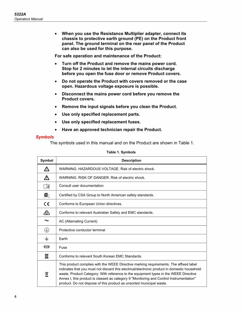
Symbols The symbols used in this manual and on the Product are shown in Table 1.
Table 1. Symbols
Symbol Description
X WARNING. HAZARDOUS VOLTAGE. Risk of electric shock.
W WARNING. RISK OF DANGER. Risk of electric shock.
Consult user documentation.
) Certified by CSA Group to North American safety standards.
P Conforms to European Union directives.
Conforms to relevant Australian Safety and EMC standards.
AC (Alternating Current)
. Protective conductor terminal
Earth
Fuse
Conforms to relevant South Korean EMC Standards.
~
This product complies with the WEEE Directive marking requirements. The affixed label indicates that you must not discard this electrical/electronic product in domestic household waste. Product Category: With reference to the equipment types in the WEEE Directive Annex I, this product is classed as category 9 "Monitoring and Control Instrumentation" product. Do not dispose of this product as unsorted municipal waste.
Multifunction Electrical Tester Calibrator Contact Fluke Calibration
5
Contact Fluke Calibration To contact Fluke Calibration, call one of the following telephone numbers: • Technical Support USA: 1-877-355-3225 • Calibration/Repair USA: 1-877-355-3225 • Canada: 1-800-36-FLUKE (1-800-363-5853) • Europe: +31-40-2675-200 • Japan: +81-3-6714-3114 • Singapore: +65-6799-5566 • China: +86-400-810-3435 • Brazil: +55-11-3759-7600 • Anywhere in the world: +1-425-446-6110 To see product information and download the latest manual supplements, visit the Fluke Calibration website at www.flukecal.com. To register your product, visit http://flukecal.com/register-product.
Specifications Safety specifications are located in the printed 5322A Safety Information. Full specifications are located online in the 5322A Specifications.
Service Information Contact an authorized Fluke Calibration Service Center if the Product needs calibration or repair during the warranty period. See Contact Fluke Calibration. Please have Product information such as the purchase date and serial number ready when scheduling a repair. To reship the Product, use the original shipping container. If the original carton is not available, then order a new container from Fluke Calibration. See Contact Fluke Calibration.
5322A Operators Manual
6
Calibrator Functions The Product performs output and measurement functions. Output Functions • Insulation resistance • Earth resistance and continuity • Loop, line, and ground bond resistance • RCD and Ground Fault Circuit Interrupter (GFCI) tests • Leakage current source • AC/DC voltage generation (5322A/VLC only) Measurement Functions • AC/DC voltage and current measure • AC Power, including phase • Hipot voltage distortion, ripple coefficient • Flash test voltage, Class I and Class II • Load current
Function Descriptions The subsequent sections describe various functions of the Product. Unless otherwise noted, the descriptions apply to all models of the 5322A.
Insulation Resistance When using the 5322A for insulation resistance calibration, the Product acts as a high-resistance source from 10 kΩ to 10 GΩ with 4½ digit resolution. A single value 100 GΩ selection is available as well. Depending on the selected resistance value, maximum applied test voltages range from 50 V to 1500 V peak. The 5322A/5 has a 5 kV high-resistance source with a fully-programmable resistance range from 10 kΩ to 100 GΩ. Maximum test voltage for this option is from 50 V to 5500 Vpk MAX, depending on setup resistance value.
Earth Resistance and Continuity The Product sources low resistance values from 100 mΩ to 10 kΩ with 3½ digits of resolution. This function is used in either 2-wire or 4-wire mode to calibrate continuity testers and earth resistance testers that source currents from 5 mA to 700 mA.
Multifunction Electrical Tester Calibrator Calibrator Functions
7
Loop, Line, and Ground Bond Resistance The Product sources high power rated low resistance standards from 14 mΩ to 1.7 kΩ, which are especially suited for loop impedance, line impedance, and ground bond resistance testing. Ground bond outputs can be configured as either 2-wire or 4-wire. The Product senses and displays Device Under Test (DUT) test conditions, types of test current, and current levels up to 40 A. In the 5322A/VLC, an Active Loop Compensation module will compensate for residual resistance when performing loop and line impedance calibrations.
Residual Current Device (RCD) Testing In the RCD function, the Product acts as a circuit breaker to calibrate trip time in the range of 10 ms to 5 s, and trip current in the range of 3 mA to 3 A. All tested parameters of the DUT are scanned and displayed on the Product display.
Leakage Current Source The Product sources simulated leakage current from 0.1 mA to 30 mA with a maximum compliance voltage up to 250 V ac. Leakage current modes include touch, substitute, and differential current.
AC/DC Voltage Generation (5322A/VLC and 5322A/5/VLC Only) When equipped with the ac/dc voltage calibrator, the Product is capable of calibrating the voltmeter function on many electrical safety testers. The output voltage range is 3 V to 600 V both ac and dc. The ac frequency range is 40 Hz to 400 Hz. This voltage source also generates stable power line voltage for powering appliance testers.
Meter Functions The Product is equipped with a built-in low frequency voltmeter and ammeter. The voltmeter measures up to 5000 V ac rms or V dc, while the ammeter measures up to 30 A. The Meter also measures ac power, including phase, and dc power.
HIPOT Function In the HIPOT sub function, the Product can measure total harmonic distortion of ac signals up to 5000 V ac rms and ripple coefficient of dc signals up to 5000 V dc. The function is suited for HIPOT tester parameter verification. The Product also has the capability to verify HIPOT timers up to 999 s.
5322A Operators Manual
8
Flash Function The Product can verify the flash function of PAT testers in both Class I to 1500 V and Class II to 3000 V.
Other Features For ease of use, the Product includes other features such as setup menus, power line condition testing at power-up and hardware and software overload protection. Front-panel control of the Product is accomplished through function keys for frequently used functions, edit controls, and menu selection softkeys. All necessary information such as Product status, menu selections and readings are displayed through a luminescent display on the front panel. The Product is equipped with an IEEE 488 bus, and USB interfaces for controlling the Product from a PC or instrument controller.
Accessories The subsequent sections cover the accessories available for the Product. When ordering an accessory after the original purchase, include a reference to the Product, as well as the description from the following tables.
Multifunction Electrical Tester Calibrator Accessories
9
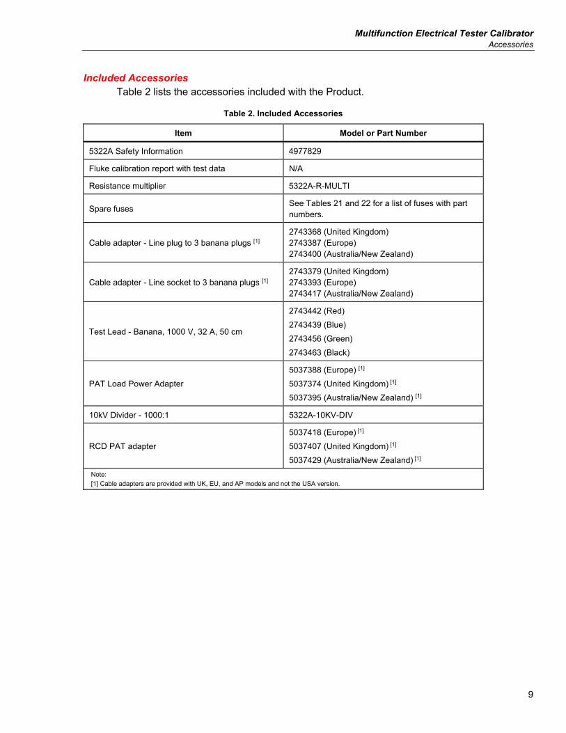
Included Accessories Table 2 lists the accessories included with the Product.
Table 2. Included Accessories
Item Model or Part Number
5322A Safety Information 4977829
Fluke calibration report with test data N/A
Resistance multiplier 5322A-R-MULTI
Spare fuses See Tables 21 and 22 for a list of fuses with part numbers.
Cable adapter - Line plug to 3 banana plugs [1] 2743368 (United Kingdom) 2743387 (Europe) 2743400 (Australia/New Zealand)
Cable adapter - Line socket to 3 banana plugs [1] 2743379 (United Kingdom) 2743393 (Europe) 2743417 (Australia/New Zealand)
Test Lead - Banana, 1000 V, 32 A, 50 cm
2743442 (Red) 2743439 (Blue) 2743456 (Green) 2743463 (Black)
PAT Load Power Adapter 5037388 (Europe) [1] 5037374 (United Kingdom) [1] 5037395 (Australia/New Zealand) [1]
10kV Divider - 1000:1 5322A-10KV-DIV
RCD PAT adapter 5037418 (Europe) [1] 5037407 (United Kingdom) [1] 5037429 (Australia/New Zealand) [1]
Note: [1] Cable adapters are provided with UK, EU, and AP models and not the USA version.
5322A Operators Manual
10
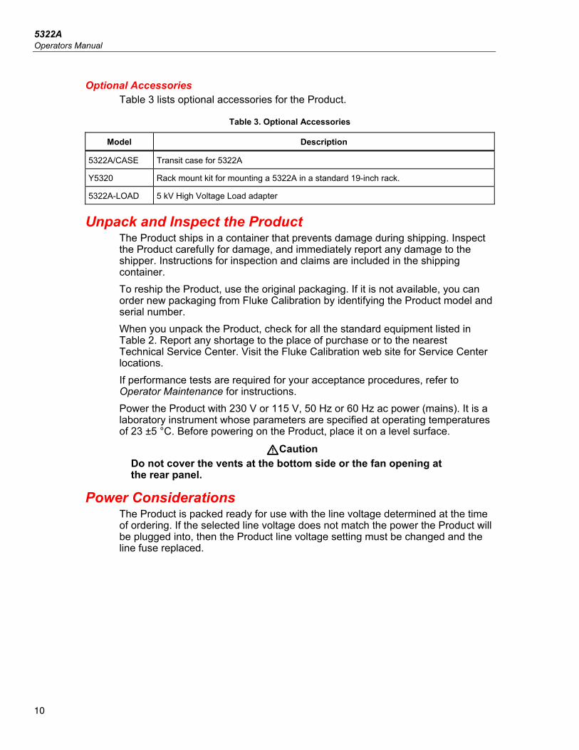
Optional Accessories Table 3 lists optional accessories for the Product.
Table 3. Optional Accessories
Model Description
5322A/CASE Transit case for 5322A
Y5320 Rack mount kit for mounting a 5322A in a standard 19-inch rack.
5322A-LOAD 5 kV High Voltage Load adapter
Unpack and Inspect the Product The Product ships in a container that prevents damage during shipping. Inspect the Product carefully for damage, and immediately report any damage to the shipper. Instructions for inspection and claims are included in the shipping container. To reship the Product, use the original packaging. If it is not available, you can order new packaging from Fluke Calibration by identifying the Product model and serial number. When you unpack the Product, check for all the standard equipment listed in Table 2. Report any shortage to the place of purchase or to the nearest Technical Service Center. Visit the Fluke Calibration web site for Service Center locations. If performance tests are required for your acceptance procedures, refer to Operator Maintenance for instructions. Power the Product with 230 V or 115 V, 50 Hz or 60 Hz ac power (mains). It is a laboratory instrument whose parameters are specified at operating temperatures of 23 ±5 °C. Before powering on the Product, place it on a level surface.
WCaution Do not cover the vents at the bottom side or the fan opening at the rear panel.
Power Considerations The Product is packed ready for use with the line voltage determined at the time of ordering. If the selected line voltage does not match the power the Product will be plugged into, then the Product line voltage setting must be changed and the line fuse replaced.
Multifunction Electrical Tester Calibrator Power Considerations
11
Mains Power Cord A mains power cord that will connect to the power receptacles found in the region to which the Product is shipped is included with each Product.
XWWarning To prevent possible electrical shock, fire, or personal injury: • Use only the mains power cord and connector approved for the
voltage and plug configuration in your country and rated for the Product.
• Replace the mains power cord if the insulation is damaged or if the insulation shows signs of wear.
• Make sure the ground conductor in the mains power cord is connected to a protective earth ground. Disruption of the protective earth could put voltage on the chassis that could cause death.
• Do not use a two-conductor adapter or extension cord; this will break the protective ground connection. If a two-conductor power cord must be used, a grounding wire must be connected between the Product ground terminal and a protective earth ground before connecting the power cord or operating the Product. After you verify that the line voltage selection switch is set to the correct position, verify that the correct fuse for that line voltage is installed.
Mains Voltage
XW Warning To prevent possible electrical shock, fire, or personal injury:
• Do not put the Product where access to the mains power cord is blocked.
• The Product enclosure must be grounded through the grounding conductor of the power cord, or through the rear panel ground binding post.
The Product comes with the appropriate line power plug for the country of purchase. If a different type is necessary, refer to Table 4. They list and show the mains line power plug types available from Fluke Calibration.
5322A Operators Manual
12
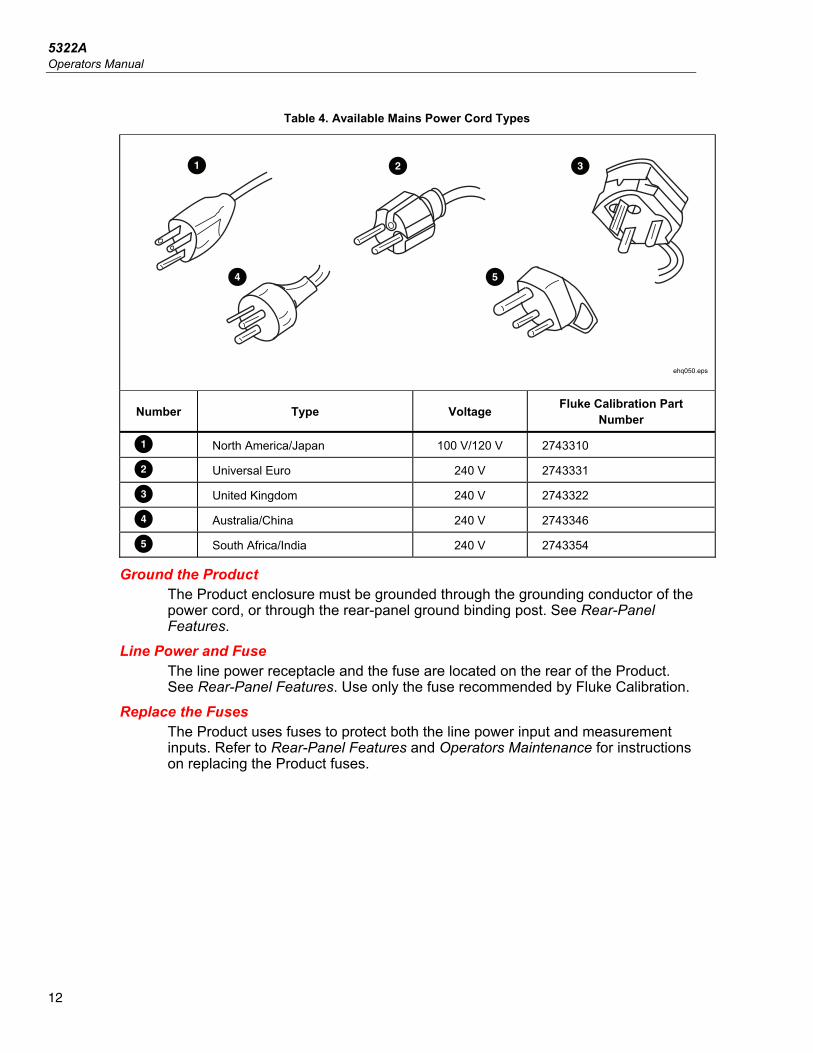
Table 4. Available Mains Power Cord Types
ehq050.eps
Number Type Voltage Fluke Calibration Part Number
North America/Japan 100 V/120 V 2743310
Universal Euro 240 V 2743331
United Kingdom 240 V 2743322
D Australia/China 240 V 2743346
E South Africa/India 240 V 2743354
Ground the Product The Product enclosure must be grounded through the grounding conductor of the power cord, or through the rear-panel ground binding post. See Rear-Panel Features.
Line Power and Fuse The line power receptacle and the fuse are located on the rear of the Product. See Rear-Panel Features. Use only the fuse recommended by Fluke Calibration.
Replace the Fuses The Product uses fuses to protect both the line power input and measurement inputs. Refer to Rear-Panel Features and Operators Maintenance for instructions on replacing the Product fuses.
Multifunction Electrical Tester Calibrator Install the Product in an Equipment Rack
13
Select the Line Voltage The Product operates on two different input line voltages. The line voltage setting is indicated on the face of the line voltage switch found on the Product rear panel. See Rear-Panel Features. To change the line voltage: 1. Disconnect the Product from line power by unplugging the line power cord. 2. Using a flat-blade screwdriver, rotate the switch until the desired voltage is
under the arrowhead on the line voltage switch. 3. Ensure the proper Line Power fuse for the selected line voltage selection is
installed in the Product. See Line Power Fuses. 4. Attach the Product to the power source using a line power cord appropriate
for the mains outlet.
Install the Product in an Equipment Rack The Product can be mounted in a standard-width, 24-inch (61-cm) deep equipment rack. To mount the Product in an equipment rack, use the Rack Mount Kit, Model Y5320A, instructions are included with the kit.
Switch Power On With the Product setup for the proper line voltage, push the power switch on the back panel to the I side of the switch. See Rear-Panel Features. During its power-up cycle, the Product shows a power supply test screen while initializing internal circuits and checking the mains connection. The mains connection tests are: • Power line voltage test – The line voltage must be within preset limits. For the
230 V setting, the range must be between 180 V and 260 V. For the 115 V setting, the limits are between 90 V to 130 V.
Note The Product requires standard nonsymmetrical power line mains (NT) with line (hot) wire, protection earth, and neutral wire.
• Power line frequency test – The frequency must be within preset limits: 49 Hz to 51 Hz or 59 Hz to 61 Hz.
• Potential difference and polarity test – The potential difference between neutral and protective earth must be less than 15 V.
5322A Operators Manual
14
The Product indicates a pass condition with a checkmark and fail condition with an X. The power-up selftest is a go/no-go test. For example, if any of the tests fail, a red x is shown on the Voltage, Frequency, or L-N-PE test lines. If the Product detects that the power line is improperly connected, for example the line or hot wire is reversed with the neutral wire, it shows Fail, In this case, remove the power cord and correct the problem before trying to power the Product on. The Product shows Pass for several seconds while it performs additional internal circuitry tests, if all tests pass and the power line is properly connected. A similar Fail indication is shown in the voltage and frequency tests if the power supply voltage or frequency is out of specified limits.
Note The polarity of the neutral and the line wires must be correct for the Product to power on. If the L-N-PE test fails during the power-on process, the neutral and the line wires could be miswired at the Mains connection socket. This probable wiring error must be corrected. Only a qualified service technician should make this change.
When the mains power tests finish, the Product initializes to Meter mode operation. During the power-up process, the display shows a message indicating that the relays require cleaning. The message indicates that relays for the Ground Bond Resistance function and Loop/Line resistance function need to be cleaned with an internal cleaning procedure. The message appears if more than 90 days has passed since the last cleaning. 1. Push Setup>Maintenance>Relays cleaning procedure to clean the relays
at any time. The Product's Ground Bond Resistance and Loop/Line resistance specifications are dependent upon how often you clean the relay. See the 5322A Specifications online for details.
2. Ignore the cleaning request with the EXIT softkey if necessary, or push the Continue softkey to start the process. When Continue is selected, the Product prompts to remove all test leads from the front-panel terminals and after confirmation it starts the relays cleaning. The Procedure takes about 2 minutes. Then the Product resets to its reference state of METER mode operation.
When EXIT is selected the Product goes on to its reference state directly without executing the relay cleaning procedure. However, the message is shown again during the next power-up until the procedure is run. During the power-up process, the Product, by default, measures the residual line resistance in the mains supply.
Multifunction Electrical Tester Calibrator Operation Rules
15
The measurement takes approximately 10 seconds and is used in the Loop/Line impedance function. The measurement can cause current spikes to occur on the mains supply, so this start-up measurement can be disabled if desired. Access to changing the setting is in Setup>Line&Loop scan, and the Start Up SCAN parameter. When the parameter is set to Off, initial residual resistance measurement during power up is omitted.
Note The Product resets to its reference state whenever mains power is removed and then reapplied to the Product.
Operation Rules W Caution
The following rules should be strictly observed to ensure correct operation of the Product:
• Turn on and turn off the Product only with the power switch on the rear panel.
• Do not connect the Product to a power source with a voltage other than that set by the voltage selector on the rear panel.
• Do not block the vent openings located at the rear and bottom panels.
• Keep all liquids and small objects from entering the Product through the vent openings.
• The Product must not be operated in a dusty environment. It was designed to be used in a laboratory.
• Do not operate the Product outside its operating temperature range.
• Connect the instruments to be calibrated to the proper output terminals.
• If the instruments to be calibrated are not connected to the Product output terminals using their original cables, ensure that only cables rated for the applicable voltage and current are used.
Whenever possible, use the setup menu to ground the LO output terminal. See GND on the setup function, applicable for the low-resistance source, high-resistance source, and voltage calibrator (VLC option).
Warm-Up Time Once the Product reaches its reference state, it can be used for calibration. However, the Product will only make calibrations to its specified accuracy after it has been allowed to warm up for at least 30 minutes.
Note During these first 30 minutes, the Product cannot calibrate. If Product calibration is attempted during this period, the Product indicates that it cannot access the calibration.
5322A Operators Manual
16
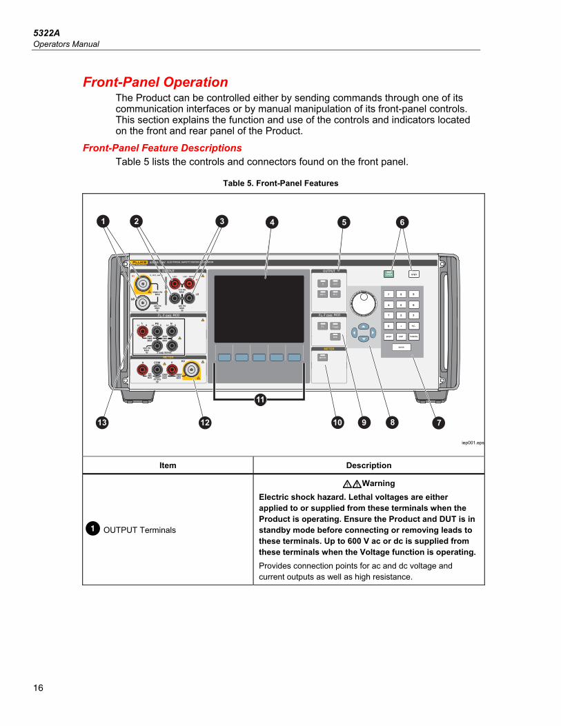
Front-Panel Operation The Product can be controlled either by sending commands through one of its communication interfaces or by manual manipulation of its front-panel controls. This section explains the function and use of the controls and indicators located on the front and rear panel of the Product.
Front-Panel Feature Descriptions Table 5 lists the controls and connectors found on the front panel.
Table 5. Front-Panel Features
LO
METER
, L, L
+/-
1 2 3 4 5
7810 91213
6
11
iep001.eps
Item Description
OUTPUT Terminals
XWWarning Electric shock hazard. Lethal voltages are either applied to or supplied from these terminals when the Product is operating. Ensure the Product and DUT is in standby mode before connecting or removing leads to these terminals. Up to 600 V ac or dc is supplied from these terminals when the Voltage function is operating. Provides connection points for ac and dc voltage and current outputs as well as high resistance.
Multifunction Electrical Tester Calibrator Front-Panel Operation
17
Table 5. Front-Panel Features (cont.)
Item Description
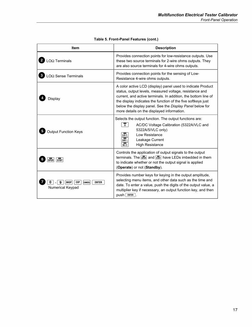
LOΩ Terminals Provides connection points for low-resistance outputs. Use these two source terminals for 2-wire ohms outputs. They are also source terminals for 4-wire ohms outputs.
LOΩ Sense Terminals Provides connection points for the sensing of Low-Resistance 4-wire ohms outputs.
D Display
A color active LCD (display) panel used to indicate Product status, output levels, measured voltage, resistance and current, and active terminals. In addition, the bottom line of the display indicates the function of the five softkeys just below the display panel. See the Display Panel below for more details on the displayed information.
E Output Function Keys
Selects the output function. The output functions are: AC/DC Voltage Calibration (5322A/VLC and 5322A/5/VLC only) Low Resistance Leakage Current High Resistance
F Controls the application of output signals to the output terminals. The and have LEDs imbedded in them to indicate whether or not the output signal is applied (Operate) or not (Standby).
G - Numerical Keypad
Provides number keys for keying in the output amplitude, selecting menu items, and other data such as the time and date. To enter a value, push the digits of the output value, a multiplier key if necessary, an output function key, and then push .
5322A Operators Manual
18
Table 5. Front-Panel Features (cont.)
Item Description
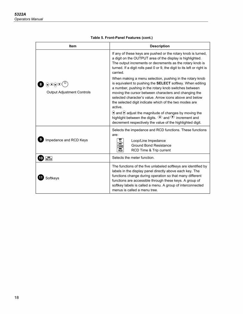
H Output Adjustment Controls
If any of these keys are pushed or the rotary knob is turned, a digit on the OUTPUT area of the display is highlighted. The output increments or decrements as the rotary knob is turned. If a digit rolls past 0 or 9, the digit to its left or right is carried. When making a menu selection, pushing in the rotary knob is equivalent to pushing the SELECT softkey. When editing a number, pushing in the rotary knob switches between moving the cursor between characters and changing the selected character’s value. Arrow icons above and below the selected digit indicate which of the two modes are active. and adjust the magnitude of changes by moving the highlight between the digits. and increment and decrement respectively the value of the highlighted digit.
I Impedance and RCD Keys
Selects the impedance and RCD functions. These functions are: Loop/Line Impedance Ground Bond Resistance RCD Time & Trip current
J Selects the meter function.
K Softkeys
The functions of the five unlabeled softkeys are identified by labels in the display panel directly above each key. The functions change during operation so that many different functions are accessible through these keys. A group of softkey labels is called a menu. A group of interconnected menus is called a menu tree.
Multifunction Electrical Tester Calibrator Front-Panel Operation
19
Table 5. Front-Panel Features (cont.)
Item Description
L Meter Terminals
Provides connection points for meter measurements. The V terminal is for ac and dc voltages up to 1100 V dc/ac. The HV terminal, also referred to as the HV 5 kV Probe, measures up to 5000 V ac rms or dc. The A terminal is for ac and dc currents. The COM terminal is the return for all meter measurements.
M Impedance and RCD Terminals
Provides connection points for the Loop and Line impedance testing as well as RCD testing and Ground Bond Resistance testing.
5322A Operators Manual
20
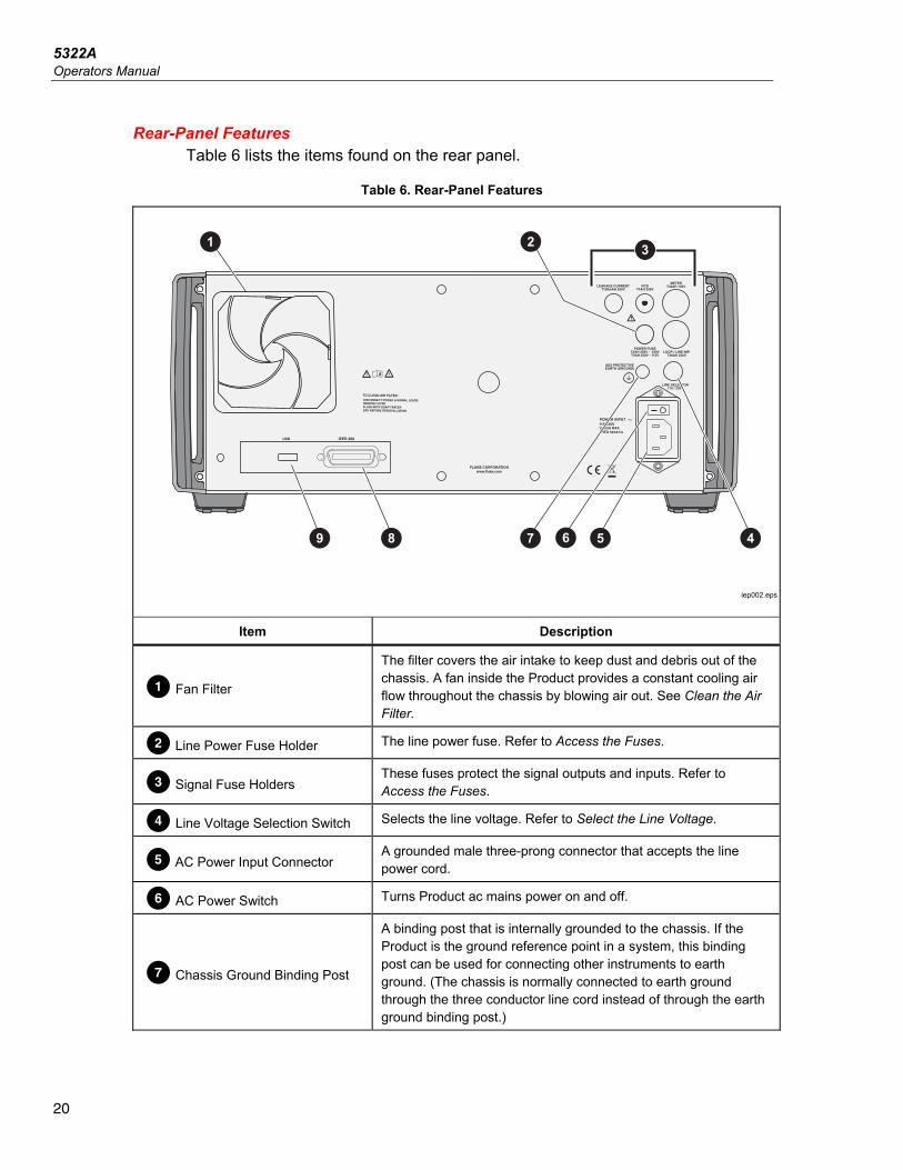
Rear-Panel Features Table 6 lists the items found on the rear panel.
Table 6. Rear-Panel Features
USB
1250V50/60 Hz
1
115/230V
7 589 46
2 3
&
X»
iep002.eps
Item Description
Fan Filter
The filter covers the air intake to keep dust and debris out of the chassis. A fan inside the Product provides a constant cooling air flow throughout the chassis by blowing air out. See Clean the Air Filter.
Line Power Fuse Holder The line power fuse. Refer to Access the Fuses.
Signal Fuse Holders These fuses protect the signal outputs and inputs. Refer to Access the Fuses.
D Line Voltage Selection Switch Selects the line voltage. Refer to Select the Line Voltage.
E AC Power Input Connector A grounded male three-prong connector that accepts the line power cord.
F AC Power Switch Turns Product ac mains power on and off.
G Chassis Ground Binding Post
A binding post that is internally grounded to the chassis. If the Product is the ground reference point in a system, this binding post can be used for connecting other instruments to earth ground. (The chassis is normally connected to earth ground through the three conductor line cord instead of through the earth ground binding post.)
Multifunction Electrical Tester Calibrator Front-Panel Operation
21
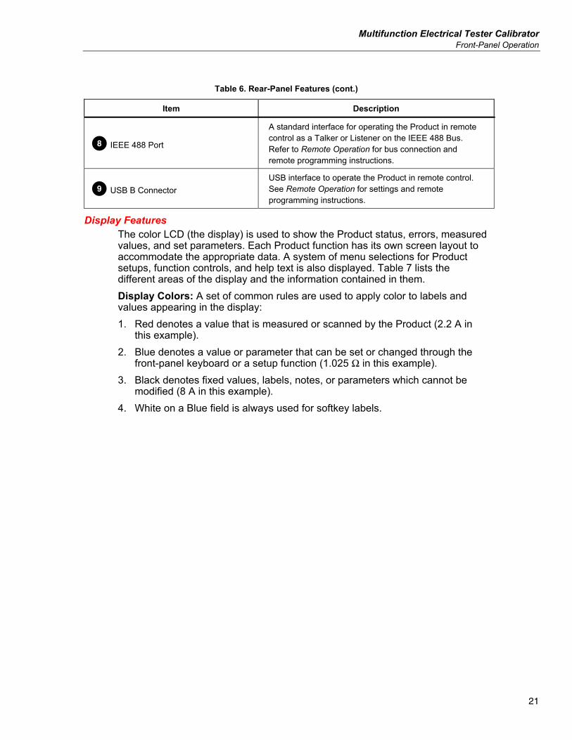
Table 6. Rear-Panel Features (cont.)
Item Description
H IEEE 488 Port
A standard interface for operating the Product in remote control as a Talker or Listener on the IEEE 488 Bus. Refer to Remote Operation for bus connection and remote programming instructions.
I USB B Connector USB interface to operate the Product in remote control. See Remote Operation for settings and remote programming instructions.
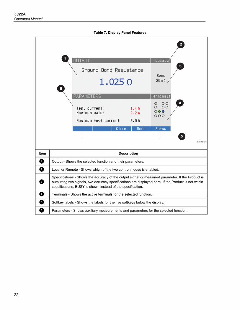
Display Features The color LCD (the display) is used to show the Product status, errors, measured values, and set parameters. Each Product function has its own screen layout to accommodate the appropriate data. A system of menu selections for Product setups, function controls, and help text is also displayed. Table 7 lists the different areas of the display and the information contained in them. Display Colors: A set of common rules are used to apply color to labels and values appearing in the display: 1. Red denotes a value that is measured or scanned by the Product (2.2 A in
this example). 2. Blue denotes a value or parameter that can be set or changed through the
front-panel keyboard or a setup function (1.025 Ω in this example). 3. Black denotes fixed values, labels, notes, or parameters which cannot be
modified (8 A in this example). 4. White on a Blue field is always used for softkey labels.
5322A Operators Manual
22
Table 7. Display Panel Features
1
2
3
5
4
6
iep102.eps
Item Description
Output - Shows the selected function and their parameters.
Local or Remote - Shows which of the two control modes is enabled.
Specifications - Shows the accuracy of the output signal or measured parameter. If the Product is outputting two signals, two accuracy specifications are displayed here. If the Product is not within specifications, BUSY is shown instead of the specification.
D Terminals - Shows the active terminals for the selected function.
E Softkey labels - Shows the labels for the five softkeys below the display.
F Parameters - Shows auxiliary measurements and parameters for the selected function.
Multifunction Electrical Tester Calibrator Control the Product
23
Control the Product The subsequent sections give an overview of basic Product operation. More detailed use is described in Product Functions.
Select a Function Once the Product is powered on and the self-test has completed successfully, the Product sets itself to its reference state of Meter mode. To change the Product state: 1. Push the desired function key.
Whenever a different function is selected, the Product uses the parameters that were set the last time the function was used.
Note Whenever the function changes, the Product always switches to STANDBY mode.
XWWarning To prevent possible electrical shock, fire, or personal injury, do not connect to live output terminals. The Product can supply voltages that can cause death.
2. Make the appropriate connections between the Product and DUT. Refer to the Terminals area of the display as a guide.
3. If necessary, make changes to the functions parameters through the setup menu by pushing the Setup softkey. To return to the function selected without changing the parameters, push the softkey under Exit.
4. With the desired function selected, function parameters set, and the DUT properly connected to the Product, push the OPER key to activate the Product outputs.
Help The Help guide in the Product shows information on the selected function that may help with proper function settings. To access the Help guide, in any function, push the Mode softkey and select Help. The guide is available in six languages: English, German, French, Spanish, Italian, and Chinese. When finished reading the help messages, push the Exit softkey to return to the selected function.
Note Each function has associated Help.
5322A Operators Manual
24
Set the Output Signal Value All Product functions allow you to set the primary and auxiliary parameter values in different ways: • Numeric keyboard • Cursor keys • Rotary Knob The cursor keys and rotary knob are also used to make menu selections in the setup window.
Note If an entry results in overflow or underflow of the Product range, a Value too Large or Value too Small error message is shown.
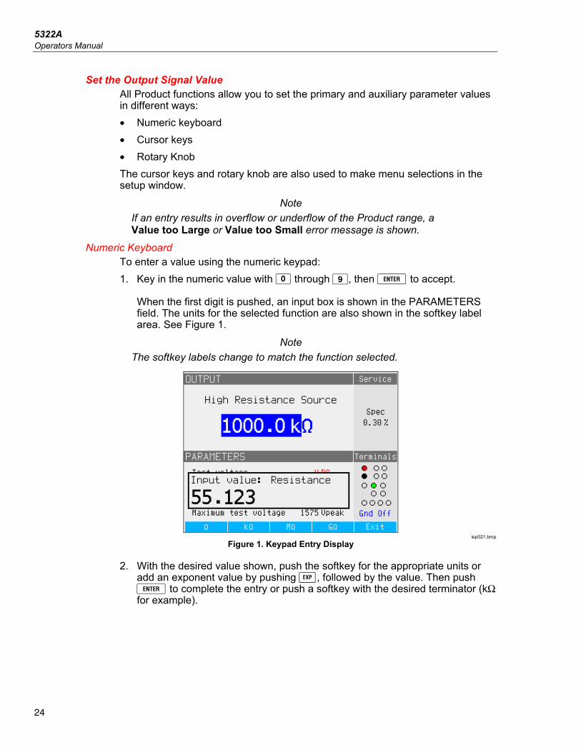
Numeric Keyboard To enter a value using the numeric keypad: 1. Key in the numeric value with through , then to accept.
When the first digit is pushed, an input box is shown in the PARAMETERS field. The units for the selected function are also shown in the softkey label area. See Figure 1.
Note The softkey labels change to match the function selected.
iep021.bmp
Figure 1. Keypad Entry Display
2. With the desired value shown, push the softkey for the appropriate units or add an exponent value by pushing , followed by the value. Then push to complete the entry or push a softkey with the desired terminator (kΩ for example).
Multifunction Electrical Tester Calibrator Control the Product
25
Note To exit the numeric entry without entering the typed value, push . The Product changes the parameter to the value entered, displays the entered value and the input box disappears.
3. To exit the edit mode, push the Exit softkey. Cursor Key Editing
To enter a value with the cursor keys: 1. Push any one of the cursor keys to start an entry.
An arrowhead pointing up appears above a digit and an arrowhead pointing down appears below the same digit to indicate which digit is being edited.
2. Push to increase or to decrease the active digit. 3. Push or to move to the next adjacent digit. 4. To return to the main screen, push the Exit softkey.
Edit Values with Rotary Knob Control The rotary knob control works independently or in conjunction with the cursor keys. To enter a value using the rotary knob: 1. Push in the rotary knob to enter the edit mode.
Because the rotary knob is used to position the cursor on a digit and increment or decrement a digit, icons above and below the digit indicate which of the two movements the rotary knob is set for: digit selection or digit setting. Digit selection is indicated by a left-pointing arrow above the digit and a right-pointing arrow below the digit. Turning the rotary knob when these icons are displayed moves the cursor to an adjacent digit. Digit setting is indicated by an upward-pointing arrowhead above a digit and a downward-pointing arrowhead below the same digit. Turning the rotary knob when these icons are displayed increments or decrements the digit.
Note To switch between digit selection and digit setting, push in the rotary knob. Each push of the rotary knob toggles between the two movements.
2. While in the digit setting mode, turn the rotary knob clockwise to increase the selected digit or counterclockwise to decrease the selected digit. When the digit reaches 9, further clockwise rotation sets the present digit to zero and increments the digit to the left by one. When the digit reaches 1, further counterclockwise rotation sets the selected digit to 9 and decrements the digit to the left by one. If the selected digit is the most significant digit, decrementing it from 1 to 0 will cause the digit to go blank.
3. To exit the edit mode, push the Exit softkey.
5322A Operators Manual
26
Readings Readings taken by the Product functions are shown either in the OUTPUT/INPUT area or PARAMETERS area of the display. All readings are shown in red with an appropriate units label. If a reading is outside the specified limits of the function, the Product disconnects the active terminals and shows the Input overloaded error message.
Connection/Disconnection of Output Terminals Whenever the Product is powered up, all terminals are disconnected and the amber LED in the STBY key is illuminated. To connect the output signal to the Output Terminals, push . The green LED inside illuminates and the amber LED on will extinguish. To disconnect the Output Signal from the Output Terminals, push . The green LED in the OPER key extinguishes and the amber LED on illuminates indicating the Product is ready but the terminals are disconnected.
Note Whenever the function changes, the Product switches to STANDBY mode.
If at any time a voltage >30 V is generated or detected on the input or output terminals, the Product shows in the OUTPUT area of the display to signify high voltage. While the Product is in the operate mode, and the output voltage is below 30 V, the output terminals will be disconnected if the volt increases to 30 V or above. After the higher voltage is set, push to reconnect the output terminals with the higher voltage.
Multifunction Electrical Tester Calibrator Calibrator Setup Menu
27
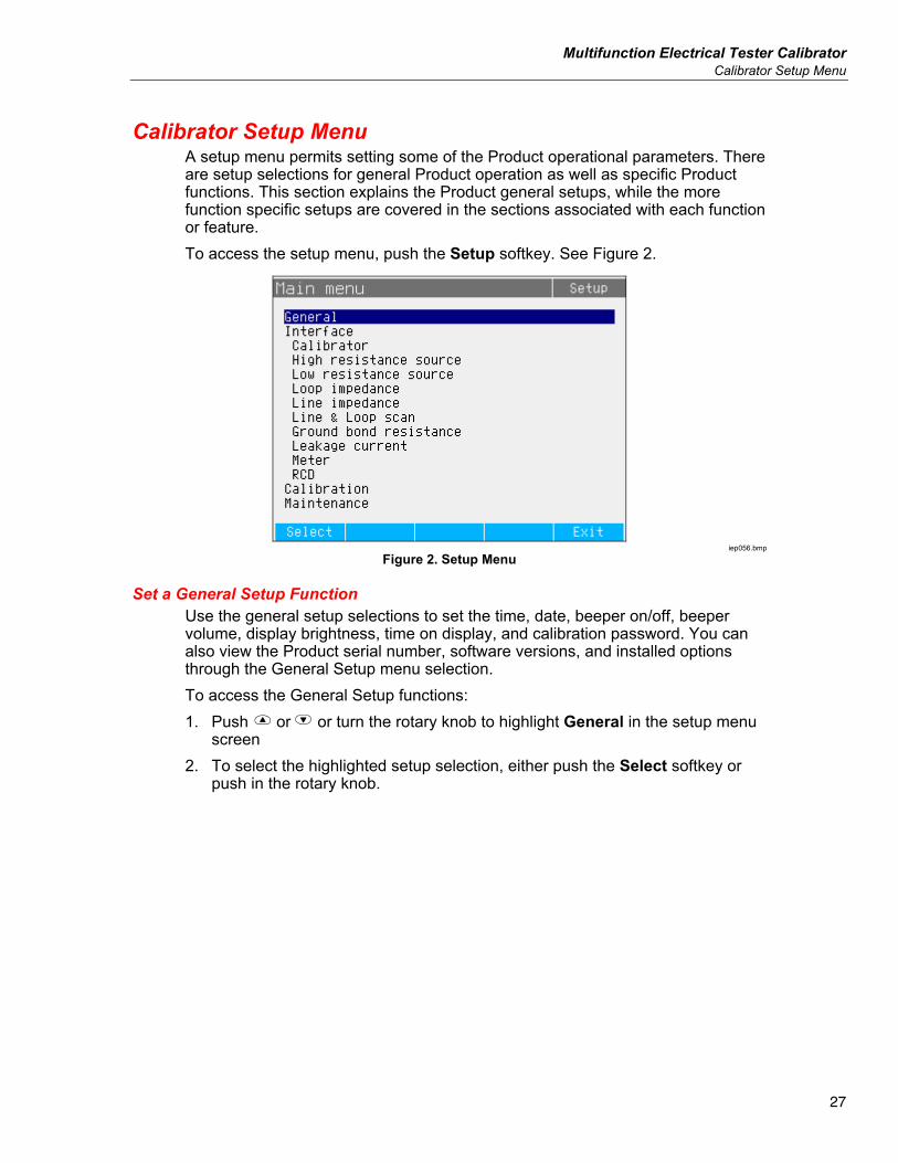
Calibrator Setup Menu A setup menu permits setting some of the Product operational parameters. There are setup selections for general Product operation as well as specific Product functions. This section explains the Product general setups, while the more function specific setups are covered in the sections associated with each function or feature. To access the setup menu, push the Setup softkey. See Figure 2.
iep056.bmp
Figure 2. Setup Menu
Set a General Setup Function Use the general setup selections to set the time, date, beeper on/off, beeper volume, display brightness, time on display, and calibration password. You can also view the Product serial number, software versions, and installed options through the General Setup menu selection. To access the General Setup functions: 1. Push or or turn the rotary knob to highlight General in the setup menu
screen 2. To select the highlighted setup selection, either push the Select softkey or
push in the rotary knob.
5322A Operators Manual
28
Set the Beeper Volume To set the beeper volume: 1. After you enter the setup menu, push or or turn the rotary knob to
highlight Beeper Volume in the list of setup selections. 2. Push the Select softkey or push in the rotary knob. 3. Set the beeper volume between 0 and 15 with the rotary knob, the cursor
keys, or enter the value directly with the keypad. Note
For safety warnings and messages, the beeper will still sound even when the beeper volume is set to zero.
4. Push the WRITE softkey to set the beeper volume and return to the setup menu.
Set the Display Brightness To set the brightness of the display: 1. After entering the setup menu, push or or turn the rotary knob to
highlight Display Brightness in the list of setup selections. 2. Push the Select softkey or push in the rotary knob. 3. Set the display brightness between 0 and 7 with the rotary knob, the cursor
keys, or enter the value directly with the keypad. 4. Push the Write softkey to set the display brightness and return to the setup
menu. Enable/Disable the Beeper
To enable or disable the Product beeper: 1. After you enter the setup menu, push or or turn the rotary knob to
highlight Beeper in the list of setup selections. 2. Push the Select softkey or push in the rotary knob. 3. Move the cursor with the rotary knob or cursor keys to highlight either Beeper
On or Beeper Off. 4. Push the Select softkey or push in the rotary knob.
Set Screen Saver To select a time for the screen to turn off after the last user keyboard input: 1. After you enter the setup menu, push P or Q or turn the rotary knob to
highlight SCREEN SAVER in the list of setup selections. 2. Push the Select softkey or push in the rotary knob. 3. Select a desired time to turn the screen off after the last user front-panel input
or remote inactivity. Values range from 5 minutes to 60 minutes as well as an OFF (screen always on) setting.
4. Push the Select softkey or push in the rotary knob. 5. Push the EXIT softkey
Multifunction Electrical Tester Calibrator Calibrator Setup Menu
29
Set the Calibration Password The calibration default password is set to 2235. Only when the password is changed to a non-zero value must a password be entered to access the calibration mode. The purpose of the password is to prevent unauthorized users from changing the calibration settings. To set the calibration code: 1. After you enter the setup menu, push or or turn the rotary knob to
highlight Calibration Password in the list of setup selections. 2. Push the Select softkey or push in the rotary knob. 3. If the calibration password is set to a non-zero value, you will be prompted to
enter the present password. 4. Use the keyboard to enter a new code and push . Make sure what is
shown in the display and what you think you have entered are the same. After completing the next step, you must have the correct password to gain access to the calibration functions.
5. Push the Write softkey to set the calibration password and return to the setup menu. To exit setting the password without changing it, push Exit.
Set the Time To set the time: 1. After you enter the setup menu, push or or turn the knob to highlight
Time in the list of setup selections. 2. Push the Select softkey or push in the rotary knob. 3. Use or to position the cursor on the least significant digit of the hours,
minutes, or seconds. The cursor only rests on the least significant digit. 4. Use or or turn the rotary knob to change the time element. 5. Push the Exit softkey to accept the date and exit the date setting function.
5322A Operators Manual
30
Set the Date To set the date: 1. After you enter the setup menu, push or or turn the rotary knob to
highlight Date in the list of setup selections. 2. Push the Select softkey or push in the rotary knob. 3. Use or to position the cursor on the least significant digit of the year,
month or day. The cursor only rests on the least significant digit. The format of the date is dd/mm/yyyy.
4. Use the or or rotate the rotary knob to change the date element. 5. Push the Exit softkey to accept the date and exit the date setting function.
Set the User Interface Language To set the language: 1. After entering the setup menu, push or or turn the rotary knob to
highlight Language in the list of setup selections. 2. Push the Select softkey or push in the rotary knob. 3. Select the preferred language from the list. 4. Push the Select softkey or push in the rotary knob. 5. Push the Exit softkey.
View the Device Information To view Product information (serial number, software versions, and installed options): 1. After entering the setup menu, push or or turn the rotary knob to
highlight Device Information in the list of setup selections. 2. Push the Select softkey or push in the rotary knob. 3. After viewing the information, push the Exit softkey.
Multifunction Electrical Tester Calibrator Factory Settings
31
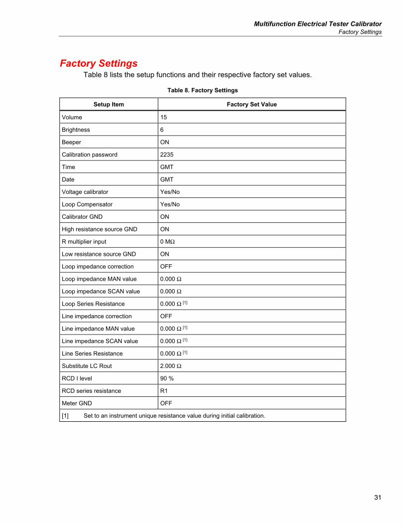
Factory Settings Table 8 lists the setup functions and their respective factory set values.
Table 8. Factory Settings
Setup Item Factory Set Value
Volume 15
Brightness 6
Beeper ON
Calibration password 2235
Time GMT
Date GMT
Voltage calibrator Yes/No
Loop Compensator Yes/No
Calibrator GND ON
High resistance source GND ON
R multiplier input 0 MΩ
Low resistance source GND ON
Loop impedance correction OFF
Loop impedance MAN value 0.000 Ω
Loop impedance SCAN value 0.000 Ω
Loop Series Resistance 0.000 Ω [1]
Line impedance correction OFF
Line impedance MAN value 0.000 Ω [1]
Line impedance SCAN value 0.000 Ω [1]
Line Series Resistance 0.000 Ω [1]
Substitute LC Rout 2.000 Ω
RCD I level 90 %
RCD series resistance R1
Meter GND OFF
[1] Set to an instrument unique resistance value during initial calibration.
5322A Operators Manual
32
Product Functions This section describes use of the Product functions to calibrate testers and meters. It is assumed the reader is already familiar with the Product controls, connections, and indicators covered in Front-Panel Operation. See Safety Information before doing reading this section.
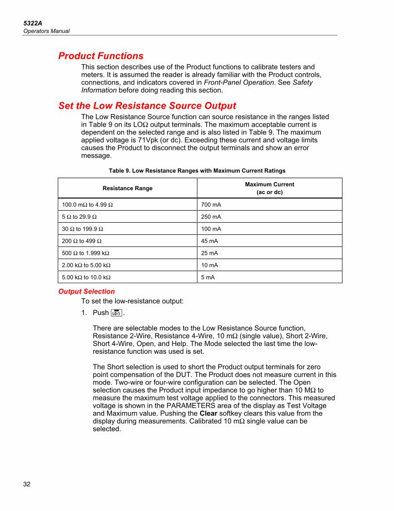
Set the Low Resistance Source Output The Low Resistance Source function can source resistance in the ranges listed in Table 9 on its LOΩ output terminals. The maximum acceptable current is dependent on the selected range and is also listed in Table 9. The maximum applied voltage is 71Vpk (or dc). Exceeding these current and voltage limits causes the Product to disconnect the output terminals and show an error message.
Table 9. Low Resistance Ranges with Maximum Current Ratings
Resistance Range Maximum Current (ac or dc)
100.0 mΩ to 4.99 Ω 700 mA
5 Ω to 29.9 Ω 250 mA
30 Ω to 199.9 Ω 100 mA
200 Ω to 499 Ω 45 mA
500 Ω to 1.999 kΩ 25 mA
2.00 kΩ to 5.00 kΩ 10 mA
5.00 kΩ to 10.0 kΩ 5 mA
Output Selection To set the low-resistance output: 1. Push .
There are selectable modes to the Low Resistance Source function, Resistance 2-Wire, Resistance 4-Wire, 10 mΩ (single value), Short 2-Wire, Short 4-Wire, Open, and Help. The Mode selected the last time the low-resistance function was used is set. The Short selection is used to short the Product output terminals for zero point compensation of the DUT. The Product does not measure current in this mode. Two-wire or four-wire configuration can be selected. The Open selection causes the Product input impedance to go higher than 10 MΩ to measure the maximum test voltage applied to the connectors. This measured voltage is shown in the PARAMETERS area of the display as Test Voltage and Maximum value. Pushing the Clear softkey clears this value from the display during measurements. Calibrated 10 mΩ single value can be selected.
Multifunction Electrical Tester Calibrator Set the Low Resistance Source Output
33
2. If Open or Short or 10 mΩ single value is desired, push the Mode softkey. Then, with the cursor keys or rotary knob, highlight Short 2-Wire, Short 4-Wire, Open, or 10 mΩ push Select or push in the rotary knob to select. 10 mΩ value is available for 4-wire application only.
3. Set the resistance value with the keyboard, cursor keys or rotary knob. The resistance for this function is output through the terminals with either a 2-wire or 4-wire connection. For 2-wire resistance calibration, connections to the DUT are made using the LOΩ HI and LOΩ LO terminals. For 4-wire resistance calibration, additional connections are necessary using the LOΩ-SENSE HI and LOΩ-SENSE LO terminals.
Note 4-wire resistance mode is used for low resistance calibrations of DUTs equipped with the 4-wire measurement capability.
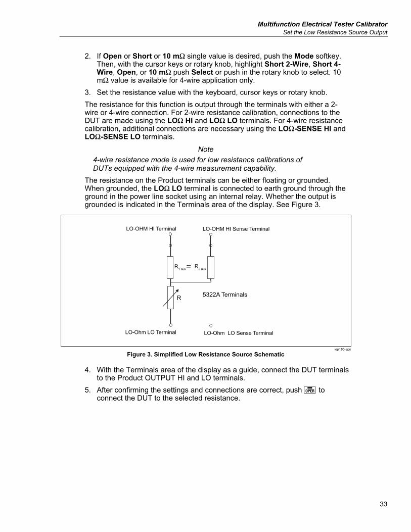
The resistance on the Product terminals can be either floating or grounded. When grounded, the LOΩ LO terminal is connected to earth ground through the ground in the power line socket using an internal relay. Whether the output is grounded is indicated in the Terminals area of the display. See Figure 3.
=
LO-OHM HI Terminal
LO-Ohm LO Terminal LO-Ohm LO Sense Terminal
LO-OHM HI Sense Terminal
R
R1 aux R2 aux
5322A Terminals
iep185.eps
Figure 3. Simplified Low Resistance Source Schematic
4. With the Terminals area of the display as a guide, connect the DUT terminals to the Product OUTPUT HI and LO terminals.
5. After confirming the settings and connections are correct, push to connect the DUT to the selected resistance.
5322A Operators Manual
34
In 4-wire mode, the Product can insert a pair of fixed auxiliary resistors to the LO ohm - and LO-ohm Sense HI terminals as shown in Figure 3. One of a pair of auxiliary resistor values can be chosen: 500 Ω, 1 kΩ, 2 kΩ, 5 kΩ, or SHORT. When SHORT is selected no resistor is inserted. Use this feature to check the effect of actual cable resistance on the performance of earth ground resistance testers.
Note Before you adjust the value, make sure the current generated by the DUT does not exceed the maximum allowed value
With the output connected, you can adjust the resistance value with the keyboard, cursor keys or rotary knob. Any new values set with the front panel take approximately 500 ms to show on the output terminals. Should the set value exceed the upper range limit or lower range limit, the Product shows Value too Large or Value too Small, respectively. To change between 2-wire and 4-wire operation: 1. Push the Mode softkey. 2. With the cursor keys or rotary knob, move the cursor to Resistance 2-Wire
or Resistance 4-Wire and either push the Select softkey or push in the rotary knob. 2-Wire or 4-Wire shows next to the resistance value in the OUTPUT area of the display.
To select the 10 mΩ single value: 1. Push the Mode softkey. 2. Use the cursor keys or rotary knob to move the cursor to 10 mOhm and push
the Select softkey or push in the rotary knob. 4-Wire calibration value of the 10 mOhm segment in main field is displayed. To switch between grounded and ungrounded (floating) output: 1. Push the Setup softkey. 2. With the cursor keys or rotary knob, highlight Low resistance source and
either push the Select softkey or push in the rotary knob. 3. With the cursor keys or rotary knob, highlight Low resistance source GND
and either push the Select softkey or push in the rotary knob. 4. With the cursor keys or rotary knob, highlight either GND On or GND Off and
either push the Select softkey or push in the rotary knob. 5. Push the EXIT softkey repeatedly to return to the main display. In 2-wire mode, low Resistance Source function has a test lead resistance compensation feature. The lead resistance can be saved into 5322A memory. The Product then automatically compensates the resistance by adding the test lead series resistance to the output value that is shown. The lowest-adjustable resistance value of the Low resistance source cannot be lower than the stored lead resistance. The range of lead compensation is from 0 Ω to 2.000 Ω.
Multifunction Electrical Tester Calibrator Set the High Resistance Source Output
35
To change the test lead compensated value: 1. Push the Series R softkey. 2. Use the cursor keys, rotary knob, or numerical keyboard to setup new test
lead resistance and push the Ohm softkey or push ENTER or push in the rotary knob.
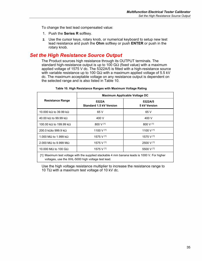
Set the High Resistance Source Output The Product sources high resistance through its OUTPUT terminals. The standard high-resistance output is up to 100 GΩ (fixed value) with a maximum applied voltage of 1575 V dc. The 5322A/5 is fitted with a high-resistance source with variable resistance up to 100 GΩ with a maximum applied voltage of 5.5 kV dc. The maximum acceptable voltage on any resistance output is dependent on the selected range and is also listed in Table 10.
Table 10. High Resistance Ranges with Maximum Voltage Rating
Resistance Range Maximum Applicable Voltage DC
5322A Standard 1.5 kV Version
5322A/5 5 kV Version
10.000 kΩ to 39.99 kΩ 65 V 65 V
40.00 kΩ to 99.99 kΩ 400 V 400 V
100.00 kΩ to 199.99 kΩ 800 V [1] 800 V [1]
200.0 kΩto 999.9 kΩ 1100 V [1] 1100 V [1]
1.000 MΩ to 1.999 kΩ 1575 V [1] 1575 V [1]
2.000 MΩ to 9.999 MΩ 1575 V [1] 2500 V [1]
10.000 MΩ to 100 GΩ 1575 V [1] 5500 V [1]
[1] Maximum test voltage with the supplied stackable 4 mm banana leads is 1000 V. For higher voltages, use the XHL-5000 high voltage test lead.
Use the high voltage resistance multiplier to increase the resistance range to 10 TΩ with a maximum test voltage of 10 kV dc.
5322A Operators Manual
36
Output Selection To set the high resistance output: 1. Push .
The selectable modes to the high-resistance source function are: • 5322A: Resistance, 100 GΩ, Open, Short, Help • 5322A/5: Resistance, 100 GΩ, Open, Short, Help The Short selection is used to short the output terminals to test for the maximum test current up to 10 mA. This measured current is displayed in the PARAMETERS area of the display as Maximum value. The Open selection is used to test the open circuit maximum test voltage. This measured parameter is shown in the PARAMETERS area of the display. The 100 GΩ resistance value is internally connected to the output terminals in this case.
2. If Short or Open is selected, push the Mode softkey. Then, use the cursor keys or rotary knob to highlight Resistance and select it by pushing Select or pushing in the rotary knob.
3. The value established the last time the high resistance function was used is set and displayed in the OUTPUT area of the display.
4. Use the keypad, cursor keys, or rotary knob to set the resistance value. 5. For this function, the resistance is output through the terminals with either a
2-wire or 3-wire connection. For 2-wire resistance calibration, connections to the DUT are made through the HIΩ HI and HIΩ LO terminals.
Note 3-wire resistance mode is sometimes necessary to improve calibration stability. This is especially true for resistances over 100 MΩ. The third terminal is usually connected to the guard or ground terminal on the DUT. If the DUT is equipped with a GND terminal, it should be connected to the PE terminal. See Types of Megohmmeters for more details.
6. The resistance on the Product OUTPUT HI and LO terminals can either be floating or grounded. When grounded, the HIΩ LO terminal is connected to earth ground in the power line socket through an internal relay.
7. Using the Terminals part of the display as a guide, connect the DUT terminals to the Product OUTPUT HI and LO terminals.
8. After confirming all settings and connections are correct, push to connect the DUT to the selected resistance.
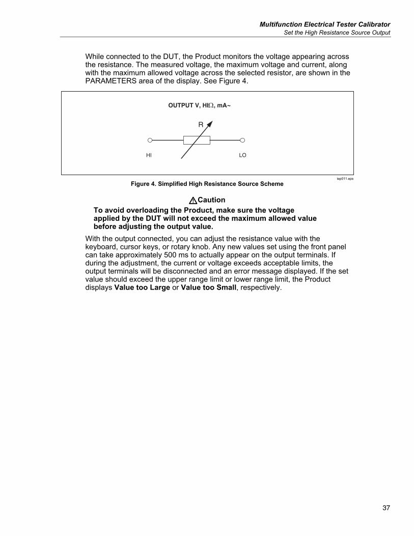
Multifunction Electrical Tester Calibrator Set the High Resistance Source Output
37
While connected to the DUT, the Product monitors the voltage appearing across the resistance. The measured voltage, the maximum voltage and current, along with the maximum allowed voltage across the selected resistor, are shown in the PARAMETERS area of the display. See Figure 4.
R
OUTPUT V, HI, mA~
HI LO
iep011.eps
Figure 4. Simplified High Resistance Source Scheme
WCaution To avoid overloading the Product, make sure the voltage applied by the DUT will not exceed the maximum allowed value before adjusting the output value.
With the output connected, you can adjust the resistance value with the keyboard, cursor keys, or rotary knob. Any new values set using the front panel can take approximately 500 ms to actually appear on the output terminals. If during the adjustment, the current or voltage exceeds acceptable limits, the output terminals will be disconnected and an error message displayed. If the set value should exceed the upper range limit or lower range limit, the Product displays Value too Large or Value too Small, respectively.
5322A Operators Manual
38
To switch between grounded and ungrounded (floating) output: 1. Push the Setup softkey. 2. Using the cursor keys or rotary knob, highlight High resistance source and
either push the Select softkey or push in the rotary knob. 3. Using the cursor keys or rotary knob, highlight High resistance source GND
and either push the Select softkey or push in the rotary knob. 4. Using the cursor keys or rotary knob, move the cursor to GND On or GND
Off and either push the Select softkey or push in the rotary knob. 5. Push the Exit softkey repeatedly to return to the main display. The High-Resistance Multiplier may be used to extend the Product range to 10 TΩ. To activate the High-Resistance Multiplier, push the R Mult softkey. Yes should appear to the right of R multiplier in the PARAMETERS area of the display. Pushing the R Mult softkey again turns off the resistance multiplier. The high-resistance multiplier outputs high resistance from 350 MΩ to 10 TΩ with a maximum applied voltage of 10 kV dc. The multiplier is only used with insulation resistance testers with a third terminal, commonly called the Guard terminal. See Calibrate Insulation Resistance Testers with the Resistance Multiplier. Most testers of this type use a virtual ground-sensing circuit, that effectively has an input resistance of 0 Ω. The resistance multiplier operation is based on a passive T-type resistance network, with a nominal multiplication value of 1000. The exact multiplication value depends on the resistance multiplier calibration, so refer to the multiplier's calibration data to determine actual output. The input resistance of the multiplier is approximately 300 MΩ. As mentioned, the multiplier can be used for checking Device Under Test (DUTs) that use a virtual ground (current to voltage converter) input as the current sense terminal and an effective input resistance of 0 Ω. For DUTs with a finite input resistance and a non-virtual ground on the sense terminal, the input resistance must be taken into consideration. The Product has a parameter R multiplier input in the Setup menu for this purpose. The default value is 0.00 MΩ, with a maximum setting value of 100 MΩ. The input resistance of the DUT’s sense terminal should be entered into the R multiplier input for the multiplier to work properly.
Note The input resistance of the DUT’s sense terminal is different for various models of megohmmeters. For megohmmeters with a virtual ground, 0 Ω should be written into the R multiplier input parameter.
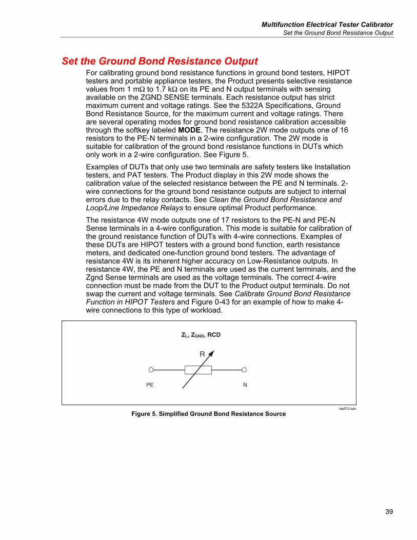
Multifunction Electrical Tester Calibrator Set the Ground Bond Resistance Output
39
Set the Ground Bond Resistance Output For calibrating ground bond resistance functions in ground bond testers, HIPOT testers and portable appliance testers, the Product presents selective resistance values from 1 mΩ to 1.7 kΩ on its PE and N output terminals with sensing available on the ZGND SENSE terminals. Each resistance output has strict maximum current and voltage ratings. See the 5322A Specifications, Ground Bond Resistance Source, for the maximum current and voltage ratings. There are several operating modes for ground bond resistance calibration accessible through the softkey labeled MODE. The resistance 2W mode outputs one of 16 resistors to the PE-N terminals in a 2-wire configuration. The 2W mode is suitable for calibration of the ground bond resistance functions in DUTs which only work in a 2-wire configuration. See Figure 5. Examples of DUTs that only use two terminals are safety testers like Installation testers, and PAT testers. The Product display in this 2W mode shows the calibration value of the selected resistance between the PE and N terminals. 2-wire connections for the ground bond resistance outputs are subject to internal errors due to the relay contacts. See Clean the Ground Bond Resistance and Loop/Line Impedance Relays to ensure optimal Product performance. The resistance 4W mode outputs one of 17 resistors to the PE-N and PE-N Sense terminals in a 4-wire configuration. This mode is suitable for calibration of the ground resistance function of DUTs with 4-wire connections. Examples of these DUTs are HIPOT testers with a ground bond function, earth resistance meters, and dedicated one-function ground bond testers. The advantage of resistance 4W is its inherent higher accuracy on Low-Resistance outputs. In resistance 4W, the PE and N terminals are used as the current terminals, and the Zgnd Sense terminals are used as the voltage terminals. The correct 4-wire connection must be made from the DUT to the Product output terminals. Do not swap the current and voltage terminals. See Calibrate Ground Bond Resistance Function in HIPOT Testers and Figure 0-43 for an example of how to make 4-wire connections to this type of workload.
R
ZL, ZGND, RCD
PE N
iep012.eps
Figure 5. Simplified Ground Bond Resistance Source
5322A Operators Manual
40
Use the Ground Bond Resistance Mode To set the Ground Bond resistance output: 1. Push .
The default mode is the resistance mode. The value used the last time the ground bond resistance function was used is set and displayed in the OUTPUT area of the display. If already in the Ground Bond Function, push the softkey labeled MODE.
2. Using the cursor keys or rotary knob, highlight either Resistance 2W or Resistance 4W and either push the Select softkey or push in the rotary knob.
Note When you use the 2W configuration, the Product relay-cleaning procedure must be performed at periodic intervals. See Clean the Ground Bond Resistance and Loop/Line Impedance Relays and the 5322A Specifications.
3. Set the resistance value using the rotary knob or keypad. If the entered value is not exactly one of the 17 possible selections, the resistance closest to the value entered will be selected.
4. Using the Terminals area of the display as a guide, connect the DUT’s terminals to the Product PE and N terminals of the ZL, ZGND and RCD terminals. These terminals are always floating from ground.
5. After confirming all settings and connections are correct, push to connect the DUT to the selected resistance.
While connected to the DUT, the Product monitors the voltage and current appearing across the resistance. The actual current flowing through the resistance, the maximum value, along with the maximum allowed current, is shown in the PARAMETERS area of the display. All individual resistance outputs have two test current measurement ranges, high and low. The ratio between them is 10:1 (see the 5322A Specifications at the Fluke Calibration website). To switch from the high-current range (default) to the low-current push the Lo curr softkey. The active selected current range is shown on the display by the low current indication On and Off, with the line below showing maximum applicable test current. Ground bond resistor outputs are equipped with test lead resistance compensation. When the test lead resistance is known it can be stored in Calibrator memory. The display then shows calibration value of the selected resistor plus the test lead resistance (Series resistance). To enter test lead resistance push the Setup softkey, select Ground bond resistance and Series resistance. Enter the resistance value using numerical keyboard, rotary buttons or cursor keys. Currently stored test lead resistance is shown in the line Series resistance. Test lead compensation is available in 2W mode only.
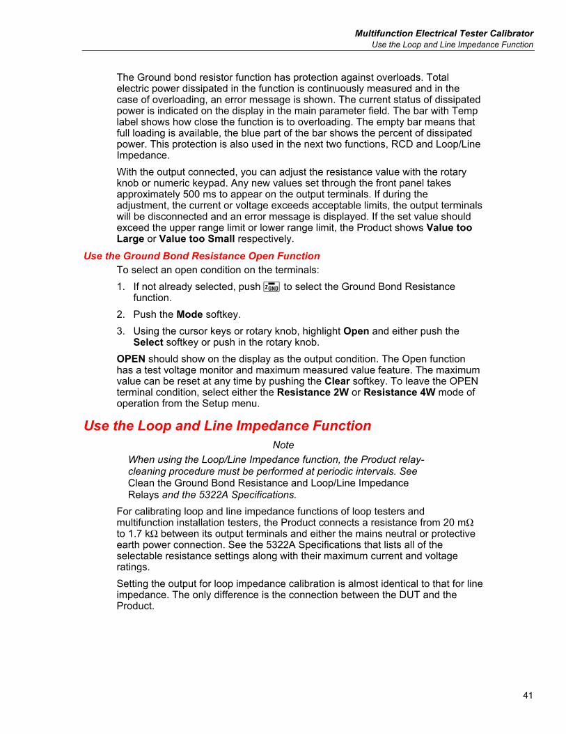
Multifunction Electrical Tester Calibrator Use the Loop and Line Impedance Function
41
The Ground bond resistor function has protection against overloads. Total electric power dissipated in the function is continuously measured and in the case of overloading, an error message is shown. The current status of dissipated power is indicated on the display in the main parameter field. The bar with Temp label shows how close the function is to overloading. The empty bar means that full loading is available, the blue part of the bar shows the percent of dissipated power. This protection is also used in the next two functions, RCD and Loop/Line Impedance. With the output connected, you can adjust the resistance value with the rotary knob or numeric keypad. Any new values set through the front panel takes approximately 500 ms to appear on the output terminals. If during the adjustment, the current or voltage exceeds acceptable limits, the output terminals will be disconnected and an error message is displayed. If the set value should exceed the upper range limit or lower range limit, the Product shows Value too Large or Value too Small respectively.
Use the Ground Bond Resistance Open Function To select an open condition on the terminals: 1. If not already selected, push to select the Ground Bond Resistance
function. 2. Push the Mode softkey. 3. Using the cursor keys or rotary knob, highlight Open and either push the
Select softkey or push in the rotary knob. OPEN should show on the display as the output condition. The Open function has a test voltage monitor and maximum measured value feature. The maximum value can be reset at any time by pushing the Clear softkey. To leave the OPEN terminal condition, select either the Resistance 2W or Resistance 4W mode of operation from the Setup menu.
Use the Loop and Line Impedance Function Note
When using the Loop/Line Impedance function, the Product relay-cleaning procedure must be performed at periodic intervals. See Clean the Ground Bond Resistance and Loop/Line Impedance Relays and the 5322A Specifications.
For calibrating loop and line impedance functions of loop testers and multifunction installation testers, the Product connects a resistance from 20 mΩ to 1.7 kΩ between its output terminals and either the mains neutral or protective earth power connection. See the 5322A Specifications that lists all of the selectable resistance settings along with their maximum current and voltage ratings. Setting the output for loop impedance calibration is almost identical to that for line impedance. The only difference is the connection between the DUT and the Product.
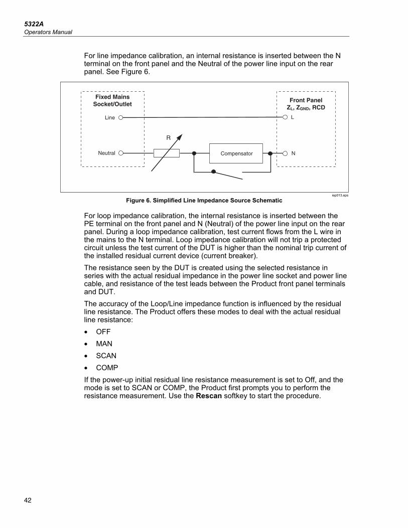
5322A Operators Manual
42
For line impedance calibration, an internal resistance is inserted between the N terminal on the front panel and the Neutral of the power line input on the rear panel. See Figure 6.
Neutral
Line
R
Front PanelZL, ZGND, RCD
NCompensator
L
Fixed MainsSocket/Outlet
iep013.eps
Figure 6. Simplified Line Impedance Source Schematic
For loop impedance calibration, the internal resistance is inserted between the PE terminal on the front panel and N (Neutral) of the power line input on the rear panel. During a loop impedance calibration, test current flows from the L wire in the mains to the N terminal. Loop impedance calibration will not trip a protected circuit unless the test current of the DUT is higher than the nominal trip current of the installed residual current device (current breaker). The resistance seen by the DUT is created using the selected resistance in series with the actual residual impedance in the power line socket and power line cable, and resistance of the test leads between the Product front panel terminals and DUT. The accuracy of the Loop/Line impedance function is influenced by the residual line resistance. The Product offers these modes to deal with the actual residual line resistance: • OFF • MAN • SCAN • COMP If the power-up initial residual line resistance measurement is set to Off, and the mode is set to SCAN or COMP, the Product first prompts you to perform the resistance measurement. Use the Rescan softkey to start the procedure.
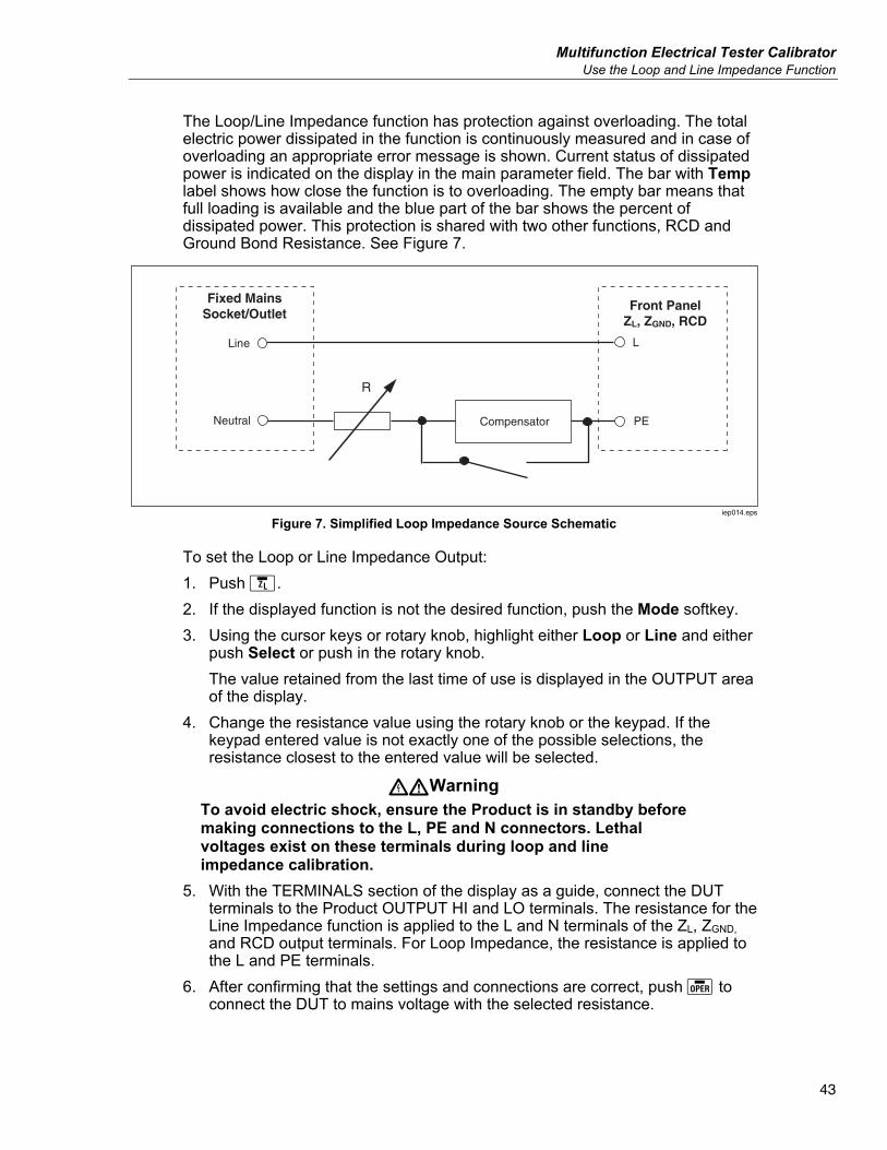
Multifunction Electrical Tester Calibrator Use the Loop and Line Impedance Function
43
The Loop/Line Impedance function has protection against overloading. The total electric power dissipated in the function is continuously measured and in case of overloading an appropriate error message is shown. Current status of dissipated power is indicated on the display in the main parameter field. The bar with Temp label shows how close the function is to overloading. The empty bar means that full loading is available and the blue part of the bar shows the percent of dissipated power. This protection is shared with two other functions, RCD and Ground Bond Resistance. See Figure 7.
Neutral
Line
R
Front PanelZL, ZGND, RCD
PECompensator
L
Fixed MainsSocket/Outlet
iep014.eps
Figure 7. Simplified Loop Impedance Source Schematic
To set the Loop or Line Impedance Output: 1. Push . 2. If the displayed function is not the desired function, push the Mode softkey. 3. Using the cursor keys or rotary knob, highlight either Loop or Line and either
push Select or push in the rotary knob. The value retained from the last time of use is displayed in the OUTPUT area of the display.
4. Change the resistance value using the rotary knob or the keypad. If the keypad entered value is not exactly one of the possible selections, the resistance closest to the entered value will be selected.
XWWarning To avoid electric shock, ensure the Product is in standby before making connections to the L, PE and N connectors. Lethal voltages exist on these terminals during loop and line impedance calibration.
5. With the TERMINALS section of the display as a guide, connect the DUT terminals to the Product OUTPUT HI and LO terminals. The resistance for the Line Impedance function is applied to the L and N terminals of the ZL, ZGND, and RCD output terminals. For Loop Impedance, the resistance is applied to the L and PE terminals.
6. After confirming that the settings and connections are correct, push to connect the DUT to mains voltage with the selected resistance.
5322A Operators Manual
44
While connected to the DUT, the Product monitors the voltage and current appearing across the resistance. The actual current flowing in the resistance is displayed in the PARAMETERS area of the display with the hold feature. The measured current value can be reset with the Clear softkey. In addition to actual current, the polarity of the test signal generated by the DUT, the Prospective Fault Current (PFC), and the mode of residual impedance correction are shown in the PARAMETERS area of the display. The type and polarity of the DUT signal is identified as fullwave ( or ), positive pulse () or negative pulse (). The prospective fault current is computed by measuring the actual ac voltage on the output terminals, and then multiplying it by the residual resistance calibration value.
Note The displayed resistance value appears at the Product OUTPUT HI and LO terminals. The calibration value includes resistance of test leads specified in the parameter Series resistance.
With the output connected, adjust the resistance value using the rotary knob or numeric keypad. Any new values set through the front panel take approximately 500 ms to appear on the output terminals. If the set value should exceed the upper range limit or lower range limit, the Product displays Value too Large or Value too Small, respectively.
Line and Loop Residual Impedance While calibrating loop and line impedance functions, the Product uses its ac line power circuit as part of the measurement. The impedance of this branch circuit can cause a significant amount of undetermined impedance in calibration. Therefore, it is important to ensure the mains circuit of the Product has the lowest possible impedance. Residual impedance is that impedance sensed at the power input socket of the Product. Residual line impedance is the impedance found between the line (L) and neutral (N) wires.
Note The actual residual impedance of the Product and the power circuit to which it is connected is used in the calibration process for the loop and line impedance calibration. Therefore, this impedance sets the lowest impedance value and becomes the calibration zero point for DUTs.
To ensure the best quality and stability of calibration: • Use only the power cord supplied with the Product. • Ensure the power outlet makes good contact with the Product power cord. • Have qualified service personnel ensure the branch circuit wire connections
to the power outlet are tight and the lowest contact resistance possible. • Never use extension cords or power strips to power the Product. • Because residual impedance can be affected by other electrical devices
attached to the same branch circuit as the Product, move these devices to other circuits.
Multifunction Electrical Tester Calibrator Use the Loop and Line Impedance Function
45
Note During a loop residual impedance test, internal test current flowing between the L and N mains wires is approximately 4 A. Both line and loop residual impedance tests can be performed on a protected network.
Select the Residual Impedance Correction Mode To make accurate line and loop impedance calibrations, the actual line and loop impedance of the power mains connection of the Calibration must be taken into consideration. To do this, the Product uses one of three methods to compensate for the residual impedance present at the power inlet. Two methods are available with the standard instrument, and a third method is available with the optional 5322A/VLC configuration. When doing these tests, the displayed resistance value is the sum of the selected resistance plus any line or loop compensation. Without compensation, only the selected resistance is displayed. The first method (MAN) is a manual correction of the residual impedance. The residual impedance can be added to the calibration value manually. The displayed value is the sum of the selected resistance and the manually entered value. The second method (SCAN) uses an internal circuit that scans the residual impedance, saves the value, and then adds it to the selected resistance value. The displayed value is the sum of the selected resistance and the value determined by the scanning process. A third method, COMP (5322A/VLC only) uses an internal electronic compensation circuit to effectively eliminate the actual residual impedance in the power mains circuits of the Product from the impedance measured by the DUT. In this way the DUT measures just the selected Calibrator resistance value. This compensation circuit is limited to 25 A peak of DUT current. If these values are exceeded, the compensation block is disconnected and the compensation mode set to OFF. The maximum impedance compensation depends on the load current, typically 2 Ω at low-level testing.
5322A Operators Manual
46
W Caution • With the DUT, check an actual mains circuit first before
connecting the DUT to the Product to ensure that the DUT is working properly.
• Do not exceed the maximum levels of test current, including spikes and time period when using the compensator. The limits are defined in the Specifications found at www.Flukecal.com.
• Though the compensator has hardware and firmware protection, it is not fully protected against fast, high-level current spikes. The spikes can arise especially when a DUT is damaged, for example, if the DUT’s input terminals are internally shorted.
• For DUTs in an unknown condition and with a risk of having failed, for example, with internally shorted terminals, do not use the COMP mode. Damage to the Product may result. The SCAN mode can be used to see that the DUT readings give the expected results.
Separate loop and line residual impedance correction values are stored in the Product using the methods in this section. To select the residual impedance correction mode: 1. Push the Setup softkey. 2. Select either Loop Impedance or Line Impedance. 3. Using the cursor keys or rotary knob, highlight Line imp. compensation (or
Loop imp. compensation for Loop impedance function) and either push the Select softkey or push in the rotary knob.
4. Using the cursor keys or rotary knob, highlight OFF, MAN, SCAN or COMP, and then push the Select softkey or push in the rotary knob. OFF – No compensation is used. MAN – Adds the user defined residual impedance to the selected resistor. SCAN – Measures the residual impedance and adds it to the selected resistor value. COMP – Measures the value and electronically subtracts out this residual impedance by inserting a negative resistance at the input.
5. Push the Exit softkey repeatedly to return to the main screen.
Multifunction Electrical Tester Calibrator Use the Loop and Line Impedance Function
47
Set the Manual Residual Impedance Correction Value To manually enter the residual impedance correction value: 1. Push the Setup softkey. 2. Select either Loop Impedance or Line Impedance. 3. Using the cursor keys or rotary knob, highlight Line imp. MAN value (or
Loop imp. MAN value for Loop impedance function) and either push the Select softkey or push in the rotary knob.
4. Using the keypad, cursor keys and/or rotary knob, enter the desired residual impedance correction value.
5. After confirming the correct value is in the display, push the Write softkey to enter the correction value into the calibration. To exit without changing the value, push the Exit softkey.
6. Push the Exit softkey repeatedly to return to the main screen. Note
The maximum residual impedance correction value that can be entered manually is between 0 and 10 Ω.
To use this manually entered value, you must select the manual residual impedance compensation mode as described in the Select the Residual Impedance Correction Mode section earlier. When the Residual Impedance Correction mode is set to MANUAL, the stored manual value entered in this section is added to the selected loop or line impedance value and their sum displayed as the calibration value.
Set the Scanned Residual Impedance Correction Value The Product has a built-in circuit for measuring the actual residual impedance. The SCAN function provides a residual impedance value that not only includes the power line socket, but the power line cord impedance, the contact resistance, and some of the interconnection inside the Product. The lowest residual line or loop impedance is limited by the Product measured residual line or loop impedance. The measured residual impedance is added to the selected resistor value.
Note The Residual Line or Loop impedance value can be refreshed at any time with the RESCAN softkey. The next Rescan operation is blocked for 60 seconds after the last launch. The Label of the RESCAN softkey changes color from white to gray and the time remaining to the next available application is shown above the label.
If the loop or line residual impedance exceeds 10 Ω, an error message is displayed and the scan mode is turned off.
To SCAN for a residual impedance correction value, push the RESCAN softkey, available in both the Loop and Line Impedance modes. The Product measures the residual impedance of the mains circuitry to perform the SCAN. Since a SCAN heats up internal circuitry, the RESCAN function is disabled with a countdown timer for 60 s after a SCAN.
5322A Operators Manual
48
To view the SCAN value: 1. push the SETUP softkey. 2. Use the cursor keys or rotary knob to move the cursor to Line & Loop Scan
and either push the Select softkey or push in the rotary knob. 3. This submenu also has the option to conduct a SCAN automatically at
startup. When Start Up Scan is set to On, the Product performs scans whenever it is powered up. RESCAN automatically measures the residual impedance without connecting the front-panel connectors and stores the value. The SCAN impedance value cannot be entered manually.
Note The Product scans residual Line and Loop impedance only as a symmetrical parameter, that is, both positive and negative half-wave configurations are measured and the average value displayed.
Note When the SCAN function is used in the Loop or Line impedance mode, 4 A at 230 V and 2 A at 115 V line voltage amps of current flows between the L and N mains wires. Therefore, this function can be used on mains with residual current circuit breakers.
4. Push the Exit softkey repeatedly to return to the main screen. To use this scanned value, you must select the SCAN or COMP residual impedance compensation mode as described in the Select the Residual Impedance Correction Mode section earlier in this chapter. When the Residual Impedance Correction mode is set to SCAN, the stored scanned value measured in this section is added to the selected loop or line impedance value, and their sum displayed as the calibration value.
Note Line residual impedance and Loop residual impedance corrections are two different and distinct values and are applied based on which correction mode is selected. Loop impedance calibration is performed on the L and PE mains wires from which the Product draws power. Line impedance calibration is performed on the L and N mains wires.
When the residual line or loop impedance compensation is set to SCAN, the Product performs a SCAN measurement of these two impedances during its power up cycle if the Start Up SCAN parameter is set to On.
Multifunction Electrical Tester Calibrator Use the Loop and Line Impedance Function
49
Set the Compensation Residual Impedance Correction Value The Product has a compensation circuit to electrically compensate for residual impedance. The compensation circuit is limited in test current amplitude and length of measurement. The maximum test current generated by the DUT has to be less than 25 A and 1500 ms in duration. See the graph of the compensator working conditions in the 5322A Specifications located at the Fluke Calibration website. The Product will disconnect the compensation mode when overloaded and automatically set the correction mode to OFF. The maximum compensation is 2 Ω.
W Caution • Check an actual mains circuit first before connecting the
DUT to the Product to ensure that the DUT is working properly.
• Do not exceed the maximum levels of test current, including spikes and time period when using the compensator. The limits are defined in the Specifications found at www.Flukecal.com.
• Though the compensator has hardware and firmware protection, it is not fully protected against fast, high-level current spikes. The spikes can arise especially when a DUT is damaged, for example, if the DUT’s input terminals are internally shorted.
• For DUTs in an unknown condition and with a risk of having failed, for example, with internally shorted terminals, do not use the COMP mode. Damage to the Product may result. The SCAN mode can be used to see that the DUT readings give the expected results.
To select the compensation method of residual impedance correction: 1. Push the Setup softkey. 2. Using the cursor keys or rotary knob, move the cursor to Line imp. COMP
value (Loop imp. COMP value for Loop impedance function) and either push the Select softkey or push in the rotary knob. The Product measures the residual impedance and the compensator uses the measured value to set the compensation circuit.
3. Push the Exit softkey repeatedly to return to the main menu. To use this compensation mode, select the COMP residual impedance compensation mode as described in the Select the Residual Impedance Correction Mode section earlier in this section. When the Residual Impedance Correction mode is set to COMP, the stored scanned value is used to set the compensation circuit parameters to electronically zero the actual residual impedance. Only the selected loop or line impedance value is displayed on the screen during a calibration.
5322A Operators Manual
50
Set the Compensation of Test Lead Resistance Value The Product offers compensation for test lead resistance used for Line or Loop impedance calibration. The resistance value of the leads in use or a cable adapter can be entered and saved in the Setup menu independently for Loop and Line mode. To enter the value: 1. Push the Setup softkey. 2. With the cursor keys or rotary knob, move the cursor to Loop impedance or
Line impedance and either push the Select softkey or push in the rotary knob.
3. With the cursor keys or rotary knob, move the cursor to the Series resistance parameter and either push the Select softkey or push in the rotary knob.
4. Enter the actual test lead series resistance and push the WRITE softkey to confirm.
The Loop impedance and Line impedance function do not share the same series resistance parameter. If the same test leads are applied for both functions, the series resistance parameter has to be entered into both functions. The Product cannot measure test lead resistance. The resistance value must be measured with a suitable ohmmeter.
Use the Leakage Current Function The Product employs these leakage current modes: passive leakage current, active leakage current (5322A/VLC and 5322A/5/VLC only), differential leakage current, substitute leakage current and Help. There are two special test modes for substitute leakage: • Substitute Short • Substitute Open To select a leakage current mode: 1. Push . 2. If the leakage current mode that you want is not shown, push the Mode
softkey. 3. Using the cursor keys or rotary knob, highlight a selection (Passive,
Substitute, Differential, or Active) and either push or push in the rotary knob.
The primary difference between passive/differential leakage current and substitute leakage current is the voltage used. Passive/differential leakage uses the line voltage of the DUT. Substitute leakage current uses voltages in the range of 50 V.
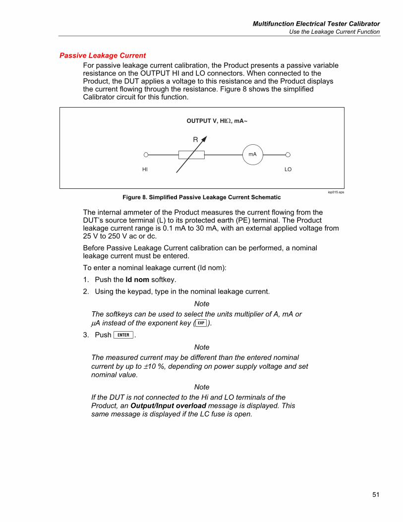
Multifunction Electrical Tester Calibrator Use the Leakage Current Function
51
Passive Leakage Current For passive leakage current calibration, the Product presents a passive variable resistance on the OUTPUT HI and LO connectors. When connected to the Product, the DUT applies a voltage to this resistance and the Product displays the current flowing through the resistance. Figure 8 shows the simplified Calibrator circuit for this function.
R
OUTPUT V, HI, mA~
HI LO
mA
iep015.eps
Figure 8. Simplified Passive Leakage Current Schematic
The internal ammeter of the Product measures the current flowing from the DUT’s source terminal (L) to its protected earth (PE) terminal. The Product leakage current range is 0.1 mA to 30 mA, with an external applied voltage from 25 V to 250 V ac or dc. Before Passive Leakage Current calibration can be performed, a nominal leakage current must be entered. To enter a nominal leakage current (Id nom): 1. Push the Id nom softkey. 2. Using the keypad, type in the nominal leakage current.
Note The softkeys can be used to select the units multiplier of A, mA or μA instead of the exponent key ().
3. Push . Note
The measured current may be different than the entered nominal current by up to ±10 %, depending on power supply voltage and set nominal value.
Note If the DUT is not connected to the Hi and LO terminals of the Product, an Output/Input overload message is displayed. This same message is displayed if the LC fuse is open.
5322A Operators Manual
52
To start a Passive Leakage Current calibration: 1. Push . 2. If Passive Leakage Current is not already displayed, push the Mode
softkey. 3. Using the cursor keys or rotary knob, highlight the Passive selection and
either push the Select softkey or push in the rotary knob. 4. Referring to the terminals part of the display, connect the DUT to the Product. 5. Push the START button on the DUT. 6. Push to start the calibration process.
The Product monitors the input connectors for voltage. When a voltage in the acceptable range is detected, the Product switches in a resistance to start current flow. The Product has a settling time (typically 3 seconds) to adjust the resistance for a current value that matches the nominal current set on the Product. If the voltage is too low or none existent, the Product shows an error message. The Test voltage too low message is also displayed when the LC fuse is open.
Note The captured main leakage current simplifies calibration of testers that measure leakage current for a limited time of just several seconds. Even after the test current is removed from DUT, the main leakage current remains in the display.
During passive leakage current calibration, the display indicates the captured leakage current flowing in the DUT 2 seconds to 3 seconds after the Product senses the correct voltage on the inputs. Until the correct voltage is detected, the display indicates ----. The PARAMETERS area of the display shows nominal current entered through the setup menu, continuous current flowing through the DUT and touch voltage in volts. Both continuous and captured current values are rms (ac+dc) values.
Differential Leakage Current For differential leakage current, the Product sinks a preset leakage current that flows from the DUT to the PE terminal, which results in an unbalance between current flowing from the DUT’s line terminal and the returning current flowing to the DUT’s neutral terminal. The DUT detects this current difference and displays it as differential leakage current. The Product works as a variable resistance load with a milliammeter in series. Test voltage is generated by the DUT. Differential leakage mode differs from the passive leakage current mode in the connection of the DUT to the Product. The simplified schematic for differential leakage current is identical to that for passive leakage current show in Figure 8.
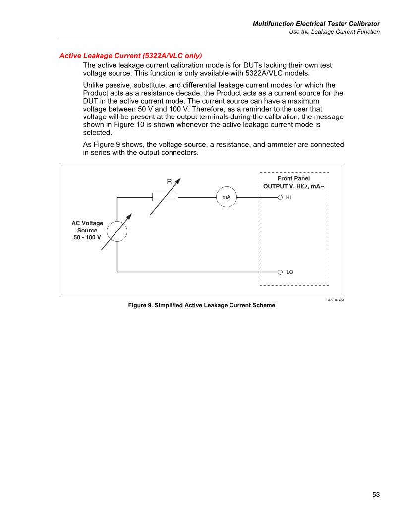
Multifunction Electrical Tester Calibrator Use the Leakage Current Function
53
Active Leakage Current (5322A/VLC only) The active leakage current calibration mode is for DUTs lacking their own test voltage source. This function is only available with 5322A/VLC models. Unlike passive, substitute, and differential leakage current modes for which the Product acts as a resistance decade, the Product acts as a current source for the DUT in the active current mode. The current source can have a maximum voltage between 50 V and 100 V. Therefore, as a reminder to the user that voltage will be present at the output terminals during the calibration, the message shown in Figure 10 is shown whenever the active leakage current mode is selected. As Figure 9 shows, the voltage source, a resistance, and ammeter are connected in series with the output connectors.
Front PanelOUTPUT V, HI, mA~
AC VoltageSource
50 - 100 V
LO
HI
R
mA
iep016.eps
Figure 9. Simplified Active Leakage Current Scheme
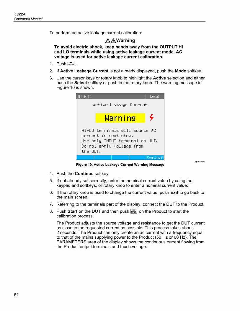
5322A Operators Manual
54
To perform an active leakage current calibration:
XWWarning To avoid electric shock, keep hands away from the OUTPUT HI and LO terminals while using active leakage current mode. AC voltage is used for active leakage current calibration.
1. Push . 2. If Active Leakage Current is not already displayed, push the Mode softkey. 3. Use the cursor keys or rotary knob to highlight the Active selection and either
push the Select softkey or push in the rotary knob. The warning message in Figure 10 is shown.
iep060.bmp
Figure 10. Active Leakage Current Warning Message
4. Push the Continue softkey 5. If not already set correctly, enter the nominal current value by using the
keypad and softkeys, or rotary knob to enter a nominal current value. 6. If the rotary knob is used to change the current value, push Exit to go back to
the main screen. 7. Referring to the terminals part of the display, connect the DUT to the Product. 8. Push Start on the DUT and then push on the Product to start the
calibration process. The Product adjusts the source voltage and resistance to get the DUT current as close to the requested current as possible. This process takes about 2 seconds. The Product can only create an ac current with a frequency equal to that of the mains supplying power to the Product (50 Hz or 60 Hz). The PARAMETERS area of the display shows the continuous current flowing from the Product output terminals and touch voltage.
Multifunction Electrical Tester Calibrator Use the Leakage Current Function
55
Substitute Leakage Current Mode The substitute leakage current mode, often used in Appliance testers, uses a safe low level test voltage instead of power line voltage. The DUT measures the leakage current flowing at its SENSE terminal. This current is used to calculate what the current would be at the nominal power line voltage. This recalculated current is displayed for the leakage current value. The Product works as a simple variable resistance. Using the nominal leakage current and known nominal voltage in the power line, the Product calculates the appropriate resistance using the following formula:
outalnoalno RIVR −= minmin / Inominal is the nominal leakage current set by the user. V nominal is nominal line voltage selectable in the Setup menu from series: 100 V, 110 V, 115 V, 120 V, 127 V, 220 V, 230 V, and 240 V. After calculating the resistance, the Product connects the resistance to the output terminals. To start a substitute leakage current calibration: 1. Push . 2. If Substitute Leakage Current is not already displayed, push the Mode
softkey. 3. Using the cursor keys or rotary knob, highlight the Substitute selection and
either push the Select softkey or push in the rotary knob. 4. If necessary, either use the rotary knob or keypad to change the current
value. 5. Referring to the TERMINALS area of the display, connect the DUT to the
Product. 6. Push the START button on the DUT. 7. Push to start the calibration process.
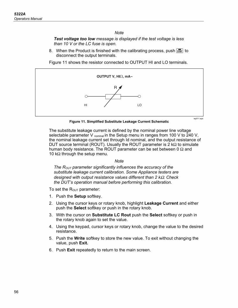
5322A Operators Manual
56
Note Test voltage too low message is displayed if the test voltage is less than 10 V or the LC fuse is open.
8. When the Product is finished with the calibrating process, push to disconnect the output terminals.
Figure 11 shows the resistor connected to OUTPUT HI and LO terminals.
R
OUTPUT V, HI, mA~
HI LO
iep011.eps
Figure 11. Simplified Substitute Leakage Current Schematic
The substitute leakage current is defined by the nominal power line voltage selectable parameter V nominal in the Setup menu in ranges from 100 V to 240 V, the nominal leakage current set through Id nominal, and the output resistance of DUT source terminal (ROUT). Usually the ROUT parameter is 2 kΩ to simulate human body resistance. The ROUT parameter can be set between 0 Ω and 10 kΩ through the setup menu.
Note The ROUT parameter significantly influences the accuracy of the substitute leakage current calibration. Some Appliance testers are designed with output resistance values different than 2 kΩ. Check the DUT’s operation manual before performing this calibration.
To set the ROUT parameter: 1. Push the Setup softkey. 2. Using the cursor keys or rotary knob, highlight Leakage Current and either
push the Select softkey or push in the rotary knob. 3. With the cursor on Substitute LC Rout push the Select softkey or push in
the rotary knob again to set the value. 4. Using the keypad, cursor keys or rotary knob, change the value to the desired
resistance. 5. Push the Write softkey to store the new value. To exit without changing the
value, push Exit. 6. Push Exit repeatedly to return to the main screen.
Multifunction Electrical Tester Calibrator Use the Leakage Current Function
57
To set the V nominal parameter: 1. Push the Setup softkey. 2. Use the cursor keys or rotary knob to highlight Leakage Current and either
push the Select softkey or push in the rotary knob. 3. With the cursor on Substitute nominal voltage push the Select softkey or
push in the rotary knob again to set the value. 4. Use the keypad, cursor keys, or rotary knob to change the value to the
desired voltage. 5. Push the Write softkey to store the new value. To exit without changing the
value, push Exit. 6. Push Exit repeatedly to return to the main screen. In the Substitute leakage current function, the Product measures and shows real (actual) test current sourced by DUT (Id in mA) and Touch voltage which is between the HI and LO terminals. The Substitute leakage current mode has two additional functions: • Substitute Short • Substitute Open These functions enable verification of the DUT's supplied leakage source. Both functions can be activated from the main leakage current menu with the Mode softkey. The Substitute Short function measures the short circuit current of the DUT, loading the DUT by a resistor with a nominal value of approximately 120 Ω. The Substitute Open function measures the touch voltage of the DUT under an open circuit condition. Load resistance is >30 MΩ. The resistance value that the Product connects to the HI and LO output terminals is calculated and shown in the field PARAMETERS.
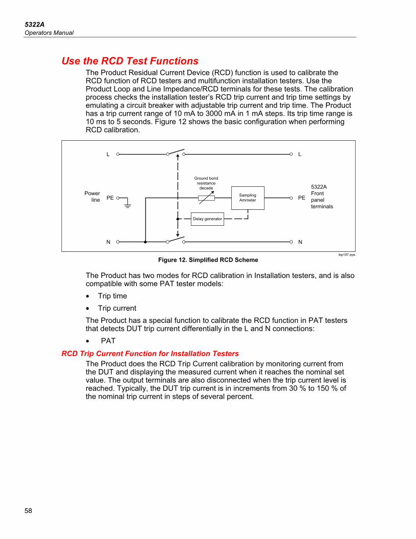
5322A Operators Manual
58
Use the RCD Test Functions The Product Residual Current Device (RCD) function is used to calibrate the RCD function of RCD testers and multifunction installation testers. Use the Product Loop and Line Impedance/RCD terminals for these tests. The calibration process checks the installation tester’s RCD trip current and trip time settings by emulating a circuit breaker with adjustable trip current and trip time. The Product has a trip current range of 10 mA to 3000 mA in 1 mA steps. Its trip time range is 10 ms to 5 seconds. Figure 12 shows the basic configuration when performing RCD calibration.
N N
LL
PE PE
Ground bondresistance
decade
Sampling Ammeter
Delay generator
Power line
5322AFront panel terminals
Iep187.eps
Figure 12. Simplified RCD Scheme
The Product has two modes for RCD calibration in Installation testers, and is also compatible with some PAT tester models: • Trip time • Trip current The Product has a special function to calibrate the RCD function in PAT testers that detects DUT trip current differentially in the L and N connections: • PAT
RCD Trip Current Function for Installation Testers The Product does the RCD Trip Current calibration by monitoring current from the DUT and displaying the measured current when it reaches the nominal set value. The output terminals are also disconnected when the trip current level is reached. Typically, the DUT trip current is in increments from 30 % to 150 % of the nominal trip current in steps of several percent.
Multifunction Electrical Tester Calibrator Use the RCD Test Functions
59
Note The incremental step level for RCD Trip current from a DUT depends on the manufacturer’s design and lies between 2 % and 10 % per step. Full wave or pulse trip current can be used depending on the DUT.
To perform an RCD Calibration: 1. Push . 2. If RCD Trip Current is not already displayed, push the Mode softkey. 3. Using the cursor keys or rotary knob, highlight the Trip Current selection and
either push the Select softkey or push in the rotary knob. The last nominal trip current and the series resistance for touch voltage simulation settings are shown in the PARAMETERS area of the display. If the nominal trip current setting needs to be changed, see To Change the Nominal Trip Current section below. If the resistance setting needs to be changed, see To Change the Touch Voltage section below.
XWWarning To avoid electric shock, ensure the Product is in standby while making connections to the L and N connectors. Lethal voltages are present on the L and N connectors during RCD Trip Current calibration.
4. Referring to the terminals part of the display, connect the DUT to the Product. 5. Push to start the calibration process. 6. Push Start on the DUT. When the level of test current flowing from the DUT reaches the set nominal trip current value, the Product starts to measure current amplitude. The measuring process lasts for several power line cycles. The Product simulates tripping of a breaker by disconnecting the output connectors and displays the measured trip current.
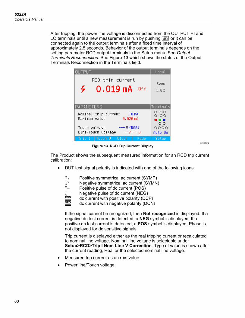
5322A Operators Manual
60
After tripping, the power line voltage is disconnected from the OUTPUT HI and LO terminals until a new measurement is run by pushing or it can be connected again to the output terminals after a fixed time interval of approximately 2.5 seconds. Behavior of the output terminals depends on the setting parameter RCD output terminals in the Setup menu. See Output Terminals Reconnection. See Figure 13 which shows the status of the Output Terminals Reconnection in the Terminals field.
iep65.bmp
Figure 13. RCD Trip Current Display
The Product shows the subsequent measured information for an RCD trip current calibration:
• DUT test signal polarity is indicated with one of the following icons: Positive symmetrical ac current (SYMP) Negative symmetrical ac current (SYMN) Positive pulse of dc current (POS) Negative pulse of dc current (NEG) dc current with positive polarity (DCP) dc current with negative polarity (DCN) If the signal cannot be recognized, then Not recognized is displayed. If a negative dc test current is detected, a NEG symbol is displayed. If a positive dc test current is detected, a POS symbol is displayed. Phase is not displayed for dc sensitive signals. Trip current is displayed either as the real tripping current or recalculated to nominal line voltage. Nominal line voltage is selectable under Setup>RCD>Trip I Nom Line V Correction. Type of value is shown after the current reading, Real or the selected nominal line voltage.
• Measured trip current as an rms value • Power line/Touch voltage
Multifunction Electrical Tester Calibrator Use the RCD Test Functions
61
Power Line Voltage The Product measures the power line voltage as a first step in the tripping procedure. This voltage is measured after the output terminals are switched on.
Touch (contact) Voltage Touch voltage is the voltage difference between N and PE potentials. DUTs can usually measure this voltage and display it as a measured value or detect crossing over the safe voltage level (25 V to 50 V typical) with an indication of this event. Touch voltage generated by the Product depends on the selected series resistance and setup nominal trip current. It is scanned and displayed in this field. See Table 11. To change the nominal trip current: 1. Push the Trip I softkey. 2. Using the keypad, type in the desired nominal trip current value and push .
Note The Product nominal trip current can be set between 3 mA and 3000 mA.
3. Push Exit to return to the RCD calibration main screen. The Product simulates touch voltage using 16 fixed-value resistors from 25 mΩ to 1.7 kΩ. Depending on the set trip current, only a few nominal touch voltage values are available. Push the Touch V softkey to see a list of available values. To change the nominal touch voltage: 1. Push the Touch V softkey. 2. A list of available series resistors for touch voltage simulation is shown as
Rxx. The nominal values of the touch voltage related to the selected trip current are shown with each resistor. Use the rotary button or cursor key to select the nominal touch current. Resistors with a displayed nominal voltage of --- have a touch voltage <1 V and cannot be used for touch voltage verification for the selected trip current setting.
3. Push the Select softkey to confirm and return.
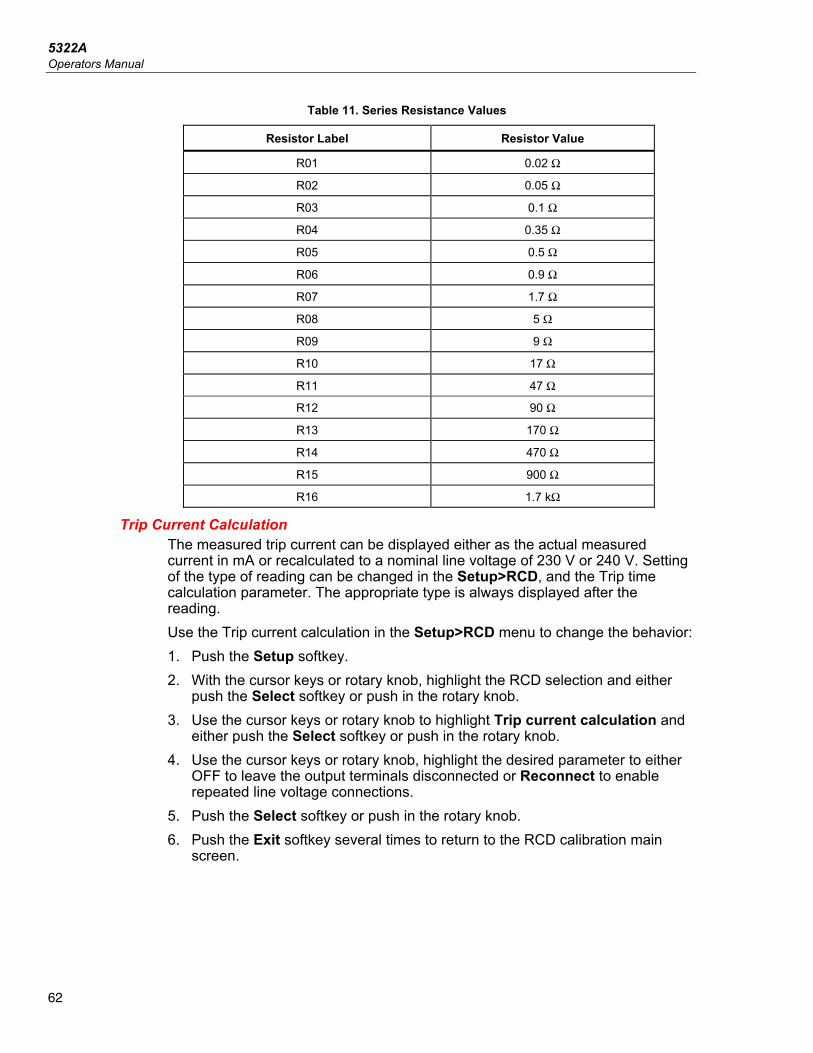
5322A Operators Manual
62
Table 11. Series Resistance Values
Resistor Label Resistor Value
R01 0.02 Ω
R02 0.05 Ω
R03 0.1 Ω
R04 0.35 Ω
R05 0.5 Ω
R06 0.9 Ω
R07 1.7 Ω
R08 5 Ω
R09 9 Ω
R10 17 Ω
R11 47 Ω
R12 90 Ω
R13 170 Ω
R14 470 Ω
R15 900 Ω
R16 1.7 kΩ
Trip Current Calculation The measured trip current can be displayed either as the actual measured current in mA or recalculated to a nominal line voltage of 230 V or 240 V. Setting of the type of reading can be changed in the Setup>RCD, and the Trip time calculation parameter. The appropriate type is always displayed after the reading. Use the Trip current calculation in the Setup>RCD menu to change the behavior: 1. Push the Setup softkey. 2. With the cursor keys or rotary knob, highlight the RCD selection and either
push the Select softkey or push in the rotary knob. 3. Use the cursor keys or rotary knob to highlight Trip current calculation and
either push the Select softkey or push in the rotary knob. 4. Use the cursor keys or rotary knob, highlight the desired parameter to either
OFF to leave the output terminals disconnected or Reconnect to enable repeated line voltage connections.
5. Push the Select softkey or push in the rotary knob. 6. Push the Exit softkey several times to return to the RCD calibration main
screen.
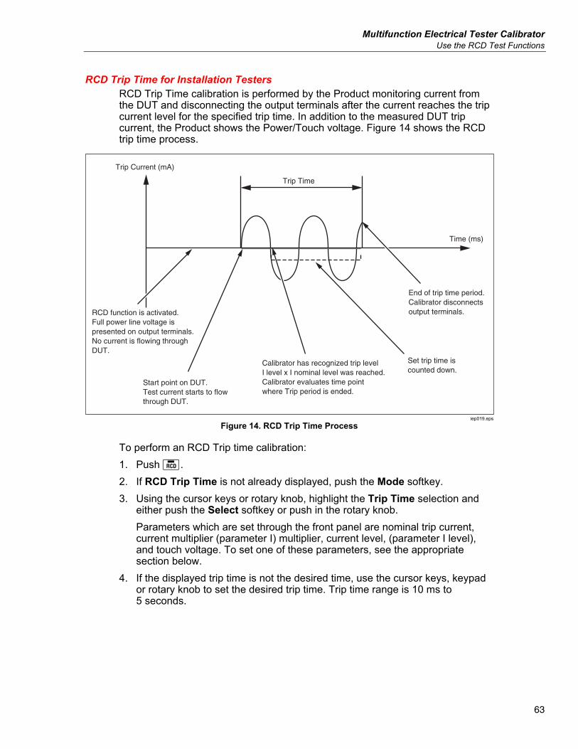
Multifunction Electrical Tester Calibrator Use the RCD Test Functions
63
RCD Trip Time for Installation Testers RCD Trip Time calibration is performed by the Product monitoring current from the DUT and disconnecting the output terminals after the current reaches the trip current level for the specified trip time. In addition to the measured DUT trip current, the Product shows the Power/Touch voltage. Figure 14 shows the RCD trip time process.
RCD function is activated.Full power line voltage is presented on output terminals.No current is flowing throughDUT.
Start point on DUT.Test current starts to flowthrough DUT.
Calibrator has recognized trip levelI level x I nominal level was reached.Calibrator evaluates time pointwhere Trip period is ended.
Set trip time iscounted down.
End of trip time period.Calibrator disconnectsoutput terminals.
Trip Time
Trip Current (mA)
Time (ms)
iep019.eps
Figure 14. RCD Trip Time Process
To perform an RCD Trip time calibration: 1. Push . 2. If RCD Trip Time is not already displayed, push the Mode softkey. 3. Using the cursor keys or rotary knob, highlight the Trip Time selection and
either push the Select softkey or push in the rotary knob. Parameters which are set through the front panel are nominal trip current, current multiplier (parameter I) multiplier, current level, (parameter I level), and touch voltage. To set one of these parameters, see the appropriate section below.
4. If the displayed trip time is not the desired time, use the cursor keys, keypad or rotary knob to set the desired trip time. Trip time range is 10 ms to 5 seconds.
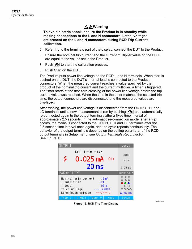
5322A Operators Manual
64
XWWarning To avoid electric shock, ensure the Product is in standby while making connections to the L and N connectors. Lethal voltages are present on the L and N connectors during RCD Trip Current calibration.
5. Referring to the terminals part of the display, connect the DUT to the Product. 6. Ensure the nominal trip current and the current multiplier value on the DUT,
are equal to the values set in the Product. 7. Push to start the calibration process. 8. Push Start on the DUT. The Product puts power line voltage on the RCD L and N terminals. When start is pushed on the DUT, the DUT’s internal load is connected to the Product connectors. When the measured current reaches a value specified by the product of the nominal trip current and the current multiplier, a timer is triggered. The timer starts at the first zero crossing of the power line voltage before the trip current value was reached. When the time in the timer matches the selected trip time, the output connectors are disconnected and the measured values are displayed. After tripping, the power line voltage is disconnected from the OUTPUT HI and LO terminals until a new measurement is run by pushing or is automatically re-connected again to the output terminals after a fixed time interval of approximately 2.5 seconds. In the automatic re-connection mode, after a trip occurs, the mains is connected to the OUTPUT HI and LO terminals after the 2.5 second time interval once again, and the cycle repeats continuously. The behavior of the output terminals depends on the setting parameter of the RCD output terminals in Setup menu, see Output Terminals Reconnection. See Figure 15.
iep027.bmp
Figure 15. RCD Trip Time Display

Multifunction Electrical Tester Calibrator Use the RCD Test Functions
65
The Product shows the following for an RCD trip time calibration:
• DUT test signal polarity is indicated with one of the following icons: Positive symmetrical ac current (SYMP) Negative symmetrical ac current (SYMN) Positive pulse of dc current (POS) Negative pulse of dc current (NEG) dc current with positive polarity (DCP) dc current with negative polarity (DCN)
Similar to the Trip current function, the current reading is displayed in red, and noted as a real (actual) tripping current or recalculated to a nominal line voltage. Nominal line voltage is selectable under Setup>RCD>Trip I Nom Line V Correction. The nature of the tripping current is shown after the current reading, either Real or the selected nominal line voltage. If the signal cannot be recognized, then Not recognized is displayed. When the trip time is set to <20 ms, only positive and negative polarity are detected. If a negative dc test current is detected, a NEG symbol is displayed. If a positive dc test current is detected, a POS symbol is displayed. Phase is not displayed for dc sensitive signals. • Measured trip current as an rms value. • Power line/Touch voltage
Power Line Voltage The Product measures the power line voltage as a first step in the tripping procedure. This voltage is measured after the output terminals are switched on.
Touch (contact) Voltage Touch voltage is the voltage difference between N and PE potentials. DUTs can usually measure this voltage and display it as a measured value or detect crossing over the safe voltage level (25 V to 50 V typical) with an indication of this event. Touch voltage generated by the Product depends on selected series resistance and setup nominal trip current. It is scanned and displayed in this field. See Figure 16.
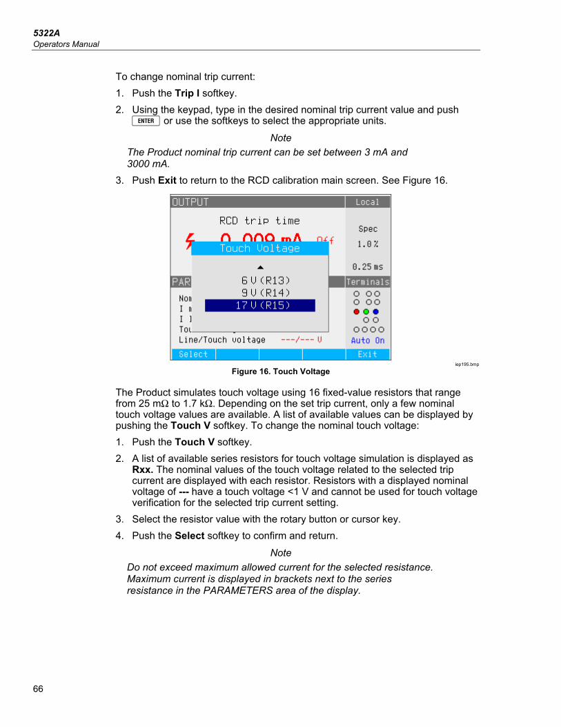
5322A Operators Manual
66
To change nominal trip current: 1. Push the Trip I softkey. 2. Using the keypad, type in the desired nominal trip current value and push or use the softkeys to select the appropriate units.
Note The Product nominal trip current can be set between 3 mA and 3000 mA.
3. Push Exit to return to the RCD calibration main screen. See Figure 16.
iep195.bmp
Figure 16. Touch Voltage
The Product simulates touch voltage using 16 fixed-value resistors that range from 25 mΩ to 1.7 kΩ. Depending on the set trip current, only a few nominal touch voltage values are available. A list of available values can be displayed by pushing the Touch V softkey. To change the nominal touch voltage: 1. Push the Touch V softkey. 2. A list of available series resistors for touch voltage simulation is displayed as
Rxx. The nominal values of the touch voltage related to the selected trip current are displayed with each resistor. Resistors with a displayed nominal voltage of --- have a touch voltage <1 V and cannot be used for touch voltage verification for the selected trip current setting.
3. Select the resistor value with the rotary button or cursor key. 4. Push the Select softkey to confirm and return.
Note Do not exceed maximum allowed current for the selected resistance. Maximum current is displayed in brackets next to the series resistance in the PARAMETERS area of the display.
Multifunction Electrical Tester Calibrator Use the RCD Test Functions
67
To change the current multiplier: 1. Push the I Mult softkey. 2. Push the I Mult softkey for the desired current multiplier value and either
push the Select softkey or push in the rotary knob. Available multipliers are 0.5, 1, 1.4, 2, and 5. 0.5 – This setting is used for Installation testers that test non-tripping RCDs. When this value is set, the Product measures DUT trip current for 5 seconds and then disconnects the output terminals. If the DUT current exceeds the set nominal trip current or is greater than 4000 mA, the Product disconnects the output connectors and displays a Trip current too high error message. Some DUTs generate prepulses before tripping pulses. When the 0.5 I Multiplier constant is setup in the DUT, the amplitude of the prepulse is approximately the same level as the tripping pulse. The Product can recognize and ignore the prepulse when the setup trip time is higher than two periods of the line frequency wave. Practically, when supplied from 50 Hz mains, the prepulse is ignored when trip time is set in the Product to 40 ms or higher. If the trip time is <40 ms , the Product cannot recognize the first pulse as a prepulse and trips. 1 – This setting is the most common for Installation testers. Depending on the I level parameter, the Product may or may not ignore any pretest pulses generated by the DUT which are below the value determined by I level and nominal trip current settings. Pretest pulses are ignored if their level is below the pretest I level value. If the pretest pulses are higher than the I level parameter, the Product reads them as real (actual) trip current pulses. 1.4 and 2 – These settings are used for testing DUTs that measure current overload. The Product and DUT current multipliers should be set to the same value when calibrating using this setting. These settings multiply the nominal trip current setting by 1.4 or 2 and uses it as the trip point. If the trip current exceeds 300 % of the nominal current setting or 3000 mA, the output terminals are disconnected and a Trip current too high error message displayed. The maximum nominal trip current that can be used with this setting is 1500 mA. 5 – This setting multiplies the nominal trip current by 5 and uses that value as the trip current value. If the trip current exceeds 750 % of the nominal trip current setting or 3000 mA, the output terminals are disconnected and a Trip current too high error message is displayed. The maximum nominal trip current that can be used with this setting is 600 mA.
Note Multiplier values of 2 and 5 are for testing of fast tripping RCDs.
5322A Operators Manual
68
To change the current level detection setting: 1. Push the Setup softkey. 2. Using the cursor keys or rotary knob, highlight the RCD selection and either
push the Select softkey or push in the rotary knob 3. Using the cursor keys or rotary knob, highlight I level and either push the
Select softkey or push in the rotary knob. 4. Using the cursor keys or rotary knob, highlight the desired current level (5,
30, 60, 75, 90, 100, and 120) and either push the Select softkey or push in the rotary knob.
5. Push the Exit softkey several times to return to the RCD calibration main screen. The I level parameter allows the Product to ignore pretest pulses generated by many DUTs. Pretest pulses can be as high as 50 % of the nominal trip current value. This parameter is also used for testing DUTs that generate trip currents less than the nominal trip current. The recommended setting is 90 % and is set as the default value for the current level.
Output Terminals Reconnection After tripping, the power line voltage is either disconnected until a new measurement is run by pushing or the power line voltage can be automatically connected and re-connected to the output terminals after a fixed time interval of approximately 2.5 seconds. The Automatic reconnection is intended to be used with testers that draw power from the Product's L and N terminals. Use Automatic reconnection in the Setup>RCD menu to control this behavior: 1. Push the Setup softkey. 2. Use the cursor keys or rotary knob to highlight the RCD selection and either
push the Select softkey or push in the rotary knob. 3. Using the cursor keys or rotary knob, highlight Automatic reconnection and
either push the Select softkey or push in the rotary knob. See Figure 17. 4. Use the cursor keys or rotary knob to highlight the desired parameter, either
Off to leave output terminals disconnected or Reconnect to enable repeated line voltage connection.
5. Push the Select softkey or push in the rotary knob. 6. Push the Exit softkey several times to return to the RCD calibration main
screen.
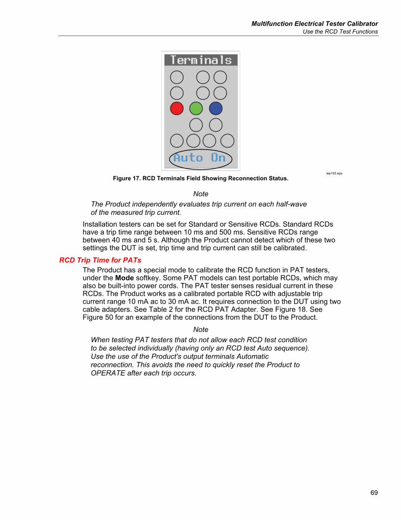
Multifunction Electrical Tester Calibrator Use the RCD Test Functions
69
Auto On
Terminals
iep193.eps
Figure 17. RCD Terminals Field Showing Reconnection Status.
Note The Product independently evaluates trip current on each half-wave of the measured trip current.
Installation testers can be set for Standard or Sensitive RCDs. Standard RCDs have a trip time range between 10 ms and 500 ms. Sensitive RCDs range between 40 ms and 5 s. Although the Product cannot detect which of these two settings the DUT is set, trip time and trip current can still be calibrated.
RCD Trip Time for PATs The Product has a special mode to calibrate the RCD function in PAT testers, under the Mode softkey. Some PAT models can test portable RCDs, which may also be built-into power cords. The PAT tester senses residual current in these RCDs. The Product works as a calibrated portable RCD with adjustable trip current range 10 mA ac to 30 mA ac. It requires connection to the DUT using two cable adapters. See Table 2 for the RCD PAT Adapter. See Figure 18. See Figure 50 for an example of the connections from the DUT to the Product.
Note When testing PAT testers that do not allow each RCD test condition to be selected individually (having only an RCD test Auto sequence). Use the use of the Product's output terminals Automatic reconnection. This avoids the need to quickly reset the Product to OPERATE after each trip occurs.
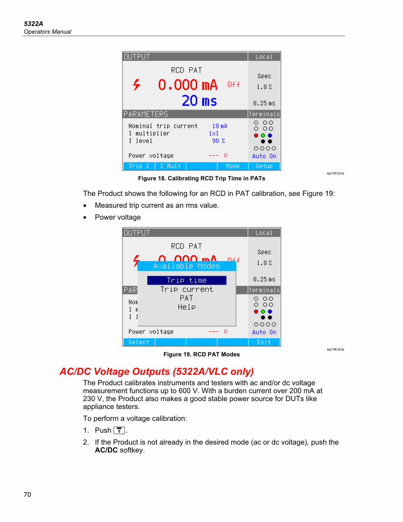
5322A Operators Manual
70
iep180.bmp
Figure 18. Calibrating RCD Trip Time in PATs
The Product shows the following for an RCD in PAT calibration, see Figure 19: • Measured trip current as an rms value. • Power voltage
iep196.bmp
Figure 19. RCD PAT Modes
AC/DC Voltage Outputs (5322A/VLC only) The Product calibrates instruments and testers with ac and/or dc voltage measurement functions up to 600 V. With a burden current over 200 mA at 230 V, the Product also makes a good stable power source for DUTs like appliance testers. To perform a voltage calibration: 1. Push . 2. If the Product is not already in the desired mode (ac or dc voltage), push the
AC/DC softkey.
Multifunction Electrical Tester Calibrator AC/DC Voltage Outputs (5322A/VLC only)
71
Note For ac voltage, the Product only generates a sinusoidal signal.
XWWarning To prevent possible electrical shock, fire, or personal injury, make sure the Product is in Standby while making connections to the OUTPUT HI and LO; or the ZL, ZGND, RCD terminals. Lethal voltages can be present on these connectors during Operate.
3. Referring to the TERMINALS area of the display, connect the DUT to the Product.
4. If necessary, set the output value using the keypad, cursor keys, or rotary knob.
5. After confirming the correct settings and connections, push to connect the DUT to the selected voltage. With the voltage applied to the DUT, the voltage setting can be changed using the cursor keys, rotary knob or keypad.
XWWarning To avoid electric shock, ensure the Product is in standby before touching the OUTPUT HI and LO terminals. Whenever the output voltage is above 30 V ac or dc, the icon appears in the display.
6. When finished, push to remove the voltage from the OUTPUT HI and LO terminals and DUT.
In the Voltage calibration mode, the Product output is either grounded or ungrounded. When the output is grounded, the Product LO terminal is connected internally to PE or the ground connection of the power cable connector and the Product chassis. An ungrounded or floating output opens this connection through an internal relay. See Figure 20. AC voltage can be synchronized to line frequency. Synchronization setup is available using the Sync softkey.
Note The Product has electronic overload protection and disconnects the output terminals when the output current exceeds the maximum allowed current. A current overload message is also displayed when the Product becomes overloaded.
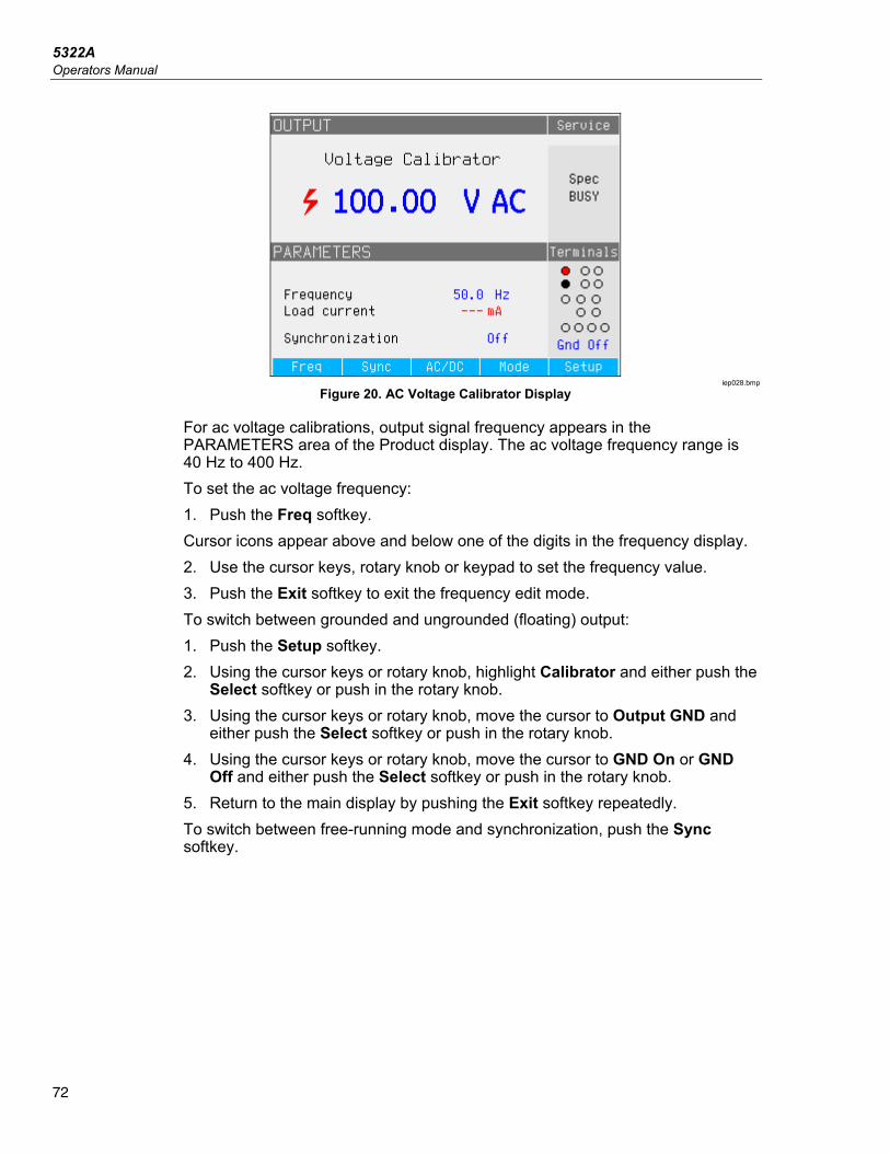
5322A Operators Manual
72
iep028.bmp
Figure 20. AC Voltage Calibrator Display
For ac voltage calibrations, output signal frequency appears in the PARAMETERS area of the Product display. The ac voltage frequency range is 40 Hz to 400 Hz. To set the ac voltage frequency: 1. Push the Freq softkey. Cursor icons appear above and below one of the digits in the frequency display. 2. Use the cursor keys, rotary knob or keypad to set the frequency value. 3. Push the Exit softkey to exit the frequency edit mode. To switch between grounded and ungrounded (floating) output: 1. Push the Setup softkey. 2. Using the cursor keys or rotary knob, highlight Calibrator and either push the
Select softkey or push in the rotary knob. 3. Using the cursor keys or rotary knob, move the cursor to Output GND and
either push the Select softkey or push in the rotary knob. 4. Using the cursor keys or rotary knob, move the cursor to GND On or GND
Off and either push the Select softkey or push in the rotary knob. 5. Return to the main display by pushing the Exit softkey repeatedly. To switch between free-running mode and synchronization, push the Sync softkey.
Multifunction Electrical Tester Calibrator Measure with the Built-in Multimeter
73
Measure with the Built-in Multimeter The Product is equipped with an ac/dc voltage, current, current leakage, and time interval meter. The meter has five selectable modes as well as a help guide: • Multimeter: The meter will measure up to 1100 V rms and up to 30 A rms
simultaneously. This makes it possible to measure power consumption and line current simultaneously when calibrating appliance testers.
• HIPOT LC: The meter will simultaneously measure output voltage and leakage current of hipot testers up to 300 mA.
• HIPOT Timer: The meter measures the time interval of hipot testers up to 999 seconds.
• Flash Leakage Current: The meter measures test voltage of a flash tester using the HV 5kV terminal, and the flash testers leakage current using the A terminal. The flash tester can be set to Class I or Class II.
• Flash Voltage: The meter measures test voltage of a flash using the HV 5kV terminal. The flash tester can be set to Class I or Class II.
• Help: The help guide offers basic information about the selected function. The meter input terminals and function selection button are located in the lower left corner of the front panel (See items 4 and 6 in Table 5 of Front-Panel Operation). The V terminal is for ac and dc voltages up to 1100 V dc/ac. The HV terminal, also referred to as the HV 5 kV Probe, measures up to 5000 V ac rms or dc and is used for HIPOT and PAT Flash tests. The A terminal is for ac and dc currents. The COM terminal is the return for all meter measurements.
Note When measuring with the built-in multimeter, the meter terminals are always connected. Measurements are taken whether the Product is in standby or operate mode.
5322A Operators Manual
74
Function Selection To set the meter mode: 1. Push the Mode softkey to display the Available Modes menu. 2. Using the cursor keys or rotary knob, highlight the mode. 3. Push the Select softkey or push in the rotary knob to select the highlighted
mode. The rolling average parameter can be set for Multimeter readings. Available averages are 1, 2, 4, 8, and 16. With any of the rolling average settings, the display is updated every 300 ms, although the x averaged value will not occur until after x readings. For example, with a rolling average set to 8, the first reading will have no averaging, the second reading is the average of readings 1 and 2, the 3rd reading is the average of 1, 2, and 3, and so on. To set the parameter: 1. Push the Setup softkey. 2. Use the cursor keys or rotary knob to highlight Meter and either push the
Select softkey or push in the rotary knob. 3. Use the cursor keys or rotary knob to highlight Meter rolling avg and either
push the Select softkey or push in the rotary knob. 4. Use the cursor keys or rotary knob to highlight one of the values and either
push the Select softkey or push in the rotary knob. 5. Return to the multimeter display by pushing the Exit softkey repeatedly. Multimeter Functions In the Multimeter function, the Product measures ac or dc voltage, current, power, and phase shift between voltage and current when in ac mode. To make a voltage measurement using the built-in multimeter: 1. Push . 2. Push the AC/DC softkey to select between ac or dc mode. 3. Connect the test leads to the V and COM jacks.
Note Whenever a voltage exceeding 30 V is detected, the icon appears in the display.
Multifunction Electrical Tester Calibrator Measure with the Built-in Multimeter
75
To make a current measurement using the built-in multimeter: 1. Push . 2. Push the AC/DC softkey to select between ac or dc mode. 3. Connect the test leads to the A and COM jacks. The COM connector is the low signal connection for both voltage and current input. The maximum voltage between COM and PE is 2200 V. When both voltage and current are supplied to the meter inputs, both readings are displayed in the OUTPUT area of the display. In addition, a Power value is calculated and displayed in the PARAMETERS area of the display. When in ac mode, the power reading can be displayed in W, VA or VAr. The phase between voltage and current is also shown as power factor or degrees. To switch between different expressions of ac power: 1. Push the Setup softkey. 2. Using the cursor keys or rotary knob, highlight Meter and either push the
Select softkey or push in the rotary knob. 3. Using the cursor keys or rotary knob, highlight AC Power Unit and either
push the Select softkey or push in the rotary knob. 4. Using the cursor keys or rotary knob, highlight VA, VAr, or W and either push
the Select softkey or push in the rotary knob. 5. Return to the multimeter display by pushing the Exit softkey repeatedly. To change how Phase is displayed: 1. Push the Setup softkey. 2. Use the cursor keys or rotary knob to highlight Meter and either push the
Select softkey or push in the rotary knob. 3. Use the cursor keys or rotary knob to highlight Phase and either push the
Select softkey or push in the rotary knob. 4. Use the cursor keys or rotary knob to highlight degrees or PF and either
push the Select softkey or push in the rotary knob. 5. Return to the multimeter display by pushing the Exit softkey repeatedly.
5322A Operators Manual
76
Multimeter Input Selection The Input softkey has these selections: No HV probe, 10 kV probe, 40 kV prove, and HV 5 kV. When set to No HV probe, the Meter V terminal is active and measures up to 1100 V rms. When set to 10 kV probe or 40 kV probe, an external high-voltage probe is used along with the Meter V terminal. The Fluke 5322A 10 kV Divider (probe) divides the voltage down so the multimeter can measure dc voltage or ac voltage up to 10 kV with a frequency of 50 Hz or 60 Hz. The Fluke 80k-40 probe will divide down the voltage so the multimeter can measure dc voltage or ac voltage up to 40 kV with a frequency of 50 Hz or 60 Hz. The HV input, selected by setting the Probe parameter to HV 5 kV, offers direct measurement of up to 5000 V ac rms or dc using the separated input terminal on the front panel. See DUT Calibration Examples. Using the Input softkey, you can set one of these positions: • No HV probe, which activates the V-COM meter input terminals. • 10 kV probe, external 5322A 10 kV Divider using the V-COM meter input
terminals. • 40 kV probe, external Fluke Calibration probe using the V-COM meter input
terminals. The 40 kV probe is an accessory that can be ordered from Fluke Calibration.
• HV 5kV using the HV-COM terminals to directly measure 5000 V ac rms or dc.
HIPOT LC Function The HIPOT LC function is for HIPOT tester verification. The Product measures test voltages sourced by a HIPOT tester (DUT) and leakage current using the 5322A LOAD device and the built-in meter. The maximum voltage and current measured are held on the display until the Clear softkey is pushed or the main function is changed. See Figures 21 and 23. The Product also measures distortion and ripple coefficient of the HIPOT test voltage. In ac mode the Product measures total harmonic distortion (THD), in dc mode it measures ripple coefficient. The ripple coefficient is displayed in two formats: • Absolute ripple coefficient, defined as the difference between minimum and
maximum measured dc level. It is expressed in volts. • Relative ripple coefficient, defined as the ratio between the root mean square
(RMS) of the ac signal to the average dc level of the signal. It is expressed in %.
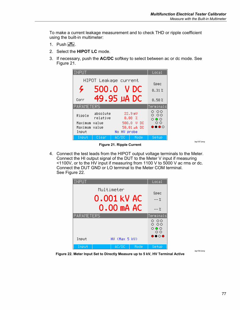
Multifunction Electrical Tester Calibrator Measure with the Built-in Multimeter
77
To make a current leakage measurement and to check THD or ripple coefficient using the built-in multimeter: 1. Push . 2. Select the HIPOT LC mode. 3. If necessary, push the AC/DC softkey to select between ac or dc mode. See
Figure 21.
Iep197.bmp
Figure 21. Ripple Current
4. Connect the test leads from the HIPOT output voltage terminals to the Meter. Connect the HI output signal of the DUT to the Meter V input if measuring <1100V, or to the HV input if measuring from 1100 V to 5000 V ac rms or dc. Connect the DUT GND or LO terminal to the Meter COM terminal. See Figure 22.
iep194.bmp
Figure 22. Meter Input Set to Directly Measure up to 5 kV, HV Terminal Active
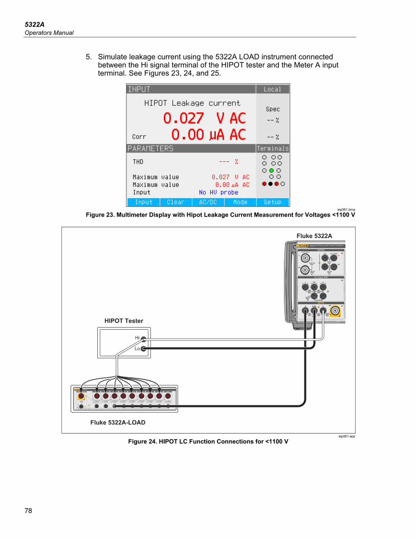
5322A Operators Manual
78
5. Simulate leakage current using the 5322A LOAD instrument connected between the Hi signal terminal of the HIPOT tester and the Meter A input terminal. See Figures 23, 24, and 25.
iep061.bmp
Figure 23. Multimeter Display with Hipot Leakage Current Measurement for Voltages <1100 V
Hi
Lo
HIPOT Tester
Fluke 5322A-LOAD
Fluke 5322AOR
iep061.eps
Figure 24. HIPOT LC Function Connections for <1100 V
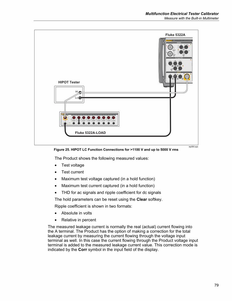
Multifunction Electrical Tester Calibrator Measure with the Built-in Multimeter
79
Hi
Lo
HIPOT Tester
Fluke 5322A
Fluke 5322A-LOAD
OR
iep064.eps
Figure 25. HIPOT LC Function Connections for >1100 V and up to 5000 V rms
The Product shows the following measured values: • Test voltage • Test current • Maximum test voltage captured (in a hold function) • Maximum test current captured (in a hold function) • THD for ac signals and ripple coefficient for dc signals The hold parameters can be reset using the Clear softkey. Ripple coefficient is shown in two formats: • Absolute in volts • Relative in percent
The measured leakage current is normally the real (actual) current flowing into the A terminal. The Product has the option of making a correction for the total leakage current by measuring the current flowing through the voltage input terminal as well. In this case the current flowing through the Product voltage input terminal is added to the measured leakage current value. This correction mode is indicated by the Corr symbol in the input field of the display.
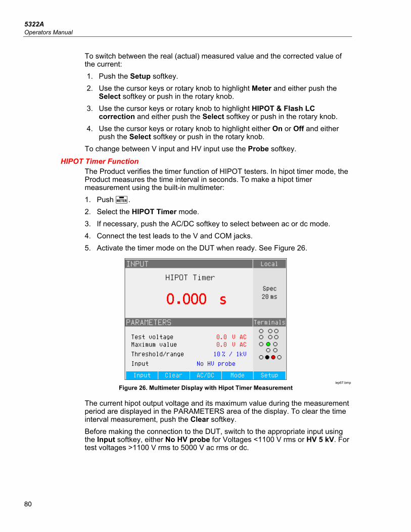
5322A Operators Manual
80
To switch between the real (actual) measured value and the corrected value of the current: 1. Push the Setup softkey. 2. Use the cursor keys or rotary knob to highlight Meter and either push the
Select softkey or push in the rotary knob. 3. Use the cursor keys or rotary knob to highlight HIPOT & Flash LC
correction and either push the Select softkey or push in the rotary knob. 4. Use the cursor keys or rotary knob to highlight either On or Off and either
push the Select softkey or push in the rotary knob. To change between V input and HV input use the Probe softkey.
HIPOT Timer Function The Product verifies the timer function of HIPOT testers. In hipot timer mode, the Product measures the time interval in seconds. To make a hipot timer measurement using the built-in multimeter: 1. Push . 2. Select the HIPOT Timer mode. 3. If necessary, push the AC/DC softkey to select between ac or dc mode. 4. Connect the test leads to the V and COM jacks. 5. Activate the timer mode on the DUT when ready. See Figure 26.
iep67.bmp
Figure 26. Multimeter Display with Hipot Timer Measurement
The current hipot output voltage and its maximum value during the measurement period are displayed in the PARAMETERS area of the display. To clear the time interval measurement, push the Clear softkey. Before making the connection to the DUT, switch to the appropriate input using the Input softkey, either No HV probe for Voltages <1100 V rms or HV 5 kV. For test voltages >1100 V rms to 5000 V ac rms or dc.
Multifunction Electrical Tester Calibrator Measure with the Built-in Multimeter
81
The Product enables setting of the threshold voltage for the Timer function. The parameter is adjustable in the Setup>METER, with the HIPOT Timer threshold parameter. The threshold is expressed as a percent of the applied voltage from 10 % to 99 %.
Note Uncertainty of displayed time depends on selection of ac or dc mode. In ac mode, uncertainty is determined by the length of one period of the hipot output voltage frequency.
WCaution To prevent possible damage to the Product, do not exceed 2200 V pk between COM and PE.
Flash V (Voltage) Function The Product verifies the Class I and Class II Flash test voltage of PAT testers. Nominal PAT tester test voltage output for the Class I flash test is 1500 V ac and 3000 V ac for the Class II. In the Flash Class I test, the DUT internally shorts its L and N output terminals, and applies approximately 1500 V relative to the PE terminal. In the Flash Class II test, the DUT internally shorts its L and N terminals and applies approximately 3000 V ac relative to the PE terminal. The Class II test the voltage applied by the DUT to its PE terminal is at approximately 1500 V relative to ground, in antiphase to the voltage it applies to its L and N terminals. The Meter high voltage input terminal, labelled HV, and the Meter COM terminal, must be used for both Flash Class I and Class II test voltage calibration. The Flash Voltage Mode is intended for DUT Flash test voltage calibration under open circuit conditions, according to DUT specifications. The Product Flash V Mode screen is similar to the Flash LC Mode screen (see Figure 27), except that only voltage is displayed. The Product cannot measure leakage current in the Flash V Mode. Use the Flash LC Mode for PAT tester Flash leakage current calibration. To make DUT Flash voltage measurements: 1. Push . 2. Using the Mode softkey, select the Flash V function.
5322A Operators Manual
82
Flash LC (Leakage Current) Function The Product verifies the Flash test leakage current readout of PAT testers. PAT tester DUTs use the same leakage current detection and measurement circuits for the Class I and Class II Flash tests. Therefore, PAT testers are generally calibrated for Flash leakage current using only their Class I Flash test function. The Meter high voltage input terminal, labelled HV, the Meter COM terminal, and the METER A terminal are used for this calibration. To measure Class I leakage current, use a resistance load. It is connected between HV and A terminal input terminals. The Product shows leakage current as either the current flowing through the Meter HV terminal input, or just the current flowing through the A input terminal. To set what is shown, go to Setup>METER and choose the HIPOT & Flash LC correction parameter. The appropriate indication is shown on the main Flash Leakage Current display. See Figure 27. In the Flash LC Mode, the Product also displays the voltage between the COM and HV terminals, corresponding to the DUT Flash test output voltage under loaded conditions. PAT tester Flash Class I and Class II test voltage outputs have current limiting, typically using resistors in series with the connection to the shorted L and N terminals and the connection to the Flash Probe terminal. Therefore when loaded, the measured output voltage may be significantly lower than the nominal 1500V for Class I or 3000V for Class II. To make DUT Flash leakage current measurements: 1. Push . 2. Use the Mode softkey to select the Flash LC function.
Note Leakage measurements for the DUT Flash Class II function is usually not performed, as the DUT Class I and Class II tests use the same leakage current detection circuits.
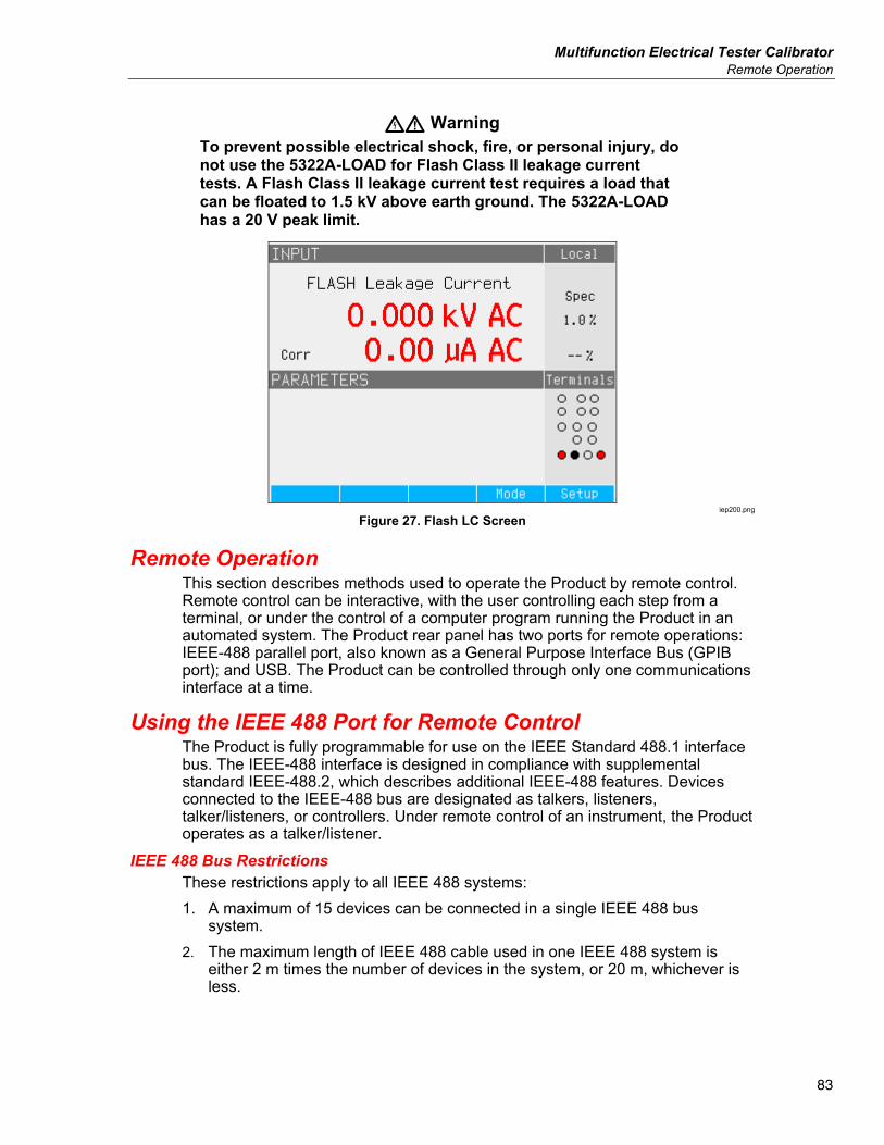
Multifunction Electrical Tester Calibrator Remote Operation
83
XW Warning To prevent possible electrical shock, fire, or personal injury, do not use the 5322A-LOAD for Flash Class II leakage current tests. A Flash Class II leakage current test requires a load that can be floated to 1.5 kV above earth ground. The 5322A-LOAD has a 20 V peak limit.
iep200.png
Figure 27. Flash LC Screen
Remote Operation This section describes methods used to operate the Product by remote control. Remote control can be interactive, with the user controlling each step from a terminal, or under the control of a computer program running the Product in an automated system. The Product rear panel has two ports for remote operations: IEEE-488 parallel port, also known as a General Purpose Interface Bus (GPIB port); and USB. The Product can be controlled through only one communications interface at a time.
Using the IEEE 488 Port for Remote Control The Product is fully programmable for use on the IEEE Standard 488.1 interface bus. The IEEE-488 interface is designed in compliance with supplemental standard IEEE-488.2, which describes additional IEEE-488 features. Devices connected to the IEEE-488 bus are designated as talkers, listeners, talker/listeners, or controllers. Under remote control of an instrument, the Product operates as a talker/listener.
IEEE 488 Bus Restrictions These restrictions apply to all IEEE 488 systems: 1. A maximum of 15 devices can be connected in a single IEEE 488 bus
system. 2. The maximum length of IEEE 488 cable used in one IEEE 488 system is
either 2 m times the number of devices in the system, or 20 m, whichever is less.
5322A Operators Manual
84
Set up the IEEE 488 Port Setting up the Product on the IEEE 488 bus requires setting the bus address and the connection to the controller. To set up for IEEE 488 bus control: 1. Turn off the Product. 2. Connect the Product to the controller using an IEEE 488 cable. Fluke
Calibration recommends shielded cables Y8021 (1 m), Y8022 (2 m), or Y8023 (4 m).
3. Turn the Product power on. 4. Push the Setup softkey. 5. Use the cursor keys or rotary knob to highlight Interface and either push the
Select softkey or push in the rotary knob. 6. If the Active Interface selection does not already read IEEE 488, use the
cursor keys or rotary knob to highlight Active Interface and either push the Select softkey or push in the rotary knob. Otherwise, skip to step 9.
7. Use the cursor keys or rotary knob to highlight IEEE 488 and either push the Select softkey or push in the rotary knob.
8. Push Exit to return to the Interface setup menu. 9. If the IEEE 488 Address selection does not already indicate the desired
address, use the cursor keys or rotary knob to highlight IEEE 488 Address and either push Select or push in the rotary knob. Otherwise, skip to step 11.
Note The IEEE address is set at the factory to 2, and remains at 2 until changed. 10. Push either the UP or DOWN softkey to change the address. The address
can be set between 00 and 30. 11. Push the Exit softkey.
Use the USB Port for Remote Control Use this procedure is to control the Product from a terminal or a computer with the USB interface. The Product can be controlled with a USB (Universal Serial Bus) interface. A Personal Computer (PC) or other controlling device with a USB interface (USB type-A connector), as well as a standard USB A-B cable is necessary. The USB interface must be selected from the Product system menu (Setup>Interface>Active interface). The USB interface is seen as a virtual COM port so the baud rate must be set on the Product and PC. The Product is equipped with a USB type B connector. Make these settings on your PC for proper operation: Baud rate Set to the same as the Product Data bits 8 Stop bits 1 Parity None
Multifunction Electrical Tester Calibrator Use the USB Port for Remote Control
85
The proper COM port must also be selected. After the Product is connected to the PC, a virtual COM port appears in the System Control panel of a Microsoft Windows operating system. This COM port is labeled USB Serial Port (COMxx). When you use the USB port, the command SYST:REM or SYST:RWL must first be sent to the Product to place it into remote operation.
Note If the Product is not placed into the remote mode (by first sending it SYST:REM or SYST:RWL), it only responds to non-executable commands like SYST:ERR?.
Set up the USB Port To set the Product for remote control through the USB interface: 1. Turn the Product off. 2. Connect the Product to a terminal or computer with a USB A/B cable. 3. Turn the Product power on. 4. Push the Setup softkey. 5. Use the cursor keys or rotary knob to highlight Interface and either push the
Select softkey or push in the rotary knob. 6. If the Active Interface selection does not already read USB, use the cursor
keys or rotary knob to highlight Active Interface and either push the Select softkey or push in the rotary knob. Otherwise, skip to step 9.
7. Use the cursor keys or rotary knob to highlight USB and either push the Select softkey or push in the rotary knob.
8. Push EXIT to return to the Interface setup menu. 9. If the baud rate is not already set to the desired speed, use the cursor keys or
rotary knob to highlight Baud Rate and either push the Select softkey or push in the rotary knob. Otherwise, skip to step 11.
10. Push either the UP or DOWN softkey to set the baud rate to the desired speed. The baud rate must match the speed of the terminal or computer to which the Product will be connected. The baud rate can be set to 1200, 2400, 4800, 9600, 19200, 38400, 76800, or 115200.
11. Push the softkey under Exit on the display. 12. Put the Product into the remote mode by sending the command SYST:REM
or SYST:RWL. Data can now be transferred through the USB Port in the format of 8 bits, no parity and one stop bit.
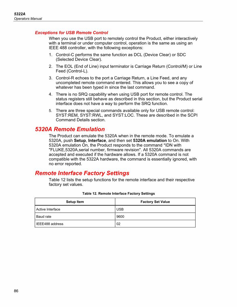
5322A Operators Manual
86
Exceptions for USB Remote Control When you use the USB port to remotely control the Product, either interactively with a terminal or under computer control, operation is the same as using an IEEE 488 controller, with the following exceptions: 1. Control-C performs the same function as DCL (Device Clear) or SDC
(Selected Device Clear). 2. The EOL (End of Line) input terminator is Carriage Return (Control/M) or Line
Feed (Control-L). 3. Control-R echoes to the port a Carriage Return, a Line Feed, and any
uncompleted remote command entered. This allows you to see a copy of whatever has been typed in since the last command.
4. There is no SRQ capability when using USB port for remote control. The status registers still behave as described in this section, but the Product serial interface does not have a way to perform the SRQ function.
5. There are three special commands available only for USB remote control: SYST:REM, SYST:RWL, and SYST:LOC. These are described in the SCPI Command Details section.
5320A Remote Emulation The Product can emulate the 5320A when in the remote mode. To emulate a 5320A, push Setup, Interface, and then set 5320A emulation to On. With 5320A emulation On, the Product responds to the command *IDN with "FLUKE,5320A,serial number, firmware revision". All 5320A commands are accepted and executed if the hardware allows. If a 5320A command is not compatible with the 5322A hardware, the command is essentially ignored, with no error reported.
Remote Interface Factory Settings Table 12 lists the setup functions for the remote interface and their respective factory set values.
Table 12. Remote Interface Factory Settings
Setup Item Factory Set Value
Active Interface USB
Baud rate 9600
IEEE488 address 02
Multifunction Electrical Tester Calibrator Command Syntax Information
87
Command Syntax Information All the commands described in this section can be issued through either of the two communication connections. However, to be properly processed by the Product, each command must have the proper syntax. The following syntax rules apply to all the remote commands. A command consists of a word by itself or a word followed by one or more parameters. A description of how the Product processes incoming characters provides the basis for answering other possible questions about syntax. Information about syntax of response messages is also given.
Parameter Syntax Rules All commands listed in this section are explained in two columns: KEYWORD and PARAMETERS. The KEYWORD column includes the name of the command. Each command includes one or more keywords. If a keyword is in brackets ( [ ] ), it is not mandatory. Non-mandatory commands are used only to achieve compatibility with language standard SCPI. Capital letters designate the abbreviated form of the commands; extended form is written in lowercase. Command parameters are in brackets (<>); each parameter is separated using a comma. Parameters in brackets ( [ ] ) are not mandatory. Line ( | ) means or and is used to separate several alternative parameters. A semicolon (;) is used to separate more commands written on one line. For example: SAF:LR 100.5;:OUTP ON Many of the remote commands require parameters, which must be used properly to avoid command errors. When a command error (CME) error occurs, bit 5 in the Event Status Enable (ESR) goes to 1. General rules for parameter use are: 1. When a command has more than one parameter, the parameters must be
separated by commas. 2. When more than one command is contained in one line to the Product, each
command must be separated by a semicolon. For example: SAF:LR 100.5;:OUTP ON.
3. Numeric parameters may have up to 255 significant figures and their exponents may range from -32000 to +32000. The useful range for Calibrator programming is ±2.2 E-308 to ±1.8 E308.
4. Including too many parameters causes a command error. 5. Null parameters cause a command error. For example, the adjacent commas
in CLOCK 133700, , 071787. 6. Do not use expressions, for example (4+2*13), as parameters.
5322A Operators Manual
88
Terminators To signify the end of a response sent to the controller, the Product sends a terminator. For response message terminators, the Product sends the ASCII character Line Feed with the EOI control line held high. The subsequent characters are recognized by the Product as terminators when encountered in incoming data: • ASCII LF and CR characters • Any ASCII character sent with the EOI control line true
Note (only for USB) Each command must end in <cr> or <lf>. Both codes <crlf> can be used at the same time. The Product executes all commands written on one line of the program after it receives <cr>, <lf> or <crlf> code. Without this code, the program line is ignored.
Description of Abbreviations <DNPD> Decimal Numeric Program Data - This format expresses decimal
number with or without the exponent. <CPD> Character Program Data - Usually, it represents a group of
alternative character parameters. For example ON | OFF | 0 | 1. <SPD> String Program Data - String value consisting from more parts. It
is used for date/time setting. ? A flag that indicates a request for the value of the parameter
specified by the command. Do not use any other parameter than the question mark.
(?) A flag indicating a request for the parameter specified by the command. This command permits a value to be set as well as requested.
<cr> carriage return - ASCII code 13. This code executes the program line.
<lf> line feed - ASCII code 10. This code executes the program line.
Multifunction Electrical Tester Calibrator Supported SCPI Commands
89
Numeric Output Format When the Product is queried and a value is returned, the Product formats the numerical value in standard exponential format. For example, 40 mA is output as 40e-03.
Supported SCPI Commands This section explains the SCPI (Standard Commands for Programmable Instruments) commands available to program the Product. This section includes: • A list of the supported SCPI commands • A discussion of how to use the command set • A detailed description of each command in the set
Note These conventions are used for SCPI command syntax:
• Square brackets ( [ ] ) indicate optional keywords or parameters.
• Braces ( ) enclose parameters within a command string.
• Triangle brackets ( < > ) indicate that you must substitute a value for the enclosed parameter.
• Capital letters indicate the abbreviated form of a command and are required while lowercase letters are optional.
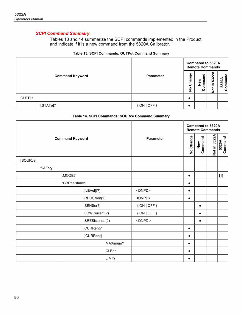
5322A Operators Manual
90
SCPI Command Summary Tables 13 and 14 summarize the SCPI commands implemented in the Product and indicate if it is a new command from the 5320A Calibrator.
Table 13. SCPI Commands: OUTPut Command Summary
Command Keyword Parameter
Compared to 5320A Remote Commands
No
Cha
nge
New
C
omm
and
Not
in 5
322A
5320
A
Com
man
d
OUTPut
[:STATe]? ON | OFF
Table 14. SCPI Commands: SOURce Command Summary
Command Keyword Parameter
Compared to 5320A Remote Commands
No
Cha
nge
New
C
omm
and
Not
in 5
322A
53
20A
C
omm
and
[SOURce]
:SAFety
:MODE? [1]
:GBResistance
[:LEVel](?) <DNPD>
:RPOSition(?) <DNPD>
:SENSe(?) ON | OFF
:LOWCurrent(?) ON | OFF
:SRESistance(?) <DNPD >
:CURRent?
[:CURRent]
:MAXimum?
:CLEar
:LIMit?
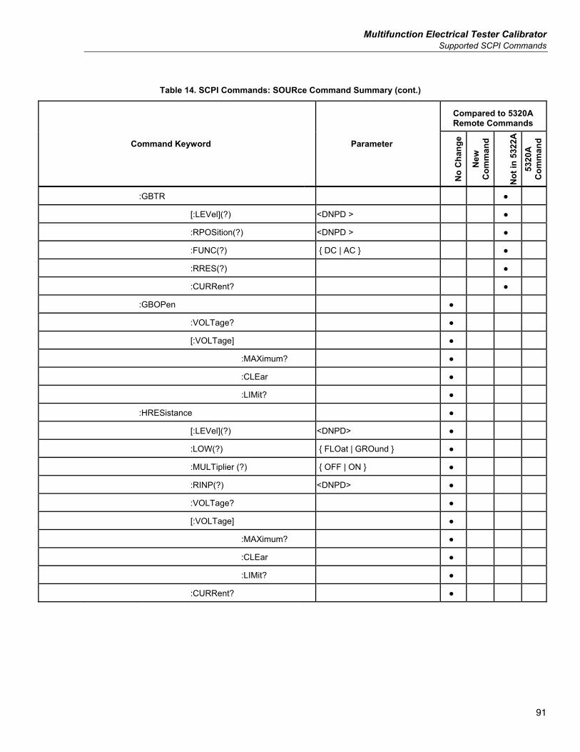
Multifunction Electrical Tester Calibrator Supported SCPI Commands
91
Table 14. SCPI Commands: SOURce Command Summary (cont.)
Command Keyword Parameter
Compared to 5320A Remote Commands
No
Cha
nge
New
C
omm
and
Not
in 5
322A
53
20A
C
omm
and
:GBTR
[:LEVel](?) <DNPD >
:RPOSition(?) <DNPD >
:FUNC(?) DC | AC
:RRES(?)
:CURRent?
:GBOPen
:VOLTage?
[:VOLTage]
:MAXimum?
:CLEar
:LIMit?
:HRESistance
[:LEVel](?) <DNPD>
:LOW(?) FLOat | GROund
:MULTiplier (?) OFF | ON
:RINP(?) <DNPD>
:VOLTage?
[:VOLTage]
:MAXimum?
:CLEar
:LIMit?
:CURRent?
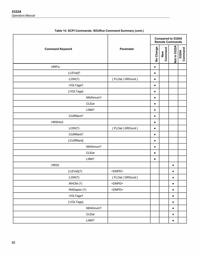
5322A Operators Manual
92
Table 14. SCPI Commands: SOURce Command Summary (cont.)
Command Keyword Parameter
Compared to 5320A Remote Commands
No
Cha
nge
New
C
omm
and
Not
in 5
322A
53
20A
C
omm
and
:HRFix
[:LEVel]?
:LOW(?) FLOat | GROund
:VOLTage?
[:VOLTage]
:MAXimum?
:CLEar
:LIMit?
:CURRent?
:HRSHort
:LOW(?) FLOat | GROund
:CURRent?
[:CURRent]
:MAXimum?
:CLEar
:LIMit?
:HR25
[:LEVel](?) <DNPD>
:LOW(?) FLOat | GROund
:RHCM (?) <DNPD>
:RADaptor (?) <DNPD>
:VOLTage?
[:VOLTage]
:MAXimum?
:CLEar
:LIMit?
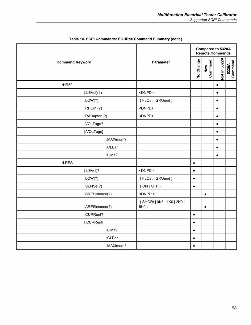
Multifunction Electrical Tester Calibrator Supported SCPI Commands
93
Table 14. SCPI Commands: SOURce Command Summary (cont.)
Command Keyword Parameter
Compared to 5320A Remote Commands
No
Cha
nge
New
C
omm
and
Not
in 5
322A
53
20A
C
omm
and
:HR50
[:LEVel](?) <DNPD>
:LOW(?) FLOat | GROund
:RHCM (?) <DNPD>
:RADaptor (?) <DNPD>
:VOLTage?
[:VOLTage]
:MAXimum?
:CLEar
:LIMit?
:LRES
[:LEVel]? <DNPD>
:LOW(?) FLOat | GROund
:SENSe(?) ON | OFF
:SRESistance(?) <DNPD >
:ARESistance(?) SHORt | 0K5 | 1K0 | 2K0 | 5K0
:CURRent?
[:CURRent]
:LIMit?
:CLEar
:MAXimum?
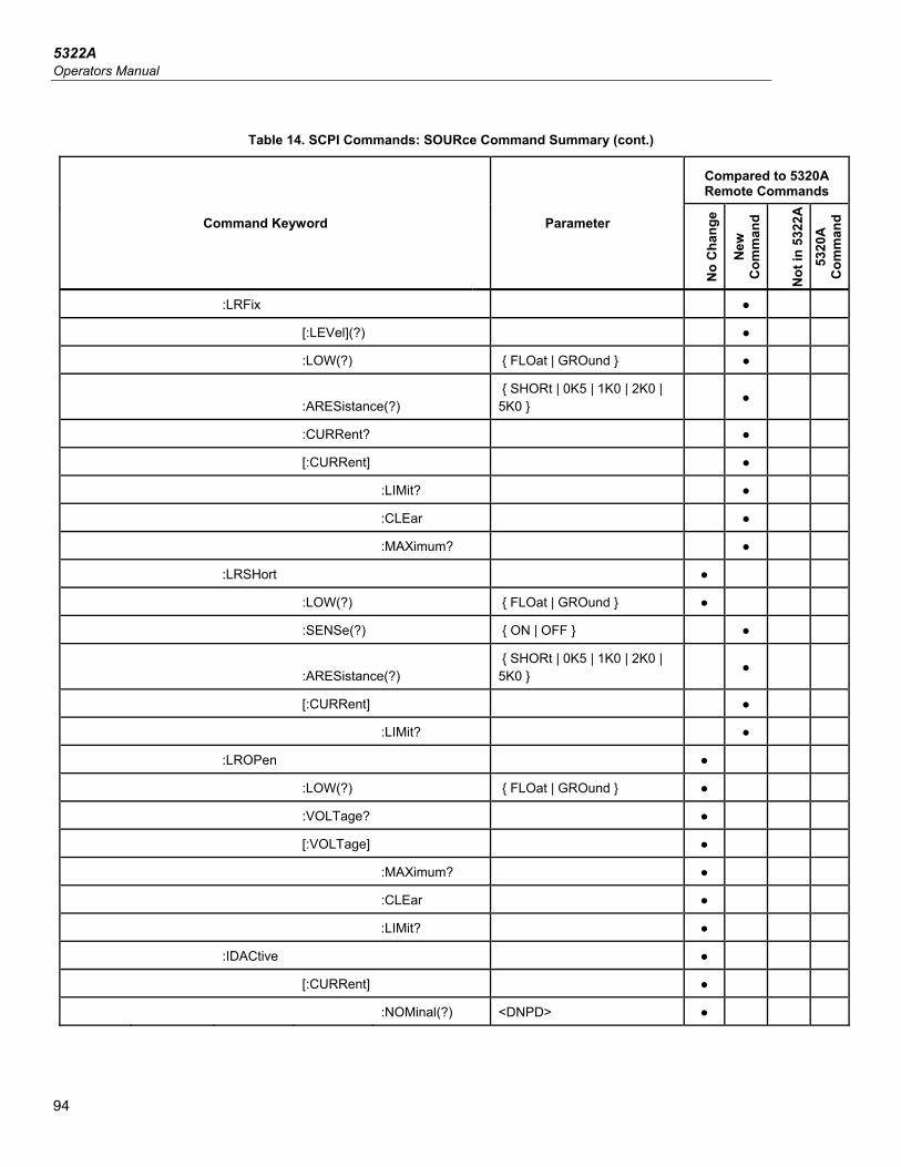
5322A Operators Manual
94
Table 14. SCPI Commands: SOURce Command Summary (cont.)
Command Keyword Parameter
Compared to 5320A Remote Commands
No
Cha
nge
New
C
omm
and
Not
in 5
322A
53
20A
C
omm
and
:LRFix
[:LEVel](?)
:LOW(?) FLOat | GROund
:ARESistance(?) SHORt | 0K5 | 1K0 | 2K0 | 5K0
:CURRent?
[:CURRent]
:LIMit?
:CLEar
:MAXimum?
:LRSHort
:LOW(?) FLOat | GROund
:SENSe(?) ON | OFF
:ARESistance(?) SHORt | 0K5 | 1K0 | 2K0 | 5K0
[:CURRent]
:LIMit?
:LROPen
:LOW(?) FLOat | GROund
:VOLTage?
[:VOLTage]
:MAXimum?
:CLEar
:LIMit?
:IDACtive
[:CURRent]
:NOMinal(?) <DNPD>
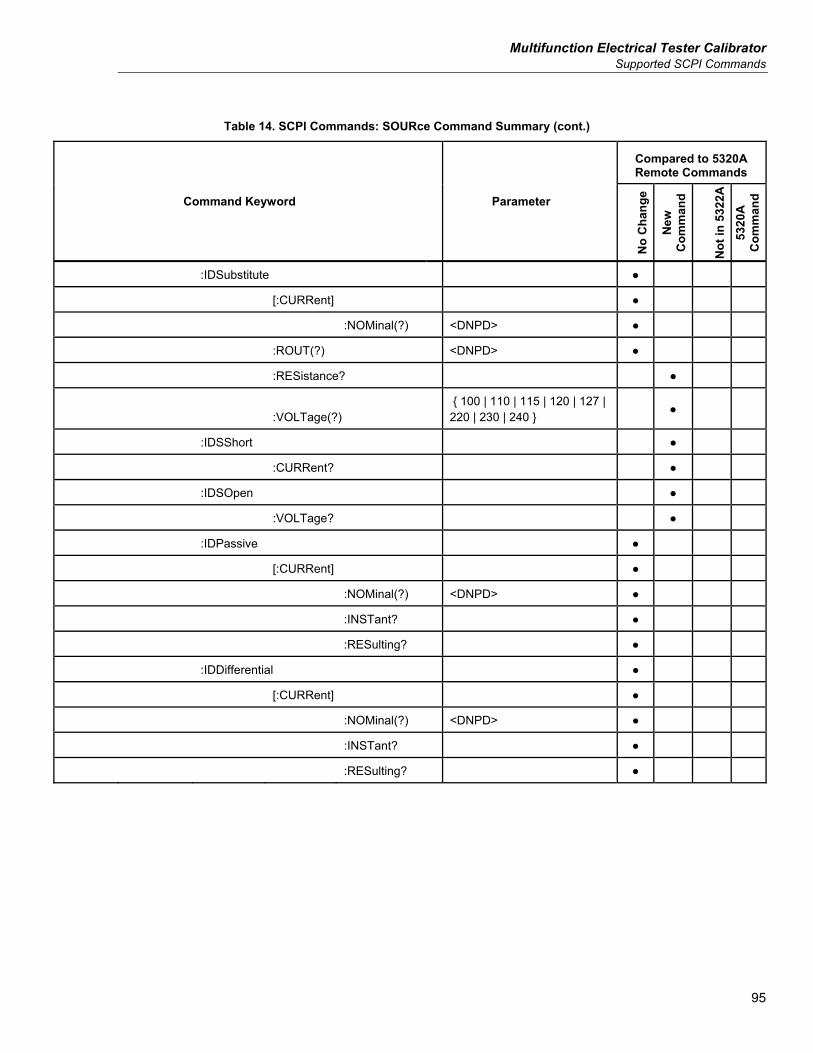
Multifunction Electrical Tester Calibrator Supported SCPI Commands
95
Table 14. SCPI Commands: SOURce Command Summary (cont.)
Command Keyword Parameter
Compared to 5320A Remote Commands
No
Cha
nge
New
C
omm
and
Not
in 5
322A
53
20A
C
omm
and
:IDSubstitute
[:CURRent]
:NOMinal(?) <DNPD>
:ROUT(?) <DNPD>
:RESistance?
:VOLTage(?) 100 | 110 | 115 | 120 | 127 | 220 | 230 | 240
:IDSShort
:CURRent?
:IDSOpen
:VOLTage?
:IDPassive
[:CURRent]
:NOMinal(?) <DNPD>
:INSTant?
:RESulting?
:IDDifferential
[:CURRent]
:NOMinal(?) <DNPD>
:INSTant?
:RESulting?
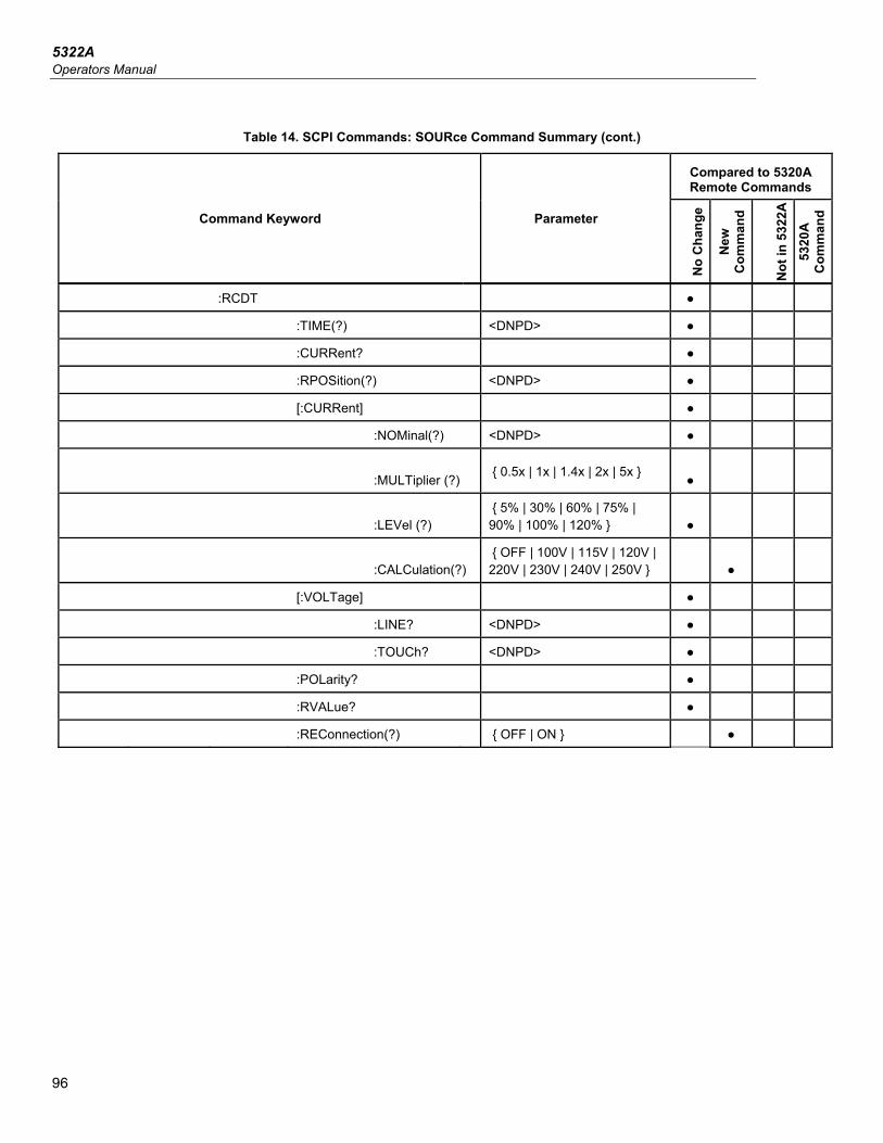
5322A Operators Manual
96
Table 14. SCPI Commands: SOURce Command Summary (cont.)
Command Keyword Parameter
Compared to 5320A Remote Commands
No
Cha
nge
New
C
omm
and
Not
in 5
322A
53
20A
C
omm
and
:RCDT
:TIME(?) <DNPD>
:CURRent?
:RPOSition(?) <DNPD>
[:CURRent]
:NOMinal(?) <DNPD>
:MULTiplier (?) 0.5x | 1x | 1.4x | 2x | 5x
:LEVel (?) 5% | 30% | 60% | 75% | 90% | 100% | 120%
:CALCulation(?) OFF | 100V | 115V | 120V | 220V | 230V | 240V | 250V
[:VOLTage]
:LINE? <DNPD>
:TOUCh? <DNPD>
:POLarity?
:RVALue?
:REConnection(?) OFF | ON
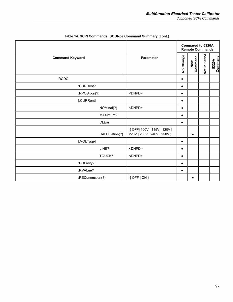
Multifunction Electrical Tester Calibrator Supported SCPI Commands
97
Table 14. SCPI Commands: SOURce Command Summary (cont.)
Command Keyword Parameter
Compared to 5320A Remote Commands
No
Cha
nge
New
C
omm
and
Not
in 5
322A
5320
A
Com
man
d
:RCDC
:CURRent?
:RPOSition(?) <DNPD>
[:CURRent]
:NOMinal(?) <DNPD>
:MAXimum?
:CLEar
:CALCulation(?) OFF| 100V | 115V | 120V | 220V | 230V | 240V | 250V
[:VOLTage]
:LINE? <DNPD>
:TOUCh? <DNPD>
:POLarity?
:RVALue?
:REConnection(?) OFF | ON
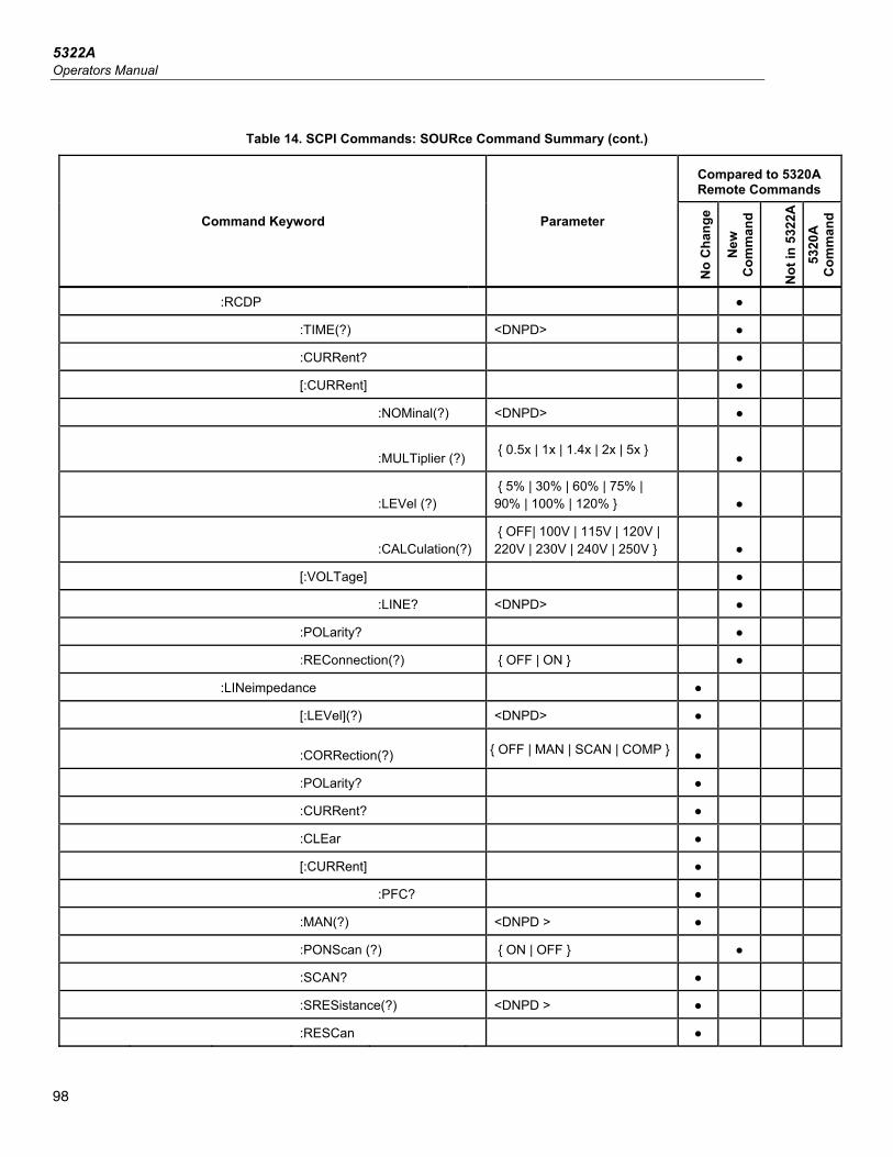
5322A Operators Manual
98
Table 14. SCPI Commands: SOURce Command Summary (cont.)
Command Keyword Parameter
Compared to 5320A Remote Commands
No
Cha
nge
New
C
omm
and
Not
in 5
322A
53
20A
C
omm
and
:RCDP
:TIME(?) <DNPD>
:CURRent?
[:CURRent]
:NOMinal(?) <DNPD>
:MULTiplier (?) 0.5x | 1x | 1.4x | 2x | 5x
:LEVel (?) 5% | 30% | 60% | 75% | 90% | 100% | 120%
:CALCulation(?) OFF| 100V | 115V | 120V | 220V | 230V | 240V | 250V
[:VOLTage]
:LINE? <DNPD>
:POLarity?
:REConnection(?) OFF | ON
:LINeimpedance
[:LEVel](?) <DNPD>
:CORRection(?) OFF | MAN | SCAN | COMP
:POLarity?
:CURRent?
:CLEar
[:CURRent]
:PFC?
:MAN(?) <DNPD >
:PONScan (?) ON | OFF
:SCAN?
:SRESistance(?) <DNPD >
:RESCan
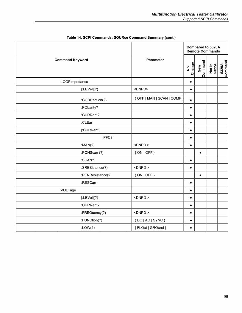
Multifunction Electrical Tester Calibrator Supported SCPI Commands
99
Table 14. SCPI Commands: SOURce Command Summary (cont.)
Command Keyword Parameter
Compared to 5320A Remote Commands
No
Cha
nge
New
C
omm
and
Not
in
5322
A
5320
A
Com
man
d
:LOOPimpedance
[:LEVel](?) <DNPD>
:CORRection(?) OFF | MAN | SCAN | COMP
:POLarity?
:CURRent?
:CLEar
[:CURRent]
:PFC?
:MAN(?) <DNPD >
:PONScan (?) ON | OFF
:SCAN?
:SRESistance(?) <DNPD >
:PENResistance(?) ON | OFF
:RESCan
:VOLTage
[:LEVel](?) <DNPD >
:CURRent?
:FREQuency(?) <DNPD >
:FUNCtion(?) DC | AC | SYNC
:LOW(?) FLOat | GROund
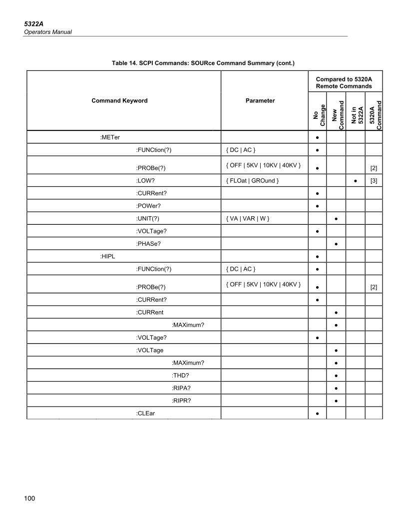
5322A Operators Manual
100
Table 14. SCPI Commands: SOURce Command Summary (cont.)
Command Keyword Parameter
Compared to 5320A Remote Commands
No
Cha
nge
New
C
omm
and
Not
in
5322
A
5320
A
Com
man
d
:METer
:FUNCtion(?) DC | AC
:PROBe(?) OFF | 5KV | 10KV | 40KV [2]
:LOW? FLOat | GROund [3]
:CURRent?
:POWer?
:UNIT(?) VA | VAR | W
:VOLTage?
:PHASe?
:HIPL
:FUNCtion(?) DC | AC
:PROBe(?) OFF | 5KV | 10KV | 40KV [2]
:CURRent?
:CURRent
:MAXimum?
:VOLTage?
:VOLTage
:MAXimum?
:THD?
:RIPA?
:RIPR?
:CLEar
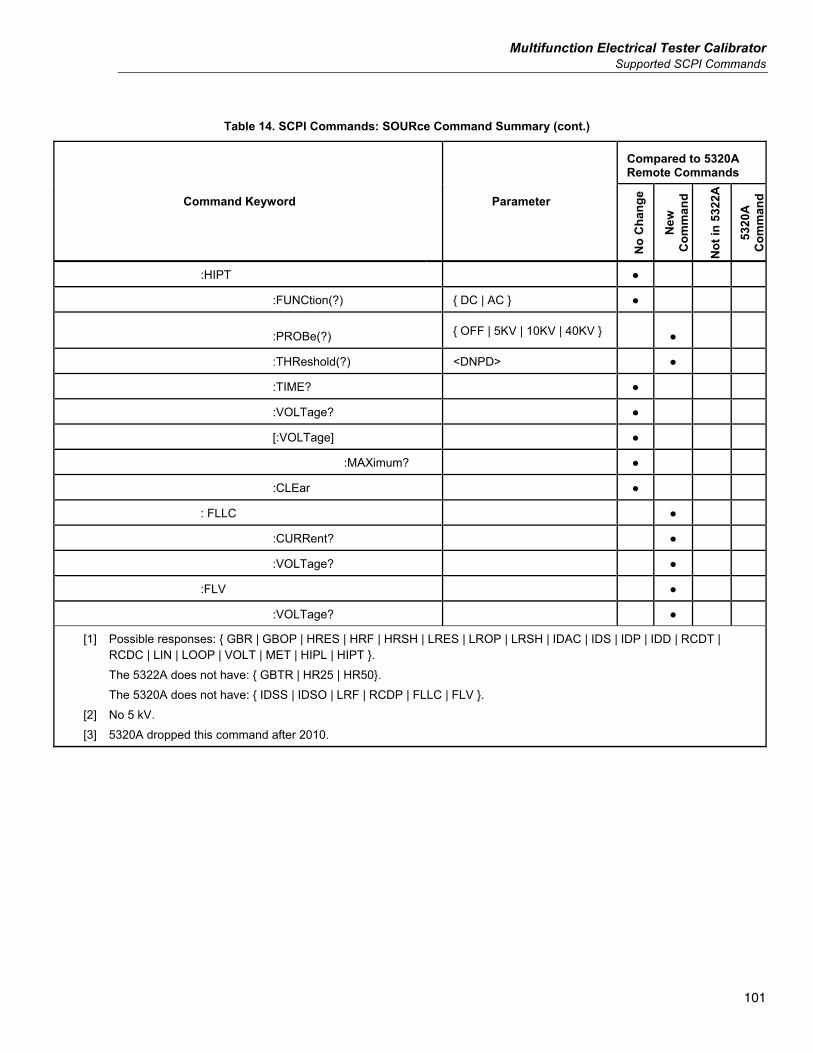
Multifunction Electrical Tester Calibrator Supported SCPI Commands
101
Table 14. SCPI Commands: SOURce Command Summary (cont.)
Command Keyword Parameter
Compared to 5320A Remote Commands
No
Cha
nge
New
C
omm
and
Not
in 5
322A
5320
A
Com
man
d
:HIPT
:FUNCtion(?) DC | AC
:PROBe(?) OFF | 5KV | 10KV | 40KV
:THReshold(?) <DNPD>
:TIME?
:VOLTage?
[:VOLTage]
:MAXimum?
:CLEar
: FLLC
:CURRent?
:VOLTage?
:FLV
:VOLTage?
[1] Possible responses: GBR | GBOP | HRES | HRF | HRSH | LRES | LROP | LRSH | IDAC | IDS | IDP | IDD | RCDT | RCDC | LIN | LOOP | VOLT | MET | HIPL | HIPT . The 5322A does not have: GBTR | HR25 | HR50. The 5320A does not have: IDSS | IDSO | LRF | RCDP | FLLC | FLV . [2] No 5 kV. [3] 5320A dropped this command after 2010.
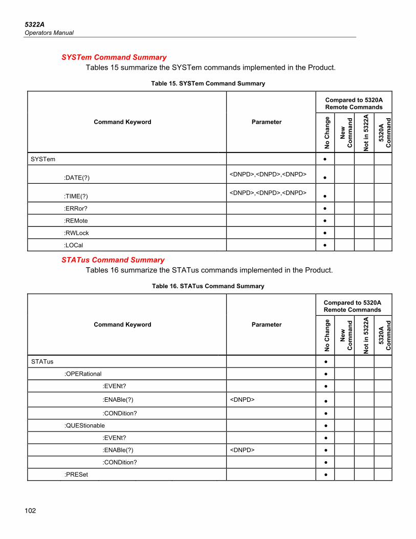
5322A Operators Manual
102
SYSTem Command Summary Tables 15 summarize the SYSTem commands implemented in the Product.
Table 15. SYSTem Command Summary
Command Keyword Parameter
Compared to 5320A Remote Commands
No
Cha
nge
New
C
omm
and
Not
in 5
322A
5320
A
Com
man
d
SYSTem
:DATE(?) <DNPD>,<DNPD>,<DNPD>
:TIME(?) <DNPD>,<DNPD>,<DNPD>
:ERRor?
:REMote
:RWLock
:LOCal
STATus Command Summary Tables 16 summarize the STATus commands implemented in the Product.
Table 16. STATus Command Summary
Command Keyword Parameter
Compared to 5320A Remote Commands
No
Cha
nge
New
C
omm
and
Not
in 5
322A
5320
A
Com
man
d
STATus
:OPERational
:EVENt?
:ENABle(?) <DNPD>
:CONDition?
:QUEStionable
:EVENt?
:ENABle(?) <DNPD>
:CONDition?
:PRESet
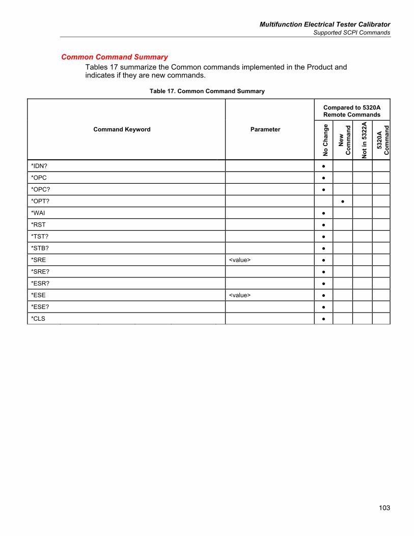
Multifunction Electrical Tester Calibrator Supported SCPI Commands
103
Common Command Summary Tables 17 summarize the Common commands implemented in the Product and indicates if they are new commands.
Table 17. Common Command Summary
Command Keyword Parameter
Compared to 5320A Remote Commands
No
Cha
nge
New
C
omm
and
Not
in 5
322A
5320
A
Com
man
d
*IDN?
*OPC
*OPC?
*OPT?
*WAI
*RST
*TST?
*STB?
*SRE <value>
*SRE?
*ESR?
*ESE <value>
*ESE?
*CLS
5322A Operators Manual
104
SCPI Command Details The following sections give a detailed description of each command.
Using the OUTPut Commands Remotely controlling the application of the Product output terminals is accomplished through the OUTPut command.
OUTPut[:STATe](?) <CPD> ON | OFF Description: Similar to the front panel , this command will apply or remove
the output signal to or from the Product output terminals. Parameters: <CPD> ON Output signal applied OFF Output signal disconnected Query: OUTP? Returns ON or OFF to indicate status of output signal.
Using the SOURce Commands Setting up functions that generate an output are controlled through the SOURCE command set. All calibration functions are controlled through a subset of commands under the SOURCE command called SAFETY.
[SOURce]:SAFety This subsystem allows controlling the individual functions of the Product.
[SOUR]:SAF:MODE? Description: This command returns the selected mode of the Product GBR |
GBOP | HRES | HRF | HRSH | LRES | LROP | LRSH | IDAC | IDS | IDP | IDD | RCDT | RCDC | LIN | LOOP | VOLT | MET | HIPL | HIPT | FLI | FLII .
Query: SAF:MODE? Returns one of the following functions: GBR – Ground Bond Resistance mode GBOP – Ground Bond Resistance Open HRES – High-resistance mode HRF – 100GOhm Fix Resistance HRSH – High Resistance Short LRES – Low-Resistance mode LROP – Low Resistance Open LRSH – Low Resistance Short IDAC – Leakage Current Active mode IDS – Leakage Current Substitute mode IDSS – Leakage Current Substitute mode Short IDSO – Leakage Current Substitute mode Open IDP – Leakage Current Passive mode IDD – Leakage Current Differential mode RCDT – RCD Trip Time mode RCDC – RCD Trip Current mode
Multifunction Electrical Tester Calibrator Supported SCPI Commands
105
RCDP – RCD PAT mode LIN – Line Impedance mode LOOP – Loop Impedance mode VOLT – Voltage Calibrator mode MET – Multimeter mode HIPL – Hipot Leakage current HIPT – Hipot Timer FLI – Flash Class I FLII –Flash Class II
[SOUR]:SAF:GBR[:LEV] (?) [<DNPD>] Description: This command sets the resistance value. If not already selected,
this command switches the Product to the Ground Bond Resistance function.
Parameters: <DNPD> Parameter represents the value of the resistance expressed in Ohms. The Product selects the nearest resistance value.
Example: SAF:GBR 0.1 Ground Bond Resistance with 100 mΩ. Query: SAF:GBR? Product returns the set value of resistance using
exponential format. Example: 50.54mΩ is returned as 50.54e-03.
[SOUR]:SAF:GBR:RPOS (?) <DNPD> Description: This command selects one of the 16 available resistances. Index of
resistance is from 0 (25 mΩ) to 15 (2 kΩ). If not already selected, this command switches the Product to the Ground Bond Resistance function.
Parameters: <DNPD> Parameter represents index of required resistance. Acceptable range is 0 … 15.
Example: SAF:GBR:RPOS 2 Ground Bond Resistance index 2 (100mΩ). Query: SAF:GBR:RPOS? Product returns the index of selected
resistance. Example: 4 is returned as 4. [SOUR]:SAF:GBR:SENS(?) <CPD> ON | OFF
Description: This command selects 4-wire Ground Bond Resistance mode (remote sense). If not already selected, this command switches the Product to the Ground Bond Resistance function.
Parameters: <CPD> ON selects 4-wire mode OFF selects 2-wire mode
Example: SAF:GBR:SENS ON 4-wire Ground Bond Resistance mode . Query: SAF:GBR:SENS? Product returns ON in 4-wire mode and
OFF in 2-wire
5322A Operators Manual
106
[SOUR]:SAF:GBR:LOWC(?) <CPD> ON | OFF Description: This command selects the Low Current feature of the Ground
Bond Resistance mode. If not already selected, this command switches the Product to the Ground Bond Resistance function.
Parameters: <CPD> ON activates Low Current feature OFF deactivates Low Current feature
Example: SAF:GBR:LOWC ON Low Current feature activation Query: SAF:GBR:LOWC? Product returns ON or OFF.
[SOUR]:SAF:GBR:SRES(?) <DNPD> Description: This command sets the series resistance of connection cables. If
not already selected, this command switches the Product to the Ground Bond Resistance function.
Parameters: <DNPD> Parameter represents the value of series resistance in Ω. The Specifications (online at www.Flukecal.com) lists the acceptable ranges.
Example: SAF:GBR:SRES 0.072 Query: SAF:GBR:SRES? Product returns the value of series
resistance using exponential format. Example: 0.072Ω is returned as 0.072e+00.
[SOUR]:SAF:GBR:CURR? Description: This command returns the measured current flowing through the
selected resistance. The Product returns the current value using exponential format. Example: 2.5A is returned as 2.500e+00. If not already selected, this command switches the Product to the Ground Bond Resistance function.
Query: SAF:GBR:CURR? [SOUR]:SAF:GBR[:CURR]:LIM?
Description: This command returns the maximum current allowed flowing through the selected resistance. The Product returns the current value using an exponential format. Example: 10 A is returned as 10.000e+00. If not already selected, this command switches the Product to the Ground Bond Resistance function.
Query: SAF:GBR:LIM?
Multifunction Electrical Tester Calibrator Supported SCPI Commands
107
[SOUR]:SAF:GBR[:CURR]:MAX? Description: This command returns the maximum (peak) value of current to flow
through the selected resistance. Maximum value can be cleared using the command SAF:GBR:CLEar. If not already selected, this command switches the Product to the Ground Bond Resistance function.
Product returns the current value using exponential format. Example: 10 A is returned as 10.000e+00.
Query: SAF:GBR:MAX? [SOUR]:SAF:GBR[:CURR]:CLE
Description: Clears the maximum (peak) value of current flowing through the selected resistance. If not already selected, this command switches the Product to the Ground Bond Resistance function.
Example: SAF:GBR:CLE [SOUR]:SAF:GBOP
Description: This command switches the Product into the Ground Bond Resistance mode and sets the Open mode.
Example: SAF:GBOP Ground Bond Resistance function Open [SOUR]:SAF:GBOP:VOLT?
Description: This command returns the voltage measured on the open terminals. The Product returns the voltage value using exponential format. Example: 20 V is returned as 20.0e+00. If not already selected, this command switches the Product to the Ground Bond Resistance Open mode.
Query: SAF:GBOP:VOLT? [SOUR]:SAF:GBOP[:VOLT]:LIM?
Description: This command returns the maximum allowed value of voltage on the open terminals. The Product returns the current value using exponential format. Example: 250 V is returned as 250.0e+00. If not already selected, this command switches the Product to the Ground Bond Resistance Open mode.
Query: SAF:GBOP:LIM? [SOUR]:SAF:GBOP[:VOLT]:MAX?
Description: This command returns the maximum (peak) value of voltage measured on the open terminals. Maximum value can be cleared using the command SAF:GBOP:CLEar. The Product returns the current value using exponential format. Example: 30 V is returned as 30.0e+00. If not already selected, it also switches the Product to the Ground Bond Resistance Open mode.
Query: SAF:GBOP:MAX?
5322A Operators Manual
108
[SOUR]:SAF:GBOP[:VOLT]:CLE Description: Clears the maximum (peak) value of voltage measured on the open
terminals. Example: SAF:GBOP:CLE
[SOUR]:SAF:HRES[:LEV](?) [<DNPD>] Description: This command sets the resistance value. If not already selected,
this command switches the Product to the High-Resistance mode. Parameters: <DNPD> Parameter represents the value of the resistance
expressed in Ohms. See the Specifications (found online at www.Flukecal.com) for the acceptable ranges.
Example: SAF:HRES 1.052E6 High-resistance mode 1.052 MΩ. Query: SAF:HRES? The Product returns the set value of
resistance using exponential format. Example: 10 MΩ is returned as 10.000e+06.
[SOUR]:SAF:HRES:LOW(?) <CPD> FLOat | GROund Description: This command connects or disconnects the High Resistance Lo
terminal to/from GND terminal. If not already selected, this command switches the Product to the High-Resistance mode.
Parameters: <CPD> GROund grounds the High Resistance output FLOat floats the High Resistance output from ground Example: SAF:HREs:LOW GRO Grounds the High Resistance output
terminal LO Query: SAF:HREs:LOW? The Product returns GRO when the output
is grounded or FLO when floating. [SOUR]:SAF:HRES:MULT(?) <CPD> ON | OFF
Description: This command enables the High-Resistance Multiplier. If not already selected, this command switches the Product to the High-Resistance mode.
Parameters: <CPD> ON enables multiplier. Resistance value is multiplied by 1000. OFF disables multiplier. Example: SAF:HRES:MULT ON Enable the probe (High-Resistance
Multiplier) Query: SAF:HRES:MULT? The Product returns ON when the
multiplier is enabled or OFF when disabled.
Multifunction Electrical Tester Calibrator Supported SCPI Commands
109
[SOUR]:SAF:HRES:RINP(?) <DNPD> Description: This command sets the input resistance of the DUT sense terminal,
when the multiplier is used. If not already selected, this command switches the Product to the High-Resistance mode.
Parameters: <DNPD> Parameter represents the value of input series resistance expressed in Ohms. Default value is 0, range is limited to 100 MΩ.
Example: SAF:HRES:RINP 10.52E6 Sets series resistance to 10.52 MΩ. Query: SAF:HRES:RINP? The Product returns the value of
series resistance using exponential format. Example: 1MΩ is returned as 1.000e+06.
[SOUR]:SAF:HRES:VOLT? Description: This command returns the measured voltage on the resistance.
The Product returns the voltage value using exponential format. Example: 120 V is returned as 120.0e+00. If not already selected, this command switches the Product to the High-Resistance mode.
Query: SAF:HRES:VOLT? [SOUR]:SAF:HRES[:VOLT]:LIM?
Description: This command returns the maximum allowed value of voltage on the resistance. The Product returns the voltage value using integer format. Example: 500 V is returned as 500. If not already selected, this command switches the Product to the High-Resistance mode.
Query: SAF:HRES:LIM? [SOUR]:SAF:HRES[:VOLT]:MAX?
Description: This command returns the maximum (peak) value of voltage measured on the resistance. Maximum value can be cleared using the command SAF:HRES:CLEar. The Product returns the current value using exponential format. Example: 700 V is returned as 700.0e+00. If not already selected, this command switches the Product to the High-Resistance mode.
Query: SAF:HRES:MAX? [SOUR]:SAF:HRES[:VOLT]:CLE
Description: Clears the maximum (peak) value of voltage measured on the resistance. If not already selected, this command switches the Product to the High-Resistance mode.
Example: SAF:HRES:CLE [SOUR]:SAF:HRES:CURR?
Description: This command returns the measured current flowing through the resistance. The Product returns the current value using exponential format. Example: 120 μA is returned as 120e-06. If not already selected, this command switches the Product to the High-Resistance mode.
Query: SAF:HRES:CURR?
5322A Operators Manual
110
[SOUR]:SAF:HRF(?) Description: This command switches the Product into the High-Resistance
mode (function 100 GOhm). Example: SAF:HRF 100GOhm Fix Resistance Mode. Query: SAF:HRF? The Product returns the fixed resistance
using exponential format. Example: 101Gohm is returned as 101.00e+09
[SOUR]:SAF:HRF:LOW(?)<CPD> FLOat | GROund Description: This command connects or disconnects the High Resistance Lo
terminal to/from GND terminal. If not already selected, this command switches the Product to the High-Resistance mode (function 100GOhm).
Parameters: <CPD> GROund grounds the High Resistance output
FLOat floats the High Resistance Output from ground.
Example: SAF:HRF:LOW GRO Grounds the High Resistance Lo output terminal.
Query: SAF:HRF:LOW? The Product returns GRO when the output is grounded or FLO when floating.
[SOUR]:SAF:HRF:VOLT? Description: This command returns the measured voltage on the resistance.
The Product returns the voltage value using exponential format. Example: 120 V is returned as 120.0e+00. If not already selected, this command switches the Product to the High-Resistance mode (function 100GOhm).
Query: SAF:HRF:VOLT? [SOUR]:SAF:HRF[:VOLT]:LIM?
Description: This command returns the maximum allowed value of voltage on the resistance. The Product returns the voltage value using integer format. Example: 500 V is returned as 500. If not already selected, this command switches the Product to the High-Resistance mode (function 100GOhm).
Query: SAF:HRF:LIM? [SOUR]:SAF:HRF[:VOLT]:MAX?
Description: This command returns the maximum (peak) value of voltage measured on the resistance. Maximum value can be cleared using the command SAF:HRF:CLEar. The Product returns the current value using exponential format. Example: 700 V is returned as 700.0e+00. If not already selected, this command switches the Product to the High-Resistance mode (function 100GOhm).
Query: SAF:HRF:MAX?
Multifunction Electrical Tester Calibrator Supported SCPI Commands
111
[SOUR]:SAF:HRF[:VOLT]:CLE Description: Clears the maximum (peak) value of voltage measured on the
resistance. If not already selected, this command switches the Product to the High-Resistance mode (function 100GOhm).
Example: SAF:HRF:CLE [SOUR]:SAF:HRF:CURR?
Description: This command returns the measured current flowing through the resistance. The Product returns the current value using exponential format. Example: 120 nA is returned as 120e-09. If not already selected, this command switches the Product to the High-Resistance mode (function 100GOhm).
Query: SAF:HRF:CURR? [SOUR]:SAF:HRSH
Description: This command switches the Product into the High-Resistance mode (Short).
Example: SAF:HRSH High-resistance mode (Short). [SOUR]:SAF:HRSH:LOW(?) <CPD> FLOat | GROund
Description: This command connects or disconnects the high resistance Lo terminal to/from GND terminal. If not already selected, this command switches the Product into the High-Resistance mode (function Short).
Parameters: <CPD> GROund grounds the High Resistance Output. FLOat floats the High Resistance output from ground. Example: SAF:HRSH:LOW GRO Grounds the High Resistance output
terminal Lo. Query: SAF:HRSH:LOW? The Product returns GRO when the
output is grounded or FLO when floating.
[SOUR]:SAF:HRSH:CURR? Description: This command returns the measured current flowing through the
shorted terminals. If not already selected, this command switches the Product into the High-Resistance mode (function Short).
Product returns the current value using exponential format. Example: 10 mA is returned as 10.00e-03.
Query: SAF:HRSH:CURR?
5322A Operators Manual
112
[SOUR]:SAF:HRSH[:CURR]:LIM? Description: This command returns the maximum allowed value of current
flowing through the shorted terminals. The Product returns the voltage value using exponential format. Example: 50 mA is returned as 50.00e-03. If not already selected, this command switches the Product into the High-Resistance mode (function Short).
Query: SAF:HRSH:LIM? [SOUR]:SAF:HRSH[:CURR]:MAX?
Description: This command returns the maximum (peak) value of current flowing through the shorted terminals. Maximum current value can be cleared using the command SAF:HRSH:CLEar. The Product returns the current value using exponential format. Example: 20 mA is returned as 20.00e-03. If not already selected, this command switches the Product into the High-Resistance mode (function Short).
Query: SAF:HRSH:MAX? [SOUR]:SAF:HRSH[:CURR]:CLE
Description: Clears the maximum (peak) value of current flowing through the shorted terminals. If not already selected, this command switches the Product into the High-Resistance mode (function Short).
Example: SAF:HRSH:CLE [SOUR]:SAF:LRES[:LEV](?) [<DNPD>]
Description: This sets the resistance value. If not already selected, this command switches the Product to the Low-Resistance mode (function Resistance).
Parameters: <DNPD> Parameter represents the value of the resistance expressed in Ohms. See the Specifications (found online at www.Flukecal.com) for acceptable ranges.
Example: SAF:LRES 105.2 Low Resistance 105.2 Ω. Query: SAF:LRES? The Product returns the set value of resistance
using exponential format. Example: 100 Ω is returned as 100.0e+00.
Multifunction Electrical Tester Calibrator Supported SCPI Commands
113
[SOUR]:SAF:LRES:LOW(?) <CPD> FLOat | GROund Description: This command connects or disconnects the Low Resistance Lo
terminal to/from GND terminal. If not already selected, this command switches the Product to the Low-Resistance mode (function Resistance).
Parameters: <CPD> GROund grounds the Low-Resistance output FLOat floats the Low-Resistance output from ground Example: SAF:LRES:LOW GRO Grounds the Lo resistance output
terminal Lo. Query: SAF:LRES:LOW? The Product returns GRO when the
output is grounded or FLO when floating [SOUR]:SAF:LRES:SRES(?) <CPD>
Description: This sets the series resistance value. If not already selected, this command switches the Product to the Low-Resistance mode (function Resistance).
Parameters: (DNPD> Parameter represents the value of the series resistance expressed in Ohms. See the Specifications (found online at www.Flukecal.com) for acceptable ranges.
Example: SAF:LRES:SRES 0.085 Series resistance 0.085Ω Query: SAF:LRES:SRES? The Product returns the set value of
resistance using exponential format. Example: 0.1 Ω is returned as 0.100e+00
[SOUR]:SAF:LRES:ARES(?) <CPD> SHORt | 0K5 | 1K0 | 2K0 | 5K0 Description: This sets the auxiliary resistance value. If not already selected, this
command switches the Product to the Low-Resistance mode (function Resistance).
• SHORt – short circuit between voltage and current terminals • 0K5 – 500 Ω between voltage and current terminals • 1K0 – 1 kΩ between voltage and current terminals • 2K0 – 2 kΩ between voltage and current terminals • 5K0 – 5 kΩ between voltage and current terminals
Example: SAF:LRES:ARES 0K5 Sets auxiliary resistance to 500 Ω. Query: SAF:LRES:ARES? The Product returns selected value of auxiliary resistance.
5322A Operators Manual
114
[SOUR]:SAF:LRES:CURR? Description: This command returns the measured current flowing through the
resistance. The Product returns the current value using exponential format. Example: 100 mA is returned as 100e-03. If not already selected, this command switches the Product to the Low-Resistance mode (function Resistance).
Query: SAF:LRES:CURR? [SOUR]:SAF:LRES[:CURR]:LIM?
Description: This command returns the maximum allowed value of current flowing through the resistance. The Product returns the current value using exponential format. Example: 100 mA is returned as 100e-03. If not already selected, this command switches the Product to the Low-Resistance mode (function Resistance).
Query: SAF:LRES:LIM? [SOUR]:SAF:LRES[:CURR]:MAX?
Description: This command returns the maximum (peak) value of current flowing through the selected resistance. Maximum value can be cleared using the command SAF:LRES:CLEar. If not already selected, this command switches the Product to the Low-Resistance mode (function Resistance).
The Product returns the current value using exponential format. Example: 100 mA is returned as 100e-03.
Query: SAF:LRES:MAX? [SOUR]:SAF:LRES[:CURR]:CLE
Description: Clears the maximum (peak) value of current flowing through the selected resistance. If not already selected, this command switches the Product to the Low-Resistance mode (function Resistance).
Example: SAF:LRES:CLE [SOUR]:SAF:LRF(?)
Description: This If not already selected, this command switches the Product into the Low-Resistance mode (function 10mOhm).
Parameters: <DNPD> Parameter represents the value of the resistance expressed in Ohms. See the Specifications (found online at www.Flukecal.com) for acceptable ranges.
Example: SAF:HRF 100GΩ fix resistance mode Query: SAF:LRF?
Multifunction Electrical Tester Calibrator Supported SCPI Commands
115
[SOUR]:SAF:LRF:LOW(?) <CPD> FLOat | GROund Description: This command connects or disconnects the low resistance Lo
terminal to/from GND terminal. If not already selected, this command switches the Product into the Low-Resistance mode (function 10mOhm).
Parameters: <CPD> GROund grounds the Low-Resistance output FLOat floats the Low-Resistance output from ground Example: SAF:LRF:LOW GRO Grounds the low-resistance output terminal. Query: SAF:LRF:LOW? The Product returns GRO when the output is
grounded or FLO when floating. [SOUR]:SAF:LRF:ARES(?) <CPD> SHORt | 0K5 | 1K0 | 2K0 | 5K0
Description: This sets the auxiliary resistance value. If not already selected, this command switches the Product into the Low-Resistance mode (function 10mOhm). SHORt – short circuit between voltage and current terminals 0K5 – 500 Ohm between voltage and current terminals 1K0 – 1 kOhm between voltage and current terminals 2K0 – 2 kOhm between voltage and current terminals 5K0 – 5 kOhm between voltage and current terminals
Query: SAF:LRF:ARES? The Product returns selected value of auxiliary resistance. Example: 1 kΩ is returned as 0K5.
[SOUR]:SAF:LRF:CURR? Description: This command returns the measured current flowing through the
resistance. The Product returns the current value using exponential format. Example: 100 mA is returned as 100e-03. If not already selected, this command switches the Product into the Low-Resistance mode (function 10mOhm).
Query: SAF:LRF:CURR? [SOUR]:SAF:LRF[:CURR]:MAX?
Description: This command returns the maximum (peak) value of current flowing through the selected resistance. Maximum value can be cleared using the command SAF:LRF:CLEar. The Product returns the current value using exponential format. Example: 100 mA is returned as 100e-03. If not already selected, this command switches the Product into the Low-Resistance mode (function 10mOhm).
Query: SAF:LRF:MAX?
5322A Operators Manual
116
[SOUR]:SAF:LRF[:CURR]:CLE Description: Clears the maximum (peak) value of current flowing through the
selected resistance. If not already selected, this command switches the Product into the Low-Resistance mode (function 10mOhm).
Example: SAF:LRF:CLE [SOUR]:SAF:LRSH
Description: This command switches the Product into the Short Low-Resistance Short mode.
Example: SAF:LRSH Short Low-Resistance Short mode [SOUR]:SAF:LRSH:LOW(?) <CPD> FLOat | GROund
Description: This command connects or disconnects the low resistance Lo terminal to/from GND terminal. If not already selected, this command switches the Product into the Low-Resistance mode (function Short).
Parameters: <CPD> GROund grounds the Low-Resistance output
If not already set, it also switches the Product to the Low-Resistance Short mode.
FLOat floats the Low-Resistance output from ground
Query: SAF:LRSH:LOW GRO Grounds the Lo-resistance output terminal. [SOUR]:SAF:LRSH:SENS(?) <CPD> ON | OFF
Description: This command selects the 4-wire Low Resistance Short mode and configures it to either 2-wire or 4-wire.
Parameters: <CPD> ON selects 4-wire resistance mode OFF selects 2-wire resistance mode Example: SAF:LRSH:SENS ON 4-wire Low-Resistance mode (function
Short) Query: SAF:LRSH:SENS? The Product returns ON in 4-wire mode
and OFF in 2-wire Product into Low-Resistance mode (function Short).
Multifunction Electrical Tester Calibrator Supported SCPI Commands
117
[SOUR]:SAF:LRSH:ARES(?) <CPD> SHORt | 0K5 | 1K0 | 2K0 | 5K0 Description: This sets the auxiliary resistance value in the Low-Resistance
mode. If not already selected, this command switches the Product into the Low-Resistance mode (function Short).
Parameters: <CPD> SHORt – short circuit between voltage and current terminals
0K5 – 500 Ω between voltage and current terminals
1K0 – 1 kΩ between voltage and current terminals
2K0 – 2 kΩ between voltage and current terminals
5K0 – 5 kΩ between voltage and current terminals
Query: SAF:LRSH:ARES? The Product returns selected value of auxiliary resistance. Example: 500 Ω is returned as 0K5.
[SOUR]:SAF:LRSH[:CURR]:LIM? Description: This command returns the maximum allowed value of current
flowing through the resistance. The Product returns the current value using exponential format. Example: 1000 mA is returned as 1000e-03. If not already selected, this command switches the Product into the Low-Resistance mode (function Short).
Query: SAF:LRSH:LIM? [SOUR]:SAF:LROP
Description: This command switches the Product into the Low-Resistance Open mode.
Example: SAF:LROP Low-Resistance function Open. [SOUR]:SAF:LROP:LOW(?) <CPD> FLOat | GROund
Description: This command connects or disconnects the Low Resistance Lo terminal to/from GND terminal. If not already selected, this command switches the Product into the Low-Resistance mode (function Open).
Parameters: <CPD> GROund grounds the Low-Resistance output FLOat floats the Low-Resistance output from ground Example: SAF:LROP:LOW GRO Grounds the low-resistance Lo output
terminal. Query: SAF:LROP:LOW? The Product returns GRO when the output
is grounded or FLO when floating.
5322A Operators Manual
118
[SOUR]:SAF:LROP:VOLT? Description: This command returns the voltage measured on the open
terminals. The Product returns the voltage value using exponential format. Example: 20.0 V is returned as 20.0e+00. This command switches the Product into the Low-Resistance mode (function Open).
Query: SAF:LROP:VOLT? [SOUR]:SAF:LROP[:VOLT]:LIM?
Description: This command returns the maximum allowed value of voltage on the open terminals. Product returns the current value using exponential format. Example: 50.0 V is returned as 50.0e+00. This command switches the Product into the Low-Resistance mode (function Open).
Query: SAF:LROP:LIM? [SOUR]:SAF:LROP[:VOLT]:MAX?
Description: This command returns the maximum (peak) value of voltage measured on the open terminals. Maximum value can be cleared using command SAF:LROP:CLEar. The Product returns the current value using exponential format. Example: 20.0 V is returned as 20.0e+00. If not already selected, this command switches the Product into the Low-Resistance mode (function Open).
Query: SAF:LROP:MAX? [SOUR]:SAF:LROP[:VOLT]:CLE
Description: Clears the maximum (peak) value of voltage measured on the open terminals. If not already selected, this command switches the Product into the Low-Resistance mode (function Open).
Example: SAF:LROP:CLE [SOUR]:SAF:IDAC
Description: This command switches the Product into the Leakage Current Active function mode.
Example: SAF:IDAC Sets Leakage Current Active mode [SOUR]:SAF:IDAC[:CURR]:NOM(?) <DNPD>
Description: This sets the nominal value of leakage current. If not already selected, this command switches the Product into the Leakage Current Active function mode. Nominal value of leakage current is applicable to all leakage current modes (IDA, IDP, IDS, IDD).
Parameters: <DNPD> Parameter represents the value of the leakage current expressed in Amps. See the Specifications (found online at www.Flukecal.com) for acceptable ranges.
Example: SAF:IDAC:NOM 0.01 Leakage Current Active mode 10 mA. Query: SAF:IDAC:NOM? The Product returns the nominal value of
leakage current using exponential format. Example: 10 mA is returned as 10.00e-03.
Multifunction Electrical Tester Calibrator Supported SCPI Commands
119
[SOUR]:SAF:IDS Descriptions: This command switches the Product into the Leakage Current
Substitute function mode. Example: SAF:IDS Sets the Leakage Current Substitute mode.
[SOUR]:SAF:IDS[:CURR]:NOM(?) <DNPD> Description: This command sets the nominal value of leakage current. If not
already selected, this command switches the Product into the Leakage Current Substitute function mode. Nominal value of leakage current is applicable for all leakage current modes (IDA, IDP, IDS, IDD).
Parameters: <DNPD> Parameter represents the value of the leakage current expressed in Amps. See the Specifications (found online at www.Flukecal.com) for the acceptable ranges.
Example: SAF:IDS:NOM 0.01 Leakage Current Substitute mode 10 mA. Query: SAF:IDS:NOM? The Product returns the nominal value of
leakage current using exponential format. Example: 10mA is returned as 10.00e-03.
[SOUR]:SAF:IDS:ROUT(?) <DNPD> Description: This command sets the value of DUT output resistance. If not
already selected, this command switches the Product into the Leakage Current Substitute function mode.
Parameters: <DNPD> Parameter represents the value of DUT output resistance expressed in Ohms. The Technical Data section lists the acceptable range.
Example: SAF:IDS:ROUT 2000 Output resistance of DUT is 2000 Ω Query: SAF:IDS:ROUT? The Product returns the value of output
resistance using exponential format. Example: 2000Ω is returned as 2000e+00.
[SOUR]:SAF:IDS:RES? Descriptions: This command returns the value of the set DUT output resistance
using exponential format. Example: 10.22 kΩ is returned as 10.220e+03. This command switches the Product into the Leakage Current Substitute function mode.
Query: SAF:IDS:RES?
5322A Operators Manual
120
[SOUR]:SAF:IDS:VOLT (?) <CPD> 100 | 110 | 115 | 120 | 127 | 220 | 230 | 240 Description: This sets the nominal voltage value in the Substitute Leakage
Current mode. If not already selected, this command switches the Product into the Leakage Current Substitute function mode. Nominal value of leakage current is applicable for all leakage current modes (IDA, IDP, IDS, IDD).
Parameters: <CPD> Example: SAF:VOLT 230 Sets the nominal voltage to 230 V. Query: SAF:VOLT? 230 V is returned as 230.
Product returns selected value of nominal voltage. Example: 230 V is returned as 230.
[SOUR]:SAF:IDSS Description: This command switches the Product into the Leakage Current
Substitute Short mode. Example: SAF:IDSS Sets the Leakage Current Substitute Short mode.
[SOUR]:SAF:IDSS:CURR? Description: Returns the measured current value using exponential format.
Example: 1 mA is returned as 1.0000e-03. If not already selected, this command switches the Product into the Leakage Current Substitute Short function mode.
Query: SAF:IDSS:CURR? [SOUR]:SAF:IDSO
Description: This command switches the Product into the Leakage Current Substitute Open mode. If not already selected, this command switches the Product into the Leakage Current Substitute Open mode.
Example: SAF:IDSS Sets the Leakage Current Substitute Short mode: [SOUR]:SAF:IDSO:VOLT?
Description: Returns the measured voltage value using exponential format. Example: 50 V is returned as 50.1e+00. If not already selected, this command switches the Product into the Leakage Current Substitute Open mode.
Query: SAF:IDSS:CURR? [SOUR]:SAF:IDP
Description: This command switches the Product into the Leakage Current Passive function mode.
Example: SAF:IDP Sets the Leakage Current Passive mode.
Multifunction Electrical Tester Calibrator Supported SCPI Commands
121
[SOUR]:SAF:IDP[:CURR]:NOM(?) <DNPD> Description: This command sets the nominal value of leakage current. If not
already selected, this command switches the Product into the Leakage Current Passive function mode.
Nominal value of leakage current is applicable for all leakage current modes (IDA, IDP, IDS, IDD).
Parameters: <DNPD> Parameter represents the value of the leakage current expressed in Amps. See the Specifications (found online at www.Flukecal.com) for acceptable ranges.
Example: SAF:IDP:NOM 0.01 Leakage Current Passive Mode 10 mA. Query: SAF:IDP:NOM? The Product returns the nominal value of
leakage current using exponential format. Example: 10mA is returned as 10.00e-03.
[SOUR]:SAF:IDP[:CURR]:INST? Description: This command returns the instantaneous measured current
flowing through the Product. Product returns the current value using exponential format. Example: 1 mA is returned as 1.0000e-03. If not already selected, this command switches the Product into the Leakage Current Passive function mode.
Query: SAF:IDP:INST? [SOUR]:SAF:IDP[:CURR]:RES?
Description: This command returns the resulting measured DUT current. Product returns the current value using exponential format.
Query: SAF:IDP:RES? 1mA is returned as 1.0000e-03. [SOUR]:SAF:IDD
Description: This command switches the Product into the Leakage Current Differential function mode.
Example: SAF:IDD Sets the Leakage Current Differential mode. [SOUR]:SAF:IDD[:CURR]:NOM(?) <DNPD>
Description: This command sets the nominal value of leakage current. If not already selected, this command switches the Product into the Leakage Current Differential function mode. Nominal value of leakage current is applicable for all leakage current modes (IDA, IDP, IDS, IDD).
Parameters: <DNPD> Parameter represents the value of the leakage current expressed in Amps. See the Specifications (found online at www.Flukecal.com) for the acceptable ranges.
Example: SAF:IDD:NOM 0.01 Leakage Current Differential Mode 10Ma. Query: SAF:IDD:NOM? The Product returns the nominal value of
leakage current using exponential format. Example: 10mA is returned as 10.00e-03.
5322A Operators Manual
122
[SOUR]:SAF:IDD[:CURR]:INST? Description: This command returns the instantaneous measured current
flowing through the Product. The Product returns the current value using exponential format. Example: 1 mA is returned as 1.0000e-03. If not already selected, this command switches the Product into the Leakage Current Differential function mode.
Query: SAF:IDD:INST? [SOUR]:SAF:IDD[:CURR]:RES?
Description: This command returns the measured current flowing through the DUT. Product returns the current value using exponential format. If not already selected, this command switches the Product into the Leakage Current Differential function mode.
Query: SAF:IDD:RES? 1mA is returned as 1.0000e-03 [SOUR]:SAF:RCDT:TIME(?) <DNPD>
Description: This command sets the nominal value of trip time. If not already selected, this command switches the Product into the RCD Trip Time function mode.
Parameters: <DNPD> Parameter represents the value of the leakage current expressed in seconds. See the Specifications (found online at www.Flukecal.com) for acceptable ranges.
Example: SAF:RCDT:TIME 0.055 RCD Trip Time mode 55ms. Query: SAF:RCDT:TIME? The Product returns the nominal
value of trip time using exponential format. Example: 20 ms is returned as 20e-03.
[SOUR]:SAF:RCDT:CURR? Description: Returns the measured trip current.
Product returns measured trip current value using exponential format. Example: 0,25A is returned as 250.00e-03. If not already selected, this command switches the Product into the RCD Trip Time function mode.
Query: SAF:RCDT:CURR?
Multifunction Electrical Tester Calibrator Supported SCPI Commands
123
[SOUR]:SAF:RCDT:RPOS(?) <DNPD> Description: This command selects one of the 16 available resistances. The
index of resistance is from 0 (25 mΩ) to 15 (2 kΩ). If not already selected, this command switches the Product into the RCD Trip Time function mode.
Selected resistance is also applicable for the RCDT Current function.
Parameters: <DNPD> Parameter represents index of required resistance. Acceptable range is 0 … 15.
Example: SAF:RCDT:RPOS 2 Series resistance index 2 (100 mΩ) Query: SAF:RCDT:RPOS? The Product returns the index of selected
resistance using integer format. Example: 4 is returned as 4.
[SOUR]:SAF:RCDT[:CURR]:NOM(?) <DNPD> Description: This command sets the nominal trip current value to the value
specified by <DNPD>. If not already selected, it also switches the Product to the RCD Time function.
Selected resistance is also applicable for the RCDT Current function.
Parameters: <DNPD> Parameter represents index of required resistance. Acceptable range is 0 … 15.
Example: Series resistance index 2 (100 mΩ) Query: SAF:RCDT:NOM? The Product returns the index of selected
resistance using integer format. Example: 4 is returned as 4.
[SOUR]:SAF:RCDT[:CURR]: :NOM(?) <DNPD> Description: This command sets the nominal value of trip current. f not already
selected, this command switches the Product into the RCD Trip Time function mode.
Parameters: <DNPD> Parameter represents the nominal value of the trip current expressed in Amps. See the Specifications (found online at www.Flukecal.com) for the acceptable ranges.
Nominal value of trip current is also applicable for the RCDT Current function.
Example: SAF:RCDT:NOM 1 Nominal Trip Time 1 A Query: SAF:RCDT:NOM? The Product returns the nominal value of
trip time using exponential format. Example: 200 mA is returned as 200e-03.
5322A Operators Manual
124
[SOUR]:SAF:RCDT[:CURR]:MULT(?) <CPD> 0.5x | 1x | 1.4x | 2x | 5x Description: This command sets the multiplier of nominal trip current. If not
already selected, this command switches the Product into the RCD Trip Time function mode.
Parameters: <CPD> Parameter represents the multiplier value. Four multipliers are available.
0.5x 1x 1.4x 2x 5x Example: SAF:RCDT:MULT 2x Multiplier x2 Query: SAF:RCDT:MULT? The Product returns set multiplier.
[SOUR]:SAF:RCDT[:CURR]:LEV(?) <CPD> 5% | 30% | 60% | 75% | 90% | 100% | 120% Description: This command sets the percent of nominal trip current level to the
value specified by <CPD>. If not already selected, this command switches the Product into the RCD Trip Time function mode.
Parameters: <CPD> Parameter represents the nominal trip level. 5% 30% 60% 75% 90% 100% 120% Example: SAF:RCDT:LEV 75% Level 75% Query: SAF:RCDT:LEV? Product returns set level.
Multifunction Electrical Tester Calibrator Supported SCPI Commands
125
[SOUR]:SAF:RCDT[:CURR]:CALC(?) <CPD> OFF | 100V | 115V | 120V | 220V | 230V | 240V | 250V
Description: This command defines the calculation formula for measured current. If not already selected, this command switches the Product into the RCD Trip Time function mode.
Parameters: <CPD> Parameter sets the calculation formula. OFF No calculation, displays Real
(actual) current 100V 115V 120V 220V 230V 240V 250V Example: SAF:RCDT:CALC OFF No calculation. Display is Real (actual) current. Query: SAF:RCDT:CALC? The Product returns set calculation
formula. [SOUR]:SAF:RCDT:[VOLT]:LINE?
Description: Returns the measured mains power supply voltage. The Product returns measured power supply voltage using integer format. Example: 230 V is returned as 230. If not already selected, this command switches the Product into the RCD Trip Time function mode.
Query: SAF:RCDT:LINE? [SOUR]:SAF:RCDT:[VOLT]:TOUC?
Description: Returns the measured touch voltage. The Product returns measured power supply voltage using integer format. Example: 10 V is returned as 10. If not already selected, this command switches the Product into the RCD Trip Time function mode.
Query: SAF:RCDT:TOUC?
5322A Operators Manual
126
[SOUR]:SAF:RCDT:POL? Description: Returns the type of test signal generated by the DUT POS | NEG |
SYMP | SYMN | DCP | DCN | NO. If not already selected, this command switches the Product into the RCD Trip Time function mode.
Query: SAF:RCDT:POL? Types are: Test current is pulse (dc) with positive polarity (POS) Test current is pulse (dc) with negative polarity (NEG) Test current is symmetrical (ac) with positive phase (SYMP) Test current is symmetrical (ac) with negative phase (SYMN) Test current is dc with positive polarity (DCP) Test current is dc with negative polarity (DCN) NO is returned when the generated test signal is invalid.
[SOUR]:SAF:RCDT:RVAL? Description: Returns the calibration value of the selected series resistance. The
Product returns the resistance using exponential format. Example: 25 mΩ is returned as 25.00e-03. If not already selected, this command switches the Product into the RCD Trip Time function mode.
Query: SAF:RCDT:RVAL? [SOUR]:SAF:RCDT:REC <CPD> ON | OFF
Description: This command automatically re-connects the output terminals and places the Product into Operate after tripping. The re-connection occurs in a fixed time interval of approximately 2.5 seconds.
Parameters: <CPD> ON enables Automatic reconnection
OFF disables Automatic reconnection Query: SAF:RCDT:REC?
[SOUR]:SAF:RCDC Description: This command switches the Product into the RCD Trip Current
function mode. If not already selected, this command switches the Product into the RCD Trip Current function mode.
Example: SAF:RCDC
Multifunction Electrical Tester Calibrator Supported SCPI Commands
127
[SOUR]:SAF:RCDC:CURR? Description: Returns the measured trip current. The Product returns measured
trip current value using exponential format. Example: 1 mA is returned as 1.0000e-03. If not already selected, this command switches the Product into the RCD Trip Current function mode.
Query: SAF:RCDC:CURR? [SOUR]:SAF:RCDC:RPOS(?) <DNPD>
Description: This command selects one of the 16 available resistances. Index of resistance is from 0 (25 mΩ) to 15 (2 kΩ). If not already selected, this command switches the Product into the RCD Trip Current function mode.
Selected resistance is also applicable for the RCDC Time function. Parameters: <DNPD> Parameter represents index of required
resistance. Acceptable range is 0 … 15. Example: SAF:RCDC:RPOS 2 Series resistance index 2 (100 mΩ) Query: SAF:RCDC:RPOS? The Product returns the index of selected
resistance using exponential format. Example: 4 is returned as 4.
[SOUR]:SAF:RCDC[:CURR]:NOM(?) <DPND> Description: This command sets the nominal value of trip current. If not already
selected, this command switches the Product into the RCD Trip Current function mode. Nominal value of trip current is also applicable for the RCDC Time mode.
Parameters: <DNPD> Parameter represents the nominal value of the trip current expressed in Amps. See the Specifications (found online at www.Flukecal.com) for the acceptable ranges.
Example: SAF:RCDC:NOM 1 Nominal Trip Time 1 A. Query: SAF:RCDC:NOM? The Product returns the nominal value of
trip time using exponential format. Example: 200 mA is returned as 200e-03.
[SOUR]:SAF:RCDC[:CURR]:MAX? Description: This command returns the maximum (peak) value of trip current.
Maximum value can be cleared using command SAF:RCDC:CLEar. The Product returns the current value using exponential format. Example: 1 mA is returned as 1.0000e-03. If not already selected, this command switches the Product into the RCD Trip Current function mode.
Query: SAF:RCDC:MAX?
5322A Operators Manual
128
[SOUR]:SAF:RCDC[:CURR]:CLE Description: This command clears the maximum (peak) value of trip current.
This command switches the Product into the RCD Trip Current function mode.
Example: SAF:RCDC:CLE [SOUR]:SAF:RCDC[:CURR]:CALC(?) <CPD> OFF | 100V | 115V | 120V | 220V | 230V | 240V | 250V
Description: This command defines the calculation formula for measured current. If not already selected, this command switches the Product into the RCD Trip Current function mode.
Parameters: <CPD> Parameter sets the calculation formula. OFF No calculation, displays Real (actual) current.
100V 115V 120V 220V 230V 240V 250V
Example: SAF:RCDC:CALC 240V Calculation based on 240 V mains Query: SAF:RCDC:CALC? The Product returns set calculation
formula. [SOUR]:SAF:RCDC:[VOLT]:LINE?
Description: Returns the measured mains power supply voltage. The Product returns the measured power supply voltage using integer format. Example: 230 V is returned as 230. If not already selected, this command switches the Product into the RCD Trip Current function mode.
Query: SAF:RCDC:LINE? [SOUR]:SAF:RCDC:[VOLT]:TOUC?
Description: Returns the measured touch voltage. The Product returns measured voltage using integer format. Example: 10 V is returned as 10. If not already selected, this command switches the Product into the RCD Trip Current function mode.
Query: SAF:RCDT:TOUC?
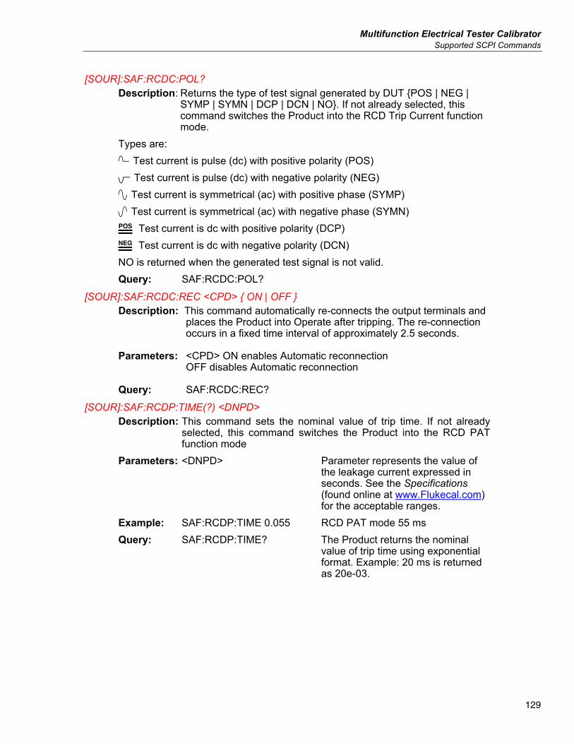
Multifunction Electrical Tester Calibrator Supported SCPI Commands
129
[SOUR]:SAF:RCDC:POL? Description: Returns the type of test signal generated by DUT POS | NEG |
SYMP | SYMN | DCP | DCN | NO. If not already selected, this command switches the Product into the RCD Trip Current function mode.
Types are: Test current is pulse (dc) with positive polarity (POS) Test current is pulse (dc) with negative polarity (NEG) Test current is symmetrical (ac) with positive phase (SYMP) Test current is symmetrical (ac) with negative phase (SYMN) Test current is dc with positive polarity (DCP) Test current is dc with negative polarity (DCN) NO is returned when the generated test signal is not valid. Query: SAF:RCDC:POL?
[SOUR]:SAF:RCDC:REC <CPD> ON | OFF Description: This command automatically re-connects the output terminals and
places the Product into Operate after tripping. The re-connection occurs in a fixed time interval of approximately 2.5 seconds.
Parameters: <CPD> ON enables Automatic reconnection OFF disables Automatic reconnection
Query: SAF:RCDC:REC?
[SOUR]:SAF:RCDP:TIME(?) <DNPD> Description: This command sets the nominal value of trip time. If not already
selected, this command switches the Product into the RCD PAT function mode
Parameters: <DNPD> Parameter represents the value of the leakage current expressed in seconds. See the Specifications (found online at www.Flukecal.com) for the acceptable ranges.
Example: SAF:RCDP:TIME 0.055 RCD PAT mode 55 ms Query: SAF:RCDP:TIME? The Product returns the nominal
value of trip time using exponential format. Example: 20 ms is returned as 20e-03.
5322A Operators Manual
130
[SOUR]:SAF:RCDP:CURR? Description: Returns the measured trip current. The Product returns measured
trip current value using exponential format. Example: 0,25 A is returned as 250.00e-03. If not already selected, this command switches the Product into the RCD PAT function mode.
Query: SAF:RCDP:CURR? [SOUR]:SAF:RCDP[:CURR]:NOM(?) <DNPD>
Description: This command sets the nominal value of trip current. If not already selected, this command switches the Product into the RCD PAT function mode.
Parameters: <DNPD> Parameter represents the nominal value of the trip current expressed in Amps. See the Specifications (found online at www.Flukecal.com) for acceptable ranges.
Example: SAF:RCDP:NOM 0.01 Nominal Trip Current is set to 10 mA Query: SAF:RCDP:NOM? The Product returns the nominal value of
trip time using exponential format. Example: 200 mA is returned as 200e-03.
[SOUR]:SAF:RCDP[:CURR]:MULT(?) <CPD> 0.5x | 1x | 1.4x | 2x | 5x Description: This command sets the multiplier of nominal trip current. Parameters: <CPD> Parameter represents the multiplier value.
Five multipliers are available. 0.5x 1x 1.4x 2x 5x Example: SAF:RCDP:MULT 2x Multiplier x2 Query: SAF:RCDP:LEV? Product returns the set multiplier.
Multifunction Electrical Tester Calibrator Supported SCPI Commands
131
[SOUR]:SAF:RCDP[:CURR]:LEV(?) <CPD> 5% | 30% | 60% | 75% | 90% | 100% | 120%
Description: This command sets the percent of nominal trip current level to the value specified by <CPD>.
Parameters: <CPD> Parameter represents the nominal trip level. 5% 30% 60% 75% 90% 100% Example: SAF:RCDP:LEV 75% Sets the level to 75 % Query: SAF:RCDP:LEV? Returns the Product current set level.
[SOUR]:SAF:RCDP[:CURR]:CALC(?) <CPD> OFF | 100V | 115V | 120V | 220V | 230V | 240V | 250V
Description: This command defines the calculation formula for measured current. If not already selected, this command switches the Product into the RCD PAT function mode. Parameters: <CPD> Parameter represents calculation formula.
OFF No calculation, displays Real (actual) current.
100V 115V 120V 220V 230V 240V 250V
Example: SAF:RCDP:CALC 120V Calculation based on 120 V mains. Query: SAF:RCDP:CALC? Returns the set calculation formula.
[SOUR]:SAF:RCDP[:VOLT]:LINE? Description: Returns the measured mains power supply voltage.
Product returns measured power supply voltage using integer format. Example: 230 V is returned as 230. If not already selected, this command switches the Product into the RCD PAT function mode.
Query: SAF:RCDP:LINE?
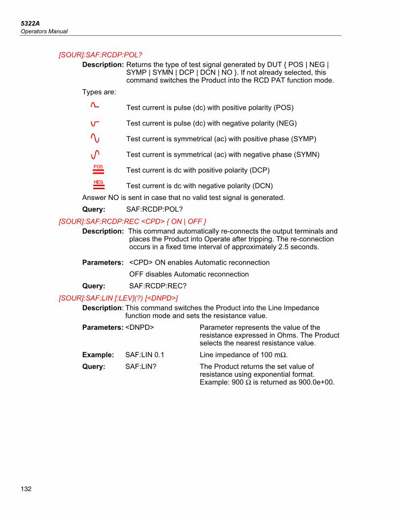
5322A Operators Manual
132
[SOUR]:SAF:RCDP:POL? Description: Returns the type of test signal generated by DUT POS | NEG |
SYMP | SYMN | DCP | DCN | NO . If not already selected, this command switches the Product into the RCD PAT function mode.
Types are:
Test current is pulse (dc) with positive polarity (POS)
Test current is pulse (dc) with negative polarity (NEG)
Test current is symmetrical (ac) with positive phase (SYMP)
Test current is symmetrical (ac) with negative phase (SYMN)
Test current is dc with positive polarity (DCP)
Test current is dc with negative polarity (DCN) Answer NO is sent in case that no valid test signal is generated. Query: SAF:RCDP:POL?
[SOUR]:SAF:RCDP:REC <CPD> ON | OFF Description: This command automatically re-connects the output terminals and
places the Product into Operate after tripping. The re-connection occurs in a fixed time interval of approximately 2.5 seconds.
Parameters: <CPD> ON enables Automatic reconnection OFF disables Automatic reconnection
Query: SAF:RCDP:REC? [SOUR]:SAF:LIN [:LEV](?) [<DNPD>]
Description: This command switches the Product into the Line Impedance function mode and sets the resistance value.
Parameters: <DNPD> Parameter represents the value of the resistance expressed in Ohms. The Product selects the nearest resistance value.
Example: SAF:LIN 0.1 Line impedance of 100 mΩ. Query: SAF:LIN? The Product returns the set value of
resistance using exponential format. Example: 900 Ω is returned as 900.0e+00.
Multifunction Electrical Tester Calibrator Supported SCPI Commands
133
[SOUR]:SAF:LIN:CORR (?) <CPD> OFF | MAN | SCAN | COMP Description: This command sets the mode of residual impedance correction. Parameters: <CPD> Parameter represents type of
residual impedance correction. If not already selected, this command switches the Product into the Line Impedance function mode. • OFF no correction • MAN manual residual impedance
correction • SCAN scanned residual impedance
correction • COMP compensated residual
impedance correction Example: SAF:LIN:CORR MAN Manual correction of residual impedance. Query: SAF:LIN:CORR? Returns the type of residual correction
mode selected. [SOUR]:SAF:LIN:POL?
Description: Returns the type of test signal generated by the DUT. If not already selected, it also switches the Product to the Line Impedance function.
Query: SAF:LIN:POL? Types are: Test current is pulse (dc) with positive polarity (POS) Test current is pulse (dc) with negative polarity (NEG) Test current is symmetrical (ac) with positive phase (SYMP) Test current is symmetrical (ac) with negative phase (SYMN) Test current is dc with positive polarity (DCP) Test current is dc with negative polarity (DCN) NO is returned when the generated test signal is not valid.
[SOUR]:SAF:LIN:CURR? Description: This command returns the measured maximum (peak) value of
current flowing through the selected resistance. Maximum value can be cleared using command SAF:LIN:CLEar. The Product returns the current value using exponential format. Example: 215 mA is returned as 215.0e-03
Query: SAF:LIN:CURR?
5322A Operators Manual
134
[SOUR]:SAF:LIN:CLE Description: Clears the maximum (peak) value of current flowing through the
selected resistance. This command switches the Product into the Line Impedance function mode.
Example: SAF:LIN:CLE [SOUR]:SAF:LIN[:CURR]:PFC?
Description: This command returns the value of the prospective fault current. The Product returns the current value using exponential format. Example: 100 A is returned as 100e+00. If not already selected, this command switches the Product into the Line Impedance function mode.
Query: SAF:LIN:PFC? [SOUR]:SAF:LIN:MAN(?) <DNPD>
Description: This command sets the manually-entered value of residual impedance. This command switches the Product into the Line Impedance function mode.
Parameters: <DNPD> Parameter represents the value of residual impedance in Ω. See the Specifications (found online at www.Flukecal.com) for acceptable ranges.
Example: SAF:LIN:MAN 0.87 Query: SAF:LIN:MAN? The Product returns the manual entered
value of residual impedance using exponential format. Example: 0.72 Ω is returned as 0.720e+00.
[SOUR]:SAF:LIN:PONS(?) <CPD> ON | OFF Description: This command sets the Power ON (Start Up) switch. This
command switches the Product into the Line Impedance function mode.
The state of the Power ON switch is the same for the Loop and Line functions.
Parameters: <CPD> Parameter represents the switch state. GROund grounds the Low-Resistance output
FLOat floats the Low-Resistance output from ground
Query: SAF:LIN:PONS? The Product returns the set switch state.
Multifunction Electrical Tester Calibrator Supported SCPI Commands
135
[SOUR]:SAF:LIN:SRES(?) <DNPD> Description: This command sets the series resistance of the connection cables.
This command switches the Product into the Line Impedance function mode.
Parameters: <DNPD> Parameter represents the value of series resistance in Ω. See the Specifications (found online at www.Flukecal.com) for the acceptable ranges.
Query: SAF:LIN:SRES? The Product returns the value of series resistance using exponential format. Example: 0.72 Ω is returned as 0.720e+00.
[SOUR]:SAF:LIN:RESC Description: Starts internal measurement of power line residual impedance. If
not already selected, this command switches the Product into the Line Impedance function mode.
Example: SAF:LIN:RESC [SOUR]:SAF:LOOP[:LEV](?) [<DNPD>] Description: This command switches the Product into the Loop Impedance
function mode and sets the resistance value. Parameters: <DNPD> Parameter represents the value of the
resistance expressed in Ohms. The Product selects the nearest resistance value.
Example: SAF:LOOP 0.1 Loop Impedance 100 mΩ Query: SAF:LOOP? The Product returns the set value of
resistance using exponential format. Example: 900 Ω is returned as 900.0e+00.
5322A Operators Manual
136
[SOUR]:SAF:LOOP:CORR(?) <CPD> OFF | MAN | SCAN | COMP Description: This command sets the mode of residual impedance correction.
This command switches the Product into the Loop Impedance function mode.
Parameters: <CPD> Parameter represents type of residual impedance correction. OFF no correction MAN manual residual impedance
correction SCAN scanned residual impedance
correction COMP compensated residual
impedance correction Example: SAF:LOOP:CORR MAN Manual correction of residual
impedance. Query: SAF:LOOP:CORR MAN? Returns the type of residual
impedance correction. [SOUR]:SAF:LOOP:POL?
Description: Returns the type of test signal generated by DUT POS | NEG | SYM | NO . This command switches the Product into the Loop Impedance function mode.
Query: SAF:LOOP:POL? Returns type of test signal generated by DUT POS | NEG | SYM | DCP | DCN | NO
Types are: Test current is pulse (dc) with positive polarity (POS) Test current is pulse (dc) with negative polarity (NEG) Test current is symmetrical (ac) with positive phase (SYM) Answer NO is sent in case an invalid test signal is generated.
[SOUR]:SAF:LOOP:CURR? Description: This command returns the measured maximum (peak) value of
current flowing through the selected resistance. Maximum value can be cleared using command SAF:LOOP:CLEar. Product returns the current value using exponential format. Example: 215 mA is returned as 215.0e-03. This command switches the Product into the Loop Impedance function mode.
Query: SAF:LOOP:CURR? [SOUR]:SAF:LOOP:CLE
Description: Clears the maximum (peak) value of current flowing through the selected resistance. This command switches the Product into the Loop Impedance function mode.
Example: SAF:LINE:CLE
Multifunction Electrical Tester Calibrator Supported SCPI Commands
137
[SOUR]:SAF:LOOP[:CURR]:PFC? Description: This command returns the value of prospective fault current. The Product returns the current value using exponential format.
Example: 100A is returned as 100e+00. This command switches the Product into the Loop Impedance function mode.
Query: SAF:LOOP:PFC? [SOUR]:SAF:LOOP:MAN(?) <DNPD>
Description: This command sets the manual entered value of residual impedance.
Parameters: <DNPD> Parameter represents the value of residual impedance in Ω. See the Specifications (found online at www.Flukecal.com) for acceptable ranges.
Example: SAF:LOOP:MAN 0.87 Set manual compensation value to 0.87 Ω. Query: SAF:LOOP:MAN? Returns the manual compensation value.
[SOUR]:SAF:LOOP:SCAN? Description: Returns the scanned loop residual impedance value. If not already
selected, it also switches the Product to the Loop Impedance function.
Example: SAF:LOOP:MAN 0.87 Query: SAF:LOOP:SCAN? Product returns the manual entered value of
residual impedance using exponential format. Example: 0.72 Ω is returned as 0.720e+00.
[SOUR]:SAF:LOOP:SCAN? Description: Returns the scanned value of loop residual impedance.
Product returns the scanned value using exponential format. Example: 0.72 Ω is returned as 0.720e+00. This command switches the Product into the Loop Impedance function mode. The Scan value is the same for Loop and Line functions.
Query: SAF:LOOP:SCAN?
5322A Operators Manual
138
[SOUR]:SAF:LOOP:PONS(?) <CPD> ON | OFF Description: This command sets the Power ON (Start Up) switch. This
command switches the Product into the Loop Impedance function mode. The state of the Power ON switch is the same for Loop and Line functions.
Parameters: <CPD> Parameter represents the switch state. ON Sets the power ON OFF Sets the power OFF Example: SAF:LOOP:PONS ON Query: SAF:LOOP:PONS? The Product returns set switch state.
[SOUR]:SAF:LOOP:SRES(?) <DNPD> Description: This command sets the series resistance of connection cables. Parameters: <DNPD> Parameter sets the value of series resistance in Ω.
See the Specifications (found online at www.Flukecal.com) for the acceptable ranges. This command switches the Product into the Loop Impedance function mode.
Example: SAF:LOOP:SRES 0.07 Query: SAF:LOOP:SRES? The Product returns the value of series
resistance using exponential format. Example: 0.72Ω is returned as 0.720e+00.
[SOUR]:SAF:LOOP:PENR(?) <CPD> ON | OFF Description: This command sets the PE-N resistance switch. This command
switches the Product into the Loop Impedance function mode. Parameters: <CPD> Parameter represents the switch state.
ON Sets the PE-N resistance switch ON OFF Sets the PE-N resistance switch OFF Example: SAF:LOOP:PENR ON Query: SAF:LOOP:PENR? The Product returns set switch state.
[SOUR]:SAF:LOOP:RESC Description: Starts the internal measurement of power line residual impedance.
This command switches the Product into the Line Impedance function mode.
Example: SAF:LOOP:RESC
Multifunction Electrical Tester Calibrator Supported SCPI Commands
139
[SOUR]:SAF:VOLT[: LEV](?) [<DNPD>] Description: This command sets the output voltage from the Voltage calibrator
function. Parameters: <DNPD> Parameter represents the value of
generated voltage expressed in Volts. Example: SAF:VOLT 100 Voltage Calibrator 100V. Query: SAF:VOLT? The Product returns the value of the
generated voltage using exponential format. Example: 50.5 V is returned as 50.50e+00.
[SOUR]:SAFE:VOLT:CURR? Description: This command returns the measured load current in the voltage
calibrator function. The Product returns the current value using exponential format. Example: 5 mA is returned as 5e-03. This command switches the Product into the Voltage Calibrator function mode.
Query: SAF:VOLT:CURR? [SOUR]:SAF:VOLT:FREQ(?) <DNPD>
Description: This command sets the frequency in the AC Voltage Calibrator mode. This command switches the Product into the Voltage Calibrator function mode.
Parameters: <DNPD> Parameter represents the value of frequency expressed in Hz.
Example: SAF:VOLT:FREQ 60 60 Hz. Query: SAF:VOLT? The Product returns the value of frequency
using exponential format. Example: 50 Hz is returned as 50.0e+00.
[SOUR]:SAF:VOLT:FUNC(?) <CPD> DC | AC | SYNC Description: This command selects dc or ac output voltage signal from the
Voltage calibrator function. This command switches the Product into the Voltage Calibrator function mode.
Parameters: <CPD> DC sets a dc output signal AC sets an ac output signal
SYNC sets an ac output signal synchronized with the power supply frequency
Example: SAF:VOLT:FUNC AC Set to an ac voltage output signal. Query: SAF:VOLT:FUNC? The Product returns AC, DC, or SYNC.
5322A Operators Manual
140
[SOUR]:SAF:VOLT:LOW(?) <CPD> FLOat | GROund Description: This command connects or disconnects the Voltage Calibrator Lo
terminal to/from GND terminal. This command switches the Product into the Voltage Calibrator function mode.
Parameters: <CPD> GROund grounds the Voltage Calibrator Output. FLOat floats the Voltage Calibrator output from ground. Example: SAF:VOLT:LOW GRO Grounds the Voltage Calibrator Lo output
terminal. Query: SAF:VOLT:LOW? The Product returns GRO when the output
is grounded or FLO when floating. [SOUR]:SAF:MET:FUNC(?) <CPD> DC | AC
Description: This command selects the dc or ac multimeter mode. This command switches the Product into the Meter function mode.
Parameters: <CPD> DC sets to the dc multimeter mode. AC sets to the ac multimeter mode. Example: SAF:MET:FUNC AC Sets to the ac multimeter mode. Query: SAF:MET:FUNC? The Product returns ac or dc.
[SOUR]:SAF:MET:PROB(?) <CPD> OFF | 5KV | 10KV | 40KV Description: This command selects the HV internal or external high voltage
probe for the voltmeter. This command switches the Product into the Meter function mode.
Parameters: <CPD> OFF – multimeter with no probe (V terminal) 5KV – multimeter with internal 5 kV probe (HV
terminal) 10KV – multimeter with external 10 kV probe 40KV – multimeter with external 40 kV probe
Example: SAF:MET:PROB 10KV Set 10kV external high voltage probe in multimeter mode.
Query: SAF:MET:PROB? The Product returns OFF, 5KV, 10KV or 40KV.
[SOUR]:SAF:MET:CURR? Description: This command returns the measured current. The Product returns
the current value using exponential format. Example: 215 mA is returned as 215.00e-03. This command switches the Product into the Meter function mode.
Query: SAF:MET:CURR?
Multifunction Electrical Tester Calibrator Supported SCPI Commands
141
[SOUR]:SAF:MET:POW? Description: This command returns the measured power. The Product returns
the power value using exponential format. Example: 45 VA is returned as 45.00e+00. This command switches the Product into the Meter function mode.
Query: SAF:MET:POW? [SOUR]:SAF:MET:UNIT <CPD> VA | VAR | W
Description: This command sets the units when measuring power. If not already selected, this command switches the Product into the Meter Multimeter mode.
Parameters: <CPD> VA sets the units to VA (apparent power) VAR sets the units to VAR (reactive power) W sets the units to W (active power)
Query: SAF:MET:UNIT? [SOUR]:SAF:MET:VOLT?
Description: This command returns the measured voltage. The Product returns the voltage value using exponential format. Example: 230 V is returned as 230.0e+00. This command switches the Product into the Meter function mode.
Query: SAF:MET:VOLT? [SOUR]:SAF:MET:PHAS?
Description: This command returns the measured phase. The Product returns the phase value using exponential format. Example: 60° is returned as 60.00e+00. This command switches the Product into the Meter function AC mode.
Query: SAF:MET:PHAS? [SOUR]:SAF:HIPL:FUNC(?) <CPD> DC | AC
Description: This command selects dc or ac hipot leakage current mode. This command switches the Product into the Hipot leakage current function mode.
Parameters: <CPD> DC sets a dc hipot leakage current mode. AC sets an ac hipot leakage current mode.
Example: SAF:HIPL:FUNC AC Set to the ac hipot leakage current mode. Query: SAF:HIPL:FUNC? The Product returns ac or dc.
5322A Operators Manual
142
[SOUR]:SAF:HIPL:PROB(?) <CPD> OFF | 5KV | 10KV | 40KV Description: This command selects the internal or external high voltage probe
for hipot leakage current. This command switches the Product into the Hipot leakage current function mode.
Parameters: <CPD> OFF – hipot leakage current with no probe (V terminal) 5KV – hipot leakage current with the HV terminal 10KV – hipot leakage current with an external 10kV probe 40KV – hipot leakage current with an external 40kV probe
Example: SAF:HIPL:PROB 10KV Set to the external 10kV high voltage probe in hipot leakage current mode.
Query: SAF:HIPL:PROB? Returns whether the multimeter is measuring with a probe and if so, which probe is being used.
[SOUR]:SAF:HIPL:CURR? Description: This command returns the measured current. The Product returns
the current value using exponential format. Example: 215 mA is returned as 215.00e-03. This command switches the Product into the Hipot leakage current function mode.
Query: SAF:MET:CURR? [SOUR]:SAF:HIPL:CURR:MAX?
Description: This command returns the maximum (peak) value of measured voltage. Maximum value can be cleared using the command SAF:HIPL:CLEar. The Product returns the current value using exponential format. Example: 215 mA is returned as 215.00e-03.
Query: SAF:HIPL:CURR:MAX? [SOUR]:SAF:HIPL:VOLT?
Description: This command returns the measured voltage. The Product returns the voltage value using exponential format. Example: 230 V is returned as 230.0e+00. This command switches the Product into the Hipot leakage current function mode.
Query: SAF:HIPL:VOLT?
Multifunction Electrical Tester Calibrator Supported SCPI Commands
143
[SOUR]:SAF:HIPL:VOLT:MAX? Description: This command returns the maximum (peak) value of measured
voltage. Maximum value can be cleared using the command SAF:HIPL:CLEar. The Product returns the current value using exponential format. Example: 230 V is returned as 230.0e+00. This command switches the Product into the Hipot leakage current function mode.
Query: SAF:HIPL:VOLT:MAX? [SOUR]:SAF:HIPL:CLE
Description: Clears the maximum (peak) measured voltage. This command switches the Product into the Hipot leakage current function mode.
Example: SAF:HIPL:CLE [SOUR]:SAF:HIPL:VOLT:THD?
Description: This command returns the THD value of measured voltage. The Product returns the THD value using exponential format. Example: 0% is returned as 0.00e+00. This command switches the Product into the Hipot leakage current function mode.
Query: SAF:HIPL:VOLT:THD? [SOUR]:SAF:HIPL:VOLT:RIPA?
Description: This command returns the Ripple absolute measured voltage using exponential format. Example: 1 V is returned as 1.000e+00. This command switches the Product into the Hipot leakage current function mode.
Query: SAF:HIPL:VOLT:RIPA? [SOUR]:SAF:HIPL:VOLT:RIPR?
Description: This command returns the Ripple relative measured voltage using exponential format. Example: 0 % is returned as 0.00e+00. This command switches the Product into the Hipot leakage current function mode.
Query: SAF:HIPL:VOLT:RIPR?
5322A Operators Manual
144
[SOUR]:SAF:HIPT:FUNC(?) <CPD> DC | AC Description: This command selects dc or ac hipot timer mode. This command
switches the Product into the Hipot timer function mode. Parameters: <CPD> DC sets to the dc hipot timer mode. AC sets to the ac hipot timer mode. Example: SAF:HIPT:FUNC AC Set to the AC hipot timer mode. Query: SAF:HIPT:FUNC? The Product returns ac or dc.
[SOUR]:SAF:HIPT:PROB(?) <CPD> OFF | 5KV | 10KV | 40KV Description: This command selects the internal or external high voltage probe
for hipot timer. If not already selected, this command switches the Product into the Hipot timer mode.
Parameters: <CPD> OFF – hipot timer with no probe (V terminal) 5KV – hipot timer with the HV terminal 10KV – hipot timer with an external 10kV probe 40KV – hipot timer with an external 40kV probe Example: SAF:HIPT:PROB 10KV Set to the external 10kV high voltage
probe in hipot timer mode. Query: SAF:HIPT:PROB? Returns whether the multimeter is measuring
with a probe and if so, which probe is being used. [SOUR]:SAF:HIPT:THR(?) <DNPD>
Description: This command sets the threshold level in Hipot timer mode. If not already selected, this command switches the Product to Hipot timer.
Parameters: <DNPD> Represents the value of the threshold level expressed in percent.
Example: SAF:HIPT:THR 50 Set the threshold to 50%. Query: SAF:HIPT:THR? The Product returns the threshold value in integer
format. [SOUR]:SAF:HIPT:TIME?
Description: This command returns the measured time using exponential format. Example: 2.15 s is returned as 2.150e+00. This command switches the Product into the Hipot timer function mode.
Query: SAF:HIPT:TIME?
Multifunction Electrical Tester Calibrator Supported SCPI Commands
145
[SOUR]:SAF:HIPT:VOLT? Description: This command returns the measured voltage using exponential
format. Example: 230 V is returned as 230.0e+00. This command switches the Product into the Hipot timer function mode.
Query: SAF:HIPT:VOLT? [SOUR]:SAF:HIPT:[VOLT]:MAX?
Description: This command returns the maximum (peak) measured voltage. Maximum value (and time) can be cleared using command SAF:HIPT:CLEar. The Product returns the current value using exponential format. Example: 230 V is returned as 230.0e+00. This command switches the Product into the Hipot timer function mode.
Query: SAF:HIPT:MAX? [SOUR]:SAF:HIPT:CLE?
Description: Clears the measured time and maximum (peak) value of measured voltage. This command switches the Product into the Hipot timer function mode.
Query: SAF:HIPT:CLE [SOUR]:SAF:FLLC:CURR?
Description: This command returns the measured current using exponential format. Example: 215mA is returned as 215.00e-03. This command switches the Product into the Flash Leakage Current function mode.
Query: SAF:FLLC:CURR? [SOUR]:SAF:FLLC:VOLT?
Description: This command returns the measured voltage using exponential format. Example: 230 V is returned as 230.0e+00. This command switches the Product into the Flash Leakage Current function mode.
Query: SAF:FLLC:VOLT? [SOUR]:SAF:FLV:VOLT?
Description: This command returns the measured voltage using exponential format. Example: 230 V is returned as 230.0e+00. This command switches the Product into the Flash Voltage function mode.
Query: SAF:FLV:VOLT? Using SYSTem Commands
The SYSTEM commands are used to read and control miscellaneous Product functions.
SYSTem subsystem The subsystem controls various system elements of the Product.
5322A Operators Manual
146
SYST:DATE(?) <DNPD>,<DNPD>,<DNPD> Description: This command sets the system date of the Product. Parameters: <DNPD> Represents date in format YYYY, MM, DD <DNPD> <DNPD> Example: SYSR:DATE 2017,11,05 Sets the Product date function to
November 5, 2017. Query: SAF:DATE? The Product returns current value of
system date in format YYYY,MM,DD. where YYYY = year (2000..2099) MM = month (01..12) DD = day (01..31)
SYST:TIME(?) <DNPD>,<DNPD>,<DNPD> Description: This command sets the time of the Product. Represents time in
format HH,MM,SS. Parameters: <DNPD> HH = hour (00..23) <DNPD> MM = minute (00..59) <DNPD> SS = second (00..59)
SYST:ERR? Description: Query the multimeter error queue. Detected errors are placed in the
queue. Returns the first error from the queue. The queue is type first in, first out. The error is deleted after reading.
The response is in the form of String Program Data, and consists of two elements: a code number and error message.
If all errors are read Product returns the message 0, No Error. In case of overflow in the error queue, the last error in the queue is
–350,Queue overflow. Also the earliest errors remain in the queue, and the most recent error is discarded.
Query: SYST:ERR? SYST:REM
Description: This command places the Product into the remote mode for USB operation. All keys on the front panel, except the LOCAL key, are disabled.
Note It is not possible to send or receive data over USB when the Product is not in remote mode.
SYST:RWL Description: This command places the Product into the remote mode for USB
operation. All keys on the front panel, including the LOCAL key, are disabled.
Multifunction Electrical Tester Calibrator Supported SCPI Commands
147
SYST:LOC Description: This command returns the Product to the local mode. This
command is for USB interface. STATus Subsystem
This subsystem is used to enable bits in the Operation and Questionable Event registers. The Operation and Questionable: Event, Enable and Condition registers can be interrogated to determine their state. STATus :OPERational :EVENt? :ENABle(?) <DNPD> :CONDition? :QUEStionable :EVENt? :ENABle(?) <DNPD> :CONDition? :PRESet
STAT:OPER:EVEN? Description: Returns the content of Operational Data Event register. It is a
decimal value which corresponds to the binary-weighted sum of all bits set in the register. Register is cleared after this query.
Query: STAT:OPER:EVEN? STAT:OPER:ENAB? <DNPD>
Description: This command enables bits in the Operational Data Enable register. Selected bits are summarized at bit 7 (OSS) of the IEEE488.2 Status Byte register.
Parameters: <DNPD> Parameter represents desired value of Operational Data Enable register as a decimal number.
Example: STAT:OPER:ENAB 2 Set bit 1 in the Operational Data Enable register (other bits are 0).
Query: SAF:OPER:ENAB? The Product returns the value of the register as a decimal number. Example: 64 is returned as 64.
5322A Operators Manual
148
STAT:OPER:COND? Description: Returns the content of the Operational Condition register. It is a
decimal value which corresponds to the binary-weighted sum of all bits in the register. The register is not cleared after this query. The response to the query therefore represents an instantaneous Snapshot of the register state, at the time that the query was accepted.
Query: STAT:OPER:COND? STAT:QUES:EVEN?
Returns the content of Questionable Data Event register. It is a decimal value which corresponds to the binary-weighted sum of all bits set in the register. Register is cleared after this query. Query: STAT:QUES:EVEN?
STAT:QUES:ENAB? <DNPD> This command enables bits in the Questionable Data Enable register. Selected bits are summarized at bit 3 (QSS) of the IEEE488.2 Status Byte register. Parameters: <DNPD> Parameter represents desired value
of Questionable Data Enable register bits as a decimal number. Product returns the value of the register as a decimal number. Example: 64 is returned as 64.
Query: STAT:QUES:ENAB 2 Set bit 1 in the Questionable Data Enable register (other bits are 0).
STAT:QUES:COND? Returns the content of Questionable Condition register. It is a decimal value which corresponds to the binary-weighted sum of all bits in the register. The register is not cleared after this query. The response to the query therefore represents an instantaneous Snapshot of the register state, at the time that the query was accepted. Query: STAT:QUES:COND?
STAT:PRES This command clears all bits in the Operation Data Enable register and in the Questionable Data Enable register. Example: STAT:PRES
Multifunction Electrical Tester Calibrator Supported SCPI Commands
149
IEEE 488.2 Common Commands The commands in this section are common to the IEEE 488.2 standard. A summary of the Product IEEE Command Commands are listed in Table 17.
Instrument Identification
*IDN? This command returns the identification of the manufacturer, model, serial number and firmware revision. When 5320A remote emulation is set to Off, the *IDN? response is "FLUKE,5322A,serial number,firmware revision", for example "FLUKE,5322A,650001217,0.045" When 5320A remote emulation is set to On, the *IDN? response is "FLUKE,5320A,serial number,firmware revisions", where firmware revisions are comprised of four parts separated with a "+". An example is "FLUKE,5320A,650001217,3.45+2.44+1.34+1.01".
Operation complete
*OPC This command sets the OPC bit in the ESR (Event Status Register) when all pending operations are complete.
Operation complete?
*OPC? This command returns 1 to the output queue after all pending operations are complete.
Option Identification
*OPT? This command returns the Product hardware configuration. The reply is formatted as follows: o1,o2,o3,x,x,x Where:
The value of o1 references the calibrator module The value of o2 references the compensator module The value of o3 references the 5kV resistance decade
Note The last three positions in the return string are reserved for future use.
A value of "0" indicates the option is not present. A value of "1" indicates the option is present. Example: 1,1,1,0,0,0 means the calibrator, compensator, and 5kV resistance decade are present.
5322A Operators Manual
150
Wait-to-Continue command
*WAI Prevents the Product from executing any further commands or queries until all previous remote commands have been executed.
Reset
*RST This command resets the Product to its initial status.
Test operation
*TST? This command launches an internal self-test. Return the self-test result (0 for pass or 1 for fail).
Read Status Byte
*STB? This query returns number in range 0 to 255 with information about content of register STB, which carries the MSS bit status.
Service Request Enable
*SRE <value> This command sets condition of the Service Request Enable register. Since bit 6 is not used, the maximum value is 191.
Read Service Request Enable
*SRE? Returns the Service Request Enable Register number.
Read Event Status Register
*ESR? Returns the contents of the Event Status Register and clears the register.
Set Event Status Enable
*ESE <value> This command programs the Event Status Enable register bits. Parameter value is number in range 0 – 255.
Read Event Status Enable
*ESE? Returns the Event Status Enable register.
Clear status
*CLS This command clears the Event Status Register and the Status Byte Register except the MAV bit and output queue. Output line is not reset.
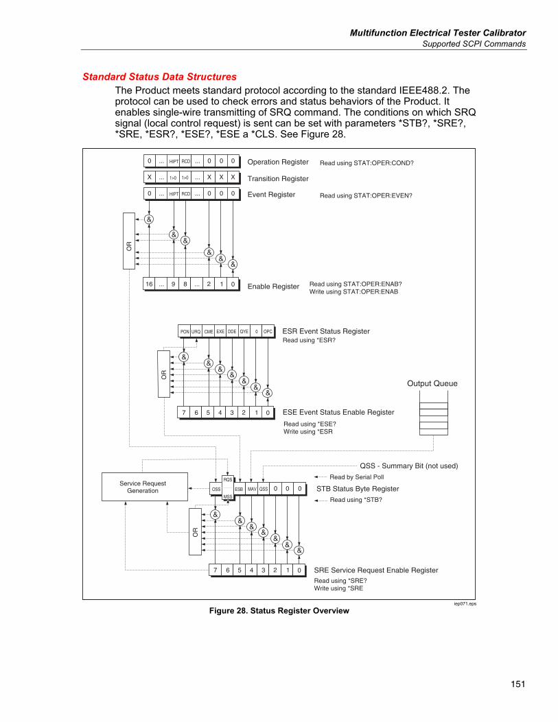
Multifunction Electrical Tester Calibrator Supported SCPI Commands
151
Standard Status Data Structures The Product meets standard protocol according to the standard IEEE488.2. The protocol can be used to check errors and status behaviors of the Product. It enables single-wire transmitting of SRQ command. The conditions on which SRQ signal (local control request) is sent can be set with parameters *STB?, *SRE?, *SRE, *ESR?, *ESE?, *ESE a *CLS. See Figure 28.
000
01234567
&&
&&
&&
&OR
STB Status Byte RegisterESB OSS MAV
Read using *SRE?Write using *SRE
SRE Service Request Enable Register
Output Queue
Read by Serial Poll
Read using *STB?
Service RequestGeneration
QSS - Summary Bit (not used)
QSS
MSS
RQS
01234567
&&
&&
&&
&OR
ESR Event Status RegisterCME URQ PON EXE
Read using *ESR?
Read using *ESE?Write using *ESR
ESE Event Status Enable Register
DDE QYE OPC0
0
0000 ...
12...89...16
&
&&
&
&
&OR
HIPT RCD
Enable Register Read using STAT:OPER:ENAB?Write using STAT:OPER:ENAB
Transition Register
Operation Register
Event Register
Read using STAT:OPER:COND?
Read using STAT:OPER:EVEN?...
XXXX ...1>0 1>0...
0000 ...HIPT RCD...
iep071.eps
Figure 28. Status Register Overview
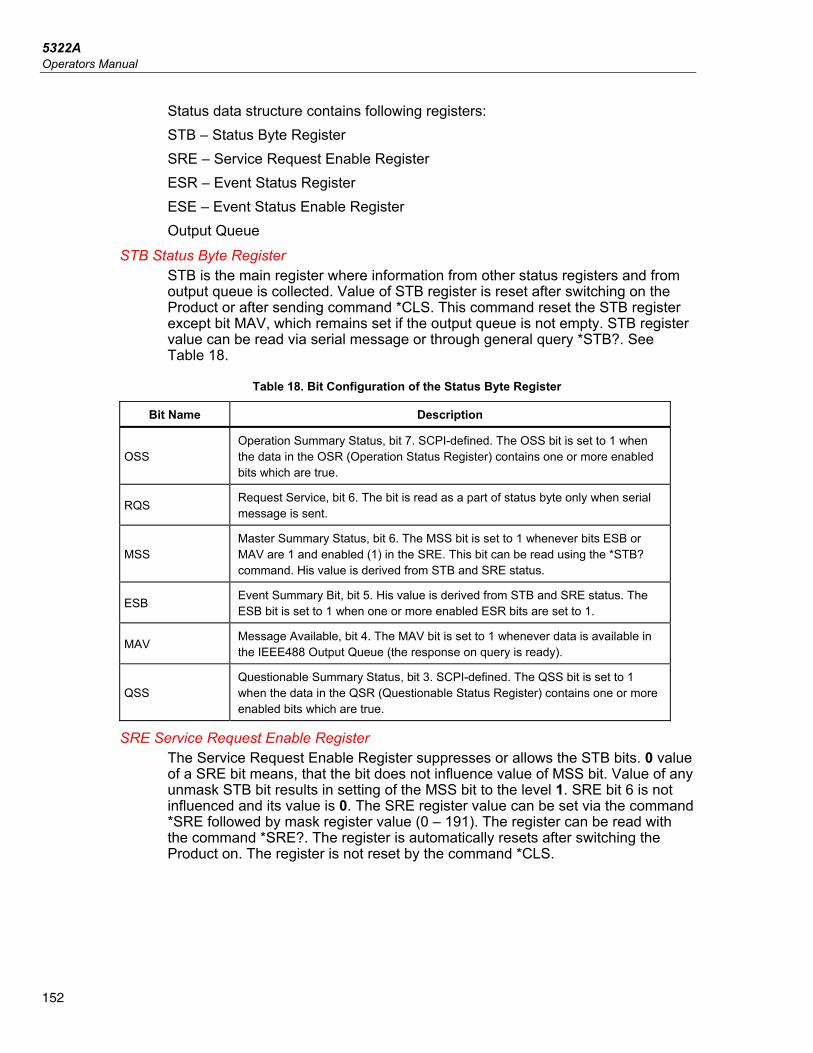
5322A Operators Manual
152
Status data structure contains following registers: STB – Status Byte Register SRE – Service Request Enable Register ESR – Event Status Register ESE – Event Status Enable Register Output Queue
STB Status Byte Register STB is the main register where information from other status registers and from output queue is collected. Value of STB register is reset after switching on the Product or after sending command *CLS. This command reset the STB register except bit MAV, which remains set if the output queue is not empty. STB register value can be read via serial message or through general query *STB?. See Table 18.
Table 18. Bit Configuration of the Status Byte Register
Bit Name Description
OSS Operation Summary Status, bit 7. SCPI-defined. The OSS bit is set to 1 when the data in the OSR (Operation Status Register) contains one or more enabled bits which are true.
RQS Request Service, bit 6. The bit is read as a part of status byte only when serial message is sent.
MSS Master Summary Status, bit 6. The MSS bit is set to 1 whenever bits ESB or MAV are 1 and enabled (1) in the SRE. This bit can be read using the *STB? command. His value is derived from STB and SRE status.
ESB Event Summary Bit, bit 5. His value is derived from STB and SRE status. The ESB bit is set to 1 when one or more enabled ESR bits are set to 1.
MAV Message Available, bit 4. The MAV bit is set to 1 whenever data is available in the IEEE488 Output Queue (the response on query is ready).
QSS Questionable Summary Status, bit 3. SCPI-defined. The QSS bit is set to 1 when the data in the QSR (Questionable Status Register) contains one or more enabled bits which are true.
SRE Service Request Enable Register The Service Request Enable Register suppresses or allows the STB bits. 0 value of a SRE bit means, that the bit does not influence value of MSS bit. Value of any unmask STB bit results in setting of the MSS bit to the level 1. SRE bit 6 is not influenced and its value is 0. The SRE register value can be set via the command *SRE followed by mask register value (0 – 191). The register can be read with the command *SRE?. The register is automatically resets after switching the Product on. The register is not reset by the command *CLS.
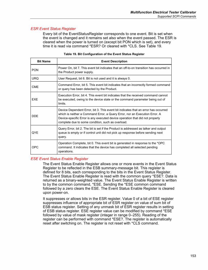
Multifunction Electrical Tester Calibrator Supported SCPI Commands
153
ESR Event Status Register Every bit of the EventStatusRegister corresponds to one event. Bit is set when the event is changed and it remains set also when the event passed. The ESR is cleared when the power is turned on (except bit PON which is set), and every time it is read via command *ESR? Or cleared with *CLS. See Table 19.
Table 19. Bit Configuration of the Event Status Register
Bit Name Event Description
PON Power On, bit 7. This event bit indicates that an off-to-on transition has occurred in the Product power supply.
URQ User Request, bit 6. Bit is not used and it is always 0.
CME Command Error, bit 5. This event bit indicates that an incorrectly formed command or query has been detected by the Product.
EXE Execution Error, bit 4. This event bit indicates that the received command cannot be executed, owing to the device state or the command parameter being out of limits.
DDE
Device Dependent Error, bit 3. This event bit indicates that an error has occurred which is neither a Command Error, a Query Error, nor an Execution Error. A Device-specific Error is any executed device operation that did not properly complete due to some condition, such as overload.
QYE Query Error, bit 2. The bit is set if the Product is addressed as talker and output queue is empty or if control unit did not pick up response before sending next query.
OPC Operation Complete, bit 0. This event bit is generated in response to the *OPC command. It indicates that the device has completed all selected pending operations.
ESE Event Status Enable Register The Event Status Enable Register allows one or more events in the Event Status Register to be reflected in the ESB summary-message bit. This register is defined for 8 bits, each corresponding to the bits in the Event Status Register. The Event Status Enable Register is read with the common query *ESE?. Data is returned as a binary-weighted value. The Event Status Enable Register is written to by the common command, *ESE. Sending the *ESE common command followed by a zero clears the ESE. The Event Status Enable Register is cleared upon power-on. It suppresses or allows bits in the ESR register. Value 0 of a bit of ESE register suppresses influence of appropriate bit of ESR register on value of sum bit of ESB status register. Setting of any unmask bit of ESR register results in setting of ESB status register. ESE register value can be modified by command *ESE followed by value of mask register (integer in range 0–255). Reading of the register can be performed with command *ESE?. The register is automatically reset after switching on. The register is not reset with *CLS command.
5322A Operators Manual
154
Operation Status Register The following ‘sticky’ bits in the Operation register are set by their associated conditions: Bit 8 RCD: trip current has been reached in trip time counting is in progress. Bit 9 HIPT: HIPOT Timer has been started and counting is in progress. Setting of Transition Filter is fixed (1 -> 0 change). Bit 8 in the Event Register is set after the RCD trip time function is finished. Bit 9 in the Event Register is set after the HIPOT Timer function is finished.
Questionable Status Register Not used in the Product.
Output Queue The Output Queue stores response messages until they are read from control unit. If there is at minimum one sign in the output queue, the MAV register (message available) is set. The Output Queue is cleared upon power-on and after reading all signs from output queue.
Error Queue The Error Queue stores error messages. They are placed in a first in, first out queue. The queue is read destructively using the query command SYSTem:ERRor? to obtain a code number and error message. The query SYSTem:ERRor? can be used to read errors in the queue until it is empty, when the message 0, No Error will be returned.
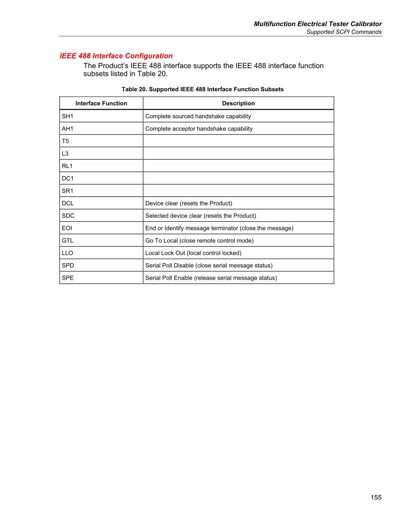
Multifunction Electrical Tester Calibrator Supported SCPI Commands
155
IEEE 488 Interface Configuration The Product’s IEEE 488 interface supports the IEEE 488 interface function subsets listed in Table 20.
Table 20. Supported IEEE 488 Interface Function Subsets
Interface Function Description
SH1 Complete sourced handshake capability
AH1 Complete acceptor handshake capability
T5
L3
RL1
DC1
SR1
DCL Device clear (resets the Product)
SDC Selected device clear (resets the Product)
EOI End or Identify message terminator (close the message)
GTL Go To Local (close remote control mode)
LLO Local Lock Out (local control locked)
SPD Serial Poll Disable (close serial message status)
SPE Serial Poll Enable (release serial message status)
5322A Operators Manual
156
Operator Maintenance XW Warning
To prevent possible electrical shock, fire, or personal injury • For safe operation and maintenance of the Product, turn the
Product off and remove the mains power cord. Stop for 2 minutes to let the power assemblies discharge before you open the fuse door.
• Do not operate the Product with covers removed or the case open. Hazardous voltage exposure is possible.
• Remove the input signals before you clean the Product. • Use only specified replacement parts. • Use only specified replacement fuses. • Have an approved technician repair the Product.
This section ex-plains the routine maintenance and calibration tasks required to keep the Product in optimal operating condition. The tasks covered in this section include: • Cleaning the internal relays used in Ground Bond Resistance and Loop/Line
functions. • Replacing the fuse • Cleaning the air filter and external surfaces • Verifying the operation of the Product There are no user serviceable items within the Product, the operator is not permitted to remove product covers. For intensive maintenance, tasks such as repair, contact the Fluke Calibration service center. The Product should be calibrated annually.
Multifunction Electrical Tester Calibrator Clean the Ground Bond Resistance and Loop/Line Impedance Relays
157
Clean the Ground Bond Resistance and Loop/Line Impedance Relays
The power relays used in the Ground Bond Resistance and Loop/Line Impedance functions require periodic cleaning to minimize their contact resistance. The Ground Bond Resistance and Loop/Line Impedance specifications are based on how often the relays are cleaned. See the 5322A Specifications. If the relay cleaning procedure has not been performed within the past 90 days, the Product prompts you to run the cleaning procedure at startup with the displayed message Start the cleaning procedure. The message shows after the Product is turned on allowing you to run the cleaning procedure immediately or to continue without cleaning the relays. If the cleaning procedure has not been completed, the same message is shown during the next startup operation until the relay cleaning procedure has been completed. Besides the reminder function, relay cleaning can be started manually from the Setup menu. The cleaning procedure exercises the relays on the REL board a number of times with current flowing through them. To perform the relay cleaning procedure, disconnect all external connections to the Product front panel. To clean the relays: 1. Push the Setup softkey. 2. Use the cursor keys or rotary knob to highlight Maintenance and either push
the Select softkey or push in the rotary knob. 3. Use the cursor keys or rotary knob to highlight the Relay cleaning
procedure selection and either push the Select softkey or push in the rotary knob.
4. Push the Select softkey to start the procedure. Please wait is displayed. When the relay cleaning procedure is finished, the Product automatically returns to the main menu.
5322A Operators Manual
158
Access the Fuses The Product uses fuses to protect both the line-power input and various front-panel terminals of the Product. The subsequent sections describe the replacement procedures and lists the appropriate fuses used in the Product.
Line-Power Fuse The Product has a line-power fuse in series with the power supply. Table 21 indicates the proper fuse for each line voltage selection. To replace the line power fuse: 1. Unplug the power cord from the Product. 2. Locate the fuse holder labeled Power Fuse on the rear panel of the Product
(see Rear-Panel Features). 3. Using a flat-blade screwdriver in the slot on the end of the fuse holder,
unscrew the fuse holder. 4. Replace the fuse with one rated for the selected line voltage. 5. Reinsert the fuse holder and screw it into the socket.
Table 21. Line Power Fuses
Line Voltage Selection Fuse Fluke Part No.
115 V W T4L250V (5 x 20 mm) 2743488
230 V W T2L250V (5 x 20 mm) 2743495
Measurement Input Fuses The Amps (A) terminal of the METER input, the HI terminal of the OUPUT terminals, and the L terminal or the RCD terminals are protected by fuses at the rear of the Product. To replace these fuses: 1. Unplug all connections to the front panel of the Product. 2. Unplug the power cord from the Product. 3. Locate the fuse holder for the function on the rear panel of the Product (see
Rear-Panel Features). 4. Using a flat-blade screwdriver in the slot on the end of the fuse holder,
unscrew the fuse holder. 5. Replace the fuse with one rated for the selected function. See Table 22. 6. Reinsert the fuse holder and screw it into the socket.
Multifunction Electrical Tester Calibrator Clean the Air Filter
159
W Caution To avoid damaging the Product, use only the fuse specified for each of the measurement inputs as listed in Table 22.
Table 22. Measurement Input Fuses
Input Fuse Fluke Part No.
RCD W F3.15H250 V (5 mm x 20 mm) 2743508
Leakage Current W F100mL250 V (5 mm x 20 mm) 2743513
Meter W T20H500 V (6.3 mm x 32 mm) 4778086
Loop/Line Impedance W T4H500V (6.3 mm x 32 mm) 2743524
Clean the Air Filter W Caution
Damage caused by overheating may occur if the area around the fan is restricted, the intake air is too warm, or the air filter becomes clogged.
The air filter must be removed and cleaned at least every 30 days, or more frequently if the Product is operated in a dusty environment. The air filter is accessible from the rear panel of the Product. To clean the air filter, proceed as follows, see Figure 29: 1. Unplug all connections to the front panel of the Product. 2. Unplug the power cord from the Product. 3. Remove the filter by grasping the outside edges of the filter and pulling
straight out. 4. Remove the filter element from the filter frame. 5. Clean the filter by washing it in soapy water. Rinse and dry the filter element
thoroughly before reinstalling. 6. Reinstall the filter element into the filter frame. 7. Snap the filter frame back on to the fan housing.
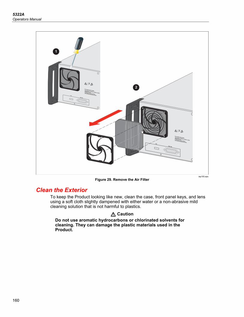
5322A Operators Manual
160
USB
&
USB
1
2
X»
&
X»
iep183.eps
Figure 29. Remove the Air Filter
Clean the Exterior To keep the Product looking like new, clean the case, front panel keys, and lens using a soft cloth slightly dampened with either water or a non-abrasive mild cleaning solution that is not harmful to plastics.
W Caution Do not use aromatic hydrocarbons or chlorinated solvents for cleaning. They can damage the plastic materials used in the Product.
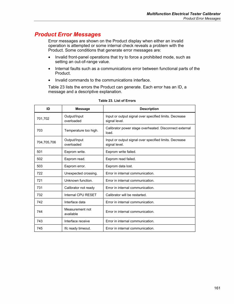
Multifunction Electrical Tester Calibrator Product Error Messages
161
Product Error Messages Error messages are shown on the Product display when either an invalid operation is attempted or some internal check reveals a problem with the Product. Some conditions that generate error messages are: • Invalid front-panel operations that try to force a prohibited mode, such as
setting an out-of-range value. • Internal faults such as a communications error between functional parts of the
Product. • Invalid commands to the communications interface. Table 23 lists the errors the Product can generate. Each error has an ID, a message and a descriptive explanation.
Table 23. List of Errors
ID Message Description
701,702 Output/Input overloaded
Input or output signal over specified limits. Decrease signal level.
703 Temperature too high. Calibrator power stage overheated. Disconnect external load.
704,705,706 Output/Input overloaded
Input or output signal over specified limits. Decrease signal level.
501 Eeprom write. Eeprom write failed.
502 Eeprom read. Eeprom read failed.
503 Eeprom error. Eeprom data lost.
722 Unexpected crossing. Error in internal communication.
721 Unknown function. Error in internal communication.
731 Calibrator not ready Error in internal communication.
732 Internal CPU RESET Calibrator will be restarted.
742 Interface data Error in internal communication.
744 Measurement not available Error in internal communication.
743 Interface receive Error in internal communication.
745 Ifc ready timeout. Error in internal communication.
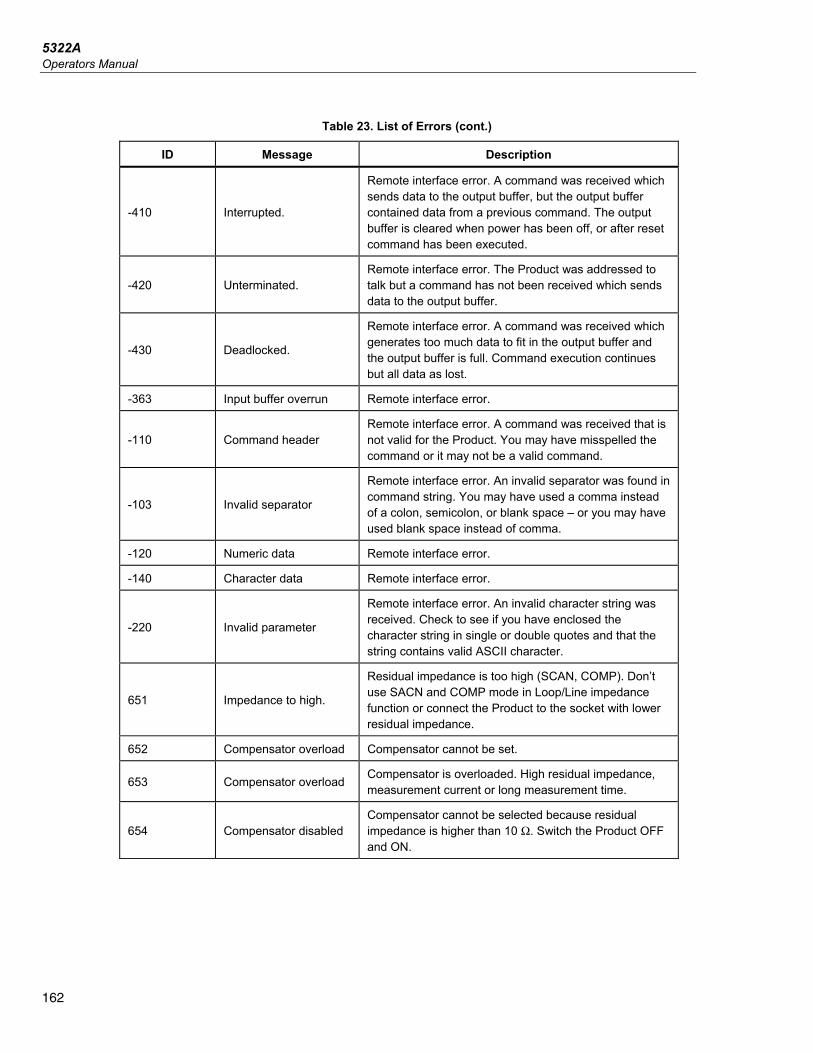
5322A Operators Manual
162
Table 23. List of Errors (cont.)
ID Message Description
-410 Interrupted.
Remote interface error. A command was received which sends data to the output buffer, but the output buffer contained data from a previous command. The output buffer is cleared when power has been off, or after reset command has been executed.
-420 Unterminated. Remote interface error. The Product was addressed to talk but a command has not been received which sends data to the output buffer.
-430 Deadlocked.
Remote interface error. A command was received which generates too much data to fit in the output buffer and the output buffer is full. Command execution continues but all data as lost.
-363 Input buffer overrun Remote interface error.
-110 Command header Remote interface error. A command was received that is not valid for the Product. You may have misspelled the command or it may not be a valid command.
-103 Invalid separator
Remote interface error. An invalid separator was found in command string. You may have used a comma instead of a colon, semicolon, or blank space – or you may have used blank space instead of comma.
-120 Numeric data Remote interface error.
-140 Character data Remote interface error.
-220 Invalid parameter
Remote interface error. An invalid character string was received. Check to see if you have enclosed the character string in single or double quotes and that the string contains valid ASCII character.
651 Impedance to high.
Residual impedance is too high (SCAN, COMP). Don’t use SACN and COMP mode in Loop/Line impedance function or connect the Product to the socket with lower residual impedance.
652 Compensator overload Compensator cannot be set.
653 Compensator overload Compensator is overloaded. High residual impedance, measurement current or long measurement time.
654 Compensator disabled Compensator cannot be selected because residual impedance is higher than 10 Ω. Switch the Product OFF and ON.
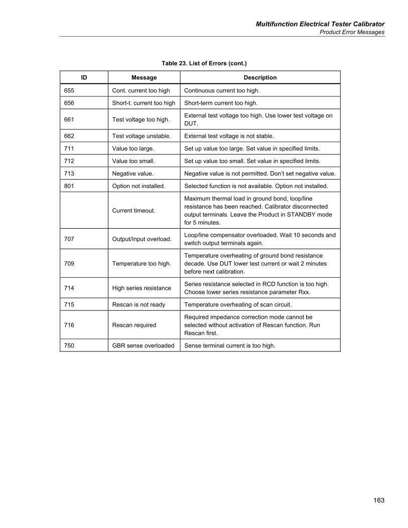
Multifunction Electrical Tester Calibrator Product Error Messages
163
Table 23. List of Errors (cont.)
ID Message Description
655 Cont. current too high Continuous current too high.
656 Short-t. current too high Short-term current too high.
661 Test voltage too high. External test voltage too high. Use lower test voltage on DUT.
662 Test voltage unstable. External test voltage is not stable.
711 Value too large. Set up value too large. Set value in specified limits.
712 Value too small. Set up value too small. Set value in specified limits.
713 Negative value. Negative value is not permitted. Don’t set negative value.
801 Option not installed. Selected function is not available. Option not installed.
Current timeout.
Maximum thermal load in ground bond, loop/line resistance has been reached. Calibrator disconnected output terminals. Leave the Product in STANDBY mode for 5 minutes.
707 Output/Input overload. Loop/line compensator overloaded. Wait 10 seconds and switch output terminals again.
709 Temperature too high. Temperature overheating of ground bond resistance decade. Use DUT lower test current or wait 2 minutes before next calibration.
714 High series resistance Series resistance selected in RCD function is too high. Choose lower series resistance parameter Rxx.
715 Rescan is not ready Temperature overheating of scan circuit.
716 Rescan required Required impedance correction mode cannot be selected without activation of Rescan function. Run Rescan first.
750 GBR sense overloaded Sense terminal current is too high.
5322A Operators Manual
164
What to Do In Case of Product Failure If an obvious failure occurs during operation (for example the display is not lit, the fan is not turning), the Product must be powered off immediately. First, check the line power fuse located on the rear panel of the Product. See Access the Fuses. If a Product range or an operating mode is not functioning and the user cannot correct the fault, contact the Fluke Calibration Service Center. Subtle faults can cause different symptoms and have different causes. Usually, they cause instability of some parameter. Subtle defects can be caused by events such as unacceptable distortion or degraded insulation. In this case contact the Fluke Calibration Service Center. If the rules for correct operation are not adhered to, it may seem as if the Product has a subtle defect. Some abnormalities may actually be due to circumstances outside of the Product, or operator error. See Prepare the Product for Operation. Most frequent cases of defects are: • Mains voltage out of tolerance limits, unstable, distorted voltage or there are
voltage spikes present. • Incorrect grounding of the mains circuit (bad connection of the ground
terminal of the mains outlet). • Proximity to sources that have either high conducted or radiated
electromagnetic fields. • Strong electrostatic or electromagnetic fields which can cause major
instability during usage, particularly when working with high impedance (>1 MΩ).
DUT Calibration Examples This section demonstrates the use of the Product with actual calibration examples for various DUTs. For each Product function, calibration steps along with connection figures are provided for at least one DUT.
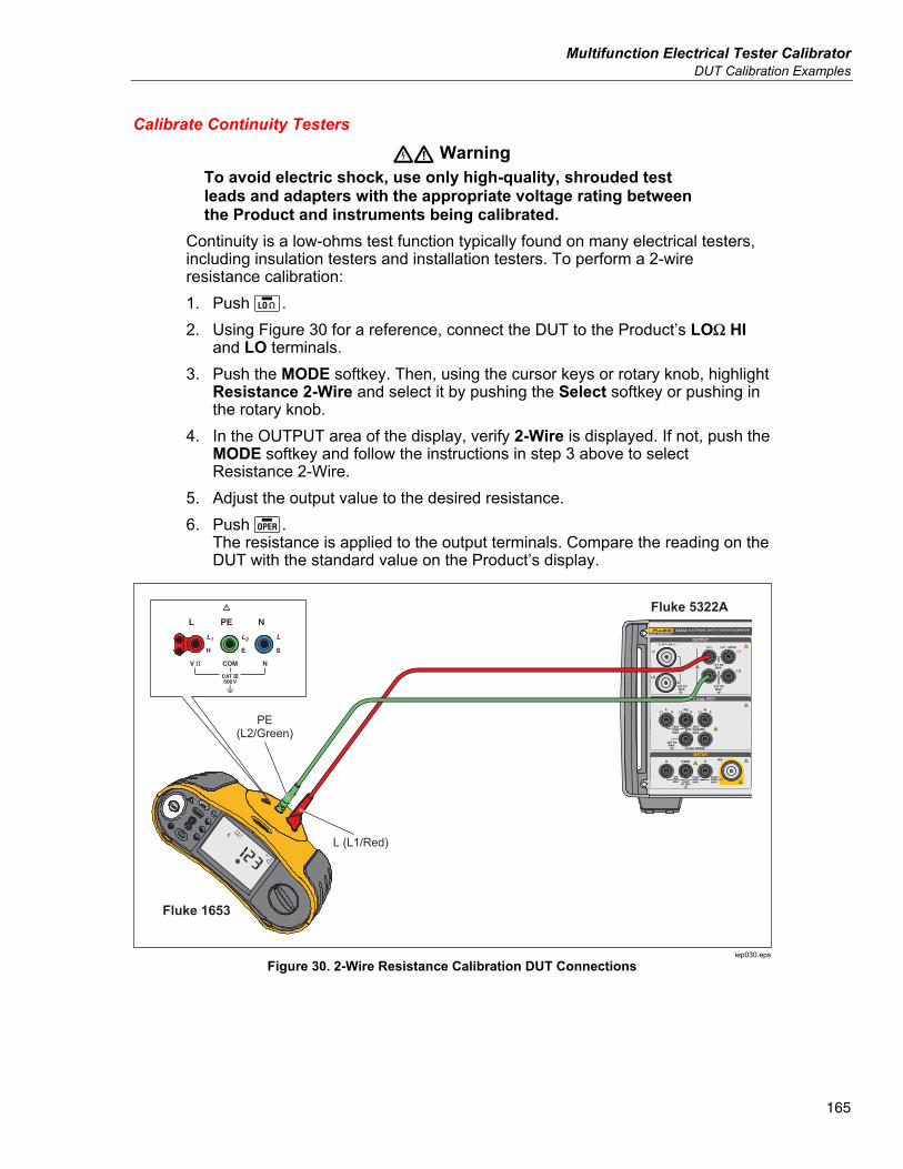
Multifunction Electrical Tester Calibrator DUT Calibration Examples
165
Calibrate Continuity Testers
XW Warning To avoid electric shock, use only high-quality, shrouded test leads and adapters with the appropriate voltage rating between the Product and instruments being calibrated.
Continuity is a low-ohms test function typically found on many electrical testers, including insulation testers and installation testers. To perform a 2-wire resistance calibration: 1. Push . 2. Using Figure 30 for a reference, connect the DUT to the Product’s LOΩ HI
and LO terminals. 3. Push the MODE softkey. Then, using the cursor keys or rotary knob, highlight
Resistance 2-Wire and select it by pushing the Select softkey or pushing in the rotary knob.
4. In the OUTPUT area of the display, verify 2-Wire is displayed. If not, push the MODE softkey and follow the instructions in step 3 above to select Resistance 2-Wire.
5. Adjust the output value to the desired resistance. 6. Push .
The resistance is applied to the output terminals. Compare the reading on the DUT with the standard value on the Product’s display.
Fluke 1653
L (L1/Red)
Fluke 5322A
PE(L2/Green)
iep030.eps
Figure 30. 2-Wire Resistance Calibration DUT Connections
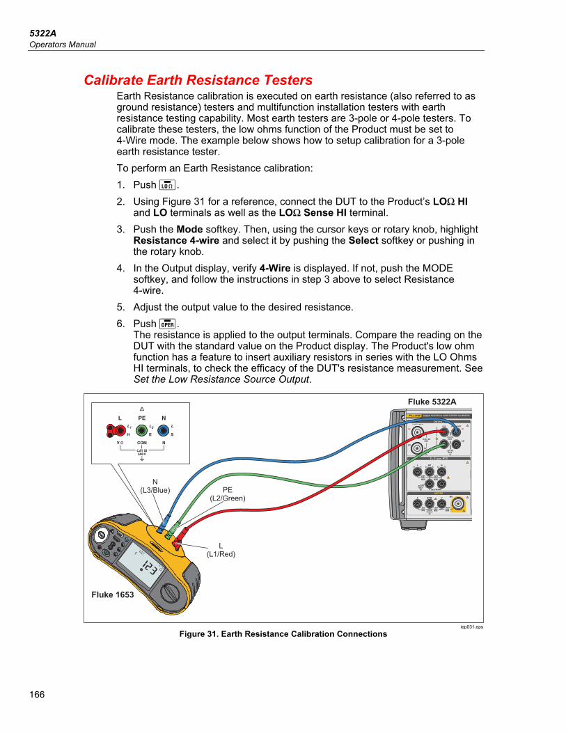
5322A Operators Manual
166
Calibrate Earth Resistance Testers Earth Resistance calibration is executed on earth resistance (also referred to as ground resistance) testers and multifunction installation testers with earth resistance testing capability. Most earth testers are 3-pole or 4-pole testers. To calibrate these testers, the low ohms function of the Product must be set to 4-Wire mode. The example below shows how to setup calibration for a 3-pole earth resistance tester. To perform an Earth Resistance calibration: 1. Push . 2. Using Figure 31 for a reference, connect the DUT to the Product’s LOΩ HI
and LO terminals as well as the LOΩ Sense HI terminal. 3. Push the Mode softkey. Then, using the cursor keys or rotary knob, highlight
Resistance 4-wire and select it by pushing the Select softkey or pushing in the rotary knob.
4. In the Output display, verify 4-Wire is displayed. If not, push the MODE softkey, and follow the instructions in step 3 above to select Resistance 4-wire.
5. Adjust the output value to the desired resistance. 6. Push .
The resistance is applied to the output terminals. Compare the reading on the DUT with the standard value on the Product display. The Product's low ohm function has a feature to insert auxiliary resistors in series with the LO Ohms HI terminals, to check the efficacy of the DUT's resistance measurement. See Set the Low Resistance Source Output.
Fluke 5322A
Fluke 1653
PE(L2/Green)
L(L1/Red)
N(L3/Blue)
iep031.eps
Figure 31. Earth Resistance Calibration Connections
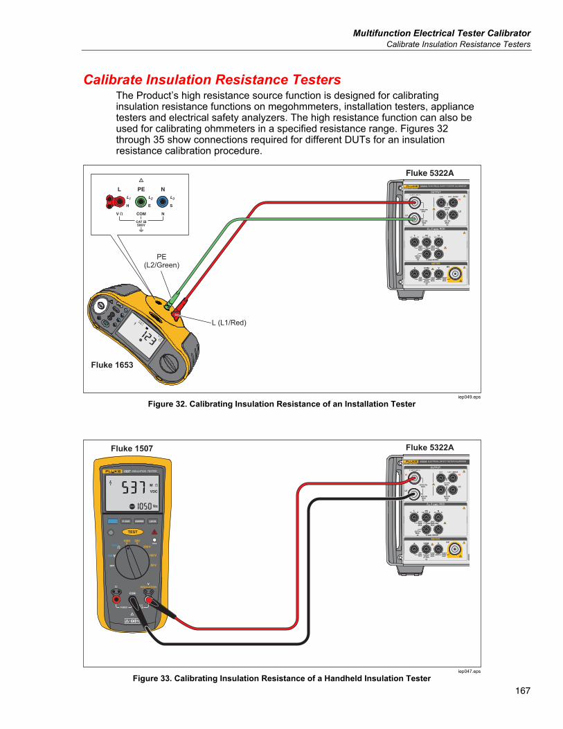
Multifunction Electrical Tester Calibrator Calibrate Insulation Resistance Testers
167
Calibrate Insulation Resistance Testers The Product’s high resistance source function is designed for calibrating insulation resistance functions on megohmmeters, installation testers, appliance testers and electrical safety analyzers. The high resistance function can also be used for calibrating ohmmeters in a specified resistance range. Figures 32 through 35 show connections required for different DUTs for an insulation resistance calibration procedure.
Fluke 5322A
Fluke 1653
PE(L2/Green)
L (L1/Red)
iep049.eps
Figure 32. Calibrating Insulation Resistance of an Installation Tester
Fluke 1507 Fluke 5322A
iep047.eps
Figure 33. Calibrating Insulation Resistance of a Handheld Insulation Tester
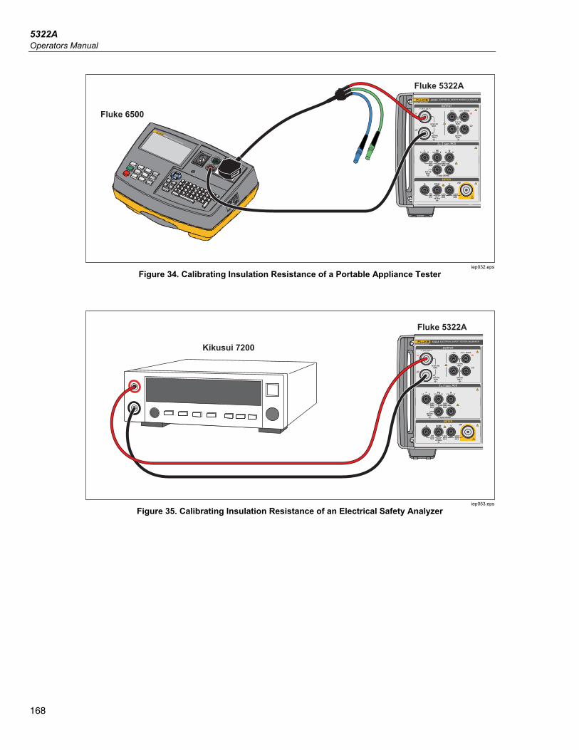
5322A Operators Manual
168
Fluke 5322A
Fluke 6500
IPE < 3.5mA
(0.75mA PORTABLE
APPLIANCE)
INSULATION I SUB
BOND ZERO
IEC LEAD
EARTH BOND
LOAD / LEAK
ITOUCH
ITOUCH < 0.25 mA
RISO > 1.0M Class I R ISO > 2.0M Class II
RPE < 0.1 RISO > 1.0M Class I
RPE 200mA, RPE 25A
RPE < 0.1 + LEADPROBE ONLY WITH
CLASS II APPLIANCE
6500-2 APPLIANCE TESTER
iep032.eps
Figure 34. Calibrating Insulation Resistance of a Portable Appliance Tester
Kikusui 7200
Fluke 5322AATOR
iep053.eps
Figure 35. Calibrating Insulation Resistance of an Electrical Safety Analyzer
Multifunction Electrical Tester Calibrator Calibrate Insulation Resistance Testers
169
To do an Insulation Resistance calibration: 1. Push . 2. Using Figures 33, 34, or 35, connect the DUT to the Product’s HI Ω OUTPUT
HI and LO terminals. 3. Push the Mode softkey. Then, using the cursor keys or rotary knob, highlight
Resistance and select it by pushing the Select softkey or pushing in the rotary knob.
4. Adjust the resistance value for the desired resistance. W Caution
To avoid an overload condition, ensure the DUT test voltage is below the Product’s allowed voltage limit before adjusting the resistance value. 1. Set the test voltage on the DUT. 2. Push . 3. Activate the measurement on the DUT by pushing its start or test button.
The test voltage generated by the DUT is measured by the Product and displayed in the PARAMETERS area of the display.
4. Compare the DUT reading with the resistance value in the OUTPUT area of the display.
5. Stop the test by releasing the appropriate test button on the DUT. 6. Push to disconnect the output terminals from the DUT.
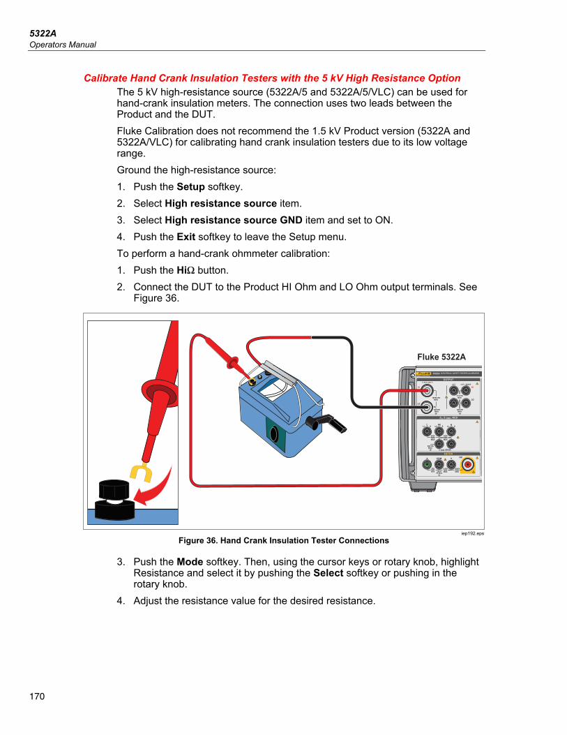
5322A Operators Manual
170
Calibrate Hand Crank Insulation Testers with the 5 kV High Resistance Option The 5 kV high-resistance source (5322A/5 and 5322A/5/VLC) can be used for hand-crank insulation meters. The connection uses two leads between the Product and the DUT. Fluke Calibration does not recommend the 1.5 kV Product version (5322A and 5322A/VLC) for calibrating hand crank insulation testers due to its low voltage range. Ground the high-resistance source: 1. Push the Setup softkey. 2. Select High resistance source item. 3. Select High resistance source GND item and set to ON. 4. Push the Exit softkey to leave the Setup menu. To perform a hand-crank ohmmeter calibration: 1. Push the HiΩ button. 2. Connect the DUT to the Product HI Ohm and LO Ohm output terminals. See
Figure 36.
Fluke 5322A
UI
UI
iep192.eps
Figure 36. Hand Crank Insulation Tester Connections
3. Push the Mode softkey. Then, using the cursor keys or rotary knob, highlight Resistance and select it by pushing the Select softkey or pushing in the rotary knob.
4. Adjust the resistance value for the desired resistance.
Multifunction Electrical Tester Calibrator Calibrate Insulation Resistance Testers
171
W Caution To avoid an overload condition, make sure that the DUT test voltage is below the Product’s allowed voltage limit before you adjust the resistance value.
5. Push OPER. 6. Activate the measurement on the DUT by cranking the handle. 7. The test voltage generated by the DUT is measured by the Product and
shown on the display. 8. Compare the DUT reading with the resistance value in the OUTPUT area of
the display. Note
An alternative to this procedure is to change the Product output resistance using the rotary knob so that the DUT reads a cardinal point. The deviation from nominal is an indication of the error of the meter.
9. Release the handle on the DUT to stop the test. 10. Push STBY to disconnect the output terminals from the DUT.
Calibrate Insulation Resistance Testers with the Resistance Multiplier
XW Warning To avoid electric shock, connect the Resistance Multiplier adapter chassis to protective earth ground (PE) on the Product front panel. The ground terminal on the rear panel of the Product can also be used for this purpose.
The Product’s Resistance Multiplier adapter is used to increase the range of the high resistance source from 350 MΩ to 10 TΩ for calibrating DUTs with stimulus voltage up to 10 kV. The Resistance Multiplier is only used with insulation resistance testers with a third terminal, commonly called the Guard terminal. Most testers of this type use a virtual ground sensing circuit, that effectively gives an input resistance of 0 Ω. The Product accommodates testers that have either 0 Ω input impedance or a finite input impedance. The Product has a setup parameter, R multiplier input, to accommodate different input impedances for insulation testers. The R multiplier input has a default setting of 0 Ω, which are the most common type of testers with a virtual ground sensing circuit. For other testers with a different input impedance, the R multiplier input value must be set to match the input resistance of the DUT. To access the R multiplier input setting: 1. Push the Setup softkey. 2. Scroll down to High Resistance Source. 3. Push the Select softkey.
5322A Operators Manual
172
Choose R multiplier input, which can be changed from 0 Ω to 100.00 MΩ. To use the Resistance Multiplier: 1. Push . 2. Connect the DUT to the resistance multiplier adapter and the Product as
shown in Figure 37 and Figure 38. 3. Push the Mode softkey. Then, use the cursor keys or rotary knob to highlight
Resistance and select it by pushing the Select softkey or by pushing in the rotary knob.
Note For correct readings, the high resistance source ground must be turned off. Go to Setup>High resistance source>High resistance source GND and select Off.
4. If YES is not already displayed after R Multiplier in the PARAMETERS area of the display, push the R Mult softkey.
5. Adjust the value for desired resistance. 6. Push .
WCaution When using the Resistance Multiplier, the Product cannot monitor the DUT scan test voltage. To avoid possible damage to the adapter and Product, do not exceed maximum peak voltage of 10k V on the input terminals of the Resistance Multiplier.
7. Activate the measurement on the DUT by pushing its start or test button. 8. Compare the DUT reading with the resistance value in the OUTPUT area of
the display. 9. Stop the test by releasing the appropriate test button on the DUT. 10. Push to disconnect the output terminals from the DUT.
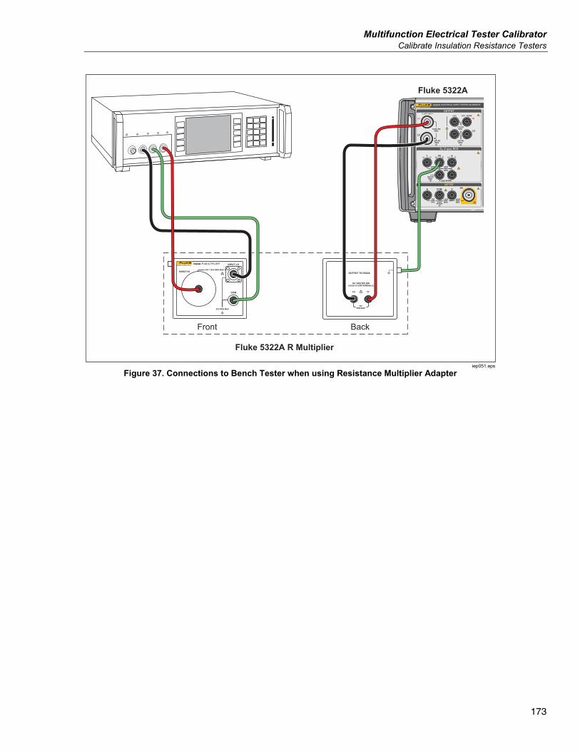
Multifunction Electrical Tester Calibrator Calibrate Insulation Resistance Testers
173
Fluke 5322A
Fluke 5322A R Multiplier
Front Back
iep051.eps
Figure 37. Connections to Bench Tester when using Resistance Multiplier Adapter
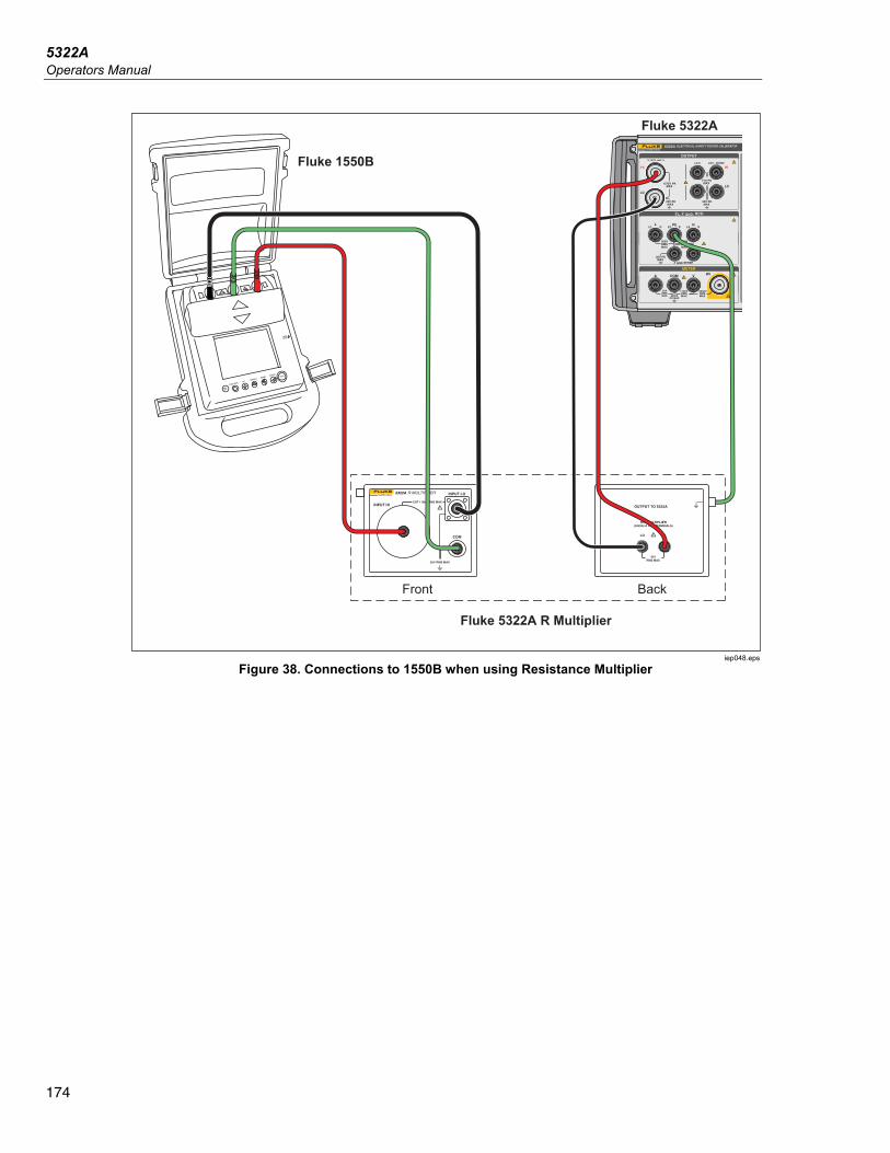
5322A Operators Manual
174
FUNCTION
ON/OFF
UPSCROLL
IRDAPORT
DOWN ENTERTEST
Fluke 5322A R Multiplier
Front Back
Fluke 1550B
Fluke 5322A
iep048.eps
Figure 38. Connections to 1550B when using Resistance Multiplier
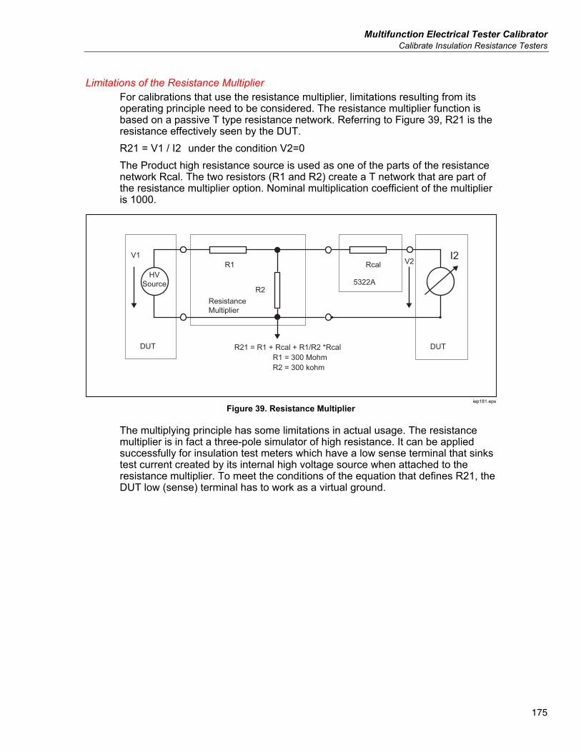
Multifunction Electrical Tester Calibrator Calibrate Insulation Resistance Testers
175
Limitations of the Resistance Multiplier For calibrations that use the resistance multiplier, limitations resulting from its operating principle need to be considered. The resistance multiplier function is based on a passive T type resistance network. Referring to Figure 39, R21 is the resistance effectively seen by the DUT. R21 = V1 / I2 under the condition V2=0 The Product high resistance source is used as one of the parts of the resistance network Rcal. The two resistors (R1 and R2) create a T network that are part of the resistance multiplier option. Nominal multiplication coefficient of the multiplier is 1000.
I2R1
DUT DUT
HVSource
ResistanceMultiplier
5322A
Rcal
R2
R21 = R1 + Rcal + R1/R2 *Rcal R1 = 300 Mohm R2 = 300 kohm
V1V2
iep181.eps
Figure 39. Resistance Multiplier
The multiplying principle has some limitations in actual usage. The resistance multiplier is in fact a three-pole simulator of high resistance. It can be applied successfully for insulation test meters which have a low sense terminal that sinks test current created by its internal high voltage source when attached to the resistance multiplier. To meet the conditions of the equation that defines R21, the DUT low (sense) terminal has to work as a virtual ground.
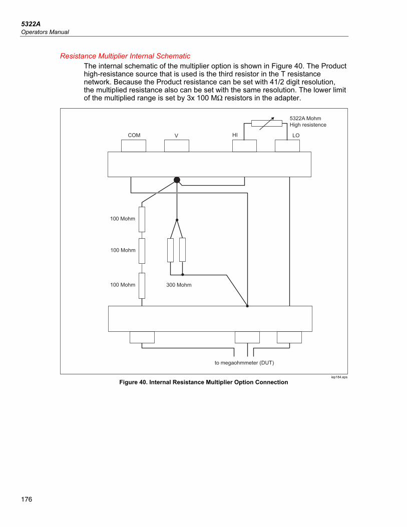
5322A Operators Manual
176
Resistance Multiplier Internal Schematic The internal schematic of the multiplier option is shown in Figure 40. The Product high-resistance source that is used is the third resistor in the T resistance network. Because the Product resistance can be set with 41/2 digit resolution, the multiplied resistance also can be set with the same resolution. The lower limit of the multiplied range is set by 3x 100 MΩ resistors in the adapter.
COM
100 Mohm
5322A MohmHigh resistence
to megaohmmeter (DUT)
100 Mohm
100 Mohm 300 Mohm
V HI LO
iep184.eps
Figure 40. Internal Resistance Multiplier Option Connection
Multifunction Electrical Tester Calibrator Calibrate Insulation Resistance Testers
177
Types of Megohmmeters and Use of the Resistance Multiplier From a functional point of view, megohmmeters have these designs: a. Two terminal meters. Terminal meters are equipped with two single sense
terminals usually measuring a resistance ratio against an internal range resistor. The meters require two pole resistance standards for calibration. The meters can be calibrated with the Product up to 100 GΩ but not in the extended range with the resistance multiplier adapter. Typical examples are models Fluke 165x and other hand-held ohmmeters and multimeters.
b. Two terminal meters with a third Guard terminal. The guard terminal is used the most for electrostatic shielding to avoid spurious leakage currents flowing along the surface of objects in the measurement area. The meters can be calibrated with the Product up to 100 GΩ but not in the extended range with the resistance multiplier adapter.
c. Three terminal meters with a proper third terminal (COM or GUARD or GROUND) and with a virtual μA-meter low sense terminal. The COM terminal is used as a common terminal of the source of test voltage and the sense μA-meter. The meters can be calibrated both directly by the Product and the resistance multiplier adapter.
d. Three terminal meters with a third terminal (COM or GUARD or GROUND) and with a μA-meter that has a fixed input resistance in the low sense terminal. The COM terminal is again used as a common terminal of the source of test voltage and sense μA-meter. The meters can be calibrated directly with the Product and with the resistance multiplier adapter. The input resistance in the low meter terminal must be known and entered as a correction in the Product (Setup>High resistance source>R multiplier input). The meter input resistance is usually specified in its operation manual.
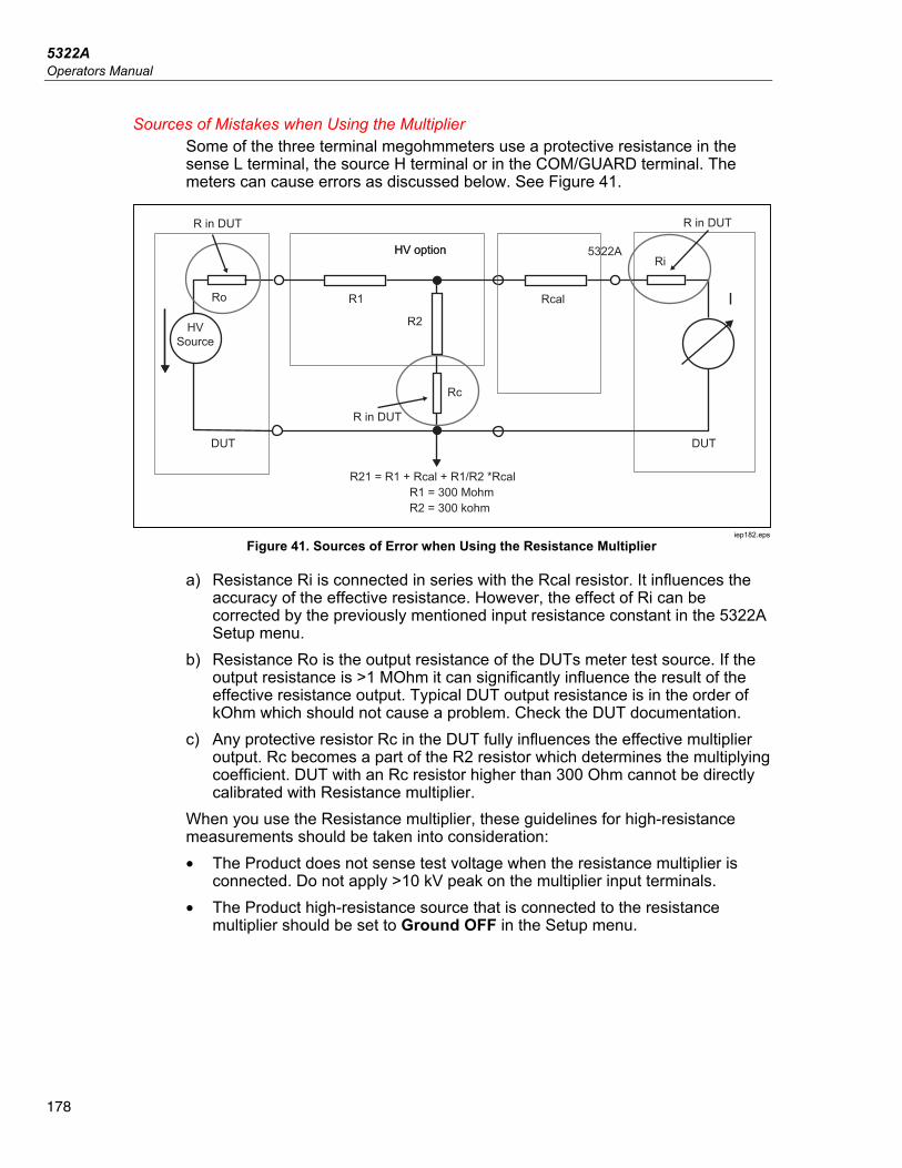
5322A Operators Manual
178
Sources of Mistakes when Using the Multiplier Some of the three terminal megohmmeters use a protective resistance in the sense L terminal, the source H terminal or in the COM/GUARD terminal. The meters can cause errors as discussed below. See Figure 41.
HV Source
Rc
Ro
Ri
DUT
R in DUT R in DUT
R in DUT
DUT
R1
R21 = R1 + Rcal + R1/R2 *Rcal R1 = 300 Mohm R2 = 300 kohm
5322AHV optionHV option
R2
Rcal I
iep182.eps
Figure 41. Sources of Error when Using the Resistance Multiplier
a) Resistance Ri is connected in series with the Rcal resistor. It influences the accuracy of the effective resistance. However, the effect of Ri can be corrected by the previously mentioned input resistance constant in the 5322A Setup menu.
b) Resistance Ro is the output resistance of the DUTs meter test source. If the output resistance is >1 MOhm it can significantly influence the result of the effective resistance output. Typical DUT output resistance is in the order of kOhm which should not cause a problem. Check the DUT documentation.
c) Any protective resistor Rc in the DUT fully influences the effective multiplier output. Rc becomes a part of the R2 resistor which determines the multiplying coefficient. DUT with an Rc resistor higher than 300 Ohm cannot be directly calibrated with Resistance multiplier.
When you use the Resistance multiplier, these guidelines for high-resistance measurements should be taken into consideration: • The Product does not sense test voltage when the resistance multiplier is
connected. Do not apply >10 kV peak on the multiplier input terminals. • The Product high-resistance source that is connected to the resistance
multiplier should be set to Ground OFF in the Setup menu.
Multifunction Electrical Tester Calibrator Calibrate Insulation Resistance Testers
179
XWWarning To prevent possible electrical shock, fire, or personal injury, when you use the Resistance Multiplier adapter, connect its chassis to protective earth ground (PE) on the Product front panel. The ground terminal on the rear panel of the Product can also be used for this purpose.
• Some megohmmeters may require switching leads from the Product OUTPUT HI and LO terminals to the HI and LO terminals on the Resistance multiplier. Check which configuration gives the desired readings.
Calibrate Ground Bond Resistance Testers Use the Ground Bond Resistance function to calibrate ground bond testers. Some multifunction electrical testers include ground bond testing functionality, including portable appliance testers and electrical safety analyzers.
XW Warning To avoid electric shock, test leads must NOT be connected to N or L contacts of the DUT’s appliance socket. These contacts have power line voltage applied to them. Also ensure the PE pin does not have dangerous voltage present before making any connections.
W Caution To avoid possible damage to the Product, ensure DUT test current does not exceed maximum allowed current for the test being performed. See the Specifications document at www.Flukecal.com for maximum ratings.
To calibrate Ground Bond Resistance tester: 1. Push . 2. Connect the DUT to the ZGND PE and N terminals of the Product as in
Figure 42 and Figure 43. 3. Push the Mode softkey. Then, using the cursor keys or rotary knob, highlight
Resistance and select it by pushing the Select softkey or pushing in the rotary knob.
4. Select the Ground Bond Resistance function on the DUT. 5. Adjust the resistance value to the desired resistance.
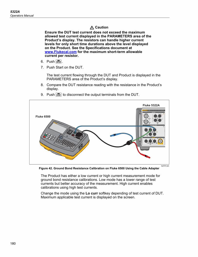
5322A Operators Manual
180
W Caution Ensure the DUT test current does not exceed the maximum allowed test current displayed in the PARAMETERS area of the Product’s display. The resistors can handle higher current levels for only short time durations above the level displayed on the Product. See the Specifications document at www.Flukecal.com for the maximum short-term allowable current per resistor.
6. Push . 7. Push Start on the DUT.
The test current flowing through the DUT and Product is displayed in the PARAMETERS area of the Product’s display.
8. Compare the DUT resistance reading with the resistance in the Product’s display.
9. Push to disconnect the output terminals from the DUT.
IPE < 3.5mA
(0.75mA PORTABLE
APPLIANCE)
INSULATION I SUB
BOND ZERO
IEC LEAD
EARTH BOND
LOAD / LEAK
ITOUCH
ITOUCH < 0.25 mA
RISO > 1.0M Class I R ISO > 2.0M Class II
RPE < 0.1 RISO > 1.0M Class I
RPE 200mA, RPE 25A
RPE < 0.1 + LEADPROBE ONLY WITH
CLASS II APPLIANCE
6500-2 APPLIANCE TESTER
Fluke 5322A
Fluke 6500
iep034.eps
Figure 42. Ground Bond Resistance Calibration on Fluke 6500 Using the Cable Adapter
The Product has either a low current or high current measurement mode for ground bond resistance calibrations. Low mode has a lower range of test currents but better accuracy of the measurement. High current enables calibrations using high test currents. Change the mode using the Lo curr softkey depending of test current of DUT. Maximum applicable test current is displayed on the screen.
Multifunction Electrical Tester Calibrator Calibrate Ground Bond Resistance Function in HIPOT Testers
181
Calibrate Ground Bond Resistance Function in HIPOT Testers
Use the 4-wire Ground Bond resistance mode to calibrate ground bond resistance testers that have a four-terminal connection. Typical application is calibration of HIPOT testers and dedicated ground bond testers.
W Caution To avoid possible damage to the Product, ensure DUT test current does not exceed maximum allowed current for the test being performed. See the Specifications document at www.Flukecal.com for maximum ratings.
To perform a Ground Bond Resistance calibration in the 4-wire Ground Bond resistance mode: 1. Push . 2. Connect the Product as shown in Figure 43. 3. Push the MODE softkey, then using the cursor keys or rotary knob, highlight
Resistance 4W and select it by pushing the Select softkey or pushing in the rotary knob.
4. Select the Nominal resistance by pushing the Nom R softkey until the desired resistance is shown in the Parameters display area.
5. Set the Product to low current or high current mode using Product softkey depending upon the DUT setting.
6. Push . 7. Start the DUT test. The Product INPUT display shows the actual value of the
nominal resistance (R0 – R 5) in red while the DUT is measuring. At the end of the test, the INPUT display turns black. Match that reading against the last reading on the DUT.
8. Push and disconnect the DUT from the Product. 9. Use either low current or high current mode depending upon the tester
setting.
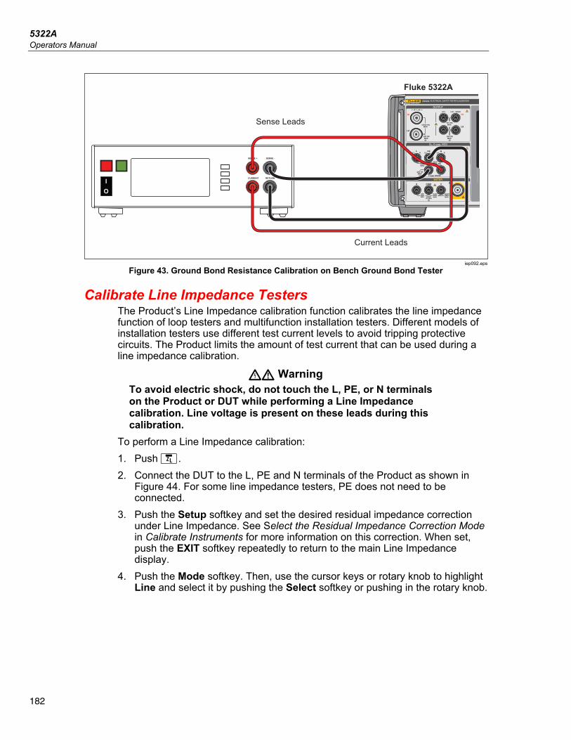
5322A Operators Manual
182
Fluke 5322A
SENSE + SENSE -
CURRENT RETURN
IO
Sense Leads
Current Leads
iep092.eps
Figure 43. Ground Bond Resistance Calibration on Bench Ground Bond Tester
Calibrate Line Impedance Testers The Product’s Line Impedance calibration function calibrates the line impedance function of loop testers and multifunction installation testers. Different models of installation testers use different test current levels to avoid tripping protective circuits. The Product limits the amount of test current that can be used during a line impedance calibration.
XW Warning To avoid electric shock, do not touch the L, PE, or N terminals on the Product or DUT while performing a Line Impedance calibration. Line voltage is present on these leads during this calibration.
To perform a Line Impedance calibration: 1. Push . 2. Connect the DUT to the L, PE and N terminals of the Product as shown in
Figure 44. For some line impedance testers, PE does not need to be connected.
3. Push the Setup softkey and set the desired residual impedance correction under Line Impedance. See Select the Residual Impedance Correction Mode in Calibrate Instruments for more information on this correction. When set, push the EXIT softkey repeatedly to return to the main Line Impedance display.
4. Push the Mode softkey. Then, use the cursor keys or rotary knob to highlight Line and select it by pushing the Select softkey or pushing in the rotary knob.
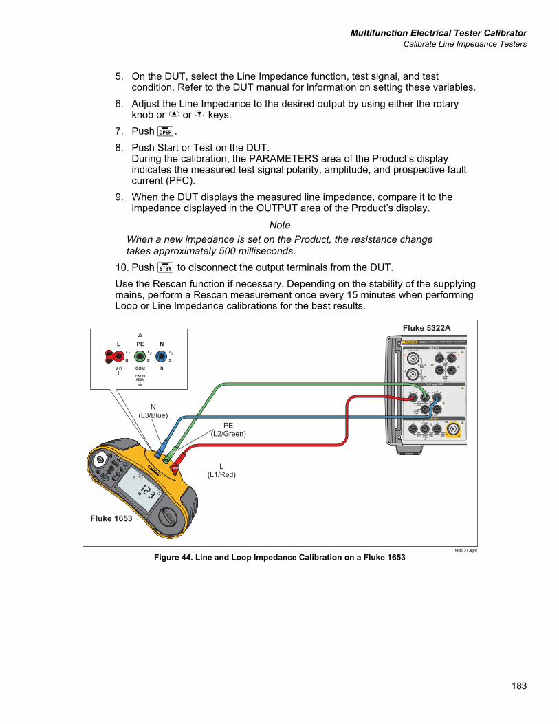
Multifunction Electrical Tester Calibrator Calibrate Line Impedance Testers
183
5. On the DUT, select the Line Impedance function, test signal, and test condition. Refer to the DUT manual for information on setting these variables.
6. Adjust the Line Impedance to the desired output by using either the rotary knob or or keys.
7. Push . 8. Push Start or Test on the DUT.
During the calibration, the PARAMETERS area of the Product’s display indicates the measured test signal polarity, amplitude, and prospective fault current (PFC).
9. When the DUT displays the measured line impedance, compare it to the impedance displayed in the OUTPUT area of the Product’s display.
Note When a new impedance is set on the Product, the resistance change takes approximately 500 milliseconds.
10. Push to disconnect the output terminals from the DUT. Use the Rescan function if necessary. Depending on the stability of the supplying mains, perform a Rescan measurement once every 15 minutes when performing Loop or Line Impedance calibrations for the best results.
Fluke 1653
Fluke 5322A
PE(L2/Green)
L(L1/Red)
N(L3/Blue)
iep037.eps
Figure 44. Line and Loop Impedance Calibration on a Fluke 1653
5322A Operators Manual
184
Calibrate Loop Impedance Testers Use the Product Loop Impedance calibration function to calibrate loop testers and multifunction installation testers.
XW Warning To avoid electric shock, do not touch the L, PE, or N terminals on the Product or DUT while performing a Loop Impedance calibration. Line voltage is present on these leads during this calibration.
To perform a Loop Impedance calibration: 1. Push . 2. Connect the DUT to the L, PE, and N terminals of the Product as shown in
Figure 44. 3. Push the Setup softkey and set the desired residual impedance correction
under Loop Impedance. See Select the Residual Impedance Correction Mode in Calibrate Instruments for more information on this correction. When set, push the EXIT softkey repeatedly to return to the main Line Impedance display.
4. Push the Mode softkey. Then, use the cursor keys or rotary knob to highlight Loop and select it by pushing the Select softkey or by pushing in the rotary knob.
5. On the DUT, select the Loop Impedance function, test signal, and test condition. Refer to the DUT manual for information on setting these variables.
6. Set the Product to the desired Z residual correction setting. Many DUTs can be used with the COMP setting with good results. See Calibrate Instruments for more information regarding the Z residual correction.
7. Check the series resistance setting on the Product. Ensure the value is appropriate for this DUT setup. See Calibrate Instruments for more information on the series resistance feature.
8. Adjust the Loop Impedance to the desired output by using the rotary knob or or keys.
9. Push . 10. Push Start on the DUT. 11. When the DUT displays the measured line impedance, compare it to the
impedance displayed in the OUTPUT area of the Product display. Note
When a new impedance is set on the Product, the resistance change takes approximately 500 milliseconds.
12. Push to disconnect the output terminals from the DUT. Use the Rescan function if necessary. Depending on the stability of the supplying mains it is recommended to perform a Rescan measurement once every 15 minutes when performing Loop or Line Impedance calibrations.
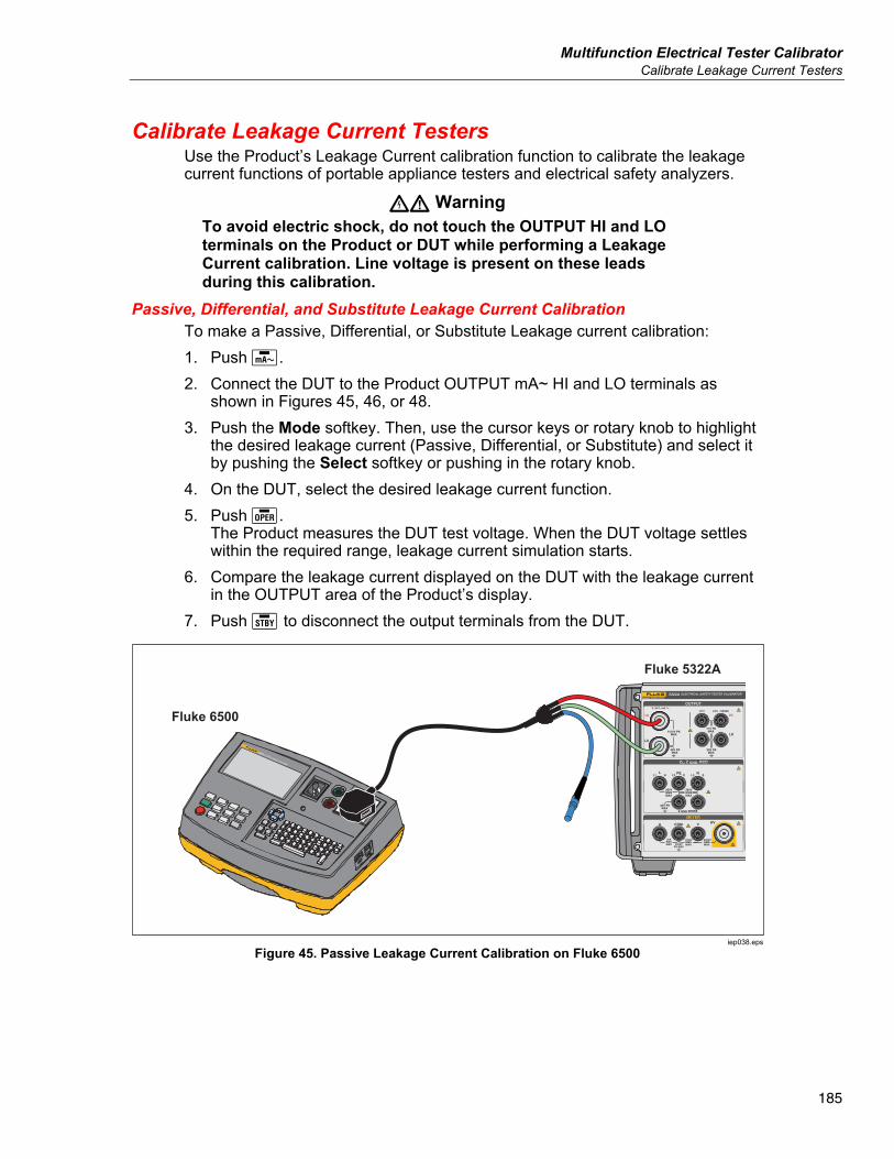
Multifunction Electrical Tester Calibrator Calibrate Leakage Current Testers
185
Calibrate Leakage Current Testers Use the Product’s Leakage Current calibration function to calibrate the leakage current functions of portable appliance testers and electrical safety analyzers.
XW Warning To avoid electric shock, do not touch the OUTPUT HI and LO terminals on the Product or DUT while performing a Leakage Current calibration. Line voltage is present on these leads during this calibration.
Passive, Differential, and Substitute Leakage Current Calibration To make a Passive, Differential, or Substitute Leakage current calibration: 1. Push . 2. Connect the DUT to the Product OUTPUT mA~ HI and LO terminals as
shown in Figures 45, 46, or 48. 3. Push the Mode softkey. Then, use the cursor keys or rotary knob to highlight
the desired leakage current (Passive, Differential, or Substitute) and select it by pushing the Select softkey or pushing in the rotary knob.
4. On the DUT, select the desired leakage current function. 5. Push .
The Product measures the DUT test voltage. When the DUT voltage settles within the required range, leakage current simulation starts.
6. Compare the leakage current displayed on the DUT with the leakage current in the OUTPUT area of the Product’s display.
7. Push to disconnect the output terminals from the DUT.
IPE < 3.5mA
(0.75mA PORTABLE
APPLIANCE)
INSULATION I SUB
BOND ZERO
IEC LEAD
EARTH BOND
LOAD / LEAK
ITOUCH
ITOUCH < 0.25 mA
RISO > 1.0M Class I R ISO > 2.0M Class II
RPE < 0.1 RISO > 1.0M Class I
RPE 200mA, RPE 25A
RPE < 0.1 + LEADPROBE ONLY WITH
CLASS II APPLIANCE
6500-2 APPLIANCE TESTER
Fluke 5322A
Fluke 6500
iep038.eps
Figure 45. Passive Leakage Current Calibration on Fluke 6500
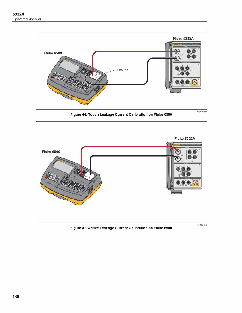
5322A Operators Manual
186
IPE < 3.5mA
(0.75mA PORTABLE
APPLIANCE)
INSULATION I SUB
BOND ZERO
IEC LEAD
EARTH BOND
LOAD / LEAK
ITOUCH
ITOUCH < 0.25 mA
RISO > 1.0M Class I R ISO > 2.0M Class II
RPE < 0.1 RISO > 1.0M Class I
RPE 200mA, RPE 25A
RPE < 0.1 + LEADPROBE ONLY WITH
CLASS II APPLIANCE
6500-2 APPLIANCE TESTER
Fluke 5322A
Fluke 6500
Line Pin
iep039.eps
Figure 46. Touch Leakage Current Calibration on Fluke 6500
IPE < 3.5mA
(0.75mA PORTABLE
APPLIANCE)
INSULATION I SUB
BOND ZERO
IEC LEAD
EARTH BOND
LOAD / LEAK
ITOUCH
ITOUCH < 0.25 mA
RISO > 1.0M Class I R ISO > 2.0M Class II
RPE < 0.1 RISO > 1.0M Class I
RPE 200mA, RPE 25A
RPE < 0.1 + LEADPROBE ONLY WITH
CLASS II APPLIANCE
6500-2 APPLIANCE TESTER
Fluke 5322A
Fluke 6500
ATOR
iep056.eps
Figure 47. Active Leakage Current Calibration on Fluke 6500
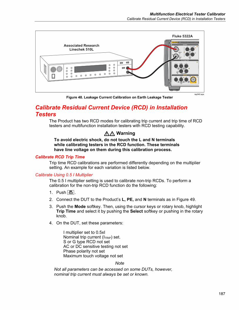
Multifunction Electrical Tester Calibrator Calibrate Residual Current Device (RCD) in Installation Testers
187
Associated ResearchLinechek 510L
Fluke 5322A
iep040.eps
Figure 48. Leakage Current Calibration on Earth Leakage Tester
Calibrate Residual Current Device (RCD) in Installation Testers
The Product has two RCD modes for calibrating trip current and trip time of RCD testers and multifunction installation testers with RCD testing capability.
WX Warning To avoid electric shock, do not touch the L and N terminals while calibrating testers in the RCD function. These terminals have line voltage on them during this calibration process.
Calibrate RCD Trip Time Trip time RCD calibrations are performed differently depending on the multiplier setting. An example for each variation is listed below.
Calibrate Using 0.5 I Multiplier The 0.5 I multiplier setting is used to calibrate non-trip RCDs. To perform a calibration for the non-trip RCD function do the following: 1. Push . 2. Connect the DUT to the Product’s L, PE, and N terminals as in Figure 49. 3. Push the Mode softkey. Then, using the cursor keys or rotary knob, highlight
Trip Time and select it by pushing the Select softkey or pushing in the rotary knob.
4. On the DUT, set these parameters: I multiplier set to 0.5xI Nominal trip current (ITRIP) set. S or G type RCD not set AC or DC sensitive testing not set Phase polarity not set Maximum touch voltage not set
Note Not all parameters can be accessed on some DUTs, however, nominal trip current must always be set or known.
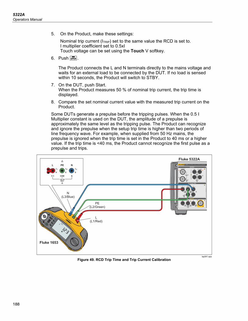
5322A Operators Manual
188
5. On the Product, make these settings: Nominal trip current (ITRIP) set to the same value the RCD is set to. I multiplier coefficient set to 0.5xI Touch voltage can be set using the Touch V softkey.
6. Push . The Product connects the L and N terminals directly to the mains voltage and waits for an external load to be connected by the DUT. If no load is sensed within 10 seconds, the Product will switch to STBY.
7. On the DUT, push Start. When the Product measures 50 % of nominal trip current, the trip time is displayed.
8. Compare the set nominal current value with the measured trip current on the Product.
Some DUTs generate a prepulse before the tripping pulses. When the 0.5 I Multiplier constant is used on the DUT, the amplitude of a prepulse is approximately the same level as the tripping pulse. The Product can recognize and ignore the prepulse when the setup trip time is higher than two periods of line frequency wave. For example, when supplied from 50 Hz mains, the prepulse is ignored when the trip time is set in the Product to 40 ms or a higher value. If the trip time is <40 ms, the Product cannot recognize the first pulse as a prepulse and trips.
PE(L2/Green)
Fluke 5322A
Fluke 1653
L(L1/Red)
N(L3/Blue)
iep041.eps
Figure 49. RCD Trip Time and Trip Current Calibration
Multifunction Electrical Tester Calibrator Calibrate Residual Current Device (RCD) in Installation Testers
189
Calibrate with 1 X I Multiplier In the 1 x I Multiplier mode, the Product acts like a circuit breaker with a set nominal trip current and trip time. To perform a calibration of RCD time: 1. Connect the DUT to the Product’s L, PE, and N terminals as shown in
Figure 49. 2. Push .
If RCD Trip Time does not already appear in the OUTPUT area of the display, push the Mode softkey. Then, use the cursor keys or rotary knob to highlight Trip Time and select it by pushing the Select softkey or pushing in the rotary knob.
3. On the DUT, set these parameters: I multiplier set to 1xI Nominal trip current (ITRIP) set. S or G type RCD not set AC or dc sensitive testing not set Phase polarity not set Maximum touch voltage not set
Note Not all parameters can be accessed on some DUTs. However, nominal trip current must always be set or known.
4. On the Product, make these settings: Nominal trip time in ms Nominal trip current (ITRIP) set to the same value the RCD is set to. I multiplier coefficient set to 1xI I level coefficient. Default set to 90 %. Touch voltage can be set using the Touch V softkeys.
5. Push . The Product connects the L and N terminals directly to the mains voltage and waits for an external load to be connected by the DUT. If the Product does not sense a load within 10 seconds, the Product switches to STBY.
6. On the DUT, push Start. The Product measures the current, after the nominal trip current is reached, the Product starts a timer, and then disconnects the output terminals when the nominal trip time has elapsed.
7. Compare the nominal trip time on the Product display with the trip time displayed on the DUT.
5322A Operators Manual
190
Calibrate with 1.4XI, 2 X I, and 5 X I Multipliers The 1.4 X, 2 X, and 5 X multipliers are used to test RCDs under current overloading conditions, with 1.4 times, 2 times or 5 times higher current than the nominal current setting. To perform an RCD trip time calibration with 1.4 X, 2 X, or 5 X multiplier: 1. Push . 2. Connect the DUT to the Product’s L, PE, and N terminals as in Figure 49. 3. Push the Mode softkey. Then, use the cursor keys or rotary knob to highlight
Trip Time and select it by pushing the Select softkey or pushing in the rotary knob.
4. On the DUT, set these parameters: I multiplier set to 1.4XI, 2xI, or 5xI Nominal trip current (ITRIP) set. S or G type RCD not set AC or dc sensitive testing not set Phase polarity not set Maximum touch voltage not set
Note Not all parameters can be accessed on the DUT, however, nominal trip current must always be set or known.
5. On the Product, make these settings: Nominal trip time in ms Nominal trip current (ITRIP) set to the same value the RCD is set to. I multiplier coefficient set to 1.4xI, 2xI, or 5xI, same as that on the DUT. I level coefficient. Default set to 90 %. Touch voltage can be set using the Touch V softkeys.
6. Push . 7. On the DUT, push Start.
The Product measures the current. After the nominal trip current is reached, the Product starts a timer, and then disconnects the output terminals when the nominal trip time has elapsed.
8. Compare the nominal trip time on the Product display with the trip time displayed on the DUT.
Note When calibrating with a 1.4xI, 2xI, or 5xI setting, the DUT time interval is limited to several hundred milliseconds. If the DUT stops the calibration before the elapsed trip time, the Product disconnects the output terminals from the DUT and displays Set trip time too high.
Multifunction Electrical Tester Calibrator Calibrate Residual Current Device (RCD) in Installation Testers
191
Calibrate RCD Trip Current The Product uses the same connections for trip current calibration as trip time calibration. To do an RCD trip current calibration: 1. Push . 2. Connect the DUT to the Product’s L, PE, and N terminals as shown in
Figure 49. 3. Push the Mode softkey. Then, using the cursor keys or rotary knob, highlight
Trip Current and select it by pushing the Select softkey or pushing in the rotary knob.
4. On the DUT, set these parameters: Trip current function selected Trip current (ITRIP) set S or G type RCD not set AC or dc sensitive testing not set Phase polarity not set Maximum touch voltage not set
5. On the Product, make these settings: Nominal trip current (ITRIP) is set to the same value as the RCD. The series resistance of the touch voltage can be set using the Setup and RCD softkeys. The default series resistance is set to the minimum value.
6. Push . 7. On the DUT, push Start.
The Product measures and then displays the trip current.
8. Compare the nominal trip current with the measured trip current on the Product’s display.
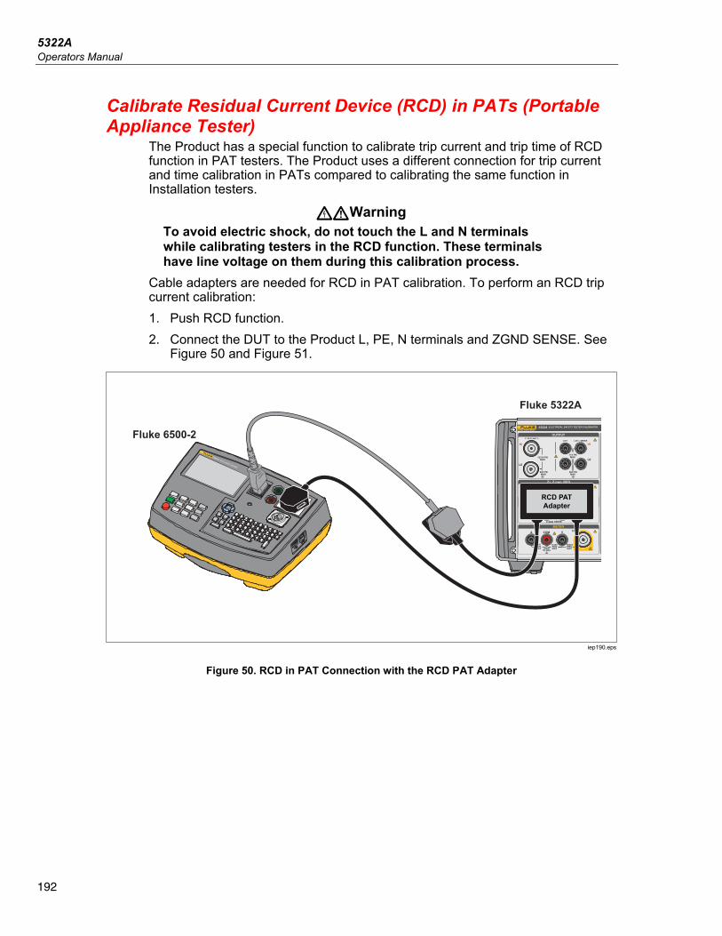
5322A Operators Manual
192
Calibrate Residual Current Device (RCD) in PATs (Portable Appliance Tester)
The Product has a special function to calibrate trip current and trip time of RCD function in PAT testers. The Product uses a different connection for trip current and time calibration in PATs compared to calibrating the same function in Installation testers.
XWWarning To avoid electric shock, do not touch the L and N terminals while calibrating testers in the RCD function. These terminals have line voltage on them during this calibration process.
Cable adapters are needed for RCD in PAT calibration. To perform an RCD trip current calibration: 1. Push RCD function. 2. Connect the DUT to the Product L, PE, N terminals and ZGND SENSE. See
Figure 50 and Figure 51.
IPE < 3.5mA
(0.75mA PORTABLE
APPLIANCE)
INSULATION I SUB
BOND ZERO
IEC LEAD
EARTH BOND
LOAD / LEAK
ITOUCH
ITOUCH < 0.25 mA
RISO > 1.0M Class I R ISO > 2.0M Class II
RPE < 0.1 RISO > 1.0M Class I
RPE 200mA, RPE 25A
RPE < 0.1 + LEADPROBE ONLY WITH
CLASS II APPLIANCE
6500-2 APPLIANCE TESTER
IPE < 3.5mA
(0.75mA PORTABLE
APPLIANCE)
INSULATION I SUB
BOND ZERO
IEC LEAD
EARTH BOND
LOAD / LEAK
ITOUCH
ITOUCH < 0.25 mA
RISO > 1.0M Class I R ISO > 2.0M Class II
RPE < 0.1 RISO > 1.0M Class I
RPE 200mA, RPE 25A
RPE < 0.1 + LEADPROBE ONLY WITH
CLASS II APPLIANCE
6500-2 APPLIANCE TESTER
Fluke 5322A
Fluke 6500-2
RCD PATAdapter
iep190.eps
Figure 50. RCD in PAT Connection with the RCD PAT Adapter
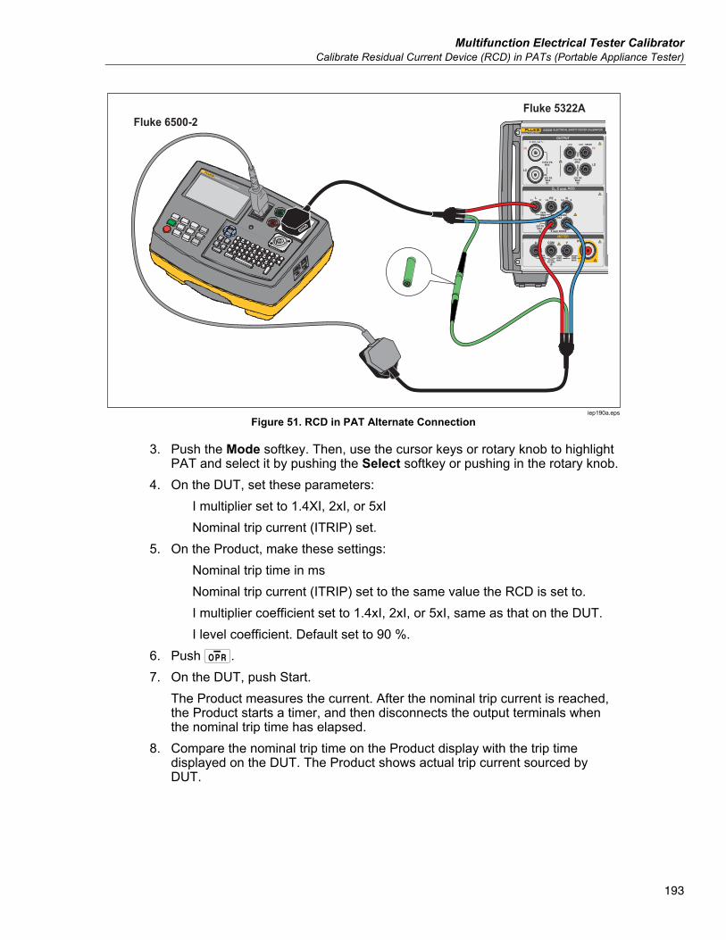
Multifunction Electrical Tester Calibrator Calibrate Residual Current Device (RCD) in PATs (Portable Appliance Tester)
193
Fluke 5322AFluke 6500-2
IPE < 3.5mA
(0.75mA PORTABLE
APPLIANCE)
INSULATION I SUB
BOND ZERO
IEC LEAD
EARTH BOND
LOAD / LEAK
ITOUCH
ITOUCH < 0.25 mA
RISO > 1.0M Class I R ISO > 2.0M Class II
RPE < 0.1 RISO > 1.0M Class I
RPE 200mA, RPE 25A
RPE < 0.1 + LEADPROBE ONLY WITH
CLASS II APPLIANCE
6500-2 APPLIANCE TESTER
IPE < 3.5mA
(0.75mA PORTABLE
APPLIANCE)
INSULATION I SUB
BOND ZERO
IEC LEAD
EARTH BOND
LOAD / LEAK
ITOUCH
ITOUCH < 0.25 mA
RISO > 1.0M Class I R ISO > 2.0M Class II
RPE < 0.1 RISO > 1.0M Class I
RPE 200mA, RPE 25A
RPE < 0.1 + LEADPROBE ONLY WITH
CLASS II APPLIANCE
6500-2 APPLIANCE TESTER
iep190a.eps
Figure 51. RCD in PAT Alternate Connection
3. Push the Mode softkey. Then, use the cursor keys or rotary knob to highlight PAT and select it by pushing the Select softkey or pushing in the rotary knob.
4. On the DUT, set these parameters: I multiplier set to 1.4XI, 2xI, or 5xI Nominal trip current (ITRIP) set.
5. On the Product, make these settings: Nominal trip time in ms Nominal trip current (ITRIP) set to the same value the RCD is set to. I multiplier coefficient set to 1.4xI, 2xI, or 5xI, same as that on the DUT. I level coefficient. Default set to 90 %.
6. Push . 7. On the DUT, push Start.
The Product measures the current. After the nominal trip current is reached, the Product starts a timer, and then disconnects the output terminals when the nominal trip time has elapsed.
8. Compare the nominal trip time on the Product display with the trip time displayed on the DUT. The Product shows actual trip current sourced by DUT.
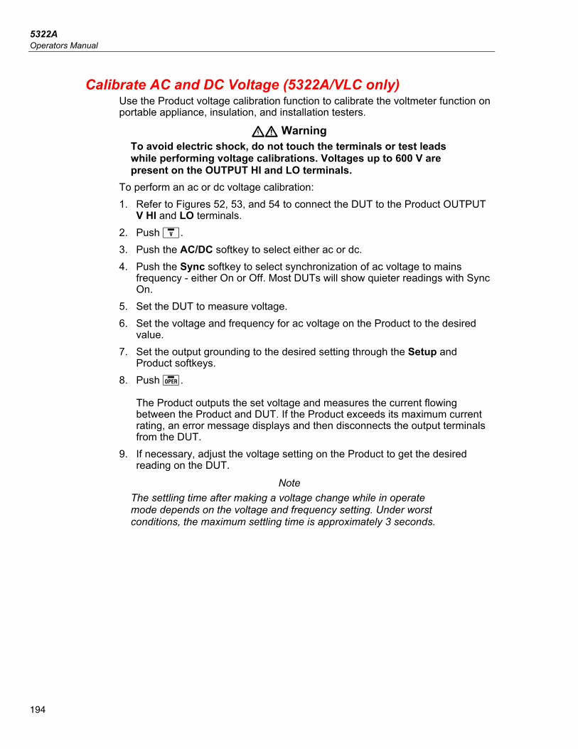
5322A Operators Manual
194
Calibrate AC and DC Voltage (5322A/VLC only) Use the Product voltage calibration function to calibrate the voltmeter function on portable appliance, insulation, and installation testers.
XW Warning To avoid electric shock, do not touch the terminals or test leads while performing voltage calibrations. Voltages up to 600 V are present on the OUTPUT HI and LO terminals.
To perform an ac or dc voltage calibration: 1. Refer to Figures 52, 53, and 54 to connect the DUT to the Product OUTPUT
V HI and LO terminals. 2. Push . 3. Push the AC/DC softkey to select either ac or dc. 4. Push the Sync softkey to select synchronization of ac voltage to mains
frequency - either On or Off. Most DUTs will show quieter readings with Sync On.
5. Set the DUT to measure voltage. 6. Set the voltage and frequency for ac voltage on the Product to the desired
value. 7. Set the output grounding to the desired setting through the Setup and
Product softkeys. 8. Push .
The Product outputs the set voltage and measures the current flowing between the Product and DUT. If the Product exceeds its maximum current rating, an error message displays and then disconnects the output terminals from the DUT.
9. If necessary, adjust the voltage setting on the Product to get the desired reading on the DUT.
Note The settling time after making a voltage change while in operate mode depends on the voltage and frequency setting. Under worst conditions, the maximum settling time is approximately 3 seconds.
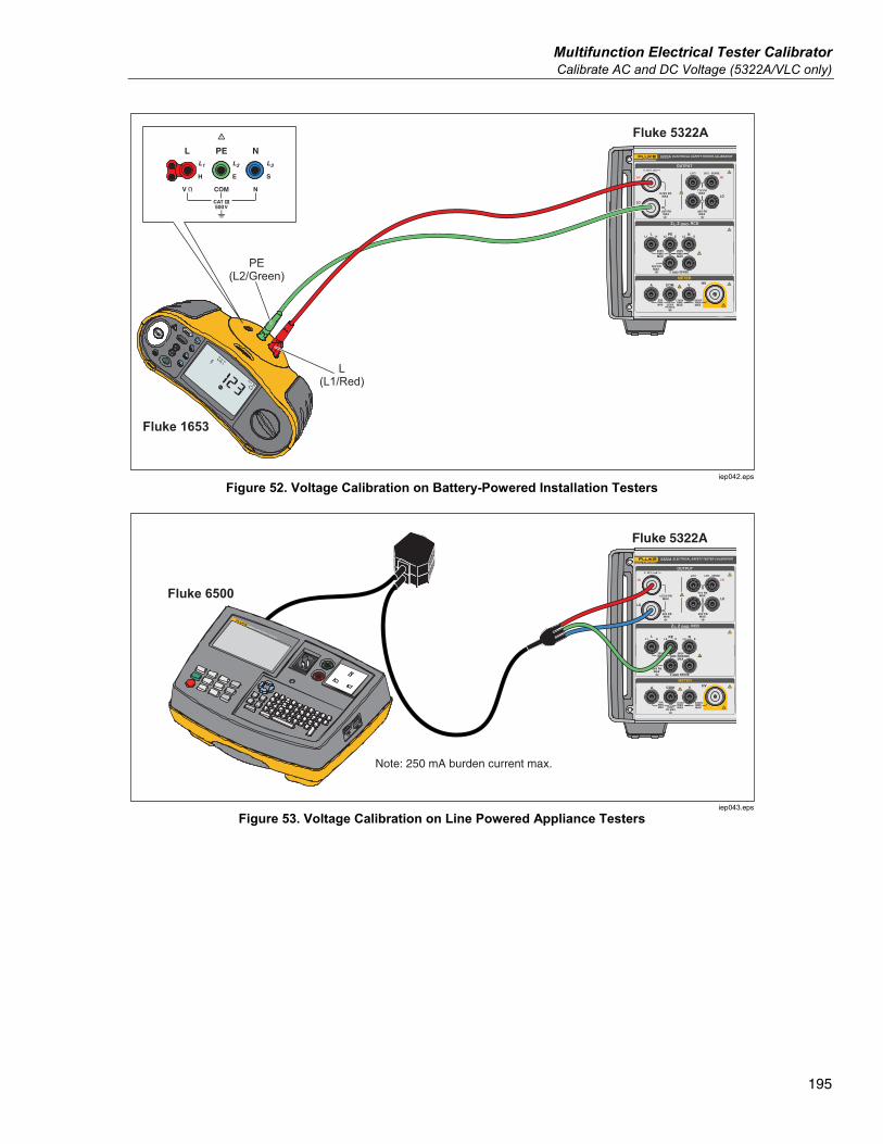
Multifunction Electrical Tester Calibrator Calibrate AC and DC Voltage (5322A/VLC only)
195
Fluke 5322A
Fluke 1653
L(L1/Red)
PE(L2/Green)
iep042.eps
Figure 52. Voltage Calibration on Battery-Powered Installation Testers
IPE < 3.5mA
(0.75mA PORTABLE
APPLIANCE)
INSULATION I SUB
BOND ZERO
IEC LEAD
EARTH BOND
LOAD / LEAK
ITOUCH
ITOUCH < 0.25 mA
RISO > 1.0M Class I R ISO > 2.0M Class II
RPE < 0.1 RISO > 1.0M Class I
RPE 200mA, RPE 25A
RPE < 0.1 + LEADPROBE ONLY WITH
CLASS II APPLIANCE
6500-2 APPLIANCE TESTER
Fluke 5322A
Fluke 6500
Note: 250 mA burden current max.
iep043.eps
Figure 53. Voltage Calibration on Line Powered Appliance Testers
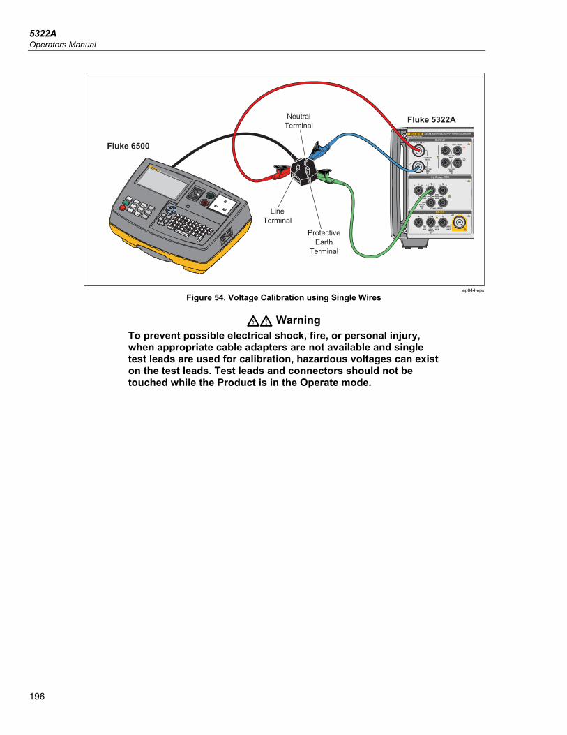
5322A Operators Manual
196
IPE < 3.5mA
(0.75mA PORTABLE
APPLIANCE)
INSULATION I SUB
BOND ZERO
IEC LEAD
EARTH BOND
LOAD / LEAK
ITOUCH
ITOUCH < 0.25 mA
RISO > 1.0M Class I R ISO > 2.0M Class II
RPE < 0.1 RISO > 1.0M Class I
RPE 200mA, RPE 25A
RPE < 0.1 + LEADPROBE ONLY WITH
CLASS II APPLIANCE
6500-2 APPLIANCE TESTER
Fluke 5322A
Fluke 6500
LineTerminal
NeutralTerminal
ProtectiveEarth
Terminal
iep044.eps
Figure 54. Voltage Calibration using Single Wires
XW Warning To prevent possible electrical shock, fire, or personal injury, when appropriate cable adapters are not available and single test leads are used for calibration, hazardous voltages can exist on the test leads. Test leads and connectors should not be touched while the Product is in the Operate mode.
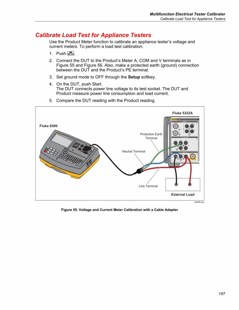
Multifunction Electrical Tester Calibrator Calibrate Load Test for Appliance Testers
197
Calibrate Load Test for Appliance Testers Use the Product Meter function to calibrate an appliance tester’s voltage and current meters. To perform a load test calibration: 1. Push . 2. Connect the DUT to the Product’s Meter A, COM and V terminals as in
Figure 55 and Figure 56. Also, make a protected earth (ground) connection between the DUT and the Product’s PE terminal.
3. Set ground mode to OFF through the Setup softkey. 4. On the DUT, push Start.
The DUT connects power line voltage to its test socket. The DUT and Product measure power line consumption and load current.
5. Compare the DUT reading with the Product reading.
IPE < 3.5mA
(0.75mA PORTABLE
APPLIANCE)
INSULATION I SUB
BOND ZERO
IEC LEAD
EARTH BOND
LOAD / LEAK
ITOUCH
ITOUCH < 0.25 mA
RISO > 1.0M Class I R ISO > 2.0M Class II
RPE < 0.1 RISO > 1.0M Class I
RPE 200mA, RPE 25A
RPE < 0.1 + LEADPROBE ONLY WITH
CLASS II APPLIANCE
6500-2 APPLIANCE TESTER
External Load
Line Terminal
Protection EarthTerminal
Neutral Terminal
Fluke 5322A
Fluke 6500
iep058.eps
Figure 55. Voltage and Current Meter Calibration with a Cable Adapter
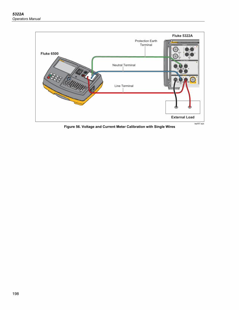
5322A Operators Manual
198
IPE < 3.5mA
(0.75mA PORTABLE
APPLIANCE)
INSULATION I SUB
BOND ZERO
IEC LEAD
EARTH BOND
LOAD / LEAK
ITOUCH
ITOUCH < 0.25 mA
RISO > 1.0M Class I R ISO > 2.0M Class II
RPE < 0.1 RISO > 1.0M Class I
RPE 200mA, RPE 25A
RPE < 0.1 + LEADPROBE ONLY WITH
CLASS II APPLIANCE
6500-2 APPLIANCE TESTER
Fluke 5322A
Fluke 6500
External Load
Line Terminal
Protection EarthTerminal
Neutral Terminal
ATOR
iep057.eps
Figure 56. Voltage and Current Meter Calibration with Single Wires
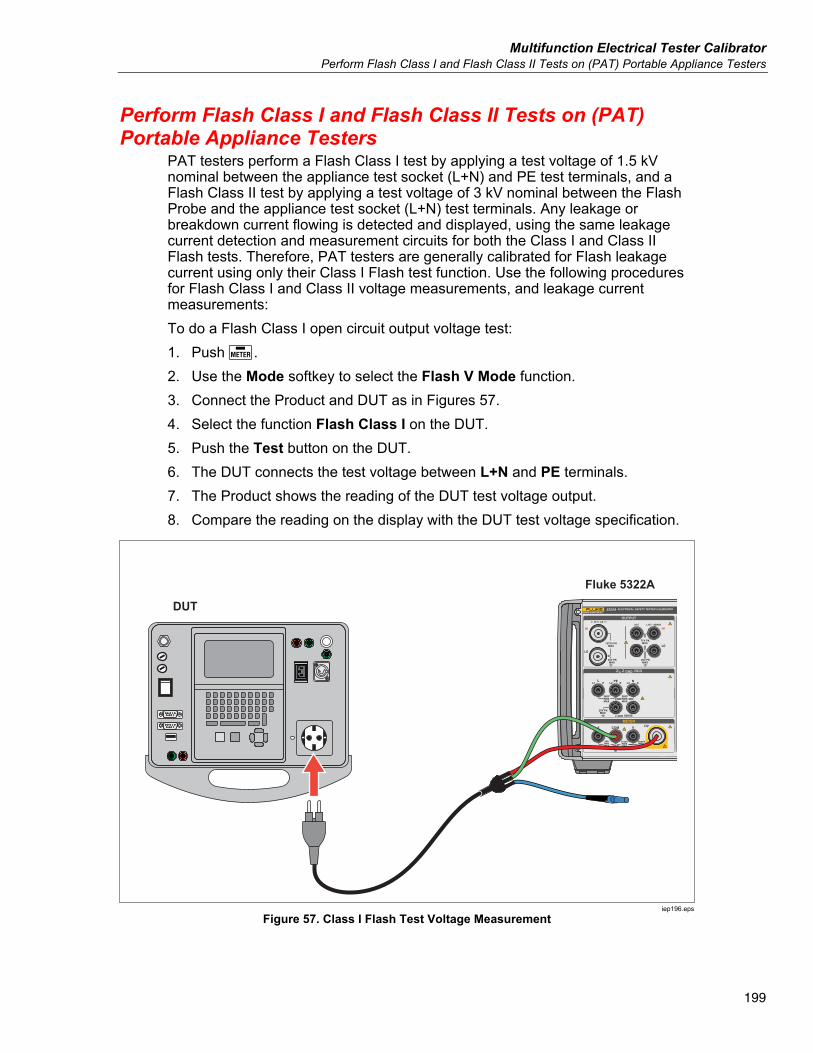
Multifunction Electrical Tester Calibrator Perform Flash Class I and Flash Class II Tests on (PAT) Portable Appliance Testers
199
Perform Flash Class I and Flash Class II Tests on (PAT) Portable Appliance Testers
PAT testers perform a Flash Class I test by applying a test voltage of 1.5 kV nominal between the appliance test socket (L+N) and PE test terminals, and a Flash Class II test by applying a test voltage of 3 kV nominal between the Flash Probe and the appliance test socket (L+N) test terminals. Any leakage or breakdown current flowing is detected and displayed, using the same leakage current detection and measurement circuits for both the Class I and Class II Flash tests. Therefore, PAT testers are generally calibrated for Flash leakage current using only their Class I Flash test function. Use the following procedures for Flash Class I and Class II voltage measurements, and leakage current measurements: To do a Flash Class I open circuit output voltage test: 1. Push . 2. Use the Mode softkey to select the Flash V Mode function. 3. Connect the Product and DUT as in Figures 57. 4. Select the function Flash Class I on the DUT. 5. Push the Test button on the DUT. 6. The DUT connects the test voltage between L+N and PE terminals. 7. The Product shows the reading of the DUT test voltage output. 8. Compare the reading on the display with the DUT test voltage specification.
Fluke 5322A
DUT
iep196.eps
Figure 57. Class I Flash Test Voltage Measurement
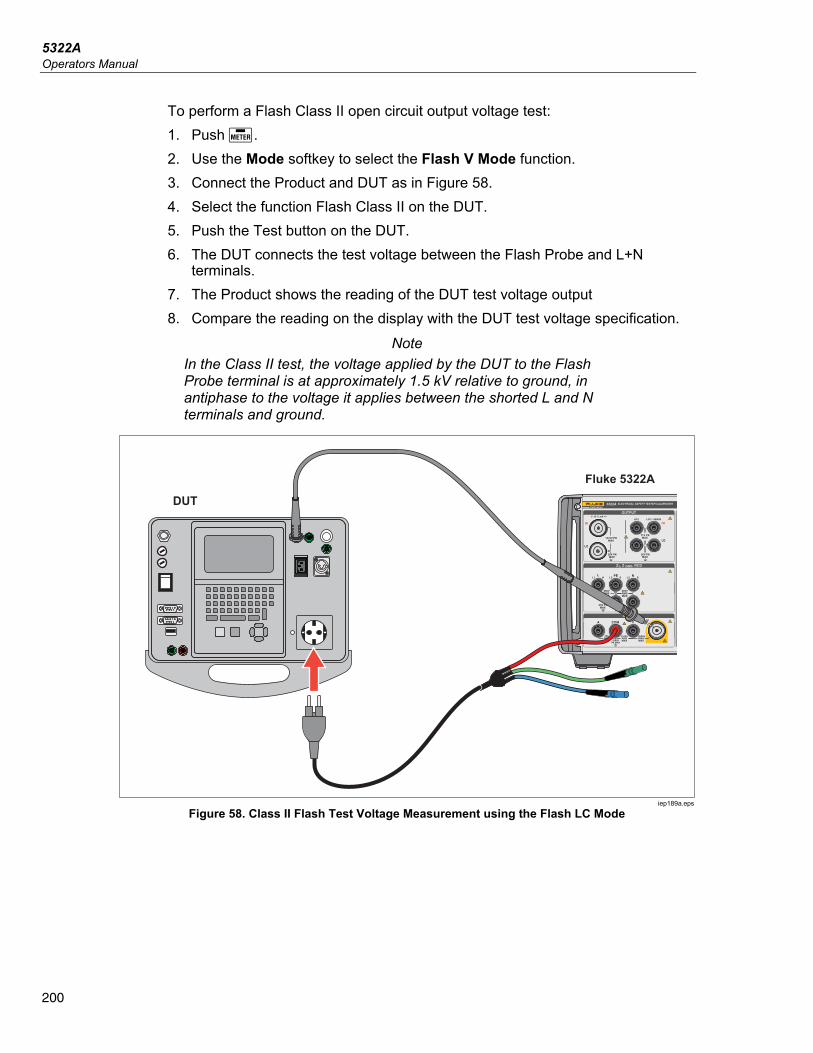
5322A Operators Manual
200
To perform a Flash Class II open circuit output voltage test: 1. Push . 2. Use the Mode softkey to select the Flash V Mode function. 3. Connect the Product and DUT as in Figure 58. 4. Select the function Flash Class II on the DUT. 5. Push the Test button on the DUT. 6. The DUT connects the test voltage between the Flash Probe and L+N
terminals. 7. The Product shows the reading of the DUT test voltage output 8. Compare the reading on the display with the DUT test voltage specification.
Note In the Class II test, the voltage applied by the DUT to the Flash Probe terminal is at approximately 1.5 kV relative to ground, in antiphase to the voltage it applies between the shorted L and N terminals and ground.
Fluke 5322A
DUT
iep189a.eps
Figure 58. Class II Flash Test Voltage Measurement using the Flash LC Mode
Multifunction Electrical Tester Calibrator Perform Flash Class I and Flash Class II Tests on (PAT) Portable Appliance Testers
201
To do a leakage current test: 1. Push . 2. Use the Mode softkey to select the Flash LC Mode function. 3. Connect the Product and DUT as in Figure 59. 4. Choose an appropriate 5322A-LOAD load resistance value to simulate the
required leakage current value, and connect using a jumper inserted into the corresponding 5322A-LOAD resistor sockets, as in Figure 59.
5. Select the function Flash Class II on the DUT. 6. Push the Test button on the DUT.
The DUT connects the test voltage between L+N and PE terminals. The Product shows the simulated leakage current flowing. The product also shows the loaded DUT test voltage output.
7. Compare the Product current reading with the DUT reading and leakage current specification.
Note PAT tester Flash test outputs have current limiting, typically using resistors in series with the connection to the shorted L and N terminals and the connection to the Flash Probe terminal. Therefore, when loaded, the measured output voltage will be lower than the nominal values quoted in the DUT specifications, to an extent determined by the simulated (loaded) leakage current flowing and the series current limiting resistor values. PAT testers generally have a Flash Test limit (shorted output) current of 5mA, so a current limiting resistor of approximately 300 kΩ can be used.
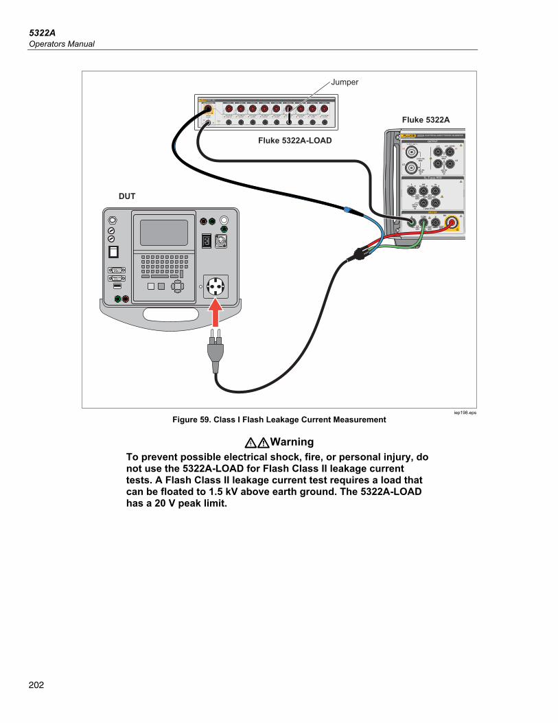
5322A Operators Manual
202
Fluke 5322A
DUT
Fluke 5322A-LOAD
Jumper
iep198.eps
Figure 59. Class I Flash Leakage Current Measurement
XWWarning To prevent possible electrical shock, fire, or personal injury, do not use the 5322A-LOAD for Flash Class II leakage current tests. A Flash Class II leakage current test requires a load that can be floated to 1.5 kV above earth ground. The 5322A-LOAD has a 20 V peak limit.
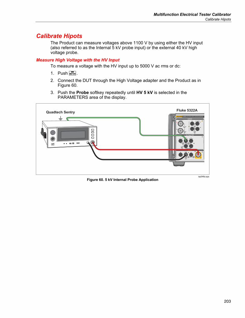
Multifunction Electrical Tester Calibrator Calibrate Hipots
203
Calibrate Hipots The Product can measure voltages above 1100 V by using either the HV input (also referred to as the Internal 5 kV probe input) or the external 40 kV high voltage probe.
Measure High Voltage with the HV Input To measure a voltage with the HV input up to 5000 V ac rms or dc: 1. Push . 2. Connect the DUT through the High Voltage adapter and the Product as in
Figure 60. 3. Push the Probe softkey repeatedly until HV 5 kV is selected in the
PARAMETERS area of the display.
Quadtech Sentry Fluke 5322A
iep046a.eps
Figure 60. 5 kV Internal Probe Application
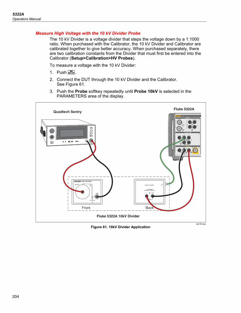
5322A Operators Manual
204
Measure High Voltage with the 10 kV Divider Probe The 10 kV Divider is a voltage divider that steps the voltage down by a 1:1000 ratio. When purchased with the Calibrator, the 10 kV Divider and Calibrator are calibrated together to give better accuracy. When purchased separately, there are two calibration constants from the Divider that must first be entered into the Calibrator (Setup>Calibration>HV Probes). To measure a voltage with the 10 kV Divider: 1. Push . 2. Connect the DUT through the 10 kV Divider and the Calibrator.
See Figure 61. 3. Push the Probe softkey repeatedly until Probe 10kV is selected in the
PARAMETERS area of the display.
Quadtech SentryFluke 5322A
Fluke 5322A 10kV Divider
Front Back
10kV DIVIDER
iep194.eps
Figure 61. 10kV Divider Application
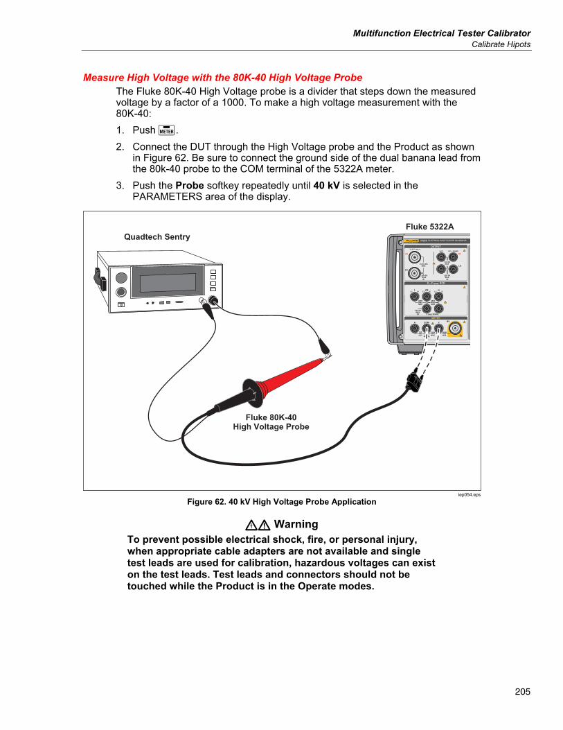
Multifunction Electrical Tester Calibrator Calibrate Hipots
205
Measure High Voltage with the 80K-40 High Voltage Probe The Fluke 80K-40 High Voltage probe is a divider that steps down the measured voltage by a factor of a 1000. To make a high voltage measurement with the 80K-40: 1. Push . 2. Connect the DUT through the High Voltage probe and the Product as shown
in Figure 62. Be sure to connect the ground side of the dual banana lead from the 80k-40 probe to the COM terminal of the 5322A meter.
3. Push the Probe softkey repeatedly until 40 kV is selected in the PARAMETERS area of the display.
Quadtech SentryFluke 5322A
Fluke 80K-40High Voltage Probe
iep054.eps
Figure 62. 40 kV High Voltage Probe Application
XW Warning To prevent possible electrical shock, fire, or personal injury, when appropriate cable adapters are not available and single test leads are used for calibration, hazardous voltages can exist on the test leads. Test leads and connectors should not be touched while the Product is in the Operate modes.
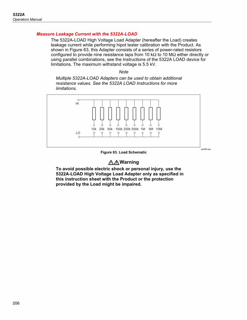
5322A Operators Manual
206
Measure Leakage Current with the 5322A-LOAD The 5322A-LOAD High Voltage Load Adapter (hereafter the Load) creates leakage current while performing hipot tester calibration with the Product. As shown in Figure 63, this Adapter consists of a series of power-rated resistors configured to provide nine resistance taps from 10 kΩ to 10 MΩ either directly or using parallel combinations, see the Instructions of the 5322A LOAD device for limitations. The maximum withstand voltage is 5.5 kV.
Note Multiple 5322A-LOAD Adapters can be used to obtain additional resistance values. See the 5322A LOAD Instructions for more limitations.
10k 25k 50k
HI
100k 250k 500k 1M 5M 10MLO
iep069.eps
Figure 63. Load Schematic
XWWarning To avoid possible electric shock or personal injury, use the 5322A-LOAD High Voltage Load Adapter only as specified in this instruction sheet with the Product or the protection provided by the Load might be impaired.
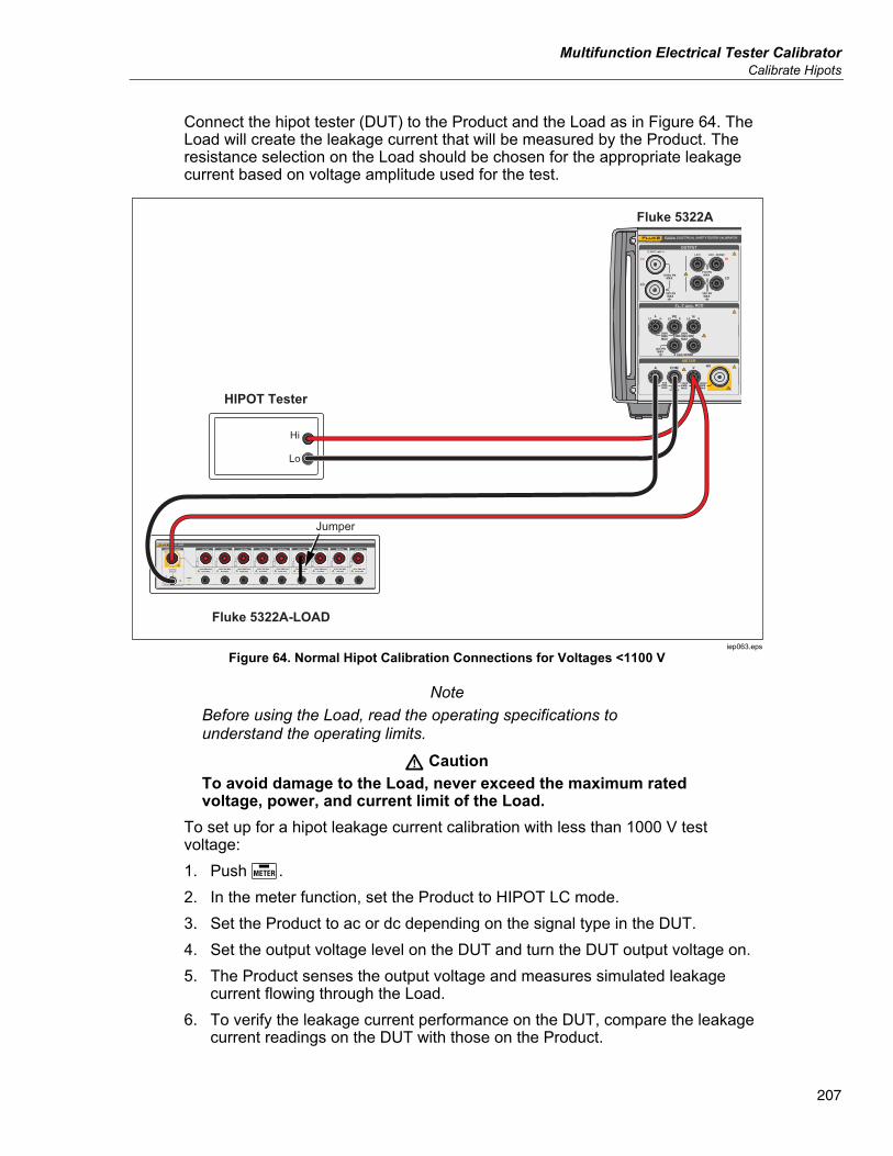
Multifunction Electrical Tester Calibrator Calibrate Hipots
207
Connect the hipot tester (DUT) to the Product and the Load as in Figure 64. The Load will create the leakage current that will be measured by the Product. The resistance selection on the Load should be chosen for the appropriate leakage current based on voltage amplitude used for the test.
Hi
Lo
HIPOT Tester
Fluke 5322A-LOAD
Fluke 5322AOR
Jumper
iep063.eps
Figure 64. Normal Hipot Calibration Connections for Voltages <1100 V
Note Before using the Load, read the operating specifications to understand the operating limits.
W Caution To avoid damage to the Load, never exceed the maximum rated voltage, power, and current limit of the Load.
To set up for a hipot leakage current calibration with less than 1000 V test voltage: 1. Push . 2. In the meter function, set the Product to HIPOT LC mode. 3. Set the Product to ac or dc depending on the signal type in the DUT. 4. Set the output voltage level on the DUT and turn the DUT output voltage on. 5. The Product senses the output voltage and measures simulated leakage
current flowing through the Load. 6. To verify the leakage current performance on the DUT, compare the leakage
current readings on the DUT with those on the Product.
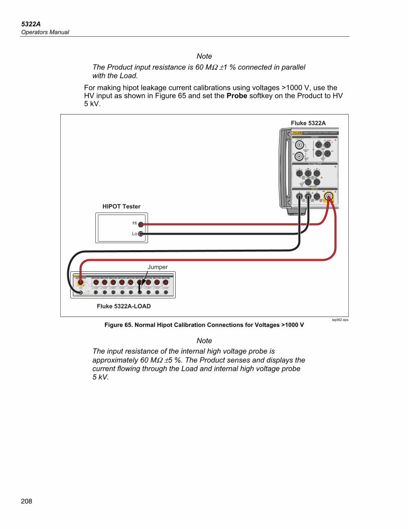
5322A Operators Manual
208
Note The Product input resistance is 60 MΩ ±1 % connected in parallel with the Load.
For making hipot leakage current calibrations using voltages >1000 V, use the HV input as shown in Figure 65 and set the Probe softkey on the Product to HV 5 kV.
Hi
Lo
HIPOT Tester
Fluke 5322A-LOAD
Fluke 5322AOR
Jumper
iep062.eps
Figure 65. Normal Hipot Calibration Connections for Voltages >1000 V
Note The input resistance of the internal high voltage probe is approximately 60 MΩ ±5 %. The Product senses and displays the current flowing through the Load and internal high voltage probe 5 kV.