Embed Size (px)
Citation preview
1
Abstract
We describe the calibration of a catadioptric
omnidirectional video-projection system that adjusts its
projection to the geometry of any scene by means of a
rotating camera. Correction of geometric distortions
requires 3D reconstruction of the scene. A camera is used
to detect projected point features and calibration is
performed in three successive steps: precalibration of
camera assuming pure rotation, precalibration of
catadioptric projector under central approximation and
calibration of the global system, by minimizing the
squared distance between the reflected and perceived
rays, and by relaxing previous constraints, to refine values
of extrinsic parameters. Simulation is used to validate
estimated values of parameters and distance between the
3D reconstruction of the projection room and its expected
geometry. Influence of noise in detected point coordinates
is studied and preliminary results for the reconstruction
and projection in real conditions are reported.
1. Introduction
1.1. Context
We describe a novel system designed to achieve
omnidirectional projection in a scene of any geometry.
There are several ways to illuminate a whole room. The
usual way is to use several projection channels, with one
channel for each wall, each calibrated independently of the
others. The main problem here lies in managing the
superimposition of the channels, either using unsharp
masks to obtain a fade effect between images or by
photometric calibration [3]. When a single projection
channel is used, optical systems must be designed to
spread light in all directions: for this purpose one-channel
systems often use a fish-eye lens. This expensive device
produces strong radial distortions and its field of view is
limited to half a space at most. Instead we propose using
an optical association between a projector aimed at the
room ceiling and a convex mirror placed on it. The most
straightforward choice for the mirror shape is hemispheric;
however, this is not the best choice from an optical point
of view, as angular resolution is not homogeneous. This
type of mirror has already been used to scatter light onto a
dome surface in planetarium applications [2]. As the
projector and mirror are never perfectly aligned,
calibration is a major problem in the modeling of optical
paths for projection. The main drawback of these systems
is that they require laborious manual installation and that
the projection is computed for a given scene geometry
(dome, cave-like, etc.). We propose an automatic
procedure for calibration and image mapping to any scene
geometry. Although in practice most rooms are planar
piecewise, the user does not have to know the exact scene
layout. All that is required in order to illuminate the scene
in every direction is to place the projector beneath the
mirror so that the light beam covers the whole hemispheric
surface.
1.2. Originality
To our knowledge, little work has been done on
catadioptric projection systems [9]. Most reports have
been in the context of catadioptric sensors, but the optical
geometry of a catadioptric projector can be identically
represented by the pinhole model. In [9], the authors
propose warping the projection with specific mirrors
computed for a given image to scene mapping. Our
approach is on the contrary to use low cost revolution
mirrors of simple shape and to infer this mapping from the
scene geometry reconstructed by the system itself.
Automatic scene meshing facilitates modeling operations
and opens the way to mixed reality applications.
To estimate the relative position of the mirror and the
catadioptric projector, an omnidirectional sensor
composed of a rotating wide angle camera is used. The
association of the catadioptric projector and the rotating
camera has the same geometry as a hybrid stereovision
device (Fig. 1).
Methods used in non central catadioptric stereovision
[5] must be adapted to this particular combination. Both
camera and projector are non-central: as described in
section 2, the camera optical center is slightly moved away
from its rotation axis, and the association of perspective
optics with a hemispherical mirror is known not to possess
a single view point but to present a caustic surface. A key
Automatic Calibration of a Single-Projector Catadioptric Display System
Benjamin Astre, Laurent Sarry
ERIM, Univ. Auvergne
BP 38, 63001 Clermont-Fd France [astre,sarry]@u-clermont1.fr
Christophe Lohou, Eric Zeghers
LAIC, IUT, Univ. Auvergne
BP 86, 63172 Aubière France [lohou,zeghers]@laic.u-clermont1.fr
978-1-4244-2243-2/08/$25.00 ©2008 IEEE
2
point in this work is to use projected features that will be
detected by the camera in an omnidirectional context. This
principle is widely applied for perspective projector
camera combinations, with point-like features for
calibration and black and white or colored stripes for 3D
object modeling, once transformations between projector
and camera are known [10]. In other works, the mapping
between projector and camera images handled without
calibration of the projector [11,12]. It cannot be easily
extended to the geometry of our projection system which
is omnidirectional and non-central for both projection and
acquisition, and moreover it would be impossible to
generate a view point which is different from the one of
the camera. In our case, points are used to compute the
image-to-scene mapping by calibrating the system and
reconstructing them in the world coordinates system
(WCS), assumed to correspond to the projector referential.
Then it is possible to create an undistorted panorama from
any point of view, even if it is distant from the camera.
Another advantage to know the scene geometry is that it
may be used in simulation for radiometric fidelity of the
projection.
Here, results of self-calibration are presented for both
simulated and real projection scenes and results for 3D
reconstruction are compared with the expected geometry.
2. Geometric description of the system
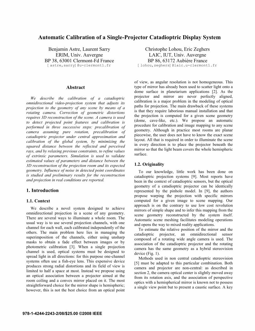
The self-calibrating system has four separate
components: a video-projector, a hemispherical mirror, a
camera and a camera holder equipped with a stepper
motor. As depicted in Fig. 1, the camera is set into rotation
around the optical axis of the projector: it ensures that the
camera can see the whole scene with no shadow zone
caused by the other components. The rotating camera
itself does not mask the projector beam. It would have
been more difficult to design with a catadioptric camera
for instance. Also, the camera is placed as far as possible
from the mirror: the angles, between rays reflected by the
mirror and detected rays are at their maximum and
triangulation is therefore more accurate for the
reconstruction of points in 3D.
In the following, the different referentials of the system
are described with rigid transformations linking them. The
projector referential is considered as the world coordinate
system. The angular step for camera rotation ensures
approximate overlapping of half a field of view.
The hemispherical mirror used in this system is totally
described by its radius rm. For the projector and the
camera the same pin-hole model can be used with
perspective projection matrix P (Pp and Pc respectively).
An image point in homogeneous coordinates is related
to a 3D point M by:
(1)
with
(2)
where f is focal length (in mm), m0= (u0,v0) principal point
(in mm) and (ku,kv) pixel dimension inverses (in pixels per
mm). For the camera, the need for a wide angle of view
(short focal length) requires taking into account radial
second order distortion function fd of center cd (in mm)
and coefficients k1, k2 [8] that relates distorted coordinates
m’c with undistorted ones mc:
(3)
with
(4)
and
(5)
3. Self-calibration
3.1. Principle
As the system possesses many degrees of freedom, its
Figure 1: The system is characterized by four different
coordinate systems related to the videoprojector p (WCS), the
mirror m, the camera holder h and the camera at angulation i,
ci. Rigid transformations have six degrees of freedom for
[Rphtph], [Rpmtpm] and [Rhc0thc0] and one degree for the rotating
camera [Rc0citc0ci]. The origins of these referentials are optical
centers Cp and Cc and mirror center Cm. A scene point M is
obtained at the intersection between the projected ray reflected
by the mirror and the ray incident to the camera.
[Rc0citc0ci]
Cp
Projector
Scene
Mirror
[Rphtph]
Cc0
[Rpmtpm]
Cm
S
[Rhc0thc0]
Holder
Cci
Camera
Cp
M
3
ease of use depends on a robust self-calibrating process.
When all the transformations between components are
known, light paths from the mirror and to the camera can
be computed, and projected points are inferred from the
intersections between them.
The user has to calibrate the system once for a given
projection scene. The process must also be started over if
the position of the system relative to the scene changes.
The inputs of calibration are the coordinates of points in
the projector matrix and their corresponding image
coordinates at every camera rotation steps (Fig. 2). Some
parameters, in particular the intrinsic ones, are to be
specified by the user, and the others are automatically
estimated.
Calibration is performed in three separate steps. The
first two are precalibration steps for the rotating camera
and the catadioptric projector. For the camera, the
perception redundancy in rotation of projected points is
used, while for the projector, methods inferred from
central catadioptric sensors are used. The approximate
values of parameters computed from these two initial steps
are used as the initialization for a global calibration
process designed to refine parameter values with no
further simplifying assumptions regarding system
geometry.
3.2. Approximate camera calibration
This section describes the determination of the axis of
rotation, the orientation of the camera with regard to its
holder and the parameters of the perspective projection
and distortions.
Of these parameters, some are known from camera
specifications (uc0, vc0, kcu, kcv and fc), and others will be
assumed for simplification. The angular camera rotation
step is accurately known from the motor step number and
the gear factor imposed by the pulleys and synchronization
belt. The remaining unknowns are: [Rhc0thc0], cd, k1 and k2.
The principle for the rotating camera calibration is
derived from [7], but adapted to use points illuminated on
the scene. Redundancy of points detected during camera
rotation is used: the camera coordinates of every point
detected on two successive frames are compared. For
every point j and every image pair (i,i+1) the squared
distance d between point mi+1,j detected in the second
image, and the point computed from the rotation of point
mi,j in the first image, is minimized to estimate the
unknown parameters. All the coordinates are expressed in
the camera image plane referential at angle i+1 denoted
ci+1
:
(6)
The ratio of the depths of the
illuminated point M with regard to the camera between
angles i and i+1 is unknown unless the assumption of pure
rotation is made, i.e. that the rotation axis crosses the
camera optical center Cc. This cannot be exactly true for
the real system otherwise the camera itself would mask the
projector light beam, but in this case, the rigid
transformation is simplified to Rc0c1 because the rotation
axis and angle are the same for all i:
(7)
Non-pure rotation, and the change in scale that goes
with it, can be taken into account by optimizing focal
length fc as well as other parameters. The estimated value
of fc will be underestimated if the camera looks across the
projector beam or otherwise overestimated. However it is
discarded and replaced by the true value at the end of
camera precalibration for the following steps.
The cost function (7) is minimized by means of the
Levenberg-Marquardt routine LMDIF1 from MINPACK
library [6].
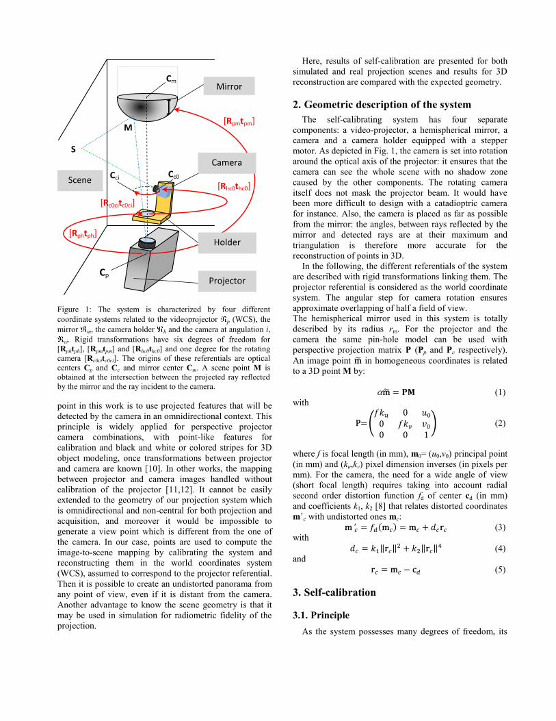
Figure 2: Image of the projected point features organized as a radial mesh (a); the corresponding images acquired by the rotating camera
in the first steps (b), (c), (d)... Projection is limited to the angle of view of the camera. Points are shut down one by one to pair them with
camera points. A robust detection algorithm is used to compute the centers of gravity of camera points.
(a) (b) (c) (d)
4
3.3. Approximate calibration of the catadioptric
projector
Once camera parameters are approximately known, it is
possible to determine an initial configuration for the
catadioptric projector. Parameters intrinsic to the projector
(up0, vp0, kpu, kpv and fp) are known from technical
specifications, as is the radius of the mirror rm. The
remaining unknowns are the extrinsic parameters relating
camera holder, projector and mirror. The algorithm uses
an epipolarity relationship between the rotating camera
(8), assumed to be central (center Cc) if the previous pure
rotation condition holds, and the catadioptric projector
(Fig. 3).
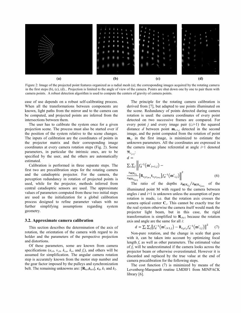
The actual shape of the mirror caustic surface in the
hemispherical case is assumed to be restricted to a single
focal point Fm located at 0.64 radius from the center (h =
0.64). In [5], this distance was shown to minimize the sum
of squared angular distances between true rays coming
from the mirror and rays assumed to come from the focal
point (Fig. 3). The central approximation is made more
accurate by the fact that rays are close to the revolution
axis of the mirror, itself collinear to the projector view
axis. Thus for this calibration stage, only points in the
middle of the projector matrix that project onto the scene
at a small height are considered.
In contrast to the method described in [5] for
catadioptric stereovision, as intrinsic parameters of the
camera and the catadioptric projector are known at this
stage, the epipolarity constraint uses the essential matrix E
instead of the fundamental one to relate rays coming from
the mirror and incident to the camera
:
(8)
The essential matrix E and the translation between the
projector and mirror are the unknowns at this stage.
In contrast to the solution proposed in [5], where only
coordinate z of was recovered, alignment of the
projector with the mirror cannot be assumed because
positioning is manual. Also, for our system, the height of
the mirror relative to the projector can be measured with
sufficient accuracy by the user. Therefore only
will be sought.
The reflected ray vm is given by:
, (9)
and its derivatives by:
(10)
where vp is the unit vector of the projected ray so that
and .
and its derivatives are given by:
(11)
and
(12)
with
(13)
and
(14)
In order to obtain a linear solution for E and ,
linearization of equation (8) is performed by decomposing
vector vm into Taylor’s series in the neighborhood of .
As stated above, instead of a linearizing with respect to
, it is done vs. to estimate relative
alignment between projector and mirror:
(15)
Figure 3: Simplified scheme of epipolar geometry. The reflected
ray v’m is changed into vm, collinear to FmM, for the central
assumption. It approximately holds for the rays close to
projector axis of view. Cc is the center of the circular trajectory
of the camera optical center.
[Rpm tpm]
hrm
pp
Fm
vm
v’m
fp
vp
M
m
Cm rm
Cc
vc
S
Cp
hrm
pp
Fm
vm
v’m
fp
vp
M
m
Cm rm
Cc
vc
S
Cp
[Rpm tpm]
5
From equations (8) and (15), we have:
(16)
with
(17)
and
. (18)
When the essential matrix E is written as a column
vector e in row priority order, the epipolar equation (8) is
equivalent to a multiparameter eigenvalue problem
(MEP):
(19)
where the jth
rows of matrices D0, D1 and D2 corresponding
to the jth
calibration point are given by:
.
Unlike the polynomial eigenvalue problem derived in
[5], an MEP cannot be made equivalent to a generalized
eigenvalue problem, as several eigenvalues must be
computed. An iterative gradient descent algorithm [1] was
used to solve this problem starting from guess values for E
and .
The extrinsic parameters between the
camera central position Cc and the central mirror are
recovered from E. Direction of translation is given by
the minimal singular value of E. Coplanarity of rows ei of
E is not ensured essentially because of the non-central
assumption. Therefore, it is forced by projecting the ei
onto the plane normal to . The rotation matrix is then
given by:
(20)
Extrinsic parameters between the projector and the
holder [Rphtph] are obtained from transformation [Rpmtpm],
inferred from the central approximation with the estimated
value for , and from Rhc0, approximately known from
camera calibration.
3.4. Global calibration and refinement of
parameters
After the two first calibrations for the rotating camera
and the catadioptric projector, the purpose of the third step
is to compute final values of parameters. Both pure
rotation and central approximations are relaxed.
Calibration is based on the minimization of the sum of
the orthogonal distances between rays reflected from the
mirror v’m and rays detected by the camera vc (Fig. 3). It is
performed for all visible projected points by means of a
quasi-Newton algorithm with finite difference gradient
estimation.
Not all the system parameters are optimized. Three
situations are likely to occur:
Besides intrinsic parameters of the camera and the
projector, some extrinsic parameters are assumed to
be measured with sufficient accuracy and will not be
optimized. This is the case for the relative heights of
the system components ( and ). Owing
to the specific configuration of the system (camera
rotation axis nearly merged with catadioptric
projector axis CpCm), reflected and perceived rays
still intersect when the camera holder is placed closer
to the mirror. This is the natural tendency when
heights are optimized. As a result, rays intersect
closer to the common axis of the system and the
global scale of the reconstructed points is affected.
This is another reason to set height values;
Some parameters have been estimated with sufficient
accuracy by precalibration steps and will be set. Their
values are often correlated with others, and they will
affect convergence. This is the case for Rhc0, k1 and k2;
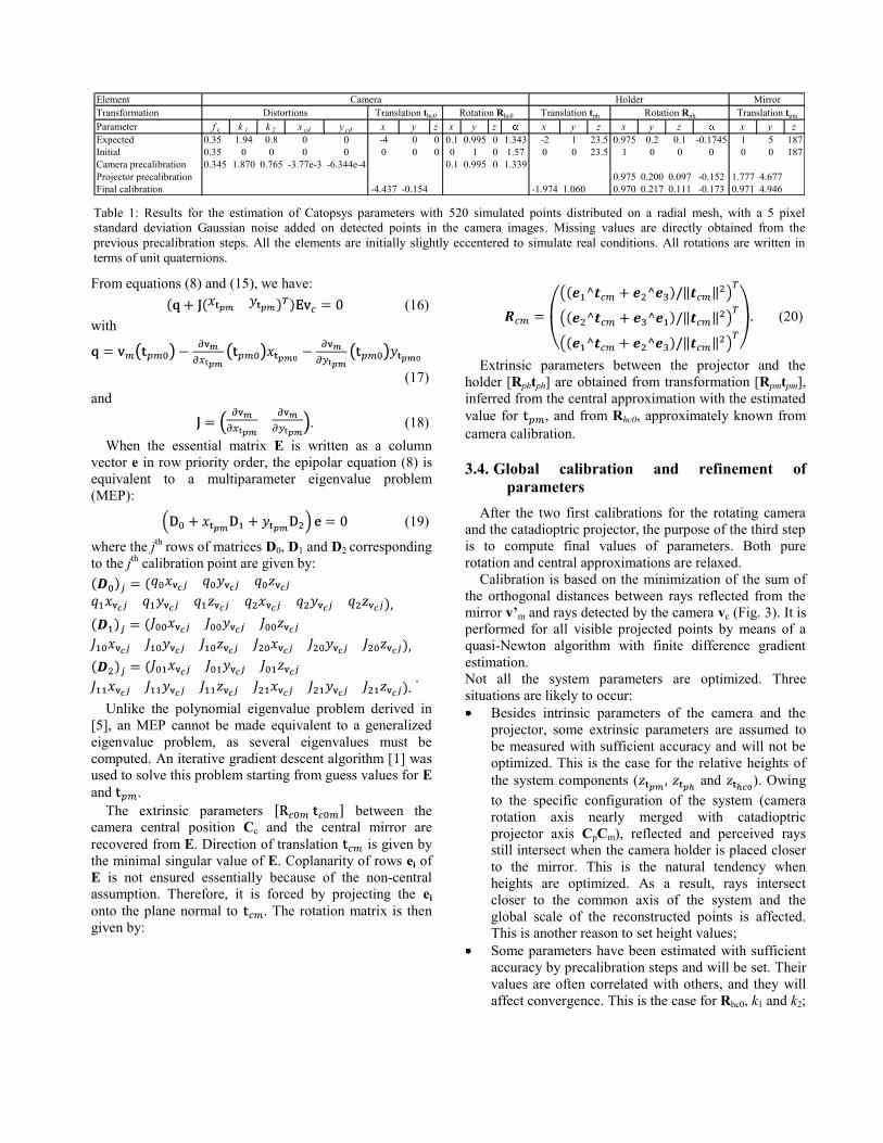
Table 1: Results for the estimation of Catopsys parameters with 520 simulated points distributed on a radial mesh, with a 5 pixel
standard deviation Gaussian noise added on detected points in the camera images. Missing values are directly obtained from the
previous precalibration steps. All the elements are initially slightly eccentered to simulate real conditions. All rotations are written in
terms of unit quaternions.
Element Camera Holder Mirror
Transformation Distortions Translation thc0 Rotation Rhc0 Translation tph Rotation Rph Translation tpm
Parameter f c k 1 k 2 x cd y cd x y z x y z x y z x y z x y z
Expected 0.35 1.94 0.8 0 0 -4 0 0 0.1 0.995 0 1.343 -2 1 23.5 0.975 0.2 0.1 -0.1745 1 5 187
Initial 0.35 0 0 0 0 0 0 0 0 1 0 1.57 0 0 23.5 1 0 0 0 0 0 187
Camera precalibration 0.345 1.870 0.765 -3.77e-3 -6.344e-4 0.1 0.995 0 1.339
Projector precalibration 0.975 0.200 0.097 -0.152 1.777 4.677
Final calibration -4.437 -0.154 -1.974 1.060 0.970 0.217 0.111 -0.173 0.971 4.946
6
Some parameters have never been optimized:
or their values are not accurate enough after the
precalibration step: and Rph
(indirectly obtained from the essential matrix E).
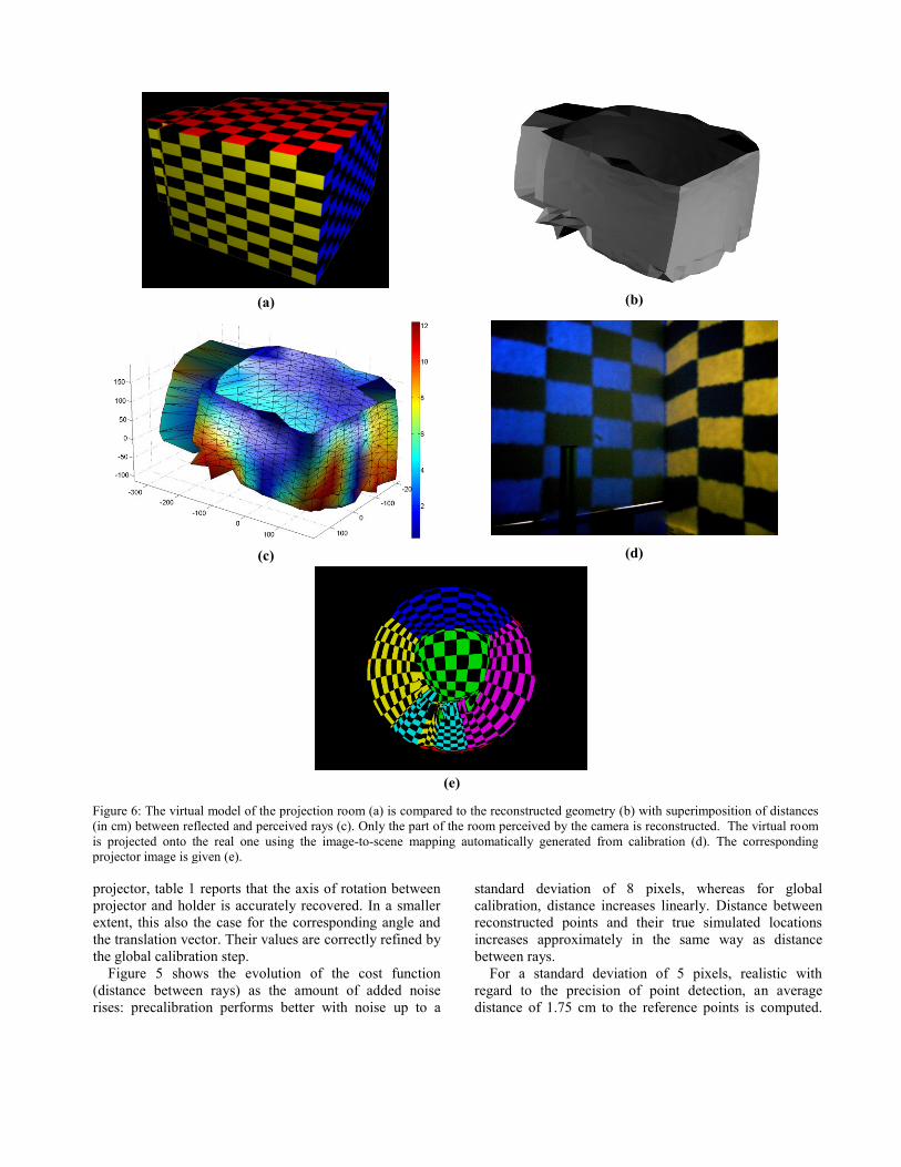
4. Image-to-scene mapping
Once the optimization of parameters is achieved, for
every point mj in the projector matrix, a 3D point Sj can be
reconstructed as the closest point between rays vm and vc,
and thus it is possible to reconstruct the projection scene
geometry if points structured in a mesh are projected (Fig.
4).
A viewpoint V is usually defined for a user standing
close to the projector. Rendering of the virtual scene to be
projected is performed in every direction from this
viewpoint: six perspective renderings are produced
simultaneously on a cubemap. Each pixel mj of the
projector matrix is then assigned the color of the rendering
in the direction VSi.
5. Results and validation
5.1. Materials
The simulation environment is composed of a room of
known geometry (Fig. 6(a)) about 20 square meters in area
with the projection system in the middle. This is composed
of a Dell 5100 MP videoprojector of resolution SXGA+
(1400 1050 pixels) at the highest focal length of the zoom
interval fp=4.6 cm, a Matrix Vision camera of resolution
XGA (1024 768 pixels) with a wide angle objective of
focal length fc=3.5 mm, a 30 cm radius mirror and a 200-
step motor for rotation movement.
For a presentation projector like the one used here, the
ordinate of the projector principal point vp0 is not equal to
half the image plane height, because the visual axis is
tilted with respect to the optical axis. It has been
empirically and approximately estimated. As it has much
the same effect as the inclination of the projector, there is
no need to optimize it in the following.
5.2. Simulated data
The extrinsic transformations between system
components are given values compatible with a manual
setting. The exact optical paths from 520 points on the
projector matrix to the scene are then computed, and their
coordinates in the camera plane are measured for 14
images spaced every 27.2°.
Validation is performed on simulated data to compare
estimated with expected values of parameters (Table 1).
Results are given for a 5-pixel standard deviation Gaussian
noise added to the coordinates in the image plane, which
corresponds approximately to a deviation of 1.5 cm for the
projected points (in the case of a wall located 2 m from the
projector). In this case, precalibration steps give good
initial guess values for the final refinement of parameters.
Indeed, as stated in paragraph 3.2, the value of focal
length is underestimated by camera precalibration because
of non-pure rotation (0.345 instead of 0.35), but distortion
parameters are recovered with good accuracy. It would not
have been the case if focal length was set to its true value
and not optimized. Concerning precalibration of the
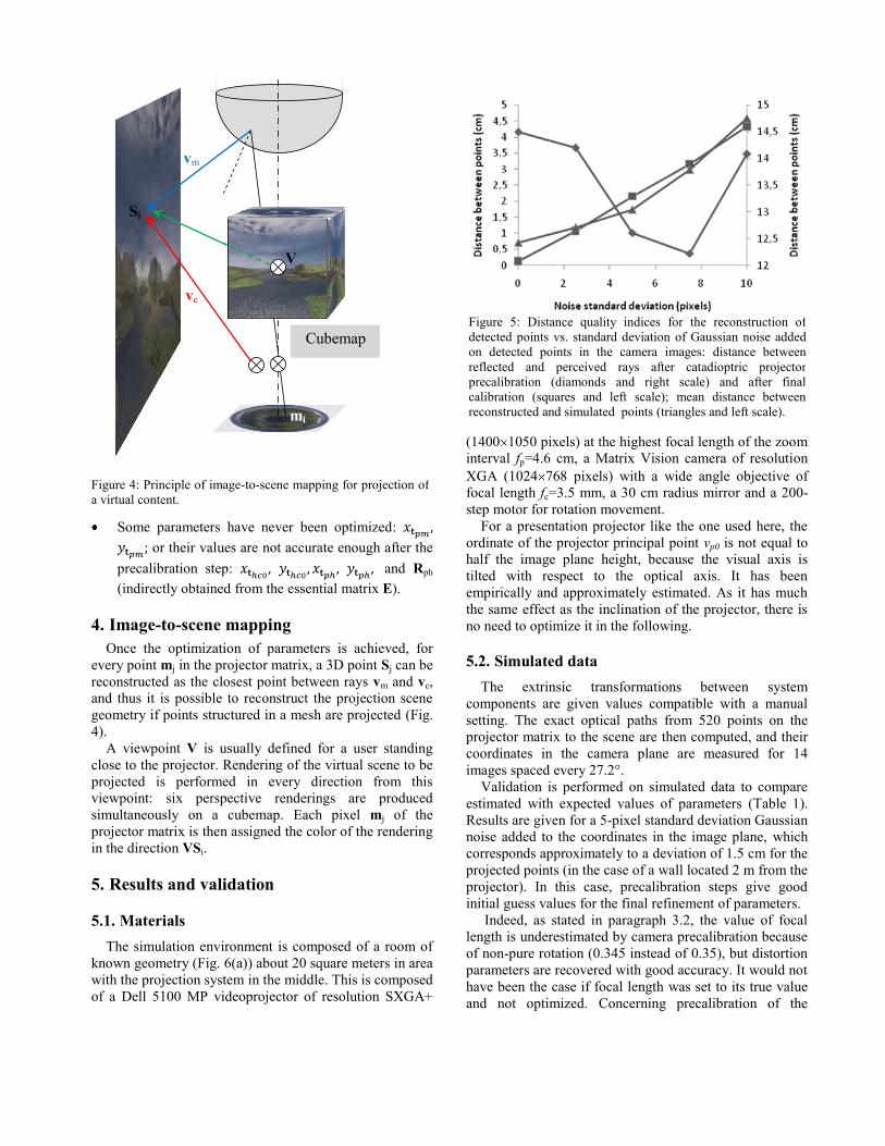
Figure 5: Distance quality indices for the reconstruction of
detected points vs. standard deviation of Gaussian noise added
on detected points in the camera images: distance between
reflected and perceived rays after catadioptric projector
precalibration (diamonds and right scale) and after final
calibration (squares and left scale); mean distance between
reconstructed and simulated points (triangles and left scale).
Figure 4: Principle of image-to-scene mapping for projection of
a virtual content.
mi
Si
V
Cubemap
vm
vc
7
projector, table 1 reports that the axis of rotation between
projector and holder is accurately recovered. In a smaller
extent, this also the case for the corresponding angle and
the translation vector. Their values are correctly refined by
the global calibration step.
Figure 5 shows the evolution of the cost function
(distance between rays) as the amount of added noise
rises: precalibration performs better with noise up to a
standard deviation of 8 pixels, whereas for global
calibration, distance increases linearly. Distance between
reconstructed points and their true simulated locations
increases approximately in the same way as distance
between rays.
For a standard deviation of 5 pixels, realistic with
regard to the precision of point detection, an average
distance of 1.75 cm to the reference points is computed.
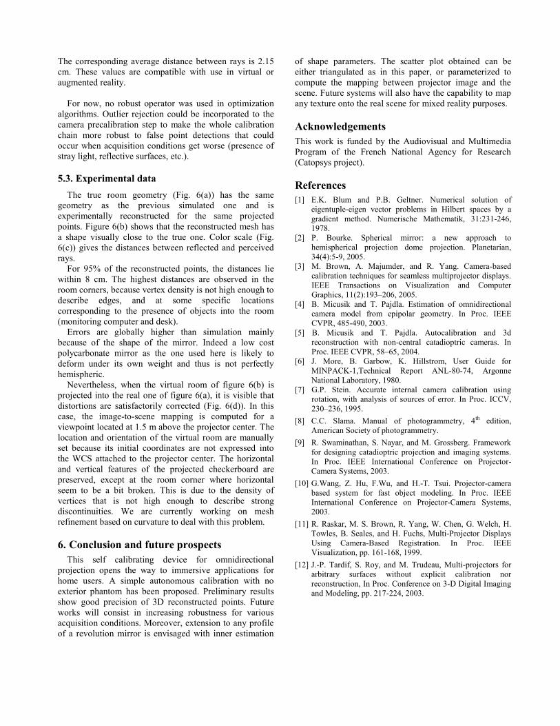
Figure 6: The virtual model of the projection room (a) is compared to the reconstructed geometry (b) with superimposition of distances
(in cm) between reflected and perceived rays (c). Only the part of the room perceived by the camera is reconstructed. The virtual room
is projected onto the real one using the image-to-scene mapping automatically generated from calibration (d). The corresponding
projector image is given (e).
(a) (b)
(c) (d)
(e)
8
The corresponding average distance between rays is 2.15
cm. These values are compatible with use in virtual or
augmented reality.
For now, no robust operator was used in optimization
algorithms. Outlier rejection could be incorporated to the
camera precalibration step to make the whole calibration
chain more robust to false point detections that could
occur when acquisition conditions get worse (presence of
stray light, reflective surfaces, etc.).
5.3. Experimental data
The true room geometry (Fig. 6(a)) has the same
geometry as the previous simulated one and is
experimentally reconstructed for the same projected
points. Figure 6(b) shows that the reconstructed mesh has
a shape visually close to the true one. Color scale (Fig.
6(c)) gives the distances between reflected and perceived
rays.
For 95% of the reconstructed points, the distances lie
within 8 cm. The highest distances are observed in the
room corners, because vertex density is not high enough to
describe edges, and at some specific locations
corresponding to the presence of objects into the room
(monitoring computer and desk).
Errors are globally higher than simulation mainly
because of the shape of the mirror. Indeed a low cost
polycarbonate mirror as the one used here is likely to
deform under its own weight and thus is not perfectly
hemispheric.
Nevertheless, when the virtual room of figure 6(b) is
projected into the real one of figure 6(a), it is visible that
distortions are satisfactorily corrected (Fig. 6(d)). In this
case, the image-to-scene mapping is computed for a
viewpoint located at 1.5 m above the projector center. The
location and orientation of the virtual room are manually
set because its initial coordinates are not expressed into
the WCS attached to the projector center. The horizontal
and vertical features of the projected checkerboard are
preserved, except at the room corner where horizontal
seem to be a bit broken. This is due to the density of
vertices that is not high enough to describe strong
discontinuities. We are currently working on mesh
refinement based on curvature to deal with this problem.
6. Conclusion and future prospects
This self calibrating device for omnidirectional
projection opens the way to immersive applications for
home users. A simple autonomous calibration with no
exterior phantom has been proposed. Preliminary results
show good precision of 3D reconstructed points. Future
works will consist in increasing robustness for various
acquisition conditions. Moreover, extension to any profile
of a revolution mirror is envisaged with inner estimation
of shape parameters. The scatter plot obtained can be
either triangulated as in this paper, or parameterized to
compute the mapping between projector image and the
scene. Future systems will also have the capability to map
any texture onto the real scene for mixed reality purposes.
Acknowledgements
This work is funded by the Audiovisual and Multimedia
Program of the French National Agency for Research
(Catopsys project).
References
[1] E.K. Blum and P.B. Geltner. Numerical solution of
eigentuple-eigen vector problems in Hilbert spaces by a
gradient method. Numerische Mathematik, 31:231-246,
1978.
[2] P. Bourke. Spherical mirror: a new approach to
hemispherical projection dome projection. Planetarian,
34(4):5-9, 2005.
[3] M. Brown, A. Majumder, and R. Yang. Camera-based
calibration techniques for seamless multiprojector displays.
IEEE Transactions on Visualization and Computer
Graphics, 11(2):193–206, 2005.
[4] B. Micusik and T. Pajdla. Estimation of omnidirectional
camera model from epipolar geometry. In Proc. IEEE
CVPR, 485-490, 2003.
[5] B. Micusik and T. Pajdla. Autocalibration and 3d
reconstruction with non-central catadioptric cameras. In
Proc. IEEE CVPR, 58–65, 2004.
[6] J. More, B. Garbow, K. Hillstrom, User Guide for
MINPACK-1,Technical Report ANL-80-74, Argonne
National Laboratory, 1980.
[7] G.P. Stein. Accurate internal camera calibration using
rotation, with analysis of sources of error. In Proc. ICCV,
230–236, 1995.
[8] C.C. Slama. Manual of photogrammetry, 4th edition,
American Society of photogrammetry.
[9] R. Swaminathan, S. Nayar, and M. Grossberg. Framework
for designing catadioptric projection and imaging systems.
In Proc. IEEE International Conference on Projector-
Camera Systems, 2003.
[10] G.Wang, Z. Hu, F.Wu, and H.-T. Tsui. Projector-camera
based system for fast object modeling. In Proc. IEEE
International Conference on Projector-Camera Systems,
2003.
[11] R. Raskar, M. S. Brown, R. Yang, W. Chen, G. Welch, H.
Towles, B. Seales, and H. Fuchs, Multi-Projector Displays
Using Camera-Based Registration. In Proc. IEEE
Visualization, pp. 161-168, 1999.
[12] J.-P. Tardif, S. Roy, and M. Trudeau, Multi-projectors for
arbitrary surfaces without explicit calibration nor
reconstruction, In Proc. Conference on 3-D Digital Imaging
and Modeling, pp. 217-224, 2003.


