Embed Size (px)
Citation preview
0-2
ACTYON SPORTS 2010.01
3650-01
DSI M78 6-SPEED A/T
3650-01AUTOMATIC TRANSMISSION
1. DSI M78 6-SPEED AUTOMATIC TRANSMISSION GENERAL
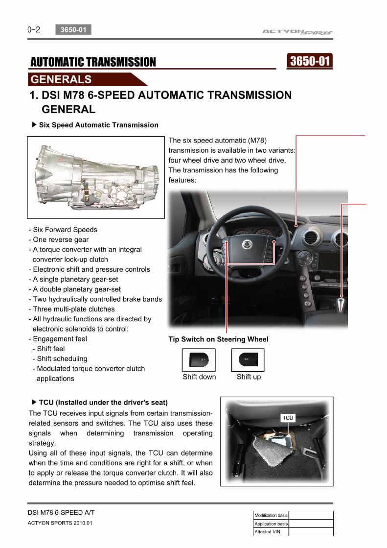
The six speed automatic (M78) transmission is available in two variants: four wheel drive and two wheel drive.The transmission has the following features:
Six Speed Automatic Transmission▶
- Six Forward Speeds- One reverse gear- A torque converter with an integral converter lock-up clutch- Electronic shift and pressure controls- A single planetary gear-set- A double planetary gear-set- Two hydraulically controlled brake bands- Three multi-plate clutches- All hydraulic functions are directed by electronic solenoids to control:- Engagement feel - Shift feel - Shift scheduling - Modulated torque converter clutch applications
The TCU receives input signals from certain transmission-related sensors and switches. The TCU also uses these signals when determining transmission operating strategy.Using all of these input signals, the TCU can determine when the time and conditions are right for a shift, or when to apply or release the torque converter clutch. It will also determine the pressure needed to optimise shift feel.
TCU (Installed under the driver's seat)▶
Tip Switch on Steering Wheel
Shift down Shift up
0-3
DSI M78 6-SPEED A/TACTYON SPORTS 2010.01
3650-01
Six Speed Automatic Transmission▶
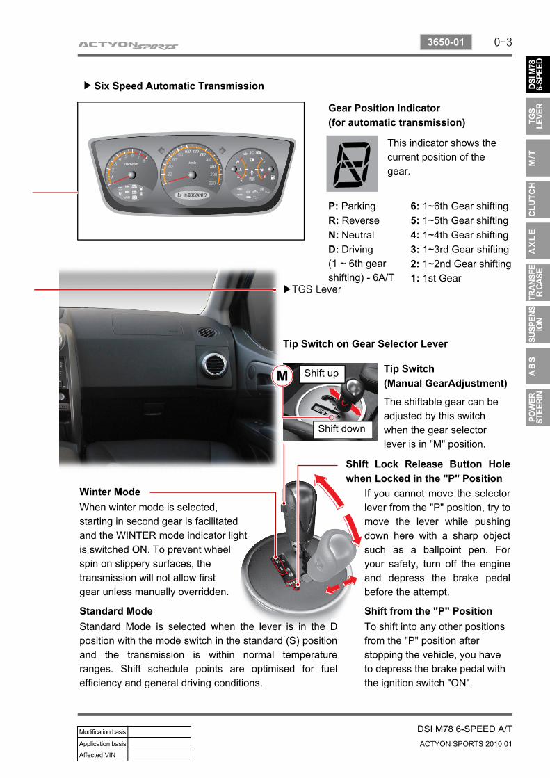
Gear Position Indicator (for automatic transmission)
This indicator shows the current position of the gear.
P: ParkingR: ReverseN: NeutralD: Driving (1 ~ 6th gear shifting) - 6A/T
6: 1~6th Gear shifting5: 1~5th Gear shifting4: 1~4th Gear shifting3: 1~3rd Gear shifting2: 1~2nd Gear shifting1: 1st Gear
▶TGS Lever
Tip Switch on Gear Selector Lever
Tip Switch (Manual GearAdjustment)
The shiftable gear can be adjusted by this switch when the gear selector lever is in "M" position.
Winter Mode
Standard Mode
Shift Lock Release Button Hole when Locked in the "P" Position
Shift from the "P" Position
When winter mode is selected, starting in second gear is facilitated and the WINTER mode indicator light is switched ON. To prevent wheel spin on slippery surfaces, the transmission will not allow first gear unless manually overridden.
Standard Mode is selected when the lever is in the Dposition with the mode switch in the standard (S) position and the transmission is within normal temperature ranges. Shift schedule points are optimised for fuel efficiency and general driving conditions.
If you cannot move the selector lever from the "P" position, try to move the lever while pushing down here with a sharp object such as a ballpoint pen. For your safety, turn off the engine and depress the brake pedal before the attempt.
To shift into any other positions from the "P" position after stopping the vehicle, you have to depress the brake pedal with the ignition switch "ON".
Shift up
Shift down
0-4
ACTYON SPORTS 2010.01
3650-01
DSI M78 6-SPEED A/T
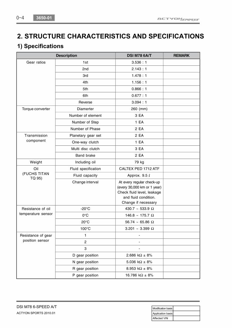
1) Specifications2. STRUCTURE CHARACTERISTICS AND SPECIFICATIONS
0-5
DSI M78 6-SPEED A/TACTYON SPORTS 2010.01
3650-01
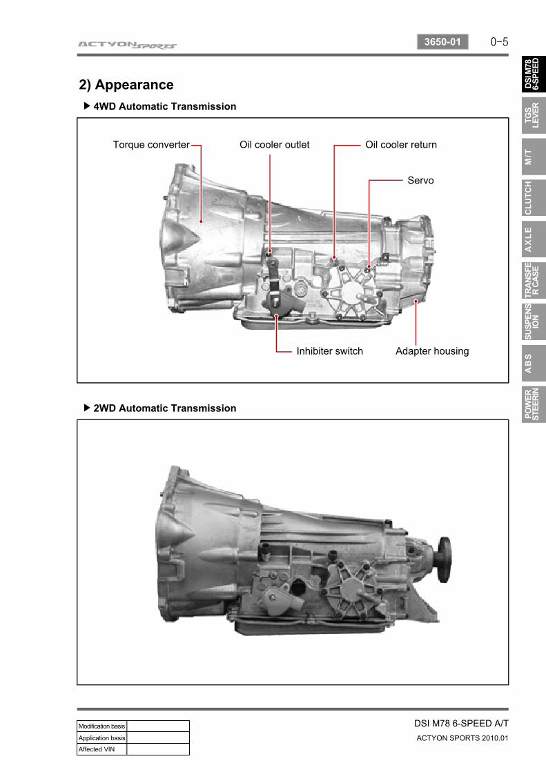
4WD Automatic Transmission▶
2) Appearance
2WD Automatic Transmission▶
Torque converter Oil cooler outlet Oil cooler return
Servo
Adapter housingInhibiter switch
0-6
ACTYON SPORTS 2010.01
3650-01
DSI M78 6-SPEED A/T
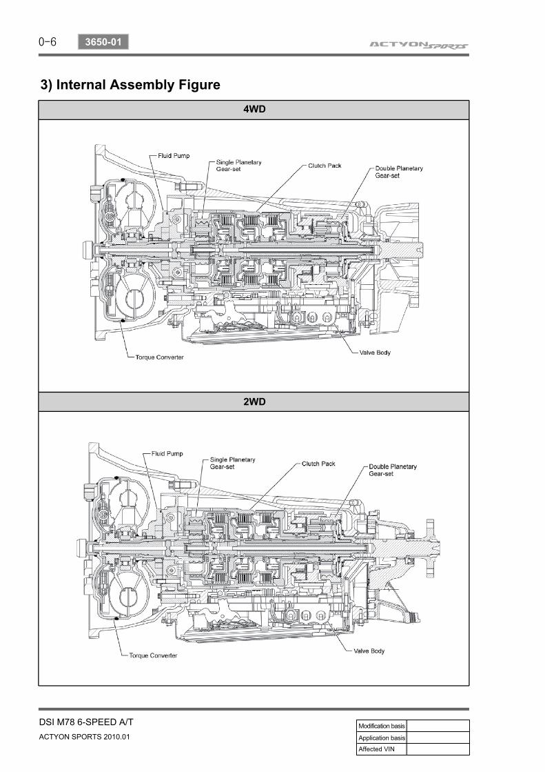
3) Internal Assembly Figure
2WD
4WD
0-7
DSI M78 6-SPEED A/TACTYON SPORTS 2010.01
3650-01
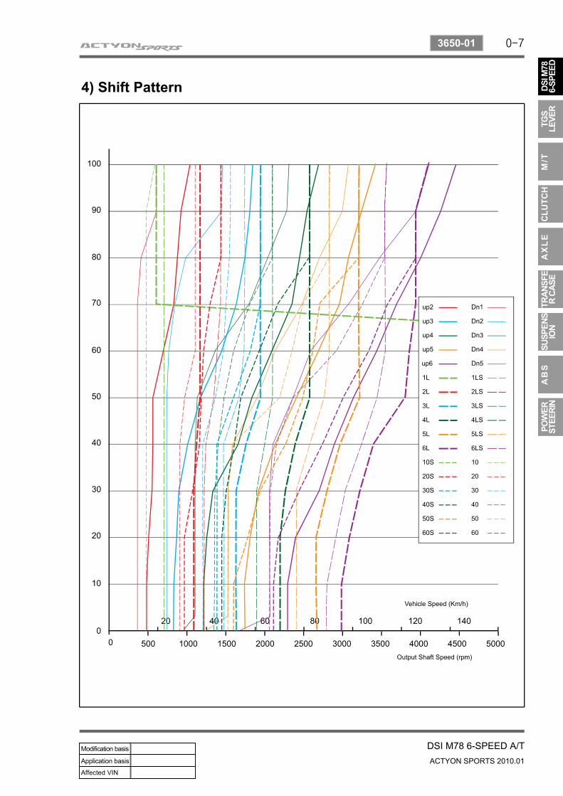
4) Shift Pattern
0-8
ACTYON SPORTS 2010.01
3650-01
DSI M78 6-SPEED A/T
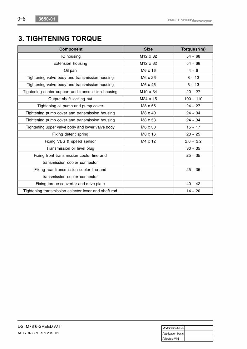
3. TIGHTENING TORQUE
0-9
DSI M78 6-SPEED A/TACTYON SPORTS 2010.01
3650-01
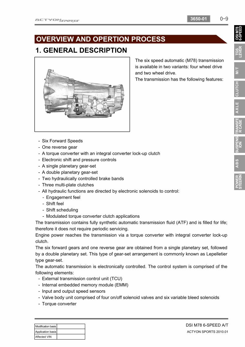
1. GENERAL DESCRIPTIONThe six speed automatic (M78) transmission is available in two variants: four wheel drive and two wheel drive.The transmission has the following features:
Six Forward SpeedsOne reverse gearA torque converter with an integral converter lock-up clutchElectronic shift and pressure controlsA single planetary gear-setA double planetary gear-setTwo hydraulically controlled brake bandsThree multi-plate clutchesAll hydraulic functions are directed by electronic solenoids to control:
---------
Engagement feelShift feelShift schedulingModulated torque converter clutch applications
----
The transmission contains fully synthetic automatic transmission fluid (ATF) and is filled for life; therefore it does not require periodic servicing.Engine power reaches the transmission via a torque converter with integral converter lock-up clutch.The six forward gears and one reverse gear are obtained from a single planetary set, followed by a double planetary set. This type of gear-set arrangement is commonly known as Lepelletier type gear-set.The automatic transmission is electronically controlled. The control system is comprised of the following elements:
External transmission control unit (TCU)Internal embedded memory module (EMM)Input and output speed sensorsValve body unit comprised of four on/off solenoid valves and six variable bleed solenoidsTorque converter
-----
0-10
ACTYON SPORTS 2010.01
3650-01
DSI M78 6-SPEED A/T
2. ADVANCED SIX SPEED FEATURES1) Characteristics
Early Downshifts with Hard Braking and Skip Shifts▶
When heavy braking is detected, the transmission downshifts early and skips gears to provide increased engine braking to provide gear selection for tip-in.
If the accelerator pedal is released when travelling uphill, upshifts are prevented to reduce busyness on grades. If the accelerator pedal is released when travelling downhill, upshifts are prevented to enhance engine braking.
Upshifts are prevented when the throttle is backed off very quickly to reduce busyness in sporty driving.
Gear Hold Going Uphill/Downhill▶
Upshift Prevention with Fast-off Accelerator Pedal▶
Drive and Reverse Engagement▶
A soft engagement feature avoids harsh take up of drive when selecting Drive or Reverse. This is achieved by limiting engine speed and engine torque which results in a rapid, but progressive engagement of either Drive or Reverse when moving from the Park or Neutral positions. Driveand Reverse engagements from either Park or Neutral are performed in less than 2.2 seconds.There is no drive engagement prevention strategy implemented on the transmission system as there is sufficient engine strategy to protect the system. However, reverse engagement is prevented until engine speed is less than 1400 rpm and the accelerator pedal position is less than 12% and vehicle speed is less than 10 km/h.
The transmission features converter clutch lock-up in all gears. This feature provides improved fuel economy and vehicle performance. It also improves transmission cooling efficiency when towing heavy loads at low speeds, e.g. in city driving or hill terrain.
Converter Clutch Lock-Up In All Gears▶
Converter Clutch Lock-Up In All Gears▶
The embedded memory module (EMM) is matched to the transmission's valve bodies during transmission assembly to ensure refined shift quality. The EMM is integrated into the input speed sensor which is mounted on the valve body in the transmission. The EMM is used to store data such as valve body calibration data and valve body serial number.Upon installation, the TCU will download the data from the EMM and utilise this data in the operation of the transmission.
0-11
DSI M78 6-SPEED A/TACTYON SPORTS 2010.01
3650-01
2) Transmission CoolingThe transmission cooling system ensures rapid warm-up and constant operating temperature resulting in reduced fuel consumption and refined shift quality.It also includes a cooler by-pass within the hydraulic system to allow sufficient cooling and lubrication to the transmission drivetrain in the event of a blockage in the transmission cooler.
3) Shift Strategy
Transmission gear change is controlled by the TCU. The TCU receives inputs from various engine and vehicle sensors to select shift schedules and to control the shift feel and torque converter clutch (TCC) operation at each gear change
Gear Hold Going Uphill/Downhill▶
Coastdown▶
Coastdown downshifts occur at 0% pedal when the vehicle is coasting down to a stop.
Torque Demand▶
Torque demand downshifts occur (automatically) when the driver demand for torque is greater than the engine can provide at that gear ratio. If applied, the transmission will disengage the TCC to provide added acceleration.
0-12
ACTYON SPORTS 2010.01
3650-01
DSI M78 6-SPEED A/T
3. FUNCTION OF EACH MODE1) Description(1) Shift Lock Release Button Hole when Locked in the "P" PositionIf you cannot move the selector lever from the "P" position, try to move the lever while pushing down here with a sharp object such as a ballpoint pen. For your safety, turn off the engine and depress the brake pedal before the attempt.
To shift into any other positions from the "P" position after stopping the vehicle, you have to depress the brake pedal with the ignition switch "ON".
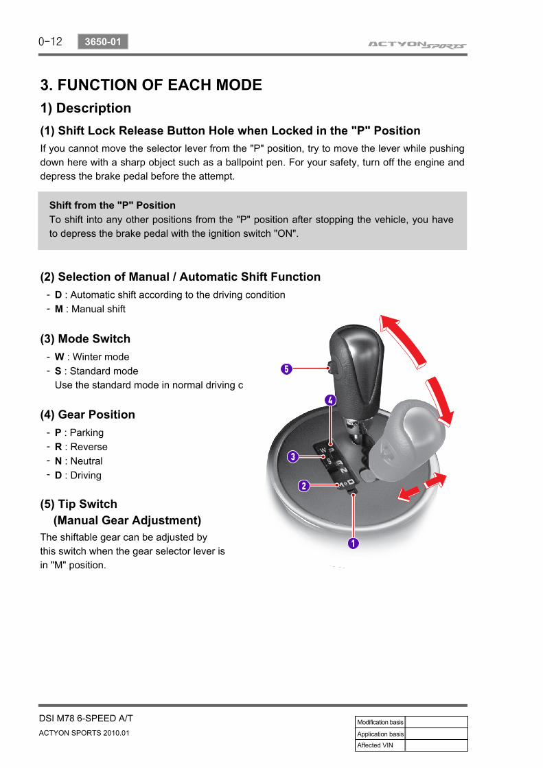
(2) Selection of Manual / Automatic Shift Function
Shift from the "P" Position
D : Automatic shift according to the driving conditionM : Manual shift
--
(3) Mode SwitchW : Winter modeS : Standard modeUse the standard mode in normal driving c
--
(4) Gear PositionP : ParkingR : ReverseN : NeutralD : Driving
----
(5) Tip Switch (Manual Gear Adjustment)The shiftable gear can be adjusted by this switch when the gear selector lever is in "M" position.
0-13
DSI M78 6-SPEED A/TACTYON SPORTS 2010.01
3650-01
2) Range Mode (Manual Mode)This allows the driver to define the highest possible gear by selecting "+" or "-" on the gear selector when the lever is in the "M" position. When the lever is first moved to the manual "M"position the transmission will select the lowest possible gear.When maximum engine rpm is reached the transmission will upshift automatically regardless of the driver selected limit. 4WD models with low range will not automatically upshift when low range is selected.
Kickdown FunctionIf you need to accelerate rapidly, depress the accelerator pedal completely to the floor. Then, a one- or two-lever gear will automatically be engaged. This is called the Kickdown function.
1st Gear State▶
The 1st gear state will display on the instrument cluster. Unlike the normal 1st gear, engine braking will be available in this manual 1st state.
2st Gear State▶
3st Gear State▶
4st Gear State▶
5st Gear State▶
6st Gear State▶
The 2nd gear state will display on the instrument cluster. 2-1 automatic kick-down shifts are available. 2nd gear has engine braking available.
The 3rd gear state will display on the instrument cluster. 3-2 and 3-1 automatic kick-down shifts are available. 3rd gear has engine braking available.
The 4th gear state will display on the instrument cluster. 4-3, 4-2 and 4-1 automatic kick-down shifts are available. 4th gear has engine braking available.
The 5th gear state will display on the instrument cluster. 5-4, 5-3 automatic kick-down shifts are available. 5th gear has engine braking available.
The 6th gear state will display on the instrument cluster. 6-5, 6-4 automatic kick-down shifts are available. 6th gear has engine braking availabl
0-14
ACTYON SPORTS 2010.01
3650-01
DSI M78 6-SPEED A/T
4. LIMP HOME MODEIn case of transmission malfunction▶
1.
2.
3.
4.
In case of overheated transmission▶
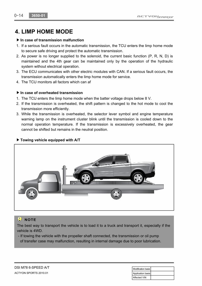
Towing vehicle equipped with A/T▶
If a serious fault occurs in the automatic transmission, the TCU enters the limp home mode to secure safe driving and protect the automatic transmission.As power is no longer supplied to the solenoid, the current basic function (P, R, N, D) is maintained and the 4th gear can be maintained only by the operation of the hydraulic system without electrical operation.The ECU communicates with other electric modules with CAN. If a serious fault occurs, the transmission automatically enters the limp home mode for service.The TCU monitors all factors which can af
The TCU enters the limp home mode when the batter voltage drops below 8 V.If the transmission is overheated, the shift pattern is changed to the hot mode to cool the transmission more efficiently.While the transmission is overheated, the selector lever symbol and engine temperature warning lamp on the instrument cluster blink until the transmission is cooled down to the normal operation temperature. If the transmission is excessively overheated, the gear cannot be shifted but remains in the neutral position.
1.2.
3.
The best way to transport the vehicle is to load it to a truck and transport it, especially if the vehicle is 4WD. - If towing the vehicle with the propeller shaft connected, the transmission or oil pump of transfer case may malfunction, resulting in internal damage due to poor lubrication.
0-15
DSI M78 6-SPEED A/TACTYON SPORTS 2010.01
3650-01
5. TRANSMISSION ELECTRONIC CONTROL SYSTEM1) General FATCS About TCUThe transmission control unit (TCU) and its input/output network control the following transmission operations:
2) Transmission Control UnitCaution: If the TCU requires reprogramming the handbrake must be firmly applied and the transmission placed in Park (P).The transmission control unit (TCU) is mounted under the left-hand front seat and controls the operation of the transmission.The TCU is activated and deactivated by the ignition power supply and is connected to the transmission link harness by a 26 pin connector.The TCU processes information received from internal sensors and signals received across the CAN bus in analogue and digital forms such as:
Shift timingLine pressure Clutch pressure (shift feel)Torque converter clutch
----
In addition, the TCU receives input signals from certain transmission-related sensors and switches. The TCU also uses these signals when determining transmission operating strategy.Using all of these input signals, the TCU can determine when the time and conditions are right for a shift, or when to apply or release the torque converter clutch. It will also determine the pressure needed to optimise shift feel. To accomplish this, the TCU operates six variable bleed control solenoids and four on/off solenoids to control transmission operation.The following provides a brief description of each of the sensors and actuators used to control transmission operation.
Transmission input speedTransmission output speedAccelerator pedal positionGear selector positionEngine torqueEngine speedTransmission fluid temperatureBrake pedal statusEngine oil temperatureEngine coolant temperatureAmbient air temperatureBarometric pressure
------------
This information is used by the TCU to decide which shift pattern to select and for shift energy management. Electro-hydraulic solenoid valves and variable bleed solenoids control the transmission gear changes.
0-16
ACTYON SPORTS 2010.01
3650-01
DSI M78 6-SPEED A/T
Six variable bleed solenoids and four on/off solenoids are used to direct transmission fluid flow to control the fluid pressure within the three clutches and two bands. Separate pressure regulators are used exclusively for torque converter clutch control and main transmission line pressure.The TCU monitors all TCU inputs and outputs to confirm correct system operation. If a fault occurs the TCU is able to perform default action and inform the driver of the problem through the instrument cluster warning lights. Detailed information is available via trouble codes which can be read with the service tool.
Supply Monitoring▶
Solenoid Supply Monitoring▶
Gear Ratio Monitoring▶
Torque Converter Monitoring▶
If the battery voltage is either too great or too low, the TCU will detect a fault condition.
While the solenoid operating transistors are being activated, checks are run for open circuits, shorts circuits to ground and short circuits to supply. The monitoring function evaluates the voltage characteristics during the switch ON process checking for the above faults.
The gear ratio diagnostic checks if each gear ratio is correctly engaged. Also, following a gear shift the diagnostic checks if the transmission has engaged the target gear within the allowed time.
The TCU checks if the torque converter can be locked correctly. If torque converter lock-up does not occur correctly the TCU performs the appropriate fail-safe action of opening the torque converter clutch.
3) Transmission Control Monitoring SystemThe TCU monitors all input and outputs to identify possible failures. If a fault is detected, the TCU takes the appropriate action to ensure the transmission maintains a safe mode of operation, without sacrificing transmission durability or driver safety.
4) Shift Energy ManagementThis function involves reducing or increasing the engine output torque during shifting. The aim when upshifting is to reduce the energy which is dissipated in the friction elements of the transmission. This is done by reducing the engine torque during the ratio change without interrupting the tractive drive. This function is used for:- Increasing the transmission service life by shortening the slipping time- Improving the shift comfort by reducing the step change in torque caused by the gearshift
0-17
DSI M78 6-SPEED A/TACTYON SPORTS 2010.01
3650-01
- Transferring a higher engine power, this is allowed by the mechanical in-gear strength of the transmissionReal-time control of engine torque is required to maintain maximum shift quality and transmission durability. The TCU has the ability to control the engine torque during the gearshift to synchronise with the operation of the transmission clutches.
Pressure Modulation▶
To provide a high level of shift comfort and durability, the hydraulic pressure in the shift related friction elements of the transmission must be matched accurately to the transmission input torque. This hydraulic pressure is composed of a hydraulically pre-set basic pressure and a controlling pressure which is set by one of the variable bleed solenoids.The transmission input torque can be directly calculated from the following operating parameters: engine torque signals, engine speed or any signals transmitted from the engine management ECU by CAN, and converter slip. Separate pressure characteristics for each gear change make it possible to adapt precisely to the particular shift operation.High and Low range operation has different parameters to optimise shift quality.
4) Shift Map SelectionThe driver can manually select between normal (S) and winter modes (W) via the mode switch. Depending on the transmission temperature, uphill and downhill grades and altitude, shift maps will be selected by the TCU to suit the driving conditions. The following maps are available.
Normal Mode▶
Normal Mode is selected when the lever is in the D position with the mode switch in the normal (S) position and the transmission is within normal temperature ranges. Shift schedule points are optimised for fuel efficiency and general driving conditions.
Uphill and Downhill Mode▶
Altitude Mode▶
In this mode, depending on the load of the vehicle, adaptive shift maps are selected to progressively adjust the shift points and torque converter lock points.
Shift points are automatically adjusted at higher altitudes to compensate for changes in engine torque where the torque produced by the engine is greatly reduced by the effects of reduced barometric pressure and temperature.
Winter Mode▶
When winter mode is selected, starting in second gear is facilitated and the WINTER mode indicator light is switched ON. To prevent wheel spin on slippery surfaces, the transmission will not allow first gear unless manually overridden.
0-18
ACTYON SPORTS 2010.01
3650-01
DSI M78 6-SPEED A/T
Low Range Schedule▶
When the transfer case is in 4L position, the transmission uses a different shift map to optimise low range driving. Similar to winter mode, 1st gear is inhibited. The transmission may skip gears, e.g. 2-4, to optimise engine rpm.
Warm up Schedule▶
Used typically when transmission fluid temperature is below 20°C.
The torque converter will not lock-up below 20°C to assist in transmission warm-up.
Hot Mode▶
The hot mode is progressively applied between temperatures of 110°C- 145°C. The torque converter lock-up is increased to prevent heat generation by the torque converter.As additional assistance to the hot mode, the following are activated:- Above 110°C - the electrical radiator fans are switch ON- Above 130°C - the engine torque will be reduced and the WINTER light on the instrument cluster will flash- Above 145°C - the transmission will neutralise until the fluid temperature falls below 120°C as a final protection.Activation of the hot mode inhibits other transmission performance features including uphill and downhill compensation and altitude compensation. Some degradation in shift feel may be experienced as the torque converter is not unlocked during shifting. The fluid temperature must be below 105캜 to exit all hot modes.
Cruise▶
When cruise control is activated the engine ECU may request the transmission to downshift under trailing throttle conditions to increase engine braking.
0-19
DSI M78 6-SPEED A/TACTYON SPORTS 2010.01
3650-01
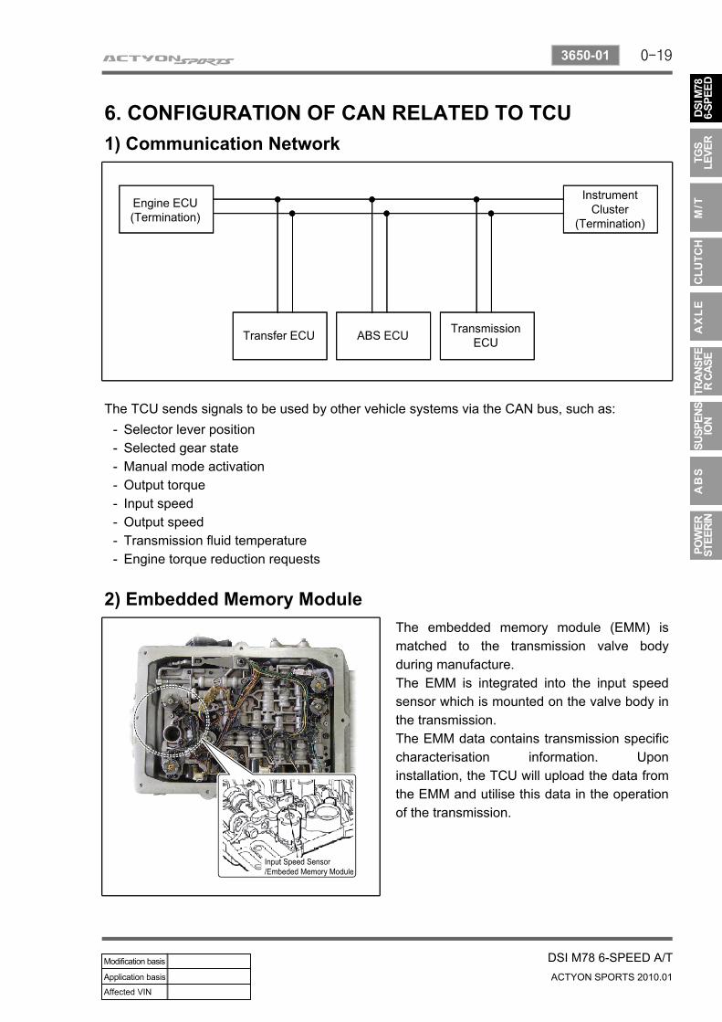
6. CONFIGURATION OF CAN RELATED TO TCU1) Communication Network
The TCU sends signals to be used by other vehicle systems via the CAN bus, such as:
2) Embedded Memory ModuleThe embedded memory module (EMM) is matched to the transmission valve body during manufacture.The EMM is integrated into the input speed sensor which is mounted on the valve body in the transmission.The EMM data contains transmission specific characterisation information. Upon installation, the TCU will upload the data from the EMM and utilise this data in the operation of the transmission.
Selector lever positionSelected gear stateManual mode activationOutput torqueInput speedOutput speedTransmission fluid temperatureEngine torque reduction requests
--------
0-20
ACTYON SPORTS 2010.01
3650-01
DSI M78 6-SPEED A/T
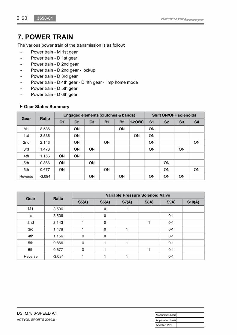
7. POWER TRAINThe various power train of the transmission is as follow:
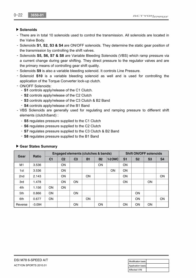
Gear States Summary▶
Power train - M 1st gearPower train - D 1st gearPower train - D 2nd gearPower train - D 2nd gear - lockupPower train - D 3rd gearPower train - D 4th gear - D 4th gear - limp home modePower train - D 5th gearPower train - D 6th gear
--------
0-21
DSI M78 6-SPEED A/TACTYON SPORTS 2010.01
3650-01
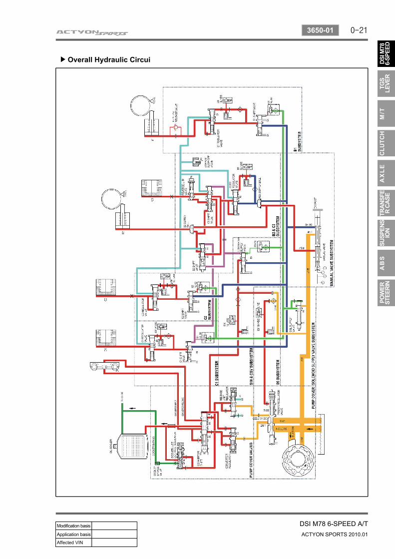
Overall Hydraulic Circui▶
0-22
ACTYON SPORTS 2010.01
3650-01
DSI M78 6-SPEED A/T
Solenoids▶
There are in total 10 solenoids used to control the transmission. All solenoids are located in the Valve Body.Solenoids S1, S2, S3 & S4 are ON/OFF solenoids. They determine the static gear position of the transmission by controlling the shift valves.Solenoids S5, S6, S7 & S8 are Variable Bleeding Solenoids (VBS) which ramp pressure via a current change during gear shifting. They direct pressure to the regulator valves and are the primary means of controlling gear shift quality.Solenoids S9 is also a variable bleeding solenoid. It controls Line Pressure. Solenoid S10 is a variable bleeding solenoid as well and is used for controlling the application of the Torque Converter lock-up clutch. ON/OFF Solenoids:
-
-
-
--
-
Gear States Summary▶
S1 controls apply/release of the C1 Clutch.S2 controls apply/release of the C2 ClutchS3 controls apply/release of the C3 Clutch & B2 BandS4 controls apply/release of the B1 Band
----
VBS Solenoids are generally used for regulating and ramping pressure to different shift elements (clutch/band) :
-
S5 regulates pressure supplied to the C1 ClutchS6 regulates pressure supplied to the C2 ClutchS7 regulates pressure supplied to the C3 Clutch & B2 BandS8 regulates pressure supplied to the B1 Band
----
0-23
DSI M78 6-SPEED A/TACTYON SPORTS 2010.01
3650-01
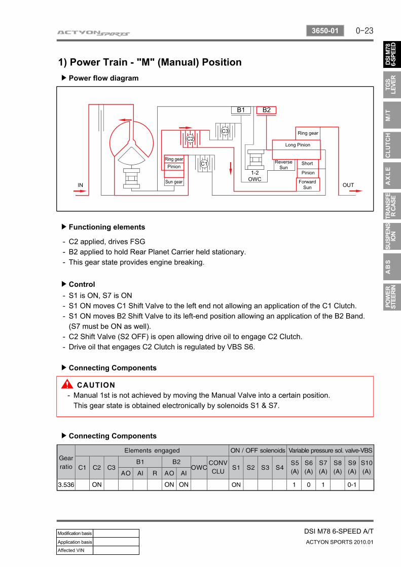
1) Power Train - "M" (Manual) PositionPower flow diagram▶
Functioning elements▶
C2 applied, drives FSGB2 applied to hold Rear Planet Carrier held stationary.This gear state provides engine breaking.
---
Control▶
Connecting Components▶
S1 is ON, S7 is ONS1 ON moves C1 Shift Valve to the left end not allowing an application of the C1 Clutch.S1 ON moves B2 Shift Valve to its left-end position allowing an application of the B2 Band.(S7 must be ON as well).C2 Shift Valve (S2 OFF) is open allowing drive oil to engage C2 Clutch.Drive oil that engages C2 Clutch is regulated by VBS S6.
---
--
Connecting Components▶
Manual 1st is not achieved by moving the Manual Valve into a certain position.This gear state is obtained electronically by solenoids S1 & S7.
-
0-24
ACTYON SPORTS 2010.01
3650-01
DSI M78 6-SPEED A/T
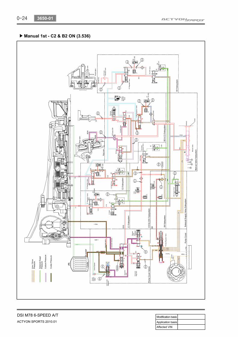
Manual 1st - C2 & B2 ON (3.536)▶
0-25
DSI M78 6-SPEED A/TACTYON SPORTS 2010.01
3650-01
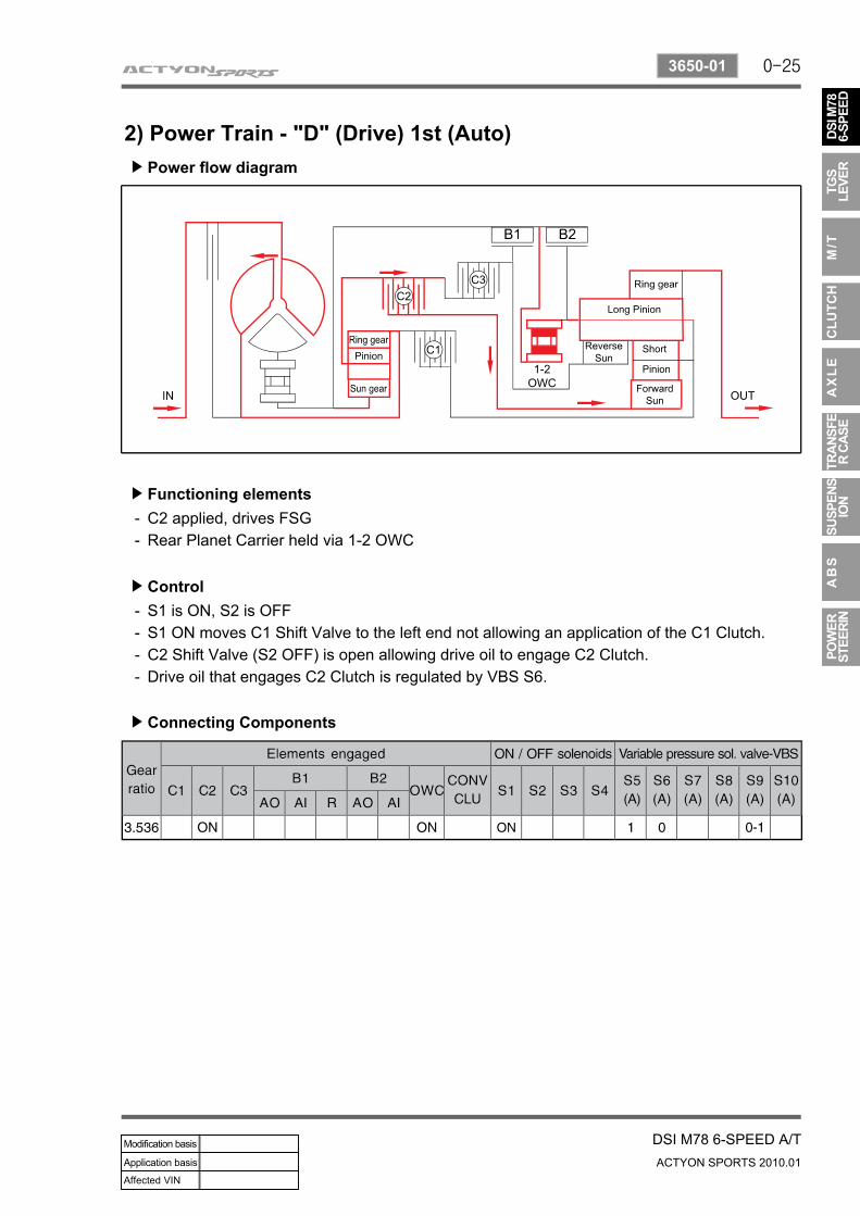
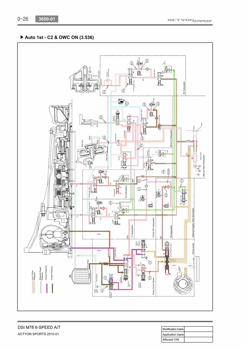
2) Power Train - "D" (Drive) 1st (Auto)Power flow diagram▶
Functioning elements▶
C2 applied, drives FSGRear Planet Carrier held via 1-2 OWC
--
Control▶
Connecting Components▶
S1 is ON, S2 is OFFS1 ON moves C1 Shift Valve to the left end not allowing an application of the C1 Clutch.C2 Shift Valve (S2 OFF) is open allowing drive oil to engage C2 Clutch.Drive oil that engages C2 Clutch is regulated by VBS S6.
----
0-26
ACTYON SPORTS 2010.01
3650-01
DSI M78 6-SPEED A/T
Auto 1st - C2 & OWC ON (3.536)▶
0-27
DSI M78 6-SPEED A/TACTYON SPORTS 2010.01
3650-01
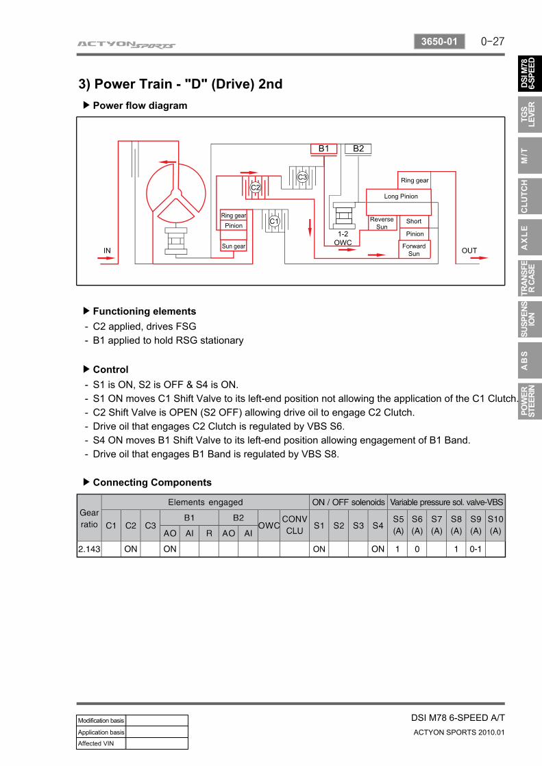
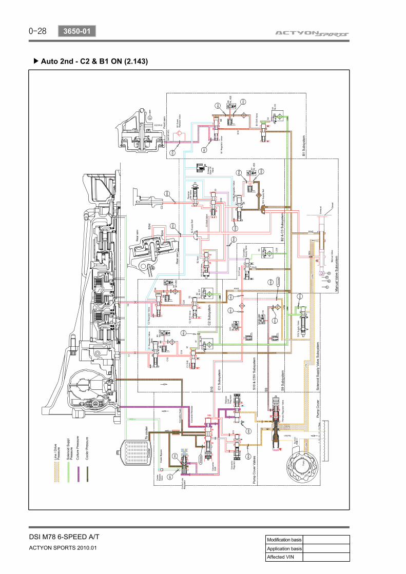
3) Power Train - "D" (Drive) 2ndPower flow diagram▶
Functioning elements▶
C2 applied, drives FSGB1 applied to hold RSG stationary
--
Control▶
Connecting Components▶
S1 is ON, S2 is OFF & S4 is ON.S1 ON moves C1 Shift Valve to its left-end position not allowing the application of the C1 Clutch.C2 Shift Valve is OPEN (S2 OFF) allowing drive oil to engage C2 Clutch.Drive oil that engages C2 Clutch is regulated by VBS S6.S4 ON moves B1 Shift Valve to its left-end position allowing engagement of B1 Band.Drive oil that engages B1 Band is regulated by VBS S8.
------
0-28
ACTYON SPORTS 2010.01
3650-01
DSI M78 6-SPEED A/T
Auto 2nd - C2 & B1 ON (2.143)▶
0-29
DSI M78 6-SPEED A/TACTYON SPORTS 2010.01
3650-01
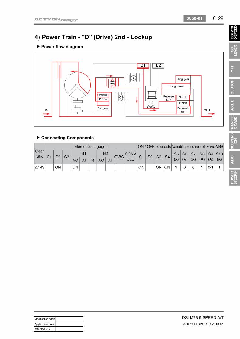
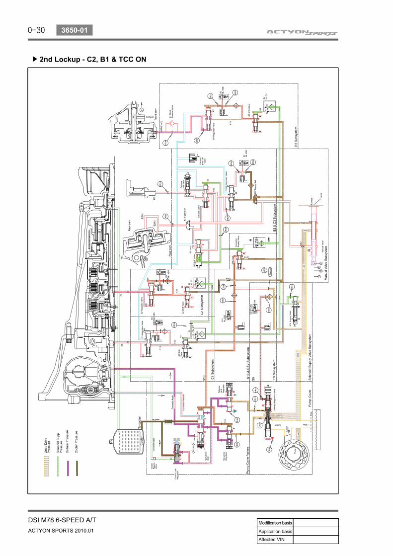
4) Power Train - "D" (Drive) 2nd - LockupPower flow diagram▶
Connecting Components▶
0-30
ACTYON SPORTS 2010.01
3650-01
DSI M78 6-SPEED A/T
2nd Lockup - C2, B1 & TCC ON▶
0-31
DSI M78 6-SPEED A/TACTYON SPORTS 2010.01
3650-01
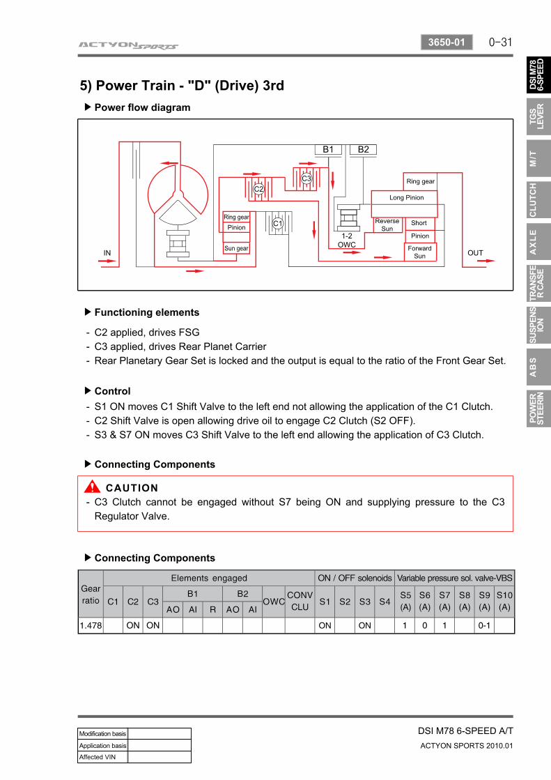
5) Power Train - "D" (Drive) 3rdPower flow diagram▶
Functioning elements▶
C2 applied, drives FSGC3 applied, drives Rear Planet CarrierRear Planetary Gear Set is locked and the output is equal to the ratio of the Front Gear Set.
---
Control▶
Connecting Components▶
S1 ON moves C1 Shift Valve to the left end not allowing the application of the C1 Clutch.C2 Shift Valve is open allowing drive oil to engage C2 Clutch (S2 OFF).S3 & S7 ON moves C3 Shift Valve to the left end allowing the application of C3 Clutch.
---
Connecting Components▶
C3 Clutch cannot be engaged without S7 being ON and supplying pressure to the C3 Regulator Valve.
-
0-32
ACTYON SPORTS 2010.01
3650-01
DSI M78 6-SPEED A/T
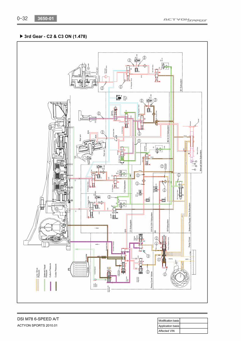
3rd Gear - C2 & C3 ON (1.478)▶
0-33
DSI M78 6-SPEED A/TACTYON SPORTS 2010.01
3650-01
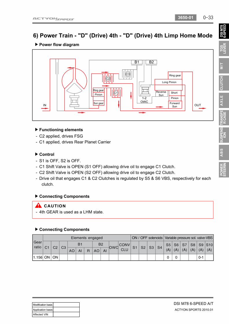
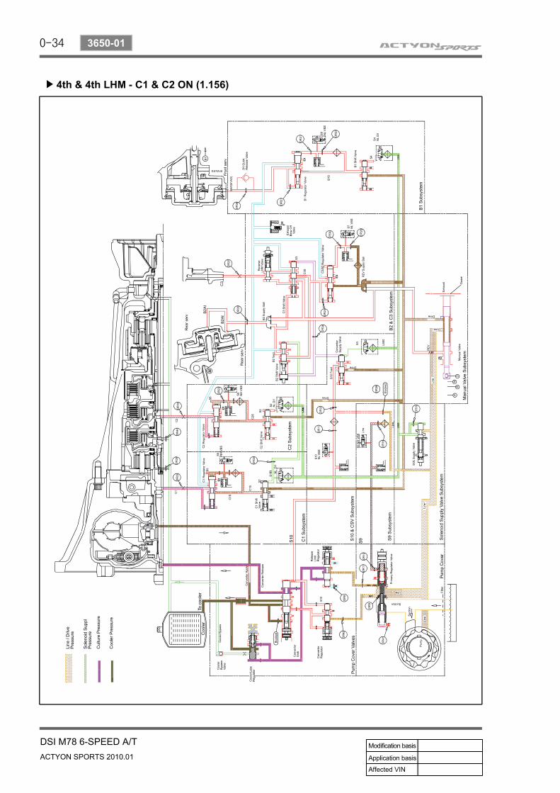
6) Power Train - "D" (Drive) 4th - "D" (Drive) 4th Limp Home ModePower flow diagram▶
Functioning elements▶
C2 applied, drives FSGC1 applied, drives Rear Planet Carrier
--
Control▶
Connecting Components▶
S1 is OFF, S2 is OFF.C1 Shift Valve is OPEN (S1 OFF) allowing drive oil to engage C1 Clutch.C2 Shift Valve is OPEN (S2 OFF) allowing drive oil to engage C2 Clutch.Drive oil that engages C1 & C2 Clutches is regulated by S5 & S6 VBS, respectively for each clutch.
----
4th GEAR is used as a LHM state.-
Connecting Components▶
0-34
ACTYON SPORTS 2010.01
3650-01
DSI M78 6-SPEED A/T
4th & 4th LHM - C1 & C2 ON (1.156)▶
0-35
DSI M78 6-SPEED A/TACTYON SPORTS 2010.01
3650-01
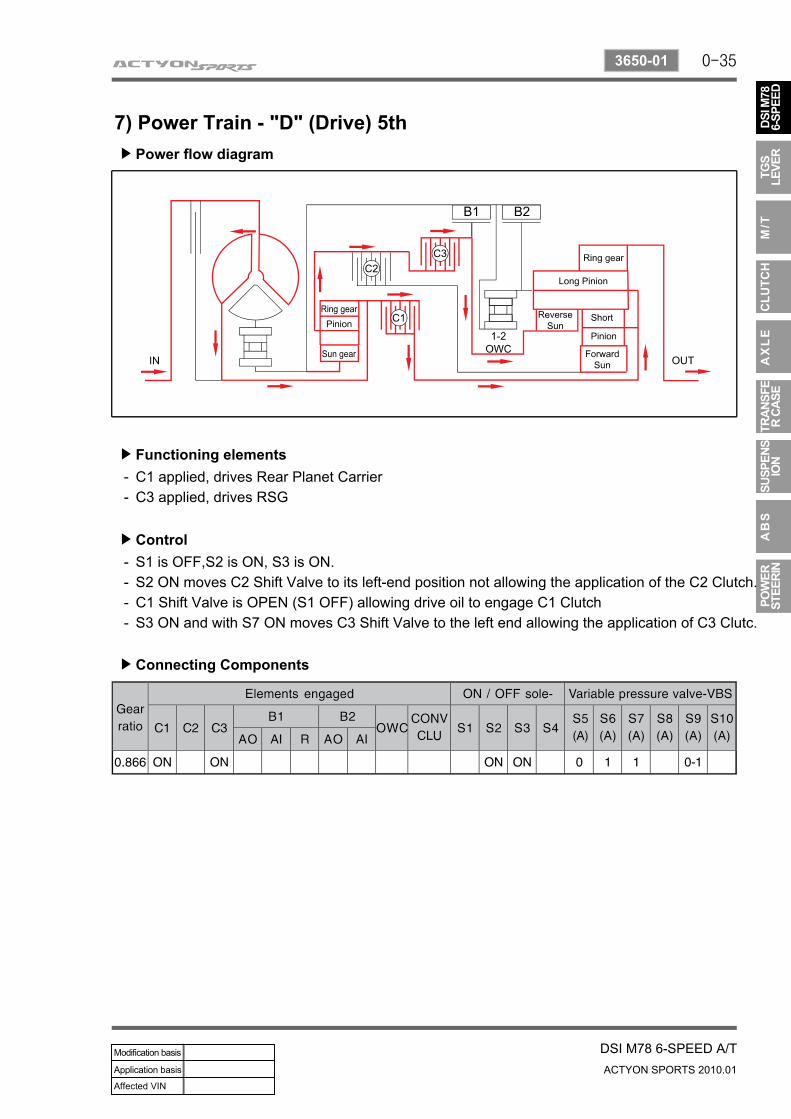
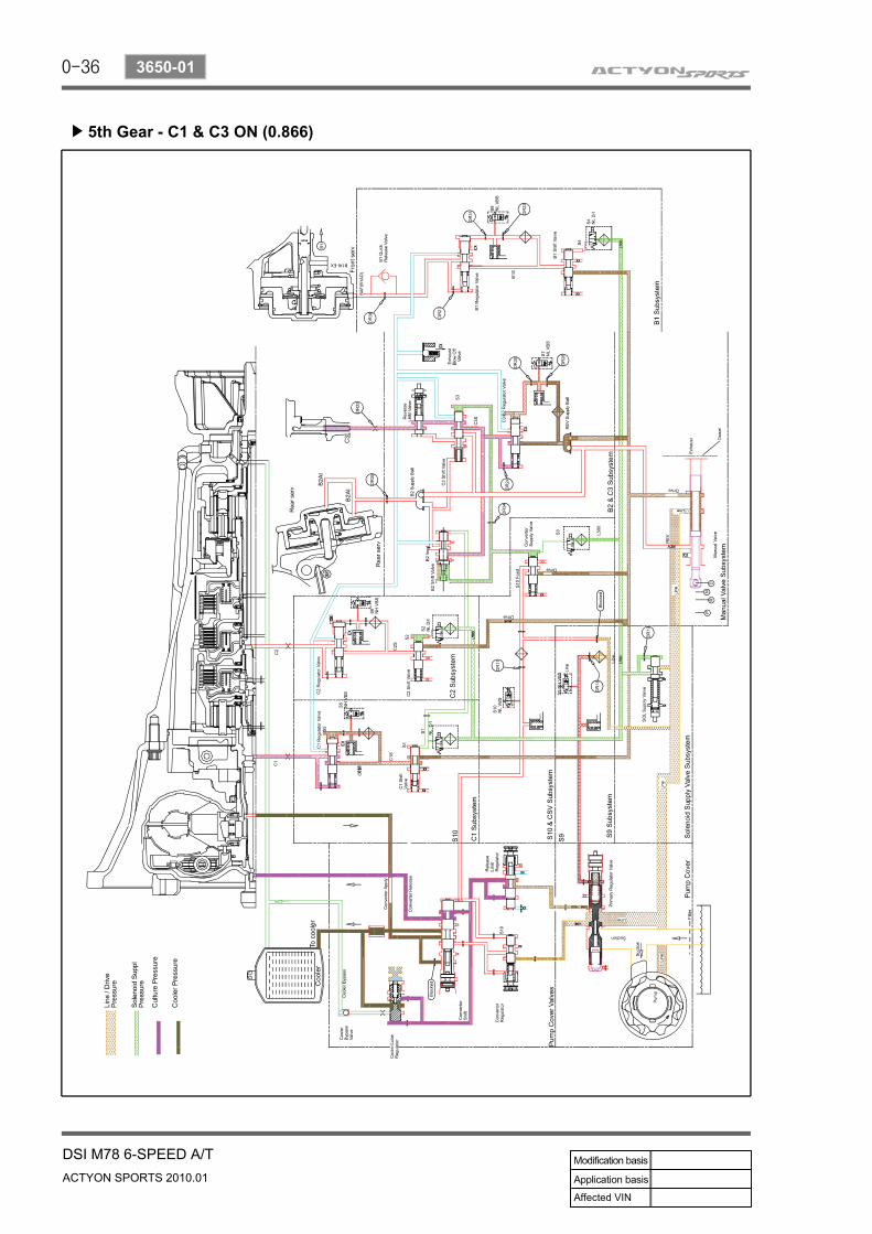
7) Power Train - "D" (Drive) 5thPower flow diagram▶
Functioning elements▶
C1 applied, drives Rear Planet CarrierC3 applied, drives RSG
--
Control▶
Connecting Components▶
S1 is OFF,S2 is ON, S3 is ON.S2 ON moves C2 Shift Valve to its left-end position not allowing the application of the C2 Clutch.C1 Shift Valve is OPEN (S1 OFF) allowing drive oil to engage C1 ClutchS3 ON and with S7 ON moves C3 Shift Valve to the left end allowing the application of C3 Clutc.
----
0-36
ACTYON SPORTS 2010.01
3650-01
DSI M78 6-SPEED A/T
5th Gear - C1 & C3 ON (0.866)▶
0-37
DSI M78 6-SPEED A/TACTYON SPORTS 2010.01
3650-01
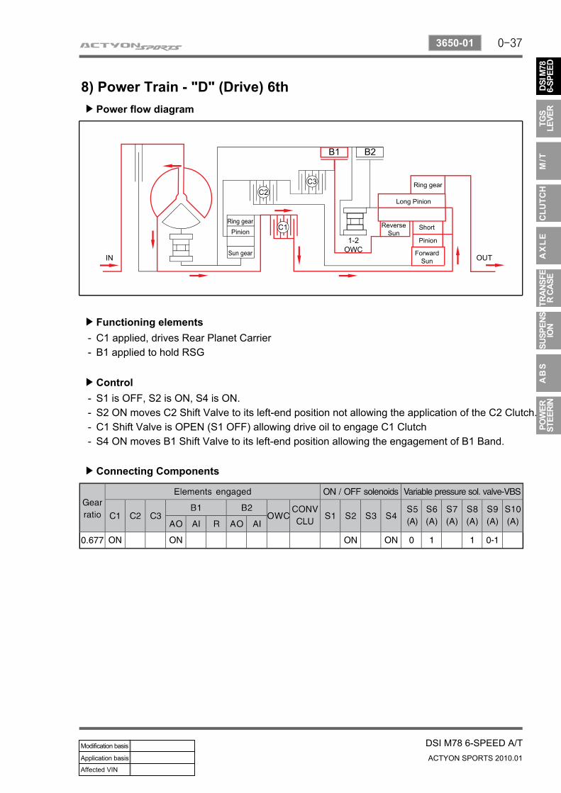
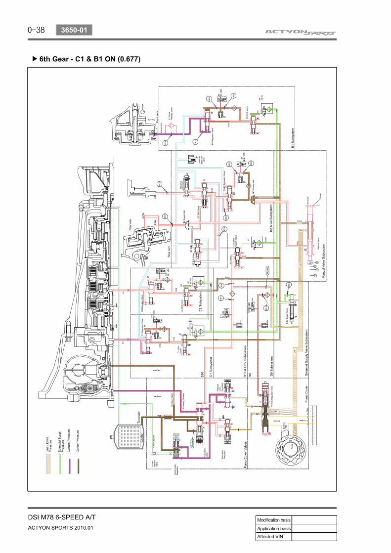
8) Power Train - "D" (Drive) 6thPower flow diagram▶
Functioning elements▶
C1 applied, drives Rear Planet CarrierB1 applied to hold RSG
--
Control▶
Connecting Components▶
S1 is OFF, S2 is ON, S4 is ON.S2 ON moves C2 Shift Valve to its left-end position not allowing the application of the C2 Clutch.C1 Shift Valve is OPEN (S1 OFF) allowing drive oil to engage C1 ClutchS4 ON moves B1 Shift Valve to its left-end position allowing the engagement of B1 Band.
----
0-38
ACTYON SPORTS 2010.01
3650-01
DSI M78 6-SPEED A/T
6th Gear - C1 & B1 ON (0.677)▶
0-39
DSI M78 6-SPEED A/TACTYON SPORTS 2010.01
3650-01
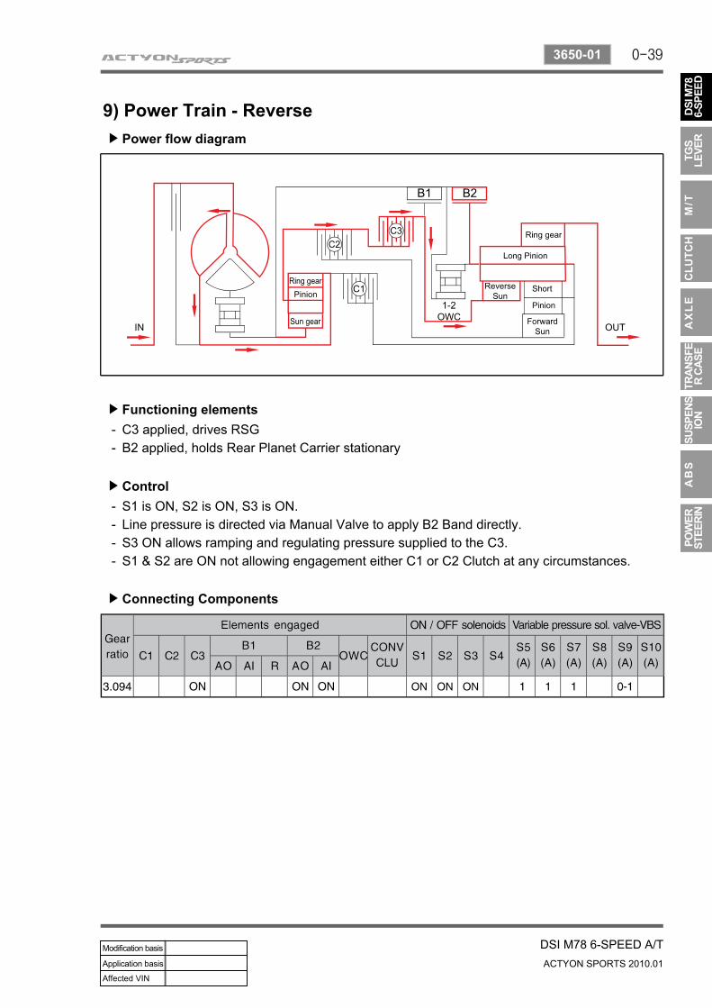
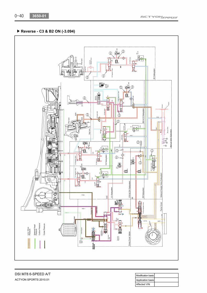
9) Power Train - ReversePower flow diagram▶
Functioning elements▶
C3 applied, drives RSGB2 applied, holds Rear Planet Carrier stationary
--
Control▶
Connecting Components▶
S1 is ON, S2 is ON, S3 is ON.Line pressure is directed via Manual Valve to apply B2 Band directly.S3 ON allows ramping and regulating pressure supplied to the C3. S1 & S2 are ON not allowing engagement either C1 or C2 Clutch at any circumstances.
----
0-40
ACTYON SPORTS 2010.01
3650-01
DSI M78 6-SPEED A/T
Reverse - C3 & B2 ON (-3.094)▶
0-41
DSI M78 6-SPEED A/TACTYON SPORTS 2010.01
3650-01
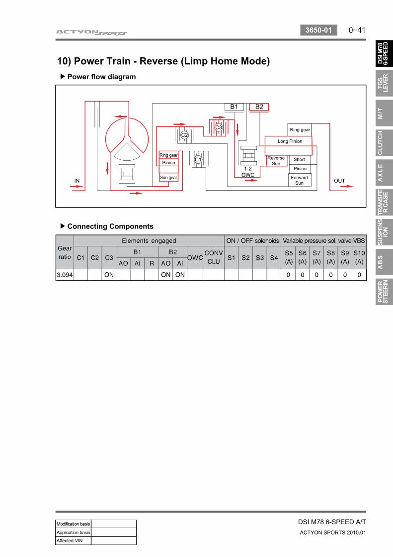
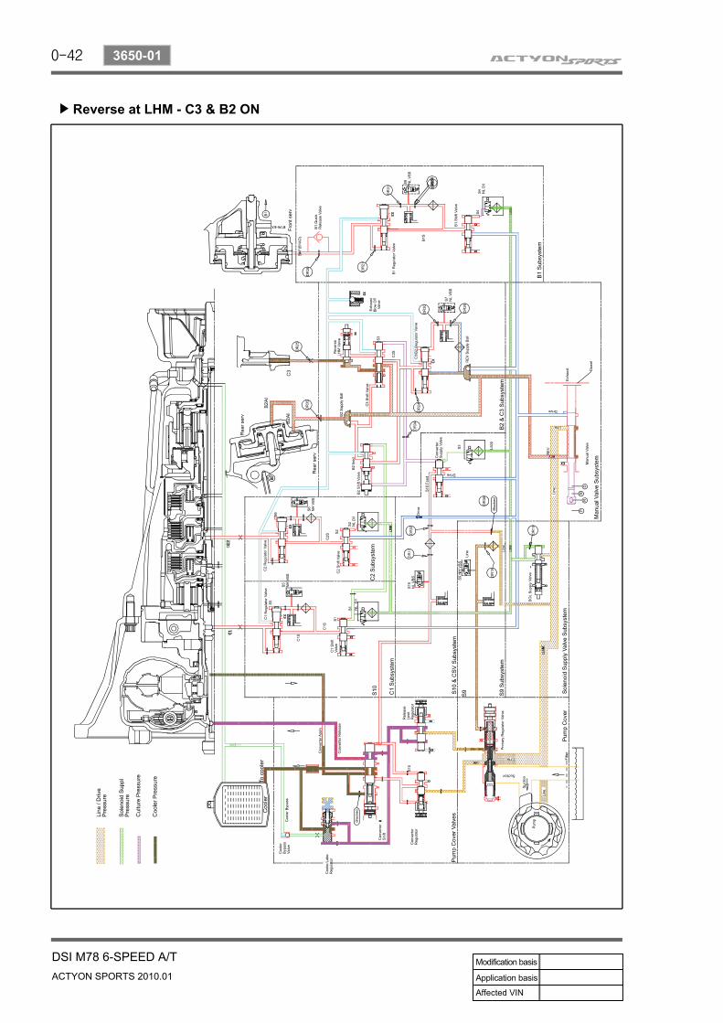
10) Power Train - Reverse (Limp Home Mode)Power flow diagram▶
Connecting Components▶
0-42
ACTYON SPORTS 2010.01
3650-01
DSI M78 6-SPEED A/T
Reverse at LHM - C3 & B2 ON▶
0-43
DSI M78 6-SPEED A/TACTYON SPORTS 2010.01
3650-01
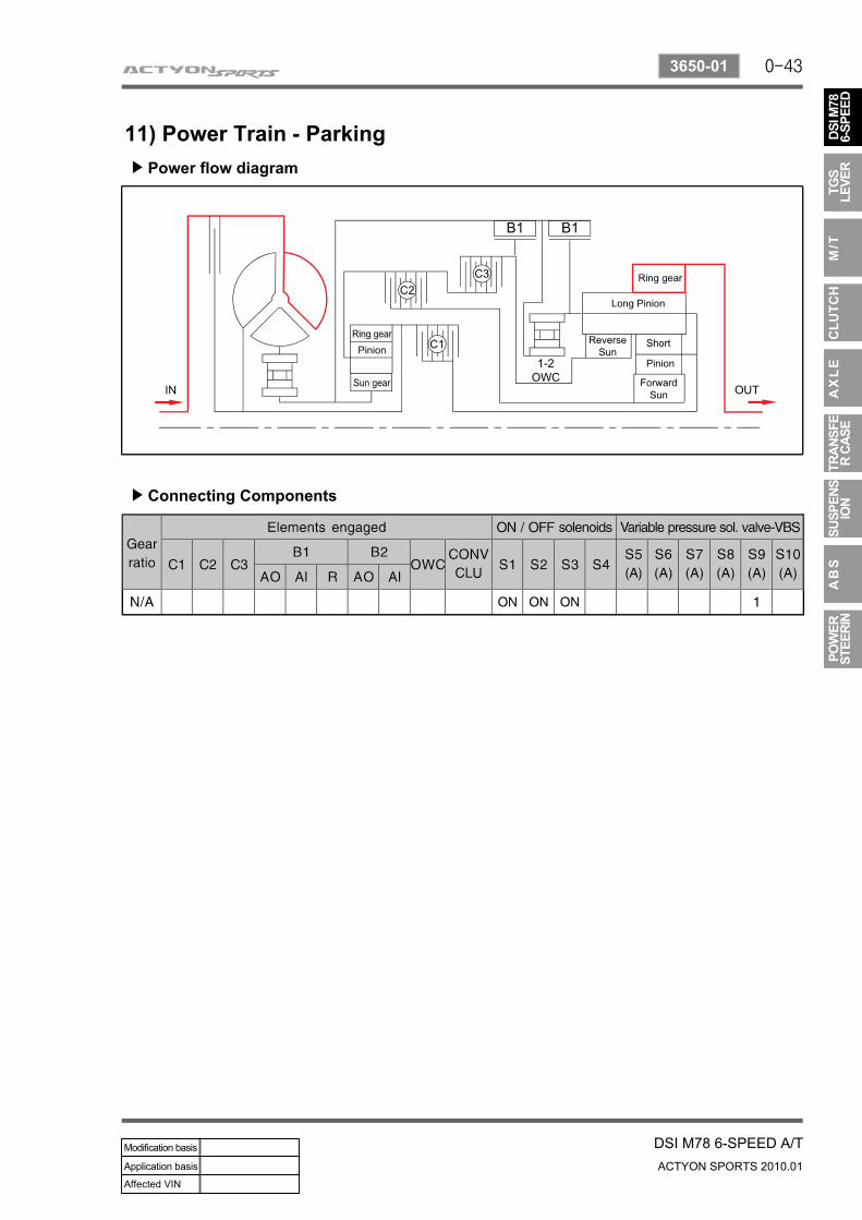
11) Power Train - ParkingPower flow diagram▶
Connecting Components▶
0-44
ACTYON SPORTS 2010.01
3650-01
DSI M78 6-SPEED A/T
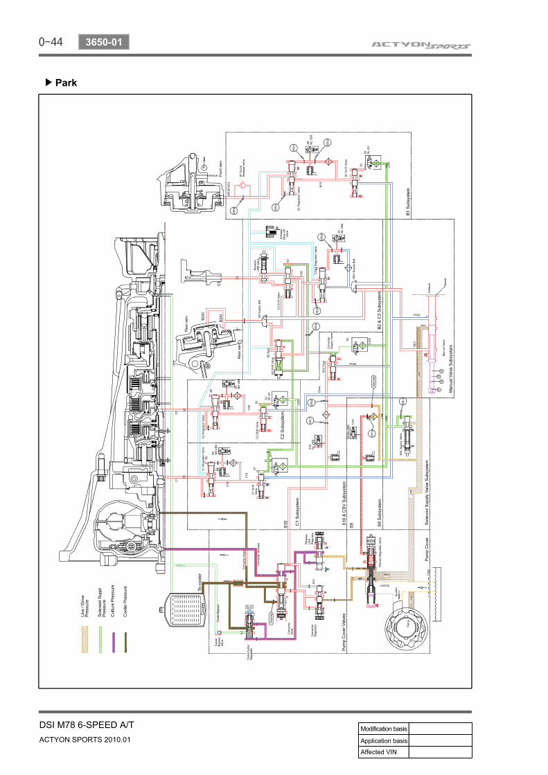
Park▶
0-45
DSI M78 6-SPEED A/TACTYON SPORTS 2010.01
3650-01
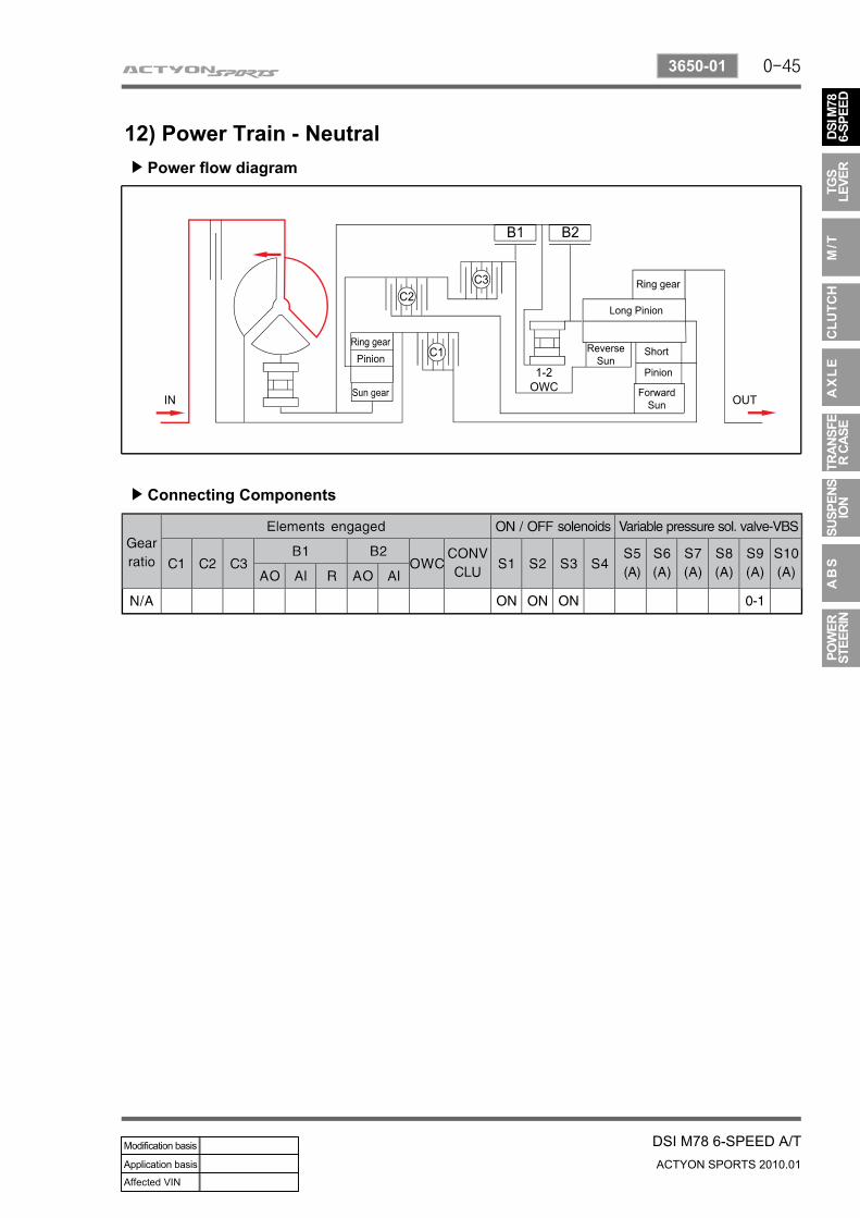
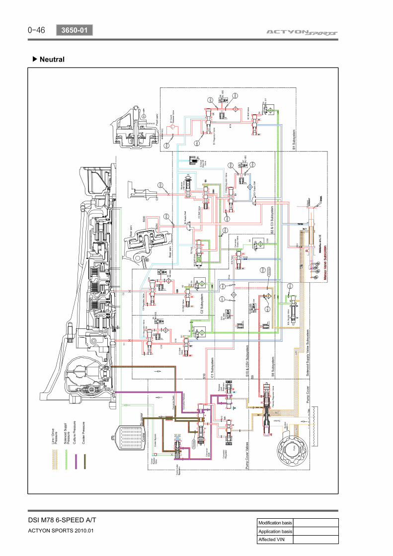
12) Power Train - NeutralPower flow diagram▶
Connecting Components▶
0-46
ACTYON SPORTS 2010.01
3650-01
DSI M78 6-SPEED A/T
Neutral▶
0-95
DSI M78 6-SPEED A/TACTYON SPORTS 2010.01
3110-01
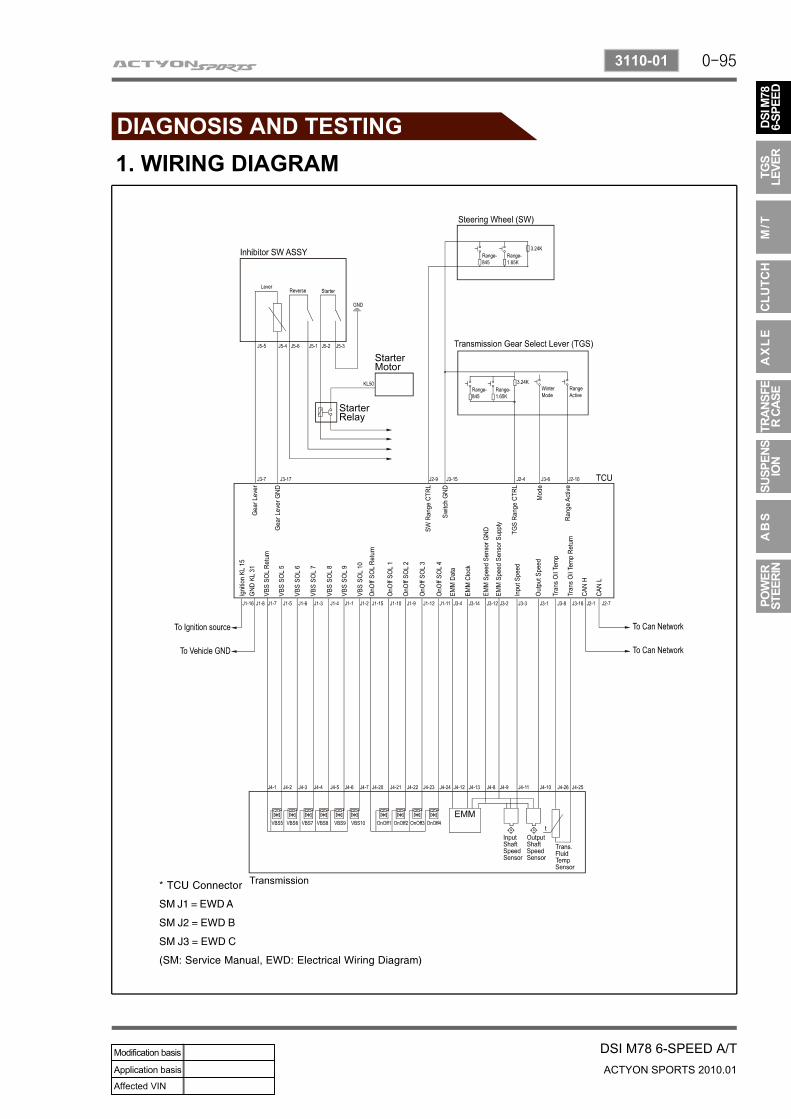
1. WIRING DIAGRAM
0-96
ACTYON SPORTS 2010.01
3110-01
DSI M78 6-SPEED A/T
1) Transmission Control Unit
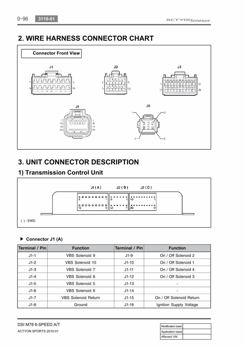
2. WIRE HARNESS CONNECTOR CHART
Connector Front View
3. UNIT CONNECTOR DESCRIPTION
Connector J1 (A)▶
0-97
DSI M78 6-SPEED A/TACTYON SPORTS 2010.01
3110-00
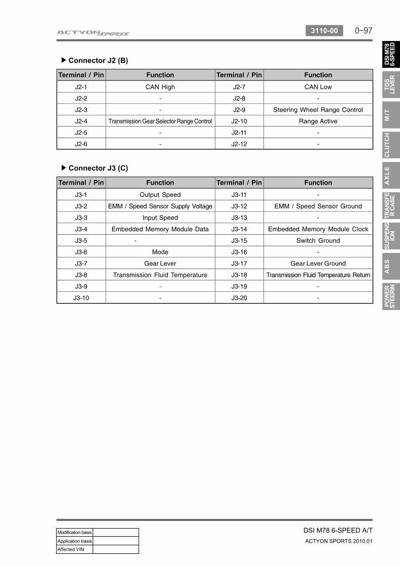
Connector J2 (B)▶
Connector J3 (C)▶
0-98
ACTYON SPORTS 2010.01
3110-00
DSI M78 6-SPEED A/T
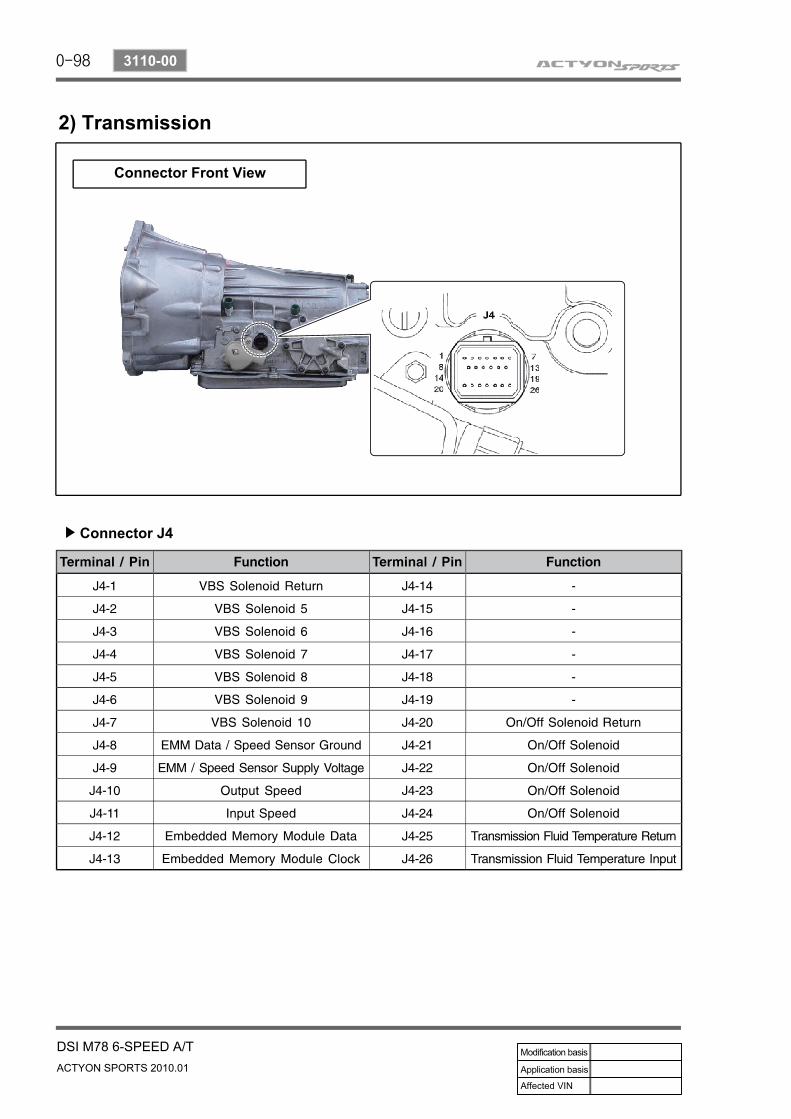
2) Transmission
Connector J4▶
Connector Front View
0-99
DSI M78 6-SPEED A/TACTYON SPORTS 2010.01
3110-00
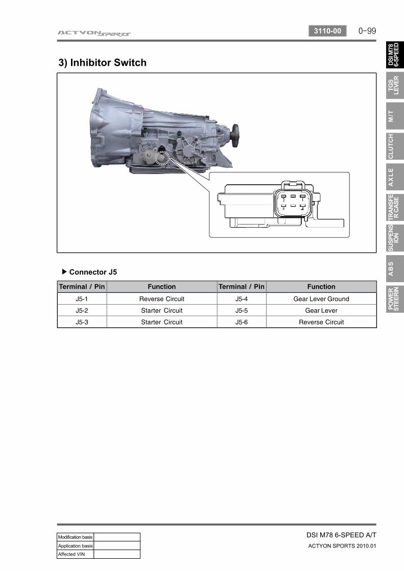
3) Inhibitor Switch
Connector J5▶
0-100
ACTYON SPORTS 2010.01
3110-00
DSI M78 6-SPEED A/T
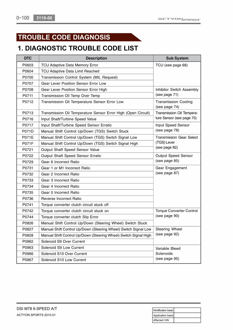
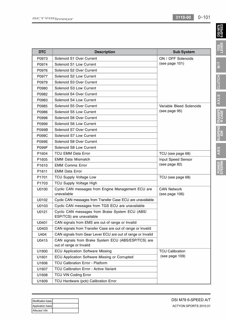
1. DIAGNOSTIC TROUBLE CODE LIST
0-101
DSI M78 6-SPEED A/TACTYON SPORTS 2010.01
3110-00
0-102
ACTYON SPORTS 2010.01
3110-00
DSI M78 6-SPEED A/T
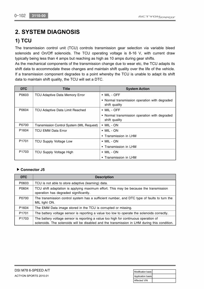
2. SYSTEM DIAGNOSIS1) TCUThe transmission control unit (TCU) controls transmission gear selection via variable bleed solenoids and On/Off solenoids. The TCU operating voltage is 8-16 V, with current draw typically being less than 4 amps but reaching as high as 10 amps during gear shifts.As the mechanical components of the transmission change due to wear etc, the TCU adapts its shift data to accommodate these changes and maintain shift quality over the life of the vehicle. If a transmission component degrades to a point whereby the TCU is unable to adapt its shift data to maintain shift quality, the TCU will set a DTC.
Connector J5▶
0-103
DSI M78 6-SPEED A/TACTYON SPORTS 2010.01
3110-00
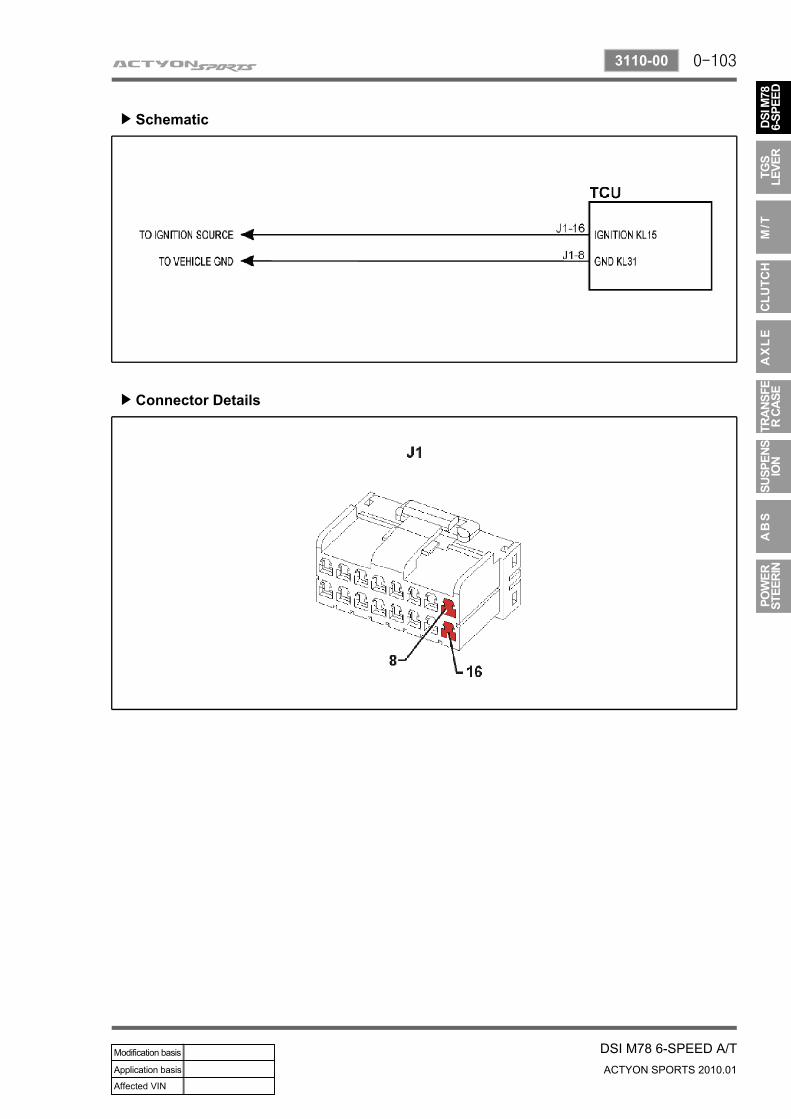
Schematic▶
Connector Details▶
0-104
ACTYON SPORTS 2010.01
3110-00
DSI M78 6-SPEED A/T
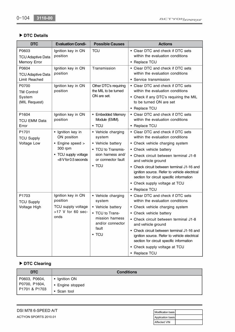
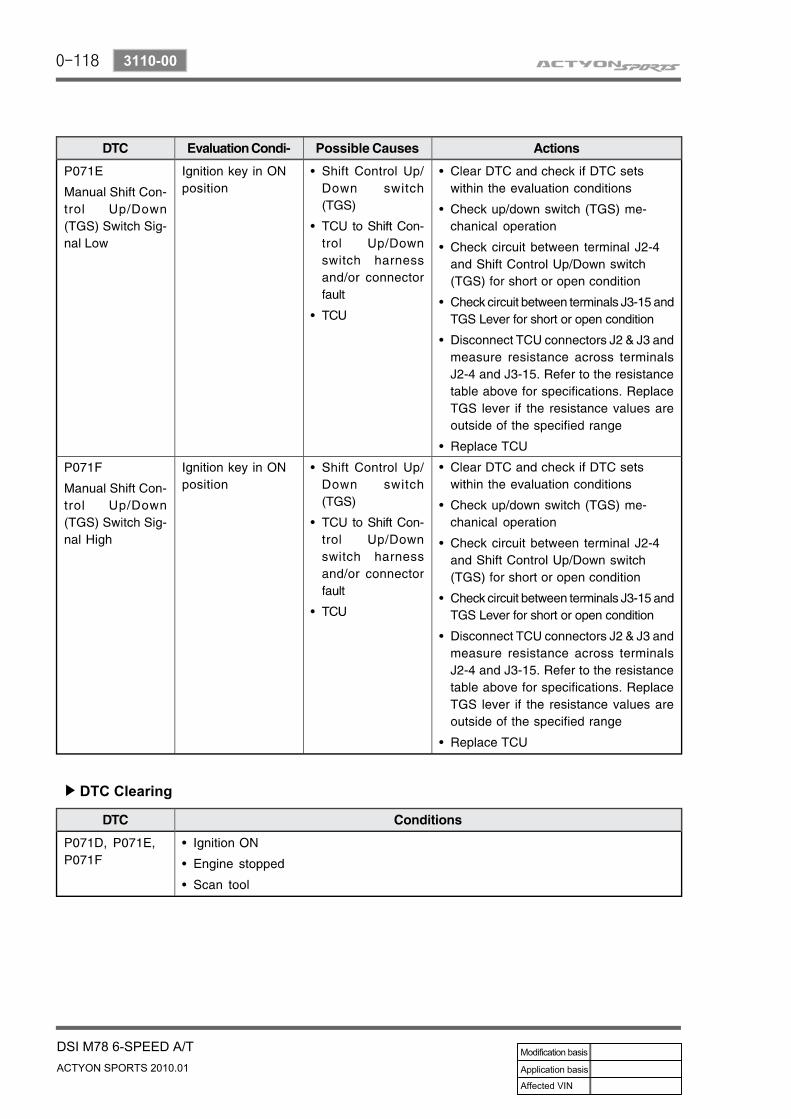
DTC Details▶
DTC Clearing▶
0-105
DSI M78 6-SPEED A/TACTYON SPORTS 2010.01
3110-00
2) Inhibitor Switch Assembly
DTC Description▶
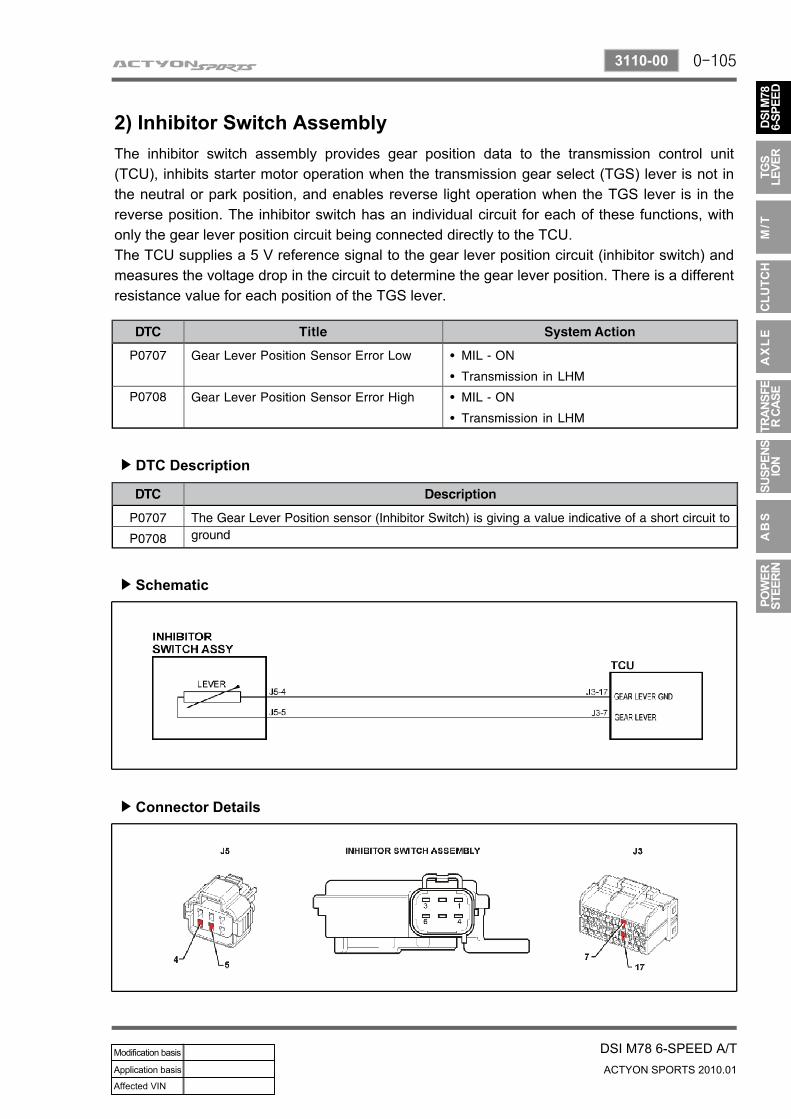
The inhibitor switch assembly provides gear position data to the transmission control unit (TCU), inhibits starter motor operation when the transmission gear select (TGS) lever is not in the neutral or park position, and enables reverse light operation when the TGS lever is in the reverse position. The inhibitor switch has an individual circuit for each of these functions, with only the gear lever position circuit being connected directly to the TCU.The TCU supplies a 5 V reference signal to the gear lever position circuit (inhibitor switch) and measures the voltage drop in the circuit to determine the gear lever position. There is a different resistance value for each position of the TGS lever.
Schematic▶
Connector Details▶
0-106
ACTYON SPORTS 2010.01
3110-00
DSI M78 6-SPEED A/T
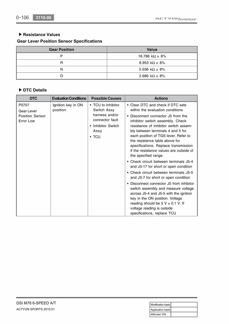
Resistance Values▶
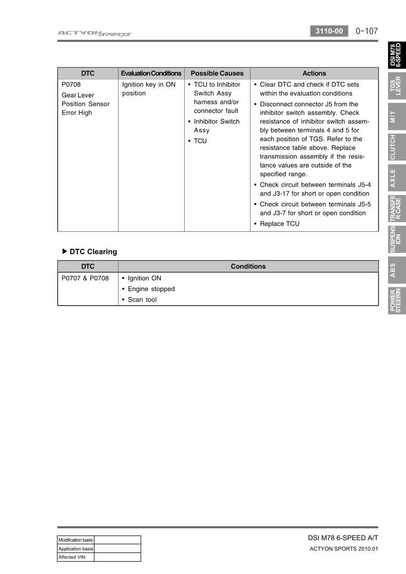
DTC Details▶
Gear Lever Position Sensor Specifications
0-107
DSI M78 6-SPEED A/TACTYON SPORTS 2010.01
3110-00
DTC Clearing▶
0-108
ACTYON SPORTS 2010.01
3110-00
DSI M78 6-SPEED A/T
3) Transmission Cooling
DTC Description▶
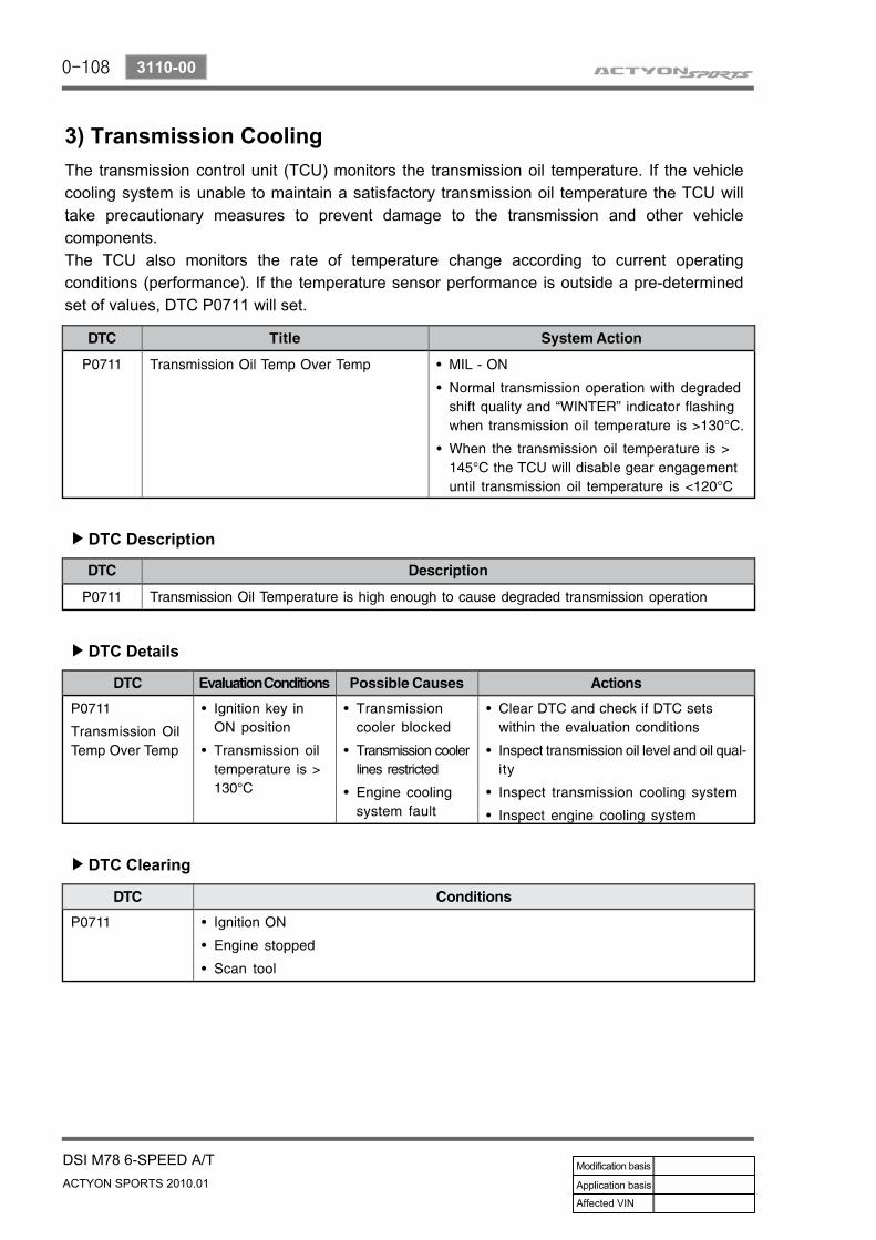
The transmission control unit (TCU) monitors the transmission oil temperature. If the vehicle cooling system is unable to maintain a satisfactory transmission oil temperature the TCU will take precautionary measures to prevent damage to the transmission and other vehicle components.The TCU also monitors the rate of temperature change according to current operating conditions (performance). If the temperature sensor performance is outside a pre-determined set of values, DTC P0711 will set.
DTC Details▶
DTC Clearing▶
0-109
DSI M78 6-SPEED A/TACTYON SPORTS 2010.01
3110-00
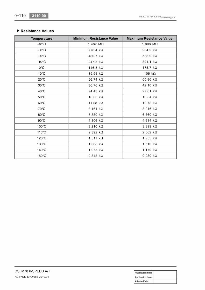
4) Transmission Oil Temperature Sensor
DTC Description▶
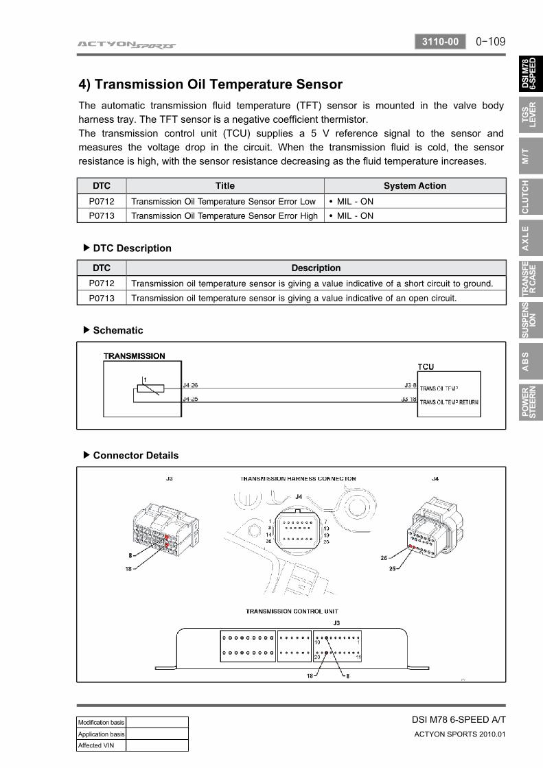
The automatic transmission fluid temperature (TFT) sensor is mounted in the valve body harness tray. The TFT sensor is a negative coefficient thermistor. The transmission control unit (TCU) supplies a 5 V reference signal to the sensor and measures the voltage drop in the circuit. When the transmission fluid is cold, the sensor resistance is high, with the sensor resistance decreasing as the fluid temperature increases.
Schematic▶
Connector Details▶
0-110
ACTYON SPORTS 2010.01
3110-00
DSI M78 6-SPEED A/T
Resistance Values▶
0-111
DSI M78 6-SPEED A/TACTYON SPORTS 2010.01
3110-00
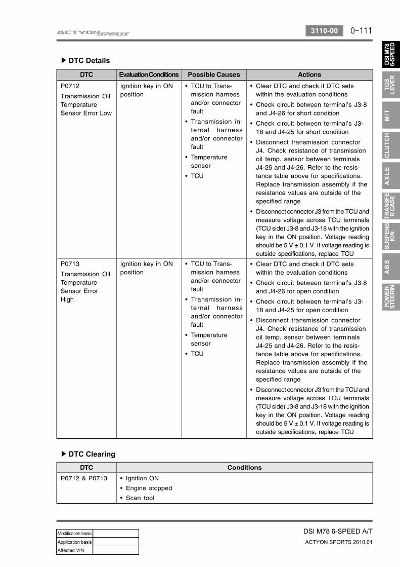
DTC Details▶
DTC Clearing▶
0-112
ACTYON SPORTS 2010.01
3110-00
DSI M78 6-SPEED A/T
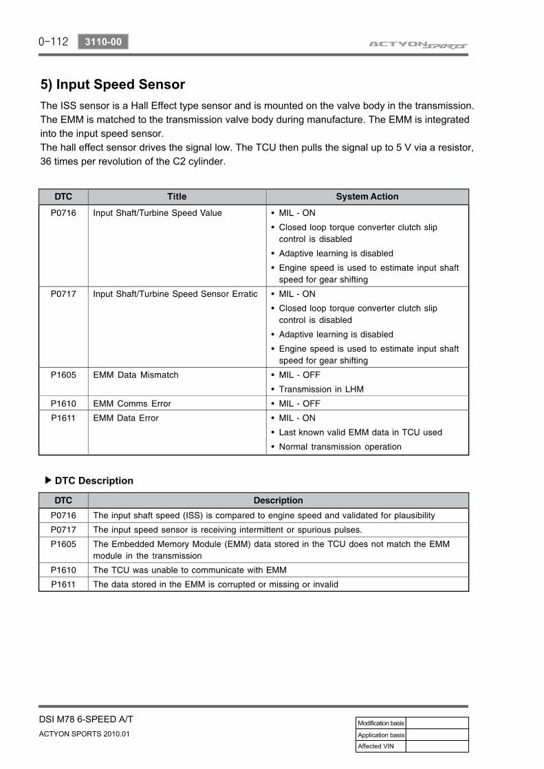
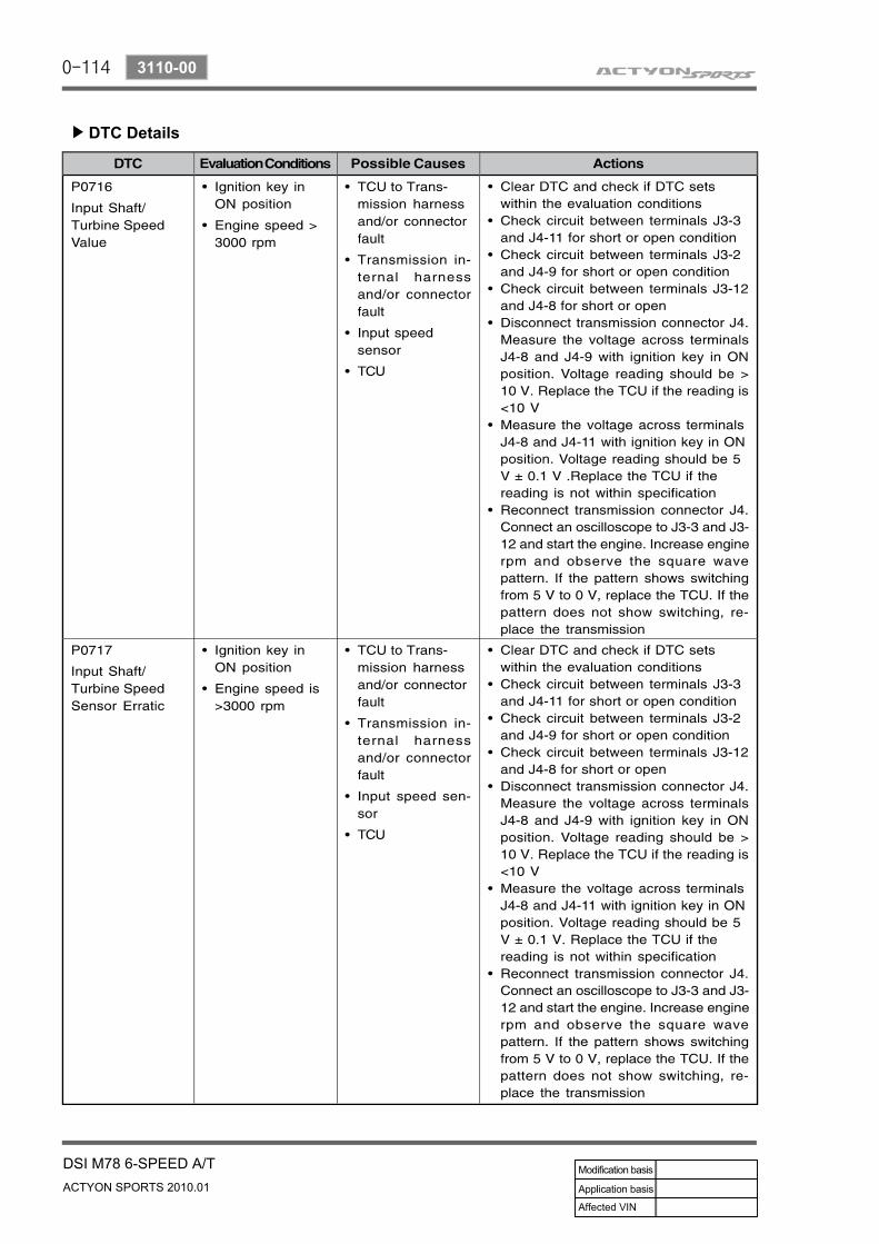
5) Input Speed Sensor
DTC Description▶
The ISS sensor is a Hall Effect type sensor and is mounted on the valve body in the transmission.The EMM is matched to the transmission valve body during manufacture. The EMM is integrated into the input speed sensor.The hall effect sensor drives the signal low. The TCU then pulls the signal up to 5 V via a resistor, 36 times per revolution of the C2 cylinder.
0-113
DSI M78 6-SPEED A/TACTYON SPORTS 2010.01
3110-00
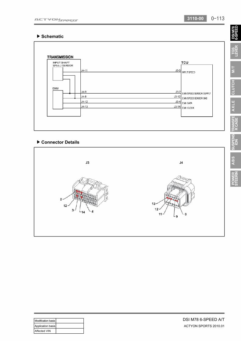
Schematic▶
Connector Details▶
0-114
ACTYON SPORTS 2010.01
3110-00
DSI M78 6-SPEED A/T
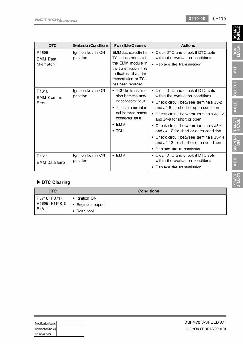
DTC Details▶
0-115
DSI M78 6-SPEED A/TACTYON SPORTS 2010.01
3110-00
DTC Clearing▶
0-116
ACTYON SPORTS 2010.01
3110-00
DSI M78 6-SPEED A/T
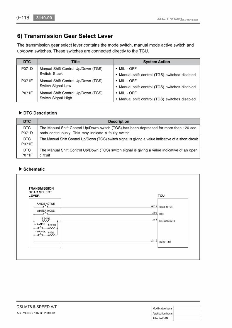
6) Transmission Gear Select Lever
DTC Description▶
The transmission gear select lever contains the mode switch, manual mode active switch and up/down switches. These switches are connected directly to the TCU.
Schematic▶
0-117
DSI M78 6-SPEED A/TACTYON SPORTS 2010.01
3110-00
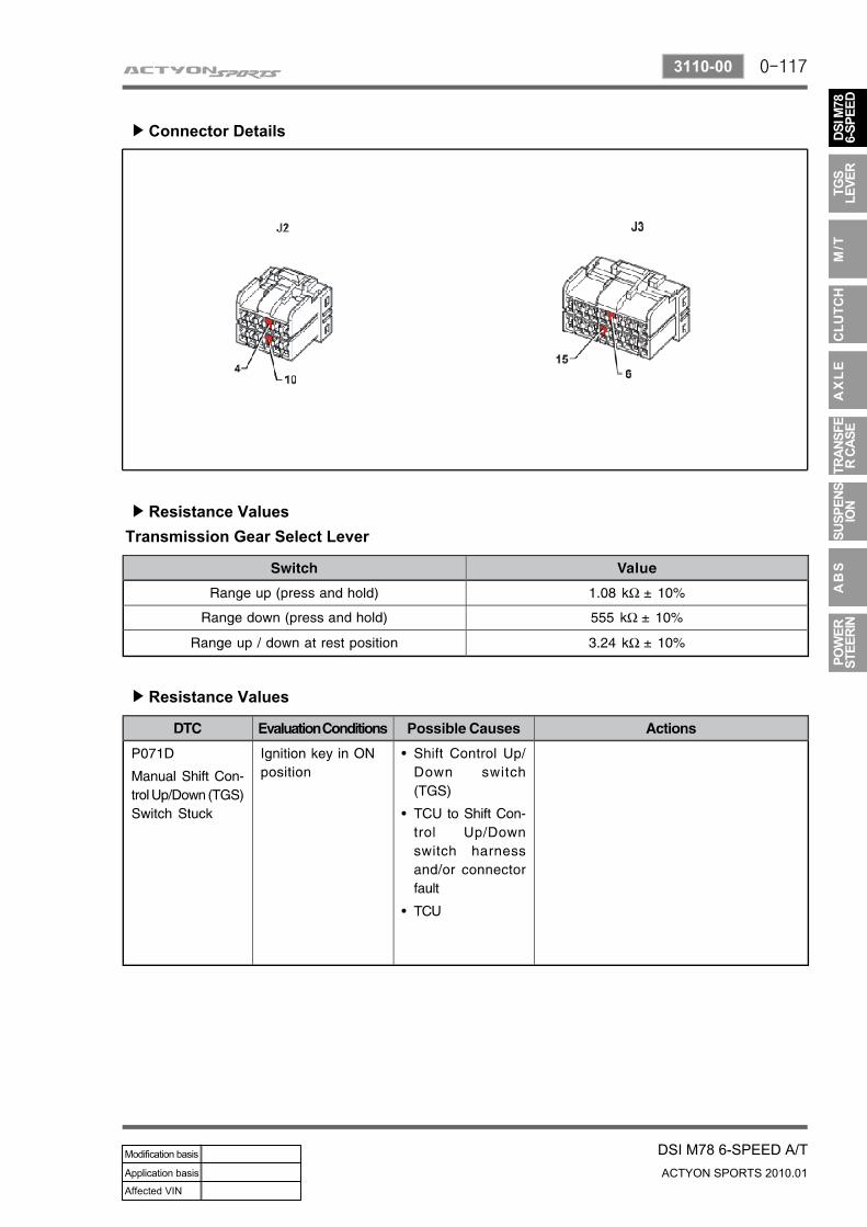
Connector Details▶
Resistance Values▶
Transmission Gear Select Lever
Resistance Values▶
0-118
ACTYON SPORTS 2010.01
3110-00
DSI M78 6-SPEED A/T
DTC Clearing▶
0-119
DSI M78 6-SPEED A/TACTYON SPORTS 2010.01
3110-00
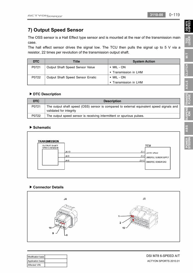
7) Output Speed Sensor
DTC Description▶
The OSS sensor is a Hall Effect type sensor and is mounted at the rear of the transmission main case. The hall effect sensor drives the signal low. The TCU then pulls the signal up to 5 V via a resistor, 22 times per revolution of the transmission output shaft.
Schematic▶
Connector Details▶
0-120
ACTYON SPORTS 2010.01
3110-00
DSI M78 6-SPEED A/T
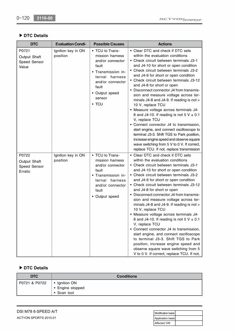
DTC Details▶
DTC Details▶
0-121
DSI M78 6-SPEED A/TACTYON SPORTS 2010.01
3110-00
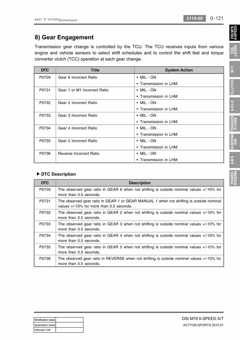
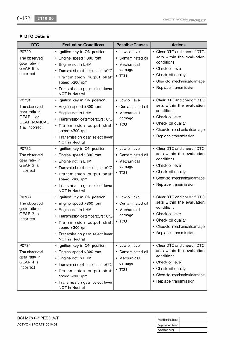
8) Gear Engagement
DTC Description▶
Transmission gear change is controlled by the TCU. The TCU receives inputs from various engine and vehicle sensors to select shift schedules and to control the shift feel and torque converter clutch (TCC) operation at each gear change.
0-122
ACTYON SPORTS 2010.01
3110-00
DSI M78 6-SPEED A/T
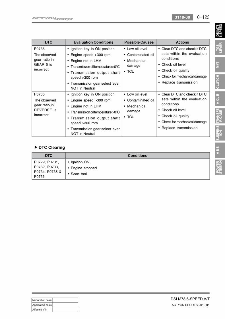
DTC Details▶
0-123
DSI M78 6-SPEED A/TACTYON SPORTS 2010.01
3110-00
DTC Clearing▶
0-124
ACTYON SPORTS 2010.01
3110-00
DSI M78 6-SPEED A/T
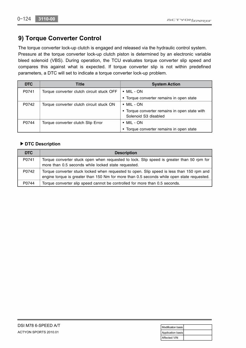
9) Torque Converter Control
DTC Description▶
The torque converter lock-up clutch is engaged and released via the hydraulic control system.Pressure at the torque converter lock-up clutch piston is determined by an electronic variable bleed solenoid (VBS). During operation, the TCU evaluates torque converter slip speed and compares this against what is expected. If torque converter slip is not within predefined parameters, a DTC will set to indicate a torque converter lock-up problem.
0-125
DSI M78 6-SPEED A/TACTYON SPORTS 2010.01
3110-00
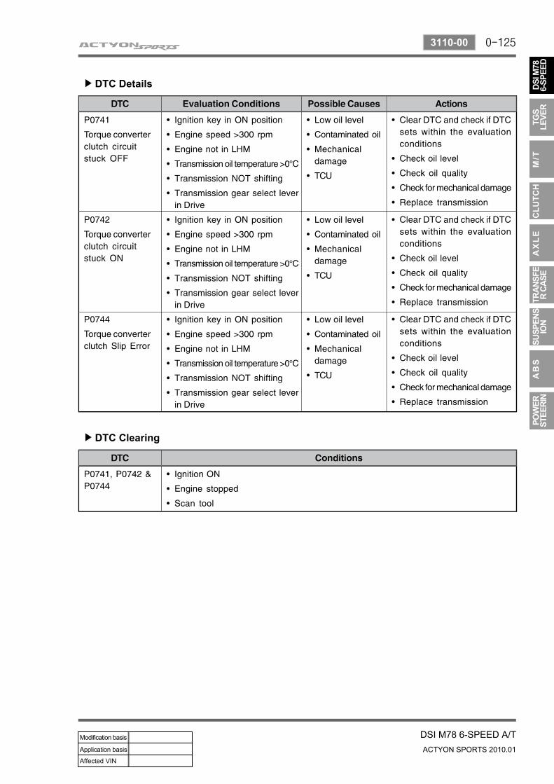
DTC Details▶
DTC Clearing▶
0-126
ACTYON SPORTS 2010.01
3110-00
DSI M78 6-SPEED A/T
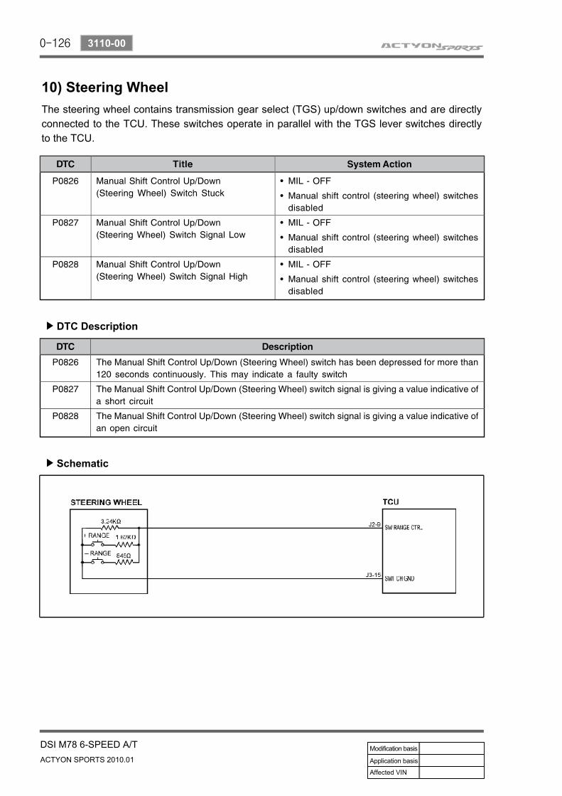
10) Steering Wheel
DTC Description▶
The steering wheel contains transmission gear select (TGS) up/down switches and are directly connected to the TCU. These switches operate in parallel with the TGS lever switches directly to the TCU.
Schematic▶
0-127
DSI M78 6-SPEED A/TACTYON SPORTS 2010.01
3110-00
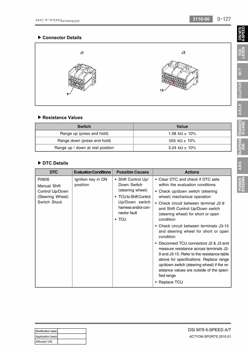
Connector Details▶
Resistance Values▶
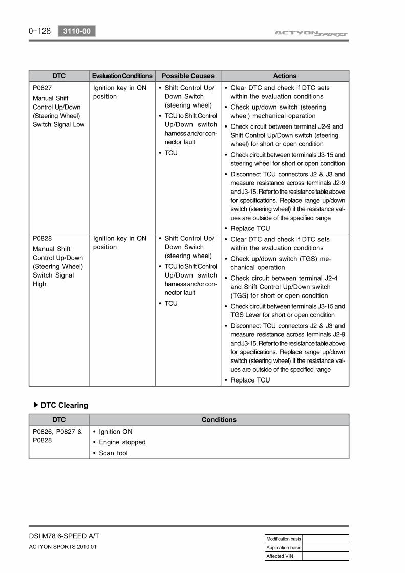
DTC Details▶
0-128
ACTYON SPORTS 2010.01
3110-00
DSI M78 6-SPEED A/T
DTC Clearing▶
0-129
DSI M78 6-SPEED A/TACTYON SPORTS 2010.01
3110-00
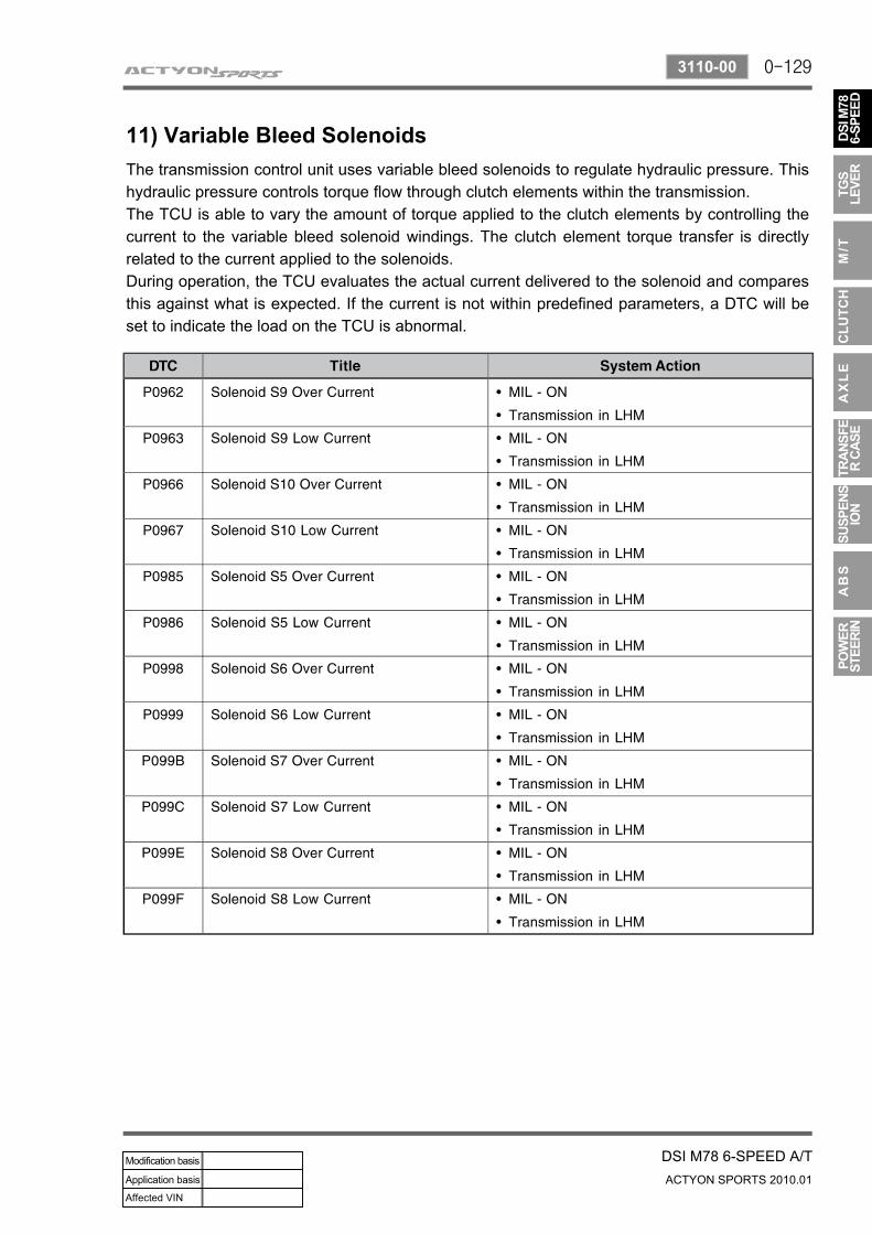
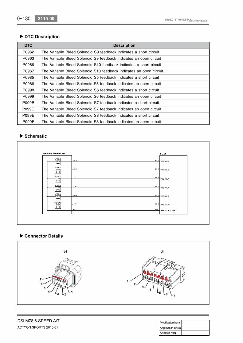
11) Variable Bleed SolenoidsThe transmission control unit uses variable bleed solenoids to regulate hydraulic pressure. This hydraulic pressure controls torque flow through clutch elements within the transmission.The TCU is able to vary the amount of torque applied to the clutch elements by controlling the current to the variable bleed solenoid windings. The clutch element torque transfer is directly related to the current applied to the solenoids.During operation, the TCU evaluates the actual current delivered to the solenoid and compares this against what is expected. If the current is not within predefined parameters, a DTC will be set to indicate the load on the TCU is abnormal.
0-130
ACTYON SPORTS 2010.01
3110-00
DSI M78 6-SPEED A/T
DTC Description▶
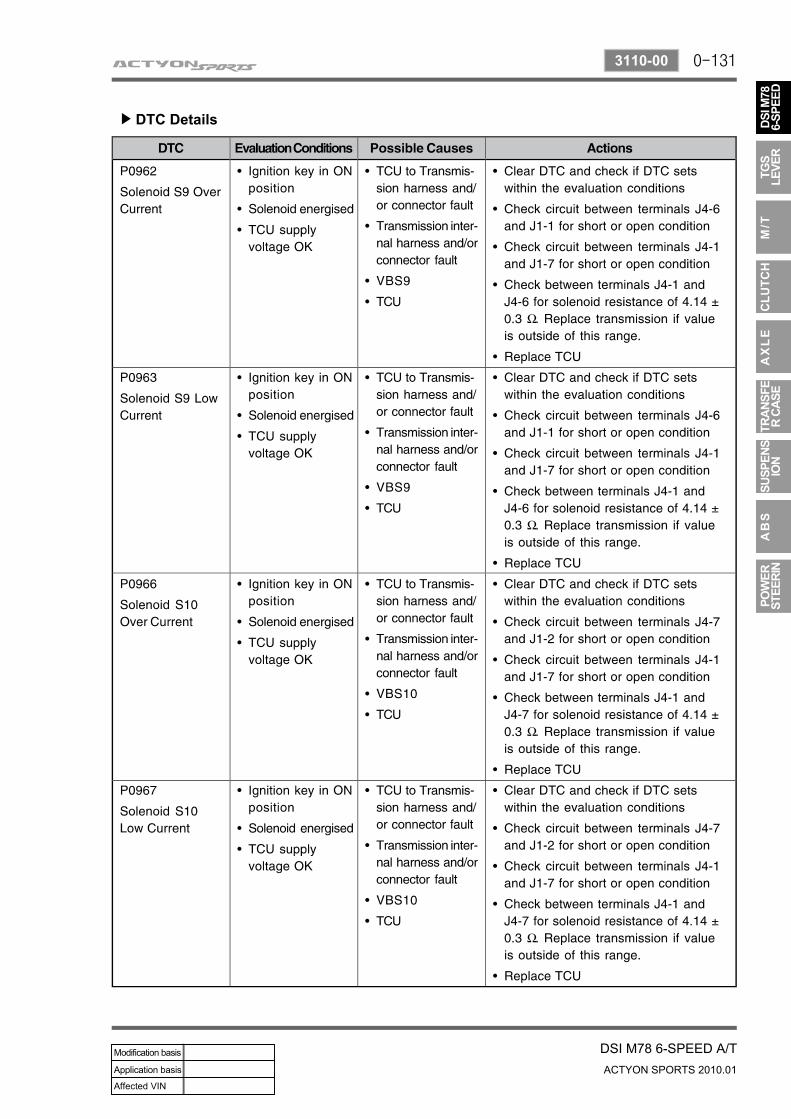
Schematic▶
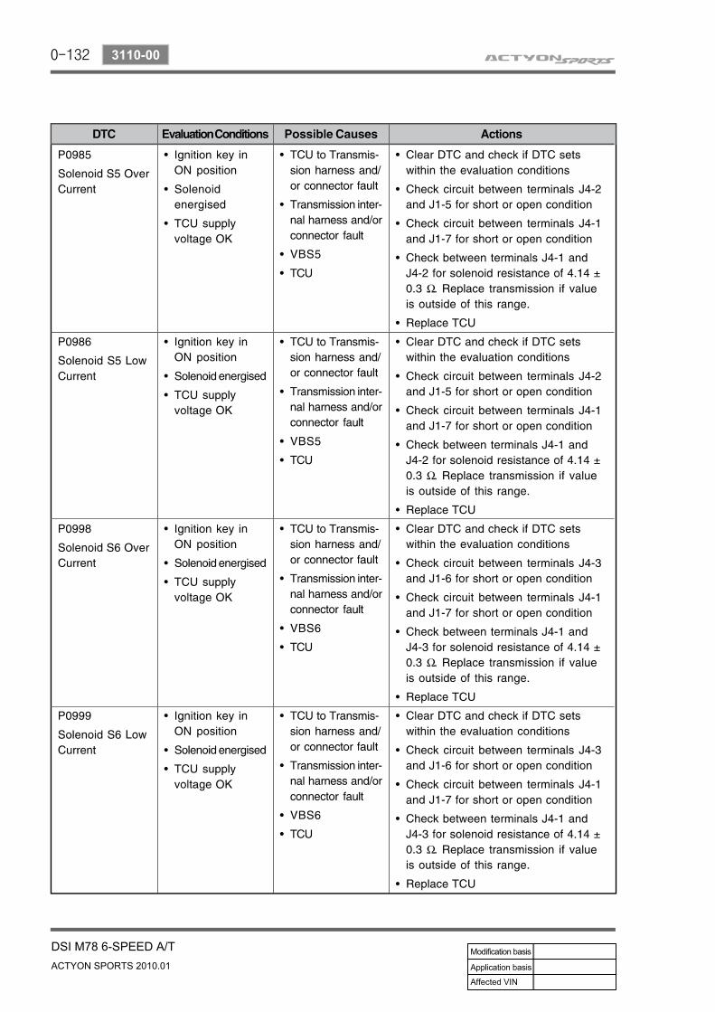
Connector Details▶
0-131
DSI M78 6-SPEED A/TACTYON SPORTS 2010.01
3110-00
DTC Details▶
0-132
ACTYON SPORTS 2010.01
3110-00
DSI M78 6-SPEED A/T
0-133
DSI M78 6-SPEED A/TACTYON SPORTS 2010.01
3110-00
0-134
ACTYON SPORTS 2010.01
3110-00
DSI M78 6-SPEED A/T
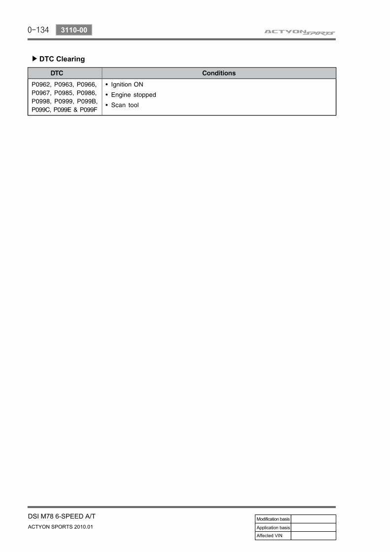
DTC Clearing▶
0-135
DSI M78 6-SPEED A/TACTYON SPORTS 2010.01
3110-00
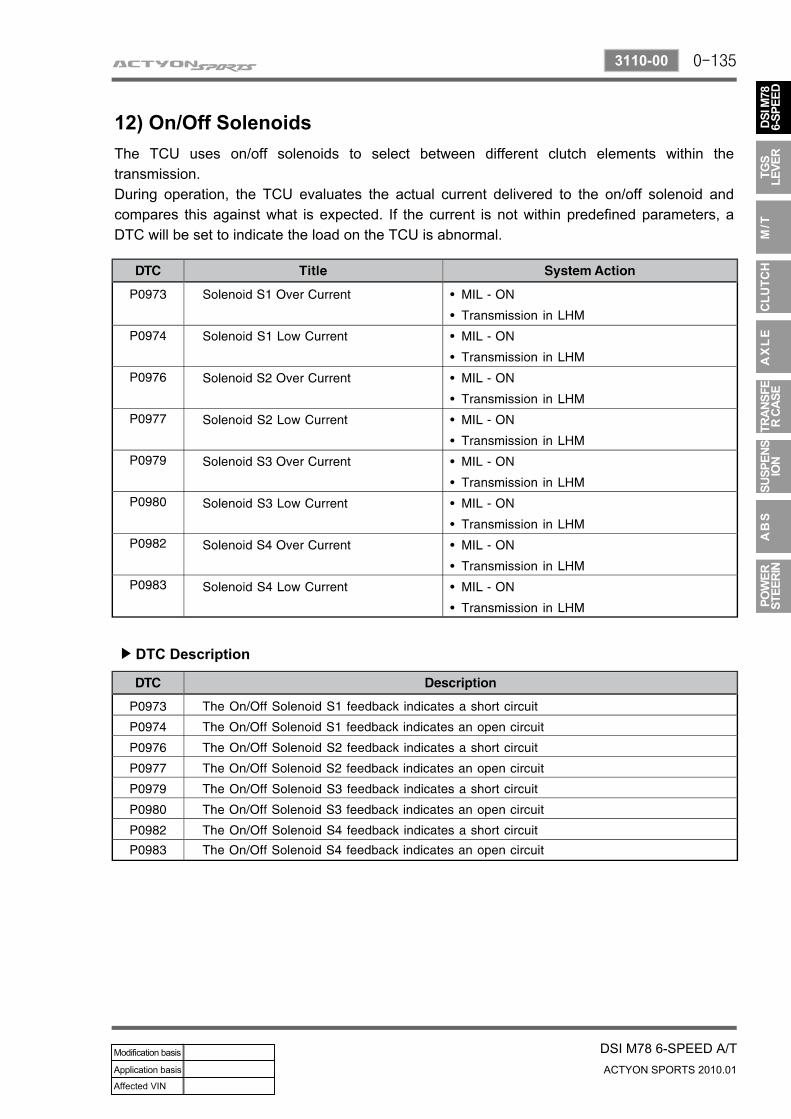
12) On/Off SolenoidsThe TCU uses on/off solenoids to select between different clutch elements within the transmission.During operation, the TCU evaluates the actual current delivered to the on/off solenoid and compares this against what is expected. If the current is not within predefined parameters, a DTC will be set to indicate the load on the TCU is abnormal.
DTC Description▶
0-136
ACTYON SPORTS 2010.01
3110-00
DSI M78 6-SPEED A/T
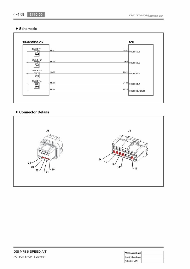
Schematic▶
Connector Details▶

0-137
DSI M78 6-SPEED A/TACTYON SPORTS 2010.01
3110-00
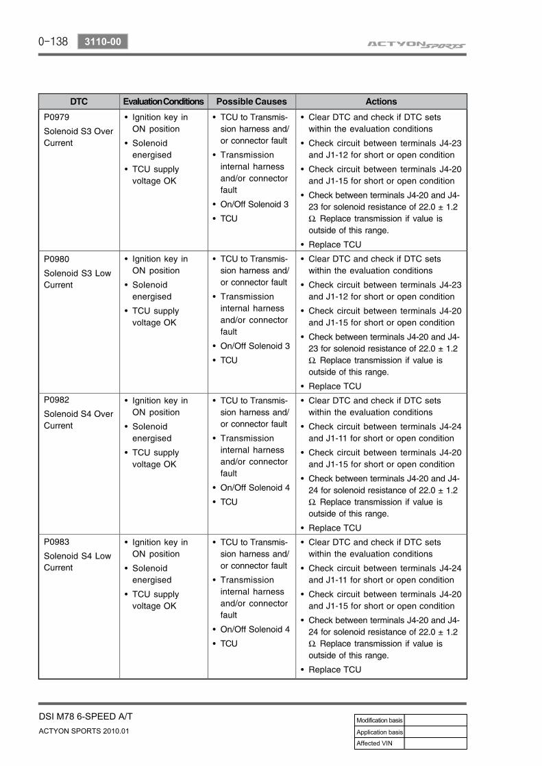
DTC Details▶
0-138
ACTYON SPORTS 2010.01
3110-00
DSI M78 6-SPEED A/T
0-139
DSI M78 6-SPEED A/TACTYON SPORTS 2010.01
3110-00
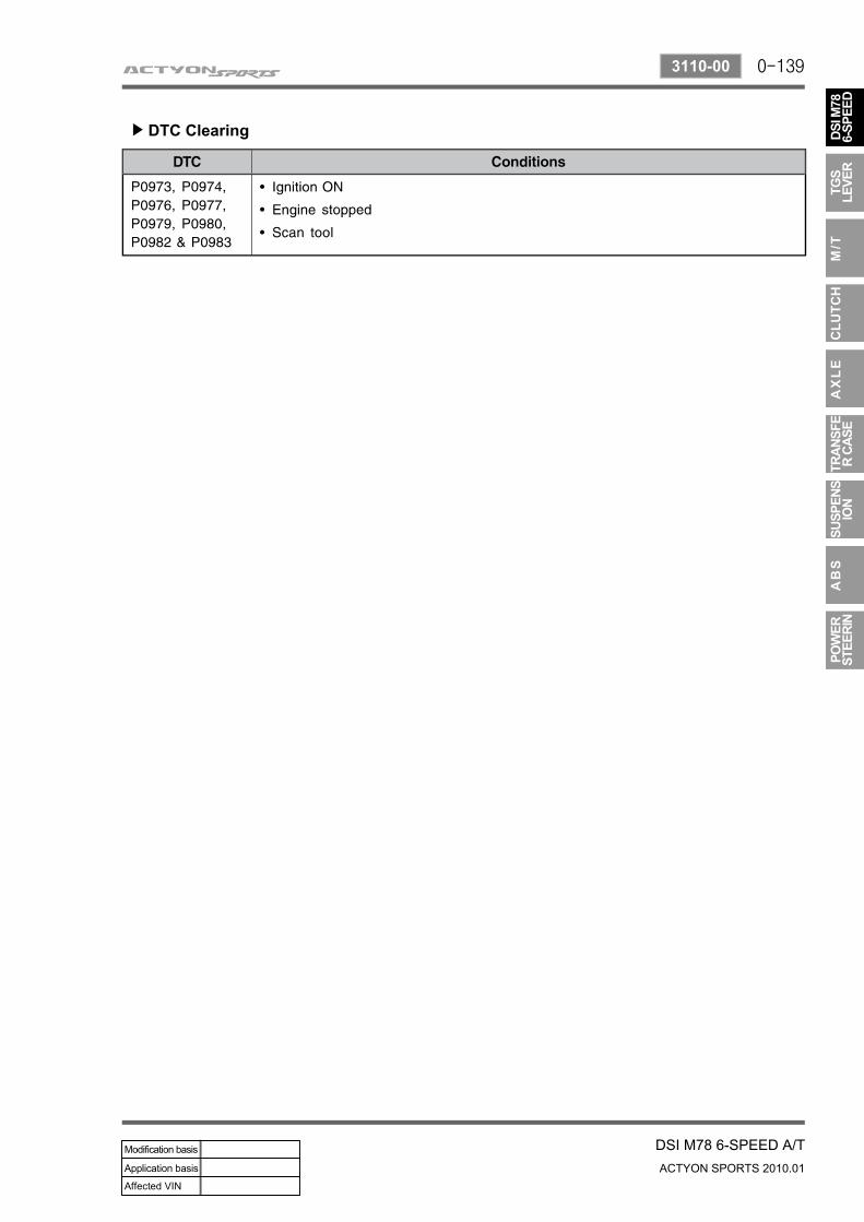
DTC Clearing▶
0-140
ACTYON SPORTS 2010.01
3110-00
DSI M78 6-SPEED A/T
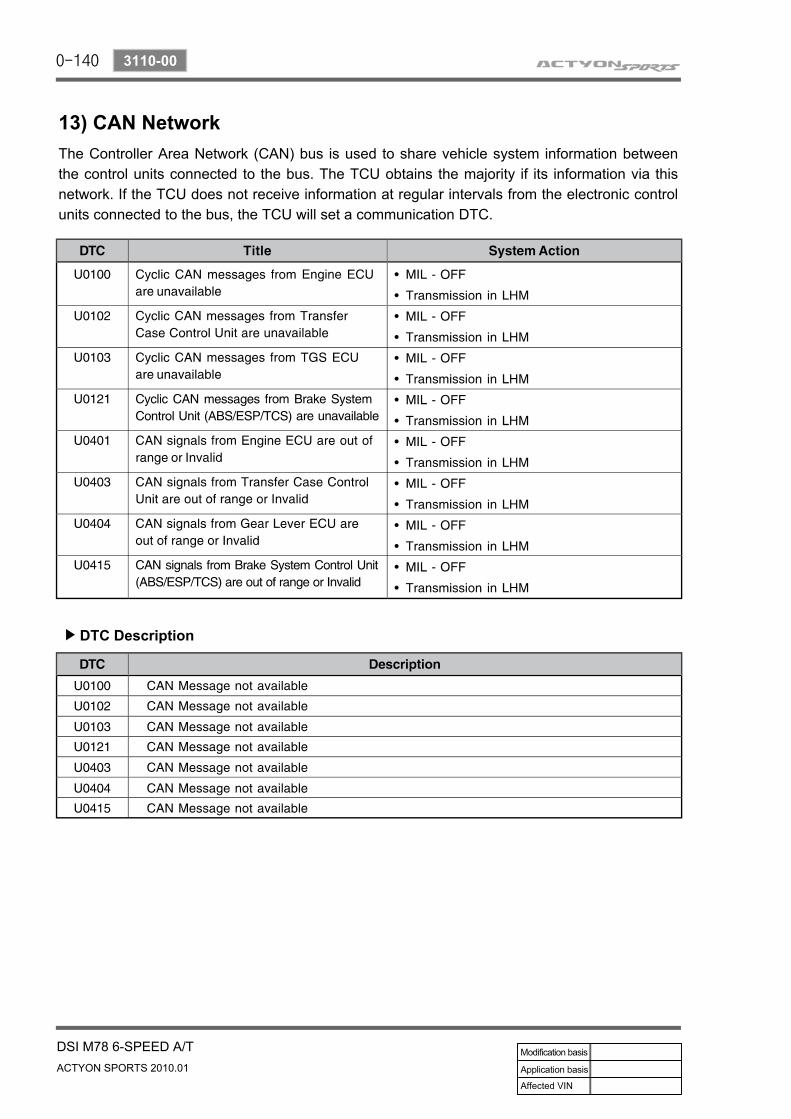
13) CAN NetworkThe Controller Area Network (CAN) bus is used to share vehicle system information between the control units connected to the bus. The TCU obtains the majority if its information via this network. If the TCU does not receive information at regular intervals from the electronic control units connected to the bus, the TCU will set a communication DTC.
DTC Description▶
0-141
DSI M78 6-SPEED A/TACTYON SPORTS 2010.01
3110-00
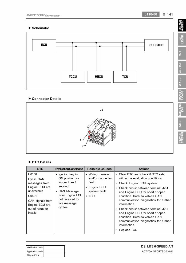
Schematic▶
Connector Details▶
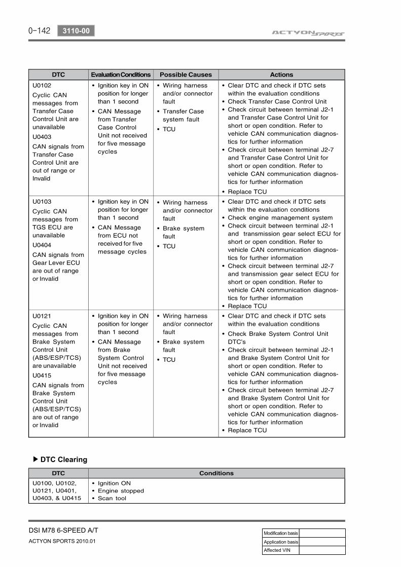
DTC Details▶
0-142
ACTYON SPORTS 2010.01
3110-00
DSI M78 6-SPEED A/T
DTC Clearing▶
0-143
DSI M78 6-SPEED A/TACTYON SPORTS 2010.01
3110-00
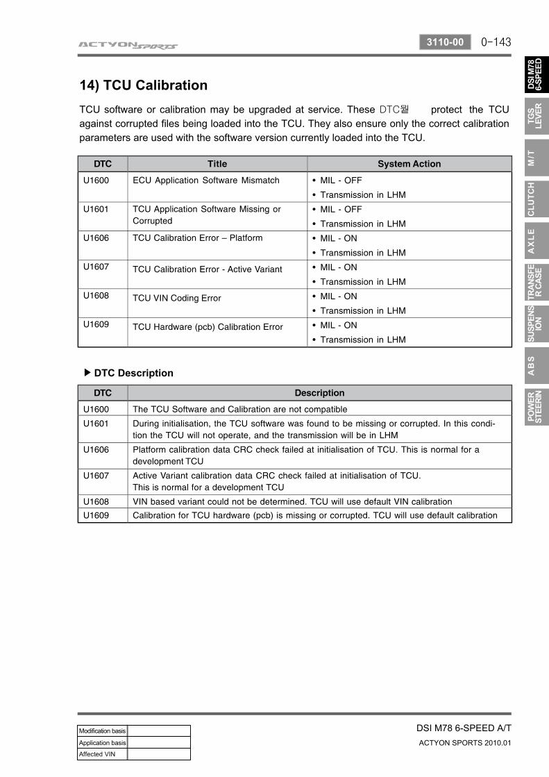
14) TCU CalibrationTCU software or calibration may be upgraded at service. These DTC뭩 protect the TCU against corrupted files being loaded into the TCU. They also ensure only the correct calibration parameters are used with the software version currently loaded into the TCU.
DTC Description▶
0-144
ACTYON SPORTS 2010.01
3110-00
DSI M78 6-SPEED A/T
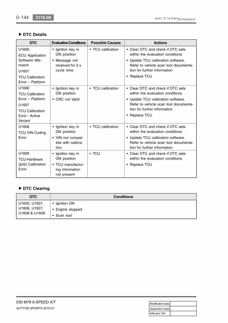
DTC Details▶
DTC Clearing▶
0-145
DSI M78 6-SPEED A/TACTYON SPORTS 2010.01
3680-01
3680-01MAINTENANCE OPERATIONS
1. OIL TEST 1) Hydraulic SystemIf there is a problem in the hydraulic system, perform the following:
Test transmission oilInspect the manual linkage adjustmentCheck the engine's idling speedPerform the stall testPerform the driving test
-----
2) Oil TestCheck the Amount of Oil▶
This check must be performed when the engine is warm. If there is insufficient oil and the vehicle moves, shift loss or delay may happen. First, check the transmission malfunction code. If there is a problem with the shaft speed, insufficient oil may cause the problem.When there is an abnormal shift delay or loss of driving power during driving or reversing, perform the driving test. When the level of oil is low and this vehicle is moving on a corner, there will be a brief driving power loss. When both oil temperature and level are low, there will be loss of driving power. Replenish oil if the engine is completely warmed up and there is no loss of driving power, but there is still a problem with the vehicle speed.
Oil Check and Replenishment▶
When replenishing or changing transmission oil, a genuine recommended oil must be used. If non-approved oil is used, it will have fatal impacts on the transmission's performance and life. Never use such oil. Wrong oil can damage the transmission. When the transmission oil is hot, do not remove the filler plug. Wait for 2 hours to cool down the oil. Then, remove the plug.
When the engine is hot, wait for 2 hours before replenishing transmission oil. Then, the transmission's temperature also becomes cooled down to a proper range. When the filler plug is removed while the temperature of oil is hot, oil will flow out and its level in the transmission will go down. Push the selection lever to the "P" position and shut off the engine. Raise up the vehicle with a proper lift. Clean up the surroundings of the filler plug before removing the plug. After removing the plug, clean up the plug thoroughly and inspect the O-ring for any damage.
1.
2.3.4.
0-146
ACTYON SPORTS 2010.01
3680-01
DSI M78 6-SPEED A/T
After attaching the filler pump to the transmission, lower the vehicle and replenish oil. Engage the parking brake, start the engine while the selection lever is engaged to "P" and press the foot brake. Then, start shifting the selection lever to all positions. Replenish oil until you can sense moving of the transmission gears. Shut off the engine again and raise up the vehicle. Ensure that the vehicle maintains horizontal balance. Shut off the engine, wait for at least 3 minutes (within 1 hour), and remove the filler pump. If oil reaches to just below the filler inlet, it is appropriate. If not, replenish oil until it reaches this level. Replace the filler plug with a new one. Wipe off oil on the transmission or other parts of the vehicle. Apply the specified torque to tighten up the filler plug (30 ~ 35 Nm).
5.
6.
7.
8.
9.
Oil check/Replenishment when there is an insufficient amount of oil▶
Engage the shift lever to the "P" position and shut off the engine. Raise this vehicle with an appropriate lift.Clean up the surroundings of the filler plug before removing the plug. After removing the plug, clean up the plug thoroughly and inspect the O-ring for any damage. Then, attach the filler pump to the oil inlet. After attaching the filler pump to the transmission, lower this vehicle and replenish oil.
1.2.3.
4.When the transmission torque converter has no oil: 9.5 ℓ
When the transmission torque converter is filled with oil: 4.5 ℓ
a.b.Engage the parking brake, start the engine while the selection lever is engaged to "P" and depress the foot brake. Then, start shifting the selection lever to all positions. Replenish oil until you can sense moving of the transmission gears. Add a 0.5 ℓ of recommended oil. Shut off the engine and raise this vehicle with an appropriate lifte. Detach the filler pump. Replace the filler plug with a new one (Tightening torque: 30 ~ 35 Nm).When this vehicle travels 3.5 ~ 4.5 kilometers with the engine's RPM below 2500, the temperature of the transmission will reach to 50 ~ 60°C. With the engine idling, press the brake pedal and shift the transmission selector lever to all positions several times. Shut off the engine and raise the vehicle with an appropriate lift. Maintain horizontal balance of the vehicle if possible. Remove the filler plug 3 minutes after shutting off the engine. If oil reaches just below the filler inlet, it is appropriate. If not, replenish oil until it reaches this level.Replace the filler plug with a new one. Wipe off oil on the transmission or other parts of the vehicle. Apply the specified torque to tighten up the filler plug (30 ~ 35 Nm).
5.
6.7.
8.
9.
10.
11.
12.
0-147
DSI M78 6-SPEED A/TACTYON SPORTS 2010.01
3680-01
2. STALL TESTStall testing can be performed on the Model 78 6 speed automatic transmission to determine whether the transmission clutches can hold the full engine torque without slipping.Stall testing should be performed for a period no longer then 10 seconds.
Apply Hand BrakeStart EnginePress Brake PedalShift to "DRIVE" Press Accelerator Pedal to 100 % for 6 secondsObserve Engine speedRelease Accelerator PedalShift To ReversePress Accelerator Pedal to 100 % for 6 secondsObserve Engine speed
----------
If engine speed is observed > 3000 rpm; transmission hardware failure
0-148
ACTYON SPORTS 2010.01
3680-01
DSI M78 6-SPEED A/T
3. TRANSMISSION RESET PROCEDURE (REPLACEMENT TRANSMISSION)t is necessary to reset the adaptive data stored within the transmission control unit (TCU) when the transmission and or TCU have been replaced.
Green Offset Reset▶
Carried out when a replacement transmission has been installed in a vehicle.
Adaptive Reset▶
Carried out when one of the following has occurred:Replace transmissionReplace TCU
--
Green Offset Reset Procedure▶
To perform a green offset reset procedure, proceed as follows:Connect the vehicle's diagnostic scan tool to the vehicles diagnostic connector. Refer to the vehicle repair manual for information on connecting the scan tool.With the transmission gear select (TGS) lever in Park, turn the ignition key to the ON position (engine not running).Using the scan tool, set the parameter Set Km Travelled to 0Km.Run the task Activate Adaptive Green Offset.Turn the ignition key to the OFF position.Start the vehicle and check for normal operation.
1.
2.
3.4.5.6.
Adaptive Reset Procedure▶
To perform an adaptive reset procedure, proceed as follows:Connect the vehicle's diagnostic scan tool to the vehicles diagnostic connector. Refer to the vehicle repair manual for information on connecting the scan tool.With the transmission gear select (TGS) lever in Park, turn the ignition key to the ON position (engine not running).Set the parameter Set Km Travelled to 0 Km.Run the task Reset Adaptive Data.Turn the ignition key to the OFF position.Start the vehicle and check for normal operation.
1.
2.
3.4.5.6.
0-149
DSI M78 6-SPEED A/TACTYON SPORTS 2010.01
3680-01
4. FLUID LEVEL INSPECTION
As the temperature of the transmission fluid greatly affects the fluid level, this procedure must only be carried out with the transmission fluid temperature below 50°C). If the transmission fluid temperature is greater than 50°C and the correct procedure is not followed, the result could be a false reading of the fluid level.Fluid level inspection must be carried out with the vehicle level.Caltex PED 1712 ATF must be used.
---
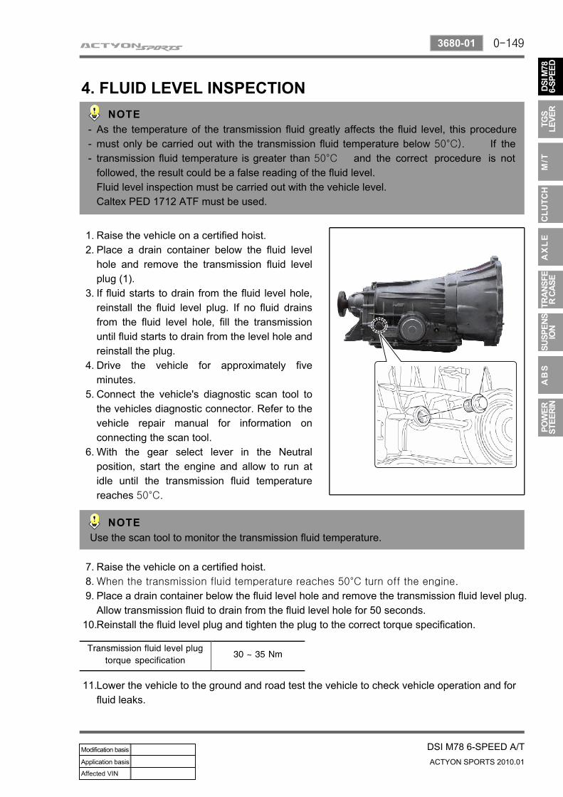
Raise the vehicle on a certified hoist. Place a drain container below the fluid level hole and remove the transmission fluid level plug (1).If fluid starts to drain from the fluid level hole, reinstall the fluid level plug. If no fluid drains from the fluid level hole, fill the transmission until fluid starts to drain from the level hole and reinstall the plug.Drive the vehicle for approximately five minutes.Connect the vehicle's diagnostic scan tool to the vehicles diagnostic connector. Refer to the vehicle repair manual for information on connecting the scan tool.With the gear select lever in the Neutral position, start the engine and allow to run at idle until the transmission fluid temperature reaches 50°C.
1.2.
3.
4.
5.
6.
Use the scan tool to monitor the transmission fluid temperature.
Raise the vehicle on a certified hoist.When the transmission fluid temperature reaches 50°C turn off the engine.
Place a drain container below the fluid level hole and remove the transmission fluid level plug. Allow transmission fluid to drain from the fluid level hole for 50 seconds.Reinstall the fluid level plug and tighten the plug to the correct torque specification.
7.8.9.
10.
Lower the vehicle to the ground and road test the vehicle to check vehicle operation and for fluid leaks.
11.
0-150
ACTYON SPORTS 2010.01
3680-01
DSI M78 6-SPEED A/T
5. TRANSMISSION COOLER AND HYDRAULIC LINE FLUSHING PROCEDURE
To prevent transmission damage due to contaminants being present in the transmission cooler and/or hydraulic lines, the cooler and lines must be flushed.
Raise the vehicle on a certified hoist. Using compressed air, clear the cooler lines of any residual fluid.Connect the front transmission cooler line to the transmission.
1.2.3.
Connect one end of a rubber hose to the end of the rear cooler line and place the other end in a suitable container to collect the transmission fluid as it is pumped out.Start the engine and run for approximately 30 seconds at idle. (With ATF at 50°C
temperature, a minimum of 2.5litres oil flow after 30 seconds.) Whist the engine is running, have an assistant pump transmission fluid into the transmission fluid level hole.Connect the rear transmission cooler line to the transmission.
4.
5.
6.
7.
Check the transmission fluid level; refer to Fluid Level Inspection on page 69.8.
6. LUBRICATIONAutomatic transmission fluid..................Caltex PED 1712 ATF
0-151
DSI M78 6-SPEED A/TACTYON SPORTS 2010.01
3680-01
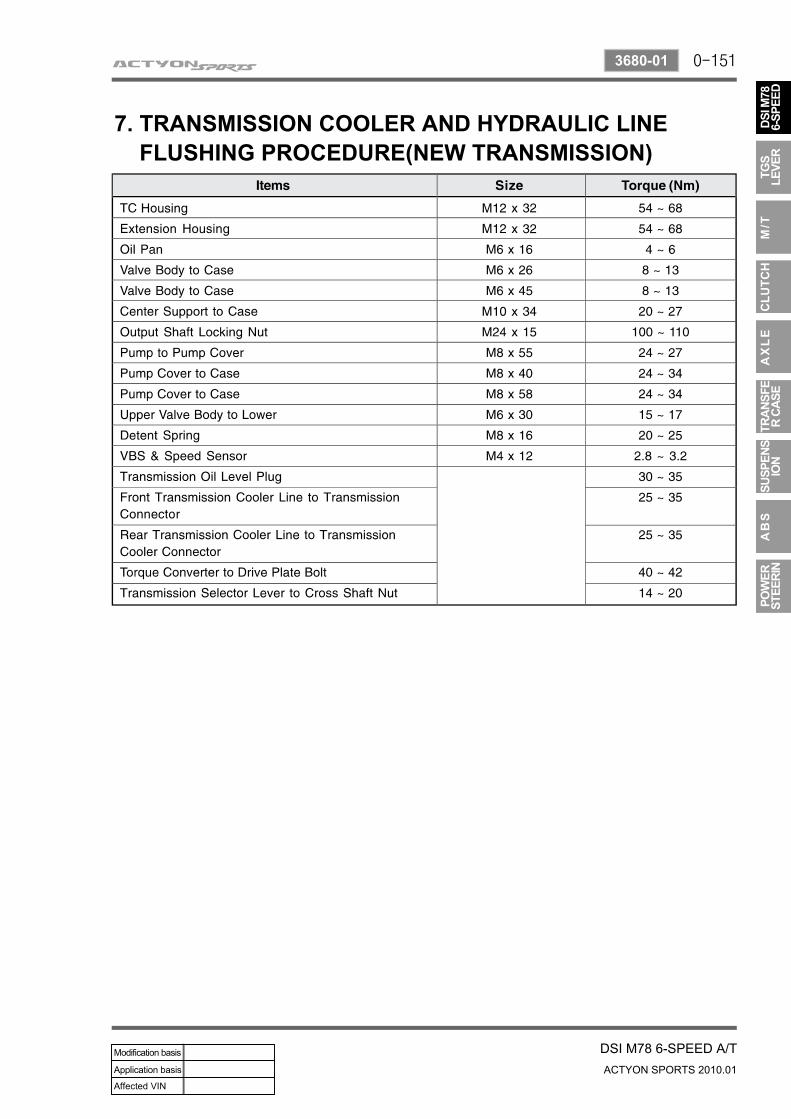
7. TRANSMISSION COOLER AND HYDRAULIC LINE FLUSHING PROCEDURE(NEW TRANSMISSION)


