Embed Size (px)
Citation preview

Geometric Properties of Central Catadioptric LineImages
Joao P. Barreto and Helder Araujo
Institute of Systems and RoboticsDept. of Electrical and Computer Engineering
University of CoimbraCoimbra, Portugal
jpbar, [email protected]://www.isr.uc.pt/∼jpbar
Abstract. It is highly desirable that an imaging system has a single effectiveviewpoint. Central catadioptric systems are imaging systems that use mirrors toenhance the field of view while keeping a unique center of projection. A generalmodel for central catadioptric image formation has already been established. Thepresent paper exploits this model to study the catadioptric projection of lines.The equations and geometric properties of general catadioptric line imaging arederived. We show that it is possible to determine the position of both the effec-tive viewpoint and the absolute conic in the catadioptric image plane from theimages of three lines. It is also proved that it is possible to identify the type ofcatadioptric system and the position of the line at infinity without further infor-mation. A methodology for central catadioptric system calibration is proposed.Reconstruction aspects are discussed. Experimental results are presented. All theresults presented are original and completely new.
1 Introduction
Many applications in computer vision, such as surveillance and model acquisition forvirtual reality, require that a large field of view is imaged. Visual control of motion canalso benefit from enhanced fields of view [1, 2, 4]. One effective way to enhance the fieldof view of a camera is to use mirrors [5–9]. The general approach of combining mirrorswith conventional imaging systems is referred to as catadioptric image formation [3].
The fixed viewpoint constraint is a requirement ensuring that the visual sensor onlymeasures the intensity of light passing through a single point in 3D space (the projectioncenter). Vision systems verifying the fixed viewpoint constraint are called central pro-jection systems. Central projection systems present interesting geometric properties. Asingle effective viewpoint is a necessary condition for the generation of geometricallycorrect perspective images [10], and for the existence of epipolar geometry inherentto the moving sensor and independent of the scene structure [1]. It is highly desirablefor any vision system to have a single viewpoint. In [10], Baker et al. derive the en-tire class of catadioptric systems with a single effective viewpoint. Systems built usinga parabolic mirror with an orthographic camera, or an hyperbolic, elliptical or planarmirror with a perspective camera verify the fixed viewpoint constraint.
2 Barreto and Araujo
In [12], Geyer et al. introduce an unifying theory for all central catadioptric systemswhere conventional perspective imaging appears as a particular case. They show thatcentral panoramic projection is isomorphic to a projective mapping from the sphere toa plane with a projection center on the perpendicular to the plane. A modified versionof this unifying model is presented in [21]. The mapping between points in the 3Dworld and points in the catadioptric image plane is split into three steps. World pointsare mapped into an oriented projective plane by a linear function described by a 3 × 4matrix (similar to the projective camera model referred in [13]). The oriented projectiveplane is then transformed by a non-linear function f(). The last step is a collineationin the plane depending on the mirror parameters, the pose of the camera in relation tothe reflective surface and the camera intrinsic parameters. The model obtained is gen-eral, intuitive and isolates the non-linear characteristics of general catadioptric imageformation.
A line in 3D projects into a conic in a general catadioptric image. The equationsand geometric properties of the resulting conic are derived in [12]. In [12, 14] the in-trinsic calibration of central catadioptric systems using line projections is discussed. Amethod to calibrate a system consisting of a paraboloid and an orthographic lens usingtwo sets of parallel lines is presented in [14]. Our work uses the established mappingmodel to derive the equations and geometric properties of general central catadioptricline projections. The derived geometric properties are used to determine the position ofthe effective viewpoint and the absolute conic in the catadioptric plane from three lineimages. With the effective viewpoint and the absolute conic it is possible to computethe position of the line at infinity from two line images. Moreover we show that mirrorparameters can be partially recovered directly from a single line image. The proposedtheory is useful to both calibration and 3D reconstruction applications. Some experi-mental results are presented.
2 General Model for Central Catadioptric Imaging
In [10], Baker et al. derive the entire class of catadioptric systems with a single effectiveviewpoint. Systems built using a a parabolic mirror with an orthographic camera, oran hyperbolic, elliptical or planar mirror with a perspective camera verify the fixedviewpoint constraint. An unifying model for all central projection panoramic imagingis proposed in [12]. This section presents a modified version of this model.
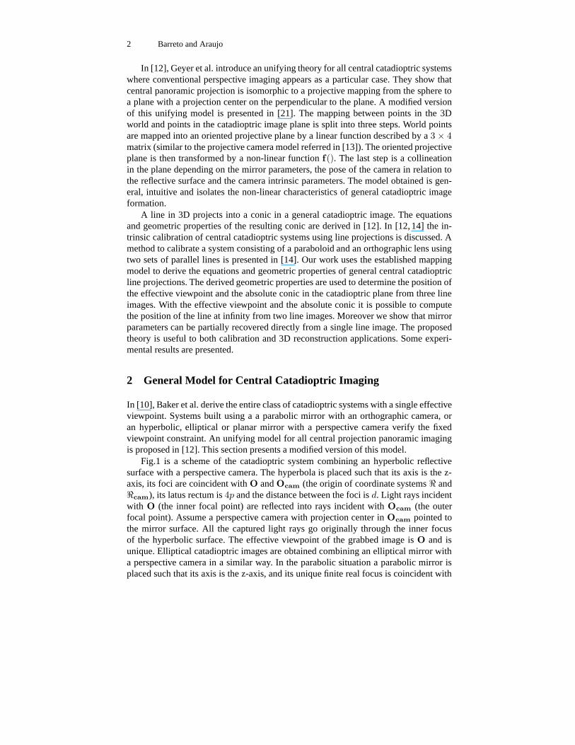
Fig.1 is a scheme of the catadioptric system combining an hyperbolic reflectivesurface with a perspective camera. The hyperbola is placed such that its axis is the z-axis, its foci are coincident with O and Ocam (the origin of coordinate systems < and<cam), its latus rectum is 4p and the distance between the foci is d. Light rays incidentwith O (the inner focal point) are reflected into rays incident with Ocam (the outerfocal point). Assume a perspective camera with projection center in Ocam pointed tothe mirror surface. All the captured light rays go originally through the inner focusof the hyperbolic surface. The effective viewpoint of the grabbed image is O and isunique. Elliptical catadioptric images are obtained combining an elliptical mirror witha perspective camera in a similar way. In the parabolic situation a parabolic mirror isplaced such that its axis is the z-axis, and its unique finite real focus is coincident with
Properties of Central Catadioptric Line Image 3
x = P.Xhw
X w
x cam
X cam
Z cam
Ycam
X
Z
O
4p
d
proj. ray
proj. ray
Fig. 1. Central catadioptric vision system
O. Light rays incident with O are reflected into rays parallel with the z-axis whichare captured by an orthographic camera with image plane perpendicular to the z-axis.The effective viewpoint is in O and is unique. A catadioptric system made up of aperspective camera steering a planar mirror also verifies the fixed viewpoint constraint.The effective projection center is behind the mirror in the perpendicular line passingthrough camera center. Its distance to the camera center is twice the distance betweenthe planar mirror and the camera.
Consider a generic scene point, visible by the catadioptric system, with cartesian co-ordinates Xw in the catadioptric reference frame. The corresponding homogeneous rep-resentation is Xh
w. Visible points in the scene Xhw are mapped into projective rays/points
x in the catadioptric system reference frame centered in the effective viewpoint. Thetransformation is linear being described by a 3 × 4 matrix P. We can think of theprojective rays x as points in an oriented projective plane T2. Notice that in standardprojective geometry, given a projective point x, λx represents the same point wheneverλ 6= 0. In an oriented projective plane this is only true if λ > 0 [17]. This is importantwhen modelling panoramic vision sensors where diametrically opposite points relativeto the projection center can be simultaneously imaged.
xcam = Mc.f(x) (1)
Mc =
ψ − ξ 0 00 ξ − ψ 00 0 1
(2)
f(x) = (x
√
x2 + y2 + z2,
y√
x2 + y2 + z2,
z√
x2 + y2 + z2+ ξ)t (3)
To each oriented projective ray/point x, corresponds a projective ray/point xcam ina coordinate system whose origin is in the camera projection center. Notice that x andxcam must intersect in the mirror surface (see Fig.1). We can think of this transforma-tion as a non-linear mapping between two oriented projective planes. The relationship

4 Barreto and Araujo
Mirror Surface ξ ψ
Parabolic√
x2 + y2 + z2 = 2p− z 1 1 + 2p
Hyperbolic(z− d
2)2
( 1
2(√
d2+4p2−2p))2
− x2+y2
p(√
d2+4p2−2p)
= 1d√
d2+4p2
d+2p√d2+4p2
Elliptical(z− d
2)2
( 1
2(√
d2+4p2+2p))2+
x2+y2
p(√
d2+4p2+2p)= 1
d√d2+4p2
d−2p√d2+4p2
Planar z =d
20 1
Table 1. Column 1: Reflective surfaces for the different cases of central panoramic imaging.Column 2 and 3: Parameters ξ and ψ of the general central catadioptric model
between these two points can be written in the form of equation 1 (the proof is availableat [22]). The matrix Mc depends on the mirror parameters (see equation 2). The pa-rameters ξ and ψ are presented in Table.1. Function f() is given by equation 3. Noticethat f(λx) = λx whenever λ > 0. f() is a positive homogeneous function and corre-spondence xc = f(x) can be interpreted as a non-linear mapping between two orientedprojective planes.
xi = KcRcxcam represents the measured point in the catadioptric image plane.The relation between xi and xcam is established by a collineation depending on cam-era orientation (matrix Rc) and camera intrinsic parameters (matrix Kc). In the case ofthe hyperbolic and elliptical systems, the fixed viewpoint constraint is verified when-ever the camera center is coincident with the second focus of the reflective surface.There are no restrictions on the camera orientation and Rc is a 3 × 3 rotation matrixspecifying the camera pose. The same can be said when using a planar mirror. For theparabolic situation the camera is orthographic with center at infinity. However there isan important restriction, its image plane must be orthogonal to the paraboloid axis. Weare going to assume that Rc = I for the parabolic mirror situation.
xi = Hc.f(P.Xh
w) (4)
Hc = Kc.Rc.Mc (5)
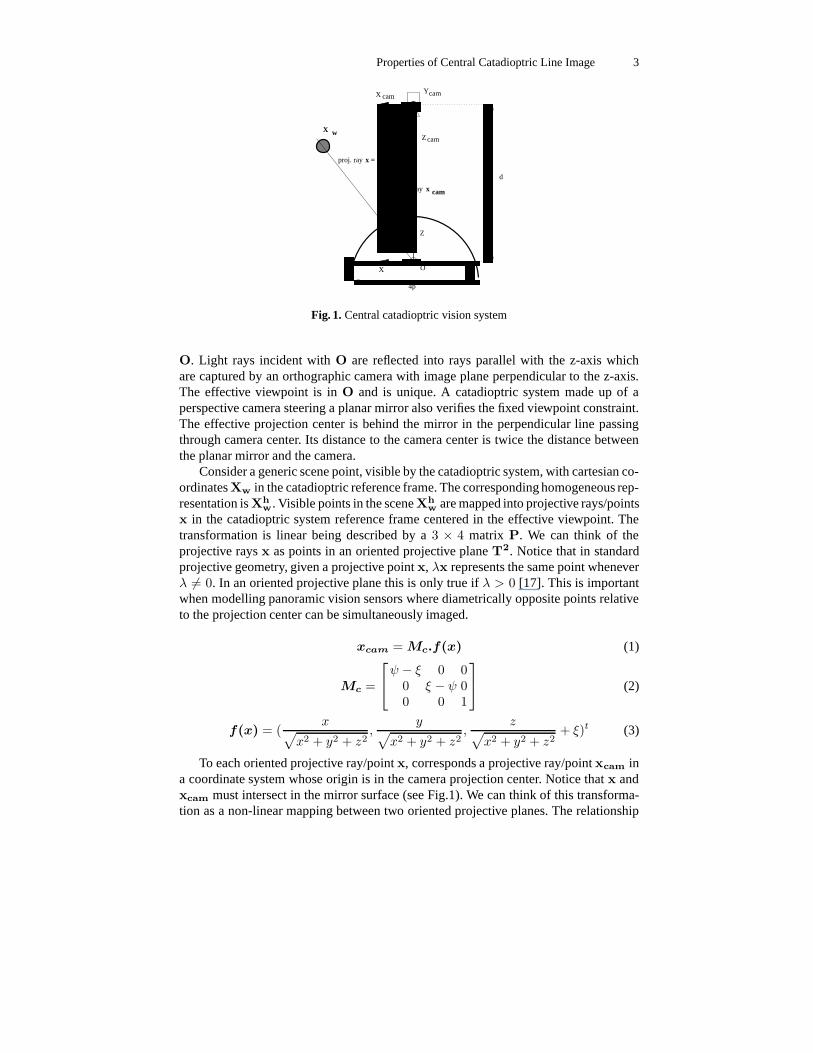
A scheme of the proposed model for general central projection is presented in Fig.2. The mapping between points in the world Xw and projective points in image xi isgiven by equation 4. Points Xh
w in projective 3D space are transformed in points x inthe oriented projective plane with origin in the effective viewpoint of the catadioptricsystems (x = P.Xh
w). Points x are mapped in points xc in a second oriented projectiveplane. The correspondence function xc = f(x) is non-linear. Projective points xi incatadioptric image plane are obtained after a collineation Hc (xi = Hcxc).
Figure 2 depicts an intuitive “concrete” model for the proposed general central pro-jection mapping. To each visible point in space corresponds an oriented projective ray xjoining the 3D point with the effective projection center O. The projective ray intersectsa unit sphere centered in O in a unique point Q. Consider a point Oc with coordinates(0, 0,−ξ)t. To each x corresponds an oriented projective ray xc going through Oc and
Properties of Central Catadioptric Line Image 5
R3
ε T 2
w w w
w w w
x c =
x i =
H c = .MK .R c c c
εXw=
Xw= (x ,y ,z ,1) ε3
Ph
P=R[I|−C]
(x ,y ,z )
homogeneous
ε T 2
(x ,y ,z ) ε 2P
function f()
(x ,y ,z )c
(x ,y ,z )
cc
i i i
x=
Z c
cX
Yc
X w
x c
n
X
O
Z
Y
Oc
Q
proj. ray
proj. ray x
ξ
α
.
ξ
.
Fig. 2. “Concrete” model for central catadioptric image formation (point and line imaging)
Q. Points in catadioptric image plane xi (not represented in the figure) are obtainedafter a collineation Hc of 2D projective points xc. The scene is projected in the spheresurface and then points on the sphere are re-projected in catadioptric image plane from anovel projection center Oc. Point Oc only depends on mirror parameters (see Table.1).
3 General Central Catadioptric Imaging of Lines
Assume a line in space lying on plane Π = (nx, ny, nz, 0)t which contains the effectiveviewpoint O. Accordingly to the model of Fig. 2, line world points Xw are mapped inthe oriented projective plane on points x lying on n = (nx, ny, nz)
t (nt.x = 0).
Ω =
n2x(1 − ξ2) − n2
zξ2 nxny(1 − ξ2) nxnz
nxny(1 − ξ2) n2y(1 − ξ2) − n2
zξ2 nynz
nxnz nynz n2z
(6)
The non-linear f mapping (equation 3) establishes the relation between points xand xc. It can be shown that points x verifying nt.x = 0 are mapped into points xc
which verify xctΩxc = 0 with Ω given by equation 6). Thus a line in space is mapped
into a conic curve Ω. Points xc and xi in the catadioptric image plane are related bya familiar collineation Hc. Since a projective transformation maps a conic on a conicwe can conclude that in general the catadioptric image of a world line is a conic curve.This section assumes Hc = I and the study will focus on the non-linear f() mapping.
Fig.2 depicts central catadioptric line projection using the sphere model. The worldline in space is projected into a great circle in the sphere surface. This great circle is
6 Barreto and Araujo
the curve of intersection of plane Π, containing both the line and the projection centerO, and the unit sphere. The projective rays xc, joining Oc to points in the great circle,form a central cone surface. The central cone, with vertex in the Oc, projects into theconic Ω in the canonical image plane. Notice that we can always think of a conic Ωin the projective plane as a central cone of projective rays with vertex in the projectioncenter. Ω is a degenerate conic whenever nz = 0. If the imaged line is co-planar withthe Z-axis of the catadioptric reference frame, the corresponding catadioptric image isalso a line. This can be easily understood using the sphere model for the mapping.
∆ = (n2x + n2
y)(1 − ξ2) − n2zξ (7)
α = arctan(nz
√
n2x + n2
y
) (8)
Equation 7 gives the conic discriminant ∆. For ∆ = 0, ∆ > 0 and ∆ < 0 theconic curve Ω is respectively a parabola, an hyperbola and an ellipse/circle. Considerthe normal n = (nx, ny, nz)
t to plane Π (Fig. 2) and the angle α between n and planeXOY (equation 8). From equation 7 and 8 it results that ∆ = 0 whenever tan(α)2 =(1 − ξ2)/ξ2. If the normal to the plane Π intersects the unitary sphere in the dashedcircles of Fig. 2 then the line image is a parabola. Moreover if the intersection point isbetween the circles the line image is an hyperbola and if the intersection point is aboveor below the circles the line image is an ellipse/circle.
µ = (−ny, nx, 0)t (9)
P1, P2 = (−nxnz
(n2x + n2
y)(1 ± ξ√
1 +n2
z
n2x+n2
y),−
nynz
(n2x + n2
y)(1 ± ξ√
1 +n2
z
n2x+n2
y), 1)t
(10)Affine (center, asymptotes) and euclidean (principal axis, focus, eccentricity) pa-
rameters of the conic curve Ω (equation 6) were derived in [12, 21] assuming the lineat infinity and the circular points at their canonical positions [13, 20]. The catadioptricimage of a line is the conic curve Ω only if collineation Hc is the identity. In generalHc 6= I and the derived affine and euclidean properties do not hold. Equations 9 and10 present two results that will be needed latter. µ is one of the principal axis of Ω andP1 and P2 are the points where µ intersects the conic curve.
4 Geometric Properties of Central Catadioptric Line Images
In the derived central projection model, points in the scene are projected on the sur-face of an unitary sphere centered in the effective viewpoint O. The catadioptric imageis captured by a conventional perspective camera which projects the points from thesphere to a plane. If Hc = I then the image plane is on the canonical position (bycanonical we mean orthogonal to the forward looking Z axis). Consider that, wheneverHc = I, the image plane is the plane at infinity Π∞. To each sphere point P corre-sponds a projective ray going through the camera center Oc. Point P projects on Pwhich is the intersection of the projective ray OcP with Π∞.
Properties of Central Catadioptric Line Image 7
Oc
P2
P1
P1 P2
Π∝
P1
P2
!"
#$
%&
'(') *+ ,(,-(- .(./(/01
2345
67
8(89 :(:;<=
O
D O N
Π
π
µ
ΟΝ
D
π
µπ ^^
^^^^^
^∝
M
Ω
H c
Fig. 3. Projecting sphere points in the plane at infinity and the projective transformation Hc ofΠ∞ in the catadioptric image plane.
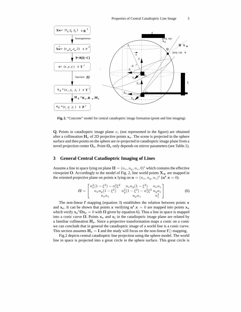
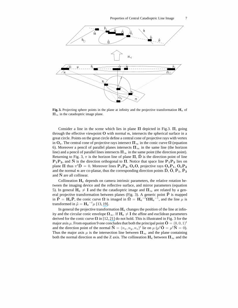
Consider a line in the scene which lies in plane Π depicted in Fig.3. Π, goingthrough the effective viewpoint O with normal n, intersects the spherical surface in agreat circle. Points on the great circle define a central cone of projective rays with vertexin Oc. The central cone of projective rays intersect Π∞ in the conic curve Ω (equation6). Moreover a pencil of parallel planes intersects Π∞ in the same line (the horizonline) and a pencil of parallel lines intersects Π∞ in the same point (the direction point).Returning to Fig. 3, π is the horizon line of plane Π, D is the direction point of lineP1P2, and N is the direction orthogonal to Π. Notice that space line P1P2 lies onplane Π thus πtD = 0. Moreover lines P1P2, OcO, projective rays OcP1, OcP2
and the normal n are co-planar, thus the corresponding direction points D, O, P1, P2
and N are all collinear.Collineation Hc depends on camera intrinsic parameters, the relative rotation be-
tween the imaging device and the reflective surface, and mirror parameters (equation5). In general Hc 6= I and the the catadioptric image and Π∞ are related by a gen-eral projective transformation between planes (Fig. 3). A generic point P is mappedin P = HcP, the conic curve Ω is imaged in Ω = Hc
−tΩHc−1, and the line µ is
transformed in µ = Hc−tµ [13, 19].
In general the projective transformation Hc changes the position of the line at infin-ity and the circular conic envelope Ω∞. If Hc 6= I the affine and euclidean parametersderived for the conic curve Ω in [12, 21] do not hold. This is illustrated in Fig. 3 for themajor axis µ. From equation 9 one concludes that both the principal point O = (0, 0, 1)t
and the direction point of the normal N = (nx, ny, nz)t lie on µ (µtO = µtN = 0).
Thus the major axis µ is the intersection line between Π∞ and the plane containingboth the normal direction n and the Z axis. The collineation Hc between Π∞ and the
8 Barreto and Araujo
catadioptric image plane maps µ in µ and Ω in Ω. In general µ is no longer a principalaxis of Ω. Nevertheless the projective transformation preserves collinearity, incidenceand the cross-ratio. These invariants will be exploited to establish geometric relationsfor line catadioptric imaging when Hc 6= I.
4.1 Three Catadioptric Line Images
>>??
@@AA
BBBBBBBBBBBB
CCCCCCCCCCCC
X
O
Z
Y
ξ
B
B
B
F
F
F
12
12
1313
23
23
Oc
ΠΠ
Π
1
3
2
CommonDirection
D12
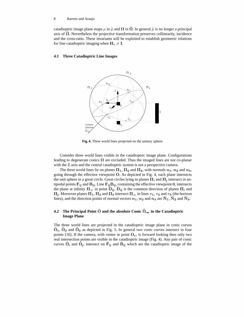
Fig. 4. Three world lines projected on the unitary sphere.
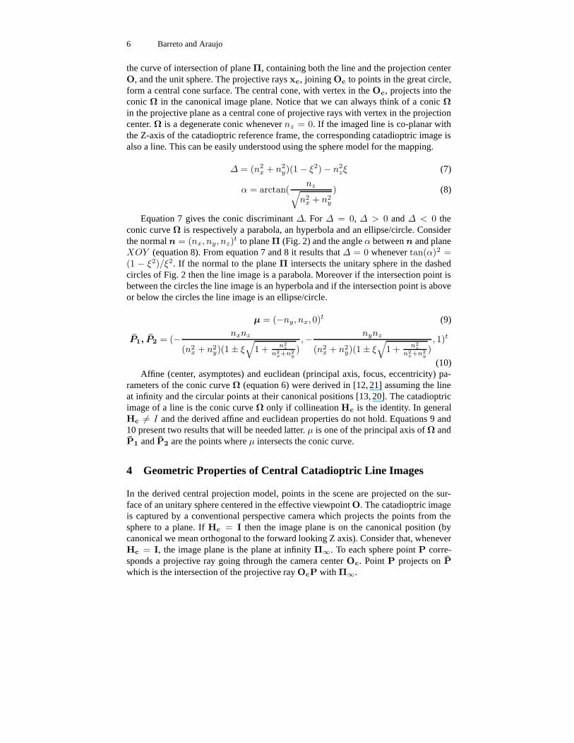
Consider three world lines visible in the catadioptric image plane. Configurationsleading to degenerate conics Ω are excluded. Thus the imaged lines are not co-planarwith the Z axis and the central catadioptric system is not a perspective camera.
The three world lines lie on planes Π1, Π2 and Π3, with normals n1, n2 and n3,going through the effective viewpoint O. As depicted in Fig. 4, each plane intersectsthe unit sphere in a great circle. Great circles lying in planes Πi and Πj intersect in an-tipodal points Fij and Bij. Line FijBij, containing the effective viewpoint 0, intersectsthe plane at infinity Π∞ in point Dij. Dij is the common direction of planes Πi andΠj. Moreover planes Π1, Π2 and Π3 intersect Π∞ in lines π1, π2 and π3 (the horizonlines), and the direction points of normal vectors n1, n2 and n3 are N1, N2 and N3.
4.2 The Principal Point O and the absolute Conic Ω∞ in the CatadioptricImage Plane
The three world lines are projected in the catadioptric image plane in conic curvesΩ1, Ω2 and Ω3 as depicted in Fig. 5. In general two conic curves intersect in fourpoints [16]. If the camera, with center in point Oc, is forward looking then only tworeal intersection points are visible in the catadioptric image (Fig. 4). Any pair of coniccurves Ωi and Ωj, intersect on Fij and Bij which are the catadioptric image of the

Properties of Central Catadioptric Line Image 9
A^
B^
A^
B^
A^
B^
Ω^
Ω^
Ω^
π
π
π
DEDF
GH
IJ
KL
MN
OEOPEPQR
ST UV
WX
YZ
[\
]]^^
_`
ab
cd
eEeEeEeEeEeEeEeEeEeEeEeEeEeEeEeEeEeEeEeEeEeEeEeEeeEeEeEeEeEeEeEeEeEeEeEeEeEeEeEeEeEeEeEeEeEeEeEeEeeEeEeEeEeEeEeEeEeEeEeEeEeEeEeEeEeEeEeEeEeEeEeEeEeeEeEeEeEeEeEeEeEeEeEeEeEeEeEeEeEeEeEeEeEeEeEeEeEeeEeEeEeEeEeEeEeEeEeEeEeEeEeEeEeEeEeEeEeEeEeEeEeEeeEeEeEeEeEeEeEeEeEeEeEeEeEeEeEeEeEeEeEeEeEeEeEeEeeEeEeEeEeEeEeEeEeEeEeEeEeEeEeEeEeEeEeEeEeEeEeEeEeeEeEeEeEeEeEeEeEeEeEeEeEeEeEeEeEeEeEeEeEeEeEeEeEeeEeEeEeEeEeEeEeEeEeEeEeEeEeEeEeEeEeEeEeEeEeEeEeEeeEeEeEeEeEeEeEeEeEeEeEeEeEeEeEeEeEeEeEeEeEeEeEeEe
fEfEfEfEfEfEfEfEfEfEfEfEfEfEfEfEfEfEfEfEfEfEfEfEffEfEfEfEfEfEfEfEfEfEfEfEfEfEfEfEfEfEfEfEfEfEfEfEffEfEfEfEfEfEfEfEfEfEfEfEfEfEfEfEfEfEfEfEfEfEfEfEffEfEfEfEfEfEfEfEfEfEfEfEfEfEfEfEfEfEfEfEfEfEfEfEffEfEfEfEfEfEfEfEfEfEfEfEfEfEfEfEfEfEfEfEfEfEfEfEffEfEfEfEfEfEfEfEfEfEfEfEfEfEfEfEfEfEfEfEfEfEfEfEffEfEfEfEfEfEfEfEfEfEfEfEfEfEfEfEfEfEfEfEfEfEfEfEffEfEfEfEfEfEfEfEfEfEfEfEfEfEfEfEfEfEfEfEfEfEfEfEffEfEfEfEfEfEfEfEfEfEfEfEfEfEfEfEfEfEfEfEfEfEfEfEffEfEfEfEfEfEfEfEfEfEfEfEfEfEfEfEfEfEfEfEfEfEfEfEf
gEgEgEgEgEgEgEgEgEgEgEgEgEgEgEgEgEgEgEgEgEgEgEgEgEgEgEggEgEgEgEgEgEgEgEgEgEgEgEgEgEgEgEgEgEgEgEgEgEgEgEgEgEgEggEgEgEgEgEgEgEgEgEgEgEgEgEgEgEgEgEgEgEgEgEgEgEgEgEgEgEggEgEgEgEgEgEgEgEgEgEgEgEgEgEgEgEgEgEgEgEgEgEgEgEgEgEgEggEgEgEgEgEgEgEgEgEgEgEgEgEgEgEgEgEgEgEgEgEgEgEgEgEgEgEggEgEgEgEgEgEgEgEgEgEgEgEgEgEgEgEgEgEgEgEgEgEgEgEgEgEgEggEgEgEgEgEgEgEgEgEgEgEgEgEgEgEgEgEgEgEgEgEgEgEgEgEgEgEggEgEgEgEgEgEgEgEgEgEgEgEgEgEgEgEgEgEgEgEgEgEgEgEgEgEgEggEgEgEgEgEgEgEgEgEgEgEgEgEgEgEgEgEgEgEgEgEgEgEgEgEgEgEggEgEgEgEgEgEgEgEgEgEgEgEgEgEgEgEgEgEgEgEgEgEgEgEgEgEgEggEgEgEgEgEgEgEgEgEgEgEgEgEgEgEgEgEgEgEgEgEgEgEgEgEgEgEggEgEgEgEgEgEgEgEgEgEgEgEgEgEgEgEgEgEgEgEgEgEgEgEgEgEgEggEgEgEgEgEgEgEgEgEgEgEgEgEgEgEgEgEgEgEgEgEgEgEgEgEgEgEggEgEgEgEgEgEgEgEgEgEgEgEgEgEgEgEgEgEgEgEgEgEgEgEgEgEgEggEgEgEgEgEgEgEgEgEgEgEgEgEgEgEgEgEgEgEgEgEgEgEgEgEgEgEggEgEgEgEgEgEgEgEgEgEgEgEgEgEgEgEgEgEgEgEgEgEgEgEgEgEgEggEgEgEgEgEgEgEgEgEgEgEgEgEgEgEgEgEgEgEgEgEgEgEgEgEgEgEggEgEgEgEgEgEgEgEgEgEgEgEgEgEgEgEgEgEgEgEgEgEgEgEgEgEgEggEgEgEgEgEgEgEgEgEgEgEgEgEgEgEgEgEgEgEgEgEgEgEgEgEgEgEg
hEhEhEhEhEhEhEhEhEhEhEhEhEhEhEhEhEhEhEhEhEhEhEhEhEhEhhEhEhEhEhEhEhEhEhEhEhEhEhEhEhEhEhEhEhEhEhEhEhEhEhEhEhhEhEhEhEhEhEhEhEhEhEhEhEhEhEhEhEhEhEhEhEhEhEhEhEhEhEhhEhEhEhEhEhEhEhEhEhEhEhEhEhEhEhEhEhEhEhEhEhEhEhEhEhEhhEhEhEhEhEhEhEhEhEhEhEhEhEhEhEhEhEhEhEhEhEhEhEhEhEhEhhEhEhEhEhEhEhEhEhEhEhEhEhEhEhEhEhEhEhEhEhEhEhEhEhEhEhhEhEhEhEhEhEhEhEhEhEhEhEhEhEhEhEhEhEhEhEhEhEhEhEhEhEhhEhEhEhEhEhEhEhEhEhEhEhEhEhEhEhEhEhEhEhEhEhEhEhEhEhEhhEhEhEhEhEhEhEhEhEhEhEhEhEhEhEhEhEhEhEhEhEhEhEhEhEhEhhEhEhEhEhEhEhEhEhEhEhEhEhEhEhEhEhEhEhEhEhEhEhEhEhEhEhhEhEhEhEhEhEhEhEhEhEhEhEhEhEhEhEhEhEhEhEhEhEhEhEhEhEhhEhEhEhEhEhEhEhEhEhEhEhEhEhEhEhEhEhEhEhEhEhEhEhEhEhEhhEhEhEhEhEhEhEhEhEhEhEhEhEhEhEhEhEhEhEhEhEhEhEhEhEhEhhEhEhEhEhEhEhEhEhEhEhEhEhEhEhEhEhEhEhEhEhEhEhEhEhEhEhhEhEhEhEhEhEhEhEhEhEhEhEhEhEhEhEhEhEhEhEhEhEhEhEhEhEhhEhEhEhEhEhEhEhEhEhEhEhEhEhEhEhEhEhEhEhEhEhEhEhEhEhEhhEhEhEhEhEhEhEhEhEhEhEhEhEhEhEhEhEhEhEhEhEhEhEhEhEhEhhEhEhEhEhEhEhEhEhEhEhEhEhEhEhEhEhEhEhEhEhEhEhEhEhEhEhhEhEhEhEhEhEhEhEhEhEhEhEhEhEhEhEhEhEhEhEhEhEhEhEhEhEh
iEiEiEiEiEiEiEiEiEiEiEiEiEiEiEiEiEiEiEiEiEiEiEiEiEiEiEiEiEiEiEiEiEiEiEiEiEiiEiEiEiEiEiEiEiEiEiEiEiEiEiEiEiEiEiEiEiEiEiEiEiEiEiEiEiEiEiEiEiEiEiEiEiEiEiiEiEiEiEiEiEiEiEiEiEiEiEiEiEiEiEiEiEiEiEiEiEiEiEiEiEiEiEiEiEiEiEiEiEiEiEiEiiEiEiEiEiEiEiEiEiEiEiEiEiEiEiEiEiEiEiEiEiEiEiEiEiEiEiEiEiEiEiEiEiEiEiEiEiEiiEiEiEiEiEiEiEiEiEiEiEiEiEiEiEiEiEiEiEiEiEiEiEiEiEiEiEiEiEiEiEiEiEiEiEiEiEiiEiEiEiEiEiEiEiEiEiEiEiEiEiEiEiEiEiEiEiEiEiEiEiEiEiEiEiEiEiEiEiEiEiEiEiEiEiiEiEiEiEiEiEiEiEiEiEiEiEiEiEiEiEiEiEiEiEiEiEiEiEiEiEiEiEiEiEiEiEiEiEiEiEiEiiEiEiEiEiEiEiEiEiEiEiEiEiEiEiEiEiEiEiEiEiEiEiEiEiEiEiEiEiEiEiEiEiEiEiEiEiEi
jEjEjEjEjEjEjEjEjEjEjEjEjEjEjEjEjEjEjEjEjEjEjEjEjEjEjEjEjEjEjEjEjEjEjEjEjEjjEjEjEjEjEjEjEjEjEjEjEjEjEjEjEjEjEjEjEjEjEjEjEjEjEjEjEjEjEjEjEjEjEjEjEjEjEjjEjEjEjEjEjEjEjEjEjEjEjEjEjEjEjEjEjEjEjEjEjEjEjEjEjEjEjEjEjEjEjEjEjEjEjEjEjjEjEjEjEjEjEjEjEjEjEjEjEjEjEjEjEjEjEjEjEjEjEjEjEjEjEjEjEjEjEjEjEjEjEjEjEjEjjEjEjEjEjEjEjEjEjEjEjEjEjEjEjEjEjEjEjEjEjEjEjEjEjEjEjEjEjEjEjEjEjEjEjEjEjEjjEjEjEjEjEjEjEjEjEjEjEjEjEjEjEjEjEjEjEjEjEjEjEjEjEjEjEjEjEjEjEjEjEjEjEjEjEjjEjEjEjEjEjEjEjEjEjEjEjEjEjEjEjEjEjEjEjEjEjEjEjEjEjEjEjEjEjEjEjEjEjEjEjEjEjjEjEjEjEjEjEjEjEjEjEjEjEjEjEjEjEjEjEjEjEjEjEjEjEjEjEjEjEjEjEjEjEjEjEjEjEjEjkEkEkEkEkEkEkEkEkEkEkEkEkEkEkEkEkEkEkEkEkkEkEkEkEkEkEkEkEkEkEkEkEkEkEkEkEkEkEkEkEkkEkEkEkEkEkEkEkEkEkEkEkEkEkEkEkEkEkEkEkEkkEkEkEkEkEkEkEkEkEkEkEkEkEkEkEkEkEkEkEkEkkEkEkEkEkEkEkEkEkEkEkEkEkEkEkEkEkEkEkEkEkkEkEkEkEkEkEkEkEkEkEkEkEkEkEkEkEkEkEkEkEkkEkEkEkEkEkEkEkEkEkEkEkEkEkEkEkEkEkEkEkEkkEkEkEkEkEkEkEkEkEkEkEkEkEkEkEkEkEkEkEkEkkEkEkEkEkEkEkEkEkEkEkEkEkEkEkEkEkEkEkEkEkkEkEkEkEkEkEkEkEkEkEkEkEkEkEkEkEkEkEkEkEkkEkEkEkEkEkEkEkEkEkEkEkEkEkEkEkEkEkEkEkEkkEkEkEkEkEkEkEkEkEkEkEkEkEkEkEkEkEkEkEkEkkEkEkEkEkEkEkEkEkEkEkEkEkEkEkEkEkEkEkEkEkkEkEkEkEkEkEkEkEkEkEkEkEkEkEkEkEkEkEkEkEkkEkEkEkEkEkEkEkEkEkEkEkEkEkEkEkEkEkEkEkEkkEkEkEkEkEkEkEkEkEkEkEkEkEkEkEkEkEkEkEkEkkEkEkEkEkEkEkEkEkEkEkEkEkEkEkEkEkEkEkEkEkkEkEkEkEkEkEkEkEkEkEkEkEkEkEkEkEkEkEkEkEkkEkEkEkEkEkEkEkEkEkEkEkEkEkEkEkEkEkEkEkEkkEkEkEkEkEkEkEkEkEkEkEkEkEkEkEkEkEkEkEkEkkEkEkEkEkEkEkEkEkEkEkEkEkEkEkEkEkEkEkEkEkkEkEkEkEkEkEkEkEkEkEkEkEkEkEkEkEkEkEkEkEkkEkEkEkEkEkEkEkEkEkEkEkEkEkEkEkEkEkEkEkEkkEkEkEkEkEkEkEkEkEkEkEkEkEkEkEkEkEkEkEkEkkEkEkEkEkEkEkEkEkEkEkEkEkEkEkEkEkEkEkEkEkkEkEkEkEkEkEkEkEkEkEkEkEkEkEkEkEkEkEkEkEkkEkEkEkEkEkEkEkEkEkEkEkEkEkEkEkEkEkEkEkEkkEkEkEkEkEkEkEkEkEkEkEkEkEkEkEkEkEkEkEkEkkEkEkEkEkEkEkEkEkEkEkEkEkEkEkEkEkEkEkEkEkkEkEkEkEkEkEkEkEkEkEkEkEkEkEkEkEkEkEkEkEkkEkEkEkEkEkEkEkEkEkEkEkEkEkEkEkEkEkEkEkEkkEkEkEkEkEkEkEkEkEkEkEkEkEkEkEkEkEkEkEkEkkEkEkEkEkEkEkEkEkEkEkEkEkEkEkEkEkEkEkEkEkkEkEkEkEkEkEkEkEkEkEkEkEkEkEkEkEkEkEkEkEkkEkEkEkEkEkEkEkEkEkEkEkEkEkEkEkEkEkEkEkEkkEkEkEkEkEkEkEkEkEkEkEkEkEkEkEkEkEkEkEkEkkEkEkEkEkEkEkEkEkEkEkEkEkEkEkEkEkEkEkEkEk
lElElElElElElElElElElElElElElElElElElEllElElElElElElElElElElElElElElElElElElEllElElElElElElElElElElElElElElElElElElEllElElElElElElElElElElElElElElElElElElEllElElElElElElElElElElElElElElElElElElEllElElElElElElElElElElElElElElElElElElEllElElElElElElElElElElElElElElElElElElEllElElElElElElElElElElElElElElElElElElEllElElElElElElElElElElElElElElElElElElEllElElElElElElElElElElElElElElElElElElEllElElElElElElElElElElElElElElElElElElEllElElElElElElElElElElElElElElElElElElEllElElElElElElElElElElElElElElElElElElEllElElElElElElElElElElElElElElElElElElEllElElElElElElElElElElElElElElElElElElEllElElElElElElElElElElElElElElElElElElEllElElElElElElElElElElElElElElElElElElEllElElElElElElElElElElElElElElElElElElEllElElElElElElElElElElElElElElElElElElEllElElElElElElElElElElElElElElElElElElEllElElElElElElElElElElElElElElElElElElEllElElElElElElElElElElElElElElElElElElEllElElElElElElElElElElElElElElElElElElEllElElElElElElElElElElElElElElElElElElEllElElElElElElElElElElElElElElElElElElEllElElElElElElElElElElElElElElElElElElEllElElElElElElElElElElElElElElElElElElEllElElElElElElElElElElElElElElElElElElEllElElElElElElElElElElElElElElElElElElEllElElElElElElElElElElElElElElElElElElEllElElElElElElElElElElElElElElElElElElEllElElElElElElElElElElElElElElElElElElEllElElElElElElElElElElElElElElElElElElEllElElElElElElElElElElElElElElElElElElEllElElElElElElElElElElElElElElElElElElEllElElElElElElElElElElElElElElElElElElEllElElElElElElElElElElElElElElElElElElEl
mEmEmEmEmmEmEmEmEmmEmEmEmEmmEmEmEmEmmEmEmEmEmmEmEmEmEmmEmEmEmEmmEmEmEmEmmEmEmEmEmmEmEmEmEmmEmEmEmEmmEmEmEmEmmEmEmEmEmmEmEmEmEmmEmEmEmEmmEmEmEmEmmEmEmEmEmmEmEmEmEmmEmEmEmEmmEmEmEmEmmEmEmEmEmmEmEmEmEmmEmEmEmEmmEmEmEmEmmEmEmEmEmmEmEmEmEmmEmEmEmEmmEmEmEmEmmEmEmEmEmmEmEmEmEmmEmEmEmEmmEmEmEmEmmEmEmEmEmmEmEmEmEmmEmEmEmEmmEmEmEmEmmEmEmEmEmmEmEmEmEmmEmEmEmEmmEmEmEmEmmEmEmEmEmmEmEmEmEmmEmEmEmEmmEmEmEmEmmEmEmEmEmmEmEmEmEmmEmEmEmEm
nEnEnEnnEnEnEnnEnEnEnnEnEnEnnEnEnEnnEnEnEnnEnEnEnnEnEnEnnEnEnEnnEnEnEnnEnEnEnnEnEnEnnEnEnEnnEnEnEnnEnEnEnnEnEnEnnEnEnEnnEnEnEnnEnEnEnnEnEnEnnEnEnEnnEnEnEnnEnEnEnnEnEnEnnEnEnEnnEnEnEnnEnEnEnnEnEnEnnEnEnEnnEnEnEnnEnEnEnnEnEnEnnEnEnEnnEnEnEnnEnEnEnnEnEnEnnEnEnEnnEnEnEnnEnEnEnnEnEnEnnEnEnEnnEnEnEnnEnEnEnnEnEnEnnEnEnEnnEnEnEnnEnEnEn
oEoEoEoEoEoEoEoEoEoEoEoEoEoEoEoEoEoEoEooEoEoEoEoEoEoEoEoEoEoEoEoEoEoEoEoEoEoEooEoEoEoEoEoEoEoEoEoEoEoEoEoEoEoEoEoEoEooEoEoEoEoEoEoEoEoEoEoEoEoEoEoEoEoEoEoEooEoEoEoEoEoEoEoEoEoEoEoEoEoEoEoEoEoEoEooEoEoEoEoEoEoEoEoEoEoEoEoEoEoEoEoEoEoEooEoEoEoEoEoEoEoEoEoEoEoEoEoEoEoEoEoEoEooEoEoEoEoEoEoEoEoEoEoEoEoEoEoEoEoEoEoEooEoEoEoEoEoEoEoEoEoEoEoEoEoEoEoEoEoEoEooEoEoEoEoEoEoEoEoEoEoEoEoEoEoEoEoEoEoEooEoEoEoEoEoEoEoEoEoEoEoEoEoEoEoEoEoEoEooEoEoEoEoEoEoEoEoEoEoEoEoEoEoEoEoEoEoEooEoEoEoEoEoEoEoEoEoEoEoEoEoEoEoEoEoEoEooEoEoEoEoEoEoEoEoEoEoEoEoEoEoEoEoEoEoEooEoEoEoEoEoEoEoEoEoEoEoEoEoEoEoEoEoEoEooEoEoEoEoEoEoEoEoEoEoEoEoEoEoEoEoEoEoEooEoEoEoEoEoEoEoEoEoEoEoEoEoEoEoEoEoEoEooEoEoEoEoEoEoEoEoEoEoEoEoEoEoEoEoEoEoEooEoEoEoEoEoEoEoEoEoEoEoEoEoEoEoEoEoEoEooEoEoEoEoEoEoEoEoEoEoEoEoEoEoEoEoEoEoEooEoEoEoEoEoEoEoEoEoEoEoEoEoEoEoEoEoEoEooEoEoEoEoEoEoEoEoEoEoEoEoEoEoEoEoEoEoEooEoEoEoEoEoEoEoEoEoEoEoEoEoEoEoEoEoEoEooEoEoEoEoEoEoEoEoEoEoEoEoEoEoEoEoEoEoEooEoEoEoEoEoEoEoEoEoEoEoEoEoEoEoEoEoEoEooEoEoEoEoEoEoEoEoEoEoEoEoEoEoEoEoEoEoEooEoEoEoEoEoEoEoEoEoEoEoEoEoEoEoEoEoEoEooEoEoEoEoEoEoEoEoEoEoEoEoEoEoEoEoEoEoEooEoEoEoEoEoEoEoEoEoEoEoEoEoEoEoEoEoEoEooEoEoEoEoEoEoEoEoEoEoEoEoEoEoEoEoEoEoEooEoEoEoEoEoEoEoEoEoEoEoEoEoEoEoEoEoEoEooEoEoEoEoEoEoEoEoEoEoEoEoEoEoEoEoEoEoEooEoEoEoEoEoEoEoEoEoEoEoEoEoEoEoEoEoEoEooEoEoEoEoEoEoEoEoEoEoEoEoEoEoEoEoEoEoEooEoEoEoEoEoEoEoEoEoEoEoEoEoEoEoEoEoEoEooEoEoEoEoEoEoEoEoEoEoEoEoEoEoEoEoEoEoEooEoEoEoEoEoEoEoEoEoEoEoEoEoEoEoEoEoEoEooEoEoEoEoEoEoEoEoEoEoEoEoEoEoEoEoEoEoEooEoEoEoEoEoEoEoEoEoEoEoEoEoEoEoEoEoEoEooEoEoEoEoEoEoEoEoEoEoEoEoEoEoEoEoEoEoEooEoEoEoEoEoEoEoEoEoEoEoEoEoEoEoEoEoEoEooEoEoEoEoEoEoEoEoEoEoEoEoEoEoEoEoEoEoEooEoEoEoEoEoEoEoEoEoEoEoEoEoEoEoEoEoEoEo
pEpEpEpEpEpEpEpEpEpEpEpEpEpEpEpEpEpEppEpEpEpEpEpEpEpEpEpEpEpEpEpEpEpEpEpEppEpEpEpEpEpEpEpEpEpEpEpEpEpEpEpEpEpEppEpEpEpEpEpEpEpEpEpEpEpEpEpEpEpEpEpEppEpEpEpEpEpEpEpEpEpEpEpEpEpEpEpEpEpEppEpEpEpEpEpEpEpEpEpEpEpEpEpEpEpEpEpEppEpEpEpEpEpEpEpEpEpEpEpEpEpEpEpEpEpEppEpEpEpEpEpEpEpEpEpEpEpEpEpEpEpEpEpEppEpEpEpEpEpEpEpEpEpEpEpEpEpEpEpEpEpEppEpEpEpEpEpEpEpEpEpEpEpEpEpEpEpEpEpEppEpEpEpEpEpEpEpEpEpEpEpEpEpEpEpEpEpEppEpEpEpEpEpEpEpEpEpEpEpEpEpEpEpEpEpEppEpEpEpEpEpEpEpEpEpEpEpEpEpEpEpEpEpEppEpEpEpEpEpEpEpEpEpEpEpEpEpEpEpEpEpEppEpEpEpEpEpEpEpEpEpEpEpEpEpEpEpEpEpEppEpEpEpEpEpEpEpEpEpEpEpEpEpEpEpEpEpEppEpEpEpEpEpEpEpEpEpEpEpEpEpEpEpEpEpEppEpEpEpEpEpEpEpEpEpEpEpEpEpEpEpEpEpEppEpEpEpEpEpEpEpEpEpEpEpEpEpEpEpEpEpEppEpEpEpEpEpEpEpEpEpEpEpEpEpEpEpEpEpEppEpEpEpEpEpEpEpEpEpEpEpEpEpEpEpEpEpEppEpEpEpEpEpEpEpEpEpEpEpEpEpEpEpEpEpEppEpEpEpEpEpEpEpEpEpEpEpEpEpEpEpEpEpEppEpEpEpEpEpEpEpEpEpEpEpEpEpEpEpEpEpEppEpEpEpEpEpEpEpEpEpEpEpEpEpEpEpEpEpEppEpEpEpEpEpEpEpEpEpEpEpEpEpEpEpEpEpEppEpEpEpEpEpEpEpEpEpEpEpEpEpEpEpEpEpEppEpEpEpEpEpEpEpEpEpEpEpEpEpEpEpEpEpEppEpEpEpEpEpEpEpEpEpEpEpEpEpEpEpEpEpEppEpEpEpEpEpEpEpEpEpEpEpEpEpEpEpEpEpEppEpEpEpEpEpEpEpEpEpEpEpEpEpEpEpEpEpEppEpEpEpEpEpEpEpEpEpEpEpEpEpEpEpEpEpEppEpEpEpEpEpEpEpEpEpEpEpEpEpEpEpEpEpEppEpEpEpEpEpEpEpEpEpEpEpEpEpEpEpEpEpEppEpEpEpEpEpEpEpEpEpEpEpEpEpEpEpEpEpEppEpEpEpEpEpEpEpEpEpEpEpEpEpEpEpEpEpEppEpEpEpEpEpEpEpEpEpEpEpEpEpEpEpEpEpEppEpEpEpEpEpEpEpEpEpEpEpEpEpEpEpEpEpEppEpEpEpEpEpEpEpEpEpEpEpEpEpEpEpEpEpEppEpEpEpEpEpEpEpEpEpEpEpEpEpEpEpEpEpEppEpEpEpEpEpEpEpEpEpEpEpEpEpEpEpEpEpEppEpEpEpEpEpEpEpEpEpEpEpEpEpEpEpEpEpEppEpEpEpEpEpEpEpEpEpEpEpEpEpEpEpEpEpEp
O
F
F
F
B
BB
D
D
D
r
r
r
12
12
12
12
23
23
23
23
13
13
13
13
^
^
^
^
^
^
^ ^
^
^
^^
^
1
1
2
2
3
3
3
3
2
2
1
1
Fig. 5. Determining the principal point and the absolute conic from three catadioptric line images
antipodal points Fij and Bij. Line rij goes through the two intersection points of coniccurves Ωi and Ωj (rij = Fij ∧ Bij).
Proposition 1: Consider the line catadioptric images Ωi and Ωj intersecting on Fij andBij. The catadioptric image center O is always collinear with the intersection points ofthe two conics.
Proof: The effective viewpoint O always lies in the plane defined by the two antipodalpoints Fij, Bij and the camera center Oc (Fig. 4). Consider the intersection line rij
of plane OcFijBij with Π∞. Since plane OcFijBij contains projective rays OcFij,OcBij and OcO, then points Fij, Bij and O must lie in rij. The projective transforma-tion Hc preserves collinearity, thus O must lie on rij.
Corollary 1: The image center O can be determined from three catadioptric line imagesΩ1, Ω2 and Ω3 whenever the lines r12, r13 and r23 are not coincident.
Lines r12, r13 and r23 are coincident whenever the three world lines project on threegreat circles in the sphere surface which intersect in the same pair of antipodal points(see Fig. 4). This exception only occurs if the rank of matrix [Π1Π2Π3] is less than 3which means that the three imaged world lines can be intersected by a same line goingthrough the effective viewpoint O.
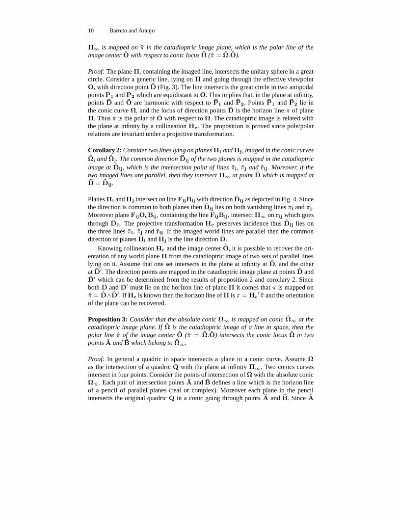
Proposition 2: The conic of points Ω is the catadioptric image of a line in space lyingon a plane Π going through the effective viewpoint. The intersection line π of Π with
10 Barreto and Araujo
Π∞ is mapped on π in the catadioptric image plane, which is the polar line of theimage center O with respect to conic locus Ω (π = Ω.O).
Proof: The plane Π, containing the imaged line, intersects the unitary sphere in a greatcircle. Consider a generic line, lying on Π and going through the effective viewpointO, with direction point D (Fig. 3). The line intersects the great circle in two antipodalpoints P1 and P2 which are equidistant to O. This implies that, in the plane at infinity,points D and O are harmonic with respect to P1 and P2. Points P1 and P2 lie inthe conic curve Ω, and the locus of direction points D is the horizon line π of planeΠ. Thus π is the polar of O with respect to Ω. The catadioptric image is related withthe plane at infinity by a collineation Hc. The proposition is proved since pole/polarrelations are invariant under a projective transformation.
Corollary 2: Consider two lines lying on planes Πi and Πj, imaged in the conic curvesΩi and Ωj. The common direction Dij of the two planes is mapped in the catadioptricimage at Dij, which is the intersection point of lines πi, πj and rij. Moreover, if thetwo imaged lines are parallel, then they intersect Π∞ at point D which is mapped atD = Dij.
Planes Πi and Πj intersect on line FijBij with direction Dij as depicted in Fig. 4. Sincethe direction is common to both planes then Dij lies on both vanishing lines πi and πj.Moreover plane FijOcBij, containing the line FijBij, intersect Π∞ on rij which goesthrough Dij. The projective transformation Hc preserves incidence thus Dij lies onthe three lines πi, πj and rij. If the imaged world lines are parallel then the commondirection of planes Πi and Πj is the line direction D.
Knowing collineation Hc and the image center O, it is possible to recover the ori-entation of any world plane Π from the catadioptric image of two sets of parallel lineslying on it. Assume that one set intersects in the plane at infinity at D, and the otherat D′. The direction points are mapped in the catadioptric image plane at points D andD′ which can be determined from the results of proposition 2 and corollary 2. Sinceboth D and D′ must lie on the horizon line of plane Π it comes that π is mapped onπ = D∧D′. If Hc is known then the horizon line of Π is π = Hc
tπ and the orientationof the plane can be recovered.
Proposition 3: Consider that the absolute conic Ω∞ is mapped on conic Ω∞ at thecatadioptric image plane. If Ω is the catadioptric image of a line in space, then thepolar line π of the image center O (π = Ω.O) intersects the conic locus Ω in twopoints A and B which belong to Ω∞.
Proof: In general a quadric in space intersects a plane in a conic curve. Assume Ωas the intersection of a quadric Q with the plane at infinity Π∞. Two conics curvesintersect in four points. Consider the points of intersection of Ω with the absolute conicΩ∞. Each pair of intersection points A and B defines a line which is the horizon lineof a pencil of parallel planes (real or complex). Moreover each plane in the pencilintersects the original quadric Q in a conic going through points A and B. Since A

Properties of Central Catadioptric Line Image 11
and B are the circular points of the plane one concludes that the intersection conicis a circle. Thus the pencil of parallel planes intersect the quadric in circular sections[15]. Fig. 3 shows that a line in space projects in a great circle in the sphere surface.The great circle defines a central cone Q of projective rays with vertex in Oc, whichintersects Π∞ in Ω. According to proposition 2, π = Ω.O is the horizon line of theplane Π, going through the effective viewpoint, and containing the imaged line. Theplane cuts the central cone Q of projective rays in a circular section (the great circle).Thus the corresponding horizon line π intersects Ω in two circular points which lie inthe absolute conic Ω∞. The established relations hold in the catadioptric image planeafter the projective transformation Hc.
Corollary 3: The absolute conic Ω∞ in the catadioptric image plane can be determinedfrom the three image lines Ω1, Ω2 and Ω3
For each conic locus compute the polar line of the image center O and determine thetwo intersection points of the obtained line with the original conic curve. Six points ofΩ∞ are obtained: A1, B1, A2, B2, A3 and B3 (see Fig. 5). Since five points define aconic locus, the six points are sufficient to estimate Ω∞.
4.3 Estimating Mirror Parameters from the Catadioptric Projection of Lines
Assume that both the catadioptric image center O and the absolute conic Ω∞ areknown. The conic curve Ω is the catadioptric image of a line in space lying on planeΠ going through the center O of the catadioptric system. From proposition 2 it resultsthat π = Ω.O is the locus where the horizon line of Π is mapped. If N is the directionpoint of the normal to the plane then N is mapped on N = Ω∞.π at the catadioptricimage plane.
Proposition 4: Consider the normal direction N of a plane Π containing the effectiveviewpoint. If N is mapped on N then the major axis µ of the projection Ω on Π∞ of aline lying on Π is mapped on µ = O ∧ N
Proof: Figure3 depicts the major axis µ as the intersection of plane at infinity with theplane defined by the normal vector n to Π and the Z axis. This result comes directlyfrom equation 9. Notice that both O and N lie on µ. Since collineation Hc preservesincidence comes that both points O and N must lie on the locus µ where µ is mapped.
Corollary 4: If the conic of points Ω is the catadioptric image of a line lying on Πthen the pole of µ with respect to Ω lies on π∞ which is the intersection line of thecatadioptric image plane with the plane at infinity Π∞.
Corollary 5: If both the catadioptric image center O and absolute conic Ω∞ areknown, it is possible to determine the position of the line at infinity π∞ from two distinctcatadioptric line images.
The major axis µ is a diameter of the conic Ω, thus the corresponding pole lies in the
12 Barreto and Araujo
line at infinity π∞ [20]. Since the pole/polar relations are preserved under a projectivetransformation comes that point Ω∗µ must lie on π∞ (Ω∗ is the conic envelope of Ω).Corollary 5 arises from the fact that a line is defined by two points. Notice that if π∞ ison the canonical position (0, 0, 1)t then Hc is an affine transformation and the camerais not rotated with respect to the reflective surface (R = I in equation 5). Points D andM, depicted on Fig. 3, are the intersection points of µ with the horizon line of Π andthe line at infinity at the catadioptric image plane (D = µ ∧ π and M = µ ∧ π∞).
Proposition 5: The cross ratio of points O, M, D and N lying on µ, only dependson the angle between plane Π and plane XOY of the catadioptric reference frame. Inparticular D, N; O, M = − tan(α)2 with α the angle of equation 8.
Proof: Consider the major axis µ depicted on Fig. 3 given in equation 9. The originof Π∞ is O = (0, 0, 1)t and the normal vector n intersects the plane at infinity atN = (nx, ny, nz)
t. Moreover the intersection point D of µ and π is D = µ ∧ π =
(−nxnz,−nynz, n2x +n2
y)t. Point M is the direction point of µ. The line at infinity π∞
is on the canonical position thus, from equation 9, results M = (nx, ny, 0)t. Computingthe cross-ratio between the four points arises D, N; O, M = − tan(α)2. The cross-ratio is a projective invariant and the proposition is proved.
Proposition 6: Consider point P1 and P2 where line µ intersects the correspondingconic locus Ω (the catadioptric line image). The cross ratio of points D, N, P1 and P2
depends on catadioptric system parameter ξ and on angle α (equation 8). In particular2P1, D; N, P2 = 1 + ξ| cot(α)|.
Proof: At the plane at infinity Π∞, major axis µ intersects conic locus Ω on pointsP1 and P2 provided by equation 10 (see Fig. 3). Computing the cross-ratio it comesP1, D; N, P2 = 1+ξ| cot(α)|
2 . Points P1, P2, D and N mapped on the catadioptricimage plane at points P1, P2, D and N by collineation Hc which preserves the cross-ratio.
Corollary 6: Consider the points O, N, D, M, P1 and P2 lying on line µ associatedwith catadioptric line image Ω, as depicted in Fig. 3. The ξ parameter of the central
catadioptric system is ξ = (2P1, D; N, P2 − 1)√
−D, N; O, M
5 Calibration Algorithm and Results
The previous section shows that it is possible to estimate the catadioptric image centerand the absolute conic from three line images. Moreover it is possible to estimate theposition of the line at infinity and the ξ parameter of the catadioptric vision system.In this section we use the established propositions to derive the following calibrationalgorithm.
Properties of Central Catadioptric Line Image 13
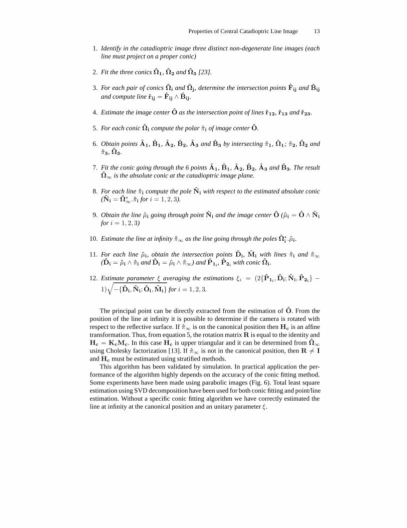
1. Identify in the catadioptric image three distinct non-degenerate line images (eachline must project on a proper conic)
2. Fit the three conics Ω1, Ω2 and Ω3 [23].
3. For each pair of conics Ωi and Ωj, determine the intersection points Fij and Bij
and compute line rij = Fij ∧ Bij.
4. Estimate the image center O as the intersection point of lines r12, r13 and r23.
5. For each conic Ωi compute the polar πi of image center O.
6. Obtain points A1, B1, A2, B2, A3 and B3 by intersecting π1, Ω1; π2, Ω2 andπ3, Ω3.
7. Fit the conic going through the 6 points A1, B1, A2, B2, A3 and B3. The resultΩ∞ is the absolute conic at the catadioptric image plane.
8. For each line πi compute the pole Ni with respect to the estimated absolute conic(Ni = Ω∗
∞.πi for i = 1, 2, 3).
9. Obtain the line µi going through point Ni and the image center O (µi = O ∧ Ni
for i = 1, 2, 3)
10. Estimate the line at infinity π∞ as the line going through the poles Ω∗i .µi.
11. For each line µi, obtain the intersection points Di, Mi with lines πi and π∞(Di = µi ∧ πi and Di = µi ∧ π∞) and P1i
, P2iwith conic Ωi.
12. Estimate parameter ξ averaging the estimations ξi = (2P1i, Di; Ni, P2i
−
1)√
−Di, Ni; Oi, Mi for i = 1, 2, 3.
The principal point can be directly extracted from the estimation of O. From theposition of the line at infinity it is possible to determine if the camera is rotated withrespect to the reflective surface. If π∞ is on the canonical position then Hc is an affinetransformation. Thus, from equation 5, the rotation matrix R is equal to the identity andHc = KcMc. In this case Hc is upper triangular and it can be determined from Ω∞
using Cholesky factorization [13]. If π∞ is not in the canonical position, then R 6= Iand Hc must be estimated using stratified methods.
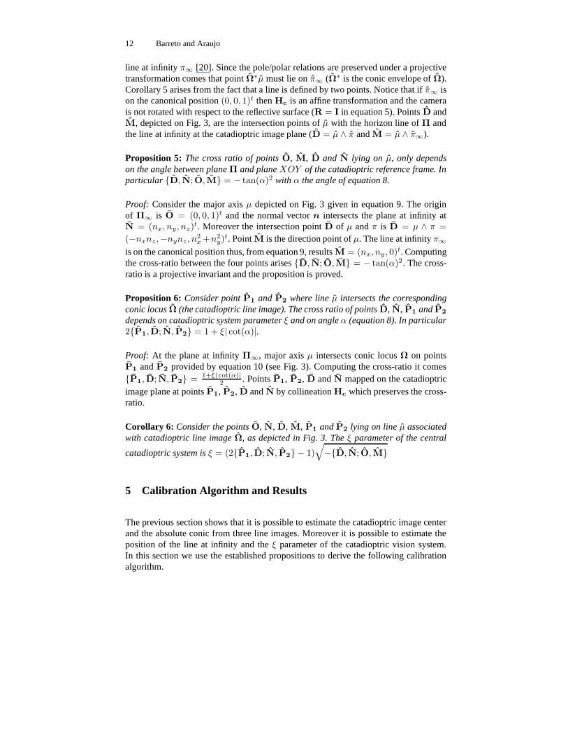
This algorithm has been validated by simulation. In practical application the per-formance of the algorithm highly depends on the accuracy of the conic fitting method.Some experiments have been made using parabolic images (Fig. 6). Total least squareestimation using SVD decomposition have been used for both conic fitting and point/lineestimation. Without a specific conic fitting algorithm we have correctly estimated theline at infinity at the canonical position and an unitary parameter ξ.
14 Barreto and Araujo
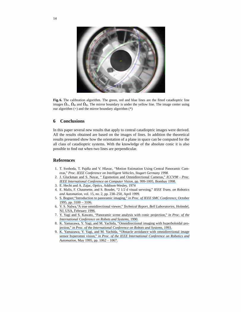
Fig. 6. The calibration algorithm. The green, red and blue lines are the fitted catadioptric lineimages Ω1, Ω2 and Ω3. The mirror boundary is under the yellow line. The image center usingour algorithm (+) and the mirror boundary algorithm (*)
6 Conclusions
In this paper several new results that apply to central catadioptric images were derived.All the results obtained are based on the images of lines. In addition the theoreticalresults presented show how the orientation of a plane in space can be computed for theall class of catadioptric systems. With the knowledge of the absolute conic it is alsopossible to find out when two lines are perpendicular.
References
1. T. Svoboda, T. Pajdla and V. Hlavac, “Motion Estimation Using Central Panoramic Cam-eras,” Proc. IEEE Conference on Intelligent Vehicles, Stugart Germany 1998.
2. J. Gluckman and S. Nayar, “ Egomotion and Omnidirectional Cameras,” ICCV98 - Proc.IEEE International Conference on Computer Vision, pp. 999-1005, Bombay 1998.
3. E. Hecht and A. Zajac, Optics, Addison-Wesley, 19744. E. Malis, F. Chaumette, and S. Boudet, “2 1/2 d visual servoing,” IEEE Trans. on Robotics
and Automation, vol. 15, no. 2, pp. 238–250, April 1999.5. S. Bogner,“Introduction to panoramic imaging,” in Proc. of IEEE SMC Conference, October
1995, pp. 3100 – 3106.6. V. S. Nalwa,“A true omnidirectional viewer,” Technical Report, Bell Laboratories, Holmdel,
NJ, USA, February 1996.7. Y. Yagi and S. Kawato, “Panoramic scene analysis with conic projection,” in Proc. of the
International Conference on Robots and Systems, 1990.8. K. Yamazawa, Y. Yagi, and M. Yachida, “Omnidirectional imaging with hyperboloidal pro-
jection,” in Proc. of the International Conference on Robots and Systems, 1993.9. K. Yamazawa, Y. Yagi, and M. Yachida, “Obstacle avoidance with omnidirectional image
sensor hyperomni vision,” in Proc. of the IEEE International Conference on Robotics andAutomation, May 1995, pp. 1062 – 1067.
Properties of Central Catadioptric Line Image 15
10. S. Baker and S. Nayar, “A Theory of Catadioptric Image Formation,” ICCV98 - Proc. IEEEInternational Conference on Computer Vision, pp. 35-42, Bombay 1998.
11. T. Svoboda, T. Pajdla and V. Hlavac, “Epipolar Geometry for Panoramic Cameras,” ECCV98-Proc. Of 5th European Conference on Computer Vision, pp 218-332, Freiburg Germany1998.
12. C. Geyer and K. Daniilidis, “A Unifying Theory for Central Panoramic Systems and PraticalImplications,” ECCV2000-Proc. European Conference on Computer Vision, pp. 445-461,Dublin 2000.
13. R. Hartley and A. Zisserman, ‘Multiple View geometry in Computer Vision, Cambridge Uni-versity Press, 2000.
14. C. Geyer and K. Daniilidis, “Catadioptric Camera Calibration”, ICCV99 - Proc. of IEEEInternational Conference on Computer Vision, pp. 398-403, Corfu, Greece, 1999.
15. Barry Spain, Analytical Quadrics, Pergamon Press, 1960.16. Barry Spain, Analytical Conics, Pergamon Press, 1957.17. S. Laveau and O. Faugeras, “Oriented Projective Geometry for Computer Vision”, ECCV96
- Proc. of European Conference on Computer Vision, 199618. Jorge Stolfi, Oriented Projective Geometry, Academic Press Inc., 1991.19. O. Faugeras, Three-dimensional computer vision, a Geometric Viewpoint, MIT Press, 1993.20. J. G. Semple, G. T. Kneebone, Algebraic Projective Geometry, Clarendon Press, 1998.21. Joao P. Barreto and H. Araujo,“Issues on the geometry of central catadioptric imaging,” in
Proc. of the IEEE Int. Conf. on Computer Vision and Pattern Recognition, Kauai, Haway,USA, December 2001.
22. Joao P. Barreto and H. Araujo,“Study of the Geometry of Central Catadioptric Systems,” ISRTechnical Report, Coimbra, May 2001.
23. Z. Zhang, Parameter Estimation Techniques: A Tutorial with Application to Conic Fitting,INRIA Raport de Recherche n 2676, October 1995.


