Embed Size (px)
Citation preview
Advantage™ VISION:Builder® Advantage ™ VISION:Two™ for z/OS
Workbench for ISPF Reference Guider7
B02635-1E

This documentation and related computer software program (hereinafter referred to as the "Documentation") is for the end user's informational purposes only and is subject to change or withdrawal by Computer Associates International, Inc. ("CA") at any time.
This documentation may not be copied, transferred, reproduced, disclosed or duplicated, in whole or in part, without the prior written consent of CA. This documentation is proprietary information of CA and protected by the copyright laws of the United States and international treaties.
Notwithstanding the foregoing, licensed users may print a reasonable number of copies of this documentation for their own internal use, provided that all CA copyright notices and legends are affixed to each reproduced copy. Only authorized employees, consultants, or agents of the user who are bound by the confidentiality provisions of the license for the software are permitted to have access to such copies.
This right to print copies is limited to the period during which the license for the product remains in full force and effect. Should the license terminate for any reason, it shall be the user's responsibility to return to CA the reproduced copies or to certify to CA that same have been destroyed.
To the extent permitted by applicable law, CA provides this documentation "as is" without warranty of any kind, including without limitation, any implied warranties of merchantability, fitness for a particular purpose or noninfringement. In no event will CA be liable to the end user or any third party for any loss or damage, direct or indirect, from the use of this documentation, including without limitation, lost profits, business interruption, goodwill, or lost data, even if CA is expressly advised of such loss or damage.
The use of any product referenced in this documentation and this documentation is governed by the end user's applicable license agreement.
The manufacturer of this documentation is Computer Associates International, Inc.
Provided with "Restricted Rights" as set forth in 48 C.F.R. Section 12.212, 48 C.F.R. Sections 52.227- 19(c)(1) and (2) or DFARS Section 252.227-7013(c)(1)(ii) or applicable successor provisions.
© 2005 Computer Associates International, Inc.
All trademarks, trade names, service marks, and logos referenced herein belong to their respective companies.
Contents
Chapter 1: IntroductionOverview of VISION:Workbench for ISPF . . . . . . . . . . . . . . . . . . . . . . . . . . . . . . . . . . . . . . . . . . . . . . . . . . . . . .1-1Creating a VISION:Transact Application . . . . . . . . . . . . . . . . . . . . . . . . . . . . . . . . . . . . . . . . . . . . . . . . . . . . . . .1-4
Online Application Summary. . . . . . . . . . . . . . . . . . . . . . . . . . . . . . . . . . . . . . . . . . . . . . . . . . . . . . . . . . . . . .1-7Creating a VISION:Builder Application . . . . . . . . . . . . . . . . . . . . . . . . . . . . . . . . . . . . . . . . . . . . . . . . . . . . . . . .1-8
Batch Application Summary . . . . . . . . . . . . . . . . . . . . . . . . . . . . . . . . . . . . . . . . . . . . . . . . . . . . . . . . . . . . . .1-12Creating a File Definition . . . . . . . . . . . . . . . . . . . . . . . . . . . . . . . . . . . . . . . . . . . . . . . . . . . . . . . . . . . . . . . . . . .1-12Using the VISION:Workbench for ISPF Utilities . . . . . . . . . . . . . . . . . . . . . . . . . . . . . . . . . . . . . . . . . . . . . . .1-15Using the Help Facility . . . . . . . . . . . . . . . . . . . . . . . . . . . . . . . . . . . . . . . . . . . . . . . . . . . . . . . . . . . . . . . . . . . . .1-18
Chapter 2: Using VISION:Workbench for ISPFSimilarities to ISPF . . . . . . . . . . . . . . . . . . . . . . . . . . . . . . . . . . . . . . . . . . . . . . . . . . . . . . . . . . . . . . . . . . . . . . . . . .2-1VISION:Workbench for ISPF Screen Formats . . . . . . . . . . . . . . . . . . . . . . . . . . . . . . . . . . . . . . . . . . . . . . . . . . .2-4
Panel Name . . . . . . . . . . . . . . . . . . . . . . . . . . . . . . . . . . . . . . . . . . . . . . . . . . . . . . . . . . . . . . . . . . . . . . . . . . . . .2-5Commands. . . . . . . . . . . . . . . . . . . . . . . . . . . . . . . . . . . . . . . . . . . . . . . . . . . . . . . . . . . . . . . . . . . . . . . . . . . . . . . . .2-8
Primary Commands . . . . . . . . . . . . . . . . . . . . . . . . . . . . . . . . . . . . . . . . . . . . . . . . . . . . . . . . . . . . . . . . . . . . .2-9Line Commands . . . . . . . . . . . . . . . . . . . . . . . . . . . . . . . . . . . . . . . . . . . . . . . . . . . . . . . . . . . . . . . . . . . . . . . .2-13
Interactive Help Facilities . . . . . . . . . . . . . . . . . . . . . . . . . . . . . . . . . . . . . . . . . . . . . . . . . . . . . . . . . . . . . . . . . . .2-16Split Screen Processing. . . . . . . . . . . . . . . . . . . . . . . . . . . . . . . . . . . . . . . . . . . . . . . . . . . . . . . . . . . . . . . . . . . . . .2-20Editing Items . . . . . . . . . . . . . . . . . . . . . . . . . . . . . . . . . . . . . . . . . . . . . . . . . . . . . . . . . . . . . . . . . . . . . . . . . . . . .2-21
Step 1.: Select an Item Type . . . . . . . . . . . . . . . . . . . . . . . . . . . . . . . . . . . . . . . . . . . . . . . . . . . . . . . . . . . . . .2-22Step 2.: Specify Item Location . . . . . . . . . . . . . . . . . . . . . . . . . . . . . . . . . . . . . . . . . . . . . . . . . . . . . . . . . . . . .2-22
Specifying Source Libraries . . . . . . . . . . . . . . . . . . . . . . . . . . . . . . . . . . . . . . . . . . . . . . . . . . . . . . . . . . .2-23Using the Definition Item Entry Panel . . . . . . . . . . . . . . . . . . . . . . . . . . . . . . . . . . . . . . . . . . . . . . . . . .2-24Using the Application Item Entry Panel . . . . . . . . . . . . . . . . . . . . . . . . . . . . . . . . . . . . . . . . . . . . . . . . .2-25Concatenating Libraries . . . . . . . . . . . . . . . . . . . . . . . . . . . . . . . . . . . . . . . . . . . . . . . . . . . . . . . . . . . . . .2-25Library Considerations. . . . . . . . . . . . . . . . . . . . . . . . . . . . . . . . . . . . . . . . . . . . . . . . . . . . . . . . . . . . . . . .2-26Partitioned Data Set Considerations (PDS) . . . . . . . . . . . . . . . . . . . . . . . . . . . . . . . . . . . . . . . . . . . . . . .2-26Sequential Data Set Considerations . . . . . . . . . . . . . . . . . . . . . . . . . . . . . . . . . . . . . . . . . . . . . . . . . . . . .2-27
Contents iii
COMLIB Considerations. . . . . . . . . . . . . . . . . . . . . . . . . . . . . . . . . . . . . . . . . . . . . . . . . . . . . . . . . . . . . . 2-28Item Selection Lists . . . . . . . . . . . . . . . . . . . . . . . . . . . . . . . . . . . . . . . . . . . . . . . . . . . . . . . . . . . . . . . . . . 2-28
Step 3.: Specify Validation Libraries (VISION:Builder only) . . . . . . . . . . . . . . . . . . . . . . . . . . . . . . . . . . 2-30Step 4.: Edit the Selected Item . . . . . . . . . . . . . . . . . . . . . . . . . . . . . . . . . . . . . . . . . . . . . . . . . . . . . . . . . . . . 2-31
Field Name Validation (VISION:Builder only) . . . . . . . . . . . . . . . . . . . . . . . . . . . . . . . . . . . . . . . . . . . 2-32Duplicate Entry Checking (VISION:Builder only) . . . . . . . . . . . . . . . . . . . . . . . . . . . . . . . . . . . . . . . . 2-33
Step 5.: Validate the Item . . . . . . . . . . . . . . . . . . . . . . . . . . . . . . . . . . . . . . . . . . . . . . . . . . . . . . . . . . . . . . . . 2-33Validating Definitions . . . . . . . . . . . . . . . . . . . . . . . . . . . . . . . . . . . . . . . . . . . . . . . . . . . . . . . . . . . . . . . . 2-34Definitions Retrieved From COMLIB . . . . . . . . . . . . . . . . . . . . . . . . . . . . . . . . . . . . . . . . . . . . . . . . . . . 2-34Definitions Retrieved From PDS or Sequential Data Set . . . . . . . . . . . . . . . . . . . . . . . . . . . . . . . . . . . 2-35Validating VISION:Builder Applications. . . . . . . . . . . . . . . . . . . . . . . . . . . . . . . . . . . . . . . . . . . . . . . . 2-36Validating VISION:Transact Applications. . . . . . . . . . . . . . . . . . . . . . . . . . . . . . . . . . . . . . . . . . . . . . . 2-37
Step 6.: Saving the Item. . . . . . . . . . . . . . . . . . . . . . . . . . . . . . . . . . . . . . . . . . . . . . . . . . . . . . . . . . . . . . . . . . 2-38Introduction to the Import Option . . . . . . . . . . . . . . . . . . . . . . . . . . . . . . . . . . . . . . . . . . . . . . . . . . . . . . . . . . . 2-39
COBOL Definitions . . . . . . . . . . . . . . . . . . . . . . . . . . . . . . . . . . . . . . . . . . . . . . . . . . . . . . . . . . . . . . . . . . . . . 2-41DB2 Table Definitions . . . . . . . . . . . . . . . . . . . . . . . . . . . . . . . . . . . . . . . . . . . . . . . . . . . . . . . . . . . . . . . . . . . 2-47VISION:Results Definitions . . . . . . . . . . . . . . . . . . . . . . . . . . . . . . . . . . . . . . . . . . . . . . . . . . . . . . . . . . . . . . 2-51VISION:Inquiry Definitions . . . . . . . . . . . . . . . . . . . . . . . . . . . . . . . . . . . . . . . . . . . . . . . . . . . . . . . . . . . . . . 2-54VISION:Builder Definitions . . . . . . . . . . . . . . . . . . . . . . . . . . . . . . . . . . . . . . . . . . . . . . . . . . . . . . . . . . . . . . 2-57Duplicate Field Name Check . . . . . . . . . . . . . . . . . . . . . . . . . . . . . . . . . . . . . . . . . . . . . . . . . . . . . . . . . . . . . 2-58Duplicate Field Name Editor . . . . . . . . . . . . . . . . . . . . . . . . . . . . . . . . . . . . . . . . . . . . . . . . . . . . . . . . . . . . . 2-60
Introduction to Job Submission . . . . . . . . . . . . . . . . . . . . . . . . . . . . . . . . . . . . . . . . . . . . . . . . . . . . . . . . . . . . . . 2-61How the Submission Facility Works . . . . . . . . . . . . . . . . . . . . . . . . . . . . . . . . . . . . . . . . . . . . . . . . . . . . . . 2-62Using the Submission Facility . . . . . . . . . . . . . . . . . . . . . . . . . . . . . . . . . . . . . . . . . . . . . . . . . . . . . . . . . . . . 2-64Step 1.: Specify Item to Submit . . . . . . . . . . . . . . . . . . . . . . . . . . . . . . . . . . . . . . . . . . . . . . . . . . . . . . . . . . . 2-65Step 2.: Supplying File Information . . . . . . . . . . . . . . . . . . . . . . . . . . . . . . . . . . . . . . . . . . . . . . . . . . . . . . . 2-65Step 3.: Completing the Options Panel. . . . . . . . . . . . . . . . . . . . . . . . . . . . . . . . . . . . . . . . . . . . . . . . . . . . . 2-68Step 4.: Completing the User Panel. . . . . . . . . . . . . . . . . . . . . . . . . . . . . . . . . . . . . . . . . . . . . . . . . . . . . . . . 2-69Step 5.: Generating JCL or CLISTs . . . . . . . . . . . . . . . . . . . . . . . . . . . . . . . . . . . . . . . . . . . . . . . . . . . . . . . . 2-70
Using the Utilities Subsystem . . . . . . . . . . . . . . . . . . . . . . . . . . . . . . . . . . . . . . . . . . . . . . . . . . . . . . . . . . . . . . . 2-70VISION:Workbench for ISPF Parameters Subsystem . . . . . . . . . . . . . . . . . . . . . . . . . . . . . . . . . . . . . . . . . . . 2-71User Profile - First Time User Setup . . . . . . . . . . . . . . . . . . . . . . . . . . . . . . . . . . . . . . . . . . . . . . . . . . . . . . . . . . 2-72
Setting Session Parameters . . . . . . . . . . . . . . . . . . . . . . . . . . . . . . . . . . . . . . . . . . . . . . . . . . . . . . . . . . . . . . 2-73Setting List Data Set Parameters . . . . . . . . . . . . . . . . . . . . . . . . . . . . . . . . . . . . . . . . . . . . . . . . . . . . . . . . . 2-77Setting Item Entry and Validation Library Defaults . . . . . . . . . . . . . . . . . . . . . . . . . . . . . . . . . . . . . . . . . 2-78Setting the Screen Developer Profile . . . . . . . . . . . . . . . . . . . . . . . . . . . . . . . . . . . . . . . . . . . . . . . . . . . . . . 2-79Setting Default Job Submission Information . . . . . . . . . . . . . . . . . . . . . . . . . . . . . . . . . . . . . . . . . . . . . . . . 2-80
VISION:Builder Background/Batch Processing . . . . . . . . . . . . . . . . . . . . . . . . . . . . . . . . . . . . . . . . . . 2-81VISION:Builder Foreground Processing . . . . . . . . . . . . . . . . . . . . . . . . . . . . . . . . . . . . . . . . . . . . . . . . 2-82VISION:Transact Background Processing . . . . . . . . . . . . . . . . . . . . . . . . . . . . . . . . . . . . . . . . . . . . . . . 2-83VISION:Transact Foreground Processing . . . . . . . . . . . . . . . . . . . . . . . . . . . . . . . . . . . . . . . . . . . . . . . 2-84
iv Workbench for ISPF Reference Guide
Allocating ISPFILE . . . . . . . . . . . . . . . . . . . . . . . . . . . . . . . . . . . . . . . . . . . . . . . . . . . . . . . . . . . . . . . . . . . . . . . . .2-85Allocating ISPFILE for VISION:Transact . . . . . . . . . . . . . . . . . . . . . . . . . . . . . . . . . . . . . . . . . . . . . . . . . . .2-85Allocating ISPFILE for VISION:Builder . . . . . . . . . . . . . . . . . . . . . . . . . . . . . . . . . . . . . . . . . . . . . . . . . . . .2-85File Tailoring Output Data Set Characteristics. . . . . . . . . . . . . . . . . . . . . . . . . . . . . . . . . . . . . . . . . . . . . . .2-86
The List Data Set . . . . . . . . . . . . . . . . . . . . . . . . . . . . . . . . . . . . . . . . . . . . . . . . . . . . . . . . . . . . . . . . . . . . . . . . . . .2-87Using Navigation Short Cuts . . . . . . . . . . . . . . . . . . . . . . . . . . . . . . . . . . . . . . . . . . . . . . . . . . . . . . . . . . . . . . . .2-89
Using Command Stacking. . . . . . . . . . . . . . . . . . . . . . . . . . . . . . . . . . . . . . . . . . . . . . . . . . . . . . . . . . . . . . . .2-89Using the Option Jump Function . . . . . . . . . . . . . . . . . . . . . . . . . . . . . . . . . . . . . . . . . . . . . . . . . . . . . . . . .2-93Using Multiple Line Command Selections . . . . . . . . . . . . . . . . . . . . . . . . . . . . . . . . . . . . . . . . . . . . . . . . . .2-96
Maintaining Existing Source . . . . . . . . . . . . . . . . . . . . . . . . . . . . . . . . . . . . . . . . . . . . . . . . . . . . . . . . . . . . . . . . .2-98VISION:Builder and VISION:Transact Source Importing Guidelines . . . . . . . . . . . . . . . . . . . . . . . . . . .2-98
Importing Source for VISION:Builder Only . . . . . . . . . . . . . . . . . . . . . . . . . . . . . . . . . . . . . . . . . . . . . .2-99Importing Source for VISION:Transact Only . . . . . . . . . . . . . . . . . . . . . . . . . . . . . . . . . . . . . . . . . . . . .2-99
VISION:Transact Conversions . . . . . . . . . . . . . . . . . . . . . . . . . . . . . . . . . . . . . . . . . . . . . . . . . . . . . . . . . . . .2-99Converting Run Control Information . . . . . . . . . . . . . . . . . . . . . . . . . . . . . . . . . . . . . . . . . . . . . . . . . . . . . .2-99Converting Screen Control Statements . . . . . . . . . . . . . . . . . . . . . . . . . . . . . . . . . . . . . . . . . . . . . . . . . . . .2-100
VISION:Builder Validation Considerations . . . . . . . . . . . . . . . . . . . . . . . . . . . . . . . . . . . . . . . . . . . . . . . . . . .2-102DB2 Considerations . . . . . . . . . . . . . . . . . . . . . . . . . . . . . . . . . . . . . . . . . . . . . . . . . . . . . . . . . . . . . . . . . . . .2-102Sample Reports . . . . . . . . . . . . . . . . . . . . . . . . . . . . . . . . . . . . . . . . . . . . . . . . . . . . . . . . . . . . . . . . . . . . . . . .2-104
VISION:Transact Validation Considerations . . . . . . . . . . . . . . . . . . . . . . . . . . . . . . . . . . . . . . . . . . . . . . . . . .2-106DB2 Considerations . . . . . . . . . . . . . . . . . . . . . . . . . . . . . . . . . . . . . . . . . . . . . . . . . . . . . . . . . . . . . . . . . . . .2-106Catalog Considerations . . . . . . . . . . . . . . . . . . . . . . . . . . . . . . . . . . . . . . . . . . . . . . . . . . . . . . . . . . . . . . . . .2-107
Using the Screen Developer . . . . . . . . . . . . . . . . . . . . . . . . . . . . . . . . . . . . . . . . . . . . . . . . . . . . . . . . . . . . . . . .2-108Completing Screen Developer Options . . . . . . . . . . . . . . . . . . . . . . . . . . . . . . . . . . . . . . . . . . . . . . . . . . . .2-108
Using the PROFILE Option . . . . . . . . . . . . . . . . . . . . . . . . . . . . . . . . . . . . . . . . . . . . . . . . . . . . . . . . . .2-109Using the PROLOGUE option. . . . . . . . . . . . . . . . . . . . . . . . . . . . . . . . . . . . . . . . . . . . . . . . . . . . . . . . .2-113Using the PROCATTR Option . . . . . . . . . . . . . . . . . . . . . . . . . . . . . . . . . . . . . . . . . . . . . . . . . . . . . . . .2-114Using the LAYOUT Option . . . . . . . . . . . . . . . . . . . . . . . . . . . . . . . . . . . . . . . . . . . . . . . . . . . . . . . . . . .2-114Using the SEGMENTS Option . . . . . . . . . . . . . . . . . . . . . . . . . . . . . . . . . . . . . . . . . . . . . . . . . . . . . . . .2-116Using the FIELDS Option. . . . . . . . . . . . . . . . . . . . . . . . . . . . . . . . . . . . . . . . . . . . . . . . . . . . . . . . . . . . .2-117Using the DISPATTR Option. . . . . . . . . . . . . . . . . . . . . . . . . . . . . . . . . . . . . . . . . . . . . . . . . . . . . . . . . .2-122Using the VIEW Option . . . . . . . . . . . . . . . . . . . . . . . . . . . . . . . . . . . . . . . . . . . . . . . . . . . . . . . . . . . . . .2-125
Using Special Screen Developer Primary Commands . . . . . . . . . . . . . . . . . . . . . . . . . . . . . . . . . . . . . . .2-127Using Jump Commands . . . . . . . . . . . . . . . . . . . . . . . . . . . . . . . . . . . . . . . . . . . . . . . . . . . . . . . . . . . . . .2-127Using VIEW Option Commands . . . . . . . . . . . . . . . . . . . . . . . . . . . . . . . . . . . . . . . . . . . . . . . . . . . . . .2-129Using Zoom Processing Commands . . . . . . . . . . . . . . . . . . . . . . . . . . . . . . . . . . . . . . . . . . . . . . . . . . .2-130
ASL Procedure Validation. . . . . . . . . . . . . . . . . . . . . . . . . . . . . . . . . . . . . . . . . . . . . . . . . . . . . . . . . . . . . . . . . .2-131Using Comment and CALL Statements . . . . . . . . . . . . . . . . . . . . . . . . . . . . . . . . . . . . . . . . . . . . . . . . . . . . . .2-132The Unexpected Error Panel . . . . . . . . . . . . . . . . . . . . . . . . . . . . . . . . . . . . . . . . . . . . . . . . . . . . . . . . . . . . . . . .2-133Contacting Computer Associates . . . . . . . . . . . . . . . . . . . . . . . . . . . . . . . . . . . . . . . . . . . . . . . . . . . . . . . . . . . .2-134
Contents v

Index
vi Workbench for ISPF Reference Guide
Chapter
1 I
ntroductionThis chapter provides you with a brief introduction to VISION:Workbench™ for ISPF and gives you an overview of the product by describing some examples. It illustrates only those panels most relevant to the example. This chapter does not attempt to teach you all of the codes and commands that are available when using VISION:Workbench for ISPF. Chapter 2, “Using VISION:Workbench for ISPF” of this guide introduces you to these. The extensive Help system of over 700 panels is also discussed in Chapter 2, “Using VISION:Workbench for ISPF”.
This chapter covers the following:
■ Overview of VISION:Workbench for ISPF on page 1-1
■ Creating a VISION:Transact Application on page 1-4
■ Creating a VISION:Builder Application on page 1-8
■ Creating a File Definition on page 1-12
■ Using the VISION:Workbench for ISPF Utilities on page 1-15
■ Using the Help Facility on page 1-18
Overview of VISION:Workbench for ISPFVISION:Workbench for ISPF is an interactive development facility for creating and maintaining your VISION:Transact™ (online) and VISION:Builder® (batch) applications and definitions. In this friendly interactive environment, you can develop applications quickly and easily. VISION:Workbench for ISPF also has a facility for creating and maintaining VISION:Inform® definitions.
VISION:Workbench for ISPF allows you to describe your applications on a series of panels. By filling in appropriate entries on these panels, an entire application can be described in a matter of minutes. The same VISION:Workbench for ISPF panels you use to create new applications and definitions can also be used to maintain any existing VISION:Builder and VISION:Transact applications or definitions.
Introduction 1–1
Overview of VISION:Workbench for ISPF
In this interactive environment, individual entries are syntax checked and validated as you enter them. If VISION:Workbench for ISPF finds an incorrect entry, it displays an informational message to help you provide the correct information. If you do not know what to enter, there is an extensive Help facility that can provide detailed information on how to complete the entry. The information you need is always online.
For special assistance, an in-depth tutorial is provided. It can be used by new users who want to become familiar with the system or by experienced users seeking additional information on specific topics.
VISION:Workbench operates within the increasingly popular and friendly ISPF environment. It takes full advantage of the following ISPF facilities:
■ Standard ISPF primary and line commands.
■ Industry-wide standard panel formats and PF key usage.
■ Menu selections and pre-determined paths to application building and maintenance.
■ Navigational short cuts between panels.
■ An extensive online Help facility at both the panel level and the field level.
■ An in-depth tutorial.
In addition to creating complete applications, you can also use VISION:Workbench for ISPF to create individual data definitions, such as file definitions. VISION:Workbench for ISPF lets you define all types of file structures from simple flat files to complex relational databases. The definition process also extends to tables, transactions, reports, and the procedural requests that tie entire applications together.
With the same ease used to create file definitions, you can use VISION:Workbench for ISPF to paint VISION:Transact application screens, too.
VISION:Workbench for ISPF provides an additional feature to VISION:Transact application developers – the ability to preview how the screen looks and acts. You will not have to do a lot of compiles to find out your screen does not work the way you expected or that the screen field you want highlighted is blinking instead.
When creating individual data definitions, each definition is saved as a separate item. These individual components can be reused whenever and wherever you like. Create entirely new applications using components already used in other applications. There is no limit to the number of times you can reuse a component. The development cost savings realized from this feature alone makes VISION:Workbench for ISPF the most important application development tool your installation can use.
1–2 Workbench for ISPF Reference Guide
Overview of VISION:Workbench for ISPF
Once your application is error free and ready for processing, submit it to TSO directly from your VISION:Workbench for ISPF session. VISION:Workbench for ISPF contains panels that provide all the information for foreground or background processing. You can even view the results online.
VISION:Workbench is easily installed and modified to meet your particular installation standards. Because it is like ISPF, its panels can be tailored to meet your unique requirements. PF key designations can be changed. Your unique JCL and processing requirements can be customized.
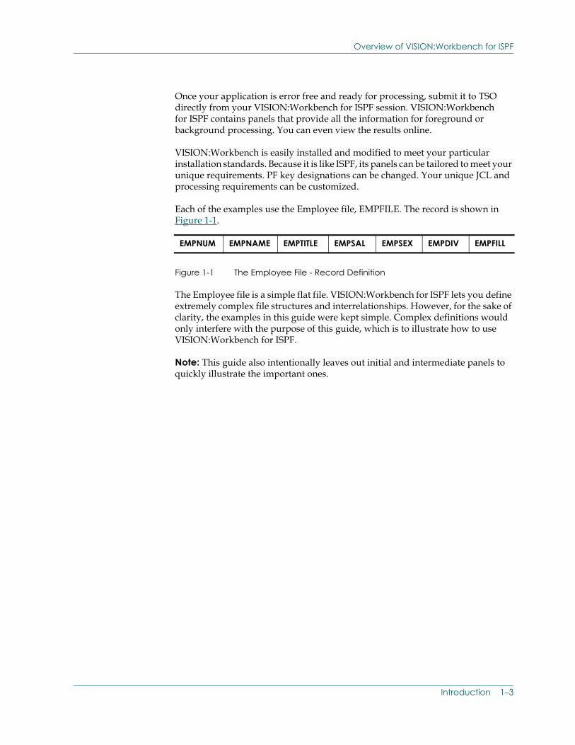
Each of the examples use the Employee file, EMPFILE. The record is shown in Figure 1-1.
Figure 1-1 The Employee File - Record Definition
The Employee file is a simple flat file. VISION:Workbench for ISPF lets you define extremely complex file structures and interrelationships. However, for the sake of clarity, the examples in this guide were kept simple. Complex definitions would only interfere with the purpose of this guide, which is to illustrate how to use VISION:Workbench for ISPF.
Note: This guide also intentionally leaves out initial and intermediate panels to quickly illustrate the important ones.
EMPNUM EMPNAME EMPTITLE EMPSAL EMPSEX EMPDIV EMPFILL
Introduction 1–3
Creating a VISION:Transact Application
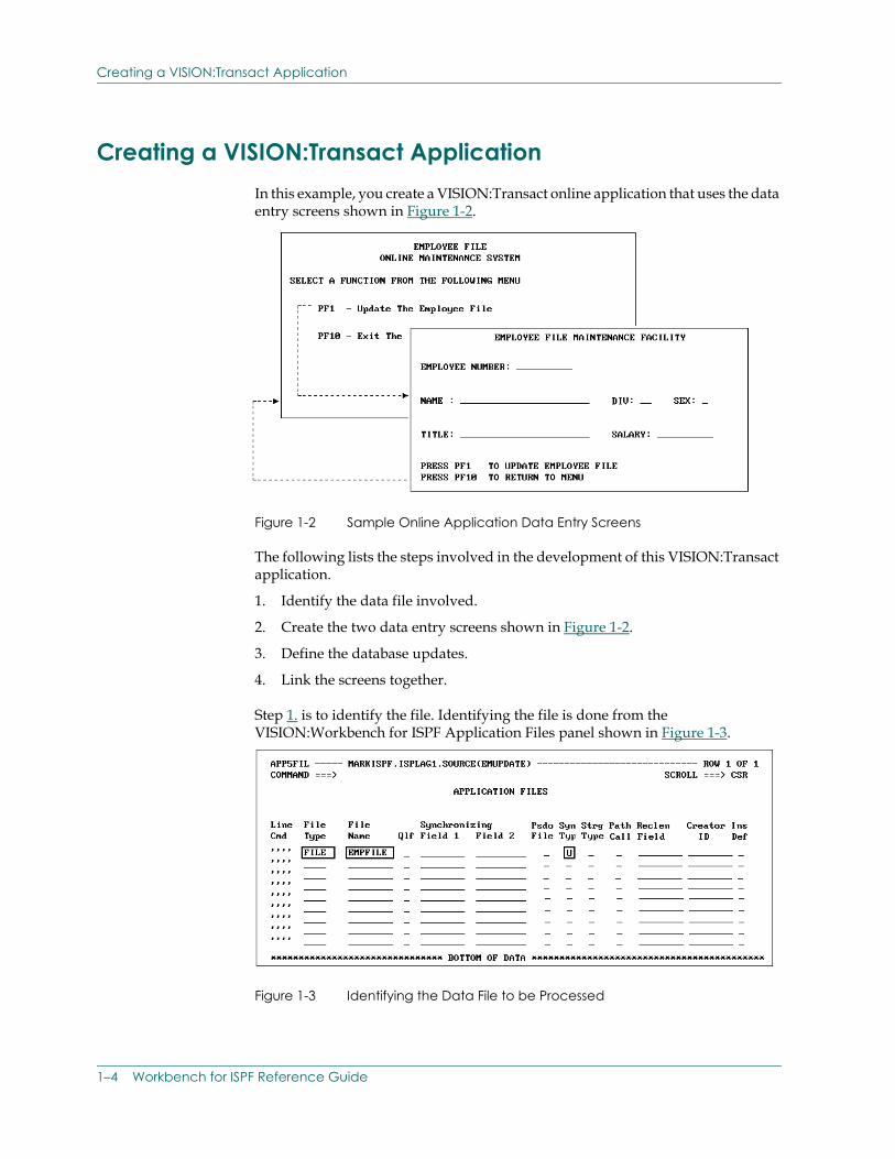
Creating a VISION:Transact ApplicationIn this example, you create a VISION:Transact online application that uses the data entry screens shown in Figure 1-2.
Figure 1-2 Sample Online Application Data Entry Screens
The following lists the steps involved in the development of this VISION:Transact application.
1. Identify the data file involved.
2. Create the two data entry screens shown in Figure 1-2.
3. Define the database updates.
4. Link the screens together.
Step 1. is to identify the file. Identifying the file is done from the VISION:Workbench for ISPF Application Files panel shown in Figure 1-3.
Figure 1-3 Identifying the Data File to be Processed
1–4 Workbench for ISPF Reference Guide
Creating a VISION:Transact Application
To identify the file, specify the name of the file (EMPFILE). For this application, also specify that the file can be updated. Step 1. is complete.
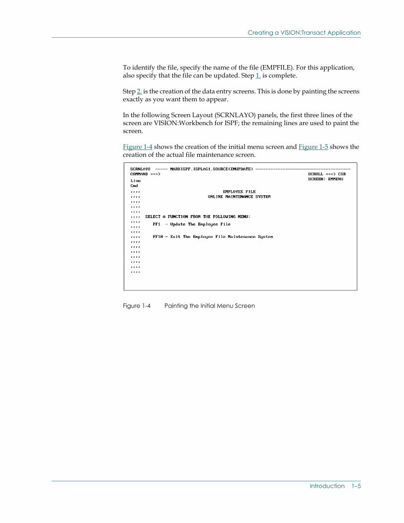
Step 2. is the creation of the data entry screens. This is done by painting the screens exactly as you want them to appear.
In the following Screen Layout (SCRNLAYO) panels, the first three lines of the screen are VISION:Workbench for ISPF; the remaining lines are used to paint the screen.
Figure 1-4 shows the creation of the initial menu screen and Figure 1-5 shows the creation of the actual file maintenance screen.
Figure 1-4 Painting the Initial Menu Screen
Introduction 1–5

Creating a VISION:Transact Application
Figure 1-5 Painting the File Maintenance Screen
Notice how the screen layouts have been drawn exactly as the screen is to appear in the application.
Painting provides you with the layout and tells you what the screen is going to look like. It does not tell you where to get the data to display on the screen or where to put the data that is entered on the screen. So next you need to map the data to and from the screen. This is achieved by using the panel shown in Figure 1-6 to define the screen fields.
Figure 1-6 Identifying the Screen Data Fields
1–6 Workbench for ISPF Reference Guide
Creating a VISION:Transact Application
Step 3. is the definition of screen fields. This step allows you to:
■ Identify from where the screen data is to come.
■ Identify to where the screen data is to go.
For your convenience, the top part of the Screen Field panel enables you to look at the layout of the screen as you identify the purpose of each screen field.
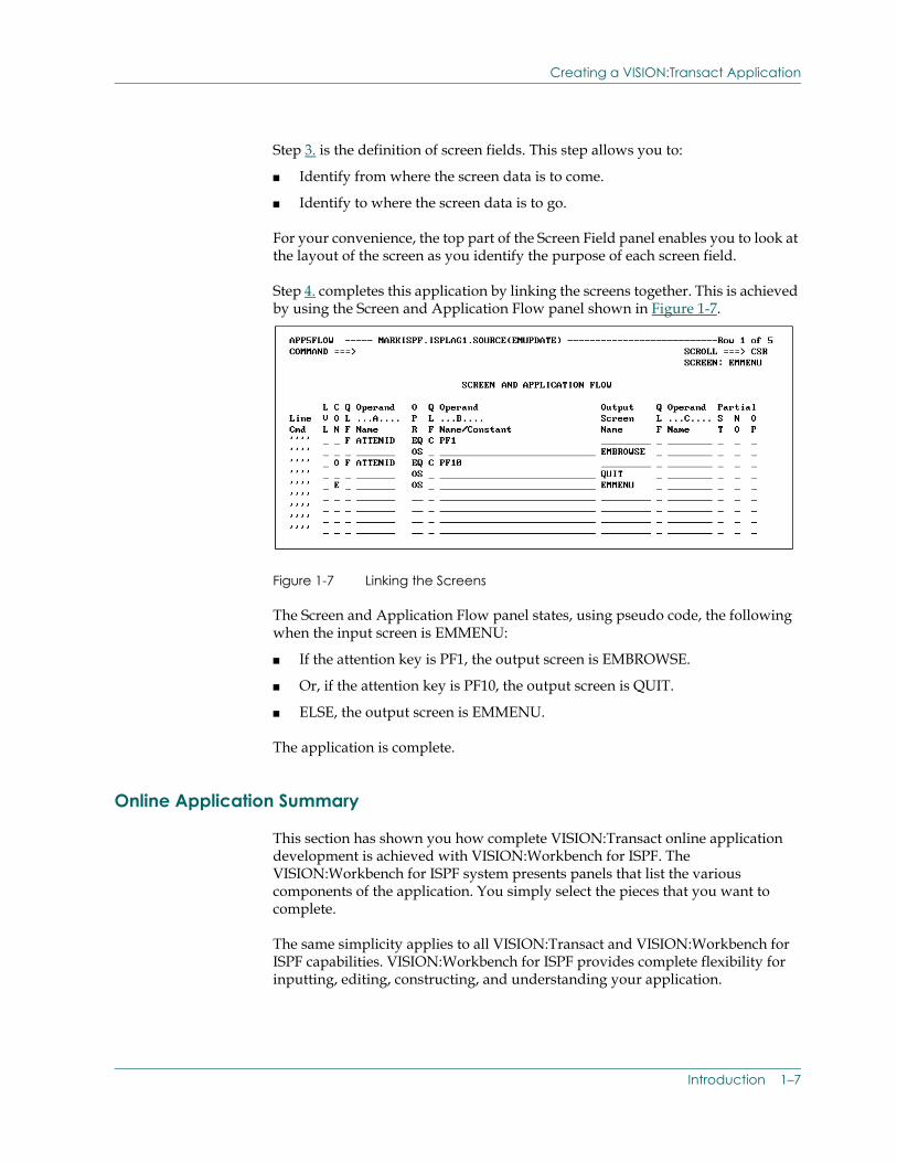
Step 4. completes this application by linking the screens together. This is achieved by using the Screen and Application Flow panel shown in Figure 1-7.
Figure 1-7 Linking the Screens
The Screen and Application Flow panel states, using pseudo code, the following when the input screen is EMMENU:
■ If the attention key is PF1, the output screen is EMBROWSE.
■ Or, if the attention key is PF10, the output screen is QUIT.
■ ELSE, the output screen is EMMENU.
The application is complete.
Online Application Summary
This section has shown you how complete VISION:Transact online application development is achieved with VISION:Workbench for ISPF. The VISION:Workbench for ISPF system presents panels that list the various components of the application. You simply select the pieces that you want to complete.
The same simplicity applies to all VISION:Transact and VISION:Workbench for ISPF capabilities. VISION:Workbench for ISPF provides complete flexibility for inputting, editing, constructing, and understanding your application.
Introduction 1–7
Creating a VISION:Builder Application
VISION:Transact provides the capabilities for generating applications for IMS or CICS/MVS®, and for integrating complex databases such as IMS/DB or DB2®. In addition, VISION:Transact permits joins between IMS/DB, DB2, and VSAM. Complex screen interactions can be developed with extensive validation and automatic transaction back out in the event of a data error.
VISION:Workbench for ISPF is the easiest way to generate online applications.
VISION:Transact is the easiest way to execute online applications.
Creating a VISION:Builder ApplicationIn this example, you will create a VISION:Builder batch application using VISION:Workbench for ISPF. Once the application is created, VISION:Workbench for ISPF can also be used to automatically generate JCL and submit the application.
Keep in mind, VISION:Builder can handle extremely complex data structures and synchronize many different databases at one time. It can apply transactions and update an old master file to create a new master file. It can create as many as 255 reports in one pass of the database and output up to 10 subfiles. It can join up to 10 different databases. On top of this, it has a powerful procedural language for coding complex algorithms.
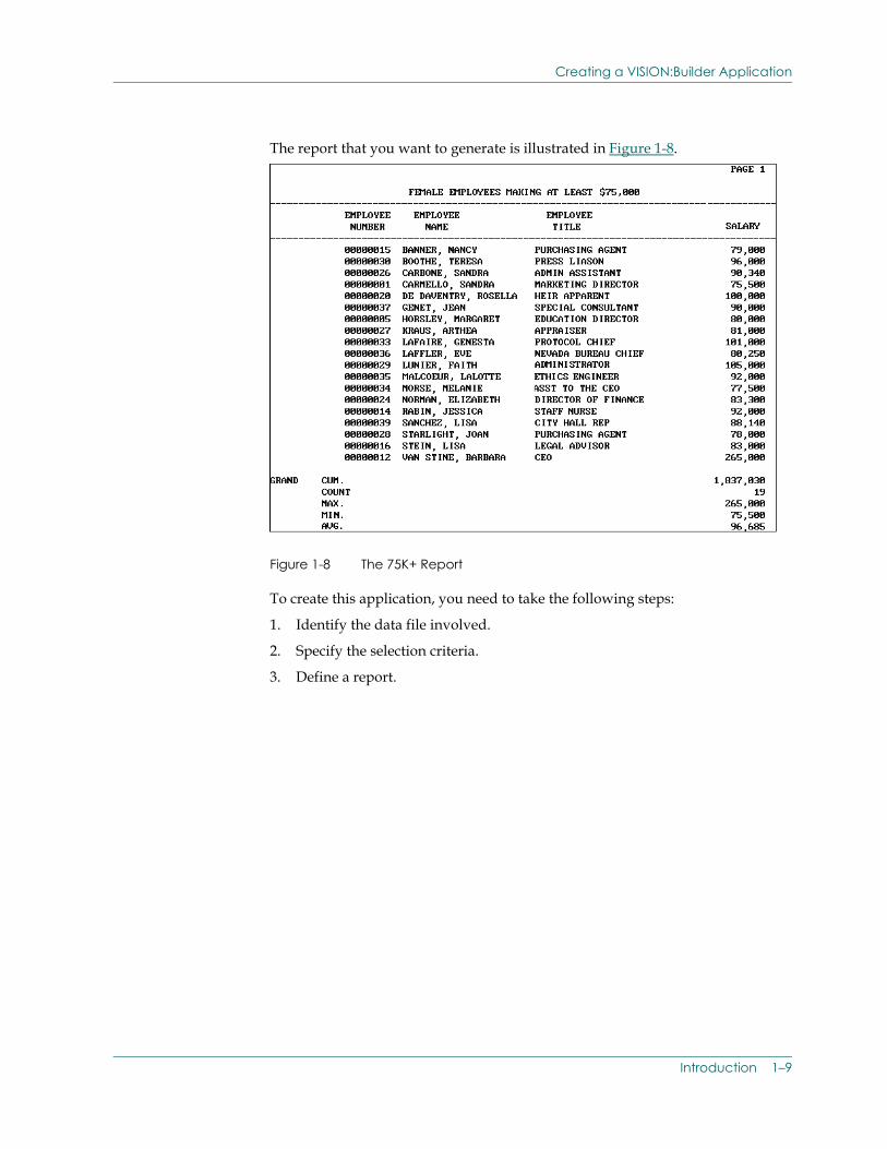
In this example, you will create a VISION:Builder application that will generate a report from the Employee file. This application will select all female employees who make at least $75,000 a year. In addition, for the selected group, the report will display the following:
■ The number of females meeting this criteria.
■ The cumulative salary for the entire report.
■ The highest salary.
■ The lowest salary.
■ The average salary.
1–8 Workbench for ISPF Reference Guide
Creating a VISION:Builder Application
The report that you want to generate is illustrated in Figure 1-8.
Figure 1-8 The 75K+ Report
To create this application, you need to take the following steps:
1. Identify the data file involved.
2. Specify the selection criteria.
3. Define a report.
Introduction 1–9
Creating a VISION:Builder Application
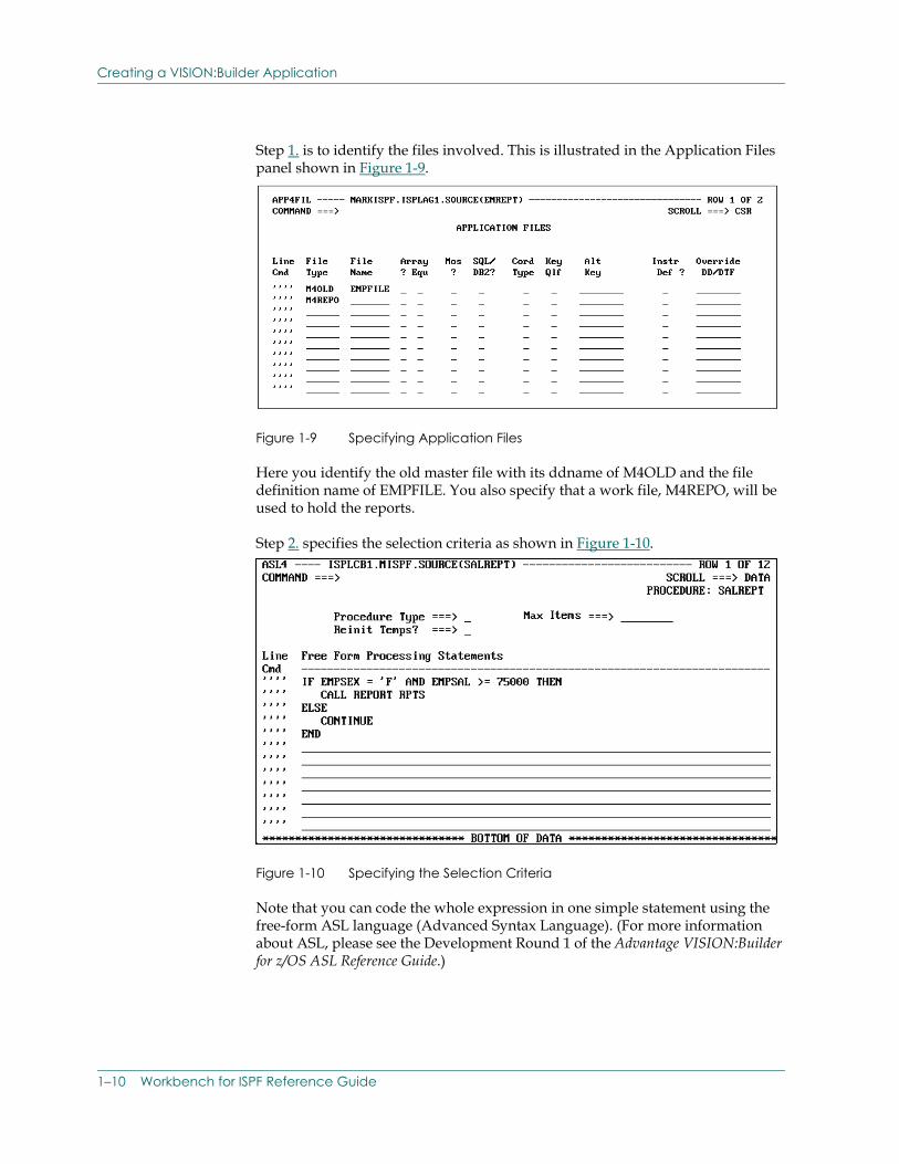
Step 1. is to identify the files involved. This is illustrated in the Application Files panel shown in Figure 1-9.
Figure 1-9 Specifying Application Files
Here you identify the old master file with its ddname of M4OLD and the file definition name of EMPFILE. You also specify that a work file, M4REPO, will be used to hold the reports.
Step 2. specifies the selection criteria as shown in Figure 1-10.
Figure 1-10 Specifying the Selection Criteria
Note that you can code the whole expression in one simple statement using the free-form ASL language (Advanced Syntax Language). (For more information about ASL, please see the Development Round 1 of the Advantage VISION:Builder for z/OS ASL Reference Guide.)
1–10 Workbench for ISPF Reference Guide
Creating a VISION:Builder Application
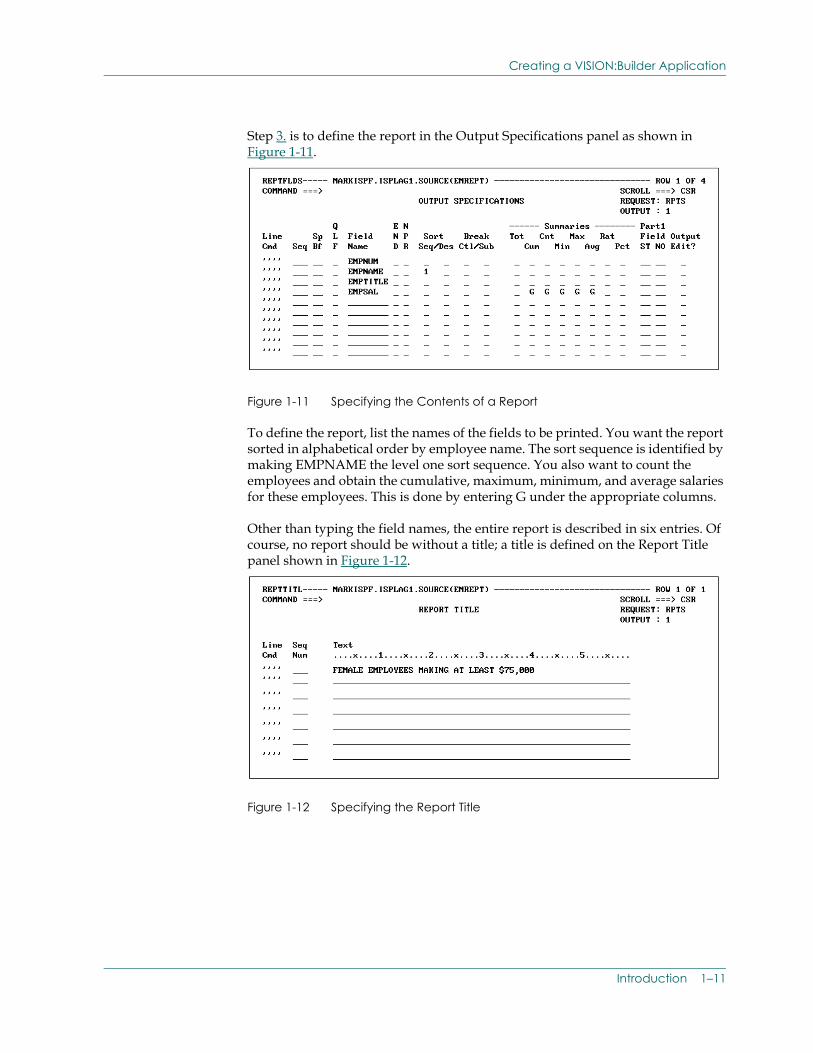
Step 3. is to define the report in the Output Specifications panel as shown in Figure 1-11.
Figure 1-11 Specifying the Contents of a Report
To define the report, list the names of the fields to be printed. You want the report sorted in alphabetical order by employee name. The sort sequence is identified by making EMPNAME the level one sort sequence. You also want to count the employees and obtain the cumulative, maximum, minimum, and average salaries for these employees. This is done by entering G under the appropriate columns.
Other than typing the field names, the entire report is described in six entries. Of course, no report should be without a title; a title is defined on the Report Title panel shown in Figure 1-12.
Figure 1-12 Specifying the Report Title
Introduction 1–11
Creating a File Definition
Batch Application Summary
To show you the simplicity of VISION:Workbench for ISPF, the application was kept simple. But, there are many additional things you could have done to implement an extremely complex application.
The fourth generation language (ASL) itself is extremely powerful and can be used to implement complex algorithms over complex databases. It has the arithmetic and logical expressions that you would expect to find in any 4GL language. It also has powerful text manipulation capabilities along with a rich variety of powerful operators.
There are many capabilities that can be used to design reports literally the way that you would like to see them. While you have seen how to create a single report, you could have developed 255 reports with the same simplicity as the one you just created. And all this applies to joins of IMS, DB2, VSAM, and other databases.
VISION:Workbench for ISPF is the easiest way to generate batch applications.
VISION:Builder is the easiest way to execute batch applications.
Creating a File DefinitionVISION:Workbench for ISPF provides a powerful facility for creating file definitions. VISION:Builder, VISION:Inform, and VISION:Transact can support the processing of complex hierarchical files or interrelated DB2 tables composed of an extensive number of fields with different formats. However, because the purpose of this document is to help you understand VISION:Workbench for ISPF, the example will use the simple Employee file to demonstrate the VISION:Workbench for ISPF file definition process.
As with the previous examples, some panels are intentionally left out. Only those panels most relevant to creating a file definition are shown. To define this file definition, you need to take the following steps:
1. Identify the file type.
2. Describe the structure of the file.
3. Provide field information.
4. Provide column headings for use on reports.
1–12 Workbench for ISPF Reference Guide
Creating a File Definition
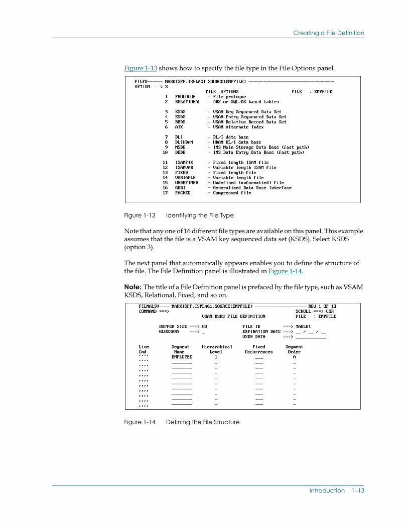
Figure 1-13 shows how to specify the file type in the File Options panel.
Figure 1-13 Identifying the File Type
Note that any one of 16 different file types are available on this panel. This example assumes that the file is a VSAM key sequenced data set (KSDS). Select KSDS (option 3).
The next panel that automatically appears enables you to define the structure of the file. The File Definition panel is illustrated in Figure 1-14.
Note: The title of a File Definition panel is prefaced by the file type, such as VSAM KSDS, Relational, Fixed, and so on.
Figure 1-14 Defining the File Structure
Introduction 1–13
Creating a File Definition
Extremely complex file structures of up to 9 hierarchical levels and up to 255 different segment types can be defined. Relational tables and relational views can be joined in a virtually unlimited number of ways. In this example, you use a single level, flat file structure.
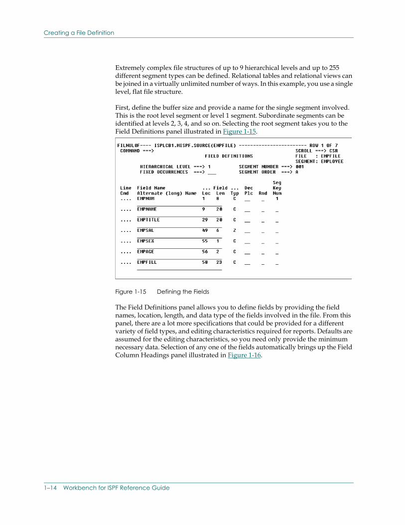
First, define the buffer size and provide a name for the single segment involved. This is the root level segment or level 1 segment. Subordinate segments can be identified at levels 2, 3, 4, and so on. Selecting the root segment takes you to the Field Definitions panel illustrated in Figure 1-15.
Figure 1-15 Defining the Fields
The Field Definitions panel allows you to define fields by providing the field names, location, length, and data type of the fields involved in the file. From this panel, there are a lot more specifications that could be provided for a different variety of field types, and editing characteristics required for reports. Defaults are assumed for the editing characteristics, so you need only provide the minimum necessary data. Selection of any one of the fields automatically brings up the Field Column Headings panel illustrated in Figure 1-16.
1–14 Workbench for ISPF Reference Guide
Using the VISION:Workbench for ISPF Utilities
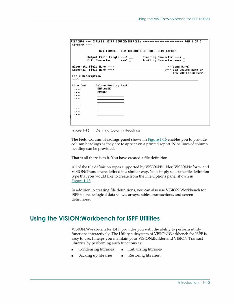
Figure 1-16 Defining Column Headings
The Field Column Headings panel shown in Figure 1-16 enables you to provide column headings as they are to appear on a printed report. Nine lines of column heading can be provided.
That is all there is to it. You have created a file definition.
All of the file definition types supported by VISION:Builder, VISION:Inform, and VISION:Transact are defined in a similar way. You simply select the file definition type that you would like to create from the File Options panel shown in Figure 1-13.
In addition to creating file definitions, you can also use VISION:Workbench for ISPF to create logical data views, arrays, tables, transactions, and screen definitions.
Using the VISION:Workbench for ISPF Utilities VISION:Workbench for ISPF provides you with the ability to perform utility functions interactively. The Utility subsystem of VISION:Workbench for ISPF is easy to use. It helps you maintain your VISION:Builder and VISION:Transact libraries by performing such functions as:■ Condensing libraries ■ Initializing libraries■ Backing up libraries ■ Restoring libraries.
Introduction 1–15
Using the VISION:Workbench for ISPF Utilities
Further, it provides an easy means of manipulating cataloged items on the library:
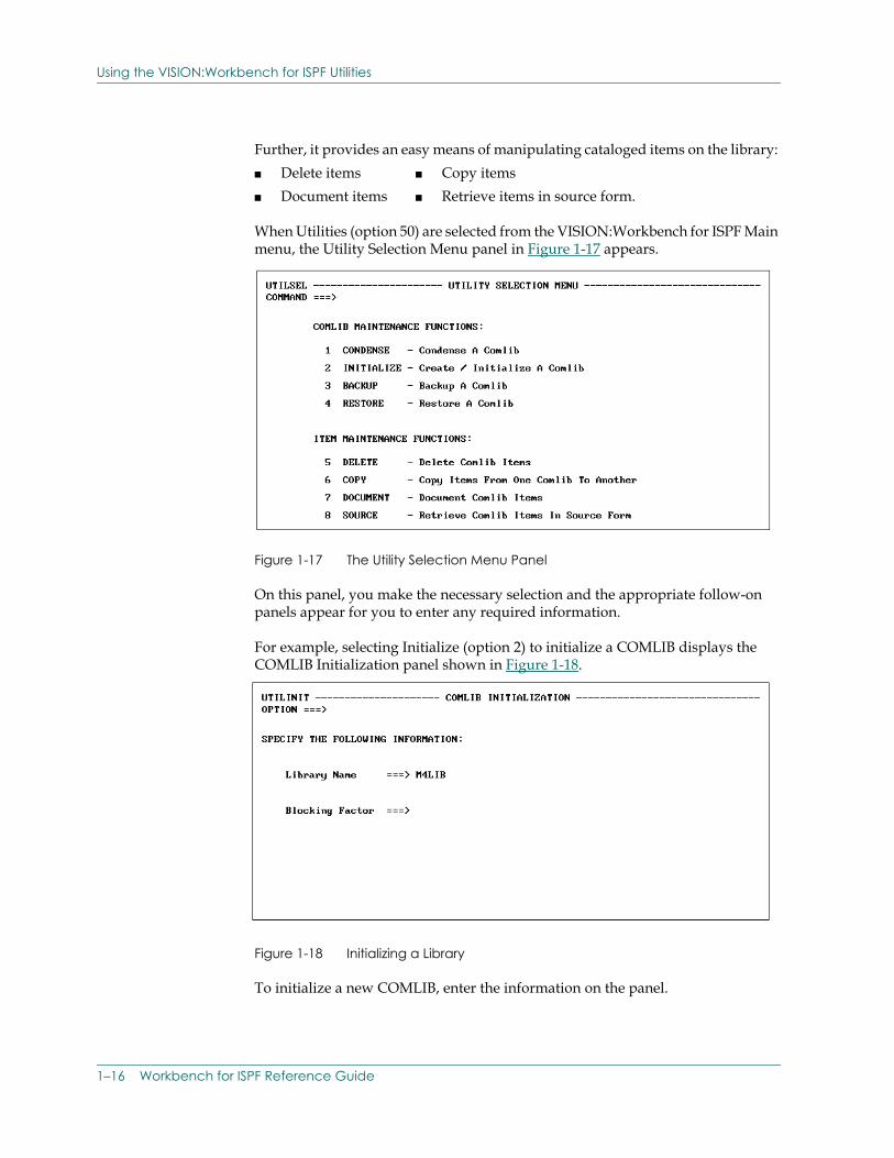
When Utilities (option 50) are selected from the VISION:Workbench for ISPF Main menu, the Utility Selection Menu panel in Figure 1-17 appears.
Figure 1-17 The Utility Selection Menu Panel
On this panel, you make the necessary selection and the appropriate follow-on panels appear for you to enter any required information.
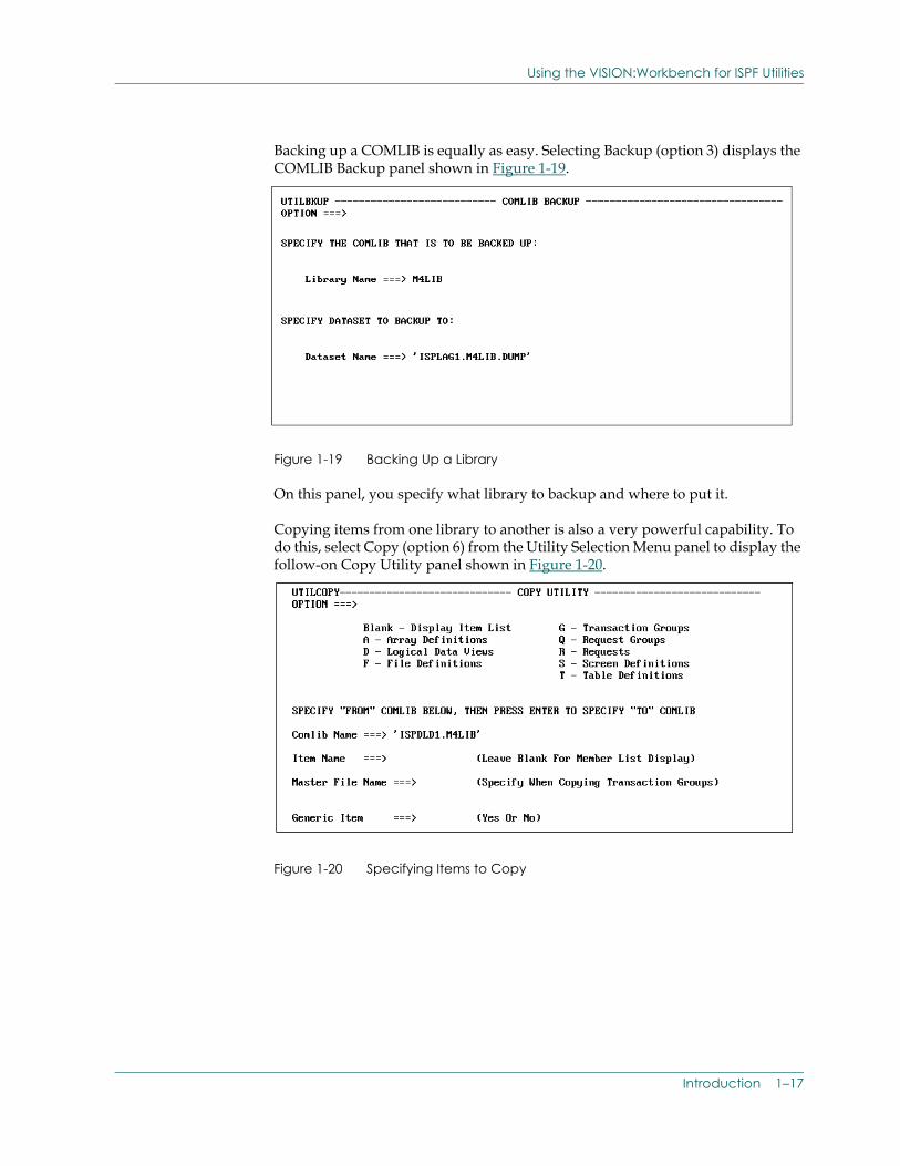
For example, selecting Initialize (option 2) to initialize a COMLIB displays the COMLIB Initialization panel shown in Figure 1-18.
Figure 1-18 Initializing a Library
To initialize a new COMLIB, enter the information on the panel.
■ Delete items ■ Copy items■ Document items ■ Retrieve items in source form.
1–16 Workbench for ISPF Reference Guide
Using the VISION:Workbench for ISPF Utilities
Backing up a COMLIB is equally as easy. Selecting Backup (option 3) displays the COMLIB Backup panel shown in Figure 1-19.
Figure 1-19 Backing Up a Library
On this panel, you specify what library to backup and where to put it.
Copying items from one library to another is also a very powerful capability. To do this, select Copy (option 6) from the Utility Selection Menu panel to display the follow-on Copy Utility panel shown in Figure 1-20.
Figure 1-20 Specifying Items to Copy
Introduction 1–17
Using the Help Facility
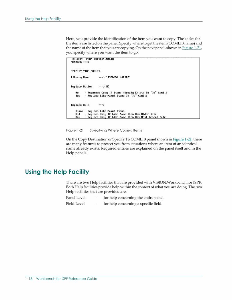
Here, you provide the identification of the item you want to copy. The codes for the items are listed on the panel. Specify where to get the item (COMLIB name) and the name of the item that you are copying. On the next panel, shown in Figure 1-21, you specify where you want the item to go.
Figure 1-21 Specifying Where Copied Items
On the Copy Destination or Specify To COMLIB panel shown in Figure 1-21, there are many features to protect you from situations where an item of an identical name already exists. Required entries are explained on the panel itself and in the Help panels.
Using the Help FacilityThere are two Help facilities that are provided with VISION:Workbench for ISPF. Both Help facilities provide help within the context of what you are doing. The two Help facilities that are provided are: Panel Level – for help concerning the entire panel. Field Level – for help concerning a specific field.
1–18 Workbench for ISPF Reference Guide
Using the Help Facility
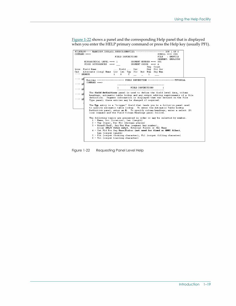
Figure 1-22 shows a panel and the corresponding Help panel that is displayed when you enter the HELP primary command or press the Help key (usually PF1).
Figure 1-22 Requesting Panel Level Help
Introduction 1–19
Using the Help Facility
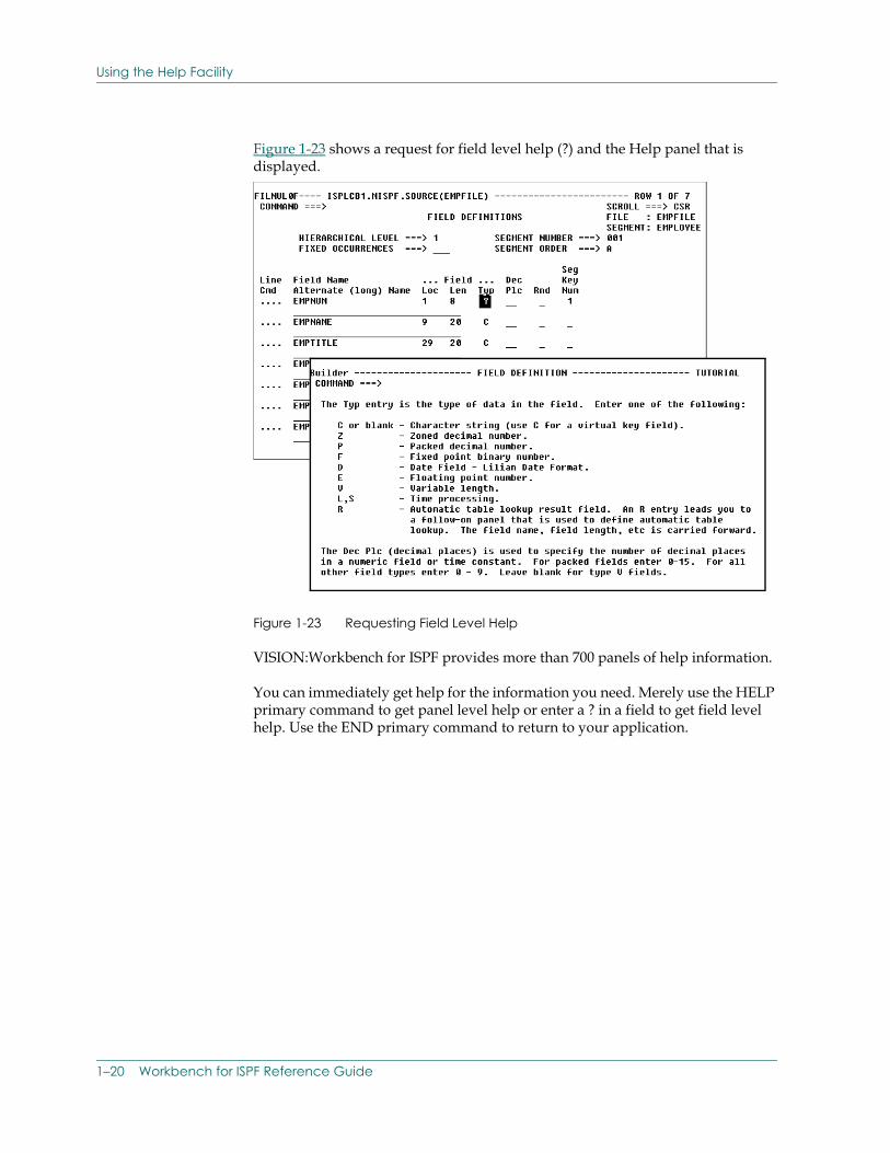
Figure 1-23 shows a request for field level help (?) and the Help panel that is displayed.
Figure 1-23 Requesting Field Level Help
VISION:Workbench for ISPF provides more than 700 panels of help information.
You can immediately get help for the information you need. Merely use the HELP primary command to get panel level help or enter a ? in a field to get field level help. Use the END primary command to return to your application.
1–20 Workbench for ISPF Reference Guide
Chapter
2 U
sing VISION:Workbench for ISPFThis chapter teaches you how to use VISION:Workbench for ISPF. Reading it enables you to quickly start using VISION:Workbench for ISPF in a productive and efficient manner.
Similarities to ISPF on page 2-1 briefly discusses basic information that is useful while learning VISION:Workbench for ISPF. It introduces you to some common VISION:Workbench for ISPF terminology. It also provides general background information to help you start using VISION:Workbench for ISPF.
The rest of this chapter discusses detailed information about using VISION:Workbench for ISPF and concepts behind VISION:Workbench for ISPF. Some of this information is specific in nature and may not apply to all parts of VISION:Workbench for ISPF. You can determine which sections are of interest to you by scanning the Contents.
Similarities to ISPFVISION:Workbench is designed to look and function in a manner very similar to ISPF. Because of this, users that are already familiar with ISPF find themselves right at home using VISION:Workbench. VISION:Workbench's panel formats, command entry, and interactive Help facility are all patterned after ISPF.
The only major difference in the way ISPF and VISION:Workbench function is in the structured panel hierarchy that VISION:Workbench creates and maintains. This hierarchy allows you to construct your applications and definitions in a structured and organized manner. When using VISION:Workbench for ISPF to edit your source, you proceed through the VISION:Workbench for ISPF panel hierarchy using the Select line command. You travel back up through the hierarchy using the END primary command.
Using VISION:Workbench for ISPF 2–1
Similarities to ISPF
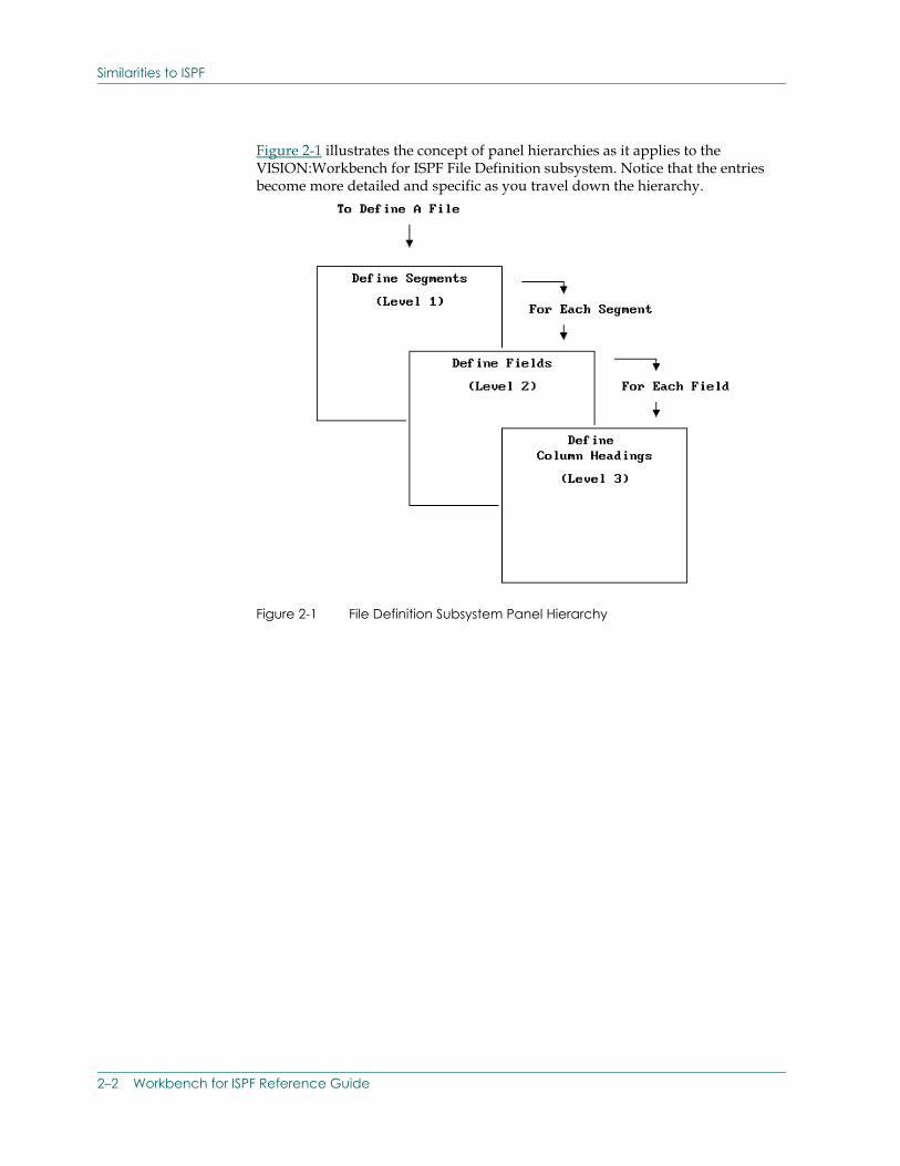
Figure 2-1 illustrates the concept of panel hierarchies as it applies to the VISION:Workbench for ISPF File Definition subsystem. Notice that the entries become more detailed and specific as you travel down the hierarchy.
Figure 2-1 File Definition Subsystem Panel Hierarchy
2–2 Workbench for ISPF Reference Guide
Similarities to ISPF
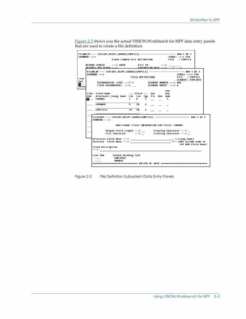
Figure 2-2 shows you the actual VISION:Workbench for ISPF data entry panels that are used to create a file definition.
Figure 2-2 File Definition Subsystem Data Entry Panels
Using VISION:Workbench for ISPF 2–3
VISION:Workbench for ISPF Screen Formats
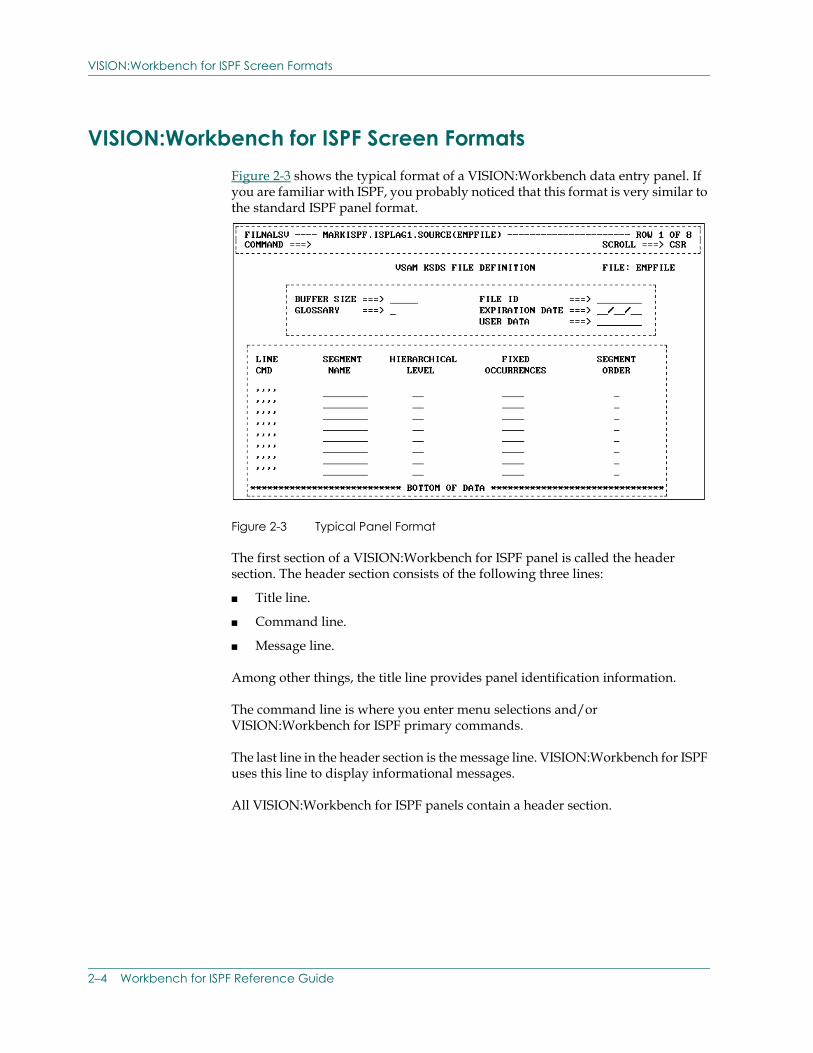
VISION:Workbench for ISPF Screen FormatsFigure 2-3 shows the typical format of a VISION:Workbench data entry panel. If you are familiar with ISPF, you probably noticed that this format is very similar to the standard ISPF panel format.
Figure 2-3 Typical Panel Format
The first section of a VISION:Workbench for ISPF panel is called the header section. The header section consists of the following three lines:
■ Title line.
■ Command line.
■ Message line.
Among other things, the title line provides panel identification information.
The command line is where you enter menu selections and/or VISION:Workbench for ISPF primary commands.
The last line in the header section is the message line. VISION:Workbench for ISPF uses this line to display informational messages.
All VISION:Workbench for ISPF panels contain a header section.
2–4 Workbench for ISPF Reference Guide
VISION:Workbench for ISPF Screen Formats
The remaining two sections, shown in Figure 2-3, comprise the data entry areas of a panel. VISION:Workbench for ISPF utilizes the following types of data entry areas:
■ Fixed data entry areas.
■ Scrollable data entry areas.
The fixed data entry area contains entries that occur only once. These fields usually contain summary information from the previous panel (also known as the parent panel).
In contrast to the fixed data entry area, the scrollable data entry area contains multiply-occurring data rows that pertain to the current panel. When entering information in scrollable data areas, the ISPF UP and DOWN scroll commands can be used to page through the multiply-occurring rows of data. The ISPF LEFT and RIGHT scroll commands can be used to display scrollable areas that are wider than your terminal.
Panel Name
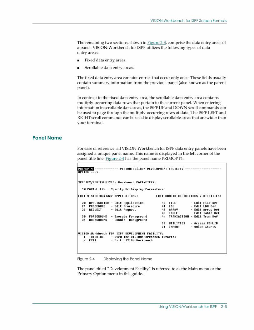
For ease of reference, all VISION:Workbench for ISPF data entry panels have been assigned a unique panel name. This name is displayed in the left corner of the panel title line. Figure 2-4 has the panel name PRIMOPT4.
Figure 2-4 Displaying the Panel Name
The panel titled “Development Facility” is referred to as the Main menu or the Primary Option menu in this guide.
Using VISION:Workbench for ISPF 2–5
VISION:Workbench for ISPF Screen Formats
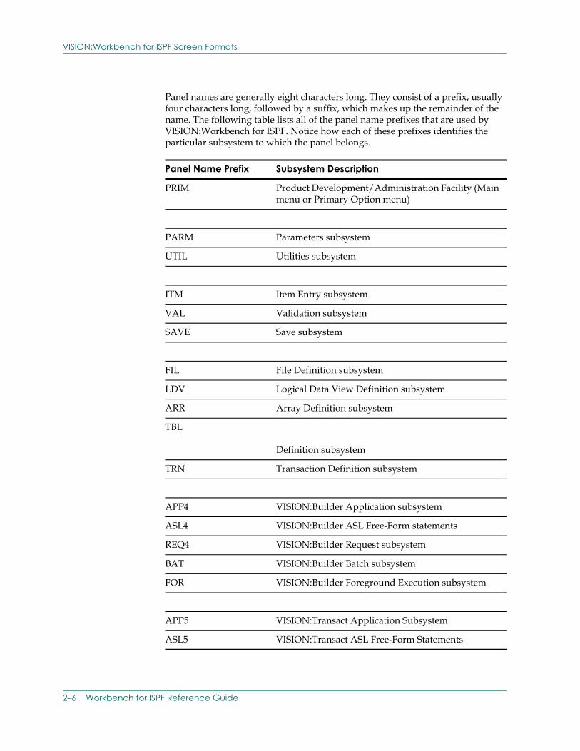
Panel names are generally eight characters long. They consist of a prefix, usually four characters long, followed by a suffix, which makes up the remainder of the name. The following table lists all of the panel name prefixes that are used by VISION:Workbench for ISPF. Notice how each of these prefixes identifies the particular subsystem to which the panel belongs.
Panel Name Prefix Subsystem Description
PRIM Product Development/Administration Facility (Main menu or Primary Option menu)
PARM Parameters subsystem
UTIL Utilities subsystem
ITM Item Entry subsystem
VAL Validation subsystem
SAVE Save subsystem
FIL File Definition subsystem
LDV Logical Data View Definition subsystem
ARR Array Definition subsystem
TBL
Definition subsystem
TRN Transaction Definition subsystem
APP4 VISION:Builder Application subsystem
ASL4 VISION:Builder ASL Free-Form statements
REQ4 VISION:Builder Request subsystem
BAT VISION:Builder Batch subsystem
FOR VISION:Builder Foreground Execution subsystem
APP5 VISION:Transact Application Subsystem
ASL5 VISION:Transact ASL Free-Form Statements
2–6 Workbench for ISPF Reference Guide
VISION:Workbench for ISPF Screen Formats
The remaining portion of the panel name, called the suffix, uniquely identifies a specific panel within the subsystem. The suffix usually represents the specific function that the panel performs within the subsystem.
In the following text, panels can be referenced by the fixed portion of the title. For example, “an Item Entry panel” may reference a Definition Item Entry panel, an Application Item Entry panel, or a File Item Entry panel. Panel titles are in mixed case and do not include dashes.
Another means of uniquely identifying a panel is through the panel identification or panel ID. The panel ID should not be confused with the panel name. While the panel name provides an EXTERNAL means for the USER to uniquely identify each panel, the panel ID provides an INTERNAL means for ISPF or VISION:Workbench for ISPF to uniquely identify each panel.
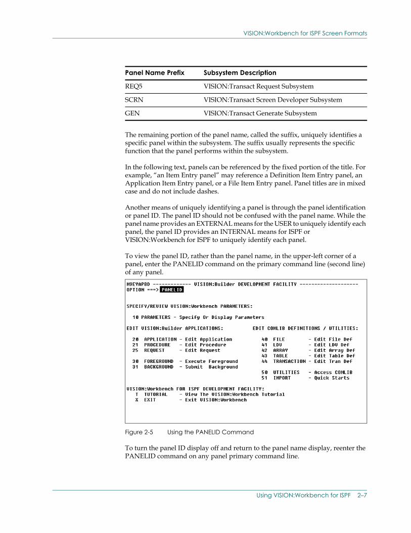
To view the panel ID, rather than the panel name, in the upper-left corner of a panel, enter the PANELID command on the primary command line (second line) of any panel.
Figure 2-5 Using the PANELID Command
To turn the panel ID display off and return to the panel name display, reenter the PANELID command on any panel primary command line.
REQ5 VISION:Transact Request Subsystem
SCRN VISION:Transact Screen Developer Subsystem
GEN VISION:Transact Generate Subsystem
Panel Name Prefix Subsystem Description
Using VISION:Workbench for ISPF 2–7
Commands
CommandsAs with ISPF, VISION:Workbench for ISPF commands can be broken down into the following two categories:
■ Primary commands.
■ Line commands.
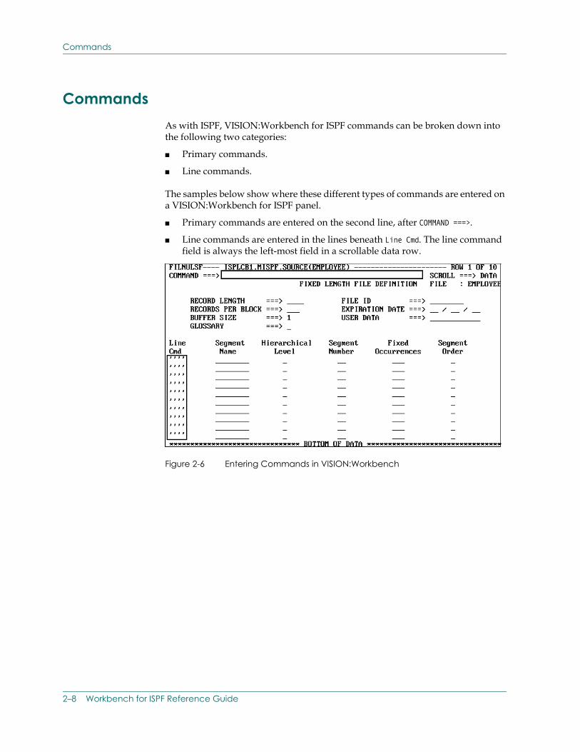
The samples below show where these different types of commands are entered on a VISION:Workbench for ISPF panel.
■ Primary commands are entered on the second line, after COMMAND ===>.
■ Line commands are entered in the lines beneath Line Cmd. The line command field is always the left-most field in a scrollable data row.
Figure 2-6 Entering Commands in VISION:Workbench
2–8 Workbench for ISPF Reference Guide
Commands
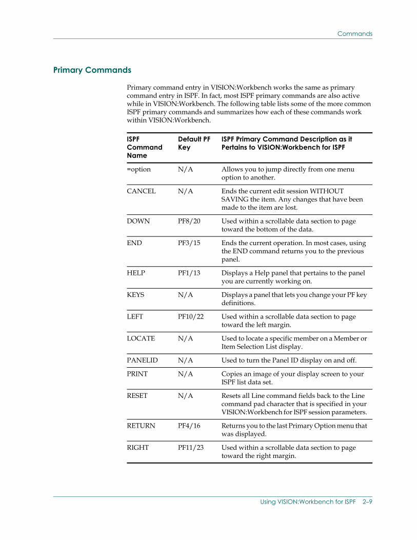
Primary Commands
Primary command entry in VISION:Workbench works the same as primary command entry in ISPF. In fact, most ISPF primary commands are also active while in VISION:Workbench. The following table lists some of the more common ISPF primary commands and summarizes how each of these commands work within VISION:Workbench.
ISPF Command Name
Default PF Key
ISPF Primary Command Description as it Pertains to VISION:Workbench for ISPF
=option N/A Allows you to jump directly from one menu option to another.
CANCEL N/A Ends the current edit session WITHOUT SAVING the item. Any changes that have been made to the item are lost.
DOWN PF8/20 Used within a scrollable data section to page toward the bottom of the data.
END PF3/15 Ends the current operation. In most cases, using the END command returns you to the previous panel.
HELP PF1/13 Displays a Help panel that pertains to the panel you are currently working on.
KEYS N/A Displays a panel that lets you change your PF key definitions.
LEFT PF10/22 Used within a scrollable data section to page toward the left margin.
LOCATE N/A Used to locate a specific member on a Member or Item Selection List display.
PANELID N/A Used to turn the Panel ID display on and off.
PRINT N/A Copies an image of your display screen to your ISPF list data set.
RESET N/A Resets all Line command fields back to the Line command pad character that is specified in your VISION:Workbench for ISPF session parameters.
RETURN PF4/16 Returns you to the last Primary Option menu that was displayed.
RIGHT PF11/23 Used within a scrollable data section to page toward the right margin.
Using VISION:Workbench for ISPF 2–9
Commands
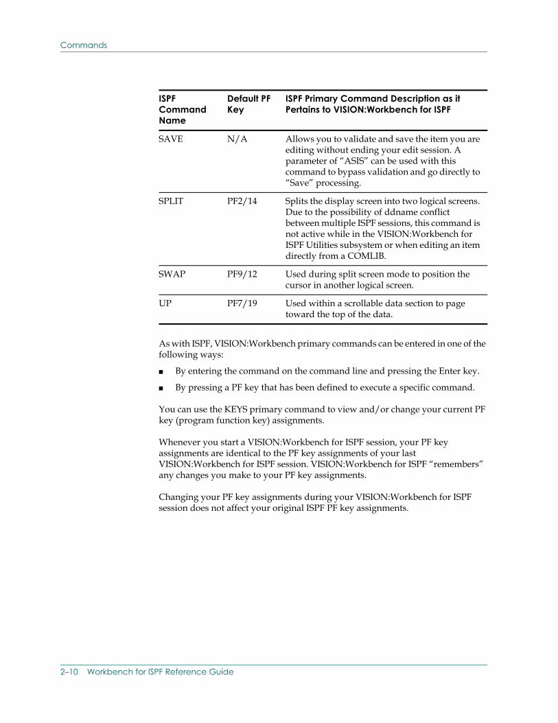
As with ISPF, VISION:Workbench primary commands can be entered in one of the following ways:
■ By entering the command on the command line and pressing the Enter key.
■ By pressing a PF key that has been defined to execute a specific command.
You can use the KEYS primary command to view and/or change your current PF key (program function key) assignments.
Whenever you start a VISION:Workbench for ISPF session, your PF key assignments are identical to the PF key assignments of your last VISION:Workbench for ISPF session. VISION:Workbench for ISPF “remembers” any changes you make to your PF key assignments.
Changing your PF key assignments during your VISION:Workbench for ISPF session does not affect your original ISPF PF key assignments.
SAVE N/A Allows you to validate and save the item you are editing without ending your edit session. A parameter of “ASIS” can be used with this command to bypass validation and go directly to “Save” processing.
SPLIT PF2/14 Splits the display screen into two logical screens. Due to the possibility of ddname conflict between multiple ISPF sessions, this command is not active while in the VISION:Workbench for ISPF Utilities subsystem or when editing an item directly from a COMLIB.
SWAP PF9/12 Used during split screen mode to position the cursor in another logical screen.
UP PF7/19 Used within a scrollable data section to page toward the top of the data.
ISPF Command Name
Default PF Key
ISPF Primary Command Description as it Pertains to VISION:Workbench for ISPF
2–10 Workbench for ISPF Reference Guide
Commands
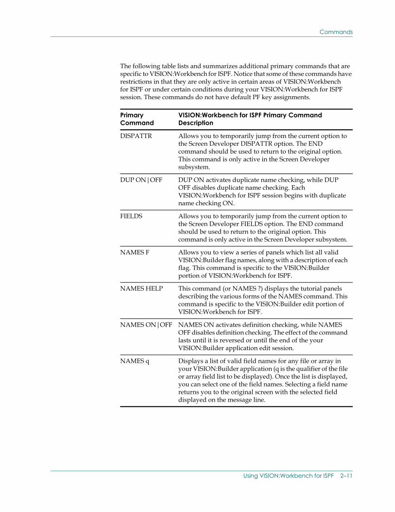
The following table lists and summarizes additional primary commands that are specific to VISION:Workbench for ISPF. Notice that some of these commands have restrictions in that they are only active in certain areas of VISION:Workbench for ISPF or under certain conditions during your VISION:Workbench for ISPF session. These commands do not have default PF key assignments.
Primary Command
VISION:Workbench for ISPF Primary Command Description
DISPATTR Allows you to temporarily jump from the current option to the Screen Developer DISPATTR option. The END command should be used to return to the original option. This command is only active in the Screen Developer subsystem.
DUP ON|OFF DUP ON activates duplicate name checking, while DUP OFF disables duplicate name checking. Each VISION:Workbench for ISPF session begins with duplicate name checking ON.
FIELDS Allows you to temporarily jump from the current option to the Screen Developer FIELDS option. The END command should be used to return to the original option. This command is only active in the Screen Developer subsystem.
NAMES F Allows you to view a series of panels which list all valid VISION:Builder flag names, along with a description of each flag. This command is specific to the VISION:Builder portion of VISION:Workbench for ISPF.
NAMES HELP This command (or NAMES ?) displays the tutorial panels describing the various forms of the NAMES command. This command is specific to the VISION:Builder edit portion of VISION:Workbench for ISPF.
NAMES ON|OFF NAMES ON activates definition checking, while NAMES OFF disables definition checking. The effect of the command lasts until it is reversed or until the end of the your VISION:Builder application edit session.
NAMES q Displays a list of valid field names for any file or array in your VISION:Builder application (q is the qualifier of the file or array field list to be displayed). Once the list is displayed, you can select one of the field names. Selecting a field name returns you to the original screen with the selected field displayed on the message line.
Using VISION:Workbench for ISPF 2–11
Commands
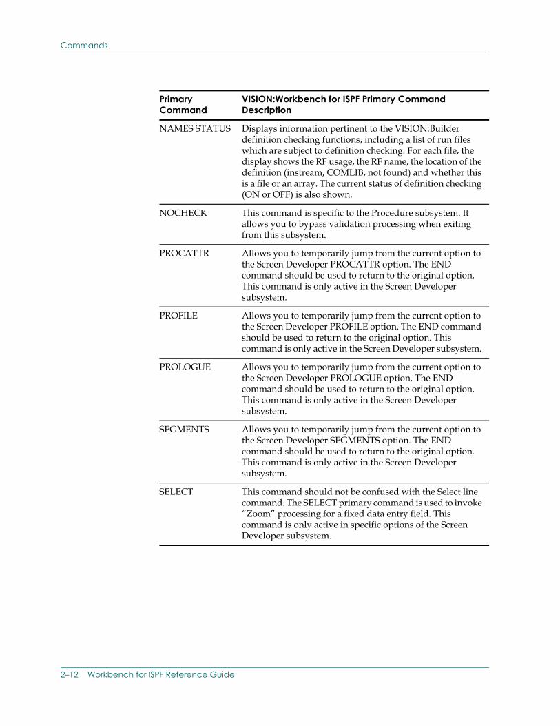
NAMES STATUS Displays information pertinent to the VISION:Builder definition checking functions, including a list of run files which are subject to definition checking. For each file, the display shows the RF usage, the RF name, the location of the definition (instream, COMLIB, not found) and whether this is a file or an array. The current status of definition checking (ON or OFF) is also shown.
NOCHECK This command is specific to the Procedure subsystem. It allows you to bypass validation processing when exiting from this subsystem.
PROCATTR Allows you to temporarily jump from the current option to the Screen Developer PROCATTR option. The END command should be used to return to the original option. This command is only active in the Screen Developer subsystem.
PROFILE Allows you to temporarily jump from the current option to the Screen Developer PROFILE option. The END command should be used to return to the original option. This command is only active in the Screen Developer subsystem.
PROLOGUE Allows you to temporarily jump from the current option to the Screen Developer PROLOGUE option. The END command should be used to return to the original option. This command is only active in the Screen Developer subsystem.
SEGMENTS Allows you to temporarily jump from the current option to the Screen Developer SEGMENTS option. The END command should be used to return to the original option. This command is only active in the Screen Developer subsystem.
SELECT This command should not be confused with the Select line command. The SELECT primary command is used to invoke “Zoom” processing for a fixed data entry field. This command is only active in specific options of the Screen Developer subsystem.
Primary Command
VISION:Workbench for ISPF Primary Command Description
2–12 Workbench for ISPF Reference Guide
Commands
Line Commands
Line commands differ from primary commands in that they serve a very specific purpose. They are used to manipulate and/or process the scrollable data entry area of a panel. Line commands are entered in the line command field of scrollable data rows. The line command field is always the left-most field in a scrollable data row.
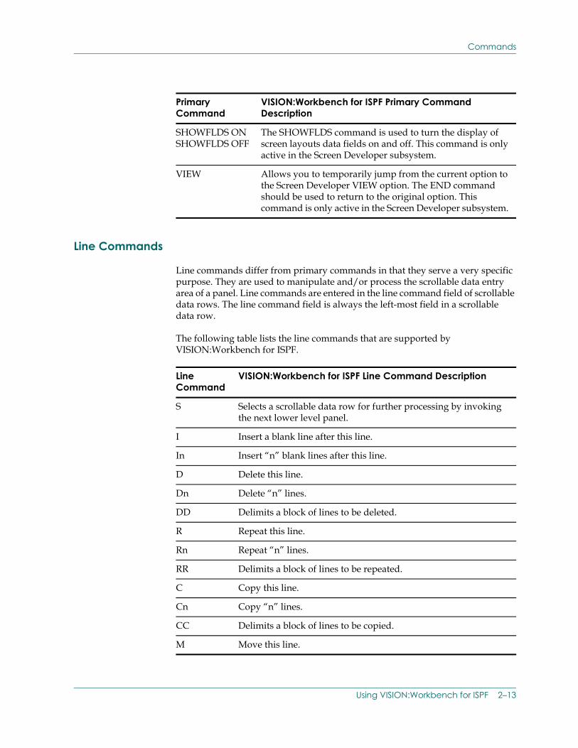
The following table lists the line commands that are supported by VISION:Workbench for ISPF.
SHOWFLDS ON SHOWFLDS OFF
The SHOWFLDS command is used to turn the display of screen layouts data fields on and off. This command is only active in the Screen Developer subsystem.
VIEW Allows you to temporarily jump from the current option to the Screen Developer VIEW option. The END command should be used to return to the original option. This command is only active in the Screen Developer subsystem.
Primary Command
VISION:Workbench for ISPF Primary Command Description
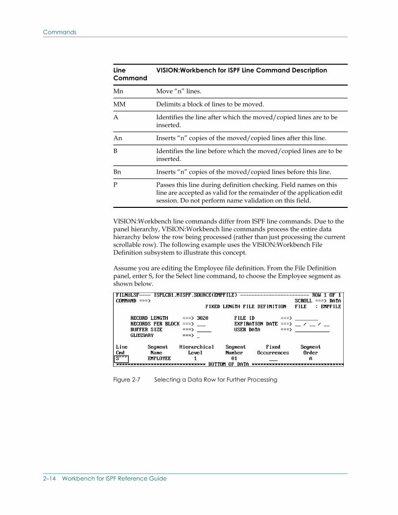
Line Command
VISION:Workbench for ISPF Line Command Description
S Selects a scrollable data row for further processing by invoking the next lower level panel.
I Insert a blank line after this line.
In Insert “n” blank lines after this line.
D Delete this line.
Dn Delete “n” lines.
DD Delimits a block of lines to be deleted.
R Repeat this line.
Rn Repeat “n” lines.
RR Delimits a block of lines to be repeated.
C Copy this line.
Cn Copy “n” lines.
CC Delimits a block of lines to be copied.
M Move this line.
Using VISION:Workbench for ISPF 2–13
Commands
VISION:Workbench line commands differ from ISPF line commands. Due to the panel hierarchy, VISION:Workbench line commands process the entire data hierarchy below the row being processed (rather than just processing the current scrollable row). The following example uses the VISION:Workbench File Definition subsystem to illustrate this concept.
Assume you are editing the Employee file definition. From the File Definition panel, enter S, for the Select line command, to choose the Employee segment as shown below.
Figure 2-7 Selecting a Data Row for Further Processing
Mn Move “n” lines.
MM Delimits a block of lines to be moved.
A Identifies the line after which the moved/copied lines are to be inserted.
An Inserts “n” copies of the moved/copied lines after this line.
B Identifies the line before which the moved/copied lines are to be inserted.
Bn Inserts “n” copies of the moved/copied lines before this line.
P Passes this line during definition checking. Field names on this line are accepted as valid for the remainder of the application edit session. Do not perform name validation on this field.
Line Command
VISION:Workbench for ISPF Line Command Description
2–14 Workbench for ISPF Reference Guide
Commands
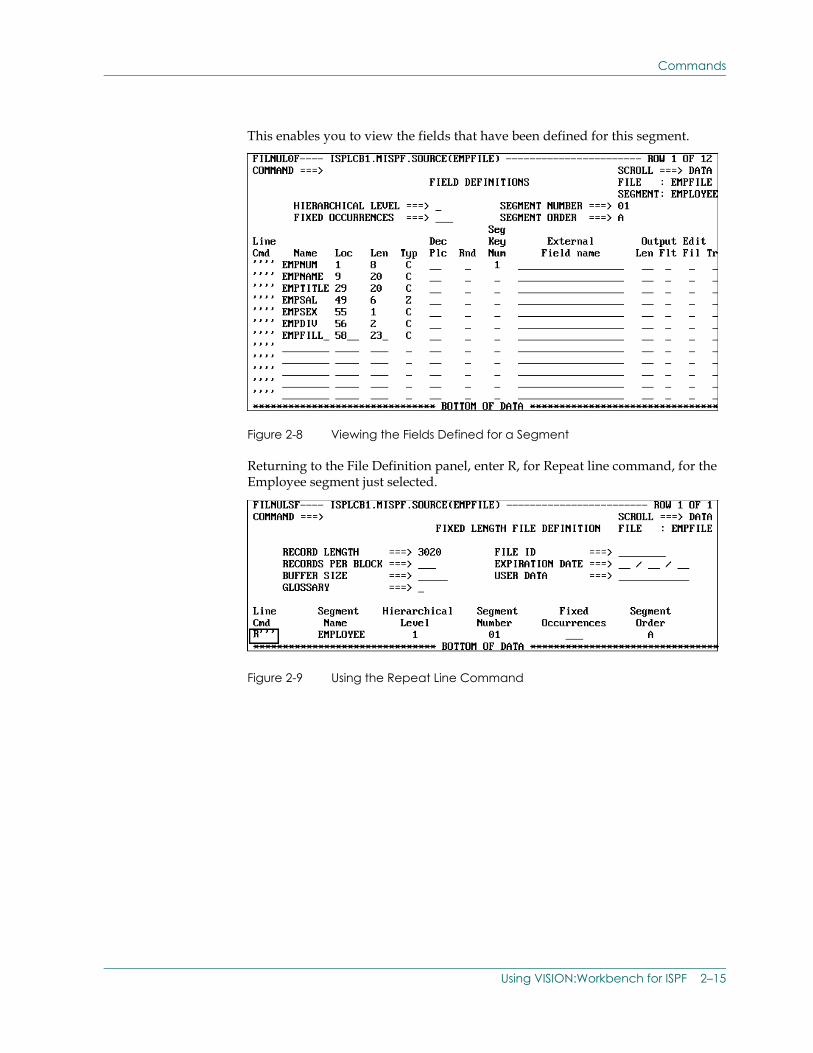
This enables you to view the fields that have been defined for this segment.
Figure 2-8 Viewing the Fields Defined for a Segment
Returning to the File Definition panel, enter R, for Repeat line command, for the Employee segment just selected.
Figure 2-9 Using the Repeat Line Command
Using VISION:Workbench for ISPF 2–15
Interactive Help Facilities
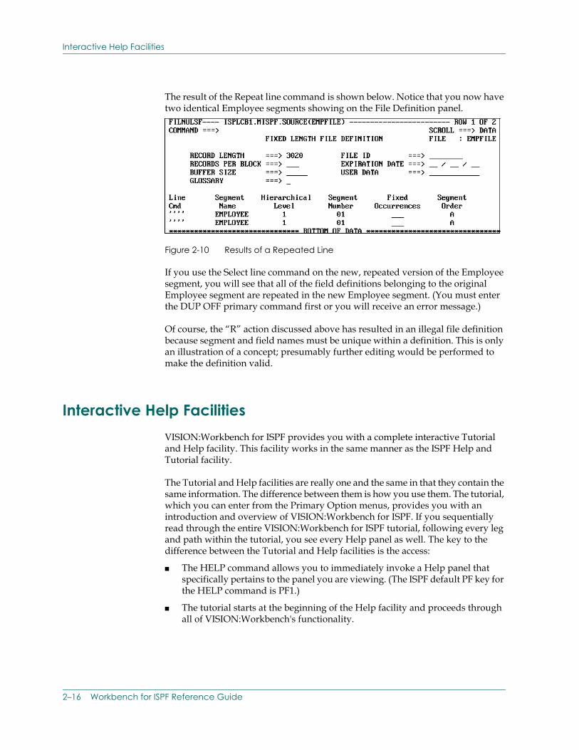
The result of the Repeat line command is shown below. Notice that you now have two identical Employee segments showing on the File Definition panel.
Figure 2-10 Results of a Repeated Line
If you use the Select line command on the new, repeated version of the Employee segment, you will see that all of the field definitions belonging to the original Employee segment are repeated in the new Employee segment. (You must enter the DUP OFF primary command first or you will receive an error message.)
Of course, the “R” action discussed above has resulted in an illegal file definition because segment and field names must be unique within a definition. This is only an illustration of a concept; presumably further editing would be performed to make the definition valid.
Interactive Help Facilities VISION:Workbench for ISPF provides you with a complete interactive Tutorial and Help facility. This facility works in the same manner as the ISPF Help and Tutorial facility.
The Tutorial and Help facilities are really one and the same in that they contain the same information. The difference between them is how you use them. The tutorial, which you can enter from the Primary Option menus, provides you with an introduction and overview of VISION:Workbench for ISPF. If you sequentially read through the entire VISION:Workbench for ISPF tutorial, following every leg and path within the tutorial, you see every Help panel as well. The key to the difference between the Tutorial and Help facilities is the access:
■ The HELP command allows you to immediately invoke a Help panel that specifically pertains to the panel you are viewing. (The ISPF default PF key for the HELP command is PF1.)
■ The tutorial starts at the beginning of the Help facility and proceeds through all of VISION:Workbench's functionality.
2–16 Workbench for ISPF Reference Guide
Interactive Help Facilities
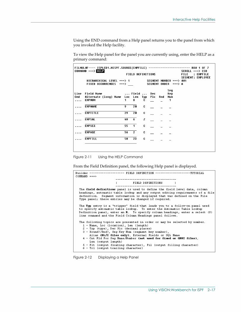
Using the END command from a Help panel returns you to the panel from which you invoked the Help facility.
To view the Help panel for the panel you are currently using, enter the HELP as a primary command:
Figure 2-11 Using the HELP Command
From the Field Definition panel, the following Help panel is displayed.
Figure 2-12 Displaying a Help Panel
Using VISION:Workbench for ISPF 2–17
Interactive Help Facilities
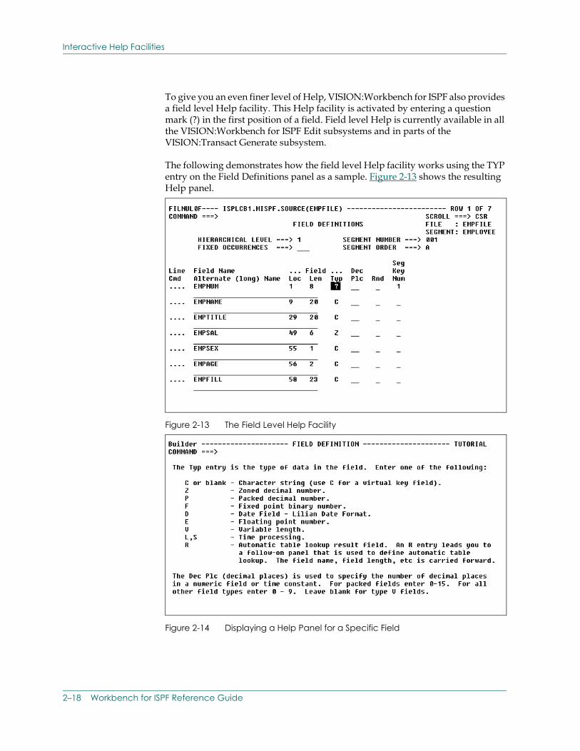
To give you an even finer level of Help, VISION:Workbench for ISPF also provides a field level Help facility. This Help facility is activated by entering a question mark (?) in the first position of a field. Field level Help is currently available in all the VISION:Workbench for ISPF Edit subsystems and in parts of the VISION:Transact Generate subsystem.
The following demonstrates how the field level Help facility works using the TYP entry on the Field Definitions panel as a sample. Figure 2-13 shows the resulting Help panel.
Figure 2-13 The Field Level Help Facility
Figure 2-14 Displaying a Help Panel for a Specific Field
2–18 Workbench for ISPF Reference Guide
Interactive Help Facilities
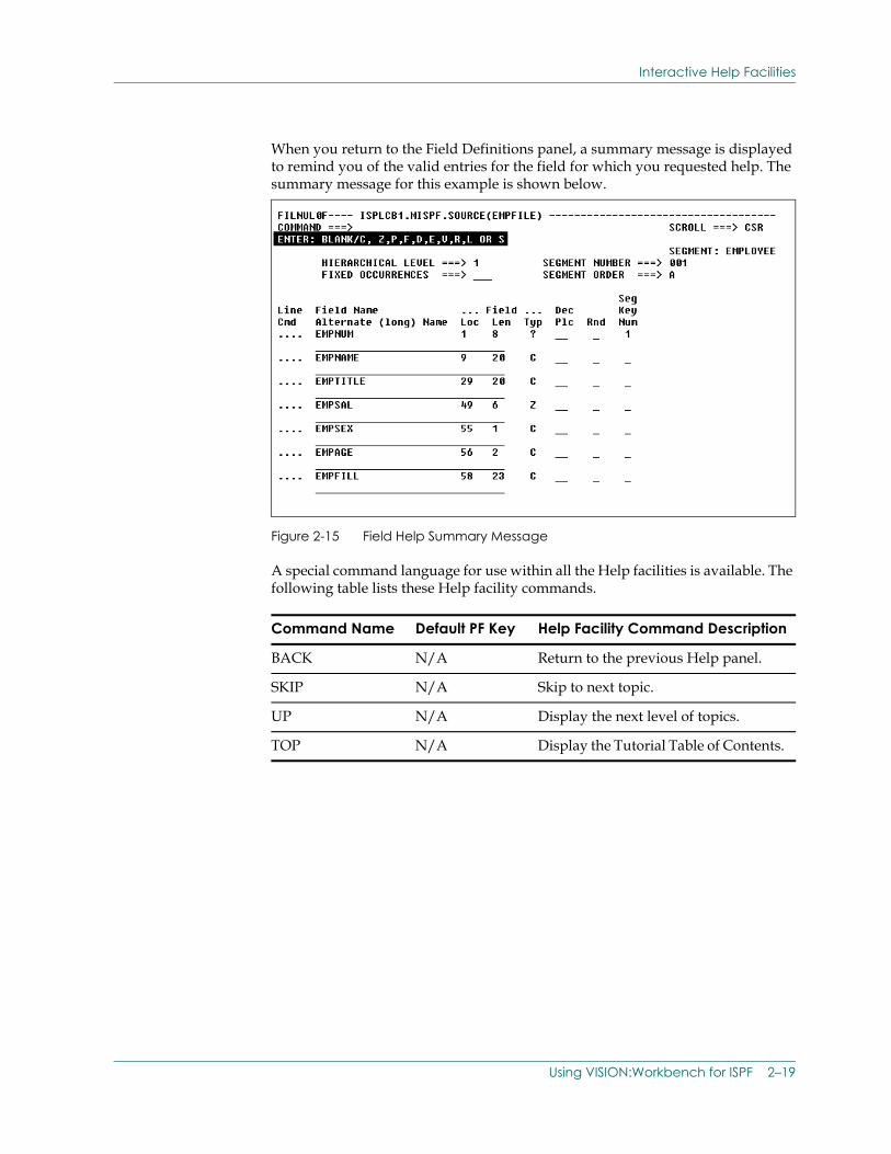
When you return to the Field Definitions panel, a summary message is displayed to remind you of the valid entries for the field for which you requested help. The summary message for this example is shown below.
Figure 2-15 Field Help Summary Message
A special command language for use within all the Help facilities is available. The following table lists these Help facility commands.
Command Name Default PF Key Help Facility Command Description
BACK N/A Return to the previous Help panel.
SKIP N/A Skip to next topic.
UP N/A Display the next level of topics.
TOP N/A Display the Tutorial Table of Contents.
Using VISION:Workbench for ISPF 2–19
Split Screen Processing
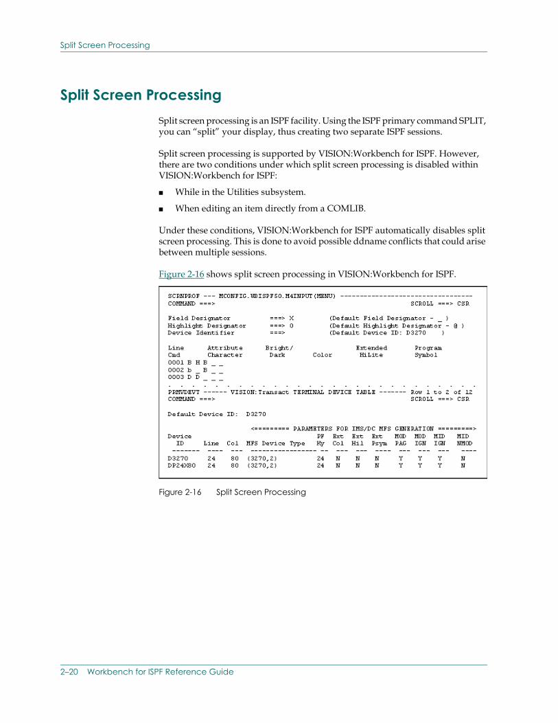
Split Screen ProcessingSplit screen processing is an ISPF facility. Using the ISPF primary command SPLIT, you can “split” your display, thus creating two separate ISPF sessions.
Split screen processing is supported by VISION:Workbench for ISPF. However, there are two conditions under which split screen processing is disabled within VISION:Workbench for ISPF:
■ While in the Utilities subsystem.
■ When editing an item directly from a COMLIB.
Under these conditions, VISION:Workbench for ISPF automatically disables split screen processing. This is done to avoid possible ddname conflicts that could arise between multiple sessions.
Figure 2-16 shows split screen processing in VISION:Workbench for ISPF.
Figure 2-16 Split Screen Processing
2–20 Workbench for ISPF Reference Guide
Editing Items
Editing Items Now that you have some general background information on how VISION:Workbench for ISPF works, you can use VISION:Workbench for ISPF to create and/or maintain your applications and definitions.
The various types of items supported by VISION:Workbench for ISPF are divided into two distinct categories:
■ Definition items.
■ Application items.
This grouping is summarized in the following table.
Notice that requests, procedures, and screen definitions are not considered definition items. Rather, they are categorized as application items. This distinction becomes important later in the edit process.
Now you are ready to start the edit process.
The VISION:Workbench for ISPF edit process consists of the following six steps:
1. Select an item type.
2. Specify item location and name.
3. Specify validation libraries.
4. Edit the item.
5. Validate the item.
6. Save the item.
Product VISION:Workbench for ISPF
Definition Items Application Items
VISION:Builder Support
File DefinitionsLogical Data ViewsArray DefinitionsTable DefinitionsTransaction Definitions
ApplicationsProceduresRequests
VISION:Inform Support
File DefinitionsLogical Data ViewsTable Definitions
ProceduresRequests
VISION:Transact Support
File DefinitionsScreen Definitions
ApplicationsProceduresRequests
Using VISION:Workbench for ISPF 2–21
Editing Items
Each of these steps is discussed in the following sections.
Step 1.: Select an Item Type
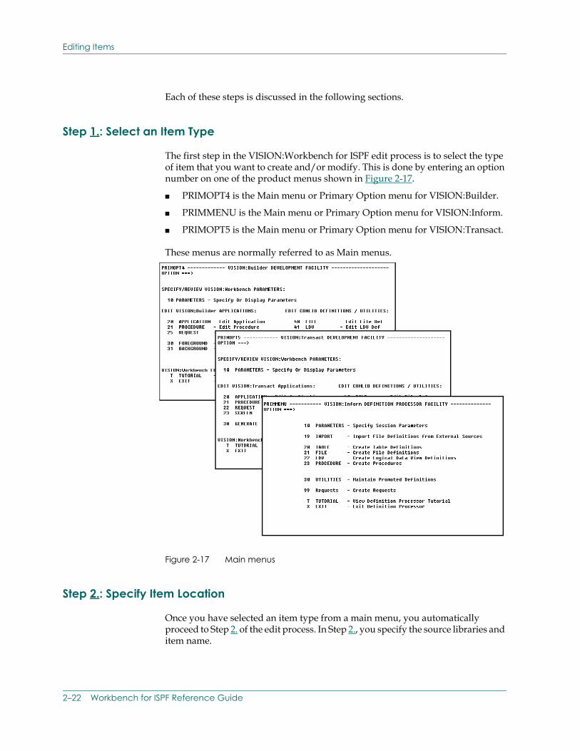
The first step in the VISION:Workbench for ISPF edit process is to select the type of item that you want to create and/or modify. This is done by entering an option number on one of the product menus shown in Figure 2-17.
■ PRIMOPT4 is the Main menu or Primary Option menu for VISION:Builder.
■ PRIMMENU is the Main menu or Primary Option menu for VISION:Inform.
■ PRIMOPT5 is the Main menu or Primary Option menu for VISION:Transact.
These menus are normally referred to as Main menus.
Figure 2-17 Main menus
Step 2.: Specify Item Location
Once you have selected an item type from a main menu, you automatically proceed to Step 2. of the edit process. In Step 2., you specify the source libraries and item name.
2–22 Workbench for ISPF Reference Guide
Editing Items
■ Specifying source libraries allows you to tell VISION:Workbench for ISPF where an item is located.
■ Specifying an item name allows you to tell VISION:Workbench for ISPF the name of the particular item that you want to edit.
Specifying Source Libraries
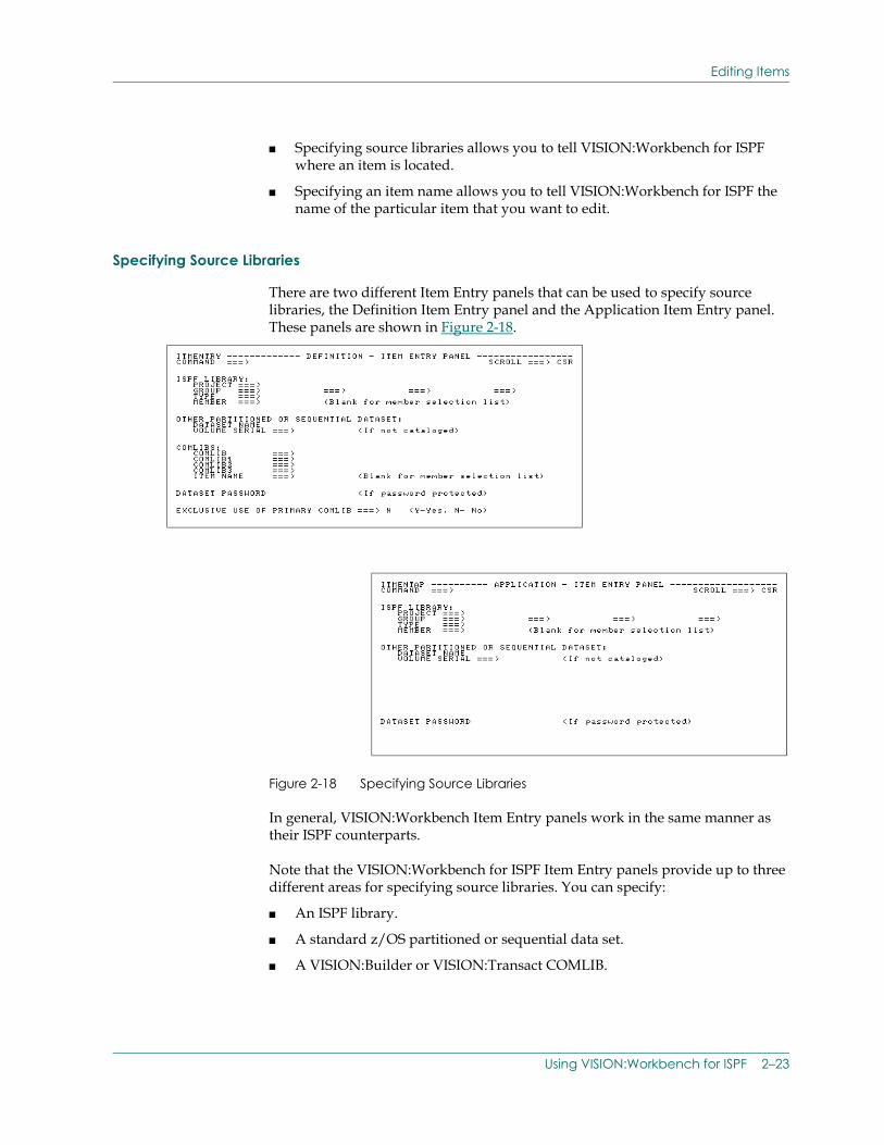
There are two different Item Entry panels that can be used to specify source libraries, the Definition Item Entry panel and the Application Item Entry panel. These panels are shown in Figure 2-18.
Figure 2-18 Specifying Source Libraries
In general, VISION:Workbench Item Entry panels work in the same manner as their ISPF counterparts.
Note that the VISION:Workbench for ISPF Item Entry panels provide up to three different areas for specifying source libraries. You can specify:
■ An ISPF library.
■ A standard z/OS partitioned or sequential data set.
■ A VISION:Builder or VISION:Transact COMLIB.
Using VISION:Workbench for ISPF 2–23
Editing Items
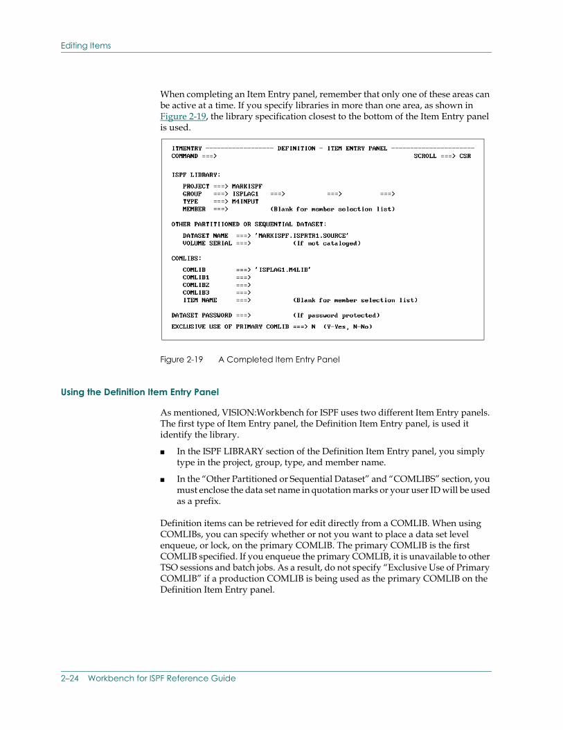
When completing an Item Entry panel, remember that only one of these areas can be active at a time. If you specify libraries in more than one area, as shown in Figure 2-19, the library specification closest to the bottom of the Item Entry panel is used.
Figure 2-19 A Completed Item Entry Panel
Using the Definition Item Entry Panel
As mentioned, VISION:Workbench for ISPF uses two different Item Entry panels. The first type of Item Entry panel, the Definition Item Entry panel, is used it identify the library.
■ In the ISPF LIBRARY section of the Definition Item Entry panel, you simply type in the project, group, type, and member name.
■ In the “Other Partitioned or Sequential Dataset” and “COMLIBS” section, you must enclose the data set name in quotation marks or your user ID will be used as a prefix.
Definition items can be retrieved for edit directly from a COMLIB. When using COMLIBs, you can specify whether or not you want to place a data set level enqueue, or lock, on the primary COMLIB. The primary COMLIB is the first COMLIB specified. If you enqueue the primary COMLIB, it is unavailable to other TSO sessions and batch jobs. As a result, do not specify “Exclusive Use of Primary COMLIB” if a production COMLIB is being used as the primary COMLIB on the Definition Item Entry panel.
2–24 Workbench for ISPF Reference Guide
Editing Items
Using the Application Item Entry Panel
The second type of Item Entry panel, the Application Item Entry panel, is used to edit application items.
Application items (which include screen definitions, requests and procedures) can only be retrieved from a partitioned or sequential data set. They cannot be retrieved directly from a COMLIB. To edit a cataloged application item such as a screen definition or request, use the VISION:Workbench for ISPF Utilities subsystem source statement retrieval option to retrieve the item and store it in a partitioned or sequential data set. You can then edit the retrieved source from that data set. Please see Using the Utilities Subsystem on page 2-70, Using the Utilities Subsystem, for additional information.
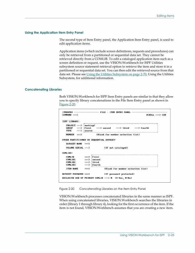
Concatenating Libraries
Both VISION:Workbench for ISPF Item Entry panels are similar in that they allow you to specify library concatenations in the File Item Entry panel as shown in Figure 2-20.
Figure 2-20 Concatenating Libraries on the Item Entry Panel
VISION:Workbench processes concatenated libraries in the same manner as ISPF. When using concatenated libraries, VISION:Workbench searches the libraries in order (library 1 through library 4), looking for the first occurrence of the item. If the item is not found, VISION:Workbench assumes that you are creating a new item.
Using VISION:Workbench for ISPF 2–25
Editing Items
Unless specifically overridden on the Save panel, VISION:Workbench for ISPF always writes the item out to the first or primary library in the specified Item Entry concatenation sequence. This is true even if the item was retrieved from another library.
Library Considerations
The following sections discuss considerations relevant to each of the library types: partitioned data set (PDS), sequential data set, and COMLIB.
Partitioned Data Set Considerations (PDS)
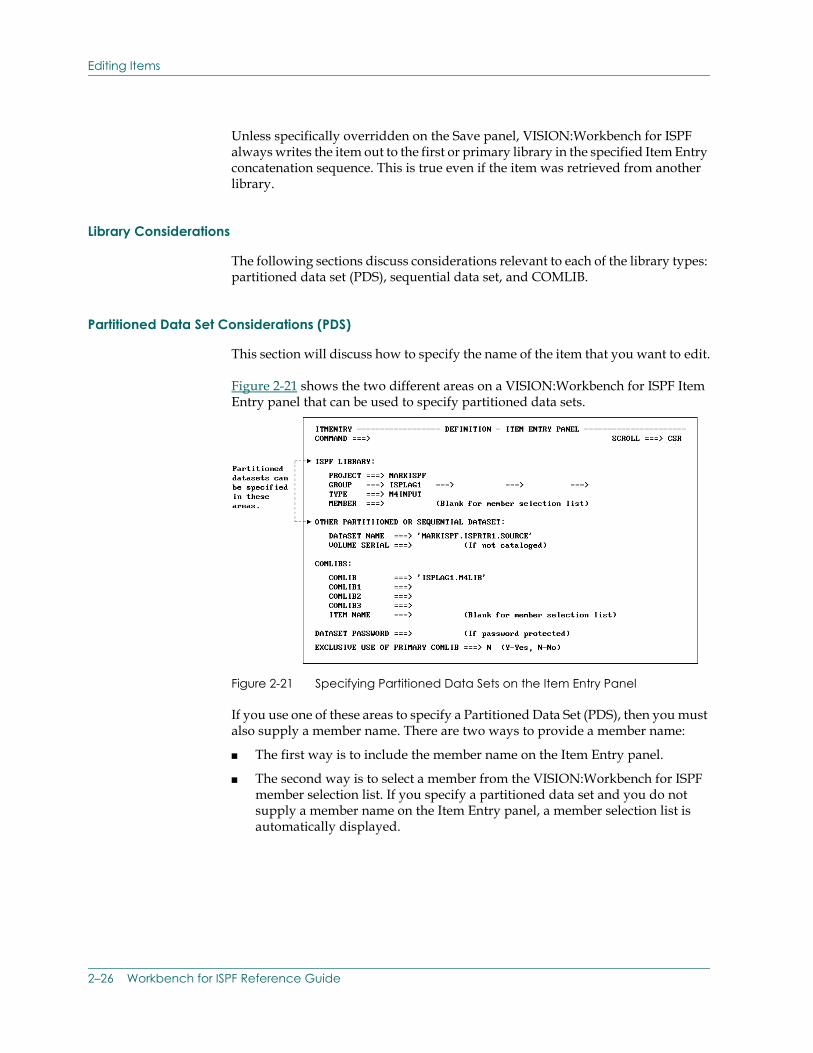
This section will discuss how to specify the name of the item that you want to edit.
Figure 2-21 shows the two different areas on a VISION:Workbench for ISPF Item Entry panel that can be used to specify partitioned data sets.
Figure 2-21 Specifying Partitioned Data Sets on the Item Entry Panel
If you use one of these areas to specify a Partitioned Data Set (PDS), then you must also supply a member name. There are two ways to provide a member name:
■ The first way is to include the member name on the Item Entry panel.
■ The second way is to select a member from the VISION:Workbench for ISPF member selection list. If you specify a partitioned data set and you do not supply a member name on the Item Entry panel, a member selection list is automatically displayed.
2–26 Workbench for ISPF Reference Guide
Editing Items
When specifying member names, VISION:Workbench for ISPF requires that the specified member name be identical to the member's item name. In other words, when editing an existing member from a partitioned data set, the specified member name must be identical to the item name that is specified in the first eight positions of the item's run control information. If these two names are not identical, VISION:Workbench for ISPF automatically changes the item name specified in the run control source to match the specified member name when the item is saved.
If you are creating a new item, you can choose any member name that does not already exist in the specified item entry source libraries. When the new item is saved, the specified member name is used as the item name in the generated run control information.
Sequential Data Set Considerations
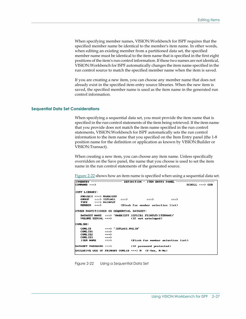
When specifying a sequential data set, you must provide the item name that is specified in the run control statements of the item being retrieved. If the item name that you provide does not match the item name specified in the run control statements, VISION:Workbench for ISPF automatically sets the run control information to the item name that you specified on the Item Entry panel (the 1-8 position name for the definition or application as known by VISION:Builder or VISION:Transact).
When creating a new item, you can choose any item name. Unless specifically overridden on the Save panel, the name that you choose is used to set the item name in the run control statements of the generated source.
Figure 2-22 shows how an item name is specified when using a sequential data set.
Figure 2-22 Using a Sequential Data Set
Using VISION:Workbench for ISPF 2–27
Editing Items
The item name is specified in the same way that the member name is specified for a partitioned data set.
COMLIB Considerations
When specifying a COMLIB as your source library, you must also specify an item name. There are two ways to specify an item name.
■ The first way is to include the item name on the Item Entry panel.
■ The second way is to select an item from the VISION:Workbench for ISPF Item Selection List. If you specify a COMLIB and you do not supply an item name on the Item Entry panel, an Item Selection List is automatically displayed.
When specifying item names, VISION:Workbench for ISPF requires that the specified item name be identical to the item name that is specified in the item's run control information. If these two names are not identical VISION:Workbench for ISPF automatically sets the item name in the run control statements to match the item name specified on Item Entry panel or Selection List when the item is saved.
When creating a new item, you can choose any item name that does not already exist in the specified COMLIB(s). When the new item is saved, the name that you have specified is used to set the item name in the item's run control statements.
Item Selection Lists
For simplicity, the term “Item Name” is used throughout this guide to refer to both member name entry (partitioned data set) and item name entry (sequential data set and COMLIBs).
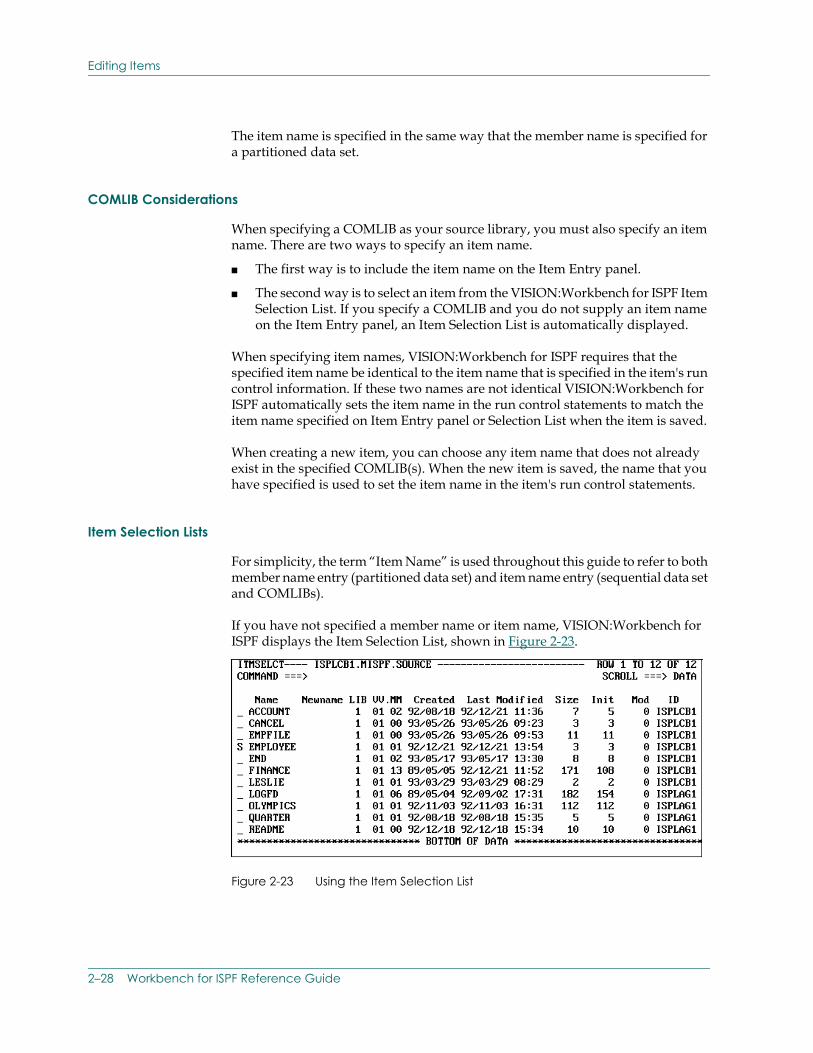
If you have not specified a member name or item name, VISION:Workbench for ISPF displays the Item Selection List, shown in Figure 2-23.
Figure 2-23 Using the Item Selection List
2–28 Workbench for ISPF Reference Guide
Editing Items
The VISION:Workbench for ISPF Item Selection List works in a manner very similar to the standard ISPF member selection list. To view this list, leave the item name blank on the Item Entry panel and press the Enter key.
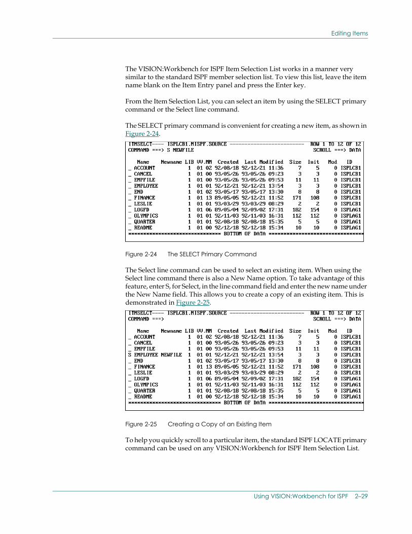
From the Item Selection List, you can select an item by using the SELECT primary command or the Select line command.
The SELECT primary command is convenient for creating a new item, as shown in Figure 2-24.
Figure 2-24 The SELECT Primary Command
The Select line command can be used to select an existing item. When using the Select line command there is also a New Name option. To take advantage of this feature, enter S, for Select, in the line command field and enter the new name under the New Name field. This allows you to create a copy of an existing item. This is demonstrated in Figure 2-25.
Figure 2-25 Creating a Copy of an Existing Item
To help you quickly scroll to a particular item, the standard ISPF LOCATE primary command can be used on any VISION:Workbench for ISPF Item Selection List.
Using VISION:Workbench for ISPF 2–29
Editing Items
Once you have completed the appropriate Item Entry panel by specifying your source data sets and item name, VISION:Workbench for ISPF can proceed with the import process. During the import process, VISION:Workbench for ISPF loads the specified item into VISION:Workbench for ISPF internal tables. These tables are used to display the item in a structured, hierarchical manner.
Step 3.: Specify Validation Libraries (VISION:Builder only)
Step 3. of the VISION:Workbench for ISPF edit process only applies to VISION:Builder applications. This step is automatically bypassed for all other item types.
The validation library step allows you to concatenate up to four validation COMLIBs. If you specify validation libraries on this panel and enter a Y in the “Names Validation On?” entry, information from these libraries is used during your edit session to assist in interactive validation of your entries. This enables VISION:Workbench for ISPF to perform a more thorough validation during your edit session.
Keep in mind that if the Specify Validation Libraries panel is displayed and the entries are left blank, you cannot perform a global validation of your application. The term “global validation” is explained during the discussion on Step 5 of the edit process.
2–30 Workbench for ISPF Reference Guide
Editing Items
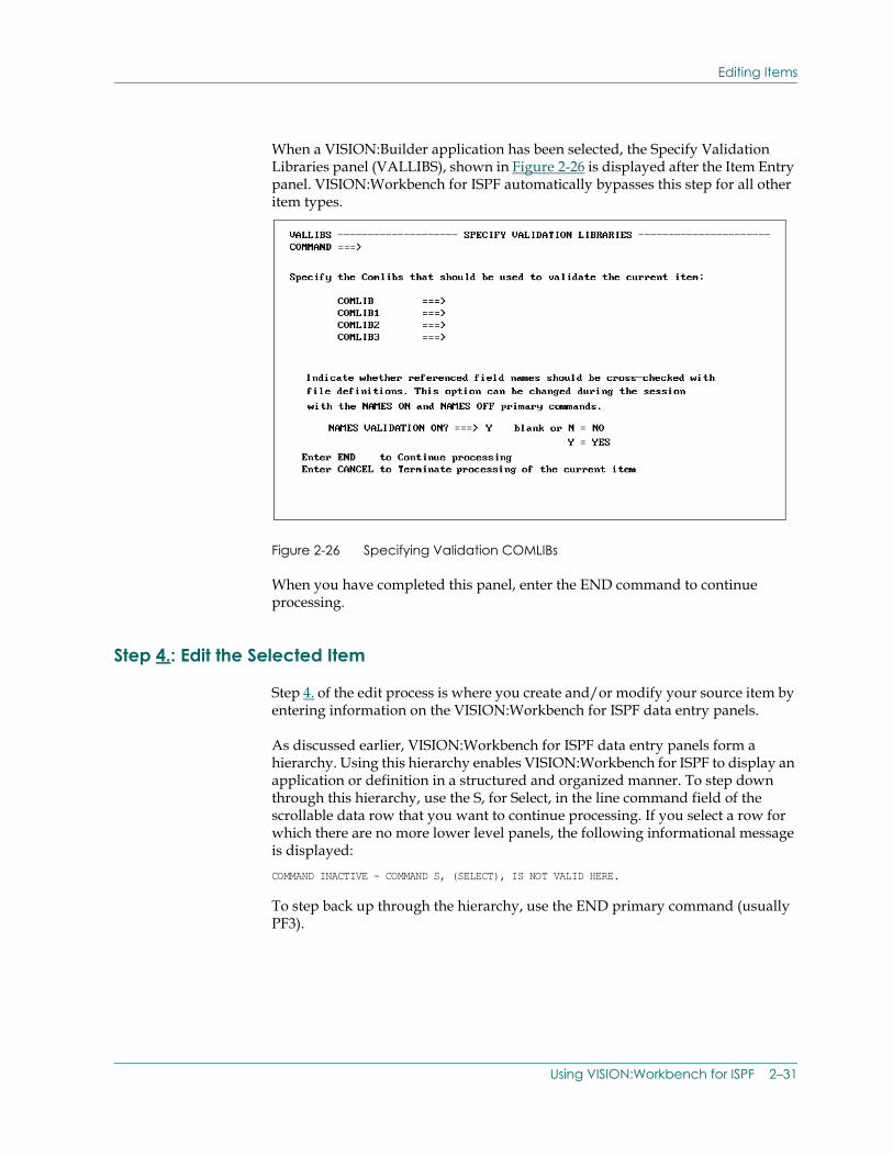
When a VISION:Builder application has been selected, the Specify Validation Libraries panel (VALLIBS), shown in Figure 2-26 is displayed after the Item Entry panel. VISION:Workbench for ISPF automatically bypasses this step for all other item types.
Figure 2-26 Specifying Validation COMLIBs
When you have completed this panel, enter the END command to continue processing.
Step 4.: Edit the Selected Item
Step 4. of the edit process is where you create and/or modify your source item by entering information on the VISION:Workbench for ISPF data entry panels.
As discussed earlier, VISION:Workbench for ISPF data entry panels form a hierarchy. Using this hierarchy enables VISION:Workbench for ISPF to display an application or definition in a structured and organized manner. To step down through this hierarchy, use the S, for Select, in the line command field of the scrollable data row that you want to continue processing. If you select a row for which there are no more lower level panels, the following informational message is displayed: COMMAND INACTIVE - COMMAND S, (SELECT), IS NOT VALID HERE.
To step back up through the hierarchy, use the END primary command (usually PF3).
Using VISION:Workbench for ISPF 2–31
Editing Items
Whenever you are uncertain about how to complete a data entry panel, remember to use the interactive Help facility. You can request Help for the entire screen using the HELP primary command or for a particular field by entering “?” in the first byte of the field in question.
Field Name Validation (VISION:Builder only)
Field name validation is the process of searching the COMLIBs entered on the list of validation libraries for fields referenced in your application. If the referenced field is not found in the appropriate file or array definition in one of the validation libraries, an error message is issued. This type of validation is done for the following fields:
■ Output field name in traditional (non-ASL) requests.
■ Operands A, B, and C in traditional requests when the corresponding qualifier refers to one of the following file usages: M4NEW, M4OLD, M4TRAN, M4CORDn, ARRAYn, or ARRAYx.
There are three ways to turn off name validation:
1. You can enter an N in the “Names Validation On?” entry on the application validation panel. See Figure 2-26.
2. The NAMES ON and NAMES OFF primary commands can be used to turn names validation on and off during the application edit session. These commands can be used as many times as needed to toggle the status of name validation during the edit session. The NAMES OFF command does not affect global validation (discussed in Step 5.).
3. While names validation is active, you can enter P, for Pass line command, to force VISION:Workbench for ISPF to recognize an undefined field name as valid for the duration of the session. However, if the application contains numerous undefined fields, it may be necessary to use the NAMES OFF command in order to continue the edit session.
Regardless of whether names validation is on or off, VISION:Workbench for ISPF always prevents you from entering invalid flag names in traditional (non-ASL) requests. (To get a list of valid VISION:Builder flags, enter the NAMES F primary command.)
2–32 Workbench for ISPF Reference Guide
Editing Items
Duplicate Entry Checking (VISION:Builder only)
VISION:Workbench for ISPF also checks for invalid duplicate entries during an application edit session. Fields which are checked for invalid duplicate entries include array field names, field names within file definitions, request output numbers, request names, temporary field names, report sort sequences, file usages, and file segment names. Temporary field name validations do not take cataloged requests or ASL procedures into account when searching for duplicate names. However, these are taken into account during the global validation at the end of a VISION:Workbench for ISPF session.
You can prevent VISION:Workbench for ISPF from checking for invalid duplicate entries any time during your application edit session by using the DUP OFF primary command. The DUP ON primary command can be used to reactivate the duplicate checking. Each VISION:Workbench for ISPF session begins with duplicate checking ON.
Step 5.: Validate the Item
Step 5. of the edit process does not apply to procedures, requests, and screens. If you are editing one of these item types, this step is automatically bypassed.
The validation step is invoked at the end of your edit session. This step gives you the opportunity to request a global validation of the item you are editing. The following describes how validation is performed for various items:
■ For definition items, global validation is performed by invoking the COMLIB to validate the entire definition.
■ For VISION:Builder applications, global validation is performed by invoking a VISION:Builder scan run.
■ For VISION:Transact applications, global validation is performed by invoking an actual VISION:Transact APPGEN run.
During these validation runs, the entire item is checked not only for valid syntax, but for consistency among all associated entries across the entire item.
After the global validation has completed, you can browse the output generated during the validation processing. When browsing this listing, you can use the ISPF SCROLL RIGHT, LEFT, UP, and DOWN primary commands to examine the entire listing. You can also use the ISPF FIND primary command to look for specific character strings within the listing.
Using VISION:Workbench for ISPF 2–33
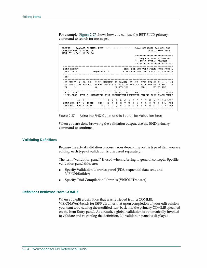
Editing Items
For example, Figure 2-27 shows how you can use the ISPF FIND primary command to search for messages.
Figure 2-27 Using the FIND Command to Search for Validation Errors
When you are done browsing the validation output, use the END primary command to continue.
Validating Definitions
Because the actual validation process varies depending on the type of item you are editing, each type of validation is discussed separately.
The term “validation panel” is used when referring to general concepts. Specific validation panel titles are:
■ Specify Validation Libraries panel (PDS, sequential data sets, and VISION:Builder)
■ Specify Trial Compilation Libraries (VISION:Transact)
Definitions Retrieved From COMLIB
When you edit a definition that was retrieved from a COMLIB, VISION:Workbench for ISPF assumes that upon completion of your edit session you want to re-catalog the modified item back into the primary COMLIB specified on the Item Entry panel. As a result, a global validation is automatically invoked to validate and re-catalog the definition. No validation panel is displayed.
2–34 Workbench for ISPF Reference Guide
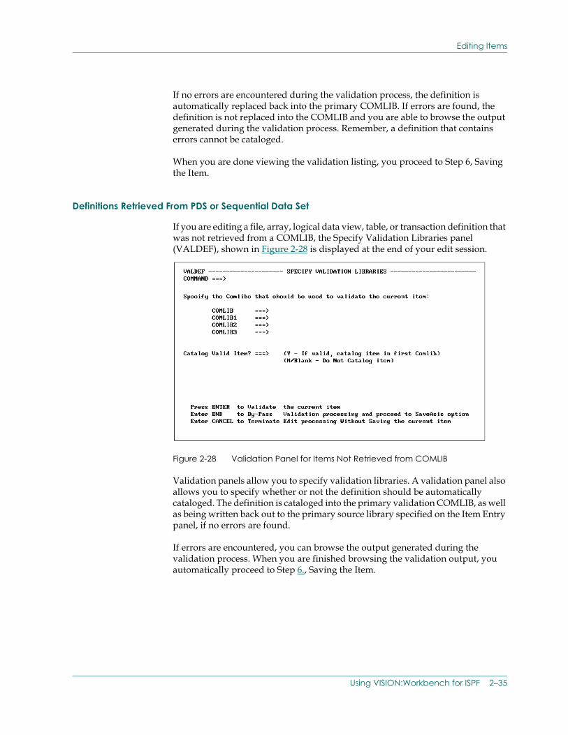
Editing Items
If no errors are encountered during the validation process, the definition is automatically replaced back into the primary COMLIB. If errors are found, the definition is not replaced into the COMLIB and you are able to browse the output generated during the validation process. Remember, a definition that contains errors cannot be cataloged.
When you are done viewing the validation listing, you proceed to Step 6, Saving the Item.
Definitions Retrieved From PDS or Sequential Data Set
If you are editing a file, array, logical data view, table, or transaction definition that was not retrieved from a COMLIB, the Specify Validation Libraries panel (VALDEF), shown in Figure 2-28 is displayed at the end of your edit session.
Figure 2-28 Validation Panel for Items Not Retrieved from COMLIB
Validation panels allow you to specify validation libraries. A validation panel also allows you to specify whether or not the definition should be automatically cataloged. The definition is cataloged into the primary validation COMLIB, as well as being written back out to the primary source library specified on the Item Entry panel, if no errors are found.
If errors are encountered, you can browse the output generated during the validation process. When you are finished browsing the validation output, you automatically proceed to Step 6., Saving the Item.
Using VISION:Workbench for ISPF 2–35
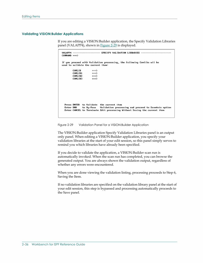
Editing Items
Validating VISION:Builder Applications
If you are editing a VISION:Builder application, the Specify Validation Libraries panel (VALAPP4), shown in Figure 2-29 is displayed.
Figure 2-29 Validation Panel for a VISION:Builder Application
The VISION:Builder application Specify Validation Libraries panel is an output only panel. When editing a VISION:Builder application, you specify your validation libraries at the start of your edit session, so this panel simply serves to remind you which libraries have already been specified.
If you decide to validate the application, a VISION:Builder scan run is automatically invoked. When the scan run has completed, you can browse the generated output. You are always shown the validation output, regardless of whether any errors were encountered.
When you are done viewing the validation listing, processing proceeds to Step 6, Saving the Item.
If no validation libraries are specified on the validation library panel at the start of your edit session, this step is bypassed and processing automatically proceeds to the Save panel.
2–36 Workbench for ISPF Reference Guide
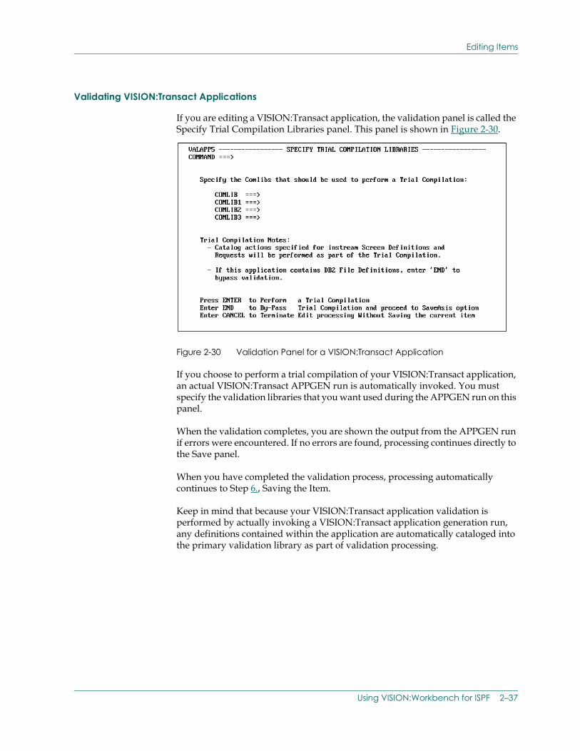
Editing Items
Validating VISION:Transact Applications
If you are editing a VISION:Transact application, the validation panel is called the Specify Trial Compilation Libraries panel. This panel is shown in Figure 2-30.
Figure 2-30 Validation Panel for a VISION:Transact Application
If you choose to perform a trial compilation of your VISION:Transact application, an actual VISION:Transact APPGEN run is automatically invoked. You must specify the validation libraries that you want used during the APPGEN run on this panel.
When the validation completes, you are shown the output from the APPGEN run if errors were encountered. If no errors are found, processing continues directly to the Save panel.
When you have completed the validation process, processing automatically continues to Step 6., Saving the Item.
Keep in mind that because your VISION:Transact application validation is performed by actually invoking a VISION:Transact application generation run, any definitions contained within the application are automatically cataloged into the primary validation library as part of validation processing.
Using VISION:Workbench for ISPF 2–37
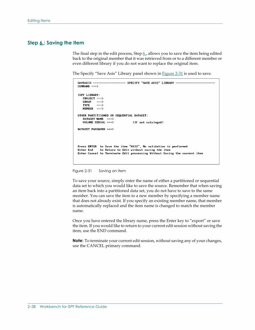
Editing Items
Step 6.: Saving the Item
The final step in the edit process, Step 6., allows you to save the item being edited back to the original member that it was retrieved from or to a different member or even different library if you do not want to replace the original item.
The Specify “Save Asis” Library panel shown in Figure 2-31 is used to save.
Figure 2-31 Saving an Item
To save your source, simply enter the name of either a partitioned or sequential data set to which you would like to save the source. Remember that when saving an item back into a partitioned data set, you do not have to save to the same member. You can save the item to a new member by specifying a member name that does not already exist. If you specify an existing member name, that member is automatically replaced and the item name is changed to match the member name.
Once you have entered the library name, press the Enter key to “export” or save the item. If you would like to return to your current edit session without saving the item, use the END command.
Note: To terminate your current edit session, without saving any of your changes, use the CANCEL primary command.
2–38 Workbench for ISPF Reference Guide
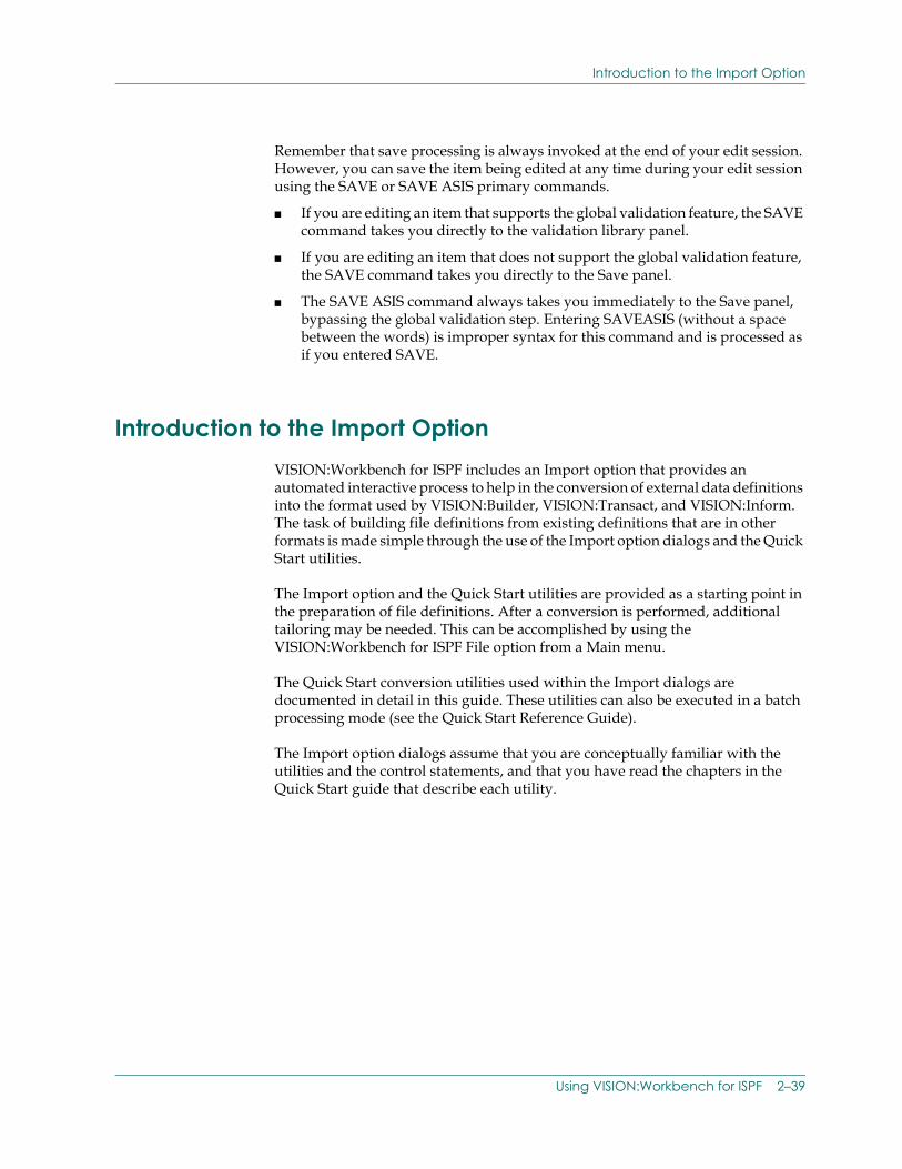
Introduction to the Import Option
Remember that save processing is always invoked at the end of your edit session. However, you can save the item being edited at any time during your edit session using the SAVE or SAVE ASIS primary commands.
■ If you are editing an item that supports the global validation feature, the SAVE command takes you directly to the validation library panel.
■ If you are editing an item that does not support the global validation feature, the SAVE command takes you directly to the Save panel.
■ The SAVE ASIS command always takes you immediately to the Save panel, bypassing the global validation step. Entering SAVEASIS (without a space between the words) is improper syntax for this command and is processed as if you entered SAVE.
Introduction to the Import OptionVISION:Workbench for ISPF includes an Import option that provides an automated interactive process to help in the conversion of external data definitions into the format used by VISION:Builder, VISION:Transact, and VISION:Inform. The task of building file definitions from existing definitions that are in other formats is made simple through the use of the Import option dialogs and the Quick Start utilities.
The Import option and the Quick Start utilities are provided as a starting point in the preparation of file definitions. After a conversion is performed, additional tailoring may be needed. This can be accomplished by using the VISION:Workbench for ISPF File option from a Main menu.
The Quick Start conversion utilities used within the Import dialogs are documented in detail in this guide. These utilities can also be executed in a batch processing mode (see the Quick Start Reference Guide).
The Import option dialogs assume that you are conceptually familiar with the utilities and the control statements, and that you have read the chapters in the Quick Start guide that describe each utility.
Using VISION:Workbench for ISPF 2–39
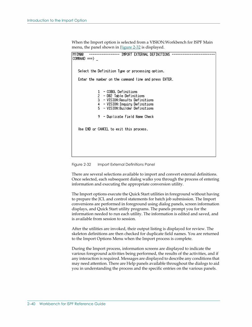
Introduction to the Import Option
When the Import option is selected from a VISION:Workbench for ISPF Main menu, the panel shown in Figure 2-32 is displayed.
Figure 2-32 Import External Definitions Panel
There are several selections available to import and convert external definitions. Once selected, each subsequent dialog walks you through the process of entering information and executing the appropriate conversion utility.
The Import options execute the Quick Start utilities in foreground without having to prepare the JCL and control statements for batch job submission. The Import conversions are performed in foreground using dialog panels, screen information displays, and Quick Start utility programs. The panels prompt you for the information needed to run each utility. The information is edited and saved, and is available from session to session.
After the utilities are invoked, their output listing is displayed for review. The skeleton definitions are then checked for duplicate field names. You are returned to the Import Options Menu when the Import process is complete.
During the Import process, information screens are displayed to indicate the various foreground activities being performed, the results of the activities, and if any interaction is required. Messages are displayed to describe any conditions that may need attention. There are Help panels available throughout the dialogs to aid you in understanding the process and the specific entries on the various panels.
2–40 Workbench for ISPF Reference Guide
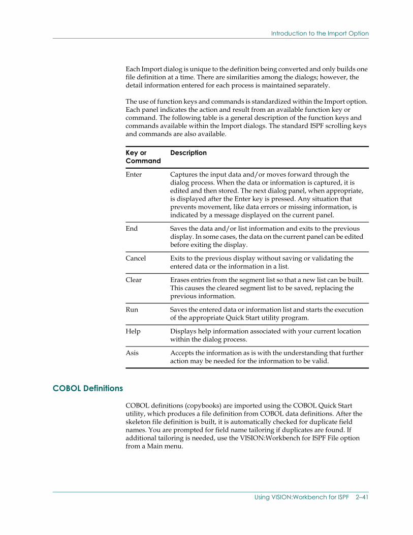
Introduction to the Import Option
Each Import dialog is unique to the definition being converted and only builds one file definition at a time. There are similarities among the dialogs; however, the detail information entered for each process is maintained separately.
The use of function keys and commands is standardized within the Import option. Each panel indicates the action and result from an available function key or command. The following table is a general description of the function keys and commands available within the Import dialogs. The standard ISPF scrolling keys and commands are also available.
COBOL Definitions
COBOL definitions (copybooks) are imported using the COBOL Quick Start utility, which produces a file definition from COBOL data definitions. After the skeleton file definition is built, it is automatically checked for duplicate field names. You are prompted for field name tailoring if duplicates are found. If additional tailoring is needed, use the VISION:Workbench for ISPF File option from a Main menu.
Key or Command
Description
Enter Captures the input data and/or moves forward through the dialog process. When the data or information is captured, it is edited and then stored. The next dialog panel, when appropriate, is displayed after the Enter key is pressed. Any situation that prevents movement, like data errors or missing information, is indicated by a message displayed on the current panel.
End Saves the data and/or list information and exits to the previous display. In some cases, the data on the current panel can be edited before exiting the display.
Cancel Exits to the previous display without saving or validating the entered data or the information in a list.
Clear Erases entries from the segment list so that a new list can be built. This causes the cleared segment list to be saved, replacing the previous information.
Run Saves the entered data or information list and starts the execution of the appropriate Quick Start utility program.
Help Displays help information associated with your current location within the dialog process.
Asis Accepts the information as is with the understanding that further action may be needed for the information to be valid.
Using VISION:Workbench for ISPF 2–41
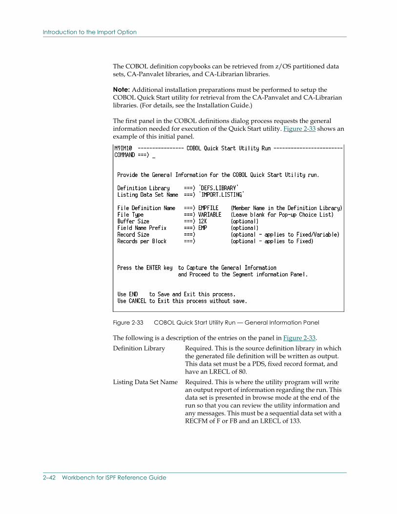
Introduction to the Import Option
The COBOL definition copybooks can be retrieved from z/OS partitioned data sets, CA-Panvalet libraries, and CA-Librarian libraries.
Note: Additional installation preparations must be performed to setup the COBOL Quick Start utility for retrieval from the CA-Panvalet and CA-Librarian libraries. (For details, see the Installation Guide.)
The first panel in the COBOL definitions dialog process requests the general information needed for execution of the Quick Start utility. Figure 2-33 shows an example of this initial panel.
Figure 2-33 COBOL Quick Start Utility Run — General Information Panel
The following is a description of the entries on the panel in Figure 2-33.Definition Library Required. This is the source definition library in which
the generated file definition will be written as output. This data set must be a PDS, fixed record format, and have an LRECL of 80.
Listing Data Set Name Required. This is where the utility program will write an output report of information regarding the run. This data set is presented in browse mode at the end of the run so that you can review the utility information and any messages. This must be a sequential data set with a RECFM of F or FB and an LRECL of 133.
2–42 Workbench for ISPF Reference Guide
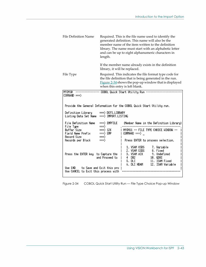
Introduction to the Import Option
Figure 2-34 COBOL Quick Start Utility Run — File Type Choice Pop-up Window
File Definition Name Required. This is the file name used to identify the generated definition. This name will also be the member name of the item written to the definition library. The name must start with an alphabetic letter and can be up to eight alphanumeric characters in length.
If the member name already exists in the definition library, it will be replaced.
File Type Required. This indicates the file format type code for the file definition that is being generated in the run. Figure 2-34 shows the pop-up window that is displayed when this entry is left blank.
Using VISION:Workbench for ISPF 2–43
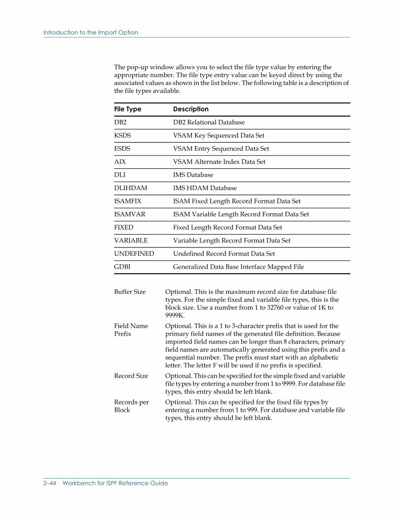
Introduction to the Import Option
The pop-up window allows you to select the file type value by entering the appropriate number. The file type entry value can be keyed direct by using the associated values as shown in the list below. The following table is a description of the file types available.
File Type Description
DB2 DB2 Relational Database
KSDS VSAM Key Sequenced Data Set
ESDS VSAM Entry Sequenced Data Set
AIX VSAM Alternate Index Data Set
DLI IMS Database
DLIHDAM IMS HDAM Database
ISAMFIX ISAM Fixed Length Record Format Data Set
ISAMVAR ISAM Variable Length Record Format Data Set
FIXED Fixed Length Record Format Data Set
VARIABLE Variable Length Record Format Data Set
UNDEFINED Undefined Record Format Data Set
GDBI Generalized Data Base Interface Mapped File
Buffer Size Optional. This is the maximum record size for database file types. For the simple fixed and variable file types, this is the block size. Use a number from 1 to 32760 or value of 1K to 9999K.
Field Name Prefix
Optional. This is a 1 to 3-character prefix that is used for the primary field names of the generated file definition. Because imported field names can be longer than 8 characters, primary field names are automatically generated using this prefix and a sequential number. The prefix must start with an alphabetic letter. The letter F will be used if no prefix is specified.
Record Size Optional. This can be specified for the simple fixed and variable file types by entering a number from 1 to 9999. For database file types, this entry should be left blank.
Records per Block
Optional. This can be specified for the fixed file types by entering a number from 1 to 999. For database and variable file types, this entry should be left blank.
2–44 Workbench for ISPF Reference Guide
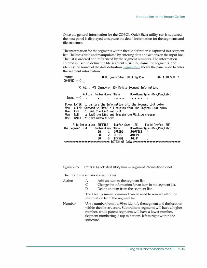
Introduction to the Import Option
Once the general information for the COBOL Quick Start utility run is captured, the next panel is displayed to capture the detail information for the segments and file structure.
The information for the segments within the file definition is captured in a segment list. The list is built and manipulated by entering data and actions on the input line. The list is ordered and referenced by the segment numbers. The information entered is used to define the file segment structure, name the segments, and identify the source of the data definition. Figure 2-35 shows the panel used to enter the segment information.
Figure 2-35 COBOL Quick Start Utility Run — Segment Information Panel
The Input line entries are as follows:Action A Add an item to the segment list.
C Change the information for an item in the segment list.D Delete an item from the segment list.The Clear primary command can be used to remove all of the information from the segment list.
Number Use a number from 1 to 99 to identify the segment and the location within the file structure. Subordinate segments will have a higher number, while parent segments will have a lower number. Segment numbering is top to bottom, left to right within the structure.
Using VISION:Workbench for ISPF 2–45
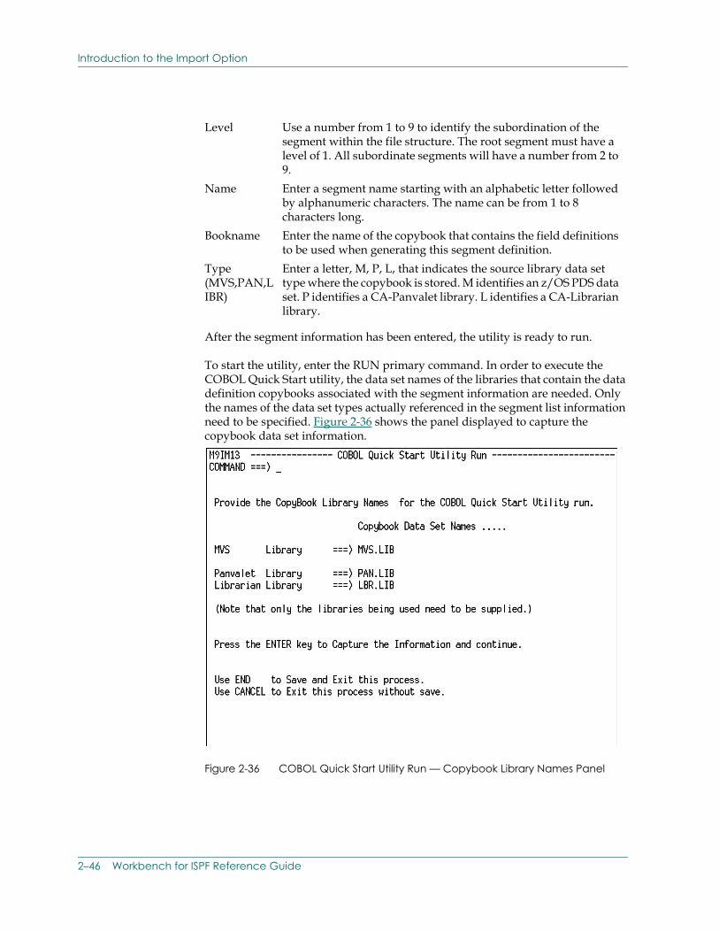
Introduction to the Import Option
After the segment information has been entered, the utility is ready to run.
To start the utility, enter the RUN primary command. In order to execute the COBOL Quick Start utility, the data set names of the libraries that contain the data definition copybooks associated with the segment information are needed. Only the names of the data set types actually referenced in the segment list information need to be specified. Figure 2-36 shows the panel displayed to capture the copybook data set information.
Figure 2-36 COBOL Quick Start Utility Run — Copybook Library Names Panel
Level Use a number from 1 to 9 to identify the subordination of the segment within the file structure. The root segment must have a level of 1. All subordinate segments will have a number from 2 to 9.
Name Enter a segment name starting with an alphabetic letter followed by alphanumeric characters. The name can be from 1 to 8 characters long.
Bookname Enter the name of the copybook that contains the field definitions to be used when generating this segment definition.
Type (MVS,PAN,LIBR)
Enter a letter, M, P, L, that indicates the source library data set type where the copybook is stored. M identifies an z/OS PDS data set. P identifies a CA-Panvalet library. L identifies a CA-Librarian library.
2–46 Workbench for ISPF Reference Guide
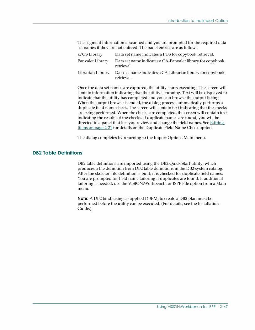
Introduction to the Import Option
The segment information is scanned and you are prompted for the required data set names if they are not entered. The panel entries are as follows.
Once the data set names are captured, the utility starts executing. The screen will contain information indicating that the utility is running. Text will be displayed to indicate that the utility has completed and you can browse the output listing. When the output browse is ended, the dialog process automatically performs a duplicate field name check. The screen will contain text indicating that the checks are being performed. When the checks are completed, the screen will contain text indicating the results of the checks. If duplicate names are found, you will be directed to a panel that lets you review and change the field names. See Editing Items on page 2-21 for details on the Duplicate Field Name Check option.
The dialog completes by returning to the Import Options Main menu.
DB2 Table Definitions
DB2 table definitions are imported using the DB2 Quick Start utility, which produces a file definition from DB2 table definitions in the DB2 system catalog. After the skeleton file definition is built, it is checked for duplicate field names. You are prompted for field name tailoring if duplicates are found. If additional tailoring is needed, use the VISION:Workbench for ISPF File option from a Main menu.
Note: A DB2 bind, using a supplied DBRM, to create a DB2 plan must be performed before the utility can be executed. (For details, see the Installation Guide.)
z/OS Library Data set name indicates a PDS for copybook retrieval.Panvalet Library Data set name indicates a CA-Panvalet library for copybook
retrieval.Librarian Library Data set name indicates a CA-Librarian library for copybook
retrieval.
Using VISION:Workbench for ISPF 2–47
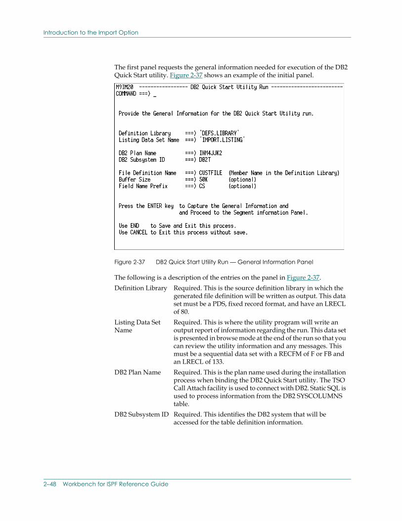
Introduction to the Import Option
The first panel requests the general information needed for execution of the DB2 Quick Start utility. Figure 2-37 shows an example of the initial panel.
Figure 2-37 DB2 Quick Start Utility Run — General Information Panel
The following is a description of the entries on the panel in Figure 2-37.Definition Library Required. This is the source definition library in which the
generated file definition will be written as output. This data set must be a PDS, fixed record format, and have an LRECL of 80.
Listing Data Set Name
Required. This is where the utility program will write an output report of information regarding the run. This data set is presented in browse mode at the end of the run so that you can review the utility information and any messages. This must be a sequential data set with a RECFM of F or FB and an LRECL of 133.
DB2 Plan Name Required. This is the plan name used during the installation process when binding the DB2 Quick Start utility. The TSO Call Attach facility is used to connect with DB2. Static SQL is used to process information from the DB2 SYSCOLUMNS table.
DB2 Subsystem ID Required. This identifies the DB2 system that will be accessed for the table definition information.
2–48 Workbench for ISPF Reference Guide

Introduction to the Import Option
Once the general information for the DB2 Quick Start utility run is captured, the next panel is displayed to capture the detail information for the segments and file structure.
The information for the segments within the file definition is captured in a segment list. The list is built and manipulated by entering data and actions on the input line. The list is ordered and referenced by the segment numbers. The information entered is used to define the file segment structure, name the segments, and identify the source of the data definition. Figure 2-38 shows the panel used to enter the segment information.
File Definition Name
Required. This is the file name used to identify the generated definition. This name will also be the member name of the item written to the definition library. The name must start with an alphabetic letter and can be up to eight alphanumeric characters in length.If the member name already exists in the definition library, it will be replaced.
Buffer Size Optional. This defines the size of the buffer needed to hold the maximum logical record. Use a number from 1 to 32760 or value of 1K to 9999K.
Field Name Prefix Optional. This is a 1 to 3-character prefix that is used for the primary field names of the generated file definition. Because the DB2 column names can be longer that 8 characters, primary field names are automatically generated using this prefix and a sequential number. The prefix must start with an alphabetic letter. The letter F will be used if no prefix is specified.
Using VISION:Workbench for ISPF 2–49
Introduction to the Import Option
Figure 2-38 DB2 Quick Start Utility Run — Segment Information Panel
The Input line entries are as follows:Action A Add an item to the list.
C Change the information for an item in the list.D Delete an item from the list.The Clear primary command can be used to remove all of the information from the segment list.
Number Use a number from 1 to 99 to identify the segment and the location within the file structure. Subordinate segments will have a higher number, while parent segments will have a lower number. Segment numbering is top to bottom, left to right within the structure.
Level Use a number from 1 to 9 to identify the subordination of the segment within the file structure. The root segment must have a level of 1. All subordinate segments will have a number from 2 to 9.
Name Enter a segment name starting with an alphabetic letter followed by alphanumeric characters. The name can be from 1 to 8 characters long.
DB2Table Name
Enter the name of the DB2 table that contains the column information to be used when generating the segment field definitions.
Creator Enter the authorization ID, creator ID, or an asterisk (*) to qualify the DB2 table name being accessed for field information. An asterisk (*) retrieves field information from all tables with the specified name.
2–50 Workbench for ISPF Reference Guide
Introduction to the Import Option
After the segment information has been entered, the utility is ready to run.
The utility will access the DB2 SYSCOLUMNS table and extract the column information for referenced tables in the segment list information.
Once the segment information is captured, enter the RUN primary command to start executing the utility. The screen will contain information indicating that the utility is running. Text will be displayed to indicate that the utility has completed and you can browse the output listing. When the output browse is ended, the dialog process automatically performs a duplicate field name check. The screen will contain text indicating that the checks are being performed. When the checks are completed, the screen will contain text indicating the results of the checks. If duplicate names are found, you will be directed to a panel that lets you review and change the field names. See Editing Items on page 2-21 for details on the Duplicate Field Name Check option.
The dialog completes by returning to the Import Options Main menu.
VISION:Results Definitions
VISION:Results™ definitions are imported using the VISION:Results Quick Start utility, which produces a file definition from a VISION:Results file definition. After the skeleton file definition is built, it is checked for duplicate field names. You are prompted for field name tailoring if duplicates are found. If additional tailoring is needed, use the VISION:Workbench for ISPF File option from a Main menu.
The VISION:Results definitions can be retrieved from z/OS Partitioned Data Sets, CA-Panvalet libraries, and CA-Librarian libraries.
Note: Additional installation preparations must be performed to setup the VISION:Results Quick Start utility for retrieval from the CA-Panvalet and CA-Librarian libraries. (For details, see the Installation Guide.)
Using VISION:Workbench for ISPF 2–51
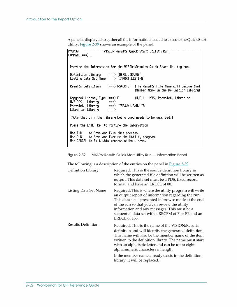
Introduction to the Import Option
A panel is displayed to gather all the information needed to execute the Quick Start utility. Figure 2-39 shows an example of the panel.
Figure 2-39 VISION:Results Quick Start Utility Run — Information Panel
The following is a description of the entries on the panel in Figure 2-39.Definition Library Required. This is the source definition library in
which the generated file definition will be written as output. This data set must be a PDS, fixed record format, and have an LRECL of 80.
Listing Data Set Name Required. This is where the utility program will write an output report of information regarding the run. This data set is presented in browse mode at the end of the run so that you can review the utility information and any messages. This must be a sequential data set with a RECFM of F or FB and an LRECL of 133.
Results Definition Required. This is the name of the VISION:Results definition and will identify the generated definition. This name will also be the member name of the item written to the definition library. The name must start with an alphabetic letter and can be up to eight alphanumeric characters in length.If the member name already exists in the definition library, it will be replaced.
2–52 Workbench for ISPF Reference Guide
Introduction to the Import Option
The information on the panel is scanned and you are prompted for the required copybook data set names if they are not entered.
Copybook Library Type Enter a letter, M, P, L, to indicate the source library data set type where the Results definition is stored.
M indicates that the copybook is stored in a z/OS PDS data set.
P indicates that the copybook is stored in a CA-Panvalet library.
L indicates that the copybook is stored in a CA-Librarian library.
The data set name that corresponds to the value entered here must be supplied in one of the subsequent entries on this panel.
z/OSPDS Library
The z/OS data set name where the VISION:Results definition is stored for copybook retrieval.
Panvalet Library The CA-Panvalet data set name where the VISION:Results definition is stored for copybook retrieval.
Librarian Library The CA-Librarian data set name where the VISION:Results definition is stored for copybook retrieval.
Using VISION:Workbench for ISPF 2–53
Introduction to the Import Option
Once the information on this panel is captured, enter the RUN primary command to start executing the utility. The screen will contain information indicating that the utility is running. Text will be displayed to indicate that the utility has completed and you can browse the output listing. When the output browse is ended, the dialog process automatically performs a duplicate field name check. The screen will contain text indicating that the checks are being performed. When the checks are completed, the screen will contain text indicating the results of the checks. If duplicate names are found, you will be directed to a panel that lets you review and change the field names. See Editing Items on page 2-21 for details on the Duplicate Field Name Check option.
The dialog completes by returning to the Import Option menu.
VISION:Inquiry Definitions
VISION:Inquiry® definitions are imported using the VISION:Inquiry Quick Start utility, which produces a file definition from VISION:Inquiry database maps. After the skeleton file definition is built, it is checked for duplicate field names. You are prompted for field name tailoring if duplicates are found. If additional tailoring is needed, use the VISION:Workbench for ISPF File option from a Main menu.
The VISION:Inquiry database maps are retrieved from the unloaded sequential copy of the system database created by the VISION:Inquiry IXULOAD utility. The IXULOAD utility is described in the VISION:Inquiry Technical Reference Guide.
A panel is displayed to gather all the information needed to execute the Quick Start utility. Figure 2-40 shows an example of the panel.
2–54 Workbench for ISPF Reference Guide
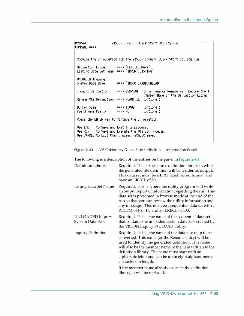
Introduction to the Import Option
Figure 2-40 VISION:Inquiry Quick Start Utility Run — Information Panel
The following is a description of the entries on the panel in Figure 2-40.Definition Library Required. This is the source definition library in which
the generated file definition will be written as output. This data set must be a PDS, fixed record format, and have an LRECL of 80.
Listing Data Set Name Required. This is where the utility program will write an output report of information regarding the run. This data set is presented in browse mode at the end of the run so that you can review the utility information and any messages. This must be a sequential data set with a RECFM of F or FB and an LRECL of 133.
UNLOADED Inquiry System Data Base
Required. This is the name of the sequential data set that contains the unloaded system database created by the VISION:Inquiry IXULOAD utility.
Inquiry Definition Required. This is the name of the database map to be converted. This name (or the Rename entry) will be used to identify the generated definition. This name will also be the member name of the item written to the definition library. The name must start with an alphabetic letter and can be up to eight alphanumeric characters in length.If the member name already exists in the definition library, it will be replaced.
Using VISION:Workbench for ISPF 2–55
Introduction to the Import Option
Once the information is captured, enter the RUN primary command to start executing the utility. The screen will contain information indicating that the utility is running. Text will be displayed to indicate that the utility has completed and you can browse the output listing. When the output browse is ended, the dialog process automatically performs a duplicate field name check. The screen will contain text indicating that the checks are being performed. When the checks are completed, the screen will contain text indicating the results of the checks. If duplicate names are found, you will be directed to a panel that lets you review and change the field names. See Editing Items on page 2-21 for details on the Duplicate Field Name Check option.
The dialog completes by returning to the Import Option menu.
Rename the Definition Optional. This is used to change the database map name on the generated definition. If used, this name will be used to identify the generated definition. This name will also be the member name of the item written to the definition library. The name must start with an alphabetic letter and can be up to eight alphanumeric characters in length.If the member name already exists in the definition library, it will be replaced.
Buffer Size Optional. This defines the size of the buffer needed to hold the maximum logical record. Use a number from 1 to 32760 or value of 1K to 9999K. This value is only used if the imported definition is for an IMS database.
Field Name Prefix Optional. This is a 1 to 3-character prefix that is used for the primary field names of the generated file definition. Because imported field names can be longer that 8 characters, primary field names are automatically generated using this prefix and a sequential number. The prefix must start with an alphabetic letter. The letter F will be used if no prefix is specified.
2–56 Workbench for ISPF Reference Guide
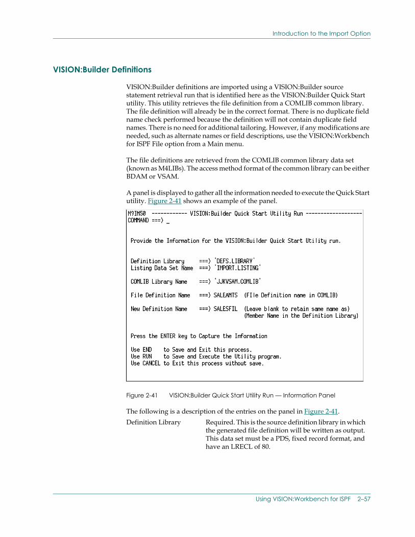
Introduction to the Import Option
VISION:Builder Definitions
VISION:Builder definitions are imported using a VISION:Builder source statement retrieval run that is identified here as the VISION:Builder Quick Start utility. This utility retrieves the file definition from a COMLIB common library. The file definition will already be in the correct format. There is no duplicate field name check performed because the definition will not contain duplicate field names. There is no need for additional tailoring. However, if any modifications are needed, such as alternate names or field descriptions, use the VISION:Workbench for ISPF File option from a Main menu.
The file definitions are retrieved from the COMLIB common library data set (known as M4LIBs). The access method format of the common library can be either BDAM or VSAM.
A panel is displayed to gather all the information needed to execute the Quick Start utility. Figure 2-41 shows an example of the panel.
Figure 2-41 VISION:Builder Quick Start Utility Run — Information Panel
The following is a description of the entries on the panel in Figure 2-41.Definition Library Required. This is the source definition library in which
the generated file definition will be written as output. This data set must be a PDS, fixed record format, and have an LRECL of 80.
Using VISION:Workbench for ISPF 2–57
Introduction to the Import Option
Once the information is captured, enter the RUN primary command to start executing the utility. The screen will contain information indicating that the utility is running. Text will be displayed to indicate that the utility has completed and you can browse the output listing. There is no duplicate field name check performed.
The dialog completes by returning to the Import Option menu.
Duplicate Field Name Check
The Duplicate Field Name Check is performed automatically from the individual Import dialogs. This checking can also be performed on request against any file definition that was either generated, developed, or copied to a definition library.
The file definition will be retrieved and scanned. The primary field names and the alternate field names are checked for duplicate occurrences. Each field name in the definition must be unique. If duplicates are found, a panel will be displayed and changes can be entered. Once the changes are complete, the updated definition is rewritten to the definition library. The duplicate checking is performed in foreground using a procedure language program.
Listing Data Set Name Required. This is where the utility program will write an output report of information regarding the run. This data set is presented in browse mode at the end of the run so that you can review the utility information and any messages. This must be a sequential data set with a RECFM of F or FB and an LRECL of 133.
COMLIB Library Name Required. This is the name of the common library data set that contains the file definitions to be retrieved.
File Definition Name Required. This is the file definition name of the item stored in the common library. This name will be used to identify the retrieved definition. This name will also be the member name of the item written to the definition library unless a new name is specified.If the member name already exists in the definition library, it will be replaced.
New Definition Name Optional. This is used to change the file definition name of the retrieved item. The name must start with an alphabetic letter and can be up to eight alphanumeric characters in length. This name will also be the member name of the item written to the definition library.If the member name already exists in the definition library, it will be replaced.
2–58 Workbench for ISPF Reference Guide
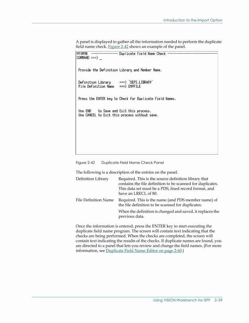
Introduction to the Import Option
A panel is displayed to gather all the information needed to perform the duplicate field name check. Figure 2-42 shows an example of the panel.
Figure 2-42 Duplicate Field Name Check Panel
The following is a description of the entries on the panel.
Once the information is entered, press the ENTER key to start executing the duplicate field name program. The screen will contain text indicating that the checks are being performed. When the checks are completed, the screen will contain text indicating the results of the checks. If duplicate names are found, you are directed to a panel that lets you review and change the field names. (For more information, see Duplicate Field Name Editor on page 2-60.)
Definition Library Required. This is the source definition library that contains the file definition to be scanned for duplicates. This data set must be a PDS, fixed record format, and have an LRECL of 80.
File Definition Name Required. This is the name (and PDS member name) of the file definition to be scanned for duplicates.When the definition is changed and saved, it replaces the previous data.
Using VISION:Workbench for ISPF 2–59
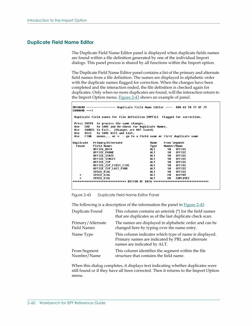
Introduction to the Import Option
Duplicate Field Name Editor
The Duplicate Field Name Editor panel is displayed when duplicate fields names are found within a file definition generated by one of the individual Import dialogs. This panel process is shared by all functions within the Import option.
The Duplicate Field Name Editor panel contains a list of the primary and alternate field names from a file definition. The names are displayed in alphabetic order with the duplicate names flagged for correction. When the changes have been completed and the interaction ended, the file definition is checked again for duplicates. Only when no more duplicates are found, will the interaction return to the Import Option menu. Figure 2-43 shows an example of panel.
Figure 2-43 Duplicate Field Name Editor Panel
The following is a description of the information the panel in Figure 2-43.
When this dialog completes, it displays text indicating whether duplicates were still found or if they have all been corrected. Then it returns to the Import Option menu.
Duplicate Found This column contains an asterisk (*) for the field names that are duplicates as of the last duplicate check scan.
Primary/Alternate Field Names
The names are displayed in alphabetic order and can be changed here by typing over the name entry.
Name Type This column indicates which type of name is displayed. Primary names are indicated by PRI, and alternate names are indicated by ALT.
From Segment Number/Name
This column identifies the segment within the file structure that contains the field name.
2–60 Workbench for ISPF Reference Guide
Introduction to Job Submission
Introduction to Job SubmissionVISION:Workbench for ISPF provides both VISION:Builder and VISION:Transact users with an interactive job submission and execution facility that allows you to do the following:
■ Run your VISION:Builder applications.
■ Compile/generate your VISION:Transact applications.
■ Catalog your definitions in an interactive environment.
This facility automatically generates the necessary JCL for a batch job submission or the necessary CLIST for a foreground job execution. At your request, the generated JCL/CLIST can be automatically submitted, written out to disk for later use, or both.
Note: Using the Foreground option, you can route all generated output directly to your terminal for immediate viewing.
The following discussion on the VISION:Workbench Submission facility has been divided into two parts:
■ How the Submission facility works.
■ Completing the Submission facility data entry panels.
Using VISION:Workbench for ISPF 2–61
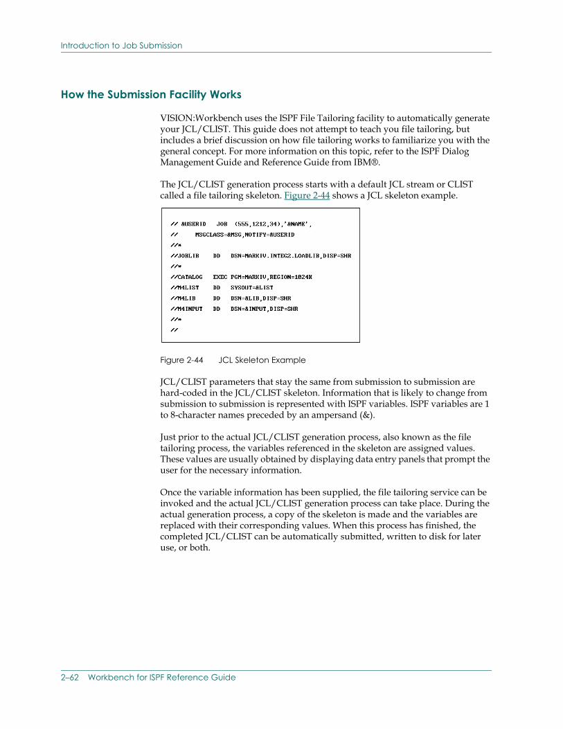
Introduction to Job Submission
How the Submission Facility Works
VISION:Workbench uses the ISPF File Tailoring facility to automatically generate your JCL/CLIST. This guide does not attempt to teach you file tailoring, but includes a brief discussion on how file tailoring works to familiarize you with the general concept. For more information on this topic, refer to the ISPF Dialog Management Guide and Reference Guide from IBM®.
The JCL/CLIST generation process starts with a default JCL stream or CLIST called a file tailoring skeleton. Figure 2-44 shows a JCL skeleton example.
Figure 2-44 JCL Skeleton Example
JCL/CLIST parameters that stay the same from submission to submission are hard-coded in the JCL/CLIST skeleton. Information that is likely to change from submission to submission is represented with ISPF variables. ISPF variables are 1 to 8-character names preceded by an ampersand (&).
Just prior to the actual JCL/CLIST generation process, also known as the file tailoring process, the variables referenced in the skeleton are assigned values. These values are usually obtained by displaying data entry panels that prompt the user for the necessary information.
Once the variable information has been supplied, the file tailoring service can be invoked and the actual JCL/CLIST generation process can take place. During the actual generation process, a copy of the skeleton is made and the variables are replaced with their corresponding values. When this process has finished, the completed JCL/CLIST can be automatically submitted, written to disk for later use, or both.
2–62 Workbench for ISPF Reference Guide
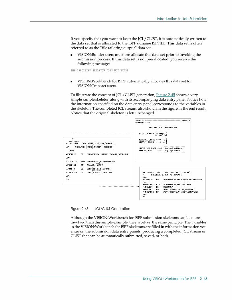
Introduction to Job Submission
If you specify that you want to keep the JCL/CLIST, it is automatically written to the data set that is allocated to the ISPF ddname ISPFILE. This data set is often referred to as the “file tailoring output” data set.
■ VISION:Builder users must pre-allocate this data set prior to invoking the submission process. If this data set is not pre-allocated, you receive the following message:
THE SPECIFIED SKELETON DOES NOT EXIST.
■ VISION:Workbench for ISPF automatically allocates this data set for VISION:Transact users.
To illustrate the concept of JCL/CLIST generation, Figure 2-45 shows a very simple sample skeleton along with its accompanying data entry panel. Notice how the information specified on the data entry panel corresponds to the variables in the skeleton. The completed JCL stream, also shown in the figure, is the end result. Notice that the original skeleton is left unchanged.
Figure 2-45 JCL/CLIST Generation
Although the VISION:Workbench for ISPF submission skeletons can be more involved than this simple example, they work on the same principle. The variables in the VISION:Workbench for ISPF skeletons are filled in with the information you enter on the submission data entry panels, producing a completed JCL stream or CLIST that can be automatically submitted, saved, or both.
Using VISION:Workbench for ISPF 2–63
Introduction to Job Submission
Using the Submission Facility
Because the submission process is very similar for both VISION:Builder and VISION:Transact, the process for both products is summarized in one discussion.
The Submission facility is entered from the VISION:Workbench Main menu. Selecting a submission option (Foreground or Background options for VISION:Builder or Generate option for VISION:Transact) displays an (Batch or Foreground) Item Entry panel.
Note: Foreground or background processing is specified in the Item Entry panel for VISION:Transact.
The figures used in this discussion are from the VISION:Builder Background option (which displays a Batch Item Entry panel). They assume the use of the default VISION:Workbench skeletons and user panels as shipped on your VISION:Workbench for ISPF installation tape. These panels are very similar to the panels used by the other submission options as well. If you understand how these panels work, you will be right at home when using any of the VISION:Builder or VISION:Transact submission facilities.
Once you select a submission (Background, Foreground, or Generate) option, the submission process is as follows:
1. Complete the Item Entry panel. Specify the location of the source object that is to be submitted.
2. Complete the Data Set Specifications panel. This panel supplies information about the files that are needed to actually run the job.
3. Complete the Options panel. This panel supplies processing options for the actual file tailoring process.
4. Complete the User panel. This panel allows you to enter site dependent information that may be needed to successfully complete your JCL and/or CLIST.
5. VISION:Workbench for ISPF generates the necessary JCL or CLIST by invoking ISPF File Tailoring facility.
2–64 Workbench for ISPF Reference Guide
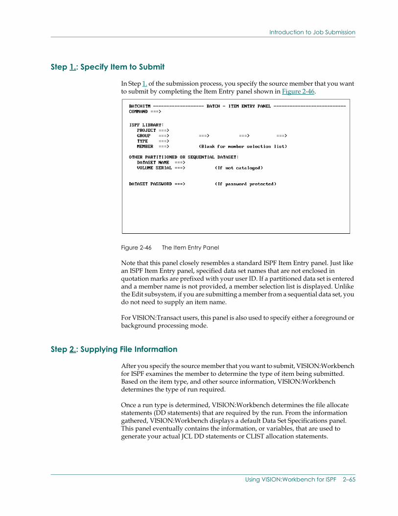
Introduction to Job Submission
Step 1.: Specify Item to Submit
In Step 1. of the submission process, you specify the source member that you want to submit by completing the Item Entry panel shown in Figure 2-46.
Figure 2-46 The Item Entry Panel
Note that this panel closely resembles a standard ISPF Item Entry panel. Just like an ISPF Item Entry panel, specified data set names that are not enclosed in quotation marks are prefixed with your user ID. If a partitioned data set is entered and a member name is not provided, a member selection list is displayed. Unlike the Edit subsystem, if you are submitting a member from a sequential data set, you do not need to supply an item name.
For VISION:Transact users, this panel is also used to specify either a foreground or background processing mode.
Step 2.: Supplying File Information
After you specify the source member that you want to submit, VISION:Workbench for ISPF examines the member to determine the type of item being submitted. Based on the item type, and other source information, VISION:Workbench determines the type of run required.
Once a run type is determined, VISION:Workbench determines the file allocate statements (DD statements) that are required by the run. From the information gathered, VISION:Workbench displays a default Data Set Specifications panel. This panel eventually contains the information, or variables, that are used to generate your actual JCL DD statements or CLIST allocation statements.
Using VISION:Workbench for ISPF 2–65
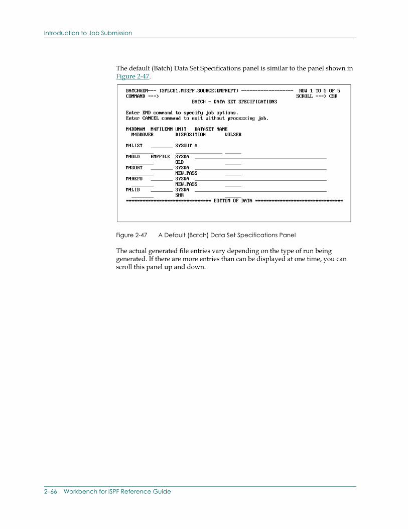
Introduction to Job Submission
The default (Batch) Data Set Specifications panel is similar to the panel shown in Figure 2-47.
Figure 2-47 A Default (Batch) Data Set Specifications Panel
The actual generated file entries vary depending on the type of run being generated. If there are more entries than can be displayed at one time, you can scroll this panel up and down.
2–66 Workbench for ISPF Reference Guide
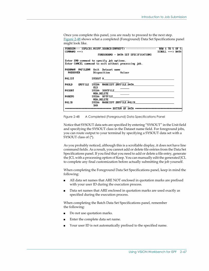
Introduction to Job Submission
Once you complete this panel, you are ready to proceed to the next step. Figure 2-48 shows what a completed (Foreground) Data Set Specifications panel might look like.
Figure 2-48 A Completed (Foreground) Data Specifications Panel
Notice that SYSOUT data sets are specified by entering “SYSOUT” in the Unit field and specifying the SYSOUT class in the Dataset name field. For foreground jobs, you can route output to your terminal by specifying a SYSOUT data set with a SYSOUT class of (*).
As you probably noticed, although this is a scrollable display, it does not have line command fields. As a result, you cannot add or delete file entries from the Data Set Specifications panel. If you find that you need to add or delete a file entry, generate the JCL with a processing option of Keep. You can manually edit the generated JCL to complete any final customization before actually submitting the job yourself.
When completing the Foreground Data Set Specifications panel, keep in mind the following:
■ All data set names that ARE NOT enclosed in quotation marks are prefixed with your user ID during the execution process.
■ Data set names that ARE enclosed in quotation marks are used exactly as specified during the execution process.
When completing the Batch Data Set Specifications panel, remember the following:
■ Do not use quotation marks.
■ Enter the complete data set name.
■ Your user ID is not automatically prefixed to the specified name.
Using VISION:Workbench for ISPF 2–67
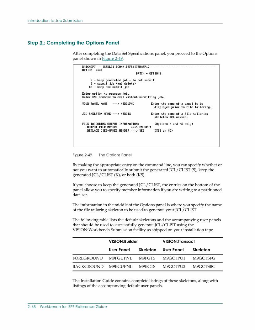
Introduction to Job Submission
Step 3.: Completing the Options Panel
After completing the Data Set Specifications panel, you proceed to the Options panel shown in Figure 2-49.
Figure 2-49 The Options Panel
By making the appropriate entry on the command line, you can specify whether or not you want to automatically submit the generated JCL/CLIST (S), keep the generated JCL/CLIST (K), or both (KS).
If you choose to keep the generated JCL/CLIST, the entries on the bottom of the panel allow you to specify member information if you are writing to a partitioned data set.
The information in the middle of the Options panel is where you specify the name of the file tailoring skeleton to be used to generate your JCL/CLIST.
The following table lists the default skeletons and the accompanying user panels that should be used to successfully generate JCL/CLIST using the VISION:Workbench Submission facility as shipped on your installation tape.
The Installation Guide contains complete listings of these skeletons, along with listings of the accompanying default user panels.
VISION:Builder VISION:Transact
User Panel Skeleton User Panel Skeleton
FOREGROUND M9FGUPNL M9FGTS M9GCTPU1 M9GCTSFG
BACKGROUND M9BGUPNL M9BGTS M9GCTPU2 M9GCTSBG
2–68 Workbench for ISPF Reference Guide
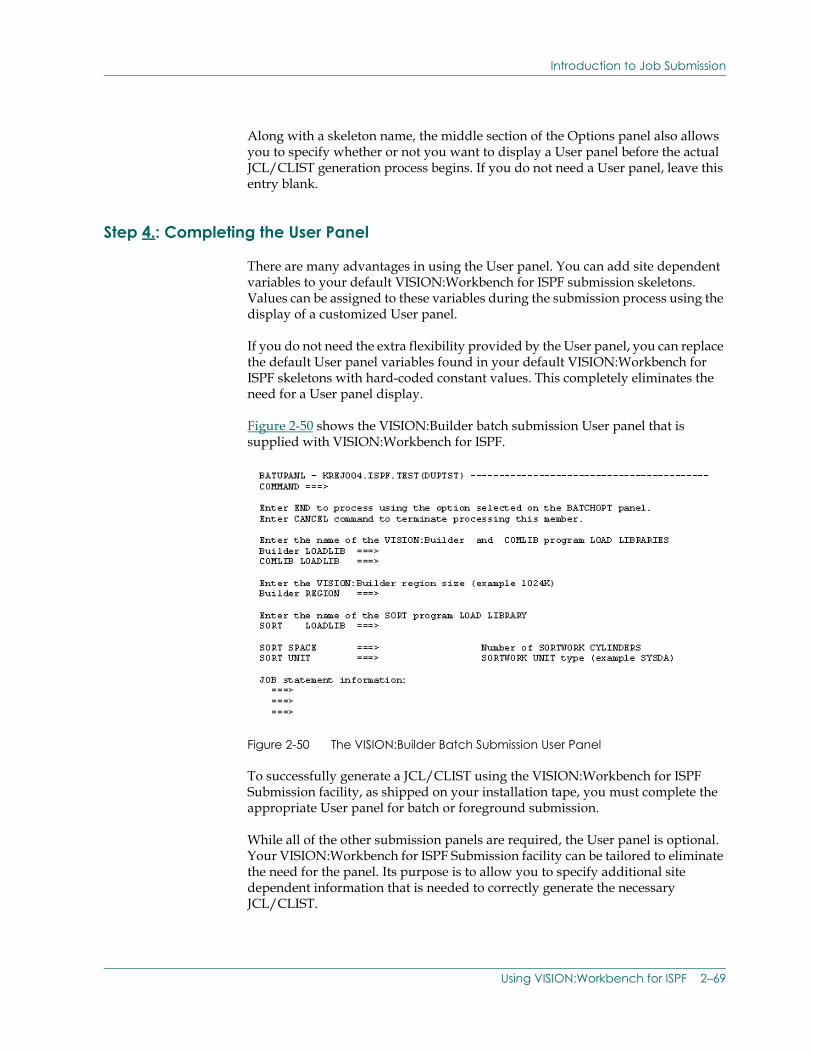
Introduction to Job Submission
Along with a skeleton name, the middle section of the Options panel also allows you to specify whether or not you want to display a User panel before the actual JCL/CLIST generation process begins. If you do not need a User panel, leave this entry blank.
Step 4.: Completing the User Panel
There are many advantages in using the User panel. You can add site dependent variables to your default VISION:Workbench for ISPF submission skeletons. Values can be assigned to these variables during the submission process using the display of a customized User panel.
If you do not need the extra flexibility provided by the User panel, you can replace the default User panel variables found in your default VISION:Workbench for ISPF skeletons with hard-coded constant values. This completely eliminates the need for a User panel display.
Figure 2-50 shows the VISION:Builder batch submission User panel that is supplied with VISION:Workbench for ISPF.
Figure 2-50 The VISION:Builder Batch Submission User Panel
To successfully generate a JCL/CLIST using the VISION:Workbench for ISPF Submission facility, as shipped on your installation tape, you must complete the appropriate User panel for batch or foreground submission.
While all of the other submission panels are required, the User panel is optional. Your VISION:Workbench for ISPF Submission facility can be tailored to eliminate the need for the panel. Its purpose is to allow you to specify additional site dependent information that is needed to correctly generate the necessary JCL/CLIST.
Using VISION:Workbench for ISPF 2–69
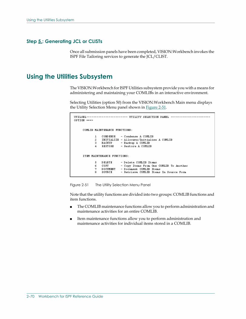
Using the Utilities Subsystem
Step 5.: Generating JCL or CLISTs
Once all submission panels have been completed, VISION:Workbench invokes the ISPF File Tailoring services to generate the JCL/CLIST.
Using the Utilities Subsystem The VISION:Workbench for ISPF Utilities subsystem provide you with a means for administering and maintaining your COMLIBs in an interactive environment.
Selecting Utilities (option 50) from the VISION:Workbench Main menu displays the Utility Selection Menu panel shown in Figure 2-51.
Figure 2-51 The Utility Selection Menu Panel
Note that the utility functions are divided into two groups: COMLIB functions and item functions.
■ The COMLIB maintenance functions allow you to perform administration and maintenance activities for an entire COMLIB.
■ Item maintenance functions allow you to perform administration and maintenance activities for individual items stored in a COMLIB.
2–70 Workbench for ISPF Reference Guide
VISION:Workbench for ISPF Parameters Subsystem
Because the Utilities subsystem is simple and straightforward to use, it is not discussed in detail. Below are a few rules for performing utility functions:
■ If you are ever unsure about how to complete a panel, use the interactive Help. The Help facility is invoked using the HELP primary command, usually PF1.
■ Whenever you are specifying a data set name, your TSO user ID is prefixed to the data set name if the data set name is not enclosed in quotation marks. If the data set name is enclosed in quotation marks, it is used exactly as specified.
■ Any printed output that you specifically request while using the Utilities subsystem is written out to the VISION:Workbench list data set. The VISION:Workbench list data set works exactly as its ISPF list data set counterpart. The VISION:Workbench list data set is discussed in greater detail later in this chapter.
■ The ISPF Split Screen primary command is not active in the VISION:Workbench Utilities subsystem. This is done to avoid possible allocation conflicts between the multiple, logical sessions that are created when using Split Screen.
VISION:Workbench for ISPF Parameters Subsystem The VISION:Workbench for ISPF Parameters subsystem provides you with information regarding your Computer Associates products.
Selecting Parameters (option 10) from the VISION:Workbench Main menu displays the Parameters Selection Menu panel. The menu contains three option groups and varies depending on which product you are using (VISION:Workbench with VISION:Builder or VISION:Workbench with VISION:Transact).
Session Parameters Group
All menus offer the Session option and the List option in the Session Parameters group. These options allow you to customize certain operating characteristics of your VISION:Workbench for ISPF session.
Maintenance Level Group
The Maintenance Level group Modifications option, also contained on all menus, provides you with a list of all system modifications (SMs) that are currently installed on your VISION:Workbench for ISPF system.
Using VISION:Workbench for ISPF 2–71
User Profile - First Time User Setup
Default Site Parameters group:
The Default Site Parameters group allows you to browse the default parameter modules associated with VISION:Builder, VISION:Transact, and COMLIB. These options vary depending on the version of VISION:Workbench for ISPF that you are using.
■ When you are using the VISION:Builder version of VISION:Workbench for ISPF, you have options for browsing both the COMLIB parameter module (MARKLIBP) and the VISION:Builder parameter module (M4PARAMS).
■ When you are using the VISION:Transact version of VISION:Workbench for ISPF, you have options for browsing the COMLIB parameter module (MARKLIBP), the VISION:Transact parameter module (FIVEPARM), and the VISION:Transact terminal device table.
User Profile - First Time User SetupJust as you have a personal user profile for your regular ISPF session, you also have a personal user profile for VISION:Workbench. This profile is automatically created and added to your ISPF profile library (member IADSPROF) the first time that you use VISION:Workbench.
Every ISPF user has a personal profile library associated with their user ID. This library can be thought of as a save area in that it provides a place for ISPF and ISPF applications such as VISION:Workbench to save information about you between sessions. Without a profile library, you would have to reenter all the standard information that you routinely use during your session at the start of each new session. Using a profile library allows this standard session information to be saved at the end of your session. At the start of your next session, the information is automatically retrieved from your profile and placed into the appropriate panels as default entries.
The information that is stored in this user profile is referred to as “session profile information.” For more detailed information on how user profiles work, see IBM's ISPF User's Guide.
Because your VISION:Workbench user profile is empty the very first time that you use VISION:Workbench, take a few minutes to review and complete your user profile information. Once this is done, you do not have to do it again, unless you want to change this information.
2–72 Workbench for ISPF Reference Guide
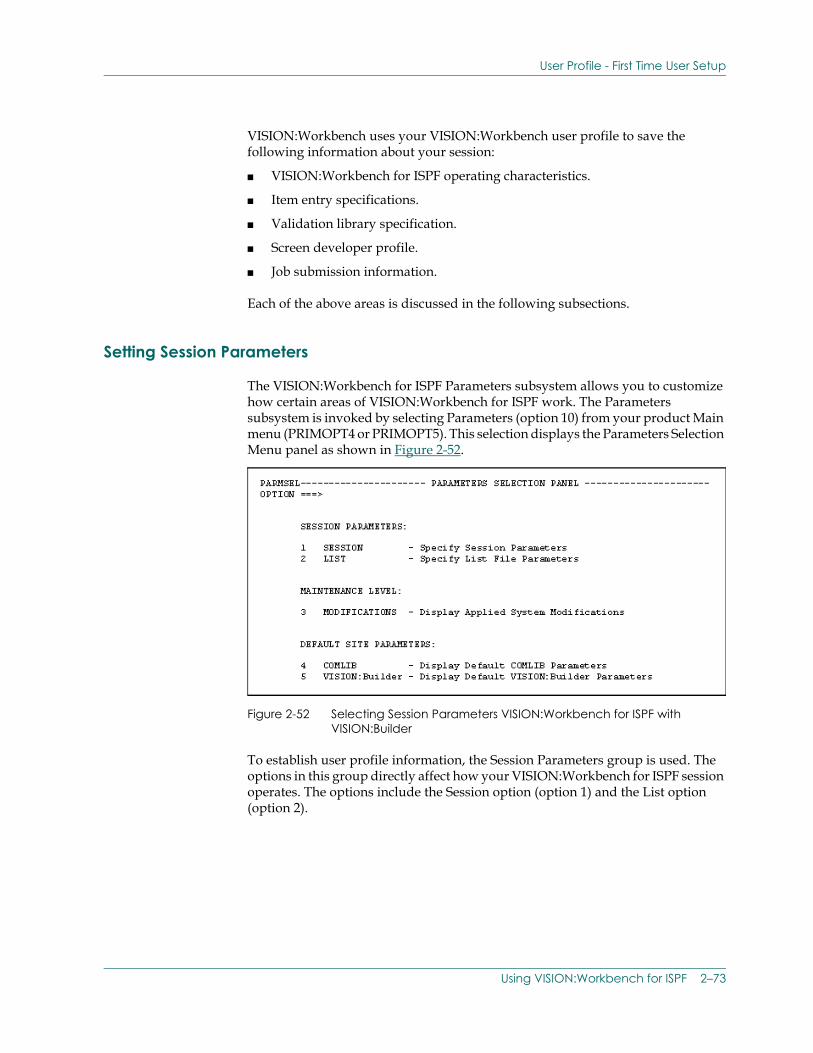
User Profile - First Time User Setup
VISION:Workbench uses your VISION:Workbench user profile to save the following information about your session:
■ VISION:Workbench for ISPF operating characteristics.
■ Item entry specifications.
■ Validation library specification.
■ Screen developer profile.
■ Job submission information.
Each of the above areas is discussed in the following subsections.
Setting Session Parameters
The VISION:Workbench for ISPF Parameters subsystem allows you to customize how certain areas of VISION:Workbench for ISPF work. The Parameters subsystem is invoked by selecting Parameters (option 10) from your product Main menu (PRIMOPT4 or PRIMOPT5). This selection displays the Parameters Selection Menu panel as shown in Figure 2-52.
Figure 2-52 Selecting Session Parameters VISION:Workbench for ISPF with VISION:Builder
To establish user profile information, the Session Parameters group is used. The options in this group directly affect how your VISION:Workbench for ISPF session operates. The options include the Session option (option 1) and the List option (option 2).
Using VISION:Workbench for ISPF 2–73
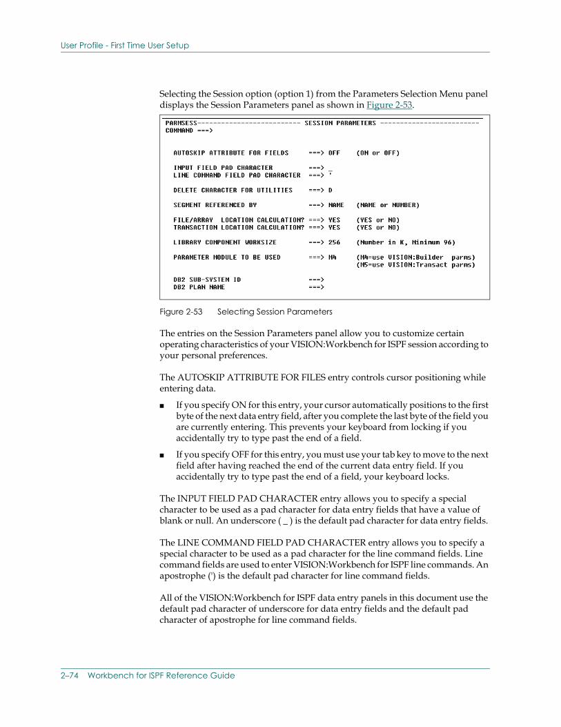
User Profile - First Time User Setup
Selecting the Session option (option 1) from the Parameters Selection Menu panel displays the Session Parameters panel as shown in Figure 2-53.
Figure 2-53 Selecting Session Parameters
The entries on the Session Parameters panel allow you to customize certain operating characteristics of your VISION:Workbench for ISPF session according to your personal preferences.
The AUTOSKIP ATTRIBUTE FOR FILES entry controls cursor positioning while entering data.
■ If you specify ON for this entry, your cursor automatically positions to the first byte of the next data entry field, after you complete the last byte of the field you are currently entering. This prevents your keyboard from locking if you accidentally try to type past the end of a field.
■ If you specify OFF for this entry, you must use your tab key to move to the next field after having reached the end of the current data entry field. If you accidentally try to type past the end of a field, your keyboard locks.
The INPUT FIELD PAD CHARACTER entry allows you to specify a special character to be used as a pad character for data entry fields that have a value of blank or null. An underscore ( _ ) is the default pad character for data entry fields.
The LINE COMMAND FIELD PAD CHARACTER entry allows you to specify a special character to be used as a pad character for the line command fields. Line command fields are used to enter VISION:Workbench for ISPF line commands. An apostrophe (') is the default pad character for line command fields.
All of the VISION:Workbench for ISPF data entry panels in this document use the default pad character of underscore for data entry fields and the default pad character of apostrophe for line command fields.
2–74 Workbench for ISPF Reference Guide
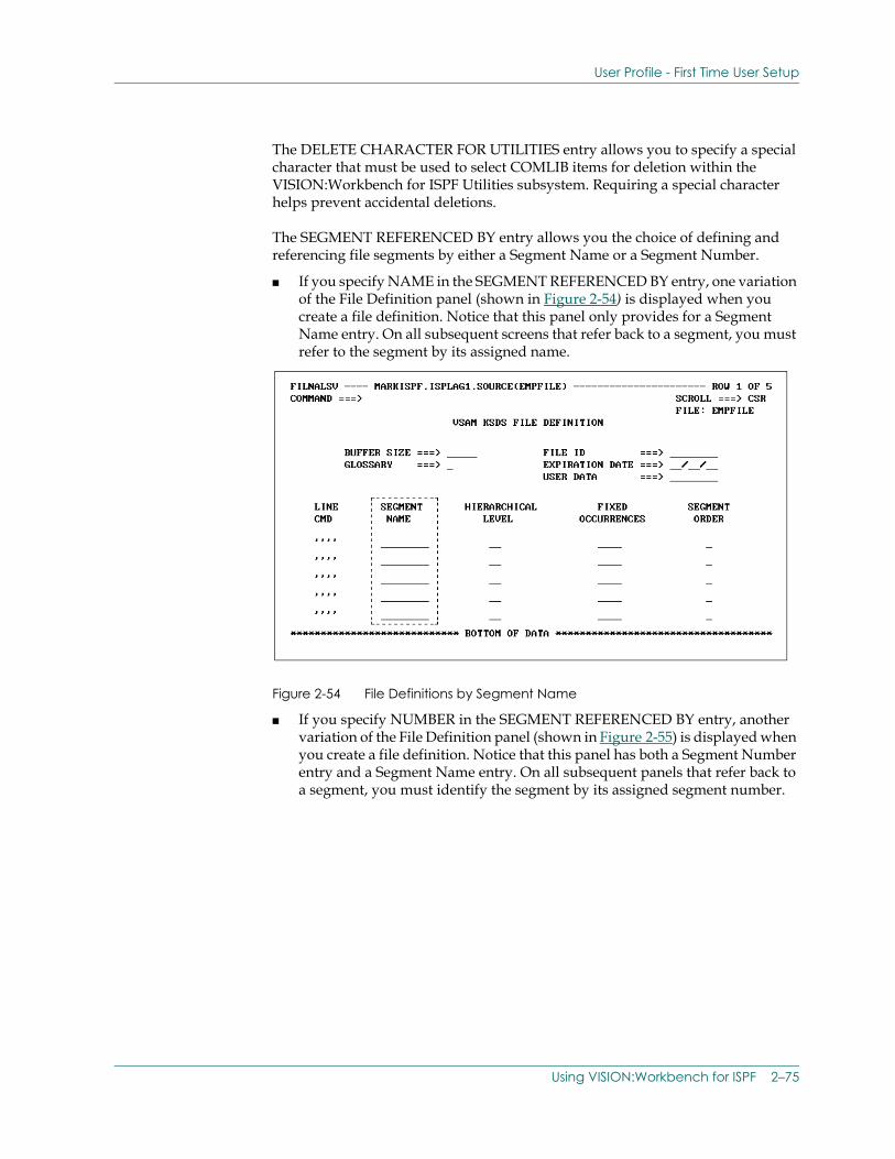
User Profile - First Time User Setup
The DELETE CHARACTER FOR UTILITIES entry allows you to specify a special character that must be used to select COMLIB items for deletion within the VISION:Workbench for ISPF Utilities subsystem. Requiring a special character helps prevent accidental deletions.
The SEGMENT REFERENCED BY entry allows you the choice of defining and referencing file segments by either a Segment Name or a Segment Number.
■ If you specify NAME in the SEGMENT REFERENCED BY entry, one variation of the File Definition panel (shown in Figure 2-54) is displayed when you create a file definition. Notice that this panel only provides for a Segment Name entry. On all subsequent screens that refer back to a segment, you must refer to the segment by its assigned name.
Figure 2-54 File Definitions by Segment Name
■ If you specify NUMBER in the SEGMENT REFERENCED BY entry, another variation of the File Definition panel (shown in Figure 2-55) is displayed when you create a file definition. Notice that this panel has both a Segment Number entry and a Segment Name entry. On all subsequent panels that refer back to a segment, you must identify the segment by its assigned segment number.
Using VISION:Workbench for ISPF 2–75
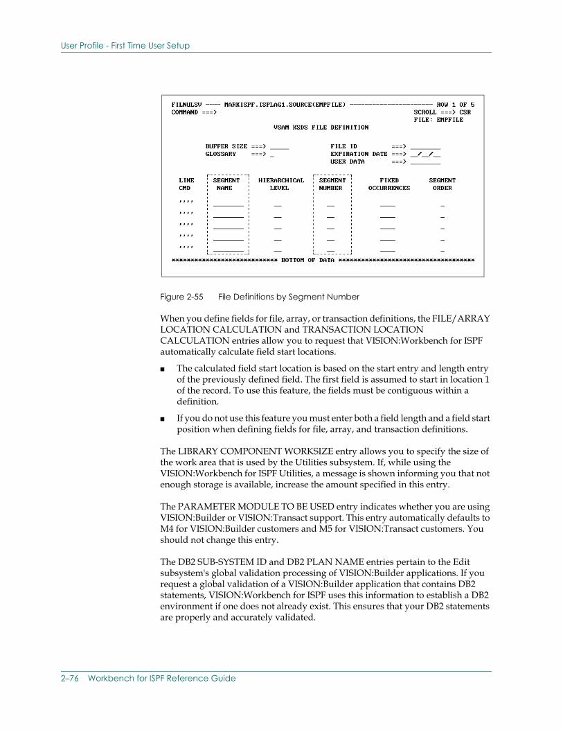
User Profile - First Time User Setup
Figure 2-55 File Definitions by Segment Number
When you define fields for file, array, or transaction definitions, the FILE/ARRAY LOCATION CALCULATION and TRANSACTION LOCATION CALCULATION entries allow you to request that VISION:Workbench for ISPF automatically calculate field start locations.
■ The calculated field start location is based on the start entry and length entry of the previously defined field. The first field is assumed to start in location 1 of the record. To use this feature, the fields must be contiguous within a definition.
■ If you do not use this feature you must enter both a field length and a field start position when defining fields for file, array, and transaction definitions.
The LIBRARY COMPONENT WORKSIZE entry allows you to specify the size of the work area that is used by the Utilities subsystem. If, while using the VISION:Workbench for ISPF Utilities, a message is shown informing you that not enough storage is available, increase the amount specified in this entry.
The PARAMETER MODULE TO BE USED entry indicates whether you are using VISION:Builder or VISION:Transact support. This entry automatically defaults to M4 for VISION:Builder customers and M5 for VISION:Transact customers. You should not change this entry.
The DB2 SUB-SYSTEM ID and DB2 PLAN NAME entries pertain to the Edit subsystem's global validation processing of VISION:Builder applications. If you request a global validation of a VISION:Builder application that contains DB2 statements, VISION:Workbench for ISPF uses this information to establish a DB2 environment if one does not already exist. This ensures that your DB2 statements are properly and accurately validated.
2–76 Workbench for ISPF Reference Guide
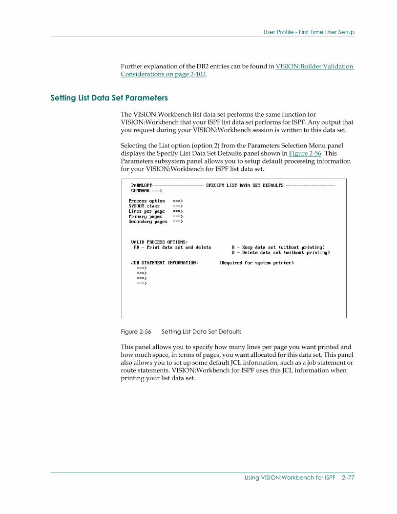
User Profile - First Time User Setup
Further explanation of the DB2 entries can be found in VISION:Builder Validation Considerations on page 2-102.
Setting List Data Set Parameters
The VISION:Workbench list data set performs the same function for VISION:Workbench that your ISPF list data set performs for ISPF. Any output that you request during your VISION:Workbench session is written to this data set.
Selecting the List option (option 2) from the Parameters Selection Menu panel displays the Specify List Data Set Defaults panel shown in Figure 2-56. This Parameters subsystem panel allows you to setup default processing information for your VISION:Workbench for ISPF list data set.
Figure 2-56 Setting List Data Set Defaults
This panel allows you to specify how many lines per page you want printed and how much space, in terms of pages, you want allocated for this data set. This panel also allows you to set up some default JCL information, such as a job statement or route statements. VISION:Workbench for ISPF uses this JCL information when printing your list data set.
Using VISION:Workbench for ISPF 2–77
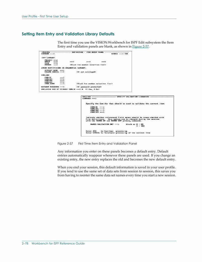
User Profile - First Time User Setup
Setting Item Entry and Validation Library Defaults
The first time you use the VISION:Workbench for ISPF Edit subsystem the Item Entry and validation panels are blank, as shown in Figure 2-57.
Figure 2-57 First Time Item Entry and Validation Panel
Any information you enter on these panels becomes a default entry. Default entries automatically reappear whenever these panels are used. If you change an existing entry, the new entry replaces the old and becomes the new default entry.
When you end your session, this default information is saved in your user profile. If you tend to use the same set of data sets from session to session, this saves you from having to reenter the same data set names every time you start a new session.
2–78 Workbench for ISPF Reference Guide
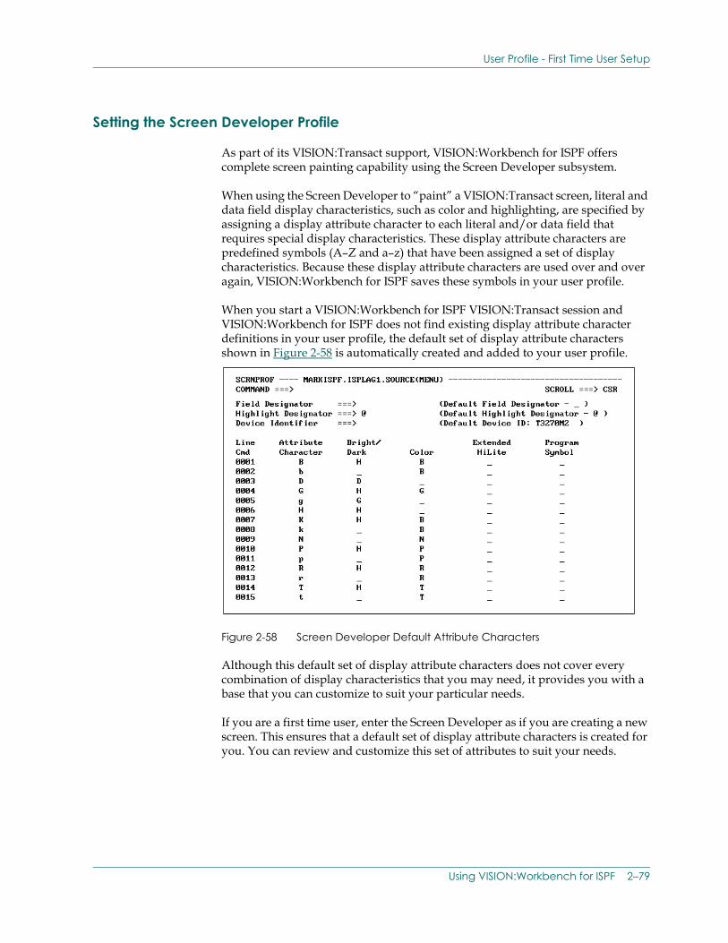
User Profile - First Time User Setup
Setting the Screen Developer Profile
As part of its VISION:Transact support, VISION:Workbench for ISPF offers complete screen painting capability using the Screen Developer subsystem.
When using the Screen Developer to “paint” a VISION:Transact screen, literal and data field display characteristics, such as color and highlighting, are specified by assigning a display attribute character to each literal and/or data field that requires special display characteristics. These display attribute characters are predefined symbols (A–Z and a–z) that have been assigned a set of display characteristics. Because these display attribute characters are used over and over again, VISION:Workbench for ISPF saves these symbols in your user profile.
When you start a VISION:Workbench for ISPF VISION:Transact session and VISION:Workbench for ISPF does not find existing display attribute character definitions in your user profile, the default set of display attribute characters shown in Figure 2-58 is automatically created and added to your user profile.
Figure 2-58 Screen Developer Default Attribute Characters
Although this default set of display attribute characters does not cover every combination of display characteristics that you may need, it provides you with a base that you can customize to suit your particular needs.
If you are a first time user, enter the Screen Developer as if you are creating a new screen. This ensures that a default set of display attribute characters is created for you. You can review and customize this set of attributes to suit your needs.
Using VISION:Workbench for ISPF 2–79
User Profile - First Time User Setup
When you have completed your customizations, exit the Screen Developer subsystem. This ensures that your customized display attribute character definitions are replaced back into your user profile. The next time that you use the Screen Developer your display attribute characters are set up and ready to use.
Setting Default Job Submission Information
This section specifically discusses the information that you need to complete the job submission information in the Options panel and the User panel. For a complete discussion on using the Submission options, see Introduction to Job Submission on page 2-61, Introduction to Job Submission, earlier in this guide.
The VISION:Workbench for ISPF Submission facility is entered through the Main menu.
Once entered, most of your job submission information is saved in your VISION:Workbench for ISPF user profile; you do not have to enter it again unless you want to change a specification.
This discussion focuses on the information that you need to provide the first time through. Find out this information before you actually try and use any of the Submission options. Proper generation of your JCL and/or CLISTs depends on proper and accurate information being entered on the job submission data entry panels.
■ If your VISION:Workbench for ISPF job submission information has been tailored to meet the particular requirements of your site, consult with the person who completed the customization to determine what information you need to supply.
■ If your VISION:Workbench for ISPF job submission information is not customized and you are using it as supplied, the following figures show the default information that you must provide to successfully complete the Options panel and the User panel.
Note: “Options panel” is a generic term. The actual Option panel name varies depending on product and mode.
Product Mode Options User Panel
VISION:Builder Background (Batch)
Figure 2-59 Figure 2-60
VISION:Builder Foreground Figure 2-61 Figure 2-62
VISION:Transact Background Figure 2-63 Figure 2-64
VISION:Transact Foreground Figure 2-65 Figure 2-66
2–80 Workbench for ISPF Reference Guide
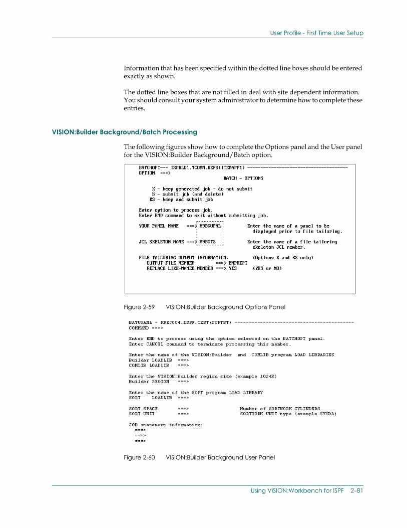
User Profile - First Time User Setup
Information that has been specified within the dotted line boxes should be entered exactly as shown.
The dotted line boxes that are not filled in deal with site dependent information. You should consult your system administrator to determine how to complete these entries.
VISION:Builder Background/Batch Processing
The following figures show how to complete the Options panel and the User panel for the VISION:Builder Background/Batch option.
Figure 2-59 VISION:Builder Background Options Panel
Figure 2-60 VISION:Builder Background User Panel
Using VISION:Workbench for ISPF 2–81
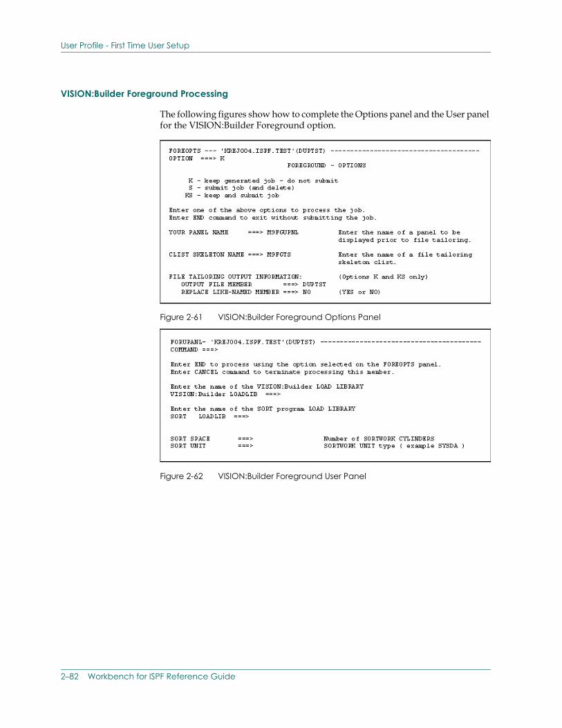
User Profile - First Time User Setup
VISION:Builder Foreground Processing
The following figures show how to complete the Options panel and the User panel for the VISION:Builder Foreground option.
Figure 2-61 VISION:Builder Foreground Options Panel
Figure 2-62 VISION:Builder Foreground User Panel
2–82 Workbench for ISPF Reference Guide
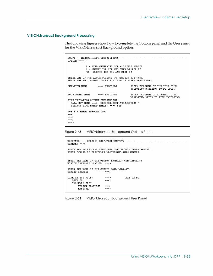
User Profile - First Time User Setup
VISION:Transact Background Processing
The following figures show how to complete the Options panel and the User panel for the VISION:Transact Background option.
Figure 2-63 VISION:Transact Background Options Panel
Figure 2-64 VISION:Transact Background User Panel
Using VISION:Workbench for ISPF 2–83
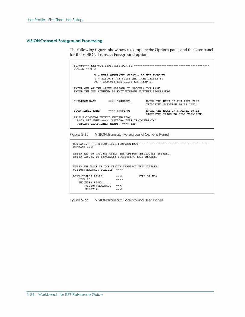
User Profile - First Time User Setup
VISION:Transact Foreground Processing
The following figures show how to complete the Options panel and the User panel for the VISION:Transact Foreground option.
Figure 2-65 VISION:Transact Foreground Options Panel
Figure 2-66 VISION:Transact Foreground User Panel
2–84 Workbench for ISPF Reference Guide
Allocating ISPFILE
Allocating ISPFILE If you specify the K (for Keep) or KS (for Keep/Submit) options on the Options panel during the VISION:Workbench for ISPF job submission process, the generated JCL or CLIST is automatically written to the data set that is allocated to the ISPF ddname ISPFILE. This data set is often referred to as the file tailoring output data set.
Allocating ISPFILE for VISION:Transact
VISION:Transact users do not need to allocate a file tailoring output data set. VISION:Workbench for ISPF automatically allocates the output data set specified on the Options panel.
You should keep the following things in mind when completing this panel:
■ If you DO NOT enclose this data set name in quotation marks, your user ID is prefixed to the specified name.
■ If you DO enclose this data set name in quotation marks, it is used exactly as entered on the panel.
Allocating ISPFILE for VISION:Builder
VISION:Builder users (who plan to use the submission Keep or Keep/Submit processing options) must pre-allocate their file tailoring output data set. It must be allocated prior to using either of the VISION:Builder submission options. The VISION:Builder submission options DO NOT automatically allocate this data set for you.
If you do not pre-allocate this file, you receive the following error message on the Options panel: THE SPECIFIED SKELETON DOES NOT EXIST.
You can automatically allocate or manually allocate ISPFILE:
■ Automate the pre-allocation of a file tailoring output data set by including an ISPFILE allocation in your ISPF startup CLIST. This ensures that your file tailoring output data set is always allocated and ready to use whenever you are using VISION:Workbench for ISPF.
■ Manually allocate a file tailoring output data set using the TSO ALLOCATE command. This allocation only needs to be done once per VISION:Workbench for ISPF VISION:Builder session. The example below shows how this can be done from your VISION:Workbench for ISPF Main menu.
Using VISION:Workbench for ISPF 2–85
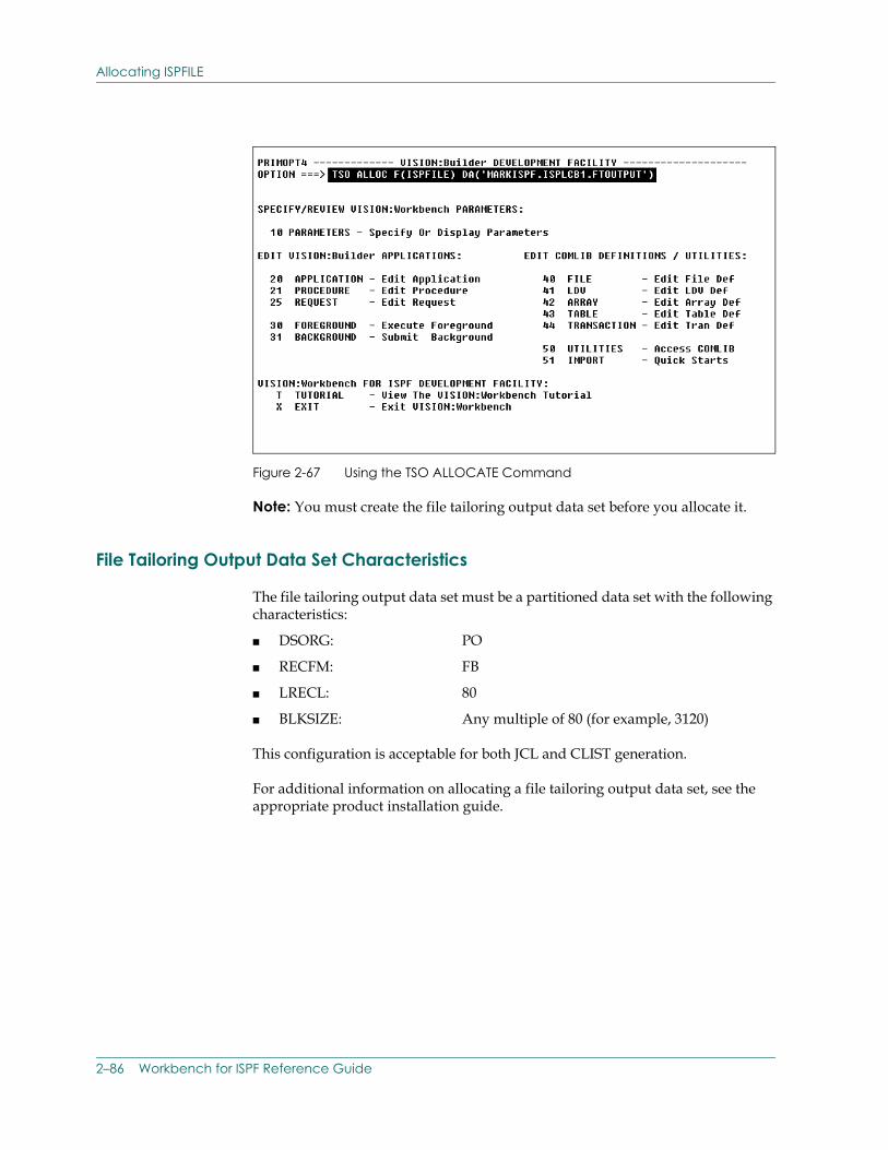
Allocating ISPFILE
Figure 2-67 Using the TSO ALLOCATE Command
Note: You must create the file tailoring output data set before you allocate it.
File Tailoring Output Data Set Characteristics
The file tailoring output data set must be a partitioned data set with the following characteristics:
■ DSORG: PO
■ RECFM: FB
■ LRECL: 80
■ BLKSIZE: Any multiple of 80 (for example, 3120)
This configuration is acceptable for both JCL and CLIST generation.
For additional information on allocating a file tailoring output data set, see the appropriate product installation guide.
2–86 Workbench for ISPF Reference Guide
The List Data Set
The List Data SetThe VISION:Workbench list data set corresponds to the ISPF list data set in purpose and function. It is used to hold all output that you request during your VISION:Workbench session. For example, if you use the VISION:Workbench Utilities subsystem to perform a source statement retrieval and you request a hard-copy of the retrieved source, the retrieved source listing is automatically written to this data set.
The VISION:Workbench for ISPF list data set must be allocated to the ddname M9LIST. You can pre-allocate this data set prior to invoking VISION:Workbench for ISPF, but pre-allocation is not mandatory. If VISION:Workbench for ISPF finds that this data set has not been pre-allocated, it dynamically allocates it for you, as needed, using the following naming convention: &SYSPREF.(&SYSUID.)M9TEMPn.LIST
The &SYSUID qualifier is only used if different from the system prefix, SYSPREF.
If you choose to pre-allocate M9LIST, you can allocate it as a SYSOUT data set or you can allocate it with the following characteristics:
■ DSORG = PS
■ RECFM = FBA
■ LRECL = 133
■ BLKSIZE = 1330
When you terminate a VISION:Workbench for ISPF session in which the list data set was pre-allocated prior to invoking VISION:Workbench for ISPF, VISION:Workbench for ISPF DOES NOT perform any kind of termination processing on this data set. It is up to you to print and/or delete this data set as needed.
Using VISION:Workbench for ISPF 2–87
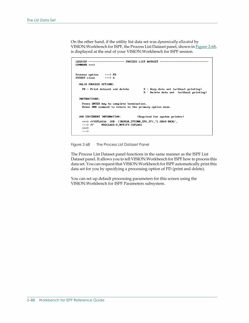
The List Data Set
On the other hand, if the utility list data set was dynamically allocated by VISION:Workbench for ISPF, the Process List Dataset panel, shown in Figure 2-68, is displayed at the end of your VISION:Workbench for ISPF session.
Figure 2-68 The Process List Dataset Panel
The Process List Dataset panel functions in the same manner as the ISPF List Dataset panel. It allows you to tell VISION:Workbench for ISPF how to process this data set. You can request that VISION:Workbench for ISPF automatically print this data set for you by specifying a processing option of PD (print and delete).
You can set up default processing parameters for this screen using the VISION:Workbench for ISPF Parameters subsystem.
2–88 Workbench for ISPF Reference Guide
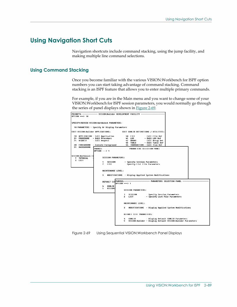
Using Navigation Short Cuts
Using Navigation Short CutsNavigation shortcuts include command stacking, using the jump facility, and making multiple line command selections.
Using Command Stacking
Once you become familiar with the various VISION:Workbench for ISPF option numbers you can start taking advantage of command stacking. Command stacking is an ISPF feature that allows you to enter multiple primary commands.
For example, if you are in the Main menu and you want to change some of your VISION:Workbench for ISPF session parameters, you would normally go through the series of panel displays shown in Figure 2-69.
Figure 2-69 Using Sequential VISION:Workbench Panel Displays
Using VISION:Workbench for ISPF 2–89
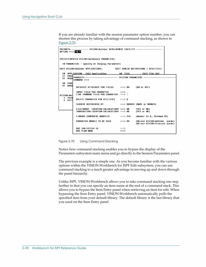
Using Navigation Short Cuts
If you are already familiar with the session parameter option number, you can shorten this process by taking advantage of command stacking, as shown in Figure 2-70.
Figure 2-70 Using Command Stacking
Notice how command stacking enables you to bypass the display of the Parameters subsystem main menu and go directly to the Session Parameters panel.
The previous example is a simple one. As you become familiar with the various options within the VISION:Workbench for ISPF Edit subsystem, you can use command stacking to a much greater advantage in moving up and down through the panel hierarchy.
Unlike ISPF, VISION:Workbench allows you to take command stacking one step further in that you can specify an item name at the end of a command stack. This allows you to bypass the Item Entry panel when retrieving an item for edit. When bypassing the Item Entry panel, VISION:Workbench automatically pulls the specified item from your default library. The default library is the last library that you used on the Item Entry panel.
2–90 Workbench for ISPF Reference Guide
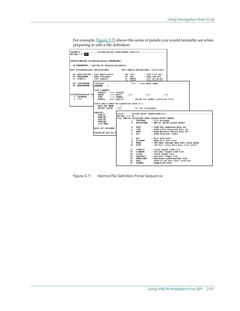
Using Navigation Short Cuts
For example, Figure 2-71 shows the series of panels you would normally see when preparing to edit a file definition.
Figure 2-71 Normal File Definition Panel Sequence
Using VISION:Workbench for ISPF 2–91
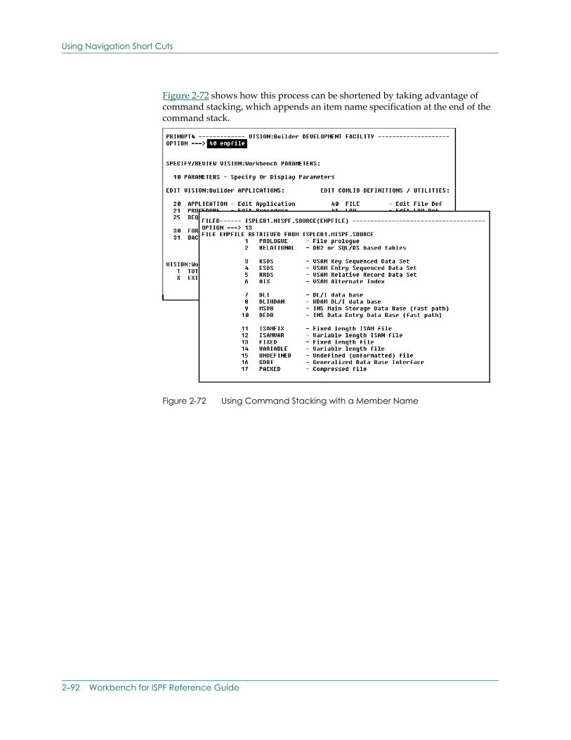
Using Navigation Short Cuts
Figure 2-72 shows how this process can be shortened by taking advantage of command stacking, which appends an item name specification at the end of the command stack.
Figure 2-72 Using Command Stacking with a Member Name
2–92 Workbench for ISPF Reference Guide
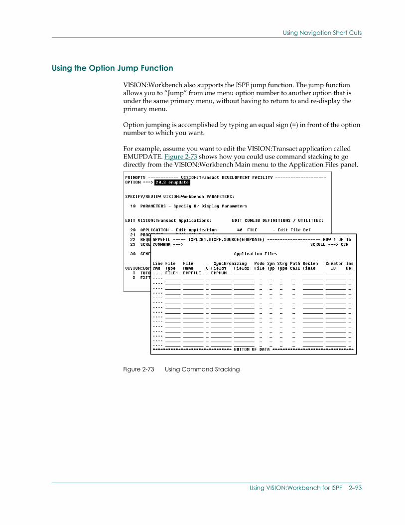
Using Navigation Short Cuts
Using the Option Jump Function
VISION:Workbench also supports the ISPF jump function. The jump function allows you to “Jump” from one menu option number to another option that is under the same primary menu, without having to return to and re-display the primary menu.
Option jumping is accomplished by typing an equal sign (=) in front of the option number to which you want.
For example, assume you want to edit the VISION:Transact application called EMUPDATE. Figure 2-73 shows how you could use command stacking to go directly from the VISION:Workbench Main menu to the Application Files panel.
Figure 2-73 Using Command Stacking
Using VISION:Workbench for ISPF 2–93
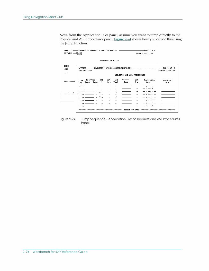
Using Navigation Short Cuts
Now, from the Application Files panel, assume you want to jump directly to the Request and ASL Procedures panel. Figure 2-74 shows how you can do this using the Jump function.
Figure 2-74 Jump Sequence - Application Files to Request and ASL Procedures Panel
2–94 Workbench for ISPF Reference Guide
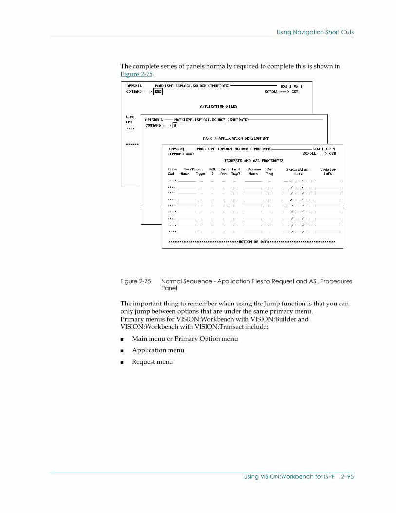
Using Navigation Short Cuts
The complete series of panels normally required to complete this is shown in Figure 2-75.
Figure 2-75 Normal Sequence - Application Files to Request and ASL Procedures Panel
The important thing to remember when using the Jump function is that you can only jump between options that are under the same primary menu. Primary menus for VISION:Workbench with VISION:Builder and VISION:Workbench with VISION:Transact include:
■ Main menu or Primary Option menu
■ Application menu
■ Request menu
Using VISION:Workbench for ISPF 2–95
Using Navigation Short Cuts
The following table lists the VISION:Workbench primary menus.
Note that navigation through the VISION:Workbench for ISPF panel hierarchy becomes faster as you become more familiar with the available options.
Using Multiple Line Command Selections
VISION:Workbench for ISPF allows you to select multiple rows of data for continued processing at one time. If you select multiple rows, VISION:Workbench for ISPF automatically processes each selected row in sequence, one after another.
For example, to enter additional field information, you can use the Select line command to select multiple field rows. As shown in Figure 2-76, VISION:Workbench for ISPF processes all of the selected field rows before returning to the Field Definitions panel.
Primary Menu Name Primary Menu Description
PRIMOPT4 VISION:Builder Main or Primary Option Menu
APP4DEVL VISION:Builder Application Development Menu
REQ4MENU VISION:Builder Request Parts Menu
PRIMOPT5 VISION:Transact Main or Primary Option Menu
APP5DEVL VISION:Transact Application Development Menu
REQ5MENU VISION:Transact Request Parts Menu
SCRNMENU VISION:Transact Screen Developer Menu
2–96 Workbench for ISPF Reference Guide
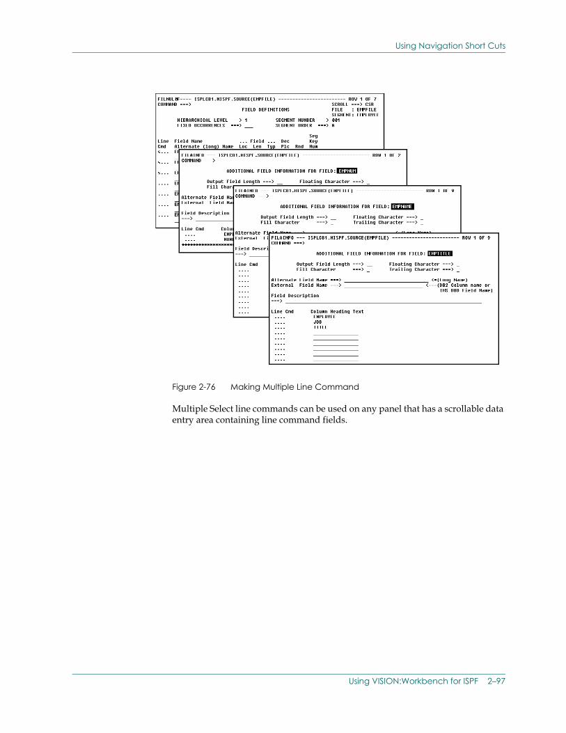
Using Navigation Short Cuts
Figure 2-76 Making Multiple Line Command
Multiple Select line commands can be used on any panel that has a scrollable data entry area containing line command fields.
Using VISION:Workbench for ISPF 2–97
Maintaining Existing Source
Maintaining Existing SourceIn addition to creating new application systems, VISION:Workbench for ISPF can be used to maintain and enhance your existing VISION:Builder and VISION:Transact application systems.
The process of loading an existing source item into VISION:Workbench for ISPF for modification is called importing. The process of writing the modified source back out to disk is called exporting.
When importing existing source, the following guidelines apply to all VISION:Builder and VISION:Transact items:
■ VISION:Workbench for ISPF correctly imports any item that was generated using VISION:Workbench for ISPF or VISION:Workbench for DOS.
■ VISION:Workbench for ISPF also imports existing items that are not generated under VISION:Workbench for ISPF. When importing items that are not generated by VISION:Workbench for ISPF, you should adhere to the following guidelines. If these guidelines are not followed, the import process can produce unpredictable results.
VISION:Builder and VISION:Transact Source Importing Guidelines
The following describes guidelines for importing source not generated by VISION:Workbench for ISPF:
■ When retrieving source from a partitioned data set, the member name must be identical to the item name specified in the first eight positions of the run control information. If these two names are not identical, VISION:Workbench for ISPF automatically changes the run control item name to match the specified member name.
■ The item should be syntactically correct.
■ The item must only contain one item of the selected type. For example, when importing a file definition, the source member being imported can only contain one file definition. When importing an application, the source member being imported can only contain one application. Applications can, however, contain multiple instream definitions.
■ Definition delete statements (“Y” in position 19) are commonly placed in front of a definition to ensure that the existing version of the definition is deleted before the new version is cataloged. However, you should be aware that VISION:Workbench for ISPF ignores these delete statements. They are not imported. As a result, avoid the use of delete statements and use the replace operator instead.
2–98 Workbench for ISPF Reference Guide
Maintaining Existing Source
■ The source should contain source statements that are placed in the same order as shown on your formatted source statement listings. When formatted source statement listings are produced, statements are sequenced in what is considered to be the most efficient processing order. In general, this is the same statement order that VISION:Workbench for ISPF expects to encounter during the import process. Trying to import existing source members that contain “out of order” statements can produce unpredictable results.
■ All statements with the same name in columns 1-8 must be grouped together.
■ All IT statements should be placed at the beginning of the item.
■ ASL Procedures must have a ##PROC statement immediately following the ER statement (where, # is the system delimiter) and a ##PEND statement at the end of the procedure.
Importing Source for VISION:Builder Only
The following describes guidelines for importing VISION:Builder source:
■ All processing and temporary field specifications must come before the report specifications.
■ Each report must start with an En statement that must be followed by the remaining report specification statements for that report.
■ Definition replace specification is preserved in the following definition types: stand-alone file definitions, logical data view definitions, array definitions, table definitions, and transaction definitions. The replace specification is not preserved in file definitions within an application. Any value other than an “R” is dropped during the import process.
Importing Source for VISION:Transact Only
All VISION:Transact requests must start with an ER statement.
VISION:Transact Conversions
When importing existing VISION:Transact applications with a Run Type of A on the RC statement (column 38), VISION:Workbench for ISPF automatically converts the Run Type to G and sets the Library Open entry (28) to U.
Converting Run Control Information
The most significant change in the run control statement conversion is that, if present, file information is removed from the run control (RC) statement and placed on a run file (RF) statement instead.
Using VISION:Workbench for ISPF 2–99
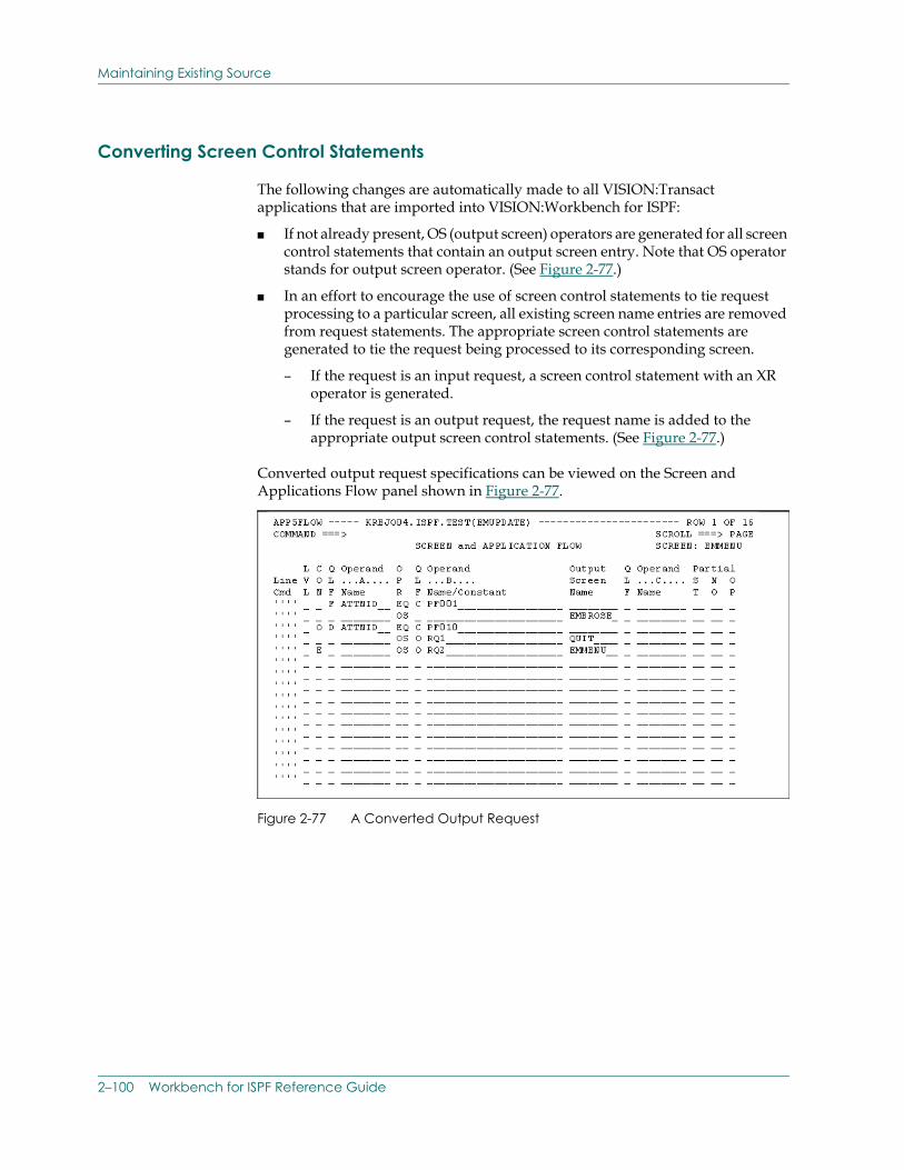
Maintaining Existing Source
Converting Screen Control Statements
The following changes are automatically made to all VISION:Transact applications that are imported into VISION:Workbench for ISPF:
■ If not already present, OS (output screen) operators are generated for all screen control statements that contain an output screen entry. Note that OS operator stands for output screen operator. (See Figure 2-77.)
■ In an effort to encourage the use of screen control statements to tie request processing to a particular screen, all existing screen name entries are removed from request statements. The appropriate screen control statements are generated to tie the request being processed to its corresponding screen.
– If the request is an input request, a screen control statement with an XR operator is generated.
– If the request is an output request, the request name is added to the appropriate output screen control statements. (See Figure 2-77.)
Converted output request specifications can be viewed on the Screen and Applications Flow panel shown in Figure 2-77.
Figure 2-77 A Converted Output Request
2–100 Workbench for ISPF Reference Guide
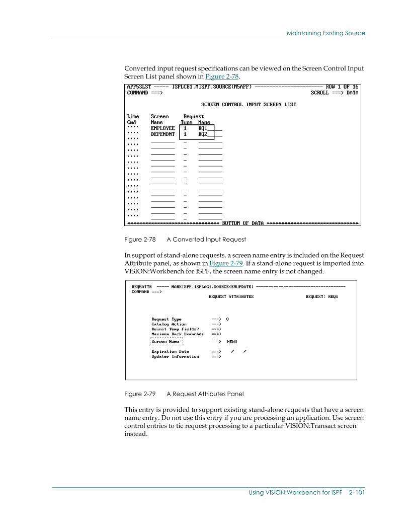
Maintaining Existing Source
Converted input request specifications can be viewed on the Screen Control Input Screen List panel shown in Figure 2-78.
Figure 2-78 A Converted Input Request
In support of stand-alone requests, a screen name entry is included on the Request Attribute panel, as shown in Figure 2-79. If a stand-alone request is imported into VISION:Workbench for ISPF, the screen name entry is not changed.
Figure 2-79 A Request Attributes Panel
This entry is provided to support existing stand-alone requests that have a screen name entry. Do not use this entry if you are processing an application. Use screen control entries to tie request processing to a particular VISION:Transact screen instead.
Using VISION:Workbench for ISPF 2–101
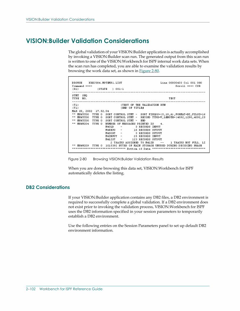
VISION:Builder Validation Considerations
VISION:Builder Validation Considerations The global validation of your VISION:Builder application is actually accomplished by invoking a VISION:Builder scan run. The generated output from this scan run is written to one of the VISION:Workbench for ISPF internal work data sets. When the scan run has completed, you are able to examine the validation results by browsing the work data set, as shown in Figure 2-80.
Figure 2-80 Browsing VISION:Builder Validation Results
When you are done browsing this data set, VISION:Workbench for ISPF automatically deletes the listing.
DB2 Considerations
If your VISION:Builder application contains any DB2 files, a DB2 environment is required to successfully complete a global validation. If a DB2 environment does not exist prior to invoking the validation process, VISION:Workbench for ISPF uses the DB2 information specified in your session parameters to temporarily establish a DB2 environment.
Use the following entries on the Session Parameters panel to set up default DB2 environment information.
2–102 Workbench for ISPF Reference Guide
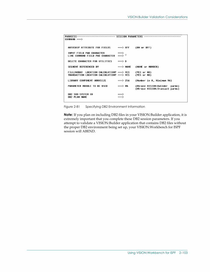
VISION:Builder Validation Considerations
Figure 2-81 Specifying DB2 Environment Information
Note: If you plan on including DB2 files in your VISION:Builder application, it is extremely important that you complete these DB2 session parameters. If you attempt to validate a VISION:Builder application that contains DB2 files without the proper DB2 environment being set up, your VISION:Workbench for ISPF session will ABEND.
Using VISION:Workbench for ISPF 2–103
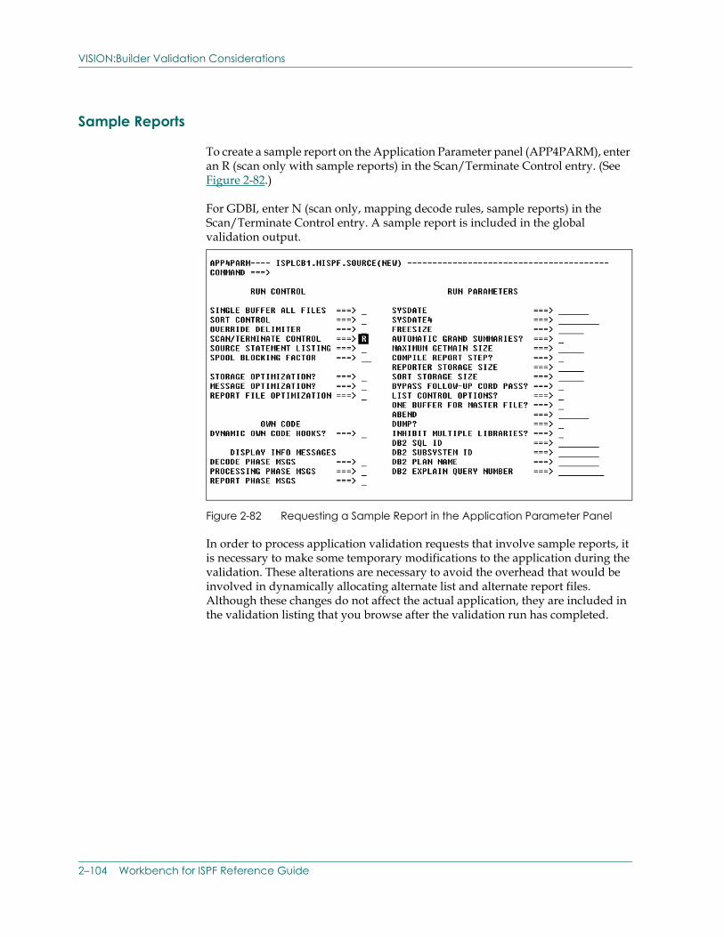
VISION:Builder Validation Considerations
Sample Reports
To create a sample report on the Application Parameter panel (APP4PARM), enter an R (scan only with sample reports) in the Scan/Terminate Control entry. (See Figure 2-82.)
For GDBI, enter N (scan only, mapping decode rules, sample reports) in the Scan/Terminate Control entry. A sample report is included in the global validation output.
Figure 2-82 Requesting a Sample Report in the Application Parameter Panel
In order to process application validation requests that involve sample reports, it is necessary to make some temporary modifications to the application during the validation. These alterations are necessary to avoid the overhead that would be involved in dynamically allocating alternate list and alternate report files. Although these changes do not affect the actual application, they are included in the validation listing that you browse after the validation run has completed.
2–104 Workbench for ISPF Reference Guide
VISION:Builder Validation Considerations
When processing an application validation run that includes sample reports, the following alterations are made to a copy of your application:
■ If the Scan/Terminate Control entry is R (scan only with sample reports) and you have specified the use of an alternate report file in your report parameter specifications, VISION:Workbench for ISPF temporarily sets the Source Statement Listing entry to D (report output to M4LIST1).
The Scan/Terminate and Source Statement Listing entries are found on the Application Parameter panel, APP4PARM.
■ If the Scan/Terminate Control entry is N (scan only, mapping decode rules, sample reports), VISION:Workbench for ISPF temporarily sets the Source Statement Listing entry to E (report output to include both application and mapping request statements).
The Scan/Terminate and Source Statement Listing entries are found on the Application Parameter panel, APP4PARM.
■ Application file entries that have a File Usage entry of M4REPn, are not included in the application validation run.
This File Usage entry is found on the Application Files panel, APP4FIL.
■ All Report Handling entries of RF (alternate report file) are temporarily replaced by a Report Handling entry of AL (alternate list file).
The Report Handling entry is found on the Report Output Specifications panel (REQ4REPT), within the Application Request option of VISION:Workbench for ISPF.
Using VISION:Workbench for ISPF 2–105
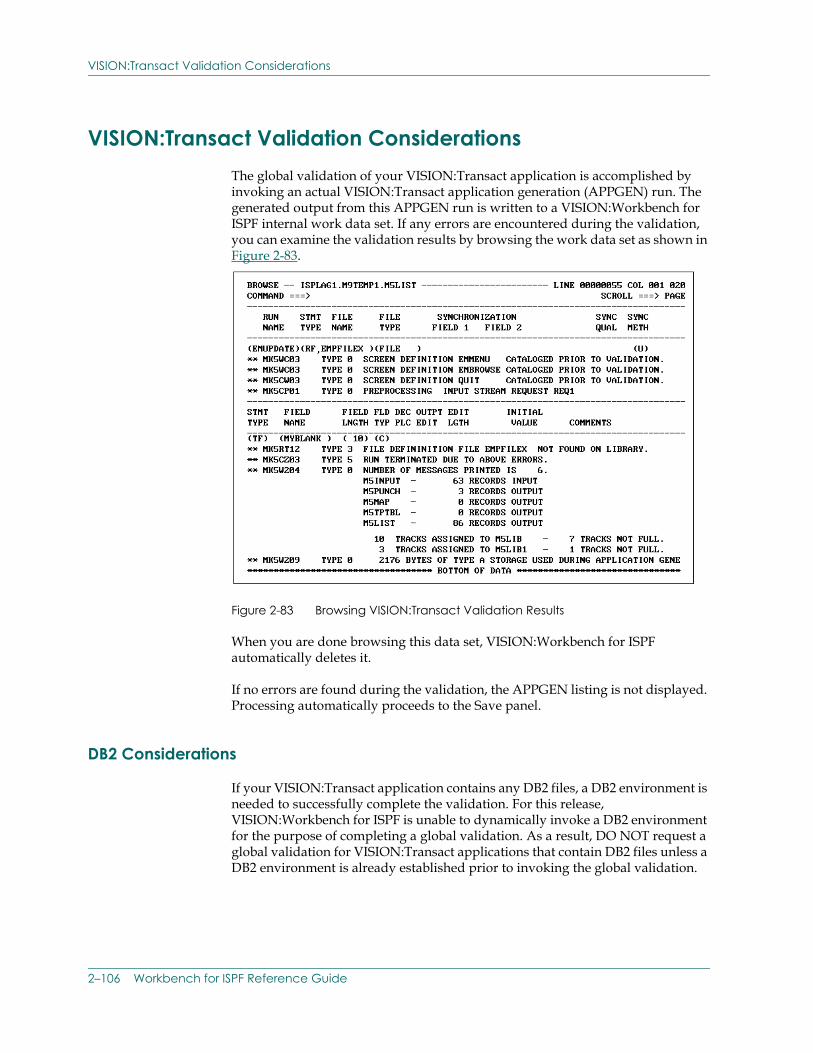
VISION:Transact Validation Considerations
VISION:Transact Validation Considerations The global validation of your VISION:Transact application is accomplished by invoking an actual VISION:Transact application generation (APPGEN) run. The generated output from this APPGEN run is written to a VISION:Workbench for ISPF internal work data set. If any errors are encountered during the validation, you can examine the validation results by browsing the work data set as shown in Figure 2-83.
Figure 2-83 Browsing VISION:Transact Validation Results
When you are done browsing this data set, VISION:Workbench for ISPF automatically deletes it.
If no errors are found during the validation, the APPGEN listing is not displayed. Processing automatically proceeds to the Save panel.
DB2 Considerations
If your VISION:Transact application contains any DB2 files, a DB2 environment is needed to successfully complete the validation. For this release, VISION:Workbench for ISPF is unable to dynamically invoke a DB2 environment for the purpose of completing a global validation. As a result, DO NOT request a global validation for VISION:Transact applications that contain DB2 files unless a DB2 environment is already established prior to invoking the global validation.
2–106 Workbench for ISPF Reference Guide
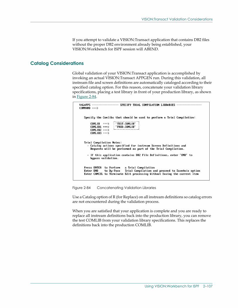
VISION:Transact Validation Considerations
If you attempt to validate a VISION:Transact application that contains DB2 files without the proper DB2 environment already being established, your VISION:Workbench for ISPF session will ABEND.
Catalog Considerations
Global validation of your VISION:Transact application is accomplished by invoking an actual VISION:Transact APPGEN run. During this validation, all instream file and screen definitions are automatically cataloged according to their specified catalog option. For this reason, concatenate your validation library specifications, placing a test library in front of your production library, as shown in Figure 2-84.
Figure 2-84 Concatenating Validation Libraries
Use a Catalog option of R (for Replace) on all instream definitions so catalog errors are not encountered during the validation process.
When you are satisfied that your application is complete and you are ready to replace all instream definitions back into the production library, you can remove the test COMLIB from your validation library specifications. This replaces the definitions back into the production COMLIB.
Using VISION:Workbench for ISPF 2–107
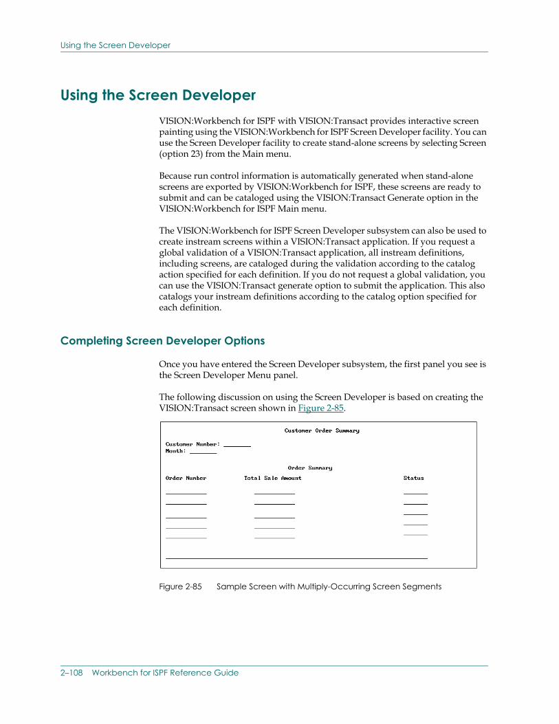
Using the Screen Developer
Using the Screen DeveloperVISION:Workbench for ISPF with VISION:Transact provides interactive screen painting using the VISION:Workbench for ISPF Screen Developer facility. You can use the Screen Developer facility to create stand-alone screens by selecting Screen (option 23) from the Main menu.
Because run control information is automatically generated when stand-alone screens are exported by VISION:Workbench for ISPF, these screens are ready to submit and can be cataloged using the VISION:Transact Generate option in the VISION:Workbench for ISPF Main menu.
The VISION:Workbench for ISPF Screen Developer subsystem can also be used to create instream screens within a VISION:Transact application. If you request a global validation of a VISION:Transact application, all instream definitions, including screens, are cataloged during the validation according to the catalog action specified for each definition. If you do not request a global validation, you can use the VISION:Transact generate option to submit the application. This also catalogs your instream definitions according to the catalog option specified for each definition.
Completing Screen Developer Options
Once you have entered the Screen Developer subsystem, the first panel you see is the Screen Developer Menu panel.
The following discussion on using the Screen Developer is based on creating the VISION:Transact screen shown in Figure 2-85.
Figure 2-85 Sample Screen with Multiply-Occurring Screen Segments
2–108 Workbench for ISPF Reference Guide
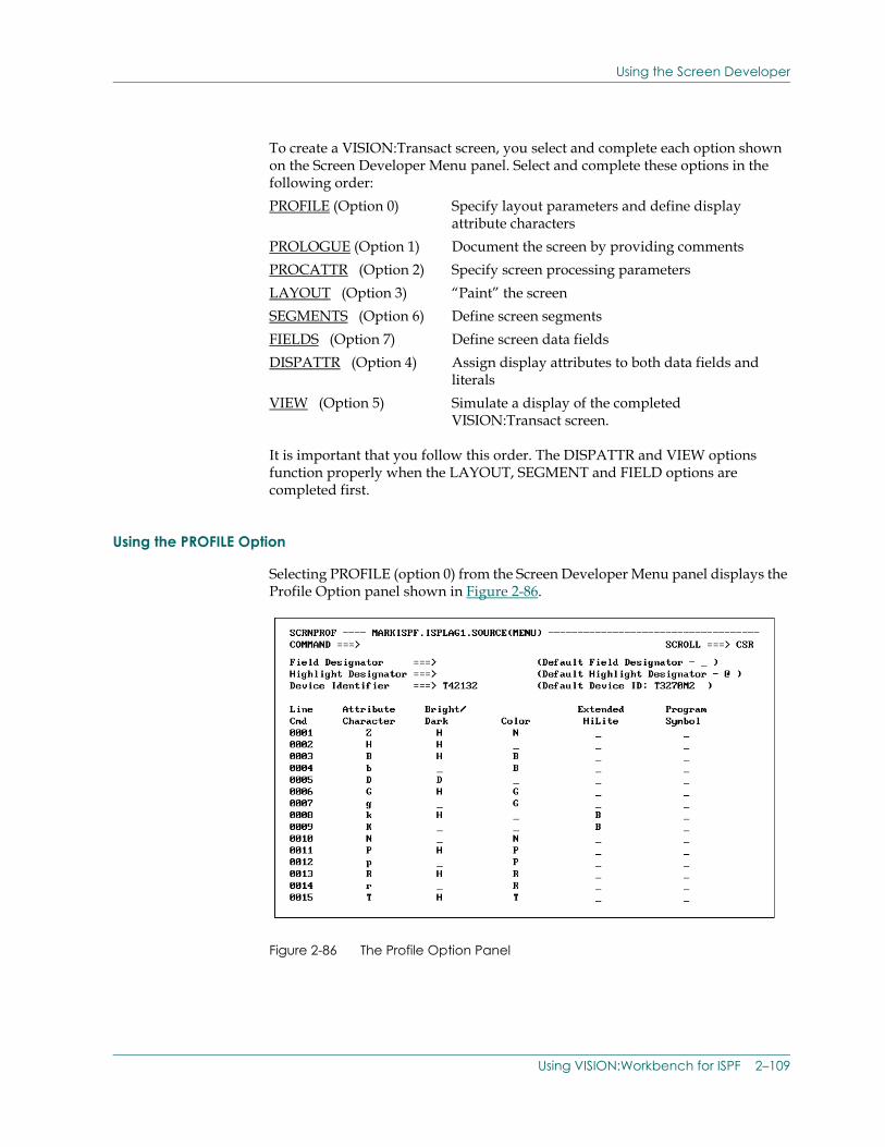
Using the Screen Developer
To create a VISION:Transact screen, you select and complete each option shown on the Screen Developer Menu panel. Select and complete these options in the following order:
It is important that you follow this order. The DISPATTR and VIEW options function properly when the LAYOUT, SEGMENT and FIELD options are completed first.
Using the PROFILE Option
Selecting PROFILE (option 0) from the Screen Developer Menu panel displays the Profile Option panel shown in Figure 2-86.
Figure 2-86 The Profile Option Panel
PROFILE (Option 0) Specify layout parameters and define display attribute characters
PROLOGUE (Option 1) Document the screen by providing commentsPROCATTR (Option 2) Specify screen processing parametersLAYOUT (Option 3) “Paint” the screenSEGMENTS (Option 6) Define screen segmentsFIELDS (Option 7) Define screen data fieldsDISPATTR (Option 4) Assign display attributes to both data fields and
literalsVIEW (Option 5) Simulate a display of the completed
VISION:Transact screen.
Using VISION:Workbench for ISPF 2–109
Using the Screen Developer
The information on this Profile Option panel can be divided into two sections:
■ Layout information.
■ Attribute information.
The layout section of this panel provides VISION:Workbench for ISPF with the information necessary to process and generate your VISION:Transact screen layout source statements.
The layout information section contains the following entries:
Field Designator identifies what character is to be used to indicate the placement and length of data fields on the screen in the LAYOUT option. You do not have to make an entry in this field unless you want to override the default field designator character that is shown.
Highlight Designator identifies what character VISION:Workbench for ISPF should use to generate highlighted literals on VISION:Transact screen layout source statements. If you do not specify a highlight character, the default highlight character shown is automatically used by VISION:Workbench for ISPF when generating your screen layout source statements.
Unlike coding in native VISION:Transact, when using the Screen Developer to create screens, you do not use the highlight character within the LAYOUT option to indicate highlighting of literals. All display attribute characteristics are assigned through the Display Attribute option, DISPATTR.
Device Identifier identifies what type of screen you are generating. You can specify any device identifier that has been previously defined in your VISION:Transact device table.
2–110 Workbench for ISPF Reference Guide
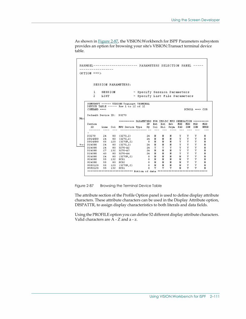
Using the Screen Developer
As shown in Figure 2-87, the VISION:Workbench for ISPF Parameters subsystem provides an option for browsing your site's VISION:Transact terminal device table.
Figure 2-87 Browsing the Terminal Device Table
The attribute section of the Profile Option panel is used to define display attribute characters. These attribute characters can be used in the Display Attribute option, DISPATTR, to assign display characteristics to both literals and data fields.
Using the PROFILE option you can define 52 different display attribute characters. Valid characters are A - Z and a - z.
Using VISION:Workbench for ISPF 2–111
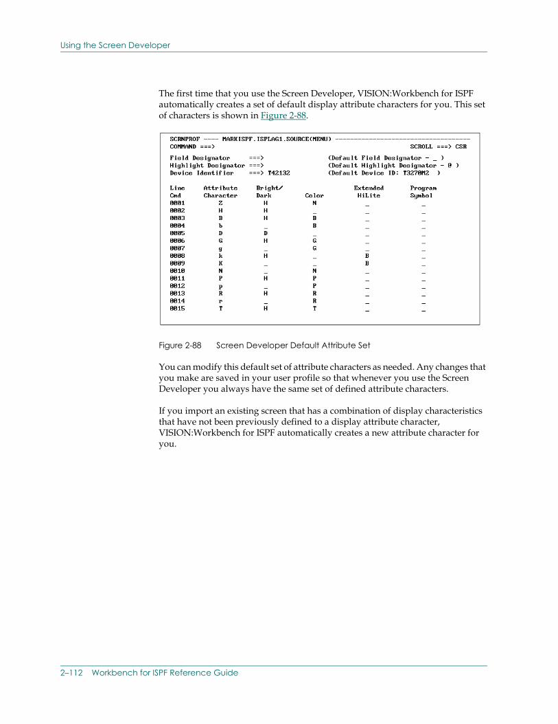
Using the Screen Developer
The first time that you use the Screen Developer, VISION:Workbench for ISPF automatically creates a set of default display attribute characters for you. This set of characters is shown in Figure 2-88.
Figure 2-88 Screen Developer Default Attribute Set
You can modify this default set of attribute characters as needed. Any changes that you make are saved in your user profile so that whenever you use the Screen Developer you always have the same set of defined attribute characters.
If you import an existing screen that has a combination of display characteristics that have not been previously defined to a display attribute character, VISION:Workbench for ISPF automatically creates a new attribute character for you.
2–112 Workbench for ISPF Reference Guide
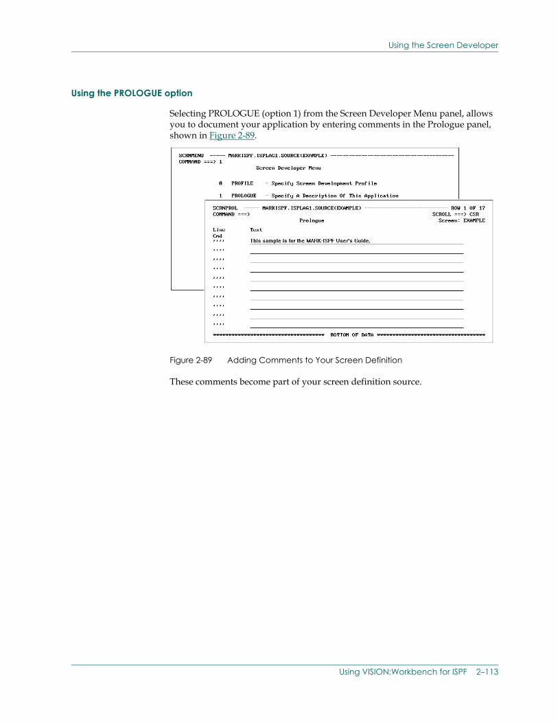
Using the Screen Developer
Using the PROLOGUE option
Selecting PROLOGUE (option 1) from the Screen Developer Menu panel, allows you to document your application by entering comments in the Prologue panel, shown in Figure 2-89.
Figure 2-89 Adding Comments to Your Screen Definition
These comments become part of your screen definition source.
Using VISION:Workbench for ISPF 2–113
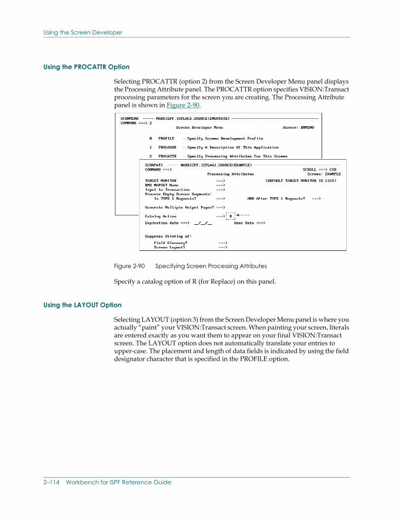
Using the Screen Developer
Using the PROCATTR Option
Selecting PROCATTR (option 2) from the Screen Developer Menu panel displays the Processing Attribute panel. The PROCATTR option specifies VISION:Transact processing parameters for the screen you are creating. The Processing Attribute panel is shown in Figure 2-90.
Figure 2-90 Specifying Screen Processing Attributes
Specify a catalog option of R (for Replace) on this panel.
Using the LAYOUT Option
Selecting LAYOUT (option 3) from the Screen Developer Menu panel is where you actually “paint” your VISION:Transact screen. When painting your screen, literals are entered exactly as you want them to appear on your final VISION:Transact screen. The LAYOUT option does not automatically translate your entries to upper-case. The placement and length of data fields is indicated by using the field designator character that is specified in the PROFILE option.
2–114 Workbench for ISPF Reference Guide
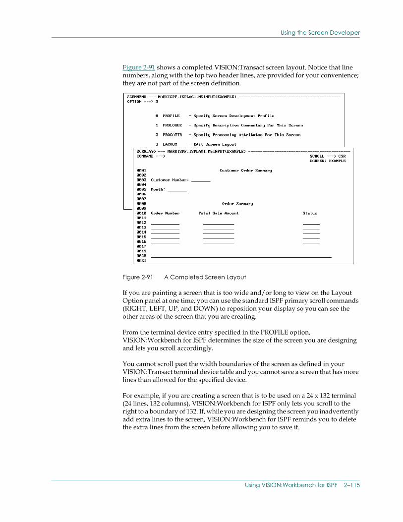
Using the Screen Developer
Figure 2-91 shows a completed VISION:Transact screen layout. Notice that line numbers, along with the top two header lines, are provided for your convenience; they are not part of the screen definition.
Figure 2-91 A Completed Screen Layout
If you are painting a screen that is too wide and/or long to view on the Layout Option panel at one time, you can use the standard ISPF primary scroll commands (RIGHT, LEFT, UP, and DOWN) to reposition your display so you can see the other areas of the screen that you are creating.
From the terminal device entry specified in the PROFILE option, VISION:Workbench for ISPF determines the size of the screen you are designing and lets you scroll accordingly.
You cannot scroll past the width boundaries of the screen as defined in your VISION:Transact terminal device table and you cannot save a screen that has more lines than allowed for the specified device.
For example, if you are creating a screen that is to be used on a 24 x 132 terminal (24 lines, 132 columns), VISION:Workbench for ISPF only lets you scroll to the right to a boundary of 132. If, while you are designing the screen you inadvertently add extra lines to the screen, VISION:Workbench for ISPF reminds you to delete the extra lines from the screen before allowing you to save it.
Using VISION:Workbench for ISPF 2–115
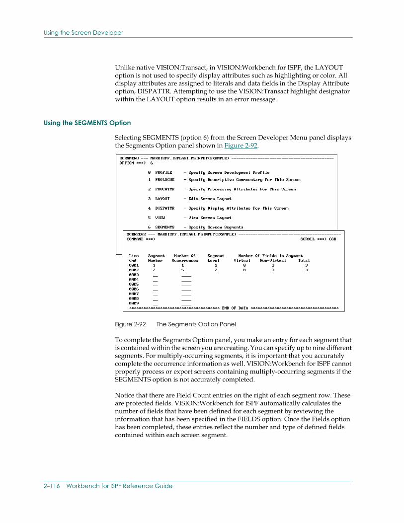
Using the Screen Developer
Unlike native VISION:Transact, in VISION:Workbench for ISPF, the LAYOUT option is not used to specify display attributes such as highlighting or color. All display attributes are assigned to literals and data fields in the Display Attribute option, DISPATTR. Attempting to use the VISION:Transact highlight designator within the LAYOUT option results in an error message.
Using the SEGMENTS Option
Selecting SEGMENTS (option 6) from the Screen Developer Menu panel displays the Segments Option panel shown in Figure 2-92.
Figure 2-92 The Segments Option Panel
To complete the Segments Option panel, you make an entry for each segment that is contained within the screen you are creating. You can specify up to nine different segments. For multiply-occurring segments, it is important that you accurately complete the occurrence information as well. VISION:Workbench for ISPF cannot properly process or export screens containing multiply-occurring segments if the SEGMENTS option is not accurately completed.
Notice that there are Field Count entries on the right of each segment row. These are protected fields. VISION:Workbench for ISPF automatically calculates the number of fields that have been defined for each segment by reviewing the information that has been specified in the FIELDS option. Once the Fields option has been completed, these entries reflect the number and type of defined fields contained within each screen segment.
2–116 Workbench for ISPF Reference Guide
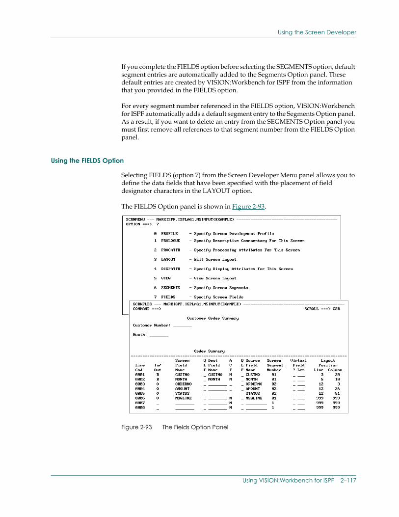
Using the Screen Developer
If you complete the FIELDS option before selecting the SEGMENTS option, default segment entries are automatically added to the Segments Option panel. These default entries are created by VISION:Workbench for ISPF from the information that you provided in the FIELDS option.
For every segment number referenced in the FIELDS option, VISION:Workbench for ISPF automatically adds a default segment entry to the Segments Option panel. As a result, if you want to delete an entry from the SEGMENTS Option panel you must first remove all references to that segment number from the FIELDS Option panel.
Using the FIELDS Option
Selecting FIELDS (option 7) from the Screen Developer Menu panel allows you to define the data fields that have been specified with the placement of field designator characters in the LAYOUT option.
The FIELDS Option panel is shown in Figure 2-93.
Figure 2-93 The Fields Option Panel
Using VISION:Workbench for ISPF 2–117
Using the Screen Developer
Note that the Fields Option panel has two separate display areas. The top display area allows you to browse your screen layout as it is currently defined. It can be thought of as a miniature VIEW option. This can serve as a useful reminder when defining your screen data fields.
The bottom display area of this panel is where you actually start to define your data fields.
Use the following guidelines when completing the Screen Developer FIELDS option:
■ Fields should be defined in the exact sequence (left to right, top to bottom) that they appear on the Layout Option panel.
■ Only the first occurrence of multiply-occurring fields should be defined.
■ With the exception of virtual fields, all fields must be assigned a unique screen field name. Duplicate screen field names must not be specified. Input/output fields should be specified as one entry, using the IN/OUT specification of B (for both).
■ It is important that you accurately complete the Segment entry. All segment numbers entered here should have been previously defined in the SEGMENTS option. If you do not complete the SEGMENTS option first, default segment entries are added to the Segments Option panel for all segment numbers that are referenced on the Fields Option panel. As a result, to delete a default Segment entry from the SEGMENTS option, you must first remove all references of that segment number from the Fields Option panel.
■ The Layout Position fields are informational entries that are automatically calculated by VISION:Workbench for ISPF. These positions represent the starting location of each data field that has been defined in the LAYOUT option. For multiply-occurring fields, only the starting location of the first occurrence is displayed.
In order for the layout position information to be correct, you must properly complete the LAYOUT and SEGMENT options prior to entering the FIELDS option. If you find that the specified layout positions do not correspond to the fields you are defining, incorrect data has been entered in either your LAYOUT, SEGMENTS, or FIELDS option.
Figure 2-93, shows how preliminary field information for the sample screen is to be completed.
Notice how the fields are defined in the exact order that they appear on the Layout Option panel. Only the first occurrence of the multiply-occurring segment 2 fields are defined.
2–118 Workbench for ISPF Reference Guide
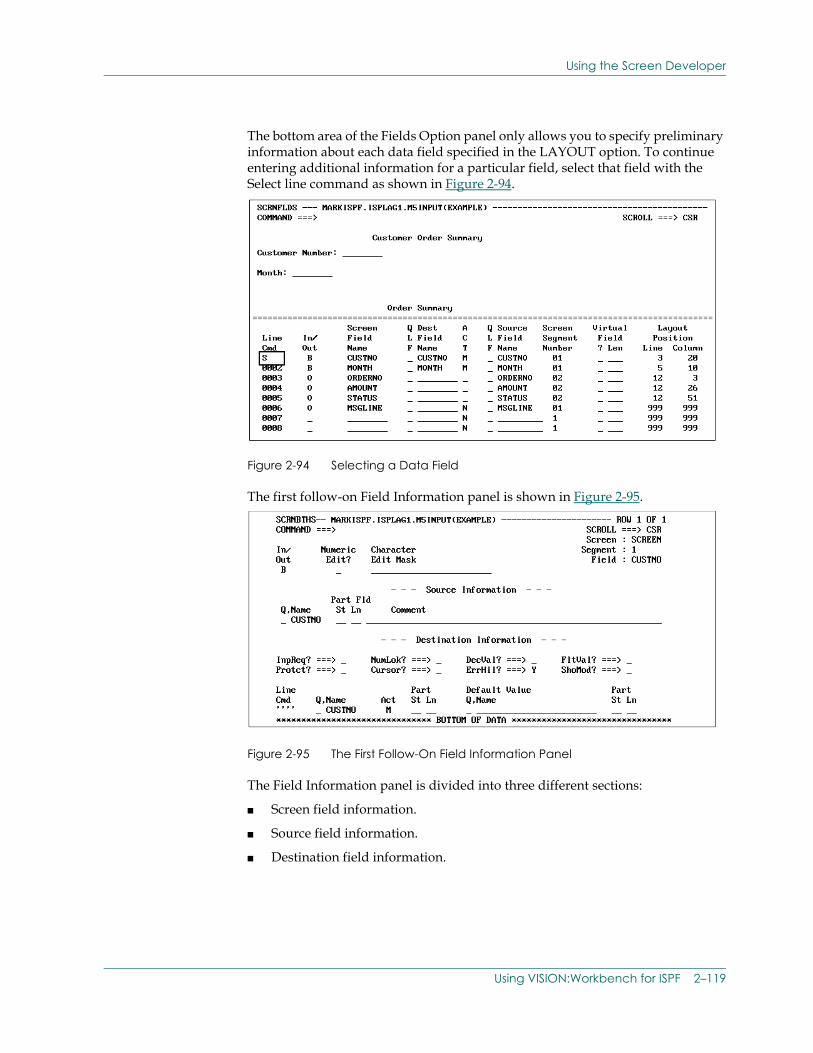
Using the Screen Developer
The bottom area of the Fields Option panel only allows you to specify preliminary information about each data field specified in the LAYOUT option. To continue entering additional information for a particular field, select that field with the Select line command as shown in Figure 2-94.
Figure 2-94 Selecting a Data Field
The first follow-on Field Information panel is shown in Figure 2-95.
Figure 2-95 The First Follow-On Field Information Panel
The Field Information panel is divided into three different sections:
■ Screen field information.
■ Source field information.
■ Destination field information.
Using VISION:Workbench for ISPF 2–119
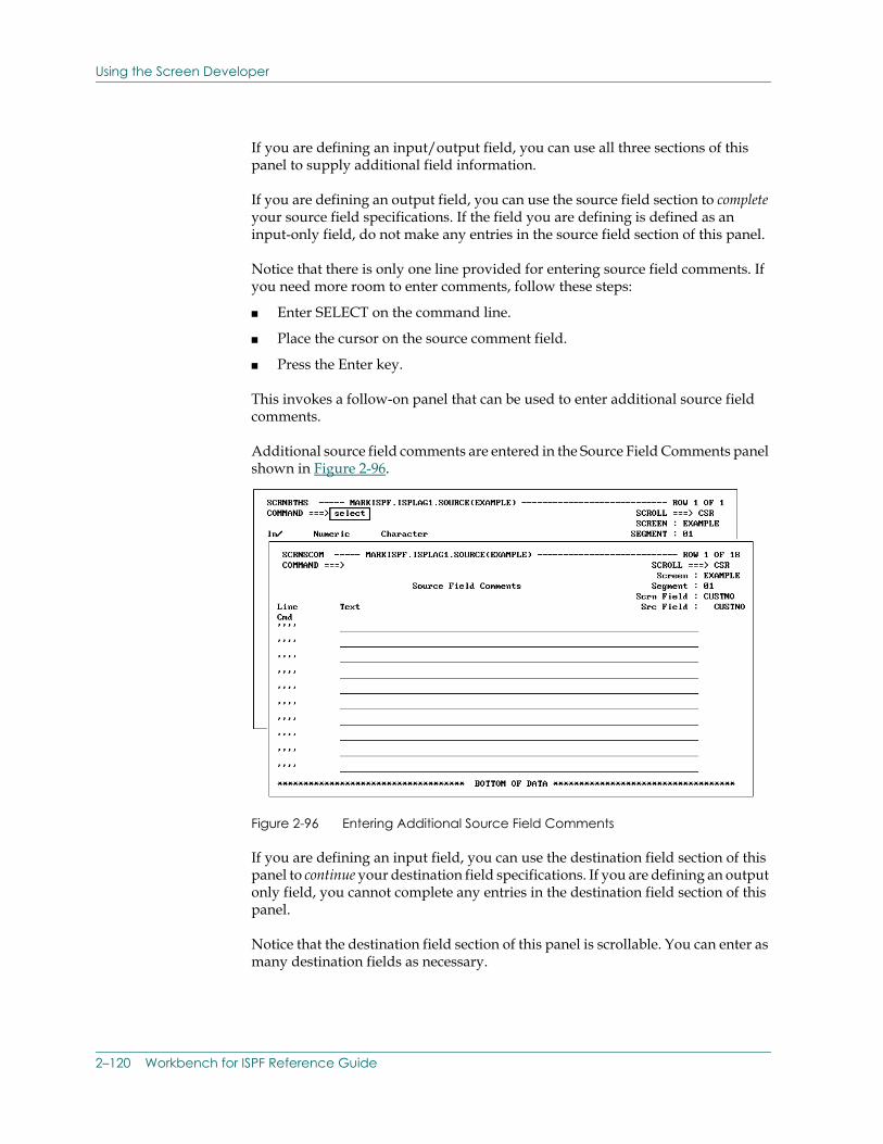
Using the Screen Developer
If you are defining an input/output field, you can use all three sections of this panel to supply additional field information.
If you are defining an output field, you can use the source field section to complete your source field specifications. If the field you are defining is defined as an input-only field, do not make any entries in the source field section of this panel.
Notice that there is only one line provided for entering source field comments. If you need more room to enter comments, follow these steps:
■ Enter SELECT on the command line.
■ Place the cursor on the source comment field.
■ Press the Enter key.
This invokes a follow-on panel that can be used to enter additional source field comments.
Additional source field comments are entered in the Source Field Comments panel shown in Figure 2-96.
Figure 2-96 Entering Additional Source Field Comments
If you are defining an input field, you can use the destination field section of this panel to continue your destination field specifications. If you are defining an output only field, you cannot complete any entries in the destination field section of this panel.
Notice that the destination field section of this panel is scrollable. You can enter as many destination fields as necessary.
2–120 Workbench for ISPF Reference Guide
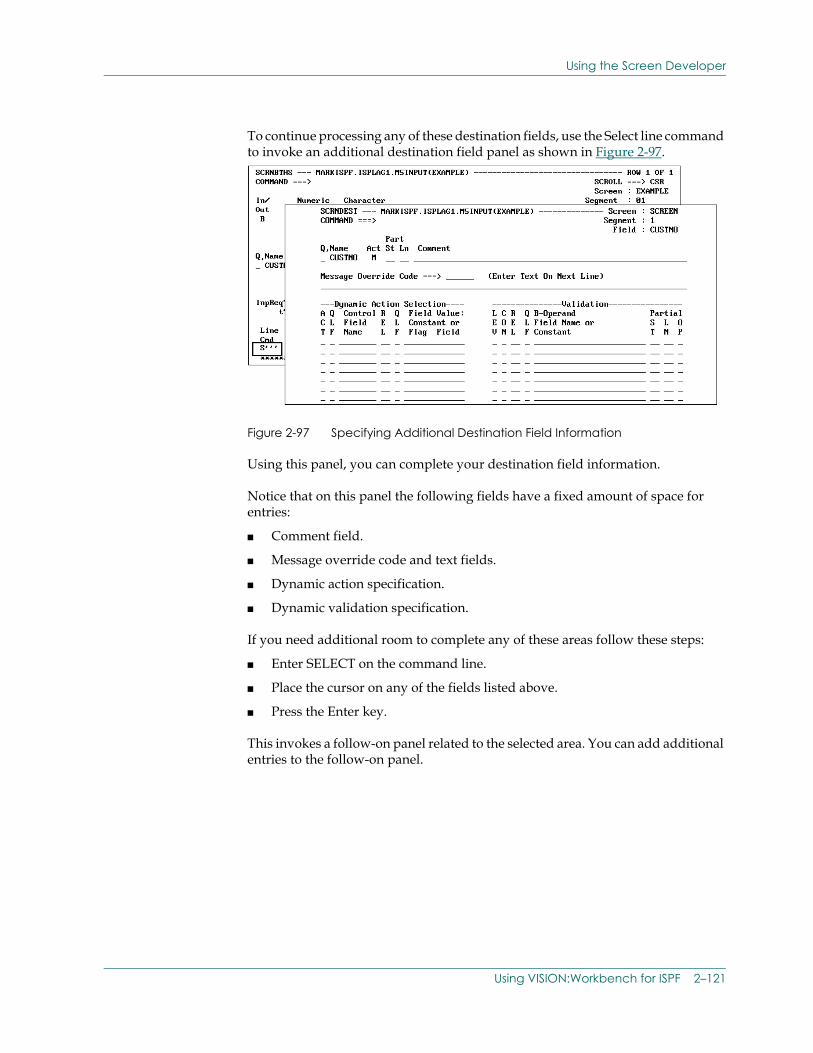
Using the Screen Developer
To continue processing any of these destination fields, use the Select line command to invoke an additional destination field panel as shown in Figure 2-97.
Figure 2-97 Specifying Additional Destination Field Information
Using this panel, you can complete your destination field information.
Notice that on this panel the following fields have a fixed amount of space for entries:
■ Comment field.
■ Message override code and text fields.
■ Dynamic action specification.
■ Dynamic validation specification.
If you need additional room to complete any of these areas follow these steps:
■ Enter SELECT on the command line.
■ Place the cursor on any of the fields listed above.
■ Press the Enter key.
This invokes a follow-on panel related to the selected area. You can add additional entries to the follow-on panel.
Using VISION:Workbench for ISPF 2–121
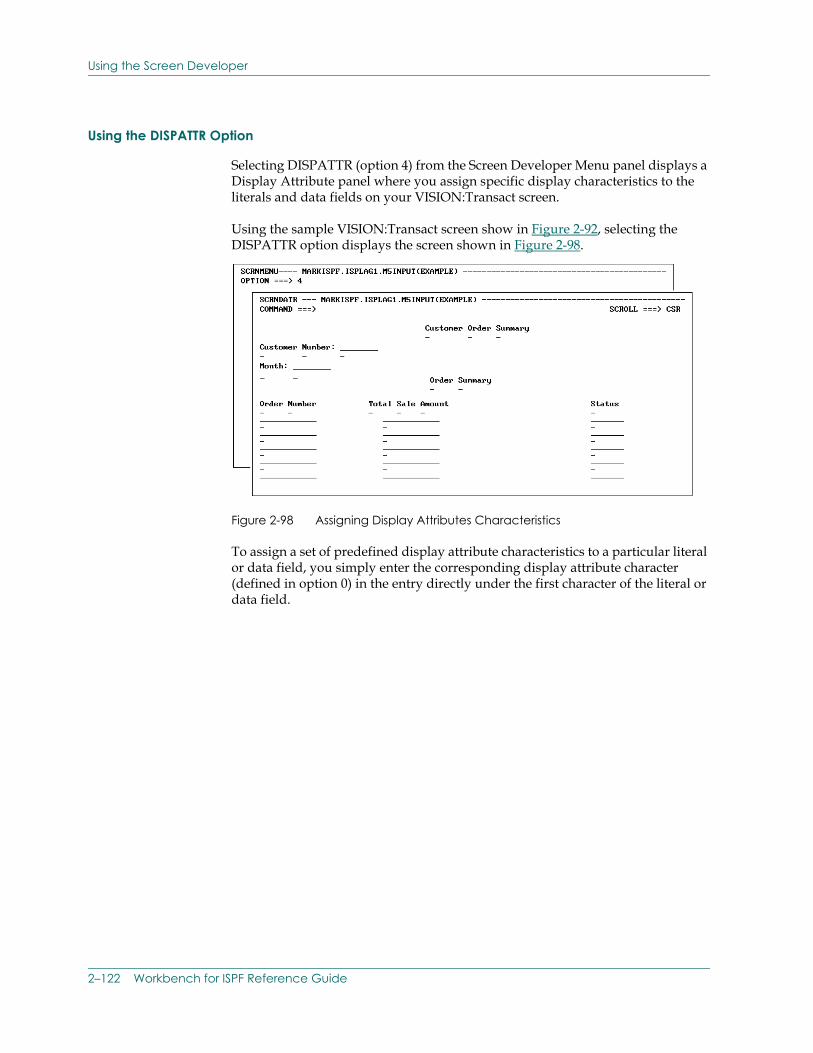
Using the Screen Developer
Using the DISPATTR Option
Selecting DISPATTR (option 4) from the Screen Developer Menu panel displays a Display Attribute panel where you assign specific display characteristics to the literals and data fields on your VISION:Transact screen.
Using the sample VISION:Transact screen show in Figure 2-92, selecting the DISPATTR option displays the screen shown in Figure 2-98.
Figure 2-98 Assigning Display Attributes Characteristics
To assign a set of predefined display attribute characteristics to a particular literal or data field, you simply enter the corresponding display attribute character (defined in option 0) in the entry directly under the first character of the literal or data field.
2–122 Workbench for ISPF Reference Guide
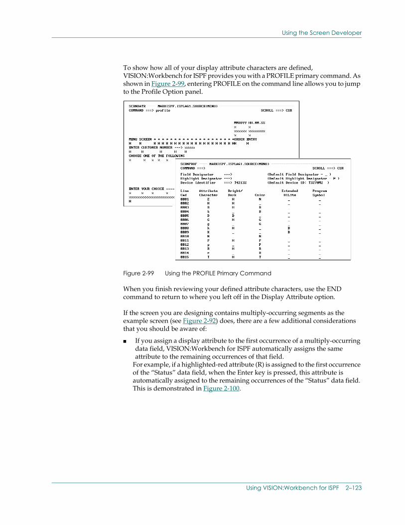
Using the Screen Developer
To show how all of your display attribute characters are defined, VISION:Workbench for ISPF provides you with a PROFILE primary command. As shown in Figure 2-99, entering PROFILE on the command line allows you to jump to the Profile Option panel.
Figure 2-99 Using the PROFILE Primary Command
When you finish reviewing your defined attribute characters, use the END command to return to where you left off in the Display Attribute option.
If the screen you are designing contains multiply-occurring segments as the example screen (see Figure 2-92) does, there are a few additional considerations that you should be aware of:
■ If you assign a display attribute to the first occurrence of a multiply-occurring data field, VISION:Workbench for ISPF automatically assigns the same attribute to the remaining occurrences of that field.
For example, if a highlighted-red attribute (R) is assigned to the first occurrence of the “Status” data field, when the Enter key is pressed, this attribute is automatically assigned to the remaining occurrences of the “Status” data field. This is demonstrated in Figure 2-100.
Using VISION:Workbench for ISPF 2–123
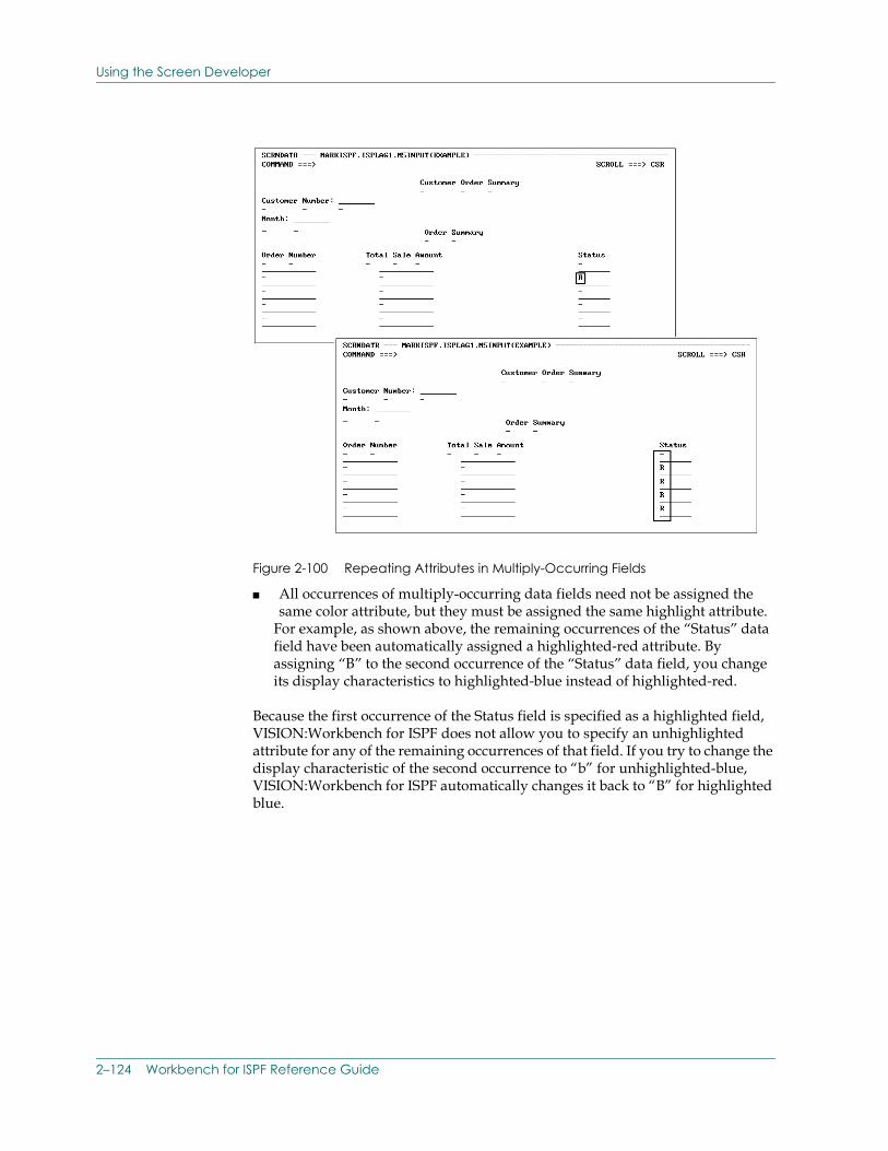
Using the Screen Developer
Figure 2-100 Repeating Attributes in Multiply-Occurring Fields
■ All occurrences of multiply-occurring data fields need not be assigned the same color attribute, but they must be assigned the same highlight attribute.
For example, as shown above, the remaining occurrences of the “Status” data field have been automatically assigned a highlighted-red attribute. By assigning “B” to the second occurrence of the “Status” data field, you change its display characteristics to highlighted-blue instead of highlighted-red.
Because the first occurrence of the Status field is specified as a highlighted field, VISION:Workbench for ISPF does not allow you to specify an unhighlighted attribute for any of the remaining occurrences of that field. If you try to change the display characteristic of the second occurrence to “b” for unhighlighted-blue, VISION:Workbench for ISPF automatically changes it back to “B” for highlighted blue.
2–124 Workbench for ISPF Reference Guide
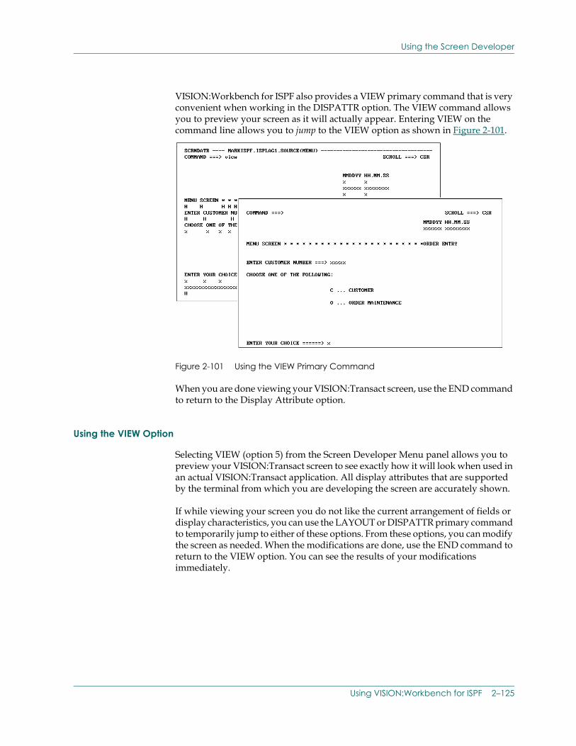
Using the Screen Developer
VISION:Workbench for ISPF also provides a VIEW primary command that is very convenient when working in the DISPATTR option. The VIEW command allows you to preview your screen as it will actually appear. Entering VIEW on the command line allows you to jump to the VIEW option as shown in Figure 2-101.
Figure 2-101 Using the VIEW Primary Command
When you are done viewing your VISION:Transact screen, use the END command to return to the Display Attribute option.
Using the VIEW Option
Selecting VIEW (option 5) from the Screen Developer Menu panel allows you to preview your VISION:Transact screen to see exactly how it will look when used in an actual VISION:Transact application. All display attributes that are supported by the terminal from which you are developing the screen are accurately shown.
If while viewing your screen you do not like the current arrangement of fields or display characteristics, you can use the LAYOUT or DISPATTR primary command to temporarily jump to either of these options. From these options, you can modify the screen as needed. When the modifications are done, use the END command to return to the VIEW option. You can see the results of your modifications immediately.
Using VISION:Workbench for ISPF 2–125
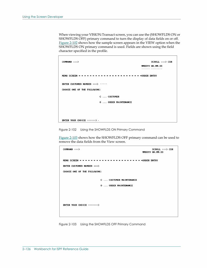
Using the Screen Developer
When viewing your VISION:Transact screen, you can use the (SHOWFLDS ON or SHOWFLDS OFF) primary command to turn the display of data fields on or off. Figure 2-102 shows how the sample screen appears in the VIEW option when the SHOWFLDS ON primary command is used. Fields are shown using the field character specified in the profile.
Figure 2-102 Using the SHOWFLDS ON Primary Command
Figure 2-103 shows how the SHOWFLDS OFF primary command can be used to remove the data fields from the View screen.
Figure 2-103 Using the SHOWFLDS OFF Primary Command
2–126 Workbench for ISPF Reference Guide
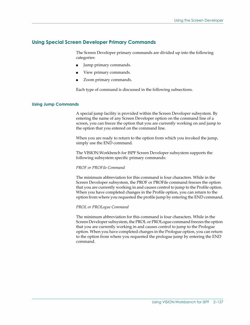
Using the Screen Developer
Using Special Screen Developer Primary Commands
The Screen Developer primary commands are divided up into the following categories:
■ Jump primary commands.
■ View primary commands.
■ Zoom primary commands.
Each type of command is discussed in the following subsections.
Using Jump Commands
A special jump facility is provided within the Screen Developer subsystem. By entering the name of any Screen Developer option on the command line of a screen, you can freeze the option that you are currently working on and jump to the option that you entered on the command line.
When you are ready to return to the option from which you invoked the jump, simply use the END command.
The VISION:Workbench for ISPF Screen Developer subsystem supports the following subsystem specific primary commands:
PROF or PROFile Command
The minimum abbreviation for this command is four characters. While in the Screen Developer subsystem, the PROF or PROFile command freezes the option that you are currently working in and causes control to jump to the Profile option. When you have completed changes in the Profile option, you can return to the option from where you requested the profile jump by entering the END command.
PROL or PROLogue Command
The minimum abbreviation for this command is four characters. While in the Screen Developer subsystem, the PROL or PROLogue command freezes the option that you are currently working in and causes control to jump to the Prologue option. When you have completed changes in the Prologue option, you can return to the option from where you requested the prologue jump by entering the END command.
Using VISION:Workbench for ISPF 2–127
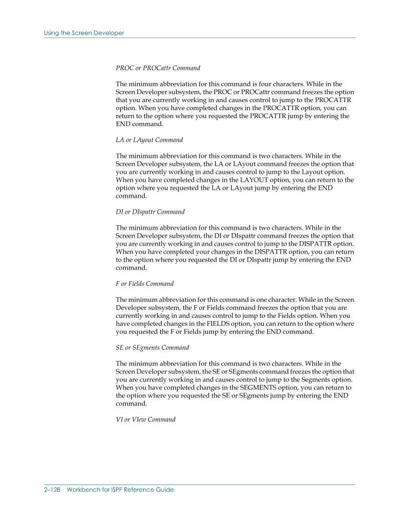
Using the Screen Developer
PROC or PROCattr Command
The minimum abbreviation for this command is four characters. While in the Screen Developer subsystem, the PROC or PROCattr command freezes the option that you are currently working in and causes control to jump to the PROCATTR option. When you have completed changes in the PROCATTR option, you can return to the option where you requested the PROCATTR jump by entering the END command.
LA or LAyout Command
The minimum abbreviation for this command is two characters. While in the Screen Developer subsystem, the LA or LAyout command freezes the option that you are currently working in and causes control to jump to the Layout option. When you have completed changes in the LAYOUT option, you can return to the option where you requested the LA or LAyout jump by entering the END command.
DI or DIspattr Command
The minimum abbreviation for this command is two characters. While in the Screen Developer subsystem, the DI or DIspattr command freezes the option that you are currently working in and causes control to jump to the DISPATTR option. When you have completed your changes in the DISPATTR option, you can return to the option where you requested the DI or DIspattr jump by entering the END command.
F or Fields Command
The minimum abbreviation for this command is one character. While in the Screen Developer subsystem, the F or Fields command freezes the option that you are currently working in and causes control to jump to the Fields option. When you have completed changes in the FIELDS option, you can return to the option where you requested the F or Fields jump by entering the END command.
SE or SEgments Command
The minimum abbreviation for this command is two characters. While in the Screen Developer subsystem, the SE or SEgments command freezes the option that you are currently working in and causes control to jump to the Segments option. When you have completed changes in the SEGMENTS option, you can return to the option where you requested the SE or SEgments jump by entering the END command.
VI or VIew Command
2–128 Workbench for ISPF Reference Guide
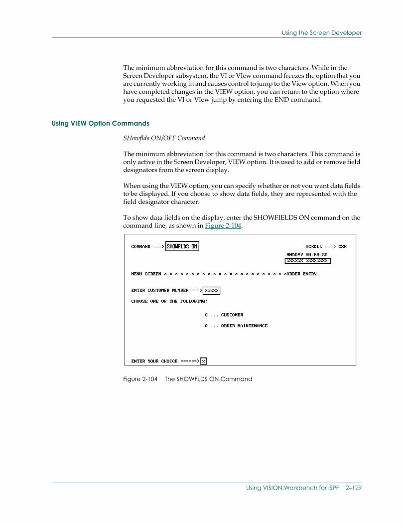
Using the Screen Developer
The minimum abbreviation for this command is two characters. While in the Screen Developer subsystem, the VI or VIew command freezes the option that you are currently working in and causes control to jump to the View option. When you have completed changes in the VIEW option, you can return to the option where you requested the VI or VIew jump by entering the END command.
Using VIEW Option Commands
SHowflds ON/OFF Command
The minimum abbreviation for this command is two characters. This command is only active in the Screen Developer, VIEW option. It is used to add or remove field designators from the screen display.
When using the VIEW option, you can specify whether or not you want data fields to be displayed. If you choose to show data fields, they are represented with the field designator character.
To show data fields on the display, enter the SHOWFIELDS ON command on the command line, as shown in Figure 2-104.
Figure 2-104 The SHOWFLDS ON Command
Using VISION:Workbench for ISPF 2–129
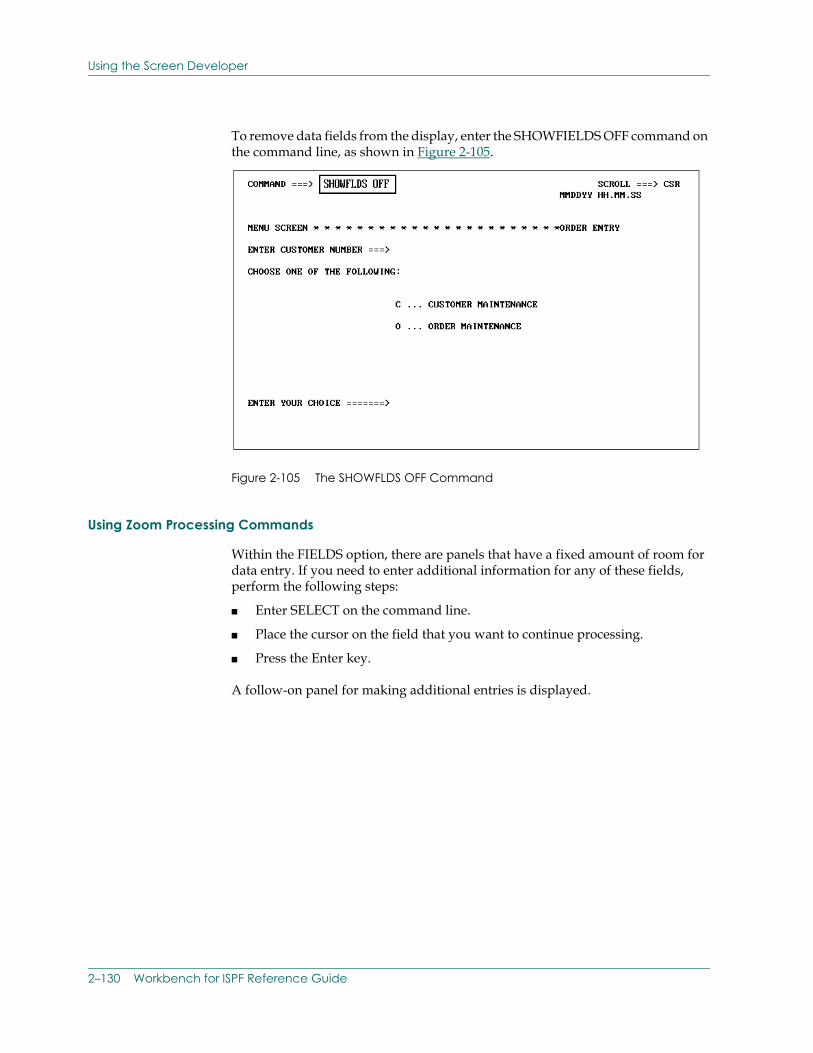
Using the Screen Developer
To remove data fields from the display, enter the SHOWFIELDS OFF command on the command line, as shown in Figure 2-105.
Figure 2-105 The SHOWFLDS OFF Command
Using Zoom Processing Commands
Within the FIELDS option, there are panels that have a fixed amount of room for data entry. If you need to enter additional information for any of these fields, perform the following steps:
■ Enter SELECT on the command line.
■ Place the cursor on the field that you want to continue processing.
■ Press the Enter key.
A follow-on panel for making additional entries is displayed.
2–130 Workbench for ISPF Reference Guide
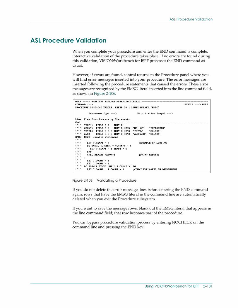
ASL Procedure Validation
ASL Procedure ValidationWhen you complete your procedure and enter the END command, a complete, interactive validation of the procedure takes place. If no errors are found during this validation, VISION:Workbench for ISPF processes the END command as usual.
However, if errors are found, control returns to the Procedure panel where you will find error messages inserted into your procedure. The error messages are inserted following the procedure statements that caused the errors. These error messages are recognized by the EMSG literal inserted into the line command field, as shown in Figure 2-106.
Figure 2-106 Validating a Procedure
If you do not delete the error message lines before entering the END command again, rows that have the EMSG literal in the command line are automatically deleted when you exit the Procedure subsystem.
If you want to save the message rows, blank out the EMSG literal that appears in the line command field; that row becomes part of the procedure.
You can bypass procedure validation process by entering NOCHECK on the command line and pressing the END key.
Using VISION:Workbench for ISPF 2–131
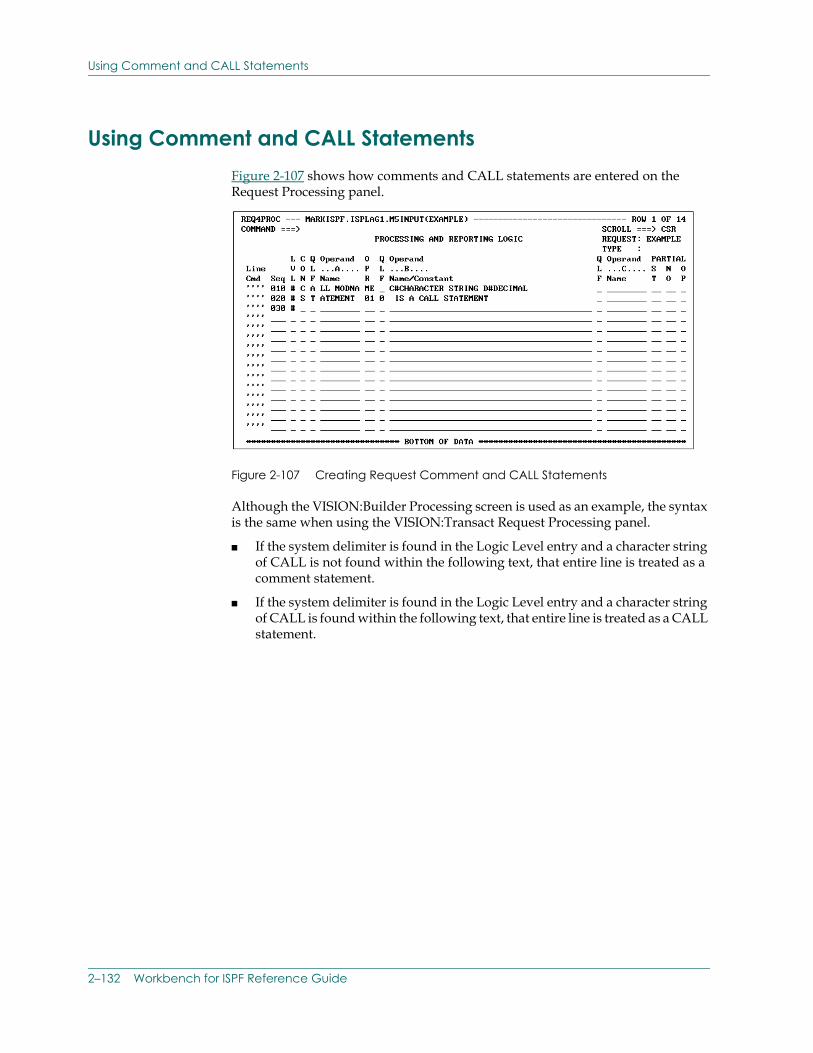
Using Comment and CALL Statements
Using Comment and CALL StatementsFigure 2-107 shows how comments and CALL statements are entered on the Request Processing panel.
Figure 2-107 Creating Request Comment and CALL Statements
Although the VISION:Builder Processing screen is used as an example, the syntax is the same when using the VISION:Transact Request Processing panel.
■ If the system delimiter is found in the Logic Level entry and a character string of CALL is not found within the following text, that entire line is treated as a comment statement.
■ If the system delimiter is found in the Logic Level entry and a character string of CALL is found within the following text, that entire line is treated as a CALL statement.
2–132 Workbench for ISPF Reference Guide
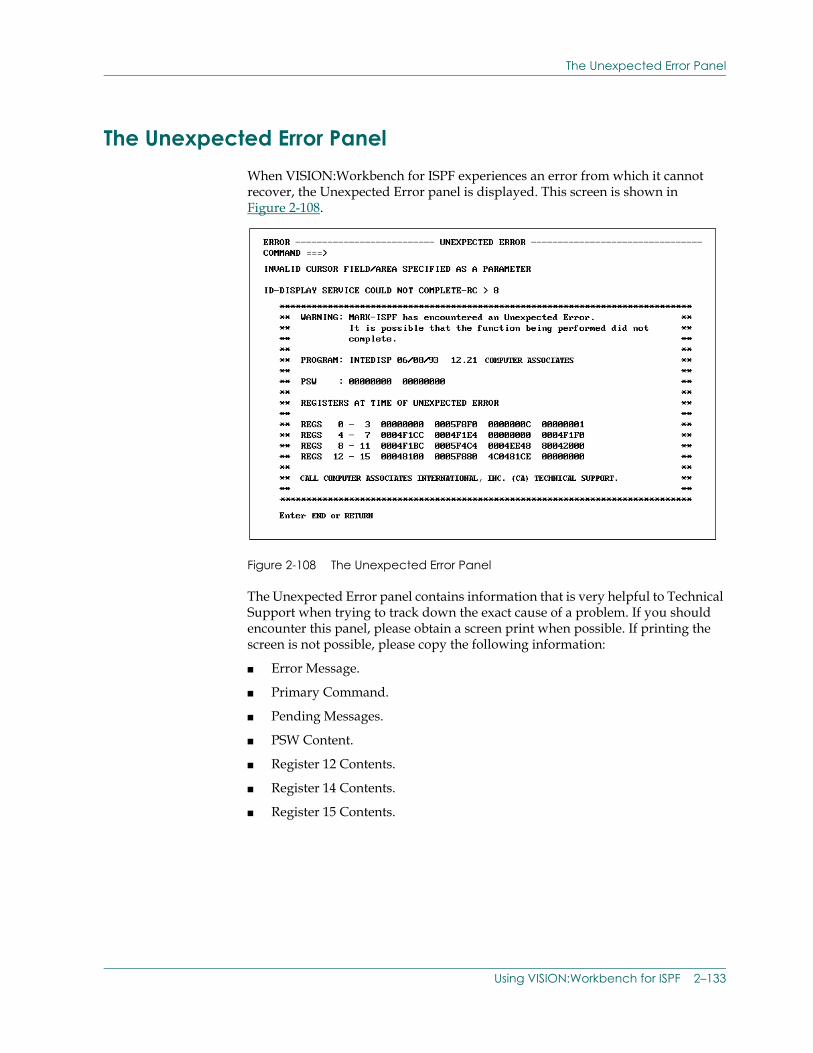
The Unexpected Error Panel
The Unexpected Error PanelWhen VISION:Workbench for ISPF experiences an error from which it cannot recover, the Unexpected Error panel is displayed. This screen is shown in Figure 2-108.
Figure 2-108 The Unexpected Error Panel
The Unexpected Error panel contains information that is very helpful to Technical Support when trying to track down the exact cause of a problem. If you should encounter this panel, please obtain a screen print when possible. If printing the screen is not possible, please copy the following information:
■ Error Message.
■ Primary Command.
■ Pending Messages.
■ PSW Content.
■ Register 12 Contents.
■ Register 14 Contents.
■ Register 15 Contents.
Using VISION:Workbench for ISPF 2–133

Contacting Computer Associates
In addition, please supply as much of the following information as possible:
■ What part of VISION:Workbench for ISPF were you working in?
■ Exactly what were you trying to do?
■ What was the last data entry panel that you saw and/or completed?
■ Any error messages that were displayed?
■ Other comments that you feel might be helpful?
Once you have gathered as much of this information as possible, contact Computer Associates Technical Support.
Contacting Computer AssociatesFor technical assistance with this product, contact Computer Associates Technical Support on the Internet at supportconnect.ca.com. Technical support is available 24 hours a day, 7 days a week.
2–134 Workbench for ISPF Reference Guide
Index
Symbols
? for help, 1-20, 2-18, 2-32
A
action, 2-45, 2-50
allocate, 2-63, 2-65
APP4FIL Application Files panel, 2-105
APP4PARM Application Parameter panelscan/terminate control entry, 2-104, 2-105source statement listing entry, 2-105
APPGEN application generation, 2-37, 2-106, 2-107
application items, 2-21applications, 2-21procedures, 2-21requests, 2-21screen definitions, 2-21
ASL, 1-10, 1-12, 2-33, 2-99procedure validation, 2-131Request and ASL Procedures panel, 2-94
Attention key, 1-7
B
backup, 1-16, 1-17
batch, 1-1, 1-12application sample, 1-8execute applications, 1-12
generate applications, 1-12
bookname, 2-46
browse, 2-72, 2-102default parameter modules, 2-72terminal device table, 2-111validation output, 2-33
buffer size, 2-44, 2-49, 2-56
C
CALL statements, 2-132
catalog, 2-61, 2-114VISION:Transact considerations, 2-107
CICS/MVS, 1-8
CLIST, 2-62default, 2-62generate, 2-62pre-allocate ISPFILE, 2-85
COBOL Copybook Library Names panel, 2-46
COBOL definitions, 2-41
COBOL General Information panel, 2-42
COBOL Segment Information panel, 2-45
COMLIB, 2-23, 2-107backup, 1-17copy items, 1-18data set level enqueue (lock), 2-24edit, 2-20exclusive use, 2-24initialize, 1-16
Index–1
item name, 2-28maintenance, 2-70MARKLIBP parameter module, 2-72primary, 2-24utilities, 2-70validation, 2-30
COMLIB library name, 2-58
command stacking, 2-89attach item name, 2-90
commands, 2-4, 2-8line, 2-8, 2-13primary, 2-8zoom, 2-130
comments, 2-132additional destination field, 2-121additional source field, 2-120
concatenate libraries, 2-25
considerationsCOMLIB, 2-28DB2, 2-102partitioned data sets (PDS), 2-26sequential data set, 2-27
conversionsinput requests, 2-101output requests, 2-100
copy, 1-17, 2-29, 2-62
copybook library type, 2-53
creator, 2-50
D
data entry, 2-5, 2-31
Data Set Specifications panels, 2-64batch, 2-64, 2-65foreground, 2-64, 2-67
data setsfile tailoring output, 2-85list, 2-87partitioned (PDS), 2-26sequential, 2-27
work, 2-102
DB2, 1-8, 2-102plan name, 2-76session parameters, 2-103subsystem ID, 2-76VISION:Transact considerations, 2-106VISION:Transact environment, 2-106
DB2 bind, 2-48
DB2 General Information panel, 2-48
DB2 plan name, 2-48
DB2 Segment Information panel, 2-50
DB2 subsystem ID, 2-48
DB2 table definitions, 2-47
DB2 table name, 2-50
defaults, 2-78display attribute characters, 2-79, 2-112Item Entry panel, 2-78job submission information, 2-80library, 2-90pad character, 2-74processing parameters, 2-88site parameters, 2-72Validation Library panel, 2-78
definition items, 2-21array definitions, 2-21file definitions, 2-21logical data views, 2-21table definitions, 2-21transaction definitions, 2-21
definition library, 2-42, 2-48, 2-52, 2-55, 2-57, 2-59
definitionsdata definitions, 1-2file definitions, 1-2instream, 2-98retrieve from COMLIB, 2-34
device identifier, 2-110
display attributes, 2-122
duplicate entries, 2-33
duplicate entry checking, 2-33
Index–2 Workbench for ISPF Reference Guide
duplicate field name check, 2-58
duplicate field name editor, 2-60
duplicate found, 2-60
E
edit, 2-21application items, 2-21definition items, 2-21items, 2-31select, 2-21, 2-22source statement retrieval, 2-25specify item location, 2-21, 2-22specify source libraries, 2-23specify validation libraries, 2-21validate item, 2-21
employee file (EMPFILE), 1-5, 1-8
exporting source, 2-98
F
FacilityJump, 2-127
facility, 2-61file tailoring, 2-64help, 1-18, 2-1, 2-16ISPF file tailoring, 2-62ISPF help, 2-16ISPF split screen, 2-20submission, 2-61, 2-62, 2-64, 2-80tutorial, 2-16
field definition name, 2-58
field definitions, 1-6, 1-14
field designator character, 2-110
field display characteristics, 2-79
field name prefix, 2-44, 2-49, 2-56
field name validation, 2-32
fields, 2-117, 2-118additional destination field comments, 2-121
additional source field comments, 2-120destination, 2-119screen, 2-119source, 2-119
file definition name, 2-43, 2-49, 2-59
file definitions, 1-2, 1-12, 1-14create, 1-12sample, 1-12
file structures, 1-12, 1-14
file tailoring, 2-62, 2-70ISPFILE, 2-63output data set, 2-85, 2-86skeleton, 2-62
file type, 2-43
file type Choice window, 2-43
file types, 1-12, 1-13
filesapplication, 1-10Application Files panel, 2-105master (old), 1-10work, 1-10
flags (flag names), 2-32
from segment number/name, 2-60
G
GDBI, 2-104
global validation, 2-30, 2-32, 2-76, 2-104automatic, 2-34VISION:Builder, 2-102VISION:Transact, 2-106
H
help, 1-1, 1-18, 2-16? in a field, 2-18field level, 1-18Help key, 1-19, 1-20, 2-90, 2-92, 2-93HELP primary command, 1-19, 1-20, 2-90, 2-92, 2-93
Index–3
panel level, 1-18Summary message, 2-19
highlight designator, 2-110
I
Import External Definitions panel, 2-40
import optionfunction keys, 2-41
importing source, 2-98guidelines, 2-98VISION:Builder, 2-99VISION:Transact, 2-99VISION:Transact conversions, 2-99
IMS, 1-8
IMS/DB, 1-8
initialize, 1-16COMLIB, 1-16
inquiry definition, 2-55
invalidduplicate entries, 2-33flag names, 2-32
ISPF, 1-2, 2-1& variables in skeletons, 2-62file tailoring, 2-62, 2-64, 2-70jump, 2-93LEFT & RIGHT scroll commands, 2-5LIBRARY section, 2-24multiple sessions, 2-20primary commands, 2-9profile library, 2-72Split screen processing, 2-20split screen processing, 2-71UP & DOWN scroll commands, 2-5
ISPFILE, 2-63, 2-85allocate/pre-allocate, 2-85automatic allocate (VISION:Transact), 2-63, 2-85file tailoring output data set, 2-85manual allocate (VISION:Builder), 2-85pre-allocate required, 2-63
Item Entry panels, 2-23, 2-64application, 2-23, 2-25batch, 2-64, 2-65defaults, 2-78definition, 2-23, 2-24foreground, 2-64ISPF, 2-65
item names, 2-28item name entry, 2-28item selection list, 2-28member name entry, 2-26, 2-28
item selection list, 2-9, 2-28, 2-29
items, 2-20application items, 2-21copy, 1-17create, 2-29default, 2-78definition items, 2-21edit, 2-21, 2-31names, 2-28save, 2-38validate, 2-33
J
JCL, 1-8, 2-62automatically generate, 1-8default, 2-62generate, 2-62
JCL/CLIST, 2-62file tailoring, 2-62generate, 2-61, 2-62, 2-69Keep, 2-68submit, 2-68
job submission, 2-61, 2-62, 2-80background, 2-83background/batch, 2-81file information, 2-65foreground, 2-82, 2-84processing options, 2-68specify item, 2-65
Index–4 Workbench for ISPF Reference Guide
submission facility, 2-64user panel, 2-69
jump, 2-93
L
level, 2-46, 2-50
librarian library, 2-47, 2-53
librariesbackup, 1-16, 1-17COMLIB, 2-23concatenate, 2-25, 2-107copy items, 1-17initialize, 1-16ISPF, 2-23partitioned or sequential data set, 2-23profile, 2-72restore, 1-16sequential data set, 2-27specify validation, 2-30
line commands, 2-8, 2-13ISPF, 2-14pass, 2-32repeat, 2-15, 2-16select, 2-1, 2-14, 2-16, 2-29, 2-121using multiple, 2-96VISION:Workbench, 2-14
link screens, 1-7
List data setM9LIST, 2-87
list data set, 2-71, 2-77, 2-87default processing parameters, 2-88dynamic allocation, 2-88holds output, 2-87Process List Dataset panel, 2-88set parameters, 2-77termination processing, 2-87
listing data set name, 2-42, 2-48, 2-52, 2-55, 2-58
M
M4LIST1, 2-105source statement listing entry, 2-105
M4OLD, 1-10
M4PARAMS, 2-72
M4REPn, 2-105File usage entry, 2-105
M4REPO, 1-10
M9BGTS skeleton, 2-68
M9BGUPNL panel, 2-68
M9FGTS skeleton, 2-68
M9FGUPNL user panel, 2-68
M9GCTPU1 user panel, 2-68
M9GCTPU2 user panel, 2-68
M9GCTSBG skeleton, 2-68
M9GCTSFG skeleton, 2-68
M9LIST, 2-87pre-allocate, 2-87
MARKLIBP, 2-72
member names, 2-26, 2-27, 2-28
member selection list, 2-9, 2-65
menusapplication development APP4DEVL/APP5DEVL, 2-96list of primary menus, 2-96Main, 1-16, 2-5, 2-22, 2-71, 2-80, 2-85, 2-108Parameters Selection, 2-73Primary Option, 2-5, 2-22Primary Option PRIMOPT4/PRIMOPT5, 2-22, 2-96PRIMOPT4/PRIMOPT5, 2-16Request REQ4MENU/REQ5MENU, 2-96Screen Developer, 2-96, 2-108Utility Selection, 1-17, 2-70
messages, 2-4, 2-85EMSG, 2-131error, 2-16, 2-133
Index–5
informational, 1-2, 2-31message line, 2-4summary, 2-19Unexpected Error panel, 2-133use FIND primary command, 2-34
MVS library, 2-47
MVS PDS library, 2-53
N
name, 2-46, 2-50
name type, 2-60
names validation, 2-30
navigation, 2-89jump facility, 2-93
new definition name, 2-58
number, 2-45, 2-50
O
online, 1-1application sample, 1-4execute applications, 1-8generate applications, 1-8
option numbers, 2-22, 2-89
OPTIONSPROLOGUE, 2-12
optionsapplication request, 2-105background, 2-64, 2-83background/batch, 2-81backup, 1-17catalog, 2-107default site parameters, 2-72DISPATTR, 2-11, 2-109, 2-110, 2-111, 2-122Display Attribute, 2-110, 2-111FIELDS, 2-11, 2-109, 2-116, 2-117, 2-118Foreground, 2-61, 2-64, 2-82, 2-84Generate, 2-64, 2-108initialize, 1-16
Jumping, 2-93Keep, 2-67, 2-85Keep/Submit, 2-85LAYOUT, 2-109, 2-110, 2-114, 2-118Layout Option panel, 2-115List, 2-71, 2-73, 2-77Modifications, 2-71New Name, 2-29Options panel, 2-64, 2-80, 2-85Parameters, 2-71, 2-73PD, 2-88Primary Option, 2-16PROCATTR, 2-12, 2-109, 2-114PROFILE, 2-12, 2-109, 2-111, 2-115Profile Option panel, 2-123PROLOGUE, 2-109, 2-113replace, 2-114screen, 2-108SEGMENTS, 2-12, 2-109, 2-116, 2-117, 2-118Segments Option panel, 2-118SELECT, 2-12session, 2-71, 2-73source statement retrieval, 2-25utilities, 1-16, 2-70VIEW, 2-13, 2-109, 2-118, 2-125, 2-126, 2-129
outputapplication, 2-61list data set, 2-77M9LIST, 2-87printed, 2-71route to terminal, 2-67screens, 1-7validation, 2-33
P
pad characters, 2-74
panel hierarchy, 2-1, 2-2, 2-31
panel ID, 2-7
panel namessuffix, 2-7
Index–6 Workbench for ISPF Reference Guide
panel sections, 2-4fixed data entry area, 2-5header, 2-4scrollable data entry area, 2-5
panels, 1-1, 1-3, 2-3, 2-22, 2-89, 2-91, 2-96additional destination field, 2-121Application Files, 2-94, 2-95, 2-105application files, 1-4, 1-10Application Item Entry, 2-23, 2-25Application Parameter, 2-105Batch Data Set Specifications, 2-66, 2-67Batch Item Entry, 2-65Batch Submission User, 2-69column heading, 1-15COMLIB backup, 1-17COMLIB Initialization, 1-16copy destination, 1-18copy utility, 1-17Data Set Specifications, 2-64, 2-65Default Data Set Specifications, 2-66Default user panel, 2-68Definition Item Entry, 2-23, 2-24Development/Administration Facility, 2-5Display Attribute, 2-122field column headings, 1-14Field Definitions, 2-18field definitions, 1-14Field Information, 2-119Fields Option, 2-117, 2-119File Definition, 2-14, 2-16file definition, 1-13, 1-14File Definition (Segment name & number), 2-76File Definition (Segment name), 2-75File Item Entry, 2-25file options, 1-13, 1-15Follow-on, 2-119Foreground Data Set Specifications, 2-67Help, 2-17ISPF Item Entry, 2-65Item Entry, 2-23, 2-65, 2-78Layout Option, 2-115, 2-118Name, 2-5
Options, 2-64, 2-68, 2-80, 2-81, 2-82, 2-83, 2-84, 2-85output specifications, 1-10, 1-11Parameters Selection Menu, 2-71, 2-73parent (previous), 2-5Primary Option, 2-5, 2-22Procedure, 2-131Process List Dataset, 2-88Processing Attributes, 2-114Profile Option, 2-109, 2-111, 2-123Prologue, 2-113Report Output Specifications, 2-105report title, 1-11Request and ASL Procedures, 2-94, 2-95Request Attribute, 2-101Request Processing, 2-132Save, 2-27, 2-36, 2-37, 2-39Screen and Application Flow, 2-100screen and application flow, 1-7Screen Control Input Screen List, 2-101Screen Developer Menu, 2-108, 2-109, 2-113, 2-114, 2-116, 2-117, 2-122, 2-125screen field, 1-7screen Layout, 1-5Segments Option, 2-116, 2-117Session Parameters, 2-74Source Field Comments, 2-120Specify "Save Asis" Library, 2-38specify "To" COMLIB pane, 1-18Specify List Data Set Defaults, 2-77Specify Trial Compilation Libraries, 2-37, 2-107Specify Validation Libraries, 2-30, 2-31, 2-35, 2-78Typical format, 2-4Unexpected Error, 2-133User, 2-64, 2-69, 2-80, 2-81, 2-82, 2-83, 2-84utility Selection menu, 1-16Validation, 2-37, 2-78
Panvalet library, 2-47, 2-53
parameters, 2-77list data set, 2-77session, 2-71, 2-73, 2-74, 2-102
Parameters Selection Menu panel
Index–7
default site parameters group, 2-72maintenance level group, 2-71session parameters group, 2-71
parameters subsystem, 2-71
partitioned data sets (PDS), 2-26, 2-86member names, 2-26
PF keys, 1-3, 2-10assignments, 2-10KEYS primary command, 2-10
primary commands, 2-4, 2-8, 2-9CANCEL, 2-38command stacking, 2-89DISPATTR, 2-11, 2-125DUP OFF, 2-11, 2-16DUP ON, 2-11, 2-33END, 1-20, 2-1, 2-12, 2-17FIELDS, 2-11HELP, 1-19, 1-20, 2-9, 2-16, 2-90, 2-92, 2-93ISPF FIND, 2-34ISPF LOCATE, 2-29ISPF SCROLL DOWN, 2-33ISPF SCROLL LEFT, 2-33ISPF SCROLL RIGHT, 2-33ISPF SCROLL UP, 2-33KEYS, 2-10LAYOUT, 2-125Most ISPF commands active, 2-9NAMES F, 2-11, 2-32NAMES HELP, 2-11NAMES OFF, 2-11, 2-32NAMES ON, 2-11, 2-32NAMES q, 2-11NAMES STATUS, 2-11, 2-12NOCHECK, 2-11, 2-12PANELID, 2-7PROCATTR, 2-12PROFILE, 2-12, 2-123PROLOGUE, 2-12SAVE, 2-39SAVE ASIS, 2-39screen developer, 2-127
SEGMENTS, 2-12SELECT, 2-12, 2-29SHOWFLDS OFF, 2-13, 2-126SHOWFLDS ON, 2-13, 2-126split screen, 2-71VIEW, 2-12, 2-13, 2-125
primary/alternate field names, 2-60
product menus, 2-22
Profile Option paneldevice identifier, 2-110field designator, 2-110highlight designator, 2-110
profiles, 2-72default information, 2-78library, 2-72PROFILE option, 2-109save processing information, 2-80screen developer profile, 2-79screen display characteristics, 2-79session profile information, 2-72user, 2-72user profile IADSPROF, 2-72, 2-79
program function (PF) keys, 2-10
R
record size, 2-44
records per block, 2-44
rename the definition, 2-56
reports, 1-8, 1-11alternate report files, 2-105define, 1-11output specifications, 2-105samples, 2-104
REQ4REPT Report Output Specifications panel, 2-105
Report Handling entry, 2-105
requests, 2-21, 2-101converted input, 2-101converted output, 2-100
Index–8 Workbench for ISPF Reference Guide
Request Attribute panel, 2-101screen control statements, 2-100stand-alone support, 2-101
restore, 1-16
results definition, 2-52
run control statements, 2-27, 2-28, 2-99
run typesAPPGEN run, 2-33, 2-37, 2-106, 2-107Scan run, 2-33, 2-102Validation runs, 2-33
S
save, 2-36, 2-39items, 2-38
scan/terminate control entryN for GDBI, 2-104R for sample report, 2-104
screen control statements, 2-100
screen developer, 2-108DI or DIspattr, 2-128DISPATTR, 2-109, 2-122F or Fields, 2-128FIELDS, 2-109FIELDS option, 2-117jump, 2-127LA or LAyout, 2-128LAYOUT, 2-109, 2-114PROC or PROCattr, 2-128PROCATTR, 2-109, 2-114PROF or PROFile, 2-127PROFILE, 2-109, 2-115PROL or PROLogue, 2-127PROLOGUE, 2-109, 2-113SE or SEgments, 2-128SEGMENTS, 2-109, 2-116SHowflds ON/OFF, 2-129special primary commands, 2-127VI or VIew, 2-128VIEW, 2-109, 2-124, 2-125, 2-129zoom processing commands, 2-130
screen layouts, 1-6
screen painting, 2-79
screens, 1-5, 2-100create data entry screens, 1-5define fields, 1-6file maintenance, 1-6initial menu, 1-5input, 1-7layouts, 1-5limits, 2-115link, 1-7paint, 1-2, 1-5, 1-6, 2-79preview, 1-2screen control statements, 2-100split screen processing, 2-71stand-alone, 2-108
SegmentsSEGMENTS option, 2-116
segments, 1-14multiply-occurring, 2-123name, 2-75number, 2-75Segments Option panel, 2-116, 2-118
select line command, 2-29
SELECT primary command, 2-29
session parameters, 2-9, 2-73, 2-74autoskip, 2-74DB2 environment, 2-102DB2 PLAN NAME, 2-76DB2 SUBSYSTEM ID, 2-76delete character, 2-75input pad character, 2-74line command pad character, 2-74segment reference, 2-75specify parameters module, 2-76start locations, 2-76work area size, 2-76
session profile information, 2-72
source, 2-98exporting, 2-98
Index–9
guidelines, 2-98importing, 2-98retrieval, 2-25retrieve, 2-87, 2-98statement order, 2-99VISION:Builder, 2-99VISION:Transact, 2-99
split screen processing, 2-20, 2-71disabled, 2-20
start locations, 2-76
statement order, 2-99
structured panel hierarchy, 2-1
subsystemsDB2, 2-76edit, 2-18, 2-65, 2-78file definition, 2-2, 2-14generate, 2-18parameters, 2-71, 2-73, 2-77, 2-88procedure, 2-12, 2-131screen developer, 2-12, 2-79, 2-80, 2-108, 2-127utilities, 2-20, 2-25, 2-70, 2-71, 2-75, 2-87
System Modifications (SMs), 2-71
T
terminal device table, 2-111
titlespanel title line, 2-4
trial compilation, 2-37
TSO, 1-3ALLOCATE command, 2-85
tutorial, 2-16
type, source library, 2-46
U
unloaded inquiry system data base, 2-55
user panels, 2-80
user profile IADSPROF, 2-72
utilities, 1-15, 2-70special delete character, 2-75specify work area, 2-76
V
validation, 2-30, 2-76definitions, 2-34entries, 1-2field names, 2-32items, 2-21, 2-33libraries, 2-21, 2-30names, 2-30output, 2-33specify validation libraries panel, 2-78turn off, 2-32VISION:Builder applications, 2-30, 2-36, 2-102VISION:Transact applications, 2-37, 2-106
VISION:Builder, 1-1background/batch processing, 2-64, 2-81create applications, 1-1, 1-8create file definitions, 1-1DB2 considerations, 2-102foreground processing, 2-82import source, 2-98, 2-99M4PARAMS parameter module, 2-72maintain applications, 2-98PRIMOPT4, 2-22, 2-73validation considerations, 2-102validation libraries, 2-30
VISION:Builder definitions, 2-57
VISION:Builder Information panel, 2-57
VISION:Inquiry definitions, 2-54
VISION:Inquiry Information panel, 2-55
VISION:Results definitions, 2-51
VISION:Results Information panel, 2-52
VISION:Transact, 1-1background processing, 2-83conversions, 2-99create application screens, 1-2
Index–10 Workbench for ISPF Reference Guide
create applications, 1-1, 1-4create file definitions, 1-1DB2 environment, 2-106FIVEPARAM parameter module, 2-72foreground processing, 2-84import source, 2-98, 2-99maintain applications, 2-98PRIMOPT5, 2-22, 2-73screen painting, 2-108screen preview, 1-2, 2-125terminal device table, 2-72, 2-111trial compilation, 2-37validation considerations, 2-106
VISION:Workbenchcreate batch applications, 1-1create online applications, 1-1, 1-4help, 1-1, 1-2, 1-18, 2-16overview, 1-1panel names, 2-5primary commands, 2-33tutorial, 1-2, 2-16utilities, 1-15
VISION:Workbench for DOS, 2-98
VSAM, 1-8
Z
zoom processing commands, 2-130
Index–11


