Embed Size (px)
Citation preview

z/OS and OS/390
Managed System Infrastructure forOperationsSetting Up and Using
SC33-7968-05
���


z/OS and OS/390
Managed System Infrastructure forOperationsSetting Up and Using
SC33-7968-05
���

Note!
Before using this information and the product it supports, be sure to read the general information under “Notices” onpage 369.
Fifth Edition (June 2003)
This edition applies to Version 1 Release 1 of z/OS (Program Number 5694-A01) and to Version 2 Release 10 ofOS/390 (Program Number 5647–A01) and to all subsequent releases and modifications until otherwise indicated innew editions.
Order publications through your IBM representative or the IBM branch office serving your locality. Publications arenot stocked at the address given below.
A form for readers’ comments appears at the back of this publication. If the form has been removed, address yourcomments to:
IBM Deutschland Entwicklung GmbHDepartment 3248Schoenaicher Strasse 220D-71032 BoeblingenFederal Republic of Germany
If you prefer to send comments electronically, use one of the following methods:FAX (Germany): 07031 + 16-3456FAX (Other Countries): (+49)+7031-16-3456Internet: [email protected]
When you send information to IBM, you grant IBM a nonexclusive right to use or distribute the information in anyway it believes appropriate without incurring any obligation to you.
© Copyright International Business Machines Corporation 2002-03. All rights reserved.US Government Users Restricted Rights – Use, duplication or disclosure restricted by GSA ADP Schedule Contractwith IBM Corp.

Contents
Figures . . . . . . . . . . . . . . vii
Tables . . . . . . . . . . . . . . . ix
About this book . . . . . . . . . . . xiWho should use this book . . . . . . . . . xiHow this book is organized . . . . . . . . . xiWhere to find more information . . . . . . . xii
Using LookAt to look up message explanations xiiAccessing z/OS™ licensed documents on theInternet . . . . . . . . . . . . . . xiii
Part 1. Introducing Managed SystemInfrastructure for Operations . . . . 1
Chapter 1. General concept . . . . . . 3The structure of msys for Operations and its positionwithin the sysplex . . . . . . . . . . . . 4
Internal structure of msys for Operations . . . . 4msys for Operations within the sysplex . . . . 4
Task and message automation . . . . . . . . 5Understanding tasks . . . . . . . . . . . 6Automatic recovery and message automation . . 6
Chapter 2. Sysplex functions. . . . . . 9Managing couple data sets. . . . . . . . . . 9
Ensuring continuous availability of alternatecouple data sets . . . . . . . . . . . . 9INGPLEX CDS . . . . . . . . . . . . 10Customization . . . . . . . . . . . . 10
Managing the system logger . . . . . . . . . 10Resizing the LOGR couple data sets . . . . . 11Notifying the operator of incorrect share options 11Customization . . . . . . . . . . . . 11
Recovery functions . . . . . . . . . . . . 12Resolving a system log failure . . . . . . . 12Resolving WTO(R) buffer shortages . . . . . 12Handling long-running enqueues (ENQs) . . . 12System removal . . . . . . . . . . . . 14Recovering auxiliary storage shortage . . . . 15Customization . . . . . . . . . . . . 15
Managing coupling facilities . . . . . . . . . 15INGCF DRAIN . . . . . . . . . . . . 17INGCF ENABLE. . . . . . . . . . . . 18INGCF PATH. . . . . . . . . . . . . 18INGCF STRUCTURE . . . . . . . . . . 18Customization . . . . . . . . . . . . 19
The IBM Health Checker for z/OS and Sysplex . . 19General prerequisites . . . . . . . . . . 19HealthChecker best practice values . . . . . 19INGPLEX BESTpractices . . . . . . . . . 20INGHC. . . . . . . . . . . . . . . 20Customization . . . . . . . . . . . . 21
Hardware validation . . . . . . . . . . . 21
Prerequisites . . . . . . . . . . . . . 23Miscellaneous sysplex functions . . . . . . . 23
Recording IPL Information . . . . . . . . 23System dump options . . . . . . . . . . 23Multisystem dumps . . . . . . . . . . 24SLIP traps . . . . . . . . . . . . . . 24
Part 2. Setting up msys forOperations . . . . . . . . . . . . 25
Chapter 3. Installing msys forOperations . . . . . . . . . . . . . 27Functional prerequisites . . . . . . . . . . 27
Software prerequisites . . . . . . . . . . 27Hardware prerequisites . . . . . . . . . 28
Preparing the hardware . . . . . . . . . . 29Understanding the hardware interface . . . . 29Preparing the master Hardware ManagementConsole. . . . . . . . . . . . . . . 30Preparing the Support Element . . . . . . . 30
Planning for the domain and EMCS console names 32Domain names . . . . . . . . . . . . 32EMCS console names and the automation routertask . . . . . . . . . . . . . . . . 32
Target libraries . . . . . . . . . . . . . 34Preparing the MVS system . . . . . . . . . 35
Modifying the maximum number of languageprocessor (REXX) environments for msys forOperations . . . . . . . . . . . . . 35Updating member SCHEDxx . . . . . . . 36Updating member MPFLSTxx . . . . . . . 36Message Automation . . . . . . . . . . 36Updating the link list and APF authorizationswith PROGxx. . . . . . . . . . . . . 36Updating member COMMNDxx . . . . . . 37
Preparing msys for Operations . . . . . . . . 37Allocating data sets and VSAM clusters using jobINGALLC0 and INGALLC4 . . . . . . . . 37Loading members of partitioned data sets . . . 38Setting up the system logger . . . . . . . 39
Preparing VTAM . . . . . . . . . . . . 41Modifying the application (APPL) major node . . 41
Preparing the startup procedure and theinitialization style sheet . . . . . . . . . . 42
Modifying the msys for Operations startupprocedure . . . . . . . . . . . . . . 42Customizing the initialization style sheet . . . 43
Editing the customization member AOFCUST . . . 44AUTO section – switching functions On and Off 45COMMON section – common definitions . . . 47PAGE section – predefined and dynamicallyallocated local page data sets . . . . . . . 47ENQ section – resources to be monitored andjobs to be canceled . . . . . . . . . . . 50
© Copyright IBM Corp. 2002-03 iii
||||||||||||||
11111111111111
11||||||||||
|||||||||||||||
||
||
11
||||||||

HEALTHCHK section – specifying user overrides 53CDS section – spare volumes for CDS recovery 65HW section – hardware configuration . . . . 66IXC102A section – hardware commands . . . . 67WTOBUF section – jobs to be canceled in case ofbuffer shortage . . . . . . . . . . . . 69
Chapter 4. Making security definitions 71Activating security classes . . . . . . . . . 71Defining operators, passwords, and logon attributes 71
Defining operator identifiers and passwords . . 71Defining operator logon attributes in the NVSSsegment of an SAF product . . . . . . . . 72
Command authorization . . . . . . . . . . 73Overview . . . . . . . . . . . . . . 73Command authorization using an SAF product 74Additional recommendations for commandauthorization . . . . . . . . . . . . . 77Determining the user identity used for authoritychecking commands . . . . . . . . . . 78Understanding security for specific commands 80
Controlling access to data sets and members . . . 85Data set security. . . . . . . . . . . . 85NVSS READSEC and WRITESEC commands . . 88
Controlling access to the processor hardwarefunctions . . . . . . . . . . . . . . . 89
Enabling NVSS . . . . . . . . . . . . 89Access to the CPCs . . . . . . . . . . . 90Levels of CPC access . . . . . . . . . . 90Defining the CPC access level . . . . . . . 90
Chapter 5. Activating msys forOperations . . . . . . . . . . . . . 93Starting msys for Operations using the MSOAPROCstartup procedure . . . . . . . . . . . . 93Logging on to msys for Operations . . . . . . 94
Chapter 6. Configuring msys forOperations for your environment . . . 95Defining passwords for VSAM databases . . . . 95Printing the network log and trace log . . . . . 95
Part 3. Using the msys forOperations operator interface . . . 97
Chapter 7. Logging on to msys forOperations . . . . . . . . . . . . . 99
Chapter 8. The message displayscreen . . . . . . . . . . . . . . 103Session identification line . . . . . . . . . 103Message area . . . . . . . . . . . . . 104
Reply messages . . . . . . . . . . . 104Held messages . . . . . . . . . . . . 105Windowed responses . . . . . . . . . . 105
Response area . . . . . . . . . . . . . 105Command entry area . . . . . . . . . . . 106
Chapter 9. Issuing commands . . . . 107Repeating commands. . . . . . . . . . . 107Issuing MVS system commands . . . . . . . 107
Chapter 10. Moving between thecomponents and using function keys . 109Moving between components . . . . . . . . 109Using program function keys . . . . . . . . 109
Listing PF and PA keys . . . . . . . . . 109
Chapter 11. Using the netlog . . . . . 111Displaying the netlog . . . . . . . . . . . 111Structure of the log entries . . . . . . . . . 111Log browse filtering . . . . . . . . . . . 113
Chapter 12. Getting online help. . . . 115Examples . . . . . . . . . . . . . . . 115
Part 4. Command reference . . . . 117
Chapter 13. General commands . . . 119ALL (BROWSE, WINDOW). . . . . . . . . 119AUTOWRAP . . . . . . . . . . . . . 119BACK (BROWSE, HELP, WINDOW). . . . . . 119BLOG . . . . . . . . . . . . . . . . 120BOTTOM (BROWSE, HELP) . . . . . . . . 120BROWSE . . . . . . . . . . . . . . . 120DEFAULTS . . . . . . . . . . . . . . 121DISPFK . . . . . . . . . . . . . . . 121END (BROWSE, HELP) . . . . . . . . . . 121FIND (BROWSE) . . . . . . . . . . . . 122FIND (WINDOW) . . . . . . . . . . . . 122FORWARD . . . . . . . . . . . . . . 123HELP . . . . . . . . . . . . . . . . 123INDEX . . . . . . . . . . . . . . . 123INPUT . . . . . . . . . . . . . . . 124LIST . . . . . . . . . . . . . . . . 124LISTA . . . . . . . . . . . . . . . . 124LOCATE (BROWSE) . . . . . . . . . . . 125LOGOFF . . . . . . . . . . . . . . . 125MSG . . . . . . . . . . . . . . . . 125MVS . . . . . . . . . . . . . . . . 126OVERRIDE . . . . . . . . . . . . . . 126REPEAT (BROWSE) . . . . . . . . . . . 126RETRIEVE . . . . . . . . . . . . . . 127RETURN (BROWSE, HELP) . . . . . . . . 127ROLL . . . . . . . . . . . . . . . . 127SET. . . . . . . . . . . . . . . . . 127TOP (BROWSE, HELP) . . . . . . . . . . 128WHO . . . . . . . . . . . . . . . . 128WINDOW . . . . . . . . . . . . . . 128
Chapter 14. Sysplex-relatedcommands . . . . . . . . . . . . 131Additional parameters for System Operationscommands . . . . . . . . . . . . . . 132INGCF . . . . . . . . . . . . . . . 132
DRAIN . . . . . . . . . . . . . . 138ENABLE . . . . . . . . . . . . . . 145
iv z/OS and OS/390 msys for Operations Setting Up and Using
11
||||
|||||||||||

PATH . . . . . . . . . . . . . . . 148STRUCTURE . . . . . . . . . . . . 149
INGCFL . . . . . . . . . . . . . . . 152Purpose . . . . . . . . . . . . . . 152Syntax. . . . . . . . . . . . . . . 152Parameters . . . . . . . . . . . . . 152
INGHC . . . . . . . . . . . . . . . 153Purpose . . . . . . . . . . . . . . 153Types of reports . . . . . . . . . . . 153Syntax. . . . . . . . . . . . . . . 154Parameters . . . . . . . . . . . . . 155Examples . . . . . . . . . . . . . . 156Line mode output . . . . . . . . . . . 160
INGPLEX . . . . . . . . . . . . . . 161BESTpractices . . . . . . . . . . . . 164CDS . . . . . . . . . . . . . . . 167SYStem . . . . . . . . . . . . . . 173CONsole . . . . . . . . . . . . . . 175IPL . . . . . . . . . . . . . . . . 177SDUMP . . . . . . . . . . . . . . 179SVCdump . . . . . . . . . . . . . 181SLIP . . . . . . . . . . . . . . . 184
Chapter 15. Debugging and supportcommands . . . . . . . . . . . . 187ACF . . . . . . . . . . . . . . . . 187AOCTRACE. . . . . . . . . . . . . . 187DISPACF . . . . . . . . . . . . . . . 189DISPAOPS . . . . . . . . . . . . . . 189DISPASF . . . . . . . . . . . . . . . 190DISPATHR . . . . . . . . . . . . . . 191DISPERRS . . . . . . . . . . . . . . 192DISPFLGS . . . . . . . . . . . . . . 193DISPMSGS . . . . . . . . . . . . . . 194DISPWTOR . . . . . . . . . . . . . . 195INGAUTO . . . . . . . . . . . . . . 196INGCUST . . . . . . . . . . . . . . 196
Part 5. Setup reference . . . . . . 199
Chapter 16. msys for Operationsdefinition statements reference. . . . 201Statement formats . . . . . . . . . . . . 201Syntax conventions for definition statements . . . 201AUTH. . . . . . . . . . . . . . . . 202OPERATOR . . . . . . . . . . . . . . 203OPTIONS . . . . . . . . . . . . . . 204PROFILE . . . . . . . . . . . . . . . 211PROFILEN . . . . . . . . . . . . . . 212TRANSTBL . . . . . . . . . . . . . . 213
Part 6. Automation-relatedmessages . . . . . . . . . . . . 215
Chapter 17. Messages. . . . . . . . 217
Part 7. Appendixes . . . . . . . . 225
Appendix A. Making securitydefinitions using the commandauthorization table . . . . . . . . . 227Defining security using msys for Operationsdefinitions . . . . . . . . . . . . . . 227
Overview of operator security . . . . . . . 227Using msys for Operations for passwordauthorization . . . . . . . . . . . . 228Using msys for Operations without passwordauthorization . . . . . . . . . . . . 228Operator logon attributes . . . . . . . . 228Defining operator attributes in msys forOperations profiles . . . . . . . . . . 229Dynamically adding or deleting operators . . . 230Command authorization. . . . . . . . . 230Controlling access to data sets and members 249
Appendix B. Return codes . . . . . . 253Macro return codes . . . . . . . . . . . 253
Macro DSICES return codes in Register 15. . . 253Macro DSIDKS return codes in Register 15 . . 254Macro DSIMQS return codes in Register 15 . . 256Macro DSIPRS return codes in Register 15. . . 256Macro DSIPSS return codes in Register 15 . . . 257Macro DSIPUSH return codes in Register 15 . . 258Macro DSIZCSMS return codes in Register 15 259Macro DSIZCSMS minor return codes inRegister 0 . . . . . . . . . . . . . 259Macro DSIZVSMS return codes in Register 15 259Macro DSIZVSMS minor return codes inRegister 0 . . . . . . . . . . . . . 260
VIEW and BROWSE return codes . . . . . . 260
Appendix C. Coexistence of msys forOperations and SA OS/390 releases . 263SA OS/390 V1R3 . . . . . . . . . . . . 263SA OS/390 V2R1 . . . . . . . . . . . . 263SA OS/390 V2R2 . . . . . . . . . . . . 263
Appendix D. msys for Operationscustomization checklist . . . . . . . 265Step 1: Creating shared and system-unique VSAMand non-VSAM data sets . . . . . . . . . 265Step 2: Adding additional procedures to PROCLIB 271Step 3: Authorizing and linking data sets . . . . 272Step 4: Updating the active SCHEDxx member . . 273Step 5: Updating the active MPFLSTxx member 274
VTAM Requirements . . . . . . . . . . 274Step 6: Defining the application major nodes toVTAM. . . . . . . . . . . . . . . . 275Step 7: Customizing the security definitions . . . 275Step 8: Customizing the CNMSTYLE style sheetand members DSIDMNK, DSIOPFU andDSICMPRC . . . . . . . . . . . . . . 285Step 9: Customizing the member AOFCUST . . . 288Step 10: Building the VTAM logmode table . . . 306Step 11: Increasing the number of entries in theREXX Environment Table . . . . . . . . . 307Step 12: Hardware customization of the SEs . . . 309
Contents v
11111111111111
11

Appendix E. The IBM Health Checkerfor z/OS and Sysplex checks. . . . . 329
Appendix F. Response messages,error strings, condition codes . . . . 339Response messages (AOFA0000 – AOFA0018) . . 339Asynchronous response messages(AOFA0100-AOFA0900) . . . . . . . . . . 344Condition codes . . . . . . . . . . . . 345
Hardware Communication Task condition codes″00B00xxx″ . . . . . . . . . . . . . 346SNMP Data Exchange Services ″0B100xxx″ . . 348SNMP Command Services ″0B200xxx″ . . . . 349BCP Internal Interface Transport Services″0Bx00xxx″ . . . . . . . . . . . . . 350
Appendix G. Sense codes, hardwareobject status summary . . . . . . . 355Sense codes . . . . . . . . . . . . . . 355Hardware object status summary . . . . . . . 363
Glossary . . . . . . . . . . . . . 365
Notices . . . . . . . . . . . . . . 369Programming interface information . . . . . . 370Trademarks . . . . . . . . . . . . . . 370
Index . . . . . . . . . . . . . . . 371
vi z/OS and OS/390 msys for Operations Setting Up and Using
111

Figures
1. msys for Operations in a simple ParallelSysplex configuration . . . . . . . . . 5
2. Automation for message IXC263I. . . . . . 83. AOFCUST section HEALTHCHK . . . . . 574. Message output after starting msys for
Operations . . . . . . . . . . . . . 935. Example of msys for Operations logon panel 996. msys for Operations news panel . . . . . 1007. msys for Operations main menu . . . . . 1018. Sample message display screen . . . . . 1039. Sample display screen . . . . . . . . 104
10. Network log entries . . . . . . . . . 11211. INGCF selection panel . . . . . . . . 13812. DRAIN command dialog panel: before any
action . . . . . . . . . . . . . . 14113. DRAIN command dialog: confirmation panel
for REBUILD . . . . . . . . . . . 14214. DRAIN command dialog panel: after rebuild 14215. DRAIN command dialog panel: after forcing 14316. DRAIN command dialog panel: panel after
draining . . . . . . . . . . . . . 14417. DRAIN command dialog panel: after
inactivation . . . . . . . . . . . . 14418. ENABLE command dialog: panel before any
action . . . . . . . . . . . . . . 14619. Confirmation panel for ENABLE . . . . . 14720. ENABLE command dialog: panel after
enabling . . . . . . . . . . . . . 14721. ENABLE command dialog panel: after
populating . . . . . . . . . . . . 14822. PATH dialog panel. . . . . . . . . . 14923. STRUCTURE dialog panel . . . . . . . 15024. INGHC panel . . . . . . . . . . . 15725. INGHC check confirmation panel . . . . . 15926. INGHC refresh confirmation panel . . . . 16027. INGHC line mode output . . . . . . . 16128. INGPLEX selection panel . . . . . . . 16429. INGPLEX BESTpractices panel . . . . . . 16530. INGPLEX CDS dialog panel . . . . . . 16831. Confirmation panel for switching from the
current primary CDS to the alternate CDS . . 16932. INGPLEX CDS dialog panel after the switch 17033. CFRM couple data set information panel
before policy switch . . . . . . . . . 17134. Confirmation panel for policy switch 17235. Channel path information for CFRM couple
data sets . . . . . . . . . . . . . 17236. INGPLEX SYSTEM dialog panel . . . . . 17437. INGPLEX CONS dialog panel . . . . . . 17538. INGPLEX IPL main panel . . . . . . . 17839. INGPLEX dump options panel. . . . . . 17940. INGPLEX SDUMP panel . . . . . . . . 18041. INGPLEX SDUMP modification panel 18142. INGPLEX SVCDUMP target system selection
panel . . . . . . . . . . . . . . 182
43. INGPLEX SVCDUMP address space selectionpanel . . . . . . . . . . . . . . 183
44. INGPLEX SVCDUMP address space detailpanel . . . . . . . . . . . . . . 183
45. INGPLEX SVCDUMP dump option panel 18446. INGPLEX SLIP main panel . . . . . . . 18547. AOCTRACE command dialog panel 1 18848. AOCTRACE command dialog panel 2 18849. Display of Automation Control File settings
for subsystem (DISPACF SUBSYSTEM) . . . 18950. Automation operators panel . . . . . . 19051. Display of automation status file information
for DISPASF SYSLOG . . . . . . . . . 19152. DISPATHR command dialog panel . . . . 19253. DISPERRS command dialog panel . . . . 19354. DISPFLGS command dialog panel . . . . 19455. Authorized Message Receivers Panel 19556. Display of outstanding replies (DISPWTOR) 19657. Example of LISTVAR command output 23258. Combination of sample job members
INGALLC0 and INGALLC4 inING.SINGSAMP . . . . . . . . . . 266
59. Installation specific customization. . . . . 27260. Sample member CNMSAF1 in
NETVIEW.DSIPARM . . . . . . . . . 27661. RACF definitions that are required by
Internal Hardware Transport . . . . . . 28462. AUTO section of the AOFCUST member in
ING.SINGNPRM . . . . . . . . . . 28963. SMP/E USERMOD to increase the number of
table entries . . . . . . . . . . . . 30864. Log on as ACSADMIN . . . . . . . . 31065. Select the Groups icon . . . . . . . . 31166. Select the required CPC . . . . . . . . 31267. Single Object Operations Task Confirmation
panel . . . . . . . . . . . . . . 31368. Select the Support Element Settings icon 31369. Network tab in the Support Element Settings
notebook window . . . . . . . . . . 31470. API tab in the Support Element Settings
notebook window . . . . . . . . . . 31571. API Settings Change Information panel 31572. Select the SNMP Configuration icon . . . . 31673. Set the first community name . . . . . . 31774. Set the second community name . . . . . 31875. End the Single Object Operations session 31976. Log off as ACSADMIN . . . . . . . . 32077. Log on as SYSPROG . . . . . . . . . 32178. Select the Groups icon . . . . . . . . 32279. Select the required CPC . . . . . . . . 32380. Single Object Operations Task Confirmation
panel . . . . . . . . . . . . . . 32481. Select the CPC Operational Customization
icon. . . . . . . . . . . . . . . 32482. Select the Change LPAR Security icon 32583. Set the Cross Partition Authority . . . . . 326
© Copyright IBM Corp. 2002-03 vii
11
111111111111

84. Change Logical Partition Security notificationpanel . . . . . . . . . . . . . . 326
85. End the Single Object Operations session 327
viii z/OS and OS/390 msys for Operations Setting Up and Using

Tables
1. Target data sets . . . . . . . . . . . 342. Partitioned data sets for msys for Operations 373. VSAM clusters for msys for Operations 384. SOURCEID determination . . . . . . . 795. Command identifiers for the CHRON
command . . . . . . . . . . . . . 826. VSAM clusters for which passwords can be
defined . . . . . . . . . . . . . . 957. Message origin codes . . . . . . . . . 1128. Message type codes . . . . . . . . . 1129. Interrelationships between OPTIONS
keyword values (part 1 of 2) . . . . . . 20910. Interrelationships between OPTIONS
keyword values (part 2 of 2) . . . . . . 20911. Defining and verifying operator authority 20912. Protecting commands executed in NVSS 21013. Operator security definition types. . . . . 227
14. SOURCEID determination . . . . . . . 24315. NVSS command identifiers for the CHRON
command . . . . . . . . . . . . . 24716. Return codes from VIEW and BROWSE 26017. Overview of HealthChecker best practices
checksOverview of HealthChecker BestPractices Checks . . . . . . . . . . 329
18. AOFA0000 response message error strings 33919. Hardware Communication Task condition
codes . . . . . . . . . . . . . . 34620. SNMP Data Exchange Services condition
codes . . . . . . . . . . . . . . 34821. SNMP Command Services condition codes 35022. BCP Internal Interface Transport Services
condition codes . . . . . . . . . . . 35123. Status values for CPC and image objects
provided by the z900 API . . . . . . . 363
© Copyright IBM Corp. 2002-03 ix
1111

x z/OS and OS/390 msys for Operations Setting Up and Using

About this book
This book describes Managed System Infrastructure for Operations (msys forOperations). msys for Operations provides a simplified operating environment forParallel Sysplexes. This simplification relates to two areas: automation of recoveryactions, and a command interface that allows you to perform complex tasks usingfunction keys.
Throughout this book, unless a particular release is named, any references to z/OSalso apply to OS/390, and vice versa. In these cases, this means that references tothe two operating systems are interchangeable.
Note: The sections marked with a revision bar ‘|’ describe enhanced automationfunctions shipped with SPE OW50146 (03/2002). This functionality is onlyavailable if you have installed OW50146.
Note: Those sections marked with the following revision bar ‘1’ describe enhancedautomation functions shipped with SPE OW56107 (05/2003). Thisfunctionality is only available if you have installed OW56107.
Who should use this bookThis book is intended for sysplex operators and system programmers. Sysplexoperators will use the enhanced command interface of msys for Operations fortheir daily work; system programmers are primarily responsible for installationand customization of the product, but will also make use of the commandinterface.
Both types of users are expected to have a basic knowledge of Parallel Sysplexes.
How this book is organizedThis book contains the following parts:v Part 1, “Introducing Managed System Infrastructure for Operations”, on page 1
describes the general concept and the functional scope of msys for Operations,including brief explanations of the relevant sysplex terms and concepts. It isintended as a general introduction for both operators and system programmers.System programmers can also use it to decide which automatic recovery actionsare to be enabled.
v Part 2, “Setting up msys for Operations”, on page 25 describes the installationand customization of msys for Operations. It also describes how to protectsystem resources from unauthorized use. This part is of interest mainly tosystem programmers.
v Part 3, “Using the msys for Operations operator interface”, on page 97 describesthe msys for Operations operator interface.
v Part 4, “Command reference”, on page 117 contains descriptions of all thecommands that are available with msys for Operations. This part is divided intothree chapters:– Chapter 13, “General commands”, on page 119 contains the operator interface
commands.
© Copyright IBM Corp. 2002-03 xi
|||
111

– Chapter 14, “Sysplex-related commands”, on page 131 describes thecommands that are used for sysplex management.
– Chapter 15, “Debugging and support commands”, on page 187 describescommands that are used for problem determination. These commands willmainly be used by system programmers.
v Part 5, “Setup reference”, on page 199 contains information for the systemprogrammer about additional security options and the configuration statementsof NetView System Services (NVSS).
Where to find more informationThe following table lists publications that are related to z/OS:
Title Order Number
z/OS MVS Setting Up a Sysplex SA22-7625
z/OS MVS Programming: Sysplex Services Guide SA22-7617
The following table lists publications that are related to OS/390:
Title Order Number
OS/390 MVS Setting Up a Sysplex GC28-1779
OS/390 MVS Programming: Sysplex Services Guide GC28-1771
Throughout this book, these publications will be referred to as MVS Setting Up aSysplex and MVS Programming: Sysplex Services Guide. You should refer to thepublication that is related to the operating system you are using, that is, eitherz/OS or OS/390.
z/OS msys for Operations Home pageFor the latest news on msys for Operations, visit the msys for Operationshome page at http://www.ibm.com/servers/eserver/zseries/msys/msysops
Using LookAt to look up message explanationsLookAt is an online facility that lets you look up explanations for most messagesyou encounter, as well as for some system abends and codes. Using LookAt to findinformation is faster than a conventional search because in most cases LookAt goesdirectly to the message explanation.
You can access LookAt from the Internet at:http://www.ibm.com/eserver/zseries/zos/bkserv/lookat/ or from anywhere inz/OS or z/OS.e where you can access a TSO/E command line (for example,TSO/E prompt, ISPF, z/OS UNIX System Services running OMVS).
The LookAt Web site also features a mobile edition of LookAt for devices such asPocket PCs, Palm OS, or Linux-based handhelds. So, if you have a handhelddevice with wireless access and an Internet browser, you can now access LookAtmessage information from almost anywhere.
xii z/OS and OS/390 msys for Operations Setting Up and Using

To use LookAt as a TSO/E command, you must have LookAt installed on yourhost system. You can obtain the LookAt code for TSO/E from a disk on your z/OSCollection (SK3T-4269) or from the LookAt Web site’s Download link.
Accessing z/OS™ licensed documents on the Internetz/OS licensed documentation is available on the Internet in PDF format at the IBMResource Link™ Web site at:http://www.ibm.com/servers/resourcelink
Licensed documents are available only to customers with a z/OS license. Access tothese documents requires an IBM Resource Link user ID and password, and a keycode. With your z/OS order you received a Memo to Licensees, (GI10-0671), thatincludes this key code. 1
To obtain your IBM Resource Link user ID and password, log on to:http://www.ibm.com/servers/resourcelink
To register for access to the z/OS licensed documents:1. Sign in to Resource Link using your Resource Link user ID and password.2. Select User Profiles located on the left-hand navigation bar.
Note: You cannot access the z/OS licensed documents unless you have registeredfor access to them and received an e-mail confirmation informing you thatyour request has been processed.
Printed licensed documents are not available from IBM.
You can use the PDF format on either z/OS Licensed Product Library CD-ROM orIBM Resource Link to print licensed documents.
1. z/OS.e™ customers received a Memo to Licensees, (GI10-0684) that includes this key code.
About this book xiii

xiv z/OS and OS/390 msys for Operations Setting Up and Using
Part 1. Introducing Managed System Infrastructure forOperations
This part describes the goals and scope of the functions that are offered byManaged System Infrastructure for Operations (msys for Operations). It is intendedfor both system programmers and operators. It has the following chapters:v Chapter 1, “General concept”, on page 3v Chapter 2, “Sysplex functions”, on page 9
© Copyright IBM Corp. 2002-03 1

2 z/OS and OS/390 msys for Operations Setting Up and Using

Chapter 1. General concept
msys for Operations provides a simplified environment for operating ParallelSysplexes. Managing a Parallel Sysplex, although easier than administering themember systems independently, is still a rather complex task. Recovery andmaintenance actions may require the operator to enter long chains of complicatedcommands. These chains may branch depending on the status of the resources tobe managed. Even gathering the necessary information can be difficult.
Consider the following examples:1. After switching from a primary to an alternate couple data set (CDS), the
system issues the message IXC263I, which indicates that an alternate CDS is nolonger available. Because this would entail a single point of failure, theoperator must provide a new alternate CDS. To allocate and format this newalternate CDS, the operator must call the formatting tool for CDSs. In this callseveral parameters must be specified, and it is essential that the parametervalues for the new alternate CDS are not smaller than those for the oldalternate CDS (which is now the primary). Next, the new alternate CDS mustbe introduced to the system with the SETXCF COUPLE,ACOUPLE command.
2. To remove a coupling facility (CF) from the sysplex, the sender paths of allsystems to that CF must be set OFFLINE. Currently the operator must do thisseparately for every system. There is a risk that the operator may erroneouslydisable the sender paths of the backup CF that maintains operations during theremoval of the other CF. If this happens, the sysplex will go down.
msys for Operations reduces the complexities of operating a sysplex as follows:v A number of recovery actions can be completely automated. These include:
– Creating or re-creating missing alternate couple data setsmsys for Operations reacts to message IXC263I, calls the formatting tool withthe parameters of the current primary CDS, and introduces the new alternateCDS to the system. No operator intervention is required.
– Expanding the couple data sets for the system logger in case of a directoryshortage
– Resolving write-to-operator (WTO) and write-to-operator-with-reply (WTOR)buffer shortages
– System log recovery– Handling long-running ENQs– Hung command recovery
Each automatic recovery action can be enabled or disabled separately. Bydefault, all actions are disabled. A number of them can be customized. Enabling,disabling, and customizing is performed by editing a special data set memberthat is described in detail in “Editing the customization member AOFCUST” onpage 44.
v msys for Operations provides three global commands (INGPLEX, INGCF, andINGHC) that:– Display comprehensive information about sysplex components in a structured
way (for example, couple data sets, policies, coupling facilities, structures,members of the sysplex)
© Copyright IBM Corp. 2002-03 3

– Allow you to use function keys to perform complex command sequences thatare based on the information displayed (for example, draining a couplingfacility, or reintegrating a coupling facility into the sysplex)One step in the draining process is to set the sender paths of the respectiveCF offline, as described in Example 2 on page 3. With msys for Operations,this can be done for all members of the sysplex with one key stroke. There isalso no risk of confusing the CF to be removed with the backup CF.
– Enable you to use the IBM Health Checker for z/OS and Sysplex(HealthChecker). This is a tool that checks the current, active z/OS andsysplex settings and definitions for an image, and compares their values tothose either suggested by IBM or defined by you.
The INGPLEX and INGCF commands support actions that have an impact onthe sysplex configuration. You can control access to these actions through asecurity product such as Resource Access Control Facility (RACF). For details,see “Command authorization” on page 73.
For a short explanation of the relevant sysplex concepts and a more detaileddescription of the functional scope of msys for Operations, see Chapter 2, “Sysplexfunctions”, on page 9.
The structure of msys for Operations and its position within thesysplex
This section briefly sketches the internal structure of msys for Operations and itsposition within the sysplex.
Internal structure of msys for Operationsmsys for Operations combines the functions of two licensed products, NetView forOS/390 and System Automation for OS/390 (SA OS/390). The SA OS/390 part ofmsys for Operations provides the sysplex specific recovery functions andcommands. In this book, it will be referred to as Sysplex Functions. It runs on top ofthe NetView part that supplies the infrastructure with basic services such as thecommand interface, triggering of automated recovery, and logging. It will bereferred to as NVSS (NetView System Services) in this book. For more informationon NVSS, see “Task and message automation” on page 5.
Because msys for Operations contains a subset of the functions offered by thelicensed products, you can migrate to them from it. The relation between thelicensed products is similar to that between the two parts of msys for Operations.A licensed NetView is a prerequisite for the automation functions of the licensedSA OS/390. You should note that the formation of msys for Operations from thesetwo licensed products is still visible in its panels and help texts. Therefore, youmay encounter ’NetView’ or ’SA OS/390’ where you would expect ’msys forOperations’.
msys for Operations within the sysplexFigure 1 on page 5 shows a sample sysplex with msys for Operations installed:
4 z/OS and OS/390 msys for Operations Setting Up and Using

This Parallel Sysplex consists of two Multiple Virtual Storage (MVS) images andtwo coupling facilities. Cross-system coupling facility (XCF) (Cross-systemCoupling Facility) and XES (Cross-system Extended Services) are the sysplexcomponents of MVS. XCF supplies the basic sysplex services, and XES managesthe coupling facilities and structures. The sysplex components of both MVS imagesmust be able to access the primary sysplex and CFRM (Coupling Facility ResourceManagement) couple data sets. For more information on couple data sets andcoupling facilities, see Chapter 2, “Sysplex functions”, on page 9.
msys for Operations must be installed on every system of the Parallel Sysplex.Because NVSS, and therefore msys for Operations, is a Virtual TelecommunicationsAccess Method (VTAM) application, msys for Operations must be defined toVTAM during the installation (see “Preparing VTAM” on page 41). The individualinstances of msys for Operations use XCF and XES for mutual communication(through an XCF group) and for triggering maintenance and recovery actions.
Task and message automationThis section provides a short introduction to some of the key concepts of the NVSSpart of msys for Operations.
Figure 1. msys for Operations in a simple Parallel Sysplex configuration
The structure of msys for Operations and its position within the sysplex
Chapter 1. General concept 5

Understanding tasksmsys for Operations is internally organized through tasks. If you are a systemprogrammer, it will be helpful for you to have a basic understanding of thisinternal structure because you will have to specify names and attributes for certaintasks during installation.
A task is a process with certain properties that is defined to, and runs within, msysfor Operations. Tasks can be started and stopped. Every request you put to msysfor Operations is executed by a task.
One common type of task is an operator station task (OST). This starts when youhave successfully logged on to msys for Operations. The OST establishes andmaintains the online session with you. It receives your commands, executes them,and displays the messages that are sent in response. The OST is stopped when youlog off. OSTs are defined to msys for Operations through the operator ID and apassword, and a set of authorizations.
OSTs receive and execute the commands of a human operator. The automationprocedures of msys for Operations also need tasks that execute commands forthem. However, OSTs that were started by an operator logon are not suitable forthese for two reasons. First, you cannot be sure that the respective user is reallylogged on, and second, an automation procedure needs no terminal to pass acommand to the task that is to execute it.
To accommodate the needs of automation, msys for Operations provides anothertype of task that is called an autotask. These perform functions similar to those ofOSTs, but they do not require a terminal or online user. They are usually startedimmediately after the start of msys for Operations and are active until it is shutdown. One important application of autotasks is message automation, which isdescribed in the following section.
Note that autotasks and OSTs do not differ in their definition. Both are definedthrough an ID and certain authorizations. They differ in the way in which they arestarted: OSTs are started with an operator logon; autotasks are started with acommand. Thus, the same task can be started as an OST and an autotask. For thedefinition of IDs for human operators and autotasks, see “Defining operators,passwords, and logon attributes” on page 71.
Another important type of task is the automation router task. This receives theautomatable MVS messages and plays a crucial role in message automation (see“Automatic recovery and message automation”). Its name must be specified duringthe installation of msys for Operations (see “Customizing the initialization stylesheet” on page 43).
Automatic recovery and message automationmsys for Operations performs most of its automatic recovery actions in response tocertain messages that are issued by the sysplex components of MVS (XCF andXES). For these messages, msys for Operations message automation supplies ahard–coded message automation table that specifies what has to be done inresponse to the message, and which task should execute that response.
You have to define these messages as capable of being automated to the MVSmessage processing facility (MPF) during installation of msys for Operations. Fordetails refer to “Updating member MPFLSTxx” on page 36. If appropriatedefinitions exist and MPF is activated, it forwards the messages to msys for
Task and message automation
6 z/OS and OS/390 msys for Operations Setting Up and Using

Operations at run–time. In msys for Operations, the automation router taskreceives the message, reads the automation table, and routes the command that isassociated with the message to its associated task, which then issues the command.
The tasks that perform automated recovery actions are started as autotasksimmediately after the start of msys for Operations, and are active as long as msysfor Operations itself is running. Thus, recovery actions can be performed evenwhen no human operator is logged on. In order to enhance performance, msys forOperations distributes the automated responses to several autotasks that work inparallel.
In example 1 on page 3, message automation works as follows (Figure 2 on page 8illustrates the information flow):1. After the alternate CDS for a certain CDS type has been made the primary, XCF
issues the message IXC263I, which implies that an alternate CDS is no longeravailable (for details on CDSs, see “Managing couple data sets” on page 9).
2. If IXC263I has been defined as automatable, the message is forwarded to msysfor Operations. The automation router task receives the message.
3. The automation router task then reads the automation table, which contains anentry for IXC263I. The command specified in that entry will create a newalternate CDS. The entry also specifies the task that is to execute thatcommand. The command is routed to the task that is specified in the tableentry.
4. The target task executes the command.5. A new alternate CDS is created for the CDS type in question, which involves
the following:a. Allocating the new CDS by calling the XCF formatting toolb. Defining the formatted data set to XCF
Task and message automation
Chapter 1. General concept 7

Figure 2. Automation for message IXC263I
Task and message automation
8 z/OS and OS/390 msys for Operations Setting Up and Using

Chapter 2. Sysplex functions
This chapter gives an overview of the sysplex functions that are available withmsys for Operations. These are grouped by sysplex component, for example,couple data sets or coupling facilities. Each subsection describes the functions ofone group, and how they can be customized. All customization information mustbe defined in the member AOFCUST, which is described in detail in “Editing thecustomization member AOFCUST” on page 44.
At the beginning of each subsection, relevant sysplex concepts are brieflyexplained, with the emphasis on the actions that have an impact on the sysplexconfiguration. For more information about Parallel Sysplexes, see MVS Setting Up aSysplex and MVS Programming: Sysplex Services Guide..
Display functions are only mentioned.
Managing couple data setsCouple data sets (CDSs) contain control information about the sysplex and itsresources, and are of crucial importance for the functioning of a Parallel Sysplex.Particularly important are the SYSPLEX couple data set, which containsinformation about the systems and the communication structure (XCF groups) ofthe sysplex, and the CFRM couple data set, which specifies its coupling facilities(CFs) and structures (see “Managing coupling facilities” on page 15). Every MVSsystem in a Parallel Sysplex must have access to these CDSs, and to those of allother implemented sysplex functions, such as SFM and Application ResponseMeasurement (ARM).
If a member system cannot access a CDS, the corresponding sysplex function isimpacted, and in some cases the sysplex will go down. It is thereforerecommended that you define two CDSs to XCF for every CDS type required forthe implementation of the sysplex. One of these, the primary CDS, is the one that isactually used. The other, which is called the alternate CDS, serves as a backup copy.The two CDSs contain the same data. Whenever the primary CDS changes, XCFupdates the alternate CDS accordingly. If an alternate CDS is available for a certaintype, XCF automatically switches to this alternate CDS whenever a member can nolonger access the primary CDS.
All CDSs except the sysplex couple data set contain one or more user-definedconfigurations, called policies. For each CDS type, only one policy can be active.However, it is possible to switch the active policy at run time. Refer to “INGPLEXCDS” on page 10 for further information.
msys for Operations offers two functions for easier CDS management:v Automated creation and recovery of alternate couple data sets for continuous
availabilityv INGPLEX CDS, which simplifies management of couple data sets
Ensuring continuous availability of alternate couple data setsWhen an alternate CDS exists for a given CDS type and the current primary CDSfails, XCF makes this alternate the primary CDS. After this switch, however, analternate CDS no longer exists, and if the current primary CDS also fails, the
© Copyright IBM Corp. 2002-03 9

problems that were to be avoided by the creation of an alternate occur again. Toavoid this single-point-of-failure situation, msys for Operations provides a recoverymechanism that tries to ensure that an alternate CDS is always available for everyCDS type used.
msys for Operations creates a new alternate CDS in the following two situations:v During initialization, msys for Operations checks that an alternate CDS is
specified for every primary CDS. If there is a primary CDS for which noalternate CDS exists, msys for Operations automatically creates it.
v At run time, msys for Operations ensures that a new alternate is createdwhenever the current alternate has been removed or switched to the primaryone.
INGPLEX CDSINGPLEX CDS displays information about all couple data sets, including details ofthe respective policies, and allows you to perform the following actions for everyCDS type that is required for the implementation.:v Switch from the primary to the alternate CDSv Define a new alternate CDSv Change the active policy (if applicable)v Automatically rebuild a structure after the activation of the CFRM policy
For the first two actions, INGPLEX CDS offers automatic creation of a newalternate CDS. You can also specify your own alternate CDS. For more informationon INGPLEX CDS, see “CDS” on page 167.
CustomizationRecovery of alternate CDSs is initiated either by the CDS function of INGPLEX orin the background (for example, at initialization time). Background recovery can beswitched on and off by setting or unsetting CDS in the AUTO section of AOFCUST.Automatic re-creation with INGPLEX CDS is always enabled. It cannot be switchedoff in the AUTO section.
You must specify the spare volumes that msys for Operations may use for creatingmissing alternate CDSs (the CDS section of AOFCUST). This is also required forautomatic creation with INGPLEX CDS. Every CDS type has its own pool of sparevolumes. Note that if you do not define spare volumes for a CDS type, no recoverywill be performed for this type. For details on the AOFCUST entries, see “Editingthe customization member AOFCUST” on page 44.
You can control access to those functions of INGPLEX CDS that modify the sysplexconfiguration. Refer to “Command authorization” on page 73 for details.
Managing the system loggerThe system logger provides a sysplex-wide logging facility. Applications that usethe system logger write their log data into log streams. Within a Parallel Sysplex,these log streams are usually associated with a coupling facility structure. Forfurther information about coupling facility structures, refer to “Managing couplingfacilities” on page 15. By using a coupling facility log stream, members of amultisystem application can merge their logs even when residing on differentsystems.
Managing couple data sets
10 z/OS and OS/390 msys for Operations Setting Up and Using
|

When an application writes data to a log stream, this data is at first storedtemporarily in the associated structure (coupling facility log stream) or a localbuffer (DASD-only log stream). From there, it is off-loaded into a log stream dataset that is automatically allocated by the system logger. When this log stream dataset is full, the system logger allocates a second one, and so on.
The control information for the system logger, which includes a directory for thelog stream data sets of every log stream, is contained in the LOGR couple data set.The total number of log stream data sets that can be allocated by the system loggeris determined when the LOGR couple data set is formatted.
Two problems that can arise in connection with the log stream data sets are ashortage of directory space in the LOGR CDS and incorrect share options for thelog stream data sets. msys for Operations provides the following recovery actionsfor these problems:v The primary and alternate LOGR CDSs are automatically resized if there is a
directory shortagev The operator is notified if the share options for log stream data sets are not
defined correctly (from z/OS 1.3 the system resolves this problem itself)
Resizing the LOGR couple data setsThe LOGR CDS contains information about the log stream data sets used by thesystem logger which is stored in directory extents. Every directory extent record canhold information on up to 168 log stream data sets. The number of directoryextents available in a LOGR CDS is specified when the CDS is formatted (using theDSEXTENT parameter). When all available directory extents have been used, thesystem logger can no longer allocate new log stream data sets. This can causeconsiderable problems for applications that use the system logger.
With msys for Operations, you can avoid this situation. If you switch on loggerrecovery, msys for Operations automatically reformats your primary and alternateLOGR CDS with an increased DSEXTENT parameter whenever the system reportsa directory shortage.
Notifying the operator of incorrect share options
Note: This section applies to z/OS 1.2 and below.If you wish to use the system logger, you must define share options for the logstream data sets. Merging data from several systems into one coupling facility logstream requires you to specify VSAM SHAREOPTIONS(3,3) for the log stream datasets. With other share options, especially (1,3), such a merge will fail. If youmanage your DASD data sets with SMS (Storage Management Subsystem), apossible cause for incorrect share options is that the data class you use for the logstream data sets is also used for other purposes that require different share options.
msys for Operations provides a control mechanism for VSAM share options. Theshare options are checked on a daily basis. If incorrect share options are detected,msys for Operations notifies the operator.
CustomizationAutomation of system logger recovery is enabled by setting LOGGER in the AUTOsection of AOFCUST.
Managing the system logger
Chapter 2. Sysplex functions 11

No further customization is required. Note however that if you switch onautomation for system logger recovery, you also activate the recovery function foralternate CDSs (see “Ensuring continuous availability of alternate couple data sets”on page 9), even if CDS automation is switched off. For details, see “Editing thecustomization member AOFCUST” on page 44.
Recovery functions
Resolving a system log failureWhen the system log is inactive, msys for Operations attempts to start it by issuingthe WRITELOG START command, and to make it the hardcopy log by issuing theVARY SYSLOG,HARDCPY command.
SYSLOG message automation has been enhanced with a recovery function. Bothfunctions (recovery and automation of message IEE043I) exist in parallel. Recoverytakes place if the system log becomes inactive. It responds to message IEE037Dfollowing one of the messages IEE043I, IEE533E, or IEE769E, and it responds tomessage IEE041I.
CustomizationAutomation of system log recovery is enabled by setting LOG in the AUTO section ofAOFCUST.
For details on the AOFCUST entries, see “Editing the customization memberAOFCUST” on page 44.
Resolving WTO(R) buffer shortagesWhen all WTO(R) buffers are in use, it is possible that commands can no longer beprocessed. To resolve this, there are several options: you can extend the buffer,change the properties of the affected consoles, or cancel jobs that issue WTO(R)s.
msys for Operations provides recovery of buffer shortage in two stages. It first triesto extend the buffer and modify the console characteristics, if applicable. If thisdoes not help, it then cancels jobs that issue WTO(R)s. You must specify which jobscan be canceled by msys for Operations if there is a buffer shortage.
CustomizationAutomation of buffer shortage recovery is enabled by setting WTO in the AUTOsection of AOFCUST.
If you want msys for Operations to resolve a buffer shortage by cancel jobs thatissue WTO(R)s in order, you must specify these jobs in the WTOBUF section of theAOFCUST member.
For details on the AOFCUST entries, see “Editing the customization memberAOFCUST” on page 44.
Handling long-running enqueues (ENQs)This recovery function lets you:v Check which resources are blockedv Customize automation to cancel or keep the jobs that block the resourcev Customize automation to dump the jobs before they are canceled
Managing the system logger
12 z/OS and OS/390 msys for Operations Setting Up and Using
|
|
|||
|||||
|||
||
|
|||
||||
|||
|||
||
|
|
|
|
|

You can determine which resources you want to monitor. You can define a valuefor the maximum time a job can lock a resource while other jobs are waiting for it.If this amount of time is exceeded, recovery takes place. Identification of andelimination of these potential bottlenecks helps to reduce the risk of a ParallelSysplex outage.
While the time definition describes an inclusion list, you also have the possibilityto define an exclusion list of resources that are not monitored at all.
For more information about installing the ENQ function, see “ENQ section –resources to be monitored and jobs to be canceled” on page 50.
This function has now been extended to include automatic recovery of theSYSIEFSD family of resources.
SYSIEFSD resource recoveryThe purpose of this function is to detect critical ENQ resources that, if held forextended periods of time, can cause commands to hang. Hung commands oftenresult in multisystem outages. The focus of this function is on the SYSIEFSD familyof resources that is involved in 98% of hung command outages:v SYSIEFSD Q10 – this resource is required for every command. It is used to
serialize changes to the CSCB chain. If any task gets this resource and thenhangs, all commands will be locked out of the system. This also means that allconsoles will be locked out of the system. This is because, as soon as a consoleissues a command after Q10 has hung, it will be waiting behind Q10, and thatlocks out the task that handles all MCS consoles. EMCS consoles will then alsoget locked out one by one as they issue a command and also get hung behindQ10. Actions taken to free up this hang cannot include issuing a command (forexample, D GRS)—the task has to be terminated via CALLRTM.
v SYSIEFSD Q4 – this resource is used to serialize changes to the UCB byallocation and VARY command processing. Allocation obtains the resource asSHARED, while the VARY command obtains it exclusively. If a VARY commandhangs while holding this resource, all allocations will also hang. The VARYcommand that is hung can be displayed and abended with the CMDS command.
v SYSIEFSD VARYDEV – this resource is used in the processing of VARYcommands. If the resource is hung, then all VARY commands will hang behindit. The VARY command that is hung can be displayed and abended with theCMDS command.
v SYSIEFSD CHNGDEVS – this resource is used in the processing of UNLOADcommands. If this resource is hung, then other UNLOAD commands will behung behind it, and allocations may also hang. The UNLOAD command that ishung can be displayed and abended with the CMDS command.
If any of these resources do not execute within 10 seconds, they are considered tohave hung.
Hung command recoveryThe purpose of this function is to detect hung commands that often result inmultisystem outages. Any commands shown by the MVS command CMDS SHOWthat do not execute within 30 seconds are considered to have hung. Exceptions tothis are the following commands:v TRACE and DUMP are given a time limit of 5 minutes because they are
interactive commandsv SET SLIP and SET MPF are excluded from hung command recovery
Recovery functions
Chapter 2. Sysplex functions 13
|||||
||
||
||
|||||
|||||||||
|||||
||||
||||
||
11111
11
1

v A dump is made for all other commands that are abended because the reasonfor abending them is not known.
CustomizationAutomation of handling long-running enqueues is enabled by setting ENQ in theAUTO section of AOFCUST.
For details on the AOFCUST entries, see “Editing the customization memberAOFCUST” on page 44.
Neither SYSIEFSD resource recovery nor hung command recovery need furthercustomization.
System removalThe purpose of this function is to isolate failed systems from a Parallel Sysplex byremoving them as quickly as possible. It also ensures fast mean time to recovery(MTTR) for those system images that you wish to restart immediately if anunavoidable outage occurs.
Note: This function is unavailable when running on a z/OS image which runsunder z/VM, even if the function is enabled.
In particular, the function automates the messages IXC102A and IXC402D.
The automation of the first message completes the Sysplex Failure Management(SFM). Under certain circumstances SFM cannot complete the isolation of a failedsystem. This is because SFM’s HW isolation, resetting the channel subsystem (CSS)of the failed system, is driven through the CF. When connectivity between thesystem image and the coupling facility is lost, SFM cannot perform the hardwareisolation (ISOLATE command) and defers resetting the system image until manualoperator intervention occurs. Message IXC102A tells the operator to manually resetthe HW and then reply ″DOWN″ to the message, after which SFM safely partitionsthe system image out of the sysplex. The longer the delay lasts, the more thecomponents and applications that rely on XCF messaging are impacted. The delaycan eventually lead to a sysplex outage when the failed system has I/O operationspending. Automation of this message minimizes the delay.
The second message has the same impact as the first one. However, this messageindicates a possible temporary inoperative status of the system due to a missingstatus update. For this reason the automation gives the system the chance torecover before the removal takes place by replying ″INTERVAL=sss″ to the firstoccurrence of message IXC402D. The interval time is calculated as twice theSPINTIME value (defined in parmlib member EXSPATxx) plus 5 seconds.
The automation does the removal of a system in two stages. The first stage clearsany pending I/O operations by sending a hardware command to the SupportElement. This requires information about the software running on the hardware.Because the system issuing message IXC102A or IXC402D does not necessarilyhave access to the hardware of the failed system, the automation needs predefinedmapping between software and hardware. Depending on this mapping, it thenroutes the hardware command to the system that has access to the hardware of thefailed system. For further information about hardware requirements refer to“Preparing the hardware” on page 29 and “IXC102A section – hardwarecommands” on page 67.
Recovery functions
14 z/OS and OS/390 msys for Operations Setting Up and Using
11
|||
||
||
|
1111
11
1
||||||||||||
111111
1111111111

The second stage replies to the outstanding WTOR with ″DOWN″ triggering theremoval of the system from the sysplex.
CustomizationAutomation of message IXC102A is enabled by setting XCF in the AUTO section ofAOFCUST.
For details on the AOFCUST entries, see “Editing the customization memberAOFCUST” on page 44.
Recovering auxiliary storage shortageWith the automation of local page data sets, msys for Operations preventsauxiliary storage shortage outages by dynamically allocating spare local page datasets when needed. The function checks which jobs cause the shortage conditionand whether additional page data sets can be added. If this is not possible, the jobthat is causing the shortage will be canceled if this has been defined.
To enable local page data set automation, you should customize the PAGTOTLparameter (defined in one of the IEASYSxx PARMLIB members used during IPL).Make sure that you set the PAGTOTL parameter to a value greater than thenumber of local page data sets currently used.
Local page data sets must be defined in the master catalog and should not beSMS-managed. It is recommended that you use pre-allocated local data sets insteadof dynamically allocated ones. This makes the process faster because formattingnewly allocated page data sets is time-consuming (10sec./35MB). Each predefinedlocal page data set should be allocated with 10% space of local page space that iscurrently used by the system. If predefined page data sets can no longer beallocated, new local page data sets will be created dynamically.
CustomizationAutomation of the recovery of auxiliary storage shortage is enabled by setting PAGEin the AUTO section of AOFCUST.
For details on the AOFCUST entries, see “Editing the customization memberAOFCUST” on page 44.
Managing coupling facilitiesA coupling facility (CF) is a logical partition that provides storage for data exchangebetween components of an application that is distributed across different systemsin a Parallel Sysplex. A Parallel Sysplex can contain more than one CF. The storageof a coupling facility is divided into areas that are called structures. You canimagine a structure as a special kind of data set. It is these structures, which areidentified by their name, that are accessed for reading and writing by theapplication components.
The association between CFs and structures is dynamic. A structure that is used byan application need not be allocated at all (for example, when the application isnot running), and can be allocated on different CFs at different points in time. Forevery structure, there exists a preference list that defines the CFs on which it may beallocated. The order of the CFs in that list determines which CF is selected whenmore than one member of the list satisfies all allocation requirements (for example,provides enough space).
Recovery functions
Chapter 2. Sysplex functions 15
11
|||
||
|
|||||
||||
|||||||
|
||
||

The preference list, the space requirements, and other properties of the structuresare defined in the active CFRM policy. This policy is contained in the CFRMcouple data set. Refer to “Managing couple data sets” on page 9 for furtherinformation.
XES allocates a structure that does not yet reside on any CF when an applicationcomponent needs to be connected to it. Note that the application component onlyspecifies the name of the structure that it wants to access. It is XES that decides onwhich CF the structure is allocated. This decision is influenced by the structuredefinition in the active CFRM policy. After the structure has been allocated, therequesting application component can access it, and further components of thisapplication can require to connect to it. An application component that has accessto an allocated structure is referred to as an active connector to this structure.
In the simplest case, XES deallocates a structure when all connected applicationcomponents have disconnected from the structure. However, an applicationcomponent can require that the structure or its own connection to the structure bepersistent. When the structure is persistent it remains allocated even when theapplication component is no longer connected to it. When a connection is persistentthe structure remains allocated after a failure of that connection. The applicationcomponent in question remains a connector to the structure, although not an activeone. It is now a failed persistent connector. In both cases, you can force thedeallocation of the structure as soon as it no longer has active connectors.
Allocated structures can be rebuilt. Rebuilding is the process of reconstructing astructure on the same, or another, CF. A rebuild consists of three main steps. First,XES allocates the new structure instance. Then, the data of the old structure isreconstructed in the new structure. Finally, XES deallocates the old structureinstance. Note that you cannot specify the target CF in your rebuild request. Aswith structure allocation, XES selects it from the preference list.
There are two methods for rebuild: user-managed, and (from OS/390 2.8 onward)system-managed. With user-managed rebuild, the active connectors are responsiblefor reconstructing the data. With system-managed rebuild, XES transfers the datato the new structure instance. System-managed rebuild is thus also available forstructures without active connectors. These structures can either themselves bepersistent or have failed persistent connections.
When an application component connects to a structure, it specifies whether itallows the structure to be rebuilt through user-managed or system-managedrebuild. For structures with active connectors, both rebuild methods require that allactive connectors allow the respective rebuild method.
You can also duplex structures. Duplexing means maintaining two instances of thesame structure on different CFs at the same time. Duplexing serves to increaseavailability and usability of a structure.
Typical management tasks for CFs are removing a CF from the sysplex andreintegrating it again. These tasks have several steps that must be performed in acertain order and can be quite complex. To simplify these operations, msys forOperations offers the INGCF command. INGCF has several functions, which serveto manipulate structures and the CFs themselves. These functions are brieflydescribed in the following. For more information, see “INGCF” on page 132.
Some functions deal with the sender paths of a coupling facility. They have thefollowing limitations. First, at least one system in the sysplex that is running the
Managing coupling facilities
16 z/OS and OS/390 msys for Operations Setting Up and Using

automation must know the control unit id (CUID) of the coupling facility. If this isnot the case, no missing sender paths can be resolved.
A missing sender path occurs when a coupling facility is deactivated prior to asystem IPL (or reIPL) and then activated afterwards. The system that has beenIPLed (or reIPLed) does not recognize the coupling facility. To determine themissing sender paths, the automation calls the HOM interface of HCD. Resolvingthe missing path information is only possible when either the complete networkaddress is defined in HCD along with the processor id, or you provide the CPCsynonym used by the automation as the processor id. However, it is recommendedthat you define both. If neither is defined, the system that misses the sender pathsmust run the automation.
INGCF DRAININGCF DRAIN displays information about the allocated structures of a CF andsupports removal of this CF from the sysplex. Usually, draining a CF requires thatat least one alternate CF be enabled for the sysplex.
With INGCF DRAIN, you can perform the following sequence of tasks:1. Rebuild all structures that can be rebuilt with user-managed or
system-managed rebuild on an alternative coupling facility, and deallocatestructure instances on the target CF that are being duplexed on another CF. Forduplex structures, the duplexing process is stopped.The scope of the rebuild action depends partly on the release level of thesystems from which the structures were allocated:v Structures that were allocated from a system with OS/390 2.7 or below can
only be rebuilt if they have at least one active connector and all its activeconnectors support user-managed rebuild.
v Structures that were allocated from a system with OS/390 2.8 or above canbe rebuilt if they have an active connector and support either user-managedor system-managed rebuild, or if they have no active connector.
Note: INGCF DRAIN rebuilds structures one at a time (SETXCFSTART,REBUILD,STRNAME=), not globally (SETXCFSTART,REBUILD,CFNAME=), and always on a CF that is different fromthe target CF (LOCATION=OTHER).
2. Force the deallocation of structures that have no active connectors and couldnot be rebuilt.
3. Disconnect the coupling facility from the systems to which it is connected.4. Deactivate the coupling facility.
Note: This task is unavailable when running on a z/OS image which runsunder z/VM.
INGCF DRAIN ensures that the supported actions are carried out in the rightorder. Thus, for example, INGCF DRAIN lets you disconnect the coupling facilityfrom the systems only after all structures of the coupling facility have been movedto another CF or have been deallocated. After each step, INGCF DRAIN presentsthe results of that step. You can then choose whether you want to initiate the nextstep.
For further information about the INGCF DRAIN command refer to “INGCF” onpage 132.
Managing coupling facilities
Chapter 2. Sysplex functions 17
|
||

INGCF ENABLEINGCF ENABLE is the counterpart of INGCF DRAIN. It supports integration of anew CF into a sysplex and reintegration of an existing CF into the sysplex, forexample, after maintenance of the CF.
Note: INGCF ENABLE assumes that the receiver paths from the CF to the systemsin the sysplex have been defined and activated. This requires a POR of theCPC on which the CF resides.
With INGCF ENABLE, you can perform the following sequence of tasks:1. Activate the coupling facility.
Note: This task is unavailable when running on a z/OS image which runsunder z/VM.
2. Connect the systems of the sysplex with the coupling facility (sender paths).3. Switch to another CFRM policy if
v the target CF is not defined in the active policy, andv a policy is available that contains the target CF and definitions for all active
CFs and all allocated structures.4. Populate the target CF, that is, rebuild all those structures on the target CF, if
this CF is the first usable one in the preference list, provided that this is notexcluded by other requirements.
When the structures have been allocated on the target CF, INGCF ENABLEdisplays the result.
As with INGCF DRAIN, INGCF ENABLE ensures that the supported actions arecarried out in the right order. Thus, you can only start populating the target CFafter it has been connected to the systems in the sysplex.
For further information about the INGCF ENABLE command refer to “INGCF” onpage 132.
INGCF PATHINGCF PATH lets you set the sender paths ONLINE or OFFLINE. The last senderpath can only be set offline when no more structures are allocated. For furtherinformation about the INGCF PATH command refer to “INGCF” on page 132.
INGCF STRUCTUREINGCF STRUCTURE displays all the allocated structures of a CF and informationabout their current conditions. For a selected structure, you can:v Display detailed informationv Initiate a rebuild on another CF, depending on the rebuild pending status
(PENDING calls LOCATION=NORMAL, otherwise LOCATION=OTHER)v Force the deletion of the structurev Start and stop duplexing
Rebuild and deletion can only be performed for structures with certain conditions.
For further information about the INGCF STRUCTURE command refer to“INGCF” on page 132.
Managing coupling facilities
18 z/OS and OS/390 msys for Operations Setting Up and Using
|
||
|||
||
|

CustomizationNone. For information on how to control access to INGCF, refer to “Commandauthorization” on page 73.
Note that the ENABLE function requires that the active IODF is catalogued.Otherwise, sender path information cannot be retrieved in certain situations.
The IBM Health Checker for z/OS and SysplexThe IBM Health Checker for z/OS and Sysplex is a tool that checks the current,active operating system (z/OS or OS/390) and sysplex settings and definitions foran image, and compares their values to those either suggested by IBM or definedby you, as your criteria. The objective of the HealthChecker is to identify potentialproblems before they impact your availability, or in worst cases, cause outages. Thefunction produces reports (snapshots of your system) to help you analyze thevalues defined for this system. msys for Operations can automate the running ofthe checks sysplex-wide and provides an easy-to-use interface for viewing thereport data.
General prerequisitesThe following operating systems are supported by the HealthChecker:v OS/390 R10 or laterv all z/OS releases
The following system configurations are supported:v XCFLOCAL is NOT supportedv MONOPLEXv MULTISYSTEM
HealthChecker best practice valuesThe values used by the HealthChecker are also referred to as best practices andoriginate from a variety of sources, including books and Web sites. However, thefact that the information comes from various sources can make it more difficult foryou to ensure that your configurations reflect all of the suggestions. Using theHealthChecker means that this work is done for you. Another problem is keepingup with the changes that may have been made on your systems and ensuring thatthey still reflect either IBM’s suggestions or your own criteria. To address this, youcan ensure that the HealthChecker be run on demand or automatically, and henceeasily determine if new values have introduced potential exceptions. We alsorealize that there are customer-unique and system-unique cases where the IBMsuggestions are not appropriate. Therefore, you can either specify overrides to IBMvalues or suppress the running of a check. See “HEALTHCHK section – specifyinguser overrides” on page 53 for details.
The HealthChecker checks the current values that are being used by your system;it does not check PARMLIB values. The scope of the checks are the local systemwhere the function is run. It does not check values on other systems within thesysplex, although some values checked are sysplex-wide in scope. We recommendthat you run the HealthChecker on all systems in your sysplex. In this case, all thesystems in your sysplex will run the LOCAL checks (system-wide scope) but onlyone system in your sysplex will run the GLOBAL checks (sysplex-wide scope) inaddition to the LOCAL checks. The way this latter system is determined is suchthat the HealthChecker function does an exclusive ENQ on a global GRS resource.The system that gets that LOCK will also do the Global checks.
Managing coupling facilities
Chapter 2. Sysplex functions 19
1
111111111
1
1
1
1
1
1
1
1
1
1111111111111
1111111111

When the HealthChecker function is enabled, it performs regular checks atpredefined time intervals. The time intervals are defined individually for eachcheck as part of IBM’s best practices, although you can also override them. Thechecks are done based on IBM’s best practices or your overrides. TheHealthChecker implements the best practices in these ways:1. Consolidates best practice values from multiple IBM sources2. Reports on your configuration’s active settings compared to IBM’s suggestions,
simplifying administration and operations3. Reports on your configuration’s active settings specific to any
customer-specified preferences that can be used to override IBM values4. Provides a mechanism for IBM to distribute updates to best practice values or
to provide additional checks in a manner that is easily integrated into yourenvironment
The basis for the values used by the IBM Health Checker for z/OS and Sysplexinclude:v Parallel Sysplex and z/OS publications:
– z/OS MVS Setting Up a Sysplex
– z/OS MVS Planning: Operations, SA22-7601– z/OS MVS Initialization and Tuning Reference, SA22-7592
v Parallel Sysplex Availability ChecklistThe Parallel Sysplex Availability Checklist can be found at:http://www.ibm.com/servers/eserver/zseries/pso/
v ITSO Redbooks– OS/390 Parallel Sysplex Configuration, Volume 1: Overview, SG24-5637– OS/390 Parallel Sysplex Configuration, Volume 2: Cookbook, SG24-5638– OS/390 Parallel Sysplex Configuration, Volume 3: Connectivity, SG24-5639
The Redbooks can be found at:http://www.redbooks.ibm.com/
v z/OS Parallel Sysplex Test Report, SA22-7663The Parallel Sysplex Test Report can be found at:http://www.ibm.com/servers/eserver/zseries/zos/integtst/
v Washington System Center FlashesWashington System Center Flashes can be found at:http://www.ibm.com/support/techdocs/
Of particular interest for migration to a 64-bit environment is whitepaperWP100269, z/OS Performance: Managing Processor Storage in a 64-bit environment,and Washington System Center Flash 10086, Software Capacity Planning: Migrationto 64 bit Mode.
INGPLEX BESTpracticesThis command allows you to view the currently active best practices (for adescription of the command, see “INGPLEX” on page 161).
INGHCThis command has two purposes:1. Display the results of the checks2. Trigger actions in the HealthChecker
The IBM Health Checker for z/OS and Sysplex
20 z/OS and OS/390 msys for Operations Setting Up and Using
11111
1
11
11
111
11
1
1
1
1
1
1
1
1
1
1
1
1
1
1
1
1
1
1
1
1111
1
11
1
1
1
1

Types of reportsThe HealthChecker reports reflect values at a point in time (snapshot). The reportis comprised of a series of records in the System Logger. These records arecomprised of the following components:v Message text and explanationv Actions that can be taken in case of an exception to address the exceptionv IBM suggestionsv Reasons for IBM’s suggestions
Types of actionsThe following types of actions are available:v You can request selected or all checks to be done immediately instead of waiting
for the time interval of the respective checks to elapse. This is useful if you havemade some change to your system and you want to immediately have thesechanges checked against the best practices. You can select individual systems inyour sysplex or all at once.
v When you define or change your overrides to IBM’s best practices, you canrequest the HealthChecker to take notice of these updates. You can selectindividual systems in your sysplex or all at once. The latter is useful inparticular if the AOFCUST member that contains your overrides is sharedamong all of your systems.
CustomizationAutomation of the HealthChecker is enabled by setting HEALTHCHK in the AUTOsection of AOFCUST.
You can override IBM’s suggestions in the HEALTHCHK section in the AOFCUSTmember in order to:v Specify your own values for a checkv Disable the running of a check
Hardware validationThis function performs cross-validation of the hardware configuration mapped outin AOFCUST against the actual hardware configuration that is running. Thisinformation is critical to accurately control logical partitions (LPARs) on anysupported CPC within the HMC/SE LAN over the BCP Internal Interface.
Hardware validation uses the CPC name, Partition name and Partition number toensure that the LPARs defined in AOFCUST are on the correct CPC and located onthe correct partition number. However, this helps only for coupling facilitiesbecause their partition identifiers must be defined in the active CFRM policy.
For MVS images, information from the HMC/SE (such as system name andsysplex name that are stored during initialization) is used to verify thecorresponding AOFCUST definitions. During initialization of the automation’sHardware Command Interface and just before a disruptive request is sent to apartition, new checks are made to ensure that everything matches correctly.
Note: Only active images can be verified. For inactive images we must still rely ondefinitions made in AOFCUST.
An active system in this context is a system belonging to the same sysplexas the system that runs the hardware validation, that is msys for Operations
The IBM Health Checker for z/OS and Sysplex
Chapter 2. Sysplex functions 21
1111
1
1
1
1
11
11111
11111
1
11
11
1
1
1
1111
1111
11111
11
11

checks only systems and coupling facilities within its own sysplex.Hardware validation runs on an msys for Operations system primarily duringstartup, and subsequently when changes to the definition in AOFCUST are appliedthrough the ACF command (ACF COLD). The validation checks the definitions ofall registered systems, that is whenever an msys for Operations system performsthe hardware validation, it validates all systems and coupling facilities that areactive in the sysplex at this point in time. Registered systems are systems runningmsys for Operations or SA OS/390 that have joined the same XCF group.
The validation of active systems and coupling facilities requires that the CPCs thathost the active systems must all be defined in the HW section of AOFCUST.
The data for inactive systems cannot be verified. However, these definitions arechecked for consistency across all registered systems. As soon as one of theseinactive systems or coupling facilities joins the sysplex or is made available for use,the validation is run for the particular image only.
Retrieving actual hardware information can take up to 5 minutes per CPCdepending on the model and its LPARs. During the time that the hardwarevalidation takes place all other hardware-related automation is either delayed orcannot be performed, depending on the type of recovery. For this reason thevalidation carries out ″delta″ processing. That is validating only the data that haschanged. This also includes the absence of data resulting in terminating CPCconnections when CPC definitions are missing that have been applied by a priorvalidation. The actions resulting from the validation are performed on ALLregistered systems. This has two advantages:v you don’t need to recycle NetView for changes in hardware definitions.v you only need to make the changes available to one system.
The first part of the hardware validation triggered by the ACF command or theautomation startup determines what CPC connections must be terminated andinitiated, namely in this sequence. The resulting actions are performed on allregistered systems. When this step has been completed successfully the imagevalidation is performed.
The image validation collects actual hardware information, and verifies the currenthardware definitions against the actual data and the definitions found on all otherregistered systems. It informs you if:v a real system or coupling facility could not be validated because either actual
hardware information or user definitions are not availablev the image definitions could not be evaluated because the actual hardware
information is not availablev the real system or coupling facility is not active and the image definitions of
some of the registered systems are differentv any definition value has been corrected that was improperly defined or not
defined at all
Changes in hardware definitions can be made available to all registered systems bysimply invoking the command ACF COLD at only one of the these systems. Thereis one exception: the change of the authorization token value used for thecommunication with a particular CPC. A change of this value requires 3 steps:1. In the first step you must remove the particular CPC definition and then
invoke the ACF command as above.
Hardware validation
22 z/OS and OS/390 msys for Operations Setting Up and Using
11111111
11
1111
111111111
1
1
11111
111
11
11
11
11
1111
11

2. When the command completes successfully the next step is to change theauthorization token value of the CPC at the Support Element.
3. The final step is to define the CPC again with the new token value and invokethe ACF command again.
Note: This behavior of the ACF command applies to the hardware definitionsONLY.
The second part of the validation is triggered by either the message IXC517I that isissued when a coupling facility is made available for use, or by the automationitself when notified that a system joined the sysplex. Both trigger the automationto perform only the validation of the new system or coupling facility. Multipleoccurrences of messages for the same system or coupling facility are ignored whilethis system or coupling facility is validated. In case of a new system, the advantagehere is that the real hardware is validated before the system starts NetView andthe automation. If this automation then detects no difference between its currentdefinitions and the definitions of the other registered systems—which is the normalcase—only a consistency check takes place. This check does not require any realhardware information.
PrerequisitesHardware validation has the following prerequisites:v msys for Operations must have been initialized. For this reason the validation is
delayed until the initialization has completed.v All coupling facilities that are used in the sysplex must reside on a CMOS-S/390
G5 processor or higher. Only these processors return the partition identifier thatis required for validating coupling facilities.
v The BCP Internal Interface must have been initialized to accept requests. Or,when unavailable, at least one other registered system must have access to thehardware. Registered systems are systems running msys for Operations orSA OS/390 that have joined the same XCF group.
Note: Hardware validation is not supported on MVS systems running underz/VM.
Miscellaneous sysplex functions
Recording IPL InformationWith the INGPLEX IPL command you can record, view and compare the operatingsystem’s IPL information. If, after the IPL, a system does not behave as expected,the IPL recording function enables you to identify parameters that were changed,for example, since the last IPL. The recording function enables you to comparedifferent IPL scenarios. INGPLEX IPL is a tool that helps to identify and resolvethe cause of startup problems. For further information about the INGPLEX IPLcommand refer to Chapter 14, “Sysplex-related commands”, on page 131.
System dump optionsThe enhanced INGPLEX functions allow you to control dump optionssysplex-wide, for registered systems, that is, those on which the automation runs.For further information refer to Chapter 14, “Sysplex-related commands”, onpage 131.
Hardware validation
Chapter 2. Sysplex functions 23
11
11
11
11111111111
1
1
11
111
1111
11
1|
|
|||||||
|
||||

Multisystem dumpsOne of the enhanced INGPLEX functions provides an easy-to-use interface formultisystem dumps. For further information refer to Chapter 14, “Sysplex-relatedcommands”, on page 131.
SLIP trapsThe enhanced INGPLEX functions also let you view, enable, disable, and deleteSLIP traps defined in the sysplex. For further information refer to Chapter 14,“Sysplex-related commands”, on page 131.
Miscellaneous sysplex functions
24 z/OS and OS/390 msys for Operations Setting Up and Using
|
|||
|
|||

Part 2. Setting up msys for Operations
This part describes how to install and customize msys for Operations. It has thefollowing chapters:v Chapter 3, “Installing msys for Operations”, on page 27v Chapter 4, “Making security definitions”, on page 71v Chapter 5, “Activating msys for Operations”, on page 93v Chapter 6, “Configuring msys for Operations for your environment”, on page 95
© Copyright IBM Corp. 2002-03 25

26 z/OS and OS/390 msys for Operations Setting Up and Using

Chapter 3. Installing msys for Operations
This chapter describes the prerequisites and the steps to follow in planning andpreparing for the installation of msys for Operations.
Functional prerequisitesTo obtain current service recommendations and to identify current product servicerequirements, contact the IBM Customer Support Center or use S/390 SoftwareXcelto obtain the current ″PSP Bucket″.
The following lists the functional hardware and software prerequisites that arerequired for using the enhanced Parallel Sysplex automation functionality shippedwith APARs OW50146 and OW56107.
Software prerequisitesThe following APARs need to be installed:APAR PTF FMID Area Function
OW56013 UW94365 HBB7703 msys Retrofit for OS/390 R10 and z/OS V1R1
This APAR enables msys for Operations to run on OS/390 R10 and z/OS V1R1.This APAR also addresses the following problems:v problems with migration to SA OS/390 V2 due to syntax errors in the generated
ACF fragment Z999APROv the message AOF784I AUTOMATION CONTROL IS EMPTY OR DOES NOT EXIST appears
during initializationv during WTO(R) buffer shortage recovery, NOVALUE CONDITION TRAPPED IN
INGRX735 LINE 97 occursv APPL START UP PROC sample INGNVAP0 contains outdated informationAPAR PTF FMID Area Function
OW51923 UW84343 HBB7703 SPI BCP (Basic Control Program) internalinterface used by system
UW84344 HBB7705 recovery and coupling facilityUW84345 HBB7706 functions
This APAR allows multiple applications (especially HCD and msys for Operations)to use the BCP Internal Interface simultaneously. msys for Operations uses thisinterface to activate, inactivate, and query a coupling facility as well as sendhardware commands to the LPAR of the system which is being partitioned out ofthe sysplex.APAR PTF FMID Area Function
OW52369 UW86446 HBB7703 XCF Coupling facility functionsUW86444 HBB7705UW86445 HBB7706
With z/OS 1.2, XCF introduced a different behavior from the previousfunctionality of how users are informed when a rebuild duplex process hascompleted. This also applies to OS/390 R10. Only users starting the duplex processare informed when this process has been stopped. Therefore, all automationfunctions doing rebuilds will time out for structures whose duplex process has
© Copyright IBM Corp. 2002-03 27
|
|||
||1
|
|
|||
||
||
||
||
|
||||||
|||||
|||||
|||||

been started by MVS or by another operator. This APAR resolves the situation byinforming the user who started the duplex process as well as the user who stops it.APAR PTF FMID Area Function
OW56587 UW94992 HBB7703 GRS Elimination of long running ENQsUW94993 HBB7705UW94994 HBB7706UW94995 HBB7707
The automation of eliminating long-running ENQs is only available when thisAPAR is installed. After installing the APAR you can activate this automation byissuing the ACF COLD command from the NCCF screen of the NVSS where youwant to run this sysplex-wide automation. This command will schedule theautomation function on the appropriate autotask when the APAR has been applied.Recycling the NVSS address space has the same result.APAR PTF FMID Area Function
OW53637 HBB7703 XCF Structure rebuild functionHBB7705HBB7706
With z/OS 1.2 XCF introduced a different behavior from previous functionality ofhow users are informed when a rebuild duplex process has completed. This alsoapplies to OS/390 R10. This also affects messages issued on behalf of the SETXCFALTER command. When the automation rebuilds a structure, it also checks itsinitial and current size. If the initial size is less than the current size, theautomation tries to change the initial size to the current size. Because the expectedmessage is no longer issued as a command response, the automation times outwhen waiting for it and issues an appropriate message. Even if automationcontinues, the message could be misleading. This APAR resolves the problem.
Hardware prerequisites
Note: msys for Operations does not support any hardware commands whenrunning on a z/OS image which runs under z/VM. Refer to Chapter 2,“Sysplex functions”, on page 9 for information about which particularfunctions are affected.
Required Support Element LIC levelsFor current information about the required LIC levels for the following serversrefer to the ″PSP Bucket″.v zSeriesv CMOS-S/390 G5, G6v CMOS-S/390 G3, G4
Required Hardware Management Console LIC levelsFor zSeries processors, the following LIC levels are required:v Driver 3g, J11213.107v Driver 3c, J10638.116
For CMOS-S/390 G5 and G6 processors the following LIC level is required:v Driver 26.F99918.140
These MCL levels are required for all HMCs that serve as Master HMCs and havethe LIC change console service enabled. Note that at least one HMC in yourprocessor LAN configuration must have this service enabled in order to providecross-CPC communication over the BCP Internal Interface.
Functional prerequisites
28 z/OS and OS/390 msys for Operations Setting Up and Using
||
||||||
||||||
|||||
|||||||||
|
||||
|||
|
|
|
||
|
|
|
|
||||

The following sections describe how to install and customize msys for Operations.It is assumed that you have completed all the steps that are described in theprogram directory, and that the target libraries for both the Sysplex Functions andthe NVSS part of msys for Operations are available.
If you are using SA OS/390 V1R3 and migrate from OS/390 R9 and prior releasesto OS/390 R10 and later releases, you can enable msys for Operations functionsand run SA OS/390 V1R3 on the same systems. For details, see Appendix C,“Coexistence of msys for Operations and SA OS/390 releases”, on page 263. If youare using SA OS/390 V2R1, you must install PTFs UW90711 and UW90712(APARs OW37539 and OW48837) and APAR OW56013, which provide all thefunctions of msys for Operations within SA OS/390 V2R1, so that there is no needto install msys for Operations.
The installation of msys for Operations has the following steps:v Preparing the hardwarev Planning for domain and console namesv Preparing the MVS Systemv Preparing the msys for Operations data setsv Defining msys for Operations to VTAMv Updating the start procedure and the initialization style sheetv Editing the AOFCUST member with which the Sysplex Functions are
customized
msys for Operations must be installed and run on every MVS image of the ParallelSysplex you want to control or retrieve information from. The customization effortcan be minimized by sharing the data sets with which msys for Operations isinstalled and through the use of symbols where systems require certain uniquevalues. This can be done by using system symbols that are resolved differently onevery system.
Note: When MVS is running under z/VM, msys for Operations does not supportany hardware commands. See Chapter 2, “Sysplex functions”, on page 9 formore details.
Preparing the hardwareThis section describes the steps necessary to prepare your processor hardware inthe sysplex to use the Parallel Sysplex enhancements shipped with APAROW50146.
Understanding the hardware interfaceIn order to allow the sysplex-wide activation or deactivation of the couplingfacilities and to control sysplex members leaving the sysplex, msys for Operationsuses the BCP (Basic Control Program) internal interface. The BCP Internal Interfaceof the following processor hardware families is supported:v zSeriesv CMOS-S/390 G6v CMOS-S/390 G5
Using the MVS BCP Internal Interface allows you to send hardware operationscommands, such as SYSTEM RESET or ACTIVATE, to the Support Element
Functional prerequisites
Chapter 3. Installing msys for Operations 29
|
|
|||
|
||||
|
|
|
||

attached to the individual processor hardware (CPC). If the CPC is configured inLPAR mode, the operations command can be sent to all logical partitions definedto the CPC.
With the enhanced sysplex functions of msys for Operations, sysplex membersrunning on CPCs other than their own image can also be controlled through theBCP Internal Interface. This is possible by defining all CPCs in your sysplex to themaster HMC of your processor hardware LAN.
The following processor hardware can be controlled as a target with the BCPInternal Interface of the above listed processors, but cannot use the msys forOperations BCP Internal Interface to control itself or other processors:v CMOS-S/390 G4v CMOS-S/390 G3
Note that the MVS/HCD function uses the BCP Internal Interface to updateIOCDS and IPL information in the Support Elements of addressed CPCs. Youcannot use msys for Operations to perform these tasks, nor can HCD be used toperform the hardware operations functions of msys for Operations.
Preparing the master Hardware Management ConsoleTo prepare the master HMC, log on to the HMC in your LAN that is to be usedfor change management operations with a user ID having SYSPROG authority. TheHMC must have the CPC objects of your sysplex in the defined CPCs group.
Select Console Actions and click on the Enable Hardware Management ConsoleServices icon. Set the LIC change Enabled radio button. Press the OK button to savethe change or press cancel if LIC change was already set to Enabled.
Usually, there is one HMC in a CPC LAN environment that has LIC changepermanently enabled. It will automatically be used by the BCP Internal Interface.Make sure that this HMC has all CPC objects of your sysplex in the Defined CPCsgroup.
Preparing the Support ElementBefore the BCP Internal Interface can be used, you need to verify for the CPCSupport Elements in your sysplex that the required prerequisite MCL levels areactive, and that any essential services have been enabled with the necessarysettings. This requires the following:v Configure SNMPv Enable API and set the community namev Set the cross partition flag (LPAR mode)
For additional SNMP and API configuration information please refer to zSeries 900Application Programming Interfaces, Chapter 6, ″Configuring for the Data ExchangeAPIs″.
Configure SNMPYou have to specify two community names to use the BCP Internal Interface. Forthis task, you need to be logged on in Access Administrator mode on your CPC’sSupport Element. To complete this task:1. Start the SNMP Configuration task by double clicking the Console Actions icon
in the Views area of the Console.
Preparing the hardware
30 z/OS and OS/390 msys for Operations Setting Up and Using
|||
||||
|||
|
|
||||
|
|||
|||
||||
|
||||
|
|
|
|||
||||
||

2. Select the Communities tab of the SNMP Configuration notebook window.3. For the API community name, enter the following information and select the
Add push button to add the new community name:
Protocol Select UDP from the drop-down list.
Name The API Community name you have chosen.
Address The TCP/IP address of the Support Elementwhich you previously made a note of.
Network Mask 255.255.255.255
Access Type Select the Read only radio button.4. For the BCP Internal Interface community name, enter the following
information and select the Add push button to add the new community name:
Protocol Select UDP from the drop-down list.
Name MSYSOPS (Use the CPC authtkn name that youdefined for the CPC in the HW section of yourhardware configuration entry of the AOFCUST)
Address 127.0.0.1
Network Mask 255.255.255.255
Access Type Select the Read/write radio button.5. Select the OK push button to save the changed settings and close the SNMP
notebook window.6. If any of the above data was added or changed, you need to shutdown and
restart the Console before the changes will be put into effect. However, beforedoing so, continue with the configuration steps for Console below.
Enable the API and set the community nameIn order to use the BCP Internal Interface, the Support Element API function needsto be enabled. To complete this task:1. Start the Support Element Settings task by double clicking the Console Actions
icon in the Views area of the Console.2. Select the API tab of the Support Element Settings notebook window. If not
already active, enable the API by checking the Enable the Support ElementConsole Application Program Interface check box.
3. In the Community name field, enter the community name you chose when youconfigured for SNMP.
4. Select the Apply push button to save the changes.5. Finally, for the changes you have made to the Support Element to become
active, you must reboot the Support Element.
Set the cross partition flagsFor this task, you need to be logged on in System Programmer mode on your CPC’sSupport Element. To complete this task:1. Click on the CPC Group and highlight the CPC icon.2. Select the CPC Operation Customization task.3. Click on the Change LPAR Security icon. The window displayed shows the
security settings from the active IOCDS for the logical partitions defined on thisCPC.
4. For each logical partition that should use the BCP Internal Interface to controlanother partition on this CPC, check the Cross Partition Authority check box.
Preparing the hardware
Chapter 3. Installing msys for Operations 31
|
||
||
||
|||
||
||
||
||
||||
||
||
||
||
|||
|||
||
|||
||
|
||
|||
|
|
|||
||

Planning for the domain and EMCS console namesmsys for Operations must be installed on every system of the sysplex. For each ofthese instances, you must specify a domain name, and that name must be uniqueacross the network. Also, when you wish to run msys for Operations and alicensed NetView on the same system, this instance of NetView must have adomain name that is different from that of all the msys for Operations instanceswithin the network.
Furthermore, the automation router task that receives MVS messages and passesthem over to automation will be running within every instance of msys forOperations. For these tasks, you must define a name that is unique among all msysfor Operations tasks across the sysplex. Moreover, when you run msys forOperations and a licensed NetView on the same system, the automation router taskof the licensed product must also have a name that is different from those of allmsys for Operations instances.
When planning a scheme for the domain and automation router names you mightconsider using system symbols for the following reasons:v You can share certain data set members, for example, the msys for Operations
start procedure (MSOAPROC), among all systems of the sysplex.v You can add further systems to your sysplex, or install a licensed NetView on a
system on which msys for Operations is running, without any changes to yournaming conventions.
Domain namesEvery instance of msys for Operations must be assigned a domain name that isunique across the network. The samples supplied with msys for Operations useMSO&SYSCLONE as the domain name. &SYSCLONE is a system-defined symbol whosedefault value is the last two characters of the system name, as specified for the&SYSNAME. symbol, which is also system-defined. You can override the default byspecifying a value for &SYSCLONE in IEASYMxx.
You can retain this name for all instances of msys for Operations if the followingconditions are satisfied:v The value of &SYSCLONE is different for every system of the sysplex.v You do not run an msys for Operations instance and a licensed NetView on the
same system.
The domain name must be specified on one hand in the start procedureMSOAPROC of msys for Operations or the initialization style sheet (see “Preparingthe startup procedure and the initialization style sheet” on page 42), and on theother hand in the VTAM definitions (see “Preparing VTAM” on page 41).
EMCS console names and the automation router taskOperator tasks use EMCS consoles to send commands from msys for Operations tothe MVS operating system and to receive messages from MVS. The automationrouter task (see “Defining the name of the automation router task” on page 44) alsouses an EMCS console to receive messages from MVS. You can explicitly assign anEMCS console to an operator task or let msys for Operations assign itautomatically. The EMCS console for the automation router task is always assignedby msys for Operations.
Planning for the domain and EMCS console names
32 z/OS and OS/390 msys for Operations Setting Up and Using

When an EMCS console is assigned to a task it is given a name. If you assign theconsole explicitly, you must specify that name. If msys for Operations assigns theconsole automatically, it uses the name of the task as the console name.
The important point is the EMCS console names must be unique across thesysplex, and that it is difficult to meet this requirement when the console namesare identical with the task names. When, for example, operator A has logged onwith the ID OPER1 on system KEY1, and has been assigned an EMCS console bymsys for Operations, this console has the name OPER1. If operator B logs onsubsequently on system KEY2 with the same operator ID, the automaticassignment of an EMCS console for the OST on KEY2 will fail, because a consolewith the name OPER1 already exists within the sysplex. B will not be able to issueMVS commands.
For operator tasks, you can avoid such a name clash by specifying the commandlist LOGPROF1 as the initial command in the operator profile (IC parameter in theNetView segment of RACF). This command list, which is supplied by msys forOperations, will then assign an EMCS console with a unique name to the operatortask. The characters that are used in determining unique console names can betailored by updating the common global variable AOFCNMASK. This global isused as a hex mask to extract characters from the following string when generatingunique console names with command AOCGETCN.left(opid(),8)||right(opid(),8),||left(aofsysname,4)||right(aofsysname,4),||left(applid(),8)||right(applid(),8),||’ABCDEFGHIJKLMNOPQRSTUVWXYZ0123456789$›#@_|?’
where:
opid()is a function which returns the OST task name
aofsysnameis a common global which stores the system name
applid()is a function which returns the VTAM LU name
The default for AOFCNMASK is 290C0D0E0F101718. X'29' selects character A inposition 41, X'0C' to X'10' selects the last five characters of the opid in positions 12to 16, and X'17' and X'18' select the last two characters of the sysname in positions23 and 24. If AOFCNMASK is null, AOCGETCN will attempt to obtain a uniqueextended MCS console after a one-minute interval, followed by a two-minuteinterval and so forth for a maximum of 5 passes (15 minutes elapsed from theinitial invocation of the command).
The AOFCNMASK common global can be set using the CNMSTYLE setCOMMON global function. For example:COMMON.AOFCNMASK = 2A01020304051718
X'2A' selects character B in position 42, X'01' to X'05' selects the first five charactersof the opid in positions 1 to 5, and X'17' and X'18' select the last two characters ofthe sysname in positions 23 and 24. This entry should be placed adjacent to theCOMMON.WAITTIME entry in your CxxSTYLE version of CNMSTYLE. For thisentry to be activated msys for Operations will need to be restarted. For moredetails, see “Defining operator logon attributes in the NVSS segment of an SAFproduct” on page 72.
Planning for the domain and EMCS console names
Chapter 3. Installing msys for Operations 33

As for the automation router tasks of the individual msys for Operations instances,the only way to avoid naming conflicts of the associated EMCS consoles is toensure that the task names are unique sysplex wide. The name of the automationrouter task for the individual msys for Operations instances is specified in theinitialization style sheet. For details, see “Defining the name of the automationrouter task” on page 44.
Target librariesTable 1 shows a list of target data sets as provided by the SMP/E installationprocess to be used for production on your system.
Table 1. Target data sets
Data Set Name Description
NETVIEW.VnRnMn.BNJPNL1 NVSS panels
NETVIEW.VnRnMn.BNJPNL2 NVSS panels
NETVIEW.VnRnMn.BNJSRC1 not used
NETVIEW.VnRnMn.CNMCLST NVSS clists
NETVIEW.VnRnMn.CNMINST NVSS installation
NETVIEW.VnRnMn.CNMLINK NVSS program library
NETVIEW.VnRnMn.CNMPNL1 NVSS online help
NETVIEW.VnRnMn.CNMSAMP NVSS samples
NETVIEW.VnRnMn.DSIPARM NVSS definition members
NETVIEW.VnRnMn.DSIPRF NVSS operator profiles
NETVIEW.VnRnMn.NVULIB NVSS program library
NETVIEW.VnRnMn.SCNMLNK1 NVSS link list modules
NETVIEW.VnRnMn.SCNMLPA1 NVSS LPA modules
NETVIEW.VnRnMn.SCNMMAC1 NVSS macros
NETVIEW.VnRnMn.SDSIMSG1 NVSS messages
NETVIEW.VnRnMn.SDSIOPEN NVSS key settings
NETVIEW.VnRnMn.SDUIMSG1 not used
NETVIEW.VnRnMn.SEKGCAS1 not used
NETVIEW.VnRnMn.SEKGLANG not used
NETVIEW.VnRnMn.SEKGLNK1 not used
NETVIEW.VnRnMn.SEKGLUTB not used
NETVIEW.VnRnMn.SEKGMOD1 not used
NETVIEW.VnRnMn.SEKGMOD2 not used
NETVIEW.VnRnMn.SEKGPNL1 not used
NETVIEW.VnRnMn.SEKGSMP1 not used
NETVIEW.VnRnMn.SEZLCLST not used
NETVIEW.VnRnMn.SEZLINST not used
NETVIEW.VnRnMn.SEZLLINK not used
NETVIEW.VnRnMn.SEZLPNLU not used
NETVIEW.VnRnMn.SEZLSAMP not used
NETVIEW.VnRnMn.SFLBDAT1 not used
Planning for the domain and EMCS console names
34 z/OS and OS/390 msys for Operations Setting Up and Using

Table 1. Target data sets (continued)
Data Set Name Description
ING.SINGMOD1 Sysplex Functions modules
ING.SINGMOD2 Sysplex Functions modules
ING.SINGMOD3 not used
ING.SINGNMSG Sysplex Functions messages
ING.SINGNPNL Sysplex Functions panels
ING.SINGNPRF Sysplex Functions profiles
ING.SINGNPRM Sysplex Functions DSIPARM andother samples
ING.SINGNREX Sysplex Functions REXX execs
ING.SINGFautoSAMP Sysplex Functions general samples
Preparing the MVS systemThis chapter describes the steps necessary to prepare your MVS system for theinstallation of msys for Operations.
Modifying the maximum number of language processor(REXX) environments for msys for Operations
Before the TSO/E language processor can process an exec, a language processorenvironment must exist. A language processor environment is the environment inwhich a REXX exec runs. The following discusses how msys for Operations usesthese REXX environments and highlights issues to consider when estimating thenumber of language processor environments needed for your configuration.
msys for Operations provides several parts that contain REXX source code.
msys for Operations also contains several parts that make use of the Data REXXfunction. The Data REXX function allows the inclusion of REXX instructions andfunctions in data files.
When a REXX command list is run in msys for Operations, the REXX interpretersets up a language processor environment for msys for Operations. When thecommand list ends, this unique environment can be held for reuse by the sametask. msys for Operations retains these REXX environments to improve REXXenvironment initialization performance. As a result, it is very important to have asufficient number of REXX environments available to msys for Operations. If moreblocks are required than are available, msys for Operations issues the CNM416IREXX environment initialization error message.
msys for Operations retains up to three REXX environments and their associatedstorage until the operator logs off. Additionally, msys for Operations will alwaysretain one REXX environment per task for Data REXX use.
The IRXANCHR table is a Time Sharing Option Extensions (TSO/E) table used toreserve storage for REXX environments. Both msys for Operations and TSO/E referto this table when allocating storage for each REXX environment that is activated.
To change the number of environment table entries, you can use the IRXTSMPEsample that TSO/E provides in SYS1.SAMPLIB or you can create your own
Target libraries
Chapter 3. Installing msys for Operations 35

IRXANCHR load module. The IRXTSMPE sample is a System ModificationProgram/Extended (SMP/E) user modification (USERMOD) to change the numberof language processor environments in an address space. The prologue ofIRXTSMPE has instructions for using the sample job. The SMP/E code that isincluded in the IRXTSMPE sample handles the installation of the load module.
Note: IBM recommends that you set the number of environments to 200. Thiswould require to set the ENTRYNUM parameter in the call of IRXANCHR callto 401.
Updating member SCHEDxxDefine the msys for Operations program as nonswappable in MVS. The msys forOperations program must run in MVS storage key 8.
To make the msys for Operations program nonswappable, use the SCHEDxxmember of SYS1.PARMLIB. Ensure the SCHEDxx statement for the msys forOperations program is PGM=DSIMNT. You should use the sample INGSCHE0supplied with ING.SINGSAMP.
Updating member MPFLSTxxIn order to enable message automation with msys for Operations, you must codestatements for the relevant messages in the PARMLIB member MPFLSTxx (see“Automatic recovery and message automation” on page 6). The INGEMPF memberwhich resides in the Sysplex Functions sample library ING.SINGSAMP contains allthe necessary statements. Copy these statements into your MPFLSTxx member.
AUTO(YES) is required in the .NO_ENTRY statement to gather all unknown WTORs. Ifyou ensure that the unknown WTORs are routed to automation via the generalMPF exit IEAVMXIT and you have all messages that are specified in the messageautomation table also specified in MPFLSTxx with AUTO(YES), you can specifyAUTO(NO) for the .NO_ENTRY statement.
Message AutomationMessages processed by the automation either via the NVSS MAT (messageautomation table) or by the NVSS commands TRAP and WAIT must not besuppressed by any MPF (message processing facility) list being used.
The following messages must be available for the Parallel Sysplex automation:IEA230E IEA231A IEA232A IEA404A IEA405E IEA406I IEA794IIEE037D IEE041I IEE043I IEE205I IEE400I IEE503I IEE533EIEE600I IEE712I IEE769E IEE889IILR009EINGY1097IIRA200E IRA201E IRA202I IRA204EIXC102A IXC247D IXC250I IXC251I IXC255I IXC402D IXC500I IXC501A IXC517I IXC559IIXC560AIXG257I IXG261EIXL126I IXL127A
Updating the link list and APF authorizations with PROGxxThe member INGPROG0 of ING.SINGSAMP contains a sample PROGxx member.Use this member to update the link list and the APF authorizations dynamically. Inorder to activate the updates, follow the instructions in the sample.
Preparing the MVS system
36 z/OS and OS/390 msys for Operations Setting Up and Using
|
|||
|
||||||||||
|

Note: The dynamic updates are only in effect until the next IPL. In order to makethem persistent, add a line to your COMMNDxx member as follows:COM=’SET PROGxx’
Updating member COMMNDxxDefine the msys for Operations procedure collecting the IPL information in MVS.Add the following statement to a COMMNDxx Parmlib member that is shared byall systems in the sysplex:COM=’S HSAPIPLC,SUB=MSTR’
Preparing msys for OperationsThis chapter describes how to:v Allocate the user data sets and VSAM clusters required by msys for Operationsv Load required members into user and system data setsv Defining the logger CDS samples in ING.SINGSAMP
Allocating data sets and VSAM clusters using job INGALLC0and INGALLC4
The job INGALLC0 is contained in member INGALLC0 of ING.SINGSAMP. Itallocates partitioned data sets and VSAM clusters. They are listed, and theirfunction is briefly explained, in Table 2 and Table 3 on page 38. The data set andcluster names used in the tables are those that are supplied with the sample job;’xxxxx’ is taken as a place holder for the domain name. The third column specifiesthe DD statement of the msys for Operations startup procedure MSOAPROCwhere the data set or cluster is be specified (see “Modifying the msys forOperations startup procedure” on page 42).
The job INGALLC4 is contained in member INGALLC4 of ING.SINGSAMP. Itallocates the IPLDATA VSAM cluster also listed in Table 3 on page 38. The initialrecord in IPLDATA can be customized to control the maximum number of IPLrecords per system that will be stored and whether comments in PARMLIBmembers are to be stored. The data set must be allocated on a volume shared byall systems in the sysplex. Customize and run the JCL to allocate the data set.Recatalog the data set on all other systems in the sysplex if the catalog is notshared.
The PDSs are listed in the following table.
Table 2. Partitioned data sets for msys for Operations
Data Set Name Function DD Statement
MSOPS.USER.DSIPARM Will hold shared definitionmembers, for example theAOFCUST (see “Editing thecustomization member AOFCUST”on page 44).
DSIPARM
MSOPS.USER.xxxxx.DSIPARM Will hold system–specific definitionmembers.
DSIPARM
MSOPS.USER.xxxxx.DSILIST See note 1. DSILIST
MSOPS.USER.xxxxx.DSIASRC See note 1. DSIASRC
MSOPS.USER.xxxxx.DSIARPT See note 1. DSIARPT
Preparing the MVS system
Chapter 3. Installing msys for Operations 37
|
|||
|
|

Table 2. Partitioned data sets for msys for Operations (continued)
Data Set Name Function DD Statement
MSOPS.USER.xxxxx.VTAMLST Will contain the VTAM sourcedefinitions. See “Preparing VTAM”on page 41.
DSIVTAM
MSOPS.USER.VTAMLIB Will contain VTAM load modules.See note 2.
Notes:
1. This data set is not required for msys for Operations. However, this data set is requiredfor NetView operation. It is strongly recommended that you allocate this data set toenable installation of the NetView product in the future.
2. Add the VTAMLIB data set to the list of authorized libraries in the IEAAPFxx ofSYS1.PARMLIB.
The following table contains the VSAM clusters:
Table 3. VSAM clusters for msys for Operations
Data Set Name Function DDStatement
NETVIEW.VnRnMn.xxxxx.DSILOGP Contains the primary network log.See Chapter 11, “Using the netlog”,on page 111.
DSILOGP
NETVIEW.VnRnMn.xxxxx.DSILOGS Contains the secondary networklog. See Chapter 11, “Using thenetlog”, on page 111.
DSILOGS
NETVIEW.VnRnMn.xxxxx.DSITRCP Contains the primary trace log. DSITRCP
NETVIEW.VnRnMn.xxxxx.DSITRCS Contains the secondary trace log. DSITRCS
NETVIEW.VnRnMn.xxxxx.DSISVRT Saves internal information for aneventual restart of msys forOperations.
DSISVRT
ING.xxxxx.STATS Contains the automation status file.This file is used by the SysplexFunctions of msys for Operations.
AOFSTAT
ING.xxxxx.IPLDATA Contains IPL information recordedafter IPL. This file is used by theSysplex Functions of msys forOperations.
HSAIPL
Note: The records needed for the system to view databases as active data sets areadded during msys for Operations initialization.
Edit the sample job as described in the comments of the sample, and submit thejob.
Loading members of partitioned data setsThis section documents data set members that you must copy from the targetlibraries to system or user libraries.
Loading DSIPARM membersInitially, the shared MSOPS.USER.DSIPARM data set and the system–specificMSOPS.USER.xxxxx.DSIPARM data sets (where xxxxx is the domain name) are
Preparing msys for Operations
38 z/OS and OS/390 msys for Operations Setting Up and Using
|||||
|

empty. When performing the administration steps documented in this manual,copy the members you need to change from NETVIEW.VnRnMn.DSIPARM orING.SINGSAMP to MSOPS.USER.DSIPARM or MSOPS.USER.xxxxx.DSIPARM. Bydoing this, you maintain a copy of the original member as it was installed from thedistribution tape.
The edited members that can or should be kept in the sharedMSOPS.USER.DSIPARM include:v The customization member AOFCUST. For further information refer to “Editing
the customization member AOFCUST” on page 44.v The initialization style sheet CxxSTYLE. For further information refer to
“Customizing the initialization style sheet” on page 43.v The backup command authorization table CNMSBAK1 (to be copied from
NETVIEW.VnRnMn.CNMSAMP). For further information refer to “Protectingimmediate commands when CMDAUTH=SAF” on page 76.
v The specification member DSIDMNK for some system level parameters.
Adding Procedures to PROCLIBCopy the following members of ING.SINGSAMP into a library that is part of thePROCLIB concatenation:v INGNVAP0
This member contains a sample startup procedure MSOAPROC for msys forOperations. Rename the member to MSOAPROC. Review the procedure, at leastfor the high level qualifiers. See “Modifying the msys for Operations startupprocedure” on page 42.
v INGPIXCU, INGPHOM, INGPIPLC, and HSAPIPLCThese procedures are used internally. Follow the customization instructions, ifany, that are contained within these procedures.
Note: INGPIXCU and INGPHOM make use of certain data sets for which thestarted task users that are associated with these procedures and withNVSS must have the appropriate authorizations. For details, see“Granting NVSS and the STC-user access to data sets” on page 86.
The member CNMSJM04 in NETVIEW.VnRnMn.CNMSAMP contains a sampleprint job for the network log (see Chapter 11, “Using the netlog”, on page 111) andthe trace log. Copy this member to SYS1.PROCLIB and rename it to CNMPRT. Ifyou defined passwords for the network log and the trace log (see “Definingpasswords for VSAM databases” on page 95), add a password statement toCNMPRT.
Setting up the system loggerBecause the HealthChecker backend stores all check results in the system logger,the following must be fulfilled:v for stand-alone systems, PLEXCFG=MONOPLEX must be defined in
SYS1.PARMLIB(IEASYSxx).v systems in a sysplex must run in XCF mode and PLEXCFG=MULTISYSTEM
must be defined in SYS1.PARMLIB(IEASYSxx).
Next, the LOGR couple data sets must be formatted, if this has not already beendone. For this task you can use the sample JCL provided in the INGJFCDSmember of the sample library. To define the log stream in:
Preparing msys for Operations
Chapter 3. Installing msys for Operations 39
|
||
||||
1
11
11
11
111

v a single system environment, use the sample JCL provided in memberINGJDLGM.
v a sysplex, use the sample JCL provided in member INGJDLGS.
In both cases you may want to adapt the HLQ parameter in the LOGR policyaccording to your environment. The default is IXGLOGR.
Use the corresponding INGJDxxx members as input and make the changesaccording to the values below:v Log stream definitions for CF
DATA TYPE(LOGR)
DEFINE STRUCTURE NAME(ING_HEALTHCHKLOG)LOGSNUM(1)MAXBUFSIZE(65532)AVGBUFSIZE(1024)
DEFINE LOGSTREAM NAME(ING.HEALTH.CHECKER.HISTORY)DESCRIPTION(HEALTH_CHECK_LOG)STRUCTNAME(ING_HEALTHCHKLOG)STG_DUPLEX(NO)LS_DATACLAS(NO_LS_DATACLAS)LS_MGMTCLAS(NO_LS_MGMTCLAS)LS_STORCLAS(NO_LS_STORCLAS)LS_SIZE(4096)AUTODELETE(YES)RETPD(365)HLQ(NO_HLQ)HIGHOFFLOAD(80)LOWOFFLOAD(0)DIAG(YES)
v Log stream for DASD onlyDATA TYPE(LOGR)
DEFINE LOGSTREAM NAME(ING.HEALTH.CHECKER.HISTORY)DESCRIPTION(HEALTH_CHECK_LOG)DASDONLY(YES)MAXBUFSIZE(65532)STG_DATACLAS(NO_STG_DATACLAS)STG_MGMTCLAS(NO_STG_MGMTCLAS)STG_STORCLAS(NO_STG_STORCLAS)STG_SIZE(4096)LS_DATACLAS(NO_LS_DATACLAS)LS_MGMTCLAS(NO_LS_MGMTCLAS)LS_STORCLAS(NO_LS_STORCLAS)LS_SIZE(4096)AUTODELETE(YES)RETPD(365)HLQ(NO_HLQ)HIGHOFFLOAD(80)LOWOFFLOAD(0)DIAG(YES)
For a sysplex environment, you must additionally add the log structure to theCFRM policy:
STRUCTURE NAME(ING_HEALTHCHKLOG)SIZE(8M)PREFLIST(cfname,cfname)
In this CFRM policy, you have to adapt the PREFLIST for structureING_HEALTHCHKLOG. Also adapt the SIZE parameter to a recommendedminimum of 8 megabytes (8M). The system logger must be authorized. If it is notyet assigned privileged and/or trusted RACF status, refer to the chapter ″Planning
Preparing msys for Operations
40 z/OS and OS/390 msys for Operations Setting Up and Using
11
1
11
11
1
111111111111111111111
1
11111111111111111111
11
111
1111

for System Logger Applications;″ in z/OS MVS Setting Up a Sysplex for moreinformation on how to define authorization to system logger resources. The namesof the system logger resource used by msys for Operations areING.HEALTH.CHECKER.HISTORY. All NetViews need to be authorized foraccessing the log streams. They need update access forRESOURCE(ING.HEALTH.CHECKER.HISTORY) CLASS(LOGSTRM). For furtherinformation see the section ″Authorization for System Logger Application Programs″ inz/OS MVS Setting Up a Sysplex.
Preparing VTAMBecause msys for Operations is a VTAM application, you must define it to VTAM.msys for Operations supplies a sample definition for an application major node inthe member INGVTAM of ING.SINGSAMP. Copy this member toMSOPS.USER.xxxxx.VTAMLST, which was allocated by INGALLC0, and edit it ifneeded. When you use MSO&SYSCLONE as your domain name, no changes arerequired.
Note: If you are using VTAM V4R4 or above, ensure that XCF signallingconnectivity is in place in your sysplex, either with CTCs or with CFsignalling structures.
Add this member to your VTAM configuration list ATCCONxx. A sample list iscontained in member CNMS0003 of NETVIEW.VnRnMn.CNMSAMP. You can copythis sample to MSOPS.USER.xxxxx.VTAMLST and edit it as required.
Modifying the application (APPL) major nodeYou may want to modify the following operands of the major node definition:v Passwordv Domain IDv Logmode table
Changing the password (PRTCT parameter)The original password on the ACBpassword keyword in CNMSTPWD(%INCLUDEd in the initialization style sheet) is MSO&SYSCLONE. If you changethis password, change every occurrence of PRTCT in INGVTAM to the same value.For example, if you change the password to PW006, then change:MSO&SYSCLONE. APPL AUTH=(NVPACE,ACQ,PASS),PRTCT=MSO&SYSCLONE., X
toMSO&SYSCLONE. APPL AUTH=(NVPACE,ACQ,PASS),PRTCT=PW006,EAS=4, X
Changing the domain IDWhen you change the domain ID from MSO&SYSCLONE to something else, youmust change every occurrence of MSO&SYSCLONE in INGVTAM to the currentdomain ID, except for the password. For example, if you changed the domain IDto MYDOM, then you must also change the model definitionMSO&SYSCLONE.* APPL AUTH=(NVPACE,SPO,ACQ,PASS),PRTCT=MSO&SYSCLONE., X
toMYDOM* APPL AUTH=(NVPACE,SPO,ACQ,PASS),PRTCT=MSO&SYSCLONE., X
Preparing msys for Operations
Chapter 3. Installing msys for Operations 41
11111111

Notes:
1. An APPL name prefixed with MSO&SYSCLONE cannot have its suffix changed.The new name must retain the LUC suffix. Thus, MSO&SYSCLONE.LUCwould have to be changed to MYDOMLUC.
2. If you code the optional ACBNAME operand on the APPL statement, it mustmatch the APPL name in column 1. Therefore, if you change the domain ID,you must also change the value of ACBNAME.
Changing the logmode table (MODETAB parameter)The member CNMS0001 of NETVIEW.VnRnMn.CNMSAMP contains a samplelogmode table named AMODETAB that includes logmode entries for msys forOperations sessions. The application definitions in INGVTAM point to entries inthis table with their MODETAB and DLOGMOD parameters, for example:MODETAB=AMODETAB,DLOGMOD=DSILGMOD
When you want to use this table, copy it to MSOPS.USER.xxxxx.VTAMLST (wherexxxxx is the domain name) and edit it as required. Subsequently, assemble andlink-edit it with Job CNMSJ006 (contained inNETVIEW.VnRnMn.CNMSAMP.CNMSJ006). CNMSJ006 places the assembled tableinto MSOPS.USER.VTAMLIB.
The definitions of AMODETAB take effect the next time you start VTAM or issuethe VTAM commandMODIFY NET,TABLE,NEWTAB=AMODETAB,OPTION=LOAD
If you already have a table that contains all the required entries change the valueof the MODETAB parameter to your table name, if necessary.
Preparing the startup procedure and the initialization style sheetWhen you start msys for Operations, you use the START procedure MSOAPROC(INGNVAP0); you must review that procedure. Furthermore, you must customizethe style sheet that contains the initialization information for msys for Operations.
Modifying the msys for Operations startup procedureMSOAPROC (INGNVAP0) was copied to the PROCLIB when you loadedpartitioned data sets during installation (see “Adding Procedures to PROCLIB” onpage 39). Make the following changes to the msys for Operations startup procedure(MSOAPROC).
Setting symbolsYou can set the following JCL symbols in MSOAPROC:
Q1This symbol determines the high level qualifier for user data sets. In thesample procedure, it is set to ING.USER.
DOMAINWith this symbol you can specify the domain name of the msys for Operationsinstance to be started. The domain must be defined to VTAM with this name.The name must be unique across the network. It must not contain more thanfive characters.
You have three options for specifying the domain name:1. In the initialization style sheet2. In the startup procedure
Preparing VTAM
42 z/OS and OS/390 msys for Operations Setting Up and Using

3. In the START command
The START command has the highest priority, the style sheet the lowest.
In the sample procedure, the DOMAIN symbol is set to MSO&SYSCLONE</xph>,where &SYSCLONE is a predefined system symbol. The default value of&SYSCLONE consists of the last two characters of the system name.However, you can override this value in IEASYMxx.
You can accept the settings of MSOAPROC, and share the startup procedureamong all systems of the sysplex, if the following conditions are satisfied:v The value of &SYSCLONE is different for every system of the sysplex.v You do not run an msys for Operations instance and a licensed NetView on
the same system.
SQ1This symbol determines the high level qualifier for the NVSS data sets. In thesample procedure, it is set to NETVIEW.VnRnMn.
SQ2This symbol determines the high level qualifier for the Sysplex Functions datasets. In the sample procedure, it is set to ING.
VQ1This symbol determines the high level qualifier for the VSAM clusters ofNVSS. In the sample procedure, it is set to NETVIEW.VnRnMn.
NV2IThis symbol determines the name of the style sheet that is used forinitialization of msys for Operations. It can also be used to construct uniquenames. The value must consist of exactly two characters. The default is ’NM’.In the sample procedure, no value is set.
The style sheet that msys for Operations is to use for initialization must havethe name CxxSTYLE, where xx is the value of &NV2I. For example, if you set&NV2I to N1, msys for Operations will expect to find a member CN1STYLE inDSIPARM. If you do not specify a value for &NV2I, the member CNMSTYLEwill be used.
If you wish to use the same style sheet for all msys for Operations instances ofthe sysplex, do not specify a value for &NV2I and keep CNMSTYLE inMSOPS.USER.DSIPARM.
Customizing the initialization style sheetWhen msys for Operations is started it reads a member of DSIPARM that containsthe initialization parameters. This initialization member is called style sheet.
The name of the style sheet that msys for Operations will access is controlled bythe value of &NV2I in the msys for Operations start procedure. The value of&NV2I replaces the second and third characters of the default name CNMSTYLE.For example, a value of E1 for &NV2I causes msys for Operations initialization touse member CE1STYLE in DSIPARM. For more information on NV2I, see “Settingsymbols” on page 42.
For initialization of msys for Operations, you must customize the SSIname entryand the TOWER entry.
Preparing the startup procedure and the initialization style sheet
Chapter 3. Installing msys for Operations 43

Defining the name of the automation router taskThe automation router task receives the unsolicited MVS messages that are definedas automatable in MPFLSTxx, and initiates the automated response if theautomation table contains an entry for that message. You must specify the name ofthis task as the value of the SSIname keyword. It is essential that the name of thistask is unique sysplex wide. This has the following reason:
The automation router task needs an EMCS console to receive MVS messages. Thename of this console is identical with the task name. But EMCS consoles must haveunique names across the sysplex. Therefore, the automation router task of everymsys for Operations instance must have a different name from all otherautomation router tasks within the sysplex.
Provided that you do not run msys for Operations and a licensed NetView on thesame system, you can ensure that the names are unique, and at the same timeshare the style sheet among the members of the sysplex, by definingSSIname=&DOMAIN.SIR
where &DOMAIN has a different value on every system (for example, by setting theDOMAIN symbol to MSO&SYSCLONE, see “Domain names” on page 32). Keep theshared style sheet in MSOPS.USER.DSIPARM.
Note: msys for Operations does not use the subsystem interface (SSI) of NetView,but the automation router task must be active nevertheless.
Activating the SA towerIn order to enable msys for Operations for the Sysplex Functions, remove theasterisk before ’SA’ in the TOWER statement, that is, change:TOWER = *SA *AON *MSM *Graphics *AMI MVScmdMgt
toTOWER = SA *AON *MSM *Graphics *AMI MVScmdMgt
Editing the customization member AOFCUSTAOFCUST is the customization member for the sysplex-related recovery actions ofmsys for Operations. It:v Tells msys for Operations which recovery actions are to be performed
automatically.v Supplies information that msys for Operations needs for some of these recovery
actions.
Note: By default, all recovery actions are disabled.
A sample of the AOFCUST member is contained in the ING.SINGNPRM library. Itis recommended to edit a copy of this sample and copy it to the data set&Q1..DSIPARM specified in the startup procedure MSOAPROC. It is highlyrecommended that this data set is shared in the sysplex so that all instances ofmsys for Operations within the sysplex are customized identically.
AOFCUST consists of several sections.v “AUTO section – switching functions On and Off” on page 45v “COMMON section – common definitions” on page 47
Preparing the startup procedure and the initialization style sheet
44 z/OS and OS/390 msys for Operations Setting Up and Using

v “PAGE section – predefined and dynamically allocated local page data sets” onpage 47
v “ENQ section – resources to be monitored and jobs to be canceled” on page 50v “HEALTHCHK section – specifying user overrides” on page 53v “CDS section – spare volumes for CDS recovery” on page 65v “HW section – hardware configuration” on page 66v “IXC102A section – hardware commands” on page 67v “WTOBUF section – jobs to be canceled in case of buffer shortage” on page 69
The format of these sections is described by syntax diagrams. Note the followingconvention for these diagrams:
Line break symbol in the syntax diagramsIn the syntax diagrams IN this chapter, the symbol P┘ denotes a line break.
The format of a section is:
RR
S
section_keyword( P┘ )
entry P┘
RP
Every entry must be placed in a separate line. The closing parenthesis of a sectionmust also be on a separate line. The maximum length of any line is 72 characters.
The entries can consist of only one keyword, but they can also have an internalstructure of their own. You can comment out an entry by entering an asterisk incolumn 1.
For checking the syntactical correctness of AOFCUST, msys for Operationsprovides the INGCUST command. For details, see “INGCUST” on page 196.
AUTO section – switching functions On and Off
PurposeYou can enable or disable the recovery functions of msys for Operations in theAUTO section. By default, all recovery actions are disabled.
Format
RR AUTO( P┘
S CDS P┘ENQHEALTHCHKLOGLOGGERPAGEWTOXCF
) RP
Editing the customization member AOFCUST
Chapter 3. Installing msys for Operations 45
|||||||||||||||||||||||||||||||||||1

ParametersCDS Switches on background recovery of alternate CDSs. Automatic recreation
of CDSs with INGPLEX CDS is always enabled. It cannot be switched offin the AUTO section. For general information, see “Ensuring continuousavailability of alternate couple data sets” on page 9.
For recovery of alternate CDSs, you must specify the spare volumes onwhich msys for Operations may allocate the new alternate CDSs in the CDSsection.
ENQ Enables the handling of long-running ENQs, including the hung commandrecovery.
HEALTHCHKEnables the HealthChecker, which checks the current, active sysplexsettings and definitions for an image, and compares these values to thoseeither suggested by IBM (known as best practices) or defined by you.
LOG Switches on recovery of the system log. For general information, see“Resolving a system log failure” on page 12.
LOGGERSwitches on the recovery actions relating to the system logger. For generalinformation, see “Managing the system logger” on page 10.
Note that if you switch on automation for system logger recovery, you alsoactivate the recovery function for alternate CDSs, even if CDS automation(CDS keyword) is switched off. Therefore, if you decide to use systemlogger automation, but do not want msys for Operations to recreatealternate CDSs for some or all CDS types, you must delete any sparevolumes defined for the types in question.
PAGE Prevents auxiliary storage shortages by predefining local page data sets.
WTO Switches on recovery of WTO(R) buffer shortages. For general information,see “Resolving WTO(R) buffer shortages” on page 12.
For WTO(R) buffer recovery, specify the jobs that may be canceled in orderto resolve the buffer shortage in the WTOBUF section.
XCF Switches on the automation of the IXC102A and IXC402D messages. If XCFis enabled, make sure that the following conditions are met:v msys for Operations must run on all systems in the sysplex because the
message is issued only on one systemv The failing system must be enabled for this automationv The BCP Internal Interface must be availablev The failing system must be running on a G3 or follow-on CPC
Because the automation must know where the system is located, to sendthe hardware command to the appropriate Support Element you mustpredefine your hardware configuration in the HW section of AOFCUST.
Furthermore, if you want to define hardware commands other thanSYSRESET, or to disable the automation for some systems, you need tosupply definitions in the IXC102A section of AOFCUST. Note that only thefollowing hardware commands are accepted:v SYSRESETv LOADv ACTIVATE
AUTO section – switching functions On and Off
46 z/OS and OS/390 msys for Operations Setting Up and Using
1
|||
1111
||
|||
||
|
|
|
|||
||||
|
|
|

v DEACTIVATE
ExampleIn the following example, the first system is re-IPLed when the automation takesplace. The second system is deactivated, and the third system is not automated atall. All systems not specified are automated depending on the flag XCF in theAUTO section. For these systems the default action SYSRESET CLEAR is beingperformed.
IXC102A(CMD(sys1,LOAD CLEAR)CMD(sys2,DEACTIVATE)DISABLE(sys3)
)
COMMON section – common definitions
PurposeThis section defines values that are common to all functions of msys forOperations. Note that the TEMPHLQ parameter is required by the automation.
Format
RR COMMON( P┘ TEMPHLQ ( hlq ) P┘STCJOBNM ( jobname )
P┘ ) RP
ParametersTEMPHLQ
This keyword introduces the high-level qualifier which is used to assemblea data set name for allocating temporary data sets needed by programsrunning as started tasks.
hlq The high-level qualifier can consist of 17 characters. The name mustcomply to the MVS naming rules.
STCJOBNMThis keyword introduces the job name being used for programs running asstarted tasks. When not defined the job name of each started task defaultsto the procedure name.
jobnameThe job name may consist of up to 8 characters. The name must comply tothe MVS job naming rules.
ExampleCOMMON(
TEMPHLQ (AOC.TEMP)STCJOBNM(AOCSTC)
)
PAGE section – predefined and dynamically allocated localpage data sets
PurposeThe recovery prevents outages caused by auxiliary storage shortages.
To enable the function add the PAGE keyword to the existing section AUTO in themember AOFCUST. Note that also the PAGTOTL parameter defined in one of
AUTO section – switching functions On and Off
Chapter 3. Installing msys for Operations 47
|
|
|||
|
||||||||||||||||||||||||||||||||||||
|
|
||||
|||
||||
|||
|||||
|
|
||
||

IEASYSxx PARMLIB members used during the IPL must specify a value greaterthan the number of local page data sets currently used. And, you must havedefined at least one predefined local page data set or a spare volume including thehigh level qualifier.
Format
RR PAGE( R
R P┘Predefined Data Set Dynamically Allocated Data Set
R
RJob
P┘ ) RP
Predefined Data Set
S DSN ( dsname ) P┘
Dynamically Allocated Data Set
HLQ ( hlq ) P┘ CYL ( nnn ) P┘ Volume List
Volume List
S S
,
VOL ( volume ) P┘
Job
S JOB ( * , CANCEL ) P┘jobname[*] KEEP
ParametersCANCEL
This keyword indicates that the specified job is canceled when the jobcaused the shortage and the shortage cannot be relieved within a specifictime frame.
CYL This keyword defines the space being used on dynamic allocations of pagedata sets.
DSN This keyword defines the data set name of a predefined spare local pagedata set.
HLQ This keyword defines the high level qualifier of dynamically allocated pagedata sets.
PAGE section – predefined and dynamically allocated local page data sets
48 z/OS and OS/390 msys for Operations Setting Up and Using
||||
|
||||||
|||||||||||||||||||||||||||
|||||||||||||||||||
|
|
|||||||||||||||||||||||
|
|
||||||||||||||||||||||||||||||||||
|
|||||||||||||||||||||||||||||
|
|
|||||||||||||||||||||||||||||||||||||
|
|
||||
|||
|||
|||

JOB This keyword defines the job being checked when shortage conditionoccurs.
KEEP This keyword indicates that the specified job must not be canceled whenthe job caused the shortage.
VOL This keyword defines a list of volumes where a local page data set can beallocated dynamically.
dsn Is the name of a predefined local page data set. The data set must beallocated on a volume shared by all systems in the sysplex and cataloguedin the master catalog. In case the systems in the sysplex do not share themaster catalog the page data set must be recatalogued on each systemexcept the one which created the data set using the following IDCAMSstatement:DEF PAGESPACE(NAME(dsn) VOLUME(volume) RECATALOG)
hlq Is the high-level qualifier which is used to assemble a data set name forcreating and allocating a page data set. The qualifier may consist of up to23(!) characters and must comply to the MVS data set naming rules.
Note: The high level qualifier must point to the master catalog and mustnot be SMS managed.
jobnameIs the name of a job or a name pattern. Specify KEEP or CANCEL for jobsthat can or cannot be canceled. You can use wildcards when specifying thejob name.
nnn Is the space in cylinders (100-999) being used for the dynamic allocation ofa local page data set.
volume Is the serial number of a volume where a local page data set can beallocated.
Note: The volumes must be shared by all systems in the sysplex.
UsageTo customize the automation, you can define the following:v The predefined local page data sets that can be immediately added via
PAGEADD.v The potential volumes where new local page data sets can be allocated.v The high-level qualifiers of those local page data sets being dynamically
allocated. The actual data set name is built by concatenating the qualifier by ’.V’followed by the volume serial number being used in the allocation.
v The amount of space for each dynamic allocation of a local page data set. Ifomitted a default value of 400 is used.
Note: On a 3390 DASD 100 cylinders are adequate to 70 MB. The formattingprocess lasts approximately 18 seconds for this amount of space.
v The names of jobs that can or cannot be canceled. If no ″JOB(*,...)″ statement isdefined, the following statement is generated:
JOB(*,KEEP)
All keywords except HLQ and CYL can be specified as often as needed. Up to 8volume names can be specified per VOL statement. When both JOB(*,CANCEL)and JOB(*,KEEP) are specified the KEEP statement takes precedence.
PAGE section – predefined and dynamically allocated local page data sets
Chapter 3. Installing msys for Operations 49
|||
|||
|||
|||||||
|
||||
||
||||
|||
|||
|
||
||
|
|||
||
||
||
|
|||

The qualifiers of the HLQ statement may contain system symbols like&SYSNAME. If a symbol cannot be substituted it is replaced by its name. Thequalifier is appended by the system name followed by ’.Vvvvvvv.Snn’ to assemblethe data set name where ’v’ is the volume serial number and ’n’ is a sequencenumber from 00 to 99.
The recommendation is to use predefined spare local page data sets rather thandynamically allocated data sets. This minimizes the time of the storage shortage.Each predefined local page data set should be allocated with 10% space of localpage space currently used by the system.
Note: After a predefined spare local page data set has been made available by theautomation to any system in the sysplex and it is no longer being used, youmust delete the data set manually using the PAGEDEL to return the data setto pool of spare local page data sets.
ExamplePAGE(
DSN (SPARE.LOCAL.PAGE.DS1)DSN (SPARE.LOCAL.PAGE.DS2)HLQ (SPARE.DYNLOCAL.PAGE)CYL (600)VOL (vol111,vol222,vol333)VOL (vol999)JOB (BTCH*,CANCEL)JOB (*,KEEP)
)
ENQ section – resources to be monitored and jobs to becanceled
PurposeThis section defines the resources that are to be monitored or excluded frommonitoring when you want to automate long running ENQs. As soon as oneexclude statement is defined, processing is treated as exclusion processing.
Note: No customization is possible for hung command recovery or for recovery ofthe SYSIEFSD family of minor resources (Q10, Q4, VARYDEV, andCHNGDEVS). The time interval after which commands are considered tohave hung is 30 seconds, for SYSIEFSD resources it is 10 seconds, and forthe TRACE and DUMP commands it is 5 minutes..
You must define the following:v The resource(s) being monitored or being excluded from monitoringv The time frame for each resource when an ENQ on the resource is treated as a
long running ENQ or, if resources are to be excluded from monitoring, theexclusion keyword
To prevent any outage you may define what jobs locking the resource can becanceled when a long running ENQ is detected. You also can define if those jobsare being dumped before canceled. You can define:v The names of the jobs which should be canceled or kept when detecting a long
running ENQv The title of the dump taken before a job is canceledv The default storage areas to be dumped
PAGE section – predefined and dynamically allocated local page data sets
50 z/OS and OS/390 msys for Operations Setting Up and Using
|||||
||||
||||
|||||||||||
|
|
||||
11111
|
|
|||
|||
||
|
|

v The symbol definitions to be used when the dump specifications are providedby a PARMLIB member
Format
RR ENQ( P┘ Resource R
RDUMP ( sdata ) P┘ Job Symbol Definition TITLE ( title ) P┘
R
R P┘ ) RP
Resource
S RES ( qname , rname , waittime ) P┘Exclude
Job
S JOB ( * , DUMP ) P┘jobname[*] KEEPasid NODUMP
xx[,xx]
Symbol Definition
S SYMDEF ( * , [&]&symbol. = ’value’. ) P┘jobname[*]asid
ParametersDUMP
This keyword defines the dump options being used when a dump is takenbefore the job is canceled.
On the JOB statement it indicates that the specified job is canceled with adump using the default dump options when the job is the owner of a longrunning ENQ.
ExcludeThis keyword defines the resource(s) that are to be excluded frommonitoring.
Specifying one ’Exclude’ statement requires the generic defintion ofRES(*,*,waittime)
to complete the exclusion list.
JOB This keyword defines the job being checked when a long running ENQ isdetected.
ENQ section – resources to be monitored and jobs to be canceled
Chapter 3. Installing msys for Operations 51
||
|
|||||||||||||
|||||||||||||||||||||||||||||||||||||||
|||||||||||
|
||||||||||||||||||||||||||||||||||||
|
|
||||||||||||||||||||||||||||||||||||||||||||||
|
|
|||||||||||||||||||||||||||||||||||||||
|
|
|||
|||
|||
|
|
|
|||

KEEP This keyword indicates that the specified job must not be canceled whenthe job is the owner of a long running ENQ.
NODUMPThis keyword indicates that the specified job is canceled without a dumpwhen the job is the owner of a long running ENQ.
RES This keyword defines the resource to be monitored.
SYMDEFThis keyword defines the symbol being substituted when a dump is taken.
TITLE This keyword defines the default dump title when a dump is taken.
asid is the four-character address space ID, for example, 000A.
jobnameis the name of a job or a name pattern. You can use wildcards whenspecifying the job name.
qname is the major resource name being checked. You can use wildcards whenspecifying the major resource name.
rname is the minor resource name being checked. You can use wildcards whenspecifying the minor resource name.
sdata specifies the storage areas to be dumped when the keyword DUMP is usedinstead of a PARMLIB member. If omitted the following areas are assumed:
CSA Common Service Area
GRSQ Global resource serialization (ENQ/DEQ/RESERVE)queues
RGN Private area of address space being dumped, includingLSQA (Local System Queue Area) and SWA (SchedulerWork Area)
SQA System queue area
NOSUM No summary dump
TRT GTF, system trace, master trace, and NIP hardcopy bufferdata
For further details of dump options refer to the description of the MVSDUMP command.
symbol is the name of a system symbol to be substituted.
title is the title of the dump. The title can be up to 100 characters in length. Ifomitted the title defaults to ″Dump by msys for Operations due to a long ENQdetection″.
value is the substitution value.
waittimeis the time in seconds (30 — 999) after the automation treats an ENQ as along blocking ENQ.
xx is the suffix of a IEADMCxx PARMLIB member describing the dumpspecifications. This suffix is used on the dump command instead of thedefault dump options when a job is canceled due a long running ENQdetection.
ENQ section – resources to be monitored and jobs to be canceled
52 z/OS and OS/390 msys for Operations Setting Up and Using
|||
|||
||
||
||
||
|||
|||
|||
|||
||
|||
||||
||
||
|||
||
||
||||
||
|||
|||||

RestrictionsDefining any resource to be excluded from monitoring requires the genericresource definition
RES(*,*,waittime)
If you omit this definition, the automation assumes the following default:RES(*,*,30)
UsageThe syntax rules for the PARMLIB suffix(es) and the symbol definitions comply tothe rules of the MVS DUMP command. For details see MVS System Commands.
The keywords RES, JOB, and SYMDEF can be specified as needed. SpecifyingKEEP on the JOB statement means this job must not be canceled regardless of thelocks being held. The remaining specifications DUMP, NODUMP, and the suffix(es)allow the cancellation of the job after the wait time has expired. NODUMPsuppresses the dump before the job is canceled.
Note that to use ENQ automation, GRS must be active and the softwareprerequisites must be fulfilled, see “Software prerequisites” on page 27.
ExampleENQ(
DUMP (CSA,RGN,SUM,GRSQ)JOB (0001,KEEP)JOB (CICS*,KEEP)JOB (ABC*,NODUMP)JOB (BTCH*,D0,D1)JOB (*,DUMP)RES (MAJOR1,MINOR1,30)RES (MAJOR2,*,999)TITLE (Dump by automation due to a long ENQ detection)
)
HEALTHCHK section – specifying user overrides
PurposeIn this section, you can override IBM’s suggestions, which are hard coded. You caneither:v Enable or disable the HealthChecker function as a whole—this is done in the
AUTO section of AOFCUST:– If you enable the function in AOFCUST, you can disable it temporarily for a
certain period of time with the INGAUTO command.– Conversely, if you disable the function in AOFCUST, you can enable it
temporarily for a certain period of time with the INGAUTO command.– While the HealthChecker is enabled, checks are repeated, based on individual
time intervals that have been set for each check.v Specify your own values for a checkv Disable the running of a check
The syntax requirements are described in “Format” on page 54, and also in theAOFCUST member, see Figure 3 on page 57. You must provide both a DATE andREASON parameter in your user overrides:v The DATE is entered in the format yyyymmdd.
ENQ section – resources to be monitored and jobs to be canceled
Chapter 3. Installing msys for Operations 53
|||
|
|
|
|||
|||||
11
||||||||||||
1
111
11
11
11
11
1
1
111
1

v The REASON is used as your comment area to describe your rationale for theoverride. These comments can be up to 100 characters long. Your comments(REASONs) are also displayed in the report output.
If you do not want to specify any user preferences, you can leave theHEALTHCHK section empty.
Format
RR SHEALTHCHK( Check parameters ; ) RP
Check parameters:
P┘CHECK(checkname) P┘DATE(date)P┘PARMS(parmvalue) P┘NOCALL
R
R P┘REASON(reason)P┘TIMEINT(interval) P┘SEVERITY(level)
ParametersCHECK
This keyword indicates the check that is to be overridden.
DATE This keyword defines the date when the override was made.
PARMSThis keyword defines the parameters, if applicable, for the check.
NOCALLThis keyword indicates that the check will be suppressed.
REASONThis keyword defines the reason for the override. It can be a maximum of100 characters long, and is enclosed in single quotes.
TIMEINTThis keyword overrides the predefined time interval in which the check isrepeated.
SEVERITYThis keyword overrides the predefined severity used to flag report data forthe check.
checknameThis variable is the name of the check. See Table 17 on page 329 for a list ofthe checks and an indication of whether they are local or global, and whattheir interval is.
date This is the date that the user last defined the override. It is in yyyymmddformat and must be later than the corresponding date in the IBM bestpractices.
parmvalueThis variable indicates the user-defined values for the check. More detailedinformation about specific parameters can be found in the AOFCUSTmember (see Figure 3 on page 57).
HEALTHCHK section – specifying user overrides
54 z/OS and OS/390 msys for Operations Setting Up and Using
111
11
1
11111111111111111111
1
1
111111111111111111111111
1111111111111111111111
1
1
11
11
11
11
111
111
111
1111
1111
1111

reason This variable is the text string of the REASON keyword. This is the reasonwhy you want to perform the override.
intervalThis variable is the time interval, in hours and minutes, after which thecheck is repeated, in the format hh:mm.
level This variable is the severity used to flag report data for the check. It can beHigh (H), Medium (M), or Low (L).
UsageAlthough the checks and IBM best practices values that are used by theHealthChecker are suitable for most enterprises, you may decide that you want tocustomize the HealthChecker to better meet your needs. You can override IBM’srecommendations in the AOFCUST data set by:v changing valuesv suppressing IBM checks
You should create a copy of AOFCUST to make your updates. This ensures thatyour preferences will not be overwritten if a new level of the HealthChecker isinstalled. The syntax requirements are described in the AOFCUST member, asshown in Figure 3 on page 57.
Rules: The following rules apply for the user policy:v The USER reason appears in the report if there is an exception to the user
override.v Current design rationale for the DATE parameter: Most users will use the IBM
defaults, however there are some that have unique configurations (as theydocument in AOFCUST). If and when IBM changes the default values, wewould like those of you that specified your own values to re-examine therationale behind the values that you have specified. We can accomplish this byupdating the IBM date when the IBM defaults are changed, and then enforcingthe rule that the USER dates must be newer than the IBM date.As suggested in “Usage” above, you should create a copy of AOFCUST to makeyour updates. Thus, your preferences will not be overwritten when a new levelof the HealthChecker is installed. You must then evaluate the new AOFCUST,comparing its dates to those in your prior level of AOFCUST. Any desiredoverrides must have a date later than that shipped in the new level ofAOFCUST. This ensures that you will get the expected results. If an IBM date ismore current than the DATE for the override of the parameter, then theHealthChecker will issue an error message.We enforce a later date in AOFCUST to ensure that customers re-evaluate theirdecision to override IBM best practices after IBM makes a change to them. If thedate on these is later than the date in the AOFCUST, the HealthChecker will notperform the check. Thus, we force either an update of the date in AOFCUST, orthe customer decides not to override IBM best practices any longer.
Changing parameter values: You can override any IBM check that uses the PARMstatement to specify the values to be used. The report will display the results of thechecks, the values used to evaluate the check, and the rationale of the check. Anumber of messages also provide actions and references to additional information.The IBM checks, including those that can be overridden, are described inAppendix E, “The IBM Health Checker for z/OS and Sysplex checks”, on page 329.
Example: This example shows how you can modify the check for the number ofEMCS consoles. The original check that uses IBM’s best practices is as follows:
HEALTHCHK section – specifying user overrides
Chapter 3. Installing msys for Operations 55
111
111
111
11111
1
1
1111
1
11
1111111
11111111
11111
111111
11

CHECK(Number_EMCS_consoles)DATE(20030102)PARMS(5000,10000)REASON(’Excessive numbers of EMCS consoles cause slowdown’);
This check verifies that the number of active EMCS consoles is less than 5000, andthat the number of inactive EMCS consoles is less than 10000.
The following example shows how to specify your own, preferred values for thenumber of active and inactive EMCS consoles. Suppose that you updateAOFCUST, specifying that the check should be for more than 25 active EMCSconsoles and more than 100 inactive EMCS consoles. The text in bold indicates thevalues that you must change.CHECK(Number_EMCS_consoles)
DATE(20030401)PARMS(25,100)REASON(’Reduced IBM values of 5000, 10000 to 25,100.’);
The TIMEINT and SEVERITY parameters can be changed in a similar way.
Suppressing an IBM check: There may be some checks that you don’t feel areapplicable for your environment. You can omit these checks from theHealthChecker. The following example shows how to specify that the check fornumber of EMCS consoles is not performed. To do this, use the NOCALLparameter.
To suppress this check, specify the following. The text in bold indicates the valuesthat you must change.CHECK(Verify_numbers_EMCS_consoles)
DATE(20030401)NOCALLREASON(’This check is not valid for our environment.’);
ExampleFigure 3 on page 57 shows an example of the HEALTHCHK section of AOFCUST.
HEALTHCHK section – specifying user overrides
56 z/OS and OS/390 msys for Operations Setting Up and Using
1111
11
11111
1111
1
11111
11
1111
111

* ------------------------------------------------------------------* Health Checker section* ------------------------------------------------------------------* This is the definition of the user’s best practices (USERPARM) for* the Health Checker.** In the following, IBMPARM means the IBM best practices as shown* by command INGPLEX BESTpractices.** USER INSTRUCTIONS:* 1. Use USERPARM to override IBMPARM.* 2. Follow documentation below for details of each check.* 3. Specify PARMS, TIMEINT, SEVERITY, or NOCALL,* as well as REASON, and DATE.* DATE in USERPARM should be later than DATE in IBMPARM,* REASON in USERPARM should be different from REASON in IBMPARM.** SYNTAX:* 1. 1st keyword must be CHECK* 2. End each statement with a semi-colon.* 3. Use cols 1-72 only for statements.* 4. Keywords on each statements are:* CHECK - must match a CHECK in IBMPARM.* REASON - max 100 chars - enclose in quotes. For formatting* reasons it is recommended that individual words not* span lines because a blank is inserted automatically* with each line break.* Internal processing reduces a sequence of blanks to one* blank, so for each such sequence reduce the allowed* maximum of 100 characters by 1.* If REASON spans multiple lines, then for each but the* last line subtract one inserted blank per line from the* allowed maximum of 100 characters.* DATE - yyyymmdd - must be later than matching date in IBMPARM.* Since the value specified is used for a simple compare* with IBM’s date, the input values are checked for* validity only as far as needed, i.e. not for total* match with the calendar, i.e. 20030231 would be* accepted.* SEVERITY - HIGH, MEDIUM, or LOW - overrides the predefined* severity used to flag report data for the check* TIMEINT - hh:mm - overrides the predefined time interval in* which the check is repeated - in hours and minutes.* NOCALL - eliminates a check.* If you specify both, NOCALL and PARMS, the check is* still eliminated* PARMS - format varies with each check - see IBMPARM.**------------------------------------------------------------------** The following are the definitions from IBMPARM, they can be used as* samples to set USERPARM.**HEALTHCHK(** ------------------------------------------------------------------* CouplingFacility_Structure status:* ------------------------------------------------------------------** Create a list of all Systems defined and report on their status.** Create a list of all CFs defined and report on their status.** Create a list of all STRuctures defined and report on status.** PARAMETERS: None required.* ------------------------------------------------------------------*CHECK(CouplingFacility_Structure)* Severity(Medium)* DATE(20030102)* reason(’Check CF and Structure location’);*
Figure 3. AOFCUST section HEALTHCHK (Part 1 of 8)
HEALTHCHK section – specifying user overrides
Chapter 3. Installing msys for Operations 57
11111111111111111111111111111111111111111111111111111111111111111111111
111

* ------------------------------------------------------------------* CouplingFacility_Structure descriptions:* ------------------------------------------------------------------** Create a report showing what systems, CFs, and structures are* defined in the sysplex. This report will show appropriate status* and connection status of these resources.** PARAMETERS: None required.* ------------------------------------------------------------------*CHECK(Sys_CF_STR_Report)* Severity(Low)* DATE(20030102)* reason(’Create System, CF, Structure report’);** ------------------------------------------------------------------* XCF_Signalling checks:* ------------------------------------------------------------------* Check #1:* Check that ALL transport classes are set up to service* the pseudo-group name ’UNDESIG ’,* i.e. that any XCF message can use each transport class.* Check #2:* Check that all defined Transport Classes are assigned to* at least one pathout (outbound path).* Check #3:* Check that most pathouts have a transport class defined* with a "small" (parm4) classlength and at least one other* transport class is defined with a higher "large" (parm5)* classlength.* Check #4:* Check that multiple (at least parm3) Pathout/Pathin pairs* are in the WORKING (i.e. OPERATIONAL) state for each system* in the sysplex connected to the current system.* Check #5:* Check that there is a MAXMSG of at least the indicated* minimum value (parm1) for each transport class.* Check #6:* Check each inbound signal path and ensure that each can* support at least the indicated minimum number (parm2) of* messages from the sending system.* (AMDPMXMS / (AMDPATH1_BuffLen + 2K)) should be > specified* minimum number of messages supported by the path.** PARAMETERS:* Check #1: None required.* Check #2: None required.* Check #3: Parameters 4 and 5* Check #4: Parameter 3* Check #5: Parameter 1* Check #6: Parameter 2** XCF_Signalling positional parameter descriptions:** 1. Check #5 parameter 1:* The minimum MAXMSG value for transport classes.* This is an INTEGER. The maximum acceptable value is 999999.** 2. Check #6 parameter 2:* The minimum number of XCF messages that an inbound* XCF signal path should support to avoid message backup.* This is an INTEGER. The maximum acceptable value is 999999.*
Figure 3. AOFCUST section HEALTHCHK (Part 2 of 8)
HEALTHCHK section – specifying user overrides
58 z/OS and OS/390 msys for Operations Setting Up and Using
111111111111111111111111111111111111111111111111111111111111111
111
1
1

* 3. Check #4 parameter 3:* Specifies the minimum pathout/pathin pair count* for a system.* This is an INTEGER. The maximum acceptable value is 9.** 4. Check #3 parameter 4:* Specifies the maximum value to be interpreted as a "small"* (XCF transport) classlength.* This is an INTEGER. The maximum acceptable value is 9999.** 5. Check #3 parameter 5:* Specifies the minimum value to be interpreted as a "large"* (XCF transport) classlength.* This is an INTEGER. The maximum acceptable value is 62464.* The minimum acceptable value is 4028.* The specified value does not include the 68 additional bytes* used by XCF for internal control blocks* ------------------------------------------------------------------*CHECK(XCF_Signalling)* Severity(Medium)* DATE(20030102)* PARMS(750,30,2,956,4028)* REASON(’Avoid problems with XCF signalling.’);** ------------------------------------------------------------------* XCF signalling structures in coupling facilities:* ------------------------------------------------------------------* When XCF signalling structures in coupling facilities are used,* check that:* 1. not all the signalling structures reside on the same* coupling facility (CF).* 2. multiple links (or CHPIDs) to each CF are both* ONLINE and OPERATING.** PARAMETERS: None required.* ------------------------------------------------------------------*CHECK(XCF_Signalling_Structures_in_CF)* Severity(Medium)* DATE(20030102)* REASON(’Avoid problems with XCF signalling in CFs.’);** ------------------------------------------------------------------* CONSOLE Names:* ------------------------------------------------------------------* Check that each Console has the NAME parameter specified** PARAMETERS: None required.* ------------------------------------------------------------------*CHECK(Console_Names)* Severity(High)* DATE(20030102)* REASON(’Like named consoles are matched across the sysplex’);** ------------------------------------------------------------------* Alternate CONSOLE Groups:* ------------------------------------------------------------------* Check that each Console has the ALTGRP parameter specified.** PARAMETERS: None required.* ------------------------------------------------------------------*CHECK(Alternate_Console_groups)* Severity(Medium)* DATE(20030102)* REASON(’Provides good recovery from console loss’);*
Figure 3. AOFCUST section HEALTHCHK (Part 3 of 8)
HEALTHCHK section – specifying user overrides
Chapter 3. Installing msys for Operations 59
11111111111111111111111111111111111111111111111111111111111111111
1111

* ------------------------------------------------------------------* Master authority:* ------------------------------------------------------------------* Check that each system has a console with MASTER authority.** PARAMETERS: None required.* ------------------------------------------------------------------*CHECK(Console_master)* Severity(Medium)* DATE(20030102)* REASON(’Needed for DCCF and other situations’);** ------------------------------------------------------------------* CONSOLE MSCOPE versus Routcodes:* ------------------------------------------------------------------* Check that each console has an acceptable mix of MSCOPE and* Routcodes.** PARAMETERS: None required.* ------------------------------------------------------------------*CHECK(Console_MSCOPE_and_Routcodes)* Severity(Medium)* DATE(20030102)* REASON(’Avoids overloading any console. Reduces number of*messages sent to Sysplex consoles’);** ------------------------------------------------------------------* AMRF and Eventual Action message retention:* ------------------------------------------------------------------* If AMRF is ON, check that Eventual_Action messages are not* retained.** PARAMETERS: None required.* ------------------------------------------------------------------*CHECK(AMRF_and_MPF_consistent)* Severity(Medium)* DATE(20030102)* REASON(’Avoids long chains of messages in storage’);** ------------------------------------------------------------------* CONSOLEs and ROUTCODE 11:* ------------------------------------------------------------------* Check that no console is receiving ROUTCODE 11 messages.** PARAMETERS: None required.* ------------------------------------------------------------------*CHECK(Console_routcode_11)* Severity(Low)* DATE(20030102)* REASON(’Not really needed as for programmer info only’);** ------------------------------------------------------------------* Sysplex Master Console:* ------------------------------------------------------------------* Check that the MASTER console is active.** PARAMETERS: None required.* ------------------------------------------------------------------*CHECK(Sysplex_master)* Severity(High)* DATE(20030102)* REASON(’Needed in emergencies’);*
Figure 3. AOFCUST section HEALTHCHK (Part 4 of 8)
HEALTHCHK section – specifying user overrides
60 z/OS and OS/390 msys for Operations Setting Up and Using
111111111111111111111111111111111111111111111111111111111111111
1111

* EMCS consoles and MSCOPE versus Routcodes:* ------------------------------------------------------------------* Check that each EMCS console has an acceptable mix of MSCOPE and* Routcodes.** PARAMETERS: None* ------------------------------------------------------------------*CHECK(EMCS_MSCOPE_and_Routcodes)* Severity(Medium)* DATE(20030102)* REASON(’ROUTCODE(ALL) and non-local MSCOPE will cause a large*number of messages to be processed’);** ------------------------------------------------------------------* EMCS Consoles and HARDCOPY Flag:* ------------------------------------------------------------------* Check that each EMCS console does not have the HARDCOPY flag set* if MSCOPE > 1.** PARAMETERS: None* ------------------------------------------------------------------*CHECK(EMCS_hardcopy)* Severity(Medium)* DATE(20030102)* REASON(’EMCS consoles with HARDCOPY specified will process an*excessive number of messages’);** ------------------------------------------------------------------* SYSCONS and MSCOPE:* ------------------------------------------------------------------* Check that the SYSCONS has only local MSCOPE.** PARAMETERS: None* ------------------------------------------------------------------*CHECK(SYSCONS_MSCOPE)* Severity(Medium)* DATE(20030102)* REASON(’If SYSCONS is used in emergencies it should not have*to process large numbers of messages’);** ------------------------------------------------------------------* SYSCONS and ROUTCODE:* ------------------------------------------------------------------* Check that the SYSCONS has advisable routcodes.** PARAMETERS: None* ------------------------------------------------------------------*CHECK(SYSCONS_ROUTCODES)* Severity(Low)* DATE(20030102)* REASON(’If SYSCONS is used in emergencies it should not have*to process large numbers of messages’);** ------------------------------------------------------------------* Number of EMCS Consoles* ------------------------------------------------------------------* Check that there is not an excessive number of EMCS consoles.** PARAMETERS:* 1. Maximum number of ACTIVE EMCS consoles on this system.* Values between 0 and 99999999 are accepted.* Must be numeric.* 2. Maximum number of INACTIVE EMCS consoles on the entire* sysplex. Values between 0 and 99999999 are accepted.* Must be numeric.* ------------------------------------------------------------------
Figure 3. AOFCUST section HEALTHCHK (Part 5 of 8)
HEALTHCHK section – specifying user overrides
Chapter 3. Installing msys for Operations 61
111111111111111111111111111111111111111111111111111111111111111111
1111

*CHECK(Number_EMCS_consoles)* Severity(High)* DATE(20030102)* PARMS(5000,10000)* REASON(’Excessive numbers of EMCS consoles cause slowdown’);** ------------------------------------------------------------------* SYSCONS and PD mode:* ------------------------------------------------------------------* Check that SYSCONS is not in PD mode** PARAMETERS: None* ------------------------------------------------------------------*CHECK(SYSCONS_PD_MODE)* Severity(Low)* DATE(20030102)* REASON(’SYSCONS should be run in Problem Determination mode*only when there is a problem’);** ------------------------------------------------------------------* SYSCONS and MASTER authority:* ------------------------------------------------------------------* Check that SYSCONS has MASTER authority** PARAMETERS: None* ------------------------------------------------------------------*CHECK(SYSCONS_MASTER)* Severity(High)* DATE(20030102)* REASON(’SYSCONS needs MASTER authority to resolve problems in*emergency situations’);** ------------------------------------------------------------------* Available Frame Queue Thresholds:* ------------------------------------------------------------------* Check that the available frame queue thresholds are not set too* low.** PARAMETERS:* 1. 64 bit Minimum LOW threshold (special action commences).* 2. 64 bit Minimum OK threshold (special action ceases).* 3. 31 bit Minimum LOW threshold (special action commences).* 4. 31 bit Minimum OK threshold (special action ceases).* ------------------------------------------------------------------*CHECK(Available_Frame_Queue_Thresholds)* Severity(High)* DATE(20030211)* PARMS(400,600,200,400)* REASON(’System may not recover in time if set too low’);** ------------------------------------------------------------------* V=R specification:* ------------------------------------------------------------------* Check for the existence of V=R (REAL) storage.** PARAMETERS: None required.* ------------------------------------------------------------------*CHECK(Real_Storage_Availability)* Severity(Low)* DATE(20030102)* REASON(’Performance may be impacted’);*
Figure 3. AOFCUST section HEALTHCHK (Part 6 of 8)
HEALTHCHK section – specifying user overrides
62 z/OS and OS/390 msys for Operations Setting Up and Using
11111111111111111111111111111111111111111111111111111111111111
1111

* ------------------------------------------------------------------* Reconfigurable Storage specification:* ------------------------------------------------------------------* Check for the existence of reconfigurable (RSU) storage.** PARAMETERS: None required.* ------------------------------------------------------------------*CHECK(RSU_Storage_Availability)* Severity(Low)* DATE(20030102)* REASON(’Performance may be impacted’);** ------------------------------------------------------------------* XCF Cleanup value:* ------------------------------------------------------------------* Check that the XCF cleanup time is set to a reasonable value to* hasten the removal of a dead system from the SYSPLEX.** PARAMETERS:* 1. Recommended XCF cleanup time in seconds.* The maximum acceptable value is 86400* ------------------------------------------------------------------*CHECK(XCF_Cleanup_Value)* Severity(Low)* DATE(20030102)* PARMS(15)* REASON(’Quick removal of a dead system from SYSPLEX’);** ------------------------------------------------------------------* XCF Failure Dectection Interval setting:* ------------------------------------------------------------------* Check that the XCF failure detection interval equates to the* formula PARM1*SPINTIME+PARM2.** PARAMETERS:* 1. Multiplier.* 2. Constant.* ------------------------------------------------------------------*CHECK(XCF_Failure_Detection_Interval)* Severity(Medium)* DATE(20030102)* PARMS(2,5)* REASON(’Allow adequate time to recover from spin situation*before system is assumed dead’);** ------------------------------------------------------------------* Sysplex Failure Management:* ------------------------------------------------------------------* Check that the status of a SYSPLEX failure management (SFM) policy* is as recommended.** PARAMETERS:* 1. Recommended SFM status (ACTIVE/INACTIVE).* ------------------------------------------------------------------*CHECK(XCF_SYSPLEX_Failure_Management)* Severity(Medium)* DATE(20030102)* PARMS(ACTIVE)* REASON(’An SFM policy provides better failure management’);*
Figure 3. AOFCUST section HEALTHCHK (Part 7 of 8)
HEALTHCHK section – specifying user overrides
Chapter 3. Installing msys for Operations 63
111111111111111111111111111111111111111111111111111111111111
1111

* ------------------------------------------------------------------* SDUMP dynamic allocation of datasets:* ------------------------------------------------------------------* Check that SDUMP is using dynamic allocation and that it has* not been disabled by the CHNGDUMP command.** PARAMETERS: None required.* ------------------------------------------------------------------*CHECK(SDUMP_Availability)* Severity(Medium)* DATE(20030102)* REASON(’SDUMP setup should ensure adequate diagnostics are*gathered on the 1st occurrence of problems’);** ------------------------------------------------------------------* GRS mode:* ------------------------------------------------------------------* Check that GRS is in the suggested mode** PARAMETERS:* 1. Mode required, STAR, RING or NONE.* ------------------------------------------------------------------*CHECK(GRS_Mode)* Severity(High)* DATE(20030102)* PARMS(STAR)* REASON(’GRS should run in STAR mode to improve performance.’)** ------------------------------------------------------------------* Couple Dataset Separation:* ------------------------------------------------------------------* Check that SYSPLEX Couple dataset and Function Couple datasets* are properly isolated with alternates.** Parameters: N/A* ------------------------------------------------------------------*CHECK(CDS_Dataset_Separation)* Severity(High)* DATE(20030102)* reason(’Ensure that CDS separation has been maintained’);** ------------------------------------------------------------------* Filesystem Automove setting:* ------------------------------------------------------------------* Check that Unix System Services Filesystem Automove is correct* in a SYSPLEX environment* PARAMETERS:* 1. File system MODE, SYSPLEX has Automove support* other File Modes, NOPLEX will not check AutoMove* ------------------------------------------------------------------*CHECK(USS_FILESYS_CONFIG)* Severity(High)* DATE(20030102)* PARMS(SYSPLEX)* REASON(’USS Automove moves a file system to a new system in*the Sysplex when the owning system fails’);*)HEALTHCHK(*CHECK(GRS_Mode)* DATE(my date)* PARMS(STAR)* TIMEINT(24:00)* SEVERITY(High)* REASON(’my reason’);)
Figure 3. AOFCUST section HEALTHCHK (Part 8 of 8)
HEALTHCHK section – specifying user overrides
64 z/OS and OS/390 msys for Operations Setting Up and Using

CDS section – spare volumes for CDS recovery
PurposeThe volumes on which msys for Operations may allocate a new alternate CDS arespecified in the CDS section. Every CDS type has its own pool of spare volumes. Ifyou define no spare volumes for a CDS type, no recovery will be performed forthis type even if CDS is set in the AUTO section.
The CDS section contains two types of entries, the high level qualifier for the newalternate CDSs, and one list of spare volumes for every CDS type. The list cancontain up to eight volumes.
Format
RR CDS( P┘ HLQ hlq P┘Spare volumes
) RP
Spare volumes
S S
,
VOL ( SYSPLEX , volume_list ) P┘CFRMARMLOGRSFM
ParametersHLQ This value keyword introduces the high-level qualifier for the data sets.
hlq The high-level qualifier can consist of one to three data set qualifiers. Thename must comply to the MVS naming rules and can have up to 26characters.
VOL Every VOL entry specifies the spare volumes for one CDS type. Only oneVOL entry can be specified per CDS type.
CDS_typeThe CDS type must be the first element of the VOL entry.
volume_listFor every VOL entry, up to eight volumes can be specified. Note that theexistence of these volumes is not checked by msys for Operations.
Usagev The spare volumes must not be managed by SMS.v In order to improve performance and availability, you should associate spare
volumes with CDS types according to the recommendations given in MVSSetting Up a Sysplex. It is recommended that you define three spare volumes forevery CDS type for which alternate CDSs are to be (re)created automatically.
ExampleCDS(
HLQ AOC.CDS.TESTVOL (SYSPLEX,AOCLIB,AOCUSR,AOCBCK)VOL (CFRM,AOCUSR,AOCLIB,AOCBCK)
CDS section – spare volumes for CDS recovery
Chapter 3. Installing msys for Operations 65

VOL (LOGR,AOCLIB,AOCUSR,AOCBCK)VOL (SFM,AOCLIB,AOCUSR,AOCBCK)VOL (ARM,AOCLIB,AOCUSR,AOCBCK)
)
HW section – hardware configuration
PurposeThe purpose of this function is the cross-validation of the hardware configurationmapped out in AOFCUST against the actual running hardware configuration. Thisinformation is critical to accurately control logical partitions (LPAR) on anysupported CPC within the HMC/SE LAN over the BCP Internal Interface.Previously, an exposure existed where an operation such as System Reset could besent to the wrong partition and disrupt operations on that image.
Format
RR HW( P┘ CPC Image ) RP
CPC
S CPC ( cpcsyn , netid.nau , authtkn ) P┘
Image
S IMAGE ( sysname , lparname , cpcsyn , plexname , CF ) P┘MVSOTHER
ParametersCPC This keyword defines the Central Processor Complex (CPC), and may be
repeated as much as necessary.
cpcsyn This is the synonym character string for the Central Processor Complex(CPC). The maximum length is eight characters.
Note: It is strongly recommended that you use the processor id youdefined in HCD as the synonym.
netid.nauThis is the network address of the Support Element. Obtain thisinformation from the CPC Support Element or the HMCs where the CPC isdefined.
authtknThis is the authorization information for communications. The CPCsupport element, BCP Internal Interface configuration provides thisinformation. The authorization value is the BCP Internal Interfacecommunity name. msys for Operations can process authtkn specifications inuppercase letters only. Therefore, it may be necessary to change yourSupport Element BCP Internal Interface community name field, see“Preparing the Support Element” on page 30.
CDS section – spare volumes for CDS recovery
66 z/OS and OS/390 msys for Operations Setting Up and Using
|
|||||||
|
|||||||||||||||||||||
|
|||||||||||||||||||||||||||||||
|
|
|||||||||||||||||||||||||||||||||||||||||||||||
|
|
|||
|||
||
||||
||||||||

IMAGEdefines a single system and its linkage to a CPC, and may be repeated asmuch as necessary.
sysnameThis is the name of the software image (system). For MVS systems it is theMVS system name defined. For a coupling facility (CF) it is the couplingfacility name defined. For other systems use the name that identifies themin your system configuration.
lparnameThis is the name of a Logical PARtition (hardware image), the systemdefined to run on the CPC specified with cpcsyn.
Note: When defining a CPC running in basic mode, you must define theLPAR name to be identical to the CPC name.
cpcsyn This is the synonym character string for the Central Processor Complex(CPC). The maximum length is eight characters.
plexnameThis is the name of the sysplex where the MVS system sysname is definedas a member. If sysname identifies a coupling facility, refer to the couplingdefinitions to identify the sysplex name that the coupling facility is relatedto. If sysname is not a member of an MVS sysplex, omit the parameter butleave the comma.
MVS|CF|OTHERChoose MVS if sysname has a z/OS or OS/390 operating system. ChooseCF if sysname is a coupling facility, use OTHER for any other operatingsystem.
ExampleHW(CPC (FREEWAY,DEIBMD1.X7F1E30A,PUBLIC)CPC (SAFOS ,DEIBMD1.X7F1F20A,PUBLIC)CPC (YORAMA ,DEIBMD1.X7E1FA0A,PUBLIC)IMAGE (CF1 ,CF1 ,FREEWAY ,SYSPLEX ,CF )IMAGE (CF2 ,CFF ,FREEWAY ,SYSPLEX ,CF )IMAGE (CFD ,CFD ,FREEWAY ,CIM7PLEX,CF )IMAGE (CFx ,CFE ,FREEWAY ,SYSPLEX ,CF )IMAGE (CIM7 ,CIM7 ,FREEWAY ,CIM7PLEX,MVS )
IXC102A section – hardware commands
PurposeThis section allows you to define alternative hardware commands (SYSRESET isthe default) to be performed when the automation of messages IXC102A andIXC402D take place. Because the automation flag XCF also controls other functions,you can enable or disable the automation of messages IXC102A and IXC402D forparticular systems.
Format
RR IXC102A( P┘Enable
Command DisableP┘ ) RP
HW section – hardware configuration
Chapter 3. Installing msys for Operations 67
|||
|||||
|||
||
|||
||||||
||||
||||||||||
|
|11111
|
||||||||||||||||||||||||||||||||||||
|

Command
S CMD ( sysname , command ) P┘
Disable
S S
,
DISABLE ( system ) P┘
Enable
S S
,
ENABLE ( system ) P┘
ParametersCMD This keyword defines the hardware command to be sent to the specified
system in case this system is being partitioned out of the sysplex by theautomation.
sysnameThe name of a MVS image.
commandThis must be one of the following commands:1. SYSRESET [CLEAR]—this is the default2. DEACTIVATE3. ACTIVATE [P(image_profile_name)]4. LOAD [P(load_profile_name)] [CLEAR]
where
CLEARindicates that the storage is being cleared.
P specifies the profile to be used. The name can consist of up to 16alphanumeric characters. If the parameter is omitted the lastprofile is being used.
Note:The following restriction applies to the processor operationscommands ACTIVATE and LOAD:
Both commands invoke processor functions, which can causeasynchronous events such as operator messages at BCP (BasicControl Program) internal interface initialization time or processorhardware wait states. Currently, the BCP Internal Interface doesnot allow to monitor and control these events.
IXC102A section – hardware commands
68 z/OS and OS/390 msys for Operations Setting Up and Using
|
|||||||||||||||||||||||||||
|
|
|||||||||||||||||||||||||||||
|
|
|||||||||||||||||||||||||||||
|
|
||||
||
||
|
|
|
|
|
||
|||||
|||
||||||||

The command is being sent to the Support Element before the outstandingWTOR is replied.
Note: The commands above are disruptive commands. Because theSupport Element still considers the affected image as operating, itrejects any disruptive commands unless otherwise stated. Thisrequires that the option FORCE is specified, and it is automaticallyappended by the automation routine.
ENABLEThis keyword defines the system(s) that are enabled for the automation ofthe IXC102A and IXC402D messages.
DISABLEThis keyword defines the system(s) that are disabled for the automation ofthe IXC102A and IXC402D messages.
UsageThe following apply to the use of this automation function:v msys for Operations must be running on all systems in the sysplex because the
message is issued only on the system that detects the failure condition.v The function must be enabled on each system.v The inoperative system must be running on a G3 or follow-on CPC that has the
required MCL installed.v At least one system, on which the BCP Internal Interface must be available, must
have access to the SE of the inoperative system. (See “Hardware prerequisites”on page 28.)
ExampleIn the following example, the first system is re-IPLed when the automation takesplace. The second system is deactivated, and the third system is not automated atall. All systems not specified are automated depending on the flag XCF in theAUTO section. For these systems the default action SYSRESET CLEAR is beingperformed.
IXC102A(CMD(sys1,LOAD CLEAR)CMD(sys2,DEACTIVATE)DISABLE(sys3)
)
WTOBUF section – jobs to be canceled in case of buffershortage
PurposeIn the WTOBUF section, you specify which jobs can be canceled in case of a WTO orWTOR buffer shortage. Every entry of this section states that a job or group of jobsmust be kept or canceled when a WTO and/or WTOR buffer shortage occurs.
Format
RR WTOBUF( P┘ Jobs ) RP
Jobs
IXC102A section – hardware commands
Chapter 3. Installing msys for Operations 69
||
|||||
|||
|||
11
11
1
11
111
||||||
|||||
|

S job_name WTO CANCEL P┘job_name* WTOR KEEP* *
Parametersjob_name
Specifies a job or group of jobs to be kept or canceled. You specify a groupof jobs by using an asterisk (’*’) as a placeholder for all jobs or for jobswhose name starts with a given string (for example, ’abc*’ for all jobnames starting with ’abc’).
buffer_typePossible values are:
WTO WTO buffer
WTOR WTOR buffer
* Both buffer types
processing_optionPossible values are
CANCEL This keyword indicates that the specified job is canceledwhen the job caused the shortage and the shortage cannotbe relieved within a specific time frame.
KEEP This keyword indicates that the specified job must not becanceled when the job caused the shortage.
Usagemsys for Operations reads the entries of this section downward and applies thefirst matching entry it finds, regardless of whether more specific matching entriesoccur farther down in the list. Thus, when the first entry is * * CANCEL, and thesecond is ABCD * KEEP, then job ABCD is canceled. All jobs for which no matchingentry is found are kept.
ExampleIn the following example, all jobs whose name starts with ’ABC’ are kept, exceptjob ABCD. All other jobs are canceled.WTOBUF(
ABCD * CANCELABC* * KEEP* * CANCEL
)
IXC102A section – hardware commands
70 z/OS and OS/390 msys for Operations Setting Up and Using

Chapter 4. Making security definitions
This chapter describes how to protect your system resources from unauthorizedaccess and how to implement a security concept that grants operators access tothose commands and resources they need. The recommended method to do this inmsys for Operations is to use a Security Access Facility (SAF) product, such asResource Access Control Facility (RACF).
An alternative method to protect your resources and commands without using anSAF product is described in “Defining security using msys for Operationsdefinitions” on page 227.
Activating security classesAn INGSAF1 sample job is delivered with msys for Operations in the SINGSAMPlibrary. The sample predefines security settings for your use which enable you tomake a quick start. Customize the job (follow the instructions in the sample) andsubmit the job. The following assumes that you either tailor the file to yourenterprise’s requirements, or that you issue the necessary commands from thesystem console.
To restrict which operators can log on to the msys for Operations domain, torestrict which commands the operators are authorized to issue, and to ensure thatthe msys for Operations domain starts properly, the following SAF classes must beactivated:v APPLv NETCMDSv NETSPAN
To activate these classes, issue the following commands:SETROPTS CLASSACT(APPL)SETROPTS CLASSACT(NETCMDS) GRPLISTSETROPTS CLASSACT(NETSPAN)
To protect the msys for Operations domain from unauthorized access, issue thefollowing command to define the msys for Operations domain name to previouslydefined RACF class APPL:RDEFINE APPL domain_name UACC(NONE)
where domain_name is the domain name specified in the msys for Operationsstartup procedure MSOAPROC (INGNVAP0).
Defining operators, passwords, and logon attributesThis section provides the following information about operator security:v Operator identifiers and passwordsv Operator logon attributes
Defining operator identifiers and passwordsDefine a unique operator identifier for each operator who logs on to msys forOperations by changing or adding an ADDUSER statement in sample INGSAF1.
© Copyright IBM Corp. 2002-03 71

For example, change:ADDUSER OPER1 PASSWORD(user1)
toADDUSER NEWOPER PASSWORD(PW1)
In this example, NEWOPER is the operator identifier and PW1 is the initial password.The first time NEWOPER logs on to msys for Operations, the password must bechanged.
Note that the names of msys for Operations commands, components, printers(hardcopy logs), terminals, or task identifiers should not be used for operatoridentifiers. Also, do not use the following reserved keywords:
ALL NNTDPR OPTDST OSTHCL PPTHCT SYSOPLOG TCTMNT
An operator can change their password from the msys for Operations logon panelwhen an SAF product is being used for password authorization.
Defining tasks to RACFThe PPT and SSIR tasks must be defined to RACF.
For the PPT task, change the domain name in INGSAF1 in the following commandto match the domain name that is specified in your msys for Operations startupprocedure. For example, if the domain name is MSO01 change:ADDUSER domain_namePPT
toADDUSER MSO01PPT
For the SSIR task, change the task name you defined (as described in “Defining thename of the automation router task” on page 44) to match the task name in thefollowing command. For example, if the domain name is MSO01 change:ADDUSER domainSIR
toADDUSER MSO01SIR
Use the ADDUSER and ALTUSER commands for all of the msys for Operationsautotasks exactly as specified in sample INGSAF1.
Defining operator logon attributes in the NVSS segment of anSAF product
Operator logon attributes describe logon attributes that are associated with anoperator. Operator logon attributes are defined in the NVSS segment of an SAFproduct. The following operator attributes are supported:
Defining operator identifiers and passwords
72 z/OS and OS/390 msys for Operations Setting Up and Using

CTL CTL defines an operator’s authority to control resources.CTL(GLOBAL) is recommended to enable operators to control allmsys for Operations resources.
IC IC specifies the initial command list to run when an operator logson. Initial command list LOGPROF1 defines PF key definitions anda unique MVS console name. It is recommended to use LOGPROF1for all operators except automated operators (autotasks).
MSGRECVR MSGRECVR specifies whether an operator is eligible to receiveunsolicited messages that are not routed to a particular operatorusing either the ASSIGN command or msys for Operationsautomation. Possible values for MSGRECVR are either YES or NO.Usually, the first operator to be logged on with MSGRECVR(YES)is the authorized receiver of unsolicited messages.
In RACF, operator logon attributes are defined using the ALTUSER command. Forexample:ALTUSER NEWUSER NETVIEW(IC(LOGPROF1) CTL(GLOBAL) MSGRECVR(YES))
When the operator NEWUSER logs on:v The initial command list LOGPROF1 is runv Operator NEWUSER controls all msys for Operations resourcesv Operator NEWUSER can receive unsolicited messages
Use the RACF PERMIT command to enable operators to log on to the domainname specified in your msys for Operations startup procedure. For example, toenable operator NEWOPER to log on to domain MSO01, specify the followingRACF command in INGSAF1:PERMIT MSO01 CLASS(APPL) ID(NEWOPER) ACCESS(READ)
where MSO01 is the domain name and NEWOPER is the operator ID. Instead ofan operator ID you can also specify a group, for example MSYSOPS1.
Command authorizationThis section provides the following information about command authorization:v Overviewv Command authorization using an SAF product such as RACFv Command authorization for specific commandsv Additional recommendations about command authorization
OverviewCommand authorization is the process of protecting commands from unauthorizeduse and selectively grant access to them.
Use RACF, or a comparable SAF product, to restrict access to commands,keywords, and values, and to grant operator access to them. You do this bydefining the commands, keywords, and values as resources in the NETCMDS classof the SAF product, and then selectively granting operator access. This is mosteasily done by grouping operators into groups that correspond to their roles andlevel of expertise. The next step is to connect your users to those groups.
Defining operator logon attributes in the NVSS segment of an SAF product
Chapter 4. Making security definitions 73

You can also specify commands, keywords, and values that are accessibleuniversally. When you make these changes, you can have them take effect byrequesting the SAF product to refresh the NETCMDS class definitions. You do nothave to issue msys for Operations commands to include the changes.
In the INGSAF1 sample the following groups are predefined:
MSYSOPS0Users listed in this group are allowed to execute administrative commands.
MSYSOPS1Users listed in this group are allowed to execute FORCE and REBUILDactions on structures.
MSYSOPS2Users listed in this group are allowed to execute the SETXCF commandwith parameter ACOUPLE and PSWITCH
MSYSOPS3Users listed in this group are allowed to execute the full functionality ofINGCF ENABLE and INGCF DRAIN
MSYSOPS4Users listed in this group are allowed to execute most restricted base NVSScommands
MSYSOPS5Users listed in this group are allowed to execute all commands
Command authorization using an SAF productThe following sections describe the steps that are necessary for authorizingcommands using an SAF product such as RACF.
Defining msys for Operations commands as NETCMDSresourcesTo define msys for Operations commands as resources in the NETCMDScommands class, use resource names as described in the following.
Commands are checked separately from keywords and values. When definingresource names, remember that the command is checked first. Commands,keywords, and value combinations are checked in the following order:netid.luname.commandnetid.luname.command.keywordnetid.luname.command.keyword.value
Where:
netidIndicates the VTAM network identifier. You can specify a generic character (*)for this field.
This value is compared with the VTAM network identifier from the lastactivation of VTAM or +NONE+ if VTAM has not been activated. If you do notneed to differentiate between netids and are not concerned about whetherVTAM has been active, specify a generic character (*) for this field.
lunameIndicates the domain name for an instance of an msys for Operations program.
commandIndicates the command name on the CMDMDL statement in the DSICMSYS
Overview
74 z/OS and OS/390 msys for Operations Setting Up and Using

member of DSIPARM, or a command list name. This must be the actualcommand name and not a synonym defined by the CMDSYN statement. Nochecking is done to validate that command is a valid command or command listname.
keywordIndicates the keyword identifier which is protected.
valueIndicates the value identifier which is protected when used with the keywordon the command.
The keyword or value used with the command may not match the keyword orvalue being protected because of synonyms, defaults, and substitutions of values inthe resource name.
Examples of NETCMDS resource definitions: The following examples show howto define NETCMDs resources using the RDEFINE command of RACF. RDEFINEcan be abbreviated to RDEF.v Create one resource in the NETCMDS class for each command you want to
protect. To protect the CF keyword of the INGCF command, specify thefollowing in the INGSAF1 sample:RDEF NETCMDS *.*.INGRCCHK.INGCF.CF UACC(NONE)
INGRCCHK is an internal routine that is called by the INGCF and INGPLEXcommands and needs to be specified.
v To minimize the number of occasions where SAF cannot achieve a commandauthorization decision, you can universally grant or deny access to theremaining commands, keywords, and values by defining a generic resourcename for msys for Operations. Using RACF, you can do this for a netid of NETAand an luname of MSO01 by issuing one of the following commands:RDEFINE NETCMDS *.*.* UACC(READ)
RDEFINE NETCMDS *.*.* UACC(NONE)
To allow an msys for Operations operator to issue an msys for Operationscommand protected in the NETCMDS class, you must grant a level of access ofat least READ.
Summary–how to perform command authorization using SAFThe following step-by-step procedure shows an example (based on the INGSAF1sample file) of how to define operator authority to RACF, assuming the operatorsare already defined to RACF.1. To activate the NETCMDS class, if not already active, specify the following:
SETROPTS CLASSACT(NETCMDS) GRPLIST
2. To define the NETCMDS class as a GENERIC class to allow the use of genericcharacters, if generic characters will be used, specify the following:SETROPTS GENERIC(NETCMDS)
3. To define groups of operators, specify the following:ADDGROUP MSYSOPS1CONNECT user1 GROUP(MSYSOPS1) UACC(READ)CONNECT user2 GROUP(MSYSOPS1) UACC(READ)ADDGROUP MSYSOPS2CONNECT user3 GROUP(MSYSOPS2) UACC(READ)CONNECT user4 GROUP(MSYSOPS2) UACC(READ)ADDGROUP MSYSOPS3CONNECT user5 GROUP(MSYSOPS3) UACC(READ)
Command authorization using an SAF product
Chapter 4. Making security definitions 75

CONNECT user6 GROUP(MSYSOPS3) UACC(READ)ADDGROUP MSYSOPS4CONNECT user7 GROUP(MSYSOPS4) UACC(READ)CONNECT user8 GROUP(MSYSOPS4) UACC(READ)ADDGROUP MSYSOPS5CONNECT user9 GROUP(MSYSOPS5) UACC(READ)CONNECT user10 GROUP(MSYSOPS5) UACC(READ)
4. Define the commands, keywords and values to be protected.To define the software-related functions of INGPLEX and INGCF as resourcesin the NETCMDS class, specify the following:RDEFINE NETCMDS *.*.INGRRCHK.INGCF.STR UACC(NONE)RDEFINE NETCMDS *.*.INGRRCHK.INGPLEX.CDS UACC(NONE)RDEFINE NETCMDS *.*.INGRRCHK.INGCF.CF UACC(NONE)RDEFINE NETCMDS *.*.INGRRCHK.INGPLEX.HW UACC(NONE)
5. To associate operator groups with command resources, specify the following:PERMIT *.*.INGRRCHK.INGCF.STR CLASS(NETCMDS) ID(MSYSOPS1) ACC(READ)PERMIT *.*.INGRRCHK.INGPLEX.CDS CLASS(NETCMDS) ID(MSYSOPS2) ACC(READ)PERMIT *.*.INGRRCHK.INGPLEX.CDS CLASS(NETCMDS) ID(MSYSOPS3) ACC(READ)PERMIT *.*.INGRRCHK.INGCF.CF CLASS(NETCMDS) ID(MSYSOPS3) ACC(READ)PERMIT *.*.INGRRCHK.INGPLEX.HW CLASS(NETCMDS) ID(MSYSOPS4) ACC(READ)
In this example:v User1 and user2 can only rebuild or force a selected structure with INGCF
STRUCTUREv User3 and user4 are allowed to rebuild or force a selected structure, to switch
policies and to manipulate couple data setsv User5 and user6 can rebuild and force a selected structure, set the sender
path of a coupling facility ONLINE or OFFLINE, switch policies, manipulatecouple data sets.
Protecting immediate commands when CMDAUTH=SAFImmediate commands are host msys for Operations commands which are definedwith TYPE=I on the CMDMDL statement in DSICMSYS, or defined with TYPE=Bon the CMDMDL statement in DSICMSYS and have been entered from thecommand line. These commands are run under the control of an IRB exit. Thisenvironment prohibits the use of an SAF RACROUTE macro to call a securityproduct.
For msys for Operations, the only immediate command that must be protected isthe CLOSE IMMED command. To define which operator can stop msys forOperations by issuing the CLOSE IMMED command, add the operator identifier tothe sample backup table, CNMSBAK1, provided with msys for Operations in theCNMSAMP library. Copy CNMSBAK1 to your DSIPARM library. For example, toprotect the CLOSE command keep the statements predefined in sample memberCNMSBAK1:GROUP MSYSOPS5 NETOP1, NETOP2PROTECT *.*.CLOSE
To authorize the MSYSOPS5 group to use the CLOSE command keep the statementin the CNMSBAK1 sample:PERMIT MSYSOPS5 *.*.CLOSE
Command authorization using an SAF product
76 z/OS and OS/390 msys for Operations Setting Up and Using
|||||
|||||
|
||

Additional recommendations for command authorization
Recommended commands to protectCustomers must decide which commands to protect based on their specific securityrequirements. However, it is recommended that you restrict the followingcommands, because they can affect the msys for Operations environment or accessto it:v AFTER (Use of the PPT keyword.)v AT (Use of the PPT keyword.)v AUTOTBLv CHRON (Use of the ROUTE keyword. See “Defining security for the CHRON
command” on page 80 for more information.)v CLOSEv DEFAULTSv EVERY (Use of the PPT keyword)v EXCMD. (See “Defining EXCMD command authorization” on page 84 for more
information.)v FOCALPTv GETCONIDv GLOBALVv INGRCCHKv MODIFYv MVS (See “Defining additional MVS command authority” on page 84 for more
information.)v OVERRIDEv PURGEv READSEC (See “NVSS READSEC and WRITESEC commands” on page 88 for
more information.)v REFRESHv RMTCMDv RUNCMDv SUBMIT (See “Defining SUBMIT command authorization” on page 85 for more
information.)v SETCONIDv STARTv STOPv VARYv WRITESEC (See “NVSS READSEC and WRITESEC commands” on page 88 for
more information.)
Exceptions to command authorization checkingMajor exceptions to command authorization checking include:v Commands entered as replies to the msys for Operations WTOR (message
DSI802A) are not authority checked. To prevent users from issuing commandsusing the WTOR, specify CMDWTOR=NO in the MVSPARM statement inDSIDMN. This prevents msys for Operations from issuing the WTOR.
v Command authority checks are not made against the PPT or DST tasks.Therefore, you need not authorize these tasks to access your protectedcommands.
v Commands issued from a source ID of *BYPASS* are not checked for commandauthorization by:– The SAF product OPERCMDS class– The SAF product NETCMDS class
Additional recommendations for command authorization
Chapter 4. Making security definitions 77

The SOURCEID will default to *BYPASS* if the command was entered at anextended multiple console support (EMCS) console and the operator was notlogged on to the EMCS console.
Auditing command authority checkingYou can audit access to protected commands, keywords, and values. This auditingcan be done on an individual command, keyword, or value basis.
You can audit access to SAF-defined resources. You can control this auditing on aresource basis. For each resource, you can specify whether to perform no auditing,to audit authorization failures, to audit authorization successes, or to audit allaccess attempts whether successful or not. For RACF, the auditing level is specifiedusing the RDEFINE or RALTER commands when you define the resource name.Additionally, to allow msys for Operations commands in general to be audited,you must ensure that the RACF SETROPTS statement specifiesAUDIT(NETCMDS). RACF generates SMF records that contain details at the auditlevel you specify for commands. You can then use the RACF report writer to createreports that describe attempts to access RACF-protected resources. For moreinformation on the RACF report writer, refer to the RACF library.
The more auditing you request the SAF product to perform, the more systemresources are required by the SAF product. You need to determine the value of theaudit level you choose versus the expense in system overhead, both processor andDASD.
Protecting commands containing special charactersThere are some special characters that cannot be included in the commandidentifier or SAF resource name. For this reason, msys for Operations translatesthese special characters to other characters before passing them to either the msysfor Operations command authorization table or the SAF product. The specialcharacters that are translated along with their translated results are:Reserved Character Translated Result
. /* +% ?& :- (dash) _ (underscore)’ ’ (blank) _ (underscore)
For example, the following msys for Operations command can be entered by anmsys for Operations operator:LIST MEMSTAT=.*
To restrict access to this keyword and value using RACF, include the followingRACF profile:LIST MEMSTAT=.+
Note that the asterisk was translated to a plus.
Determining the user identity used for authority checkingcommands
Authority checking restricts the ability of an operator or a task to use commands,keywords, and values.
Additional recommendations for command authorization
78 z/OS and OS/390 msys for Operations Setting Up and Using

Table 4 identifies the operator or task identifier that is used to authority checkmsys for Operations commands based on the command and environment. Theidentity is referred to as the SOURCEID.
Table 4. SOURCEID determination
Command and environment SOURCEID determination
EXCMD command or a same-domainLABEL command prefix used toqueue an imbedded command toanother task.
The SOURCEID is the task that issued the EXCMD command, or theexisting SOURCEID at the time the EXCMD command was issued.
TIMER commands that are scheduledto run under the PPT.
The SOURCEID is the task that issued the AT, EVERY, CHRON, or AFTERcommand, or the existing SOURCEID at the time the AT, EVERY, CHRON,or AFTER command was issued.Note: The SOURCEID is not destroyed by saving and restoring timercommands.
msys for Operations SUBMITcommand for jobs submitted to theoperating system from msys forOperations.
If OPERSEC=SAFDEF or OPERSEC=SAFCHECK, the identity that ischecked by the operating system is the issuer of the SUBMIT command, orthe existing SOURCEID at the time the SUBMIT command was issued. Forother values of OPERSEC, msys for Operations’ authority is used forsubmitting the job.
msys for Operations commands thatwere entered at an MVS operatorconsole.
When an MVS console has been associated with an autotask using theAUTOTASK command with the CONSOLE= parameter, msys for Operationscommands can be entered from that MVS console. This is done by prefixingthe msys for Operations command with the msys for Operations designatorcharacter, which by default is %. If the MVS operator has logged on to theMVS console with a user ID, the SOURCEID is the user ID of the MVSoperator.
If an operator has not logged on at the EMCS console, the SOURCEID ofthat task defaults to *BYPASS*. Commands issued from a source ID of*BYPASS* are not checked for command authorization by:v The msys for Operations command authorization tablev The SAF product OPERCMDS classv The SAF product NETCMDS class
Note: If a command is entered from the MVS master console, it will berouted to one of the following:
v The autotask with the specific console name
v The autotask with console name ″*MASTER*″
v The autotask with console name ″*ANY*″
Determining the user identity used for authority checking commands
Chapter 4. Making security definitions 79

Table 4. SOURCEID determination (continued)
Command and environment SOURCEID determination
msys for Operations commands thatare entered using the MVS MODIFYcommand.
When an MVS console has been associated with an autotask using theAUTOTASK command with the CONSOLE= parameter, msys for Operationscommands can be entered from that MVS console by issuing an MVSMODIFY or STOP command against the msys for Operations task. The msysfor Operations command is entered as text following the MODIFYcommand. The first parameter on the MODIFY command is the applicationID that is being modified. If the MVS operator has logged on to the MVSconsole with a user ID, the SOURCEID is the user ID of the MVS operator.
If an operator has not logged on at the EMCS console, the SOURCEID ofthat task defaults to *BYPASS*. Commands issued from a source ID of*BYPASS* are not checked for command authorization by:v The msys for Operations command authorization tablev The SAF product OPERCMDS classv The SAF product NETCMDS class
Note: If a command is entered from the MVS master console, it will berouted to:
v The autotask with the specific console name
v The autotask with console name ″*MASTER*″
v The autotask with console name ″*ANY*″
msys for Operations commands thatwere entered by TSO users.
When a TSO user ID has been associated with an autotask using theAUTOTASK command with the CONSOLE= parameter, msys for Operationscommands can be entered from that TSO user ID when the user is acting asan MVS operator by using an EMCS console session, or when using SDSF.The SOURCEID is the TSO user’s user ID.
Commands issued from JCL. When a job that issues a msys for Operations command is submitted by aTSO user ID, the SOURCEID is the TSO user ID. If the ID of the submitteris unknown, a default user ID is inserted. The value of the default user ID isdefined by the system installation.
MVS ROUTE command issued frommsys for Operations.
If the MVS command ROUTE is issued from a msys for Operations task, theoriginating source ID is always passed to the SAF product for authorizationchecks in the OPERCMDS class. This occurs for all settings of AUTHCHKand CMDAUTH.
Commands that are routed to anoperator from the automation table.
The SOURCEID is the operator ID to which the command is routed.Note: Commands from the automation table are subject to authoritychecking unless SEC=BY was specified on the CMDMDL statement orSEC=DE was specified (or SEC was not specified) and AUTOSEC=BYPASSis in effect. For more information, refer to the DEFAULTS command in themsys for Operations online help.
Understanding security for specific commandsThis section provides additional information about protecting the followingcommands:v CHRONv EXCMDv MVSv SUBMIT
Defining security for the CHRON commandThe CHRON command has a syntax that is more complex than most commands.CHRON uses multiple levels of keywords, items in lists, and quoted strings.
Determining the user identity used for authority checking commands
80 z/OS and OS/390 msys for Operations Setting Up and Using

Command security for the CHRON command is checked so that operands withinparentheses can be uniquely defined in an SAF product.
The following rules describe CHRON commands and which command identifiersare checked:
RULE 1: Each keyword that does not take a value (NOSAVE, SAVE, LOCAL, GMT,REFRESH, TEST, and DEBUG) is checked in the form:
Command example:netid.luname.CHRON.keyword
RULE 2: Each keyword with a value is checked in the form:netid.luname.CHRON.keyword.value
With the CHRON command, the value may be a list or quoted string.
Command example:CHRON AT=(),RECOVERY=IGNORE,NOSAVE,LOCAL,ROUTE=OPER1,ID=TEST1,COMMAND=’MSG ALL HELLO’
The following command identifiers are checked:netid.luname.CHRONnetid.luname.CHRON.AT.()netid.luname.CHRON.RECOVERY.IGNOREnetid.luname.CHRON.NOSAVEnetid.luname.CHRON.LOCALnetid.luname.CHRON.ROUTE.OPER1netid.luname.CHRON.ID.TEST1netid.luname.CHRON.COMMAND.’MSG_ALL_HELLO’
Rule 3A: Keywords appearing within parenthesized lists of other keywords arechecked using the hierarchy of keywords with a ″(″ between so that the keywordhierarchy can be uniquely identified. The compound keyword that is generated istested with the value of the innermost keyword. This checking is done at eachlevel of the nesting of the lists. When a keyword is within a list that is the value ofanother keyword, the notation uses both keywords with a ″(″ between them.
Rule 3B: From the outermost to innermost, if a ″keyword=(list)″ appears, if anyvalues appear in the list without keywords, the ″keyword=value″ check is done forthat value. The keyword that is checked is the keyword hierarchy defined by Rule3A.
Command example:CHRON EVERY=(INTERVAL=(000-01.00.00 FOR=08.00.00))
The following command identifiers are checked:netid.luname.CHRONnetid.luname.CHRON.EVERY.(INTERVAL=(000_01/00/00_FOR=08/00/00))netid.luname.CHRON.EVERY(INTERVAL.(000_01/00/00_FOR=08/00/00)netid.luname.CHRON.EVERY(INTERVAL.000_01/00/00netid.luname.CHRON.EVERY(INTERVAL(FOR.08/00/00
Substitution of certain special characters is performed as described in “Protectingcommands containing special characters” on page 78. For example, a dash becomesan underscore in the command identifier.
Understanding security for specific commands
Chapter 4. Making security definitions 81

Rule 4: Quoted string values are checked as a single value, including theapostrophes and all text within the apostrophes.
Command example:netid.luname.CHRON.REM.’ISN’’T THIS A REMARK STRING?’
The following command identifier is checked:CHRON REM=’ISN’’T THIS A REMARK STRING?’
Rule 5: For the DAYSWEEK keyword, days of the week can be followed by asublist identifying particular weeks of the month. The day name and each item inthe sublist are treated as a unit.
Command example:CHRON EVERY=(DAYSWEEK=(NOT MON(1ST 2nd)))
The following command identifiers are checked:netid.luname.CHRONnetid.luname.CHRON.EVERY.(DAYSWEEK=(NOT_MON(1ST_2ND)))netid.luname.CHRON.EVERY(DAYSWEEK.(NOT_MON(1ST_2ND))netid.luname.CHRON.EVERY(DAYSWEEK.NOTnetid.luname.EVERY(DAYSWEEK.MON(1ST)netid.luname.EVERY(DAYSWEEK.MON(2ND)
This lets you check the sublist values without concern for the order of the itemswithin the sublist. Notice that the value ″MON(1st 2nd)″ is not checked since thevalues MON(1st) and MON(2nd) are checked.
The following table illustrates a detailed list of possible command identifiers thatmay be defined for the CHRON command. The rule that causes the commandidentifier to be checked is shown in the second column.
Table 5. Command identifiers for the CHRON command
Commandsand keywordsidentifier
RULE SAF resource identifier
CHRON Command Name netid.luname.CHRON
AT=
2
2
3B
3B
2
netid.luname.CHRON.AT.()
netid.luname.CHRON.AT.(timespec datespec) 2
netid.luname.CHRON.AT.timespec
netid.luname.CHRON.AT.datespec2
netid.luname.CHRON.AT.yyy_mm_dd_hh/mm/ss/micros2
AFTER= 2
2
netid.luname.CHRON.AFTER.timespec 2
netid.luname.CHRON.AFTER.ddd_hh/mm/ss/micros 2
EVERY= 2
2
2
netid.luname.CHRON.EVERY.NONE
netid.luname.CHRON.EVERY.( )
netid.luname.CHRON.EVERY.(everyoptions) 2
Understanding security for specific commands
82 z/OS and OS/390 msys for Operations Setting Up and Using

Table 5. Command identifiers for the CHRON command (continued)
Commandsand keywordsidentifier
RULE SAF resource identifier
EVERY=(INTERVAL= 3A
3B
3B
3A
netid.luname.CHRON.EVERY(INTERVAL.( )
netid.luname.CHRON.EVERY(INTERVAL.(intervaloptions) 2
netid.luname.CHRON.EVERY(INTERVAL.timespec 2
netid.luname.CHRON.EVERY(INTERVAL.ddd_hh/mm/ss/micros 2
EVERY=(INTERVAL=(FOR=
3A
3A
netid.luname.CHRON.EVERY(INTERVAL(FOR.timespec
netid.luname.CHRON.EVERY(INTERVAL(FOR.hh/mm/ss/micros 2
EVERY=(INTERVAL=(MXREPEAT=
3A
3A
netid.luname.CHRON.EVERY(INTERVAL(MXREPEAT.NOLIMIT
netid.luname.CHRON.EVERY(INTERVAL(MXREPEAT.repeat_count
EVERY=(INTERVAL=(OFF=
3A
3A
netid.luname.CHRON.EVERY(INTERVAL(OFF.timespec
netid.luname.CHRON.EVERY(INTERVAL(OFF.hh/mm/ss/micros 2
EVERY=(REMOVE= 3A
3A, 3B
3B
3B
3A
netid.luname.CHRON.EVERY(REMOVE.MANUALLY
netid.luname.CHRON.EVERY(REMOVE.(removeoptions) 2
netid.luname.CHRON.EVERY(REMOVE.datespec 2
netid.luname.CHRON.EVERY(REMOVE.timespec 2
netid.luname.CHRON.EVERY(REMOVE.yyyy_mm_dd_hh/mm/ss/micros 2
EVERY= (REMAFTER= 3A
3A
netid.luname.CHRON.EVERY(REMAFTER.timespec 2
netid.luname.CHRON.EVERY(REMAFTER.ddd_hh/mm/ss/micros 2
EVERY= (DAYSWEEK= 3A
3B
3B
3B
5
netid.luname.CHRON.EVERY(DAYSWEEK.ALL
netid.luname.CHRON.EVERY(DAYSWEEK.(daysweeklist) 2
netid.luname.CHRON.EVERY(DAYSWEEK.NOT
netid.luname.CHRON.EVERY(DAYSWEEK.dayname
netid.luname.CHRON.EVERY(DAYSWEEK. dayname(sublist_element) 2
EVERY=(DAYSMON= 3A
3B
3B
3B
netid.luname.CHRON.EVERY(DAYSMON.ALL
netid.luname.CHRON.EVERY(DAYSMON.(dayslist) 2
netid.luname.CHRON.EVERY(DAYSMON.NOT
netid.luname.CHRON.EVERY(DAYSMON.dayofmonth 2
EVERY=(CALENDAR= 3A
3B
3B
3B
netid.luname.CHRON.EVERY(CALENDAR.ALL
netid.luname.CHRON.EVERY(CALENDAR.(calendarlist) 2
netid.luname.CHRON.EVERY(CALENDAR.NOT
netid.luname.CHRON.EVERY(CALENDAR.keyname 2
RECOVERY= 2
2
2
netid.luname.CHRON.RECOVERY.IGNORE
netid.luname.CHRON.RECOVERY.AUTOLGN
netid.luname.CHRON.RECOVERY.PURGE
SAVE 1 netid.luname.CHRON.SAVE
Understanding security for specific commands
Chapter 4. Making security definitions 83

Table 5. Command identifiers for the CHRON command (continued)
Commandsand keywordsidentifier
RULE SAF resource identifier
NOSAVE 1 netid.luname.CHRON.NOSAVE
LOCAL 1 netid.luname.CHRON.LOCAL
ID= 2 netid.luname.CHRON.ID.idname
NOTIFY= 2 netid.luname.CHRON.NOTIFY.(notifylists)
NOTIFY=(PURGE= 3B
3B
netid.luname.CHRON.NOTIFY(PURGE.(purgelist)
netid.luname.CHRON.NOTIFY(PURGE.taskname
NOTIFY=(REMOVE= 3B
3B
netid.luname.CHRON.NOTIFY(REMOVE.(removelist)
netid.luname.CHRON.NOTIFY(REMOVE.taskname
NOTIFY=(IGNORE= 3B
3B
netid.luname.CHRON.NOTIFY(IGNORE.(ignorelist)
netid.luname.CHRON.NOTIFY(IGNORE.taskname
NOTIFY=(RUN= 3B
3B
netid.luname.CHRON.NOTIFY(RUN.(runlist)
netid.luname.CHRON.NOTIFY(RUN.taskname
REFRESH 1 netid.luname.CHRON.REFRESH
TEST 1 netid.luname.CHRON.TEST
DEBUG 1 netid.luname.CHRON.DEBUG
COMMAND= 4 netid.luname.CHRON.COMMAND.’quoted string’ 2
REM= 4 netid.luname.REM.’quoted string’ 2
Defining EXCMD command authorizationThe msys for Operations EXCMD command is used to send commands to anothertask.
There are two operands that are used when issuing the EXCMD command. One isthe operator_id where the command is being sent, and the other is the commandbeing sent. These two operands are checked as a keyword-value pair.
Note: When protecting the target verb of EXCMD, specify the command verb, notany synonym. Unless otherwise documented, the verb is the label used onthe CMDMDL statement. The verb for labeled commands beginning with aslash is EXCMD.
For example, the command identifier to protect EXCMD OPER1 LOGOFF is:PROTECT *.*.EXCMD.OPER1.LOGOFF
For information about the EXCMD command refer to the online help.
Defining additional MVS command authorityYou can protect individual MVS system commands from unauthorized use withthe OPERCMDS class of an SAF product, such as RACF. This is additional
2. This value may have a special character, such as ″.″ or ″-″, for example in the programmer time notation. You substitute thecharacter ″/″ for ″.″ and ″_″ for ″-″ when making the security definition.
Understanding security for specific commands
84 z/OS and OS/390 msys for Operations Setting Up and Using

authorization checking done at the MVS level, after the command securitychecking done by the NETCMDS class of an SAF product.
To protect MVS commands:1. Ensure your OPERSEC setting has a value of SAFCHECK or SAFDEF.2. Define command profiles to restrict specific commands from operators. For
example, to restrict all operators from being able to issue an MVS QUIESCEcommand, enter:RDEFINE OPERCMDS MVS.QUIESCE UACC(NONE)
3. Ensure that the OPERCMDS class is active and enabled for processing. Thefollowing RACF commands can be used to do this:SETROPTS CLASSACT(OPERCMDS)SETROPTS RACLIST(OPERCMDS)
4. When the OPERCMDS class is active, use the RACF REFRESH function whenyou change a definition:SETROPTS RACLIST(OPERCMDS) REFRESH
Defining SUBMIT command authorizationYou can protect jobs submitted from NVSS using the SUBMIT command. When theNVSS SUBMIT command is issued, you have three layers of protection that youcan use:1. The SUBMIT command can be protected using NVSS command authorization.
This is your first layer of protection. By protecting at this level, you can stopthe processing for unauthorized users before the job is ever submitted to thesystem.
2. For jobs that reside in data sets that are NOT part of the DSIPARM data setconcatenation, you can use the SAF DATASET class to prevent users fromaccessing those data sets. Using the SAF DATASET class prevents users fromsubmitting jobs that are members of those data sets. This is the second layer ofprotection. An attempt to access the data set is made before the job is actuallysubmitted.
3. The SAF JESJOBS class can be used to prevent users from submitting specificjobs. This is effective for DSIPARM and non-DSIPARM data sets. This is thethird layer of protection. This check happens after the job has been submittedto JES, (not synchronously with the msys for Operations SUBMIT command).
Note: A failure at this level will not be reported back to the msys forOperations console. The JESJOBS class failure is only reported to themaster console or the syslog.
Controlling access to data sets and membersTo prevent unauthorized changes of data, you can protect data sets with an SAFproduct, such as RACF. To prevent unauthorized viewing of passwords and otherrestricted information, protect them with msys for Operations commands such asREADSEC and WRITESEC. See “NVSS READSEC and WRITESEC commands” onpage 88 for recommendations.
Data set securityYou can restrict unauthorized alteration of data sets from the msys for Operationsenvironment using the DATASET class of the security product. The following aresome considerations when using the DATASET class of the security product:
Understanding security for specific commands
Chapter 4. Making security definitions 85

v msys for Operations requires CONTROL access to the DSILOG data set to writeto the netlog.
v msys for Operations requires READ access to the first data set identified by theDSILIST DD statement.
v msys for Operations requires READ access to non-DSIPARM data sets that arespecified with the msys for Operations SUBMIT command.
v Each of the following NVSS commands require UPDATE access to the first dataset identified by the DSILIST DD statement.– AUTOTBL (with the LISTING keyword)– AUTOCNT (with the FILE keyword)– QRYGLOBL (with the FILE keyword)
Note: NVSS trace records are not made for calls to the DATASET class, becausethe calls are made by MVS for the NVSS tasks.
Restricting and granting access to data setsTo activate the data set protection described in the preceding section, do thefollowing:1. Add profiles for the data sets you want to protect. The RACF product requires
that the highest-level qualifier of the data set name be either a task or groupname.For example, use the RACF ADDSD command to add data set profiles. Froman authorized TSO user, enter the following command to protect theOPER1.STATS data set:ADDSD ’OPER1.STATS’
2. Authorize the operator tasks so they can access the data set. For example, usethe RACF PERMIT command to authorize operator tasks to the data set. Toauthorize NETOP1 to have update access to OPER1.STATS, enter the followingcommand from an authorized TSO user ID:PERMIT ’OPER1.STATS’ CLASS(DATASET) ID(NETOP1) ACCESS(UPDATE)
Granting NVSS and the STC-user access to data sets
Access to XCF utilities: The CDS recovery as well as some operator commandsuse the XCF utilities to retrieve couple data set information. Because the DD nameSYSPRINT is required by the utilities, but can also be assigned by NVSS forholding log data, the call of the utilities is implemented as a started task in thePROCLIB. The input and output data sets used by the started tasks aredynamically allocated and deleted by the NVSS address space. This requires theRACF ALTER access to these data sets for NVSS (nvuserid).
When the address space of the started task is created, the operating system assignsa user ID (IBM default: stcuser) to the started task. This user ID must have RACFUPDATE access to the data sets. To add a data set profile specify the following:ADDSD ’hlq.*.HSA*.*’ UACC(NONE)
where:
hlq is the high-level qualifier of the automation status file used by thecurrent NVSS
HSA* is the NVSS domain
To grant the stcuser and the nvuserid access to the data set, specify, for example:PE ’hlq.*.**.*’ CLASS(DATASET) ACC(UPDATE) ID(stcuser)PE ’hlq.*.**.*’ CLASS(DATASET) ACC(ALTER) ID(nvuserid)
Data set security
86 z/OS and OS/390 msys for Operations Setting Up and Using
||

Access to HOM Interface: Sometimes after an IPL an operating system does notknow its sender paths to the coupling facilities in the sysplex. In this case theautomation functions call the HCD HOM interface to determine the missing pathinformation. As the HOM interface must not run authorized the interface is calledvia a started task. The input and output data sets used by the started tasks aredynamically allocated and deleted by the NVSS address space. This requires theRACF ALTER access to these data sets for NVSS.
When the address space of the started task is created, the operating system assignsa user ID (IBM default: STCUSER) to the started task. This user ID must haveRACF UPDATE access to the data sets. The data set names are created as follows:
hlq.domain.HSAyyddd.Xhhmmss
where:
hlq is the high-level qualifier for temporary data set defined during thecustomization
domain is the domain ID of the current NVSS
X O or P
For an example of how to do your RACF definitions refer to “Access to XCFutilities” on page 86.
Access to IPL Information: The new automation function collecting, displaying,comparing, and deleting IPL information uses two started tasks. The first startedtask runs immediately after an IPL as part of COMMNDxx list processing, andcollects the IPL information in the msys for Operations VSAM data set ″IPLDATA″.The remaining functions are handled by a NVSS command. Since the started taskas well as the command can delete IPL information both need RACF CONTROLaccess to the VSAM data set. The started task collecting the information needsRACF read access to all parmlib members.
When a comparison of IPL information is requested the NVSS command schedulesthe second started task to call ISRSUPC — the compare utility provided by ISPF —as this utility requires fixed ddname. The input and output data sets used by thesecond started tasks are dynamically allocated and deleted by the NVSS addressspace. This requires the RACF ALTER access to these data sets for NVSS.
When the address space of the started task is created, the operating system assignsa user ID (IBM default: STCUSER) to the started task. This user ID must haveRACF UPDATE access to the data sets. The data set names are created as follows:
hlq.domain.opid.INGPIPLx
where:
hlq is the high-level qualifier for temporary data set defined during thecustomization
domain is the domain ID of the current NVSS
opid is the NVSS operator ID
x L, N, or O
For an example of how to do your RACF definitions refer to “Access to XCFutilities” on page 86.
Data set security
Chapter 4. Making security definitions 87
|||||||
|||
|
|
|||
||
||
||
||||||||
|||||
|||
|
|
|||
||
||
||
||

Access to CDS spare volumes: Because the CDS recovery allocates and deletesspare couple data sets via an XCF utility the user ID assigned to the started taskaddress space must also have RACF ALTER access to these couple data sets. Thedata set names are created as follows:hlq123.cdstype.CDSnn
where:
hlq123 is the high-level qualifier defined during customization
cdstype is ARM, CFRM, LOGR, SFM, SYSPLEX
To create a data set profile and to grant the stcuser access specify, for example:ADDSD ’hlq.**.**’ UACC(NONE)PE ’hlq.**.**’ CLASS(DATASET) ACC(ALTER) ID(stcuser)
Access to user-defined couple data sets: In addition, the user ID of the startedtask address space needs RACF READ access to all user-defined couple data sets.To add a user-defined CDS profile and grant the stcuser access specify, for example:ADDSD ’sys1.cds.**’ UACC(NONE)PE ’sys1.cds.**’ CLASS(DATASET) ACC(READ) ID(stcuser)
When LOGGER recovery is enabled, the user ID needs RACF ALTER access to theLOGR couple data sets as well. For example, specify the following:ADDSD ’sys1.cds.log.**’ UACC(NONE)PE ’sys1.cds.log.**’ CLASS(DATASET) ACC(ALTER) ID(stcuser)
Access to Spare Local Page Data Sets: The new auxiliary shortage recoveryallocates and formats spare page data sets. For this reason NetView requires RACFALTER access to these page data sets. The names of the spare page data set arebuilt as follows:
hlq.sysname.Vvolume.Snn
where:
hlq is the high-level qualifier for page data sets defined during thecustomization
sysname is the name of system for which the data set is allocated
volume is the serial number of the volume on which the data set isallocated
nn is a unique sequence number
For an example of how to do your RACF definitions refer to “Access to XCFutilities” on page 86.
NVSS READSEC and WRITESEC commandsUse the msys for Operations READSEC and WRITESEC commands to restrictaccess to data sets and members by msys for Operations commands. When youspecify security for the READSEC command, it affects all of the msys forOperations commands which can display sensitive information, such as:v BROWSE with a member namev NCCF LIST with the CLIST or PROFILE keywordsv PIPE stages
– < (From disk)– QSAM
Data set security
88 z/OS and OS/390 msys for Operations Setting Up and Using
||||
|
|
|||
||
|||
||
||

v VSAM command DSIVSMX
Using READSEC and WRITESEC is the only way to prevent operators fromviewing data sets and members using these msys for Operations commands. Inmsys for Operations, security is defined so that operators have access to DSIOPENand msys for Operations online help. DSIOPEN is a DD name designed to holdinformation which should not be secured, such as NEWS data and PF keydefinitions. Anything other than DSIOPEN and online help may be consideredsensitive information.
Because attempts to define security for these commands is considered a severeerror, message BNH115A is generated every time an operator logs on. The errortext for this message is “SPECIAL SECURITY IN EFFECT FOR BROWSE ANDREADSEC”, which indicates msys for Operations has defined default protection forsensitive data sets and members, and the msys for Operations commands whichdisplay data sets or members will fail. You must delete any security definitions forthe commands and reinitialize msys for Operations to clear the error condition.
If you use command authorization without specifying values for READSEC andWRITESEC, operators will have access to all data sets and members.
Do not protect DD name CNMPNL1, operators need to access online help that iscontained there.
For more information about how to use the READSEC and WRITESEC commands,refer to the online help.
Controlling access to the processor hardware functionsThe following describes what must be defined in a SAF product such as RACF toenable the usage of the SNMP over the BCP Internal Interface, in the followingreferred as HSAET32. Note that this interface is needed if you have enabled CFand XCF automation in your AOFCUST definitions.
Enabling NVSSBefore using msys for Operations for CF or XCF automation, NVSS must beauthorized for HSAET32.1. Define resource HSA.ET32OAN.HSAET32 in the CLASS FACILITY2. Permit NVSS READ ACCESS to this facility class resource. The following
example shows the RACF commands used to define the resource and to grantREAD access to it for NVSS.SETROPTS CLASSACT(FACILITY)SETROPTS RACLIST(FACILITY)RDEFINE FACILITY HSA.ET32OAN.HSAET32 UACC(NONE)PERMIT HSA.ET32OAN.HSAET32 CLASS(FACILITY) ID(stcuser) ACC(READ)
With the SETROPTS command, the RACF class FACILITY is made available. Withthe SETROPTS RACLIST command, the FACILITY class resource profile copy inthe RACF data space is enabled to increase performance. The next command,RDEFINE, fully qualifies the HSAET32 resource and sets an universal access of″NONE″. With the PERMIT command, the RACF defined user stcuser gets READaccess to this resource. Userid stcuser must be the user ID associated with yourNVSS started task. Note that with RACF you may specify the resource moregenerically if that is suitable for your environment.
NVSS READSEC and WRITESEC commands
Chapter 4. Making security definitions 89
|
||||
|
||
|
|||
||||
||||||||

Access to the CPCsEach CPC in your AOFCUST definition must have a corresponding resource profiledefined with your SAF product. The skeleton of the CPC resource is:HSA.ET32TGT.netid.nau
The netid.nau part of the resource name corresponds with the netid.nau definitionof the CPC entry in your AOFCUST definition. The period between netid and nauis part of the resource name. The following example shows how to define a CPCresource in RACF.RDEFINE FACILITY HSA.ET32TGT.DEIBMD1.X7F1F30A UACC(NONE)
The CPC with netid DEIBMD1 and nau X7F1F30A is defined as a resource in theRACF class Facility with a universal access attribute of NONE. Note that withRACF you may specify the resource more generically if that is suitable for yourenvironment.
Levels of CPC accessThe following lists the access levels and their meaning for the CPC resources.
READRetrieves, gets configuration information from the CPC
WRITEUpdates, sets configuration information of the CPC
CONTROLPerforms Operations Management Commands of the CPC
Note that this access level scheme is for the CPC and its LPAR levels.
Defining the CPC access levelDepending on the NVSS operator security chosen, the access level is checkeddifferently. If your NVSS operator security (OPERSEC) is set to MINIMAL,NETVPW, or SAFPW, the userid that is checked for hardware access is always theuserid that started the NVSS address space, which is usually an STC userid.
This userid has to be authorized for all CPC and CPC.Lpar resources you want tomanage with this NetView. If multiple users are allowed to start the NVSS addressspace, make sure they are all authorized.
If you have chosen an NVSS operator security level of OPERSEC=SAFDEF orOPERSEC=SAFCHECK, the following paragraph applies.
With msys for Operations, individual NVSS users and NVSS autotasks need to beauthorized to access the CPCs that are defined in your AOFCUST file. The currentHSAET32 interface allows the user to perform the HW functions indirectly. Nodirect command interface is provided allowing the user to issue security leveldependant commands. For this reason, the highest possible access level CONTROLhas to be given to all NVSS users entitled to perform CF enable and CF drainfunctions for a specific CPC. In addition, the following NVSS autotasks need to beauthorized with access level CONTROL for all defined CPCs:v The XCF autotasksv The autotasks defined with SYN %AOFOPXCFOPER% in automation table
member AOFMSGA0v AUTRCP
Controlling access to the processor hardware functions
90 z/OS and OS/390 msys for Operations Setting Up and Using
|
||
|
||||
|
||||
|
|
||
||
||
|
|
||||
|||
||
||||||||
|
||
|

v AUTPLEXv AUTBASEv AUTHWxxx
The autotasks used for the HW interface initialization and communication alsoneed to be authorized. Use access level CONTROL for the AUTHWxxx autotasks inyour environment.
The AUTXCFxx autotasks and the additional ones from %AOFOPXCFOPER% areused internally if INGCF DRAIN or INGCF ENABLE is invoked by an authorizeduser. IXC102A message automation is also performed by these autotasks. Thefollowing example shows how to permit access to a CPC resource in RACF.PERMIT HSA.ET32TGT.DEIBMD1.X7F1F30A CLASS(FACILITY) ID(AUTXCF) ACC(CONTROL)
The XCF autotask AUTXCF gets access level CONTROL for the CPC resourceDEIBMD1.X7F1F30A.
LPAR access example:PERMIT HSA.ET32TGT.DEIBMD1.X7F1F30A.* CLASS(FACILITY) ID(AUTXCF) ACC(CONTROL)
The XCF autotask AUTXCF gets access level CONTROL for the CPC resourceDEIBMD1.X7F1F30A and all its defined logical partitions.
Controlling access to the processor hardware functions
Chapter 4. Making security definitions 91
|
|
|
|||
||||
|
||
|
|
||

Controlling access to the processor hardware functions
92 z/OS and OS/390 msys for Operations Setting Up and Using

Chapter 5. Activating msys for Operations
If you have completed all of the steps in the previous chapters, you are ready tostart the msys for Operations program.
Starting msys for Operations using the MSOAPROC startup procedureEnter the following at the system console:S MSOAPROC
You will see messages similar to those in Figure 4.
The important messages are DSI802A, AOF532I, and AOF540I.
The WTOR message DSI802A appears as follows:*0003 DSI802A CNM01 REPLY WITH VALID NCCF SYSTEM OPERATOR COMMAND
This message indicates that NVSS has been started properly. You need not reply tothis message as long as msys for Operations is supposed to run.
When you want to shut down msys for Operations reply CLOSE IMMED to DSI802A.Note that you must be authorized to issue that reply.
The other two messages (AOF532I, and AOF540I) look similar to the following:AOF532I hh:mm:ss AUTOMATION ENVIRONMENT HAS BEEN INITIALIZEDAOF540I hh:mm:ss INITIALIZATION RELATED PROCESSING HAS BEEN COMPLETED
Display Filter View Print Options Help-------------------------------------------------------------------------------SDSF SYSLOG 6110.101 KEY2 KEY2 06/28/2001 2W 10,016 COLUMNS 51 130COMMAND INPUT ===> SCROLL ===> CSR0080 AOF532I 06:35:56 : AUTOMATION ENVIRONMENT HAS BEEN INITIALIZED 1340080 AOF869I 0 ERROR(S) ENCOUNTERED PROCESSING MEMBER ACFZ999 1350290 D C0090 IEE889I 06.35.56 CONSOLE DISPLAY 1370090 MSG: CURR=3 LIM=9999 RPLY:CURR=3 LIM=99 SYS=KEY2 PFK=020090 CONSOLE/ALT ID --------------- SPECIFICATIONS ---------------0090 SYSLOG COND=H AUTH=CMDS NBUF=0 UD=N0090 ROUTCDE=ALL0090 NO CONSOLES MEET SPECIFIED CRITERIA0290 D SMF0090 IEE974I 06.35.56 SMF DATA SETS 1390090 NAME VOLSER SIZE(BLKS) %FULL STATUS0090 P-SYS1.KEY2.MAN1 KEY2PP 9000 88 ACTIVE0090 S-SYS1.KEY2.MAN2 KEY2PP 9000 0 ALTERNATE0090 S-SYS1.KEY2.MAN3 KEY2PP 9000 0 ALTERNATE0080 AOF511I 06:35:56 : ACFZ999 AUTOMATION CONTROL FILE COMMON VALUES 1400080 HAVE BEEN INITIALIZED0080 AOF540I 06:35:57 : INITIALIZATION RELATED PROCESSING HAS BEEN 1410080 COMPLETED.0290 IEA630I OPERATOR AAUTO2Y2 NOW ACTIVE, SYSTEM=KEY2 , LU=AUTO2DSI802A IPSNN REPLY WITH VALID NCCF SYSTEM OPERATOR COMMAND
F1=HELP F2=SPLIT F3=END F4=RETURN F5=IFIND F6=BOOKF7=UP F8=DOWN F9=SWAP F10=LEFT F11=RIGHT F12=RETRIEVE
Figure 4. Message output after starting msys for Operations
© Copyright IBM Corp. 2002-03 93

These messages indicate that initialization of the Sysplex Functions part has beensuccessful.
Logging on to msys for OperationsTo log on to msys for Operations, enter:LOGON APPLID(domain_name) LOGMODE(logmode)
A logon panel is displayed, where you must specify one of the operator IDsdefined before (see “Defining operators, passwords, and logon attributes” onpage 71), and the appropriate initial password.
When your input has been accepted, you must change the password. Then themain menu of msys for Operations is be displayed. For details concerning thelogon procedure, see Chapter 7, “Logging on to msys for Operations”, on page 99.
Activating msys for Operations
94 z/OS and OS/390 msys for Operations Setting Up and Using

Chapter 6. Configuring msys for Operations for yourenvironment
The following sections explain how to configure certain functions of msys forOperations for your environment.
Defining passwords for VSAM databasesYou can define security passwords for the VSAM databases that are used bycertain NVSS tasks. The general procedure for this is as follows:1. Stop the task.2. Modify the definition statements in INGALLC0 that define the database,
changing them to include the specification of VSAM cluster passwords. Rerunjob INGALLC0 using these modified statements to delete and redefine thedatabase.
3. Update the initialization member in DSIPARM that is associated with the taskby specifying the password for the password parameters.
4. Restart the task.
The following table lists the VSAM clusters for which this is possible:
Table 6. VSAM clusters for which passwords can be defined
VSAM cluster Task DSIPARMmember
Parameter
NETVIEW.VnRnMn.xxxxx.DSILOGP DSILOG DSILOGBK PPASS
NETVIEW.VnRnMn.xxxxx.DSILOGS DSILOG DSILOGBK SPASS
NETVIEW.VnRnMn.xxxxx.DSISVRT DSISVRT DSISVRTD PPASS
Printing the network log and trace logThe member CNMSJM04 in NETVIEW.VnRnMn..V1R4M0.CNMSAMP contains asample print job for these logs. Copy this member to SYS1.PROCLIB and rename itto CNMPRT. If you defined passwords for the network log and the trace log, add apassword statement to job CNMPRT.
To change the defaults used to print the network or trace logs, control statementsmust be passed to PGM=DSIPRT using the DSIINP DD statement. You can do thisusing one of two methods:1. Create the following statements for a job stream or an in-stream procedure:
//DSIINP DD *PASSWD=passwordOPER1,OPER2,NETOP1TRANSTBL MOD=DSIEBCDC
2. Create a statement similar to the following to define a data set member tocontain the print control statements and put the preceding print controlstatements in this member.//DSIINP DD DSN=SYS1.PARMLIB(MEMBER),DISP=SHR
Only the second method applies for system-started JCL procedures.
© Copyright IBM Corp. 2002-03 95

96 z/OS and OS/390 msys for Operations Setting Up and Using

Part 3. Using the msys for Operations operator interface
This part describes how to use the msys for Operations operator interface, and hasthe following chapters:v Chapter 7, “Logging on to msys for Operations”, on page 99v Chapter 8, “The message display screen”, on page 103v Chapter 9, “Issuing commands”, on page 107v Chapter 10, “Moving between the components and using function keys”, on
page 109v Chapter 11, “Using the netlog”, on page 111v Chapter 12, “Getting online help”, on page 115
© Copyright IBM Corp. 2002-03 97

98 z/OS and OS/390 msys for Operations Setting Up and Using

Chapter 7. Logging on to msys for Operations1. To log on to msys for Operations, enter:
logon applid(applid) logmode(logmode)
where applid is the domain name of the msys for Operations application towhich you are logging on. LOGMODE is an optional parameter that specifiesinformation about your terminal session.
When you log on, msys for Operations queries the device for screen size andcolor attributes if the logmode specifies to issue the query. Otherwise, msys forOperations uses the screen size specified in the logmode. The command facilityadapts to use the entire width and depth of the screen. All components of themsys for Operations program support color where the display is capable ofdisplaying color.
When a session is established, a msys for Operations logon panel similar to theone shown in Figure 5 is displayed.
2. Enter your operator identification (for example, OPER1) in the space next to theOPERATOR ID field, where the cursor is located.Blanks entered in the msys for Operations logon fields will be treated as nullcharacters. For example, OPER 1 entered in the OPERATOR ID field of themsys for Operations logon screen will be treated as OPER1 because the blankbetween "R" and "1" is treated as a null character.
3. Enter your password. If you want to change your password, leave this fieldblank.
NN NN VV VVNNN NN EEEEEE TTTTTTTT VV VV II EEEEEE WW WW TMNNNN NN EE TT VV VV II EE WW W WWNN NN NN EEEE TT VV VV II EEEE WW WWW WWNN NNNN EE TT VV VV II EE WWWW WWWWNN NNN EEEEEE TT VVV II EEEEEE WW WWNN NN V
5697-B82 (C) Copyright Tivoli Systems 1986, 2001 - All Rights ReservedU.S. Government users restricted rights - Use, duplication, or disclosure
restricted by GSA ADP schedule contract with IBM corporation.Licensed materials - Property of Tivoli Systems.
Domain = NTV74 Tivoli NetView V1R4
OPERATOR ID ==> or LOGOFFPASSWORD ==>
HARDCOPY LOG ==> device name, or NO, default=NORUN INITIAL COMMAND ==> YES or NO, default=YES
Takeover session ==> YES or NO, default=NO
Enter logon information or PF3/PF15 to logoff
Figure 5. Example of msys for Operations logon panel
© Copyright IBM Corp. 2002-03 99

4. If you do not want to use an initial command, enter no in the RUN INITIALCOMMAND field. If you want to use an initial command, leave this field blank orenter yes. The initial command is set up by your system programmer toeliminate some manual procedures.
5. Press Enter. A panel similar to Figure 6 is displayed.
6. Press the Clear or Enter key to go to the msys for Operations Main Menu.Possibly, you must do this more than once. After msys for Operations processesthe operator profile, the main menu is displayed:
NVSS V1R4 IPSN7 02/07 Tivoli NetView IPSN7 SCHR 06/07/01 14:08:08 H- IPSN7 DSI020I OPERATOR SCHR LOGGED ON FROM TERMINAL X7626A02 USING
PROFILE (NVSSPRO5 ), HCL ( )- IPSN7 LOGPNVSS- IPSN7 DSI083I AUTOWRAP STOPPEDC IPSN7 CNM357I PFKDEF : PF KEY SETTINGS NOW ESTABLISHED. ’DISPFK’ TO SEE
YOUR PF KEY SETTINGS! IPSN7
Enter LOG or LOGOFF to terminate session.Enter HELP to obtain help.Lead operator has been notified of your logon.To obtain help from the NETWORK CONTROL CENTER, enter
MSG PPT, your question here
! IPSN7News for January 1, 2001
The operating system now contains some NetView functions. For moreinformation on NetView, see http://www.tivoli.com/nv390
-------------------------------------------------------------------------------??? *** DSI662I SCREEN HELD
Figure 6. msys for Operations news panel
Logging on to msys for Operations
100 z/OS and OS/390 msys for Operations Setting Up and Using

7. The main menu contains a command line from which you can issue commandsto msys for Operations.
CNM1NETV z/OS msys for Operations Main Menu
Operator ID = SCHR Application = IPSN7020
Enter a command (shown highlighted or in white) and press Enter.
Browse Facility BROWSE commandCommand Facility NCCF commandNews NEWS commandPF Key Settings DISPFK commandHelp Facility HELP commandIndex of help topics INDEX command
To log off or disconnect LOGOFF command or DISC command
TO SEE YOUR KEY SETTINGS, ENTER ’DISPFK’Action===>
Figure 7. msys for Operations main menu
Logging on to msys for Operations
Chapter 7. Logging on to msys for Operations 101

Logging on to msys for Operations
102 z/OS and OS/390 msys for Operations Setting Up and Using

Chapter 8. The message display screen
To access the message display screen, enter nccf on the main menu panel andpress Enter. You can also use the ROLL function (PF6 by default). For furtherinformation about the ROLL function refer to “Moving between components” onpage 109. In order to return to the main menu, enter mainmenu in the commandentry area or use the ROLL function again.
The layout of the message display screen is as follows:
Session identification lineThe first line of the panel, identified with �1�, gives you the name of the panel thatappears. The next field lists the domain name (MSO01) and your operatoridentifier (OPER1). The next two fields list the current date and time. The last twofields contain a combination of A, H, P, W, or a blank, which indicates whethermessages can be written to the panel. The A, H, P, and W indicators are describedin the following list:
A The autowrap indicator means that AUTOWRAP is active. If autowrap ison and the display is full of data, it is automatically overlaid with newdata. If autowrap is not on, press the Clear or Enter key to allow new datato overlay the display screen.
H The held-screen indicator means that the screen does not roll forwardunless it is unlocked by the operator. You can use this indicator if you needtime to read the screen before it is erased, or to freeze the screen while youmark messages for deletion or enter a command.
NCCF Tivoli NetView MSO01 OPER1 05/22/01 06:51:34 AP �1�
new messages�2�
-----------------------------------------------------------------------�3�
old messages�4�
??? �5�command entry area�6�
Figure 8. Sample message display screen
© Copyright IBM Corp. 2002-03 103

P The pause status indicator. A command list running on the operator task ispausing for operator input, and will not continue until the operator entersinformation.
W The wait indicator. A command list running on the operator task is waitingfor messages or other events, such as for a specified amount of time toelapse.
Message areaThe message area displays commands, responses, and messages from the system.Figure 9 shows a sample display screen.
The dashed line, indicated by �3� separates the latest messages from the olderones. The messages are continually updated. You can use this line to locate themost recent messages. The most recent message is the one directly above the line,in the area indicated by �2�. The older messages displayed on the screen are belowthe line, in the area indicated by �4�. The oldest message is the one directly belowthe line.
The first line of the sample screen indicates that the VTAM command DNET,ID=NCP98 was issued by OPER1 on domain MSO01. The second line indicatesthat VTAM has accepted the command. The rest of the upper part of the screenconsists of the output of the DISPLAY command. The codes in the first column ofthe first three lines indicate the type of the respective message. For the meaning ofthe type codes, see Table 8 on page 112.
Generally, messages disappear as the screen scrolls. Examples of exceptions includereply messages, held messages, and windowed responses.
Reply messagesReply messages are messages to which you should reply before you delete themfrom the display screen. These messages appear in high intensity on your displayscreen with a reply number. Unsolicited reply messages received on the system
NCCF Tivoli NetView MSO01 OPER1 05/22/01 21:41:49* MSO01 OPER1 D NET,ID=NCP98
MSO01 OPER1 IST097I DISPLAY ACCEPTED’ MSO01 OPER1IST075I NAME = NCP98 , TYPE = PU T4/5IST486I STATUS= ACTIV , DESIRED STATE= ACTIVIST247I LOAD/DUMP PROCEDURE STATUS = RESET �2�IST484I SUBAREA = 98IST391I ADJ LINK STATION = 014-S , LINE = 014-L , NODE = NTC0VTAMIST654I I/O TRACE = OFF, BUFFER TRACE = OFFIST077I SIO = 00040374 CUA = 014IST675I VR = 0, TP = 2IST314I END-----------------------------------------------------------------------�3�IST080I J0032055 ACTIV J0032057 ACTIV J0032059 ACTIV�4�IST080I J003205B ACTIV J003205D ACTIV J003205F ACTIVIST080I J0032061 ACTIV J0032063 ACTIV J0032065 ACTIVIST080I J0032067 ACTIV J0032069 ACTIV J003206B ACTIVIST080I J003206D ACTIV A19CA01 ACTIV----E A19CA02 ACTIV----EIST080I A19CA03 ACTIV----E A19CA04 ACTIV----EIST314I END???
Figure 9. Sample display screen
The message display screen
104 z/OS and OS/390 msys for Operations Setting Up and Using

console remain outstanding even after a reply is given. Delete these messagesmanually using the MVS control (K) command.
Held messagesHeld messages are messages that are defined to be held on the screen. Thesemessages appear in high intensity (or are otherwise highlighted) and appear at thetop of the message area. Specific action must be taken to remove them, such as:v De-emphasizing them with a Delete Operator Messages (DOM) commandv Specifically deleting them (by the operator)
The DOM command causes messages to lose highlighting immediately. This meansthey can now scroll off the screen. If there are more messages being held than canbe displayed on your type of terminal, message DSI151I appears and the messagesare queued. The queued messages appear only when existing ones are deleted.
To delete one or more held messages:1. Move the cursor to the message line, using either the cursor keys or the TAB
key.2. To delete a single message, press Enter. The cursor will return to the command
entry area.3. To delete multiple messages, erase the first line of each message to be deleted
(you can use the Erase EOF key) and press Enter. The cursor will return to thecommand entry area.
Attention: If an autowrap timeout occurs while you are typing over message text,that text might be moved or refreshed, thus destroying the typing that has beendone.
To avoid losing information from the command entry area, you can either:v Turn autowrap off, using the AUTOWRAP NO command.v Use the HOLD command.
Windowed responsesWindowed responses are messages that are displayed in a scrollable window usingthe msys for Operations WINDOW command. This prevents the messageresponses from being overwritten by subsequent messages, and enables you tonavigate through the information using standard BROWSE commands. For adescription of the behavior of windowed responses, refer to the WINDOWcommand in the msys for Operations online help.
Response areaNear the bottom of the screen is a line that begins with the ??? indicator. This lineis the response area, indicated by �5� in Figure 8 on page 103. Look here for errormessages.
The =X= indicator is displayed in place of the ??? indicator when messages arearriving (prior to entering or after leaving a panel). This indicator means that onlya limited set of commands can be used. Some of the commands you can use are:v AUTOWRAPv LOGOFF
The message display screen
Chapter 8. The message display screen 105

Command entry areaThe cursor is located in the command entry area, indicated by �6� in Figure 8 onpage 103. You communicate with the msys for Operations program by enteringcommands here or you can invoke another msys for Operations component (forexample, by entering mainmenu).
The message display screen
106 z/OS and OS/390 msys for Operations Setting Up and Using

Chapter 9. Issuing commands
You can issue commands from the message display screen or from the menu. Ifyou press a key on a terminal that has no keyboard buffering capability, and thecontroller is already processing a request from the host, the key is rejected, and thekeyboard can lock up. You can then press RESET to unlock the keyboard andenable input to proceed.
The length of the command entry area is limited to three lines of 80 characterseach. For input modes of two or three lines, on screens wider than 80 characters,the msys for Operations program indicates the end of the input area with threeless-than symbols (<<<). When you press any action key (Enter, any PF or PA key,or Clear), the command area is erased.
Repeating commandsThe RETRIEVE command tells the system to place the last command you enteredon the command line. If necessary, you can alter the command on the commandline, or leave it as it is, then press Enter to send the command to the system.
You can repeat the RETRIEVE command several times to display the last fewcommands that you sent to the system. The easiest way to use the RETRIEVEcommand is by assigning it to a PF key. The msys for Operations-supplied defaultfor the RETRIEVE command is PF12.
Issuing MVS system commandsTo issue commands to MVS, use the MVS command, which enables you to controlMVS system operations without using a separate screen for multiple consolesupport (MCS).
To issue a command from the msys for Operations command facility, enter MVSfollowed by a valid MVS command. For example, to display a list of active MVStasks, enter:mvs d a,l
msys for Operations displays the response from MVS on the message displayscreen.
© Copyright IBM Corp. 2002-03 107

108 z/OS and OS/390 msys for Operations Setting Up and Using

Chapter 10. Moving between the components and usingfunction keys
This chapter describes how you can move between the components of msys forOperations, and how to use and display function keys.
Moving between componentsThe msys for Operations program allows you to have multiple components activeat the same time. For example, the message display screen (which is alwaysactive), the main menu, and a output panel of the BROWSE command can beactive simultaneously. One method to move from one component to another is toenter the component name. Thus, you can enter nccf on the command line of theBROWSE panel to move to the message display panel.
You can also use the ROLL function to move among active components in acontinuous loop. The PF key for ROLL that is supplied by msys for Operations isPF6. If your PF key settings have PF6 set to ROLL, then pressing PF6 returns youto the last panel you viewed in an active component.
Using program function keysYou can use program function (PF) or program access (PA) keys to send commandsto the system. Doing so can save time because you do not have to type acommand and then press the Enter key.
Note: Occasionally, using PF keys may lead to unexpected results. This is becausePF keys work such that they do not accept new values in input fields.Instead, they reset the input fields to the values last entered with the Enterkey and then run the requested function.
Listing PF and PA keysMost PF and PA keys have already been set for you, with unique settings bycomponent. They are set to commands that you will use quite often.
To display the current settings for the message display screen PF and PA keys,enter:dispfk nccf
You can also display PF key settings for other components, such as log browse, byspecifying their component abbreviations on the DISPFK command or a PF key setto that command. For example, the msys for Operations defaults specify theDISPFK command with the APPEND keyword as PF4, allowing you to enter acomponent name on the command line, then press PF4 to see that component’s PFkeys. Browse the CNMKEYS member or enter dispfk all to display all PF keysettings.
You can change the key settings for your actual session with the SET command;see “SET” on page 127.
© Copyright IBM Corp. 2002-03 109

110 z/OS and OS/390 msys for Operations Setting Up and Using

Chapter 11. Using the netlog
The netlog is the record of the terminal activity that has occurred on the system.You can send commands, responses, and messages to the netlog. Each messagecontains the time and date it was sent and the names of the operator and domainit came from.
The netlog is stored in two VSAM data sets. One of these is the primary (referredto as netlogp), and the other the secondary log data set (referred to as netlogs).Only one log data set is used at any point in time. This is the active log data set(referred to as netloga). The other one is inactive (referred to as netlogi). At first,the primary data set is active, and the secondary inactive. When the primary logdata set becomes full, logging is continued on the secondary log data set. Now thesecondary data set is active, and the primary is inactive. When the secondary dataset becomes also full, logging switches back to the primary data set; the old entrieswill be overwritten.
You can print the inactive netlog file in batch mode, while the system is using theactive file as the log.
Displaying the netlogYou can use the BROWSE command to display a particular netlog data set. Youcan select the active or inactive log, or you can name the specific log (primary orsecondary) to browse. For example, to display the active log, enter:browse netloga
If the primary log data set is the active one, the commandbrowse netlogp
has the same effect.
You can specify a time and date range to limit the amount of netlog informationdisplayed. For example, to display the primary netlog from 1:00 p.m. on 4/07/01to 8:30 a.m. on 4/08/01, enter:browse netlogp from 4/07/01 13:00 to 4/08/01 8:30
Note: If you specify a time range for browsing the netlog, the first and the lastrecord of the specified time range remains the first and the last recordduring the entire browse.
You can use the FIND or ALL commands to locate specific information while youare browsing the netlog. For example, to find the words INVALID COMMAND,enter:f ’invalid command’
Structure of the log entriesThe following figure shows a netlog panel with a short explanation of the meaningof the individual columns:
© Copyright IBM Corp. 2002-03 111

The following table explains the codes that can occur in the Message Origincolumn.
Table 7. Message origin codes
Code Explanation
P Message from the PPT task (VTAM)
% Message to the authorized message receiver
P% Message to the authorized receiver from the PPT
* Message to a secondary receiver
P* Message to a secondary receiver from the PPT
+ Message to a copied receiver (assigned with COPY)
The following table explains the more important codes that can occur in theMessage Type column.
Table 8. Message type codes
Code Explanation
C Message or command generated by a CLIST
E Message from the operating system interface
M Message from a message command
Q Unsolicited message from VTAM
R Indicates that an operator entered the VTAM REPLY command in responseto NetView WTOR number DSI802A. This message type is logged but doesnot appear on msys for Operations consoles.
S Message text modified by user exit
t Indicates a message response from a TSO command.
U Message from locally-written programming
V VTAM command entered from the system console
STATMON.BROWSE ACTS NETWORK LOG FOR 05/29/01 (01149) COLS 001 078 13:24 AHOST: HOST01 *1* *2* *3* *4* SCROLL ==> CSR----+----1----+----2----+----3----+----4----+----5----+----6----+----7----+---005186 SCHR IPSN7 11:26:16 * SET PF12 IMMED RETRIEVE005187 SCHR IPSN7 11:26:16 - DSI633I SET COMMAND SUCCESSFULLY COMPLETED005188 AUTLOG IPSN7 % 11:27:10 - DSI208I TIME EXPIRATION - ID= ’AOFCCON ’ -005189 IPSN7PPT IPSN7 11:27:10 U AOF700I AUTOMATION: 11:27:10 < CLIST AOFRA005190 SCHR IPSN7 11:27:13 * ROLL005191 SCHR IPSN7 11:27:15 C ROLL005192 SCHR IPSN7 11:28:13 * MVS D SYMBOLS005193 SCHR IPSN7 11:28:13 " IEA007I STATIC SYSTEM SYMBOL VALUES 143005194 SCHR IPSN7 11:28:13 " &SYSCLONE. = "Y7"005195 SCHR IPSN7 11:28:13 " &SYSNAME. = "KEY7"
│ │ │ │ │ │ ││ │ │ │ │ │ ││ │ │ │ │ │ │[ [ [ │ [ │ [entry source source │ time │ message text
number task domain │ │[ [
message messageorigin type
Figure 10. Network log entries
Using the netlog
112 z/OS and OS/390 msys for Operations Setting Up and Using

Table 8. Message type codes (continued)
Code Explanation
X Indicates a cross-domain (NNT-OST) command.
Y VTAM message from the system console.
Z Indicates a message from a data services task (DST).
! Indicates a message from an immediate command processor. Whendisplayed in the immediate message area on the screen, the message typeand domain name are not displayed. When received cross-domain, thistype of message is in the normal output area, along with its domain nameand type prefix.
– Message from NVSS
* Command from a terminal operator (command echo)
+ Message from programs other than msys for Operations
> Message requiring a reply
’ Multi-line message from msys for Operations
″ Multi-line message from MVS
= Mult-line message from non-IBM code
| Indicates a message generated in a pipeline.
Log browse filteringThe BLOG command activates the netlog browse facility based on filters. You canselect which records to display using any combination of the following filters:v Select a local or remote msys for Operations. The default is the local msys for
Operations. Changing the msys for Operations domain, Netid, or operid fieldsmay result in browsing a remote msys for Operations log.
v Select the NETLOGA, NETLOGI, NETLOGS, or NETLOGP log.v Select the starting display column.v Select the operator ID for which records were logged.v Select the origin domain of records that were logged.v Select the message ID of messages that were logged.v Select the starting time and date for records that were logged.v Select the ending time and date for records that were logged.v Select a character string that will be matched with the text of a message that was
logged.
Using the netlog
Chapter 11. Using the netlog 113

Using the netlog
114 z/OS and OS/390 msys for Operations Setting Up and Using

Chapter 12. Getting online help
To access the msys for Operations online help, enter HELP item on the commandline, where item is the item for which you want help. This can be a command, amessage ID, or an abend code. For the sysplex commands INGCF and INGPLEX,you can also specify the subcommand you are interested in. If you enter HELPwithout any additional parameters, a help menu for NVSS is displayed; note,however, that the INGCF and INGPLEX commands are not included in this menu.
ExamplesTo get help for the DRAIN subcommand of the Sysplex Functions commandINGCF, enter:HELP INGCF DRAIN
To get help for the NVSS BROWSE command, enter:HELP BROWSE
To get help for message CNM937I, enter:HELP CNM937I
To get help for a user abend code (Uxxx), enter:HELP ABEND
Note: If you receive an msys for Operations message that includes an unexplainedreturn code, see “Macro return codes” on page 253.
© Copyright IBM Corp. 2002-03 115

Getting online help
116 z/OS and OS/390 msys for Operations Setting Up and Using

Part 4. Command reference
This part provides a reference for the commands available in msys for Operations,and has the following chapters:v Chapter 13, “General commands”, on page 119v Chapter 14, “Sysplex-related commands”, on page 131v Chapter 15, “Debugging and support commands”, on page 187
© Copyright IBM Corp. 2002-03 117

118 z/OS and OS/390 msys for Operations Setting Up and Using

Chapter 13. General commands
This chapter describes the commands that are supplied by NVSS. For online helpon a specific command, enter:HELP command
where command is the name of the command.
ALL (BROWSE, WINDOW)
PurposeUse the ALL command to display a specified collection of lines in BROWSE andWINDOW. If parameters are not specified, all lines are displayed and currentfiltering is disregarded. If /string/ is specified, only lines matching the string aredisplayed.
For more information, refer to the online help.
Examples
Displaying only lines containing characters TASKTo display only lines with the characters TASK, enter the following command fromthe BROWSE or WINDOW command line:ALL /TASK/
AUTOWRAP
PurposeThe AUTOWRAP command controls whether your terminal is held when thescreen is full of data, or if the screen is automatically overlaid with new data.
For more information, refer to the online help.
Examples
Setting wrap display timeTo set AUTOWRAP to display new data seven seconds after the screen is full,enter:AUTOWRAP 7
BACK (BROWSE, HELP, WINDOW)
PurposeThe BACK command scrolls backward to the beginning of the data.
For more information, refer to the online help.
© Copyright IBM Corp. 2002-03 119

Examples
Displaying a help panel further than one panel backIf you want to navigate to a help panel that is three pages back, enter one of thefollowing commands:BACK 3
B 3
BLOG
PurposeThe BLOG command activates the log browse facility, showing a subset of theinformation based on filtering criteria.
When used with no parameters, the BLOG command will display a full-screeninput panel where the filtering criteria can be entered. When used withparameters, the BLOG command will start the log browse facility based on thefiltering criteria provided on the command line arguments.
For more information, refer to the online help.
Examples
Using the BLOG input panelTo use the BLOG input panel, enter:
BLOG
The BLOG input panel is displayed where you can enter filtering information.When you have entered your choices, press Enter to start the log browse facility.
BOTTOM (BROWSE, HELP)
PurposeThe BOTTOM command displays the last page of a multipage panel.
For more information, refer to the online help.
BROWSE
PurposeThe BROWSE command enables you to scan the netlog or members of apartitioned data set (PDS).
The members are contained in a partitioned data set.
For more information, refer to the online help.
ExamplesThe format of dates and times specified in the following examples assumes thedefault setting for date and time formats on the DEFAULTS and OVERRIDEcommands.
General commands
120 z/OS and OS/390 msys for Operations Setting Up and Using

Browsing the active netlog for a specified timeTo browse the netlog (either primary or secondary) that is currently active from2:40 p.m. on February 5, 2001 to 2:00 a.m. on February 6, 2001, enter:BROWSE NETLOGA FROM 02/05/01 14:40 TO 02/06/01 2:00
Browsing the inactive netlogTo browse the netlog (either primary or secondary) that is currently inactive, enter:BROWSE NETLOGI
Browsing a DSICMD memberWhen you want to browse a DSICMD member, but do not wish to have theincluded members resolved, enter:BROWSE DSICMD NOINCL
DEFAULTS
PurposeThe DEFAULTS command sets msys for Operations-wide defaults.
You can override some of the DEFAULTS command settings for a specific operatorID using the OVERRIDE command.
You can use the LIST DEFAULTS command to get a list of the current DEFAULTSsettings and the number of dumps that have been taken for storage overlay orcontrol block overwrite conditions (DMPTAKEN).
For more information, refer to the online help.
Examples
Changing the bannerTo change the banner on the logon and message display panels, enter one of thefollowing:DEFAULTS BANNER=OneBigWord
DEFAULTS BANNER='Up to 24 characters'
DISPFK
PurposeThe DISPFK command enables you to display or save the PF key settings.
For more information, refer to the online help.
END (BROWSE, HELP)
PurposeThe END command stops the current component panel sequence and returns tothe component that was previously active.
For more information, refer to the online help.
General commands
Chapter 13. General commands 121

FIND (BROWSE)
PurposeThe FIND command locates specific information while browsing a data set and amember. You can search for a previous entry or for the next entry. The default isNEXT. You can limit columns to be searched by specifying left and right columnnumbers.
For more information, refer to the online help.
Examples
Finding the next occurrence of a specified stringTo find the next occurrence of DSI, enter:FIND DSI
orF DSI
Finding the previous occurrence of a specified stringTo scan the lines previous to the current line for an occurrence of the stringDSIDMN, enter:FIND DSIDMN PREV
orF DSIDMN P
FIND (WINDOW)
PurposeThe FIND command locates specific information while displaying data with theWINDOW command. This includes command and message help, and indexinformation. You can search for a previous entry or for the next entry. The defaultis NEXT. You can limit columns to be searched by specifying left and right columnnumbers.
The search begins where the cursor is located, if the cursor is in the display.Otherwise, the search begins at the first line of information displayed on yourscreen.
For more information, refer to the online help.
Examples
Finding the next occurrence of a specified string that limits thesearch to specified columnsTo find the next occurrence of DSIDMN in columns 1 to 90, enter:F ’DSIDMN’ 1 90
General commands
122 z/OS and OS/390 msys for Operations Setting Up and Using
FORWARD
PurposeThe FORWARD command scrolls forward toward the end of the data.
For more information, refer to the online help.
Examples
Advancing a specified number of help panelsIf you want to move ahead five help panels, enter:FORWARD 5
HELP
PurposeThe HELP command displays help information for messages and commands.
You can use the following commands while you are using the HELP facility:v BACKv BOTTOMv ENDv FORWARDv HELPv RETURNv TOP
For more information, refer to the online help.
Examples
Displaying help for commandsTo receive help for the INGPLEX command, enter:HELP INGPLEX
Displaying an online help panel for a specified messageTo display the online help panel for message CNM937I, enter:HELP CNM937I
The action suffix (I) is not required.
INDEX
PurposeThe INDEX command displays topics that are explained in the online help facility.Use the backward and forward PF keys to move through the index. Use the FINDcommand to search for a particular topic. You can select a highlighted helpselection either by typing the code (indicated in the right-hand column) on thecommand line or by placing the cursor on the selection (you can tab to this line).To view the help topic, press Enter.
For more information, refer to the online help.
General commands
Chapter 13. General commands 123

Examples
Displaying index entriesTo display the online index, enter:INDEX
To display all index entries beginning with the letter R, enter:INDEX R
INPUT
PurposeThe INPUT command modifies the length of the input area of the message displayscreen. The input area is at the bottom of the message display screen.
For more information, refer to the online help.
Examples
Changing the input area to a specified number of linesTo change the command entry area to two lines, enter:INPUT 2
LIST
PurposeThe LIST command gives information about your msys for Operations session.
For more information, refer to the online help.
Examples
Displaying the current defaultsTo display the current defaults, enter:LIST DEFAULTS
For an explanation of the various defaults, see “DEFAULTS” on page 121. Note thatsome values (for example, SENDMSG, SCRNFMT, and SCROLL) are not valid onthe DEFAULTS command.
LISTA
PurposeThe LISTA command displays the data set status, disposition, ddnames, and data setnames of the files currently allocated to the msys for Operations program. It canalso indicate which data sets contain a specific member.
The LISTA command lists the files allocated to the msys for Operations program.This includes files allocated through JCL and those allocated dynamically. Inaddition, (OPER-DS) indicates an operator data set designated by the OVERRIDEcommand. Also, (INSTORE-COMMON) indicates a member loaded by theINSTORE stage.
General commands
124 z/OS and OS/390 msys for Operations Setting Up and Using

For more information, refer to the online help.
Examples
Listing a file with a specified ddname and memberThe following example illustrates how to find the data set in DSIPARM thatcontains member DSITBL01:LISTA DSIPARM DSITBL01
Listing all allocated filesTo list all allocated files, enter:LISTA
LOCATE (BROWSE)
PurposeWith the LOCATE command you can position your log browse display at aparticular record number, or date and time. When used without parameters, theLOCATE command positions the log browse display at the first record on the datecurrently being displayed.
For more information, refer to the online help.
Examples
Locating 11 a.m. on today’s dateTo locate the log browse display at 11 a.m. on today’s date, enter:LOCATE 11:00 TODAY
LOGOFF
PurposeThe LOGOFF command ends the session between your terminal and the system.When your task terminates, some of your messages are rerouted to anotherauthorized receiver. The messages rerouted include all those messages from VTAMor from your MVS operating system that require a reply or action from you, andany messages that were routed to you as a primary receiver but were notprocessed at the time of termination.
For more information, refer to the online help.
MSG
PurposeThe MSG command sends a message to an operator or to the netlog.
For more information, refer to the online help.
General commands
Chapter 13. General commands 125

Examples
Sending a message to all active terminals and system consoleoperatorsTo send a message indicating system shutdown to all active terminals and to thesystem console operator, enter:MSG ALL,SYSTEM SHUTDOWN IN 15 MINUTES
MVS
PurposeThe MVS command enables you to enter an MVS system operator command fromthe msys for Operations program. If your task has not obtained an MVS console,the MVS command attempts to obtain one for you.
For more information, refer to the online help.
Examples
Using the MODIFY commandTo use the MODIFY command, enter:MVS MODIFY TSO,USERMAX=nnnn
OVERRIDE
PurposeThe OVERRIDE command can be used to specify options for a particular operator.The OVERRIDE options take precedence over the options specified by theDEFAULTS command. The OVERRIDE options that are related to message display(BEEP, DISPLAY, HOLD) apply to all messages that are to be displayed at theindividual operator’s terminal.
Use the LIST OVERRIDE command to request a list of the current OVERRIDEsettings.
For more information, refer to the online help.
Examples
Changing the command priorityTo change the command priority, enter:OVERRIDE CMD=low
REPEAT (BROWSE)
PurposeThe REPEAT command reissues the last FIND command while you are browsingthe netlog or a member of a partitioned data set. Because the REPEAT command issensitive to the current position of the cursor, it is normally entered using a PF key.
By repeatedly pressing the PF key set to REPEAT, you can find successiveoccurrences of a specified character string. When the first occurrence of a character
General commands
126 z/OS and OS/390 msys for Operations Setting Up and Using

string has been found, the REPEAT key will find the next occurrence. When thelast occurrence of a character string has been found, the REPEAT key can be usedto continue the search, wrapping around from the bottom line to the top line (orfrom the top line to the bottom line if the FIND command included the PREVparameter).
For more information, refer to the online help.
RETRIEVE
PurposeThe RETRIEVE command places the last command you issued in the commandinput area. This command gives you a convenient method to review, rerun, or editand rerun commands you have recently entered.
For more information, refer to the online help.
RETURN (BROWSE, HELP)
PurposeThe RETURN command returns you to the previous component or the lastselection panel that you used.
For more information, refer to the online help.
ROLL
PurposeThe ROLL command returns to a previous component and the last panel that youused in that component.
The system remembers the sequence in which you go from one component toanother. When you use the ROLL command, the system moves the name of yourcurrent component to the beginning of the sequence of components, and brings upthe component at the end of the sequence, displaying the panel that was displayedwhen you left that component.
For more information, refer to the online help.
SET
PurposeThe SET command defines PA and PF keys for the command facility or afull-screen application that supports its PF or PA settings. These settings remainvalid until you delete them or log off.
For more information, refer to the online help.
Note: The PF key settings for the INGPLEX and INGCF commands cannot bechanged with the SET command.
General commands
Chapter 13. General commands 127

Examples
Setting PF12 to retrieve your last commandTo set the PF12 key to retrieve your last command, enter:SET PF12 IMMED RETRIEVE
TOP (BROWSE, HELP)
PurposeThe TOP command displays the first page of a multipage panel.
For more information, refer to the online help.
WHO
PurposeThe WHO command list displays the status of all operator terminals andinformation about your session.
After entering the WHO command list, you see information similar to thefollowing:* MSO01 WHOC MSO01 LIST STATUS=OPS- MSO01 OPERATOR: OPER1 TERM: A01A701 STATUS: ACTIVE- MSO01 OPERATOR: AUTO1 TERM: AUTO1 STATUS: ACTIVE- MSO01 OPERATOR: AUTO2 TERM: AUTO2 STATUS: ACTIVE- MSO01 END OF STATUS DISPLAYC MSO01 LIST STATUS=NNT- MSO01 MAX SESS: 00000005- MSO01 NO ACTIVE NCCF TO NCCF SESSIONS FOUNDC MSO01 LIST OPER1- MSO01 STATION: OPER1 TERM: A01A701- MSO01 HCOPY: NOT ACTIVE PROFILE: DSIPROFA- MSO01 STATUS: ACTIVE- MSO01 AUTHRCVR: NO CONTROL: GLOBAL- MSO01 OP CLASS LIST: 2- MSO01 DOMAIN LIST: MSO01 (I) MSO02 (I) MSO03 (I)- MSO01 ACTIVE SPAN LIST: NONE- MSO01 END OF STATUS DISPLAY
For more information, refer to the online help.
WINDOW
PurposeThe WINDOW command is a full–screen application that captures and displaysdata from other commands that would normally display messages. The WINDOWcommand facilitates searching the captured data and enables you to scroll forwardand back, as well as left and right. WINDOW is also ROLLable.
For more information, refer to the online help.
General commands
128 z/OS and OS/390 msys for Operations Setting Up and Using

Examples
Displaying a data set wider than 80 charactersTo display member XYZ of data set USER.LISTING which is greater than 80characters wide, enter:
WINDOW < ’USER.LISTING(XYZ)’
General commands
Chapter 13. General commands 129

General commands
130 z/OS and OS/390 msys for Operations Setting Up and Using

Chapter 14. Sysplex-related commands
This section contains reference information about the INGCF, INGCFL, INGHCand INGPLEX commands, which support several actions. Some of these actionsimpact the system configuration. Others only serve to display information. Thedisplay actions are accessible for every operator that can call the respectivecommand. Access to related groups of actions that modify the system configurationcan be granted or denied to operators individually.
Note: The actions that are controlled by this security mechanism are marked by anasterisk (’*’) in the following descriptions.
The layout of the panels from which you initiate an action depend on yourauthorizations. The code or PF key by which you initiate a certain action is onlydisplayed when you are authorized to perform the action.
© Copyright IBM Corp. 2002-03 131
1

Additional parameters for System Operations commandsThe following parameters are available for a number of system operationscommands:
OUTMODE
This parameter lets you specify the output mode of a command. If you specifyLINE, the output is displayed in line mode, independent of the task type.
The syntax is as follows:
RR Command nameOUTMODE=LINE
RP
Further characteristics are the following:v No color attributes are set for data that is shown in line mode.v The sequence of the fields may be different in line mode than in fullscreen.v Not all fields from the fullscreen display may be shown in line mode.v Line mode output is shown in a multiline message.v Line mode output is not processed by the message automation table and is
not written to the netlog. To obtain output from a command such asDISPSTAT in the netlog, use a PIPE command, for example:PIPE NETV DISPSTAT OUTMODE=LINE | LOGTO NETLOG
v Line mode output cannot be processed by a TRAP and WAIT.v System operations commands can be issued within a NetView PIPE by using
the OUTMODE=LINE parameter, unless noted otherwise in the commanddescription.
v System operations commands supporting the OUTMODE=LINE option canbe used in user-written clists. Note however, that the format of the outputmay change for follow-on Releases.
v If you work with OUTMODE=LINE no prompt panel is displayed.v If no value is specified, the decision whether to display the command output
by means of a full-screen panel or in line mode is based on the NetViewtask type the command is running on.
OUTDSNThis parameter lets you specify the name of the data set that is to contain theoutput of the command. You can specify a sequential data set or a member ofa partitioned data set. The minimum record length is 80 bytes, except for theDISPSTAT and INGLIST commands where the minimum record length is 256bytes. The data set must already exist. The OUTDSN parameter forcesOUTMODE=LINE.
INGCF
PurposeThe INGCF command supports all the functions of msys for Operations that dealwith coupling facilities. It supports full mode and line mode—for full line modecapability, refer to “INGCFL” on page 152. If you issue INGCF in line mode, onlythe display function is available. Therefore, you cannot start an action in msys forOperations when you issue INGCF from the NCCF console.
The INGCF command supports the following parameters:
Additional parameters for System Operations commands
132 z/OS and OS/390 msys for Operations Setting Up and Using

v DRAINServes to remove all allocated structures from the coupling facility, to disconnectthe coupling facility from the systems of the sysplex, and to inactivate thecoupling facility.
v ENABLEServes to activate a coupling facility, connect it with the systems of a sysplexand to populate it with structures.
v PATHDisplays and controls the sender paths of the target coupling facility. It sets thesender paths ONLINE and OFFLINE physically and logically.
v STRUCTUREDisplays detail information and rebuilds or deletes a selected structure on thetarget coupling facility. It also lets you start and stop duplexing.
INGCF associates a status with every coupling facility, and a condition with everystructure (instance) that is allocated on the target coupling facility. The structurecondition is influenced by the release level of the system that allocated thestructure. The INGCF functions use the coupling facility state and the structureconditions to determine which action can be performed in any given situation.Therefore, the DRAIN and ENABLE functions can enforce a correct sequence ofactions for complex tasks such as draining or restoring a coupling facility.
If the selected action impacts the sysplex configuration it must be confirmed beforeexecution.
AuthorizationsThe actions that you can initiate with INGCF depend on your authorizations. Thepanels show your authorization type. Note that the authorization types apply tothe current function, and that your authorization type may vary for differentfunctions.
The following authorization types exist:
DISPLAYYou cannot initiate any action that affects the sysplex configuration.
ALL BUT (ACTIVATE|SHUTDOWN)This type only occurs in the DRAIN and ENABLE command dialogs. Youcan rebuild structures, force the deletion of structures and set the senderpaths offline and online, but you cannot inactivate or activate the couplingfacility.
ALL You can initiate all actions from the corresponding panel.
Depending on your authorizations, it is possible that you have, for example,authorization type ALL for the STRUCTURE function, and authorization typeDISPLAY for the DRAIN function.
Syntax
INGCF
Chapter 14. Sysplex-related commands 133

RR INGCFDRAIN cfnameENABLE cfnamePATH cfname
CONDITION=NOSTRUCTURE cfname
CONDITION = NOCOND YES
R
ROUTMODE=LINE
RP
cfname:
CF_name
ParametersDRAIN
Prepares a coupling facility for removal from the sysplex.
ENABLE(Re)integrates a coupling facility into a sysplex.
PATHControls the sender paths of a coupling facility.
STRUCTUREOffers manipulation of individual structures (detail information, rebuild,deletion).
CF_nameName of the target coupling facility for the specified function. The default is aselection panel that shows all available coupling facilities of the sysplex.
CONDITIONSpecify YES if you want to get the current condition for each structure.Selecting this option increases the response time required to build the display.The default is NO.
OUTMODEIf you specify OUTMODE=LINE, INGCF is called in line mode. In this mode,only the display functions of the command are available.
Restrictions and LimitationsThe ENABLE and the PATH functions require that the active IODF is catalogued.Otherwise, sender path information cannot be retrieved in certain situations.
INGCF ENABLE assumes that the receiver paths from the coupling facility to thesystems of the sysplex have been defined and activated. This requires a POR of theCPC on which the coupling facility resides.
Coupling Facility StatesThe status of a coupling facility can be as follows:
ACTIVATINGThe coupling facility is being activated and will then become DRAINED.
INGCF
134 z/OS and OS/390 msys for Operations Setting Up and Using

DEACTIVATINGThe coupling facility is being deactivated and will then become INACTIVE.
DRAININGThe coupling facility is being disconnected from the connected systems.
DRAINEDThe coupling facility has no connection to any system and can be removedfrom the sysplex.
DRAINED NOHWACCThe coupling facility has no connection to any system, but cannot beremoved from the sysplex because the BCP (Basic Control Program)internal interface is not available.
Note: This status is also displayed when the coupling facility has beendeactivated from the HMC (Hardware Management Console) butthe XCF display commands still return the name of the couplingfacility.
ENABLINGThe coupling facility is being connected to the systems of the sysplex thatuse it.
FORCINGAllocated structures are being deleted from the coupling facility. This onlyhappens with structures that have no active connectors, and with theseonly when they cannot be rebuilt by system-managed rebuild.
INACTIVEThe coupling facility is not active.
INACTIVE NOHWACCThe coupling facility is not active and cannot be activated because the BCPInternal Interface is not available.
NORMALThe coupling facility may have allocated structures and is connected to allsystems.
NORMAL OFFLINEThe coupling facility may have allocated structures. At least one systemhas set all its sender paths to this coupling facility to OFFLINE. XES willreject any rebuild request for this coupling facility.
NOTINPOLICYThe coupling facility is active but not defined in the active CFRM policy.
POPULATINGThe coupling facility is being populated with all those structures that haveit on the first place in their preference list.
REBUILDINGEither all allocated structures that can be rebuilt are being removed fromthe coupling facility by the XES rebuild process (initiated by DRAIN), orone particular such structure is being removed (initiated by theSTRUCTURE).
Structure conditionsThe condition of an allocated structure can be:
INGCF
Chapter 14. Sysplex-related commands 135

Rebuild is not supported.The structure can neither be rebuilt, nor can its deletion be forced.
The structure has at least one active connector that does not supportuser-managed rebuild, and at least one active connector that does notsupport system-managed rebuild.
System-managed processes not supported.The structure cannot be rebuilt, nor can its deletion be forced.
System-managed rebuild, which is a system-managed process, is notpossible for one of the following reasons:v The structure was allocated from a system with OS/390 2.7 or below.v The CFRM couple data sets have not been formatted to support
system-managed processes (ITEM NAME(SMREBLD) NUMBER(1) was notspecified.).
Note: In certain rare cases system-managed processes are not supportedalthough the condition that is displayed on the DRAIN panel seemsto indicate the contrary. Then, the rebuild will be initiated, but willfail with message IXC367I indicating that system-managed processesare not supported for the structure.
No alternate coupling facility defined or available.The structure can neither be rebuilt, nor can its deletion be forced.
The structure has an active connector and supports rebuild but has noalternate coupling facility defined in its preference list, or the alternatecoupling facilities defined in the preference list are currently unavailable.
Insufficient space detected for rebuild.The structure can or could not be rebuilt. Its deletion cannot be forced.
No alternate coupling facility has enough space to rebuild the structure.
Preference list is empty.The structure cannot be rebuilt because its preference list is currentlyempty. A possible reason for this is a pending policy change; for pendingpolicy changes, see “P column” on page 151.
Structure is pending deallocation.XES accepted a forced deletion of the structure but does the realdeallocation later.
Note: This status can only occur when MVS APAR OW39404 has not beeninstalled.
Structure is being rebuilt.The structure is being rebuilt to another coupling facility.
Duplex rebuild is being stopped.Two instances of the structure were maintained on different couplingfacilities. The application is being disconnected from that instance that isallocated on the target coupling facility. After disconnecting, the instance isdeleted.
No connection exists.The structure cannot be rebuilt, but you can force its deletion.
The structure has no connections and cannot be rebuilt withsystem-managed rebuild.
INGCF
136 z/OS and OS/390 msys for Operations Setting Up and Using

No alternate coupling facility for structure with no connections.The structure cannot be rebuilt, but you can force its deletion.
The structure has no connections. It could be rebuilt with system-managedrebuild, but no alternate coupling facility is defined in its preference list oravailable.
No alternate coupling facility for structure with no active connections.The structure cannot be rebuilt, but you can force its deletion.
The structure has only DISCONNECTING, FAILED, orFAILED-PERSISTENT connections. It could be rebuilt withsystem-managed rebuild, but no alternate coupling facility is defined in itspreference list or available.
The structure’s initial size is less than its actual size.The structure can be rebuilt, but this can lead to loss of data.
An initial size is specified for the structure in the active CFRM policy. Thisinitial size was used for the allocation of the structure. Afterwards, the sizeof the structure was increased either by the application itself or an operatorcommand. However, the structure will only be rebuilt with its initial size.Subsequently, INGCF will expand the structure to its actual size again, butthis will happen after the data have been transferred. To avoid a potentialloss of data, the application has to change the initial size to the actual size.
No active connection exists.The structure cannot be rebuilt, but you can force its deletion.
The structure has only DISCONNECTING, FAILED, orFAILED-PERSISTENT connections and cannot be rebuilt withsystem-managed rebuild.
Note: INGCF DRAIN deallocates structures with this condition as part ofthe REBUILD action (see “REBUILD (F10)” on page 139). INGCFSTRUCTURE accepts a rebuild request for structures with thiscondition, but deallocates them (see “Rebuild (R)” on page 150).
No connections. System-managed rebuild supported.The structure can be rebuilt.
The structure has no connections, but can be rebuilt with system-managedrebuild.
No active connections. System-managed rebuild supported.The structure can be rebuilt with system-managed rebuild.
User-managed rebuild is not possible for the structure because it has onlyDISCONNECTING, FAILED, or FAILED-PERSISTENT connections.
System-managed rebuild is supportedThe structure can be rebuilt.
The structure has active connectors. At least one active connector does notsupport user-managed rebuild, but all active connectors supportsystem-managed rebuild.
Duplex rebuild is active.The application is connected to two instances of the same structure ondifferent coupling facilities.
[No condition]When no condition is displayed, the structure can be rebuilt.
INGCF
Chapter 14. Sysplex-related commands 137

The structure has at least one active connection, and all its activeconnectors support user-managed rebuild.
Structure is awaiting rebuild.The structure has been selected for rebuild but has not been processed yet.
Structure is currently allocated on cf_name.The structure can be rebuilt on the target coupling facility with thePOPULATE action of the ENABLE function. It is currently allocated on thecf_name coupling facility, but the target coupling facility precedes cf_namein the structure’s preference list. This condition is displayed only in theENABLE command dialog.
Structure allocated in cf_name cannot be rebuilt to this CF.The structure can probably not be rebuilt on the target CF with thePOPULATE action of the ENABLE function. It is currently allocated in thecf_name CF, but the target CF precedes cf_name in the structure’s preferencelist. And, the actual size of the structure is greater than the free space ofthe target CF. This condition is displayed only in the ENABLE commanddialog.
ExampleIf you issue INGCF without any parameters, a panel with all coupling facilities ofthe sysplex is displayed:
Specify a function for a selected coupling facility and press Enter.
DRAIN
PurposeThe DRAIN function of INGCF facilitates the removal of a coupling facility fromthe sysplex, for example, for maintenance purposes. With this option, you canperform the following sequence of tasks:
INGLX900 msys/Ops - Command Dialogs Line 1 of 2Domain Id = IPSFO ---------- INGCF ---------- Date = 02/23/03Operator Id = NETOP1 Time = 13:42:35
Sysplex . . . . . . : KEY1PLEX SM process level . : 12- - - - - - - - - - - - - - - - - - - - - - - - - - - - - - - - - - - - - - - -Cmds: D drain CF / E enable CF / P display sender paths / S display structures
CF Name Total Space Free Space Free% V Lvl LP Node Descriptor-------- ----------- ---------- ----- - --- -- ------------------------------
_ CF01 507392 K 446976 K 88.09 Y 11 D 009672.RX6.IBM.51.000000064516_ CF02 245248 K 210944 K 86.01 Y 11 E 009672.RX6.IBM.51.000000064516
Command ===>F1=Help F2=End F3=Return F6=Roll
F9=Refresh F12=Retrieve
Figure 11. INGCF selection panel
INGCF
138 z/OS and OS/390 msys for Operations Setting Up and Using

1. Display information for all allocated structures of the coupling facility.2. Rebuild all rebuildable structures on another coupling facility, and delete
instances of structures on the target coupling facility that are being duplexed onanother coupling facility.
Notes:
a. The scope of the structures that can be rebuilt depends on the release levelof the sysplex members.
b. INGCF DRAIN rebuilds structures one at a time (SETXCFSTART,REBUILD,STRNAME=), not globally (SETXCFSTART,REBUILD,CFNAME=), and always on a coupling facility that isdifferent from the target coupling facility (LOCATION=OTHER).
c. Generally, you should be aware that it is XES that performs the actualrebuild. Not all of the factors that XES takes into account when allocating astructure are accessible to msys for Operations. Therefore, a rebuild requestfor a structure that should be rebuildable according to its condition can failin certain rare cases.
3. Force the deletion of structures that have no active connectors and cannot berebuilt.
Note that there are structures that you can neither rebuild nor delete with the forceaction. These include the structures that have at least one active connector and donot support rebuild. To remove such structures first disconnect all activeconnectors, and then delete the structure manually if it is persistent or haspersistent connections.4. Disconnect the coupling facility from the systems with which it is connected.5. Inactivate the target coupling facility.
INGCF DRAIN ensures that these actions are performed in the correct order, asspecified above.
ActionsThe following F-keys are supported:
*REBUILD (F10)Starts the rebuild of structures that can be rebuilt on another couplingfacility. Thus, a rebuild is only initiated for structures whose preference listcontains more than one coupling facility.
There are two methods for rebuild, user-managed and system-managedrebuild. User-managed rebuild is supported for all release levels.System-managed rebuild is only available with systems that have OS/3902.8 or above; it must have been enabled by formatting the CFRM coupledata sets with the specificationITEM NAME(SMREBLD) NUMBER(1)
System-managed rebuild is only performed when the requirements foruser-managed rebuild are not met. This applies, for example, to structureswithout active connectors.
The REBUILD action also deletes all structure instances on the targetcoupling facility that are being duplexed on another coupling facility.
Note: The REBUILD action deallocates structures with the condition ’Noactive connection exists.’. See “No active connection exists” onpage 137.
INGCF DRAIN
Chapter 14. Sysplex-related commands 139

*FORCE (F5)Forces the deallocation of structures with one of the following conditions:v No connection exists.
v No alternate coupling facility for structure with no activeconnections.
v No alternate coupling facility for structure with no connections.
This action is only made available after all structures that can be rebuilthave been rebuilt.
*DRAIN (F4)Disconnects the coupling facility from its connected systems by setting thesender path(s) OFFLINE.
This action is only enabled after all structures of the target coupling facilityhave been removed to another coupling facility or deallocated. Note thatstructures that have active connectors but do not support rebuild cannot beremoved with F10 or F5. They must be deallocated manually beforeexecuting this step is enabled.
*SHUTDOWN (F11)This action inactivates the coupling facility. It is only made available whenall connections between the coupling facility and the systems of thesysplex have been disconnected.
Note: This function key is unavailable when running on a z/OS imagewhich runs under z/VM.
Note that these actions can only be performed if INGCF DRAIN is issued in fullmode. In line mode, only the display function is available.
To avoid performance degradation due to multiple rebuild processes, orunpredictable results due to multiple executions of an action, all actions are locked.Therefore, an action is rejected if any lock exists even if the action does not affectthe action currently being performed. Because the action can take a long time it isalso executed asynchronously on a dedicated autotask, preventing the operatorfrom being blocked. To check progress, use the refresh function (F9).
ExampleIn the following example, a coupling facility is drained:1. All of its structures that can be rebuilt are rebuilt on another coupling facility,
and duplexing is stopped.2. For all structures that have no active connector and cannot be rebuilt deletion is
forced.3. All systems that are connected with the coupling facility are disconnected.4. The coupling facility is inactivated.
When you issue INGCF with the option DRAIN, you can specify the couplingfacility to be drained, for example by entering INGCF DRAIN CF01; in this case, thepanel of Figure 12 on page 141 is displayed at once. If you do not specify acoupling facility name, INGCF displays a selection panel with all coupling facilitiesthat are defined in the sysplex. After selection of CF01, INGCF displays thefollowing panel:
INGCF DRAIN
140 z/OS and OS/390 msys for Operations Setting Up and Using

The status of the coupling facility (NORMAL) and the authorization type of theoperator (ALL) are displayed on the right side of the panel header. The main part ofthe panel consists of a list containing the structures allocated in CF01 and theirconditions. The conditions are classified by color and an asterisk. The asterisksignifies that a structure cannot be rebuilt.
The only action that is enabled is REBUILD with F10. Pressing F10 calls thefollowing confirmation panel:
INGLX901 msys/Ops - Command Dialogs Line 1 of 31Domain Id = IPSFO ------- INGCF DRAIN ------- Date = 02/13/01Operator Id = NETOP1 Time = 07:01:00
Coupling Facility ==> CF01 Status . . . . . . : NORMALSysplex . . . . . ==> KEY1PLEX Permission . . . . : ALL- - - - - - - - - - - - - - - - - - - - - - - - - - - - - - - - - - - - - - - -Structure Condition---------------- -------------------------------------------------------------DFHXQLS_TESTTSQ1 No active connections. System-managed rebuild supported.DSNG_LOCK1DSNG_SCA System-managed rebuild is supported.ISGLOCKISTGENERICIXCGRSIXCPLEX_PATH1M7SG_LOCK1 *No alternate CF for structure with no active connections.M7SGEMHQ No active connections. System-managed rebuild supported.M7SGMSGQ No active connections. System-managed rebuild supported.M7SGMSGQOV No active connections. System-managed rebuild supported.
Command ===>F1=Help F2=End F3=Return F6=Roll
F8=Forward F9=Refresh F10=Rebuild F12=Retrieve
Figure 12. DRAIN command dialog panel: before any action
INGCF DRAIN
Chapter 14. Sysplex-related commands 141

After F10 was pressed and the rebuild is complete the command dialog can berefreshed with F9. It looks as follows:
One structure could not be rebuilt because no alternate coupling facility isspecified in its preference list. The REBUILD action is no longer available. Instead,the FORCE action (F5) is available because the structure that could not be rebuilthas a condition that allows forcing the deallocation of the structure. Pressing F5calls a confirmation panel similar to that for REBUILD. Pressing F10 on the
INGLX92R msys/Ops - Command DialogsDomain Id = IPSFO ------- INGCF DRAIN ------- Date = 02/13/01Operator Id = NETOP1 Time = 07:01:04
Coupling Facility . : CF01Sysplex . . . . . . : KEY1PLEX
R E B U I L D Confirmation
The REBUILD process runs asynchronously on the next system in the sysplex thathas access to the CFRM couple data set and can perform all necessary actions.Each structure that has no * indicator in front of its status is rebuilt to itsstatus accordingly. The structures are processed in sequence. Once started usethe refresh PF key for getting the current status of the process. When morethan one structure is being rebuilt a timeout occured indicating that XCF isvery busy. But processing continues. A display without any structure or onlystructures that cannot be rebuilt indicates a successful completion.
Command ===>F2=End F3=Return F6=Roll
F10=Go F11=Cancel F12=Retrieve
Figure 13. DRAIN command dialog: confirmation panel for REBUILD
INGLX901 msys/Ops - Command Dialogs Line 1 of 1Domain Id = IPSFO ------- INGCF DRAIN ------- Date = 02/13/01Operator Id = NETOP1 Time = 07:53:36
Coupling Facility ==> CF01 Status . . . . . . : NORMALSysplex . . . . . ==> KEY1PLEX Permission . . . . : ALL- - - - - - - - - - - - - - - - - - - - - - - - - - - - - - - - - - - - - - - -Structure Condition---------------- -------------------------------------------------------------M7SG_LOCK1 *No alternate CF for structure with no active connections.
Command ===>F1=Help F2=End F3=Return F5=Force F6=Roll
F9=Refresh F12=Retrieve
Figure 14. DRAIN command dialog panel: after rebuild
INGCF DRAIN
142 z/OS and OS/390 msys for Operations Setting Up and Using

confirmation panel and refreshing the command dialog after the action has beencompleted results in the following panel:
No more structures are allocated in the coupling facility, so that the couplingfacility can be released from the connections with the systems of the sysplex.Consequently, INGCF DRAIN enables the DRAIN action (F4). After completion ofthat action, the status of the coupling facility changes to DRAINED, as shown onthe following panel:
INGLX901 msys/Ops - Command Dialogs LineDomain Id = IPSFO ------- INGCF DRAIN ------- Date = 02/13/01Operator Id = NETOP1 Time = 08:12:28
Coupling Facility ==> CF01 Status . . . . . . : NORMALSysplex . . . . . ==> KEY1PLEX Permission . . . . : ALL- - - - - - - - - - - - - - - - - - - - - - - - - - - - - - - - - - - - - - - -Structure Condition---------------- -------------------------------------------------------------
Command ===>F1=Help F2=End F3=Return F4=Drain F6=Roll
F9=Refresh F12=Retrieve
Figure 15. DRAIN command dialog panel: after forcing
INGCF DRAIN
Chapter 14. Sysplex-related commands 143

Because the coupling facility is no longer connected to any system, it can beinactivated. After pressing F11 the status of the coupling facility changes toINACTIVE:
INGLX901 msys/Ops - Command Dialogs LineDomain Id = IPSFO ------- INGCF DRAIN ------- Date = 02/13/01Operator Id = NETOP1 Time = 08:12:32
Coupling Facility ==> CF01 Status . . . . . . : DRAINEDSysplex . . . . . ==> KEY1PLEX Permission . . . . : ALL- - - - - - - - - - - - - - - - - - - - - - - - - - - - - - - - - - - - - - - -Structure Condition---------------- -------------------------------------------------------------
Command ===>F1=Help F2=End F3=Return F6=Roll
F9=Refresh F11=Shutdown F12=Retrieve
Figure 16. DRAIN command dialog panel: panel after draining
INGLX901 msys/Ops - Command Dialogs LineDomain Id = IPSFO ------- INGCF DRAIN ------- Date = 02/13/01Operator Id = NETOP1 Time = 08:12:32
Coupling Facility ==> CF01 Status . . . . . . : INACTIVESysplex . . . . . ==> KEY1PLEX Permission . . . . : ALL- - - - - - - - - - - - - - - - - - - - - - - - - - - - - - - - - - - - - - - -Structure Condition---------------- -------------------------------------------------------------
Command ===>F1=Help F2=End F3=Return F6=Roll
F9=Refresh F12=Retrieve
Figure 17. DRAIN command dialog panel: after inactivation
INGCF DRAIN
144 z/OS and OS/390 msys for Operations Setting Up and Using

ENABLE
PurposeThe ENABLE function of the INGCF command is intended to support theintegration AND re-integration of a coupling facility into a sysplex. With thisoption, you can:1. Activate the target coupling facility.2. Connect the systems of the sysplex with the coupling facility.3. Switch to another CFRM policy if the target coupling facility is not defined in
the active policy and a suitable policy is available.A suitable CFRM policy must contain:v A definition of the target coupling facilityv Appropriate definitions for every active coupling facility and every allocated
structure4. Rebuild all structures on the target coupling facility whose preference list starts
with this coupling facility, unless this is excluded by other requirements.
INGCF ENABLE ensures that these actions are performed in the correct order, asspecified above.
ActionsThe possible actions and the associated F-keys are:
*ACTIVATE (F11)This action activates the CFCC (Coupling Facility Control Code) throughthe BCP Internal Interface by an ACTIVATE command.
Note: This function key is unavailable when running on a z/OS imagewhich runs under z/VM.
*ENABLE (F4)Sets the sender path(s) of all systems of the sysplex to ONLINE. Thisaction is enabled when the coupling facility is active.
*SWITCH (F5)Switches to another CFRM policy when the target coupling facility is notdefined in the active CFRM policy and a suitable policy is available. Whenthere is more than one suitable policy you can choose one of these from aselection panel.
A CFRM policy is suitable when it contains:v A definition of the target coupling facilityv Definitions for every active coupling facility and every allocated
structure
This action is only made available when the target coupling facility isactive, but not defined in the current CFRM policy.
*POPULATE (F10)Starts a rebuild process by which all structures that have the targetcoupling facility at the beginning of their preference list but are currentlyallocated on another coupling facility are allocated on the target couplingfacility.
This action requires that the coupling facility be enabled, connected to allmembers of the sysplex, and defined in the current CFRM policy. The
INGCF ENABLE
Chapter 14. Sysplex-related commands 145

action is offered whenever INGCF ENABLE detects that a structure is notallocated on the target coupling facility although it is the preferredcoupling facility of that structure.
Note: When you have drained a coupling facility with INGCF DRAIN andthen reintegrate it with INGCF ENABLE, be aware that the set ofstructures that are allocated on the target coupling facility afterpopulation can be different from the original set before the draining.Typically, this happens when the original set does not containexactly those structures that have the target coupling facility at thefirst position in their preference list.
Note that these actions can only be performed when INGCF ENABLE is called infull mode. In line mode, only the display function is available.
ExampleIn the following example, a coupling facility that has already been activated isreintegrated into the sysplex in two steps:1. The coupling facility is connected to all systems of the sysplex.2. All structures that have the target coupling facility as the first coupling facility
in their preference list are allocated on the target coupling facility.
If you issue INGCF with the option ENABLE, you can specify the coupling facilityto be reintegrated, for example by entering INGCF ENABLE CF02. In this case, thepanel of Figure 18 is displayed at once. If you do not specify a coupling facilityname, INGCF shows a selection panel with all coupling facilities that are definedin the sysplex. After selection of CF02, INGCF displays the following panel:
The selected coupling facility has already been activated manually, therefore itsstatus, as shown on the right side of the panel header, is DRAINED. Theauthorization type of the operator (ALL) is also displayed on the right side of thepanel header. The main part of the panel is empty because no structures are
INGLX901 msys/Ops - Command Dialogs LineDomain Id = IPSFO ------ INGCF ENABLE ------- Date = 02/20/01Operator Id = NETOP1 Time = 11:06:06
Coupling Facility ==> CF02 Status . . . . . . : DRAINEDSysplex . . . . . ==> KEY1PLEX Permission . . . . : ALL- - - - - - - - - - - - - - - - - - - - - - - - - - - - - - - - - - - - - - - -Structure Condition---------------- -------------------------------------------------------------
Command ===>F1=Help F2=End F3=Return F4=Enable F6=Roll
F9=Refresh F12=Retrieve
Figure 18. ENABLE command dialog: panel before any action
INGCF ENABLE
146 z/OS and OS/390 msys for Operations Setting Up and Using

allocated in CF02. The only action that is activated is ENABLE with F4. If youpress F4 the following confirmation panel is displayed:
After pressing F10 on the confirmation panel, the command dialog changes asfollows:
The status has changed to NORMAL, and F10 is enabled for populating the couplingfacility. This implies that the target coupling facility is defined in the active CFRMpolicy.
INGLX92E msys/Ops - Command DialogsDomain Id = IPSFO ------ INGCF ENABLE ------- Date = 02/20/01Operator Id = NETOP1 Time = 11:06:20
Coupling Facility . : CF02Sysplex . . . . . . : KEY1PLEX
E N A B L E Confirmation
The ENABLE process runs asynchronously on the next system in the Sysplex thathas access to the CFRM couple data set. All sender paths of all system in thesysplex are set to ONLINE. Once started use the refresh PF key for gettingthe current status of the process. The status NORMAL indicates a successfulcompletion.
Command ===>F2=End F3=Return F6=Roll
F10=Go F11=Cancel F12=Retrieve
Figure 19. Confirmation panel for ENABLE
INGLX901 msys/Ops - Command Dialogs Line 1 of 3Domain Id = IPSFO ------ INGCF ENABLE ------- Date = 02/20/01Operator Id = NETOP1 Time = 11:06:39
Coupling Facility ==> CF02 Status . . . . . . : NORMALSysplex . . . . . ==> KEY1PLEX Permission . . . . : ALL- - - - - - - - - - - - - - - - - - - - - - - - - - - - - - - - - - - - - - - -Structure Condition---------------- -------------------------------------------------------------GRPYCSQ_ADMIN Structure is currently allocated in CF01.GRPYHSAQUEUE Structure is currently allocated in CF01.HSA_LOG Structure is currently allocated in CF01.
Command ===>F1=Help F2=End F3=Return F6=Roll
F9=Refresh F10=Populate F12=Retrieve
Figure 20. ENABLE command dialog: panel after enabling
INGCF ENABLE
Chapter 14. Sysplex-related commands 147

The structure list contains three entries with the condition ’Structure is currentlyallocated in CF01.’. These are the structures that are currently allocated in CF01,but have CF02 at the first position in their preference list.
Pressing F10 populates the coupling facility, and the refreshed panel looks asfollows:
The POPULATE action is no longer available because all structures whosepreference list starts with CF02 are allocated in CF02.
PATH
PurposeThe INGCF PATH function displays the sender paths, that is, the paths from theconnected systems to the specified coupling facility.
RestrictionsThe last sender path of each system can only be set to OFFLINE when no morestructures are allocated.
INGLX901 msys/Ops - Command Dialogs Line 1 of 3Domain Id = IPSFO ------ INGCF ENABLE ------- Date = 02/20/01Operator Id = NETOP1 Time = 11:17:35
Coupling Facility ==> CF02 Status . . . . . . : NORMALSysplex . . . . . ==> KEY1PLEX Permission . . . . : ALL- - - - - - - - - - - - - - - - - - - - - - - - - - - - - - - - - - - - - - - -Structure Condition---------------- -------------------------------------------------------------GRPYCSQ_ADMIN System-managed rebuild is supported.GRPYHSAQUEUE System-managed rebuild is supported.HSA_LOG
Command ===>F1=Help F2=End F3=Return F6=Roll
F9=Refresh F12=Retrieve
Figure 21. ENABLE command dialog panel: after populating
INGCF ENABLE
148 z/OS and OS/390 msys for Operations Setting Up and Using

Example
The following command codes are available:
F Sets the sender path OFFLINE.
N Sets the sender path ONLINE.v If you have issued INGCF with the PATH parameter, the Coupling Facility field
is an input field. To display the path list of another coupling facility specify thename of the coupling facility in this field and press ENTER.
v The Allocated Structures field shows the number of allocated structures.v The Permission field shows your authorization level.v The System column contains the names of the systems that are connected to the
target coupling facility.v The CHPID column shows the IDs of the sender channel paths.v The Physical column shows the status of the sender channel paths.v The Logical column shows the logical status of the paths to that coupling facility.v The Type column shows the type of the sender channel paths.
STRUCTURE
PurposeThe STRUCTURE function of the INGCF displays the allocated structures of acoupling facility. You can initiate a rebuild or deallocation of a selected structure ifthe conditions for these actions are satisfied.
INGLX903 msys/Ops - Command Dialogs Line 1 of 14Domain Id = IPSFN ------- INGCF PATH -------- Date = 06/20/01Operator ID = HIR Time = 10:28:49
Coupling Facility ==> CF01 Allocated Structures: 37Sysplex . . . . . ==> KEY1PLEX Permission . . . . : ALL- - - - - - - - - - - - - - - - - - - - - - - - - - - - - - - - - - - - - - - -Cmds: F set OFFLINE / N set ONLINE
System CHPID Physical Logical Type-------- ----- ------------------- ------- ----KEY1 A5 ONLINE ONLINE CFS
A9 ONLINE ONLINE CFSKEY2 A5 ONLINE ONLINE CFS
A9 ONLINE ONLINE CFSKEY3 A5 ONLINE ONLINE CFS
A9 ONLINE ONLINE CFSKEY4 05 ONLINE ONLINE CFSKEY6 A5 ONLINE ONLINE CFS
A9 ONLINE ONLINE CFS
Command ===>F1=Help F2=End F3=Return F6=Roll
F8=Forward F9=Refresh F12=Retrieve
Figure 22. PATH dialog panel
INGCF PATH
Chapter 14. Sysplex-related commands 149

Example
The following action codes are available:
D Displays detail information about the structure.
*F Forces the deallocation of the structure if it has one of the followingconditions:v No connection exists.
v No alternate CF for structure with no active connections.
v No alternate CF for structure with no connections.
When you try to force the deallocation of a structure that can be rebuilt, anerror message is issued.
*P Stops duplexing of the selected structure.
*R Starts the rebuild of the selected structure. Depending on the PENDINGstatus, the automation starts the rebuild with a different LOCATIONparameter (PENDING uses the parameter LOCATION=NORMAL,otherwise LOCATION=OTHER). A rebuild with the parameterLOCATION=OTHER is only initiated for structures whose preference listcontains more than one coupling facility.
There are two methods for rebuild, user-managed and system-managedrebuild. User-managed rebuild is supported for all release levels.System-managed rebuild is only available with systems that have OS/3902.8 and above ; it must have been enabled by formatting the CFRM coupledata sets with the specificationITEM NAME(SMREBLD) NUMBER(1)
System-managed rebuild is only performed when the requirements foruser-managed rebuild are not met. This applies, for example, to structureswithout active connectors.
INGLX904 msys/Ops - Command Dialogs Line 1 of 15Domain ID = IPSFM ----- INGCF STRUCTURE ----- Date = 02/22/02Operator ID = NETOP1 Time = 16:09:04
Coupling Facility ==> CF01Sysplex . . . . . ==> KEY1PLEX Permission . . . . : ALLInclude condition ==> YES (Yes/No - Condition retrieval takes longer)- - - - - - - - - - - - - - - - - - - - - - - - - - - - - - - - - - - - - - - -Cmds: D display details / F force / P stop duplex / R rebuild / S start duplex
Structure P D Condition---------------- - - -------------------------------------------------------DSNA_GBP0 U Duplex rebuild is active.DSNA_GBP32K P UDSNA_LOCK1 S Duplex rebuild is active.DSNA_SCA S System-managed rebuild is supported.ISGLOCKISTGENERIC System-managed rebuild is supported.IXCGRSIXCVLF
Command ===>F1=Help F2=End F3=Return F6=Roll
F9=Refresh F12=Retrieve
Figure 23. STRUCTURE dialog panel
INGCF STRUCTURE
150 z/OS and OS/390 msys for Operations Setting Up and Using

INGCF STRUCTURE accepts a rebuild request for structures with thecondition ’No active connection exists.’, but deallocates them. See “Noactive connection exists” on page 137.
*S Starts duplexing of the selected structure.
There are two methods for duplexing, user-managed and system-managedduplexing. User-managed duplexing is supported for all release levels.System-managed duplexing is only available when all systems in theParallel Sysplex have been upgraded to z/OS 1.2 or later with APAROW41617, and appropriate APARs listed in the CFDUPLEX PSP bucket (formore information, see System-Managed CF Structure Duplexing,GM13-0103-03). System-managed duplexing must have been enabled byformatting the CFRM couple data sets with the specificationITEM NAME(SMDUPLEX) NUMBER(1)
System-managed duplexing is only performed when the requirements foruser-managed duplexing are not met. This applies, for example, tostructures without active connectors.
Starting the duplex rebuild of a structure requires at least the policy entryallowing the duplex rebuild of the structure. If there is no entry the duplexrebuild is disabled. The other requirements depend on the type of theduplex rebuild. When all connectors to a structure allow user-managedduplex rebuild, this type takes precedence over system-managed duplexrebuild. However, user-managed rebuild also requires at least one activeconnector. Thus, when the operator starts the duplex rebuild for a structureallowing user-managed duplex rebuild as well as system-managed rebuildbut without having active connectors, XCF tries to initiate asystem-managed duplex rebuild. System-managed duplex rebuild has thefollowing requirements:v System-managed rebuild must be supported by all connectors.v The structure must be allocated in a coupling facility supporting
system-managed duplexing and another coupling facility supportingsystem-managed duplexing must be defined in its preference list.
v The CFRM couple data set must support system-managed duplexrebuild and the structure must not have a policy change pending.
v The structure must be defined in the active CFRM policy when anyconnection state is not active.
v If you have specified INGCF with the STR parameter, the Coupling Facility fieldis an input field. To display the structure list of another coupling facility, specifythe name of the coupling facility in this field and press ENTER.
v The Include Condition field is an input field. By specifying Yes or No in thisfield you determine whether or not the conditions of the structures are displayedin the Structure column.
v The Permission field shows your authorization level. There are two possiblevalues, ALL and DISPLAY. DISPLAY signifies that you can only use the displayfunctions. ALL signifies that you can also rebuild and delete structures.
v You can specify an action code before every structure entry. The codes you canenter depend on your authorization level
v The Structure column shows the names of the structures.v The letter P in the P column indicates that policy changes are pending for the
structure.
INGCF STRUCTURE
Chapter 14. Sysplex-related commands 151

A structure has policy changes pending when it was allocated at the time of aCFRM policy switch, and XES could not bring the switch into effect for thatstructure. One reason for a pending policy change is that the old and the newpolicy define the structure differently, for example, with different preference lists.
v The Condition column shows the status of the structures. You can switch on andoff the display of the conditions through the Include Condition field.
v The D field indicates the type of duplexing being possible. The following valuesare possible:
U User-managed duplexing
S System-managed duplexing
B User-managed and system-managed duplexing
INGCFL
PurposeThe INGCFL routine supports line mode for INGCF other than display capability.For further information refer to “INGCF” on page 132.
Syntax
RRRESP = SYNC
INGCFL ACTIVATE CF_nameDEACTIVATE RESP = ASYNCDRAINENABLEPOPULATEREBUILD
RP
Parameterscfname
Is the name of the CF
ACTIVATEActivates the coupling facility
DEACTIVATEDeactivates the coupling facility after performing DRAIN
DRAINSets the sender paths to OFFLINE after performing a REBUILD
ENABLESets the sender paths to ONLINE after performing ACTIVATE
POPULATEStarts the populate process of the coupling facility after performing ENABLE
REBUILDStarts the rebuild process of the coupling facility
RESPSpecifies whether the final result is returned synchronously via return code orasynchronously via message (default: synchronous response)
INGCF STRUCTURE
152 z/OS and OS/390 msys for Operations Setting Up and Using

Note: The real activation and deactivation of a coupling facility are unavailablewhen running on a z/OS image which runs under z/VM.
INGHC
PurposeThis command serves two purposes:1. Allows you to view the reports of the IBM Health Checker for z/OS and
Sysplex (HealthChecker)2. Allows you to request the following actions from the HealthChecker:
v Perform individual checks according to your filtering optionsv Override IBM’s best practices with your own values
Types of reports
About the reportsThe following rule applies for each check overridden in the user policy: If there issome error in your specification, the check is not performed at all, that is, the IBMvalues are not used either. To make the check active again, remove your overrideor fix it, and request the HealthChecker to refresh the best practices policy.
The HealthChecker reports reflect values at a point in time (snapshot). The reportis comprised of a series of records in the Sytem Logger. These records have thefollowing components:v Message text and explanationv Recommendations of actions that can be taken to address an exceptionv IBM suggestionsv Reasons for IBM’s suggestions
The HealthChecker generates two report formats:v Regular
The regular format produces confirmation messages of those checks where theresults meet either IBM’s or your override values. For selected checks, such asseveral related to consoles or UNIX System Services file systems, additionalinformation about these resources is provided.
v Exception
The exception format provides status on checks that do not meet the criteria forthe check.
To help distinguish a successful check from one encountering an exception, therecord is explicitly marked in column ’E’ as an I(BM) or U(ser) exception. Inaddition, the status of an exception is explicitly noted in the reports as:*Exception: IBM criteria not met*
or*Exception: User criteria not met*
Unless you take any of the actions given in “Types of actions” on page 154, theHealthChecker performs regular checks at predefined time intervals. The timeintervals are defined individually for each check as part of IBM’s best practices andcan be overridden. The checks are done based on IBM’s best practices or youroverrides.
INGCFL
Chapter 14. Sysplex-related commands 153
11
1
1
11
1
1
1
1
11111
111
1
1
1
1
1
1
1111
1
11
111
1
1
1
11111

Types of actionsYou can request the HealthChecker to run selected checks or all checks at a pointin time when you want it to.
You can request the HealthChecker to update or refresh your overrides (see“Customization” on page 21).
RecommendationYou should iteratively run the HealthChecker function and take corrective actionuntil you have no exceptions. You should either update the values used in yourenvironment, override the IBM values, or suppress the IBM check. This isimportant so that on subsequent runs of the HealthChecker, you will only seeexceptions that you should attend to. Otherwise, the reports may contain a mixtureof messages that you regularly ignore and those that could reflect a new potentialproblem, making it more likely that you could miss a key exception message.
Minimally, you should run the HealthChecker when you reIPL. However, manyvalues can change between IPLs. You may therefore want to consider thefollowing:v permanently having the HealthChecker perform the checks repeatedly based on
their respective, defined time interval. If the time intervals that are predefinedby IBM do not suit your needs, you can always override them for individualchecks using the TIMEINT parameter.
v if you don’t want to have the HealthChecker permanently active, you canactivate it at regular intervals (for example, once a day) and then deactivate it.
Syntax
INGHC
RR INGHCCHECK = checklist SYSTEMS = systemlist
R
RSTART = timestamp END = timestamp
R
ROUTMODE = LINEOUTDSN = dsname
OUTMODE = LINE
RP
INGHC
154 z/OS and OS/390 msys for Operations Setting Up and Using
111
11
11111111
111
1111
11
1
1
11111111111111111111111111111111
11111111111111111111111111111
111111111111111111111111111111111
1

checklist:
S( CDS )CFCONsolesEXceptionsLatestcheckOtherREFReshNEWCheckSYStemXCFRecoveryXCFSIgnal
systemlist:
S
sysname
( sysname )
timestamp:
yyyy-mm-dd( yyyy-mm-dd hh:mm:ss )
ParametersCHECK
Defines the filter options for the data to be displayed (default: the result ofall checks):
CDS Retrieves results relating to all of the various checks of allthe couple datasets defined in the sysplex.
CF Retrieves results relating to all of the various checks of allcoupling facilities and structures in the sysplex.
CONsoles Retrieves results relating to all of the various checks of allconsoles defined in the sysplex.
EXceptions Retrieves only results indicating an exception. This meansthe resource being checked does not meet either the IBMcriteria or the user criteria.
SYStem Retrieves results relating to system resource checks.
Latestcheck Retrieves only the latest results of any kind of check.
Other Retrieves results which do not belong to any of the filters.
REFResh Triggers the refresh of the user-defined best practices, anevaluation of the new values, and finally displays the newreport data. This includes NEWCheck for all definedchecks. This function is only valid when it is executed on asystem that is running msys for Operations and, as aconsequence, the command ACF COLD is executed
INGHC
Chapter 14. Sysplex-related commands 155
1
1111111111111111111111111111111111111111111111111
1
1
111111111111111111111111
1
1
111111111111111111111
1
1
111
111
111
111
1111
11
11
11
1111111

implicitly on that system in order to read the user’s datafrom AOFCUST. The request is sent to all systemsspecified.
NEWCheck Requests the HealthChecker to immediately run checks asspecified in the filter options and display the reports forthose checks. The request is sent to all specified systems.
XCFREcovery Retrieves results relating to checks of XCF recoverysettings.
XCFSIgnal Retrieves results relating to the XCF path checks.
If you specify more than one filter option, they must be enclosed byparentheses, for example, INGHC CHECK=(EX L). When the CHECKparameter is not provided, the DEFAULT will assume ALL checks.
SYSTEMSSpecifies the list of systems for which the HealthChecker results should beretrieved, and where the specified actions are to be performed. If youspecify more than one system name, they must be enclosed by parentheses,for example, INGHC SYSTEMS=(sys1 sys2). When the SYSTEM parameter isnot provided, the DEFAULT will be all systems in the sysplex.
sysnameThe name of the system.
STARTIs the start date and, optionally, start time for the display of the historydata. The format is yyyy-mm-dd [hh:mm:ss]. If omitted, the history data fromthe last hour will be displayed, even if other parameters (such as check,systems) are specified. If you specify more than one value, they must beenclosed by parentheses, for example INGHC START=(2002-09-26 08:00:00).
END Is the end date and, optionally, end time for the display of the history data.The format is the same as for the START parameter.
timestampThe date and time in the format YYYY-MM-DD [hh:mm:ss].
OUTMODEIf you specify OUTMODE=LINE, INGHC is called in line mode. In thismode, only the display functions of the command are available, as shownin Figure 27 on page 161.
ExamplesWhen you issue the INGHC command, the panel in Figure 24 on page 157 isdisplayed.
INGHC
156 z/OS and OS/390 msys for Operations Setting Up and Using
111
1111
111
11
111
111111
11
111111
111
11
1111
1
111

This panel displays the results of all Health Check requests. The fields in thenon-scrollable area, in the top portion of the screen, allow filtering of Health Checkrequests as follows:
Start time The date and time start filter in YYYY-MM-DD HH:MM:SS formatconverted to the local timezone. This defaults to the current timeless one hour if not provided.
End time The date and time end filter in YYYY-MM-DD HH:MM:SS formatconverted to the local timezone. This defaults to the current time ifnot provided.
Exceptions The Exceptions filter returns only checks that show an exceptionthat occurred between the Start and End times. This display canalso be limited by using the other filters in this area.
Latest Check The Latestcheck filter returns only the latest checks that have beenperformed. This display can also be limited by using the otherfilters in this area. You may have no output if the Latestcheck wasperformed at a time outside the Start and End times provided.
System(s) The System(s) field enables you to restrict data to a specific systemor group of systems in a sysplex.
Note: All systems are assumed if this field is left blank.
The following allows you to filter the checks you are interested in. You cannotfilter individual checks, however, because the checks are grouped into categories.The following categories have been defined:
ConsolesThe Consoles field returns all console-related results.
CDS The CDS field returns all Couple-Data-Set-related results.
INGLX350 msys/Ops - Command Dialogs Line 1 of 82Domain Id = IPXNH ---------- INGHC ---------- Date = 04/10/03Operator Id = KHH Sysplex = KEYAPLEX Time = 09:53:16
Start time . ==> 2003-04-10 08:53:00 format: yyyy-mm-dd hh:mm:ssEnd time ... ==> Exceptions . ==> Latest Check ==>Consoles ... ==> X CDS ....... ==> X CF/STR ..... ==> X XCF signal. ==> XXCF recovery ==> X System Res. ==> X Other ...... ==> XSystem(s) .. ==>- - - - - - - - - - - - - - - - - - - - - - - - - - - - - - - - - - - - - - - -Cmds: + / - Expand/Collapse check results
Timestamp System E S Footprint------------------- -------- - - --------------------------------------------2003-04-10 09:52:15 KEYA I H USS_FILESYS_CONFIG2003-04-10 09:52:15 KEYA M SDUMP_AVAILABILITY2003-04-10 09:52:15 KEYA I M XCF_FAILURE_DETECTION_INTERVAL2003-04-10 09:52:15 KEYA I L XCF_CLEANUP_VALUE2003-04-10 09:52:15 KEYA L RSU_STORAGE_AVAILABILITY2003-04-10 09:52:15 KEYA I L REAL_STORAGE_AVAILABILITY
Command ===>F1=Help F2=End F3=Return F4=RefrPol F5=Coll. All F6=Roll
F8=Forward F9=Refresh F10=NewCheck F12=Retrieve
Figure 24. INGHC panel
INGHC
Chapter 14. Sysplex-related commands 157
1111111111111111111111111111111
1111
1111
1111
11111
111
1
111
11
11

CF/STRThe CF/STR field returns all Coupling-Facility-Structure-related results.
XCF signal.The XCF Signal field returns all XCF-Signalling-related results.
XCF recoveryThe XCF Recovery field returns all XCF-RECOVERY-related results.
System Res.The System Res. field returns all system-related check results.
Other The Other field returns all data not covered in the previous filters.
The lower portion of the panel is a scrollable area where the results of yourrequests are displayed. The output fields contain the data in the following format:
Timestamp The Timestamp field indicates the actual date and time that thehealth check was performed.
System The System field displays the system that the health check wasperformed on.
E(xception) The Exception field indicates whether there is a deviation from thespecified best practices (either IBM or User defined). An ’I’ willindicate an IBM exception exists, a ’U’ indicates that a Userexception exists. A blank indicates that there are no exceptions.
S(everity) The Severity field indicates the importance of the item. Its value isdefined in the IBM best practices or user overrides. This fieldcontains either L (Low), M (Medium), H (High).
Footprint The Footprint contains the name of the check item. For the list ofall valid names see the online help. To view an item or group ofitems in more detail, enter a ’+’ in the field to the left of the item(s)you wish to display and press Enter. To reset the display, enter a ’-’in the field to the left of the item and press Enter to collapse it. Theamount of detail displayed is limited by the size of one record inthe system logger. If the output exceeds this limit, it is truncated,and the respective footprint is displayed in a different color.
Three PF keys are specific to this panel.
RefrPol (PF4) Triggers the refresh of the user-defined best practices, and anevaluation of the new values. This includes NEWCheck for allchecks. The request is sent to the specified systems – the default isALL. This Implicitly calls the ACF COLD command in order toread the user’s data from AOFCUST. Afterwards, the report data isdisplayed, according to the filter options.
Note: If your specification for a certain check is in error, then thecheck will not be performed until the error is fixed.
Coll. All (PF5) Collapses the detail description of all check results.
NewCheck (PF10)Requests the HealthChecker to immediately run checks as specifiedin the filter options. The request is sent to all specified systems, thedefault is ALL. The report data is displayed, according to the filteroptions.
INGHC
158 z/OS and OS/390 msys for Operations Setting Up and Using
11
11
11
11
11
11
111
111
11111
1111
111111111
1
1111111
11
11
11111

Note: Even if the input fields of the filter options show only an ’X’when selected they must be 2 characters long to support upto 26 footprint lines due to NetView restrictions.
Note: You should check that the systems listed in the Policy Refresh and NewCheck confirmation panels are those for which you want to refresh theuser-defined best practices or perform a new check. This is because PF keyswork such that they do not accept new values in input fields. Instead, theyreset the input fields to the values last entered with the Enter key and thenrun the requested function. If RefrPol or Newcheck are wanted for anothersystem or for some other filter in general (systems are a filter criterion) youfirst need to change those values and press Enter. The new values are thenvalidated for correctness, and then the respective PF key can be executedcorrectly. For more information, see Chapter 10, “Moving between thecomponents and using function keys”, on page 109.
Pressing the PF10 key to request a NewCheck displays the Health Checkconfirmation screen, as shown in Figure 25.
This panel shows the selected check criteria to be performed and the systemsinvolved. If you want to cancel the new check, press PF11, otherwise press PF10 toperform the request.
The output, when returned, will be sorted in descending Timestamp order, asshown in Figure 24 on page 157. You may sort the output by issuing the SORTcommand on the command line, followed by the sort direction (ascending ordescending) and the column to sort. For example, to sort on Severity in descendingorder issue:sort d 4
To search for text strings, issue the FIND, F, RFIND or RF commands. For example,to find the string consoles, enter the following:
INGLX35C msys/Ops - Command DialogsDomain ID = IPSFM ---------- INGHC ---------- Date = 07/20/02Operator ID = HIR Sysplex = KEY1PLEX Time = 17:13:51
H E A L T H C H E C K Confirmation
You have requested an additional check of the resources below on the indicatedsystems. Press the GO function to perform the request.
Check(s) . .: CONSOLES CDS CF/STR XCF SIGNAL.XCF RECOVERY SYSTEM RES. OTHER
System(s) .: *ALL
Command ===>F2=End F3=Return F6=Roll
F10=Go F11=Cancel F12=Retrieve
Figure 25. INGHC check confirmation panel
INGHC
Chapter 14. Sysplex-related commands 159
1111111111111111111111111111
111
11111111111
111
111
11111
1
11

f consoles n
Note: The FIND command can search only the text for those check results thathave been expanded, even when the text is not visible on the action screen.
For more information about sorting output and searching for text strings, refer tothe online help.
To view an item or group of items in more detail, enter a ’+’ in the field to the leftof the item(s) you wish to display. To reset the display, enter a ’-’ in the field to theleft of the item to ’collapse’, or use PF5 to collapse all expanded items.
To refresh the user-defined best practices and evaluate the new values, press thePF4 key. The panel shown in Figure 26 is displayed.
If you want to cancel the policy refresh, press PF11, otherwise press PF10 toperform the request.
Line mode outputIf you issue the INGHC command with OUTMODE=LINE, the output shows boththe footprint data as well as the detail data, and will be similar to that shown inFigure 27 on page 161.
INGLX35P msys/Ops - Command DialogsDomain ID = IPSFM ---------- INGHC ---------- Date = 07/20/02Operator ID = HIR Sysplex = KEY1PLEX Time = 17:13:51
H E A L T H C H E C K Confirmation
You have requested a refresh of the user defined policy values forthe Health Checker. Please note that this requires that the commandACF COLD is executed implicitly to get the policy values from AOFCUST.When you press the GO function key, the action is performed on allthe systems shown below. Once the new policy values are in effect,each of these systems is triggered to run all checks against thesevalues. This is a synchronous request, meaning that control is notreturned until all systems have completed the requested action.
System(s) ..: *ALL
Command ===>F2=End F3=Return F6=Roll
F10=Go F11=Cancel F12=Retrieve
Figure 26. INGHC refresh confirmation panel
INGHC
160 z/OS and OS/390 msys for Operations Setting Up and Using
1111111111111111111111111111
1
11
11
111
111
11
1
1111

INGPLEX
PurposeThe INGPLEX command comprises all the sysplex-related functions of msys forOperations. It can be called in full mode and in line mode. If it is called in linemode, only the display functions are available. Therefore, you cannot start anaction in msys for Operations if you issue INGPLEX from an MVS console.
Syntax
RR INGPLEXBESTpracticesCDS
TYPE = ARMCFRM DETAIL = CHPIDLOGRSFMSYSPLEX
(1)CFCONsoleDUMPIPL DEL = IPLRECD
SHOW = IPLRECDDISP = IPLRECCOMP = IPLREC WITH = IPLRECLIST = sysname
SDumpSLIP
ID = slipid SYSTEM = sysnameSVCdump
sysnameSYStem
R
NVSS V 1 R 4 IPXNG Tivoli NetView IPXNG XJIVENS 03/11/03 12:30:06| IPXNGSysplex = KEYAPLEX
Timestamp System E S Footprint 11 Mar 2003 12:29:05------------------- -------- - - ----------------------------------------------2003-03-11 12:10:50 KEYB HEALTH_CHECKER_ENDED
z/OS Sysplex Health-Checker Version 01.02 5 Mar 2003 06:53:Ended for system KEYB in sysplex KEYAPLEX
At 12:10:50 on 11 Mar 20032003-03-11 12:10:50 KEYB I H CDS_DATASET_SEPARATION
The following PRIMARY couple datasets resides on Unique volumes:SYS1.KEYAPLEX.PXCFCDS: Primary SYSPLEX Couple dataset
This is consistent with the IBM recommendation that the primarySYSPLEX Couple dataset, the primary CFRM Couple dataset, and theprimary LOGR Couple dataset, should be placed on different volumes.
CDS_DATASET_SEPARATION *Exception: IBM Criteria not met*The following PRIMARY couple datasets resides on the same volume(KEYAXP):
=X= ***
Figure 27. INGHC line mode output
INGPLEX
Chapter 14. Sysplex-related commands 161
11111111111111111111111111111
1
1111
1
111111111111111111111111111111111111111111111111111111111111111111111111111111111111111111111111111

ROUTMODE=LINE
RP
IPLREC:
sysname / timestamp [/ member [/ suffix ]]
IPLRECD:
sysname / timestamp
Notes:
1 For details see “INGCF” on page 132.
ParametersBESTpractices
Displays information about the currently active HealthChecker best practices.This information is retrieved from the system that performs the global andlocal checks.
CDSDisplays information about CDSs and supports replacement of the currentalternate CDS by a new one as well as making the alternate CDS the newprimary. For further information about INGPLEX CDS refer to “CDS” onpage 167.
TYPEThe type of CDS for which the CDS function is issued. Possible values areARM, CFRM, LOGR, SFM, and SYSPLEX.
DETAILIf you specify this parameter with the CDS function, the channel paths forthe respective CDS type are displayed.
CFThis is the equivalent of the INGCF command.
CONsoleDisplays information about consoles.
DUMPShows the DUMP submenu.
IPLShows and compares IPL information. It can be issued with the followingoptions:
DELDeletes a single IPL record and all its related information. Note that theDEL parameter is supported in line mode only.
SHOWShows the details panel of the specified IPL record.
DISPShows all, one, or particular PARMLIB members used by the IPL of thespecified system and at the specified date and time.
INGPLEX
162 z/OS and OS/390 msys for Operations Setting Up and Using
1111

COMPCompares all, one, or particular PARMLIB members used by the IPL of thespecified system and at the specified date and time with those specified inthe WITH parameter.
LISTShows the IPL summary records of the specified system.
WITHThe COMP parameter compares all, one, or particular PARMLIB membersused by the IPL of the specified system, at the specified date and time withthose specified in parameter WITH.
sysnameIs the name of the system in the sysplex.
timestampIs the IPL date and time. The format is YYYYMMDDhhmm.
memberIs the name of the PARMLIB member without the suffix.
suffixIs the suffix of the PARMLIB member.
For further information about INGPLEX IPL refer to “IPL” on page 177.
SDUMPDisplays and controls the SDUMP options being set on all systems in thesysplex. For further information about INGPLEX SDUMP refer to “SDUMP” onpage 179.
SLIPDisplays and controls all SLIP traps of all systems in the sysplex. Controlling islimited to DISABLE, ENABLE, or REMOVE a SLIP trap. The followingparameters are supported:
ID Limits the line mode output and the initial full screen display to theparticular SLIP trap ID
slipidIs the ID of a SLIP trap. It can consist of one to four characters. Wildcardsare not supported.
SYSTEMLimits the line mode output and the initial full screen display to theparticular system.
For further information about INGPLEX SLIP refer to “SLIP” on page 184.
SVCDUMPAllows you to issue a multisystem dump of up to 15 address spaces includingdata spaces owned by the address spaces, structures used by the addressspaces, and XCF group members on the same or on other systems in thesysplex of those groups the address spaces have joined. The followingparameter is supported:
sysnameIs the name of the system having joined the XCF group of the NetView theoperator is logged on to.
INGPLEX
Chapter 14. Sysplex-related commands 163

For further information about INGPLEX SVCDUMP refer to “SVCdump” onpage 181.
SYStemDisplays information about a member system of the sysplex.
OUTMODEIf you specify OUTMODE=LINE, INGPLEX is called in linemode. In thismode, only the display functions of the command are available.
ExampleIf you specify INGPLEX without parameters, the following selection panel isdisplayed:
Specify the number or the function and press Enter.
BESTpractices
PurposeThis command allows you to view the currently active best practices from thesystem doing global checks, which is shown on the panel.
ExampleWhen you issue the INGPLEX BEST command, to display the IBM andUser-defined best practices, the panel in Figure 29 on page 165 is displayed.
INGLX000 msys/Ops - Command DialogsDomain Id = IPSFM --------- INGPLEX --------- Date = 07/20/02Operator Id = HIR Time = 23:26:27
Sysplex . . . . . . : KEY1PLEX
Select the desired command: INGPLEX ...
1 Display systems (including ETR & signalling paths) SYStem2 Display consoles CONsole3 Control coupling facilities CF4 Control couple data sets CDS
6 Display IPL information IPL7 Control dumps DUMP8 Health Checker best practices BESTpractices9 Health Checker results
Command ===>F1=Help F2=End F3=Return F6=Roll
F12=Retrieve
Figure 28. INGPLEX selection panel
INGPLEX
164 z/OS and OS/390 msys for Operations Setting Up and Using
111111111111111111111111111
1
1
111
1111

This panel displays the IBM’s and user best practices of the HealthCheckerfunction. The following fields are shown in the non-scrollable area of the screen.
System Name of the system from which the best practices are retrieved.
The best practices can only be retrieved from a system where theHealthChecker function is active. If multiple systems are eligible,the system where the checks with sysplex scope (global checks) aredone is chosen by default.
You may choose another system by overtyping the system namewith the name of the desired system. If the system name is cleared,the best practices are retrieved from the default system.
Sysplex Name of the sysplex that the system named above is part of.
The scrollable area of the screen lists the IBM best practice recommendation and, ifdefined, the user override value.
Check Best practice checkname is displayed in white.
Keyword Associated keywords for a check are displayed below thecheckname.
IBM policy valueDetails the IBM Bestpractice value. The following values aredefined:
Severity Expresses a sense of urgency about the need to fixthe exceptional situation for the check. Possiblevalues are High, Medium, Low.
Parms IBM’s recommended settings for the check.
Interval IBM’s recommendation of how often to performthe check. The time interval is shown in the formathh:mm.
INGLX351 msys/Ops - Command Dialogs Line 139 of 217Domain ID = IPXNH -- INGPLEX BESTPRACTICES -- Date = 04/10/03Operator ID = KHH Time = 09:50:09
System . . . . . ==> KEYB Sysplex . . . . . : KEYAPLEX- - - - - - - - - - - - - - - - - - - - - - - - - - - - - - - - - - - - - - - -Check
Keyword IBM policy value D User policy value---------- ------------------------------- - -------------------------------
AVAILABLE_FRAME_QUEUE_THRESHOLDSSeverity..: HighParms.....: 400,600,200,400 * 401,601,201,401Interval..: 24:00 * 0:10Version...: HBB7703Date......: 20030211 * 20030410Reason....: System may not recover in time * WE NEED OTHER PARAMETERS FOR
if set too low * OUR SYSTEMREAL_STORAGE_AVAILABILITY
Severity..: LowInterval..: 24:00
Command ===>F1=Help F2=End F3=Return F6=RollF7=Backward F8=Forward F9=Refresh F12=Retrieve
Figure 29. INGPLEX BESTpractices panel
INGPLEX BEST
Chapter 14. Sysplex-related commands 165
111111111111111111111111111111
11
1111
111
11
11
11
111
111
1111
11
1111

Version Shows the FMID of the operating system releasefor which the check is applicable. This can be arange.
Date Shows the date when IBM introduced or lastmodified the check.
Reason Documents the reason why the check should bedone.
D An asterix in this column represents a discrepancy between theIBM recommended value and a User override.
User policy valueDetails the user override values. The following values can beoverridden:v Parms, where applicablev Intervalv Datev Reasonv Severity
The value for Interval is also used to mark checks which are notperformed on the system for the following reasons:
NOCALL specifiedIndicates that in the user policy the check is specifiedexplicitly with NOCALL.
NOCALL - Check failedIndicates the checker failed 3 times.
NOCALL - System errorIndicates an unrecoverable system error in this check. Itmight also indicate an error in the IBM Parms.
NOCALL - User ErrorIndicates an error in the user parms for this check.
NOCALL - n/aIndicates the check is not applicable on the system. Forexample if the system is set up in Monoplex mode, certainchecks are not applicable.
NOCALL - Global check n/aIndicates that the check is not executed because some othersystem performs the global checks.
NOCALL - ?????Indicates that the check is not executed for some undefinedreason.
When a User value does not match an IBM recommended value, along with thediscrepancy flag, the user value is displayed in a different color.
The display of a particular keyword is suppressed if it is not applicable to thecheck.
INGPLEX BEST
166 z/OS and OS/390 msys for Operations Setting Up and Using
1111
111
111
111
111
1
1
1
1
1
11
111
11
111
11
1111
111
111
11
11

CDS
PurposeThe CDS function displays information about all the couple data sets in thesystem, including details of the corresponding policies. For every CDS type that isrequired by the implementation INGPLEX CDS allows the operator to:v Switch from the primary to the alternate CDSv Define a new alternate CDSv Change the active policy (if applicable)
Actions are started by specifying an action code for a selected CDS type on thepanel.
ActionsThe possible action codes are:
*allocate alternate CDS (A)Replaces the current alternate CDS for a selected CDS type by a new one.There are two options how to do this:v The alternate CDS is allocated automatically by msys for Operations.
This automatic allocation requires that spare volumes have been definedin AOFCUST, and that one of these spare volumes is available.
v Specify the data set that is to be used as the new alternate CDS.If you specify your own data set, observe the following:– The data set must exist– It must have been formatted with the XCF formatting tool– It must be at least as large as the current primary CDS, which means
that every value you have passed to the XCF formatting tool (forexample, in the case of a sysplex CDS, the maximum number ofsystems supported) must be equal to or greater than thecorresponding value of the primary CDS.
display CHPIDs (C)Displays information about the channel paths for the selected CDS type.
display CDS information (D)Displays detail information about the selected CDS type. This comprisesthe formatting parameters and the policies that are contained in the CDS, ifapplicable. When the CDSs of the selected type contain policies, the detailinformation panel provides further actions, namely:
display policy (D)Displays details about the selected policy.
*start policy (S)Makes the selected policy the active policy.
The policy switch must be confirmed before it is executed.
*switch alternate CDS to primary CDS (P)Makes the alternate CDS the primary one. Because an alternate CDS is nolonger available after the switch, msys for Operations shows aconfirmation panel before the action is performed. On the panel, you canspecify a new alternate CDS. When CDS recovery is switched on and youdo not supply your own alternate CDS, msys for Operations tries toallocate a new alternate CDS automatically. The special requirements for
INGPLEX CDS
Chapter 14. Sysplex-related commands 167

manual and automatic creation of the new alternate CDS are the same asthose for the replacement of the alternate CDS (action code A).
ExamplesThe following example illustrates the switch from the primary to the alternateCDS.
The following examples start with issuing INGPLEX CDS and pressing F8 on the CDScommand dialog to scroll down the CDS list. The following panel is displayed:
The panel header contains sysplex-related information about the system on whichthe INGPLEX command was executed. The details are as follows:v The System field shows the name of the system.v The Interval field shows the system failure detection interval in seconds. This
interval is the amount of time XCF lets elapse without a status update beforeassuming that the system failed.
v The OPNotify field shows the number of seconds that XCF waits beforenotifying the operator of a potential system problem.
v The Maxmsg field shows the default value for the maximum amount ofkilobytes of message buffer space. This default value is used when MAXMSG isnot specified on SETXCF START commands.
v The Cleanup field shows the number of seconds that XCF waits for cleanup ofmembers.
v The Retry field shows the default value for the retry limit. This value is usedwhen the RETRY keyword is not specified on SETXCF START commands.
v The Classlen field shows the default length (in bytes) of messages allowed for atransport class. This value is used when CLASSLEN is not specified on theSETXCF START CLASSDEF command.
INGKX300 msys/Ops - Command Dialogs Line 7 of 18Domain ID = IPSFO ------- INGPLEX CDS ------- Date = 03/01/01Operator ID = NETOP1 Sysplex = KEY1PLEX Time = 10:08:10
System..: KEY3 Interval...: 86400 OPNotify: 86400Maxmsg..: 999999 Cleanup....: 60 Retry...: 255Classlen: 956 Max CFlevel: 9 COUPLExx: COUPLER1SMREBLD.: 1 Max SMlevel: 9
Cmds: A allocate alternate CDS / C display CHPIDsD display CDS information / P switch alternate CDS to primary CDS
Type MS Volume Dev Couple Dataset Name-------- -- ------ ---- --------------------------------------------
_ CFRMPRIMARY..: 16 KEY1SP 260B SYS1.KEY1.PXESCDSALTERNATE: 16 KEYUSR 261C SYS1.KEY1.AXESCDS
_ LOGRPRIMARY..: 8 KEY1SP 260B SYS1.KEY1.PLOGCDSALTERNATE: 8 KEYUSR 261C SYS1.KEY1.ALOGCDS
Command ===>F1=Help F2=End F3=Return F6=RollPF7=Back PF8=Forward F9=Refresh F12=Retrieve
Figure 30. INGPLEX CDS dialog panel
INGPLEX CDS
168 z/OS and OS/390 msys for Operations Setting Up and Using

v The Max CFlevel field shows the maximum CFLEVEL supported by this system.This system can connect to a coupling facility with a higher CFLEVEL than thevalue of Max CFlevel but would not be enabled to use any functions supportedby the higher level coupling facility.
v The COUPLExx field shows the COUPLExx Parmlib member used for systemIPL.
v The SMRBLD field shows whether (value 1) or not (value 0) system-managedrebuild has been activated in the CFRM couple dat set.
v The Max SMlevel field shows the maximum system-managed process levelsupported by this system.
The main part of the screen shows information about the primary and alternateCDSs for every CDS type. Press F8 to scroll and display further entries. The MScolumn shows the maximum number of systems that are supported by the CDS.
Making an alternate CDS the primary CDS: In this example, the alternate LOGRcouple data set is made the new primary CDS. A new alternate CDS isautomatically generated.
To switch the LOGR couple data set, enter P before LOGR on the panel displayed inFigure 30 on page 168, and press ENTER. INGPLEX CDS displays the followingconfirmation panel:
Use this panel to determine how a new alternate CDS is to be created after theswitch. You can either specify your own new alternate CDS or let msys forOperations create it for you. When you specify the new alternate CDS yourself, thedata set must exist and must have been formatted with the XCF formatting tool.Automatic creation requires that spare volumes have been defined for LOGRcouple data sets in the AOFCUST customization file.
INGKX30A msys/Ops - Command DialogsDomain ID = IPSFO ------- INGPLEX CDS ------- Date = 03/01/01Operator Id = NETOP1 Sysplex = KEY1PLEX Time = 10:08:13
SETXCF PSWITCH Confirmation
You are going to remove the LOGR primary couple data set.The alternate couple data set SYS1.KEY1.ALOGCDSbecomes the primary as soon as you proceed with the GO function key.Immediately after the switch, automation will try to allocate a new alternatecouple data set on one of the spare volumes defined during the customization.If you want the automation to allocate your own alternate couple data setcomplete the necessary information below.
Your alternate couple dataset...
Name ==>
Volume ==>
Command ===>F2=End F3=Return F6=Roll
F10=Go F11=Cancel F12=Retrieve
Figure 31. Confirmation panel for switching from the current primary CDS to the alternateCDS
INGPLEX CDS
Chapter 14. Sysplex-related commands 169

Pressing F10 causes msys for Operations to generate the new alternate CDS. Afterreturning to the CDS command dialog, refreshing the panel, and scrolling downwith F8, the panel looks as follows:
The previous alternate LOGR CDS has become the primary, and there is a newalternate, which was created by msys for Operations according to the specificationsin the CDS section of AOFCUST.
Switching the CFRM policy: In this example, the active CFRM policy is switched.
Enter D before CFRM on the panel displayed in Figure 30 on page 168, and pressENTER. The following panel is displayed:
INGKX300 msys/Ops - Command Dialogs Line 7 of 18Domain ID = IPSFO ------- INGPLEX CDS ------- Date = 03/01/01Operator ID = NETOP1 Sysplex = KEY1PLEX Time = 10:08:25
System..: KEY3 Interval...: 86400 OPNotify: 86400Maxmsg..: 999999 Cleanup....: 60 Retry...: 255Classlen: 956 Max CFlevel: 9 COUPLExx: COUPLER1SMREBLD.: 1 Max SMlevel: 9
Cmds: A allocate alternate CDS / C display CHPIDsD display CDS information / P switch alternate CDS to primary CDS
Type MS Volume Dev Couple Dataset Name-------- -- ------ ---- --------------------------------------------
_ CFRMPRIMARY..: 16 KEY1SP 260B SYS1.KEY1.PXESCDSALTERNATE: 16 KEYUSR 261C SYS1.KEY1.AXESCDS
_ LOGRPRIMARY..: 8 KEYUSR 261C SYS1.KEY1.ALOGCDSALTERNATE: 8 AOCUSR 262B AOC.CDS.TEST.LOGR.CDS02
Command ===>F1=Help F2=End F3=Return F6=RollPF7=Back PF8=Forward F9=Refresh F12=Retrieve
Figure 32. INGPLEX CDS dialog panel after the switch
INGPLEX CDS
170 z/OS and OS/390 msys for Operations Setting Up and Using

The panel shows information about the names and locations of the CDSs. Thepanel also shows the parameters that were used by the formatting tool of XCF forthe allocation of the CDS. The POLICY field, for example, displays the maximumnumber of policies the CDS can contain. Furthermore, the panel shows informationabout the policies in the CDS, for example, how many coupling facilities andstructures are defined in every policy, and which policy is currently active.
To switch to the HIRPOL policy, enter S before this policy and press ENTER.INGPLEX CDS displays the following confirmation panel:
INGKX311 msys/Ops - Command Dialogs Line 1 of 5Domain ID = IPSFO ------- INGPLEX CDS ------- Date = 03/01/01Operator ID = NETOP1 Sysplex = KEY1PLEX Time = 10:13:13
CFRM Couple Data Set InformationData Set InformationVolume Device FORMAT TOD Data Set Name------ ------ ------------------- --------------------------------------------KEY1SP 260B 08/29/2000 08:51:30 SYS1.KEY1.PXESCDSKEYUSR 261C 08/29/2000 08:47:42 SYS1.KEY1.AXESCDSControl Card InformationMS POLICY CF STR CONNECT SMREBLD SMDUPLEX-- ------ -- --- ------- ------- --------16 8 4 64 16 1 0Policy InformationCmds: D display policy / S start policy
Name CF Str Date Time Userid-------- -- --- ---------- -------- --------
_ BZOEPOL ACTIVE 2 19 02/10/2001 10:05:47 BZOE_ HIRPOL 2 19 02/19/2001 19:45:57 HIR_ HIRPOL1 1 8 08/25/2000 09:20:04 HIR
Command ===>F1=Help F2=End F3=Return F6=Roll
PF8=Forward F9=Refresh F12=Retrieve
Figure 33. CFRM couple data set information panel before policy switch
INGPLEX CDS
Chapter 14. Sysplex-related commands 171

Displaying the channel paths for a CDS type: In this example, the channel pathsfor the CFRM couple data sets are displayed.
Enter C before CFRM on the panel displayed in Figure 30 on page 168, and pressENTER. The following panel is displayed:
v The System column shows the name of the sysplex members.
INGKX30C msys/Ops - Command DialogsDomain ID = IPSFO ------- INGPLEX CDS ------- Date = 03/01/01Operator Id = NETOP1 Sysplex = KEY1PLEX Time = 10:13:17
SETXCF START Confirmation
You are going to start a new CFRM CDS policy named HIRPOL .
The current policy
BZOEPOL
will be stopped as soon as you proceed with the GO function key,
Command ===>F2=End F3=Return F6=Roll
F10=Go F11=Cancel F12=Retrieve
Figure 34. Confirmation panel for policy switch
INGKX318 msys/Ops - Command Dialogs Line 1 of 4Domain ID = IPSFO ------- INGPLEX CDS ------- Date = 03/02/01Operator ID = NETOP1 Sysplex = KEY1PLEX Time = 08:05:46
CFRM Channel Path InformationSystem T DEVN CHPIDs SSID-------- - ---- --------------------------------------- ----KEY1 P 260A E4=+ E5=+ E2=+ E3=+ 2600
A 2610 E4=+ E5=+ E2=+ E3=+ 2600KEY2 P 260A E4=+ E5=+ E2=+ E3=+ 2600
A 2610 E4=+ E5=+ E2=+ E3=+ 2600KEY3 P 260A E4=+ E5=+ E2=+ E3=+ 2600
A 2610 E4=+ E5=+ E2=+ E3=+ 2600KEY4 P 260A 13=+ 22=+ 30=+ 94=+ 2600
A 2610 13=+ 22=+ 30=+ 94=+ 2600
Command ===>F1=Help F2=End F3=Return F6=Roll
F9=Refresh F12=Retrieve
Figure 35. Channel path information for CFRM couple data sets
INGPLEX CDS
172 z/OS and OS/390 msys for Operations Setting Up and Using

v The T column (for ’type’) indicates whether the CDS is the primary (value ’P’) oralternate (value ’A’).
v The DEVN displays the number of the device on which the CDS resides.v The CHPIDs column shows the status of the paths to the devices in the format
chpid=status_code. The codes are those of the operating system. They have thefollowing meaning:
+ The path is logically and physically available and I/O on the path wassuccessful.
* The path is physically, but not logically available. The subchannel’slogical path indicator is off but I/O to the path is successful. You canuse the command VARY PATH (ddd,nn),ONLINE to make channel path nnlogically available to device ddd.
– The path is neither logically nor physically available. The subchannel’slogical and physical indicators are both off for this channel path. You canuse the command CONFIG CHP(nn),ONLINE to make the channel pathlogically available to all devices connected to the channel.
& The device is reserved to another path. This indicator applies to deviceswith the dynamic pathing selection feature.
< The path is installed but not physically available. The start subchannelrequest received a condition code of 3.
> The device microcode has detected an error and will not allow I/O tocomplete on the path.
B The path is unable to communicate. The device indicates that a busy orreserve condition exists on the path.
C A controller error occurred while accessing the device.
D A device error occurred while accessing the device.
I Intervention is required; the device is not ready.
R The path is available and the device is reserved to this path/group. Thisonly applies to devices with the dynamic pathing feature.
T A time out has occurred; there is no response from the device. The causeof the time out is undetermined and this condition is transient.
U A storage control unit or storage director error occurred while accessingthe device.
X Unable to determine the failing unit.v The SSID field displays the storage subsystem to which the device belongs.
SYStem
PurposeThe SYSTEM function displays the target sysplex name, its GRS mode and itsmember systems.
INGPLEX CDS
Chapter 14. Sysplex-related commands 173

Example
The following command codes are available:
C Displays the online or offline status of one or more processors and any vectorfacilities, or ICRFs attached to those processors
E Displays the timer synchronization mode and ETR ports
I Displays IPL information
O Displays IOS-related configuration information
S Displays the number of megabytes of central and expanded storage assignedand available to the system
D Displays the device number of one or more in-/outbound signalling paths thatXCF can use and information about in-/outbound XCF signalling paths to thissystem
T Displays detailed signalling path information for all coupling facility structuresv The Sysplex field shows the name of the sysplex.v The GRS Mode field shows the GRS mode of the target system. The mode can
be either STAR or RING.v The CMD column allows you to specify command codes. To use one of the
command codes shown, type the appropriate letter next to the resource name,and press ENTER.
v The System column shows the name of the system.v The Status column shows the status of the system.v The Monitor Timestamp column shows the last time stamp recorded for status
monitoring on this system.v The INTERVAL column shows the system failure detection interval in seconds.
This interval is the time XCF allows to elapse without a status update before
AOFKX100 msys/Ops - Command Dialogs Line 1 of 4Domain ID = IPSFP ----- INGPLEX SYSTEM ------ Date = 03/05/01Operator ID = NETOP1 Time = 09:44:37
Sysplex . . . . . . : KEY1PLEXGRS Mode . . . . . : STAR
Display more info: C CPU E ETR I IPL O IOS S STOR/ESTORSignalling Path : D device T structure
Monitor ----------- SSUM -----------Cmd System Status Timestamp INTERVAL Action TIME WEIGHT--- -------- -------- --------- -------- ---------- -------- ------
KEY1 ACTIVE 09:44:34 86400 ISOLATE 50 50KEY2 ACTIVE 09:44:35 86400 ISOLATE 50 15KEY3 ACTIVE 09:44:34 86400 ISOLATE 50 15KEY4 ACTIVE 09:44:36 86400 ISOLATE 50 15
Command ===>F1=Help F2=End F3=Return F6=Roll
F9=Refresh F12=Retrieve
Figure 36. INGPLEX SYSTEM dialog panel
INGPLEX SYSTEM
174 z/OS and OS/390 msys for Operations Setting Up and Using

assuming that the system failed.The last three columns contain configuration data of the SFM policy (if applicable).v The SSUM Action field shows the SSUM action. It can be one of the following:
– ISOLATE– DEACTIVATE– RESET– PROMPT– N/A
v The SSUM TIME field shows the SSUM interval as specified in the current SFMpolicy.
v The SSUM WEIGHT field shows the SSUM weight specified in the current SFMpolicy. This value is used in sysplex reconfigurations after a signallingconnectivity failure.
CONsole
PurposeThe CONSOLE function displays the following information for the sysplex:v The name of the master consolev WTO & WTOR buffer utilizationv Number of queued messages (replies) of various typesv Awaiting mountsv Operator requests and list of consoles (name, status, authority, number of WTOR
buffers, UD, device, system, ALTGRP, MSCOPE)
Example
The following command codes are available:
D Displays details for the console
INGLX400 msys/Ops - Command Dialogs Line 1 of 6Domain Id = IPSFP ----- INGPLEX CONSOLE ----- Date = 04/12/01Operator Id = NETOP1 Time = 10:36:26
Sysplex . . . . . . : KEY1PLEX Master Console . . . : --none--Message Buffer Usage : 14 / 9999 Reply Buffer Usage . : 14 / 99Awaiting Replies . . : 14 Eventual Action . . : 0Immediate Action . . : 0 Awaiting Mounts . . : 0Critical Action . . : 0 Operator Requests . : 0- - - - - - - - - - - - - - - - - - - - - - - - - - - - - - - - - - - - - - - -Cmds: D Details / R Requests
Console Status AUTH NBUF UD Device System ALTGRP MSCOPE-------- -------- ------ ---- -- ------ -------- -------- --------MASTER INACTIVE MASTER n/a Y -none- --none-- --none-- *ALLMASTER1 INACTIVE ALL n/a N -none- --none-- --none-- *ALL03 INACTIVE MASTER n/a N -none- --none-- --none-- *ALL04 INACTIVE MASTER n/a N -none- --none-- --none-- *ALL05 INACTIVE MASTER n/a N -none- --none-- --none-- *ALL06 INACTIVE MASTER n/a N -none- --none-- --none-- *ALL
Command ===>F1=Help F2=End F3=Return F6=Roll
F9=Refresh F12=Retrieve
Figure 37. INGPLEX CONS dialog panel
INGPLEX SYSTEM
Chapter 14. Sysplex-related commands 175

R Displays the actual requests for the consolev The Sysplex field shows the name of the sysplex.v The Message Buffer Usage field shows the limit of the number of WTO message
buffers allowed outstanding.v The Awaiting Replies field shows a decimal number representing the number of
messages awaiting replies.v The Immediate Action field shows a decimal number representing the number
of outstanding immediate action messages (with descriptor codes 1 or 2). If thenumber is greater than 99999, asterisks appear in this field.
v The Critical Action field shows a decimal number representing the number ofoutstanding critical eventual action messages (with descriptor code 11). If thenumber is greater than 99999, asterisks appear in this field.
v The Master Console field shows the name of the master console.v The Reply Buffer Usage field shows the limit of the number of WTOR message
buffers allowed outstanding. The maximum value of yyyy is specified by theRMAX parameter in the CONSOLxx parmlib member.
v The Eventual Action field shows a decimal number representing the number ofoutstanding eventual action messages (with descriptor code 3). If the number isgreater than 99999, asterisks appear in this field.
v The Awaiting Mounts field shows a decimal number representing the number ofoutstanding mount requests.
v The Operator Requests field shows a decimal number representing the numberof outstanding requests for operator intervention.
v The CMD column lets you specify the command codes shown on the panel.Enter the appropriate letter next to the resource name, and press ENTER.
v The Console column shows the name of the console as specified in theCONSOLxx parmlib member.
v The Status field shows the status of the console. The following values can occur:
HARDCOPY Hardcopy log. This condition is only indicated if the console isactive on the system where the command processes.
ACTIVE Active console
ACTIVE-P In the process of becoming an active console. This condition isonly indicated if the console is active on the system where thecommand is processing.
MASTER Master console
INACTIVE Inactive console
INACT-P In the process of becoming a non-active console. This conditionis only indicated if the console is active on the system where thecommand is processing.
PROB-DET The active system console is in the problem determination mode.PD is indicated only for the system console.
SUBSYS Subsystem-allocatable consolev The AUTH column shows which commands may be entered from this console.
The following values can occur:
ALL Any INFO, SYS, IO, or CONS command may be entered fromthis console.
INGPLEX CONSOLE
176 z/OS and OS/390 msys for Operations Setting Up and Using
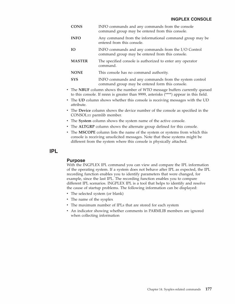
CONS INFO commands and any commands from the consolecommand group may be entered from this console.
INFO Any command from the informational command group may beentered from this console.
IO INFO commands and any commands from the I/O Controlcommand group may be entered from this console.
MASTER The specified console is authorized to enter any operatorcommand.
NONE This console has no command authority.
SYS INFO commands and any commands from the system controlcommand group may be entered form this console.
v The NBUF column shows the number of WTO message buffers currently queuedto this console. If nnnn is greater than 9999, asterisks (****) appear in this field.
v The UD column shows whether this console is receiving messages with the UDattribute.
v The Device column shows the device number of the console as specified in theCONSOLxx parmlib member.
v The System column shows the system name of the active console.v The ALTGRP column shows the alternate group defined for this console.v The MSCOPE column lists the name of the system or systems from which this
console is receiving unsolicited messages. Note that these systems might bedifferent from the system where this console is physically attached.
IPL
PurposeWith the INGPLEX IPL command you can view and compare the IPL informationof the operating system. If a system does not behave after IPL as expected, the IPLrecording function enables you to identify parameters that were changed, forexample, since the last IPL. The recording function enables you to comparedifferent IPL scenarios. INGPLEX IPL is a tool that helps to identify and resolvethe cause of startup problems. The following information can be displayed:v The selected system (or blank)v The name of the sysplexv The maximum number of IPLs that are stored for each systemv An indicator showing whether comments in PARMLIB members are ignored
when collecting information
INGPLEX CONSOLE
Chapter 14. Sysplex-related commands 177

Example
Use F10 and F11 to scroll through all available columns. SORT by column numbersis supported as well as the FIND and RFind command to locate information on thepanel. You can also limit the display to a particular system by specifying thesystem name in the appropriate entry field.
The following command codes are available:
C Compares the complete IPL information with another IPL record. A secondpanel will be displayed where you can select the second record.
D Displays detailed information about this IPL record.
E Erases the IPL information records. This action must be confirmed.v The Sysplex field shows the name of the sysplex.v The System field shows the name of the system in the sysplex.v The IPL Timestamp field shows the date and time of the IPL. The format is
YYYY-MM-DD HH:MM converted to local timezone.v The Dev field shows the IPL device number.v The Volume field shows the volume serial of the IPL device.v The OpSys field shows the name of the operating system, for example, z/OS or
OS/390.v The Release field shows the release level of the operationg system.v The FMID field shows the FMID of the operating system.
For further information about the panel fields refer to the online help.
INGLX200 msys/Ops - Command Dialogs Line 1 of 6Domain ID = IPSFM ------- INGPLEX IPL ------- Date = 02/22/02Operator ID = NETOP1 Time = 17:59:27
System . . . . . ==> Max. number of IPL records/system : 10Sysplex . . . . . ==> KEY1PLEX Suppression of PARMLIB comments . : N- - - - - - - - - - - - - - - - - - - - - - - - - - - - - - - - - - - - - - - -Cmds: C compare record / D display details / E erase record
System IPL Timestamp Dev Volume OpSys Release FMID-------- ---------------- ---- ------ ------ -------- --------KEYA 2002-02-22 13:52 770E 120204 z/OS SP7.0.2 HBB7705KEYA 2002-02-09 09:28 770E 120204 z/OS SP7.0.2 HBB7705KEYA 2002-02-08 15:28 770E 120204 z/OS SP7.0.2 HBB7705KEYA 2001-12-10 14:31 0707 120147 z/OS SP7.0.2 HBB7705KEYB 2002-02-22 13:59 770E 120204 z/OS SP7.0.2 HBB7705KEYB 2002-02-14 16:24 770E 120204 z/OS SP7.0.2 HBB7705KEYB 2002-02-11 18:46 770E 120204 z/OS SP7.0.2 HBB7705KEYB 2002-02-11 15:36 770E 120204 z/OS SP7.0.2 HBB7705KEYB 2002-02-11 14:22 770E 120204 z/OS SP7.0.2 HBB7705
Command ===>F1=Help F2=End F3=Return F6=Roll
F8=Forward F9=Refresh F10=Previous F11=Next F12=Retrieve
Figure 38. INGPLEX IPL main panel
INGPLEX IPL
178 z/OS and OS/390 msys for Operations Setting Up and Using

SDUMP
PurposeThe INGPLEX SDUMP command lets you control the default dump optionssysplex-wide.
ExampleThe dump functions can be invoked directly by specifying the commands, or fromthe dump panel of the INGPLEX command selecting the appropriate command. Inaddition, you can invoke the dump submenu from the main panel of the INGPLEXcommand selecting command 7. The following panel is displayed:
If you select option 1, the following panel is displayed:
INGLX250 msys/Ops - Command Dialogs Line 1 of 12Domain Id = IPSFP --------- INGPLEX --------- Date = 02/26/02Operator Id = NETOP1 Time = 16:30:36
Sysplex . . . . . . : KEY1PLEX
Select the desired command: INGPLEX ...
1 Control default SDUMP options SDUMP2 Issue SVC dumps SVCDUMP3 Control SLIP trap settings SLIP
Command ===>F1=Help F2=End F3=Return F6=Roll
F12=Retrieve
Figure 39. INGPLEX dump options panel
INGPLEX SDUMP
Chapter 14. Sysplex-related commands 179

The following command code is available:
C changeInvokes the modification panel by providing the options of the selected systemas input
v The Sysplex field shows the name of the sysplex.v The System field shows the name of the system in the sysplex.v The Permission field shows your authorization level.v The Dump options field shows the default SDUMP options of all systems in the
sysplex. For each system the following details are displayed:
Q= Shows whether or not SDUMP quiesces the system while dumping thecontents of the SQA or CSA.
TYPE=Causes SVC dump to dump the cross memory address spaces that thecaller has when SVC dump gets control (XMEM) or when the errorcausing the dump occurs (XMEME).
BUFFERS=Shows the reserved storage exlusively used by SVC dump. This storagecan be used while capturing the contents of the common area storage.
MaxSpaceShows the maximum amount of virtual storage that SVC dump can useto capture volatile virtual storage data, summary dump data, andcomponent-specific data before writing the dump to DASD.
MsgTimeShows for which amout of time (mm) the message IEA793A is shown atthe console. When the system deletes the message, it also deletes thecaptured dump.
INGLX251 msys/Ops - Command Dialogs Line 1 of 12Domain Id = IPSFP ------ INGPLEX SDUMP ------ Date = 02/26/02Operator Id = NETOP1 Time = 15:44:58
Sysplex . . . . . ==> KEY1PLEX Permission . . . . : ALL- - - - - - - - - - - - - - - - - - - - - - - - - - - - - - - - - - - - - - - -Cmds: C change
System Dump options-------- -------------------------------------------------------------------KEY1 Q= Type= Buffers= 0K MaxSpace= 500M MsgTime=99999
LSQATRT
KEY2 Q= Type= Buffers= 0K MaxSpace= 500M MsgTime=99999LSQA
TRTKEY3 Q= Type= Buffers= 0K MaxSpace= 500M MsgTime=99999
LSQATRT
KEY4 Q= Type= Buffers= 0K MaxSpace= 500M MsgTime=99999
Command ===>F1=Help F2=End F3=Return F6=Roll
F8=Forward F9=Refresh F12=Retrieve
Figure 40. INGPLEX SDUMP panel
INGPLEX SDUMP
180 z/OS and OS/390 msys for Operations Setting Up and Using

The FIND and RFIND commands are supported. If you specify command code C,the following panel is displayed:
The modification panel allows to modify all SDUMP options. Furthermore, you candelete SDUMP options. After entering your changes you can set the new optionsfor:v The selected systemv All systems in the sysplexv Selected systems in the sysplex
To set the options press the appropriate F-key. If you want to modify selectedsystems in the sysplex, you are prompted for the systems on which the SDUMPoptions are being changed. To reset the options to the state when the modificationpanel was invoked press F5 Undo all.
Note: The user must be authorized to change any SDUMP option. Theauthorization can be any of those which are used for controlling couplingfacilities and couple data sets.
For further information about the panel fields refer to the online help.
SVCdump
PurposeThe INGPLEX SVCDUMP function allows you to issue a multisystem dump of upto 15 address spaces of a single system including their data spaces and structures.
INGLX252 msys/Ops - Command Dialogs Line 1 of 12Domain Id = IPSFP ------ INGPLEX SDUMP ------ Date = 02/26/02Operator Id = NETOP1 Time = 16:18:08
System . . . . . . : KEY1Sysplex . . . . . . : KEY1PLEX Recommended options are underlined.
NODUMP ... ==> N (all other options below are ignored)
ALLNUC ... ==> ALLPSA(*) ==> COUPLE ... ==> CSA ...... ==>GRSQ ..... ==> LPA ...... ==> LSQA ..... ==> Y NUC ...... ==>PSA ...... ==> RGN ...... ==> SERVERS .. ==> SQA(*) ... ==>SUMSUMP(*) ==> SWA ...... ==> TRT ...... ==> Y WLM ...... ==>XESDATA .. ==> (*) = The NOxxx option is generated when not selected.
Q(uiesce) ==> (YES / NO)Type ..... ==> (XMEM / XMEME)Buffers .. ==> 0K (nnnnK / nnnM)MaxSpace . ==> 500 (MB)MsgTime .. ==> 99999 (minutes)
Command ===>F1=Help F2=End F3=Return F4=Set SYS F5=Undo all F6=Roll
F10=Set SYSS F11=Set SYSP F12=Retrieve
Figure 41. INGPLEX SDUMP modification panel
INGPLEX SDUMP
Chapter 14. Sysplex-related commands 181

Example
v The Sel field lets you select a system from which a multisystem dump is issued.v The System field shows the name of the system having joined the same XCF
group the operator is logged on to.
For further information about the panel fields refer to the online help. Afterselecting a system and pressing ENTER, the following panel is displayed:
INGLX26S msys/Ops - Command Dialogs Line 1 of 6Domain Id = IPSFP ----- INGPLEX SVCDUMP ----- Date = 02/06/02Operator Id = NETOP1 Time = 17:05:17
The following systems of sysplex KEY1PLEX are registered to the automation.Use any non-blank character to select one system and then press ENTER.
Sel System--- --------
KEY2KEY3KEY4
Command ===>F1=Help F2=End F3=Return F6=Roll
F12=Retrieve
Figure 42. INGPLEX SVCDUMP target system selection panel
INGPLEX SVCdump
182 z/OS and OS/390 msys for Operations Setting Up and Using

If you select VTAM address space and WATS address space, which is a user, pressENTER, then F5, the following panel is displayed:
Address space VTAM has some data spaces (D), one list structure (L) and someXCF group members (M). TSO user WATS has nothing.
The following command codes are supported:
D Deselects the previous selection
INGLX260 msys/Ops - Command Dialogs Line 38 of 63Domain Id = IPXFG ----- INGPLEX SVCDUMP ----- Date = 03/11/02Operator Id = NETOP1 Time = 12:26:26
System . . . . . ==> KEYASysplex . . . . . ==> KEYAPLEX- - - - - - - - - - - - - - - - - - - - - - - - - - - - - - - - - - - - - - - -Cmds: D/S de-/select job names for the SVC dump (up to 15 can be specified)
Jobname ASID WorkUnitID Userid-------- ---- ---------- --------TNF 0024TRACE 0004TSO 003B STC05983 STCUSERVLF 0019VMCF 0025VTAM 001E STC05982 STCUSER selectedWATS 0217 TSU06587 _ selectedWLM 000BXCFAS 0006
Command ===>F1=Help F2=End F3=Return F5=NextPnl F6=Roll
F8=Forward F9=Refresh F12=Retrieve
Figure 43. INGPLEX SVCDUMP address space selection panel
INGLX261 msys/Ops - Command Dialogs Line 1 of 9Domain Id = IPXFG ----- INGPLEX SVCDUMP ----- Date = 03/11/02Operator Id = NETOP1 Time = 12:34:04
System . . . . . . : KEYASysplex . . . . . . : KEYAPLEX- - - - - - - - - - - - - - - - - - - - - - - - - - - - - - - - - - - - - - - -Cmds: D/S de-/select the areas to be dumped (max. 113 structures)
A selection of the job name includes all related areas.
Jobname ASID T Data Space/XCF Group Member/Structure-------- ---- - -------------------------------------------VTAM 001E
D IST90C95D 00012IXLD 00013IXLL ISTGENERIC selectedM ISTCFS01.KEYB.VTAM.IPXVH___DEIBMIPS selectedM ISTXCF.KEYB.VTAM.IPXVH___DEIBMIPS selectedM IXCLO008.KEYB.VTAM.M28 selected
WATS 0217Command ===>F1=Help F2=End F3=Return F4=PrevPnl F5=NextPnl F6=Roll
F8=Forward F9=Refresh F12=Retrieve
Figure 44. INGPLEX SVCDUMP address space detail panel
INGPLEX SVCdump
Chapter 14. Sysplex-related commands 183

S Selects a local address space, data space, structure, or XCF group memberaddress space for the SVC dump.
If you press F5, the dump option selection panel is displayed:
The panel shows the default dump options being set on invocation. Afterspecifying the dump title, press F5 to issue the dump. When the dump is taken,the function returns to the address space selection panel with all selections cleared.The SORT, FIND and RFIND commands are supported for selection panels only.For further information about the panel fields refer to the online help.
SLIP
PurposeWith the INGPLEX SLIP command you can display serviceability level indicationprocessing (SLIP) traps being set at all systems in the sysplex. With INGPLEX SLIPyou can view, enable, disable, and delete the SLIP trap defined in the sysplex.
INGLX262 msys/Ops - Command DialogsDomain Id = IPSFP ------- INGPLEX SVC ------- Date = 02/26/02Operator Id = NETOP1 Time = 18:02:56
System . . . . . . : KEY3Sysplex . . . . . . : KEY1PLEX
Title .... ==>==>
SDATA Dump Options (recommended options are underlined)ALLNUC ... ==> ALLPSA(*) ==> Y COUPLE ... ==> CSA ...... ==> YGRSQ ..... ==> Y LPA ...... ==> LSQA ..... ==> NUC ...... ==> YPSA ...... ==> RGN ...... ==> Y SERVERS .. ==> SQA(*) ... ==> YSUMSUMP(*) ==> Y SWA ...... ==> TRT ...... ==> Y WLM ...... ==>XESDATA .. ==> (*) = The NOxxx option is used when not selected.
Structure Dump Options (SUMMARY and ADJUNCT/ENTRYDATA are mutually exclusive)COCLASS .. ==> EMCONTROLS ==> LISTNUM .. ==> STGCLASS . ==>ADJUNCT .. ==> ENTRYDATA ==> SUMMARY .. ==>
Command ===>F1=Help F2=End F3=Return F4=PrevPnl F5=Dump F6=Roll
F12=Retrieve
Figure 45. INGPLEX SVCDUMP dump option panel
INGPLEX SVCdump
184 z/OS and OS/390 msys for Operations Setting Up and Using

Example
The following command codes are available:
+ Shows the settings of the SLIP trap.
– Hides the settings of the SLIP trap.
D Disables the SLIP trap.
E Enables the SLIP trap.
R Deletes the SLIP trap.
The SORT, FIND and RFIND commands are supported.
Note: The user must be authorized to enable, disable, and delete a SLIP trap. Theauthorization can be any of those which are used for controlling couplingfacilities and couple data sets.
For information about the panel fields refer to the online help.
INGLX270 msys/Ops - Command Dialogs Line 1 of 96Domain Id = IPSFP ------ INGPLEX SLIP ------- Date = 02/26/02Operator Id = NETOP1 Time = 18:20:21
System . . . . . ==> (leave blank for all systems)Slip Trap Id . . ==> (leave blank for all ids)Sysplex . . . . . ==> KEY1PLEX Permission . . . . : ALL- - - - - - - - - - - - - - - - - - - - - - - - - - - - - - - - - - - - - - - -Cmds: +/- display/hide settings D disable E enable R remove
System Id Status Settings-------- ---- -------- ---------------------------------------------------KEY1 XB37 ENABLEDKEY1 XD37 ENABLEDKEY1 XE37 ENABLEDKEY1 X0E7 ENABLEDKEY1 X0F3 ENABLEDKEY1 X013 ENABLEDKEY1 X028 ENABLEDKEY1 X13E ENABLED
Command ===>F1=Help F2=End F3=Return F6=Roll
F8=Forward F9=Refresh F12=Retrieve
Figure 46. INGPLEX SLIP main panel
INGPLEX SLIP
Chapter 14. Sysplex-related commands 185

INGPLEX SLIP
186 z/OS and OS/390 msys for Operations Setting Up and Using

Chapter 15. Debugging and support commands
ACF
PurposeThe ACF command is used to load automation control file data. You can use ACFto refresh data of a particular system.
The ACF COLD command is used to activate configuration changes you havemade in the msys for Operations configuration file AOFCUST.
The following list shows the most important messages issued during the operationof the ACF COLD command:U IPUFD ING900I CUSTOMIZATION MEMBER AOFCUST HAS BEEN PROCESSED SUCCESSFULLYU IPUFD AOF100I 09:17:52 : ’ACF COLD’ COMMAND ISSUED| IPUFD AOF782I AUTOMATION CONTROL FILE PROCESSING COMPLETED
AOCTRACE
PurposeThe AOCTRACE command turns the debugging feature on or off. It works withboth a global debugging feature, and two automation procedure (REXX EXEC)specific ones.
ExamplesIf you enter aoctrace on you see a message indicating that the debugging facilityhas been enabled. While the debugging facility is enabled, message AOF700I iswritten to the netlog for each procedure that is being processed. If you enteraoctrace a panel similar to that in Figure 47 on page 188 is displayed:
© Copyright IBM Corp. 2002-03 187

If you press Enter, a panel similar to that in Figure 48 is displayed:
To switch on the trace for member ingrx000 enter the following:aoctrace ingrx000,on,r
To switch off the trace for member ingrx000 enter the following:aoctrace ingrx000,off,r
AOFKAAND msys/Ops - Command DialogsDomain ID = IPSNL ---------- AOCTRACE ---------- Date = 04/27/01Operator ID = NETOP1 Time = 13:43:59
Current global mode is ON Trace Settings
Current clist is ingrx000 A Alldebug is R Resultstrace is r I Intermediates
C CommandsSelect option: E Errors1 Turn global execution trace OFF F Failures2 Turn specific clist debug L Labels3 Show current clist debug settings O Off4 Display clists being traced N Normal
_ DefaultSpecify Subroutines to be traced: (* for all)*
Command ===> 2PF1=Help PF2=End PF3=Return PF6=Roll PF12=Retrieve
Figure 47. AOCTRACE command dialog panel 1
AOFKAAND msys/Ops - Command DialogsDomain ID = IPSNL ---------- AOCTRACE ---------- Date = 04/27/01Operator ID = NETOP1 Time = 13:44:16
Current global mode is ON Trace Settings
Current clist is INGRX000 A Alldebug is ON R Resultstrace is R I Intermediates
C CommandsSelect option: E Errors1 Turn global execution trace OFF F Failures2 Turn specific clist debug OFF L Labels3 Show current clist debug settings O Off4 Display clists being traced N Normal
_ DefaultSpecify Subroutines to be traced: (* for all)*
AOF095I AOCTRACE INGRX000,ON,R FUNCTION SUCCESSFULLY COMPLETEDCommand ===>
PF1=Help PF2=End PF3=Return PF6=Roll PF12=Retrieve
Figure 48. AOCTRACE command dialog panel 2
AOCTRACE
188 z/OS and OS/390 msys for Operations Setting Up and Using

MessagesThe following messages are issued (the first when the trace is switched on, and thesecond when it is switched off):AOF302I 13:44:52 : REQUEST AOFRADBG INGRX000 ON R BY NETOP1 IS COMPLETED FOR NETOP1
AOF302I 13:45:18 : REQUEST AOFRADBG INGRX000 OFF BY NETOP1 IS COMPLETED FOR NETOP1
DISPACF
PurposeThe DISPACF command displays resource information and automation policysettings for a specific entry or entry-type pair in the automation control file.
ExamplesIf you enter dispacf subsystem, a panel similar to the following is displayed:
This command displays information for all types of the MVSESA entry, becauseyou accepted the default TYPE=*.
DISPAOPS
PurposeThe DISPAOPS command lists the automation operators that are currently active.
AOFK3D0X msys/Ops - Command Response Line 1 of 10Domain ID = IPSN7 ---------- DISPACF ---------- Date = 06/13/01Operator ID = NETOP1 Time = 17:41:10
Command = ACF ENTRY=MVSESA,TYPE=*,REQ=DISPSYSTEM = KEY7 AUTOMATION CONFIGURATION DISPLAY - ENTRY= MVSESA-------------------------------------------------------------------------------AUTOMATION CONFIGURATION DISPLAY - ENTRY= MVSESATYPE IS IEE041ICMD = (,,’MVS VARY SYSLOG,HARDCPY’)TYPE IS IEE043ICMD = (,,’MVS WRITELOG START’)TYPE IS IEE533ECMD = (,,’MVS WRITELOG START’)TYPE IS WTOBUFCODE = (*,*,,""CANCEL"")END OF MULTI-LINE MESSAGE GROUP
Command ===>PF1=Help PF2=End PF3=Return PF6=Roll
PF9=Refresh PF12=Retrieve
Figure 49. Display of Automation Control File settings for subsystem (DISPACFSUBSYSTEM)
AOCTRACE
Chapter 15. Debugging and support commands 189

ExamplesEnter dispaops on any command line and press the Enter key. You see a panelsimilar to the following:
v The System field shows the name of the system where the automated function isdefined
v The Automated Function field shows the name of the automated function usedin msys for Operations automation procedures
v The Primary field shows the NVSS automation operator ID assigned to thisautomated function
v The Status field shows the current status of the primary automation operatorv The Secondary field shows the Backup NVSS automation operator ID assigned
to this automated functionv The Status field shows the current status of the backup automation operator
The primary and backup NVSS automation operator IDs are assigned to theautomated function in the command dialogs.
DISPASF
PurposeDISPASF displays the information contained in the automation status file. Thisincludes the:v Automation statusv Operator ID that last changed the recordv Last threshold exceededv Date and time of last monitoring cycle
AOFK2SO msys/Ops - Command Dialogs Line 1 of 17Domain ID = IPSN7 ---------- DISPAOPS ---------- Date = 06/13/01Operator ID = NETOP1 Time = 17:45:05
AutomatedSystem Function Primary Status Secondary Status-------- ---------- ------- ------ --------- ------KEY7 AOFWRK01 AUTWRK01 ACTIVKEY7 AOFWRK02 AUTWRK02 ACTIVKEY7 AOFWRK03 AUTWRK03 ACTIVKEY7 BASEOPER AUTBASE ACTIVKEY7 GSSOPER AUTGSS ACTIVKEY7 JESOPER AUTJES ACTIVKEY7 LOGOPER AUTLOG ACTIVKEY7 MONOPER AUTMON ACTIVKEY7 MSGOPER AUTMSG ACTIVKEY7 MVSCONS AUTCON ACTIVKEY7 NETOPER AUTNET1 ACTIVKEY7 RECOPER AUTREC ACTIVKEY7 RPCOPER AUTRPC ACTIV
Command ===>PF1=Help PF2=End PF3=Return PF6=Roll
PF8=Forward PF9=Refresh PF12=Retrieve
Figure 50. Automation operators panel
DISPAOPS
190 z/OS and OS/390 msys for Operations Setting Up and Using

ExamplesIf you enter dispasf syslog a panel similar to the following is displayed:
DISPATHR
PurposeThe DISPATHR command displays a summary of the msys for Operationsthresholds.
ExamplesWhen you enter dispathr you see a panel similar to the following:
AOFK3D0X msys/Ops - Command Response Line 1 of 11Domain ID = IPSN7 ---------- DISPASF ---------- Date = 06/13/01Operator ID = NETOP1 Time = 16:47:09
Command = ASF ID=SYSLOG,REQ=DISPSYSTEM = KEY7 STATISTICS DISPLAY REQUESTED FOR SYSLOG-------------------------------------------------------------------------------STATISTICS DISPLAY REQUESTED FOR SYSLOGID= SYSLOG , TYPE= MVSESA , STATUS= DOWNLAST UPDATE BY OPERATOR AUTRECLAST THRESHOLD EXCEEDED - INFROPERATOR NOTIFIED: NLAST STATUS CHANGE DATE= 06/08/01 , TIME= 10:25 , OPID= AUTRECLAST MONITORED DATE= 06/08/01 , TIME= 10:25
ERROR COUNT DATE TIME01 06/08/01 10:2502 06/13/01 12:22
END OF MULTI-LINE MESSAGE GROUP
Command ===>PF1=Help PF2=End PF3=Return PF6=Roll
PF9=Refresh PF12=Retrieve
Figure 51. Display of automation status file information for DISPASF SYSLOG
DISPASF
Chapter 15. Debugging and support commands 191

v The System field shows the name of the system where the resource is defined.v The Resource field shows the name of the resource. The first three entries are
always DEFAULTS, MVSESA, and SUBSYSTEM.v The Critical field shows the critical threshold for the resource.
If no critical threshold has been specified, the field is blank.v The Frequent field shows the frequent threshold for the resource.v The Infrequent field shows the infrequent threshold for the resource.
Thresholds have the format nn in hh:mm, which means that the threshold isexceeded if more than nn errors occur within hh hours and mm minutes.
DISPERRS
PurposeThe DISPERRS command displays information about resources for which errorshave been recorded in the status file.
ExamplesWhen you enter disperrs you see a panel similar to the following:
AOFKAAD4 msys/Ops - Command Dialogs Line 1 of 4Domain ID = IPSN7 ---------- DISPATHR ---------- Date = 06/13/01Operator ID = NETOP1 Time = 17:52:14
System Resource Critical Frequent Infrequent-------- ----------- ----------- ----------- -----------KEY7 DEFAULTSKEY7 MVSESAKEY7 SUBSYSTEMKEY7 SYSLOG 3 in 02:00 2 in 02:00 1 in 02:00
Command ===>PF1=Help PF2=End PF3=Return PF6=Roll
PF9=Refresh PF12=Retrieve
Figure 52. DISPATHR command dialog panel
DISPATHR
192 z/OS and OS/390 msys for Operations Setting Up and Using

v The System field shows the name of the system where the resource is defined.v The Resource field shows the name of the resource.v The Type field shows the type of resource.v The Thrs field shows the type of threshold that has been violated. This is either
CRIT (critical), FREQ (frequent), or INFR (infrequent).v The No field shows the sequence number assigned to the error.v The Date and Time fields show the date and time when the error occurred.
DISPFLGS
PurposeThe DISPFLGS command shows whether msys for Operations functions areenabled (Recovery flag set to Y), or disabled (Recovery flag set to N).
ExamplesWhen you enter dispflgs in msys for Operations you see a panel similar to thefollowing:
AOFKAAD5 msys/Ops - Command Dialogs Line 1 of 9Domain ID = IPSN7 ---------- DISPERRS ---------- Date = 06/13/01Operator ID = NETOP1 Time = 17:55:23
System Resource Type Thrs No Date Time-------- ----------- ----------- ---- -- -------- -----KEY7 AOFIPLDT CONTROL 7 06/06/01 08:09KEY7 6 04/25/01 15:28KEY7 5 04/21/01 09:51KEY7 4 04/20/01 12:42KEY7 3 04/18/01 17:05KEY7 2 02/27/01 16:11KEY7 1 02/16/01 15:15KEY7 SYSLOG MVSESA INFR 2 06/13/01 12:22KEY7 1 06/08/01 10:25
Command ===>PF1=Help PF2=End PF3=Return PF6=Roll
PF9=Refresh PF12=Retrieve
Figure 53. DISPERRS command dialog panel
DISPERRS
Chapter 15. Debugging and support commands 193

As can be seen in Figure 54, the minor resource flags for CDS, HEALTHCHK,LOG, WTO, XCF are set to ON (Y) and therefore these functions have beenenabled.
DISPMSGS
PurposeThe DISPMSGS command displays which automation operators receive eachautomated message.
ExamplesEnter dispmsgs on a command line to display the Authorized Message Receiverspanel:
AOFKAAAU msys/Ops - Command Dialogs Line 1 of 8Domain ID = IPSN7 ---------- DISPFLGS ---------- Date = 02/18/03Operator ID = NETOP1 Time = 18:02:59System = KEY7 Actual EffectiveResource A I S R D RS A I S R D RS Settings---------------------- - - - - - - - - - - - - -----------------------DEFAULTS Y - - - - - Y Y Y Y Y Y - No explicit settingMVSESA - - - - - - Y Y Y Y Y Y N Turned offCDS - - - Y - - Y Y Y Y Y Y E Consult exitENQ - - - N - - Y Y Y N Y Y Y Turned onHEALTHCHK - - - Y - - Y Y Y Y Y Y ? ErrorLOG - - - Y - - Y Y Y Y Y YLOGGER - - - N - - Y Y Y N Y Y FlagsWTO - - - Y - - Y Y Y Y Y Y ----------------------XCF - - - Y - - Y Y Y Y Y Y A Automation
SUBSYSTEM - - - - - - Y Y Y Y Y Y I Initial startS Start upR RecoveryD Shut downRS Restart
Command ===>PF1=Help PF2=End PF3=Return PF6=Roll
PF9=Refresh PF12=Retrieve
Figure 54. DISPFLGS command dialog panel
DISPFLGS
194 z/OS and OS/390 msys for Operations Setting Up and Using

v The Message field shows the message or message prefix.v The Primary Receivers field shows the automation operators, identified by their
NVSS IDs. The Primary Receivers column lists automation operators that canreceive the messages listed beside their names. These messages go to the firstautomation operator listed in the Primary Receivers column that is active.
v The Secondary Receivers field shows the Alternate automation operators,identified by their NVSS IDs. Secondary Receivers receive copies of the messageslisted beside their names.
DISPWTOR
PurposeThe DISPWTOR command displays all WTORs that are currently outstanding.
ExamplesIf you enter dispwtor you see a panel similar to the following:
AOFK2SM msys/Ops - Command Dialogs Line 1 of 9Domain ID = IPSN7 ---------- DISPMSGS ---------- Date = 06/13/01Operator ID = NETOP1 System = KEY7 Time = 18:08:09
Message Primary Receivers Secondary Receivers------- ----------------- -------------------’AOF*’ AUTMSG AUTSYS AUTBASE’IEA*’ AUTREC AUTSYS AUTBASE’IEE889I AUTSYS AUTBASE’IEE*’ AUTREC AUTSYS AUTBASE’IOS*’ AUTREC AUTSYS AUTBASE’IXC263I AUTXCF2 AUTSYS AUTBASE’IXG257I AUTXCF2 AUTSYS AUTBASE’IXG261E AUTXCF2 AUTSYS AUTBASE’*’ AUTLOG AUTSYS AUTBASE
Command ===>PF1=Help PF2=End PF3=Return PF6=Roll
PF9=Refresh PF12=Retrieve
Figure 55. Authorized Message Receivers Panel
DISPMSGS
Chapter 15. Debugging and support commands 195

v The Rply field shows the outstanding reply number.v The System field shows the name of the system for which the reply is
outstanding.v The Subsystem field shows the subsystem name, or MVSESA if the reply is from
a resource that is not a subsystem.v The Message field shows the text of the message.
INGAUTO
PurposeINGAUTO ON,MVSESA.function_qualifier enables msys for Operations functions.Refer to Figure 54 on page 194 for a list of the function_qualifier flags. INGAUTOallows you to manipulate these flags. To display the flags, use the DISPFLGScommand (see “DISPFLGS” on page 193).
INGAUTO OFF,MVSESA.function_qualifier disables an msys for Operationsfunction.
ExamplesTo turn all automation on for the WTOR buffer shortage recovery, enter thefollowing:ingauto on,mvsesa.wto
INGCUST
PurposeINGCUST is a service function that is used in msys for Operations for checking thesyntactical correctness of the customization member AOFCUST.
AOFKADAC msys/Ops - Command Dialogs Line 1 of 2Domain ID = IPSN7 ---------- DISPWTOR ---------- Date = 06/13/01Operator ID = NETOP1 Time = 18:15:12
Rply System Subsystem Message---- -------- ----------- ----------------------------------------
32 KEY7 MVSESA DSI802A IPSN7 REPLY WITH VALID NCCFSYSTEM OPERATOR COMMAND
Command ===>PF1=Help PF2=End PF3=Return PF6=Roll
PF9=Refresh PF12=Retrieve
Figure 56. Display of outstanding replies (DISPWTOR)
DISPWTOR
196 z/OS and OS/390 msys for Operations Setting Up and Using

After changing AOFCUST in msys for Operations, check the syntactical correctnessof the member before starting msys for Operations. If AOFCUST is syntacticallyincorrect, msys for Operations cannot be started. To perform the check issueINGCUST with INSTORE as its first parameter. INGCUST informs you about theresult with a message.
INGCUST does not require that the name of the input member is AOFCUST. Butin order to use a member with a different name for the customization of msys forOperations, you must rename it back to AOFCUST.
ExamplesINGCUST INSTORE MYCUST
This command checks the customization member MYCUST for syntacticalcorrectness. Note that in order to use it, you must rename it to AOFCUST.
INGCUST
Chapter 15. Debugging and support commands 197

INGCUST
198 z/OS and OS/390 msys for Operations Setting Up and Using

Part 5. Setup reference
This part provides a reference for setting up msys for Operations, and has thefollowing chapter:v Chapter 16, “msys for Operations definition statements reference”, on page 201
© Copyright IBM Corp. 2002-03 199

200 z/OS and OS/390 msys for Operations Setting Up and Using

Chapter 16. msys for Operations definition statementsreference
Definition statements are used by msys for Operations for performing systemadministration tasks. System administration is the process of redefining systemdefaults and storage requirements. You can perform administration subtasksduring msys for Operations installation or when you redefine network resources.
In planning for installation and network management tasks, you determine thefacilities you need to run msys for Operations. You also need to identify hardwarerequirements and specific resources used by msys for Operations. This informationcan help you determine requirements for user coding and msys for Operationsdefinitions.
After copying current definition statements from the sample files, you can begin tomodify existing definition statements or create new ones. You can alter definitionstatements during a first-time msys for Operations installation, or later, whilerunning your production system.
Statement formatsThe format of a definition statement is:v Statement namev General introduction
The general introduction explains overall options, assumptions, and the purposeof the statement. Each introduction explains the name of the member and whereyou code the statement.
v Definition statement syntaxThe definition statement syntax is a model statement that is formatted accordingto the code conventions.
v Operand descriptionsThis section describes each operand you can specify for the definition statement.The description includes the specific values or variable information that you canspecify for the operand.
Syntax conventions for definition statementsThese syntax conventions apply to most statements:v Code at least one blank between a label name and the name of the definition
statement, and between the name of the definition statement and the firstoperand. One or more blanks, or a single comma with no blanks, must separatethe statement operands. You cannot separate the operands with a combination ofcommas and blanks. If you omit the optional label name, you still need toprecede the definition statement with one or more blanks.
v The label field must not exceed 8 characters, and the field must start incolumn 1.
v Continuation from one line to the next is not allowed. However, you can repeatthe definition statement and add the remaining information. For the followingexample:
© Copyright IBM Corp. 2002-03 201

LOGINIT AUTOFLIP=YESLOGINIT RESUME=YES
Is the same as:LOGINIT AUTOFLIP=YES,RESUME=YES
v Place comments on a separate line for DSIPARM members. The first column of acomment line must contain an asterisk (*).
v Many definition files conclude with an END statement. This END statement hasno operands and cannot begin in column 1.
v All NVSS program identifiers, which are called names, must not exceed 8characters unless specified. The first character must be alphabetical andalphabetical characters must be in uppercase.
v Command names, command list names, and any other NVSS program identifiersmust not contain commas (,), periods (.), blanks ( ), apostrophes (’), ampersands(&), asterisks (*), or equal signs (=). Commas, periods, blanks, and equal signsare used as delimiters when the definition statements are parsed. The othercharacters have special meanings for NVSS command lists.
v Command names and command list names must begin in column 1.v System symbolics can be coded on any NVSS definition statement to provide
unique information to the msys for Operations system. System symbolics areuseful when running msys for Operations on different systems where you wantto have different characteristics. This unique information (as defined by thesystem symbolic values) will remain on your system definitions until youchange those definitions and re-IPL MVS.
AUTHThe AUTH statement defines an operator’s authority to view and control resourcesand specifies whether an operator is eligible to be the authorized receiver. Codethis statement in a member specified by a PROFILEN statement associated withthe operator. See “OPERATOR” on page 203 and “PROFILEN” on page 212 forinformation on how a PROFILEN statement is associated with an operator. Asample member supplied with msys for Operations is DSIPROFA.
The syntax for the AUTH statement is:
AUTH
RR AUTHMSGRECVR=NO
MSGRECVR= NOYES
RP
Where:
MSGRECVR=NO|YESSpecifies whether operators using this profile can receive unsolicited messagesthat are not routed to a particular operator by the use of the NVSS ASSIGNcommand or by NVSS automation.
NOIndicates that operators using the profile containing this statement do notreceive unsolicited messages. NO is the default.
Syntax conventions for definition statements
202 z/OS and OS/390 msys for Operations Setting Up and Using

YESIndicates that an operator using this profile can be the authorized messagereceiver.
Usage Notes:
v In NVSS, the authorized receiver is the operator authorized to receive all theunsolicited and authorized messages that are not routed to a specific operatorwith an ASSIGN command or a ROUTE action in an NVSS automationstatement. The authorized receiver is determined by the order in which operatorterminals are defined to NVSS and by the order in which authorized operatorshave logged on.
v When several operators are eligible to receive a particular message, NVSS usesthe following priority order (from the lowest to the highest) to route the messageto the proper operator:– The operator designated by an ASSIGN command– The operator or operators designated by the ROUTE action in the automation
table– An operator
If more than one operator is logged on, the one logged on first has priority.– An autotask operator
If more than one autotask has been started, the one started first has priority.Use the ASSIGN command if an autotask is going to be the receiver ofunsolicited messages.
– The system console operator
OPERATORWhen OPERSEC is not specified as SAFDEF on either the OPTIONS statement inDSIDMN or on the REFRESH command, the OPERATOR statement identifies eachoperator who can log on to this NVSS program. This statement is also used todefine operator identifiers that can be started as automation tasks by theAUTOTASK command. The OPERATOR statement must come before its associatedPROFILEN statements. You code this statement in DSIOPF.
You can dynamically add or delete operators by adding or deleting OPERATORstatements in DSIOPF and issuing the REFRESH OPERS command.
The syntax for the OPERATOR statement is:
OPERATOR
RR opid OPERATOR PASSWORD=password,NOCHECK
RP
Where:
opidIndicates the 1–8 character value that identifies an operator. Valid charactersfor the operator identifier are letters A–Z, the numbers 0–9, or the specialcharacters number sign (#), at sign (@), or dollar sign ($). The identifier mustbegin in column 1. Each operator must have a unique operator identifier. Also,code an operator statement for each operator identifier you want to use for anautomation task. Do not use the names of hardcopy logs, terminals, or task
AUTH
Chapter 16. msys for Operations definition statements reference 203

identifiers as operator identifiers. The following identifiers are reserved by theNVSS program and cannot be used as operator identifiers:v ALLv DPRv DSTv HCLv HCTv LOGv MNTv NNTv OPTv OSTv PPTv SYSOPv TCT
Additionally, if the operator identifier is the same as the LU name (terminal),some command lists assume that the operator is an autotask and do not run.
PASSWORD=passwordIndicates the 1–8 character operator password. You are required to code apassword, but the password is ignored if you code OPTIONSOPERSEC=MINIMAL or OPERSEC=SAFCHECK in DSIDMN. The password isalso ignored if you use this operator identifier when starting an autotask usingthe AUTOTASK command. For operator identifiers set up specifically forautotasks, use the password to identify the operator as such.
NOCHECKAllows the NVSS operator to log on without NVSS verifying the password. Inthis case, message DWO354 is sent to the authorized receiver indicating thatthe operator has logged on and the password has not been verified by NVSS.The advantage of this option over OPERSEC=MINIMAL is that the operator’sprofile is used and any initial command specified is used. NOCHECK must bepreceded by a comma.
OPTIONSThe OPTIONS statement describes the type of security settings msys forOperations uses. This checking includes:v Authorizing a user to log on as an msys for Operations operatorv Validating the password and identity of a user logging on to msys for
Operationsv Specifying where the attributes for an msys for Operations operator are definedv Protecting commands executed in NVSS
Code the OPTIONS statement in DSIDMN. You can use the REFRESH command todynamically change these options.
There can be more than one OPTIONS statement. If you specify the same keywordon more than one OPTIONS statement, the first occurrence is used. Subsequentspecifications of a keyword result in an error message and initialization continues.
During initialization, messages BNH180I, BNH191I, and BNH193I are issued todisplay the operator and command security settings that will be used by msys forOperations. If error messages are displayed during initialization, message DSI813Ais issued at the end of initialization to give the operator a chance to continue or toterminate initialization.
OPERATOR
204 z/OS and OS/390 msys for Operations Setting Up and Using

An OPTIONS statement is required for msys for Operations and a value must bespecified for the OPERSEC and CMDAUTH keywords.
If OPERSEC=SAFDEF, you do not need a DSIPRF specification in your msys forOperations procedure. If you later want to issue a REFRESH command withOPERSEC specified as either NETVPW or SAFCHECK, you must first dynamicallyallocate DSIPRF, if it is not in your msys for Operations procedure.
If OPERSEC=SAFDEF, you do not need a DSIOPF member in DSIPARM. If youlater want to issue a REFRESH command with OPERSEC specified as eitherNETVPW or SAFCHECK, DSIPARM must contain a DSIOPF member for theREFRESH command to complete successfully.
The syntax for the OPTIONS statement is:
OPTIONS
RRlabel
(1)OPTIONS ,OPERSEC= SAFCHECK
MINIMALNETVPWSAFDEF
R
R,CMDAUTH=SAF
,SAFNODEC=PASS,CMDAUTH= SAF
,SAFNODEC= PASSFAIL
,BACKTBL=table_nameTABLE,TBLNAME=table_name
,AUTHCHK=SOURCEID
,AUTHCHK= TARGETIDSOURCEID
RP
Notes:
1 For more information about the interrelationship of keywords, see Table 9 onpage 209.
Where:
labelIndicates the optional label for the OPTIONS statement. This label identifiesthe statement for any related error messages.
OPERSEC=MINIMAL|NETVPW|SAFCHECK|SAFDEFDefines the method used to allow users to log on to NVSS.
MINIMALSpecifies that msys for Operations operators are defined by a list ofoperator identifiers in DSIOPF. There is no password validation. Thelogon profile is not used and logon operands specified on the logonmenu are ignored.
Other keywords cannot be specified on the OPTIONS statement whenMINIMAL is specified. If other keywords are specified, they areignored, a message is issued, and initialization continues. MessageDSI813A is issued at the end of initialization, indicating these errorsand giving the operator a chance to continue or to terminateinitialization.
OPTIONS
Chapter 16. msys for Operations definition statements reference 205

You cannot use the REFRESH command to change the OPERSECspecification when MINIMAL is specified.
NETVPWSpecifies that msys for Operations operators are defined by a list ofoperator identifiers in DSIOPF. The identification is validated with apassword associated with the identifier in DSIOPF. The profile, readfrom DSIPRF at logon, contains information about what the operator isallowed to do, and limits commands and resources that the operatorcan use.
CMDAUTH=SAF should not be specified when OPERSEC=NETVPW.If CMDAUTH=SAF is specified, no authorization checks are performedwhen commands are issued.
If an error with the CMDAUTH specification is detected, an errormessage is issued and initialization continues. Message DSI813A isissued at the end of initialization, indicating that errors have occurredand giving the operator a chance to continue or to terminateinitialization.
SAFCHECKSpecifies that operator identification and password checking isperformed using an SAF security product. The operator identifier mustalso be defined in DSIOPF, and other attributes given to the operator atlogon are taken from the operator’s specified profile in DSIPRF.
Security access checks that occur when an operator tries to access adata set that is protected in the DATASET class of an SAF product oran MVS system command that is protected in the OPERCMDS class ofan SAF product are checked against the authority of the operator.
This specification allows CMDAUTH to be specified as TABLE or SAF.
SAFDEFSpecifies that operator identification and password checking is doneusing an SAF security product. Authority to log on as an msys forOperations operator is controlled through the APPL class. The operatoridentifier must be authorized to the resource name in the APPL classwhich represents msys for Operations.
The attributes given to the operator at logon are defined in theNVSSsegment of the operator’s user profile in the SAF product.
When OPERSEC=SAFDEF is specified, any value for CMDAUTH canbe used.
CMDAUTH=SAF|TABLEDefines the method used by msys for Operations to protect command usage.For a list of commands with keywords and values that can be protected, see“Recommended commands to protect” on page 77.
CMDAUTH cannot be specified when OPERSEC=MINIMAL. With otherOPERSEC settings you can issue the REFRESH command to change themethod used for command authorization.
If the CMDMDL statement for a command specifies SEC=BY, no authoritychecking is done for that command. Command authorization checking forautomation table commands can also be bypassed by specifyingAUTOSEC=BYPASS on the DEFAULTS command.
SAF Specifies that msys for Operations performs command authorization
OPTIONS
206 z/OS and OS/390 msys for Operations Setting Up and Using

checking using an SAF security product. The commands you want toprotect should be defined in the NETCMDS class in the securityproduct. The operators that you want to give access to the commandscan be permitted to use the resource names that represent commands,keywords, and values. For more information, see “Commandauthorization” on page 73.
If AUTHCHK is not specified when CMDAUTH=SAF, it defaults toSOURCEID during initialization. When the REFRESH command isused, there is no default for AUTHCHK.
If, during initialization, the NETCMDS class is not active or thesecurity product is not active and BACKTBL is not specified, noauthorization checking is performed when commands are issued. Anerror message is issued and initialization continues. Message DSI813Ais issued at the end of initialization, indicating that errors haveoccurred and giving the operator a chance to continue initialization orto terminate it.
If, during command authorization checking, the NETCMDS class isinactivated, the security product is inactivated, or there is no resourcename defined for the command being issued, msys for Operations usesthe command authorization table specified by BACKTBL. If BACKTBLis not specified, authority to issue the command is determined by thevalue of SAFNODEC.
For immediate commands, authority checking is not performed bySAF. These commands should be protected using the commandauthorization table specified by BACKTBL.
CMDAUTH=SAF can only be specified when OPERSEC=SAFCHECKor OPERSEC=SAFDEF. If CMDAUTH=SAF is specified with any othervalue for OPERSEC, initialization continues, and no authorization is ineffect. Message DSI813A is issued at the end of initialization, indicatingthat errors have occurred and giving the operator a chance to continueor to terminate initialization.
TABLESpecifies that authorization checking is performed using a dynamiccommand authorization table specified by the TBLNAME keyword.The table can be modified and reloaded using the REFRESH command.
If AUTHCHK is not specified, it defaults to SOURCEID forCMDAUTH=TABLE during initialization. When the REFRESHcommand is used, there is no default for AUTHCHK.
If CMDAUTH=TABLE is specified and TBLNAME is not specified, orif the member specified by TBLNAME is not found, messages areissued and command authorization checks are not performed. MessageDSI813A is issued at the end of initialization, indicating that errorshave occurred and giving the operator a chance to continueinitialization or to terminate it.
BACKTBL=table_nameSpecifies the 1–8 character name of the command authorization table usedwhen CMDAUTH=SAF and SAF checking cannot be performed for thecommand being issued. This can occur when:v The command is an immediate command.v There is no resource name defined in the NETCMDS class which protects or
authorizes this command.
OPTIONS
Chapter 16. msys for Operations definition statements reference 207

v The NETCMDS class is not active.v The security product is not active.
The table name is a member name in a DSIPARM data set.
The BACKTBL and SAFNODEC options are mutually exclusive. When both arespecified, the BACKTBL option is used.
table_nameSpecifies the name of the table. For more information on how to buildthe table, see “Command authorization” on page 73.
If CMDAUTH=SAF is specified and the backup command authorization tablecontains syntax errors, messages are issued. Message DSI813A is issued at theend of initialization, indicating that errors have occurred and giving theoperator a chance to continue initialization or to terminate it. If the reply toDSI813A is YES, the table will still be loaded with the statements that arecoded correctly. If the backup table contains no valid statements, NVSScontinues with no backup table.
AUTHCHK=SOURCEID| TARGETIDSpecifies the user ID that is to be used when verifying command authorizationand span authorization for VTAM commands. For specific information abouthow the SOURCEID and TARGETID are determined, “Commandauthorization” on page 73.
SOURCEIDSpecifies to check the authority of the original issuer or the ID closestto the original issuer.
Access failure messages display the source issuer of the command.SOURCEID is the default when CMDAUTH=SAF.
TARGETIDSpecifies to check the authority of the task under which the commandruns.
SAFNODEC=PASS|FAILDefines the action taken by msys for Operations when BACKTBL is notspecified and the SAF product cannot make a decision on command authority.This can occur when:v There is no resource name defined in the NETCMDS class which protects or
authorizes this command.v The NETCMDS class is not active.v The security product is not active.
The default is to pass the command.
The SAFNODEC and BACKTBL options are mutually exclusive. When both arespecified, the BACKTBL is used.
PASS Specifies that users should be allowed to issue all commands when theSAF product cannot make a security decision.
FAIL Specifies that users should not be allowed to issue any commandswhen the SAF product cannot make a security decision.
Attention: Specifying PASS indicates that no command authorization checkingis performed if the SAF product becomes unavailable or otherwisecannot make a decision. Specifying FAIL keeps you from issuing
OPTIONS
208 z/OS and OS/390 msys for Operations Setting Up and Using

any commands (except when SEC=BY is specified on the CMDMDLstatement or AUTOSEC=BYPASS is in effect for automationcommands) if the SAF product becomes unavailable or otherwisecannot make a decision. For this reason, it is better to define abackup command authorization table than to use SAFNODEC.
Interrelationships of keywords:
Table 9 shows the relationships between OPERSEC and CMDAUTH specifications.
Table 9. Interrelationships between OPTIONS keyword values (part 1 of 2)
IF OPERSEC= CMDAUTH
TABLE SAF
MINIMAL Not valid Not valid
NETVPW Is valid Not valid
SAFCHECK Is valid Is valid
SAFDEF Is valid Is valid
Table 10 shows the relationships between CMDAUTH, TBLNAME, BACKTBL,SAFNODEC, and AUTHCHK specifications.
Table 10. Interrelationships between OPTIONS keyword values (part 2 of 2)
CMDAUTH= TBLNAME BACKTBL SAFNODEC AUTHCHK
TARGETID SOURCEID
SAF Ignored Is valid Is valid,defaults toPASS, and isignored ifBACKTBL isspecified
Is valid Default
TABLE Required Ignored Ignored Is valid Default
Operator Authority:
Table 11 shows how the OPERSEC and OPSPAN keywords are used to specify howoperator verification and authority checking is to be performed.
Table 11. Defining and verifying operator authority
Keyword Related Defaults Restrictions Effect
OPERSEC= MINIMAL v CMDAUTH is ignored.v Cannot use REFRESH to
change OPERSEC.
v Logon profile ignoredv Logon operands ignoredv No password validationv Operator must be
defined in DSIOPF
OPERSEC= NETVPW CMDAUTH=TABLE mustbe specified.
v Not valid whenCMDAUTH=SAF
v Password validated fromDSIOPF
v Operator must bedefined in DSIOPF
v Profile read from DSIPRF
OPTIONS
Chapter 16. msys for Operations definition statements reference 209

Table 11. Defining and verifying operator authority (continued)
Keyword Related Defaults Restrictions Effect
OPERSEC= SAFCHECK v CMDAUTH must bespecified.
v Password verificationusing SAF product
v Operator must bedefined in DSIOPF
v Profile read from DSIPRFv NVSS task user IDs are
used for any SAF callsfor NVSS operators, suchas to the DATASET class.
OPERSEC= SAFDEF v CMDAUTH must bespecified.
v Password verificationusing SAF product
v Operator logon authorityusing RACF APPL class
v Operator attributesdefined in NetViewsegment of SAF product
v NVSS task userids areused for any SAF callsfor NVSS operators, suchas to the DATASET class.
Protecting Commands:
Table 12 shows how the CMDAUTH and related options are used to specify howoperator command authority checking is to be performed.
Table 12. Protecting commands executed in NVSS
Keyword Related Defaults Restrictions Effect
CMDAUTH= TABLE AUTHCHK default isSOURCEID.
Command authorization isbased on the specifiedtable.
CMDAUTH= SAF AUTHCHK default isSOURCEID.
Cannot be specified ifOPERSEC is MINIMAL orNETVPW.
Command authorizationusing the NETCMDS classof an SAF product.Immediate commands arenot checked in theNETCMDS class, but abackup commandauthorization table can beused for this purpose.
TBLNAME= table_name Required ifCMDAUTH=TABLE
Identifies the table to beused
OPTIONS
210 z/OS and OS/390 msys for Operations Setting Up and Using

Table 12. Protecting commands executed in NVSS (continued)
Keyword Related Defaults Restrictions Effect
BACKTBL= table_name Valid only whenCMDAUTH=SAF
Specifies the backup tableto be used for immediatecommands and when theSAF product cannot make asecurity decision. This canoccur when:v There is no resource
name defined in theNETCMDS class whichprotects or authorizesthis command
v The NETCMDS class isnot active
v The security product isnot active.
SAFNODEC= PASS|FAIL Defaults to PASS
Only used whenCMDAUTH=SAF and noBACKTBL is specified
Identifies whether to PASSor FAIL command authoritychecking if the SAF productcan reach no decision.
AUTHCHK= SOURCEID Default whenCMDAUTH=TABLE
Authorization is based onthe authority of the originalissuer of the command orthe ID closest to theoriginal issuer.
AUTHCHK= TARGETID Authorization is based onthe authority of the IDunder which the commandruns.
Usage Notes:v When CMDAUTH=SAF and no backup command authorization table is used,
immediate commands are not checked and will pass even if SAFNODEC=FAIL.
PROFILEThe PROFILE statement defines the profile name to the system. PROFILE must bethe first statement in each profile definition. Code this statement in a memberspecified by a PROFILEN statement associated with the operator. See“OPERATOR” on page 203 and “PROFILEN” on page 212 to determine how aPROFILEN statement is associated with an operator. Profiles are not used whenOPERSEC=SAFDEF. Examples of sample members that are supplied with theNVSS program are DSIPROFA and DSIPROFB, which can be found inNETVIEW.DSIPRF.
The syntax for the PROFILE statement is:
PROFILE
RR profilename PROFILEHCL=hclname ,CONSNAME=consname ,IC=text
RP
Where:
OPTIONS
Chapter 16. msys for Operations definition statements reference 211

profilenameIndicates the name of the member that contains the profile. This name mustbegin in column 1.
HCL=hclnameIndicates the name of the hardcopy printer that is automatically started whenthis operator logs on. Define this name in the VTAM definition and in themsys for Operations HARDCOPY definition statement in DSIDMN. HCL is anoptional operand. The IC keyword, when specified, must always be specifiedas the last keyword.
Although each operator can be assigned to only one hardcopy printer, severaloperators can share the same printer. However, if too many operators share thesame hardcopy printer, messages for that device can accumulate and messagesmight not be printed for some time after they are received.
CONSNAME=consnameIndicates the default extended console name for operators using this profile.This default console name is used when the operator does not specify aconsole name using the GETCONID or SETCONID command. It is also theconsole name used when you issue the MVS command and have notpreviously obtained an extended console. The console name must be a 2 to 8characters long, as required by MVS. Valid characters for console names areA–Z, 0–9, @, #, or $. The first character of the console name must be alphabetic(A–Z) or one of the following special characters: @, #, or $. For moreinformation on console names, refer to the MVS library. For more informationon the implications of specifying CONSNAME, refer to the GETCONID andSETCONID command in the msys for Operations online help. The IC keyword,when specified, must always be specified as the last keyword.
IC=LOGPROF1|LOGPROF2LOGPROF3LOGPROF4Specifies the command list that is run immediately after a successful log on.Use LOGPROF1 for Msys for Operations operators, because it defines PF keysand a unique console name. Use LOGPROF2 for the AUTO1 autotask.LOGPROF3 assigns a unique console name to the task and should be used forthe Msys for Operations autotasks other than AUTO1 and AUTO2. UseLOGPROF4 for the AUTO2 autotask.
PROFILENThe PROFILEN statement associates the name of a particular profile or list ofprofiles with an operator identification. Code PROFILEN as often as necessary toensure that all the possible profile names are associated with a particular operatoridentification. An OPERATOR statement must precede each PROFILEN statementor group of statements. You code this statement in DSIOPF. Profiles are not usedwhen OPERSEC=SAFDEF.
The syntax for the PROFILEN statement is:
PROFILEN
RRlabel
PROFILEN S
,
profilename RP
Where:
PROFILE
212 z/OS and OS/390 msys for Operations Setting Up and Using

labelIndicates the optional label for the PROFILEN statement. This label identifiesthe statement in any related error messages.
profilename [,...]Indicates the profile name to be associated with the operator identificationdefined in the preceding OPERATOR statement. The profile name is a 1–8character name that matches the profilename given on a PROFILE statement in aprofile member. The first name listed in the first PROFILEN statement is usedby default if an operator does not specify a profilename in the log on request.Note that multiple profile names must be separated by commas.
TRANSTBLThe TRANSTBL statement defines a character translation set to the NVSS program.Code this statement in the DSIDMN member. Stop and restart the NVSS programto implement the changes.
The syntax for the TRANSTBL statement is:
TRANSTBL
RRlabel
TRANSTBL MOD=DSIEBCDC
DSIEBCDCDSIKANJIDSIKTKNA
RP
Where:
labelIs the optional label for the TRANSTBL statement. This label identifies thestatement in any related error messages.
MOD=DSIEBCDC|DSIKANJI|DSIKTKNASpecifies a particular load module name that contains a 1024-byte charactertranslation set. Specify MOD=DSIEBCDC for EBCDIC support,MOD=DSIKANJI for kanji support, or MOD=DSIKTKNA for katakana support.
DSIEBCDCSelects an 8-bit coded character set called EBCDIC. This is the default.
DSIKANJISelects a character set of symbols used in Japanese ideographicalphabets called kanji.
DSIKTKNASelects a Japanese character translation set called katakana.
Usage Notes:
v All devices must use the same character set for meaningful results.v The TRANSTBL value for the log printer program should be the same value as
the value used for the NVSS program definition. The NVSS program does notcheck these values for compatibility.
v If you define more than one TRANSTBL statement, the NVSS program uses thelast one you entered.
PROFILEN
Chapter 16. msys for Operations definition statements reference 213

TRANSTBL
214 z/OS and OS/390 msys for Operations Setting Up and Using

Part 6. Automation-related messages
This part provides a reference of new messages that have been introduced withAPAR OW56107 and that are not yet accessible with LookAt (see “Using LookAt tolook up message explanations” on page xii), and has the following chapter:v Chapter 17, “Messages”, on page 217
© Copyright IBM Corp. 2002-03 215

216 z/OS and OS/390 msys for Operations Setting Up and Using

Chapter 17. Messages
AOF924A AUTOMATION OF MESSAGE ixc_msgTERMINATED. REASON: reason[,{PROCESSOR OPERATIONS|BCPII}COMMAND RC=rc]. SYSID: sysname.
Explanation: The variable ixc_msg shows the messagethat triggered the automation. It can have the followingvalues and explanations:
IXC102A XCF is removing a system from thesysplex.
IXC402D XCF determined that a system in thesysplex appears to be inoperative.
XCF waits for the reply to proceed. However, the replycould not be automated.
The variable reason shows the reason code that wasissued. It can have the following values:
10 The message being automated has not beenformatted as expected. The messageidentifier could not be located.
11 A command was issued to the MVS systemwhich reported that a system left thesysplex. A timeout occurred while waitingfor a reply to this command.
12 The proxy resource name for the systemleaving the sysplex could not bedetermined.
13 The Support Element of the system leavingthe sysplex cannot be reached.
14 The target system name of the ISQ900Imessage could not be obtained or the targetsystem which sent the ISQ900I message isnot initialized to processor operations.
15 The replyid for the message beingautomated could not be determined.
16 The system name could not be located inthe automated message.
17 The message that triggered the automationcould not be retrieved for automation.
18 The automation requirements for thesystem leaving the sysplex could not bedetermined.
19 An error occurred while checking if themessage was still outstanding.
30 A processor operations command failed.Refer to the appropriate commanddescription.
31 A timeout occurred while waiting for theresponse of the Processor Managementcommand.
32 The reply to the outstanding WTOR couldnot be sent.
33 An error occurred while determining thestatus of the local sysplex.
The variable rc shows the value of the return code.
System Action: Processing terminates.
Operator Response: Depending on which messagetriggered the automation, respond as follows:
IXC102A Complete the shutdown of the systemleaving the sysplex. Then replyDOWN to the outstanding WTOR.
IXC402D Either reply ’INTERVAL=sssss’ (range0 to 86400) to give the system thespecified interval to become operativeagain. Or, complete the shutdown ofthe system leaving the sysplex. Thenreply DOWN to the outstandingWTOR.
System Programmer Response: Correct the problem.If reason code 11 was issued, no action is required.
Module: AOFRX700, AOFRX701, AOFRX702,INGRX705, INGRX706
Classes: 40, 43
TEC: YES
AOF925I AUTOMATION OF MESSAGE ixc_msgFOR system COMPLETEDSUCCESSFULLY
Explanation: The automation of message IXC102A orIXC402D for system system ompleted successfully. Thesystem is no longer part of the sysplex.
System Action: None.
Operator Response: None.
System Programmer Response: None.
Module: AOFRX700, AOFRX701, AOFRX702,INGRX705, INGRX706.
Classes: None.
TEC: NO
© Copyright IBM Corp. 2002-03 217
11111
111
111
111
11
11
1111
11111
1111
111
11111
111
111
111
1111
111
1111
1111
111
111
1
1
11
1111
11111111
11
11
1
1
1111
111
1
1
1
11
1
1

AOF926I ERROR error DETECTED DURINGAUTOMATION OF MESSAGE ixc_msg
Explanation: The routine responsible for theautomation of messages IXC102A and IXC402D foundan error.
v The variable error shows the error condition. Thefollowing error conditions can occur:
10 The message is neither the IXC102A nor theIXC402D message.
11 The same message is being processed byanother task.
12 Two or more commands were defined in thecustomization dialogs for message IXC102A.However, only one ISQCCMD can beissued.
13 The command defined for IXC102A messageis not an ISQCCMD command.
14 The reply is no longer outstanding.
15 Incorrect call of a subsequent clist.
30 Using the supplied or default command, anattempt was made to deactivate the systemleaving the sysplex. Another attempt will bemade using the default command.
System Action: Processing terminates for conditions10, 11, 14, and 15. For conditions 12, 13 and 30processing continues using the default processormanagement command SYSRESET CLEAR.
Operator Response: None.
System Programmer Response: If error conditions 12,13 or 30 occurred, correct the definitions and reload theautomation control file.
Module: AOFRX700, AOFRX701, AOFRX702,INGRX705, INGRX706.
Classes: None.
TEC: NO
AOF960E HARDWARE INFORMATION OFsystem COULD NOT BE VALIDATED.
Explanation: The automation detected that neither thehardware information of the indicated system has beendefined, nor a connection to the Support Element of theindicated system has been made for any of theregistered systems. If the system fails, the automation(if enabled) is not able to take the appropriatehardware actions to prevent possible hardware-relatedoutages caused by the system.
The following variables are used:
system The name of a system or a coupling facility.
System Action: Processing continues.
Operator Response: None.
System Programmer Response: Add the hardwaredefinitions and make them available to all registeredsystems using the ACF command. You can ignore thismessage if: the indicated system will run theautomation, you have defined the necessary hardwareinformation, and the system is able to contact thehardware.
Module: INGRX804, INGRX809
Classes: 40.
TEC: NO
AOF961I UNABLE TO CANCEL UN-NAMEDJOB(SYSTEM=sysname/ASID=asid/TCB=tcbaddr).RESOURCE=resource.
Explanation: Automation detected a long runningenqueue but is unable to cancel the job because the jobname is unknown and it is running on anun-automated system.
The following variables are used:
sysnameThe name of the system running the addressspace.
asid The address space id running the task.
tcbaddr The TCB address of the task holding theenqueue.
resource The enqueue resource major and minor name.
System Action: None.
Operator Response: None.
System Programmer Response: Ensure the enqueue isreleased and terminate the job if necessary.
Module: INGRX741
Classes: 40, 43.
TEC: YES
AOF962I UNABLE TO TERMINATE UN-NAMEDJOB(SYSTEM=sysname/ASID=asid/TCB=tcbaddr).RESOURCE=resource.
Explanation: Automation detected a long runningenqueue but is unable to cancel the job because the jobname is unknown. An attempt to abend the task hasalso failed. Message AOF200I will detail why the abendhas failed.
The following variables are used:
sysnameThe name of the system running the addressspace.
Messages
218 z/OS and OS/390 msys for Operations Setting Up and Using
111
111
11
111
111
11111
111
11
11
11111
1111
1
111
11
1
1
111
11111111
1
11
1
1
1111111
1
1
1
11111
1111
1
111
11
111
11
1
1
11
1
1
1
11111
11111
1
111

asid The address space id running the task.
tcbaddr The TCB address of the task holding theenqueue.
resource The enqueue resource major and minor name.
System Action: None.
Operator Response: None.
System Programmer Response: Ensure the enqueue isreleased and terminate the job if necessary.
Module: INGRX741
Classes: 40, 43.
TEC: YES
AOF963I UN-NAMED JOB(SYSTEM=sysname/ASID=asid/TCB=tcbaddr)IS BEING TERMINATED.RESOURCE=resource.
Explanation: Automation detected a long runningenqueue but is unable to cancel the job because the jobname is unknown. Automation is attempting to abendthe task.
The following variables are used:
sysnameThe name of the system running the addressspace.
asid The address space id running the task.
tcbaddr The TCB address of the task holding theenqueue.
resource The enqueue resource major and minor name.
System Action: None.
Operator Response: None.
System Programmer Response: Check that the job hasabended and ensure that the enqueue is released.
Module: INGRX741
Classes: 40, 43.
TEC: YES
AOF964I Due to the detection of a long minor_reslock the task taskid in address space asidon system sysname is being abended.
Explanation: The automation detected a lock on theindicated minor system resource being held for morethan 10 seconds. To prevent the lockout of furthercommands the task holding the lock is being abendedwith the ability to do its own recovery.
The following variables are used:
minor_res The minor resource name of the lock.The major name is SYSIEFSD.
taskid The task id holding the lock.
asid The address space id running thetask.
sysname The name of the system running theaddress space.
System Action: The automation calls the RecoveryTermination Manager to abend the indicated task.
Operator Response: None.
System Programmer Response: None.
Module: INGRX743
Classes: 40, 43.
TEC: YES
AOF965I The command command issued byjobname is being purged due to a hungcommand detection.
Explanation: The automation detected a commandthat is still executing. The command is abended toavoid lockouts of other commands.
The following variables are used:
command The first two words of the commandtext when applicable.
jobname The job name issued the command.
System Action: The automation abends the indicatedcommand.
Operator Response: None.
System Programmer Response: None.
Module: INGRX743
Classes: 40
TEC: NO
AOF966I Value value of type type for sysnamecould not be evaluated.
Explanation: The value for the indicated type couldnot be verified. The reason is that the BCP internalinterface to the corresponding Support Elements couldnot be established on any of the registered systems inthe sysplex.
The following variables are used:
sysname The name of the defined operatingsystem.
value The defined value.
type The type in question. This can be oneof the following:
CPC The CPC name.
LPAR The LPAR name.
Messages
Chapter 17. Messages 219
11
111
11
1
1
11
1
1
1
11111
1111
1
111
11
111
11
1
1
11
1
1
1
1111
11111
1
111
11
111
111
11
1
1
1
1
1
1111
111
1
111
11
11
1
1
1
1
1
111
11111
1
111
11
111
11
11

SYSPLEX The SYSLEX name.
TYPE The operatingsystem type, such asMVS or CF.
System Action: Processing continues.
Operator Response: None.
System Programmer Response: None.
Module: INGRX809
Classes: 40
TEC: NO
AOF967E Value mismatch detected betweensystem1 and system2 for system3 and typetype.
Explanation: The automation detected that the valueof the indicated type could not be verified. The reasonis that the BCP internal interface to the correspondingSupport Elements wasn’t established on any of theregistered systems in the sysplex. In addition, at leasttwo different definitions exist for the indicated type ondifferent msys systems.
As soon as the automation gets access to the SupportElement, the value will be re-evaluated andautomatically corrected.
The following variables are used:
system1 The name of a system running msysfor Operations.
system2 The name of a system running msysfor Operations.
system3 The name of the defined operatingsystem.
type The type in question. This can be oneof the following:
CPC The CPC name.
LPAR The LPAR name.
SYSPLEX The SYSLEX name.
TYPE The operatingsystem type, such asMVS or CF.
System Action: Processing continues.
Operator Response: None.
System Programmer Response: Check and correct thedefinitions before the next start-up of the affectedsystems.
Module: INGRX809
Classes: 40
TEC: NO
AOF968E Value oldvalue of type type for sysname1on sysname2 has been replaced bynewvalue.
Explanation: The automation detected that the user’shardware definition differs from the actual hardware. Ifthe local system name is not shown in the message, adifferent setup other than the local system has beenused . This should generally be avoided.
The following variables are used:
sysname1 The name of the defined operatingsystem.
newvalue The new value.
oldvalue The improper value. This may be(NULL) if a value has been found inthe hardware configuration but thereis no definition in AOFCUST.
sysname2 The name of the system where theimproper setting was detected.
type The type in question. This can be oneof the following:
CPC The CPC name.
LPAR The LPAR name.
SYSPLEXThe SYSLEX name.
TYPE The operating system type,such as MVS or CF.
System Action: The improper definition is temporarilyreplaced by the actual value to prevent any outage thatcould be caused by the old value.
Operator Response: None.
System Programmer Response: Check and correct thedefinitions in AOFCUST before the next start-up of theindicated system.
Module: INGRX809
Classes: 40
TEC: NO
HSAM5211I MEMBER member FOUND IN dsn.
Explanation: The indicated member has been found inthe indicated data set of the PARMLIB concatenation.
The variable member shows the name of the memberbeing processed using the MVS PARMLIB service.
The variable dsn shows the data set name fromwhich the member has been read.
System Action: None.
Operator Response: None.
System Programmer Response: None.
Module: HSAPSIPL
Messages
220 z/OS and OS/390 msys for Operations Setting Up and Using
11
1111
1
1
1
1
1
1
1111
1111111
111
1
111
111
111
111
11
11
11
1111
1
1
111
1
1
1
1111
11111
1
111
11
11111
111
111
11
11
11
111
111
1
111
1
1
1

HSAM5212E I/O ERROR READING MEMBERmember.
Explanation: An I/O error occurred when trying toread the indicated PARMLIB member.
The variable member shows the name of the memberbeing processed using the MVS PARMLIB service.
System Action: None.
Operator Response: Inform your system programmer.
System Programmer Response: Correct the problemand re-run the program.
Module: HSAPSIPL
ING805I requestor REQUESTS TO CONNECT TOCPC cpcaddr.
Explanation: The hardware interface tries to establisha connection to the indicated processor hardware.
The variable requestor shows the originator ofthe request.
The variable cpcaddr shows the address of theCPC.
System Action: Processing continues.
Operator Response: None.
System Programmer Response: None.
Classes: 40.
Module: INGRVX80
ING806E COMMUNICATION WITH CPC cpcaddrCANNOT BE ESTABLISHED
Explanation: A failure occurred while the processorhardware was contacted through the hardwareinterface.
The variable cpcaddr shows the address of theCPC with which no session could not beestablished.
System Action: None.
Operator Response: None.
System Programmer Response: Check the netlog forAOFAxxxx messages to obtain more information, forexample the available condition and sense codes.Correct the problem and restart the session to the PC.
ING810I requestor REQUESTS TO DISCONNECTFROM CPC cpcaddr.
Explanation: The hardware interface terminates thecommunication with the indicated processor hardware.
The variable requestor shows the originator ofthe request.
The variable cpcaddr shows the address of theCPC.
System Action: Processing continues.
Operator Response: None.
System Programmer Response: None.
Classes: 40.
Module: INGRVX80
ING910I HEALTH CHECKER BACKEND TASKIS ACTIVE
Explanation: The customer has turned on the healthchecking function. This causes the NetView task thatruns the health checker backend (AOFHC) to bestarted.
System Action: The health checking function isactivated.
Operator Response: None.
System Programmer Response: None.
Classes: None.
ING911I HEALTH CHECKER BACKEND TASKHAS TERMINATED
Explanation: The customer has turned off the healthchecking function. This causes the NetView task thatruns the health checker backend (AOFHC) to beterminated.
System Action: The health checking function isdeactivated.
Operator Response: None.
System Programmer Response: None.
Classes: None.
ING912E ENVIRONMENT PROBLEM WITHHEALTH CHECKER BACKEND,REASON:
Explanation: The NetView task running the healthchecker backend is either not active or has detectedsome error situation in the run time environment.
System Action: The requested function cannot beperformed. If the task is not already inactive, the taskmight terminate depending on the severity of theproblem.
Operator Response: Contact the system programmer.
System Programmer Response: Try to analyze theproblem to see whether there might be a shortage ofsystem resources. If you cannot resolve the problem,please call IBM support.
Classes: None.
Messages
Chapter 17. Messages 221
111
11
111
111
1
1
1
1
1
111
111
1111
1
1
1111
111
11
111
111
1
1
1
1
1
111
1111
11
1
1
1
111
1111
11
1
1
1
1111
111
1111
1
1111
1

ING913I ERROR IN LINE x POSITION y INUSERPARM FILE
Explanation: This prefix is used for messages of theparser of the health checker function. The cause of theproblem is some syntax error in the customer’soverride of IBM’s best practices.
This message extends over multiple lines, the follow onlines have message prefix ING917I.
System Action: The health checker continues, theoverride in error is not ignored. This means that thecheck with the erroneous override is not performed atall until the problem is fixed.
Operator Response: Contact the system programmer.
System Programmer Response: The reason explainsthe cause of the error as well as the check whichdetected the error. Please use this information to correctthe problem.
Please note that the line number does not refer to youroriginal data. Instead, this message refers to theNetView global variables AOF.0INGPKMAI.*.
Please use command ’qrygloblvars=AOF.0INGPKMAI.*’ to display the values of thesevariables to analyze the problem.
Go back to the original definition of your overrides,locate the line with the error, and correct it.
The line you identified with this procedure is the linewhich triggered the parser to detect the error. Theactual line of error could be before this line.
Classes: None.
ING914E CUSTOMIZATION ERROR FORHEALTH CHECKER BACKEND,REASON:
Explanation: The NetView task running the healthchecker backend has detected some error situation inyour user overrides of IBM’s best practices.
If this message extends over multiple lines, the followon lines have message prefix ING917I.
System Action: The health checker continues, theoverride in error is not ignored. This means that thecheck with the erroneous override is not performed atall until the problem is fixed.
Operator Response: Contact the system programmer.
System Programmer Response: The reason explainsthe cause of the error as well as the check whichdetected the error. Please use this information to correctthe problem.
These messages may refer to ’Line x in fileUSERPARM’. In such case the reference actually meansthe NetView variable AOF.0INGPKMAI.x.
Please use command ’qryglobl
vars=AOF.0INGPKMAI.*’ to display the values of thesevariables to analyze the problem.
Go back to the original definition of your overrides,locate the line with the error, and correct it.
Classes: None.
ING915I EXCEPTION DETECTED:
Explanation: This message is used for automationreasons. It is issued when the Health Checker functiondetects an exception during a check. The name andseverity of the particular check that raised theexception is shown in the message text.
System Action: None.
Operator Response: None.
System Programmer Response: Use commandINGHC to look at the report of the Health Checkerfunction to determine the cause of the exception.
Classes: 40, 46.
ING916I text
Explanation: These messages are used internally bythe health checker function and would normally not bevisible on the console or in the netlog. The messageshave varying contents, they are used to send data backand forth between frontend and backend.
System Action: None.
Operator Response: None.
System Programmer Response: None.
Classes: None.
ING917I text
Explanation: This message is used for formattingreasons. It extends other messages with prefix ’ING91x’if these messages get longer than one line.
Please use the help for the message with prefix’ING91x’ preceeding this message.
System Action: None.
Operator Response: None.
System Programmer Response: None.
Classes: None.
ING918I BEST PRACTICES POLICIES AREUNAVAILABLE
Explanation: You requested the best practices policyinformation for the health checker function.
However, the system from where the information is tobe retrieved currently does not run the health checkerfunction.
Messages
222 z/OS and OS/390 msys for Operations Setting Up and Using
111
1111
11
1111
1
1111
111
111
11
111
1
1111
111
11
1111
1
1111
111
1
11
11
1
11
11111
1
1
111
1
11
11111
1
1
1
1
11
111
11
1
1
1
1
111
11
111

If you did not explicitly specify a system name, thismessage means that currently no system in the sysplexruns the health checker function.
System Action: Processing terminates.
Operator Response: Run the command ’INGAUTOON HEALTHCHK’ on at least one system in thesysplex and repeat your request.
System Programmer Response: None.
Classes: None.
ING919E HEALTH CHECKER FUNCTIONDISABLED
Explanation: In order to correctly apply the specifiedfilters for the display of the Health Checker results,command INGHC must communicate with the HealthChecker backend task. This message occurs when thiscommunication is not successful.
Most probably this message means that the HealthChecker function is disabled, you may use command’DISPFLGS’ to verify this.
System Action: Processing continues.
Operator Response: Run the command ’INGAUTOON HEALTHCHK’ on the system where you want torun the INGHC command and press PF9 to refresh thedisplay.
System Programmer Response: None.
Classes: None.
Messages
Chapter 17. Messages 223
111
1
111
1
1
111
11111
111
1
1111
1
1

Messages
224 z/OS and OS/390 msys for Operations Setting Up and Using

Part 7. Appendixes
This part contains the following appendices:v Appendix A, “Making security definitions using the command authorization
table”, on page 227v Appendix B, “Return codes”, on page 253v Appendix C, “Coexistence of msys for Operations and SA OS/390 releases”, on
page 263v Appendix D, “msys for Operations customization checklist”, on page 265v Appendix E, “The IBM Health Checker for z/OS and Sysplex checks”, on
page 329v Appendix F, “Response messages, error strings, condition codes”, on page 339v Appendix G, “Sense codes, hardware object status summary”, on page 355
© Copyright IBM Corp. 2002-03 225

226 z/OS and OS/390 msys for Operations Setting Up and Using

Appendix A. Making security definitions using the commandauthorization table
Defining security using msys for Operations definitionsUse the information in this appendix to define your security using only msys forOperations definitions instead of using an SAF product. msys for Operationsdelivers a INGSCAT1 sample file. The sample predefines security settings for youruse. To use the sample, copy it to your DSIPARM concatenation, customize it thereand change the OPTIONS statement in DSIDNMK toCMDAUTH=TABLE,TABLENAME=INGSCAT1. The following assumes that you either tailorthe file to your enterprise’s requirements, or that you issue the necessarycommands from the system console.
Note that the HSAET32 BCP interface requires the use of an SAF product. If youplan to use the CF ENABLE, CF DRAIN, and IXC102A automation functions, it isrecommended to use an SAF-related OPERSEC value. MINIMAL or NETVPW isnot recommended.
Overview of operator securityOperator security can be defined using msys for Operations, an SAF product suchas RACF, or a combination of both. The OPERSEC keyword in the OPTIONSstatement determines which type of operator security is used. Use the REFRESHcommand to change the value of the OPERSEC keyword.
Review the information in Table 13 to determine which type of operator securitybest meets your requirements.
Note: It is recommended to use an SAF product exclusively (OPERSEC=SAFDEF)for operator security.
Table 13. Operator security definition types
OPERSEC value Type of operator password and logon attributes
MINIMAL Both operator passwords and logon attributes are ignored.
NETVPW Operator passwords and logon attributes are provided exclusively bymsys for Operations. Operator passwords are specified in DSIOPF.Logon attributes are specified in member DSIOPF and defined inDSIPRF.
SAFDEF Operator passwords and logon attributes are provided exclusively byan SAF product. Operator passwords are checked by an SAF product,and logon attributes are defined in the NetView segment of an SAFproduct. Access to the data sets protected in the DATASET class and toMVS system commands protected in the OPERCMDS class of the SAFproduct are checked at the individual task level.
SAFCHECK Operator passwords and logon attributes are provided by acombination of msys for Operations and an SAF product. Operatorpasswords are checked by an SAF product, with operator profilesspecified in msys for Operations member DSIOPF and logon attributevalues defined in DSIPRF. Access to the data sets protected in theDATASET class and to MVS system commands protected in theOPERCMDS class of the SAF product are checked at the individual tasklevel.
© Copyright IBM Corp. 2002-03 227
||||

For a description of the OPERSEC keyword, see Chapter 16, “msys for Operationsdefinition statements reference”, on page 201.
By defining msys for Operations operators exclusively to an SAF product, youeliminate the need for members DSIOPF and DSIPRF. See “Defining operators,passwords, and logon attributes” on page 71 for more information on definingoperators and operator attributes using an SAF product.
Operator identifiersDefine a unique operator identifier for each operator who logs on to msys forOperations.
Do not use the names of msys for Operations commands, components, printers(hardcopy logs), terminals, or task identifiers for operator identifiers. Also, do notuse the following reserved keywords:
ALL NNTDPR OPTDST OSTHCL PPTHCT SYSOPLOG TCTMNT
Using msys for Operations for password authorizationUse password security to prevent unauthorized logging on to msys for Operations.To use msys for Operations for password authorization, specifyOPERSEC=NETVPW on the OPTIONS statement in DSIDMN or on the msys forOperations REFRESH command. The password stored in DSIOPF is used to checklogon password authorization, so you must update DSIOPF to change a password.
Note: To prevent unauthorized viewing or modification of DSIOPF and commandlists which contain passwords, see “Controlling access to data sets andmembers” on page 249.
Define the operator identifier and password with the OPERATOR definitionstatement in DSIOPF as follows:NEWOPER OPERATOR PASSWORD=NEWOPER
PROFILEN DSIPROFB
Where NEWOPER is the operator identifier and NEWOPER is the operator password.
Using msys for Operations without password authorizationWhen OPERSEC=MINIMAL is defined in the OPTIONS statement, msys forOperations does not perform any password checking. Unless you use other waysof keeping your system secure, such as physically restricting access to terminals,you should use password security.
Operator logon attributesOperator logon attributes describe characteristics associated with an operator.
Defining security using msys for Operations definitions
228 z/OS and OS/390 msys for Operations Setting Up and Using

Operator logon attributes can be defined in msys for Operations, in an SAFproduct, or in both. Although only one definition can be in effect at a time, youcan dynamically change whether operator logon attributes are used from msys forOperations operator profiles (DSIPRF) or the NetView segment of an SAF product.
Whether you define operator profiles in DSIPRF or define operators in an SAFproduct, altering the logon attributes will not have an effect on the task until it islogged off, then logged on again. Before altering or migrating operator definitions,you should understand the following operator attributes:v IC keyword on a PROFILE statementv MSGRECVR keyword on an AUTH statement
Using MSGRECVRThe MSGRECVR attribute of the AUTH statement can be used in both msys forOperations operator profiles and in the NetView segment of an SAF product. Itspecifies whether operators are eligible to receive unsolicited messages that are notrouted to a particular operator using either the msys for Operations ASSIGNcommand or msys for Operations automation.
For more information about using the MSGRECVR keyword in a DSIPRF profile,see to “AUTH” on page 202.
Using ICIf the IC keyword is specified, it must be the last keyword on the PROFILEstatement. For more information about using the IC keyword in a DSIPRF profile,see “PROFILE” on page 211.
Defining operator attributes in msys for Operations profilesYou can code more than one profile for an operator. You can also use the sameprofile for more than one operator. For each operator profile, create a profilemember in DSIPRF with a PROFILE definition as the first statement in that file.Other definition statements, such as AUTH, follow this PROFILE statement.
Here is an example showing how you could add an operator definition to theDSIOPF member of DSIPARM:NEWOPER OPERATOR PASSWORD=NEWOPER
PROFILEN DSIPROFA
You can define profiles that:v Specify a command or a command list to run automatically when an operator
logs onv Specify whether an operator is eligible to be the authorized receiver of
undeliverable messages.
For examples of profile definitions, browse profiles DSIPROFA and DSIPROFB.
Here is an excerpt of sample profile DSIPROFA:DSIPROFA PROFILE IC=LOGPROF1
AUTH MSGRECVR=NO,CTL=GLOBALEND
Note: msys for Operations does not use the CTL statement defined in DSIPROFA.
The profile in the previous example specifies:
Defining security using msys for Operations definitions
Appendix A. Making security definitions using the command authorization table 229

IC=LOGPROF1A command list named LOGPROF1 (CNME1049) is run automaticallywhen an operator logs on with this profile.
MSGRECVR=NOOperator is not eligible to be the authorized receiver.
You can define other profiles as necessary by creating additional profile membersin DSIPRF. For more information about creating profile members, see “PROFILE”on page 211.
Dynamically adding or deleting operatorsIf you are using msys for Operations operator definitions in DSIOPF, you can usethe msys for Operations REFRESH OPERS command to dynamically add or deleteoperators while msys for Operations is running. This command refreshes operatordefinitions in DSIOPF that were added since the last time msys for Operations wasstopped and restarted or since the last REFRESH OPERS command was issued.You can also use the REFRESH OPERS,TEST command to check the operatordefinitions that will change when you issue the REFRESH OPERS command.
Command authorizationThis section provides the following information about command authorization:v An overview of command authorizationv Command authorization using the command authorization tablev Command authorization for specific commands
It is recommended that you review this section in its entirety before you begin todefine your command security.
OverviewCommand authorization is the process of protecting commands from unauthorizeduse.
A command authorization table (CAT) enables you to restrict access to commands,keywords, and values. It then allows you to permit operators and groups ofoperators to access these restricted commands, keywords, and values. You can alsospecify commands, keywords, and values that pass authorization checking. TheNVSS command authorization table is stored as a member of DSIPARM. You canuse the REFRESH command to dynamically update your table. See “Commandauthorization using a command authorization table (CAT)” on page 232 for moreinformation.
Recommended commands to protect: Customers must decide which commandsto protect based on their unique security requirements. However, it isrecommended that, at a minimum, you restrict the following commands, becausethey can affect the msys for Operations environment or access to it:v AFTER (Use of the PPT keyword.)v AT (Use of the PPT keyword.)v AUTOTBLv CHRON (Use of the ROUTE keyword. See “Defining security for the CHRON
command” on page 245 for more information.)v CLOSEv DEFAULTSv EVERY (Use of the PPT keyword)v EXCMD. (See the msys for Operations online help for more information.)
Defining security using msys for Operations definitions
230 z/OS and OS/390 msys for Operations Setting Up and Using

v FOCALPTv GETCONIDv GLOBALVv INGRCCHKv MODIFYv MVS (See “MVS” on page 126 for more information.)v OVERRIDEv PURGEv READSEC (See the online help for more information.)v REFRESHv RMTCMDv RUNCMDv SUBMIT (See the online help for more information.)v SETCONIDv STARTv STOPv VARYv WRITESEC (See the online help for more information.)
Exceptions to command authorization checking: Major exceptions to commandauthorization checking include:v Commands entered as replies to the msys for Operations WTOR (message
DSI802A) are not authority checked. To prevent users from issuing commandsusing the WTOR, specify CMDWTOR=NO in the MVSPARM statement inDSIDMN. This prevents msys for Operations from issuing the WTOR.
v Command authority checks are not made against the PPT or DST tasks;therefore, you do not need to authorize these tasks to access your protectedcommands.
v Commands issued from a source ID of *BYPASS* are not checked for commandauthorization by The NVSS command authorization table. The SOURCEID willdefault to *BYPASS* if the command was entered at an extended multiple consolesupport (EMCS) console and the operator was not logged on to the EMCSconsole.
Auditing command authority checking: You can audit accesses to protectedcommands, keywords, and values. This auditing can be done on an individualcommand, keyword, or value basis.
For command authorization using a NVSS command authorization table, you canspecify the CATAUDIT keyword on the DEFAULTS command to determine thelevel of auditing performed. With the option not to audit, you can chose to auditunsuccessful or failed attempts to access protected command identifiers, or to auditall matches on command identifiers in your table. For more information on theDEFAULTS command, refer to the NVSS online help. You can also specify specificauditing levels on specific command identifiers using PROTECT and EXEMPTstatements with the AUDIT keyword, as described in “Table Statements” onpage 234.
If auditing is specified, the records are written to SMF as record type 38.
Protecting commands containing special characters: There are some specialcharacters that cannot be included in the command identifier or SAF resourcename. For this reason, NVSS translates these special characters to other charactersbefore passing them to either the NVSS command authorization table. The specialcharacters that are translated along with their translated results are:
Command authorization
Appendix A. Making security definitions using the command authorization table 231

Reserved Character Translated Result. /* +% ?& :- (dash) _ (underscore)’ ’ (blank) _ (underscore)
As an example, the following NVSS command can be entered by a NVSS operator:LIST MEMSTAT=*
To restrict access to the FPCAT keyword and its value in the commandauthorization table, include the following statement:PROTECT NETA.MSO01.LIST.MEMSTAT.+
Note that the asterisk was translated to a plus.
Command authorization using a command authorization table(CAT)NVSS provides the ability to use a NVSS command authorization table to restrictthe use of commands and operands to specific operators or groups of operators.The table consists of a member in DSIPARM containing the authorizationstatements. This table can include statements to embed other members fromDSIPARM. Using a NVSS command authorization table, you can also protectcommand lists that do not have a CMDMDL statement in DSICMSYS. The samplecommand authorization table supplied with msys for Operations is INGSCAT1.The following sections provide the information that you need to modifyINGSCAT1 to meet your security requirements.
Command identifiers: Identify which commands, keywords, and values areprotected using command identifiers. The format of the command identifiers forthe NVSS command authorization table is the same as the format of the resourcenames used in the NETCMDS class in an SAF product. In its full form, a commandidentifier uses these fields: netid.luname.command.keyword.value.
Use the NVSS LISTVAR command to determine the netid and luname values foryour systems. In the LISTVAR example shown in Figure 57, the current values areNETA for netid and the NVSS domain, MSO01, for luname.
LISTVARCNM353I LISTVAR : OPSYSTEM = MVS/ESACNM353I LISTVAR : MVSLEVEL = SP5.1.0CNM353I LISTVAR : CURSYS = VTAM430CNM353I LISTVAR : VTAMLVL = VT43CNM353I LISTVAR : VTCOMPID = 5695-11701-301CNM353I LISTVAR : NETVIEW = NV31CNM353I LISTVAR : NETID = NETACNM353I LISTVAR : DOMAIN = MSO01CNM353I LISTVAR : APPLID = MSO01007CNM353I LISTVAR : OPID = OPER3CNM353I LISTVAR : LU = A01A703CNM353I LISTVAR : TASK = OSTCNM353I LISTVAR : NCCFCNT = 0CNM353I LISTVAR : HCOPY =CNM353I LISTVAR : CURCONID =CNM353I LISTVAR : DATE = 11/03/94CNM353I LISTVAR : TIME = 13:41
Figure 57. Example of LISTVAR command output
Command authorization
232 z/OS and OS/390 msys for Operations Setting Up and Using

Note that some characters are reserved if you are using the NVSS commandauthorization table or an SAF security product for command authorizationchecking.
The command identifier can be up to 246 characters in length, including theperiods that serve as field delimiters. The individual fields of the commandidentifier have no maximum length as long as the entire command identifier lengthdoes not exceed 246 characters.
You can use generic characters in command identifiers. An asterisk (*) can be usedto indicate that all possible values of a field are protected or permitted, exceptthose that are more explicitly specified. You can use the asterisk either as areplacement for a field or as a trailing character to indicate that all items that beginwith the specified characters are to be protected. The percent sign (%) can be usedas a single character generic anywhere within the command identifier. Genericcharacters are useful to specify a level of protection for commands for which thereis not a match in the table. You can do this because the most specific commandidentifier determines the level of protection for a command.
Note: The generic character combination %* is not valid.
Commands are checked separately from keywords and values. When designingcommand identifiers, keep in mind that the command is checked first, in additionto the subsequent security checking for the command, keyword, and valuecombinations. Keywords and their associated values are checked as a pair. Toprotect a keyword that has a value associated with it, there must be an entry in thevalue position of the command identifier. The command identifiers can be in theseformats:netid.luname.commandnetid.luname.command.keyword (used only for keywords without values)netid.luname.command.keyword.value
Where:
netidIndicates the VTAM network identifier. You can specify a generic character (*)for this field.
The netid specification is syntax checked for format (netid may not begin with aleft parenthesis) but no checking is done to verify that the netid specifiedmatches the current netid. This field is treated as a place holder and issupported so that the format of the command identifier in the NVSS commandauthorization table is the same as the format of a resource name in theNETCMDS class of an SAF product.
lunameIndicates the domain identifier. Only statements which match your luname areloaded when the NVSS command authorization table is activated, but allstatements are syntax checked, regardless of luname.
commandIndicates the command name on the CMDMDL statement in the DSICMSYSmember of DSIPARM, or a command list name. This must be the actualcommand name and not a synonym defined by the CMDSYN statement. Nochecking is done to validate that command is a valid command or command listname.
keywordIndicates the keyword identifier that is protected.
Command authorization
Appendix A. Making security definitions using the command authorization table 233

valueIndicates the value identifier that is protected when used with the keyword onthe command.
Command authorization table syntax: Table statements consist of free-form textwhich specify a table statement type followed by its operands. You can enter thetext in upper or lowercase, with the exception of %INCLUDE statements, whichmust be in uppercase. For all other statements, the text is converted to uppercasewhen the table is processed. The table statements must be coded between columns1 and 72. If a statement is too long to fit between columns 1 and 72, you can usethe <BEGIN> and <END> statements when multiple lines should be treated as asingle statement. You can include a sequence number in columns 73 through 80 forproblem determination purposes. If NVSS encounters any errors while processingthe table statements, the error messages issued include the sequence number of theline in error. An asterisk in column 1 denotes a comment and causes the rest of theNVSS command authorization table line to be ignored.
Table Statements: This section describes the format and function of the followingstatement types:v <BEGIN> and <END>v %INCLUDEv PROTECTv EXEMPTv GROUPv PERMITv SETVAR
<BEGIN> and <END> Statements: The <BEGIN> and <END> statements specifythe beginning and end of a NVSS command authorization table statement thatspans multiple input lines. The total length of any individual table statement mustnot exceed 4096 characters, including blanks, which provides a maximum of 56input lines.
The syntax for the <BEGIN> and <END> statements are:
<BEGIN>
RR <BEGIN> RP
<END>
RR <END> RP
The <BEGIN> and <END> statements must appear on lines by themselves.Command identifiers may continue onto more than one line, but statement types,group names, and each user ID in a userid_list should not span more than oneline. As you enter multiple input lines, be careful not to accidentally put anasterisk in column 1, because the remainder of that line will be treated as acomment.
Example:
To enter a command authorization statement that spans two input lines, use thefollowing:
Command authorization
234 z/OS and OS/390 msys for Operations Setting Up and Using

<BEGIN>GROUP ALLOPS OPER1,OPER2,OPER3,OPER4,OPER5,OPER6,OPER7,OPER8,OPER9,
OPER10,OPER11<END>
Note: Blank characters between input lines alignment are valid.
%INCLUDE statement: The %INCLUDE statement enables you to keep portions ofyour NVSS command authorization table in separate DSIPARM members. Both the%INCLUDE statement and its values (either the membername or &varname) must becapitalized.
The syntax for the %INCLUDE statement is:
%INCLUDE statement
RR %INCLUDE membername&varname
RP
Where:
%INCLUDEIndicates the keyword coded at the beginning of each %INCLUDEstatement.
membernameIndicates the name of the DSIPARM member to be included.
&varnameIndicates the name of an existing local or global variable, preceded by theampersand (&) character.
Usage notes:
1. Each %INCLUDE statement can be no longer than one line.2. A member that has been included can contain %INCLUDE statements as well
as other NVSS command authorization table statements.3. A member that has been included cannot include itself either directly or
indirectly.4. If you specify a variable name for the value of the %INCLUDE, the NVSS
program includes the designated member when you issue the REFRESHcommand with CMDAUTH=TABLE. You cannot use a variable name in acommand authorization table specified on an OPTIONS statement in DSIDMNfor NVSS initialization. NVSS searches for the variables in the following order:v If the REFRESH command is issued from a command procedure, the NVSS
program searches first for a local variable of the name varname, then for atask global variable, and finally for a common global variable.
v If the REFRESH command is not issued from a command procedure, theNVSS program searches for a task global variable of the name varname andthen for a common global variable.
If you change the value of the variable after activating the NVSS commandauthorization table, the member that is included does not change, unless youreissue the REFRESH command.
Example:
Command authorization
Appendix A. Making security definitions using the command authorization table 235
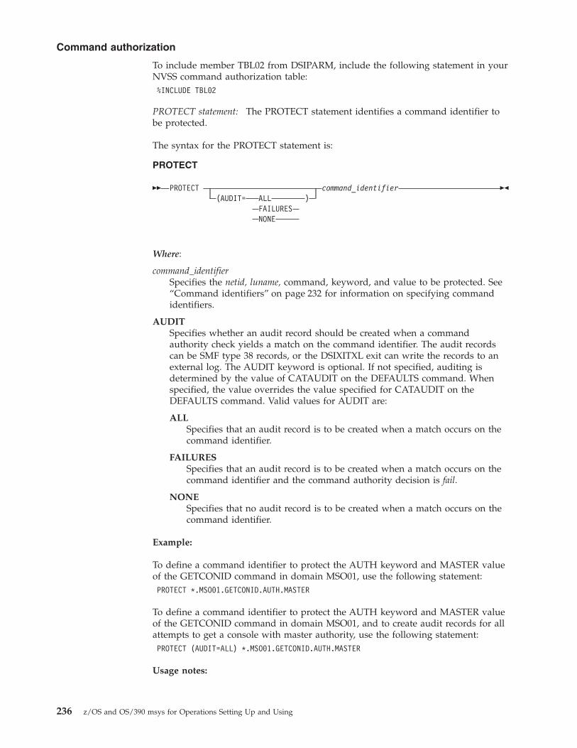
To include member TBL02 from DSIPARM, include the following statement in yourNVSS command authorization table:%INCLUDE TBL02
PROTECT statement: The PROTECT statement identifies a command identifier tobe protected.
The syntax for the PROTECT statement is:
PROTECT
RR PROTECT command_identifier(AUDIT= ALL )
FAILURESNONE
RP
Where:
command_identifierSpecifies the netid, luname, command, keyword, and value to be protected. See“Command identifiers” on page 232 for information on specifying commandidentifiers.
AUDITSpecifies whether an audit record should be created when a commandauthority check yields a match on the command identifier. The audit recordscan be SMF type 38 records, or the DSIXITXL exit can write the records to anexternal log. The AUDIT keyword is optional. If not specified, auditing isdetermined by the value of CATAUDIT on the DEFAULTS command. Whenspecified, the value overrides the value specified for CATAUDIT on theDEFAULTS command. Valid values for AUDIT are:
ALLSpecifies that an audit record is to be created when a match occurs on thecommand identifier.
FAILURESSpecifies that an audit record is to be created when a match occurs on thecommand identifier and the command authority decision is fail.
NONESpecifies that no audit record is to be created when a match occurs on thecommand identifier.
Example:
To define a command identifier to protect the AUTH keyword and MASTER valueof the GETCONID command in domain MSO01, use the following statement:PROTECT *.MSO01.GETCONID.AUTH.MASTER
To define a command identifier to protect the AUTH keyword and MASTER valueof the GETCONID command in domain MSO01, and to create audit records for allattempts to get a console with master authority, use the following statement:PROTECT (AUDIT=ALL) *.MSO01.GETCONID.AUTH.MASTER
Usage notes:
Command authorization
236 z/OS and OS/390 msys for Operations Setting Up and Using

v Create one PROTECT statement for each command that you want to protect. Forexample, to protect the STOP command for luname MSO01, create a table entryas follows:PROTECT *.MSO01.STOP
v Create one PROTECT statement for each command and keyword that does nothave an associated value which you want to protect. For example, to protect theOFF keyword on the AUTOTBL command for luname MSO01, create a tableentry as follows:PROTECT *.MSO01.AUTOTBL.OFF
v Create one PROTECT statement for each command, keyword, and valuecombination that you want to protect. For example, to protect the FORCEkeyword with a value of AUTO1 on the STOP command for luname MSO01,create a table entry as follows:PROTECT *.MSO01.STOP.FORCE.AUTO1
v To protect all values of FORCE in the previous example, create a table entry asfollows:PROTECT *.MSO01.STOP.FORCE.*
v To protect all values of FORCE that begin with ″TEST″ and end with ″0″, createa table entry as follows:PROTECT *.MSO01.STOP.FORCE.TEST%0
v To allow an NVSS operator to issue an NVSS command that is protected with aPROTECT statement, you must use a PERMIT statement for each operator ID orgroup of operators that should be authorized.
v If you have more than one statement that describes the same command,keyword, and value, the first is used and all others are ignored. The netid andluname values are ignored once the NVSS command authorization table isloaded. The following example shows how generic characters cause the secondcommand identifier to be ignored. If the following statements are included in theNVSS command authorization table for domain MSO01, only the first is used:PROTECT *.*.AUTOTBL.MEMBER.DSITBL01PROTECT *.MSO01.AUTOTBL.MEMBER.DSITBL01
EXEMPT Statement: The EXEMPT statement identifies a command and optionallya keyword and value to be exempted from command authorization.
It enables all users to issue a command, keyword, or value, which is similar todefining a resource in the NETCMDS class with a universal access of read(UACC(READ)).
Using specific EXEMPT statements can reduce the amount of processing requiredfor command authorization checking, and can improve performance.
The syntax for the EXEMPT statement is:
EXEMPT
RR EXEMPT command_identifier(AUDIT= ALL )
NONE
RP
Where:
Command authorization
Appendix A. Making security definitions using the command authorization table 237

command_identifierIs the identifier specifying the netid, luname, command, keyword, and value tobe exempted. See “Command identifiers” on page 232 for information onspecifying command identifiers.
AUDITSpecifies whether an audit record should be created when a commandauthority check yields a match on the command identifier. The audit recordscan be SMF type 38 records, or the DSIXITXL exit can write the records to anexternal log. The AUDIT keyword is optional. If not specified, auditing isdetermined by the value of CATAUDIT on the DEFAULTS command. Whenspecified, the value overrides the value specified for CATAUDIT on theDEFAULTS command. The values allowed for AUDIT are:
ALLSpecifies that an audit record is to be created when a match occurs on thecommand identifier.
NONESpecifies that no audit record is to be created when a match occurs on thecommand identifier.
Example:
To define a command identifier to exempt the LIST command in any domain, youmust use the following statements:EXEMPT *.*.LISTEXEMPT *.*.LIST.*
The first statement applies only to the LIST command. The trailing asterisk in thesecond statement causes this command identifier to apply to all keywords andvalues of the LIST command that are not more explicitly specified.
GROUP statement: The GROUP statement defines a list of operators to beassociated with a specific group name for command security purposes. The groupname is unrelated to other groups of operators, such as the groups used to routemessages using the NVSS ASSIGN command.
The syntax for the GROUP statement is:
GROUP
RR S
,
GROUP group_name userid RP
Where:
group_nameIs the 1–8 character name of the group you are defining. The group_namecannot contain an ampersand (&), asterisk (*), or percent sign (%). The groupname cannot be the same as any of your user IDs that are defined in the NVSScommand authorization table.
useridIs the 1–8 character identifier of a user to be included in the group. The useridcannot contain an ampersand (&), asterisk (*), or percent sign (%). This mustbe an individual user ID and not the name of a group.
Command authorization
238 z/OS and OS/390 msys for Operations Setting Up and Using

Example:
To define a group named NIGHTOPS containing operators FELIX, MORRIS, andTOM, use the following:GROUP NIGHTOPS FELIX,MORRIS,TOM
To define a large number of operators to a group, you can either repeat the samegroup name on multiple group statements or create a multiple-line groupstatement using the NVSS <BEGIN> and <END> statements.
PERMIT statement: The PERMIT statement authorizes a user ID or group to issuea command and optionally a keyword and value. The command identifier musthave been previously protected with a PROTECT statement. You can include morethan one PERMIT statement for the same command identifier.
The syntax for the PERMIT statement is:
PERMIT
RR PERMIT authorized_name command_identifier RP
Where:
authorized_nameIs the 1–8 character name of a user ID or a group that is authorized to issuethe command, keyword, and value identified by the command_identifier. Theauthorized_name cannot contain an ampersand (&), asterisk (*), or percent sign(%). No checking is done to verify that a user ID is a valid NVSS operator ID.
Note: User IDs used in your table statements are independent of DSIOPFoperator definitions and SAF product definitions. Even if an operatorhas been deleted from DSIOPF or the SAF product, the operator willcontinue to have the same command authority with respect to the activeNVSS command authorization table as long as the operator remainslogged on.
command_identifierIs the identifier specifying the netid, luname, command, keyword, and value tobe authorized. See “Command identifiers” on page 232 for information onspecifying command identifiers.
Examples of generic characters in PERMIT and PROTECT statements: The followingexamples assume you are using the NVSS command authorization table statementsto define command authorization and that your NVSS domain name (luname) isMSO01. To authorize only NETOP1 to issue the GETCONID command with theAUTH keyword and a value of MASTER, include the following statements:PROTECT *.MSO01.GETCONID.AUTH.MASTERPERMIT NETOP1 *.MSO01.GETCONID.AUTH.MASTER
v To protect all other keywords on the GETCONID command, include thefollowing statement:PROTECT *.MSO01.GETCONID.*
v It is not required to use a generic character in the value position, but since all ofthe GETCONID keywords have corresponding values, a command identifier of*.MSO01.GETCONID.*.* would be functionally equivalent.
Command authorization
Appendix A. Making security definitions using the command authorization table 239

v Some commands have keywords that are issued without a corresponding value.For example, the SAVE and PPT keywords of the EVERY command do not havea value. To authorize NETOP1 in domain MSO01 to issue the EVERY commandwith both the SAVE and PPT keywords, include the following statements:* PROTECT KEYWORDS ON "EVERY" COMMANDPROTECT *.MSO01.EVERY.SAVEPROTECT *.MSO01.EVERY.PPTPERMIT NETOP1 *.MSO01.EVERY.SAVEPERMIT NETOP1 *.MSO01.EVERY.PPT
v To protect both the SAVE and PPT keywords and all other keywords on theEVERY command, include the following statement:PROTECT *.MSO01.EVERY.*
v Notice that there is no generic character used for value. The command identifier*.MSO01.EVERY.*.* would not protect the SAVE and PPT keywords, but wouldonly protect keywords that are specified with a corresponding value. Thecommand identifier *.MSO01.EVERY.* protects keywords that have correspondingvalues as well as keywords that do not have corresponding values.
v Using an asterisk (*) as a trailing generic character at the end of a commandidentifier allows you match on subsequent values in that field and subsequentfields. Using a trailing asterisk in the command field will protect the command,and all its keywords and values. For example, if you use this statement:PROTECT *.*.STOP*
It will protect the NVSS STOP command, and all its keywords and values. Notethat this is equivalent to coding all three of the following statements:PROTECT *.*.STOPPROTECT *.*.STOP.*PROTECT *.*.STOP*.*
v Using a trailing asterisk in the keyword field will protect the keyword for thatcommand, with all the values on that keyword. For example, to protect all thevalues on all the REXX keywords for the NVSS DEFAULTS command, use thisstatement:PROTECT *.*.DEFAULTS.REXX*
SETVAR statement: The SETVAR statement defines a table variable to representmultiple values which can be used in command identifiers. Table variables mustrepresent an entire field value and must be defined before being used.
The syntax for the SETVAR statement is:
SETVAR
RR S
,
SETVAR variable_name value RP
Where:
variable_nameIs the 1–32 character name of the variable you are defining. The variable namecannot contain an ampersand (&), dash (-), period (.), asterisk (*), or percentsign (%).
valueIs the 1–242 character value to be included in the command identifier. Thevalue cannot contain an ampersand (&), dash (-), or period (.).
Command authorization
240 z/OS and OS/390 msys for Operations Setting Up and Using

Examples:
To define a variable EURODOM to represent domains MSO01, CNM02, andCNM99, use the following:SETVAR EURODOM MSO01,CNM02,CNM99
To subsequently use the variable &EURODOM in a PROTECT statement, includethe following:PROTECT *.&EURODOM.STOP
When processed, this generates the equivalent of the following table statements:PROTECT *.MSO01.STOPPROTECT *.CNM02.STOPPROTECT *.CNM99.STOP
Note that the table variable EURODOM represented the entire field value. Aspecification such as the following is not valid:SETVAR EURODOM 01,02,99PROTECT *.CNM&EURODOM.STOP
To define a variable XDOM to represent commands ROUTE and RMTCMD, usethe following:SETVAR XDOM ROUTE,DSIUSNDM
To subsequently use the variable &XDOM in a PROTECT statement, include thefollowing:PROTECT *.MSO01.&XDOM
This generates the equivalent of the following table statements:PROTECT *.MSO01.ROUTEPROTECT *.MSO01.DSIUSNDM
Loading the NVSS command authorization table: The NVSS commandauthorization table can be loaded during NVSS initialization as specified by theOPTIONS statement in the DSIDMN member of DSIPARM. During initialization, ifsyntax errors are encountered, messages are issued but any valid statements in thetable are still loaded. After NVSS initialization is complete, errors can be correctedand the table reloaded using the REFRESH command. If there are syntax errors inthe table processed by the REFRESH command, the table is not loaded. There is aTEST keyword on the REFRESH command that you can use to check for syntaxerrors before attempting to load the table.
Using the NVSS command authorization table to protect VTAM commandkeywords and values: You can restrict any keywords and values of a VTAMcommand using the NVSS command authorization table. For values entered withthe VTAM keyword ID, SLU, PLU, LU1, and LU2, if the VTAM resource isqualified with a network ID, access to the network ID and resource name arechecked separately. So they should be defined in separate PROTECT statements.The VTAM resource name and the network ID can be up to 8 characters long. IfIDTYPE=IPADDR is entered with the VTAM DISPLAY command, the valueentered with the ID keyword is an IP address and can be longer than 8 characters.
For example, the following statements are defined in the NVSS commandauthorization table:
Command authorization
Appendix A. Making security definitions using the command authorization table 241

PROTECT *.*.DISPLAY.ID.NETAPROTECT *.*.DISPLAY.ID.DSICRTRPROTECT *.*.DISPLAY.ID.87/123/136/121
An NVSS operator would not be able to execute the following VTAM commands:D NET,ID=NETA.NTVB5LUD NET,ID=NETA.DSICRTRD NET,ID=NETB.DSICRTRD NET,ID=87.123.136.121,IDTYPE=IPADDR
The operator can, however, execute the following commands:D NET,ID=NTVB5LUCD NET,ID=NETB.NTVB5LUC
Command authorization table – usage notes: Some command identifiers aremore specific than others. For example, the following table statements are orderedfrom most specific to least specific, as you can determine by comparing thecharacter strings from left to right:PROTECT *.MSO01.STOP.FORCE.MSO01PPTPROTECT *.MSO01.STOP.FORCE.*PROTECT *.MSO01.STOP.*
The most specific PROTECT statement in your NVSS command authorization tableis the statement with the generic character latest in the sequence of fields, after thenetid and luname fields. Only the most specific statement that matches thecommand being issued is used for command authorization.
The type of generic character is also used to determine which command identifieris most specific. Because the percent sign (%) generic character replaces just asingle character, the percent sign is considered more specific than the asterisk (*)generic character. For example, ABC% is more specific than ABC* when evaluatingthe value ABCD.
For example, the value SYS1 matches both the SY%1 and the SYS* identifiers. In thiscase, SYS* is considered to be more specific because the generic character is in thefourth position, rather than SY%1 which has a generic character in the thirdposition.
If both a PROTECT and an EXEMPT statement are coded for the same commandidentifier, message BNH184E will be issued indicating a syntax error in the NVSScommand authorization table.
If this message is issued due to a REFRESH command, the NVSS commandauthorization table is not loaded. If the message is issued during initialization, theNVSS command authorization table is loaded, but only the first (PROTECT orEXEMPT) statement is used. Use message BNH184E to find the problem.
Command authorization table example: The following steps provide an exampleof defining operator authority using an NVSS command authorization table:1. Define groups of operators.
GROUP GRP1 NETOP1,NETOP2,AUTO1,AUTO2<BEGIN>GROUP GRP2 OPER1,OPER2,OPER3,OPER4,OPER5,OPER6,NETOP1,NETOP2,AUTO1,AUTO2<END>
Note that these operators have been grouped into two classes of authorization.
Command authorization
242 z/OS and OS/390 msys for Operations Setting Up and Using

2. Define the commands, keywords, and values to be protected.v The following statements define the OVERRIDE command as unprotected
except for the REXXSTRF keyword. This keyword can only be used byoperators in group GRP1.EXEMPT NETA.MSO01.OVERRIDEPROTECT NETA.MSO01.OVERRIDE.REXXSTRF.*PERMIT GRP1 NETA.MSO01.OVERRIDE.REXXSTRF.*
v All of the following statements are comments. If you remove the asterisksfrom these statements, they protect the GLOBALV command and restrict itsuse to operators in groups GRP1 and GRP2. The statements also protect theSAVEC and RESTOREC keywords, and restrict their use to operators ingroups GRP1 and GRP2. Finally, the statements protect the asterisk (*) andPURGEC keywords, and restrict their use to operators in group GRP1.* PROTECT NETA.MSO01.GLOBALV* PERMIT GRP1 NETA.MSO01.GLOBALV* PERMIT GRP2 NETA.MSO01.GLOBALV* PROTECT NETA.MSO01.GLOBALV.SAVEC* PERMIT GRP1 NETA.MSO01.GLOBALV.SAVEC* PERMIT GRP2 NETA.MSO01.GLOBALV.SAVEC* PROTECT NETA.MSO01.GLOBALV.RESTOREC* PERMIT GRP1 NETA.MSO01.GLOBALV.RESTOREC* PERMIT GRP2 NETA.MSO01.GLOBALV.RESTOREC* PROTECT NETA.MSO01.GLOBALV.ASTERISK* PERMIT GRP1 NETA.MSO01.GLOBALV.ASTERISK* PROTECT NETA.MSO01.GLOBALV.PURGEC* PERMIT GRP1 NETA.MSO01.GLOBALV.PURGEC
Determining the user identity used for authority checkingcommandsAuthority checking restricts the ability of an operator or a task to use commands,keywords, and values.
Table 14 identifies the operator or task identifier that is used to authority checkmsys for Operations commands based on the command and environment. Theidentity is referred to as the SOURCEID.
Table 14. SOURCEID determination
Command and environment SOURCEID determination
EXCMD command or a same-domainLABEL command prefix used toqueue an imbedded command toanother task.
The SOURCEID is the task that issued the EXCMD command, or theexisting SOURCEID at the time the EXCMD command was issued.
TIMER commands that are scheduledto run under the PPT.
The SOURCEID is the task that issued the AT, EVERY, CHRON, or AFTERcommand, or the existing SOURCEID at the time the AT, EVERY, CHRON,or AFTER command was issued.Note: The SOURCEID is not destroyed by saving and restoring timercommands.
NVSS SUBMIT command for jobssubmitted to the operating systemfrom NVSS.
If OPERSEC=SAFCHECK or OPERSEC=SAFDEF, the identity that ischecked by the operating system is the issuer of the SUBMIT command, orthe existing SOURCEID at the time the SUBMIT command was issued. Forother values of OPERSEC, NVSS’s authority is used for submitting the job.
Command authorization
Appendix A. Making security definitions using the command authorization table 243

Table 14. SOURCEID determination (continued)
Command and environment SOURCEID determination
NVSS commands that were entered atan MVS operator console.
When an MVS console has been associated with an autotask using theAUTOTASK command with the CONSOLE= parameter, NVSS commandscan be entered from that MVS console. This is done by prefixing the NVSScommand with the NVSS designator character, which by default is %. If theMVS operator has logged on to the MVS console with a user ID, theSOURCEID is the user ID of the MVS operator.
If an operator has not logged on at the EMCS console, the SOURCEID ofthat task defaults to *BYPASS*. Commands issued from a source ID of*BYPASS* are not checked for command authorization by:v The NVSS command authorization tablev The SAF product OPERCMDS classv The SAF product NETCMDS class
Note: If a command is entered from the MVS master console, it will berouted to one of the following:
v The autotask with the specific console name
v The autotask with console name ″*MASTER*″
v The autotask with console name ″*ANY*″
NVSS commands that are enteredusing the MVS MODIFY command.
When an MVS console has been associated with an autotask using theAUTOTASK command with the CONSOLE= parameter, NVSS commandscan be entered from that MVS console by issuing an MVS MODIFY or STOPcommand against the NVSS task. The NVSS command is entered as textfollowing the MODIFY command. The first parameter on the MODIFYcommand is the application ID that is being modified. If the MVS operatorhas logged on to the MVS console with a user ID, the SOURCEID is theuser ID of the MVS operator.
If an operator has not logged on at the EMCS console, the SOURCEID ofthat task defaults to *BYPASS*. Commands issued from a source ID of*BYPASS* are not checked for command authorization by:v The NVSS command authorization tablev The SAF product OPERCMDS classv The SAF product NETCMDS class
Note: If a command is entered from the MVS master console, it will berouted to:
v The autotask with the specific console name
v The autotask with console name ″*MASTER*″
v The autotask with console name ″*ANY*″
NVSS commands that were enteredby TSO users.
When a TSO user ID has been associated with an autotask using theAUTOTASK command with the CONSOLE= parameter, NVSS commandscan be entered from that TSO user ID when the user is acting as an MVSoperator by using an EMCS console session, or when using SDSF. TheSOURCEID is the TSO user’s user ID.
Commands issued from JCL. When a job that issues a NVSS command is submitted by a TSO user ID,the SOURCEID is the TSO user ID. If the ID of the submitter is unknown, adefault user ID is inserted. The value of the default user ID is defined bythe system installation.
MVS ROUTE command issued fromNVSS.
If the MVS command ROUTE is issued from a NVSS task, the originatingsource ID is always passed to the SAF product for authorization checks inthe OPERCMDS class. This occurs for all settings of AUTHCHK andCMDAUTH.
Command authorization
244 z/OS and OS/390 msys for Operations Setting Up and Using

Table 14. SOURCEID determination (continued)
Command and environment SOURCEID determination
Commands that are routed to anoperator from the automation table.
The SOURCEID is the operator ID to which the command is routed.Note: Commands from the automation table are subject to authoritychecking unless SEC=BY was specified on the CMDMDL statement orSEC=DE was specified (or SEC was not specified) and AUTOSEC=BYPASSis in effect. For more information, refer to the DEFAULTS command in theNVSS online help.
CNMSMSG service (PL/I and C). If CNMSMSG is called to queue a command from one task to another, theSOURCEID is the task name (TVBOPID) of the CNMSMSG issuer, or theexisting SOURCEID at the time the CNMSMSG service was called.
Understanding security for specific commandsThis section provides additional information about protecting the followingcommands:v CHRONv EXCMDv MVSv SUBMIT
Defining security for the CHRON command: The CHRON command has syntaxthat is more complex than most commands. CHRON uses multiple levels ofkeywords, items in lists, and quoted strings.
Command security for the CHRON command is checked so that operands withinparentheses can be uniquely defined in the command authorization table(CMDAUTH=TABLE).
The following rules describe CHRON commands and which command identifiersare checked:
Rule 1: Each keyword that does not take a value (NOSAVE, SAVE, LOCAL, GMT,REFRESH, TEST, and DEBUG) is checked in the form:
Command example:netid.luname.CHRON.keyword
Rule 2: Each keyword with a value is checked in the form:
Command example:netid.luname.CHRON.keyword.value
With the CHRON command, the value may be a list or quoted string.
Command example:CHRON AT=(),RECOVERY=IGNORE,NOSAVE,LOCAL,ROUTE=OPER1,ID=TEST1,COMMAND=’MSG ALL HELLO’
The following command identifiers are checked:netid.luname.CHRONnetid.luname.CHRON.AT.()netid.luname.CHRON.RECOVERY.IGNOREnetid.luname.CHRON.NOSAVEnetid.luname.CHRON.LOCAL
Command authorization
Appendix A. Making security definitions using the command authorization table 245

netid.luname.CHRON.ROUTE.OPER1netid.luname.CHRON.ID.TEST1netid.luname.CHRON.COMMAND.’MSG_ALL_HELLO’
Rule 3A: Keywords appearing within parenthesized lists of other keywords arechecked using the hierarchy of keywords with a ″(″ between so that the keywordhierarchy can be uniquely identified. The compound keyword that is generated istested with the value of the innermost keyword. This checking is done at eachlevel of the nesting of the lists. When a keyword is within a list that is the value ofanother keyword, the notation uses both keywords with a ″(″ between them.
Rule 3B: From the outermost to innermost, if a ″keyword=(list)″ appears, if anyvalues appear in the list without keywords, the ″keyword=value″ check is done forthat value. The keyword that is checked is the keyword hierarchy defined by Rule3A.
Command example:CHRON EVERY=(INTERVAL=(000-01.00.00 FOR=08.00.00))
The following command identifiers are checked:netid.luname.CHRONnetid.luname.CHRON.EVERY.(INTERVAL=(000_01/00/00_FOR=08/00/00))netid.luname.CHRON.EVERY(INTERVAL.(000_01/00/00_FOR=08/00/00)netid.luname.CHRON.EVERY(INTERVAL.000_01/00/00netid.luname.CHRON.EVERY(INTERVAL(FOR.08/00/00
Substitution of certain special characters is performed as described in “Protectingcommands containing special characters” on page 78. For example, a dash becomesan underscore in the command identifier.
Rule 4: Quoted string values are checked as a single value, including theapostrophes and all text within the apostrophes.
Command example:netid.luname.CHRON.REM.’ISN’’T THIS A REMARK STRING?’
The following command identifier is checked:CHRON REM=’ISN’’T THIS A REMARK STRING?’
Rule 5: For the DAYSWEEK keyword, days of the week can be followed by asublist identifying particular weeks of the month. The day name and each item inthe sublist are treated as a unit.
Command example:CHRON EVERY=(DAYSWEEK=(NOT MON(1ST 2nd)))
The following command identifiers are checked:netid.luname.CHRONnetid.luname.CHRON.EVERY.(DAYSWEEK=(NOT_MON(1ST_2ND)))netid.luname.CHRON.EVERY(DAYSWEEK.(NOT_MON(1ST_2ND))netid.luname.CHRON.EVERY(DAYSWEEK.NOTnetid.luname.EVERY(DAYSWEEK.MON(1ST)netid.luname.EVERY(DAYSWEEK.MON(2ND)
This lets you check the sublist values without concern for the order of the itemswithin the sublist. Notice that the value ″MON(1st 2nd)″ is not checked since thevalues MON(1st) and MON(2nd) are checked.
Command authorization
246 z/OS and OS/390 msys for Operations Setting Up and Using

Table 15 illustrates a detailed list of possible command identifiers that may bedefined for the CHRON command. The rule that causes the command identifier tobe checked is shown in the second column.
Table 15. NVSS command identifiers for the CHRON command
Commandsand keywordsidentifier
RULE Command authorization table identifier
CHRON Command name netid.luname.CHRON
AT=
2
2
3B
3B
2
netid.luname.CHRON.AT.()
netid.luname.CHRON.AT.(timespec datespec) 2
netid.luname.CHRON.AT.timespec
netid.luname.CHRON.AT.datespec2
netid.luname.CHRON.AT.yyy_mm_dd_hh/mm/ss/micros2
AFTER= 2
2
netid.luname.CHRON.AFTER.timespec 2
netid.luname.CHRON.AFTER.ddd_hh/mm/ss/micros 2
EVERY= 2
2
2
netid.luname.CHRON.EVERY.NONE
netid.luname.CHRON.EVERY.( )
netid.luname.CHRON.EVERY.(everyoptions) 2
EVERY=(INTERVAL= 3A
3B
3B
3A
netid.luname.CHRON.EVERY(INTERVAL.( )
netid.luname.CHRON.EVERY(INTERVAL.(intervaloptions) 2
netid.luname.CHRON.EVERY(INTERVAL.timespec 2
netid.luname.CHRON.EVERY(INTERVAL.ddd_hh/mm/ss/micros 2
EVERY=(INTERVAL=(FOR=
3A
3A
netid.luname.CHRON.EVERY(INTERVAL(FOR.timespec
netid.luname.CHRON.EVERY(INTERVAL(FOR.hh/mm/ss/micros 2
EVERY=(INTERVAL=(MXREPEAT=
3A
3A
netid.luname.CHRON.EVERY(INTERVAL(MXREPEAT.NOLIMIT
netid.luname.CHRON.EVERY(INTERVAL(MXREPEAT.repeat_count
EVERY=(INTERVAL=(OFF=
3A
3A
netid.luname.CHRON.EVERY(INTERVAL(OFF.timespec
netid.luname.CHRON.EVERY(INTERVAL(OFF.hh/mm/ss/micros 2
EVERY=(REMOVE= 3A
3A, 3B
3B
3B
3A
netid.luname.CHRON.EVERY(REMOVE.MANUALLY
netid.luname.CHRON.EVERY(REMOVE.(removeoptions) 2
netid.luname.CHRON.EVERY(REMOVE.datespec 2
netid.luname.CHRON.EVERY(REMOVE.timespec 2
netid.luname.CHRON.EVERY(REMOVE.yyyy_mm_dd_hh/mm/ss/micros 2
EVERY= (REMAFTER= 3A
3A
netid.luname.CHRON.EVERY(REMAFTER.timespec 2
netid.luname.CHRON.EVERY(REMAFTER.ddd_hh/mm/ss/micros 2
Command authorization
Appendix A. Making security definitions using the command authorization table 247

Table 15. NVSS command identifiers for the CHRON command (continued)
Commandsand keywordsidentifier
RULE Command authorization table identifier
EVERY= (DAYSWEEK= 3A
3B
3B
3B
5
netid.luname.CHRON.EVERY(DAYSWEEK.ALL
netid.luname.CHRON.EVERY(DAYSWEEK.(daysweeklist) 2
netid.luname.CHRON.EVERY(DAYSWEEK.NOT
netid.luname.CHRON.EVERY(DAYSWEEK.dayname
netid.luname.CHRON.EVERY(DAYSWEEK. dayname(sublist_element) 2
EVERY=(DAYSMON= 3A
3B
3B
3B
netid.luname.CHRON.EVERY(DAYSMON.ALL
netid.luname.CHRON.EVERY(DAYSMON.(dayslist) 2
netid.luname.CHRON.EVERY(DAYSMON.NOT
netid.luname.CHRON.EVERY(DAYSMON.dayofmonth 2
EVERY=(CALENDAR= 3A
3B
3B
3B
netid.luname.CHRON.EVERY(CALENDAR.ALL
netid.luname.CHRON.EVERY(CALENDAR.(calendarlist) 2
netid.luname.CHRON.EVERY(CALENDAR.NOT
netid.luname.CHRON.EVERY(CALENDAR.keyname 2
RECOVERY= 2
2
2
netid.luname.CHRON.RECOVERY.IGNORE
netid.luname.CHRON.RECOVERY.AUTOLGN
netid.luname.CHRON.RECOVERY.PURGE
SAVE 1 netid.luname.CHRON.SAVE
NOSAVE 1 netid.luname.CHRON.NOSAVE
LOCAL 1 netid.luname.CHRON.LOCAL
ID= 2 netid.luname.CHRON.ID.idname
NOTIFY= 2 netid.luname.CHRON.NOTIFY.(notifylists)
NOTIFY=(PURGE= 3B
3B
netid.luname.CHRON.NOTIFY(PURGE.(purgelist)
netid.luname.CHRON.NOTIFY(PURGE.taskname
NOTIFY=(REMOVE= 3B
3B
netid.luname.CHRON.NOTIFY(REMOVE.(removelist)
netid.luname.CHRON.NOTIFY(REMOVE.taskname
NOTIFY=(IGNORE= 3B
3B
netid.luname.CHRON.NOTIFY(IGNORE.(ignorelist)
netid.luname.CHRON.NOTIFY(IGNORE.taskname
NOTIFY=(RUN= 3B
3B
netid.luname.CHRON.NOTIFY(RUN.(runlist)
netid.luname.CHRON.NOTIFY(RUN.taskname
REFRESH 1 netid.luname.CHRON.REFRESH
TEST 1 netid.luname.CHRON.TEST
DEBUG 1 netid.luname.CHRON.DEBUG
COMMAND= 4 netid.luname.CHRON.COMMAND.’quoted string’ 2
REM= 4 netid.luname.REM.’quoted string’ 3
Command authorization
248 z/OS and OS/390 msys for Operations Setting Up and Using

Defining EXCMD command authorization: The NVSS EXCMD command is usedto send commands to another task.
There are two operands that are used when issuing the EXCMD command. One isthe operator_id where the command is being sent, and the other is the commandbeing sent. These two operands are checked as a keyword-value pair.
Note: When protecting the target verb of EXCMD, specify the command verb, notany synonym. Unless otherwise documented, the verb is the label used onthe CMDMDL statement. The verb for labeled commands beginning with aslash is EXCMD
For example, the command identifier to protect EXCMD OPER1 LOGOFF is:PROTECT *.*.EXCMD.OPER1.LOGOFF
Defining additional MVS command authority: You can protect individual MVSsystem commands from unauthorized use with the OPERCMDS class of an SAFproduct, such as RACF. This is additional authorization checking done at the MVSlevel, after the command security checking done by the NVSS commandauthorization table.
To protect MVS commands:1. Ensure your OPERSEC setting has a value of SAFCHECK or SAFDEF.2. Define command profiles to restrict specific commands from operators. For
example, to restrict all operators from being able to issue an MVS QUIESCEcommand, enter:RDEFINE OPERCMDS MVS.QUIESCE UACC(NONE)
3. Ensure that the OPERCMDS class is active and enabled for processing. Thefollowing RACF commands can be used to do this:SETROPTS CLASSACT(OPERCMDS)SETROPTS RACLIST(OPERCMDS)
4. When the OPERCMDS class is active, use the RACF REFRESH function whenyou change a definition:SETROPTS RACLIST(OPERCMDS) REFRESH
Defining SUBMIT command authorization: You can protect jobs submitted fromNVSS using the SUBMIT command. When the NVSS SUBMIT command is issued,the SUBMIT command can be protected using NVSS command authorization. Byprotecting at this level, you can stop the processing for unauthorized users beforethe job is ever submitted to the system.
Controlling access to data sets and membersTo prevent unauthorized alteration of data, you can protect data sets with an SAFproduct, such as RACF. To prevent unauthorized viewing of passwords and otherrestricted information, protect them with NVSS commands such as READSEC andWRITESEC.
3. This value may have a special character, such as ″.″ or ″-″, for example in the programmer time notation. You substitute thecharacter ″/″ for ″.″ and ″_″ for ″-″ when making the security definition.
Command authorization
Appendix A. Making security definitions using the command authorization table 249

Data set securityYou can restrict unauthorized alteration of data sets from the NVSS environmentusing the DATASET class of the security product. The following are someconsiderations when using the DATASET class of the security product:v NVSS requires CONTROL access to the DSILOG data set to write to the netlog.v NVSS requires READ access to the first data set identified by the DSILIST DD
statement.v NVSS requires READ access to non-DSIPARM data sets that are specified on the
NVSS SUBMIT command.v Each of the following NVSS commands require UPDATE access to the first data
set identified by the DSILIST DD statement.– AUTOTBL (with the LISTING keyword)– AUTOCNT (with the FILE keyword)– QRYGLOBL (with the FILE keyword)– SECMIGR (with output to DSILIST)
v If you use SECMIGR to convert from the NVSS command authorization table toRACF (TBL2RACF), the operator running SECMIGR requires READ authority tothe data set containing the NVSS command authorization table being converted.
v If you specify your own output data set, the operator running SECMIGRrequires UPDATE authority to your output data set.
Note: NVSS trace records are not made for calls to the DATASET class, becausethe calls are made by MVS for the NVSS tasks.
Restricting access to data setsTo activate the data set protection described in the preceding section, do thefollowing:1. To enable task-level authorization checking, initialize NVSS product using
OPTIONS values of OPERSEC=SAFCHECK or OPERSEC=SAFDEF. If you didnot initialize the NVSS product using these values, you can also change theOPERSEC values using the NVSS REFRESH command.
2. If you are using an SAF product, add profiles for the data sets you want toprotect. The RACF product requires that the highest-level qualifier of the dataset name be either a task or group name.For example, use the RACF ADDSD command to add data set profiles. Froman authorized TSO user, enter the following command to protect theOPER1.STATS data set:ADDSD ’OPER1.STATS’
3. If you are using an SAF product, authorize the operator tasks so they canaccess the data set. For example, use the RACF PERMIT command to authorizeoperator tasks to the data set. To authorize NETOP1 to have update access toOPER1.STATS, enter the following command from an authorized TSO user:PERMIT ’OPER1.STATS’ CLASS(DATASET) ID(NETOP1) ACCESS(UPDATE)
NVSS READSEC and WRITESEC commandsUse the NVSS READSEC and WRITESEC commands to restrict access to data setsand members by NVSS commands. When you specify security for the READSECcommand, it affects all of the NVSS commands which can display sensitiveinformation, such as:v BROWSE with a member namev NCCF LIST with the CLIST or PROFILE keywordsv PIPE stages
– < (From disk)
Controlling access to data sets and members
250 z/OS and OS/390 msys for Operations Setting Up and Using

– QSAMv VSAM command DSIVSMX
Using READSEC and WRITESEC is the only way to prevent operators fromviewing data sets and members using these NVSS commands. In NVSS, security isdefined so that operators have access to DSIOPEN and msys for Operations onlinehelp. DSIOPEN is a DD name designed to hold information which should not besecured, such as NEWS data and PF key definitions. Anything other thanDSIOPEN and the online help may be considered sensitive information.
Because attempts to define security for these NVSS commands is considered asevere error, message BNH115A is generated every time an operator logs on. Theerror text for this message is “SPECIAL SECURITY IN EFFECT FOR BROWSEAND READSEC”, which indicates NVSS has defined default protection forsensitive data sets and members, and the NVSS commands which display data setsor members will fail. You must delete any security definitions for the commandsand reinitialize NVSS to clear the error condition.
If you use command authorization without specifying values for READSEC andWRITESEC, operators will have access to all data sets and members.
Do not protect DD name CNMPNL1, operators need to access online help that iscontained there.
For more information about how to use the READSEC and WRITESEC commands,refer to the online help.
Controlling access to data sets and members
Appendix A. Making security definitions using the command authorization table 251

Controlling access to data sets and members
252 z/OS and OS/390 msys for Operations Setting Up and Using

Appendix B. Return codes
This appendix provides information about macro return codes and about returncodes from VIEW and BROWSE (see “VIEW and BROWSE return codes” onpage 260).
Macro return codesThis section provides return codes for the following macros:v DSICESv DSIDKS, on page 254v DSIMQS; on page 256v DSIPRS, on page 256v DSIPSS, on page 257v DSIPUSH, on page 258v DSIZCSMS, on page 259v DSIZVSMS, on page 259
Macro DSICES return codes in Register 15The following return codes for macro DSICES are found in register 15:
0 The function is successful. One of the following describes what occurred:v A regular command is found in the system command table and the
address of the SCT entry is returned.v The verb is not found in the SCT (if you specify CLISTCK, a command
list is found with the specified name), and the dummy SCT entry for acommand list is returned.
4 The command that is found can be processed as a regular or immediatecommand; the address is returned.
8 An immediate command is found in the system command table; theaddress is returned.
12 The module is not found, or there is an incorrect verb length; no address isreturned.
16 The operator is not authorized to issue the command. This is caused by thesecurity definitions that are in place for this command. No address isreturned in SCTADDR.
This return code is not applicable if MODNAME was specified.
20 Either the command found is incompatible with the task type that calledthe routine, and the address is returned; or you specified CLISTCK=YESand the request is issued in an asynchronous exit, and the address is notreturned.
24 You specified CLISTCK=YES but the command or command list is notfound in DSISCT or DSICLD.
28 You specified CLISTCK=YES but storage requested for CLISTCKprocessing is not obtained.
32 NVSS internal error.
© Copyright IBM Corp. 2002-03 253

36 An unexpected return code was received from the security authorizationfacility (SAF). Message BNH238E is issued with the SAF return codeinserted. This return code is not applicable if MODNAME was specified asthis specification causes no authorization checking to be performed.
40 Authorization to the command is not granted because the securityenvironment for the operator cannot be established. Message BNH239E isissued when this condition is first encountered to provide the securityproduct return code information. Message BNH273I is issued when thecondition has been corrected. This return code is not applicable ifMODNAME was specified as this specification causes no authorizationchecking to be performed.
44 Authorization to the command is not granted because an unexpectedreturn code was received from the command authorization table. MessageBNH199E is issued indicating the command identifier and the operator IDbeing checked. This return code is not applicable if MODNAME wasspecified as this specification causes no authorization checking to beperformed.
48 Authorization to the command is not granted because the NVSS internalsecurity information containing the source ID of the command could notbe found. Message BNH277E is issued identifying the command beingchecked. This return code is not applicable if MODNAME was specified asthis specification causes no authorization checking to be performed.
52 Authorization to the command is not granted because the source ID isblank in the NVSS internal security information. Message BNH277E isissued identifying the command being checked. This return code is notapplicable if MODNAME was specified because this specification causesno authorization checking to be performed.
Macro DSIDKS return codes in Register 15The return codes and code meanings in register 15 are dependent on the “TYPE=”specification.
The following return codes are for TYPE=CONN:
0 The function is successful. Data control blocks and I/O buffer are obtainedand initialized.
4 An incorrect data set name.
12 No storage was available for I/O buffer.
The following return codes are for TYPE=FIND:
0 The function is successful. The member or file is found and the first recordis read.
4 The member or file is not found in the source statement library or in thespecified library, or an empty member or file is found.
8 The member or file is found but an I/O error occurred on the first read.
12 The specified definition name or data set has not been opened.
20 The specified control block identifier is not valid; the member or file is notfound.
28 There is a syntax error in the %INCLUDE card.
Macro DSICES return codes in Register 15
254 z/OS and OS/390 msys for Operations Setting Up and Using

36 There is an incorrect member name on the %INCLUDE card.
40 There is an incorrect embed member, which can cause a deadlockcondition. (This occurs when a member embeds itself.)
44 An unrecoverable system error occurred. An internal NVSS service failed,because of a storage failure.
46 An I/O error is encountered while trying to include a member specified ina %INCLUDE statement.
100 + xxAn error occurred during CLOSE processing. msys for Operations attemptsto recover the data set after a failure during a previous FIND or READ.Refer to the description of the xx return code under the CLOSE macro inyour operating system macro reference.
200 + xxAn error occurred during OPEN processing. msys for Operations attemptsto recover the data set after a failure during a previous FIND or READ.Refer to the description of the xx return code under the OPEN macro inyour operating system macro reference.
The following return codes are for TYPE=DISC:
0 The disconnect is successful; data and I/O buffers are freed successfully.
20 The specified control block identifier is not valid and no storage is freed.
46 An I/O error is encountered while trying to INCLUDE a member specifiedin a %INCLUDE statement.
The following return codes are for TYPE=READ:
0 The function is successful; the record is read.
4 The end of data is reached.
8 An I/O error occurred during reading.
12 Reading of this record is prohibited; an I/O error may have occurred, theend of data may have been reached, or the caller did not issueTYPE=FIND first.
20 The specified control block identifier is not valid; the record is not read.
28 There is a syntax error in the %INCLUDE card.
36 A member name on the %INCLUDE card is not valid.
40 An embed member is not valid and can cause a deadlock condition. (Thisoccurs when a member embeds itself.)
44 An unrecoverable system error occurred. An internal service failed, becauseof a storage failure.
46 An I/O error is encountered while trying to include a member specified ina %INCLUDE statement.
100 + xxAn error occurred during CLOSE processing. msys for Operations attemptsto recover the data set after a failure during a previous FIND or READ.Refer to the description of the xx return code under the CLOSE macro inyour operating system macro reference.
Macro DSIDKS return codes in Register 15
Appendix B. Return codes 255

200 + xxAn error occurred during OPEN processing. msys for Operations attemptsto recover the data set after a failure during a previous FIND or READ.Refer to the description of the xx return code under the OPEN macro inyour operating system macro reference.
Macro DSIMQS return codes in Register 15The following return codes for macro DSIMQS are found in register 15:
0 The function was successful; the message is queued.
4 The buffer length was either:v Not greater than 0v Less than the combined length of HDRBLEN plus HDRTDISPv Greater than 32000
8 The operator ID designated as the receiver of authorized messages was notfound.
12 A buffer could not be obtained or dynamic resource control failed.
16 msys for Operations is terminating; the external request cannot becompleted.
20 The SWB address is not valid.
22 The list specified with the LIST option contained no operator IDs. Itcontained only unassigned group IDs.
23 Messages were routed to the first 255 operators or groups, or both.
24 The value specified for priority was not valid.
26 The internal function request for the command to be run contains theIFRAUTBC or IFRAUTBN fields. The task that receives this command hasno MQS receipt support and cannot process these fields.
28 A message stack enquiry failed.
32 NVSS internal error.
Note: When a command procedure written in REXX or NVSS command listlanguage is executing, NVSS services all message queues, except thelow-priority queue, at three points:v Initially, before the first instructionv After the execution of any NVSS commandv Throughout the period of any wait state (for &WAIT, &PAUSE, or WAIT)
Because of this, two command lists queued at the same time to the high- ornormal-priority queues appear to run in reverse order. The first one isinitiated, then before it executes its first instruction, it is preempted, and thesecond command executes. To have command lists execute in the orderqueued, always queue them at low priority.
Macro DSIPRS return codes in Register 15The following return codes for macro DSIPRS are found in register 15:
0 The function was successful. The required size of the table was returned inPDBSIZE, or the command was parsed and the parse table was built.
4 The input buffer was parsed, but there was no data in the input buffer (0
Macro DSIDKS return codes in Register 15
256 z/OS and OS/390 msys for Operations Setting Up and Using

length data) or the data in the input buffer was all blanks. Only the bufferaddress and number of entries (0) could be returned in the parse table.
8 The parse table was too small for the input buffer; a partial parse table wasbuilt, and the number of entries was set to the number that the parse tablecould hold. The size of the parse table should be increased.
12 Unbalanced quotes. Returned only if SUB=YES is specified.
16 The number of characters between two consecutive delimiters in the inputbuffer was greater than 255.
20 An unpaired double-byte character set (DBCS) delimiter of DBCS databytes was found in the input buffer. For example, one of the following mayhave occurred:v The end of the input buffer was found before the DBCS data-ending
delimiter shift-in (X'0F').v A second DBCS data-beginning delimiter shift-out (X'0E') was found
before the DBCS data-ending delimiter shift-in (X'0F').v An odd number of DBCS data bytes were found between DBCS data
delimiters.
100 No PDB or an incorrect PDB was passed; or no PDBSIZE or an incorrectPDBSIZE was passed.
Note: You must specify the operands DELIM, FIRST, and SUB, identically, in thepair of DSIPRS parse commands issued. Otherwise, the second parse can failor the storage can be overlaid.
Macro DSIPSS return codes in Register 15The following return codes for macro DSIPSS are found in register 15:
0 The function was successful; the message is written. For TYPE=PSSWAIT,an ECB has been posted. Check the ECB list to determine which event hascompleted. For TYPE=ASYPANEL, the send or receive request has passedNVSS syntax and buffer checking and has been sent to VTAM; it does notindicate the success or failure of VTAM completion of the receive. Youmust check the ECB post code to determine the success or failure of theASYPANEL request. The post code is put into the ECB specified in thepanel parameter list.
4 For TYPE=XSEND, no request parameter list (RPL) was found and no datawas sent.
8 Parameter error. There is an error in the formatting of the message bufferheader. For TYPE=XSEND, the session is not active and no data is sent. ForTYPE=ASYPANEL, the parameter list is inconsistent. If you specify theoutput buffer, you must also specify the length. If you specify the inputECB, you must specify the input area address, input area length, and thedata length address of the returned length.
12 There is not enough storage available to complete the request. No output issent, and the input command processor cannot be scheduled.
16 DSIPSS TYPE=OUTPUT was issued for an immediate command or in anIRB exit routine. Use DSIPSS TYPE=IMMED or DSIMQS instead.
20 No terminal session exists. For TYPE=ASYPANEL, the panel request camefrom a task other than an OST. No input is received. For TYPE=CANCEL,the panel request came from a task other than an OST.
Macro DSIPRS return codes in Register 15
Appendix B. Return codes 257

36 For TYPE=ASYPANEL, a temporary error occurred. The contents of thepanel have been modified. Reformat the panel using an Erase/Write orErase/Write Alternate 3270 command. Then retry the request.
40 A permanent I/O error occurred. Do not retry the request. No output issent, and no input processor is scheduled. For TYPE=ASYPANEL, no inputis received. For TYPE=CANCEL, NVSS is unable to restart normal terminalactivity.
48 For TYPE=ASYPANEL, no I/O is scheduled because the commandprocessor issued a second DSIPSS TYPE=ASYPANEL requesting inputbefore the previous request had completed.
56 For TYPE=PSSWAIT or TYPE=TESTWAIT, at least one NVSS ECB wasposted.
68 For TYPE=OUTPUT or TYPE=IMMED, a message being processed for theRMTCMD command failed to be transmitted. This error can occur whenthe DSIUDST task is inactive.
The following ECB post codes for PSS TYPE=ASYPANEL are found in the ECB ifyou specified one:
0 The function was successful; the requested data is available.
12 There is not have enough storage available to complete the request. Theoutput data was sent, but the input data is not available.
36 A temporary error occurred during a full-screen read. Retry the request.The output data was sent, but the input data is not available.
40 A permanent error occurred during a full-screen read. Do not retry therequest. The output data was sent, but the input data is not available.
52 The requested input was canceled by DSIPSS TYPE=CANCEL. Do notretry the request immediately. The output data was sent, but the input datais not available.
Macro DSIPUSH return codes in Register 15The following return codes for macro DSIPUSH are found in register 15:
0 The function was successful; the long-running command request is queued.
4 Storage is not available for the request.
8 The ABEND reinstate or LOGOFF routine is required but was notspecified.
12 The request was issued from an incorrect task:v RESUME request issued under DSTv ABEND request issued under DSTv DSIPUSH issued and task is not an OST, NNT, DST, or PPT
16 The request was issued while in an immediate command or while theNVSS program is in an exit, or in the middle of a LOGOFF routine orABEND reinstate routine.
20 The RESUME routine is a command list, or the CMDMDL statement didnot pass validity checking, or the operator’s scope class does not permitaccess to the RESUME routine.
Verify that the first CMDMDL statement for this command in DSICMD isnot type immediate.
Macro DSIPSS return codes in Register 15
258 z/OS and OS/390 msys for Operations Setting Up and Using

24 The ABEND reinstate routine is a command list, or the CMDMDLstatement did not pass validity checking, or the operator’s scope class doesnot permit access to the RESUME routine.
Verify that the first CMDMDL statement for this command in DSICMD isnot type immediate.
28 The LOGOFF routine is a command list, or the CMDMDL statement didnot pass validity checking.
Verify that the first CMDMDL statement for this command in DSICMD isnot type immediate.
32 The macro invocation is not valid. Fix assembly errors before trying to runthe program.
Macro DSIZCSMS return codes in Register 15The following major return codes for macro DSIZCSMS are found in register 15:
0 The function was successful; data was sent to VTAM.
4 The requested function could not be performed.
8 The input buffer was too small to build a forward RU.
12 An error was found in a parameter specification.
16 The program did not execute under a data services task.
20 The RULENG exceeded the maximum RU length required.
Macro DSIZCSMS minor return codes in Register 0The following minor return codes for macro DSIZCSMS are found in register zero(0):
0 The function was successful.
4 The SWB was not valid.
8 The DSRB was not valid.
12 The DSRB that was passed was in use.
16 An unsolicited DSRB was passed.
20 An operator ID specified in the DSRB was not valid.
24 Reserved.
28 There was insufficient storage to process the request.
32 The CNMI is inactive.
36 The request was rejected by the access method.
48 The specified SECONDS value was not valid.
Macro DSIZVSMS return codes in Register 15The following major return codes for macro DSIZVSMS are found in register 15:
0 Successful completion of VSAM function.
4 Manipulative macro error occurred during processing.
8 An error occurred in the EXECUTE form of a manipulative macro. Anoperand was not in the list.
Macro DSIPUSH return codes in Register 15
Appendix B. Return codes 259

12 Unsuccessful completion.
16 DSIZVSMS was issued while not executing under a DST.
Macro DSIZVSMS minor return codes in Register 0The following minor return codes for macro DSIZVSMS are found in register zero(0):
0 Successful completion.
4 The specified DSRB was not valid or in use.
8 An ACB was unavailable or was not open. This may be due to a SWITCHtaskname,T command having been issued.
12 Resume verb processing error.
16 An installation exit rejected the request.
20 The VSAM I/O request was not valid or there was an I/O schedulingerror.
24 Data truncation occurred during substitution of data in an installation exit;or control block storage could not be obtained.
28 An installation exit returned a return code that was not valid.
Note: For more information about specifying FUNC and OPTION, refer to theOS/VS VSAM library. For an explanation of RPL feedback codes, refer to theOS/VS VSAM library and the MVS/ESA library.
VIEW and BROWSE return codesTable 16 lists and describes the return codes that can be received for the VIEW andBROWSE command. The table also provides a brief description of the action youneed to take.
Table 16. Return codes from VIEW and BROWSE
Code Meaning Your action
4 v Specified panel not found in CNMPNL1, CNMMSGF, orCNMCMDF data sets (MVS).
v Possible input/output (I/O) error.
Put panel definition in correct data setor file.
8 Panel definition format not valid; no noncomment lines found. Correct format of panel definition.
12 You are not authorized to browse the member. Ask your system programmer toredefine your authorization.
16 VIEW command processor invoked with parameters that are notvalid. Name1 must be 1 to 8 characters and name2 must be avalid panel ID. Valid parameters are INPUT, NOINPUT, MSG,NOMSG.
Correct command list to use validoption.
24 Full-screen command processor is available to OST only. Do not invoke VIEW from a non-OST.
28 Change file to logical record length of 80 bytes.
32 Unrecoverable error resulted from macro call. Error could be thatCNMMSGF or CNMCMDF has not been installed for onlinemessage or command help. Also, refer to message DWO050I inthe NVSS log.
Install CNMMSGF or CNMCMDF.Otherwise, call IBM for service.
36 Unrecoverable internal programming error occurred. Also, referto message DWO050I in the NVSS log.
Call IBM for service.
Macro DSIZVSMS return codes in Register 15
260 z/OS and OS/390 msys for Operations Setting Up and Using

Table 16. Return codes from VIEW and BROWSE (continued)
Code Meaning Your action
40 Browse panel CNMBROWS, which is used for browsingmembers, was not found.
Put CNMBROWS in correct data set orfile.
81 Panel definition format not valid; no text indicator line found, ormore than 49 option definitions found.
Correct format of panel definition.
83 Panel definition format not valid; comment lines in wrong place. Correct format of panel definition.
VIEW and BROWSE return codes
Appendix B. Return codes 261

VIEW and BROWSE return codes
262 z/OS and OS/390 msys for Operations Setting Up and Using

Appendix C. Coexistence of msys for Operations andSA OS/390 releases
This appendix gives you information about ensuring compatibility of msys forOperations with the following SA OS/390 releases:v SA OS/390 V1R3v SA OS/390 V2R1v SA OS/390 V2R2
SA OS/390 V1R3When you migrate your system to OS/390 R10 or later, and you are usingSA OS/390 V1R3, you can run msys for Operations and SA OS/390 V1R3 on thesame systems if the following requirements are met:v msys for Operations and SA OS/390 V1R3 must belong to different XCF groups.
Since the XCF group suffix for msys for Operations should not be changed, thisimplies that the suffix for SA OS/390 V1R3 must not be A0.
v To ensure that msys for Operations and SA OS/390 V1R3 do not generate thesame console names (for the requirement of unique console names see “EMCSconsole names and the automation router task” on page 32) you must change theglobal variable AOFCNMASK in AOFEXDEF (see System Automation for OS/390Customization Version 1 Release 3, Appendix F). For example, you could specifyAOFCNMASK=290C0D0E0F101518. The default is 290C0D0E0F101718.
v Certain functions of SA OS/390 V1R3 that are also available in msys forOperations must be switched off in SA OS/390 V1R3. These are:– WTO buffer recovery
To switch off WTO buffer recovery perform the following steps:1. Select the MVS Component policy object.2. Select the WTOBUF AUTOMATION policy of MVS Component.3. Set the Recovery flag to NO.
– The CFDRAIN commandThis command is available in msys for Operations as the DRAINsubcommand of the INGCF command. To disable the CFDRAIN command inSA OS/390 V1R3 remove the CFDRAIN synonym from AOFCMD.
SA OS/390 V2R1SA OS/390 V2R1 is fully compatible with msys for Operations.
SA OS/390 V2R2SA OS/390 V2R2 is fully compatible with msys for Operations.
© Copyright IBM Corp. 2002-03 263

264 z/OS and OS/390 msys for Operations Setting Up and Using

Appendix D. msys for Operations customization checklist
The following summarizes the customization steps necessary to implementManaged System Infrastructure for Operations (msys for Operations), includingSPE UW99415. These activities need to be performed on each system following theinstallation. If the same PROCLIB and PARMLIB data sets are shared among theparticipating systems, then these changes need only be made once on any systemand will be applicable to every system.
This appendix provides examples that you can use to quickly set up msys forOperations. Once you have become familiar with the various functions, you canthen make your own changes.
Step 1: Creating shared and system-unique VSAM and non-VSAM datasets
Start by creating the shared and system unique VSAM and non-VSAM data sets.The shared DSIPARM data set will contain customized, installation unique msysfor Operations settings. We recommend that you share this data set because thiswill minimize setup activities. The sample job to perform this activity is memberINGALLC0 in ING.SINGSAMP. Modify this job so that a set of unique data sets iscreated for each participating system, as shown in Figure 58 on page 266. For moreinformation, see “Allocating data sets and VSAM clusters using job INGALLC0and INGALLC4” on page 37.
Note: The 2nd job step copies a seed record into the IPLDATA cluster after it iscreated. This record is in stream under data definition name (ddname)LOWKEY and the 1st 20 bytes must be hexadecimal zeros and not spaces orblanks (X'40's) as they would appear:
10Y00000000000000000000FFE4444444444444444444444444444444444444444444444444000000000000000000001080000000000000000000000000000000000000000000000000
© Copyright IBM Corp. 2002-03 265

//RONNMSOA JOB (034D000,TS),NORTHRUP,CLASS=C,MSGCLASS=T,// NOTIFY=RONN//MSOALOC PROC Q1=MSOPS, ** DSN HIGH LEVEL QUALIFIER// DOMAIN=, ** MSYS/OPS DOMAIN NAME// SER=TOTSTJ, ** WHERE TO ALLOCATE DATA SET// DSN=, ** Low LVL DSN QUALIFIER// PS=, ** PRIMARY PDS SPACE// RECFM=FB, ** RECORDFORMAT// LRECL=80, ** RECORDLENGTH// BLKSIZE=6160, ** BLOCKSIZE// DIR= ** DIRECTORY BLOCKS FOR PDS SPACE//STEP1 EXEC PGM=IEFBR14//DSNMODEL DD DSN=&&Q1 &DOMAIN..&DSN,// DISP=(NEW,CATLG,CATLG),// SPACE=(CYL,(&PS,1,&DIR)),// DCB=(RECFM=&RECFM,LRECL=&LRECL,BLKSIZE=&BLKSIZE),// UNIT=SYSDA,VOL=SER=&SER// PEND//DSIPARM EXEC MSOALOC,DSN=DSIPARM,PS=5,DIR=30,DOMAIN=SHARED,BLKSIZE=3920//DSILST1 EXEC MSOALOC,DOMAIN=MSO47,DSN=DSILIST,PS=1,DIR=10//DSILST2 EXEC MSOALOC,DOMAIN=MSO54,DSN=DSILIST,PS=1,DIR=10//DSILST3 EXEC MSOALOC,DOMAIN=MSO55,DSN=DSILIST,PS=1,DIR=10//*//STEP2 EXEC PGM=IDCAMS//SYSPRINT DD SYSOUT=*//SYSIN DD DATA,DLM=’||’/* *************************************************************** *//* Define Shared VSAM Cluster For Saving IPL Related Information *//* *************************************************************** */SET MAXCC=0DEF CLUSTER(NAME(MSOPS.SHARED.IPLDATA) -
INDEXED -NOREUSE -IMBED -KEYS(20 0) -RECSZ(90 4089) -CISZ(4096) -SHR(4 3) -REC(10000 1000)) -VOL(TOTSTJ) -
DATA(NAME(MSOPS.SHARED.IPLDATA.DATA)) -INDEX(NAME(MSOPS.SHARED.IPLDATA.INDEX))
IF LASTCC = 0 THEN -DOREPRO IFILE(LOWKEY) -
ODS(MSOPS.SHARED.IPLDATA)END
||//LOWKEY DD DATA,DLM=’||’
10Y||//* +-- Y/N SAVE PARMLIB DATA W/ OR W/O COMMENTS//* ++--- NN NUMBER OF IPL RECORDS PER SYSTEM//*//STEP3 EXEC PGM=IDCAMS//SYSPRINT DD SYSOUT=*//SYSIN DD DATA,DLM=’||’
Figure 58. Combination of sample job members INGALLC0 and INGALLC4 inING.SINGSAMP (Part 1 of 6)
Step 1: Creating shared and system-unique VSAM and non-VSAM data sets
266 z/OS and OS/390 msys for Operations Setting Up and Using

/* *************************************************************** *//* Define System SC47 Unique VSAM Clusters - msys/Ops Domain MSO47 *//* *************************************************************** */DEF CLUSTER(NAME(MSOPS.MSO47.DSILOGP) -
INDEXED -KEYS (4,8) -RECSZ(125,404) -FSPC(0,0) -REUSE -SHR(2) -CYLINDERS(1) -VOL(TOTSTJ)) -
DATA -(CISZ(4096)) -INDEX -(CISZ(1024) -IMBED)
DEF CLUSTER(NAME(MSOPS.MSO47.DSILOGS) -INDEXED -KEYS (4,8) -RECSZ(125,404) -FSPC(0,0) -REUSE -SHR(2) -CYLINDERS(1) -VOL(TOTSTJ)) -
DATA -(CISZ(4096)) -INDEX -(CISZ(1024) -IMBED)
DEF CLUSTER(NAME(MSOPS.MSO47.DSITRCP) -INDEXED -KEYS (4,8) -RECSZ(114,146) -FSPC(0,0) -REUSE -SHR(2) -CYLINDERS(1) -VOL(TOTSTJ)) -
DATA -(CISZ(16384)) -INDEX -(CISZ(512) -IMBED)
DEF CLUSTER(NAME(MSOPS.MSO47.DSITRCS) -INDEXED -KEYS (4,8) -RECSZ(114,146) -FSPC(0,0) -REUSE -SHR(2) -CYLINDERS(1) -VOL(TOTSTJ)) -
DATA -(CISZ(16384)) -INDEX -(CISZ(512) -IMBED)
Figure 58. Combination of sample job members INGALLC0 and INGALLC4 inING.SINGSAMP (Part 2 of 6)
Step 1: Creating shared and system-unique VSAM and non-VSAM data sets
Appendix D. msys for Operations customization checklist 267

DEF CLUSTER(NAME(MSOPS.MSO47.DSISVRT) -INDEXED -SHR(2) -VOL(TOTSTJ) -CYLINDERS(2 1) -KEYS(54 0) -RECSZ(64 0512) -FSPC(5 5) -REUSE) -DATA -(CISZ(8192)) -INDEX -(CISZ(4096) -IMBED)
DEF CLUSTER(NAME(MSOPS.MSO47.STATS) -VOL(TOTSTJ) -KEYS(20 0) -RECSZ(252 252) -FSPC(0 0) -SHR(2) -CISZ(512) -INDEXED -REUSE -IMBED) -
DATA -(NAME(MSOPS.MSO47.STATS.DATA) -CYL(2 0)) -
INDEX -(NAME(MSOPS.MSO47.STATS.INDEX) -TRK(2 0))
/* *************************************************************** *//* Define System SC54 Unique VSAM Clusters - msys/Ops Domain MSO54 *//* *************************************************************** */DEF CLUSTER(NAME(MSOPS.MSO54.DSILOGP) -
INDEXED -KEYS (4,8) -RECSZ(125,404) -FSPC(0,0) -REUSE -SHR(2) -CYLINDERS(1) -VOL(TOTSTJ)) -
DATA -(CISZ(4096)) -INDEX -(CISZ(1024) -IMBED)
DEF CLUSTER(NAME(MSOPS.MSO54.DSILOGS) -INDEXED -KEYS (4,8) -RECSZ(125,404) -FSPC(0,0) -REUSE -SHR(2) -CYLINDERS(1) -VOL(TOTSTJ)) -
DATA -(CISZ(4096)) -INDEX -(CISZ(1024) -IMBED)
Figure 58. Combination of sample job members INGALLC0 and INGALLC4 inING.SINGSAMP (Part 3 of 6)
Step 1: Creating shared and system-unique VSAM and non-VSAM data sets
268 z/OS and OS/390 msys for Operations Setting Up and Using

DEF CLUSTER(NAME(MSOPS.MSO54.DSITRCP) -INDEXED -KEYS (4,8) -RECSZ(114,146) -FSPC(0,0) -REUSE -SHR(2) -CYLINDERS(1) -VOL(TOTSTJ)) -
DATA -(CISZ(16384)) -INDEX -(CISZ(512) -IMBED)
DEF CLUSTER(NAME(MSOPS.MSO54.DSITRCS) -INDEXED -KEYS (4,8) -RECSZ(114,146) -FSPC(0,0) -REUSE -SHR(2) -CYLINDERS(1) -VOL(TOTSTJ)) -
DATA -(CISZ(16384)) -INDEX -(CISZ(512) -IMBED)
DEF CLUSTER(NAME(MSOPS.MSO54.DSISVRT) -INDEXED -SHR(2) -VOL(TOTSTJ) -CYLINDERS(2 1) -KEYS(54 0) -RECSZ(64 0512) -FSPC(5 5) -REUSE) -
DATA -(CISZ(8192)) -INDEX -(CISZ(4096) -IMBED)
DEF CLUSTER(NAME(MSOPS.MSO54.STATS) -VOL(TOTSTJ) -KEYS(20 0) -RECSZ(252 252) -FSPC(0 0) -SHR(2) -CISZ(512) -INDEXED -REUSE -IMBED) -
DATA -(NAME(MSOPS.MSO54.STATS.DATA) -CYL(2 0)) -
INDEX -(NAME(MSOPS.MSO54.STATS.INDEX) -TRK(2 0))
Figure 58. Combination of sample job members INGALLC0 and INGALLC4 inING.SINGSAMP (Part 4 of 6)
Step 1: Creating shared and system-unique VSAM and non-VSAM data sets
Appendix D. msys for Operations customization checklist 269

/* *************************************************************** *//* Define System SC55 Unique VSAM Clusters - msys/Ops Domain MSO55 *//* *************************************************************** */DEF CLUSTER(NAME(MSOPS.MSO55.DSILOGP) -
INDEXED -KEYS (4,8) -RECSZ(125,404) -FSPC(0,0) -REUSE -SHR(2) -CYLINDERS(1) -VOL(TOTSTJ)) -
DATA -(CISZ(4096)) -INDEX -(CISZ(1024) -IMBED)
DEF CLUSTER(NAME(MSOPS.MSO55.DSILOGS) -INDEXED -KEYS (4,8) -RECSZ(125,404) -FSPC(0,0) -REUSE -SHR(2) -CYLINDERS(1) -VOL(TOTSTJ)) -
DATA -(CISZ(4096)) -INDEX -(CISZ(1024) -IMBED)
DEF CLUSTER(NAME(MSOPS.MSO55.DSITRCP) -INDEXED -KEYS (4,8) -RECSZ(114,146) -FSPC(0,0) -REUSE -SHR(2) -CYLINDERS(1) -VOL(TOTSTJ)) -
DATA -(CISZ(16384)) -INDEX -(CISZ(512) -IMBED)
DEF CLUSTER(NAME(MSOPS.MSO55.DSITRCS) -INDEXED -KEYS (4,8) -RECSZ(114,146) -FSPC(0,0) -REUSE -SHR(2) -CYLINDERS(1) -VOL(TOTSTJ)) -
DATA -(CISZ(16384)) -INDEX -(CISZ(512) -IMBED)
Figure 58. Combination of sample job members INGALLC0 and INGALLC4 inING.SINGSAMP (Part 5 of 6)
Step 1: Creating shared and system-unique VSAM and non-VSAM data sets
270 z/OS and OS/390 msys for Operations Setting Up and Using

Step 2: Adding additional procedures to PROCLIBFive additional procedures need to be copied into a PROCLIB data set, usuallySYS1.PROCLIB, pointed to by the PROC00 DD definition statement in the JES2procedure. The sample members are INGNVAP0, HSAPIPLC, INGPHOM,INGPIPLC and INGPIXCU and can be found in ING.SINGSAMP. For moreinformation, see “Adding Procedures to PROCLIB” on page 39.
The 1st procedure, INGNVAP0, starts msys for Operations and requiresinstallation-specific customization as highlighted in Figure 59 on page 272. It maybe renamed to anything you choose.
DEF CLUSTER(NAME(MSOPS.MSO55.DSISVRT) -INDEXED -SHR(2) -VOL(TOTSTJ) -CYLINDERS(2 1) -KEYS(54 0) -RECSZ(64 0512) -FSPC(5 5) -REUSE) -
DATA -(CISZ(8192)) -INDEX -(CISZ(4096) -IMBED)
DEF CLUSTER(NAME(MSOPS.MSO55.STATS) -VOL(TOTSTJ) -KEYS(20 0) -RECSZ(252 252) -FSPC(0 0) -SHR(2) -CISZ(512) -INDEXED -REUSE -IMBED) -
DATA -(NAME(MSOPS.MSO55.STATS.DATA) -CYL(2 0)) -
INDEX -(NAME(MSOPS.MSO55.STATS.INDEX) -TRK(2 0))
||//
Figure 58. Combination of sample job members INGALLC0 and INGALLC4 inING.SINGSAMP (Part 6 of 6)
Step 2: Adding additional procedures to PROCLIB
Appendix D. msys for Operations customization checklist 271

The 2nd procedure, HSAPIPLC, should be run immediately after an IPL andcauses information related to the IPL to be written away for later retrieval andcomparison. Ensure that the correct high level qualifiers (HLQs) are used and addthe entry COM=’S HSAPIPLC’ to COMMNDxx to automatically start this procedurefollowing an IPL.//HSAPIPLC PROC HLQ1=ING,HLQ2=MSOPS//COLLECT EXEC PGM=HSAPSIPL,REGION=2M//STEPLIB DD DISP=SHR,DSN=&HLQ1..SINGMOD1//HSAIPL DD DISP=SHR,DSN=&HLQ2..IPLDATA
The other procedures require no changes, are used dynamically for internalprocesses and should be copied as is. If not copied to SYS1.PROCLIB ensure thatthe Proclib data set is concatenated to the IEFPDSI data definition statement inSYS1.PARMLIB(MSTRJCL).
Step 3: Authorizing and linking data setsFrom the following list of data sets, the first three need to be authorized. Inaddition, the SINGMOD2 data set must be added to the LNKLST concatenationand the SINGMOD3 data set to the LPALST concatenation. For more information,see “Updating the link list and APF authorizations with PROGxx” on page 36.1. ING.SINGMOD1
//MSOPS PROC DOMAIN=MSO&SYSCLONE., ** MSYS/OPS DOMAIN NAME// SQ1=’NETVIEW’, ** NVSS DSN HLQ// SQ3=’ING’, ** MSAS DSN HLQ// VQ1=MSOPS ** VSAM DSN HLQ//MSOPS EXEC PGM=DSIMNT,TIME=1440,REGION=64M,DPRTY=(13,13),// PARM=(24K,200,’&DOMAIN’,’’,’’,’’,’’)//SYSPRINT DD SYSOUT=*//STEPLIB DD DSN=&SQ3..SINGMOD1,DISP=SHR// DD DSN=&SQ1..CNMLINK,DISP=SHR//DSICLD DD DSN=&SQ3..SINGNREX,DISP=SHR// DD DSN=&SQ1..CNMCLST,DISP=SHR// DD DSN=&SQ1..CNMSAMP,DISP=SHR//DSIOPEN DD DSN=&SQ1..SDSIOPEN,DISP=SHR//DSIPARM DD DSN=MSOPS.SHARED.DSIPARM,DISP=SHR// DD DSN=&SQ3..SINGNPRM,DISP=SHR// DD DSN=&SQ1..DSIPARM,DISP=SHR//DSILIST DD DSN=MSOPS.&DOMAIN..DSILIST,DISP=SHR//DSIVTAM DD DSN=ESA.SYS1.VTAMLST,DISP=SHR//DSIPRF DD DSN=&SQ3..SINGNPRF,DISP=SHR// DD DSN=&SQ1..DSIPRF,DISP=SHR//DSIMSG DD DSN=&SQ3..SINGNMSG,DISP=SHR// DD DSN=&SQ1..SDSIMSG1,DISP=SHR//BNJPNL1 DD DSN=&SQ1..BNJPNL1,DISP=SHR//BNJPNL2 DD DSN=&SQ1..BNJPNL2,DISP=SHR//CNMPNL1 DD DSN=&SQ3..SINGNPNL,DISP=SHR// DD DSN=&SQ1..CNMPNL1,DISP=SHR// DD DSN=&SQ1..SEKGPNL1,DISP=SHR//DSILOGP DD DSN=&VQ1..&DOMAIN..DSILOGP,// DISP=SHR,AMP=’AMORG,BUFNI=20,BUFND=20’//DSILOGS DD DSN=&VQ1..&DOMAIN..DSILOGS,// DISP=SHR,AMP=’AMORG,BUFNI=20,BUFND=20’//DSITRCP DD DSN=&VQ1..&DOMAIN..DSITRCP,// DISP=SHR,AMP=AMORG//DSITRCS DD DSN=&VQ1..&DOMAIN..DSITRCS,// DISP=SHR,AMP=AMORG//DSISVRT DD DSN=&VQ1..&DOMAIN..DSISVRT,// DISP=SHR,AMP=AMORG//AOFSTAT DD DSN=&VQ1..&DOMAIN..STATS,// DISP=SHR,AMP=AMORG//HSAIPL DD DSN=&VQ1..SHARED.IPLDATA,// DISP=SHR,AMP=AMORG
Figure 59. Installation specific customization
Step 2: Adding additional procedures to PROCLIB
272 z/OS and OS/390 msys for Operations Setting Up and Using
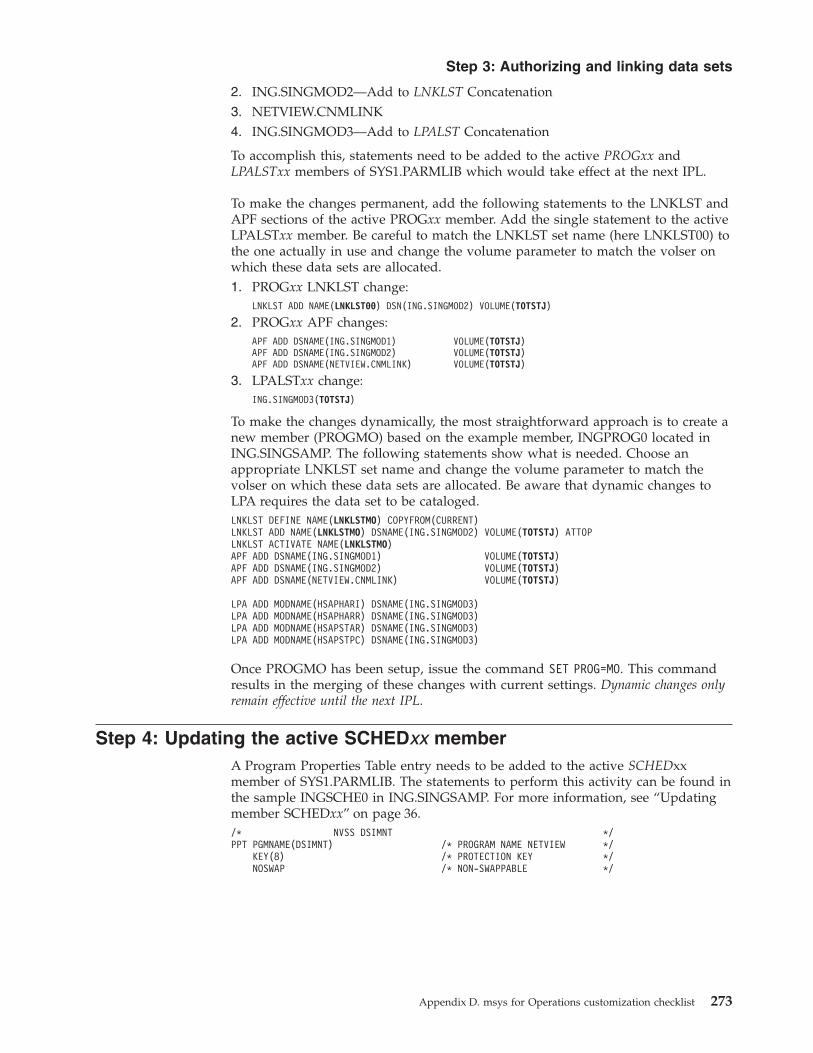
2. ING.SINGMOD2—Add to LNKLST Concatenation3. NETVIEW.CNMLINK4. ING.SINGMOD3—Add to LPALST Concatenation
To accomplish this, statements need to be added to the active PROGxx andLPALSTxx members of SYS1.PARMLIB which would take effect at the next IPL.
To make the changes permanent, add the following statements to the LNKLST andAPF sections of the active PROGxx member. Add the single statement to the activeLPALSTxx member. Be careful to match the LNKLST set name (here LNKLST00) tothe one actually in use and change the volume parameter to match the volser onwhich these data sets are allocated.1. PROGxx LNKLST change:
LNKLST ADD NAME(LNKLST00) DSN(ING.SINGMOD2) VOLUME(TOTSTJ)
2. PROGxx APF changes:APF ADD DSNAME(ING.SINGMOD1) VOLUME(TOTSTJ)APF ADD DSNAME(ING.SINGMOD2) VOLUME(TOTSTJ)APF ADD DSNAME(NETVIEW.CNMLINK) VOLUME(TOTSTJ)
3. LPALSTxx change:ING.SINGMOD3(TOTSTJ)
To make the changes dynamically, the most straightforward approach is to create anew member (PROGMO) based on the example member, INGPROG0 located inING.SINGSAMP. The following statements show what is needed. Choose anappropriate LNKLST set name and change the volume parameter to match thevolser on which these data sets are allocated. Be aware that dynamic changes toLPA requires the data set to be cataloged.LNKLST DEFINE NAME(LNKLSTMO) COPYFROM(CURRENT)LNKLST ADD NAME(LNKLSTMO) DSNAME(ING.SINGMOD2) VOLUME(TOTSTJ) ATTOPLNKLST ACTIVATE NAME(LNKLSTMO)APF ADD DSNAME(ING.SINGMOD1) VOLUME(TOTSTJ)APF ADD DSNAME(ING.SINGMOD2) VOLUME(TOTSTJ)APF ADD DSNAME(NETVIEW.CNMLINK) VOLUME(TOTSTJ)
LPA ADD MODNAME(HSAPHARI) DSNAME(ING.SINGMOD3)LPA ADD MODNAME(HSAPHARR) DSNAME(ING.SINGMOD3)LPA ADD MODNAME(HSAPSTAR) DSNAME(ING.SINGMOD3)LPA ADD MODNAME(HSAPSTPC) DSNAME(ING.SINGMOD3)
Once PROGMO has been setup, issue the command SET PROG=MO. This commandresults in the merging of these changes with current settings. Dynamic changes onlyremain effective until the next IPL.
Step 4: Updating the active SCHEDxx memberA Program Properties Table entry needs to be added to the active SCHEDxxmember of SYS1.PARMLIB. The statements to perform this activity can be found inthe sample INGSCHE0 in ING.SINGSAMP. For more information, see “Updatingmember SCHEDxx” on page 36./* NVSS DSIMNT */PPT PGMNAME(DSIMNT) /* PROGRAM NAME NETVIEW */
KEY(8) /* PROTECTION KEY */NOSWAP /* NON-SWAPPABLE */
Step 3: Authorizing and linking data sets
Appendix D. msys for Operations customization checklist 273

Step 5: Updating the active MPFLSTxx memberThe active Message Processing Facility List, MPFLSTxx in SYS1.PARMLIB needs tobe updated (for more information, see “Updating member MPFLSTxx” on page 36).If no form of automation is in use, then the statements to perform this activity canbe found in sample member INGEMPF in ING.SINGSAMP. The only statementsrequired are:.NO_ENTRY,SUP(NO),RETAIN(YES),AUTO(YES).DEFAULT,SUP(YES),RETAIN(YES),AUTO(NO)
However, if the installation’s current processing is reliant on existing MPFLSTxxsettings which may be incompatible with the above, then the following specificstatements will need to be worked into the active member instead:AOF603D,SUP(NO),RETAIN(NO),AUTO(YES)AOF*,SUP(NO),RETAIN(NO),AUTO(NO)IXC102A,SUP(NO),RETAIN(NO),AUTO(YES)IXC247D,SUP(NO),RETAIN(NO),AUTO(YES)IXC263I,SUP(NO),RETAIN(NO),AUTO(YES)IXC402D,SUP(NO),RETAIN(NO),AUTO(YES)IXC500I,SUP(NO),RETAIN(NO),AUTO(YES)IXC501I,SUP(NO),RETAIN(NO),AUTO(YES)IXC559I,SUP(NO),RETAIN(NO),AUTO(YES)IXC560I,SUP(NO),RETAIN(NO),AUTO(YES)IXC*,SUP(NO),RETAIN(NO),AUTO(NO)IXG257I,SUP(NO),RETAIN(NO),AUTO(YES)IXG261E,SUP(NO),RETAIN(NO),AUTO(YES)IXG*,SUP(NO),RETAIN(NO),AUTO(NO)IEA404A,SUP(NO),RETAIN(NO),AUTO(YES)IEA405E,SUP(NO),RETAIN(NO),AUTO(YES)IEA406I,SUP(NO),RETAIN(NO),AUTO(YES)IEA231A,SUP(NO),RETAIN(NO),AUTO(YES)IEA230E,SUP(NO),RETAIN(NO),AUTO(YES)IEA232I,SUP(NO),RETAIN(NO),AUTO(YES)IEA*,SUP(NO),RETAIN(NO),AUTO(NO)IEE043I,SUP(NO),RETAIN(NO),AUTO(YES)IEE037D,SUP(NO),RETAIN(NO),AUTO(YES)IEE041I,SUP(NO),RETAIN(NO),AUTO(YES)IEE533E,SUP(NO),RETAIN(NO),AUTO(YES)IEE769E,SUP(NO),RETAIN(NO),AUTO(YES)IEE889I,SUP(NO),RETAIN(NO),AUTO(YES)IEE400I,SUP(NO),RETAIN(NO),AUTO(YES)IEE600I,SUP(NO),RETAIN(NO),AUTO(YES)IEE*,SUP(NO),RETAIN(NO),AUTO(NO)
VTAM Requirementsmsys for Operations requires VTAM to be operational on every participatingsystem in the sysplex (for more information, see “Preparing VTAM” on page 41).Fortunately, Cross-System Coupling Facility (XCF) services are most often used forVTAM-to-VTAM communication within a sysplex virtually eliminating the needfor any VTAM definitions. Essentially, the first VTAM to start creates an XCFgroup called ISTXCF. This forms the basis of communication with other sysplexVTAMs. As subsequent VTAMs initialize, they join the same XCF group and aredynamically recognized.
There are two considerations:1. XCF signaling must be configured to use a Coupling Facility,
Channel-to-Channel Connections or both.2. XCFINIT=NO must not be specified in the ATCSTRxx member that is used
during VTAM initialization.
Step 5: Updating the active MPFLSTxx member
274 z/OS and OS/390 msys for Operations Setting Up and Using

Step 6: Defining the application major nodes to VTAMDefine the msys for Operations application major nodes to VTAM (for moreinformation, see “Preparing VTAM” on page 41). The statements to perform thisactivity can be found in the sample INGVTAM member in ING.SINGSAMP. Thiswill be a new member which can be named anything you choose, such asAPMSOxx. It must be placed in the data set pointed to by the VTAMLST datadefinition statement in the VTAM procedure. This data set must also be coded onthe DSIVTAM data definition statement of the procedure used to start msys forOperations as described in Step 2: Adding additional procedures to PROCLIB.Once this member is in place, the current ATCCONxx member should be edited toinclude the new member name just created. This will ensure that VTAM activatesthese APPLs during startup.************************************************************************ THIS APPLICATION MAJNODE DEFINES msys/Ops (NVSS) TO VTAM **** DOMAIN: MSO&SYSCLONE. ************************************************************************
VBUILD TYPE=APPL*********************************************************************** MSYS_OPS MAIN TASK ***********************************************************************MSO&SYSCLONE. APPL AUTH=(VPACE,ACQ,PASS),PRTCT=MSO&SYSCLONE., X
MODETAB=AMODETAB,DLOGMOD=DSIL6MOD, XAPPC=YES,PARSESS=YES, XDMINWNL=4,DMINWNR=4,DSESLIM=8,VPACING=10, XAUTOSES=2
********************************************************************** MSYS_OPS PRIMARY POI - (PROGRAM OPERATOR INTERFACE) **********************************************************************MSO&SYSCLONE.PPT APPL AUTH=(NVPACE,SPO),PRTCT=MSO&SYSCLONE.,EAS=1, X
MODETAB=AMODETAB,DLOGMOD=DSILGMOD*********************************************************************** MSYS_OPS SUBTASKS ***********************************************************************MSO&SYSCLONE.* APPL AUTH=(NVPACE,SPO,ACQ),PRTCT=MSO&SYSCLONE.,EAS=4, X
MODETAB=AMODETAB,DLOGMOD=DSILGMOD
Alternatively, activation can be performed dynamically using the followingcommand:’V NET,ACT,ID=APMSOXX’
Step 7: Customizing the security definitionsMake the determined security definition changes. The statements to perform thisactivity can be found in the sample CNMSAF1 in NETVIEW.DSIPARM. Therecommendation is to use an SAF product, and the statements in this memberassume that Security Server (RACF) is used. If this is not being used, thestatements will need to be altered to conform with the product that is in use.Extensive customization is necessary here as highlighted in the following example.The highlighted statements also include required additions to the CNMSAF1sample member. For more information, see Chapter 4, “Making securitydefinitions”, on page 71.
Step 6: Defining the application major nodes to VTAM
Appendix D. msys for Operations customization checklist 275

//RONNSAF JOB (POK,999),NORTHRUP,CLASS=C,MSGCLASS=T,NOTIFY=&SYSUID//STP1 EXEC PGM=IKJEFT01//SYSTSPRT DD SYSOUT=*//SYSTSIN DD *,DLM=@@/*/**********************************************************************/* To activate the classes needed for msys for Operations and protect/* against unauthorized logon, change ’domain_name’ to the domain/* name specified in your msys for Operations startup procedure./**********************************************************************SETROPTS CLASSACT(APPL)SETROPTS CLASSACT(NETCMDS) GRPLISTRDEF APPL MSO47 UACC(NONE)RDEF APPL MSO54 UACC(NONE)RDEF APPL MSO55 UACC(NONE)/*/**********************************************************************/* To define the task identifiers needed for msys for Operations,/* change ’domain_name’ to your msys for Operations domain name and/* ’SSIR_task_name’ to the CNMCSSIR task name you specified in/* CNMSTYLE./**********************************************************************ADDUSER MSO47PPTADDUSER MSO54PPTADDUSER MSO55PPTADDUSER MSO47SIRADDUSER MSO54SIRADDUSER MSO55SIR/*
Figure 60. Sample member CNMSAF1 in NETVIEW.DSIPARM (Part 1 of 8)
Step 7: Customizing the security definitions
276 z/OS and OS/390 msys for Operations Setting Up and Using

/**********************************************************************/* msys for Operations autotasks - DO NOT CHANGE/**********************************************************************ADDUSER AUTO1ALTUSER AUTO1 NETVIEW(IC(LOGPROF2) MSGRECVR(NO))ADDUSER AUTO2ALTUSER AUTO2 NETVIEW(IC(LOGPROF4) MSGRECVR(NO))ADDUSER DBAUTO1ALTUSER DBAUTO1 NETVIEW(IC(LOGPROF4) MSGRECVR(NO))ADDUSER DSILCOPRALTUSER DSILCOPR NETVIEW(MSGRECVR(NO))ADDUSER AUTBASEALTUSER AUTBASE NETVIEW(IC(AOFRAAIC) MSGRECVR(NO))ADDUSER AUTGSSALTUSER AUTGSS NETVIEW(IC(AOFRAAIC) MSGRECVR(NO))ADDUSER AUTMONALTUSER AUTMON NETVIEW(IC(AOFRAAIC) MSGRECVR(NO))ADDUSER AUTMSGALTUSER AUTMSG NETVIEW(IC(AOFRAAIC) MSGRECVR(NO))ADDUSER AUTNET1ALTUSER AUTNET1 NETVIEW(IC(AOFRAAIC) MSGRECVR(NO))ADDUSER AUTRECALTUSER AUTREC NETVIEW(IC(AOFRAAIC) MSGRECVR(NO))ADDUSER AUTSYSALTUSER AUTSYS NETVIEW(IC(AOFRAAIC) MSGRECVR(NO))ADDUSER AUTLOGALTUSER AUTLOG NETVIEW(IC(AOFRAAIC) MSGRECVR(NO))ADDUSER AUTCONALTUSER AUTCON NETVIEW(IC(AOFRAAIC) MSGRECVR(NO))ADDUSER AUTRPCALTUSER AUTRPC NETVIEW(IC(AOFRAAIC) MSGRECVR(NO))ADDUSER AUTWRK01ALTUSER AUTWRK01 NETVIEW(IC(AOFRAAIC) MSGRECVR(NO))ADDUSER AUTWRK02ALTUSER AUTWRK02 NETVIEW(IC(AOFRAAIC) MSGRECVR(NO))ADDUSER AUTWRK03ALTUSER AUTWRK03 NETVIEW(IC(AOFRAAIC) MSGRECVR(NO))ADDUSER AUTJESALTUSER AUTJES NETVIEW(IC(AOFRAAIC) MSGRECVR(NO))ADDUSER AUTSHUTALTUSER AUTSHUT NETVIEW(IC(AOFRAAIC) MSGRECVR(NO))ADDUSER AUTXCFALTUSER AUTXCF NETVIEW(IC(AOFRAAIC) MSGRECVR(NO))ADDUSER AUTXCF2ALTUSER AUTXCF2 NETVIEW(IC(AOFRAAIC) MSGRECVR(NO))ADDUSER AUTHW001ALTUSER AUTHW001 NETVIEW(IC(AOFRAAIC) CTL(GLOBAL) OPCLASS(1,2))ADDUSER AUTHW002ALTUSER AUTHW002 NETVIEW(IC(INGRX805) CTL(GLOBAL) OPCLASS(1,2))/*
Figure 60. Sample member CNMSAF1 in NETVIEW.DSIPARM (Part 2 of 8)
Step 7: Customizing the security definitions
Appendix D. msys for Operations customization checklist 277

/**********************************************************************/* Edit the following defaults appropriately to define your operators./**********************************************************************ADDUSER RONNALTUSER RONN NETVIEW(IC(LOGPROF1) MSGRECVR(NO))ADDUSER HIRALTUSER HIR NETVIEW(IC(LOGPROF1) MSGRECVR(NO))ADDUSER TILALTUSER TIL NETVIEW(IC(LOGPROF1) MSGRECVR(NO))ADDUSER FURNEAKALTUSER FURNEAK NETVIEW(IC(LOGPROF1) MSGRECVR(NO))ADDUSER NIELSONALTUSER NIELSON NETVIEW(IC(LOGPROF1) MSGRECVR(NO))ADDUSER WATSALTUSER WATS NETVIEW(IC(LOGPROF1) MSGRECVR(NO))ADDUSER OPER1ALTUSER OPER1 NETVIEW(IC(LOGPROF1) MSGRECVR(NO))ADDUSER OPER2ALTUSER OPER2 NETVIEW(IC(LOGPROF1) MSGRECVR(NO))ADDUSER OPER3ALTUSER OPER3 NETVIEW(IC(LOGPROF1) MSGRECVR(NO))ADDUSER OPER4ALTUSER OPER4 NETVIEW(IC(LOGPROF1) MSGRECVR(NO))ADDUSER OPER5ALTUSER OPER5 NETVIEW(IC(LOGPROF1) MSGRECVR(NO))ADDUSER OPER6ALTUSER OPER6 NETVIEW(IC(LOGPROF1) MSGRECVR(NO))ADDUSER NETOP1ALTUSER NETOP1 NETVIEW(IC(LOGPROF1) MSGRECVR(YES))ADDUSER NETOP2ADDUSER OPER6ALTUSER OPER6 NETVIEW(IC(LOGPROF1) MSGRECVR(NO))ADDUSER NETOP1ALTUSER NETOP1 NETVIEW(IC(LOGPROF1) MSGRECVR(YES))ADDUSER NETOP2ALTUSER NETOP2 NETVIEW(IC(LOGPROF1) MSGRECVR(YES))/*/*********************************************************************/* Group your operators according to their responsibilities and/* roles. Add as many CONNECT statements as you need. Each operator/* can be connected to as many groups as needed./*/* Operators are connected to a group according the functions they/* are permitted run. They must also be connected to every lower group/* as well. For example, Operators connected to MSYSOPS3 would also/* require access to functions in the lower groups. To establish this/* they must be connected to MSYSOPS1 and MSYSOPS2 in order to have/* the appropriate access authority assigned to them./*/* If users are not listed as member of any group, they will still/* be able to use the INGPLEX and INGCF commands for display/* purposes and any other msys for Operations commands that are/* not specifically protected./*
Figure 60. Sample member CNMSAF1 in NETVIEW.DSIPARM (Part 3 of 8)
Step 7: Customizing the security definitions
278 z/OS and OS/390 msys for Operations Setting Up and Using

/*********************************************************************/* Users listed in this group are allowed to execute/* administrative INGAUTO command./*********************************************************************ADDGROUP MSYSOPS0CONNECT NETOP1 GROUP(MSYSOPS0) UACC(READ)CONNECT NETOP2 GROUP(MSYSOPS0) UACC(READ)CONNECT OPER1 GROUP(MSYSOPS0) UACC(READ)CONNECT OPER2 GROUP(MSYSOPS0) UACC(READ)CONNECT OPER3 GROUP(MSYSOPS0) UACC(READ)CONNECT OPER4 GROUP(MSYSOPS0) UACC(READ)CONNECT OPER5 GROUP(MSYSOPS0) UACC(READ)CONNECT RONN GROUP(MSYSOPS0) UACC(READ)CONNECT HIR GROUP(MSYSOPS0) UACC(READ)CONNECT TIL GROUP(MSYSOPS0) UACC(READ)CONNECT FURNEAK GROUP(MSYSOPS0) UACC(READ)CONNECT NIELSON GROUP(MSYSOPS0) UACC(READ)CONNECT WATS GROUP(MSYSOPS0) UACC(READ)/*********************************************************************/* Users listed in this group are allowed to execute FORCE and/* REBUILD actions on structures./*********************************************************************ADDGROUP MSYSOPS1CONNECT NETOP1 GROUP(MSYSOPS1) UACC(READ)CONNECT NETOP2 GROUP(MSYSOPS1) UACC(READ)CONNECT OPER1 GROUP(MSYSOPS1) UACC(READ)CONNECT RONN GROUP(MSYSOPS1) UACC(READ)CONNECT HIR GROUP(MSYSOPS1) UACC(READ)CONNECT TIL GROUP(MSYSOPS1) UACC(READ)CONNECT FURNEAK GROUP(MSYSOPS1) UACC(READ)CONNECT NIELSON GROUP(MSYSOPS1) UACC(READ)CONNECT WATS GROUP(MSYSOPS1) UACC(READ)/*********************************************************************/* Users listed in this group are allowed to execute the SETXCF/* command with parm "ACOUPLE" and "PSWITCH"./*********************************************************************ADDGROUP MSYSOPS2CONNECT NETOP1 GROUP(MSYSOPS2) UACC(READ)CONNECT NETOP2 GROUP(MSYSOPS2) UACC(READ)CONNECT OPER2 GROUP(MSYSOPS2) UACC(READ)CONNECT RONN GROUP(MSYSOPS2) UACC(READ)CONNECT HIR GROUP(MSYSOPS2) UACC(READ)CONNECT TIL GROUP(MSYSOPS2) UACC(READ)CONNECT FURNEAK GROUP(MSYSOPS2) UACC(READ)CONNECT NIELSON GROUP(MSYSOPS2) UACC(READ)CONNECT WATS GROUP(MSYSOPS2) UACC(READ)
Figure 60. Sample member CNMSAF1 in NETVIEW.DSIPARM (Part 4 of 8)
Step 7: Customizing the security definitions
Appendix D. msys for Operations customization checklist 279

/*********************************************************************/* Users listed in this group are allowed to execute the full/* functionality of INGCF ENABLE and INGCF DRAIN (without HW/* action ACTIVATE/DEACTIVATE)./*********************************************************************ADDGROUP MSYSOPS3CONNECT NETOP1 GROUP(MSYSOPS3) UACC(READ)CONNECT NETOP2 GROUP(MSYSOPS3) UACC(READ)CONNECT OPER3 GROUP(MSYSOPS3) UACC(READ)CONNECT RONN GROUP(MSYSOPS3) UACC(READ)CONNECT HIR GROUP(MSYSOPS3) UACC(READ)CONNECT TIL GROUP(MSYSOPS3) UACC(READ)CONNECT FURNEAK GROUP(MSYSOPS3) UACC(READ)CONNECT NIELSON GROUP(MSYSOPS3) UACC(READ)CONNECT WATS GROUP(MSYSOPS3) UACC(READ)/*********************************************************************/* Users listed in this group are allowed to do most restricted/* base NVSS commands and ACF COLD (due to EXCMD)./*********************************************************************ADDGROUP MSYSOPS4CONNECT NETOP1 GROUP(MSYSOPS4) UACC(READ)CONNECT NETOP2 GROUP(MSYSOPS4) UACC(READ)CONNECT OPER1 GROUP(MSYSOPS4) UACC(READ)CONNECT OPER2 GROUP(MSYSOPS4) UACC(READ)CONNECT OPER3 GROUP(MSYSOPS4) UACC(READ)CONNECT AUTO1 GROUP(MSYSOPS4) UACC(READ)CONNECT AUTO2 GROUP(MSYSOPS4) UACC(READ)CONNECT DBAUTO1 GROUP(MSYSOPS4) UACC(READ)CONNECT DSILCOPR GROUP(MSYSOPS4) UACC(READ)CONNECT AUTBASE GROUP(MSYSOPS4) UACC(READ)CONNECT AUTGSS GROUP(MSYSOPS4) UACC(READ)CONNECT AUTMON GROUP(MSYSOPS4) UACC(READ)CONNECT AUTMSG GROUP(MSYSOPS4) UACC(READ)CONNECT AUTNET1 GROUP(MSYSOPS4) UACC(READ)CONNECT AUTREC GROUP(MSYSOPS4) UACC(READ)CONNECT AUTSYS GROUP(MSYSOPS4) UACC(READ)CONNECT AUTLOG GROUP(MSYSOPS4) UACC(READ)CONNECT AUTCON GROUP(MSYSOPS4) UACC(READ)CONNECT AUTRPC GROUP(MSYSOPS4) UACC(READ)CONNECT AUTWRK01 GROUP(MSYSOPS4) UACC(READ)CONNECT AUTWRK02 GROUP(MSYSOPS4) UACC(READ)CONNECT AUTWRK03 GROUP(MSYSOPS4) UACC(READ)CONNECT AUTJES GROUP(MSYSOPS4) UACC(READ)CONNECT AUTSHUT GROUP(MSYSOPS4) UACC(READ)CONNECT AUTXCF GROUP(MSYSOPS4) UACC(READ)CONNECT AUTXCF2 GROUP(MSYSOPS4) UACC(READ)CONNECT AUTHW001 GROUP(MSYSOPS4) UACC(READ)CONNECT AUTHW002 GROUP(MSYSOPS4) UACC(READ)CONNECT RONN GROUP(MSYSOPS4) UACC(READ)CONNECT HIR GROUP(MSYSOPS4) UACC(READ)CONNECT TIL GROUP(MSYSOPS4) UACC(READ)CONNECT FURNEAK GROUP(MSYSOPS4) UACC(READ)CONNECT NIELSON GROUP(MSYSOPS4) UACC(READ)CONNECT WATS GROUP(MSYSOPS4) UACC(READ)
Figure 60. Sample member CNMSAF1 in NETVIEW.DSIPARM (Part 5 of 8)
Step 7: Customizing the security definitions
280 z/OS and OS/390 msys for Operations Setting Up and Using

/*********************************************************************/* Users listed in this group are allowed to do any commands./*********************************************************************ADDGROUP MSYSOPS5CONNECT NETOP1 GROUP(MSYSOPS5) UACC(READ)CONNECT NETOP2 GROUP(MSYSOPS5) UACC(READ)CONNECT RONN GROUP(MSYSOPS5) UACC(READ)CONNECT HIR GROUP(MSYSOPS5) UACC(READ)CONNECT TIL GROUP(MSYSOPS5) UACC(READ)CONNECT FURNEAK GROUP(MSYSOPS5) UACC(READ)CONNECT NIELSON GROUP(MSYSOPS5) UACC(READ)CONNECT WATS GROUP(MSYSOPS5) UACC(READ)/*/*********************************************************************/* To allow your operators to log on to msys for Operations, change/* ’domain_name’ to your domain name. Be sure to add PERMIT/* statements for any operators not connected to any groups./* NOTE: Autotasks do not have to be permitted to log on./*********************************************************************PERMIT MSO47 CLASS(APPL) ID(MSYSOPS0) ACCESS(READ)PERMIT MSO47 CLASS(APPL) ID(MSYSOPS1) ACCESS(READ)PERMIT MSO47 CLASS(APPL) ID(MSYSOPS2) ACCESS(READ)PERMIT MSO47 CLASS(APPL) ID(MSYSOPS3) ACCESS(READ)PERMIT MSO47 CLASS(APPL) ID(MSYSOPS4) ACCESS(READ)PERMIT MSO47 CLASS(APPL) ID(MSYSOPS5) ACCESS(READ)PERMIT MSO54 CLASS(APPL) ID(MSYSOPS0) ACCESS(READ)PERMIT MSO54 CLASS(APPL) ID(MSYSOPS1) ACCESS(READ)PERMIT MSO54 CLASS(APPL) ID(MSYSOPS2) ACCESS(READ)PERMIT MSO54 CLASS(APPL) ID(MSYSOPS3) ACCESS(READ)PERMIT MSO54 CLASS(APPL) ID(MSYSOPS4) ACCESS(READ)PERMIT MSO54 CLASS(APPL) ID(MSYSOPS5) ACCESS(READ)PERMIT MSO55 CLASS(APPL) ID(MSYSOPS0) ACCESS(READ)PERMIT MSO55 CLASS(APPL) ID(MSYSOPS1) ACCESS(READ)PERMIT MSO55 CLASS(APPL) ID(MSYSOPS2) ACCESS(READ)PERMIT MSO55 CLASS(APPL) ID(MSYSOPS3) ACCESS(READ)PERMIT MSO55 CLASS(APPL) ID(MSYSOPS4) ACCESS(READ)PERMIT MSO55 CLASS(APPL) ID(MSYSOPS5) ACCESS(READ)SETROPTS RACLIST(APPL) REFRESH/*/**********************************************************************/* Add FACILITY class resources for the Internal Hardware Transport &/* dynamic CDS functions./**********************************************************************SETROPTS GENERIC(FACILITY)RDEF FACILITY HSA.ET32* UACC(NONE)RDEF FACILITY MVSADMIN.LOGR UACC(NONE)RDEF FACILITY MVSADMIN.XCF.ARM UACC(NONE)RDEF FACILITY MVSADMIN.XCF.CFRM UACC(NONE)RDEF FACILITY MVSADMIN.XCF.SFM UACC(NONE)
Figure 60. Sample member CNMSAF1 in NETVIEW.DSIPARM (Part 6 of 8)
Step 7: Customizing the security definitions
Appendix D. msys for Operations customization checklist 281

/*********************************************************************/* Add RDEF statements to the following list to define resources to/* the NETCMDS class for any additional commands to which you wish to/* restrict access./*********************************************************************SETROPTS GENERIC(NETCMDS)RDEF NETCMDS *.*.* UACC(READ)RDEF NETCMDS *.*.ACF.COLD UACC(NONE)RDEF NETCMDS *.*.INGAUTO UACC(NONE)RDEF NETCMDS *.*.INGRCCHK.INGCF.STR UACC(NONE)RDEF NETCMDS *.*.INGRCCHK.INGPLEX.CDS UACC(NONE)RDEF NETCMDS *.*.INGRCCHK.INGCF.CF UACC(NONE)RDEF NETCMDS *.*.INGRCCHK.INGPLEX.HW UACC(NONE)RDEF NETCMDS *.*.REFRESH UACC(NONE)RDEF NETCMDS *.*.DEFAULTS UACC(NONE)RDEF NETCMDS *.*.LOGONPW UACC(NONE)RDEF NETCMDS *.*.TS UACC(NONE)RDEF NETCMDS *.*.RID UACC(NONE)RDEF NETCMDS *.*.PURGE UACC(NONE)RDEF NETCMDS *.*.ALLOCATE UACC(NONE)RDEF NETCMDS *.*.FREE UACC(NONE)RDEF NETCMDS *.*.EXCMD UACC(NONE)RDEF NETCMDS *.*.MODIFY UACC(NONE)RDEF NETCMDS *.*.VARY UACC(NONE)RDEF NETCMDS *.*.CNME2008 UACC(NONE)RDEF NETCMDS *.*.MVS UACC(NONE)RDEF NETCMDS *.*.START UACC(NONE)RDEF NETCMDS *.*.STOP UACC(NONE)RDEF NETCMDS *.*.SWITCH UACC(NONE)RDEF NETCMDS *.*.RESETDB UACC(NONE)RDEF NETCMDS *.*.AUTOTBL UACC(NONE)RDEF NETCMDS *.*.AUTOTASK UACC(NONE)RDEF NETCMDS *.*.EZLEF002 UACC(NONE)RDEF NETCMDS *.*.OVERRIDE.MAXCPU UACC(NONE)RDEF NETCMDS *.*.OVERRIDE.MAXCPU.* UACC(NONE)RDEF NETCMDS *.*.OVERRIDE.MAXIO UACC(NONE)RDEF NETCMDS *.*.OVERRIDE.MAXIO.* UACC(NONE)RDEF NETCMDS *.*.OVERRIDE.MAXMQIN UACC(NONE)RDEF NETCMDS *.*.OVERRIDE.MAXMQIN.* UACC(NONE)RDEF NETCMDS *.*.OVERRIDE.MAXMQOUT UACC(NONE)RDEF NETCMDS *.*.OVERRIDE.MAXMQOUT.* UACC(NONE)RDEF NETCMDS *.*.OVERRIDE.MAXSTG UACC(NONE)RDEF NETCMDS *.*.OVERRIDE.MAXSTG.* UACC(NONE)RDEF NETCMDS *.*.OVERRIDE.SLOWSTG UACC(NONE)RDEF NETCMDS *.*.OVERRIDE.SLOWSTG.* UACC(NONE)RDEF NETCMDS *.*.OVERRIDE.REXXSTRF UACC(NONE)RDEF NETCMDS *.*.OVERRIDE.REXXSTRF.* UACC(NONE)RDEF NETCMDS *.*.OVERRIDE.TASK UACC(NONE)RDEF NETCMDS *.*.OVERRIDE.TASK.* UACC(NONE)RDEF NETCMDS *.*.CLOSE UACC(NONE)/************* Protect access data sets ******************************RDEF NETCMDS *.*.READSEC.DSIPARM.* UACC(NONE)RDEF NETCMDS *.*.WRITESEC.* UACC(NONE)RDEF NETCMDS *.*.WRITESEC.*.* UACC(NONE)/************* General "disallow" statements *************************RDEF NETCMDS *.*.CNME1087 UACC(NONE)RDEF NETCMDS *.*.DSIZKNYJ UACC(NONE)RDEF NETCMDS *.*.DSIUSNDM UACC(NONE)RDEF NETCMDS *.*.FOCALPT UACC(NONE)RDEF NETCMDS *.*.NPDA UACC(NONE)/*
Figure 60. Sample member CNMSAF1 in NETVIEW.DSIPARM (Part 7 of 8)
Step 7: Customizing the security definitions
282 z/OS and OS/390 msys for Operations Setting Up and Using

/**********************************************************************/* Add data set names with special authority requirements. Change/* ’MSOPS’ to the high level qualifier you have chosen./**********************************************************************AD MSOPS.** UACC(READ)AD MSOPS.*.DSILOGP UACC(READ)AD MSOPS.*.DSILOGS UACC(READ)AD MSOPS.*.DSILIST UACC(READ)/*/*********************************************************************/* Add PERMIT statements to the following list to permit the/* appropriate operators and groups to use the restricted commands/* you added to the list above./*********************************************************************PE *.*.INGAUTO CLASS(NETCMDS) ID(MSYSOPS0) ACCESS(READ)PE *.*.INGRCCHK.INGCF.STR CLASS(NETCMDS) ID(MSYSOPS1) ACCESS(READ)PE *.*.INGRCCHK.INGPLEX.CDS CLASS(NETCMDS) ID(MSYSOPS2) ACCESS(READ)PE *.*.INGRCCHK.INGCF.CF CLASS(NETCMDS) ID(MSYSOPS3) ACCESS(READ)PE *.*.ACF.COLD CLASS(NETCMDS) ID(MSYSOPS4) ACCESS(READ)PE *.*.REFRESH CLASS(NETCMDS) ID(MSYSOPS4) ACCESS(READ)PE *.*.DEFAULTS CLASS(NETCMDS) ID(MSYSOPS4) ACCESS(READ)PE *.*.LOGONPW CLASS(NETCMDS) ID(MSYSOPS4) ACCESS(READ)PE *.*.TS CLASS(NETCMDS) ID(MSYSOPS4) ACCESS(READ)PE *.*.RID CLASS(NETCMDS) ID(MSYSOPS4) ACCESS(READ)PE *.*.PURGE CLASS(NETCMDS) ID(MSYSOPS4) ACCESS(READ)PE *.*.ALLOCATE CLASS(NETCMDS) ID(MSYSOPS4) ACCESS(READ)PE *.*.FREE CLASS(NETCMDS) ID(MSYSOPS4) ACCESS(READ)PE *.*.EXCMD CLASS(NETCMDS) ID(MSYSOPS4) ACCESS(READ)PE *.*.MODIFY CLASS(NETCMDS) ID(MSYSOPS4) ACCESS(READ)PE *.*.VARY CLASS(NETCMDS) ID(MSYSOPS4) ACCESS(READ)PE *.*.CNME2008 CLASS(NETCMDS) ID(MSYSOPS4) ACCESS(READ)PE *.*.MVS CLASS(NETCMDS) ID(MSYSOPS4) ACCESS(READ)PE *.*.START CLASS(NETCMDS) ID(MSYSOPS4) ACCESS(READ)PE *.*.STOP CLASS(NETCMDS) ID(MSYSOPS4) ACCESS(READ)PE *.*.SWITCH CLASS(NETCMDS) ID(MSYSOPS4) ACCESS(READ)PE *.*.RESETDB CLASS(NETCMDS) ID(MSYSOPS4) ACCESS(READ)PE *.*.AUTOTBL CLASS(NETCMDS) ID(MSYSOPS4) ACCESS(READ)PE *.*.AUTOTASK CLASS(NETCMDS) ID(MSYSOPS4) ACCESS(READ)PE *.*.EZLEF002 CLASS(NETCMDS) ID(MSYSOPS4) ACCESS(READ)PE *.*.OVERRIDE.MAXCPU CLASS(NETCMDS) ID(MSYSOPS4) ACCESS(READ)PE *.*.OVERRIDE.MAXCPU.* CLASS(NETCMDS) ID(MSYSOPS4) ACCESS(READ)PE *.*.OVERRIDE.MAXIO CLASS(NETCMDS) ID(MSYSOPS4) ACCESS(READ)PE *.*.OVERRIDE.MAXIO.* CLASS(NETCMDS) ID(MSYSOPS4) ACCESS(READ)PE *.*.OVERRIDE.MAXMQIN CLASS(NETCMDS) ID(MSYSOPS4) ACCESS(READ)PE *.*.OVERRIDE.MAXMQIN.* CLASS(NETCMDS) ID(MSYSOPS4) ACCESS(READ)PE *.*.OVERRIDE.MAXMQOUT CLASS(NETCMDS) ID(MSYSOPS4) ACCESS(READ)PE *.*.OVERRIDE.MAXMQOUT.* CLASS(NETCMDS) ID(MSYSOPS4) ACCESS(READ)PE *.*.OVERRIDE.MAXSTG CLASS(NETCMDS) ID(MSYSOPS4) ACCESS(READ)PE *.*.OVERRIDE.MAXSTG.* CLASS(NETCMDS) ID(MSYSOPS4) ACCESS(READ)PE *.*.OVERRIDE.SLOWSTG CLASS(NETCMDS) ID(MSYSOPS4) ACCESS(READ)PE *.*.OVERRIDE.SLOWSTG.* CLASS(NETCMDS) ID(MSYSOPS4) ACCESS(READ)PE *.*.OVERRIDE.REXXSTRF CLASS(NETCMDS) ID(MSYSOPS4) ACCESS(READ)PE *.*.OVERRIDE.REXXSTRF.* CLASS(NETCMDS) ID(MSYSOPS4) ACCESS(READ)PE *.*.OVERRIDE.TASK CLASS(NETCMDS) ID(MSYSOPS4) ACCESS(READ)PE *.*.OVERRIDE.TASK.* CLASS(NETCMDS) ID(MSYSOPS4) ACCESS(READ)PE *.*.READSEC.DSIPARM.* CLASS(NETCMDS) ID(MSYSOPS4) ACCESS(READ)PE *.*.WRITESEC.* CLASS(NETCMDS) ID(MSYSOPS4) ACCESS(READ)PE *.*.WRITESEC.*.* CLASS(NETCMDS) ID(MSYSOPS4) ACCESS(READ)PE *.*.INGRCCHK.INGPLEX.HW CLASS(NETCMDS) ID(MSYSOPS4) ACCESS(READ)PE HSA.ET32* CLASS(FACILITY) ID(SYS1) ACCESS(CONTROL)PE MSOPS.*.DSILOGP CLASS(DATASET) ID(MSYSOPS5) ACCESS(CONTROL)PE MSOPS.*.DSILOGS CLASS(DATASET) ID(MSYSOPS5) ACCESS(CONTROL)PE MSOPS.*.DSILIST CLASS(DATASET) ID(MSYSOPS5) ACCESS(ALTER)PE MVSADMIN.XCF.ARM CLASS(FACILITY) ID(SYS1) ACCESS(ALTER)PE MVSADMIN.XCF.CFRM CLASS(FACILITY) ID(SYS1) ACCESS(ALTER)PE MVSADMIN.XCF.SFM CLASS(FACILITY) ID(SYS1) ACCESS(ALTER)PE MVSADMIN.LOGR CLASS(FACILITY) ID(SYS1) ACCESS(ALTER)/*SETROPTS RACLIST(NETCMDS,FACILITY) REFRESH@@//
Figure 60. Sample member CNMSAF1 in NETVIEW.DSIPARM (Part 8 of 8)
Step 7: Customizing the security definitions
Appendix D. msys for Operations customization checklist 283

There is an alternate, less robust method of defining msys for Operations useridswithout using an SAF product if you prefer. However, be aware that this isconsiderably less secure and that functions dependent on the Internal HardwareTransport will still require SAF authorization. In Step 1: Creating shared andsystem-unique VSAM and non-VSAM data sets, a shared user DSIPARM data setwas created. This data set was placed ahead of the others in the DSIPARM datadefinition concatenation in the MSOPS procedure as shown in “Step 2: Addingadditional procedures to PROCLIB” on page 271. Copy members DSIDMNK andDSIOPFU from NETVIEW.DSIPARM into this data set. Make changes to theoptions in these members as described in the “Step 8: Customizing theCNMSTYLE style sheet and members DSIDMNK, DSIOPFU and DSICMPRC” onpage 285. If use of CF management capabilities (CF Drain and CF Enable) andpartitioning of failed systems (IXC102A) is required then the following RACFdefinitions must be made.
//RONNSAF JOB (POK,999),NORTHRUP,CLASS=C,MSGCLASS=T,NOTIFY=&SYSUID//STP1 EXEC PGM=IKJEFT01//SYSTSPRT DD SYSOUT=*//SYSTSIN DD *,DLM=@@/*/**********************************************************************/* MANDATORY RACF DEFINITIONS REQUIRED BY INTERNAL HARDWARE TRANSPORT/**********************************************************************/* Define the default userid that will be associated with msys for/* Operations started tasks, the values ’STC’, ’SYS1’, ’SAFADMIN’ and/* ’MSO1234’ may be changed. In most situations this type of userid/* will already be defined./**********************************************************************SETROPTS CLASSACT(STARTED) RACLIST(STARTED)ADDUSER STC DFLTGRP(SYS1) OWNER(SAFADMIN) PASSWORD(MSO1234) OPERATIONSSETROPTS RACLIST(STARTED) REFRESH/*/**********************************************************************/* msys for Operations Autotasks/**********************************************************************ADDUSER AUTHW001 NETVIEW(IC(AOFRAAIC) CTL(GLOBAL) OPCLASS(1,2))ADDUSER AUTHW002 NETVIEW(IC(INGRX805) CTL(GLOBAL) OPCLASS(1,2))ADDUSER AUTXCF NETVIEW(IC(AOFRAAIC) CTL(GLOBAL) OPCLASS(1,2))ADDUSER AUTXCF2 NETVIEW(IC(AOFRAAIC) CTL(GLOBAL) OPCLASS(1,2))ADDUSER AUTRPC NETVIEW(IC(AOFRAAIC) CTL(GLOBAL) OPCLASS(1,2))ADDUSER AUTBASE NETVIEW(IC(AOFRAAIC) CTL(GLOBAL) OPCLASS(1,2))/*/**********************************************************************/* Add the FACILITY class resource profile for the Internal Hardware/* Transport/**********************************************************************SETROPTS GENERIC(FACILITY)RDEF FACILITY HSA.ET32* UACC(NONE)SETROPTS RACLIST(FACILITY) REFRESH/*/*********************************************************************/* Set permissions for Internal Hardware Transport resources/*********************************************************************PE HSA.ET32* CLASS(FACILITY) ID(SYS1) ACCESS(CONTROL)/*@@//
Figure 61. RACF definitions that are required by Internal Hardware Transport
Step 7: Customizing the security definitions
284 z/OS and OS/390 msys for Operations Setting Up and Using

Step 8: Customizing the CNMSTYLE style sheet and membersDSIDMNK, DSIOPFU and DSICMPRC
Customizing NetView System Services (NVSS), the backbone of msys forOperations (HPZ8500), involves altering the NVSS Style Sheet and some additionalmembers. The changes to the options are determined by the security schemechosen and whether the full NetView product is already used by the installation.All members are located in the NETVIEW.DSIPARM data set. The style sheet isCNMSTYLE and always requires changing. Optional members are DSIDMNK,DSIOPFU, and DSICMPRC. Copy these members into the shared user-definedDSIPARM data set, locate the relevant record, and make the changes ashighlighted. For more information, see “Customizing the initialization style sheet”on page 43.
Customization for NVSS—no NetView licenseCNMSTYLE
1. Insert * in the following line:*DOMAIN = C&NV2I.01
Add the statement:DOMAIN = &DOMAIN.
2. Insert * in the following line:*NetID = &CNMNETID.
3. Insert * in the following line:*SSIname = C&NV2I.CSSIR
Add the statement:SSIname = &DOMAIN.SIR
Note: Changes to the optional members DSIDMNK and DSIOPFU are necessary ifan SAF product is not being used.
DSIDMNK
1. Remove * from the following line:OPTIONS OPERSEC=NETVPW,CMDAUTH=SCOPE,OPSPAN=NETV
2. Insert * in the following line:*OPTIONS OPERSEC=SAFDEF,CMDAUTH=SAF,AUTHCHK=SOURCEID
3. Insert * in the following line:*OPTIONS BACKTBL=CNMSBAK1
DSIOPFUAdd the following set of lines for each operator, where opid is theoperator’s ID and password is their password:opid OPERATOR PASSWORD=password
PROFILEN DSIPROFA
Customization for full NetView 1.4CNMSTYLE
1. Insert * in the following line:*DOMAIN = C&NV2I.01
Add the statement:
Step 8: Customizing the CNMSTYLE style sheet and members DSIDMNK, DSIOPFU andDSICMPRC
Appendix D. msys for Operations customization checklist 285

DOMAIN = &DOMAIN.
2. Insert * in the following line:*NetID = &CNMNETID.
3. Insert * in the following line:*SSIname = C&NV2I.CSSIR
Add the statement:SSIname = &DOMAIN.SIR
4. Remove * in front of SA (that is, uncomment SA):TOWER = SA *AON *MSM *Graphics *AMI MVScmdMgt
5. Insert * in the following line:*TOWER.SA = license
6. Change Y to N in the following line:TASK.CNMTAMEL.INIT=N
7. Change Y to N in the following line:TASK.DUIDGHB.INIT=N
8. Insert * in the following line:*%INCLUDE C&NV2I.STGEN
9. Change N to Y in the following line:TASK.CNMCALRT.INIT=Y
DSICMPRC
1. Change Y to N in the following line:EZLSPIPC CMDMDL MOD=EZLSPIPC,TYPE=R,RES=N,ECHO=N,SEC=BY
2. Change Y to N in the following line:EZLSRTVE CMDMDL MOD=EZLSRTVE,TYPE=R,RES=N,ECHO=N,SEC=BY
DSIDMNK
1. Remove * from the following line:LOADEXIT NONE
Note: Changes to the optional members DSIDMNK and DSIOPFU arenecessary when an SAF product is not being used.
2. Remove * from the following line:OPTIONS OPERSEC=NETVPW,CMDAUTH=SCOPE,OPSPAN=NETV
Insert * in the following line:*OPTIONS OPERSEC=SAFDEF,CMDAUTH=SAF,AUTHCHK=SOURCEID
Insert * in the following line:*OPTIONS BACKTBL=CNMSBAK1
DSIOPFUAdd the following set of lines for each operator, where opid is theoperator’s ID and password is their password:opid OPERATOR PASSWORD=password
PROFILEN DSIPROFA
Customization for NetView 5.1When using NetView 5.1 be aware that the DSIDMNK member has been removed.Statements previously in this member are now part of the style sheet. In addition,
Step 8: Customizing the CNMSTYLE style sheet and members DSIDMNK, DSIOPFU andDSICMPRC
286 z/OS and OS/390 msys for Operations Setting Up and Using

SAF is not the default security scheme. Because of this there are changes relating tothe security setup irrespective of the scheme chosen.
CNMSTYLE
1. Insert * in the following line:*DOMAIN = C&NV2I.01
Add the statement:DOMAIN = &DOMAIN.
2. Insert * in the following line:*NetID = &CNMNETID.
3. Insert * and add the statement in the following lines:*SSIname = C&NV2I.CSSIR*SSIname = C&NV2I.CSSIRSSIname = &DOMAIN.SIR
4. When SAF is being used, insert * in the NETVPW line and remove *from the SAFDEF lines, as follows:*SECOPTS.OPERSEC = NETVPW*SECOPTS.OPERSEC = SAFCHECK*SECOPTS.OPERSEC = SAFPWSECOPTS.OPERSEC = SAFDEF*SECOPTS.OPERSEC = MINIMAL
5. Insert * in TABLE.CNMSCAT2 line and, only if SAF is being used,remove * from the SAF.CNMSBAK1 line, as follows*SECOPTS.CMDAUTH = TABLE.CNMSCAT2SECOPTS.CMDAUTH = SAF.CNMSBAK1*SECOPTS.CMDAUTH = SAF.PASS*SECOPTS.CMDAUTH = SAF.FAIL*SECOPTS.CMDAUTH = SCOPE.CNMSCOP1
6. No changes are necessary to the following lines:SECOPTS.AUTHCHK = SOURCEID*SECOPTS.AUTHCHK = TARGETID
7. Insert * in the NETV line and remove * from the SAF line, as follows:*SECOPTS.OPSPAN = NETVSECOPTS.OPSPAN = SAF
8. Remove * from the SA option and add * to the NPDA and NLDMoptions, as follows:TOWER = SA *AON *MSM *Graphics MVScmdMgt *NPDA *TARA *NLDM *AMI
9. Insert * in the following line:*TOWER.SA = license
10. Change Y to N in the following line:TASK.CNMTAMEL.INIT=N
11. Change Y to N in the following line:TASK.DUIDGHB.INIT=N
12. Insert * in the following line:*%INCLUDE C&NV2I.STGEN
Note: The following changes to options are necessary when an SAFproduct is not being used.
1. No changes are required to the following lines:
Step 8: Customizing the CNMSTYLE style sheet and members DSIDMNK, DSIOPFU andDSICMPRC
Appendix D. msys for Operations customization checklist 287

SECOPTS.OPERSEC = NETVPW*SECOPTS.OPERSEC = SAFCHECK*SECOPTS.OPERSEC = SAFPW*SECOPTS.OPERSEC = SAFDEF*SECOPTS.OPERSEC = MINIMAL
2. Insert * in TABLE.CNMSCAT2 line and remove * from theSCOPE.CNMSCOP1 line, as follows*SECOPTS.CMDAUTH = TABLE.CNMSCAT2SECOPTS.CMDAUTH = SAF.CNMSBAK1*SECOPTS.CMDAUTH = SAF.PASS*SECOPTS.CMDAUTH = SAF.FAILSECOPTS.CMDAUTH = SCOPE.CNMSCOP1
3. These are the defaults, so no changes are necessary to the followinglines:SECOPTS.AUTHCHK = SOURCEID*SECOPTS.AUTHCHK = TARGETID
4. These are the defaults, so no changes are necessary to the followinglines:SECOPTS.OPSPAN = NETV*SECOPTS.OPSPAN = SAF
DSIOPFUAdd the following set of lines for each operator, where opid is theoperator’s ID and password is their password:opid OPERATOR PASSWORD=password
PROFILEN DSIPROFA
Step 9: Customizing the member AOFCUSTTurn on the msys for Operations functions that you are interested in. By default allfunctions that take automated action ship disabled and are controlled by theAOFCUST member located in ING.SINGNPRM. Extensive comments are includedwithin AOFCUST. Start by copying this member to the shared DSIPARM data setpreviously created and make the desired changes there. For more information, see“Editing the customization member AOFCUST” on page 44.
The AUTO section controls function enablement. Functions are enabled byremoving comments (*) from the statements you wish to enable. Each function hasa corresponding detailed section where installation specific values are coded. Such asthe actions you permit msys for Operations to take, volumes available for dynamicallocation, data set HLQs and so on.
Processor and logical partition configurations are also defined to msys forOperations within this member. This is done in the HW Section which has norelationship to the AUTO section. During msys for Operations initialization checksare made to see if z/OS is able to use an Internal Hardware Transport for directhardware interaction. If so, this capability is enabled.
Note: It is critical that everything defined in the HW section exactly represents thedefinitions in HCD and in use by the Support Element (SE) for any givenprocessor. Failure to do this could result in hardware manipulation thattargets the wrong CPC/LPAR.
Step 8: Customizing the CNMSTYLE style sheet and members DSIDMNK, DSIOPFU andDSICMPRC
288 z/OS and OS/390 msys for Operations Setting Up and Using

*---------------------------------------------------------------* AUTO section*---------------------------------------------------------------* This section contains keywords representing automated* functions:* CDS Enables recovery of missing CDS allocations.* HEALTHCHK Enables viewing of Best Practices values as compared* to User defined values. This assists in reducing multi-* system outages (MSO).* ENQ Enables recovery of a long running ENQ detection and* "HUNG" command recovery.* LOG Enables recovery of a syslog start failure.* LOGGER Enables recovery of a system logger offload* condition.* PAGE Enables recovery of a local page dataser shortage.* WTO Enables recovery of WTO/WTOR buffer shortage* conditions.* XCF Enables recovery to prevent a sysplex outage when a* system leaves the sysplex due to a failure condition.* Other keywords are not valid.* These keywords only affect message initiated automation.* They do not affect automation initiated using INGCF/INGPLEX.** An asterisk ’*’ placed in column 1 marks a line as comment.* Example:To enable the WTO/WTOR Buffer Shortage Recovery use:** AUTO(* WTO* )** or** AUTO(* * CDS* * HEALTHCHK* * ENQ* * LOGGER* * LOG* * PAGE* WTO* * XCF* )*---------------------------------------------------------------*AUTO(* CDS* HEALTHCHK* ENQ* LOG* LOGGER* PAGE* WTO* XCF)*
Figure 62. AUTO section of the AOFCUST member in ING.SINGNPRM (Part 1 of 17)
Step 9: Customizing the member AOFCUST
Appendix D. msys for Operations customization checklist 289

*---------------------------------------------------------------* COMMON section*---------------------------------------------------------------* The definitions within this section are common to all other* sections.* Do NOT comment out this section.** The parameters in this section and all following sections may use* MVS or user-defined system symbolics, including the NetView-supplied* &DOMAIN symbolic.** The following parameters must be defined per line.** 1.The keyword TEMPHLQ.** TEMPHLQ: This keyword introduces a high level qualifier* which is used to assemble a data set name for* allocating temporary data sets needed by programs* running as started tasks.* The qualifier may consist of up to 17 characters* according to the OS/390 data set naming rules* (hlq1.hlq2.hlq3).* There must be only one line containing the TEMPHLQ* keyword within AOFCUST.** Note: Netview must have RACF ALTER access to the* qualifier. The userid of the started tasks* must have RACF UPDATE access to the qualifier.** 2.The keyword STCJOBNM** STCJOBNM: This keyword introduces the job name being used* for programs running as started tasks.* The qualifier may consist of up to 8 characters* according to the OS/390 job naming rules.* There must be only one line containing the* STCJOBNM keyword within AOFCUST.* When not defined the job name of each started task* defaults to the procedure name.** Example:** COMMON(* TEMPHLQ (MSYS.TEMP.DSNHLQ)* STCJOBNM (MSYSSTCJ)* )*--------------------------------*COMMON(TEMPHLQ (MSYS.TEMP)
)*
Figure 62. AUTO section of the AOFCUST member in ING.SINGNPRM (Part 2 of 17)
Step 9: Customizing the member AOFCUST
290 z/OS and OS/390 msys for Operations Setting Up and Using

*---------------------------------------------------------------* WTOBUF section*---------------------------------------------------------------* The definitions within this section will be applied if ’WTOBUF’* is defined in the AUTO section.* An asterisk ’*’ placed in column 1 marks a line as comment.* With each statement you can define address spaces handled* separately at the resolution of WTO/WTOR buffer shortage* conditions.* Three parameters must be defined per line.* 1.The address space name. A wildcard character (i.e.’*’) is* supported at the end of this parameter.* 2.WTO,WTOR or *. This parameter indicates if the automation* shall be applied to WTO buffer shortage conditions,* or to WTOR buffer shortage conditions* or to both.* 3.KEEP or CANCEL. This parameter indicates if an address* space must be kept or canceled upon a buffer shortage* condition which is caused by this address space.** Note:1. The default for all job names not listed in this section* is KEEP.* 2. If there are multiple statements within the* WTOBUF section they either should define all* job names of which address spaces to be kept (KEEP) or* they should define only those to be canceled (CANCEL).* 3. ’* * CANCEL’ will override the default to cancel all* address spaces. It should be the only statement* within the WTOBUF section.** If AOFCUST is shared between the images within a sysplex,* these definitions are valid sysplex wide.It must be considered* that the jobnames for your applications can be different on* each system.*** Example:Applications with jobname CICS and jobname beginning* with IMS must not be canceled (must be kept) upon* WTO and WTOR buffer shortage conditions.* All other jobs can be canceled.** WTOBUF(* CICS * KEEP* IMS* * KEEP* )*---------------------------------------------------------------*WTOBUF(*JOB1 WTOR CANCEL*JOB2* WTO CANCEL*JOB3* * CANCEL* WTOR CANCEL* WTO CANCEL)*
Figure 62. AUTO section of the AOFCUST member in ING.SINGNPRM (Part 3 of 17)
Step 9: Customizing the member AOFCUST
Appendix D. msys for Operations customization checklist 291

*---------------------------------------------------------------* CDS section*---------------------------------------------------------------* The definitions within this section will be applied if ’CDS’* is defined in the AUTO section.* An asterisk ’*’ placed in column 1 marks a line as comment.** In this section CDS related automation can be customized.* Two parameters must be defined per line.** 1.The keyword HLQ or VOL.** HLQ:This keyword introduces a high level qualifier* which is used to assemble a data set name for* creating and/or allocating an alternate CDS.* The qualifier may consist of up to 26 characters* according to the OS/390 data set naming rules* (hlq1.hlq2.hlq3).* The qualifier is appended by the CDS type and ’.CDS0n’* where ’n’is a sequence number.* There must be only one line containing the HLQ keyword* within AOFCUST. The HLQ keyword must be the first word* in line.** VOL:This parameter introduces a list of volume names* per CDS type. The list contains the names of volumes* which are eligible when automation is going to* creating and/or allocate an alternate CDS.* There may be multiple ’VOL’definitions but only one* per type and per line.* The VOL keyword must be the first word in line.** 2.The list of volume names per CDS type** (cds_type,vol1,vol2,vol3,vol4,vol5,vol6,vol7,vol8)** ’cds_type’ represents the CDS type.* In case of automation an alternate CDS of this type* will be allocated.* Valid values are SYSPLEX,ARM,CFRM,LOGR or SFM.** ’vol1,vol2,vol3,...’ represent volume names.* The volume names must be in accordance to the OS/390* volume naming rules.* A maximum of 8 volumes can be defined.** Note: Do not specify SMS managed volumes.* Do not specify volumes which already contain allocated* couple data sets.*** Example:** CDS(* HLQ SYS1.PLEX2.CDS* VOL (SYSPLEX,CDS01,CDS02,CDS03)* VOL (CFRM,CDS01,CDS02,CDS03)* VOL (ARM,CDS01,CDS02,CDS03)* VOL (LOGR,CDS01,CDS02,CDS03)* VOL (SFM,CDS01,CDS02,CDS03)* )*--------------------------------*CDS(HLQ hlq1.hlq2.hlq3,
* VOL (CFRM,vol1),* VOL (ARM,vol2,vol3),* VOL (LOGR,vol4,vol5,vol6),* VOL (SFM,vol7,vol8,vol9,vola),* VOL (SYSPLEX,volb,volc,vold,vole,volf,volg,volh,voli))*
Figure 62. AUTO section of the AOFCUST member in ING.SINGNPRM (Part 4 of 17)
Step 9: Customizing the member AOFCUST
292 z/OS and OS/390 msys for Operations Setting Up and Using

*---------------------------------------------------------------* ENQ section*---------------------------------------------------------------* The definitions within this section will be applied if ’ENQ’* is defined in the AUTO section.* An asterisk ’*’ placed in column 1 marks a line as comment.** Note that a customization of the "HUNG" command recovery is not* possible.** In this section ENQ related automation can be customized.** 1.The keywords DUMP, JOB, RES, SYMDEF and TITLE.** DUMP: This keyword defines the DUMP option being used* for the SDATA parameter on the dump command. It* applies for the JOB(job,DUMP) statements only.* (Range: Any combination of SDATA dump values)** JOB: This parameter defines what jobs cannot be cancelled* (JOB(job,KEEP)), what jobs can be cancelled without a* dump (JOB(job,NODUMP)), what jobs can be cancelled* with a dump using the default dump options* (JOB(job,DUMP), and finally what jobs can be* cancelled with a dump using the IEADMCxx PARMLIB* members.* (Range: jobnames including wild cards or 4 character* address space ids)** RES: This parameter defines the major and minor resources* being checked for long running ENQs. The time value* is the time after which an ENQ is treated as long running* Or, if you specify any abbreviation of EXCLUDE this* resource is not monitored at all. However, any exclude* definition requires a generic include definition* RES(*,*,time) to complete the exclusion list.* (Range: 1 to 8 characters major resource name,* 1 to 50 characters minor resource name,* Exclude or 30 to 999 seconds wait time)** SYMDEF:This parameter defines a system sysmbol and its* substitution value.* (Range: Any valid symbol definition)** TITLE: The parameter defines the title of each dump being* taken with the default dump options.* (Range: Up to 100 characters in mixed case)** JOB, RES, and SYMDEF statements can be defined as much as* needed. For DUMP, SYMDEF, and TITLE statements refer to* the MVS DUMP command for more details.** 2.The default values for parameters being omitted** DUMP: CSA GRSQ RGN SQA NOSUM TRT** JOB: *,DUMP* Only, when no "JOB(*,..)" statement has been defined** TITLE: Dump by msys for Operations due to a lonq ENQ detection** RES: RES(*,*,30)* is automatically added if you specify any* RES(major,minor,Exclude) statement but no* RES(*,*,time) statement.*
Figure 62. AUTO section of the AOFCUST member in ING.SINGNPRM (Part 5 of 17)
Step 9: Customizing the member AOFCUST
Appendix D. msys for Operations customization checklist 293

* Example:** ENQ(* DUMP (sdata_values)* JOB (0001,KEEP)* JOB (CICS*,KEEP)* JOB (IMS*,NODUMP)* JOB (ABC*,D0,D1)* JOB (*,DUMP)* RES (MAJOR1,MINOR1,EXCL)* RES (MAJOR1,MINOR*,60)* RES (MAJOR2,*,120)* RES (MAJOR3*,*,300)* RES (*,*,999)* SYMDEF (*,&DUMPID01=’GLOBAL’)* SYMDEF (*,&DUMPID02=’LOCAL’)* TITLE (Dump by automation due to a long ENQ detection)* )*--------------------------------*ENQ(* RES (*,*,999)* DUMP (CSA,GRSQ,RGN,SQA,NOSUM,TRT)* JOB (*,DUMP)* TITLE (Dump by msys for Operations due to a lonq ENQ detection))**---------------------------------------------------------------* PAGE section*---------------------------------------------------------------* The definitions within this section will be applied if ’PAGE’* is defined in the AUTO section.* An asterisk ’*’ placed in column 1 marks a line as comment.** In this section PAGE related automation can be customized.** 1.The keywords CYL, DSN, HLQ, JOB, and VOL.** CYL:This parameter defines the maximum number of cylinders* used for the space allocation to format a local page* data set dynamically. The minimum/maximum/default values* are 100/999/400. The recovery uses the maximum* available space between the minimum and the specified* value.* Note: On a 3390 DASD 100 CYLS are adequate to 70 MB.* The formatting process lasts approximately 18* seconds for this amount of space.** DSN:This parameter defines a pre-formatted spare page* data set to be used in the recovery situation.* Note: The data set must be allocated on a volume* shared by all systems in the sysplex.** HLQ:This keyword introduces a high level qualifier* which is used to assemble a data set name for* creating and allocating a page data set.* The qualifier may consist of up to 23(!) characters* according to the OS/390 data set naming rules* (hlq1.hlq2.hlq3).* The qualifier is appended the system name followed by* ’.Vvvvvvv.Snn’ where ’v’ is the volume serial number and* ’n’ sequence number from 00 to 99.* Note: The high level qualifier must point to the master* catalog and must not be SMS managed.*
Figure 62. AUTO section of the AOFCUST member in ING.SINGNPRM (Part 6 of 17)
Step 9: Customizing the member AOFCUST
294 z/OS and OS/390 msys for Operations Setting Up and Using

* JOB:This parameter defines what jobs cannot be cancelled* (KEEP) or can be cancelled (CANCEL) in case the* auxiliary shortage condition cannot be resolved and* the job is one of those jobs with the most rapidly* increasing storage requirements.* Trailing wild card is supported.** VOL:This parameter introduces a list of volume names which are* eligible when automation creates and allocates a new page* data set. The volume names must be in accordance to the OS/390* volume naming rules. This parameter must be used in conjunction* with the HLQ parameter.* Note: The volume must be shared by all systems in the sysplex.** All keywords except HLQ can be defined as many as needed.* At least one of DSN or HLQ/VOL must be defined.** 2.The default values for parameters being omitted** CYL: 400** JOB: *,KEEP* Only, when no "JOB(*,..)" statement has been defined** Example:** PAGE(* DSN (dsn1)* DSN (dsn2)* HLQ (hlq1.hlq2.hlq3)* CYL (nnn)* JOB (ABC,KEEP)* JOB (ABC*,CANCEL)* JOB (*,KEEP)* VOL (vol111,vol112,vol113)* VOL (vol211)* VOL (vol311,vol312)* )*--------------------------------*PAGE(* HLQ (hlq1.hlq2.hlq3)* CYL (400)* VOL (vol1,vol2)* JOB (*,KEEP)* DSN (dsn1)* DSN (dsn2))**---------------------------------------------------------------* HW section*---------------------------------------------------------------* The definitions within this section will be applied indepent* of the definitions in the AUTO section. They apply to coupling* facility related functions as well as to the automation of the* message IXC102A. The defintions must reflect the actual* hardware configuration. Otherwise the appropriate functions* will not work properly.* An asterisk ’*’ placed in column 1 marks a line as comment.** In this section HW related automation can be customized.** 1.The keywords CPC and IMAGE.** CPC: This parameter defines a CPC (Central Processor* Complex).** IMAGE:This parameter defines an operating system running on* a CPC. To indicate that CPC runs in basic mode you* must define the CPC name as the LPAR name.*
Figure 62. AUTO section of the AOFCUST member in ING.SINGNPRM (Part 7 of 17)
Step 9: Customizing the member AOFCUST
Appendix D. msys for Operations customization checklist 295

* You can define as many CPC and IMAGE statements as needed* but only one per line.** 2.The parameters in particular:** authcomm - the authentication value being used for* communication with the Support Element.* Note: This value must match the value specified* in the Support Element for SNMP communication.* Keep in mind that SNMP handles upper case* and lower characters differently.** cpcname - the name of CPC hosting the operating system.** imagetype - the type of the operating system, either CF,* MVS, or OTHER.** lparname - the name of LPAR running the opearing system.* Note: When a CPC runs in basic mode specify the CPC* name as the LPAR name.** netid.nau - the network address of the Support Element of* the CPC.** plexname - the name of the sysplex.** sysname - the name of the operating system.*** Example:** HW(* CPC (cpcname,netid.nau,authcomm)* IMAGE (sysname,lparname,cpcname,plexname,imagetype)* )*--------------------------------*HW(* CPC (cpcsyn,netid.nau,authcomm)* IMAGE (cfname ,lparname,cpcsyn,sysplexname,CF)* IMAGE (sysname,lparname,cpcsyn,sysplexname,MVS)* IMAGE (name ,lparname,cpcsyn, ,OTHER))**---------------------------------------------------------------* IXC102A section*---------------------------------------------------------------* The definitions within this section will be applied if ’XCF’* is defined in the AUTO section.* An asterisk ’*’ placed in column 1 marks a line as comment.** In this section IXC102A related automation can be customized.** 1.The keywords CMD, DISABLE, and ENABLE.** CMD: This parameter defines the command being sent to the* Support Element when the IXC102A message is trapped.* Even the Support Element accepts many commands only* the next four commands are accpeted by the automation* to solve the recovery situation:** ACTIVATE [PN(image_profile_name)]** DEACTIVATE** SYSRESET [CLEAR]** LOAD [P(load_profile_name)] [CLEAR]*
Figure 62. AUTO section of the AOFCUST member in ING.SINGNPRM (Part 8 of 17)
Step 9: Customizing the member AOFCUST
296 z/OS and OS/390 msys for Operations Setting Up and Using

* As the Support Element treats the affected system* still as running the automation automatically appends* each command with the parameter FORCE forcing the* Support Element to accept the command anyway.** DISABLE:This parameter defines the system(s) being excluded* from automation when an IXC102A message is issued for* the system.** ENABLE: This parameter defines the system(s) being automated* when an IXC102A message is issued for the system.*** You can define DISABLE and ENABLE statements as many as needed* but only one per line.* You can also have multiple ’CMD’ definitions but only one per* system and per line.*** 2.The parameters in particular:** image_profile_name - the IMAGE profile name designates* information stored in the Support Element* used to build a logical partition in a* CPC and to IPL an operating system** load_profile_name - the LOAD profile name designates* information stored in the Support Element* used to IPL an operating system** CLEAR - clears the main storage*** When you omit the profile name the Support Element uses the* profile which was used at the last operation.*** 3.The default values for parameters being omitted** The default command for a system defined in the HW section* is ’SYSRESET CLEAR’.**** Example:** IXC102A(* CMD (sysname5,’command’)* CMD (sysname6,’command’)* DISABLE (sysname1,sysname2,sysname3)* DISABLE (sysname4)* ENABLE (sysname5,sysname6)* ENABLE (sysname7)* )*--------------------------------*IXC102A(* CMD (sysname,SYSRESET CLEAR)* DISABLE (sysname)* ENABLE (sysname))*
Figure 62. AUTO section of the AOFCUST member in ING.SINGNPRM (Part 9 of 17)
Step 9: Customizing the member AOFCUST
Appendix D. msys for Operations customization checklist 297

* ------------------------------------------------------------------* Health Checker section* ------------------------------------------------------------------* This is the definition of the user’s best practices (USERPARM) for* the Health Checker.** In the following, IBMPARM means the IBM best practices as shown* by command INGPLEX BESTpractices.** USER INSTRUCTIONS:* 1. Use USERPARM to override IBMPARM.* 2. Follow documentation below for details of each check.* 3. Specify PARMS, TIMEINT, SEVERITY, or NOCALL,* as well as REASON, and DATE.* DATE in USERPARM should be later than DATE in IBMPARM,* REASON in USERPARM should be different from REASON in IBMPARM.** SYNTAX:* 1. 1st keyword must be CHECK* 2. End each statement with a semi-colon.* 3. Use cols 1-72 only for statements.* 4. Keywords on each statements are:* CHECK - must match a CHECK in IBMPARM.* REASON - max 100 chars - enclose in quotes. For formatting* reasons it is recommended that individual words not* span lines because a blank is inserted automatically* with each line break.* Internal processing reduces a sequence of blanks to one* blank, so for each such sequence reduce the allowed* maximum of 100 characters by 1.* If REASON spans multiple lines, then for each but the* last line subtract one inserted blank per line from the* allowed maximum of 100 characters.* DATE - yyyymmdd - must be later than matching date in IBMPARM.* Since the value specified is used for a simple compare* with IBM’s date, the input values are checked for* validity only as far as needed, i.e. not for total* match with the calendar, i.e. 20030231 would be* accepted.* SEVERITY - HIGH, MEDIUM, or LOW - overrides the predefined* severity used to flag report data for the check* TIMEINT - hh:mm - overrides the predefined time interval in* which the check is repeated - in hours and minutes.* NOCALL - eliminates a check.* If you specify both, NOCALL and PARMS, the check is* still eliminated* PARMS - format varies with each check - see IBMPARM.**------------------------------------------------------------------** The following are the definitions from IBMPARM, they can be used as* samples to set USERPARM.**HEALTHCHK(** ------------------------------------------------------------------* CouplingFacility_Structure status:* ------------------------------------------------------------------** Create a list of all Systems defined and report on their status.** Create a list of all CFs defined and report on their status.** Create a list of all STRuctures defined and report on status.** PARAMETERS: None required.* ------------------------------------------------------------------*CHECK(CouplingFacility_Structure)* Severity(Medium)* DATE(20030102)* reason(’Check CF and Structure location’);*
Figure 62. AUTO section of the AOFCUST member in ING.SINGNPRM (Part 10 of 17)
Step 9: Customizing the member AOFCUST
298 z/OS and OS/390 msys for Operations Setting Up and Using

* ------------------------------------------------------------------* CouplingFacility_Structure descriptions:* ------------------------------------------------------------------** Create a report showing what systems, CFs, and structures are* defined in the sysplex. This report will show appropriate status* and connection status of these resources.** PARAMETERS: None required.* ------------------------------------------------------------------*CHECK(Sys_CF_STR_Report)* Severity(Low)* DATE(20030102)* reason(’Create System, CF, Structure report’);** ------------------------------------------------------------------* XCF_Signalling checks:* ------------------------------------------------------------------* Check #1:* Check that ALL transport classes are set up to service* the pseudo-group name ’UNDESIG ’,* i.e. that any XCF message can use each transport class.* Check #2:* Check that all defined Transport Classes are assigned to* at least one pathout (outbound path).* Check #3:* Check that most pathouts have a transport class defined* with a "small" (parm4) classlength and at least one other* transport class is defined with a higher "large" (parm5)* classlength.* Check #4:* Check that multiple (at least parm3) Pathout/Pathin pairs* are in the WORKING (i.e. OPERATIONAL) state for each system* in the sysplex connected to the current system.* Check #5:* Check that there is a MAXMSG of at least the indicated* minimum value (parm1) for each transport class.* Check #6:* Check each inbound signal path and ensure that each can* support at least the indicated minimum number (parm2) of* messages from the sending system.* (AMDPMXMS / (AMDPATH1_BuffLen + 2K)) should be > specified* minimum number of messages supported by the path.** PARAMETERS:* Check #1: None required.* Check #2: None required.* Check #3: Parameters 4 and 5* Check #4: Parameter 3* Check #5: Parameter 1* Check #6: Parameter 2** XCF_Signalling positional parameter descriptions:** 1. Check #5 parameter 1:* The minimum MAXMSG value for transport classes.* This is an INTEGER. The maximum acceptable value is 999999.** 2. Check #6 parameter 2:* The minimum number of XCF messages that an inbound* XCF signal path should support to avoid message backup.* This is an INTEGER. The maximum acceptable value is 999999.*
Figure 62. AUTO section of the AOFCUST member in ING.SINGNPRM (Part 11 of 17)
Step 9: Customizing the member AOFCUST
Appendix D. msys for Operations customization checklist 299

* 3. Check #4 parameter 3:* Specifies the minimum pathout/pathin pair count* for a system.* This is an INTEGER. The maximum acceptable value is 9.** 4. Check #3 parameter 4:* Specifies the maximum value to be interpreted as a "small"* (XCF transport) classlength.* This is an INTEGER. The maximum acceptable value is 9999.** 5. Check #3 parameter 5:* Specifies the minimum value to be interpreted as a "large"* (XCF transport) classlength.* This is an INTEGER. The maximum acceptable value is 62464.* The minimum acceptable value is 4028.* The specified value does not include the 68 additional bytes* used by XCF for internal control blocks* ------------------------------------------------------------------*CHECK(XCF_Signalling)* Severity(Medium)* DATE(20030102)* PARMS(750,30,2,956,4028)* REASON(’Avoid problems with XCF signalling.’);** ------------------------------------------------------------------* XCF signalling structures in coupling facilities:* ------------------------------------------------------------------* When XCF signalling structures in coupling facilities are used,* check that:* 1. not all the signalling structures reside on the same* coupling facility (CF).* 2. multiple links (or CHPIDs) to each CF are both* ONLINE and OPERATING.** PARAMETERS: None required.* ------------------------------------------------------------------*CHECK(XCF_Signalling_Structures_in_CF)* Severity(Medium)* DATE(20030102)* REASON(’Avoid problems with XCF signalling in CFs.’);** ------------------------------------------------------------------* CONSOLE Names:* ------------------------------------------------------------------* Check that each Console has the NAME parameter specified** PARAMETERS: None required.* ------------------------------------------------------------------*CHECK(Console_Names)* Severity(High)* DATE(20030102)* REASON(’Like named consoles are matched across the sysplex’);** ------------------------------------------------------------------* Alternate CONSOLE Groups:* ------------------------------------------------------------------* Check that each Console has the ALTGRP parameter specified.** PARAMETERS: None required.* ------------------------------------------------------------------*CHECK(Alternate_Console_groups)* Severity(Medium)* DATE(20030102)* REASON(’Provides good recovery from console loss’);*
Figure 62. AUTO section of the AOFCUST member in ING.SINGNPRM (Part 12 of 17)
Step 9: Customizing the member AOFCUST
300 z/OS and OS/390 msys for Operations Setting Up and Using

* ------------------------------------------------------------------* Master authority:* ------------------------------------------------------------------* Check that each system has a console with MASTER authority.** PARAMETERS: None required.* ------------------------------------------------------------------*CHECK(Console_master)* Severity(Medium)* DATE(20030102)* REASON(’Needed for DCCF and other situations’);** ------------------------------------------------------------------* CONSOLE MSCOPE versus Routcodes:* ------------------------------------------------------------------* Check that each console has an acceptable mix of MSCOPE and* Routcodes.** PARAMETERS: None required.* ------------------------------------------------------------------*CHECK(Console_MSCOPE_and_Routcodes)* Severity(Medium)* DATE(20030102)* REASON(’Avoids overloading any console. Reduces number of*messages sent to Sysplex consoles’);** ------------------------------------------------------------------* AMRF and Eventual Action message retention:* ------------------------------------------------------------------* If AMRF is ON, check that Eventual_Action messages are not* retained.** PARAMETERS: None required.* ------------------------------------------------------------------*CHECK(AMRF_and_MPF_consistent)* Severity(Medium)* DATE(20030102)* REASON(’Avoids long chains of messages in storage’);** ------------------------------------------------------------------* CONSOLEs and ROUTCODE 11:* ------------------------------------------------------------------* Check that no console is receiving ROUTCODE 11 messages.** PARAMETERS: None required.* ------------------------------------------------------------------*CHECK(Console_routcode_11)* Severity(Low)* DATE(20030102)* REASON(’Not really needed as for programmer info only’);** ------------------------------------------------------------------* Sysplex Master Console:* ------------------------------------------------------------------* Check that the MASTER console is active.** PARAMETERS: None required.* ------------------------------------------------------------------*CHECK(Sysplex_master)* Severity(High)* DATE(20030102)* REASON(’Needed in emergencies’);*
Figure 62. AUTO section of the AOFCUST member in ING.SINGNPRM (Part 13 of 17)
Step 9: Customizing the member AOFCUST
Appendix D. msys for Operations customization checklist 301

* EMCS consoles and MSCOPE versus Routcodes:* ------------------------------------------------------------------* Check that each EMCS console has an acceptable mix of MSCOPE and* Routcodes.** PARAMETERS: None* ------------------------------------------------------------------*CHECK(EMCS_MSCOPE_and_Routcodes)* Severity(Medium)* DATE(20030102)* REASON(’ROUTCODE(ALL) and non-local MSCOPE will cause a large*number of messages to be processed’);** ------------------------------------------------------------------* EMCS Consoles and HARDCOPY Flag:* ------------------------------------------------------------------* Check that each EMCS console does not have the HARDCOPY flag set* if MSCOPE > 1.** PARAMETERS: None* ------------------------------------------------------------------*CHECK(EMCS_hardcopy)* Severity(Medium)* DATE(20030102)* REASON(’EMCS consoles with HARDCOPY specified will process an*excessive number of messages’);** ------------------------------------------------------------------* SYSCONS and MSCOPE:* ------------------------------------------------------------------* Check that the SYSCONS has only local MSCOPE.** PARAMETERS: None* ------------------------------------------------------------------*CHECK(SYSCONS_MSCOPE)* Severity(Medium)* DATE(20030102)* REASON(’If SYSCONS is used in emergencies it should not have*to process large numbers of messages’);** ------------------------------------------------------------------* SYSCONS and ROUTCODE:* ------------------------------------------------------------------* Check that the SYSCONS has advisable routcodes.** PARAMETERS: None* ------------------------------------------------------------------*CHECK(SYSCONS_ROUTCODES)* Severity(Low)* DATE(20030102)* REASON(’If SYSCONS is used in emergencies it should not have*to process large numbers of messages’);** ------------------------------------------------------------------* Number of EMCS Consoles* ------------------------------------------------------------------* Check that there is not an excessive number of EMCS consoles.** PARAMETERS:* 1. Maximum number of ACTIVE EMCS consoles on this system.* Values between 0 and 99999999 are accepted.* Must be numeric.* 2. Maximum number of INACTIVE EMCS consoles on the entire* sysplex. Values between 0 and 99999999 are accepted.* Must be numeric.* ------------------------------------------------------------------
Figure 62. AUTO section of the AOFCUST member in ING.SINGNPRM (Part 14 of 17)
Step 9: Customizing the member AOFCUST
302 z/OS and OS/390 msys for Operations Setting Up and Using

*CHECK(Number_EMCS_consoles)* Severity(High)* DATE(20030102)* PARMS(5000,10000)* REASON(’Excessive numbers of EMCS consoles cause slowdown’);** ------------------------------------------------------------------* SYS CONS and PD mode:* ------------------------------------------------------------------* Check that SYSCONS is not in PD mode** PARAMETERS: None* ------------------------------------------------------------------*CHECK(SYSCONS_PD_MODE)* Severity(Low)* DATE(20030102)* REASON(’SYSCONS should be run in Problem Determination mode*only when there is a problem’);** ------------------------------------------------------------------* SYSCONS and MASTER authority:* ------------------------------------------------------------------* Check that SYSCONS has MASTER authority** PARAMETERS: None* ------------------------------------------------------------------*CHECK(SYSCONS_MASTER)* Severity(High)* DATE(20030102)* REASON(’SYSCONS needs MASTER authority to resolve problems in*emergency situations’);** ------------------------------------------------------------------* Available Frame Queue Thresholds:* ------------------------------------------------------------------* Check that the available frame queue thresholds are not set too* low.** PARAMETERS:* 1. 64 bit Minimum LOW threshold (special action commences).* 2. 64 bit Minimum OK threshold (special action ceases).* 3. 31 bit Minimum LOW threshold (special action commences).* 4. 31 bit Minimum OK threshold (special action ceases).* ------------------------------------------------------------------*CHECK(Available_Frame_Queue_Thresholds)* Severity(High)* DATE(20030211)* PARMS(400,600,200,400)* REASON(’System may not recover in time if set too low’);** ------------------------------------------------------------------* V=R specification:* ------------------------------------------------------------------* Check for the existence of V=R (REAL) storage.** PARAMETERS: None required.* ------------------------------------------------------------------*CHECK(Real_Storage_Availability)* Severity(Low)* DATE(20030102)* REASON(’Performance may be impacted’);*
Figure 62. AUTO section of the AOFCUST member in ING.SINGNPRM (Part 15 of 17)
Step 9: Customizing the member AOFCUST
Appendix D. msys for Operations customization checklist 303

* ------------------------------------------------------------------* Reconfigurable Storage specification:* ------------------------------------------------------------------* Check for the existence of reconfigurable (RSU) storage.** PARAMETERS: None required.* ------------------------------------------------------------------*CHECK(RSU_Storage_Availability)* Severity(Low)* DATE(20030102)* REASON(’Performance may be impacted’);** ------------------------------------------------------------------* XCF Cleanup value:* ------------------------------------------------------------------* Check that the XCF cleanup time is set to a reasonable value to* hasten the removal of a dead system from the SYSPLEX.** PARAMETERS:* 1. Recommended XCF cleanup time in seconds.* The maximum acceptable value is 86400* ------------------------------------------------------------------*CHECK(XCF_Cleanup_Value)* Severity(Low)* DATE(20030102)* PARMS(15)* REASON(’Quick removal of a dead system from SYSPLEX’);** ------------------------------------------------------------------* XCF Failure Dectection Interval setting:* ------------------------------------------------------------------* Check that the XCF failure detection interval equates to the* formula PARM1*SPINTIME+PARM2.** PARAMETERS:* 1. Multiplier.* 2. Constant.* ------------------------------------------------------------------*CHECK(XCF_Failure_Detection_Interval)* Severity(Medium)* DATE(20030102)* PARMS(2,5)* REASON(’Allow adequate time to recover from spin situation*before system is assumed dead’);** ------------------------------------------------------------------* Sysplex Failure Management:* ------------------------------------------------------------------* Check that the status of a SYSPLEX failure management (SFM) policy* is as recommended.** PARAMETERS:* 1. Recommended SFM status (ACTIVE/INACTIVE).* ------------------------------------------------------------------*CHECK(XCF_SYSPLEX_Failure_Management)* Severity(Medium)* DATE(20030102)* PARMS(ACTIVE)* REASON(’An SFM policy provides better failure management’);*
Figure 62. AUTO section of the AOFCUST member in ING.SINGNPRM (Part 16 of 17)
Step 9: Customizing the member AOFCUST
304 z/OS and OS/390 msys for Operations Setting Up and Using

* ------------------------------------------------------------------* SDUMP dynamic allocation of datasets:* ------------------------------------------------------------------* Check that SDUMP is using dynamic allocation and that it has* not been disabled by the CHNGDUMP command.** PARAMETERS: None required.* ------------------------------------------------------------------*CHECK(SDUMP_Availability)* Severity(Medium)* DATE(20030102)* REASON(’SDUMP setup should ensure adequate diagnostics are*gathered on the 1st occurrence of problems’);** ------------------------------------------------------------------* GRS mode:* ------------------------------------------------------------------* Check that GRS is in the suggested mode** PARAMETERS:* 1. Mode required, STAR, RING or NONE.* ------------------------------------------------------------------*CHECK(GRS_Mode)* Severity(High)* DATE(20030102)* PARMS(STAR)* REASON(’GRS should run in STAR mode to improve performance.’)** ------------------------------------------------------------------* Couple Dataset Separation:* ------------------------------------------------------------------* Check that SYSPLEX Couple dataset and Function Couple datasets* are properly isolated with alternates.** Parameters: N/A* ------------------------------------------------------------------*CHECK(CDS_Dataset_Separation)* Severity(High)* DATE(20030102)* reason(’Ensure that CDS separation has been maintained’);** ------------------------------------------------------------------* Filesystem Automove setting:* ------------------------------------------------------------------* Check that Unix System Services Filesystem Automove is correct* in a SYSPLEX environment* PARAMETERS:* 1. File system MODE, SYSPLEX has Automove support* other File Modes, NOPLEX will not check AutoMove* ------------------------------------------------------------------*CHECK(USS_FILESYS_CONFIG)* Severity(High)* DATE(20030102)* PARMS(SYSPLEX)* REASON(’USS Automove moves a file system to a new system in*the Sysplex when the owning system fails’);*)HEALTHCHK(*CHECK(GRS_Mode)* DATE(my date)* PARMS(STAR)* TIMEINT(24:00)* SEVERITY(High)* REASON(’my reason’);)
Figure 62. AUTO section of the AOFCUST member in ING.SINGNPRM (Part 17 of 17)
Step 9: Customizing the member AOFCUST
Appendix D. msys for Operations customization checklist 305

Step 10: Building the VTAM logmode tableThis step is optional depending on whether prior installation actions have beentaken. If the installation is currently running NetView as part of the normalprocess, then the actions described here will most likely have been done. If not,perform these additional tasks to build the VTAM logon mode table, AMODETAB.This table defines the session protocols for the different devices and applicationsused by msys for Operations. For more information, see “Changing the logmodetable (MODETAB parameter)” on page 42.1. Start off by checking whether AMODETAB is already in place. Browse the JCL
statements used to start VTAM. Locate the VTAMLIB DD definition statementwhich may address a single data set or multiple data sets that are concatenatedtogether. Browse the applicable data sets checking for a member AMODETAB.If found browse the actual member and issue a FIND DSIL6MOD browsecommand. If everything checks out, you are done. If nothing is found, proceedwith the creation of this member.
Note: If AMODETAB is found but an entry for DSIL6MOD is not, then stepswill need to be taken in conjunction with the installation’s NetworkingGroup to modify the current AMODETAB to include the DSIL6MODstatements referenced below.
2. Prepare a data set into which AMODETAB will be linked. Although this can bedone directly into SYS1.VTAMLIB, the recommendation is to create a userdefined VTAMLIB data set, with the same attributes as SYS1.VTAMLIB andmake this the first data set in the VTAMLIB concatenated list. If a user definedVTAMLIB data set already exists, then you are done here and can proceed tothe next step.
Note: Remember that SYS1.VTAMLIB is authorized. Any new data set that ismade part of the same concatenation must also be authorized. Refer toStep 2: Adding additional procedures to PROCLIBon how to do this.
3. Compile and linked it AMODETAB into the chosen data set. Two samplemembers, CNMSJ006 (JCL) and CNMS0001 (AMODETAB source), can be foundin NETVIEW.CNMSAMP. The following job, is based on CNMSJ006 butreduced to the specific statements required. Make similar changes applicable toyour installation and run the job to create the AMODETAB member. If theSYSLMOD data set that you chose already existed and was part of theprocedure used to start VTAM, you are done. Otherwise, complete the finaltask.//AMODETAB JOB (034D000,TS),NORTHRUP,CLASS=C,MSGCLASS=T,// REGION=6M,NOTIFY=&SYSUID//ASM EXEC PGM=ASMA90,PARM=’NODECK,OBJECT’//SYSPRINT DD SYSOUT=*//SYSLIB DD DSN=SYS1.MACLIB,DISP=SHR// DD DSN=SYS1.SISTMAC1,DISP=SHR//SYSUT1 DD UNIT=3390,SPACE=(CYL,(1,1))//SYSUT2 DD UNIT=3390,SPACE=(CYL,(1,1))//SYSUT3 DD UNIT=3390,SPACE=(CYL,(1,1))//SYSLIN DD DSN=&&SYSGO,DISP=(,PASS),UNIT=3390,SPACE=(CYL,(1,1))//SYSIN DD DSN=NETVIEW.CNMSAMP(CNMS0001),DISP=SHR//*//LINK EXEC PGM=HEWL,PARM=’LIST,MAP,XREF,RENT’,COND=(4,LT)//SYSPRINT DD SYSOUT=*//SYSUT1 DD SPACE=(CYL,(1,1)),DISP=(NEW,PASS),UNIT=3390//SYSLMOD DD DSN=MSOPS.CUSTOM.VTAMLIB(AMODETAB),DISP=SHR//SYSLIN DD DSN=&&SYSGO,DISP=(OLD,DELETE)//
Step 10: Building the VTAM logmode table
306 z/OS and OS/390 msys for Operations Setting Up and Using

Note: If your installation already has an AMODTAB defined but is missing thetable entry for DSIL6MOD; the following MODEENT statements must beadded to it:************************************************************************ ** LOGMODE ENTRY FOR 6.2 APPLICATIONS ** ************************************************************************DSIL6MOD MODEENT LOGMODE=DSIL6MOD,FMPROF=X’13’,TSPROF=X’07’, X
PRIPROT=X’B0’,SECPROT=X’B0’,COMPROT=X’50B1’,TYPE=X’00’, XSSNDPAC=X’00’,SRCVPAC=X’03’,PSNDPAC=X’03’, XRUSIZES=X’8888’,PSERVIC=X’060200000000000000002C00’
4. Authorize the new user defined VTAMLIB data set. Add it at the front of theVTAMLIB DD definition statements in the procedure used to start VTAM.
Step 11: Increasing the number of entries in the REXX EnvironmentTable
This step is optional depending on whether prior installation actions have beentaken. If the installation is currently running NetView as part of the normalprocess, then the actions described here will most likely have been done. If not, thenumber of entries in the REXX Environment Table (IRXANCHR) will need to bechecked and increased if necessary. The following steps can be used to determinethe present value that is set and increase it if necessary. For more information, see“Modifying the maximum number of language processor (REXX) environments formsys for Operations” on page 35.1. Browse SYS1.LINKLIB(IRXANCHR). On the command line, type HEX and hit
Enter. The following will be displayed. Check the highlighted value on yourdisplay. In this example the change had already been applied—X'01F4' is avalue of 500. If the value in your display is X'0190' (a value of 400) or more youare done. Otherwise proceed to the next step to increase the number of tableentries.BROWSE SYS1.LINKLIB(IRXANCHR) Line 00000000 Col 001 080Command ===> Scroll ===> CSR********************************* Top of Data **********************************
------------------------------------------------------------------------------.0......IRXANCHR......+28000001CDECDCCD000000440000010099715389000060E0------------------------------------------------------------------------------0³..............................................................................8F0000000000000000000000000000000000000000000000000000000000000000000000000000000A100000000000000000000000000000000000000000000000000000000000000000000000000000------------------------------------------------------------------------------0..5695DF108 ......Ä.?810FFFFCCFFF400001063605256954610801403F133F------------------------------------------------------------------------------0.d0..569623400 .....818800FFFFFFFFF40000104401056962340001303F------------------------------------------------------------------------------............ .+ ..+00000000000040440044D0000400600000E001E0------------------------------------------------------------------------------IRXANCHR0100...4................................................................CDECDCCDFFFF000F000000020000000000000000000000000000000000000000000000000000000099715389010000140000000800000000000000000000000000000000000000000000000000000000------------------------------------------------------------------------------******************************** Bottom of Data ********************************
2. Apply the following SMP/E USERMOD to increase the number of table entries.The sample, IRXTSMPE, can be found in SYS1.SAMPLIB. Determine the FMIDof MOD entry IRXANCHR from SMP/E. For z/OS 1.2 this is HTE26D2. Make
Step 10: Building the VTAM logmode table
Appendix D. msys for Operations customization checklist 307

the highlighted changes, apply the USERMOD and either re-IPL or issue a ’FLLA,REFRESH’ command after copying the updated IRXANCHR into the currentSYS1.LINKLIB.
Note: Do not attempt to use AMASPZAP to make these changes. The numberof table entries coded determines the size of this load module andincorrectly changing it will result in a system that you will not be able tolog on to.
++ USERMOD (TSOANCH)/*******************************************************************USERMOD TO CHANGE THE NUMBER OF ENTRIES IN THE IRXANCHR TABLE TOSUPPORT A LARGER NUMBER OF CONCURRENT ENVIRONMENTS.*******************************************************************/.++ VER (Z038) FMID(HTE26D2) /* REPLACE XXXXXXX WITH YOUR CURRENT
SYSTEM FMID @YA60165*/.++ SRC (IRXANCHR) SYSLIB(SAMPLIB) DISTLIB(ASAMPLIB).
TITLE ’IRXANCHR - THE REXX ENVIRONMENT TABLE’MACROIRXANCHR &ENTRYNUM=40
*/***START OF SPECIFICATIONS******************************************/*/* */*/* MACRO-NAME = IRXANCHR */*/* */*/* COPYRIGHT = */*/* 5685-085 COPYRIGHT IBM CORP. 1991 */*/* THIS PRODUCT CONTAINS RESTRICTED MATERIALS OF IBM, */*/* REFER TO COPYRIGHT INSTRUCTIONS FORM NUMBER G120-2083. */*/* */*/* DESCRIPTIVE-NAME = Macro to build IRXANCHR */*/* */*/* FUNCTION = IRXANCHR is a macro to be used by an installation */*/* to create the REXX Environment Table. If an */
*/* installation decides that the default number of */*/* permitted REXX environments is too small (or too */*/* large) they can update it via this macro. */*/* */*/* INSTALLATION = */*/* This macro as shipped in SYS1.SAMPLIB will create */*/* (via SMP/E) a new IRXANCHR load module with 40 */*/* REXX environments. To change the number of allowable*/*/* environments, you must: */*/* */*/* 1. change the ENTRYNUM= parameter on the */*/* IRXANCHR macro invocation at the end of this */*/* sample to the desired value (default is 40.) */*/* */*/* 2. change the FMID in the ++VER line to the */*/* FMID of your current TSO/E release. */*/* */*/* 3. install following the instructions for SMP/E */*/* user modifications. */*/* */*/* INVOCATION = MACRO SPECIFICATION IS: */*/* */*/* IRXANCHR ENTRYNUM=nn */*/* */*/* ENTRYNUM=nn specifies the number */*/* of elements for the array. */*/* */*/* ENTRYNUM=40 is the default. */
Figure 63. SMP/E USERMOD to increase the number of table entries (Part 1 of 2)
Step 11: Increasing the number of entries in the REXX Environment Table
308 z/OS and OS/390 msys for Operations Setting Up and Using

Step 12: Hardware customization of the SEsThis step describes the hardware customization that must be performed on everySupport Element (SE) that was defined in the AOFCUST policy in Step 9:Customizing the member AOFCUST. Carrying out this step will require you toreboot the Support Element. For more information, see “Preparing the SupportElement” on page 30.1. Logon as ACSADMIN. If you do this from the change management HMC, every
CPC on the HMC/SE LAN can be reached. These changes must be performedon every CPC where msys for Operations hardware control is desired.
*/* */*/* CHANGE ACTIVITY = */*/* */*/* OY36194 - Created for TSO/E Version 2 Release 1 @YA36194*/*/* */*/* OY51911 - Versioned into JTE23X2. FMID on ++VER */*/* statement updated to JTE23X2 @YA51911*/*/* */*/* OY60165 - Changed the FMID to XXXXXXX which the */*/* installation will replace with their */*/* current TSO/E FMID. @YA60165*/*/* */*/***END OF SPECIFICATIONS********************************************/
&ID SETC ’IRXANCHR’ eye catcher&VERSION SETC ’0100’ version number&TOTAL SETA &ENTRYNUM number of entries in table&LENGTH SETA 40 size of each entry&ID CSECT this is a load module&ID AMODE 31 AMODE = 31 bit addressing&ID RMODE ANY RMODE = anywhereID DC CL8’&ID’ insert eye catcherVERSION DC CL4’&VERSION’ insert version numberTOTAL DC F’&TOTAL’ total number of entriesUSED DC F’0’ number of used entries (0)LENGTH DC F’&LENGTH’ length of each entry
DC XL8’0’ RESERVEDFIRST DS 0D first entry: double word boundry
DC (&TOTAL)XL&LENGTH’0’ total entriesMEND end of macro
*/********************************************************************/*/* */*/* IRXANCHR - The REXX environment table */*/* */*/* To change the number of allowable REXX environments, you must: */*/* */*/* */*/* 1. change the ENTRYNUM= parameter on the */*/* IRXANCHR macro invocation to the desired */*/* value (default is 40.) */*/* */*/* 2. change the FMID in the ++VER line to the */*/* FMID of your current TSO/E release. */*/* */*/* 3. install following the instructions for SMP/E */*/* user modifications. */*/* */*/********************************************************************/
IRXANCHR ENTRYNUM=400END
Figure 63. SMP/E USERMOD to increase the number of table entries (Part 2 of 2)
Step 12: Hardware customization of the SEs
Appendix D. msys for Operations customization checklist 309

2. Select the Groups icon in the Views window and double click on the DefinedCPCs icon.
Figure 64. Log on as ACSADMIN
Step 12: Hardware customization of the SEs
310 z/OS and OS/390 msys for Operations Setting Up and Using

3. Select the CPC that you are changing and drag it to, or double click on, theSingle Object Operations icon.
Figure 65. Select the Groups icon
Step 12: Hardware customization of the SEs
Appendix D. msys for Operations customization checklist 311

This will establish a session with the SE for that CPC; select Yes to establishthe session. Any changes made here can also be performed directly at the SEby logging on there. However, when making changes to multiple CPCs, theHMC is more convenient.
Figure 66. Select the required CPC
Step 12: Hardware customization of the SEs
312 z/OS and OS/390 msys for Operations Setting Up and Using

4. Double click the Support Element Settings icon in the Console Actions WorkArea.
Figure 67. Single Object Operations Task Confirmation panel
Figure 68. Select the Support Element Settings icon
Step 12: Hardware customization of the SEs
Appendix D. msys for Operations customization checklist 313

5. Select the Network tab, if it is not already visible. Make a note of the PrimarySE IP Address because you will need it when creating the 1st communityname in 8 on page 316.
6. Select the API tab. Make sure that the Enable the Support Element ConsoleApplication Program Interface check box is selected. Fill in the CommunityName field. The value coded here can be anything you choose except the valuecoded in the HW Section of AOFCUST on the CPC statement. This field iscase sensitive. Use upper case and insert or overwrite any existing value. TheSNMP agent parameters field should already be set. If not, set it to-transport udp -dpi tcp.
Figure 69. Network tab in the Support Element Settings notebook window
Step 12: Hardware customization of the SEs
314 z/OS and OS/390 msys for Operations Setting Up and Using

Select the Apply push button to save the changes. A panel informs you thatchanges on this panel require you to reboot the SE - select the OK button tocontinue. You can reboot the SE when setup is complete.
Figure 70. API tab in the Support Element Settings notebook window
Figure 71. API Settings Change Information panel
Step 12: Hardware customization of the SEs
Appendix D. msys for Operations customization checklist 315

7. Double click the SNMP Configuration icon in the Console Actions view.
8. If not already active, select the Communities tab. Two community namesneed to be created on this panel, as shown below. The Name field is casesensitive. Use upper case.a. Create an entry identical to the name specified in Support Element Settings
in 6. Enter the following information and select the Add push button toadd the new community name:
Protocol Select UDP from the drop-down list
Name The API Community name you have chosen, in this caseAIB
Address The TCP/IP address of the Primary Support Element whichyou previously made a note of
Network MaskThis value must be 255.255.255.255
Access Type Select the read only radio button
Figure 72. Select the SNMP Configuration icon
Step 12: Hardware customization of the SEs
316 z/OS and OS/390 msys for Operations Setting Up and Using

b. Create an entry identical to the value coded in the HW Section ofAOFCUST. Enter the following information and select the Add pushbutton to add the new community name:
Protocol Select UDP from the drop-down list
Name In this case, the name is AIBSNMP
Address This value must be 127.0.0.1
Network MaskThis value must be 255.255.255.255
Access Type Select the read/write radio button
Figure 73. Set the first community name
Step 12: Hardware customization of the SEs
Appendix D. msys for Operations customization checklist 317

c. Click the OK button when both community names have been created.9. To end your Single Object Operations session, double click the Log off icon in
the Console Actions Work Area.
Figure 74. Set the second community name
Step 12: Hardware customization of the SEs
318 z/OS and OS/390 msys for Operations Setting Up and Using

10. To end your HMC session as ACSADMIN, double click the Logoff icon in theConsole Actions Work Area.
Figure 75. End the Single Object Operations session
Step 12: Hardware customization of the SEs
Appendix D. msys for Operations customization checklist 319

11. Log on as SYSPROG.
Figure 76. Log off as ACSADMIN
Step 12: Hardware customization of the SEs
320 z/OS and OS/390 msys for Operations Setting Up and Using

12. Select the Groups icon in the Views window and double click on the DefinedCPCs icon.
Figure 77. Log on as SYSPROG
Step 12: Hardware customization of the SEs
Appendix D. msys for Operations customization checklist 321

13. Select the CPC that you are changing and drag it to, or double click on, theSingle Object Operations icon in the CPC Recovery task window.
Figure 78. Select the Groups icon
Step 12: Hardware customization of the SEs
322 z/OS and OS/390 msys for Operations Setting Up and Using

This will establish a session with the SE for that CPC; select Yes to establishthe session. This takes you back into the SE for that CPC and is necessarybecause this stage of the setup cannot be completed under ACSADMIN.
Figure 79. Select the required CPC
Step 12: Hardware customization of the SEs
Appendix D. msys for Operations customization checklist 323

14. Select the Task List icon in the Views area. Cycle the task window until theCPC Operational Customization icon is displayed, or select it from the Task ListWork Area view.
Figure 80. Single Object Operations Task Confirmation panel
Figure 81. Select the CPC Operational Customization icon
Step 12: Hardware customization of the SEs
324 z/OS and OS/390 msys for Operations Setting Up and Using

15. Select the Groups icon in the Views area and double click the Change LPARSecurity icon in the CPC Operational Customization task window.
16. Click the check boxes under Cross Partition Authority for those LogicalPartitions on which the Internal Hardware Transport is to be enabled. Clickthe Save and change button.
Figure 82. Select the Change LPAR Security icon
Step 12: Hardware customization of the SEs
Appendix D. msys for Operations customization checklist 325

17. Click the OK button on the panel that informs you that the operation iscomplete.
Figure 83. Set the Cross Partition Authority
Figure 84. Change Logical Partition Security notification panel
Step 12: Hardware customization of the SEs
326 z/OS and OS/390 msys for Operations Setting Up and Using

18. To end your Single Object Operations session, select the Console Actions iconand double click the Logoff icon in the Console Actions Work Area.
19. This completes the setup for a single CPC and must be repeated for everyCPC that will be under the msys for Operations sphere of control. Repeatsteps 1 through 18 for the remaining CPCs that require this customization.Once this has been, done you must reboot the Support Element for thechanges that you have made to it to become active.
Figure 85. End the Single Object Operations session
Step 12: Hardware customization of the SEs
Appendix D. msys for Operations customization checklist 327
Step 12: Hardware customization of the SEs
328 z/OS and OS/390 msys for Operations Setting Up and Using

Appendix E. The IBM Health Checker for z/OS and Sysplexchecks
This appendix provides details of the checks carried out by the IBM HealthChecker for z/OS and Sysplex.
Table 17 gives a list of the check names and indicates whether they are local orglobal, and what their interval is for repetitive checks:
Table 17. Overview of HealthChecker best practices checksOverview of HealthChecker BestPractices Checks
Check name Page Type Interval
ALTERNATE_CONSOLE_GROUPS 333 local 24 hours
AMRF_AND_MPF_CONSISTENT 334 local 24 hours
AVAILABLE_FRAME_QUEUE_THRESHOLDS 330 local 24 hours
CDS_DATASET_SEPARATION 331 global 1 hour
CONSOLE_MASTER 333 local 24 hours
CONSOLE_MSCOPE_AND_ROUTCODES 334 local 24 hours
CONSOLE_NAMES 333 local 24 hours
CONSOLE_ROUTCODE_11 334 local 24 hours
COUPLINGFACILITY_STRUCTURE 331 local 12 hours
EMCS_HARDCOPY 335 local 12 hours
EMCS_MSCOPE_AND_ROUTCODES 334 local 12 hours
GRS_MODE 337 global 24 hours
NUMBER_EMCS_CONSOLES 335 global 12 hours
REAL_STORAGE_AVAILABILITY 336 local 24 hours
RSU_STORAGE_AVAILABILITY 336 local 24 hours
SDUMP_AVAILABILITY 337 local 24 hours
SYS_CF_STR_REPORT 332 global 24 hours
SYSCONS_MASTER 336 local 8 hours
SYSCONS_MSCOPE 335 local 24 hours
SYSCONS_PD_MODE 335 local 24 hours
SYSCONS_ROUTCODES 335 local 24 hours
SYSPLEX_MASTER 333 global 24 hours
USS_FILESYS_CONFIG 330 local 24 hours
XCF_CLEANUP_VALUE 336 local 24 hours
XCF_FAILURE_DETECTION_INTERVAL 336 local 24 hours
XCF_SIGNALLING 332 local 12 hours
XCF_SIGNALLING_STRUCTURES_IN_CF 332 local 1 hour
XCF_SYSPLEX_FAILURE_MANAGEMENT 337 global 24 hours
© Copyright IBM Corp. 2002-03 329
1
1
1
11
11
111
1111
1111
1111
1111
1111
1111
1111
1111
1111
1111
1111
1111
1111
1111
1111
1111
1111
1111
1111
1111
1111
1111
1111
1111
1111
1111
1111
1111
11111

Note: In the following list of checks, ″User override″ refers to your ability tospecify parameters that override the IBM values. A subset of the checkssupport this. However, all checks can be individually disabled so that thecheck is not run.
v Automove setup verification
Check name: USS_FILESYS_CONFIG
Best practice: You should define your version and sysplex root HFS data asAUTOMOVE, and define your system-specific file systems asUNMOUNT. Do not define a file system as NOAUTOMOVE orUNMOUNT and a file system underneath it as AUTOMOVE. Ifyou do, the file system defined as AUTOMOVE will not beavailable until the failing system is restarted. A sysplex filesystem that changes ownership as the result of a system failure,will only be accessible in the new environment if its mount pointis also accessible. The Automove check verifies that your filesystems are setup according to these rules. This check is onlyapplicable for images that are part of a sysplex.
The AUTOMOVE|NOAUTOMOVE|UNMOUNT parameters onROOT and MOUNT indicate what happens to the file system ifthe system that owns that file system goes down. TheAUTOMOVE parameter specifies that ownership of the filesystem is automatically moved to another system. It is thedefault. The NOAUTOMOVE parameter specifies that the filesystem will not be moved if the owning system goes down andthe file system is not accessible. – UNMOUNT specifies that thefile system will be unmounted when the system leaves thesysplex.
User override: Yes
Reference: See z/OS UNIX System Services Planning, GA22-7800 and APARII3129.
v Available frame queue threshold, reclaiming storage frames
Check name: Available_Frame_Queue_Thresholds
Best practice: To avoid situations where the system does not start to reclaimstorage frames soon enough, you should evaluate the values forstorage. If you are running in 31-bit mode, then both theMCCAFCTH and the MCCAECTH values are used. If you arerunning in 64-bit mode, then only the MCCAECTH value isused. For migrations to a 64-bit environment, this check iscritical because the same value used in 31-bit mode couldintroduce problems. IBM suggests that the IEAOPTxx parametersare set as follows:– MCCAFCTH
MCCAFCTH specifies the low and the OK threshold valuesfor central storage. The lowvalue indicates the number offrames on the available frame queue when stealing begins.The okvalue indicates the number of frames on the availableframe queue when stealing ends. You can monitor actualconditions on the RMF Paging Activity Report (RMF Monitor1) or equivalent performance monitoring product and adjustaccordingly.
– MCCAECTH
The IBM Health Checker for z/OS and Sysplex checks
330 z/OS and OS/390 msys for Operations Setting Up and Using
1111
1
11
111111111111
1111111111
11
111
1
11
1111111111
1
11111111
1

MCCAECTH specifies the low and the OK threshold valuesfor expanded storage. The lowvalue indicates the number offrames on the available frame queue when real storagemanager (RSM) frame stealing begins. The okvalue indicatesthe number of frames on the available frame queue whenstealing ends. You can monitor actual conditions on the RMFPaging Activity Report (RMF Monitor 1) or equivalentperformance monitoring product and adjust accordingly.
Note: This parameter is ignored in 64-bit mode.In 31-bit mode, the defaults are sufficient. For these twoparameters, the defaults are MCCAFCTH=(50,100), andMCCAECTH=(150,300). The OK point for available frames ina 31-bit mode implementation is 400 frames, 100 from centralstorage and 300 from expanded storage.
For 64-bit mode, after installing APARs OW55902 andOW55729, the default values for MCCAFCTH are (400,600).These are IBM’s minimum suggested settings. It is suggestedthat you allow MCCAFCTH to default to (400,600). Highervalues are acceptable.
User override: Yes
Reference: See z/OS MVS Initialization and Tuning Reference, SA22-7592 forinformation about the MCCAFCTH and MCCAECTH IEAOPTxxparameters, and z/OS RMF Report Analysis, SC33-7991 forinformation about using the Paging Activity report. You shouldalso be familiar with the whitepaper z/OS Performance: ManagingProcessor Storage in a 64-bit environment,WP100269.
v Couple data set separation
Check name: CDS_Dataset_Separation
Best practice: There are three facets to this check:– The primary sysplex, CFRM, and LOGR couple data sets
should not reside on the same volume due to the amount ofI/O activity for each of these data sets.
– For all couple data sets, the primary couple data sets shouldreside on a separate volume from the alternate couple dataset.
– Each primary couple data set has an active alternate coupledata set.
User override: No
Reference: The publication, Parallel Sysplex Availability Checklist, providesdetailed recommendations and characteristics about theplacement of primary and alternate couple data sets. See also thesection, ″Planning for the couple data sets,″ in z/OS MVS SettingUp a Sysplex, SA22-7625.
v Coupling facility structure attributes and location
Check name: CouplingFacility_Structure
Best practice: This check also displays each of the defined coupling facilities,their status, and the relationship between the coupling facilitiesand structures. The check compares placement based on thepreference list, specified in the CFRM policy, which is used to
The IBM Health Checker for z/OS and Sysplex checks
Appendix E. The IBM Health Checker for z/OS and Sysplex checks 331
11111111
111111
11111
11
1111111
1
11
11
111
111
11
11
111111
1
11
11111

designate the location of coupling facility structures forperformance and capacity considerations.
This check shows current status and attributes of each couplingfacility. For example, it shows whether a coupling facility isvolatile or nonvolatile. Determine if the current status differsfrom your expectations or requirements.
User override: No
Reference: Refer to the following sections in z/OS MVS Setting Up a Sysplex,SA22-7625: ″Understanding preference and exclusion lists″ forinformation about specification of preferences; ″Using thePOPULATECF Function to Rebuild Coupling Facility Structures″if you want to rebuild any of the coupling facility structures intheir preferred coupling facility.
v Create report for coupling facilities, structures, and systems
Check name: Sys_CF_STR_Report
Best practice: This check produces a report displaying systems, couplingfacilities, structures and status of these resources.
User override: No
Reference: See the topic about Sysplex policies in Parallel Sysplex AvailabilityChecklist for recommendations about structure placement,preferences, and characteristics of structures.
v Cross system coupling facility (XCF) signalling
Check name: XCF_Signalling
Best practice: This check verifies the following:1. all transport classes should be set up to service the
pseudo-group name 'UNDESIG'. This ensures that any XCFmessage can use each transport class.
2. all defined Transport Classes are assigned to at least onepathout (outbound path).
3. most pathouts have a transport class defined with a "small"classlength, and at least one other transport class is definedwith a higher "large" classlength.
4. multiple pathout/pathin pairs are in the operational state foreach system in the sysplex that is connected to the currentsystem.
5. a MAXMSG value of a minimum size is defined for eachtransport class.
6. each inbound signal path can support a minimum number ofmessages from the sending system.
These actions avoid a single point of failure. Exceptionconditions flagged by this check can reflect a hardware orconfiguration problem.
User override: Yes
Reference: See the topic about Sysplex policies in Parallel Sysplex AvailabilityChecklistfor recommendations about structure placement,preferences, and characteristics of structures.
v Cross system coupling facility (XCF) structure location
The IBM Health Checker for z/OS and Sysplex checks
332 z/OS and OS/390 msys for Operations Setting Up and Using
11
1111
11
1111111
1
11
111
11
1111
1
11
11
111
11
111
111
11
11
111
11
1111
1

Check name: XCF_Signalling_Structures_in_CF
Best practice: If multiple XCF signaling structures are in use, then all of themshould not reside on the same coupling facility. There should beat least two online, operational links to each coupling facility.Also, there should not be fewer operational links (CHPID) thanthere are active links. These actions avoid a single point offailure. Conditions flagged by this check can reflect a hardwareproblem.
User override: No
Reference: See the topic about Sysplex policies in Parallel Sysplex AvailabilityChecklistfor recommendations about structure placement,preferences, and characteristics of structures.
v Sysplex console checks
The following group of checks is performed:– Consoles are assigned names.
Check name: Console_Names
Best practice: IBM suggests that MCS, SNA_MCS, and subsystem consolesare assigned names; this reduces the number of console IDs tohelp address the limit of 99 consoles per sysplex. Consolenames are specified within the CONSOLxx parmlib entry,using the NAME parameter. The assignment of names toconsoles is also required to use alternate groups for consoles.
User override: No– Alternate groups are defined for consoles.
Check name: Alternate_Console_groups
Best practice: IBM suggests that you define alternate groups for consoles(using the ALTGRP parameter of the CONSOLxx parmlibmember). This increases availability if there is a consolefailure. In such cases, MVS will attempt to switch to anotherconsole. Specifying alternate groups (ALTGRP) is preferable tothe use of alternate consoles (ALTCONS).
User override: No– Consoles on each system have a console with master authority that has been
defined with command association.
Check name: Console_master
Best practice: IBM suggests there is a console defined with both MASTERauthority and command association for each system in thesysplex.
For the Console_master check to be successful, each system inthe sysplex requires a console. If you did not configure yoursysplex so that each system has a console, then you shouldconsider disabling this check using the NOCALL parameter.IBM requests feedback on the value of this check.
User override: No– Master console is active
Check name: Sysplex_master
The IBM Health Checker for z/OS and Sysplex checks
Appendix E. The IBM Health Checker for z/OS and Sysplex checks 333
11
11111111
11
1111
1
1
1
11
1111111
11
1
11
1111111
11
11
11
1111
11111
11
1
11

Best practice: IBM suggests that the Sysplex Master Console is active withinthe sysplex.
User override: No– Console message scope and routing codes
Check name: Console_MSCOPE_and_Routcodes
Best practice: Due to the potentially high volume of messages that could bereceived by a console, IBM suggests that consoles limit themessages and routing codes received to that console’sfunctions. This will improve availability by improvingperformance and preventing buffer shortages. For example, aconsole that has a multisystem scope, should receivemessages specific to that console’s function. Conversely,consoles that are configured ROUTCODE(ALL) should limitthe scope of messages received to a single system.
User override: No– Use of Action message retention facility (AMRF) and retention of eventual
action messages
Check name: AMRF_and_MPF_consistent
Best practice: IBM performs this check only if you are using AMRF. Themessages can be retrieved at a later time (using the DISPLAYR command). Also, eventual action messages should not beretained to keep the message from becoming too long.
User override: No– No console is receiving route code 11 messages
Check name: Console_routcode_11
Best practice: Operator consoles do not need to receive routing code 11,which are system programmer messages. This keepsunnecessary messages from being delivered to a console.Route code 11 messages can be retrieved using the DISPLAYR,CE command.
User override: No
Reference: See z/OS MVS Planning: Operations, SA22-7601; the Consolestopic in Parallel Sysplex Availability Checklist; and Parallel SysplexManaging Software for Availability, SG24-5451.
v Extended master console (EMCS) checks
To extend the number of consoles on MVS systems, or to allow applications andprograms to access MVS messages and send commands, an installation can useextended MCS consoles. The use of these consoles can help alleviate theconstraint of the 99 MCS console limit. Moving to an extended MCS consolebase from a subsystem-allocatable console base will allow for easier expansion ina sysplex.Once an EMCS console is defined and activated, it lives for the life of thesysplex-whether it remains active or not. After the number of EMCS consoles(including inactive consoles) becomes very large, console initialization duringIPL can be elongeated by minutes. This may occur due to an error in NetViewsetup or if a CLIST does not reuse EMCS console names. This results in anon-going increase in the number of EMCS consoles defined.– Extended master console messages scope and routing codes
The IBM Health Checker for z/OS and Sysplex checks
334 z/OS and OS/390 msys for Operations Setting Up and Using
111
11
1
11
1111111111
11
11
11
11111
11
1
11
111111
11
1111
1
111111
111111
1

Check name: EMCS_Mscope_and_Routcode
Best practice: Due to the potentially high volume of messages that could bereceived by a console, IBM suggests that EMCS consoles limitthe messages and routing codes received to that console’sfunctions. This will improve availability by improvingperformance and preventing buffer shortages. For example, ifan EMCS console is receiving messages from multiplesystems, limit the number of route codes assigned to thisconsole. You should not specify ROUTCODE( ALL).Conversely, if an EMCS console is intended to receive allroute codes, the scope should be limited to a single system.
User override: No– Extended consoles with master authority should not be allowed to receive
hardcopy messages or to be backup devices for hardcopy medium.
Check name: EMCS_hardcopy
Best practice: An EMCS console should not be defined to receive hardcopymessages if the message scope (MSCOPE) is greater than 1.
User override: No– Number of EMCS consoles is within recommended range
Check name: Number_EMCS_consoles
Best practice: If the combined total of active and inactive EMCS consoles isexcessive, performance can be impacted.
User override: Yes
Reference: See: z/OS MVS Planning: Operations, SA22-7601; the Consolestopic in Parallel Sysplex Availability Checklist; and Parallel SysplexManaging Software for Availability, SG24-5451.
v MVS system console checks
The following group of checks is performed:– System console is defined to have a local message scope
Check name: SYSCONS_MSCOPE
Best practice: MVS system consoles should be defined to have a localmessage scope. This reduces the amount of message trafficand improves performance and availability. This is ofparticular importance when the MVS system console is usedduring recovery actions.
User override: No– System console is defined to have a limited number of routing codes
Check name: SYSCONS_ROUTCODES
Best practice: MVS system consoles should be defined to have a limited setof routing codes. This reduces the amount of message trafficand improves performance and availability. The consoleshould be defined with either ROUTCODE(1,2,10) orROUTCODE(NONE). This is of particular importance whenthe MVS system console is used during recovery actions.
User override: No– System consoles are not running in problem determination mode
The IBM Health Checker for z/OS and Sysplex checks
Appendix E. The IBM Health Checker for z/OS and Sysplex checks 335
11
11111111111
11
11
11
111
11
1
11
111
11
1111
1
1
1
11
111111
11
1
11
1111111
11
1

Check name: SYSCONS_PDMODE
Best practice: System consoles should not be running in problemdetermination mode during normal operations. Problemdetermination mode degrades performance.
User override: No– Active system console is defined with MASTER authority
Check name: SYSCONS_MASTER
Best practice: The active MCS system console should be defined to haveMASTER authority. This is of particular importance when theMVS system console is used as a backup to the sysplexmaster console.
User override: No
Reference: See: z/OS MVS Planning: Operations, SA22-7601; Consoles topic inParallel Sysplex Availability Checklist; and Parallel Sysplex ManagingSoftware for Availability, SG24-5451.
v Real storage settings
Check name: Real_Storage_Availability
Best practice: IBM suggests that both the real and reconfigurable storageparameters should be set to 0. However, this would not be validif you need to reconfigure storage or to run V=R jobs. TheIEASYSxx parmlib member should specify the REAL parameteras REAL=0. This will improve performance.
User override: No
Reference: See z/OS MVS Initialization and Tuning Reference, SA22-7592.v Reconfigurable storage settings
Check name: RSU_Storage_Availability
Best practice: IBM suggests that both the real and reconfigurable storageparameters should be set to 0. RSU reflects the amount of centralstorage to be made available for storage reconfiguration. TheIEASYSxx parmlib member should specify the RSU parameter asRSU=0.
User override: No
Reference: See z/OS MVS Initialization and Tuning Reference, SA22-7592.v XCF cleanup value
Check name: XCF_Cleanup_Value
Best practice: You should specify a value of 15 for the CLEANUP parameter inthe COUPLExx parmlib member. Cleanup specifies how manyseconds the system waits for before notifying members that thissystem is terminating, and loading a nonrestartable wait state.This is the amount of time that members of the sysplex have toperform cleanup processing.
User override: Yes
Reference: See z/OS MVS Initialization and Tuning Reference, SA22-7592.v Sysplex failure detection interval
Check name: XCF_Failure_Detection_Interval
The IBM Health Checker for z/OS and Sysplex checks
336 z/OS and OS/390 msys for Operations Setting Up and Using
11
1111
11
1
11
11111
11
1111
1
11
111111
11
11
1
11
111111
11
11
1
11
1111111
11
11
1
11

Best practice: The CLEANUP INTERVAL parameter in the COUPLE xxparmlib member must be coordinated with the spin recoveryactions (SPINRCVY) statement in the EXSPATxx parmlibmember. The HealthChecker checks that the CLEANUPINTERVAL value conforms to the IBM formula (2*SPINRCVT+5).
The spintime should be defined as 10 seconds for a system ineither basic mode or LPAR mode with dedicated CPs. Thespintime should be defined as 40 seconds for LPAR mode whenthe CPs are shared.
User override: Yes
Reference: For information about the EXSPATxx parmlib member, refer toz/OS MVS Initialization and Tuning Reference, SA22-7592 and toz/OS MVS Setting Up a Sysplex, SA22-7625.
v Sysplex failure management (SFM) is active
Check name: XCF_SYSPLEX_Failure_Management
Best practice: IBM suggests that you use sysplex failure management (SFM) todefine actions to be performed in the event of:– Signaling connectivity failures in the sysplex– System failures, indicated by a status update missing
condition– The need to reconfigure systems in a PR/SM environment.
User override: Yes
Reference: See z/OS MVS Setting Up a Sysplex, SA22-7625 for informationabout defining SFM policies and the Parallel Sysplex AvailabilityChecklist.
v SVC- dump is using dynamically allocated data sets
Check name: SDUMP_Availability
Best practice: IBM suggests that you use dynamic allocation for your dumpdata sets to ensure that complete diagnostic data is captured atthe first occurrence. If your dump data sets are not dynamicallyallocated and become full, you can lose important diagnosticinformation.
User override: No
Reference: See z/OS MVS Diagnosis: Tools and Service Aids, GA22-7589 forinformation about allocating stand-alone dump data sets.
v Global Resource Serialization (GRS) STAR configuration
Check name: GRS_Mode
Best practice: A STAR configuration is recommended due to the advantagesthat it provides with regard to availability, real storageconsumption, processing capacity, and response time.
User override: Yes
Reference: See z/OS MVS Planning: Global Resource Serialization, SA22-7600.
The IBM Health Checker for z/OS and Sysplex checks
Appendix E. The IBM Health Checker for z/OS and Sysplex checks 337
111111
1111
11
1111
1
11
111
1
11
1
11
1111
1
11
111111
11
111
1
11
1111
11
11

The IBM Health Checker for z/OS and Sysplex checks
338 z/OS and OS/390 msys for Operations Setting Up and Using

Appendix F. Response messages, error strings, conditioncodes
Response messages (AOFA0000 – AOFA0018)Automation returns the following messages to indicate command-invocation,parameter-list, or parameter-resolution problems.
AOFA0000
Explanation: This response message is returned as an indicator for command-invocation, parameter-list, orparameter-resolution problems. If the AOFA0000 response message is returned from the INGHWCMD command list,its data portion is an error string (see Table 18). If the AOFA0000 response message is returned from theINGHWCOM communication task command processor, its data portion contains a condition code from 001 through033.
Table 18. AOFA0000 response message error strings
Error type Error strings
Parm error p_has_invalid_event_specification.TRACE_option_must_be_ON_or_OFFProc_or_Sys_name_and_HW_function_name_is_requiredTimeout_range_ttt_already_definedTimeout_tt_out_of_range_1-59.Timeout_specification_range_tt_is_not_valid.Timeout_specification_tt_is_not_valid.Timeout_specification_ttt_ends_invalid.hwcmd_with_FORCE_operand_is_not_valid.hwcmd_is_not_a_supported_HW-function.p_must_be_a_decimal_integer_value_or_ALLp_EXTERNAL_CPU_definition_errorCN_Activation_profile_name_not_alphanumericCN_Profile_name_is_a_positional_parmp_does_not_support_target_wildcard.p_is_in_wrong_position.lparm_load_parm_length_must_be_8.devnum_device_address_not_hexadecimal.devnum_mandatory_load_address_invalid.lval_Load_value_definition_error.lval_Load_value_is_a_positional_parm.pn_load_profile_name_not_alphanumeric.pn_Load_profile_definition_error.pn_Profile_name_is_a_positional_parm.spc_P_and_LV_specs_are_mutually_exclusive.name_invalid_chars_in_proc_or_sys_name.name_name_longer_than_8_characters.parm_Parm_is_unknown_or_in_wrong_position.
Resolve error sysname_null_string_BCP_command_errorpname_has_no_IP_address_defined.No_HWOPER_task_defined.pname_has_no_AUTHTKN_defined.name_Name_is_not_defined.sysname_for_CFs_LOAD/SYSRESET_are_not_supported.sysname_type_specification_missing_or_invalid.pname_has_invalid_CPC_address_format.
© Copyright IBM Corp. 2002-03 339
1

Table 18. AOFA0000 response message error strings (continued)
Error type Error strings
Check Task hwtask_reached QueueLimit_qlimhwtask_task_msqqeue_data_is_invalidhwtask_task_is_not_available
Hardware Interface internal_interface_is_disabled_or_not_activeinternal_interface_status_cannot_be_determined
Authorization error hwcmd_has_undefined_access_levelacclevel_to_resname_not_allowed_for_userBadRC_during_access_chk_for_resname
Examples: 1. The INGHWCMD command failed returning an AOFA0000 error string:
INGHWCMD MYSYS GETISTAT
AOFA0000 Resolve error:"MYSYS"_is_not_a_predefined_system_or_CF-name
2. The INGHWCMD command failed. Message AOFA0000 was returned by INGHWCOM command processor. Thecondition code 00B00003 indicates that an unknown communication interface name was passed from INGHWCMD toINGHWCOM.
INGHWCMD SC50 GETISTAT
AOFA0000 GETISTAT STATUS(REJECTED) CONDITION(00B00003) SENSE() CPCSNAME()TSTIME(020111073708)
AOFA0001
Explanation: This response message is returned from a request of the following hardware command functions:ACTIVATE, DEACTIVATE, LOAD, RESTART, SYSRESET, START, STOP, CBU, EXTERNAL
Examples: 1. The hardware function STOP was successfully performed for system KEY7:
INGHWCMD KEY7 STOP
AOFA0001 STOP KEY STATUS(SUCCESS)CPCSNAME(DEIBMD1.X7E1FA0A)TSTIME(020111135810)
2. The hardware function SYSRESET was rejected by INGHWCOM. The condition code 00B00056 indicates thatsystem KEY6 is still operational and cannot be disrupted. In order to perform a disruptive hardware operation, theFORCE option must be specified:
INGHWCMD KEY6 SYSRESET
AOFA0001 SYSRESET KEY6CONDITION(00B00056)SENSE()CPCSNAME(DEIBMD1.X7E1FA0A)TSTIME(020111142827)
AOFA0002
Explanation: This message is the response to an INITCOM request. INITCOM establishes a session betweenINGHWCOM and the Processor Support Element of the addressed hardware.
Example: The session between the INGHWCOM and the processor Support Element of the CPCDEIBMD1.X7E1FA0A, configured with the hardware name ″YORAMA″ is established successfully:
INGHWCMD YORAMA INITCOM
AOFA0002 INITCOM YORAMA STATUS(SUCCESS)CPCSNAME(DEIBMD1.X7E1FA0A)TSTIME(020111143851)
Response messages (AOFA0000 – AOFA0018)
340 z/OS and OS/390 msys for Operations Setting Up and Using

AOFA0003
Explanation: This message is the response to an INITCOM request to a HMC. INITCOM establishes a sessionbetween INGHWCOM and the addressed CPC. In case this CPC is defined over an HMC, for each CPC found on theHMC, an extra line is shown in the report.
Example: The session between INGHWCOM and the HMC where SERVER1 is defined, is established successfully.Implicitly, the sessions to the other CPCs of that HMC are also established:
INGHWCMD SERVER1 INITCOM
AOFA0003 INITCOM SERVER1 STATUS(SUCCESS)TSTIME(030117084549)
AOFA0003 INITCOM CPCSNAME(DEIBMIPS.IP3T1000)AOFA0003 INITCOM CPCSNAME(AUIBMQXP.QXPTHES1)AOFA0003 INITCOM CPCSNAME(AUIBMQXP.QXPTHES9)AOFA0003 INITCOM CPCSNAME(DEIBMD1.X7E1FA0A)AOFA0003 INITCOM CPCSNAME(DEIBMD1.X7F1E30A)AOFA0003 INITCOM CPCSNAME(DEIBMD1.X7F1F20A)AOFA0003 INITCOM REPORT COMPLETE
AOFA0004
Explanation: This message is the response to a TERMCOM request. TERMCOM ends a session betweenINGHWCOM and the Processor Support Element of the addressed hardware.
Examples: 1. The session between the INGHWCOM and the Processor Support Element of the CPCUSIBMSC.SCZP107 configured with the hardware name ″P701″ is terminated successfully:
INGHWCMD P701 TERMCOM
AOFA0004 TERMCOM P701 STATUS(SUCCESS)CPCSNAME(USIBMSC.SCZP701)TSTIME(020111090930)
2. The session termination between the INGHWCOM and the Processor Support Element of the CPCUSIBMSC.SCZP701 configured with the hardware name ″P701″ was rejected. Condition code 00B00033 indicates thatno session existed to terminate:
INGHWCMD P701 TERMCOM
AOFA0004 TERMCOM P701 STATUS(REJECTED) CONDITION(00B00033) SENSE()CPCSNAME(USIBMSC.SCZP701) TSTIME(020111091447)
AOFA0005
Explanation: This message is the response to a TERMCOM request for a CPC, which is defined over an HMCconnection. In this case, TERMCOM terminates the session between the INGHWCOM task and the HMC.
Example: The session between INGHWCOM and the HMC where SERVER1 is defined, is terminated successfully.Implicitly the sessions the other CPCs of that HMC are also terminated.
INGHWCMD SERVER1 TERMCOM
AOFA0005 TERMCOM SERVER1 STATUS(SUCCESS)TSTIME(030117085107)
AOFA0005 TERMCOM CPCSNAME(DEIBMIPS.IP3T1000)AOFA0005 TERMCOM CPCSNAME(AUIBMQXP.QXPTHES1)AOFA0005 TERMCOM CPCSNAME(AUIBMQXP.QXPTHES9)AOFA0005 TERMCOM CPCSNAME(DEIBMD1.X7E1FA0A)AOFA0005 TERMCOM CPCSNAME(DEIBMD1.X7F1E30A)AOFA0005 TERMCOM CPCSNAME(DEIBMD1.X7F1F20A)AOFA0005 TERMCOM REPORT COMPLETE
Response messages (AOFA0000 – AOFA0018)
Appendix F. Response messages, error strings, condition codes 341

AOFA0016
Explanation: This message is the response to a CPCDATA request. It returns a report consisting of multipleAOFA0016 messages. The CPCDATA request combines the GETSINFO request for a CPC with the list of GETIINFOrequest, one for each image of the CPC.
Examples: 1. The AOFA0016 report message consists of three line record types. The first line type is always the CPCreport. The last line is always the report completion type. In between, 1–nIMAGE report lines may be displayed,depending on the number of images that are defined for the CPC.
AOFA0016 CPCDATA FREEWAY STATUS(OPERATING)PDATA(TYPE(2064),MODEL(107),S/N(000020051528))APROF(DEFAULT) MODE(LPAR) CPCSNAME(DEIBMD1.X7F1E30A)TIME(020701083608)
AOFA0016 CPCDATA CPCINAME(CF1) STATUS(OPERATING) IDATA() MODE(CF)AOFA0016 CPCDATA CPCINAME(KEY3)STATUS(OPERATING)
IDATA(OSNAME(KEY3),OSTYPE(MVS),OSLEVEL(V1R2),SYSPLEX(KEY1PLEX))MODE(ESA390)
AOFA0016 CPCDATA CPCINAME(VMA) STATUS(OPERATING)IDATA(OSNAME(BOEVMA),OSTYPE(VM)) MODE(ESA390)
AOFA0016 CPCDATA CPCINAME(DER1) STATUS(OPERATING) IDATA() MODE(LINUXONLY)AOFA0016 CPCDATA CPCINAME(DER2) STATUS(NOT_OPERATING) IDATA() MODE(LINUXONLY)AOFA0016 CPCDATA REPORT COMPLETE
The STATUS field of line one, the CPC status, can have the following values:
OPERATINGNOT_OPERATINGNO_POWERSTATUS_CHECKEXCEPTIONSPOWERSAVESERVICELINKNOTACTIVESERVICE_REQUNKNOWN
The PDATA field of line one contains type, model, and serial number of the CPC. The APROF field of line onecontains the last used activation profile name to activate the CPC. The MODE field of line one, the CPC mode, canhave the following values:
ESA390S370FMFMAEHMHMEALPARESA390TPFCFFMEXHMASLINUXONLY
For each identified CPC image, an AOFA0016 report line is generated. The CPCINAME field of an image report linecontains the image name of an identified image. The IDATA field contains a collection of the available informationsupplied by the image BCP. This information can be OSNAME, OSTYPE, or OSLEVEL. For BCPs of type MVS it can beSYSPLEX. Note, that one or more IDATA fields may not be available in the AOFA0016, AOFA0017 response reports.This is because not all BCPs may supply the complete field set. The STATUS field of an image report line containsthe same status values as supplied with the GETISTAT report message AOFA0017.
2. The processor, defined as YORAMA was initialized in ESA390 mode and has a NOT_OPERATING status. The lastACTIVATE was performed using profile KEY6BASIC. Due to its non operational status, no BCP information isavailable in the IDATA field.
Response messages (AOFA0000 – AOFA0018)
342 z/OS and OS/390 msys for Operations Setting Up and Using

AOFA0016 CPCDATA YORAMA STATUS(NOT_OPERATING)PDATA(TYPE(9672),MODEL(RX4),S/N(000510064523)) MODE(ESA390)APROF(KEY6BASIC) CPCSNAME(DEIBMD1.X7E1FA0A) TSTIME(020703094909)
AOFA0016 CPCDATA CPCINAME(X7E1FA0A:Image) IDATA()AOFA0016 CPCDATA REPORT COMPLETE
AOFA0017
Explanation: This message is the response to a GETISTAT or GETSSTAT request. GETISTAT queries the status of animage object and GETSSTAT queries the status of a CPC object. After successful completion, the status field ofmessage AOFA0017 may have one of the following values:
GETISTAT GETSSTAT------------- -------------OPERATING OPERATINGNOT_OPERATING NOT_OPERATINGNOT_ACTIVATED NO_POWERSTATUS_CHECK STATUS_CHECKEXCEPTIONS EXCEPTIONSPOWERSAVE POWERSAVE
SERVICELINKNOTACTIVESERVICE_REQ
Examples: 1. The CPC USIBMSC.SCZP801 is currently powered off:
INGHWCMD P801 GETSSTAT
AOFA0017 GETSSTAT P801 STATUS(NO_POWER)CPCSNAME(USIBMSC.SCZP801)TSTIME(020111095319)
2. The own system (’*’), which runs on LPAR A3 of CPC USIBMSC.SCZP801 has a status of OPERATING and itssystem name is SC50:
INGHWCMD * GETISTAT
AOFA0017 GETISTAT SC50STATUS(OPERATING)CPCINAME(A3)CPCSNAME(USIBMSC.SCZP801)TSTIME(020111095940)
3. On processor YORAMA, the logical partition KEY7 has a status of OPERATING:
INGHWCMD YORAMA.KEY7 GETISTAT
AOFA0017 GETISTAT YORAME STATUS (OPERATING) CPCINAME(KEY7)CSNAME(DEIBMD1.X7E1FA0A) TSTIME(020204130403)
AOFA0018
Explanation:
Examples: 1. From the own system (’*’), the CPC addresses list in PDATA are in your scope of control. With an BCPInternal Interface connection, this list is determined internally from the local SE by contacting the HMC in yourprocessor LAN which has the ″Change Management″ function enabled. The content of the Defined CPCs group ofthis HMC represents the CPCs you can contact through this BCP Internal Interface session. Each scope list isterminated with a ″report complete″ message. The PDATA field of the AOFA0018 message contains CPC relatedinformation. The first PDATA entry is always the full qualified address of the CPC (cpcsname). Other PDATAinformation may be added in the future, separated by a comma.
INGHWCMD * GETCLUSTER
AOFA0018 GETCLUSTER SC50 STATUS(SUCCESS)CPCSNAME(USIBMSC.SCZP801)TSTIME(020112054842)AOFA0018 GETCLUSTER PDATA(USIBMSC.SCZP801)AOFA0018 GETCLUSTER PDATA(USIBMSC.SCZP701)AOFA0018 GETCLUSTER PDATA(USIBMSC.SCZP702)AOFA0018 GETCLUSTER PDATA(USIBMSC.SCZP601)AOFA0018 GETCLUSTER REPORT COMPLETE
Response messages (AOFA0000 – AOFA0018)
Appendix F. Response messages, error strings, condition codes 343

2. This GETCLUSTER request failed with a condition code of 0B100224 representing a BCP Internal Interfacetransport timeout condition:
INGHWCMD * GETCLUSTER
AOFA0018 GETCLUSTER SC50 STATUS(FAILED) CONDITION(0B100224)SENSE(00000000 0000 00000000)CPCSNAME(USIBMSC.SCZP801)TSTIME(020111085916)
AOFA0019
Explanation: This message is the response to a FILTER LIST command.
Example: The filter list report shows the filters that are in place for the SERVER1 CPC. Only images that have atleast one filter set, can forward their events to NetView operators or operator groups.
INGHWCMD SERVER1 FILTER LIST
AOFA0019 FILTER SERVER1 STATUS(SUCCESS)CPCSNAME(DEIBMD1.X7F1F20A) TSTIME(030128090248)
AOFA0019 FILTER CPC PDATA(OP(TIL ) PFX(ISQ900I ))AOFA0019 FILTER INAME(KEY1) PDATA(OP(GEOOPER ) PFX(GEO001I )AOFA0019 FILTER INAME(KEY2) PDATA(OP(OPER5 ) PFX(GEO0001I)AOFA0019 FILTER INAME(KEY2) PDATA(OP(GEOOPER ) PFX(GEO001I )AOFA0019 FILTER INAME(KEY2) PDATA(OP(TIL ) PFX(AOFA0900)AOFA0019 FILTER INAME(KEYA) PDATA(OP(OPER5 ) PFX(GEO0001I)AOFA0019 FILTER INAME(KEYA) PDATA(OP(+ISQCMON) PFX(ISQ900I )AOFA0019 FILTER INAME(KEYB) PDATA(OP(OPER5 ) PFX(GEO0001I)AOFA0019 FILTER INAME(KEYB) PDATA(OP(+ISQCMON) PFX(ISQ900I )AOFA0019 FILTER INAME(KEYC) PDATA(OP(+ISQCMON) PFX(ISQ900I )AOFA0019 FILTER INAME(OLI1) PDATA(OP(+ISQOPER) PFX(ISQ900I )AOFA0019 FILTER INAME(OLI1) PDATA(OP(+ISQCMON) PFX(ISQ900I )AOFA0019 FILTER REPORT COMPLETE
If a prefix field PFX was specified with a filter SET command, its text is placed in front of every event message. If noprefix is given with a FILTER SET command, the default prefix AOFA0900 is used.
AOFA0099
Explanation: This message is returned as response to a connection status request command.
Example: The CPC SERVER1 is connected to this NetView using task AUTHW007. The connection is made eitherthrough INTERNAL or SNMP tranport. The BCP Internal Interface uses the internal transport and always has theSupport Element (SE) as target. For the SNMP tranport, either SE or HMC can be the target. The empty EVENTS listindicates that the task is not registered to receive any asynchronous events from the hardware.
INGHWCMD SERVER1 STATCOM
AOFA0099 STATCOM SERVER1 STATUS(CONNECTED)TASK(AUTHW007)TRANSPORT(INTERNAL)TARGET(SE)EVENTS()CPCSNAME(IBM390PS.P1234567)TSTIME(030104091131)
Asynchronous response messages (AOFA0100-AOFA0900)Events from CPCs or CPC images arrive as asynchronous messages in NetView.The following event types are supported by INGHWCMD interface:v Messages from the Operating System (BCP messages)v Status Changes of CPC or CPC image objectsv Hardware Messages from the CPC and its associated CPC imagesv SNA Alert data from the CPC and its associated CPC images
Response messages (AOFA0000 – AOFA0018)
344 z/OS and OS/390 msys for Operations Setting Up and Using

AOFA0100 NEWSTATUS(obj_status_number) OLDSTATUS(obj_status_number)
Explanation: This message appears in the msgtext section of a filter message from the CPC.LPAR that you havespecified in a FILTER SET command. It indicates the status change of a CPC or CPC image.
Before you can receive this type of message, you must have initialized a session with an SE/HMC for EventNotifications of type status change (ST). In the FILTER SET command, you must also have specified a NetViewoperator–or group name–as the receiver for these event messages. For each CPC or CPC image, a FILTER SETcommand must be issued.
Example:: Partition KEY4 of FREEWAY was successfully CP stopped. The status changed from OPERATING (0001)to NOT_OPERATING (0002).
INGHWCMD FREEWAY INITCOM EN(ST)INGHWCMD FREEWAY FILTER SET(KEY4) OP(TIL)INGHWCMD FREEWAY.KEY4 STOP
AOFA0001 STOP FREEWAY.KEY4 STATUS(SUCCESS) CPCINAME(KEY4)CPCSNAME(DEIBMD1.X7F1E30A)TSTIME(030208143117)
AOFA0900 FREEWAY.KEY4 SC AOFA0100 NEWSTATUS(0002)OLDSTATUS(0001)
INGHWCMD FREEWAY.KEY4 START
AOFA0001 START FREEWAY.KEY4 STATUS(SUCCESS) CPCINAME(KEY4)CPCSNAME(DEIBMD1.X7F1E30A)TSTIME(030208143305)
AOFA0900 FREEWAY.KEY4 SC AOFA0100 NEWSTATUS(0001)OLDSTATUS(0002)
After the LPAR was CP started again, its status went back to OPERATING. Note, that prefix message AOFA0900 isshown since the FILTER SET was made without a PFX specification. Only status changes are shown, because noother event notifications were specified in the INITCOM request.
AOFA0900 CpcName.ImageName ConID Event_message_string
Explanation: This response message uses the following variables:
CpcName.ImageNameSpecifies the name of the processor as defined in AOFCUST and the image or LPAR name that hascaused this event.
ConID For BCP message events, this is OC, indicating a message from the oper- console. For all otherevent messages, it is SC, indicating a message from the system console.
Event_message_stringSpecifies the message text from the operating system as shown on the SE or HMC, or the messagestring specific to the other event types.
Condition codesThis section gives further information about the condition codes for errorsassociated with the following:v Hardware Communication Task ″00B00xxx″
v SNMP Data Exchange Services ″0B100xxx″
v SNMP Command Services ″0B200xxx″
v BCP Internal Interface Transport Services ″0Bx00xxx″
Asynchronous response messages (AOFA0100-AOFA0900)
Appendix F. Response messages, error strings, condition codes 345

Hardware Communication Task condition codes ″00B00xxx″Table 19 lists the condition codes for Hardware Communication Task ″00B00xxx″.
Table 19. Hardware Communication Task condition codes
ReasonCode
Error String Error Description
001 ING_invalid_HLL_buffer INGHWCOM was invoked, but the NetView HLL buffer found forC/C++ is not valid.
002 ING_origuser_invalid The userid and output correlator passed to INGHWCOM is not valid.
003 ING_interface_invalid The hardware interface name passed to INGHWCOM is not valid.Allowed interface names are BCP Internal Interface, SNMP, or SNA.
004 ING_interface_missing No hardware interface name is passed to INGHWCOM.
005 ING_tgt_length-error Parsing Error: The target object name (processor or image name) has aninvalid length. It must be 1 to 8 characters.
006 ING_tgt_missing Parsing Error: The target object name (processor or image name) is notspecified.
007 ING_cpc_length_error Parsing Error: The CPC address specification netid.nau has an invalidlength. It must not exceed 17 characters.
008 ING_cpc_missing Parsing Error: The CPC address specification that is a requiredparameter for the request is missing.
009 ING_imgname_length_err. Parsing Error: The image name (Lpar name) parameter has an invalidlength.
00A ING_imgname_missing Parsing Error: The image name (Lpar name) is a required parameter forthe request, but has not been specified.
00B ING_force_invalid Parsing Error: The FORCE option is specified in the request but is notsupported for the HW function. The following HW functions allow theFORCE option:
v ACTIVATE, DEACTIVATE, SYSRESET, LOAD
00C ING_force_missing Parsing Error: The FORCE option is required for the request, but has notbeen specified.
00D ING_auth_missing Parsing Error: The AUTHENTICATION specification that is required foreach request is missing.
00E ING_timeout_missing Parsing Error: The required TIMEOUT parameter is missing in therequest.
00F ING_OCFCMD_truncated Parsing Error: The HW function (OCFCMD) exceeds the maximumallowed length, which is 40 characters.
010 ING_OCFCMD_missing Parsing Error: No HW function (OCFCMD) was specified in the request.
020 ING_SNMP_noIP_address Parameter Resolution Error: The SNMP interface was specified for theHW request, but no IP address information is available.
021 ING_OCF_resolve_failed Parameter Resolution Error: No HW function name to resolve, same aserror 010.
022 ING_OCF_not_resolved Parameter Resolution Error: An invalid HW function name wasdetected.
030 ING_nt_alloc_error Storage Allocation Error: The Netid base table could not be allocatedusing CNMNAMS services.
031 ING_img_alloc_error Storage Allocation Error: The storage for a system image could not beallocated using CNMNAMS services.
032 ING_img_locate_error Storage Allocation Error: The previously allocated storage for a systemimage could not be located using CNMNAMS services.
Condition codes
346 z/OS and OS/390 msys for Operations Setting Up and Using

Table 19. Hardware Communication Task condition codes (continued)
ReasonCode
Error String Error Description
033 ING_notinit_error Storage Allocation Error: An HW function request was issued for aprocessor/system image without having allocated storage for thatprocessor/system image. This happens if no INITCOM request wasmade prior the first a HW function request.
050 ING_notinitized_error HW Function Error: An HW function request was issued for aprocessor/system image without having done an INITCOM. Same aserror 033.
051 ING_imgnotfound_error HW Function Error: An HW function request was issued for a systemimage which could not be located as an image belonging to theaddressed CPC.
052 ING_funcunknown_error HW Function Error: An unknown HW function name was requested.Same as error 022.
053 ING_nocpcobject_error HW Function Error: GETCLUSTER failed. Cluster list attribute notresolved by the processor support element.
054 ING_nocluster_error HW Function Error: GETCLUSTER failed. The cluster list returned bythe processor support element was empty.
055 ING_nohwstatus_error HW Function Error: An HW function which requires to determine thestatus of the object prior execution cannot be processed because theobject status cannot be determined. This error is valid only forprocessors where the FORCE option has to be emulated byINGHWCOM.
056 ING_disruptive_cmd HW Function Error: A disruptive HW function was requested withoutthe FORCE option and the processor/image object is in an operationalstate. INGHWCOM uses FORCE(NO) (allow no disruptive commands)as default. If you want to allow disruptive commands you must specifythe FORCE option in the INGHWCMD request.
057 ING_noistatus_error HW Function Error: CBU failed. A CBU function was requested but thecurrent CBU status cannot be determined.
058 ING_noiobject_error HW Function Error: CBU failed. The processor hardware does notsupport the CBU installed object attribute.
059 ING_cbustatus_error HW Function Error: CBU failed. A CBU status was returned that doesnot allow the request.
060 ING_filter_error HW Function Error: A filter SET/UNSET command failed. Either a filtertable is full and no new filters can be set, or a specific image name doesnot exist on the CPC. A maximum of 10 filter entries can be set perimage.
070 ING_hmccpc_tbl_error Initialization Error: Internal HMC/CPC/IMG table error occured duringINITCOM processing. Enable TRACE or AOCTRACE and rerunINITCOM to get additional information about the problem.
071 ING_hmccpc_tbl_error Initialization Error: For an image, the dynamic storage allocation requestfailed during INITCOM processing. Enable TRACE or AOCTRACE andrerun INITCOM to get additional information about the problem.
0A0 ING_invalid_task HW Task Error: The HW communication interface is running on aNetView task that is not the configured task. Module INGHWCOMterminates. Verify that INGRCUST contains a valid autotask name forthe HWOPER02 and HWOPER01 keywords (msys for Operations only).For SA OS/390, make sure you have defined autotask names for thekeywords HWOPER01 and HWOPER02 in your active automationpolicy. Use the SA Dialog to verify this.
Condition codes
Appendix F. Response messages, error strings, condition codes 347

Table 19. Hardware Communication Task condition codes (continued)
ReasonCode
Error String Error Description
0A2 ING_config_error HW Task Error: The configuration information about the NetViewautotask names to be used for the HW communication interface cannotbe retrieved. This happens if the interface is called but msys forOperations or SA OS/390 initialization is not complete. This error alsohappens if the autotasks are not defined. See error code 0A0 foradditional information.
SNMP Data Exchange Services ″0B100xxx″Note that this set of condition codes applies to SNMP connections only.
Table 20 lists the condition codes that are returned if there is an error with thefollowing INGHWCMD functions:v INITCOMv TERMCOMv ACTIVATEv DEACTIVATEv SYSRESETv STARTv STOPv RESTARTv LOADv CBUv EXTERNALv GETSSTATv GETISTAT
The condition code data ″xxx″ prefixed by 0B100 is returned as part of thefollowing response messages, with a status value of REJECTED or FAILED:v AOFA0001v AOFA0002v AOFA0004v AOFA0017v AOFA0018
The table data is taken from zSeries 900 Application Programming Interface hardwaredocumentation.
Table 20. SNMP Data Exchange Services condition codes
Condition Code Error String
001 HWMCA_DE_NO_SUCH_OBJECT
002 HWMCA_DE_INVALID_DATA_TYPE
003 HWMCA_DE_INVALID_DATA_LENGTH
004 HWMCA_DE_INVALID_DATA_PTR
005 HWMCA_DE_INVALID_DATA_VALUE
006 HWMCA_DE_INVALID_INIT_PTR
Condition codes
348 z/OS and OS/390 msys for Operations Setting Up and Using

Table 20. SNMP Data Exchange Services condition codes (continued)
Condition Code Error String
007 HWMCA_DE_INVALID_ID_PTR
008 HWMCA_DE_INVALID_BUF_PTR
009 HWMCA_DE_INVALID_BUF_SIZE
010 HWMCA_DE_INVALID_DATATYPE_PTR
011 HWMCA_DE_INVALID_TARGET
012 HWMCA_DE_INVALID_EVENT_MASK
013 HWMCA_DE_INVALID_PARAMETER
014 HWMCA_DE_READ_ONLY_OBJECT
015 HWMCA_DE_SNMP_INIT_ERROR
This is a retryable condition code.
016 HWMCA_DE_INVALID_OBJECT_ID
017 HWMCA_DE_REQUEST_ALLOC_ERROR
018 HWMCA_DE_REQUEST_SEND_ERROR
019 HWMCA_DE_TIMEOUT
020 HWMCA_DE_REQUEST_RECV_ERROR
021 HWMCA_DE_SNMP_ERROR
Check if the SNMP API is enabled on the SE.
022 HWMCA_DE_INVALID_TIMEOUT
028 HWMCA_DE_INVALID_HOST
029 HWMCA_DE_INVALID_COMMUNITY
099 HWMCA_DE_TRANSPORT_ERROR
SNMP Command Services ″0B200xxx″Note that this set of condition codes applies to SNMP connections only.
Table 21 on page 350 lists the condition codes that are returned if there is an errorwith the following hardware functions:v ACTIVATEv DEACTIVATEv SYSRESETv STARTv STOPv RESTARTv LOADv CBUv EXTERNAL
The condition code data ″xxx″ prefixed by 0B200 is returned as part of theAOFA0001 response message with a status value of REJECTED or FAILED.
The table data is taken from zSeries 900 Application Programming Interface hardwaredocumentation.
SNMP Data Exchange Services ″0B100xxx″
Appendix F. Response messages, error strings, condition codes 349

Table 21. SNMP Command Services condition codes
Condition Code Error String
001 HWMCA_CMD_NO_SUCH_OBJECT
002 HWMCA_CMD_INVALID_DATA_TYPE
003 HWMCA_CMD_INVALID_DATA_LENGTH
004 HWMCA_CMD_INVALID_DATA_PTR
005 HWMCA_CMD_INVALID_DATA_VALUE
006 HWMCA_CMD_INVALID_INIT_PTR
007 HWMCA_CMD_INVALID_ID_PTR
010 HWMCA_CMD_INVALID_DATATYPE_PTR
013 HWMCA_CMD_INVALID_PARAMETER
017 HWMCA_CMD_REQUEST_ALLOC_ERROR
018 HWMCA_CMD_REQUEST_SEND_ERROR
019 HWMCA_CMD_TIMEOUT
020 HWMCA_CMD_REQUEST_RECV_ERROR
021 HWMCA_CMD_SNMP_ERROR
022 HWMCA_CMD_INVALID_TIMEOUT
023 HWMCA_CMD_INVALID_CMD
024 HWMCA_CMD_OBJECT_BUSY
025 HWMCA_CMD_INVALID_OBJECT
026 HWMCA_CMD_COMMAND_FAILED
027 HWMCA_CMD_INITTERM_OK
028 HWMCA_CMD_CBU_DISRUPTIVE_OK
029 HWMCA_CMD_CBU_PARTIAL_HW
030 HWMCA_CMD_CBU_NO_SPARES
031 HWMCA_CMD_CBU_TEMPORARY
032 HWMCA_CMD_CBU_NOT_ENABLED
033 HWMCA_CMD_CBU_NOT_AUTHORIZED
034 HWMCA_CMD_CBU_FAILED
035 HWMCA_CMD_CBU_ALREADY_ACTIVE
BCP Internal Interface Transport Services ″0Bx00xxx″Note that this set of condition codes applies to BCP Internal Interface connectionsonly.
Table 22 on page 351 lists the condition codes that are returned if there is an errorwith the following INGHWCMD functions:v INITCOMv TERMCOMv ACTIVATEv DEACTIVATEv SYSRESETv START
SNMP Command Services ″0B200xxx″
350 z/OS and OS/390 msys for Operations Setting Up and Using

v STOPv RESTARTv LOADv CBUv EXTERNALv GETSSTATv GETISTAT
The condition code data ″xxx″ prefixed by 0B100 or 0B200 is returned as part of thefollowing response messages, with a status value of REJECTED or FAILED:v AOFA0001v AOFA0002v AOFA0004v AOFA0017v AOFA0018
Table 22. BCP Internal Interface Transport Services condition codes
Reason Code Error Description
100 A problem was encountered prior to sending the request to theHSAET32 API for processing. This is likely due to a failure to anenvironmental error. Check if the Support Element is fullyoperational. A running reboot of the SE may have caused thisproblem.
101 A problem was encountered prior to sending the request to theHSAET32 API for processing. This is likely due to a failure toproperly enable the API, however it may be due to paramaterand/or environmental errors.
102 A report list overflow occurred. This return code should notcurrently be issued for SNMP requests, however is included forOCF query (Query-Read-Cluster) compatibility.
110 The issuer of the request is not (RACF) authorized to the requestedfunction. Note that (like HCD) the HSAET32 services require thatRACF or a compatible SAF product be installed and operational.
111 The control block ID or version of the HSDB passed to HSAET32services is invalid. For hwmcaapi requests, this indicates thatHSAPHCPI is incompatible with the supporting HSAPHARImodule.
112 The requested function is invalid or not supported by the currentlevel of HSAET32 services. For hwmcaapi requests, this indicatesan incompatibility between HSAPHCPI and the supportingHSAPHARI module.
113 The control block ID of the request list passed to HSAET32 servicesis invalid or inappropriate for the requested function. Forhwmcaapi requests, this indicates a problem in moduleHSAPHCPI.
114 The request list entry count passed to HSAET32 services is invalidor inappropriate for the requested function. For hwmcaapirequests, this indicates a problem in module HSAPHCPI.
115 The request list entry pointer passed to HSAET32 services is nulland therefore invalid. For hwmcaapi requests, this indicates aproblem in module HSAPHCPI.
BCP Internal Interface Transport Services ″0Bx00xxx″
Appendix F. Response messages, error strings, condition codes 351

Table 22. BCP Internal Interface Transport Services condition codes (continued)
Reason Code Error Description
116 Some of the input areas passed to HSAET32 services exist in astorage area that the caller does not have authority tofetch/update.
117 The input parameter list generated by the HSAXHARI (orCBDIHSD) macro does not have the correct version ID or type, ordoes not point to an HSDB.
118 The control block ID of the Output Report request list passed toHSAET32 services is invalid or inappropriate for the requestedfunction. For hwmcaapi requests, this indicates a problem inmodule HSAPHCPI.
119 The session token is invalid. This is probably due to a previousfailure of the hwmcaterminate request being issued for the session,or improper modification of the HWMCA_SCLP_TARGET_INFOstructure.
120 The host environment does not support HSAET32 services.HSAET32 services are not currently on VM hosts.
121 An address space resource manager could not be established.
122 A task resource manager could not be established.
123 The HSAET32 associated recovery routine (HSAPHARR) wasentered due to an unexpected error processing the request.
124 The CBDMHWA CSECT could not be found in the nucleus.
125 The HSAET32 monitor exit (HSAPHMON) could not beestablished as the secondary ET32 listner exit for the application.
126 The system date and time could not be obtained to correlate HREand associated MDS-MU’s.
127 A failure attempting occurred attempting to access the HWAX.
129 An attempt to send the MDS_MU requests across the BCP InternalInterface interface failed.
130 Either the EP_OPERATIONS_MGMT vector (9F22) from the eventtype 30 data was not available or its length was invalid.
131 Either the application name-group for theEP_OPERATIONS_MGMT application (event type 30 data) was notreturned in the 9F22 vector or its length was invalid.
132 Either the NetID of the local support element was not returned inthe application name-group for the EP_OPERATIONS_MGMTapplication (event type 30 data) or its length was invalid.
133 Either the NAU of the local support element was not returned inthe application name-group for the EP_OPERATIONS_MGMTapplication (event type 30 data) or its length was invalid.
134 Either the CPC image name vector (9F70) from the event type 30data was not available or its length was invalid.
136 Either the primary OCF name vector (9F81) from the event type 30data was not available or its length was invalid.
150 HSAPHSPI was unable to establish an ESTAEX recoveryenvironment.
151 HSAPHSPI identified a parameter that is not contextually valid.
152 HSAPHSPI identified a missing parameter that is contextuallyrequired.
BCP Internal Interface Transport Services ″0Bx00xxx″
352 z/OS and OS/390 msys for Operations Setting Up and Using

Table 22. BCP Internal Interface Transport Services condition codes (continued)
Reason Code Error Description
153 HSAPHSPI identified a parameter value that is syntacticallyincorrect.
204 The request was accepted by the local support element and will beprocessed asynchronously. No further reason code is provided.(This function is not currently used by the hwmcaapiimplementation).
208 Execution of request was failed by the target support element. Thisindication is normally accompanied by a condition report which isreturned as the error reason, and may also be accompanied bysense data further identifying the cause of the failure.
212 The request was rejected by the local support element. Thisindication is normally accompanied by a condition report which isreturned as the error reason.
216 An MDS-MU error message was received from the target supportelement. The condition report code is returned as the error reason.
220 HSAPHMON detected an structural error while processing theincoming report from the target support element. An internalreason code is generated to further describe the request.
224 No response was received from the target support element withinthe time interval designated for the request. No further reasoncode provided.
228 An error was detected in a request list entry. An internal reasoncode is generated to identify the field in error. (This code is notused for hwmcaapi requests).
232 A routing error has occurred while forwarding the requests forprocessing. This indication is normally accompanied by a conditionreport which is returned as the error reason.
BCP Internal Interface Transport Services ″0Bx00xxx″
Appendix F. Response messages, error strings, condition codes 353

BCP Internal Interface Transport Services ″0Bx00xxx″
354 z/OS and OS/390 msys for Operations Setting Up and Using

Appendix G. Sense codes, hardware object status summary
Sense codesNote that for BCP Internal Interface connections the sense codes are copied fromthe request response report information into the AOFAxxxx messages. For SNMPconnections, the sense data is taken from theHWMCA_EVENT_COMMAND_RESPONSE return codes, which is currently notsupported. For SNA connections this information is provided in the CSAAxxxxmessages, which can be found in the netlog.
The following table lists the sense codes returned in an error case of the followinghardware functions: ACTIVATE, DEACTIVATE, SYSRESET, START, STOP,RESTART, LOAD, CBU, EXTERNAL.
The table data is copied from ″Managing Your Processors″ hardwaredocumentation. Note that the data listed here as sense codes correspond to theOperations Management Condition Code Reference in the above nameddocumentation. For BCP Internal Interface and SNMP connections only a subset ofthis SNA set applies.
Sense codes are returned in the SENSE field of the AOFAxxxxx messages.
The online description of the sense codes is also available in NetView. Enter SENSEcode on the NCCF screen to view the explanation of the sense code.
0806000A RESOURCE UNKNOWN
Explanation: The profile name (CNAME) specified ina operations command is not recognized by thereceiving node.
System Programmer Response: Correct theconfiguration identifier and resend the request.
08090000 Mode inconsistency: The requestedfunction cannot be performed in thepresent state of the receiver.
Explanation: This command is prohibited because thetarget is in an incompatible mode. For example, anITIMER request is not accepted when the system ispower-on reset in LPAR mode.
System Programmer Response: This function cannotbe performed in the present state of the receiver. Retrythe request after the target mode status has changed.
08090001 Mode inconsistency: The requestedfunction cannot be performed in thepresent state of the receiver.
Explanation: Acceptance of the command isprohibited because the target is in an incompatiblemode. For example, an ITIMER request is not acceptedwhen the system is power-on reset in LPAR mode.
System Programmer Response: None. This functioncannot be performed in the present state of the receiver.
08090027 Mode inconsistency: The requestedfunction cannot be performed in thepresent state of the receiver.
Explanation: The receiving Hardware ManagementConsole is not in the correct state to automatically dialout using the attached modem.
System Programmer Response: Ensure the receivingHardware Management Console is customized to usethe auto-dial and RSF functions.
08090051 Mode inconsistency: The requestedfunction cannot be performed in thepresent state of the receiver.
Explanation: Operations management control is notenabled.
System Programmer Response: Enable the system forautomated operations and resend the request. Ensurethat the Emergency Power Off switch is on.
© Copyright IBM Corp. 2002-03 355

080A000A Permission rejected: The receiver hasdenied an implicit or explicit request ofthe sender.
Explanation: A STATLEV request was rejected becauseit was not compatible with the status reporting valuesset in the receiver.
System Programmer Response: Correct the STATLEVvalue and resend the request.
080A000C Permission rejected: The receiver hasdenied an implicit or explicit request ofthe sender.
Explanation: A SETCLOCK request has failed becauseit required that a clock be set in a configuration wherea dominant timing source has priority.
System Programmer Response: If the Sysplex Timer isthe dominant timing source, then the SOURCE, TIME,UTCO, and OFFSET operands cannot be used in thecommand string. Remove these operands and resendthe request.
080C0005 Procedure not supported: A procedurespecified is not supported in thereceiver.
Explanation: The command is not supported.
System Programmer Response: Resend the requestusing a supported command, if possible.
080C0007 Procedure not supported: A procedurespecified is not supported in thereceiver.
Explanation: A request for a function is supported bythe receiver, but the resource identified in the requestdoes not support that function. This function cannot becanceled.
System Programmer Response: None.
080F0001 End-user not authorized: The requestingend-user does not have access to therequested resource.
Explanation: Authorization checks have not beensuccessfully passed.
System Programmer Response: Correct the commandauthorization-token and resend the request.
08120000 Insufficient resource: The receivercannot act on the request because of atemporary lack of resource.
Explanation: System resources are temporarily busy.
System Programmer Response: Resend command ifrequired.
08120011 Insufficient resource: The receivercannot act on the request because of atemporary lack of resource.
Explanation: Insufficient storage is available to thetarget component to satisfy the request.
System Programmer Response: Resend command.
08120012 Insufficient resource: The receivercannot act on the request because of atemporary lack of resource.
Explanation: A timed command was rejected becausethe OCF timed operations queue was full.
System Programmer Response: Cancel anyunnecessary scheduled requests and resend thecommand.
08150001 Function active: A request to activate anelement or procedure was received, butthe element or procedure was alreadyactive.
Explanation: Unable to perform the command becausethe target CPC Subset or CPC Image is operational andthe force operand has not indicated the overrideselection.
System Programmer Response: Put the system in theappropriate state and resend the command.
081A0000 Request sequence error.
Explanation: Unable to perform the command becausethe target partition is in the deactivated state.
System Programmer Response: Activate the logicalpartition, then resend the original request.
081A0009 Request sequence error.
Explanation: Unable to perform command becausepower is not on.
System Programmer Response: Send a POWERON orACTIVATE command, then resend the original request.
081A000A Request sequence error.
Explanation: Unable to perform command becausepower-on reset is not complete.
System Programmer Response: Send a POWERON orACTIVATE command, then resend the original request.
081A000B Request sequence error.
Explanation: Unable to perform command because thetargeted CP is not in the stopped state.
System Programmer Response: Send a STOPcommand, then resend the original request.
Sense codes
356 z/OS and OS/390 msys for Operations Setting Up and Using

081A000E Request sequence error.
Explanation: Unable to perform command because theinterval timer is present only when the CPC Image isoperating in S/370 mode.
System Programmer Response: None. The requestedcommand cannot be performed when the system ispower-on reset in either ESA/390 mode or LPAR mode.
081A0010 Request sequence error.
Explanation: The request is rejected or failed becausethe target resource is already in the state or conditionthat the request would have provided.
System Programmer Response: None. The requestedcommand has already been performed.
081C0005 Request not executable: The requestedfunction cannot be executed because ofa permanent error condition in thereceiver.
Explanation: A power-on request failed.
System Programmer Response: Verify power isavailable and resend the command.
081C0006 Request not executable: The requestedfunction cannot be executed because ofa permanent error condition in thereceiver.
Explanation: A POR(YES) or POR(IML) failed. Thismay be accompanied by a hardware alert.
System Programmer Response: Retry the operation. Ifthe problem persists, follow local procedures forreporting a processor complex problem.
081C0007 Request not executable: The requestedfunction cannot be executed because ofa permanent error condition in thereceiver.
Explanation: An operating system load request (forexample, LOAD) failed.
System Programmer Response: Retry the operation. Ifthe problem persists, follow local procedures forreporting a processor complex problem.
081C000A Request not executable: A POWEROFFrequest cannot be performed because ofa permanent error condition in thereceiver.
Explanation: A power off request failed due to anunexpected power status.
System Programmer Response: Reset any abnormalpower conditions at the receiver, such as tripped circuit
breakers, and retry the power off command. If theproblem persists, follow local procedures for reportinga processor complex problem.
081C00BA Request not executable: The requestedfunction cannot be executed because ofa permanent error condition in thereceiver.
Explanation: The receiver has an error resulting froma licensed internal code problem that preventsexecution of the request.
System Programmer Response: Retry the operation. Ifthe problem persists, follow local procedures forreporting a processor complex problem.
081F0000 Request was canceled by an operator.
Explanation: The operator has canceled the requestedfunction.
System Programmer Response: Resend the commandif required.
082D0001 Busy.
Explanation: Resources needed to process the requestare being used.
System Programmer Response: Wait for the resourcesto be released, then resend the request.
08380000 Request not executable because ofresource or component stateincompatibility: The request is notexecutable because it is not compatiblewith the state of a resource orcomponent in the receiver.
Explanation: Unable to perform the command becausethe system is in an invalid state.
System Programmer Response: Put the system in astate that is compatible with the requested commandand resend the request.
08380017 Request not executable because ofresource or component stateincompatibility: The request is notexecutable because it is not compatiblewith the state of a resource orcomponent in the receiver.
Explanation: Execution of the request referred to in acancel command has proceeded too far to cancel.
System Programmer Response: None. The requestyou want to cancel is already being processed.
Sense codes
Appendix G. Sense codes, hardware object status summary 357

08380018 Request not executable because ofresource or component stateincompatibility: The request is notexecutable because it is not compatiblewith the state of a resource orcomponent in the receiver.
Explanation: Cancellation of the request referred to ina cancel command cannot be done without disruptingCPC Subset resources.
System Programmer Response: None. The requestfailed during processing and cannot be completet.
08380019 Request not executable because ofresource or component stateincompability: The request is notexecutable because it is not compatiblewith the state of a resource orcomponent in the receiver.
Explanation: The timing-window time specified in acommand request has expired. The request will not behonored.
System Programmer Response: Resend thecommabnd with a valid timing-window.
0838001B Request not executable because ofresource or component stateincompatibility: The request is notexecutable because it is not compatiblewith the state of a resource orcomponent in the receiver.
Explanation: Request will not be honored because itwas submitted to a node at a time when a localoperator or other application reserved control of thenode.
System Programmer Response: Request the localoperator to release control (log off), or retry later.
08380037 Operating system is not receiving. Therequest is not executable because theoperating system is not able to respondbecause it is in an inactive or quiescedstate.
Explanation: Request will not be honored because itrequires that the resource operating system is in anactive state.
System Programmer Response:
08380038 Request not executable because ofresource or component stateincompatibility: The request is notexecutable because it is not compatiblewith the state of a resource orcomponent in the receiver.
Explanation: Request will not be honored because itrequires that the resource not exist, but the resourcealready exists.
System Programmer Response: If the resource is aprofile name, change the profile name in the commandstring and resend the request.
084C0001 Permanent insufficient resource:Receiver cannot act on the requestbecause resources required to honor therequest are permanently unavailable.The sender should not retryimmediately because the situation is nottransient.
Explanation: Disk space is unavailable to complete therequest.
System Programmer Response: Follow localprocedures for reporting a processor complex problem.
084F0000 Resource not available: A requestedresource is not available to service thegiven request.
Explanation: A resource error exits which mayindicate a configuration problem or insufficientresource to execute the command.
System Programmer Response: Check theaccompanying SDATA codes, if any exist, to determinethe specific resource error.
085B0000 Unknown resource name: The identifiedresource, required to complete therequested command, is not known.
Explanation: The profile name specified in theAUTOACT operand of the RESET profile is notrecognized by the receiving node.
System Programmer Response: Correct the profilename and resend the request.
085B0003 Unknown resource name: The identifiedresource, required to complete therequested commands, is not known.
Explanation: The clock identifier specified in aSETCLOCK command is in error. Either the OCF isunknown to the receiver, or the TOD is invalid.
System Programmer Response: Correct the CLOCKparameter and resend the request.
Sense codes
358 z/OS and OS/390 msys for Operations Setting Up and Using

085B0004 Unknown resource name: The identifiedresource, required to complete therequested command, is not known.
Explanation: The timing source name specified in aSETCLOCK command is unknown to the receiver.
System Programmer Response: Correct the SOURCEoperand and resend the request.
085B0005 Unknown resource name: The identifiedresource, required to complete therequested command, is not known.
Explanation: The correlator referred to by a cancelcommand is inknown to the receiver, or represents acommand already completed.
System Programmer Response: None. There is nopending request to cancel.
085B0006 Unknown resource name: The identifiedresource, required to complete therequest command, is not known.
Explanation: The timing source name specified in aSETCLOCK command is the same as the clock name tobe set.
System Programmer Response: Correct either theCLOCK or the SOURCE operand and resend therequest.
085C0000 System exception. The node experiencesan exception condition within a residentsystem or subsystem that inhibitsfurther processing by the component.
Explanation: An internal error has occurred with theprocessing of this request. This may be accompanied bya hardware alert.
System Programmer Response: Retry the operation. Ifthe problem persists, follow local procedures forreporting a processor complex problem.
085C0001 System exception: The node experiencesan exception condition within a residentsystem or subsystem that inhibitsfurther processing by the component.
Explanation: The exception is identifiable as asystem-related problem. This may be accompanied by ahardware alert.
System Programmer Response: Retry the operation. Ifthe problem persists, follow local procedures forreporting a processor complex problem.
085C0002 System exception: The node experiencesan exception condition within a residentsystem or subsystem that inhibitsfurther processing by the component.
Explanation: If accompanied by an SDATA code, thiscondition code indicates that a complete activationfailed. Activation was completed only through thepower-on reset step. See the SDATA code for additionalinformation.
If there is no SDATA code, the exception is identified asa permanent system-related problem. This may beaccompanied by a hardware alert.
System Programmer Response: If the code is returnedfor an ACTIVATE request, to complete activation, sendanother ACTIVATE request to complete the initialprogram load.
For all other requests, retry the operation. If theproblem persists, follow local procedures for reportinga processor complex problem.
086B0B10 Sub-field value invalid.
Explanation: An invalid XATIME operand wasspecified on the command request.
System Programmer Response: Correct the XATIMEoperand and resend the request.
086B0B20 Sub-field value invalid.
Explanation: An invalid XBTIME operand wasspecified on the command request.
System Programmer Response: Correct the XBTIMEoperand and resend the request.
086B0B30 Sub-field value invalid.
Explanation: An invalid INTERVAL operand wasspecified on the command request.
System Programmer Response: Correct theINTERVAL operand and resend the request.
086B0B40 Sub-field value invalid.
Explanation: An invalid COUNT operand wasspecified on the command request.
System Programmer Response: Correct the COUNToperand and resend the request.
086B8110 Sub-field value invalid.
Explanation: If returned for a CANCEL request, theOCF does not support the canceling of this CANCELTCORR(hex-value) request.
For all other requests, this code indicates that an
Sense codes
Appendix G. Sense codes, hardware object status summary 359

invalid FORCE operand was specified on the commandrequest.
System Programmer Response: None, if the code isreturned for a CANCEL request; this function cannot beperformed. For all other requests, correct the FORCEoperand and resent the request.
086B8115 Sub-field value invalid.
Explanation: An invalid CLOCK operand wasspecified on a SETCLOCK command.
System Programmer Response: Correct the operandand resend the request.
086B8120 Sub-field value invalid.
Explanation: If returned on a SETCLOCK command,an invalid SOURCE operand was specified. If returnedon an ACTIVATE command, an invalid CHANGEoperand was specified.
System Programmer Response: Correct the operandand resend the request.
086B8130 Sub-field value invalid.
Explanation: If returned for a CANCEL request, theOCF does not support the canceling of this CANCELDEFERRED request.
If returned for a SETCLOCK, this code indicates that aninvalid TIME operand was specified on the request.
System Programmer Response: None, if the code isreturned for a CANCEL request; this function cannot beperformed. If the code is returned for a SETCLOCKrequest, correct the TIME operand and resend therequest.
086B8140 Sub-field value invalid.
Explanation: An invalid UTCO operand was specifiedon a SETCLOCK request.
System Programmer Response: Correct the operandand resend the request.
086B8150 Sub-field value invalid.
Explanation: An invalid UTCO operand was specifiedon a SETCLOCK request.
System Programmer Response: Correct the operandand resend the request.
086D8115 Required sub-field missing.
Explanation: The CLOCK operand is missing on aSETCLOCK command.
System Programmer Response: Correct the operandand resend the request.
08A80001 Multiple-domain support routingexception: the MDS router in thereporting NAU is unable to perform therequired routing for an MDS MU.
Explanation: Origin or destination NAU nameunknown. For NetView, either the origin or thedestination Net ID in the MDS header is invalid.
System Programmer Response: Ensure the node isavailable and correct the configuration definition.
08A80002 Multiple-domain support routingexception: The MDS router in thereporting NAU is unable to perform therequired routing for an MDS MU. MSapplication name not recognized.
Explanation: The NAU directory services areunavailable.
System Programmer Response: Retry the operationafter the directory service problem has been corrected.
08A80003 Multiple-domain support routingexception: the MDS router in thereporting NAU is unable to perform therequired routing for an MDS MU. MSapplication name not recognized.
Explanation: For applications using the NetView LU6.2 transport, this sense code indicates that one of theMS applications named in the request is not registeredwith NetView.
System Programmer Response: Ensure the node isavailable and retry the operation.
08A80009 Multiple Domain Support (MDS)routing exception: The MDS router inthe reporting NAU is unable to performthe required routing for a MDS MU.
Explanation: Destination not supported by thereported network node (NN). The NN has received anMDS MU from another node that cannot be routed.
System Programmer Response: Ensure theconfiguration is correct and the node is available, thenretry the operation.
08A8000A Multiple-domain support routingexception: The MDS router in thereporting NAU is unable to perform therequired routing for an MDS MU.Unrecoverable session failure.Unrecoverable TP failure in remotenode.
Explanation: The MDS_Send TP in the reporting nodewas unable to send the message because of anallocation error. Retries have been exhausted.
Sense codes
360 z/OS and OS/390 msys for Operations Setting Up and Using

System Programmer Response: Resend the operationafter the network node becomes available.
08A8000B Multiple-domain support routingexception: the MDS router in thereporting NAU is unable to perform therequired routing for an MDS MU. Thenetwork had a failure during anoperation request transmission;Unrecoverable TP failure.
Explanation: The MDS_Send TP in the reporting nodewas unable to send the message because of a TP failurein a remote node. Retries have been exhausted.
System Programmer Response: After the networkproblem has been corrected, retry the operation request.
08A8000F Multiple-domain support routingexception: the MDS router in thereporting NAU is unable to perform therequired routing for an MDS MU; MSapplication congestion.
Explanation: The MDS router in the destination NAUis unable to communicate with the destination MSapplication because of local congestion (implementationbuffer space for queuing additional MDS MU(s) hasbeen exhausted).
System Programmer Response: Resend the operationrequest after the congestion has cleared.
08A80013 Multiple-domain support routingexception: the MDS router in thereporting NAU is unable to perform therequired routing for an MDS MU;Session outage involving an MDS LU6.2 session has occurred. For NetView,further sense data is contained withinthe supplemental report subfield in theSNA condition report containing thissense code.
Explanation: The last session to the indicateddestination has been deactivated. For NetView, furthersense data is contained within the supplemental reportsubfield in the SNA condition report containing thissense code.
System Programmer Response: Retry the operationafter the destination session is reinstated.
08A90001 Multiple-domain support transactionfailure: The reporting MDS router orMS application has detected a conditionthat has impacted an outstanding unit ofwork (identified by the unit-of-workcorrelator of the MDS error message) orMDS MU.
Explanation: The failure was caused by an outage of aCPSVCMG session.
System Programmer Response: Ensure the node isavailable and retry the operation.
08A90003 Multiple-domain support transactionfailure: The reporting MDS router orMS application has detected a conditionthat has impacted an outstanding unit ofwork (identified by the unit-of-workcorrelator of the MDS error message) orMDS MU; Unit of work canceled byreporting MS application program.
Explanation: The unit of work has been canceledbecause of a timeout in the reporting MS applicationprogram. For applications using the NetView LU 6.2transport, the timeout value is determined by theSECONDS parameter on the transport send service, ofthe RCVREPLY value set by the DEFAULTS command.
System Programmer Response: Retry the operation.
08A90004 Multiple-domain support transactionfailure: The reporting MDS router orMS application has detected a conditionthat has implacted an outstanding unitof work (identified by the unit-of-workcorrelator of the MDS error message) orMDS MU; Unit of work canceled byreporting MDS router.
Explanation: The unit of work has been canceled by agarbage-collection time-out in the reporting MDSrouter. For applications using the NetView LU 6.2transport, this sense code is returned if the timeoutvalue for a request matches that set by MAXREPLY onthe DEFAULTS command.
System Programmer Response: Retry the operation. Ifthe problem persists, follow local procedures forreporting a processor complex problem.
08B20000 A timeout occurred trying to issue thecommand. The data transmissionbetween the application in the processorand the support element was notcompleted, the command acceptancereport was not received before thetimeout condition occurred.
Explanation: A timeout has occurred while waiting fortransmission of data between two applications.
Sense codes
Appendix G. Sense codes, hardware object status summary 361

System Programmer Response: Retry the operation. Ifthe problem persists, follow local procedures forreporting a processor complex problem.
08B20002 Data transmission failure: The datatransmission between an application inthe support element and an applicationin the processor was incomplete causingabnormal termination of the function.
Explanation: A timeout has occurred while waiting fortransmission of data between two applications.
System Programmer Response: Retry the operation. Ifthe problem persists, follow local procedures forreporting a processor complex problem.
1003000D Function not supported.
Explanation: The function identified in the request isnot supported.
System Programmer Response: Correct the commandstring and resend the request.
100B0001 Required structure absent.
Explanation: An operand required by the commandwas not found in the command string.
System Programmer Response: Enter the requiredoperand and resend the request.
100B0002 Precluded structure present.
Explanation: The operand indicated in SDATA is notallowed by the command or by other operands.
System Programmer Response: Remove the precludedoperand or correct the command and resend therequest.
100B0003 Multiple occurrences of anon-repeatable structure.
Explanation: A value that cannot be repeated wasdetected in the command string.
System Programmer Response: Change the duplicatevalue(s) to unique value(s) and resend the request.
100B0004 Excess occurrences of a repeatablestructure.
Explanation: A value that can be repeated hasexceeded the maximum number of occurrencespermitted in the command string.
System Programmer Response: Reduce the number ofoccurrences of the value in error to an acceptablenumber and resend the request.
100B0006 Length outside specified range.
Explanation: The length of the operand indicated inSDATA is outside the allowable range.
System Programmer Response: Correct the operanddata-value and resend the request.
100B0007 Length exception; length arithmetic isout of balance.
Explanation: The length of the operand value for theoperand indicated in SDATA is not consistent with theallowable values.
System Programmer Response: Correct the operanddata-value and resend the request.
100B000A Required compination of structures anddata values absent.
Explanation: One command operand or data-valuethat is present in the command string requires anotheroperand or data-value that is absent.
System Programmer Response: Correct the operandor data-value and resend the request.
100B000B Precluded combination of structures anddata values present.
Explanation: One command operand or data-value isin conflict with one or more other operands ordata-values.
System Programmer Response: Remove the precludedoperand(s) or correct the command and resend therequest. Also check the activation profile(s) used foractivation, as the error may be the result of incorrectprofile data.
100B000C Unknown or unsupported data-value.
Explanation: The data value in the operand indicatedby SDATA is either unknown or unsupported.
System Programmer Response: Correct the operanddata-value and resend the request.
100B000D Incompatible data-values.
Explanation: The data value in the operand indicatedby SDATA is not compatible with this or other values.
System Programmer Response: Correct the conflictingoperand data-value and resend the request.
100B000E Precluded character present.
Explanation: The data value in the operand indicatedby SDATA contains a character that is not allowed forthe indicated operand.
System Programmer Response: Correct the operand
Sense codes
362 z/OS and OS/390 msys for Operations Setting Up and Using

data-value and resend the request.
100B000F Data-value out of range.
Explanation: The data value in the operand indicatedby SDATA is not within the range allowed for theindicated operand.
System Programmer Response: Correct the operanddata-value and resend the request.
100B0011 Precluded data-value.
Explanation: The data value in the operand indicatedby SDATA is not allowed by this or other operands.
System Programmer Response: Replace the precludedoperand data-value and resend the request.
100B0012 Recognized but unsupported structure.
Explanation: The operand indicated by SDATA isrecognized but not supported by the target supportelement.
System Programmer Response: Remove the
unsupported operand and resend the request.
80180002 Resource unknown
Explanation: The secondary OCF specified in theOCFNAME operand is not recognized, or an invalidcommand was issued to the OCF. For scheduledoperations, this may indicate that the logical partitionexisted when the command was validated and placedon the timed operations queue, but was no longer validwhen the timing-window for processing arrived.
System Programmer Response: Ensure the system ispower-on reset in LPAR mode and the secondary-namein the OCFNAME operand matches a logical partitionname in the active IOCDS, or specify the correctOCFNAME in the command.
80180003 Resource unknown.
Explanation: Unrecognized Destination ApplicationName in the DAN operand of RUNCMD.
System Programmer Response: Correct the operanddata-value and resend the request.
Hardware object status summaryTable 23 lists the status values for CPC and image objects provided by the z900API. The status description was taken from the HMC online help because the APIdocumentation does not provide this information. Note that the z900 SNMP APIprovides only a subset of the object states provided by the HMC.
Table 23. Status values for CPC and image objects provided by the z900 API
OPERATING 0001 Image: All of the image’s processors are operating.
CPC: All of the CPC’s processors are operating.
NO POWER 0002 CPC: CPC power is off.
NOTOPERATING
0004 Image: None of the image’s processors are operating, but theexact status of the processors vary.
CPC: If a power-on reset has not been performed: The CPC’sprocessors cannot operate until a power-on reset of the CPC isperformed. If a power-on reset was performed: None of theCPC’s processors are operating, but the exact status of theprocessors vary.
NOT ACTIVATED 0008 Image: The image is defined in the CPC’s current input/output(I/O) configuration, but is not activated.
EXCEPTIONS 0010 Image: At least one of the image’s processors is operating, andat least one processor is not operating, but the exact status ofthe processors vary.
CPC: At least one of the CPC’s processors is operating, and atleast one processor is not operating, but the exact status of theprocessors vary.
Sense codes
Appendix G. Sense codes, hardware object status summary 363

Table 23. Status values for CPC and image objects provided by the z900 API (continued)
STATUS CHECK 0020 Image: The CPC is not communicating with the supportelement. The status of the image and its CPs cannot bedetermined.
CPC: The CPC is not communicating with the support element.
POWERSAVE 0040 CPC: Utility power for the CPC failed, and one or more of itsactive control programs put the CPC in a power save state. TheCPC is using only enough power from its alternate, temporarypower source to preserve data for the control programs that putit in the power save state.
Image: The image cannot operate until power for the CPC isrestored.
LINK NOTACTIVE
0080 CPC: The CPC’s support element is not communicating withthis HMC. The status of the CPC cannot be determined.
SERVICE 0100 CPC: A console operator enabled service status for the CPC(ordinarily done at the request of a service representative toallow providing service for the CPC).
SERIOUSALERT 0200
ALERT 0400
ENVALERT 0800
SERVICEREQUIRED
1000 The next disruption will result in the CPC operating indegraded capacity, or it will fail to operate.
Hardware object status summary
364 z/OS and OS/390 msys for Operations Setting Up and Using

Glossary
This glossary defines technical terms andabbreviations used in z/OS Managed SystemInfrastructure for Operations documentation. Ifyou do not find the term you are looking for,view IBM Glossary of Computing Terms, or TivoliGlossary located at:http://www.ibm.com/ibm/terminology
http://publib.boulder.ibm.com/tividd/glossary/termsmst04.htm
Aauthorized (message) receiver. The operator who isauthorized to receive all the unsolicited and authorizedmessages that are not routed to a specific operator.
automation router task. The automation router taskreceives the unsolicited messages that are defined asautomatable and initiates the automated response if theautomation table contains an entry for this message.
autotask. An unattended operator station task thatdoes not require a terminal or a logged-on user.Autotasks can run independently of VTAM and aretypically used for automated console operations.
CCDS. Couple Data Set.
CF. Coupling Facility.
CFRM. Coupling facility resource management.
CFRM policy. A set of coupling facility and structuredefinitions. The purpose of a CFRM policy is to specifywhich coupling facilities and structures are available inthe sysplex. There can be several CFRM policies, butonly one of these can be active at any given time.Activating a different CFRM policy is possible atruntime. The CFRM policies are contained in the CFRMcouple data set.
connector. An application (component) that isconnected to a structure.
couple data set. A data set that contains controlinformation about the sysplex or a sysplex–relatedfunction such as CFRM. Every MVS system of a sysplexmust have access to the couple data set of all functionsthat are implemented in the sysplex.
coupling facility. A logical partition that providesstorage for data exchange between applications across
the sysplex. The storage of a coupling facility is dividedinto areas that are called structures. Structures areidentified by their name.
cross-system coupling facility (XCF). A component ofMVS that supports cooperation between authorizedprograms running within a sysplex on the same ordifferent members.
cross-system extended services (XES). A set ofservices that allow authorized applications orsubsystems running in a sysplex to share data using acoupling facility.
Ddata services task (DST). The msys for Operationssubtask that gathers, records, and manages data in aVSAM file or a network device that contains networkmanagement information.
DST. Data Services Task.
duplexing. Maintaining two instances of a structurewith the same name on different coupling facilities at thesame time. Duplexing allows applications to maintain abackup version of their structures so that the structureis still available when one of its instances has failed.
EEMCS. extended multiple console support.
Llogical partition. A logical processor complex within aphysical processor complex that operates independentlyof the other logical partitions within that physicalprocessor complex.
LPAR. Logically Partitioned Mode.
Mmessage automation table. A table that specifies theautomated response to certain messages. The entries ofthe table determine which command is to be issued inresponse to the respective message, and which autotaskis to execute the command.
message processing facility (MPF). An MVS facilitythat controls message display and message processing.
© Copyright IBM Corp. 2002-03 365

multisystem application. An application program thathas various functions distributed across members of asysplex.
Ooperator station task (OST). The task that establishesand maintains the online session with the networkoperator. There is one operator station task for eachnetwork operator who logs on to msys for Operations.
Ppolicy. A set of sysplex-related definitions that iscontained in a CDS and takes effect by being activated.Some CDSs can contain more than one policy. In thiscase only one policy can be active at a given time.
PPT. primary POI task.
primary POI task (PPT) . The subtask that processesall unsolicited messages that are received from theVTAM program operator interface (POI) and deliversthem to the controlling operator or to the commandprocessor.
preference list. An ordered list of coupling facilitiesthat is associated with a structure. The preference listspecifies the coupling facilities on which the structurecan be allocated. Usually, the system allocates thestructure on the first coupling facility in the list that isnot excluded by other requirements (for example, thesize of the structure). The preference list is part of thestructure definition in a CFRM policy.
RRACF. Resource Access Control Facility.
rebuild. A process by which data from an initialinstance of a structure is reconstructed in anotherstructure instance with the same name on the same oranother coupling facility.
There are two types of rebuild, plain rebuild andduplexing. With the first type, the new structureinstance will replace the initial one, whereas duplexingwill simply create a second instance.
A rebuild can be accomplished by two methods,user-managed rebuild and (from release 8 onwards)system-managed rebuild. With user-managed rebuild,the connectors are responsible for reconstructing thedata, whereas this is done by XES in case of asystem-managed rebuild.
SSFM. Sysplex Failure Management
SFM policy. A set of system-related entries thatspecify how a failure of that system or its connectionswithin the sysplex is to be handled. There can beseveral SFM policies, but only one of these can beactive at any given time. The active SFM policy can beswitched at runtime. The SFM policies are contained inthe SFM couple data set
SMF. System Management Facility.
solicited message. A message which is sent inresponse to an operator command, and which has aspecific destination, such as an msys for Operationsoperator. Contrast unsolicited message
structure. A storage area in a coupling facility that isassociated with a name. Structures serve to exchangedata between applications components across thesysplex. They are allocated when an applicationscomponent requires to be connected to the structure;when all connected components have terminated theconnection normally, the structure is deallocated againexcept when it has been declared persistent by aconnector.
Most properties of the structure are specified by theconnecting application, for instance its purpose andinternal organization, whether the structure ispersistent, and whether rebuild is allowed. However, theapplication does not select the coupling facility onwhich the structure is allocated; this is done by XESbased on a preference list. The application only knowsthe name of the structure.
sysplex. One or more MVS systems that reside on oneore more processors and are connected with each otherso that programs in one of the systems cancommunicate with programs in another system. Thereare two types of sysplexes, basic and parallel. ParallelSysplexes usually contain one or more coupling facilities.
sysplex failure management. An MVS componentthat manages system and connectivity failures within asysplex according to a predefined policy. The SFMcouple data set contains the active and eventualalternate policies.
system logger. An MVS component which enablesapplications to log data without needing to know howand where the data is stored, and which allowsmultisystem applications to use a common log.
System Management Facility (SMF). A standardfeature of z/OS that collects and records a variety ofsystem and job-related information.
Ttask. (1) A process with certain properties that isdefined to, and runs within, msys for Operations. (2)
366 z/OS and OS/390 msys for Operations Setting Up and Using

Started task, an MVS procedure that is started with theSTART command of MVS. (3) A major unit in aprocessing sequence.
Uunsolicited message. A message that was notexpected in response to an operator action. Contrastsolicited message.
Wwrite-to-operator (WTO). A request to send a messageto an operator at the z/OS operator console. Thisrequest is made by an application and is handled bythe WTO processor, which is part of the z/OSsupervisor program.
write-to-operator-with-reply (WTOR). A request tosend a message to an operator at the z/OS operatorconsole which requires a response from the operator.This request is made by an application and is handledby the WTO processor, which is part of the z/OSsupervisor program.
WTO. Write-to-Operator.
WTOR. Write-to-Operator-with-Reply.
XXCF. Cross-system coupling facility
XCF group. A set of program instances or functionsacross the sysplex that a multisystem applicationdefines to XCF. Members of an XCF group cancommunicate with each other by XCF services.
XES. Cross-system extended services.
Glossary 367

368 z/OS and OS/390 msys for Operations Setting Up and Using

Notices
This information was developed for products and services offered in the U.S.A.IBM may not offer the products, services, or features discussed in this document inother countries. Consult your local IBM representative for information on theproducts and services currently available in your area. Any reference to an IBMproduct, program, or service is not intended to state or imply that only that IBMproduct, program, or service may be used. Any functionally equivalent product,program, or service that does not infringe any IBM intellectual property right maybe used instead. However, it is the user’s responsibility to evaluate and verify theoperation of any non-IBM product, program, or service.
IBM may have patents or pending patent applications covering subject matter inthis document. The furnishing of this document does not give you any license tothese patents. You can send license inquiries, in writing, to:
IBM Director of LicensingIBM CorporationNorth Castle DriveArmonk, NY 10504-1785USA
The following paragraph does not apply to the United Kingdom or any othercountry where such provisions are inconsistent with local law: INTERNATIONALBUSINESS MACHINES CORPORATION PROVIDES THIS PUBLICATION ″AS IS″WITHOUT WARRANTY OF ANY KIND, EITHER EXPRESS OR IMPLIED,INCLUDING, BUT NOT LIMITED TO, THE IMPLIED WARRANTIES OFNON-INFRINGEMENT, MERCHANTABILITY OR FITNESS FOR A PARTICULARPURPOSE. Some states do not allow disclaimer of express or implied warranties incertain transactions, therefore, this statement may not apply to you.
This information could include technical inaccuracies or typographical errors.Changes are periodically made to the information herein; these changes will beincorporated in new editions of the publication. IBM may make improvementsand/or changes in the product(s) and/or the program(s) described in thispublication at any time without notice.
Any references in this information to non-IBM Web sites are provided forconvenience only and do not in any manner serve as an endorsement of those Websites. The materials at those Web sites are not part of the materials for this IBMproduct and use of those Web sites is at your own risk.
IBM may use or distribute any of the information you supply in any way itbelieves appropriate without incurring any obligation to you.
Licensees of this program who wish to have information about it for the purposeof enabling: (i) the exchange of information between independently createdprograms and other programs (including this one) and (ii) the mutual use of theinformation which has been exchanged, should contact:
IBM DeutschlandInformationssysteme GmbHDepartment 3982
© Copyright IBM Corp. 2002-03 369

Pascalstrasse 10070569 StuttgartGermany
Such information may be available, subject to appropriate terms and conditions,including in some cases, payment of a fee.
The licensed program described in this document and all licensed materialavailable for it are provided by IBM under terms of the IBM Customer Agreement,IBM International Program License Agreement or any equivalent agreementbetween us.
Programming interface informationThis publication documents information that is NOT intended to be used as aProgramming Interface of msys for Operations.
TrademarksThe following terms are trademarks or service marks of the IBM corporation in theUnited States or other countries or both:
IBMMVS/ESANetView (Tivoli Systems Inc.)OS/390Parallel SysplexRACFVTAMz/OS
Microsoft, Windows, Windows NT and the Windows logo are registeredtrademarks of Microsoft Corporation.
UNIX is a registered trademark of the Open Group in the United States and othercountries.
Other company, product, and service names may be trademarks or service marksof others.
370 z/OS and OS/390 msys for Operations Setting Up and Using

Index
Special characters%INCLUDE statement 235&DOMAIN 42&NV2I 43&SQ1 43&SQ2 43&SYSCLONE 32, 43&VQ1 43P┘ symbol 45
AACF file manager command 187activating
security classes 71active connector 16ADDSD, RACF command 86, 250administration, system 201ALL command 111, 119alternate CDS 9
allocating 167spare volumes 65, 167turn into primary CDS 9, 167
alternate CDS recoverycustomization of 10
AOCTRACE command dialog 187AOF532I message 93AOF540I message 93AOFCUST customization member 44,
196AUTO section 10, 11, 12, 14, 15, 45CDS section 10, 65COMMON section 47ENQ section 14, 50HEALTHCHK section 53HW section 66IXC102A section 67LOG section 12PAGE section 47WTOBUF section 12, 69
asterisk (*) generic character 239ATCCONxx VTAM configuration list 41attributes, operator 228auditing command authorization 78, 231AUTH statement
MSGRECVR keyword usage 229usage 202
AUTHCHK keyword, OPTIONSstatement 208
authorization checkingcommands 74, 232data set 85, 249
authorized receiver 203AUTOCNT data set security 86, 250automation
of IXC102A message 14of IXC402D message 14of local page data sets 15SYSLOG message 12
automation operatorsdetermining active 189
automation router task 6EMCS console name 32uniqueness of name 34, 43
automation taskoperator 203
autotask 6, 7AUTOTBL data set security 86, 250AUTOWRAP command 119auxiliary storage shortage
customization of recovery 15recovering 15
BBACK command 119BACKTBL keyword, OPTIONS
statement 207BEGIN statement 234BLOG command 113, 120BOTTOM command 120BROWSE command 111, 120
CCDS
INGPLEX command 10CDS (couple data set) 9CF
See coupling facility 15CFRM couple data set 16CFRM policy 16
pending changes 152, 167policy switch 145
character translation sets 213CHRON command 80, 245CLOSE IMMED command,
protecting 76CMDAUTH keyword, OPTIONS
statement 206CNMSJ006 sample job 42CNMSJM04 sample job 39coexistence
of msys for Operations withSA OS/390 releases 263
commandcontaining special characters 78, 231restriction suggestions 77, 230security 74, 204, 232
command authorizationauditing 78, 231EXCMD 84, 249MVS commands 84, 249source ID determination 79, 243
command authorization tableauditing 78
command authorization types 73, 230command entry area 106
command identifiers, NVSS commandauthorization table 232
commandsACF 187ALL 111, 119AOCTRACE 187AUTOWRAP 119BACK 119BLOG 113, 120BOTTOM 120BROWSE 111, 120DEFAULTS 121DISPACF 189DISPAOPS 189DISPASF 190DISPATHR 191DISPERRS 192DISPFK 121DISPFLGS 193DISPMSGS 194DISPWTOR 195END 121FIND 111, 122FORWARD 123HELP 123INDEX 123INGAUTO 196INGCF 132INGCF DRAIN 17, 138INGCF ENABLE 18, 145INGCF PATH 148INGCF STRUCTURE 149INGCFL 152INGCUST 196INGHC 153INGPLEX 161INGPLEX BESTpractices 164INGPLEX CDS 166INGPLEX CONSOLE 175INGPLEX IPL 177INGPLEX SDUMP 179INGPLEX SLIP 184INGPLEX SVCDUMP 181INGPLEX SYTEM 173INPUT 124issuing 106
MVS commands 107LIST 124LISTA 124LOCATE 125LOGOFF 125MSG 125MVS 126not authority checked 77, 231OVERRIDE 126REPEAT 126repeating 107RETRIEVE 107, 127RETURN 127ROLL 109, 127SET 127
© Copyright IBM Corp. 2002-03 371

commands (continued)TOP 128WHO 128WINDOW 128
COMMNDxx 37COMMON section in AOFCUST 47connector
active 16failed persistent 16
CONSNAME keyword, PROFILEstatement 212
console name, setting 212couple data set (CDS) 9
alternate CDS 9allocating 167recovery 9spare volumes 167turn into primary CDS 167
policy 9primary CDS 9
coupling facilitiesmanaging 15
coupling facility (CF) 15draining 17, 138enabling 18, 145populating 145receiver path 134sender path 140, 145states 134
customizationof alternate CDS recovery 10of auxiliary storage shortage 15of hung command recovery 14of IXC102A message automation 15of SYSIEFSD resource recovery 14of system log recovery 12of system logger recovery 11of WTO(R) buffer shortage
recovery 12
Ddata set protection
control viewing 88, 250general security 85, 250READSEC usage 88, 250
data set security 85, 249debugging commands
ACF 187AOCTRACE 187DISPACF 189DISPAOPS 189DISPASF 190DISPATHR 191DISPERRS 192DISPFLGS 193DISPMSGS 194DISPWTOR 195
DEFAULTS command 121defining operator logon attributes 228definition
statementsmsys for Operations 201
definition statement format 201directory extent 11DISPACF command dialog 189DISPAOPS command 189
DISPASF command 190DISPATHR command 191DISPERRS command 192DISPFK command 121DISPFLGS command 193DISPMSGS command 194DISPWTOR command 195documents, licensed xiiidomain name
&DOMAIN symbol 42uniqueness 32, 42
DSI802A message 93DSIDMN sample
OPTIONS statement 205, 211TRANSTBL statement 213
DSILIST DD statement 86, 250DSIOPF sample
OPERATOR statement 203PROFILEN statement 212
DSIPARM member 38AOFCUST 39CxxSTYLE 39CNMSBAK1 39DSIDMNK 39
DSIPRFAO samplePROFILE statement 211
DSIPRFLC samplePROFILE statement 211
DSIPRFMO samplePROFILE statement 211
DSIPRFWD samplePROFILE statement 211
DSIPROFA 211DSIPROFA sample
AUTH statement 202PROFILE statement 211
DSIPROFB 211DSIPROFB sample
PROFILE statement 211duplexing
system-managed 151user-managed 151
dynamic command authorizationdynamic 232
EEBCDIC character set 213EMCS console name
automation router task 32END command 121END statement 202, 234ENQ section in AOFCUST 50ENQs
See enqueues 12enqueues
long-running, handling 12long-running, recovery
customization 14EXCMD command authorization 84, 249EXEMPT statement 237
Ffailed persistent connector 16
failed systemisolation of 14
FIND command 111, 122flags 196FORWARD command 123
Ggeneric characters 233generic security statements 239GETCONID
console name 212GROUP statement 238
HHCL keyword, PROFILE statement 211HEALTHCHK section in AOFCUST 53held-screen indicator, msys for
Operations panel 103HELP command 123hung command recovery 13
customization of 14HW section in AOFCUST 66
IIC keyword
PROFILE statement 211identifier, operator 203immediate commands, protecting 76INDEX command 123INGALLC0 sample job 37INGAUTO command 196INGCF command 16, 132
authorizations 133DRAIN 17, 138ENABLE 18, 145PATH 18, 148STRUCTURE 18, 149
INGCFL command 152INGCUST command 196INGEMPF sample 36INGHC command 153INGNVAP0 sample 39INGPLEX command 161
BESTpractices 164CDS 10, 166CONSOLE 175IPL 177SDUMP 179SLIP 184SVCDUMP 181SYSTEM 173
INGPROG0 sample 36INGRCCHK, internal routine 75INGSCHE0 sample 36INGVTAM major node sample 41initialization style sheet 43
naming scheme 43SSIname keyword 44TOWER keyword 44
INPUT command 124IODF 19, 134IRXANCHR table 35
372 z/OS and OS/390 msys for Operations Setting Up and Using

IXC102A messageautomation of 14customization of automation of 15
IXC102A section in AOFCUST 67IXC402D message
automation of 14
JJapanese character translation 213jobs
CNMSJ006 42CNMSJM04 39INGALLC0 37
Kkanji, character set 213katakana, character set 213keywords
AUTHCHK, OPTIONS statement 208BACKTBL, OPTIONS statement 207CMDAUTH, OPTIONS
statement 206CNMCON
AUTH statement 202CONSNAME, PROFILE
statement 212HCL, PROFILE statement 211IC
PROFILE statement 211MOD
TRANSTBL statement 213MSGRECVR, AUTH statement 202OPERSEC, OPTIONS statement 205PASSWORD
OPERATOR statement 203SAFNODEC, OPTIONS
statement 208
Llabels 201language processor environment msys for
Operations 35licensed documents xiiiLIST command 124LISTA command 124local page data set
automation of 15LOCATE command 125log stream 10log stream data set 11logmode table 42LOGOFF command 125logon
security 204logon attributes 229logon procedure 99LOGPROF1 command list 33LOGR couple data set 11long-running enqueues
handling 12LookAt message retrieval tool xii
Mmaking security definitions 71message
authorized receiver 203unsolicited 202
message area 104message automation 6
MPFLSTxx 36message automation table 6message display screen 103
command entry area 106message area 104response area 105session identification line 103
message origin, netlog 112message retrieval tool, LookAt xiimessage types, netlog 112, 113messages
AOF532I 93AOF540I 93DSI802A 93
MINIMAL value of OPERSEC 228MOD keyword
TRANSTBL statement 213MPFLSTxx 36MSG command 125MSGRECVR keyword, AUTH
statement 202, 229MSOAPROC startup procedure 39, 42msys for Operations
coexistence with SA OS/390 1.3 29coexistence with SA OS/390
releases 263commands, protecting 74defining operator attributes 229General concept 3NVSS (NetView System Services)
part 4password security 228position within the sysplex 4starting 93structure 4Sysplex Functions part 4
MVS command 126console name 212
MVS commandsissuing from msys for
Operations 107MVS component
MPF (message processing facility) 6XCF (Cross–system Coupling
Facility) 5XES (Cross–system Extended
Services) 5MVS system commands
protecting 84, 249
NNETCMDS class 74, 207netlog 109
displaying 111entry structure 111log data sets 111message origin 112message types 112, 113
netlog (continued)printing inactive log 111
NetView segment of an SAFproduct 229
NetView System Services (NVSS) 4NOMSG option 260NVSS
commands, protecting 232NVSS (NetView System Services) 4NVSS command authorization table
auditing 231command identifiers 232definition 230example 242EXEMPT statement 237GROUP statement 238loading 241PERMIT statement 239PROTECT statement 236SETVAR statement 240special characters 78, 231statements 234syntax 234testing 241
Oonline help 115operator
adding or deleting dynamically 230attributes 228authority, defining 202autotask 203changing security method 227identifier 203logon
security 71, 205password security 71profile 212routing messages to 202testing definitions 230
operator attributesusing msys for Operations 229
operator identifiersrestrictions 71, 228
operator informationdefining operators 227logon attributes 227passwords 227
OPERATOR statement 203OPERCMDS class of an SAF product 85,
249OPERSEC keyword 228OPERSEC keyword, OPTIONS
statement 205OPTIONS statement 204
OPERSEC keyword 228OST (operator station task) 6OUTDSN parameter 132OUTMODE parameter 132outstanding WTORs
displaying 195OVERRIDE command 126
Index 373

PPAGE section in AOFCUST 47panels
AOCTRACE 187Authorized Message Receivers 195Automation Operators 190Command Response 189, 191DISPAOPS 190DISPASF 191DISPATHR 192DISPERRS 192, 193DISPFLGS 193DISPMSGS 194DISPWTOR 195, 196INGAUTO 196
parametersadditional, for System Operations
commandsOUTDSN 132OUTMODE 132
PARMLIBMPFLSTxx 36PROGxx 36SCHEDxx 36
partitioned data set 37password authorization 71PASSWORD keyword
OPERATOR statement 203password security 71
operator 71using msys for Operations 228
pattern-matching characters 239pause status indicator, msys for
Operations panel 103pending policy changes 152, 167percent sign (%) generic character 239PERMIT statement 239persistent connection 16persistent structure 16policy 9
CFRM 16switch 167
preference list 15primary CDS 9procedure
HSAPIPLC 39INGPHOM 39INGPIPLC 39INGPIXCU 39MSAOAPROC 42
PROFILE statementCONSNAME keyword 212HCL keyword 212IC keyword 212, 229overview 211usage 229
PROFILEN statement 212PROGxx 36program function keys 109
displaying settings 109PROTECT statement 236protecting commands 74, 232
QQRYGLOBL data set security 86, 250
RRACF security
example of command security 75operator attributes 229
READSEC usagerestricting access 88, 250
rebuild 16, 139, 150system-managed 16, 139, 150user-managed 16, 139, 150
receiver path 134recovery
alternate CDS 9customization 10
auxiliary storage shortage 15hung command 13long-running enqueues
customization 14SYSIEFSD resource 13system log 12
customization 12system logger
customization 11directory shortage 11VSAM share options 11
WTO(R) buffer shortage 12customization 12
recovery automation flag 196recovery functions 12
handling long-running enqueues 12REFRESH command
OPERSEC keyword 228REPEAT command 126resolving
pending I/Os for systems beingremoved from the sysplex
customization of 15system log failure 12WTO(R) buffer shortages 12
response area 105restricting
commands, keywords, andvalues 232
restricting accessWRITESEC 88, 250
restricting access to commands 73, 230RETRIEVE command 107, 127return codes 260RETURN command 127REXX
IRXANCHR table 35language processor environment msys
for Operations 35ROLL command 109, 127
SSA OS/390 releases
coexistence with msys forOperations 263
SAF command authorizationauditing 78, 231example 75NETCMDS resources 74special characters 78
SAFNODEC keyword, OPTIONSstatement 208
samplesAOFCUST 44CNMSJ006 42CNMSJM04 39INGALLC0 37INGEMPF 36INGNVAP0 39INGPROG0 36INGSCHE0 36INGVTAM 41
SCHEDxx 36SECMIGR
data set security 250security
changing method for operators 227characters in statements
generic 239pattern-matching 239wildcards 239
controlling access to commands 74,232
data set 85, 249EXCMD authorization 84, 249file 85, 249immediate commands 76member 85, 249MVS commands 84, 249NETCMDS class 74NVSS command authorization
table 232operator
type of logon security 204password 71SAF command authorization 74
security classesactivating 71
security definitionsmaking 71
sender path 140, 145session identification line 103SET command 127SETVAR statement 240SFM
See Sysplex Failure Management 14SLIP TRAP 184SSIname keyword (CxxSTYLE) 44startup procedure 39, 42storage key 36structure 15
allocation 16conditions 135, 152deallocation 16, 140, 150duplexing 16
system-managed 151user-managed 151
pending policy changes 152, 167persistent 16preference list 15rebuild 16, 139, 150
system-managed 16, 139, 150user-managed 16, 139, 150
SUBMIT command 85, 249symbol 29
&DOMAIN 42&NV2I 43&SQ1 43&SQ2 43
374 z/OS and OS/390 msys for Operations Setting Up and Using

symbol (continued)&SYSCLONE 32, 43&VQ1 43
syntax conventions 201SYSIEFSD resource recovery 13
customization of 14SYSLOG message automation 12Sysplex Failure Management (SFM) 14Sysplex Functions 4system authorization facility product
ADDSD, RACF command 86, 250APPL class 206auditing command authorization 78,
231command authorization overview 73command security 74NETCMDS class 74NetView segment 229OPERCMDS class 85, 249
system log 12system log recovery
customization of 12system logger
directory extent 11log stream 10log stream data set 11
VSAM share options 11LOGR couple data set 11
system logger recoverycustomization of 11
system removal 14system-managed duplexing 151system-managed rebuild 16, 139, 150
Ttarget libraries 34task 6
automation router task 6, 32, 43autotask 6, 7OST (operator station task) 6
testing operator definitions 230TOP command 128TOWER keyword (CxxSTYLE) 44trace
with AOCTRACE command 187translation
character 213TRANSTBL statement 213
Uunbalanced quote 257unsolicited messages, routing to an
operator 202user-managed duplexing 151user-managed rebuild 16, 139, 150
VVIEW command processor
return code 260VSAM cluster 38
password 95VTAM 5
configuration list ATCCONxx 41
VTAM (continued)defining msys for Operations to 41INGVTAM sample 41logmode table 42
VTAM major nodechanging logmode table entries 42changing the domain ID 41changing the password 41
VTAMLST data sets 38
Wwait indicator, msys for Operations
panel 104WHO command 128wildcards in security statements 239WINDOW command 128WRITESEC usage
restricting access 88, 250WTO(R) buffer 12, 69WTO(R) buffer shortage recovery
customization of 12WTORs
displaying outstanding WTORs 195
XXCF (Cross–system Coupling Facility) 5XES (Cross–system Extended Services) 5
Index 375

376 z/OS and OS/390 msys for Operations Setting Up and Using

Readers’ Comments — We’d Like to Hear from You
z/OS and OS/390Managed System Infrastructure for OperationsSetting Up and Using
Publication No. SC33-7968-05
Overall, how satisfied are you with the information in this book?
Very Satisfied Satisfied Neutral Dissatisfied VeryDissatisfied
Overall satisfaction h h h h h
How satisfied are you that the information in this book is:
Very Satisfied Satisfied Neutral Dissatisfied VeryDissatisfied
Accurate h h h h h
Complete h h h h h
Easy to find h h h h h
Easy to understand h h h h h
Well organized h h h h h
Applicable to your tasks h h h h h
Please tell us how we can improve this book:
Thank you for your responses. May we contact you? h Yes h No
When you send comments to IBM, you grant IBM a nonexclusive right to use or distribute your comments in anyway it believes appropriate without incurring any obligation to you.
Name Address
Company or Organization
Phone No.

Readers’ Comments — We’d Like to Hear from YouSC33-7968-05
SC33-7968-05
����Cut or FoldAlong Line
Cut or FoldAlong Line
Fold and Tape Please do not staple Fold and Tape
Fold and Tape Please do not staple Fold and Tape
NO POSTAGENECESSARYIF MAILED IN THEUNITED STATES
BUSINESS REPLY MAILFIRST-CLASS MAIL PERMIT NO. 40 ARMONK, NEW YORK
POSTAGE WILL BE PAID BY ADDRESSEE
IBM Deutschland Entwicklung GmbHInformation DevelopmentDepartment 3248Schoenaicher Strasse 22071032 BoeblingenFederal Republic of Germany
_ _ _ _ _ _ _ _ _ _ _ _ _ _ _ _ _ _ _ _ _ _ _ _ _ _ _ _ _ _ _ _ _ _ _ _ _ _ _ _ _ _ _ _ _ _ _ _ _ _ _ _ _ _ _ _ _ _ _ _ _ _ _ _ _ _ _ _ _ _ _ _ _ _ _ _ _ _ _ _ _ _ _ _ _ _ _ _ _
_ _ _ _ _ _ _ _ _ _ _ _ _ _ _ _ _ _ _ _ _ _ _ _ _ _ _ _ _ _ _ _ _ _ _ _ _ _ _ _ _ _ _ _ _ _ _ _ _ _ _ _ _ _ _ _ _ _ _ _ _ _ _ _ _ _ _ _ _ _ _ _ _ _ _ _ _ _ _ _ _ _ _ _ _ _ _ _ _
__
__
__
__
__
__
__
__
__
__
__
__
__
__
__
__
__
__
__
__
__
__
__
__
__
__
__
__
__
__
__
__
__
__
__
__
__
__
__
__
__
__
__
__
__
__
__
__
__
_


����
Program Number: 5694-A01
Printed in U.S.A.
SC33-7968-05


