Embed Size (px)
Citation preview


Advanced Mechanics in Robotic Systems


Nestor Eduardo Nava RodríguezEditor
Advanced Mechanicsin Robotic Systems
123

Prof. Nestor Eduardo Nava RodríguezCarlos III UniversityAv. Universidad 3028911 Leganés, MadridSpaine-mail: [email protected]
ISBN 978-0-85729-587-3 e-ISBN 978-0-85729-588-0DOI 10.1007/978-0-85729-588-0Springer London Dordrecht Heidelberg New York
British Library Cataloguing in Publication DataA catalogue record for this book is available from the British Library
� Springer-Verlag London Limited 2011Apart from any fair dealing for the purposes of research or private study, or criticism or review, aspermitted under the Copyright, Designs and Patents Act 1988, this publication may only be reproduced,stored or transmitted, in any form or by any means, with the prior permission in writing of thepublishers, or in the case of reprographic reproduction in accordance with the terms of licenses issuedby the Copyright Licensing Agency. Enquiries concerning reproduction outside those terms should besent to the publishers.The use of general descriptive names, registered names, trademarks, etc. in this publication does notimply, even in the absence of a specific statement, that such names are exempt from the relevantprotective laws and regulations and therefore free for general use.The publisher makes no representation, express or implied, with regard to the accuracy of theinformation contained in this book and cannot accept any legal responsibility or liability for any errorsor omissions that may be made.
Cover design: eStudio Calamar, Berlin/Figueres
Printed on acid-free paper
Springer is part of Springer Science+Business Media (www.springer.com)

Preface
This book provides information of the stage of mechanical design for relevantapplications in robotic fields. During recent years, some new technologies havebeen developed and put into widespread use. Humans have always been fasci-nated with the concept of artificial life and the construction of machines that lookand behave like people. The robotics evolution demands even more developmentof successful systems with high-performance characteristics for practical anduseful applications. For example, humanoid robot is a system elaborated forhelping or replacing persons in dangerous or undesirable works. But, it is acomplex machine in which an effective design represents a challenge forresearchers and scientists. Therefore, mechanical designers have studied suitablemethods and procedures in order to obtain feasible results for this kind of bipedwalking machines. In rehabilitation field, the inclusion of robots is growing uprapidly since the good operation results that have been performed for theseautomated machines. Mechanical prosthesis of hand, arms or legs have improvedthe quality of life for handicap people providing them autonomy and versatility.Beside industrial robots, mobile robots can be the most frequent robot devicesfound in the market; vacuum machines or wheeled and legged robot for inspectionor security applications are examples of commercial products that can be bought ina shop or by online. Parallel manipulators have opened a place in simulatorsmarket since its high structural stiffness, high payload and high-accuracy posi-tioning in reduced workspace. Airplane simulator, automobile simulators andvideo game platforms are some examples of practical applications of these kindsof manipulators. The principal drawbacks of parallel manipulator are their limitedworkspace and losing of stiffness in singular position. The international roboticscommunity has been working for resolving these handicaps by designing novelmechanisms that allow improving the parallel robot operation. Similarly, severalinnovative solutions for mechanical design of robotic systems have been reportedfrom research centres and universities around the world. The aim of this book is toillustrate originals and ambitious mechanical designs and techniques for devel-oping new robot prototypes with successful operation skills. In particular,humanoid robots, robotics hands, mobile robots, parallel manipulators and human
v

centred robots are our case of study because they represent mechatronic projectswith future growing expectation. Since for a good control strategy a goodmechanical design is required, a book chapter has been spent on description ofsuitable design methods thinking of control architecture. I would like to take thisopportunity to thank the authors of this book very much for their efforts and thetime that they have spent in order to share their accumulated information andunderstanding of robotic systems.
Madrid, November 2010 Nestor Eduardo Nava Rodríguez
vi Preface

Contents
Humanoid Robots . . . . . . . . . . . . . . . . . . . . . . . . . . . . . . . . . . . . . . . 1Luis Maria Cabás Ormaechea
Robotic Hands . . . . . . . . . . . . . . . . . . . . . . . . . . . . . . . . . . . . . . . . . 19Ramiro Cabás Ormaechea
Mobile Robots . . . . . . . . . . . . . . . . . . . . . . . . . . . . . . . . . . . . . . . . . . 41Ángel Gaspar González Rodríguez and Antonio González Rodríguez
Parallel Manipulators . . . . . . . . . . . . . . . . . . . . . . . . . . . . . . . . . . . . 59Erika Ottaviano
Human Centered Mechatronics . . . . . . . . . . . . . . . . . . . . . . . . . . . . . 75Alberto Jardón Huete and Santiago Martinez de la Casa
Mechanical Design Thinking of Control Architecture . . . . . . . . . . . . . 91Nestor Eduardo Nava Rodríguez
vii


Contributors
R. Cabás Ormaechea Robotics Lab, Carlos III University, Madrid, Spain
L. M. Cabás Ormaechea Robotics Lab, Carlos III University, Madrid, Spain
A. González Rodríguez Applied Mechanical Department, University of Castilla-LaMancha, Spain
Á. G. González Rodríguez Electronic Engineering and Automation Department,University of Jaén, Spain
Á. Jardón Huete Robotics Lab, Universidad Carlos III de Madrid, Madrid, Spain
S. Martinez de la Casa Robotics Lab, Universidad Carlos III de Madrid, Madrid,Spain
N. E. Nava Rodríguez Robotics Lab, Carlos III University, Madrid, Spain
E. Ottaviano DiMSAT, University of Cassino, Cassino, Italy
ix


Humanoid Robots
Luis Maria Cabás Ormaechea
Abstract This chapter is based within the study of the humanoid robots world andfocuses specifically on the mechatronic study of them. From a scientific stand-point, will be represented mechanically this anthropomorphic robots (from now,called humanoid robots) as a final link in the evolutionary chain in robotics area.Likewise, the design of humanoid robots is based on a wide range of mechatronicdisciplines (such as material science, mechanics, and even biomechanics), and wewill try to describe them in this chapter. Therefore, the aim of this chapter is toapproach progressively the problem of the humanoid robot design, using physicaland mechanics concepts, interacting through analogies with the human body. Thechapter begins making a further description of the humanoid robots world,showing the evolutionary process that have undergone this type of robots in recentyears. With this run-through of the main important points, we try to describe ageneral procedure to find a key criteria for successful process design of humanoidrobots. This ‘‘robot-making’’ process to explain an analysis with initial theoreticalcalculations that result in the selection of the various mechanical components of ahumanoid robot (actuators, motors until structural components). Then, the objetiveof this chapter is to present the comprehensive analysis of mechanical design of ahumanoid robot that allows to know and quantify the variables you will encounteralong the design process of this type of machines.
1 Introduction
The robotics proposes an attractive point of view of the technology with respect toscience. From a purely technological point of view, there are many applicationsthrough the use of robots: military and security tasks, health sector, domestic
L. M. Cabás Ormaechea (&)Robotics Lab, Carlos III University, Av. Universidad 30,28911 Leganés, Madrid, Spaine-mail: [email protected]
N. E. Nava Rodríguez (ed.), Advanced Mechanics in Robotic Systems,DOI: 10.1007/978-0-85729-588-0_1, � Springer-Verlag London Limited 2011
1

services, means of access and exploration of remote or dangerous places, in theindustry (cottage, car, heavy, iron and steel) to increase the productivity and theefficiency. Therefore it is expected to generate a wide variety of applications forthe robots that will give a technological added to this type of machines, as in anyevolutionary technology process. In a scientifical point of view, understand andexplain the human intelligence behaviour and then, through this knowledge, try tocreate intelligent machines still follows one of the greatest scientific challengesand a highly topical subject even, is in this field where could best produce thesechallenges. On the other hand, one of the best theories related to human intelli-gence maintain, that the human intelligence can only be understood when it isassociated with a physical body (embody) that allows it to interact with the world.So, if we have this kind of gorgeous mechanical machines, it will allow us toadvance in modern control theories, so that the robot can not only walk even canrun and help in many tasks (dynamically controlled). Finally, the robotics allowsresearch in the design of new sensors and electronic equipment that meets needs inenergy savings (to operate in real time) and low cost required for the developmentof humanoid robots.
2 Robots Coexisting with Human Beings
All of these desires and projects listed above will influence our daily lives. It isestimated that humanoid robots will change it in a large-measure our lives in thefuture. It is expected from this kind of robots, it will assist people to performfunctions in virtually all types of activities. In fact, they are developing robots thatassist in housework (cleaning, grass cutting, etc.), security, and entertainment,educational and even robots that assist elderly people or with disabilities. In I ? Dresearches, there are more than a hundred projects related to humanoid robots inthe world. The strange thing is that we can draw a parallel of the current state ofhumanoid robot with personal computers. Just before the discovery of computers(and their high growth rate through the last 30 years), nobody thought that thisinvention would become in personal computers. Fifteen years ago no one couldsee the usefulness of phones that they could fit in their pockets. Specifically,humanoid robots offer great technological challenges that once it achieved, it willbe most fascinating. Starting with the basic tasks until they have the ability to usethe tools that man has been used throughout history and without it has to beadapted to special environments. This may seem easy, but it is very importantbecause it demonstrates the versatility of the humanoid robot in an environmentthat has been created by opening a wide range of applications (as many workenvironments).
2 L. M. C. Ormaechea

3 Humanoid Robots: Definition and Classification
Like flying, one of the most sought challenges was to create a man very like him,able to communicate in their own environments and, at some point, be autonomousin its decisions: a robot. In the twenty-first century, the industrial citizen has seenthe need to learn in recent years, the meaning of new terms marked by a hightechnological content. Irrespective of technological advances and the implicationsof these developments, science-fiction element of our culture will always be amirror of our concerns, desires, and fears and hope forces for the future. Generally,robots novels and films show a little resemblance the robots that have beenmanufactured or designed in reality, however, because of their stellar participationin most, if not all, those futuristic movies have allowed us that the term and themachine be more familiar, making easier integrates it into our daily lives beforethey see the reality. After sometime was enough those we have seen as a real robot,either on a television or print news, and we put aside the myth and we accept therobot as a machine more than our environment, that sort of animated mechanicalarm with speed and precision welded vehicle body or insert electronic chips onplates. From there, the rest remained within the limits of our imagination. Roboticsas a tool of science fiction (or vice versa), takes its inspiration from reality, from alack of something or necessity in daily life and exploits it to unimagined future.This revolution not only regarding on definition of robot, but also in its practicalapplications makes that possibilities for creating will be multiplied.
4 Advantages and Disadvantages
Taking into account the design of this kind of machines, the human had to lookinto the nature due to its present big part of inspiration for the designers. Howeverthe designer concluded that copying exactly the nature is not reliable and it isbecoming useless and complex. So scientists of the University of California,Berkley, have focused in one common characteristic in all of the animals thatwithout it, the robot will be useless: locomotion. After numerous studies, one ofthe most significant discoveries was that, regardless of the number of legs and howto perform the movement, each animal performs the same force to press the soilregardless of the leg in question. Therefore, the principle of motion is the same inall legs. However, bipedal animals have something we do not have as a centipede:greater stability, with respect to the first and greater maneuverability with respectto the second. The advantage of legged locomotion is that each makes the func-tions as a buffer spring and they all work as a team, led synchronously by the brainin order to do the activity that the animal wants. But paradoxically, if you look atmost of the robots that exist today, one can see that they have a common char-acteristic which is the lack of speed and smoothness of movement. The walk of therobots is very elegant and is a problem that researchers have spent decades trying
Humanoid Robots 3

to solve. However, we will see a more detailed overview of benefits and differ-ences of the walk that the robots actually have:
1. Mobility: Legged robots exhibit greater mobility than those who use wheelsbecause they use intrinsically omnidirectional mobility steering. This meansthey can change direction on the main axis of the body by moving only theirsupport (legs). Furthermore, they can also rotate about the axis of their bodywithout lifting their legs supported by just their joints, that means that its bodycan rotate, tilt and change position.
2. Active suspension: Intrinsically, a robot with legs has a suspension for adap-tation by varying the height of his body with the position of their legs intouneven ground. In this way the movement can be softer than a wheeled robotbecause the latter will always be parallel to the ground by adopting similarpositions to the relief of the land.
3. Natural ground or Land discontinuous: The wheeled robots require continuoussurface in order to move efficiently. At first the robots with legs do not require acontinuous ground and may travel along sandy, muddy, steep and smooth land.
4. Landslide: A wheel can slide on a surface because of adhesion, the legs of arobot usually deposit the weight of the robot directly on the ground and thechances of slipping are lower.
5. Average speed: A robot with leg can overcome small obstacles maintaining aconstant speed of its body with rectilinear uniform motion if its necessary or ifthe programmer so wishes.
6. Overcoming obstacles: The robots with leg can overcome obstacles which havelow height compared to the size of the robot. On the other hand, a wheeledrobot could be stuck if the size of the obstacle is greater than the radius of thewheel.
The tendency in recent years has tried to incorporate robots into daily lifewithin the home or workplace, to do this, it is very important also the design, sincethey must be able to adapt to different environments which not requiring clear andstructured extensive handling, overcome obstacles in height and also makes themlook most familiar, always eyeing the Uncanny Valley. Of course, robots with legsare not the general solution of robotic locomotion. They present a series ofproblems and disadvantages that have kept them out of the use in industrial andservice sectors. However, humanoid robots are more complex than those that usewheels with regard to electronics, Control and scroll speed (provided that thesurface is flat, of course). But the main disadvantages that we can find are thefollowing:
1. Mechanics: A system for locomotion with legs is much harder to get than thosewith wheels. The wheel is an extremely simple mechanism. With a singleactuator, we can provide motion to the robot, however, one single leg requiredseveral kinematic links and joints. One leg needs at least three actuators toallow full movement.
4 L. M. C. Ormaechea

2. Electronics: Each robot joint is associated it with a controller and must becontrolled individually. This means that it requires many sensors as joints.A robot with wheels is always in contact with the ground, thus simplifying theelectronics.
3. Control: A humanoid must coordinate the positions of all joints to make anymove even with very strict guidelines to prevent fall (ZMP Control) and it iscertainly more complex than a similar robot with wheels.
4. A wheeled locomotion mechanism on land surface is much faster than a similarmechanism which use legs.
5 Design Methodology
The design process consist of transform information based on conditions, needsand requirements related to the description of a structure, in order to satisfy thisstructure. Thus, we could say that the person, who designs, is a processor ofinformation. Not only he starts with necessity to get something, but also withknowledge that the designer have acquired, this in order to get this imaginedsolution become true confirming all the characteristics for those who have beencreated. Today we speak of design as a science and it recognizes the interaction ofa large set of features within its definition, problem solving, decision making,development, learning, knowledge, optimization, organization, satisfaction ofneeds; all of them are necessary but not sufficient by themselves. In this chapter, inthe main topic of this article, we are going to describe the mechatronic designmethodology of the natural size of humanoid robot, through a methodology for thedesign of it, made through the knowledge gained during the design and manu-facture of prototypes RH and RH-0-1.
Definition of the Priority Tasks
It is pretended that this developed robot has to look like human beings so that theirpresence have to be friendly. That means, in general, the prototype. The RH-0 willhave a bipedal locomotion in order to move and will have a hinged clip on the endsof their arms to manipulate small objects and a head equipped with sensors,through which the robot could be orient and move in their environment work.Moreover, as one of the tasks of the robot is the attention to disabled people, it hasbeen designed with specific measures for a person sitting in a wheelchair caninteract with the humanoid robot (which is a specific constraint objective that weare looking for) but really the applications that can be allocated to a robot of thiskind today are many and various, including the following:
Humanoid Robots 5

1. Human Assistance, for which it must be able to live with people and work wellin their environment. Examples of such applications: assistance to elderly ordisabled persons, personal assistants in offices, hospitals, schools, hotels and allkinds of public services that can be imagined.
2. Performing physical labor, transportation of goods both individually and col-lectively with other robots or with humans when it comes to large pieces. In thisregard, it is noted the importance of this kind of robots when it comes totransportation in buildings where it is necessary to go up and down stairs,walking through narrow corridors, etc.
3. Periodic maintenance, with this application is intended that the robot performthose maintenance tasks that results dangerous for integrity of the operator, ase.g., electric transport airlines, and inspection of bridges in the reactor corenuclear, etc.
4. Surveillance and rescue work, security and surveillance applications forbuildings and people, as well as applications in rescue work in developingnatural stress, collapse of buildings, etc.
5. Entertainment and education, the robot must be capable of fulfilling leisureactivities such as sports, play. In the case of education, the applications areintended to be guides in museums, explain lessons to students.
With these applications, it is understood that the environments where the robotperforms its functions should be unstructured and need to do so in a broadspectrum of possibilities, from an industry to a house, past shops and hospitals,therefore, the robot should be able to walk both flat or sloping surfaces as well assave point, from up and down stairs, up a hill or mountain. Despite the functionaldiversity that may lead to having this kind of machines, to believe in a multitudeof different solutions (in fact, hardly a human being performs the same activity inthe same way twice) can be counterproductive to the goal of project, largelybecause of our imagination. However, we must never cease to be realistic whenyou assign sizing or assign a PT. This concept of flexibility should be consideredas another fundamental requirement to be considered early in the design of thehumanoid.
Finally, the basic design of this first prototype, the RH-0, and what we think thatwill be the ‘‘Priority Takes’’ are the following:
1. Assist human.2. Walk straight.3. Walking in circles.4. Up/down stairs.5. Incorporate the functionality of human arms when walking.6. Carry objects weighing up to 750 gr.7. Gesturing with his arms (pointing, waving).
6 L. M. C. Ormaechea

Conceptual Design
These types of mechanical devices have two major subsystems, divided on kine-matic chains defined as lower body and upper body. The lower string is formed bythe legs and its primary function is to provide the entire robot locomotion throughthe environment of action and the upper chain is formed by the arms, hands andhead. The union of these two parts form the hip. Like humans beings, the upper ismade up by the arms, which can be interpreted well as two robotic manipulatorsthat give you the versatility to help achieve the objective. Furthermore, we findhere the torso and back that would be the trunk of the robot whose function due tothe lacking mobility, is host of onboard electronics. This part is also responsiblefor helping maintain the balance of the whole mechanism to shift the center ofgravity to the proper position, thanks to the large amount of mass that we havehosted here.
Mechanical Synthesis
Anthropomorphism is a set of beliefs or doctrines which attribute to the divinefigure, or qualities of man. One of the most important features of humanoid robotsis the spirit in which they are designed. From this point of view it will be taken intoaccount the following basic features:
1. Head: It is very important that all humanoid robots have to need a head in orderto present it to the environment. The robot will be devoted primarily to theinteraction with the human population. Hence the importance of them look ashuman as possible, reflected mainly in the face and increased the capacity ofgesture that allows the interaction of emotions, in turn, social inclusion. Thus,the face of the robot must be able to reflect the basic emotions (sadness, anger,fear, surprise, happiness and disgust). Besides presenting the face, must possessvision, not for personal use but for their interaction with the user, and for othersensing systems that allow it to be positioned and be oriented in the environ-ment of interaction. For this reason, it is necessary to provide the head of amechanism in order to be oriented. For this, we should put a DoF whose lines ofaction coincide at one point and in this way facilitating the kinematics of thesame. The head should contain all the necessary mechanisms for all mentionedgestures and are able to work in a future. The use of eyelids, lips and mobiledevices that give movement to the brow of the robot will be an aim in thedevelopment of humanoid robot. In the future, are also placed here the elementsfor the humanoid robot to interact through gestures with the human population.
2. Arms: Ideally, we should build an architecture arm 5, 6 and 7 DoF. In mostcases, the arms have 5 or 6 DoF, have less than human arms, which is akinematic chain of 7 DoF. If we assume that the degrees of freedom necessaryto position and orient a body in space is 6 DoF human arms would then be
Humanoid Robots 7

redundant. The advantage provided by 7 DoF is not only the hand is located andoriented, but also the same arm. It is also preferred that the motors are coupleddirectly to the joints (Direct Drive). This helps to eliminate weight, but mostlymechanical backlash grows over use of broadcasts. This provides the facility toorient and position the arm without changing the hand position, power neces-sary to avoid obstacles, even find positions that involve less energy expenditureduring movement. This should be taken into account to develop the bestmechanical system and that will be addressed in this research.
3. Legs: This component of the robot, is the one that will give the necessary supportto the entire structure, which involves loading the weight of all engines,machinery, batteries, electronics and various materials involved. On them willswing around the chest and arms balance by looking for correct positioning of thecenter of gravity. Their engines must respond quickly and in coordination withthe whole structure, and also absorb all the momentum that causes the movement.
Study of the Worst Case Analysis (WCA)
Following the analysis of the most unfavorable positions, forget the pair and theirsubsequent engine, also have been used several hypotheses as demonstrated in hiscase. From a more practical standpoint, we calculated the most unfavorablepositions whether they be more achievable or not. This led, of course, both to verylarge results as well as those positions impossible to achieve for the humanoid. Butthe main objective of these states was a first approach to values and also managed,better adapted to the software currently used. Then, based on the theory of ZMPthey are opted to take more realistic positions considering ZMP validity andcomply with the requirements for each PT.
In conclusion of this stage, we can say
1. In the sagittal plane, we obtained very convincing pairs based on technicallyfeasible positions. Pseudo-state was considered a real for each case.
2. As a prerequisite, you should always consider the ZMP is located within theeligible area.
3. The joints obtained were considerably lower than those estimated in previousanalysis because the engine and the structure are subjected at more relaxedposition.
Preliminary Design of the Robot
Within these considerations, we point out:
1. Building materials: The materials used in building the robot should be light-weight and highly resistant. Of course the design of mechanical components
8 L. M. C. Ormaechea

should help in this task. On the other hand, one of the major problems in thedevelopment of humanoid robots is the energy efficiency because it has not yetdeveloped enough batteries and small electric motors and high capacity, so theoptimization mechanical structure is of prime importance.
2. Optimal mechanical design: The performance of the humanoid robot restsessentially on the mechanical design. The pieces should have less inertiapossible without sacrificing strength and rigidity. The optimal mechanicaldesign allows to develop lighter and stronger parts, increasing responsiveness.The assembly of mechanical system should produce a stable, solid and robustsystem. Without doubt, one of the main characteristics that define the robot isthat it includes DoF. Talk of DoF is the same as talking about the number andtype of movements that the robot can perform. On the other hand, watching themovements of the robot, it is possible to determinate the number of DoF that ispresents.
3. Mechanical actuators: We must use effective actuators and strong. However, weare not leaving aside the possibility of investigating other types of actuators,including hydraulic or pneumatic. It is important to develop mechanisms forsmall actuators that can be housed in very small spaces in the arm and hand.The joints may be powered by mechanical energy conversion devices of anelectrical, hydraulic or pneumatic.
4. Balance: For many authors, to achieve a right balance is the most importantconsideration when designing a mechanical humanoid robot. The primaryobjective of all design in the biped locomotion is to ensure that when the robotwalks it will achieve a dynamic equilibrium. Control methods are used toachieve dynamic balance, however the mechanical design must be chosenso that the robot can respond quickly to the required movements. One methodto achieve this goal, is to distribute the dough through the robot in such waythat any movement (sudden or not) must to be small. Thus, these movementscan be made quickly without generating large moments that usually destabilizethe robot. To achieve this, the CoM should be placed as low as possible, tostabilize the inertia of the robot but also fairly high, in order to move only smallamounts of mass to correct unwanted behavior. The correct placement for thetrunk CoM would be slightly lower, similar to humans. This provides stabilityand allows the trunk to be moved; changing from place to CoM for accelera-tions that counter exist unwanted accelerations.
In addition to these considerations, we studied the range of motion of joints inthe human being, to keep them as reference in the respective RH-0. So with theseconcepts we divide the study into two parts:
1. Structure and distribution of the DoF in the arms.2. Structure and distribution of the DoF in the legs.
So for the arms we required movements that simply are imitating the humanwalking, extension of the frontal and lateral plane, transport and carry with light-weight things. Based on these concepts, we selected an arm with sagittal mobility
Humanoid Robots 9

and front in the shoulder, sagittal mobility in the elbow and transversal mobility inthe wrist; additionally we will place a clamp to manipulate objects. As a summary,4 DoF in the arm. For the trunk, we recommend one DoF in the transverse plane toenlarge the angle of arm movement around this axis. We prefer this DoF at the topof the column. The result of this study leads us to select the structure of 6 DoF,which guarantees enough mobility for a stable ride similar to human beings. In thistype of structure selected, with certain variations, related to mobility in the hip, anarea critical to a stable path and in turn keep the stability of the robot, as well asassume the primary role of supporting the upper weight of the robot (torso, arms,batteries, electronic components, etc.). We then have the conventional structuresimilar to a simple portico, whose bending strength is mainly concentrated in thecenter of it. This is used by Asimo and most humanoids, due that its good per-formance has been proved. On the other hand, the novel cantilever structure, thatwas introduced by the HRP-2, this type of structure allows to distribute the bendingstresses in the hip due to higher weight in the robot body.
Calculation of the Mechanical Requirements
The purpose of the dynamics is to establish the relationship between the forces andmoments acting on a body, and the movement in which it originates. This rela-tionship in the case of a robot is given by the mentioned dynamic model, whichmathematically relates:
1. The location of the robot due to the joint variables defined by its coordinates orfor the locations of its end, and their derivatives: velocity and acceleration.
2. The forces and torques applied to the joints.3. The dimensional parameters of the robot, such as length, mass and inertia of its
elements.
To obtain these kind of mechanisms that have a high number of degrees offreedom, the difficulty increases significantly. This makes that this dynamic modelcould not be done always in a closed manner, i.e., expressed by a set of normalequations of differential type of 2nd order, whose integration allows knowing themovement when applying forces you have to do it for a particular movement.The dynamic model must be solved iteratively using a numerical procedure. Theproblem of obtaining the dynamic model of a robot is one of the most difficultaspects of robotics, which has been avoided in numerous occasions and that,however, it is essential to achieve the following purposes:
1. Robot motion simulation.2. Design and evaluation of the mechanical arm.3. Sizing of the actuators.4. Design and evaluation of dynamic control of robot.
10 L. M. C. Ormaechea
It is important to know that the full dynamic model of a robot should includenot only the dynamics of its elements (bars or links), but also own their trans-mission systems, actuators and electronic control equipment. These kinds of ele-ments incorporate into the dynamic model new inertia, friction, saturation ofelectronic equipment, etc. further increasing their complexity. There are twopossible approaches to the balance of forces and torques involved on a robot, thatresult in the so called models:
1. Direct dynamic model: it expresses the temporal evolution of the robot jointcoordinates in terms of forces and torques involved.
2. Inverse dynamic model: it expresses the forces and torques involved in terms ofthe evolution of joint coordinates and their derivatives.
The obtaining of the dynamic model of any mechanism is mainly based on theapproach to equilibrium of forces and moments acting on it and respectivelyestablished on the second law of Newton and its equivalent for rotational move-ments, the law of Euler.
Center of Gravity (CoG) Trajectory
Previously justified the desired trajectory for the ZMP, during the progress of therobot along a full step. The kinematic simulations that have been done provides atrajectory considering that all the conditions were not fulfilled, however it wasclose enough to the desired goal. It shows the evolution of the position of the CoG(blue line) along with the both feet in red on the left, and on the right shows thesimulation of robot movement during its time evolution. The main objective, asnamed above, of all these calculations and algorithms, is the determination of themotors to ensure optimum performance of the biped, at powerful point of view.The selection of these kinds of motors are taken into account the results obtained(with speed and zero acceleration) in quasi-static state. At this stage of the project,it is difficult to find the nature of the mechanical stresses to which they mustsubject the robot, so it is supposed to a quasi-static state (both their velocities astheir accelerations were very low) even though logically the robot moves.Therefore, it is very important for the dynamic analysis of robot, the choice of anacceleration and proper motion velocities, because this selection will depend ontorque efforts on its joints and even the possibility of the system to respondadequately with its motors. The way to compensate the quasi-static calculation ofstresses generated in the robot to expect a good response and movement of thesystem, is adding a safety factor to the values obtained (taking into account theinertial factors too), so that all engines are oversized in order to respond to higherloads in an effective way. In addition to calculations, the process of obtaining thesepermits to establish a set of conclusions is to be taken into account in futuredesigns. Note that carried out an exhaustive dynamic study, can make it difficultand very costly. The dynamic study presented above, has many simplifications and
Humanoid Robots 11

approximations, and yet, its development has been quite complex in the amount ofadjustments which have been necessary to integrate the theoretical bases thatunderpin the analysis and the mechanical structure selected for the robot.
Selection of the Actuators
The aim of all mechanical drive is to move a load at a certain speed and positionit where it is necessary. In usual robot actuators they have variable chargesdepending on the position of the joints and cargo handled at that time. The mostwidely used actuator system in robotics is the electric-power and represent itapproximately 50% of the total weight of the robot. Therefore, the selectionprocess will focus on these kinds of motors (regardless of pneumatic technology,artificial muscles or other). Proper selection of these motors is crucial to get the‘‘best robot possible’’. The study of the possible variations of the load, itsmargins and its identification is the biggest effort in the selection processactuator. For the proper selection of actuators, it should make a proper study ofthe torque that is transmitted for each axis of the joint. To obtain these torqueswe used the WCA and the inverse dynamic analysis helped by an advancedsimulation tools that allow rapid assessment of margins of security to be mustput in each axis and allow the robot to reach each position. For example, in thedesign stage it is needed to locate a new component which is an increase volume(or length or weight) compared to the previous one. It is very useful to knowhow this change affects the variation of CoG in torque on each axis, to decidewhere to put it. This process, due to constant interaction with other researchgroups, although it seems very frequent trivial to perform. Humanoid robots havethe characteristic of present low accelerations and speeds and duty cycles of longduration. This is essential in the design of the actuator because it allowsimportant simplifications:
1. Concentrated Mass Model: We will perform static calculations on a model ofpoint masses very simple, based on location of major components and modeledas point masses in certain locations.
2. Worst Case Analysis (WCA): Starting from the proper characterization of theload, identify the worst cases of positions of the robot (of the actuator point ofview), in each of the joint axes.
3. Quasi-Static Analysis: The most commonly adopted solution in the selection ofan actuator is to use a motor running at high speed with a high ratio gearbox.This is justified by the fact delivering better efficiencies at these speeds and thatthis high reduction ratio squared divided by a factor of inertia reflected to themotor.
A problem often encountered by the designer is to adapt the engine to thespecific load for its optimal operation from a technical standpoint. It is importantfor this purpose that the engines have the ability to accelerate the load and to
12 L. M. C. Ormaechea

move at a preset time without suffering overheating under normal operation. Alsoto be taken into account is that it shall not cause electromagnetic interference thatcan affect other equipment or cause discomfort to the user due to the noiseproduced by its use. In order to optimally design the actuator it is necessary toknow well the burden that must be moved by the motor, and this knowledge mustbe obtained through simulations as realistic as possible of the tasks and theoperating environment in which to develop the robot. The selection of an enginehas to be accompanied also by the study of power available for this engine. Forexample, if it has batteries or if it must to design a power system for this kind ofactuator. It is therefore necessary to define parallel of all systems on board therobot.
Structural Analysis Behavior
The Process Simulation is an important tool in engineering which is used torepresent a process, making this process more simple and understandable. Manytimes, this kind of simulation are essentials (in other cases not), but without thisprocedure, the analysis becomes more complicated. The introduction byComputer-Aided Design analysis (CAD) is an essential step in the conceptualdesign stage. The great development of computational methods (both hardwareand software) have enabled us to tackle the resolution of complex analyticalmathematical physicists whose decision would be practically impossible. Thefinite element models (FEM) are used in mechanical engineering for Computer-Aided Engineering Analysis (CAE), a variety of mechanisms or parts, which inturn are fully complementary to the CAD model, which are, basically, geometricrepresentations of these mechanisms or parts. The finite element method (FEM) isone of the most important techniques of simulation and certainly the most widelyused in industrial applications and their use is extended to too many physicalproblems. The FEM method can generate a solid virtual aspect, and from thereverify its behavior under different working conditions, study and group behavior,etc. This gives us a more thorough point of view of the final performance of therobot before it is built by detecting problems that would otherwise have beendetected or failed after its final construction. The FEM is a very useful andpowerful tool that allows a large amount of analysis on components and complexstructures, provided by the classical analytical methods.
Mechanical Evolution
The last step in our design process and mechanical design of a humanoid robot, hasto do with the process of assembly and final testing.
Humanoid Robots 13

General Integration
Once the mechanical assembly is finalized, comes the whole integration withelectronic components (vision cameras, controllers, batteries, etc.).
Starting Up
Following the launch of the robot and simple testing of communication, varioustests are performed to verify the correct operation of each of the subsystemsintegrated on board.
Laboratory and Outdoor Tests
Both in laboratory and in outdoor tests, work will focus on integrating softwarecontrol and correct some mechanical problems. It employs a large part of the effortand time in debugging the execution of the movement of walking in a straight line,the more important achievement before getting the other gaits. To get this type ofmovement with this kind of machine, it is needed to coordinate the actuators of thelower body of robot at all times. Although the reference position at each momentfor each axis controllers may be correct, it is necessary to include a correction ofthe parameters of each controller, depending on the speed of execution of thestraight line.
Optimization
Due to changes that occur in the robot, especially in regard to the total weight ofitself, it is necessary to redesign and optimization of same. Basically, thesechanges pointed to two areas of work perfectly distinct but closely interrelated:
1. Redesign based on inverse dynamic analysis.2. Mechanical changes due to the above point.
Hits
1. Structural Analysis: The robot must strictly comply with the requirements forwhich will be conceived. Among the tests that will be submitted they should nothave structural problems.
14 L. M. C. Ormaechea

2. Design and form of the parts: Each parts are designed starting usually after astudy of human beings. Let’s say that each piece will respond to its design. Ifwe add, that also will take into account aesthetics; we have a structure pleasingto the eye.
3. Inverse Dynamic Analysis: It is important that the inverse dynamic analysismust be very successful, allowing in a few iterations to solve an issue that couldbe considered the bottleneck of the design of a humanoid robot. Keep in mindthat if you do not have a versatile tool for such calculations the results willaffect not only within the scope of related research and in the characteristics ofthe robot also falling into unnecessary economic costs for the research.
4. Behaviour During a Dynamic Gait: it is true that in mechanics, a good indi-vidual performance need not entail a right ‘‘group’’ behavior. However,encompassing the above points, having a correct structural analysis, an effectivedesign and optimized inverse dynamic analysis, the mechanical result can notbe other than a global behavior during gait excellent.
5. Robust Platform: the final result is to obtain a stable research platform, versatileand fully adaptable to future improvements.
That is, the possibility to apply new movement patterns, develop new tech-niques (Priority Tasks), i.e., improve the performances of certain movement pat-terns with different motor demands in order to contribute to successfulparticipation in different physical activities.
6 Conclusion
With regard to the design process shown and developed in this chapter, we can saythat it is very simple and extremely practical, is meeting the requirements at alltimes and basically taking into account a large number of variables, that when youstart a project of this magnitude are unknown. In this chapter we have presented adesign methodology applied to humanoid robots with several comments regardingthe project RH. The description of these calculations was following the method-ology in a more organized way, clear and concise. This methodology has been theresult of work by the author, made during the design and construction of the RH-0and its corresponding development, the RH-1. As a practical application, thismethodology rather than proposing a closed instructions to be followed in indi-vidual cases, aims to provide some key-concepts for the successful development ofa project as complex as designing a technologically advanced machine. It alsohelps to clarify and provide a starting point to a clear and concise horizon aspresented with a large number of variables involved in the design. Like othermethodologies, it is presented as the achievement of several consecutive stages butit should be developed in a cyclical and concurrent way. As a general description,we start with the definition of the problem. The main problem remains to reconcileproperly the needs of the project (often betrayed by our imagination) with the
Humanoid Robots 15

requirements mechanically possible for a humanoid robot. To do so, has createdthe concept of Priority Tasks (PT), which tries to cover this problem, wheredifferent groups are involved, share the responsibility of trying to narrow in themost realistic way these PT. The proposed solutions must consider and evaluatethe possibilities and limitations imposed in addition to the setting where theactivity occurs. The result of this phase will be a series of functional specificationsand constraints, and the approach of a solution at the conceptual level. However,we must keep in mind that due to the cyclical nature of this methodology should besufficiently flexible to adapt to continuous changes that may occur later. Thesecond part of the proposed methodology, suggests the development of the solu-tion, by mechanical means of each of the PT previous proposals. This is achievedusing the tools provided to us by the mechanics and a constant review and eval-uation of the proposed model, that after each iteration, it become more defined,until to be ready for manufacturing. This phase will end with the manufacture andprototype implementation of a positive assessment from all aspects. Finally, thelast stage begins after the launch of the prototype and requires the completefunctional evaluation of the robot in operation, by testing in different environmentsand real situations. It is important to highlight the interconnectedness of all thesubsystems in the robot, the simplifications that are used to manage the uncertaintyassociated with the early stages of design and the need for software tools, allconnected together under one powerful system information that facilitates theanalysis and design decisions with a fundamentally approach holistic. As can beseen, through the application of this methodology, we have found the solution: ahumanoid robot.
References
Aghili F, Buehler M, Hollerbach J (2000) Development of a high performance direct-drive joint.IEEE/RSJ International Conference on Intelligent Robots and Systems
Aguayo F, Soltero V (2002) Metodología del diseño Industrial. Un enfoque desde la IngenieríaConcurrente. Madrid
Alcaide Marzal J, Diego J, Artacho M (2001) Diseño de producto: Métodos y técnicasArbulú M, Pardos J, Cabás LM, Staroverov P, Kaynov D, Pérez C, Rodríguez MA, Balaguer C
(2005) Rh-0 humanoid full size robot‘s control strategy based on the lie logic technique.IEEE-RAS International Conference on Humanoid Robots.
Arbulú M, Prieto F, Cabás LM, Staroverov P, Kaynov D, Balaguer C (2005) Zmp human measuresystem. International Conference on Climbing and Walking Robots
Arbulú M, Cabás LM, Kaynov D, Staroverov P, Balaguer C (2007) Trends of new roboticsplatform, designing humanoid robot rh-1. CARS & FOF 07 23rd ISPE InternationalConference on CAD/CAM Robotics and Factories of the Future
Arbulú M, Kaynov D, Cabás LM, Staroverov P, Balaguer C (2007) Nuevas tendencias enplataformas de robótica, caso robot humanoide rh-1. Intercon 2007 XIV CongresoInternacional de Ingeniería Eléctrica, Electrónica y Sistemas
Artobolevsky I (1976) Mechanisms in modern engineering design 5(1)Barrientos A, Penin LF, Balaguer C, Aracil R (1997) Fundamentos de Robótica
16 L. M. C. Ormaechea

Barter JT (1957) Estimation of the mass of body segments. Wright-Patterson Air Force Base,Ohio
Belohoubek P, Valny M, Kolíbal Z, Krpec E (2002) Mechatronic optimization in robotdevelopment. Production Machines, Syst. & Robotics, Brno Univ. of Technol., CzechRepublic; Industrial Technology, IEEE International Conference 2:747-750
Blanco D, Castejon C, Kadhim C, Moreno L (2005) Predesign of an anthropomorphic lightweightmanipulator. International Conference on Climbing and Walking Robots
Caballero R, Armada M, Sánchez V (2000) Extending zero moment point to a segment usingreduced order biped model. International Conference on Climbing and Walking Robots
Cabás LM (2009) Mecatrónica Bioinspirada de RH de Tamaño Natural. PhD Thesys, Carlos IIIUniversity, Madrid
Cabás R, Cabás LM, Balaguer C (2006) Optimized design of the underactuated robotic hand.International Conference on Robotics and Automation
Carbone G, Lim H-O, Takanishi A, Ceccarelli M (2003) Stiffness analysis of the humanoid robotwabian riv: Modelling. International Conference on Robotics and Automation
Cartwright T (2001) Design and implementation of small scale joint controllers for a humanoidrobot. University of Queensland
Chanchai C, Prabhas C (2001) Automatic synthesis of robot programs for a biped static walker byevolutionary computation. Asian Symposium on Industrial Automation and Robotics BITEC
Clauser C (1969) Weight, volume and center of mass of segments of the human bodyCollins SH, Wisse M, Ruina A (2001) A three-dimensional passive-dynamic walking robot with
two legs and knees. The International Journal of Robotics Research 20(7):607–615Corporation AHM (2003) Asimo technical informationCraig JJ (1986) Introduction to Robotics: Mechanics and Control. Reading, MADe la Guia I, Staroverov P, Arbulu M, Balaguer C (2002) Fast algorithm for kinematics problems
solving of the low-cost legged robot leroi. Robotics Lab. Department of Systems Engineeringand Automation, University Carlos III of Madrid, Spain
De Torre Doblas, S. Análisis dinámico del robot humanoide RH-0. PhD thesis, UniversidadCarlos III de Madrid, 2003
Erbatur K, Okazaki A, Obiya K, Takahashi T, Kawamura A (2002) A study on the zero momentpoint measurement for biped walking robots. Advanced Motion Control, InternationalWorkshop 431-436
Espiau B, Sardain P (2000) The biped robot bip2000. Tech. repFaure F, Debunne G, Cani-Gascuel P, Multon F (1997) Dynamic analysis of human walking.
Eurographics Workshop on Computer Animation and SimulationFaure F, Debunne G, Cani-Gascuel P, Multon F (1997) Dynamic analysis of human walking.
Eurographics Workshop on Computer Animation and SimulationFeatherstone R, Orin D (2000) Robot dynamics: Equations and algorithms. Int. Conf. Robotics &
Automation 826–834French MJ (1999) Conceptual design for engineers. The Design Council, LondonFukui T (2001) The honda humanoid robot. International Symposium on RoboticsGoswami A (1999) Foot-rotation indicator (fri) point: a new gait planning tool to evaluate
postural stability of biped robots. Department of Computer and information science.University of Pennsylvania
Gravez F, Mohamed B, Ouezdou FB (2002) Dynamic simulation of a humanoid robot with fourdof’s torso. International Conference on Robotics and Automation 1:511–516
Harada K, Kajita S, Kaneko K, Hirukawa H (2003) Zmp analysis for arm/leg coordination.International Conference on Intelligent Robots and Systems
Harada K, Kajita S, Kanehiro F, Fujiwara K, Kaneko K, Yokoi K, Hirukawa H (2004) Real-timeplanning of humanoid robot’s gait for force controlled manipulation. International Conferenceon Robotics and Automation
Kurazume R, Tanaka S, Yamashita M, Yoneda K (2005) Straight legged walking of a bipedrobot. Telecommunications in Japan under Strategic Information and Communications R&DPromotion Programme (SCOPE). International Conference on Intelligent Robots and Systems
Humanoid Robots 17

Li Q, Takanishi A, Kato I (1991) A biped walking robot having a zmp measurement system usinguniversal force-moment sensors. International Conference on Intelligent Robots and Systems1568–1573
Marchese S, Muscato G, Virk G (2001) Dynamically stable trajectory synthesis for a biped robotduring the single-support phase. International Conference on Advanced IntelligentMechatronics 2:953–958
Featherstone R Robot dynamics algorithmsWyeth GD, Kee M, Wagstaff N, Brewer J, StirZaker T, Cartwright BB Design of an autonomous
humanoid robot. School Computer science and electrical engenieering, University ofQueensland, Australia
18 L. M. C. Ormaechea

Robotic Hands
Ramiro Cabás Ormaechea
Abstract One of the main objectives of the robotic is to make the systems able tointeract, modify, transmit and receive information from the human environment.They reach the possibility to replace the human being in simple and basic func-tions with better results. In this way, robotic hands play a relevant role since theycan perform different tasks, such as holding and manipulating, reaching visualcommunication and obtaining direct contact with the environment, interacting andeven modifying it. When we refer to robotic hands the first thing that comes up toour mind is a robotic system that tries to imitate, in the closest way, the skills andshapes that human hands have. There are many different robotic hands and each ofthem marks a determined improvement in a specific aspect, due to new technologyused in its development, since it has been designed from an innovative mechanicsystem or mechanism. Technology and mechanics applied to robotics help inimproving faster. These two concepts, as it is going to be detailed in this Chapter,must be closely related because the efficient use of one of them depends on theimprovement of the other. Basing in our classification, it is possible to dividerobotic hands in to two types: the multi-actuated robotic hands, directed bytechnology and helped by special mechanisms, and the underactuated robotichands, focused on complex and innovative mechanic systems. The second clas-sification adds a new system concept that allows generating several and inde-pendent tasks fulfilled with only one actuator, referring to a new generation ofrobotic hands able to manipulate in a more dextrous way. In this Chapter, robotichands will be analysed from its technological and mechanical aspects. First, therewill be a brief explanation of robotic hands that have incorporated innovativemechanisms or new technology. Afterwards, the Chapter will focus on functionalproblems that can be found in the robotic hands development. Finally, some
R. Cabás Ormaechea (&)Robotics Lab, Carlos III University, Av. Universidad 30,28911 Leganés, Madrid, Spaine-mail: [email protected]
N. E. Nava Rodríguez (ed.), Advanced Mechanics in Robotic Systems,DOI: 10.1007/978-0-85729-588-0_2, � Springer-Verlag London Limited 2011
19

solutions will be detailed through mechanical systems and how they can affect thedevelopment of new robotic hands, studying the case of underactuated architectures.
1 State of Art
The robotic hand of the Robonaut, the humanoid robot for space applications,developed by the NASA (Ambrose et al. 2000; Bluethmann et al. 2003) is prob-ably by this time the robotic hand that is the more similar to the human hand. TheRobonaut has been designed to help the astronauts in their space tasks (ExtraVehicular Activity(EVA)). It has been reached after many years of investigationsdriven in exclusivity to humanoids. Its first predecessor was built in 1973, at theJohnson Space Centre (NASA). This mobile robot was formed by two arms withnon-anthropomorphic hands in its extremes, and stereo cameras to reach a tri-dimensional vision. The Robonaut is endowed by a technology superior to itspredecessor’s, which refers not only to its electronic but also to the level of itsmaterials, actuators and intelligent control system. The objective of the Robonautis to replace the astronauts in their ship tasks not only inside it but also at theoutside and in places where the human being might be in danger. For that reasonthe robot was conceived with similar shape and size to the human being and is tele-operated. It can also manipulate and hold astronauts tools, and scroll for similarenvironments. The Robonaut has only one leg with one anchor at its end thatallows it to fix to prepared surfaces. Apart from being the first humanoid robot tohave slight movement and a torque-force control to make them, the dexterity of itshand named the Robonaut Hand is sufficiently elevated as to fulfil tasks whichwere almost impossible to reach by the rest of the robot hands of the same era.To make this possible, the weight and size of the Robonaut Hand are absolutelyanthropomorphic (Lovchik and Diftler 1999). It is able to make similar movementsand to have a similar dexterity to the human being. Four fingers and one thumb,together with a wrist and a forearm, form the Robonaut Hand. It has 22 degrees offreedom or joints (20 at the hand and 2 at the wrist), from which 14 (12 of the handand 2 from the wrist) are remotely controlled and driven by brushless motorslocated on the forearm. The cinematic of the equipment is close to the humanstructure, in a high proportion. The hand is clearly divided in two parts: theGroup of elements that are part of the manipulation with dexterity, and the Groupwhich participate in the holding and that allows the hand to maintain stable anobject. With this structure the Hand fulfils the principal characteristics required tomanipulate general-purpose tools in activities inside the EVA, as mentioned inseveral articles (Jau 1994; Jau 1995). The dexterity group is formed by two fingerswith three degrees of freedom (index and middle) and a thumb, while the holdingGroup is formed by two fingers with one degree of freedom (ring and little fingers)and the palm of the hand with its degree of freedom. As another example we canmention the Ultra light Anthropomorphic Hand, developed by the Karlsruhe
20 R. Cabás Ormaechea
Research Centre. It is one of the lightest robotic hands, which exist considering therelation size-weight. Its main objective is to be the start of a new investigation areadedicated to robotic hands developed humanoid robots or as human prosthesis. Thestructure of this hand is formed by 17 independent elements and 18 joints of which13 (three on the wrist and ten on the fingers) are controlled. The size of the Ultra lightAnthropomorphic Hand is higher than the human being’s (Schultz et al. 2001), butit maintains its anthropomorphic cinematic. This can be understood to be a firsttesting prototype design. This robotic hand is divided in three sections. The firstformed by the fingers, which have actuators, flexion sensors and touch sensors.The second with a metacarpus that has space enough to host the micro-controller,the micro-valves, the energy source and a micro-compressor. The wrist that hoststhe necessary actuators to flex the hand forms the last section.
One of the technological improvements that this robotic hand offers is thedevelopment of flexible hydraulic actuators, which have a positive size-strengthrelation. These actuators, due to its special design, are fully integrated inside thefingers and make complex movements even though their manufacturing cost isconsiderably low. The structure of this actuator is basically formed by two ele-ments that join the mobile parts and, also, act as a hinge. Inside it, there is locatedthe flexible hydraulic actuator that divides the two elements, making the move-ments and providing the necessary strength when fluid is injected. The advantagesof the pneumatic actuators are: robust construction, ability to make large forces(from the 3 N until the 6 N, depending on the joints) and a high efficiency (Schultzet al. 1999). GIFU has been developing robotic hands since 1997. During that yearthe first robotic hand, the GIFU Hand I, was made public (Kawasaki and Komatsu1998; Kawasaki and Komatsu 1999). The GIFU Hand II (Kawasaky et al. 2002)was known in 1999; the GIFU Hand III (Mouri et al. 2002) during 2002, and thelast one, the KH Hand Type S (Mouri et al. 2005), in 2004. These four robotichands look similar due to the fact that the design concept was remained in all ofthem, modifying and improving certain aspects related to technology and materialduring each development. These hands were designed as a research platform inholding and manipulating areas. For that reason, they are compact, light andanthropomorphic, in what refers to its size and shape. Another important aspectthat remained in the evolution of the GIFU robotic hands is their easy maintenanceand manufacturing. The GIFU Hand III’s thumb has four joints with four degreesof freedom. However each finger has only three degrees of freedom, giving a totalof 20 degrees of freedom to the hand from which 16 are controlled. They also havefour joints with an orthogonal axis near the palm that simulates the movements ofa human hand. This structural configuration, along with the sensors used (FSRsensors with 859 contact points), helps the GIFU Hand II to have a large abilityto manipulate objects, simulating the human hand in an effective way. In whatintegration refers, the robotic hand can be mounted in any arm because itsfunctioning is absolutely autonomous. Also Bologna University is developingrobotic hands since 1988 when they presented their first prototype: the UB Hand I(Bologni et al. 1988). Its second version, the UB Hand II was manufactured in1992 (Bonivento et al. 1991; Melchiorri and Vassura 1992; Eusebi et al. 1994).
Robotic Hands 21

The third and newest version, the UB Hand III (Biagiotti et al. 2003a, b;Biagiotti et al. 2004; Lotti et al. 2004; Lotti et al. 2005). The structure of theUB Hand III is totally different from the previously mentioned robotic hands.It adds new technology and new design concepts. It is formed by one palm,one thumb and four fingers. All the fingers and the thumb have four degreesof freedom and have the possibility to be actuated independently or in pairs,like the human hands. The structure of the finger is particularly different fromtraditional robotic hands. Its design is inspired in the biological model of thehuman hand. It has no conventional rotate joints. On the contrary its pha-langes are coupled by elastic hinges auctioned by tendons. This design con-cept makes the finger to be more simple and economic, without damaging itsfunctionality (Lotti and Vassura 2002). Finally, the finger is covered andprotected by an elastic and synthetic material that imitates the texture of thehuman skin.
In regards to the kind of actuators used, they are now considering two alter-natives: actuators based on McKibben’s Artificial Muscles, or brushless ballscrews engines. In any case, designers assure that this robotic hand has the ver-satility to adapt itself to any kind of actuator, considering not only the existingones but also those, which can appear in the future. Due to the little free space thatremains on the robotic hand structure, the total of the actuators are located on theforearm. Shadow Robot Company is a robotic company that has focused, duringthese last years, one of their principal research areas to the development of ahuman hand, named the Shadow Hand. This robotic hand has had many prototypeswith different versions of each. They have improved since then Prototype A untilthe latest named Prototype C. Basically the difference between them falls ontechnological advantages in control material, new material, structural improve-ments and more advanced configurations which imitates better the movement andcinematic of a human hand. The Shadow Hand is a robotic hand integrated to itsforearm, where all the actuators are located. For that reason it cannot be usedseparately (Walker 2003; Reichel and Company 2004; Rothling et al. 2007;Shadow 2007). Materials used for the construction of the structure of the prototypeare a large variety of synthetics, aluminium, steels and other specific materials,making the hand to weight 3–9 kilograms (without considering its pneumaticenergy source) in its last version. The structure of the Prototype C is formed by 25joints or degrees of freedom, which are all controlled. This allows the hand to fulfiltasks similar to the ones done by a human hand. The robotic hand is driven by thepneumatic actuators based on the McKibben’s Artificial Muscles. Its movement isguided from the forearm until each joint through the tendons. For the correctfunctioning of the robotic hand 40 of these actuators are needed. The controlsystem and the electronic of the prototypes are what have been mostly improved.They started with slow, voluminous and cost full systems. By now, it is all inte-grated in the same robotic hand, which means an advantage for its use in differentenvironments outside laboratories. The Deutsch Aerospace Research Centre(DLR) begun by middle 90 s a new phase of the design of robotic hands, whichnamed DLR Hands. This investigation area had the main objective of developing a
22 R. Cabás Ormaechea

manipulating arm, of which exists three prototypes: the LWR-I, the LWR-II andthe LWR-III, which is not only the latest and more advanced but also the one tele-operated from the inside of the ship or from central control, for space purposes andtasks (Hirzinger et al. 1994). Based on the first prototype DLR Three FingerRobotic Hand (Liu et al. 1995), two other robotic hands were built: the DLRHand I and the newest and more advanced DLR Hand II. The DLR Hand I wasdesigned in 1997. It has a palm, three fingers and a thumb formed by 17 structuralelements with a total of 16 degrees of freedom. 12 of them are controlled. Thethree fingers and the thumb are equal. The difference of this Project was to have allthe actuators integrated on the palm or directly on the finger joints. The structureof the hand is formed by almost 1000 mechanical components. The DLR Hand IIadds an improvement in areas such us actuators, materials, sensors, controlarchitecture. Strategically, important efforts were done referring to the holdingtechnology (Butterfass et al. 2001). The configuration of the robotic hand keeps itssemi- anthropomorphic structure: one palm, three fingers and a thumb formed by18 structural elements. They have 17 degrees of freedom from which 13 arecontrolled by actuators (electrical engines). The DLR Hand II adds an openskeletal structure with an easier maintenance and a reduction in its built costs. Thepalm has the possibility of being reconfigured depending on the object it is askedto hold or manipulate. The thumb and the fourth finger can change its positionhelping the palm in its tasks (Borst et al. 2003; Butterfass et al. 2004). Even thoughthe philosophy of locating all the actuators on the palm and on the joints remains,the actuators mounted are stronger than the previously used in its predecessor.They have the ability of reaching strength of 30 N on the fingertips. On the otherhand, the actuators movement is transferred to the joints through the Harmonicdrives and the reducing which enlarge their precision. In what material refers, thefingertips were covered by silicone. This means a progress on the object subjectionapproaching the Project functioning to a human hand. In what robotic clamps refer,we can mention the Barret Hand, developed by the Barrett Technology Inc.Company in 1988. It was one of the first non-anthropomorphic robotic hands witha complex control system that was commercialized. It has been evolved throughthe years keeping its configuration. However, what have changed are the buildingmaterials, actuators sensors and control systems (Townsend 2000; Barrett 2008).Since its creation until today a large number of universities, technological insti-tutes and innovating companies use the Barrett Hand as a platform for their owndevelopments and research, as it is recognised as a versatile and robust roboticclamp. It has one palm and three similar fingers. Two of them are able to changetheir position to get even parallel and on the same direction of the third finger.Each finger has two joints auctioned by only one electrical engine. On the palmthere is a fourth engine in charge of locating the two mobile fingers. Theseactuators reach strength of 15 newton on the fingertips. The total weight of theclamp is of approximately 1.18 kg. A newer robotic clamp is the High-SpeedTokyo Hand. The High-Speed Tokyo Hand is a hand specially developed to getobject at high velocity (Namiki et al. 2003). The design philosophy used in thisrobotic clamp is based on maximizing the strength it can reach and minimizing the
Robotic Hands 23

number of mechanisms used. It is focused on three aspects: low weight, highvelocity and acceleration, and finally the precision. The structure of the High-SpeedTokyo Hand is formed by three fingers mounted on a platform that cannot beconsidered a palm named right finger, index finger and left finger. The index fingerhas two degrees of freedom while the right and left fingers have three degrees offreedom each, reaching a total of eight degrees. Each joint is driven by a mini-actuator of high performance with Harmonic Drive reducers, specially designed andsuited for them. For the censoring, they have located in each joint some strain gaugesand a vision system. The mechanical set of the hand weights only 800 g.
2 Multi-Stage Robotoic Hand Design Philosophy
It can be said that the design philosophy of robotic hands are nowadays divided inthree groups: multi-actuator robotic hands, underactuated robotics hands and therobotic clamps or grippers. The difference between them lies in the number ofactuators they have and the degrees of freedom they are able to control with thoseactuators. Considering the level of the manipulating or holding tasks able to bereached by them, a scheme comparing them with the human hand is shown in Fig. 1.As it can be seen, if the number of actuators or the degrees of freedom affects thedesign philosophy, we realise that even the underactuated robotic hands and thegrippers have a certain relation, there is an important space between these two groupsand the multi-actuator robotics hands. Figure 2 represents a scheme of the designphilosophy based on actuators and focused on the multi-actuator robotics hands, andin Fig. 3 appears the same scheme but focused on the underactuated robotics handsand on the grippers. What the Multi-state Robotics Hands design philosophy pro-poses is to define them in regard to the states they can offer to their driving system,considering as driving system their actuator or group of actuators that offer themovement to the degrees of freedom of the robotic system.
On the other hand, each driving system has a unique driving degree that makesit suitable for a specific robotic system or robotic hand, in this particular case. As aconventional actuator can offer only three states as a maximum (two movementsplus a static or standby states), it can be said that the driving degree of a systemis 3n, where n is the number of actuators of that robotic system. Mathematically,the driving degree of a driving system can be represented as:
# ¼ xn; ð1Þ
where x is the number of states offered by a determined actuator and n is thenumber of actuators a driving system has. If Eq. 1 is generalized for a drivingsystem that might have many actuators and from different kind, the value of hwould be of:
# ¼ xn11 � x
n22 � . . . � xnm
m ð2Þ
24 R. Cabás Ormaechea

# ¼Ym
j¼1
xnj
j ð3Þ
The elevated driving degree of a robotic system does not assure high skills orhigh functionality due to the fact that these characteristics are also associated to thestructural configuration, the sensorial system and the control system of a roboticsystem. However, it can help to give an idea of the ability a driving system cangive to reach complex tasks. A low driving degree in a robotic system means ahigh limit for complex tasks. This concept sums up the limits robotic clamps andunderactuated robotic hands have in order to do complex tasks in regard to its
Fig. 1 Differences between multi-actuator hands, underactuated robotics hands, grippers and thehuman hand
Fig. 2 Actuator based philosophy focused on multi-actuator robotics hands
Robotic Hands 25

driving degree. Consequently we can say: ‘‘to enlarge the dexterity degree of arobotic hand is fundamental to increase the driving degree of the system and thiscan be only reached in two ways: arising the number of actuators (n) or increasingthe number of states each actuator can offer (x)’’. This can be illustrated in thefollowing way: three actuators offer three states each; they have the same drivingdegree than a unique actuator able to offer 27 states, because:
if x = 3 and n = 3 we have:
h1 ¼ 33 ¼ 27 ð4Þ
and if x = 27 and n = 1
h2 ¼ 271 ¼ 27 ð5Þ
Consequently h1 = h2, the two driving systems are equivalents and have thesame ability to approach the same tasks even if one of them have only oneactuator. With this new defined concept, it is possible to join the simplicity of therobotic systems with a minimum number of actuators (underactuated robotic handsand grippers) with the complexity of those, which have a large number of them(multi-actuated robotics hands). It is possible to approach the large number ofstates to make different tasks using the control of only one actuator, replacing thedexterous that could be reached by a group of independent actuators. This newdesign philosophy focused more on the states of a driving system than in thenumber of actuators it may have, is named ‘‘Multi-States Robotics Hands’’ and canbe seen detailed on the diagram of Fig. 4. To make this philosophy acceptable is
Fig. 3 Actuator based philosophy focused on underactuated robotics hands and grippers
26 R. Cabás Ormaechea

necessary to find an actuator able to offer inside a driving system independentstates at different degrees of freedom in a robotic system. This means that a Multi-State actuator should be developed in accordance to Fig. 5. Three different statescan be defined in a driving system: static states, discrete and relative, all of themdepend on the involvement or effects caused on the robotic system.
1. Static states: A state that does not act on the robotic system, making the elementof the robotic system on which they act to remain unalterable in time.
2. They act over the robotic system. This state can take two different movementways but its absolute value keep constant in time for a certain action.
3. Relative states: They act over the robotic system. This state can take twodifferent movement ways but its absolute value can vary in time for a certainaction.
On the other hand, an actuator can offer a discrete state when, onceapproached its action, it is not possible to have a variation on its velocityassociated parameters; and every time that actuator fulfils an action, the move-ment is the same. This characteristic can be seen in industrial pneumatic clampsand also in electrical engines that are in lack of any kind of velocity control.It can be affirmed that all the states offered by actuators nowadays are relativestates. This is due to the fact that, in order to guarantee the real control ofdetermined tasks at all levels, it is fundamental that the states offered by adriving system are relatives which means that they should be able to vary theactions characteristics in any time or, what is almost the same, to have thepossibility of being controlled to give a determined consequence to each actioninside the robotic system. These kind of properties are the ones that make thehumanoids walk at different velocities, the robotic arms to reach specific pathsand the robotic hands to manipulate objects with different configurations. For thatreason, it can be said that the driving system to be implemented on a roboticsystem should offer only static and relative states leaving the discrete states forspecific actions that need no determined control.
Fig. 4 Multi-States Robotics Hands
Robotic Hands 27

3 RL1 and RL2 Hand
The first robotic hand designed under Multi-State Robotics Hands philosophy wasthe RL1 Hand. It was developed by the Robotics Lab of the Carlos III University.The second generation of the RL1 Hand, the RL2 Hand, has two important aspectsthat differs it from the first one: the improvement of its mechanism and the fingerconfiguration dedicated to reach more functionality without modifying the initialconcept. Both robotic hands have been designed to be mounted on the robotic armMATS, even though it can be mounted in other robotic systems with only min-imum changes thanks to its configuration. The MATS (Fig. 6) (Balaguer et al.2003; Giménez and Balaguer 2003; Giménez et al. 2004, Correal et al. 2005,2006; Balaguer et al. 2005) have also been developed at the Robotics Lab of theCarlos III University and it emerges as a concrete use of the auto-contened andsymmetric robotic arm that has also been developed for the experience andknowledge of the same group of people. The objective of the MATS robot is toadd a tool of high technology for daily use of disabled people, elderly people andpeople with special necessities at home and other quotidian environments. It wasmeant to be mounted on the wheelchair of the user and to also scroll throughprepared environments in which the user unfolds such as their own house orworkplace. To make it possible, the MATS was conceived as an arm with fivesymmetric degrees of freedom that allows it to perform all the tasks with thesame functionality, regardless the extremity from which it is held. The RL Hands
Fig. 5 Actuator basedphilosophy focused on multi-states robotics hands
28 R. Cabás Ormaechea

specifications have been restrictive due to the fact that they were supposed to behosted inside each docking and were also supposed to leave the arm whennecessary.
RL1 Hand
Even though there have been many formalities that have narrowed the freedom ofthe design of this robotic system, they have also caused the rethink of severaldesign parameters of the actual philosophies. It also forced a more exhaustiveanalysis and at a lower level of the robotic system, the driving system and howto give it more functionality, in this case, to the robotic hand. As it has beenpreviously mentioned, by the time the RL1 (Cabás and Balaguer 2005) wasdesigned, the MATS were already developed and were causing its initial experi-mental results. That is the moment when emerges the possibility to design a newrobotic hand to be perfectly able to be integrated to the arm and to have morefunctionality. However it was required to be created under several parametersalready established by the development. Those parameters were:
1. Integration: The integration of the RL1 was supposed to be complete. Thisimplied the RL1 to be created inside the arm but not damaging the functionalityof it.
2. Weight: The new design should diminish the inertia moment to the extreme ofthe arm and to improve the end load. The weight saved at the RL1 should bewon in loading.
3. Size: The size of the RL1 was restricted to the interior dimension of the anchor.4. Functionality: It was required to hold daily objects by an ordinary user in their
personal environments and workplaces.
Fig. 6 Robotic Arm MATS—Robotics Lab of Carlos III University
Robotic Hands 29

5. Driving system: The driving system, as the control system, should be hostedinside the anchor, indirectly restricting the design in strength and number ofactuators it should have.
Once these pre-established requirements were defined, the general configura-tion of the RL1 Hand were detailed as:
• Number of fingers• Palm configuration• Number of DOF and actuated DOF• Kind of actuator• Kind of Strength Transmission• Involved mechanisms
Finally it was concluded that the RL1 Hand should be formed by one thumbwith two degrees of freedom plus two fingers opposite to it, with three degrees offreedom each. They would be fixed over a plane and static palm. Apart from thepalm, all the RL1 Hand structure should enter and leave the MATS anchor whenneeded by the user. The final design of the RL1 Hand was divided in two sub-systems: the finger design and the driving system design. The driving of all thejoints of each finger is done by tendons and poleis, and driven by a main pulleythat is part of the driving system. In Fig. 7 is shown the location of the primary andsecondary pulleys that make the pair to each finger phalange and also the tendontrajectories through it.
Fig. 7 RL1 Hand’s finger configuration
30 R. Cabás Ormaechea

Most of the robotic hands that exist nowadays are mounted on the extremities ofa robotic arm. It is said that they are available at any time as it is only necessary tomove the hand to the necessary place to approach the tasks. They are in anoperative state without the need of a previous movement through an actuatorsystem. For the RL1 Hand, this situation is different as it is situated inside ananchor (Fig. 8).
It requires not only moving the hand to the necessary location but also aprevious step to put the hand in an operative state. For that reason, the RL1 Handshould pass through an intermediate step that allows it to leave the anchor in orderto be operative afterwards. The actuator system should provide all the necessarystates the RL1 Hand might need to achieve holding tasks and, apart from that,should develop all the movements to pass from the different states: standby tooperative. A specific design for the RL1 Hand of an actuator system is shown inFig. 9.
The driving system of the RL1 Hand is formed by an energy transformer thatprovides three states to the two mechanisms named MA1 and MA2. Both mech-anisms give movement to all the robotic system elements. Only one of them worksat a time, thanks to a specific mechanism.
This allows the energy transformer to send its movement selectively to eachMax depending on the state of the Hand. The extraction system is shown inFig. 10. In it is possible to see, apart from all the elements that form it, a mobileplatform named Main Platform, which moves in only one direction through theGuiding Columns. The central Main Axis that transmits the movement of theenergy transformer and the state selector mechanism, which is solidary to the MainPlatform, makes this Platform to move up and down positioning the fingers outsideand inside the anchor. The states selector mechanism, thanks to a mechanicalfusible hosted inside it, passes from a spindle which runs over a central SlottedAxis to a pulley that hosts the tendons of the three fingers and transmits themoment generated by the energy transformer to each joint, every time the main
Fig. 8 Location of the RL1 Hand inside the docking
Robotic Hands 31

platform finds a limit at the Top Bracket. The fingers and the thumb are hosted in acradle. The main function of these cradles is to allow the fingers to remain in aparallel and straight position inside the anchor. As it is seen in Fig. 7, the cradlepulley helps the tendon to pass in an inverted way. For that reason, the joint thatcorresponds to the cradle rotates in a contrary way to the rest of the joints. Another
Fig. 9 RL1 Hand’s driving system
Fig. 10 Drive system integrated inside the RL1 Hand’s structure
32 R. Cabás Ormaechea

objective of the cradle is to help the driving system of the RL1 to reach all thepositions and tasks needed by rotating the energy transformer in just one way. Thisallows the hand to pass from a standby state to and operative one, ready to hold anobject through different states transforming mechanisms. It is possible to see analready developed RL1 Hand in Fig. 11. This group of mechanisms make the RL1Hand driving system to be formed by a unique Multi-State Actuator that allows theHand to pass through different positions, since the resting states inside the anchoruntil the fingers and thumb driving position, necessary to hold an object. It is alsopossible to see those different positions. Finally, Fig. 12 shows the RL1 materi-alizing holding tasks for different objects with different shapes and sizes.
RL2 Hand
The RL2 Hand has been designed to be mounted on a new version of the MATSRobot, The ASIBOT Robot Arm that differs from the previous version bysmall changes at the control system, sensor system and the capacity computingresources, without changing the mechanical structure. For that reason, the pre-determined requirements for the RL2 Hand are the same as the ones detailed forthe RL1 Hand. The RL2 Hand was intended to enlarge the functionality of theHand referring to shape and size of the objects to be held, basing the entire projecton the experience obtained with the RL1 Hand. The RL1 Hand was able to hold in
Fig. 11 RL1 Hand and its states
Robotic Hands 33

a correct way fully or partially enveloped object, such as cylinders, elongatedprisms, etc. However, in what plane objects referred (i.e., books or boxes) orelongated cylinders, in which the section was below a certain threshold (i.e., a pen)the efficiency of the holding was uncertain and unstable. As the mentioned objectsare daily used, it was one of the main purposes of the RL2 Hand to better theholding liability. To enlarge the number of phalanges of a robotic hand higher theprobabilities of reaching a higher number of contact points between the robotichand and the object. That means that improving the holding security withouthaving the independent control over the degrees of freedom might be only usefulfor a determined kind of object sizes and shapes. The RL2 Hand has a newconfiguration of the elements as it allows the possibility of taking some of themout without decreasing the holding liability. However, it gives more functionalityto the hand by the adding of new passive mechanisms. The strength transmitionsystem through tendons and pulleys used for the RL1 Hand, was really successful.However, it was inefficient because only one portion of the strength exercised bythe engine reached every part of the joints. This point was observed in the newdesign improving the efficiency of the transmission helping the engine energysavings and the re-positioning of the pulleys inside the finger (Cabás et al. 2006).Two negative phenomena related to the Underactuated robotics hands are the rollback phenomenon and the ejection phenomenon (Birglen et al. 2008).
The roll back phenomenon appears at Underactuated robotics hands that havemany Degrees of Freedom (DOF) and for design issues the last phalange is able tomake an elevated par before the object gets tightened in a balanced way in relationwith the rest of the elements. It slides over the object and starts to close over itselfwithout producing a touching point and making the whole object holding totallyinefficient. On the other hand, the ejection phenomenon is produced when the last
Fig. 12 RL1 Hand with different types of grasp tasks
34 R. Cabás Ormaechea

phalange does not reach the roll back because it stops in a point determined by theobject but cannot make an effort over the object. The problem lies on an instableand uneffective contact point. For that reason, depending on the position of theobject to be held, it can discard. These two phenomena were identified with certainobjects of the RL1 Hand and should be fixed at the RL2 Hand. One of the potentialsolutions was to enlarge the size of the last phalange but the limit of the short spaceavailable the only alternative was to reduce the size of the phalanges and reducingthe size of the objects able to be held. The other option, which was finally taken,was to eliminate the last phalange and to balance the length of the other two. Thenew configuration of the interior of the RL2 Hand fingers is shown in the Fig. 13.The RL2 Hand finger has three joints, two active and one passive. This last passivejoint is the one that allows the RL2 to have more functionality and efficiency whenholding plane objects like books and boxes. When the fingers begin the closingstep they also locate themselves in a way that last phalange rotates in the contraryway putting the contact surfaces parallel.Inside the finger, as it can be seen in thiscase, the tendon only reaches the second joint to give movement to the secondphalange.Another important improvement added by the RL2 Hand finger is thehosting of the two strength sensors on the contact surfaces, under the Hand. Thisconfiguration allows not only to measure the strength reached by that surface butalso to calculate the longitudinal position of the contact point through the valueeach phalange sensor takes. This has been an important improvement for theknowledge and the learning of repetitive tasks. In order to have the sensors signalor to be more precise, to have the cabling that connects the sensors to the controlsystem, out of damage danger or getting broken with the tendon or pulley’sinternal movement, the interior of each phalange has been longitudinally dividedin two parts: one of it has all the signal cabling and, the other has all the pulleysand necessary mechanisms for the joint driving.
Fig. 13 RL2 Hand0s finger configuration
Robotic Hands 35
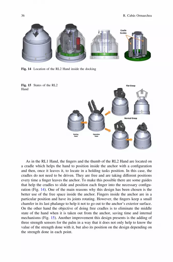
As in the RL1 Hand, the fingers and the thumb of the RL2 Hand are located ona cradle which helps the hand to position inside the anchor with a configurationand then, once it leaves it, to locate in a holding tasks position. In this case, thecradles do not need to be driven. They are free and are taking different positionsevery time a finger leaves the anchor. To make this possible there are some guidesthat help the cradles to slide and position each finger into the necessary configu-ration (Fig. 14). One of the main reasons why this design has been chosen is thebetter use of the free space inside the anchor. Fingers inside the anchor are in aparticular position and have its joints rotating. However, the fingers keep a smallchamfer in its last phalange to help it not to go out to the anchor’s exterior surface.On the other hand the objective of doing free cradles is to eliminate the middlestate of the hand when it is taken out from the anchor, saving time and internalmechanisms (Fig. 15). Another improvement this design presents is the adding ofthree strength sensors for the palm in a way that it does not only help to know thevalue of the strength done with it, but also its position on the design depending onthe strength done in each point.
Fig. 14 Location of the RL2 Hand inside the docking
Fig. 15 States of the RL2Hand
36 R. Cabás Ormaechea

These three sensors are located in the states mechanism selector, the Multi-State Actuator, which interacts with the palm and is taken out to cover theASIBOT contacts, when the Main Platform is removed. The extraction systemof the RL2 Hand fingers keeps almost intact its functioning philosophy becausethe results obtained at the RL1 Hand has been successful. In this particular case,the design has been only focused on the energetic performance of the energytransformer. Pulleys have been located in all the tendons way avoiding them topass over surfaces that can create unnecessary friction. In Fig. 16, it is possible tosee the changes done for this last design and a detail of the pieces that compoundit. The final result of the design is shown in Fig. 17.
Fig. 16 Drive system integrated inside the RL2 Hand’s structure
Fig. 17 Final design of the RL2 Hand
Robotic Hands 37

References
Ambrose R, Aldridge H, Askew R, Burridge R, Bluethmann W, Diftler M, Lovchik C, MagruderD, Rehnmark F (2000) Robonaut: NASA’s space humanoid. IEEE Intell Syst Appl 15
Balaguer C, Giménez A, Jardón A, Correal R, Cabas R, Staroverov P (2003) Light weightautonomous robot for elderly and disabled persons’ service. Int Conf Field Serv Rob
Balaguer C, Giménez A, Jardón A, Cabas R, Correal R (2005) Live experimentation of theservice robot applications elderly people care in home environments. IEEE Int Conf IntellRob Syst
Biagiotti L, Lotti F, Melchiorri C, Vassura G (2003a) An integrated approach to the design ofcomplex robotic end-effectors. IEEE/ASME Int Conf Adv Int Mechatron 1:70–75
Biagiotti L, Lotti F, Melchiorri C, Vassura G (2003b) Mechatronic design of innovative fingersfor anthropomorphic robot hands. IEEE Int Conf Rob Autom 3:3187–3192
Biagiotti L, Lott F, Melchiorri C, Vassura G, Tiezzi P (2004) UBH 3: an anthropomorphic handwith simplified endo-skeletal structure and soft continuous fingerpads. IEEE Int Conf RobAutom 5:4736–4741
Birglen L, Laliberté T, Gosselin C (2008) Underactuated Robotic Hand. Springer Tracts inAdvanced Robotics (STAR), Springer
Bluethmann W, Ambrose R, Diftler M, Askew S, Huber E, Goza M, Rhenmark F, Lovchik C,Magruder D (2003) Robonaut: A Robot Designed to Work with Humans in Space. Auton Rob14:179–197
Bologni L, Caselli S, Melchiorri C (1988) Design Issues for the U.B. Robotic Hand. AdvancedResearch Workshop ARW: Robots with Redundancy: Design, Sensing and Control
Bonivento C, Faldella E, Vassura G (1991) The University of Bologna Robotic Hand Project:current state and future developments. IEEE Fifth Int Con Adv Rob 1:349–356
Borst C, Fischer Haidacher S, Liu H, Hirzinger G (2003) DLR hand II: experiments andexperience with an anthropomorphic hand. IEEE Int Conf Rob Autom 1:702–707
Butterfass J, Grebenstein M, Liu H, Hirzinger G (2001) DLR-Hand II: next generation of adextrous robot hand. IEEE Int Conf Rob Autom 1:109–114
Butterfass J, Fischer M, Grebenstein M, Haidacher S, Hirzinger G (2004) Design and experienceswith DLR hand II. World Autom Congr 15:105–110
Cabás R, Balaguer C (2005) Design and development of a light weight embodied robotic handactivated with only one actuator. IEEE Int Conf Intell Rob Syst
Cabás R, Cabás LM, Balaguer C (2006) Optimized design of the underactuated robotic hand.IEEE Int Conf Rob Autom
Correal R, Jardón A, Cabas R, Giménez A, Balaguer C (2005) Asibot, robot de asistencia adiscapacitados y personas mayores. Congreso Internacional sobre Domótica, Robótica yTeleasistencia
Correal R, Jardón A, Martínez S, Cabas R, Giménez A, Balaguer C (2006) Human-RobotCoexistence in Robot-Aided Apartment. International Symposium on Automation andRobotics in Construction
Data Sheet of the Barrett Hand (2008) Barrett Technology IncEusebi A, Fantuzzi C, Melchiorri C, Sandri M, Tonielli A (1994) The UB Hand II control system:
design features and experimental results. Int Conf Ind Electron, Control Instrum 2:782–787Giménez A, Balaguer C (2003) The MATS robotic system to assist disabled people in their home
environments. IEEE Int Conf Intell Rob SystGiménez A, Jardón A, Correal R, Cabas R, Balaguer C (2004) Service robot applications for
elederly people care in home environments. International workshop on advances in servicerobotics
Hirzinger G, Brunner B, Dietrich J, Heindi J (1994) ROTEX: The First Remotely ControlledRobot in Space. IEEE Int Conf Rob Autom 3:2604–2611
Jau B (1994) Feasibility analysis of performing EVA tasks with dextrous robots. JPL IOM 3474-94-007
38 R. Cabás Ormaechea

Jau B (1995) Dexterous telemanipulation with four fingered hand system. IEEE Int Conf RobAutom 1:338–343
Kawasaki H, Komatsu T (1998) Development of an anthropomorphic robot hand driven by built-in servo-motors. Int Conf ICAM 1:215–220
Kawasaki H, Komatsu T (1999) Mechanism design of antropomorphic robot hand: GIFU Hand I.J Rob Mechatron 11:269–273
Kawasaky H, Komatsu T, Uchiyama K (2002) Dexterous anthropomorphic robot hand withdistributed tactile sensor - Gifu hand II. IEEE-ASME Trans Mechatron 7:296–303
Liu H, Meusel P, Hirzinger G (1995) A tactile sensing system for the DLR three-finger robothand. IMEKO Technical Committee on Robotics 91-96
Lotti F, Vassura G (2002) A novel approach to mechanical design of articulated fingers forrobotic hands. IEEE Int Conf Intell Rob and Syst 2:1687–1692
Lotti F, Tiezzi P, Vassura G (2004) UBH 3: investigating alternative design concepts for robotichands. IEEE World Autom Congr 15:135–140
Lotti F, Tiezzi P, Vassura G, Biagiotti L, Palli G, Melchiorri C (2005) Development of UB Hand3: Early Results. IEEE Int Conf Rob Autom 4488-4493
Lovchik C, Diftler M (1999) The Robonaut Hand: A dextrous robot hand for space. IEEE IntConf Rob Autom 2:907–912
Melchiorri C, Vassura G (1992) Mechanical And Control Features Of The University Of BolognaHand Version 2. IEEE/RSJ Int Conf Intell Rob Syst 187-193
Mouri T, Kawasaki H, Yoshikawa K, Takai J, Ito S (2002) Anthropomorphic robot hand: GIFUHand III. Int Conf Control, Autom Syst 1288-1293
Mouri T, Kawasaki H, Umebayashi K (2005) Developments of New Anthropomorphic RobotHand and its Master Slave System. IEEE Int Conf Intell Rob Syst 3225-3230
Namiki A, Imai Y, Ishikawa M, Kanek M (2003) Development of a High-speed MultifingeredHand System and Its Application to Catching. IEEE Int Conf Intell Rob Syst 2666-2671
Reichel M, Company TSR (2004) Transformation of Shadow Dextrous Hand and Shadow FingerTest Unit from Prototype to Product for Intelligent Manipulation and Grasping. InternationalConference on Intelligent Manipulation and Grasping
Rothling F, Haschke R, Steil J, Ritter H (2007) Platform portable anthropomorphic grasping withthe bielefeld 20-DOF shadow and 9-DOF TUM hand. IEEE/RSJ Int Conf Intell Robots andSyst 2951-2956
Schultz S, Pylatiuk C, Bretthauer G (1999) A new class of flexible fluidic actuators and theirapplications in medical engineering. Automatisierungstechnik 47:390–395
Schultz S, Pylatiuk C, Bretthauer G (2001) A new ultralight anthropomorphic hand. IEEE IntConf Rob Autom 3:2437–2441
Shadow Dextrous Hand C5: Technical Specificaction (2007) Shadow Robot Company, LtdTownsend WT (2000) MCB - Industrial robot feature articule - Barrett Hand Grasper. Ind Robot:
An Int J 27(3):181–188Walker R (2003) Design of a Dextrous Hand for advanced CLAWAR applications. CLAWAR
International Conference on Climbing and Walking Robots
Robotic Hands 39


Mobile Robots
Ángel Gaspar González Rodríguez and Antonio González Rodríguez
Abstract This chapter presents an introduction to mobile robots in the field of theservice robots, paying special attention to the mechanical structure of wheeled,legged, hybrid and tracked robots. The issues regarding to the maneuverability andcapability of overcoming obstacles are discussed for the wheeled robots. A clas-sification of the wheeled robots is made according to the way they are steered anddriven, exposing the forward kinematics equations for every basic scheme. Thecommon characteristics of hybrid and tracked robots are also presented, togetherwith their advantages and drawbacks. A classification of legged robots is alsoincluded, focusing mainly on the structure of the leg and discussing relevant issuesregarding controlability and efficiency.
1 Introduction
Nowadays, most of the robots are found in the industrial activity, especially asfixed robot manipulators. When they began to be incorporated to the factories, alsodid the mobile robots as automated guided vehicles (AGV), transporting goods andtools along a predefined trajectory. Cravens Company installed the first one in1954 at Mercury Motor Express in Columbia, SC. However, in present days mostof the applications for the new mobile robot designs belong to the service field.This fact has given rise to identification between robot manipulators (and parallel
Á. G. González Rodríguez (&)Electronic Engineering and Automation Department, University of Jaén, Jaén, Spaine-mail: [email protected]
A. González RodríguezApplied Mechanical Departement, University of Castilla-La Mancha, Madrid, Spaine-mail: [email protected]
N. E. Nava Rodríguez (ed.), Advanced Mechanics in Robotic Systems,DOI: 10.1007/978-0-85729-588-0_3, � Springer-Verlag London Limited 2011
41

robots) as the unique industrial robots, and on the other hand between mobilerobots and service robots, although important and consolidated exceptions exist(see Fig. 1). This way, most of the industrial robots are parallel robots or robotarms in one of these possible serial configurations: Cartesian, cylindrical,anthropomorphic robots or SCARA as the most important ones. However, theycan be found out of the industrial activity, as flight simulator (Stewart 1965; Pislaet al. 2009), surgical systems like daVinci system, aid to individuals with dis-ability (McCaffrey 2003), in rehabilitation tasks (Harwin 2003), tele-manipulatedin dangerous radioactive or biological manipulation. As defined by the Interna-tional Federation of Robotics, service robots are the ones installed in non-manufacturing operations. However, this term is more commonly applied torobots operating out of the industrial activity. Service robots usually includemovement capacities, and therefore mobile robots find its main source ofapplication as service robots. There are numerous configurations for mobilerobots, each one more adapted to the environment in which the robot mustoperate. Basically there are flying (Howard and Kaminer 1995; Chao et al. 2007),underwater (Yuh 2000; Terada 2000) and terrestrial robots, and among theseones, hopping (Raibert et al. 1984), climbing (Nagakubo and Hirose 1994; Fuet al. 2007), but mainly wheeled, tracked and walking robots, which will be theobjective of this chapter. Figure 1 shows some examples of industrial and servicerobot applications (García et al. 2007).
Mobile robots have not spread in the same extent as the industrial robots, whoseabsence is not understood in several applications of the industrial activity. Theindustrial robot success in replacing the human operator is mainly due to the costreduction, which is a factor that has not been shown so clear when projecting oracquiring a mobile robot. Fortunately, there are a growing number of exceptionslike the autonomous transportation systems, the robots for surveillance, domesticcleaning robots or the last generation of humanoid ones. Disregarding the eco-nomical factor, the mobile robots have been successfully installed in applica-tions with environments that are inaccessible or hazardous for a human being(Apostolopoulos and Bares 1995), or in tasks with very demanding duty cycle or avery high fatigue factor. In these situations, the mobile robots can be fullyautonomous if the system can operate without a continuous external human con-trol, or semi-autonomous if they require the guidance of an operator but with thecapability of accomplishing certain tasks such as obstacle avoidance.
AGV
Arms over mobile platforms
Painting
Manipulation
Sealing
Palletizing Surgical robots RehabilitationHandicapped aid
Teleoperated (radioactive, biological)
ExplorationTour guide
Domestic robots
Agricultural
Demining
Surveillance
Service Robots
Manipulator arms
Mobile Robots
Industrial Robots
Service Robots
Welding
Assembling
Cut
Fig. 1 Distribution of robotsaccording to their application(industrial or service robots)and displacement capabilities(manipulator arms or mobilerobots)
42 Á. G. González Rodríguez and A. González Rodríguez

2 Wheeled Robots
Wheels are an unnatural but highly efficient means of locomotion, and it is thepreferred method to use in mobile robots when no obstacles are present in theenvironment in which the robot is going to operate. Their good performance lieson their simple control to move and maneuver, its high capacity load and effi-ciency, and reduced cost compared to other solutions.
Type of Wheels
Mobile robots use three basic types of conventional wheels (Campion et al. 1996)(see Fig. 2):
1. Fixed wheels, in which the center of the wheel is a fixed point of the frame,where only rotation around the horizontal axle is permitted.
2. Centered orientable wheels, which allow the motion of the wheel plane arounda vertical axle passing through the center of the wheel. The orientation isusually active, i.e., driven.
3. Off-centered self-orientable wheels, also known as caster or castor wheels,which are orientable with respect to the frame, although the wheel plane rotatesaround a vertical axle which does not pass through the center of the wheel. Ifthe wheel is not properly headed, a tangential force appears at certain distancefrom the wheel center. It gives rise to a torque that orientates the wheel plane inthe direction of the tangential force, avoiding the lateral slipping.
Besides these conventional wheels, special wheels can be used to obtain anomni-directional motion. This is the case of mecanum or Swedish wheels, withsmall passive free rollers located at the outer rim of the wheel, which permits thelateral motion of the wheel (Campion and Chung 2008). Their axis of rotation isparallel to the wheel plane, as in the Swedish 908 model, or it can make anintermediate angle, as in the Swedish 458 model, for a smoother performance.
(a) (b) (c) (d) (e)
Fig. 2 Conventional wheels: a Fixed wheel. b Centered orientable wheel. c Off-centeredorientable wheel. d Swedish wheel 908. e Swedish wheel 458
Mobile Robots 43

Regardless of the wheel type, for a wheeled robot to exhibit a rolling motion,every wheel must follow a circular trajectory around the same point, that is knownas instantaneous center of curvature or rotation (ICC or ICR at Fig. 3). If thevehicle follows a linear trajectory, this point is at the infinity. The orientation ofthe steering wheels determines the proximity of the ICR and in turn, the vehicleorientation. The rotational speed of the wheels must be varied accordingly and thedegrees of freedom (DOF) are reduced to the vehicle speed and orientation.
Since the vehicle situation on the surface (often referred to as pose) is definedby a two-coordinate position and an orientation, it is not possible to changearbitrarily these values nor every path is achievable. In a simplified way, the termnon-holonomic is applied to the robot with less controllable degrees of freedomthan the necessary to define its pose, i.e., its position and orientation. In a non-holonomic vehicle like a wheeled one, unless slippage occurs, the wheels cannotmove in a direction parallel to the axis. This means a constraint in the lateralmotion that decreases the degrees of freedom (Bekey 2005). As in the case of a carparking in parallel, its state or pose is determined by the path followed to reach it,and it is possible to get to any state by performing a sequence of maneuvers, whosenumber and amplitude depend on the environment clearance and the vehiclecharacteristics.
Different Ways to Steer a Wheeled Vehicle
There are different ways of driving a wheeled vehicle (Dudek and Jenkin 2000).
Differential Drive
It consists of two wheels mounted on a common axis driven by different motors.One or two undriven wheels, usually of the type of caster wheels, are included forstability. The magnitude and sense of each wheel velocity determine the kind ofmotion to be performed: if the speed of both wheels is the same, the robot moveslinearly; if the speed is the same in magnitude but with opposed sign, the robotrotates in place; in any other case, the robot rotates with an angular speed xt
around the ICR whose distance R to the robot is obtained from Fig. 4.
ICR
Fig. 3 Instantaneous centerof rotation or curvature of awheeled vehicle
44 Á. G. González Rodríguez and A. González Rodríguez

R ¼ dðvL þ vRÞvL � vR
xt ¼vL � vR
2d¼ rðxsL � xsRÞ
2d: ð1Þ
The high steering capability of differential drive vehicles allows them to movein narrow and curved environments as in urban pipelines. Its major drawback,deduced from the previous expression, is the fact that the orientation h of thevehicle is very sensitive to the difference between both wheel speeds. Examples ofdifferentially driven motors are the low-cost indoor robots as the Pioneer P3-DX,the Kephera or the TuteBot, and the all-terrain ATRV from iRobot, with a morerugged configuration.
Tricycle
A different three-wheel configuration can be obtained if the middle wheel issteered and driven. This is a less complex configuration although the absence ofdifferential drive limits its maneuverability. From Fig. 5, the distance R from theICR to the tricycle axis as well as the turn velocity xt can be obtained
R ¼ d
tan a
xt ¼vs
dsin a ¼ xs r
dsin a
ð2Þ
where vs, xs and r are respectively the linear speed of the front wheel, its angularspeed and its radius.
Synchronous Drive
A synchronous drive vehicle consists of several wheels (typically three), equallyspaced, each of them capable of being driven and steered. All the wheels pointin the same direction and rotate at the same speed, which means that it only hastwo degrees of freedom. However, due to its high maneuverability that allowsthe robot to control its orientation directly, it behaves as a holonomic robotFig. 6.
d
vR
vL
R
ICR
ωsR
θ
ωsL
ωt = θωt (R-d) = vR
ωt (R+d) = vL
r .
Fig. 4 Differential drive kinematics
Mobile Robots 45

Omni-directional Drive
It includes Swedish wheels to obtain a holonomic performance with three DOFs.An example is the platform Uranus with four Swedish wheels 458, in which onlythree of them can be independently driven.
Ackerman Steering
Also known as kingpin steering, it is the kind of steering commonly used byautomobiles and in large robots. Its schema is the one represented in Fig. 7. Inorder to avoid lateral slipping the axis of the steering wheels cannot be parallel,and must point to the ICR. This is achieved by turning the inner wheel through ahigher angle than the outer one (aL [ aR). Assuming that in these conditions thevehicle turns through an angle aeq, then the system is defined by
Rþ L2 ¼ d cot aL
R� L2 ¼ d cot aR
R ¼ d cot aeq
9=
;)R ¼ d
2 ðcot aL þ cot aRÞcot aL � cot aR ¼ L
dcot aeq ¼ cot aR þ L
2d
8<
: : ð3Þ
d
R
ICR
ωs
α
ωt
Fig. 5 Tricycleconfiguration in which thefront wheel is steered anddriven
ωs
ωt
ω
ω
v = ωs r
v
v2r
Fig. 6 Synchronous drivekinematics. Wheels turn at xt
in unison and rotates at thesame speed xs
46 Á. G. González Rodríguez and A. González Rodríguez

The maximum angle a that the steered wheels can turn has a limited value,which in turn limits the minimum radius of curvature and hence itsmaneuverability.
Wheeled Robots in Rough Terrains or With Obstacles
There are two main techniques to allow a wheeled robot without articulated legs tomove in rough terrains or with obstacles.
Low Inflation Wheels
Wheels by itself have certain capability of overcoming obstacles, which dependsbasically on two parameters: diameter and inflation pressure. The height of theobstacle that the wheel is able to overcome is proportional to the diameter.Nevertheless, a larger wheel reduces maneuverability and can impede the supportin a step tread. With regard to the inflation, a lower pressure allows the generationof higher contact forces in the obstacles edge (Lawn 2002). In contrast, the effi-ciency is drastically reduced. To increase the efficiency and maneuverability,several prototypes have been built combining low inflation wheels with eithertracks or high pressure wheels (Uchida et al. 1999; Hirose et al. 2001).
Cluster of Wheels
A cluster of wheels consists of a set of wheels mounted on a bar attached to thechassis by means of a shaft that permits the relative rotation. This rotation suc-cessively locates the wheels in the following step tread or in the higher flat part ofthe obstacle. Figure 8 shows a prototype with a second cluster to improve thestability. Following this research line, different prototypes has been developed, likethe wheelchair Freedom from Tomo Co. Ltd, the wheelchair IBOT 3000 or thedesign presented in (Lawn and Ishimatzu 2003).The advantages of the clusters are:fair rolling efficiency, comfort and stability when negotiating a step (dislike the
ICR
αRαL αeq
RL
d
Fig. 7 Ackerman steeringkinematics
Mobile Robots 47

tracks). The more important drawbacks are high value of the torque driving thecluster axle, the high number of motors and brakes, as well as the complex tra-jectory of the cluster center of rotation, which makes the system control morecomplicated.
3 Tracked Robots
Tracks have been so far the method that to a higher extent has been identified asall-terrain means of locomotion. Tracks provide robots with the ability of over-coming steps and obstacles with different geometries and moving in very roughterrains without increasing the control complexity.
They were initially conceived to propel tanks during the First World War andlater its use has been spreading to numerous fields. Nowadays they have becomeirreplaceable in much of the heavy machinery used in civil engineering. Theirapplication in robotics is mainly focused on military purposes or hazardousenvironments (Trevelyan et al. 2008; Zhao et al. 2008; Welch and Edmonds 1993),for inaccessible place explorations and in platforms/chairs for handicapped people(Lawn et al. 2001; Hirose et al. 1992). Tracked robots are differentially drivenvehicles that allow turning with lower radius of curvature. However, slippage onthe ground is necessary in order to turn the vehicle. On the other hand, in order toovercome obstacles, high friction coefficients between track and ground arerequired. Therefore, treads may wear rapidly and must be replaced frequently(Bekey 2005). Other disadvantages are lower speed than wheeled robots, and thefact that they can deteriorate the surface when moving in urban or domesticenvironments. In case of transporting elder or disabled people, the lack of primarydampers reduces the user comfort. Additionally, the stability of tracked robotswhen negotiating the descent of a step is temporarily lost, which may causeuncertainty and panic.
Fig. 8 Wheel chair withdouble wheel cluster (sourceTomo Co. Ltd. AndTamagawa University)
48 Á. G. González Rodríguez and A. González Rodríguez

4 Legged Robots
Legs are the most important and active member among the ones that improve themobility of robots. Unlike wheeled robots they must be able to move in soft andrough terrains (like mud, sand, forest, rocks) or overcoming obstacles like steps.With regard to the configurations of legs for walking robots, there are three typesof research lines: articulated legs, passive-dynamic legs, and decoupled configu-ration legs.
Articulated Legs
The vast majority of the current legged robots use very simple leg schemes,which are made up of a chain of links joined by joints according to one of thetwo forms shown in Fig. 9: insect-like legs and mammal-like legs. The legs ofreptiles have a similar configuration to mammals, although the parallel axes(labelled as T2 and T3) belong to very separated vertical planes and hence theyundergo higher torques (Guardabrazo and Gonzalez de Santos 2004). Reptile-likerobots also require an articulated body to keep balance during the crawlmovement (Ishihara and Kuroi 2006). Although different types of actuators canbe found, most of biped robots use the scheme shown in Fig. 9b in whichelectrical motors drive rotational joints. As reproduced in Fig. 10a biped robotlegs require a relatively wide and flat foot to provide static stability and improvethe dynamic one. Unless a penguin gait is not a concern (Collins et al. 2005),
(a) (b)
Fig. 9 Articulated legs consisting of three rotational joints: a insect-like. b mammal-like
Mobile Robots 49

the clearance of the foot must be accomplished by means of an ankle, with arotational joint whose axis is perpendicular to the sagittal plane.
In order to keep balance a lateral movement is required that is performed by aset of two joints per leg (not shown in the figure), one in the hip and another inthe ankle, whose axes are parallel to the movement direction. This high numberof joints allows an extended set of movements and activities, e.g., walk, run,climbing stairs, dance, fight, play football. Despite their current application astoys or research bed tests, biped robots are intended to operate as assistancerobots. Since they must be in close interaction with humans, these robotsmust, for psychological reasons, mimic the human appearance, configuration andmovements. This is because legs for biped robots have an articulated configu-ration like humans, disregarding factors like autonomy that is not a concern indomestic applications. A different type of movers is included in the Big-Dog thatuses hydraulic linear actuators as it shown in Fig. 10b. Since it is a quadruped,the ankle answers other purposes, mainly compliance and reaction absorption.Articulated legs have an important problem related to the size of actuators. If therobot wants to raise its body, the robot must exert torques TK and TA (or forcesFK and FA) in knee and ankle, that can be as high as
T � LLm g ð4Þ
For a certain value of mass m and link length LL. Due to the coupled structure,during stance, transfer, leg ascent or leg descent, the robot must operate all of theleg actuators. However, the horizontal and vertical movements have very differentcharacteristics for a creature with legs, whether robot or animal: vertical move-ments require a lot of strength to bear the weight of the creature, and the hori-zontal movement does not need as much strength but a high speed to increase the
(a) (b)
Fig. 10 Conventionalschemes for articulated legs:a with rotary motor (Asimo).b with linear actuators(Big-Dog)
50 Á. G. González Rodríguez and A. González Rodríguez

step frequency. This way, all of the actuators are oversized to have both highvalues of torque and speed, leading to increased power losses and weight. Sincecurrent technology determines the weight and power of electric motors, leggedrobots driven by electrical actuators are heavy and with low capacity. Big-Dogaddresses these limitations by including hydraulic actuators.Another drawback is that these structurally simple configurations require, how-ever, a complex calculation of the inverse kinematics to accomplish the desiredfoot trajectory. In addition, the unit control must split the trajectories for all of theinvolved motors and continuously regulate their speed to generate this path. Themovement should be accurate because a small error of a few degrees meanscentimetres in the leg support, which would lead the robot to get out of balanceand fall. The control task became so complex that the step frequency cannot bevery high, and therefore, the walking robot is much slower than the legged animalswith similar sizes. In consequence, schemes using articulated legs lack reducedefficiency, increased control complexity and over sizing. Two research lines aim tocontribute more-efficient designs: passive-dynamic walkers and decoupledconfigurations.
5 Passive-Dynamic Walking
Walking is a repetitive movement in which every bar of the legs accelerates,decelerates and stops at every step. Robots spends energy every acceleration andusually also every deceleration, leading to important power losses and reducedefficiency. There are, nevertheless, examples of high efficiency legged artificiallocomotion during last years. Most of them are based on the concept of passive-dynamic walking, which was developed by McGeer in the late 1980s. First walkerswere coupled inverted pendulums that descend a shallow slope due to the transfer-ence between gravity energy and inertia (McGeer 1990a). By powering some of itsjoints, the robot can walk in flat surfaces. For example, a driven ankle allows thesupported leg to rise, thus providing enough gravitational energy to perform a newstep as it were walking down a slope. Further versions add knees to the initial design.As explained in McGeer (1990b) there are two reasons for this change. First, kneesgive rise to a more natural gait, and this analogy facilitates the study of the walkingcycle. Second, flexing knees allows the robot to bring forward the leg that is in the airwithout help of motors. Additional examples of passive-dynamic walker are found inCollins et al. (2005). In McGeer (1990c), the scheme of an efficient running robot waspresented. To allow the vertical movement, each of the two legs consisted of two barsjoined by a telescopic joint with linear springs. A rotational joint with a torsion springattached the legs to the body, creating an alternative movement. Adjusting thestiffness of all of the springs the gait frequency was accordingly modified, taking intoaccount that the frequency varies with the square root of the stiffness.In addition, actuators must be included to allow the robot to overcome obstacles. Firstsolution use pneumatic actuators, most of them based on the McKibben design
Mobile Robots 51

(Schulte 1961). Pneumatic actuators are light and simple, but they need complexvalves and compressors (or a tank), drawbacks that impede their use in e.g.,prosthesis. These systems are also difficult to control. One interesting robot withpneumatic actuators is Lucy, developed in Brussels (Vanderborght et al. 2006). Adifferent type of artificial muscles are the ones based on electroactive polymers(EAPs), whose shape is modified when they are applied a voltage, as reported inDuncheon (2005) and Ashely (2003). They exhibit the ability to undergo a largeamount of deformation. However, the preferred solution consists of a combination ofa DC motor and an elastic element (Pratt and Williamson 1995). The system stiffnessis adjusted to its maximum value for operations where a direct drive is needed, e.g., tosurpass an obstacle or to keep balance when the robot is stopped. During normalwalking in a flat surface with an optimal efficiency, the joint stiffness is adjusted to thegait frequency. There are different approaches that are summarized in Ham et al.(2009).
6 Decoupled Configurations
Another solution to improve efficiency starts from the fact that the horizontal andvertical movements have different characteristics in terms of torque and speed.Therefore, it is more-efficient to decouple these movements and drive them withdifferent kind of actuators. Typically, a high-ratio gearbox is used for verticalmovements and a more direct drive for the horizontal movement. Additionally,decoupling reduces power losses since actuators that move do not withstand theweight and vice versa (Kar 2003). Besides the more suitable actuator selection, adecoupled configuration simplifies the inverse kinematics calculation that in turn,simplifies the trajectory control, especially during the support phase, and leads tomore continuous and efficient trajectories to be described by the actuators. Asshown in Fig. 11 decoupled configuration has been traditionally achieved bymeans of SCARA configuration and two-dimensional pantographs. Theirsequences or joints are respectively rotational-rotational-prismatic and rotational-prismatic-prismatic. The structure of Fig. 11b assembles a mammal configuration.A preferred, but not necessarily better, configuration mimics the insect or reptilestructure and movement, operating the rotational joint around a vertical axis.Climbing robots like the ROWER, the REST, or the tethered ROBOCLIMBERuse a SCARA configuration. Many of the Hirose’s robots TITAN, the tetheredclimber DANTE II or the MECANT use a two-dimensional pantograph. Thehybrid Wheel leg of Guccione and Muscato (2003) includes a similar performance(rotational-prismatic-prismatic) although without using a pantograph. The legmechanism of Gonzalez Rodriguez et al. (2009) also falls into the decoupled legmechanisms but with a different structure. It has been designed in order to obtainfast and easy controlled walking operation in obstacle-free environments. A wideworkspace allows the leg overcome high obstacles. The leg structure avoids jointlocking and is not sensitive to reactions in any direction. According to the scheme
52 Á. G. González Rodríguez and A. González Rodríguez

of Fig. 12, two DOFs are required to obtain horizontal (a) and vertical (b) motionof the leg in the saggital plane. This mechanism is synthesized to provide anapproximate straight trajectory segment during the support phase, only operatingover one actuator, with the other being inactive. The third DOF allows rotating theplane of movement with respect to an axis parallel to the movement direction, andit is driven by a third linear actuator. It is necessary to maintain stability and tomake the robot turn. Once the vertical, lateral and horizontal movements of the leg
(a) (b)
Fig. 11 Decoupled configurations: a SCARA. b two-dimensional pantograph
(a) (b) (c)
Fig. 12 Scheme of the legand actuator for thecorresponding movements:a horizontal. b vertical.c lateral
Mobile Robots 53

are decoupled, a properly selected reduction gear allows using motors with lesspower and weight.
The leg performance is improved by adding a mechanism that obtains pro-portionality between the speed in the horizontal DOF and the horizontal footspeed.
7 Hybrid Systems
Hybrid robots are machines that combine articulated legs and wheels with the aimof exploiting the capabilities of both wheeled and legged robots. Two researchlines can be differentiated: legs and wheels, and leg with wheels.
Hybrid Systems Using Legs and Wheels
This solution typically presents the form of a biped structure that has addedpassive wheels in the rear part to increase stability and the capacity load (seeFig. 13). The leg configuration can follow any of the schemes presented in theprevious section. Different factors can lead the designer to choose this solution:economical reasons since it replaces two or more legs by wheels; to simplify thecontrol that implements the robot gait; to increase the capacity load; and toincrease the robot speed. In contrast, this solution limits the height of theobstacles that the robot can overcome and the roughness of the terrain throughwhich the robot can move. Examples of this type of hybrid robot are the
Fig. 13 Hybrid locomotionsystem with two legs and twowheels
54 Á. G. González Rodríguez and A. González Rodríguez

prototype presented in Guccione and Muscato (2003), Cubero (2000) and Ger-mann et al. (2005).
Hybrid Systems Using Legs with Wheels
This method consists in including wheels in the extremes of the articulated legs, ina similar way to human skater. To this scheme belongs the prototypes presented inAarnio et al. (2000), Grand et al. (2004) and Siegwart et al. (2002). The commondrawbacks of these models derive from the numerous degrees of freedom to driveand control. It results in increased complexity, weights and costs. The Roller-Walker from Hirose and Takeuchi (1996) partially address these drawbacks,adopting two means of locomotion: walking on roughness terrains or withobstacles; and skating on passive wheels when moving on flat surfaces. Thisstructure avoids the traction, steering and braking systems for the wheels, thusreducing weight, volume and cost.
8 Other Hybrid Locomotion Systems
To the group of hybrid system also belong other structures like the RHex or theASWARD, which respectively use one or several compliance passive arms attachedto a driven rotational shaft. Figure 14 shows a hybrid locomotion wheelchair(Gonzalez Rodriguez et al. 2007), designed to negotiate steps and stairs by means of aclimbing mechanism attached to each shaft. A different mechanism is responsible ofkeeping balance and improving the performance when climbing stairs.
climbingmechanism
positioningmechanism
Fig. 14 Hybrid locomotionwheelchair with twomechanisms to negotiate astair
Mobile Robots 55

References
Aarnio P, Koskinen K, Salmi S (2000) Simulation of the hybtor robot. International conferenceclimbinng walking robots. Professional Engineering Publishing, pp 267–274
Apostolopoulos D, Bares J (1995) Locomotion configuration of a robust rappelling robot.International conference on intelligent robots and systems, human robot interaction andcooperative robots proceedings, vol 3, pp 280–284
Ashely S (2003) Artificial muscles. Sci Am 289(4):53–59Bekey GA (2005) Autonomous robots. From biological inspiration to implementation and
control. MIT Press, Cambridge, MACampion G, Bastin G, D’Andréa-Novel B (1996) Structural properties and classification of
kinematics and dynamic models of wheeled mobile robots. IEEE Trans Robotics Autom 23(1)pp 47–62
Campion G, Chung W (2008) Wheeled Robots. In: Siciliano B, Khatib O Springer Book ofRobotics, Springer, Gale virtual reference library
Chao H, Cao Y, Chen YQ (2007) Autopilots for small fixed-wing unmanned air vehicles: asurvey. Int Conf on Mechat Autom ICMA 3144–3149
Collins S, Ruina A, Tedrake R, Wisse M (2005) Efficient bipedal robots based on passive-dynamic walkers. Science 307(5712):1082
Cubero, SN (2000) A 6-legged hybrid walking and wheeled vehicle. Int Conf Mechatron MachVis Pract (M2VIP) pp 293–302
Dudek G, Jenkin M (2000) Computational principles of mobile robotic. Cambridge UniversityPress, Cambridge
Duncheon C (2005) Robots will be of service with muscles, not motors. Int J Indus Robots32(6):452–455
Fu Y, Li Z, Yang H et al (2007) Development of a wall climbing robot with wheel-leg hybridlocomotion mechanism. IEEE Int Conf Robot Biomim ROBIO pp 1876–1881
García E, Jiménez MA, González de Santos P, Armada M (2007) The evolution of roboticresearch from industrial robotics to field and service robotics. IEEE Robotics Autom Mag14(1):90–103
Germann D, Hiller M, Schramm D (2005) Design and control of the quadruped walking robotALDURO. Int Symp Autom Robot Constr ISARC
Gonzalez Rodriguez A, Morales R, Batlle V, Pintado P (2007) Improving the mechanical designof new staircase wheelchair. Indus Robot 34(2):110–115
Gonzalez Rodriguez AG, Gonzalez Rodriguez A, Nieto AJ, Morales R (2009) Design andsimulation of an easy operating leg for walking robots. International Conference onMechatronic pp 1–6
Grand C, Benamar F, Plumet P et al (2004) Stability and traction optimized of a reconfigurablewheel-legged robot. Int J Robot Res 23(10–11):1041–1058
Guardabrazo TA, Gonzalez de Santos P (2004) Building an energetic model to evaluate andoptimize power consumption in walking robots. Ind Robot Int J 31(2):201–208
Guccione S, Muscato G (2003) The wheeleg robot. IEEE Robot Autom Mag 10(4):33–43Ham R, Sugar T, Vanderborght B, Hollander K, Lefeber D (2009) Compliant actuator designs.
Robot Autom Mag 16(3):81–94Harwin W (2003) GENTLE/S: Robotic assistance in neuro and motor rehabilitation. Resource
document. Cybernetics. http://www.gentle.reading.ac.uk. Accessed Oct 2010Hirose S and Takeuchi H (1996) Study on roller-walk (basic characteristics and its control). IEEE
Int Conf on Robot Autom 3265–3270Hirose S, Sensu T, Aoki S (1992) The TAQT Carrier: A practical terrain-adaptive Quadru-Track
carrier Robot. Proc. IEEE/RSJ Int. Conf. on Intelligent Robots and Systems 2069–2073Hirose S, Fukushima F, Damoto R, Nakamoto H (2001) Design of terrain adaptative versatile
crawler vehicle Helios-VI. Proceedings of the IEEE/RSJ International Conference IntelligentRobots and System
56 Á. G. González Rodríguez and A. González Rodríguez

Howard RM, Kaminer I (1995) Survey of unmanned air vehicles. Proc Am Control Conf5:2950–2953
Ishihara H, Kuroi K (2006) A four-leg locomotion robot for heavy load transportation.International Conference on Intelligent Robots and Systems, pp 5731–5736
Kar DC (2003) Design of statically stable walking robot: a review. J Robotic Syst 20:671–686
Lawn MJ (2002) Study of stair-climbing assistive mechanisms for the disabled. PhD thesis,http://murraylawn.org/MJLnewW/StaiCPhD.pdf. Accessed Oct 2010
Lawn MJ, Ishimatzu T (2003) Modeling of a stair-climbing wheelchair mechanism with highsingle-step capability. IEEE Trans Neural Syst Rehabil Res 11(3)
Lawn MJ, Sakai T, Kuroiwa M, Ishimatzu T (2001) Development and practical application of astairclimbing wheelchair in Nagasaki. J Hum Friendly Welf Robotic Syst 33–39
McCaffrey EJ (2003) Kinematic analysis and evaluation of wheelchair mounted robotic arms.Thesis, University of South Florida, http://etd.fcla.edu/SF/SFE0000195/McCaffreyThesis.pdf.Accessed Oct 2010
McGeer T (1990a) Passive dynamic walking. Int J Robot Res 9(2):62–82McGeer T (1990b) Passive walking with knees. IEEE Int Conf Robot Autom 3:1640–1645McGeer T (1990c) Passive Bipedal running. Roy Soc London B 240(1297):107–134Nagakubo A, Hirose S (1994) Walking and running of the quadruped wall-climbing robot. Proc
IEEE Int Conf Robot Autom 2:1005–1012Pisla DL, Itul TP, Pisla A et al (2009) Dynamics of a parallel platform for helicopter flight
simulation considering friction. SYROM 2009:365–378Pratt G, Williamson M (1995) Series elastic actuators. International conference on intelligent
robots IROS, pp 399–406Raibert MH, Brown HB, Chepponis M (1984) Experiments in balance with a 3D one-legged
hopping machine. Int J Robotics Res 3(1):75–92Schulte HF (1961) The characteristics of the mcKibben artificial muscle.The application of
external power in prosthetics and orthotics. Natl Acad Sci Natl Res Counc 874:94–115Siegwart R, Lamon P, Estier T et al (2002) Innovative design for wheeled locomotion in rough
terrain. J Robot Auton Sys. doi:10.1016/S0921-8890(02)00240-3Stewart D (1965) A platform with 6 degrees of freedom. Instit Mech Eng 180(1):371–386Terada Y (2000) A trial for animatronic systems including aquatic robots. J Robotic Soc Japan
18(2):37–39Trevelyan JP, Kang S-C, Hamel WR (2008) Robotics in hazardous applications. In Springer
Handbook of Robotics Part F. pp 1101–1126Uchida Y, Furuichi K, Hirose S (1999) Fundamental performance of 6 wheeled off-road vehicle
helios-V. Int Conf Robot AutomVanderborght B, Verrelst B, Van Ham R, Lefeber D (2006) Controlling a bipedal walking robot
actuated by pleated pneumatic artificial muscles. Robotica 24(4):401–410Welch RV, Edmonds GO (1993) Applying robotics to hazmat. Resource document
http://hdl.handle.net/2014/36468. Accessed Oct 2010Yuh J (2000) Design and control of autonomous underwater robots: A survey. Auton Robots
8:7–24Zhao J, Liu G, Liu Y, Zhu Y (2008) Research on the application of a marsupial robot for coal
mine rescue. Intell Robotics Appl. doi:10.1007/978-3-540-88518-4_120
Mobile Robots 57


Parallel Manipulators
Erika Ottaviano
Abstract Nowadays parallel robots have been extensively studied and new pro-totypes have been patented and commercialized for a large number of industrialand non industrial applications. A recent trend in parallel manipulators concernswith the emerging area of modular re-configurable parallel robots. This class cannot only be referred to classical parallel manipulators, but also to cable-basedsystems. Recently, a new class of parallel robots has been developed, namely thecable-based parallel ones, and they have attracted the attention of the Roboticscommunity because of their potential advantages over conventional parallelrobots. In this context, a survey is presented on recent developments on modularre-configurable parallel robots, both classical manipulators and cable-based ones.A case study of a re-configurable cable-based parallel manipulator is presented.
1 Introduction
Recent trends in parallel manipulators show a growing interest in modularre-configurable parallel robots. This class can be referred either to classical parallelmanipulators, but also to cable-based systems. In this context, issues related tomodular re-configurable parallel robots are presented, both referring to classicalones and cable-based manipulators.
A Modular Re-configurable Robot (MRR) consists of a number of discrete mod-ules, which are capable of being mechanically and usually electrically connected witheach other (Yim et al. 2004). A configuration is defined as a particular arrangement ofconnectivity between independent modules. A configuration can be represented in
E. Ottaviano (&)DiMSAT, University of Cassino, Cassino, Italye-mail: [email protected]
N. E. Nava Rodríguez (ed.), Advanced Mechanics in Robotic Systems,DOI: 10.1007/978-0-85729-588-0_4, � Springer-Verlag London Limited 2011
59

graph form, called configuration graph in which, the vertices represent the modules andthe edges represent the connection between the modules (Asadpour et al. 2008).While the number of different varieties of modules in a single MRR is usually small, thecapabilities of a single module, which may only have one active degree of freedom(DOF), are modest, the combination can form an arbitrarily complex structure.Furthermore, it may allow to obtain a huge number of different robots with differentapplication starting from the same set of modules (Agrawal et al. 2001).
Theoretically, a well designed set of modules can lead to the construction of robotfor almost any purpose That provides a potential for cost savings in industrial frame.In fact, while in bigger companies with high lot sizes highly specialized systems canbe used, smaller and medium sized companies can make profit of re-configurablerobots (Bi et al. 2006). The investment cost in purchasing a robot is worth it, becauseit can be re-configured at relatively low-cost according to the task (Modungwa et al.2008). This is not the only benefit from designing a modular robot, in fact, it gives thepossibility of re-configuration, which allows modules connecting (or docking) anddisconnecting according to the needs. Referring to the above-mentioned property,the mechanical interface between any two modules can be electrically actuated, i.e.,the modules can self-connect and self-disconnect under the robot’s own control andthus completely changing its fundamental structure (Stechert and Franke 2007).
Self-reconfiguration is a transition between two configurations by a series ofelementary actions such as connect and disconnect (Slee 2006). Therefore, ifconventional robots are usually built on purpose for performing a limited numberof tasks in one specific environment, i.e., assembling, cleaning, welding, deliv-ering; modular re-configurable ones allow changing their configuration in orderto adapt to the environment and task changes. The advantages of developingre-configurable systems can include adaptability, reusability, convertibility, com-pactness, fault-tolerance and emergency behavior.
Modular robots can be divided into two categories based on their mechanicaldesign: homogeneous and heterogeneous systems (Slee 2006). In first type, allmodules are mechanically identical. One of the advantages of homogeneous systemsis that all modules can be replaced by any other module, if they fail. Examples ofhomogeneous modular robots are the M-TRAN and the ATRON robot.
Heterogeneous modular robots have at least two mechanically different modulesand the most common ones have two different modules. Examples are the Tetrobot andSMAnet robots. In chain-based systems it may be an additional passive module pro-viding branching of chains of active modules, like the PolyBot. However, the CKBot isa heterogeneous chain-based system which has both different active and passivemodules and depending on the functionality the modules also provide branching.
The concept of modularity has been used in the design of serial-type industrialrobots for flexibility, ease of maintenance, and rapid deployment.
A classification of modules can be based on their functionality (Yang et al. 2001):
• Structure module—passive module which adds structural features.• Actuated module—active module, which enables the robot to perform tasks,
such as locomotion and manipulation.
60 E. Ottaviano

• Sensor module—provides sensory inputs about the environment.• Power module—provides energy to the robot.
Research into re-configurable systems is primarily active in Robotics. Examplesof re-configurable robots can be found in applications including planetary explo-ration, undersea mining, search and rescue and other tasks in unstructured,unknown environments (Hjelle and Lipson 2009; Agrawal et al. 2001; Lee andSanderson 2001; Yim et al. 2004). Another challenging application is assistingrobots for aged care or disabled people. These robot can fetch, carry and assistwith walking and motion (Chugo et al. 2008).
Another interesting classification of modular re-configurable robots has beenproposed into three categories (Xi et al. 2006): self-assembly, self configuring andmanual configuring. Self-assembly robots are those with the highest level ofre-configurability because they can detach from and attach into a robotic systemautomatically. Self-configuring robots cannot perform self-assembly. However,they can perform re-configuration after a robotic system is assembled with somekind of manual assistance. Manual configuring robots are in fact modular robots.They can only be re-configured with a sort of manual assistance. It is worth notingthat parallel manipulators may belong to the last two categories. Furthermore, selfor manual configuring can be used to overcome their main drawbacks. Because aparallel robot usually has a limited workspace, trajectory planning and applicationdevelopment can be difficult. In order to overcome the problem, the modularityconcept can be introduced in the design of parallel robots.
Cable-based parallel manipulators are a class of parallel robots that consist of afixed base (or frame) and mobile platform, which are connected by several cables.Therefore, they are structurally similar to the classical parallel ones, in which legsare replaced by cables. Due to the nature of cables (Irvine 1981; Kozak et al. 2006;Riehl et al. 2009), they possess in general favorable characteristics such as: goodinertial properties, their actuator transmission systems can be fixed on the base, andcables are lighter and thus, they can have higher payload-to-weight ratio (Krut et al.2008; Dekker et al. 2006; Albus et al. 1993; August design 2010). They can berelatively low-cost, modular, and easy to re-configure according to their design byrelocating connecting points of cables (Castelli et al. 2009; Ottaviano et al. 2009).
In this Chapter an overview and issues are presented on the design problemfor classical parallel and cable-based architectures, and task-oriented designs.A model for simulation and experimental set-up are presented for a novelre-configurable parallel cable-based robot, which appear to be interesting forapplication as motion assisting and aiding system.
2 Issues on Modular Re-Configurable Parallel Robots
Referring to parallel manipulators a re-configurable system consists of a set ofmodules, which may be identified as actuators, passive joints, rigid links (con-nectors), mobile platforms, and end-effectors, that can be rapidly assembled into a
Parallel Manipulators 61

complete robot with various configurations. A modular parallel robot configurationthus can be rapidly constructed and its workspace can be modified by changing theleg attachment points, the joint types, and link lengths for a diversity of taskrequirements. Because of the re-configurability, a modular parallel robot systemhas unlimited configurations.
Most commonly used joints for modular re-configurable parallel robots are oneDOF joints, such as revolute or prismatic pairs, two DOF joints, such as universalpairs, and three DOF joints, such as spherical pairs, as shown in Fig. 1.
It is worth noting that the above mentioned joints can be either structure oractuated modules.
Some authors classify structure modules for parallel manipulators such aspassive joint modules (without actuators) (Yang et al. 2001).
It is also worth to mention that structure modules, which include end-effectormodules, can be considered fixed-dimension modules. Rigid links, module con-nectors, and mobile platforms can be designed with customized dimensions. Thesemodules usually have simple designs and can be rapidly built based on functionalrequirements. Allowing for dimensional change in module design provides theend-users the ability to rapidly fine-tune the kinematic and dynamic performancesof the robot, especially, the size and geometry of the workspace. Therefore, a set oflinks and mobile platforms with various geometrical shapes and dimensions maybe constructed as based on standard mechanical designs for saving costs.
For the sake of modularity, the actuated modules must be compact and there-fore, they may be self-contained in intelligent mechatronic drive units. In partic-ular, each drive unit may include a built-in motor (power module), a controller, anamplifier, and the communication interface. Communication and power trans-mission is provided by cables and suitable interfaces.
Selecting and combining the above-mentioned modules an unlimited number ofparallel architectures can be obtained (Li et al. 2005a). Among all possiblecombinations non-redundant topological structures must be selected. A classifi-cation of configuration schemes for a class of parallel robots with 6 DOF is shownin Table 1, as based on the work of Podhorodeski and Pittens (1994).
The closed-loop structure of parallel robots imposes kinematic constraints onthe dimensions of the robot sub-assembly, and makes the construction of a usefulparallel robot configuration from entirely standard modules challenging.
Parallel manipulators commonly produced by machine-tool manufactures canbe systematized in three main groups (Gogu 2007; Liu et al. 2007):
Fig. 1 Modules for parallel robots: a prismatic (P); b revolute (R); c universal (U); d spherical (S)
62 E. Ottaviano

• Systems with variable leg lengths commonly known as Gough-Stewart plat-forms (i.e., Variax of Giddings & Lewis, Octahedral Hexapod of Ingersoll,Okuma Cosmo Center PM-600, CMW 380, DR-Mader Hexapod),
• Systems with fixed leg lengths and actuated by linear and/or rotating motorsusually mounted on the fixed base (i.e., Delta-type Quickstep HS500 ofKrauseco&Mauser, sprint Z3 of DS Technology, Urane SX of Comau,PA35 of Hitachi Seiki, Rotopod of Sandia, HexaM of Toyoda, Pegasus ofReichenbacher),
• Systems with a passive leg (i.e., Tricept of Neos Robotics AB, Tripteor of PCI,Tricept machining Center 845 of SMT Tricept AB).
In general, these parallel manipulators have coupled motions, moreover, theGough- Stewart type platforms usually have 6 DOF, but for a large number ofapplication, mainly in industrial environment, less than 6 DOF are needed toposition (and orientate) the moving platform with the end-effector, which is usu-ally a rotating tool (Herve 2006). Therefore, designing a modular re-configurableparallel manipulator may lead to consider a system with less DOF and use itscapability of self or manual configuring to accomplish several types of tasks(Li et al. 2005b; Tanabe and Takeda 2010).
In the following an example of three-legged parallel robot is chosen as the normof modular parallel robot design. In addition, the number of legs may affect theoccurrence of leg interference. Therefore, considering a reduced number of legscan lead to less chance of leg interference. Leg symmetry is an advantage forparallel robots when uniform force distribution among the supporting legs androbot configuration control are considered. Furthermore, if in the design processunnecessary offsets of the leg links are eliminated and the joint directions areparallel or at right angle, the construction and kinematic modeling of the legs willbe simplified and manual or self configuring will be greatly simplified.
Figure 2 shows an example of a re-configurable parallel manipulator with threelegs. In particular, the actuated modules are the prismatic and revolute joints fixedon the base and the legs are composed by structure modules with fixed lengths.This manipulator allows manual configuring, since it may be possible to changethe relative position and orientation of the actuated modules resulting in theconfiguration of Fig. 2a in which the prismatic pairs are arranged in parallel, andin the configuration shown in Fig. 2b in which the prismatic pairs are arrangedalong lines intersecting in one point. The above-mentioned configuration changeallows obtaining different position workspaces, in terms of both shape and
Table 1 Classification of non-redundant parallel robots with 6 DOF
No. of legs in parallel 1 2 3 4 5 6
No. actuated modules (1 DOF) in eachleg
6 1,5 2,43,3
3,3,01,1,41,2,32,2,2
1,1,1,31,1,2,2
1,1,1,1,2 1,1,1,1,1,1
Parallel Manipulators 63

dimensions, as shown in Fig. 3. It is worth noting that the simulation result hasbeen obtained by re-configuring the same basic modules.
The resulting position workspace in Fig. 3b is 2.4 times larger than the oneshown in Fig. 3a in terms of volume.
The design methodology for re-configurable parallel manipulators is usuallybased on the sequential decomposition of mechanical, mechatronic and controlsubsystems, so that at each step a subset of design variables can be consideredseparately. Although this commonly used design approach seems to be intuitivelypractical, it does not take into account the high coupling among various subsys-tems that may indeed play a significant role in multidisciplinary systems (Lee andSanderson 2001).
The need of correlation among subsystems implies that they must be consideredtogether in the design and synthesis process. In an optimal design process, designrequirements should be collected from all the disciplines, and they are offeredequal opportunities to contribute to the current state of the design in parallel.The synergy resulting from integrating different disciplines in the design processhas been used in a limited number of scientific works.
However, the challenge in a concurrent design process is that the multidisci-plinary system model can become prohibitively complicated; hence computa-tionally demanding with a large number of objective and constraint functions to betaken into account simultaneously with a great number of design variables.
Typically, the problem of robot configuration optimization can be formulated asfinding a robot modules assembly that can achieve a certain task requirement. Theassembly of a re-configurable robot can be treated as a compound entity with finitenumber of elements. Finding the most suitable task-oriented robot configurationthen becomes a discrete design optimization problem. Issues related to the designof modular re-configurable parallel robots can be considered as: configurationselection, kinematic, singularity and workspace analysis. Because a modular robotmay have unlimited assembly configurations, the selection of suitable moduleassembly configuration is important because it leads to a very different workspaceand related features.
Fig. 2 An example of re-configurable parallel manipulator: a when prismatic pairs are arrangedin parallel; b when they are arranged as intersecting lines
64 E. Ottaviano

Unlike conventional serial robots using Denavit-Hartenberg (D-H) parametersfor kinematics models, general and systematic algorithms for the kinematicanalysis of parallel robots are still an open issue in Robotics (Dasgupta andMruthyunjaya 2000; Merlet 2006).
In the forward kinematics aspect, no general closed-form solution algorithm hasbeen developed for parallel robots except for certain specific robot architectures.Furthermore, the derivation of forward and inverse kinematics becomes verycomplicated because their solutions may not be unique for certain configurations.Typically, the forward and inverse kinematics of parallel robots are derived basedon a specific configuration and geometry (Bande et al. 2005).
Most of the closed-form solution algorithms make use of an algebraic analyticalapproach, and involve solving high order polynomial equations, which requiresextensive computation effort (Angeles 2003; Merlet 2006). The kinematics ofmodular re-configurable robots can be formulated based on the Local Product-of-Exponentials presentation POE, which can uniformly describe the robot jointaxes using generic line coordinates regardless of the type of the joints (Yang et al.2001). It has been shown in related works that local POE formula is a systematicand well-structured method for the kinematic analysis of parallel robots.
Another key issue in the analysis of parallel manipulators regards singularity.Some authors studied a transformation for 6 DOF Gough-Stewart type platformsthat preserves their singularities (Husty et al. 2002), thus it is possible classifyingplatforms in families sharing the same singularities (Alberich-Carramiñana et al.2007; Borras et al. 2009). One such family of mechanisms has been studied in thecontext of composite serial in-parallel robots (Simaan and Shoham 2001). Theoutcome of this research is re-configuring parallel manipulators in such a way thatsingularity loci do not change. Furthermore, it is possible to characterize self-motions associated with non-trivial architectural singularities, which has animportant practical applications in redundant parallel robots and re-configurableparallel robots. For example, a redundant parallel robot, in which its fixed platform
Fig. 3 Position workspace of the re-configurable parallel manipulator in Fig. 2: a actuatedmodules arranged in parallel; b actuated modules arranged as intersecting
Parallel Manipulators 65

attachments can be moved along guides, should be controlled in such a way that itremains far from this kind of singularities. Alternatively, another interestingapplication is in approaching them so that the robot stiffness is reduced in a givendirection to ease some tasks requiring accommodation.
3 Issues on Re-Configurable Cable-Based Parallel Robots
Cable-based parallel robots are a class of parallel manipulators in which rigidlinks are replaced by cables, which may be exerted or retracted by suitableactuation system (Nist Robocrane 2010; Williams et al. 2004). As basic charac-teristic they may be modular and re-configurable, since main components areactuated modules (linear or rotary motors) pulleys, and cables, which must beattached by suitable connectors to the fixed frame and end-effector (or movingplatform) (Ottaviano 2008a; Bruckmann et al. 2008). The simplicity of theirmechanical design lead to cost savings and possibility to be deployable, portable,disassembled and assembled on site in the desired configuration. For cable-basedrobots either self or manual configuring can be considered. For instance, inmanual configuring relocating of attachment points for cables can be performedeither on the fixed or mobile platforms. Furthermore, a rebuilding to a completenew fixed structure using the existing components is possible too. After rebuild-ing, a new cable robot with new kinematic characteristics and a new workspace isavailable.
Self configuration deals with changing of kinematic characteristics in operation.This can include adaptive joints that can block one DOF or consider additionalDOFs to move the connecting points in operation.
Figure 4 shows a scheme of possible configuration changes for a 4 cable and 7cable-based parallel robots, in terms of a change of base and platform attachmentpoints. In particular, the last schemes in Fig. 4a, b represent possible mechanicaldesign including actuated modules (motors) and structure modules (pulleys).
It is worth noting that a self or manual configuring of the system will allow adifferent workspace. In Fig. 5 examples are reported for the position workspace ofthe two configurations of the 7 cable-based manipulator in Fig. 4b.
By changing three base attachment points and end-effector attachment pointsthe resulting workspace volume changes more of 30%. Large differences can befound in the orientation workspace of the manipulator in the two configurations.
For cable-based parallel manipulators Kinetostatics or Dynamics should besolved in order to analyze the workspace (Kawamura et al. 2000). Unlike classicalparallel robots for which the Kinematics can be rather difficult, a change of theconfiguration in cable-based robot does not increase the computational complexityof this analysis.
Issues for the design of modular re-configurable cable-based manipulatorscan be referred to the determination of the feasible workspace (Diao and Ma2007; Gouttefarde and Gosselin 2004; Riechel and Ebert-Uphoff 2004; Roberts
66 E. Ottaviano

et al. 1998), for which all the cables are in tension, and cables interference(Andrade-Cetto and Thomas 2008; Lahouar et al. 2009; Merlet 2004).
4 A Case of Study for a Re-Configurable Cable-Based ParallelRobot
The CALOWI (Cassino Wire Low-Cost Robot) is a cable-based parallel manip-ulator that has been designed and built at LARM, University of Cassino (Ottaviano2008b). It possess 4 cables and thus 4 DOF, as well as a large workspace, ifcompared to the size of the fixed structure. The manipulator was designed initiallyfor fully-constrained planar applications, and subsequently for spatial applicationsas under-constrained suspended robot. It has been tested for path-planning andrescue applications, for medical applications and to support mobility (Castelli2010).
The prototype is shown in Fig. 6, in which the upper surface can be used forplanar applications, and Fig. 6b shows the manipulator in the spatial version. Thefixed structure is made of aluminum that is extremely light and yet has a goodstiffness. This results in a reduced weight of the robot, which can be easily dis-assembled and assembled on site. The end-effector of the manipulator can have
(a)
(b)
Fig. 4 Scheme of possible configurations for cable-based parallel robots: a a 4 cablemanipulator; b a 7 cable manipulator
Parallel Manipulators 67

Fig. 5 Position workspace of the cable-based parallel manipulator in Fig. 4b
68 E. Ottaviano

two different configurations: the first one has been named 4-2 with two attachmentpoints and shown in Fig. 6c, and the latter one is named 4-4 with four attachmentpoints, as shown in Fig. 6d. The system is equipped with load sensors to monitorcables’ tensions.
The mechatronic design of the robot has been conceived by allowing themanual configuring of the system in one combination of the 4 possible cases thatare shown in Fig. 6.
In the following it will be shown how it can be used as upper and/or lower limbsaiding motion system. The planar version is used for upper limbs and spatialversion for lower limbs and as an assisting device.
Referring to the application of the system as upper limb motion assisting devicea model of the cable-based manipulator was developed in ADAMS environmentconsidering the planar version with the end-effector configuration 4–2, as shown inthe scheme of Fig. 6c. For the purpose of under-investigation, an ad-hoc rigid bodyhas been considered as end-effector. It is composed by a cylindrical element for thegrasping action and a disc-shaped element to slide on a flat surface and allow sometrajectories that can be set a priori. In Fig. 7a the overall model of the system isreported, consisting of the planar cable manipulator and human body model. Thedeveloped model in ADAMS environment can be complementary in a rehabili-tation task for defining the objective and movements, through an appropriatesimulation, and its numerical result can actively aid motions, in the process ofrehabilitation itself (Mayhew et al. 2005; Surdilovic et al. 2007). Depending on theproposed tasks experimental tests were carried out by using the prototype
Fig. 6 The 4 cable-based manipulator CALOWI at LARM: a planar version; b spatial version;c 4-2 end-effector configuration; d 4-4 end-effector configuration
Parallel Manipulators 69

CALOWI in the planar version and with end-effector configuration 4-2, accordingto the laboratory lay-out shown in Fig. 7b.
The same 4-cable based manipulator has been used as assisting motion systemfor the thigh and leg. The model of the human body in Fig. 8a is seated on awheelchair, which is considered attached to the fixed frame of the manipulator andmoving parts are those inherent to the right lower limb: thigh, leg and right foot.
Figure 8a shows the model of the CALOWI manipulator that interacts with thehuman body, simulating the aiding motion application.
In particular, first experiments were carried out considering the manipulator inthe spatial version with the end-effector configuration 4-4 for laboratory experi-ments involving adult healthy volunteers. The lay-out for the experimental tests isshown in Fig. 8b).
It has been experimentally verified that manual configuring for a cable-basedmanipulator is an easy and fast task. Furthermore, the mechanical design of thefixed frame and pulleys were developed by considering the possibility of selfconfiguring of the robot by adding actuating modules to the system.
Fig. 7 A system for the motion aiding of upper limbs: a a model in ADAMS environment;b laboratory set-up
Fig. 8 A system for the lower limbs movements: a ADAMS model of the manipulator andhuman body; b laboratory set-up
70 E. Ottaviano

5 Conclusion
In this Chapter issues related to the design of modular re-configurable parallel robotshave been reported, referring both to classical parallel structures and cable-basedmanipulators. In particular, examples of workspace variation are reported for bothclasses. The design of a modular re-configurable parallel manipulator is still an openissue in the Robotics community since it is a multidisciplinary and complex process.Issues to be taken into account are addressed for manual and self configuring,both for classical and cable-based manipulators. A case of study of a modularre-configurable cable-based robot is proposed as assisting and aiding motion system.
References
Agrawal SK, Yim M, Suh JW (2001) Polyhedral Single Degree-of-freedom ExpandingStructures. ICRA IEEE Int Conf Rob Autom 4:3338–3343
Alberich-Carramiñana M, Thomas F, Torras C (2007) Flagged Parallel Manipulators. IEEE TransRob 23(5):1013–1023
Albus J, Bostelman R, Dagalakis N (1993) The NIST ROBOCRANE. J Rob Syst 10(5):709–724Andrade-Cetto J, Thomas F (2008) A Wire-Based Active Tracker. IEEE Trans Rob 24(3):
642–651Angeles J (2003) Fundamentals of Robotic Mechanical Systems. Springer, LondonAsadpour M, Sproewitz A, Billard A, Dillenbourg P, Jan Ijspeert A (2008) Graph signature for
self-reconfiguration planning. IEEE/RSJ Int Conf Intell Robots Syst 863-869August Design website (2010). http://www.august-design.com. Accessed Oct 2010Bande P, Seibt M, Uhlmann E, Saha SK, Rao PVM (2005) Kinematics analyses of Dodekapod.
Mech Mach Theory 40:740–756Bi ZM, Gruver WA, Zhang WJ, Lang SYT (2006) Automated modeling of modular robotic
configurations. Rob Auton Syst 54:1015–1025Borras J, Thomas F, Ottaviano E, Ceccarelli M (2009) Reconfigurable 5-DOF 5-SPU parallel
platform. ASME/IFToMM International Conference on Reconfigurable Mechanisms andRobots (ReMAR)
Bruckmann T, Mikelsons L, Brandt T, Hiller M, Schramm D (2008) Wire Robots Part IKinematics, Analysis & Design. In: Ryu JH (ed) Parallel Manipulators New Developments.I-Tech Education and Publishing, Vienna
Castelli G (2010) Analysis, Modeling, Simulation and Tests on cable-based parallel manipulators,PhD thesis, University of Cassino, Italy
Castelli G, Ottaviano E, Gonzalez A (2009) Analysis and simulation of a new cartesian cable-suspended Robot. J Mech Eng Sci. doi:10.1243/09544062JMES1976
Chugo D, Asawa T, Kitamura T, Jia S, Takase K (2008) A rehabilitation walker with standingand walking assistance. IEEE/RSJ Int Conf Intell Robots Syst 260- 265
Dasgupta B, Mruthyunjaya TS (2000) The stewart platform manipulator: a review. Mech MachTheory 35:15–40
Dekker R, Khajepour A, Behzadipour S (2006) Design and Testing of an Ultra-High-Speed CableRobot. Int J Rob Autom 21(1):25–34
Diao X, Ma O (2007) A Method of Verifying Force-Closure Condition for General CableManipulators with Seven Cables. Mech Mach Theory 42:1563–1576
Gogu G (2007) Isogliden-TaRb: a Family of up to Five Axes Reconfigurable and MaximallyRegular Parallel Kinematic Machines. J Manuf Syst 36(5):419–426
Parallel Manipulators 71

Gouttefarde M, Gosselin C (2004) On the properties and the determination of the wrench-closureworkspace of planar parallel cable-driven mechanisms. Des Eng Tech Conf Comput Inf EngConf DETC2004-57127
Herve JM (2006) Translational parallel manipulators with doubly planar limbs. Mech MachTheory 41:433–455
Hjelle D, Lipson H (2009) A robotically reconfigurable truss. ASME/IEEE Int ConfReconfigurable Mech Robots
Husty M, Mielczarek S, Hiller M (2002) A redundant spatial stewart-gough platform with amaximal forward kinematics solution set. In Int Symp Adv Robot Kinematics 147-154
Irvine H (1981) Cable Structures. MIT Press, CambridgeKawamura S, Kino H, Won C (2000) High-Speed Manipulation by using a Parallel Wire-Driven
Manipulators. Robotica 18(1):13–21Kozak K, Zhou Q, Wang J (2006) Static Analysis of Cable-Driven Manipulators With Non-
Negligible Cable Mass. IEEE Trans Rob 22(3):425–433Krut S, Ramdani N, Gouttefarde M, Company O, Pierrot F (2008) A parallel cable-driven crane
for scara-motions. Int Des Eng Tech Conf Comput Inf Eng Conf DETC2008-49969Lahouar S, Ottaviano E, Zeghoul S, Romdhane L, Ceccarelli M (2009) Collision free path-
planning for cable-driven parallel robots. J Rob Auton Syst 57(11):1083–1093Lee WH, Sanderson AC (2001) Dynamic Analysis and Distributed Control of the Tetrobot
Modular Reconfigurable Robotic System. Auton Robots 10:67–82Li M, Zhang D, Zhao X, Hu SJ, Chetwynd DG (2005a) Conceptual Design and Dimensional
Synthesis of a Reconfigurable Hybrid Robot. J Manuf Sci Eng 127:647–653Li W, Gao F, Zhang J (2005b) R-CUBE, a decoupled parallel manipulator only with revolute
joints. Mech Mach Theory 40:467–473Liu HT, Huang T, Zhao XM, Mei JP, Chetwynd DG (2007) Optimal design of the TriVariant
robot to achieve a nearly axial symmetry of kinematic performance. Mech Mach Theory42:1643–1652
Mayhew D, Bachrach B, Rymer WZ, Beer RF (2005) Development of the MACARM—a novelcable robot for upper limb neurorehabilitation. Int Conf Rehabil Rob 299-302
Merlet JP (2004) Analysis of the influence of wires interference on the workspace of wire robot.Adv Robot Kinematics 211-218
Merlet JP (2006) Parallel Robots. Springer, DordrechtModungwa D, Tlale NS, Kumile C.M (2008) Design of a novel parallel reconfigurable machine
tool. Mechatron Forum Biennial Int ConfOttaviano E (2008a) Design issues and application of cable-based parallel manipulators for
rehabilitation therapy. Appl Bionics Biomech 5(2):65–75Ottaviano E (2008b) Analysis and Design of a Four-Cable-Driven Parallel Manipulator for Planar
and Spatial Tasks. Institution of Mechanical Engineers, Part C: Journal of MechanicalEngineering Science 222:1583–1592
Ottaviano E, Castelli G, Rea P (2009) Macchina automatica cartesiana CCSR (Cartesian cable-suspended robot) basata su sistema a cavi per la movimentazione di carichi. italian patentFR2009A000025
Podhorodeski RP, Pittens KH (1994) A Class of Parallel Manipulators Based on KinematicallySimple Branches. ASME J Mech Design 116:908–914
Riechel AT, Ebert-Uphoff I (2004) Force-feasible workspace analysis for underconstrained point-mass cable robots. IEEE Int Conf Rob Autom 4956–4962
Riehl N, Gouttefarde M, Krut S, Baradat C, Pierrot F (2009) Effects on non-negligible cable masson the behavior of large workspace cable-driven parallel mechanism. IEEE Int Conf RobAutom 2193–2198
Roberts RG, Graham T, Lippitt T (1998) On the Inverse Kinematics, Statics and Fault Toleranceof Cable-Suspended Robots. J Rob Syst 15(10):581–597
Simaan N, Shoham M (2001) Singularity analysis of a class of composite serial in-parallel robots.IEEE Trans Rob Autom 17(3):301–311
72 E. Ottaviano

Stechert C, Franke H-J (2007) Requirement-oriented configuration of parallel robotic systems.CIRP Design Conference 2007 - The Future of Product Development, Berlin 259-268
Slee S (2006) Control Algorithms for Self-Reconfigurable RobotsSurdilovic D, Zhang J, Bernhardt R (2007) String-man: wire-robot technology for safe, flexible
and human-friendly gait rehabilitation. Int Conf Rehabil Rob 446-453Tanabe M, Takeda Y (2010) Kinematic design of a translational parallel manipulator with fine
adjustment of platform orientation. Adv Mech Eng 485358NIST ROBOCRANE website (2010).http://isd.mel.nist.gov/projects/robocrane/index.html. Accessed
Oct 2010Williams RL, Albus JS, Bostelman RV (2004) 3D Cable-Based Cartesian Metrology System.
J Rob Syst 21(5):237–257Xi F, Xu Y, Xiong G (2006) Design and analysis of a re-configurable parallel robot. Mech Mach
Theory 41:191–211Yang G, Chen I-M, Kiat LW, Song HY (2001) Kinematic Design of Modular Reconfigurable
In-Parallel Robots. Auton Robots 10(1):83–89Yim M, Shen W-M, Salemi B, Rus D, Moll M, Lipson H, Klavins E, Chirikjian GS (2004)
Modular self-reconfigurable robot systems. IEEE Rob Autom Mag 43–52
Parallel Manipulators 73


Human Centered Mechatronics
Alberto Jardón Huete and Santiago Martinez de la Casa
Abstract Mechatronics is an applied interdisciplinary science that aims tointegrate mechanical elements, electronics and parts of biological organisms.Mechatronics’ end goal is to design useful products. When those products arefocused in human welling, helping them or by restoring lost capabilities, anymechatronics solution should consider at the beginning of the design process thatall the mechanics, control and electronics must work cooperatively with and forhuman. Several challenges related to control issues and the role of human andmachine in the control loop could be better achieved if human centered mechanicaldesign approaches are assumed. From a mechanical point of view the developmentof robots that could operate in close interaction with human is a big challenge. Softhuman–robot interaction is the branch that covers those topics. To analyze thisfact, in this chapter, a general classification of the different types of robotic sys-tems that currently could be found as well as actuators commonly used. The safetyof the robotic assistant, working in close cooperation with humans, is currently atopic of interest in the robotics community. There are many ways to design andconduct intrinsically safe systems, from those that use complex sensory systems tomonitor the user within the working environment to avoid contact, even the mostsophisticated seeking to minimize the inertia of its moving parts (links) in order toreduce damage in case of accidental collision. Safety mechanisms will be reviewedbased on variable stiffness actuators, novel designs of all-gear-motor shaft, etc.The study will include risk assessment and safety for the user. Risk and safetystandards will be reviewed. Taking into account undesired collision, two types ofsafety strategies are reported: pre-contact and post-contact strategies. The firstminimize the possible effect of the accident before it occurs. The latter should
A. Jardón Huete (&) � S. Martinez de la CasaRobotics Lab, Carlos III University, Av. Universidad 30,28911 Leganés, Madrid, Spaine-mail: [email protected]
S. Martinez de la Casae-mail: [email protected]
N. E. Nava Rodriguez (ed.), Advanced Mechanics in Robotic Systems,DOI: 10.1007/978-0-85729-588-0_5, � Springer-Verlag London Limited 2011
75

minimize the consequences of that accident. Those new advances in the designtechniques are being applied for ultra-light weight robotics arms and also pros-thesis combined with new solutions in kinematic synthesis, materials, geometryand shape of mechanical components, actuators technologies and new thermal andFEM analysis techniques to validate them.
1 Introduction
Service robots can be used in a wide range of applications. Many technicalproblems derivate from this fact because they require a high flexibility when beinghandled, showing a great adaptability, however. They must work in environmentwhich has been adapted according to humans’ needs. There has been an increasingdemand for their application in task where humans are present or/and where it isrequired a physical interaction between humans and robots. It is in those situationswhen the interaction problem appears. Interaction between robot and humansshould be performed in a safe way. Robots shall guarantee safe behavior whenhuman contact occurs. This requirement has been denominated ‘‘Human-friendlyrobots’’ by some authors. However attaining established levels of performancewhile ensuring safety creates formidable challenges in mechanical design, actua-tion, sensing and control. To promote safety without compromising performance, ahuman-friendly robotic technique must become human centered. These techniquesand devices make use of cooperative tasks between robots and humans for per-forming many useful activities while guaranteeing the safety.
When service robots have a direct contact with humans and they interact withthem, they are denominated assistant robots. According to Helms et al. (2002), anassistant robot is that adaptable device which interacts directly for providingassistance, using sensors, performers and processing. These assistive robots’evolution gave pass to the personal robots whose work is to carry out a wide rangeof tasks. This means a modification in the device’s ‘‘personalized use’’. Perhapsthere is not any other more joined application as the adaptation of prosthesis for aspecific user (here the interaction is constant). The development of prosthesis hasbeen tightly linked to the development of assistant robotics. This applicationdemands nowadays several mechanic and Soft pHRI control solutions. Althoughthe story of these devices started 30 years ago, its evolution has not been theexpected one. There are several reasons that justify this stagnation. Firstly, thelittle functionality obtained regarding the use of healthy arms and hands, due notonly to mechanical limitations or control strategies but also, to the user’s possi-bilities when transmitting the proper orders to produce the expected movements.A way to perform this is to use the own user’s mioelectrics signals (those producedby the brain when moving body muscles). It is very complicated to define theproper simultaneous control strategies for the position and stiffness of each joint,in such a way that it will be possible to obtain a similar performance to that of a
76 A. Jardón Huete and S. Martinez de la Casa

healthy extremity (Del Ama et al. 2010). Finally, we have to mention the need ofseveral sources of power to feed the engines; therefore, in order to obtain acertain autonomy, the user ought to carry those power cells around the perfor-mance area. All of these things have come up during the search of a compromiseamong accuracy, aesthetics and operative conditions. The goal is to developsolutions based on prosthesis with specific functions but they should keep aminimal aesthetics and operative conditions. These problems appear in otherapplications, as we will see further on. Recently researches are those of Rahmanet al. (2006) in the AI duPont Institute (US), who designs passive upperextremity prosthesis as easily adjustable link lengths and anti-gravity lift. Whilethe previous one is a counterweight system that does not require external power,the Mulos project (Yardley et al. 1997) is electric upper extremity prosthesis.Some of these developments are the Utah arm and hand prosthesis developed byJacobsen et al. (2008) in the MIT or the one carried out by Kyberd et al. (2001)of a prosthetic hand in Southampton. Those works have progressed whenincluding ‘‘Soft-robotics’’ techniques that will be described later on. An exampleis the development of prosthesis in an upper body exoskeleton to provide powerto the arm and a lower body exoskeleton. This fact benefits the user thanks to theaugmentation to the legs during walking activities through the use of pneumaticsmuscles (Caldwell et al. 2007).
2 Safety Strategies for Close Human–Robot Interaction
As practical robots operate in a dynamic environment, unexpected collisionsbetween the robot and the environment are likely to occur. It is important thatduring these collisions, both the robot and the object it is colliding with suffer aslittle damage as possible. This becomes even more important when the robotoperates in an environment together with humans where impacts can cause seriousconsequences. Assistive robots needs more than others to operate close and also incontact with humans, so their design must follow different requirements than thoseof conventional industrial applications: safety is first and foremost. An inherentlysafe system is a clever designed mechanical arrangement that cannot be made tocause harm. Obviously the best arrangement could be achieved but malicious useis always possible. We are interested in fail-safe systems which cannot cause harmwhen it fails. It should be developed in those technologies that allow a closeinteraction with the user. If the future designed robot needs to perform movementsclose to the user or, in some circumstances, to have a direct contact with him themain goal will be to guarantee safety every time. The robot must work in aharmless way, working in an usual way, not even in case of grave failure. Aftermaking sure of this, we can set out objectives regarding the robot’s performance,functionality, speed and accuracy.
Human Centered Mechatronics 77

3 Risk Assessment and User Injury
Robots meant for physical Human–Robot Interaction must remain safe against allpossible circumstances, including unexpected impacts. The risk is the resultantmeasure of multiplying the foreseen consequences after a failure by the probabilityfor this to happen. When analyzing this risk in robots, we distinguish four levelsaccording to the risk degree, (Bell and Reinert 1990; Corke 1999): and the proba-bilities for the robot harming the user: without enough strength, harmless, seriousharm and death. Industrial robots are usually classified between the levels 3 and 4,however, the risk degree can be reduced by avoiding people to get into the perfor-mance area. If someone trespass the safety area, the robot will stop. There is only oneprogram mode for allowing people inside the performance area and it is whenrobot’s speed is limited. It is necessary to provide mechanisms which keep user’welfare all the time. The biggest risk in RA lays on a possible robot arm’s collisionwhen performing handling tasks near the user. Some authors classify the safetystrategies as pre-contact strategies and post-contact strategies. The first ones have tominimize the possible effect of the accident before it happens. The second ones haveto minimize the effect of the accident. Regarding the automobile industry, the ABSwill be regarded as a pre-contact mechanism; the design of structures for absorbingthe impact energy will be regarded as post-contact mechanism. From a designer’spoint of view, it is quite interesting to distinguish between mechanisms that shouldbe considered from the initial design phase and those that will be used during therobot’s performance. Recently, many efforts have been carried out for includingsafety protocols from the beginning of the design phase. Some authors (Ikuta et al.2003) have been focused on quantifying the damage suffered by the users only whenthe implemented strategies have failed. The final goal is to design robotic armswhich, in case of an accident, inflict the least possible damage. The level of theprovoked harm through a collision is a well documented topic in biomechanics withthe peculiarity of being focused on the automobile and sport world. Several index formeasuring the gravity of the injuries have been written, among them we can pointout the Gadd Severity Index (GSI), the Head Injury Criterion (HIC), the criteria ‘‘3ms’’, or the Thoracic Trauma Index (TTI), the Viscous Injury Response(CV), orThoracic Trauma Index (TTI). Many of them make reference to restriction curve oftolerance developed by the Wayne State University (WSUTL) which are based onthe experimentation over animal corpses in 1,960. Those experimentations show theacceptable acceleration regarding the impact time being the damage criteria that ofthe cranial fracture in corpses subjected to an impact against plain and hard surfaces.This WSUTL curve put in relation the acceleration caused in the corpse’s headversus the impact span, shows that it is possible to apply very high accelerations ifthey have a short span, however, those acceleration whose span is under 10 or 15 msare less tolerated. Recently, many similar researches have been carried out on therobotic field (Zinn et al. 2002). A frequent expression obtained when evaluatingthe harm produced is the Gadd’s equation which is obtained as a consequence of theWSUTL, called Gadd Severity Index expressed as followed:
78 A. Jardón Huete and S. Martinez de la Casa

GSI ¼ZT
0
ands; ð5:1Þ
where a is the head acceleration, n (frequently 2.5) is a weighty factor and T thepulse span. If the value of this index is over 1,000, the acceleration pulse is con-sidered dangerous for life. Versace (1971) establishes that, due to the WSUTLdrawn by the average acceleration; any comparison should be performed taking intoaccount the average acceleration of the pulse of interest. Thanks to this aspect andthe Gadd’s expression, the Head Injury Criteria (HIC) can be described as followed:
HIC ¼ T1T
ZT
0
aðsÞds
2
4
3
52:5
ð5:2Þ
T corresponds to the final impact time. Due to the difficulty when calculating thistime span it is necessary to consider the worst HIC value with a variable T whereT is similar to the time spent by the head reaching its highest speed (usually,T B 15 ms). A HIC value similar or higher to 1,000 is typically associated to avery critical head injury; a value of 100 is the appropriate one for a properperformance of a machine physically interacting with humans. A HIC general-ization allows us to consider collisions in other body areas. We only need tosubstitute the coefficient 2,5 by other value empirically defined (Zinn et al. 2002).In order to obtain a more basic and useful equation for a optimizing designprocess, we need to consider the basic case of a stiff arm in a robot with freedom ofmovements, moving at a V uniform speed before impacting against a human.The integration of movement equations, according to the HIC equation, allowspresenting a safety index for Robots through the expression:
SIR ¼ 22p
� �32 Kcov
Moper
� �34 Mrob
Mrob �Moper
� �74
v52 ð5:3Þ
Mrob is the effective total mass of the robot, Moper is the mass of the impactedoperator and Kcov is the global stiffness of the robot’s arm presenting a protectingcover. The SIR index, and generally the HCI in a robotic context, has beeninvestigated with very satisfying results (Echávarri et al. 2007). Through obtainingrisk coefficients, during the robot’s design period, it is possible to evaluatequantitatively the effect when introducing a specific mechanism, for example,introducing chamfers into the link structure to minimize the injury risk in case ofaccident, covering the area absorbing the impact, or applying any variableimpedance control system. Following the electric analogy we can define themechanic impedance as:
ZðsÞ ¼ FðsÞVðsÞ ð5:4Þ
V(s) is the body speed and F(s) is the strength to which the contact point isbeing subjected (Homayoun and Bon 1999; Heinzmann and Zelinsky 1999). These
Human Centered Mechatronics 79

advanced impedance control techniques (Hogan 1985) allow carrying out manyadvance handling tasks, controlling in a precise way the forces applied in theedge. They require complex dynamic robotic models and strength sensor on thewrist. Although these control systems are very sensitive to the changes anderrors in model parameters, recent researches are analyzing the solidity of theactive impedance control schemes for detecting collisions. Specially, it is veryinteresting to see the effect of the post-collision strategies facing collisionson different body parts (De Luca et al. 2006). As an attempt to define somestandards and benchmarking, the crash-tests of light-weight robots has beensystematically investigated. Standards and guidelines for the evaluation andcomparison of safety in physical human–robot interaction are basically still anopen issue and were up to now only addressed in ISO 10218 form the stan-dardization body’s side. In (Haddadin et al. 2008a, b) a first proposal for a set ofstandardized robot-dummy crash-tests is presented. ISO is developing standardsfor safety and the vocabulary for service robots and considering other aspectssuch as performance and characteristics of the robots of the future (Virket al. 2008). IEC has recently initiated the standardization of the methods formeasuring the performance of household cleaning robots (Rhim et al. 2007).This is a hot issue in human centre robotics and SO TC 184/SC 2, is a workcommittee which has been active in developing standards for industrial robotsand has widened its scope recently to include service robots as well as industrialrobots (Virk et al. 2008). In the following section a review of strategies andmechanism for reducing risk are presented.
4 Risk Reduction Mechanisms
The traditional approach for robot design includes a motor and a gear making arigid, heavy robot to behave gently and safely in an almost hopeless task ifrealistic conditions are taken into account. In order to try to achieve less risk,active control strategies were adopted as mentioned above. Modifying controllersfor rigid robot manipulators to achieve stiffness, impedance control needs addsensors (force, contact and proximity) and complex low level control schemes.There are intrinsic limitations to alter by control the behaviour of the arm if themechanical bandwidth is not matched to the task. So a co-design of mechanicsand control is unavoidable. Among the strategies mentioned in the literature(Dombre et al. 2001), can be found various mechanisms, which must be takeninto account from the design phase itself (Bicchi et al. 2001; McDermid 1990).As an example, the relative location of the robot to the user during the executionof a path, dramatically affect the safety. A sudden shoulder side change neededto avoid a singularity, can hit the user. From the very conception kinematics inthe design phase: from the size and range of each link to the choice of DOF(Jardón 2006) to the use of ‘‘damper’’ or touch sensors. Initially, it was proposedto gradually increase the number of sensors to avoid collisions. This mechanism
80 A. Jardón Huete and S. Martinez de la Casa

led to the extreme, has led to the use of proximity–sensitive skins, as proposedby Cheing and Lumelsky (1989) and Iwata et al. (2001). Following the tradi-tional approach of stiff actuator, others authors have been employed soft struc-tures and elastic materials. Then the first was to minimize rotor and link inertia,use inertia compliant covering if possible. The addiction of soft covers in thelinks surfaces to limit the transmitted inertia in case of collision. The avoidanceof sharp or cutting shapes, effectively decreased risk, but must be accompaniedof a speed reduction to decrease injury potential. One of the earliest works in thearea is e.g., TOU flexible manipulator Casals et al. (1993) developed atthe Technical University of Catalonia. Other way to decrease the inertia is theintroduction of elastic elements in the output shaft, a series elastic actuation(Pratt and Williamson 1995). The disadvantage of elastic coupling is clearly adegradation of the performance. Intuitively, the elastic transmission makes thelink to respond slowly to an input torque and oscillations occur around the targetposition, so it is expected that the response time of an elastically actuated armincreases dramatically. The problem of controlling passive elastic joint torecover performance has been extensively studied in the robotics literature, bothin the general case (Spong 1987; De Luca and Lucibello 1998; Kelly et al. 1994;Lanari et al. 1993) and in the context of safety-oriented design (Pratt andWilliamson 1995).
Other systems make use of reversible geared motors and mechanical limitersthrough calibrated clutches that do not overpass a specific torque, in such a waythat the motor continues turning but the produced movement is not transmitted tothe exit axis. These mechanisms minimize the risk of getting trapped by themanipulator. This fact requires either limiting the power of the performers in thedesign (optimizing its size to the task requirement avoiding the over sizing) orthrough executing control with a software working on the supervision of thepower consume, or through the use of specific sensors to limit the torque in eachmotor axis. The generation of DLR light-weight robots is among the mostadvanced implementations of the ‘‘traditional’’ approach implementing activecontrol schemes impedance (Hirzinger et al. 2003). It aims to control the posi-tion and strength by adjusting the mechanical impedance in each axis andtherefore at the end of the robot. The control adjusts the stiffness of the arm asthe external forces that are generated when contact with the environment or theuser (Hogan 1985; Heinzmann and Zelinsky 1999). In any case, anti-impactimplement strategies, which means being able to distinguish between contact andcollision (Homayoun and Bon 1999), which is not a trivial problem in robotics-friendly being application-dependent. This approach also meets the followingrestrictions: 1. Limited torque/link inertia ratio, 2. Limited mechanical band-width, 3. Limited sample bandwidth. The fact is also the most advanced light-weight manipulators show a not depreciable delay for collision detection.Consequently some authors conclude that active force control is unsafe in realconditions and propose actuators based on variable stiffness actuators (VSA)(Bicchi et al. 2003), allowing the dynamic decoupling of the actuator link, butalways moving reducing inertia.
Human Centered Mechatronics 81

5 Light-weight Robots: The Role of the Inertiaand the Compliance
The main idea is to keep low weight mass in movement to secure low risk of injury incase of accidental collision, as its reduces the kinetic energy. The use of lightweightmanipulators, to minimize the risk, is a strategy widely accepted as having less massin motion the consequences of stroke if it occurs will be lower. An example of theinterest that is causing the safety is reflected in the number of ultralight manipulatorsthat has been developed in the German Institute DLR. These prototypes are char-acterized by low inertia of its links to have reversible actuators and compleximpedance control system based on force-torque sensors built into each axis(Hirzinger et al. 2003). For the development of ultralight robots it is critical to set theitems on board to a minimum in size and number, to achieve the minimum totalweight of the prototype. To achieve this integration requires: embed all the elementsof board control and appropriate selection of structural materials, concurrentlycompleting the mechanical and electronic design, minimizing the size and weight ofall control elements, all of this while satisfying the needs of the application (Jardón2006). This weight reduction is limited in practice by the payload specifications,motor power adjustment and material selection for link structures. Payload is nor-mally related to the task. As assistive arm must be at least strong as human ones, buttoo much power will increase unnecessary the weight of the arm making it lesspotentially safe. Also the design factors as size or the length plays an important role inthe end design. The most advanced lightweight manipulators has got payload/weightratios of near 1, (as DLR III without control cabinet) and typically 0.15–0.35. If oneperson could move/hold the robot, shapes and volumes are also important. Clampingrisk must be avoided if design assures portability. Aspects of system reliability andsafety are particularly important in applications where the stake user’s physicalintegrity, especially when it has reduced its physical and (or) mental abilities. Bear inmind that full accuracy and safety of the system is not feasible, (Harwin and Rahman1992; Van Der Loos et al. 1992), so it is necessary to know the maximum acceptableratio of cost/risk according to the expected benefit. This leads to the design of suchsystems which should include mechanisms for the user to lose control of the system,even in the event offailure of any of the systems. Lately the research efforts try to deepin the holistic concept of dependability: A system is dependable if it is able to deliverthe service (function) as expected, for the time that it is necessary (i.e., reliable) or atthe instants when it is demanded (i.e., available). A system is safe if the interruption ofthe service does not lead to catastrophic consequences or its likelihood is negligible.
6 Design for Safety-Performance Trade-off
In human–robot interaction, accurate positioning is secondary against the‘‘natural’’ soft interaction. Also in assistive devices the time to perform a task isnot so critical, so slow motions are welcome. That is, certain safety strategies
82 A. Jardón Huete and S. Martinez de la Casa

involve a reduction in benefits for the robot. For example, the speed limit is awrong in the execution of any task to increase the time it takes to complete. Bustmost of our daily activities involve interaction with the environment, so improvingthese abilities is an important area for design. The trade-off between safety andperformance is the key issue for PhRI, the last year trend is changing from stiffnon-heavy robots, highly sensitized and powered with complex compliance con-trollers, towards friendly and soft robots. Simultaneous control of motion andstiffness can be achieved by explicit stiffness control. The optimal balance betweensafe behaviour and required performance is still an open problem. For solutionsthat involve an optimal balance between both factors, some authors proposeactuators based on transmissions of variable stiffness VSA (Bicchi and Tonietti2004), but the best solution will obviously depend in each case to consider.Examples can be found taking advantage of the incorporation of sensors of therobot itself, to be used also as an interface. In this line emphasizes the MOBMANrobot, developed within the project Morpha (Project MORPHA 2001), consistingof a mobile base equipped with manipulator, with 13 total DOF, has got in all itshousing a kind of ‘‘artificial skin’’ provided with force sensors. Force sensors areused to measure the user’ forces when he leads the arm in the desired positions byallowing guided programming by touch interaction (Wichert and Lawitzky2001).This also allows the touch sensor to be used by the user to steer the robotwhen it is in an ambiguous situation and cannot go out by itself. The Barret WAM(Whole Arm Manipulator) is a tendon driven light weight which could be con-sidered the first intrinsically safer pHRI robot. Developed originally at MIT andsold by Barrett Technology Inc, (Brooks 1991) a high dexterous three-finger handis integrated. As presented previously the generation of DLR light-weight robots isamong the most advanced implementations of the ‘‘Safely controlled’’ approach inorder to achieve intrinsically safer robots (De Luca et al. 2006). Also a highlycomplex hand design is integrated on the tip. Based on the DLR LWR-III,industrial robotics manufacturer KUKA sold it as a research platform. The KUKAlight-weight robot is similar to the human arm with seven degrees of freedom.Each joint has sensors for joint position and joint torque. The KUKA robot con-troller can operate the robot in position, velocity and torque-controlled. The firstexample tends to achieve safety interaction by means of low inertia links designand mechanically ‘‘back-drivability’’. The second one by means of light weightand active controls based on the intrinsic sensing of forces, that allows changingarm behaviour from soft and compliance to highly rigid if needed. Some previouswork was based on air muscles, (Daerden and Lefeber 2002; Verrelst et al. 2006),DEXTER cable-actuated robot arm from ARTS Lab of Univ. SSSA Pisa. Also thepresence of flexible and compliance elements has been demonstrated useful, as theflexible and soft covered arm TOU (Casals et al. 1993).
The following section approaches try to keep low levels of injury risk changingcontinuously during task execution the value of mechanical variables such asstiffness, damping, and gear-ratio. The stiffness can be adjusted mechanically as orthe Mechanical Impedance Adjuster (Morita and Sugano 1996), by means of amechanical/control co-design that implies an extra motor to change it dynamically,
Human Centered Mechatronics 83

like variable stiffness actuator of (Bicchi et al. 2003). Some prototypes that meetsthis approach are the Wheelchair-Mounted Robotic Arm of Sugano Laboratory inWaseda University, and the arms of TWENDY-ONE assistive mobile platform(Twendy 2010).
7 Practical Approaches for a Designer Perspective(some Successful Cases)
The passive approach to implement variable stiffness pretends to guarantee thesafety level by means of the optimization of the actuator’s mechanical structure.A set of two or more linear actuators in an antagonistic configuration about thejoint are used or, by means of non-linear spring as an elastic transmission betweeneach of the motors and the actuated link. This mimics the arrangement of antag-onistic muscle pairs acting about a joint. By using physical springs driven bynonbackdrivable actuators, constant forces can be applied without the constantinput of energy required in the active case. The big advantage is that they arehighly energy efficient; they only need to overcome friction losses.
8 Equilibrium-Controlled Stiffness
These compliant actuators use a fixed stiffness spring in series with a traditionalmethod of actuation. The measurement of the unit displacement and force onthe spring is applied to adjust the torque supplied by the motor, otherwise knownas impedance control. To obtain variable stiffness, the virtual stiffness of theactuator is adjusted by dynamically adjusting the equilibrium position of the spring(Van Ham et al. 2007).
Sugar has also developed a spring-based actuator (Bharadwaj et al. 2005), whichuses the concept of equilibrium-controlled stiffness. A linear spring is added in seriesto a stiff actuator, and the equilibrium position of the spring is controlled to exert adesired force or desired stiffness (De Luca and Lucibello 1998; Thorson et al. 2007).The compliance is actively changed using a control law instead of fixing the com-pliance by passively adding springs. The force-control problem is converted to aposition-control problem using electric motors. The motor position is adjusted basedon the deflection of the spring to alter the tension or compression of the spring.
9 Antagonistic Controlled Stiffness
This way of stiffness control is based on the same principle used in the humanelbow joint. Biceps and triceps are antagonistic actuators, that is, they producemovement in opposite directions. This kind of actuators can only move in one
84 A. Jardón Huete and S. Martinez de la Casa

direction. Then the joint needs at least two actuators to be moved in two directions.In this case, the joint resulting stiffness depends on the value of the antagonisticforces applied by the actuators. Migliore et al. (2005) describe a device based onan antagonistic combination of two non-linear springs. The mechanism consists oftwo rotary servo actuator joined by two linear springs. The joint equilibriumposition changes when the servomotors rotate in the same direction. If the ser-vomotors rotate in opposite directions the joint stiffness is adjusted. The mainadvantage of this design is the selection of force–elongation characteristic of thesprings during the design stage. The disadvantage is the size of the device,complexity and friction of mechanisms. Other antagonistic systems based on thesame principles are described deeply in Koganezawa et al. (2006), English andRussell (1999), Tonietti et al. (2005) and Hurst et al. (2004). An alternative tolinear springs for the stiffness modification are the pneumatic artificial muscles(PAM). These devices use the compressibility property of the air inside an elasticmaterial chamber. In this way, the muscle has similar behavior than springs.McKibben (Chou and Hannaford 1996) muscle is the most popular. The problemsof these kinds of joints are their non-linearity, slow dynamics, hysteresis and thenecessity of compressed air. The pleated PAM (PPAM) (Sulzer and Peshkin MPatton 2005) solves some of the mentioned problems.
10 Structure Controlled Stiffness
The modification of the elastic element structure is an alternative to the configu-ration of antagonistic linear springs. It is called SCS (Structure Control Stiffness)(Bharadwaj et al. 2005). For instance, the inertia or the length can be modified inthese mechanisms. Kawamura et al. (2002) suggest a structure composed by thinglass sheets inside an elastic plastic chamber. The applied normal force folds thedevice but, if vacuum is applied, the sheets are compressed and the stiffness of thedevice is increased. This system is very easy to build but the friction betweensheets is difficult to control. Recently, a new type of actuator, based on the conceptof length variation, was presented in (Hollander et al. 2005) and called as Jackspring. Mechanic adjustment can be made changing the number of active coils.
11 Mechanically Controlled Stiffness
Other alternative is the design of actuators based on mechanically controlledstiffness. Derived from the concept developed in the Vrije University in Brussels,the MACCEPA (Van Ham et al. 2007) device consists of three bodies rotatingaround an axis. One spring is placed between point c and b. Its stiffness iscontrolled mechanically by a servomotor. The joint angle u is established byanother servomotor. The main advantages of MACCEPA device are the linearity
Human Centered Mechatronics 85

of angle-torque characteristic and the independence between stiffness and positioncontrol. Even though, joint friction depends on its stiffness and the servomotorsneed more space inside the structure. By other side, the German Aerospace Centre(DLR) proposes other type of device: the variable joint stiffness (VS-Joint), aspresented in (Haddadin et al. 2008a, b). The main idea of this device is the lengthvariation of several springs and, consequently, its stiffness. The preset stiffness iscontrolled by a little servomotor. During operation, the joint motor produces itsrotation and a cam mechanism adjusts dynamically the output stiffness. This jointallows an easy stiffness adaptation depending on the application. In the particularcase of ASIBOT assistive robot, due to its space and weight limitations, two maingoals have been adopted in the design process from a mechanical point of view:the first is to decrease the overall weight meanwhile new sensors and subsystemmay be introduced on board. The second try to find better actuators, is to increasepayload to weight ratio, but improving safety. The idea is to uncouple motorinertia of the actuator output shaft by means of a VSA inspired magneto-rheo-logical fluid clutch, called MRJ (Casillas et al. 2007). The working principle of thisnovelty design MRJV1.0 is found in its blade. This shape is designed to achievevariable friction depending on the magnetic field generated. Controlling the field,friction can be controlled. Due to the friction characteristics of the fluidized blade,the coupling between input and output shaft changes. Although some work isrequired to validate the solution proposed in order to test the efforts in workingphase, some FEM analysis support this line. A schema of the first results ispresented at (Casillas et al. 2007). Some real prototypes are still under improve-ment in order to validate the technical viability for the adoption of this technologyfor new ASIBOT generations of actuators, but due social motivation an eco-nomical study must be passed. The light-weight robot ASIBOT2, aims to be adomestic robot assistant without on board intelligence, but safe and reliable withits mechatronic design and force-torque sensing, cameras at the tips, and controlalong the entire robot structure. Our target is to develop and test new light-weightdomestic climbing robot specifically designed and programmed for human–robotinteraction in domestic environments, ‘‘dependability proved’’. Extensive experi-mental and clinical trials and direct user implications on design stages are neededto find a widely accepted solution.
12 Conclusion
This is a review about some requirements, technologies and methods to beincluded in the design of practical friendly or human oriented robots. Related tothe most promising actuators developments some considerations must be adopted.It is critical to develop collision detection schemes with high sensitivity for injuryprevention for both joint classes presented above: active compliance and passivecompliance (VSA joints based). Clear advantages for the last approach has beenreported (Haddadin et al. 2010) in joint protection during impacts with the
86 A. Jardón Huete and S. Martinez de la Casa

environment and the large performance increases that are achievable. As the maingoals of running VIACTOR1 VII EU projects claims ‘‘developing and exploitingactuation technologies for a new generation of robots that can co-exist andcooperate with people and get much closer to the human manipulation andlocomotion performance than today’s robots do. At the same time these robots areexpected to be safe, in the sense that interacting with them should not constitute ahigher injury risk to humans than the interaction with another cautious human’’.‘‘This ambitious goal can, however, not be achieved with the existing robottechnology’’. Focus on human-friendly, variable stiffness actuators are a provenmechanism to provide intrinsically compliant behaviour. The suggested line ofresearch is to embed on robots methodologies to supervise energy storage of itselastic elements. Those components could generate unsafe high speeds, when thecontroller is trying to suppress unwanted tip oscillations. These methodologiesmust cover from collision avoidance, detection and reaction strategies workingaccording to cognitive related high level fault modules that evaluate and supervisesystem awareness of the user oriented task.
References
Albu-Schaffer A, Ott C, Hirzinger G (2005) A unified passivity based control framework forposition, torque and impedance control of flexible joint robots. Int Symp Rob Res
Bell R, Reinert D (1990) Risk and system integrity concepts for safety-related control systems.In: Redmill F, Anderson T (eds) Safety-critical systems: current issues, techniques andstandards. Chapman & Hall, London
Bharadwaj K, Sugar TG, Koeneman JB, Koeneman EJ (2005) Design of a robotic gait trainerusing spring over muscle actuators for ankle stroke rehabilitation. ASME J Biomech Eng127:1009–1013 (Special Issue on Medical Devices)
Bicchi A, Tonietti G (2004) Fast and soft arm tactics: dealing with the safety-performance trade-off in robot arms design and control. IEEE Rob Autom Mag 11(2):22–33
Bicchi A, Rizzini L, Tonietti G (2001) Compliant design for intrinsic safety: general issues andpreliminary design. Int Conf Intell Rob Syst
Bicchi A, Tonietti G, Bavaro M, Piccigallo M (2003) Variable stiffness actuators for fast and safemotion control. In: Siciliano B, Khatib O, Groen FCA (eds) Proceedings of ISRR 2003,Springer tracts in advanced robotics (STAR). Springer, Berlin
Brooks RA (1991) Intelligence without reason. Int Joint Conf on Artif Intell 569-595Caldwell DG, Tsagarakis NG, Kousidou S, Costa N, Sarakoglou I (2007) Development of a soft
Exoskelton. Int J Humanoid Rob 4(3):1–24Casals A, Villa R, Casals D (1993) A soft assistance arm for thetraplegics. TIDE congress
pp 103–107Casillas I, Jardón A, Gimenéz A, López JA (2007) Diseño de una articulación de impedancia
variable basada en un fluido magnetoreológico. VIII Congreso Iberoamericano de IngenieriaMecánica
Cheing E, Lumelsky V (1989) Proximity sensing in robot manipulator motion planning: systemand implementation issues. IEEE Trans Rob Autom 5:740–751
1 http://www.viactors.eu/objectives.htm
Human Centered Mechatronics 87

Chou CP, Hannaford B (1996) Measurement and modeling of McKibben pneumatic artificialmuscles. Trans Rob Autom 12(1):90–102
Corke PI (1999) Safety of advanced robots in human environments. A discussion paper forInternational Advances Robotics Program, Online: http://www.international-robotics.org/wg/safety. Accessed Oct 2010
Daerden F, Lefeber D (2002) Pneumatic artificial muscles: actuators for robotics and automation.Eur J Mech Environ Eng 47(1):10–21
De Luca A, Lucibello P (1998) A general algorithm for dynamic feedback linearization of robotswith elastic joints. IEEE Int Conf Robot Automat pp 504–510
De Luca A, Albu-Schaffer A, Haddadin S, Hirzinger G (2006) Collision detection and safereaction with the DLR-III lightweight manipulator arm. IEEE/RS J Int Conf Intell Rob Syst1623–1630
Del Ama AJ, Gil A, et al (2010) Exoesqueletos híbridos para la compensación de la marcha.XXXV Jornadas de Automática
Dombre E, Poignet P, Pierrot F, Duchemin G, Urbain L (2001) Intrinsically safe active roboticsystems for medical applications. IARP/IEEE-RAS Joint workshop on technical challenge fordependable robots in human environments pp 21–22
Echávarri J, Carbone G, Muñoz JL, Ceccarelli M (2007) Safety issues for service robots. Int ConfRob
English C, Russell D (1999) Mechanics and stiffness limitations of a variable stiffness actuator foruse in prosthetic limbs. Mech Mach Theor 34(1):7–25
Gadd CW (1966) Use of weighted impulse criterion for estimating injury hazard. Stapp Car CrashConf 164–174
Haddadin S, Albu-Schaffer A, De Luca A, Hirzinger G (2008a) Collision detection and reaction:a contribution to safe physical human-robot interaction. IEEE/RSJ Int Conf Intell Rob Syst
Haddadin S, Albu-Schaffer A, Frommberger M, Hirzinger G (2008b) The role of the robot massand velocity in physical human-robot interaction—part II: constrained blunt impacts. IEEE IntConf Rob Autom 2:1331–1338
Haddadin S, Albu-Schaeffer A, Eiberger O, Hirzinger G (2010) New insights concerning intrinsicjoint elasticity for safety. IEEE/RSJ Int Conf Intell Rob Syst
Helms E, Schraft RD, Haegele, M (2002) Rob@work: robot assistant in industrial environments.International workshop on robot and human interactive communication pp 399–404
Harwin W, Rahman T (1992) Safe software in rehabilitation mechatronic and robotics design.RESNA 15th Annual Conference pp 100–102
Heinzmann J, Zelinsky A (1999) The safe control of human-friendly robots. IEEE/RSJ Int ConfIntell Rob Syst pp 1020–1025
Hirzinger G, Albu-Schaffer A, Hahnle M, Schaefer I, Sporer N (2001) On a new generation oftorque controlled light-weight robots. IEEE Int Conf Rob Autom
Hirzinger G, Albu-Schaffer A, Ott C, Frese U (2003) Cartesian impedance control of redundantrobots: recent results with the DLR-light-weight-arms. Int Conf Rob Autom
Hogan N (1985) Impedance control: an approach to manipulation. ASME J Dyn Syst MeasControl 107(1):1–24
Hollander K, Sugar T, Herring D (2005) Adjustable robotic tendon using a ‘‘jack spring’’. IntConf Rehabil Rob pp 113–118
Homayoun S, Bon B (1999) Real-time collision avoidance for position-controlled manipulators.IEEE Trans Rob Autom 15:670–677
Hurst JW, Chestnutt J, Rizzi A (2004) An actuator with mechanically adjustable seriescompliance. Carnegie Mellon University, USA
Ikuta, Ishii, Nokata (2003) Safety evaluation method of design and control for human-care robots.Int J Rob Res
Iwata H, Hoshino H, Morita T, Sugano S (2001) Force detectable surface covers for humanoidrobots. IEEE/ASME Int Conf Adv Intell Mech 1205–1210
Jacobsen SC et al (2008) Development of the utah artificial arm. Trans Biomed Eng 4:249–269
88 A. Jardón Huete and S. Martinez de la Casa

Jardón A (2006) Assistive robot design methodology: Application to portable robot ASIBOT.PhD Thesis, Carlos III University of Madrid, Madrid
Jardón A, Martínez S, Giménez A, Balaguer C (2007) Assistive robots dependability in domesticenvironment: the ASIBOT kitchen test bed. IARP-IEEE/RAS-EURON Joint workshop onshared control for robotic ultra-operations
Kawamura S, Yamamoto T, Ishida D, Ogata T, Nakayama Y, Tabata O, Sugiyama S (2002)Development of passive elements with variable mechanical impedance for wearable robots.IEEE Int Conf Rob Autom 1:248–253
Kelly R, Ortega R, Ailon A, Loria A (1994) Global regulation of flexible joints robots usingapproximate differentiation. IEEE Trans Automat Contr 39(6):1222–1224
Koganezawa K, Inaba T, Nakazawa T (2006) Stiffness and angle control of antagonisticallydriven joint. IEEE/RAS-EMBS Int Conf Biomed Rob Biomechatron pp 1007–1013
Kyberd PJ et al (2001) The design of anthropomorphic prosthetic hands: a study of thesouthampton hand. Robotica 16(6):593–600
Lanari L, Sicard P, Wen JT (1993) Trajectory tracking of flexible joint robots: A passivityapproach. Eur Control Conf
McDermid J (1990) Issues in the development of safety critical systems. In: Redmill F, AndersonT (eds) Safety-critical systems: current issues, techniques and standards. Chapman & Hall,London
Migliore SA, Brown EA, DeWeerth SP (2005) Biologically inspired joint stiffness control. IEEEInt Conf Rob Autom pp 4508–4513
Morita T, Sugano S (1996) Development of 4-DOF manipulator using mechanical impedanceadjuster. Int Conf Rob Autom 4:2902–2907
Pratt G, Williamson M (1995) Series elastic actuators. IEEE/RSJ Int Conf Intell Rob Syst1:399–406
Project MORPHA (2001), Web:http://www.morpha.de. Accessed Oct 2010Rahman T, Sample W, Jayakumar S, King MM et al (2006) Passive exoskeletons for assisting
limb movement. J Rehabil Res Dev 43:583–590Rhim S, Ryu J, Park K, Lee S (2007) Performance evaluation criteria for autonomous cleaning
robots. IEEE Int Symp Comput Intell Rob Autom 1:167–172Spong MW (1987) Modeling and control of elastic joint robots. ASME J Dyn Syst Meas Control
109(4):310–319Sulzer J, Peshkin M Patton J (2005) MARIONET: An exotendondriven, rotary series elastic
actuator for exerting joint torque. Int Conf Rob Rehabil pp 103–108Thorson M et al (2007) Design considerations for a variable stiffness actuator in a robot that
walks and runs. JSME Conf Rob Mechatron pp 101–105Tonietti G, Schiavi R, Bicchi A (2005) Design and control of a variable stiffness actuator for safe
and fast physical human/robot interaction. IEEE Int Conf Rob Autom 526–531Twendy-one, WASEDA University Sugano Laboratory TWENDY team (2010), http://www.
twendyone.com/concept_e.html. Accessed April 2010Van Der Loos HFM, Lees DS, Leifer LJ (1992) Safety considerations for rehabilitative and
human service robot systems. RESNA Annu Conf 322–324Van Ham R, Vanderborght B, Van Damme M, Verrelst B, Lefeber D (2007) MACCEPA, the
mechanically adjustable compliance and controllable equilibrium position actuator: designand implementation in a biped robot. Rob Autom Syst 55(10):761–768
Verrelst B, Van Ham R, Vanderborght B, Lefeber D, Daerden F, Van Damme M (2006) Secondgeneration pleated pneumatic artificial muscle and its robotic applications. Adv Rob 20(7):783–805
Versace J (1971) A review of the severity index. Stapp Car Crash Conf pp 771–796Virk GS, Moon S, Gelin R (2008) ISO standards for service robots. International workshop on
climbing and walking robots and the support technologies for mobile machines pp 133–138Wichert GV, Lawitzky G (2001) Man-machine interaction for robot applications in everyday
environment. IEEE International workshop on robot and hum interaction pp 18–21
Human Centered Mechatronics 89

Wolf S, Hirzinger G (2008) A new variable stiffness design: matching requirements of the nextrobot generation. IEEE Int Conf Rob Autom
Yardley A, Parrini G, Carus D, Thorpe J (1997) Development of an upper limb orthotic exercisesystem. ICORR pp 59–62
Zinn M, Khatib O, Roth B, Salisbury JK (2002) A new actuation approach for human friendlyrobot design. Symp Exp Rob ISER’02
90 A. Jardón Huete and S. Martinez de la Casa

Mechanical Design Thinking of ControlArchitecture
Nestor Eduardo Nava Rodríguez
Abstract Modern research prevents interdisciplinary activities, in which expertsof several fields work together in order to obtain a final solution with highperformance characteristics. The main fields in robotics are control, electronicsand mechanics. These areas are highly close and they must collaborate together inrobotic projects deciding the most suitable solution of every sub-system for asuccessful operation as an integrate system. For example, a suitable mechanicaldesign can simplify the requirements of control and electronics. This chapter dealswith the importance of the mechanical design in the development of mechatronicdevices as easy-operation systems. Low-cost robots are related to new emergingapplication areas and they can be also operated in a simpler way compared to thetypical industrial robots. The synthesis process of mechanism that composedthe robotic structures represents a key phase in the mechanical design of easy-operation prototypes. The main idea is to obtain dynamic systems in which theirtransfer functions do not present undesirable characteristics from the controlpoint of view, for instance, all poles equal to zero or non linearity of inputs.For this goal, the mechanical designer should consider the recommendation fromthe control strategist during the mechanism synthesis. Similar, backlash, hystere-sis, shafts offset and fiction are also undesirable mechanical characteristics fornon complex control architecture. Some tips are reported in this chapter for amechanical design in which these undesirable characteristics are reduced as muchas possible.
N. E. Nava Rodríguez (&)Robotics Lab, Carlos III University, Av. Universidad 30,28911 Leganés, Madrid, Spaine-mail: [email protected]
N. E. Nava Rodríguez (ed.), Advanced Mechanics in Robotic Systems,DOI: 10.1007/978-0-85729-588-0_6, � Springer-Verlag London Limited 2011
91

1 Introduction
Several powerful strategies have been developed in order to revolve the problem ofcontrolling complex engineering systems. Hysteresis, backlash, friction andvibration are typical problems found in mechanical structures that yield unsuitableresponses (Ogata 1998). Successful method of linearization have been developedand included as part of strategies that compensate these kinds of phenomenon. Themodern control engineering includes using strategies, for example neuronal net-works, evolution strategies, artificial intelligence even cognitive science, to buildstrong architectures with the capacity of compensating complex dynamic systems.These control systems contain complex codes that require high computationalefforts and modern hardware resources unfeasible for robotics applications.Autonomy is one of the most desired characteristics for a robot prototype, thus thecontrol system should provide the possibility of fulfilling this requirement in termof low-weight, compactness and suitable dimensions. In the main cases, hardwarewith these characteristics presents high cost and needs personnel with high tech-nical knowledge. Therefore, not so-complex control architecture is always con-sidered a better solution for a practical application of a robotic system. The designof a mechanical structure with characteristics that do not require high compen-sation due to non linearity problems can reduce the complexity in the design of acontrol strategy. Moreover, an adequate synthesis of robot mechanism, in order tomake it as compact as possible, can generate kinematics and dynamics formula-tions that allow controlling by implementing traditional control systems. Forexample, a mechanism with a kinematic chain with only revolute joints presentssimpler kinematics and dynamics than a mechanism with spherical, prismatic andcylindrical joints. Similarly, a reduced number of DOF (degrees of freedom) helpsto reduce formulation.
I present in this chapter some guidelines for the design of robotics system witheasy-operation features. Considering these guidelines, the result solutions of thedesign process present robustness, compactness and accuracy. Some representativeexamples of systems designs considering the proposed procedure have beenillustrated. Not so-complex control architecture can be applied to manage theserobots.
2 Guidelines for an Accurate Mechanical Design ThroughIllustrative Examples
In the mechanical design, some details must be always taken into account in orderto avoid problem for a correct operation. Moreover, if a machine performance isaccurate it will be controlled in a not so-complex way. Now, some tips in themechanical design are going to point out for cancelling mechanical phenomenonthat can make difficult the control design and even reduce the useful time of life.
92 N. E. Nava Rodríguez

Alignment of Components
Components that rotate around a same axis, but are not assembled with each other,must be lined up ensuring no offset between their local rotation axis. Figure 1shows the cross-section of a revolute joint as part of a robotic system. Note that themechanical design of this joint has been developed to obtain a compact and robuststructure. A correct alignment between joint shafts ensures the cancelation ofvibration produced inside the joint body.
For example, an offset between motor shaft and output shaft yields reactiontorque between components that can break some of them at high rotationalvelocities. One solution can be making the shaft concentric. A feature in the fully-left tip of motor shaft of Fig. 1 allows fitting the fully-right tip of output shaftinside the motor shaft through a ball bearing. The ball bearing allows the relativemovement between motor and output shaft. Similarly, the joint housings have beendesigned in order to keep the components aligned. The motor housing presents aslot feature on the external diameter that permit to install the output shaft housing.The output shaft housing presents a projection that can be introduced in the slotfeature of the motor housing ensuring the alignment.
Friction Avoidance
Friction in mechanism joints introduces no linearity in the dynamic formulationsince the friction angles must be computed by using trigonometric functions (Raoand Dukkipati 2006). The methods of linearization require high computationalefforts, thus cancelling frictions in the mechanical design is a suitable solution thatsimplifies the control architecture (Armstrong-Hélouvry 1991). Figure 2 showsexamples of two revolute joint designs, in which two different solutions have beenassumed for providing relative movement among components. In particular, thejoint design of Fig. 2a contains bronze bushes that generate high friction leading toloss of mechanical energy (Nava Rodríguez 2010). Other devices can be used inorder to reduce friction as much as possible, for example ball bearing, as shown inFig. 2b. Note in Fig. 1 the proposed joint contains ball bearing that permit a low-friction movement among components. Rolling bearing can also be used in
Fig. 1 Cross-section of arevolute joint designed byfollowing the proposedguidelines
Mechanical Design Thinking of Control Architecture 93

application in which the just transversal loads are required to be resisted (SKFhomepage 2010). In some cases, the design requirements include the resistance toboth high axial and transversal loads as well as bending torques. Four-point contactball bearing can be a feasible solution for this problem (SKF homepage 2010).
For example in the joint design of Fig. 1, a four-point contact ball bearing isused to support the output shaft withstanding the external forces thus protecting thegearbox. Harmonic-Drive gearbox is selected for Fig. 1 joint and it does notpresent resistance to high external forces (HD Homepage 2010).
Vibration Avoidance
Vibration is a mechanical phenomenon that gives unfeasible oscillatory movementto a structure. Several strategies have been used in order to avoid the effect ofvibrations (Bachmann et al. 1995). In the control issue, the vibration does notallow the system reaching the stable state, thus a frequency control can be applied.Nevertheless, vibration can be a white noise that presents variable amplitude andfrequency. Under this condition, the control architecture requires complex code toresolve this problem (Preumont 2002). The vibration problem can be studied intwo ways, such as joint level and whole structure level. At joint level, the com-ponents of the internal structure should be assembled compactly avoiding anyclearance among them. Components like the spacing ring of Fig. 1 ensure thecompactness of the joint structure. Similarly, bearings can also be used to jointcomponents that rotate with different characteristics in a compact way, as shown inFig. 1. At whole structure level, the design should be carried out in order to obtainsimilar dimensions of transversal area for the mechanism links. For example,Fig. 3a shows an arm design in which dimensions reduction of the transversal areacan be noted at elbow and wrist. Vibration concentrations will appeare at thesepoints since as long as the transversal area is small the vibrations are increased(De Silva 2007). The robotic arm of Fig. 3b presents a compact design inwhich the dimensions of transversal area are quite similar along whole structure.
Fig. 2 Revolute joints with different levels of friction (Nava Rodríguez 2010): a high-frictiondesign; b low-friction design
94 N. E. Nava Rodríguez

Moreover, this design has been conceived as modular with the actuation separatedin three groups: shoulder, elbow and wrist. The shoulder group contains theshoulder pitch and yaw as well as the upper-arm roll actuators, the elbow groupcontains the elbow pitch and the forearm roll actuators and the wrist group con-tains the wrist pitch and roll actuators. These groups are joined by two cylindricallinks.
The aim of the modular design of the robotic arm of Fig. 3b is to obtain a robustand compact design avoiding vibrations.
The use of screws as jointing elements increases vibration in a structure(De Silva 2007). Therefore, a novel solution can be used as special glue to jointcomponents, but this method does not alloy disassembling the structure. Never-theless, the mechanical assembly can be studied in order to apply glue in somecomponents installation without interference in the disassembly. Thus, the numberof necessary screws for the whole assembly is reduced as well as the vibrationlevel.
Cantilever Avoidance
Using two contact points to support a structure is strongly recommended. To useonly one supporting point yields a cantilever structure that present bending torquesaround the support. The structure flexion generated by the bending torques pro-vides an offset between the computed position of the end-effector and the realposition. In some robotic applications, in which high accuracy is necessary, thestructure flexion can represent difficulties that control system should compensate(Sciavicco and Siciliano 2005). Nevertheless, this compensation is not necessary ifstructure flexion is cancelled. Some examples of designs in which the cantilever isavoided can be recognized in Figs. 1, 2b, 3b, 4. In particular, note the jointstructure of Fig. 1 corresponds to the shoulder yaw, elbow pitch and wrist pitch
Fig. 3 Robotic arms designs: a a 3D-CAD scheme of an arm structure; b an arm design withrobustness and compactness
Mechanical Design Thinking of Control Architecture 95

joints of the robotic arm of Fig. 3b. The components that provide the connectionamong these joints and the robot structure are supporting in two points by properball bearing, as shown in the cross-section of Fig. 1. Similarly, Fig. 2b shows ajoint design with two ball bearings supporting the component, transparent inFig. 2b, which works as interface with the rest of the structure.
In other way, the interface of the joint model of Fig. 2a, in transparent, isconnected to the output shaft by a component in cantilever. This component canflex reducing the accuracy of the structure. Finally, Fig. 4 shows a cross-section ofa revolute joint that actuates a slider mechanism. The joint structure is supportedby two pulleys and slide rings ensuring the robustness of the design. Similarly, theconnection shaft is supporting two points in order to avoid flexions.
Backlash Avoidance
Backlash is a well known problem that reduces the accuracy of a robot operation.Backlash and Coulomb friction in combination with compliant gears, couplingsand shafts render it difficult to achieve high-precision speed, position and forcecontrol in pointing and tracking systems (Troch et al. 1991). The necessary pro-cedure that the control strategy should follow to cancel backlash can be saved witha compact mechanical design. Passive components as transmission elements, likewires and belts, can be useful as compliance elements (Zinn et al. 2004) but theycan slip and flex producing position offsets between motor and output shafts.Therefore, using articulated mechanism as transmission elements can be a suc-cessful solution to this problem. The vision system of Fig. 5a uses the four-barlinkages of Fig. 5b to transmit tilt and pan actuations to the eye. The articulatedmechanism of Fig. 5b has been designed carefully in order to obtain enoughstiffness, compactness as well as avoiding cantilever by its ‘‘sandwich’’ configu-ration (Following bar between two pieces).
Fig. 4 Cross-section of arevolute joint indicating itsmain components (NavaRodríguez et al. 2009)
96 N. E. Nava Rodríguez
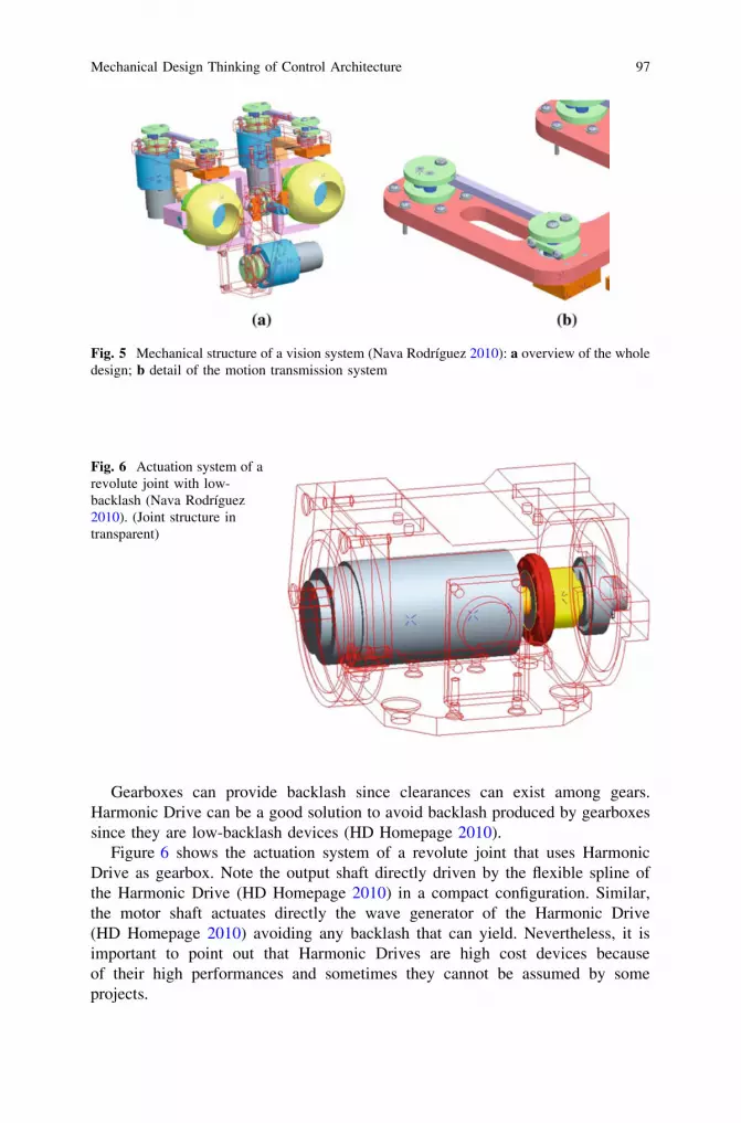
Gearboxes can provide backlash since clearances can exist among gears.Harmonic Drive can be a good solution to avoid backlash produced by gearboxessince they are low-backlash devices (HD Homepage 2010).
Figure 6 shows the actuation system of a revolute joint that uses HarmonicDrive as gearbox. Note the output shaft directly driven by the flexible spline ofthe Harmonic Drive (HD Homepage 2010) in a compact configuration. Similar,the motor shaft actuates directly the wave generator of the Harmonic Drive(HD Homepage 2010) avoiding any backlash that can yield. Nevertheless, it isimportant to point out that Harmonic Drives are high cost devices becauseof their high performances and sometimes they cannot be assumed by someprojects.
Fig. 5 Mechanical structure of a vision system (Nava Rodríguez 2010): a overview of the wholedesign; b detail of the motion transmission system
Fig. 6 Actuation system of arevolute joint with low-backlash (Nava Rodríguez2010). (Joint structure intransparent)
Mechanical Design Thinking of Control Architecture 97
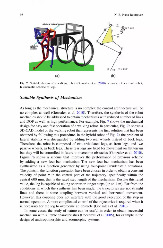
Suitable Synthesis of Mechanism
As long as the mechanical structure is no complex the control architecture will beno complex as well (Gonzalez et al. 2010). Therefore, the synthesis of the robotmechanics should be addressed to obtain mechanisms with reduced number of linksand DOF as well as high performance. For example, Fig. 7 shows the mechanicaldesign for easy and fast operation of a walking robot. In particular, Fig. 7a shows a3D-CAD model of the walking robot that represents the first solution that has beenobtained by following this procedure. In the hybrid robot of Fig. 7a the problem oflateral stability was disregarded by adding two rear wheels instead of back legs.Therefore, the robot is composed of two articulated legs, as front legs, and twopassive wheels, as back legs. These rear legs are fixed for movement on flat terrainbut they will be controlled in future to overcome obstacles (Gonzalez et al. 2010).Figure 7b shows a scheme that improves the performance of previous schemeby adding a new four-bar mechanism The new four-bar mechanism has beensynthesized as a function generator by using four-point Freudenstein equations.The points in the function generation have been chosen in order to obtain a constantvelocity of point P in the central part of the trajectory, specifically within thecentral 600 mm, that is the rated step length of the mechanism. Despite this ratedvalue, the leg is capable of taking shorter or longer steps (up to 1 m). Far from theconditions in which the synthesis has been made, the trajectories are not straightlines and there is some coupling between vertical and horizontal movement.However, this coupling does not interfere with the good execution of the step innormal operation. A more complicated control of the trajectories is required when itis necessary for the leg to overcome an obstacle (Gonzalez et al. 2010).
In some cases, the study of nature can be useful in order to obtain successfulmechanism with suitable characteristics (Ceccarelli et al. 2005), for example in thedesign of anthropomorphic and zoomorphic systems.
Fig. 7 Suitable design of a walking robot (Gonzalez et al. 2010): a model of a virtual robot;b kinematic scheme of legs
98 N. E. Nava Rodríguez

Figure 8 shows an overview of a robotic hand with three-one DOF articulatedfingers. The design process of this robotics hand has been developed by studying thehuman hand performance (Nava Rodríguez et al. 2004), (Ceccarelli et al. 2005),(Ceccarelli et al. 2006), (Nava Rodríguez et al. 2006) since for the design of ananthropomorphic hand a suitable knowledge of the human grasp is needed. Cylin-drical grasp of human hand has been analysed since it represents the most used graspin industrial applications (Cutkosky 1989). In particular, dimensions of fingers,grasping forces and contact points between fingers and objects have been investi-gated in human grasping. The dimensions of each phalange of index, medium andthumb have been measured for five persons (Nava Rodríguez et al. 2004). Figure 9ashows a photo sequence of a cylindrical grasp performance of a human hand. Thepositions of marks of human hand fingers of Fig. 9a have been measured in order toachieve this position by the robotic hand of Fig. 8. The force measuring system ofFig. 9b has been set up in a human hand for developing the experimental test ofFig. 9c. The grasp forces of several objects with different shapes and dimensionshave been measured in order to compare results with experimental validations of therobotic hand of Fig. 8. The experimental results show the practical feasibility of theprototype as three-fingered robotic sensored hand with three 1 DOF anthropomor-phic fingers, having human-like operation (Nava Rodríguez et al. 2004). Thehuman-like characteristics of the robotic hand of Fig. 8 simplify its control archi-tecture since some aspects of grasp have been checked in the mechanical design, forexample performance of fingers and grasping force.
The robotic device of Fig. 10 is another example of a system inspired in the studyof human body. This device has been used for rehabilitation of injured human wrist.The chosen class of mechanical solutions is based on a serial structure, with directdrive by the motors: one motor drives the pronation/supination, one motor theflexion/extension and two parallely coupled motors the abduction/adduction.
The main features of this arrangement are: 1) good rigidity of the structure; 2)direct drive of the manipulandum, which eliminates any backlash in the force/motion transmission; 3) minimization of the overall inertia, because most of the
Fig. 8 Robotic hand withthree-one DOF articulatedfingers (Nava Rodríguez et al.2004)
Mechanical Design Thinking of Control Architecture 99
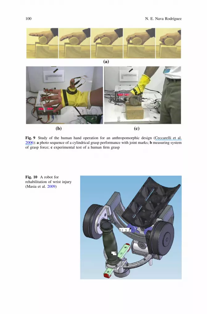
Fig. 9 Study of the human hand operation for an anthropomorphic design (Ceccarelli et al.2006): a photo sequence of a cylindrical grasp performance with joint marks; b measuring systemof grasp force; c experimental test of a human firm grasp
Fig. 10 A robot forrehabilitation of wrist injury(Masia et al. 2009)
100 N. E. Nava Rodríguez

mass is either fixed, or close to the rotation axes; 4) independence of each singleDOF (Masia et al. 2009).
The ranges of motion for each DOF have been fixed based on the human wristcapabilities. Figure 11 shows plots of human wrist movements, in which ranges ofmotions can be recognized. Thus, the mechanical design of the wrist robot ofFig. 10 has been constrained to move from -70� to 70� for flexion/extension, from-35 to 35 for abduction/adduction and from -80 to 80 for pronation/supination.A suitable adaptive control has been implemented in the robot wrist in order tomaximize task complexity as a function of the level of performance. It inducesthe patient to maximize the ability to face complex tasks while minimizing thereliance on robot assistance (Masia et al. 2009).
Particular Cases
Particular systems, for example vision or cognitive systems require to work undercertain condition that do not interfere with their correct operation. In this case, an
Fig. 11 Study of the human wrist movements for an anthropomorphic design (Masia et al. 2009)
Mechanical Design Thinking of Control Architecture 101
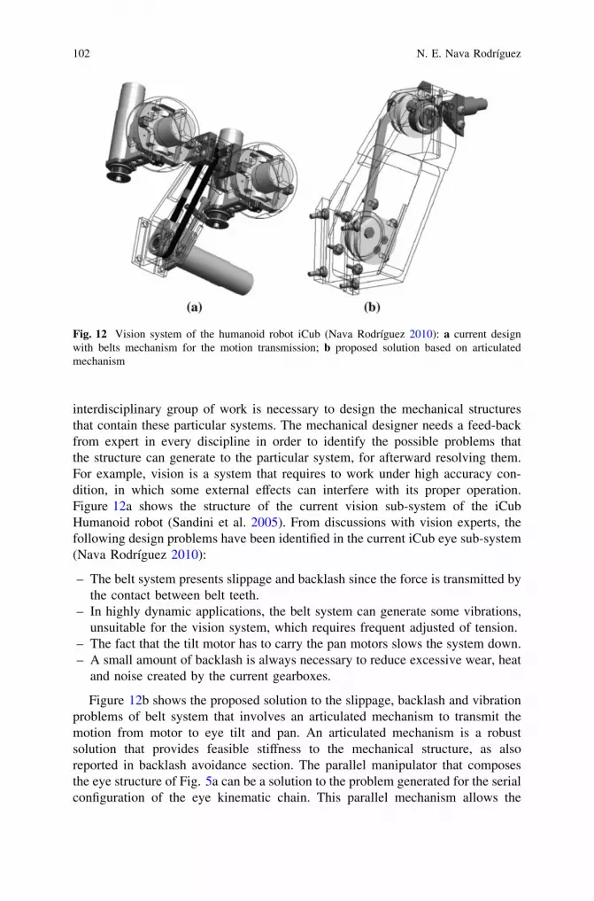
interdisciplinary group of work is necessary to design the mechanical structuresthat contain these particular systems. The mechanical designer needs a feed-backfrom expert in every discipline in order to identify the possible problems thatthe structure can generate to the particular system, for afterward resolving them.For example, vision is a system that requires to work under high accuracy con-dition, in which some external effects can interfere with its proper operation.Figure 12a shows the structure of the current vision sub-system of the iCubHumanoid robot (Sandini et al. 2005). From discussions with vision experts, thefollowing design problems have been identified in the current iCub eye sub-system(Nava Rodríguez 2010):
– The belt system presents slippage and backlash since the force is transmitted bythe contact between belt teeth.
– In highly dynamic applications, the belt system can generate some vibrations,unsuitable for the vision system, which requires frequent adjusted of tension.
– The fact that the tilt motor has to carry the pan motors slows the system down.– A small amount of backlash is always necessary to reduce excessive wear, heat
and noise created by the current gearboxes.
Figure 12b shows the proposed solution to the slippage, backlash and vibrationproblems of belt system that involves an articulated mechanism to transmit themotion from motor to eye tilt and pan. An articulated mechanism is a robustsolution that provides feasible stiffness to the mechanical structure, as alsoreported in backlash avoidance section. The parallel manipulator that composesthe eye structure of Fig. 5a can be a solution to the problem generated for the serialconfiguration of the eye kinematic chain. This parallel mechanism allows the
Fig. 12 Vision system of the humanoid robot iCub (Nava Rodríguez 2010): a current designwith belts mechanism for the motion transmission; b proposed solution based on articulatedmechanism
102 N. E. Nava Rodríguez
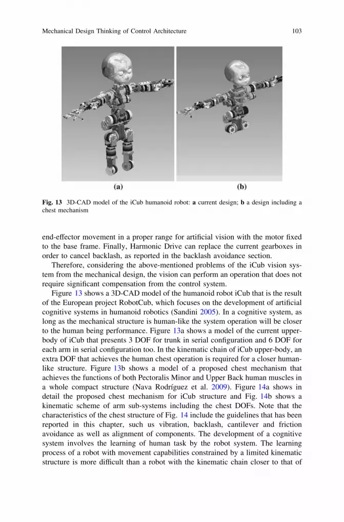
end-effector movement in a proper range for artificial vision with the motor fixedto the base frame. Finally, Harmonic Drive can replace the current gearboxes inorder to cancel backlash, as reported in the backlash avoidance section.
Therefore, considering the above-mentioned problems of the iCub vision sys-tem from the mechanical design, the vision can perform an operation that does notrequire significant compensation from the control system.
Figure 13 shows a 3D-CAD model of the humanoid robot iCub that is the resultof the European project RobotCub, which focuses on the development of artificialcognitive systems in humanoid robotics (Sandini 2005). In a cognitive system, aslong as the mechanical structure is human-like the system operation will be closerto the human being performance. Figure 13a shows a model of the current upper-body of iCub that presents 3 DOF for trunk in serial configuration and 6 DOF foreach arm in serial configuration too. In the kinematic chain of iCub upper-body, anextra DOF that achieves the human chest operation is required for a closer human-like structure. Figure 13b shows a model of a proposed chest mechanism thatachieves the functions of both Pectoralis Minor and Upper Back human muscles ina whole compact structure (Nava Rodríguez et al. 2009). Figure 14a shows indetail the proposed chest mechanism for iCub structure and Fig. 14b shows akinematic scheme of arm sub-systems including the chest DOFs. Note that thecharacteristics of the chest structure of Fig. 14 include the guidelines that has beenreported in this chapter, such us vibration, backlash, cantilever and frictionavoidance as well as alignment of components. The development of a cognitivesystem involves the learning of human task by the robot system. The learningprocess of a robot with movement capabilities constrained by a limited kinematicstructure is more difficult than a robot with the kinematic chain closer to that of
Fig. 13 3D-CAD model of the iCub humanoid robot: a current design; b a design including achest mechanism
Mechanical Design Thinking of Control Architecture 103

human body. Therefore, the computational efforts of the iCub control system forachieving cognitive operation of manipulation has been reduced by considering theproposed chest mechanism of Figs. 13b and 14.
3 Conclusions
Some important guidelines have been presented for an accurate mechanical designthat provides characteristics for development of not so-complex control architec-ture. Problems like backlash, vibration, high friction, cantilever and offsets amongcomponents, which can interfere with a proper operation of a robot system, havebeen resolved by proposing suitable solutions from the mechanical point of view.Usually, these problems could be resolved by the control architecture that requirescomplex strategies of linearization and compensation as well as high computa-tional efforts. Nevertheless, the proposed mechanical improvements are effectiveand can be applied in a practical application in a built system. Simplifyingthe dynamic formulation that control system must compensate, by simplifying thekinematic chain, is a feasible way to reduce the complexity of the control system.A proper synthesis of the robot mechanisms yields a kinematic chain with ade-quate links and DOFs for a successful operation. Finally, to mimic the perfor-mance of accurate/optimized systems is a suitable way to optimize the robotoperation and reduce the control architecture compensation. For example, thehuman body is a high optimized machine since its centuries of evolution and it canrepresent a good model for mimicking performance.
The modern research involves the participation of experts in different fieldscomposing a multidisciplinary group for the development of complex systems likehumanoid robots. Some mechanical solutions applied to the structure design caninterfere with the proper operation of certain complex systems. These solutions
Fig. 14 Chest mechanism structure proposed for iCub humanoid (Nava Rodríguez et al. 2009):a overview of the whole design; b kinematic scheme
104 N. E. Nava Rodríguez

can be successful from the mechanical point of view but their characteristicscannot be proper in specific applications. Therefore, feed-back from expert ofother research lines is necessary for the mechanical designer.
References
Armstrong-Hélouvry B (1991) Control of machines with friction. Kluwer, DordrechtBachmann H, Ammann WJ, Deischl F, Eisenmann J, Floegl I, Hirsch GH, Klein GH, Lande GJ,
Mahrenholtz O, Natke HG, Nussbaumer H, Pretlove AJ, Rainer JH, Saemann E, SteinbeisserL (1995) Vibration problems in structures: Practical guidelines. Birkhäuser, Berlin
Ceccarelli M, Nava Rodríguez NE, Carbone G, Lopez-Cajun C (2005) Optimal design of drivingmechanism in a 1 D.O.F. anthropomorphic finger. J Appl Bionics Biomech 2(2):103–110
Ceccarelli M, Nava Rodríguez NE, Giuseppe C (2006) Design and tests of a three finger handwith 1 Dof articulated fingers. Int J Robotica 24:183–196
Cutkosky MR (1989) On grasp choice, grasp model, and the design of hands for manufacturingtasks. IEEE Trans Rob Autom 5(3):269–279
De Silva CW (2007) Vibration: fundamental and practice. Taylor and Francys, New YorkGonzalez RA, Gonzalez RAG, Morales R (2010) Mechanical synthesis for easy and fast
operation in climbing and walking robots. In: Behnam M (ed) Climbing and walking robots,INTECH
HD homepage (2010) www.harmonicdrive.com. Accessed October 2010SKF homepage (2010) www.skf.com. Accessed October 2010Masia L, Casadio M, Nava Rodríguez NE, Morasso P, Sandini G, Giannoni P (2009) Adaptive
training strategy of distal movements by means of a wrist-robot. International conferences onadvances in computer-human interactions 20223
Nava Rodríguez NE (2010) Design issue of a new icub head sub-system. Rob Comput IntegrManuf 26(2):119–129
Nava Rodriguez NE, Carbone G, Ottaviano E, Ceccarelli M (2004) An experimental validation ofa three—fingered hand with 1 dof anthropomorphic fingers. Intell Manipulation Grasping285-290
Nava Rodriguez NE, Carbone G, Ceccarelli M (2006) Optimal design of driving mechanism in a1-d.o.f. anthropomorphic finger. Mech Mach Theory 41(8):897–911
Nava Rodriguez NE, Abderrahim M, Moreno L (2009) A mechanism design of a chest sub-systemfor humanoid robot. ASME International conference of advance intelligent mechatronicsAIM2009 43
Ogata K (1998) Modern control engineering. Prentice Hall, New JerseyPreumont A (2002) Vibration control of active structures: An introduction. Kluwer, DordrechtRao JS, Dukkipati RV (2006) Mechanism and machine science. New Age, New DelhiSandini G, Metta G, Verson D, Caldwell D, Tsagarakis N, Beira R, Santos-Victor J, Ijspeert A,
Righetti L, Cappiello G, Stellin G, Becchi F (2005) The robotcub project an open frameworkfor research in embodied cognition. Humanoids
Sciavicco L, Siciliano B (2005) Modelling and control of robot manipulators. Springer-Verlag,London
Troch I, Desoyer K, Kopacek P (1991) Robot control 1991 (SYROCO ‘91): Selected papers fromthe 3rd IFAC/IFIP/IMACS symposium. International federation of automatic control, Vienna
Zinn M, Khatib O, Roth B, Salisbury JK (2004) Playing it safe [human-friendly robot]. RobAutom Mag 11(2):12–21
Mechanical Design Thinking of Control Architecture 105


