Embed Size (px)
Citation preview
ME202: ADVANCED MECHANICS OF SOLIDS
1Presented to S4 ME students of RSET
by Dr. Manoj G Tharian24th January 2019
MODULE – I
Introduction to Stress Analysis& Displacement Field
2Presented to S4 ME students of RSET
by Dr. Manoj G Tharian24th January 2019
ME010 306(CE) STRENGTH OF MATERIALS & STRUCTURAL ENGINEERING
Course Objectives:
1. To impart concepts of stress and strain analyses in a solid.
2. To study the methodologies in theory of elasticity at a basic level.
3. To acquaint with the solution of advanced bending problems.
4. To get familiar with energy methods for solving structural mechanics problems.
3Presented to S4 ME students of RSET
by Dr. Manoj G Tharian24th January 2019
Module – I
1. Introduction to stress analysis in elastic solids
2. Stress at a point - Stress tensor
3. Stress components in rectangular and polar coordinate systems
4. Cauchy’s equations
5. Stress transformation.
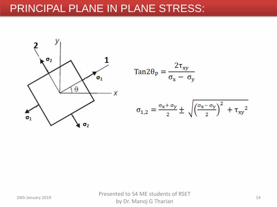
6. Principal stresses and planes.
7. Hydrostatic and Deviatoric stress components, Octahedral shear stress
8. Equations of equilibrium.
4Presented to S4 ME students of RSET
by Dr. Manoj G Tharian24th January 2019
5Presented to S4 ME students of RSET
by Dr. Manoj G Tharian24th January 2019
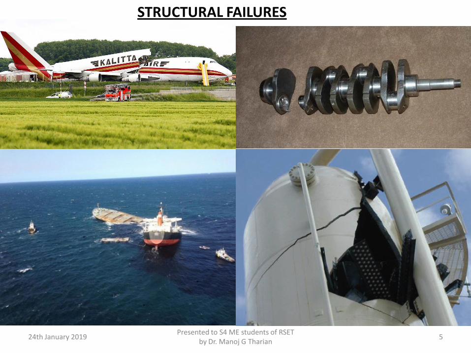
STRUCTURAL FAILURES
6Presented to S4 ME students of RSET
by Dr. Manoj G Tharian24th January 2019
7Presented to S4 ME students of RSET
by Dr. Manoj G Tharian24th January 2019
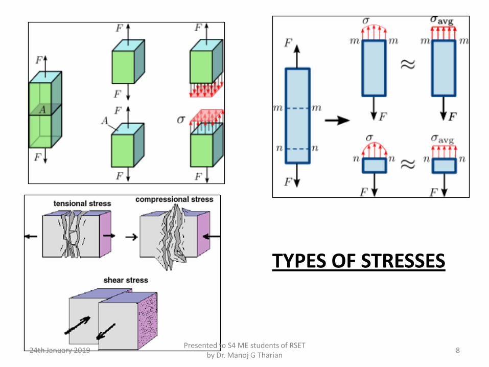
TYPES OF STRESSES
8Presented to S4 ME students of RSET
by Dr. Manoj G Tharian24th January 2019
Presented to S4 ME students of RSET by Dr. Manoj G Tharian
924th January 2019
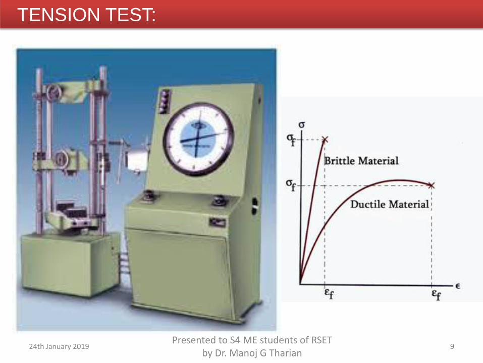
TENSION TEST:
10Presented to S4 ME students of RSET
by Dr. Manoj G Tharian24th January 2019
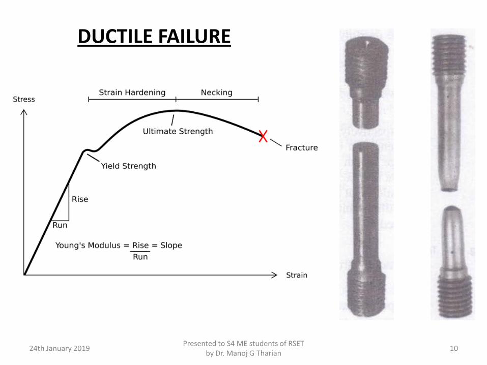
DUCTILE FAILURE
11Presented to S4 ME students of RSET
by Dr. Manoj G Tharian24th January 2019
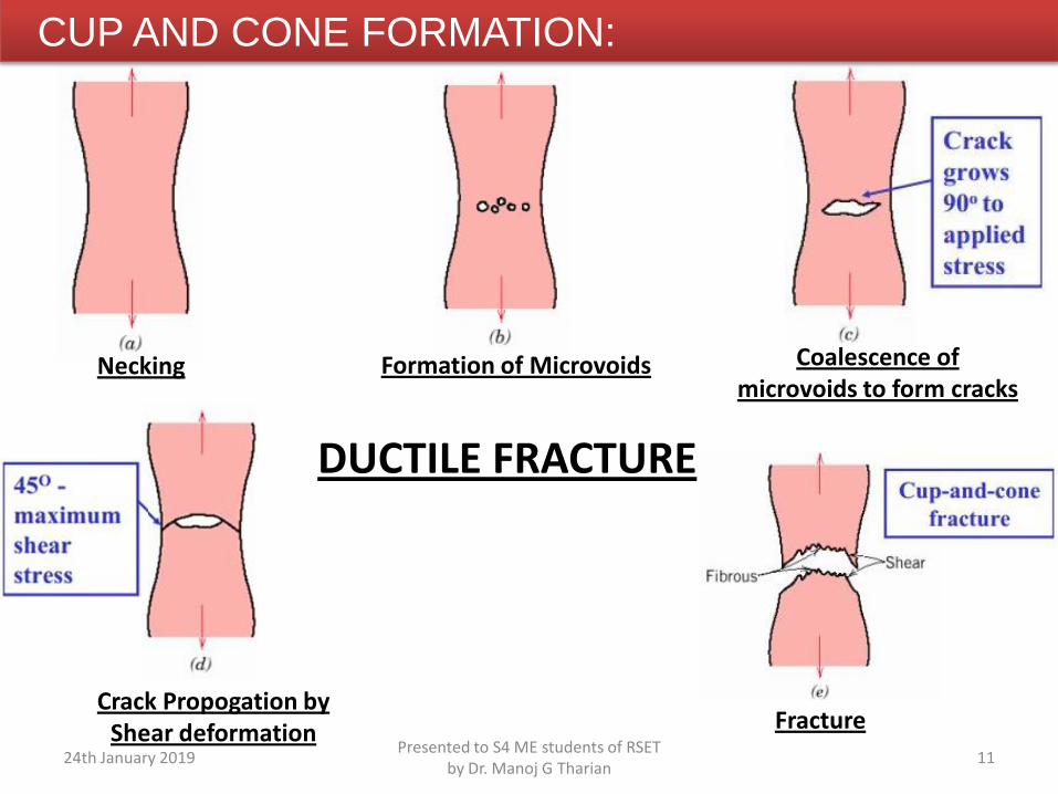
CUP AND CONE FORMATION:
DUCTILE FRACTURE
Necking Formation of Microvoids Coalescence of microvoids to form cracks
FractureCrack Propogation by
Shear deformation
Presented to S4 ME students of RSET by Dr. Manoj G Tharian
1224th January 2019
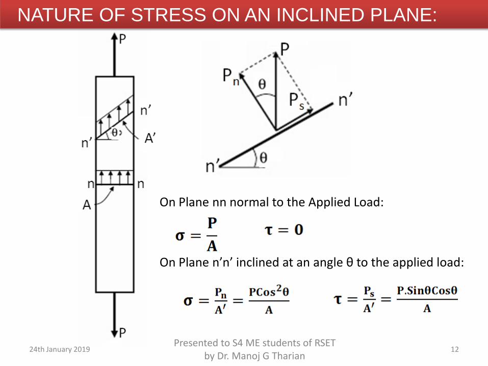
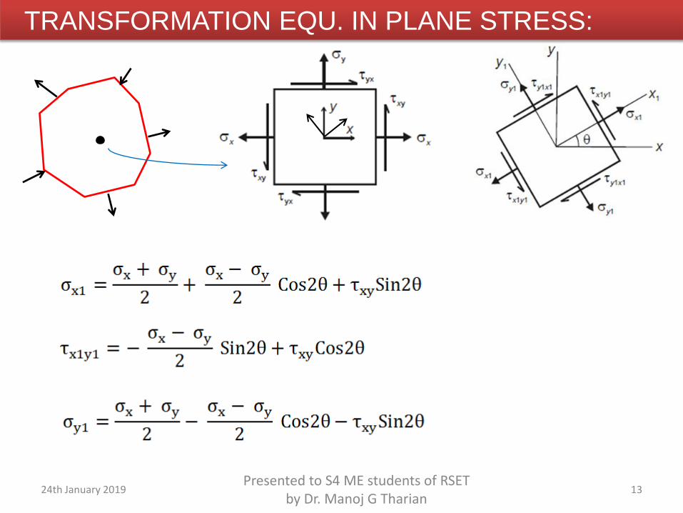
NATURE OF STRESS ON AN INCLINED PLANE:
On Plane nn normal to the Applied Load:
On Plane n’n’ inclined at an angle θ to the applied load:
Presented to S4 ME students of RSET by Dr. Manoj G Tharian
1324th January 2019
TRANSFORMATION EQU. IN PLANE STRESS:
Presented to S4 ME students of RSET by Dr. Manoj G Tharian
1424th January 2019
PRINCIPAL PLANE IN PLANE STRESS:
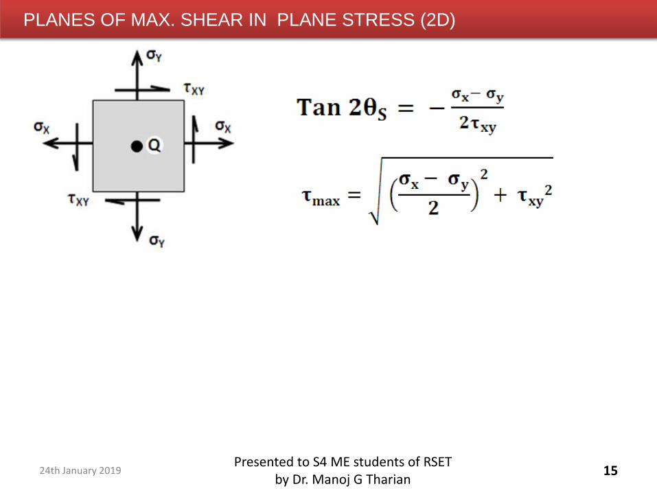
PLANES OF MAX. SHEAR IN PLANE STRESS (2D)
15Presented to S4 ME students of RSET
by Dr. Manoj G Tharian24th January 2019
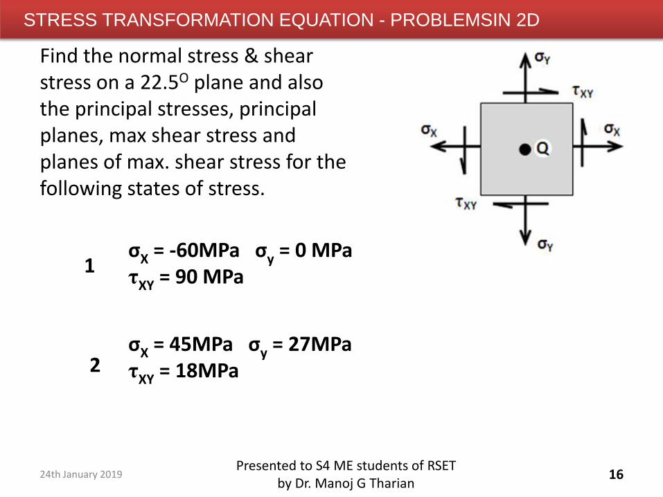
STRESS TRANSFORMATION EQUATION - PROBLEMSIN 2D
16Presented to S4 ME students of RSET
by Dr. Manoj G Tharian
Find the normal stress & shear stress on a 22.5O plane and also the principal stresses, principal planes, max shear stress and planes of max. shear stress for the following states of stress.
σX = -60MPa σy = 0 MPaτXY = 90 MPa
σX = 45MPa σy = 27MPaτXY = 18MPa
1
2
24th January 2019
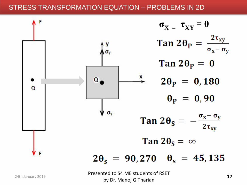
STRESS TRANSFORMATION EQUATION – PROBLEMS IN 2D
17Presented to S4 ME students of RSET
by Dr. Manoj G Tharian
σX = τXY = 0
24th January 2019
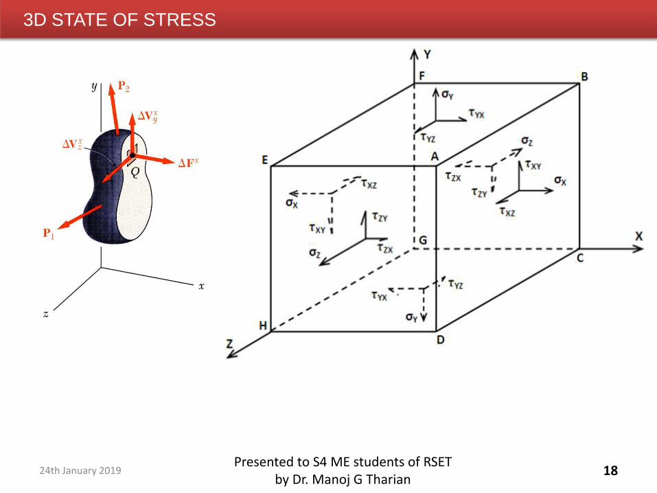
3D STATE OF STRESS
18Presented to S4 ME students of RSET
by Dr. Manoj G Tharian24th January 2019
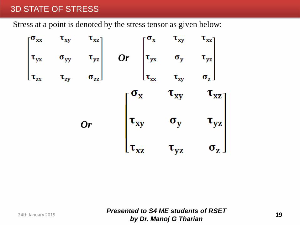
3D STATE OF STRESS
19Presented to S4 ME students of RSET
by Dr. Manoj G Tharian
Stress at a point is denoted by the stress tensor as given below:
Or
Or
24th January 2019
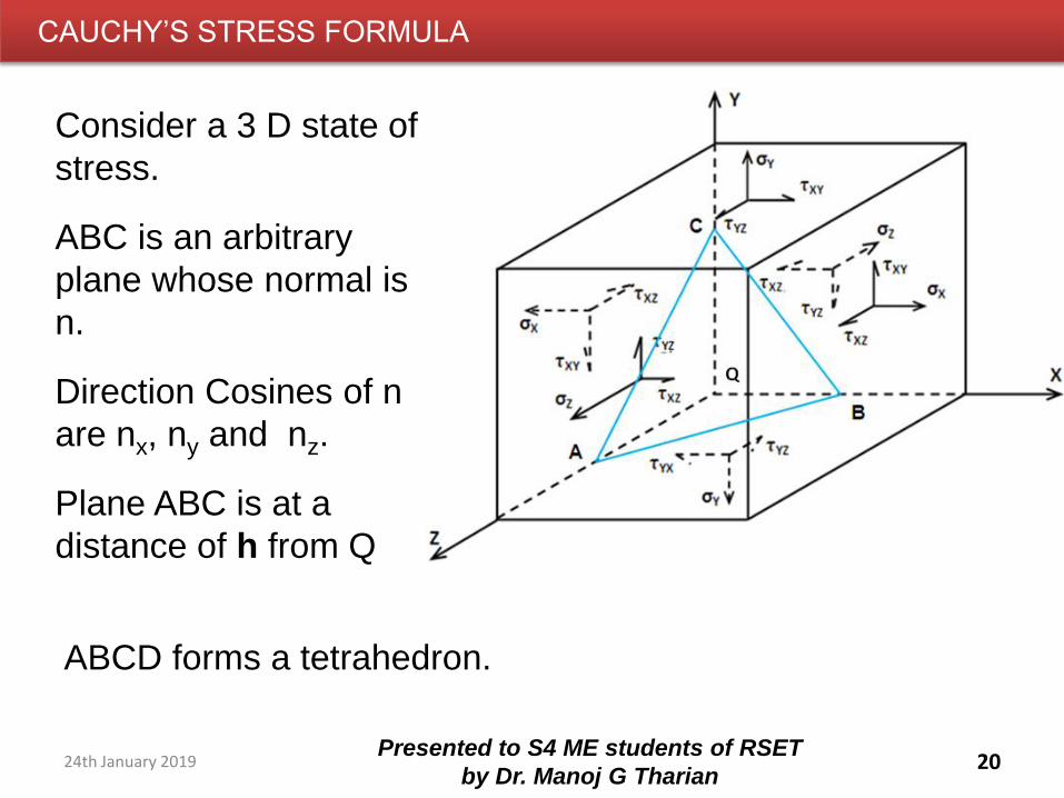
CAUCHY’S STRESS FORMULA
20Presented to S4 ME students of RSET
by Dr. Manoj G Tharian
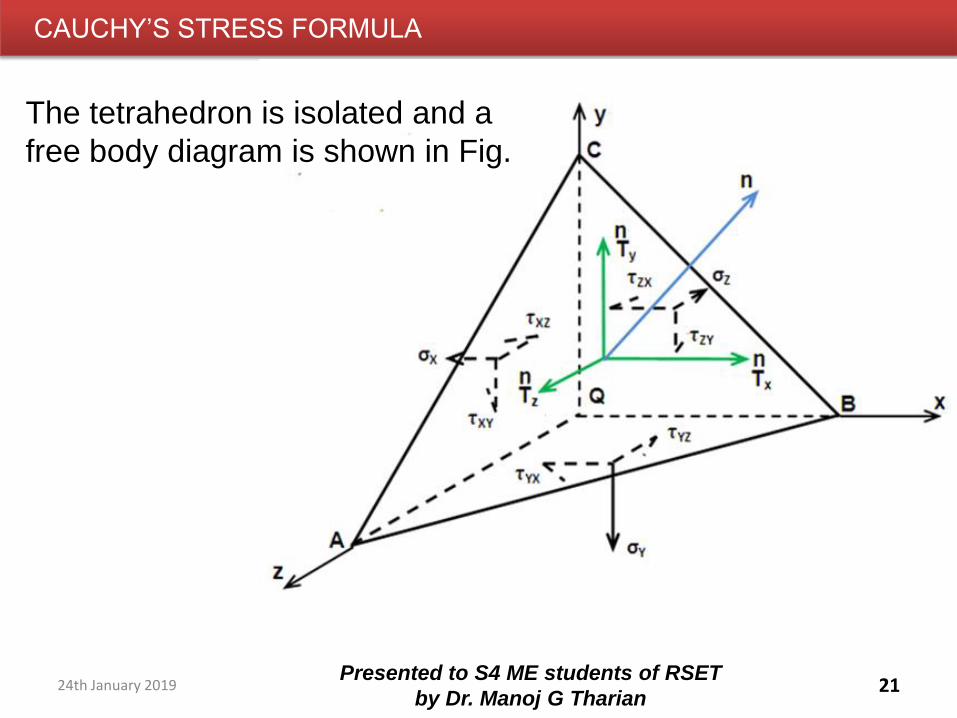
Consider a 3 D state of
stress.
ABC is an arbitrary
plane whose normal is
n.
Direction Cosines of n
are nx, ny and nz.
Plane ABC is at a
distance of h from Q
ABCD forms a tetrahedron.
24th January 2019
CAUCHY’S STRESS FORMULA
21Presented to S4 ME students of RSET
by Dr. Manoj G Tharian
The tetrahedron is isolated and a
free body diagram is shown in Fig.
24th January 2019
CAUCHY’S STRESS FORMULA
22Presented to S4 ME students of RSET
by Dr. Manoj G Tharian
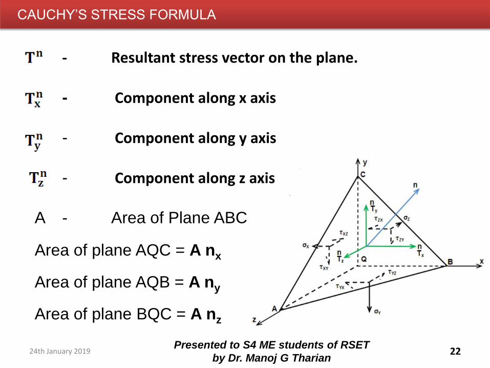
- Resultant stress vector on the plane.
- Component along x axis
- Component along y axis
- Component along z axis
A - Area of Plane ABC
Area of plane AQC = A nx
Area of plane AQB = A ny
Area of plane BQC = A nz
24th January 2019
CAUCHY’S STRESS FORMULA
23Presented to S4 ME students of RSET
by Dr. Manoj G Tharian
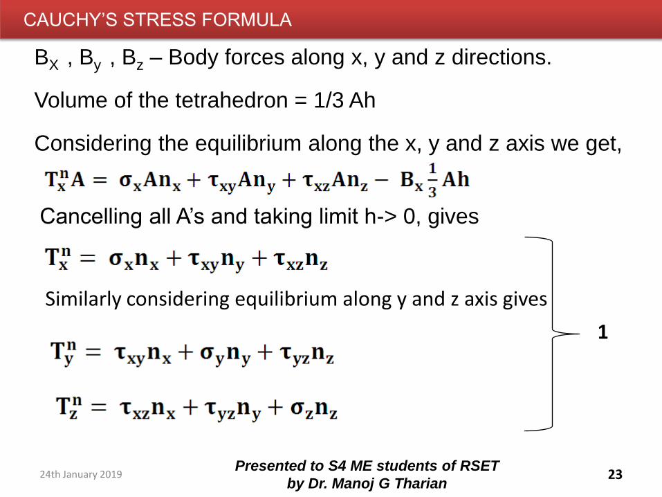
BX , By , Bz – Body forces along x, y and z directions.
Volume of the tetrahedron = 1/3 Ah
Considering the equilibrium along the x, y and z axis we get,
Cancelling all A’s and taking limit h-> 0, gives
Similarly considering equilibrium along y and z axis gives
1
24th January 2019
CAUCHY’S STRESS FORMULA
24Presented to S4 ME students of RSET
by Dr. Manoj G Tharian
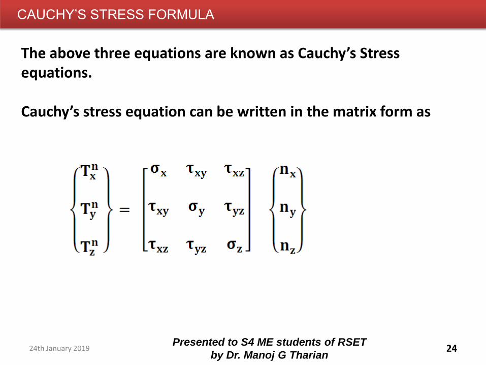
The above three equations are known as Cauchy’s Stress equations.
Cauchy’s stress equation can be written in the matrix form as
24th January 2019
CAUCHY’S STRESS FORMULA
25Presented to S4 ME students of RSET
by Dr. Manoj G Tharian
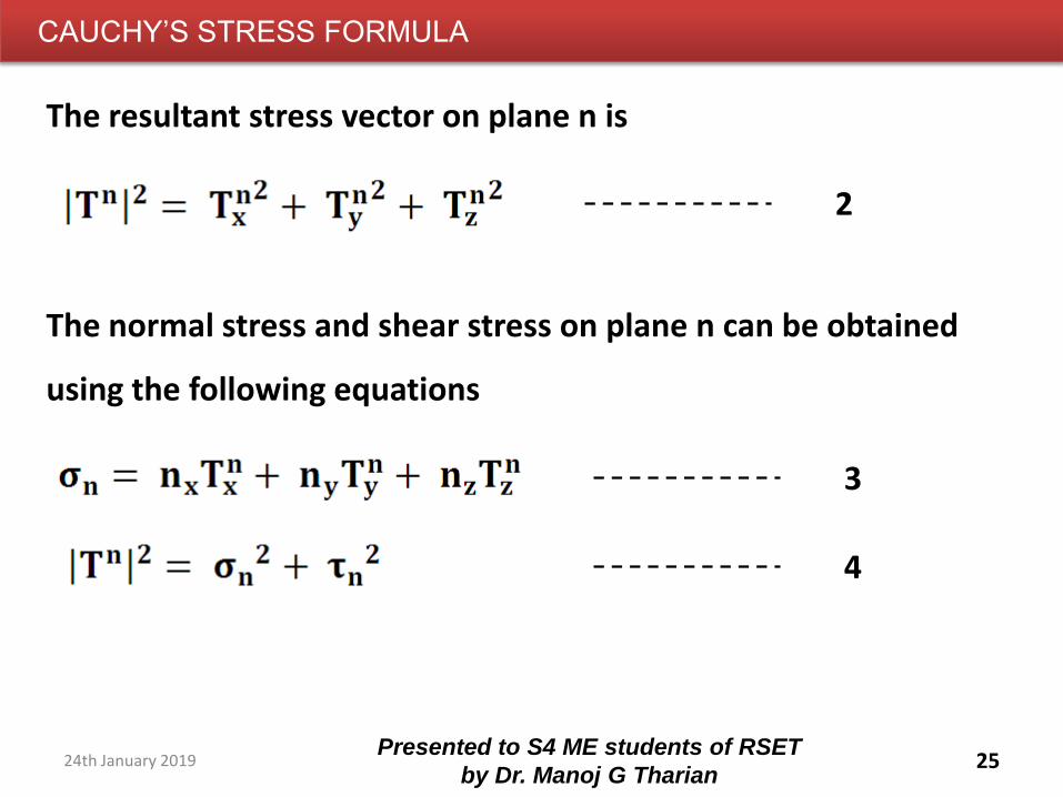
The resultant stress vector on plane n is
The normal stress and shear stress on plane n can be obtained
using the following equations
2
3
4
24th January 2019
CAUCHY’S STRESS FORMULA - PROBLEM
26Presented to S4 ME students of RSET
by Dr. Manoj G Tharian
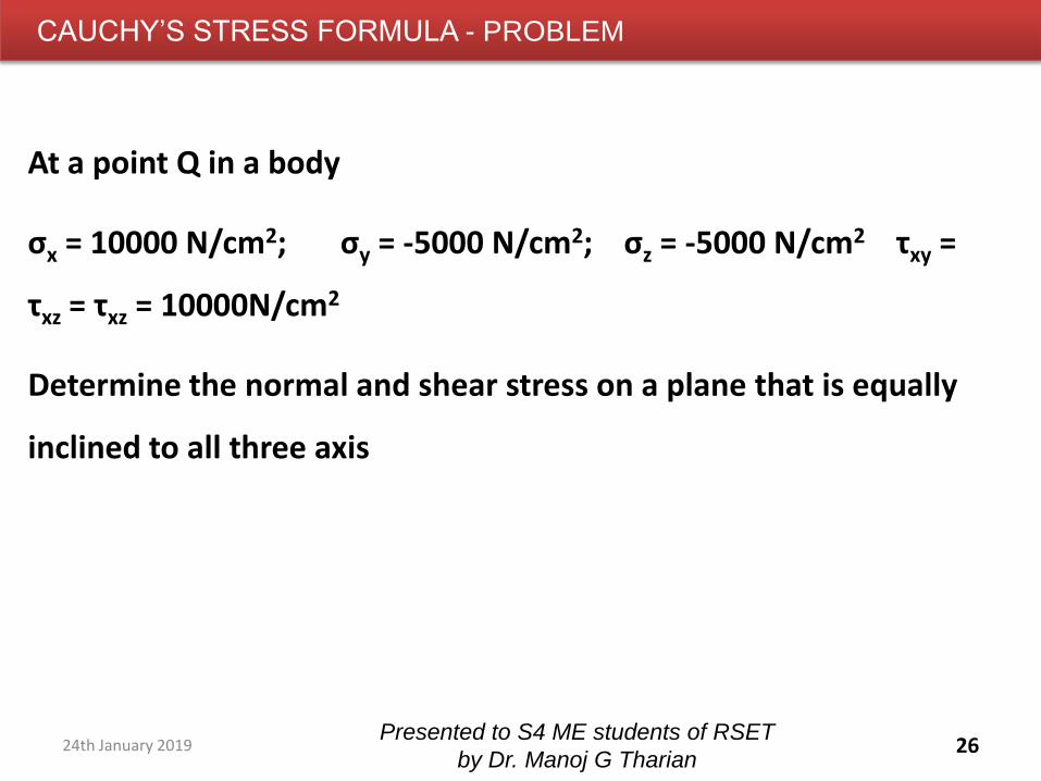
At a point Q in a body
σx = 10000 N/cm2; σy = -5000 N/cm2; σz = -5000 N/cm2 τxy =
τxz = τxz = 10000N/cm2
Determine the normal and shear stress on a plane that is equally
inclined to all three axis
24th January 2019
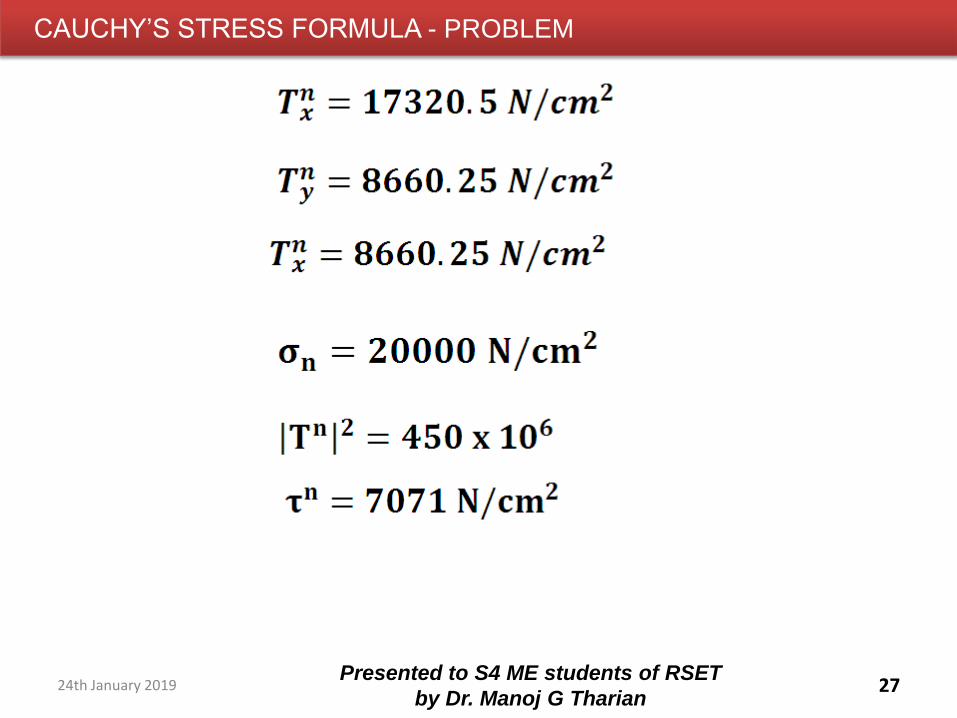
CAUCHY’S STRESS FORMULA - PROBLEM
27Presented to S4 ME students of RSET
by Dr. Manoj G Tharian24th January 2019
28Presented to S4 ME students of RSET
by Dr. Manoj G Tharian24th January 2019
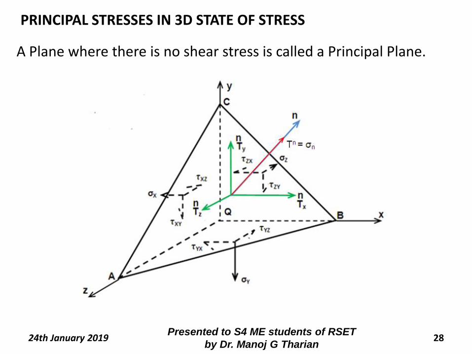
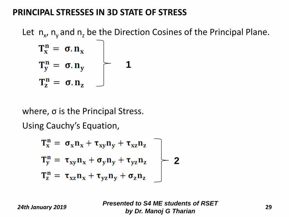
A Plane where there is no shear stress is called a Principal Plane.
PRINCIPAL STRESSES IN 3D STATE OF STRESS
29Presented to S4 ME students of RSET
by Dr. Manoj G Tharian24th January 2019
Let nx, ny and nz be the Direction Cosines of the Principal Plane.
where, σ is the Principal Stress.
1
Using Cauchy’s Equation,
2
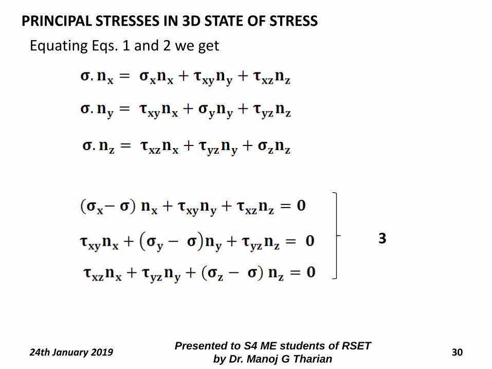
PRINCIPAL STRESSES IN 3D STATE OF STRESS
30Presented to S4 ME students of RSET
by Dr. Manoj G Tharian24th January 2019
Equating Eqs. 1 and 2 we get
3
PRINCIPAL STRESSES IN 3D STATE OF STRESS
31Presented to S4 ME students of RSET
by Dr. Manoj G Tharian24th January 2019
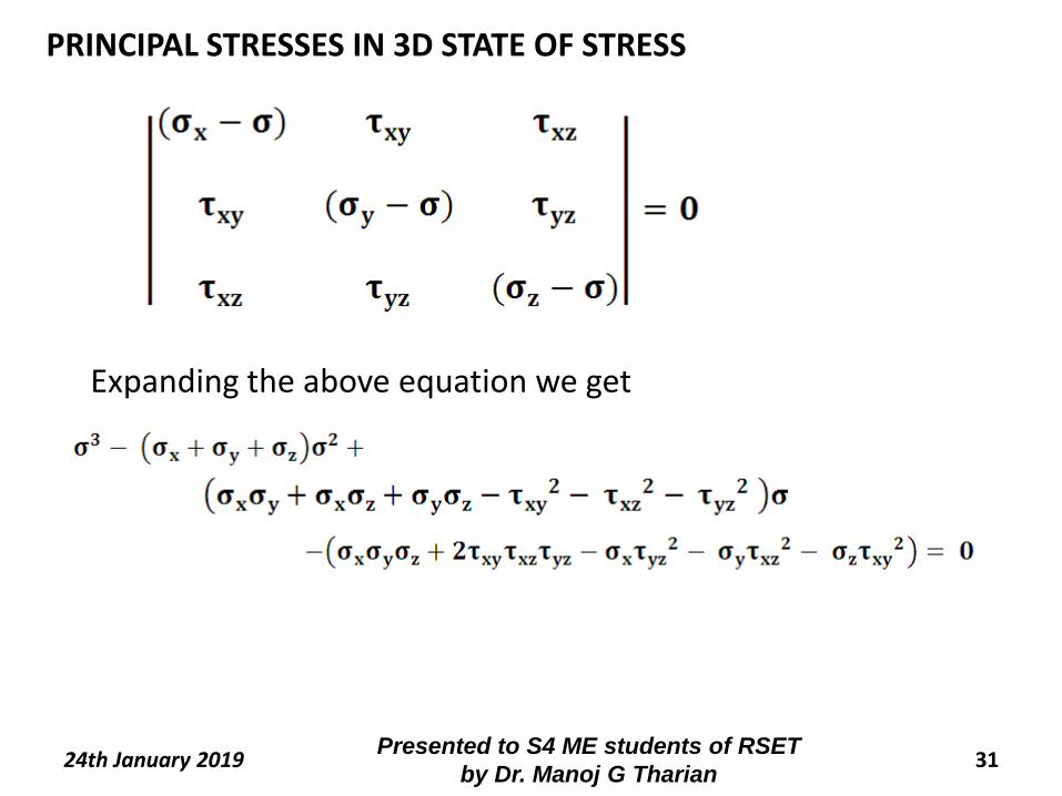
Expanding the above equation we get
PRINCIPAL STRESSES IN 3D STATE OF STRESS
32Presented to S4 ME students of RSET
by Dr. Manoj G Tharian24th January 2019
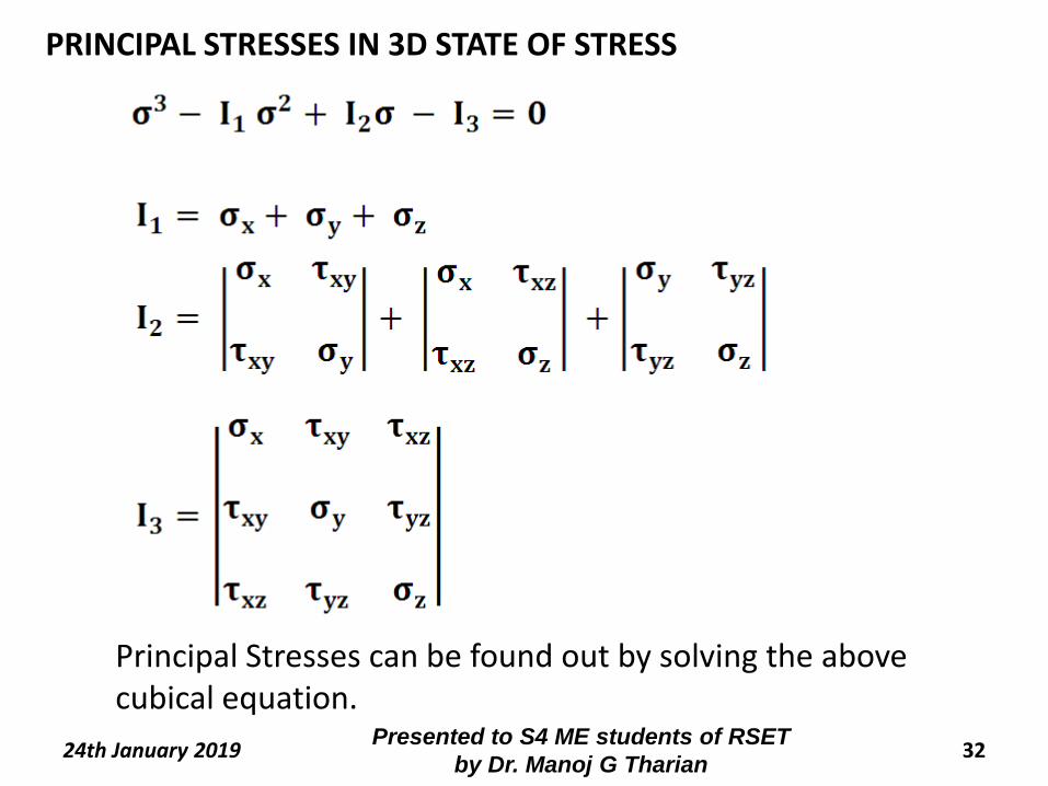
Principal Stresses can be found out by solving the above cubical equation.
PRINCIPAL STRESSES IN 3D STATE OF STRESS
33Presented to S4 ME students of RSET
by Dr. Manoj G Tharian24th January 2019
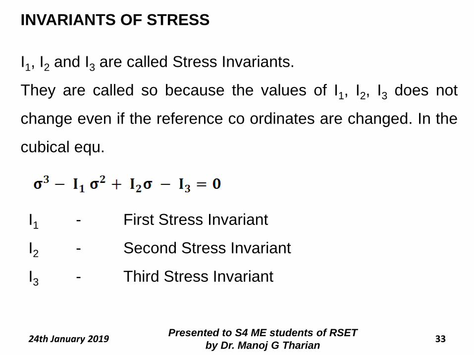
I1, I2 and I3 are called Stress Invariants.
They are called so because the values of I1, I2, I3 does not
change even if the reference co ordinates are changed. In the
cubical equ.
I1 - First Stress Invariant
I2 - Second Stress Invariant
I3 - Third Stress Invariant
INVARIANTS OF STRESS
34Presented to S4 ME students of RSET
by Dr. Manoj G Tharian24th January 2019
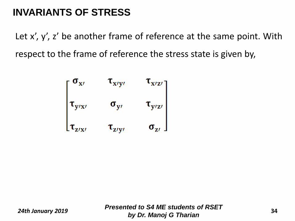
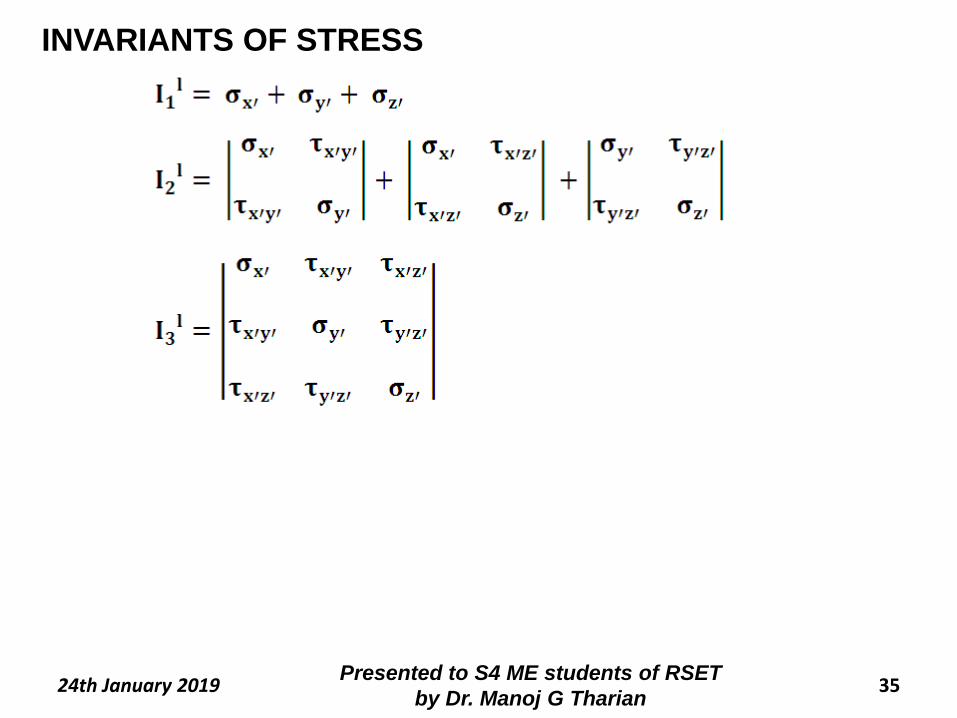
Let x’, y’, z’ be another frame of reference at the same point. With
respect to the frame of reference the stress state is given by,
INVARIANTS OF STRESS
35Presented to S4 ME students of RSET
by Dr. Manoj G Tharian24th January 2019
INVARIANTS OF STRESS
36Presented to S4 ME students of RSET
by Dr. Manoj G Tharian24th January 2019
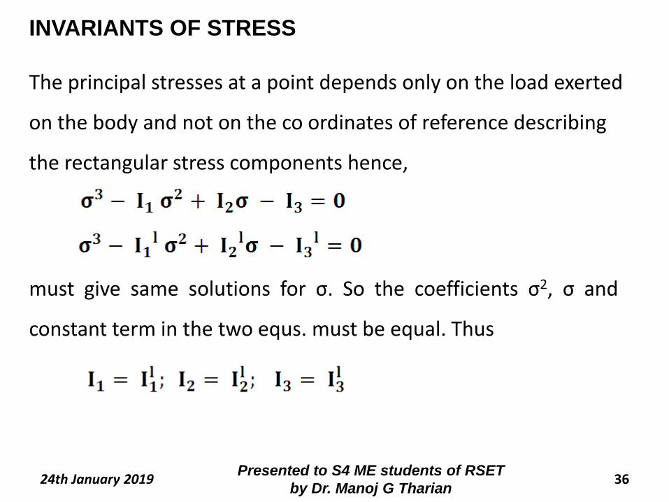
The principal stresses at a point depends only on the load exerted
on the body and not on the co ordinates of reference describing
the rectangular stress components hence,
must give same solutions for σ. So the coefficients σ2, σ and
constant term in the two equs. must be equal. Thus
INVARIANTS OF STRESS
37Presented to S4 ME students of RSET
by Dr. Manoj G Tharian24th January 2019
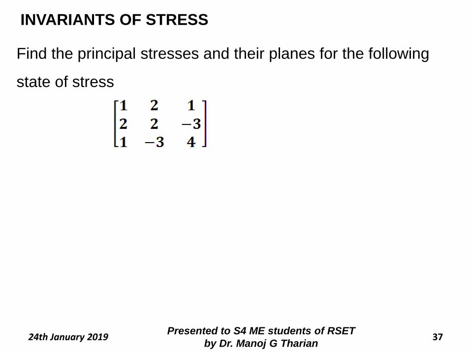
Find the principal stresses and their planes for the following
state of stress
INVARIANTS OF STRESS
38Presented to S4 ME students of RSET
by Dr. Manoj G Tharian24th January 2019
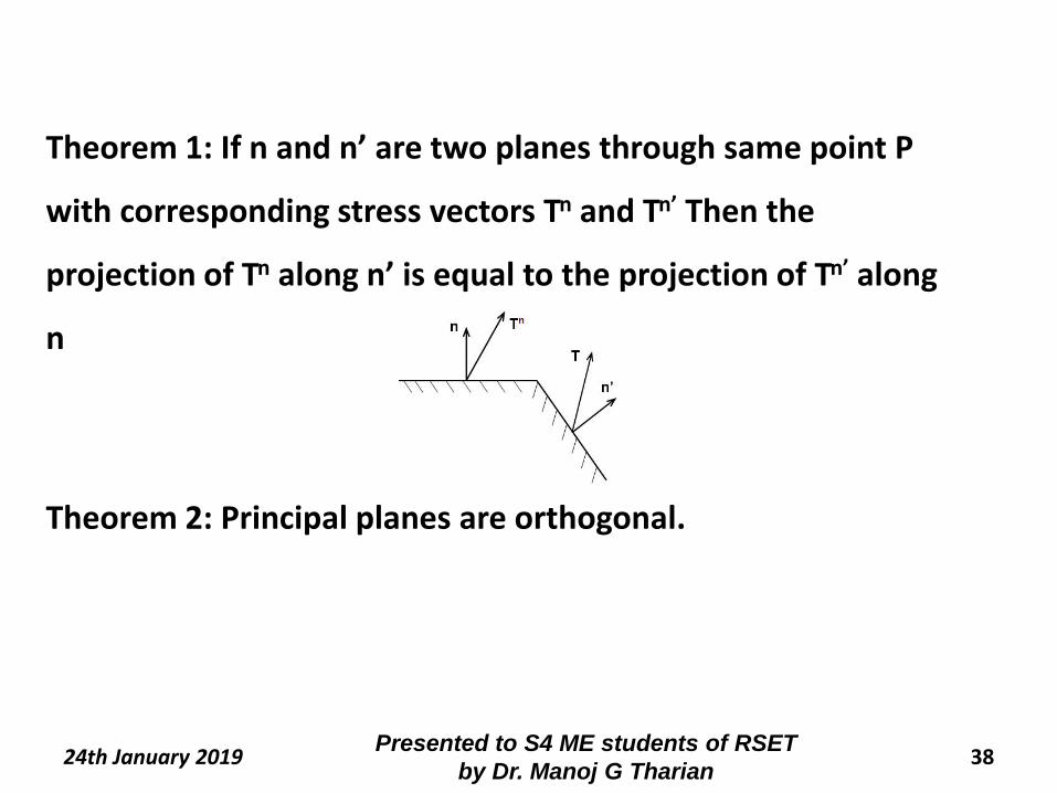
Theorem 1: If n and n’ are two planes through same point P
with corresponding stress vectors Tn and Tn’ Then the
projection of Tn along n’ is equal to the projection of Tn’ along
n
Theorem 2: Principal planes are orthogonal.
39Presented to S4 ME students of RSET
by Dr. Manoj G Tharian24th January 2019
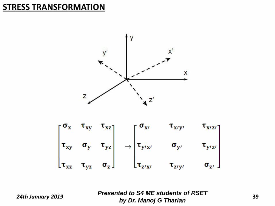
STRESS TRANSFORMATION
40Presented to S4 ME students of RSET
by Dr. Manoj G Tharian24th January 2019
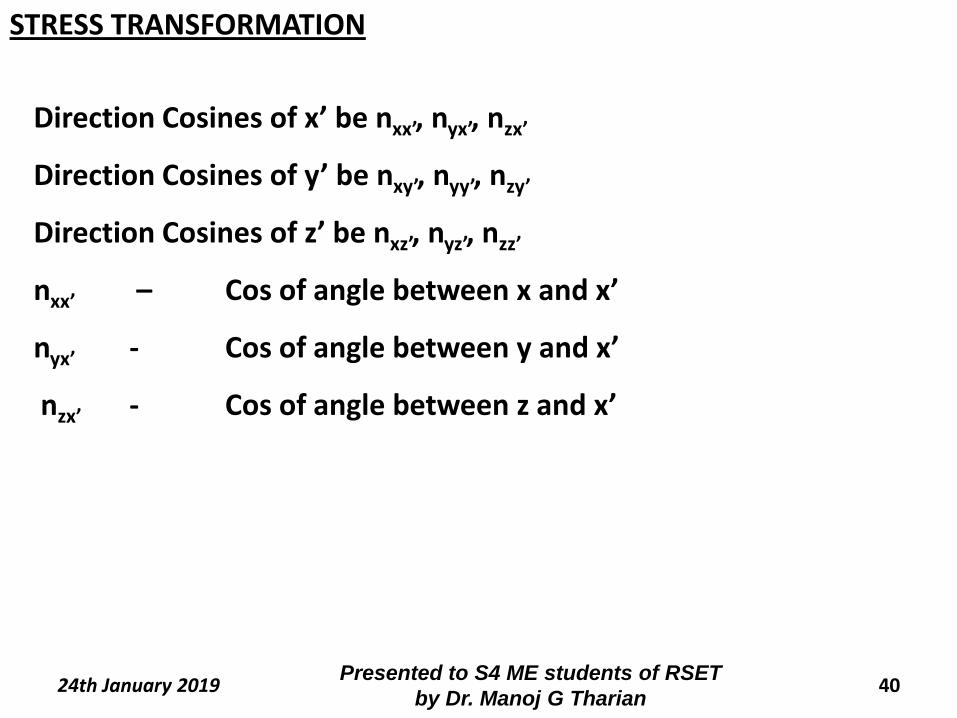
Direction Cosines of x’ be nxx’, nyx’, nzx’
Direction Cosines of y’ be nxy’, nyy’, nzy’
Direction Cosines of z’ be nxz’, nyz’, nzz’
nxx’ – Cos of angle between x and x’
nyx’ - Cos of angle between y and x’
nzx’ - Cos of angle between z and x’
STRESS TRANSFORMATION
41Presented to S4 ME students of RSET
by Dr. Manoj G Tharian24th January 2019
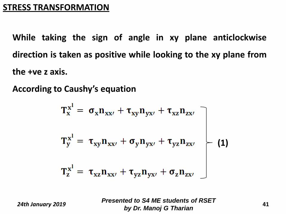
While taking the sign of angle in xy plane anticlockwise
direction is taken as positive while looking to the xy plane from
the +ve z axis.
According to Caushy’s equation
(1)
STRESS TRANSFORMATION
42Presented to S4 ME students of RSET
by Dr. Manoj G Tharian24th January 2019
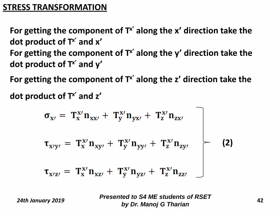
For getting the component of Tx’ along the x’ direction take the dot product of Tx’ and x’For getting the component of Tx’ along the y’ direction take the dot product of Tx’ and y’
For getting the component of Tx’ along the z’ direction take the
dot product of Tx’ and z’
(2)
STRESS TRANSFORMATION
43Presented to S4 ME students of RSET
by Dr. Manoj G Tharian24th January 2019
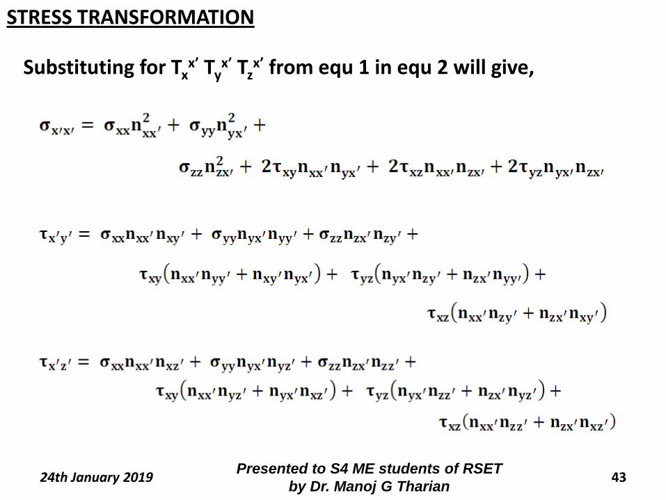
Substituting for Txx’ Ty
x’ Tzx’ from equ 1 in equ 2 will give,
STRESS TRANSFORMATION
44Presented to S4 ME students of RSET
by Dr. Manoj G Tharian24th January 2019
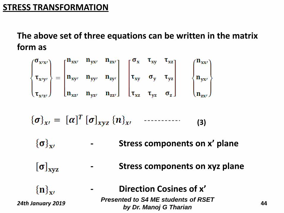
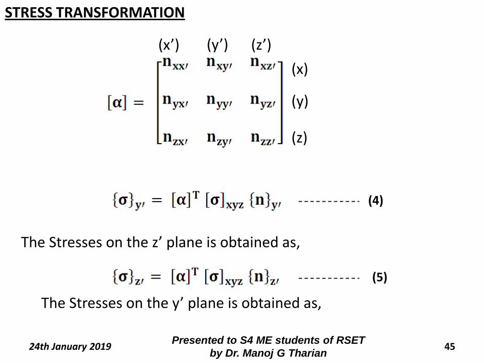
The above set of three equations can be written in the matrix form as
- Stress components on x’ plane
- Stress components on xyz plane
- Direction Cosines of x’
(3)
STRESS TRANSFORMATION
45Presented to S4 ME students of RSET
by Dr. Manoj G Tharian24th January 2019
The Stresses on the y’ plane is obtained as,
The Stresses on the z’ plane is obtained as,
(x)
(y)
(z)
(x’) (y’) (z’)
(4)
(5)
STRESS TRANSFORMATION
46Presented to S4 ME students of RSET
by Dr. Manoj G Tharian24th January 2019
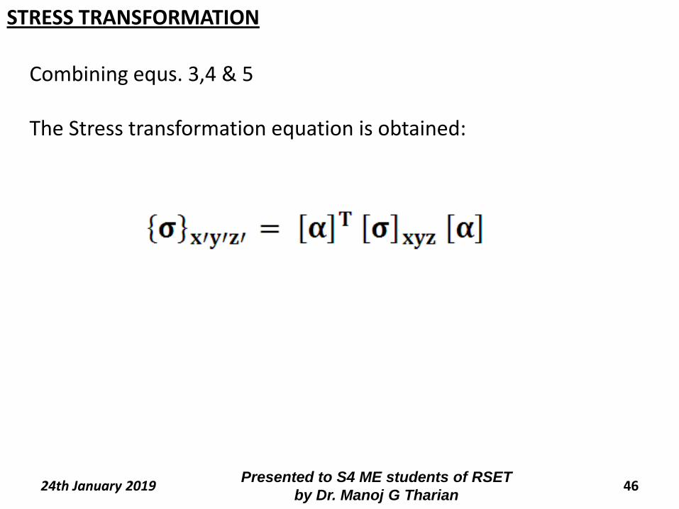
Combining equs. 3,4 & 5
The Stress transformation equation is obtained:
STRESS TRANSFORMATION
47Presented to S4 ME students of RSET
by Dr. Manoj G Tharian24th January 2019
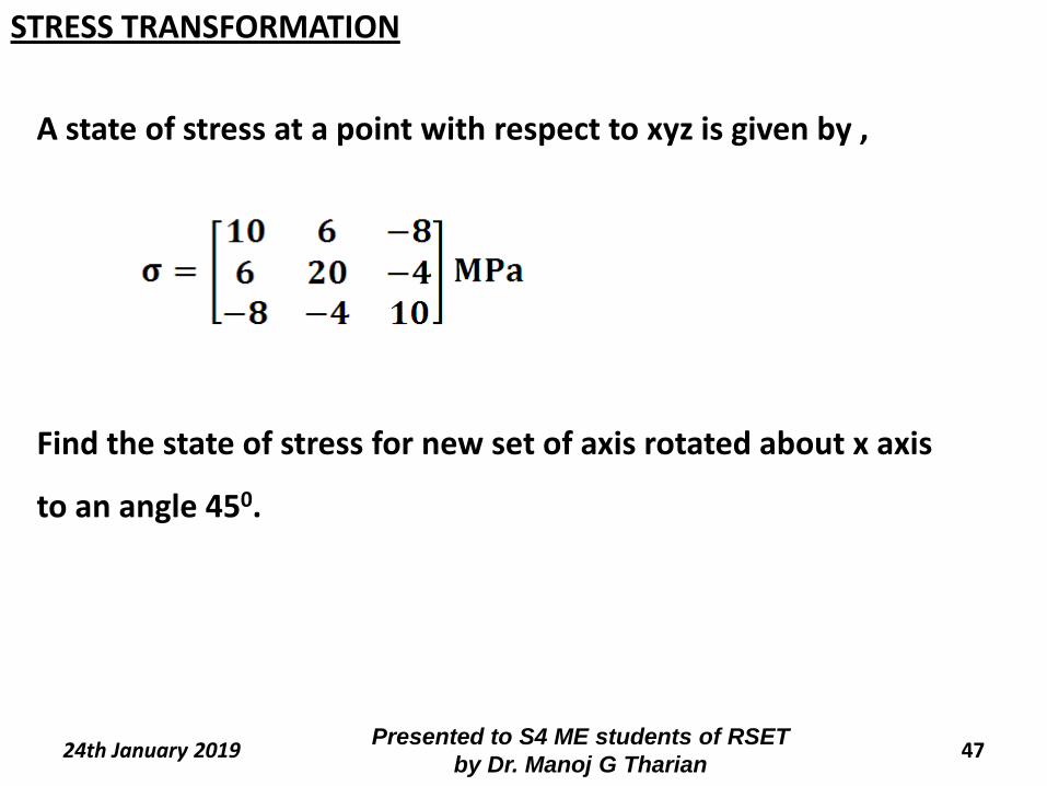
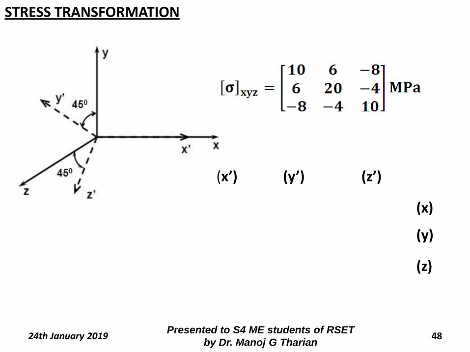
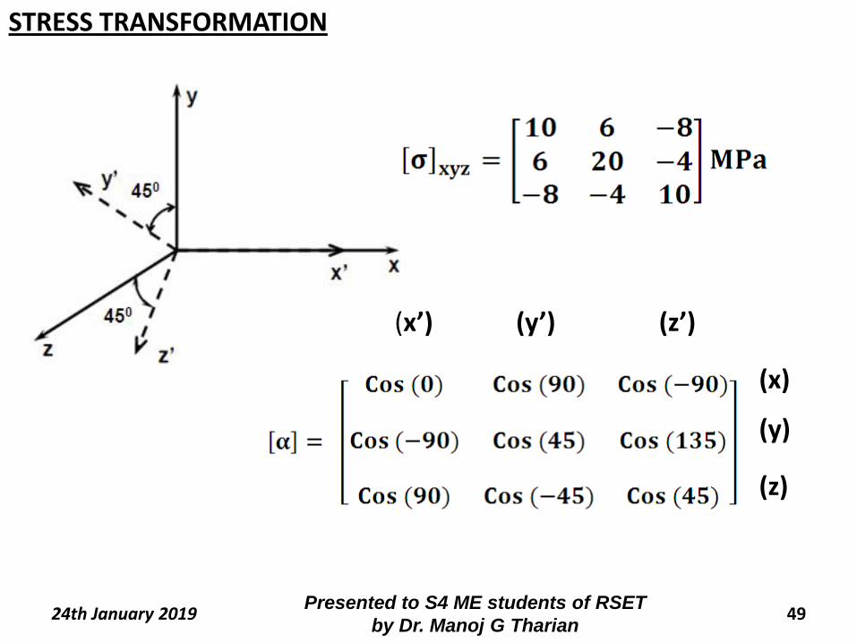
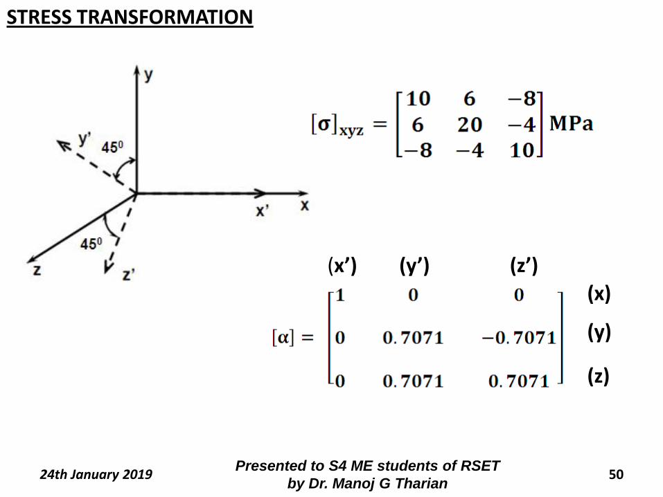
A state of stress at a point with respect to xyz is given by ,
Find the state of stress for new set of axis rotated about x axis
to an angle 450.
STRESS TRANSFORMATION
48Presented to S4 ME students of RSET
by Dr. Manoj G Tharian24th January 2019
(x)
(y)
(z)
(x’) (y’) (z’)
STRESS TRANSFORMATION
49Presented to S4 ME students of RSET
by Dr. Manoj G Tharian24th January 2019
(x)
(y)
(z)
(x’) (y’) (z’)
STRESS TRANSFORMATION
50Presented to S4 ME students of RSET
by Dr. Manoj G Tharian24th January 2019
(x)
(y)
(z)
(x’) (y’) (z’)
STRESS TRANSFORMATION
51Presented to S4 ME students of RSET
by Dr. Manoj G Tharian24th January 2019
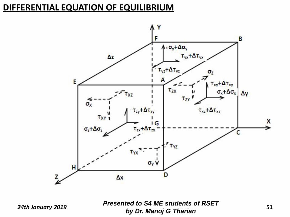
DIFFERENTIAL EQUATION OF EQUILIBRIUM
52Presented to S4 ME students of RSET
by Dr. Manoj G Tharian24th January 2019
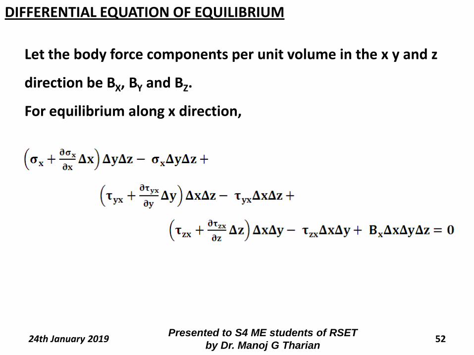
Let the body force components per unit volume in the x y and z
direction be BX, BY and BZ.
For equilibrium along x direction,
DIFFERENTIAL EQUATION OF EQUILIBRIUM
53Presented to S4 ME students of RSET
by Dr. Manoj G Tharian24th January 2019
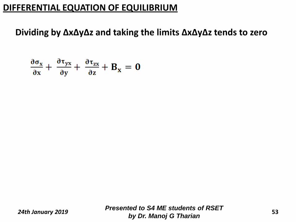
Dividing by ΔxΔyΔz and taking the limits ΔxΔyΔz tends to zero
DIFFERENTIAL EQUATION OF EQUILIBRIUM
54Presented to S4 ME students of RSET
by Dr. Manoj G Tharian24th January 2019
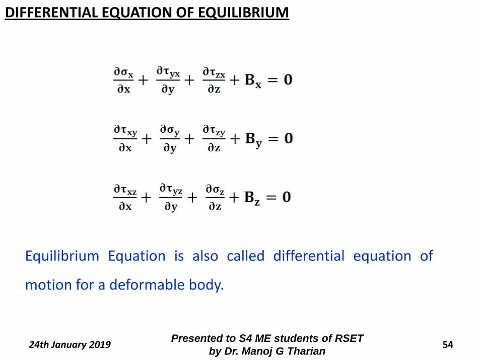
DIFFERENTIAL EQUATION OF EQUILIBRIUM
Equilibrium Equation is also called differential equation of
motion for a deformable body.
55Presented to S4 ME students of RSET
by Dr. Manoj G Tharian24th January 2019
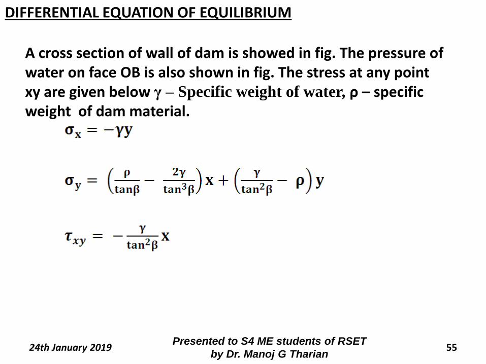
A cross section of wall of dam is showed in fig. The pressure of water on face OB is also shown in fig. The stress at any point xy are given below γ – Specific weight of water, ρ – specific weight of dam material.
DIFFERENTIAL EQUATION OF EQUILIBRIUM
56Presented to S4 ME students of RSET
by Dr. Manoj G Tharian24th January 2019
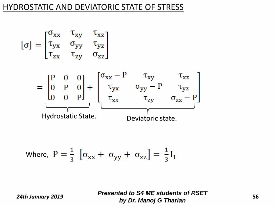
Hydrostatic State.
HYDROSTATIC AND DEVIATORIC STATE OF STRESS
Deviatoric state.
Where,
57Presented to S4 ME students of RSET
by Dr. Manoj G Tharian24th January 2019
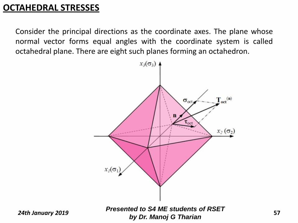
Consider the principal directions as the coordinate axes. The plane whosenormal vector forms equal angles with the coordinate system is calledoctahedral plane. There are eight such planes forming an octahedron.
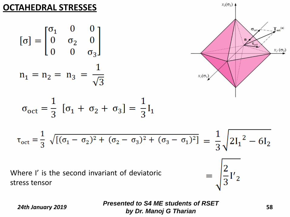
OCTAHEDRAL STRESSES
58Presented to S4 ME students of RSET
by Dr. Manoj G Tharian24th January 2019
Where I’ is the second invariant of deviatoricstress tensor
OCTAHEDRAL STRESSES
24th January 2019 59Presented to S4 ME students of RSET
by Dr. Manoj G Tharian
60Presented to S4 ME students of RSET
by Dr. Manoj G Tharian24th January 2019
Displacement Field
The displacement undergone by any point on a body can be
expressed as a function of original coordinates. The
displacement field U is expressed as
U = ui + vj+ wk
This function is known as displacement field vector where,
u = f1(x,y,z)
v = f2(x,y,z)
w = f3(x,y,z)
STRAIN
61Presented to S4 ME students of RSET
by Dr. Manoj G Tharian24th January 2019
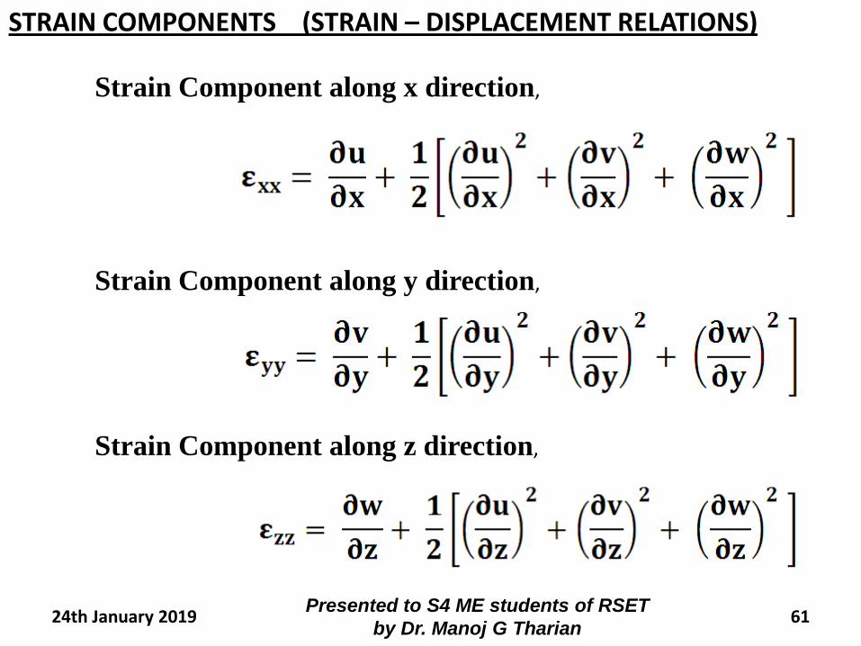
Strain Component along x direction,
Strain Component along y direction,
Strain Component along z direction,
STRAIN COMPONENTS (STRAIN – DISPLACEMENT RELATIONS)
62Presented to S4 ME students of RSET
by Dr. Manoj G Tharian24th January 2019
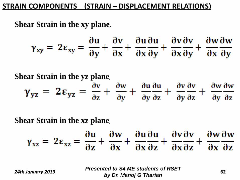
Shear Strain in the xy plane,
Shear Strain in the yz plane,
Shear Strain in the xz plane,
STRAIN COMPONENTS (STRAIN – DISPLACEMENT RELATIONS)
63Presented to S4 ME students of RSET
by Dr. Manoj G Tharian24th January 2019
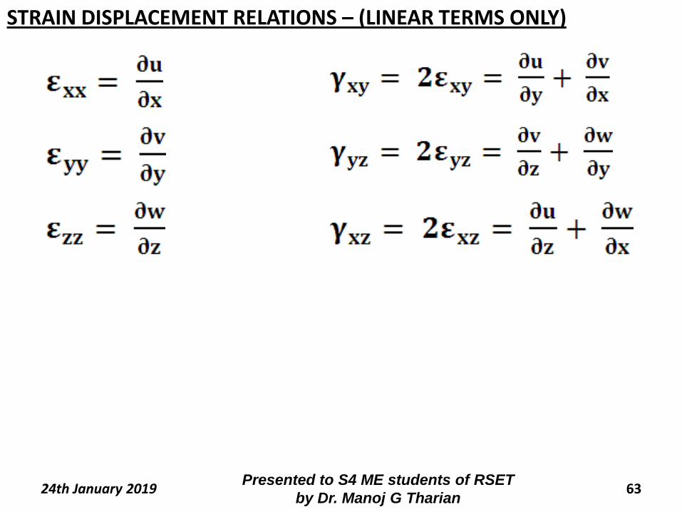
STRAIN DISPLACEMENT RELATIONS – (LINEAR TERMS ONLY)
64Presented to S4 ME students of RSET
by Dr. Manoj G Tharian24th January 2019
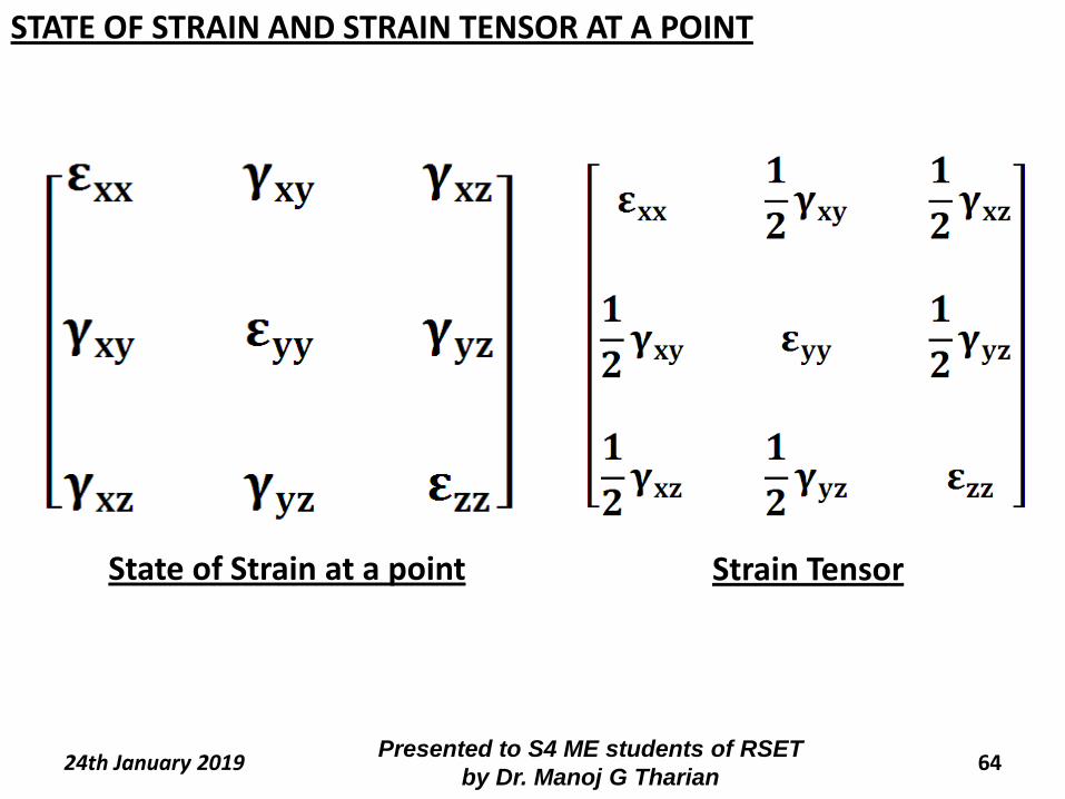
State of Strain at a point Strain Tensor
STATE OF STRAIN AND STRAIN TENSOR AT A POINT
65Presented to S4 ME students of RSET
by Dr. Manoj G Tharian24th January 2019
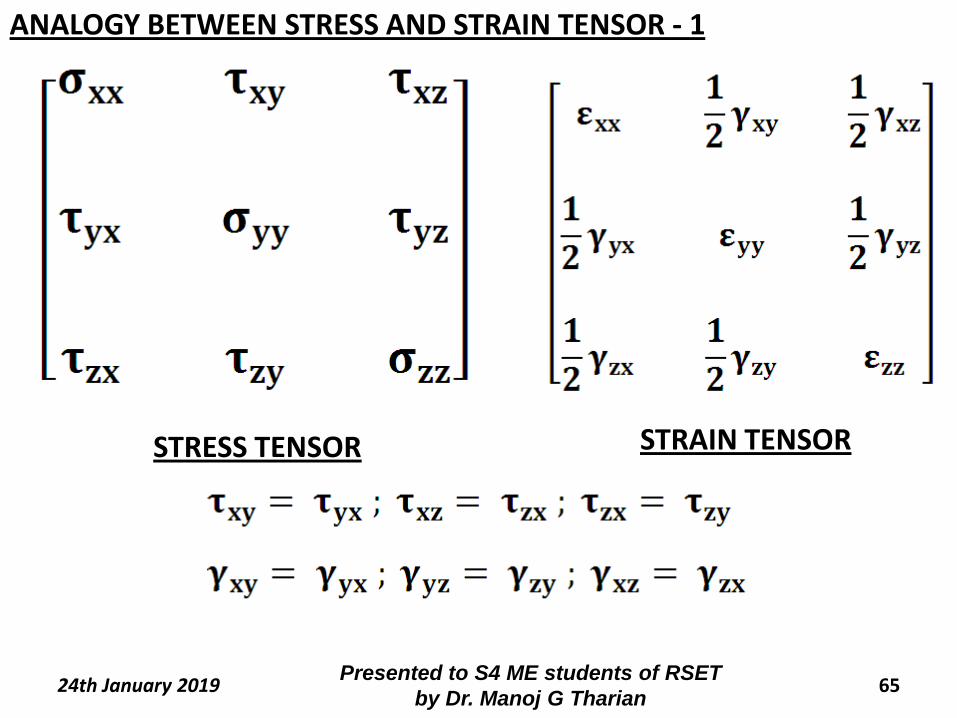
STRESS TENSOR STRAIN TENSOR
ANALOGY BETWEEN STRESS AND STRAIN TENSOR - 1
66Presented to S4 ME students of RSET
by Dr. Manoj G Tharian24th January 2019
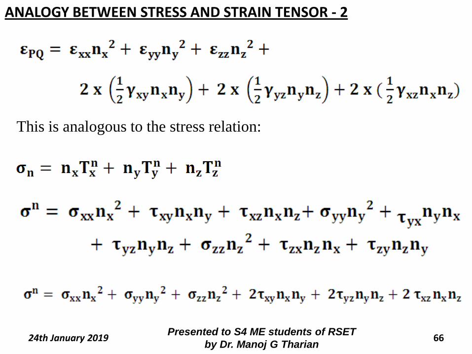
This is analogous to the stress relation:
ANALOGY BETWEEN STRESS AND STRAIN TENSOR - 2
67Presented to S4 ME students of RSET
by Dr. Manoj G Tharian24th January 2019
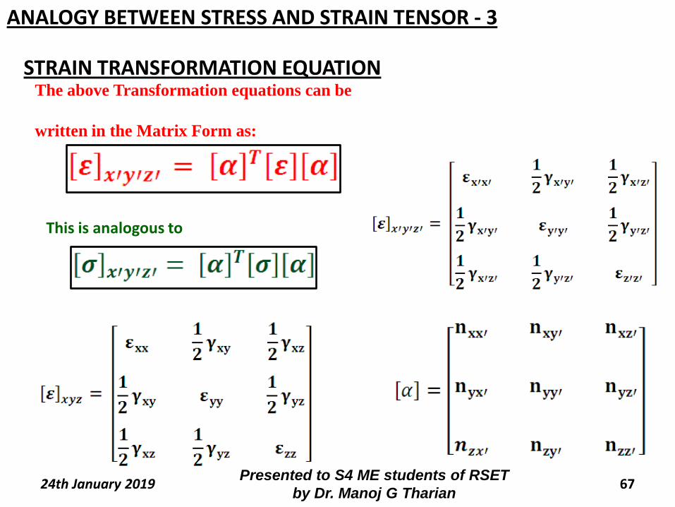
STRAIN TRANSFORMATION EQUATIONThe above Transformation equations can be
written in the Matrix Form as:
This is analogous to
ANALOGY BETWEEN STRESS AND STRAIN TENSOR - 3
68Presented to S4 ME students of RSET
by Dr. Manoj G Tharian24th January 2019
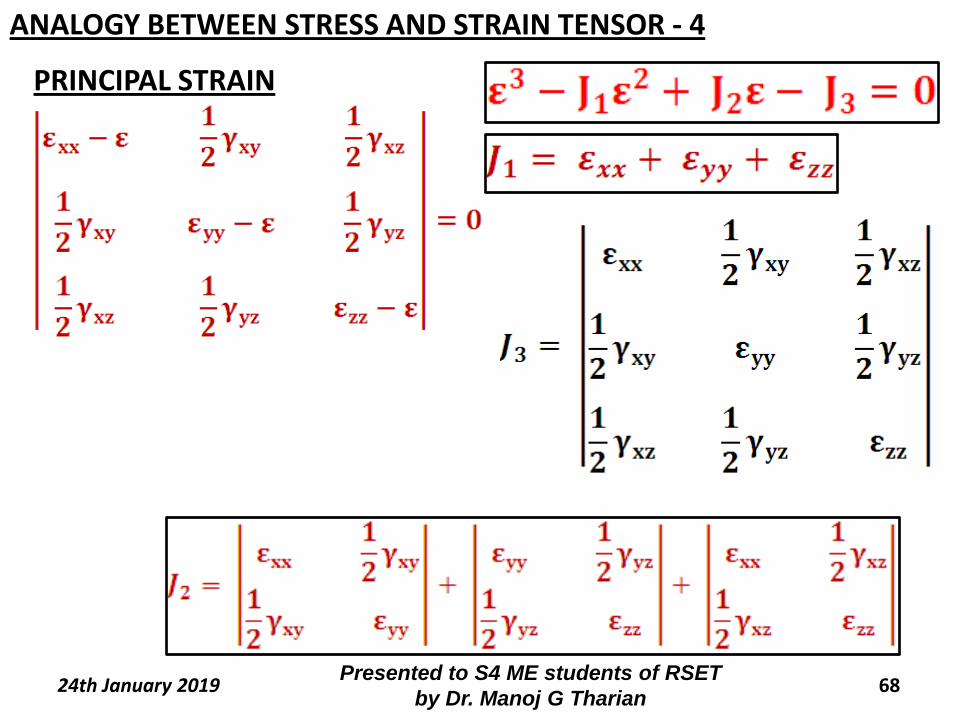
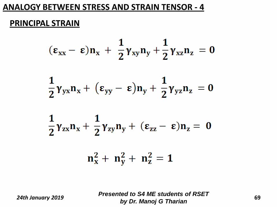
PRINCIPAL STRAIN
ANALOGY BETWEEN STRESS AND STRAIN TENSOR - 4
69Presented to S4 ME students of RSET
by Dr. Manoj G Tharian24th January 2019
PRINCIPAL STRAIN
ANALOGY BETWEEN STRESS AND STRAIN TENSOR - 4
70Presented to S4 ME students of RSET
by Dr. Manoj G Tharian24th January 2019
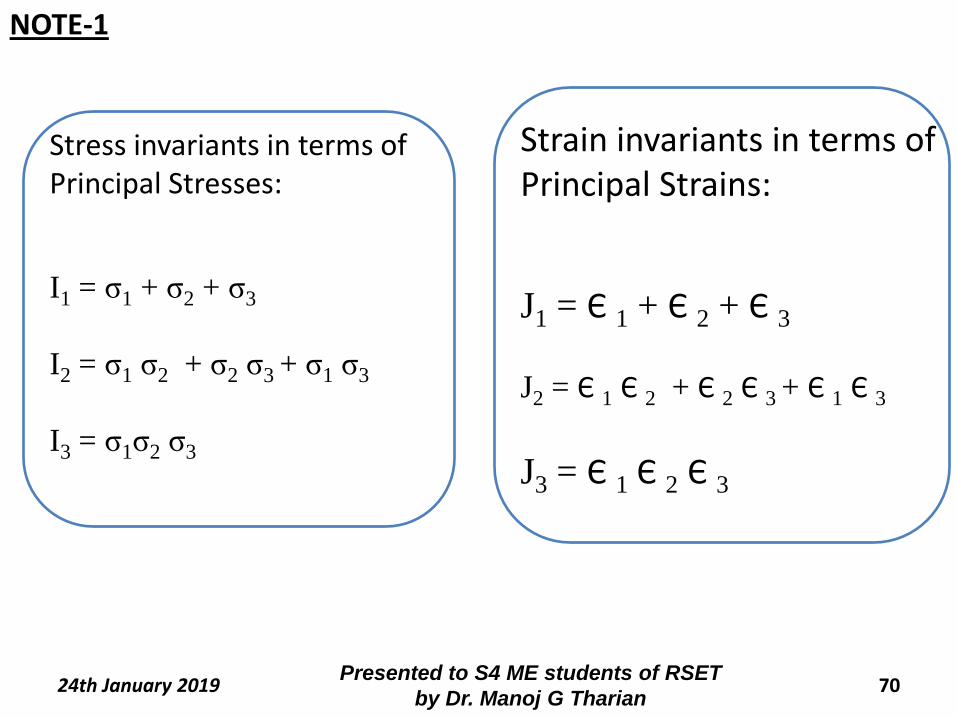
Stress invariants in terms of Principal Stresses:
I1 = σ1 + σ2 + σ3
I2 = σ1 σ2 + σ2 σ3 + σ1 σ3
I3 = σ1σ2 σ3
Strain invariants in terms of Principal Strains:
J1 = Є 1 + Є 2 + Є 3
J2 = Є 1 Є 2 + Є 2 Є 3 + Є 1 Є 3
J3 = Є 1 Є 2 Є 3
NOTE-1
71Presented to S4 ME students of RSET
by Dr. Manoj G Tharian24th January 2019
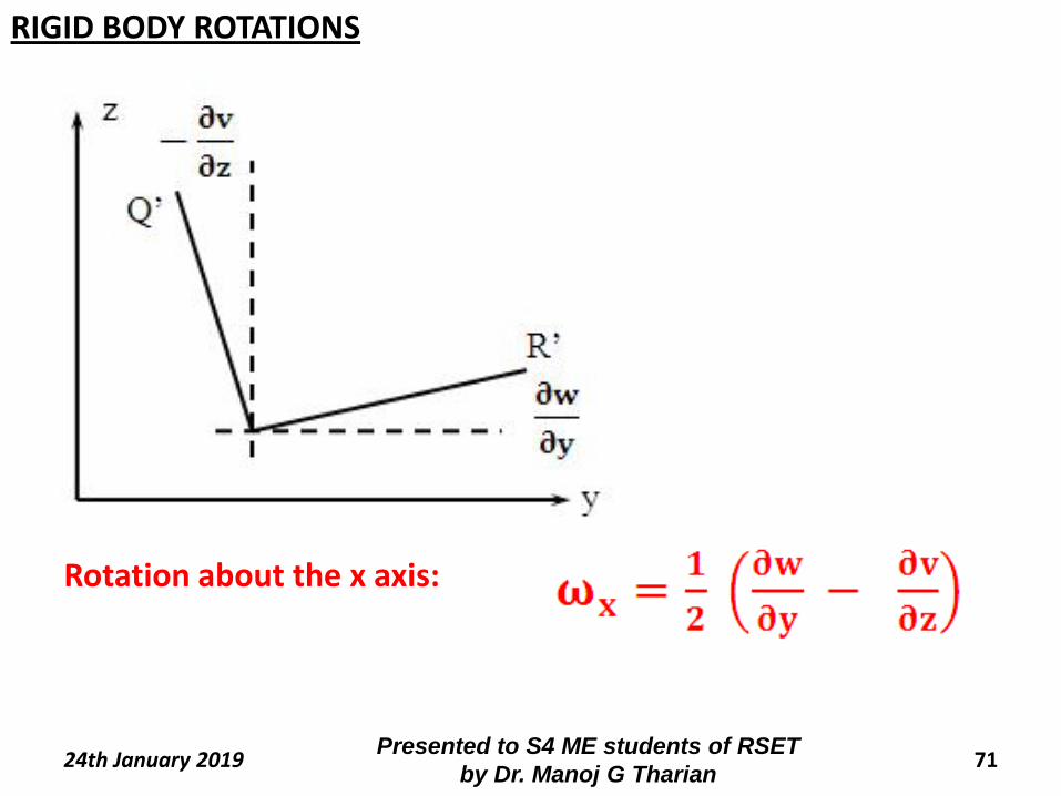
Rotation about the x axis:
RIGID BODY ROTATIONS
72Presented to S4 ME students of RSET
by Dr. Manoj G Tharian24th January 2019
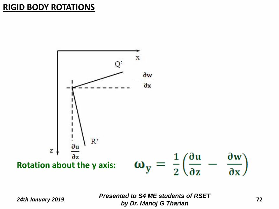
Rotation about the y axis:
RIGID BODY ROTATIONS
73Presented to S4 ME students of RSET
by Dr. Manoj G Tharian24th January 2019
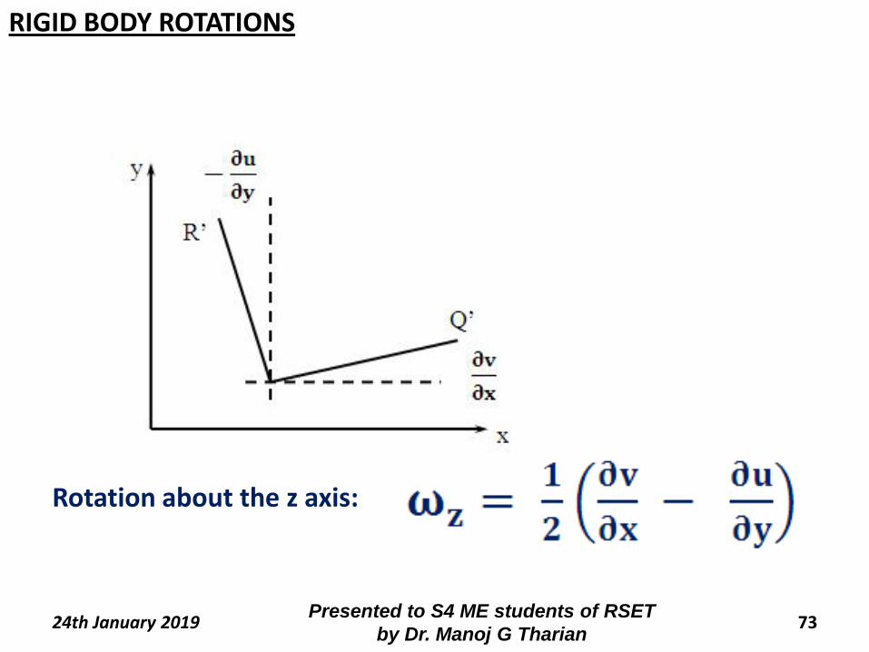
Rotation about the z axis:
RIGID BODY ROTATIONS
74Presented to S4 ME students of RSET
by Dr. Manoj G Tharian24th January 2019
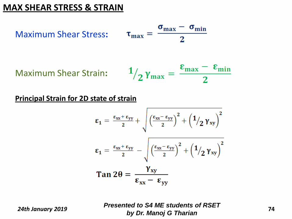
Maximum Shear Stress:
Maximum Shear Strain:
Principal Strain for 2D state of strain
MAX SHEAR STRESS & STRAIN
75Presented to S4 ME students of RSET
by Dr. Manoj G Tharian24th January 2019
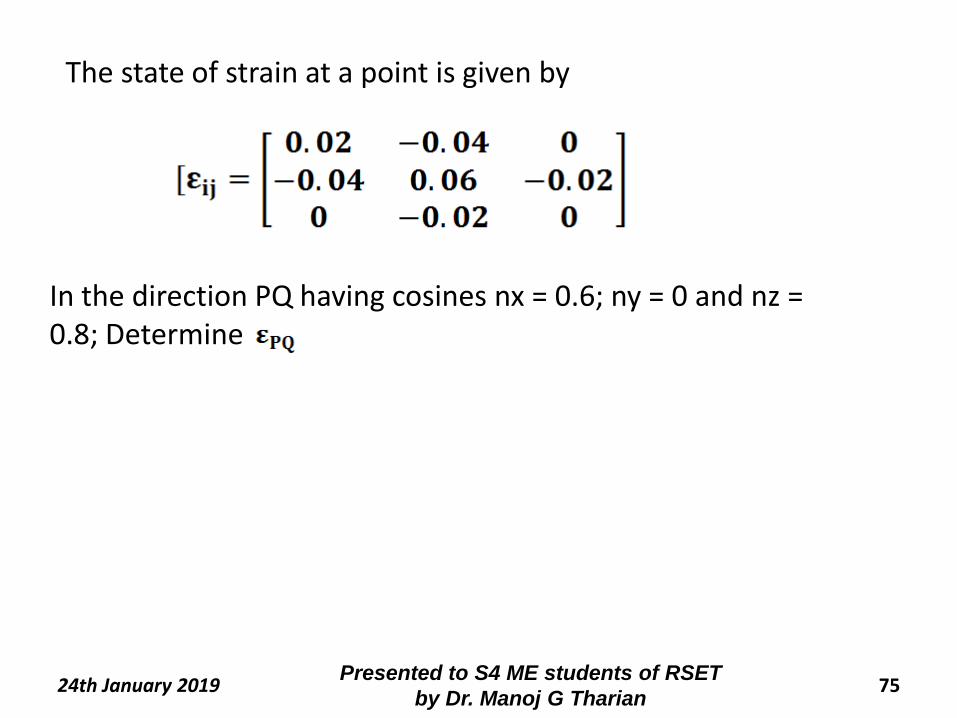
The state of strain at a point is given by
In the direction PQ having cosines nx = 0.6; ny = 0 and nz = 0.8; Determine
76Presented to S4 ME students of RSET
by Dr. Manoj G Tharian24th January 2019
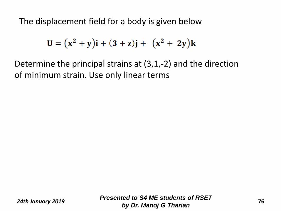
The displacement field for a body is given below
Determine the principal strains at (3,1,-2) and the direction of minimum strain. Use only linear terms
77Presented to S4 ME students of RSET by
Dr. Manoj G Tharian24th January 2019
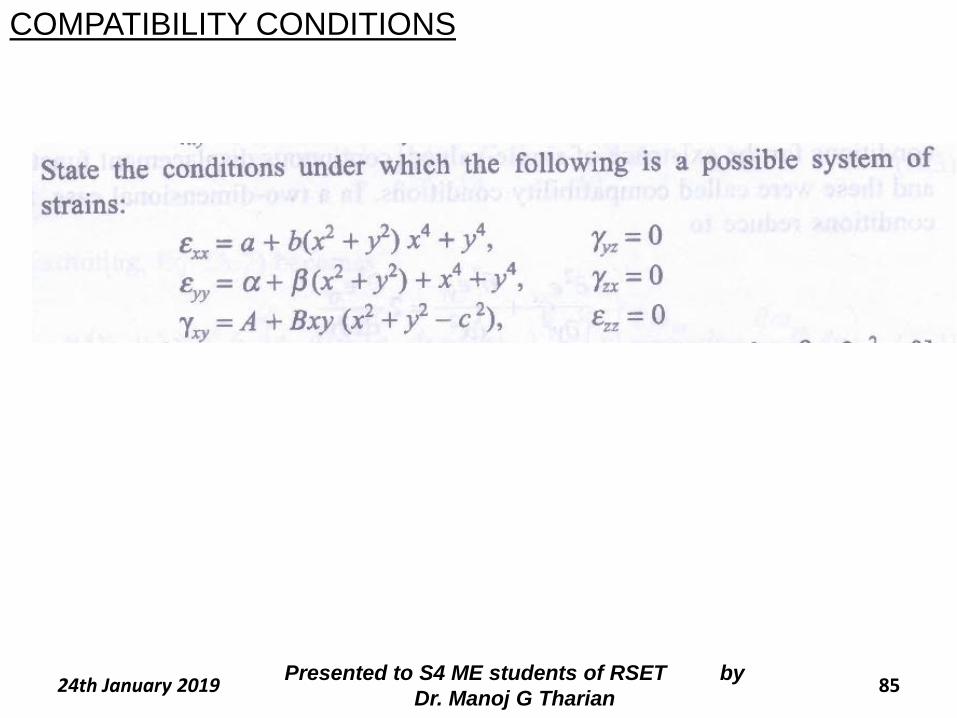
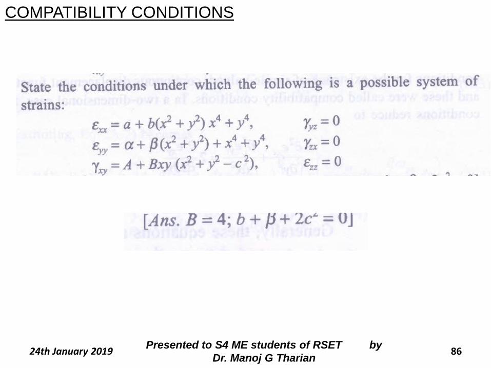
COMPATIBILITY CONDITIONS
COMPATIBILITY CONDITIONS
78Presented to S4 ME students of RSET by
Dr. Manoj G Tharian24th January 2019
COMPATIBILITY CONDITIONS
79Presented to S4 ME students of RSET by
Dr. Manoj G Tharian24th January 2019
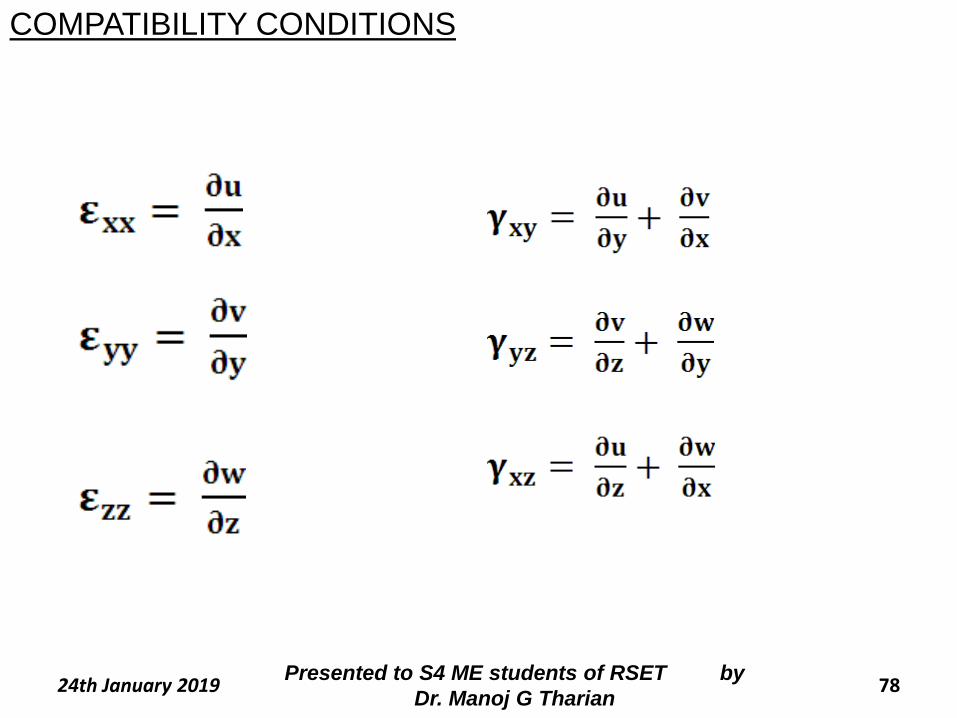
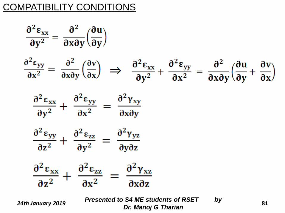
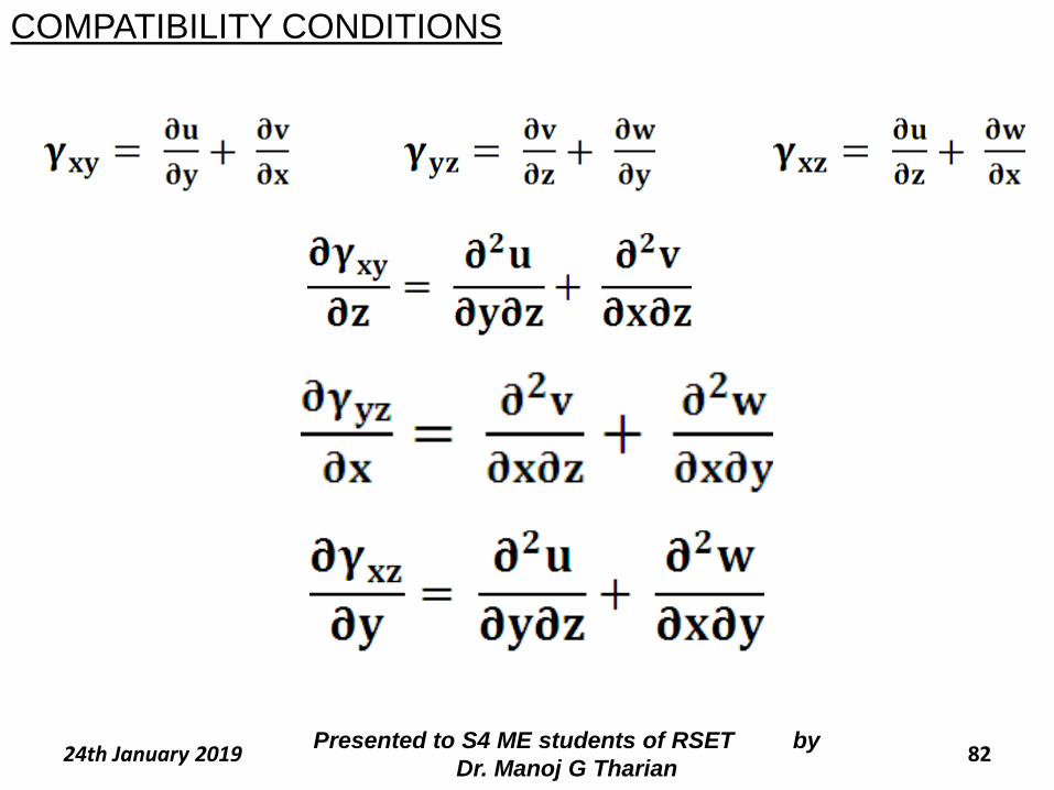
The three displacement components and six strain components
are related by six strain displacement relations of Cauchy.
The determination of six strain components from three
displacement components involves only differentiation.
However the reverse operation that is determination of three
displacement components from six strain components is more
complicated. Since it involves integrating six equations to obtain 3
functions.
COMPATIBILITY CONDITIONS
80Presented to S4 ME students of RSET by
Dr. Manoj G Tharian24th January 2019
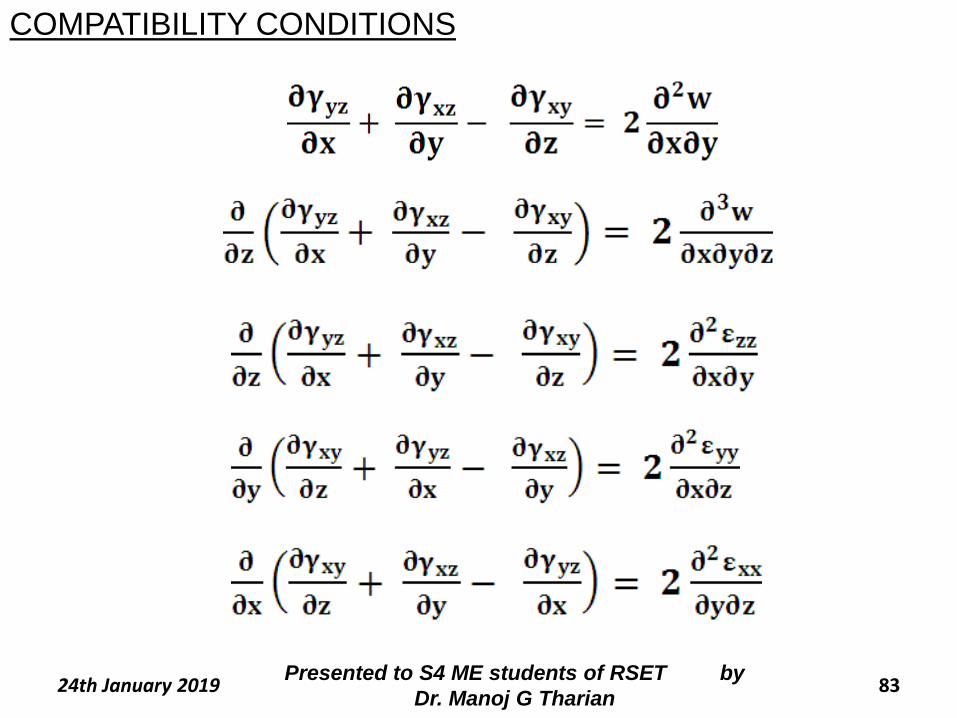
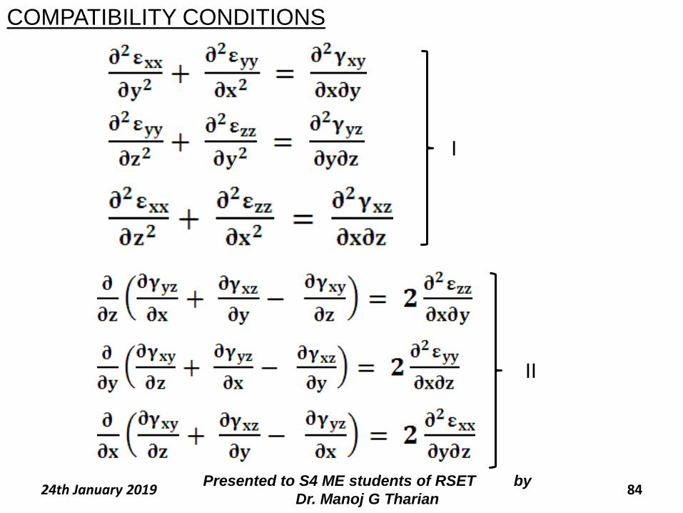
Therefore all strain components cannot be prescribed arbitrarily
and there must exist a definite relation among the strain
components. This relation among strain components is called
compatibility equations
COMPATIBILITY CONDITIONS
8124th January 2019Presented to S4 ME students of RSET by
Dr. Manoj G Tharian
COMPATIBILITY CONDITIONS
8224th January 2019Presented to S4 ME students of RSET by
Dr. Manoj G Tharian
COMPATIBILITY CONDITIONS
8324th January 2019Presented to S4 ME students of RSET by
Dr. Manoj G Tharian
COMPATIBILITY CONDITIONS
8424th January 2019Presented to S4 ME students of RSET by
Dr. Manoj G Tharian
I
II
COMPATIBILITY CONDITIONS
8524th January 2019Presented to S4 ME students of RSET by
Dr. Manoj G Tharian
COMPATIBILITY CONDITIONS
8624th January 2019Presented to S4 ME students of RSET by
Dr. Manoj G Tharian
COMPATIBILITY CONDITIONS


