Embed Size (px)
Citation preview
2X Series Installation Manual
P/N 501-405003-1-31 • REV 03.10 • ISS 07NOV13
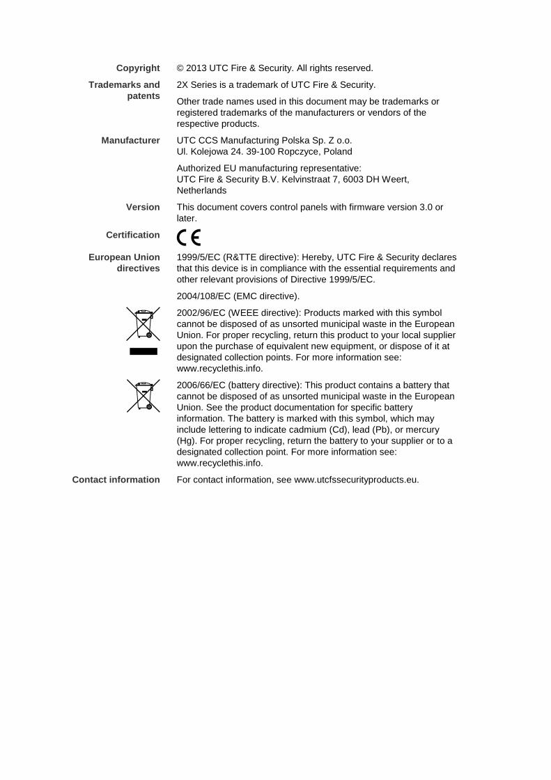
Copyright © 2013 UTC Fire & Security. All rights reserved.
Trademarks and patents
2X Series is a trademark of UTC Fire & Security.
Other trade names used in this document may be trademarks or registered trademarks of the manufacturers or vendors of the respective products.
Manufacturer UTC CCS Manufacturing Polska Sp. Z o.o. Ul. Kolejowa 24. 39-100 Ropczyce, Poland
Authorized EU manufacturing representative: UTC Fire & Security B.V. Kelvinstraat 7, 6003 DH Weert, Netherlands
Version This document covers control panels with firmware version 3.0 or later.
Certification
European Union directives
1999/5/EC (R&TTE directive): Hereby, UTC Fire & Security declares that this device is in compliance with the essential requirements and other relevant provisions of Directive 1999/5/EC.
2004/108/EC (EMC directive).
2002/96/EC (WEEE directive): Products marked with this symbol cannot be disposed of as unsorted municipal waste in the European Union. For proper recycling, return this product to your local supplier upon the purchase of equivalent new equipment, or dispose of it at designated collection points. For more information see: www.recyclethis.info.
2006/66/EC (battery directive): This product contains a battery that cannot be disposed of as unsorted municipal waste in the European Union. See the product documentation for specific battery information. The battery is marked with this symbol, which may include lettering to indicate cadmium (Cd), lead (Pb), or mercury (Hg). For proper recycling, return the battery to your supplier or to a designated collection point. For more information see: www.recyclethis.info.
Contact information For contact information, see www.utcfssecurityproducts.eu.
2X Series Installation Manual i
Content
Important information ii
Chapter 1 Introduction 1 Product range 2 Product compatibility 3 Product overview 4
Chapter 2 Installation 15 Electrical safety 16 Cabinet and PCB layout 17 Cabinet installation 19 Connections 24
Chapter 3 Configuration and commissioning 35 Introduction 36 Maintenance level operation and configuration 39 Installer level operation and configuration 53 Commissioning 102
Chapter 4 Maintenance 105 Fire alarm system maintenance 106 Battery maintenance 107
Chapter 5 Technical specifications 109
Appendix A Default configurations 117
Appendix B PSTN country codes 119
Appendix C Menu maps 121
Appendix D Regulatory information 129
Index 131
ii 2X Series Installation Manual
Important information
Introduction This is the installation manual for the 2X Series fire alarm, repeater, and evacuation control panels. Read these instructions and all related documentation entirely before installing or operating this product.
Firmware compatibility Information in this document covers control panels with firmware version 3.0 or later. This document must not be used as a guide to installation, configuration, or operation of control panels with an earlier firmware version.
To check the firmware version of your control panel, see the Revision report in the Reports menu.
Limitation of liability To the maximum extent permitted by applicable law, in no event will UTCFS be liable for any lost profits or business opportunities, loss of use, business interruption, loss of data, or any other indirect, special, incidental, or consequential damages under any theory of liability, whether based in contract, tort, negligence, product liability, or otherwise. Because some jurisdictions do not allow the exclusion or limitation of liability for consequential or incidental damages the preceding limitation may not apply to you. In any event the total liability of UTCFS shall not exceed the purchase price of the product. The foregoing limitation will apply to the maximum extent permitted by applicable law, regardless of whether UTCFS has been advised of the possibility of such damages and regardless of whether any remedy fails of its essential purpose.
Installation in accordance with this manual, applicable codes, and the instructions of the authority having jurisdiction is mandatory.
While every precaution has been taken during the preparation of this manual to ensure the accuracy of its contents, UTCFS assumes no responsibility for errors or omissions.
Advisory messages Advisory messages alert you to conditions or practices that can cause unwanted results. The advisory messages used in this document are shown and described below.
WARNING: Warning messages advise you of hazards that could result in injury or loss of life. They tell you which actions to take or to avoid in order to prevent the injury or loss of life.

2X Series Installation Manual iii
Caution: Caution messages advise you of possible equipment damage. They tell you which actions to take or to avoid in order to prevent the damage. Note: Note messages advise you of the possible loss of time or effort. They describe how to avoid the loss. Notes are also used to point out important information that you should read.

iv 2X Series Installation Manual
2X Series Installation Manual 1
Chapter 1 Introduction
Summary This chapter provides an introduction to your control panel, the main controls, and the indicators.
Content Product range 2 Product compatibility 3 Product overview 4
The user interface 4 Front panel controls and indicators 6 LCD controls and indicators 10 Acoustic indicators 12 Conditions 12
Chapter 1: Introduction
2 2X Series Installation Manual
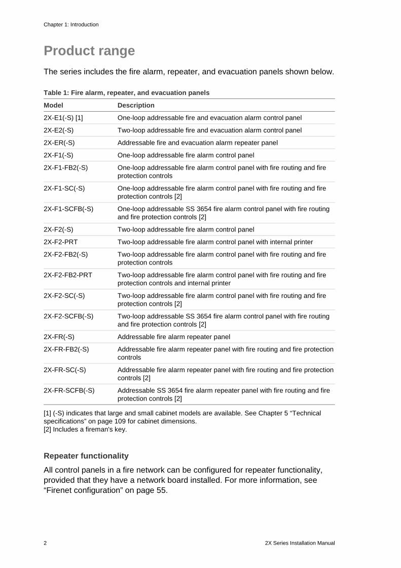
Product range The series includes the fire alarm, repeater, and evacuation panels shown below.
Table 1: Fire alarm, repeater, and evacuation panels
Model Description
2X-E1(-S) [1] One-loop addressable fire and evacuation alarm control panel
2X-E2(-S) Two-loop addressable fire and evacuation alarm control panel
2X-ER(-S) Addressable fire and evacuation alarm repeater panel
2X-F1(-S) One-loop addressable fire alarm control panel
2X-F1-FB2(-S) One-loop addressable fire alarm control panel with fire routing and fire protection controls
2X-F1-SC(-S) One-loop addressable fire alarm control panel with fire routing and fire protection controls [2]
2X-F1-SCFB(-S) One-loop addressable SS 3654 fire alarm control panel with fire routing and fire protection controls [2]
2X-F2(-S) Two-loop addressable fire alarm control panel
2X-F2-PRT Two-loop addressable fire alarm control panel with internal printer
2X-F2-FB2(-S) Two-loop addressable fire alarm control panel with fire routing and fire protection controls
2X-F2-FB2-PRT Two-loop addressable fire alarm control panel with fire routing and fire protection controls and internal printer
2X-F2-SC(-S) Two-loop addressable fire alarm control panel with fire routing and fire protection controls [2]
2X-F2-SCFB(-S) Two-loop addressable SS 3654 fire alarm control panel with fire routing and fire protection controls [2]
2X-FR(-S) Addressable fire alarm repeater panel
2X-FR-FB2(-S) Addressable fire alarm repeater panel with fire routing and fire protection controls
2X-FR-SC(-S) Addressable fire alarm repeater panel with fire routing and fire protection controls [2]
2X-FR-SCFB(-S) Addressable SS 3654 fire alarm repeater panel with fire routing and fire protection controls [2]
[1] (-S) indicates that large and small cabinet models are available. See Chapter 5 “Technical specifications” on page 109 for cabinet dimensions. [2] Includes a fireman's key.
Repeater functionality All control panels in a fire network can be configured for repeater functionality, provided that they have a network board installed. For more information, see “Firenet configuration” on page 55.
Chapter 1: Introduction
2X Series Installation Manual 3
Fire routing and fire protection control and indication In this document, information on control and indication for fire routing and fire protection applies only to control panels that include those features.
Product compatibility Products compatible with these control panels are listed in the supplied compatibility list. Only those products specified in the compatibility list are guaranteed to be compatible with these control panels. For further details contact your local supplier.
Chapter 1: Introduction
4 2X Series Installation Manual
Product overview This topic provides an introduction to the control panel user interface, LCD, operator controls, and indicators.
For a detailed overview of front panel controls and indicators, see “Front panel controls and indicators” on page 6.
The user interface
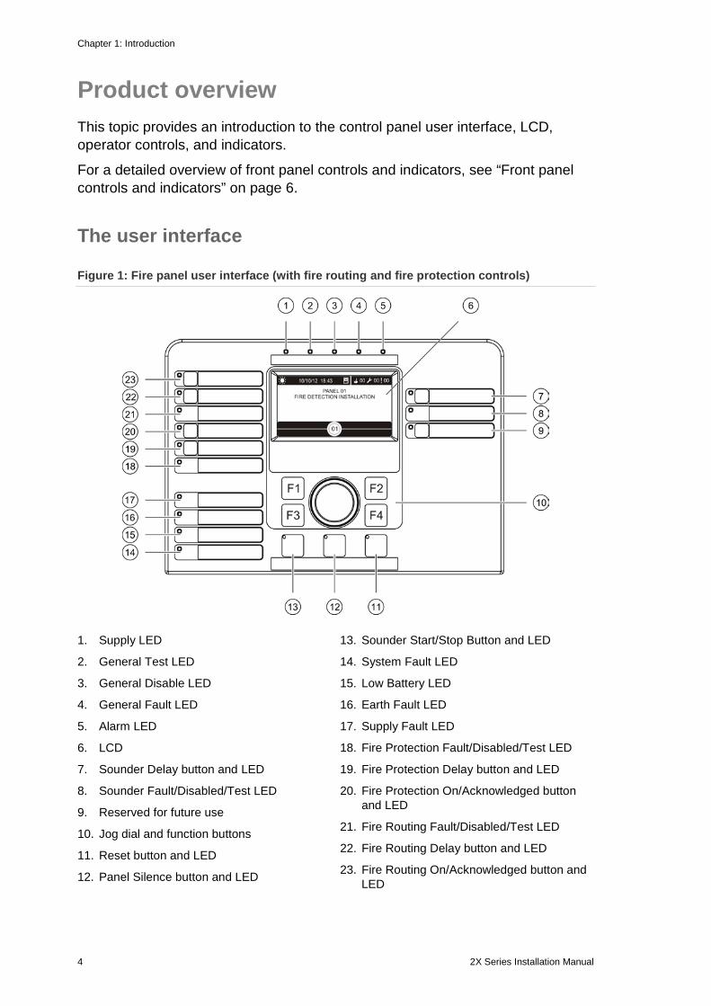
Figure 1: Fire panel user interface (with fire routing and fire protection controls)
1. Supply LED
2. General Test LED
3. General Disable LED
4. General Fault LED
5. Alarm LED
6. LCD
7. Sounder Delay button and LED
8. Sounder Fault/Disabled/Test LED
9. Reserved for future use
10. Jog dial and function buttons
11. Reset button and LED
12. Panel Silence button and LED
13. Sounder Start/Stop Button and LED
14. System Fault LED
15. Low Battery LED
16. Earth Fault LED
17. Supply Fault LED
18. Fire Protection Fault/Disabled/Test LED
19. Fire Protection Delay button and LED
20. Fire Protection On/Acknowledged button and LED
21. Fire Routing Fault/Disabled/Test LED
22. Fire Routing Delay button and LED
23. Fire Routing On/Acknowledged button and LED
Chapter 1: Introduction
2X Series Installation Manual 5
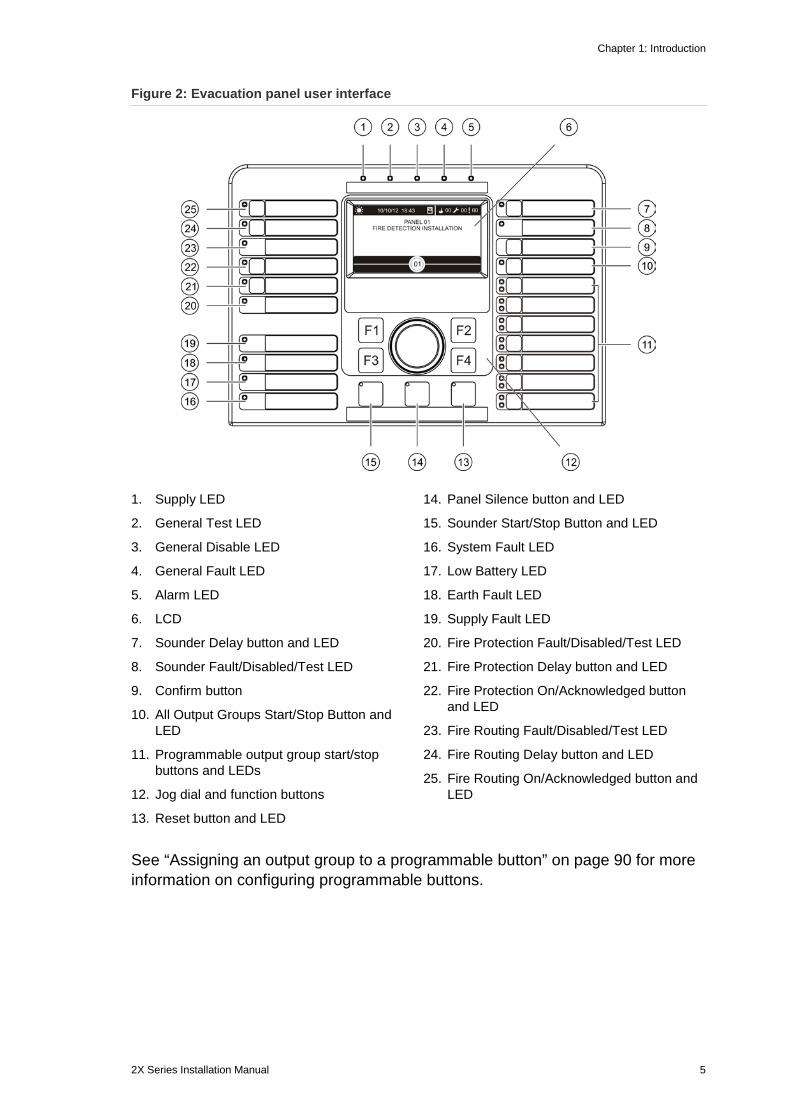
Figure 2: Evacuation panel user interface
1. Supply LED
2. General Test LED
3. General Disable LED
4. General Fault LED
5. Alarm LED
6. LCD
7. Sounder Delay button and LED
8. Sounder Fault/Disabled/Test LED
9. Confirm button
10. All Output Groups Start/Stop Button and LED
11. Programmable output group start/stop buttons and LEDs
12. Jog dial and function buttons
13. Reset button and LED
14. Panel Silence button and LED
15. Sounder Start/Stop Button and LED
16. System Fault LED
17. Low Battery LED
18. Earth Fault LED
19. Supply Fault LED
20. Fire Protection Fault/Disabled/Test LED
21. Fire Protection Delay button and LED
22. Fire Protection On/Acknowledged button and LED
23. Fire Routing Fault/Disabled/Test LED
24. Fire Routing Delay button and LED
25. Fire Routing On/Acknowledged button and LED
See “Assigning an output group to a programmable button” on page 90 for more information on configuring programmable buttons.
Chapter 1: Introduction
6 2X Series Installation Manual
Configuration options Depending on your configuration, the labels for some interface buttons may change. See Table 2 below.
Table 2: Configured changes to interface buttons and LEDs
Item EN 54 NEN 2575
10 All Output Groups Start/Stop All Evacuation Start/Stop
11 Programmable output group start/stop Evacuation area sounders start/stop [1]
15 Sounder Start/Stop Fire Sounder Start/Stop
[1] If the evacuation panel is operating in NEN 2575 mode, only sounder output groups can be associated with the programmable start/stop buttons.
Front panel controls and indicators Operational features described in this section are not available to all users. More information on control panel operation and access restrictions can be found in the topic “User levels” on page 36.
Common controls and indicators The table below includes information for the common controls and indicators available for fire, repeater, and evacuation panels.
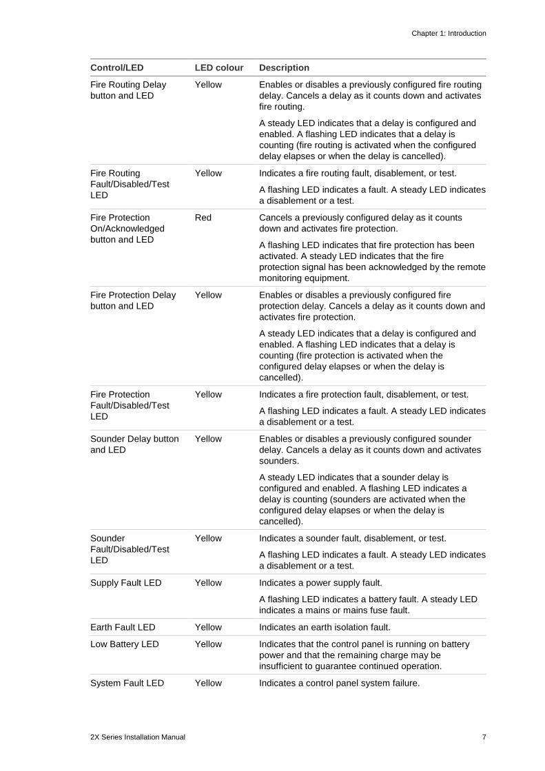
Table 3: Common controls and indicators
Control/LED LED colour Description
Supply LED Green Indicates that the system is powered up.
General Test LED Yellow Indicates that one or more features or devices are being tested.
General Disable LED Yellow Indicates that one or more features or devices are disabled.
General Fault LED Yellow Indicates a general fault. The fault LED for the corresponding device or feature also flashes.
Alarm LED Red Indicates a fire alarm.
A flashing LED indicates that the alarm was activated by a detector. A steady LED indicates that the alarm was activated by a manual call point.
Fire Routing On/Acknowledged button and LED
Red Cancels a previously configured delay as it counts down and activates fire routing.
A flashing LED indicates that fire routing has been activated. A steady LED indicates that the fire routing signal has been acknowledged by the remote monitoring equipment.
Chapter 1: Introduction
2X Series Installation Manual 7
Control/LED LED colour Description
Fire Routing Delay button and LED
Yellow Enables or disables a previously configured fire routing delay. Cancels a delay as it counts down and activates fire routing.
A steady LED indicates that a delay is configured and enabled. A flashing LED indicates that a delay is counting (fire routing is activated when the configured delay elapses or when the delay is cancelled).
Fire Routing Fault/Disabled/Test LED
Yellow Indicates a fire routing fault, disablement, or test.
A flashing LED indicates a fault. A steady LED indicates a disablement or a test.
Fire Protection On/Acknowledged button and LED
Red Cancels a previously configured delay as it counts down and activates fire protection.
A flashing LED indicates that fire protection has been activated. A steady LED indicates that the fire protection signal has been acknowledged by the remote monitoring equipment.
Fire Protection Delay button and LED
Yellow Enables or disables a previously configured fire protection delay. Cancels a delay as it counts down and activates fire protection.
A steady LED indicates that a delay is configured and enabled. A flashing LED indicates that a delay is counting (fire protection is activated when the configured delay elapses or when the delay is cancelled).
Fire Protection Fault/Disabled/Test LED
Yellow Indicates a fire protection fault, disablement, or test.
A flashing LED indicates a fault. A steady LED indicates a disablement or a test.
Sounder Delay button and LED
Yellow Enables or disables a previously configured sounder delay. Cancels a delay as it counts down and activates sounders.
A steady LED indicates that a sounder delay is configured and enabled. A flashing LED indicates a delay is counting (sounders are activated when the configured delay elapses or when the delay is cancelled).
Sounder Fault/Disabled/Test LED
Yellow Indicates a sounder fault, disablement, or test.
A flashing LED indicates a fault. A steady LED indicates a disablement or a test.
Supply Fault LED Yellow Indicates a power supply fault.
A flashing LED indicates a battery fault. A steady LED indicates a mains or mains fuse fault.
Earth Fault LED Yellow Indicates an earth isolation fault.
Low Battery LED Yellow Indicates that the control panel is running on battery power and that the remaining charge may be insufficient to guarantee continued operation.
System Fault LED Yellow Indicates a control panel system failure.
Chapter 1: Introduction
8 2X Series Installation Manual
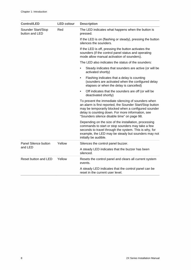
Control/LED LED colour Description
Sounder Start/Stop button and LED
Red The LED indicates what happens when the button is pressed.
If the LED is on (flashing or steady), pressing the button silences the sounders.
If the LED is off, pressing the button activates the sounders (if the control panel status and operating mode allow manual activation of sounders).
The LED also indicates the status of the sounders:
• Steady indicates that sounders are active (or will be activated shortly)
• Flashing indicates that a delay is counting (sounders are activated when the configured delay elapses or when the delay is cancelled)
• Off indicates that the sounders are off (or will be deactivated shortly)
To prevent the immediate silencing of sounders when an alarm is first reported, the Sounder Start/Stop button may be temporarily blocked when a configured sounder delay is counting down. For more information, see “Sounders silence disable time” on page 98.
Depending on the size of the installation, processing commands to start or stop sounders may take a few seconds to travel through the system. This is why, for example, the LED may be steady but sounders may not initially be audible.
Panel Silence button and LED
Yellow Silences the control panel buzzer.
A steady LED indicates that the buzzer has been silenced.
Reset button and LED Yellow Resets the control panel and clears all current system events.
A steady LED indicates that the control panel can be reset in the current user level.
Chapter 1: Introduction
2X Series Installation Manual 9
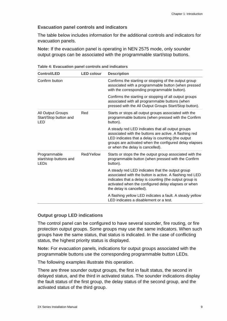
Evacuation panel controls and indicators The table below includes information for the additional controls and indicators for evacuation panels.
Note: If the evacuation panel is operating in NEN 2575 mode, only sounder output groups can be associated with the programmable start/stop buttons.
Table 4: Evacuation panel controls and indicators
Control/LED LED colour Description
Confirm button Confirms the starting or stopping of the output group associated with a programmable button (when pressed with the corresponding programmable button).
Confirms the starting or stopping of all output groups associated with all programmable buttons (when pressed with the All Output Groups Start/Stop button).
All Output Groups Start/Stop button and LED
Red Starts or stops all output groups associated with the programmable buttons (when pressed with the Confirm button).
A steady red LED indicates that all output groups associated with the buttons are active. A flashing red LED indicates that a delay is counting (the output groups are activated when the configured delay elapses or when the delay is cancelled).
Programmable start/stop buttons and LEDs
Red/Yellow Starts or stops the the output group associated with the programmable button (when pressed with the Confirm button).
A steady red LED indicates that the output group associated with the button is active. A flashing red LED indicates that a delay is counting (the output group is activated when the configured delay elapses or when the delay is cancelled).
A flashing yellow LED indicates a fault. A steady yellow LED indicates a disablement or a test.
Output group LED indications The control panel can be configured to have several sounder, fire routing, or fire protection output groups. Some groups may use the same indicators. When such groups have the same status, that status is indicated. In the case of conflicting status, the highest priority status is displayed.
Note: For evacuation panels, indications for output groups associated with the programmable buttons use the corresponding programmable button LEDs.
The following examples illustrate this operation.
There are three sounder output groups, the first in fault status, the second in delayed status, and the third in activated status. The sounder indications display the fault status of the first group, the delay status of the second group, and the activated status of the third group.
Chapter 1: Introduction
10 2X Series Installation Manual
There are two fire routing output groups, the first is in activated status and the second is in acknowledged status. The fire routing indication displays the acknowledged status but not the activation status (the acknowledgement status takes priority).
For more information on output groups, see “Output groups” on page 86.
LCD controls and indicators
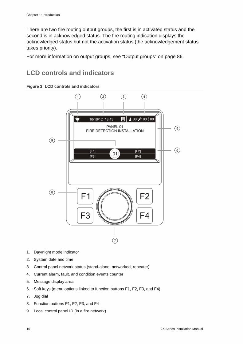
Figure 3: LCD controls and indicators
1. Day/night mode indicator
2. System date and time
3. Control panel network status (stand-alone, networked, repeater)
4. Current alarm, fault, and condition events counter
5. Message display area
6. Soft keys (menu options linked to function buttons F1, F2, F3, and F4)
7. Jog dial
8. Function buttons F1, F2, F3, and F4
9. Local control panel ID (in a fire network)
Chapter 1: Introduction
2X Series Installation Manual 11
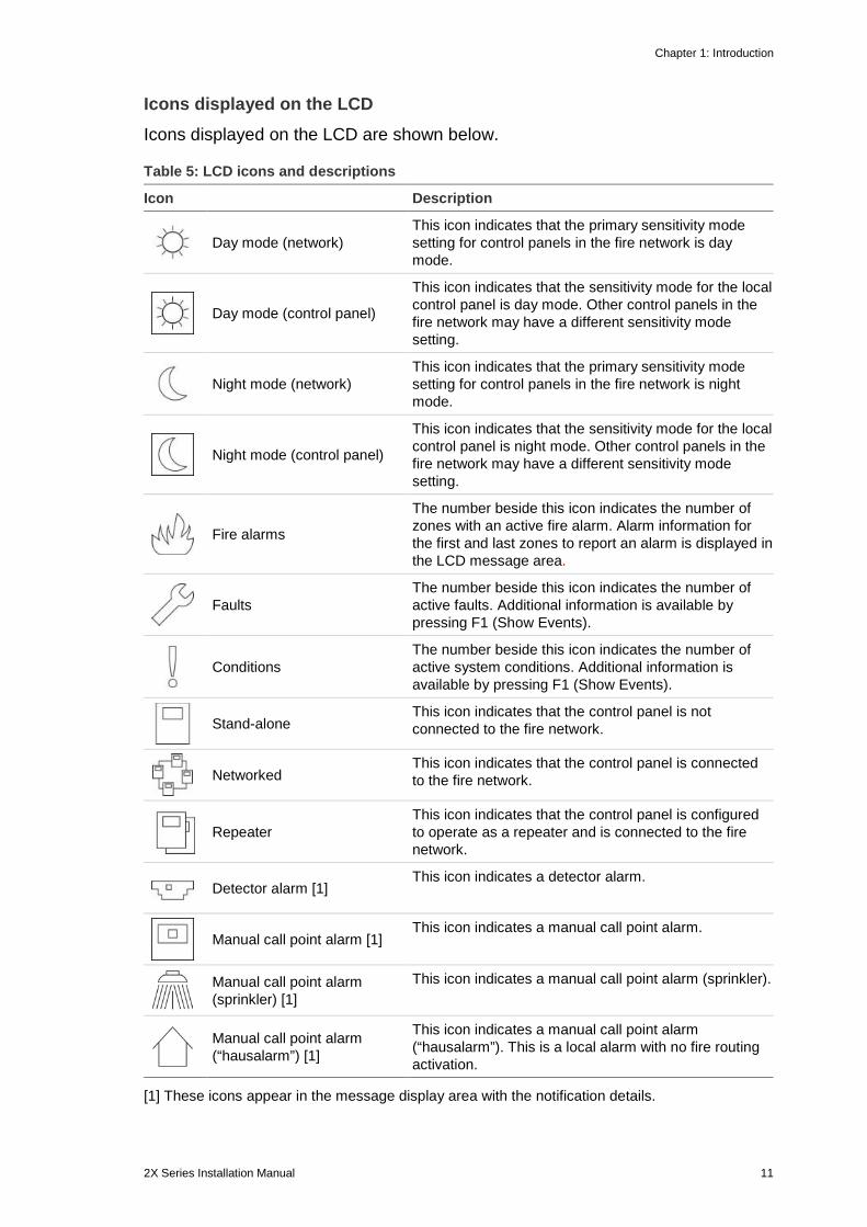
Icons displayed on the LCD Icons displayed on the LCD are shown below.
Table 5: LCD icons and descriptions
Icon Description
Day mode (network)
This icon indicates that the primary sensitivity mode setting for control panels in the fire network is day mode.
Day mode (control panel)
This icon indicates that the sensitivity mode for the local control panel is day mode. Other control panels in the fire network may have a different sensitivity mode setting.
Night mode (network)
This icon indicates that the primary sensitivity mode setting for control panels in the fire network is night mode.
Night mode (control panel)
This icon indicates that the sensitivity mode for the local control panel is night mode. Other control panels in the fire network may have a different sensitivity mode setting.
Fire alarms
The number beside this icon indicates the number of zones with an active fire alarm. Alarm information for the first and last zones to report an alarm is displayed in the LCD message area.
Faults
The number beside this icon indicates the number of active faults. Additional information is available by pressing F1 (Show Events).
Conditions
The number beside this icon indicates the number of active system conditions. Additional information is available by pressing F1 (Show Events).
Stand-alone
This icon indicates that the control panel is not connected to the fire network.
Networked
This icon indicates that the control panel is connected to the fire network.
Repeater
This icon indicates that the control panel is configured to operate as a repeater and is connected to the fire network.
Detector alarm [1]
This icon indicates a detector alarm.
Manual call point alarm [1]
This icon indicates a manual call point alarm.
Manual call point alarm (sprinkler) [1]
This icon indicates a manual call point alarm (sprinkler).
Manual call point alarm (“hausalarm”) [1]
This icon indicates a manual call point alarm (“hausalarm”). This is a local alarm with no fire routing activation.
[1] These icons appear in the message display area with the notification details.
Chapter 1: Introduction
12 2X Series Installation Manual
Indication of remote and local events on the LCD The local control panel ID is always displayed on the LCD (see Figure 3 on page 10).
If your control panel forms part of a fire network, the event notification includes the panel ID reporting the event as follows:
• If the panel ID matches the local ID, then the event relates to the local control panel
• If the panel ID does not match the local ID, then the event is reported by the remote control panel with the panel ID indicated
Repeater panels are installed only in fire networks and by default have a network board installed. Fire alarm control panels must have a network board installed to connect to a fire network.
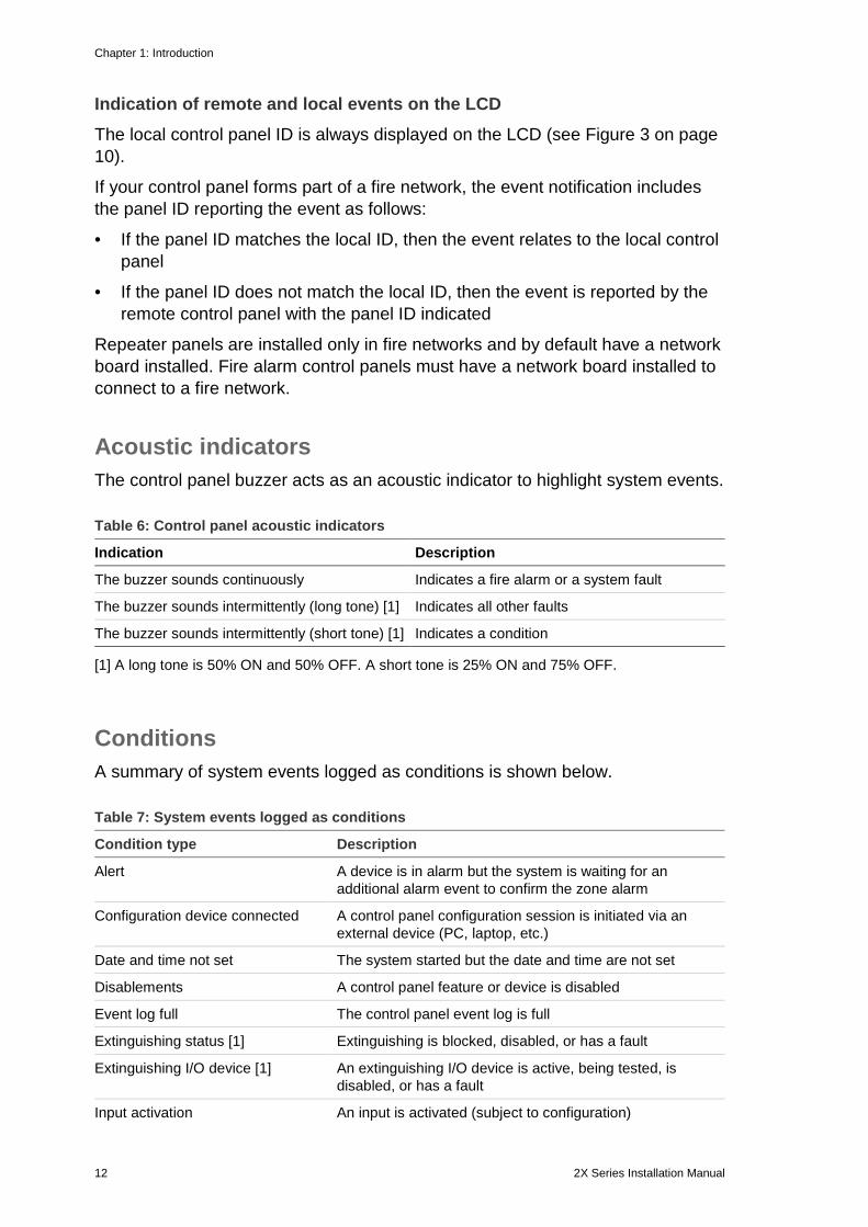
Acoustic indicators The control panel buzzer acts as an acoustic indicator to highlight system events.
Table 6: Control panel acoustic indicators
Indication Description
The buzzer sounds continuously Indicates a fire alarm or a system fault
The buzzer sounds intermittently (long tone) [1] Indicates all other faults
The buzzer sounds intermittently (short tone) [1] Indicates a condition
[1] A long tone is 50% ON and 50% OFF. A short tone is 25% ON and 75% OFF.
Conditions A summary of system events logged as conditions is shown below.
Table 7: System events logged as conditions
Condition type Description
Alert A device is in alarm but the system is waiting for an additional alarm event to confirm the zone alarm
Configuration device connected A control panel configuration session is initiated via an external device (PC, laptop, etc.)
Date and time not set The system started but the date and time are not set
Disablements A control panel feature or device is disabled
Event log full The control panel event log is full
Extinguishing status [1] Extinguishing is blocked, disabled, or has a fault
Extinguishing I/O device [1] An extinguishing I/O device is active, being tested, is disabled, or has a fault
Input activation An input is activated (subject to configuration)
Chapter 1: Introduction
2X Series Installation Manual 13
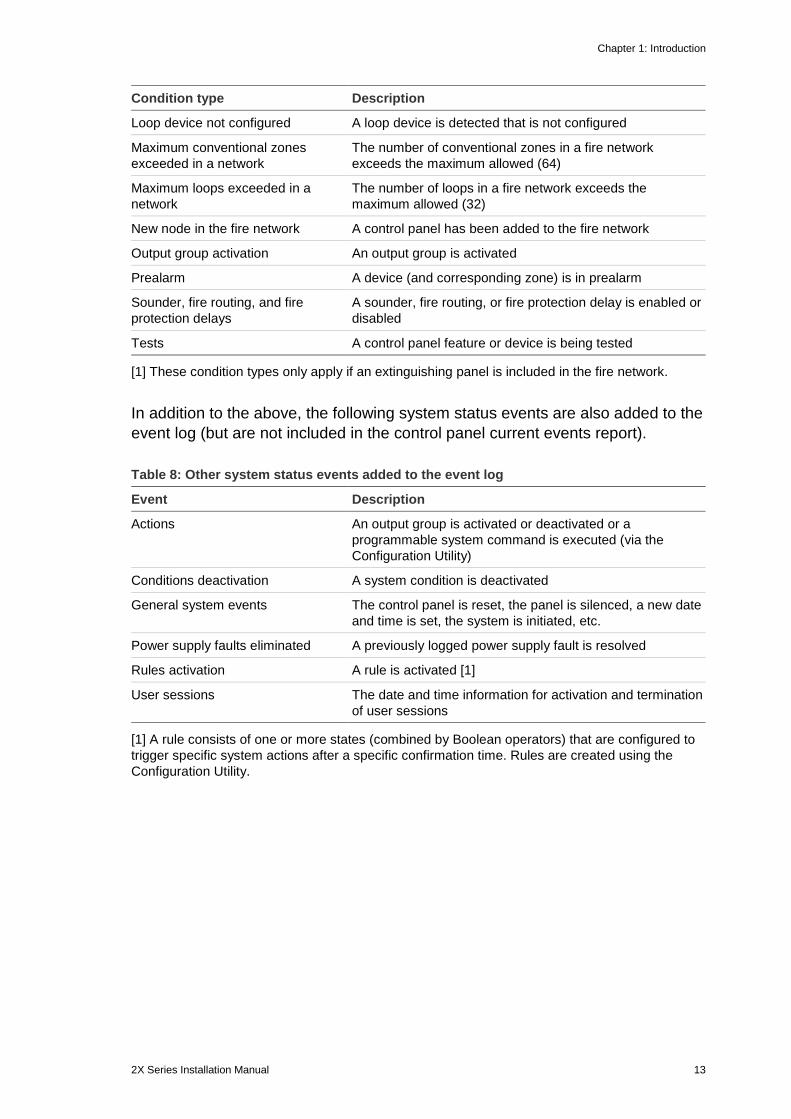
Condition type Description
Loop device not configured A loop device is detected that is not configured
Maximum conventional zones exceeded in a network
The number of conventional zones in a fire network exceeds the maximum allowed (64)
Maximum loops exceeded in a network
The number of loops in a fire network exceeds the maximum allowed (32)
New node in the fire network A control panel has been added to the fire network
Output group activation An output group is activated
Prealarm A device (and corresponding zone) is in prealarm
Sounder, fire routing, and fire protection delays
A sounder, fire routing, or fire protection delay is enabled or disabled
Tests A control panel feature or device is being tested
[1] These condition types only apply if an extinguishing panel is included in the fire network.
In addition to the above, the following system status events are also added to the event log (but are not included in the control panel current events report).
Table 8: Other system status events added to the event log
Event Description
Actions An output group is activated or deactivated or a programmable system command is executed (via the Configuration Utility)
Conditions deactivation A system condition is deactivated
General system events The control panel is reset, the panel is silenced, a new date and time is set, the system is initiated, etc.
Power supply faults eliminated A previously logged power supply fault is resolved
Rules activation A rule is activated [1]
User sessions The date and time information for activation and termination of user sessions
[1] A rule consists of one or more states (combined by Boolean operators) that are configured to trigger specific system actions after a specific confirmation time. Rules are created using the Configuration Utility.

Chapter 1: Introduction
14 2X Series Installation Manual
2X Series Installation Manual 15
Chapter 2 Installation
Summary This chapter provides detailed installation and connection information for your control panel.
Caution: This product must be installed and maintained by qualified personnel adhering to the CEN/TS 54-14 standard (or the corresponding national standard) and any other applicable regulations.
Content Electrical safety 16 Cabinet and PCB layout 17 Cabinet installation 19
Where to install the control panel 19 Fixing the cabinet to the wall 19 Adding the menu inserts 20 Connecting the user interface cable 21 Connecting the internal printer and loading paper 22
Connections 24 Recommended cables 24 Overview of fire system connections 25 Connecting loops 26 Connecting loop devices 28 Connecting inputs 28 Connecting outputs 28 Connecting the mains power supply 30 Connecting the batteries 32 Connecting expansion boards 32 Connecting a fire network 32 Connecting an external printer or ASCII terminal 34

Chapter 2: Installation
16 2X Series Installation Manual
Electrical safety WARNING: Electrocution hazard. To avoid personal injury or death from electrocution, remove all sources of power and allow stored energy to discharge before installing or removing equipment.
Caution: Equipment damage hazard. This product is sensitive to electrostatic discharge (ESD). To avoid damage, follow accepted ESD handling procedures.
Chapter 2: Installation
2X Series Installation Manual 17
Cabinet and PCB layout
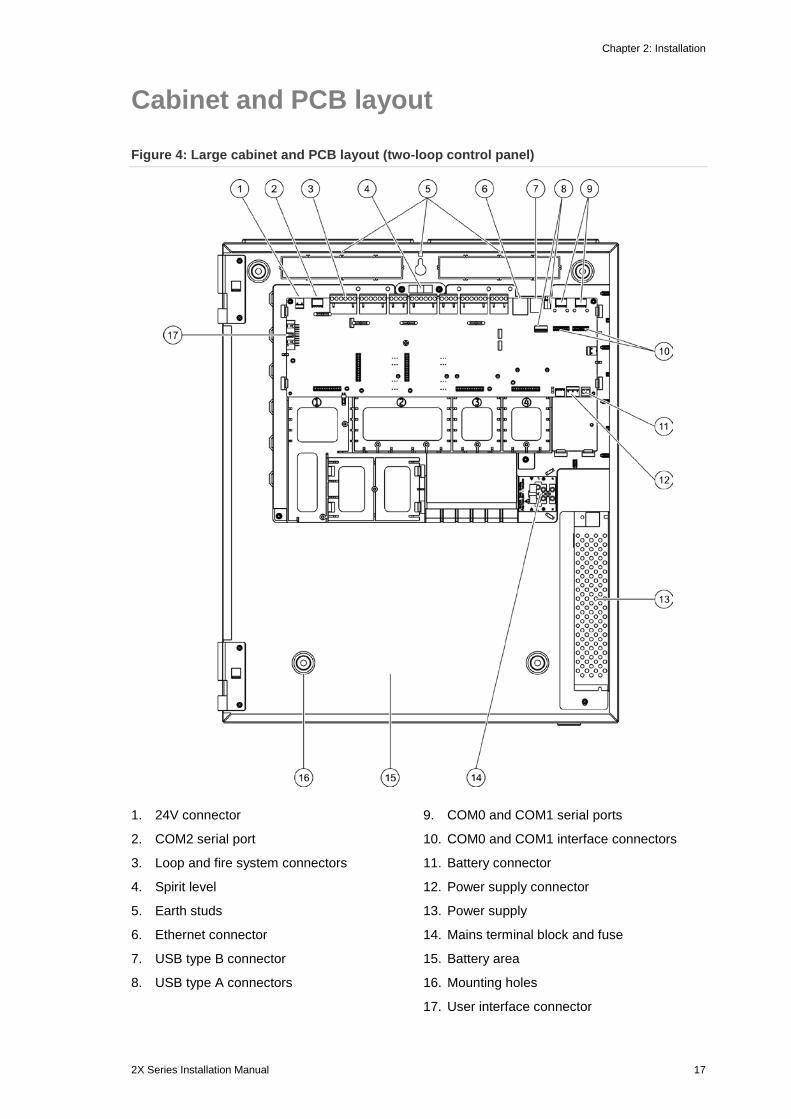
Figure 4: Large cabinet and PCB layout (two-loop control panel)
1. 24V connector
2. COM2 serial port
3. Loop and fire system connectors
4. Spirit level
5. Earth studs
6. Ethernet connector
7. USB type B connector
8. USB type A connectors
9. COM0 and COM1 serial ports
10. COM0 and COM1 interface connectors
11. Battery connector
12. Power supply connector
13. Power supply
14. Mains terminal block and fuse
15. Battery area
16. Mounting holes
17. User interface connector
Chapter 2: Installation
18 2X Series Installation Manual
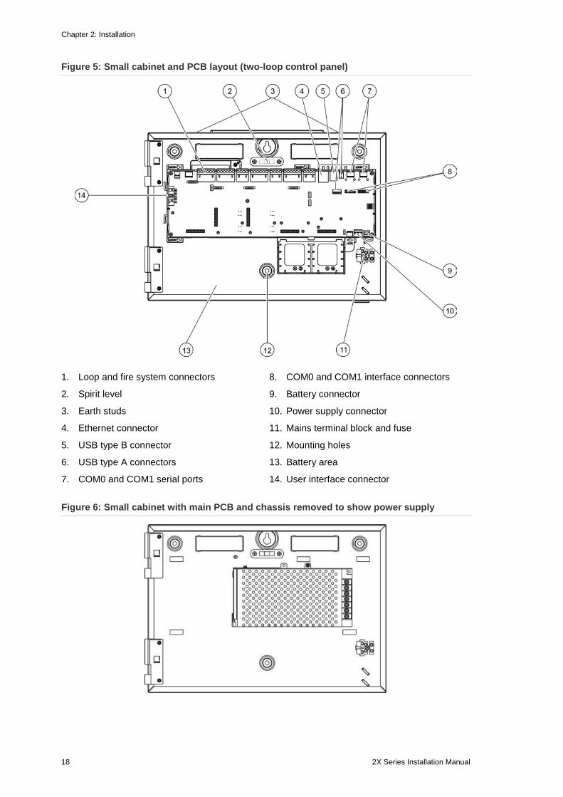
Figure 5: Small cabinet and PCB layout (two-loop control panel)
1. Loop and fire system connectors
2. Spirit level
3. Earth studs
4. Ethernet connector
5. USB type B connector
6. USB type A connectors
7. COM0 and COM1 serial ports
8. COM0 and COM1 interface connectors
9. Battery connector
10. Power supply connector
11. Mains terminal block and fuse
12. Mounting holes
13. Battery area
14. User interface connector
Figure 6: Small cabinet with main PCB and chassis removed to show power supply
Chapter 2: Installation
2X Series Installation Manual 19
Cabinet installation
Where to install the control panel Install the control panel in a location that is free from construction dust and debris, and immune to extreme temperature ranges and humidity. See Chapter 5 “Technical specifications” on page 109 for more information on the operating temperature and relative humidity specifications.
Provide enough floor and wall space to allow the control panel to be installed and serviced without any obstructions.
The cabinet should be mounted so that the user interface is at eye level.
Note: This product has been certified to EN 54-2 using the standard wall mounting installation method described below. If other mounting options are used, take care to install the panel in an area that is not subject to excessive vibration or shock.
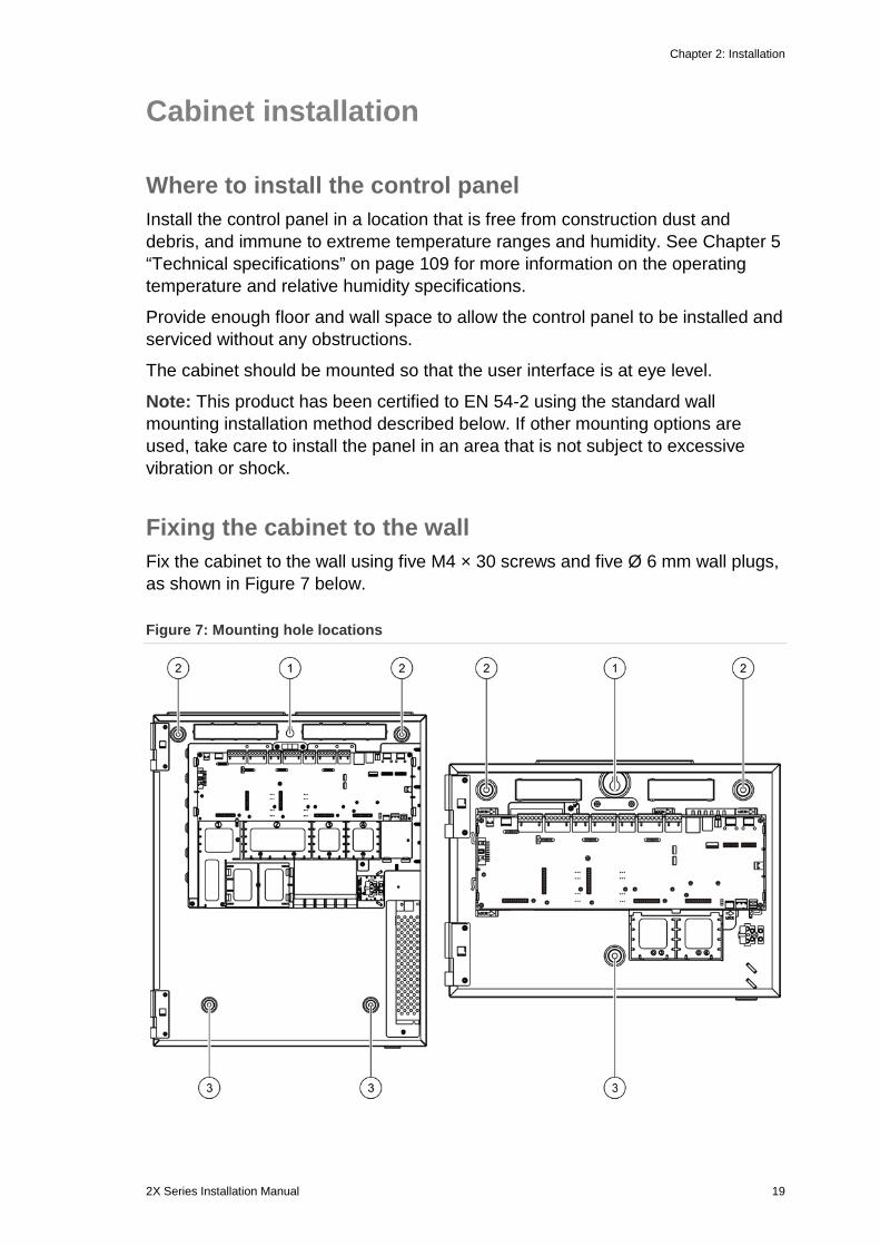
Fixing the cabinet to the wall Fix the cabinet to the wall using five M4 × 30 screws and five Ø 6 mm wall plugs, as shown in Figure 7 below.
Figure 7: Mounting hole locations
Chapter 2: Installation
20 2X Series Installation Manual
To fix the cabinet to the wall: 1. Hold the cabinet to the wall at the required installation height.
2. Ensure that the cabinet is level using the built-in spirit level and mark drill points on the wall.
3. Drill all required holes and insert a 6 mm wall plug into each.
4. Insert a screw in position (1) and hang the cabinet onto this screw.
5. Insert screws in positions (2) and tighten.
6. Insert screws in position (3) and tighten.
7. Tighten screw in position (1).
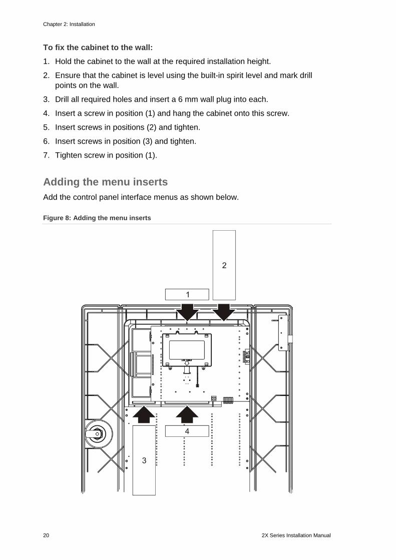
Adding the menu inserts Add the control panel interface menus as shown below.
Figure 8: Adding the menu inserts
Chapter 2: Installation
2X Series Installation Manual 21
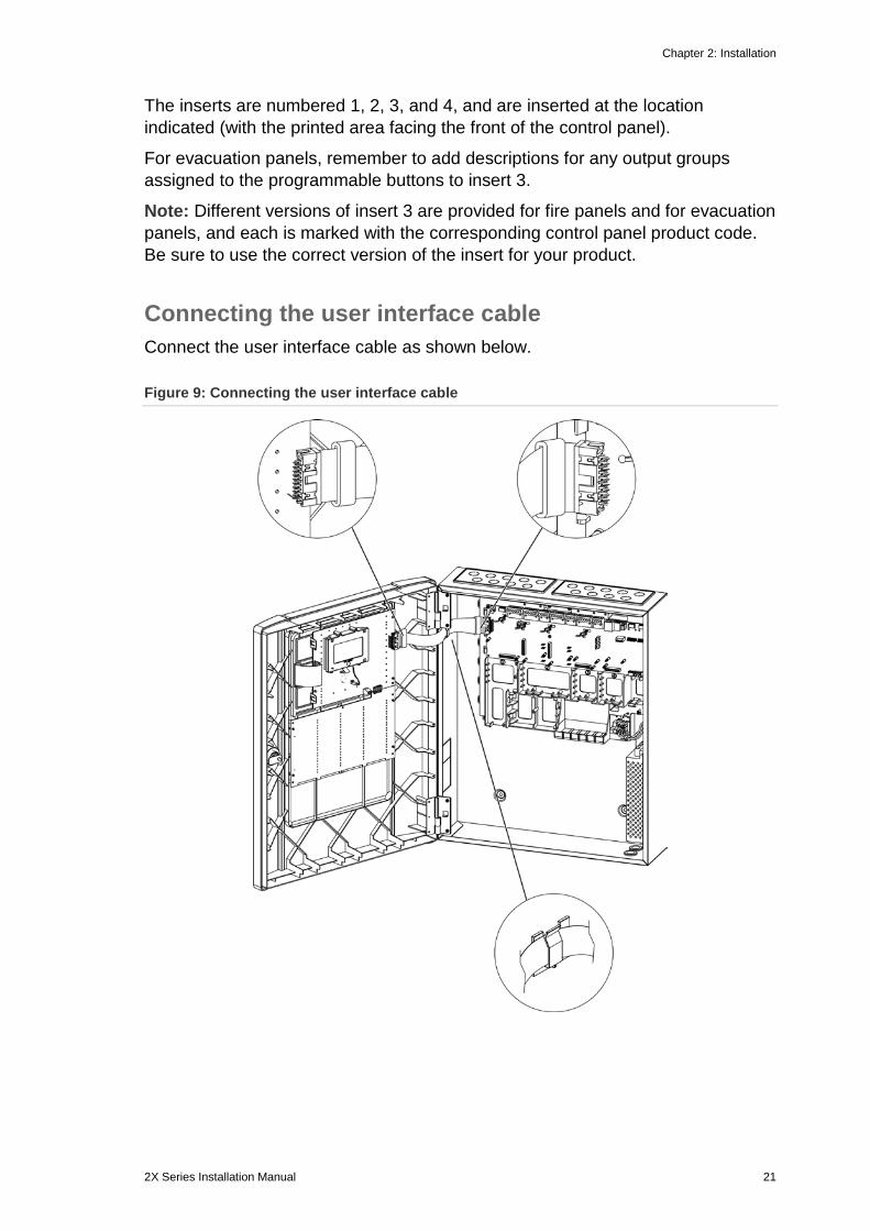
The inserts are numbered 1, 2, 3, and 4, and are inserted at the location indicated (with the printed area facing the front of the control panel).
For evacuation panels, remember to add descriptions for any output groups assigned to the programmable buttons to insert 3.
Note: Different versions of insert 3 are provided for fire panels and for evacuation panels, and each is marked with the corresponding control panel product code. Be sure to use the correct version of the insert for your product.
Connecting the user interface cable Connect the user interface cable as shown below.
Figure 9: Connecting the user interface cable
Chapter 2: Installation
22 2X Series Installation Manual
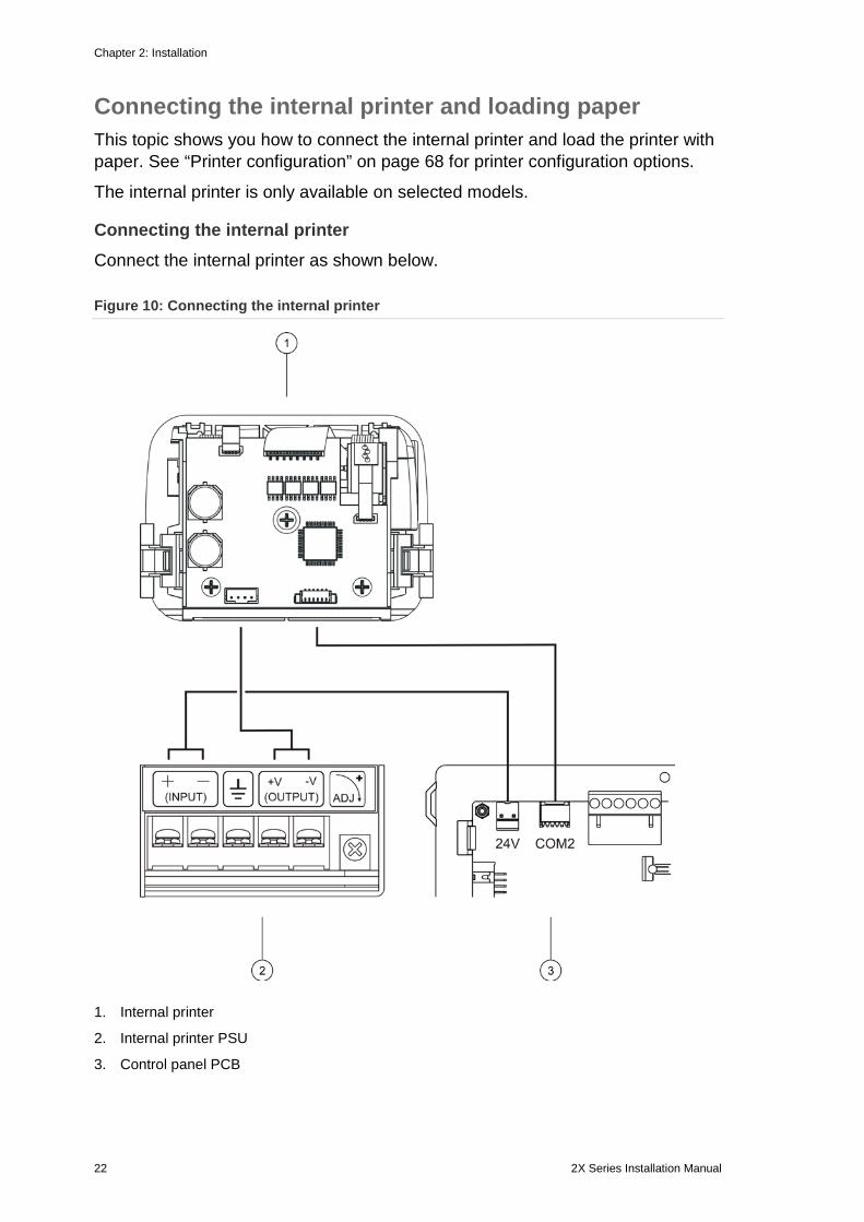
Connecting the internal printer and loading paper This topic shows you how to connect the internal printer and load the printer with paper. See “Printer configuration” on page 68 for printer configuration options.
The internal printer is only available on selected models.
Connecting the internal printer Connect the internal printer as shown below.
Figure 10: Connecting the internal printer
1. Internal printer
2. Internal printer PSU
3. Control panel PCB
Chapter 2: Installation
2X Series Installation Manual 23
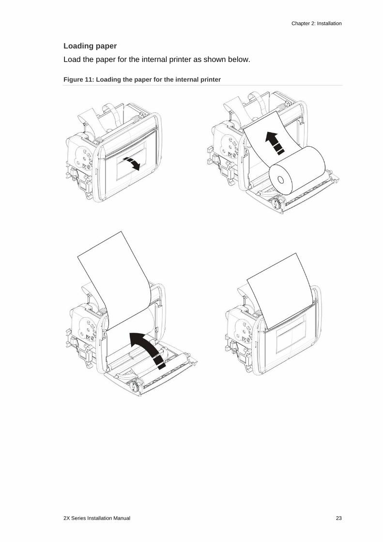
Loading paper Load the paper for the internal printer as shown below.
Figure 11: Loading the paper for the internal printer
Chapter 2: Installation
24 2X Series Installation Manual
Connections
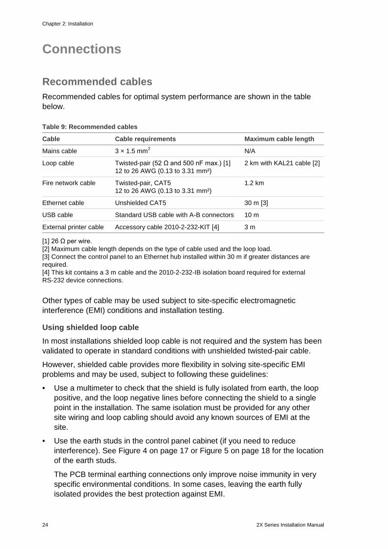
Recommended cables Recommended cables for optimal system performance are shown in the table below.
Table 9: Recommended cables
Cable Cable requirements Maximum cable length
Mains cable 3 × 1.5 mm2 N/A
Loop cable Twisted-pair (52 Ω and 500 nF max.) [1] 12 to 26 AWG (0.13 to 3.31 mm²)
2 km with KAL21 cable [2]
Fire network cable Twisted-pair, CAT5 12 to 26 AWG (0.13 to 3.31 mm²)
1.2 km
Ethernet cable Unshielded CAT5 30 m [3]
USB cable Standard USB cable with A-B connectors 10 m
External printer cable Accessory cable 2010-2-232-KIT [4] 3 m
[1] 26 Ω per wire. [2] Maximum cable length depends on the type of cable used and the loop load. [3] Connect the control panel to an Ethernet hub installed within 30 m if greater distances are required. [4] This kit contains a 3 m cable and the 2010-2-232-IB isolation board required for external RS-232 device connections.
Other types of cable may be used subject to site-specific electromagnetic interference (EMI) conditions and installation testing.
Using shielded loop cable In most installations shielded loop cable is not required and the system has been validated to operate in standard conditions with unshielded twisted-pair cable.
However, shielded cable provides more flexibility in solving site-specific EMI problems and may be used, subject to following these guidelines:
• Use a multimeter to check that the shield is fully isolated from earth, the loop positive, and the loop negative lines before connecting the shield to a single point in the installation. The same isolation must be provided for any other site wiring and loop cabling should avoid any known sources of EMI at the site.
• Use the earth studs in the control panel cabinet (if you need to reduce interference). See Figure 4 on page 17 or Figure 5 on page 18 for the location of the earth studs.
The PCB terminal earthing connections only improve noise immunity in very specific environmental conditions. In some cases, leaving the earth fully isolated provides the best protection against EMI.
Chapter 2: Installation
2X Series Installation Manual 25
To determine noise immunity, check the communications error rate and the stability of analogue values for installed devices.
Securing cables Use 20 mm cable glands to ensure clean and secure connections. All cables should be fed through the cable guides in the cabinet housing to eliminate movement.
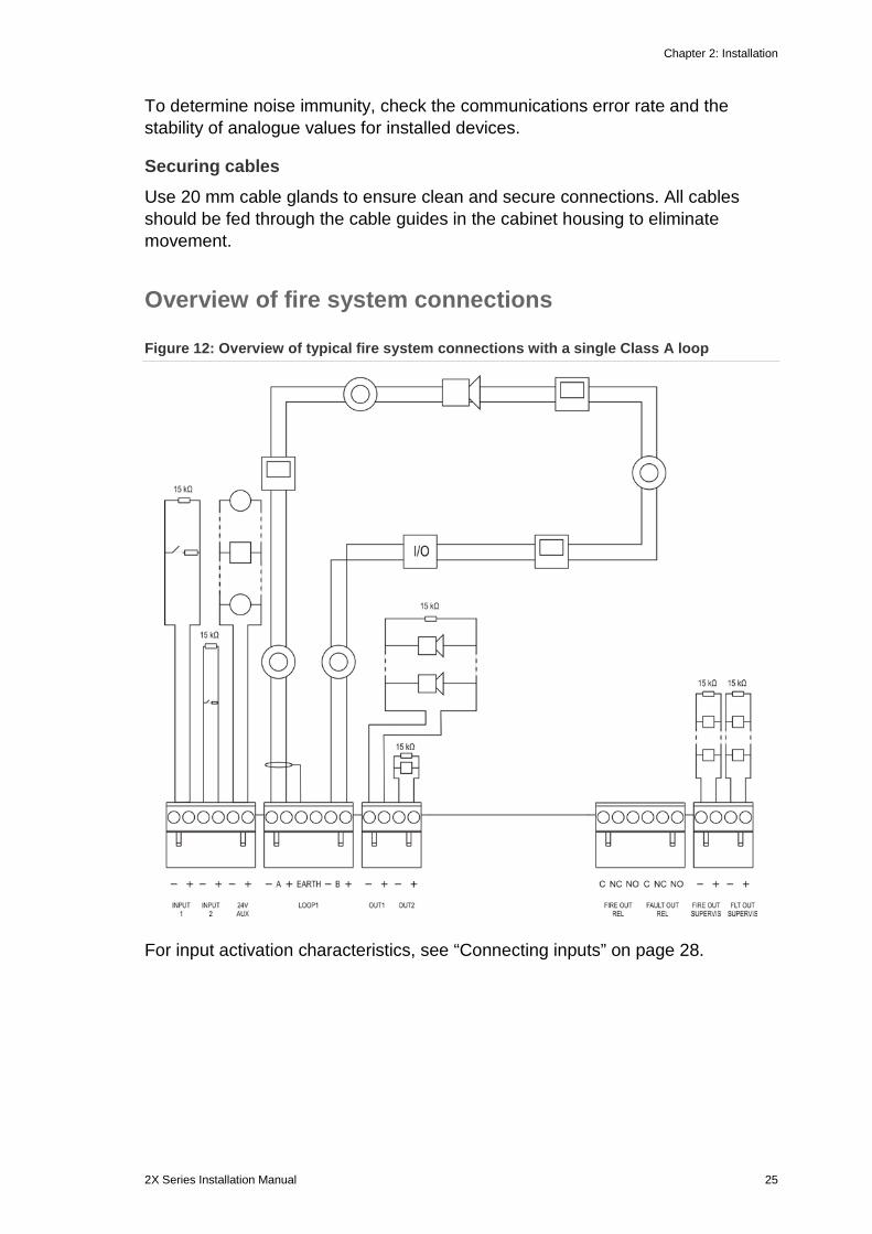
Overview of fire system connections
Figure 12: Overview of typical fire system connections with a single Class A loop
For input activation characteristics, see “Connecting inputs” on page 28.
Chapter 2: Installation
26 2X Series Installation Manual
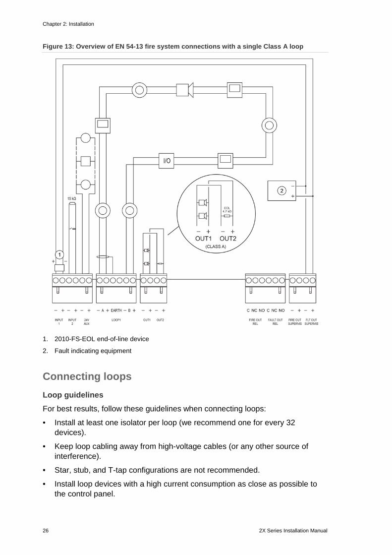
Figure 13: Overview of EN 54-13 fire system connections with a single Class A loop
1. 2010-FS-EOL end-of-line device
2. Fault indicating equipment
Connecting loops Loop guidelines For best results, follow these guidelines when connecting loops:
• Install at least one isolator per loop (we recommend one for every 32 devices).
• Keep loop cabling away from high-voltage cables (or any other source of interference).
• Star, stub, and T-tap configurations are not recommended.
• Install loop devices with a high current consumption as close as possible to the control panel.
Chapter 2: Installation
2X Series Installation Manual 27
• Ensure that the loop cable complies with the cable specifications outlined in “Recommended cables” on page 24.
• If using shielded loop cable, ensure that the shield is continuous (connected through to each loop device). To prevent earth loops caused by electromagnetic interference, only one cable shield should be connected to earth, as shown in Figure 12 on page 25.
Class A loop connection Connect Class A loops as shown in Figure 12 on page 25. Class A loops are supervised for open and short circuits. Terminate unused Class A loops A (+) to B (+) and A (−) to B (−).
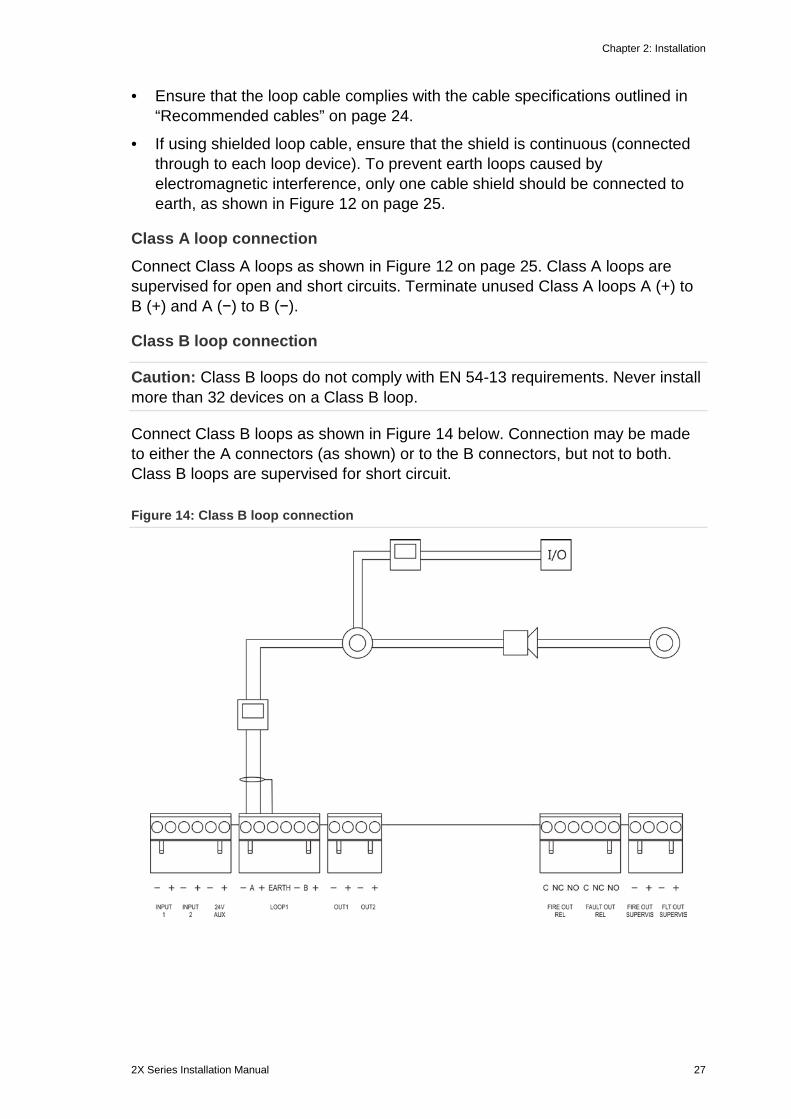
Class B loop connection
Caution: Class B loops do not comply with EN 54-13 requirements. Never install more than 32 devices on a Class B loop.
Connect Class B loops as shown in Figure 14 below. Connection may be made to either the A connectors (as shown) or to the B connectors, but not to both. Class B loops are supervised for short circuit.
Figure 14: Class B loop connection
Chapter 2: Installation
28 2X Series Installation Manual
Connecting loop devices Each loop can support up to 128 devices. For detailed loop device installation information, see your device installation sheet.
Connecting inputs Input functionality Each control panel has two supervised inputs, marked INPUT1 and INPUT2. For input configuration, see “Field configuration” on page 73.
Connecting inputs Connect input switches to INPUT1 and INPUT2, as shown in Figure 12 on page 25. For input supervision (open and short circuit), install a 15 kΩ resistor.
If an input is not used, the 15 kΩ end-of-line resistor must be installed across the unused terminals to avoid an open circuit fault on the input.
Input activation characteristics Input activation characteristics are shown in the table below.
Table 10: Input activation characteristics
State Activation value
Active 60.2 Ω ≤ active value ≤ 8 kΩ
Normal 10 kΩ ≤ value ≤ 20.2 kΩ
Short circuit ≤ 60.2 Ω
High impedance fault 8 kΩ < value < 10 kΩ
Open circuit ≥ 20.2 kΩ
Connecting outputs Control panel outputs are shown in the table below.
Table 11: Control panel outputs
Output Description Supervision
24V AUX Used to supply power to auxiliary equipment. The output can be configured as resettable and to shut down when there is no mains power.
Short circuit, voltage level
OUT1, OUT2, etc. Configurable outputs (the default configuration is sounder output). The number of configurable outputs depends on the control panel model (see the topic below).
Note: These outputs comply with EN 54-13 requirements when configured as Class A outputs.
Short circuit, open circuit
Chapter 2: Installation
2X Series Installation Manual 29
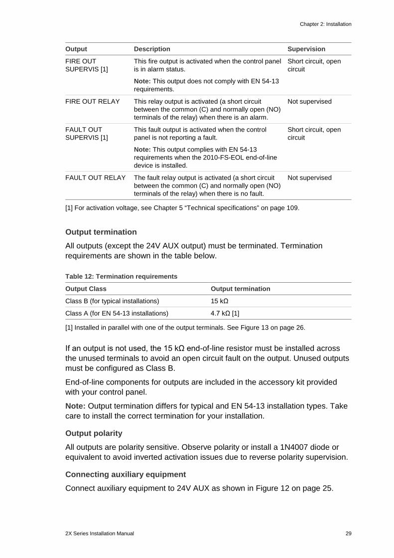
Output Description Supervision
FIRE OUT SUPERVIS [1]
This fire output is activated when the control panel is in alarm status.
Note: This output does not comply with EN 54-13 requirements.
Short circuit, open circuit
FIRE OUT RELAY This relay output is activated (a short circuit between the common (C) and normally open (NO) terminals of the relay) when there is an alarm.
Not supervised
FAULT OUT SUPERVIS [1]
This fault output is activated when the control panel is not reporting a fault.
Note: This output complies with EN 54-13 requirements when the 2010-FS-EOL end-of-line device is installed.
Short circuit, open circuit
FAULT OUT RELAY The fault relay output is activated (a short circuit between the common (C) and normally open (NO) terminals of the relay) when there is no fault.
Not supervised
[1] For activation voltage, see Chapter 5 “Technical specifications” on page 109.
Output termination All outputs (except the 24V AUX output) must be terminated. Termination requirements are shown in the table below.
Table 12: Termination requirements
Output Class Output termination
Class B (for typical installations) 15 kΩ
Class A (for EN 54-13 installations) 4.7 kΩ [1]
[1] Installed in parallel with one of the output terminals. See Figure 13 on page 26.
If an output is not used, the 15 kΩ end-of-line resistor must be installed across the unused terminals to avoid an open circuit fault on the output. Unused outputs must be configured as Class B.
End-of-line components for outputs are included in the accessory kit provided with your control panel.
Note: Output termination differs for typical and EN 54-13 installation types. Take care to install the correct termination for your installation.
Output polarity All outputs are polarity sensitive. Observe polarity or install a 1N4007 diode or equivalent to avoid inverted activation issues due to reverse polarity supervision.
Connecting auxiliary equipment Connect auxiliary equipment to 24V AUX as shown in Figure 12 on page 25.
Chapter 2: Installation
30 2X Series Installation Manual
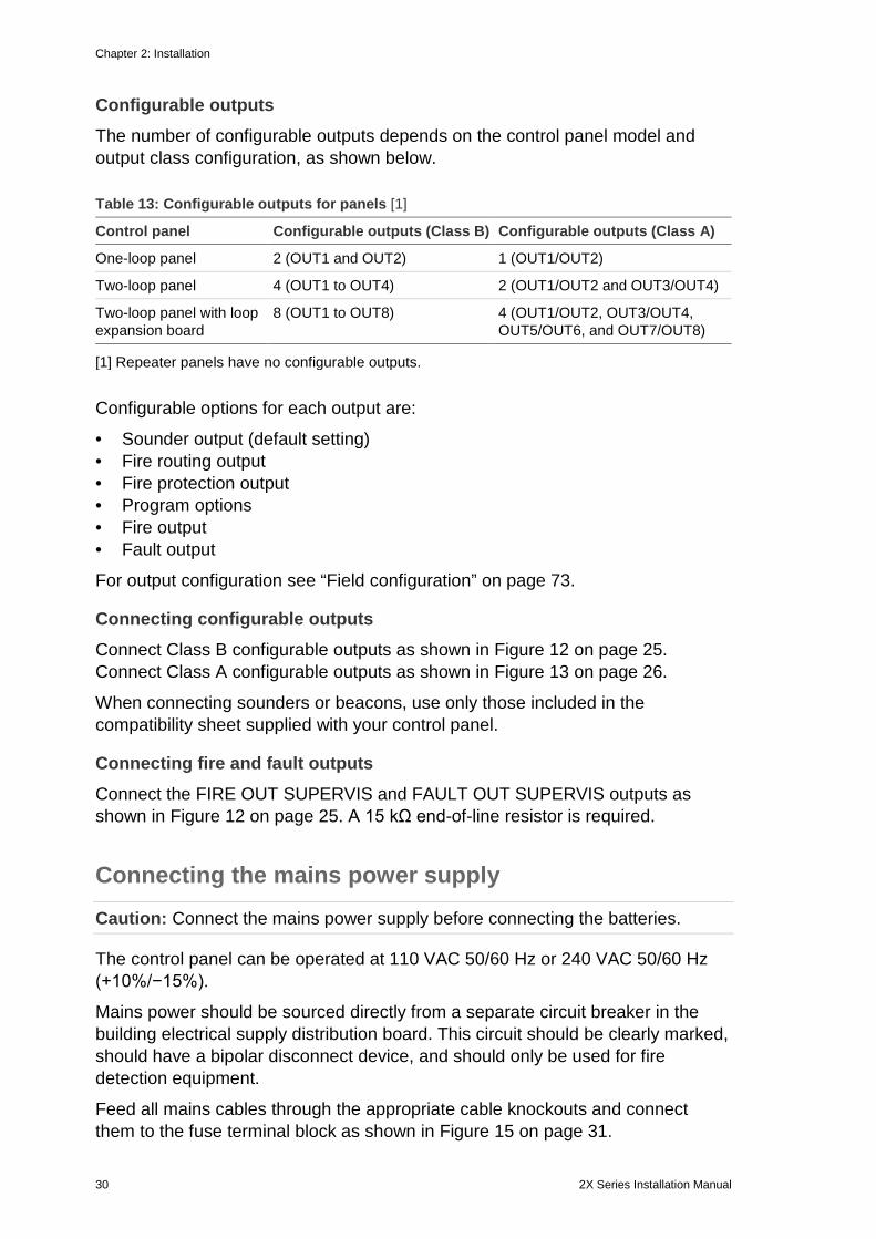
Configurable outputs The number of configurable outputs depends on the control panel model and output class configuration, as shown below.
Table 13: Configurable outputs for panels [1]
Control panel Configurable outputs (Class B) Configurable outputs (Class A)
One-loop panel 2 (OUT1 and OUT2) 1 (OUT1/OUT2)
Two-loop panel 4 (OUT1 to OUT4) 2 (OUT1/OUT2 and OUT3/OUT4)
Two-loop panel with loop expansion board
8 (OUT1 to OUT8) 4 (OUT1/OUT2, OUT3/OUT4, OUT5/OUT6, and OUT7/OUT8)
[1] Repeater panels have no configurable outputs.
Configurable options for each output are:
• Sounder output (default setting) • Fire routing output • Fire protection output • Program options • Fire output • Fault output
For output configuration see “Field configuration” on page 73.
Connecting configurable outputs Connect Class B configurable outputs as shown in Figure 12 on page 25. Connect Class A configurable outputs as shown in Figure 13 on page 26.
When connecting sounders or beacons, use only those included in the compatibility sheet supplied with your control panel.
Connecting fire and fault outputs Connect the FIRE OUT SUPERVIS and FAULT OUT SUPERVIS outputs as shown in Figure 12 on page 25. A 15 kΩ end-of-line resistor is required.
Connecting the mains power supply
Caution: Connect the mains power supply before connecting the batteries.
The control panel can be operated at 110 VAC 50/60 Hz or 240 VAC 50/60 Hz (+10%/−15%).
Mains power should be sourced directly from a separate circuit breaker in the building electrical supply distribution board. This circuit should be clearly marked, should have a bipolar disconnect device, and should only be used for fire detection equipment.
Feed all mains cables through the appropriate cable knockouts and connect them to the fuse terminal block as shown in Figure 15 on page 31.
Chapter 2: Installation
2X Series Installation Manual 31
Keep mains cables separate from other cabling to avoid potential short circuits and interference. Use the provided cable ties to secure mains cables to the cabinet on either side of the fuse terminal block to prevent movement.
Caution: If the control panel has a network board installed, the mains cable must enter the cabinet from the bottom for proper operation.
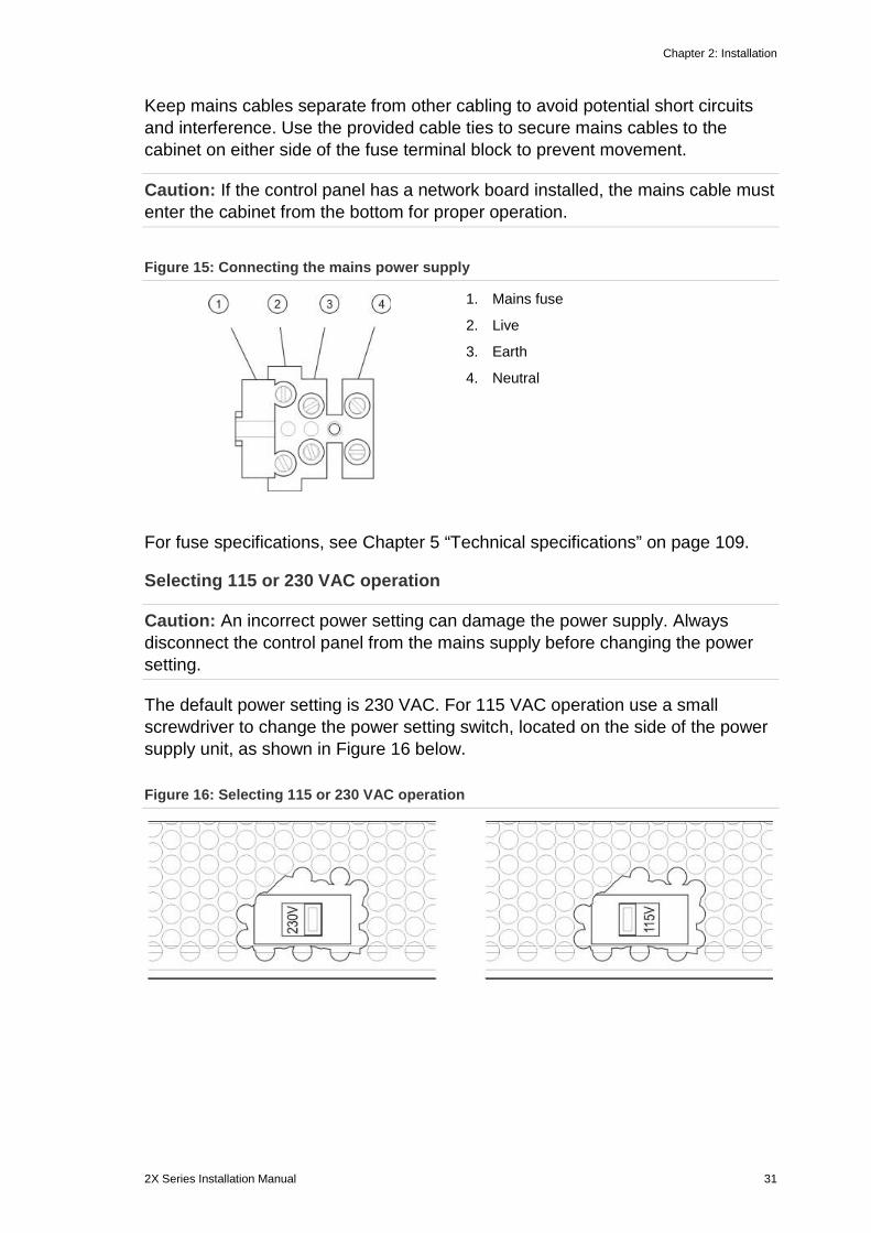
Figure 15: Connecting the mains power supply
1. Mains fuse
2. Live
3. Earth
4. Neutral
For fuse specifications, see Chapter 5 “Technical specifications” on page 109.
Selecting 115 or 230 VAC operation
Caution: An incorrect power setting can damage the power supply. Always disconnect the control panel from the mains supply before changing the power setting.
The default power setting is 230 VAC. For 115 VAC operation use a small screwdriver to change the power setting switch, located on the side of the power supply unit, as shown in Figure 16 below.
Figure 16: Selecting 115 or 230 VAC operation
Chapter 2: Installation
32 2X Series Installation Manual
Connecting the batteries The control panel requires two 12 V, rechargeable, sealed lead-acid batteries with 7.2, 12, or 18 Ah capacity (see “Battery maintenance” on page 107).
Batteries are located inside the control panel cabinet and must be installed in series. Polarity must be observed.
Connect batteries to the BAT connector on the control panel PCB. No other equipment may be connected to the BAT connector.
Note: If the control panel indicates a Supply Fault, then the batteries may need to be replaced.
Connecting expansion boards
Caution: Always disconnect the control panel from the mains power supply before installing an expansion board.
See your expansion board installation sheet for detailed installation information.
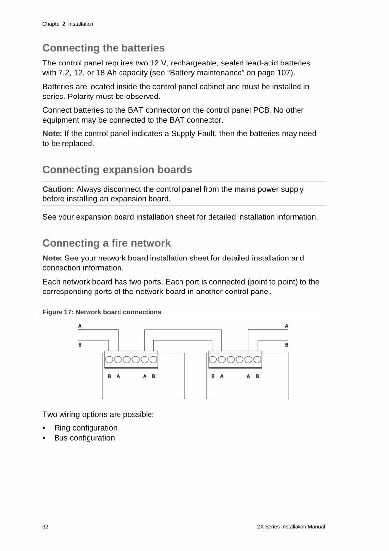
Connecting a fire network Note: See your network board installation sheet for detailed installation and connection information.
Each network board has two ports. Each port is connected (point to point) to the corresponding ports of the network board in another control panel.
Figure 17: Network board connections
Two wiring options are possible:
• Ring configuration • Bus configuration
Chapter 2: Installation
2X Series Installation Manual 33
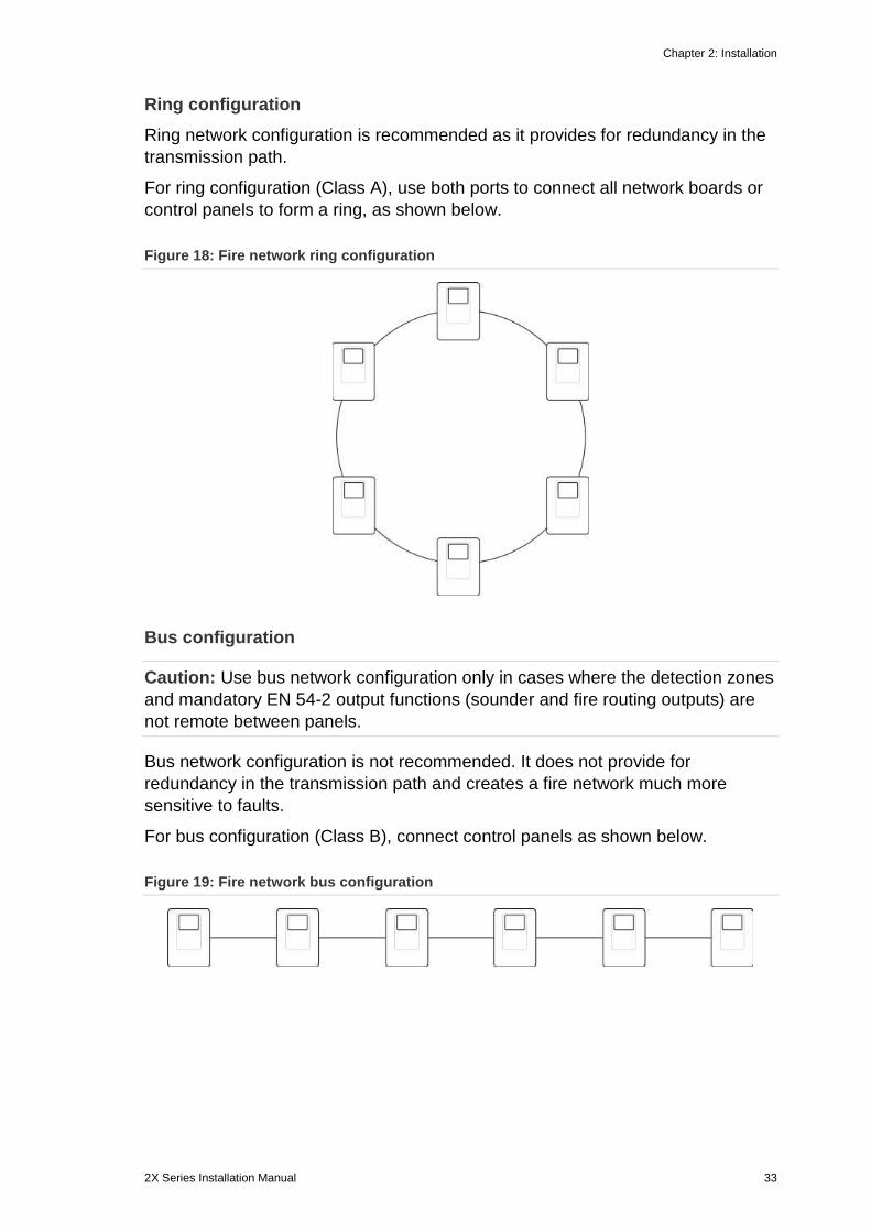
Ring configuration Ring network configuration is recommended as it provides for redundancy in the transmission path.
For ring configuration (Class A), use both ports to connect all network boards or control panels to form a ring, as shown below.
Figure 18: Fire network ring configuration
Bus configuration
Caution: Use bus network configuration only in cases where the detection zones and mandatory EN 54-2 output functions (sounder and fire routing outputs) are not remote between panels.
Bus network configuration is not recommended. It does not provide for redundancy in the transmission path and creates a fire network much more sensitive to faults.
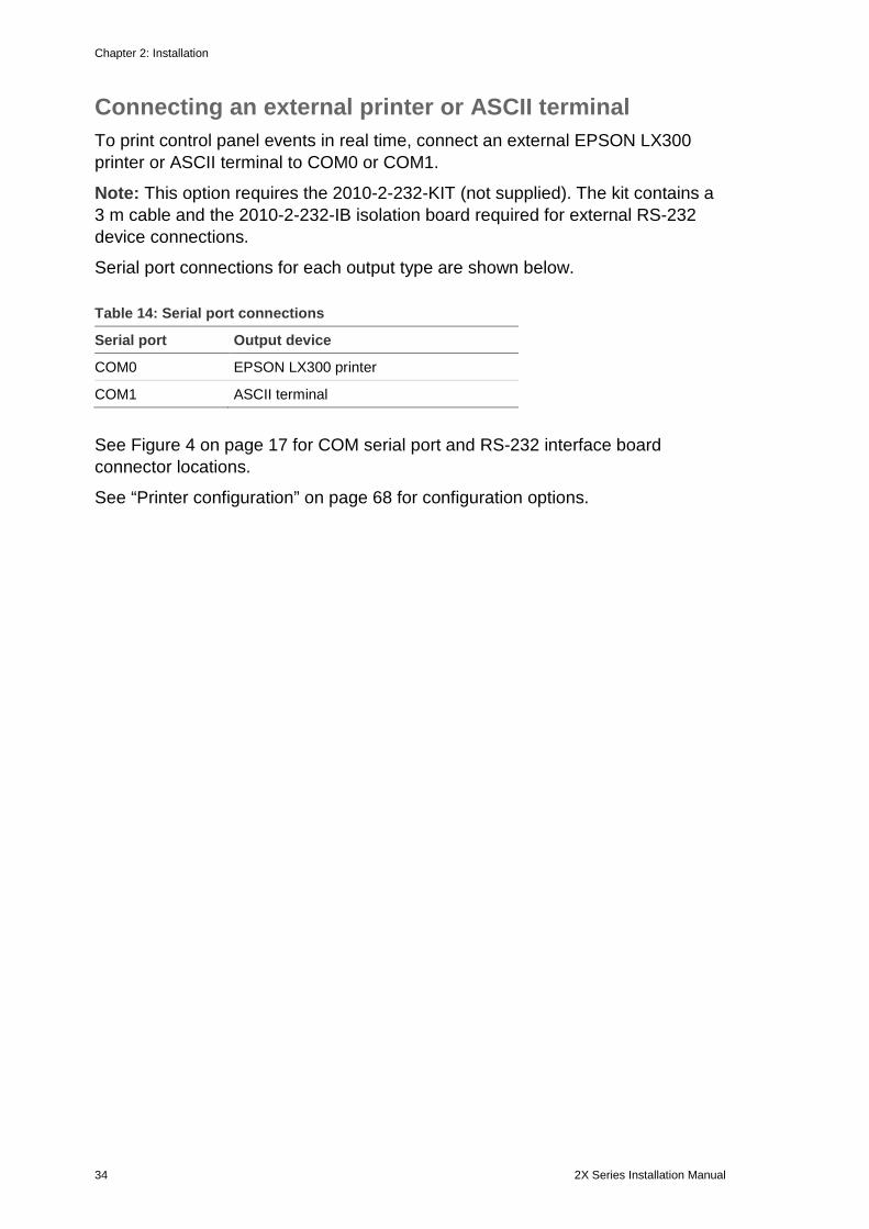
For bus configuration (Class B), connect control panels as shown below.
Figure 19: Fire network bus configuration
Chapter 2: Installation
34 2X Series Installation Manual
Connecting an external printer or ASCII terminal To print control panel events in real time, connect an external EPSON LX300 printer or ASCII terminal to COM0 or COM1.
Note: This option requires the 2010-2-232-KIT (not supplied). The kit contains a 3 m cable and the 2010-2-232-IB isolation board required for external RS-232 device connections.
Serial port connections for each output type are shown below.
Table 14: Serial port connections
Serial port Output device
COM0 EPSON LX300 printer
COM1 ASCII terminal
See Figure 4 on page 17 for COM serial port and RS-232 interface board connector locations.
See “Printer configuration” on page 68 for configuration options.
2X Series Installation Manual 35
Chapter 3 Configuration and commissioning
Summary This chapter provides configuration and commissioning information for your control panel and fire detection system.
Content Introduction 36
User levels 36 Configuration overview 37
Maintenance level operation and configuration 39
The Panel setup menu 40 The Communications menu 44 The Disable/Enable menu 45 The Test menu 46 The Reports menu 49 The Password setup menu 52
Installer level operation and configuration 53
The Main menu 53 Panel configuration 53 ID configuration 54 Regional options 55 Firenet configuration 55 Communications configuration 59 Other settings 61 Load/Save configuration 64 Expansion board configuration 66 Load auxiliary files 66 Firmware updates 67 Printer configuration 68 DACT configuration 69
Field configuration 73 Autosetup 73 Loop device configuration 74 Zone configuration 75 Panel I/O configuration 82 Activation configuration 90 Loop Class configuration 98 Tests 99 Password setup 100
Commissioning 102
Chapter 3: Configuration and commissioning
36 2X Series Installation Manual
Introduction
User levels Access to some of the features of this product is restricted by the user level assigned to a user account.
Public The public level is the default user level.
This level allows basic operational tasks, such as responding to a fire alarm or fault warning at the control panel. No password is required.
Operational tasks for this user level are described in the product operation manual.
Operator The operator level allows additional operational tasks and is reserved for authorized users who have been trained to operate the control panel. The default password for the default operator user is 2222. Operational tasks for this user level are described in the product operation manual.
Maintenance The maintenance level allows routine maintenance tasks and is reserved for authorized users who have been trained to operate and maintain the control panel and fire system. The default password for the default maintenance user is 3333.
Installer The installer level allows full system configuration and is reserved for authorized users installing and configuring the control panel and fire system. The default password for the default installer user is 4444.
Restricted user levels Restricted user levels are protected by password security. You are required to enter the username and password assigned to you.
The control panel automatically exits from a restricted user level and reverts to the public user level after a few minutes if no button is pressed. The automatic timeout period depends on the active user level, as shown below.
Chapter 3: Configuration and commissioning
2X Series Installation Manual 37
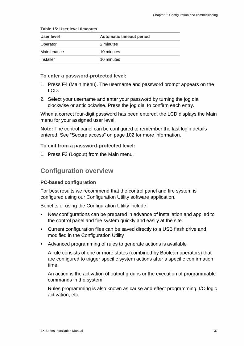
Table 15: User level timeouts
User level Automatic timeout period
Operator 2 minutes
Maintenance 10 minutes
Installer 10 minutes
To enter a password-protected level: 1. Press F4 (Main menu). The username and password prompt appears on the
LCD.
2. Select your username and enter your password by turning the jog dial clockwise or anticlockwise. Press the jog dial to confirm each entry.
When a correct four-digit password has been entered, the LCD displays the Main menu for your assigned user level.
Note: The control panel can be configured to remember the last login details entered. See “Secure access” on page 102 for more information.
To exit from a password-protected level: 1. Press F3 (Logout) from the Main menu.
Configuration overview PC-based configuration For best results we recommend that the control panel and fire system is configured using our Configuration Utility software application.
Benefits of using the Configuration Utility include:
• New configurations can be prepared in advance of installation and applied to the control panel and fire system quickly and easily at the site
• Current configuration files can be saved directly to a USB flash drive and modified in the Configuration Utility
• Advanced programming of rules to generate actions is available
A rule consists of one or more states (combined by Boolean operators) that are configured to trigger specific system actions after a specific confirmation time.
An action is the activation of output groups or the execution of programmable commands in the system.
Rules programming is also known as cause and effect programming, I/O logic activation, etc.
Chapter 3: Configuration and commissioning
38 2X Series Installation Manual
When configuring your fire system using the Configuration Utility:
1. Configure the communications settings if you plan to download configurations using an Ethernet connection. This is not required if you plan to save configurations to a PC connected to the control panel USB connector.
2. Configure the date and time at the control panel and load the configuration as described in “Loading and saving configuration files” on page 64.
For more information on the Configuration Utility, contact your local distributor.
Control panel configuration recommendations Use the control panel configuration wizards to guide you through the configuration process for most applications.
To access the configuration wizards press F1 (Wizards) from the installer level Main menu.
In general we recommend the following configuration order:
1. Control panel configuration (date and time, expansion boards, control panel ID and description, fire network, and communications). For more information, see “Panel configuration” on page 53.
2. Field configuration (loop devices, zones, and control panel inputs and outputs). For more information, see “Field configuration” on page 73.
3. Change all default passwords for increased security. For more information, see “Changing your password” on page 100.
Configuration controls Use function buttons F1 to F4 and the jog dial (see Figure 3 on page 10) to navigate the LCD menu, to select menu options, and to enter passwords and system information, as shown below. Entering passwords and system information
Turn the jog dial clockwise or anticlockwise to enter passwords and other system information. Press the jog dial to confirm an entry.
Selecting soft keys from the LCD menu
Press the function buttons F1 to F4 to select the corresponding menu options (Main menu, Logout, Exit, etc.).
Navigating and confirming menu selections
Turn the jog dial clockwise or anticlockwise to select an option from the on-screen menu. Press the jog dial to confirm the selection.
The control panel ID on the LCD is white text with a dark background when the jog dial is active (the control panel is waiting for input).
Chapter 3: Configuration and commissioning
2X Series Installation Manual 39
Configuration options The options listed below are available when making configuration changes to the control panel.
The control panel configuration (and configuration revision) is only updated when configuration changes are applied by pressing F3 (Apply).
The configuration revision change and timestamp are recorded in the Revision report and can be accessed at operator, maintenance, and installer levels.
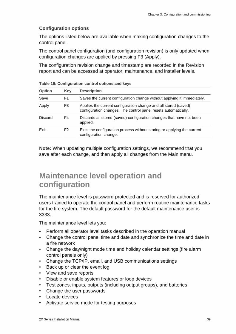
Table 16: Configuration control options and keys
Option Key Description
Save F1 Saves the current configuration change without applying it immediately.
Apply F3 Applies the current configuration change and all stored (saved) configuration changes. The control panel resets automatically.
Discard F4 Discards all stored (saved) configuration changes that have not been applied.
Exit F2 Exits the configuration process without storing or applying the current configuration change.
Note: When updating multiple configuration settings, we recommend that you save after each change, and then apply all changes from the Main menu.
Maintenance level operation and configuration The maintenance level is password-protected and is reserved for authorized users trained to operate the control panel and perform routine maintenance tasks for the fire system. The default password for the default maintenance user is 3333.
The maintenance level lets you:
• Perform all operator level tasks described in the operation manual • Change the control panel time and date and synchronize the time and date in
a fire network • Change the day/night mode time and holiday calendar settings (fire alarm
control panels only) • Change the TCP/IP, email, and USB communications settings • Back up or clear the event log • View and save reports • Disable or enable system features or loop devices • Test zones, inputs, outputs (including output groups), and batteries • Change the user passwords • Locate devices • Activate service mode for testing purposes
Chapter 3: Configuration and commissioning
40 2X Series Installation Manual
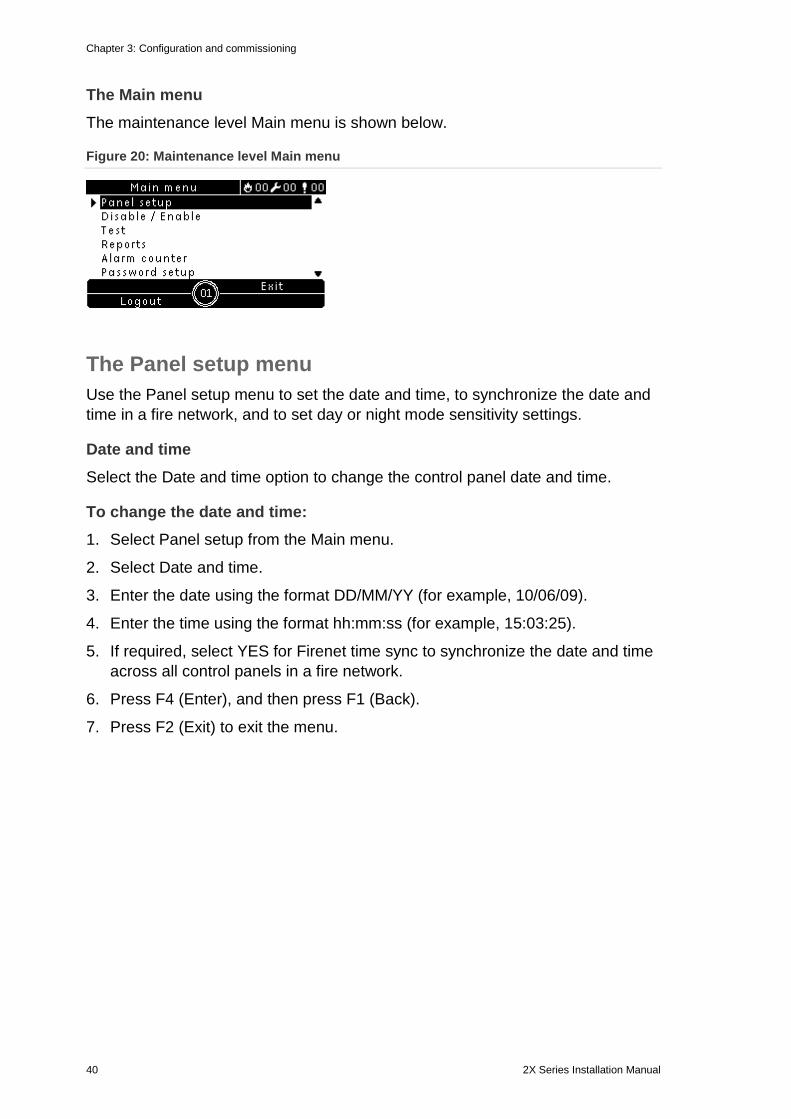
The Main menu The maintenance level Main menu is shown below.
Figure 20: Maintenance level Main menu
The Panel setup menu Use the Panel setup menu to set the date and time, to synchronize the date and time in a fire network, and to set day or night mode sensitivity settings.
Date and time Select the Date and time option to change the control panel date and time.
To change the date and time: 1. Select Panel setup from the Main menu.
2. Select Date and time.
3. Enter the date using the format DD/MM/YY (for example, 10/06/09).
4. Enter the time using the format hh:mm:ss (for example, 15:03:25).
5. If required, select YES for Firenet time sync to synchronize the date and time across all control panels in a fire network.
6. Press F4 (Enter), and then press F1 (Back).
7. Press F2 (Exit) to exit the menu.
Chapter 3: Configuration and commissioning
2X Series Installation Manual 41
Day/night mode sensitivity settings Select the Day/Night mode option to change selected day/night fire detection and response criteria based on preconfigured time settings, as shown below.
Note: This option is not available on repeater panels.
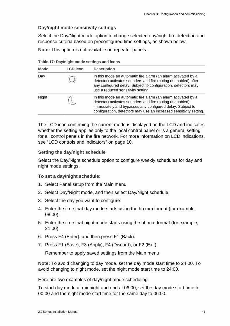
Table 17: Day/night mode settings and icons
Mode LCD icon Description
Day
In this mode an automatic fire alarm (an alarm activated by a detector) activates sounders and fire routing (if enabled) after any configured delay. Subject to configuration, detectors may use a reduced sensitivity setting.
Night
In this mode an automatic fire alarm (an alarm activated by a detector) activates sounders and fire routing (if enabled) immediately and bypasses any configured delay. Subject to configuration, detectors may use an increased sensitivity setting.
The LCD icon confirming the current mode is displayed on the LCD and indicates whether the setting applies only to the local control panel or is a general setting for all control panels in the fire network. For more information on LCD indications, see “LCD controls and indicators” on page 10.
Setting the day/night schedule Select the Day/Night schedule option to configure weekly schedules for day and night mode settings.
To set a day/night schedule: 1. Select Panel setup from the Main menu.
2. Select Day/Night mode, and then select Day/Night schedule.
3. Select the day you want to configure.
4. Enter the time that day mode starts using the hh:mm format (for example, 08:00).
5. Enter the time that night mode starts using the hh:mm format (for example, 21:00).
6. Press F4 (Enter), and then press F1 (Back).
7. Press F1 (Save), F3 (Apply), F4 (Discard), or F2 (Exit).
Remember to apply saved settings from the Main menu.
Note: To avoid changing to day mode, set the day mode start time to 24:00. To avoid changing to night mode, set the night mode start time to 24:00.
Here are two examples of day/night mode scheduling.
To start day mode at midnight and end at 06:00, set the day mode start time to 00:00 and the night mode start time for the same day to 06:00.
Chapter 3: Configuration and commissioning
42 2X Series Installation Manual
To start night mode at 22:00 and end at midnight, set the night mode start time for the day to 22:00 and the day mode start time for the following day to 00:00.
Setting the holiday calendar Select the Holiday calendar option to configure a day or night mode setting for a range of dates.
To configure day/night mode for dates: 1. Select Panel setup from the Main menu.
2. Select Day/Night mode, and then select Holiday calendar.
3. Select F3 (New) to enter a new holiday period or select an existing holiday period from the displayed list.
To delete an existing holiday period, press F4 (Delete).
4. Enter the start date and the end date for the holiday sensitivity setting. The date format is DD/MM (for example, 29/11 for 29 November).
5. Select the sensitivity mode (day or night) for the holiday period. The default setting is night mode (it is assumed that there are no people on site during the holiday period).
6. Enter any additional holiday periods as described in steps 3 and 4.
7. Press F4 (Enter), and then press F1 (Back).
8. Press F1 (Save), F3 (Apply), F4 (Discard), or F2 (Exit).
Remember to apply saved settings from the Main menu.
Additional day/night mode settings Select the Day/Night setup option to configure additional settings such as manual override of day/night mode schedule and holiday calendar mode changes or delay behaviour in night mode.
The configuration options available are shown in the table below.
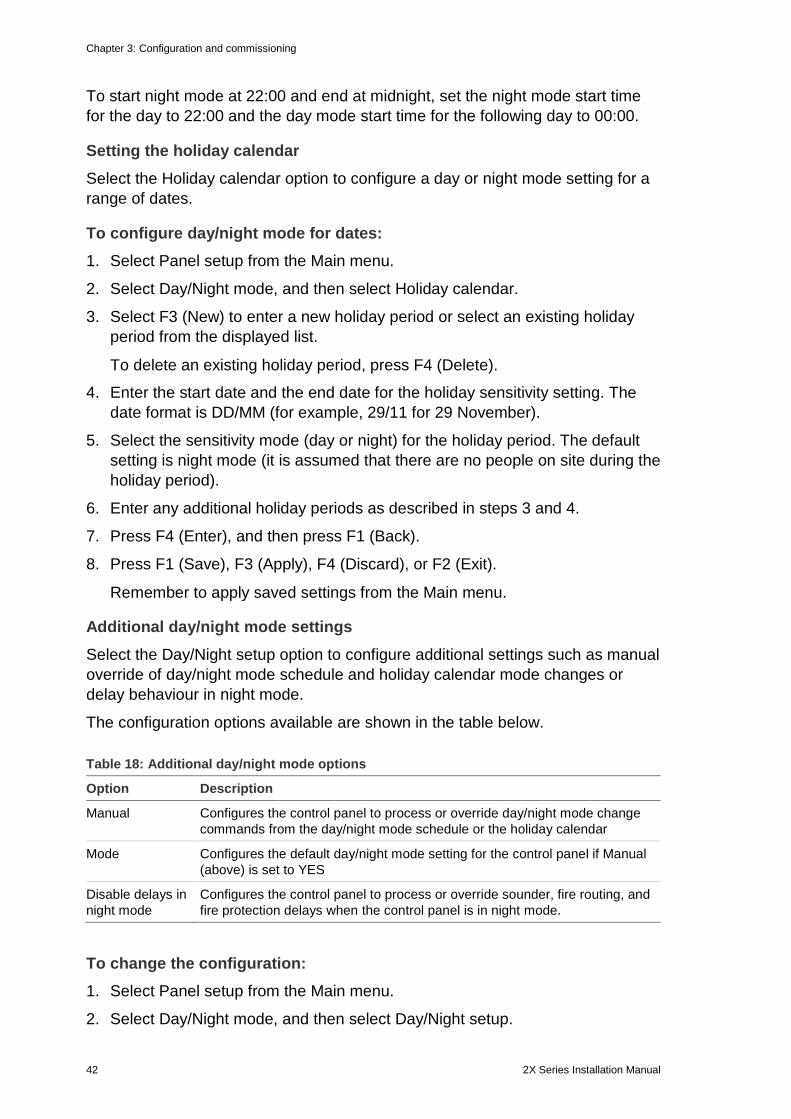
Table 18: Additional day/night mode options
Option Description
Manual Configures the control panel to process or override day/night mode change commands from the day/night mode schedule or the holiday calendar
Mode Configures the default day/night mode setting for the control panel if Manual (above) is set to YES
Disable delays in night mode
Configures the control panel to process or override sounder, fire routing, and fire protection delays when the control panel is in night mode.
To change the configuration: 1. Select Panel setup from the Main menu.
2. Select Day/Night mode, and then select Day/Night setup.
Chapter 3: Configuration and commissioning
2X Series Installation Manual 43
3. Select Manual, and then select NO (to process mode change commands from the day/night mode schedule and holiday calendar) or YES (to override mode change commands from the day/night mode schedule and holiday calendar).
The default setting is NO (mode change commands from the Day/Night mode schedule and Holiday calendar are processed as configured).
4. Select Mode, and then select DAY or NIGHT to define the default control panel sensitivity mode if Manual (above) is set to YES.
The default setting is DAY. If Manual is set to NO, then no mode configuration is required.
5. Select Disable delays in night mode, and then select which sounder, fire routing, or fire protection delays to process or override when the control panel is in night mode.
By default, all delays are disabled when the control panel is in night mode.
6. Press F4 (Enter), and then press F1 (Back).
7. Press F1 (Save), F3 (Apply), F4 (Discard), or F2 (Exit).
Remember to apply saved settings from the Main menu.
Notes on day and night mode settings Day/night mode may be configured to change with a remote input. Depending on the installation settings, the system may be configured to use an external input to override the day/night mode setting until the following programmed change (if any).
Control panels in the same network can have different day/night mode sensitivity settings.
If the command filter is configured accordingly, a control panel can operate a local day/night mode setting independently from other control panels in the same network. A local day/night mode setting is indicated on the local control panel LCD by the corresponding icon. See “Icons displayed on the LCD” on page 11.
If the control panel is a repeater, remember that the day/night mode displayed corresponds to those control panels configured to accept the global sensitivity mode command. Some control panels in the network may be operating with locally-defined sensitivity settings.
The day/night mode setting for all control panels in a fire network is included in the Firenet status report.
For more information on the global controls, see “Global controls” on page 57.
Chapter 3: Configuration and commissioning
44 2X Series Installation Manual
The Communications menu Use the Communications menu to set up email accounts for event notifications and to safely remove a USB device connected to the control panel.
Managing email accounts Select the Email accounts option to manage the email accounts for remote monitoring and to configure the types of events sent to each email address.
To configure email accounts: 1. Select Communications from the Main menu.
2. Select Email accounts, and then select the account to be edited (the default names are Account 1, Account 2, etc.).
3. Select the types of events to be included in the notification email: alarms, faults, conditions, or log events (any other system status change event).
If no event type is selected, the email notification service is not activated.
4. Enter the email address associated with the email account.
5. Press F4 (Enter), and then press F1 (Back).
6. Press F1 (Save), F3 (Apply), F4 (Discard), or F2 (Exit).
Remember to apply saved settings from the Main menu.
Note: This feature requires TCP/IP and email server details to be configured.
Removing a USB device Select the Remove USB device option to safely remove a USB device connected to the control panel (for example, a flash drive).
Caution: Failure to remove a USB flash drive as described may result in loss of data and/or damage to your flash drive.
To remove a USB device: 1. Select Panel setup from the Main menu, and then select Communications.
2. Select Remove USB device. A message displays on the LCD confirming the operation.
3. Press F2 (Exit) to exit the menu.
4. Open the control panel door and remove the flash drive.
Chapter 3: Configuration and commissioning
2X Series Installation Manual 45
The Disable/Enable menu Use the Disable/Enable menu to disable and enable the system features and devices. Features and devices can be disabled remotely if the control panel is part of a fire network. Disabled features and devices do not indicate faults or fire alarms.
Note: Changes to disable/enable configuration at this user level are not stored in the control panel configuration and are not included in any saved configuration files.
The following features or devices can be disabled or enabled from this menu:
• Zones
• Devices
• Control panel inputs and outputs
• Output groups (sounder, fire routing, fire protection, or program)
Disabling a system feature or device
To disable a feature or device: 1. Select Disable/Enable from the Main menu.
2. Select Disable (or Remote Disable if the feature or device is not local to the control panel).
3. Select the corresponding option (zones, devices, etc.).
4. For local disablements, select the feature or device to be disabled, and then press the jog dial to confirm the disablement.
For remote disablements, enter the Firenet ID of the feature or device to be disabled, and then press the jog dial to confirm the disablement.
5. Press F2 (Exit) to exit the menu.
Repeat to enable a disabled feature or device.
Notes
• Active outputs cannot be disabled.
• Devices or zones in alarm are not disabled until the control panel is manually reset.
• In maintenance level operation, to disable Class A outputs each output used must be disabled (for example, if OUT1 and OUT2 are combined to create a single Class A output, then both OUT1 and OUT2 must be disabled individually).
Chapter 3: Configuration and commissioning
46 2X Series Installation Manual
The Test menu Use the Test menu to test system features or devices. The following features or devices can be tested from this menu:
• Zones
• Control panel input activation
• Control panel and loop output activation
• Output group activation
• Device LED activation
• Remote features and devices
• Batteries
Note: Tests for outputs and output groups (local or remote) continue for as long as the test screen is visible. There is no automatic timeout for the output activation test and system information will not be visible on the LCD for the duration of the test. Operation not related to the activation test continues as normal in the background.
Testing zones
To test a zone: 1. Select Test from the Main menu.
2. Select Zones.
3. Select the zone to test, and then press the jog dial to start the test. Press the jog dial again to end the test for the selected zone.
You can select and test up to a maximum of four zones to test at the same time.
4. Press F2 (Exit) to exit the menu.
Repeat the above steps to end the zone test.
When an alarm is activated in a zone in test:
• The zone test is confirmed on the LCD while the alarm is active
• If a zone board is installed and the corresponding zone is included on the zone board, then the zone alarm LED is flashing or steady (depending on the source of the alarm)
• Fire routing, fire protection, sounders, and programmable activations are not activated
• The control panel resets the initiating device after 5 seconds and clears the alarm (manual call points must first be closed before an automatic reset can be applied)
• The event is recorded in the event log
Chapter 3: Configuration and commissioning
2X Series Installation Manual 47
When there is a fire alarm in any zone that is not in test, the control panel responds to the alarm event as configured.
Testing control panel input activation
To test activation of an input: 1. Determine the input functionality (consult your fire system installation details).
2. Select Service mode from the Test menu, and then select Local or Global.
Service mode ensures that outputs are not accidentally activated during input tests. Set Service mode to Global to avoid local and network output activation. For more information, see “Service mode” on page 49.
3. Activate the input device according to the device instructions.
4. Check that the control panel reports the input activation as expected (this depends on the input configuration, device type, etc.).
When the test is complete, reset the control panel and exit service mode.
Testing control panel and loop output activation
To test activation of an output: 1. Select Test from the Main menu.
2. Select Output test from the Test menu, and then select Panel outputs or Loop outputs.
3. Select the output you want to test, and then select YES (to activate the output) or NO (to deactivate the output).
4. Press the jog dial again to end the test.
5. Press F2 (Exit) to exit the menu.
Testing output group activation
To test output group activation: 1. Select Test from the Main menu, and then select Output group.
2. Select the ID of the output group you want to test, and then select YES (to activate the output group) or NO (to deactivate the output group).
3. Press the jog dial again to end the test.
4. Press F2 (Exit) to exit the menu.
Chapter 3: Configuration and commissioning
48 2X Series Installation Manual
Locating devices Select the Locate device option to activate a loop device LED. This helps to identify the location of a device in the installation. You will need the Firenet ID of any remote device LED to be activated.
To locate a device: 1. Select Test from the Main menu, and then select Locate device.
2. Select the loop number, All loops, or Remote (if Remote is selected, enter the Firenet ID, loop number, and device address when prompted).
A list of all the devices on the selected loops is displayed.
3. Select the corresponding device, and then press the jog dial to activate the device LED. To turn off the device LED, press the jog dial again.
4. Press F2 (Exit) to exit the menu.
Testing remote features or devices Select the Remote test option to test remote features or devices. You will need the Firenet ID of the remote feature or device to be tested.
To test remote features or devices: 1. Select Test from the Main menu, and then select Remote Test.
2. Select Panel and enter the control panel Firenet ID.
3. Select Element, and then select Device, Group, or Zone. Enter the device loop and address information, the group number, or the zone number.
For devices enter the loop number and the device address in the format L.DDD (for example, 1.089 for device 89 on loop 1).
4. Select Active then select YES (to start the test) or NO (to stop the test).
5. Press the jog dial again to end the test.
6. Press F2 (Exit) to exit the menu.
Testing batteries Select the Battery test option to test the batteries. For more information on battery status messages, see “Battery maintenance” on page 107.
To test the batteries: 1. Select Test from the Main menu.
2. Select Battery test.
A message confirming battery status displays on the LCD.
3. Press F2 (Exit) to exit the menu.
Chapter 3: Configuration and commissioning
2X Series Installation Manual 49
Service mode Select the Activate service mode option to avoid accidental activation or deactivation of outputs or output groups (local or remote) during tests.
In this mode the control panel indicates and logs activation events as configured but does not activate or deactivate the corresponding output. This can be used to verify control panel event configuration and to verify that outputs are not activated accidentally.
Note: An automatic timeout for Service mode may be configured at Installer level. See “Service mode timeout” on page 64.
To activate service mode: 1. Select Test from the Main menu, and then select Service mode.
2. Select Activate service mode, and then select YES (to activate service mode) or NO (to deactivate service mode).
3. Select Global, and then select YES (to activate service mode across the network) or NO (for local testing only).
4. Press F2 (Exit) to exit the menu.
Remember to exit service mode when all tests are completed.
The Reports menu Use the Reports menu to view, clear, or back up the event log and to display a variety of system status reports. The reports available to maintenance users are shown in the table below.
Table 19: Reports available to maintenance users
Report Description
Event log Displays, clears, or backs up the event log. The event log contains all the alarm, fault, and condition events recorded by the control panel.
Attention required Displays all devices reporting a fault condition.
Revision Displays your control panel software revision, control panel configuration revision, and system boards serial number data.
Contact details Displays maintenance or installation contractor contact information (subject to installer configuration).
Zone status [1] Displays the current status information for zones.
Zone mapping [1] Displays which devices are assigned to each zone in your fire system.
Device status [1] Displays the current status information for control panel devices. Device information available in real time includes: instant, mean, maximum, and minimum analog values, alarm level, and communication error rate.
Panel I/O status Displays the current status information for the control panel inputs and outputs.
Chapter 3: Configuration and commissioning
50 2X Series Installation Manual
Report Description
Output Groups status [1] Displays the control panel output groups (sounders, fire routing, fire protection, or program) that are currently active.
Rules status Displays the control panel rules that are currently active. A rule consists of one or more states (combined by Boolean operators) that are configured to trigger specific system actions after a specific confirmation time. Rules are created using the configuration utility.
Firenet status Displays the current status for all control panels in the fire network.
Save reports Saves reports.
[1] These reports are not available for repeater panels.
Viewing or clearing the event log Select the View all option or the Clear option to view or clear alarm, fault, and condition events logged by the control panel.
To view or clear the event log: 1. Select Reports from the Main menu.
2. Select Event log, and then select View all (to view all current entries) or Clear (to delete all current entries).
3. Press F2 (Exit) to exit the menu.
The event log can include a maximum of 9,999 entries. When the maximum number of entries is reached, the oldest entries are deleted as new entries are recorded.
Backing up the event log Select the Backup option to create a backup of the event log. The backup reports are saved to a USB flash drive (not supplied) in XML format and can be viewed with the Configuration Utility.
To back up the event log: 1. Open the control panel cabinet door.
2. Insert a USB flash drive into either of the USB connectors (Figure 21, item 1).
3. Close the control panel cabinet door.
4. Select Reports from the Main menu.
5. Select Event log, and then select Backup.
6. Follow the on-screen instructions.
7. Press F2 (Exit) to exit.
8. Remove the flash drive as described in “Removing a USB device” on page 44.
Chapter 3: Configuration and commissioning
2X Series Installation Manual 51
Note: If your flash drive is not recognized by the control panel, reformat it as FAT32 from a PC and try again. If the problem persists, try a different flash drive.
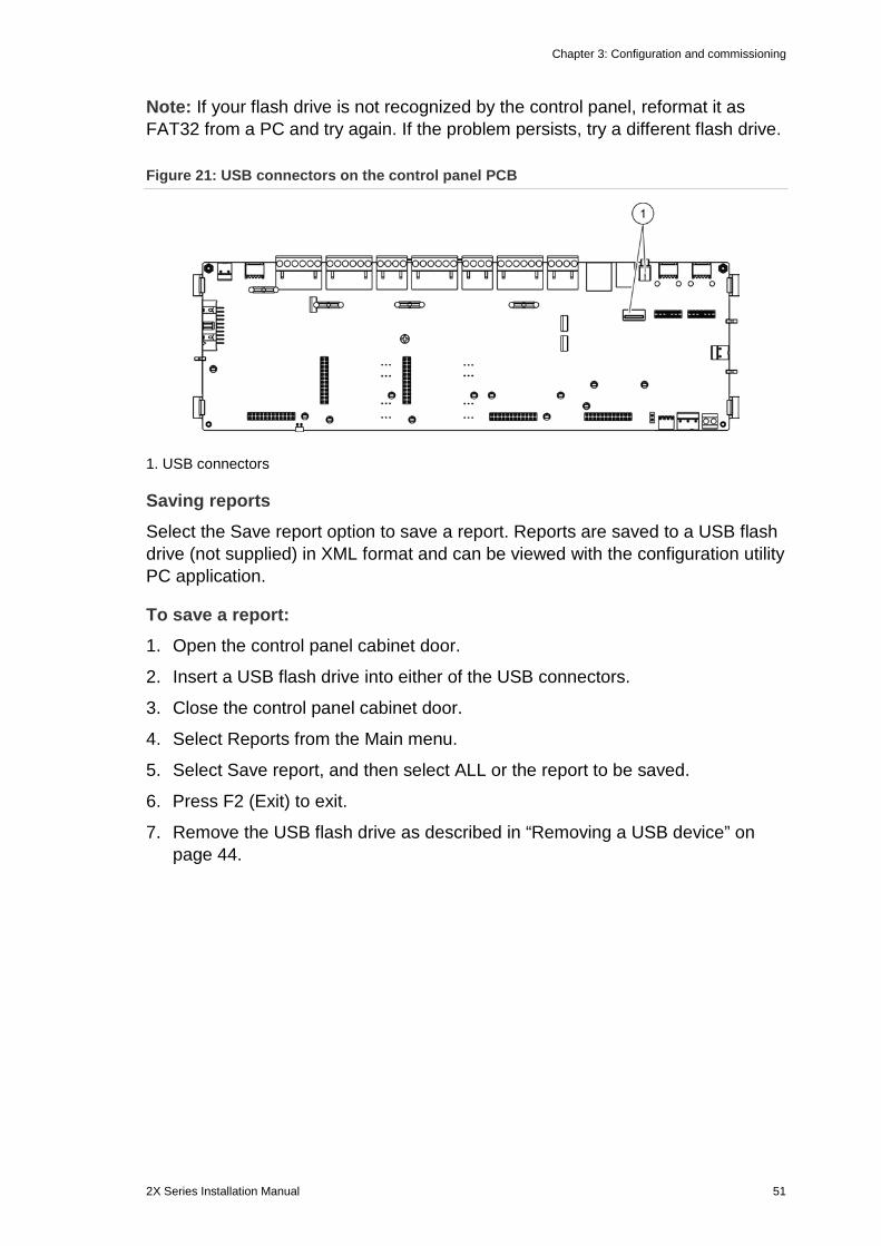
Figure 21: USB connectors on the control panel PCB
1. USB connectors
Saving reports Select the Save report option to save a report. Reports are saved to a USB flash drive (not supplied) in XML format and can be viewed with the configuration utility PC application.
To save a report: 1. Open the control panel cabinet door.
2. Insert a USB flash drive into either of the USB connectors.
3. Close the control panel cabinet door.
4. Select Reports from the Main menu.
5. Select Save report, and then select ALL or the report to be saved.
6. Press F2 (Exit) to exit.
7. Remove the USB flash drive as described in “Removing a USB device” on page 44.
Chapter 3: Configuration and commissioning
52 2X Series Installation Manual
The Password setup menu Use the Password setup menu to change your maintenance password and to manage operator user accounts.
Changing your password Select the Change password option to change your password. You cannot change passwords for other maintenance users.
To change your password: 1. Select Password setup from the Main menu, and then select Change
password.
2. Enter your current password.
3. Enter and then confirm your new password.
4. Press F4 (Enter), and then press F1 (Back).
5. Press F1 (Save), F3 (Apply), F4 (Discard), or F2 (Exit).
Remember to apply saved settings from the Main menu.
Managing users Select the Manage users option to edit, delete, or create operator user accounts. The control panel allows for a maximum of 20 user accounts (all user levels combined).
To edit an operator user account: 1. Select Password setup from the Main menu, and then select Manage users.
A list of the user accounts that you have permission to edit is displayed.
2. Select the user account you want to edit.
3. Select the information to be edited and enter the change.
To change the operator user password, re-enter your maintenance user password, and then allocate and confirm the new operator password.
4. Press F4 (Enter), and then press F1 (Back).
5. Press F1 (Save), F3 (Apply), F4 (Discard), or F2 (Exit).
Remember to apply saved settings from the Main menu.
To delete an operator user account: 1. Select Password setup from the Main menu, and then select Manage users.
A list of the user accounts that you have permission to edit is displayed.
2. Select the user account you want to delete.
You cannot delete the default operator user account.
3. Press F4 (Delete) to delete the selected account.

Chapter 3: Configuration and commissioning
2X Series Installation Manual 53
4. Press F4 (Enter), and then press F1 (Back).
5. Press F1 (Save), F3 (Apply), F4 (Discard), or F2 (Exit).
Remember to apply saved settings from the Main menu.
To create a new operator user account: 1. Select Password setup from the Main menu, and then select Manage users.
2. Press F3 (New) to create a new account.
3. Enter a username and a password for the new account.
Usernames help to identify user session activity in the event log.
4. Press F4 (Enter), and then press F1 (Back).
5. Press F1 (Save), F3 (Apply), F4 (Discard), or F2 (Exit).
Remember to apply saved settings from the Main menu.
Installer level operation and configuration The installer level is password-protected and is reserved for authorized users installing and configuring the control panel and the fire system. The default password for the default installer user is 4444.
The Main menu The installer level Main menu is shown below.
Figure 22: The installer level Main menu
Panel configuration Use the Panel setup menu to access the control panel configuration options shown below.
Table 20: Control panel configuration
Option Description
ID configuration Configures the control panel Firenet ID (for the fire network) and description. The description is displayed on the LCD when the control panel is in standby.
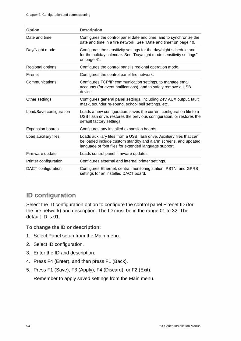
Chapter 3: Configuration and commissioning
54 2X Series Installation Manual
Option Description
Date and time Configures the control panel date and time, and to synchronize the date and time in a fire network. See “Date and time” on page 40.
Day/Night mode Configures the sensitivity settings for the day/night schedule and for the holiday calendar. See “Day/night mode sensitivity settings” on page 41.
Regional options Configures the control panel's regional operation mode.
Firenet Configures the control panel fire network.
Communications Configures TCP/IP communication settings, to manage email accounts (for event notifications), and to safely remove a USB device.
Other settings Configures general panel settings, including 24V AUX output, fault mask, sounder re-sound, school bell settings, etc.
Load/Save configuration Loads a new configuration, saves the current configuration file to a USB flash drive, restores the previous configuration, or restores the default factory settings.
Expansion boards Configures any installed expansion boards.
Load auxiliary files Loads auxiliary files from a USB flash drive. Auxiliary files that can be loaded include custom standby and alarm screens, and updated language or font files for extended language support.
Firmware update Loads control panel firmware updates.
Printer configuration Configures external and internal printer settings.
DACT configuration Configures Ethernet, central monitoring station, PSTN, and GPRS settings for an installed DACT board.
ID configuration Select the ID configuration option to configure the control panel Firenet ID (for the fire network) and description. The ID must be in the range 01 to 32. The default ID is 01.
To change the ID or description: 1. Select Panel setup from the Main menu.
2. Select ID configuration.
3. Enter the ID and description.
4. Press F4 (Enter), and then press F1 (Back).
5. Press F1 (Save), F3 (Apply), F4 (Discard), or F2 (Exit).
Remember to apply saved settings from the Main menu.
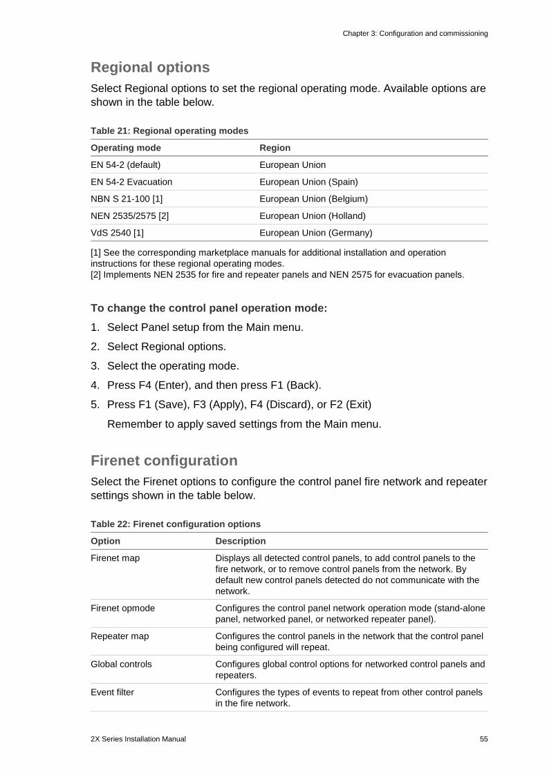
Chapter 3: Configuration and commissioning
2X Series Installation Manual 55
Regional options Select Regional options to set the regional operating mode. Available options are shown in the table below.
Table 21: Regional operating modes
Operating mode Region
EN 54-2 (default) European Union
EN 54-2 Evacuation European Union (Spain)
NBN S 21-100 [1] European Union (Belgium)
NEN 2535/2575 [2] European Union (Holland)
VdS 2540 [1] European Union (Germany)
[1] See the corresponding marketplace manuals for additional installation and operation instructions for these regional operating modes. [2] Implements NEN 2535 for fire and repeater panels and NEN 2575 for evacuation panels.
To change the control panel operation mode: 1. Select Panel setup from the Main menu.
2. Select Regional options.
3. Select the operating mode.
4. Press F4 (Enter), and then press F1 (Back).
5. Press F1 (Save), F3 (Apply), F4 (Discard), or F2 (Exit)
Remember to apply saved settings from the Main menu.
Firenet configuration Select the Firenet options to configure the control panel fire network and repeater settings shown in the table below.
Table 22: Firenet configuration options
Option Description
Firenet map Displays all detected control panels, to add control panels to the fire network, or to remove control panels from the network. By default new control panels detected do not communicate with the network.
Firenet opmode Configures the control panel network operation mode (stand-alone panel, networked panel, or networked repeater panel).
Repeater map Configures the control panels in the network that the control panel being configured will repeat.
Global controls Configures global control options for networked control panels and repeaters.
Event filter Configures the types of events to repeat from other control panels in the fire network.
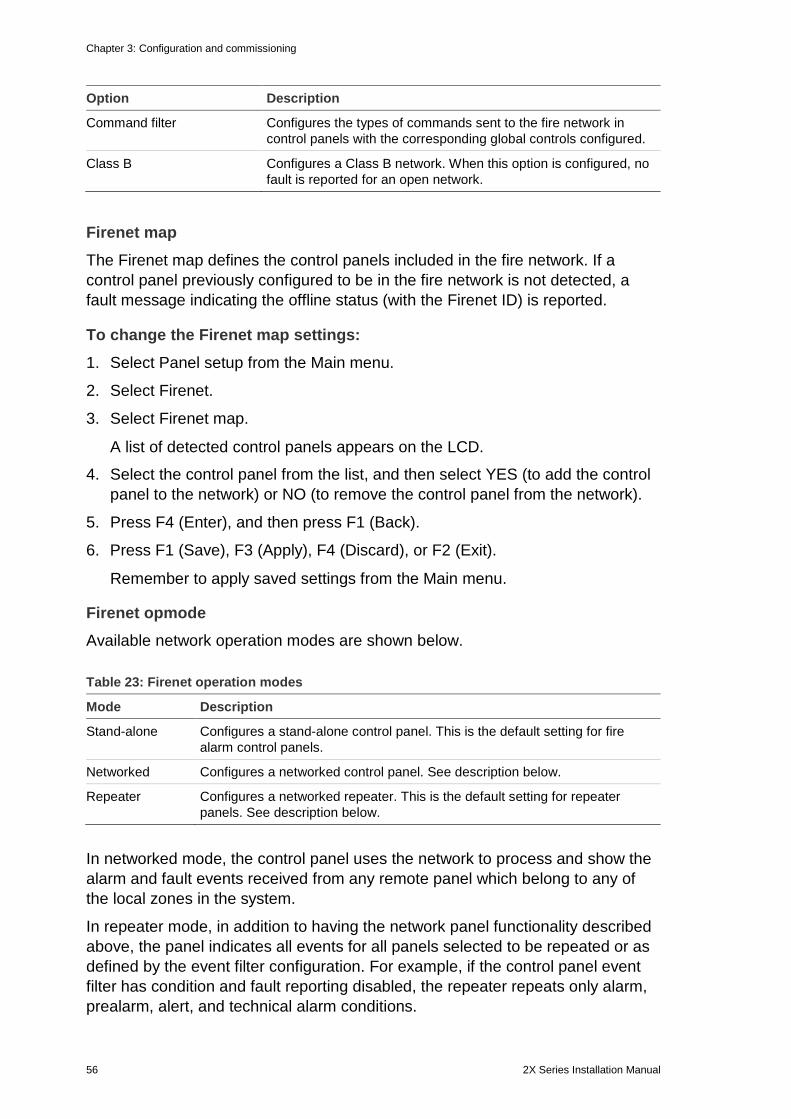
Chapter 3: Configuration and commissioning
56 2X Series Installation Manual
Option Description
Command filter Configures the types of commands sent to the fire network in control panels with the corresponding global controls configured.
Class B Configures a Class B network. When this option is configured, no fault is reported for an open network.
Firenet map The Firenet map defines the control panels included in the fire network. If a control panel previously configured to be in the fire network is not detected, a fault message indicating the offline status (with the Firenet ID) is reported.
To change the Firenet map settings: 1. Select Panel setup from the Main menu.
2. Select Firenet.
3. Select Firenet map.
A list of detected control panels appears on the LCD.
4. Select the control panel from the list, and then select YES (to add the control panel to the network) or NO (to remove the control panel from the network).
5. Press F4 (Enter), and then press F1 (Back).
6. Press F1 (Save), F3 (Apply), F4 (Discard), or F2 (Exit).
Remember to apply saved settings from the Main menu.
Firenet opmode Available network operation modes are shown below.
Table 23: Firenet operation modes
Mode Description
Stand-alone Configures a stand-alone control panel. This is the default setting for fire alarm control panels.
Networked Configures a networked control panel. See description below.
Repeater Configures a networked repeater. This is the default setting for repeater panels. See description below.
In networked mode, the control panel uses the network to process and show the alarm and fault events received from any remote panel which belong to any of the local zones in the system.
In repeater mode, in addition to having the network panel functionality described above, the panel indicates all events for all panels selected to be repeated or as defined by the event filter configuration. For example, if the control panel event filter has condition and fault reporting disabled, the repeater repeats only alarm, prealarm, alert, and technical alarm conditions.
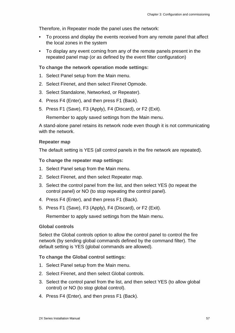
Chapter 3: Configuration and commissioning
2X Series Installation Manual 57
Therefore, in Repeater mode the panel uses the network:
• To process and display the events received from any remote panel that affect the local zones in the system
• To display any event coming from any of the remote panels present in the repeated panel map (or as defined by the event filter configuration)
To change the network operation mode settings: 1. Select Panel setup from the Main menu.
2. Select Firenet, and then select Firenet Opmode.
3. Select Standalone, Networked, or Repeater).
4. Press F4 (Enter), and then press F1 (Back).
5. Press F1 (Save), F3 (Apply), F4 (Discard), or F2 (Exit).
Remember to apply saved settings from the Main menu.
A stand-alone panel retains its network node even though it is not communicating with the network.
Repeater map The default setting is YES (all control panels in the fire network are repeated).
To change the repeater map settings: 1. Select Panel setup from the Main menu.
2. Select Firenet, and then select Repeater map.
3. Select the control panel from the list, and then select YES (to repeat the control panel) or NO (to stop repeating the control panel).
4. Press F4 (Enter), and then press F1 (Back).
5. Press F1 (Save), F3 (Apply), F4 (Discard), or F2 (Exit).
Remember to apply saved settings from the Main menu.
Global controls Select the Global controls option to allow the control panel to control the fire network (by sending global commands defined by the command filter). The default setting is YES (global commands are allowed).
To change the Global control settings: 1. Select Panel setup from the Main menu.
2. Select Firenet, and then select Global controls.
3. Select the control panel from the list, and then select YES (to allow global control) or NO (to stop global control).
4. Press F4 (Enter), and then press F1 (Back).
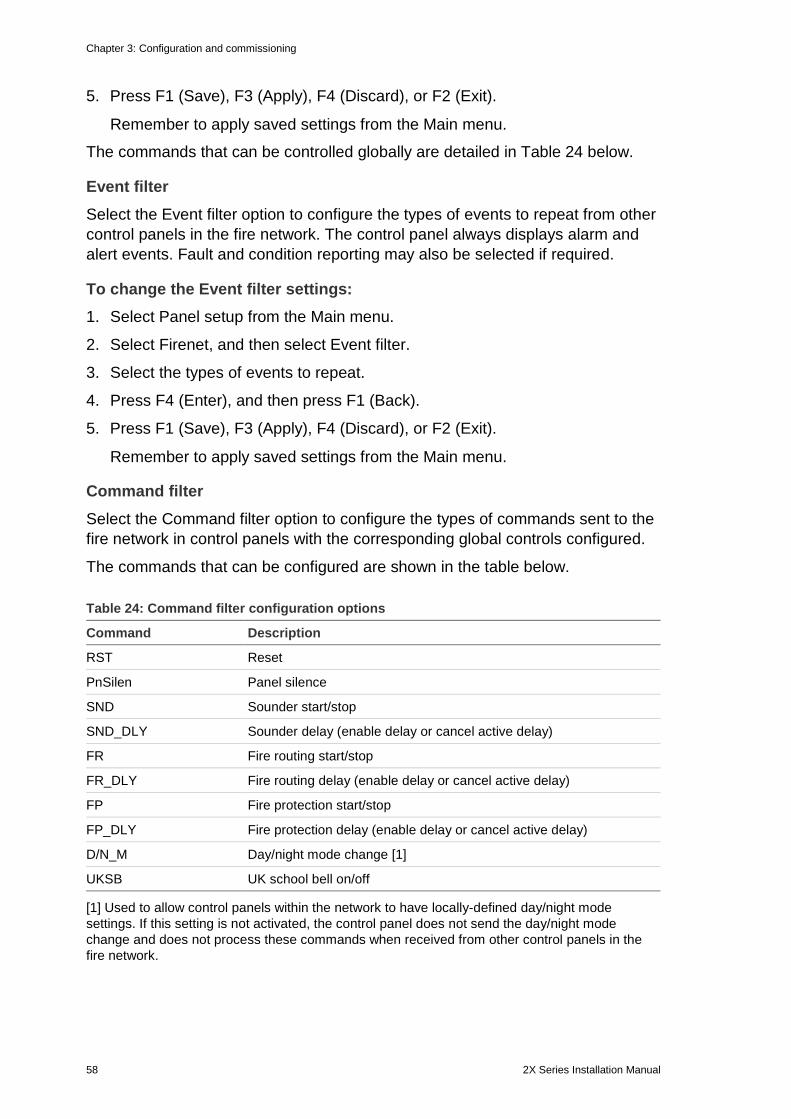
Chapter 3: Configuration and commissioning
58 2X Series Installation Manual
5. Press F1 (Save), F3 (Apply), F4 (Discard), or F2 (Exit).
Remember to apply saved settings from the Main menu.
The commands that can be controlled globally are detailed in Table 24 below.
Event filter Select the Event filter option to configure the types of events to repeat from other control panels in the fire network. The control panel always displays alarm and alert events. Fault and condition reporting may also be selected if required.
To change the Event filter settings: 1. Select Panel setup from the Main menu.
2. Select Firenet, and then select Event filter.
3. Select the types of events to repeat.
4. Press F4 (Enter), and then press F1 (Back).
5. Press F1 (Save), F3 (Apply), F4 (Discard), or F2 (Exit).
Remember to apply saved settings from the Main menu.
Command filter Select the Command filter option to configure the types of commands sent to the fire network in control panels with the corresponding global controls configured.
The commands that can be configured are shown in the table below.
Table 24: Command filter configuration options
Command Description
RST Reset
PnSilen Panel silence
SND Sounder start/stop
SND_DLY Sounder delay (enable delay or cancel active delay)
FR Fire routing start/stop
FR_DLY Fire routing delay (enable delay or cancel active delay)
FP Fire protection start/stop
FP_DLY Fire protection delay (enable delay or cancel active delay)
D/N_M Day/night mode change [1]
UKSB UK school bell on/off
[1] Used to allow control panels within the network to have locally-defined day/night mode settings. If this setting is not activated, the control panel does not send the day/night mode change and does not process these commands when received from other control panels in the fire network.
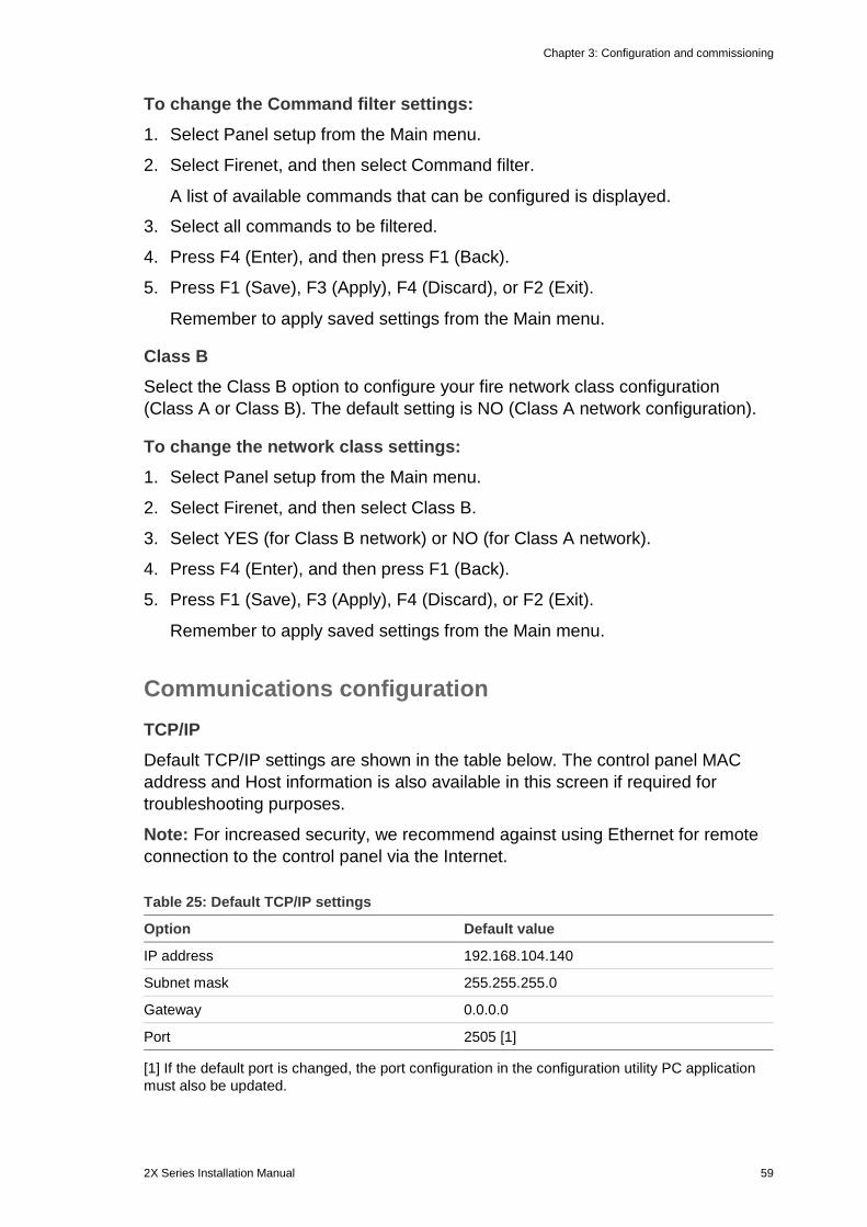
Chapter 3: Configuration and commissioning
2X Series Installation Manual 59
To change the Command filter settings: 1. Select Panel setup from the Main menu.
2. Select Firenet, and then select Command filter.
A list of available commands that can be configured is displayed.
3. Select all commands to be filtered.
4. Press F4 (Enter), and then press F1 (Back).
5. Press F1 (Save), F3 (Apply), F4 (Discard), or F2 (Exit).
Remember to apply saved settings from the Main menu.
Class B Select the Class B option to configure your fire network class configuration (Class A or Class B). The default setting is NO (Class A network configuration).
To change the network class settings: 1. Select Panel setup from the Main menu.
2. Select Firenet, and then select Class B.
3. Select YES (for Class B network) or NO (for Class A network).
4. Press F4 (Enter), and then press F1 (Back).
5. Press F1 (Save), F3 (Apply), F4 (Discard), or F2 (Exit).
Remember to apply saved settings from the Main menu.
Communications configuration TCP/IP Default TCP/IP settings are shown in the table below. The control panel MAC address and Host information is also available in this screen if required for troubleshooting purposes.
Note: For increased security, we recommend against using Ethernet for remote connection to the control panel via the Internet.
Table 25: Default TCP/IP settings
Option Default value
IP address 192.168.104.140
Subnet mask 255.255.255.0
Gateway 0.0.0.0
Port 2505 [1]
[1] If the default port is changed, the port configuration in the configuration utility PC application must also be updated.
Chapter 3: Configuration and commissioning
60 2X Series Installation Manual
To change the TCP/IP settings: 1. Select Panel setup from the Main menu, and then select Communications.
2. Select TCP/IP.
3. Enter the IP, Subnet mask, Gateway, and Port information.
4. Press F4 (Enter), and then press F1 (Back).
5. Press F1 (Save), F3 (Apply), F4 (Discard), or F2 (Exit).
Remember to apply saved settings from the Main menu.
Note: If your network is protected by a firewall, the port configuration in your firewall must be updated to allow local communication with external software.
Email accounts Select the Email accounts option to manage the email accounts for remote monitoring and to configure the types of events sent to each email address. For correct operation, TCP/IP and email server details must be configured (see “Email server” below).
Note: Maintenance users are also able to modify settings for this service.
To manage email accounts: 1. Select Communications from the Main menu.
2. Select Email accounts, and then select the account to be edited (the default names are Account 1, Account 2, etc.).
3. Select the types of events to be included in the notification email: alarms, faults, conditions, or log events (any other system status change event).
If no event type is selected, the email notification service is not activated.
4. Enter the email address associated with the email account.
5. Press F4 (Enter), and then press F1 (Back).
6. Press F1 (Save), F3 (Apply), F4 (Discard), or F2 (Exit).
Remember to apply saved settings from the Main menu.
Email server Select the Email server option to configure the email server settings for sending configured notification emails. IT support may be required to configure this option.
To configure the email server: 1. Select Panel setup from the Main menu, and then select Communications.
2. Select Email server.
3. Enter the Host (domain) and the IP address of the email server.
The Host name is optional.
Chapter 3: Configuration and commissioning
2X Series Installation Manual 61
4. Press F4 (Enter), and then press F1 (Back).
5. Press F1 (Save), F3 (Apply), F4 (Discard), or F2 (Exit).
Remember to apply saved settings from the Main menu.
Other settings 24V auxiliary Select the 24V AUX config option to configure the 24V AUX output state during reset and when the control panel is running on battery power. The default setting for both options is NO (the 24V AUX output is not deactivated).
To change the configuration: 1. Select Panel setup from the Main menu.
2. Select Other settings, and then select 24V AUX config.
3. Select YES or NO for deactivation during reset.
4. Select YES or NO for deactivation when running on battery power.
5. Press F4 (Enter), and then press F1 (Back).
6. Press F1 (Save), F3 (Apply), F4 (Discard), or F2 (Exit).
Remember to apply saved settings from the Main menu.
Fault mask Select the Fault mask option to configure the reporting status for battery and earth faults. The default setting for both options is YES (all faults are reported).
To change the configuration: 1. Select Panel setup from the Main menu.
2. Select Other settings, and then select Fault mask.
3. Select YES or NO for battery fault notifications.
4. Select YES or NO for earth fault notifications.
5. Press F4 (Enter), and then press F1 (Back).
6. Press F1 (Save), F3 (Apply), F4 (Discard), or F2 (Exit).
Remember to apply saved settings from the Main menu.
Note: If NO is selected for either option, the corresponding faults are not recorded in the event log.
Chapter 3: Configuration and commissioning
62 2X Series Installation Manual
Sounders re-sound Select the Sounder re-sound option to configure stopped sounder functionality when new zone alarms are reported. The available configuration options are shown below. The default setting is YES (sounders re-sound for new zone alarms).
Note: By default, sounders only re-sound for a new alarm (in the same zone) if a manual call point alarm is reported following a detector alarm.
Table 26: Sounder re-sound configuration options
YES (default) A new zone in alarm re-sounds the sounders
NO A new zone in alarm does not re-sound the sounders
Device If checked, any new device in alarm in the same zone (including detectors) re-sounds the sounders.
To change the configuration: 1. Select Panel setup from the Main menu.
2. Select Other settings, and then select Sounder re-sound.
3. Select YES or NO.
4. Select and check the Device check box if you want any new device in alarm in the same zone to re-sound the sounders.
5. Press F4 (Enter), and then press F1 (Back).
6. Press F1 (Save), F3 (Apply), F4 (Discard), or F2 (Exit).
Remember to apply saved settings from the Main menu.
School bells Select the School bells option to configure school bell operation and duration (in seconds). By default school bells are not activated.
To change the configuration: 1. Select Panel setup from the Main menu.
2. Select Other settings, and then select School bells.
3. Select Activate school bells while input is ON, and then select YES or NO.
Select YES for the school bells to sound only while the input is active, or NO if the bells should continue to sound when the input is off.
4. Select Time, and then enter the duration in seconds (1 to 10).
Enter the school bell duration in seconds if you selected NO in step 3, or leave the duration blank if you selected YES.
5. Press F4 (Enter), and then press F1 (Back).
Chapter 3: Configuration and commissioning
2X Series Installation Manual 63
6. Press F1 (Save), F3 (Apply), F4 (Discard), or F2 (Exit).
Remember to apply saved settings from the Main menu.
Self-test Select the Self-test option to schedule a functional self-test for each loop device and to generate a daily report in devices that support this feature. By default self-test is not enabled.
To change the configuration: 1. Select Panel setup from the Main menu.
2. Select Other settings, and then select Self-test.
3. Select and check the Enabled check box.
4. Select TestH, and then enter the start time for the self-test (00:00 to 23:59).
5. Select ReportH, and then enter the time for the report to be generated (00:00 to 23:59).
6. Press F4 (Enter), and then press F1 (Back).
7. Press F1 (Save), F3 (Apply), F4 (Discard), or F2 (Exit).
Remember to apply saved settings from the Main menu.
Pulse activation Select the Pulse activation option to configure the fire routing output activation pulse time, in milliseconds, for external devices that require pulsed activation. By default the output activation is continuous.
This option is not available for repeaters or control panels that do not include fire routing controls.
To change the configuration: 1. Select Panel setup from the Main menu.
2. Select Other settings, and then select Pulse Activation.
3. Select and clear the Contin. check box.
4. Select PulseT, and then enter the pulse time value in milliseconds (0 to 10000).
If the PulseT value is 0, the output activation is continuous.
5. Press F4 (Enter), and then press F1 (Back).
6. Press F1 (Save), F3 (Apply), F4 (Discard), or F2 (Exit).
Remember to apply saved settings from the Main menu.
Chapter 3: Configuration and commissioning
64 2X Series Installation Manual
Service mode timeout Select the Service mode timeout option to configure a timeout value (in minutes) for Service mode (see “Service mode” on page 49). By default the Service mode timeout is not enabled.
To change the configuration: 1. Select Panel setup from the Main menu.
2. Select Other settings, and then select Service mode timeout.
3. Select and check the Enabled check box.
4. Select Timeout, and then enter the timeout value in minutes (1 to 120).
The default timeout value is 30 minutes.
5. Press F4 (Enter), and then press F1 (Back).
6. Press F1 (Save), F3 (Apply), F4 (Discard), or F2 (Exit).
Remember to apply saved settings from the Main menu.
Load/Save configuration Restoring the previous configuration Select the Restore configuration option to restore the previous system configuration.
To restore the system configuration: 1. Select Panel setup from the Main menu, and then select Configuration.
2. Select Restore configuration and confirm your selection.
3. Press F4 (Enter), and then press F1 (Back).
4. Press F1 (Save), F3 (Apply), F4 (Discard), or F2 (Exit).
Remember to apply saved settings from the Main menu.
Loading and saving configuration files Select the Load configuration option or the Save configuration option to load a system configuration file from a USB flash drive or to save the current system configuration file to a USB flash drive.
Note: If your flash drive is not recognized by the control panel, reformat it as FAT32 from a PC and try again. If the problem persists, try a different flash drive.
To load a configuration: 1. Open the control panel door and insert the USB flash drive with the
configuration file into either of the USB type A connectors (see Figure 4 on page 17). Close the control panel door.
2. Select Panel setup from the Main menu.
Chapter 3: Configuration and commissioning
2X Series Installation Manual 65
3. Select Configuration, and then select Load configuration.
4. Select the configuration file to load.
5. Press F4 (Enter), and then press F1 (Back).
6. Press F1 (Save), F3 (Apply), F4 (Discard), or F2 (Exit).
Remember to apply saved settings from the Main menu.
7. Remove the USB flash drive as described in “Removing a USB device” on page 44.
To save a configuration to file: 1. Open the control panel door and insert the USB flash drive into either of the
USB type A connectors (see Figure 4 on page 17). Close the control panel door.
2. Select Panel setup from the Main menu.
3. Select Configuration, and then select Save configuration.
The current configuration is saved in XML format using a default naming format.
4. Press F4 (Enter), and then press F1 (Back).
5. Press F1 (Save), F3 (Apply), F4 (Discard), or F2 (Exit).
Remember to apply saved settings from the Main menu.
6. Remove the USB flash drive as described in “Removing a USB device” on page 44.
Restoring the default configuration Select the Default configuraton option to restore the system to the default factory settings detailed in Appendix A “Default configurations” on page 117.
To restore the default system configuration: 1. Select Panel setup from the Main menu, and then select Configuration.
2. Select Default configuration and confirm your selection.
3. Press F4 (Enter), and then press F1 (Back).
4. Press F1 (Save), F3 (Apply), F4 (Discard), or F2 (Exit).
Remember to apply saved settings from the Main menu.
Chapter 3: Configuration and commissioning
66 2X Series Installation Manual
Expansion board configuration Select the Expansion boards option to add an installed expansion board to the control panel configuration.
The available expansion boards are shown in the table below.
Table 27: Available expansion boards
Option Description
LB Loop board
NB Network board [1]
ZIC Zone LED indicator board
PIB Peripherals interface board
DACT DACT board
[1] By default repeater panels have the network board configured as installed.
To add an expansion board: 1. Select Panel setup from the Main menu.
2. Select Expansion boards.
3. Select the expansion board that you want to add, and then select YES.
4. Press F4 (Enter), and then press F1 (Back).
5. Press F1 (Save), F3 (Apply), F4 (Discard), or F2 (Exit).
Remember to apply saved settings from the Main menu.
If an installed expansion board is not detected by the control panel, a system fault is indicated.
Load auxiliary files Select the Load auxiliary files option to load auxiliary files from a USB flash drive. Auxiliary files that can be loaded include custom standby and alarm screens, and updated language or font files provided by the manufacturer.
Loading custom standby and alarm screens Select the Splash screens option to load custom standby and alarm screens in bitmap (BMP) format.
To load custom screen images: 1. Open the control panel door and insert the USB flash drive into either of the
USB type A connectors (see Figure 4 on page 17). Close the control panel door.
2. Select Panel setup from the Main menu.
Chapter 3: Configuration and commissioning
2X Series Installation Manual 67
3. Select Configuration, and then select Load auxiliary files.
4. Select Splash screens.
5. Select the bitmap file to load and confirm the selection.
6. Press F4 (Enter), and then press F1 (Back).
7. Press F1 (Save), F3 (Apply), F4 (Discard), or F2 (Exit).
Remember to apply saved settings from the Main menu.
8. Remove the USB flash drive as described in “Removing a USB device” on page 44.
Loading language files or fonts Select the Languages or Language fonts option to load language files or fonts provided by the manufacturer.
To load language files or fonts: 1. Open the control panel door and insert the USB flash drive with the required
files into either of the USB type A connectors (see Figure 4 on page 17). Close the control panel door.
2. Select Panel setup from the Main menu.
3. Select Configuration, and then select Load auxiliary files.
4. Select Languages or Language fonts.
5. Select the file to load and confirm the selection.
6. Press F4 (Enter), and then press F1 (Back).
7. Press F1 (Save), F3 (Apply), F4 (Discard), or F2 (Exit).
Remember to apply saved settings from the Main menu.
8. Remove the USB flash drive as described in “Removing a USB device” on page 44.
Firmware updates
Caution: Updating the control panel firmware may delete the current installation configuration data. Always back up your configuration data before updating the control panel firmware.
Select this option to load control panel firmware updates provided by the manufacturer. The update application may only be available in English.
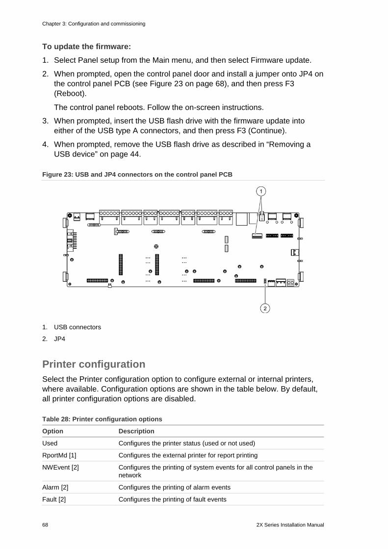
Chapter 3: Configuration and commissioning
68 2X Series Installation Manual
To update the firmware: 1. Select Panel setup from the Main menu, and then select Firmware update.
2. When prompted, open the control panel door and install a jumper onto JP4 on the control panel PCB (see Figure 23 on page 68), and then press F3 (Reboot).
The control panel reboots. Follow the on-screen instructions.
3. When prompted, insert the USB flash drive with the firmware update into either of the USB type A connectors, and then press F3 (Continue).
4. When prompted, remove the USB flash drive as described in “Removing a USB device” on page 44.
Figure 23: USB and JP4 connectors on the control panel PCB
1. USB connectors
2. JP4
Printer configuration Select the Printer configuration option to configure external or internal printers, where available. Configuration options are shown in the table below. By default, all printer configuration options are disabled.
Table 28: Printer configuration options
Option Description
Used Configures the printer status (used or not used)
RportMd [1] Configures the external printer for report printing
NWEvent [2] Configures the printing of system events for all control panels in the network
Alarm [2] Configures the printing of alarm events
Fault [2] Configures the printing of fault events
Chapter 3: Configuration and commissioning
2X Series Installation Manual 69
Option Description
Cond [2] Configures the printing of condition events
StatCH [2] Configures the printing of status change events (for example, inputs and outputs)
[1] This option is not available for internal printers. [2] When RportMd is checked, these system events are not printed.
To change the configuration: 1. Select Panel setup from the Main menu.
2. Select Other settings, and then select Printer config.
3. Select Int printer config or Ext printer config.
4. Select and check the check box for the options that you want to enable.
5. Press F4 (Enter), and then press F1 (Back).
6. Press F1 (Save), F3 (Apply), F4 (Discard), or F2 (Exit).
Remember to apply saved settings from the Main menu.
DACT configuration Select the DACT configuration option to configure settings for an installed DACT expansion board. Configuration options are shown in the table below.
Table 29: DACT configuration options
Option Description
General config Configures the DACT status (used or not used) and event reporting options
Ethernet config Configures Ethernet settings for monitoring network communication with the central monitoring station (CMS)
CMS config Configures CMS settings
PSTN config Configures PSTN settings
GPRS config [1] Configures GPRS settings
[1] Requires an optional GPRS expansion board to be installed.
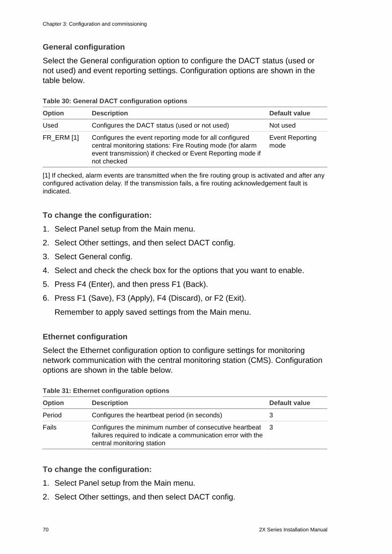
Chapter 3: Configuration and commissioning
70 2X Series Installation Manual
General configuration Select the General configuration option to configure the DACT status (used or not used) and event reporting settings. Configuration options are shown in the table below.
Table 30: General DACT configuration options
Option Description Default value
Used Configures the DACT status (used or not used) Not used
FR_ERM [1] Configures the event reporting mode for all configured central monitoring stations: Fire Routing mode (for alarm event transmission) if checked or Event Reporting mode if not checked
Event Reporting mode
[1] If checked, alarm events are transmitted when the fire routing group is activated and after any configured activation delay. If the transmission fails, a fire routing acknowledgement fault is indicated.
To change the configuration: 1. Select Panel setup from the Main menu.
2. Select Other settings, and then select DACT config.
3. Select General config.
4. Select and check the check box for the options that you want to enable.
5. Press F4 (Enter), and then press F1 (Back).
6. Press F1 (Save), F3 (Apply), F4 (Discard), or F2 (Exit).
Remember to apply saved settings from the Main menu.
Ethernet configuration Select the Ethernet configuration option to configure settings for monitoring network communication with the central monitoring station (CMS). Configuration options are shown in the table below.
Table 31: Ethernet configuration options
Option Description Default value
Period Configures the heartbeat period (in seconds) 3
Fails Configures the minimum number of consecutive heartbeat failures required to indicate a communication error with the central monitoring station
3
To change the configuration: 1. Select Panel setup from the Main menu.
2. Select Other settings, and then select DACT config.
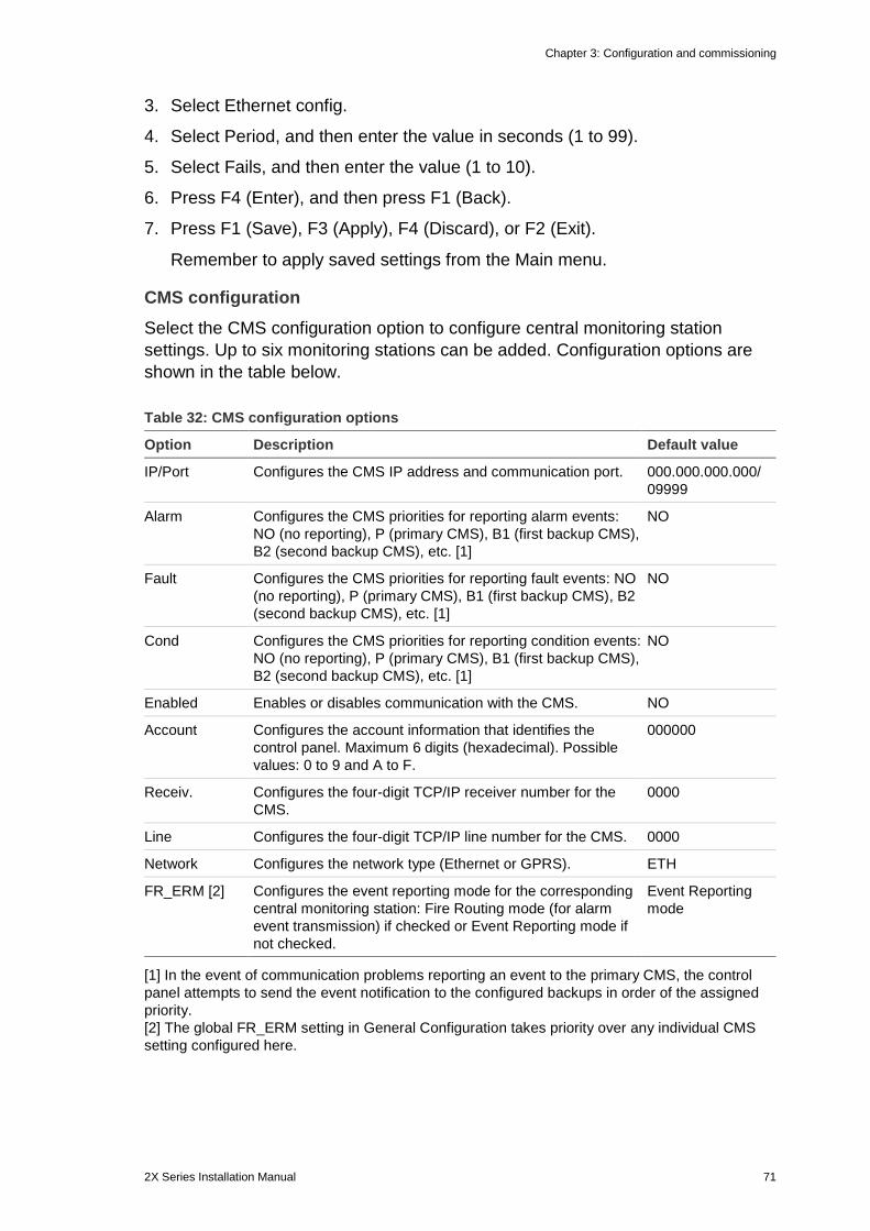
Chapter 3: Configuration and commissioning
2X Series Installation Manual 71
3. Select Ethernet config.
4. Select Period, and then enter the value in seconds (1 to 99).
5. Select Fails, and then enter the value (1 to 10).
6. Press F4 (Enter), and then press F1 (Back).
7. Press F1 (Save), F3 (Apply), F4 (Discard), or F2 (Exit).
Remember to apply saved settings from the Main menu.
CMS configuration Select the CMS configuration option to configure central monitoring station settings. Up to six monitoring stations can be added. Configuration options are shown in the table below.
Table 32: CMS configuration options
Option Description Default value
IP/Port Configures the CMS IP address and communication port. 000.000.000.000/ 09999
Alarm Configures the CMS priorities for reporting alarm events: NO (no reporting), P (primary CMS), B1 (first backup CMS), B2 (second backup CMS), etc. [1]
NO
Fault Configures the CMS priorities for reporting fault events: NO (no reporting), P (primary CMS), B1 (first backup CMS), B2 (second backup CMS), etc. [1]
NO
Cond Configures the CMS priorities for reporting condition events: NO (no reporting), P (primary CMS), B1 (first backup CMS), B2 (second backup CMS), etc. [1]
NO
Enabled Enables or disables communication with the CMS. NO
Account Configures the account information that identifies the control panel. Maximum 6 digits (hexadecimal). Possible values: 0 to 9 and A to F.
000000
Receiv. Configures the four-digit TCP/IP receiver number for the CMS.
0000
Line Configures the four-digit TCP/IP line number for the CMS. 0000
Network Configures the network type (Ethernet or GPRS). ETH
FR_ERM [2] Configures the event reporting mode for the corresponding central monitoring station: Fire Routing mode (for alarm event transmission) if checked or Event Reporting mode if not checked.
Event Reporting mode
[1] In the event of communication problems reporting an event to the primary CMS, the control panel attempts to send the event notification to the configured backups in order of the assigned priority. [2] The global FR_ERM setting in General Configuration takes priority over any individual CMS setting configured here.
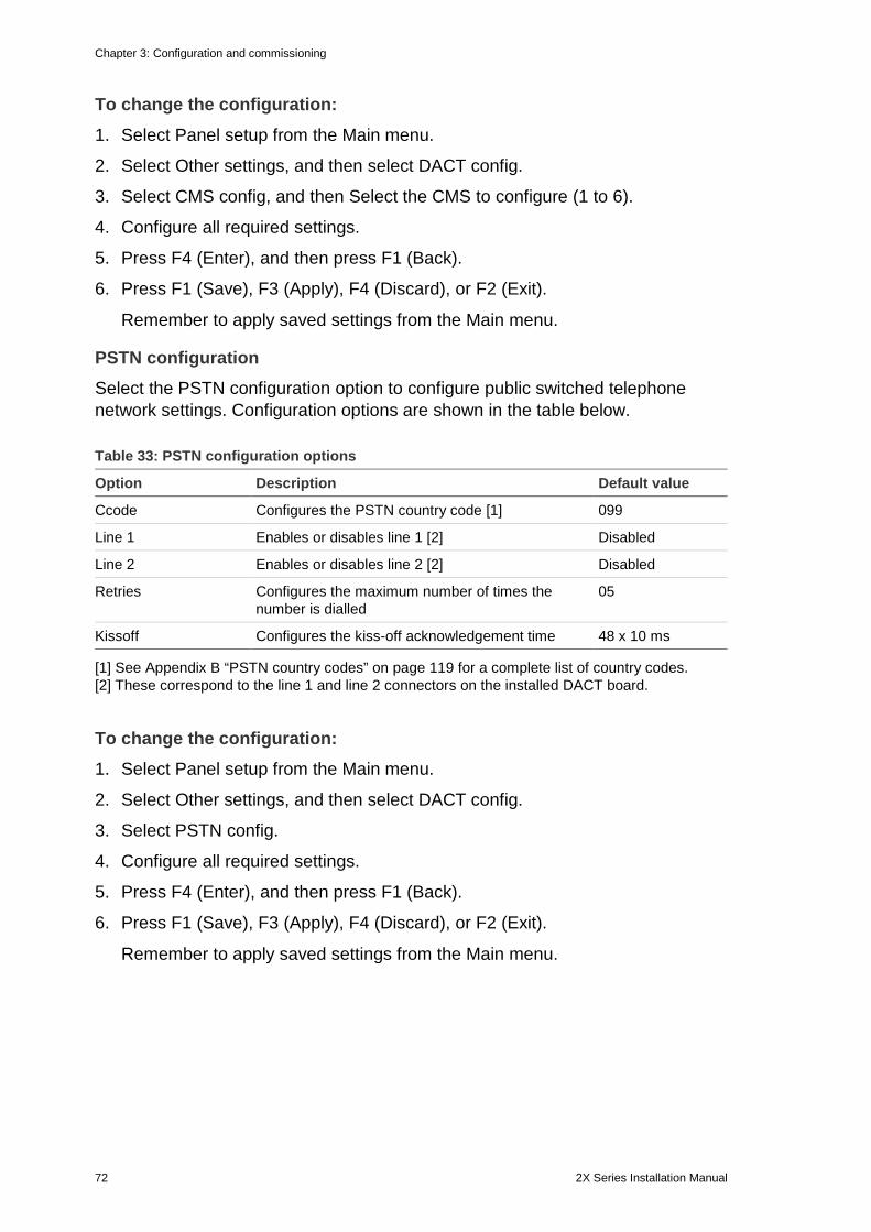
Chapter 3: Configuration and commissioning
72 2X Series Installation Manual
To change the configuration: 1. Select Panel setup from the Main menu.
2. Select Other settings, and then select DACT config.
3. Select CMS config, and then Select the CMS to configure (1 to 6).
4. Configure all required settings.
5. Press F4 (Enter), and then press F1 (Back).
6. Press F1 (Save), F3 (Apply), F4 (Discard), or F2 (Exit).
Remember to apply saved settings from the Main menu.
PSTN configuration Select the PSTN configuration option to configure public switched telephone network settings. Configuration options are shown in the table below.
Table 33: PSTN configuration options
Option Description Default value
Ccode Configures the PSTN country code [1] 099
Line 1 Enables or disables line 1 [2] Disabled
Line 2 Enables or disables line 2 [2] Disabled
Retries Configures the maximum number of times the number is dialled
05
Kissoff Configures the kiss-off acknowledgement time 48 x 10 ms
[1] See Appendix B “PSTN country codes” on page 119 for a complete list of country codes. [2] These correspond to the line 1 and line 2 connectors on the installed DACT board.
To change the configuration: 1. Select Panel setup from the Main menu.
2. Select Other settings, and then select DACT config.
3. Select PSTN config.
4. Configure all required settings.
5. Press F4 (Enter), and then press F1 (Back).
6. Press F1 (Save), F3 (Apply), F4 (Discard), or F2 (Exit).
Remember to apply saved settings from the Main menu.
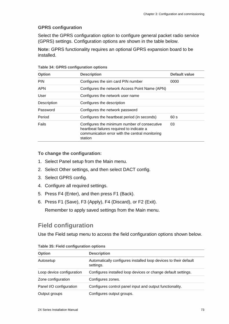
Chapter 3: Configuration and commissioning
2X Series Installation Manual 73
GPRS configuration Select the GPRS configuration option to configure general packet radio service (GPRS) settings. Configuration options are shown in the table below.
Note: GPRS functionality requires an optional GPRS expansion board to be installed.
Table 34: GPRS configuration options
Option Description Default value
PIN Configures the sim card PIN number 0000
APN Configures the network Access Point Name (APN)
User Configures the network user name
Description Configures the description
Password Configures the network password
Period Configures the heartbeat period (in seconds) 60 s
Fails Configures the minimum number of consecutive heartbeat failures required to indicate a communication error with the central monitoring station
03
To change the configuration: 1. Select Panel setup from the Main menu.
2. Select Other settings, and then select DACT config.
3. Select GPRS config.
4. Configure all required settings.
5. Press F4 (Enter), and then press F1 (Back).
6. Press F1 (Save), F3 (Apply), F4 (Discard), or F2 (Exit).
Remember to apply saved settings from the Main menu.
Field configuration Use the Field setup menu to access the field configuration options shown below.
Table 35: Field configuration options
Option Description
Autosetup Automatically configures installed loop devices to their default settings.
Loop device configuration Configures installed loop devices or change default settings.
Zone configuration Configures zones.
Panel I/O configuration Configures control panel input and output functionality.
Output groups Configures output groups.
Chapter 3: Configuration and commissioning
74 2X Series Installation Manual
Option Description
Activation configuration Configures output group delays and regional investigation time options.
Loop class Configures the installation loop wiring Class (Class A or Class B).
Autosetup Select the Autosetup option to automatically configure installed loop devices. Autosetup assigns a default configuration for each device type detected.
To begin autosetup: 1. Select Field setup from the Main menu, and then select Autosetup.
2. Select the corresponding loop or All loops.
During the search the LCD displays the message “Autosetup in progress”. When the autosetup is complete the list of detected devices is displayed.
3. Press F4 (Enter), and then press F1 (Back).
4. Press F1 (Save), F3 (Apply), F4 (Discard), or F2 (Exit).
Remember to apply saved settings from the Main menu.
Autosetup will:
• Assign all initiating devices (including zone modules) to zone 1
• Assign all sounder devices to the default sounder output group (output group number 1)
• Assign all nonsupervised outputs (relays) to the default program output group (output group number 301)
• Assign all extinguishing devices to the default extinguishing output group (output group number 801)
Extinguishing output groups are only activated with a confirmed alarm. They are not activated by zone alarms and rules.
• Assign all fire routing outputs (where available) to the default fire routing output group (output group number 971)
• Assign all fire protection outputs (where available) to the default fire protection output group (output group number 981)
• Assign the default initial zone to zone 1
By default all zones activate all output groups with no delay.
Note: Autosetup is incremental and retains the device text description for previously configured devices.
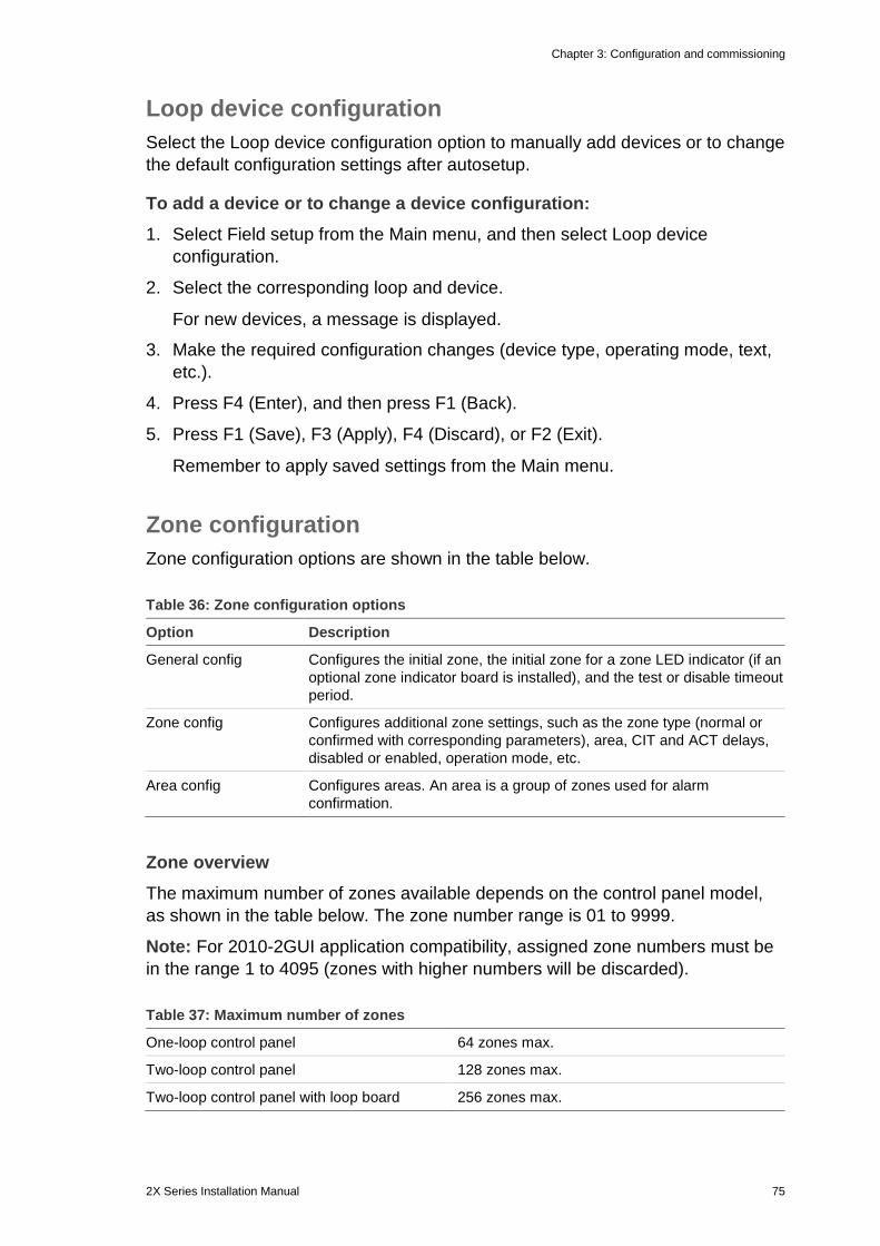
Chapter 3: Configuration and commissioning
2X Series Installation Manual 75
Loop device configuration Select the Loop device configuration option to manually add devices or to change the default configuration settings after autosetup.
To add a device or to change a device configuration: 1. Select Field setup from the Main menu, and then select Loop device
configuration.
2. Select the corresponding loop and device.
For new devices, a message is displayed.
3. Make the required configuration changes (device type, operating mode, text, etc.).
4. Press F4 (Enter), and then press F1 (Back).
5. Press F1 (Save), F3 (Apply), F4 (Discard), or F2 (Exit).
Remember to apply saved settings from the Main menu.
Zone configuration Zone configuration options are shown in the table below.
Table 36: Zone configuration options
Option Description
General config Configures the initial zone, the initial zone for a zone LED indicator (if an optional zone indicator board is installed), and the test or disable timeout period.
Zone config Configures additional zone settings, such as the zone type (normal or confirmed with corresponding parameters), area, CIT and ACT delays, disabled or enabled, operation mode, etc.
Area config Configures areas. An area is a group of zones used for alarm confirmation.
Zone overview The maximum number of zones available depends on the control panel model, as shown in the table below. The zone number range is 01 to 9999.
Note: For 2010-2GUI application compatibility, assigned zone numbers must be in the range 1 to 4095 (zones with higher numbers will be discarded).
Table 37: Maximum number of zones
One-loop control panel 64 zones max.
Two-loop control panel 128 zones max.
Two-loop control panel with loop board 256 zones max.
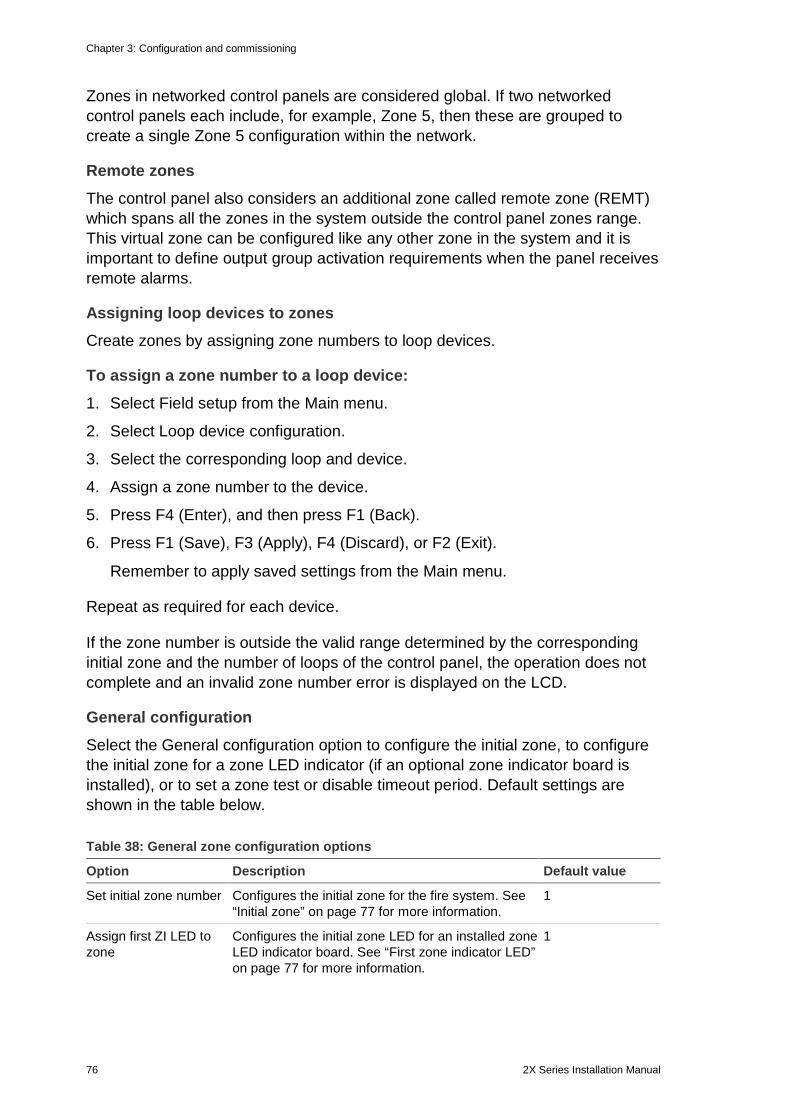
Chapter 3: Configuration and commissioning
76 2X Series Installation Manual
Zones in networked control panels are considered global. If two networked control panels each include, for example, Zone 5, then these are grouped to create a single Zone 5 configuration within the network.
Remote zones The control panel also considers an additional zone called remote zone (REMT) which spans all the zones in the system outside the control panel zones range. This virtual zone can be configured like any other zone in the system and it is important to define output group activation requirements when the panel receives remote alarms.
Assigning loop devices to zones Create zones by assigning zone numbers to loop devices.
To assign a zone number to a loop device: 1. Select Field setup from the Main menu.
2. Select Loop device configuration.
3. Select the corresponding loop and device.
4. Assign a zone number to the device.
5. Press F4 (Enter), and then press F1 (Back).
6. Press F1 (Save), F3 (Apply), F4 (Discard), or F2 (Exit).
Remember to apply saved settings from the Main menu.
Repeat as required for each device.
If the zone number is outside the valid range determined by the corresponding initial zone and the number of loops of the control panel, the operation does not complete and an invalid zone number error is displayed on the LCD.
General configuration Select the General configuration option to configure the initial zone, to configure the initial zone for a zone LED indicator (if an optional zone indicator board is installed), or to set a zone test or disable timeout period. Default settings are shown in the table below.
Table 38: General zone configuration options
Option Description Default value
Set initial zone number Configures the initial zone for the fire system. See “Initial zone” on page 77 for more information.
1
Assign first ZI LED to zone
Configures the initial zone LED for an installed zone LED indicator board. See “First zone indicator LED” on page 77 for more information.
1
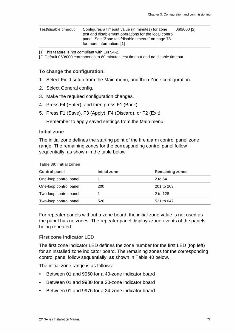
Chapter 3: Configuration and commissioning
2X Series Installation Manual 77
Test/disable timeout Configures a timeout value (in minutes) for zone test and disablement operations for the local control panel. See “Zone test/disable timeout” on page 78 for more information. [1]
060/000 [2]
[1] This feature is not compliant with EN 54-2. [2] Default 060/000 corresponds to 60 minutes test timeout and no disable timeout.
To change the configuration: 1. Select Field setup from the Main menu, and then Zone configuration.
2. Select General config.
3. Make the required configuration changes.
4. Press F4 (Enter), and then press F1 (Back).
5. Press F1 (Save), F3 (Apply), F4 (Discard), or F2 (Exit).
Remember to apply saved settings from the Main menu.
Initial zone The initial zone defines the starting point of the fire alarm control panel zone range. The remaining zones for the corresponding control panel follow sequentially, as shown in the table below.
Table 39: Initial zones
Control panel Initial zone Remaining zones
One-loop control panel 1 2 to 64
One-loop control panel 200 201 to 263
Two-loop control panel 1 2 to 128
Two-loop control panel 520 521 to 647
For repeater panels without a zone board, the initial zone value is not used as the panel has no zones. The repeater panel displays zone events of the panels being repeated.
First zone indicator LED The first zone indicator LED defines the zone number for the first LED (top left) for an installed zone indicator board. The remaining zones for the corresponding control panel follow sequentially, as shown in Table 40 below.
The initial zone range is as follows:
• Between 01 and 9960 for a 40-zone indicator board
• Between 01 and 9980 for a 20-zone indicator board
• Between 01 and 9976 for a 24-zone indicator board
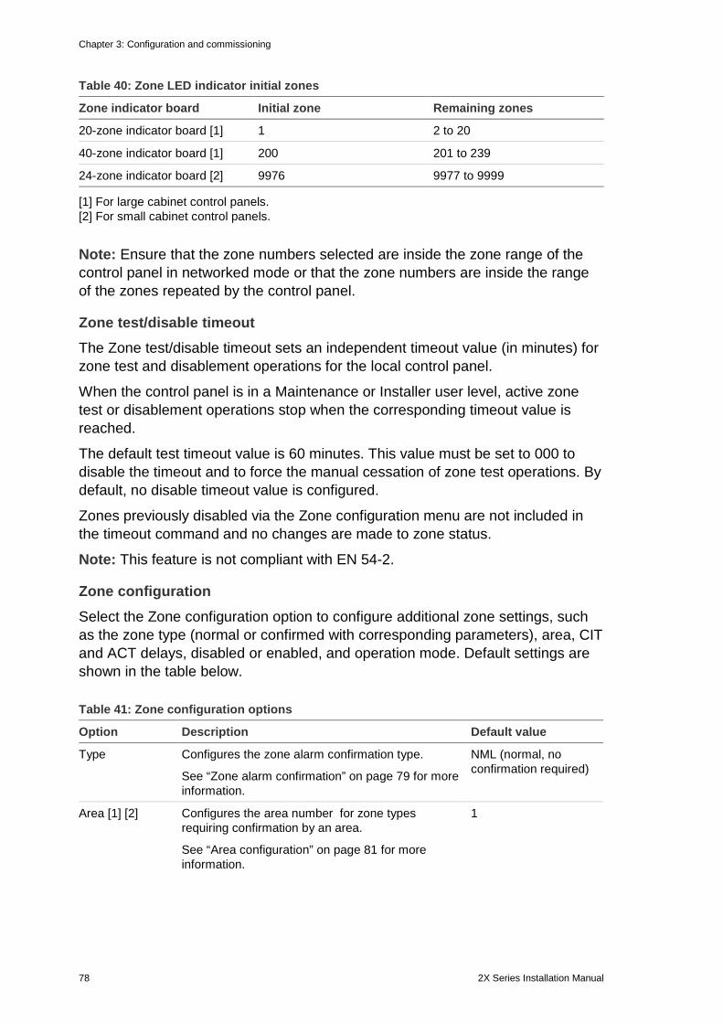
Chapter 3: Configuration and commissioning
78 2X Series Installation Manual
Table 40: Zone LED indicator initial zones
Zone indicator board Initial zone Remaining zones
20-zone indicator board [1] 1 2 to 20
40-zone indicator board [1] 200 201 to 239
24-zone indicator board [2] 9976 9977 to 9999
[1] For large cabinet control panels. [2] For small cabinet control panels.
Note: Ensure that the zone numbers selected are inside the zone range of the control panel in networked mode or that the zone numbers are inside the range of the zones repeated by the control panel.
Zone test/disable timeout The Zone test/disable timeout sets an independent timeout value (in minutes) for zone test and disablement operations for the local control panel.
When the control panel is in a Maintenance or Installer user level, active zone test or disablement operations stop when the corresponding timeout value is reached.
The default test timeout value is 60 minutes. This value must be set to 000 to disable the timeout and to force the manual cessation of zone test operations. By default, no disable timeout value is configured.
Zones previously disabled via the Zone configuration menu are not included in the timeout command and no changes are made to zone status.
Note: This feature is not compliant with EN 54-2.
Zone configuration Select the Zone configuration option to configure additional zone settings, such as the zone type (normal or confirmed with corresponding parameters), area, CIT and ACT delays, disabled or enabled, and operation mode. Default settings are shown in the table below.
Table 41: Zone configuration options
Option Description Default value
Type Configures the zone alarm confirmation type.
See “Zone alarm confirmation” on page 79 for more information.
NML (normal, no confirmation required)
Area [1] [2] Configures the area number for zone types requiring confirmation by an area.
See “Area configuration” on page 81 for more information.
1
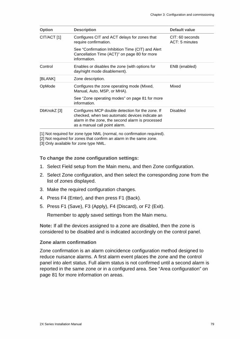
Chapter 3: Configuration and commissioning
2X Series Installation Manual 79
Option Description Default value
CIT/ACT [1] Configures CIT and ACT delays for zones that require confirmation.
See “Confirmation Inhibition Time (CIT) and Alert Cancellation Time (ACT)” on page 80 for more information.
CIT: 60 seconds ACT: 5 minutes
Control Enables or disables the zone (with options for day/night mode disablement).
ENB (enabled)
[BLANK] Zone description.
OpMode Configures the zone operating mode (Mixed, Manual, Auto, MSP, or MHA).
See “Zone operating modes” on page 81 for more information.
Mixed
DbKnokZ [3] Configures MCP double detection for the zone. If checked, when two automatic devices indicate an alarm in the zone, the second alarm is processed as a manual call point alarm.
Disabled
[1] Not required for zone type NML (normal, no confirmation required). [2] Not required for zones that confirm an alarm in the same zone. [3] Only available for zone type NML.
To change the zone configuration settings: 1. Select Field setup from the Main menu, and then Zone configuration.
2. Select Zone configuration, and then select the corresponding zone from the list of zones displayed.
3. Make the required configuration changes.
4. Press F4 (Enter), and then press F1 (Back).
5. Press F1 (Save), F3 (Apply), F4 (Discard), or F2 (Exit).
Remember to apply saved settings from the Main menu.
Note: If all the devices assigned to a zone are disabled, then the zone is considered to be disabled and is indicated accordingly on the control panel.
Zone alarm confirmation Zone confirmation is an alarm coincidence configuration method designed to reduce nuisance alarms. A first alarm event places the zone and the control panel into alert status. Full alarm status is not confirmed until a second alarm is reported in the same zone or in a configured area. See “Area configuration” on page 81 for more information on areas.
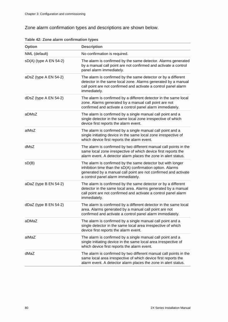
Chapter 3: Configuration and commissioning
80 2X Series Installation Manual
Zone alarm confirmation types and descriptions are shown below.
Table 42: Zone alarm confirmation types
Option Description
NML (default) No confirmation is required.
sD(A) (type A EN 54-2) The alarm is confirmed by the same detector. Alarms generated by a manual call point are not confirmed and activate a control panel alarm immediately.
aDsZ (type A EN 54-2) The alarm is confirmed by the same detector or by a different detector in the same local zone. Alarms generated by a manual call point are not confirmed and activate a control panel alarm immediately.
dDsZ (type A EN 54-2) The alarm is confirmed by a different detector in the same local zone. Alarms generated by a manual call point are not confirmed and activate a control panel alarm immediately.
aDMsZ The alarm is confirmed by a single manual call point and a single detector in the same local zone irrespective of which device first reports the alarm event.
aIMsZ The alarm is confirmed by a single manual call point and a single initiating device in the same local zone irrespective of which device first reports the alarm event.
dMsZ The alarm is confirmed by two different manual call points in the same local zone irrespective of which device first reports the alarm event. A detector alarm places the zone in alert status.
sD(B) The alarm is confirmed by the same detector but with longer inhibition time than the sD(A) confirmation option. Alarms generated by a manual call point are not confirmed and activate a control panel alarm immediately.
aDaZ (type B EN 54-2) The alarm is confirmed by the same detector or by a different detector in the same local area. Alarms generated by a manual call point are not confirmed and activate a control panel alarm immediately.
dDaZ (type B EN 54-2) The alarm is confirmed by a different detector in the same local area. Alarms generated by a manual call point are not confirmed and activate a control panel alarm immediately.
aDMaZ The alarm is confirmed by a single manual call point and a single detector in the same local area irrespective of which device first reports the alarm event.
aIMaZ The alarm is confirmed by a single manual call point and a single initiating device in the same local area irrespective of which device first reports the alarm event.
dMaZ The alarm is confirmed by two different manual call points in the same local area irrespective of which device first reports the alarm event. A detector alarm places the zone in alert status.
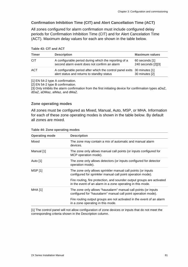
Chapter 3: Configuration and commissioning
2X Series Installation Manual 81
Confirmation Inhibition Time (CIT) and Alert Cancellation Time (ACT) All zones configured for alarm confirmation must include configured delay periods for Confirmation Inhibition Time (CIT) and for Alert Cancelation Time (ACT). Maximum delay values for each are shown in the table below.
Table 43: CIT and ACT
Timer Description Maximum values
CIT A configurable period during which the reporting of a second alarm event does not confirm an alarm
60 seconds [1] 240 seconds [2][3]
ACT A configurable period after which the control panel exits alert status and returns to standby status
30 minutes [1] 30 minutes [2]
[1] EN 54-2 type A confirmation. [2] EN 54-2 type B confirmation. [3] Only inhibits the alarm confirmation from the first initiating device for confirmation types aDaZ, dDaZ, aDMaz, aIMaz, and dMaZ.
Zone operating modes All zones must be configured as Mixed, Manual, Auto, MSP, or MHA. Information for each of these zone operating modes is shown in the table below. By default all zones are mixed.
Table 44: Zone operating modes
Operating mode Description
Mixed The zone may contain a mix of automatic and manual alarm devices.
Manual [1] The zone only allows manual call points (or inputs configured for MCP operation mode).
Auto [1] The zone only allows detectors (or inputs configured for detector operation mode).
MSP [1] The zone only allows sprinkler manual call points (or inputs configured for sprinkler manual call point operation mode).
Fire routing, fire protection, and sounder output groups are activated in the event of an alarm in a zone operating in this mode.
MHA [1] The zone only allows “hausalarm” manual call points (or inputs configured for “hausalarm” manual call point operation mode).
Fire routing output groups are not activated in the event of an alarm in a zone operating in this mode.
[1] The control panel will not allow configuration of zone devices or inputs that do not meet the corresponding criteria shown in the Description column.
Chapter 3: Configuration and commissioning
82 2X Series Installation Manual
Area configuration Select the Area configuration option to configure confirmation areas. An area is a group of zones where an alarm event can confirm the initial alarm in a zone.
The maximum number of areas available to configure is the same as the number of zones for the control panel:
• A one-loop control panel has 64 zones and 64 areas
• A two-loop control panel has 128 zones and 128 areas
• A four-loop control panel has 256 zones and 256 areas
To configure an area: 1. Select Field setup from the Main menu, and then select Zone configuration.
2. Select Area configuration.
3. Select the area number to configure.
A list of available zones is displayed.
4. Select zones to be included in the confirmation area and press the jog dial to confirm each selection.
YES indicates that a zone is included in the confirmation area, NO indicates that a zone is not included in the confirmation area.
5. Press F1 (Save), F3 (Apply), F4 (Discard), or F2 (Exit).
Remember to apply saved settings from the Main menu.
Note: When configuring a confirmed zone, remember that remote zones with the same zone number can activate a control panel alarm without confirmation. To avoid this type of unwanted alarm, configure the remote zones accordingly.
Panel I/O configuration Panel input configuration Configurable options for control panel inputs are shown below.
Table 45: Configurable options for control panel inputs
Option Description
Type Configures the input operation mode
Control Enables or disables an input
Input types are shown in Table 46 below. The default mode for all inputs is LG (logged activation: an unlatched condition stored in the event log).
To configure a control panel input: 1. Select Field setup from the Main menu.
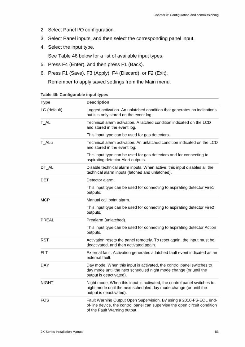
Chapter 3: Configuration and commissioning
2X Series Installation Manual 83
2. Select Panel I/O configuration.
3. Select Panel inputs, and then select the corresponding panel input.
4. Select the input type.
See Table 46 below for a list of available input types.
5. Press F4 (Enter), and then press F1 (Back).
6. Press F1 (Save), F3 (Apply), F4 (Discard), or F2 (Exit).
Remember to apply saved settings from the Main menu.
Table 46: Configurable input types
Type Description
LG (default) Logged activation. An unlatched condition that generates no indications but it is only stored on the event log.
T_AL
Technical alarm activation. A latched condition indicated on the LCD and stored in the event log.
This input type can be used for gas detectors.
T_ALu Technical alarm activation. An unlatched condition indicated on the LCD and stored in the event log.
This input type can be used for gas detectors and for connecting to aspirating detector Alert outputs.
DT_AL
Disable technical alarm inputs. When active, this input disables all the technical alarm inputs (latched and unlatched).
DET Detector alarm.
This input type can be used for connecting to aspirating detector Fire1 outputs.
MCP Manual call point alarm.
This input type can be used for connecting to aspirating detector Fire2 outputs.
PREAL Prealarm (unlatched).
This input type can be used for connecting to aspirating detector Action outputs.
RST Activation resets the panel remotely. To reset again, the input must be deactivated, and then activated again.
FLT External fault. Activation generates a latched fault event indicated as an external fault.
DAY Day mode. When this input is activated, the control panel switches to day mode until the next scheduled night mode change (or until the output is deactivated).
NIGHT Night mode. When this input is activated, the control panel switches to night mode until the next scheduled day mode change (or until the output is deactivated).
FOS Fault Warning Output Open Supervision. By using a 2010-FS-EOL end-of-line device, the control panel can supervise the open circuit condition of the Fault Warning output.
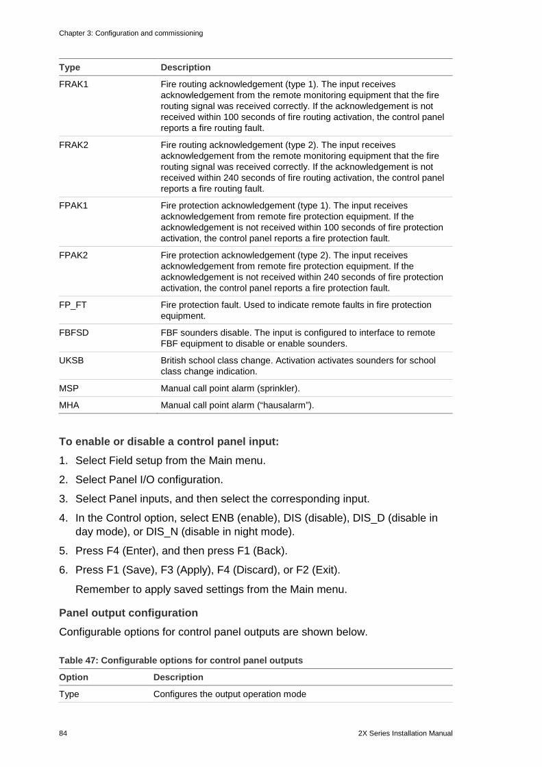
Chapter 3: Configuration and commissioning
84 2X Series Installation Manual
Type Description
FRAK1 Fire routing acknowledgement (type 1). The input receives acknowledgement from the remote monitoring equipment that the fire routing signal was received correctly. If the acknowledgement is not received within 100 seconds of fire routing activation, the control panel reports a fire routing fault.
FRAK2 Fire routing acknowledgement (type 2). The input receives acknowledgement from the remote monitoring equipment that the fire routing signal was received correctly. If the acknowledgement is not received within 240 seconds of fire routing activation, the control panel reports a fire routing fault.
FPAK1 Fire protection acknowledgement (type 1). The input receives acknowledgement from remote fire protection equipment. If the acknowledgement is not received within 100 seconds of fire protection activation, the control panel reports a fire protection fault.
FPAK2 Fire protection acknowledgement (type 2). The input receives acknowledgement from remote fire protection equipment. If the acknowledgement is not received within 240 seconds of fire protection activation, the control panel reports a fire protection fault.
FP_FT Fire protection fault. Used to indicate remote faults in fire protection equipment.
FBFSD FBF sounders disable. The input is configured to interface to remote FBF equipment to disable or enable sounders.
UKSB British school class change. Activation activates sounders for school class change indication.
MSP Manual call point alarm (sprinkler).
MHA Manual call point alarm (“hausalarm”).
To enable or disable a control panel input: 1. Select Field setup from the Main menu.
2. Select Panel I/O configuration.
3. Select Panel inputs, and then select the corresponding input.
4. In the Control option, select ENB (enable), DIS (disable), DIS_D (disable in day mode), or DIS_N (disable in night mode).
5. Press F4 (Enter), and then press F1 (Back).
6. Press F1 (Save), F3 (Apply), F4 (Discard), or F2 (Exit).
Remember to apply saved settings from the Main menu.
Panel output configuration Configurable options for control panel outputs are shown below.
Table 47: Configurable options for control panel outputs
Option Description
Type Configures the output operation mode
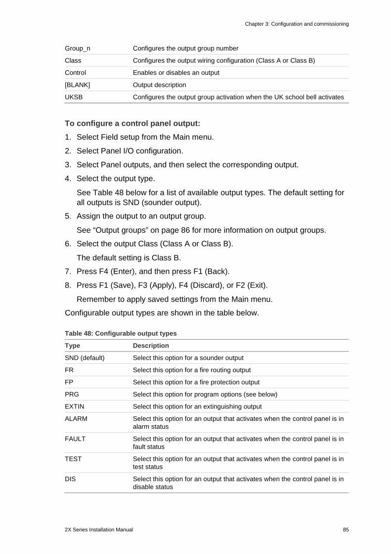
Chapter 3: Configuration and commissioning
2X Series Installation Manual 85
Group_n Configures the output group number
Class Configures the output wiring configuration (Class A or Class B)
Control Enables or disables an output
[BLANK] Output description
UKSB Configures the output group activation when the UK school bell activates
To configure a control panel output: 1. Select Field setup from the Main menu.
2. Select Panel I/O configuration.
3. Select Panel outputs, and then select the corresponding output.
4. Select the output type.
See Table 48 below for a list of available output types. The default setting for all outputs is SND (sounder output).
5. Assign the output to an output group.
See “Output groups” on page 86 for more information on output groups.
6. Select the output Class (Class A or Class B).
The default setting is Class B.
7. Press F4 (Enter), and then press F1 (Back).
8. Press F1 (Save), F3 (Apply), F4 (Discard), or F2 (Exit).
Remember to apply saved settings from the Main menu.
Configurable output types are shown in the table below.
Table 48: Configurable output types
Type Description
SND (default) Select this option for a sounder output
FR Select this option for a fire routing output
FP Select this option for a fire protection output
PRG Select this option for program options (see below)
EXTIN Select this option for an extinguishing output
ALARM Select this option for an output that activates when the control panel is in alarm status
FAULT Select this option for an output that activates when the control panel is in fault status
TEST Select this option for an output that activates when the control panel is in test status
DIS Select this option for an output that activates when the control panel is in disable status

Chapter 3: Configuration and commissioning
86 2X Series Installation Manual
To enable or disable a control panel output: 1. Select Field setup from the Main menu.
2. Select Panel I/O configuration.
3. Select Outputs, and then select the output to be enabled or disabled.
Configurable outputs are listed as OUT1, OUT2, etc, the supervised alarm output is listed as ALM_O, and the supervised fault output is listed as FLT_O.
4. In the Control option, select ENB (enable), DIS (disable), DIS_D (disable in day mode), or DIS_N (disable in night mode).
5. Press F4 (Enter), and then press F1 (Back).
6. Press F1 (Save), F3 (Apply), F4 (Discard), or F2 (Exit).
Remember to apply saved settings from the Main menu.
Note: At the installer level, changes to the configuration of a Class A output are applied to all output pairs used to create the Class A output (OUT1/OUT2, etc.). This includes enable/disable configuration options. For example, if the OUT1 type is changed to PRG and Group-n changed to 5, then the configuration of the paired OUT2 is updated automatically to match these settings.
Output groups Select the Output groups option to configure the control panel output groups. Control panel outputs must be assigned to output groups for activation.
An output group is a collection of outputs of the same type that activate and deactivate at the same time (they are commanded simultaneously). Output groups are identified by the output group number.
Outputs are assigned to the default output groups during autosetup (see “Autosetup” on page 73).
Up to 300 sounder, fire routing, fire protection, extinguishing, and program output groups can be configured (depending on group type).
Sounder output groups, fire routing output groups, and fire protection output groups are controlled (and their status indicated) by the corresponding sounder, fire routing, and fire protection buttons and LEDs on the front of the control panel.
Program output groups have no associated buttons or LEDs on the front of the control panel but their status is displayed on the LCD.
The default control panel output groups are shown below.
Note: This option is not available on repeater panels.
Table 49: Default output groups
Group number Type Description
1 SND Sounder and supervised outputs.
301 PRG Nonsupervised relay outputs. These outputs are assigned to this group during autosetup.
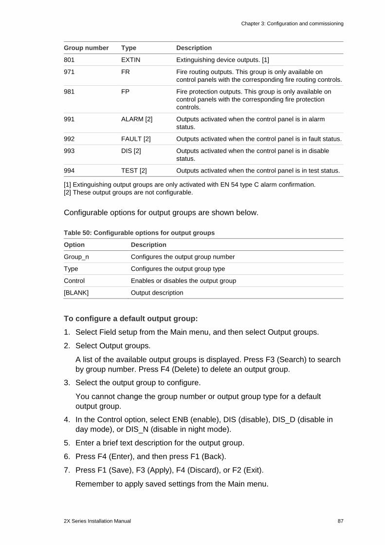
Chapter 3: Configuration and commissioning
2X Series Installation Manual 87
Group number Type Description
801 EXTIN Extinguishing device outputs. [1]
971 FR Fire routing outputs. This group is only available on control panels with the corresponding fire routing controls.
981 FP Fire protection outputs. This group is only available on control panels with the corresponding fire protection controls.
991 ALARM [2] Outputs activated when the control panel is in alarm status.
992 FAULT [2] Outputs activated when the control panel is in fault status.
993 DIS [2] Outputs activated when the control panel is in disable status.
994 TEST [2] Outputs activated when the control panel is in test status.
[1] Extinguishing output groups are only activated with EN 54 type C alarm confirmation. [2] These output groups are not configurable.
Configurable options for output groups are shown below.
Table 50: Configurable options for output groups
Option Description
Group_n Configures the output group number
Type Configures the output group type
Control Enables or disables the output group
[BLANK] Output description
To configure a default output group: 1. Select Field setup from the Main menu, and then select Output groups.
2. Select Output groups.
A list of the available output groups is displayed. Press F3 (Search) to search by group number. Press F4 (Delete) to delete an output group.
3. Select the output group to configure.
You cannot change the group number or output group type for a default output group.
4. In the Control option, select ENB (enable), DIS (disable), DIS_D (disable in day mode), or DIS_N (disable in night mode).
5. Enter a brief text description for the output group.
6. Press F4 (Enter), and then press F1 (Back).
7. Press F1 (Save), F3 (Apply), F4 (Discard), or F2 (Exit).
Remember to apply saved settings from the Main menu.
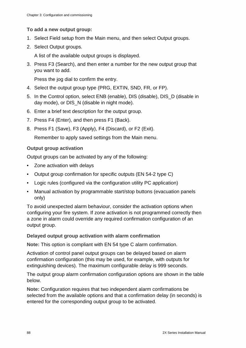
Chapter 3: Configuration and commissioning
88 2X Series Installation Manual
To add a new output group: 1. Select Field setup from the Main menu, and then select Output groups.
2. Select Output groups.
A list of the available output groups is displayed.
3. Press F3 (Search), and then enter a number for the new output group that you want to add.
Press the jog dial to confirm the entry.
4. Select the output group type (PRG, EXTIN, SND, FR, or FP).
5. In the Control option, select ENB (enable), DIS (disable), DIS_D (disable in day mode), or DIS_N (disable in night mode).
6. Enter a brief text description for the output group.
7. Press F4 (Enter), and then press F1 (Back).
8. Press F1 (Save), F3 (Apply), F4 (Discard), or F2 (Exit).
Remember to apply saved settings from the Main menu.
Output group activation Output groups can be activated by any of the following:
• Zone activation with delays
• Output group confirmation for specific outputs (EN 54-2 type C)
• Logic rules (configured via the configuration utility PC application)
• Manual activation by programmable start/stop buttons (evacuation panels only)
To avoid unexpected alarm behaviour, consider the activation options when configuring your fire system. If zone activation is not programmed correctly then a zone in alarm could override any required confirmation configuration of an output group.
Delayed output group activation with alarm confirmation Note: This option is compliant with EN 54 type C alarm confirmation.
Activation of control panel output groups can be delayed based on alarm confirmation configuration (this may be used, for example, with outputs for extinguishing devices). The maximum configurable delay is 999 seconds.
The output group alarm confirmation configuration options are shown in the table below.
Note: Configuration requires that two independent alarm confirmations be selected from the available options and that a confirmation delay (in seconds) is entered for the corresponding output group to be activated.
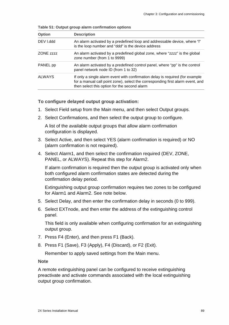
Chapter 3: Configuration and commissioning
2X Series Installation Manual 89
Table 51: Output group alarm confirmation options
Option Description
DEV l.ddd An alarm activated by a predefined loop and addressable device, where “l” is the loop number and “ddd” is the device address
ZONE zzzz An alarm activated by a predefined global zone, where “zzzz” is the global zone number (from 1 to 9999)
PANEL pp An alarm activated by a predefined control panel, where “pp” is the control panel network node ID (from 1 to 32)
ALWAYS If only a single alarm event with confirmation delay is required (for example for a manual call point zone), select the corresponding first alarm event, and then select this option for the second alarm
To configure delayed output group activation: 1. Select Field setup from the Main menu, and then select Output groups.
2. Select Confirmations, and then select the output group to configure.
A list of the available output groups that allow alarm confirmation configuration is displayed.
3. Select Active, and then select YES (alarm confirmation is required) or NO (alarm confirmation is not required).
4. Select Alarm1, and then select the confirmation required (DEV, ZONE, PANEL, or ALWAYS). Repeat this step for Alarm2.
If alarm confirmation is required then the output group is activated only when both configured alarm confirmation states are detected during the confirmation delay period.
Extinguishing output group confirmation requires two zones to be configured for Alarm1 and Alarm2. See note below.
5. Select Delay, and then enter the confirmation delay in seconds (0 to 999).
6. Select EXTnode, and then enter the address of the extinguishing control panel.
This field is only available when configuring confirmation for an extinguishing output group.
7. Press F4 (Enter), and then press F1 (Back).
8. Press F1 (Save), F3 (Apply), F4 (Discard), or F2 (Exit).
Remember to apply saved settings from the Main menu.
Note
A remote extinguishing panel can be configured to receive extinguishing preactivate and activate commands associated with the local extinguishing output group confirmation.
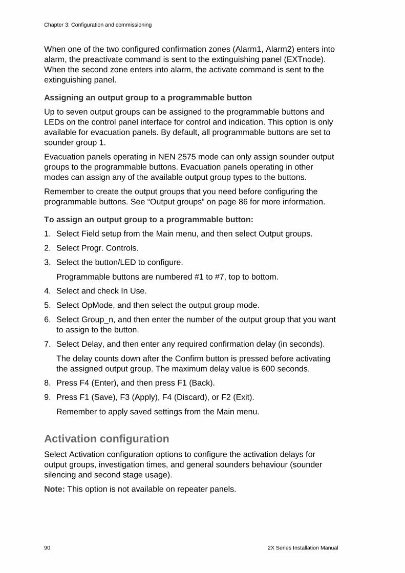
Chapter 3: Configuration and commissioning
90 2X Series Installation Manual
When one of the two configured confirmation zones (Alarm1, Alarm2) enters into alarm, the preactivate command is sent to the extinguishing panel (EXTnode). When the second zone enters into alarm, the activate command is sent to the extinguishing panel.
Assigning an output group to a programmable button Up to seven output groups can be assigned to the programmable buttons and LEDs on the control panel interface for control and indication. This option is only available for evacuation panels. By default, all programmable buttons are set to sounder group 1.
Evacuation panels operating in NEN 2575 mode can only assign sounder output groups to the programmable buttons. Evacuation panels operating in other modes can assign any of the available output group types to the buttons.
Remember to create the output groups that you need before configuring the programmable buttons. See “Output groups” on page 86 for more information.
To assign an output group to a programmable button: 1. Select Field setup from the Main menu, and then select Output groups.
2. Select Progr. Controls.
3. Select the button/LED to configure.
Programmable buttons are numbered #1 to #7, top to bottom.
4. Select and check In Use.
5. Select OpMode, and then select the output group mode.
6. Select Group_n, and then enter the number of the output group that you want to assign to the button.
7. Select Delay, and then enter any required confirmation delay (in seconds).
The delay counts down after the Confirm button is pressed before activating the assigned output group. The maximum delay value is 600 seconds.
8. Press F4 (Enter), and then press F1 (Back).
9. Press F1 (Save), F3 (Apply), F4 (Discard), or F2 (Exit).
Remember to apply saved settings from the Main menu.
Activation configuration Select Activation configuration options to configure the activation delays for output groups, investigation times, and general sounders behaviour (sounder silencing and second stage usage).
Note: This option is not available on repeater panels.
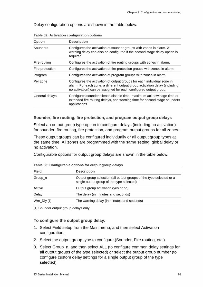
Chapter 3: Configuration and commissioning
2X Series Installation Manual 91
Delay configuration options are shown in the table below.
Table 52: Activation configuration options
Option Description
Sounders Configures the activation of sounder groups with zones in alarm. A warning delay can also be configured if the second stage delay option is required.
Fire routing Configures the activation of fire routing groups with zones in alarm.
Fire protection Configures the activation of fire protection groups with zones in alarm.
Program Configures the activation of program groups with zones in alarm.
Per zone Configures the activation of output groups for each individual zone in alarm. For each zone, a different output group activation delay (including no activation) can be assigned for each configured output group.
General delays Configures sounder silence disable time, maximum acknowledge time or extended fire routing delays, and warning time for second stage sounders applications.
Sounder, fire routing, fire protection, and program output group delays Select an output group type option to configure delays (including no activation) for sounder, fire routing, fire protection, and program output groups for all zones.
These output groups can be configured individually or all output group types at the same time. All zones are programmed with the same setting: global delay or no activation.
Configurable options for output group delays are shown in the table below.
Table 53: Configurable options for output group delays
Field Description
Group_n Output group selection (all output groups of the type selected or a single output group of the type selected)
Active Output group activation (yes or no)
Delay The delay (in minutes and seconds)
Wrn_Dly [1] The warning delay (in minutes and seconds)
[1] Sounder output group delays only.
To configure the output group delay: 1. Select Field setup from the Main menu, and then select Activation
configuration.
2. Select the output group type to configure (Sounder, Fire routing, etc.).
3. Select Group_n, and then select ALL (to configure common delay settings for all output groups of the type selected) or select the output group number (to configure custom delay settings for a single output group of the type selected).
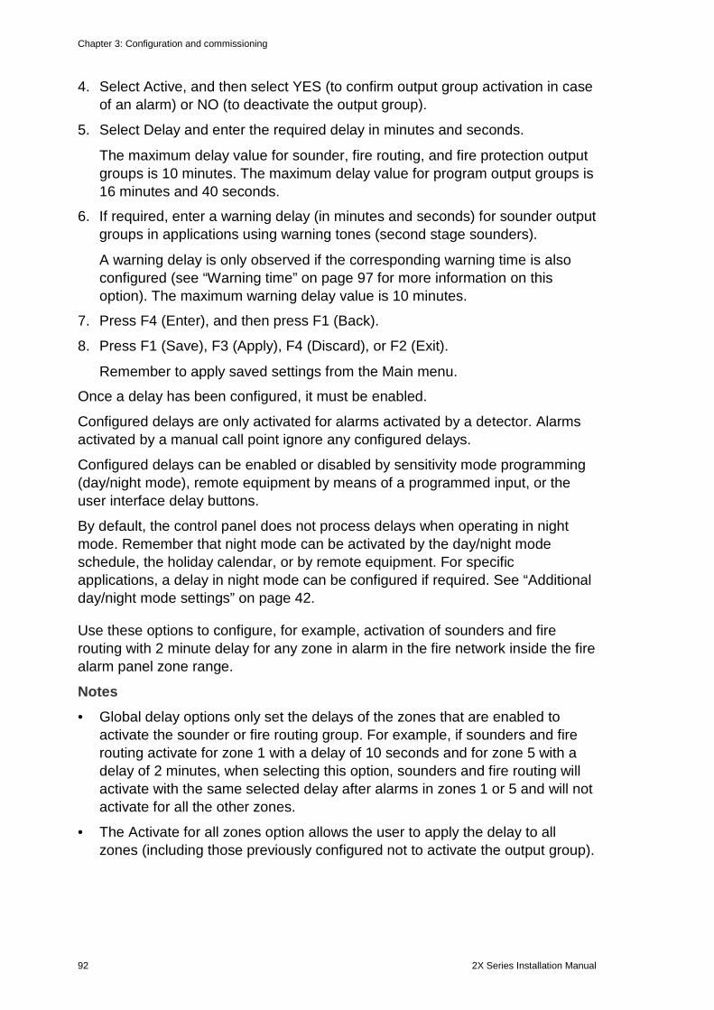
Chapter 3: Configuration and commissioning
92 2X Series Installation Manual
4. Select Active, and then select YES (to confirm output group activation in case of an alarm) or NO (to deactivate the output group).
5. Select Delay and enter the required delay in minutes and seconds.
The maximum delay value for sounder, fire routing, and fire protection output groups is 10 minutes. The maximum delay value for program output groups is 16 minutes and 40 seconds.
6. If required, enter a warning delay (in minutes and seconds) for sounder output groups in applications using warning tones (second stage sounders).
A warning delay is only observed if the corresponding warning time is also configured (see “Warning time” on page 97 for more information on this option). The maximum warning delay value is 10 minutes.
7. Press F4 (Enter), and then press F1 (Back).
8. Press F1 (Save), F3 (Apply), F4 (Discard), or F2 (Exit).
Remember to apply saved settings from the Main menu.
Once a delay has been configured, it must be enabled.
Configured delays are only activated for alarms activated by a detector. Alarms activated by a manual call point ignore any configured delays.
Configured delays can be enabled or disabled by sensitivity mode programming (day/night mode), remote equipment by means of a programmed input, or the user interface delay buttons.
By default, the control panel does not process delays when operating in night mode. Remember that night mode can be activated by the day/night mode schedule, the holiday calendar, or by remote equipment. For specific applications, a delay in night mode can be configured if required. See “Additional day/night mode settings” on page 42.
Use these options to configure, for example, activation of sounders and fire routing with 2 minute delay for any zone in alarm in the fire network inside the fire alarm panel zone range.
Notes
• Global delay options only set the delays of the zones that are enabled to activate the sounder or fire routing group. For example, if sounders and fire routing activate for zone 1 with a delay of 10 seconds and for zone 5 with a delay of 2 minutes, when selecting this option, sounders and fire routing will activate with the same selected delay after alarms in zones 1 or 5 and will not activate for all the other zones.
• The Activate for all zones option allows the user to apply the delay to all zones (including those previously configured not to activate the output group).
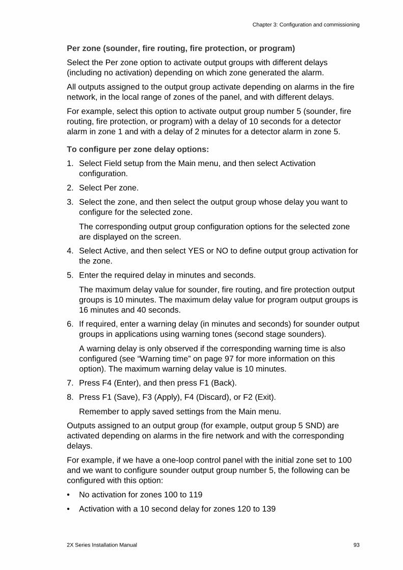
Chapter 3: Configuration and commissioning
2X Series Installation Manual 93
Per zone (sounder, fire routing, fire protection, or program) Select the Per zone option to activate output groups with different delays (including no activation) depending on which zone generated the alarm.
All outputs assigned to the output group activate depending on alarms in the fire network, in the local range of zones of the panel, and with different delays.
For example, select this option to activate output group number 5 (sounder, fire routing, fire protection, or program) with a delay of 10 seconds for a detector alarm in zone 1 and with a delay of 2 minutes for a detector alarm in zone 5.
To configure per zone delay options: 1. Select Field setup from the Main menu, and then select Activation
configuration.
2. Select Per zone.
3. Select the zone, and then select the output group whose delay you want to configure for the selected zone.
The corresponding output group configuration options for the selected zone are displayed on the screen.
4. Select Active, and then select YES or NO to define output group activation for the zone.
5. Enter the required delay in minutes and seconds.
The maximum delay value for sounder, fire routing, and fire protection output groups is 10 minutes. The maximum delay value for program output groups is 16 minutes and 40 seconds.
6. If required, enter a warning delay (in minutes and seconds) for sounder output groups in applications using warning tones (second stage sounders).
A warning delay is only observed if the corresponding warning time is also configured (see “Warning time” on page 97 for more information on this option). The maximum warning delay value is 10 minutes.
7. Press F4 (Enter), and then press F1 (Back).
8. Press F1 (Save), F3 (Apply), F4 (Discard), or F2 (Exit).
Remember to apply saved settings from the Main menu.
Outputs assigned to an output group (for example, output group 5 SND) are activated depending on alarms in the fire network and with the corresponding delays.
For example, if we have a one-loop control panel with the initial zone set to 100 and we want to configure sounder output group number 5, the following can be configured with this option:
• No activation for zones 100 to 119
• Activation with a 10 second delay for zones 120 to 139
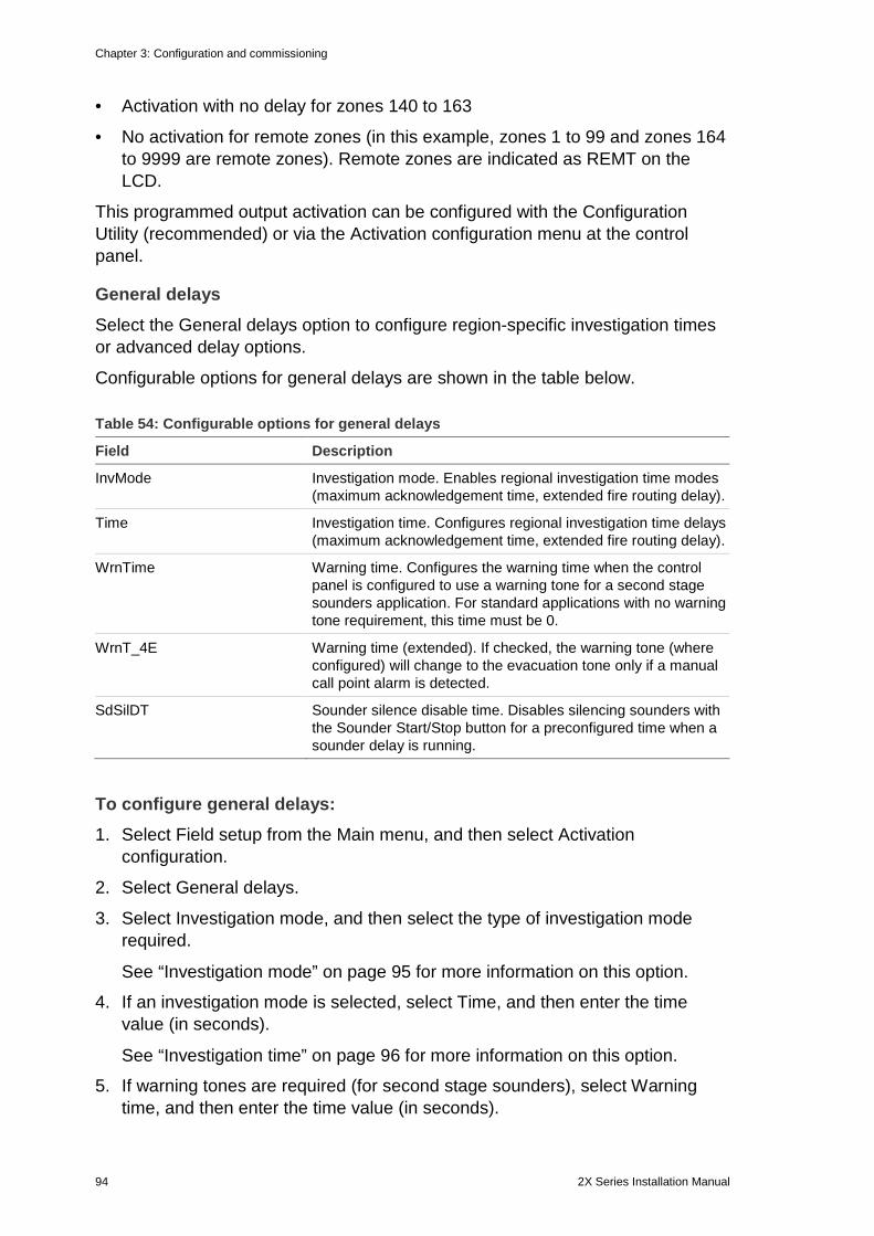
Chapter 3: Configuration and commissioning
94 2X Series Installation Manual
• Activation with no delay for zones 140 to 163
• No activation for remote zones (in this example, zones 1 to 99 and zones 164 to 9999 are remote zones). Remote zones are indicated as REMT on the LCD.
This programmed output activation can be configured with the Configuration Utility (recommended) or via the Activation configuration menu at the control panel.
General delays Select the General delays option to configure region-specific investigation times or advanced delay options.
Configurable options for general delays are shown in the table below.
Table 54: Configurable options for general delays
Field Description
InvMode Investigation mode. Enables regional investigation time modes (maximum acknowledgement time, extended fire routing delay).
Time Investigation time. Configures regional investigation time delays (maximum acknowledgement time, extended fire routing delay).
WrnTime Warning time. Configures the warning time when the control panel is configured to use a warning tone for a second stage sounders application. For standard applications with no warning tone requirement, this time must be 0.
WrnT_4E Warning time (extended). If checked, the warning tone (where configured) will change to the evacuation tone only if a manual call point alarm is detected.
SdSilDT Sounder silence disable time. Disables silencing sounders with the Sounder Start/Stop button for a preconfigured time when a sounder delay is running.
To configure general delays: 1. Select Field setup from the Main menu, and then select Activation
configuration.
2. Select General delays.
3. Select Investigation mode, and then select the type of investigation mode required.
See “Investigation mode” on page 95 for more information on this option.
4. If an investigation mode is selected, select Time, and then enter the time value (in seconds).
See “Investigation time” on page 96 for more information on this option.
5. If warning tones are required (for second stage sounders), select Warning time, and then enter the time value (in seconds).
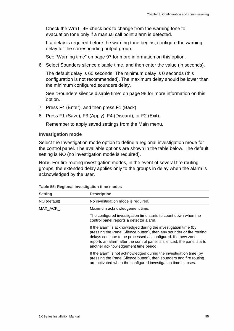
Chapter 3: Configuration and commissioning
2X Series Installation Manual 95
Check the WrnT_4E check box to change from the warning tone to evacuation tone only if a manual call point alarm is detected.
If a delay is required before the warning tone begins, configure the warning delay for the corresponding output group.
See “Warning time” on page 97 for more information on this option.
6. Select Sounders silence disable time, and then enter the value (in seconds).
The default delay is 60 seconds. The minimum delay is 0 seconds (this configuration is not recommended). The maximum delay should be lower than the minimum configured sounders delay.
See “Sounders silence disable time” on page 98 for more information on this option.
7. Press F4 (Enter), and then press F1 (Back).
8. Press F1 (Save), F3 (Apply), F4 (Discard), or F2 (Exit).
Remember to apply saved settings from the Main menu.
Investigation mode Select the Investigation mode option to define a regional investigation mode for the control panel. The available options are shown in the table below. The default setting is NO (no investigation mode is required).
Note: For fire routing investigation modes, in the event of several fire routing groups, the extended delay applies only to the groups in delay when the alarm is acknowledged by the user.
Table 55: Regional investigation time modes
Setting Description
NO (default) No investigation mode is required.
MAX_ACK_T Maximum acknowledgement time.
The configured investigation time starts to count down when the control panel reports a detector alarm.
If the alarm is acknowledged during the investigation time (by pressing the Panel Silence button), then any sounder or fire routing delays continue to be processed as configured. If a new zone reports an alarm after the control panel is silenced, the panel starts another acknowledgement time period.
If the alarm is not acknowledged during the investigation time (by pressing the Panel Silence button), then sounders and fire routing are activated when the configured investigation time elapses.
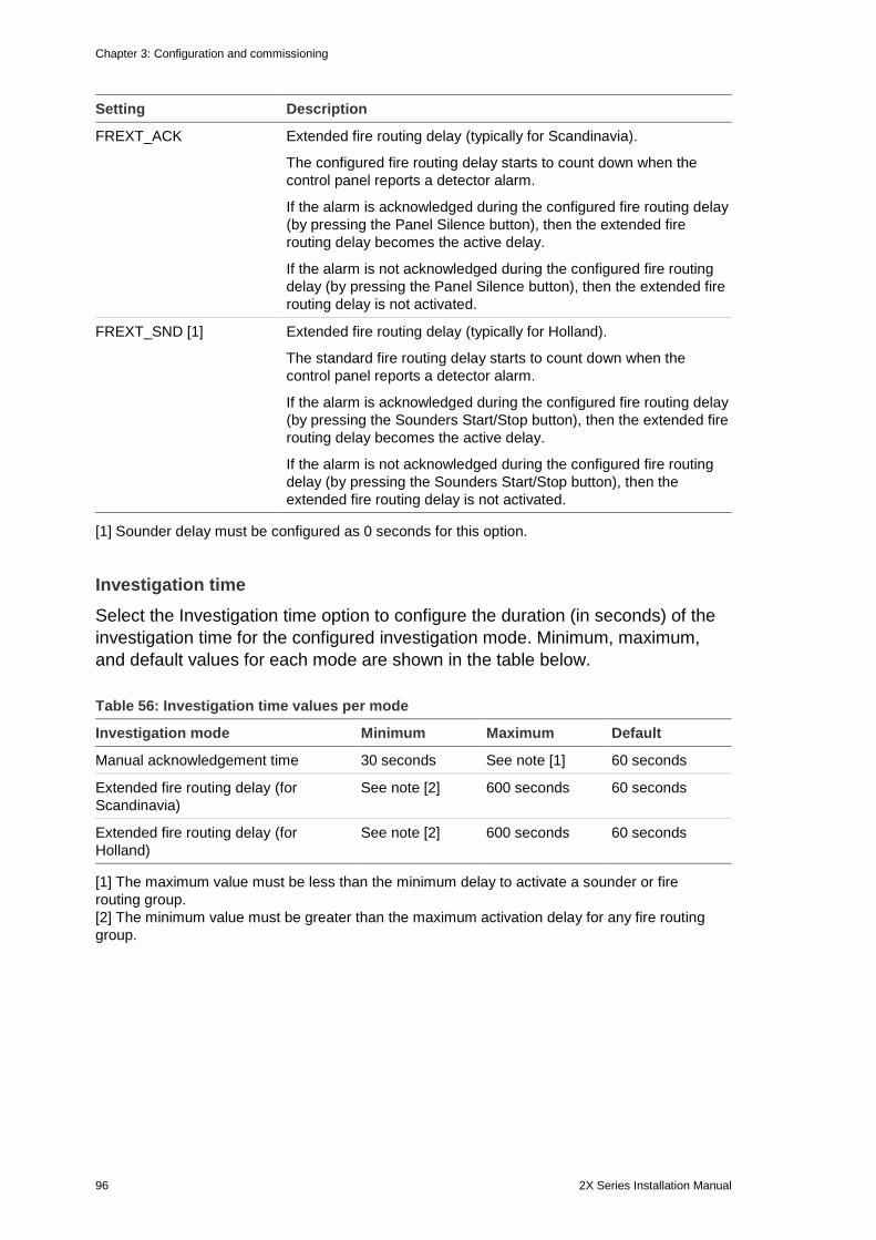
Chapter 3: Configuration and commissioning
96 2X Series Installation Manual
Setting Description
FREXT_ACK Extended fire routing delay (typically for Scandinavia).
The configured fire routing delay starts to count down when the control panel reports a detector alarm.
If the alarm is acknowledged during the configured fire routing delay (by pressing the Panel Silence button), then the extended fire routing delay becomes the active delay.
If the alarm is not acknowledged during the configured fire routing delay (by pressing the Panel Silence button), then the extended fire routing delay is not activated.
FREXT_SND [1] Extended fire routing delay (typically for Holland).
The standard fire routing delay starts to count down when the control panel reports a detector alarm.
If the alarm is acknowledged during the configured fire routing delay (by pressing the Sounders Start/Stop button), then the extended fire routing delay becomes the active delay.
If the alarm is not acknowledged during the configured fire routing delay (by pressing the Sounders Start/Stop button), then the extended fire routing delay is not activated.
[1] Sounder delay must be configured as 0 seconds for this option.
Investigation time Select the Investigation time option to configure the duration (in seconds) of the investigation time for the configured investigation mode. Minimum, maximum, and default values for each mode are shown in the table below.
Table 56: Investigation time values per mode
Investigation mode Minimum Maximum Default
Manual acknowledgement time 30 seconds See note [1] 60 seconds
Extended fire routing delay (for Scandinavia)
See note [2] 600 seconds 60 seconds
Extended fire routing delay (for Holland)
See note [2] 600 seconds 60 seconds
[1] The maximum value must be less than the minimum delay to activate a sounder or fire routing group. [2] The minimum value must be greater than the maximum activation delay for any fire routing group.
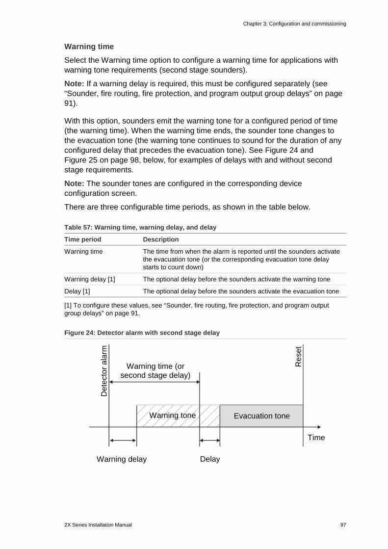
Chapter 3: Configuration and commissioning
2X Series Installation Manual 97
Warning time Select the Warning time option to configure a warning time for applications with warning tone requirements (second stage sounders).
Note: If a warning delay is required, this must be configured separately (see “Sounder, fire routing, fire protection, and program output group delays” on page 91).
With this option, sounders emit the warning tone for a configured period of time (the warning time). When the warning time ends, the sounder tone changes to the evacuation tone (the warning tone continues to sound for the duration of any configured delay that precedes the evacuation tone). See Figure 24 and Figure 25 on page 98, below, for examples of delays with and without second stage requirements.
Note: The sounder tones are configured in the corresponding device configuration screen.
There are three configurable time periods, as shown in the table below.
Table 57: Warning time, warning delay, and delay
Time period Description
Warning time The time from when the alarm is reported until the sounders activate the evacuation tone (or the corresponding evacuation tone delay starts to count down)
Warning delay [1] The optional delay before the sounders activate the warning tone
Delay [1] The optional delay before the sounders activate the evacuation tone
[1] To configure these values, see “Sounder, fire routing, fire protection, and program output group delays” on page 91.
Figure 24: Detector alarm with second stage delay
Warning tone Evacuation tone
Warning time (or second stage delay)
Warning delay Delay
Det
ecto
r ala
rm
Res
et
Time
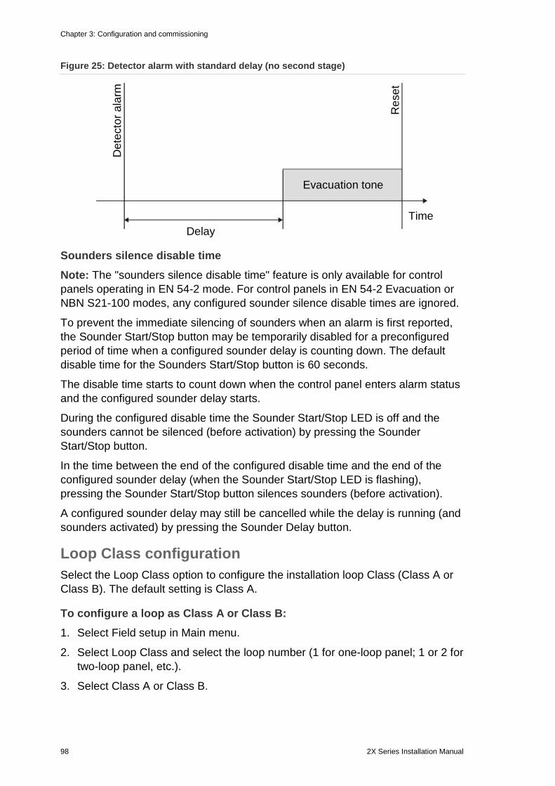
Chapter 3: Configuration and commissioning
98 2X Series Installation Manual
Figure 25: Detector alarm with standard delay (no second stage)
Sounders silence disable time Note: The "sounders silence disable time" feature is only available for control panels operating in EN 54-2 mode. For control panels in EN 54-2 Evacuation or NBN S21-100 modes, any configured sounder silence disable times are ignored.
To prevent the immediate silencing of sounders when an alarm is first reported, the Sounder Start/Stop button may be temporarily disabled for a preconfigured period of time when a configured sounder delay is counting down. The default disable time for the Sounders Start/Stop button is 60 seconds.
The disable time starts to count down when the control panel enters alarm status and the configured sounder delay starts.
During the configured disable time the Sounder Start/Stop LED is off and the sounders cannot be silenced (before activation) by pressing the Sounder Start/Stop button.
In the time between the end of the configured disable time and the end of the configured sounder delay (when the Sounder Start/Stop LED is flashing), pressing the Sounder Start/Stop button silences sounders (before activation).
A configured sounder delay may still be cancelled while the delay is running (and sounders activated) by pressing the Sounder Delay button.
Loop Class configuration Select the Loop Class option to configure the installation loop Class (Class A or Class B). The default setting is Class A.
To configure a loop as Class A or Class B: 1. Select Field setup in Main menu.
2. Select Loop Class and select the loop number (1 for one-loop panel; 1 or 2 for two-loop panel, etc.).
3. Select Class A or Class B.
Evacuation tone
Delay
Det
ecto
r ala
rm
Res
et
Time
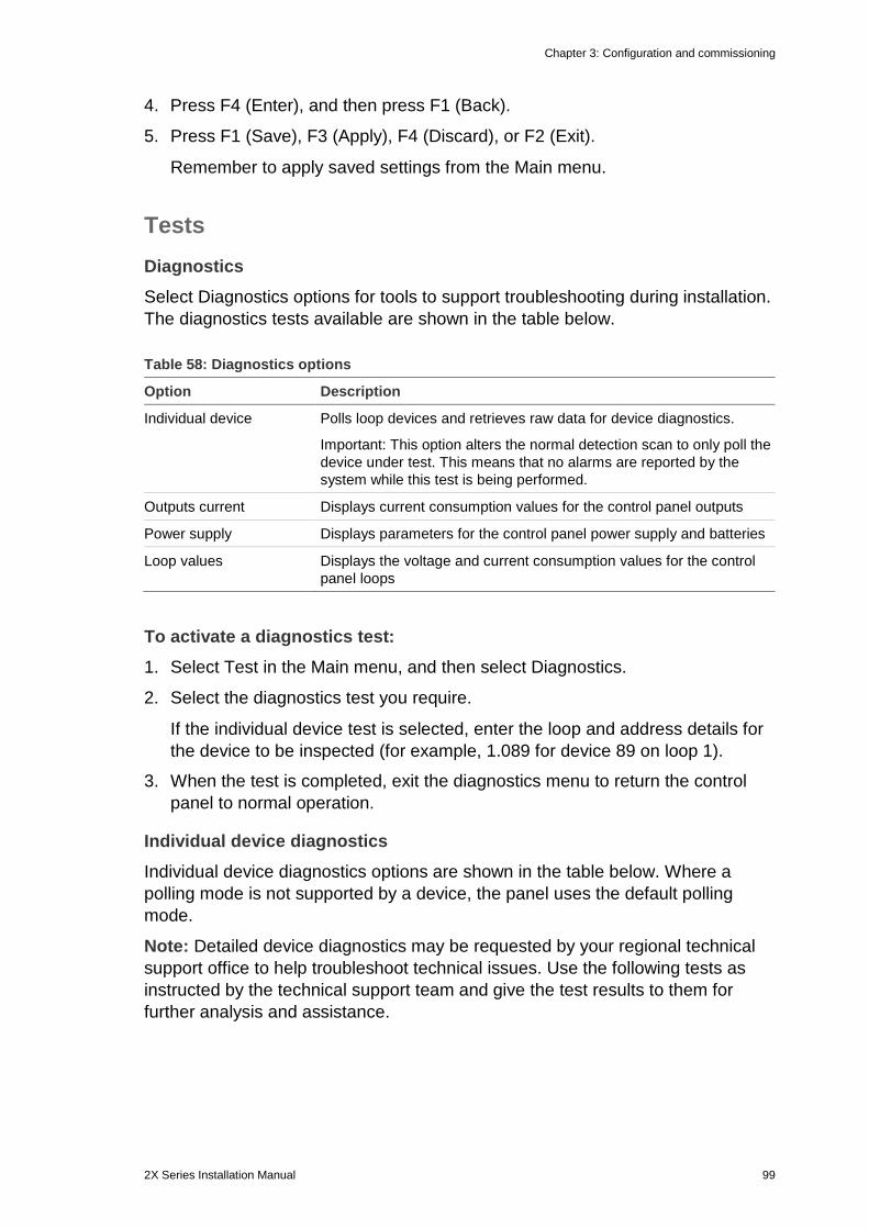
Chapter 3: Configuration and commissioning
2X Series Installation Manual 99
4. Press F4 (Enter), and then press F1 (Back).
5. Press F1 (Save), F3 (Apply), F4 (Discard), or F2 (Exit).
Remember to apply saved settings from the Main menu.
Tests Diagnostics Select Diagnostics options for tools to support troubleshooting during installation. The diagnostics tests available are shown in the table below.
Table 58: Diagnostics options
Option Description
Individual device Polls loop devices and retrieves raw data for device diagnostics.
Important: This option alters the normal detection scan to only poll the device under test. This means that no alarms are reported by the system while this test is being performed.
Outputs current Displays current consumption values for the control panel outputs
Power supply Displays parameters for the control panel power supply and batteries
Loop values Displays the voltage and current consumption values for the control panel loops
To activate a diagnostics test: 1. Select Test in the Main menu, and then select Diagnostics.
2. Select the diagnostics test you require.
If the individual device test is selected, enter the loop and address details for the device to be inspected (for example, 1.089 for device 89 on loop 1).
3. When the test is completed, exit the diagnostics menu to return the control panel to normal operation.
Individual device diagnostics Individual device diagnostics options are shown in the table below. Where a polling mode is not supported by a device, the panel uses the default polling mode.
Note: Detailed device diagnostics may be requested by your regional technical support office to help troubleshoot technical issues. Use the following tests as instructed by the technical support team and give the test results to them for further analysis and assistance.
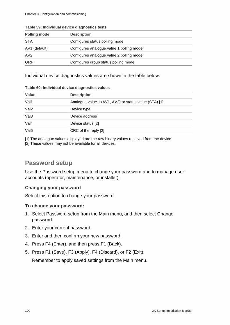
Chapter 3: Configuration and commissioning
100 2X Series Installation Manual
Table 59: Individual device diagnostics tests
Polling mode Description
STA Configures status polling mode
AV1 (default) Configures analogue value 1 polling mode
AV2 Configures analogue value 2 polling mode
GRP Configures group status polling mode
Individual device diagnostics values are shown in the table below.
Table 60: Individual device diagnostics values
Value Description
Val1 Analogue value 1 (AV1, AV2) or status value (STA) [1]
Val2 Device type
Val3 Device address
Val4 Device status [2]
Val5 CRC of the reply [2]
[1] The analogue values displayed are the raw binary values received from the device. [2] These values may not be available for all devices.
Password setup Use the Password setup menu to change your password and to manage user accounts (operator, maintenance, or installer).
Changing your password Select this option to change your password.
To change your password: 1. Select Password setup from the Main menu, and then select Change
password.
2. Enter your current password.
3. Enter and then confirm your new password.
4. Press F4 (Enter), and then press F1 (Back).
5. Press F1 (Save), F3 (Apply), F4 (Discard), or F2 (Exit).
Remember to apply saved settings from the Main menu.
Chapter 3: Configuration and commissioning
2X Series Installation Manual 101
Managing users Select the Manage users option to edit, delete, or create operator, maintenance, or installer user accounts. The control panel allows for a maximum of 20 user accounts (all user levels combined).
To edit a user account: 1. Select Password setup from the Main menu, and then select Manage users.
A list of all user accounts is displayed.
2. Select the user account you want to edit.
3. Select the information to be edited and enter the change.
To change the user password you need to re-enter your installer password, and then allocate and confirm the new user account password.
4. Press F4 (Enter), and then press F1 (Back).
5. Press F1 (Save), F3 (Apply), F4 (Discard), or F2 (Exit).
Remember to apply saved settings from the Main menu.
To delete a user account: 1. Select Password setup from the Main menu, and then select Manage users.
A list of all user accounts is displayed.
2. Select the user account you want to delete.
You cannot delete the default user accounts
3. Press F4 (Delete) to delete the selected account.
4. Press F4 (Enter), and then press F1 (Back).
5. Press F1 (Save), F3 (Apply), F4 (Discard), or F2 (Exit).
Remember to apply saved settings from the Main menu.
To create a new user account: 1. Select Password setup from the Main menu, and then select Manage users.
2. Press F3 (New) to create a new account.
3. Enter a username, a password, and a user level for the new account.
Usernames help to identify user session activity in the event log.
4. Press F4 (Enter), and then press F1 (Back).
5. Press F1 (Save), F3 (Apply), F4 (Discard), or F2 (Exit).
Remember to apply saved settings from the Main menu.
Chapter 3: Configuration and commissioning
102 2X Series Installation Manual
Secure access Select the Secure access option to configure the control panel to allow secure or nonsecure access. The default setting is for secure access (all username and password information must be entered at each login).
• If nonsecure access is selected, the control panel automatically prefills the last username and password combination entered for login
• If secure access is selected, all username and password information must be entered at each login
To configure the security setting: 1. Select Password setup from the Main menu, and then select Secure access.
2. Select the required security setting.
3. Press F4 (Enter), and then press F1 (Back).
4. Press F1 (Save), F3 (Apply), F4 (Discard), or F2 (Exit).
Remember to apply saved settings from the Main menu.
Commissioning After the control panel and corresponding devices are installed and configured, the system must be commissioned.
Check the following:
• That the fire system is designed in accordance with all required regulations and standards
• That the maximum alarm current in your installation does not exceed the maximum current specifications of the power supply
• That all equipment is correctly installed and tested and that all cabling complies with the recommendations outlined in “Recommended cables” on page 24
• That all software functions are correctly programmed
• That all installed detectors are appropriate for installation environment and operate correctly
• That all inputs and outputs operate correctly
• That any input/output logic (rules and actions) configuration is correct
• That the fire system is functioning correctly in standby and is not reporting any alarms or faults
Chapter 3: Configuration and commissioning
2X Series Installation Manual 103
• That under the alarm conditions (with all applicable devices activated), the current consumption does not exceed the power supply specifications (if the batteries are not activated the current consumption is within the specifications)

Chapter 3: Configuration and commissioning
104 2X Series Installation Manual
2X Series Installation Manual 105
Chapter 4 Maintenance
Summary This chapter includes information on fire alarm system and battery maintenance.
Content Fire alarm system maintenance 106 Battery maintenance 107
Chapter 4: Maintenance
106 2X Series Installation Manual
Fire alarm system maintenance To ensure correct functioning of your control panel and fire alarm system, and compliance with all European regulations, the following maintenance checks should be followed.
Caution: Ensure that fire routing (where configured) has been disabled or that the fire brigade has been notified of any planned fire alarm tests.
Quarterly maintenance Contact your installation or maintenance contractor to carry out a quarterly inspection of the fire alarm system.
This must test at least one device per zone and verify that the control panel responds to all fault and alarm events.
The control panel power supply should be checked and the batteries tested using the “Battery test” menu option (see “Battery test fault indications” on page 107).
Annual maintenance Contact your installation or maintenance contractor to carry out an annual inspection of the fire alarm system.
This must test all system devices and verify that the control panel responds to all fault and alarm events. All electrical connections must be visually inspected to make sure that they are securely fastened, that they have not been damaged, and that they are appropriately protected.
Cleaning Keep the outside and inside of the control panel clean. Carry out periodic cleaning using a damp cloth for the outside. Do not use products containing solvents to clean the unit. Do not clean the inside of the cabinet with liquid products.
Chapter 4: Maintenance
2X Series Installation Manual 107
Battery maintenance The control panel requires two 12 V, rechargeable, sealed lead-acid batteries with 7.2, 12, or 18 Ah capacity. Compatible batteries for this product are shown in Table 61 below.
Batteries are located inside the control panel cabinet and must be installed in series. Polarity must be observed. Connect batteries to the BAT connector on the control panel PCB.
Table 61: Compatible batteries
Battery type Recommended batteries
12 V, 7.2 Ah UTCFS BS127N Fiamm FG20721/2 Yuasa NP7-12
12 V, 12 Ah UTCFS BS130N Fiamm FG21201/2 Yuasa NP12-12
12 V, 18 Ah UTCFS BS131N Fiamm FG21703 Yuasa NP17-12
Battery test fault indications A flashing Supply Fault LED indicates a battery fault or a battery cable fault. Additional information for the fault is displayed on the LCD, as shown below.
Table 62: Battery fault messages
LCD message Description
Battery high resistance FLT The batteries may be damaged or fully discharged
Battery fault The batteries may be damaged
Battery disconnected The batteries are disconnected or no batteries are installed
Battery short circuit There is a battery cable short circuit
If the control panel reports any of the above battery faults, check the battery cables. If the cables are in good condition and all connections are correct, then the batteries should be replaced immediately.
In addition to the above, the following battery charger faults may display:
• Battery charger: sensor HI • Battery charger: sensor LO • Battery charger: overvoltage • Battery charger: undervoltage • Battery charger: compensation
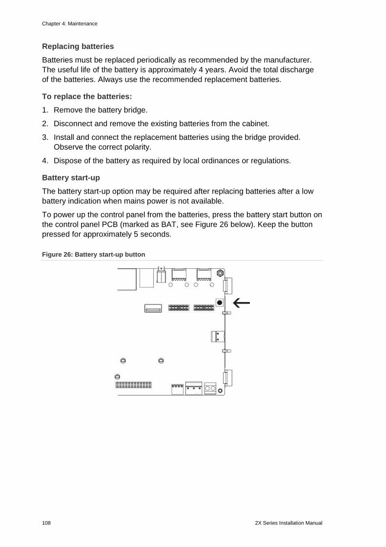
Chapter 4: Maintenance
108 2X Series Installation Manual
Replacing batteries Batteries must be replaced periodically as recommended by the manufacturer. The useful life of the battery is approximately 4 years. Avoid the total discharge of the batteries. Always use the recommended replacement batteries.
To replace the batteries: 1. Remove the battery bridge.
2. Disconnect and remove the existing batteries from the cabinet.
3. Install and connect the replacement batteries using the bridge provided. Observe the correct polarity.
4. Dispose of the battery as required by local ordinances or regulations.
Battery start-up The battery start-up option may be required after replacing batteries after a low battery indication when mains power is not available.
To power up the control panel from the batteries, press the battery start button on the control panel PCB (marked as BAT, see Figure 26 below). Keep the button pressed for approximately 5 seconds.
Figure 26: Battery start-up button
2X Series Installation Manual 109
Chapter 5 Technical specifications
Summary This chapter provides technical specifications for your control panel.
Content Loop specifications 110 Power supply specifications 110 Battery and battery charger specifications 111 LCD specifications 111 Communication port specifications 112 Fire network specifications 112 Input and output specifications 112 Internal printer specifications 113 Mechanical and environmental specifications 114
Chapter 5: Technical specifications
110 2X Series Installation Manual
Loop specifications Loop configuration Class A or Class B
Loop protocol 2000 series
Isolators At least one isolator per loop (we recommend one isolator for every 32 devices)
Number of loop devices 128 max.
Electrical characteristics – maximum per loop
250 mA at 36 VDC (29 to 36 VDC)
Resistance 52 Ω max. (26 Ω per wire)
Capacitance 500 nF max.
Power supply specifications Mains voltage 240/110 VAC +10% −15%
Mains frequency 50/60 Hz ±5%
Mains current Maximum Average
1.5 A at 240 VAC 3.15 A at 110 VAC 0.6 A at 240 VAC 1.3 A at 110 VAC
CIE input voltage and current (mains on) 24 VDC, 4 A
Power (mains on) 137 VA (24 VDC, 4 A)
CIE input voltage (mains off) 21 to 29 VDC
Maximum ripple at full load 150 mVpp
Note: Ripple and noise are measured at 20 MHz of bandwidth by using a 12-inch twisted-pair wire terminated with a 0.1 µF and 47 µF parallel capacitor.
Mains fuse T4A-250V at 240 VAC T4A-250V at 110 VAC
Typical control panel current consumption (with no devices connected) One-loop control panel Two-loop control panel Two-loop control panel with printer Repeater panel
180 mA at 24 VDC 250 mA at 24 VDC 315 mA at 24 VDC 110 mA at 24 VDC
Chapter 5: Technical specifications
2X Series Installation Manual 111
Typical expansion board current consumption Network board DACT board DACT board (with GPRS board) Loop board [1] Peripherals boards [1] 2010-2-PIB 2010-2-PIB-8I 2010-2-PIB-8O 2010-2-PIB-8I8O Zone LED boards 20/24-zones 40-zones
50 mA at 24 VDC 45 mA at 24 VDC 100 mA at 24 VDC 120 mA at 24 VDC 26 mA at 24 VDC 25 mA at 24 VDC 16 mA at 24 VDC 26 mA at 24 VDC 12 mA at 24 VDC 14 mA at 24 VDC
Quiescent current (Imax a) 2.5 A max. at 24 VDC
Alarm current (Imax b) 4 A max. at 24 VDC
[1] No loads connected.
Battery and battery charger specifications For recommended battery specifications, see “Battery maintenance” on page 107. Type Sealed lead-acid batteries (2X)
Battery charging voltage 27.3 V at 20ºC – 36 mV/ºC
Battery charging current 1.2 A max.
Low battery indication 23.6 VDC ± 1% at 25ºC
Note: Additional 0.2 V (max.) drop if Imax b current in battery cables.
System shutdown warning 21.5 VDC ± 1% at 25ºC
System shutdown (for battery protection)
21 VDC ± 1% at 25ºC
LCD specifications Display type 240 x 128 dot graphic LCD (monochromatic)
LCD dimensions (L x W) 83 x 44 mm (active area)
Backlight type LED style
Backlight colour White
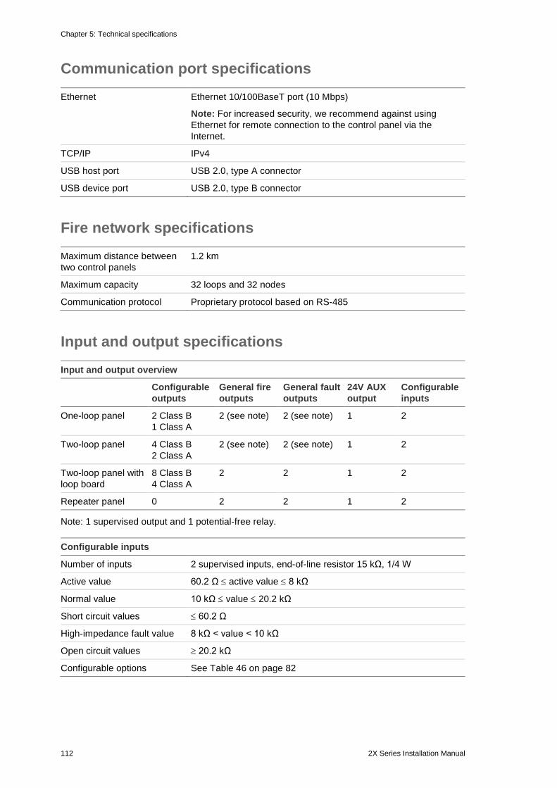
Chapter 5: Technical specifications
112 2X Series Installation Manual
Communication port specifications Ethernet Ethernet 10/100BaseT port (10 Mbps)
Note: For increased security, we recommend against using Ethernet for remote connection to the control panel via the Internet.
TCP/IP IPv4
USB host port USB 2.0, type A connector
USB device port USB 2.0, type B connector
Fire network specifications Maximum distance between two control panels
1.2 km
Maximum capacity 32 loops and 32 nodes
Communication protocol Proprietary protocol based on RS-485
Input and output specifications Input and output overview
Configurable outputs
General fire outputs
General fault outputs
24V AUX output
Configurable inputs
One-loop panel 2 Class B 1 Class A
2 (see note) 2 (see note) 1 2
Two-loop panel 4 Class B 2 Class A
2 (see note) 2 (see note) 1 2
Two-loop panel with loop board
8 Class B 4 Class A
2 2 1 2
Repeater panel 0 2 2 1 2
Note: 1 supervised output and 1 potential-free relay. Configurable inputs
Number of inputs 2 supervised inputs, end-of-line resistor 15 kΩ, 1/4 W
Active value 60.2 Ω ≤ active value ≤ 8 kΩ
Normal value 10 kΩ ≤ value ≤ 20.2 kΩ
Short circuit values ≤ 60.2 Ω
High-impedance fault value 8 kΩ < value < 10 kΩ
Open circuit values ≥ 20.2 kΩ
Configurable options See Table 46 on page 82
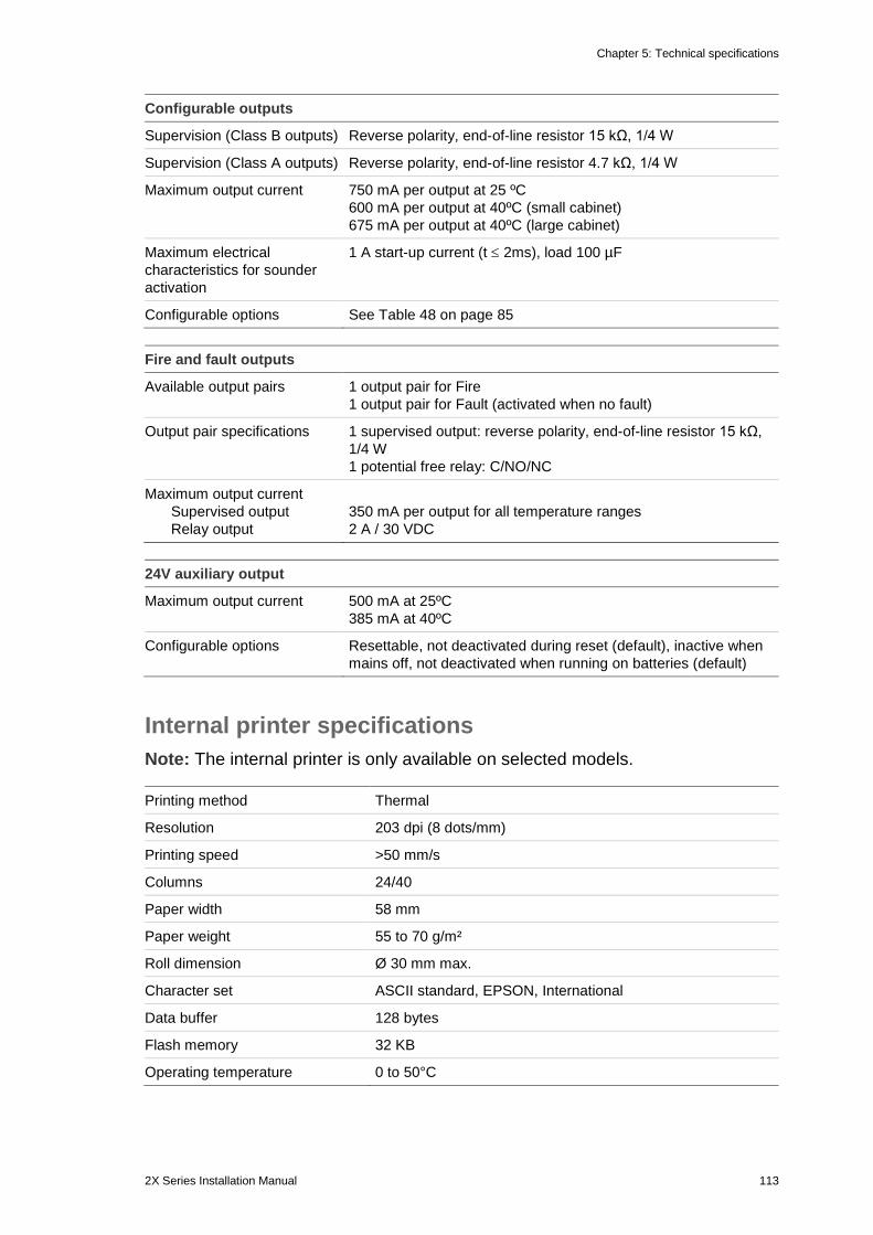
Chapter 5: Technical specifications
2X Series Installation Manual 113
Configurable outputs
Supervision (Class B outputs) Reverse polarity, end-of-line resistor 15 kΩ, 1/4 W
Supervision (Class A outputs) Reverse polarity, end-of-line resistor 4.7 kΩ, 1/4 W
Maximum output current 750 mA per output at 25 ºC 600 mA per output at 40ºC (small cabinet) 675 mA per output at 40ºC (large cabinet)
Maximum electrical characteristics for sounder activation
1 A start-up current (t ≤ 2ms), load 100 µF
Configurable options See Table 48 on page 85 Fire and fault outputs
Available output pairs 1 output pair for Fire 1 output pair for Fault (activated when no fault)
Output pair specifications 1 supervised output: reverse polarity, end-of-line resistor 15 kΩ, 1/4 W 1 potential free relay: C/NO/NC
Maximum output current Supervised output Relay output
350 mA per output for all temperature ranges 2 A / 30 VDC
24V auxiliary output
Maximum output current 500 mA at 25ºC 385 mA at 40ºC
Configurable options Resettable, not deactivated during reset (default), inactive when mains off, not deactivated when running on batteries (default)
Internal printer specifications Note: The internal printer is only available on selected models. Printing method Thermal
Resolution 203 dpi (8 dots/mm)
Printing speed >50 mm/s
Columns 24/40
Paper width 58 mm
Paper weight 55 to 70 g/m²
Roll dimension Ø 30 mm max.
Character set ASCII standard, EPSON, International
Data buffer 128 bytes
Flash memory 32 KB
Operating temperature 0 to 50°C
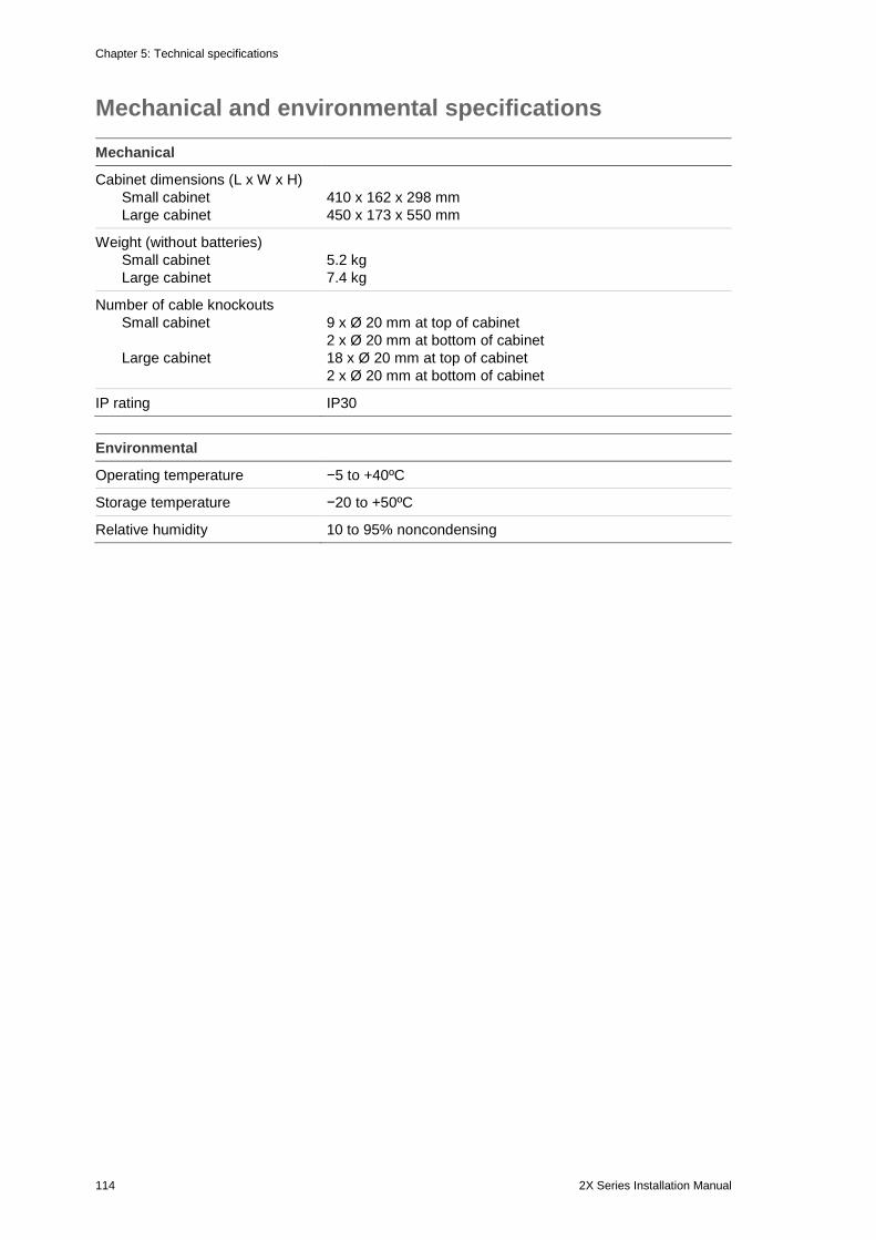
Chapter 5: Technical specifications
114 2X Series Installation Manual
Mechanical and environmental specifications Mechanical
Cabinet dimensions (L x W x H) Small cabinet Large cabinet
410 x 162 x 298 mm 450 x 173 x 550 mm
Weight (without batteries) Small cabinet Large cabinet
5.2 kg 7.4 kg
Number of cable knockouts Small cabinet Large cabinet
9 x Ø 20 mm at top of cabinet 2 x Ø 20 mm at bottom of cabinet 18 x Ø 20 mm at top of cabinet 2 x Ø 20 mm at bottom of cabinet
IP rating IP30 Environmental
Operating temperature −5 to +40ºC
Storage temperature −20 to +50ºC
Relative humidity 10 to 95% noncondensing
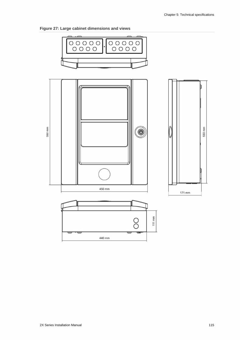
Chapter 5: Technical specifications
2X Series Installation Manual 115
Figure 27: Large cabinet dimensions and views
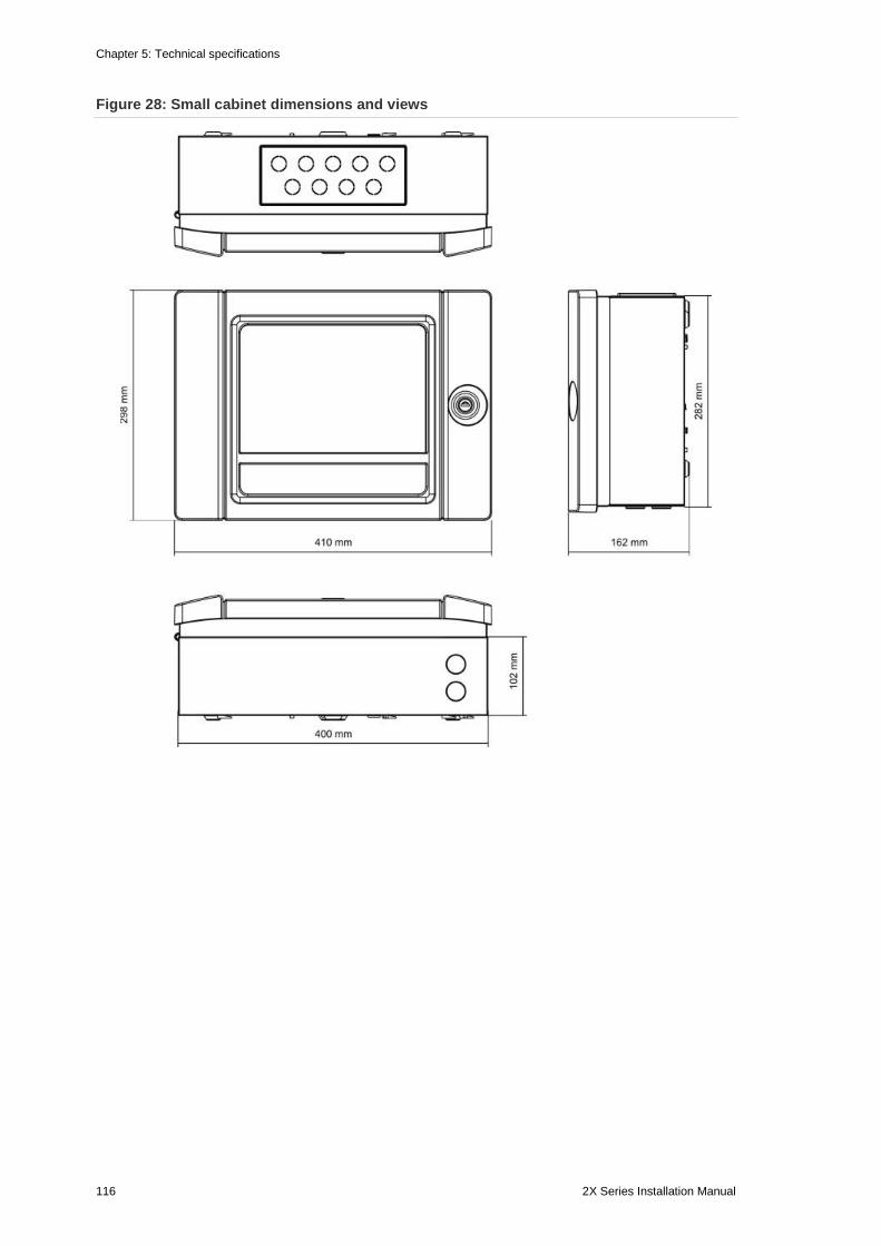
Chapter 5: Technical specifications
116 2X Series Installation Manual
Figure 28: Small cabinet dimensions and views
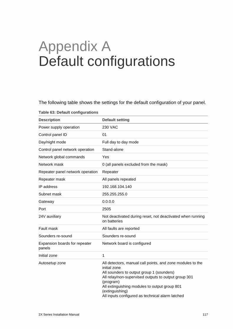
2X Series Installation Manual 117
Appendix A Default configurations
The following table shows the settings for the default configuration of your panel.
Table 63: Default configurations
Description Default setting
Power supply operation 230 VAC
Control panel ID 01
Day/night mode Full day to day mode
Control panel network operation Stand-alone
Network global commands Yes
Network mask 0 (all panels excluded from the mask)
Repeater panel network operation Repeater
Repeater mask All panels repeated
IP address 192.168.104.140
Subnet mask 255.255.255.0
Gateway 0.0.0.0
Port 2505
24V auxiliary Not deactivated during reset, not deactivated when running on batteries
Fault mask All faults are reported
Sounders re-sound Sounders re-sound
Expansion boards for repeater panels
Network board is configured
Initial zone 1
Autosetup zone All detectors, manual call points, and zone modules to the initial zone All sounders to output group 1 (sounders) All relay/non-supervised outputs to output group 301 (program) All extinguishing modules to output group 801 (extinguishing) All inputs configured as technical alarm latched
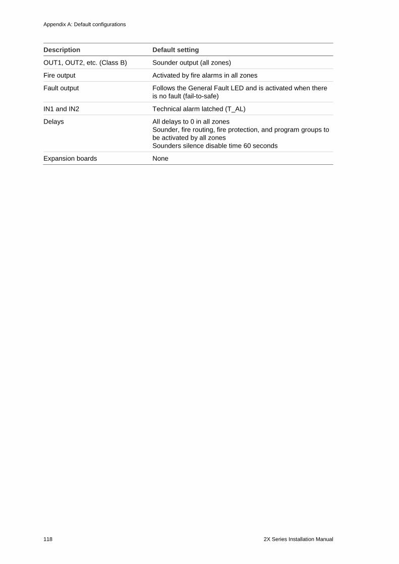
Appendix A: Default configurations
118 2X Series Installation Manual
Description Default setting
OUT1, OUT2, etc. (Class B) Sounder output (all zones)
Fire output Activated by fire alarms in all zones
Fault output Follows the General Fault LED and is activated when there is no fault (fail-to-safe)
IN1 and IN2 Technical alarm latched (T_AL)
Delays All delays to 0 in all zones Sounder, fire routing, fire protection, and program groups to be activated by all zones Sounders silence disable time 60 seconds
Expansion boards None
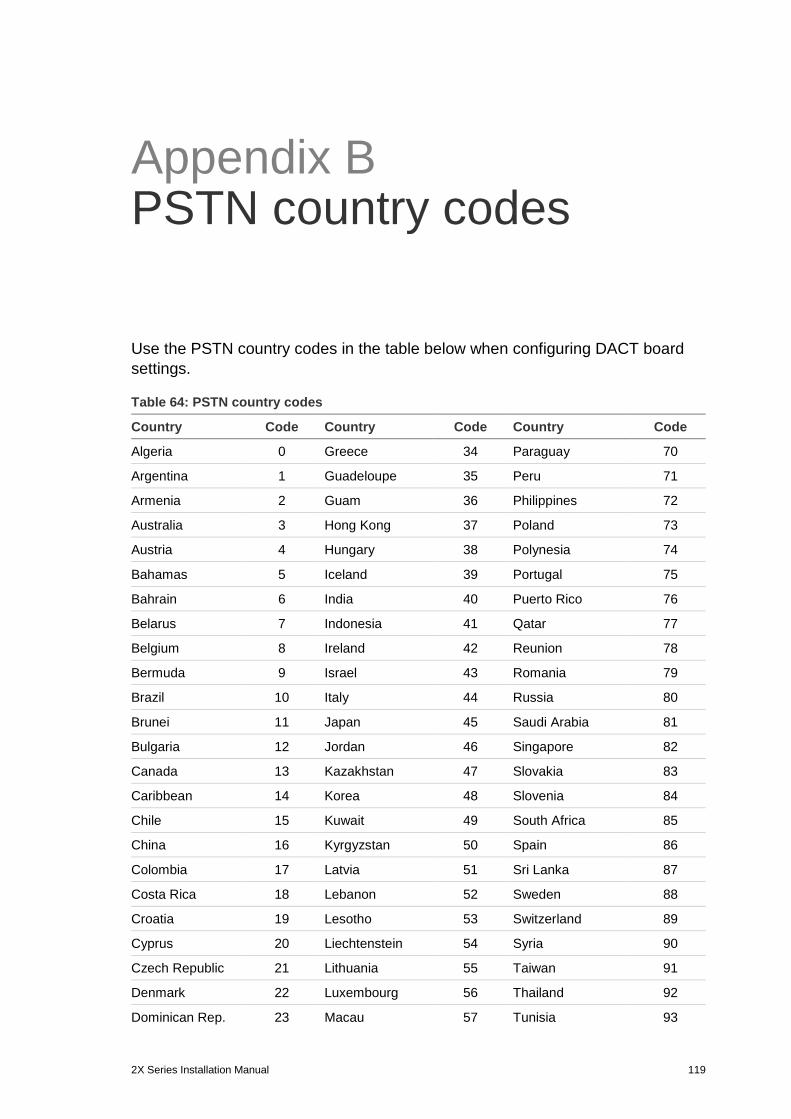
2X Series Installation Manual 119
Appendix B PSTN country codes
Use the PSTN country codes in the table below when configuring DACT board settings.
Table 64: PSTN country codes
Country Code Country Code Country Code
Algeria 0 Greece 34 Paraguay 70
Argentina 1 Guadeloupe 35 Peru 71
Armenia 2 Guam 36 Philippines 72
Australia 3 Hong Kong 37 Poland 73
Austria 4 Hungary 38 Polynesia 74
Bahamas 5 Iceland 39 Portugal 75
Bahrain 6 India 40 Puerto Rico 76
Belarus 7 Indonesia 41 Qatar 77
Belgium 8 Ireland 42 Reunion 78
Bermuda 9 Israel 43 Romania 79
Brazil 10 Italy 44 Russia 80
Brunei 11 Japan 45 Saudi Arabia 81
Bulgaria 12 Jordan 46 Singapore 82
Canada 13 Kazakhstan 47 Slovakia 83
Caribbean 14 Korea 48 Slovenia 84
Chile 15 Kuwait 49 South Africa 85
China 16 Kyrgyzstan 50 Spain 86
Colombia 17 Latvia 51 Sri Lanka 87
Costa Rica 18 Lebanon 52 Sweden 88
Croatia 19 Lesotho 53 Switzerland 89
Cyprus 20 Liechtenstein 54 Syria 90
Czech Republic 21 Lithuania 55 Taiwan 91
Denmark 22 Luxembourg 56 Thailand 92
Dominican Rep. 23 Macau 57 Tunisia 93
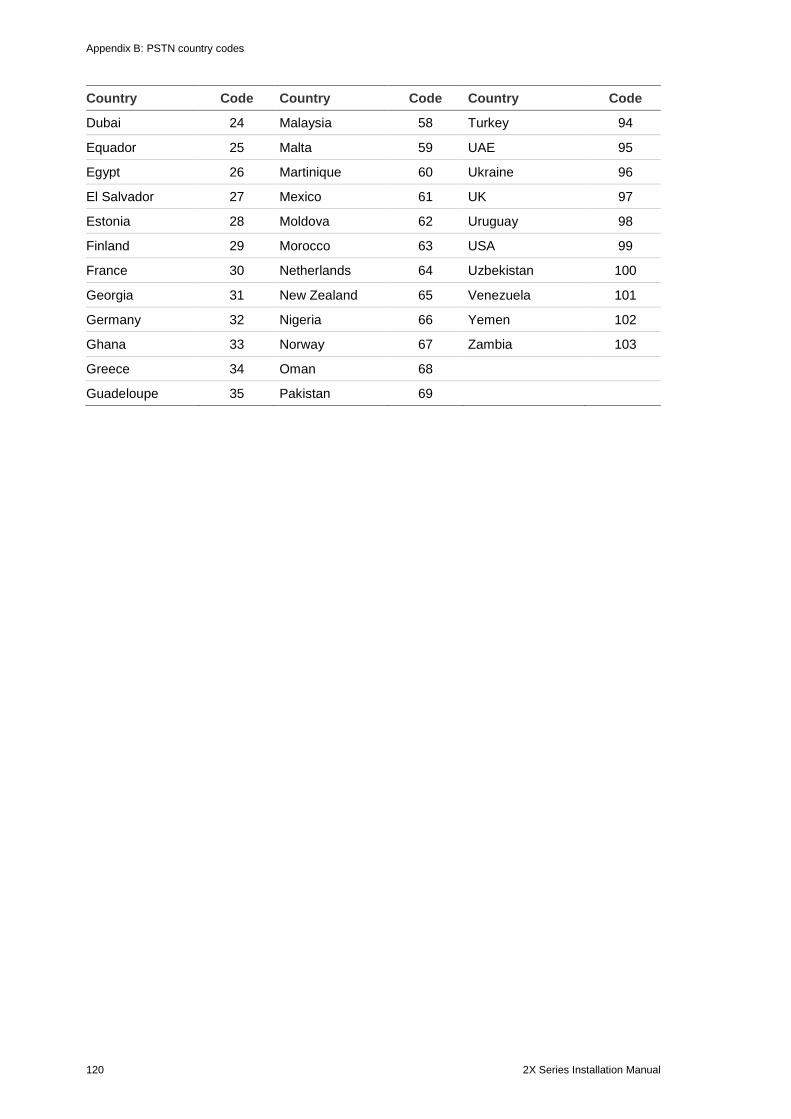
Appendix B: PSTN country codes
120 2X Series Installation Manual
Country Code Country Code Country Code
Dubai 24 Malaysia 58 Turkey 94
Equador 25 Malta 59 UAE 95
Egypt 26 Martinique 60 Ukraine 96
El Salvador 27 Mexico 61 UK 97
Estonia 28 Moldova 62 Uruguay 98
Finland 29 Morocco 63 USA 99
France 30 Netherlands 64 Uzbekistan 100
Georgia 31 New Zealand 65 Venezuela 101
Germany 32 Nigeria 66 Yemen 102
Ghana 33 Norway 67 Zambia 103
Greece 34 Oman 68
Guadeloupe 35 Pakistan 69
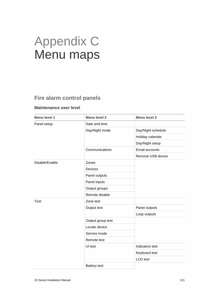
2X Series Installation Manual 121
Appendix C Menu maps
Fire alarm control panels Maintenance user level Menu level 1 Menu level 2 Menu level 3
Panel setup Date and time
Day/Night mode Day/Night schedule
Holiday calendar
Day/Night setup
Communications Email accounts
Remove USB device
Disable/Enable Zones
Devices
Panel outputs
Panel inputs
Output groups
Remote disable
Test Zone test
Output test Panel outputs
Loop outputs
Output group test
Locate device
Service mode
Remote test
UI test Indicators test
Keyboard test
LCD test
Battery test
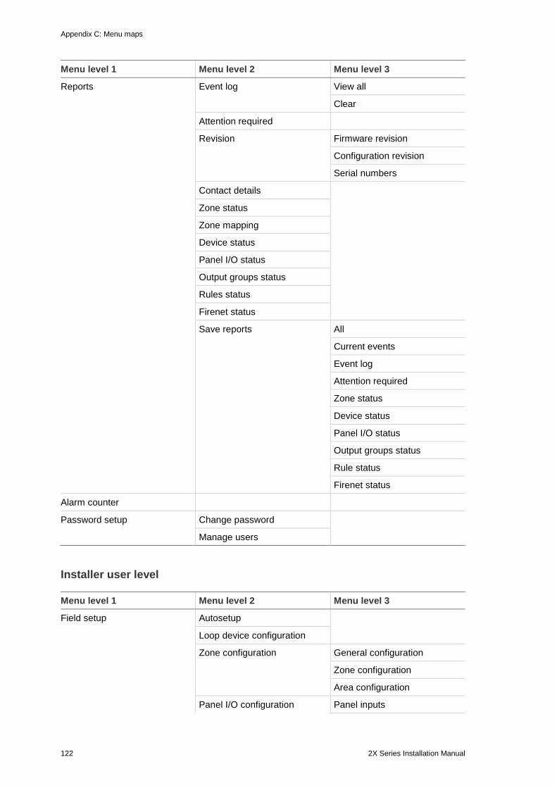
Appendix C: Menu maps
122 2X Series Installation Manual
Menu level 1 Menu level 2 Menu level 3
Reports Event log View all
Clear
Attention required
Revision Firmware revision
Configuration revision
Serial numbers
Contact details
Zone status
Zone mapping
Device status
Panel I/O status
Output groups status
Rules status
Firenet status
Save reports All
Current events
Event log
Attention required
Zone status
Device status
Panel I/O status
Output groups status
Rule status
Firenet status
Alarm counter
Password setup Change password
Manage users
Installer user level Menu level 1 Menu level 2 Menu level 3
Field setup Autosetup
Loop device configuration
Zone configuration General configuration
Zone configuration
Area configuration
Panel I/O configuration Panel inputs
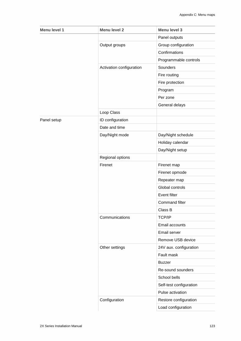
Appendix C: Menu maps
2X Series Installation Manual 123
Menu level 1 Menu level 2 Menu level 3
Panel outputs
Output groups Group configuration
Confirmations
Programmable controls
Activation configuration Sounders
Fire routing
Fire protection
Program
Per zone
General delays
Loop Class
Panel setup ID configuration
Date and time
Day/Night mode Day/Night schedule
Holiday calendar
Day/Night setup
Regional options
Firenet Firenet map
Firenet opmode
Repeater map
Global controls
Event filter
Command filter
Class B
Communications TCP/IP
Email accounts
Email server
Remove USB device
Other settings 24V aux. configuration
Fault mask
Buzzer
Re-sound sounders
School bells
Self-test configuration
Pulse activation
Configuration Restore configuration
Load configuration
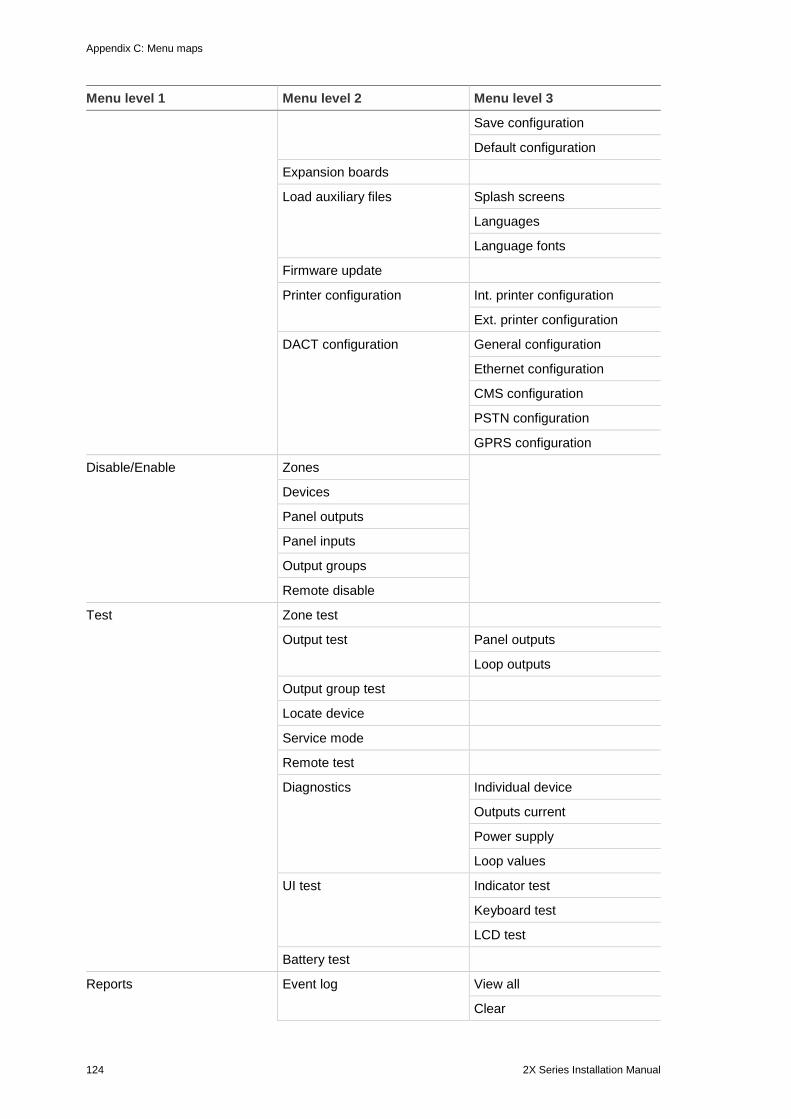
Appendix C: Menu maps
124 2X Series Installation Manual
Menu level 1 Menu level 2 Menu level 3
Save configuration
Default configuration
Expansion boards
Load auxiliary files Splash screens
Languages
Language fonts
Firmware update
Printer configuration Int. printer configuration
Ext. printer configuration
DACT configuration General configuration
Ethernet configuration
CMS configuration
PSTN configuration
GPRS configuration
Disable/Enable Zones
Devices
Panel outputs
Panel inputs
Output groups
Remote disable
Test Zone test
Output test Panel outputs
Loop outputs
Output group test
Locate device
Service mode
Remote test
Diagnostics Individual device
Outputs current
Power supply
Loop values
UI test Indicator test
Keyboard test
LCD test
Battery test
Reports Event log View all
Clear
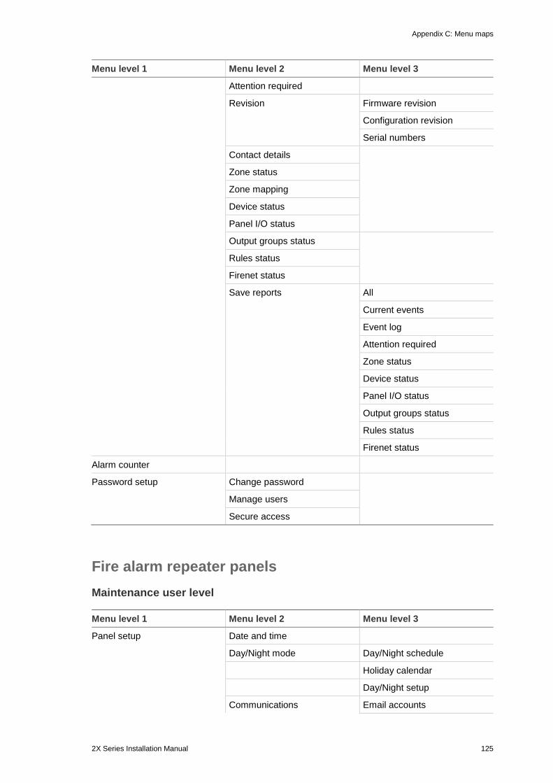
Appendix C: Menu maps
2X Series Installation Manual 125
Menu level 1 Menu level 2 Menu level 3
Attention required
Revision Firmware revision
Configuration revision
Serial numbers
Contact details
Zone status
Zone mapping
Device status
Panel I/O status
Output groups status
Rules status
Firenet status
Save reports All
Current events
Event log
Attention required
Zone status
Device status
Panel I/O status
Output groups status
Rules status
Firenet status
Alarm counter
Password setup Change password
Manage users
Secure access
Fire alarm repeater panels Maintenance user level Menu level 1 Menu level 2 Menu level 3
Panel setup Date and time
Day/Night mode Day/Night schedule
Holiday calendar
Day/Night setup
Communications Email accounts
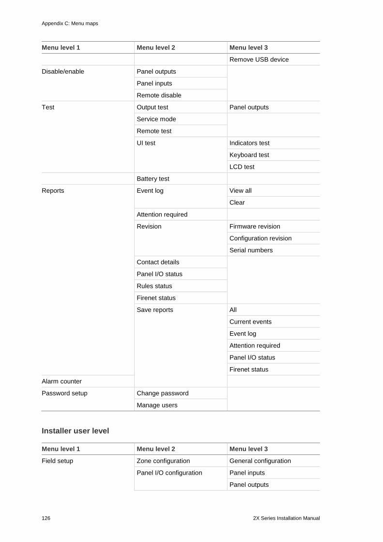
Appendix C: Menu maps
126 2X Series Installation Manual
Menu level 1 Menu level 2 Menu level 3
Remove USB device
Disable/enable Panel outputs
Panel inputs
Remote disable
Test Output test Panel outputs
Service mode
Remote test
UI test Indicators test
Keyboard test
LCD test
Battery test
Reports Event log View all
Clear
Attention required
Revision Firmware revision
Configuration revision
Serial numbers
Contact details
Panel I/O status
Rules status
Firenet status
Save reports All
Current events
Event log
Attention required
Panel I/O status
Firenet status
Alarm counter
Password setup Change password
Manage users
Installer user level Menu level 1 Menu level 2 Menu level 3
Field setup Zone configuration General configuration
Panel I/O configuration Panel inputs
Panel outputs
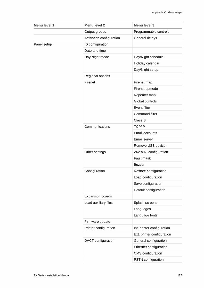
Appendix C: Menu maps
2X Series Installation Manual 127
Menu level 1 Menu level 2 Menu level 3
Output groups Programmable controls
Activation configuration General delays
Panel setup ID configuration
Date and time
Day/Night mode Day/Night schedule
Holiday calendar
Day/Night setup
Regional options
Firenet Firenet map
Firenet opmode
Repeater map
Global controls
Event filter
Command filter
Class B
Communications TCP/IP
Email accounts
Email server
Remove USB device
Other settings 24V aux. configuration
Fault mask
Buzzer
Configuration Restore configuration
Load configuration
Save configuration
Default configuration
Expansion boards
Load auxiliary files Splash screens
Languages
Language fonts
Firmware update
Printer configuration Int. printer configuration
Ext. printer configuration
DACT configuration General configuration
Ethernet configuration
CMS configuration
PSTN configuration
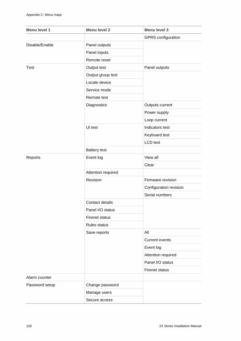
Appendix C: Menu maps
128 2X Series Installation Manual
Menu level 1 Menu level 2 Menu level 3
GPRS configuration
Disable/Enable Panel outputs
Panel inputs
Remote reset
Test Output test Panel outputs
Output group test
Locate device
Service mode
Remote test
Diagnostics Outputs current
Power supply
Loop current
UI test Indicators test
Keyboard test
LCD test
Battery test
Reports Event log View all
Clear
Attention required
Revision Firmware revision
Configuration revision
Serial numbers
Contact details
Panel I/O status
Firenet status
Rules status
Save reports All
Current events
Event log
Attention required
Panel I/O status
Firenet status
Alarm counter
Password setup Change password
Manage users
Secure access
2X Series Installation Manual 129
Appendix D Regulatory information
European standards for fire control and indicating equipment These control panels have been designed in accordance with European EN 54-2, and EN 54-4 standards.
In addition, they comply with the following EN 54-2 optional requirements.
Table 65: EN 54-2 optional requirements
Option Description
7.8 Output to fire alarm devices [1]
7.9.1 Output to fire alarm routing equipment [2]
7.9.2 Alarm confirmation input from fire alarm routing equipment [2]
7.10 Output to fire protection equipment (type A, B, and C) [3]
7.11 Delays to outputs [4]
7.12 Dependencies on more than one alarm signal (types A, B, and C) [4]
7.13 Alarm counter
8.4 Total loss of the power supply
8.9 Output to fault warning routing equipment
9.5 Disablement of addressable points [4]
10 Test condition [4]
[1] Excluding repeaters and control panels operating in EN 54-2 Evacuation mode or NBN mode. [2] Excluding repeaters, control panels without fire routing, and control panels with fire routing operating in NBN mode. [3] Excluding repeaters and control panels without fire protection controls. [4] Excluding repeaters.
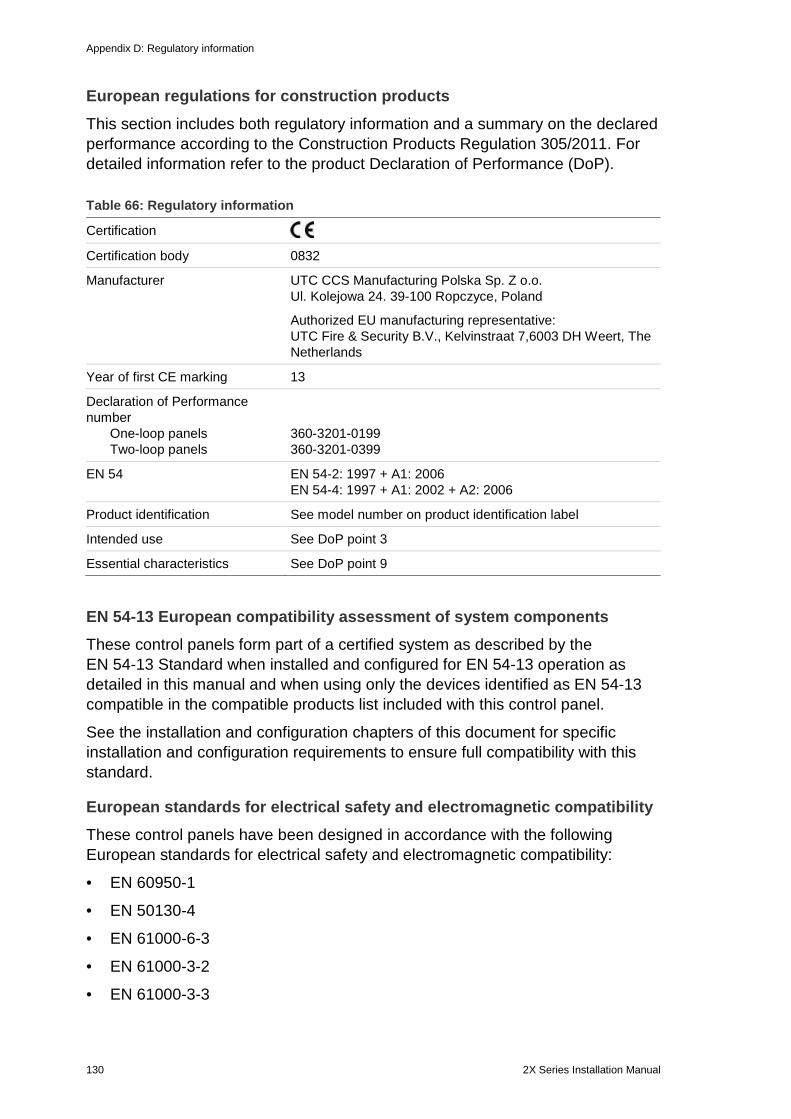
Appendix D: Regulatory information
130 2X Series Installation Manual
European regulations for construction products
This section includes both regulatory information and a summary on the declared performance according to the Construction Products Regulation 305/2011. For detailed information refer to the product Declaration of Performance (DoP).
Table 66: Regulatory information
Certification Certification body 0832
Manufacturer UTC CCS Manufacturing Polska Sp. Z o.o. Ul. Kolejowa 24. 39-100 Ropczyce, Poland
Authorized EU manufacturing representative: UTC Fire & Security B.V., Kelvinstraat 7,6003 DH Weert, The Netherlands
Year of first CE marking 13
Declaration of Performance number One-loop panels Two-loop panels
360-3201-0199 360-3201-0399
EN 54 EN 54-2: 1997 + A1: 2006 EN 54-4: 1997 + A1: 2002 + A2: 2006
Product identification See model number on product identification label
Intended use See DoP point 3
Essential characteristics See DoP point 9
EN 54-13 European compatibility assessment of system components These control panels form part of a certified system as described by the EN 54-13 Standard when installed and configured for EN 54-13 operation as detailed in this manual and when using only the devices identified as EN 54-13 compatible in the compatible products list included with this control panel.
See the installation and configuration chapters of this document for specific installation and configuration requirements to ensure full compatibility with this standard.
European standards for electrical safety and electromagnetic compatibility These control panels have been designed in accordance with the following European standards for electrical safety and electromagnetic compatibility:
• EN 60950-1
• EN 50130-4
• EN 61000-6-3
• EN 61000-3-2
• EN 61000-3-3
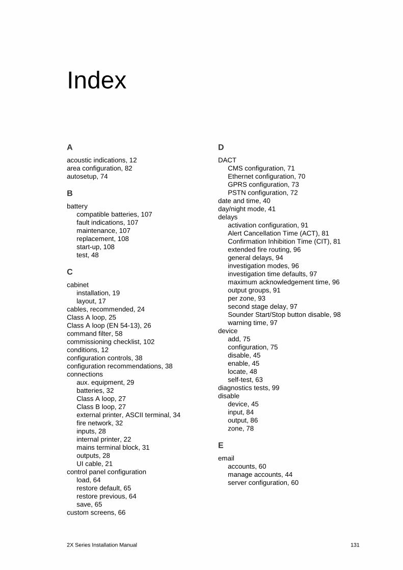
2X Series Installation Manual 131
Index
A acoustic indications, 12 area configuration, 82 autosetup, 74
B battery
compatible batteries, 107 fault indications, 107 maintenance, 107 replacement, 108 start-up, 108 test, 48
C cabinet
installation, 19 layout, 17
cables, recommended, 24 Class A loop, 25 Class A loop (EN 54-13), 26 command filter, 58 commissioning checklist, 102 conditions, 12 configuration controls, 38 configuration recommendations, 38 connections
aux. equipment, 29 batteries, 32 Class A loop, 27 Class B loop, 27 external printer, ASCII terminal, 34 fire network, 32 inputs, 28 internal printer, 22 mains terminal block, 31 outputs, 28 UI cable, 21
control panel configuration load, 64 restore default, 65 restore previous, 64 save, 65
custom screens, 66
D DACT
CMS configuration, 71 Ethernet configuration, 70 GPRS configuration, 73 PSTN configuration, 72
date and time, 40 day/night mode, 41 delays
activation configuration, 91 Alert Cancellation Time (ACT), 81 Confirmation Inhibition Time (CIT), 81 extended fire routing, 96 general delays, 94 investigation modes, 96 investigation time defaults, 97 maximum acknowledgement time, 96 output groups, 91 per zone, 93 second stage delay, 97 Sounder Start/Stop button disable, 98 warning time, 97
device add, 75 configuration, 75 disable, 45 enable, 45 locate, 48 self-test, 63
diagnostics tests, 99 disable
device, 45 input, 84 output, 86 zone, 78
E email
accounts, 60 manage accounts, 44 server configuration, 60
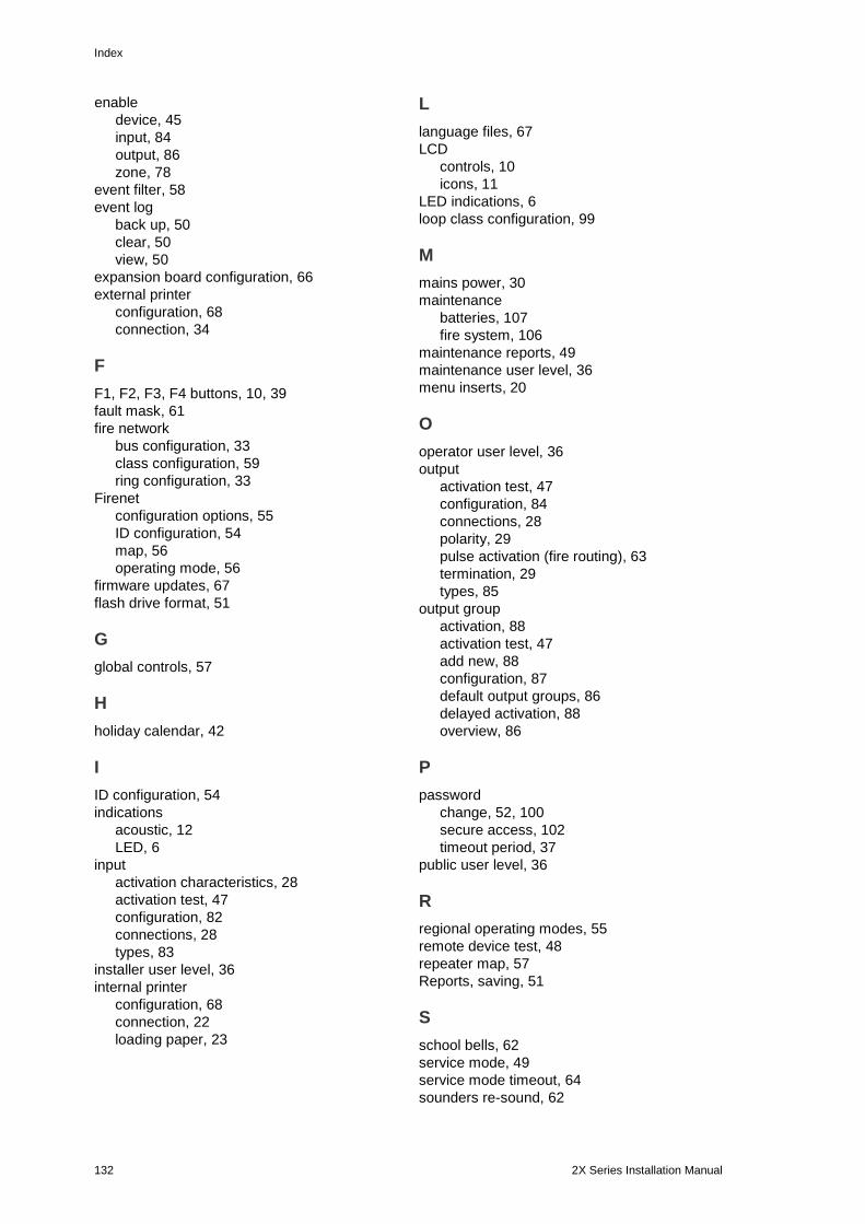
Index
132 2X Series Installation Manual
enable device, 45 input, 84 output, 86 zone, 78
event filter, 58 event log
back up, 50 clear, 50 view, 50
expansion board configuration, 66 external printer
configuration, 68 connection, 34
F F1, F2, F3, F4 buttons, 10, 39 fault mask, 61 fire network
bus configuration, 33 class configuration, 59 ring configuration, 33
Firenet configuration options, 55 ID configuration, 54 map, 56 operating mode, 56
firmware updates, 67 flash drive format, 51
G global controls, 57
H holiday calendar, 42
I ID configuration, 54 indications
acoustic, 12 LED, 6
input activation characteristics, 28 activation test, 47 configuration, 82 connections, 28 types, 83
installer user level, 36 internal printer
configuration, 68 connection, 22 loading paper, 23
L language files, 67 LCD
controls, 10 icons, 11
LED indications, 6 loop class configuration, 99
M mains power, 30 maintenance
batteries, 107 fire system, 106
maintenance reports, 49 maintenance user level, 36 menu inserts, 20
O operator user level, 36 output
activation test, 47 configuration, 84 connections, 28 polarity, 29 pulse activation (fire routing), 63 termination, 29 types, 85
output group activation, 88 activation test, 47 add new, 88 configuration, 87 default output groups, 86 delayed activation, 88 overview, 86
P password
change, 52, 100 secure access, 102 timeout period, 37
public user level, 36
R regional operating modes, 55 remote device test, 48 repeater map, 57 Reports, saving, 51
S school bells, 62 service mode, 49 service mode timeout, 64 sounders re-sound, 62
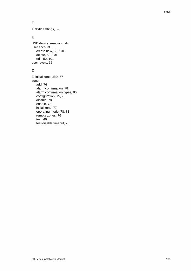
Index
2X Series Installation Manual 133
T TCP/IP settings, 59
U USB device, removing, 44 user account
create new, 53, 101 delete, 52, 101 edit, 52, 101
user levels, 36
Z ZI initial zone LED, 77 zone
add, 76 alarm confirmation, 78 alarm confirmation types, 80 configuration, 75, 78 disable, 78 enable, 78 initial zone, 77 operating mode, 78, 81 remote zones, 76 test, 46 test/disable timeout, 78