Embed Size (px)
Citation preview

Basic PRO 5A G2-(1X 2X)Digital Servo DriveInstallation Guide
January 2013 (Ver. 1.2)

Basic Pro Installation Guide
Notice • This guide is delivered subject to the following conditions and restrictions: This
guide contains proprietary information belonging to Motor power Company Srl. Such information is supplied solely for the purpose of assisting users of the Basic Pro (1X 2X) servo drive in its installation.
• The text and graphics included in this manual are for the purpose of illustration and reference only. The specifications on which they are based are subject to change without notice.
• Motor power Company and the Motor power Company logo are trademarks of Motor power Company Srl.
• Information in this document is subject to change without notice.
Version Release Date Status Change/Remarks
Ver. 1.0 June 2012 BPRO-IG_G2.PDF
Ver. 1.1 October 2012 BPRO-IG_G2.PDF I/O Label Changes
Ver. 1.2 January 2013 BPRO-IG_G2.PDF P&D Schema Updated
2
Basic Pro Installation Guide
ContentsChapter1:Safety Information ...................................................................................................................... 5
1.1Warnings........................................................................................................................................... 61.2Cautions............................................................................................................................................ 61.3Directives and Standards................................................................................................................... 71.4CE Mark Conformance....................................................................................................................... 71.5Warranty Information........................................................................................................................ 8
Chapter2:Introduction ................................................................................................................................ 92.1Drive Description .............................................................................................................................. 92.2Product Features............................................................................................................................... 9
2.2.1Current Control ......................................................................................................................... 92.2.2Velocity Control ...................................................................................................................... 102.2.3Position Control ....................................................................................................................... 102.2.4Communication Options........................................................................................................... 102.2.5Feedback Options ................................................................................................................... 102.2.6Fault Protection ....................................................................................................................... 10
2.3System Architecture........................................................................................................................ 112.4How to Use this Guide ..................................................................................................................... 12
Chapter3:Installation ................................................................................................................................ 133.1Before You Begin ............................................................................................................................ 13
3.1.1Site Requirements .................................................................................................................. 133.1.2Hardware Requirements.......................................................................................................... 133.1.3AC Power Requirements .......................................................................................................... 143.1.4Recommended Wire Cross-sections ........................................................................................14
3.2Unpacking the Drive Components ...................................................................................................153.3Mounting the Basic Pro .................................................................................................................. 153.4Connecting the Cables .................................................................................................................... 16
3.4.1Wiring the Basic Pro ................................................................................................................ 163.4.2Connecting the Main Power Cables ........................................................................................193.4.3Connecting the Motor Cable.....................................................................................................203.4.4Connecting the auxiliary Supply 24V.......................................................................................213.4.5Encoder cable X1,X2................................................................................................................ 213.4.6Encoder Output X4,X5 ............................................................................................................ 233.4.7Braking Resistor connector .....................................................................................................233.4.8RS 232 Interface connector......................................................................................................243.4.9Set point (CAN/CMD) connector ..............................................................................................243.4.10General I/O connector ........................................................................................................... 253.4.11Connector X6......................................................................................................................... 25
Chapter4:Fault conditions.......................................................................................................................... 26Appendix A:Technical Specifications.......................................................................................................... 28
A.1Mechanical Dimensions................................................................................................................... 28A.2Power Ratings.................................................................................................................................. 29A.3Environmental Conditions................................................................................................................ 29A.4Connections..................................................................................................................................... 29A.5Feedback......................................................................................................................................... 30A.6Analog Input.................................................................................................................................... 30A.7Digital Inputs................................................................................................................................... 30A.8Digital Outputs................................................................................................................................ 31A.9Regeneration................................................................................................................................... 31
Appendix B:Motor Configuration................................................................................................................ 32B.1Motor Phasing - F11......................................................................................................................... 32B.2Hall signal sequence........................................................................................................................ 33
Appendix C:Other Connectors................................................................................................................... 34C.1Resolver Feedback Input [X4/X5] ....................................................................................................34C.2SSI Output [X6]................................................................................................................................ 35C.3Pulse And Direction Input [X6]......................................................................................................... 37
3

Basic Pro Installation Guide 4

Basic Pro Installation Guide
Chapter1: Safety Information
In order to achieve the optimum, safe operation of the Basic Pro servo drive, it is imperative that you implement the safety procedures included in this installation guide. This information is provided to protect you and to keep your work area safe when operating the Basic Pro and accompanying equipment. Please read this chapter carefully before you begin the installation process.
Before you start, ensure that all system components are connected to earth ground. Electrical safety is provided through a low-resistance earth connection.
Only qualified personnel may install, adjust, maintain and repair the servo drive. A “qualified person” has the knowledge and authorization to perform tasks such as transporting, assembling, installing, commissioning and operating motors.
The Basic Pro servo drive contains electrostatic-sensitive components that can be damaged if handled incorrectly. To prevent any electrostatic damage, avoid contact with highly insulating materials, such as plastic film and synthetic fabrics. Place the product on a conductive surface and ground yourself in order to discharge any possible static electricity build-up.
To avoid any potential hazards that may cause severe personal injury or damage to the product during operation, keep all covers and cabinet doors shut.
The following safety symbols are used in this manual:
Warning: This information is needed to avoid a safety hazard, which might cause bodily injury.
Caution: This information is necessary for preventing damage to the product or to other equipment.
Note: This is auxiliary information that ensures the correct operation of the equipment.
1.1 Warnings
5

Basic Pro Installation Guide
To avoid electric hazards to personnel and electrical contacts, never connect/disconnect the servo drive while the power source is on.
Power cables can carry a high voltage, even when the motor is not in motion. Disconnect the Basic Pro from all voltage sources before it is opened for servicing.
The Basic Pro servo drive contains grounding conduits for electric current protection. Any disruption to these conduits may cause the device to become “hot” (live) and dangerous.
After shutting off the power and removing the power source from your equipment, wait at least 3 minute before touching or disconnecting parts of the equipment that are normally loaded with electrical charges (such as capacitors or contacts). Measuring the electrical contact points with a meter before touching the equipment is recommended.
1.2 Cautions
The Basic Pro servo drive contains hot surfaces and electrically-charged components during operation.
The maximum AC power supply connected to the instrument must comply with the parameters outlined in this guide.
The Basic Pro servo drive must be connected to an approved 24VDC auxiliary power supply through a line that is separated from hazardous line voltages using reinforced or double insulation in accordance with approved safety standards.
The Basic Pro series is designed to gets its power from a 30 - 255 VAC single phase power source. It can be connected directly to the line voltage. An isolation transformer is not needed.
Before switching on the Basic Pro, verify that all safety precautions have been observed and that the installation procedures in this manual have been followed.
6

Basic Pro Installation Guide
1.3 Directives and Standards
The Basic Pro servo drive conforms to the following industry safety standards:
Safety Standard Item
Designed in Compliance with UL508c and UL840
Conformance to the following safety standards:
• Power Conversion Equipment• Insulation Coordination, Including
Clearance and Creepage distances of electrical equipment
Designed in compliance with UL60950 (formerly UL1950)
Safety of Information Technology Equipment, Including Electrical Business Equipment
In compliance with EN60204-1 Low Voltage Directive, 73/23/EEC
1.4 CE Mark Conformance
The Basic Pro servo drive is intended for incorporation in a machine or end product. The actual end product must comply with all safety aspects of the relevant requirements of the European Safety of Machinery Directive 98/37/EC as amended, and with those of the most recent versions of standards EN60204-1 and EN292-2 at the least.
According to Annex III of Article 13 of Council Directive 93/68/EEC, amending Council Directive 73/23/EEC concerning electrical equipment designed for use within certain voltage limits, the Basic Pro meets the provisions outlined in Council Directive 73/23/EEC. The party responsible for ensuring that the equipment meet the limits required by EMC regulations is the manufacturer of the end product.
1.5 Warranty Information
7

Basic Pro Installation Guide
The products covered in this manual are warranted to be free of defects in material and workmanship and conform to the specifications stated either within this document or in the product catalogue description. All Motor Power Company products are warranted for a period of 12 months from the time of shipment. No other warranties, expressed or implied — and including a warranty of merchantability and fitness for a particular purpose — extend beyond this warranty.
8

Basic Pro Installation Guide
Chapter2: Introduction
This installation guide describes the Basic Pro servo drive and the steps for its wiring, installation and powering up. Following these guidelines ensures maximum functionality of the drive and the system to which it is connected.
2.1 Drive Description
The Basic Pro is a powerful servo drive that operates in digital current, velocity, position, in conjunction with a permanent-magnet synchronous brushless motor. The Basic Pro features flexible sinusoidal, with vector control. The Basic Pro can operate as a stand-alone device or as part of a multi-axis network in a distributed configuration.
The Basic Pro drive is set up and tuned using Motor Power Company Basic PRO GU software. This Windows-based application enables users to quickly and simply configure the servo drive for optimal use with the selected Motor Power Company Motor.
The Basic Pro connects directly to 110/230 VAC single-phase or three-phase power source. A separate 24 VDC power supply serves as both the auxiliary supply and the backup supply. This allows a safe and economical "power backup" feature that is essential for positioning systems.
The Basic Pro operate with RS-232 and/or CANopen communications.
2.2 Product Features
2.2.1 Current Control
• Fully digital • Sinusoidal commutation with vector control with encoder and/or digital Hall
sensors • 12-bit current loop resolution
9

Basic Pro Installation Guide
2.2.2 Velocity Control
• Fully digital • Programmable PI and FF (feed forward) control filters • Sample rate two times current loop sample time • Automatic, manual and advanced manual tuning and determination of
optimal gain and phase margins
2.2.3 Position Control
• Programmable PI control filter• Programmable filters• Position follower mode for monitoring the motion of the slave axis relative
to a master axis, via an auxiliary encoder input or the between the 2 axis of the dual
• Position-based and time-based ECAM mode that supports a non-linear follower mode, in which the motor tracks the master motion using an ECAM table stored in flash memory (in progress)
2.2.4 Communication Options
• RS-232 serial communication • CANopen for fast communication in a multi-axis distributed environment
2.2.5 Feedback Options
• Digital Halls – up to 2 KHz • Incremental Encoder with Digital Halls for commutation – 2 MHz.• Encoder outputs, buffered, differential• Basic Pro provide 5V supply voltage for all the feedback options
2.2.6 Fault Protection
The Basic Pro includes built-in protection against possible fault conditions, including:
• Status reporting for a large number of possible fault conditions • Protection against conditions such as excessive temperature, under/over
voltage, loss of commutation signal, short circuits between the motor power outputs and between each output and power input/return
• Recovery from loss of commutation signals and from communication errors
10
Basic Pro Installation Guide
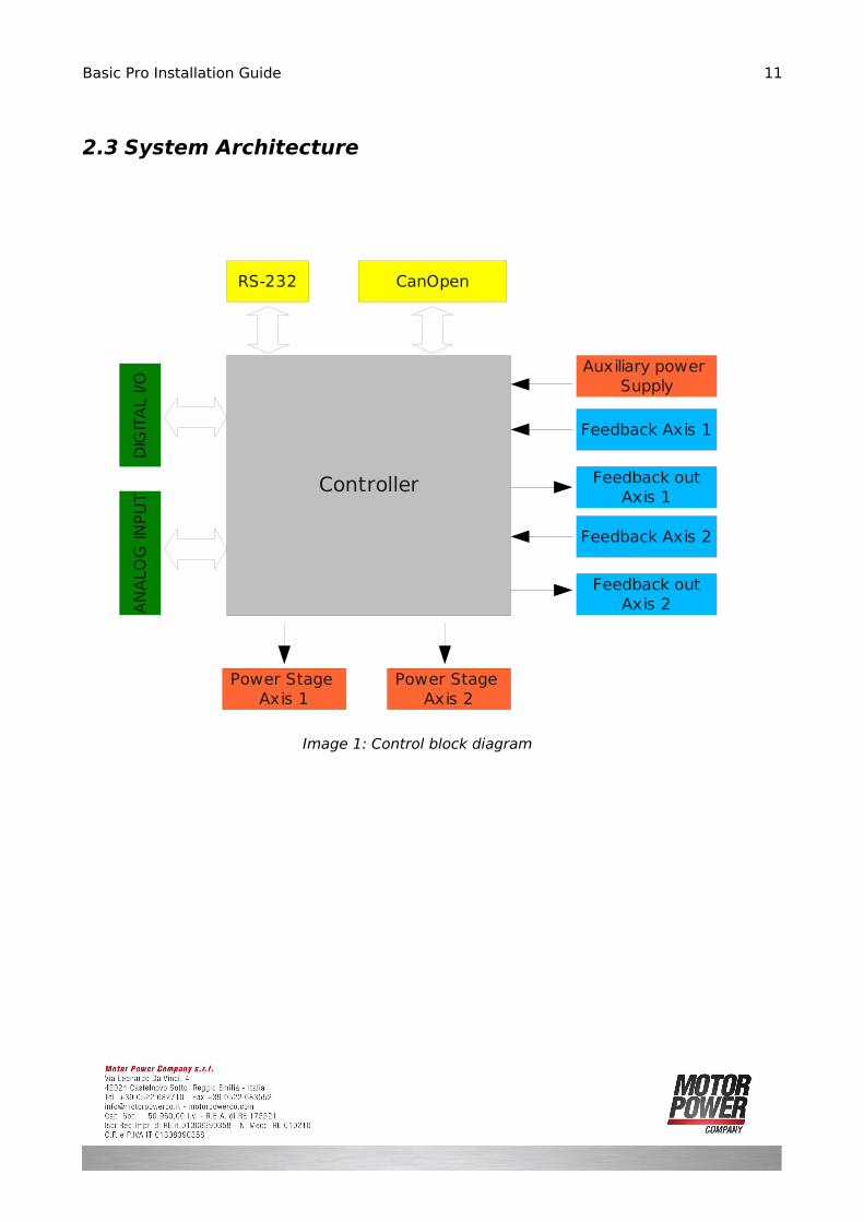
2.3 System Architecture
11
Image 1: Control block diagram
RS-232 CanOpen
DIG
ITA
L I/O
AN
ALO
G IN
PU
T
Power Stage Axis 1
Power Stage Axis 2
Auxiliary power Supply
Controller
Feedback Axis 1
Feedback outAxis 1
Feedback Axis 2
Feedback outAxis 2

Basic Pro Installation Guide
2.4 How to Use this Guide
In order to install and operate your Basic Pro servo drive, you will use this manual in conjunction with a set of others documentation. Installation is your first step;after carefully reading the safety instructions in the first chapter, the following chapters provide you with installation instructions as follows:
Chapter 3, Installation, provides step-by-step instructions for unpacking, mounting, connecting and powering up the Basic Pro.
The Appendix A , Technical Specifications, lists all the drive ratings and specifications. Upon completing the instructions in this guide, your Basic Pro servo drive should be successfully mounted and installed. From this stage, you need to consult higher-level documentation in order to set up and fine-tune the system for optimal operation.The following table describes the accompanying documentation that you will require.
Programming Basic Pro CanOpen ImplementationBasic Pro Software Manual
Installation Basic Pro Installation Guide
Check Motor Power Company web site to download all the manual that you still miss.
12

Basic Pro Installation Guide
Chapter3: Installation
3.1 Before You Begin
3.1.1 Site Requirements
You can guarantee the safe operation of the Basic Pro by ensuring that it is installed in an appropriate environment.
Feature Value
Ambient operating temperature 0 °C – 40 °C (32 °F – 104 °F)
Maximum operating altitude with no derating. 1,000 m (3,000 ft)
Maximum relative humidity 90% non-condensing
Operating area atmosphere No flammable gases or vapors permitted in area
The servo drive dissipates its heat by natural convection. The maximum operating ambient temperature of 0 °C – 40 °C (32 °F – 104 °F) must not be exceeded.
Models for extended environmental conditions are available. Ask to a Motor Power Company Representative for more information.
3.1.2 Hardware Requirements
The components that you will need to install properly your Basic Pro are:
Component Connector Section Diagram
Main Power Cable 220VAC
Motor Power Cable MOTORn
Auxiliary Power Cable and D I/O I/O
Feedback Cable ENCnIN
Extended D I/O Cable # I/O EXT
Auxiliary Feedback # ENC n OUT
# If needed
13
Basic Pro Installation Guide
Brake Resistance # REGEN
RS 232 Cable COM1
Canopen and Analog Command CMD/CAN
You need also a PC for Setup and Tuning, and all the necessary data from the Motor Power Company Motor Datasheet.
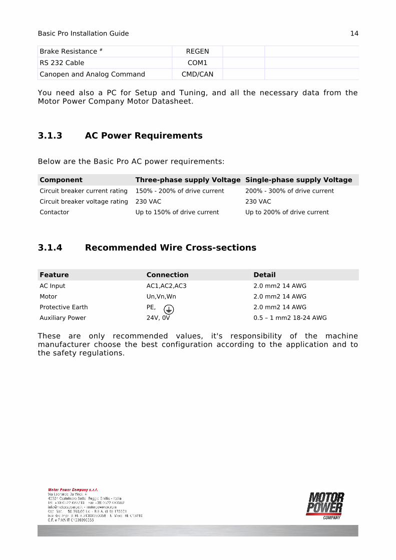
3.1.3 AC Power Requirements
Below are the Basic Pro AC power requirements:
Component Three-phase supply Voltage Single-phase supply Voltage
Circuit breaker current rating 150% - 200% of drive current 200% - 300% of drive current
Circuit breaker voltage rating 230 VAC 230 VAC
Contactor Up to 150% of drive current Up to 200% of drive current
3.1.4 Recommended Wire Cross-sections
Feature Connection Detail
AC Input AC1,AC2,AC3 2.0 mm2 14 AWG
Motor Un,Vn,Wn 2.0 mm2 14 AWG
Protective Earth PE, 2.0 mm2 14 AWG
Auxiliary Power 24V, 0V 0.5 – 1 mm2 18-24 AWG
These are only recommended values, it's responsibility of the machine manufacturer choose the best configuration according to the application and to the safety regulations.
14

Basic Pro Installation Guide
3.2 Unpacking the Drive Components
Before you begin working with the Basic Pro system, verify that you have all of its components, as follows:
• The Basic Pro servo drive • The Basic Pro User Interface software and all manual �
• The Motor Power Company Motor and appropriated cables�
To unpack the Basic Pro: 1. Carefully remove the servo drive from the box. 2. Check the drive to ensure that there is no visible damage to the instrument.
If any damage has occurred, report it immediately to the carrier that delivered your drive.
3. To ensure that the Basic Pro you have unpacked is the appropriate type for your requirements, locate the part number sticker on the side of the Basic Pro.
4. Verify that the Basic Pro type is the one that you ordered.
3.3 Mounting the Basic Pro
The Basic Pro has been designed for Wall Mount mounting option.
The drives inside the cabinet must have enough space for air circulation, the minimum distance between 2 units is 5cm.
If necessary on the bottom side of the device is possible to mount an external fan for additional heat sink, when the drive is used with high rms current or in high temp environment.
15

Basic Pro Installation Guide
3.4 Connecting the Cables
3.4.1 Wiring the Basic Pro
Once the Basic Pro is mounted, you are ready to wire the device. Proper wiring, grounding and shielding are essential for ensuring safe, immune and optimal servo performance of the servo drive.
16
Image 2: Mounting Instruction
Basic Pro Installation Guide
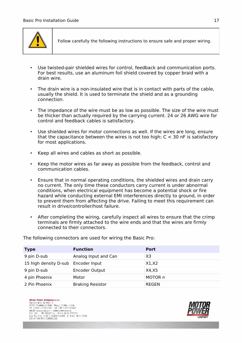
Follow carefully the following instructions to ensure safe and proper wiring.
• Use twisted-pair shielded wires for control, feedback and communication ports. For best results, use an aluminum foil shield covered by copper braid with a drain wire.
• The drain wire is a non-insulated wire that is in contact with parts of the cable, usually the shield. It is used to terminate the shield and as a grounding connection.
• The impedance of the wire must be as low as possible. The size of the wire must be thicker than actually required by the carrying current. 24 or 26 AWG wire for control and feedback cables is satisfactory.
• Use shielded wires for motor connections as well. If the wires are long, ensure that the capacitance between the wires is not too high: C < 30 nF is satisfactory for most applications.
• Keep all wires and cables as short as possible.
• Keep the motor wires as far away as possible from the feedback, control and communication cables.
• Ensure that in normal operating conditions, the shielded wires and drain carry no current. The only time these conductors carry current is under abnormal conditions, when electrical equipment has become a potential shock or fire hazard while conducting external EMI interferences directly to ground, in order to prevent them from affecting the drive. Failing to meet this requirement can result in drive/controller/host failure.
• After completing the wiring, carefully inspect all wires to ensure that the crimp terminals are firmly attached to the wire ends and that the wires are firmly connected to their connectors.
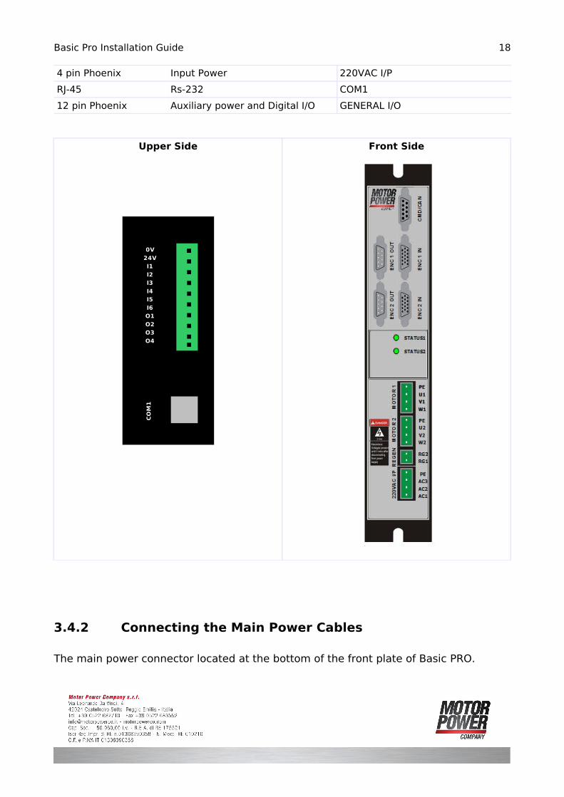
The following connectors are used for wiring the Basic Pro:
Type Function Port
9 pin D-sub Analog Input and Can X3
15 high density D-sub Encoder Input X1,X2
9 pin D-sub Encoder Output X4,X5
4 pin Phoenix Motor MOTOR n
2 Pin Phoenix Braking Resistor REGEN
17
Basic Pro Installation Guide
4 pin Phoenix Input Power 220VAC I/P
RJ-45 Rs-232 COM1
12 pin Phoenix Auxiliary power and Digital I/O GENERAL I/O
Upper Side Front Side
3.4.2 Connecting the Main Power Cables
The main power connector located at the bottom of the front plate of Basic PRO.
18
0V
24VI1
I2I3
I4I5
I6O1
O2O3
O4
CO
M1

Basic Pro Installation Guide
Connect the main power supply cable to the AC1, AC2 and AC3 terminals of the main power connector. Connect the Protective Earth wire to the nearest PE terminal on the terminal block.
Pin Signal Function
1 PE Protective Earth
2 AC3 Main Power Phase3
3 AC2 Main Power Phase2
4 AC1 Main Power Phase1
For single-phase operation please connect PE, AC1, AC2. Remember that operating the drive in Single-phase mode the system will be affected by a voltage drop-down proportional to the current usage.
Note for AC power connection:
✗ For best noise immunity, a shielded (not twisted) cable is recommended (not mandatory) for the AC power supply cable. A 4-wire shielded cable should be used. The gauge is determined by the actual current consumption of the motor.
✗ Connect the four wires to the AC power leads of the source. ✗ For safety requirements, the fourth wire must be used for the protective earth
connection (connected to the PE terminal).
3.4.3 Connecting the Motor Cable
The main power connector located in the low-middle front plate of Basic PRO.
19
Image 3: Power Connector
BASIC PRO
AC1
AC2
AC3
PE
Basic Pro Installation Guide
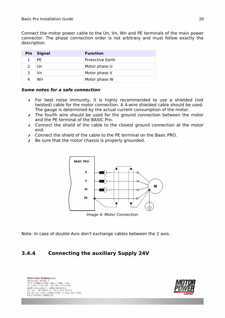
Connect the motor power cable to the Un, Vn, Wn and PE terminals of the main power connector. The phase connection order is not arbitrary and must follow exactly the description.
Pin Signal Function
1 PE Protective Earth
2 Un Motor phase U
3 Vn Motor phase V
4 Wn Motor phase W
Some notes for a safe connection:
✗ For best noise immunity, it is highly recommended to use a shielded (not twisted) cable for the motor connection. A 4-wire shielded cable should be used. The gauge is determined by the actual current consumption of the motor.
✗ The fourth wire should be used for the ground connection between the motor and the PE terminal of the BASIC Pro.
✗ Connect the shield of the cable to the closest ground connection at the motor end.
✗ Connect the shield of the cable to the PE terminal on the Basic PRO. ✗ Be sure that the motor chassis is properly grounded.
Note: In case of double Axis don't exchange cables between the 2 axis.
3.4.4 Connecting the auxiliary Supply 24V
20
Image 4: Motor Connection
BASIC PRO
U
V
W
PE
Basic Pro Installation Guide
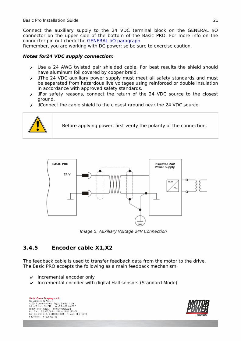
Connect the auxiliary supply to the 24 VDC terminal block on the GENERAL I/O connector on the upper side of the bottom of the Basic PRO. For more info on the connector pin out check the GENERAL I/O paragraph.Remember, you are working with DC power; so be sure to exercise caution.
Notes for24 VDC supply connection:
✗ Use a 24 AWG twisted pair shielded cable. For best results the shield should have aluminum foil covered by copper braid.
✗ The 24 VDC auxiliary power supply must meet all safety standards and must� be separated from hazardous live voltages using reinforced or double insulation in accordance with approved safety standards.
✗ For safety reasons, connect the return of the 24 VDC source to the closest� ground.
✗ Connect the cable shield to the closest ground near the 24 VDC source. �
Before applying power, first verify the polarity of the connection.
3.4.5 Encoder cable X1,X2
The feedback cable is used to transfer feedback data from the motor to the drive.The Basic PRO accepts the following as a main feedback mechanism:
✔ Incremental encoder only✔ Incremental encoder with digital Hall sensors (Standard Mode)
21
Image 5: Auxiliary Voltage 24V Connection
BASIC PRO
24 V
Insulated 24VPower Supply

Basic Pro Installation Guide
✔ Digital Hall sensors only�
X1/2 connector is located on the front of the Basic PRO and has a 15-pin D-sub socket. Connect the Feedback cable from the motor to X1/2 using a 15-pin, D-Sub plug with a metal housing. When assembling the Feedback cable, follow the instructions listed below.
Pin Signal Function
1 A Encoder A Channel
2 B Encoder B Channel
3 Z Encoder Z Channel
4 - -
5 /A Encoder /A Channel
6 /B Encoder /B Channel
7 +5V Encoder Power Supply
8 HALL W Hall Signal W
9 HALL U Hall Signal U
10 - -
11 0 V Encoder Power Supply Return
12 SHIELD SHIELD
13 /Z Encoder /Z Channel
14 HALL V Hall Signal V
15 - -
Feedback Cable Instruction:✗ The Basic PR features easy-to-use D-sub type connections for all Feedback
cables. Below are instructions and diagrams describing how to assemble those cables.
✗ Use 24, 26 or 28 AWG twisted-pair shielded cables (24 AWG cable is recommended) with max length of 20 meter (for longer distance contact the manufacturer).
✗ For best results, the shield should have aluminum foil covered by copper braid.✗ Use only a D-sub connector with a metal housing.✗ Attach the braid shield tightly to the metal housing of the D-type connector.✗ On the motor side connections, ground the shield to the motor chassis.✗ On controller side connections, follow the controller manufacturer’s
recommendations concerning the shield.
22
Basic Pro Installation Guide
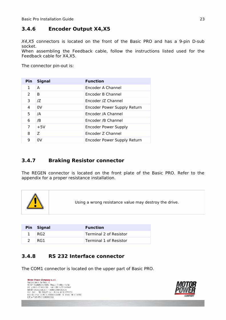
3.4.6 Encoder Output X4,X5
X4,X5 connectors is located on the front of the Basic PRO and has a 9-pin D-sub socket. When assembling the Feedback cable, follow the instructions listed used for the Feedback cable for X4,X5.
The connector pin-out is:
Pin Signal Function
1 A Encoder A Channel
2 B Encoder B Channel
3 /Z Encoder /Z Channel
4 0V Encoder Power Supply Return
5 /A Encoder /A Channel
6 /B Encoder /B Channel
7 +5V Encoder Power Supply
8 Z Encoder Z Channel
9 0V Encoder Power Supply Return
3.4.7 Braking Resistor connector
The REGEN connector is located on the front plate of the Basic PRO. Refer to the appendix for a proper resistance installation.
Using a wrong resistance value may destroy the drive.
Pin Signal Function
1 RG2 Terminal 2 of Resistor
2 RG1 Terminal 1 of Resistor
3.4.8 RS 232 Interface connector
The COM1 connector is located on the upper part of Basic PRO.
23
Basic Pro Installation Guide
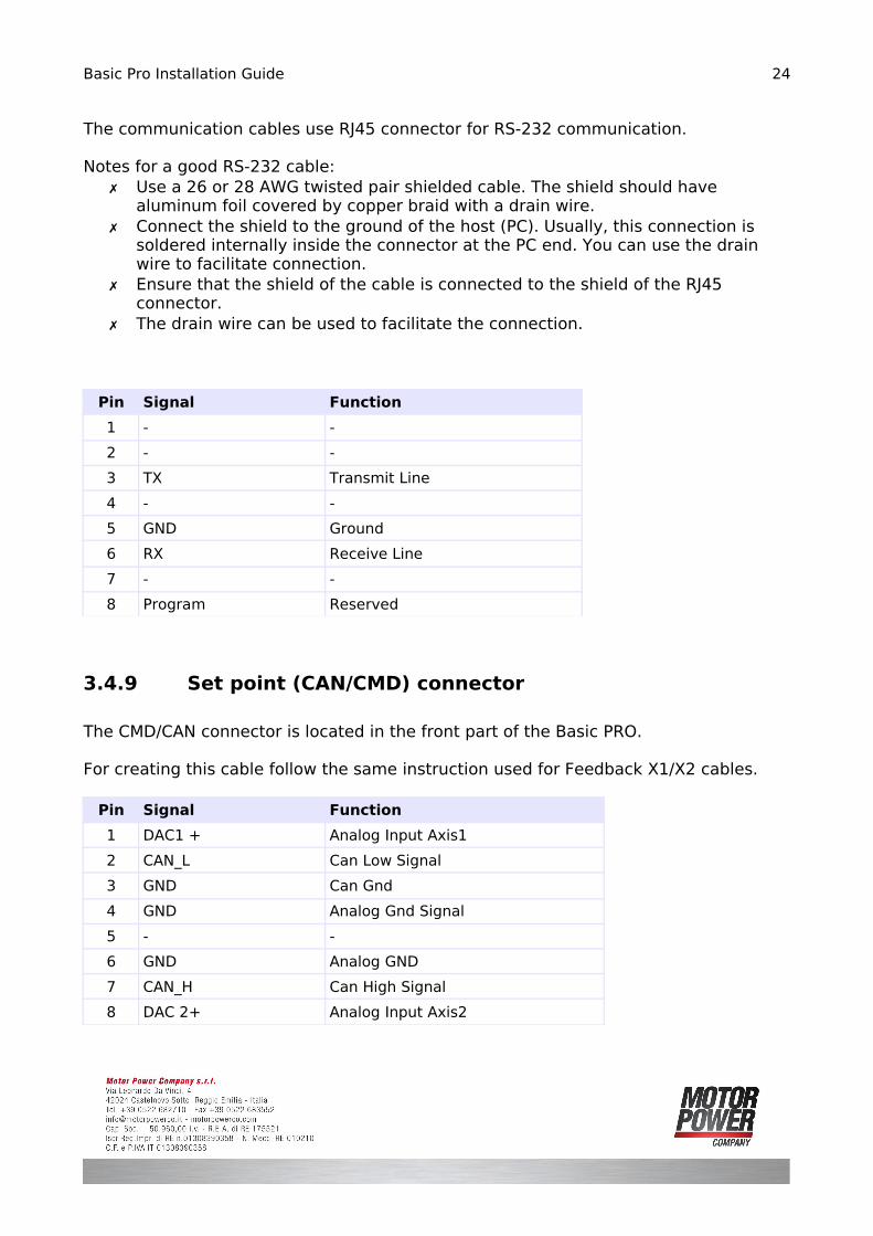
The communication cables use RJ45 connector for RS-232 communication.
Notes for a good RS-232 cable:✗ Use a 26 or 28 AWG twisted pair shielded cable. The shield should have
aluminum foil covered by copper braid with a drain wire. ✗ Connect the shield to the ground of the host (PC). Usually, this connection is
soldered internally inside the connector at the PC end. You can use the drain wire to facilitate connection.
✗ Ensure that the shield of the cable is connected to the shield of the RJ45 connector.
✗ The drain wire can be used to facilitate the connection.
Pin Signal Function
1 - -
2 - -
3 TX Transmit Line
4 - -
5 GND Ground
6 RX Receive Line
7 - -
8 Program Reserved
3.4.9 Set point (CAN/CMD) connector
The CMD/CAN connector is located in the front part of the Basic PRO.
For creating this cable follow the same instruction used for Feedback X1/X2 cables.
Pin Signal Function
1 DAC1 + Analog Input Axis1
2 CAN_L Can Low Signal
3 GND Can Gnd
4 GND Analog Gnd Signal
5 - -
6 GND Analog GND
7 CAN_H Can High Signal
8 DAC 2+ Analog Input Axis2
24
Basic Pro Installation Guide
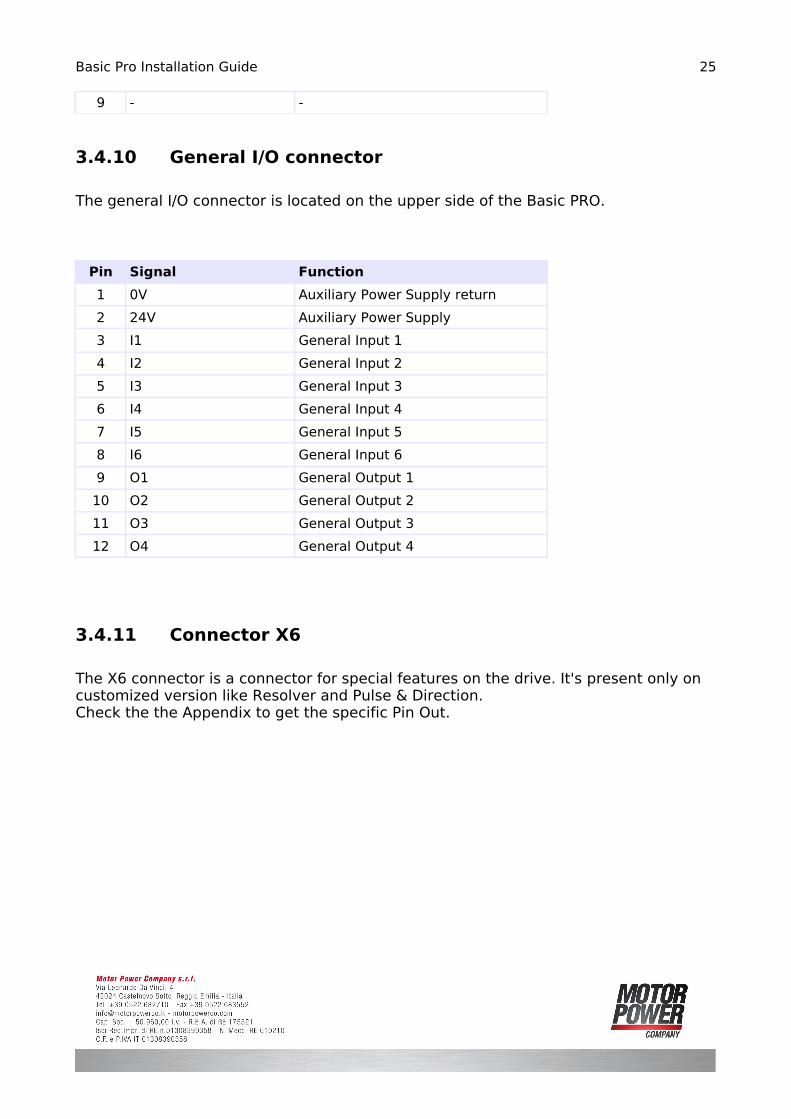
9 - -
3.4.10 General I/O connector
The general I/O connector is located on the upper side of the Basic PRO.
Pin Signal Function
1 0V Auxiliary Power Supply return
2 24V Auxiliary Power Supply
3 I1 General Input 1
4 I2 General Input 2
5 I3 General Input 3
6 I4 General Input 4
7 I5 General Input 5
8 I6 General Input 6
9 O1 General Output 1
10 O2 General Output 2
11 O3 General Output 3
12 O4 General Output 4
3.4.11 Connector X6
The X6 connector is a connector for special features on the drive. It's present only on customized version like Resolver and Pulse & Direction.Check the the Appendix to get the specific Pin Out.
25
Basic Pro Installation Guide
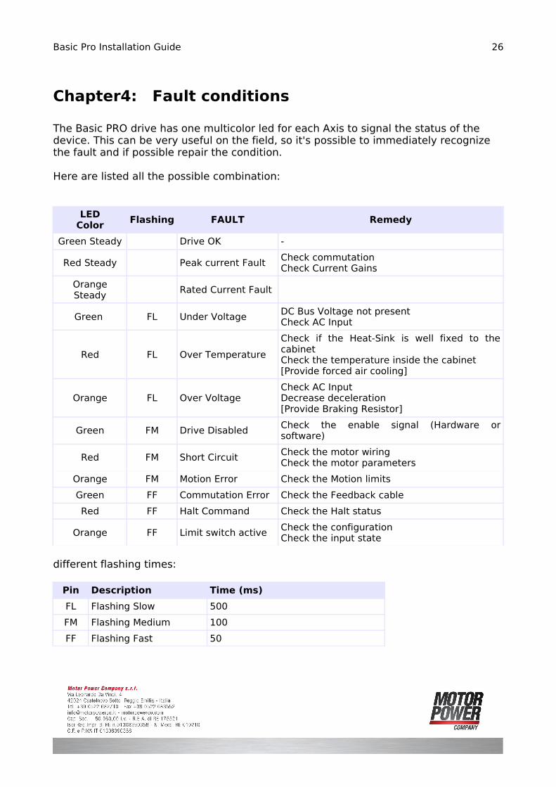
Chapter4: Fault conditions
The Basic PRO drive has one multicolor led for each Axis to signal the status of the device. This can be very useful on the field, so it's possible to immediately recognize the fault and if possible repair the condition.
Here are listed all the possible combination:
LEDColor
Flashing FAULT Remedy
Green Steady Drive OK -
Red Steady Peak current Fault Check commutation Check Current Gains
Orange Steady
Rated Current Fault
Green FL Under Voltage DC Bus Voltage not presentCheck AC Input
Red FL Over Temperature
Check if the Heat-Sink is well fixed to the cabinetCheck the temperature inside the cabinet[Provide forced air cooling]
Orange FL Over VoltageCheck AC InputDecrease deceleration[Provide Braking Resistor]
Green FM Drive Disabled Check the enable signal (Hardware or software)
Red FM Short Circuit Check the motor wiringCheck the motor parameters
Orange FM Motion Error Check the Motion limits
Green FF Commutation Error Check the Feedback cable
Red FF Halt Command Check the Halt status
Orange FF Limit switch active Check the configurationCheck the input state
different flashing times:
Pin Description Time (ms)
FL Flashing Slow 500
FM Flashing Medium 100
FF Flashing Fast 50
26

Basic Pro Installation Guide
Appendix A: Technical Specifications
A.1 Mechanical Dimensions
Feature Units 05-1X 05-2X
Size mm 129x262x52 127x262x52
Weight Kg 1,5 1,5
27
Image 6: Mechanical Dimensions
Basic Pro Installation Guide
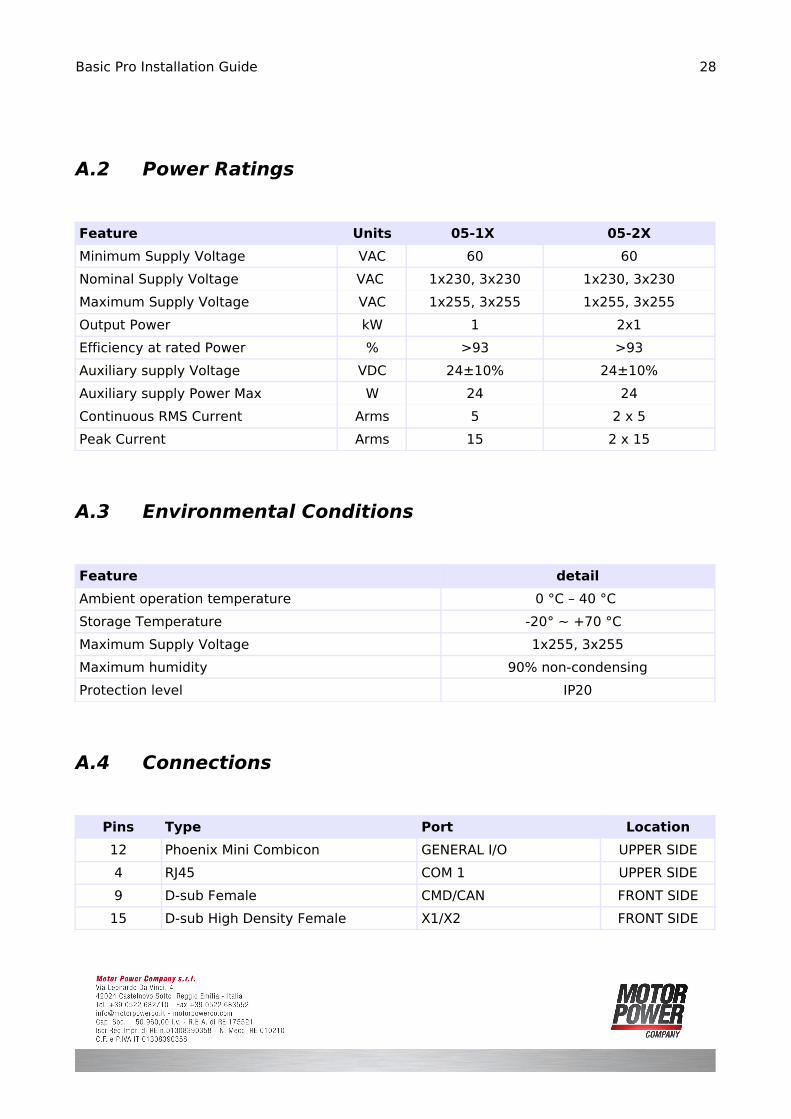
A.2 Power Ratings
Feature Units 05-1X 05-2X
Minimum Supply Voltage VAC 60 60
Nominal Supply Voltage VAC 1x230, 3x230 1x230, 3x230
Maximum Supply Voltage VAC 1x255, 3x255 1x255, 3x255
Output Power kW 1 2x1
Efficiency at rated Power % >93 >93
Auxiliary supply Voltage VDC 24±10% 24±10%
Auxiliary supply Power Max W 24 24
Continuous RMS Current Arms 5 2 x 5
Peak Current Arms 15 2 x 15
A.3 Environmental Conditions
Feature detail
Ambient operation temperature 0 °C – 40 °C
Storage Temperature -20° ~ +70 °C
Maximum Supply Voltage 1x255, 3x255
Maximum humidity 90% non-condensing
Protection level IP20
A.4 Connections
Pins Type Port Location
12 Phoenix Mini Combicon GENERAL I/O UPPER SIDE
4 RJ45 COM 1 UPPER SIDE
9 D-sub Female CMD/CAN FRONT SIDE
15 D-sub High Density Female X1/X2 FRONT SIDE
28
Basic Pro Installation Guide
9 D-sub Male # X4/X5 FRONT SIDE
9 D-sub Male X6 FRONT SIDE
4 Phoenix PC-4 MOTORn FRONT SIDE
2 Phoenix PC-4 REGEN FRONT SIDE
4 Phoenix PC-4 230VAC I/P FRONT SIDE
A.5 Feedback
Feature Units detail
Encoder Input A B Z Differential
Maximum Input Frequency MHz 2
Hall Inputs Differential 5V
Output Power Supply 5V, 200mA max
Protection level IP20
A.6 Analog Input
Feature Units detail
Type Single Ended
Common mode voltage range V ±10
ADC Resolution bit 12
A.7 Digital Inputs
Feature Units detail
Type Opto isolated DC input
Input Voltage (Active High) V 24
Input Current mA 10
# (If encoder option board is present the connector will be female)
29
Basic Pro Installation Guide
A.8 Digital Outputs
Feature Units detail
Type Opto isolated DC output
Output Voltage V 24
Output Current mA 100
A.9 Regeneration
Feature Units detail
Switching Threshold V On:372 Off:360
Maximum Current Arms 6
Recommended Resistance(#) 130 Ohm, 400 W(#) Using a smaller resistance can damage the device. The resistance may become very hot during hard braking cycles.
30
Basic Pro Installation Guide
Appendix B: Motor Configuration
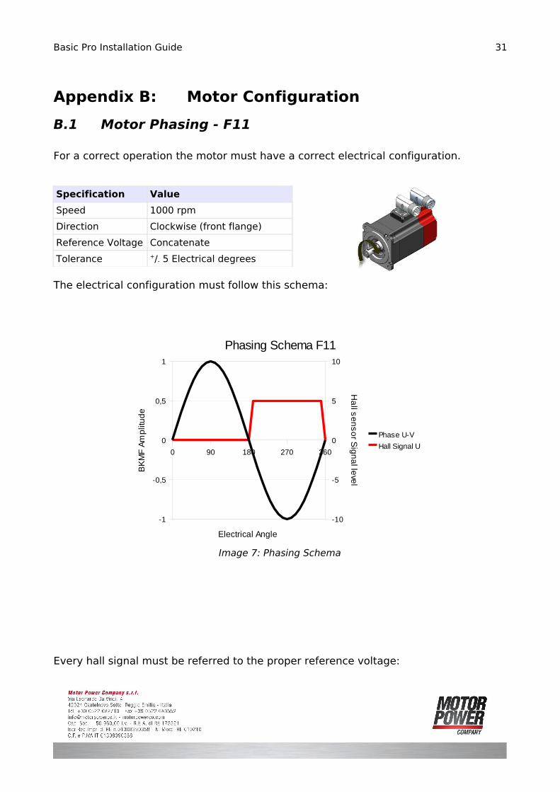
B.1 Motor Phasing - F11
For a correct operation the motor must have a correct electrical configuration.
Specification Value
Speed 1000 rpm
Direction Clockwise (front flange)
Reference Voltage Concatenate
Tolerance +/- 5 Electrical degrees
The electrical configuration must follow this schema:
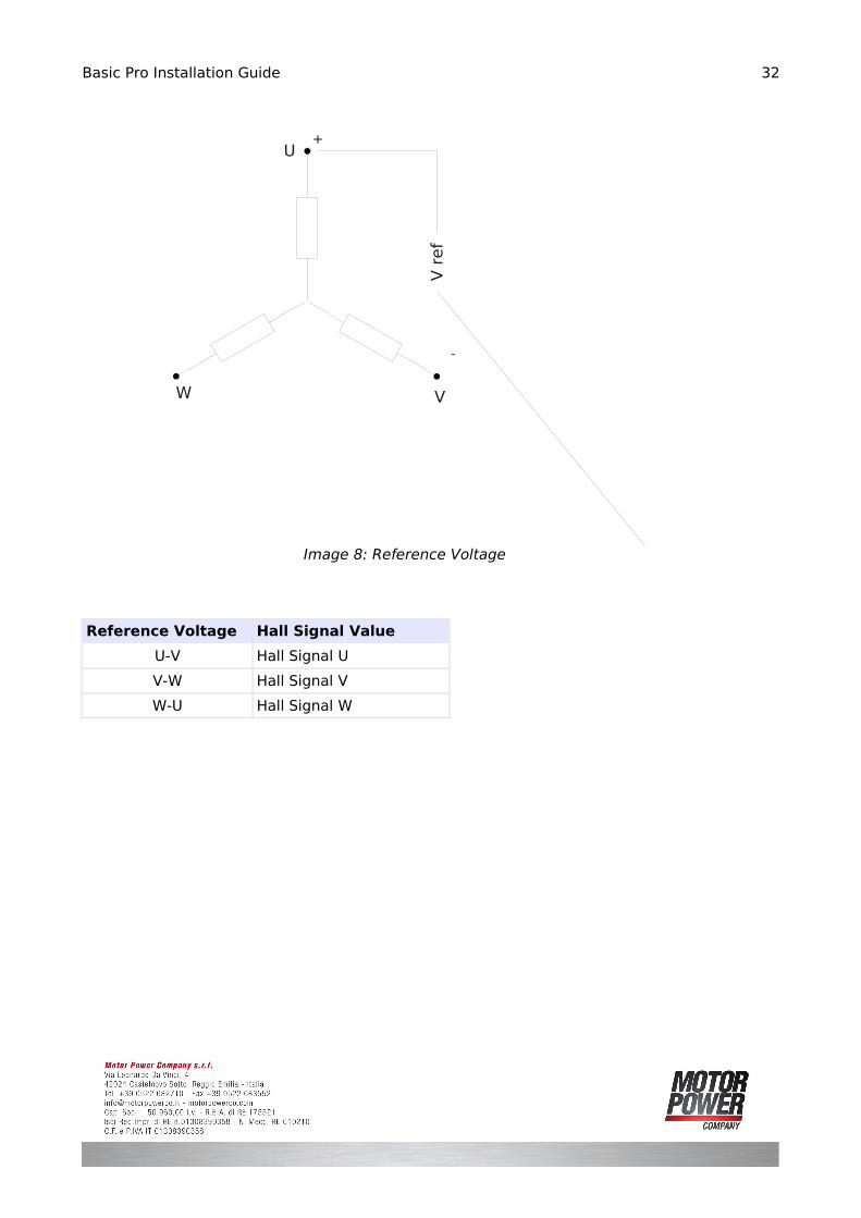
Every hall signal must be referred to the proper reference voltage:
31
Image 7: Phasing Schema
0 90 180 270 360
-1
-0,5
0
0,5
1
-10
-5
0
5
10
Phasing Schema F11
Phase U-V
Hall Signal U
Electrical Angle
BK
MF
Am
plit
ud
e
Ha
ll se
ns
or S
i gn
al le
vel
Basic Pro Installation Guide
Reference Voltage Hall Signal Value
U-V Hall Signal U
V-W Hall Signal V
W-U Hall Signal W
32
Image 8: Reference Voltage
U
VW
V r
ef
+
-
Basic Pro Installation Guide
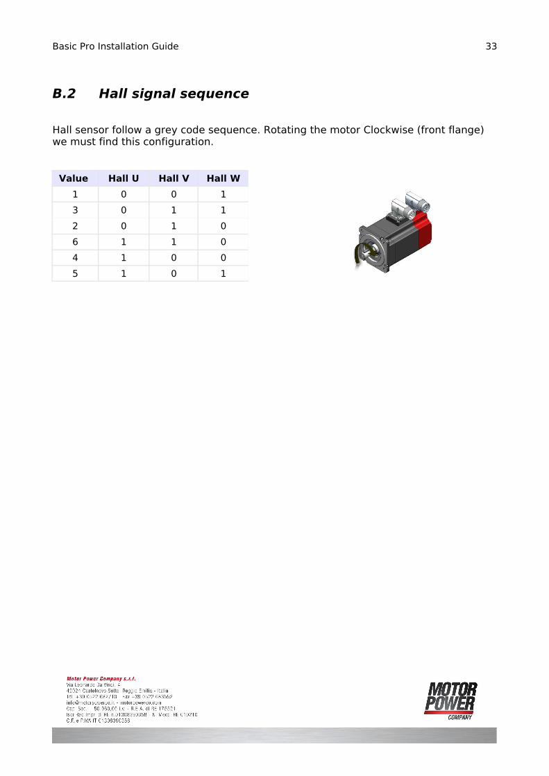
B.2 Hall signal sequence
Hall sensor follow a grey code sequence. Rotating the motor Clockwise (front flange) we must find this configuration.
Value Hall U Hall V Hall W
1 0 0 1
3 0 1 1
2 0 1 0
6 1 1 0
4 1 0 0
5 1 0 1
33
Basic Pro Installation Guide
Appendix C: Other Connectors
C.1 Resolver Feedback Input [X4/X5]
This option is available only on Resolver Drives. The connector X4/X5 are D-sub 9 pin Female.
Pin Signal Function
1 REF Resolver Reference Supply
2 /REF Resolver Reference Supply
3 COS Cosine Signal
4 /COS /Cosine Signal
5 SIN Sine Signal
6 /SIN /Sine Signal
7 - -
8 - -
9 - -
Resolved interface details
Feature Detail
Resolver Format Sine/Cosine - Differential
Input Resistance > 5 KOhm
Resolution Fixed 12bits
Carrier Frequency 20 KHz
Reference Voltage Supplied by BASIC PRO – 7 Veff
34
Basic Pro Installation Guide
C.2 SSI Output [X6]
This option is available only on Resolver Drives. The connector X6 is D-sub 9 pin Male.
This option is available only on the single axis model.
Pin Signal Function
1 DATA_OUT - Resolver Reference Supply
2 CLK_IN - Resolver Reference Supply
3 DATA_OUT + Cosine Signal
4 CLK_IN + /Cosine Signal
5 - -
6 - -
7 - -
8 - -
9 GND Ground
Signal Specifications
Feature Detail
Max Clk Input Frequency 500 KHz
Signals Data/Clk In accordance with RS-422. 5V Differential
Response time 5 ms
Number of Bits 24
35

Basic Pro Installation Guide
Data Values
Bit Function Description
1 Position Position Bit msb
2 Position Position Bit
3 Position Position Bit
4 Position Position Bit
5 Position Position Bit
6 Position Position Bit
7 Position Position Bit
8 Position Position Bit
9 Position Position Bit
10 Position Position Bit
11 Position Position Bit
12 Position Position Bit lsb
13 HOME Home Switch
14 NLS Negative Limit Switch
15 PLS Positive Limit Switch
16 Always 0 Reserved
17 Always 0 Reserved
18 Over Velocity Fault
19 Velocity Tracking Error Fault
20 Short Circuit Fault
21 Rated Motor Current Fault
22 Peak Motor Current Fault
23 Undervoltage Fault
24 Overvoltage Fault
36
Basic Pro Installation Guide
C.3 Pulse And Direction Input [X6]
This option is available only on Pulse and Direction Drive, if the drive is single axis only the AXIS1 pins will be used.
Pin Signal Function
1 DIR_AXIS2 Direction Axis2
2 DIR_AXIS1 Direction Axis1
3 /DIR_AXIS2 /Direction Axis2
4 /DIR_AXIS1 /Direction Axis1
5 PULSE_AXIS2 Pulse Axis2
6 PULSE_AXIS1 Pulse Axis1
7 /PULSE_AXIS2 /Pulse Axis2
8 /PULSE_AXIS1 /Pulse Axis1
9 - -
37
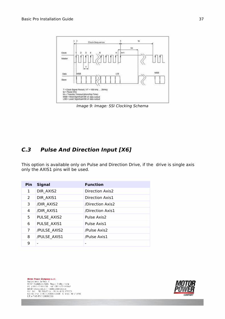
Image 9: Image: SSI Clocking Schema
Basic Pro Installation Guide
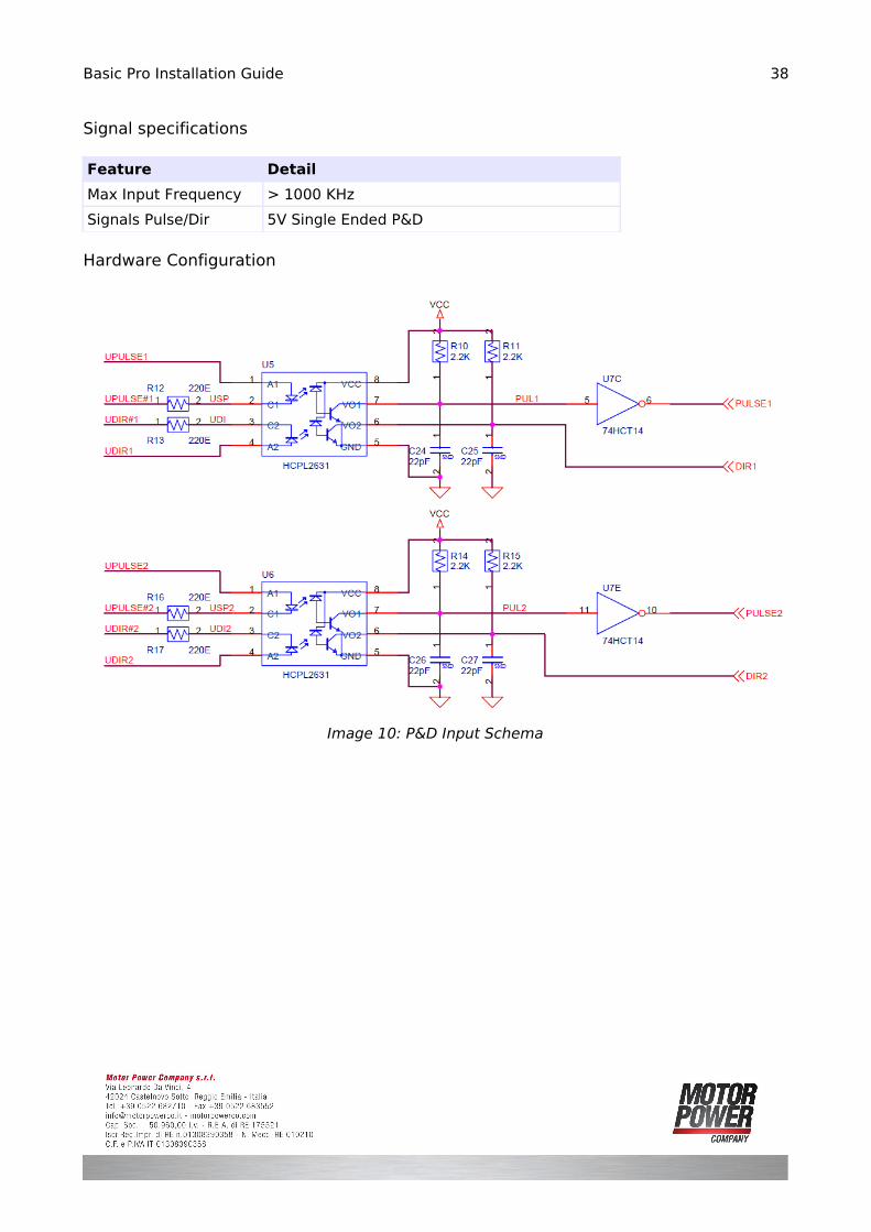
Signal specifications
Feature Detail
Max Input Frequency > 1000 KHz
Signals Pulse/Dir 5V Single Ended P&D
Hardware Configuration
38
Image 10: P&D Input Schema