Embed Size (px)
Citation preview
IM-P357-04 CH Issue 9 1
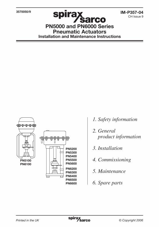
PN5000 and PN6000 SeriesPneumatic Actuators
Installation and Maintenance Instructions
1. Safety information
2. General product information
3. Installation
4. Commissioning
5. Maintenance
6. Spare parts
Printed in the UK © Copyright 2006
IM-P357-04CH Issue 9
3570050/9
PN5100PN6100
PN5200PN5300PN5400PN5500PN5600
PN6200PN6300PN6400PN6500PN6600

IM-P357-04 CH Issue 92
IM-P357-04 CH Issue 9 3
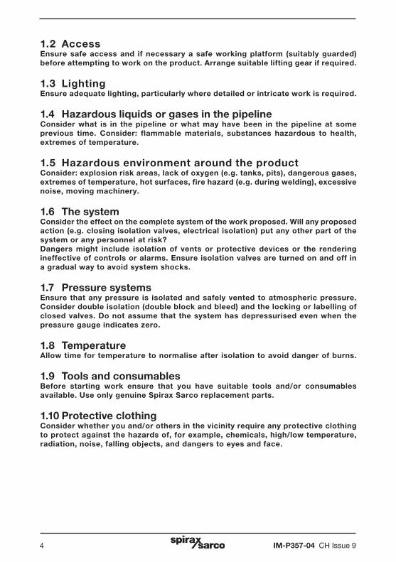
Safe operation of these products can only be guaranteed if they are properly installed, commissioned, used and maintained by qualified personnel (see Section 1.11) in compliance with the operating instructions. General installation and safety instructions for pipeline and plant construction, as well as the proper use of tools and safety equipment must also be complied with.
1.1 Intended useReferring to the Installation and Maintenance Instructions, name-plate and Technical Information Sheet, check that the product is suitable for the intended use/application. The products comply with the requirements of the European Pressure Equipment Directive 97/23/EC and fall within the category 'SEP'. It should be noted that products within this category are required by the Directive not to carry the mark.
i) These products have been specifically designed for use on compressed air, which is in Group 2 of the above mentioned Pressure Equipment Directive. The products’ use on other fluids may be possible but, if this is contemplated, Spirax Sarco should be contacted to confirm the suitability of the product for the application being considered.
ii) Check material suitability, pressure and temperature and their maximum and minimum values. If the maximum operating limits of the product are lower than those of the system in which it is being fitted, or if malfunction of the product could result in a dangerous overpressure or overtemperature occurrence, ensure a safety device is included in the system to prevent such over-limit situations.
iii) Determine the correct installation situation and direction of fluid flow.
iv) Spirax Sarco products are not intended to withstand external stresses that may be induced by any system to which they are fitted. It is the responsibility of the installer to consider these stresses and take adequate precautions to minimise them.
v) Remove protection covers from all connections before installation.
1. Safety information
IM-P357-04 CH Issue 94
1.2 AccessEnsure safe access and if necessary a safe working platform (suitably guarded) before attempting to work on the product. Arrange suitable lifting gear if required.
1.3 LightingEnsure adequate lighting, particularly where detailed or intricate work is required.
1.4 Hazardous liquids or gases in the pipelineConsider what is in the pipeline or what may have been in the pipeline at some previous time. Consider: flammable materials, substances hazardous to health, extremes of temperature.
1.5 Hazardous environment around the productConsider: explosion risk areas, lack of oxygen (e.g. tanks, pits), dangerous gases, extremes of temperature, hot surfaces, fire hazard (e.g. during welding), excessive noise, moving machinery.
1.6 The systemConsider the effect on the complete system of the work proposed. Will any proposed action (e.g. closing isolation valves, electrical isolation) put any other part of the system or any personnel at risk? Dangers might include isolation of vents or protective devices or the rendering ineffective of controls or alarms. Ensure isolation valves are turned on and off in a gradual way to avoid system shocks.
1.7 Pressure systems Ensure that any pressure is isolated and safely vented to atmospheric pressure. Consider double isolation (double block and bleed) and the locking or labelling of closed valves. Do not assume that the system has depressurised even when the pressure gauge indicates zero.
1.8 TemperatureAllow time for temperature to normalise after isolation to avoid danger of burns.
1.9 Tools and consumablesBefore starting work ensure that you have suitable tools and/or consumables available. Use only genuine Spirax Sarco replacement parts.
1.10 Protective clothingConsider whether you and/or others in the vicinity require any protective clothing to protect against the hazards of, for example, chemicals, high/low temperature, radiation, noise, falling objects, and dangers to eyes and face.
IM-P357-04 CH Issue 9 5
1.11 Permits to workAll work must be carried out or be supervised by a suitably competent person.Installation and operating personnel should be trained in the correct use of the product according to the Installation and Maintenance Instructions.Where a formal 'permit to work' system is in force it must be complied with. Where there is no such system, it is recommended that a responsible person should know what work is going on and, where necessary, arrange to have an assistant whose primary responsibility is safety.Post 'warning notices' if necessary.
1.12 HandlingManual handling of large and/or heavy products may present a risk of injury. Lifting, pushing, pulling, carrying or supporting a load by bodily force can cause injury particularly to the back. You are advised to assess the risks taking into account the task, the individual, the load and the working environment and use the appropriate handling method depending on the circumstances of the work being done.
1.13 Residual hazardsIn normal use the external surface of the product may be very hot. If used at the maximum permitted operating conditions the surface temperature of some products may reach temperatures of 90°C (194°F).Many products are not self-draining. Take due care when dismantling or removing the product from an installation (refer to 'Maintenance instructions').
1.14 FreezingProvision must be made to protect products which are not self-draining against frost damage in environments where they may be exposed to temperatures below freezing point.
1.15 DisposalUnless otherwise stated in the Installation and Maintenance Instructions, this product is recyclable and no ecological hazard is anticipated with its disposal providing due care is taken.
1.16 Returning productsCustomers and stockists are reminded that under EC Health, Safety and Environment Law, when returning products to Spirax Sarco they must provide information on any hazards and the precautions to be taken due to contamination residues or mechanical damage which may present a health, safety or environmental risk. This information must be provided in writing including Health and Safety data sheets relating to any substances identified as hazardous or potentially hazardous.
IM-P357-04 CH Issue 96
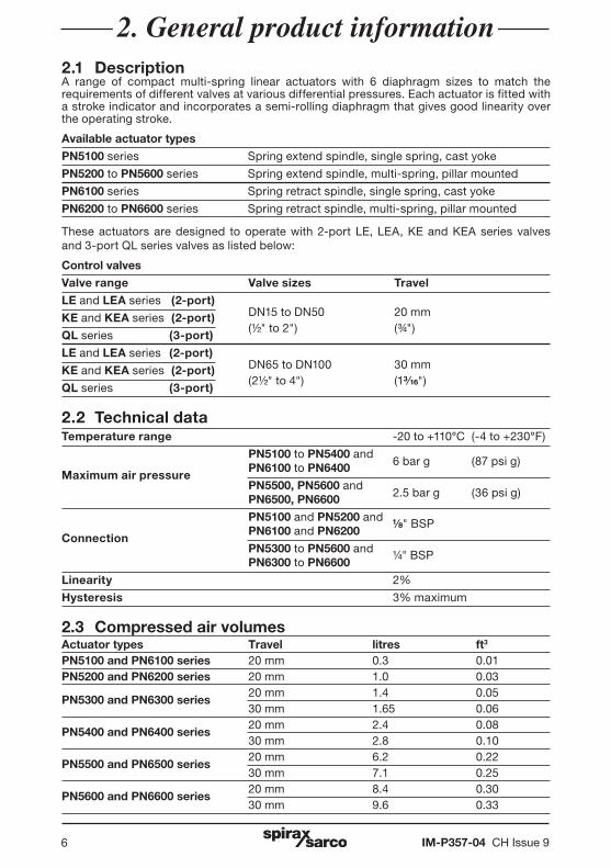
2. General product information2.1 DescriptionA range of compact multi-spring linear actuators with 6 diaphragm sizes to match the requirements of different valves at various differential pressures. Each actuator is fitted with a stroke indicator and incorporates a semi-rolling diaphragm that gives good linearity over the operating stroke.
Available actuator types
PN5100 series Spring extend spindle, single spring, cast yoke
PN5200 to PN5600 series Spring extend spindle, multi-spring, pillar mounted
PN6100 series Spring retract spindle, single spring, cast yoke
PN6200 to PN6600 series Spring retract spindle, multi-spring, pillar mounted
These actuators are designed to operate with 2-port LE, LEA, KE and KEA series valves and 3-port QL series valves as listed below:
Control valves
Valve range Valve sizes Travel
LE and LEA series (2-port)
KE and KEA series (2-port) DN15 to DN50 20 mm
QL series (3-port) (½" to 2") (¾")
LE and LEA series (2-port)
KE and KEA series (2-port) DN65 to DN100 30 mm
QL series (3-port) (2½" to 4") (1 ")
2.2 Technical dataTemperature range -20 to +110°C (-4 to +230°F)
PN5100 to PN5400 and 6 bar g (87 psi g)
Maximum air pressure PN6100 to PN6400
PN5500, PN5600 and 2.5 bar g (36 psi g) PN6500, PN6600
PN5100 and PN5200 and
Connection PN6100 and PN6200
" BSP
PN5300 to PN5600 and PN6300 to PN6600
¼" BSP
Linearity 2%
Hysteresis 3% maximum
2.3 Compressed air volumesActuator types Travel litres ft3
PN5100 and PN6100 series 20 mm 0.3 0.01PN5200 and PN6200 series 20 mm 1.0 0.03
PN5300 and PN6300 series 20 mm 1.4 0.05
30 mm 1.65 0.06
PN5400 and PN6400 series 20 mm 2.4 0.08
30 mm 2.8 0.10
PN5500 and PN6500 series 20 mm 6.2 0.22
30 mm 7.1 0.25
PN5600 and PN6600 series 20 mm 8.4 0.30
30 mm 9.6 0.33
IM-P357-04 CH Issue 9 7
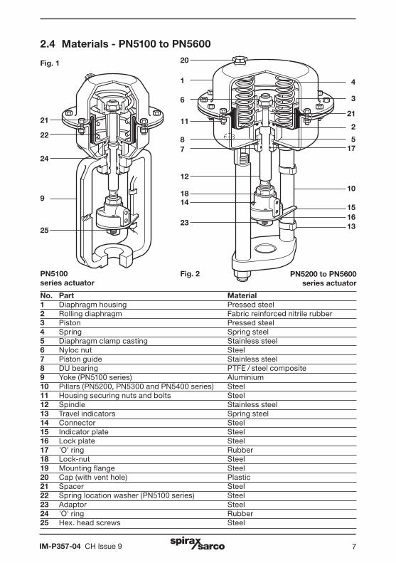
No. Part Material 1 Diaphragm housing Pressed steel 2 Rolling diaphragm Fabric reinforced nitrile rubber 3 Piston Pressed steel 4 Spring Spring steel 5 Diaphragm clamp casting Stainless steel 6 Nyloc nut Steel 7 Piston guide Stainless steel 8 DU bearing PTFE / steel composite 9 Yoke (PN5100 series) Aluminium 10 Pillars (PN5200, PN5300 and PN5400 series) Steel 11 Housing securing nuts and bolts Steel 12 Spindle Stainless steel 13 Travel indicators Spring steel 14 Connector Steel 15 Indicator plate Steel 16 Lock plate Steel 17 'O' ring Rubber 18 Lock-nut Steel 19 Mounting flange Steel 20 Cap (with vent hole) Plastic 21 Spacer Steel 22 Spring location washer (PN5100 series) Steel 23 Adaptor Steel 24 'O' ring Rubber25 Hex. head screws Steel
PN5100series actuator
Fig. 1
PN5200 to PN5600series actuator
23
1418
12
78
1
6
11
10
15
1316
4
3
21
2
517
9
24
22
21
2.4 Materials - PN5100 to PN5600
25
Fig. 2
20

IM-P357-04 CH Issue 98
Fig. 3
PN6200 to PN6600 series actuator
PN6100series actuator
22
245
2
11
4817
10
12
15
1316
23
1418
17
20
6
21
9
No. Part Material 1 Diaphragm housing Pressed steel 2 Rolling diaphragm Fabric reinforced nitrile rubber 3 Piston Pressed steel 4 Spring Spring steel 5 Diaphragm clamp casting Stainless steel 6 Nyloc nut Steel 7 Piston guide Stainless steel 8 DU bearing PTFE / steel composite 9 Yoke (PN6100 series) Aluminium 10 Pillars (PN6200, PN6300 and PN6400 series) Steel 11 Housing securing nuts and bolts Steel 12 Spindle Stainless steel 13 Travel indicators Spring steel 14 Connector Steel 15 Indicator plate Steel 16 Lock plate Steel 17 'O' ring Rubber 18 Lock-nut Steel 19 Mounting flange Steel 20 Cap (with vent hole) Plastic 21 Spacer Steel 22 Spring location washer (PN6100 series) Steel 23 Adaptor Steel 24 'O' ring Rubber25 Hex. head screws Steel
2.5 Materials - PN6100 to PN6600
25
Fig. 4
3
IM-P357-04 CH Issue 9 9
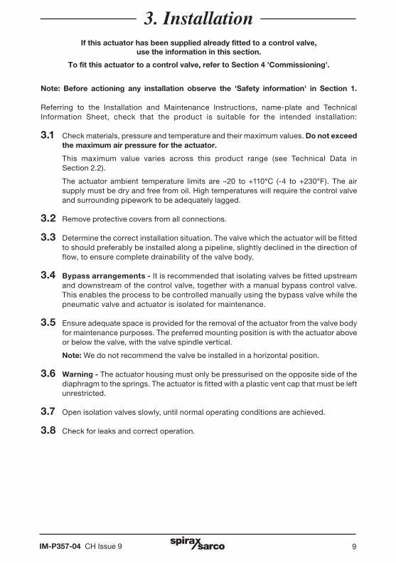
3. InstallationIf this actuator has been supplied already fitted to a control valve,
use the information in this section.
To fit this actuator to a control valve, refer to Section 4 'Commissioning'.
Note: Before actioning any installation observe the 'Safety information' in Section 1.
Referring to the Installation and Maintenance Instructions, name-plate and Technical Information Sheet, check that the product is suitable for the intended installation:
3.1 Check materials, pressure and temperature and their maximum values. Do not exceed the maximum air pressure for the actuator.
This maximum value varies across this product range (see Technical Data in Section 2.2).
The actuator ambient temperature limits are –20 to +110°C (-4 to +230°F). The air supply must be dry and free from oil. High temperatures will require the control valve and surrounding pipework to be adequately lagged.
3.2 Remove protective covers from all connections.
3.3 Determine the correct installation situation. The valve which the actuator will be fitted to should preferably be installed along a pipeline, slightly declined in the direction of flow, to ensure complete drainability of the valve body.
3.4 Bypass arrangements - It is recommended that isolating valves be fitted upstream and downstream of the control valve, together with a manual bypass control valve. This enables the process to be controlled manually using the bypass valve while the pneumatic valve and actuator is isolated for maintenance.
3.5 Ensure adequate space is provided for the removal of the actuator from the valve body for maintenance purposes. The preferred mounting position is with the actuator above or below the valve, with the valve spindle vertical.
Note: We do not recommend the valve be installed in a horizontal position.
3.6 Warning - The actuator housing must only be pressurised on the opposite side of the diaphragm to the springs. The actuator is fitted with a plastic vent cap that must be left unrestricted.
3.7 Open isolation valves slowly, until normal operating conditions are achieved.
3.8 Check for leaks and correct operation.
IM-P357-04 CH Issue 910
Actuator typeNo.of
springs
Free length (mm)
Inside diameter
(mm)
Colour stripe
Spring range Travel
Weight approximate
kg
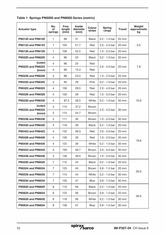
PN5120 and PN6120 1 89 51 Black 0.2 - 1.0 bar 20 mm
3.5PN5123 and PN6123 1 104 51.7 Red 2.0 - 4.0 bar 20 mm
PN5126 and PN6126 1 106 52.5 Red 1.0 - 2.0 bar 20 mm
PN5220 and PN6220 4 80 23 Black 0.2 - 1.0 bar 20 mm
7.8PN5223 and PN62234 96 25 Red
2.0 - 4.0 bar 20 mm4 96 15.4 Red
PN5226 and PN6226 4 88 23.5 Red 1.0 - 2.0 bar 20 mm
PN5320 and PN6320 4 85 29 Pink 0.2 - 1.0 bar 20 mm
10.9
PN5323 and PN6323 4 100 29.5 Red 2.0 - 4.0 bar 20 mm
PN5326 and PN6326 4 100 28 Red 1.0 - 2.0 bar 20 mm
PN5330 and PN6330 4 87.5 28.5 White 0.2 - 1.0 bar 30 mm
PN5333 and PN63334 115 37.2 Brown
2.0 - 4.0 bar 30 mm4 115 24.7 Brown
PN5336 and PN6336 4 111 30 Brown 1.0 - 2.0 bar 30 mm
PN5420 and PN6420 4 116 39 Black 0.2 - 1.0 bar 20 mm
18.8
PN5423 and PN6423 4 132 38.3 Red 2.0 - 4.0 bar 20 mm
PN5426 and PN6426 4 130 39 Red 1.0 - 2.0 bar 20 mm
PN5430 and PN6430 4 122 39 White 0.2 - 1.0 bar 30 mm
PN5433 and PN6433 4 150 49.7 Brown 2.0 - 4.0 bar 30 mm
PN5436 and PN6436 4 146 39.5 Brown 1.0 - 2.0 bar 30 mm
PN5520 and PN6520 7 112 44 Black 0.2 - 1.0 bar 20 mm
26.0PN5524 and PN6524 7 125 45 Brown 0.8 - 1.5 bar 20 mm
PN5530 and PN6530 7 115 44 White 0.2 - 1.0 bar 30 mm
PN5534 and PN6534 7 135 47 Blue 0.8 - 1.5 bar 30 mm
PN5620 and PN6620 8 110 56 Black 0.2 - 1.0 bar 20 mm
36.0PN5624 and PN6624 8 123 56 Brown 0.8 - 1.5 bar 20 mm
PN5630 and PN6630 8 116 56 White 0.2 - 1.0 bar 30 mm
PN5634 and PN6634 8 136 57 Blue 0.8 - 1.5 bar 30 mm
Table 1 Springs PN5000 and PN6000 Series (metric)
(outer)
(inner)
(outer)
(inner)
IM-P357-04 CH Issue 9 11
Actuator typeNo.of
springs
Free length (mm)
Inside diameter
(mm)
Colour stripe
Spring range Travel
Weight approximate
lbs
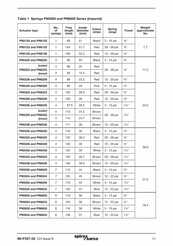
PN5120 and PN6120 1 89 51 Black 3 - 15 psi ¾"
7.7PN5123 and PN6123 1 104 51.7 Red 29 - 58 psi ¾"
PN5126 and PN6126 1 106 52.5 Red 15 - 29 psi ¾"
PN5220 and PN6220 4 80 23 Black 3 - 15 psi ¾"
17.2PN5223 and PN62234 96 25 Red
29 - 58 psi ¾"4 96 15.4 Red
PN5226 and PN6226 4 88 23.5 Red 15 - 29 psi ¾"
PN5320 and PN6320 4 85 29 Pink 3 - 15 psi ¾"
24.0
PN5323 and PN6323 4 100 29.5 Red 29 - 58 psi ¾"
PN5326 and PN6326 4 100 28 Red 15 - 29 psi ¾"
PN5330 and PN6330 4 87.5 28.5 White 3 - 15 psi 1¼"
PN5333 and PN63334 115 37.2 Brown
29 - 58 psi 1¼"4 115 24.7 Brown
PN5336 and PN6336 4 111 30 Brown 15 - 29 psi 1¼"
PN5420 and PN6420 4 116 39 Black 3 - 15 psi ¾"
39.9
PN5423 and PN6423 4 132 38.3 Red 29 - 58 psi ¾"
PN5426 and PN6426 4 130 39 Red 15 - 29 psi ¾"
PN5430 and PN6430 4 122 39 White 3 - 15 psi 1¼"
PN5433 and PN6433 4 150 49.7 Brown 29 - 58 psi 1¼"
PN5436 and PN6436 4 146 39.5 Brown 15 - 29 psi 1¼"
PN5520 and PN6520 7 112 44 Black 3 - 15 psi ¾"
57.3PN5524 and PN6524 7 125 45 Brown 12 - 22 psi ¾"
PN5530 and PN6530 7 115 44 White 3 - 15 psi 1¼"
PN5534 and PN6534 7 135 47 Blue 12 - 22 psi 1¼"
PN5620 and PN6620 8 110 56 Black 3 - 15 psi ¾"
79.4PN5624 and PN6624 8 123 56 Brown 12 - 22 psi ¾"
PN5630 and PN6630 8 116 56 White 3 - 15 psi 1¼"
PN5634 and PN6634 8 136 57 Blue 12 - 22 psi 1¼"
Table 1 Springs PN5000 and PN6000 Series (imperial)
(outer)
(inner)
(outer)
(inner)
IM-P357-04 CH Issue 912
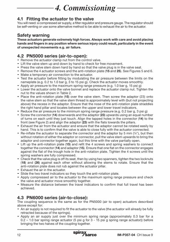
4. Commissioning4.1 Fitting the actuator to the valveYou will need: a compressed air supply, a filter regulator and pressure gauge. The regulator should be self-venting or use some alternative method to be able to exhaust the air to the actuator.
Safety warningThese actuators generate extremely high forces. Always work with care and avoid placing hands and fingers in any position where serious injury could result, particularly in the event of unexpected movements e.g. air failure.
4.2 PN5000 series (air-to-open):- Remove the actuator clamp nut from the control valve.- Lift the valve stem up and down by hand to check for free movement.- Press the valve stem down hard by hand so that the valve plug is in the valve seat.- Remove the 4 actuator screws and the anti-rotation plate (15 and 25). See Figures 5 and 6.- Make a temporary air connection to the actuator.- Test the actuator before fitting by modulating the air pressure between the limits on the
nameplate (e.g. 0.2 to 1.0 bar g, 3 to 15 psi g). Check the actuator moves smoothly.- Apply air pressure to the maximum spring range pressure (e.g. 1.0 bar g, 15 psi g)- Lower the actuator onto the valve bonnet and replace the actuator clamp nut. Tighten the
nut to the values shown in Table 2.- Place the anti-rotation plate (15) over the valve stem. Then screw the adaptor (23) onto
the valve stem so that the valve stem thread is approximately level with (but not projecting above) the recess in the adaptor. Ensure that the nose of the anti-rotation plate straddles the right hand pillar and locates between the upper and lower travel indicators.
- Reduce the air pressure to the minimum spring range pressure (e.g. 0.2 bar g, 3 psi g)- Screw the connector (14) downwards and the adaptor (23) upwards using an equal number
of turns on each until they just touch. Align the tapped holes in the connector (14) to the front (see Figure 2) and align the adaptor (23) with the flats towards the pillars.
- Exhaust the air from the actuator and ensure that the adaptor cannot be rotated easily by hand. This is to confirm that the valve is able to close fully with the actuator connected.
- Re-inflate the actuator to separate the connector and the adaptor by 5 mm (¼"), but then without rotation of either the adaptor or connector, pull the valve stem upwards to bring the adaptor and connector together again, but this time with the valve partially open.
- Lift up the anti-rotation plate (15) and refit the 4 screws and spring washers to connect together the connector (14) and adaptor (15). Ensure that one flat on the connector engages against the flat of the trough hole in the anti-rotation plate. Tighten the 4 screws until the spring washers are fully compressed.
- Check that the valve plug is off its seat, then by using two spanners, tighten the two locknuts (18) and (26) against each other without allowing the stems to rotate. Ensure that the
anti-rotation plate does not rub against the actuator pillar.- Exhaust the air in the actuator.- Slide the two travel indicators so they touch the anti-rotation plate.- Apply compressed air to the actuator to the maximum spring range pressure and check
the valve and actuator move smoothly together.- Measure the distance between the travel indicators to confirm that full travel has been
achieved.
4.3 PN6000 series (air-to-close):The coupling sequence is the same as for the PN5000 (air to open) actuators described above except for:- An air supply is not required to fit the actuator to the valve (the actuator will already be fully
retracted because of the springs).- Apply an air supply just over the minimum spring range (approximately 0.3 bar for a 0.2 – 1.0 bar spring range actuator (5 psi g for 3 - 15 psi g spring range actuator)) before
bringing the two halves of the coupling together.
IM-P357-04 CH Issue 9 13
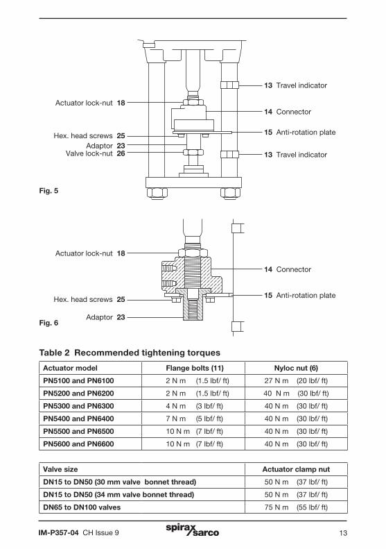
Actuator model Flange bolts (11) Nyloc nut (6)
PN5100 and PN6100 2 N m (1.5 lbf/ ft) 27 N m (20 lbf/ ft)
PN5200 and PN6200 2 N m (1.5 lbf/ ft) 40 N m (30 lbf/ ft)
PN5300 and PN6300 4 N m (3 lbf/ ft) 40 N m (30 lbf/ ft)
PN5400 and PN6400 7 N m (5 lbf/ ft) 40 N m (30 lbf/ ft)
PN5500 and PN6500 10 N m (7 lbf/ ft) 40 N m (30 lbf/ ft)
PN5600 and PN6600 10 N m (7 lbf/ ft) 40 N m (30 lbf/ ft)
Valve size Actuator clamp nut
DN15 to DN50 (30 mm valve bonnet thread) 50 N m (37 lbf/ ft)
DN15 to DN50 (34 mm valve bonnet thread) 50 N m (37 lbf/ ft)
DN65 to DN100 valves 75 N m (55 lbf/ ft)
Table 2 Recommended tightening torques
Hex. head screws 25
13 Travel indicator
Valve lock-nut 26Adaptor 23
Actuator lock-nut 1814 Connector
15 Anti-rotation plate
13 Travel indicator
Actuator lock-nut 18
Adaptor 23
14 Connector
15 Anti-rotation plateHex. head screws 25
Fig. 5
Fig. 6
IM-P357-04 CH Issue 914
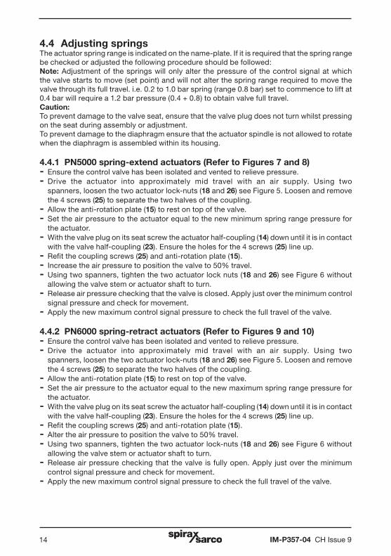
4.4 Adjusting springsThe actuator spring range is indicated on the name-plate. If it is required that the spring range be checked or adjusted the following procedure should be followed:Note: Adjustment of the springs will only alter the pressure of the control signal at which the valve starts to move (set point) and will not alter the spring range required to move the valve through its full travel. i.e. 0.2 to 1.0 bar spring (range 0.8 bar) set to commence to lift at 0.4 bar will require a 1.2 bar pressure (0.4 + 0.8) to obtain valve full travel.Caution: To prevent damage to the valve seat, ensure that the valve plug does not turn whilst pressing on the seat during assembly or adjustment.To prevent damage to the diaphragm ensure that the actuator spindle is not allowed to rotate when the diaphragm is assembled within its housing.
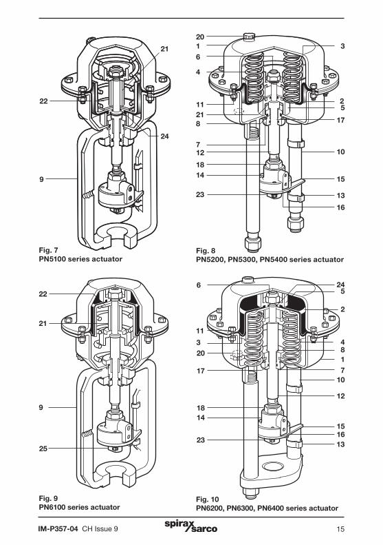
4.4.1 PN5000 spring-extend actuators (Refer to Figures 7 and 8)- Ensure the control valve has been isolated and vented to relieve pressure.- Drive the actuator into approximately mid travel with an air supply. Using two
spanners, loosen the two actuator lock-nuts (18 and 26) see Figure 5. Loosen and remove the 4 screws (25) to separate the two halves of the coupling.
- Allow the anti-rotation plate (15) to rest on top of the valve.- Set the air pressure to the actuator equal to the new minimum spring range pressure for
the actuator.- With the valve plug on its seat screw the actuator half-coupling (14) down until it is in contact
with the valve half-coupling (23). Ensure the holes for the 4 screws (25) line up. - Refit the coupling screws (25) and anti-rotation plate (15).- Increase the air pressure to position the valve to 50% travel.- Using two spanners, tighten the two actuator lock nuts (18 and 26) see Figure 6 without
allowing the valve stem or actuator shaft to turn.- Release air pressure checking that the valve is closed. Apply just over the minimum control
signal pressure and check for movement.- Apply the new maximum control signal pressure to check the full travel of the valve.
4.4.2 PN6000 spring-retract actuators (Refer to Figures 9 and 10)- Ensure the control valve has been isolated and vented to relieve pressure.- Drive the actuator into approximately mid travel with an air supply. Using two
spanners, loosen the two actuator lock-nuts (18 and 26) see Figure 5. Loosen and remove the 4 screws (25) to separate the two halves of the coupling.
- Allow the anti-rotation plate (15) to rest on top of the valve.- Set the air pressure to the actuator equal to the new maximum spring range pressure for
the actuator.- With the valve plug on its seat screw the actuator half-coupling (14) down until it is in contact
with the valve half-coupling (23). Ensure the holes for the 4 screws (25) line up. - Refit the coupling screws (25) and anti-rotation plate (15).- Alter the air pressure to position the valve to 50% travel.- Using two spanners, tighten the two actuator lock-nuts (18 and 26) see Figure 6 without
allowing the valve stem or actuator shaft to turn.- Release air pressure checking that the valve is fully open. Apply just over the minimum
control signal pressure and check for movement.- Apply the new maximum control signal pressure to check the full travel of the valve.
IM-P357-04 CH Issue 9 15
3
25
17
10
15
13
16
Fig. 8PN5200, PN5300, PN5400 series actuator
22
9
21
24
2016
4
11218
712
1814
23
Fig. 7PN5100 series actuator
Fig. 10PN6200, PN6300, PN6400 series actuator
Fig. 9 PN6100 series actuator
22245
2
11
4817
10
12
15
1316
23
1418
17
20
6
21
9
25
3
IM-P357-04 CH Issue 916
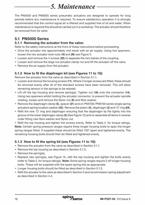
The PN5000 and PN6000 series pneumatic actuators are designed to operate for long periods before any maintanance is required. To ensure satisfactory operation it is strongly recommended that the control signal air is filtered and supplied free of oil and water. When maintenance is required this should be carried out in a workshop. The actuator should therefore be removed from its valve.
5.1 PN5000 Series 5.1.1 Removing the actuator from the valve:Refer to the safety instructions at the front of these instructions before proceeding.- Drive the actuator into approximately mid travel with an air supply. Using two spanners,
loosen the two actuator lock-nuts (18 and 26) see Figure 5.- Loosen and remove the 4 screws (25) to separate the two halves of the coupling.- Loosen and remove the large nut actuator clamp nut and lift the actuator off the valve.- Remove the air supply from the actuator.
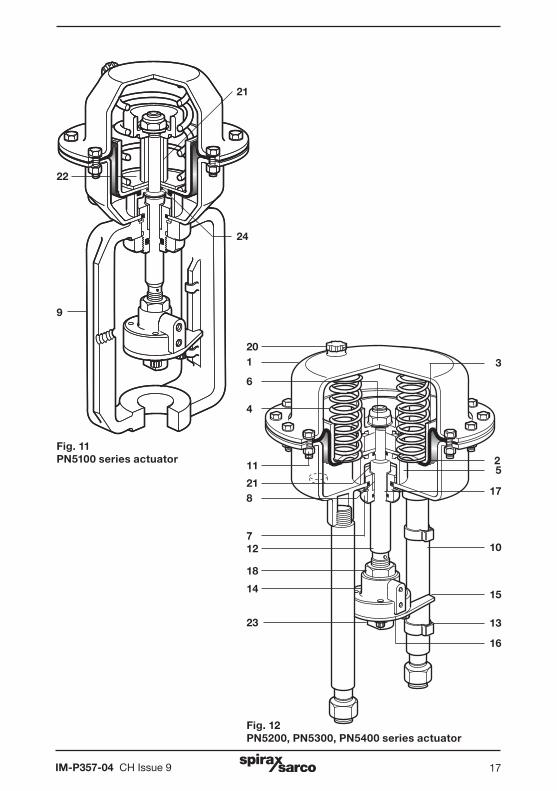
5.1.2 How to fit the diaphragm kit (see Figures 11 to 15): Remove the actuator from the valve as described in Section 5.1.1. - Loosen and remove the housing screws (11). Where 3 longer screws are fitted, these should
be removed evenly after all of the standard screws have been removed. This will allow remaining tension in the springs to be relaxed.
- Lift off the top housing and remove spring(s). Tighten nut (18) onto the connector (14). Using two spanners whilst holding the actuator connector, to prevent the actuator spindle rotating, loosen and remove the Nyloc nut (6) and fibre washer.
- Remove the diaphragm clamp (5), spacer (21) and on PN5100 / PN6100 series single spring actuators spring location washer (22). Remove the piston (3), diaphragm (2) and 'O' ring (24).
- Refit the new 'O' ring and diaphragm ensuring that the diaphragm lip fits tightly into the groove of the lower diaphragm clamp (5) (See Figure 12) and re-assemble all items in reverse order fitting new fibre washer and Nyloc nut.
- Refit the top housing and tighten the screws evenly. Refer to Table 2, for torque ratings. Note: Certain spring pressure ranges require three longer housing bolts to span the longer spring ranges fitted. If supplied these should be fitted 120° apart and tightened evenly. The remaining housing bolts should then be fitted and tightened evenly.
5.1.3 How to fit the spring kit (see Figures 11 to 15): - Remove the actuator from the valve as described in Section 5.1.1.- Remove the top housing as described in Section 5.1.2. - Remove the spring(s). - Replace new spring(s), see Figure 15, refit the top housing and tighten the bolts evenly
(refer to Table 2, for torque ratings). Note: Some spring ranges require 3 off longer housing bolts. These will be supplied with the spare spring kits as appropriate.
- Longer housing bolts should be fitted as described in Section 5.1.2. - Refit the actuator to the valve as described in Section 3 and recommission spring adjustment
as described in Section 4.4.
5. Maintenance
IM-P357-04 CH Issue 9 17
3
25
17
10
15
13
16
Fig. 12PN5200, PN5300, PN5400 series actuator
22
9
21
24
201
6
4
11
218
712
18
14
23
Fig. 11PN5100 series actuator
IM-P357-04 CH Issue 918
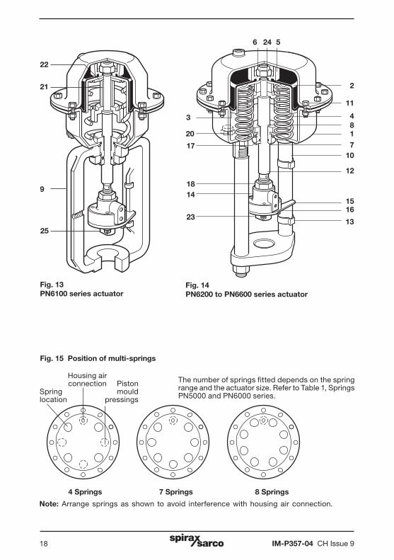
Fig. 14PN6200 to PN6600 series actuator
Fig. 13PN6100 series actuator
22
24 5
2
11
4817
10
12
15
13
1623
1418
17
20
6
21
9
25
3
Housing air connection PistonSpring mouldlocation pressings
4 Springs 7 Springs 8 Springs
Note: Arrange springs as shown to avoid interference with housing air connection.
The number of springs fitted depends on the spring range and the actuator size. Refer to Table 1, Springs PN5000 and PN6000 series.
Fig. 15 Position of multi-springs
IM-P357-04 CH Issue 9 19
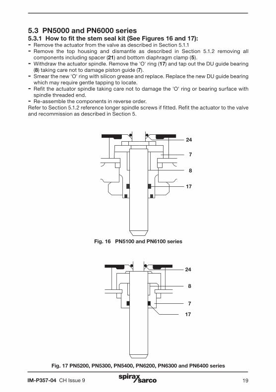
5.3 PN5000 and PN6000 series 5.3.1 How to fit the stem seal kit (See Figures 16 and 17): - Remove the actuator from the valve as described in Section 5.1.1 - Remove the top housing and dismantle as described in Section 5.1.2 removing all
components including spacer (21) and bottom diaphragm clamp (5). - Withdraw the actuator spindle. Remove the 'O' ring (17) and tap out the DU guide bearing
(8) taking care not to damage piston guide (7). - Smear the new 'O' ring with silicon grease and replace. Replace the new DU guide bearing
which may require gentle tapping to locate. - Refit the actuator spindle taking care not to damage the 'O' ring or bearing surface with
spindle threaded end. - Re-assemble the components in reverse order. Refer to Section 5.1.2 reference longer spindle screws if fitted. Refit the actuator to the valve and recommission as described in Section 5.
Fig. 17 PN5200, PN5300, PN5400, PN6200, PN6300 and PN6400 series
Fig. 16 PN5100 and PN6100 series
24
7
8
17
24
8
7
17
IM-P357-04 CH Issue 920
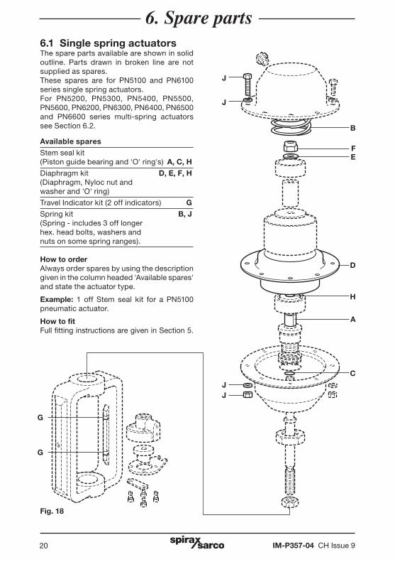
6.1 Single spring actuatorsThe spare parts available are shown in solid outline. Parts drawn in broken line are not supplied as spares. These spares are for PN5100 and PN6100 series single spring actuators. For PN5200, PN5300, PN5400, PN5500, PN5600, PN6200, PN6300, PN6400, PN6500 and PN6600 series multi-spring actuators see Section 6.2.
Available spares
Stem seal kit (Piston guide bearing and 'O' ring's) A, C, H
Diaphragm kit D, E, F, H (Diaphragm, Nyloc nut and washer and 'O' ring)
Travel Indicator kit (2 off indicators) G
Spring kit B, J(Spring - includes 3 off longer hex. head bolts, washers and nuts on some spring ranges).
How to order Always order spares by using the description given in the column headed 'Available spares' and state the actuator type.
Example: 1 off Stem seal kit for a PN5100 pneumatic actuator.
How to fitFull fitting instructions are given in Section 5.
6. Spare parts
G
G
JJ
J
J
FE
B
D
H
A
C
Fig. 18
IM-P357-04 CH Issue 9 21
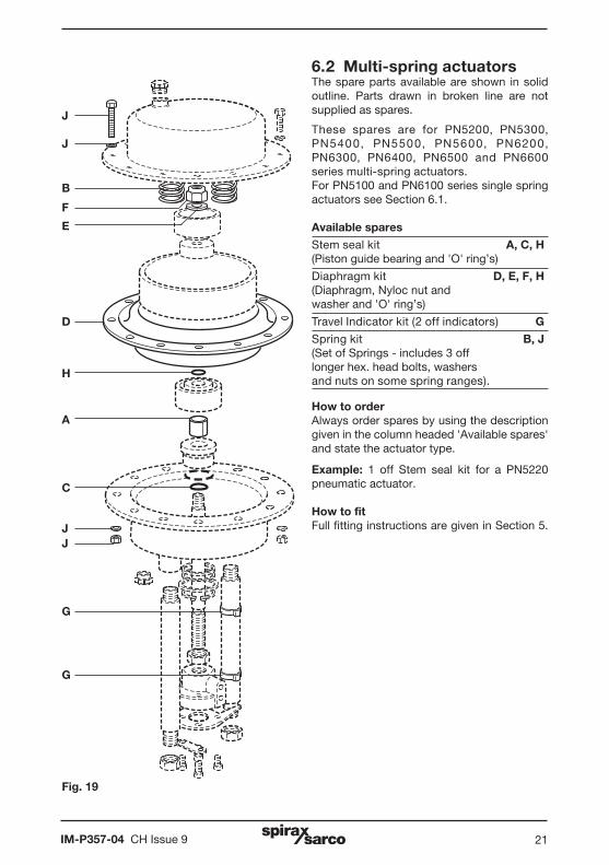
6.2 Multi-spring actuatorsThe spare parts available are shown in solid outline. Parts drawn in broken line are not supplied as spares.
These spares are for PN5200, PN5300, PN5400, PN5500, PN5600, PN6200, PN6300, PN6400, PN6500 and PN6600 series multi-spring actuators.For PN5100 and PN6100 series single spring actuators see Section 6.1.
Available spares
Stem seal kit A, C, H(Piston guide bearing and 'O' ring’s)
Diaphragm kit D, E, F, H (Diaphragm, Nyloc nut and washer and 'O' ring’s)
Travel Indicator kit (2 off indicators) G
Spring kit B, J(Set of Springs - includes 3 off longer hex. head bolts, washers and nuts on some spring ranges).
How to order Always order spares by using the description given in the column headed 'Available spares' and state the actuator type.
Example: 1 off Stem seal kit for a PN5220 pneumatic actuator.
How to fit Full fitting instructions are given in Section 5.
Fig. 19
G
G
JJ
C
A
H
D
J
J
B
F
E

IM-P357-04 CH Issue 922

IM-P357-04 CH Issue 9 23

IM-P357-04 CH Issue 924