Embed Size (px)
Citation preview
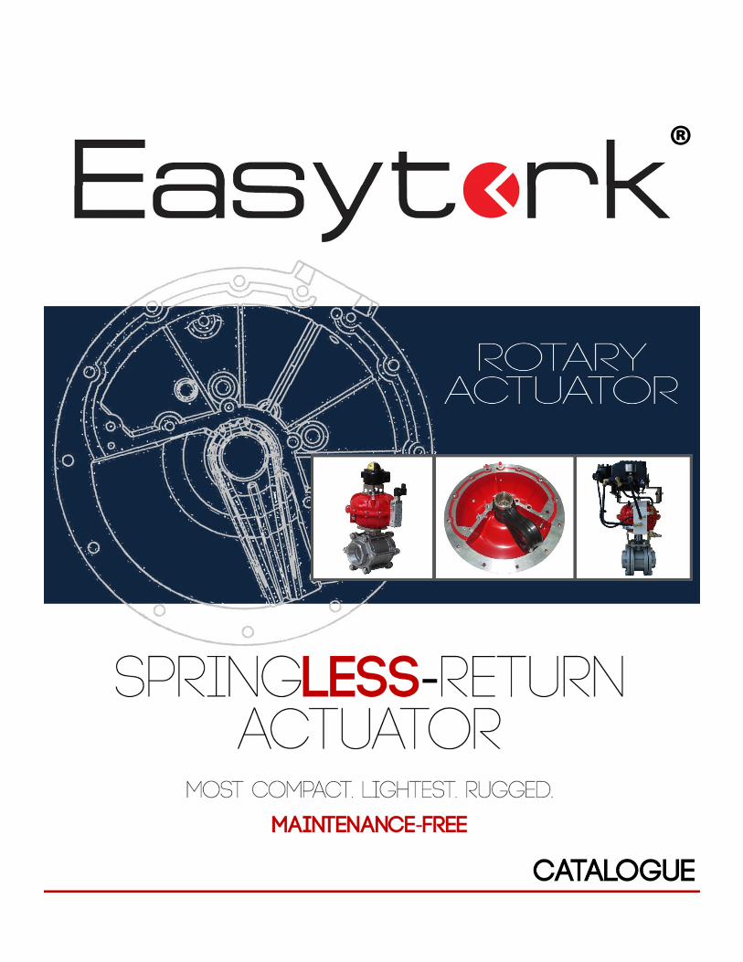
®
Table of Contents
Easytork Vane Actuator (“EVA”)
Overview 4
Principle and Sizing 10
Technical Information 12
Other EVA Adaptations
Gearbox Equivalent: Manual Override Without Air Supply 19
Control Valve Options 20
180°°°° System 22
Lockout and Partial Stroke Test Device 24
Chemical Version 26
Fast-Acting 27
Easytork Air Pilot Valve (“EPV”) 28
Easytork Solenoid Valve (“ESV”)
Overview 29
Technical Information 33
Mounting Bracket and Plate
Easytork Mounting Bracket & Fixture 35
Butterfly Valve Spacer Plate 37
NAMUR Mounting Bracket 38
Ordering Codes 39
i
Easytork Automation Corporation
About
We believe in selling “easy”. Easytork brings genuine value by offering clients an actuator that saves time, saves costs, simplifies operations, improves their scope of offerings, and improves quality and uptime – all in one simple package.
We achieve this by introducing a patented technology. Easytork has multiple patents (approved and pending) covering the interaction between, and specific items, for the following: the actuator, integral air reservoir, ERPP, ESV, PST & lockout device.
Patent protection extends to vane, rack & pinion and scotch yoke principles.
Questions or inquires can be directed to [email protected].
Awards
ii
2013: Emerson Arch Grant Recipient
Arch Grants, in close relation with the State of Missouri, the City of St. Louis, and the regional business community, created the competition to create a more robust entrepreneurial culture and infrastructure in St. Louis. With 707 applicants from 15 countries and 40 states in 2013, the 20 companies that were chosen represent “the best of a terrific group of companies”.
2015: Accelerate St. Louis Challenge
The St. Louis Economic Development Partnership awarded Easytork second place in a region wide young company competition, and was also awarded the Most Promising Minority Owned Business. Easytork was chosen from a pool of 140 company applicants.
Easytork Vane Actuator (“EVA”)
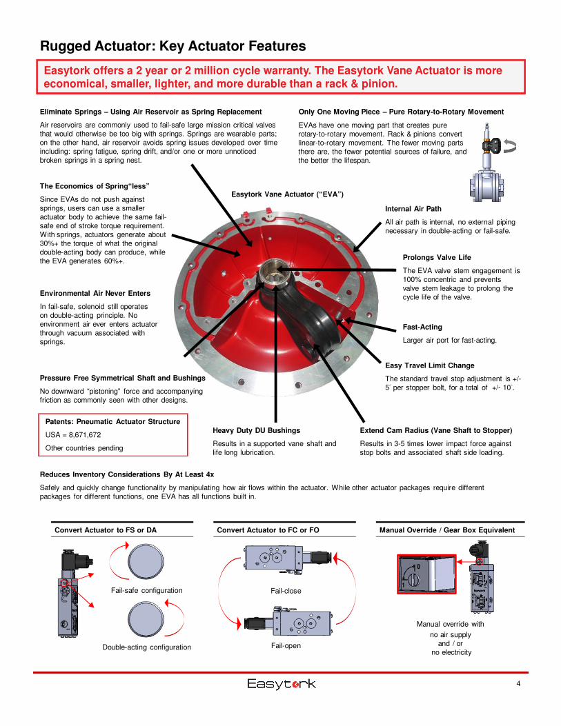
Only One Moving Piece – Pure Rotary-to-Rotary Movement
Internal Air Path
All air path is internal, no external piping necessary in double-acting or fail-safe.
Environmental Air Never Enters
In fail-safe, solenoid still operates on double-acting principle. No environment air ever enters actuator through vacuum associated with springs.
4
Rugged Actuator: Key Actuator Features
Easytork offers a 2 year or 2 million cycle warranty. The Easytork Vane Actuator is more economical, smaller, lighter, and more durable than a rack & pinion.
Eliminate Springs – Using Air Reservoir as Spring Replacement
Air reservoirs are commonly used to fail-safe large mission critical valves that would otherwise be too big with springs. Springs are wearable parts; on the other hand, air reservoir avoids spring issues developed over time including: spring fatigue, spring drift, and/or one or more unnoticed broken springs in a spring nest.
Pressure Free Symmetrical Shaft and Bushings
No downward “pistoning” force and accompanying friction as commonly seen with other designs.
The Economics of Spring“less”
Since EVAs do not push against springs, users can use a smaller actuator body to achieve the same fail-safe end of stroke torque requirement. With springs, actuators generate about 30%+ the torque of what the original double-acting body can produce, while the EVA generates 60%+.
Convert Actuator to FS or DA Convert Actuator to FC or FO Manual Override / Gear Box Equivalent
Easy Travel Limit Change
The standard travel stop adjustment is +/-5° per stopper bolt, for a total of +/- 10°.
Heavy Duty DU Bushings
Results in a supported vane shaft and life long lubrication.
Reduces Inventory Considerations By At Least 4x
Safely and quickly change functionality by manipulating how air flows within the actuator. While other actuator packages require different packages for different functions, one EVA has all functions built in.
EVAs have one moving part that creates pure rotary-to-rotary movement. Rack & pinions convert linear-to-rotary movement. The fewer moving parts there are, the fewer potential sources of failure, and the better the lifespan.
Patents: Pneumatic Actuator Structure
USA = 8,671,672
Other countries pending
Prolongs Valve Life
The EVA valve stem engagement is 100% concentric and prevents valve stem leakage to prolong the cycle life of the valve.
Fast-Acting
Larger air port for fast-acting.
Extend Cam Radius (Vane Shaft to Stopper)
Results in 3-5 times lower impact force against stop bolts and associated shaft side loading.
Fail-safe configuration
Double-acting configuration
Manual override with
no air supply and / or
no electricity
Fail-close
Fail-open
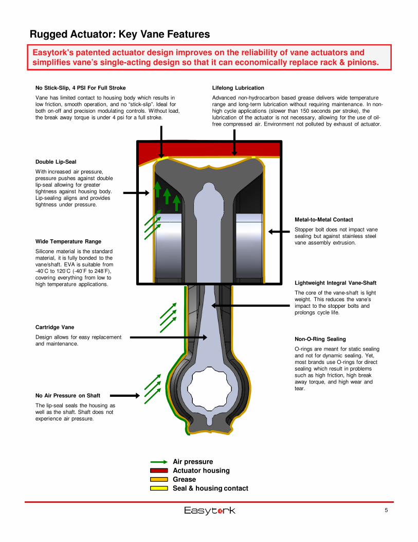
Cartridge Vane
Design allows for easy replacement and maintenance.
Non-O-Ring Sealing
O-rings are meant for static sealing and not for dynamic sealing. Yet, most brands use O-rings for direct sealing which result in problems such as high friction, high break away torque, and high wear and tear.
Double Lip-Seal
With increased air pressure, pressure pushes against double lip-seal allowing for greater tightness against housing body. Lip-sealing aligns and provides tightness under pressure.
Lightweight Integral Vane-Shaft
The core of the vane-shaft is light weight. This reduces the vane’s impact to the stopper bolts and prolongs cycle life.
Lifelong Lubrication
Advanced non-hydrocarbon based grease delivers wide temperature range and long-term lubrication without requiring maintenance. In non-high cycle applications (slower than 150 seconds per stroke), the lubrication of the actuator is not necessary, allowing for the use of oil-free compressed air. Environment not polluted by exhaust of actuator.
No Stick-Slip, 4 PSI For Full Stroke
Vane has limited contact to housing body which results in low friction, smooth operation, and no “stick-slip”. Ideal for both on-off and precision modulating controls. Without load, the break away torque is under 4 psi for a full stroke.
No Air Pressure on Shaft
The lip-seal seals the housing as well as the shaft. Shaft does not experience air pressure.
Metal-to-Metal Contact
Stopper bolt does not impact vane sealing but against stainless steel vane assembly extrusion.
5
Rugged Actuator: Key Vane Features
Easytork's patented actuator design improves on the reliability of vane actuators and simplifies vane’s single-acting design so that it can economically replace rack & pinions.
Air pressure
Actuator housing
Grease
Seal & housing contact
Wide Temperature Range
Silicone material is the standard material, it is fully bonded to the vane/shaft. EVA is suitable from -40°C to 120°C (-40°F to 248°F), covering everything from low to high temperature applications.
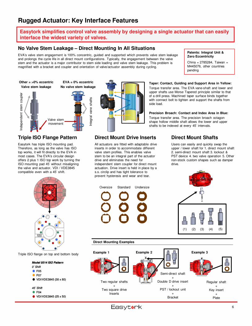
Rugged Actuator: Key Interface Features
6
Triple ISO Flange Pattern
Easytork has triple ISO mounting pad. Therefore, as long as the valve has ISO top works, it will fit directly to the EVA in most cases. The EVA’s circular design offers 2 plus 1 ISO top work by turning the ISO mounting pad 45° without misaligning the valve and actuator. VDI / VDE3845 compatible even with a 45° shift.
Triple ISO flange on top and bottom body
Model 0514 ISO Pattern
0° Shift
F05
F07
VDI/VDE3845 (30 x 80)
45° Shift
F04
VDI/VDE3845 (25 x 50)
Model 0514 ISO Pattern
0° Shift
F05
F07
VDI/VDE3845 (30 x 80)
45° Shift
F04
VDI/VDE3845 (25 x 50)
Standard UndersizeOversize
Easytork simplifies control valve assembly by designing a single actuator that can easily interface the widest variety of valves.
Taper: Contact, Guiding and Support Area in Yellow:
Torque transfer area. The EVA vane-shaft and lower and upper shafts use Morse Tapered principle similar to that of a drill press. Machined taper surface binds together with connect bolt to tighten and support the shafts from side load.
Precision Broach: Contact and Index Area in Blue:
Torque transfer area. The precision broach octagon shape hollow middle shaft allows the lower and upper shafts to be indexed at every 45° intervals.
No Valve Stem Leakage – Direct Mounting In All Situations
EVA’s valve stem engagement is 100% concentric, guided and supported which prevents valve stem leakage and prolongs the cycle life in all direct mount configurations. Typically, the engagement between the valve stem and the actuator is a major contributor to stem side loading and valve stem leakage. This problem is magnified with a bracket and coupler and orientation of valve/actuator assembly during cycling.
Patents: Integral Unit &
Zero Eccentricity
China = 2785284, Taiwan = M445076, other countries pending
Direct Mount Drive Inserts
All actuators are fitted with adaptable drive inserts in order to accommodate different valve stem profiles. This enables valve stem to be an integral part of the actuator drive and eliminates the need for independent stem coupler for direct mount actuation. Drive insert is held in place by a s.s. circlip and has tight tolerance to prevent hysteresis and wear and tear.
Direct Mounting Examples
Two regular shafts+
Two square drive Inserts
Semi-direct shaft+
Double D drive insert+
PST / lockout unit+
Bracket
Regular shaft+
Key insert+
Plate
Direct Mount Shafts
Users can easily and quickly swap the upper / lower shaft for 1. direct mount shaft 2. semi-direct mount shaft 3. lockout & PST device 4. two valve operation 5. Other non-stock custom shapes such as damper drive.
Other = >0% eccentric
Valve stem leakage
EVA = 0% eccentric
No valve stem leakage
Valve stem movement
Indep
en
den
t ste
m c
ouple
r
Inte
gra
l va
ne s
haft
s
Example 1 Example 2 Example 3
(1) (2) (4)(3) (5)
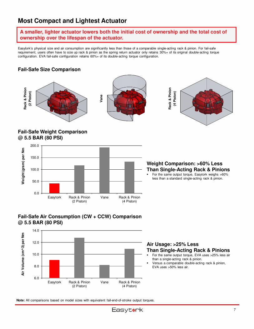
Most Compact and Lightest Actuator
Easytork’s physical size and air consumption are significantly less than those of a comparable single-acting rack & pinion. For fail-safe requirement, users often have to size up rack & pinion as the spring return actuator only retains 30%+ of its original double-acting torque configuration. EVA fail-safe configuration retains 60%+ of its double-acting torque configuration.
Fail-Safe Size Comparison
Fail-Safe Weight Comparison @ 5.5 BAR (80 PSI)
Fail-Safe Air Consumption (CW + CCW) Comparison @ 5.5 BAR (80 PSI)
Rack &
Pin
ion
(2 P
isto
n)
Van
e
Rack &
Pin
ion
(4 P
isto
n)
Note: All comparisons based on model sizes with equivalent fail-end-of-stroke output torques.
7
0.0
50.0
100.0
150.0
200.0
Easytork Rack & Pinion(2 Piston)
Vane Rack & Pinion(4 Piston)
We
igh
t (g
ram
) p
er
Nm
6.0
8.0
10.0
12.0
14.0
Easytork Rack & Pinion(2 Piston)
Vane Rack & Pinion(4 Piston)
Air
Vo
lum
e (cm
^3) p
er
Nm
A smaller, lighter actuator lowers both the initial cost of ownership and the total cost of ownership over the lifespan of the actuator.
Weight Comparison: >60% Less Than Single-Acting Rack & Pinions� For the same output torque, Easytork weighs >60%
less than a standard single-acting rack & pinion.
Air Usage: >25% LessThan Single-Acting Rack & Pinions� For the same output torque, EVA uses >25% less air
than a single-acting rack & pinion.� Versus a comparable double-acting rack & pinion,
EVA uses >50% less air.
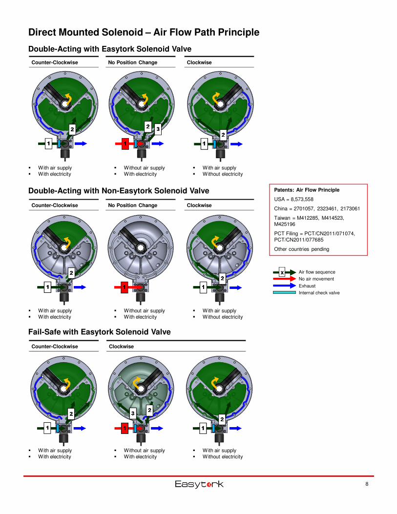
Direct Mounted Solenoid – Air Flow Path Principle
Double-Acting with Easytork Solenoid Valve
Double-Acting with Non-Easytork Solenoid Valve
Fail-Safe with Easytork Solenoid Valve
Counter-Clockwise No Position Change Clockwise
Counter-Clockwise No Position Change Clockwise
Counter-Clockwise Clockwise
� Without air supply� With electricity
� With air supply� Without electricity
� With air supply� With electricity
� Without air supply� With electricity
� With air supply� Without electricity
� With air supply� With electricity
� Without air supply� With electricity
� With air supply� Without electricity
� With air supply� With electricity
Air flow sequence
No air movement
Exhaust
Internal check valve
xxxx
8
Patents: Air Flow Principle
USA = 8,573,558
China = 2701057, 2323461, 2173061
Taiwan = M412285, M414523, M425196
PCT Filing = PCT/CN2011/071074, PCT/CN2011/077685
Other countries pending
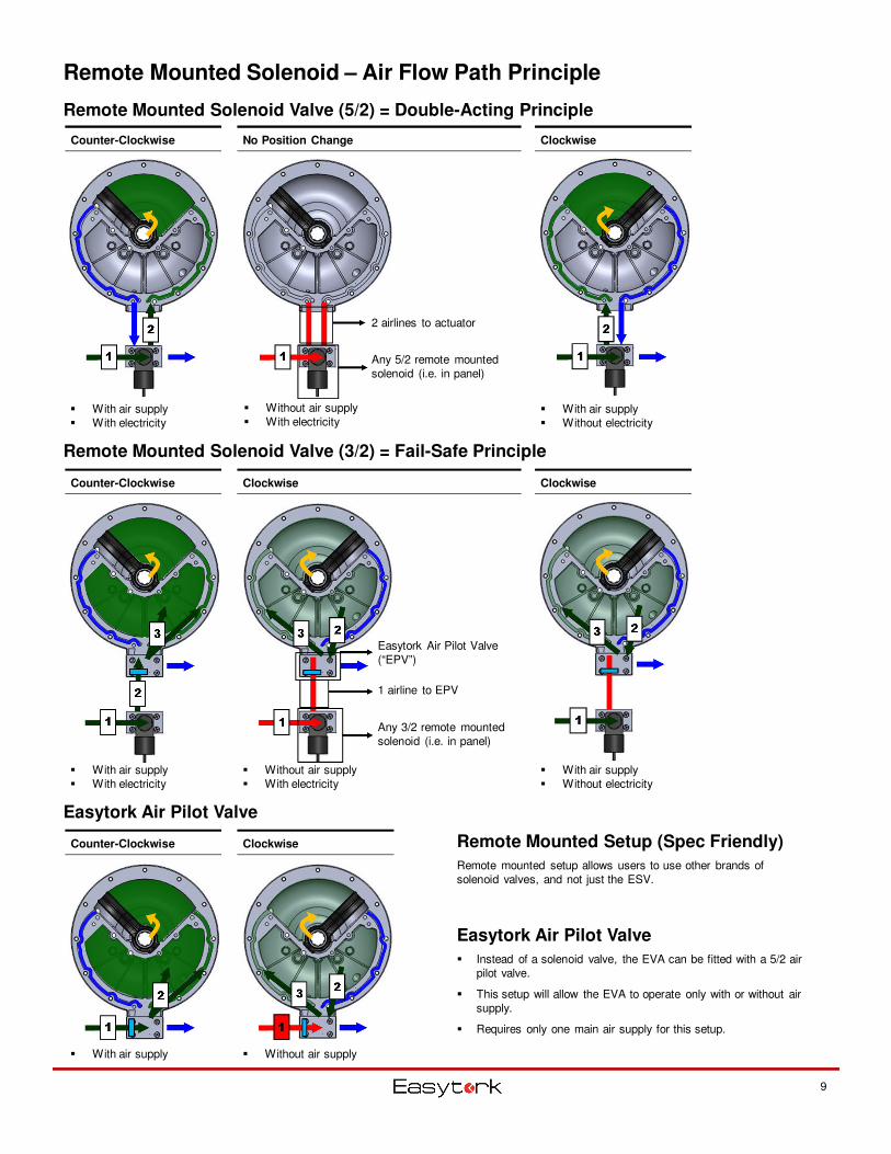
Remote Mounted Solenoid – Air Flow Path Principle
Remote Mounted Solenoid Valve (5/2) = Double-Acting Principle
Remote Mounted Solenoid Valve (3/2) = Fail-Safe Principle
Easytork Air Pilot Valve
Counter-Clockwise No Position Change Clockwise
Counter-Clockwise Clockwise Clockwise
� Without air supply� With air supply
� Without air supply� With electricity
� With air supply� Without electricity
� With air supply� Without electricity
9
Any 3/2 remote mounted solenoid (i.e. in panel)
1 airline to EPV
Easytork Air Pilot Valve (“EPV”)
Counter-Clockwise Clockwise
� With air supply� With electricity
Remote Mounted Setup (Spec Friendly)
Remote mounted setup allows users to use other brands of solenoid valves, and not just the ESV.
Easytork Air Pilot Valve
� Instead of a solenoid valve, the EVA can be fitted with a 5/2 air pilot valve.
� This setup will allow the EVA to operate only with or without air supply.
� Requires only one main air supply for this setup.
� With air supply� With electricity
� Without air supply� With electricity
2 airlines to actuator
Any 5/2 remote mounted solenoid (i.e. in panel)
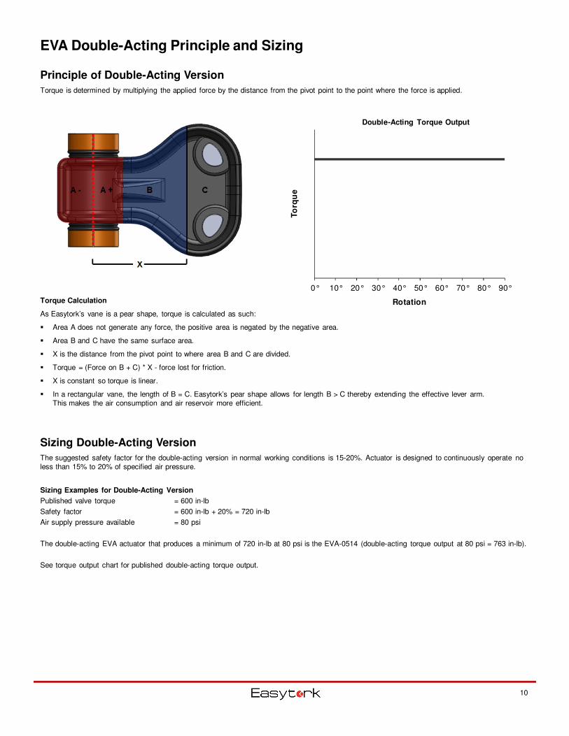
EVA Double-Acting Principle and Sizing
10
Principle of Double-Acting Version
Torque is determined by multiplying the applied force by the distance from the pivot point to the point where the force is applied.
Torque Calculation
As Easytork’s vane is a pear shape, torque is calculated as such:
� Area A does not generate any force, the positive area is negated by the negative area.
� Area B and C have the same surface area.
� X is the distance from the pivot point to where area B and C are divided.
� Torque = (Force on B + C) * X - force lost for friction.
� X is constant so torque is linear.
� In a rectangular vane, the length of B = C. Easytork’s pear shape allows for length B > C thereby extending the effective lever arm. This makes the air consumption and air reservoir more efficient.
Sizing Double-Acting Version
The suggested safety factor for the double-acting version in normal working conditions is 15-20%. Actuator is designed to continuously operate no less than 15% to 20% of specified air pressure.
Sizing Examples for Double-Acting Version
Published valve torque = 600 in-lb
Safety factor = 600 in-lb + 20% = 720 in-lb
Air supply pressure available = 80 psi
The double-acting EVA actuator that produces a minimum of 720 in-lb at 80 psi is the EVA-0514 (double-acting torque output at 80 psi = 763 in-lb).
See torque output chart for published double-acting torque output.
0° 10° 20° 30° 40° 50° 60° 70° 80° 90°To
rqu
eRotation
Double-Acting Torque Output
EVA Fail-Safe Principle and Sizing
11
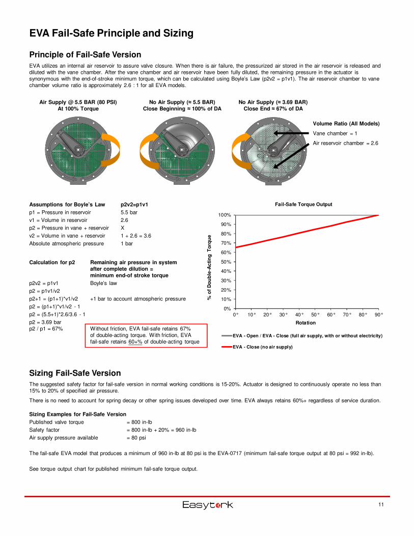
Principle of Fail-Safe Version
EVA utilizes an internal air reservoir to assure valve closure. When there is air failure, the pressurized air stored in the air reservoir is released and diluted with the vane chamber. After the vane chamber and air reservoir have been fully diluted, the remaining pressure in the actuator is synonymous with the end-of-stroke minimum torque, which can be calculated using Boyle’s Law (p2v2 = p1v1). The air reservoir chamber to vane chamber volume ratio is approximately 2.6 : 1 for all EVA models.
Sizing Fail-Safe Version
The suggested safety factor for fail-safe version in normal working conditions is 15-20%. Actuator is designed to continuously operate no less than 15% to 20% of specified air pressure.
There is no need to account for spring decay or other spring issues developed over time. EVA always retains 60%+ regardless of service duration.
Sizing Examples for Fail-Safe Version
Published valve torque = 800 in-lb
Safety factor = 800 in-lb + 20% = 960 in-lb
Air supply pressure available = 80 psi
The fail-safe EVA model that produces a minimum of 960 in-lb at 80 psi is the EVA-0717 (minimum fail-safe torque output at 80 psi = 992 in-lb).
See torque output chart for published minimum fail-safe torque output.
Air Supply @ 5.5 BAR (80 PSI)
At 100% Torque
No Air Supply (≈ 5.5 BAR)
Close Beginning ≈ 100% of DA
No Air Supply (≈ 3.69 BAR)
Close End ≈ 67% of DA
Assumptions for Boyle’s Law p2v2=p1v1
p1 = Pressure in reservoir 5.5 bar
v1 = Volume in reservoir 2.6
p2 = Pressure in vane + reservoir X
v2 = Volume in vane + reservoir 1 + 2.6 = 3.6
Absolute atmospheric pressure 1 bar
Calculation for p2 Remaining air pressure in system
after complete dilution =
minimum end-of stroke torque
p2v2 = p1v1 Boyle’s law
p2 = p1v1/v2
p2+1 = (p1+1)*v1/v2 +1 bar to account atmospheric pressure
p2 = (p1+1)*v1/v2 - 1
p2 = (5.5+1)*2.6/3.6 - 1
p2 = 3.69 barp2 / p1 = 67% Without friction, EVA fail-safe retains 67%
of double-acting torque. With friction, EVA fail-safe retains 60+% of double-acting torque
Volume Ratio (All Models)
Vane chamber = 1
Air reservoir chamber = 2.6
0%
10%
20%
30%
40%
50%
60%
70%
80%
90%
100%
0° 10° 20° 30° 40° 50° 60° 70° 80° 90°
% o
f D
ou
ble
-Ac
tin
g T
orq
ue
Rotation
Fail-Safe Torque Output
EVA - Open / EVA - Close (full air supply, with or without electricity)
EVA - Close (no air supply)
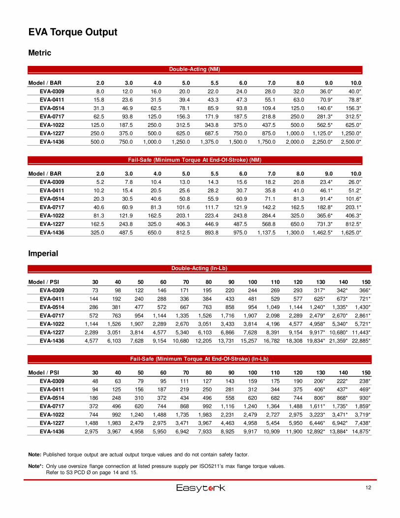
EVA Torque Output
Metric
Imperial
12
Note: Published torque output are actual output torque values and do not contain safety factor.
Note*: Only use oversize flange connection at listed pressure supply per ISO5211’s max flange torque values. Refer to S3 PCD Ø on page 14 and 15.
Double-Acting (NM)
Model / BAR 2.0 3.0 4.0 5.0 5.5 6.0 7.0 8.0 9.0 10.0
EVA-0309 8.0 12.0 16.0 20.0 22.0 24.0 28.0 32.0 36.0* 40.0*
EVA-0411 15.8 23.6 31.5 39.4 43.3 47.3 55.1 63.0 70.9* 78.8*
EVA-0514 31.3 46.9 62.5 78.1 85.9 93.8 109.4 125.0 140.6* 156.3*
EVA-0717 62.5 93.8 125.0 156.3 171.9 187.5 218.8 250.0 281.3* 312.5*
EVA-1022 125.0 187.5 250.0 312.5 343.8 375.0 437.5 500.0 562.5* 625.0*
EVA-1227 250.0 375.0 500.0 625.0 687.5 750.0 875.0 1,000.0 1,125.0* 1,250.0*
EVA-1436 500.0 750.0 1,000.0 1,250.0 1,375.0 1,500.0 1,750.0 2,000.0 2,250.0* 2,500.0*
Fail-Safe (Minimum Torque At End-Of-Stroke) (NM)
Model / BAR 2.0 3.0 4.0 5.0 5.5 6.0 7.0 8.0 9.0 10.0
EVA-0309 5.2 7.8 10.4 13.0 14.3 15.6 18.2 20.8 23.4* 26.0*
EVA-0411 10.2 15.4 20.5 25.6 28.2 30.7 35.8 41.0 46.1* 51.2*
EVA-0514 20.3 30.5 40.6 50.8 55.9 60.9 71.1 81.3 91.4* 101.6*
EVA-0717 40.6 60.9 81.3 101.6 111.7 121.9 142.2 162.5 182.8* 203.1*
EVA-1022 81.3 121.9 162.5 203.1 223.4 243.8 284.4 325.0 365.6* 406.3*
EVA-1227 162.5 243.8 325.0 406.3 446.9 487.5 568.8 650.0 731.3* 812.5*
EVA-1436 325.0 487.5 650.0 812.5 893.8 975.0 1,137.5 1,300.0 1,462.5* 1,625.0*
Double-Acting (In-Lb)
Model / PSI 30 40 50 60 70 80 90 100 110 120 130 140 150
EVA-0309 73 98 122 146 171 195 220 244 269 293 317* 342* 366*
EVA-0411 144 192 240 288 336 384 433 481 529 577 625* 673* 721*
EVA-0514 286 381 477 572 667 763 858 954 1,049 1,144 1,240* 1,335* 1,430*
EVA-0717 572 763 954 1,144 1,335 1,526 1,716 1,907 2,098 2,289 2,479* 2,670* 2,861*
EVA-1022 1,144 1,526 1,907 2,289 2,670 3,051 3,433 3,814 4,196 4,577 4,958* 5,340* 5,721*
EVA-1227 2,289 3,051 3,814 4,577 5,340 6,103 6,866 7,628 8,391 9,154 9,917* 10,680* 11,443*
EVA-1436 4,577 6,103 7,628 9,154 10,680 12,205 13,731 15,257 16,782 18,308 19,834* 21,359* 22,885*
Fail-Safe (Minimum Torque At End-Of-Stroke) (In-Lb)
Model / PSI 30 40 50 60 70 80 90 100 110 120 130 140 150
EVA-0309 48 63 79 95 111 127 143 159 175 190 206* 222* 238*
EVA-0411 94 125 156 187 219 250 281 312 344 375 406* 437* 469*
EVA-0514 186 248 310 372 434 496 558 620 682 744 806* 868* 930*
EVA-0717 372 496 620 744 868 992 1,116 1,240 1,364 1,488 1,611* 1,735* 1,859*
EVA-1022 744 992 1,240 1,488 1,735 1,983 2,231 2,479 2,727 2,975 3,223* 3,471* 3,719*
EVA-1227 1,488 1,983 2,479 2,975 3,471 3,967 4,463 4,958 5,454 5,950 6,446* 6,942* 7,438*
EVA-1436 2,975 3,967 4,958 5,950 6,942 7,933 8,925 9,917 10,909 11,900 12,892* 13,884* 14,875*
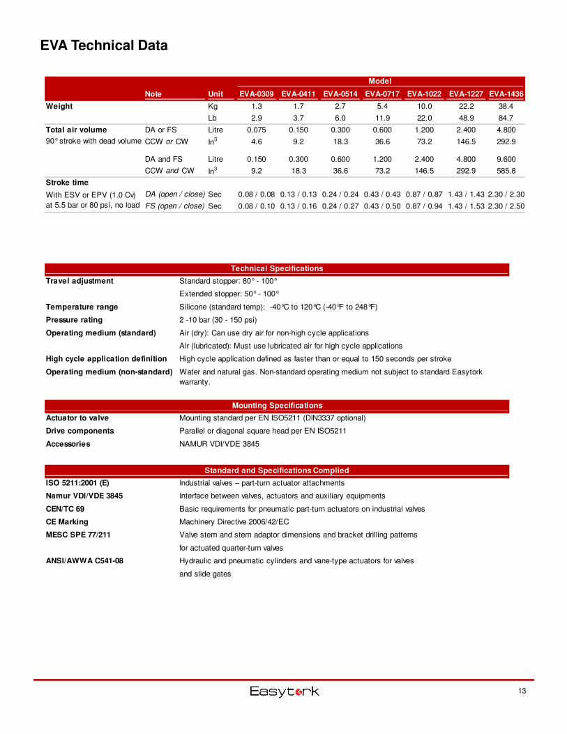
EVA Technical Data
Model
Note Unit EVA-0309 EVA-0411 EVA-0514 EVA-0717 EVA-1022 EVA-1227 EVA-1436
Weight Kg 1.3 1.7 2.7 5.4 10.0 22.2 38.4
Lb 2.9 3.7 6.0 11.9 22.0 48.9 84.7
Total air volume DA or FS Litre 0.075 0.150 0.300 0.600 1.200 2.400 4.800
CCW or CW In3 4.6 9.2 18.3 36.6 73.2 146.5 292.9
DA and FS Litre 0.150 0.300 0.600 1.200 2.400 4.800 9.600
CCW and CW In3 9.2 18.3 36.6 73.2 146.5 292.9 585.8
Stroke time
DA (open / close) Sec 0.08 / 0.08 0.13 / 0.13 0.24 / 0.24 0.43 / 0.43 0.87 / 0.87 1.43 / 1.43 2.30 / 2.30
FS (open / close) Sec 0.08 / 0.10 0.13 / 0.16 0.24 / 0.27 0.43 / 0.50 0.87 / 0.94 1.43 / 1.53 2.30 / 2.50
90° stroke with dead volume
With ESV or EPV (1.0 Cv)
at 5.5 bar or 80 psi, no load
13
Technical Specifications
Travel adjustment Standard stopper: 80° - 100°
Extended stopper: 50° - 100°
Temperature range Silicone (standard temp): -40°C to 120°C (-40°F to 248°F)
Pressure rating 2 -10 bar (30 - 150 psi)
Operating medium (standard) Air (dry): Can use dry air for non-high cycle applications
Air (lubricated): Must use lubricated air for high cycle applications
High cycle application definition High cycle application defined as faster than or equal to 150 seconds per stroke
Operating medium (non-standard) Water and natural gas. Non-standard operating medium not subject to standard Easytork
warranty.
Mounting Specifications
Actuator to valve Mounting standard per EN ISO5211 (DIN3337 optional)
Drive components Parallel or diagonal square head per EN ISO5211
Accessories NAMUR VDI/VDE 3845
Standard and Specifications Complied
ISO 5211:2001 (E) Industrial valves – part-turn actuator attachments
Namur VDI/VDE 3845 Interface between valves, actuators and auxiliary equipments
CEN/TC 69 Basic requirements for pneumatic part-turn actuators on industrial valves
CE Marking Machinery Directive 2006/42/EC
MESC SPE 77/211 Valve stem and stem adaptor dimensions and bracket drilling patterns
for actuated quarter-turn valves
ANSI/AWWA C541-08 Hydraulic and pneumatic cylinders and vane-type actuators for valves
and slide gates
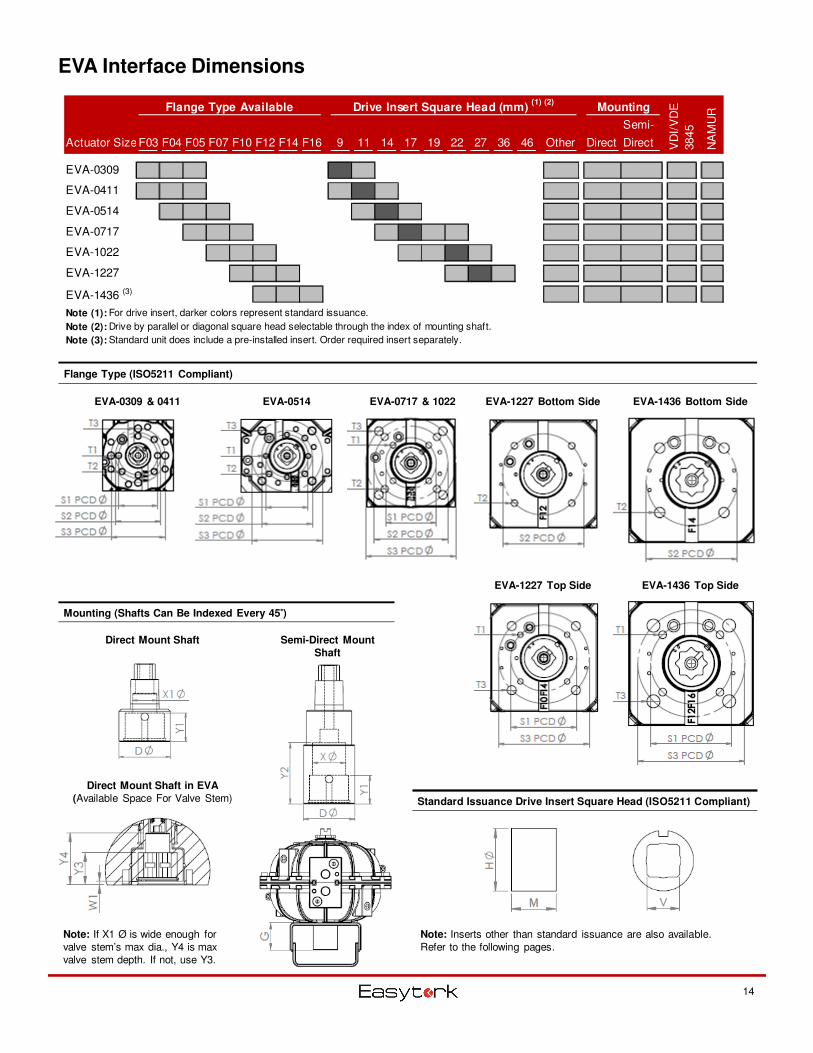
EVA Interface Dimensions
14
Mounting (Shafts Can Be Indexed Every 45°°°°)
Flange Type (ISO5211 Compliant)
Standard Issuance Drive Insert Square Head (ISO5211 Compliant)
Semi-Direct Mount
Shaft
Direct Mount Shaft
Note: Inserts other than standard issuance are also available. Refer to the following pages.
EVA-0309 & 0411 EVA-0514 EVA-0717 & 1022
Direct Mount Shaft in EVA
(Available Space For Valve Stem)
Note: If X1 Ø is wide enough for valve stem’s max dia., Y4 is max valve stem depth. If not, use Y3.
EVA-1227 Bottom Side EVA-1436 Bottom Side
EVA-1227 Top Side EVA-1436 Top Side
Flange Type Available Drive Insert Square Head (mm) (1) (2)
Mounting
Actuator SizeF03 F04 F05 F07 F10 F12 F14 F16 9 11 14 17 19 22 27 36 46 Other Direct
Semi-
Direct
EVA-0309
EVA-0411
EVA-0514
EVA-0717
EVA-1022
EVA-1227
EVA-1436 (3)
Note (1): For drive insert, darker colors represent standard issuance.
Note (2): Drive by parallel or diagonal square head selectable through the index of mounting shaft.
Note (3): Standard unit does include a pre-installed insert. Order required insert separately.
VD
I/V
DE
3845
NA
MU
R
EVA Interface Dimensions
Metric
Imperial
15
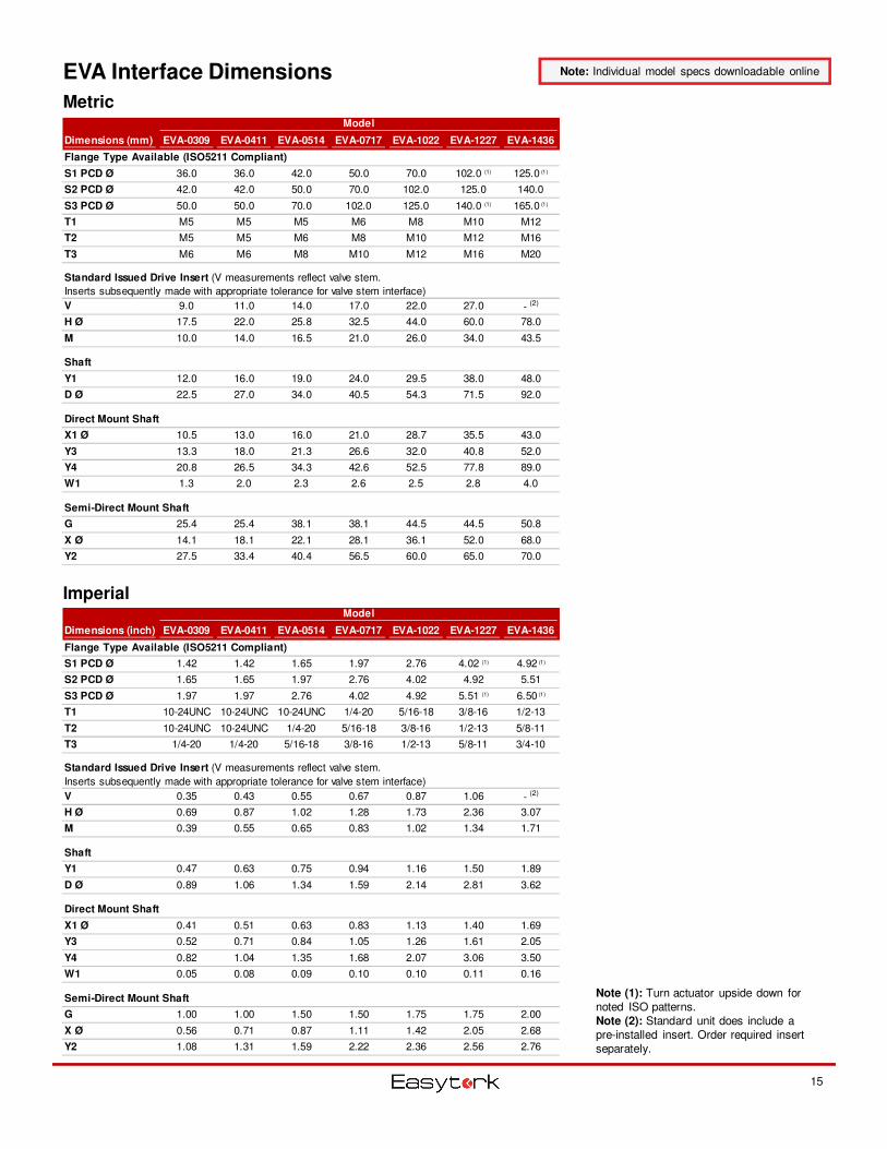
Note: Individual model specs downloadable online
Note (1): Turn actuator upside down for noted ISO patterns.Note (2): Standard unit does include apre-installed insert. Order required insert separately.
Dimensions (mm) EVA-0309 EVA-0411 EVA-0514 EVA-0717 EVA-1022 EVA-1227 EVA-1436
Flange Type Available (ISO5211 Compliant)
S1 PCD Ø 36.0 36.0 42.0 50.0 70.0 102.0 (1) 125.0 (1)
S2 PCD Ø 42.0 42.0 50.0 70.0 102.0 125.0 140.0
S3 PCD Ø 50.0 50.0 70.0 102.0 125.0 140.0 (1) 165.0 (1)
T1 M5 M5 M5 M6 M8 M10 M12
T2 M5 M5 M6 M8 M10 M12 M16
T3 M6 M6 M8 M10 M12 M16 M20
Standard Issued Drive Insert (V measurements reflect valve stem.
Inserts subsequently made with appropriate tolerance for valve stem interface)
V 9.0 11.0 14.0 17.0 22.0 27.0 - (2)
H Ø 17.5 22.0 25.8 32.5 44.0 60.0 78.0
M 10.0 14.0 16.5 21.0 26.0 34.0 43.5
Shaft
Y1 12.0 16.0 19.0 24.0 29.5 38.0 48.0
D Ø 22.5 27.0 34.0 40.5 54.3 71.5 92.0
Direct Mount Shaft
X1 Ø 10.5 13.0 16.0 21.0 28.7 35.5 43.0
Y3 13.3 18.0 21.3 26.6 32.0 40.8 52.0
Y4 20.8 26.5 34.3 42.6 52.5 77.8 89.0
W1 1.3 2.0 2.3 2.6 2.5 2.8 4.0
Semi-Direct Mount Shaft
G 25.4 25.4 38.1 38.1 44.5 44.5 50.8
X Ø 14.1 18.1 22.1 28.1 36.1 52.0 68.0
Y2 27.5 33.4 40.4 56.5 60.0 65.0 70.0
Model
Dimensions (inch) EVA-0309 EVA-0411 EVA-0514 EVA-0717 EVA-1022 EVA-1227 EVA-1436
Flange Type Available (ISO5211 Compliant)
S1 PCD Ø 1.42 1.42 1.65 1.97 2.76 4.02 (1) 4.92 (1)
S2 PCD Ø 1.65 1.65 1.97 2.76 4.02 4.92 5.51
S3 PCD Ø 1.97 1.97 2.76 4.02 4.92 5.51 (1) 6.50 (1)
T1 10-24UNC 10-24UNC 10-24UNC 1/4-20 5/16-18 3/8-16 1/2-13
T2 10-24UNC 10-24UNC 1/4-20 5/16-18 3/8-16 1/2-13 5/8-11
T3 1/4-20 1/4-20 5/16-18 3/8-16 1/2-13 5/8-11 3/4-10
Standard Issued Drive Insert (V measurements reflect valve stem.
Inserts subsequently made with appropriate tolerance for valve stem interface)
V 0.35 0.43 0.55 0.67 0.87 1.06 - (2)
H Ø 0.69 0.87 1.02 1.28 1.73 2.36 3.07
M 0.39 0.55 0.65 0.83 1.02 1.34 1.71
Shaft
Y1 0.47 0.63 0.75 0.94 1.16 1.50 1.89
D Ø 0.89 1.06 1.34 1.59 2.14 2.81 3.62
Direct Mount Shaft
X1 Ø 0.41 0.51 0.63 0.83 1.13 1.40 1.69
Y3 0.52 0.71 0.84 1.05 1.26 1.61 2.05
Y4 0.82 1.04 1.35 1.68 2.07 3.06 3.50
W1 0.05 0.08 0.09 0.10 0.10 0.11 0.16
Semi-Direct Mount Shaft
G 1.00 1.00 1.50 1.50 1.75 1.75 2.00
X Ø 0.56 0.71 0.87 1.11 1.42 2.05 2.68
Y2 1.08 1.31 1.59 2.22 2.36 2.56 2.76
Model
16
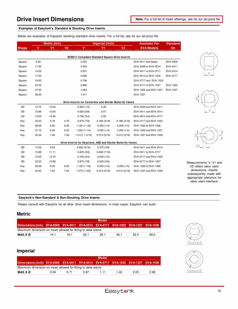
Drive Insert Dimensions
Examples of Easytork’s Standard & Stocking Drive Inserts
Easytork’s Non-Standard & Non-Stocking Drive Inserts
Metric
Imperial
Please consult with Easytork for all other drive insert dimensions. In most cases, Easytork can build.
Below are examples of Easytork stocking standard drive inserts. For a full list, ask for our list price file.
Dimensions (mm) EVA-0309 EVA-0411 EVA-0514 EVA-0717 EVA-1022 EVA-1227 EVA-1436
Maximum dimension on insert allowed for fitting to valve stems
MAX.X Ø 14.1 18.1 22.1 28.1 36.1 52.0 68.0
Model
Dimensions (inch) EVA-0309 EVA-0411 EVA-0514 EVA-0717 EVA-1022 EVA-1227 EVA-1436
Maximum dimension on insert allowed for fitting to valve stems
MAX.X Ø 0.56 0.71 0.87 1.11 1.42 2.05 2.68
Model
Metric (mm) Imperial (inch) Available For Standard
Shape V V1 V2 V V1 V2 EVA Models On
ISO5211 Compliant Standard Square Drive Inserts
Square 9.00 0.354 EVA-0411 and below EVA-0309
Square 11.00 0.433 EVA-0309 to EVA-0514 EVA-0411
Square 14.00 0.551 EVA-0411 to EVA-0717 EVA-0514
Square 17.00 0.669 EVA-0514 to EVA-1022 EVA-0717
Square 19.00 0.748 EVA-0717 and EVA-1022
Square 22.00 0.866 EVA-0717 to EVA-1227 EVA-1022
Square 27.00 1.063 EVA-1022 and EVA-1227 EVA-1227
Square 36.00 1.417 EVA-1227
Drive Inserts for Centerline and Similar Butterfly Valves
DD 12.70 10.00 0.500 (1/2) 0.39 EVA-0309 and EVA-0411
DD 15.88 12.00 0.625 (5/8) 0.47 EVA-0411 and EVA-0514
DD 19.05 14.00 0.750 (3/4) 0.55 EVA-0514 and EVA-0717
Key 22.23 4.76 4.76 0.875 (7/8) 0.188 (3/16) 0.188 (3/16) EVA-0717 and EVA-1022
Key 28.58 6.35 6.35 1.125 (1 1/8) 0.250 (1/4) 0.250 (1/4) EVA-1022 to EVA-1436
Key 31.75 6.35 6.35 1.250 (1 1/4) 0.250 (1/4) 0.250 (1/4) EVA-1022 and EVA-1227
Key 33.34 7.94 7.94 1.313 ( 1 5/16) 0.313 (5/16) 0.313 (5/16) EVA-1227 and EVA-1436
Drive Inserts for Keystone, ABZ and Similar Butterfly Valves
DD 14.29 9.53 0.563 (9/16) 0.375 (3/8) EVA-0411 and EVA-0514
DD 15.88 11.11 0.625 (5/8) 0.438 (7/16) EVA-0411 to EVA-0717
DD 19.05 12.70 0.750 (3/4) 0.500 (1/2) EVA-0717 and EVA-1022
DD 22.23 15.88 0.875 (7/8) 0.625 (5/8) EVA-0717 to EVA-1227
Key 28.58 6.35 6.35 1.125 (1 1/8) 0.250 (1/4) 0.250 (1/4) EVA-1022 to EVA-1436
Key 34.93 7.94 7.94 1.375 (1 3/8) 0.313 (5/16) 0.313 (5/16) EVA-1227 and EVA-1436
Measurements V, V1 and V2 reflect valve stem dimensions. Inserts
subsequently made with appropriate tolerance for
valve stem interface.
Note: For a full list of insert offerings, ask for our list price file
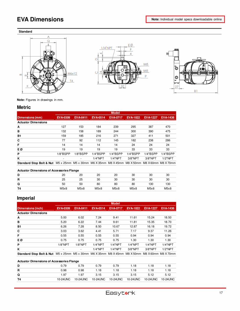
EVA Dimensions
Metric
Imperial
17
Note: Individual model specs downloadable online
Note: Figures in drawings in mm.
Standard
Dimensions (mm) EVA-0309 EVA-0411 EVA-0514 EVA-0717 EVA-1022 EVA-1227 EVA-1436
Actuator Dimensions
A 127 153 184 239 295 387 470
B 132 158 189 244 300 390 475
B1 159 185 216 271 327 411 501
C 77 92 112 145 182 238 286
F 14 14 14 14 24 24 24
E Ø 19 19 19 19 33 33 33
P 1/8"BSPP 1/8"BSPP 1/4"BSPP 1/4"BSPP 1/4"BSPP 1/4"BSPP 1/4"BSPP
K - - 1/4"NPT 1/4"NPT 3/8"NPT 3/8"NPT 1/2"NPT
Standard Stop Bolt & Nut M5 x 25mm M5 x 30mm M6 X 35mm M8 X 45mm M8 X 50mm M8 X 60mm M8 X 70mm
Actuator Dimensions of Accessories Flange
D 20 20 20 20 30 30 30
R 25 25 30 30 30 30 30
Q 50 50 80 80 80 130 130
T4 M5x8 M5x8 M5x8 M5x8 M5x8 M5x8 M5x8
Model
Dimensions (inch) EVA-0309 EVA-0411 EVA-0514 EVA-0717 EVA-1022 EVA-1227 EVA-1436
Actuator Dimensions
A 5.00 6.02 7.24 9.41 11.61 15.24 18.50
B 5.20 6.22 7.44 9.61 11.81 15.35 18.70
B1 6.26 7.28 8.50 10.67 12.87 16.18 19.72
C 3.03 3.62 4.41 5.71 7.17 9.37 11.26
F 0.55 0.55 0.55 0.55 0.94 0.94 0.94
E Ø 0.75 0.75 0.75 0.75 1.30 1.30 1.30
P 1/8"NPT 1/8"NPT 1/4"NPT 1/4"NPT 1/4"NPT 1/4"NPT 1/4"NPT
K - - 1/4"NPT 1/4"NPT 3/8"NPT 3/8"NPT 1/2"NPT
Standard Stop Bolt & Nut M5 x 25mm M5 x 30mm M6 X 35mm M8 X 45mm M8 X 50mm M8 X 60mm M8 X 70mm
Actuator Dimensions of Accessories Flange
D 0.79 0.79 0.79 0.79 1.18 1.18 1.18
R 0.98 0.98 1.18 1.18 1.18 1.18 1.18
Q 1.97 1.97 3.15 3.15 3.15 5.12 5.12
T4 10-24UNC 10-24UNC 10-24UNC 10-24UNC 10-24UNC 10-24UNC 10-24UNC
Model
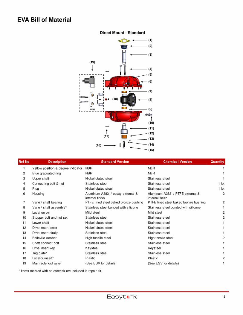
EVA Bill of Material
18
Ref No Description Standard Version Chemical Version Quantity
1 Yellow position & degree indicator NBR NBR 1
2 Blue graduated ring NBR NBR 1
3 Upper shaft Nickel-plated steel Stainless steel 1
4 Connecting bolt & nut Stainless steel Stainless steel 1 lot
5 Plug Nickel-plated steel Stainless steel 1 lot
6 Housing Aluminum A383 / epoxy external &
internal finish
Aluminum A383 / PTFE external &
internal finish
2
7 Vane / shaft bearing PTFE lined steel baked bronze bushing PTFE lined steel baked bronze bushing 2
8 Vane / shaft assembly* Stainless steel bonded with silicone Stainless steel bonded with silicone 1
9 Location pin Mild steel Mild steel 2
10 Stopper bolt and nut set Stainless steel Stainless steel 2
11 Lower shaft Nickel-plated steel Stainless steel 1
12 Drive insert lower Nickel-plated steel Stainless steel 1
13 Drive insert circlip Stainless steel Stainless steel 1
14 Belleville washer High tensile steel High tensile steel 2
15 Shaft connect bolt Stainless steel Stainless steel 1
16 Drive insert key Keysteel Keysteel 1
17 Tag plate* Stainless steel Stainless steel 1
18 Locator insert* Plastic Plastic 2
19 Main solenoid valve (See ESV for details) (See ESV for details) 1
* Items marked with an asterisk are included in repair kit.
Direct Mount - Standard
(1)
(2)
(3)
(4)
(5)
(6)
(7)
(8)
(9)
(10)
(11)
(12)
(13)
(14)
(15)
(16)
(17)
(18)
(19)
Gearbox Equivalent: Manual Override Without Air Supply
19
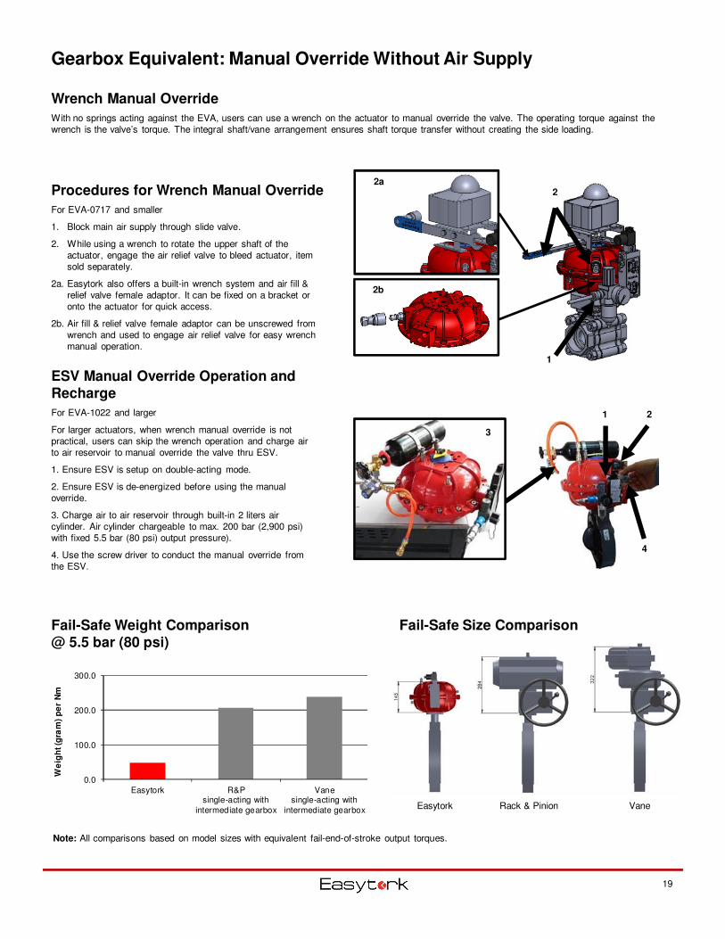
Wrench Manual Override
With no springs acting against the EVA, users can use a wrench on the actuator to manual override the valve. The operating torque against the wrench is the valve’s torque. The integral shaft/vane arrangement ensures shaft torque transfer without creating the side loading.
0.0
100.0
200.0
300.0
Easytork R&Psingle-acting with
intermediate gearbox
Vanesingle-acting with
intermediate gearbox
We
igh
t (g
ram
) p
er
Nm
Fail-Safe Weight Comparison @ 5.5 bar (80 psi)
Procedures for Wrench Manual Override
For EVA-0717 and smaller
1. Block main air supply through slide valve.
2. While using a wrench to rotate the upper shaft of the actuator, engage the air relief valve to bleed actuator, item sold separately.
2a. Easytork also offers a built-in wrench system and air fill & relief valve female adaptor. It can be fixed on a bracket or onto the actuator for quick access.
2b. Air fill & relief valve female adaptor can be unscrewed from wrench and used to engage air relief valve for easy wrench manual operation.
ESV Manual Override Operation and Recharge
For EVA-1022 and larger
For larger actuators, when wrench manual override is not practical, users can skip the wrench operation and charge air to air reservoir to manual override the valve thru ESV.
1. Ensure ESV is setup on double-acting mode.
2. Ensure ESV is de-energized before using the manual override.
3. Charge air to air reservoir through built-in 2 liters air cylinder. Air cylinder chargeable to max. 200 bar (2,900 psi) with fixed 5.5 bar (80 psi) output pressure).
4. Use the screw driver to conduct the manual override from the ESV.
1 2
4
Easytork Rack & Pinion Vane
Fail-Safe Size Comparison
Note: All comparisons based on model sizes with equivalent fail-end-of-stroke output torques.
2
1
2b
2a
3
Control Valve Options
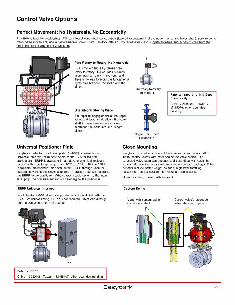
Perfect Movement: No Hysteresis, No Eccentricity
The EVA is ideal for modulating. With an integral vane-shaft construction (tapered engagement of the upper, vane, and lower shaft), pure rotary-to-rotary vane movement, and a hysteresis-free lower shaft, Easytork offers 100% repeatability and is hysteresis-free and eccentric-free from the positioner all the way to the valve stem.
Universal Positioner Plate
Easytork’s patented positioner plate (“ERPP”) provides for a universal interface for all positioners to the EVA for fail-safe applications. ERPP is available in standard or chemical resistant version with wide temp range from -40°C to 120°C (-40°F to 248°F). In fail-safe, environment air never enters ERPP through vacuum associated with spring-return actuators. A pressure sensor connects the ERPP to the positioner. When there is a disruption to the main air supply, the pressure sensor will de-energize the positioner.
Pure Rotary-to-Rotary, No Hysteresis
EVA’s movement is hysteresis-free rotary-to-rotary. Typical rack & pinion uses linear-to-rotary movement, and there is no way to avoid the fundamental hysteresis between the racks and the pinion.
One Integral Moving Piece
The tapered engagement of the upper, vane, and lower shaft allows the vane-shaft to have zero eccentricity and combines the parts into one integral piece.
ERPP Universal Interface
For fail-safe, ERPP allows any positioner to be installed with the EVA. For double-acting, ERPP is not required, users can directly pipe to port 2 and port 4 of actuator.
Patents: Integral Unit & Zero
Eccentricity
China = 2785284, Taiwan = M445076, other countries pending
Patents: ERPP
China = 3239468, Taiwan = M458467, other countries pending
20
Integral unit & zero eccentricity
Pure rotary-to-rotary movement
ERPP
Close Mounting
Easytork can custom spline cut the stainless steel vane shaft to justify control valves with extended spline valve stems. The extended valve stem can engage, and pass directly through the vane shaft resulting in a significantly more compact package. Other benefits include better weight balance, high level throttling capabilities, and is ideal for high vibration applications.
Non-stock item, consult with Easytork.
Custom Spline
Vane with custom spline cut to vane shaft
Control valve’s extended valve stem with spline
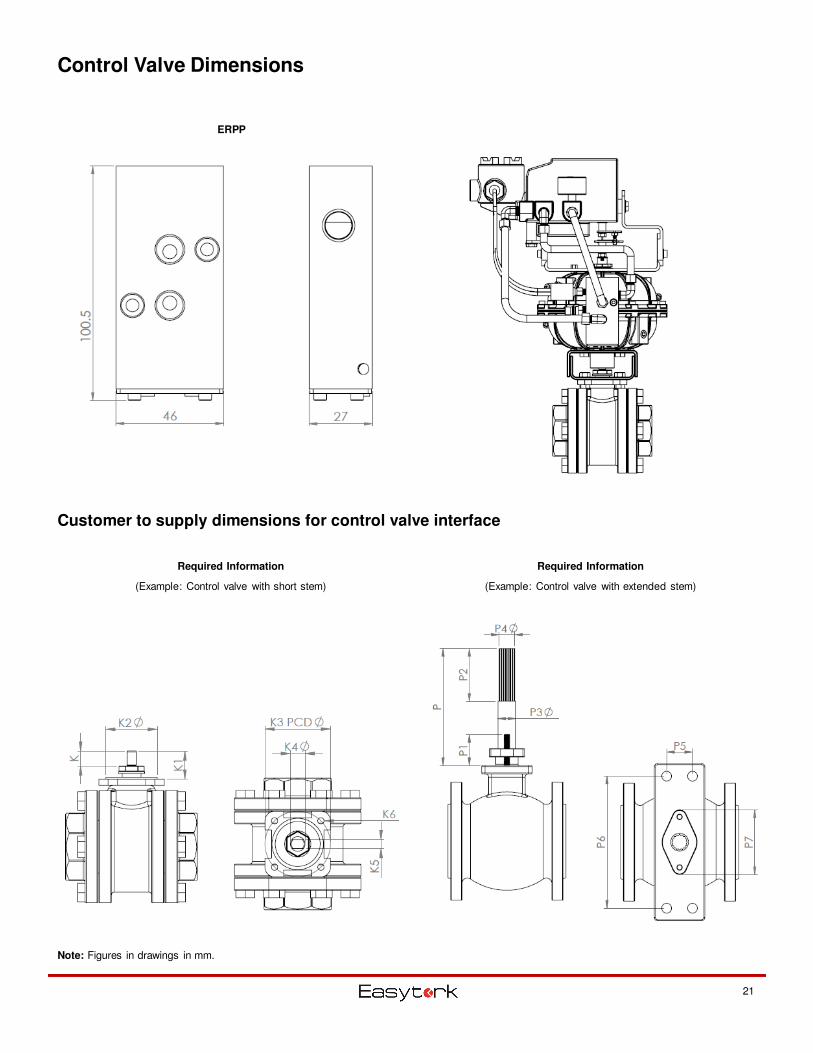
Control Valve Dimensions
Customer to supply dimensions for control valve interface
Note: Figures in drawings in mm.
21
ERPP
Required Information
(Example: Control valve with short stem)
Required Information
(Example: Control valve with extended stem)
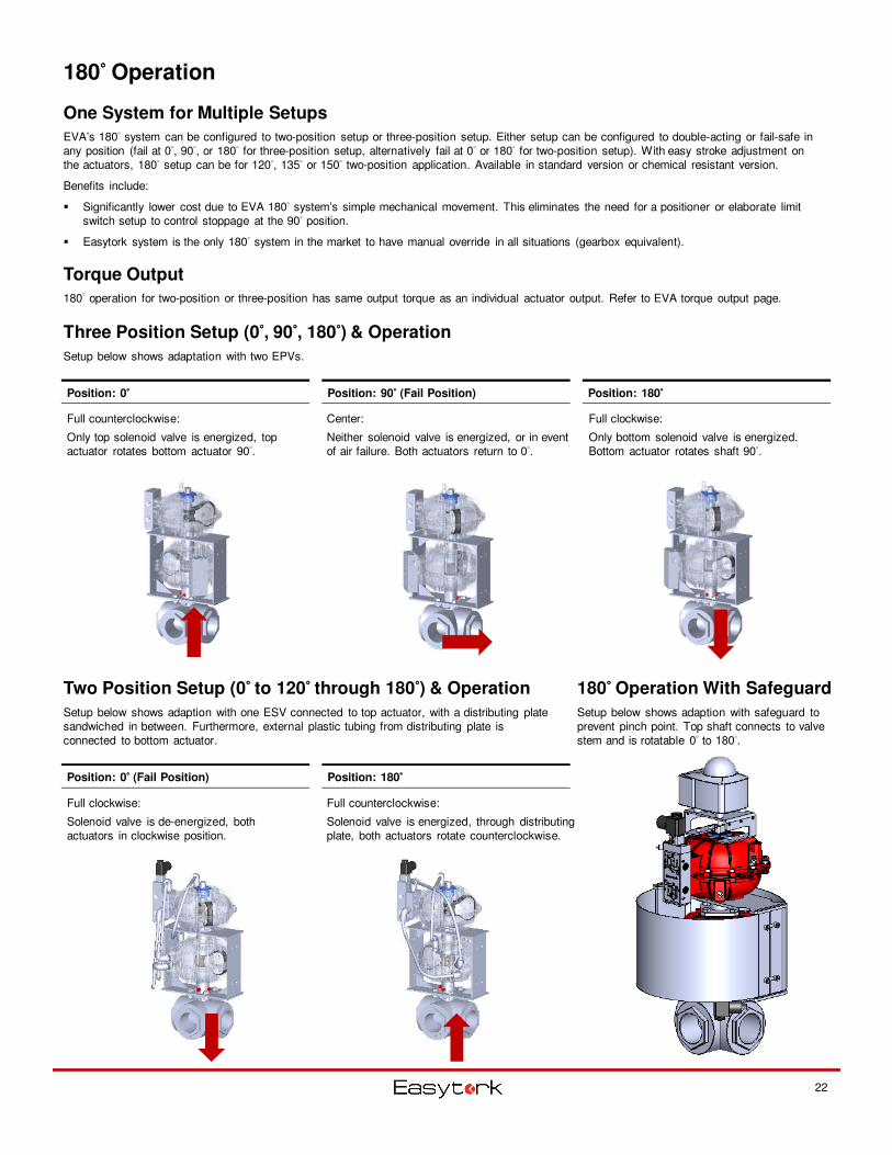
180°°°° Operation
One System for Multiple Setups
EVA’s 180° system can be configured to two-position setup or three-position setup. Either setup can be configured to double-acting or fail-safe in any position (fail at 0°, 90°, or 180° for three-position setup, alternatively fail at 0° or 180° for two-position setup). With easy stroke adjustment on the actuators, 180° setup can be for 120°, 135° or 150° two-position application. Available in standard version or chemical resistant version.
Benefits include:
� Significantly lower cost due to EVA 180° system’s simple mechanical movement. This eliminates the need for a positioner or elaborate limit switch setup to control stoppage at the 90° position.
� Easytork system is the only 180° system in the market to have manual override in all situations (gearbox equivalent).
Three Position Setup (0°°°°, 90°°°°, 180°°°°) & Operation
Setup below shows adaptation with two EPVs.
Torque Output
180° operation for two-position or three-position has same output torque as an individual actuator output. Refer to EVA torque output page.
Position: 0°°°° Position: 90°°°° (Fail Position) Position: 180°°°°
Full clockwise:
Only bottom solenoid valve is energized. Bottom actuator rotates shaft 90°.
Center:
Neither solenoid valve is energized, or in event of air failure. Both actuators return to 0°.
Full counterclockwise:
Only top solenoid valve is energized, top actuator rotates bottom actuator 90°.
Two Position Setup (0°°°° to 120°°°° through 180°°°°) & Operation
Setup below shows adaption with one ESV connected to top actuator, with a distributing plate sandwiched in between. Furthermore, external plastic tubing from distributing plate is connected to bottom actuator.
Position: 0°°°° (Fail Position) Position: 180°°°°
Full counterclockwise:
Solenoid valve is energized, through distributing plate, both actuators rotate counterclockwise.
Full clockwise:
Solenoid valve is de-energized, both actuators in clockwise position.
22
180°°°° Operation With Safeguard
Setup below shows adaption with safeguard to prevent pinch point. Top shaft connects to valve stem and is rotatable 0° to 180°.
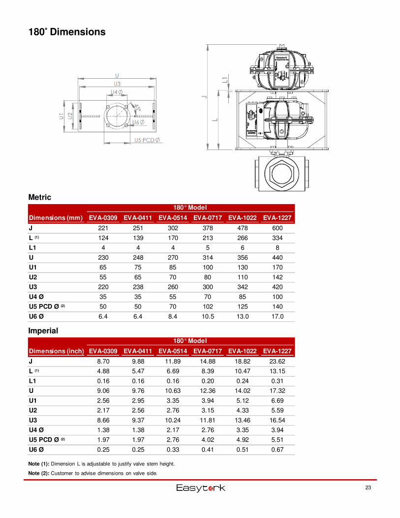
180°°°° Dimensions
Metric
Imperial
Dimensions (mm) EVA-0309 EVA-0411 EVA-0514 EVA-0717 EVA-1022 EVA-1227
J 221 251 302 378 478 600
L (1) 124 139 170 213 266 334
L1 4 4 4 5 6 8
U 230 248 270 314 356 440
U1 65 75 85 100 130 170
U2 55 65 70 80 110 142
U3 220 238 260 300 342 420
U4 Ø 35 35 55 70 85 100
U5 PCD Ø (2) 50 50 70 102 125 140
U6 Ø 6.4 6.4 8.4 10.5 13.0 17.0
180° Model
Dimensions (inch) EVA-0309 EVA-0411 EVA-0514 EVA-0717 EVA-1022 EVA-1227
J 8.70 9.88 11.89 14.88 18.82 23.62
L (1) 4.88 5.47 6.69 8.39 10.47 13.15
L1 0.16 0.16 0.16 0.20 0.24 0.31
U 9.06 9.76 10.63 12.36 14.02 17.32
U1 2.56 2.95 3.35 3.94 5.12 6.69
U2 2.17 2.56 2.76 3.15 4.33 5.59
U3 8.66 9.37 10.24 11.81 13.46 16.54
U4 Ø 1.38 1.38 2.17 2.76 3.35 3.94
U5 PCD Ø (2) 1.97 1.97 2.76 4.02 4.92 5.51
U6 Ø 0.25 0.25 0.33 0.41 0.51 0.67
180° Model
Note (1): Dimension L is adjustable to justify valve stem height.
Note (2): Customer to advise dimensions on valve side.
23
24
Standards
Lockout device fully complies with OSHA 1910.147 guidelines. This device allows for the ability to simply lockout valve and actuators in both the fully open and fully closed positions.
PST device is intended to help users comply with industry standards such as ISA S84 & IEC61508/61511 for emergency shutdown valve.
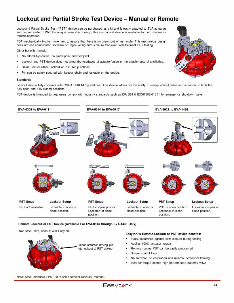
Lockout and Partial Stroke Test Device – Manual or Remote
Lockout & Partial Stroke Test (“PST”) device can be purchased as a kit and is easily adapted to EVA actuators and control system. With the unique vane shaft design, this mechanical device is available for both manual or remote operation.
PST mechanically blocks movement to assure that there is no overshoot of test angle. This mechanical design does not use complicated software or fragile wiring and is failure free even with frequent PST testing.
Other benefits include:
� No added hysteresis, no pinch point and compact.
� Lockout and PST device does not affect the interfaces of actuator/valve or the attachments of ancillaries.
� Same unit for either Lockout or PST setup options.
� Pin can be safely secured with keeper chain and lockable on the device.
Linear actuator driving pin into lockout & PST device
Note: Stock standard LPST kit in non-chemical resistant material.
EVA-0309 to EVA-0411 EVA-0514 to EVA-0717 EVA-1022 to EVA-1436
PST Setup
PST in open position. Lockable in close position.
Lockout Setup
Lockable in open or close position.
PST Setup
PST in open position. Lockable in close position.
Lockout Setup
Lockable in open or close position.
PST Setup
PST not available.
Lockout Setup
Lockable in open or close position.
Remote Lockout or PST Device (Available For EVA-0514 through EVA-1436 Only)
Easytork’s Remote Lockout or PST Device benefits:
� 100% assurance against over closure during testing
� Applies 100% actuator torque
� Remote routine PST can be easily programed
� Simple control loop
� No software, no calibration and minimal personnel training
� Ideal for torque seated high performance butterfly valve
Non-stock item, consult with Easytork.
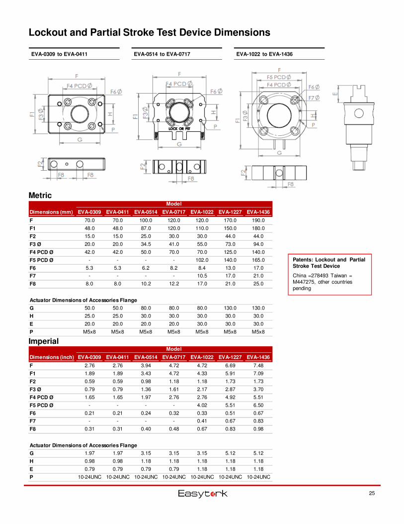
Lockout and Partial Stroke Test Device Dimensions
Metric
Imperial
25
EVA-0309 to EVA-0411 EVA-0514 to EVA-0717 EVA-1022 to EVA-1436
Patents: Lockout and Partial
Stroke Test Device
China =278493 Taiwan = M447275, other countries pending
Dimensions (mm) EVA-0309 EVA-0411 EVA-0514 EVA-0717 EVA-1022 EVA-1227 EVA-1436
F 70.0 70.0 100.0 120.0 120.0 170.0 190.0
F1 48.0 48.0 87.0 120.0 110.0 150.0 180.0
F2 15.0 15.0 25.0 30.0 30.0 44.0 44.0
F3 Ø 20.0 20.0 34.5 41.0 55.0 73.0 94.0
F4 PCD Ø 42.0 42.0 50.0 70.0 70.0 125.0 140.0
F5 PCD Ø - - - - 102.0 140.0 165.0
F6 5.3 5.3 6.2 8.2 8.4 13.0 17.0
F7 - - - - 10.5 17.0 21.0
F8 8.0 8.0 10.2 12.2 17.0 21.0 25.0
Actuator Dimensions of Accessories Flange
G 50.0 50.0 80.0 80.0 80.0 130.0 130.0
H 25.0 25.0 30.0 30.0 30.0 30.0 30.0
E 20.0 20.0 20.0 20.0 30.0 30.0 30.0
P M5x8 M5x8 M5x8 M5x8 M5x8 M5x8 M5x8
Model
Dimensions (inch) EVA-0309 EVA-0411 EVA-0514 EVA-0717 EVA-1022 EVA-1227 EVA-1436
F 2.76 2.76 3.94 4.72 4.72 6.69 7.48
F1 1.89 1.89 3.43 4.72 4.33 5.91 7.09
F2 0.59 0.59 0.98 1.18 1.18 1.73 1.73
F3 Ø 0.79 0.79 1.36 1.61 2.17 2.87 3.70
F4 PCD Ø 1.65 1.65 1.97 2.76 2.76 4.92 5.51
F5 PCD Ø - - - - 4.02 5.51 6.50
F6 0.21 0.21 0.24 0.32 0.33 0.51 0.67
F7 - - - - 0.41 0.67 0.83
F8 0.31 0.31 0.40 0.48 0.67 0.83 0.98
Actuator Dimensions of Accessories Flange
G 1.97 1.97 3.15 3.15 3.15 5.12 5.12
H 0.98 0.98 1.18 1.18 1.18 1.18 1.18
E 0.79 0.79 0.79 0.79 1.18 1.18 1.18
P 10-24UNC 10-24UNC 10-24UNC 10-24UNC 10-24UNC 10-24UNC 10-24UNC
Model
EVA Chemical Version
26
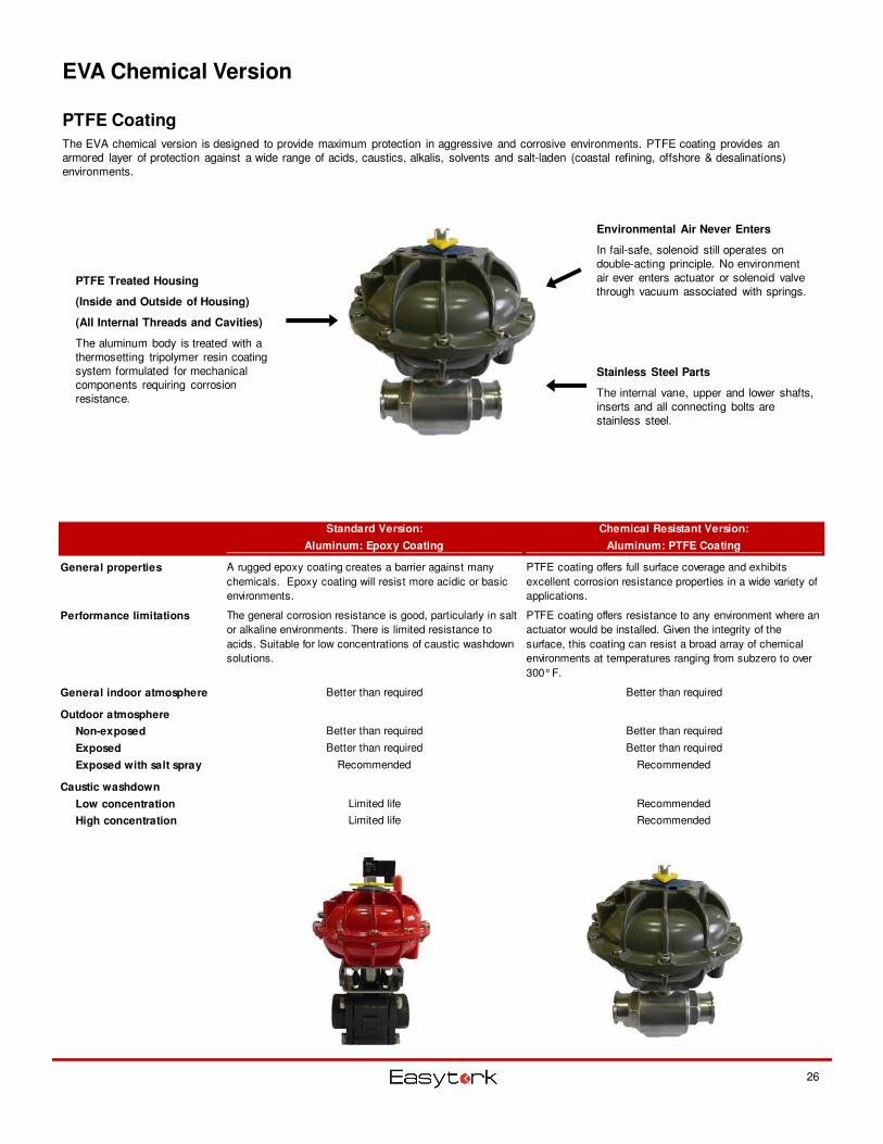
PTFE Coating
The EVA chemical version is designed to provide maximum protection in aggressive and corrosive environments. PTFE coating provides an armored layer of protection against a wide range of acids, caustics, alkalis, solvents and salt-laden (coastal refining, offshore & desalinations) environments.
PTFE Treated Housing
(Inside and Outside of Housing)
(All Internal Threads and Cavities)
The aluminum body is treated with a thermosetting tripolymer resin coating system formulated for mechanical components requiring corrosion resistance.
Stainless Steel Parts
The internal vane, upper and lower shafts, inserts and all connecting bolts are stainless steel.
Environmental Air Never Enters
In fail-safe, solenoid still operates on double-acting principle. No environment air ever enters actuator or solenoid valve through vacuum associated with springs.
Standard Version:
Aluminum: Epoxy Coating
Chemical Resistant Version:
Aluminum: PTFE Coating
General properties A rugged epoxy coating creates a barrier against many
chemicals. Epoxy coating will resist more acidic or basic
environments.
PTFE coating offers full surface coverage and exhibits
excellent corrosion resistance properties in a wide variety of
applications.
Performance limitations The general corrosion resistance is good, particularly in salt
or alkaline environments. There is limited resistance to
acids. Suitable for low concentrations of caustic washdown
solutions.
PTFE coating offers resistance to any environment where an
actuator would be installed. Given the integrity of the
surface, this coating can resist a broad array of chemical
environments at temperatures ranging from subzero to over
300° F.
General indoor atmosphere Better than required Better than required
Outdoor atmosphere
Non-exposed Better than required Better than required
Exposed Better than required Better than required
Exposed with salt spray Recommended Recommended
Caustic washdown
Low concentration Limited life Recommended
High concentration Limited life Recommended
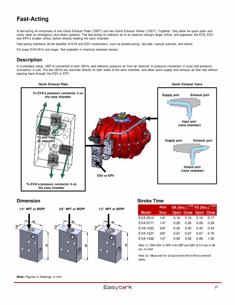
Fast-Acting
Description
In a standard setup, QEP is connected to both QEVs, and redirects pressure air from air reservoir to pressure connection 2 (ccw) and pressure connection 4 (cw). The two QEVs are mounted directly on both sides of the vane chamber, and allow quick supply and exhaust air flow rate without passing back through the ESV or EPV.
Stroke Time
Port DA (Sec.) (1)(2)
FS (Sec.) (1)(2)
Model Size Open Close Open Close
EVA-0514 1/4" 0.16 0.16 0.16 0.17
EVA-0717 1/4" 0.26 0.26 0.26 0.29
EVA-1022 3/8" 0.40 0.40 0.40 0.43
EVA-1227 3/8" 0.67 0.67 0.67 0.70
EVA-1436 1/2" 0.95 0.95 0.95 1.00
Note (1): With ESV or EPV w ith QEP and QEV at 5.5 bar or 80
psi, no load.
Note (2): Measured for actual stroke time w ithout solenoid
delay.
Note: Figures in drawings in mm.
Supply port Exhaust port
Input port
(vane chamber)
Supply port Exhaust port
Output port
(vane chamber)
Quick Exhaust Valve
27
A fast-acting kit comprises of one Quick Exhaust Plate (“QEP”) and two Quick Exhaust Valves (“QEV”). Together, they allow for quick open and close, ideal for emergency shut-down systems. The fast-acting kit redirects air to an external tubing’s larger orifice, and bypasses the EVA, ESV and EPV’s smaller orifice, before directly feeding the vane chamber.
Fast-acting maintains all the benefits of EVA and ESV combination, such as double-acting, fail-safe, manual override, and others.
For sizes EVA-0514 and larger. Not available in chemical resistant version.
ESV or EPV
Quick Exhaust Plate
To and from
air reservoir
To EVA’s pressure connector 2 on
the vane chamber
To EVA’s pressure connector 4 on
the vane chamber
1/4” NPT or BSPP 3/8” NPT or BSPP 1/2” NPT or BSPP
Dimension
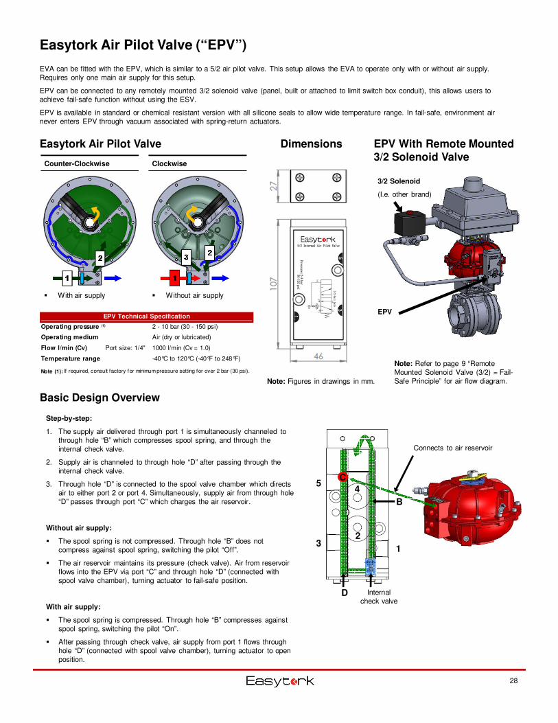
Easytork Air Pilot Valve (“EPV”)
EVA can be fitted with the EPV, which is similar to a 5/2 air pilot valve. This setup allows the EVA to operate only with or without air supply. Requires only one main air supply for this setup.
EPV can be connected to any remotely mounted 3/2 solenoid valve (panel, built or attached to limit switch box conduit), this allows users to achieve fail-safe function without using the ESV.
EPV is available in standard or chemical resistant version with all silicone seals to allow wide temperature range. In fail-safe, environment air never enters EPV through vacuum associated with spring-return actuators.
Easytork Air Pilot Valve
� Without air supply� With air supply
Counter-Clockwise Clockwise
Step-by-step:
1. The supply air delivered through port 1 is simultaneously channeled to through hole “B” which compresses spool spring, and through the internal check valve.
2. Supply air is channeled to through hole “D” after passing through the internal check valve.
3. Through hole “D” is connected to the spool valve chamber which directs air to either port 2 or port 4. Simultaneously, supply air from through hole “D” passes through port “C” which charges the air reservoir.
Without air supply:
� The spool spring is not compressed. Through hole “B” does not compress against spool spring, switching the pilot “Off”.
� The air reservoir maintains its pressure (check valve). Air from reservoir flows into the EPV via port “C” and through hole “D” (connected with spool valve chamber), turning actuator to fail-safe position.
With air supply:
� The spool spring is compressed. Through hole “B” compresses against spool spring, switching the pilot “On”.
� After passing through check valve, air supply from port 1 flows through hole “D” (connected with spool valve chamber), turning actuator to open position.
Basic Design Overview
Dimensions
28
Note: Figures in drawings in mm.
EPV With Remote Mounted 3/2 Solenoid Valve
Note: Refer to page 9 “Remote Mounted Solenoid Valve (3/2) = Fail-Safe Principle” for air flow diagram.
3/2 Solenoid
(I.e. other brand)
EPV
B
D
1
5
32
4
Internal check valve
C
Connects to air reservoir
EPV Technical Specification
Operating pressure (1) 2 - 10 bar (30 - 150 psi)
Operating medium Air (dry or lubricated)
Flow l/min (Cv) Port size: 1/4" 1000 l/min (Cv = 1.0)
Temperature range -40°C to 120°C (-40°F to 248°F)
Note (1): If required, consult factory for minimum pressure setting for over 2 bar (30 psi).
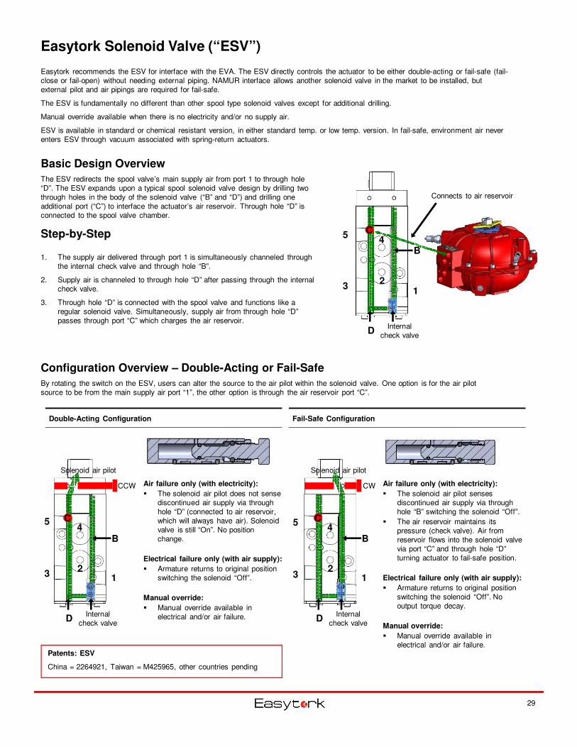
Easytork Solenoid Valve (“ESV”)
Easytork recommends the ESV for interface with the EVA. The ESV directly controls the actuator to be either double-acting or fail-safe (fail-close or fail-open) without needing external piping. NAMUR interface allows another solenoid valve in the market to be installed, but external pilot and air pipings are required for fail-safe.
The ESV is fundamentally no different than other spool type solenoid valves except for additional drilling.
Manual override available when there is no electricity and/or no supply air.
ESV is available in standard or chemical resistant version, in either standard temp. or low temp. version. In fail-safe, environment air never enters ESV through vacuum associated with spring-return actuators.
1. The supply air delivered through port 1 is simultaneously channeled through the internal check valve and through hole “B”.
2. Supply air is channeled to through hole “D” after passing through the internal check valve.
3. Through hole “D” is connected with the spool valve and functions like a regular solenoid valve. Simultaneously, supply air from through hole “D” passes through port “C” which charges the air reservoir.
Basic Design Overview
The ESV redirects the spool valve’s main supply air from port 1 to through hole “D”. The ESV expands upon a typical spool solenoid valve design by drilling two through holes in the body of the solenoid valve (“B” and “D”) and drilling one additional port (“C”) to interface the actuator’s air reservoir. Through hole “D” is connected to the spool valve chamber.
Step-by-Step
Configuration Overview – Double-Acting or Fail-Safe
By rotating the switch on the ESV, users can alter the source to the air pilot within the solenoid valve. One option is for the air pilot source to be from the main supply air port “1”, the other option is through the air reservoir port “C”.
Double-Acting Configuration Fail-Safe Configuration
Air failure only (with electricity):
� The solenoid air pilot does not sense discontinued air supply via through hole “D” (connected to air reservoir, which will always have air). Solenoid valve is still “On”. No position change.
Electrical failure only (with air supply):
� Armature returns to original position switching the solenoid “Off”.
Manual override:
� Manual override available in electrical and/or air failure.
Air failure only (with electricity):
� The solenoid air pilot senses discontinued air supply via through hole “B” switching the solenoid “Off”.
� The air reservoir maintains its pressure (check valve). Air from reservoir flows into the solenoid valve via port “C” and through hole “D” turning actuator to fail-safe position.
Electrical failure only (with air supply):
� Armature returns to original position switching the solenoid “Off”. No output torque decay.
Manual override:
� Manual override available in electrical and/or air failure.
Patents: ESV
China = 2264921, Taiwan = M425965, other countries pending
29
B
D
1
5
32
4
Internal check valve
Solenoid air pilot
C
CW
B
D
1
5
32
4
Internal check valve
Solenoid air pilot
C
CCW
B
D
1
5
32
4
Internal check valve
C
Connects to air reservoir
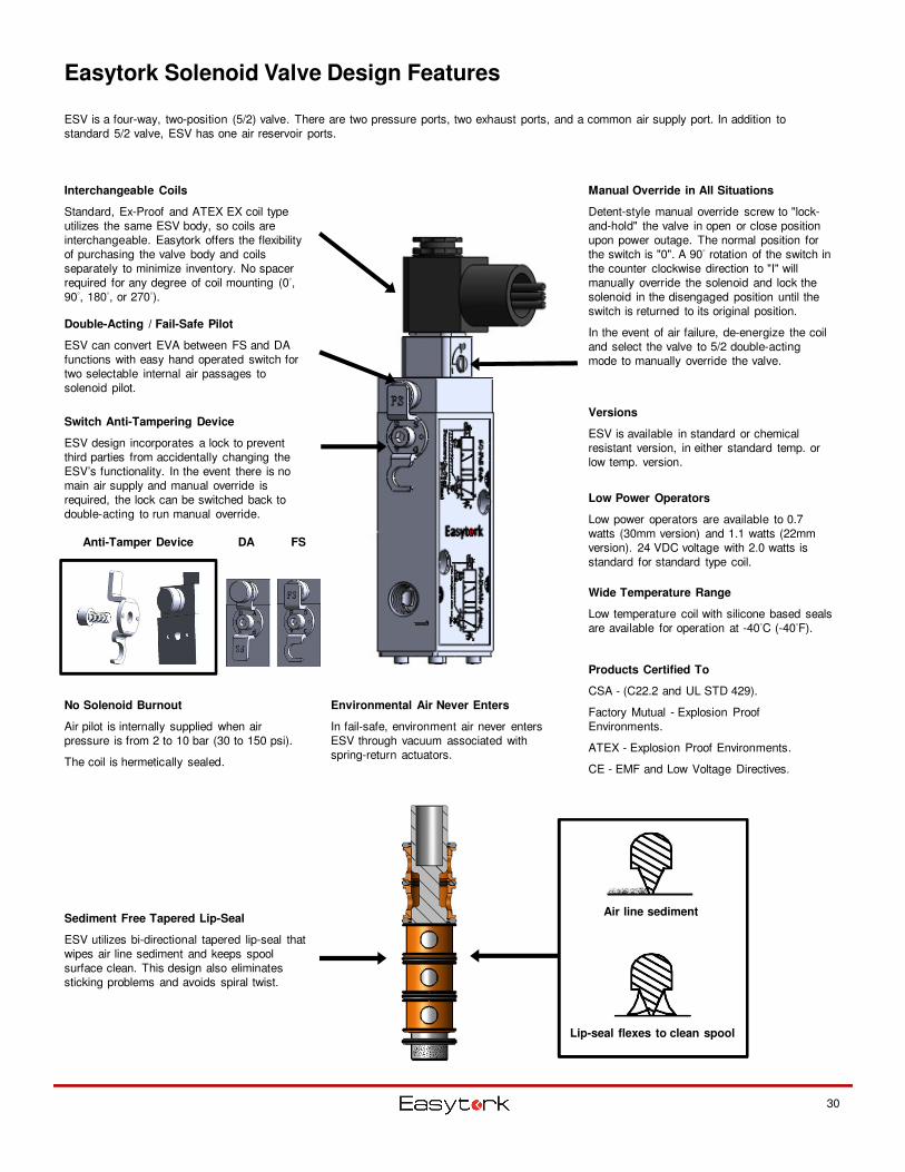
Easytork Solenoid Valve Design Features
DA FSAnti-Tamper Device
Air line sediment
Lip-seal flexes to clean spool
Interchangeable Coils
Standard, Ex-Proof and ATEX EX coil type utilizes the same ESV body, so coils are interchangeable. Easytork offers the flexibility of purchasing the valve body and coils separately to minimize inventory. No spacer required for any degree of coil mounting (0°, 90°, 180°, or 270°).
Products Certified To
CSA - (C22.2 and UL STD 429).
Factory Mutual - Explosion Proof Environments.
ATEX - Explosion Proof Environments.
CE - EMF and Low Voltage Directives.
ESV is a four-way, two-position (5/2) valve. There are two pressure ports, two exhaust ports, and a common air supply port. In addition to standard 5/2 valve, ESV has one air reservoir ports.
Wide Temperature Range
Low temperature coil with silicone based seals are available for operation at -40°C (-40°F).
Low Power Operators
Low power operators are available to 0.7 watts (30mm version) and 1.1 watts (22mm version). 24 VDC voltage with 2.0 watts is standard for standard type coil.
Manual Override in All Situations
Detent-style manual override screw to "lock-and-hold" the valve in open or close position upon power outage. The normal position for the switch is "0". A 90° rotation of the switch in the counter clockwise direction to "I" will manually override the solenoid and lock the solenoid in the disengaged position until the switch is returned to its original position.
In the event of air failure, de-energize the coil and select the valve to 5/2 double-acting mode to manually override the valve.
Sediment Free Tapered Lip-Seal
ESV utilizes bi-directional tapered lip-seal that wipes air line sediment and keeps spool surface clean. This design also eliminates sticking problems and avoids spiral twist.
No Solenoid Burnout
Air pilot is internally supplied when air pressure is from 2 to 10 bar (30 to 150 psi).
The coil is hermetically sealed.
Double-Acting / Fail-Safe Pilot
ESV can convert EVA between FS and DA functions with easy hand operated switch for two selectable internal air passages to solenoid pilot.
Switch Anti-Tampering Device
ESV design incorporates a lock to prevent third parties from accidentally changing the ESV’s functionality. In the event there is no main air supply and manual override is required, the lock can be switched back to double-acting to run manual override.
30
Versions
ESV is available in standard or chemical resistant version, in either standard temp. or low temp. version.
Environmental Air Never Enters
In fail-safe, environment air never enters ESV through vacuum associated with spring-return actuators.
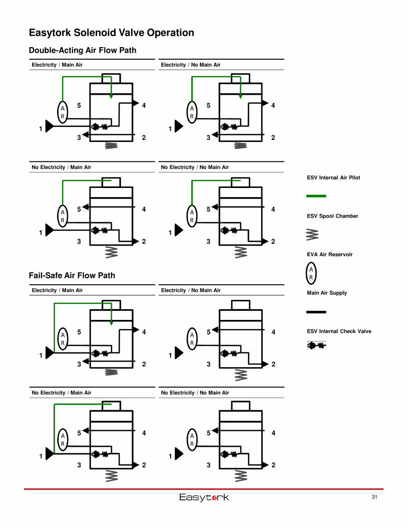
Easytork Solenoid Valve Operation
Double-Acting Air Flow Path
Fail-Safe Air Flow Path
Electricity / Main Air Electricity / No Main Air
No Electricity / Main Air No Electricity / No Main Air
Electricity / Main Air Electricity / No Main Air
No Electricity / Main Air No Electricity / No Main Air
A
R
ESV Internal Air Pilot
ESV Spool Chamber
EVA Air Reservoir
Main Air Supply
ESV Internal Check Valve
31
2
A
R
1
45
3 2
A
R
1
45
3
2
A
R
1
45
3 2
A
R
1
45
3
2
A
R
1
45
3 2
A
R
1
45
3
2
A
R
1
45
3 2
A
R
1
45
3
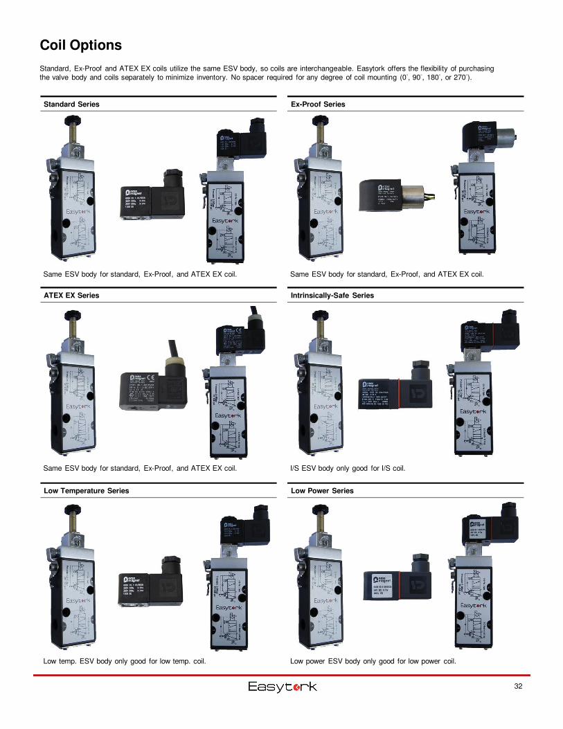
Coil Options
Standard Series Ex-Proof Series
Low Temperature Series
ATEX EX Series
Low Power Series
Intrinsically-Safe Series
32
Standard, Ex-Proof and ATEX EX coils utilize the same ESV body, so coils are interchangeable. Easytork offers the flexibility of purchasing the valve body and coils separately to minimize inventory. No spacer required for any degree of coil mounting (0°, 90°, 180°, or 270°).
Same ESV body for standard, Ex-Proof, and ATEX EX coil. Same ESV body for standard, Ex-Proof, and ATEX EX coil.
Same ESV body for standard, Ex-Proof, and ATEX EX coil. I/S ESV body only good for I/S coil.
Low temp. ESV body only good for low temp. coil. Low power ESV body only good for low power coil.
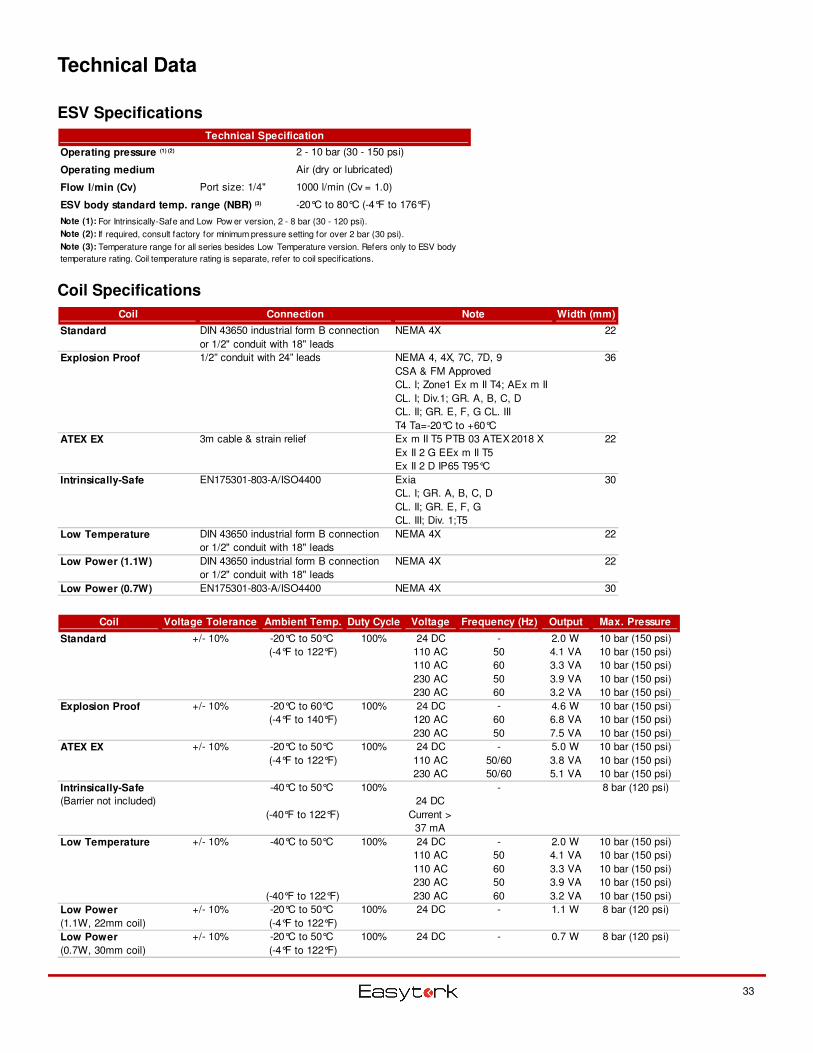
Technical Data
33
ESV Specifications
Coil Specifications
Coil Connection Note Width (mm)
Standard DIN 43650 industrial form B connection
or 1/2" conduit with 18" leads
NEMA 4X 22
Explosion Proof 1/2” conduit with 24” leads NEMA 4, 4X, 7C, 7D, 9
CSA & FM Approved
CL. I; Zone1 Ex m II T4; AEx m II
CL. I; Div.1; GR. A, B, C, D
CL. II; GR. E, F, G CL. III
T4 Ta=-20°C to +60°C
36
ATEX EX 3m cable & strain relief Ex m II T5 PTB 03 ATEX 2018 X
Ex II 2 G EEx m II T5
Ex II 2 D IP65 T95°C
22
Intrinsically-Safe EN175301-803-A/ISO4400 Exia
CL. I; GR. A, B, C, D
CL. II; GR. E, F, G
CL. III; Div. 1;T5
30
Low Temperature DIN 43650 industrial form B connection
or 1/2" conduit with 18" leads
NEMA 4X 22
Low Power (1.1W) DIN 43650 industrial form B connection
or 1/2" conduit with 18" leads
NEMA 4X 22
Low Power (0.7W) EN175301-803-A/ISO4400 NEMA 4X 30
Coil Voltage Tolerance Ambient Temp. Duty Cycle Voltage Frequency (Hz) Output Max. Pressure
Standard +/- 10% -20°C to 50°C 100% 24 DC - 2.0 W 10 bar (150 psi)
(-4°F to 122°F) 110 AC 50 4.1 VA 10 bar (150 psi)
110 AC 60 3.3 VA 10 bar (150 psi)
230 AC 50 3.9 VA 10 bar (150 psi)
230 AC 60 3.2 VA 10 bar (150 psi)
Explosion Proof +/- 10% -20°C to 60°C 100% 24 DC - 4.6 W 10 bar (150 psi)
(-4°F to 140°F) 120 AC 60 6.8 VA 10 bar (150 psi)
230 AC 50 7.5 VA 10 bar (150 psi)
ATEX EX +/- 10% -20°C to 50°C 100% 24 DC - 5.0 W 10 bar (150 psi)
(-4°F to 122°F) 110 AC 50/60 3.8 VA 10 bar (150 psi)
230 AC 50/60 5.1 VA 10 bar (150 psi)
Intrinsically-Safe -40°C to 50°C 100% - 8 bar (120 psi)
(Barrier not included)
(-40°F to 122°F)
Low Temperature +/- 10% -40°C to 50°C 100% 24 DC - 2.0 W 10 bar (150 psi)
110 AC 50 4.1 VA 10 bar (150 psi)
110 AC 60 3.3 VA 10 bar (150 psi)
230 AC 50 3.9 VA 10 bar (150 psi)
(-40°F to 122°F) 230 AC 60 3.2 VA 10 bar (150 psi)
Low Power +/- 10% -20°C to 50°C 100% 24 DC - 1.1 W 8 bar (120 psi)
(1.1W, 22mm coil) (-4°F to 122°F)
Low Power +/- 10% -20°C to 50°C 100% 24 DC - 0.7 W 8 bar (120 psi)
(0.7W, 30mm coil) (-4°F to 122°F)
24 DC
Current >
37 mA
Technical Specification
Operating pressure (1) (2) 2 - 10 bar (30 - 150 psi)
Operating medium Air (dry or lubricated)
Flow l/min (Cv) Port size: 1/4" 1000 l/min (Cv = 1.0)
ESV body standard temp. range (NBR) (3) -20°C to 80°C (-4°F to 176°F)
Note (1): For Intrinsically-Safe and Low Pow er version, 2 - 8 bar (30 - 120 psi).
Note (2): If required, consult factory for minimum pressure setting for over 2 bar (30 psi).
Note (3): Temperature range for all series besides Low Temperature version. Refers only to ESV body
temperature rating. Coil temperature rating is separate, refer to coil specif ications.
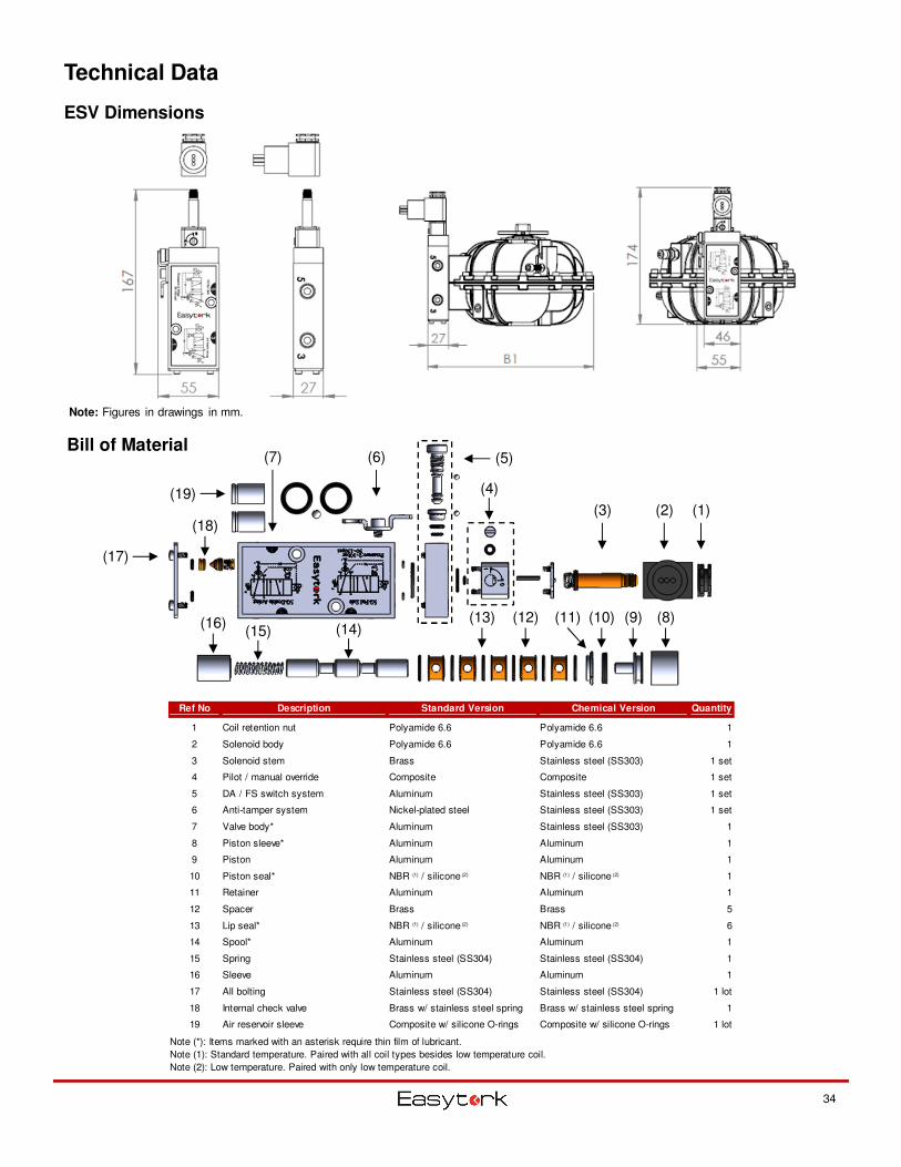
Technical Data
ESV Dimensions
Bill of Material
Note: Figures in drawings in mm.
34
(1)(3) (2)
(5)
(4)
(7) (6)
(8)(9)(10)(11)(12)(13)(14)(15)
(16)
(18)
(17)
(19)
Ref No Description Standard Version Chemical Version Quantity
1 Coil retention nut Polyamide 6.6 Polyamide 6.6 1
2 Solenoid body Polyamide 6.6 Polyamide 6.6 1
3 Solenoid stem Brass Stainless steel (SS303) 1 set
4 Pilot / manual override Composite Composite 1 set
5 DA / FS switch system Aluminum Stainless steel (SS303) 1 set
6 Anti-tamper system Nickel-plated steel Stainless steel (SS303) 1 set
7 Valve body* Aluminum Stainless steel (SS303) 1
8 Piston sleeve* Aluminum Aluminum 1
9 Piston Aluminum Aluminum 1
10 Piston seal* NBR (1) / silicone (2) NBR (1) / silicone (2) 1
11 Retainer Aluminum Aluminum 1
12 Spacer Brass Brass 5
13 Lip seal* NBR (1) / silicone (2) NBR (1) / silicone (2) 6
14 Spool* Aluminum Aluminum 1
15 Spring Stainless steel (SS304) Stainless steel (SS304) 1
16 Sleeve Aluminum Aluminum 1
17 All bolting Stainless steel (SS304) Stainless steel (SS304) 1 lot
18 Internal check valve Brass w/ stainless steel spring Brass w/ stainless steel spring 1
19 Air reservoir sleeve Composite w/ silicone O-rings Composite w/ silicone O-rings 1 lot
Note (*): Items marked with an asterisk require thin film of lubricant.
Note (1): Standard temperature. Paired with all coil types besides low temperature coil.
Note (2): Low temperature. Paired with only low temperature coil.
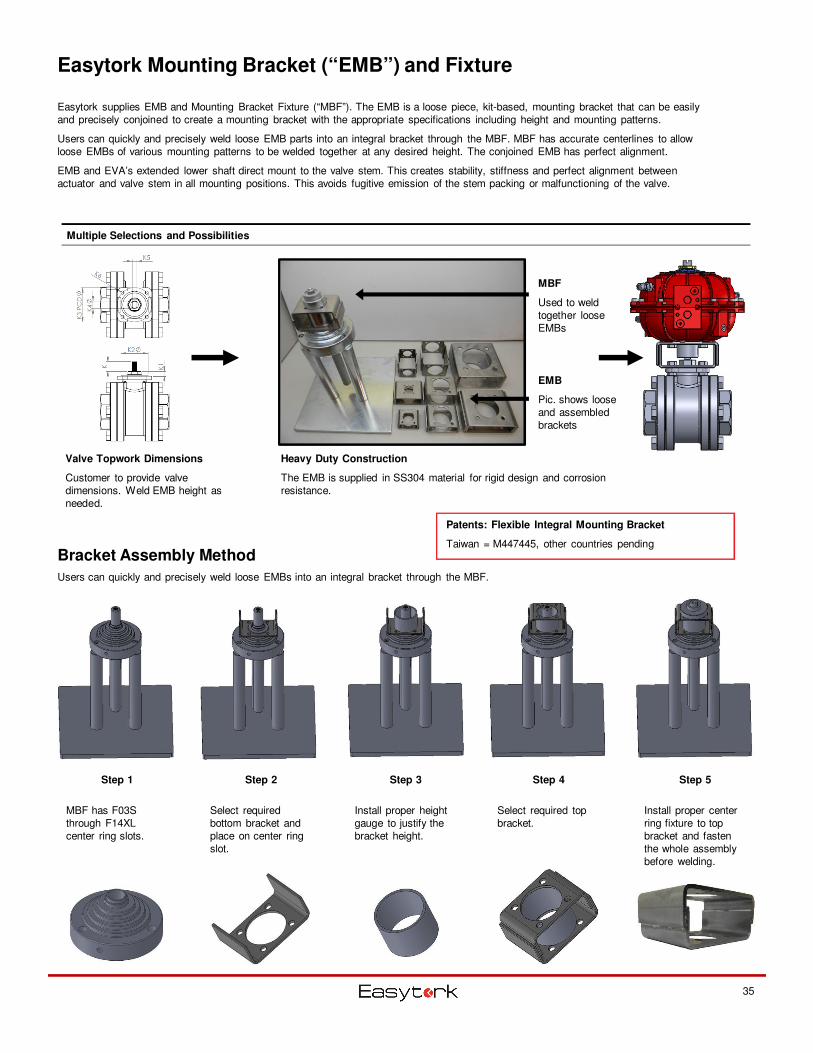
Easytork Mounting Bracket (“EMB”) and Fixture
Easytork supplies EMB and Mounting Bracket Fixture (“MBF”). The EMB is a loose piece, kit-based, mounting bracket that can be easily and precisely conjoined to create a mounting bracket with the appropriate specifications including height and mounting patterns.
Users can quickly and precisely weld loose EMB parts into an integral bracket through the MBF. MBF has accurate centerlines to allow loose EMBs of various mounting patterns to be welded together at any desired height. The conjoined EMB has perfect alignment.
EMB and EVA’s extended lower shaft direct mount to the valve stem. This creates stability, stiffness and perfect alignment between actuator and valve stem in all mounting positions. This avoids fugitive emission of the stem packing or malfunctioning of the valve.
Bracket Assembly Method
Users can quickly and precisely weld loose EMBs into an integral bracket through the MBF.
Multiple Selections and Possibilities
Step 1
MBF has F03S through F14XL center ring slots.
Step 2 Step 3 Step 4 Step 5
Select required bottom bracket and place on center ring slot.
Install proper height gauge to justify the bracket height.
Select required top bracket.
Install proper center ring fixture to top bracket and fasten the whole assembly before welding.
Patents: Flexible Integral Mounting Bracket
Taiwan = M447445, other countries pending
35
Valve Topwork Dimensions
Customer to provide valve dimensions. Weld EMB height as needed.
EMB
Pic. shows loose and assembled brackets
MBF
Used to weld together loose EMBs
Heavy Duty Construction
The EMB is supplied in SS304 material for rigid design and corrosion resistance.
Bottom Side Top Side Dimensions (mm)
(ie. Valve Pattern) (ie. Actuator Pattern) Top & Bottom Joint Dimension Bottom Dimension Top Dimension
Availability Availability A B C F MIN.D MAX.E Ød1 Ød2 Ød3 Ød4 Ød5 Ød6
S Series Bracket 50 66 60 3 30 50
F03S F03S 5.3 25 36 5.3 25 36
F04S F04S 5.3 30 42 5.3 30 42
F05S F05S 6.4 35 50 6.4 35 50
M Series Bracket 70 100 92 4 42 62
F03M F03M 5.3 25 36 5.3 25 36
F04M F04M 5.3 30 42 5.3 30 42
F05M F05M 6.4 35 50 6.4 35 50
F07M F07M 8.4 55 70 8.4 55 70
L Series Bracket 120 150 140 5 52 80
F07L 8.4 55 70
F10L F10L 10.5 70 102 10.5 70 102
F12L F12L 13.0 85 125 13.0 85 125
XL Series Bracket 160 160 150 5 70 100
F10XL 10.5 70 102
F12XL 13.0 85 125
F14XL F14XL 17.0 100 140 17.0 100 140
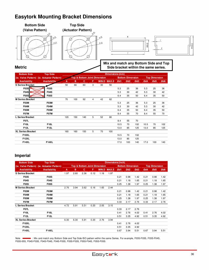
Easytork Mounting Bracket Dimensions
Bottom Side
(Valve Pattern)
Top Side
(Actuator Pattern)
Metric
Imperial
36
Bottom Side Top Side Dimensions (inch)
(ie. Valve Pattern) (ie. Actuator Pattern) Top & Bottom Joint Dimension Bottom Dimension Top Dimension
Availability Availability A B C F MIN.D MAX.E Ød1 Ød2 Ød3 Ød4 Ød5 Ød6
S Series Bracket 1.97 2.60 2.36 0.12 1.18 1.97
F03S F03S 0.21 0.98 1.42 0.21 0.98 1.42
F04S F04S 0.21 1.18 1.65 0.21 1.18 1.65
F05S F05S 0.25 1.38 1.97 0.25 1.38 1.97
M Series Bracket 2.76 3.94 3.62 0.16 1.65 2.44
F03M F03M 0.21 0.98 1.42 0.21 0.98 1.42
F04M F04M 0.21 1.18 1.65 0.21 1.18 1.65
F05M F05M 0.25 1.38 1.97 0.25 1.38 1.97
F07M F07M 0.33 2.17 2.76 0.33 2.17 2.76
L Series Bracket 4.72 5.91 5.51 0.20 2.05 3.15
F07L 0.33 2.17 2.76
F10L F10L 0.41 2.76 4.02 0.41 2.76 4.02
F12L F12L 0.51 3.35 4.92 0.51 3.35 4.92
XL Series Bracket 6.30 6.30 5.91 0.20 2.76 3.94
F10XL 0.41 2.76 4.02
F12XL 0.51 3.35 4.92
F14XL F14XL 0.67 3.94 5.51 0.67 3.94 5.51
Note : Mix and match any Bottom Side and Top Side ISO pattern within the same Series. For example, F03S-F03S, F03S-F04S,
F03S-05S, F04S-F03S, F04S-F04S, F04S-F05S, F05S-F03S, F05S-F04S, F05S-F05S.
Mix and match any Bottom Side and Top Side bracket within the same series.
37
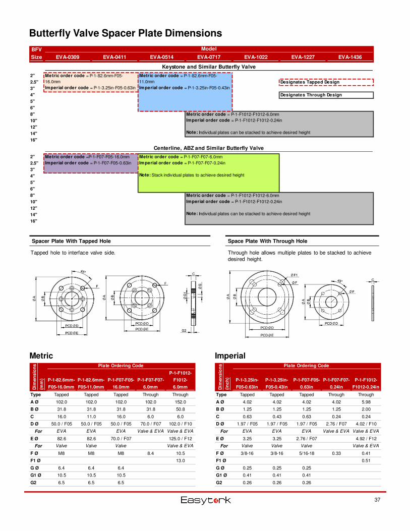
Butterfly Valve Spacer Plate Dimensions
Metric Imperial
Space Plate With Through HoleSpacer Plate With Tapped Hole
Tapped hole to interface valve side. Through hole allows multiple plates to be stacked to achieve desired height.
BFV
Size EVA-0309 EVA-0411 EVA-0514 EVA-0717 EVA-1022 EVA-1227 EVA-1436
Keystone and Similar Butterfly Valve
2"
2.5" Designates Tapped Design
3"
4" Designates Through Design
5"
6"
8"
10"
12"
14"
16"
Centerline, ABZ and Similar Butterfly Valve
2"
2.5"
3"
4"
5"
6"
8"
10"
12"
14"
16"
Model
Metric order code = P-1-82.6mm-F05-
16.0mm
Imperial order code = P-1-3.25in-F05-0.63in
Metric order code = P-1-82.6mm-F05-
11.0mm
Imperial order code = P-1-3.25in-F05-0.43in
Metric order code = P-1-F1012-F1012-6.0mm
Imperial order code = P-1-F1012-F1012-0.24in
Note: Individual plates can be stacked to achieve desired height
Metric order code = P-1-F07-F07-6.0mm
Imperial order code = P-1-F07-F07-0.24in
Note: Stack individual plates to achieve desired height
Metric order code = P-1-F1012-F1012-6.0mm
Imperial order code = P-1-F1012-F1012-0.24in
Note: Individual plates can be stacked to achieve desired height
Metric order code =P-1-F07-F05-16.0mm
Imperial order code = P-1-F07-F05-0.63in
Plate Ordering Code Plate Ordering Code
P-1-82.6mm-
F05-16.0mm
P-1-82.6mm-
F05-11.0mm
P-1-F07-F05-
16.0mm
P-1-F07-F07-
6.0mm
P-1-F1012-
F1012-
6.0mm
P-1-3.25in-
F05-0.63in
P-1-3.25in-
F05-0.43in
P-1-F07-F05-
0.63in
P-1-F07-F07-
0.24in
P-1-F1012-
F1012-0.24in
Type Tapped Tapped Tapped Through Through Type Tapped Tapped Tapped Through Through
A Ø 102.0 102.0 102.0 102.0 152.0 A Ø 4.02 4.02 4.02 4.02 5.98
B Ø 31.8 31.8 31.8 31.8 50.8 B Ø 1.25 1.25 1.25 1.25 2.00
C 16.0 11.0 16.0 6.0 6.0 C 0.63 0.43 0.63 0.24 0.24
D Ø 50.0 / F05 50.0 / F05 50.0 / F05 70.0 / F07 102.0 / F10 D Ø 1.97 / F05 1.97 / F05 1.97 / F05 2.76 / F07 4.02 / F10
For EVA EVA EVA Valve & EVA Valve & EVA For EVA EVA EVA Valve & EVA Valve & EVA
E Ø 82.6 82.6 70.0 / F07 125.0 / F12 E Ø 3.25 3.25 2.76 / F07 4.92 / F12
For Valve Valve Valve Valve & EVA For Valve Valve Valve Valve & EVA
F Ø M8 M8 M8 8.4 10.5 F Ø 3/8-16 3/8-16 5/16-18 0.33 0.41
F1 Ø 13.0 F1 Ø 0.51
G Ø 6.4 6.4 6.4 G Ø 0.25 0.25 0.25
G1 Ø 10.5 10.5 10.5 G1 Ø 0.41 0.41 0.41
G2 6.5 6.5 6.5 G2 0.26 0.26 0.26
Dim
en
sio
ns
(mm
)
Dim
en
sio
ns
(in
ch
)
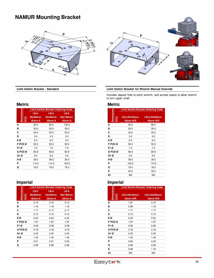
NAMUR Mounting Bracket
38
Metric
Imperial
Limit Switch Bracket for Wrench Manual OverrideLimit Switch Bracket - Standard
Includes tapped hole to store wrench, and access space to allow wrench to turn upper shaft.
Metric
Imperial
Limit Switch Bracket Ordering Code
LB-2-
30x80mm-
45mm-X
LB-2-
30x80mm-
55mm-X
LB-2-
30x130mm-
55mm-X
A 80.0 80.0 130.0
B 30.0 30.0 30.0
C 45.0 55.0 55.0
D 3.0 3.0 3.0
E Ø 6.0 6.0 6.0
F PCD Ø 50.0 50.0 50.0
F1 Ø 7.0 7.0 7.0
G PCD Ø 80.8 80.8 80.8
G1 Ø 9.0 9.0 9.0
H Ø 36.0 36.0 36.0
P 114.5 114.5 165.0
Q 76.0 76.0 76.0
Dim
en
sio
ns
(mm
)
Limit Switch Bracket Ordering Code
LB-2-
30x80mm-
45mm-X
LB-2-
30x80mm-
55mm-X
LB-2-
30x130mm-
55mm-X
A 3.15 3.15 5.12
B 1.18 1.18 1.18
C 1.77 2.17 2.17
D 0.12 0.12 0.12
E Ø 0.24 0.24 0.24
F PCD Ø 1.97 1.97 1.97
F1 Ø 0.28 0.28 0.28
G PCD Ø 3.18 3.18 3.18
G1 Ø 0.35 0.35 0.35
H Ø 1.42 1.42 1.42
P 4.51 4.51 6.50
Q 2.99 2.99 2.99
Dim
en
sio
ns
(in
ch
)
Limit Switch Bracket Ordering Code
LB-2-25x50mm-
45mm-WR
LB-2-30x80mm-
45mm-WR
A 50.0 80.0
B 25.0 30.0
C 45.0 45.0
D 3.0 3.0
E Ø 6.0 6.0
F PCD Ø 50.0 50.0
F1 Ø 7.0 7.0
G PCD Ø 80.8 80.8
G1 Ø 9.0 9.0
H Ø 36.0 36.0
P 100.0 110.0
Q 76.0 76.0
K 25.0 30.0
K1 M5 M5
Dim
en
sio
ns
(mm
)
Limit Switch Bracket Ordering Code
LB-2-25x50mm-
45mm-WR
LB-2-30x80mm-
45mm-WR
A 1.97 3.15
B 0.98 1.18
C 1.77 1.77
D 0.12 0.12
E Ø 0.24 0.24
F PCD Ø 1.97 1.97
F1 Ø 0.28 0.28
G PCD Ø 3.18 3.18
G1 Ø 0.35 0.35
H Ø 1.42 1.42
P 3.94 4.33
Q 2.99 2.99
K 0.98 1.18
K1 M5 M5
Dim
en
sio
ns
(in
ch
)
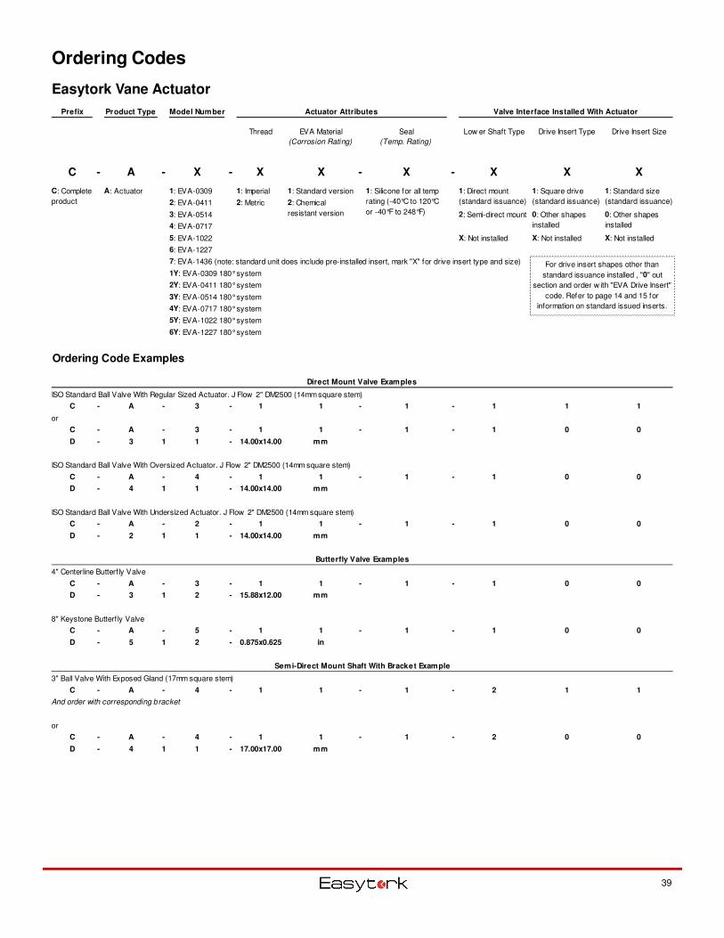
Ordering Codes
Easytork Vane Actuator
39
Prefix Product Type Model Number Actuator Attributes Valve Interface Installed With Actuator
Thread EVA Material
(Corrosion Rating)
Seal
(Temp. Rating)
Low er Shaft Type Drive Insert Type Drive Insert Size
C - A - X - X X - X - X X X
A: Actuator 1: EVA-0309 1: Imperial 1: Standard version
2: EVA-0411 2: Metric
3: EVA-0514 2: Semi-direct mount
4: EVA-0717
5: EVA-1022 X: Not installed X: Not installed X: Not installed
6: EVA-1227
7: EVA-1436 (note: standard unit does include pre-installed insert, mark "X" for drive insert type and size)
1Y: EVA-0309 180° system
2Y: EVA-0411 180° system
3Y: EVA-0514 180° system
4Y: EVA-0717 180° system
5Y: EVA-1022 180° system
6Y: EVA-1227 180° system
Ordering Code Examples
Direct Mount Valve Examples
ISO Standard Ball Valve With Regular Sized Actuator. J Flow 2" DM2500 (14mm square stem)
C - A - 3 - 1 1 - 1 - 1 1 1
or
C - A - 3 - 1 1 - 1 - 1 0 0
D - 3 1 1 - 14.00x14.00 mm
ISO Standard Ball Valve With Oversized Actuator. J Flow 2" DM2500 (14mm square stem)
C - A - 4 - 1 1 - 1 - 1 0 0
D - 4 1 1 - 14.00x14.00 mm
ISO Standard Ball Valve With Undersized Actuator. J Flow 2" DM2500 (14mm square stem)
C - A - 2 - 1 1 - 1 - 1 0 0
D - 2 1 1 - 14.00x14.00 mm
Butterfly Valve Examples
4" Centerline Butterf ly Valve
C - A - 3 - 1 1 - 1 - 1 0 0
D - 3 1 2 - 15.88x12.00 mm
8" Keystone Butterf ly Valve
C - A - 5 - 1 1 - 1 - 1 0 0
D - 5 1 2 - 0.875x0.625 in
Semi-Direct Mount Shaft With Bracket Example
3" Ball Valve With Exposed Gland (17mm square stem)
C - A - 4 - 1 1 - 1 - 2 1 1
And order with corresponding bracket
or
C - A - 4 - 1 1 - 1 - 2 0 0
D - 4 1 1 - 17.00x17.00 mm
For drive insert shapes other than
standard issuance installed , "0" out
section and order w ith "EVA Drive Insert"
code. Refer to page 14 and 15 for
information on standard issued inserts.
C: Complete
product
1: Silicone for all temp
rating (-40°C to 120°C
or -40°F to 248°F)
2: Chemical
resistant version 0: Other shapes
installed
0: Other shapes
installed
1: Direct mount
(standard issuance)
1: Square drive
(standard issuance)
1: Standard size
(standard issuance)
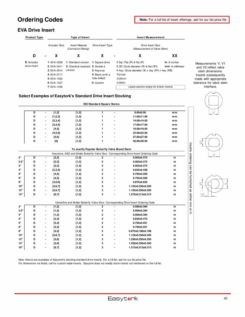
Ordering Codes
EVA Drive Insert
40
Product Type Type of Insert Insert Measurement
Actuator Size Insert Material
(Corrosion Rating)
Drive Insert Type
D - X X X - X XX
1: EVA-0309 1: Standard version 1: Square drive If Sqr: Flat (V) x f lat (V) in: In inches
2: EVA-0411 2: Double d If DD: Circle diameter (V) x f lat (V1) mm : In millimeter
3: EVA-0514 3: Keyw ay If Key: Circle diameter (V) x key (V1) x key (V2)
4: EVA-0717 Format:
5: EVA-1022 0.00mm
6: EVA-1227 0: Custom 0.000in
7: EVA-1436
Select Examples of Easytork's Standard Drive Insert Stocking
ISO Standard Square Stems
D - [1,2] [1,2] 1 - 9.00x9.00 mm
D - [1,2,3] [1,2] 1 - 11.00x11.00 mm
D - [2,3,4] [1,2] 1 - 14.00x14.00 mm
D - [3,4,5] [1,2] 1 - 17.00x17.00 mm
D - [4,5] [1,2] 1 - 19.00x19.00 mm
D - [4,5,6] [1,2] 1 - 22.00x22.00 mm
D - [5,6] [1,2] 1 - 27.00x27.00 mm
D - [6] [1,2] 1 - 36.00x36.00 mm
To Justify Popular Butterfly Valve Brand Stem
Keystone, ABZ and Similar Butterf ly Valve Size / Corresponding Drive Insert Ordering Code
2" D - [2,3] [1,2] 2 - 0.563x0.375 in
2.5" D - [2,3] [1,2] 2 - 0.563x0.375 in
3" D - [2,3] [1,2] 2 - 0.563x0.375 in
4" D - [2,3,4] [1,2] 2 - 0.625x0.438 in
5" D - [4,5] [1,2] 2 - 0.750x0.500 in
6" D - [4,5] [1,2] 2 - 0.750x0.500 in
8" D - [4,5,6] [1,2] 2 - 0.875x0.625 in
10" D - [5,6,7] [1,2] 3 - 1.125x0.250x0.250 in
12" D - [5,6,7] [1,2] 3 - 1.125x0.250x0.250 in
14" D - [6,7] [1,2] 3 - 1.375x0.313x0.313 in
Centerline and Similar Butterf ly Valve Size / Corresponding Drive Insert Ordering Code
2" D - [1,2] [1,2] 2 - 0.500x0.394 in
2.5" D - [1,2] [1,2] 2 - 0.500x0.394 in
3" D - [1,2] [1,2] 2 - 0.500x0.394 in
4" D - [2,3] [1,2] 2 - 0.625x0.472 in
5" D - [3,4] [1,2] 2 - 0.750x0.551 in
6" D - [3,4] [1,2] 2 - 0.750x0.551 in
8" D - [4,5] [1,2] 3 - 0.875x0.188x0.188 in
10" D - [5,6,7] [1,2] 3 - 1.125x0.250x0.250 in
12" D - [5,6] [1,2] 3 - 1.250x0.250x0.250 in
14" D - [5,6] [1,2] 3 - 1.250x0.250x0.250 in
16" D - [6,7] [1,2] 3 - 1.313x0.313x0.313 in
Drive Insert Size
(Measurement of Valve Stem)
Inserts
ord
erin
g c
an b
e fu
rnis
hed a
s e
ither m
m o
r in
Note: Above are examples of Easytork's stocking standard drive inserts. For a full list, ask for our list price f ile.
For dimensions not listed, call for custom made inserts. Easytork does not readily stock inserts not mentioned on the full list.
Leave section empty for blank inserts
D: Actuator
drive insert 2: Chemical resistant
version
4: Blank (w ith a
hole drilled)
Measurements V, V1 and V2 reflect valve stem dimensions.
Inserts subsequently made with appropriate
tolerance for valve stem interface.
Note: For a full list of insert offerings, ask for our list price file
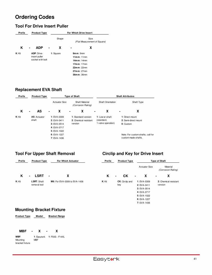
Ordering Codes
41
Tool For Drive Insert Puller
Prefix Product Type For Which Actuator
K - LSRT - X
K: Kit M6: For EVA-0309 to EVA-1436LSRT: Shaft
removal tool
Tool For Upper Shaft Removal
Replacement EVA Shaft
Prefix Product Type Type of Shaft Shaft Attributes
Actuator Size Shaft Material
(Corrosion Rating)
Shaft Orientation Shaft Type
K - AS - X - X - X - X
K: Kit 1: EVA-0309 1: Standard version 1: Direct mount
2: EVA-0411 2: Semi-direct mount
3: EVA-0514 0: Custom
4: EVA-0717
5: EVA-1022
6: EVA-1227
7: EVA-1436
Note: For custom shafts, call for
custom made shafts.
2: Chemical resistant
version
AS: Actuator
shaft
1: Low er shaft
(standard,
1 valve operation)
Mounting Bracket Fixture
Product Type Model Bracket Range
MBF - X - X
1: F03S - F14XL1: Easytork
MBF
MBF:
Mounting
bracket f ixture
Prefix Product Type For Which Drive Insert
Shape Size
(Flat Measurement of Square)
K - ADP - X - X
K: Kit 1: Square 9mm : 9mm
11mm : 11mm
14mm : 14mm
17mm : 17mm
22mm : 22mm
27mm : 27mm
36mm : 36mm
ADP: Drive
insert puller
socket w ith bolt
Prefix Product Type Type of Shaft
Actuator Size Material
(Corrosion Rating)
K - CK - X - X
K: Kit 1: EVA-0309
2: EVA-0411
3: EVA-0514
4: EVA-0717
5: EVA-1022
6: EVA-1227
7: EVA-1436
CK: Circlip and
key
2: Chemical resistant
version
Circlip and Key for Drive Insert
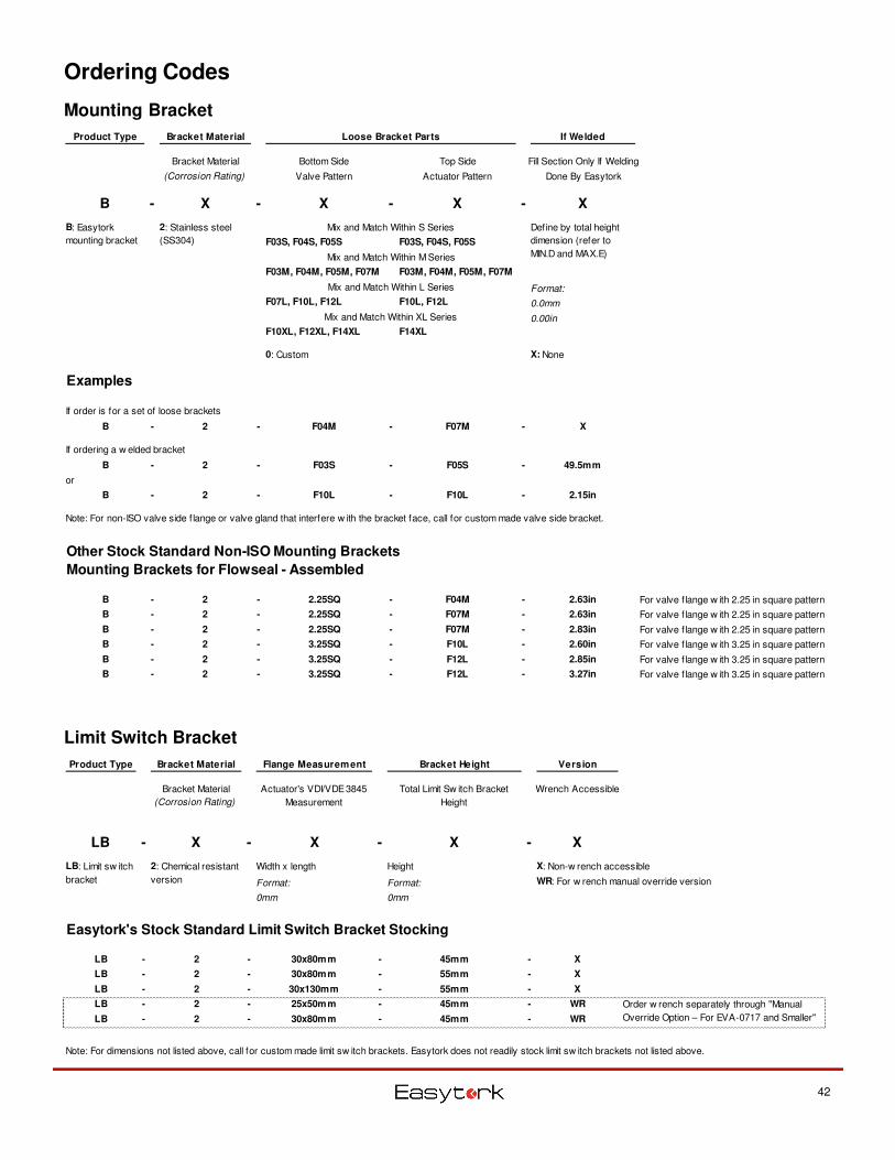
Ordering Codes
42
Mounting Bracket
Product Type Bracket Material Loose Bracket Parts If Welded
Bracket Material Bottom Side Top Side Fill Section Only If Welding
(Corrosion Rating) Valve Pattern Actuator Pattern Done By Easytork
B - X - X - X - X
Mix and Match Within S Series
F03S, F04S, F05S F03S, F04S, F05S
Mix and Match Within M Series
F03M, F04M, F05M, F07M F03M, F04M, F05M, F07M
Mix and Match Within L Series Format:
F07L, F10L, F12L F10L, F12L 0.0mm
Mix and Match Within XL Series 0.00in
F10XL, F12XL, F14XL F14XL
0: Custom X: None
Examples
If order is for a set of loose brackets
B - 2 - F04M - F07M - X
If ordering a w elded bracket
B - 2 - F03S - F05S - 49.5mm
or
B - 2 - F10L - F10L - 2.15in
Note: For non-ISO valve side f lange or valve gland that interfere w ith the bracket face, call for custom made valve side bracket.
Other Stock Standard Non-ISO Mounting Brackets
Mounting Brackets for Flowseal - Assembled
B - 2 - 2.25SQ - F04M - 2.63in For valve f lange w ith 2.25 in square pattern
B - 2 - 2.25SQ - F07M - 2.63in For valve f lange w ith 2.25 in square pattern
B - 2 - 2.25SQ - F07M - 2.83in For valve f lange w ith 2.25 in square pattern
B - 2 - 3.25SQ - F10L - 2.60in For valve f lange w ith 3.25 in square pattern
B - 2 - 3.25SQ - F12L - 2.85in For valve f lange w ith 3.25 in square pattern
B - 2 - 3.25SQ - F12L - 3.27in For valve f lange w ith 3.25 in square pattern
B: Easytork
mounting bracket
Define by total height
dimension (refer to
MIN.D and MAX.E)
2: Stainless steel
(SS304)
Limit Switch Bracket
Product Type Bracket Material Flange Measurement Bracket Height Version
Bracket Material
(Corrosion Rating)
Actuator's VDI/VDE 3845
Measurement
Total Limit Sw itch Bracket
Height
Wrench Accessible
LB - X - X - X - X
Width x length Height X: Non-w rench accessible
Format: Format: WR: For w rench manual override version
0mm 0mm
Easytork's Stock Standard Limit Switch Bracket Stocking
LB - 2 - 30x80mm - 45mm - X
LB - 2 - 30x80mm - 55mm - X
LB - 2 - 30x130mm - 55mm - X
LB - 2 - 25x50mm - 45mm - WR
LB - 2 - 30x80mm - 45mm - WR
Note: For dimensions not listed above, call for custom made limit sw itch brackets. Easytork does not readily stock limit sw itch brackets not listed above.
LB: Limit sw itch
bracket
2: Chemical resistant
version
Order w rench separately through "Manual
Override Option – For EVA-0717 and Smaller"
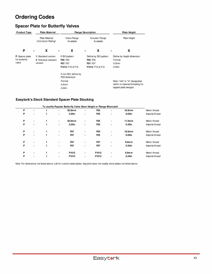
Ordering Codes
43
Spacer Plate for Butterfly Valves
Product Type Plate Material Flange Description Plate Height
Plate Material
(Corrosion Rating)
Valve Flange
Available
Actuator Flange
Available
Plate Height
P - X - X - X - X
1: Standard version If ISO pattern Define by ISO pattern Define by height dimension
F05: F05 F05: F05 Format
F07: F07 F07: F07 0.0mm
F1012: F10 & F12 F1012: F10 & F12 0.00in
Format
0.0mm
0.00in
Easytork's Stock Standard Spacer Plate Stocking
To Justify Popular Butterfly Valve Stem Height or Flange Mismatch
P - 1 - 82.6mm - F05 - 16.0mm Metric thread
P - 1 - 3.25in - F05 - 0.63in Imperial thread
P - 1 - 82.6mm - F05 - 11.0mm Metric thread
P - 1 - 3.25in - F05 - 0.43in Imperial thread
P - 1 - F07 - F05 - 16.0mm Metric thread
P - 1 - F07 - F05 - 0.63in Imperial thread
P - 1 - F07 - F07 - 6.0mm Metric thread
P - 1 - F07 - F07 - 0.24in Imperial thread
P - 1 - F1012 - F1012 - 6.0mm Metric thread
P - 1 - F1012 - F1012 - 0.24in Imperial thread
Note: For dimensions not listed above, call for custom made plates. Easytork does not readily stock plates not listed above.
If non-ISO, define by
PCD dimension
2: Chemical resistant
version
P: Spacer plate
for butterf ly
valve
Note: "mm" or "in" designates
metric or imperial threading for
tapped plate designs
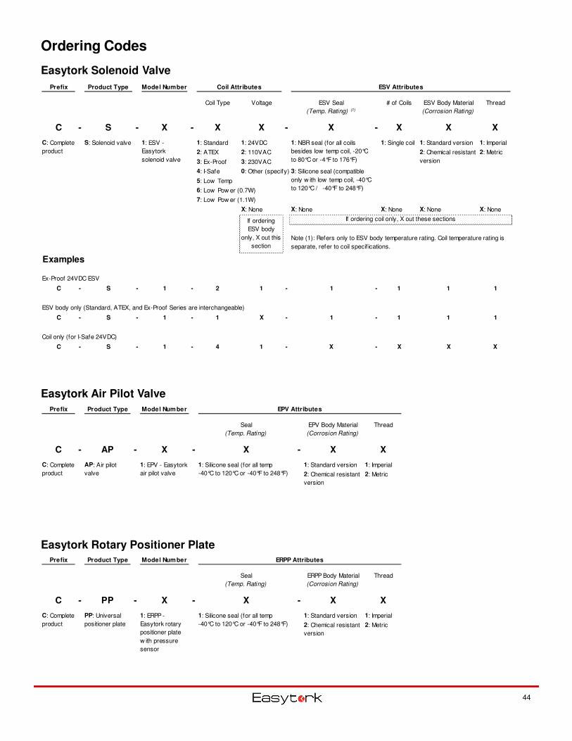
Ordering Codes
Easytork Solenoid Valve
Easytork Air Pilot Valve
Easytork Rotary Positioner Plate
44
Prefix Product Type Model Number ERPP Attributes
Seal
(Temp. Rating)
ERPP Body Material
(Corrosion Rating)
Thread
C - PP - X - X - X X
1: Standard version 1: Imperial
2: Metric2: Chemical resistant
version
C: Complete
product
PP: Universal
positioner plate
1: ERPP -
Easytork rotary
positioner plate
w ith pressure
sensor
1: Silicone seal (for all temp
-40°C to 120°C or -40°F to 248°F)
Prefix Product Type Model Number EPV Attributes
Seal
(Temp. Rating)
EPV Body Material
(Corrosion Rating)
Thread
C - AP - X - X - X X
1: Standard version 1: Imperial
2: Metric
1: Silicone seal (for all temp
-40°C to 120°C or -40°F to 248°F) 2: Chemical resistant
version
C: Complete
product
AP: Air pilot
valve
1: EPV - Easytork
air pilot valve
Prefix Product Type Model Number Coil Attributes ESV Attributes
Coil Type Voltage ESV Seal
(Temp. Rating) (1)
# of Coils ESV Body Material
(Corrosion Rating)
Thread
C - S - X - X X - X - X X X
1: Standard 1: 24VDC 1: Single coil 1: Standard version 1: Imperial
2: ATEX 2: 110VAC 2: Metric
3: Ex-Proof 3: 230VAC
4: I-Safe 0: Other (specify)
5: Low Temp
6: Low Pow er (0.7W)
7: Low Pow er (1.1W)
X: None X: None X: None X: None X: None
Examples
Ex-Proof 24VDC ESV
C - S - 1 - 2 1 - 1 - 1 1 1
ESV body only (Standard, ATEX, and Ex-Proof Series are interchangeable)
C - S - 1 - 1 X - 1 - 1 1 1
Coil only (for I-Safe 24VDC)
C - S - 1 - 4 1 - X - X X X
1: ESV -
Easytork
solenoid valve
C: Complete
product
1: NBR seal (for all coils
besides low temp coil, -20°C
to 80°C or -4°F to 176°F)
3: Silicone seal (compatible
only w ith low temp coil, -40°C
to 120°C / -40°F to 248°F)
If ordering coil only, X out these sections
2: Chemical resistant
version
S: Solenoid valve
If ordering
ESV body
only, X out this
section
Note (1): Refers only to ESV body temperature rating. Coil temperature rating is
separate, refer to coil specif ications.
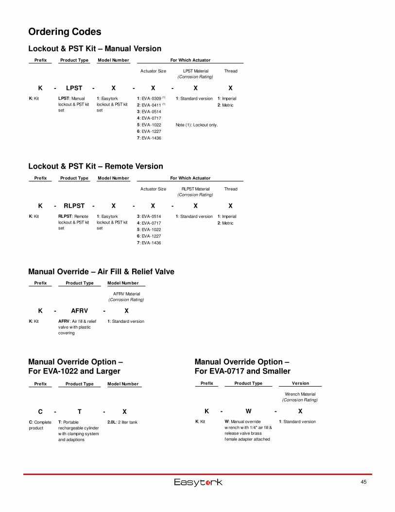
Ordering Codes
45
Lockout & PST Kit – Manual Version
Manual Override Option –For EVA-1022 and Larger
Prefix Product Type Version
Wrench Material
(Corrosion Rating)
K - W - X
K: Kit 1: Standard versionW: Manual override
w rench w ith 1/4" air f ill &
release valve brass
female adapter attached
Manual Override Option –For EVA-0717 and Smaller
Prefix Product Type Model Number
C - T - X
2.0L: 2 liter tankC: Complete
product
T: Portable
rechargeable cylinder
w ith clamping system
and adaptions
Prefix Product Type Model Number
AFRV Material
(Corrosion Rating)
K - AFRV - X
1: Standard versionK: Kit AFRV: Air f ill & relief
valve w ith plastic
covering
Manual Override – Air Fill & Relief Valve
Lockout & PST Kit – Remote Version
Prefix Product Type Model Number For Which Actuator
Actuator Size LPST Material
(Corrosion Rating)
Thread
K - LPST - X - X - X X
1: EVA-0309 (1) 1: Standard version 1: Imperial
2: EVA-0411 (1) 2: Metric
3: EVA-0514
4: EVA-0717
5: EVA-1022
6: EVA-1227
7: EVA-1436
Note (1): Lockout only.
K: Kit 1: Easytork
lockout & PST kit
set
LPST: Manual
lockout & PST kit
set
Prefix Product Type Model Number For Which Actuator
Actuator Size RLPST Material
(Corrosion Rating)
Thread
K - RLPST - X - X - X X
3: EVA-0514 1: Imperial
4: EVA-0717 2: Metric
5: EVA-1022
6: EVA-1227
7: EVA-1436
1: Standard versionK: Kit 1: Easytork
lockout & PST kit
set
RLPST: Remote
lockout & PST kit
set
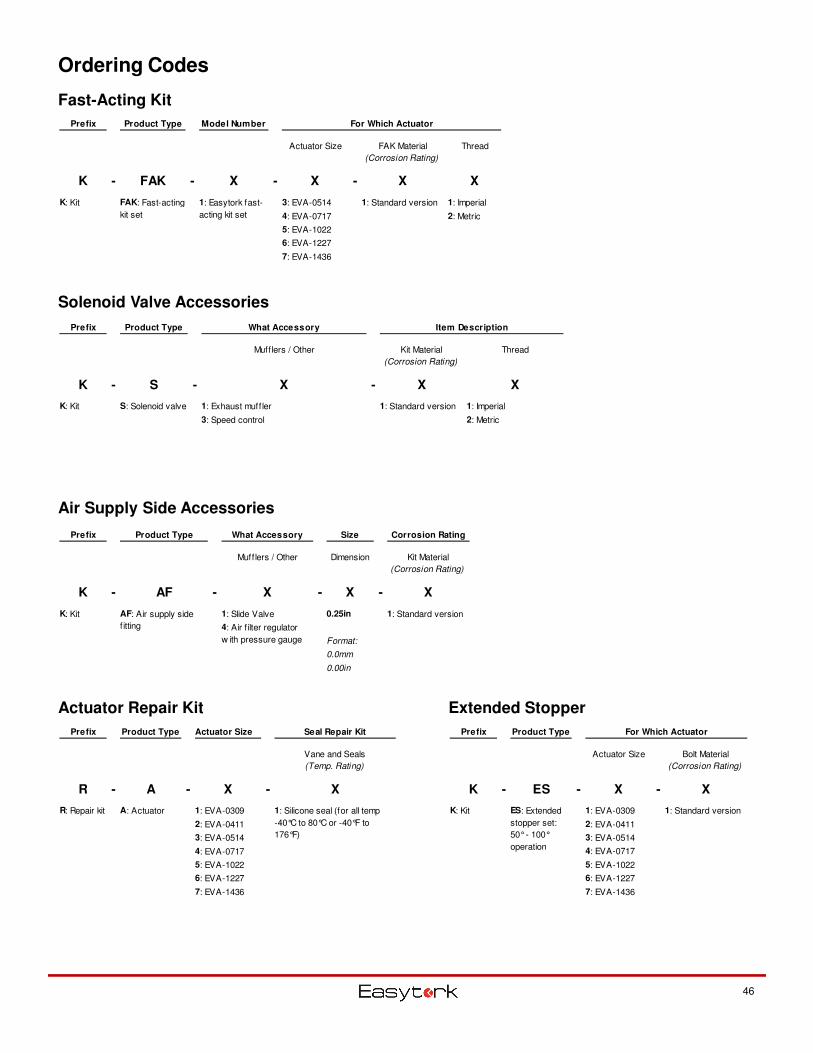
Ordering Codes
46
Prefix Product Type What Accessory Item Description
Mufflers / Other Kit Material
(Corrosion Rating)
Thread
K - S - X - X X
K: Kit 1: Exhaust muffler 1: Standard version 1: Imperial
3: Speed control 2: Metric
S: Solenoid valve
Solenoid Valve Accessories
Prefix Product Type For Which Actuator
Actuator Size Bolt Material
(Corrosion Rating)
K - ES - X - X
K: Kit 1: EVA-0309
2: EVA-0411
3: EVA-0514
4: EVA-0717
5: EVA-1022
6: EVA-1227
7: EVA-1436
ES: Extended
stopper set:
50° - 100°
operation
1: Standard version
Prefix Product Type Actuator Size Seal Repair Kit
Vane and Seals
(Temp. Rating)
R - A - X - X
R: Repair kit A: Actuator 1: EVA-0309
2: EVA-0411
3: EVA-0514
4: EVA-0717
5: EVA-1022
6: EVA-1227
7: EVA-1436
1: Silicone seal (for all temp
-40°C to 80°C or -40°F to
176°F)
Actuator Repair Kit Extended Stopper
Air Supply Side Accessories
Prefix Product Type What Accessory Size Corrosion Rating
Mufflers / Other Dimension Kit Material
(Corrosion Rating)
K - AF - X - X - X
K: Kit 1: Slide Valve 0.25in 1: Standard version
Format:
0.0mm
0.00in
AF: Air supply side
f itting 4: Air f ilter regulator
w ith pressure gauge
Prefix Product Type Model Number For Which Actuator
Actuator Size FAK Material
(Corrosion Rating)
Thread
K - FAK - X - X - X X
3: EVA-0514 1: Standard version 1: Imperial
4: EVA-0717 2: Metric
5: EVA-1022
6: EVA-1227
7: EVA-1436
K: Kit FAK: Fast-acting
kit set
1: Easytork fast-
acting kit set
Fast-Acting Kit
Note Section
Global Headquarters
Main Tel: +1-314-266-0670
Main Fax: +1-314-222-7057
www.easytork.com