Embed Size (px)
Citation preview
DISTRIBUTED SMA ACTUATORS FOR
MULTIDIRECTIONAL MANIPULATION
OF AN ACTIVE NEEDLE: INVESTIGATION
ON INTERNAL PHASE
TRANSFORMATION OF SMAS FOR
PRECISE ASSEMBLY AND
PERFORMANCE
A THESIS SUBMITTED TO THE GRADUATE DIVISION OF THE
UNIVERSITY OF HAWAIʻI AT MĀNOA IN PARTIAL FULFILLMENT
OF THE REQUIREMENTS FOR THE DEGREE OF
MASTER OF SCIENCE
IN
MECHANICAL ENGINEERING
DECEMBER 2020
By
Blayton Kenji Padasdao
Thesis Committee:
Bardia Konh, Chairperson
Scott Miller
Reza Ghorbani
Keywords: SMA, active needle, needle insertion
ii
ACKNOWLEDGEMENTS
First and foremost, I would like to thank my advisor, Dr. Bardia Konh, who welcomed me
to the AMMI lab and supported my research despite the many obstacles that were encountered. I
would also like to thank all of my colleagues (Zahra Khashei Varnamkhasti, Saeed Karimi, and
Zolboo Batsaikhan) in the AMMI lab who greatly motivated me throughout the graduate program.
I also owe a huge thank you to Dr. Philip von Doetinchem for the invaluable experience I gained
as a physics lab teaching assistant. Last but not least, I would like to thank my MS thesis
committee: Dr. Scott Miller and Dr. Reza Ghorbani for their help and insight.
iii
ABSTRACT
Today, several medical diagnosis and therapeutic cancer interventions are performed using
needles via percutaneous surgical procedures. It is often challenging to guide and track the needle
in a desired path to reach the target precisely, while avoiding sensitive organs or large arteries so
the success of these procedures highly depends on accurate placement of the needle tip at target
positions. Improving targeting accuracy necessitates improvements in medical imaging and needle
steering techniques. The former provides an improved vision on the target (i.e., cancerous tissue)
and the needle, while the latter enables an enhanced interventional tool. In spite of considerable
advancements in the medical imaging field, the structure of the needle itself has remained
unchanged. In the past decade, research works have suggested passive or active navigation of the
needle inside the tissue to improve targeting accuracy. In addition, to provide actuation and control
for needle steering, an active needle has been introduced that is activated by shape memory alloy
(SMA) actuators. However, actuation of SMAs is complex due to their nonlinear and hysteresis
behavior that depends on stress, strain, and temperature during operation.
This thesis is the culmination of studies involving the rapid manufacturing (via 3D
printing), precise assembly, and performance evaluation of multiple distributed SMA actuators in
an active flexible needle while also introducing a robot-assisted tracking system to provide the 3D
position of the needle tip during a needle insertion task. A robotic system has been developed and
programmed to move the ultrasound transducer on top of the needle tip with an adjusted velocity
while simultaneously controlling another system to pull the cable tendons and control the needle
deflection inside tissue. The position of the needle tip is provided by applying a series of image
processing techniques on transverse ultrasound images. The tracking system is tested on several
iv
needle insertion tests in a phantom tissue. The needle tip position is compared with measured data
obtained via a vision-based technique (using a camera).
Through the first study, the interactive response of the SMA actuators was investigated
using experimental tests, constitutive material model, and kinematics of the active needle. It was
shown that with proper installation of SMA actuators on the active needle, an effective
manipulation can be realized in three dimensions. The results from the second study shows that
our proposed robot-assisted ultrasound tracking method can be used to track the needle tip (average
error less than 1.5 mm) in real-time since the computational time is quite low (in milliseconds).

v
Table of Contents
ACKNOWLEDGEMENTS........................................................................................................ ii
ABSTRACT ............................................................................................................................. iii
LIST OF TABLES ................................................................................................................... vii
LIST OF FIGURES ................................................................................................................ viii
LIST OF ABBREVIATIONS.................................................................................................... ix
LIST OF SYMBOLS ..................................................................................................................x
Chapter 1. INTRODUCTION .....................................................................................................1
1.1. Cancer statistics .........................................................................................................2
1.2. Needle-based interventions ........................................................................................3
1.2.1. Importance of targeting accuracy ...........................................................................4
1.2.2. Literature search of previous needles......................................................................5
1.3. Background information on shape memory alloys .....................................................7
1.4. Background information on image-guided needle insertion ........................................9
Chapter 2. SHAPE MEMORY ALLOY ACTUATORS IN AN ACTIVE NEEDLE –
MODELING, PRECISE ASSEMBLY, AND PERFORMANCE EVALUATION ..................... 11
2.1. Materials and methods ............................................................................................. 12
2.1.1. Design concept of the 3D steerable SMA-activated needle ................................... 12
2.1.2. Active needle fabrication via rapid manufacturing................................................ 13
2.1.3. Installation of SMA actuators via a precise assembly process ............................... 14
2.1.4. Constitutive material modeling of SMAs.............................................................. 16
2.1.5. Kinematics of the active needle ............................................................................ 20
2.1.6. Experimental setup for performance evaluation of the active needle ..................... 21
2.2. Results..................................................................................................................... 22
2.2.1. Performance evaluation – 3D manipulation of the active needle ........................... 22
2.2.2. Interactive response of shape memory alloys during active needle operation ........ 26
2.2.3. Evaluation of a practical-size active needle deflection in air and inside tissue for
clinical application ............................................................................................................ 29
Chapter 3. 3D STEERABLE BIOPSY NEEDLE WITH A MOTORIZED MANIPULATION
SYSTEM AND ULTRASOUND TRACKING TO NAVIGATE INSIDE TISSUE ................... 33
3.1. Materials and methods ............................................................................................. 34
3.1.1. Design and fabrication of a 3D steerable biopsy needle ........................................ 34
3.1.2. Motorized manipulation system to bend the needle .............................................. 35
3.1.3. Robotic needle insertion system with ultrasound imaging feedback ...................... 36

vi
3.2. Results..................................................................................................................... 40
3.2.1. Improved visualization of the needle and real-time tracking with ultrasound ........ 41
CONCLUSION ......................................................................................................................... 46
FUTURE WORK ...................................................................................................................... 47
REFERENCES ......................................................................................................................... 48

vii
LIST OF TABLES
Table 1. Top 3 common types of cancer and the statistics for both male and females in 2019. .....2
Table 2. Material properties of the SMA wires used as actuators for the active needle. .............. 19 Table 3. Four case studies to evaluate the accuracy of our tracking method. .............................. 40
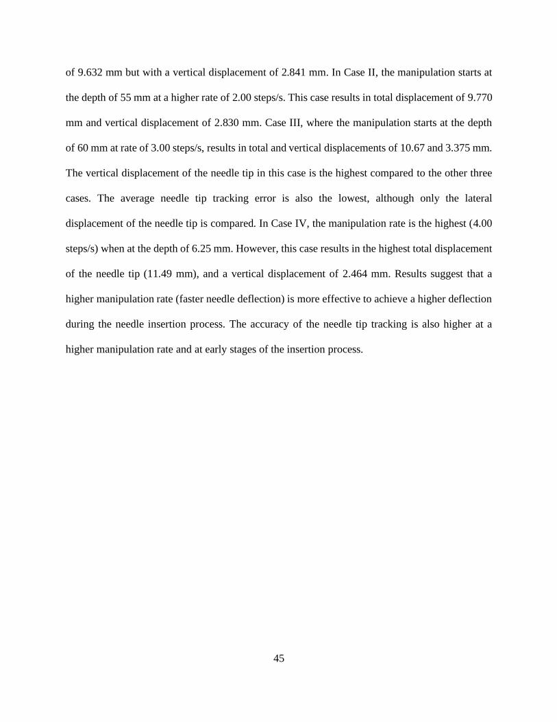
Table 4. Average and maximum error in needle tip tracking ...................................................... 44
viii
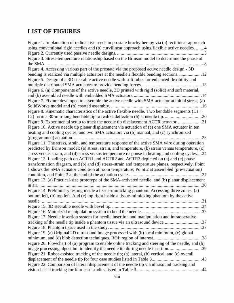
LIST OF FIGURES
Figure 1. Implantation of radioactive seeds in prostate brachytherapy via (a) rectilinear approach
using conventional rigid needles and (b) curvilinear approach using flexible active needles. .......4 Figure 2. Currently used passive needle designs. .........................................................................5
Figure 3. Stress-temperature relationship based on the Brinson model to determine the phase of
the SMA......................................................................................................................................8
Figure 4. Accessing various part of the prostate via the proposed active needle design - 3D
bending is realized via multiple actuators at the needle's flexible bending sections. ................... 12
Figure 5. Design of a 3D steerable active needle with soft tubes for enhanced flexibility and
multiple distributed SMA actuators to provide bending forces. .................................................. 13
Figure 6. (a) Components of the active needle, 3D printed with rigid (solid) and soft material,
and (b) assembled needle with embedded SMA actuators. ......................................................... 14
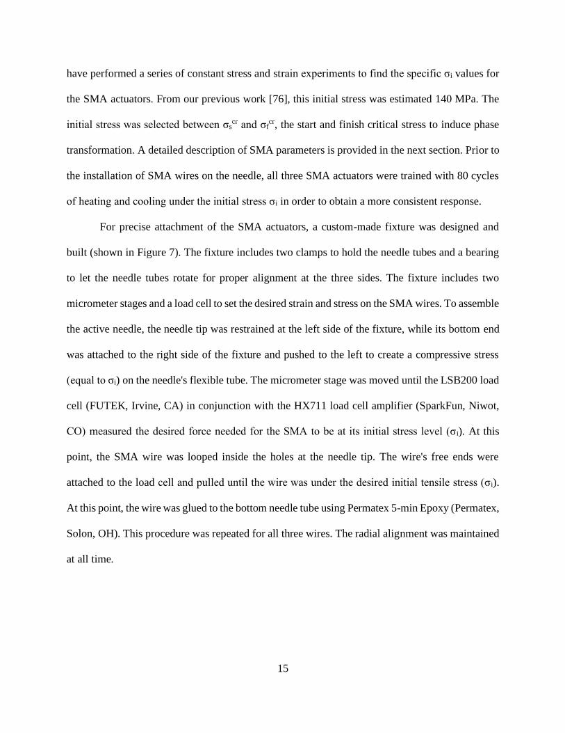
Figure 7. Fixture developed to assemble the active needle with SMA actuator at initial stress; (a)
SolidWorks model and (b) created assembly. ............................................................................ 16
Figure 8. Kinematic characteristics of the active flexible needle. Two bendable segments (L1 +
L2) form a 30-mm-long bendable tip to realize deflection (δ) at needle tip. ............................... 20
Figure 9. Experimental setup to track the needle tip displacement ACTR actuator. .................... 21 Figure 10. Active needle tip planar displacement via actuation of (a) one SMA actuator in ten
heating and cooling cycles, and two SMA actuators via (b) manual, and (c) synchronized
(programmed) actuation. ........................................................................................................... 23
Figure 11. The stress, strain, and temperature response of the active SMA wire during operation
predicted by Brinson model: (a) stress, strain, and temperature, (b) strain versus temperature, (c)
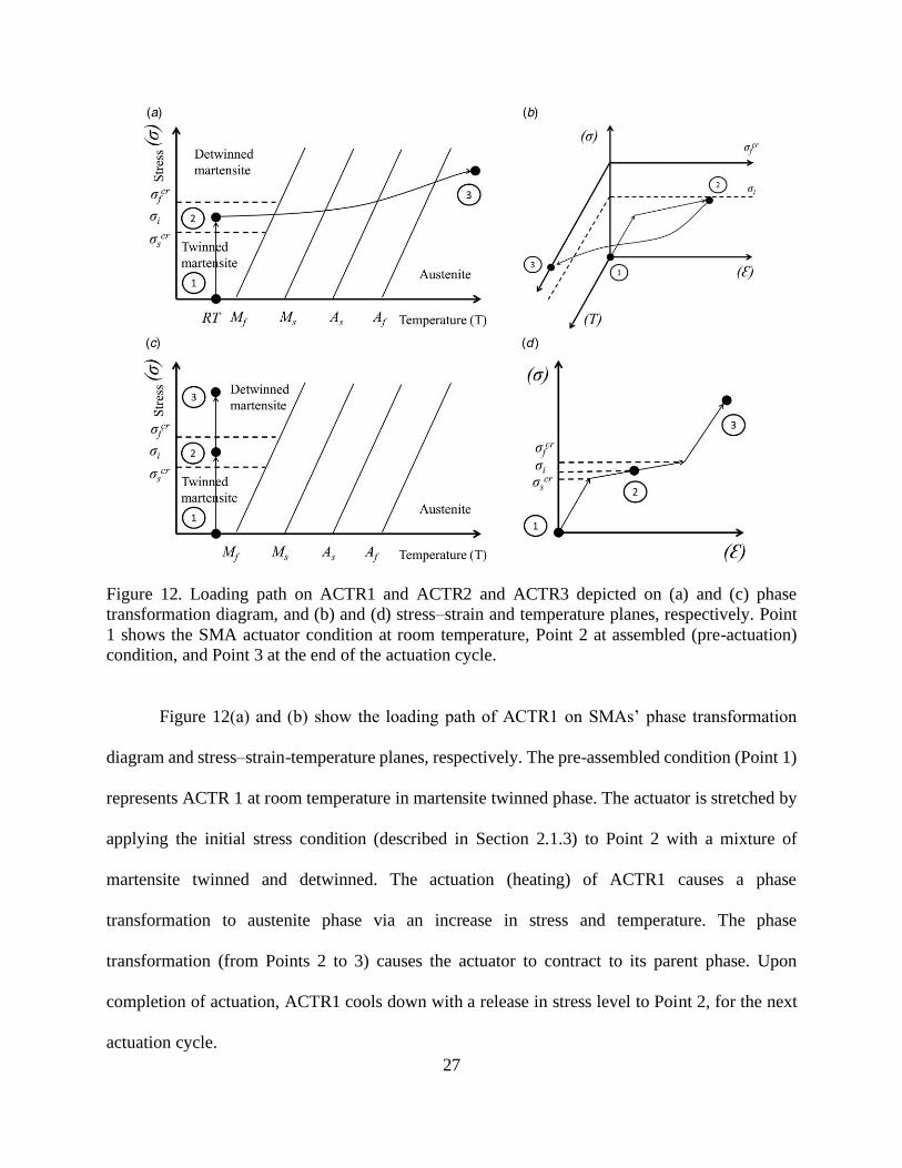
stress versus strain, and (d) stress versus temperature response in heating and cooling cycles. ... 24 Figure 12. Loading path on ACTR1 and ACTR2 and ACTR3 depicted on (a) and (c) phase
transformation diagram, and (b) and (d) stress–strain and temperature planes, respectively. Point
1 shows the SMA actuator condition at room temperature, Point 2 at assembled (pre-actuation)
condition, and Point 3 at the end of the actuation cycle. ............................................................. 27 Figure 13. (a) Practical-size prototype of the SMA-activated needle, and (b) planar displacement
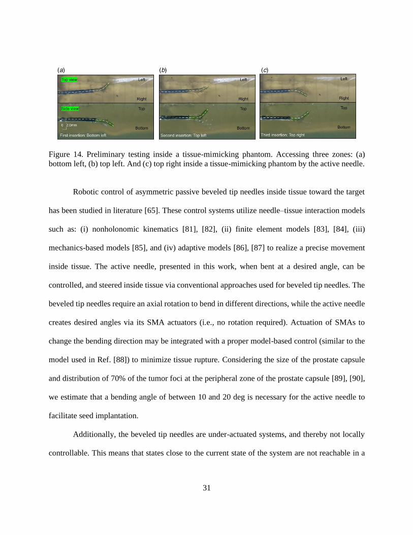
in air. ........................................................................................................................................ 30 Figure 14. Preliminary testing inside a tissue-mimicking phantom. Accessing three zones: (a)
bottom left, (b) top left. And (c) top right inside a tissue-mimicking phantom by the active
needle. ...................................................................................................................................... 31
Figure 15. 3D steerable needle with bevel tip. ........................................................................... 34 Figure 16. Motorized manipulation system to bend the needle. .................................................. 35 Figure 17. Needle insertion system for needle insertion and manipulation and intraoperative
tracking of the needle tip inside a phantom tissue via an ultrasound device. ............................... 37 Figure 18. Phantom tissue used in the study. ............................................................................. 37
Figure 19. (a) Original 2D ultrasound image processed with (b) local minimum, (c) global
minimum, and (d) blob detection techniques. ROI: region of interest......................................... 38
Figure 20. Flowchart of (a) program to enable online tracking and steering of the needle, and (b)
image processing algorithm to identify the needle tip during needle insertion. ........................... 39
Figure 21. Robot-assisted tracking of the needle tip; (a) lateral, (b) vertical, and (c) overall
displacement of the needle tip for four case studies listed in Table 3.......................................... 43
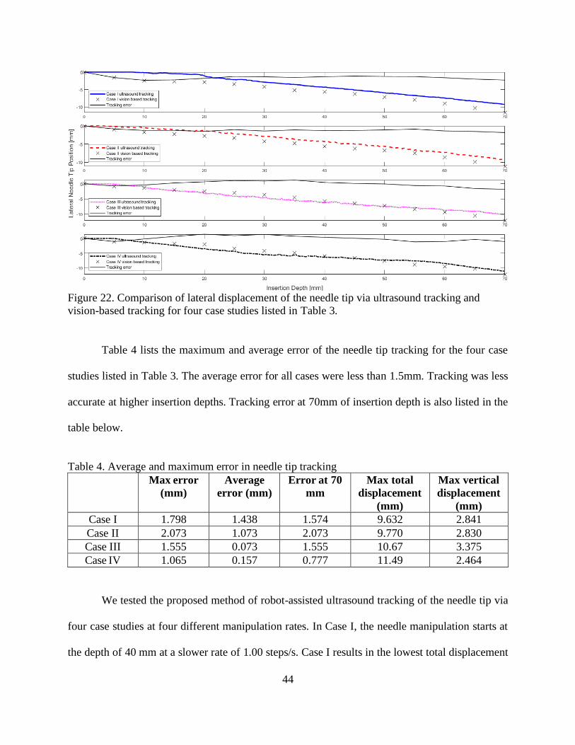
Figure 22. Comparison of lateral displacement of the needle tip via ultrasound tracking and
vision-based tracking for four case studies listed in Table 3. ...................................................... 44

ix
LIST OF ABBREVIATIONS
SMA Shape Memory Alloy
ACS American Cancer Society
EBRT External Beam Radiation Therapy
FDA Food and Drug Administration
PET Positron Emission Tomography
CT Computed Tomography
LDR Low Dose Rate
2D Two-Dimensional
3D Three-Dimensional
Ni-Ti Nickel-Titanium
NITINOL Nickel-Titanium (made in the) Naval Ordnance Lab
SME Shape Memory Effect
OWSME One-Way Shape Memory Effect
TWSME Two-Way Shape Memory Effect
MRI Magnetic Resonance Imaging
US Ultrasound
TUSS Tracked Ultrasound Snapshot
ROI Region of Interest
RANSAC Random Sample Consensus
RR Revolute-Revolute
TRUS Transrectal Ultrasound
FPS Frames Per Second
ID Inner Diameter
OD Outer Diameter
DoF Degree of Freedom
DC Direct Current
ACTR Actuator
RT Room Temperature
SLIC Simple Linear Iterative Clustering
CTA Comet Tail Artifact

x
LIST OF SYMBOLS
σ Stress
𝜎i Initial stress
𝜎𝑠𝑐𝑟 Critical start stress
𝜎𝑓𝑐𝑟 Critical finish stress
𝑀𝑓 Martensite finish temperature
𝑀𝑠 Martensite start temperature
𝐴𝑠 Austenite start temperature
𝐴𝑓 Austenite finish temperature
D Young’s Modulus
ε Strain
ξ Martensitic concentration fraction
T Temperature
Ω Phase transformation tensor
Θ Thermal coefficient of expansion
𝜉s Stress-induced martensitic concentration fraction
𝜉𝑇 Temperature-induced martensitic concentration fraction
𝐶𝐴 Stress-influenced coefficient of austenite
𝐶𝑀 Stress-influenced coefficient of martensite
𝜀0 Initial strain
𝜉0 Initial martensite volume fraction
𝑇0 Initial temperature
𝑎𝐴 Material constant in austenite phase
𝑎𝑀 Material constant in martensite phase
𝜀𝐿 Maximum recoverable strain
1
Chapter 1. INTRODUCTION
Advancements in biomedical devices have been at the forefront of research studies in
recent years to help surgeons perform more accurate procedures and subsequently lessen the
recovery time for patients. This chapter goes over recent statistics of the three most common
cancers, a literature review on the currently used needles and needle interventions, background
information on shape memory alloys, and background information on image-guided needle
insertion systems.

2
1.1. Cancer statistics
The American Cancer Society (ACS) has estimated 1.7 million new cases of cancer in the
United States in 2019, with about 600,000 projected deaths in this year alone. However, the
mortality rates for both men and women have been decreasing with 1.8% per year for males and
1.4% for females and children. While this is good news, there is still a need for improvements in
cancer treatment options. Table 1 shows the estimated new cases and deaths breakdown for three
different types of cancers [1].
Table 1. Top 3 common types of cancer and the statistics for both male and females in 2019.
Estimated New Cases Estimated Deaths
Male Female Male Female
Breast 2,670 268,600 500 41,760
Lung & Bronchus 116,440 111,710 76,650 66,020
Prostate 174,650 N/A 31,620 N/A
3
1.2. Needle-based interventions
Brachytherapy [2] and external beam radiation therapy (EBRT) [3] are commonly used in
cancer interventions to kill or shrink the cancerous tissue locally. In brachytherapy, radioactive
seeds are placed internally at the target location, while in EBRT, the radiation is passed to the
cancerous tissue via a device external to the body of the patient. Due to increased radiation
exposure risks in EBRT and availability of safer (recently discovered) radioisotopes,
brachytherapy has been generally recognized as a more efficient method especially for prostate
cancer [4]–[6].
Image-guided biopsy procedures [7], mandated by US Food and Drug Administration
(FDA), are accompanied by companion diagnosis tests to choose the most effective treatments for
breast cancer [8]. Several imaging techniques [9]–[11] are developed to identify tumor, and to help
needle navigation [12] towards the target locations. For example, positron emission tomography
(PET) fused with computed tomography (CT) imaging has been integrated with the biopsy process
for cancer diagnosis [13]. With this system, the hypermetabolic portion of a large morphologically
abnormal lesion, and the most metabolically active portion of a tumor could be determined.
Traditional surgical needles are made of rigid materials such as stainless steel, rigid plastic,
and titanium, which do not provide flexibility for the needle to navigating inside the tissue in a
non-straight path. However, a curved path is often desired in a needle-based procedure such as
brachytherapy to release a greater number of seeds via a smaller number of insertions and thereby
less trauma to the tissue. The curved path can also prevent puncturing sensitive organs or large
arteries that might be on the way toward the target location. A recent study by Podder et al. [14]
proposed a “curvilinear approach” technique (Figure 1(a) and (b)) for prostate seed implantation.
4
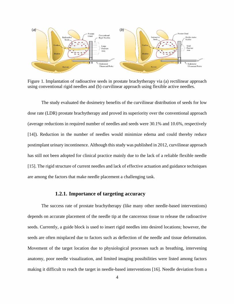
Figure 1. Implantation of radioactive seeds in prostate brachytherapy via (a) rectilinear approach
using conventional rigid needles and (b) curvilinear approach using flexible active needles.
The study evaluated the dosimetry benefits of the curvilinear distribution of seeds for low
dose rate (LDR) prostate brachytherapy and proved its superiority over the conventional approach
(average reductions in required number of needles and seeds were 30.1% and 10.6%, respectively
[14]). Reduction in the number of needles would minimize edema and could thereby reduce
postimplant urinary incontinence. Although this study was published in 2012, curvilinear approach
has still not been adopted for clinical practice mainly due to the lack of a reliable flexible needle
[15]. The rigid structure of current needles and lack of effective actuation and guidance techniques
are among the factors that make needle placement a challenging task.
1.2.1. Importance of targeting accuracy
The success rate of prostate brachytherapy (like many other needle-based interventions)
depends on accurate placement of the needle tip at the cancerous tissue to release the radioactive
seeds. Currently, a guide block is used to insert rigid needles into desired locations; however, the
seeds are often misplaced due to factors such as deflection of the needle and tissue deformation.
Movement of the target location due to physiological processes such as breathing, intervening
anatomy, poor needle visualization, and limited imaging possibilities were listed among factors
making it difficult to reach the target in needle-based interventions [16]. Needle deviation from a
5
desired path can also happen due to tissue inhomogeneity [17]. In the case of deviation from the
desired path, the needles must be removed and reinserted back into the tissue. The problem with
current brachytherapy method is that the accuracy of the needle placement is relatively low, which
may cause the radioactive seeds to be misplaced at healthy tissue, and thus lead to serious side
effects [18]. It was reported [16] that a mean maximal error of 2.7 mm in needle placement is
acceptable when targeting lesions in needle-based interventions. Recognizing the importance of
precision tracking and placement, several efforts have been made in recent years to improve
medical imaging and interventional delivery systems.
1.2.2. Literature search of previous needles
With the purpose of increasing flexibility and reducing deviations from the needle's desired
path, both passive and active needle designs have been proposed in the past decade for diagnosis
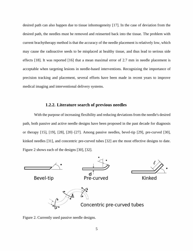
or therapy [15], [19], [28], [20]–[27]. Among passive needles, bevel-tip [29], pre-curved [30],
kinked needles [31], and concentric pre-curved tubes [32] are the most effective designs to date.
Figure 2 shows each of the designs [30], [32].
Figure 2. Currently used passive needle designs.
6
The disadvantage of passive needles is that trajectory planning can be complicated and
inaccurate [33]–[35]. Deflection with passive needles is governed by non-homogeneous
viscoelastic interactions between tissue and needle. Passive needles of a predefined shape steer in
2D with a constant radius and thereby require an axial rotation to reach targets in 3D space [36],
[37]. Rotation of the needle while advancing in the tissue not only requires a complex control
system, but also increases the risk of tissue damage [38], [39]. Active controllable needles, on the
other hand, can compensate for misalignments resulted from any unpredictable factors during
insertion. Yet there are no active needles currently commercially available, and even research
studies are at preliminary stages. A recent article by Scali et al. [40] summarized all possible
mechanical solutions for passive or active needle steering (see examples in Ref. [31], [41]–[49]).
Three research groups have proposed an active needle with on demand actuation specifically for
brachytherapy[44], [50], [51]. The problems with the first two designs were the large size and low
stiffness in Ref. [44], and low planar deflection in Ref. [50]. These needles also require large
rotations to reach out of plane targets, which results in significant tissue rupture. It should also be
noted that the target positions are close to the peripheral zone of the prostate, and thereby additional
challenge to implant the seeds via these needles. Deflection in only one direction and lack of a
hollow pathway inside the needle were the problems with the design in Ref. [51].
7
1.3. Background information on shape memory alloys
SMAs are able to exhibit properties of pseudoelasticity, shape memory effect (SME), self-
sensing, corrosion resistance while also being biocompatible. All of these properties have led
SMAs to be used to develop innovative medical devices for cardiovascular, dental, and surgical
applications [52], [53]. A commonly used SMA is Nickel-Titanium (Ni-Ti) also known as
NITINOL (Nickel-Titanium made in the Naval Ordnance Lab). Pseudoelasticity is known as the
SMA's capability to exhibit a larger recoverable elongation compared to conventional metals upon
mechanical loading. SME is the SMA's capability to realize an actuation response upon heating
due to the production of a high rate of actuation energy density [54]. This actuation is the phase
transformation between the high temperature phase of austenite and the low temperature phase of
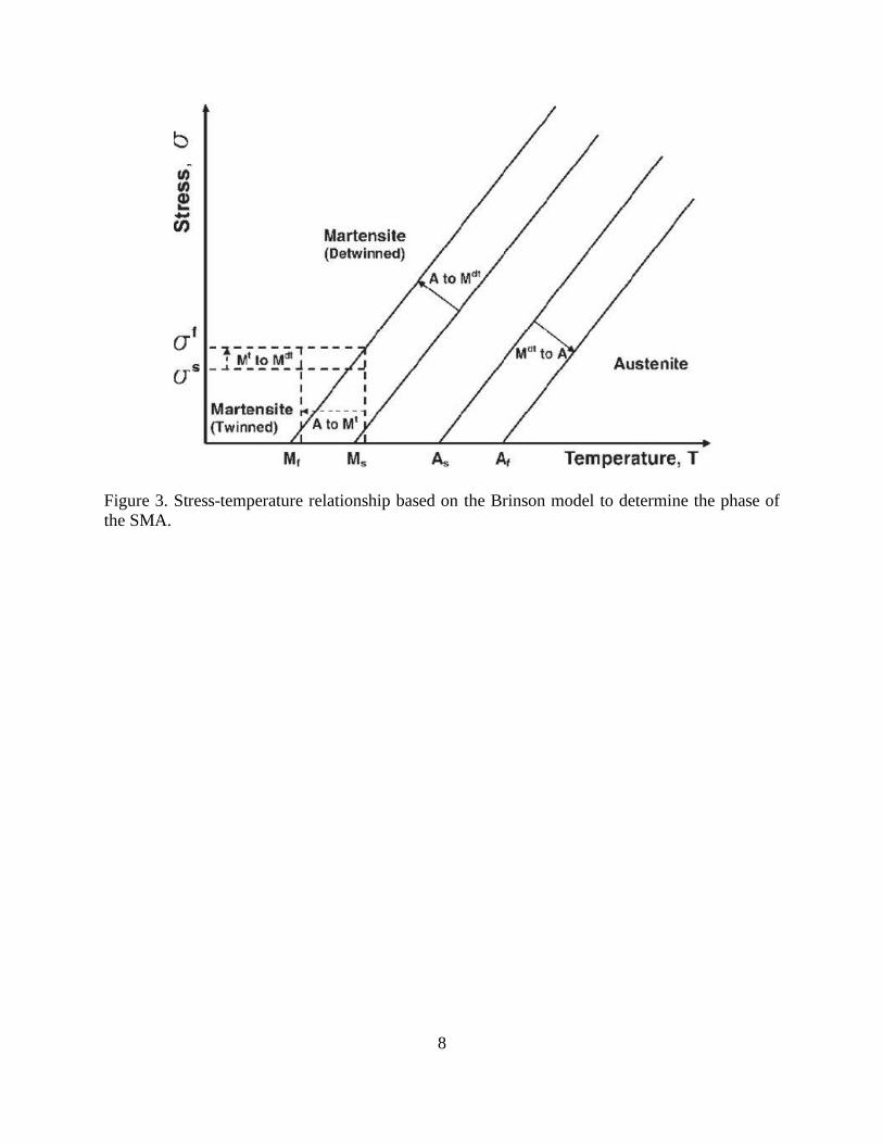
martensite. Figure 3 shows the stress-temperature graph based on the Brinson model [55]. The
Brinson model is discussed in section 2.1.4. There are two different types of SMEs known as one-
way and two-way SMEs. In one-way shape memory effect (OWSME), the SMA is deformed into
a desired shape at low temperatures and then heated to recover it shape. In two-way shape memory
effect (TWSME), the SMA remembers its shape at low- and high- temperatures. However,
utilization of SMAs in active devices is challenging due to their thermomechanically irreversible
phase transformation and their hysteresis response.
8
Figure 3. Stress-temperature relationship based on the Brinson model to determine the phase of
the SMA.
9
1.4. Background information on image-guided needle insertion
Medical imaging plays an important role in position tracking of medical devices while
operating inside the patient’s body. Specifically, in needle-based procedures, surgeons rely on this
position tracking to accurately guide the needle in a desired trajectory towards the target
location(s). Medical imaging in needle-based procedures provides online (intraoperative)
trajectory tracking of the needle tip that can be used to estimate the deviation from the desired
trajectory. This deviation can later be used as a feedback in a control algorithm for precise needle
navigation [56]. Reed et al. [57] developed a system by combining a 2D planner, image feedback,
and a linearized controller to guide the needle and restrict its out of plane movement. In another
work, 3D ultrasound tracking was used for placement of an active cannula at target positions [58].
Vrooijink et al. [59] presented a real-time tracking of the needle tip using an ultrasound device.
During needle insertion, the ultrasound transducer moves with the needle tip with adjusted velocity
to compensate for needle curvature. A 3D volumetric visualization was performed using 2D
ultrasound transducer in [60]. Doppler ultrasound imaging has also been used to visualize the
needle with high frequency vibration [61]–[63]. In comparison with CT, magnetic resonance
imaging (MRI), and fluoroscopy, ultrasound (US) offers a low cost, widely accessible, portable,
and safe imaging modality [64]. Ultrasound images are usually noisy, due to reflections,
reverberations, shadows, air pockets, and biological speckle, which makes needle tracking
challenging. However, medical professionals perform a high portion of the needle insertion tasks
(such as biopsy procedure) under ultrasound guidance. The success of the image-guided needle
insertions depends on precise tracking of the needle tip [65]. To enhance tracking, researchers have
suggested needle tracking using a single camera attached to an ultrasound transducer [66]. Optical
flow-based in-plane tracking algorithm [67], and tracking region of interest (ROI) with random

10
sample consensus (RANSAC) algorithm and Kalman filter localization [68] have also been
proposed for improved visualization. In another work [69], a method is presented to reconstruct
the needle shape using 2D transverse ultrasound images.

11
Chapter 2. SHAPE MEMORY ALLOY ACTUATORS IN AN
ACTIVE NEEDLE – MODELING, PRECISE ASSEMBLY, AND
PERFORMANCE EVALUATION
Section 2.1.1 introduces the novel design concept of the active needle with distributed
SMA actuators. Section 2.1.2 explains the fabrication process via rapid manufacturing of the active
needle components, and section 2.1.3 describes the assembly process for accurate installation of
SMA actuators on the needle structure. Section 2.1.4 describes a constitutive material model for
SMAs that is used in this study. Section 2.1.5 discusses the kinematics of the active needle. Finally,
Section 2.1.6 introduces the experimental setup to evaluate the performance of the active needle.
The results section investigates the response of the SMA actuators during active needle operation.
Section 2.2.1 presents the performance (deflection) evaluation of the active needle. The interactive
behavior of the distributed SMA actuators is explained in section 2.2.2. Section 2.2.3 introduces a
scaled-down version of the active needle to show the design's potential to be manufactured at
different scales suitable for different needle insertion procedures.
12
2.1. Materials and methods
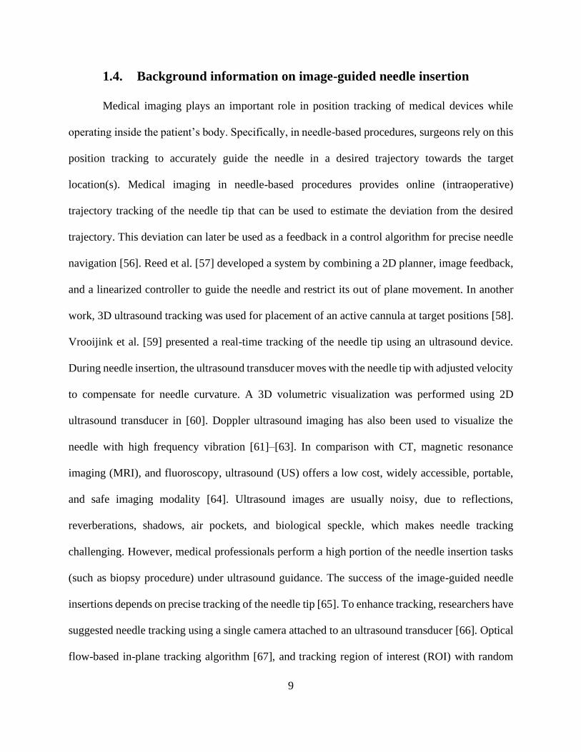
The novel design of the 3D steerable active needle is presented in this section. The active
needle privileges from actuation of multiple distributed SMA wires to realize deflection in all
directions (design concept is shown in Figure 4). The active deflection is beneficial in needle
insertion procedures to follow a curved path toward the target. This section also presents precise
manufacturing, assembly, modeling, and performance evaluation methods of the active needle.
Figure 4. Accessing various part of the prostate via the proposed active needle design - 3D bending
is realized via multiple actuators at the needle's flexible bending sections.
2.1.1. Design concept of the 3D steerable SMA-activated needle
Some research groups have suggested using SMAs to actively bend surgical needles inside
the tissue. For example, Konh et al. [51], [70] introduced an active steerable needle that could bend
inside the tissue in a 2D plane via actuation of a single SMA wire. In another work, Varnamkhasti
and Konh [71] developed an SMA-activated needle for tissue biopsy. To realize deflection in all
directions, Karimi and Konh [72], [73] developed an active steerable needle with multiple SMA
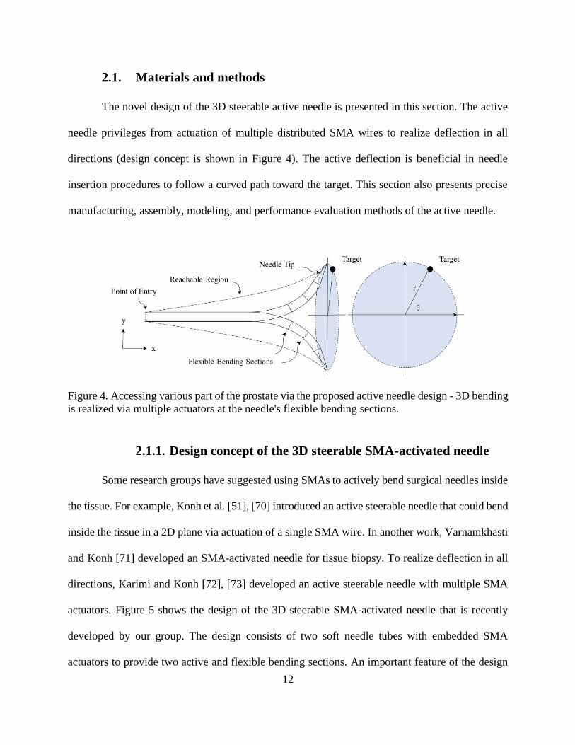
actuators. Figure 5 shows the design of the 3D steerable SMA-activated needle that is recently
developed by our group. The design consists of two soft needle tubes with embedded SMA
actuators to provide two active and flexible bending sections. An important feature of the design
13
is that the actuators are completely enclosed inside the needle wall thickness of the needle tube
(i.e., not exposed to the tissue), and thereby preventing thermal tissue damage via the heated SMA
wires. The SMA wires are usually heated to about 55°C at their maximum contraction, which could
cause thermal damage to tissue [74]. Another important feature is that the wires are looped at the
needle tip, and thereby providing double bending force for the needle. This also facilitates
electrical connections at the bottom end of the needle. Three SMA wires distributed around the
needle tube also provide a bias load that is required to pull back the active needle to its initial shape
after each cycle of actuation. The active needle configuration consists of two antagonistic SMA
wires that oppose the deflection of the needle toward the actuated (heated) SMA wire. The 3D
manipulation of the active needle in this configuration has been investigated via finite element
analyses in a previous study [75].
Figure 5. Design of a 3D steerable active needle with soft tubes for enhanced flexibility and
multiple distributed SMA actuators to provide bending forces.
2.1.2. Active needle fabrication via rapid manufacturing
To show the functionality of the design concept and to investigate the actuation
performance of the multiple SMA actuators in the active needle, a 6.0-mm-diameter prototype, 4:1
scaled version of 17-gauge brachytherapy needle, was developed. The prototype consists of two
14
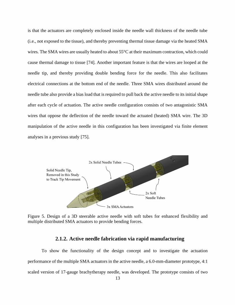
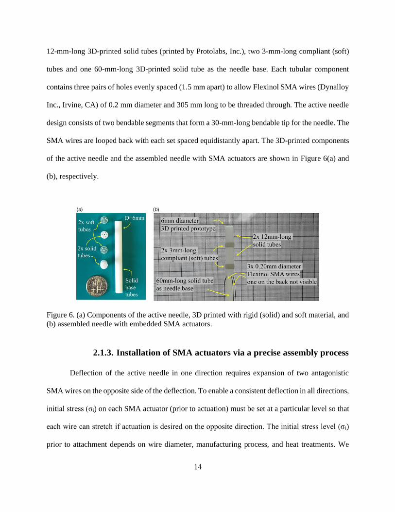
12-mm-long 3D-printed solid tubes (printed by Protolabs, Inc.), two 3-mm-long compliant (soft)
tubes and one 60-mm-long 3D-printed solid tube as the needle base. Each tubular component
contains three pairs of holes evenly spaced (1.5 mm apart) to allow Flexinol SMA wires (Dynalloy
Inc., Irvine, CA) of 0.2 mm diameter and 305 mm long to be threaded through. The active needle
design consists of two bendable segments that form a 30-mm-long bendable tip for the needle. The
SMA wires are looped back with each set spaced equidistantly apart. The 3D-printed components
of the active needle and the assembled needle with SMA actuators are shown in Figure 6(a) and
(b), respectively.
Figure 6. (a) Components of the active needle, 3D printed with rigid (solid) and soft material, and
(b) assembled needle with embedded SMA actuators.
2.1.3. Installation of SMA actuators via a precise assembly process
Deflection of the active needle in one direction requires expansion of two antagonistic
SMA wires on the opposite side of the deflection. To enable a consistent deflection in all directions,
initial stress (σi) on each SMA actuator (prior to actuation) must be set at a particular level so that
each wire can stretch if actuation is desired on the opposite direction. The initial stress level (σi)
prior to attachment depends on wire diameter, manufacturing process, and heat treatments. We
15
have performed a series of constant stress and strain experiments to find the specific σi values for
the SMA actuators. From our previous work [76], this initial stress was estimated 140 MPa. The
initial stress was selected between σscr and σf
cr, the start and finish critical stress to induce phase
transformation. A detailed description of SMA parameters is provided in the next section. Prior to
the installation of SMA wires on the needle, all three SMA actuators were trained with 80 cycles
of heating and cooling under the initial stress σi in order to obtain a more consistent response.
For precise attachment of the SMA actuators, a custom-made fixture was designed and
built (shown in Figure 7). The fixture includes two clamps to hold the needle tubes and a bearing
to let the needle tubes rotate for proper alignment at the three sides. The fixture includes two
micrometer stages and a load cell to set the desired strain and stress on the SMA wires. To assemble
the active needle, the needle tip was restrained at the left side of the fixture, while its bottom end
was attached to the right side of the fixture and pushed to the left to create a compressive stress
(equal to σi) on the needle's flexible tube. The micrometer stage was moved until the LSB200 load
cell (FUTEK, Irvine, CA) in conjunction with the HX711 load cell amplifier (SparkFun, Niwot,
CO) measured the desired force needed for the SMA to be at its initial stress level (σi). At this
point, the SMA wire was looped inside the holes at the needle tip. The wire's free ends were
attached to the load cell and pulled until the wire was under the desired initial tensile stress (σi).
At this point, the wire was glued to the bottom needle tube using Permatex 5-min Epoxy (Permatex,
Solon, OH). This procedure was repeated for all three wires. The radial alignment was maintained
at all time.
16
Figure 7. Fixture developed to assemble the active needle with SMA actuator at initial stress; (a)
SolidWorks model and (b) created assembly.
To ensure proper sealing between the solid and soft tubes of the active needle and to avoid
any gaps, a Cyanoacrylate Instant Adhesive, Garde 820, high temperature, Permabond (Henkel,
Düsseldorf, Germany) was applied to seal the areas between the segments. This adhesive has been
used in soft tubes of commercial syringes. The needle prototype was tested with water to assure
proper sealing, while bent to an extreme angle of 45° at different directions. The joints were also
tested by bending them at different angles and spotting the connections with high-resolution
(zoomed-in) images to ensure that the segments do not open small gaps upon deflection.
2.1.4. Constitutive material modeling of SMAs
SMAs are a unique class of advanced material that recover their deformed shapes, caused
by a loading condition and temperature changes, resulting in a high actuation energy density [54].
This unique characteristic pertains to the reversible crystalline phase transition between two phases
of the material known as austenite (high temperature phase) and martensite (low temperature
phase). The two phases are different in their crystal structure. Transformation between the two
phases occurs by shear lattice distortion. The forward transformation, in which the austenite phase
transforms to the martensite phase, initiates at martensite start temperature (MS) and completes at
martensite finish temperature (Mf). The reverse transformation, in which the martensite phase
17
transforms to the austenite phase, initiates at austenite start temperature (AS) and completes at
austenite finish temperature (Af) [77]. The unique characteristics of SMAs such as the SME and
pseudoelasticity, along with the material properties as corrosion resistance, and biocompatibility,
in addition to their high actuation energy densities, and self-sensing capabilities have made them
a suitable choice of actuation for active needles. However, the hysteretic behavior and low-
frequency response of SMAs are among the challenges in design and accurate performance of any
SMA-actuated devices including the active needle [54]. This section explains the constitutive
material model for SMAs based on one-dimensional Brinson model [77]. The model was coded in
MATLAB ® and used in this study to predict the response of the SMA wires. Prior to the Brinson
model, Liang and Rogers suggested that the changes on stress can relate to [77].
𝑑𝜎 = 𝐷(𝜀, 𝜉, 𝑇)𝑑𝜀 + Ω(𝜀, 𝜉, 𝑇)𝑑𝜉 + 𝜃(𝜀, 𝜉, 𝑇)𝑑𝜃 (2.1)
where 𝜎 is stress, 𝐷(𝜀, 𝜉, 𝑇) is the Young’s modulus of SMA, which is a function of strain (𝜀),
martensitic concentration fraction (𝜉) and temperature (T), Ω(𝜀, 𝜉, 𝑇) is the transformation tensor,
and 𝜃(𝜀, 𝜉, 𝑇) is the SMA’s thermal coefficient of expansion. Brinson expanded on this model by
splitting the martensitic concentration fraction into detwinned (stress induced) martensite (𝜉𝑠) and
twinned (temperature induced) martensite (𝜉𝑇):
𝜉 = 𝜉𝑠 + 𝜉𝑇 (2.2)
18
Due to different crystallographic structures of SMAs at specific temperature and stress intervals,
the following equations express the stress and temperature induced concentrations of martensite
when transforming from austenite to detwinned martensite phase:
𝐼𝑓 𝑇 > 𝑀𝑠 𝑎𝑛𝑑 [𝜎𝑠𝑐𝑟 + 𝐶𝑀(𝑇 − 𝑀𝑠)] < 𝜎 < [𝜎𝑓
𝑐𝑟 + 𝐶𝑀(𝑇 − 𝑀𝑠)] 𝑡ℎ𝑒𝑛
𝜉𝑠 =1−𝜉𝑠,0
2 cos {
𝜋
𝜎𝑠𝑐𝑟−𝜎𝑓
𝑐𝑟 [𝜎 − 𝜎𝑓𝑐𝑟 − 𝐶𝑀(𝑇 − 𝑀𝑠)]} +
1+𝜉𝑠,0
2 (2.3)
𝜉𝑇 = 𝜉𝑇,0 −𝜉𝑇,0
1−𝜉𝑠,0(𝜉𝑠 − 𝜉𝑠,0) (2.4)
𝐼𝑓 𝑇 < 𝑀𝑠 𝑎𝑛𝑑 𝜎𝑠𝑐𝑟 < 𝜎 < 𝜎𝑓
𝑐𝑟 𝑡ℎ𝑒𝑛
𝜉𝑠 =1−𝜉𝑠,0
2 cos {
𝜋
𝜎𝑠𝑐𝑟−𝜎𝑓
𝑐𝑟 𝑥 [𝜎 − 𝜎𝑓𝑐𝑟]} +
1+𝜉𝑠,0
2 (2.5)
𝜉𝑇 = 𝜉𝑇,0 −𝜉𝑇,0
1−𝜉𝑠,0(𝜉𝑠 − 𝜉𝑠,0) + Δ𝑇,𝜀 (2.6)
In order to calculate Δ𝑇,𝜀
𝐼𝑓 𝑀𝑓 < 𝑇 < 𝑀𝑠 𝑎𝑛𝑑 𝑇 < 𝑇0 𝑡ℎ𝑒𝑛
Δ𝑇,𝜀 =1−𝜉𝑇,0
2{cos[𝑎𝑀(𝑇 − 𝑀𝑓)] + 1} (2.7)
𝑒𝑙𝑠𝑒: Δ𝑇,𝜀 = 0 (2.8)
When transforming from austenite to detwinned martensite phase, the following equations are used
to express the stress and temperature induced concentrations of martensite:
𝐼𝑓 𝑇 > 𝐴𝑠 𝑎𝑛𝑑 [𝐶𝐴(𝑇 − 𝐴𝑓)] < 𝜎 < [𝐶𝐴(𝑇 − 𝐴𝑠)] 𝑡ℎ𝑒𝑛
19
𝜉 =𝜉0
2 cos {[𝑎𝐴(𝑇 − 𝐴𝑠 −
𝜎
𝐶𝐴)] + 1} (2.9)
𝜉𝑠 = 𝜉𝑠,0 −𝜉𝑠,0
𝜉0(𝜉0 − 𝜉) (2.10)
𝜉𝑇 = 𝜉𝑇,0 −𝜉𝑇,0
𝜉0(𝜉0 − 𝜉) (2.11)
𝑎𝑀 and 𝑎𝐴 are defined as constants that are dependent on the transformation temperatures where:
𝑎𝑀 =𝜋
𝑀𝑠−𝑀𝑓 (2.12)
𝑎𝐴 =𝜋
𝐴𝑓−𝐴𝑠 (2.13)
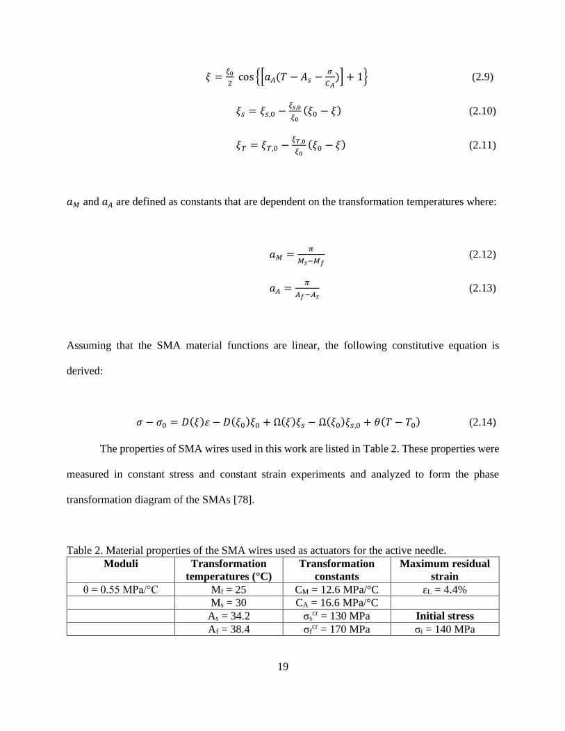
Assuming that the SMA material functions are linear, the following constitutive equation is
derived:
𝜎 − 𝜎0 = 𝐷(𝜉)𝜀 − 𝐷(𝜉0)𝜉0 + Ω(𝜉)𝜉𝑠 − Ω(𝜉0)𝜉𝑠,0 + 𝜃(𝑇 − 𝑇0) (2.14)
The properties of SMA wires used in this work are listed in Table 2. These properties were
measured in constant stress and constant strain experiments and analyzed to form the phase
transformation diagram of the SMAs [78].
Table 2. Material properties of the SMA wires used as actuators for the active needle.
Moduli Transformation
temperatures (°C)
Transformation
constants
Maximum residual
strain
θ = 0.55 MPa/°C Mf = 25 CM = 12.6 MPa/°C ɛL = 4.4%
Ms = 30 CA = 16.6 MPa/°C
As = 34.2 σscr = 130 MPa Initial stress
Af = 38.4 σfcr = 170 MPa σi = 140 MPa
20
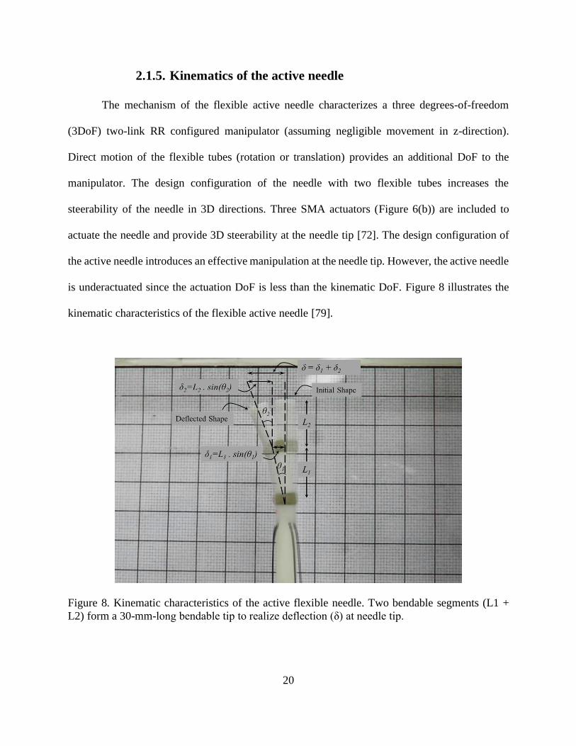
2.1.5. Kinematics of the active needle
The mechanism of the flexible active needle characterizes a three degrees-of-freedom
(3DoF) two-link RR configured manipulator (assuming negligible movement in z-direction).
Direct motion of the flexible tubes (rotation or translation) provides an additional DoF to the
manipulator. The design configuration of the needle with two flexible tubes increases the
steerability of the needle in 3D directions. Three SMA actuators (Figure 6(b)) are included to
actuate the needle and provide 3D steerability at the needle tip [72]. The design configuration of
the active needle introduces an effective manipulation at the needle tip. However, the active needle
is underactuated since the actuation DoF is less than the kinematic DoF. Figure 8 illustrates the
kinematic characteristics of the flexible active needle [79].
Figure 8. Kinematic characteristics of the active flexible needle. Two bendable segments (L1 +
L2) form a 30-mm-long bendable tip to realize deflection (δ) at needle tip.
21
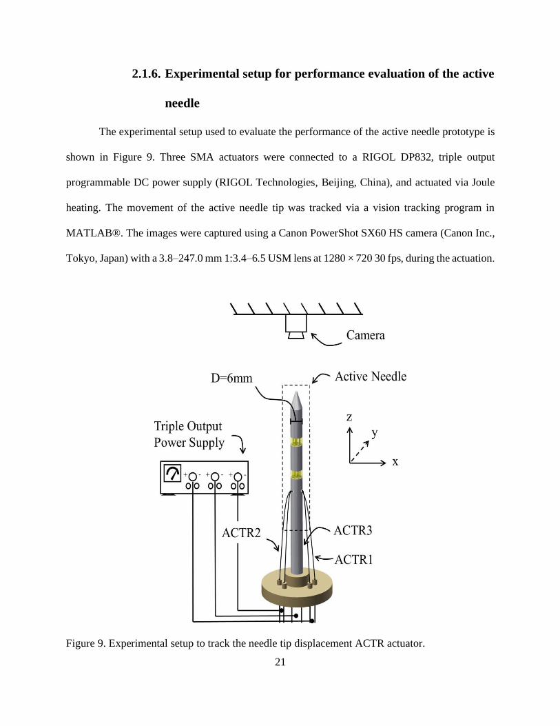
2.1.6. Experimental setup for performance evaluation of the active
needle
The experimental setup used to evaluate the performance of the active needle prototype is
shown in Figure 9. Three SMA actuators were connected to a RIGOL DP832, triple output
programmable DC power supply (RIGOL Technologies, Beijing, China), and actuated via Joule
heating. The movement of the active needle tip was tracked via a vision tracking program in
MATLAB®. The images were captured using a Canon PowerShot SX60 HS camera (Canon Inc.,
Tokyo, Japan) with a 3.8–247.0 mm 1:3.4–6.5 USM lens at 1280 × 720 30 fps, during the actuation.
Figure 9. Experimental setup to track the needle tip displacement ACTR actuator.
22
2.2. Results
This section first presents the performance (deflection) of the active needle via actuation
of SMA actuators. The strain response of the SMA wires was calculated using the kinematics of
the active needle presented in section 2.1.5, Brinson model, described in section 2.1.4, was then
used to predict the stress, strain, and temperature response of SMA actuators during thermal
loading (actuation) and thermal unloading (cooling) cycles. The results confirm that the assembly
plans and installation of SMA actuators (at the initial stress σi) on the active needle have resulted
in an effective and functional 3D manipulation.
2.2.1. Performance evaluation – 3D manipulation of the active
needle
Vision-based technique was used to capture the movement of the active needle tip, while
deflected by the SMA actuators. Images were captured using a Canon PowerShot SX60 HS camera
during operation. The needle tip position was tracked via a tracking program in MATLAB®.
Figure 10(a) shows the deflection of the active needle tip toward each SMA actuator (i.e., ACTR1,
ACTR2, and ACTR3) in ten cycles of heating and cooling. The deflection was realized via
actuation of each SMA wire when heated above its austenite transition temperature (full actuation
in one direction), while the other two SMA wires remain at room temperature (22 °C). Figure 10(b)
shows the needle tip deflection when two SMA wires were manually actuated using a power supply
(BK Precision 1696, Yorba Linda, CA) in three cycles of heating and cooling, while the third SMA
wire remains at room temperature. Figure 10(c) shows simultaneous actuation of two SMA wires
via a synchronized actuation using a programmed power supply (RIGOL DP832). The prototype
realized an average planar displacement of 19.92 ± 1.83 mm. The planar displacement (Figure
23
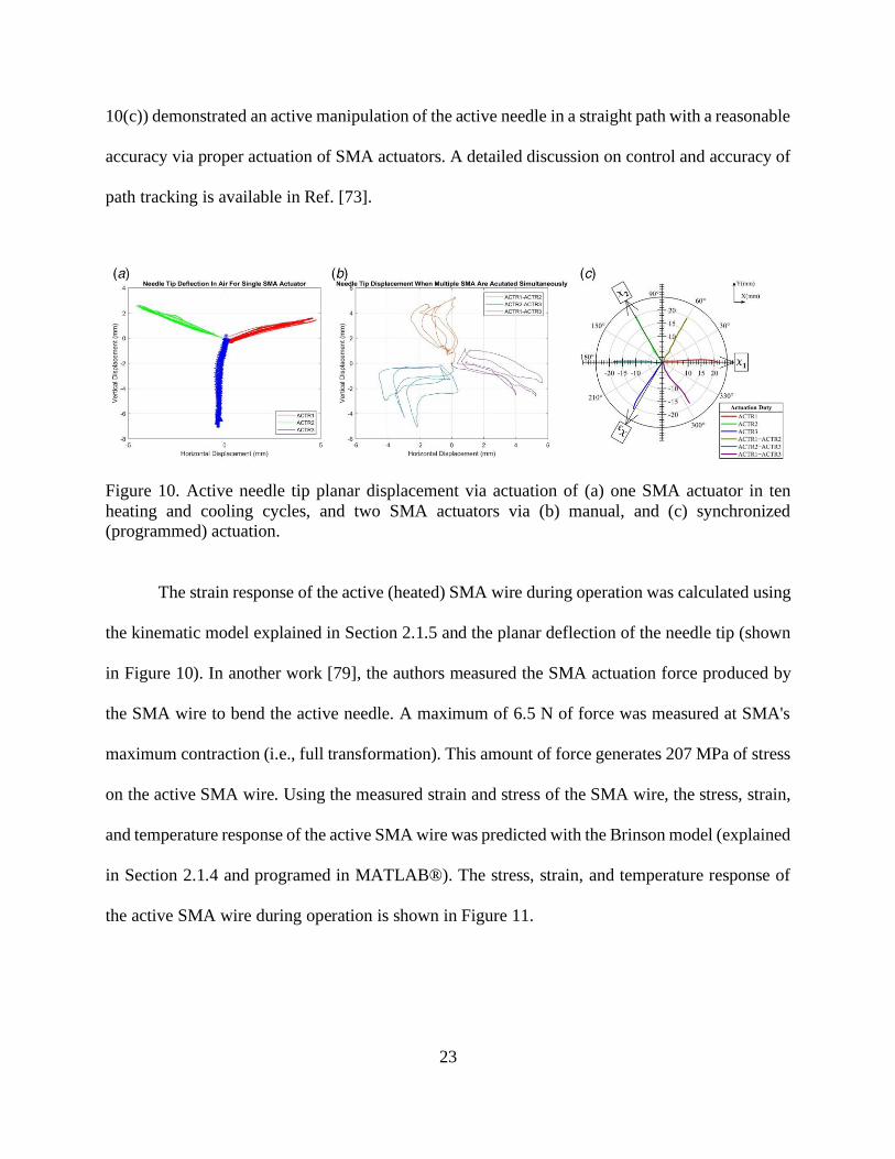
10(c)) demonstrated an active manipulation of the active needle in a straight path with a reasonable
accuracy via proper actuation of SMA actuators. A detailed discussion on control and accuracy of
path tracking is available in Ref. [73].
Figure 10. Active needle tip planar displacement via actuation of (a) one SMA actuator in ten
heating and cooling cycles, and two SMA actuators via (b) manual, and (c) synchronized
(programmed) actuation.
The strain response of the active (heated) SMA wire during operation was calculated using
the kinematic model explained in Section 2.1.5 and the planar deflection of the needle tip (shown
in Figure 10). In another work [79], the authors measured the SMA actuation force produced by
the SMA wire to bend the active needle. A maximum of 6.5 N of force was measured at SMA's
maximum contraction (i.e., full transformation). This amount of force generates 207 MPa of stress
on the active SMA wire. Using the measured strain and stress of the SMA wire, the stress, strain,
and temperature response of the active SMA wire was predicted with the Brinson model (explained
in Section 2.1.4 and programed in MATLAB®). The stress, strain, and temperature response of
the active SMA wire during operation is shown in Figure 11.
24
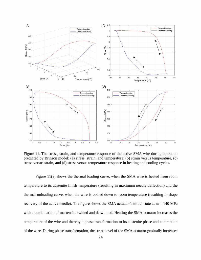
Figure 11. The stress, strain, and temperature response of the active SMA wire during operation
predicted by Brinson model: (a) stress, strain, and temperature, (b) strain versus temperature, (c)
stress versus strain, and (d) stress versus temperature response in heating and cooling cycles.
Figure 11(a) shows the thermal loading curve, when the SMA wire is heated from room
temperature to its austenite finish temperature (resulting in maximum needle deflection) and the
thermal unloading curve, when the wire is cooled down to room temperature (resulting in shape
recovery of the active needle). The figure shows the SMA actuator's initial state at σi = 140 MPa
with a combination of martensite twined and detwinned. Heating the SMA actuator increases the
temperature of the wire and thereby a phase transformation to its austenite phase and contraction
of the wire. During phase transformation, the stress level of the SMA actuator gradually increases
25
to 207 MPa. At this point, maximum contraction of the SMA actuator has resulted in maximum
deflection of the active needle. Cooling the SMA wire to room temperature results in a reverse
transformation and shape recovery of the SMA wire and the active needle.
The strain versus temperature response of the SMA wire (Figure 11(b)) shows contraction
of the SMA wire to about 4% of strain. The SMA phase transformation starts at As temperature at
about 42.6 °C and ends at Af temperature at about 46.8 °C. In reverse transformation, the SMA
wire recovers its shape in the cooling cycle, which starts at MS temperature of about 41 °C and
ends at Mf temperature of about 36 °C.
Figure 11(c) shows the stress versus strain response of the SMA wire. The loading (heating)
cycle results in 4% recovery of strain, while increasing the stress from the initial stress (σi = 140
MPa) to 207 MPa. Cooling the SMA wire to room temperature stretches the SMA wire (recovery
to 4% of strain) due to the biased stress on the needle structure applied from the other two SMA
wires on the opposite side.
Figure 11(d) shows stress versus temperature response of the SMA wire during operation.
Upon actuation, the stress elevates faster compared to a typical actuation response due to the
interactions between three SMA wires. The unloading (cooling) cycle results in stress recovery of
the SMA wire. The following section describes loading conditions and phase transformation of the
three SMA wires during the active needle operation.
26
2.2.2. Interactive response of shape memory alloys during active
needle operation
The nonlinear and hysteresis behavior of SMAs depends on changes in stress, strain, and
temperature, and the consequent phase transformation during operation. The design of the active
needle consists of three SMA actuators, where two antagonistic SMA wires always resist the
needle bending toward the third (heated) SMA actuator. This section explains the interactive
behavior of the SMA actuators during an operation, in which the active needle is intended to bend
toward ACTR1, while the other two actuators (i.e., ACTR2 and ACTR3) resist bending. Figure 12
shows the loading path that each actuator follows during operation. Point 1 represents the initial
condition of the SMA wire at room temperature. Point 2 shows the actuator under initial stress
condition and installed on the active needle. Point 3 shows the final condition of the SMA actuator
at the end of the operation. The loading path from Points 2 to 3 shows a complete phase
transformation.
27
Figure 12. Loading path on ACTR1 and ACTR2 and ACTR3 depicted on (a) and (c) phase
transformation diagram, and (b) and (d) stress–strain and temperature planes, respectively. Point
1 shows the SMA actuator condition at room temperature, Point 2 at assembled (pre-actuation)
condition, and Point 3 at the end of the actuation cycle.
Figure 12(a) and (b) show the loading path of ACTR1 on SMAs’ phase transformation
diagram and stress–strain-temperature planes, respectively. The pre-assembled condition (Point 1)
represents ACTR 1 at room temperature in martensite twinned phase. The actuator is stretched by
applying the initial stress condition (described in Section 2.1.3) to Point 2 with a mixture of
martensite twinned and detwinned. The actuation (heating) of ACTR1 causes a phase
transformation to austenite phase via an increase in stress and temperature. The phase
transformation (from Points 2 to 3) causes the actuator to contract to its parent phase. Upon
completion of actuation, ACTR1 cools down with a release in stress level to Point 2, for the next
actuation cycle.
28
Figure 12(c) and (d) show the loading path of ACTR2 and ACTR3 in the phase
transformation diagram and the stress–strain plane, respectively. At Point 1, ACTR2 and ACTR3
are in their martensite twinned phase. Installation of ACTR2 and ACTR3 on the active needle
leaves them at a mixture of twinned and detwinned martensite (similar to ACTR1). When ACTR1
contracts, ACTR2 and ACTR3 expand to their detwinned martensite phase to realize needle
bending in the direction of ACTR1. Upon completion of actuation ACTR2 and ACTR3 return to
Point 2, ready for the next operation cycle.
Heating and cooling time (i.e., slow response), large hysteresis, and low bandwidth are
important issues in precise control of SMA actuation. Several research groups have developed
different control schemes to obtain a precise and fast response of SMAs. In a previous study [73],
our group developed an electrical resistance feedback control algorithm that avoids overshoot
during heating cycle for a faster response. In another study [75], it was shown that the antagonistic
distribution of SMAs can facilitate shape recovery. The study showed a reasonable response time
of less than 5 s to change the shape of the active needle. Although this response time is still not
appropriate for some clinical applications, especially if aimed to puncture fascia or insert during a
short phase of the respiratory cycle to avoid tissue motion, it may be useful in prostate
brachytherapy, in which not a lot of dynamic motion at the needle tip is expected. Also, studies
have presented effective methods to stabilize the prostate during brachytherapy [80] that can
restrict target movements and facilitate utilization of SMA actuation.
29
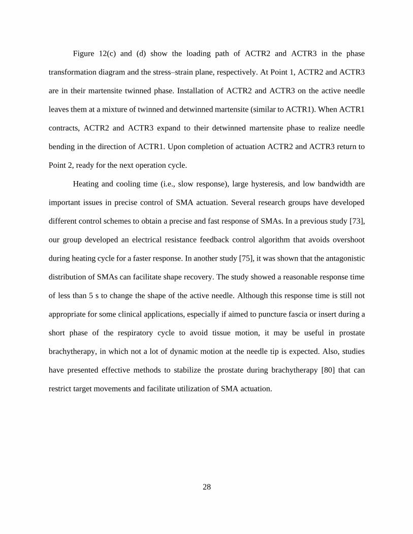
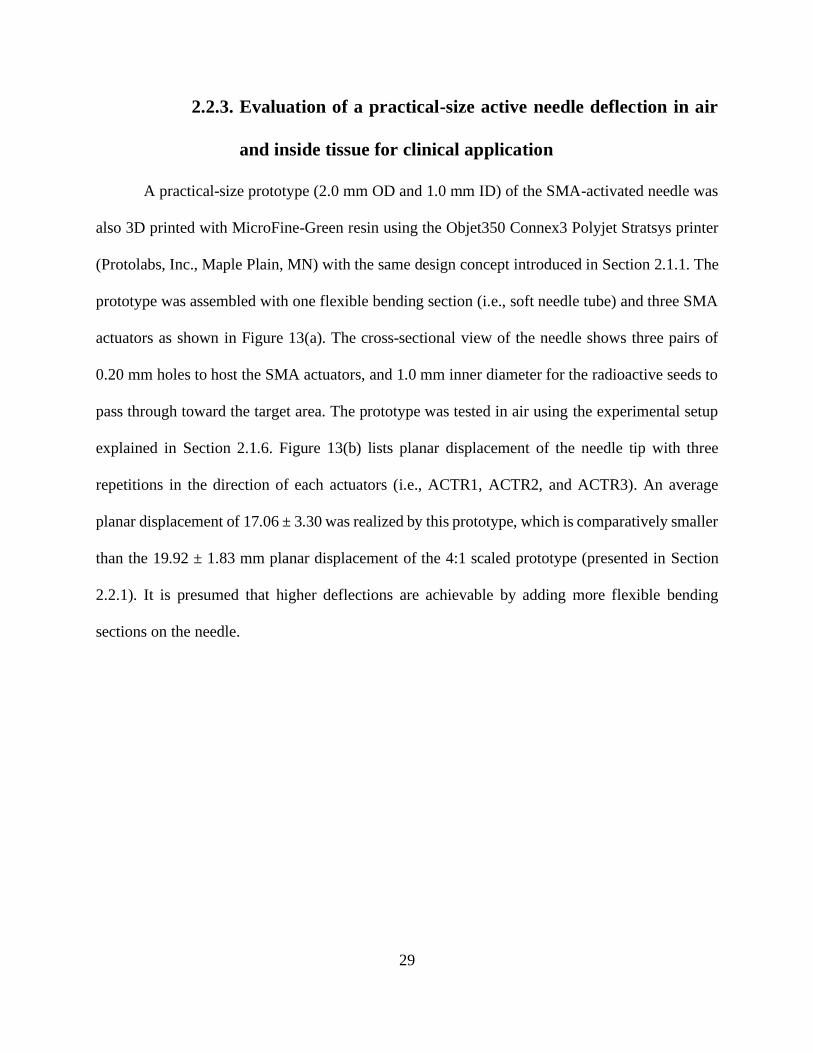
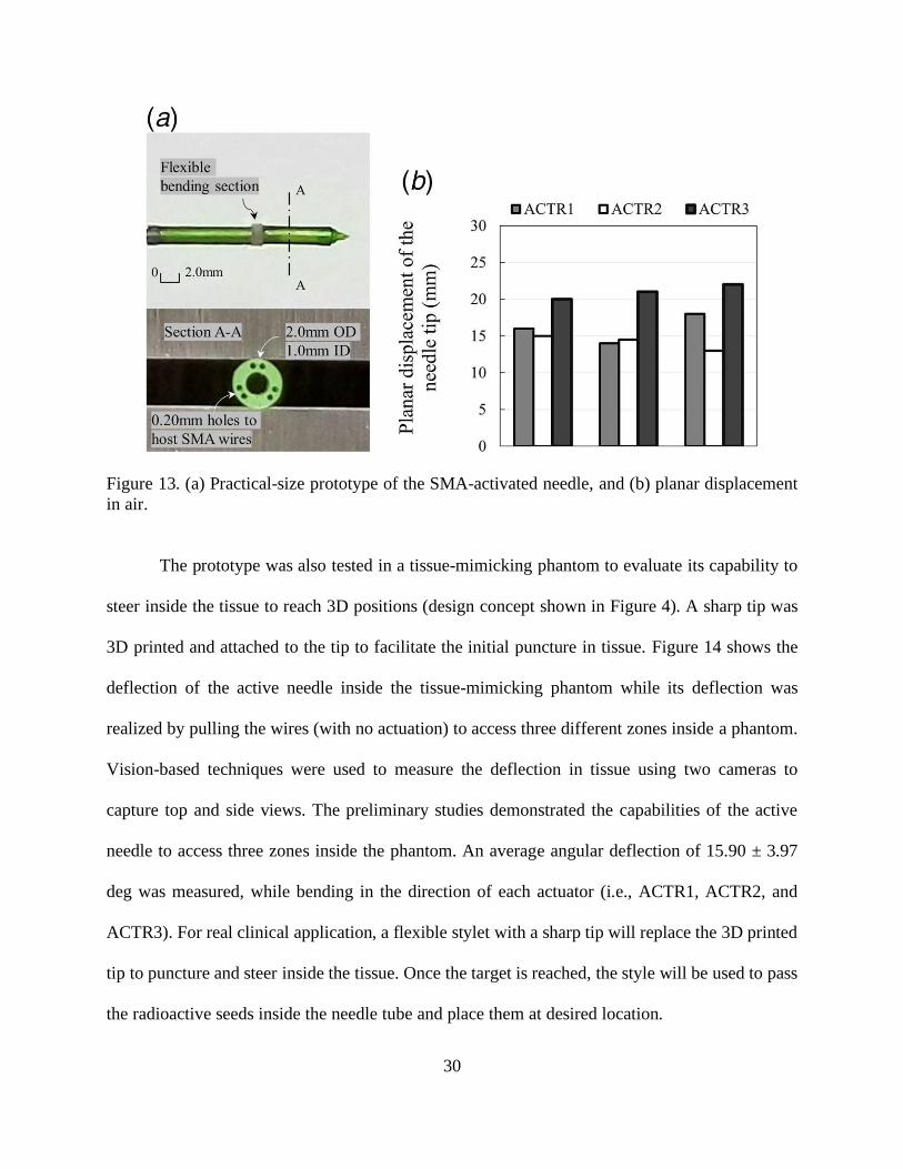
2.2.3. Evaluation of a practical-size active needle deflection in air
and inside tissue for clinical application
A practical-size prototype (2.0 mm OD and 1.0 mm ID) of the SMA-activated needle was
also 3D printed with MicroFine-Green resin using the Objet350 Connex3 Polyjet Stratsys printer
(Protolabs, Inc., Maple Plain, MN) with the same design concept introduced in Section 2.1.1. The
prototype was assembled with one flexible bending section (i.e., soft needle tube) and three SMA
actuators as shown in Figure 13(a). The cross-sectional view of the needle shows three pairs of
0.20 mm holes to host the SMA actuators, and 1.0 mm inner diameter for the radioactive seeds to
pass through toward the target area. The prototype was tested in air using the experimental setup
explained in Section 2.1.6. Figure 13(b) lists planar displacement of the needle tip with three
repetitions in the direction of each actuators (i.e., ACTR1, ACTR2, and ACTR3). An average
planar displacement of 17.06 ± 3.30 was realized by this prototype, which is comparatively smaller
than the 19.92 ± 1.83 mm planar displacement of the 4:1 scaled prototype (presented in Section
2.2.1). It is presumed that higher deflections are achievable by adding more flexible bending
sections on the needle.
30
Figure 13. (a) Practical-size prototype of the SMA-activated needle, and (b) planar displacement
in air.
The prototype was also tested in a tissue-mimicking phantom to evaluate its capability to
steer inside the tissue to reach 3D positions (design concept shown in Figure 4). A sharp tip was
3D printed and attached to the tip to facilitate the initial puncture in tissue. Figure 14 shows the
deflection of the active needle inside the tissue-mimicking phantom while its deflection was
realized by pulling the wires (with no actuation) to access three different zones inside a phantom.
Vision-based techniques were used to measure the deflection in tissue using two cameras to
capture top and side views. The preliminary studies demonstrated the capabilities of the active
needle to access three zones inside the phantom. An average angular deflection of 15.90 ± 3.97
deg was measured, while bending in the direction of each actuator (i.e., ACTR1, ACTR2, and
ACTR3). For real clinical application, a flexible stylet with a sharp tip will replace the 3D printed
tip to puncture and steer inside the tissue. Once the target is reached, the style will be used to pass
the radioactive seeds inside the needle tube and place them at desired location.
31
Figure 14. Preliminary testing inside a tissue-mimicking phantom. Accessing three zones: (a)
bottom left, (b) top left. And (c) top right inside a tissue-mimicking phantom by the active needle.
Robotic control of asymmetric passive beveled tip needles inside tissue toward the target
has been studied in literature [65]. These control systems utilize needle–tissue interaction models
such as: (i) nonholonomic kinematics [81], [82], (ii) finite element models [83], [84], (iii)
mechanics-based models [85], and (iv) adaptive models [86], [87] to realize a precise movement
inside tissue. The active needle, presented in this work, when bent at a desired angle, can be
controlled, and steered inside tissue via conventional approaches used for beveled tip needles. The
beveled tip needles require an axial rotation to bend in different directions, while the active needle
creates desired angles via its SMA actuators (i.e., no rotation required). Actuation of SMAs to
change the bending direction may be integrated with a proper model-based control (similar to the
model used in Ref. [88]) to minimize tissue rupture. Considering the size of the prostate capsule
and distribution of 70% of the tumor foci at the peripheral zone of the prostate capsule [89], [90],
we estimate that a bending angle of between 10 and 20 deg is necessary for the active needle to
facilitate seed implantation.
Additionally, the beveled tip needles are under-actuated systems, and thereby not locally
controllable. This means that states close to the current state of the system are not reachable in a

32
short insertion length [91]. The active needle proposed in this work introduces more actuators and
thereby provides more authority and control on the system.
The SMA actuators offer shape sensing as well as actuation [73]. This property of SMAs
can be used to locate the needle tip without the necessity of a sensor. The shape sensing capability
of SMA actuators may help to reduce the frequency of imaging or to reduce the duration or
complexity of imaging (e.g., 2D images combined with needle shape sensing may avoid the need
for 3D imaging) in image-guided needle insertions.
33
Chapter 3. 3D STEERABLE BIOPSY NEEDLE WITH A
MOTORIZED MANIPULATION SYSTEM AND ULTRASOUND
TRACKING TO NAVIGATE INSIDE TISSUE
Section 3.1.1 introduces the design and fabrication of the steerable biopsy needle. Section
3.1.2 explains the manipulation system that controls the needle bending and section 3.1.3 describes
the needle insertion system along with the ultrasound imaging feedback. Section 3.2 presents the
results of the research, where section 3.2.1 discusses the tracking of the needle tip and the
comparison between the ultrasound and camera (vision-based) techniques.
34
3.1. Materials and methods
3.1.1. Design and fabrication of a 3D steerable biopsy needle
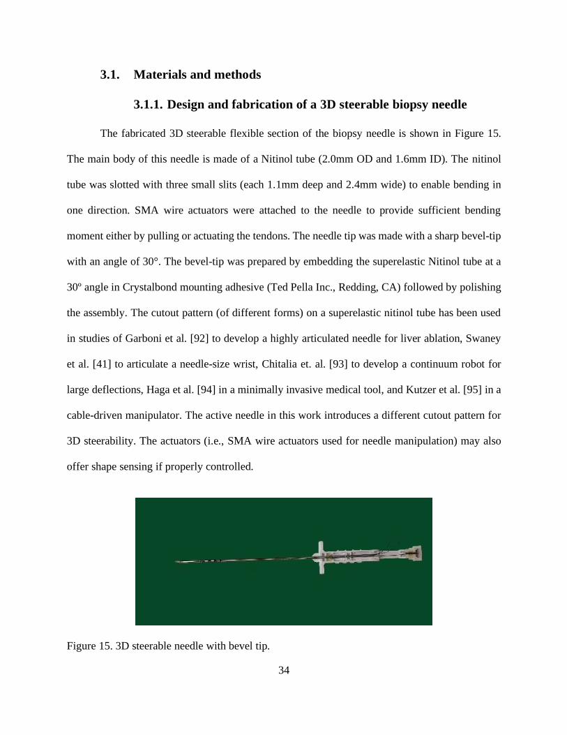
The fabricated 3D steerable flexible section of the biopsy needle is shown in Figure 15.
The main body of this needle is made of a Nitinol tube (2.0mm OD and 1.6mm ID). The nitinol
tube was slotted with three small slits (each 1.1mm deep and 2.4mm wide) to enable bending in
one direction. SMA wire actuators were attached to the needle to provide sufficient bending
moment either by pulling or actuating the tendons. The needle tip was made with a sharp bevel-tip
with an angle of 30°. The bevel-tip was prepared by embedding the superelastic Nitinol tube at a
30º angle in Crystalbond mounting adhesive (Ted Pella Inc., Redding, CA) followed by polishing
the assembly. The cutout pattern (of different forms) on a superelastic nitinol tube has been used
in studies of Garboni et al. [92] to develop a highly articulated needle for liver ablation, Swaney
et al. [41] to articulate a needle-size wrist, Chitalia et. al. [93] to develop a continuum robot for
large deflections, Haga et al. [94] in a minimally invasive medical tool, and Kutzer et al. [95] in a
cable-driven manipulator. The active needle in this work introduces a different cutout pattern for
3D steerability. The actuators (i.e., SMA wire actuators used for needle manipulation) may also
offer shape sensing if properly controlled.
Figure 15. 3D steerable needle with bevel tip.
35
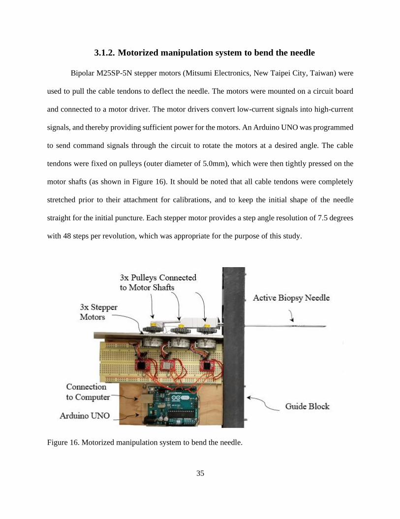
3.1.2. Motorized manipulation system to bend the needle
Bipolar M25SP-5N stepper motors (Mitsumi Electronics, New Taipei City, Taiwan) were
used to pull the cable tendons to deflect the needle. The motors were mounted on a circuit board
and connected to a motor driver. The motor drivers convert low-current signals into high-current
signals, and thereby providing sufficient power for the motors. An Arduino UNO was programmed
to send command signals through the circuit to rotate the motors at a desired angle. The cable
tendons were fixed on pulleys (outer diameter of 5.0mm), which were then tightly pressed on the
motor shafts (as shown in Figure 16). It should be noted that all cable tendons were completely
stretched prior to their attachment for calibrations, and to keep the initial shape of the needle
straight for the initial puncture. Each stepper motor provides a step angle resolution of 7.5 degrees
with 48 steps per revolution, which was appropriate for the purpose of this study.
Figure 16. Motorized manipulation system to bend the needle.
36
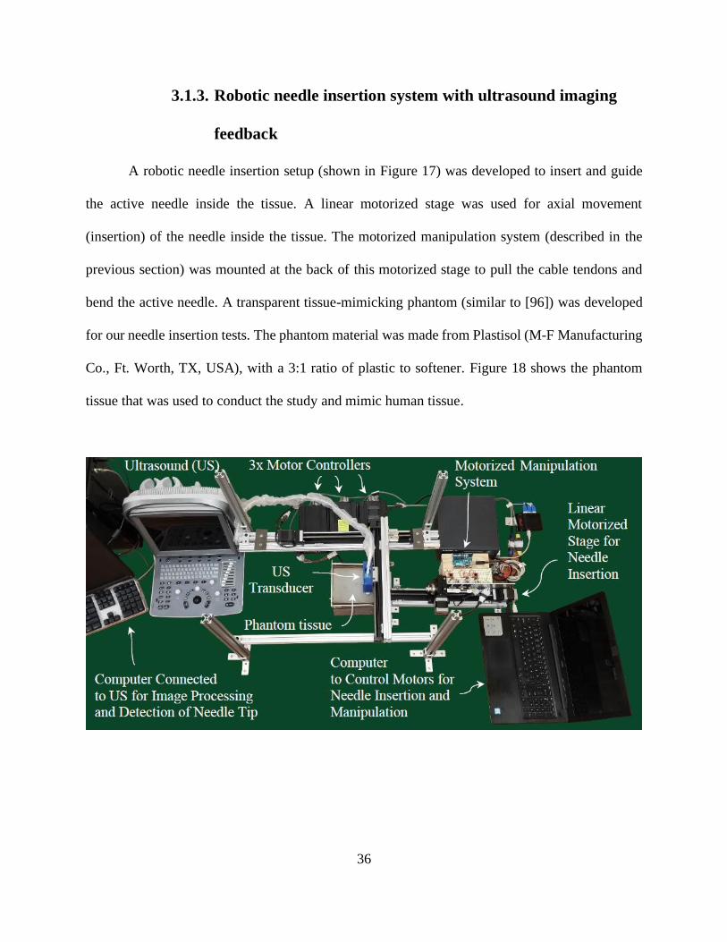
3.1.3. Robotic needle insertion system with ultrasound imaging
feedback
A robotic needle insertion setup (shown in Figure 17) was developed to insert and guide
the active needle inside the tissue. A linear motorized stage was used for axial movement
(insertion) of the needle inside the tissue. The motorized manipulation system (described in the
previous section) was mounted at the back of this motorized stage to pull the cable tendons and
bend the active needle. A transparent tissue-mimicking phantom (similar to [96]) was developed
for our needle insertion tests. The phantom material was made from Plastisol (M-F Manufacturing
Co., Ft. Worth, TX, USA), with a 3:1 ratio of plastic to softener. Figure 18 shows the phantom
tissue that was used to conduct the study and mimic human tissue.
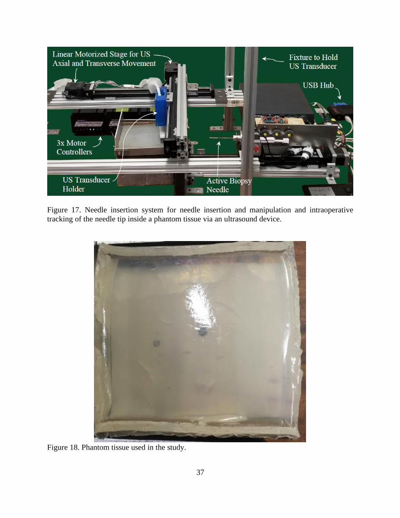
37
Figure 17. Needle insertion system for needle insertion and manipulation and intraoperative
tracking of the needle tip inside a phantom tissue via an ultrasound device.
Figure 18. Phantom tissue used in the study.
38
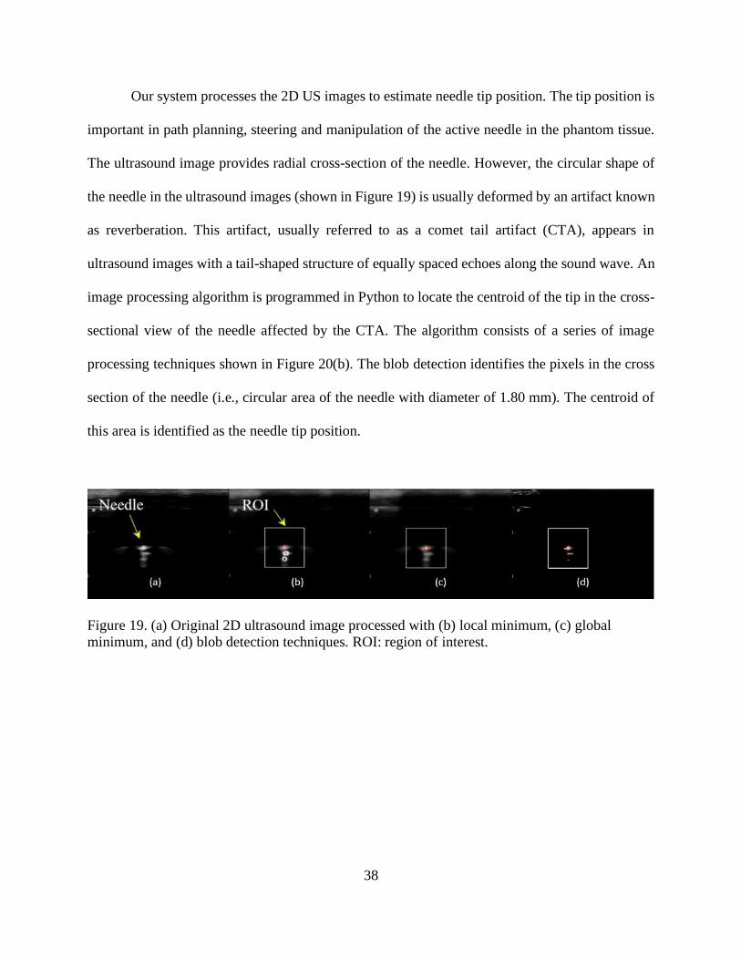
Our system processes the 2D US images to estimate needle tip position. The tip position is
important in path planning, steering and manipulation of the active needle in the phantom tissue.
The ultrasound image provides radial cross-section of the needle. However, the circular shape of
the needle in the ultrasound images (shown in Figure 19) is usually deformed by an artifact known
as reverberation. This artifact, usually referred to as a comet tail artifact (CTA), appears in
ultrasound images with a tail-shaped structure of equally spaced echoes along the sound wave. An
image processing algorithm is programmed in Python to locate the centroid of the tip in the cross-
sectional view of the needle affected by the CTA. The algorithm consists of a series of image
processing techniques shown in Figure 20(b). The blob detection identifies the pixels in the cross
section of the needle (i.e., circular area of the needle with diameter of 1.80 mm). The centroid of
this area is identified as the needle tip position.
Figure 19. (a) Original 2D ultrasound image processed with (b) local minimum, (c) global
minimum, and (d) blob detection techniques. ROI: region of interest.
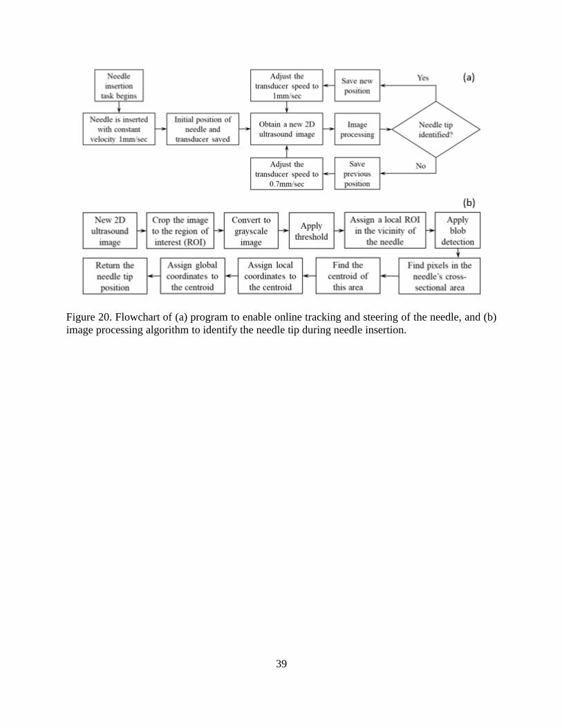
39
Figure 20. Flowchart of (a) program to enable online tracking and steering of the needle, and (b)
image processing algorithm to identify the needle tip during needle insertion.
40
3.2. Results
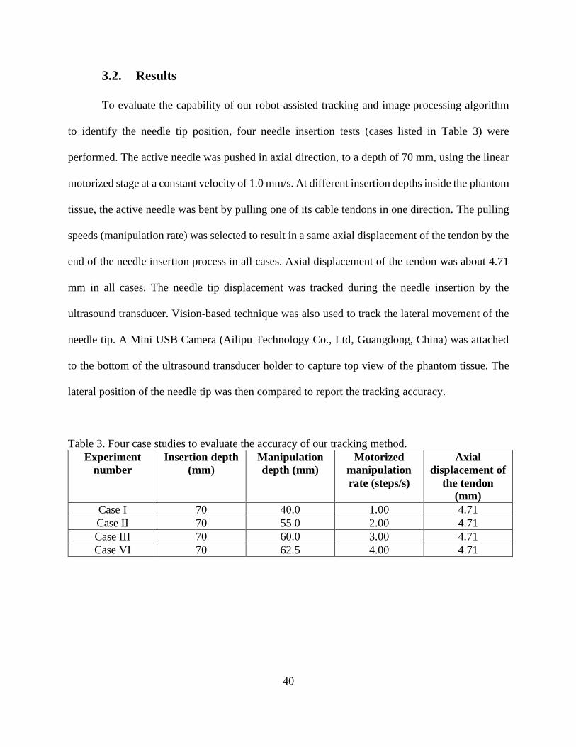
To evaluate the capability of our robot-assisted tracking and image processing algorithm
to identify the needle tip position, four needle insertion tests (cases listed in Table 3) were
performed. The active needle was pushed in axial direction, to a depth of 70 mm, using the linear
motorized stage at a constant velocity of 1.0 mm/s. At different insertion depths inside the phantom
tissue, the active needle was bent by pulling one of its cable tendons in one direction. The pulling
speeds (manipulation rate) was selected to result in a same axial displacement of the tendon by the
end of the needle insertion process in all cases. Axial displacement of the tendon was about 4.71
mm in all cases. The needle tip displacement was tracked during the needle insertion by the
ultrasound transducer. Vision-based technique was also used to track the lateral movement of the
needle tip. A Mini USB Camera (Ailipu Technology Co., Ltd, Guangdong, China) was attached
to the bottom of the ultrasound transducer holder to capture top view of the phantom tissue. The
lateral position of the needle tip was then compared to report the tracking accuracy.
Table 3. Four case studies to evaluate the accuracy of our tracking method.
Experiment
number
Insertion depth
(mm)
Manipulation
depth (mm)
Motorized
manipulation
rate (steps/s)
Axial
displacement of
the tendon
(mm)
Case I 70 40.0 1.00 4.71
Case II 70 55.0 2.00 4.71
Case III 70 60.0 3.00 4.71
Case VI 70 62.5 4.00 4.71
41
3.2.1. Improved visualization of the needle and real-time tracking
with ultrasound
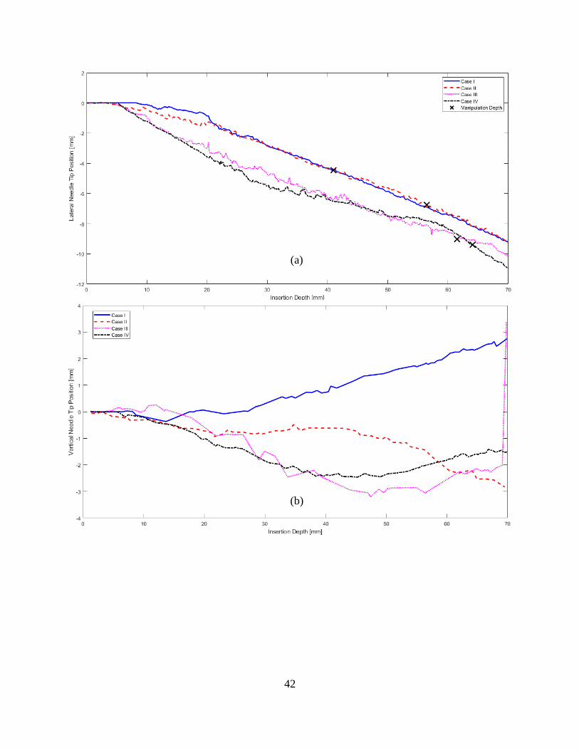
Figure 16 shows the robot-assisted needle tip tracking (via the ultrasound transducer) for
the four case studies listed in Table 3. The needle was first inserted in axial direction until its
flexible section is completely inside the phantom tissue. At different depths (marked in Figure
21a), the cable tendon was pulled (at different manipulation rates listed in Table 3) to bend the
needle in one direction. In a previous study [96], we tracked the needle tip using Simple Linear
Iterative Clustering (SLIC) superpixels method, followed by a 2D Kalman filter. The study showed
possibility of losing track of the needle tip in some ultrasound frames. The image processing
algorithm presented in this work was able to track the needle tip in real time with no lost frames
during the insertion for all cases. Figure 21(a) & (b) show the lateral and vertical displacement of
the needle, respectively. Case IV, with the most aggressive manipulation rate, although later in the
insertion process, showed the highest deflection at the depth of 70 mm. The overall deflection of
the needle tip is shown in Figure 21(c). Out of plane movements of the needle was larger at higher
insertion depth. Case III also showed the highest out of plane movement compared to the other
three cases.
42
(b)
(a)
43
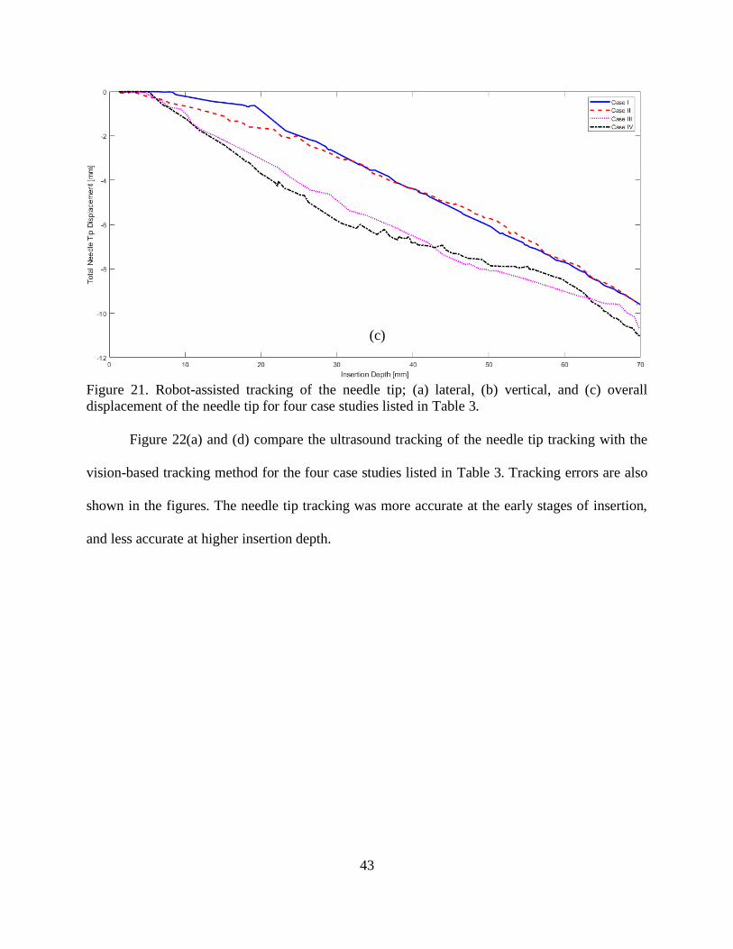
Figure 21. Robot-assisted tracking of the needle tip; (a) lateral, (b) vertical, and (c) overall
displacement of the needle tip for four case studies listed in Table 3.
Figure 22(a) and (d) compare the ultrasound tracking of the needle tip tracking with the
vision-based tracking method for the four case studies listed in Table 3. Tracking errors are also
shown in the figures. The needle tip tracking was more accurate at the early stages of insertion,
and less accurate at higher insertion depth.
(c)
44
Figure 22. Comparison of lateral displacement of the needle tip via ultrasound tracking and
vision-based tracking for four case studies listed in Table 3.
Table 4 lists the maximum and average error of the needle tip tracking for the four case
studies listed in Table 3. The average error for all cases were less than 1.5mm. Tracking was less
accurate at higher insertion depths. Tracking error at 70mm of insertion depth is also listed in the
table below.
Table 4. Average and maximum error in needle tip tracking
Max error
(mm)
Average
error (mm)
Error at 70
mm
Max total
displacement
(mm)
Max vertical
displacement
(mm)
Case I 1.798 1.438 1.574 9.632 2.841
Case II 2.073 1.073 2.073 9.770 2.830
Case III 1.555 0.073 1.555 10.67 3.375
Case IV 1.065 0.157 0.777 11.49 2.464
We tested the proposed method of robot-assisted ultrasound tracking of the needle tip via
four case studies at four different manipulation rates. In Case I, the needle manipulation starts at
the depth of 40 mm at a slower rate of 1.00 steps/s. Case I results in the lowest total displacement
45
of 9.632 mm but with a vertical displacement of 2.841 mm. In Case II, the manipulation starts at
the depth of 55 mm at a higher rate of 2.00 steps/s. This case results in total displacement of 9.770
mm and vertical displacement of 2.830 mm. Case III, where the manipulation starts at the depth
of 60 mm at rate of 3.00 steps/s, results in total and vertical displacements of 10.67 and 3.375 mm.
The vertical displacement of the needle tip in this case is the highest compared to the other three
cases. The average needle tip tracking error is also the lowest, although only the lateral
displacement of the needle tip is compared. In Case IV, the manipulation rate is the highest (4.00
steps/s) when at the depth of 6.25 mm. However, this case results in the highest total displacement
of the needle tip (11.49 mm), and a vertical displacement of 2.464 mm. Results suggest that a
higher manipulation rate (faster needle deflection) is more effective to achieve a higher deflection
during the needle insertion process. The accuracy of the needle tip tracking is also higher at a
higher manipulation rate and at early stages of the insertion process.
46
CONCLUSION
In the “Shape memory alloy actuators in an active needle – modeling, precise assembly,
and performance evaluation” paper, the interactive response of multiple SMA actuators in an
active needle manipulation is discussed. The loading path on each SMA actuator was investigated
to develop a precise assembly process for effective manipulation and repeatable performance of
the active needle. The consistent performance of SMAs in an active structure can be challenging
because of their nonlinear and hysteresis behavior. The methods suggested in this work have made
it possible to track the SMAs’ phase transformation during operation and develop a system that
can properly work with multiple distributed SMAs. This work has introduced a practical size of
active needle (2.0 mm OD and 1.0 mm ID) that can realize a 15.90 ± 3.97 deg average angular
deflection in tissue with one flexible bending section. The design of the active needle can be
modified to include an additional number of flexible bending sections to achieve higher
deflections.
In the “3D steerable biopsy needle with a motorized manipulation system and ultrasound
tracking to navigate inside tissue” paper, the application of our proposed robot-assisted ultrasound
tracking method for the needle insertions inside a phantom tissue (70mm depth) showed that the
needle tip can be tracked with an average error of <1.5 mm. Based on the results, it appears that
the manipulation rate greatly impacts the deflection of the needle tip. This study seems to suggest
that as the manipulation rate increases, the linear displacement of the needle tip will also increase.
It also shows that the tracking error between the ultrasound transducer and the camera increases
as the needle insertion depth increases. Any improvements on the accuracy of tracking at early
stages of the insertion can be used to estimate the shape of the needle and be further used to
47
estimate needle-tissue interactions. Our current processing time (in milliseconds) allows surgeons
or robots to determine the needle tip position in real time.
FUTURE WORK
Future work includes control studies of the active needle in air and inside the tissue. The
3D printing and low manufacturing cost of the active needle design allows for modifications and
scalability of needles suitable for different needle-based procedures. Higher needle bending can
be realized by adding additional flexible joints and additional SMA actuators. The design can also
be optimized for a specific procedure via changing the design parameters. Improving the image
analysis, path planning, robotic guidance, and tracking of the needle tip in real inhomogeneous
tissue is another study that is being discussed. Beef liver tissue is currently being looked into due
to its low cost and similarities to human tissue.
48
REFERENCES [1] R. L. Siegel, K. D. Miller, and A. Jemal, “Cancer statistics, 2019,” CA. Cancer J. Clin.,
vol. 69, no. 1, pp. 7–34, 2019, doi: 10.3322/caac.21551.
[2] J. Chin et al., “Brachytherapy for patients with prostate cancer: American Society of
Clinical Oncology/Cancer Care Ontario joint guideline update,” J. Clin. Oncol., vol. 35,
no. 15, pp. 1737–1743, 2017, doi: 10.1200/JCO.2016.72.0466.
[3] P. Crossan, “External beam radiation therapy,” in Breast disease: Comprehensive
management, Springer, New York, NY, 2015, pp. 377–397.
[4] N. H. J. Bittner, P. F. Orio, G. S. Merrick, B. R. Prestidge, A. C. Hartford, and S. A.
Rosenthal, “The American College of Radiology and the American Brachytherapy Society
practice parameter for transperineal permanent brachytherapy of prostate cancer,”
Brachytherapy, vol. 16, no. 1, pp. 59–67, 2017, doi: 10.1016/j.brachy.2016.06.003.
[5] C. Shah et al., “Brachytherapy provides comparable outcomes and improved cost-
effectiveness in the treatment of low/intermediate prostate cancer,” Brachytherapy, vol.
11, no. 6, pp. 441–445, 2012, doi: 10.1016/j.brachy.2012.04.002.
[6] A. N. Viswanathan, B. A. Erickson, G. S. Ibbott, W. Small, and P. J. Eifel, “The American
College of Radiology and the American Brachytherapy Society practice parameter for the
performance of low-dose-rate brachytherapy,” Brachytherapy, vol. 16, no. 1, pp. 68–74,
2017, doi: 10.1016/j.brachy.2016.06.013.
[7] A. L. Tam et al., “Image-guided biopsy in the era of personalized cancer care:
Proceedings from the society of interventional radiology research consensus panel,” J.
Vasc. Interv. Radiol., vol. 27, no. 1, pp. 8–19, 2016, doi: 10.1016/j.jvir.2015.10.019.
[8] H. D. Bear et al., “Using the 21-gene assay from core needle biopsies to choose
neoadjuvant therapy for breast cancer: A multicenter trial,” J. Surg. Oncol., vol. 115, no.
8, pp. 917–923, 2017, doi: 10.1002/jso.24610.
[9] R. Guo, G. Lu, B. Qin, and B. Fei, “Ultrasound Imaging Technologies for Breast Cancer
Detection and Management: A Review,” Ultrasound Med. Biol., vol. 44, no. 1, pp. 37–70,
2018, doi: 10.1016/j.ultrasmedbio.2017.09.012.
[10] M. G. Kanojia, M. A. M. H. Ansari, N. Gandhi, and S. K. Yadav, “Image processing
techniques for breast cancer detection: A review,” in Advances in Intelligent Systems and
Computing, 2019, doi: 10.1007/978-3-030-49342-4_63.
[11] S. Robertson, H. Azizpour, K. Smith, and J. Hartman, “Digital image analysis in breast
pathology—from image processing techniques to artificial intelligence,” Transl. Res., vol.
194, pp. 19–35, 2018, doi: 10.1016/j.trsl.2017.10.010.
[12] W. Xia et al., “Looking beyond the imaging plane: 3D needle tracking with a linear array
ultrasound probe,” Sci. Rep., vol. 7, no. 1, pp. 1–9, 2017, doi: 10.1038/s41598-017-03886-
4.
[13] B. Fei and D. M. Schuster, “PET molecular imaging-directed biopsy: A review,” Am. J.
Roentgenol., vol. 209, no. 2, pp. 255–269, 2017, doi: 10.2214/AJR.17.18047.
[14] T. K. Podder, A. P. Dicker, P. Hutapea, K. Darvish, and Y. Yu, “A novel curvilinear
approach for prostate seed implantation,” Med. Phys., vol. 39, no. 4, pp. 1887–1892, 2012,
doi: 10.1118/1.3694110.
[15] N. J. van de Berg, D. J. van Gerwen, J. Dankelman, and J. J. van den Dobbelsteen,
“Design Choices in Needle Steering -A Review,” Mechatronics, IEEE/ASME Trans., vol.
20, no. 5, pp. 2172–2183, 2015, doi: 10.1109/TMECH.2014.2365999.
[16] T. L. De Jong, N. J. van de Berg, L. Tas, A. Moelker, J. Dankelman, and J. J. van den
49
Dobbelsteen, “Needle placement errors: Do we need steerable needles in interventional
radiology?,” Med. Devices Evid. Res., vol. 37, no. 3, pp. 259–265, 2017, doi:
10.2147/MDER.S160444.
[17] B. Konh, M. Honarvar, K. Darvish, and P. Hutapea, “Simulation and experimental studies
in needle–tissue interactions,” J. Clin. Monit. Comput., vol. 31, no. 4, pp. 861–872, 2017,
doi: 10.1007/s10877-016-9909-6.
[18] G. S. Merrick, W. M. Butler, A. T. Dorsey, and H. L. Walbert, “Influence of timing on the
dosimetric analysis of transperineal ultrasound-guided, prostatic conformal
brachytherapy,” Radiat. Oncol. Investig., vol. 6, no. 4, pp. 182–190, 1998, doi:
10.1002/(SICI)1520-6823(1998)6:4<182::AID-ROI6>3.0.CO;2-U.
[19] C. S. Brockman and G. J. Harshman, “Systems and methods for off-axis tissue
manipulation,” 13/923,104, 2013.
[20] J. P. Desai and E. Ayvali, “Actuated steerable probe and systems and methods of using
same,” 9,655,679, 2017.
[21] J. S. Melsheimer, “Deflectable biopsy device,” 9,247,929, 2016.
[22] K. Eck, “Surgical needle and method of guiding a surgical needle,” 12/299,122, 2007.
[23] B. Arvanaghi, “Bendable needle assembly,” 11/525,134, 2006.
[24] K. F. Smits, J. J. Rutten, and P. G. Adams, “Method and apparatus for imparting curves in
implantable elongated medical instruments.,” 6,907,298, 2005.
[25] S. E. Salcudean, R. N. Rohling, S. H. Okazawa, and A. R. Ebrahimi, “Steerable needle,”
7,662,128, 2010.
[26] T. J. Ryan and C. J. Winslow., “Percutaneous discectomy system having a bendable
discectomy probe and a steerable cannula,” 5,285,795, 1994.
[27] W. G. Kuhle, “Biopsy needle with flared tip,” 5,938,635, 1999.
[28] D. Kraft and J. Hole., “Device and method for rapid aspiration and collection of body
tissue from within an enclosed body space,” 7,462,181, 2008.
[29] K. B. Reed et al., “Robot-Assisted Needle Steering,” in IEEE Robotics and Automation
Magazine, 2011, vol. 18, no. 4, pp. 35–46, doi: 10.1109/MRA.2011.942997.
[30] T. R. Wedlick and A. M. Okamura, “Characterization of pre-curved needles for steering in
tissue.,” in Annual International Conference of the IEEE Engineering in Medicine and
Biology Society, 2009, pp. 1200–1203, doi: 10.1109/IEMBS.2009.5333407.
[31] P. J. Swaney, J. Burgner, H. B. Gilbert, R. J. Webster, and R. J. WebsterIII, “A flexure-
based steerable needle: high curvature with reduced tissue damage.,” IEEE Trans.
Biomed. Eng., vol. 60, no. 4, pp. 906–909, 2013, doi: 10.1109/TBME.2012.2230001.
[32] R. J. Webster, J. M. Romano, and N. J. Cowan, “Mechanics of precurved-tube continuum
robots,” IEEE Trans. Robot., vol. 25, no. 1, pp. 67–78, 2009, doi:
10.1109/TRO.2008.2006868.
[33] S. Misra, K. B. Reed, B. W. Schafer, K. T. Ramesh, and A. M. Okamura, “Mechanics of
flexible needles robotically steered through soft tissue,” Int. J. Rob. Res., vol. 29, no. 13,
pp. 1640–1660, 2010, doi: 10.1177/0278364910369714.
[34] R. J. Roesthuis, M. Abayazid, and S. Misra, “Mechanics-based model for predicting in-
plane needle deflection with multiple bends,” in 2012 4th IEEE RAS & EMBS
International Conference on Biomedical Robotics and Biomechatronics (BioRob), 2012,
pp. 69–74, doi: 10.1109/BioRob.2012.6290829.
[35] N. Abolhassani, R. Patel, and M. Moallem, “Needle insertion into soft tissue: a survey.,”
Med. Eng. Phys., vol. 29, no. 4, pp. 413–431, 2007, doi:
50
10.1016/j.medengphy.2006.07.003.
[36] M. A. Meltsner, N. J. Ferrier, and B. R. Thomadsen, “Observations on rotating needle
insertions using a brachytherapy robot,” Phys. Med. Biol., vol. 52, no. 19, pp. 6027–6037,
2007, doi: 10.1088/0031-9155/52/19/021.
[37] J. A. Engh, D. S. Minhas, D. Kondziolka, and C. N. Riviere, “Percutaneous intracerebral
navigation by duty-cycled spinning of flexible bevel-tipped needles,” Neurosurgery, vol.
67, no. 4, pp. 1117–1122, 2010, doi: 10.1227/NEU.0b013e3181ec1551.
[38] J. P. Swensen, M. Lin, A. M. Okamura, and N. J. Cowan, “Torsional dynamics of
steerable needles: Modeling and fluoroscopic guidance,” IEEE Trans. Biomed. Eng., vol.
61, no. 11, pp. 2707–2717, 2014, doi: 10.1109/TBME.2014.2326161.
[39] K. B. Reed, A. M. Okamura, and N. J. Cowan, “Modeling and control of needles with
torsional friction,” IEEE Trans. Biomed. Eng., vol. 56, no. 12, pp. 2905–2916, 2009, doi:
10.1109/TBME.2009.2029240.
[40] M. Scali, T. P. Pusch, P. Breedveld, and D. Dodou, “Needle-like instruments for steering
through solid organs: A review of the scientific and patent literature,” Proc. Inst. Mech.
Eng. Part H J. Eng. Med., vol. 231, no. 3, pp. 250–265, 2017, doi:
10.1177/0954411916672149.
[41] P. J. Swaney, P. A. York, H. B. Gilbert, J. Burgner-Kahrs, and R. J. Webster, “Design,
Fabrication, and Testing of a Needle-Sized Wrist for Surgical Instruments,” J. Med.
Device., vol. 11, no. 1, p. 14501, 2017, doi: 10.1115/1.4034575.
[42] H. Su, G. Li, D. C. Rucker, R. J. Webster, and G. S. Fischer, “A Concentric Tube
Continuum Robot with Piezoelectric Actuation for MRI-Guided Closed-Loop Targeting,”
Ann. Biomed. Eng., vol. 44, no. 10, pp. 2863–2873, 2016, doi: 10.1007/s10439-016-1585-
7.
[43] S. C. Ryu, P. Renaud, R. J. Black, B. L. Daniel, and M. R. Cutkosky, “Feasibility study of
an optically actuated MR-Compatible active needle,” in IEEE/RSJ International
Conference on Intelligent Robots and Systems (IROS), 2011, pp. 2564–2569, doi:
10.1109/IROS.2011.6094945.
[44] E. Ayvali, C.-P. C. P. Liang, M. Ho, Y. Chen, and J. P. Desai, “Towards a discretely
actuated steerable cannula for diagnostic and therapeutic procedures,” Int. J. Rob. Res.,
vol. 31, no. 5, pp. 588–603, 2012, doi: 10.1177/0278364912442429.
[45] T. K. Morimoto, J. J. Cerrolaza, M. H. Hsieh, K. Cleary, A. M. Okamura, and M. G.
Linguraru, “Design of patient-specific concentric tube robots using path planning from 3-
D ultrasound,” in 39th Annual International Conference of the IEEE Engineering in
Medicine and Biology Society, 2017, pp. 165–168, doi: 10.1109/EMBC.2017.8036788.
[46] M. Abayazid, M. Kemp, and S. Misra, “3D flexible needle steering in soft-tissue
phantoms using Fiber Bragg Grating sensors,” in Proceedings - IEEE International
Conference on Robotics and Automation, 2013, pp. 5843–5849, doi:
10.1109/ICRA.2013.6631418.
[47] M. Scali, T. P. Pusch, P. Breedveld, and D. Dodou, “Ovipositor-inspired steerable needle:
design and preliminary experimental evaluation,” Bioinspir. Biomim., vol. 13, no. 1, p.
016006, 2017, doi: 10.1088/1748-3190/aa92b9.
[48] P. Sears and P. Dupont, “A steerable needle technology using curved concentric tubes,” in
IEEE International Conference on Intelligent Robots and Systems, 2006, pp. 2850–2856,
doi: 10.1109/IROS.2006.282072.
[49] N. J. van de Berg, J. Dankelman, and J. J. van den Dobbelsteen, “Design of an actively
51
controlled steerable needle with tendon actuation and FBG-based shape sensing,” Med.
Eng. Phys., vol. 37, no. 6, pp. 617–622, 2015, doi: 10.1016/j.medengphy.2015.03.016.
[50] S. C. Ryu, Z. F. Quek, P. Renaud, R. J. Black, B. L. Daniel, and M. R. Cutkosky, “An
optical actuation system and curvature sensor for a MR-compatible active needle,” in
IEEE International Conference on Robotics and Automation, 2012, pp. 1589–1594, doi:
10.1109/ICRA.2012.6224964.
[51] B. Konh and T. K. Podder, “Design and Fabrication of a Robust Active Needle using
SMA Wires,” in Design of Medical Devices Conference, 2017, doi: 10.1115/1.4029557.
[52] L. Petrini and F. Migliavacca, “Biomedical Applications of Shape Memory Alloys,” J.
Metall., vol. 2011, pp. 1–15, 2011, doi: 10.1155/2011/501483.
[53] N. B. Morgan, “Medical shape memory alloy applications - The market and its products,”
Mater. Sci. Eng. A, vol. 378, no. 1, pp. 16–23, 2004, doi: 10.1016/j.msea.2003.10.326.
[54] D. C. Lagoudas, Shape Memory Alloys: Modeling and Engineering Applications. 2008.
[55] P. Popov and D. C. Lagoudas, “Extended SMA Modeling,” in Shape Memory Alloys,
2008.
[56] N. J. Cowan et al., “Robotic needle steering: Design, modeling, planning, and image
guidance,” in Surgical Robotics, 2011, pp. 557–582.
[57] K. B. Reed, V. Kallem, R. Alterovitzt, K. Goldberg, A. M. Okamura, and N. J. Cowan,
“Integrated planning and image-guided control for planar needle steering,” in Proceedings
of the 2nd Biennial IEEE/RAS-EMBS International Conference on Biomedical Robotics
and Biomechatronics, BioRob 2008, 2008, doi: 10.1109/BIOROB.2008.4762833.
[58] P. J. Swaney et al., “Tracked 3D ultrasound targeting with an active cannula,” in Medical
Imaging 2012: Image-Guided Procedures, Robotic Interventions, and Modeling, 2012,
doi: 10.1117/12.912021.
[59] G. J. Vrooijink, M. Abayazid, S. Patil, R. Alterovitz, and S. Misra, “Needle path planning
and steering in a three-dimensional non-static environment using two-dimensional
ultrasound images,” Int. J. Rob. Res., vol. 33, no. 10, pp. 1361–1374, 2014, doi:
10.1177/0278364914526627.
[60] E. M. Boctor, R. J. Webster, M. A. Choti, R. H. Taylor, and G. Fichtinger, “Robotically
assisted ablative treatment guided by freehand 3D ultrasound,” Int. Congr. Ser., vol. 1268,
pp. 503–508, 2004, doi: 10.1016/j.ics.2004.03.261.
[61] T. K. Adebar, A. E. Fletcher, and A. M. Okamura, “3-D ultrasound-guided robotic needle
steering in biological tissue,” IEEE Trans. Biomed. Eng., vol. 61, no. 12, pp. 2899–2910,
2014, doi: 10.1109/TBME.2014.2334309.
[62] T. K. Adebar and A. M. Okamura, “3D segmentation of curved needles using Doppler
ultrasound and vibration,” in Lecture Notes in Computer Science (including subseries
Lecture Notes in Artificial Intelligence and Lecture Notes in Bioinformatics), 2013, doi:
10.1007/978-3-642-38568-1_7.
[63] J. D. Greer, T. K. Adebar, G. L. Hwang, and A. M. Okamura, “Real-time 3D curved
needle segmentation using combined B-mode and power Doppler ultrasound,” Med.
Image Comput. Comput. Assist. Interv., vol. 17, pp. 381–388, 2014.
[64] S. M. Bierig and A. Jones, “Accuracy and cost comparison of ultrasound versus
alternative imaging modalities, including CT, MR, PET, and angiography,” J. Diagnostic
Med. Sonogr., vol. 25, no. 3, pp. 138–144, 2009, doi: 10.1177/8756479309336240.
[65] C. Rossa and M. Tavakoli, “Issues in closed-loop needle steering,” Control Eng. Pract.,
vol. 62, pp. 55–69, 2017, doi: 10.1016/j.conengprac.2017.03.004.
52
[66] M. Najafi and R. Rohling, “Single camera closed-form real-time needle trajectory tracking
for ultrasound,” in Medical Imaging 2011: Visualization, Image-Guided Procedures, and
Modeling, 2011, doi: 10.1117/12.877798.
[67] E. Ayvali and J. P. Desai, “Optical Flow-Based Tracking of Needles and Needle-Tip
Localization Using Circular Hough Transform in Ultrasound Images,” Ann. Biomed. Eng.,
vol. 43, no. 8, pp. 1828–1840, 2015, doi: 10.1007/s10439-014-1208-0.
[68] Y. Zhao, A. Bernard, C. Cachard, and H. Liebgott, “Biopsy needle localization and
tracking using ROI-RK method,” Abstr. Appl. Anal., vol. 2014, pp. 1–7, 2014, doi:
10.1155/2014/973147.
[69] M. Waine, C. Rossa, R. Sloboda, N. Usmani, and M. Tavakoli, “3D shape visualization of
curved needles in tissue from 2D ultrasound images using RANSAC,” in Proceedings -
IEEE International Conference on Robotics and Automation, 2015, doi:
10.1109/ICRA.2015.7139855.
[70] Z. Khashei Varnamkhasti and B. Konh, “Design and Performance Study of a Novel
Minimally Invasive Active Surgical Needle,” J. Med. Device., vol. 13, no. 4, pp. 1–9,
2019, doi: 10.1115/1.4044526.
[71] Z. K. Varnamkhasti and B. Konh, “Cable-driven 3D steerable surgical needle for needle-
based procedures,” in Design of Medical Devices Conference, 2020, pp. 1–5.
[72] S. Karimi and B. Konh, “3D steerable active surgical needle,” in Frontiers in Biomedical
Devices, BIOMED - 2019 Design of Medical Devices Conference, DMD 2019, 2019, doi:
10.1115/DMD2019-3307.
[73] S. Karimi and B. Konh, “Self-Sensing Electrical Resistance Feedback Control of Multiple
Interacting SMA Actuators in a 3D Steerable Active Needle,” J. Intell. Mater. Syst.
Struct., vol. 13, no. 12, pp. 1524–1540, 2020.
[74] N. V Datla et al., “Polyacrylamide phantom for self-actuating needle-tissue interaction
studies,” Med. Eng. Phys., vol. 36, no. 1, pp. 140–145, 2014, doi:
10.1016/j.medengphy.2013.07.004.
[75] B. Konh, D. Sasaki, T. K. Podder, and H. Ashrafiuon, “3D Manipulation of an Active
Steerable Needle via Actuation of Multiple SMA Wires,” Robotica, vol. 38, no. 3, pp. 1–
17, 2019, doi: 10.1017/S0263574719000705.
[76] B. Konh, M. Honarvar, and P. Hutapea, “Design optimization study of a shape memory
alloy active needle for biomedical applications,” Med. Eng. Phys., vol. 37, no. 5, pp. 469–
477, 2015, doi: 10.1016/j.medengphy.2015.02.013.
[77] L. C. Brinson, “One-dimensional constitutive behavior of shape memory alloys:
Thermomechanical derivation with non-constant material functions and redefined
martensite internal variable,” J. Intell. Mater. Syst. Struct., vol. 4, no. 2, pp. 229–242,
1993, doi: 10.1177/1045389X9300400213.
[78] B. Konh, N. V Datla, and P. Hutapea, “Feasibility of SMA wire actuation for an active
steerable cannula,” J. Med. Device., vol. 9, no. 2, pp. 021002-1-021002–11, 2015, doi:
10.1115/1.4029557.
[79] S. Karimi and B. Konh, “Dynamic characteristics analyses and FEM modeling of flexible
joints of an SMA-activated flexible multi-joint needle,” in Design of Medical Devices
Conference, 2020, pp. 1–3.
[80] T. Podder et al., “Methods for prostate stabilization during transperineal LDR
brachytherapy,” Phys. Med. Biol., vol. 53, no. 6, pp. 1563–1579, 2008, doi: 10.1088/0031-
9155/53/6/004.
53
[81] R. J. Webster, J. S. Kim, N. J. Cowan, G. S. Chirikjian, and A. M. Okamura,
“Nonholonomic modeling of needle steering,” in International Journal of Robotics
Research, 2006, doi: 10.1177/0278364906065388.
[82] N. J. Cowan et al., “Robotic needle steering: Design, modeling, planning, and image
guidance,” in Surgical Robotics: Systems Applications and Visions, 2011.
[83] S. P. Dimaio and S. E. Salcudean, “Needle steering and motion planning in soft tissues,”
IEEE Trans. Biomed. Eng., vol. 52, no. 6, pp. 965–974, 2005, doi:
10.1109/TBME.2005.846734.
[84] R. Alterovitz, A. Lim, K. Goldberg, G. S. Chirikjian, and A. M. Okamura, “Steering
flexible needles under Markov motion uncertainty,” in 2005 IEEE/RSJ International
Conference on Intelligent Robots and Systems, IROS, 2005, doi:
10.1109/IROS.2005.1544969.
[85] K. G. Yan, T. Podder, Y. Yu, T. I. Liu, C. W. S. Cheng, and W. S. Ng, “Flexible needle-
tissue interaction modeling with depth-varying mean parameter: Preliminary study,” IEEE
Trans. Biomed. Eng., vol. 56, no. 2, pp. 255–262, 2009, doi:
10.1109/TBME.2008.2005959.
[86] C. Rossa, M. Khadem, R. Sloboda, N. Usmani, and M. Tavakoli, “Adaptive Quasi-Static
Modelling of Needle Deflection during Steering in Soft Tissue,” IEEE Robot. Autom.
Lett., vol. 1, no. 2, pp. 916–923, 2016, doi: 10.1109/LRA.2016.2527065.
[87] K. G. Yan et al., “An improved needle steering model with online parameter estimator,”
Int. J. Comput. Assist. Radiol. Surg., vol. 1, no. 4, pp. 205–212, 2006, doi:
10.1007/s11548-006-0058-0.
[88] M. Khadem, C. Rossa, R. S. Sloboda, N. Usmani, and M. Tavakoli, “Ultrasound-Guided
Model Predictive Control of Needle Steering in Biological Tissue,” J. Med. Robot. Res.,
vol. 1, no. 1, pp. 164007–1640011, 2016, doi: 10.1142/s2424905x16400079.
[89] R. J. Cohen, B. A. Shannon, M. Phillips, R. E. Moorin, T. M. Wheeler, and K. L. Garrett,
“Central Zone Carcinoma of the Prostate Gland: A Distinct Tumor Type With Poor
Prognostic Features,” J. Urol., vol. 179, no. 5, pp. 1762–1767, 2008, doi:
10.1016/j.juro.2008.01.017.
[90] J. E. McNeal, E. A. Redwine, F. S. Freiha, and T. A. Stamey, “Zonal distribution of
prostatic adenocarcinoma. Correlation with histologic pattern and direction of spread,”
Am. J. Surg. Pathol., vol. 12, no. 12, pp. 897–906, 1988, doi: 10.1097/00000478-
198812000-00001.
[91] A. Haddadi, O. Goksel, S. E. Salcudean, and K. Hashtrudi-Zaad, “On the controllability of
dynamic model-based needle insertion in soft tissue,” in 2010 Annual International
Conference of the IEEE Engineering in Medicine and Biology Society, EMBC’10, 2010,
doi: 10.1109/IEMBS.2010.5627676.
[92] G. Gerboni, J. D. Greer, P. F. Laeseke, G. L. Hwang, and A. M. Okamura, “Highly
Articulated Robotic Needle Achieves Distributed Ablation of Liver Tissue,” IEEE Robot.
Autom. Lett., vol. 2, no. 3, pp. 1367–1374, 2017, doi: 10.1109/LRA.2017.2668467.
[93] Y. Chitalia, N. J. Deaton, S. Jeong, N. Rahman, and J. P. Desai, “Towards FBG-Based
Shape Sensing for Micro-Scale and Meso-Scale Continuum Robots with Large
Deflection,” IEEE Robot. Autom. Lett., vol. 5, no. 2, pp. 1712–1719, 2020, doi:
10.1109/LRA.2020.2969934.
[94] Y. Haga, Y. Muyari, S. Goto, T. Matsunaga, and M. Esashi, “Development of minimally
invasive medical tools using laser processing on cylindrical substrates,” Electr. Eng.

54
Japan (English Transl. Denki Gakkai Ronbunshi), vol. 176, no. 1, pp. 65–74, 2011, doi:
10.1002/eej.21030.
[95] M. D. M. Kutzer, S. M. Segreti, C. Y. Brown, R. H. Taylor, S. C. Mears, and M. Armand,
“Design of a new cable-driven manipulator with a large open lumen: Preliminary
applications in the minimally-invasive removal of osteolysis,” in Proceedings - IEEE
International Conference on Robotics and Automation, 2011, doi:
10.1109/ICRA.2011.5980285.
[96] Z. K. Varnamkhasti, B. Konh, O. H. Maghsoudi, Y. Yu, and L. Liao, “Ultrasound needle
tracking inside a soft phantom and methods to improve the needle tip visualization,” in
Frontiers in Biomedical Devices, BIOMED - 2019 Design of Medical Devices
Conference, DMD 2019, 2019, doi: 10.1115/DMD2019-3299.