Embed Size (px)
Citation preview

116 952.500.6200 | www.exlar.com
FT Series Linear Actuators
FT SERIESHIGH FORCE ROLLER SCREW ACTUATOR
Mount virtually any servo motorLong stroke lengths available
High speed and long life
Motors shown in drawings are for illustrative purposes only and are not included with FT Actuators.
Return to table of contents

952.500.6200 | www.exlar.com 117
FT Series Linear Actuators
Feature Standard
Long Strokes 6 inch, 12 inch, 18 inch, 24 inch,36 inch, and 48 inch
Multiple ActuatorMountings
Side Mount, Side Lug, Extended Tie Rods, Rear Clevis, Front Flange, Side Trunnion, Rear Flange, Front/Rear Flange
Multiple MotorMounting Configurations
Inline Direct Drive,Parallel 1:1 Drive,
Parallel, 2:1 Reduction
FT SeriesLinear Actuators
High PerformanceAs with all Exlar roller screw products, the FT Series actuators deliver heavy load capacity, high speed capabilities, and exceptionally long life when compared to other linear actuator technologies.
Other comparably-sized screw actuator products on the market, specifically ball screw and acme screw actuators, have relatively low load capacities, short working lives and limited speed capabilities. At equivalent sizes, under moderate to heavy loads, it is reasonable to project that FT units will deliver up to 15 times the working life of those other methods. For OEM designers, this often means much more power and durability can be achieved from a much smaller footprint when Exlar FT units are used.
Contamination ProtectionThe FT Series design has all the contamination-isolation advantages of hydraulic cylinders without the limited load, life, and speed of designs built around ball or acme screws. The bearing and roller screw components in the Exlar FT Series force tubes are mounted within the sealed housing. This prevents abrasive particles and other contaminants from entering the actuator’s critical mechanisms, and assures trouble-free operation even in the most severe environments.
FT Series actuators are provided with standard grease lubrication. Custom provisions can be made for oil filled lubrication.
Technical Characteristics
Frame Sizes - in (mm) 3.5 (90), 4.8 (120), 6.0 (150), 8.0 (200)Screw Leads - in (mm) 0.2 (5), 0.25 (6), 0.4 (10), 0.5 (12),
0.8 (20), 1.2 (30)Standard Stroke Lengths in (mm)
6 (150)*, 12 (300), 18 (450), 24 (600), 36 (900), 48 (1200)
Force Range up to 40,000 lbf (178 kN)Maximum Speed up to 60 in/sec (1524 mm/s)
Operating Conditions and Usage
Accuracy:Screw Lead Error in/ft
(µm / 300 mm)0.001 (25)
Screw Travel Variation in/ft (µm / 300 mm)
0.0012 (30)
Screw Lead Backlash* in (mm) 0.002 (0.06)Friction Torque Values lbf-in (Nm) FT35: 7.0 (0.79)
FT45: 11.00 (1.24)FT60: 14.0 (1.58)FT80: 35.0 (3.95)
Efficiency:Motor Inline % 80Motor Parallel % 80Ambient Conditions:Standard Ambient Temperature °C 0 to 65Extended Ambient Temperature*** °C -30 to 65Storage Temperature °C -40 to 85IP Rating** IP65
* System backlash will be different with various types of motor mounting arrangements and couplings. Please discuss your particular configuration with your local sales representative.
** For IP65S sealing of unit with motor mounted, please contact your local sales representative.
*** Consult Exlar for extended temperature operation.
FT S
erie
s
Engineered CompatibilityExlar has removed much of the end-user-engineering burden by designing the FT series to be compatible with a wide variety of standard motors. Motor mounting, actuator mounting, and gearing configurations are available to meet nearly any application’s requirements.
Exlar FT Series force tube actuators use a planetary roller screw mounted inside a telescoping tube mechanism. The follower is attached to the moveable force tube, which then extends and retracts as the screw rotates. An external motor (supplied by Exlar or the customer) provides the rotational force.
*Not on FT60 or FT80

118 952.500.6200 | www.exlar.com
Product Features
FT Series Linear Actuators
Motor Plate Machined to Customer’s Motor Dimensions
Epoxy Coated Aluminum Housing
Sealed Output Rod
Chrome Plated Force Tube
Traditional Roller Screw
Planetary Roller Screw Mechanism
Angular Contact Thrust Bearings
9
8
1
2
20
19
20
1012
16
17
18
13
14
3
4
6
7
5
15
11
1 - Front/rear flange, English and front flange, English2 - Front flange, metric3 - Front/rear flange, English* and rear flange, English4 - Rear clevis, English5 - Rear clevis, metric6 - Rear eye English7- Rear eye, metric 9 - Side mount*, double side mount, metric side mount*, and
metric double side mount 10 - Side trunnion and metric side trunnion11 - Rear trunnion and metric rear trunnion12 - Extended tie rods and metric extended tie rods13 - Inline direct drive 14 - Parallel, 1:1 belt reduction
Parallel, 2:1 belt reduction15 - Male, US standard thread and male, US standard
thread SS16 - Male, metric thread and male metric thread SS17 - Female, US standard thread and female, US standard
thread SS 18 - Female, metric thread and female, metric thread SS 19 - External limit switch - N.O., PNP or NPN 20 - External limit switch - N.C., PNP or NPN
*Consult Factory

952.500.6200 | www.exlar.com 119
FT S
erie
s
FT Series Linear Actuators
Industries and Applications
Motors shown in drawings are for illustrative purposes only and are not included with FT Actuators.
With their high thrust capability, compact size and smooth controlled motion, FT Series actuators are an ideal replacement for hydraulics or pneumatics on injection mold toggles. Control improvements from an electromechanical servo system offer less abuse of valuable molds and more consistent performance.
The robust design of the FT series actuator can survive the rugged environment of a sawmill while providing accurate positioning at high rates and with high force.
Hydraulic cylinder replacementBall screw replacementPneumatic cylinder replacement
Automotive Lift station Automated assembly Riveting / fastening / joining PressingSawmill/Forestry Saw positioning Fence positioning
Process Control Conveyor diverters / gates Precision valve control Tension controlMachining Automated flexible fixturing Machine tool Parts clamping Precision grindersEntertainment / Simulation Action simulators Ride automation
Material Handling Stamping Indexing stages Product sorting Material cutting Web guidance Wire winding Pressing Tube bendingTest Test stands

120 952.500.6200 | www.exlar.com
FT Series Linear Actuators
1 FT35 actuators with high capacity screw option are 20 mm longer. See dimensions page 128.2 Maximum allowable actuator-generated force that can be applied routinely. Exceeding this force may result in permanent damage to the actuator. For high force, short stroke applications, consult factory.
FT35 Reflective Inertias 5 mm Lead
10 mm Lead
20 mm Lead
NMT Unit - J (0)NMT Unit - J (Stroke)
0.00040870.0000159
0.00041210.0000162
0.00042590.0000171
kg-m² (at input shaft)kg-m²/inch of stroke
Inline w/ Coupler - J (0)Inline w/ Coupler - J (Stroke)
0.00051270.0000159
0.00051610.0000162
0.00052990.0000171
kg-m² (at motor shaft)kg-m²/inch of stroke
Parallel 1:1 - J (0)Parallel 1:1 - J (Stroke)
0.00110420.0000159
0.00118550.0000162
0.00144800.0000171
Parallel 2:1 - J (0)Parallel 2:1 - J (Stroke)
0.00140290.0000040
0.00140380.0000040
0.00153450.0000043
*Pulleys for parallel mount match actuator max performance ratings
Intermediate and custom stroke lengths are available. Intermediate leads may also be available. Belt and pulley inertia varies with ratio and motor selection. Please contact your local sales representative.
Mechanical SpecificationsFT35
Standard Inline Coupling Inertia
FT35Inertia
0.000104 kg-m2 (0.000920 lbf-in s2)
Pulley inertias reflected at motor including typical pulleys, belt and standard bushings. Because of differences in belt and pulley selection due to particular motor choices, please contact your local sales representative if these values are critical to your application.
High Capacity Standard Capacity05 10 20 05 10 20
Screw Leadin 0.197 0.394 0.787 0.197 0.394 0.787
mm 5 10 20 5 10 20
Maximum Force2lbf 5,000 5,000 5,000 5,000 5,000 5,000
kN 22.2 22.2 22.2 22.2 22.2 22.2
Life at Maximum Force in x 106 15.4 24.6 56.7 8.88 14.15 32.05
km 392 626 1,440 225.6 359.4 814.2
Ca (Dynamic Load Rating)lbf 21,400 19,850 20,800 17,800 16,500 17,200
kN 95.2 88.3 92.5 79.2 73.4 76.5
Maximum Input Torquelbf-in 196 392 783 196 392 783
Nm 22.1 44.3 88.5 22.1 44.3 88.5
Max Rated RPM @ Input Shaft RPM 4,500 4,500 4,500 4,500 4,500 4,500
Maximum Linear Speed @ Maximum Rated RPM
in/sec 14.7 29.5 59.3 14.7 29.5 59.3
mm/sec 373 750 1,500 373 750 1,500
Base Actuator Weight
Stroke Length 6 Inch 12 Inch 18 Inch 24 Inch 36 Inch 48 Inch
lb 30 35 40 45 55 65
kg 14 16 18 21 25 30
Adder for Inline (excluding motor)
Adder for Parallel Drive (excluding
motor)
Adder for Front Flange
Adder for Rear Flange
Adder for Rear Clevis
Adder for Rear
Eye
Adder for Front/Rear Angle
Mounts
Adder for Two
Trunnions
Adder for Two Foot Mounts
8 (3.6) 16 (7.3) 5.4 (2.5) 7.4 (3.4) 3.0 (1.4) NA NA 19.5 (8.9) 3.3 (1.5)
Weights kg (lbs)
*See definitions on page 124

952.500.6200 | www.exlar.com 121
FT S
erie
s
FT45 Reflective Inertias 5 mm Lead
10 mm Lead
NMT Unit - J (0)NMT Unit - J (Stroke)
0.0024630.000045
0.0024740.000046
kg-m² (at input shaft)kg-m²/inch of stroke
Inline w/ Coupler - J (0)Inline w/ Coupler - J (Stroke)
0.0025710.000045
0.0025810.000046
kg-m² (at motor shaft)kg-m²/inch of stroke
Parallel 1:1 - J (0)Parallel 1:1 - J (Stroke)
0.0069110.000045
0.0069210.000046
Parallel 2:1 - J (0)Parallel 2:1 - J (Stroke)
0.0034660.000011
0.0034690.000011
*Pulleys for parallel mount match actuator max performance ratings
FT Series Linear Actuators
FT45High Capacity Standard Capacity05 10 05 10
Screw Leadin 0.197 0.394 0.197 0.394
mm 5 10 5 10
Maximum Force2lbf 10,000 10,000 10,000 10,000
kN 44.5 44.5 44.5 44.5
Life at Maximum Forcein x 106 9.81 19.14 5.67 11.06
km 249.2 486.3 144.0 280.9
Ca (Dynamic Load Rating)lbf 36,800 36,500 30,650 30,400
kN 163.7 162.4 136.3 135.2
Maximum Input Torquelbf-in 392 783 392 783
Nm 44.1 88.2 44.1 88.2
Max Rated RPM @ Input Shaft RPM 3,500 3,500 3,500 3,500
Maximum Linear Speed @ Maximum Rated RPM
in/sec 11.5 23.0 11.5 23.0
mm/sec 292 583 292 583
Base Actuator Weight
Stroke Length 6 Inch 12 Inch 18 Inch 24 Inch 36 Inch 48 Inch
lb 57 68 79 90 112 135
kg 26 31 36 41 51 61
Standard Inline Coupling Inertia
FT45Inertia
0.00010743 kg-m2 (0.000951 lbf-in s2)
Pulley inertias reflected at motor including typical pulleys, belt and standard bushings. Because of differences in belt and pulley selection due to particular motor choices, please contact your local sales representative if these values are critical to your application.
Adder for Inline (excluding motor)
Adder for Parallel Drive (excluding
motor)
Adder for Front Flange
Adder for Rear Flange
Adder for Rear Clevis
Adder for Rear
Eye
Adder for Front/Rear Angle
Mounts
Adder for Two
Trunnions
Adder for Two Foot Mounts
7.1 (3.2) 42.5 (19.3) 6.1 (2.8) 17.4 (7.9) 18.9 (8.6) 19.8 (9) NA 17.2 (7.8) 10.4 (4.7)
Weights kg (lbs)
*See definitions on page 124

122 952.500.6200 | www.exlar.com
Standard Inline Coupling Inertia
FT60Inertia
0.000330 kg-m2 (0.002921 lbf-in s2)
Pulley inertias reflected at motor including typical pulleys, belt and standard bushings. Because of differences in belt and pulley selection due to particular motor choices, please contact your local sales representative if these values are critical to your application.
FT60 Reflective Inertias 6 mm Lead
12 mm Lead
30 mm Lead
NMT Unit - J (0)NMT Unit - J (Stroke)
0.0078464 0.0002539
0.0078709 0.0002547
0.0080424 0.0002600
kg-m² (at input shaft)kg-m²/inch of stroke
Inline w/ Coupler - J (0)Inline w/ Coupler - J (Stroke)
0.0081764 0.0002539
0.0082009 0.0002547
0.0083724 0.0002600
kg-m² (at motor shaft)kg-m²/inch of stroke
Parallel 1:1 - J (0)Parallel 1:1 - J (Stroke)
0.0129357 0.0002539
0.0146113 0.0002547
0.0312682 0.0002600
Parallel 2:1 - J (0)Parallel 2:1 - J (Stroke)
0.0049158 0.0000635
0.0057202 0.0000637
0.0214777 0.0000650
*Pulleys for parallel mount match actuator max performance ratings
FT Series Linear Actuators
FT60High Capacity Standard Capacity
06 12 30 06 12 30
Screw Leadin 0.236 0.472 1.181 0.236 0.472 1.181
mm 6 12 30 6 12 30
Maximum Force2lbf 20,000 20,000 20,000 20,000 20,000 20,000
kN 89.0 89.0 89.0 89.0 89.0 89.0
Life at Maximum Force in x 106 5.7 7.3 38.6 4.1 5.2 10.7
km 145.8 184.7 981.1 104.8 133.1 271.9
Ca (Dynamic Load Rating)lbf 57,933 49,750 63,958 51,900 44,600 41,700
kN 257.7 221.3 284.5 230.9 198.4 185.5
Maximum Input Torquelbf-in 940 1880 4699 940 1880 4699
Nm 106 212 531 106 212 531
Max Rated RPM @ Input Shaft RPM 2,000 2,000 2,000 2,000 2,000 2,000
Maximum Linear Speed @ Maximum Rated RPM
in/sec 7.9 15.8 39.0 7.9 15.8 39.0
mm/sec 201 401 1000 201 401 1000Intermediate and custom stroke lengths are also available. Intermediate leads may also be available. Belt and pulley inertia varies with ratio and motor selection. * Maximum allowable actuator-generated force that can be applied routinely. Exceeding this force may result in permanent damage to the actuator. For high force, short
stroke applications, consult factory.
Base Actuator Weight
Stroke Length 12 inch 24 inch 36 Inch 48 Inch
lb 100 130 160 190
kg 45 59 72 86
Adder for Inline (excluding motor)
Adder for Parallel Drive (excluding
motor)
Adder for Front Flange
Adder for Rear Flange
Adder for Rear Clevis
Adder for Rear
Eye
Adder for Front/Rear Angle
Mounts
Adder for Two
Trunnions
Adder for Two Foot Mounts
20.4 (9.3) 39.1 (17.7) 13.4 (6.1) 15.9 (7.2) 11.1 (5) NA NA 44.3 (20.1) 10.4 (4.7)
Weights kg (lbs)
*See definitions on page 124

952.500.6200 | www.exlar.com 123
FT S
erie
s
FT Series Linear Actuators
FT80 Reflective Inertias 6 mm Lead
12 mm Lead
30 mm Lead
NMT Unit - J (0)NMT Unit - J (Stroke)
0.0302504 0.0008022
0.0303275 0.0008035
0.0308673 0.0008124
kg-m² (at input shaft)kg-m²/inch of stroke
Inline w/ Coupler - J (0)Inline w/ Coupler - J (Stroke)
0.0314604 0.0008022
0.0315375 0.0008035
0.0320773 0.0008124
kg-m² (at motor shaft)kg-m²/inch of stroke
Parallel 1:1 - J (0)Parallel 1:1 - J (Stroke)
0.0721056 0.0008022
0.0535533 0.0008035
0.1342578 0.0008124
Parallel 2:1 - J (0)Parallel 2:1 - J (Stroke)
0.0198765 0.0002006
0.0270490 0.0002009
0.0753395 0.0002031
*Pulleys for parallel mount match actuator max performance ratings
Pulley inertias reflected at motor including typical pulleys, belt and standard bushings. Because of differences in belt and pulley selection due to particular motor choices, please contact your local sales representative if these values are critical to your application.
Standard Inline Coupling Inertia
FT80Inertia
0.0001210 kg-m2 (0.010709 lbf-in s2)
FT80
Intermediate and custom stroke lengths are also available. Intermediate leads may also be available. Belt and pulley inertia varies with ratio and motor selection. Please contact your local sales representative.
* Maximum allowable actuator-generated force that can be applied routinely. Exceeding this force may result in permanent damage to the actuator. For high force, short stroke applications, consult factory.
High Capacity Standard Capacity06 12 30 06 12 30
Screw Leadin 0.236 0.472 1.181 0.236 0.472 1.181
mm 6 12 30 6 12 30
Maximum Force2lbf 40,000 40,000 40,000 40,000 40,000 40,000
kN 177.9 177.9 177.9 177.9 177.9 177.9
Life at Maximum Force in x 106 3.1 4.4 16.3 1.94 2.55 5.00
km 78.7 111.4 414.3 49.3 64.9 127
Ca (Dynamic Load Rating)lbf 94,330 84,079 95,971 80,700 70,200 64,700
kN 419.6 374 426.9 359 312.2 287.8
Maximum Input Torquelbf-in 1,880 3,760 9,399 1,880 3,760 9,399
Nm 212 425 1,062 212 425 1,062
Max Rated RPM @ Input Shaft RPM 1,750 1,750 1,750 1,750 1,750 1,750
Maximum Linear Speed @ Maximum Rated RPM
in/sec 6.9 13.8 34.4 6.9 13.8 34.4
mm/sec 175 351 875 175 351 875
Base Actuator Weight
Stroke Length 12 Inch 24 Inch 36 Inch 48 Inch
lb 190 265 340 415
kg 86 120 153 187
Adder for Inline (excluding motor)
Adder for Parallel Drive (excluding
motor)
Adder for Front Flange
Adder for Rear Flange
Adder for Rear Clevis
Adder for Rear
Eye
Adder for Front/Rear Angle
Mounts
Adder for Two
Trunnions
Adder for Two Foot Mounts
54.9 (24.9) 79.1 (35.9) 28.5 (17.5) NA NA NA NA NA 34.8 (15.8)
Weights kg (lbs)
*See definitions on page 124

124 952.500.6200 | www.exlar.com
FT Series Linear Actuators
DEFINITIONS:Maximum Force: Calculated Cubic Mean Load for the application should not exceed this value. (Values are derived from the design capacity of the FT Series actuator and should not be exceeded or relied upon for continuous operation.)
Life at Maximum Force: Estimated life that can be expected from the actuator when running at Maximum Force for intermittent periods of time. (Theoretical calculation based on the Dynamic Load Rating of the actuator and using the Maximum Force rating as the Cubic Mean Load.)
Ca (Dynamic Load Rating): A design constant used when calculating the estimated travel life of the roller screw.
Maximum Input Torque: The torque required at the screw to produce the Maximum Force rating. Exceeding this value can cause permanent damage to the actuator.
Maximum Rated RPM: The maximum allowable rotational screw speed determined by either screw length limitations or the rotational speed limit of the roller screw nut.
Maximum Linear Speed: The linear speed achieved by the actuator when Maximum Rated RPM is applied to the roller screw input shaft.
Limit Switches (if required in addition to L1, L2, L3 option in actuator model)FT35, FT60, FT80
Option Quantity Part Number DescriptionL1 1 14453 Normally Closed PNP Limit Switch (10-30 VDC, 1m. 3 wire embedded cable)L2 2 14453 Normally Closed PNP Limit Switch (10-30 VDC, 1m. 3 wire embedded cable)L3 3 14453 Normally Closed PNP Limit Switch (10-30 VDC, 1m. 3 wire embedded cable)L4 NAL5 NAL6 NA
FT45L1 1 43403 Normally Open PNP Limit Switch (10-30 VDC, 1m. 3 wire embedded cable)L2 2 43404 Normally Closed PNP Limit Switch (10-30 VDC, 1m. 3 wire embedded cable)
L3 12
4340343404
Normally Open PNP Limit Switch (10-30 VDC, 1m. 3 wire embedded cable)Normally Closed PNP Limit Switch (10-30 VDC, 1m. 3 wire embedded cable)
L4 1 67634 Normally Open NPN Limit Switch (10-30 VDC, 1m. 3 wire embedded cable)L5 2 67635 Normally Closed NPN Limit Switch (10-30 VDC, 1m. 3 wire embedded cable)
L6 12
6763467635
Normally Open NPN Limit Switch (10-30 VDC, 1m. 3 wire embedded cable)Normally Closed NPN Limit Switch (10-30 VDC, 1m. 3 wire embedded cable)
Consult your local sales representative to discuss maximum stroke length allowable with your final configuration.Some accessories are available in stainless steel. Consult Exlar for availability and lead time.* This option restricts max. load to 6.0 KN (1350 lbf) for K60, 8.9 KN (2000 lbf) for K75 and 9.3 KN (2100 lbf) for K90.
FT Series Accessories

952.500.6200 | www.exlar.com 125
FT S
erie
s
FT Series Linear Actuators
Estimated Service Life
0
1000(4.45)
2000(8.89)
3000(13.34)
4000(17.79)
5000(22.24)
6000(26.69)
Cub
ic M
ean
Load
- Lb
s (k
N)
Travel Life - Millions of Inches (mm)
FT35 Standard Capacity
FT35 20 mmFT35 10 mmFT35 5 mm
1(25.4)
10(254)
100(2540)
1,000(25,400)
10,000(25,4000)
100,000(2,540,000)
1,000,000(25,400,000)
10,000,000(254,000,000)
FT35 High Capacity
FT35 20 mmFT35 10 mmFT35 5 mm
0
1000(4.45)
2000(8.89)
3000(13.34)
4000(17.79)
5000(22.24)
6000(26.69)
1(25.4)
10(254)
100(2540)
1,000(25,400)
10,000(25,4000)
100,000(2,540,000)
1,000,000(25,400,000)
10,000,000(254,000,000)
Cub
ic M
ean
Load
- Lb
s (k
N)
Travel Life - Millions of Inches (mm)
0
2000(8.89)
4000(17.79)
6000(26.69)
8000(35.59)
10000(44.48)
12000(53.38)
Cub
ic M
ean
Load
- Lb
s (k
N)
Travel Life - Millions of Inches (mm)
FT45 Standard Capacity
FT45 10 mmFT45 5 mm
1(25.4)
10(254)
100(2540)
1,000(25,400)
10,000(25,4000)
100,000(2,540,000)
1,000,000(25,400,000)
10,000,000(254,000,000)
0
FT45 High Capacity
FT45 10 mmFT45 5 mm
2000(8.89)
4000(17.79)
6000(26.69)
8000(35.59)
10000(44.48)
12000(53.38)
1(25.4)
10(254)
100(2540)
1,000(25,400)
10,000(25,4000)
100,000(2,540,000)
1,000,000(25,400,000)
10,000,000(254,000,000)
Cub
ic M
ean
Load
- Lb
s (k
N)
Travel Life - Millions of Inches (mm)
0
FT60 Standard Capacity
FT60 30 mmFT60 12 mmFT60 6 mm
5000(22.24)
10000(44.48)
15000(66.73)
20000(88.96)
25000(111.21)
1(25.4)
10(254)
100(2540)
1,000(25,400)
10,000(25,4000)
100,000(2,540,000)
1,000,000(25,400,000)
10,000,000(254,000,000)
Cub
ic M
ean
Load
- Lb
s (k
N)
Travel Life - Millions of Inches (mm)
0
5000(22.24)
10000(44.48)
15000(66.73)
20000(88.96)
25000(111.21)
FT60 High Capacity
FT60 30 mmFT60 12 mmFT60 6 mm
Cub
ic M
ean
Load
- Lb
s (k
N)
Travel Life - Millions of Inches (mm)
1(25.4)
10(254)
100(2540)
1,000(25,400)
10,000(25,4000)
100,000(2,540,000)
1,000,000(25,400,000)
10,000,000(254,000,000)
0
5000(22.24)
10000(44.48)
15000(66.72)
20000(88.96)
25000(111.21)
30000(133.45)
35000(155.69)
40000(177.93)
45000(200.17)
FT80 Standard Capacity
FT80 30 mmFT80 12 mmFT80 6 mm
1(25.4)
10(254)
100(2540)
1,000(25,400)
10,000(25,4000)
100,000(2,540,000)
1,000,000(25,400,000)
10,000,000(254,000,000)
Cub
ic M
ean
Load
- Lb
s (k
N)
Travel Life - Millions of Inches (mm)
0
FT80 High Capacity
FT80 30 mmFT80 12 mmFT80 6 mm
5000(22.24)
10000(44.48)
15000(66.72)
20000(88.96)
25000(111.21)
30000(133.45)
35000(155.69)
40000(177.93)
45000(200.17)
1(25.4)
10(254)
100(2540)
1,000(25,400)
10,000(25,4000)
100,000(2,540,000)
1,000,000(25,400,000)
10,000,000(254,000,000)
Cub
ic M
ean
Load
- Lb
s (k
N)
Travel Life - Millions of Inches (mm)

126 952.500.6200 | www.exlar.com
FT Series Linear Actuators
Critical Speed vs Stroke Length:
* With longer stroke length actuators, the rated speed of the actuator is determined by the critical speed
Data Curves
The L10 expected life of a roller screw linear actuator is
expressed as the linear travel distance that 90% of properly maintained roller screws manufactured are expected to meet or exceed. This is not a guarantee and these charts should be used for estimation purposes only.
The underlying formula that defines this value is: Travel life in millions of inches, where: Ca = Dynamic load rating (lbf) Fcml = Cubic mean applied load (lbf) ℓ = Roller screw lead (inches)For additional details on calculating estimated service life, please refer to the Engineering Reference, page 212.
L10 = ( Ca )3 x ℓ
Fcml
Service Life Estimate Assumptions: • Sufficient quality and quantity of lubrication is maintained through-
out service life (please refer to engineering reference on page 212 for lubrication interval estimates.)
• Bearing and screw temperature between 20° C and 40° C • No mechanical hard stops (external or internal) or impact loads • No external side loads • Does not apply to short stroke, high frequency applications such
as fatigue testing or short stroke, high force applications such as pressing. (For information on calculating estimating life for unique applications please refer to the engineer-ing reference on page 212.
0
500
1000
1500
2000
2500
3000
3500
4000
4500
5000
0
RPM
Stroke, inches (mm)
FT35 - Critical Speed in RPM vs Stroke Length
Catalog Rating
7.87(200)
15.75(400)
23.62(600)
31.50(800)
39.37(1000)
47.24(1200)
0
200
400
600
800
1000
1200
1400
1600
1800
2000
0
RPM
FT80 - Critical Speed in RPM vs Stroke Length
Catalog Rating
Stroke, inches (mm)
7.87(200)
15.75(400)
23.62(600)
31.50(800)
39.37(1000)
47.24(1200)
0
500
1000
1500
2000
2500
0
RPM
Stroke, inches (mm)
FT60 - Critical Speed in RPM vs Stroke Length
Catalog Rating
7.87(200)
15.75(400)
23.62(600)
31.50(800)
39.37(1000)
47.24(1200)
0
500
1000
1500
2000
2500
3000
3500
4000
0
RPM
FT45 - Critical Speed in RPM vs Stroke Length
Catalog Rating
Stroke, inches (mm)
7.87(200)
15.75(400)
23.62(600)
31.50(800)
39.37(1000)
47.24(1200)
4500
5000

952.500.6200 | www.exlar.com 127
FT S
erie
s
FT Series Linear Actuators
4631 (20.6)
4676(20.8)
4721(21.0)
4766(21.2)
4811(21.4)
4856(21.6)
4901(21.8)
4946(22.0)
4991(22.2)
5036(22.4)
0 7.87(200)
15.75(400)
23.62(600)
31.50(800)
39.37(1000)
47.24(1200)
lbf (
kN)
Stroke, inches (mm)
FT35 - Maximum Force Rating vs Stroke
4586 (20.4) 0
0
FT45 - Maximum Force Rating vs Stroke
Stroke, inches (mm)
7.87(200)
15.75(400)
23.62(600)
31.50(800)
39.37(1000)
47.24(1200)
1124 (5.0)
2248(10.0)
3372(15.0)
4496(20.0)
5620(25.0)
6744(30.0)
7868(35.0)
8992(40.0)
10116(45.0)
11240(50.0)
lbf (
kN)
00
FT80 - Maximum Force Rating vs Stroke
Stroke, inches (mm)
7.87(200)
15.75(400)
23.62(600)
31.50(800)
39.37(1000)
47.24(1200)
8992(40.0)
13489(60.0)
17985(80.0)
22481(100.0)
26977(120.0)
31473(140.0)
35969(160.0)
40466(180.0)
44962(200.0)
lbf (
kN)
4496(20.0)
* With longer stroke length actuators, the rated speed of the actuator is determined by the critical speed
00
Stroke, inches (mm)
FT60 - Maximum Force Rating vs Stroke
7.87(200)
15.75(400)
23.62(600)
31.50(800)
39.37(1000)
47.24(1200)
4496(20.0)
6744(30.0)
8992(40.0)
11240(50.0)
13489(60.0)
15737(70.0)
17985(80.0)
20233(90.0)
22481(100.0)
lbf (
kN)
2248(10.0)
Maximum Force Rating

128 952.500.6200 | www.exlar.com
FT35 FT60 FT80
Iin 3/8-
16 UNC - 2A9/16 -
12 UNC - 2A3/4-
10 UNC - 2Amm M8 x 1.25 6g M14 x 2.0 6g M20 x 2.5 6g
Jin 1.50 2.0 2.0
mm 38.1 50.7 50.7
Kin 0.138
+0.004/-0.000.197
+0.008/-0.000.278
+0.005/-0.00
mm 3.5+0.1 0.0
5.0+0.2 -0.0
7.0+0.1 -0.0
Lin 0.236
-0.00/-0.0020.3937
+0.0006/-0.00200.709
-0.001/-0.002
mm 6.0-0.012/-0.042
10.0-0.015/-0.051
18.0-0.018/-0.061
Min Ø 3.860 BC Ø 6.79 BC Ø 9.33 BC
mm 98.0 172.4 237.0
Nin Ø 3.00 Ø 5.00 Ø 6.75
mm 76.2 127.0 171.5
FT Series Linear Actuators
Pre-sale drawings and models are representative and are subject to change. Certified drawings and models are available for a fee. Consult your local Exlar representative for details.
DimensionsBase Actuator (FT35, FT60, FT80)
+ STROKE*
A
C
BD
E
F
G
H
I
J
L
MN
K
FT35 FT60 FT80
Ain □ 3.63 □ 6.38 □ 8.50
mm 92.1 161.9 215.9
Bin 1.69 2.25 3.03
mm 42.9 57.1 77.0
Cin 9.1* 15.3 19.8
mm 232* 389 503
Din 0.62 0.83 0.90
mm 15.7 21.1 22.9
Ein 0.05 0.10 0.10
mm 1.3 2.5 2.5
Fin 2.08 2.41 3.34
mm 52.8 61.2 84.7
Gin Ø 0.748
+0.00/-0.0005Ø 1.378
+0.00/-0.0006Ø 2.362
+0.00/-0.0005
mm 19.0+0.00/-0.013
35.0+0.00/-0.016
60.0+0.00/-0.013
Hin 1.45 1.60 1.48
mm 36.8 40.5 37.5* Add 20 mm if choosing high capacity option for the FT35
Base Actuator (FT45)
[ C ] + STROKE
Α Β E
FG
H
I
D
FT45
Ain □ 4.80
mm 122.0
Bin 1.99
mm 50.5
Cin 13.9
mm 354
Din 0.72
mm 18.3
Ein Ø 3.15
mm 80.00
FT45
Fin Ø 1.102
+0.00/-0.0005
mm 28.0+0.00/-0.013
Gin 2.73
mm 69.3
Hin Ø 5.236 BC
mm 133.0
Iin 4X M12X1.75 - 6H ↓ 1.0
mm 26

952.500.6200 | www.exlar.com 129
FT S
erie
s
FT Series Linear Actuators
Clevis Mount
+ STROKE*
A D
E
C
B F
G
H
I
J
KL
FT35 FT45 (Option C) FT45 (Option G) FT60
Ain 9.60 14.55 14.55 15.55
mm 243.8 369.5 369.5 395.0
Bin 5.18 7.48 7.48 8.53
mm 131.6 190.0 190.0 216.7
Cin □ 3.63 □ 4.80 □ 4.80 □ 6.38
mm 92.1 122.0 122.0 161.9
Din 1.69 1.99 1.99 2.25
mm 42.9 50.5 50.0 57.1
Ein 9.1* 13.9 13.9 15.3
mm 232* 354 354 368
Fin 6.3 9.0 7.9 9.0
mm 159 229 201 229
Gin 1.50 2.12 1.26 2.5
mm 38.1 53.8 32.0 63.5
Hin Ø 1.000**
+0.002 / -0.001Ø 1.378±0.001
Ø 0.787H9
Ø 1.750***+0.002 / -0.001
mm 25.4+0.05 / -0.03
35.0±0.03 20.00 H9 44.45
+0.05 / -0.03
Iin 2.0 3.1 3.1 3.43
mm 50 78 78 87.1
Jin 1.00 1.4 0.6 2.13
mm 25.4 35 15 54.0
Kin 0.74 1.0 0.6 2.51
mm 19 25 15 63.9
Lin 1.52 2.03 1.18 1.25
mm 38.5 51.6 30.0 31.8Parallel motor mount shown.* Add 20 mm if choosing high capacity option for the FT35.** If “G” metric clevis option, Ø 27 mm + 0.00 / - 0.06*** If “G” metric clevis option, Ø 45 mm + 0.00 / - 0.08
Pre-sale drawings and models are representative and are subject to change. Certified drawings and models are available for a fee. Consult your local Exlar representative for details.

130 952.500.6200 | www.exlar.com
FT Series Linear Actuators
Pre-sale drawings and models are representative and are subject to change. Certified drawings and models are available for a fee. Consult your local Exlar representative for details.
Front Flange
+ STROKE*
A
B
E
F
G
J
I
HD
C
K
M
L
FT35 FT45 FT60 FT80
Ain 5.18 7.48 6.82 8.77
mm 131.6 190.0 173.2 222.8
Bin Ø 0.53 Ø 0.69 Ø 0.66 Ø 0.78
mm 13.5 17.5 16.7 19.8
Cin Ø 0.375
+0.001 / -0.000Ø 0.500
+0.001 / -0.000Ø 0.501
+0.001 / -0.000Ø 0.625
+0.001 / -0.000
mm 9.53+0.03 / 0.00
12.70+0.03 / 0.00
12.7+0.03 / 0.00
15.9+0.025 / 0.000
Din 4.75 6.38 8.32 10.75
mm 120.7 161.9 211.2 273.1
Ein 9.6 14.55 14.32 17.33
mm 243.8 369.5 363.7 440.2
Fin 2.50 3.82 4.57 6.00
mm 63.5 97.0 116.2 152.4
Gin 3.63 5.00 6.38 8.50
mm 92.1 127.0 161.9 215.9
Hin 5.8 7.63 10.00 12.75
mm 146 193.7 254.0 323.9
Iin 1.69 1.99 2.25 3.03
mm 42.9 50.5 57.1 77.0
Jin 0.63 1.00 1.00 1.25
mm 15.9 25.4 25.4 31.8
Kin 9.1* 13.9 15.3 19.8
mm 232* 354 388 503
Lin 4.19 5.26 4.6 6.43
mm 106.3 133.7 116 163.3
Min 1.96 3.05 3.19 4.40
mm 49.8 77.5 81.0 111.8* Add 20 mm if choosing high capacity option for the FT35.

952.500.6200 | www.exlar.com 131
FT S
erie
s
FT Series Linear Actuators
Pre-sale drawings and models are representative and are subject to change. Certified drawings and models are available for a fee. Consult your local Exlar representative for details.
Rear Flange (FT35, FT60)
+ STROKE
A
B
D
C
E
F
I
H
G
J
K
L M
N
FT35 FT60
Ain 5.18 8.53
mm 131.6 216.7
Bin 9.60 15.55
mm 243.8 395.0
Cin 9.00 13.00
mm 228.6 330.2
Din □ 3.63 □ 6.38
mm 92.1 161.9
Ein 1.69 2.25
mm 42.9 57.1
Fin 9.1* 15.3
mm 232* 388
Gin 4.13 5.50
mm 104.8 139.7
FT35 FT60
Hin 1.96 3.43
mm 49.8 87.1
Iin 0.63 1.00
mm 15.9 25.4
Jin Ø 0.53 Ø 0.66
mm 13.5 16.7
Kin 3.5 6.38
mm 88.9 161.9
Lin Ø 0.375
+0.001/-0.000Ø 0.501
+0.001/-0.000
mm Ø 9.53+0.03/-0.00
12.7+0.03/0.00
Min 6.5 11.00
mm 165.1 279.4
Nin 2.50 4.58
mm 63.5 116.2
Rear Flange (FT45)
[ I ] + STROKE
A
F
B
C
G
D
E
H
J
K
L
M
A B C D E F G
in 7.48 Ø 0.69 Ø 0.472+0.001/-0.00 9.45 10.83 6.00 2.48
mm 190.0 17.5 12.00+0.03/0.00 240.0 275.0 152.4 63.1
H I J K L Min 1.99 13.9 6.26 14.55 1.00 3.05
mm 50.5 354 159.0 369.5 25.4 77.5
* Add 20 mm if choosing high capacity option for the FT35

132 952.500.6200 | www.exlar.com
FT Series Linear Actuators
Pre-sale drawings and models are representative and are subject to change. Certified drawings and models are available for a fee. Consult your local Exlar representative for details.
Trunnion Mount (FT35, FT60)
STROKE+ STROKE*
A
B
C
F
DE
H
G
J
L
K
I
FT35 FT60
Gin 1.69 2.25
mm 42.9 57.1
Hin Ø 1.500**
±0.001Ø 2.500***
±0.001
mm 38.1±0.03
63.50±0.03
Iin Ø 2.00 Ø 3.50
mm 50.8 88.9
Jin 9.1* 15.3
mm 232* 388
Kin 4.19 4.57
mm 106.3 116.1
Lin 1.96 3.19
mm 49.8 81.0
FT35 FT60
Ain 5.18 6.82
mm 131.6 173.2
Bin 9.60 14.32
mm 243.8 363.7
Cin □ 3.63 □ 6.38
mm 92.1 161.9
Din 5.12 8.13
mm 130.1 206.4
Ein 7.12 12.13
mm 180.9 308.0
Fin 1.00 2.00
mm 25.4 50.8
Trunnion Mount (FT45)
[ G ] + STROKE
AC
DB
E
F
H
I
Imperial (A or 2)
Metric (V or P)
Fin 1.15 1.15
mm 29.2 29.2
Gin 13.9 13.9
mm 354 354
Hin 2.22 2.22
mm 56.4 56.4
Iin 2.73 2.73
mm 69.3 69.3
Imperial (A or 2) Metric (V or P)
Ain □ 4.80 □ 4.80
mm 122.0 122.0
Bin 8.30 7.95
mm 210.9 202.0
Cin Ø 1.750 +0.000/-0.002 Ø 1.969 +0.000/-0.002
mm 44.45 0.00/-0.05 50.00 0.00/-0.05
Din 1.75 1.57
mm 44.5 40.00
Ein 1.99 1.99
mm 50.5 50.5
* Add 20 mm if choosing high capacity option. for the FT35.** If “Q” metric side trunnion option, Ø 35 mm h7*** If “Q” metric side trunnion option, Ø 60 mm h9
*Front trunnion mount stroke length limited to 18 inches or less.

952.500.6200 | www.exlar.com 133
FT S
erie
s
FT Series Linear Actuators
Pre-sale drawings and models are representative and are subject to change. Certified drawings and models are available for a fee. Consult your local Exlar representative for details.
Extended Tie Rod Mount (FT35, FT60, FT80)
+ STROKE*
A
B
C
D
E
F
G
H I J
K
FT35 FT60 FT80
Ain 5.18 6.82 8.77
mm 131.6 173.2 222.8
Bin 9.60 14.32 17.33
mm 243.8 363.7 440.2
Cin □ 3.63 □ 6.38 □ 8.50
mm 92.1 161.9 215.9
Din Ø 3.86 BC Ø 6.79 BC Ø 9.33 BC
mm 98.0 172.4 237.0
Ein Ø 3.000
+0.000/-0.002Ø 5.000
+0.000/-0.002Ø 6.75
+0.000/-0.002
mm 76.200.00/-0.05
127.00.00/-0.05
171.450.00/-0.05
Fin 1.69 2.25 3.03
mm 42.9 57.1 77.0
FT35 FT60 FT80
Gin 1.25 2.00 3.50
mm 31.8 50.8 88.9
Hin 3/8-16 UNC-
2A9/16-12 UNC-
2A3/4-10 UNC-
2Amm M8 x 1.25 6g M14 x 2.0 6g M20 x 2.5 6g
Iin 9.1* 15.3 19.8
mm 232* 388 503
Jin 4.19 4.57 6.43
mm 106.3 116.1 163.3
Kin 1.96 3.19 4.40
mm 49.8 81.0 111.8
* Add 20 mm if choosing high capacity option for the FT35
Extended Tie Rod Mount (FT45)
[ H ] + STROKE
A
CB
F
GD
E
I
J
A B C D Ein 7.48 Ø 3.937 Ø 5.236 BC 1/2-13 UNC 2.3
mm 190.0 100.00 133.00 M12 x 1.75 6g 59
F G H I Jin 1.99 0.88 13.9 14.55 3.05
mm 50.5 22.4 354 369.5 77.5
134 952.500.6200 | www.exlar.com
FT Series Linear Actuators
Pre-sale drawings and models are representative and are subject to change. Certified drawings and models are available for a fee. Consult your local Exlar representative for details.
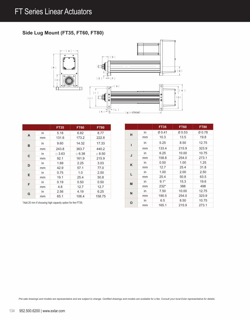
Side Lug Mount (FT35, FT60, FT80)
+ STROKE*
A
B
C
D
E F
H
L
I
J
K M
G
N
O
FT35 FT60 FT80
Ain 5.18 6.82 8.77
mm 131.6 173.2 222.8
Bin 9.60 14.32 17.33
mm 243.8 363.7 440.2
Cin □ 3.63 □ 6.38 □ 8.50
mm 92.1 161.9 215.9
Din 1.69 2.25 3.03
mm 42.9 57.1 77.0
Ein 0.75 1.0 2.00
mm 19.1 25.4 50.8
Fin 0.19 0.50 0.50
mm 4.8 12.7 12.7
Gin 2.56 4.19 6.25
mm 65.1 106.4 158.75
FT35 FT60 FT80
Hin Ø 0.41 Ø 0.53 Ø 0.78
mm 10.3 13.5 19.8
Iin 5.25 8.50 12.75
mm 133.4 215.9 323.9
Jin 6.25 10.00 10.75
mm 158.8 254.0 273.1
Kin 0.50 1.00 1.25
mm 12.7 25.4 31.8
Lin 1.00 2.00 2.50
mm 25.4 50.8 63.5
Min 9.1* 15.3 19.6
mm 232* 388 498
Nin 7.50 10.00 12.75
mm 190.5 254.0 323.9
Oin 6.5 8.50 10.75
mm 165.1 215.9 273.1* Add 20 mm if choosing high capacity option for the FT35.

952.500.6200 | www.exlar.com 135
FT S
erie
s
FT Series Linear Actuators
Pre-sale drawings and models are representative and are subject to change. Certified drawings and models are available for a fee. Consult your local Exlar representative for details.
Side Lug Mount (FT45)
[ F ] + STROKE
[ N ] + STROKE
A
C
DB
E
G
H
I
J
K
L
M
O
FT45
Ain 7.48
mm 190.0
Bin 8.50
mm 215.9
Cin 3.66
mm 93.0
Din 1.26
mm 32.0
Ein 1.99
mm 50.5
Fin 13.9
mm 354
Gin 5.26
mm 133.6
FT45
Hin 3.05
mm 77.5
Iin 14.55
mm 369.5
Jin 1.77
mm 45.0
Kin 1.14
mm 28.9
Lin Ø 0.472
+0.001/0.000
mm 12.0+0.03/0.00
Min Ø 0.53
mm 13.5
Nin 10.77
mm 273.6
Oin 2.03
mm 51.6

136 952.500.6200 | www.exlar.com
Side Mount
+ STROKE*
+ STROKE*
A
BF
E
D
C G H
I
L
M N
JK
FT35 FT60 FT80
Ain 5.18 6.82 8.77
mm 131.6 173.2 222.8
Bin 9.60 14.32 17.38
mm 243.8 363.7 440.2
Cin □ 3.63 □ 6.38 □ 8.50
mm 92.1 161.9 215.9
Din □ 3.63 □ 6.38 □ 8.50
mm 92.1 161.9 215.9
Ein 1.81 NA NA
mm 46.0 NA NA
Fin 1.69 2.25 3.03
mm 42.9 57.1 77.0
Gin 9.1* 15.3 19.8
mm 232* 388 503
FT35 FT60 FT80
Hin 4.19 4.57 6.43
mm 106.3 116.1 163.5
Iin 1.81 3.19 4.25
mm 46.1 81.0 108.0
JØ 0.2500↓0.4001
+0.0000/ -0.0005
Ø 0.5000↓1.002
+0.0000/ -0.0005
Ø 0.6250↓1.3753
+0.0000/ -0.0005
K 1/4-20 UNC- 2B ↓ .631
1/2-13 UNC-2B ↓ 1.132
5/8-11 UNC- 2B ↓ 1.253
Lin 1.63 2.50 4.00
mm 41.3 63.5 101.6
Min 0.31 0.50 0.75
mm 8 12.7 19.1
Nin 9.1* 15.3 19.6
mm 232* 388 498
FT Series Linear Actuators
*Add 20 mm if choosing high capacity option for the FT35.1 If “J” or “K” metric side mount options, M6 x 1.0 9 mm with Ø 6 mm M7 9
mm dowel hole2 If “J” or “K” metric side mount options, M12 x 1.75 19 mm with Ø 12 mm M7 12 mm Dowel Hole
3 If “J” or “K” metric side mount options, M16 x 2.0 16 mm with Ø 12 mm M7 12 mm dowel hole
* Add 20 mm if choosing high capacity option.
Pre-sale drawings and models are representative and are subject to change. Certified drawings and models are available for a fee. Consult your local Exlar representative for details.
[ A ]
[ B ] + STROKE [ C ]
[ D ]
[ E ]
[ F ]
[ G ]
FT45 (Option Y) FT45 (Option W)A in (mm) 1.99 (50.5) 1.99 (50.5)
B in (mm) 13.9 (354) 13.9 (354)
C in (mm) 9.01 (228.9) 7.90 (200.7)
D in (mm) 2.00 (50.8) 1.26 (32.0)
E in (mm) 1.378 ± 0.001 (35.0 ±0.03)
0.787 H9 (20.00 H9)
F in (mm) 3.07 (77.9) 3.07 (77.9)
G in (mm) 2.00 (50.8) 1.18 (30.0)
Rear Eye Mount

952.500.6200 | www.exlar.com 137
FT S
erie
s
Rod Ends
FT Series Linear Actuators
Case Dimensions
A
B DøC
øE øE
D
F
A B ØC D ØE F MaleU.S. Male Metric Female U.S.Female Metric
FT80 2.75 (69.9) 4.019 (102.1) 3.143 (79.8) 1.000 (25.4) 4.000 (101.6) 2.250 (57.2) 2 1/2-12 UN-2A M56x5.5 6g 2 1/2-12 UN-2B M56x5.5 6h
A B ØC D ØE F Male U.S. Male Metric Female U.S.Female Metric
FT35 1.34 (34) 1.125 (28.6) 1.434 (36.4) 0.50 (12.7) 1.750 (44.5) 0.750 (19.1) 3/4-16 UNF-2A M16x1.5 6g 3/4-16 UNF-2B M16x1.5 6h
FT45 1.81 (46.0) 2.25 (57.2) 2.0 (50.8) 0.63 (15.9) 2.250 (57.2) 1.50 (38.1) 1 1/2-12 UN-2A M36x3 6g 1 1/2-12 UN-2B M36x3 6h
FT60 2.36 (60.0) 2.750 (69.9) 2.360 (59.9) 0.750 (19.1) 3.000 (76.2) 2.000 (50.8) 1 7/8-12 UN-2A M42x4.5 6g 1 7/8-12 UN-2B M42x4.5 6h
Pre-sale drawings and models are representative and are subject to change. Certified drawings and models are available for a fee. Consult your local Exlar representative for details.
Dimensions shown in inches (mm)
FT35, FT45, FT60 FT80
R0.03750.075
0.138
T-Slot Detail
0.270
0.426
6.024
6.024
0.609
FT60
SEE T-SLOT DETAIL
3.310
3.310
0.645
FT35
See T-Slot Detail
7.900
7.900
1.173
FT80
SEE T-SLOT DETAIL
FT45
4.646
4.646
4X SensorGroove
0.260.21
0.070.22
Detail 4X Sensor Groove

138 952.500.6200 | www.exlar.com
FT Series Ordering Guide
Contact your local sales representative regarding all special actuator components.
AA = FT Frame Size35 = 3.5 inch (90 mm)45 = 4.8 inch (122 mm)60 = 6.0 inch (150 mm)80 = 8.0 inch (200 mm)
BB = Stroke Length06 = 6 inch (152 mm) FT35, FT4512 = 12 inch (305 mm) FT35, 45, 60, 8018 = 18 inch (457 mm) FT35, 4524 = 24 inch (610 mm) FT35, 45, 60, 8036 = 36 inch (914 mm) FT35, 45, 60, 8048 = 48 inch (1219 mm) FT35, 45, 60, 80
CC = Screw Lead05 = 0.2 inch, FT35, 4506 = 0.23 inch, FT60, 8010 = 0.39 inch, FT35, 4512 = 0.47 inch, FT60, 8020 = 0.79 inch, FT3530 = 1.18 inch, FT60, 80
D = Mounting Style 1
N = NoneF = Front flange, EnglishZ = Front flange, Metric, FT45R = Rear flange, English 4, 5
C = Rear clevis, English 4, 5
G = Rear clevis, Metric 4, 5
Y = Rear eye, English 4, FT45
W = Rear eye, Metric 4, FT45L = Side lugsS = Side mount, English FT35, 60, 80J = Side mount, Metric FT35, 60, 80T = Side trunnion mount, English 5, 6 FT35, 60, 80Q = Side trunnion mount, Metric 5, 6 FT35, 60, 802 = Rear trunnion mount, English, FT45P = Rear trunnion mount, Metric, FT45E = Extended tie rods, EnglishM = Extended tie rods, Metric
E = Motor Mounting Configurations 3
N = NoneI = Inline direct drive (includes Exlar standard
coupling)P = Parallel, 1:1 belt reductionQ = Parallel, 2:1 belt reduction
F = Rod EndM = Male, US standard threadA = Male, metric threadF = Female, US standard threadB = Female, metric threadW = Male, US standard thread SS, rod end onlyR = Male metric thread SS, rod end onlyV = Female, US standard thread SS, rod end onlyL = Female, metric thread SS, rod end only
GGG = Motor Mount Provisions 3,4 See page 206 for Motor Mount Code.
MM = Mechanical Options 2
XT = High capacity roller screw
Limit Switches (adjustable position throughout stroke)L1 = One N.O., PNP (FT35, 45, 60, 80)L2 = Two N.C., PNP (FT35, 45, 60 80)L3 = One N.O., PNP & Two N.C., PNP
(FT35, 45, 60, 80)L4 = One N.O., NPN (FT45)L5 = Two N.C., NPN (FT45)L6 = One N.O., NPN & Two N.C., NPN (FT45)
*See Page 124 for Limit Switch details
Please provide a drawing of motor dimensions with all orders to insure proper mounting compatibility.
NOTES:1. Mounting face size, shaft length and other details of particular motors may require special adapters or provisions for mounting. Always discuss your
motor selection with your local sales representative.2. For extended temperature operation consult factory for model number.3. MAX Std. motor size: FT35: 5.6 inch/142 mm, FT45: 7.1 inch/180 mm, FT60: 7.9 inch/200 mm, FT80: 8.5 inch/215 mm
For oversized motors, contact your local sales representative.4. Not available with inline motor mount, contact your local sales representative.5. Application details must be approved for use with an FT80.6. IP65 environmental sealing option not available.
Actuator Type & Frame Size
Stroke Length
Screw Lead
Motor Mounting Configurations
Sample Product Number: FT60-1820-GPB-N56-XTPFL2
FT AA BBCC DE F EGGG MM
Mounting Style
Rod End Thread/Rod Material
Motor Mount Provisions
Mechanical Options
For options or specials not listed above or for extended temperature operation, please contact Exlar
Commonly Ordered Options Shown in BOLD

206 952.500.6200 | www.exlar.com
Bolt Circle Diameter
(mm)
Pilot Diameter
(mm)
Shaft Diameter
(mm)
Shaft Length (mm)
Key Width (mm)
Motor Mount Code
63 40 9 20 3 IEA
63 40 9 24 3 IEB
63 40 11 23 4 IEC
63 40 14 30 5 IED
70 50 11 30 4 JGC
70 50 12 30 NA JGB
70 50 14 30 5 JGA
70 50 16 30 5 EGB
75 60 11 23 4 IHA
75 60 14 30 5 IHB
90 70 11 30 4 JKE
90 70 14 30 5 JKD
90 70 16 35 NA JKC
90 70 16 40 5 JKG
90 60 19 40 6 JKF
90 70 19 40 6 JKA
95 65 14 30 5 ELA
95 50 14 30 5 ELC
95 65 16 30 5 ELB
100 80 10 32 3 IMD
100 80 14 30 5 IMA
100 80 14 40 5 JMC
100 80 16 40 5 IMB
100 80 16 40 5 JMA
100 80 19 40 6 IMC
100 80 19 55 6 JMD
100 80 22 48 6 EMB
115 95 19 40 6 INA
115 95 19 55 6 JNC
115 95 22 45 8 JND
115 95 22 70 NA JNB
115 95 24 45 8 JNA
115 95 24 50 8 INB
130 95 19 40 6 IPC
130 110 19 40 6 IPA
130 110 24 50 8 IPB
130 95 24 50 8 IPD
130 110 32 65 10 EPB
145 110 19 55 5 JQG
145 110 22 55 6 JQF
145 110 22 70 8 JQE
145 110 22 55 8 JQH
145 110 24 55 8 JQD
145 110 24 65 8 JQC
145 110 28 55 8 JQB
145 110 28 63 8 JQA
165 130 24 50 8 IRA
165 95 24 50 8 IRG
165 110 24 50 8 IRF
165 130 28 60 8 IRB
165 130 32 50 10 IRD
165 130 32 58 10 IRC
165 130 32 80 10 IRE
190 155 32 60 10 I2A
200 114.3 22 55 6 JSE
200 114.3 28 55 8 JSF
200 114.3 35 70 10 JSB
200 114.3 35 80 10 JSA
200 114.3 42 113 10 JSD
215 180 24 50 10 ITA
215 180 28 60 10 ITB
215 180 32 58 10 ITC
215 130 32 60 10 ITE
215 180 32 80 10 ITD
215 180 38 80 10 ITF
215 180 42 82 12 ITG
235 200 35 70 10 JUC
235 200 42 85 12 JUB
235 200 42 116 12 JUD
235 200 55 116 NA JUA
265 230 38 80 10 IVA
265 230 38 110 10 IVB
265 230 42 110 12 IVC
265 230 55 110 16 JVA
265 230 60 140 18 JVC
265 230 65 140 18 JVB
300 250 48 82 14 IWB
300 250 48 112 14 IWA
300 250 60 140 18 JWA
Bolt Circle Diameter
(mm)
Pilot Diameter
(mm)
Shaft Diameter
(mm)
Shaft Length (mm)
Key Width (mm)
Motor Mount Code
Motor Mount Codes for the FT and K Series
Engineering Reference
*Consult factory if dimension is not shown.
Return to table of contents

952.500.6200 | www.exlar.com 209
Engineering Reference
Sizing and Selection of Exlar Linear and Rotary ActuatorsMove ProfilesThe first step in analyzing a motion control application and selecting an actuator is to determine the required move profile. This move profile is based on the distance to be traveled and the amount of time available in which to make that move. The calculations below can help you determine your move profile.
Each motion device will have a maximum speed that it can achieve for each specific load capacity. This maximum speed will determine which type of motion profile can be used to complete the move. Two common types of move profiles are trapezoidal and triangular. If the average velocity of the profile, is less than half the maximum velocity of the actuator, then triangular profiles can be used. Triangular Profiles result in the lowest possible acceleration and deceleration. Otherwise a trapezoidal profile can be used. The trapezoidal profile below with 3 equal divisions will result in 25% lower maximum speed and 12.5% higher acceleration and deceleration. This is commonly called a 1/3 trapezoidal profile.
The following pages give the required formulas that allow you to select the proper Exlar linear or rotary actuator for your application. The first calculation explanation is for determining the required thrust in a linear application.
The second provides the necessary equations for determining the torque required from a linear or rotary application. For rotary applications this includes the use of reductions through belts or gears, and for linear applications, through screws.
Pages are included to allow you to enter your data and easily perform the required calculations. You can also describe your application graphically and fax it to Exlar for sizing. Reference tables for common unit conversions and motion system constants are included at the end of the section.
Linear Move Profile Calculations Vmax = max.velocity-in/sec (m/sec) Vavg = avg. velocity-in/sec (m/sec) tacc = acceleration time (sec) tdec = deceleration time (sec) tcv = constant velocity (sec) ttotal = total move time (sec) acc = accel-in/sec2 (m/sec2) dec = decel-in/sec2 (m/sec2) cv = constant vel.-in/sec (m/sec) D = total move distance-in (m)
or revolutions (rotary)
Standard EquationsVavg = D / ttotalIf tacc = tdec Then: Vmax =
(ttotal/(ttotal-tacc)(Vavg) and D = Area under profile curve D = (1⁄2(tacc+tdec)+tcv)(Vmax)
Triangular Move Profile
Triangular EquationsIf tacc = ttotal/2 Then:Vmax = 2.0 (Vavg) D = (1⁄2) (ttotal) (Vmax)acc = dec = Vmax tacc
Trapezoidal Move Profile
Trapezoidal EquationsIf tacc = tcv = tdec Then:Vmax = 1.5 (Vavg) D = (2⁄3) (ttotal) (Vmax)acc = dec = Vmax tacc
tacc
acc
tcv
cv
tdec
dec
time (sec)
Velocity (in/sec)
ttotal
Vmax
Vavg
tacc
acc
tdec
dec
time (sec)
Velocity (in/sec)
ttotal
Vmax
Vavg
tacc
acc
tcv
cv
tdec
dec
time (sec)
Velocity (in/sec)
ttotal
Vmax
Vavg
tacc
acc
tdec
dec
time (sec)
Velocity (in/sec)
ttotal
Vmax
Vavg

210 952.500.6200 | www.exlar.com
Sizing and Selection of Exlar Linear Actuators
Thrust CalculationsDefinition of thrust:The thrust necessary to perform a specific move profile is equal to the sum of four components of force. These are the force due to acceleration of the mass, gravity, friction and applied forces such as cutting and pressing forces and overcoming spring forces.
Angle of Inclination
Note: at ø = 0˚ cosø = 1; sinø = 0 at ø = 90˚ cosø = 0; sinø = 1
It is necessary to calculate the required thrust for an application during each portion of the move profile, and determine the worst case criteria. The linear actuator should then be selected based on those values. The calculations at the right show calculations during acceleration which is often the most demanding segment of a profile.
LOADW
F app.
Ø
90˚
0˚
-90˚
Terms and (units) THRUST = Total linear force-lbf (N) Ø = Angle of inclination (deg) Ffriction = Force from friction-lbf (N) tacc = Acceleration time (sec) Facc = Acceleration force-lbf (N) v = Change in velocity-in/sec (m/s) Fgravity = Force due to gravity-lbf (N) µ = Coefficient of sliding friction Fapplied = Applied forces-lbf (N)
(refer to table on page 136 for different materials) WL = Weight of Load-lbf (N) g = 386.4: Acceleration of gravity - in/sec2 (9.8 m/sec2)
Thrust Calculation EquationsTHRUST = Ffriction + [Facceleration] + Fgravity + Fapplied
THRUST = WLµcosø + [(WL /386.4) (v/tacc)] + WLsinø + Fapplied
Sample Calculations: Calculate the thrust required to accelerate a200 pound mass to 8 inches per second in an acceleration time of 0.2 seconds. Calculate this thrust at inclination angles(ø) of 0˚, 90˚ and 30˚. Assume that there is a 25 pound spring force that is applied against the acceleration.
WL = 200 lbm, v = 8.0 in/sec., ta = 0.2 sec., Fapp. = 25 lbf, µ = 0.15 ø = 0˚
THRUST = WLµcosø + [(WL /386.4) (v/tacc)] + WLsinø + Fapplied = (200)(0.15)(1) + [(200/386.4)(8.0/0.2)] + (200)(0) + 25
= 30 lbs + 20.73 lbs + 0 lbs + 25 lbs = 75.73 lbs force
ø = 90˚
THRUST = WLµcosø + [(WL /386.4) (v/tacc)] + WLsinø + Fapplied = (200)(0.15)(0) + [(200/386.4)(8.0/0.2)] + (200)(1) + 25 = 0 lbs + 20.73 lbs + 200 lbs + 25 lbs = 245.73 lbs force
ø = 30˚
THRUST = WLµcosø + [(WL /386.4) (v/tacc)] + WLsinø + Fapplied = (200)(0.15)(0.866) + [(200/386.4)(8.0/0.2)] + (200)(0.5) + 25 = 26 lbs + 20.73 lbs + 100 + 25 = 171.73 lbs force

952.500.6200 | www.exlar.com 211
Motor Torque
Motor Torque CalculationsWhen selecting an actuator system it is necessary to determine the required motor torque to perform the given application. These calculations can then be compared to the torque ratings of the given amplifier and motor combination that will be used to control the actuator’s velocity and position.
When the system uses a separate motor and screw, like the FT actuator, the ratings for that motor and amplifier are consulted. In the case of the GSX Series actuators with their integral brushless motors, the required torque divided by the torque constant of the motor (Kt) must be less than the current rating of the GSX or SLM motor.
Inertia values and torque ratings can be found in the GSX, FT, and SLM/SLG Series product specifications.
For the GSX Series the screw and motor inertia are combined.
Motor with screw (GSX, GSM, FT, & EL)
Motor & motor with reducer (SLM/SLG & ER)
Motor with belt and pulley
Terms and (units)λ = Required motor torque, lbf-in (N-m)λa = Required motor acceleration torque, lbf-in (N-m) F = Applied force load, non inertial, lbf (kN)S = Screw lead, in (mm)R = Belt or reducer ratioTL = Torque at driven load lbf-in (N-m)vL = Linear velocity of load in/sec (m/sec)ωL = Angular velocity of load rad/secωm = Angular velocity of motor rad/secŋ = Screw or ratio efficiencyg = Gravitational constant, 386.4 in/s2 (9.75 m/s2)α = Angular acceleration of motor, rad/s2 m = Mass of the applied load, lb (N)JL = Reflected Inertia due to load, lbf-in-s2 (N-m-s2)Jr = Reflected Inertia due to ratio, lbf-in-s2 (N-m-s2)Js = Reflected Inertia due to external screw, lbf-in-s2 (N-m-s2)Jm = Motor armature inertia, lbf-in-s2 (N-m-s2)L = Length of screw, in (m)ρ = Density of screw material, lb/in3 (kg/m3)r = Radius of screw, in (m)π = pi (3.14159)C = Dynamic load rating, lbf (N)
Velocity EquationsScrew drive: VL = ωm*S/2π in/sec (m/sec)
Belt or gear drive: ωm = ωL*R rad/sec
Torque EquationsTorque Under Load
Screw drive (GS, FT or separate screw): λ = S • F lbf-in (N-m) 2 • π • ŋBelt and Pulley drive: λ = TL / R ŋ lbf-in (N-m)
Gear or gear reducer drive: λ = TL / R ŋ lbf - in (N-m)
Torque Under Acceleration
λa = (Jm + JR+ (Js + JL)/R2)α lbf-in
α = angular acceleration = ((RPM / 60) x 2π) / tacc, rad/sec2.
Js = π • L • ρ x r4 lb - in - s2 (N - m - s2 ) 2 • g
Total Torque per move segment
λT = λa + λ lbf-in (N-m)

212 952.500.6200 | www.exlar.com
Calculating Estimated Travel Life of Exlar Linear Actuators
Mean Load CalculationsFor accurate lifetime calculations of a roller screw in a linear application, the cubic mean load should be used. Following is a graph showing the values for force and distance as well as the calculation for cubic mean load. Forces are shown for example purposes. Negative forces are shown as positive for calculation.
F1 F2 F3 F4
S1 S2 S3 S4
0.5 inches 2.9 inches 1.0 inches 3.5 inches
Force500 lbs
250 lbs
100 lbs 50 lbs
3
Cubic Mean Load Equation
S = Distance traveled during each move segment
Value from example numbers is 217 lbs.
F13 S1 + F23 S2 + F33 S3 + F43 S4
S1 + S2 + S3 + S4
Lifetime CalculationsThe expected L10 life of a roller screw is expressed as the linear travel distance that 90% of the screws are expected to meet or exceed before experiencing metal fatigue. The mathematical formula that defines this value is below. The life is in millions of inches (mm). This standard L10 life calculation is what is expected of 90% of roller screws manufactured and is not a guarantee. Travel life estimate is based on a properly maintained screw that is free of contaminants and properly lubricated. Higher than 90% requires de-rating according to the following factors:
95% x 0.62 96% x 0.53 97% x 0.44 98% x 0.33 99% x 0.21
Note: The dynamic load rating of zero backlash, preloaded screws is 63% of the dynamic load rating of the standard non-preloaded screws. The calculated travel life of a preloaded screw will be 25% of the calculated travel life of the same size and lead of a non-preloaded screw for the same application.
Single (non-preloaded) nut:
If your application requires high force over a stroke length shorter than the length of the nut, please contact Exlar for derated life calculations. You may also download the article “Calculating Life Expectency” at www.exlar.com.
L10 = ( Ca )3 x ℓ
Fcml
Fcml =
952.500.6200 | www.exlar.com 213
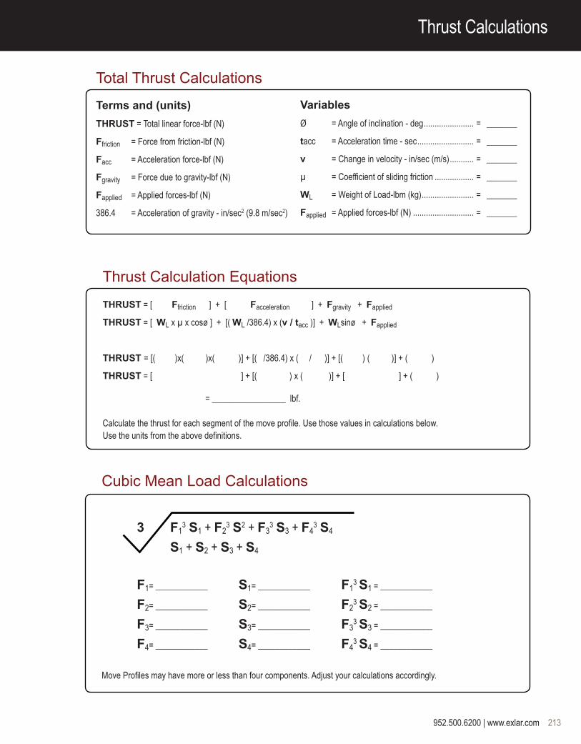
Thrust Calculations
Total Thrust Calculations
Terms and (units)
THRUST = Total linear force-lbf (N)
Ffriction = Force from friction-lbf (N)
Facc = Acceleration force-lbf (N)
Fgravity = Force due to gravity-lbf (N)
Fapplied = Applied forces-lbf (N)
386.4 = Acceleration of gravity - in/sec2 (9.8 m/sec2)
VariablesØ = Angle of inclination - deg ....................... = _______
tacc = Acceleration time - sec .......................... = _______
v = Change in velocity - in/sec (m/s) ........... = _______
µ = Coefficient of sliding friction .................. = _______
WL = Weight of Load-lbm (kg) ........................ = _______
Fapplied = Applied forces-lbf (N) ............................ = _______
Thrust Calculation Equations
THRUST = [ Ffriction ] + [ Facceleration ] + Fgravity + Fapplied
THRUST = [ WL x µ x cosø ] + [( WL /386.4) x (v / tacc )] + WLsinø + Fapplied
THRUST = [( )x( )x( )] + [( /386.4) x ( / )] + [( ) ( )] + ( )
THRUST = [ ] + [( ) x ( )] + [ ] + ( )
= _________________ lbf.
Calculate the thrust for each segment of the move profile. Use those values in calculations below. Use the units from the above definitions.
Cubic Mean Load Calculations
3 F13 S1 + F2
3 S2 + F33 S3 + F4
3 S4
S1 + S2 + S3 + S4
F1= ____________ S1= ____________ F13 S1 = ____________
F2= ____________ S2= ____________ F23 S2 = ____________
F3= ____________ S3= ____________ F33 S3 = ____________
F4= ____________ S4= ____________ F43 S4 = ____________
Move Profiles may have more or less than four components. Adjust your calculations accordingly.

214 952.500.6200 | www.exlar.com
Torque Calculations & Equations
Torque CalculationsTerms and (units)λ = Torque, lb-in (N-m) ........................................................................................................................... = -----------------------
F = Applied Load, non inertial, lbf (N) .................................................................................................... = -----------------------
S = Screw lead, in (m) ............................................................................................................................ = -----------------------
ŋ = Screw or ratio efficiency (~85% for roller screws) ........................................................................... = -----------------------
g = Gravitational constant, 386 in/s2 (9.8 m/s2) ................................................................................... = -----------------------
α = Acceleration of motor, rad/s2 ........................................................................................................... = -----------------------
R = Belt or reducer ratio ......................................................................................................................... = -----------------------
TL = Torque at driven load, lbf-in (N-m) ................................................................................................... = -----------------------
VL = Linear velocity of load, in/sec (m/sec) ............................................................................................. = -----------------------
ωL = Angular velocity of load, rad/sec ..................................................................................................... = -----------------------
ωm = Angular velocity of motor, rad/sec .................................................................................................... = -----------------------
m = Mass of the applied load, lbm (kg) ................................................................................................... = -----------------------
JR = Reflected Inertia due to ratio, lb-in-s2 (N-m-s2) .............................................................................. = -----------------------
JS = Reflected Inertia due to screw, lb-in-s2 (N-m-s2) ............................................................................ = -----------------------
JL = Reflected Inertia due to load, lb-in-s2(N-m-s2) ................................................................................ = -----------------------
JM = Motor armature inertia, lb-in-s2 (N-m-s2) ........................................................................................ = -----------------------
π = pi ..................................................................................................................................................... = -----------------------
Kt = Motor Torque constant, lb-in/amp (N-m/amp) .................................................................................. = -----------------------
* For the GS Series JS and JM are one value from the GS Specifications.
Torque EquationsTorque From Calculated Thrust. λ = SF lb - in ( N - m) = ( ) x ( )/2π (0.85) = ( ) x ( )/5.34 = ------------------------------ 2•π•ŋ
Torque Due To Load, Rotary. Belt and pulley drive: λ = TL / R ŋ lbf-in (N-m) Gear or gear reducer drive: λ = TL / Rŋ lbf-in (N-m)
Torque During Acceleration due to screw, motor, load and reduction, linear or rotary. l = (Jm + (JS + JL) / R2 ) α lb-in (N-m) = [ ( ) + ( + ) / ( ) ] ( ) = -------------------------
Total Torque = Torque from calculated Thrust + Torque due to motor, screw and load ( ) + ( ) + ( ) = _________________
Motor Current = λ / Kt = ( ) / ( ) = ____________________
3.14159

952.500.6200 | www.exlar.com 215
Exlar Application Worksheet
FAX to:Exlar Actuation Solutions(952) 368-4877Attn: Applications Engineering
Exlar Application Worksheet
Sketch/Describe Application
Velocity vs. Time Force or Torque vs. Distance
Indicate units on graphs
v f or t
time distance
Date: ____________________________________ Company Name: ___________________________________________________________________
Address: __________________________________________________________________________________________________________________
City: ______________________________________________________________ State: ___________________________ Zip Code: _____________
Phone: ______________________________________________________________ Fax: _________________________________________________
Contact: _____________________________________________________________Title: _________________________________________________

216 952.500.6200 | www.exlar.com
Exlar Application Worksheet
Exlar Application Worksheet
Date: _____________________ Contact: ____________________________ Company: ___________________________
Stroke & Speed RequirementsMaximum Stroke Needed ..................................................................... ___________________ inches (mm), revs
Index Stroke Length ............................................................................. ___________________ inches (mm), revs
Index Time ............................................................................................ ___________________ sec
Max Speed Requirements .................................................................... ___________________ in/sec (mm/sec), revs/sec
Min Speed Requirements ..................................................................... ___________________ in/sec (mm/sec), revs/sec
Required Positional Accuracy ............................................................... ___________________ inches (mm), arc min
Load & Life RequirementsGravitational Load ................................................................................ __________________ lb (N)
External Applied Load ........................................................................... __________________ lbf (N)
Inertial Load .......................................................................................... __________________ lbf (N)
Friction Load ......................................................................................... __________________ lbf (N)
Rotary Inertial Load .............................................................................. __________________ lbf-in-sec2 (Kg-m2)
or rotary mass, radius of gyr. ..................................................... lb (kg) _________________ in (mm)
Side Load (rot. or lin. actuator) ............................................................. _________________ lb (N)
Force Direction _____ Extend _____ Retract _____ Both
Actuator Orientation _____ Vertical Up _____ Vertical Down _____ Horizontal
_____ Fixed Angle _____ Degrees from Horizontal
_____ Changing Angle _____ to _____
Cycling Rate ........................................................................................ ____________________ Cycles/min/hr/day
Operating Hours per Day ..................................................................... ____________________ Hours
Life Requirement ................................................................................. ____________________ Cycles/hr/inches/mm
Configuration Mounting: _____ Side _____ Flange _____ Ext Tie Rod _____ Clevis _____ Trunnion
Rod End: _____ Male _____ Female _____ Sph Rod Eye _____ Rod Eye _____ Clevis
Rod Rotation Limiting: _____ Appl Inherent _____ External Required
Holding Brake Required: _____ Yes _____ No
Cable Length: _________ ft (m)

952.500.6200 | www.exlar.com 217
Reference Tables
Rotary Inertia To obtain a conversion from A to B, multiply by the value in the table. B Kg-m2 Kg-cm2 g-cm2 kgf-m-s2 kgf-cm-s2 gf-cm-s2 oz-in2 ozf-in-s2 lb-in2 lbf-in-s2 lb-ft2 lbf-ft-s2
A
Kg-m2 1 104 107 0.10192 10.1972 1.01972x10⁴ 5.46745x10⁴ 1.41612x10² 3.41716x10³ 8.850732 23.73025 0.73756
Kg-cm2 10-4 1 103 1.01972x10⁵ 1.01972x10³ 1.01972 5.46745 1.41612x10⁻² 0.341716 8.85073x10⁻⁴ 2.37303x10⁻³ 7.37561x10⁻⁵
g-cm2 10-7 10-3 1 1.01972x10⁻⁸ 1.01972x10⁻⁶ 1.01972x10⁻³ 5.46745x10⁻³ 1.41612x10⁻⁵ 3.41716x10⁻⁴ 8.85073x10⁻⁷ 2.37303x10⁻⁶ 7.37561x10⁻⁸
kgf-m-s2 9.80665 9.80665x10⁴ 9.80665x10⁷ 1 102 105 5.36174x10⁵ 1.388674x10³ 3.35109x10⁴ 86.79606 2.32714x10² 7.23300
kgf-cm-s2 9.80665x10⁻² 9.80665x10² 9.80665x10⁵ 10-2 1 105 5.36174 x10³ 13.8874 3.35109x10⁻² 0.86796 2.32714 7.23300x10⁻²
gf-cm-s2 9.80665x10⁻⁵ 0.980665 9.80665x10² 10-5 10-3 1 5.36174 1.38874 x10⁻² 0.335109 8.67961x10⁻⁴ 2.32714x10⁻³ 7.23300x10⁻⁵
oz-in2 1.82901x10⁻⁵ 0.182901 1.82901x10² 1.86505x10⁻⁶ 1.86505x10⁻⁴ 0.186506 1 2.59008 x10⁻³ 6.25 x10⁻² 1.61880x10⁻⁴ 4.34028x10⁻⁴ 1.34900x10⁻³
oz-in-s2 7.06154x10⁻³ 70.6154 7.06154x10⁴ 7.20077x10⁴ 7.20077x10⁻² 72.0077 3.86089x10² 1 24.13045 6.25 x10⁻² 0.167573 5.20833x10⁻⁴
lb-in2 2.92641x10⁻⁴ 2.92641 2.92641x10³ 2.98411x10⁵ 2.98411x10³ 2.98411 16 4.14414 x10² 1 2.59008x10⁻³ 6.94444x10⁻³ 2.15840x10⁻⁴
lbf-in-s2 0.112985 1.129x10³ 1.12985x10⁶ 1.15213x10² 1.15213 1.51213 x10³ 6.1774 x10³ 16 3.86088x10² 1 2681175 8.3333x10⁻²
lbf-ft2 4.21403x10⁻² 4.21403x10² 4.21403x10⁵ 4.29711x10³ 0.429711 4.297114 2.304 x10³ 5.96755 144 0.372971 1 3.10809x10⁻²
lbf-ft-s2 1.35583 1.35582x10⁴ 1.35582x10⁷ 0.138255 13.82551 1.38255x10⁴ 7.41289x10⁴ 192 4.63306x10³ 12 32.17400 1
Torque To obtain a conversion from A to B, multiply A by the value in the table. B N-m N-cm dyn-cm Kg-m Kg-cm g-cm oz-in ft-lb in-lb
A
N-m 1 10-2 107 0.109716 10.19716 1.019716 x10⁴ 141.6199 0.737562 8.85074
N-cm 102 1 105 1.019716 x10³ 0.1019716 1.019716 x10² 1.41612 7.37562 x10⁻³ 8.85074 x10⁻²
dyn-cm 10-7 10-5 1 1.019716 x10⁻⁸ 1.019716 x10⁻⁶ 1.019716 x10⁻³ 1.41612 x10⁻⁵ 7.2562 x10⁻⁸ 8.85074 x10⁻⁷
Kg-m 9.80665 980665x102 9.80665 x10⁷ 1 102 105 1.38874 x10³ 7.23301 86.79624
Kg-cm 9.80665x10⁻² 9.80665 9.80665 x10⁵ 10-2 1 103 13.8874 7.23301 x10⁻² 0.86792
g-cm 9.80665x10⁻⁵ 9.80665x10⁻³ 9.80665 x10² 10-5 10-3 1 1.38874 x10⁻² 7.23301 x10⁻⁵ 8.679624 x10⁻⁴
oz-in 7.06155x10⁻³ 0.706155 7.06155 x10⁴ 7.20077 x10⁻⁴ 7.20077 x10⁻² 72,077 1 5.20833 x10⁻³ 6.250 x10⁻²
ft-lb 1.35582 1.35582x10² 1.35582 x10⁷ 0.1382548 13.82548 1.382548 x10⁴ 192 1 12
in-lb 0.113 11.2985 1.12985 x10⁶ 1.15212 x10⁻² 1.15212 1.15212 x10³ 16 8.33333 x10⁻² 1
Common Material Densities Coefficients of Sliding FrictionMaterial oz/in3 gm/cm3 Materials in contact µ
Aluminum (cast or hard drawn) 1.54 2.66 Steel on Steel (dry) 0.58
Brass (cast or rolled) 4.80 8.30 Steel on Steel (lubricated) 0.15
Bronze (cast) 4.72 8.17 Aluminum on Steel 0.45
Copper (cast or hard drawn) 5.15 8.91 Copper on Steel 0.36
Plastic 0.64 1.11 Brass on Steel 0.44
Steel (hot or cold rolled) 4.48 7.75 Plastic on Steel 0.20
Wood (hard) 0.46 0.80 Linear Bearings 0.001
Wood (soft) 0.28 0.58

218 952.500.6200 | www.exlar.com
Product Ambient Temperatures/IP Ratings
Digit 1 - Ingress of Solid ObjectsThe IP rating system provides for 6 levels of protection against solids.
1 Protected against solid objects over 50 mm e.g. hands, large tools.
2 Protected against solid objects over 12.5 mm e.g. hands, large tools.
3 Protected against solid objects over 2.5 mm e.g. large gauge wire, small tools.
4 Protected against solid objects over 1.0 mm e.g. small gauge wire.
5 Limited protection against dust ingress.
6 Totally protected against dust ingress.
Standard Ratings for Exlar ActuatorsThe standard IP rating for Exlar Actuators is IP54S or IP65S. Ingress protection is divided into two categories: solids and liquids.
For example, in IP65S the three digits following “IP” represent different forms of environmental influence:
• The first digit represents protection against ingress of solid objects.
• The second digit represents protection against ingress of liquids.
• The suffix digit represents the state of motion during operation.
Digit 2 - Ingress of LiquidsThe IP rating system provides for 9 levels of protection against liquids.
1 Protected against vertically falling drops of water or condensation.
2 Protected against falling drops of water, if the case is positioned up to 15 degrees from vertical.
3 Protected against sprays of water from any direction, even if the case is positioned up to 60 degrees from vertical.
4 Protected against splash water from any direction.
5 Protected against low pressure water jets from any direction. Limited ingress permitted.
6 Protected against high pressure water jets from any direction. Limited ingress permitted.
7 Protected against short periods (30 minutes or less) of immersion in water of 1m or less.
8 Protected against long durations of immersion in water.
9 Protected against high-pressure, high-temperature wash-downs.
SuffixS Device standing still during
operation M Device moving during operation
Notes

952.500.6200 | www.exlar.com 219
Terms and Conditions
1. OFFER AND ACCEPTANCE: These terms and conditions constitute Seller’s offer to Buyer and acceptance by Buyer and any resulting sale is expressly limited to and conditioned upon Seller’s terms and conditions as set forth below. If Buyer objects to any of Seller’s terms and conditions, such objections must be expressly stated and brought to the attention of Seller in a written document which is separate from any purchase order or other printed form of Buyer. Such objections, or the incorporation of any additional or different terms or conditions by Buyer into a resulting order shall constitute non-acceptance of these Terms and Conditions, releasing Seller from any obligation or liability hereunder and a proposal for different terms and conditions which shall be objected to by Seller unless expressly accepted in writing by an authorized representative of Seller. Acknowledgment copy, if any, shall not constitute acceptance by Seller of any additional or different terms or conditions, nor shall Seller’s commencement of effort, in itself, be construed as acceptance of an order containing additional or different terms and conditions.
2. PRICES: Published prices and discount schedules are subject to change without notice. They are prepared for the purpose of furnishing general information and are not quotations or offers to sell on the part of the company.
3. TRADE TERMS: Shipment terms are FCA, shipping point (Exlar, Chanhassen, MN). FCA (Free Carrier) per Incoterms 2010 means the Seller delivers the goods, cleared for export into the custody of the first carrier named by the buyer at the named place, above. This term is suitable for all modes of transport, including carriage by air, rail, road, and containerized/multi-modal transport. Title of the merchandise transfers from Exlar Corporation to the Buyer when it is received from Exlar by the carrier. Where allowable, Exlar will arrange the transportation via the carrier specified by the Buyer. The Buyer is responsible for all costs associated with the shipment.
4. PAYMENT TERMS: Subject to approval of Buyer’s credit, the full net amount of each invoice is due and payable in cash within thirty (30) days of shipment. No payment discounts are offered, and minor inadvertent administrative errors contained in an invoice are subject to correction and shall not constitute reason for untimely payment. If, in the judgment of the Seller, the financial credit of Buyer at any time does not justify continuance of production or shipment of any product(s) on the payment terms herein specified, Seller may require full or partial payment prior to completion of production or shipment, or may terminate any order, or any part thereof, then outstanding. Custom products and blanket orders are subject to payment terms: 30% due at time of order, 70% due net 30 days from shipment.
5. MINIMUM BILLING: Minimum billing will be $50.00.6. DELAYS: Exlar shall not be liable for any defaults, damages or delays in fulfilling
any order caused by conditions beyond Seller’s control, including but not limited to acts of God, strike, lockout, boycott, or other labor troubles, war, riot, flood, government regulations, or delays from Seller’s subcontractors or suppliers in furnishing materials or supplies due to one or more of the foregoing clauses.
7. CANCELLATIONS: All cancelled orders for standard products are subject to order cancellation charges. The minimum cancellation charge will be 20% of the order total. Standard products, if unused may be returned in accordance with the current return policy. All returns are subject to prior approval by Exlar, and return charges may apply. No return credit for any product will be issued or authorized prior to evaluation of the product by Exlar. Custom product is not returnable. Orders for custom product are not cancelable.
8. QUANTITY PRICING AND BLANKET ORDER PRICING TERMS: Blanket order quantity pricing requires a complete delivery schedule for the volume being ordered, with all units scheduled to deliver within a 15 month period from the placement of the purchase order to the final scheduled shipment. Any requests to change the delivery schedule of a blanket order must be received in writing 60 days prior to the requested change. Failure to take delivery of the entire ordered volume will result in back charges equal to the difference in quantity price between the volume ordered and the volume received times the number of units received. A cancellation charge in accordance with the cancellation policy (item 7) will apply to any reduction in delivered volume from the original ordered quantity.
For orders receiving quantity discounts, but not as scheduled blanket orders, the same quantity pricing rules apply. Failure to take delivery of the entire quantity ordered will result in back charges equal to the difference in quantity price between the volume ordered and the volume received times the number of units received. Cancellation charges in accordance with the cancellation policy (item 7) will apply to any reduction in delivered volume from the original ordered quantity. For either blanket orders or quantity orders, in addition to any applicable cancellation charges, the customer is responsible for the value of any additional inventory allocated specifically to their order. Charges for this inventory will be invoiced in addition to cancellation charges, along with any back charges for quantity variance.
9. DESTINATION CONTROL STATEMENT: Exlar products, technology or software are exported from the United States in accordance with the Export Administration Regulations (EAR) or International Traffic in Arms Regulations (ITAR) as applicable. Diversion, transfer, transshipment or disposal contrary to U.S. law is prohibited.
10. EXPORT CONTROL AND SHIPMENT REGULATIONS: Purchaser agrees at all times to comply with all United States laws and regulations as well as International Trade Laws, as they may exist from time to time, regarding export licenses or the control or regulation of exportation or re-exportation of products or technical data sold or supplied to Distributor. Seller may terminate or suspend this order, without remedy, should the Purchaser become an entity identified on any US export denial listing. Products ordered may require authorization and/or validated export license from a U.S. government agency. Seller may terminate or suspend this order, without remedy, should a government agency approval be denied.
11. GOVERNING LAW AND VENUE: This order shall be governed by, and construed in accordance with the laws of the State of Minnesota, U.S.A. All disputes shall be resolved by a court of competent jurisdiction in the trial courts of Carver County, in the State of Minnesota.
12. ATTORNEY FEES: Reasonable attorney’s fees and other expenses of litigation must be awarded to the prevailing party in an action in which a remedy is sought under this order.
13. NON-WAIVER: The failure by the Seller to require performance of any provision shall not affect the Seller’s right to require performance at any time thereafter, nor shall a waiver of any breach or default of this Order constitute a waiver of any subsequent breach or default or a waiver of the provision itself.
14. MERGER AND INTEGRATION: These Terms and Conditions contain the entire agreement of the parties with respect to the subject matter of this order, and supersede all prior negotiations, agreements and understandings with respect thereto. Purchase orders may only be amended by a written document duly executed by buyer and seller.
15. INDEMNITY: Buyer agrees to indemnify, defend and hold harmless Exlar from any claims, loss or damages arising out of or related to Seller’s compliance with Buyer’s designs, specifications or instructions in the furnishing of products to Buyer, whether based on infringement of patents, copyrights, trademark or other right of others, breach of warranty, negligence, or strict liability or other tort.
WARRANTY AND LIMITATION OF LIABILITY: Products are warranted for two years from date of manufacture as determined by the serial number on the product label. Labels are generated and applied to the product at the time of shipment. The first and second digits are the year and the third and fourth digits represent the manufacturing week. Product repairs are warranted for 90 days from the date of the repair. The date of repair is recorded within the Exlar database and tracked by individual product serial number.
Exlar Corporation warrants its product(s) to the original purchaser and in the case of original equipment manufacturers, to their original customer to be free from defects in material and workmanship and to be made only in accordance with Exlar standard published catalog specifications for the product(s) as published at the time of purchase. Warranty or performance to any other specifications is not covered by this warranty unless otherwise agreed to in writing by Exlar and documented as part of any and all contracts, including but not limited to purchase orders, sales orders, order confirmations, purchase contracts and purchase agreements. In no event shall Exlar be liable or have any responsibility under such warranty if the product(s) has been improperly stored, installed, used or maintained, or if Buyer has permitted any unauthorized modifications, adjustments and/or repairs to such product(s). Seller’s obligation hereunder is limited solely to repairing or replacing (at its opinion), at the factory any product(s), or parts thereof, which prove to Seller’s satisfaction to be defective as a result of defective materials, or workmanship and within the period of time, in accordance with the Seller’s stated product warranty (see Terms and Conditions above), provided, however, that written notice of claimed defects shall have been given to Exlar within thirty (30) days from the date of any such defect is first discovered. The product(s) claimed to be defective must be returned to Exlar, transportation prepaid by Buyer, with written specification of the claimed defect. Evidence acceptable to Exlar must be furnished that the claimed defects were not caused by misuse, abuse, or neglect by anyone other than Exlar.
Components such as seals, wipers, bearings, brakes, bushings, gears, splines, and roller screw parts are considered wear parts and must be inspected and serviced on a regular basis. Any damage caused by failure to properly lubricate Exlar products and/or to replace wear parts at appropriate times, is not covered by this warranty. Any damage due to excessive loading is not covered by this warranty.
The use of products or components under load such that they reach the end of their expected life is a normal characteristic of the application of mechanical products. Reaching the end of a product’s expected life does not indicate any defect in material or workmanship and is not covered by this warranty.
Costs for shipment of units returned to the factory for warranty repairs are the responsibility of the owner of the product. Exlar will return ship all warranty repairs or replacements via UPS Ground at no cost to the customer.
For international customers, Exlar will return ship warranty repairs or replacements via UPS Expedited Service and cover the associated shipping costs. Any VAT or local country taxes are the responsibility of the owner of the product.
The foregoing warranty is in lieu of all other warranties (except as Title), whether expressed or implied, including without limitation, any warranty of merchantability, or of fitness for any particular purpose, other than as expressly set forth and to the extent specified herein, and is in lieu of all other obligations or liabilities on the part of Exlar.
Seller’s maximum liability with respect to these terms and conditions and any resulting sale, arising from any cause whatsoever, including without limitation, breach of contract or negligence, shall not exceed the price specified of the product(s) giving rise to the claim, and in no event shall Exlar be liable under this warranty otherwise for special, incidental or consequential damages, whether similar or dissimilar, of any nature arising or resulting from the purchase, installation, removal, repair, operation, use or breakdown of the product(s) or any other cause whatsoever, including negligence.
The foregoing warranty shall also apply to products or parts which have been repaired or replaced pursuant to such warranty, and within the period of time, in accordance with Seller’s stated warranty.
NO PERSON INCLUDING ANY AGENT OR REPRESENTATIVE OF EXLAR CORPORATION IS AUTHORIZED TO MAKE ANY REPRESENTATION OR WARRANTY ON BEHALF OF EXLAR CONCERNING ANY PRODUCTS MANUFACTURED BY EXLAR, EXCEPT TO REFER PURCHASERS TO THIS WARRANTY.
Return to table of contents


