Embed Size (px)
Citation preview
DF5 SeriesFixed-Mount
Dome
Installation/Operation Manual
C1458M-D (6/98)
Pelco • 300 W. Pontiac Way, Clovis • CA 93612-5699 USA • Pelco Online @ http://www.pelco.com
In North America and Canada: Tel (800) 289-9100 or FAX (800) 289-9150 • DataFAX (800) 289-9108
International Customers: Tel (1-209) 292-1981 or FAX (1-209) 348-1120 • DataFAX (1-209) 292-0435
2 Pelco Manual C1458M-D (6/98)
CONTENTS
Section Page
1.0 GENERAL ..................................................................................................51.1 IMPORTANT SAFEGUARDS AND WARNINGS ............................... 51.2 UNPACKING INSTRUCTIONS ..........................................................61.3 RECOMMENDED TOOLS .................................................................7
2.0 DESCRIPTION ..........................................................................................82.1 MODELS ............................................................................................8
3.0 INSTALLATION FOR IN-CEILING MODELS ............................................. 93.1 CEILING AND BACK BOX PREPARATION ...................................... 9
3.1.1 Hard Ceiling ............................................................................ 93.1.2 Suspended Ceiling ..................................................................9
3.2 WIRING ............................................................................................ 113.3 BACK BOX INSTALLATION ............................................................. 113.4 CAMERA AND LENS INSTALLATION .............................................. 13
3.4.1 Camera and Lens Pre-Installed ............................................. 133.4.2 No Camera or Lens Installed ................................................. 133.4.3 Camera Pre-Installed Without Lens ....................................... 13
3.4.3.1 General Lens Information ........................................ 13 3.4.3.2 Lens Mounting ......................................................... 13 3.4.3.3 Auto-Iris Lenses ....................................................... 13
3.5 CAMERA WIRING ............................................................................ 153.6 CAMERA ADJUSTMENTS ............................................................... 15
3.6.1 Back-Focus Adjustment ......................................................... 153.6.2 Vertical Phase Adjustment ..................................................... 16
3.7 LOWER DOME INSTALLATION ....................................................... 17
4.0 INSTALLATION FOR PENDANT MODELS .............................................. 184.1 PENDANT-MOUNT INSTALLATION ................................................ 184.2 SURFACE-MOUNT INSTALLATION ................................................ 19
5.0 MAINTENANCE ........................................................................................205.1 DOME CLEANING ............................................................................ 205.2 SERVICE MANUAL .......................................................................... 20
6.0 SPECIFICATIONS .................................................................................... 21
7.0 WARRANTY AND RETURN INFORMATION ........................................... 24
Pelco Manual C1458M-D (6/98) 3
REVISION HISTORY
Manual # Date Comments
C1458M 4/97 Original version.
C1458M-A 7/97 Rev. A. Added indoor pendant models.
C1458M-B 12/97 Added DF5C and DF5M pendant models. Addedoutdoor pendant models. Removed column for 22-gauge wire from Table B. Added dimensions for pendantmodels to Figure 17.
C1458M-C 2/98 Deleted references to SD5-P, which is covered inC1459M. Deleted exploded assembly diagrams, whichare included in C1458SM. Changed manual pagination.
C1458M-D 5/98 Revised model numbers. Revised camera installationinstructions. Removed all material relating to the DF5Cand DF5M models. Revised the procedures underSection 3.7, Lower Dome Installation. Revised oneNote and deleted another under Section 4.1, Pendant-Mount Installation. Added a Note in Section 4.2,Surface-Mount Installation.
6/98 Revised Section 4.1 and Figures 9 and 11 because ofmodification to top mount.
LIST OF ILLUSTRATIONS
Figure Page
1 Back Box Parts ..................................................................................62 Compass Tool ................................................................................... 103 Conduit Fitting Installation ................................................................ 104 Installing Back Box ........................................................................... 105 Fastening Back Box .......................................................................... 106 Tilt Table Assembly ........................................................................... 137 Location of Camera Parts and Controls ............................................ 148 Lower Dome Installation ................................................................... 179 Lower Dome Installation, Pendant Models ....................................... 1810 Surface-Mount Installation ................................................................ 1911 DF5 Series Dimension Drawing ........................................................ 23
LIST OF TABLES
Table Page
A Video Coaxial Cable Requirements .................................................. 12B 24 VAC Wiring Distances .................................................................. 12

4 Pelco Manual C1458M-D (6/98)
(This page intentionally left blank.)
Pelco Manual C1458M-D (6/98) 5
1.0 GENERAL
1.1 IMPORTANT SAFEGUARDS AND WARNINGS
Prior to installation and use of this product, the following WARNINGS should beobserved.
1. Installation and servicing should only be done by qualified service personneland conform to all local codes.
2. Unless the unit is specifically marked as a NEMA Type 3, 3R, 3S, 4, 4X, 6, or6P enclosure, it is designed for indoor use only and it must not be installedwhere exposed to rain and moisture.
3. Only use replacement parts recommended by Pelco.
4. After replacement/repair of this unit’s electrical components, conduct a resis-tance measurement between line and exposed parts to verify the exposedparts have not been connected to line circuitry.
5. The installation method and materials should be capable of supporting fourtimes the weight of the enclosure, pan/tilt, camera and lens combination.
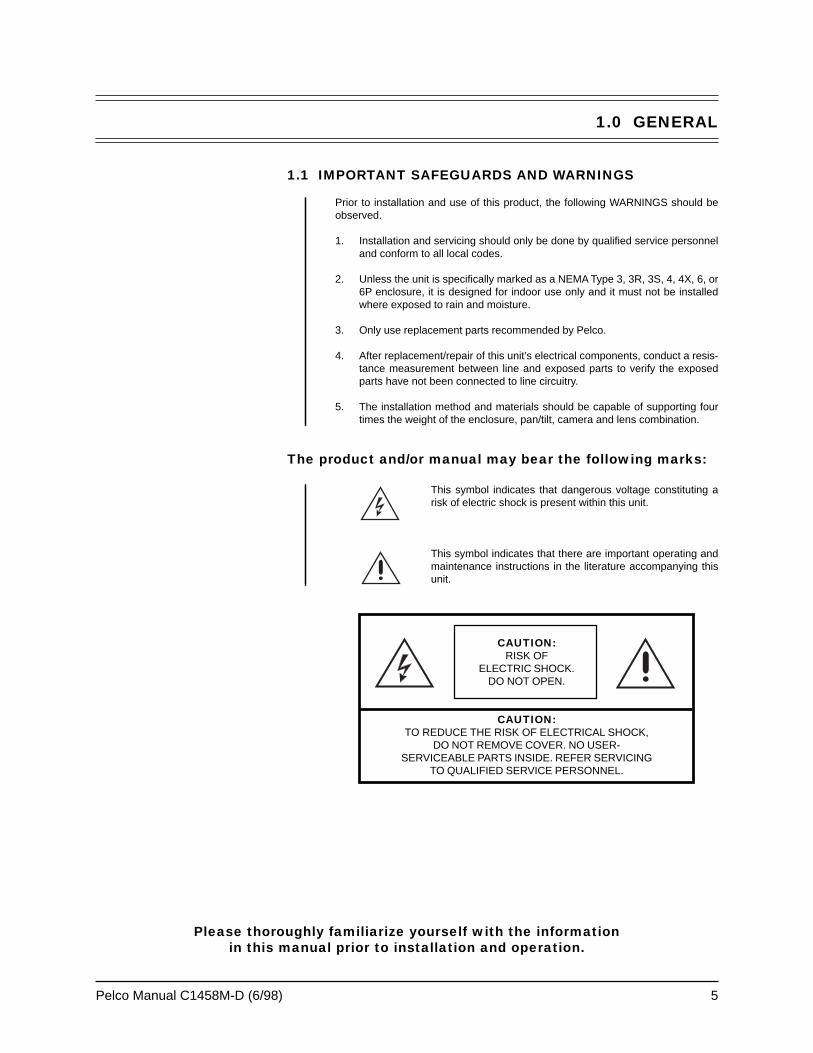
The product and/or manual may bear the following marks:
This symbol indicates that dangerous voltage constituting arisk of electric shock is present within this unit.
This symbol indicates that there are important operating andmaintenance instructions in the literature accompanying thisunit.
CAUTION:RISK OF
ELECTRIC SHOCK.DO NOT OPEN.
CAUTION:TO REDUCE THE RISK OF ELECTRICAL SHOCK,
DO NOT REMOVE COVER. NO USER-SERVICEABLE PARTS INSIDE. REFER SERVICING
TO QUALIFIED SERVICE PERSONNEL.
Please thoroughly familiarize yourself with the informationin this manual prior to installation and operation.
6 Pelco Manual C1458M-D (6/98)
1.2 UNPACKING INSTRUCTIONS
Unpack and inspect all parts carefully.
The DF5 shipping carton contains two boxes:
1 box containing the back box1 box containing the trim ring and lower dome
Inspect your equipment to make sure all parts are present.
Back Box
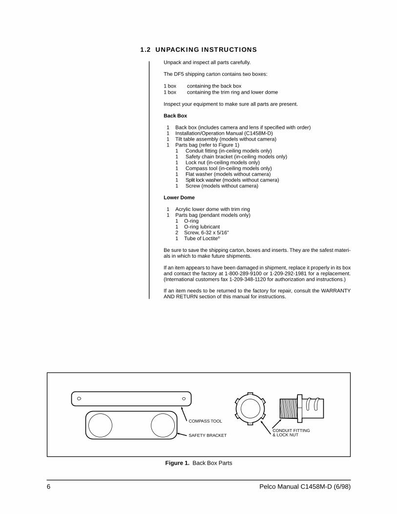
1 Back box (includes camera and lens if specified with order) 1 Installation/Operation Manual (C1458M-D) 1 Tilt table assembly (models without camera) 1 Parts bag (refer to Figure 1)
1 Conduit fitting (in-ceiling models only)1 Safety chain bracket (in-ceiling models only)1 Lock nut (in-ceiling models only)1 Compass tool (in-ceiling models only)1 Flat washer (models without camera)1 Split lock washer (models without camera)1 Screw (models without camera)
Lower Dome
1 Acrylic lower dome with trim ring1 Parts bag (pendant models only)
1 O-ring1 O-ring lubricant2 Screw, 6-32 x 5/16"1 Tube of Loctite®
Be sure to save the shipping carton, boxes and inserts. They are the safest materi-als in which to make future shipments.
If an item appears to have been damaged in shipment, replace it properly in its boxand contact the factory at 1-800-289-9100 or 1-209-292-1981 for a replacement.(International customers fax 1-209-348-1120 for authorization and instructions.)
If an item needs to be returned to the factory for repair, consult the WARRANTYAND RETURN section of this manual for instructions.
Figure 1. Back Box Parts
COMPASS TOOL
SAFETY BRACKETCONDUIT FITTING& LOCK NUT
Pelco Manual C1458M-D (6/98) 7
1.3 RECOMMENDED TOOLS
Pelco does not supply basic tools needed for the installation process. The followingtools are recommended:
Pen or pencil (in-ceiling models only)Drill with 3/32-inch drill bit (in-ceiling models only)Saw to cut hole in ceiling (in-ceiling models only)Small flat screwdriverMedium Phillips screwdriverWire stripperBNC crimp toolWire cutterCoaxial cable stripperDrill with hole saw (pendant surface-mount only)
8 Pelco Manual C1458M-D (6/98)
2.0 DESCRIPTION
DF5 Series domes are discreet surveillance domes that are designed for indoor oroutdoor use. Models include pendant and in-ceiling versions.
In-ceiling models have plenum-rated back boxes and can be installed in hard ceil-ings or standard 2' x 2' (6 x 61 cm) suspended ceilings.
Indoor pendant models come in light gray or black finish. Outdoor pendant modelsare light gray only and include a heater that allows operation down to -60° F(-51° C).
Models with a camera include a 1/3-inch format, high-resolution color or mono-chrome camera.
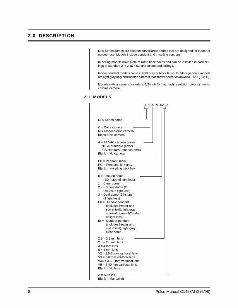
2.1 MODELS
DF5CA-PG-02.3A
DF5 Series dome
C = Color cameraM = Monochrome cameraBlank = No camera
A = 24 VAC camera powerNTSC standard (color)EIA standard (monochrome)
Blank = No camera
PB = Pendant, blackPG = Pendant, light grayBlank = In-ceiling back box
0 = Smoked dome(1/2 f-stop of light loss)
1 = Clear dome2 = Chrome dome (2
f-stops of light loss)3 = Gold dome (2 f-stops
of light loss)E0 = Outdoor pendant
(includes heater andsun shield), light gray,smoked dome (1/2 f-stopof light loss)
EI = Outdoor pendant(includes heater andsun shield), light gray,clear dome
2.3 = 2.3 mm lens2.8 = 2.8 mm lens4 = 4 mm lens8 = 8 mm lensV2 = 2.5-6 mm varifocal lensV3 = 3-8 mm varifocal lensV35 = 3.5-8 mm varifocal lensV5 = 5-40 mm varifocal lensBlank = No lens
A = Auto irisBlank = Manual iris
Pelco Manual C1458M-D (6/98) 9
3.0 INSTALLATION FOR IN-CEILING MODELS
3.1 CEILING AND BACK BOX PREPARATION
3.1.1 Hard Ceiling
1. Locate the center point where you want to drill a hole in the ceiling.
2. Drill a hole in the ceiling using a 3/32-inch drill bit.
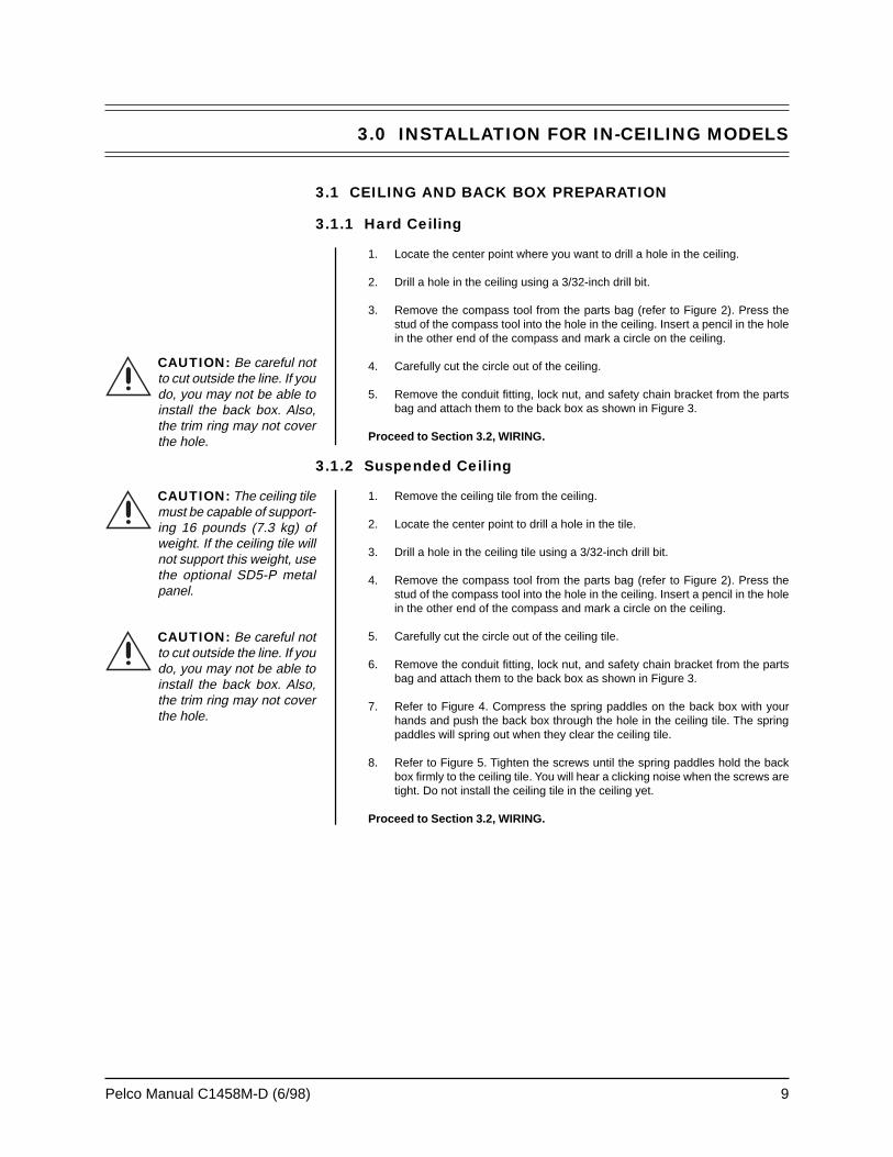
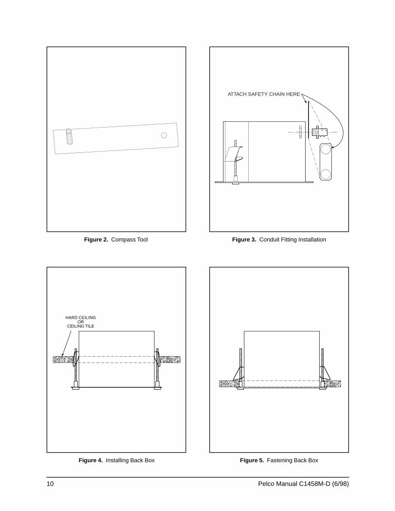
3. Remove the compass tool from the parts bag (refer to Figure 2). Press thestud of the compass tool into the hole in the ceiling. Insert a pencil in the holein the other end of the compass and mark a circle on the ceiling.
4. Carefully cut the circle out of the ceiling.
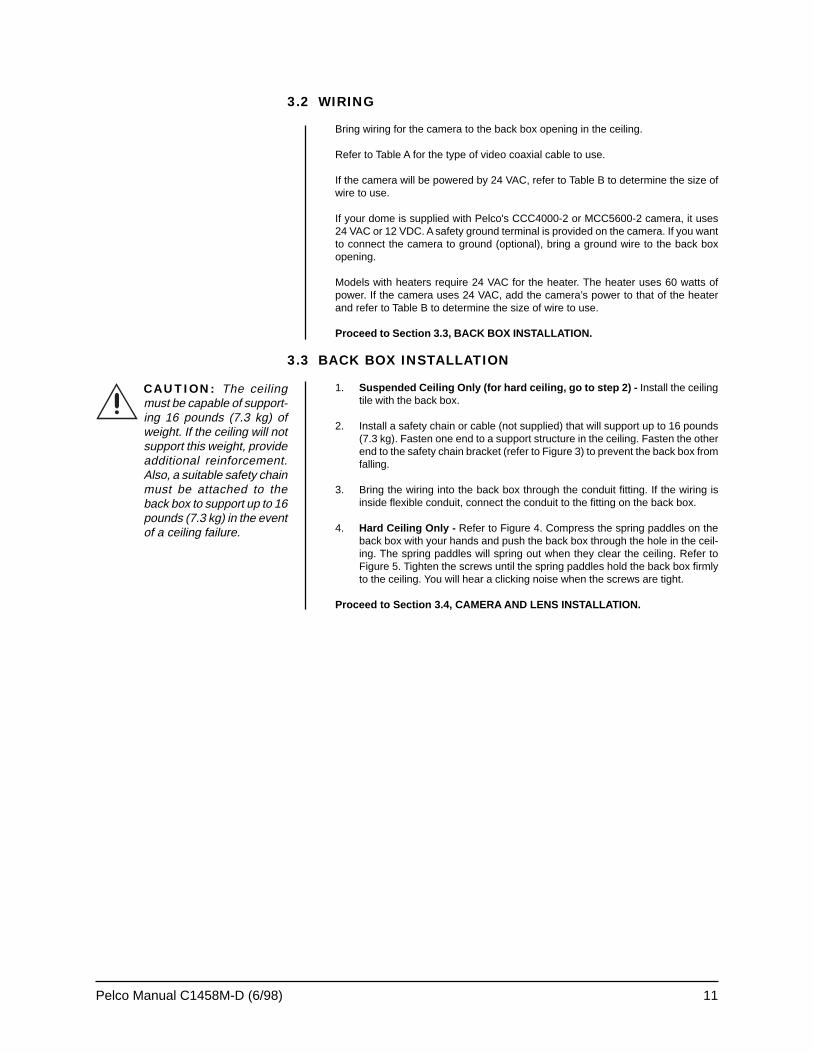
5. Remove the conduit fitting, lock nut, and safety chain bracket from the partsbag and attach them to the back box as shown in Figure 3.
Proceed to Section 3.2, WIRING.
3.1.2 Suspended Ceiling
1. Remove the ceiling tile from the ceiling.
2. Locate the center point to drill a hole in the tile.
3. Drill a hole in the ceiling tile using a 3/32-inch drill bit.
4. Remove the compass tool from the parts bag (refer to Figure 2). Press thestud of the compass tool into the hole in the ceiling. Insert a pencil in the holein the other end of the compass and mark a circle on the ceiling.
5. Carefully cut the circle out of the ceiling tile.
6. Remove the conduit fitting, lock nut, and safety chain bracket from the partsbag and attach them to the back box as shown in Figure 3.
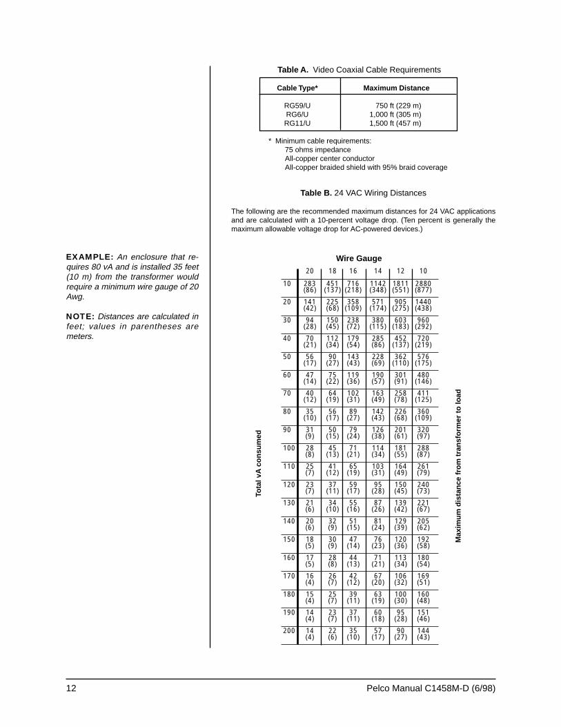
7. Refer to Figure 4. Compress the spring paddles on the back box with yourhands and push the back box through the hole in the ceiling tile. The springpaddles will spring out when they clear the ceiling tile.
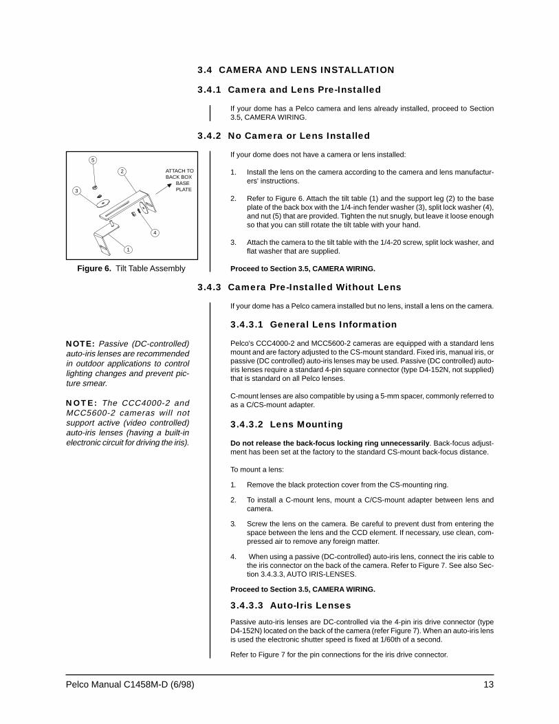
8. Refer to Figure 5. Tighten the screws until the spring paddles hold the backbox firmly to the ceiling tile. You will hear a clicking noise when the screws aretight. Do not install the ceiling tile in the ceiling yet.
Proceed to Section 3.2, WIRING.
CAUTION: Be careful notto cut outside the line. If youdo, you may not be able toinstall the back box. Also,the trim ring may not coverthe hole.
CAUTION: The ceiling tilemust be capable of support-ing 16 pounds (7.3 kg) ofweight. If the ceiling tile willnot support this weight, usethe optional SD5-P metalpanel.
CAUTION: Be careful notto cut outside the line. If youdo, you may not be able toinstall the back box. Also,the trim ring may not coverthe hole.
10 Pelco Manual C1458M-D (6/98)
Figure 4. Installing Back Box Figure 5. Fastening Back Box
Figure 2. Compass Tool Figure 3. Conduit Fitting Installation
ATTACH SAFETY CHAIN HERE
HARD CEILINGOR
CEILING TILE
Pelco Manual C1458M-D (6/98) 11
3.2 WIRING
Bring wiring for the camera to the back box opening in the ceiling.
Refer to Table A for the type of video coaxial cable to use.
If the camera will be powered by 24 VAC, refer to Table B to determine the size ofwire to use.
If your dome is supplied with Pelco's CCC4000-2 or MCC5600-2 camera, it uses24 VAC or 12 VDC. A safety ground terminal is provided on the camera. If you wantto connect the camera to ground (optional), bring a ground wire to the back boxopening.
Models with heaters require 24 VAC for the heater. The heater uses 60 watts ofpower. If the camera uses 24 VAC, add the camera’s power to that of the heaterand refer to Table B to determine the size of wire to use.
Proceed to Section 3.3, BACK BOX INSTALLATION.
3.3 BACK BOX INSTALLATION
1. Suspended Ceiling Only (for hard ceiling, go to step 2) - Install the ceilingtile with the back box.
2. Install a safety chain or cable (not supplied) that will support up to 16 pounds(7.3 kg). Fasten one end to a support structure in the ceiling. Fasten the otherend to the safety chain bracket (refer to Figure 3) to prevent the back box fromfalling.
3. Bring the wiring into the back box through the conduit fitting. If the wiring isinside flexible conduit, connect the conduit to the fitting on the back box.
4. Hard Ceiling Only - Refer to Figure 4. Compress the spring paddles on theback box with your hands and push the back box through the hole in the ceil-ing. The spring paddles will spring out when they clear the ceiling. Refer toFigure 5. Tighten the screws until the spring paddles hold the back box firmlyto the ceiling. You will hear a clicking noise when the screws are tight.
Proceed to Section 3.4, CAMERA AND LENS INSTALLATION.
CAUTION: The ceilingmust be capable of support-ing 16 pounds (7.3 kg) ofweight. If the ceiling will notsupport this weight, provideadditional reinforcement.Also, a suitable safety chainmust be attached to theback box to support up to 16pounds (7.3 kg) in the eventof a ceiling failure.
12 Pelco Manual C1458M-D (6/98)
Table A. Video Coaxial Cable Requirements
Cable Type* Maximum Distance
RG59/U 750 ft (229 m)RG6/U 1,000 ft (305 m)RG11/U 1,500 ft (457 m)
* Minimum cable requirements:75 ohms impedanceAll-copper center conductorAll-copper braided shield with 95% braid coverage
Wire Gauge
Max
imum
dis
tanc
e fr
om tr
ansf
orm
er to
load
Table B. 24 VAC Wiring Distances
The following are the recommended maximum distances for 24 VAC applicationsand are calculated with a 10-percent voltage drop. (Ten percent is generally themaximum allowable voltage drop for AC-powered devices.)
Tota
l vA
con
sum
edEXAMPLE: An enclosure that re-quires 80 vA and is installed 35 feet(10 m) from the transformer wouldrequire a minimum wire gauge of 20Awg.
NOTE: Distances are calculated infeet; values in parentheses aremeters.
20 18 16 14 12 10
10 283 451 716 1142 1811 2880(86) (137) (218) (348) (551) (877)
20 141 225 358 571 905 1440(42) (68) (109) (174) (275) (438)
30 94 150 238 380 603 960(28) (45) (72) (115) (183) (292)
40 70 112 179 285 452 720(21) (34) (54) (86) (137) (219)
50 56 90 143 228 362 576(17) (27) (43) (69) (110) (175)
60 47 75 119 190 301 480(14) (22) (36) (57) (91) (146)
70 40 64 102 163 258 411(12) (19) (31) (49) (78) (125)
80 35 56 89 142 226 360(10) (17) (27) (43) (68) (109)
90 31 50 79 126 201 320(9) (15) (24) (38) (61) (97)
100 28 45 71 114 181 288(8) (13) (21) (34) (55) (87)
110 25 41 65 103 164 261(7) (12) (19) (31) (49) (79)
120 23 37 59 95 150 240(7) (11) (17) (28) (45) (73)
130 21 34 55 87 139 221(6) (10) (16) (26) (42) (67)
140 20 32 51 81 129 205(6) (9) (15) (24) (39) (62)
150 18 30 47 76 120 192(5) (9) (14) (23) (36) (58)
160 17 28 44 71 113 180(5) (8) (13) (21) (34) (54)
170 16 26 42 67 106 169(4) (7) (12) (20) (32) (51)
180 15 25 39 63 100 160(4) (7) (11) (19) (30) (48)
190 14 23 37 60 95 151(4) (7) (11) (18) (28) (46)
200 14 22 35 57 90 144(4) (6) (10) (17) (27) (43)
Pelco Manual C1458M-D (6/98) 13
3.4 CAMERA AND LENS INSTALLATION
3.4.1 Camera and Lens Pre-Installed
If your dome has a Pelco camera and lens already installed, proceed to Section3.5, CAMERA WIRING.
3.4.2 No Camera or Lens Installed
If your dome does not have a camera or lens installed:
1. Install the lens on the camera according to the camera and lens manufactur-ers' instructions.
2. Refer to Figure 6. Attach the tilt table (1) and the support leg (2) to the baseplate of the back box with the 1/4-inch fender washer (3), split lock washer (4),and nut (5) that are provided. Tighten the nut snugly, but leave it loose enoughso that you can still rotate the tilt table with your hand.
3. Attach the camera to the tilt table with the 1/4-20 screw, split lock washer, andflat washer that are supplied.
Proceed to Section 3.5, CAMERA WIRING.
3.4.3 Camera Pre-Installed Without Lens
If your dome has a Pelco camera installed but no lens, install a lens on the camera.
3.4.3.1 General Lens Information
Pelco's CCC4000-2 and MCC5600-2 cameras are equipped with a standard lensmount and are factory adjusted to the CS-mount standard. Fixed iris, manual iris, orpassive (DC controlled) auto-iris lenses may be used. Passive (DC controlled) auto-iris lenses require a standard 4-pin square connector (type D4-152N, not supplied)that is standard on all Pelco lenses.
C-mount lenses are also compatible by using a 5-mm spacer, commonly referred toas a C/CS-mount adapter.
3.4.3.2 Lens Mounting
Do not release the back-focus locking ring unnecessarily . Back-focus adjust-ment has been set at the factory to the standard CS-mount back-focus distance.
To mount a lens:
1. Remove the black protection cover from the CS-mounting ring.
2. To install a C-mount lens, mount a C/CS-mount adapter between lens andcamera.
3. Screw the lens on the camera. Be careful to prevent dust from entering thespace between the lens and the CCD element. If necessary, use clean, com-pressed air to remove any foreign matter.
4. When using a passive (DC-controlled) auto-iris lens, connect the iris cable tothe iris connector on the back of the camera. Refer to Figure 7. See also Sec-tion 3.4.3.3, AUTO IRIS-LENSES.
Proceed to Section 3.5, CAMERA WIRING.
3.4.3.3 Auto-Iris Lenses
Passive auto-iris lenses are DC-controlled via the 4-pin iris drive connector (typeD4-152N) located on the back of the camera (refer Figure 7). When an auto-iris lensis used the electronic shutter speed is fixed at 1/60th of a second.
Refer to Figure 7 for the pin connections for the iris drive connector.
NOTE: Passive (DC-controlled)auto-iris lenses are recommendedin outdoor applications to controllighting changes and prevent pic-ture smear.
NOTE: The CCC4000-2 andMCC5600-2 cameras will notsupport active (video controlled)auto-iris lenses (having a built-inelectronic circuit for driving the iris).
Figure 6. Tilt Table Assembly
3
5
2
4
1
ATTACH TOBACK BOX
BASEPLATE
14 Pelco Manual C1458M-D (6/98)
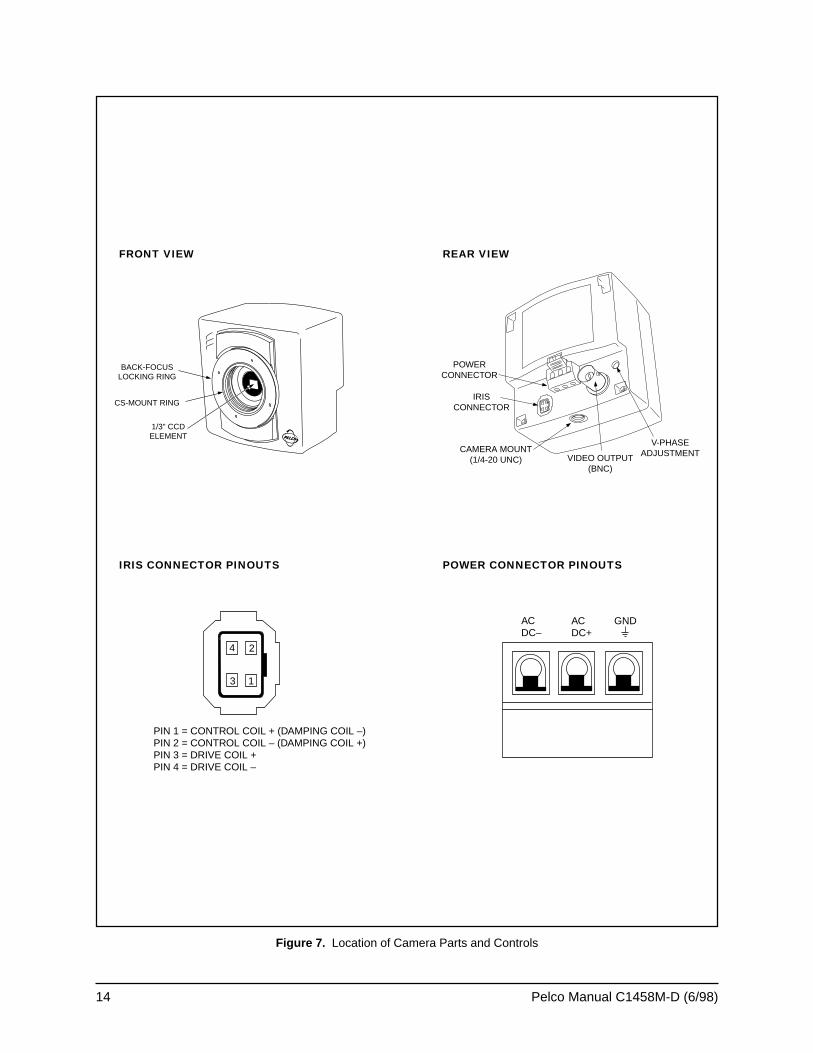
Figure 7. Location of Camera Parts and Controls
CS-MOUNT RING
1/3" CCDELEMENT
BACK-FOCUSLOCKING RING
IRISCONNECTOR
POWERCONNECTOR
CAMERA MOUNT(1/4-20 UNC) VIDEO OUTPUT
(BNC)
V-PHASEADJUSTMENT
4 2
3 1
PIN 1 = CONTROL COIL + (DAMPING COIL –)PIN 2 = CONTROL COIL – (DAMPING COIL +)PIN 3 = DRIVE COIL +PIN 4 = DRIVE COIL –
ACDC–
ACDC+
GND
FRONT VIEW REAR VIEW
IRIS CONNECTOR PINOUTS POWER CONNECTOR PINOUTS
Pelco Manual C1458M-D (6/98) 15
3.5 CAMERA WIRING
1. Connect power and video wiring to the camera.
For models with heaters, attach 24 VAC power to the terminal block inside theback box. If the camera uses 24 VAC, connect the spade lugs on the twoloose wires inside the back box to the 24 VAC input of the camera. If you donot use the wires, isolate them from touching anything.
If your dome has a Pelco CCC4000-2 or MCC5600-2 camera, connect thepower and video wiring to the camera. Refer to Figure 7. A safety groundterminal ( ) is provided on the connector block to connect the camera toground potential. Maximum voltage between the supply inputs and the safetyground must be less than 50 volts. Camera electronics are galvanically insu-lated from the camera supply, which protects a system with more than onecamera from ground loop problems. The power connector block can be re-moved from the camera to ease mounting and/or installation.
If your dome has a different type of camera, connect the power and videowiring to the camera according to the camera manufacturer's instructions.
If you are using AC power and are wiring more than one camera to the sametransformer, connect one side of the transformer to the same terminal on allcameras, and connect the other side of the transformer to the remaining ter-minal on all cameras. Failure to connect all of the cameras the same will causethe cameras to be out of phase with each other and may produce what ap-pears to be vertical roll when switching between cameras.
2. Make sure the other end of the video cable is connected to a monitor or videoequipment that goes to a monitor. Turn on power to the system. Observe themonitor and adjust the tilt table to place the camera in the desired position.Tighten the two nuts on the tilt table. It may be necessary to remove or tilt thecamera to reach the mounting nut in the top of the back box.
Proceed to Section 3.6, CAMERA ADJUSTMENTS.
3.6 CAMERA ADJUSTMENTS
Adjust the camera and lens according to the manufacturers’ instructions.
The remainder of this section applies to Pelco’s CCC4000-2 and MCC5600-2 cam-eras. Proceed to Section 3.7, LOWER DOME INSTALLATION, if you do not haveone of these cameras.
1. Aim the camera and focus the lens to the object or area to be observed.
2. If a manual-iris lens is used, adjust the iris for the best picture quality. Thelargest aperture gives the best light sensitivity, the smallest aperture the greatestdepth of field.
3.6.1 Back-Focus Adjustment
Do not release the back-focus locking ring unnecessarily . Back-focus adjust-ment has been set at the factory to the standard CS-mount back-focus distance.
Back-focus is defined as the distance between the lens optics and the camera’sCCD sensing element.
A camera that gives an unsharp picture using a particular lens may require back-focus adjustment.
To change back-focus the lens must be mounted onto the camera.
To change the back-focus:
1. With the camera operating, position the camera to view the intended object.
NOTE: The iris cable of a (pas-sive) auto-iris lens prevents thelens being rotated more than180°. In this case, disconnect theiris cable, rotate the lens a fullturn, reconnect the iris cable, andcontinue the adjustment.
NOTE: When adjusting back-focus with an auto-iris lens, theiris cable must be plugged intothe iris drive connector; other-wise, the iris will not open.
16 Pelco Manual C1458M-D (6/98)
2. Set the focus ring, if present, to infinity.
3. Set the lens iris to its widest usable opening. Use a neutral density filter withauto-iris lenses in outdoor or bright light settings to ensure maximum iris openingduring back-focus adjustment. When a neutral density filter is not available,point the camera to a relatively dark area to obtain the greatest iris opening.
4. Adjust the back-focus:
a. Turn the back-focus locking ring counterclockwise to loosen the CS-mountring.
b. Adjust the lens and the CS-mount ring together until picture is sharpest.
c. Hold the lens and CS-mount ring in place and turn the back-focus lockingring clockwise to tighten.
3.6.2 Vertical Phase Adjustment
Vertical phase (V-phase) adjustment is unnecessary when using AC power with asingle camera.
When powering more than one camera with AC, phase differences may occur as aresult of being connected to different power groups. These phase differences be-come apparent as a brief rolling of the picture each time cameras are switched,known as vertical roll. Vertical roll can be corrected by synchronizing the cameraswith the V-phase adjustment.
Generally, it is necessary to have two people in communication when cameras aresynchronized: one person at the camera to be synchronized and another person atthe monitor to observe the vertical “roll” and the effect of any adjustments made atthe camera.
To adjust the vertical phase:
1. Choose a camera to which all of the other cameras will be synchronized. Bygoing through the available cameras it can be determined the best camera towhich the others should be synchronized.
2. Select a second camera that is out of synchronization with the first camera.
3. Switch the cameras back and forth, observing the “roll” between the cameraswhen they are switched.
4. If “roll” is present, adjust the vertical phase (refer to Figure 7 for the location ofthe V-phase adjustment).
CCC4000-2 Camera: Press the V–phase button with a pointed object such asa pencil, then switch cameras again and observe the roll. Each press of thebutton will shift the phase 60°.
MCC5600-2 Camera: Adjust the potentiometer with a small Phillips screw-driver. V-phase is adjustable between 0° to 220°.
5. Repeat this process as many times as necessary and for each of the othercameras in the system.
Proceed to Section 3.7, LOWER DOME INSTALLATION.
Pelco Manual C1458M-D (6/98) 17
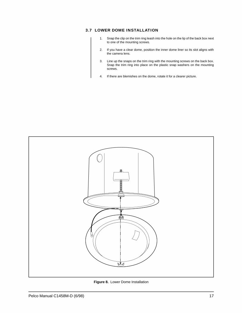
Figure 8. Lower Dome Installation
3.7 LOWER DOME INSTALLATION
1. Snap the clip on the trim ring leash into the hole on the lip of the back box nextto one of the mounting screws.
2. If you have a clear dome, position the inner dome liner so its slot aligns withthe camera lens.
3. Line up the snaps on the trim ring with the mounting screws on the back box.Snap the trim ring into place on the plastic snap washers on the mountingscrews.
4. If there are blemishes on the dome, rotate it for a clearer picture.
18 Pelco Manual C1458M-D (6/98)
4.0 INSTALLATION FOR PENDANT MODELS
4.1 PENDANT-MOUNT INSTALLATION
1. Install the pendant dome mount. Refer to the instructions supplied with themount. If the mount is outdoors, make sure it is properly sealed to keep mois-ture out.
2. Bring the wiring for the dome through the mount. Refer to Section 3.2, WIR-ING.
3. Screw the back box to the mount and bring the wiring into the back box. Ifoutdoors, apply the provided pipe sealant to the threads on the back box.
4. Refer to Sections 3.4 through 3.6 for camera and lens installation, wiring, andadjustment procedures.
5. Remove the O-ring and O-ring lubricant from the parts bag. Apply lubricant tothe O-ring. Install the O-ring in the groove on the trim ring of the lower dome.
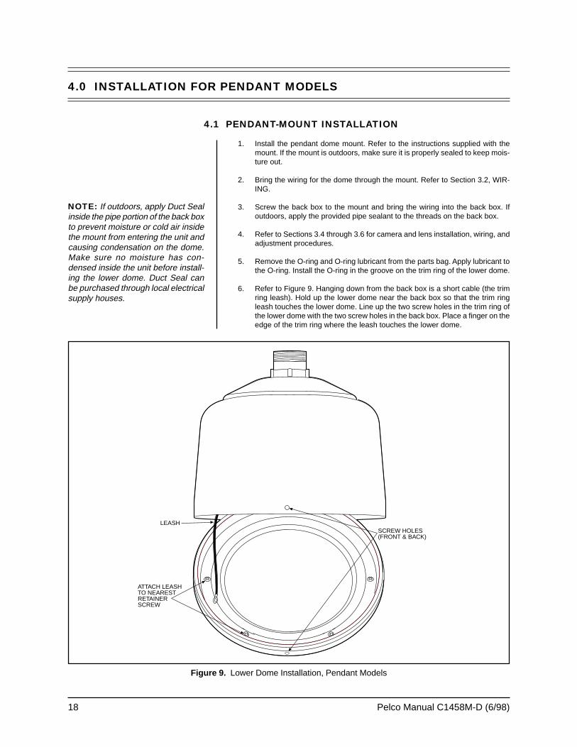
6. Refer to Figure 9. Hanging down from the back box is a short cable (the trimring leash). Hold up the lower dome near the back box so that the trim ringleash touches the lower dome. Line up the two screw holes in the trim ring ofthe lower dome with the two screw holes in the back box. Place a finger on theedge of the trim ring where the leash touches the lower dome.
Figure 9. Lower Dome Installation, Pendant Models
NOTE: If outdoors, apply Duct Sealinside the pipe portion of the back boxto prevent moisture or cold air insidethe mount from entering the unit andcausing condensation on the dome.Make sure no moisture has con-densed inside the unit before install-ing the lower dome. Duct Seal canbe purchased through local electricalsupply houses.
LEASH
ATTACH LEASHTO NEARESTRETAINERSCREW
SCREW HOLES(FRONT & BACK)
Pelco Manual C1458M-D (6/98) 19
7. Look inside the lower dome and note which of the six retainer screws is clos-est to your finger. Remove this screw and attach the trim ring leash to thescrew. Reinstall the screw securely and make sure the leash will hold thelower dome.
8. If you are installing an outdoor model, plug the two-pin heater connection inthe lower dome into the mating connector in the back box.
9. Remove the two screws and the tube of Loctite® from the parts bag. Apply adrop of Loctite® to each screw.
10. Push the lower dome inside the back box, line up the screw holes, and installthe two screws.
4.2 SURFACE-MOUNT INSTALLATION
1. Use a hole saw to drill a hole in the ceiling where you want to hang the pen-dant dome.
2. Bring the wiring for the dome to the opening. Refer to Section 3.2, WIRING.
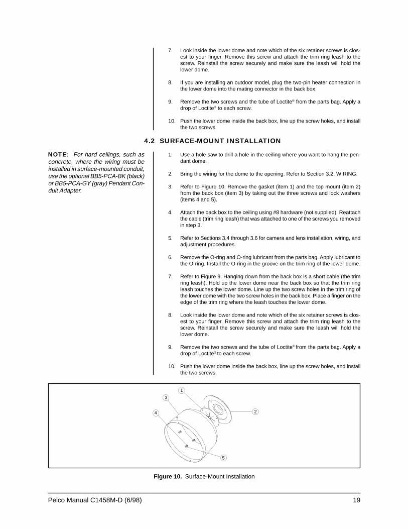
3. Refer to Figure 10. Remove the gasket (item 1) and the top mount (item 2)from the back box (item 3) by taking out the three screws and lock washers(items 4 and 5).
4. Attach the back box to the ceiling using #8 hardware (not supplied). Reattachthe cable (trim ring leash) that was attached to one of the screws you removedin step 3.
5. Refer to Sections 3.4 through 3.6 for camera and lens installation, wiring, andadjustment procedures.
6. Remove the O-ring and O-ring lubricant from the parts bag. Apply lubricant tothe O-ring. Install the O-ring in the groove on the trim ring of the lower dome.
7. Refer to Figure 9. Hanging down from the back box is a short cable (the trimring leash). Hold up the lower dome near the back box so that the trim ringleash touches the lower dome. Line up the two screw holes in the trim ring ofthe lower dome with the two screw holes in the back box. Place a finger on theedge of the trim ring where the leash touches the lower dome.
8. Look inside the lower dome and note which of the six retainer screws is clos-est to your finger. Remove this screw and attach the trim ring leash to thescrew. Reinstall the screw securely and make sure the leash will hold thelower dome.
9. Remove the two screws and the tube of Loctite® from the parts bag. Apply adrop of Loctite® to each screw.
10. Push the lower dome inside the back box, line up the screw holes, and installthe two screws.
NOTE: For hard ceilings, such asconcrete, where the wiring must beinstalled in surface-mounted conduit,use the optional BB5-PCA-BK (black)or BB5-PCA-GY (gray) Pendant Con-duit Adapter.
1
2
5
4
3
Figure 10. Surface-Mount Installation
20 Pelco Manual C1458M-D (6/98)
5.0 MAINTENANCE
5.1 DOME CLEANING
Clean the acrylic dome as necessary to maintain a clear picture. Be careful not thescratch the surfaces of the dome.
Exterior Surface - Clean the dome’s exterior surface with a nonabrasive cleaningcloth and cleaning agent that is safe for acrylic plastic. Either liquid or spray cleaner/wax suitable for fine furniture is acceptable.
Interior Surface (Except Chrome or Gold) - Clean the same as the exterior sur-face.
Interior Surface (Chrome or Gold) - The inside surface of a chrome or gold domeis easily scratched. Use the following precautions to maintain the dome’s surface.
A. Always handle the dome from the outside of its circular flange.
B. Never touch the coated inside surface. The acid in your fingerprints will even-tually etch the coating if the fingerprints are not carefully removed accordingto the recommended cleaning procedure in item E.
C. If dust or other contaminants accumulate on the dome’s interior, remove thedebris with compressed air. Compressed air cans are available from photo-graphic equipment or electronic supply dealers.
D. If heavy residue accumulates and cannot be removed with air pressure, rinsewith water and immediately dry with air pressure so that water spots will notremain. Avoid wiping the coated surface with direct hand pressure - it will easilyabrade unless extreme care is taken. Once scratched, the dome cannot berecoated.
E. If internal wiping is necessary, avoid hand rubbing. Instead, make a wick asfollows:
Use a very soft paper towel. Roll a section into a tightly wound tube. Tear thetube in half, and wet the fuzzy end of the wick with a solution of isopropylalcohol diluted with water. Hold the dome with its opening facing downwardand wipe the interior of the dome with the wet end of the wick. Use a circularmotion, starting from the outside and spiraling into the center. Use a new wickfor each two passes over the dome.
5.2 SERVICE MANUAL
If you need to service the unit, obtain a service manual in one of the following ways:
• Go to Pelco’s web site at ftp://www.pelco.com and find service manualC1458SM.
• Call Pelco’s DataFax service at 1-209-292-0435 and request document 214588.
• Contact Pelco’s Literature Department and request service manual C1458SM.
Pelco Manual C1458M-D (6/98) 21
6.0 SPECIFICATIONS
MECHANICAL
ConstructionBack Box: AluminumMountingBracket: Steel
Dimensions: See Figure 11
GENERAL
Environment: Indoor and outdoorOperatingTemperature
Indoor: 32° to 120°F (0° to 49°C)Outdoor: -10° to 120°F (-23° to 49°C)
Weight Unit ShippingIn-Ceiling(without camera): 2.80 lb (1.27 kg) 6.0 lb (2.72 kg)Pendant(without camera): 4.25 lb (1.93 kg) 8.0 lb (3.63 kg)
Add 1.50 (0.68 kg) for heater and sun shield
CAMERA
DF5 Models Without Camera
Maximum Cameraand Lens Size: (with camera positioned at 90° from horizontal)
6.0” L x 2.75” W x 2.75” H (15.24 x 6.99 x 6.99 cm)
CCC4000-2 Color (NTSC) Camera
CCD Sensor: Color 1/3" interline transferPixels: 512 x 492 (horizontal x vertical)Sensing Area: 4.7 mm x 3.5 mm (3/16" x 1/8")Sync System: Free running/line lock (when AC powered)HorizontalResolution: 400 TV linesIris Control: Electronic/passiveLens Mount: CSLight Sensitivity: 3.5 lux (≥ 50 ire/-6 dB) at f1.2ElectronicShutter Speed: 1/60 sec–1/50,000 secSignal-to-NoiseRatio: > 50 dBGain Control: AutomaticVertical PhaseAdjustment: 60° incrementsPowerRequirements: 12-27.6 VAC, 10.8-39 VDCVideo Output: CVBS, 1 Vp-p/75 ohmsLens Jack: 4-pin connector (type D4-152N)PowerConsumption: 2.7 watts (max.) (camera only)OperatingTemperature: 14° to 122°F (-10° to 50°C)Humidity: 20% to 95% relative humidityConstruction: Conductive-coated ABSMountingThreads: 1/4-20 UNCDimensions: 2.75" W x 2.88" H x 2.38" D
(70 mm x 73 mm x 60 mm)Weight: 0.45 lb (200 g) (without lens)
22 Pelco Manual C1458M-D (6/98)
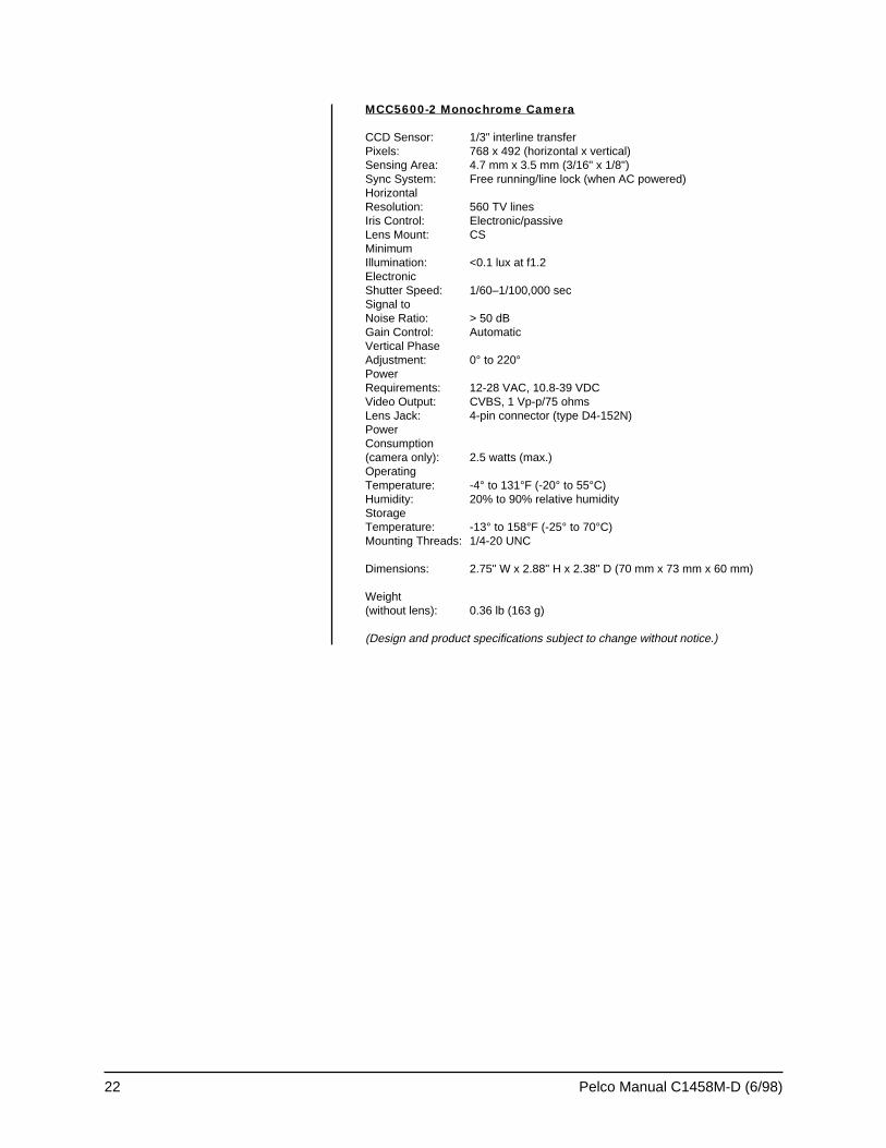
MCC5600-2 Monochrome Camera
CCD Sensor: 1/3" interline transferPixels: 768 x 492 (horizontal x vertical)Sensing Area: 4.7 mm x 3.5 mm (3/16" x 1/8")Sync System: Free running/line lock (when AC powered)HorizontalResolution: 560 TV linesIris Control: Electronic/passiveLens Mount: CSMinimumIllumination: <0.1 lux at f1.2ElectronicShutter Speed: 1/60–1/100,000 secSignal toNoise Ratio: > 50 dBGain Control: AutomaticVertical PhaseAdjustment: 0° to 220°PowerRequirements: 12-28 VAC, 10.8-39 VDCVideo Output: CVBS, 1 Vp-p/75 ohmsLens Jack: 4-pin connector (type D4-152N)PowerConsumption(camera only): 2.5 watts (max.)OperatingTemperature: -4° to 131°F (-20° to 55°C)Humidity: 20% to 90% relative humidityStorageTemperature: -13° to 158°F (-25° to 70°C)Mounting Threads: 1/4-20 UNC
Dimensions: 2.75" W x 2.88" H x 2.38" D (70 mm x 73 mm x 60 mm)
Weight(without lens): 0.36 lb (163 g)
(Design and product specifications subject to change without notice.)
Pelco Manual C1458M-D (6/98) 23
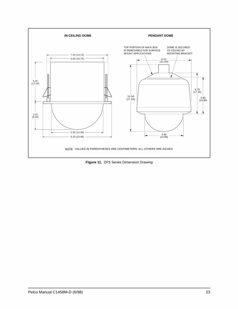
Figure 11. DF5 Series Dimension Drawing
6.60 (16.76)
5.25(13.34)
3.25(8.26)
7.25 (18.13)
8.25 (20.96)
5.90 (14.99)
NOTE: VALUES IN PARENTHESES ARE CENTIMETERS; ALL OTHERS ARE INCHES
IN-CEILING DOME PENDANT DOME
TOP PORTION OF BACK BOXIS REMOVABLE FOR SURFACEMOUNT APPLICATIONS
DOME IS SECUREDTO CEILING BYMOUNTING BRACKET
5.90(14.99)
6.75(17.15)
5.83(14.80)
10.90(27.69)
8.52(21.64)
24 Pelco Manual C1458M-D (6/98)
7.0 WARRANTY AND RETURN INFORMATION
WARRANTY
Pelco will repair or replace, without charge, any merchandise proved defective inmaterial or workmanship for a period of one year after the date of shipment. Excep-tions to this warranty are as noted below:
• Three years on Genex™ Series multiplexers.• Two years on all standard motorized and fixed focal length lenses.• Two years on Legacy®, Intercept®, PV1000 Series, CM6700/CM8500/CM9500/
CM9750/CM9760 Matrix, Spectra™, DF5 Series and DF8 Fixed Dome products.• Two years on WW5700 series window wiper (excluding wiper blades).• Two years on cameras.• Six months on all pan and tilts, scanners or preset lenses used in continuous
motion applications (that is, preset scan, tour and auto scan modes).
Pelco will warranty all replacement parts and repairs for 90 days from the date ofPelco shipment. All goods requiring warranty repair shall be sent freight prepaid toPelco, Clovis, California. Repairs made necessary by reason of misuse, alteration,normal wear, or accident are not covered under this warranty.
Pelco assumes no risk and shall be subject to no liability for damages or loss result-ing from the specific use or application made of the Products. Pelco’s liability forany claim, whether based on breach of contract, negligence, infringement of anyrights of any party or product liability, relating to the Products shall not exceed theprice paid by the Dealer to Pelco for such Products. In no event will Pelco be liablefor any special, incidental or consequential damages (including loss of use, loss ofprofit and claims of third parties) however caused, whether by the negligence ofPelco or otherwise.
The above warranty provides the Dealer with specific legal rights. The Dealer mayalso have additional rights, which are subject to variation from state to state.
If a warranty repair is required, the Dealer must contact Pelco at (800) 289-9100 or(209) 292-1981 to obtain a Repair Authorization number (RA), and provide thefollowing information:
1. Model and serial number2. Date of shipment, P.O. number, Sales Order number, or Pelco invoice number3. Details of the defect or problem
If there is a dispute regarding the warranty of a product which does not fall underthe warranty conditions stated above, please include a written explanation with theproduct when returned.
Ship freight prepaid to: Pelco300 West Pontiac WayClovis, CA 93612-5699
Method of return shipment shall be the same or equal to the method by which theitem was received by Pelco.
RETURNS
In order to expedite parts returned to the factory for repair or credit, please call thefactory at (800) 289-9100 or (209) 292-1981 to obtain an authorization number (CAnumber if returned for credit, and RA number if returned for repair). Goods returnedfor repair or credit should be clearly identified with the assigned CA/RA number andfreight should be prepaid. All merchandise returned for credit may be subject to a20% restocking and refurbishing charge.
Ship freight prepaid to: Pelco300 West Pontiac WayClovis, CA 93612-5699
®Pelco and the Pelco logo are registeredtrademarks of Pelco.
©Copyright 1998, Pelco. All rightsreserved.