Embed Size (px)
Citation preview

Aruba 3810M Switch SeriesInstallation and Getting Started Guide
Part Number: 5998-8461bPublished: May 2020Edition: 3

© Copyright 2016, 2020 Hewlett Packard Enterprise Development LP
NoticesThe information contained herein is subject to change without notice. The only warranties for HewlettPackard Enterprise products and services are set forth in the express warranty statements accompanyingsuch products and services. Nothing herein should be construed as constituting an additional warranty.Hewlett Packard Enterprise shall not be liable for technical or editorial errors or omissions contained herein.
Confidential computer software. Valid license from Hewlett Packard Enterprise required for possession, use,or copying. Consistent with FAR 12.211 and 12.212, Commercial Computer Software, Computer SoftwareDocumentation, and Technical Data for Commercial Items are licensed to the U.S. Government undervendor's standard commercial license.
Links to third-party websites take you outside the Hewlett Packard Enterprise website. Hewlett PackardEnterprise has no control over and is not responsible for information outside the Hewlett Packard Enterprisewebsite.
AcknowledgmentsIntel®, Itanium®, Pentium®, Intel Inside®, and the Intel Inside logo are trademarks of Intel Corporation inthe United States and other countries.
Microsoft® and Windows® are either registered trademarks or trademarks of Microsoft Corporation in theUnited States and/or other countries.
Adobe® and Acrobat® are trademarks of Adobe Systems Incorporated.
Java® and Oracle® are registered trademarks of Oracle and/or its affiliates.
UNIX® is a registered trademark of The Open Group.
Chapter 1 Introducing the 3810M switches.................................................. 6Front of the switches......................................................................................................................................7
Network ports....................................................................................................................................10Management ports........................................................................................................................... 11
Console ports......................................................................................................................... 11Auxiliary (Aux) port................................................................................................................ 12
Switch and port LEDs on front of the switches............................................................................. 12LED Mode select button and indicator LEDs................................................................................. 19Reset and clear buttons................................................................................................................... 20Flex Port slot and module support................................................................................................. 21
Back of the switches.....................................................................................................................................22Power supplies.................................................................................................................................. 23Power connector............................................................................................................................... 23Stacking module slot.........................................................................................................................23Fan tray assembly............................................................................................................................. 23Out-of-Band Management (OOBM) port........................................................................................23LEDs on the back of the switches....................................................................................................24
3810M Stacking Module.............................................................................................................................. 26Stacking module LEDs...................................................................................................................... 27
Switch features............................................................................................................................................. 28
Chapter 2 Installing the switch......................................................................31Included parts............................................................................................................................................... 31Installation procedures................................................................................................................................33
Summary............................................................................................................................................ 33Installation precautions....................................................................................................................34Prepare the installation site.............................................................................................................34Verify the switch boots correctly..................................................................................................... 35
LED behavior.......................................................................................................................... 37(Optional) Install the stacking module............................................................................................38
Verifying the module is installed correctly..........................................................................39Installing the Flex Port module........................................................................................................40Mount the switch.............................................................................................................................. 41
Rack or cabinet mounting.....................................................................................................41Rack mounting the 3810M switch in a 2-post rack............................................................ 42Rack mounting the 3810M switch in a 4-post rack............................................................ 44Horizontal surface mounting............................................................................................... 46
(Optional) Installing the stacking cables.........................................................................................46(Optional) Installing transceivers.....................................................................................................47
Installing the transceivers.....................................................................................................47Removing the transceiver..................................................................................................... 48
Connect the switch to a power source........................................................................................... 48(Optional) Installing a second power supply..................................................................................49
PoE/PoE+ operation...............................................................................................................49(Optional) Connect a management console.................................................................................. 49
Configuring the management console................................................................................50Setting up a console connection..........................................................................................50Console cable pinouts........................................................................................................... 52
Connect the network cables............................................................................................................ 52
Contents
Contents 3
Using the RJ-45 connectors...................................................................................................53Connecting cables to transceivers....................................................................................... 53
Stacking information and topologies.........................................................................................................54Chain topologies............................................................................................................................... 55Ring topologies..................................................................................................................................57Mesh topologies................................................................................................................................59
Sample network topologies........................................................................................................................ 63
Chapter 3 Getting started with switch configuration..............................68Recommended minimal configuration......................................................................................................68Minimal configuration through the console port connection.................................................................69Where to go from here: Networked connections.....................................................................................71Using the IP address for remote switch management............................................................................ 71
Starting a Telnet session.................................................................................................................. 71Starting a web browser session...................................................................................................... 72
Chapter 4 Replacing components................................................................. 74Replacing the fan tray.................................................................................................................................. 74Replacing the power supply........................................................................................................................75Replacing the stacking module...................................................................................................................76Replacing the Flex Port module..................................................................................................................77
Chapter 5 Troubleshooting............................................................................. 79Basic troubleshooting tips...........................................................................................................................79Diagnosing with the LEDs............................................................................................................................80Proactive networking................................................................................................................................... 92Hardware diagnostic tests...........................................................................................................................92
Testing the switch by resetting it.....................................................................................................92Checking the switch LEDs..................................................................................................... 93Checking console messages................................................................................................. 93
Testing twisted-pair cabling............................................................................................................. 93Testing switch-to-device network communications......................................................................93Testing end-to-end network communications.............................................................................. 93
Restoring the factory default configuration..............................................................................................94Downloading new switch software............................................................................................................ 94
Chapter 6 Specifications..................................................................................95Switch specifications.................................................................................................................................... 95
Physical...............................................................................................................................................95Electrical............................................................................................................................................. 96Environmental................................................................................................................................... 96Acoustics............................................................................................................................................ 97Safety.................................................................................................................................................. 97Connectivity standards.....................................................................................................................98
Stacking module specifications................................................................................................................ 100Physical.............................................................................................................................................100Environmental................................................................................................................................. 100
Flex Port specifications.............................................................................................................................. 100Physical.............................................................................................................................................100Environmental................................................................................................................................. 100
4 Aruba 3810M Switch Series Installation and Getting StartedGuide
Chapter 7 Cabling and technology information...................................... 102Cabling specifications................................................................................................................................ 102
Note on 1000BASE-T cable requirements.................................................................................... 103Note on HPE Smart Rate 2.5 Gb/s cable requirements..............................................................103Note on HPE Smart Rate 5Gb/s cable requirements..................................................................104Note on 10GBASE-T cable requirements......................................................................................104
Technology distance specifications..........................................................................................................105Mode conditioning patch cord................................................................................................................. 106Installing the patch cord............................................................................................................................107Twisted-pair cable/connector pin-outs....................................................................................................107
Straight-through twisted-pair cable for 10 Mbps or 100 Mbps network connections........... 108Cable diagram...................................................................................................................... 109Pin assignments...................................................................................................................109
Crossover twisted-pair cable for 10 Mbps or 100 Mbps network connection........................ 109Cable diagram...................................................................................................................... 110Pin assignments...................................................................................................................110
Straight-through twisted-pair cable for 1000 Mbps network connections..............................110Cable diagram...................................................................................................................... 111Pin assignments...................................................................................................................111
Chapter 8 Websites.........................................................................................112
Chapter 9 Support and other resources....................................................113Accessing Hewlett Packard Enterprise Support..................................................................................... 113Accessing updates......................................................................................................................................113Customer self repair.................................................................................................................................. 114Remote support......................................................................................................................................... 114Warranty information................................................................................................................................ 114Regulatory information............................................................................................................................. 115Documentation feedback..........................................................................................................................115
Contents 5
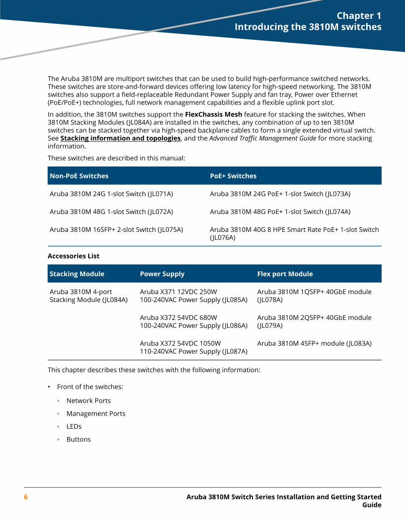
The Aruba 3810M are multiport switches that can be used to build high-performance switched networks.These switches are store-and-forward devices offering low latency for high-speed networking. The 3810Mswitches also support a field-replaceable Redundant Power Supply and fan tray, Power over Ethernet(PoE/PoE+) technologies, full network management capabilities and a flexible uplink port slot.
In addition, the 3810M switches support the FlexChassis Mesh feature for stacking the switches. When3810M Stacking Modules (JL084A) are installed in the switches, any combination of up to ten 3810Mswitches can be stacked together via high-speed backplane cables to form a single extended virtual switch.See Stacking information and topologies, and the Advanced Traffic Management Guide for more stackinginformation.
These switches are described in this manual:
Non-PoE Switches PoE+ Switches
Aruba 3810M 24G 1-slot Switch (JL071A) Aruba 3810M 24G PoE+ 1-slot Switch (JL073A)
Aruba 3810M 48G 1-slot Switch (JL072A) Aruba 3810M 48G PoE+ 1-slot Switch (JL074A)
Aruba 3810M 16SFP+ 2-slot Switch (JL075A) Aruba 3810M 40G 8 HPE Smart Rate PoE+ 1-slot Switch(JL076A)
Accessories List
Stacking Module Power Supply Flex port Module
Aruba 3810M 4-portStacking Module (JL084A)
Aruba X371 12VDC 250W100-240VAC Power Supply ( JL085A)
Aruba 3810M 1QSFP+ 40GbE module(JL078A)
Aruba X372 54VDC 680W100-240VAC Power Supply ( JL086A)
Aruba 3810M 2QSFP+ 40GbE module(JL079A)
Aruba X372 54VDC 1050W110-240VAC Power Supply ( JL087A)
Aruba 3810M 4SFP+ module (JL083A)
This chapter describes these switches with the following information:
• Front of the switches:
◦ Network Ports
◦ Management Ports
◦ LEDs
◦ Buttons
Chapter 1Introducing the 3810M switches
6 Aruba 3810M Switch Series Installation and Getting StartedGuide
◦ Flex Port Slot
◦ Module Support
• Back of the switches:
◦ Power Supplies and Power Connectors
◦ Fan Tray
◦ Out-of-Band Management (OOBM)
• 3810M Stacking Module
• Switch Features
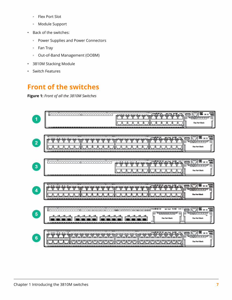
Front of the switchesFigure 1: Front of all the 3810M Switches
Chapter 1 Introducing the 3810M switches 7
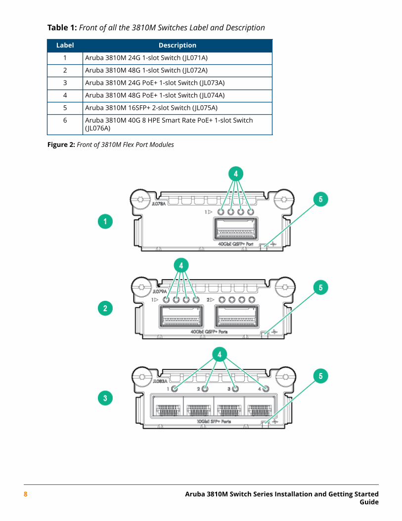
Table 1: Front of all the 3810M Switches Label and Description
Label Description
1 Aruba 3810M 24G 1-slot Switch (JL071A)
2 Aruba 3810M 48G 1-slot Switch (JL072A)
3 Aruba 3810M 24G PoE+ 1-slot Switch (JL073A)
4 Aruba 3810M 48G PoE+ 1-slot Switch (JL074A)
5 Aruba 3810M 16SFP+ 2-slot Switch (JL075A)
6 Aruba 3810M 40G 8 HPE Smart Rate PoE+ 1-slot Switch(JL076A)
Figure 2: Front of 3810M Flex Port Modules
8 Aruba 3810M Switch Series Installation and Getting StartedGuide
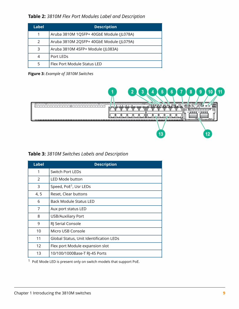
Table 2: 3810M Flex Port Modules Label and Description
Label Description
1 Aruba 3810M 1QSFP+ 40GbE Module (JL078A)
2 Aruba 3810M 2QSFP+ 40GbE Module (JL079A)
3 Aruba 3810M 4SFP+ Module (JL083A)
4 Port LEDs
5 Flex Port Module Status LED
Figure 3: Example of 3810M Switches
Table 3: 3810M Switches Labels and Description
Label Description
1 Switch Port LEDs
2 LED Mode button
3 Speed, PoE1, Usr LEDs
4, 5 Reset, Clear buttons
6 Back Module Status LED
7 Aux port status LED
8 USB/Auxiliary Port
9 RJ Serial Console
10 Micro USB Console
11 Global Status, Unit Identification LEDs
12 Flex port Module expansion slot
13 10/100/1000Base-T RJ-45 Ports
1 PoE Mode LED is present only on switch models that support PoE.
Chapter 1 Introducing the 3810M switches 9
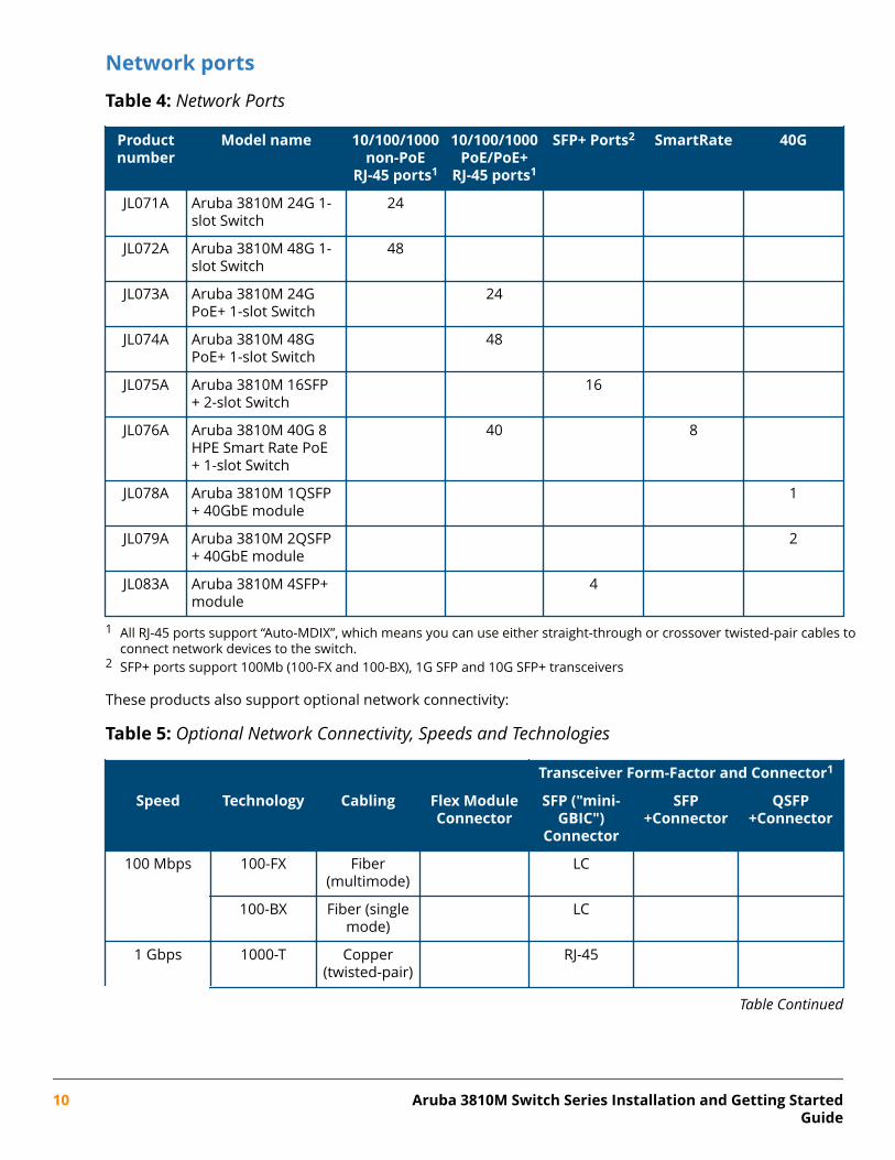
Network ports
Table 4: Network Ports
Productnumber
Model name 10/100/1000non-PoE
RJ-45 ports1
10/100/1000PoE/PoE+
RJ-45 ports1
SFP+ Ports2 SmartRate 40G
JL071A Aruba 3810M 24G 1-slot Switch
24
JL072A Aruba 3810M 48G 1-slot Switch
48
JL073A Aruba 3810M 24GPoE+ 1-slot Switch
24
JL074A Aruba 3810M 48GPoE+ 1-slot Switch
48
JL075A Aruba 3810M 16SFP+ 2-slot Switch
16
JL076A Aruba 3810M 40G 8HPE Smart Rate PoE+ 1-slot Switch
40 8
JL078A Aruba 3810M 1QSFP+ 40GbE module
1
JL079A Aruba 3810M 2QSFP+ 40GbE module
2
JL083A Aruba 3810M 4SFP+module
4
1 All RJ-45 ports support “Auto-MDIX”, which means you can use either straight-through or crossover twisted-pair cables toconnect network devices to the switch.
2 SFP+ ports support 100Mb (100-FX and 100-BX), 1G SFP and 10G SFP+ transceivers
These products also support optional network connectivity:
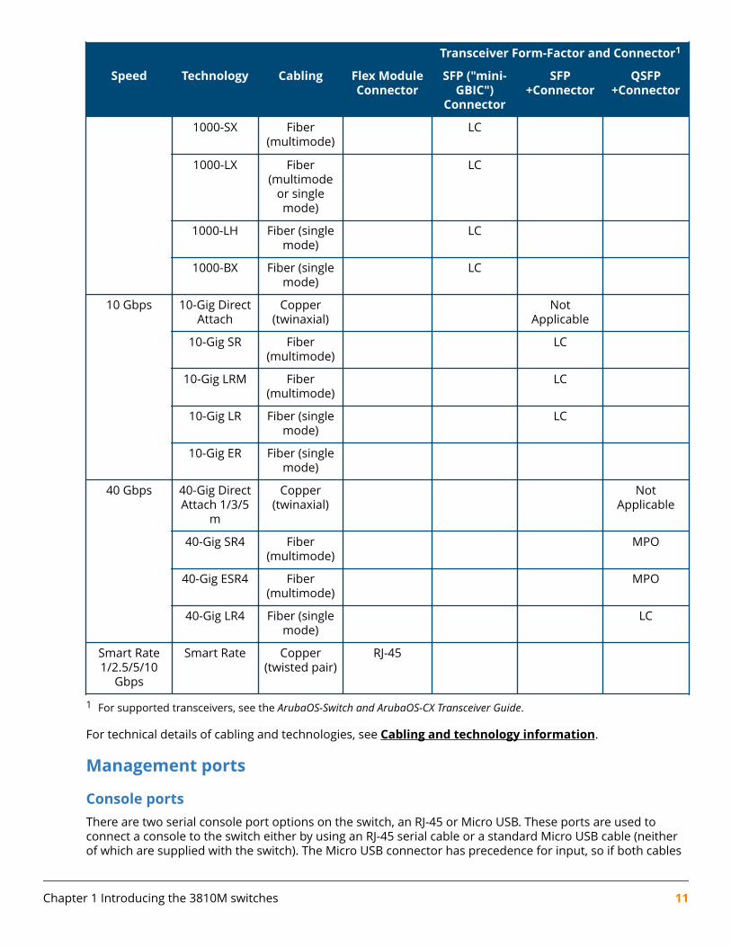
Table 5: Optional Network Connectivity, Speeds and Technologies
Transceiver Form-Factor and Connector1
Speed Technology Cabling Flex ModuleConnector
SFP ("mini-GBIC")
Connector
SFP+Connector
QSFP+Connector
100 Mbps 100-FX Fiber(multimode)
LC
100-BX Fiber (singlemode)
LC
1 Gbps 1000-T Copper(twisted-pair)
RJ-45
Table Continued
10 Aruba 3810M Switch Series Installation and Getting StartedGuide
Transceiver Form-Factor and Connector1
Speed Technology Cabling Flex ModuleConnector
SFP ("mini-GBIC")
Connector
SFP+Connector
QSFP+Connector
1000-SX Fiber(multimode)
LC
1000-LX Fiber(multimode
or singlemode)
LC
1000-LH Fiber (singlemode)
LC
1000-BX Fiber (singlemode)
LC
10 Gbps 10-Gig DirectAttach
Copper(twinaxial)
NotApplicable
10-Gig SR Fiber(multimode)
LC
10-Gig LRM Fiber(multimode)
LC
10-Gig LR Fiber (singlemode)
LC
10-Gig ER Fiber (singlemode)
40 Gbps 40-Gig DirectAttach 1/3/5
m
Copper(twinaxial)
NotApplicable
40-Gig SR4 Fiber(multimode)
MPO
40-Gig ESR4 Fiber(multimode)
MPO
40-Gig LR4 Fiber (singlemode)
LC
Smart Rate1/2.5/5/10
Gbps
Smart Rate Copper(twisted pair)
RJ-45
1 For supported transceivers, see the ArubaOS-Switch and ArubaOS-CX Transceiver Guide.
For technical details of cabling and technologies, see Cabling and technology information.
Management ports
Console portsThere are two serial console port options on the switch, an RJ-45 or Micro USB. These ports are used toconnect a console to the switch either by using an RJ-45 serial cable or a standard Micro USB cable (neitherof which are supplied with the switch). The Micro USB connector has precedence for input, so if both cables
Chapter 1 Introducing the 3810M switches 11
are plugged in, the console output is echoed to both the RJ and Micro-USB ports. But, the input is onlyaccepted from the Micro-USB.
For more information on the console connection, see (Optional) Connect a management console. Theconsole can be a PC or workstation running a VT-100 terminal emulator, or a VT-100 terminal.
Auxiliary (Aux) portAn auxiliary port for processing a USB command file or downloading switch software code. This port uses aUSB Type A connector, but does not comply with all USB protocols and standards.
Switch and port LEDs on front of the switchesThis section describes the various LEDs and their functions.
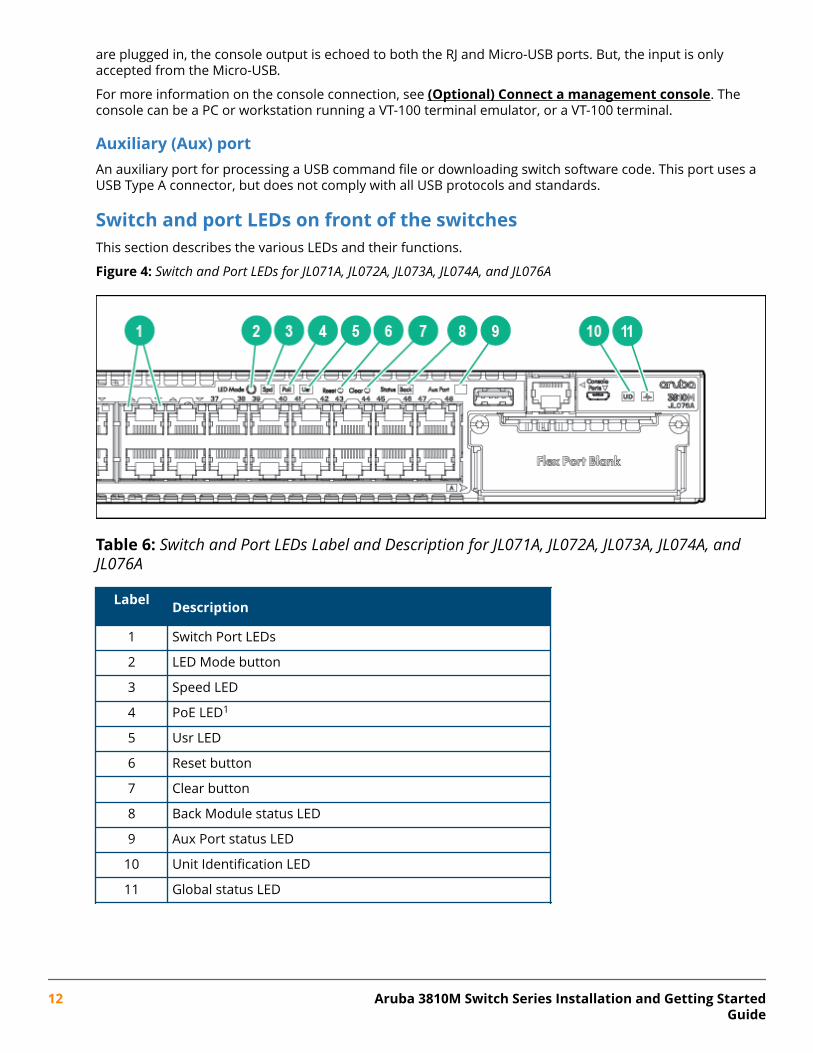
Figure 4: Switch and Port LEDs for JL071A, JL072A, JL073A, JL074A, and JL076A
Table 6: Switch and Port LEDs Label and Description for JL071A, JL072A, JL073A, JL074A, andJL076A
Label Description
1 Switch Port LEDs
2 LED Mode button
3 Speed LED
4 PoE LED1
5 Usr LED
6 Reset button
7 Clear button
8 Back Module status LED
9 Aux Port status LED
10 Unit Identification LED
11 Global status LED
12 Aruba 3810M Switch Series Installation and Getting StartedGuide
1 Only on PoE switches.
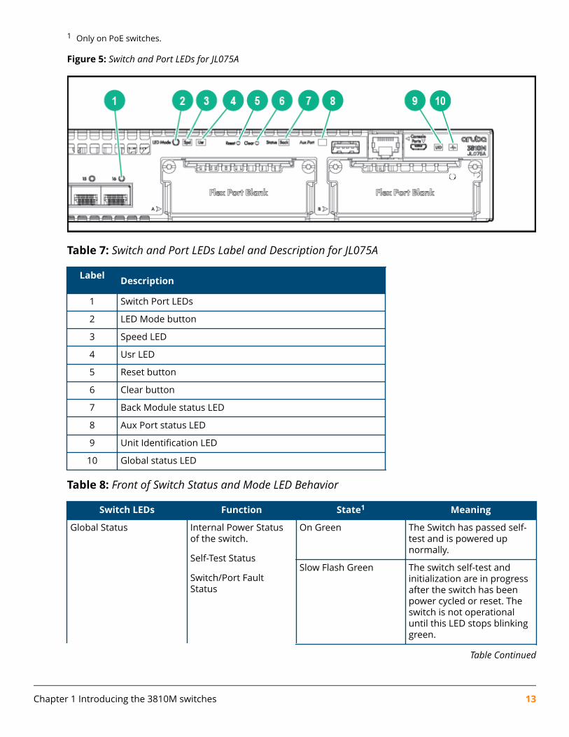
Figure 5: Switch and Port LEDs for JL075A
Table 7: Switch and Port LEDs Label and Description for JL075A
Label Description
1 Switch Port LEDs
2 LED Mode button
3 Speed LED
4 Usr LED
5 Reset button
6 Clear button
7 Back Module status LED
8 Aux Port status LED
9 Unit Identification LED
10 Global status LED
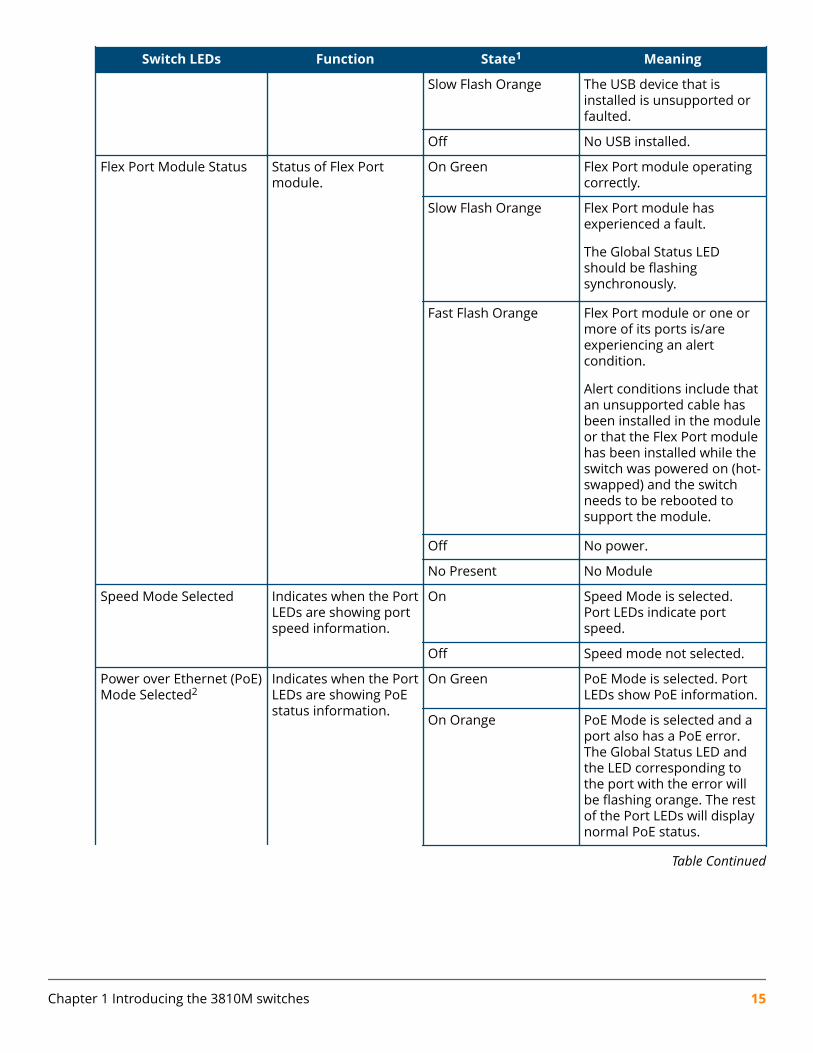
Table 8: Front of Switch Status and Mode LED Behavior
Switch LEDs Function State1 Meaning
Global Status Internal Power Statusof the switch.
Self-Test Status
Switch/Port FaultStatus
On Green The Switch has passed self-test and is powered upnormally.
Slow Flash Green The switch self-test andinitialization are in progressafter the switch has beenpower cycled or reset. Theswitch is not operationaluntil this LED stops blinkinggreen.
Table Continued
Chapter 1 Introducing the 3810M switches 13
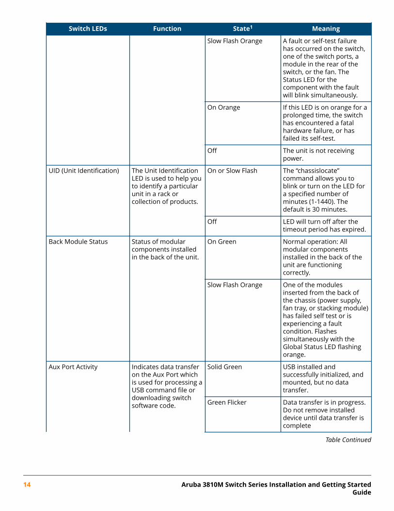
Switch LEDs Function State1 Meaning
Slow Flash Orange A fault or self-test failurehas occurred on the switch,one of the switch ports, amodule in the rear of theswitch, or the fan. TheStatus LED for thecomponent with the faultwill blink simultaneously.
On Orange If this LED is on orange for aprolonged time, the switchhas encountered a fatalhardware failure, or hasfailed its self-test.
Off The unit is not receivingpower.
UID (Unit Identification) The Unit IdentificationLED is used to help youto identify a particularunit in a rack orcollection of products.
On or Slow Flash The “chassislocate”command allows you toblink or turn on the LED fora specified number ofminutes (1-1440). Thedefault is 30 minutes.
Off LED will turn off after thetimeout period has expired.
Back Module Status Status of modularcomponents installedin the back of the unit.
On Green Normal operation: Allmodular componentsinstalled in the back of theunit are functioningcorrectly.
Slow Flash Orange One of the modulesinserted from the back ofthe chassis (power supply,fan tray, or stacking module)has failed self test or isexperiencing a faultcondition. Flashessimultaneously with theGlobal Status LED flashingorange.
Aux Port Activity Indicates data transferon the Aux Port whichis used for processing aUSB command file ordownloading switchsoftware code.
Solid Green USB installed andsuccessfully initialized, andmounted, but no datatransfer.
Green Flicker Data transfer is in progress.Do not remove installeddevice until data transfer iscomplete
Table Continued
14 Aruba 3810M Switch Series Installation and Getting StartedGuide
Switch LEDs Function State1 Meaning
Slow Flash Orange The USB device that isinstalled is unsupported orfaulted.
Off No USB installed.
Flex Port Module Status Status of Flex Portmodule.
On Green Flex Port module operatingcorrectly.
Slow Flash Orange Flex Port module hasexperienced a fault.
The Global Status LEDshould be flashingsynchronously.
Fast Flash Orange Flex Port module or one ormore of its ports is/areexperiencing an alertcondition.
Alert conditions include thatan unsupported cable hasbeen installed in the moduleor that the Flex Port modulehas been installed while theswitch was powered on (hot-swapped) and the switchneeds to be rebooted tosupport the module.
Off No power.
No Present No Module
Speed Mode Selected Indicates when the PortLEDs are showing portspeed information.
On Speed Mode is selected.Port LEDs indicate portspeed.
Off Speed mode not selected.
Power over Ethernet (PoE)Mode Selected2
Indicates when the PortLEDs are showing PoEstatus information.
On Green PoE Mode is selected. PortLEDs show PoE information.
On Orange PoE Mode is selected and aport also has a PoE error.The Global Status LED andthe LED corresponding tothe port with the error willbe flashing orange. The restof the Port LEDs will displaynormal PoE status.
Table Continued
Chapter 1 Introducing the 3810M switches 15
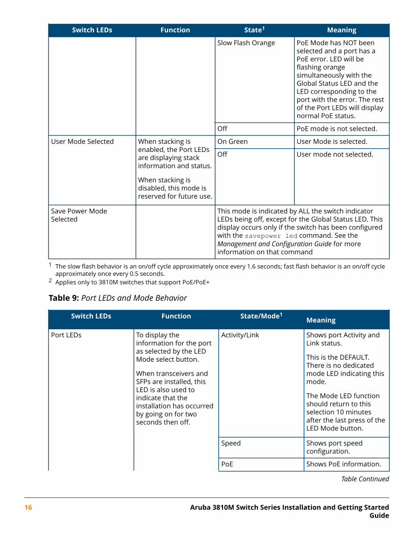
Switch LEDs Function State1 Meaning
Slow Flash Orange PoE Mode has NOT beenselected and a port has aPoE error. LED will beflashing orangesimultaneously with theGlobal Status LED and theLED corresponding to theport with the error. The restof the Port LEDs will displaynormal PoE status.
Off PoE mode is not selected.
User Mode Selected When stacking isenabled, the Port LEDsare displaying stackinformation and status.
When stacking isdisabled, this mode isreserved for future use.
On Green User Mode is selected.
Off User mode not selected.
Save Power ModeSelected
This mode is indicated by ALL the switch indicatorLEDs being off, except for the Global Status LED. Thisdisplay occurs only if the switch has been configuredwith the savepower led command. See theManagement and Configuration Guide for moreinformation on that command
1 The slow flash behavior is an on/off cycle approximately once every 1.6 seconds; fast flash behavior is an on/off cycleapproximately once every 0.5 seconds.
2 Applies only to 3810M switches that support PoE/PoE+
Table 9: Port LEDs and Mode Behavior
Switch LEDs Function State/Mode1Meaning
Port LEDs To display theinformation for the portas selected by the LEDMode select button.
When transceivers andSFPs are installed, thisLED is also used toindicate that theinstallation has occurredby going on for twoseconds then off.
Activity/Link Shows port Activity andLink status.
This is the DEFAULT.There is no dedicatedmode LED indicating thismode.
The Mode LED functionshould return to thisselection 10 minutesafter the last press of theLED Mode button.
Speed Shows port speedconfiguration.
PoE Shows PoE information.
Table Continued
16 Aruba 3810M Switch Series Installation and Getting StartedGuide
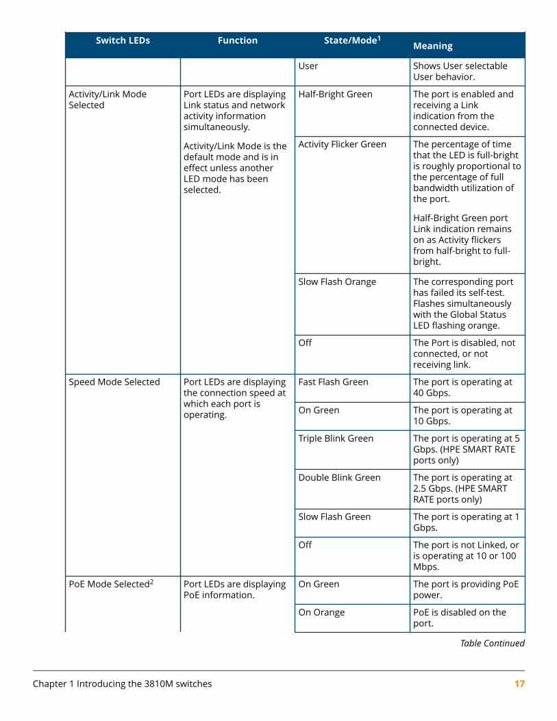
Switch LEDs Function State/Mode1Meaning
User Shows User selectableUser behavior.
Activity/Link ModeSelected
Port LEDs are displayingLink status and networkactivity informationsimultaneously.
Activity/Link Mode is thedefault mode and is ineffect unless anotherLED mode has beenselected.
Half-Bright Green The port is enabled andreceiving a Linkindication from theconnected device.
Activity Flicker Green The percentage of timethat the LED is full-brightis roughly proportional tothe percentage of fullbandwidth utilization ofthe port.
Half-Bright Green portLink indication remainson as Activity flickersfrom half-bright to full-bright.
Slow Flash Orange The corresponding porthas failed its self-test.Flashes simultaneouslywith the Global StatusLED flashing orange.
Off The Port is disabled, notconnected, or notreceiving link.
Speed Mode Selected Port LEDs are displayingthe connection speed atwhich each port isoperating.
Fast Flash Green The port is operating at40 Gbps.
On Green The port is operating at10 Gbps.
Triple Blink Green The port is operating at 5Gbps. (HPE SMART RATEports only)
Double Blink Green The port is operating at2.5 Gbps. (HPE SMARTRATE ports only)
Slow Flash Green The port is operating at 1Gbps.
Off The port is not Linked, oris operating at 10 or 100Mbps.
PoE Mode Selected2 Port LEDs are displayingPoE information.
On Green The port is providing PoEpower.
On Orange PoE is disabled on theport.
Table Continued
Chapter 1 Introducing the 3810M switches 17
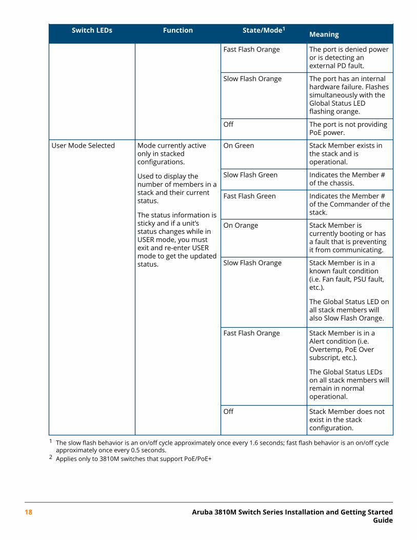
Switch LEDs Function State/Mode1Meaning
Fast Flash Orange The port is denied poweror is detecting anexternal PD fault.
Slow Flash Orange The port has an internalhardware failure. Flashessimultaneously with theGlobal Status LEDflashing orange.
Off The port is not providingPoE power.
User Mode Selected Mode currently activeonly in stackedconfigurations.
Used to display thenumber of members in astack and their currentstatus.
The status information issticky and if a unit’sstatus changes while inUSER mode, you mustexit and re-enter USERmode to get the updatedstatus.
On Green Stack Member exists inthe stack and isoperational.
Slow Flash Green Indicates the Member #of the chassis.
Fast Flash Green Indicates the Member #of the Commander of thestack.
On Orange Stack Member iscurrently booting or hasa fault that is preventingit from communicating.
Slow Flash Orange Stack Member is in aknown fault condition(i.e. Fan fault, PSU fault,etc.).
The Global Status LED onall stack members willalso Slow Flash Orange.
Fast Flash Orange Stack Member is in aAlert condition (i.e.Overtemp, PoE Oversubscript, etc.).
The Global Status LEDson all stack members willremain in normaloperational.
Off Stack Member does notexist in the stackconfiguration.
1 The slow flash behavior is an on/off cycle approximately once every 1.6 seconds; fast flash behavior is an on/off cycleapproximately once every 0.5 seconds.
2 Applies only to 3810M switches that support PoE/PoE+
18 Aruba 3810M Switch Series Installation and Getting StartedGuide
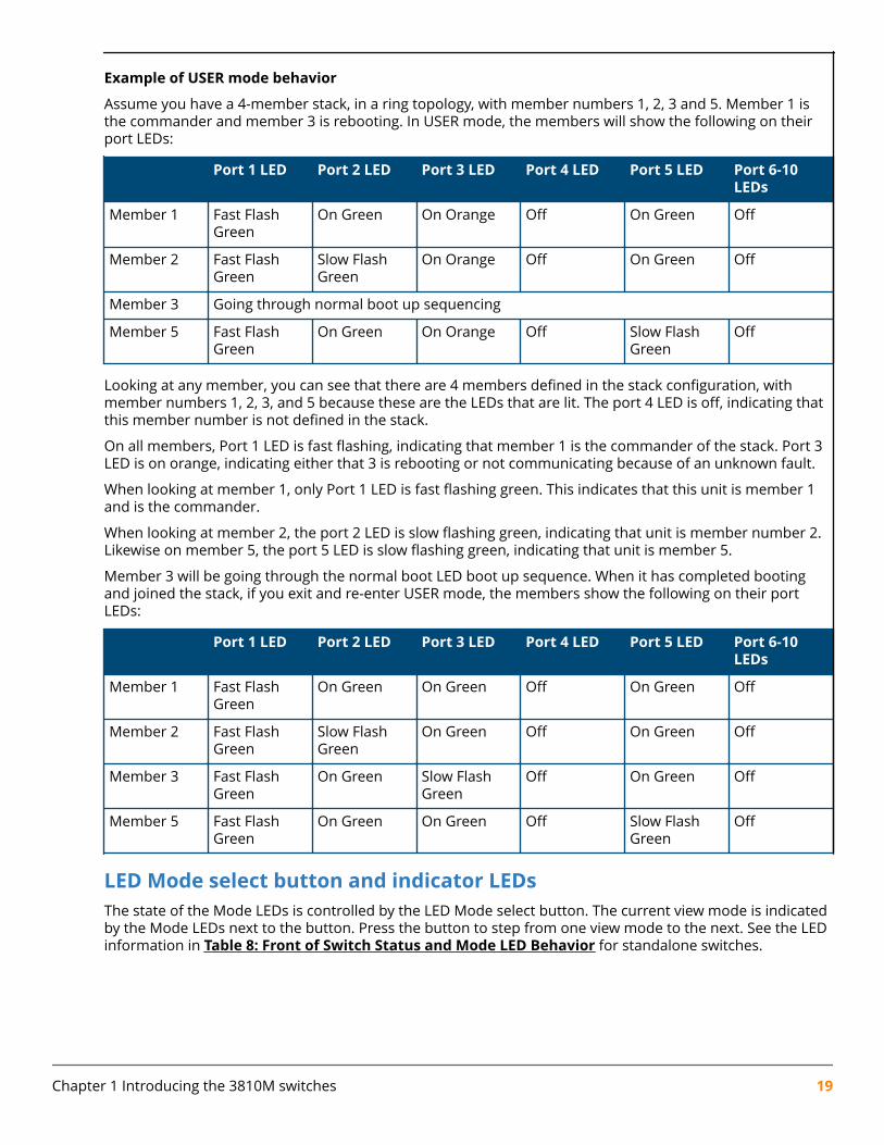
Example of USER mode behavior
Assume you have a 4-member stack, in a ring topology, with member numbers 1, 2, 3 and 5. Member 1 isthe commander and member 3 is rebooting. In USER mode, the members will show the following on theirport LEDs:
Port 1 LED Port 2 LED Port 3 LED Port 4 LED Port 5 LED Port 6-10LEDs
Member 1 Fast FlashGreen
On Green On Orange Off On Green Off
Member 2 Fast FlashGreen
Slow FlashGreen
On Orange Off On Green Off
Member 3 Going through normal boot up sequencing
Member 5 Fast FlashGreen
On Green On Orange Off Slow FlashGreen
Off
Looking at any member, you can see that there are 4 members defined in the stack configuration, withmember numbers 1, 2, 3, and 5 because these are the LEDs that are lit. The port 4 LED is off, indicating thatthis member number is not defined in the stack.
On all members, Port 1 LED is fast flashing, indicating that member 1 is the commander of the stack. Port 3LED is on orange, indicating either that 3 is rebooting or not communicating because of an unknown fault.
When looking at member 1, only Port 1 LED is fast flashing green. This indicates that this unit is member 1and is the commander.
When looking at member 2, the port 2 LED is slow flashing green, indicating that unit is member number 2.Likewise on member 5, the port 5 LED is slow flashing green, indicating that unit is member 5.
Member 3 will be going through the normal boot LED boot up sequence. When it has completed bootingand joined the stack, if you exit and re-enter USER mode, the members show the following on their portLEDs:
Port 1 LED Port 2 LED Port 3 LED Port 4 LED Port 5 LED Port 6-10LEDs
Member 1 Fast FlashGreen
On Green On Green Off On Green Off
Member 2 Fast FlashGreen
Slow FlashGreen
On Green Off On Green Off
Member 3 Fast FlashGreen
On Green Slow FlashGreen
Off On Green Off
Member 5 Fast FlashGreen
On Green On Green Off Slow FlashGreen
Off
LED Mode select button and indicator LEDsThe state of the Mode LEDs is controlled by the LED Mode select button. The current view mode is indicatedby the Mode LEDs next to the button. Press the button to step from one view mode to the next. See the LEDinformation in Table 8: Front of Switch Status and Mode LED Behavior for standalone switches.
Chapter 1 Introducing the 3810M switches 19
NOTE: Stacking Notes
• For 3810M switches that are in a stack, the Mode select button on every switch in the stackcontrols the LED mode for all the switches in the stack. Using the Mode select button on oneswitch in the stack changes the LED mode for the entire stack.
• If there is a combination of PoE/PoE+ switches and non-PoE switches in the stack, when anyof the Mode select buttons is pressed to put the stack into PoE mode, the non-PoE switchesindicate no PoE support by not illuminating any of the Mode indicator LEDs or any of theport LEDs.
• If any of the switches in the stack are configured with the Save Power LED feature, then thedefault LED Mode for the whole stack becomes the Save Power display (all LED Modeindicator LEDs are off), but only the stack members on which that feature is configureddisplay the other characteristics of that feature (all LEDs Off except for the Power LED).
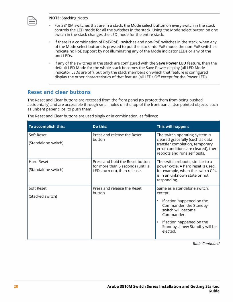
Reset and clear buttonsThe Reset and Clear buttons are recessed from the front panel (to protect them from being pushedaccidentally) and are accessible through small holes on the top of the front panel. Use pointed objects, suchas unbent paper clips, to push them.
The Reset and Clear buttons are used singly or in combination, as follows:
To accomplish this: Do this: This will happen:
Soft Reset
(Standalone switch)
Press and release the Resetbutton
The switch operating system iscleared gracefully (such as datatransfer completion, temporaryerror conditions are cleared), thenreboots and runs self tests.
Hard Reset
(Standalone switch)
Press and hold the Reset buttonfor more than 5 seconds (until allLEDs turn on), then release.
The switch reboots, similar to apower cycle. A hard reset is used,for example, when the switch CPUis in an unknown state or notresponding.
Soft Reset
(Stacked switch)
Press and release the Resetbutton
Same as a standalone switch,except:
• If action happened on theCommander, the Standbyswitch will becomeCommander.
• If action happened on theStandby, a new Standby will beelected.
Table Continued
20 Aruba 3810M Switch Series Installation and Getting StartedGuide
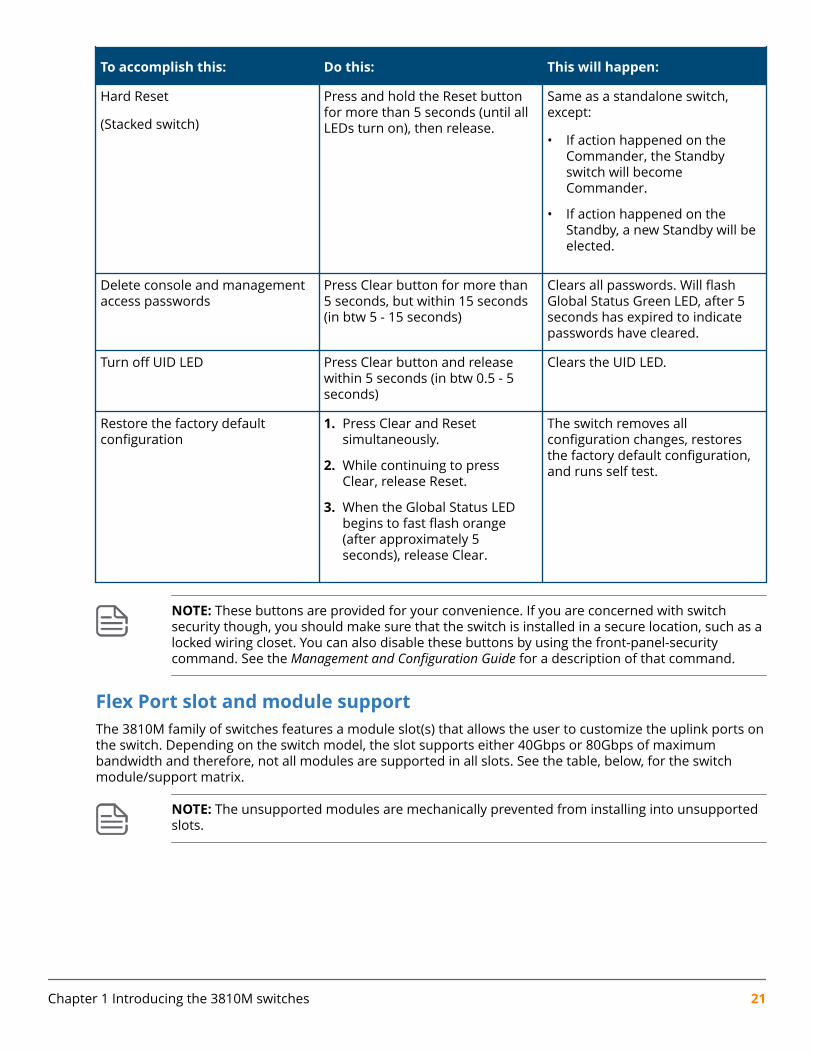
To accomplish this: Do this: This will happen:
Hard Reset
(Stacked switch)
Press and hold the Reset buttonfor more than 5 seconds (until allLEDs turn on), then release.
Same as a standalone switch,except:
• If action happened on theCommander, the Standbyswitch will becomeCommander.
• If action happened on theStandby, a new Standby will beelected.
Delete console and managementaccess passwords
Press Clear button for more than5 seconds, but within 15 seconds(in btw 5 - 15 seconds)
Clears all passwords. Will flashGlobal Status Green LED, after 5seconds has expired to indicatepasswords have cleared.
Turn off UID LED Press Clear button and releasewithin 5 seconds (in btw 0.5 - 5seconds)
Clears the UID LED.
Restore the factory defaultconfiguration
1. Press Clear and Resetsimultaneously.
2. While continuing to pressClear, release Reset.
3. When the Global Status LEDbegins to fast flash orange(after approximately 5seconds), release Clear.
The switch removes allconfiguration changes, restoresthe factory default configuration,and runs self test.
NOTE: These buttons are provided for your convenience. If you are concerned with switchsecurity though, you should make sure that the switch is installed in a secure location, such as alocked wiring closet. You can also disable these buttons by using the front-panel-securitycommand. See the Management and Configuration Guide for a description of that command.
Flex Port slot and module supportThe 3810M family of switches features a module slot(s) that allows the user to customize the uplink ports onthe switch. Depending on the switch model, the slot supports either 40Gbps or 80Gbps of maximumbandwidth and therefore, not all modules are supported in all slots. See the table, below, for the switchmodule/support matrix.
NOTE: The unsupported modules are mechanically prevented from installing into unsupportedslots.
Chapter 1 Introducing the 3810M switches 21
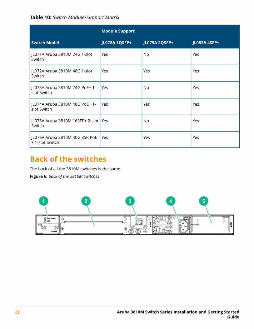
Table 10: Switch Module/Support Matrix
Module Support
Switch Model JL078A 1QSFP+ JL079A 2QSFP+ JL083A 4SFP+
JL071A Aruba 3810M 24G 1-slotSwitch
Yes No Yes
JL072A Aruba 3810M 48G 1-slotSwitch
Yes Yes Yes
JL073A Aruba 3810M 24G PoE+ 1-slot Switch
Yes No Yes
JL074A Aruba 3810M 48G PoE+ 1-slot Switch
Yes Yes Yes
JL075A Aruba 3810M 16SFP+ 2-slotSwitch
Yes No Yes
JL076A Aruba 3810M 40G 8SR PoE+ 1-slot Switch
Yes Yes Yes
Back of the switchesThe back of all the 3810M switches is the same.
Figure 6: Back of the 3810M Switches
22 Aruba 3810M Switch Series Installation and Getting StartedGuide
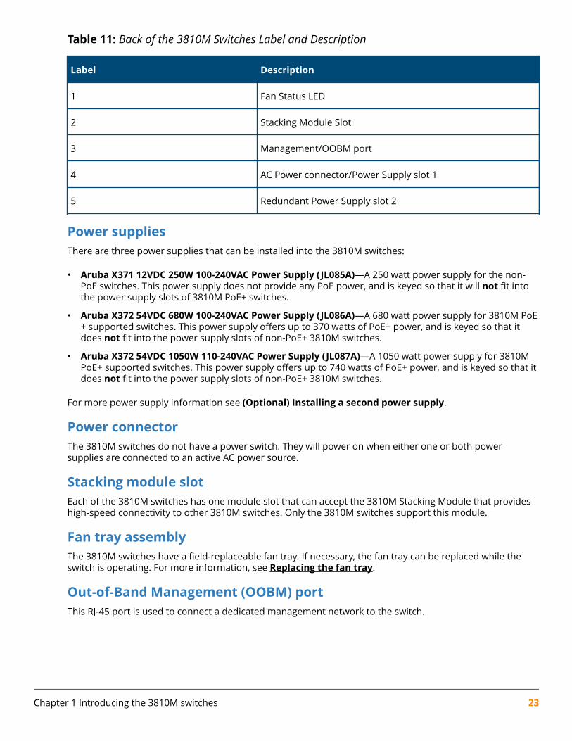
Table 11: Back of the 3810M Switches Label and Description
Label Description
1 Fan Status LED
2 Stacking Module Slot
3 Management/OOBM port
4 AC Power connector/Power Supply slot 1
5 Redundant Power Supply slot 2
Power suppliesThere are three power supplies that can be installed into the 3810M switches:
• Aruba X371 12VDC 250W 100-240VAC Power Supply (JL085A)—A 250 watt power supply for the non-PoE switches. This power supply does not provide any PoE power, and is keyed so that it will not fit intothe power supply slots of 3810M PoE+ switches.
• Aruba X372 54VDC 680W 100-240VAC Power Supply (JL086A)—A 680 watt power supply for 3810M PoE+ supported switches. This power supply offers up to 370 watts of PoE+ power, and is keyed so that itdoes not fit into the power supply slots of non-PoE+ 3810M switches.
• Aruba X372 54VDC 1050W 110-240VAC Power Supply (JL087A)—A 1050 watt power supply for 3810MPoE+ supported switches. This power supply offers up to 740 watts of PoE+ power, and is keyed so that itdoes not fit into the power supply slots of non-PoE+ 3810M switches.
For more power supply information see (Optional) Installing a second power supply.
Power connectorThe 3810M switches do not have a power switch. They will power on when either one or both powersupplies are connected to an active AC power source.
Stacking module slotEach of the 3810M switches has one module slot that can accept the 3810M Stacking Module that provideshigh-speed connectivity to other 3810M switches. Only the 3810M switches support this module.
Fan tray assemblyThe 3810M switches have a field-replaceable fan tray. If necessary, the fan tray can be replaced while theswitch is operating. For more information, see Replacing the fan tray.
Out-of-Band Management (OOBM) portThis RJ-45 port is used to connect a dedicated management network to the switch.
Chapter 1 Introducing the 3810M switches 23
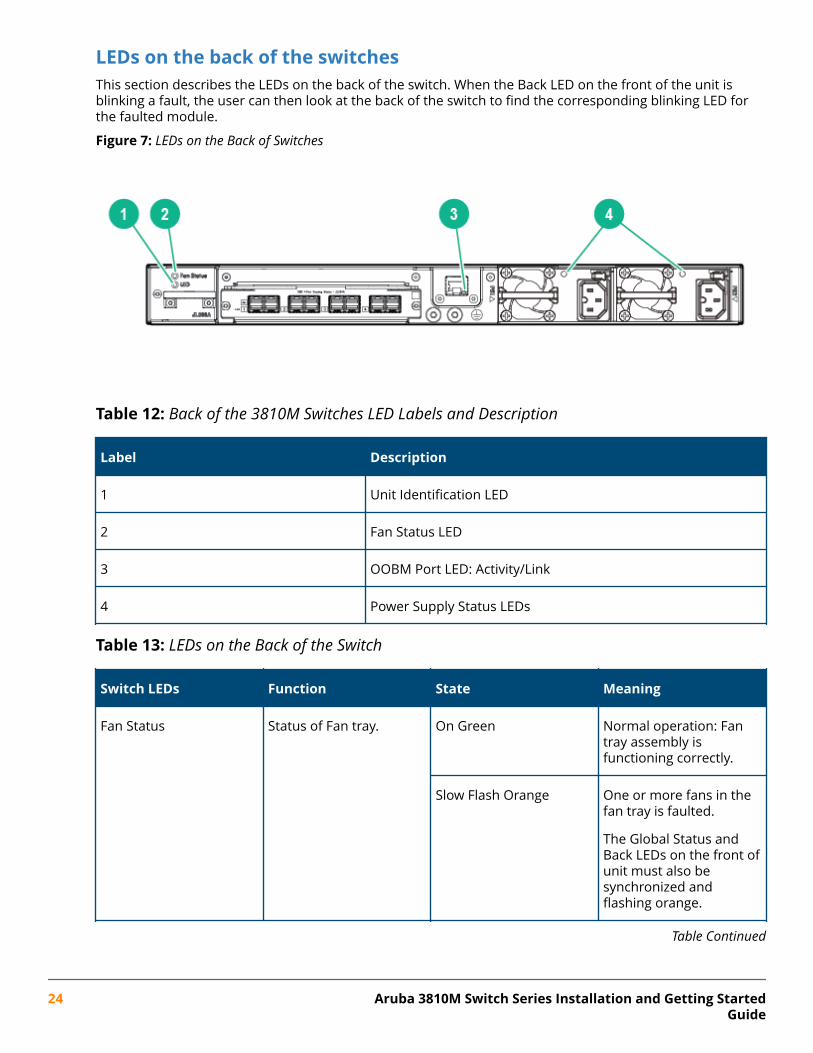
LEDs on the back of the switchesThis section describes the LEDs on the back of the switch. When the Back LED on the front of the unit isblinking a fault, the user can then look at the back of the switch to find the corresponding blinking LED forthe faulted module.
Figure 7: LEDs on the Back of Switches
Table 12: Back of the 3810M Switches LED Labels and Description
Label Description
1 Unit Identification LED
2 Fan Status LED
3 OOBM Port LED: Activity/Link
4 Power Supply Status LEDs
Table 13: LEDs on the Back of the Switch
Switch LEDs Function State Meaning
Fan Status Status of Fan tray. On Green Normal operation: Fantray assembly isfunctioning correctly.
Slow Flash Orange One or more fans in thefan tray is faulted.
The Global Status andBack LEDs on the front ofunit must also besynchronized andflashing orange.
Table Continued
24 Aruba 3810M Switch Series Installation and Getting StartedGuide
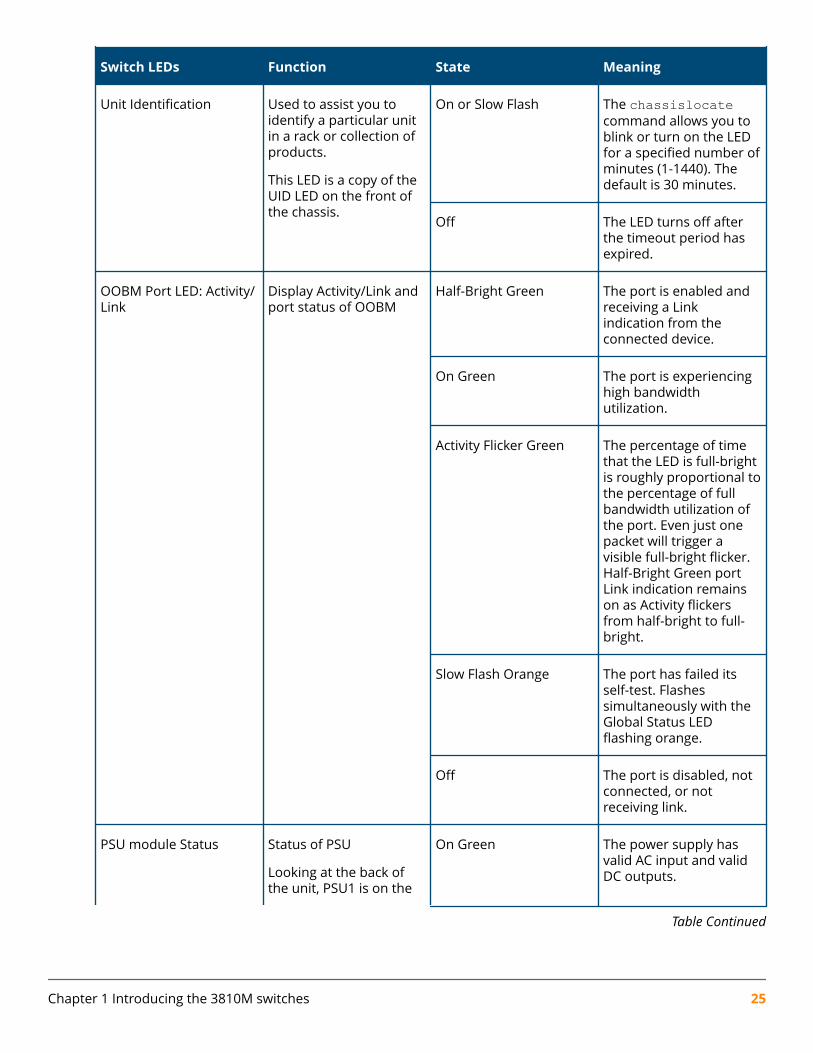
Switch LEDs Function State Meaning
Unit Identification Used to assist you toidentify a particular unitin a rack or collection ofproducts.
This LED is a copy of theUID LED on the front ofthe chassis.
On or Slow Flash The chassislocatecommand allows you toblink or turn on the LEDfor a specified number ofminutes (1-1440). Thedefault is 30 minutes.
Off The LED turns off afterthe timeout period hasexpired.
OOBM Port LED: Activity/Link
Display Activity/Link andport status of OOBM
Half-Bright Green The port is enabled andreceiving a Linkindication from theconnected device.
On Green The port is experiencinghigh bandwidthutilization.
Activity Flicker Green The percentage of timethat the LED is full-brightis roughly proportional tothe percentage of fullbandwidth utilization ofthe port. Even just onepacket will trigger avisible full-bright flicker.Half-Bright Green portLink indication remainson as Activity flickersfrom half-bright to full-bright.
Slow Flash Orange The port has failed itsself-test. Flashessimultaneously with theGlobal Status LEDflashing orange.
Off The port is disabled, notconnected, or notreceiving link.
PSU module Status Status of PSU
Looking at the back ofthe unit, PSU1 is on the
On Green The power supply hasvalid AC input and validDC outputs.
Table Continued
Chapter 1 Introducing the 3810M switches 25
Switch LEDs Function State Meaning
left and PSU2 is on theright.
Slow Flash Green Either the power supplyhas an internal fault, orswitch has a fault that iscausing power supply tocycle on/off.
Off The power supply has aninvalid AC input, orinvalid DC outputs.
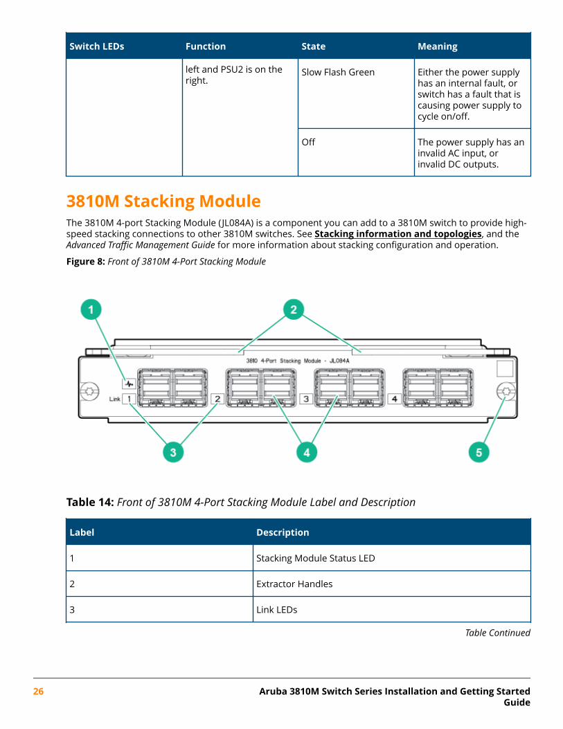
3810M Stacking ModuleThe 3810M 4-port Stacking Module (JL084A) is a component you can add to a 3810M switch to provide high-speed stacking connections to other 3810M switches. See Stacking information and topologies, and theAdvanced Traffic Management Guide for more information about stacking configuration and operation.
Figure 8: Front of 3810M 4-Port Stacking Module
Table 14: Front of 3810M 4-Port Stacking Module Label and Description
Label Description
1 Stacking Module Status LED
2 Extractor Handles
3 Link LEDs
Table Continued
26 Aruba 3810M Switch Series Installation and Getting StartedGuide
Label Description
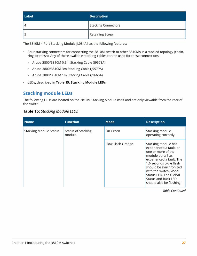
4 Stacking Connectors
5 Retaining Screw
The 3810M 4-Port Stacking Module JL084A has the following features:
• Four stacking connectors for connecting the 3810M switch to other 3810Ms in a stacked topology (chain,ring, or mesh). Any of these available stacking cables can be used for these connections:
◦ Aruba 3800/3810M 0.5m Stacking Cable (J9578A)
◦ Aruba 3800/3810M 3m Stacking Cable (J9579A)
◦ Aruba 3800/3810M 1m Stacking Cable (J9665A)
• LEDs, described in Table 15: Stacking Module LEDs.
Stacking module LEDsThe following LEDs are located on the 3810M Stacking Module itself and are only viewable from the rear ofthe switch.
Table 15: Stacking Module LEDs
Name Function Mode Description
Stacking Module Status Status of Stackingmodule
On Green Stacking moduleoperating correctly.
Slow Flash Orange Stacking module hasexperienced a fault, orone or more of themodule ports hasexperienced a fault. The1.6 seconds cycle flashshould be synchronizedwith the switch GlobalStatus LED. The GlobalStatus and Back LEDshould also be flashing.
Table Continued
Chapter 1 Introducing the 3810M switches 27
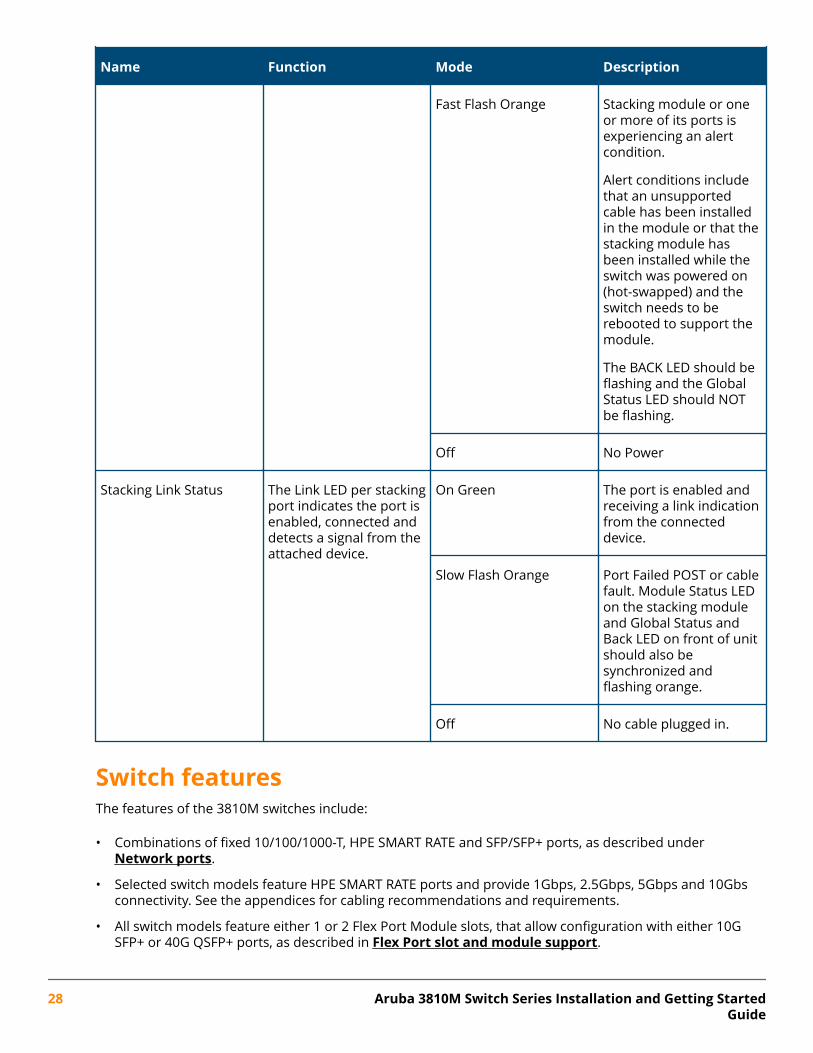
Name Function Mode Description
Fast Flash Orange Stacking module or oneor more of its ports isexperiencing an alertcondition.
Alert conditions includethat an unsupportedcable has been installedin the module or that thestacking module hasbeen installed while theswitch was powered on(hot-swapped) and theswitch needs to berebooted to support themodule.
The BACK LED should beflashing and the GlobalStatus LED should NOTbe flashing.
Off No Power
Stacking Link Status The Link LED per stackingport indicates the port isenabled, connected anddetects a signal from theattached device.
On Green The port is enabled andreceiving a link indicationfrom the connecteddevice.
Slow Flash Orange Port Failed POST or cablefault. Module Status LEDon the stacking moduleand Global Status andBack LED on front of unitshould also besynchronized andflashing orange.
Off No cable plugged in.
Switch featuresThe features of the 3810M switches include:
• Combinations of fixed 10/100/1000-T, HPE SMART RATE and SFP/SFP+ ports, as described under Network ports.
• Selected switch models feature HPE SMART RATE ports and provide 1Gbps, 2.5Gbps, 5Gbps and 10Gbsconnectivity. See the appendices for cabling recommendations and requirements.
• All switch models feature either 1 or 2 Flex Port Module slots, that allow configuration with either 10GSFP+ or 40G QSFP+ ports, as described in Flex Port slot and module support.
28 Aruba 3810M Switch Series Installation and Getting StartedGuide
• One module slot is provided in the back of the switches to support a stacking module to provideconnectivity to other 3810M switches with stacking modules. See Stacking information and topologies,and the Advanced Traffic Management Guide for more information about stacking.
• Power over Ethernet (PoE+) operation—Aruba 3810M 24G PoE+ 1-slot Switch (JL073A), Aruba 3810M 48GPoE+ 1-slot Switch (JL074A) and Aruba 3810M 40G 8 HPE Smart Rate PoE+ 1-slot Switch (JL076A) switchesare IEEE 802.3at standard compliant and provide up to 30W per port to power IP phones, wireless accesspoints, indoor web cameras, and more. For more information, see the HPE Power over Ethernet (PoE/PoE+)Planning and Implementation Guide.
The switches support 802.3af and 802.3at standard devices and some pre-standard PoE devices. For a listof these devices, see the FAQs (Frequently Asked Questions) for your switch model. PoE is enabled bydefault. (For instructions, see the Management and Configuration Guide for your switch at http://www.hpe.com/networking/resourcefinder.
• The option to have one or two internal power supplies.
A second power supply supports redundant system power and/or redundant/additional PoE power. Ifone of the internal power supplies fails, the second power supply immediately provides the powernecessary to keep the switch running, including PoE+ power on an allocated basis.
If maximum PoE+ power is used on the 48 port PoE+ switch, the second power supply is needed for PoE+power but there is no PoE power redundancy. However, system power is always maintained. On a powersupply failure, the system drops the PoE power on ports based on user priority, to maintain systempower. For more information on Power Supplies, see Power supplies.
• Plug-and-play networking—all ports are enabled by default—just connect the network cables to activenetwork devices and your switched network is operational.
• Auto MDI/MDI-X on all twisted-pair ports (10/100/1000 and 10GBase-T), meaning that all connectionscan be made using straight-through twisted-pair cables. Cross-over cables are not required, althoughthey will also work. The pin operation of each port is automatically adjusted for the attached device: if theswitch detects that another switch or hub is connected to the port, it configures the port as MDI; if theswitch detects that an end-node device is connected to the port, it configures the port as MDI-X. (See theappendices for recommended or required cabling.)
• Automatic learning of the network addresses in each switch’s 64000-address forwarding table, (withconfigurable address aging value).
• Automatically negotiated full-duplex operation for the 10/100/1000 RJ-45 ports when connected to otherauto-negotiating devices—the SFP/SFP+ ports always operate at full duplex.
• Easy management of the switch through several available interfaces:
◦ Console interface—A full featured, easy to use, VT-100 terminal interface for out-of-band or in-bandswitch management.
◦ Web browser interface—An easy to use built-in graphical interface that can be accessed fromcommon web browsers.
◦ IMC—An SNMP-based, graphical network management tool that you can use to manage your entirenetwork.
• Support for the Spanning Tree Protocol to eliminate network loops.
• Support for up to 4096 IEEE 802.1Q-compliant VLANs so you can divide the attached end nodes intological groupings that fit your business needs.
• Support for many advanced features to enhance network performance—for a description, see theManagement and Configuration Guide for your switch at http://www.hpe.com/networking/resourcefinder.
Chapter 1 Introducing the 3810M switches 29

• Ability to update the switch software. Software updates are routinely available from Hewlett PackardEnterprise.
• An auxiliary port (USB Type A connector) for processing a USB command file and updating switchsoftware.
• Low power operation:
◦ Ports on a switch or stack member may be set to operate at reduced power.
◦ Port status LEDs may be turned off.
◦ RJ-45 ports will operate at reduced power if the port is not connected (link partner is not detected).
30 Aruba 3810M Switch Series Installation and Getting StartedGuide
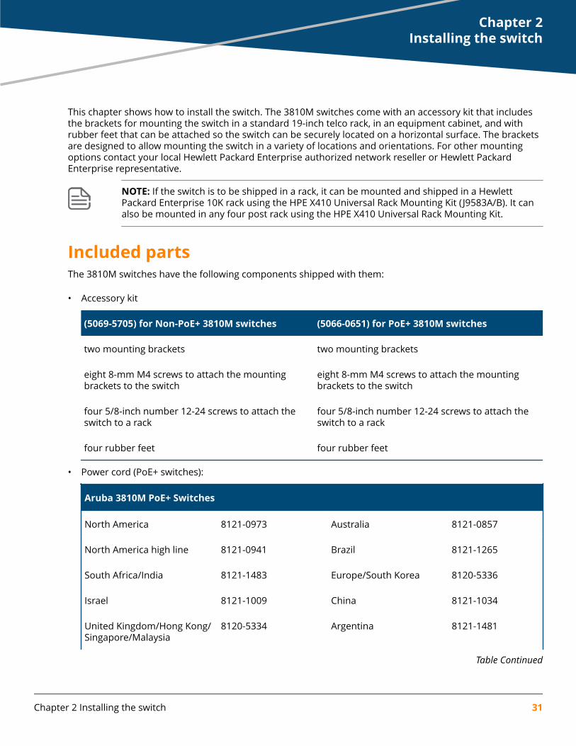
This chapter shows how to install the switch. The 3810M switches come with an accessory kit that includesthe brackets for mounting the switch in a standard 19-inch telco rack, in an equipment cabinet, and withrubber feet that can be attached so the switch can be securely located on a horizontal surface. The bracketsare designed to allow mounting the switch in a variety of locations and orientations. For other mountingoptions contact your local Hewlett Packard Enterprise authorized network reseller or Hewlett PackardEnterprise representative.
NOTE: If the switch is to be shipped in a rack, it can be mounted and shipped in a HewlettPackard Enterprise 10K rack using the HPE X410 Universal Rack Mounting Kit ( J9583A/B). It canalso be mounted in any four post rack using the HPE X410 Universal Rack Mounting Kit.
Included partsThe 3810M switches have the following components shipped with them:
• Accessory kit
(5069-5705) for Non-PoE+ 3810M switches (5066-0651) for PoE+ 3810M switches
two mounting brackets two mounting brackets
eight 8-mm M4 screws to attach the mountingbrackets to the switch
eight 8-mm M4 screws to attach the mountingbrackets to the switch
four 5/8-inch number 12-24 screws to attach theswitch to a rack
four 5/8-inch number 12-24 screws to attach theswitch to a rack
four rubber feet four rubber feet
• Power cord (PoE+ switches):
Aruba 3810M PoE+ Switches
North America 8121-0973 Australia 8121-0857
North America high line 8121-0941 Brazil 8121-1265
South Africa/India 8121-1483 Europe/South Korea 8120-5336
Israel 8121-1009 China 8121-1034
United Kingdom/Hong Kong/Singapore/Malaysia
8120-5334 Argentina 8121-1481
Table Continued
Chapter 2Installing the switch
Chapter 2 Installing the switch 31
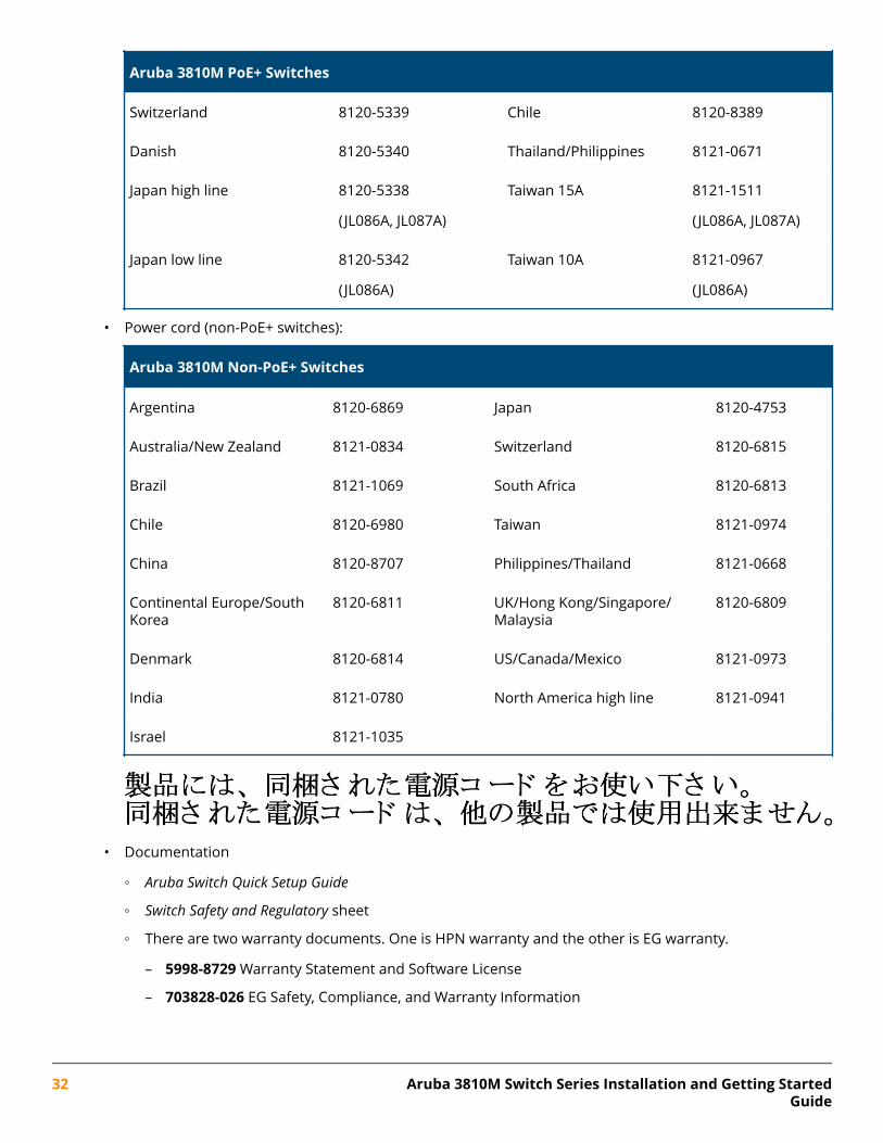
Aruba 3810M PoE+ Switches
Switzerland 8120-5339 Chile 8120-8389
Danish 8120-5340 Thailand/Philippines 8121-0671
Japan high line 8120-5338
(JL086A, JL087A)
Taiwan 15A 8121-1511
(JL086A, JL087A)
Japan low line 8120-5342
(JL086A)
Taiwan 10A 8121-0967
(JL086A)
• Power cord (non-PoE+ switches):
Aruba 3810M Non-PoE+ Switches
Argentina 8120-6869 Japan 8120-4753
Australia/New Zealand 8121-0834 Switzerland 8120-6815
Brazil 8121-1069 South Africa 8120-6813
Chile 8120-6980 Taiwan 8121-0974
China 8120-8707 Philippines/Thailand 8121-0668
Continental Europe/SouthKorea
8120-6811 UK/Hong Kong/Singapore/Malaysia
8120-6809
Denmark 8120-6814 US/Canada/Mexico 8121-0973
India 8121-0780 North America high line 8121-0941
Israel 8121-1035
• Documentation
◦ Aruba Switch Quick Setup Guide
◦ Switch Safety and Regulatory sheet
◦ There are two warranty documents. One is HPN warranty and the other is EG warranty.
– 5998-8729 Warranty Statement and Software License
– 703828-026 EG Safety, Compliance, and Warranty Information
32 Aruba 3810M Switch Series Installation and Getting StartedGuide
◦ General Safety and Regulatory booklet
◦ Aruba 3810M QSG/SRI
◦ Read Me First
Installation proceduresSummary
Procedure
1. Prepare the installation site. Ensure the physical environment is properly prepared, including havingthe correct network cabling ready to connect to the switch and having an appropriate location for theswitch. See Installation precautions for some installation precautions.
NOTE: For steps 2 and 3 below, if an 3810M switch is powered on for the first time withouta stacking module installed, stacking will be disabled and that will be saved in the switch'srunning configuration. For more information, see Stacking information and topologies
.
2. Verify the switch boots correctly. Plug the switch into a power source and observe that the LEDs onthe switch’s front panel indicate correct switch operation. When self test is complete, unplug the switch.
3. (Optional) Install the stacking module.
4. Installing the Flex Port module.
5. Mount the switch. The switch can be mounted in the 19-inch telco rack, in an equipment cabinet, or ona horizontal surface.
6. (Optional) Installing the stacking cables. If you have installed the module, you can now install up tofour stacking cables and connect them to other switches in the desired stacking topology.
7. (Optional) Installing transceivers. Depending on the switch model purchased and optional Flex Portmodule configuration, the switch can support SFP/SFP+ or QSFP+ transceivers. Depending on where theswitch is mounted, it may be easier to install the transceivers first. All transceiver types can be installedor removed while the switch is powered on.
8. Connect the switch to a power source. Once the switch is mounted, plug it into the nearby mainpower source.
9. (Optional) Installing a second power supply. You may wish to use a second power supply with theswitch to provide redundant power or added PoE+ power.
10. (Optional) Connect a management console. You may wish to modify the switch’s configuration, forexample, to configure an IP address so it can be managed using a web browser, from an SNMP networkmanagement station, or through a Telnet session. Configuration changes can be made easily by using aconsole cable to connect a PC to the switch’s console port.
11. Connect the network cables. Using the appropriate network cables, connect the network devices tothe switch ports.
At this point, the switch is fully installed. See the rest of this chapter if you need more detailed informationon any of these installation steps.
Chapter 2 Installing the switch 33
Installation precautionsFollow these precautions when installing the 3810M switches.
CAUTION:
• Ensure the power source circuits are properly grounded, then use the power cord suppliedwith the switch to connect it to the power source.
• If your installation requires a different power cord than the one supplied with the switch andpower supply, be sure the cord is adequately sized for the switch’s current requirements. Inaddition, be sure to use a power cord displaying the mark of the safety agency that definesthe regulations for power cords in your country. The mark is your assurance that the powercord can be used safely with the switch and power supply.
• When installing the switch, the AC outlet should be near the switch and should be easilyaccessible in case the switch must be powered off.
• Ensure the switch does not overload the power circuits, wiring, and over-current protection.To determine the possibility of overloading the supply circuits, add together the ampereratings of all devices installed on the same circuit as the switch and compare the total withthe rating limit for the circuit. The maximum ampere ratings are usually printed on thedevices near the AC power connectors.
• For safe operation, proper switch cooling, and reduction of electromagnetic emissions,ensure that a slot cover is installed on any unused module or power supply slot.
• Do not install the switch in an environment where the operating ambient temperature mightexceed 45°C (113°F).
• Ensure the air flow around the sides and back of the switch is not restricted.
WARNING:
• The rack or cabinet should be adequately secured to prevent it from becoming unstableand/or falling over.
• Devices installed in a rack or cabinet should be mounted as low as possible, with the heaviestdevices at the bottom and progressively lighter devices installed above.
Prepare the installation siteCabling Infrastructure - Ensure the cabling infrastructure meets the necessary network specifications. See Cabling and technology information in the appendices for more information.
Installation Location - Before installing the switch, plan its location and orientation relative to otherdevices and equipment:
34 Aruba 3810M Switch Series Installation and Getting StartedGuide
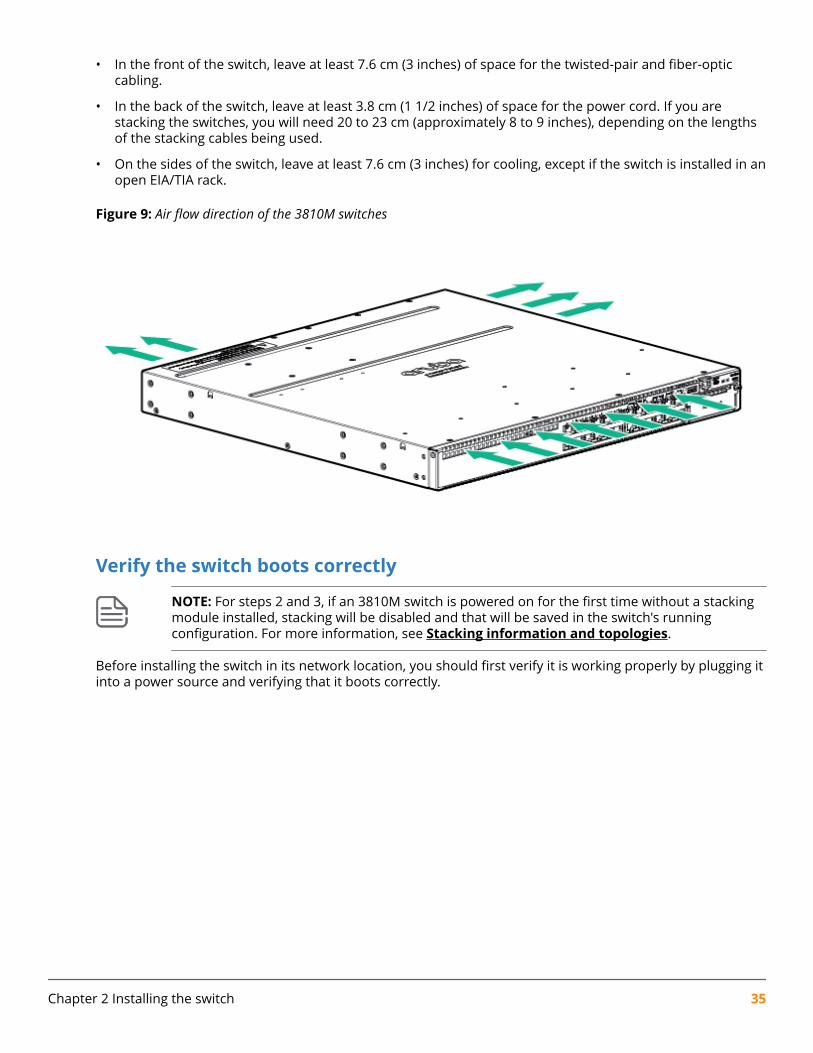
• In the front of the switch, leave at least 7.6 cm (3 inches) of space for the twisted-pair and fiber-opticcabling.
• In the back of the switch, leave at least 3.8 cm (1 1/2 inches) of space for the power cord. If you arestacking the switches, you will need 20 to 23 cm (approximately 8 to 9 inches), depending on the lengthsof the stacking cables being used.
• On the sides of the switch, leave at least 7.6 cm (3 inches) for cooling, except if the switch is installed in anopen EIA/TIA rack.
Figure 9: Air flow direction of the 3810M switches
Verify the switch boots correctly
NOTE: For steps 2 and 3, if an 3810M switch is powered on for the first time without a stackingmodule installed, stacking will be disabled and that will be saved in the switch's runningconfiguration. For more information, see Stacking information and topologies.
Before installing the switch in its network location, you should first verify it is working properly by plugging itinto a power source and verifying that it boots correctly.
Chapter 2 Installing the switch 35
Procedure
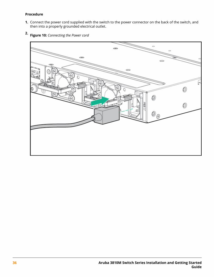
1. Connect the power cord supplied with the switch to the power connector on the back of the switch, andthen into a properly grounded electrical outlet.
2. Figure 10: Connecting the Power cord
36 Aruba 3810M Switch Series Installation and Getting StartedGuide
NOTE: The 3810M switches do not have a power switch. They are powered on when thepower cord is connected to the switch and to a power source. For safety, the power outletshould be located near the switch installation.
The switch automatically adjusts to any voltage between 100-240 (110–240 for JL087A powersupply) and either 50 or 60 Hz. No voltage range settings are required.
If your installation requires a different power cord than the one supplied with the switch, besure to use a power cord displaying the mark of the safety agency that defines theregulations for power cords in your country. The mark is your assurance that the power cordcan be used safely with the switch.
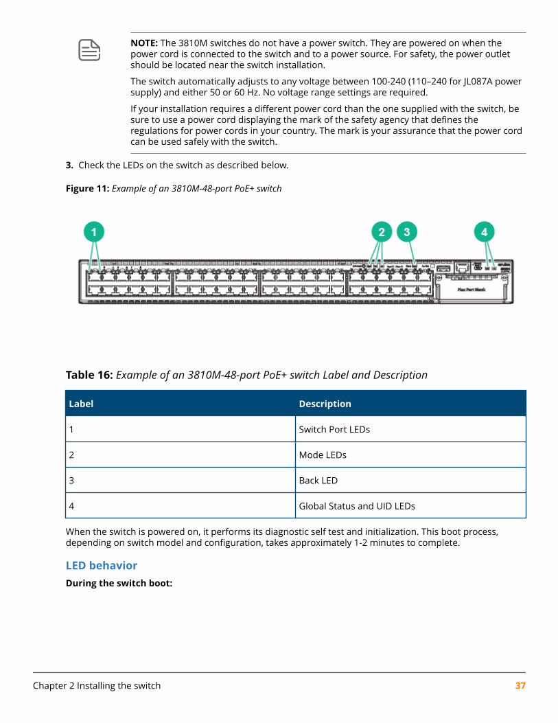
3. Check the LEDs on the switch as described below.
Figure 11: Example of an 3810M-48-port PoE+ switch
Table 16: Example of an 3810M-48-port PoE+ switch Label and Description
Label Description
1 Switch Port LEDs
2 Mode LEDs
3 Back LED
4 Global Status and UID LEDs
When the switch is powered on, it performs its diagnostic self test and initialization. This boot process,depending on switch model and configuration, takes approximately 1-2 minutes to complete.
LED behaviorDuring the switch boot:
Chapter 2 Installing the switch 37
• The Global Status, UID, and other Status and Mode LEDs will initially turn on green and bi-color LEDs willchange to orange, then back to green.
• The Global Status LED will start blinking green, indicating the switch is going thru its self-test and willcontinue to blink green until the switch if fully booted.
• The Port LEDs will come on green, turn orange, turn back to green, and then may blink on and off duringphases of the boot.
When the switch boots successfully, the LEDs display:
• Global Status and Back LEDs will be on solid green.
• Locator LED is off.
• Other status LEDs may be on or off depending on the switch configuration and the hardware installed.
• The port LEDs go into their normal operational mode:
◦ If the ports are connected to active network devices, the port LED may be on and behaves accordingto the LED mode selected. In the default LED mode (Activity/Link), the LED should show half-brightgreen to indicate Link and be flickering full-bright green to show network traffic.
◦ If the ports are not connected to active network devices, the port LED will stay off.
If the LED display is different than what is described above, especially if the Global Status LED continues toblink green for more than 120 seconds or blinks orange continually, then the switch boot has not completedcorrectly. Refer to Troubleshooting for diagnostic help.
(Optional) Install the stacking module
NOTE: Hot swapping the Stacking Module is not supported. If a module is installed with theswitch powered on, self-test of the module will not occur, the Back LED on the front of theswitch and the Module Status LED on the module will blink orange. The switch must be reset orpower cycled for the module to function. Only insert or remove a module during scheduleddowntime with the switch powered off.
Procedure
1. Remove the cover plate.
2. Insert the module aligning with the guides in the slot.
38 Aruba 3810M Switch Series Installation and Getting StartedGuide
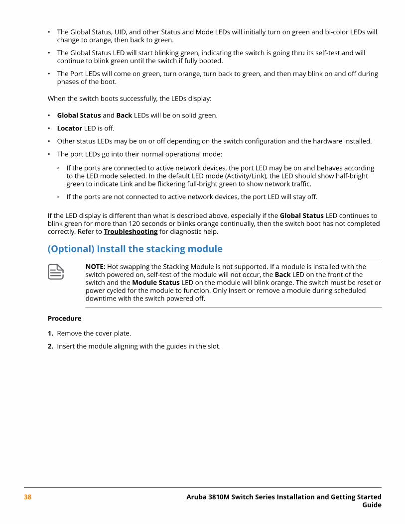
3. Once the contacts have engaged, use the extractor handles to seat the module completely.
4. Tighten the captive screws until they are snug – do not over-tighten them.
Figure 12: Installing the Module
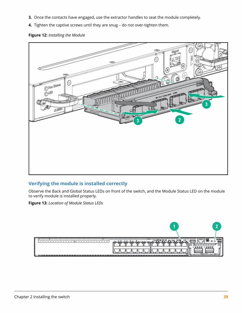
Verifying the module is installed correctlyObserve the Back and Global Status LEDs on front of the switch, and the Module Status LED on the moduleto verify module is installed properly.
Figure 13: Location of Module Status LEDs
Chapter 2 Installing the switch 39
Table 17: Location of Module Status LEDs Label and Description
Label Description
1 Back LED
2 Global Status LED
If the module is installed properly and the switch is powered on, the module undergoes a self test duringthe normal switch boot up process. You can use the LEDs to determine that the module is installed properlyand has passed the self test, as described in the following table.
Table 18: Stacking Module LED Behavior
LED Display for a Properly Installed Module
Global Status and Back LEDs onfront of the switch and ModuleStatus LED on the stackingmodule
After boot-up sequencing, LEDs are on steady green.
Link (for each stacking port on themodule)
If stacking cables are connected to the module and to a StackingModule on another powered on 3810M switch, the LED goes ON greento indicate the stacking port is enabled, connected, and detects asignal from the attached switch.
Installing the Flex Port module
Procedure
1. Unscrew the two retaining screws on the blank filler and remove it.
2. Remove the new Flex Port module from its packaging, be careful not to touch any of the circuitry on theboard.
3. Insert the Flex Port module fully into the slot as shown in the figure, below. The face plate of the modulewill be flush with the front face of the switch.
40 Aruba 3810M Switch Series Installation and Getting StartedGuide
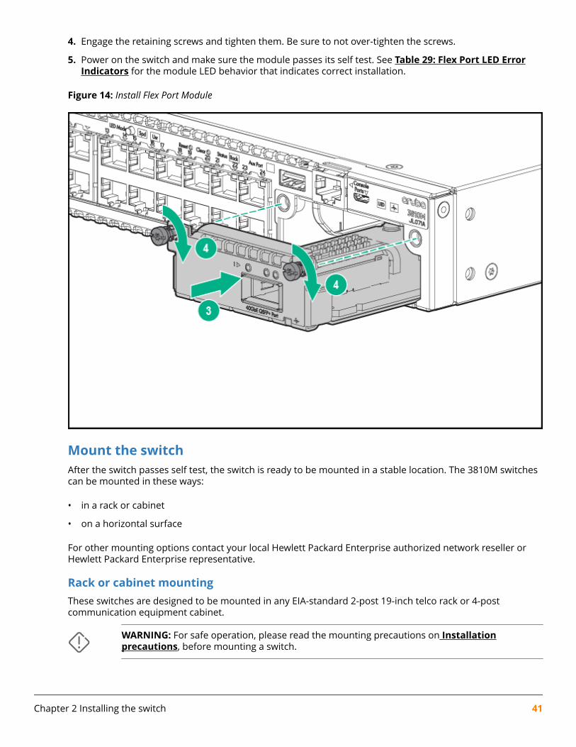
4. Engage the retaining screws and tighten them. Be sure to not over-tighten the screws.
5. Power on the switch and make sure the module passes its self test. See Table 29: Flex Port LED ErrorIndicators for the module LED behavior that indicates correct installation.
Figure 14: Install Flex Port Module
Mount the switchAfter the switch passes self test, the switch is ready to be mounted in a stable location. The 3810M switchescan be mounted in these ways:
• in a rack or cabinet
• on a horizontal surface
For other mounting options contact your local Hewlett Packard Enterprise authorized network reseller orHewlett Packard Enterprise representative.
Rack or cabinet mountingThese switches are designed to be mounted in any EIA-standard 2-post 19-inch telco rack or 4-postcommunication equipment cabinet.
WARNING: For safe operation, please read the mounting precautions on Installationprecautions, before mounting a switch.
Chapter 2 Installing the switch 41
NOTE: Equipment Cabinet Note
The 12-24 screws supplied with the switch are the correct threading for standard EIA/TIA open19-inch racks. If you are installing the switch in an equipment cabinet such as a server cabinet,use the clips and screws that came with the cabinet in place of the 12-24 screws that aresupplied with the switch.
Complete step 1, and plan which four holes you will be using in the cabinet and install all fourclips. Then proceed to step 2.
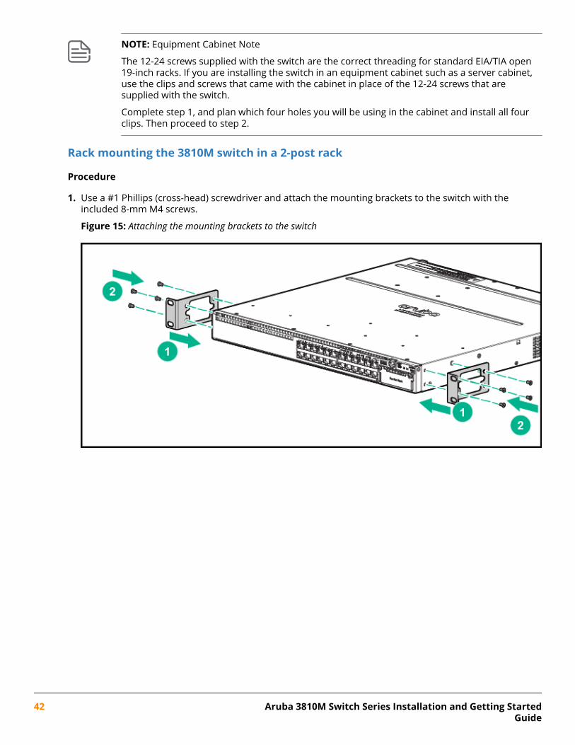
Rack mounting the 3810M switch in a 2-post rack
Procedure
1. Use a #1 Phillips (cross-head) screwdriver and attach the mounting brackets to the switch with theincluded 8-mm M4 screws.
Figure 15: Attaching the mounting brackets to the switch
42 Aruba 3810M Switch Series Installation and Getting StartedGuide
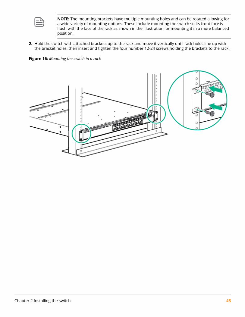
NOTE: The mounting brackets have multiple mounting holes and can be rotated allowing fora wide variety of mounting options. These include mounting the switch so its front face isflush with the face of the rack as shown in the illustration, or mounting it in a more balancedposition.
2. Hold the switch with attached brackets up to the rack and move it vertically until rack holes line up withthe bracket holes, then insert and tighten the four number 12-24 screws holding the brackets to the rack.
Figure 16: Mounting the switch in a rack
Chapter 2 Installing the switch 43
Rack mounting the 3810M switch in a 4-post rack
Procedure
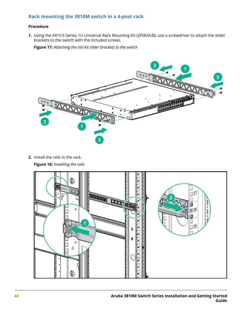
1. Using the X410 E-Series 1U Universal Rack Mounting Kit ( J9583A/B), use a screwdriver to attach the sliderbrackets to the switch with the included screws.
Figure 17: Attaching the rail kit slider brackets to the switch
2. Install the rails in the rack.
Figure 18: Installing the rails
44 Aruba 3810M Switch Series Installation and Getting StartedGuide
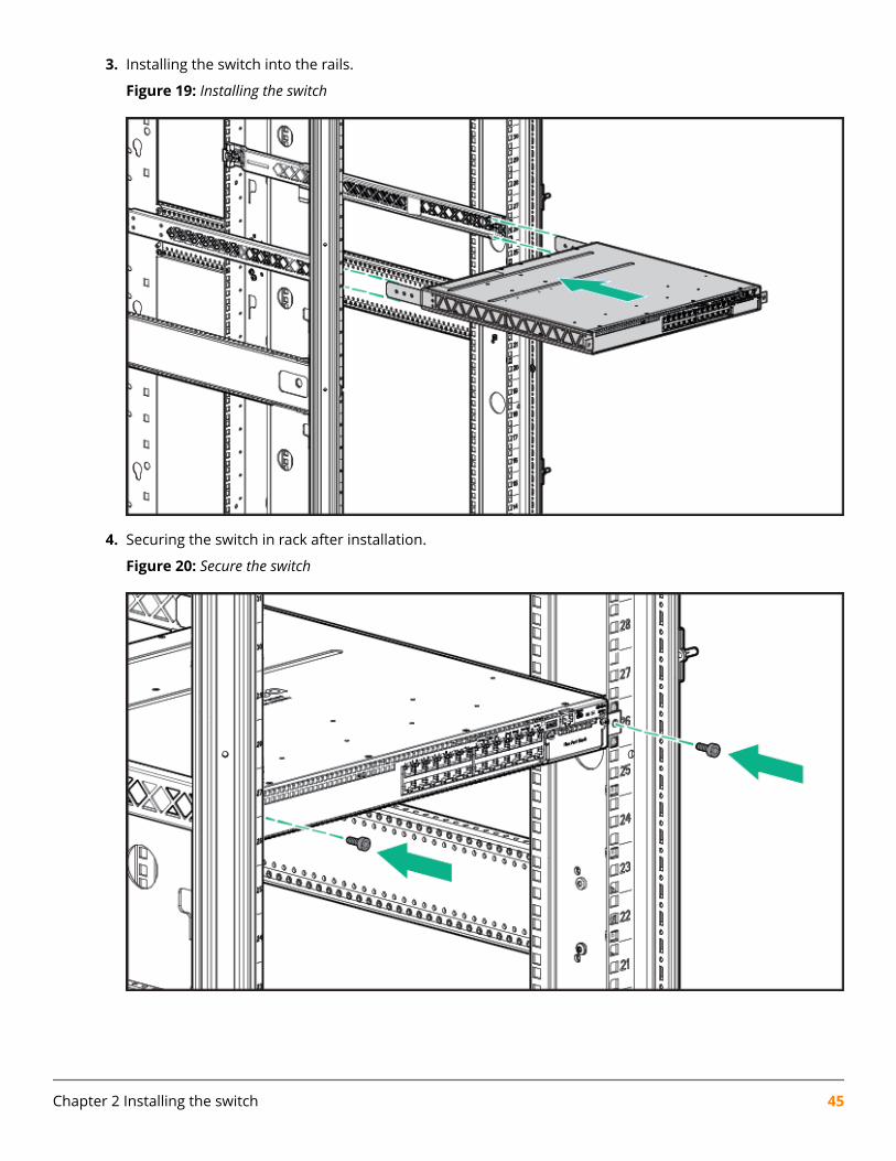
3. Installing the switch into the rails.
Figure 19: Installing the switch
4. Securing the switch in rack after installation.
Figure 20: Secure the switch
Chapter 2 Installing the switch 45
Horizontal surface mountingPlace the switch on a table or other horizontal surface. The switch comes with rubber feet in the accessorykit that can be used to help keep the switch from sliding on the surface.
Attach the rubber feet to the four corners on the bottom of the switch within the embossed angled lines.Use a sturdy surface in an uncluttered area. You may want to secure the networking cables and switchpower cord to the table leg or other part of the surface structure to help prevent tripping over the cords.
CAUTION: Make sure the air flow is not restricted around the sides and back of the switch.
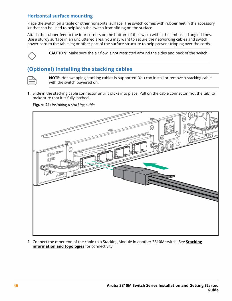
(Optional) Installing the stacking cablesNOTE: Hot swapping stacking cables is supported. You can install or remove a stacking cablewith the switch powered on.
1. Slide in the stacking cable connector until it clicks into place. Pull on the cable connector (not the tab) tomake sure that it is fully latched.
Figure 21: Installing a stacking cable
2. Connect the other end of the cable to a Stacking Module in another 3810M switch. See Stackinginformation and topologies for connectivity.
46 Aruba 3810M Switch Series Installation and Getting StartedGuide
NOTE: When switch power is on and one end of the stacking cable is inserted, the Link andModule Status LEDs on the module, and the Back LED on the front of the switch blinks orangeuntil the other end is connected to another switch stacking module. The LEDs turn solid greenwhen the cable is fully seated at both ends and a link is established.
To remove the stacking cable pull the tab on the stacking cable connector straight out.
(Optional) Installing transceiversYou can install or remove transceivers from the slots on the front of the switch without having to power offthe switch.
NOTE:
• The transceivers operate only at full duplex. Half duplex operation is not supported.
• Ensure the network cable is NOT connected when you install or remove a transceiver.
Installing the transceiversHold the transceiver by its sides and gently insert it into either of the slots on the switch until it clicks intoplace. When a transceiver is inserted the switch authenticates it. This can take 1-3 seconds, with the worstcase being 5 seconds. If the transceiver is removed before the authentication completes a self test failurewill be reported.
Chapter 2 Installing the switch 47
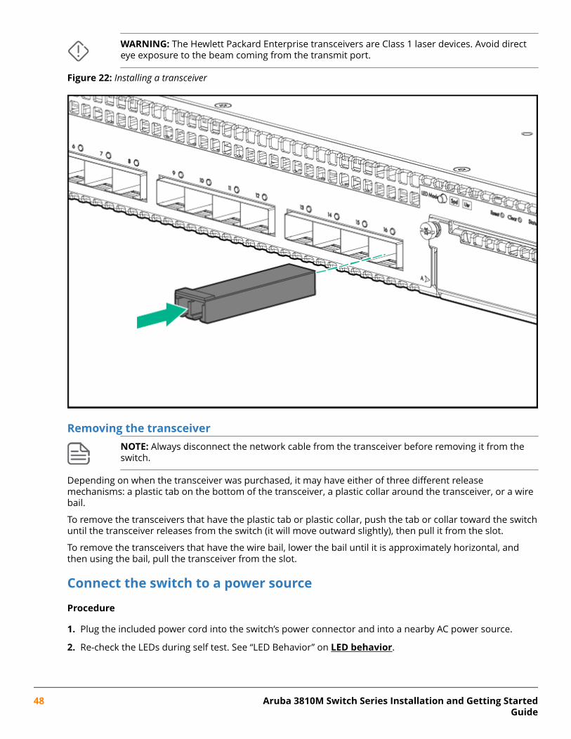
WARNING: The Hewlett Packard Enterprise transceivers are Class 1 laser devices. Avoid directeye exposure to the beam coming from the transmit port.
Figure 22: Installing a transceiver
Removing the transceiverNOTE: Always disconnect the network cable from the transceiver before removing it from theswitch.
Depending on when the transceiver was purchased, it may have either of three different releasemechanisms: a plastic tab on the bottom of the transceiver, a plastic collar around the transceiver, or a wirebail.
To remove the transceivers that have the plastic tab or plastic collar, push the tab or collar toward the switchuntil the transceiver releases from the switch (it will move outward slightly), then pull it from the slot.
To remove the transceivers that have the wire bail, lower the bail until it is approximately horizontal, andthen using the bail, pull the transceiver from the slot.
Connect the switch to a power source
Procedure
1. Plug the included power cord into the switch’s power connector and into a nearby AC power source.
2. Re-check the LEDs during self test. See “LED Behavior” on LED behavior.
48 Aruba 3810M Switch Series Installation and Getting StartedGuide
NOTE: Stacking Note
If you are stacking your 3810M switches, then the first switch you should power on is the switchthat you want to be the stack Commander. The second switch that you power on should be theone that you want to be the stack Standby. For the other switches in the stack, their member IDwill be determined by the order in which they are booted. For more information, see Stackinginformation and topologies
.
(Optional) Installing a second power supplyThere are three types of power supplies that can be installed:
• Aruba 250W Power Supply, ( JL085A, Aruba X371 250W 100-240VAC to 12VDC PS) is used with the non-PoE switches and is keyed so that it cannot be used in the PoE/PoE+ switches.
The 250W power supply provides power to operate the switch. Installing a second power supply canprovide power to the switch in case the initial power supply fails. If the power supplies are plugged intodifferent AC power sources, then redundant power can be supplied in case of loss of one of the AC powersources.
• Aruba 680W PoE+ Power Supply, ( JL086A, Aruba X372 680W 100-240VAC to 54VDC PS) used with thePoE/PoE+ switches and is keyed so that it cannot be used in the non-PoE switches.
• Aruba 1050W PoE+ Power Supply, ( JL087A, Aruba X372 1050W 100-240VAC to 54VDC PS) is used withthe PoE/PoE+ switches and is keyed so that it cannot be used in the non-PoE switches.
The 680W and 1050W power supplies provide two types of power to the PoE/PoE+ switches:
• The 680W and 1050W power supplies provide power to operate the switch. Installing a second powersupply can provide power to the switch in case the initial power supply fails. If the power supplies areplugged into different AC power sources, then redundant power can be supplied in case of loss of one ofthe AC power sources.
• Power-over-Ethernet (PoE/PoE+) power. The power supplies, supply PoE/PoE+ power to the switch.Should one of the power supplies fail, the second power supply will supply the needed PoE/PoE+ powerto continue PoE operation. For the 48 port switches, the second power supply’s PoE/PoE+ power isadditional power made available to the switch’s ports.
For further information regarding the power supply’s PoE/PoE+ capabilities, see the HPE Power overEthernet (PoE/PoE+) Planning and Implementation Guide, on the Hewlett Packard Enterprise.
PoE/PoE+ operationIt is important to understand the PoE/PoE+ power requirements of the switches because if the PoE/PoE+power is not planned and implemented correctly the end devices connected to the switch ports may notreceive power if an internal switch PoE/PoE+ power supply should fail.
For further information regarding the PoE/PoE+ capabilities, see the HPE Power over Ethernet (PoE/PoE+)Planning and Implementation Guide.
(Optional) Connect a management consoleThe switch has a full-featured, easy to use console interface for performing switch management tasksincluding:
Chapter 2 Installing the switch 49
• Monitor switch and port status and observe network activity statistics.
• Modify the switch’s configuration to optimize switch performance, enhance network traffic control, andimprove network security.
• Read the event log and access diagnostic tools to help in troubleshooting.
• Download new software to the switch.
• Add passwords to control access to the switch from the console, web browser interface, and networkmanagement stations.
After you install and power up the Switch, you must use the console port connection to minimally configurethe switch with an IP address and subnet mask before you can use a networked (in-band or out-of-band)connection to manage the switch. The minimal switch configuration is described in “Minimal ConfigurationThrough the Out-of-Band Console Connection” on Minimal configuration through the console portconnection.
To connect a console to the switch, use a console cable and connect a PC or VT-100 terminal to the Consoleserial port. The PC or terminal then functions as a management console connected directly to the switch.
You can use the Console port only for out-of-band management; it cannot be used for a Telnet connection.
Configuring the management consoleTo set up a console to manage the switch through the console port connection:
1. Configure the PC terminal emulator as a DEC VT-100 (ANSI) terminal or use a VT-100 terminal.
2. Configure the terminal with the following settings:
• A baud rate from 1200 to 115200 (the switch senses the speed)
• 8 data bits, 1 stop bit, no parity, and flow control set to Xon/Xoff
• For the Windows Terminal program, disable (uncheck) the “Use Function, Arrow, and Ctrl Keys forWindows” option.
If you use a management console with different configuration settings, be sure to reconfigure the settingson both the terminal and the switch in the following order so that both configurations are compatible:
1. Reconfigure the switch and save the new settings.
2. Reconfigure the terminal and save the new settings.
3. Reboot the switch and re-establish the console session.
Setting up a console connectionTo access the Switch through a Console port (out-of-band) connection, connect an RJ-45 or micro-USBconsole cable.
50 Aruba 3810M Switch Series Installation and Getting StartedGuide
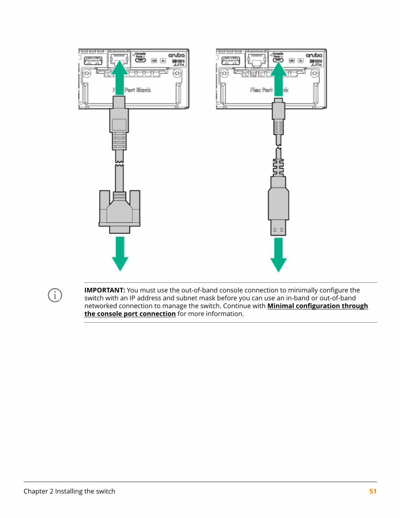
IMPORTANT: You must use the out-of-band console connection to minimally configure theswitch with an IP address and subnet mask before you can use an in-band or out-of-bandnetworked connection to manage the switch. Continue with Minimal configuration throughthe console port connection for more information.
Chapter 2 Installing the switch 51
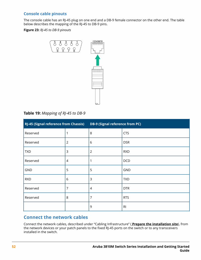
Console cable pinoutsThe console cable has an RJ-45 plug on one end and a DB-9 female connector on the other end. The tablebelow describes the mapping of the RJ-45 to DB-9 pins.
Figure 23: RJ-45 to DB-9 pinouts
Table 19: Mapping of RJ-45 to DB-9
RJ-45 (Signal reference from Chassis) DB-9 (Signal reference from PC)
Reserved 1 8 CTS
Reserved 2 6 DSR
TXD 3 2 RXD
Reserved 4 1 DCD
GND 5 5 GND
RXD 6 3 TXD
Reserved 7 4 DTR
Reserved 8 7 RTS
9 RI
Connect the network cablesConnect the network cables, described under “Cabling Infrastructure” ( Prepare the installation site), fromthe network devices or your patch panels to the fixed RJ-45 ports on the switch or to any transceiversinstalled in the switch.
52 Aruba 3810M Switch Series Installation and Getting StartedGuide
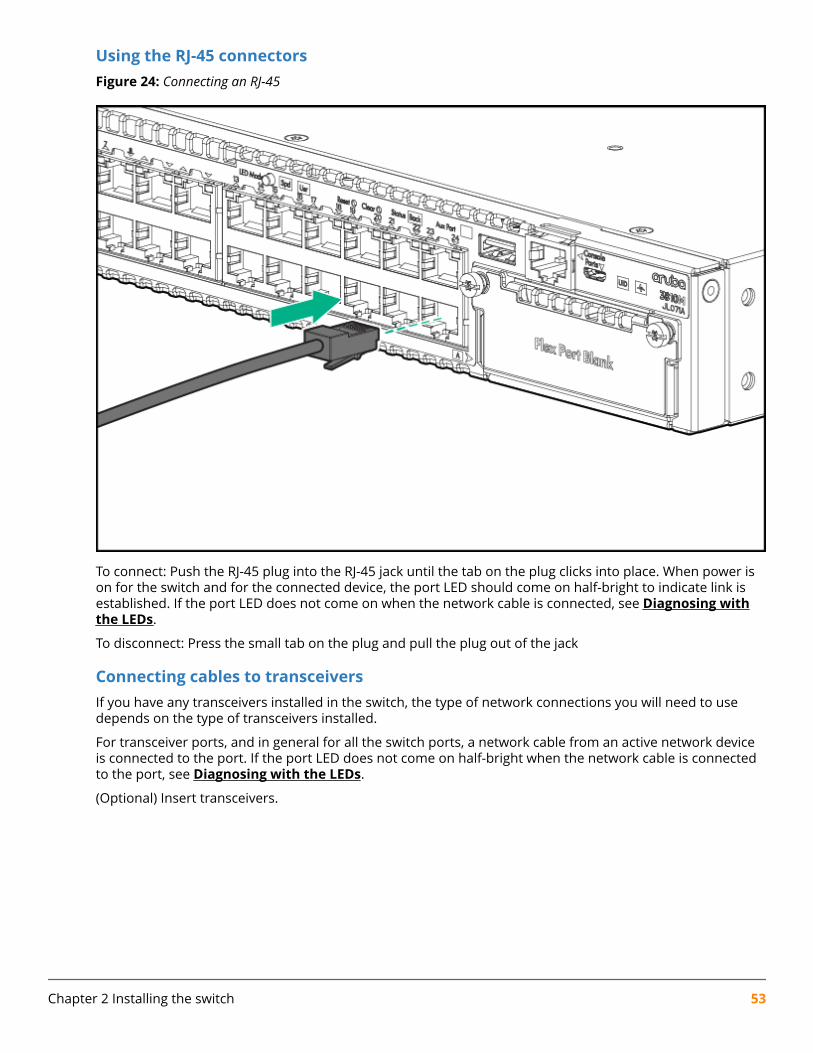
Using the RJ-45 connectorsFigure 24: Connecting an RJ-45
To connect: Push the RJ-45 plug into the RJ-45 jack until the tab on the plug clicks into place. When power ison for the switch and for the connected device, the port LED should come on half-bright to indicate link isestablished. If the port LED does not come on when the network cable is connected, see Diagnosing withthe LEDs.
To disconnect: Press the small tab on the plug and pull the plug out of the jack
Connecting cables to transceiversIf you have any transceivers installed in the switch, the type of network connections you will need to usedepends on the type of transceivers installed.
For transceiver ports, and in general for all the switch ports, a network cable from an active network deviceis connected to the port. If the port LED does not come on half-bright when the network cable is connectedto the port, see Diagnosing with the LEDs.
(Optional) Insert transceivers.
Chapter 2 Installing the switch 53
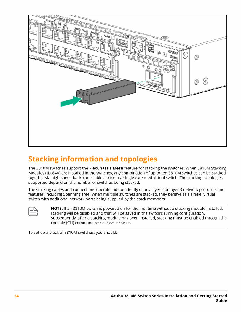
Stacking information and topologiesThe 3810M switches support the FlexChassis Mesh feature for stacking the switches. When 3810M StackingModules (JL084A) are installed in the switches, any combination of up to ten 3810M switches can be stackedtogether via high-speed backplane cables to form a single extended virtual switch. The stacking topologiessupported depend on the number of switches being stacked.
The stacking cables and connections operate independently of any layer 2 or layer 3 network protocols andfeatures, including Spanning Tree. When multiple switches are stacked, they behave as a single, virtualswitch with additional network ports being supplied by the stack members.
NOTE: If an 3810M switch is powered on for the first time without a stacking module installed,stacking will be disabled and that will be saved in the switch's running configuration.Subsequently, after a stacking module has been installed, stacking must be enabled through theconsole (CLI) command stacking enable.
To set up a stack of 3810M switches, you should:
54 Aruba 3810M Switch Series Installation and Getting StartedGuide
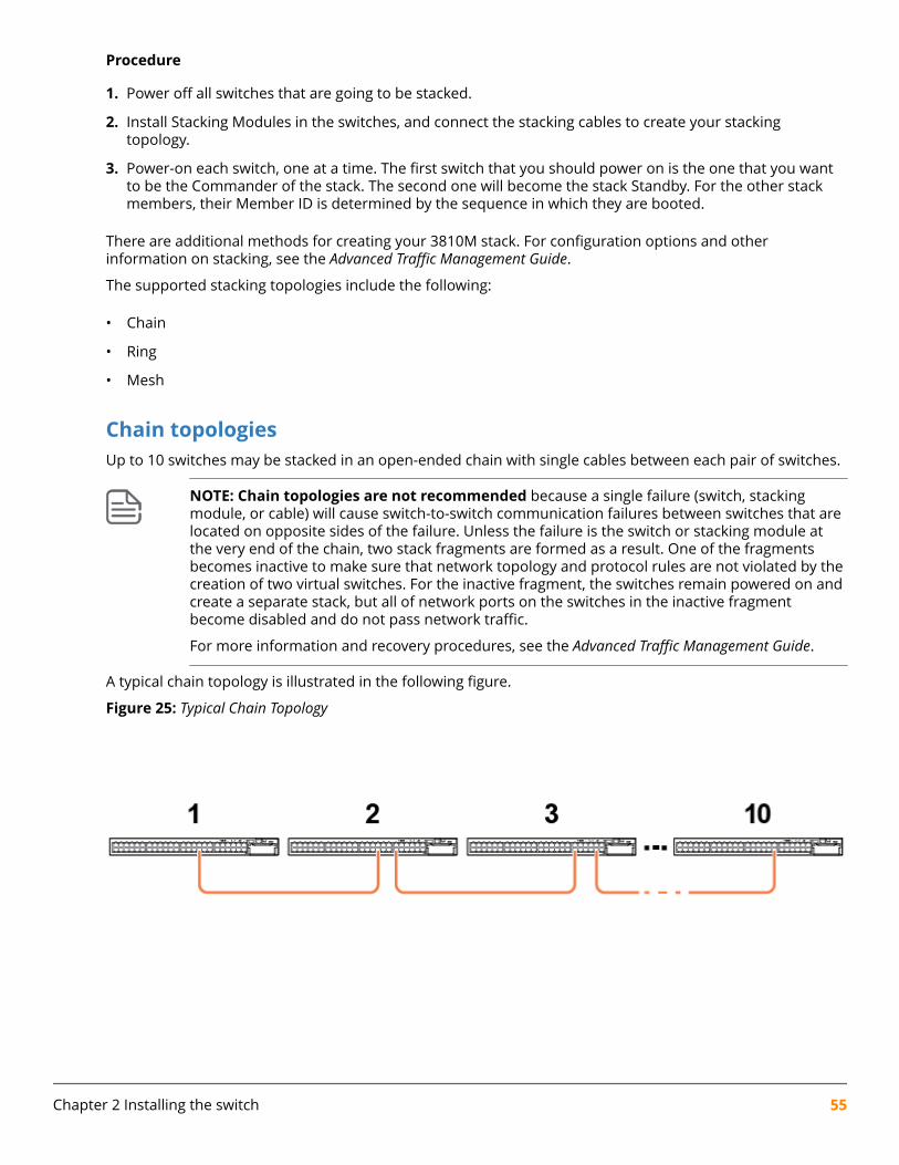
Procedure
1. Power off all switches that are going to be stacked.
2. Install Stacking Modules in the switches, and connect the stacking cables to create your stackingtopology.
3. Power-on each switch, one at a time. The first switch that you should power on is the one that you wantto be the Commander of the stack. The second one will become the stack Standby. For the other stackmembers, their Member ID is determined by the sequence in which they are booted.
There are additional methods for creating your 3810M stack. For configuration options and otherinformation on stacking, see the Advanced Traffic Management Guide.
The supported stacking topologies include the following:
• Chain
• Ring
• Mesh
Chain topologiesUp to 10 switches may be stacked in an open-ended chain with single cables between each pair of switches.
NOTE: Chain topologies are not recommended because a single failure (switch, stackingmodule, or cable) will cause switch-to-switch communication failures between switches that arelocated on opposite sides of the failure. Unless the failure is the switch or stacking module atthe very end of the chain, two stack fragments are formed as a result. One of the fragmentsbecomes inactive to make sure that network topology and protocol rules are not violated by thecreation of two virtual switches. For the inactive fragment, the switches remain powered on andcreate a separate stack, but all of network ports on the switches in the inactive fragmentbecome disabled and do not pass network traffic.
For more information and recovery procedures, see the Advanced Traffic Management Guide.
A typical chain topology is illustrated in the following figure.
Figure 25: Typical Chain Topology
Chapter 2 Installing the switch 55
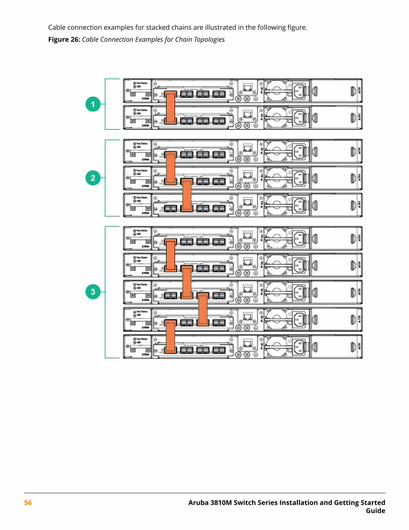
Cable connection examples for stacked chains are illustrated in the following figure.
Figure 26: Cable Connection Examples for Chain Topologies
56 Aruba 3810M Switch Series Installation and Getting StartedGuide
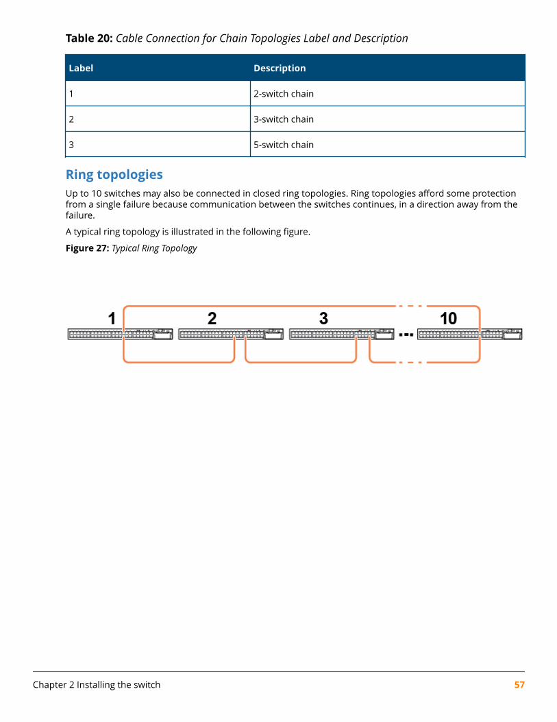
Table 20: Cable Connection for Chain Topologies Label and Description
Label Description
1 2-switch chain
2 3-switch chain
3 5-switch chain
Ring topologiesUp to 10 switches may also be connected in closed ring topologies. Ring topologies afford some protectionfrom a single failure because communication between the switches continues, in a direction away from thefailure.
A typical ring topology is illustrated in the following figure.
Figure 27: Typical Ring Topology
Chapter 2 Installing the switch 57
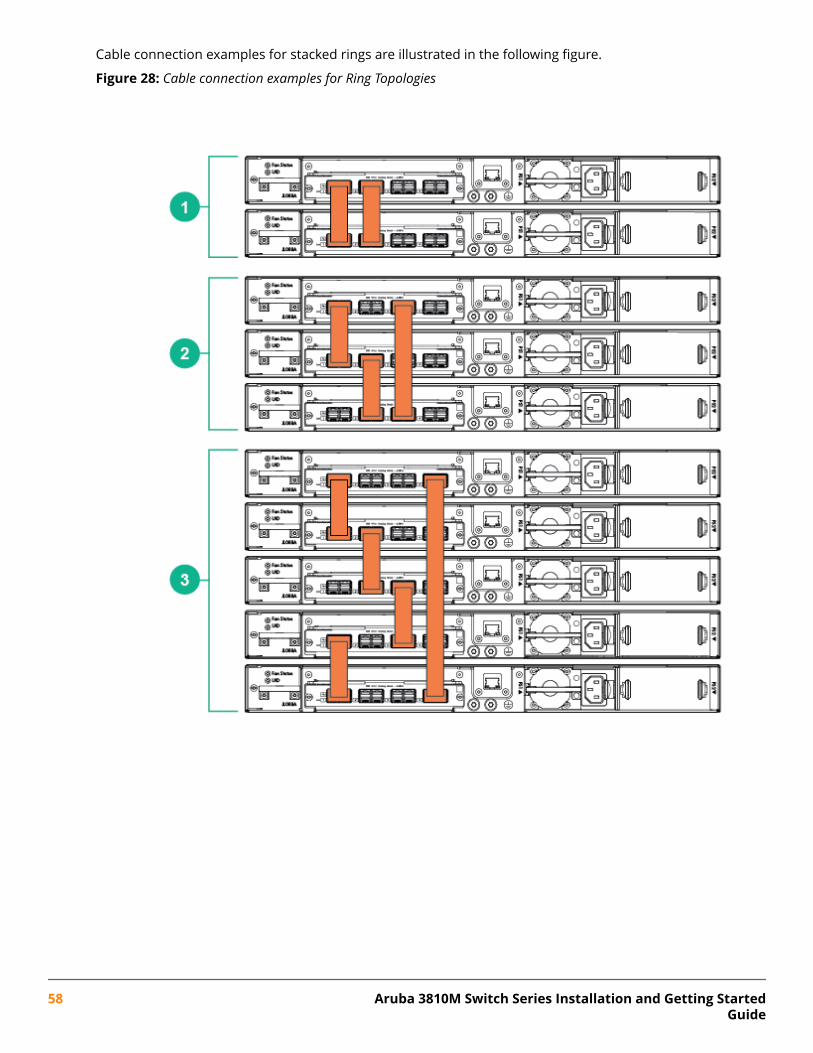
Cable connection examples for stacked rings are illustrated in the following figure.
Figure 28: Cable connection examples for Ring Topologies
58 Aruba 3810M Switch Series Installation and Getting StartedGuide
Table 21: Cable Connection for Ring Topologies Label and Description
Label Description
1 2-switch ring
2 3-switch ring
3 5-switch ring
Mesh topologiesTwo to five switches may be stacked using mesh topologies.
In mesh topologies, every switch in the stack is connected to every other switch in the stack. Hence, withfour stacking ports on the Stacking Module, the maximum number of switches that can be meshed togetheris limited to five.
Mesh topologies provide the most protection from stacking failures because communications can bererouted through multiple paths.
Chapter 2 Installing the switch 59
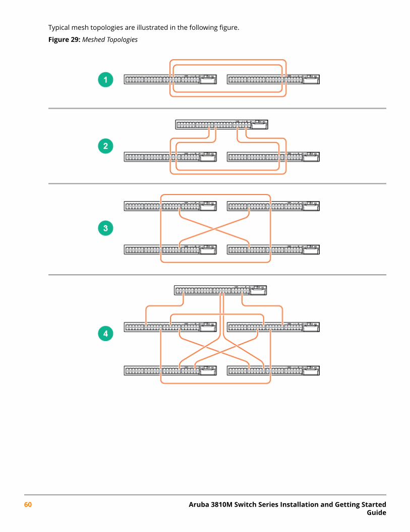
Typical mesh topologies are illustrated in the following figure.
Figure 29: Meshed Topologies
60 Aruba 3810M Switch Series Installation and Getting StartedGuide
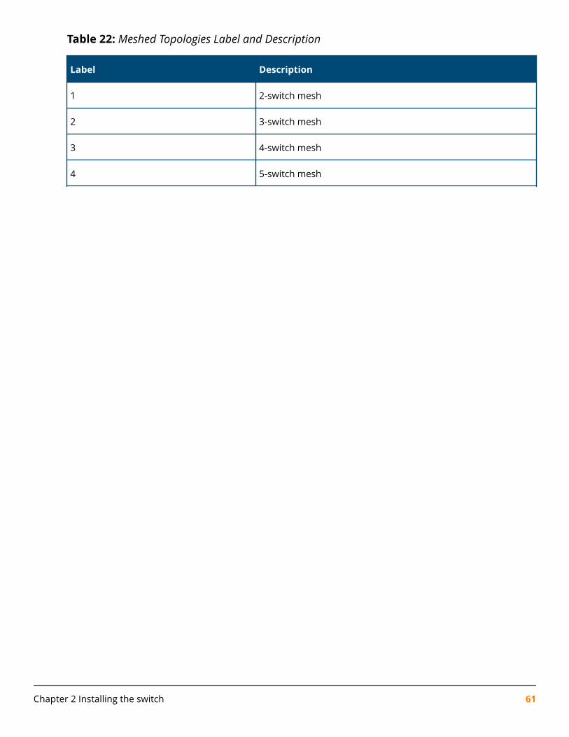
Table 22: Meshed Topologies Label and Description
Label Description
1 2-switch mesh
2 3-switch mesh
3 4-switch mesh
4 5-switch mesh
Chapter 2 Installing the switch 61
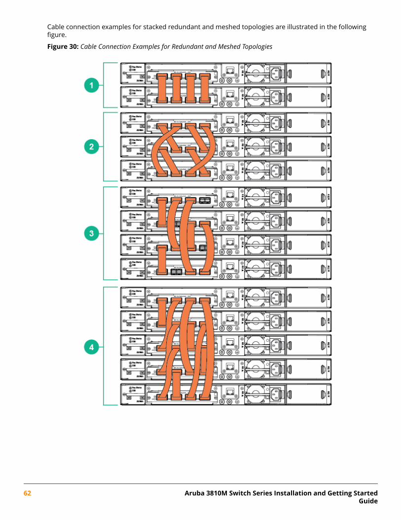
Cable connection examples for stacked redundant and meshed topologies are illustrated in the followingfigure.
Figure 30: Cable Connection Examples for Redundant and Meshed Topologies
62 Aruba 3810M Switch Series Installation and Getting StartedGuide
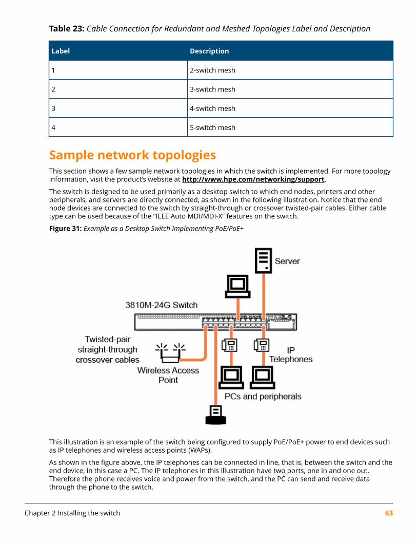
Table 23: Cable Connection for Redundant and Meshed Topologies Label and Description
Label Description
1 2-switch mesh
2 3-switch mesh
3 4-switch mesh
4 5-switch mesh
Sample network topologiesThis section shows a few sample network topologies in which the switch is implemented. For more topologyinformation, visit the product’s website at http://www.hpe.com/networking/support.
The switch is designed to be used primarily as a desktop switch to which end nodes, printers and otherperipherals, and servers are directly connected, as shown in the following illustration. Notice that the endnode devices are connected to the switch by straight-through or crossover twisted-pair cables. Either cabletype can be used because of the “IEEE Auto MDI/MDI-X” features on the switch.
Figure 31: Example as a Desktop Switch Implementing PoE/PoE+
This illustration is an example of the switch being configured to supply PoE/PoE+ power to end devices suchas IP telephones and wireless access points (WAPs).
As shown in the figure above, the IP telephones can be connected in line, that is, between the switch and theend device, in this case a PC. The IP telephones in this illustration have two ports, one in and one out.Therefore the phone receives voice and power from the switch, and the PC can send and receive datathrough the phone to the switch.
Chapter 2 Installing the switch 63
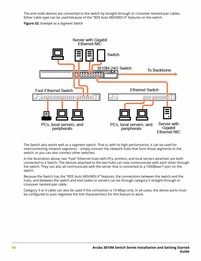
The end node devices are connected to the switch by straight-through or crossover twisted-pair cables.Either cable type can be used because of the “IEEE Auto MDI/MDI-X” features on the switch.
Figure 32: Example as a Segment Switch
The Switch also works well as a segment switch. That is, with its high performance, it can be used forinterconnecting network segments – simply connect the network hubs that form those segments to theswitch, or you can also connect other switches.
In the illustration above, two “Fast” Ethernet hubs with PCs, printers, and local servers attached, are bothconnected to a Switch. The devices attached to the two hubs can now communicate with each other throughthe switch. They can also all communicate with the server that is connected to a 1000Base-T port on theswitch.
Because the Switch has the “IEEE Auto MDI/MDI-X” features, the connections between the switch and thehubs, and between the switch and end nodes or servers can be through category 5 straight-through orcrossover twisted-pair cable.
Category 3 or 4 cable can also be used if the connection is 10 Mbps only. In all cases, the device ports mustbe configured to auto negotiate the link characteristics for this feature to work.
64 Aruba 3810M Switch Series Installation and Getting StartedGuide
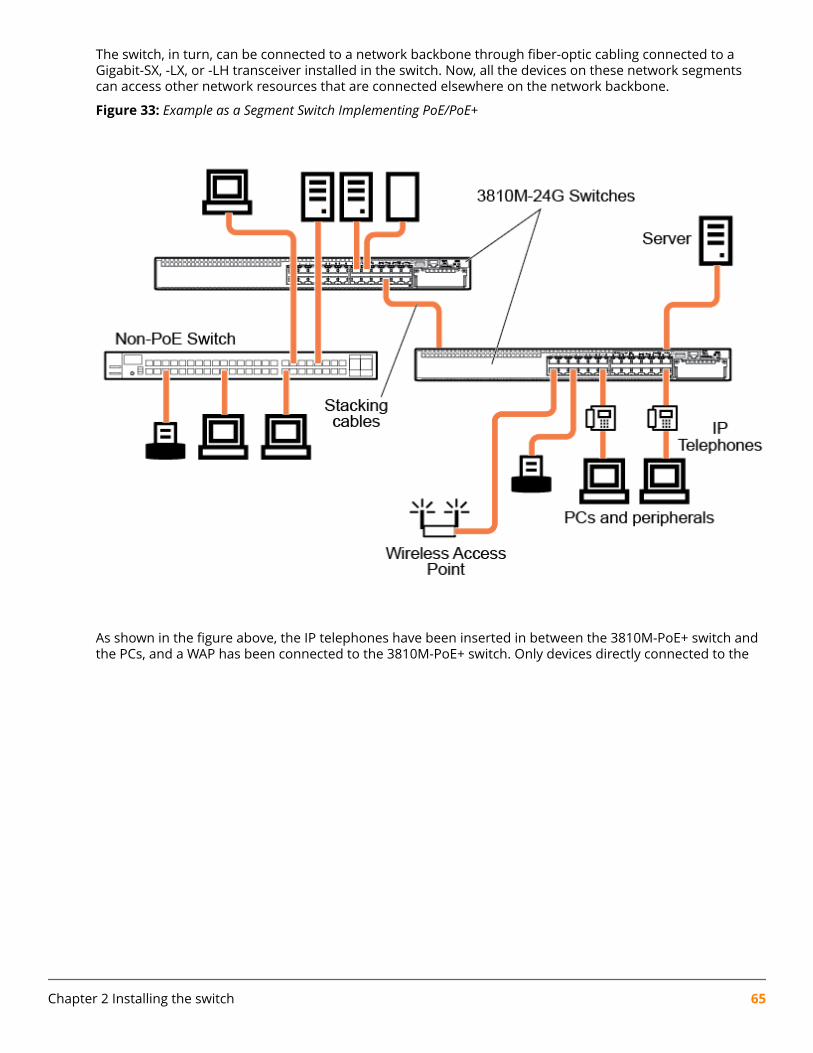
The switch, in turn, can be connected to a network backbone through fiber-optic cabling connected to aGigabit-SX, -LX, or -LH transceiver installed in the switch. Now, all the devices on these network segmentscan access other network resources that are connected elsewhere on the network backbone.
Figure 33: Example as a Segment Switch Implementing PoE/PoE+
As shown in the figure above, the IP telephones have been inserted in between the 3810M-PoE+ switch andthe PCs, and a WAP has been connected to the 3810M-PoE+ switch. Only devices directly connected to the
Chapter 2 Installing the switch 65
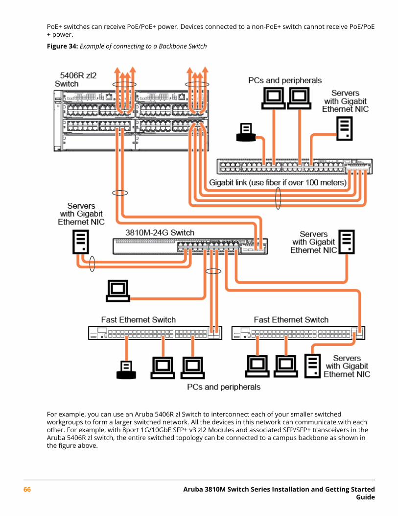
PoE+ switches can receive PoE/PoE+ power. Devices connected to a non-PoE+ switch cannot receive PoE/PoE+ power.
Figure 34: Example of connecting to a Backbone Switch
For example, you can use an Aruba 5406R zl Switch to interconnect each of your smaller switchedworkgroups to form a larger switched network. All the devices in this network can communicate with eachother. For example, with 8port 1G/10GbE SFP+ v3 zl2 Modules and associated SFP/SFP+ transceivers in theAruba 5406R zl switch, the entire switched topology can be connected to a campus backbone as shown inthe figure above.
66 Aruba 3810M Switch Series Installation and Getting StartedGuide

NOTE: In the Backbone Switch illustration, the fiber-optic connection between the 3810M Switchand the 5406R zl Switch is by way of an Aruba 3810M 4SFP+ Module installed in the 3810MSwitch, and connected to an 8port 1G/10GbE SFP+ v3 zl2 Module in the 5406R zl Switch. Theappropriate SFP+ transceivers are installed into each module.
Chapter 2 Installing the switch 67
This chapter is intended as a guide for using the console Switch Setup screen to quickly assign an IP(Internet Protocol) address and subnet mask to the switch, set a Manager password, and, optionally,configure other basic features.
For more information on using the switch console and the other switch management interfaces: the webbrowser interface and the SNMP management tool, Aruba IMC, see the Management and Configuration Guide,which is on the Hewlett Packard Enterprise website at http://www.hpe.com/networking/resourcefinder.
Recommended minimal configurationIn the factory default configuration, the switch has no IP (Internet Protocol) address and subnet mask, andno passwords. In this state, it can be managed only through a direct console connection.
To manage the switch through a networked (in-band data port or out-of-band management port)connection, you must first configure the switch with an IP address and subnet mask compatible with yournetwork.
Also, you should configure a Manager password to control access privileges from the console and webbrowser interface. Other parameters in the Switch Setup screen can be left at their default settings or youcan configure them with new values.
You can configure many other switch features through the switch’s console interface to:
• Optimize switch performance
• Enhance control of network traffic
• Improve network security
• Enable stacking
After you configure an IP address on the switch, you can manage these features more conveniently in any ofthe following ways:
• A remote Telnet session
• A web browser interface
• An SNMP network management station running a network management program, like IMC.
For a list of switch features available with and without an IP address, refer to “How IP Addressing AffectsSwitch Operation” in the Management and Configuration Guide on the Hewlett Packard Enterprise website.
For more information on IP addressing, refer to “IP Configuration” in the Management and ConfigurationGuide.
NOTE: By default, the switch is configured to acquire an IP address configuration from a DHCPor Bootp server. To use DHCP/Bootp instead of the manual configuration method described in“Minimal Configuration Through the Console Port Connection”, see “DHCP/Bootp Operation” inthe Management and Configuration Guide on the Hewlett Packard Enterprise website.
Chapter 3Getting started with switch configuration
68 Aruba 3810M Switch Series Installation and Getting StartedGuide
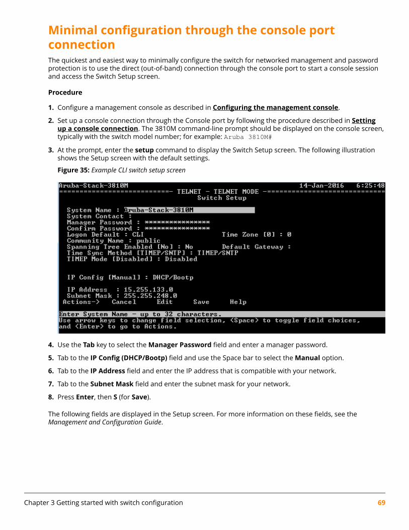
Minimal configuration through the console portconnectionThe quickest and easiest way to minimally configure the switch for networked management and passwordprotection is to use the direct (out-of-band) connection through the console port to start a console sessionand access the Switch Setup screen.
Procedure
1. Configure a management console as described in Configuring the management console.
2. Set up a console connection through the Console port by following the procedure described in Settingup a console connection. The 3810M command-line prompt should be displayed on the console screen,typically with the switch model number; for example: Aruba 3810M#
3. At the prompt, enter the setup command to display the Switch Setup screen. The following illustrationshows the Setup screen with the default settings.
Figure 35: Example CLI switch setup screen
4. Use the Tab key to select the Manager Password field and enter a manager password.
5. Tab to the IP Config (DHCP/Bootp) field and use the Space bar to select the Manual option.
6. Tab to the IP Address field and enter the IP address that is compatible with your network.
7. Tab to the Subnet Mask field and enter the subnet mask for your network.
8. Press Enter, then S (for Save).
The following fields are displayed in the Setup screen. For more information on these fields, see theManagement and Configuration Guide.
Chapter 3 Getting started with switch configuration 69
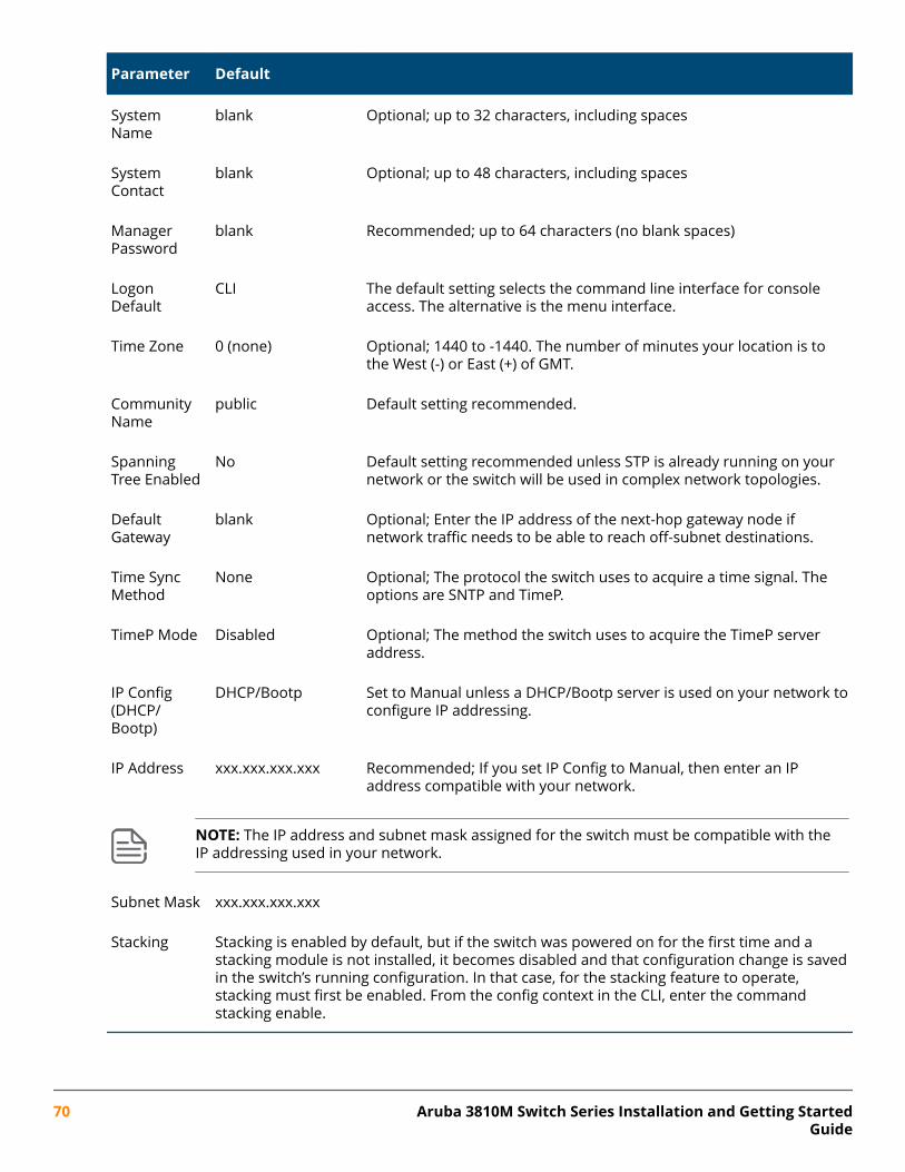
Parameter Default
SystemName
blank Optional; up to 32 characters, including spaces
SystemContact
blank Optional; up to 48 characters, including spaces
ManagerPassword
blank Recommended; up to 64 characters (no blank spaces)
LogonDefault
CLI The default setting selects the command line interface for consoleaccess. The alternative is the menu interface.
Time Zone 0 (none) Optional; 1440 to -1440. The number of minutes your location is tothe West (-) or East (+) of GMT.
CommunityName
public Default setting recommended.
SpanningTree Enabled
No Default setting recommended unless STP is already running on yournetwork or the switch will be used in complex network topologies.
DefaultGateway
blank Optional; Enter the IP address of the next-hop gateway node ifnetwork traffic needs to be able to reach off-subnet destinations.
Time SyncMethod
None Optional; The protocol the switch uses to acquire a time signal. Theoptions are SNTP and TimeP.
TimeP Mode Disabled Optional; The method the switch uses to acquire the TimeP serveraddress.
IP Config(DHCP/Bootp)
DHCP/Bootp Set to Manual unless a DHCP/Bootp server is used on your network toconfigure IP addressing.
IP Address xxx.xxx.xxx.xxx Recommended; If you set IP Config to Manual, then enter an IPaddress compatible with your network.
NOTE: The IP address and subnet mask assigned for the switch must be compatible with theIP addressing used in your network.
Subnet Mask xxx.xxx.xxx.xxx
Stacking Stacking is enabled by default, but if the switch was powered on for the first time and astacking module is not installed, it becomes disabled and that configuration change is savedin the switch’s running configuration. In that case, for the stacking feature to operate,stacking must first be enabled. From the config context in the CLI, enter the commandstacking enable.
70 Aruba 3810M Switch Series Installation and Getting StartedGuide
Where to go from here: Networked connectionsAfter the Switch is configured with a Manager password, IP address, and subnet mask, you can manage theswitch from a networked connection, such as:
• PC equipped with Telnet (see Starting a Telnet session).
• Web browser interface (see Starting a web browser session).
• SNMP-based network management station using a tool like IMC.
For more information on these management interfaces and all the features that you can configure on theswitch, refer to the Management and Configuration Guide for your switch on the Hewlett Packard Enterprisewebsite.
The following types of networked connections are supported on a 3810M Switch:
Out-of-band networked connection through the dedicated Management port
To use: Connect an RJ-45 network cable to the Mgmt port to manage a 3810M Switch through Telnet from aremote PC or UNIX workstation.
To use this port, the switch must have an IP address. IP settings can be configured through a Console portconnection (see Minimal configuration through the console port connection) or automatically from aDHCP/Bootp server.
A networked out-of-band connection through the Mgmt port allows you to manage data network switchesfrom a physically and logically separate management network.
For more information, refer to the Management and Configuration Guide.
In-band networked connection through a data port on the switch
To use: Connect a PC or UNIX workstation with a VT-100 terminal emulator directly to a switch data port.Then access the switch via Telnet from the workstation
To use Telnet, the switch must have an IP address. IP settings can be configured through a Console portconnection (see Minimal configuration through the console port connection) or automatically from aDHCP/Bootp server.
For more information on in-band and out-of-band networked connections for switch management, refer to Using the IP address for remote switch management and the Management and Configuration Guide.
NOTE: A 3810M switch can simultaneously support one out-of-band serial console sessionthrough the console port and up to six in-band Telnet/TCP (networked) sessions through thededicated Management port or data ports on the switch.
Using the IP address for remote switch managementThe switch’s IP address can be used to manage the switch from any PC on the same or on a different subnetas the switch. In a networked (in-band or out-of-band) connection, you can use a Telnet session or astandard web browser to manage the switch.
Starting a Telnet sessionTo access the switch through a Telnet session, follow these steps:
Chapter 3 Getting started with switch configuration 71
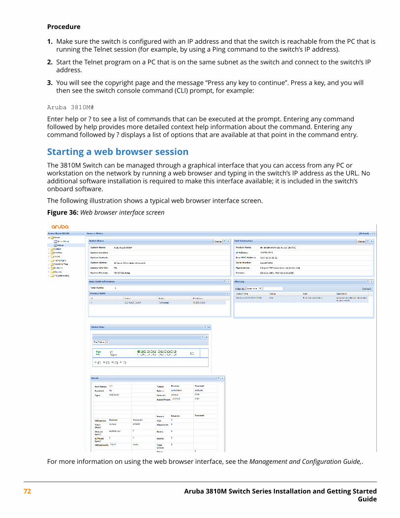
Procedure
1. Make sure the switch is configured with an IP address and that the switch is reachable from the PC that isrunning the Telnet session (for example, by using a Ping command to the switch’s IP address).
2. Start the Telnet program on a PC that is on the same subnet as the switch and connect to the switch’s IPaddress.
3. You will see the copyright page and the message “Press any key to continue”. Press a key, and you willthen see the switch console command (CLI) prompt, for example:
Aruba 3810M#Enter help or ? to see a list of commands that can be executed at the prompt. Entering any commandfollowed by help provides more detailed context help information about the command. Entering anycommand followed by ? displays a list of options that are available at that point in the command entry.
Starting a web browser sessionThe 3810M Switch can be managed through a graphical interface that you can access from any PC orworkstation on the network by running a web browser and typing in the switch’s IP address as the URL. Noadditional software installation is required to make this interface available; it is included in the switch’sonboard software.
The following illustration shows a typical web browser interface screen.
Figure 36: Web browser interface screen
For more information on using the web browser interface, see the Management and Configuration Guide,.
72 Aruba 3810M Switch Series Installation and Getting StartedGuide

An extensive help system is also available for the web browser interface. To access the help system, thesubnet on which the switch is installed must have access to the Internet, or IMC needs to be installed on anetwork management station that is on the subnet.
Chapter 3 Getting started with switch configuration 73
This chapter shows you how to remove and install the following components:
• Fan tray
• Power Supply
• Stacking Module
• Flex Port Module
NOTE: Hot Swapping
• The fan tray can be hot swapped. The switch does not need to be powered off to replace thefan tray. However, it needs to be done quickly before the switch shuts down (within 2minutes).
• The stacking module is not hot swappable. The switch must be powered off before installingor replacing the module.
CAUTION: The 3810M switches and its components are sensitive to static discharge. Use anantistatic wrist strap and observe all static precautions when replacing components.
CAUTION: If a power supply must be removed and then reinstalled, wait at least 5 secondsbefore reinstallation. Otherwise, damage to the switch may occur. The power supply needs thistime to bleed off any retained power.
Replacing the fan trayThe fan tray is hot swappable. Replacing the fan try can be done with the switch powered on. When a fanfails the Fan Status LED on the switch will blink simultaneously with the switch Fault LED. In this case, theentire fan tray needs to be replaced. Individual fans cannot be replaced.
To replace a fan tray:
Procedure
1. Remove the new fan tray assembly from it’s packaging.
2. Unscrew the retaining screw of the failed fan tray.
3. Holding the handle, pull the failed fan tray assembly straight out.
Chapter 4Replacing components
74 Aruba 3810M Switch Series Installation and Getting StartedGuide
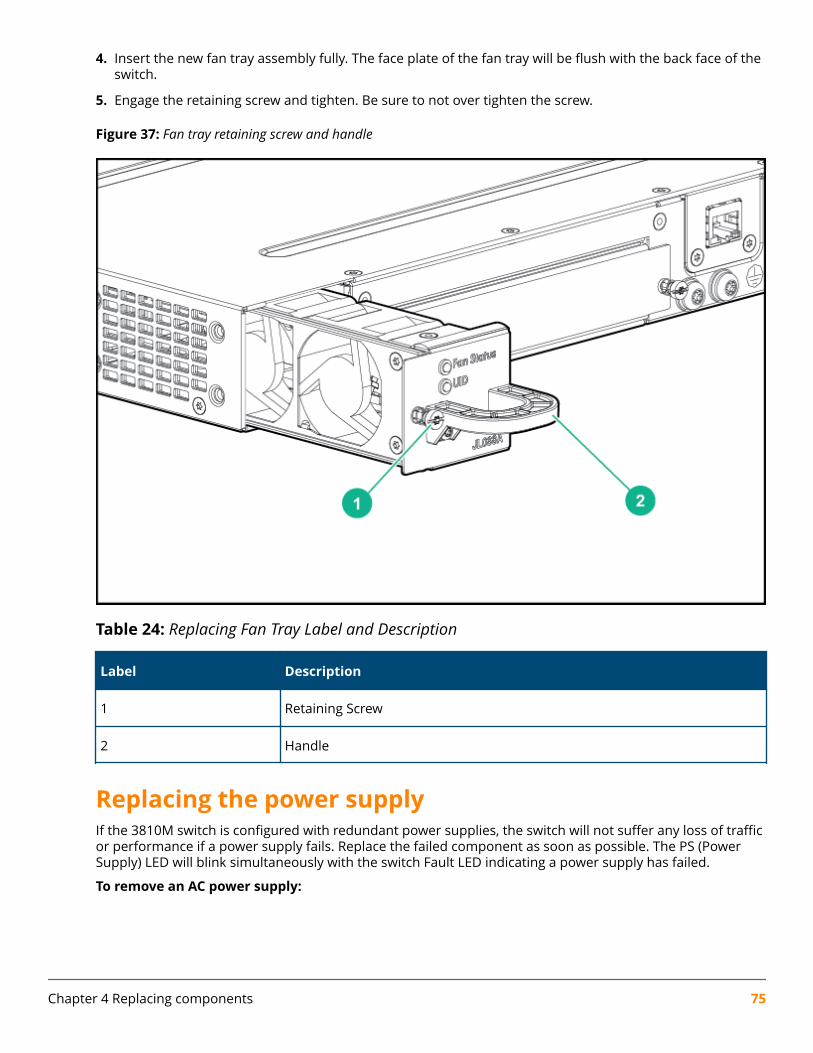
4. Insert the new fan tray assembly fully. The face plate of the fan tray will be flush with the back face of theswitch.
5. Engage the retaining screw and tighten. Be sure to not over tighten the screw.
Figure 37: Fan tray retaining screw and handle
Table 24: Replacing Fan Tray Label and Description
Label Description
1 Retaining Screw
2 Handle
Replacing the power supplyIf the 3810M switch is configured with redundant power supplies, the switch will not suffer any loss of trafficor performance if a power supply fails. Replace the failed component as soon as possible. The PS (PowerSupply) LED will blink simultaneously with the switch Fault LED indicating a power supply has failed.
To remove an AC power supply:
Chapter 4 Replacing components 75
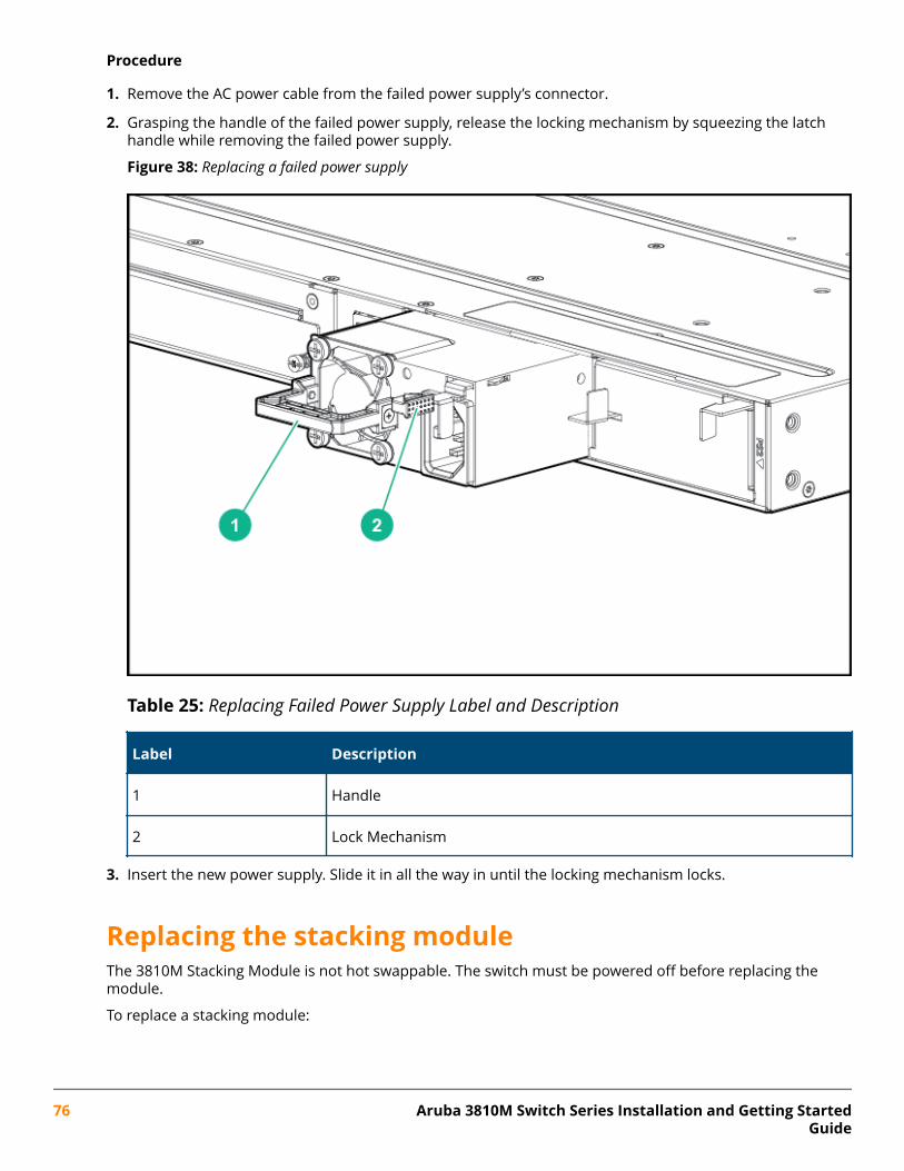
Procedure
1. Remove the AC power cable from the failed power supply’s connector.
2. Grasping the handle of the failed power supply, release the locking mechanism by squeezing the latchhandle while removing the failed power supply.
Figure 38: Replacing a failed power supply
Table 25: Replacing Failed Power Supply Label and Description
Label Description
1 Handle
2 Lock Mechanism
3. Insert the new power supply. Slide it in all the way in until the locking mechanism locks.
Replacing the stacking moduleThe 3810M Stacking Module is not hot swappable. The switch must be powered off before replacing themodule.
To replace a stacking module:
76 Aruba 3810M Switch Series Installation and Getting StartedGuide
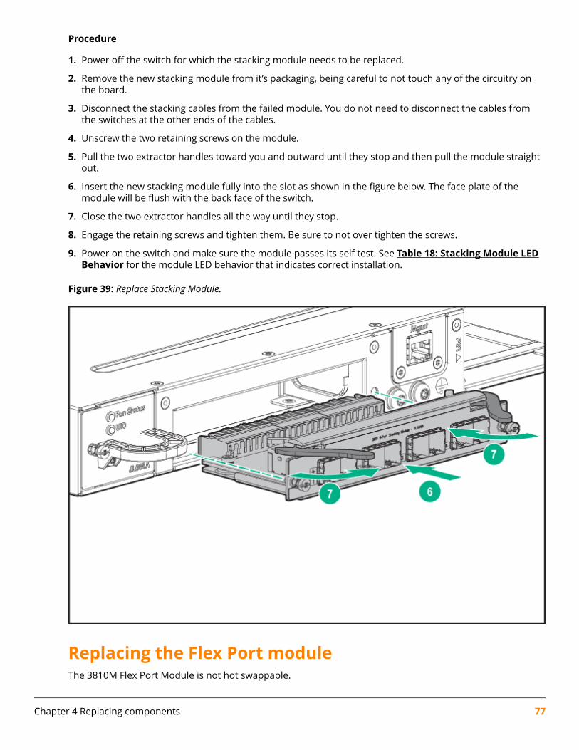
Procedure
1. Power off the switch for which the stacking module needs to be replaced.
2. Remove the new stacking module from it’s packaging, being careful to not touch any of the circuitry onthe board.
3. Disconnect the stacking cables from the failed module. You do not need to disconnect the cables fromthe switches at the other ends of the cables.
4. Unscrew the two retaining screws on the module.
5. Pull the two extractor handles toward you and outward until they stop and then pull the module straightout.
6. Insert the new stacking module fully into the slot as shown in the figure below. The face plate of themodule will be flush with the back face of the switch.
7. Close the two extractor handles all the way until they stop.
8. Engage the retaining screws and tighten them. Be sure to not over tighten the screws.
9. Power on the switch and make sure the module passes its self test. See Table 18: Stacking Module LEDBehavior for the module LED behavior that indicates correct installation.
Figure 39: Replace Stacking Module.
Replacing the Flex Port moduleThe 3810M Flex Port Module is not hot swappable.
Chapter 4 Replacing components 77
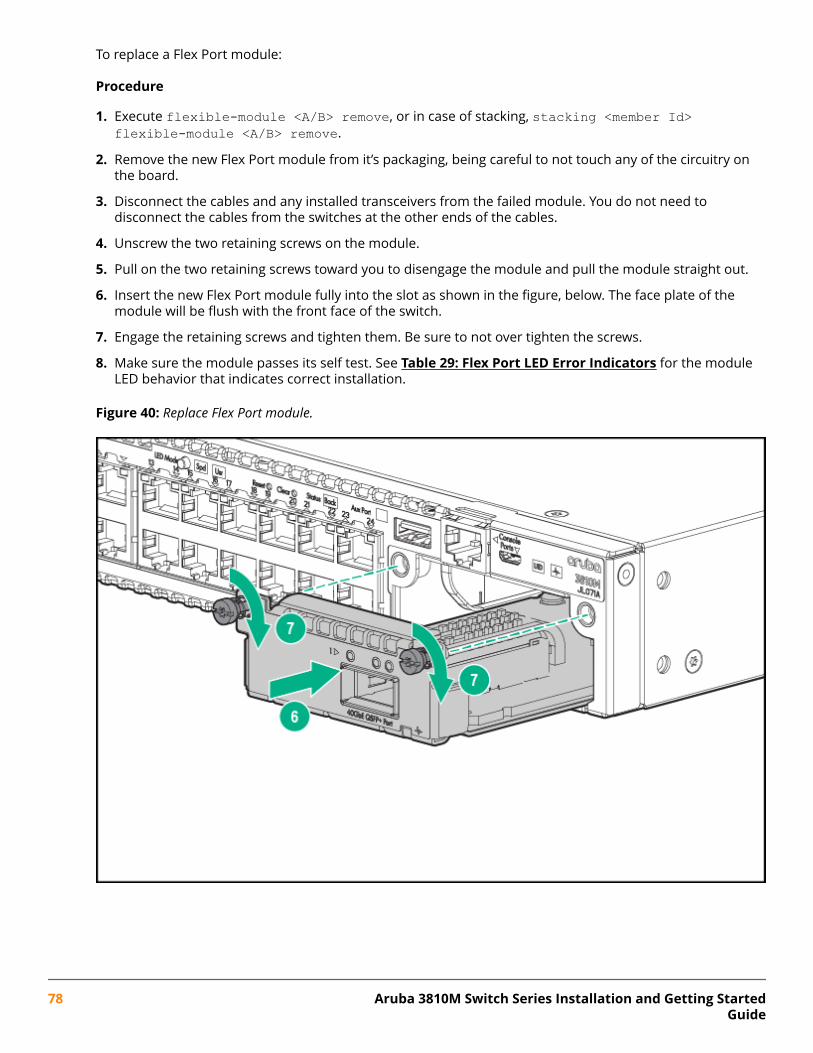
To replace a Flex Port module:
Procedure
1. Execute flexible-module <A/B> remove, or in case of stacking, stacking <member Id>flexible-module <A/B> remove.
2. Remove the new Flex Port module from it’s packaging, being careful to not touch any of the circuitry onthe board.
3. Disconnect the cables and any installed transceivers from the failed module. You do not need todisconnect the cables from the switches at the other ends of the cables.
4. Unscrew the two retaining screws on the module.
5. Pull on the two retaining screws toward you to disengage the module and pull the module straight out.
6. Insert the new Flex Port module fully into the slot as shown in the figure, below. The face plate of themodule will be flush with the front face of the switch.
7. Engage the retaining screws and tighten them. Be sure to not over tighten the screws.
8. Make sure the module passes its self test. See Table 29: Flex Port LED Error Indicators for the moduleLED behavior that indicates correct installation.
Figure 40: Replace Flex Port module.
78 Aruba 3810M Switch Series Installation and Getting StartedGuide
This chapter describes how to troubleshoot your switch. This document describes troubleshooting mostlyfrom a hardware perspective. You can perform more in-depth troubleshooting on the switch using thesoftware tools available with the switch, including the full-featured console interface, the built-in webbrowser interface, and IMC, the SNMP-based network management tool. For more information, see thechapter “Troubleshooting” in the 3810M Management and Configuration Guide. You may want to bookmarkthis Web page for easy access in the future.
This chapter describes the following:
• Basic Troubleshooting Tips
• Diagnosing with the LEDs
• Proactive Networking Tools
• Hardware Diagnostic Tests
• Restoring the Factory Default Configuration
• Downloading New Switch Software
Basic troubleshooting tipsMost problems are caused by the following situations. Check for these items first when starting yourtroubleshooting:
• Connecting to devices that have a fixed full-duplex configuration. The RJ-45 ports are configured as“Auto”. That is, when connecting to attached devices, the switch will operate in one of two ways todetermine the link speed and the communication mode (half duplex or full duplex):
◦ If the connected device is also configured to Auto, the switch will automatically negotiate both linkspeed and communication mode.
◦ If the connected device has a fixed configuration, for example 100 Mbps, at half or full duplex, theswitch will automatically sense the link speed, but will default to a communication mode of halfduplex.
Because the switch behaves in this way (in compliance with the IEEE 802.3 standard), if a deviceconnected to the switch has a fixed configuration at full duplex, the device will not connect correctly tothe switch. The result will be high error rates and very inefficient communications between the switchand the device.
Make sure that all the devices connected to the switch are configured to auto negotiate, or are configuredto speed and duplex settings matching those configured on the corresponding switch port.
• Faulty or loose cables. Look for loose or obviously faulty connections. If they appear to be OK, makesure the connections are snug. If that does not correct the problem, try a different cable.
• Non-standard cables. Non-standard and miswired cables may cause network collisions and othernetwork problems, and can seriously impair network performance. Use a new correctly-wired cable orcompare your cable to the cable in appendix B, “Cables and Connectors” for pinouts and correct cable
Chapter 5Troubleshooting
Chapter 5 Troubleshooting 79
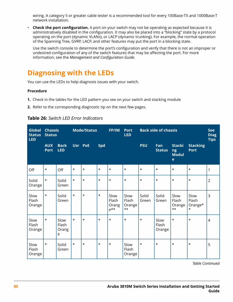
wiring. A category 5 or greater cable tester is a recommended tool for every 100Base-TX and 1000Base-Tnetwork installation.
• Check the port configuration. A port on your switch may not be operating as expected because it isadministratively disabled in the configuration. It may also be placed into a “blocking” state by a protocoloperating on the port (dynamic VLANs), or LACP (dynamic trunking). For example, the normal operationof the Spanning Tree, GVRP, LACP, and other features may put the port in a blocking state.
Use the switch console to determine the port’s configuration and verify that there is not an improper orundesired configuration of any of the switch features that may be affecting the port. For moreinformation, see the Management and Configuration Guide.
Diagnosing with the LEDsYou can use the LEDs to help diagnosis issues with your switch.
Procedure
1. Check in the tables for the LED pattern you see on your switch and stacking module
2. Refer to the corresponding diagnostic tip on the next few pages.
Table 26: Switch LED Error Indicators
GlobalStatusLED
ChassisStatus
Mode/Status FP/IM PortLED
Back side of chassis SeeDiagTips
AUXPort
BackLED
Usr PoE Spd PSU FanStatus
StackingModule
StackingPort
Off * Off * * * * * * * * * 1
SolidOrange
* SolidGreen
* * * * * * * * * 2
SlowFlashOrange
* SolidGreen
* * * SlowFlashOrange**
SlowFlashOrange**
SolidGreen
SolidGreen
SlowFlashOrange**
SlowFlashOrange**
3
SlowFlashOrange
* SlowFlashOrange
* * * * * * SlowFlashOrange
* * 4
SlowFlashOrange
* SolidGreen
* * * * SlowFlashOrange
* * * * 5
Table Continued
80 Aruba 3810M Switch Series Installation and Getting StartedGuide
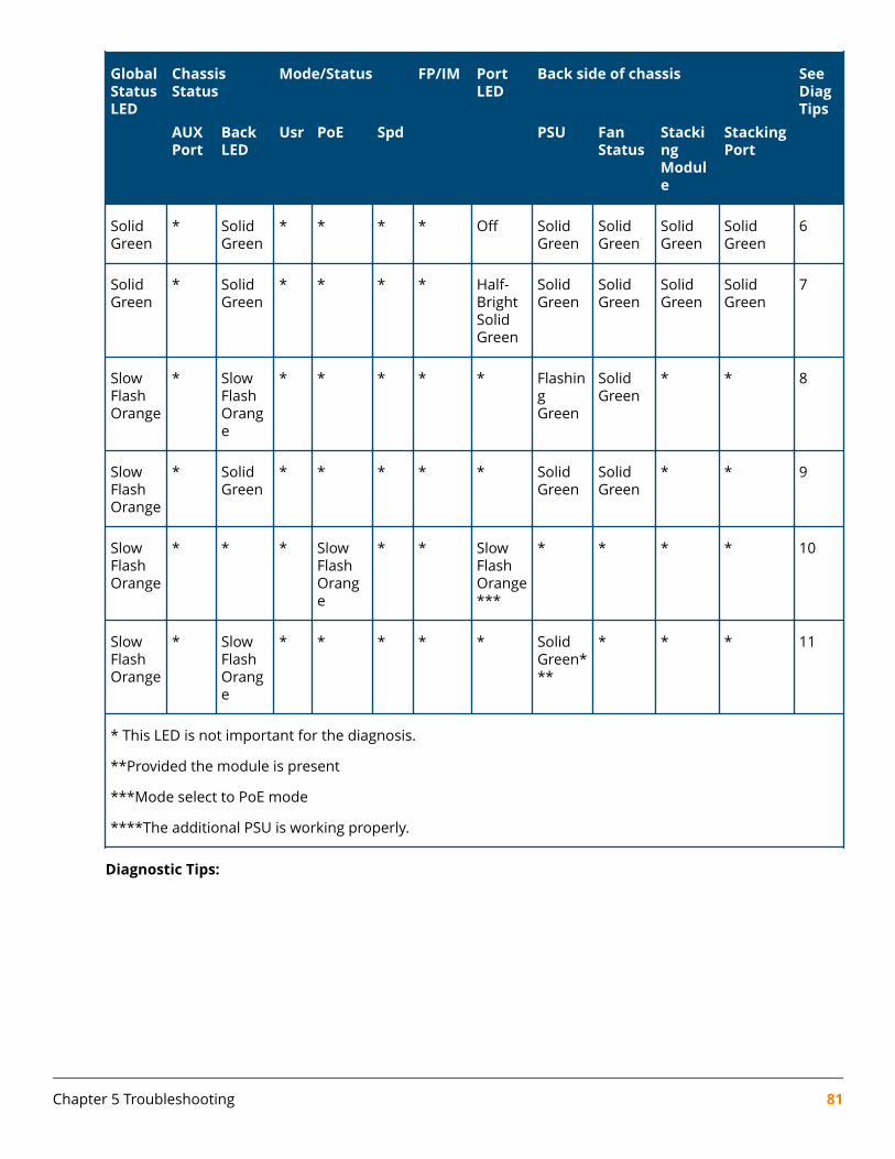
GlobalStatusLED
ChassisStatus
Mode/Status FP/IM PortLED
Back side of chassis SeeDiagTips
AUXPort
BackLED
Usr PoE Spd PSU FanStatus
StackingModule
StackingPort
SolidGreen
* SolidGreen
* * * * Off SolidGreen
SolidGreen
SolidGreen
SolidGreen
6
SolidGreen
* SolidGreen
* * * * Half-BrightSolidGreen
SolidGreen
SolidGreen
SolidGreen
SolidGreen
7
SlowFlashOrange
* SlowFlashOrange
* * * * * FlashingGreen
SolidGreen
* * 8
SlowFlashOrange
* SolidGreen
* * * * * SolidGreen
SolidGreen
* * 9
SlowFlashOrange
* * * SlowFlashOrange
* * SlowFlashOrange***
* * * * 10
SlowFlashOrange
* SlowFlashOrange
* * * * * SolidGreen***
* * * 11
* This LED is not important for the diagnosis.
**Provided the module is present
***Mode select to PoE mode
****The additional PSU is working properly.
Diagnostic Tips:
Chapter 5 Troubleshooting 81
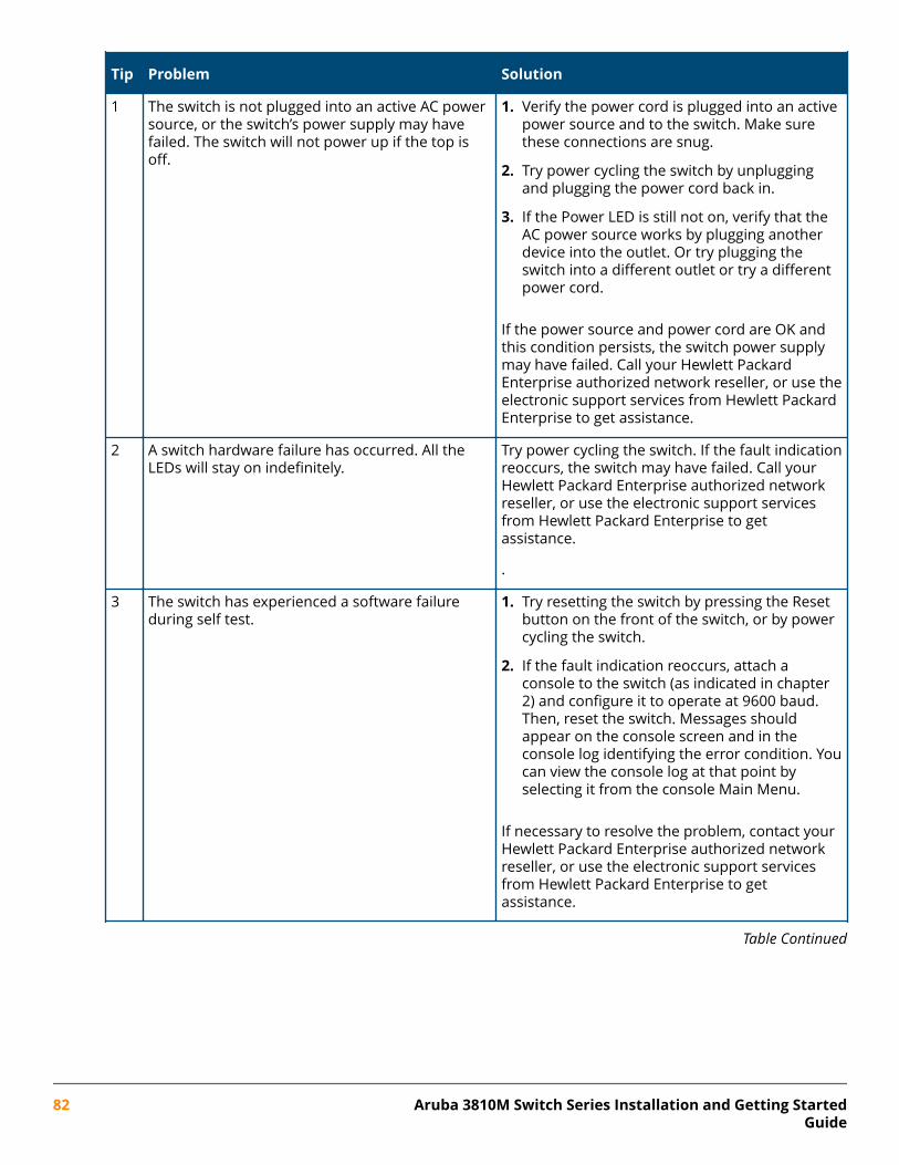
Tip Problem Solution
1 The switch is not plugged into an active AC powersource, or the switch’s power supply may havefailed. The switch will not power up if the top isoff.
1. Verify the power cord is plugged into an activepower source and to the switch. Make surethese connections are snug.
2. Try power cycling the switch by unpluggingand plugging the power cord back in.
3. If the Power LED is still not on, verify that theAC power source works by plugging anotherdevice into the outlet. Or try plugging theswitch into a different outlet or try a differentpower cord.
If the power source and power cord are OK andthis condition persists, the switch power supplymay have failed. Call your Hewlett PackardEnterprise authorized network reseller, or use theelectronic support services from Hewlett PackardEnterprise to get assistance.
2 A switch hardware failure has occurred. All theLEDs will stay on indefinitely.
Try power cycling the switch. If the fault indicationreoccurs, the switch may have failed. Call yourHewlett Packard Enterprise authorized networkreseller, or use the electronic support servicesfrom Hewlett Packard Enterprise to getassistance.
.
3 The switch has experienced a software failureduring self test.
1. Try resetting the switch by pressing the Resetbutton on the front of the switch, or by powercycling the switch.
2. If the fault indication reoccurs, attach aconsole to the switch (as indicated in chapter2) and configure it to operate at 9600 baud.Then, reset the switch. Messages shouldappear on the console screen and in theconsole log identifying the error condition. Youcan view the console log at that point byselecting it from the console Main Menu.
If necessary to resolve the problem, contact yourHewlett Packard Enterprise authorized networkreseller, or use the electronic support servicesfrom Hewlett Packard Enterprise to getassistance.
Table Continued
82 Aruba 3810M Switch Series Installation and Getting StartedGuide
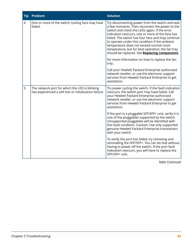
Tip Problem Solution
4 One or more of the switch cooling fans may havefailed.
Try disconnecting power from the switch and waita few moments. Then reconnect the power to theswitch and check the LEDs again. If the errorindication reoccurs, one or more of the fans hasfailed. The switch has four fans and may continueto operate under this condition if the ambienttemperature does not exceed normal roomtemperature, but for best operation, the fan trayshould be replaced. See Replacing components
for more information on how to replace the fantray.
Call your Hewlett Packard Enterprise authorizednetwork reseller, or use the electronic supportservices from Hewlett Packard Enterprise to getassistance.
5 The network port for which the LED is blinkinghas experienced a self test or initialization failure.
Try power cycling the switch. If the fault indicationreoccurs, the switch port may have failed. Callyour Hewlett Packard Enterprise authorizednetwork reseller, or use the electronic supportservices from Hewlett Packard Enterprise to getassistance.
If the port is a pluggable SFP/SFP+ unit, verify it isone of the pluggables supported by the switch.Unsupported pluggables will be identified withthis fault condition. Caution: Use only supportedgenuine Hewlett Packard Enterprise transceiverswith your switch.
To verify the port has failed, try removing andreinstalling the SFP/SFP+. You can do that withouthaving to power off the switch. If the port faultindication reoccurs, you will have to replace theSFP/SFP+ unit.
Table Continued
Chapter 5 Troubleshooting 83
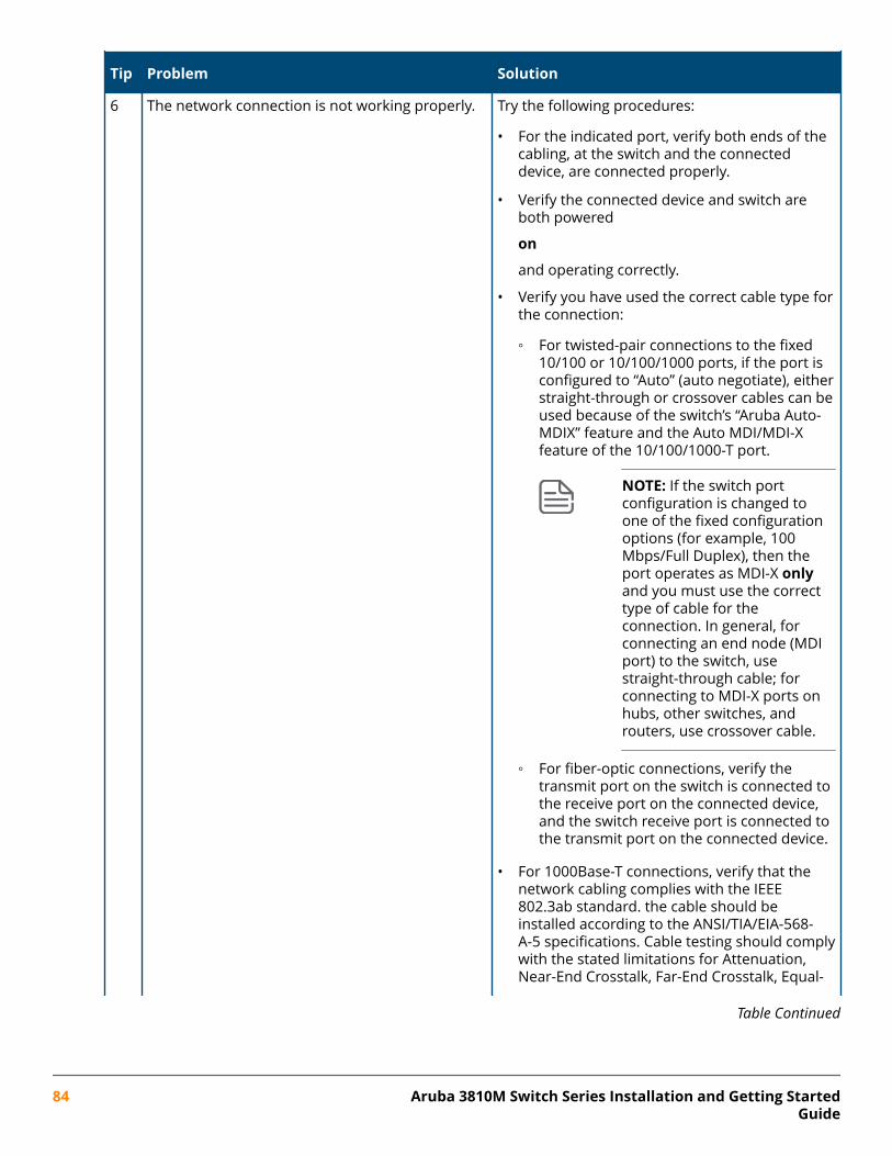
Tip Problem Solution
6 The network connection is not working properly. Try the following procedures:
• For the indicated port, verify both ends of thecabling, at the switch and the connecteddevice, are connected properly.
• Verify the connected device and switch areboth powered
on
and operating correctly.
• Verify you have used the correct cable type forthe connection:
◦ For twisted-pair connections to the fixed10/100 or 10/100/1000 ports, if the port isconfigured to “Auto” (auto negotiate), eitherstraight-through or crossover cables can beused because of the switch’s “Aruba Auto-MDIX” feature and the Auto MDI/MDI-Xfeature of the 10/100/1000-T port.
NOTE: If the switch portconfiguration is changed toone of the fixed configurationoptions (for example, 100Mbps/Full Duplex), then theport operates as MDI-X onlyand you must use the correcttype of cable for theconnection. In general, forconnecting an end node (MDIport) to the switch, usestraight-through cable; forconnecting to MDI-X ports onhubs, other switches, androuters, use crossover cable.
◦ For fiber-optic connections, verify thetransmit port on the switch is connected tothe receive port on the connected device,and the switch receive port is connected tothe transmit port on the connected device.
• For 1000Base-T connections, verify that thenetwork cabling complies with the IEEE802.3ab standard. the cable should beinstalled according to the ANSI/TIA/EIA-568-A-5 specifications. Cable testing should complywith the stated limitations for Attenuation,Near-End Crosstalk, Far-End Crosstalk, Equal-
Table Continued
84 Aruba 3810M Switch Series Installation and Getting StartedGuide
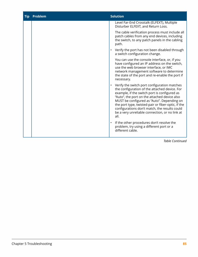
Tip Problem Solution
Level Far-End Crosstalk (ELFEXT), MultipleDisturber ELFEXT, and Return Loss.
The cable verification process must include allpatch cables from any end devices, includingthe switch, to any patch panels in the cablingpath.
• Verify the port has not been disabled througha switch configuration change.
You can use the console interface, or, if youhave configured an IP address on the switch,use the web browser interface, or IMCnetwork management software to determinethe state of the port and re-enable the port ifnecessary.
• Verify the switch port configuration matchesthe configuration of the attached device. Forexample, if the switch port is configured as“Auto”, the port on the attached device alsoMUST be configured as “Auto”. Depending onthe port type, twisted-pair or fiber-optic, if theconfigurations don’t match, the results couldbe a very unreliable connection, or no link atall.
• If the other procedures don’t resolve theproblem, try using a different port or adifferent cable.
Table Continued
Chapter 5 Troubleshooting 85
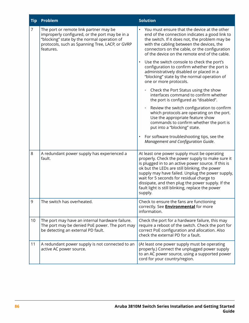
Tip Problem Solution
7 The port or remote link partner may beimproperly configured, or the port may be in a“blocking” state by the normal operation ofprotocols, such as Spanning Tree, LACP, or GVRPfeatures.
• You must ensure that the device at the otherend of the connection indicates a good link tothe switch. If it does not, the problem may bewith the cabling between the devices, theconnectors on the cable, or the configurationof the device on the remote end of the cable.
• Use the switch console to check the port’sconfiguration to confirm whether the port isadministratively disabled or placed in a“blocking” state by the normal operation ofone or more protocols.
◦ Check the Port Status using the showinterfaces command to confirm whetherthe port is configured as “disabled”.
◦ Review the switch configuration to confirmwhich protocols are operating on the port.Use the appropriate feature showcommands to confirm whether the port isput into a “blocking” state.
• For software troubleshooting tips, see theManagement and Configuration Guide.
8 A redundant power supply has experienced afault.
At least one power supply must be operatingproperly. Check the power supply to make sure itis plugged in to an active power source. If this isok but the LEDs are still blinking, the powersupply may have failed. Unplug the power supply,wait for 5 seconds for residual charge todissipate, and then plug the power supply. If thefault light is still blinking, replace the powersupply.
9 The switch has overheated. Check to ensure the fans are functioningcorrectly. See Environmental for moreinformation.
10 The port may have an internal hardware failure.The port may be denied PoE power. The port maybe detecting an external PD fault.
Check the port for a hardware failure, this mayrequire a reboot of the switch. Check the port forcorrect PoE configuration and allocation. Alsocheck the external PD for a fault.
11 A redundant power supply is not connected to anactive AC power source.
(At least one power supply must be operatingproperly.) Connect the unplugged power supplyto an AC power source, using a supported powercord for your country/region.
86 Aruba 3810M Switch Series Installation and Getting StartedGuide
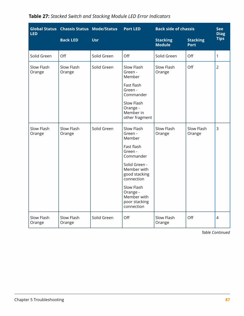
Table 27: Stacked Switch and Stacking Module LED Error Indicators
Global StatusLED
Chassis Status Mode/Status Port LED Back side of chassis SeeDiagTipsBack LED Usr Stacking
ModuleStackingPort
Solid Green Off Solid Green Off Solid Green Off 1
Slow FlashOrange
Slow FlashOrange
Solid Green Slow FlashGreen -Member
Fast flashGreen -Commander
Slow FlashOrange -Member inother fragment
Slow FlashOrange
Off 2
Slow FlashOrange
Slow FlashOrange
Solid Green Slow FlashGreen -Member
Fast flashGreen -Commander
Solid Green -Member withgood stackingconnection
Slow FlashOrange -Member withpoor stackingconnection
Slow FlashOrange
Slow FlashOrange
3
Slow FlashOrange
Slow FlashOrange
Solid Green Off Slow FlashOrange
Off 4
Table Continued
Chapter 5 Troubleshooting 87
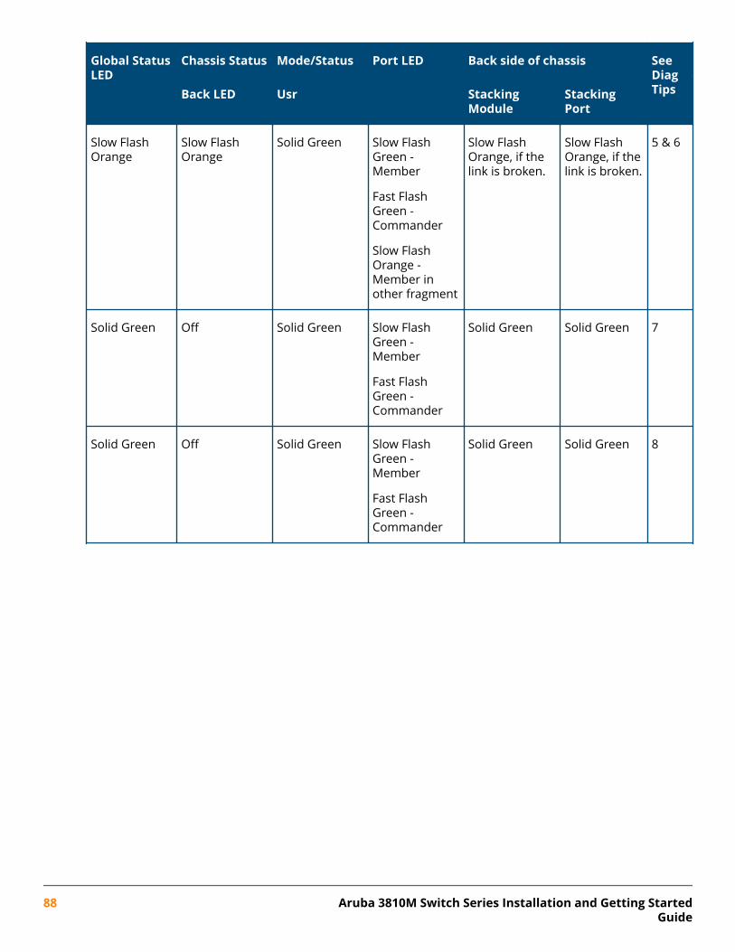
Global StatusLED
Chassis Status Mode/Status Port LED Back side of chassis SeeDiagTipsBack LED Usr Stacking
ModuleStackingPort
Slow FlashOrange
Slow FlashOrange
Solid Green Slow FlashGreen -Member
Fast FlashGreen -Commander
Slow FlashOrange -Member inother fragment
Slow FlashOrange, if thelink is broken.
Slow FlashOrange, if thelink is broken.
5 & 6
Solid Green Off Solid Green Slow FlashGreen -Member
Fast FlashGreen -Commander
Solid Green Solid Green 7
Solid Green Off Solid Green Slow FlashGreen -Member
Fast FlashGreen -Commander
Solid Green Solid Green 8
88 Aruba 3810M Switch Series Installation and Getting StartedGuide
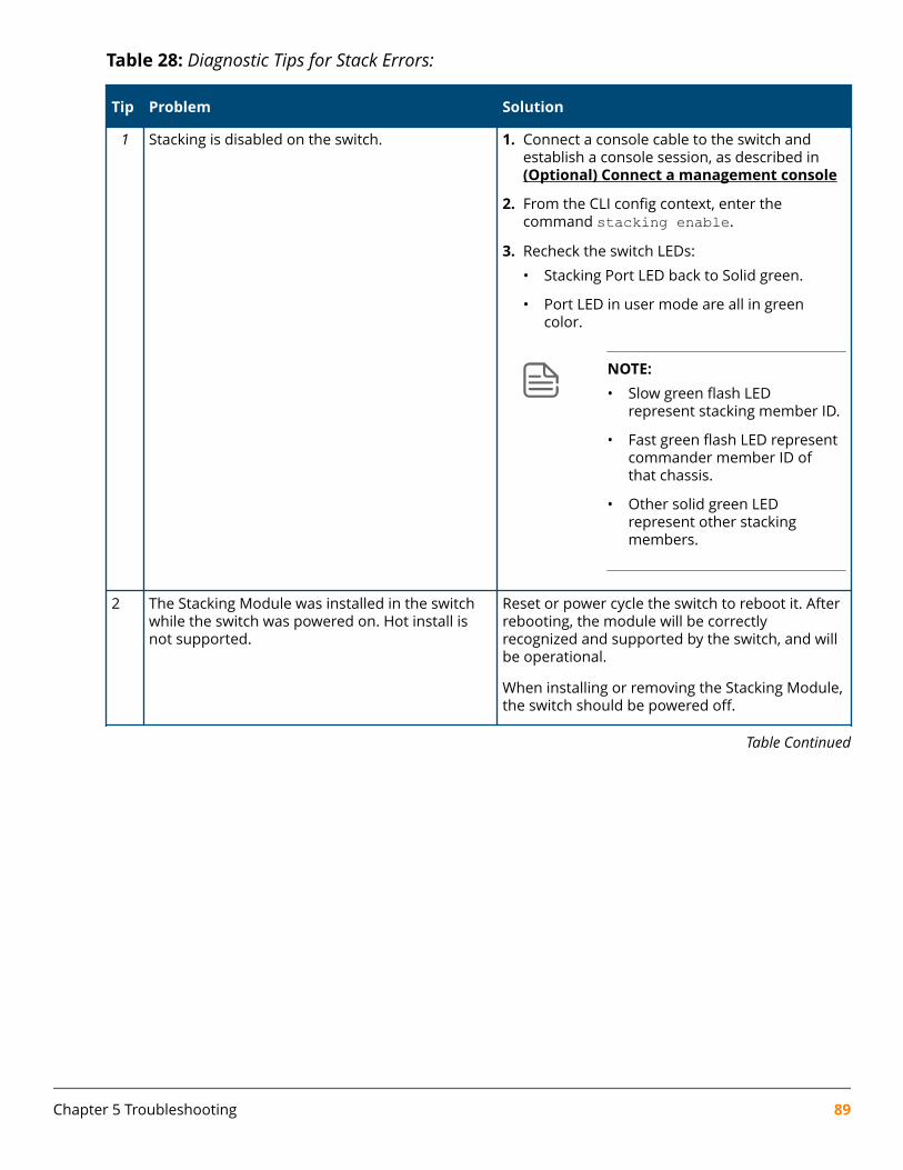
Table 28: Diagnostic Tips for Stack Errors:
Tip Problem Solution
1 Stacking is disabled on the switch. 1. Connect a console cable to the switch andestablish a console session, as described in (Optional) Connect a management console
2. From the CLI config context, enter thecommand stacking enable.
3. Recheck the switch LEDs:
• Stacking Port LED back to Solid green.
• Port LED in user mode are all in greencolor.
NOTE:• Slow green flash LED
represent stacking member ID.
• Fast green flash LED representcommander member ID ofthat chassis.
• Other solid green LEDrepresent other stackingmembers.
2 The Stacking Module was installed in the switchwhile the switch was powered on. Hot install isnot supported.
Reset or power cycle the switch to reboot it. Afterrebooting, the module will be correctlyrecognized and supported by the switch, and willbe operational.
When installing or removing the Stacking Module,the switch should be powered off.
Table Continued
Chapter 5 Troubleshooting 89
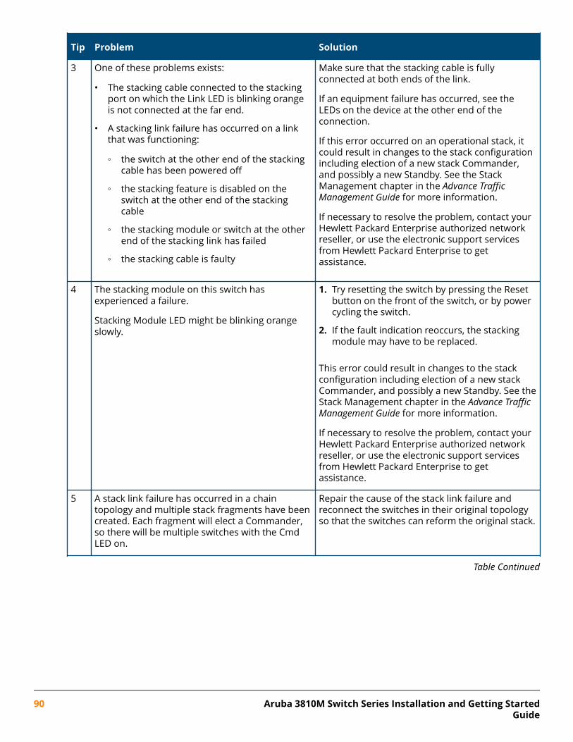
Tip Problem Solution
3 One of these problems exists:
• The stacking cable connected to the stackingport on which the Link LED is blinking orangeis not connected at the far end.
• A stacking link failure has occurred on a linkthat was functioning:
◦ the switch at the other end of the stackingcable has been powered off
◦ the stacking feature is disabled on theswitch at the other end of the stackingcable
◦ the stacking module or switch at the otherend of the stacking link has failed
◦ the stacking cable is faulty
Make sure that the stacking cable is fullyconnected at both ends of the link.
If an equipment failure has occurred, see theLEDs on the device at the other end of theconnection.
If this error occurred on an operational stack, itcould result in changes to the stack configurationincluding election of a new stack Commander,and possibly a new Standby. See the StackManagement chapter in the Advance TrafficManagement Guide for more information.
If necessary to resolve the problem, contact yourHewlett Packard Enterprise authorized networkreseller, or use the electronic support servicesfrom Hewlett Packard Enterprise to getassistance.
4 The stacking module on this switch hasexperienced a failure.
Stacking Module LED might be blinking orangeslowly.
1. Try resetting the switch by pressing the Resetbutton on the front of the switch, or by powercycling the switch.
2. If the fault indication reoccurs, the stackingmodule may have to be replaced.
This error could result in changes to the stackconfiguration including election of a new stackCommander, and possibly a new Standby. See theStack Management chapter in the Advance TrafficManagement Guide for more information.
If necessary to resolve the problem, contact yourHewlett Packard Enterprise authorized networkreseller, or use the electronic support servicesfrom Hewlett Packard Enterprise to getassistance.
5 A stack link failure has occurred in a chaintopology and multiple stack fragments have beencreated. Each fragment will elect a Commander,so there will be multiple switches with the CmdLED on.
Repair the cause of the stack link failure andreconnect the switches in their original topologyso that the switches can reform the original stack.
Table Continued
90 Aruba 3810M Switch Series Installation and Getting StartedGuide
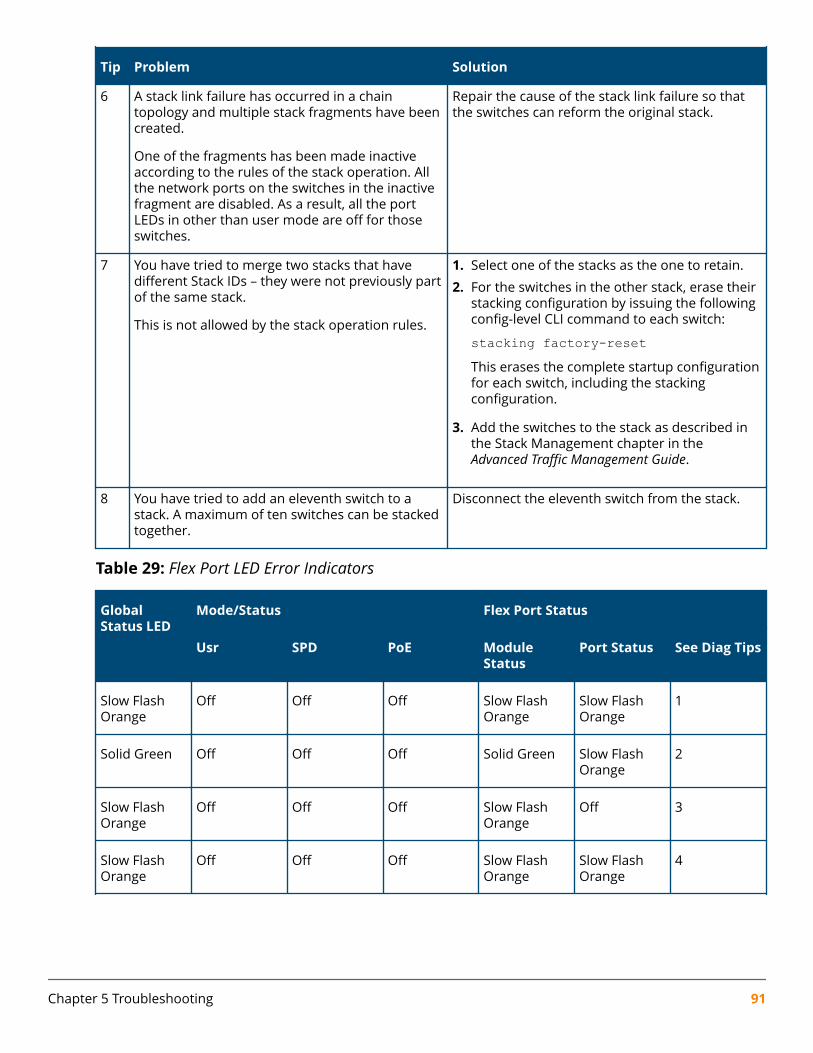
Tip Problem Solution
6 A stack link failure has occurred in a chaintopology and multiple stack fragments have beencreated.
One of the fragments has been made inactiveaccording to the rules of the stack operation. Allthe network ports on the switches in the inactivefragment are disabled. As a result, all the portLEDs in other than user mode are off for thoseswitches.
Repair the cause of the stack link failure so thatthe switches can reform the original stack.
7 You have tried to merge two stacks that havedifferent Stack IDs – they were not previously partof the same stack.
This is not allowed by the stack operation rules.
1. Select one of the stacks as the one to retain.
2. For the switches in the other stack, erase theirstacking configuration by issuing the followingconfig-level CLI command to each switch:
stacking factory-resetThis erases the complete startup configurationfor each switch, including the stackingconfiguration.
3. Add the switches to the stack as described inthe Stack Management chapter in theAdvanced Traffic Management Guide.
8 You have tried to add an eleventh switch to astack. A maximum of ten switches can be stackedtogether.
Disconnect the eleventh switch from the stack.
Table 29: Flex Port LED Error Indicators
GlobalStatus LED
Mode/Status Flex Port Status
Usr SPD PoE ModuleStatus
Port Status See Diag Tips
Slow FlashOrange
Off Off Off Slow FlashOrange
Slow FlashOrange
1
Solid Green Off Off Off Solid Green Slow FlashOrange
2
Slow FlashOrange
Off Off Off Slow FlashOrange
Off 3
Slow FlashOrange
Off Off Off Slow FlashOrange
Slow FlashOrange
4
Chapter 5 Troubleshooting 91
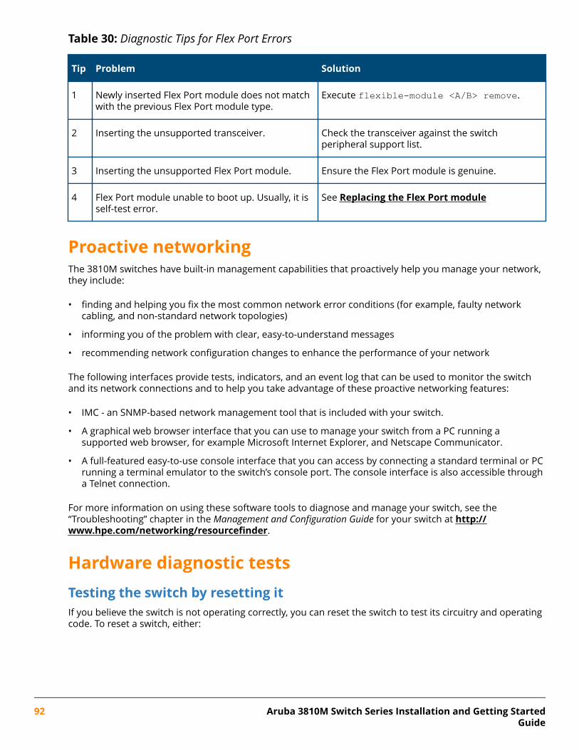
Table 30: Diagnostic Tips for Flex Port Errors
Tip Problem Solution
1 Newly inserted Flex Port module does not matchwith the previous Flex Port module type.
Execute flexible-module <A/B> remove.
2 Inserting the unsupported transceiver. Check the transceiver against the switchperipheral support list.
3 Inserting the unsupported Flex Port module. Ensure the Flex Port module is genuine.
4 Flex Port module unable to boot up. Usually, it isself-test error.
See Replacing the Flex Port module
Proactive networkingThe 3810M switches have built-in management capabilities that proactively help you manage your network,they include:
• finding and helping you fix the most common network error conditions (for example, faulty networkcabling, and non-standard network topologies)
• informing you of the problem with clear, easy-to-understand messages
• recommending network configuration changes to enhance the performance of your network
The following interfaces provide tests, indicators, and an event log that can be used to monitor the switchand its network connections and to help you take advantage of these proactive networking features:
• IMC - an SNMP-based network management tool that is included with your switch.
• A graphical web browser interface that you can use to manage your switch from a PC running asupported web browser, for example Microsoft Internet Explorer, and Netscape Communicator.
• A full-featured easy-to-use console interface that you can access by connecting a standard terminal or PCrunning a terminal emulator to the switch’s console port. The console interface is also accessible througha Telnet connection.
For more information on using these software tools to diagnose and manage your switch, see the“Troubleshooting” chapter in the Management and Configuration Guide for your switch at http://www.hpe.com/networking/resourcefinder.
Hardware diagnostic testsTesting the switch by resetting itIf you believe the switch is not operating correctly, you can reset the switch to test its circuitry and operatingcode. To reset a switch, either:
92 Aruba 3810M Switch Series Installation and Getting StartedGuide
• unplug and plug in the power cord (power cycling)
• press the Reset button on the front of the switch
• reboot the switch via the management console’s boot system command.
Power cycling the switch and pressing the Reset button both cause the switch to perform its power-on selftest, which almost always will resolve any temporary operational problems. These reset processes alsocause any network traffic counters to be reset to zero, and cause the System Up Time timer to reset to zero.
Checking the switch LEDsSee Diagnosing with the LEDs for information on interpreting the LED patterns and LED behaviors.
Checking console messagesUseful diagnostic messages may be displayed on the console screen when the switch is reset. As describedin (Optional) Connect a management console, connect a PC running a VT-100 terminal emulator programor a standard VT-100 terminal to the switch’s Console Port and configure it to run at 9600 baud, and with theother terminal communication settings shown on Configuring the management console. Then, when youreset the switch, note the messages that are displayed. Additionally, you can check the switch event log,which can be accessed from the console using the show log command, or from the console Main Menu.
Testing twisted-pair cablingNetwork cables that fail to provide a link or provide an unreliable link between the switch and the connectednetwork device may not be compatible with the IEEE 802.3 Type 10Base-T, 100Base-TX, or 1000Base-Tstandards. The twisted-pair cables attached to the switch must be compatible with the appropriatestandards. To verify your cable is compatible with these standards, use a qualified cable test device.
Testing switch-to-device network communicationsYou can perform the following communication tests to verify the network is operating correctly between theswitch and any connected device that can respond correctly to the communication test.
• Link Test -- a physical layer test that sends IEEE 802.2 test packets to any device identified by its MACaddress.
• Ping Test -- a network layer test used on IP networks that sends test packets to any device identified by itsIP address.
These tests can be performed through the switch console interface from a terminal connected to the switchor through a Telnet connection, or from the switch’s web browser interface. For more information, see theManagement and Configuration Guide for your switch.
These tests can also be performed from an SNMP network management station running a program that canmanage the switch, for example, IMC.
Testing end-to-end network communicationsBoth the switch and the cabling can be tested by running an end-to-end communications test -- a test thatsends known data from one network device to another through the switch. For example, if you have two PCson the network that have LAN adapters between which you can run a link-level test or Ping test through theswitch, you can use this test to verify that the entire communication path between the two PCs isfunctioning correctly. See your LAN adapter documentation for more information on running a link test orPing test.
Chapter 5 Troubleshooting 93
Restoring the factory default configurationAs part of your troubleshooting process on the switch, it may become necessary to return the switchconfiguration to the factory default settings. This process momentarily interrupts the switch operation,clears any passwords, clears the console event log, resets the network counters to zero, performs acomplete self test, and reboots the switch into its factory default configuration including deleting the IPaddress, if one is configured.
NOTE: This process removes all switch configuration changes you have made from the factorydefault settings. This includes, for example, configuration of VLANs, Spanning Tree, trunks, andstacking. Returning the configuration of these features to their factory default settings (usuallydisabling them) may result in network connectivity issues.
If the switch has a valid configuration, and you are restoring the factory default settings for areason other than configuration problems, you should save the switch configuration prior toperforming the factory default reset. Then, after the reset and resolution of the originalproblem, you can restore the saved configuration to the switch. For information on saving andrestoring the configuration, see the Management and Configuration Guide.
You can restore the factory default configuration either on the switch itself, or through the switch console.
To execute the factory default reset on the switch, perform these steps:
Procedure
1. Using pointed objects, simultaneously press both the Reset and Clear buttons on the front of the switch.
2. Continue to press the Clear button while releasing the Reset button.
3. When the Global Status LED begins to fast flash orange (after approximately 5 seconds), release the Clearbutton.
4. The switch will then complete its boot process and begin operating with its configuration restored to thefactory default settings.
To restore the factory default configuration using the console, execute the erase startup-configcommand from the console command prompt.
For stacked switches, reset stacking configurations to factory defaults by executing the stackingfactory-reset command.
Downloading new switch softwareSoftware Updates can be downloaded to the switch through several methods. See Support and otherresources.
94 Aruba 3810M Switch Series Installation and Getting StartedGuide
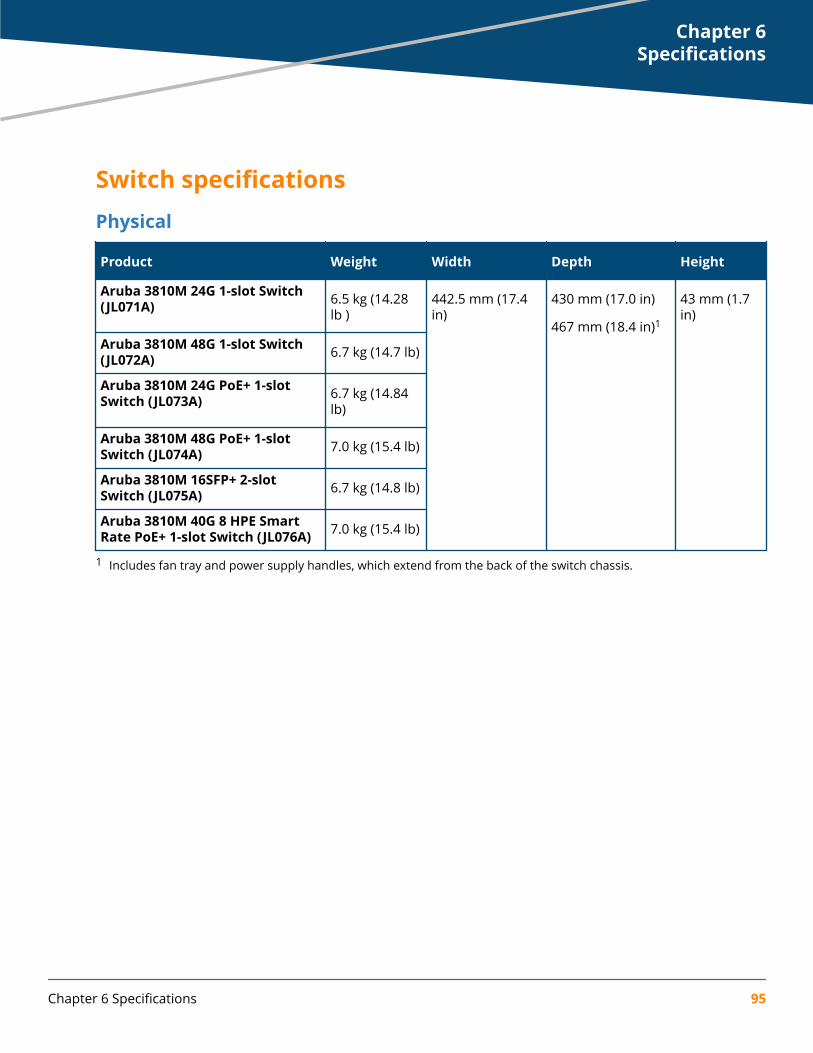
Switch specificationsPhysical
Product Weight Width Depth Height
Aruba 3810M 24G 1-slot Switch(JL071A) 6.5 kg (14.28
lb )442.5 mm (17.4in)
430 mm (17.0 in)
467 mm (18.4 in)1
43 mm (1.7in)
Aruba 3810M 48G 1-slot Switch(JL072A) 6.7 kg (14.7 lb)
Aruba 3810M 24G PoE+ 1-slotSwitch (JL073A) 6.7 kg (14.84
lb)
Aruba 3810M 48G PoE+ 1-slotSwitch (JL074A) 7.0 kg (15.4 lb)
Aruba 3810M 16SFP+ 2-slotSwitch (JL075A) 6.7 kg (14.8 lb)
Aruba 3810M 40G 8 HPE SmartRate PoE+ 1-slot Switch (JL076A) 7.0 kg (15.4 lb)
1 Includes fan tray and power supply handles, which extend from the back of the switch chassis.
Chapter 6Specifications
Chapter 6 Specifications 95
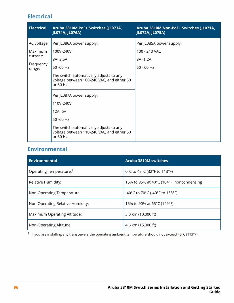
Electrical
Electrical Aruba 3810M PoE+ Switches (JL073A,JL074A, JL076A)
Aruba 3810M Non-PoE+ Switches (JL071A,JL072A, JL075A)
AC voltage:
Maximumcurrent:
Frequencyrange:
Per JL086A power supply:
100V-240V
8A- 3.5A
50 -60 Hz
The switch automatically adjusts to anyvoltage between 100-240 VAC, and either 50or 60 Hz.
Per JL085A power supply:
100 - 240 VAC
3A -1.2A
50 - 60 Hz
Per JL087A power supply:
110V-240V
12A- 5A
50 -60 Hz
The switch automatically adjusts to anyvoltage between 110-240 VAC, and either 50or 60 Hz.
Environmental
Environmental Aruba 3810M switches
Operating Temperature:1 0°C to 45°C (32°F to 113°F)
Relative Humidity: 15% to 95% at 40°C (104°F) noncondensing
Non-Operating Temperature: -40°C to 70°C (-40°F to 158°F)
Non-Operating Relative Humidity: 15% to 90% at 65°C (149°F)
Maximum Operating Altitude: 3.0 km (10,000 ft)
Non-Operating Altitude: 4.6 km (15,000 ft)
1 If you are installing any transceivers the operating ambient temperature should not exceed 45°C (113°F).
96 Aruba 3810M Switch Series Installation and Getting StartedGuide
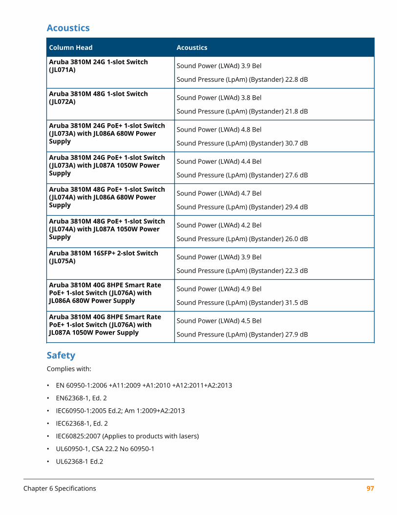
Acoustics
Column Head Acoustics
Aruba 3810M 24G 1-slot Switch(JL071A) Sound Power (LWAd) 3.9 Bel
Sound Pressure (LpAm) (Bystander) 22.8 dB
Aruba 3810M 48G 1-slot Switch(JL072A) Sound Power (LWAd) 3.8 Bel
Sound Pressure (LpAm) (Bystander) 21.8 dB
Aruba 3810M 24G PoE+ 1-slot Switch(JL073A) with JL086A 680W PowerSupply
Sound Power (LWAd) 4.8 Bel
Sound Pressure (LpAm) (Bystander) 30.7 dB
Aruba 3810M 24G PoE+ 1-slot Switch(JL073A) with JL087A 1050W PowerSupply
Sound Power (LWAd) 4.4 Bel
Sound Pressure (LpAm) (Bystander) 27.6 dB
Aruba 3810M 48G PoE+ 1-slot Switch(JL074A) with JL086A 680W PowerSupply
Sound Power (LWAd) 4.7 Bel
Sound Pressure (LpAm) (Bystander) 29.4 dB
Aruba 3810M 48G PoE+ 1-slot Switch(JL074A) with JL087A 1050W PowerSupply
Sound Power (LWAd) 4.2 Bel
Sound Pressure (LpAm) (Bystander) 26.0 dB
Aruba 3810M 16SFP+ 2-slot Switch(JL075A) Sound Power (LWAd) 3.9 Bel
Sound Pressure (LpAm) (Bystander) 22.3 dB
Aruba 3810M 40G 8HPE Smart RatePoE+ 1-slot Switch (JL076A) withJL086A 680W Power Supply
Sound Power (LWAd) 4.9 Bel
Sound Pressure (LpAm) (Bystander) 31.5 dB
Aruba 3810M 40G 8HPE Smart RatePoE+ 1-slot Switch (JL076A) withJL087A 1050W Power Supply
Sound Power (LWAd) 4.5 Bel
Sound Pressure (LpAm) (Bystander) 27.9 dB
SafetyComplies with:
• EN 60950-1:2006 +A11:2009 +A1:2010 +A12:2011+A2:2013
• EN62368-1, Ed. 2
• IEC60950-1:2005 Ed.2; Am 1:2009+A2:2013
• IEC62368-1, Ed. 2
• IEC60825:2007 (Applies to products with lasers)
• UL60950-1, CSA 22.2 No 60950-1
• UL62368-1 Ed.2
Chapter 6 Specifications 97
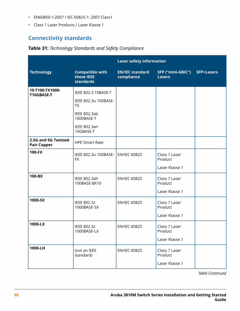
• EN60850-1:2007 / IEC 60825-1: 2007 Class1
• Class 1 Laser Products / Laser Klasse 1
Connectivity standards
Table 31: Technology Standards and Safety Compliance
Laser safety information
Technology Compatible withthese IEEEstandards
EN/IEC standardcompliance
SFP ("mini-GBIC")Lasers
SFP+Lasers
10-T100-TX1000-T10GBASE-T IEEE 802.3 10BASE-T
IEEE 802.3u 100BASE-TX
IEEE 802.3ab1000BASE-T
IEEE 802.3an10GBASE-T
2.5G and 5G Twisted-Pair Copper HPE Smart Rate
100-FX IEEE 802.3u 100BASE-FX
EN/IEC 60825 Class 1 LaserProduct
Laser Klasse 1
100-BX IEEE 802.3ah100BASE-BX10
EN/IEC 60825 Class 1 LaserProduct
Laser Klasse 1
1000-SX IEEE 802.3z1000BASE-SX
EN/IEC 60825 Class 1 LaserProduct
Laser Klasse 1
1000-LX IEEE 802.3z1000BASE-LX
EN/IEC 60825 Class 1 LaserProduct
Laser Klasse 1
1000-LH (not an IEEEstandard)
EN/IEC 60825 Class 1 LaserProduct
Laser Klasse 1
Table Continued
98 Aruba 3810M Switch Series Installation and Getting StartedGuide
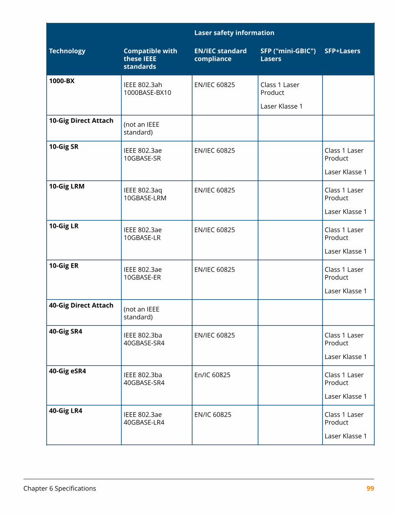
Laser safety information
Technology Compatible withthese IEEEstandards
EN/IEC standardcompliance
SFP ("mini-GBIC")Lasers
SFP+Lasers
1000-BX IEEE 802.3ah1000BASE-BX10
EN/IEC 60825 Class 1 LaserProduct
Laser Klasse 1
10-Gig Direct Attach (not an IEEEstandard)
10-Gig SR IEEE 802.3ae10GBASE-SR
EN/IEC 60825 Class 1 LaserProduct
Laser Klasse 1
10-Gig LRM IEEE 802.3aq10GBASE-LRM
EN/IEC 60825 Class 1 LaserProduct
Laser Klasse 1
10-Gig LR IEEE 802.3ae10GBASE-LR
EN/IEC 60825 Class 1 LaserProduct
Laser Klasse 1
10-Gig ER IEEE 802.3ae10GBASE-ER
EN/IEC 60825 Class 1 LaserProduct
Laser Klasse 1
40-Gig Direct Attach (not an IEEEstandard)
40-Gig SR4 IEEE 802.3ba40GBASE-SR4
EN/IEC 60825 Class 1 LaserProduct
Laser Klasse 1
40-Gig eSR4 IEEE 802.3ba40GBASE-SR4
En/IC 60825 Class 1 LaserProduct
Laser Klasse 1
40-Gig LR4 IEEE 802.3ae40GBASE-LR4
EN/IC 60825 Class 1 LaserProduct
Laser Klasse 1
Chapter 6 Specifications 99
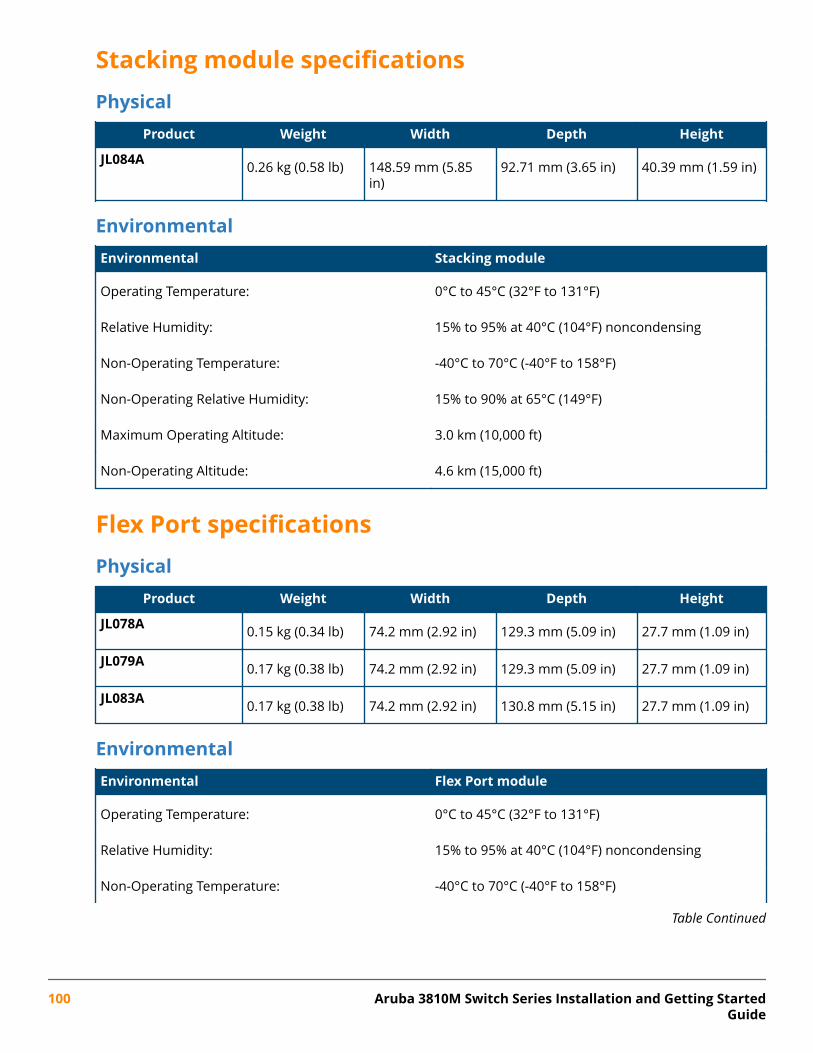
Stacking module specificationsPhysical
Product Weight Width Depth Height
JL084A 0.26 kg (0.58 lb) 148.59 mm (5.85in)
92.71 mm (3.65 in) 40.39 mm (1.59 in)
EnvironmentalEnvironmental Stacking module
Operating Temperature: 0°C to 45°C (32°F to 131°F)
Relative Humidity: 15% to 95% at 40°C (104°F) noncondensing
Non-Operating Temperature: -40°C to 70°C (-40°F to 158°F)
Non-Operating Relative Humidity: 15% to 90% at 65°C (149°F)
Maximum Operating Altitude: 3.0 km (10,000 ft)
Non-Operating Altitude: 4.6 km (15,000 ft)
Flex Port specificationsPhysical
Product Weight Width Depth Height
JL078A 0.15 kg (0.34 lb) 74.2 mm (2.92 in) 129.3 mm (5.09 in) 27.7 mm (1.09 in)
JL079A 0.17 kg (0.38 lb) 74.2 mm (2.92 in) 129.3 mm (5.09 in) 27.7 mm (1.09 in)
JL083A 0.17 kg (0.38 lb) 74.2 mm (2.92 in) 130.8 mm (5.15 in) 27.7 mm (1.09 in)
EnvironmentalEnvironmental Flex Port module
Operating Temperature: 0°C to 45°C (32°F to 131°F)
Relative Humidity: 15% to 95% at 40°C (104°F) noncondensing
Non-Operating Temperature: -40°C to 70°C (-40°F to 158°F)
Table Continued
100 Aruba 3810M Switch Series Installation and Getting StartedGuide

Environmental Flex Port module
Non-Operating Relative Humidity: 15% to 90% at 65°C (149°F)
Maximum Operating Altitude: 3.0 km (10,000 ft)
Non-Operating Altitude: 4.6 km (15,000 ft)
Chapter 6 Specifications 101
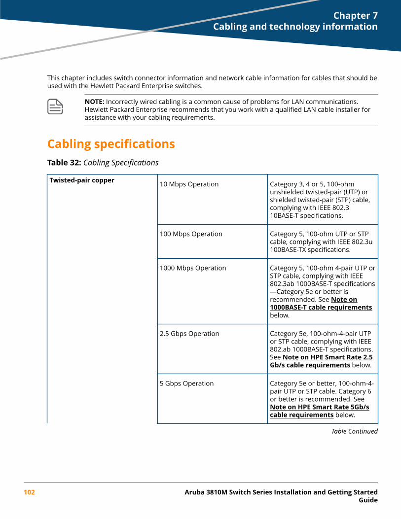
This chapter includes switch connector information and network cable information for cables that should beused with the Hewlett Packard Enterprise switches.
NOTE: Incorrectly wired cabling is a common cause of problems for LAN communications.Hewlett Packard Enterprise recommends that you work with a qualified LAN cable installer forassistance with your cabling requirements.
Cabling specificationsTable 32: Cabling Specifications
Twisted-pair copper 10 Mbps Operation Category 3, 4 or 5, 100-ohmunshielded twisted-pair (UTP) orshielded twisted-pair (STP) cable,complying with IEEE 802.310BASE-T specifications.
100 Mbps Operation Category 5, 100-ohm UTP or STPcable, complying with IEEE 802.3u100BASE-TX specifications.
1000 Mbps Operation Category 5, 100-ohm 4-pair UTP orSTP cable, complying with IEEE802.3ab 1000BASE-T specifications—Category 5e or better isrecommended. See Note on1000BASE-T cable requirementsbelow.
2.5 Gbps Operation Category 5e, 100-ohm-4-pair UTPor STP cable, complying with IEEE802.ab 1000BASE-T specifications.See Note on HPE Smart Rate 2.5Gb/s cable requirements below.
5 Gbps Operation Category 5e or better, 100-ohm-4-pair UTP or STP cable. Category 6or better is recommended. See Note on HPE Smart Rate 5Gb/scable requirements below.
Table Continued
Chapter 7Cabling and technology information
102 Aruba 3810M Switch Series Installation and Getting StartedGuide
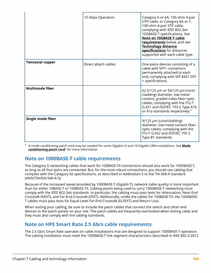
10 Gbps Operation Category 6 or 6A, 100-ohm 4-pairUTP cable, or Category 6A or 7,100-ohm 4-pair STP cable,complying with IEEE 802.3an10GBASE-T specifications. See Note on 10GBASE-T cablerequirements below, and see Technology distancespecifications for distancessupported with each cable type.
Twinaxial copper Direct attach cables One-piece devices consisting of acable with SFP+ connectorspermanently attached to eachend, complying with SFF 8431 SFP+ specifications.
Multimode fiber 62.5/125 μm or 50/125 μm (core/cladding) diameter, low metalcontent, graded index fiber-opticcables, complying with the ITU-TG.651 and ISO/IEC 793-2 Type A1bor A1a standards respectively.1
Single mode fiber 9/125 μm (core/cladding)diameter, low metal content fiber-optic cables, complying with theITU-T G.652 and ISO/IEC 793-2Type B1 standards.
1 A mode conditioning patch cord may be needed for some Gigabit-LX and 10-Gigabit LRM installations. See Modeconditioning patch cord“ for more information
Note on 1000BASE-T cable requirementsThe Category 5 networking cables that work for 100BASE-TX connections should also work for 1000BASE-T,as long as all four-pairs are connected. But, for the most robust connections, you should use cabling thatcomplies with the Category 5e specifications, as described in Addendum 5 to the TIA-568-A standard(ANSI/TIA/EIA-568-A-5).
Because of the increased speed provided by 1000BASE-T (Gigabit-T), network cable quality is more importantthan for either 10BASE-T or 100BASE-TX. Cabling plants being used to carry 1000BASE-T networking mustcomply with the IEEE 802.3ab standards. In particular, the cabling must pass tests for Attenuation, Near-EndCrosstalk (NEXT), and Far-End Crosstalk (FEXT). Additionally, unlike the cables for 100BASE-TX, the 1000BASE-T cables must pass tests for Equal-Level Far-End Crosstalk (ELFEXT) and Return Loss.
When testing your cabling, be sure to include the patch cables that connect the switch and other enddevices to the patch panels on your site. The patch cables are frequently overlooked when testing cable andthey must also comply with the cabling standards.
Note on HPE Smart Rate 2.5 Gb/s cable requirementsThe 2.5 Gb/s Smart Rate operates on cable installations that are designed to support 1000BASE-T operation.The cabling installation must meet the 1000BASE-T link segment characteristics described in IEEE 802.3-2012
Chapter 7 Cabling and technology information 103

and additionally the Category 5e or Class D limits described in the ANSI/TIA/EIA 568-C.2 and ISO/IEC 11801standards, respectively.
Note on HPE Smart Rate 5Gb/s cable requirementsThe 5 Gb/s Smart Rate operates on the majority of Category 5e and Category 6 cable installations. Category5e or Class D installations must meet the ANSI/TIA/EIA 568-C.2 or ISO/IEC 11801 transmission parameterlimits extended to 200MHz. Category 6 or Class E installations must meet their respective transmissionparameter limits as described in ANSI/TIA/EIA 568-C.2 or ISO/IEC 11801.
Also, to transmission performance, 5 Gb/s Smart Rate can be sensitive to alien noise from other cables inclose proximity or background noise from the environment. Therefore, cabling must additionally be testedfor Alien Near-End Crosstalk (ANEXT) and Alien Equal-Level-Far-End Crosstalk (AELFEXT). Depending on thecabling installation, the magnitude of alien crosstalk may further limit the maximum supported cablingdistance.
It is recommended that cable dressing be done carefully and in compliance with recommendations in theTIA TSB-155-A and ISO/IEC TR-24750.
Note on 10GBASE-T cable requirementsThe Category 6 networking cables that work for 1000BASE-T connections may work for 10GBASE-T, as longas the distance is less than 55m and the cable installation has been tested for compliance to IEEErequirements. But, for the most robust connections, you should use cabling that complies with the Category6A or Category 7 specifications, as described in the TIA-568-C (ANSI/TIA-568-C.2) and ISO/IEC 11801standards. 10GBASE-T is a sophisticated technology that relies upon high quality cable installations. It issensitive to Alien Near End Crosstalk (ANEXT) which can arrive upon the cable due to cables placed in closeproximity to the data cables. It is recommended that cable dressing be done carefully and in compliancewith recommendations in the TIA TSB-155A.
Like 1000BASE-T, 10GBASE-T requires testing of all the crosstalk and return loss parameters describedabove, and also ANEXT.
In addition to ANEXT, 10GBASE-T is more sensitive to external electrical noise in the environment. It isrecommended that radio transmitters and other sources of high frequency continuous wave radiofrequency be kept away from LAN cables.
When testing your cabling, be sure to include the patch cables that connect the switch and other enddevices to the patch panels on your site. The patch cables are frequently overlooked when testing cable andthey must also comply with the cabling standards. For 10GBASE-T, Category 6 patch cables are sensitive tomovement once link has been established, and could cause link to drop if moved. Therefore, HewlettPackard Enterprise recommends using Category 6A patch cables, or using cable management options to tiedown (dress) the Category 6 patch cables so they cannot move.
For Conducted and Radiated Immunity in accordance with EN55024, the Aruba 3810M switches are limitedto Performance Criteria A with shielded cables (CAT6/6A).
104 Aruba 3810M Switch Series Installation and Getting StartedGuide
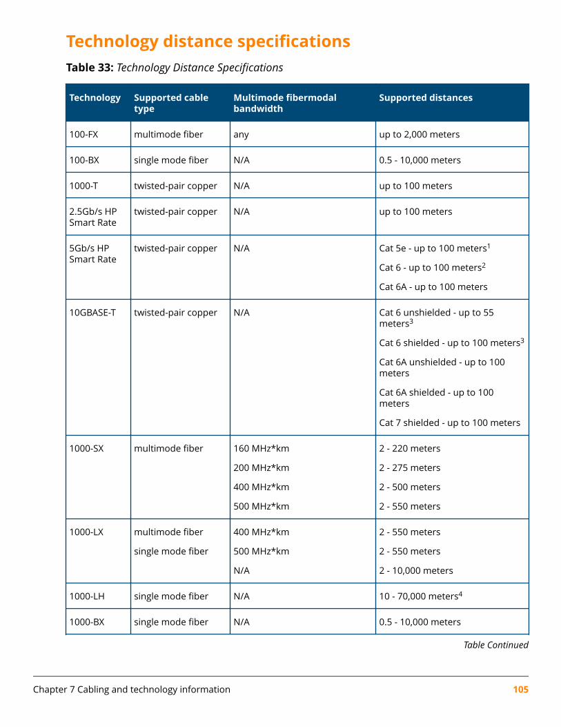
Technology distance specificationsTable 33: Technology Distance Specifications
Technology Supported cabletype
Multimode fibermodalbandwidth
Supported distances
100-FX multimode fiber any up to 2,000 meters
100-BX single mode fiber N/A 0.5 - 10,000 meters
1000-T twisted-pair copper N/A up to 100 meters
2.5Gb/s HPSmart Rate
twisted-pair copper N/A up to 100 meters
5Gb/s HPSmart Rate
twisted-pair copper N/A Cat 5e - up to 100 meters1
Cat 6 - up to 100 meters2
Cat 6A - up to 100 meters
10GBASE-T twisted-pair copper N/A Cat 6 unshielded - up to 55meters3
Cat 6 shielded - up to 100 meters3
Cat 6A unshielded - up to 100meters
Cat 6A shielded - up to 100meters
Cat 7 shielded - up to 100 meters
1000-SX multimode fiber 160 MHz*km
200 MHz*km
400 MHz*km
500 MHz*km
2 - 220 meters
2 - 275 meters
2 - 500 meters
2 - 550 meters
1000-LX multimode fiber
single mode fiber
400 MHz*km
500 MHz*km
N/A
2 - 550 meters
2 - 550 meters
2 - 10,000 meters
1000-LH single mode fiber N/A 10 - 70,000 meters4
1000-BX single mode fiber N/A 0.5 - 10,000 meters
Table Continued
Chapter 7 Cabling and technology information 105
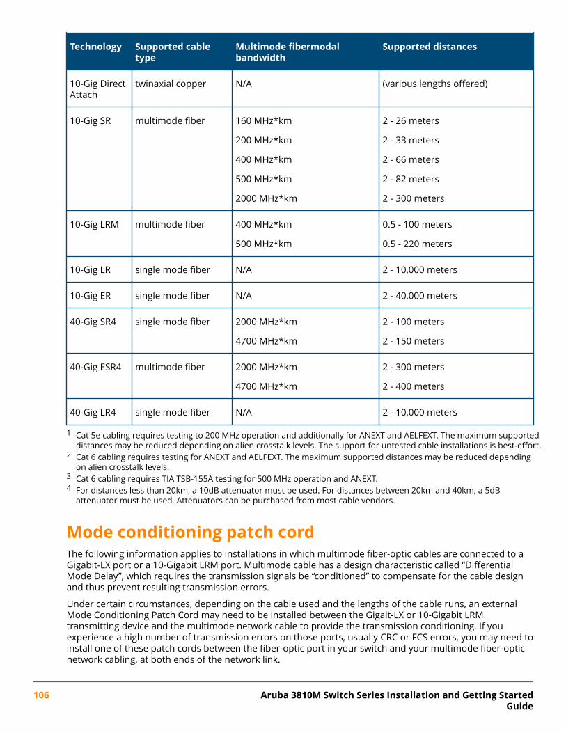
Technology Supported cabletype
Multimode fibermodalbandwidth
Supported distances
10-Gig DirectAttach
twinaxial copper N/A (various lengths offered)
10-Gig SR multimode fiber 160 MHz*km
200 MHz*km
400 MHz*km
500 MHz*km
2000 MHz*km
2 - 26 meters
2 - 33 meters
2 - 66 meters
2 - 82 meters
2 - 300 meters
10-Gig LRM multimode fiber 400 MHz*km
500 MHz*km
0.5 - 100 meters
0.5 - 220 meters
10-Gig LR single mode fiber N/A 2 - 10,000 meters
10-Gig ER single mode fiber N/A 2 - 40,000 meters
40-Gig SR4 single mode fiber 2000 MHz*km
4700 MHz*km
2 - 100 meters
2 - 150 meters
40-Gig ESR4 multimode fiber 2000 MHz*km
4700 MHz*km
2 - 300 meters
2 - 400 meters
40-Gig LR4 single mode fiber N/A 2 - 10,000 meters
1 Cat 5e cabling requires testing to 200 MHz operation and additionally for ANEXT and AELFEXT. The maximum supporteddistances may be reduced depending on alien crosstalk levels. The support for untested cable installations is best-effort.
2 Cat 6 cabling requires testing for ANEXT and AELFEXT. The maximum supported distances may be reduced dependingon alien crosstalk levels.
3 Cat 6 cabling requires TIA TSB-155A testing for 500 MHz operation and ANEXT.4 For distances less than 20km, a 10dB attenuator must be used. For distances between 20km and 40km, a 5dB
attenuator must be used. Attenuators can be purchased from most cable vendors.
Mode conditioning patch cordThe following information applies to installations in which multimode fiber-optic cables are connected to aGigabit-LX port or a 10-Gigabit LRM port. Multimode cable has a design characteristic called “DifferentialMode Delay”, which requires the transmission signals be “conditioned” to compensate for the cable designand thus prevent resulting transmission errors.
Under certain circumstances, depending on the cable used and the lengths of the cable runs, an externalMode Conditioning Patch Cord may need to be installed between the Gigait-LX or 10-Gigabit LRMtransmitting device and the multimode network cable to provide the transmission conditioning. If youexperience a high number of transmission errors on those ports, usually CRC or FCS errors, you may need toinstall one of these patch cords between the fiber-optic port in your switch and your multimode fiber-opticnetwork cabling, at both ends of the network link.
106 Aruba 3810M Switch Series Installation and Getting StartedGuide
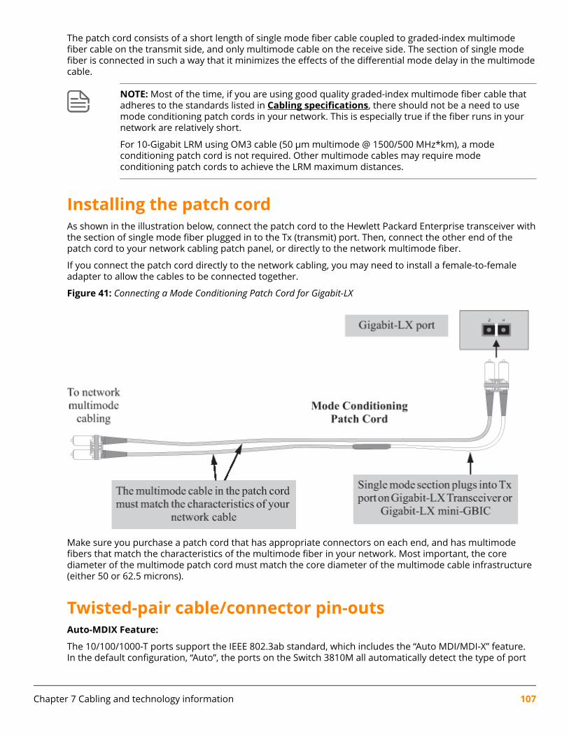
The patch cord consists of a short length of single mode fiber cable coupled to graded-index multimodefiber cable on the transmit side, and only multimode cable on the receive side. The section of single modefiber is connected in such a way that it minimizes the effects of the differential mode delay in the multimodecable.
NOTE: Most of the time, if you are using good quality graded-index multimode fiber cable thatadheres to the standards listed in Cabling specifications, there should not be a need to usemode conditioning patch cords in your network. This is especially true if the fiber runs in yournetwork are relatively short.
For 10-Gigabit LRM using OM3 cable (50 μm multimode @ 1500/500 MHz*km), a modeconditioning patch cord is not required. Other multimode cables may require modeconditioning patch cords to achieve the LRM maximum distances.
Installing the patch cordAs shown in the illustration below, connect the patch cord to the Hewlett Packard Enterprise transceiver withthe section of single mode fiber plugged in to the Tx (transmit) port. Then, connect the other end of thepatch cord to your network cabling patch panel, or directly to the network multimode fiber.
If you connect the patch cord directly to the network cabling, you may need to install a female-to-femaleadapter to allow the cables to be connected together.
Figure 41: Connecting a Mode Conditioning Patch Cord for Gigabit-LX
Make sure you purchase a patch cord that has appropriate connectors on each end, and has multimodefibers that match the characteristics of the multimode fiber in your network. Most important, the corediameter of the multimode patch cord must match the core diameter of the multimode cable infrastructure(either 50 or 62.5 microns).
Twisted-pair cable/connector pin-outsAuto-MDIX Feature:
The 10/100/1000-T ports support the IEEE 802.3ab standard, which includes the “Auto MDI/MDI-X” feature.In the default configuration, “Auto”, the ports on the Switch 3810M all automatically detect the type of port
Chapter 7 Cabling and technology information 107

on the connected device and operate as either an MDI or MDI-X port, whichever is appropriate. So for anyconnection, a straight-through twisted-pair cable can be used -- you no longer have to use crossover cables,although crossover cables can also be used for any of the connections.
If you connect a 3810M switch twisted-pair port to another switch or hub, which typically have MDI-X ports,the 3810M port automatically operates as an MDI port. If you connect it to an end node, such as a server orPC, which typically have MDI ports, the 3810M switch port operates as an MDI-X port. In all cases, you canuse standard straight-through cables or crossover cables.
If you happen to use a correctly wired crossover cable, though, the switch will still be able to automaticallydetect the MDI/MDI-X operation and link correctly to the connected device.
Other Wiring Rules:
• All twisted-pair wires used for 10 Mbps, and 100 Mbps operation must be twisted through the entirelength of the cable. The wiring sequence must conform to EIA/TIA 568-B (not USOC). See “PinAssignments” later in this appendix for a listing of the signals used on each pin.
• For 1000Base-T connections, all four pairs of wires in the cable must be available for data transmission.See Note on 1000BASE-T cable requirements for more information on 1000Base-T cabling.
• For 10 Mbps connections to the ports, you can use Category 3, 4, or 5 unshielded twisted-pair cable, assupported by the IEEE 802.3 Type 10Base-T standard.
• For 100 Mbps connections to the ports, use 100-ohm Category 5 UTP or STP cable only, as supported bythe IEEE 802.3u Type 100Base-TX standard.
• For 1000 Mbps connections, 100-ohm Category 5e or better cabling is recommended.
Straight-through twisted-pair cable for 10 Mbps or 100 Mbps networkconnectionsBecause of the Aruba Auto-MDIX operation of the 10/100 ports on the switch, for all network connections, toPCs, servers or other end nodes, or to hubs or other switches, you can use straight-through cables.
If any of these ports are given a fixed configuration, for example 100 Mbps/Full Duplex, the ports operate asMDI-X ports, and straight-through cables must be then used for connections to PC NICs and other MDIports.
108 Aruba 3810M Switch Series Installation and Getting StartedGuide
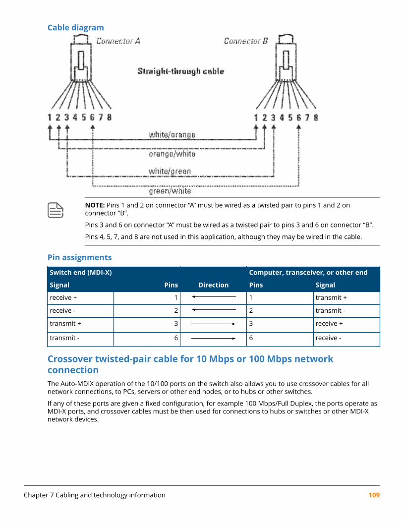
Cable diagram
NOTE: Pins 1 and 2 on connector “A” must be wired as a twisted pair to pins 1 and 2 onconnector “B”.
Pins 3 and 6 on connector “A” must be wired as a twisted pair to pins 3 and 6 on connector “B”.
Pins 4, 5, 7, and 8 are not used in this application, although they may be wired in the cable.
Pin assignments
Switch end (MDI-X) Computer, transceiver, or other end
Signal Pins Direction Pins Signal
receive + 1 1 transmit +
receive - 2 2 transmit -
transmit + 3 3 receive +
transmit - 6 6 receive -
Crossover twisted-pair cable for 10 Mbps or 100 Mbps networkconnectionThe Auto-MDIX operation of the 10/100 ports on the switch also allows you to use crossover cables for allnetwork connections, to PCs, servers or other end nodes, or to hubs or other switches.
If any of these ports are given a fixed configuration, for example 100 Mbps/Full Duplex, the ports operate asMDI-X ports, and crossover cables must be then used for connections to hubs or switches or other MDI-Xnetwork devices.
Chapter 7 Cabling and technology information 109
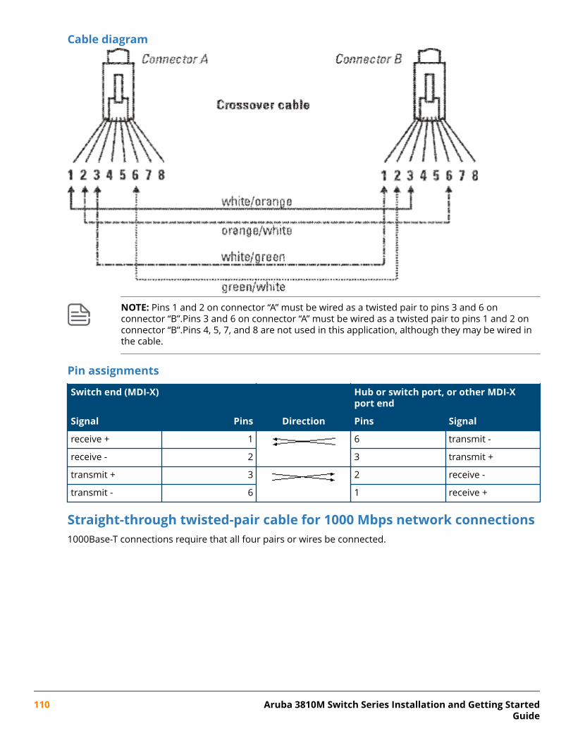
Cable diagram
NOTE: Pins 1 and 2 on connector “A” must be wired as a twisted pair to pins 3 and 6 onconnector “B”.Pins 3 and 6 on connector “A” must be wired as a twisted pair to pins 1 and 2 onconnector “B”.Pins 4, 5, 7, and 8 are not used in this application, although they may be wired inthe cable.
Pin assignments
Switch end (MDI-X) Hub or switch port, or other MDI-Xport end
Signal Pins Direction Pins Signal
receive + 1 6 transmit -
receive - 2 3 transmit +
transmit + 3 2 receive -
transmit - 6 1 receive +
Straight-through twisted-pair cable for 1000 Mbps network connections1000Base-T connections require that all four pairs or wires be connected.
110 Aruba 3810M Switch Series Installation and Getting StartedGuide
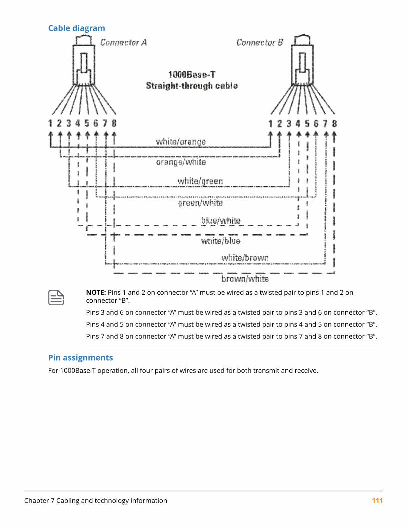
Cable diagram
NOTE: Pins 1 and 2 on connector “A” must be wired as a twisted pair to pins 1 and 2 onconnector “B”.
Pins 3 and 6 on connector “A” must be wired as a twisted pair to pins 3 and 6 on connector “B”.
Pins 4 and 5 on connector “A” must be wired as a twisted pair to pins 4 and 5 on connector “B”.
Pins 7 and 8 on connector “A” must be wired as a twisted pair to pins 7 and 8 on connector “B”.
Pin assignmentsFor 1000Base-T operation, all four pairs of wires are used for both transmit and receive.
Chapter 7 Cabling and technology information 111
Networking WebsitesHewlett Packard Enterprise Networking Information Library
www.hpe.com/networking/resourcefinder
Hewlett Packard Enterprise Networking Software
www.hpe.com/networking/software
Hewlett Packard Enterprise Networking website
www.hpe.com/info/networking
Hewlett Packard Enterprise My Networking website
www.hpe.com/networking/support
Hewlett Packard Enterprise My Networking Portal
www.hpe.com/networking/mynetworking
Hewlett Packard Enterprise Networking Warranty
www.hpe.com/networking/warranty
General websitesHewlett Packard Enterprise Information Library
www.hpe.com/info/EIL
For additional websites, see Support and other resources.
Chapter 8Websites
112 Aruba 3810M Switch Series Installation and Getting StartedGuide
Accessing Hewlett Packard Enterprise Support• For live assistance, go to the Contact Hewlett Packard Enterprise Worldwide website:
http://www.hpe.com/assistance
• To access documentation and support services, go to the Hewlett Packard Enterprise Support Centerwebsite:
http://www.hpe.com/support/hpesc
Information to collect
• Technical support registration number (if applicable)
• Product name, model or version, and serial number
• Operating system name and version
• Firmware version
• Error messages
• Product-specific reports and logs
• Add-on products or components
• Third-party products or components
Accessing updates• Some software products provide a mechanism for accessing software updates through the product
interface. Review your product documentation to identify the recommended software update method.
• To download product updates:
Hewlett Packard Enterprise Support Centerwww.hpe.com/support/hpesc
Hewlett Packard Enterprise Support Center: Software downloadswww.hpe.com/support/downloads
Software Depotwww.hpe.com/support/softwaredepot
• To subscribe to eNewsletters and alerts:
www.hpe.com/support/e-updates
• To view and update your entitlements, and to link your contracts and warranties with your profile, go tothe Hewlett Packard Enterprise Support Center More Information on Access to Support Materialspage:
Chapter 9Support and other resources
Chapter 9 Support and other resources 113

www.hpe.com/support/AccessToSupportMaterials
IMPORTANT: Access to some updates might require product entitlement when accessedthrough the Hewlett Packard Enterprise Support Center. You must have an HPE Passport set upwith relevant entitlements.
Customer self repairHewlett Packard Enterprise customer self repair (CSR) programs allow you to repair your product. If a CSRpart needs to be replaced, it will be shipped directly to you so that you can install it at your convenience.Some parts do not qualify for CSR. Your Hewlett Packard Enterprise authorized service provider willdetermine whether a repair can be accomplished by CSR.
For more information about CSR, contact your local service provider or go to the CSR website:
http://www.hpe.com/support/selfrepair
Remote supportRemote support is available with supported devices as part of your warranty or contractual supportagreement. It provides intelligent event diagnosis, and automatic, secure submission of hardware eventnotifications to Hewlett Packard Enterprise, which will initiate a fast and accurate resolution based on yourproduct's service level. Hewlett Packard Enterprise strongly recommends that you register your device forremote support.
If your product includes additional remote support details, use search to locate that information.
Remote support and Proactive Care informationHPE Get Connected
www.hpe.com/services/getconnectedHPE Proactive Care services
www.hpe.com/services/proactivecareHPE Proactive Care service: Supported products list
www.hpe.com/services/proactivecaresupportedproductsHPE Proactive Care advanced service: Supported products list
www.hpe.com/services/proactivecareadvancedsupportedproducts
Proactive Care customer informationProactive Care central
www.hpe.com/services/proactivecarecentralProactive Care service activation
www.hpe.com/services/proactivecarecentralgetstarted
Warranty informationTo view the warranty for your product or to view the Safety and Compliance Information for Server, Storage,Power, Networking, and Rack Products reference document, go to the Enterprise Safety and Compliancewebsite:
www.hpe.com/support/Safety-Compliance-EnterpriseProducts
114 Aruba 3810M Switch Series Installation and Getting StartedGuide
Additional warranty informationHPE ProLiant and x86 Servers and Options
www.hpe.com/support/ProLiantServers-WarrantiesHPE Enterprise Servers
www.hpe.com/support/EnterpriseServers-WarrantiesHPE Storage Products
www.hpe.com/support/Storage-WarrantiesHPE Networking Products
www.hpe.com/support/Networking-Warranties
Regulatory informationTo view the regulatory information for your product, view the Safety and Compliance Information for Server,Storage, Power, Networking, and Rack Products, available at the Hewlett Packard Enterprise Support Center:
www.hpe.com/support/Safety-Compliance-EnterpriseProducts
Additional regulatory information
Hewlett Packard Enterprise is committed to providing our customers with information about the chemicalsubstances in our products as needed to comply with legal requirements such as REACH (Regulation EC No1907/2006 of the European Parliament and the Council). A chemical information report for this product canbe found at:
www.hpe.com/info/reach
For Hewlett Packard Enterprise product environmental and safety information and compliance data,including RoHS and REACH, see:
www.hpe.com/info/ecodata
For Hewlett Packard Enterprise environmental information, including company programs, product recycling,and energy efficiency, see:
www.hpe.com/info/environment
Documentation feedbackHewlett Packard Enterprise is committed to providing documentation that meets your needs. To help usimprove the documentation, send any errors, suggestions, or comments to Documentation Feedback([email protected]). When submitting your feedback, include the document title, part number,edition, and publication date located on the front cover of the document. For online help content, includethe product name, product version, help edition, and publication date located on the legal notices page.
Chapter 9 Support and other resources 115


