Embed Size (px)
Citation preview

User’s Manual
2 © 2006 Moteiv Corporation
Table of Contents Tmote Tools Installation ............................................................................3 Tmote Invent Applications.......................................................................10 Uninstalling and Upgrading.....................................................................20
Uninstalling Cygwin.........................................................................20 Uninstalling TinyOS.........................................................................20 Upgrading Cygwin...........................................................................21 Upgrading TinyOS...........................................................................21
Tmote Invent Hardware...........................................................................22 Module overview .............................................................................22 Mechanical characteristics ..............................................................23 Schematics......................................................................................23 Interface to Tmote Sky ....................................................................24
Power Supply ..........................................................................................24 Schematic........................................................................................25 Battery characteristics.....................................................................25
Light sensor.............................................................................................27 Electrical and optical characteristics ...............................................27 Schematic........................................................................................27 Theory of operation .........................................................................28
Accelerometer .........................................................................................29 Schematic........................................................................................29 Electrical and mechanical characteristics .......................................30 Theory of operation .........................................................................30
Microphone..............................................................................................33 Electrical and acoustic characteristics ............................................33 Schematic........................................................................................34 Theory of operation .........................................................................35
Speaker ...................................................................................................39 Schematic........................................................................................39 Electrical and acoustic characteristics ............................................39 Theory of operation .........................................................................40
Tmote Invent Software ............................................................................43 Sensor Drivers.................................................................................43 Communications..............................................................................45 Useful TinyOS Components............................................................48
Notes .......................................................................................................49 General Information ................................................................................50
Document History............................................................................50 Address Information ........................................................................50 Headquarters...................................................................................50

3
© 2006 Moteiv Corporation
Tmote Tools Installation
NOTE: If you have previously installed TinyOS or Cygwin, either from a previous Moteiv installer, from another vendor’s installer, or on your own accord, we recommend you remove all previous TinyOS and Cygwin in-stallations before proceeding. See page 20 for more information.
Please place the Tmote Tools CD into your computer’s CD-ROM drive. After a few moments, the Moteiv Tmote Tools Setup Wizard will display:
Please click “Next”.
4 © 2006 Moteiv Corporation
Moteiv’s software is distributed under the Moteiv Public Software Li-cense. Accept the terms of the license agreement and click “Next”.
Please select the “Typical” installation option.

5
© 2006 Moteiv Corporation
Simply click “Install”.
. The Moteiv Tmote Tools installer will begin installation and configuration of your system.
6 © 2006 Moteiv Corporation
First, the Cygwin Setup window will appear and will take a few minutes to install all of the necessary packages.
After Cygwin Setup is complete, the Java platform is installed. Accept the Sun Microsystems license agreement and click “Next”.

7
© 2006 Moteiv Corporation
Choose additional Java installation options if desired, and then click “Next”.
The Java installer will proceed to install and configure Java.
8 © 2006 Moteiv Corporation
Upon completion of the Java installation, click “Finish”.
After Java is complete, the Moteiv Tmote Tools Setup Wizard will install and configure the tools required to develop and run applications using the TinyOS open source operating system. Please be patient as all of the files are installed and server tools are compiled.

9
© 2006 Moteiv Corporation
Following installation of the TinyOS tools, the Moteiv Tmote Tools Setup Wizard installs and configures Boomerang by Moteiv. This is Moteiv’s distribution of the TinyOS operating system that includes extended API support, example applications, and additional development tools.
Congratualations! Installation of Moteiv’s Tmote Tools is complete! Please proceed to the next section to start building applications with Moteiv’s Tmote devices.
10 © 2006 Moteiv Corporation
Tmote Invent Applications Now that Moteiv’s Tmote Tools and the TinyOS development environ-ment are installed on your system, let’s explore wireless sensor network-ing with Tmote Invent.
Charging indicatorReset button
User button
SpeakerMicrophone
Light sensor
Headphone jack
LEDsStrap hook
Remove the Tmote Invent units from the packaging. Turn the units on by pressing the Reset button, shown in the picture above. Plug one of the units into your USB port. If Windows displays the “Found New Hardware Wizard”, select “Install from a list or specific location (Advanced)” then “Next”. When prompted, select only “Include this location in the search” then click “Browse”. Se-lect the “USB Serial Driver” folder from the Tmote Tools CD, click “OK”, then “Next”. Windows installs the driver files, completing the installation for Tmote as a “USB Serial Port”.
11
© 2006 Moteiv Corporation
NOTE: To turn on Tmote Invent, press the Reset button. The LEDs will perform a 3-2-1 countdown indicating that the device is on. To turn off Tmote Invent, press and hold the User button. While holding the User but-ton, press and release the Reset button. The LEDs on Tmote Invent with fade from full brightness to off, indicating the device has powered down.
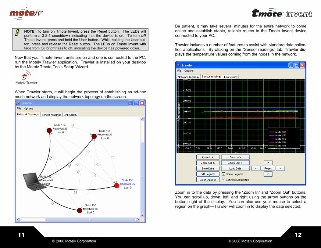
Now that your Tmote Invent units are on and one is connected to the PC, run the Moteiv Trawler application. Trawler is installed on your desktop by the Moteiv Tmote Tools Setup Wizard.
When Trawler starts, it will begin the process of establishing an ad-hoc mesh network and display the network topology on the screen.
12 © 2006 Moteiv Corporation
Be patient, it may take several minutes for the entire network to come online and establish stable, reliable routes to the Tmote Invent device connected to your PC. Trawler includes a number of features to assist with standard data collec-tion applications. By clicking on the “Sensor readings” tab, Trawler dis-plays the temperature values coming from the nodes in the network.
Zoom in to the data by pressing the “Zoom In” and “Zoom Out” buttons. You can scroll up, down, left, and right using the arrow buttons on the bottom right of the display. You can also use your mouse to select a region on the graph—Trawler will zoom in to display the data selected.

13
© 2006 Moteiv Corporation
Now, click on the “links” tab. This display assists with network commis-sioning—you can determine if the link quality between nodes is ex-tremely low, you may need to move the node or add additional nodes to the network that participate in the mesh.
You can log the data readings to a file by clicking on “Log Packets” in the “Vizualization Controls” sidebar. If you cannot find the “Vizualization Controls”, minimize Trawler. Sometimes the controls are hidden by the main Trawler window.
14 © 2006 Moteiv Corporation
Tmote Invent includes a few other applications, pre-installed on the Tmote Invent devices. To access these applications, first open a cygwin shell by clicking on the Cygwin icon installed on the Windows Desktop.
First, find out which port Tmote Invent is connected. Simply type motelist on at Cygwin command prompt.
In this example, Tmote Invent is connected to the PC using COM4, with serial number M4A663KN. You will need to know which communication port is assigned to your Tmote Invent unit in order to communicate with it; use the motelist command after connecting each Tmote Invent to identify its communications port. To query the other applications pre-installed on Tmote Invent, run the Deluge application using the following command at the Cygwin com-mand line:
Where you must replace COM4 with the communications port returned by the motelist command in the step above. Deluge returns a descrip-tion of the images pre-installed on Tmote Invent, as shown on the next page.
$ motelist Reference CommPort Description ---------- ---------- ------------------------------ M4A663KN COM4 tmote invent
MOTECOM=serial@COM4:telos java net.tinyos.tools.Deluge -p

15
© 2006 Moteiv Corporation
Pinging node ... Connected to Deluge node. Getting data for image [6] -------------------------------------------------- Currently Executing: Prog Name: Delta Compiled On: Mon Feb 27 16:05:46 PST 2006 User Hash: 0xcd45b685 Stored Image 0 - (Golden Image) Prog Name: Delta Compiled On: Mon Feb 27 16:05:46 PST 2006 Platform: tmoteinvent User ID: sentry Hostname: TestBox2 User Hash: 0xcd45b685 Num Pages: 33/33 Stored Image 1 Prog Name: DeltaLowpower Compiled On: Mon Feb 27 16:08:00 PST 2006 Platform: tmoteinvent User ID: sentry Hostname: TestBox2 User Hash: 0xcd45b685 Num Pages: 37/37 Stored Image 2 Prog Name: Ditto Compiled On: Mon Feb 27 16:20:20 PST 2006 Platform: tmoteinvent User ID: sentry Hostname: TestBox2 User Hash: 0xcd45b685 Num Pages: 36/36 Stored Image 3 Prog Name: Oscilloscope Compiled On: Mon Feb 27 16:17:25 PST 2006 Platform: tmoteinvent User ID: sentry Hostname: TestBox2 User Hash: 0xcd45b685 Num Pages: 24/24 Stored Image 4 Prog Name: N/A Compiled On: N/A Platform: N/A User ID: N/A Hostname: N/A User Hash: N/A Num Pages: N/A Stored Image 5 Prog Name: N/A Compiled On: N/A Platform: N/A User ID: N/A Hostname: N/A User Hash: N/A Num Pages: N/A -------------------------------------------------- DONE
16 © 2006 Moteiv Corporation
Tmote Invent is pre-installed with four applications before leaving the factory. Here is a description of each application:
Application Description Delta Standard mesh networking application visualized using
Moteiv Trawler. /opt/moteiv/apps/Delta
DeltaLowpower The same as above, except that DeltaLowpower runs at a 5% duty cycle instead of 100%, significantly reducing power consumption. /opt/moteiv/apps/Delta
Ditto Application that records 1 second of sound from the user, disseminates it to all nodes in the network, and any Tmote Invent unit can play back the recording. /opt/moteiv/apps/invent/Ditto
Oscilloscope Application that samples all of the sensors on Tmote Invent and broadcasts the readings that are displayed by a PC. /opt/moteiv/apps/Oscilloscope
All of your nodes are currently running Delta, but with a simple command from the PC, they can switch to running Ditto. To switch your nodes from running Delta to Ditto, run the follow program (as one line of text) on the Cygwin command line:
MOTECOM=serial@COM4:telos java net.tinyos.tools.Deluge –r –in=2
This instructs the network to reboot to image number 2. After the nodes reboot, double click the user button on any Tmote Invent device. The mote begins a 3-2-1 countdown by flashing the red LED. When the LED turns on, Tmote Invent is recording sound using the built-in microphone. After recording, Tmote Invent disseminates the recording to all neighboring nodes. During dissemination, the blue LED flashes. Once the blue LED stops flashing, press the user button on any Tmote Invent. The sound is played back through the Tmote Invent speaker. Repeat the process as many times as you want with any number of motes; they will continue to disseminate the recordings and play back the most recent sound sample.

17
© 2006 Moteiv Corporation
After running Ditto, reboot the Tmote Invent network to the Oscilloscope application. Oscilloscope samples all of Tmote Invent’s sensors and sends them over the radio for the PC to display. To reboot to Oscilloscope, issue the following command in Cygwin:
MOTECOM=serial@COM4:telos java net.tinyos.tools.Deluge –r –in=3
After rebooting the nodes to Oscilloscope, compile an application and install it on the mote. In Cygwin, change to the /opt/moteiv/apps/TOSBase directory. To compile an application for Tmote Invent, issue the following command:
Upon successful compilation, your Cygwin window should display the following output, ending with: compiled TOSBase to build/tmoteinvent/main.exe.
Now install TOSBase to the node connected to the PC with the following command:
make tmoteinvent
$ make tmoteinvent mkdir -p build/tmoteinvent compiling TOSBase to a tmoteinvent binary [verbose output omitted] C:/cygwin/opt/moteiv/tos/lib/CC2420Radio/RadioCRCPacket.nc:49:2: warning: #warning Using old communication interfaces; recommend switch to SP C:/cygwin/opt/moteiv/tos/lib/CC2420Radio/TranslateBareSendMsgC.nc:29:2: warning: #warning Using old communication interfaces; recom-mend switch to SP compiled TOSBase to build/tmoteinvent/main.exe 15422 bytes in ROM 3919 bytes in RAM msp430-objcopy --output-target=ihex build/tmoteinvent/main.exe build/tmoteinvent/main.ihex writing TOS image
make tmoteinvent reinstall,1
18 © 2006 Moteiv Corporation
where “1” is the network address assigned to the node at installation. TOSBase is a simple base station application that forwards all messages from the radio over the USB port to the PC. This mote will be used to read the oscilloscope messages sent by other nodes. To view the Oscilloscope readings from the other Tmote Invent units, start the Oscilloscope java application. Use motelist if necessary to de-termine the communications port assigned to the Tmote Invent unit run-ning TOSBase.
When the Oscilloscope application executes (as shown on the next page), it displays the data readings from each of the connected motes. The data channels are assigned as follows, and all of the values dis-played are raw ADC units. To convert to engineering units, see the README.TmoteInvent document in apps/Oscilloscope. Channel 0: Photo Channel 1: Accelerometer X-Axis Channel 2: Accelerometer Y-Axis Channel 4: InternalTemperature Channel 5: InternalVoltage After successfully compiling TOSBase and installing it on a node, you can reset all of your Tmote Invent devices back to their original factory image. The factory image, stored in Deluge image slot 0, can only be changed when Tmote Invent is connected directly to the PC. To return to the factory image, press and release the reset button three times in rapid succession. The node will blink all LEDs three times to acknowledge your command, then the LEDs will flash as the factory im-age is reloaded into program flash. Finally, Tmote Invent will count down in the same manner as when the node is first turned on, and it will begin running the Delta application. To view readings from Delta, return to page 10 and run the Trawler application.
MOTECOM=serial@COM4:tmote java com.moteiv.oscope.oscilloscope

19
© 2006 Moteiv Corporation
20 © 2006 Moteiv Corporation
Uninstalling and Upgrading If you have previously installed TinyOS or Cygwin, either from a previous Moteiv installer, from another vendor’s installer, or on your own accord, we recommend you remove all previous TinyOS and Cygwin installa-tions before proceeding. Uninstalling Cygwin Cygwin provides no method for convenient uninstall. The following steps are usually sufficient to remove Cygwin from your system:
• Close all Cygwin applications and services • Delete or rename the following keys in the registry by invoking
RegEdit or RegEdt32 o HKEY_CURRENT_USER\Software\Cygnus Solutions o HKEY_LOCAL_MACHINE\SOFTWARE\Cygnus Solutions
• Delete or rename your Cygwin install directory, which defaults to c:\cygwin
Uninstalling TinyOS If you installed TinyOS with an installation utility, just run its associated uninstaller. If not, you must manually uninstall any “tinyos”, “nesc”, and “msp430” RPM’s. Discover which RPM’s are installed by starting a Cygwin shell and running the command “rpm -qa”. Remove packages with the com-mand “rpm --erase --nodeps [package1] [package2] […]”. Here is a sample list of RPM’s that may be installed, though the particu-lar packages and versions installed on your computer may differ: tinyos-tools-1.2.1-3 msp430tools-binutils-2.16-20050607 make-3.80tinyos-1 msp430tools-python-tools-1.0-1 tinyos-javacomm-1.0.0-1 tinyos-moteiv-2.0.1-1 nesc-1.2.4-1 msp430tools-base-0.1-20050607 msp430tools-gcc-3.2.3-20050607
21
© 2006 Moteiv Corporation
msp430tools-libc-20050308cvs-20050608 mspgcc-win32tinyos-20041204-2 tinyos-1.1.15Dec2005cvs-1 Upgrading Cygwin Moteiv only supports the version of Cygwin installed by Moteiv Tmote Tools. However, any version of Cygwin installed or updated since De-cember 2004 should be compatible, although Moteiv does not support user-installed Cygwin installations. The following Cygwin packages are installed by the Moteiv Tmote Tools CD, and are the minimum required to install TinyOS and its related tools:
Upgrading TinyOS Moteiv Tmote Tools installs new versions of the compilers and tools used by TinyOS. You may be able to directly upgrade an existing TinyOS installation using the Moteiv Tmote Tools CD, although you will be on your own if something does not work.
ash autoconf autoconf-devel autoconf-stable automake auto-make-devel automake-stable base-files base-passwd bash binutils bison bzip2 crypt ctags cvs cygipc cygrunsrv cygutils cygwin diffutils editrights emacs expat file fileutils findutils flex gawk gcc gcc-core gcc-g++ gcc-mingw gcc-mingw-core gcc-mingw-g++ gdb gdbm gettext gperf grep groff gzip less libbz2_1 libcharset1 libdb4.2 libgdbm libgdbm-devel libgdbm3 libgdbm4 libgettextpo0 libiconv libiconv2 libintl1 libintl2 libintl3 libncurses5 libncurses6 libncurses7 libncurses8 libpcre libpcre0 libpopt0 libreadline4 libread-line5 libreadline6 login m4 make man mingw-runtime minires mktemp more nano ncurses openssh openssl patch patchutils perl perl_manpages postgresql python rcs readline rpm rpm-build rpm-doc rxvt sed sh-utils tar tcltk tcsh termcap terminfo texinfo textutils time unzip vim w32api wget which zip zlib
22 © 2006 Moteiv Corporation
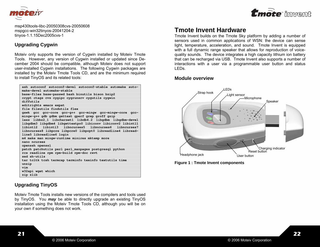
Tmote Invent Hardware Tmote Invent builds on the Tmote Sky platform by adding a number of sensors used in common applications of WSN: the device can sense light, temperature, acceleration, and sound. Tmote Invent is equipped with a full dynamic range speaker that allows for reproduction of voice-quality sounds. The device integrates a high capacity lithium ion battery that can be recharged via USB. Tmote Invent also supports a number of interactions with a user via a programmable user button and status LEDs. Module overview
Charging indicatorReset button
User button
SpeakerMicrophone
Light sensor
Headphone jack
LEDsStrap hook
Figure 1 : Tmote Invent components

23
© 2006 Moteiv Corporation
Mechanical characteristics
All dimensions are in inches. Schematics
tuO_otohP3CDA
0CAD_rekaepS
TNIresU TNIresU TESER
CCVA
1CDAY_leccA
XR0TRAU
XT0TRAU
LCS_C2I
ADS_C2I
tnI_ciMtnI_leccA
0CDAX_leccA
2CDAtuO_ciM
1CAD_rekaepS
ADS_C2ILCS_C2I
1DEL
2DEL
3DEL
1DEL2DEL3DEL
ccV ccV
ccV
tnI_leccA
X_leccA
Y_leccA
0CAD_rekaepS
tuO_ciM
NDHS_TOP
LCS_C2I
ADS_C2I
tuO_otohP
tnI_ciM
1CAD_rekaepS
0EAMD
niSVS/1CAD0CAD
erutpaCAremiT
ykSetomTotslangiS
02x0=0000010
nottubllamSnottubegraL
lortnocsDEL
1 2
4-C106PLTQ-raelCneerG8D 4-C106PLTQ-raelCneerG8D
11 2 2
33 4 4
55 6 6
77 8 8
99 01 01
2U
"1.0-redaeHnip01
2U
"1.0-redaeHnip01
1 2
1WS
M3064P-QVE
1WS
M3064P-QVE
0018R 0018R
ADS31LCS21
8O/TNI11
2DA11DA610DA51
0P 21P 32P 43P 54P 75P 86P 97P 01G
ND
6V
+1422U
5137XAM
22U
5137XAM
1 2
7-C106PLTQ-raelCdeR7D 7-C106PLTQ-raelCdeR7D
1 2
BE-C106PLTQ-raelCeulB9D BE-C106PLTQ-raelCeulB9D1 2
2WS
M3064P-QVE
2WS
M3064P-QVE
11 2 2
33 4 4
55 6 6
82U
redaeHnip6
82U
redaeHnip6
01Rk0101R
k01
0027R 0027R
0029R 0029R
1.96
68.017.3
24 © 2006 Moteiv Corporation
Interface to Tmote Sky Tmote Invent uses Moteiv’s popular Tmote Sky module for communica-tion and computation. Tmote Invent relies extensively on I2C bus for control of different sensor subcircuits. Three types of control are pro-vided: • I2C-activated GPIO lines – they are used throughout Tmote Invent
for power and shutdown of different subcircuits • I2C-controlled potentiometers – these are used for control of various
aspects of the analog signal chain, such as adjusting amplifier char-acteristics and signal thresholds
• I2C LED controller is used to actuate the LEDs visible from outside the package.
Tmote Invent uses 4 analog channels of the Tmote Sky connector for sensor data: two of these channels are dedicated to the accelerometer, one to the photo sensor, and one to the microphone. Two interrupt lines are used for analog event detection on the microphone and the acceler-ometer; two additional lines are used to bring the interrupts to the user accessible buttons. Finally, the speaker is driven by a single DAC signal. For more information on Tmote Sky, please visit Moteiv’s website at http://www.moteiv.com.
Power Supply Tmote invent is equipped with a lithium ion battery that is recharged when the device is plugged into a USB port. The battery provides a rela-tively flat discharge profile, 750 mAh capacity and 500 charge cycles. When the device is connected to a USB port, an indicator light on the left side of Tmote Invent indicates the charging status: red indicates charg-ing, green indicates a fully charged. A full charge cycle takes about 10 hours.

25
© 2006 Moteiv Corporation
Schematic
CCVDKCT
TESER
SMT
IDT
ODT
+BSU+ttaB
GHC
GHC
+BSU
+BSU
+ttaB
+ttaB
CCVD
+BSU
+BSU
GHC
SMT
IDT
ODT
KCT
yrettaB+iLredaeHGATJ
DELrotacidnIegrahCrellortnoCegrahC
tneserPBSUnehwyrettaBdaolnU
0742R 0742R
0743R 0743R
11 2 2
33 4 4
55 6 6
77 8 8
8U
mm2-redaeHnip8
8U
mm2-redaeHnip8
2Cu12Cu1
2 4
53
3U
CVL47NS
3U
CVL47NS
1
32
1Q
F30P16MXZ
1Q
F30P16MXZ
+ 1
- 2
1U
NNOC_RWP
1U
NNOC_RWP
CD4
BSU1
TAB 5
GHC 3
DNG 2
0U
5551XAM
0U
5551XAM
1
2
3
4
1D
DEL0121neerG/deR
1D
DEL0121neerG/deR
1Cu11Cu1
1Rk001
1Rk001
Battery characteristics Parameter Value Units Notes Voltage range 3.0-4.2 V Average voltage 3.7 V Nominal capacity 750 mAh C/5 discharge, 25 °C Max. discharge rate 750 mA continuous Weight 16.5 g Self discharge <10 %/month Operating temperature -20 to 60 °C Storage temperature -20 to 60 °C Cycle life >500 150mA discharge to
80% initial capacity
26 © 2006 Moteiv Corporation
Figure 2: Rechargeable battery characteristics. Tmote Invent is equipped with a lithium ion rechargeable battery. Figure 2 shows the various characteristics of the battery, which is rated to hold 80% of its initial capacity for over 500 cycles. The voltage ranges be-tween 3.0 and 4.2V: the voltage region from 85% of remaining capacity to about 95% of remaining capacity is relatively flat as the voltage falls from 3.9V to 3.6V. The battery voltage may have a significant impact on the sensor performance, the user may need to consider whether the im-pact of this 10% variation is significant. The battery voltage will also change based on temperature, and the change is greater at small re-maining capacities. When the device is plugged into the USB, the battery is charged at a rate of 80 mA; the charge conditioning is controlled via a dedicated battery charger chip, the MAX 1555. When Tmote Invent is powered via USB, the supply voltage to Tmote Invent is 3V. When the device is unplugged from the USB, occasionally the voltage transients may lead to a brown-out reset of the device.
27
© 2006 Moteiv Corporation
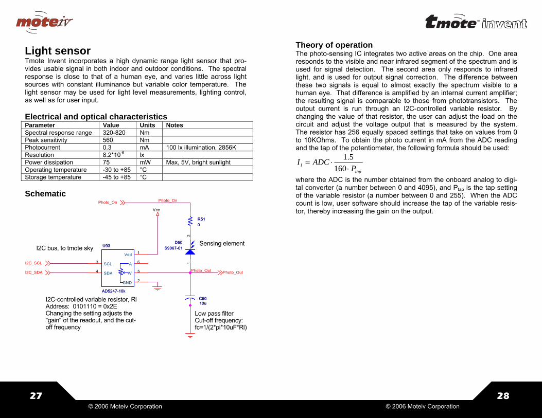
Light sensor Tmote Invent incorporates a high dynamic range light sensor that pro-vides usable signal in both indoor and outdoor conditions. The spectral response is close to that of a human eye, and varies little across light sources with constant illuminance but variable color temperature. The light sensor may be used for light level measurements, lighting control, as well as for user input. Electrical and optical characteristics Parameter Value Units Notes Spectral response range 320-820 Nm Peak sensitivity 560 Nm Photocurrent 0.3 mA 100 lx illumination, 2856K Resolution 8.2*10-6 lx Power dissipation 75 mW Max, 5V, bright sunlight Operating temperature -30 to +85 °C Storage temperature -45 to +85 °C Schematic
nO_otohP
tuO_otohP
ccV
nO_otohP
tuO_otohP
LCS_C2I
ADS_C2I
lR,rotsiserelbairavdellortnoc-C2IE2x0=0111010:sserddA
ehtstsujdagnittesehtgnignahC-tucehtdna,tuodaerehtfo"niag"
ycneuqerfffo
yksetomtot,subC2ItnemelegnisneS
retlifssapwoL:ycneuqerfffo-tuC)lR*Fu01*ip*2(/1=cf
05Cu0105Cu01
21
05D10-7609S05D10-7609S
15R0
15R0
ddV 1
DNG 2
LCS3
ADS4 W 5
A 6
39U
k01-7425DA
39U
k01-7425DA
28 © 2006 Moteiv Corporation
Theory of operation The photo-sensing IC integrates two active areas on the chip. One area responds to the visible and near infrared segment of the spectrum and is used for signal detection. The second area only responds to infrared light, and is used for output signal correction. The difference between these two signals is equal to almost exactly the spectrum visible to a human eye. That difference is amplified by an internal current amplifier; the resulting signal is comparable to those from phototransistors. The output current is run through an I2C-controlled variable resistor. By changing the value of that resistor, the user can adjust the load on the circuit and adjust the voltage output that is measured by the system. The resistor has 256 equally spaced settings that take on values from 0 to 10KOhms. To obtain the photo current in mA from the ADC reading and the tap of the potentiometer, the following formula should be used:
tapl P
ADCI⋅
⋅=160
5.1
where the ADC is the number obtained from the onboard analog to digi-tal converter (a number between 0 and 4095), and Ptap is the tap setting of the variable resistor (a number between 0 and 255). When the ADC count is low, user software should increase the tap of the variable resis-tor, thereby increasing the gain on the output.

29
© 2006 Moteiv Corporation
Accelerometer Tmote Invent’s accelerometer senses 2-axis acceleration in the plane of the device. The accelerometer provides measurements in the range of ±5g with a bandwidth of 50Hz. In addition to the simple sampling with an analog-to-digital converter, the circuit provides an adjustable threshold detector on the X-axis, which allows the mote to detect vibration events with the microcontroller running in low power mode. The accelerometer is suitable for vibration measurements, orientation detection, gesture recognition and a variety of other motion- and tilt-detection systems. Schematic
Y_leccA
RWP_LECCA RWP_LECCA
TS_LECCA
RWP_LECCA
X_leccA
RWP_LECCA
RWP_LECCA
X_leccA
nO_leccA
RWP_LECCA RWP_LECCA
NDHS_TOP
ADS_C2ILCS_C2I
nO_leccAnO_otohP
RWP_LECCA
ccV
X_leccA
Y_leccA
TS_LECCA
tnI_leccA
nO_leccA
NDHS_TOPLCS_C2IADS_C2I
retemoitnetopgnittesdlohserhTF2x0=1111010:sserddaC2I
retemoreleccAretlifylppusrewoP
tiucricnoitcetednoitarbiV
03C
u1.0
03C
u1.0
3
2
48
1+
-
A13U
2043VLT
+
-
A13U
2043VLT
1O 41
1A 11W 21B 3
NDHS5LCS6ADS70DA81DA9
ccV4dnG 01
2O 21
ssV 11
29U
m1-1425DA
29U
m1-1425DA
23Cu1.023Cu1.0
33RM1
33RM1
03RM1
03RM1
43Cu7443Cu74
5
67
+
-
B13U
2043VLT
+
-
B13U
2043VLT
13Cu1.013Cu1.0
33Cu1.033C
u1.0
13RM1
13RM1
43Rk0143Rk01
83R28
83R28
TS2
MOC3MOC5MOC6MOC7
tuoX 21
tuoY 01
sV 41sV 51
03U
023LXDA
03U
023LXDA
23RM1
23RM1
30 © 2006 Moteiv Corporation
Electrical and mechanical characteristics Parameter Value Units Notes Range ±5 g Sensitivity 156-192 mV/g Vcc=3V Sensitivity change 0.01 %/°C with temperature Resolution 3.91 mg Vcc=3V,Vref=2.5V 0g voltage bias ±0.2 V From Vcc/2, Vcc=3V 0g voltage change ±0.6 mg/°C with temperature Noise density 250 μg/√Hz RMS, @25 °C Frequency response 0-50 Hz -3dB cutoff Turn-on time 20 ms Power dissipation 490 μA Operating temperature -20-70 °C Storage temperature -65-150 °C
Theory of operation The accelerometer subcircuit is built around ADXL 320 from Analog De-vices. The accelerometer has a measurement range of ±5g and it has been configured to sense acceleration frequencies from 0 to 50 Hz. The output signals are analog voltages proportional to the acceleration. The system measures static acceleration forces, which allows it to be used as a tilt sensor. In addition to the typical sampling, the circuit may be soft-ware-programmed to provide a wakeup interrupt to the microcontroller whenever the acceleration exceeds a programmed level. The accelerometer part contains a polysilicon surface micromachined sensor and signal conditioning circuitry. Polysilicon springs suspend the sensing structure over the surface of the wafer and provide the resis-tance against the acceleration forces. Deflection of the structure is measured using a differential capacitor that consists of independent fixed plates and plates attached to the moving mass. The fixed plates are driven by 180° out-of-phase square waves. Acceleration deflects the beam and unbalances the differential capacitor, resulting in an output square wave whose amplitude is proportional to acceleration. Phase-sensitive demodulation techniques are then used to rectify the signal and determine the direction of the acceleration. In Tmote Invent, the accelerometer has been configured for a nominal bandwidth of 50Hz. Because of process variations of an internal resistor, the actual bandwidth may vary by ± 15%. In order to avoid aliasing, it is recommended that the accelerometer be sampled at a rate of at least 115 Hz. The ADXL320 noise has the characteristics of white Gaussian

31
© 2006 Moteiv Corporation
noise, which contributes equally at all frequencies and is described in terms of μg/√Hz. At the configured bandwidth, the RMS noise is 2.25 mg. Peak-to-peak noise can only be estimated by statistical methods, the table below shows the estimates for the probabilities of a peak-to-peak noise given the RMS values. For a single measurement, the peak-to-peak noise estimate is 13.5 mg.
Peak-to-peak value % time that noise exceeds that value 2x RMS 32 4x RMS 4.6 6x RMS 0.27 8x RMS 0.006
The accelerometer performance varies little with temperature. Across -20 —70 °C the sensor shows less than 1% change in sensitivity. The temperature change of the 0g offset is linear, and with two-point calibra-tion, can be compensated to within 3mg. The accelerometer has a built-in self test feature. When the ACCEL_ST signal is set to Vcc, an electrostatic force is exerted on the beam. The resulting movement of the beam allows the user to assert whether the accelerometer is functional. The typical change in the output signal is 315 mg or 0.55 V. In common usage this signal should be set to 0V (de-fault). The vibration detection circuit allows the user to generate an interrupt whenever the acceleration exceeds the programmed levels. The X-axis of accelerometer is AC-coupled into a pair of comparators: one compara-tor detects the swings into the upper acceleration bound; the other de-tects the swings into the lower acceleration bound. The spacing of the lower and upper bands is set via an I2C-controlled potentiometer with 256 taps. The acceleration bounds vthresh(in V) and athresh are related to the potentiometer tap setting via:
⎟⎟⎠
⎞⎜⎜⎝
⎛+
−⋅
±=
⎟⎟⎠
⎞⎜⎜⎝
⎛+
−⋅±=
)512(5121
2
)512(5121
2
tapaVa
tapVv
ysensitivit
ccthresh
ccthresh
32 © 2006 Moteiv Corporation
Assuming the nominal sensitivity of 174mV/g and voltage supply at 3V, the acceleration thresholds athresh in g can be obtained via the following formula:
⎟⎟⎠
⎞⎜⎜⎝
⎛+
−⋅±=)512(
51216.8tap
athresh
The accelerometer characteristics depend on supply voltage. The lith-ium ion battery of Tmote Invent provides a voltage between 3 and 4.2V; when the unit is connected to a USB port, it is powered with a 3V supply. The individual characteristics are affected as follows: • Output is ratiometric, so output sensitivity varies proportionally to
supply voltage. At the typical battery voltage of 3.6V the typical sensitivity is 209 mV/g
• Moteiv recommends reading the accelerometer readings using the supply voltage (Vcc) as the reference voltage for the analog-to-digital converter. When Vcc is used as the reference, 0g is centered around 2048 ADC units, and 1g of acceleration is equal to 245 ADC units regardless of supply voltage.
• 0g bias is ratiometric, nominally Vcc/2. • The output noise is absolute in V; as the supply voltage and sensi-
tivity increase, the noise density decrease. • Self-test response in mg is proportional to the square of the supply
voltage. When the resulting increase in sensitivity is factored in with supply voltage, the self-test response in volts is proportional to the cube of the supply voltage.
• Supply current increases roughly linearly with the supply voltage.

33
© 2006 Moteiv Corporation
Microphone Tmote Invent microphone circuit allows for omnidirectional acquisition of sounds in the range of 20-10000Hz. The amplification circuit of the mi-crophone provides variable compression ratio that allows for large-scale amplification of low-volume signals while preventing clipping of the high volume inputs. Variable noise gating prevents the amplification of back-ground noise. Taken together, these characteristics provide powerful processing of voice-band signals. The circuit also features a program-mable wakeup that can be set to provide a system interrupt when input signals exceed desired volume. The microphone may be used for voice and sound input, as well as noise detection. Taken together with Tmote Invent’s speaker system, it forms a basis for two-way voice communica-tion, environmental characterization, and acoustic ranging. Electrical and acoustic characteristics
Parameter Value Units Notes Microphone Sensitivity -35±4 dB 0dB=1V/pa, 1kHz Frequency response 20-20000 Hz Final step in the signal
chain is 10kHz 2nd order LPF.
Audio path Voltage noise density 20 nV√Hz 10:1 compression Noise -70 dBV 20kHz BW, Vin=GND THD+noise 0.2 % Vin=100mV RMS Control section VCA dynamic gain 40 dB VCA fixed gain 18 dB Compression ratio, min 1 :1 Compression ratio, max 10 :1 Rotation point 63 mV RMS Noise gate range -40 to -55 dBV Power, timing, temperature range Turn-on time 200 ms Shutdown time 1 ms Shutdown via power-
down; shutdown via sig-nal takes 1s
Power consumption 2.3 mA Operating temperature -40-85 °C Storage temperature
34 © 2006 Moteiv Corporation
Schematic
LCS_C2IADS_C2I
nO_ciM
NDHS_TOP
nO_rekaepS
NDHS_TOP
gRV cRV
VRg
VRc
tuO_ciM
REWOP_CIM
REWOP_CIMREWOP_CIM
tuO_ciMtnI_ciM
ADS_C2ILCS_C2I
REWOP_CIM REWOP_CIM REWOP_CIM REWOP_CIM
REWOP_CIM REWOP_CIM
ccV
ccV
ccV
NDHS_TOP
nO_rekaepS
NDHS_TOPLCS_C2IADS_C2I
tuO_ciM
nO_ciM
tnI_ciM
LCS_C2IADS_C2I
nO_ciM
retliFssaPwoL
4-e01=u1.*K1=sm1.0=esir_T1-e01=u1.*M1=sm001=llaf_T
puekaWcitsuocAenohporciM
gninoitidnoClangiSgolanAenohporciM
lortnocniaGC2x0=0011010sserddaC2I
lortnocnoisserpmoCD2x0=1011010:sserddaC2I
D2x0=1011010:sserddaC2I
C2x0=0011010:sserddaC2I
1 2
02D
54K01MDS
02D
54K01MDS
22C
u01
22C
u01
2O 312B 412W 512A 61
DDV5
DNG11SSV21
B09U
k01-2425DA
B09U
k01-2425DA
1
34
52
-
+
06U
139VML
-
+
06U
139VML
82Cu1.082Cu1.0
32Cu0132C
u01
51RM1
51RM1
72Cu0172Cu01
62R
k311
62R
k311
82R%5k001
82R%5k001
06Rm1
06Rm1
GN
D2
OU
T1
0M
B16-MW
0M
6-MW
52Cp001
52Cp001
2O 312B 412W 512A 61
DDV5
DNG11SSV21
B19U
m1-2425DA
B19U
m1-2425DA
42C
u01
42C
u01
02C
%01u1.0
02C
%01u1.0
12C%01p0001
12C%01p0001
61RM1
61RM1
5
31
2
4
+V
-V
+
-
12U
5127CML
+V
-V
+
-
12U
5127CML
1O 11A 21W 31B 4
NDHS6LCS7ADS80DA91DA01
A09U
k01-2425DA
A09U
k01-2425DA
1O 11A 21W 31B 4
NDHS6LCS7ADS80DA91DA01
A19U
m1-2425DA
A19U
m1-2425DA
22R
%5k01
22R
%5k01
91Cu1.091Cu1.0
02R
0
02R
0
52R
k311
52R
k31172R
%5k00172R
%5k001
NI5 TUO 9
Vdd
10
BU
Fout
4
VC
Ain
2
nwodtuhS3
DNG1 Cav
g6
Rg
7
Rc
8
02U
7612MSS
02U
7612MSS
12R%5k2.2
12R%5k2.2
81R
0
81R
0
62Cp002
62Cp002
Figure 3: Microphone subcircuit schematic
35
© 2006 Moteiv Corporation
Theory of operation The circuit is built around an omnidirectional electret microphone WM-61B made by Panasonic. The output signal from the microphone is processed by an Analog Devices SSM2167 preamplifier with variable compression ratio and noise gating. The amplified signal is filtered through a 2nd order Butterworth low pass filter with a cutoff frequency of 10 kHz, and passed to both an analog-to-digital converter and to the acoustic wakeup circuit. The acoustic wakeup circuit features a pro-grammable envelope detector and a settable threshold.
+20
+10
0
–10
–20
–3020 50 100 200 500 1000 2000 5000 10000 20000
Frequency (Hz)
)Bd(esnopseR
evitaleR
Figure 4: Spectral response of the microphone The conditioning of the microphone signal is done by the Analog Devices SSM2167 chip. At the core of the IC is a voltage-controlled amplifier that provides a gain that is dynamically adjusted by a control loop to maintain a set compression characteristic. The compression ratio is set by a sin-gle resistor and can be varied from 1:1 to over 10:1 relative to the fixed rotation point. Signals above the rotation point are limited to prevent overload and to eliminate popping. A downward expander (noise gate) prevents amplification of background noise or hum. The typical transfer characteristics for the SSM2167 are shown in Figure 5.
36 © 2006 Moteiv Corporation
INPUT – dB
Bd–
TU
PTU
O
LIMITINGREGIONLIMITING
THRESHOLD(ROTATION POINT)
COMPRESSIONREGION
1
r
1
1
DOWNWARDEXPANSIONTHRESHOLD
(NOISE GATE)
DOWNWARDEXPANSION
REGION
VDE VRP
VCA GAIN
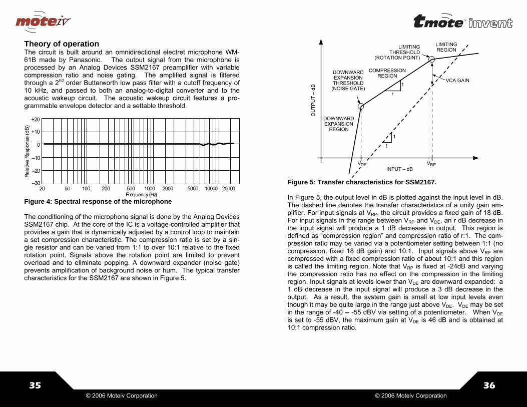
Figure 5: Transfer characteristics for SSM2167. In Figure 5, the output level in dB is plotted against the input level in dB. The dashed line denotes the transfer characteristics of a unity gain am-plifier. For input signals at VRP, the circuit provides a fixed gain of 18 dB. For input signals in the range between VRP and VDE, an r dB decrease in the input signal will produce a 1 dB decrease in output. This region is defined as “compression region” and compression ratio of r:1. The com-pression ratio may be varied via a potentiometer setting between 1:1 (no compression, fixed 18 dB gain) and 10:1. Input signals above VRP are compressed with a fixed compression ratio of about 10:1 and this region is called the limiting region. Note that VRP is fixed at -24dB and varying the compression ratio has no effect on the compression in the limiting region. Input signals at levels lower than VDE are downward expanded: a 1 dB decrease in the input signal will produce a 3 dB decrease in the output. As a result, the system gain is small at low input levels even though it may be quite large in the range just above VDE. VDE may be set in the range of -40 -- -55 dBV via setting of a potentiometer. When VDE is set to -55 dBV, the maximum gain at VDE is 46 dB and is obtained at 10:1 compression ratio.

37
© 2006 Moteiv Corporation
In Tmote Invent the compression ratio is controlled via an I2C-controlled potentiometer. The compression will not affect the gain at the VRP, but will have a great effect on amplification of low signals. Figure 6 shows the effects of different compression ratios on the amplification.
INPUT – dB
Bd–
TU
PTU
O
VDE VRP
15:1
5:1
2:1
1:1
1
1
VCA GAIN
INPUT – dBV
0
8080 70
VBd
–T
UPTU
O
60 50 40 30 20 10
10
40
50
60
70
20
30
TA = 25 CV+ = 3VRL = 100kROTATION POINT = 63mV rmsNOISE GATE SETTING = 1.4mV rms
COMPRESSION RATIO 1:1
COMPRESSION RATIO 5:1
COMPRESSION RATIO 10:1
COMPRESSION RATIO 2:1
Figure 6: Effects of varying the compression ratio (schematic view and measurement). For ratios above 1.2:1, the compression ratio r:1 is related to the potenti-ometer tap setting Ptap via:
2.1256
50+
⋅= tapP
r
The noise gate threshold VDE is set via an I2C controlled potentiometer. The threshold may be set between -40 and -55 dBV. Figure 7 illustrates the effect of different settings of noise gate threshold. The threshold set-ting is inversely proportional to the resistance RWB of the I2C-controlled potentiometer: at a tap setting of 0 the threshold is set to approximately 10 mV RMS, and at tap setting of 128 (5 kΩ) the threshold is set at ap-proximately 1mV. It is not recommended to use potentiometer settings above 128; at those settings the noise floor is over-amplified beyond the device’s limits causing problems. Table 2 summarizes the most com-monly used settings.
38 © 2006 Moteiv Corporation
VCA GAIN
INPUT – dB
Bd–
TU
PTU
O
VDE1
VRPVDE3
VDE2
1
1
r:1
RGATE –
100
10
10 3,500500
smr
Vm
–ETA
GE
SIO
N
1,000 1,500 2,5002,000 3,000
TA = 25 CV+ = 3VRLOAD = 100kCOMPRESSION RATIO 2:1ROTATION POINT = 63mV rms
Figure 7: Effects of varying the noise gate (downward expansion) threshold (left). The relationship between RGATE and the noise gate setting (right).
Compression ratio Value of RWB Pot setting Max. gain 1:1 <5 0 18 2:1 15 4 33.5 3:1 35 9 38.5 5:1 75 19 40 10:0 175 45 46
Table 1: Commonly used compression ratio settings and corre-sponding potentiometer settings, maximum gain is attained at the lowest VDE setting of -55 dBV.
Noise gate Value of RGATE Pot setting -40 0 0 -48 1 26 -54 2 51 -55 5 128
Table 2: Common settings of noise gate threshold

39
© 2006 Moteiv Corporation
Speaker Tmote Invent is equipped with a full dynamic range speaker, providing on demand sound output. The sound may either be output to a speaker or to user-supplied headphones. The speaker provides nearly 1W output at a wide frequency response. It can be used to produce voice output and a wide variety of frequency tones. The speaker, with user software, may be used in acoustic ranging applications. Schematic
0CAD_rekaepS
Vcc
OR_KPS
SP
K_LO
OL_KPS
nO_rekaepS
ccV
ccV0CAD_rekaepS
nO_rekaepS
d'qerdaplamrehTod,3320APTrednu
dnuorgottcennocton
tfarchctiwSRTNHB4TMSAR53
5Rk001
5Rk001
4Rk14Rk1
1Cu1
1Cu1
12
0S
rekaepSmho8
0S
rekaepSmho8
3R
k001
3R
k001
5C
u051
5C
u
1R
k02
1R
k02
6C
u051
6C
u
3Cu13Cu1
2Cu1
2Cu1
4Cu14Cu1
2R
k02
2R
k02
51
34
2
2S
2/enohpdaeh/kcaj
2S
2/enohpdaeh/kcaj
ddV3PAC_TLIF1
niR5
niL9
NWODTUHS2
DNG 8
OR 6
NM/TS 7
OL 01
Byp
ass
43U
3320APT
3U
3320APT
Electrical and acoustic characteristics
Parameter Value Units Notes Speaker Impedance 8 Ω Frequency range 400 to 20,000 Hz Resonant frequency 620 Hz Sensitivity 80 dB +/-3dB Nominal power output .75 Maximal power output 1.1 Power Amplifier Current consumption 3.3 mA Max 5mA Shutdown current 1 μA Output power at 3.6V 650 mW 8Ω speaker Output power at 3.6V 40 mW 32Ω headphones Maximum bandwidth 20 kHz Total distortion 0.3% THD+N 200Hz to 20kHz Lowest frequency 133 Hz 8 W speaker Lowest frequency 33 Hz 32 W headphones
40 © 2006 Moteiv Corporation
Theory of operation The speaker subsystem on Tmote Invent is designed to output sound, either to an integrated 1W speaker or to a standard 1/8” headphone jack. Tmote Invent’s speaker can be driven at levels of 650 mW across a broad frequency range. User-supplied headphones may be used to re-produce an even broader spectrum of sound. Tmote Invent uses a sin-gle DAC channel to drive both channels of the audio power amplifier. The configuration is optimized for minimal resource usage when driving the speaker. When operating with headphones, identical sound output will be heard in left and right channels. The amplifier exhibits very low distortion, both across power output levels and across frequency, as shown in Figure 9. The input stage of the power amplifier is decoupled from the DAC chan-nel by a high pass filter with a corner frequency of 8Hz. For outputs with impedances of over 64Ω that filter becomes the limiting stage in the fre-quency response. The input signal is then amplified by a factor of 3.125 when the output is directed to the headphones and by a factor of 6.25 when the output is directed to the speaker. In order to avoid clipping and allow a bit of headroom, the input signal needs to be 1/6 of the full scale when driving the speaker and 1/3 of the full scale when driving the head-phones. The table below shows the mean of the signal and the maxi-mum amplitude that can be reproduced without clipping.
Signal characteristics 8 bit DAC
Signal characteristics 12 bit DAC
Speaker 128±20 2048±328 Headphone 128±41 2048±655
The power stage consists of two Class-AB audio power amplifiers. In headphone mode, each amplifier drives a separate audio channel. When driving the speaker, the two amplifiers operate in a bridge-tied load (BTL) configuration: one power amplifier is directly connected to the load; the output of the other power amplifier is inverted and used to drive the other end of the load. As a result, the system is capable of delivering output levels that are 6 dB louder than those produced by a single ended configuration. The amplifier may be put into a shutdown mode by setting the SPEAKER_ON signal to low. In shutdown mode, the power amplifier typi-cally draws less than 1 μA. When turned on, and driven with no signal,

41
© 2006 Moteiv Corporation
the power amplifier draws about 3.3 mA. Both the maximum power out-put and the current drawn by the amplifier depend on battery voltage, Figure 8 details that dependency. When actively amplifying the signal, the system shares the inefficiencies of all Class-AB amplifiers. The am-plifier efficiency η is related to the power delivered to the speaker PL by the formula
CC
LL
VRP
42π
η =
Tmote Invent’s speaker presents a load RL of 8Ω. The power is related to the peak voltage by
L
PeakL R
VP2
2
=
The amplifier efficiency is proportional to the peak voltage. The energy not converted to sound is dissipated as heat. At its peak, with the peak voltage of 2.3V, the power amplifier dissipates 0.33W as heat; tempera-ture sensitive applications may need to account for the resulting changes.
0.0
0.5
1.0
1.5
2.0
2.5
3.0
3.0 3.5 4.0 4.5 5.0 5.5
RL = 8
THD+N = 1%f = 1 kHzMode = MonoAV = 8 dB
–re
woPtuptuO
–W
OUTPUT POWERvs
SUPPLY VOLTAGE
P O
VDD – Supply Voltage – V
Figure 8 : Output Power and Supply Current as a function of Supply Voltage
0
1
2
3
4
5
6
2.5 3.0 3.5 4.0 4.5 5.0 5.5
–tnerru
CylppuS
–A
m
SUPPLY CURRENTvs
SUPPLY VOLTAGE
ID
D
VDD – Supply Voltage – V
TA = 25 °C
Bypass = VDD/2 VDCVDD From Low-to-High LevelMode = StereoRL = Open
42 © 2006 Moteiv Corporation
AV = 8 dB
20 100 1k
N+D
HT–
esioN
sulPnoitrotsi
Dcino
mraHlatoT
–%
f – Frequency – Hz
TOTAL HARMONIC DISTORTION PLUS NOISEvs
FREQUENCY1
10k 20k
0.1
0.01
0.001
VDD = 3 VPO = 250 mWRL = 8Mode = Mono
Figure 9 : Total Harmonic Distortion plus Noise as affected by fre-quency and output power
0.01 0.1
10
1
1
0.1
0.01
TOTAL HARMONIC DISTORTION PLUS NOISEvs
OUTPUT POWER
PO – Output Power – W
N+D
HT–
esioN
sulPnoitrotsi
Dcino
mraHlatoT
–%
20 kHz
20 Hz
1 kHz
15 kHz
VDD = 3 VRL = 8Mode = MonoAV = 2.5 dB

43
© 2006 Moteiv Corporation
Tmote Invent Software Tmote Invent includes Moteiv’s TinyOS software providing a complete system for building wireless sensing applications. TinyOS consists of drivers (called “components”) that provide useful interfaces for accessing the functionality of Tmote Invent. Below, the components and corre-sponding interfaces for sensing and communication are shown; for more in-depth descriptions of these components and interfaces, please view Moteiv’s API documentation by opening index.html document inside of /opt/moteiv/docs/nesdoc Sensor Drivers The sensors on Tmote Invent each include a corresponding TinyOS driver. Please refer back to each sensor’s theory of operation for docu-mentation that describes how to interpret values from the sensors, set potentiometer values, and enable interrupts. Accelerometer TinyOS Driver: AccelDriverC Location: /opt/moteiv/tos/sensorboards/invent/ Interface Function SplitControl Turn on/off sensor ADC as AccelX Read X-axis value ADC as AccelY Read Y-axis value Potentiometer as AccelInterruptSettings Set Interrupt Threshold SensorInterrupt as AccelInterrupt Handle Accelerometer Interrupt Light Sensor TinyOS Driver: PhotoDriverC Location: /opt/moteiv/tos/sensorboards/invent Interface Function SplitControl Turn on/off sensor ADC as Photo Read Photo value Potentiometer Set Photo sensor gain
44 © 2006 Moteiv Corporation
Microphone Sensor TinyOS Driver: MicDriverC Location: /opt/moteiv/tos/sensorboards/invent Interface Function SplitControl Turn on/off sensor ADC as Mic Read single Microphone value Microphone Read large Microphone buffers Potentiometer as Vrc Set preamp compression ratio Potentiometer as Vrg Set preamp noise gate threshold Potentiometer as MicInterruptDrain Set RC drain time on interrupt Potentiometer as MicInterruptThreshold Set amplitude for interrupt SensorInterrupt as MicInterrupt Handle Microphone Interrupt Speaker TinyOS Driver: SpeakerDriverC Location: /opt/moteiv/tos/sensorboards/invent Interface Function SplitControl Turn on/off sensor Speaker Output buffer to speaker PowerControl Turn power on/off to speaker PowerKeepAlive Adjust speaker shutdown policy Temperature Sensor TinyOS Driver: InternalTempC Location: /opt/moteiv/tos/platform/msp430/adc Interface Function StdControl Turn on/off sensor ADC as InternalTempADC Read temperature value ADCSingle Advanced ADC read interface ADCMultiple Advanced ADC read interface Voltage Sensor TinyOS Driver: VoltageC Location: /opt/moteiv/tinyos-1.x/tos/system Interface Function StdControl Turn on/off sensor ADC as Voltage Read voltage value (in mV)

45
© 2006 Moteiv Corporation
Communications Moteiv’s communication system includes three main components: a Mul-tihop mesh networking protocol, a network duty cycling protocol, and the recently proposed “Sensornet Protocol” (SP) abstraction for sending and receiving messages. All of these protocols are used in Moteiv’s mesh networking application, Delta. The source code for Delta is located in /opt/moteiv/apps/Delta. Multihop Networking Moteiv’s on-demand ad-hoc networking utilizes spatial and temporal re-dundancy to reliability deliver messages across a network to their desti-nation. To use the Multihop library in an application, first include Multi-hop in your configuration:
Then wire your application to the appropriate message handlers for your message type. For example, in your configuration:
Where APP_ID is a unique 8-bit identifier for your service or application defined in a header file. Please see the documentation for details of us-ing the Send interface in Moteiv’s API documentation available at /opt/moteiv/docs/nesdoc Messages are submitted to the Multihop service and queued until there is an opportunity to route the message towards the destination. After a message is successfully sent, an event (Send.sendDone()) is fired to your service notifying you that it is now safe to use the message buffer for other purposes.
components Multihop;
AppM.Send -> MultiHop.Send[APP_ID]; AppM.Receive -> MultiHop.Receive[APP_ID];
46 © 2006 Moteiv Corporation
Low Power Operation Moteiv’s software includes a synchronization protocol for low power wire-less network. The network duty cycling approaches uses SP (described below) for establishing and maintaining a schedule whereby the entire network wakes up together and then returns to sleep. Including Moteiv’s network duty cycling is as simple as adding a single parameter to the compilation command. Simply add the lowpower keyword after the compilation platform. For example:
Try the low power networking by using Delta, the mesh networking data collection application, with the lowpower option:
Be aware that bandwidth is very limited in low power mode (each node is only awake for a few milliseconds every two seconds). The initial syn-chronization of the network may require up to 15 minutes to stabilize, but will reliably report data after the initial setup phase. Please be patient! Information about Moteiv’s network duty cycling is included in the API documentation for the NetSyncC and NetWakeC components. The source is at /opt/moteiv/tos/lib/netsync; however we strongly recommend that only the most advanced users consider modifying this code. Please note that Moteiv does not support any modifications to our source.
make tmoteinvent lowpower
cd /opt/moteiv/apps/Delta make tmoteinvent lowpower

47
© 2006 Moteiv Corporation
Sensornet Protocol (SP) SP is a unifying link abstraction for running network protocols over a va-riety of link layer and physical layer technologies without changing net-work protocol implementation. SP is implemented by the SPC compo-nent. SPC and its interfaces are described in detail in the following publication: A Unifying Link Abstraction for Wireless Sensor Networks In Proceedings of the Third ACM Conference on Embedded Networked Sensor Systems (SenSys), November 2-4, 2005. http://www.polastre.com/papers/sensys05-sp.pdf Messages are transmitted using the SPSend interface and message fu-tures are handled through the SPSendNext interface. To send a mes-sage on a particular AM type, such as AM type 5, wire your network pro-tocol to SPSend[5]. The SP message pool will hold on to a message and its corresponding packets until it may be sent over the channel. Fields of each SP message (sp_message_t) should never be directly accessed. Instead, they can be set using the parameters of the SPSend interface. Reading parameters should be done through the SPMessage interface. Reception is on a per packet basis (not a per message basis like SPSend). Packets are immediately dispatched to higher layer services based on AM type. SPReceive provides information about each packet, including a token that identifies which interface a message originated. The SP Neighbor Table is accessed through the SPNeighbor interface. Users must wire to the SP Neighbor Table with the parameter unique("SPNeighbor"). Each service has its own identity for control-ling the insertions, removals, and changes of entries in the SP Neighbor Table. See the SPNeighbor interface in the API documentation for more information. Various utilities as part of SP's processing are available in the SPUtil interface. These utilities include link estimation functions and link post-arbitration time stamps.
48 © 2006 Moteiv Corporation
Useful TinyOS Components There are many useful libraries including with Moteiv’s distribution of TinyOS. Below, many of these components and their functions are listed. For additional resources, please check Moteiv’s support website at http://www.moteiv.com/support.php. It is frequently updated with tips, techniques, and troubleshooting articles. TinyOS Distribution Organization under the /opt/moteiv directory: Directory Description apps Moteiv applications apps/invent Tmote Invent-specific applications doc/nesdoc API documentation in HTML format tos/lib TinyOS libraries (SP, Multihop, etc) tos/platform/tmote Tmote-specific platform components tos/sensorboards/invent Tmote Invent driver components tools/java Moteiv mote-interface java tools tinyos-1.x TinyOS components used by Moteiv Useful TinyOS components: TinyOS Component Function BitVectorC Methods to manipulate vectors of bits LedsC Turn on or off the LEDs MainControlC Start a component on boot with MainControlC ObjectPoolC Create and manage a pool of generic objects TimerMilliC Create a new millisecond system timer UartDetectC Detect if a PC is active & connected UartPresenceC Detect the presence of PC’s USB port UserButtonC Enable input from User Button UserButtonAdvancedC Advanced functionality from User Button The documentation for all of these components is available within the /opt/moteiv/doc/nesdoc directory. In addition to TinyOS components, there are a few useful C libraries available in /opt/moteiv/tos/lib/util/: C Library Function circularQueue.h A generic circular queue object fft_i8.h 8-bit integer FFT routines

49
© 2006 Moteiv Corporation
Notes
50 © 2006 Moteiv Corporation
General Information Document History Revision Date Notes 1.0 2006/02/27 Initial Release Address Information Web site: http://www.moteiv.com E-mail: [email protected] Technical Support Web site: http://www.moteiv.com/support.php Technical Support E-mail: [email protected] Phone Number: +1.415.692.0960 Fax Number: +1.415.358.4872 Headquarters Moteiv Corporation 55 Hawthorne St, Suite 550 San Francisco, CA 94105


![ROI in the age of keyword not provided [Mozinar]](https://img.dokumen.tips/doc/110x75/53eabc7a8d7f7289708b51f7/roi-in-the-age-of-keyword-not-provided-mozinar.jpg)