No.P37E14.pdf 98.9.28 This is the PDF file of catalog No.P37E-14.
MurataManufacturing Co., Ltd.
Cat.No.P37E-14
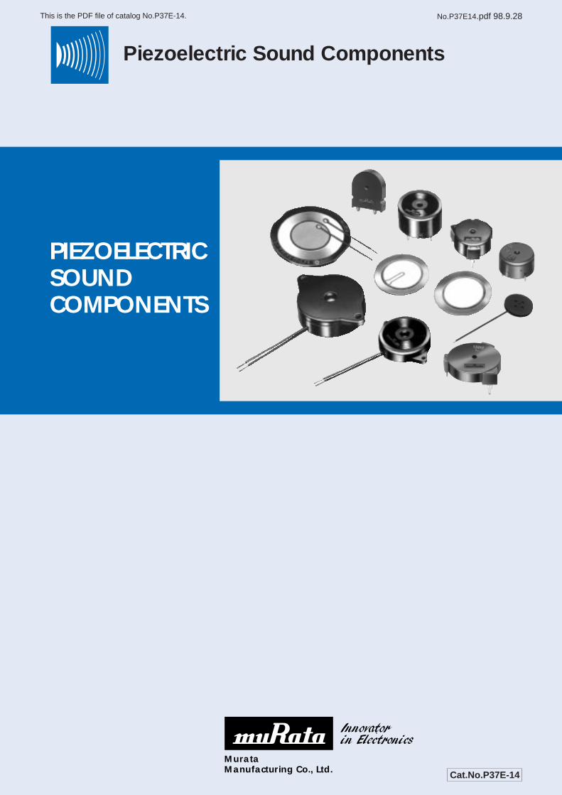
Piezoelectric Sound Components
PIEZOELECTRICSOUNDCOMPONENTS
1
No.P37E14.pdf 98.9.28 This is the PDF file of catalog No.P37E-14.
INTRODUCTION
Recently, technological innovations are being rapidlyintroduced in the area of Office Automation (OA) equipment,VCR, and Communication equipment, etc.. The coretechnologies behind these innovations are multifunction,down-sizing and weight reduction. MURATA, as the leaderof technologies for piezoelectric ceramics, has beensuccessing to develop various unique products which meetneeds in the advanced information society.The "piezoelectric sound component", which is introducedherein, is also one of MURATA's original products.Piezoelectric sound components are now drawing attentionwidely as suitable components for various electronic
equipment like as OA equipment (ex. word-processor,typewriter, FAX machine, etc..),audio equipment (ex. radio-cassette, tape recorder, etc..), and telephone sets.Also, the application range is expanding from a monitorsound for the controller to time signal, alarm, speaker, ringerand receiver for telephone set. So, now piezoelectric soundcomponents are working as an " interface" between humanand electrical equipment.This catalog is providing various types of piezoelectricsound component which could help design of equipments tolead the best solution.
CERAMITONE® (Piezoelectric Speaker), CERAMIPHONE® (Piezoelectric Receiver) and PIEZORINGER® (Piezoelectric Ringer) are thetrademark of Murata Manufacturing Co., Ltd.
2
No.P37E14.pdf 98.9.28 This is the PDF file of catalog No.P37E-14.
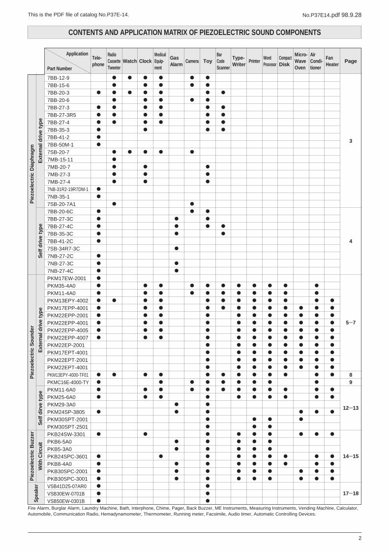
CONTENTS AND APPLICATION MATRIX OF PIEZOELECTRIC SOUND COMPONENTS
7BB-12-97BB-15-67BB-20-37BB-20-67BB-27-37BB-27-3R57BB-27-47BB-35-37BB-41-27BB-50M-17SB-20-77MB-15-117MB-20-77MB-27-37MB-27-47NB-31R2-19R7DM-17NB-35-17SB-20-7A17BB-20-6C7BB-27-3C7BB-27-4C7BB-35-3C7BB-41-2C7SB-34R7-3C7NB-27-2C7NB-27-3C7NB-27-4CPKM17EW-2001PKM35-4A0PKM11-4A0PKM13EPY-4002PKM17EPP-4001PKM22EPP-2001PKM22EPP-4001PKM22EPP-4005PKM22EPP-4007PKM22EP-2001PKM17EPT-4001PKM22EPT-2001PKM22EPT-4001PKM13EPY-4000-TF01PKMC16E-4000-TYPKM11-6A0PKM25-6A0PKM29-3A0PKM24SP-3805PKM30SPT-2001PKM30SPT-2501PKB24SW-3301PKB6-5A0PKB5-3A0PKB24SPC-3601PKB8-4A0PKB30SPC-2001PKB30SPC-3001VSB41D25-07AR0VSB30EW-0701BVSB50EW-0301B
Application
Part Number
Tele-phone
RadioCassetteTweeter
Watch ClockMedicalEquip-ment
GasAlarm
Camera ToyBarCodeScanner
Type-Writer
PrinterWordProcessor
CompactDisk
Micro-WaveOven
AirCondi-tioner
FanHeater
Page
3
4
5Y7
89
12Y13
14Y15
17Y18
Fire Alarm, Burglar Alarm, Laundry Machine, Bath, Interphone, Chime, Pager, Back Buzzer, ME Instruments, Measuring Instruments, Vending Machine, Calculator,Automobile, Communication Radio, Hemadynamometer, Thermometer, Running meter, Facsimile, Audio timer, Automatic Controlling Devices.
Pie
zoel
ectr
ic D
iap
hrag
m
Ext
erna
l dri
ve t
ype
Pie
zoel
ectr
ic S
oun
der
Pie
zoel
ectr
ic B
uzze
r
With
Cir
cuit
Sel
f d
irve
typ
eE
xter
nal d
rive
typ
eS
elf
dri
ve t
ype
Spea
ker
Piezoelectric Diaphragm External Drive/Self Drive type
PIEZOELECTRIC DIAPHRAGM
3
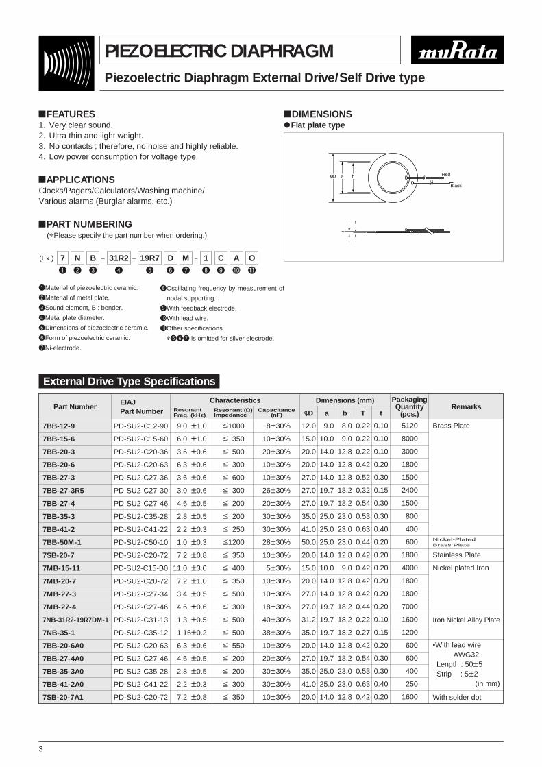
!FEATURES1. Very clear sound.2. Ultra thin and light weight.3. No contacts ; therefore, no noise and highly reliable.4. Low power consumption for voltage type.
!APPLICATIONSClocks/Pagers/Calculators/Washing machine/Various alarms (Burglar alarms, etc.)
!PART NUMBERING(*Please specify the part number when ordering.)
qMaterial of piezoelectric ceramic.
wMaterial of metal plate.
eSound element, B : bender.
rMetal plate diameter.
tDimensions of piezoelectric ceramic.
yForm of piezoelectric ceramic.
uNi-electrode.
(Ex.) 7 - -N 19R7 D - 1 C A O31R2B M
q w t y i o !0 !1re u
iOscillating frequency by measurement of
nodal supporting.
oWith feedback electrode.
!0With lead wire.
!1Other specifications.
*tyu is omitted for silver electrode.
External Drive Type Specifications
Part Number
7BB-12-9
7BB-15-6
7BB-20-3
7BB-20-6
7BB-27-3
7BB-27-3R5
7BB-27-4
7BB-35-3
7BB-41-2
7BB-50M-1
7SB-20-7
7MB-15-11
7MB-20-7
7MB-27-3
7MB-27-4
7NB-31R2-19R7DM-1
7NB-35-1
7BB-20-6A0
7BB-27-4A0
7BB-35-3A0
7BB-41-2A0
7SB-20-7A1
PD-SU2-C12-90
PD-SU2-C15-60
PD-SU2-C20-36
PD-SU2-C20-63
PD-SU2-C27-36
PD-SU2-C27-30
PD-SU2-C27-46
PD-SU2-C35-28
PD-SU2-C41-22
PD-SU2-C50-10
PD-SU2-C20-72
PD-SU2-C15-B0
PD-SU2-C20-72
PD-SU2-C27-34
PD-SU2-C27-46
PD-SU2-C31-13
PD-SU2-C35-12
PD-SU2-C20-63
PD-SU2-C27-46
PD-SU2-C35-28
PD-SU2-C41-22
PD-SU2-C20-72
9.00T1.0
6.00T1.0
3.60T0.6
6.30T0.6
3.60T0.6
3.00T0.6
4.60T0.5
2.80T0.5
2.20T0.3
1.00T0.3
7.20T0.8
11.00T3.0
7.20T1.0
3.40T0.5
4.60T0.6
1.30T0.5
1.16T0.2
6.30T0.6
4.60T0.5
2.80T0.5
2.20T0.3
7.20T0.8
V1000
V1350
V1500
V1300
V1600
V1300
V1200
V1200
V1250
V1200
V1350
V1400
V1350
V1500
V1300
V1500
V1500
V1550
V1200
V1200
V1300
V1350
18T30%
10T30%
20T30%
10T30%
10T30%
26T30%
20T30%
30T30%
30T30%
28T30%
10T30%
15T30%
10T30%
10T30%
18T30%
40T30%
38T30%
10T30%
20T30%
30T30%
30T30%
10T30%
12.0
15.0
20.0
20.0
27.0
27.0
27.0
35.0
41.0
50.0
20.0
15.0
20.0
27.0
27.0
31.2
35.0
20.0
27.0
35.0
41.0
20.0
9.0
10.0
14.0
14.0
14.0
19.7
19.7
25.0
25.0
25.0
14.0
10.0
14.0
14.0
19.7
19.7
19.7
14.0
19.7
25.0
25.0
14.0
8.0
9.0
12.8
12.8
12.8
18.2
18.2
23.0
23.0
23.0
12.8
9.0
12.8
12.8
18.2
18.2
18.2
12.8
18.2
23.0
23.0
12.8
0.22
0.22
0.22
0.42
0.52
0.32
0.54
0.53
0.63
0.44
0.42
0.42
0.42
0.42
0.44
0.22
0.27
0.42
0.54
0.53
0.63
0.42
0.10
0.10
0.10
0.20
0.30
0.15
0.30
0.30
0.40
0.20
0.20
0.20
0.20
0.20
0.20
0.10
0.15
0.20
0.30
0.30
0.40
0.20
5120
8000
3000
1800
1500
2400
1500
800
400
600
1800
4000
1800
1800
7000
1600
1200
600
600
400
250
1600
Brass Plate
Stainless Plate
Nickel plated Iron
Iron Nickel Alloy Plate
With solder dot
EIAJ Part Number
Characteristics Dimensions (mm) PackagingQuantity
(pcs.)RemarksResonant
Freq. (kHz)Resonant (Ω)Impedance
Capacitance(nF) φD a b T t
Nickel-PlatedBrass Plate
•With lead wireAWG32
Length : 50T5Strip : 5T2
(in mm)
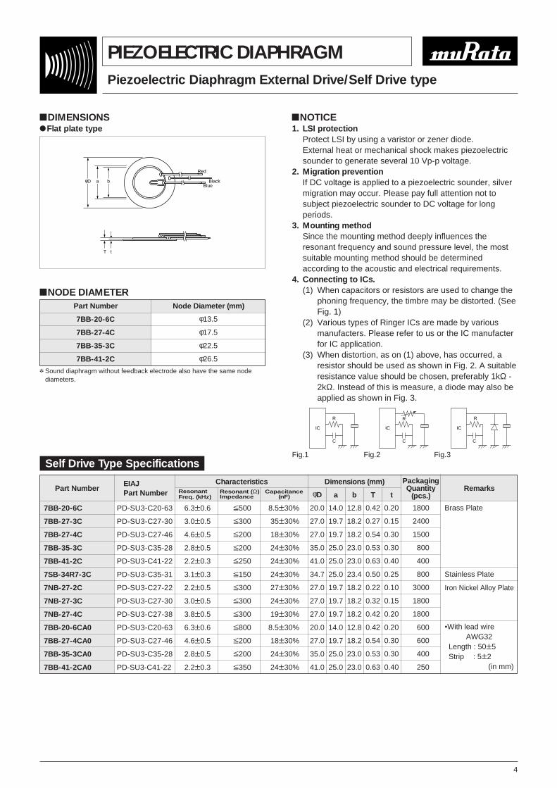
!DIMENSIONS"Flat plate type
φD a
T
t
b Red
Black
Piezoelectric Diaphragm External Drive/Self Drive type
PIEZOELECTRIC DIAPHRAGM
4
!DIMENSIONS"Flat plate type
!NODE DIAMETER
φD a
T t
b
Red
BlackBlue
Part Number
7BB-20-6C
7BB-27-3C
7BB-27-4C
7BB-35-3C
7BB-41-2C
7SB-34R7-3C
7NB-27-2C
7NB-27-3C
7NB-27-4C
7BB-20-6CA0
7BB-27-4CA0
7BB-35-3CA0
7BB-41-2CA0
PD-SU3-C20-63
PD-SU3-C27-30
PD-SU3-C27-46
PD-SU3-C35-28
PD-SU3-C41-22
PD-SU3-C35-31
PD-SU3-C27-22
PD-SU3-C27-30
PD-SU3-C27-38
PD-SU3-C20-63
PD-SU3-C27-46
PD-SU3-C35-28
PD-SU3-C41-22
6.3T0.6
3.0T0.5
4.6T0.5
2.8T0.5
2.2T0.3
3.1T0.3
2.2T0.5
3.0T0.5
3.8T0.5
6.3T0.6
4.6T0.5
2.8T0.5
2.2T0.3
V500
V300
V200
V200
V250
V150
V300
V300
V300
V800
V200
V200
V350
8.5T30%
35T30%
18T30%
24T30%
24T30%
24T30%
27T30%
24T30%
19T30%
8.5T30%
18T30%
24T30%
24T30%
20.0
27.0
27.0
35.0
41.0
34.7
27.0
27.0
27.0
20.0
27.0
35.0
41.0
14.0
19.7
19.7
25.0
25.0
25.0
19.7
19.7
19.7
14.0
19.7
25.0
25.0
12.8
18.2
18.2
23.0
23.0
23.4
18.2
18.2
18.2
12.8
18.2
23.0
23.0
0.42
0.27
0.54
0.53
0.63
0.50
0.22
0.32
0.42
0.42
0.54
0.53
0.63
0.20
0.15
0.30
0.30
0.40
0.25
0.10
0.15
0.20
0.20
0.30
0.30
0.40
1800
2400
1500
800
400
800
3000
1800
1800
600
600
400
250
Brass Plate
Stainless Plate
Iron Nickel Alloy Plate
EIAJ Part Number
Characteristics Dimensions (mm) PackagingQuantity
(pcs.)RemarksResonant
Freq. (kHz)Resonant (Ω)Impedance
Capacitance(nF) φD a b T t
Part Number Node Diameter (mm)
7BB-20-6C
7BB-27-4C
7BB-35-3C
7BB-41-2C
φ13.5
φ17.5
φ22.5
φ26.5
* Sound diaphragm without feedback electrode also have the same nodediameters.
Self Drive Type Specifications
!NOTICE1. LSI protection
Protect LSI by using a varistor or zener diode.External heat or mechanical shock makes piezoelectricsounder to generate several 10 Vp-p voltage.
2. Migration preventionIf DC voltage is applied to a piezoelectric sounder, silvermigration may occur. Please pay full attention not tosubject piezoelectric sounder to DC voltage for longperiods.
3. Mounting methodSince the mounting method deeply influences theresonant frequency and sound pressure level, the mostsuitable mounting method should be determinedaccording to the acoustic and electrical requirements.
4. Connecting to ICs.(1) When capacitors or resistors are used to change the
phoning frequency, the timbre may be distorted. (SeeFig. 1)
(2) Various types of Ringer ICs are made by variousmanufacters. Please refer to us or the IC manufacterfor IC application.
(3) When distortion, as on (1) above, has occurred, aresistor should be used as shown in Fig. 2. A suitableresistance value should be chosen, preferably 1kΩ -2kΩ. Instead of this is measure, a diode may also beapplied as shown in Fig. 3.
C
R
IC
C
R
IC
C
R
IC
Fig.1 Fig.2 Fig.3
•With lead wireAWG32
Length : 50T5Strip : 5T2
(in mm)
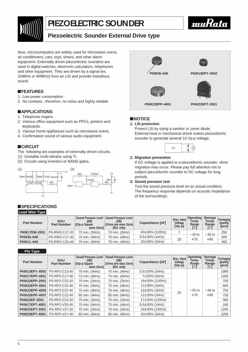
Piezoelectric Sounder External Drive type
PIEZOELECTRIC SOUNDER
5
Now, microcomputers are widely used for microwave ovens,air conditioners, cars, toys, timers, and other alarmequipment. Externally driven piezoelectric sounders areused in digital watches, electronic calculators, telephonesand other equipment. They are driven by a signal (ex,2048Hz or 4096Hz) from an LSI and provide melodioussound.
!FEATURES1. Low power consumption.2. No contacts ; therefore, no noise and highly reliable.
!SPECIFICATIONS
PKM35-4A0 PKM13EPY-4002
PKM22EPP-4001 PKM22EPT-2001
!APPLICATIONS1. Telephone ringers.2. Various office equipment such as PPCs, printers and
keyboards.3. Various home appliances such as microwave ovens.4. Confirmation sound of various audio equipment.
!CIRCUITThe following are examples of externally driven circuits.(1) Unstable multi-vibrator using Tr.(2) Circuits using inverters or NAND gates.
510Ω 20kΩ 20kΩ 510Ω 55mH
+V
1kΩ0.01µF0.01µF
+V
1kΩ1kΩ120kΩ
1MΩ
Input
0.001µF
(1) (2)
!NOTICE1. LSI protection
Protect LSI by using a varistor or zener diode.External heat or mechanical shock makes piezoelectricsounder to generate several 10 Vp-p voltage.
2. Migration preventionIf DC voltage is applied to a piezoelectric sounder, silvermigration may occur. Please pay full attention not tosubject piezoelectric sounder to DC voltage for longperiods.
3. Sound pressure testTest the sound pressure level on an actual condition.The frequency response depends on acoustic impedanceof the surroundings.
LSI
Part Number
PKM17EW-2001PKM35-4A0PKM11-4A0
EIAJPart Number
PS-RW2-C17-20PS-RW2-C17-40PS-RW2-C24-40
Sound Pressure Level[dB]
(3Vp-p Square wave 10cm)
72 min. (2kHz)75 min. (4kHz)75 min. (4kHz)
Sound Pressure Level[dB]
(1Vrms sine wave 10cm)(Ref. only)
70 min. (2kHz)70 min. (4kHz)75 min. (4kHz)
Capacitance [nF]
40T30% (120Hz)9.5T30% (1kHz)10T30% (1kHz)
Max. InputVoltage[Vp-p]
7
25
OperatingTemp.Range
[D]
Y20 toW70
StorageTemp.Range
[D]
Y30 toW80
PackagingQuantity[pcs]
250500400
Part Number
PKM13EPY-4002PKM17EPP-4001PKM22EPP-2001PKM22EPP-4001PKM22EPP-4005PKM22EPP-4007PKM22EP-2001PKM17EPT-4001PKM22EPT-2001PKM22EPT-4001
EIAJPart Number
PS-RP2-C13-40PS-RP2-C17-40PS-RP2-C22-20PS-RP2-C22-40PS-RP2-C22-40PS-RP2-C22-40PS-RP2-C22-20PS-RP2-V20-40PS-RP2-V27-20PS-RP2-V27-40
Sound Pressure Level[dB]
(3Vp-p Square wave 10cm)
70 min. (4kHz)72 min. (4kHz)70 min. (2kHz)75 min. (4kHz)75 min. (4kHz)85 min. (4kHz)75 min. (2kHz)75 min. (4kHz)70 min. (2kHz)85 min. (4kHz)
Sound Pressure Level[dB]
(1Vrms sine wave 10cm)(Ref. only)
70 min. (4kHz)70 min. (4kHz)70 min. (2kHz)75 min. (4kHz)75 min. (4kHz)85 min. (4kHz)75 min. (2kHz)75 min. (4kHz)70 min. (2kHz)85 min. (4kHz)
Capacitance [nF]
5.5T30% (1kHz)5.7T30% (1kHz)19T30% (120Hz)12T30% (1kHz)12T30% (1kHz)12T30% (1kHz)17T30% (120Hz)9.5T30% (1kHz)19T30% (120Hz)10T30% (1kHz)
Max. InputVoltage[Vp-p]
25
OperatingTemp.Range
[D]
Y20 toW70
StorageTemp.Range
[D]
Y30 toW80
PackagingQuantity[pcs]
19801200750900750750360180
12001200
Lead Wire Type
Pin Type
6
2− 1.2
2− 3.5
φ22.010.0
0.8
φ
φ 10.0
R10
.81.
2
3− 1.5
10.00.8
120˚ 120˚
1.2
8.2
6.53.
5
22.0
5.0
φ
3− 1.7φ
2− 3.5φ
φ
1.2φ
R8.5 5.0
φ22.0
10.0
10.0
8.2
R
2−φ1.2
2−φ3.51.
2
0.8
10.8
1.2
R
φ 22.010.0
0.8
10.0
φ2− 1.2
φ2− 3.5
(in mm)
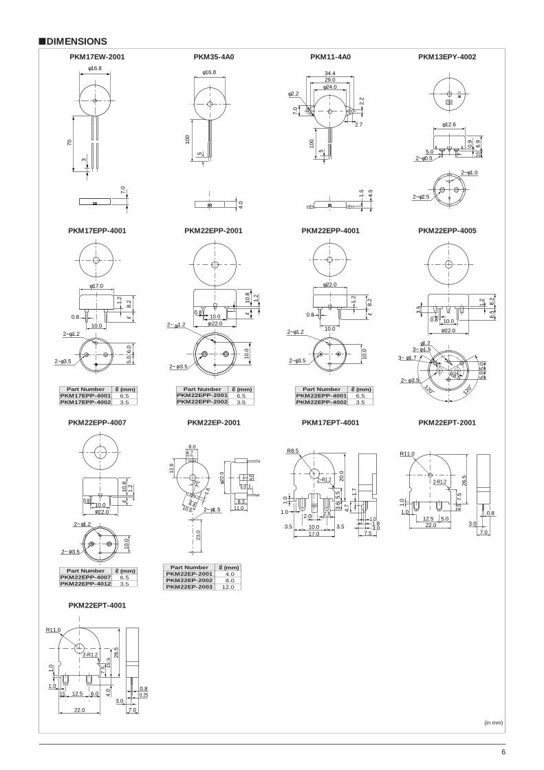
PKM22EPP-2001 PKM22EPP-4001 PKM22EPP-4005
PKM22EPP-4007
!DIMENSIONS
70φ16.8
3
7.0
φ16.8
100
5
4.0
34.429.0
φ24.0φ2.2
2.7
2.2
7.0
100
5
1.5
4.5
0.9
2−φ1.0
2−φ0.5
φ12.6
6.9
3.5
5.0
2−φ2.5
M*
2
φ17.0
10.0
8.2
R6.
05.
0
2−φ1.2
2−φ3.5
1.2
0.8
PKM17EW-2001 PKM35-4A0 PKM11-4A0 PKM13EPY-4002
PKM17EPP-4001
PKM22EP-2001 PKM17EPT-4001 PKM22EPT-2001
PKM22EPT-4001
12.6
23.0
20°
4.78.0
φ22.
0
4.0
5.0 R
8.311.0
4.810.5
1.6
2− 1.5φ
R8.5
2−R1.2
17.0
1.0
3.5 10.0 3.5
20.0
1.0
2.5
5.5
3.6
4.7
1.7
7.5
2.0
3.01.8
1.0
1.0 7.
54.
026
.5
R11.0
2-R1.2
1.012.522.0
7.0
3.05.0
0.8
2-R1.2
R11.0
7.515.5
1.0
1.03.5 12.5
22.0
6.0
7.0
4.0
3.0
26.5
0.250.8
Part NumberPKM17EPP-4001PKM17EPP-4002
R(mm)6.53.5
Part NumberPKM22EPP-2001PKM22EPP-2002
R(mm)6.53.5
Part NumberPKM22EPP-4001PKM22EPP-4002
R(mm)6.53.5
Part NumberPKM22EPP-4007PKM22EPP-4012
R(mm)6.53.5
Part NumberPKM22EP-2001PKM22EP-2002PKM22EP-2003
R(mm)14.018.012.0
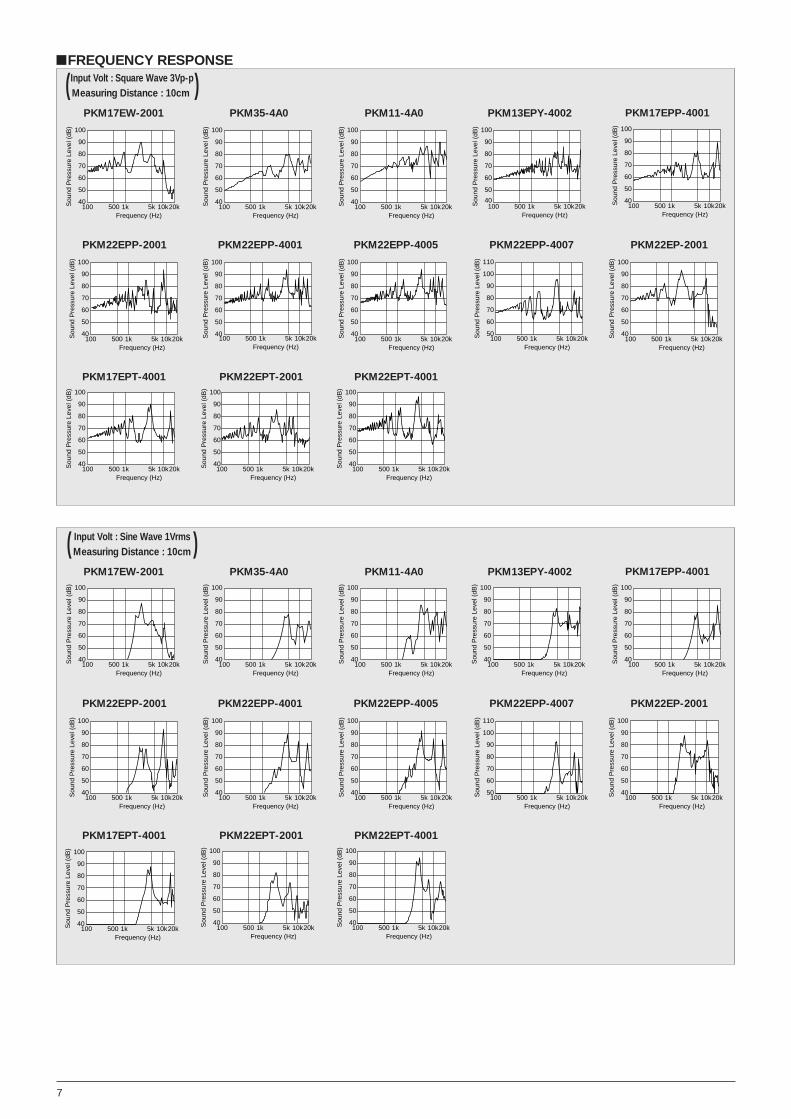
7
!FREQUENCY RESPONSEInput Volt : Square Wave 3Vp-pi( Measuring Distance : 10cm )
PKM17EW-2001 PKM35-4A0 PKM11-4A0 PKM13EPY-4002 PKM17EPP-4001
PKM22EPP-2001 PKM22EPP-4001 PKM22EPP-4005 PKM22EPP-4007 PKM22EP-2001
PKM17EPT-4001 PKM22EPT-2001 PKM22EPT-4001
Sou
nd P
ress
ure
Leve
l (dB
)
Frequency (Hz)100 500 1k 5k 10k20k
100
90
80
70
60
50
40 Sou
nd P
ress
ure
Leve
l (dB
)
Frequency (Hz)100 500 1k 5k 10k20k
100
90
80
70
60
50
40 Sou
nd P
ress
ure
Leve
l (dB
)
Frequency (Hz)100 500 1k 5k 10k20k
100
90
80
70
60
50
40
Frequency (Hz)100 500 1k 5k 10k20kS
ound
Pre
ssur
e Le
vel (
dB) 100
90
80
70
60
50
40 Sou
nd P
ress
ure
Leve
l (dB
)
Frequency (Hz)100 500 1k 5k 10k20k
100
90
80
70
60
50
40
Sou
nd P
ress
ure
Leve
l (dB
)
Frequency (Hz)100 500 1k 5k 10k20k
100
90
80
70
60
50
40
Frequency (Hz)100 500 1k 5k 10k20kS
ound
Pre
ssur
e Le
vel (
dB) 100
90
80
70
60
50
40 Sou
nd P
ress
ure
Leve
l (dB
)Frequency (Hz)
100 500 1k 5k 10k20k
100
90
80
70
60
50
40 Sou
nd P
ress
ure
Leve
l (dB
)
Frequency (Hz)100 500 1k 5k 10k20k
110
100
90
80
70
60
50 Sou
nd P
ress
ure
Leve
l (dB
)
Frequency (Hz)100 500 1k 5k 10k20k
100
90
80
70
60
50
40
Frequency (Hz)100 500 1k 5k 10k20kS
ound
Pre
ssur
e Le
vel (
dB) 100
90
80
70
60
50
40
Frequency (Hz)100 500 1k 5k 10k20kS
ound
Pre
ssur
e Le
vel (
dB) 100
90
80
70
60
50
40
Frequency (Hz)100 500 1k 5k 10k20kS
ound
Pre
ssur
e Le
vel (
dB) 100
90
80
70
60
50
40
Input Volt : Sine Wave 1Vrmsi( Measuring Distance : 10cm )PKM17EW-2001 PKM35-4A0 PKM11-4A0 PKM13EPY-4002 PKM17EPP-4001
PKM22EPP-2001 PKM22EPP-4001 PKM22EPP-4005 PKM22EPP-4007 PKM22EP-2001
PKM17EPT-4001 PKM22EPT-2001 PKM22EPT-4001
Sou
nd P
ress
ure
Leve
l (dB
)
Frequency (Hz)100 500 1k 5k 10k20k
100
90
80
70
60
50
40 Sou
nd P
ress
ure
Leve
l (dB
)
Frequency (Hz)100 500 1k 5k 10k20k
100
90
80
70
60
50
40 Sou
nd P
ress
ure
Leve
l (dB
)
Frequency (Hz)100 500 1k 5k 10k20k
100
90
80
70
60
50
40
Frequency (Hz)100 500 1k 5k 10k20kS
ound
Pre
ssur
e Le
vel (
dB) 100
90
80
70
60
50
40 Sou
nd P
ress
ure
Leve
l (dB
)
Frequency (Hz)100 500 1k 5k 10k20k
100
90
80
70
60
50
40
Sou
nd P
ress
ure
Leve
l (dB
)
Frequency (Hz)100 500 1k 5k 10k20k
100
90
80
70
60
50
40 Sou
nd P
ress
ure
Leve
l (dB
)
Frequency (Hz)100 500 1k 5k 10k20k
100
90
80
70
60
50
40 Sou
nd P
ress
ure
Leve
l (dB
)
Frequency (Hz)100 500 1k 5k 10k20k
100
90
80
70
60
50
40 Sou
nd P
ress
ure
Leve
l (dB
)
Frequency (Hz)100 500 1k 5k 10k20k
110
100
90
80
70
60
50 Sou
nd P
ress
ure
Leve
l (dB
)
Frequency (Hz)100 500 1k 5k 10k20k
100
90
80
70
60
50
40
Frequency (Hz)100 500 1k 5k 10k20kS
ound
Pre
ssur
e Le
vel (
dB) 100
90
80
70
60
50
40 Sou
nd P
ress
ure
Leve
l (dB
)
Frequency (Hz)100 500 1k 5k 10k20k
100
90
80
70
60
50
40
Frequency (Hz)100 500 1k 5k 10k20kS
ound
Pre
ssur
e Le
vel (
dB) 100
90
80
70
60
50
40
Taping Type Piezoelectric Sounder
PIEZOELECTRIC SOUNDER
8
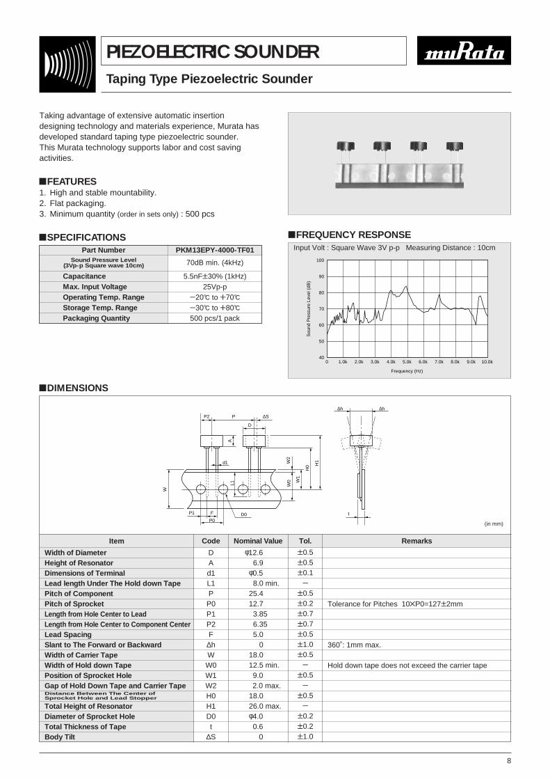
Taking advantage of extensive automatic insertiondesigning technology and materials experience, Murata hasdeveloped standard taping type piezoelectric sounder.This Murata technology supports labor and cost savingactivities.
!FEATURES1. High and stable mountability.2. Flat packaging.3. Minimum quantity (order in sets only) : 500 pcs
!SPECIFICATIONS
!DIMENSIONS
!FREQUENCY RESPONSE
100
90
80
70
60
50
400 1.0k 2.0k 3.0k 4.0k 5.0k
Frequency (Hz)
Sou
nd P
ress
ure
Leve
l (dB
)
6.0k 7.0k 8.0k 9.0k 10.0k
Part Number PKM13EPY-4000-TF01
CapacitanceMax. Input VoltageOperating Temp. RangeStorage Temp. RangePackaging Quantity
5.5nFT30% (1kHz)25Vp-p
Y20D to W70D
Y30D to W80D
500 pcs/1 pack
Item
Width of DiameterHeight of ResonatorDimensions of TerminalLead length Under The Hold down TapePitch of ComponentPitch of SprocketLength from Hole Center to LeadLength from Hole Center to Component CenterLead SpacingSlant to The Forward or BackwardWidth of Carrier TapeWidth of Hold down TapePosition of Sprocket HoleGap of Hold Down Tape and Carrier Tape
Total Height of ResonatorDiameter of Sprocket HoleTotal Thickness of TapeBody Tilt
Distance Between The Center ofSprocket Hole and Lead Stopper
DAd1L1PP0P1P2F
∆hWW0W1W2H0H1D0t
∆S
T0.5T0.5T0.1
YT0.5T0.2T0.7T0.7T0.5T1.0T0.5
YT0.5
YT0.5
YT0.2T0.2T1.0
Tolerance for Pitches 10ZP0=127T2mm
360˚: 1mm max.
Hold down tape does not exceed the carrier tape
φ12.655516.95φ0.555
555 8.0 min.25.4112.7513.8516.3515.0515.0518.05
55512.5 min.19.05
55552.0 max.18.05
555 26.0 max.φ4.05510.6515.05
Code Nominal Value Tol. Remarks
P2 P
d1
A
W
∆S
D
H1
H0
W1
W0
W2
D0
L1
P0
FP1
∆h ∆h
t
(in mm)
Input Volt : Square Wave 3V p-p Measuring Distance : 10cm
Sound Pressure Level(3Vp-p Square wave 10cm) 70dB min. (4kHz)
9
SMD Piezoelectric Sounder
PIEZOELECTRIC SOUNDER
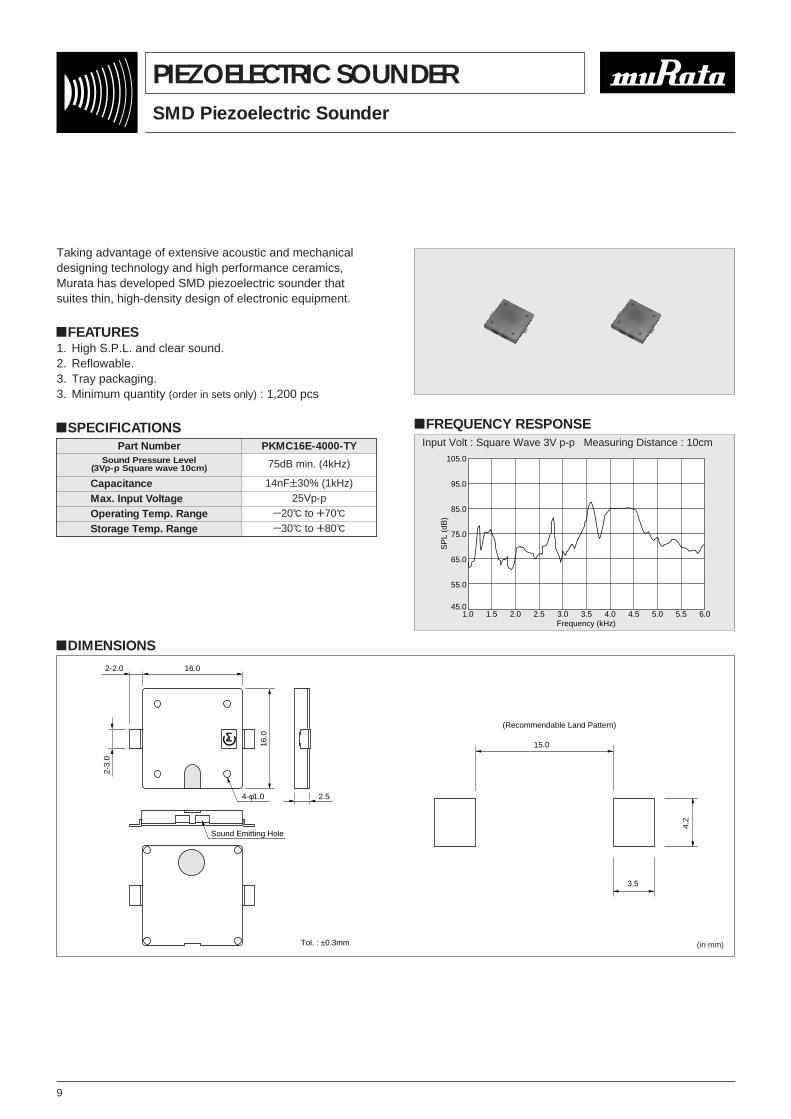
Taking advantage of extensive acoustic and mechanicaldesigning technology and high performance ceramics,Murata has developed SMD piezoelectric sounder thatsuites thin, high-density design of electronic equipment.
!FEATURES1. High S.P.L. and clear sound.2. Reflowable.3. Tray packaging.3. Minimum quantity (order in sets only) : 1,200 pcs
!SPECIFICATIONS
!DIMENSIONS
!FREQUENCY RESPONSE
105.0
95.0
85.0
75.0
65.0
55.0
45.01.0 1.5 2.0 2.5 3.0 3.5 4.0 4.5 5.0 5.5 6.0
Frequency (kHz)
SP
L (d
B)
Part Number PKMC16E-4000-TY
CapacitanceMax. Input VoltageOperating Temp. RangeStorage Temp. Range
14nFT30% (1kHz)25Vp-p
Y20D to W70D
Y30D to W80D
15.0
3.5
4.2
(Recommendable Land Pattern)
16.0
2.5
2-2.0
2-3.
0
16.0
4-φ1.0
Sound Emitting Hole
Tol. : ±0.3mm (in mm)
Input Volt : Square Wave 3V p-p Measuring Distance : 10cm
Sound Pressure Level(3Vp-p Square wave 10cm) 75dB min. (4kHz)

10
Piezoelectric Sounder/PIEZORINGER® for Telephones
PIEZOELECTRIC SOUNDER
As the result of rapid development of ICs in telephones,
demand for piezoelectric sounder as telephone ringers has
also rapidly increased. To effectively satisfy this rising
demand, Murata provides a suitable piezoelectric sounder
called PIEZORINGER®, with the following features.
!FEATURES1. Extremely clear sound.
2. Since it is voltage driven, the power consumption is quite
negligible.
3. It can be driven directly from ICs.
4. Extremely thin and light.
PKM44EW-1001C
PKM44EP-0901 PKM33EP-1201C
PKM34EW-1101/1201C
!DIMENSIONS
φ34.5
3.0
9.0
100.
0
5.0
40.046.0
2- 2.8φ
PKM34EW-1101/1201C
4.0
φ44.
0
61.0
52.0
100.
014
.0
2−φ3.5
2−R5
5
PKM44EW-1001C
φ44.0
4.0
0.2
0.5
4.0
2.0
13.0
3.0
1.0
42.6
45.0
10.0
B
1.4
1.01.8
A
Detail of A
Detail of B
PKM44EP-0901
1.0
9.0
6.0
7.5
4.0
0.5
R4.
017
.415
.6
33
R18.5
9.0
+0−0.4
1.8+0−0.1
3.2
0.2
1.7
9.016.5
120˚
A1.0
Detail of A (1/15)
PKM33EP-1201C
(in mm)
Part Number
PKM34EW-1101CPKM34EW-1201CPKM44EW-1001C
EIAJPart Number
PS-RW2-C34-11PS-RW2-C34-12PS-RW2-C44-10
Sound Pressure Level[dB]
(30Vp-p Square wave 1m)
70 min. (1.1kHz)70 min. (1.2kHz)75 min. (1kHz)
Sound Pressure Level[dB]
(1Vrms sine wave 10cm)(Ref. only)
60 min. (1.1kHz)60 min. (1.2kHz)70 min. (1kHz)
Capacitance [nF](120Hz)
40T30%32T30%68T30%
Max. InputVoltage[Vp-p]
406030
OperatingTemp.Range
[D]
Y20 toW70
StorageTemp.Range
[D]
Y30 toW80
PackagingQuantity[pcs]
25
Lead Wire Type
Part Number
PKM44EP-0901PKM33EP-1201C
EIAJPart Number
PS-RP2-C44-09PS-RP2-C33-12
Sound Pressure Level[dB]
(30Vp-p Square wave 1m)
70 min. (1kHz)
Sound Pressure Level[dB]
(1Vrms sine wave 10cm)(Ref. only) (1kHz)
60 min.65 min.
Capacitance [nF](120Hz)
68T30%40T30%
Max. InputVoltage[Vp-p]
40
OperatingTemp.Range
[D]Y20 to
W70
StorageTemp.Range
[D]Y30 to
W80
PackagingQuantity[pcs]
160300
Pin Type
Part NumberPKM33EP-1201CPKM33EP-1202C
R(mm)5.00
!SPECIFICATIONS
11
Piezoelectric Sounder/PIEZORINGER® for Telephones
PIEZOELECTRIC SOUNDER
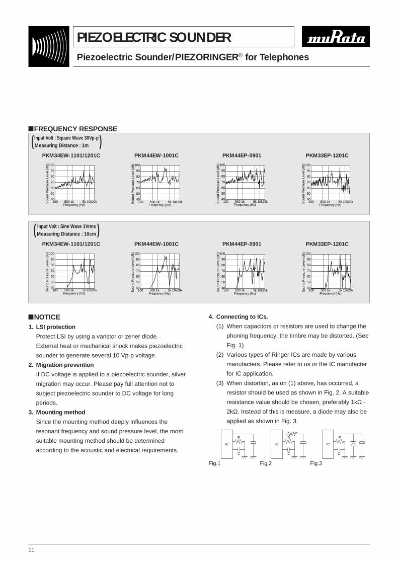
!FREQUENCY RESPONSEInput Volt : Square Wave 30Vp-pi( Measuring Distance : 1m )
PKM34EW-1101/1201C
Sou
nd P
ress
ure
Leve
l (dB
)
Frequency (Hz)100 500 1k 5k 10k20k
100
90
80
70
60
50
40
PKM44EW-1001C
Sou
nd P
ress
ure
Leve
l (dB
)
Frequency (Hz)100 500 1k 5k 10k20k
100
90
80
70
60
50
40
PKM44EP-0901
Sou
nd P
ress
ure
Leve
l (dB
)
Frequency (Hz)100 500 1k 5k 10k20k
100
90
80
70
60
50
40
PKM33EP-1201C
Sou
nd P
ress
ure
Leve
l (dB
)
Frequency (Hz)100 500 1k 5k 10k20k
100
90
80
70
60
50
40
Input Volt : Sine Wave 1Vrmsi( Measuring Distance : 10cm )PKM34EW-1101/1201C
Sou
nd P
ress
ure
Leve
l (dB
)
Frequency (Hz)100 500 1k 5k 10k20k
100
90
80
70
60
50
40
PKM44EW-1001C
Sou
nd P
ress
ure
Leve
l (dB
)
Frequency (Hz)100 500 1k 5k 10k20k
100
90
80
70
60
50
40
PKM44EP-0901
Sou
nd P
ress
ure
Leve
l (dB
)
Frequency (Hz)100 500 1k 5k 10k20k
100
90
80
70
60
50
40
PKM33EP-1201C
Sou
nd P
ress
ure
Leve
l (dB
)
Frequency (Hz)100 500 1k 5k 10k20k
100
90
80
70
60
50
40
!NOTICE1. LSI protection
Protect LSI by using a varistor or zener diode.
External heat or mechanical shock makes piezoelectric
sounder to generate several 10 Vp-p voltage.
2. Migration prevention
If DC voltage is applied to a piezoelectric sounder, silver
migration may occur. Please pay full attention not to
subject piezoelectric sounder to DC voltage for long
periods.
3. Mounting method
Since the mounting method deeply influences the
resonant frequency and sound pressure level, the most
suitable mounting method should be determined
according to the acoustic and electrical requirements.C
R
IC
C
R
IC
C
R
IC
Fig.1 Fig.2 Fig.3
4. Connecting to ICs.
(1) When capacitors or resistors are used to change the
phoning frequency, the timbre may be distorted. (See
Fig. 1)
(2) Various types of Ringer ICs are made by various
manufacters. Please refer to us or the IC manufacter
for IC application.
(3) When distortion, as on (1) above, has occurred, a
resistor should be used as shown in Fig. 2. A suitable
resistance value should be chosen, preferably 1kΩ -
2kΩ. Instead of this is measure, a diode may also be
applied as shown in Fig. 3.
12
Piezoelectric Sounder Self Drive Type
PIEZOELECTRIC SOUNDER
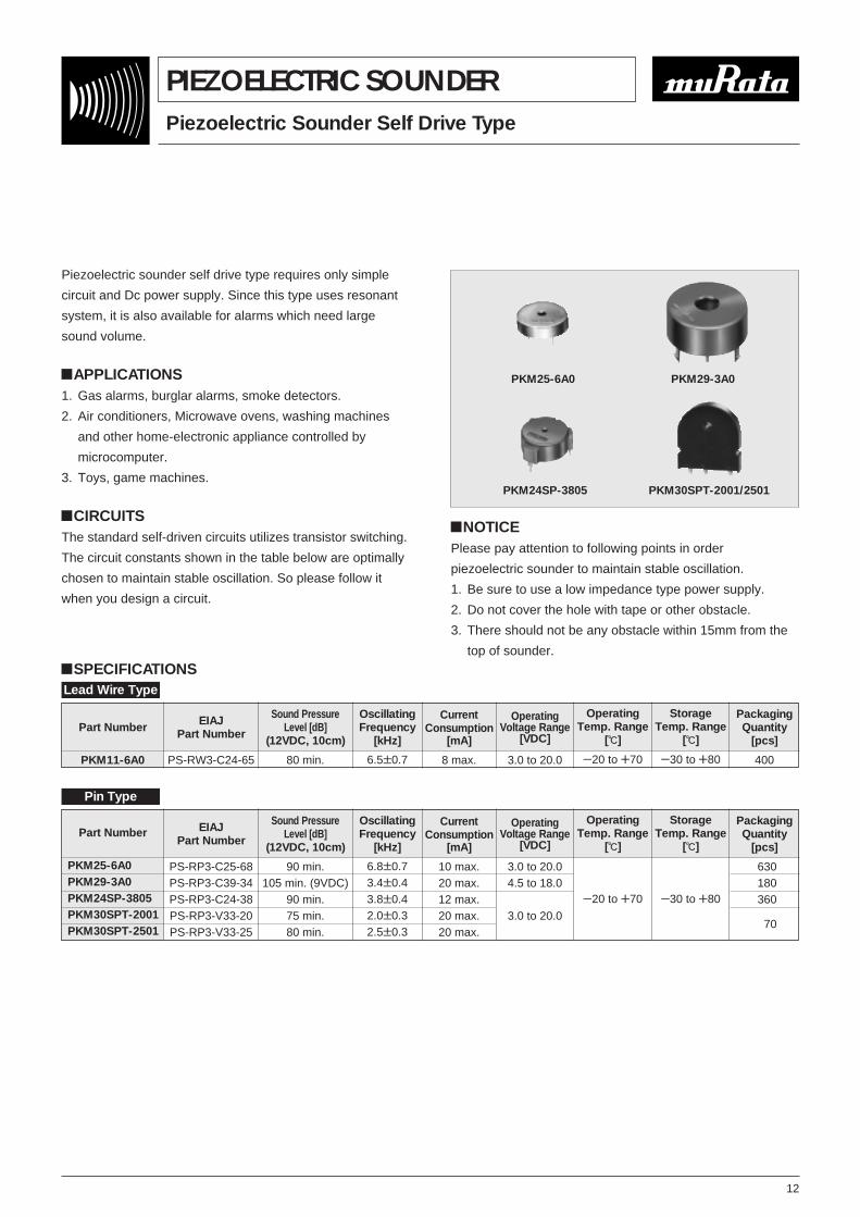
Piezoelectric sounder self drive type requires only simple
circuit and Dc power supply. Since this type uses resonant
system, it is also available for alarms which need large
sound volume.
!APPLICATIONS1. Gas alarms, burglar alarms, smoke detectors.
2. Air conditioners, Microwave ovens, washing machines
and other home-electronic appliance controlled by
microcomputer.
3. Toys, game machines.
!CIRCUITSThe standard self-driven circuits utilizes transistor switching.
The circuit constants shown in the table below are optimally
chosen to maintain stable oscillation. So please follow it
when you design a circuit.
PKM29-3A0
PKM24SP-3805 PKM30SPT-2001/2501
PKM25-6A0
Part Number
PKM11-6A0
EIAJPart Number
PS-RW3-C24-65
Sound PressureLevel [dB]
(12VDC, 10cm)
80 min.
OscillatingFrequency
[kHz]
6.5T0.7
CurrentConsumption
[mA]
8 max.
OperatingVoltage Range
[VDC]
3.0 to 20.0
OperatingTemp. Range
[D]
Y20 to W70
StorageTemp. Range
[D]
Y30 to W80
PackagingQuantity
[pcs]
400
Part Number
PKM25-6A0PKM29-3A0PKM24SP-3805PKM30SPT-2001PKM30SPT-2501
EIAJPart Number
PS-RP3-C25-68PS-RP3-C39-34PS-RP3-C24-38PS-RP3-V33-20PS-RP3-V33-25
Sound PressureLevel [dB]
(12VDC, 10cm)
90 min.105 min. (9VDC)
90 min.75 min.80 min.
OscillatingFrequency
[kHz]
6.8T0.73.4T0.43.8T0.42.0T0.32.5T0.3
CurrentConsumption
[mA]
10 max.20 max.12 max.20 max.20 max.
OperatingVoltage Range
[VDC]
3.0 to 20.04.5 to 18.0
3.0 to 20.0
OperatingTemp. Range
[D]
Y20 to W70
StorageTemp. Range
[D]
Y30 to W80
PackagingQuantity
[pcs]
630180360
70
Lead Wire Type
Pin Type
!NOTICEPlease pay attention to following points in order
piezoelectric sounder to maintain stable oscillation.
1. Be sure to use a low impedance type power supply.
2. Do not cover the hole with tape or other obstacle.
3. There should not be any obstacle within 15mm from the
top of sounder.
!SPECIFICATIONS
13
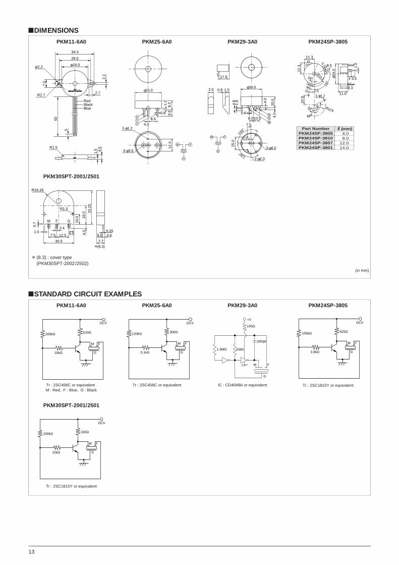
!STANDARD CIRCUIT EXAMPLES
M F
10kΩ G
510Ω200kΩ
DCV
PKM11-6A0
M F
5.1kΩ G
300Ω120kΩ
DCV
PKM25-6A0
150kΩ
150Ω
1.5MΩ
M F
G
+V
1000pF
PKM29-3A0
M F
3.9kΩ G
620Ω150kΩ
DCV
PKM24SP-3805
M F
12kΩ G
330Ω100kΩ
DCV
PKM30SPT-2001/2501
Tr : 2SC458C or equivalentM : Red, F : Blue, G : Black
Tr : 2SC458C or equivalent IC : CD4049A or equivalent Tr : 2SC1815Y or equivalent
Tr : 2SC1815Y or equivalent
!DIMENSIONS
φ
34.4
2.2
29.0
24.0
2.7
Red
R1.5
50
5
1.5 4.5
7.0
φ 2.2
BlackBlue
R2.7
PKM11-6A0
φ25.0
2-φ1.2
3-φ3.5
8.2
6.5
12.0
0.8
8.5
4.0
1.2
M F
G
M
F
G
PKM25-6A0
φ39.0
4.0
4.8
1.8
4.0
20.0
25.0
3-φ4.0
GFM
2-φ2.0
17.9
8.0
0.8
7.5
4.0
120˚
120˚
0.8 1.5
10.5
2.0
FM
G
PKM29-3A0
12.3
11.3
8.5
18˚R14.2
24.0
11.0
φ
8.3
R3.5
GF
M
18˚ R12.9
10.9
1.0
7.0G3− 1.2φ
M
130˚
130˚
PKM24SP-3805
1.0
R15.25
0.7
30.5
7.5 12.5 5.0
FM G 10.0 18
.0 33.2
5
0.250.6
7.7*(8.3)
5.04.0
R1.5
2.4
PKM30SPT-2001/2501
(in mm)
* (8.3) : cover type(PKM30SPT-2002/2502)
Part NumberPKM24SP-3805PKM24SP-3810PKM24SP-3807PKM24SP-3801
R(mm)14.018.012.014.0

14
Piezoelectric Buzzer
PIEZOELECTRIC BUZZER
This is unified piezoelectric sounder which has piezoelectric
diaphragm of 3 terminals connected to self drive circuit, and
it easily generates sound with only a DC power supply
(DC3.0-20V). Using suitably designed resonant system, this
type can be used where large sound volumes are needed.
!APPLICATIONS1. Gas alarms, burglar alarms.
2. Air conditioners, microwave ovens and various types of
microcomputer controlled home-electronic appliances.
3. Automobile speed alarms, navigators, car stereos and
other automobile equipment.
4. Toys, games, and other simple electronic devices such
as teaching aids.
!CIRCUITSThis type of piezoelectric buzzer is built in complete circuit ;
so there is no need for another circuit for generating sound.
Resistors should not be connected in
series to the power supply as this will
produce irregular oscillation.
When resistor is necessary to control
sound volume, use capacitor (1µF)
parallel with the buzzer together.
PKB24SPC-3601
PKB8-4A0 PKB30SPC-2001
PKB24SW-3301
Part Number
PKB24SW-3301PKB6-5A0PKB5-3A0
EIAJPart Number
PB-RWD-C24-33PB-RWD-C34-47PB-RWD-C42-28
Sound PressureLevel [dB]
(12VDC, 10cm)
80 min.
95 min.
OscillatingFrequency
[kHz]
3.3T0.54.7T0.72.8T0.5
CurrentConsumption
[mA]
12 max.
OperatingVoltage Range
[VDC]
3.0 to 20.0
OperatingTemp. Range
[D]
Y20 to W70
StorageTemp. Range
[D]
Y30 to W80
PackagingQuantity
[pcs]
50
25
Lead Wire Type
Part Number
PKB24SPC-3601PKB8-4A0PKB30SPC-2001PKB30SPC-3001
EIAJPart Number
PB-RPD-C24-36PB-RPD-C24-38PB-RPD-C30-20PB-RPD-C30-27
Sound PressureLevel [dB]
(12VDC, 10cm)
90 min.95 min.
92 min.
OscillatingFrequency
[kHz]
3.6T0.53.8T0.52.0T0.42.7T0.4
CurrentConsumption
[mA]
16 max.13 max.
15 max.
OperatingVoltage Range
[VDC]
3.0 to 15.03.0 to 20.0
3.0 to 15.0
OperatingTemp. Range
[D]
Y20 to W70
StorageTemp. Range
[D]
Y30 to W80
PackagingQuantity
[pcs]
65090
320
Pin Type
!NOTICEPlease pay attention to following points in order
piezoelectric sounder to maintain stable oscillation.
1. Do not cover the hole with tape or other obstacles.
2. There should not be any obstacle within 15mm from top
of buzzer.
3. Please use these piezoelectric buzzer within the limit of
rated voltage. Consult us if higher voltage type is
required.Buzzer Capacitor(1µF)
+VD.C
!SPECIFICATIONS
15
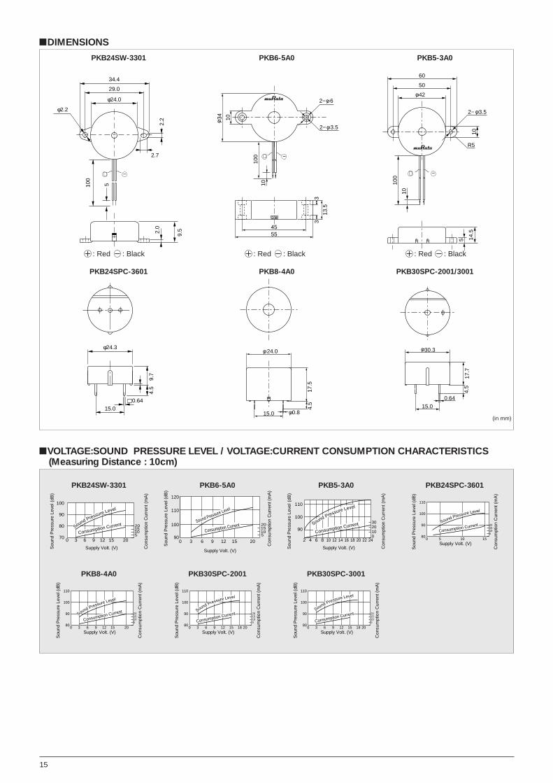
!DIMENSIONS
34.4
29.0
φ24.0
φ2.2
2.72.
2
100
5
2.0
9.5
+ −
PKB24SW-3301
34φ 10
1010
0
2− 6φ
2− 3.5φ
4555
13.5
33
+ −
PKB6-5A0
100
60
50
42φ
10
+ −
10
2− 3.5φ
R5
14.5
5
PKB5-3A0
(in mm)
φ24.3
15.00.64
9.7
4.5
PKB24SPC-3601
4.5
17.5
15.0
24.0φ
0.8φ
PKB8-4A0
0.64
30.3φ
4.5
17.7
15.0
PKB30SPC-2001/3001
!VOLTAGE:SOUND PRESSURE LEVEL / VOLTAGE:CURRENT CONSUMPTION CHARACTERISTICS(Measuring Distance : 10cm)
Sou
nd P
ress
ure
Leve
l (dB
)
Con
sum
ptio
n C
urre
nt (
mA
)
Supply Volt. (V)
070
80
90
100
3 6 9 12 15 20
Sound Pressure Level
Consumption Current 2015105
PKB24SW-3301
Consumption Current
Con
sum
ptio
n C
urre
nt (
mA
)
120
110
90
100
2015129630
Sound Pressure Level
Sou
nd P
ress
ure
Leve
l (dB
)
Supply Volt. (V)
2015105
PKB6-5A0
Sou
nd P
ress
ure
Leve
l (dB
)
Con
sum
ptio
n C
urre
nt (
mA
)
Supply Volt. (V)
2 4 6 8 10 12 14 16 18 20 22 24
90
100
110
Consumption CurrentSound Pressure Level
3020100
PKB5-3A0
Sou
nd P
ress
ure
Leve
l (dB
)
Con
sum
ptio
n C
urre
nt (
mA
)
Supply Volt. (V)0 5 10 15
2015105
80
90
100
110
Sound Pressure Level
Consumption Current
PKB24SPC-3601
Sou
nd P
ress
ure
Leve
l (dB
)
Con
sum
ptio
n C
urre
nt (
mA
)
Supply Volt. (V)0 3 6 9 12 15 20
2015105
80
90
100
110
Consumption CurrentSound Pressure Level
PKB8-4A0
Sou
nd P
ress
ure
Leve
l (dB
)
Con
sum
ptio
n C
urre
nt (
mA
)
Supply Volt. (V)0 3 6 9 12 15 18 20
2015105
80
90
100
110
Consumption CurrentSound Pressure Level
PKB30SPC-2001
Sou
nd P
ress
ure
Leve
l (dB
)
Con
sum
ptio
n C
urre
nt (
mA
)
Supply Volt. (V)0 3 6 9 12 15 18 20
2015105
80
90
100
110
Consumption CurrentSound Pressure Level
PKB30SPC-3001
W : Red Y : Black W : Red Y : Black W : Red Y : Black
16
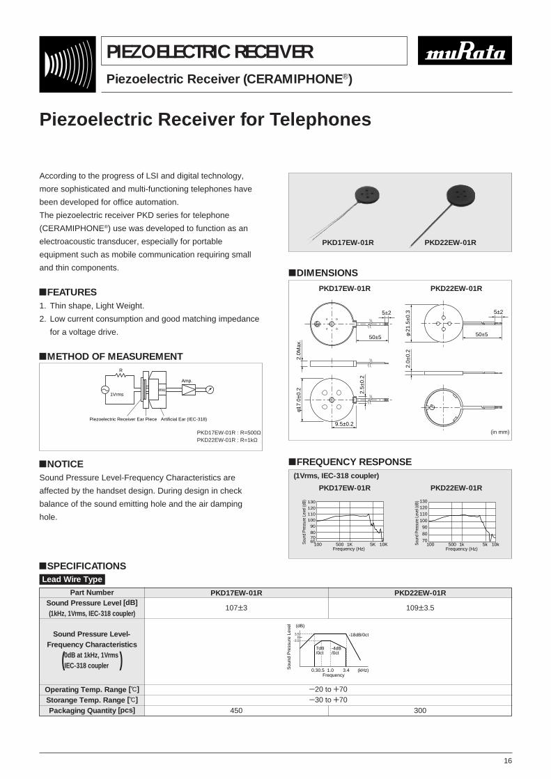
Piezoelectric Receiver (CERAMIPHONE®)
PIEZOELECTRIC RECEIVER
According to the progress of LSI and digital technology,
more sophisticated and multi-functioning telephones have
been developed for office automation.
The piezoelectric receiver PKD series for telephone
(CERAMIPHONE®) use was developed to function as an
electroacoustic transducer, especially for portable
equipment such as mobile communication requiring small
and thin components.
!FEATURES1. Thin shape, Light Weight.
2. Low current consumption and good matching impedance
for a voltage drive.
!METHOD OF MEASUREMENT
!NOTICESound Pressure Level-Frequency Characteristics are
affected by the handset design. During design in check
balance of the sound emitting hole and the air damping
hole.
Piezoelectric Receiver for Telephones
PKD17EW-01R : R=500ΩPKD22EW-01R : R=1kΩ
Part NumberSound Pressure Level [dB]
(1kHz, 1Vrms, IEC-318 coupler)
Operating Temp. Range [D]
Storange Temp. Range [D]
Packaging Quantity [pcs]
PKD22EW-01R
109T3.5
PKD17EW-01R
107T3
Y20 to W70Y30 to W70
450 300
Lead Wire Type
Sound Pressure Level-Frequency Characteristics
0dB at 1kHz, 1Vrmsi(IEC-318 couplerw w)
(dB)
0.30.5 1.0 3.4 (kHz)Frequency
Sou
nd P
ress
ure
Leve
l
7dB/0ct
-4dB/0ct
-18dB/0ct3.50
-3.5
PKD22EW-01RPKD17EW-01R
!DIMENSIONS
φ17.
0±0.
2 2.5±
0.2
9.5±0.2
2.0M
ax.
5±2
50±5
PKD17EW-01R
φ21
.5±0
.3 5±2
2.0±
0.2
50±5
PKD22EW-01R
(in mm)
!FREQUENCY RESPONSE
100 1K 5K500 10KFrequency (Hz)
Soun
d Pr
essu
re L
evel
(dB)
120110100
90
8070
130
65
PKD17EW-01R
130120110100908070
100 500 1k 5k 10kFrequency (Hz)
Soun
d Pr
essu
re L
evel
(dB)
PKD22EW-01R
(1Vrms, IEC-318 coupler)
1Vrms
R
Amp.
Piezoelectric Receiver Ear Piece Artificial Ear (IEC-318)
mic
!SPECIFICATIONS

17
Piezoelectric Speaker (CERAMITONE®)
PIEZOELECTRIC SPEAKER
!NOTICE1. Please pay full attention not to subject piezoelectric
sounder to DC voltage for long periods.
2. Protect LSI by using a varistor or zener diode.
External heat or mechanical shock makes piezoelectric
sounder to generate several 10 Vp-p voltage.
As voice synthesizing techniques with ICs and LSIs are
rapidly progressed, human voice synthesizing devices are
put into practical use for portable calculators, clocks,
vending machines, translating machines and so forth. In
order to meet the demand, Murata has developed
Piezoelectric Speaker best suited for making synthesized
voice or melody.
!FEATURES1. High efficiency compared with conventional
electromagnetic type speakers.
2. Ultra-thin and light-weight.
3. High impedance with less power consumption.
4. No electric noise, because they have no mechanical
contacts.
5. Direct drive by IC is available.
VSB41D25-07AR0
VSB35EW-0701B
VSB50EW-0301B
!DIMENSIONS
φ25.0φ41.048.0
φ50.
0
1.0
2.0
CeramicRing Metal plate
VSB41D25-07AR0
φ19.7φ27.0
1.7
Metal Plate
Supporting RingCeramic
Resinous Ring
φ35.0
VSB35EW-0701B
2.5
φ25.0φ39.0
Metal Plate
Supporting RingCeramic
Resinous Ring
φ50.0
VSB50EW-0301B
(in mm)
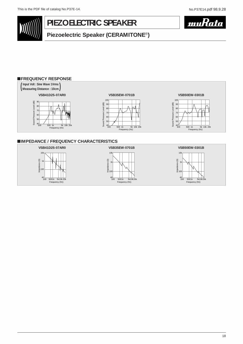
Part Number
VSB41D25-07AR0VSB35EW-0701BVSB50EW-0301B
Freq. Range[Hz]
500 to 20k600 to 20k250 to 20k
Capacitance [nF](120Hz)
140T30%340T35%600T35%
Impedance[Ω] (1kHz)
1200600300
Lowest ResonantFreq. [Hz]
900950400
Max.Input
30Vp-p75mW
150mW
Operating Temp.Range [D]
Y20 to W70
Storange Temp.Range [D]
Y30 to W80
PackagingQuantity [pcs]
10016080
!SPECIFICATIONS
No.P37E14.pdf 98.9.28 This is the PDF file of catalog No.P37E-14.
18
Piezoelectric Speaker (CERAMITONE®)
PIEZOELECTRIC SPEAKER
!FREQUENCY RESPONSEInput Volt : Sine Wave 1Vrmsi( Measuring Distance : 10cm )
VSB41D25-07AR0
Sou
nd P
ress
ure
Leve
l (dB
)
Frequency (Hz)100 500 1k 5k 10k 20k
90
80
70
60
50
40
VSB35EW-0701B
Frequency (Hz)100 500 1k 5k 10k 20kS
ound
Pre
ssur
e Le
vel (
dB)
90
100
80
70
60
50
40
VSB50EW-0301B
Frequency (Hz)100 500 1k 5k 10k 20kS
ound
Pre
ssur
e Le
vel (
dB)
90
100
80
70
60
50
40
!IMPEDANCE / FREQUENCY CHARACTERISTICSVSB41D25-07AR0
Frequency (Hz)
Impe
danc
e (Ω
)
100 5001k 5k10k 20k
10k
1k
100
40
VSB35EW-0701B
100 500Frequency (Hz)
1k 5k10k20k
Impe
danc
e (Ω
)
10k
1k
100
40
VSB50EW-0301B
100 500Frequency (Hz)
1k 5k10k20kIm
peda
nce
(Ω)
10k
1k
100
40

No.P37E14.pdf 98.9.28 This is the PDF file of catalog No.P37E-14.
Note:
1. Export Control<For customers outside Japan>Murata products should not be used or sold for use in the development, production, stockpiling or utilization of any conventional weapons or mass-destructiveweapons (nuclear weapons, chemical or biological weapons, or missiles), or any other weapons.<For customers in Japan>For products which are controlled items subject to “the Foreign Exchange and Foreign Trade Control Law” of Japan, the export license specified by the law isrequired for export.
2. Please contact our sales representatives or engineers before using our products listed in this catalog for the applications requiring especially high reliability whatdefects might directly cause damage to other party's life, body or property (listed below) or for other applications not specified in this catalog.q Aircraft equipmentw Aerospace equipmente Undersea equipmentr Medical equipmentt Transportation equipment (automobiles, trains, ships,etc.)y Traffic signal equipmentu Disaster prevention / crime prevention equipmenti Data-processing equipmento Applications of similar complexity or with reliability requirements comparable to the applications listed in the above
3. Product specifications in this catalog are as of February 1998, and are subject to change or stop the supply without notice. Please confirm the specificationsbefore ordering any product. If there are any questions, please contact our sales representatives or engineers.
4. The categories and specifications listed in this catalog are for information only. Please confirm detailed specifications by checking the product specificationdocument or requesting for the approval sheet for product specification, before ordering.
5. Please note that unless otherwise specified, we shall assume no responsibility whatsoever for any conflict or dispute that may occur in connection with the effectof our and/or third party's intellectual property rights and other related rights in consideration of your using our products and/or information described orcontained in our catalogs. In this connection, no representation shall be made to the effect that any third parties are authorized to use the rights mentionedabove under licenses without our consent.
6. None of ozone depleting substances (ODS) under the Montreal Protocol is used in manufacturing process of us.
Head Office2-26-10, Tenjin Nagaokakyo-shi, Kyoto 617-8555, Japan Phone:81-75-951-9111
International Division1-18-1 Hakusan, Midori-ku, Yokohama-shi, Kanagawa 226-0006, Japan Phone:81-45-931-7111 Fax:81-45-931-7105 E-mail:[email protected]
http://www.murata.co.jp/products/
Recommended


