Embed Size (px)
Citation preview

User’s Manualfor
MX-70 Printer
b yD a v i d A . L i e n
COMPUSOFT ® PUBLISHINGA Division of CompuSoft, Inc.
P.O. Box 19669 l San Diego, California 92119 U.S.A.

This Book was prepared especially for Epson America, Inc. by CompuSoft® Publish-ing. All rights, domestic and international are reserved by CompuSoft®, Inc. Requestsfor permission to reproduce or distribute this User’s Manual should be addressed to:
COPYRIGHT DEPTCompuSoft®, Inc.
P.O. Box 19669San Diego, CA 92119
Copyright © 1981 by CompuSoft® Publishing,A Division of CompuSoft®, Inc.
San Diego, CA 92119
All rights reserved. No part of this publication may be reproduced, stored in a retrieval system, ortransmitted, in any form or by any means, electronic, mechanical, photocopying, recording orotherwise, without the prior written permission of the publisher. No patent liability is assumedwith respect to the use of the information contained herein. While every precaution has beentaken in the preparation of this book, the publisher assumes no responsibility for errors oromissions. Neither is any liability assumed for damages resulting from the use of the informationcontained herein.
CompuSoft® is a registered trademark of CompuSoft®, Inc.
International Standard Book Number: o-932760-06-6Library of Congress Catalog Card Number: M-70726
10 9 8 7 6 5 4 3 2 1
Printed in the United States of America

FCC Compliance Statement
This equipment generates and uses radio frequency energy. If not installed andused properly, that is, in strict accordance with the manufacturer’s instructions,it may cause interference to radio and television reception. It has been typetested and found to comply with the limits for a Class B computing device inaccordance with the specifications in Subpart J of Part 15 of FCC Rules, whichare designed to provide reasonable protection against such interference in aresidential installation. However, there is no guarantee that interference willnot occur in a particular installation. If this equipment does cause interferenceto radio or television reception, which can be determined by turning the equip-ment off and on, the user is encouraged to try to correct the interference by oneor more of the following measures:
- Reorient the receiving antenna- Relocate the computer with respect to the receiver- Move the computer into a different outlet so that computer and re-
ceiver are on different branch circuits.
If necessary, the user should consult the dealer or an experienced radio/television technician for additional suggestions. The user may find the followingbooklet prepared by the Federal Communications Commission helpful:
“How to Identify and Resolve Radio-TV Interference Problems.”
This booklet is available from the U.S. Government Printing Office, Washing-ton, DC 20402, Stock No. 004-000-00345-4.
i i i

Trademark Acknowledgements
TRS-80 is a Trade Mark of Radio Shack. Centronics is a Trade Mark ofCentronics, Inc. Apple is a Trade Mark of Apple Computers, Inc. Microsoft is aTrade Mark of Microsoft, Inc.

A Personal Note From the Author
Congratulations on your decision to buy an Epson MX-70 printer! In myopinion, it’s the best dollar value in a low cost printer on the market today. Likeits big brothers the MX-80 and MX-100, its mechanical features are unsur-passed for the cost. Its electronics features are ideal for the user looking for topvalue in a printer for general utility use, and high resolution graphics.
“WHO NEEDS A LEARNERS MANUAL FOR A PRINTER?” The answer -ALMOST EVERYONE EXCEPT A COMPUTER PROFESSIONAL.
Today’s printers are very sophisticated compared to those of even a year ago.Most are not fully utilized because the instructions are too vague and confus-ing. We’re doing our best to eliminate that problem with the Epson MX-series.
Z encourage you to learn all about your new MX-70. You paid for it. Put itto work.
Dr. David A. LienSan Diego - 1981

vi

MX-70 Table of Contents
FCC Compliance Notice . . . . . . . . . . . . . . . . . . . . . . . . . . . . . . . . . . . . . . . . . . . .Trademark Credits . . . . . . . . . . . . . . . . . . . . . . . . . . . . . . . . . . . . . . . . . . . . . . . .
Personal Note from the Author . . . . . . . . . . . . . . . . . . . . . . . . . . . . . . . . . . . . .
Introduction . . . . . . . . . . . . . . . . . . . . . . . . . . . . . . . . . . . . . . . . . . . . . . . . . . . . . .Chapter 1: The Starting Line . . . . . . . . . . . . . . . . . . . . . . . . . . . . . . . . . . . . . . .
Chapter2:SenditaMessage . . . . . . . . . . . . . . . . . . . . . . . . . . . . . . . . . . . . . . .Chapter 3: More Print Control Commands . . . . . . . . . . . . . . . . . . . . . . . . . . .
Chapter 4: An Introduction to Dot Matrix Printing . . . . . . . . . . . . . . . . . . . .
Chapter 5: Graphtrax II . . . . . . . . . . . . . . . . . . . . . . . . . . . . . . . . . . . . . . . . . . . .
Chapter 6: Advanced Graphics . . . . . . . . . . . . . . . . . . . . . . . . . . . . . . . . . . . . .Chapter 7: The Final Push . . . . . . . . . . . . . . . . . . . . . . . . . . . . . . . . . . . . . . . . . .Chapter 8: Using the HIRES Screen Dump Program . . . . . . . . . . . . . . . . . . .
Appendix A: ASCII Charts for MX-70 . . . . . . . . . . . . . . . . . . . . . . . . . . . . . . . .
Appendix B: Control Codes . . . . . . . . . . . . . . . . . . . . . . . . . . . . . . . . . . . . . . . . .
Appendix C: Character Set . . . . . . . . . . . . . . . . . . . . . . . . . . . . . . . . . . . . . . . . .
Appendix D: TRS-80 Differences . . . . . . . . . . . . . . . . . . . . . . . . . . . . . . . . . . . .
Appendix E: Use with Atari . . . . . . . . . . . . . . . . . . . . . . . . . . . . . . . . . . . . . . . .
Appendix F: Use with Apple . . . . . . . . . . . . . . . . . . . . . . . . . . . . . . . . . . . . . . . .
Appendix G: Special Notes on Other Computers, Languages/Interfaces ...Appendix H: Technical Specifications . . . . . . . . . . . . . . . . . . . . . . . . . . . . . . . .Appendix I: Control Circuit Board and Initialization . . . . . . . . . . . . . . . . . . .
Appendix J: Pinout Chart . . . . . . . . . . . . . . . . . . . . . . . . . . . . . . . . . . . . . . . . . .
Appendix K: Parallel Interface Timing . . . . . . . . . . . . . . . . . . . . . . . . . . . . . . .Appendix L: Printer Maintenance . . . . . . . . . . . . . . . . . . . . . . . . . . . . . . . . . . .Appendix M: Schematic Diagram . . . . . . . . . . . . . . . . . . . . . . . . . . . . . . . . . . .Index . . . . . . . . . . . . . . . . . . . . . . . . . . . . . . . . . . . . . . . . . . . . . . . . . . . . . . . . . . . .Notice . . . . . . . . . . . . . . . . . . . . . . . . . . . . . . . . . . . . . . . . . . . . . . . . . . . . . . . . . . .
iii
ivV
ix1
13233141495967798183858991959799
101103105107109111
vii

USER’S SERVICEMANUAL
WARNINGHigh voltage exists inside this unit andthe case should be opened only by a qual-ified person!
vi i i

USER’S SERVICEMANUAL
WARNINGHigh voltage exists inside this unit andthe case should be opened only by a qual-ified person!
v i i i

Introduction
“But do I REALLY have to take a course on ‘How to operate a printer’ to usethis one?” No - not if you only want to use it for mundane printing. It prints“mundanes” very nicely.
If you want to use the exotic features it offers, approach your new printer in thesame way as your first computer - with a healthy curiosity and an open mind.They probably far exceed what you expected from a printer inexpensive enoughto call your own.
The MX-70 printer works with virtually any computer properly interfaced to it.This “Learner’s Manual” uses the popular Apple II Plus as its “driver” sincethe Apple’s high resolution graphics features so closely parallel the printers.What’s taught here applies to all computers, though not all are powerful enoughto utilize every MX-70 feature. More on that in good time.
Impatient readers should head for the appendices and usual reference materialsat the back. The rest of us will believe that this is no ordinary printer and takethe time to learn to use it right - the first time.
A good working knowledge of the BASIC* language is all that’s required as webegin, with Chapter 1.
“Users who feel their BASIC skills are a little rusty are referred to the followingbooks by the same author:
The BASIC Handbook (2nd Edition), Encyclopedia of the BASIC Lan-guage. 480 Pages. Available through CompuSoft Publishing, Box19669, San Diego, CA 92119.
Learning TRS-80 BASIC. Available through CompuSoft Publishing, Box19669, San Diego, CA 92119.
ix

X

The Starting Line
Chapter 1The Starting Line
This important chapter shows how to unpack, set up, and test your new printer.Read it before you get into trouble. The time spent will be your best investmentsince buying the printer itself.
Counting the Parts
Open the box and carefully and remove the contents. We should find:
1. This User’s Manual (obviously . . . )2. The Epson MX-70 printer3. A long box containing the ribbon cartridge4. A wire rack to guide the paper
We also need a cable to connect the printer to our particular computer. YourEpson dealer can provide cables that match the Apple, TRS-80, and othercomputers. If you use a non-Epson cable, make sure it is wired properly. Wehave tried many other cables that “should” work, but don’t.
The MX-70 uses the Centronics Standard Parallel Interface scheme. Userswhose computers require other interfacing schemes should select anotherprinter in the MX series.
Setting it up
Let’s first remove the printer lid so we can work without breaking something.Lay the MX-70 flat on a firm surface and raise its lid to the full vertical position(Figure l-l).
Figure l-l
1
Chapter 1
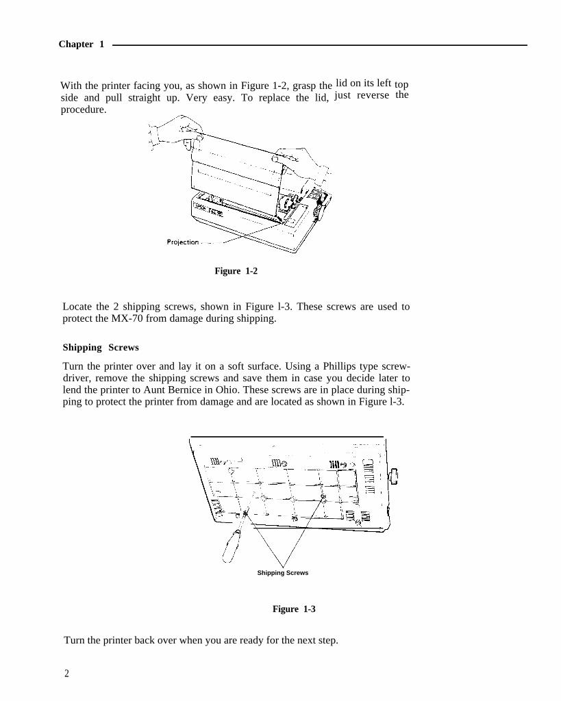
With the printer facing you, as shown in Figure 1-2, grasp theside and pull straight up. Very easy. To replace the lid,procedure.
lid on its left topjust reverse the
Figure 1-2
Locate the 2 shipping screws, shown in Figure l-3. These screws are used toprotect the MX-70 from damage during shipping.
Shipping Screws
Turn the printer over and lay it on a soft surface. Using a Phillips type screw-driver, remove the shipping screws and save them in case you decide later tolend the printer to Aunt Bernice in Ohio. These screws are in place during ship-ping to protect the printer from damage and are located as shown in Figure l-3.
Shipping Screws
Figure 1-3
Turn the printer back over when you are ready for the next step.
2

The Starting Line
Installing the Ribbon
Position the printer with the Epson label (front) facing you. Locate the paperbail (the moveable metal bar with numbers l-80 on it - see Figure l-3) and pushit toward the back of the printer, against the metal platen.
Remove the ribbon cartridge from its box and turn the plastic knob coun-terclockwise so the ribbon is tight. (Figure l-4A)
Figure 1-4A
Hold the cartridge by its vertical fin (sounds like a shark). Steer the 4 tabs on itssides into the 4 slots in the printer’s metal frame (Figure 1-4B). Press thecartridge firmly into place.
Figure 1-4B
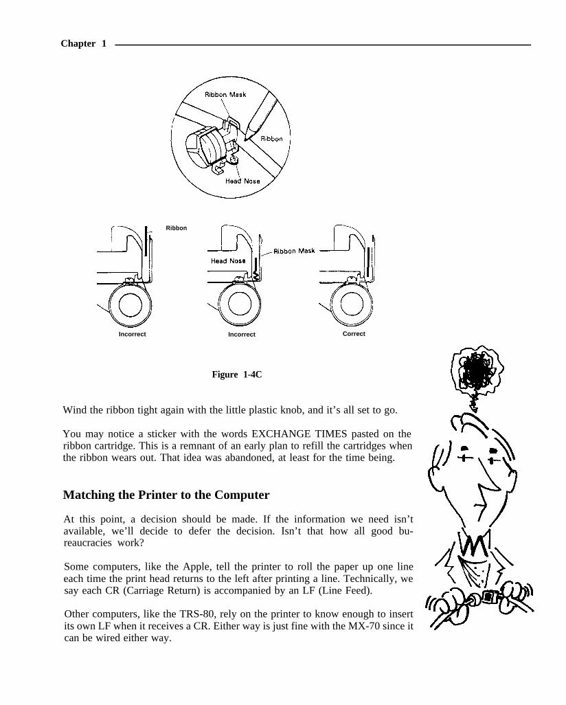
Using a pencil (or your fingers), lift the ribbon onto the slot in front of the printhead, as shown in Figure 1-4C. With a little practice, we can do all of the abovein one quick operation.
3
Chapter 1
Incorrect
Ribbon
Incorrect Correct
Figure 1-4C
Wind the ribbon tight again with the little plastic knob, and it’s all set to go.
You may notice a sticker with the words EXCHANGE TIMES pasted on theribbon cartridge. This is a remnant of an early plan to refill the cartridges whenthe ribbon wears out. That idea was abandoned, at least for the time being.
Matching the Printer to the Computer
At this point, a decision should be made. If the information we need isn’tavailable, we’ll decide to defer the decision. Isn’t that how all good bu-reaucracies work?
Some computers, like the Apple, tell the printer to roll the paper up one lineeach time the print head returns to the left after printing a line. Technically, wesay each CR (Carriage Return) is accompanied by an LF (Line Feed).
Other computers, like the TRS-80, rely on the printer to know enough to insertits own LF when it receives a CR. Either way is just fine with the MX-70 since itcan be wired either way.

The Starting Line
Opening the Case
To locate the wiring terminals, we have to open the case. The lid should still beoff. Remove the roller knob by pulling straight out, with firm but steadypressure (Figure l-5).
Figure 1-5
Turn the printer upside down on a soft surface. With a Phillips-head screwdriv-er, completely loosen (but don’t remove) all 4 corner screws as shown in Figurel-6. Place tape over the 4 holes so the screws won’t fall out when we tip theprinter right-side up again.
Figure 1-6
Now tip the printer right-side up again.
Gently wiggle the top cover loose. Wires are booked to it! We are not going tocompletely remove the cover - only open it enough to gain access to the mainwiring board.
Lift the cover up, mostly from the left side, and slide it gently to the right tofree it from the roller shaft. Be careful not to pull the wires on the right-handside. With just a bit of class we can maneuver the cover so it stands solidly inplace, as a sentinel guarding the goodies.
5

Chapter 1
Figure 1-7
Take a minute to gawk at all the stuff in the box. Wow! As Custer said, “Lookat all those . . . ” well, anyway.
Wonder how they sell it as cheap a they do? (Hope it prints as good as it looks.)
The Epson Connection
Figure l-7 shows the location of the moveable wire. It is between the 2 “pulltop” terminals, and is labeled “auto. ” To release the wire from one terminal fortransfer to the other, pull up gently on its colored top. To lock a wire in place,insert it fully in a terminal and press the colored top down. Pull gently on thewire to be sure it is securely locked.
If the “auto” wire is connected to the red (or orange) terminal, the printer relieson the computer to send its own LF along with CR. That’s what’s needed forApple-type computers.
If the “auto” wire is connected to the white terminal, a LF will automatically beadded when a CR is received from the computer. This is what’s needed for theTRS-80 and most other computers.
Terrific. So where do we put the wire for our computer?
6

The Starting Line
When in Doubt, Bluff
If you have an Apple, move (if necessary) the short white wire located betweenthem to the red terminal (as in red apple).
If you have any other computer, hook it (for now) to the white terminal.
If we guessed wrong, nothing will be harmed. We’ll just have to reopen the caseand move it to the opposite one. The results will be known early in the nextchapter.
A plastic plate is taped to the access hatch on the inside back of the lid. We caneither leave it in place as we replace the lid, tape it to the outside of the hole, oradd it to our growing collection of printer parts. In theory, the wire could bemoved from one terminal to the other through this hatch - but only by a skilleddentist.
If you are sure the wire is on the proper terminal, put the printer back togetherand tighten the screws. If not sure, put it back together and don’t tighten thescrews. The cover goes back on the way it came off - very carefully.
Printer Cable Connection
We’re getting closer to the good stuff.
Be sure both the computer and printer are turned off. Connect the printer cableto the printer only -not to the computer! It plugs into the only jack on the backof the MX-70 case.
Epson dealers can supply cables to match different computers. Check with yourEpson dealer to be sure you have the right one. Cables supplied with thecomputer frequently do not work. Do not connect the other end of the cable tothe computer, yet.
Take your time! Double-check to ensure that the cable is in place and locked.It may take a firm push on the connector to secure the locking clips. Withoutthis tight connection, printing may be erratic. Again - leave the other enddisconnected.
The Paper Rack
The wire rack with the plastic roller tube is a paper separator. It allows thepaper to feed smoothly in to and out of the printer, holding it away from thecable.
7

Chapter 1
To install the rack, simply spring the wires a bit so they pop into the holes in theprinter frame, as shown in Figure l-8.
Figure l-8
Feeding the Paper
The MX-70 accepts pin-feed paper between 4” and 10” wide. Both the left andright hand tractors are adjustable to match the spacing between the drive holes.(We never get too far from the land, do we?)
Position the box or stack of paper behind and below the printer. Reliableoperation depends somewhat on the weight of the paper keeping itself taut(Figure 1-9).
Figure 1-9
8

The Starting Line
Pull the paper bail forward. Open both tractor covers and center the paper guideroller between them (Figure l-10).
Tractor Position Lock Lever
Paper Holding Cover
Paper guide roller
Paper Holding Covers
Tractor Position Lock Levers
Figure 1-10
Feed the incoming paper above the plastic tube but below the wire frame, intothe slot and right on around to the tractors. Move the tractors as necessary tomatch the hold spacing in the paper. The tractor position lock levers are shownin Figure l-10.
Position the paper holes on top of the tractor teeth and close the tractor covers.Adjust one or both tractors so the paper is centered as you wish it, and is heldfirmly in place. Push the bail back up against the paper.
Roll the paper forward with the roller knob.
The printer moves paper forward only, and never looks back. If we must turnthe roller back manually, the power should be OFF; it helps to pull lightly on thepaper.
Pull the bail back out of the way and set the paper so the top of a new sheet ispositioned right at the scribe mark on the metal platen (Figure l-11). Push thebail back up against the paper.
9

Chapter 1
Adjusting for Paper Thickness
The MX-70 can print on all types of pre-printed multiple copy forms andcarbons, as well as ordinary printer paper. The 7 position thickness controllever (Figures l-10 and l-11) moves the print head closer to or farther from thepaper, changing the print quality somewhat. For ordinary, single-thicknesspaper, start out with the control lever at about the middle position. For multiplecopy forms, pull it towards the front of the printer. Push the lever towards therear of the printer to produce slightly darker print.
Figure 1-11
Plugging it in
One more item, and we’ll be off and running.
Printers sold in the U.S. and Canada are designed for a standard 12OV, 60Hzoutlet, and have a 3 wire ground plug. Do not attempt to defeat the grounding.When you’ve located a proper outlet, see that the POWER switch on theright-hand side (Figure l-10) is OFF, then plug the cord in!
At Last
The big moment is here. TURN IT ON!
Mmmm! Look at that! A few startup clicks, a single green light, and it just sitsthere waiting. The old days were never like this.
10

The Starting Line
Where is all the motor noise? How about some big levers, lights, and alarms?Looks like dynamite in a small silent package!
The POWER light should be lit. Press the FEED button several times andwatch it advance the paper. This doesn’t look at all complicated.
The Final Checkout
The final part of this checkout takes about 3½ minutes. It’s important that wedo it; plus it shows us what print characters are available.
Load the printer with plenty of paper. Turn the printer OFF. Hold the FEEDbutton down and turn the printer back ON - at the same time.
GO!
WOW! Look at that son-of-a-gun go. Watch the head printing. Move the paperbail out of the way to see it better, but keep your fingers (and hair) out of thehardware.
When the printer stops, advance the paper forward with the FEED button, andtear off the self-test run. Hang it up on the wall as a souvenir.
Whew!
That’s enough for this chapter. Take a short walk to vent the exhilaration. All’swell and we’re on the right track. In the next chapter we’ll hook it to thecomputer, turn it on, and see what happens. GO !
11

Send it a Message
Chapter 2Send it a Message
The MX-70 printer is smart. It knows how to follow instructons.
Any Code Devised by Man Can be Broken by Man
Many instructions are sent to the printer. Every letter, number, and other character travels from the computer through the printer cable in the form of acode made up of numbers. We know it as the ASCII code (American StandardCode for Information Interchange), pronounced ASK-key.
Let’s take a quick glance at Appendix A to refresh our memory. The decimalnumber 65 stands for the letter A - etc.
The ASCII code numbers for upper case letters, numbers, and punctuation arepretty well standardized around the world. Unfortunately, the remaining codenumbers are used in a variety of different ways, even among manufacturerswithin a single country.
Besides letters and numbers, we can also send “special” codes to make theMX-70 print wide letters, or enter a special graphics mode that permits us tocontrol where each individual dot is printed. To take advantage of these fea-tures, however, the comptuer has to be able to send these special code numbers.
As we will see, each with his own computer, not all computers can send all codenumbers. With printer technology advancing faster than computer technology,the computer has replaced the printer as the weak link in the system.
The Code Courier
In many cases, the easiest way to send these special codes is to “build” theminto the computer program along with its “regular” codes for ordinary lettersand numbers. We can do this easily using programs written in the BASIC (oranother) computer language. Because of its simplicity and overwhelming popu-larity, we will do all our demonstrating and learning here in BASIC.
We can also send these special codes at some computers “command level”before running a program. A program may even contain codes to change earliercodes, allowing us to print things the way we want them, when we want them.
The route to success in BASIC is via CHR$ (pronounced Character String).Users with so-called Integer BASIC, which may not support the CHR$ func-tion, may be restricted to very routine printing. To use the MX-70’s exotic
13

graphic and other features they will have to resort to POKEing codes or someother devious means, and are referred to their own computer’s referencemanual.
The Philosophy
This is a book about a printer, but since a printer without a computer isworthless, we must also talk about computers. It is still a book about how to usea printer.
We have chosen to write this manual around the Apple II-t computer, usingApplesoft BASIC. The Apple features high resolution graphics like the MX-70,so advanced users can create images on their screen and dump them directly tothe printer. (The Epson MX-80 printer manual was written around the TRS-80for similar obvious reasons.) Most other computers can also print HI-RESgraphics on the MX-70, even if they can’t print those same graphics on theirvideo screen. (Think about that one for a minute!)
To meet the needs of the maximum possible number of users, the first 7chapters assume use of a simple 16K non-disk system. Users with more elabo-rate systems can either pull the disk controller card and follow along, or seeAppendix F for special BASIC disk considerations.
Chapter 8 teaches use of the special disk-based screen dump program (calledHIRES), which can be supplied by Epson dealers for Apple computers. Itlogically assumes that any user who can use that diskette has an Apple disksystem with 48K of user memory, and the chapter is written accordingly.
Variations on a Theme by Dartmouth
BASICS do vary. Applesoft BASIC and some others communicate with printersin a distinct way. A command such as PR#l “hooks” the printer (or whatever
Chapter 2
14

Send it a Message
may be connected to Port #l) to the code stream sent to the video screen. PR#0“unhooks” Port #I from the video signal chain by sending ALL printing onlyto the screen.
Most other BASICS use a special word such as LPRINT to send codes directly(and exclusively) to the printer. A separate PRINT statement must be used tosend codes exclusively to the video screen.
A few computers even have a dual command that allows use of just PRINT,but everything that goes to the screen also goes to the printer port. Thecomputer you use determines which scheme you select.
If you’re not using an Apple, peel and slice the Apple programs in this manualas needed. If you know your own computer, it should be easy. If this causesgastric acidity, I respectfully suggest referring to a copy of the second edition ofThe BASIC Handbook, by your humble servant.
If you are using an Apple computer, continue straight ahead. If it’s a TRS-80,System 80, PMC-80, or any other machine using a similar Microsoft-typeBASIC, GOSUB immediately to Appendix D. Atari users GOSUB to AppendixE.If it’s any other computer that requires a special interface to drive a parallelprinter, GOSUB to any instructions that might come with that special inter-face kit.
Non-Apple users should ignore the few sections that are clearly written for theApple, like the following paragraph, unless of course you want to learn some-thing about another computer - which isn’t a bad idea.
The Apple Stem
Apple users verify that the power is OFF, then place the Epson ParallelInterface card in slot 1 (not 0) of the computer’s mother board. Connect theprinter cable as shown in Figure 2-l.
Figure 2-1
15

Chapter 2
There are many parallel interface cards made by other manufacturers. Be surethe card you purchase is designed to work with the MX-70.
Testing the Hookup
The time has come to see if all this hardware works. Whatever your computeris, now’s the time to be sure it’s hooked up to the printer.
We will soon find out if we hooked the “auto” wire to the correct terminal,mentioned in the last chapter.
Turn on the MX-70 first, then the computer. Type in the following software:
PR#l (for Apple users only, to “switch in” theprinter. We will leave it tied to the screenfor this entire chapter.)
10 FOR P = 1 TO 24 (TRS-80 and most other Microsoft
20 PRINT P
30 NEXT P
BASICS use LPRINT in Line 20)
and RUN.
If the printing is single-spaced (6 lines per inch), skip to the next paragraph. Ifthe printing is double-spaced, go back inside the printer to switch the “auto”wire to the other terminal. (Don’t forget to turn off all the power first!)Remember:
RED CAP - NO LF ADDEDWHITE CAP - ADDS LF TO EACH CR RECEIVED
If nothing printed, the problem is probably in the cable. Many connectors arewired differently than the Epson cable. See Appendix J for the correct MX-70connector wiring.
When All Systems Are “Go”
When all is well, type in this short demonstration program, but DO NOT RUNit, yet:
- TRS Model I users - see Appendix D for help with line 30.- Atari users - see Appendix E for help with trailing semicolons.
16

Send it a Message
10 PRINTTAB (14) ; “GREETINGS FROM THE GRAPHIC”
20 PRINTTAB (22); CHR$ (14); “MX-70’
30 PRINTTAB (22) CHR$ (27) “K” CHR$ (60) CHR$ (0);
40 FOR I=1 TO 25 STEP .4
50 PRINT CHR$ (2^ INT(3 .4*(SIN( I )+ l ) ) ) ;
60 NEXT I : PRINT
70 PRINTTAB (20) CHR$ (98) CHR$ (121) CHR$ (14)’ EPSON’
Time Out For Emergency Training
CAUTION: If you make a typing error that causes the program to crash, orlook weird, be sure to turn the printer OFF then on again before running thecorrected program. The faulty program may have sent an unwanted code“down the line.” It may even have sent something unpatriotic like “don’t listento the computer.” The printer will reset itself to “normal” by simply turning itOFF and ON. (Yep -just like they had to do on the first space shuttle flight).
It may even be necessary to shut the computer down cold, and start over fromthe beginning. The printer has its own internal “computer,” and the twocomputers talk to each other. If one decides to throw a temporary snit, we haveto get in between them and cool things down. It doesn’t happen often, but aswith any computer, a glitch on the power line or a static electricity dischargecan cause all sorts of heartburn. Best to know how to handle it when it comes.
Operator Now Certified
Now RUN.
There it is! We finally strapped these two pieces of high and got us a real convoy.
GREETINGS FROM THE GRAPHICM X - 7 0
b y E P S O N
Figure 2-2
technology into harness
RUN it again. This time pull the paper bail forward to get a better look at theprint head in action.
17

Chapter 2
There is a lot happening, so we’d better disect the program (like a frog) to learnall about it. Type
LIST (TRS-80 etc. use LLIST)
to LIST the program on paper.
Push the FEED button to roll the printout past the lid. Tear it off and keep ithandy so we can study the program as we go along.
SAVE the program on tape (or disk) to avoid having to type it in later.
Line by Line
We’re going to type the last program back in, a line at a time, analyzing it as wego.
An alternate strategy is to load the entire program back in from disk or tape,then delete all the lines except the ones being studied. A second alternative is toleave the program in, inserting a REM before each line, removing the REMs aswe progress. A third alternative is to leave the program intact and temporarilyinsert an END at Line 15, shifting it down the program as we progress.
Take your pick!
Line 10 is straightforward. It PRINTed, the “greetings,” starting 14 spacesfrom the left. Type it in and RUN, watching the head action as it prints.
G R E E T I N G S F R O M T H E G R A P H I C
Figure 2-3
Well, that was rather “pedestrian.”
Line 20 has 3 PRINT statements on the same line. They are separated bysemicolons, which are usually optional. The first PRINT statement TABS
the print head over 22 spaces, the second sends one of those special CHR$(character string) codes we mentioned earlier, and the third prints“MX-70.”
CHR$ (14) stands for: print DOUBLE WIDTH.
Appendix B contains all the special codes, often called CONTROLCODES.
18

Send it a Message
Not all codes actually print on either the screen or the printer. Most special or“control” codes don’t really PRINT anything, even though we must precedethem with a PRINT to “push them down the line” to the printer.
For example, type the following at the command level:
PRINT CHR$(14); "DOUBLE WIDE"
and see the words appear in double width (not double spaced).
D O U B L E W I D E
Figure 2-4
LIST the program to paper again. Notice that the double width feature is nolonger switched on. The message: EACH TIME WE WISH TO PRINTSOMETHING IN THE DOUBLE WIDE MODE, WE MUST PRECEDE ITWITH CONTROL CODE 14.
When that LINE is finished printing, the double width feature is automaticallyturned off.
Now that we understand line 20, let’s add it in and RUN our 2-line program.
G R E E T I N G S F R O M T H E G R A P H I CM X - 7 0
Figure 2-5
Pretty nice - eh? If you wish, do another LIST. Look at the printout to feelconfident that DOUBLE WIDTH really got switched off.
The programming in line 30 is a bit more exotic. It consists of only 1PRINT statement to “push” 1 TAB, a control character, a “K,” and twoASCII characters to the printer. The control code 27 stands for “ES-CAPE,” which forces us to GOSUB to another topic.
The Great Escape
The MX-70 recognizes a few so called “Escape Codes.” They are similar to(and really part of) the control codes under discussion. Escape codes should notbe confused with the escape KEY which may be on your keyboard, thoughthey are shirttail relatives.
19

Chapter 2
We send the special code CHR$ (27), which means “<Escape>,” down theline immediately preceding a control code that needs that <Escape>. Thesespecial “code pairs” are logically called “Escape codes.” We can either buildthem into a BASIC program or send them from the command level, as we didearlier with the simple stand-alone control codes. We will learn to use each“Escape code” as it is needed.
Our First Escape Code
<Escape> “K” stands for KICK it into the GRAPHICS MODE. As part ofthe graphics mode series of commands we must tell the printer how manycolumns of graphics we intend to print. The next two codes, CHR$ (60) andCHR$ (0) tell that tale:
CHR$ (60) means “expect 60 characters.” Any additional ones will beprinted as text. If less than 60 are sent, the printer will just sit and wait untilthat quota is satisfied.
CHR$ (0) tells the printer that we decline to send another 256 charac-ters. If that latter point seems a bit obscure, don’t worry. We’ll get a moredetailed explanation of what that means and plenty of practice in thegraphics chapter. Just follow along with the act, for now.
Model I TRS-80 users note: the Model I cannot send a CHR$ (0) reliablyto the printer. Try CHR$ (2) instead or see Appendix D for specialinstructions to deal with this problem.
Return
RETURNing from our GOSUB, type in line 30, but don’t RUN it, yet. We haveto create some graphics to send at the same time.
30 PRINTTAB (22) CHR$ (27) "K" CHR$ (60) CHR$ (0);
Lines 40 and 60 are the loop that sends the 60 characters from line 50 to theprinter. Actually, the loop sends a few more than 60, (2510.4 = 62.5), butwe told the printer to only accept 60, so it ignored the “overage.”
Add these lines in preparation for the big one.
40 FOR I=1 TO 25 STEP .4
60 NEXT I : PRINT
20

Send it a Message
Line 50 actually sends the messages down the line to the printer. Theexpression inside the CHR$ function looks complicated, but that’s just tokeep your atention. Observe its form, but ignore its contents. We’ll have tostudy the whole manual to find out how to generate such a pretty line ofgraphics.
Add line 50:
5 0 P R I N T C H R $ ( 2 ^ I N T ( 3 . 4 * S I N ( I ) + l ) ) ) ;
and RUN.
Isn’t that slick? It gets even better when we understand how to design our own.
The Finale
Only 1 more easy line. It’s downhill now.
Line 70 starts out with a TAB and two character codes. It’s back to theASCII chart, Appendix A to see that 98 and 121 are the codes for lowercase b and y. We’ve already used CHR$ (14) and seen that it puts theprinter in double width mode.
Add line 70:
70 PRINTTAB (20) CHR$ (98) CHR$ (l2l) CHR$ (l4)" EPSON"
and RUN. Very nice.
This has been a feature-packed chapter, but it gave us a good introduction tosome varied and powerful capabilities we can put to work. Better take a breakbefore tackling Chapter 3. It wouldn’t hurt to go through this chapter once morebefore moving on, now that we know the plot.
Print Command Codes Learned so Far
CHR$ (14) - Turns ON double-width characters.(Goes OFF by self after end of line)
21

Chapter 2
Special ‘Escape’ Codes
CHR$ (27) - The BASIC ASCII combination for “Escape.”(Special code used with letter codes)
“K” - The letter “K.” (Kicks ON graphics modewhen preceded by Escape.)
Example: PRINT CHR$ (27) “K”
22

More Print Control Commands
Chapter 3More Print Control Commands
That last chapter was a heavy one, but it gave us a good overview of manyMX-70 features. In this chapter we’ll explore a few of them in more detail.
As before, CHR$ is the magic wand. Continue to refer to Appendix B as neededto help maintain perspective on what we’re doing and where we’re going.
Double the Pleasure
There is an easy way to print 2 sizes of characters on the same line. We simplyswitch back and forth between single and double WIDTH. The result is quiteimpressive.
Type in this simple program:
9 PR #1 (Apple only. Apple disk uses:)(9 PRINT CHR$ (4) “PR# 1”)
10 PRINT TAB(10) ; (TRS type uses LPRINT)
20 PRINT CHRS(14) "DOUBLE "CHR$(20)" WIDTH CHARACTERS";
30 PRINT "ADD" CHRS(14)" EMPHASIS!"
39 PR #0 (Apple only. Apple disk uses:)(39 PRINT CHR$ (4) “PRO”“)
and RUN.
Figure 3-l
Note carefully where the spaces are positioned in lines 20 and 30. Now studythe spaces in the printout.
When a space is placed after an ASCII 14, (double width, or CANCEL singlewidth), that space is printed as 2 spaces. If placed after ASCII 20 (single width),it takes up only a single space.
23

Chapter 3
Don’t forget, double WIDTH mode is automatically turned off at the end ofeach line, unless that line ends with a semicolon (;). If we want to print a verylong line consisting entirely of double-width characters, the program linesholding the parts of that message must each have a trailing semicolon.
Double-width is quite unique but loses its visual impact if used all the time. Weget “bumped” out of it automatically at the end of each line and have to tell theprinter each time we actually need it.
Establishing the Facts
The standard “letter size” piece of paper in most parts of the world is 11” long.A maximum of 10” is usually used for printing, the remaining inch dividedbetween the top and bottom margins. “Legal size” paper is 14” long, of whichno more than 13” is used. Both sizes are 81%” wide, with no more than 8” used forprinting.
Standard typewriter or printer spacing is 6 lines per inch, or 66 lines per 11 inchpage (78 lines for a legal length page). A new line is started each l/6”.
As we’ve already seen, standard character spacing is 80 characters per line, or10 per horizontal inch.
Having reviewed and documented these dull facts and traditions, we’re pleasedto learn that with simple software commands we can change many of these“standards,” customizing them for our needs.
So Much for Tradition
Load the printer with plenty of paper as we are going to use a pile of it. Chalkthe cost up as tuition.
First, let’s see what is really meant by page length. Turn OFF the printer andadjust the paper so the perforation between two sheets is near the scribe markon the metal impact platen. Let’s remove the lid for the rest of this chapter sincewe’ll be peeking at the platen often (Figure 3-2).
Platen
Scribe Mark
Figure 3-2
24

More Print Control Commands
It may take a little practice to get the paper positioning perfect. We need to beable to do it right, especially for matching lines and boxes on pre-printed formssuch as invoices, bills of sale, purchase orders and the like.
Some users find it easier to position the paper in the ball park, then finishpositioning by reference to the match mark on the pin feed holder, one of thetractor pins, something else that moves with the paper, or some point overwhich the paper travels. Practice will make perfect.
Matchmark
77 mm
Figure 3-3
Once the paper is in position, cycle the printer OFF, then on again. Thiselectronically sets the top of form memory (known in the biz as TOF) at thecurrent paper position, Despite what follows, the printer always rememberswhere the top of the next sheet of paper is, even if WE don’t. It has a memorylike an elephant.
Type in this new program:
9 PR # l
20 FOR N = 1 TO 66
30 PRINT N
40 NEXT N
49 PR #0
and RUN.
(Apple only)
(Apple only)
Well, that was singularly unexciting. What did it tell us? Where is the top of thenext form?
1. It told us that the paper length is EXACTLY 66 rows. No more and noless.
2. Since the numbers all line up in a nice column, and there’s no verticalspacing between them, the printer does not automatically insert mar-gins at the top or bottom of a page.
25

Chapter 3
The Form Feed - in Basic Software
Let’s modify our program to print only 10 lines, then have it automatically rollthe paper up to the next TOE CHR$ (12) means “Feed Form to TOF.”
Make the program read:
9 PR #1
20 FOR N = 1 TO 1 0
3 0 PRINT N
40 NEXT N
45 PRINT CHR$(12)
49 P R # 0
(Apple)
(TRS use 12+128=140)
(Apple)
and RUN.
CURSES! (the villain said). We overshot the top of the next form by one lousyline. Did you look at it?
What went wrong? All we added was a simple Form Feed in line 45. Where didthat extra line feed come from? Hmmmm? (Knit 1, Pearl 2.)
That’s right! Every PRINT statement automatically sends a Line Feed to theprinter. We forgot to include a trailing semicolon in Line 45 to surpress it.
Sounds simple enough. Let’s change Line 45 to:
45 PRINT CHR$(12) ;
and RUN again.
Time Out for Controlled Confusion
We are genuinely on the horns of a dilemma.
Since the Apple PR#0 disconnects the printer before the final Line Feed formline 45 is executed, Apple users are seeing different results than everyone elseand are wondering what all the shouting is about. They don’t see any problem,but for the wrong reason!
Apple users replace PR#0 in line 49 with END, then RUN and see whathappens.
Get the idea, now? It overshot by one line again.
26

More Print Control Commands
Let’s all read the following “Philosophy” carefully. It is absolutely vital that weunderstand the concept of the “endless loop” to use any printer for seriousbusiness type applications.
A Little Homespun Philosophy
Having discovered the problem, and it is a very real and vital one, let’s analyzethe needs of the average user of the Form Feed (FF) command. Typically, he isa businessman sending out a long string of bills. Or, perhaps it’s an organizationmailing a stack of letters, or printing address labels. In any case, what happensis repetitive, with perhaps certain places on pre-printed forms filled in by theprinter.
This means the printer runs continuously. The program will certainly not stopafter each form is printed. The program printing all these forms will be locked ina continuous loop, READing in and processing new information from disk,tape, data lines, or even from the keyboard, then printing it in a specific formaton the forms.
Understanding and appreciating that concept is vital to understanding how FFis used.
Now, if we can delay execution of the “extra” Line Feeds caused by sendingform control commands, we can effectively forget them. Sort of like taxes.Delay them long enough and they don’t matter.
We learned long ago in our study of Elementary BASIC that a semicolon (;) atthe end of a PRINT line temporarily supresses its Line Feed and CarriageReturn. But when the program comes to its END, the supressed LF/CR catchesup. What do you suppose would happen if we put our PRINT CHR$ (12) FormFeed command into the continuous loop along with the regular print state-ments? You got it!
NOTE: The supressed LF/CR’s don’t just keep adding up and dump out at theEND, spilling all over the floor. Only 1 of them can hang over our head,awaiting disposition.
Charge!
Now we can modify our resident program so it can’t END without humanintervention:
49 GOT0 20
and RUN. Forget about the paper! If you have to fuss, worry about the medfly.
27

Chapter 3
Now we are all on the same channel, and the printer hasn’t forgotten where theTop Of Form belongs.
When the floor is strewn with paper and the point has been made, you may hitCTRL-C, (or BREAK) and let a silent smile creep across your ugly puss.Success is sweet, eh Crock! (CRUNCH!)
Onward
Suppose we’re not using full 66 line forms. When’s the last time you got astatement on a sheet of paper that big? Oh really? And it started out “Greetingsfrom the President . . ."? Well, anyway.
Let’s suppose we’re printing on forms that are only half that size, 33 lines persheet. How do we set the Form Feed to automatically go to a form that isn’t 66lines long? Tho’t you’d never ask. (Tho’t we’d never get here!)
<ESC> “C” sets the scene for us to set the form length. Add line 10:
10 PRINT CHR$ (27) "C" CHR$ (33);
<ESC> “C” followed by CHR$ (##) establishes how many lines are to be onthe form - the Form Length. It also resets the Top Of Form to the current printhead position, so be careful when using it. The form length can be from 1 to 127lines long. We will set it to 33. The semicolon at the end of Line 10 delays theinevitable LF until the program ends.
Set the paper to the top of a sheet again and RUN for several sheets. Remark-able! All this fussing and stewing really does pay off.
There’s not a lot more to say about FF and LF. It’s easy to let them draw us intotrouble, yet the trouble is so easy to avoid. If the very concept is giving youproblems, go back and restudy the HOMESPUN PHILOSOPHY, then startthis chapter over again from the beginning.
Horizontal Tabs
Type in this simple NEW program:
9 PR #1 (Apple)
10 FOR N = 5 TO 75 STEP 5
20 PRINT TAB(N); N (TRS uses LPRINT)
28

More Print Control Commands
30 NEXT N
39 PR #0 (Apple)
and RUN.
OK gang. It’s different strokes for different folks. Users who can see theirprinter merrily printing numbers out to column 75 can give their computer alittle pat on the - ah, keyboard.
Some TRS-80 users may see the printer tab over to 60, then the carriage returnsto print position 0 and continues printing numbers. This is a computer softwaredeficiency - it’s not sending the right messages to the printer. Very common.TRS-80’s released before Spring 1980 do not send TABS greater than 64.
Apple II on the other hand does not tab correctly past column 40. To prove thepoint, Apple users change line 20 to:
20 PRINT TAB(N); N;
and RUN.
It turns out that TABS in BASIC are designed for the 40 column Apple screen.TABS past the 40 column limit are treated as strings of blank spaces. There are50 blank spaces between the 45 and 50. What’s this business about an Applea day?
There are several ways around the problem. One is to TAB over with PRINTstatements containing blanks between the quotes. A nicer way, (not availableon the Apple II) is to use STRING$. See The BASIC Handbook for details.
The point of this program was to show that the MX-70 will accept horizontalTABS from BASIC, and help us determine our own computer’s capability tosend those TABS.
Code Summary
CHR$ (14) - ENTER DOUBLE WIDTH MODECHR$ (20) - EXIT DOUBLE WIDTH MODECHR$ (12) -FORM FEED (USE 140 FOR TRS-80)PR# 1 - ENABLES PRINTER FROM APPLE BASIC PROGRAMPR# 0 - DISABLES PRINTER FROM APPLE BASIC PROGRAMPRINT CHR$ (4) “PR#l” - APPLE DISK ENABLES PRINTERPRINT CHR$ (4) “PR#0” - APPLE DISK DISABLES PRINTERCHR$ (27) “C” CHR$ (##) - ESTABLISHES FORM LENGTH
l <= ## <= 127
29

An Introduction to Dot Matrix Printing
Chapter 4An Introduction to Dot Matrix Printing
(Subtitled, “Does a Dull Title Make a Topic Dull?“)
My Computer Can’t Do High Resolution Graphics!
Correction, your computer can do high resolution graphics - on the MX-70printer. Any computer that has the BASIC CHR$ function and the correctcomputer/printer interface can punch out super graphics on the MX-70. It’s aseasy as sending CHR$ (0), . . . through CHR$ (255).
Unfortunately, that may not be as simple as it sounds. If you are fluent inBinary math, you know it takes 8 bits to count from 0 to 255 to specify theabove 256 codes. (2 to the 8th power is 256.) (If you aren’t fluent in Binarymath, it still does. Hang in there.)
Many computers and printer interfaces only support 7 bits of code data, hence,transmit to the printer only the ASCII code numbers between O-127. At thiswriting, Epson’s Apple parallel interface card is in this category since AppleBASIC does not control the eighth bit. It is quite possible to drive the MX-70nicely with only code numbers from 0 to 127, but certain things are moredifficult.
How Dot Martrix Printing Works
To really understand dot matrix printing, we have to understand how the printhead works. It contains 9 “wires” or “pins” positioned one above the other, asseen in Figure 4-l. Dot matrix
Figure 4-1
31

Chapter 4
Each pin is driven by a “gun,” or electromagnet, which “fires” when told to doso by the electronics inside the printer. The printer electronics responds tothose ASCII code instructions we send from the computer in the form of“ASCII numbers.”
For example, to print the letter “I.” wires 1 and 7 are fired first. They hit theribbon, which makes marks on the paper where the left top and bottom of theletter “I” should be.
The head then shifts over a bit and wires 1,2,3,4,5,6 and 7 all fire at once,printing the center of the letter “I.” One more shift and one more shot ofneedles 1 and 7 and the letter “I” is complete. (Figure 4-2).
Figure 4-2
This is called “dot matrix” printing. Dots are printed according to a pre-designed “matrix” or “grid” system, where each letter, number, and punctua-tion mark is formed by an arrangement of dots. As we have seen, this complexprinting process takes place very quickly.
The pins fire only in groups or clusters. The firing patterns are already pro-grammed inside the printer, matching the alphanumerics (letters and numbers)and symbols found in our ASCII charts. No, we cannot fire an individualneedle yet, but that’s what all this is leading up to.
Appendix C shows all our alphanumeric characters constructed within a 7 dothigh by 5 dot wide matrix. Every letter, number, and punctuation character isdesigned to fit within that box.
Notice that the sixth column is always empty. In fact, it isn’t even shown. It’sreserved for horizontal spacing between characters.
Our smallest alphanumeric character, the period, requires only 4 dots in a 2 by 2grid. Our highest “resolution” in the non-graphic mode is therefore 4 dots.
32

An Introduction to Dot Matrix Printing
Figure 4-3
For a complete listing of all the standard MX-70 characters, look at the self-testprintout from Chapter 1. It’s right there, hanging on your wall, isn’t it?
How it all Lays out on Paper
We have seen that all the characters are a uniform 7 dots high. What AppendixC doesn’t show is that the spacing between the lines is a fixed 5 dots. This makeseach text line a total of 12 dots high.
Blank Space
‘Blank Lines
Blank Lines
Figure 4-4
Top of Line
Top of Line
Here’s another way of looking at it. There are 12 dots from the top of one row oftext to the top of the next row. Since the spacing between each pin on the printhead is l/72”, each line requires 7/72 + 5/72 = 12/72, or l/6 of an inch. 6 lines perinch. No - it isn’t just a coincidence.
33
Chapter 4
So what does all this higher mathematics have to do with graphics? Just this. Ifwe are to create high-resolution graphics on the MX-70, we have to eliminatethe “dead space” between letters by changing the automatic line spacing tosome value less than l/6 inch. We certainly don’t want a blank space 5 dots highbetween our rows of graphics!
The Line Spacing is Variable
Now that we understand the dot matrix concept and standard 12 dot “top-to-top” vertical spacing, let’s learn how to change it to suit our specific needs.
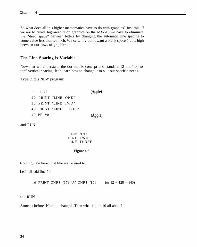
Type in this NEW program:
9 PR # l
20 PRINT "LINE ONE"
30 PRINT "LINE TWO"
40 PRINT "LINE THREE"
49 PR #0
(Apple)
(Apple)
and RUN.
L I N E O N EL I N E T W OLINE THREE
Figure 4-5
Nothing new here. Just like we’re used to.
Let’s all add line 10:
10 PRINT CHR$ (27) "A" CHR$ (12) (or 12 + 128 = 140)
and RUN.
Same as before. Nothing changed. Then what is line 10 all about?
34
An Introduction to Dot Matrix Printing
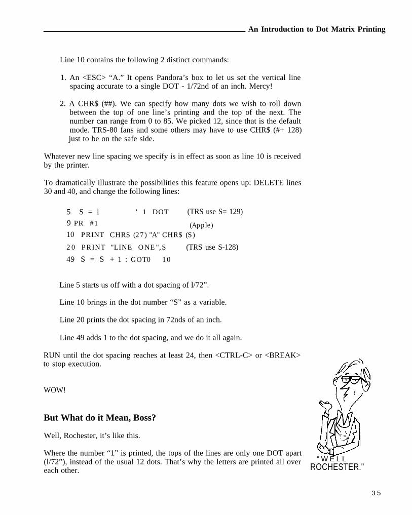
Line 10 contains the following 2 distinct commands:
1. An <ESC> “A.” It opens Pandora’s box to let us set the vertical linespacing accurate to a single DOT - 1/72nd of an inch. Mercy!
2. A CHR$ (##). We can specify how many dots we wish to roll downbetween the top of one line’s printing and the top of the next. Thenumber can range from 0 to 85. We picked 12, since that is the defaultmode. TRS-80 fans and some others may have to use CHR$ (#+ 128)just to be on the safe side.
Whatever new line spacing we specify is in effect as soon as line 10 is receivedby the printer.
To dramatically illustrate the possibilities this feature opens up: DELETE lines30 and 40, and change the following lines:
5 S = l ' 1 DOT (TRS use S= 129)
9 PR #1 (Apple)10 PRINT CHR$ (27) "A" CHR$ (S)
20 PRINT "LINE ONE",S (TRS use S-128)
49 S = S + 1 : GOT0 10
Line 5 starts us off with a dot spacing of l/72”.
Line 10 brings in the dot number “S” as a variable.
Line 20 prints the dot spacing in 72nds of an inch.
Line 49 adds 1 to the dot spacing, and we do it all again.
RUN until the dot spacing reaches at least 24, then <CTRL-C> or <BREAK>to stop execution.
WOW!
But What do it Mean, Boss?
Well, Rochester, it’s like this.
Where the number “1” is printed, the tops of the lines are only one DOT apart(l/72”), instead of the usual 12 dots. That’s why the letters are printed all overeach other.
" W E L LROCHESTER."
3 5
Chapter 4
Check the printout and find where spacing is 12. Doesn’t that look more likewhat we’re used to?
Now look at 24 dot spacing. Aha! It’s double spacing. By sending the high-powered command in line 10, we can plug in our own value of S and make theprinter give us just about any spacing we want between lines (up to 85). And, wecan do it either inside a program or at the command level. That ought to kick theold mind into overdrive!
Let’s LIST the program on paper to take a closer squint at it.
The line spacing stayed set where it was when we STOPped the program. Thatspacing is now the new “standard,” replacing our power-up value of 12 dots= l/6”.
We can, however, easily shift back to the original (default) line spacing by justsending:
PRINT CHR$ (27) “2”
Try it, then type:
LIST
Ah! Sanity has returned. Whenever we send <ESC> “2,” the spacing returnsto the “power up” value of 6 lines per inch - 12 vertical dots per line.
There are two other ways of returning the line space to its original size:
1. Use the ESC A sequence we just learned:
>PRINT CHR$ (27) “A” CHR$ (12) , or
2. Turn the printer OFF, then ON.
Turn the printer OFF, then ON, before continuing to the next topic. Rememberthat this resets the Top of Form.
Caveat
Life is never as rosy as the advertisements. If it were, where would thechallenge be?
36

An Introduction to Dot Matrix Printing
There are several code numbers already reserved for special things. If we lookclosely at the printouts from this chapter, we can see that the spacing when thefollowing numbers are used may not be what we have anticipated:
8 - reserved for (DELETE PREVIOUS CHARACTER)
9 - reserved for (TAB)
10 - reserved for Line Feed
12 - reserved for Form Feed
13 - reserved for Carriage Return
There are no nice clean ways around this problem -just very messy ones. (SeeAppendices D and F for ways to POKE these codes to the printer). Best werestrict our selection to the remaining numbers.
Underlining
Many computers do not have the capability of sending an ASCII character totemporarily suppress the Line Feed when a Carriage Return is sent. An Applerunning BASIC with the Epson printer card falls in this category. We cannot dounderlining by simply sending CHR$ (13), a simple CR, then sending underlin-ing dashes in the right places.
TRS-80 zealots can refer to Chapter 2, open up the printer, and move the autoline feed wire to the red terminal. This means absolutely no line feeds unless wesend a CHR$ (10) each time one is needed. This “technique” does permitunderlining, but for all practical purposes, it’s impractical!
Underlining should not be confused with just moving down one line thenprinting a series of dashes. True underlining requires that we first print the lineto which we want to add whole or partial underlining. We then Return theCarriage (print head), suppress the LF so the paper does not advance, and printthe underline character ASCII 95. This is called “overstriking.” The underlinecharacter is printed in position 7 of our 12 x 6 character dot matrix. Users withLF suppression can also do such things as slashing zeros, sevens, etc.
There is another way to suppress the LF using the vertical spacing tricks wejust learned. The method to be demonstrated is practical for such things asreport headings or special emphasis, where the result is deemed worthy of theextra programming effort.
37

Chapter 4
Type in this NEW program:
9 PR #1 (Apple)10 PRINT CHR$ (27) "A" CHR$ (0) (or 0+ 128)
20 PRINT "UNDERLINE"
30 FOR U=l TO 9 : PRINT CHR$ (95); : NEXT U
40 PRINT CHR$ (27) "2"
50 PRINT "WORKS"
59 PR #0 (Apple)
and RUN.
Oops, too close for comfort. We forgot that the MX-70 doesn’t have lower casedescenders, and the underline character is in that category. We’d better dropthe underline down one dot.
UNDERLINEWORKS
Figure 4-6
Change line 10 to:
10 PRINT CHR$ (27) "A" CHR$ (l)
and RUN.
Compare this RUN with the previous one. It’s looking better, isn’t it? Let’sdrop the underline position down one more dot. Go ahead - can you figure outwhat to do?
Here is how the program works:
Line 10 sets line spacing to 1 DOT (1)
Line 20 PRINTS something we want to underline
Line 30 PRINTS 9 underlines. (Computers that support STRING$ coulduse it here.) The ; suppresses the LF.
38

An Introduction to Dot Matrix Printing
Line 40 returns line spacing to the normal 12 DOTS
Line 50 PRINTS more text to show that all is normal
and that’s plenty to think about in this chapter.
Code Summary
CHR$ (27) “A” CHR$ (##) - SETS LINE SPACING TO ## DOTS(O <= ## <= 85)
CHR$ (27) “2” - RETURNS LINE SPACING TO 12 DOTSCHR$ (10) - LINE FEEDCHR$ (13) - CARRIAGE RETURN
CHR$ (95) - UNDERLINE CHARACTER
39

Graphtrax II
Chapter 5Graphtrax II
Caution - Entering High Resolution Space
To create graphics on the MX-70, we must enter a completely new mode: theGRAPHICS MODE. In this mode, pre-defined characters do not exist - onlydots. We create our own characters or images by arranging the dots howeverwe wish.
In the GRAPHICS mode we have complete control over which pins fire, andwhen. It sounds like a lot of fun, and is, but there are an awful lot of dots in justone line, let alone an entire page.
Think of it this way. There are 80 “regular” characters in a normal line (row).Each character is 6 dots wide (5 dots plus 1 blank column). That comes to 480columns in each row. Good grief!
Fortunately, we don’t have to fill all 480 columns on every line. In fact, the firstthing we do when entering graphics mode is tell the printer how many columnsof dots we will send it, a row at a time.
Warp 3
The graphics mode is entered by sending the printer a cluster or sequence of 3codes:
FORMAT: <ESC> "K" N1 N2- - - - - - - - - - - - - - - - - - - - - - - - - - - -
EXAMPLE: CHR$ (27) "K" CHR$ (15) CHR$ (0)
CHR$ (27) is of course the Escape code, and Escape “K” means KICKinto graphics mode.
CHR$ (15) says: “reserve 15 columns for graphics.” N1 can range from 0to 255 (O-127 for 7 bit computers)
CHR$ (0) If N2 is 0, it means “Ignore me, N1 specifies the number ofcolumns to expect.”
If N2 is 1, the number of columns will equal N1 + 256. If thissum of N1 and N2 exceeds 480, only 480 columns will bereserved.
41

Chapter 5
The Saki flowed like melting snow from Mt. Fuji when they contrived that wildscheme. Let’s see if we can wring it out.
Suppose we want to shoot 100 columns of graphics to the printer, on one row.What numbers would we use for N1 and N2?
CHR$ (l00) CHR$ (0) for 100 columns
Ok, so we got lucky.
How about 300 columns? Well, 300-256=44. Let’s try:
CHR$ (44) CHR$ (1)
Since N2 = CHR$ (1), 256 is added to N1. 44 + 256 = 300.
Not really so bad. Pass the Saki!
Enter these lines, but don’t RUN:
9 PR #1 (Apple)
10 PRINT CHR$ (27) "K" CHR$ (50) CHR$ (0);
TRS-80 Model I use:
10 LPRINT CHR$ (27) “K” CHR$ (50) CHR$ (2) ;
The Model I can’t send CHR$ (0) reliably, and ANY EVEN number is inter-preted as a zero in the ESC K sequence here in Graphtrax II.
How many columns is line 10 reserving, 50 or 306?
Answer=50. Don’t RUN yet.
Firing the Pins
There are 9 pins in the MX-70 print head. In graphics mode, we have control ofthe top 8 (the middle 7 for 7 bit computers).
42

Graphtrax II
We’ll label these top 8 pins as follows:
128 - 0 TOP64 - o32 - o16 - o
8 - O
4 - o2 - ol - o BOTTOM
o (Ninth pin not used)
From now on we will refer to the second pin (pin 1 above) as the “bottom” pinwhen using graphics.
Why not label them 1, 2, 3, . . . 8 etc? Well, the numbers shown are the actualASCII numbers that fire the respective pins. CHR$ (128) fires the top pin, whileCHR$ (1) k-es the bottom one. CHR$ (7) fires the bottom three (4+2+1). Justno way to escape Binary math when dealing with computers, is there?
Add these lines:
20 FOR P = 1 TO 5 0
30 PRINT CHR$ (l);
40 NEXT P
50 PRINT
59 PR #0 (Apple)
and RUN.
Sure enough, fifty little dots. CHR$ (1) in line 30 caused the bottom pin to fire.The semicolon suppressed the line feeds. The FOR-NEXT loop fired thebottom pin 50 times.
Change line 30 to:
30 PRINT CHR$ (127);
and RUN.
Figure 5-1
43

Chapter 5
Wow! A jackpot. Using the bottom of an old Coke bottle as a magnifier, we seethat each column is 7 dots high. 50 columns of 7 rows of dots. The sum of thebottom 7 pin numbers is
1 + 2 + 4 + 8 + 16 + 32 + 64 = 127
So that’s how they do it!
Quiz Time
Question: What single number will allow us to fire only the pins labeled 1, 4, and16? Think it through now. How about . . .
1 + 4 + 1 6 = 2 1 ?
Let’s try
30 PRINT CHR$ (21);
and RUN.
Oh - winning is so much fun!
Don’t be too concerned about what movie is playing on your video screen. Itmay not know how to handle these codes. It’s what’s happening on the printerthat counts.
The Grand Scheme
This is starting to make sense. The “logic” pattern must be:
Pin Labels
0 1 2 3 4 5 6 7 8 9 10 11 12 - - - - 255
128 . 128
64 . 64
32 . 32
16 . 16
8 . . . . . . 8
4 . . . . . . 4
3 2. . . . . . .
1 . . . . . . . 1
0 1 2 3 4 5 6 7 8 9 10 11 12 - - - - 255
Graphic Codes
44

Graphtrax II
Now for the Bad News
Before racing off to create a HI-RES forgery of the Mona Lisa, be aware thatthe above is how is it SUPPOSED to work. Reality is brutal - there are someexceptions to almost every rule.
Code numbers 9 and 13 for the Apple, and 0, 10, 11, and 12 for the TRS-80 createhavoc when used as N1 or N2. (It’s deja vu from the last chapter). Othercomputers may have trouble with different codes. Even worse, the printeraccepts code numbers from 0 to 255 to determine the dot pattern, but manycomputers are not able to send code numbers greater than 127. It’s the old“missing eighth bit” caper. Like the “lost chord.”
Sigh! Once again the printer can out perform a computer. In the Apple’s case,the Epson Parallel Interface card deactivates the eighth bit so Apple users cancontrol only 7 pins. If it didn’t, bit 8 from the Apple would be on all the time,firing pin 8 every time. Most TRS-80s can control all 8 pins without difficulty.
Back to the Welcome Program
We’ve seen that each pin is associated with a number. The numbers 1, 2, 4, 8,16, 32, 64, I28 all relate to the mathematical powers of 2. Binary math, and allthat stuff. Here’s the relationship:
27 = 128
26 = 64
25 = 32
24 = 16
23 = 8
22 = 4
2 1= 2
20 = 1
Let’s see if we can fire the pins, in sequence, from the bottom up. Make theprogram read:
9 PR #1 (Apple)
10 PRINT CHR$ (27) “K” CHR$ (50) CHR$ (0) ;
20 FOR P = 0 TO 6
30 PRINT CHR$ (2^P) ;
40 NEXT P
50 GOT0 20
45

Chapter 5
TRS-80 Model I:
10 LPRINT CHR$ (27) "K" CHR$ (50) CHR$ (2);
and RUN.
Figure 5-2
Press CTRL-C or BREAK to stop. Very impressive.
Note that we are not printing the slash character (ASCII number 47); butare positioning the dots one at a time. Line 50 of the “welcome program”should now make sense. We see that to fire a single pin, we must send a powerof 2 down the line to the printer. Line 50 of the “welcome program” does justthat.
50 PRINT CHR$ (2^INT(3 .4*SIN( I )+ l ) ) ) ;
The entire expression to the right of the exponent sign chooses an appropriateexponent for 2. The exponents determine which pin is fired, giving us a nicesinusoidal curve. Math types love it.
Who Sez We Ain’t Got No Class?
Let’s put the printer through some “aerobic exercises” with this NEWprogram:
9 PR #1 (Apple)10 PRINT CHR$ (27) "A" CHR$ (7)
20 FOR R=l TO 3
30 PRINT TAB (10);
40 PRINT CHR$ (27) "K" CHR$ (14) CHR$ (0);
50 FOR N=l TO 14
60 READ D : PRINT CHR$ (D);
70 NEXT N : PRINT : NEXT R
80 PRINT CHR$(27) "2"
99 PR #0 (Apple)
46
Graphtrax II
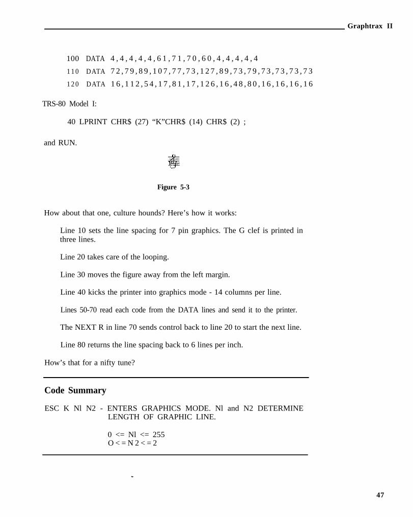
100 DATA 4 , 4 , 4 , 4 , 4 , 6 1 , 7 1 , 7 0 , 6 0 , 4 , 4 , 4 , 4 , 4
110 DATA 7 2 , 7 9 , 8 9 , 1 0 7 , 7 7 , 7 3 , 1 2 7 , 8 9 , 7 3 , 7 9 , 7 3 , 7 3 , 7 3 , 7 3
120 DATA 1 6 , 1 1 2 , 5 4 , 1 7 , 8 1 , 1 7 , 1 2 6 , 1 6 , 4 8 , 8 0 , 1 6 , 1 6 , 1 6 , 1 6
TRS-80 Model I:
40 LPRINT CHR$ (27) “K”CHR$ (14) CHR$ (2) ;
and RUN.
Figure 5-3
How about that one, culture hounds? Here’s how it works:
Line 10 sets the line spacing for 7 pin graphics. The G clef is printed inthree lines.
Line 20 takes care of the looping.
Line 30 moves the figure away from the left margin.
Line 40 kicks the printer into graphics mode - 14 columns per line.
Lines 50-70 read each code from the DATA lines and send it to the printer.
The NEXT R in line 70 sends control back to line 20 to start the next line.
Line 80 returns the line spacing back to 6 lines per inch.
How’s that for a nifty tune?
Code Summary
ESC K Nl N2 - ENTERS GRAPHICS MODE. Nl and N2 DETERMINELENGTH OF GRAPHIC LINE.
0 <= Nl <= 255O < = N 2 < = 2
47

Advanced Graphics
Chapter 6Advanced Graphics
Firing Pins at Seven Paces
The MX-70 allows any computer to control the firing of its 8 active pins bysimply sending ASCII code numbers between O-255. Conversely, these 256code numbers are sufficient to control all 8 pins. Multi-line graphics programswill therefore usually be done with a top-of-line to top-of-line spacing of 8 dots(8/72”).
As already repeated, many computers, or their printer interface boards, will notcontrol or pass code numbers greater than 127. These computers can controlonly 7 of the 8 active pins in graphics mode. With that common computerdeficiency in mind, the examples in the remaining chapters are limited to 7 dotsper line.
The limitation is not a crippling one. We just have to adjust for it. (The samefield of corn can be harvested by a 2-row corn picker as by a 4-row - it justtakes a little longer.)
Users with ‘superior’ computers can follow right along at our 7 dot clip,knowing that their computers can drive all 8 pins if desired, but not until we’veall finished the course.
Housekeeping
Let’s develop a fairly complex graphics picture a step at a time. Everybodystart by typing in these lines:
9 PR # l (Apple)10 PRINT CHR$ (27) "A" CHR$(7)
20 N=50
30 PRINT CHR$ (27) "K" CHR$ (N) CHR$ (0);
TRS-80 Model I:
30 LPRINT CHR$ (27) "K" CHR$ (N) CHR$ (2);
but don’t RUN yet.
49

Chapter 6
Line 10 sets the top-to-top line spacing at 7 dots.
Lines 20 and 30 KICK the printer into graphics mode. N specifies thenumber of graphic columns. By making it a variable, we can easily changeit later, right within a program, to print graphic lines of different lengths.
As a preliminary software test before things get too complicated, we’d bettercheck the line spacing. Add these lines:
25 FOR X=1 TO 3
40 FOR C = 1 TO 50 : PRINT CHR$ (127); : NEXT C
501 PRINT : NEXT X
. . . and we should always return the line spacing to its “normal” power-upfigure of 12 by ending every program with:
900 PRINT CHR$ (27) "2"
999 PR #0 (Non-Apple owners use END instead)
Now we can RUN.
After 3 passes of the print head, our printout should look like this:
Figure 6-1
What Are We Trying To Do?
We are creating a universal program that will READ and process large amountsof DATA, and is simple to use. READ and DATA statements are used since theDATA need be entered in the program only once, and DATA lines are easilyedited. Think about this paragraph and understand it since the going will getrougher before it gets easier.
Let’s delete lines 25 and 50 and change line 20 so it will READ in a value of N,the number of dots to be printed in a specific row:
20 READ N : PRINT TAB(10);
50

Advanced Graphics
The Data Bank
HI RESolution graphics requires lots of DATA. It comes with the territory
So, what should our DATA lines look like? How should we format them socontain the information we need? What information do we need?
they
ASCII numbers O-127 are used to specify the firing combinations for the 7 pins.Since much graphic printing, fortunately, is repetitious, we can develop acoding scheme to simplify and reduce the sheer volume of DATA required. Itcan use pairs of numbers.
To avoid needless typing, let’s use a minus sign as a “flag” for the first of thenumber pair to indicate that its value tells the number of times something is tobe repeated. The second value of the pair will specify the desired combinationof pins to be tired. For example:
100 DATA -42,127
means: “fire all 7 pins (#127) 42 times.” Think that one through before con-tinuing.
Got it?
We also have to tell the printer the number of columns to print on each line.Let’s dedicate the first number in each DATA line to that purpose.
Enter this line of DATA:
1020 DATA 55,0,3,7,15,31,63,63,-42,127,63,63,31,15,7,3
Recheck the numbers carefully to be sure they are copied correctly.
The first number tells the MX-70 to expect 55 bytes of graphic information. Therest of the numbers specify the pin combinations to be fired in each column,except for that suspicious number pair in the center: -42,127. Remember whatit means?
The Program
We also need a “DO LOOP” that will READ the DATA:
51

Chapter 6
40 FOR G=l TO N
50 READ X
120 NEXT G
130 PRINT
The numbers READ into X are the actual pin firing instructions. If X falls in therange 0 - 127, we print it in line 60 below. It also includes a “filter” to snag anynegative numbers:
60 IF X>=0 THEN PRINT CHR$ (X); : GOT0 120
TRS-80 Model I:
60 IF X>=0 POKE 14312,X : GOT0 120
65 IF PEEK (14312) <> 63 THEN 65
If X is negative, the line 60 test fails and execution falls through to:
Line 70, below, where the “G” FOR/NEXT loop is reset and the nextvalue READ into Y from the DATA line.
Line 100 PRINTS it ABS (X) times:
Add these lines:
70 G = G-X- l
80 READ Y
90 FOR P = 1 TO ABS (X)
100 PRINT CHR$ (Y);
110 NEXT P
TRS Model I:
100 POKE 14312,Y
105 IF PEEK(14312)<>63 THEN 105
52

Advanced Graphics
List and recheck the completed program to make sure everything is correct:
9 PR #1 (Apple only)
10 PRINT CHR$ (27) "A" CHR$ (7)
20 READ N : PRINT TAB (10);
30 PRINT CHR$ (27) "K" CHR$ (N) CHR$ (0);
40 FOR G=l TO N
50 READ X
60 IF X>=0 THEN PRINT CHR$ (X); : GOT0 120
70 G = G-X-l
80 READ Y
90 FOR P = 1 TO ABS(X)
100 PRINT CHR$(Y);
110 NEXT P
120 NEXT G
130 PRINT
900 PRINT CHR$(27)"2"
999 PR #0 (Non-Apple use END)
1020 DATA 55,0 ,3 ,7 ,15,31,63,63, -42,127,63,63,31,15,7 ,3
Summary of TRS-80 Model I changes:
30 LPRINT CHR$(27)"K"CHR$(N)CHR$(2);
60 POKE 14312,X
65 IF PEEK(14312)<>63 THEN 65
100 POKE 14312,Y
105 IF PEEK(14312)<>63 THEN 105
Finally, we are ready to try it out . . . so RUN.
Figure 6-2
Big deal! Maybe if we water it, it will grow.
53
Chapter 6
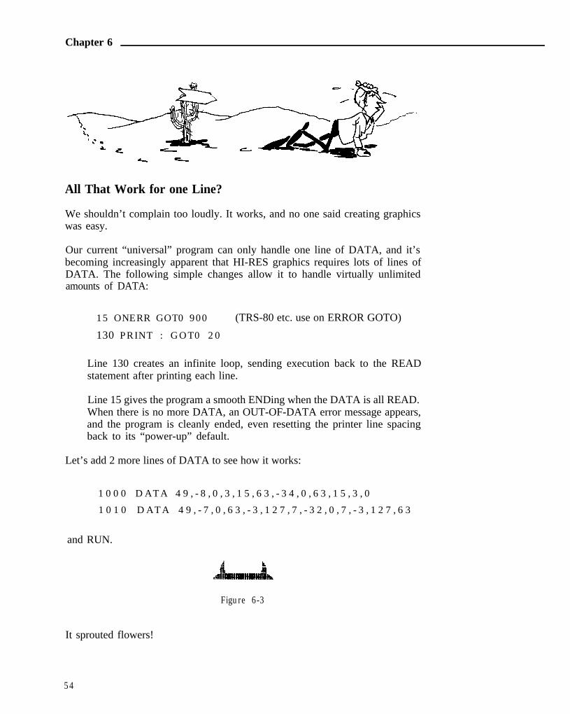
All That Work for one Line?
We shouldn’t complain too loudly. It works, and no one said creating graphicswas easy.
Our current “universal” program can only handle one line of DATA, and it’sbecoming increasingly apparent that HI-RES graphics requires lots of lines ofDATA. The following simple changes allow it to handle virtually unlimitedamounts of DATA:
15 ONERR GOT0 900 (TRS-80 etc. use on ERROR GOTO)
130 PRINT : GOT0 20
Line 130 creates an infinite loop, sending execution back to the READstatement after printing each line.
Line 15 gives the program a smooth ENDing when the DATA is all READ.When there is no more DATA, an OUT-OF-DATA error message appears,and the program is cleanly ended, even resetting the printer line spacingback to its “power-up” default.
Let’s add 2 more lines of DATA to see how it works:
1000 DATA 49, -8 ,0 ,3 ,15,63, -34,0 ,63,15,3 ,0
1010 DATA 49, -7 ,0 ,63, -3 ,127,7 , -32,0 ,7 , -3 ,127,63
and RUN.
Figure 6-3
It sprouted flowers!
54

Advanced Graphics
Rowdy Characters
Add the following lines:
1070 DATA 44 , -12 ,8 , -32 ,127
1 0 8 0 D A T A 3 9 , - 1 7 , 0 , 6 4 , 9 6 , 1 1 2 , 1 2 0 , 1 2 4 , - 1 2 , 1 2 7 , 1 2 4 ,
1 2 0 , 1 1 2 , 9 6 , 6 4
and RUN.
Figure 6-4
Oops! There’s trouble in River City. Fortunately, we’ve seen these samecontrol code problems before. Hate to keep bringing this subject up, but it doesdisturb our use of the printer.
We’ve seen codes 9 and 13 cause trouble on the Apple, and codes 0, 10, 11, and12 cause trouble on the TRS-80. If we send them to the printer via CHR$, itinterprets them as control codes instead of pin firing instructions. Unfortunate-ly, that makes sense.
Code 8 can also cause trouble since it means “delete the previous charactersent to the printer and stored in its print buffer.” In line 1070 we tried to send awhole sequence of them, and on some computers the program blew up!
For Experts Only
The errors caused by these codes do not always occur, but it is best to avoidthem if possible. Short of rewriting the program to circumvent these numbers,one way is to bypass the PRINT statement and POKE our graphic codesdirectly to the printer driver in the computer’s memory. That memory addressis 49296 (CO90 Hex) in the Apple, and 14312 (37E8 Hex) in the TRS-80 Model I(See appendices for examples of use). Other computer users can check theircomputer’s technical manual for its printer driver memory address.
The advantage of POKE over PRINT CHR$ in this specific situation is that itbypasses some of the nasty tricks we keep encountering with BASIC. Thedisadvantage is that indiscriminate POKEing can cause unbelievable softwarecrashes. Unless you really understand POKES, best to live with the limitationsinherent with your computer/printer combination, and avoid troublesomecodes when possible. Model I users will need to use the POKES shown for thisparticular example.
55
Chapter 6
A Confession
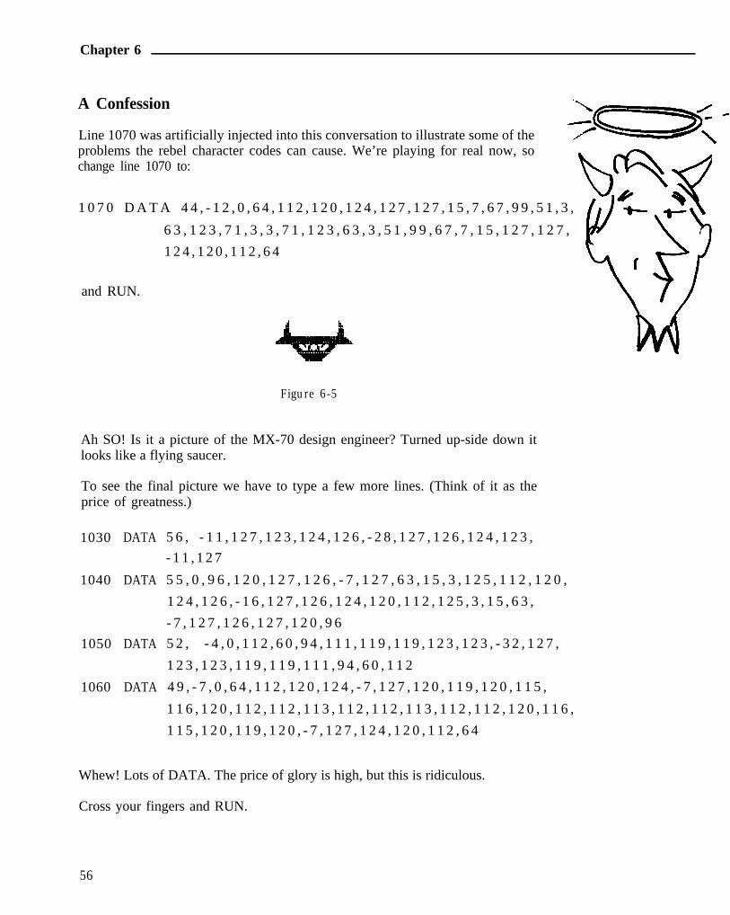
Line 1070 was artificially injected into this conversation to illustrate some of theproblems the rebel character codes can cause. We’re playing for real now, sochange line 1070 to:
1 0 7 0 D A T A 4 4 , - 1 2 , 0 , 6 4 , 1 1 2 , 1 2 0 , 1 2 4 , 1 2 7 , 1 2 7 , 1 5 , 7 , 6 7 , 9 9 , 5 1 , 3 ,
6 3 , 1 2 3 , 7 1 , 3 , 3 , 7 1 , 1 2 3 , 6 3 , 3 , 5 1 , 9 9 , 6 7 , 7 , 1 5 , 1 2 7 , 1 2 7 ,
1 2 4 , 1 2 0 , 1 1 2 , 6 4
and RUN.
Figure 6-5
Ah SO! Is it a picture of the MX-70 design engineer? Turned up-side down itlooks like a flying saucer.
To see the final picture we have to type a few more lines. (Think of it as theprice of greatness.)
1030 DATA 5 6 , - 1 1 , 1 2 7 , 1 2 3 , 1 2 4 , 1 2 6 , - 2 8 , 1 2 7 , 1 2 6 , 1 2 4 , 1 2 3 ,
- 1 1 , 1 2 7
1040 DATA 5 5 , 0 , 9 6 , 1 2 0 , 1 2 7 , 1 2 6 , - 7 , 1 2 7 , 6 3 , 1 5 , 3 , 1 2 5 , 1 1 2 , 1 2 0 ,
1 2 4 , 1 2 6 , - 1 6 , 1 2 7 , 1 2 6 , 1 2 4 , 1 2 0 , 1 1 2 , 1 2 5 , 3 , 1 5 , 6 3 ,
- 7 , 1 2 7 , 1 2 6 , 1 2 7 , 1 2 0 , 9 6
1050 DATA 5 2 , - 4 , 0 , 1 1 2 , 6 0 , 9 4 , 1 1 1 , 1 1 9 , 1 1 9 , 1 2 3 , 1 2 3 , - 3 2 , 1 2 7 ,
1 2 3 , 1 2 3 , 1 1 9 , 1 1 9 , 1 1 1 , 9 4 , 6 0 , 1 1 2
1060 DATA 4 9 , - 7 , 0 , 6 4 , 1 1 2 , 1 2 0 , 1 2 4 , - 7 , 1 2 7 , 1 2 0 , 1 1 9 , 1 2 0 , 1 1 5 ,
1 1 6 , 1 2 0 , 1 1 2 , 1 1 2 , 1 1 3 , 1 1 2 , 1 1 2 , 1 1 3 , 1 1 2 , 1 1 2 , 1 2 0 , 1 1 6 ,
1 1 5 , 1 2 0 , 1 1 9 , 1 2 0 , - 7 , 1 2 7 , 1 2 4 , 1 2 0 , 1 1 2 , 6 4
Whew! Lots of DATA. The price of glory is high, but this is ridiculous.
Cross your fingers and RUN.
56

Advanced Graphics
Figure 6-6
It was worth it!
We now have all the tools needed to design and print our own graphics. Be sureto save the finished program as we will use it in the next chapter.
Code Summary
49296 - POKE LOCATION FOR APPLE TO SEND INFO TO PRINTER
14312 - POKE LOCATION FOR TRS-80 MODEL I
57

The Final Push
Chapter 7The Final Push
Only masochists failed to SAVE the final program from the last chapter. We’renow going to delete all its DATA lines and reconstruct it for more universalapplications.
DELETE LINES 1000-1080.
Mix and Match
We are obviously amazed at the MX-70’s graphics ability. Our thoughts logi-cally lead to thinking about mixing graphics and text on the same line. Can it bedone? Sure, nothing to it. Just be sure to hang trailing semicolons on the ends oflines as needed to keep the printer from doing unwanted Line Feeds.
A few swift chops to our existing program will demonstrate the point. We canuse it as a SUBroutine to READ and PRINT a graphics string.
Change the following:
10 PRINT CHR$ (27) "A" CHR$ (l0)
15 GOT0 140
130 RETURN
Line 10 increases the line spacing to give our next figure a little breathingroom (10 dot line height.)
Lines 15 and 130 turn the first part of the program into a subroutine.
Let’s start with a single line of graphics to set the stage:
140 GOSUB 20 : PRINT
150 DATA 60, - 2 7 , 1 2 7 , 1 2 6 , 1 0 0 , 6 4 , 1 , 1 1 , 6 3 , - 2 7 , 1 2 7
and RUN.
OK. The subroutine works.
59

Chapter 7
No, it’s not another demon. It is a “broken signboard” that needs a text typeLABEL in the middle. The finished graphics/text display will be printed inthese three parts:
15 columns of graphics30 columns of text (5 characters)15 columns of graphics
Now we have to mix and match graphics and text on the same line. First, thegraphics:
160 GOSUB 20
1 7 0 D A T A 1 5 , 1 2 7 , 8 , 2 8 , 6 2 , 9 3 , - 8 , 2 8 , 0 , 0
and RUN.
Figure 7-2
Then text:
180 PRINT”82 CM”;
and RUN.
Figure 7-3
And more graphics:
190 GOSUB 20
2 0 0 D A T A 1 5 , 0 , 0 , - 8 , 2 8 , 9 3 , 6 2 , 2 8 , 8 , 1 2 7
and RUN.
60

The Final Push
Figure 7-4
Nothing to it!
NOTE: As long as semicolons are used to delay the line feeds, graphics and textare easily mixed on the same line. New lines can be started by simply addingline feeds with PRINT statements as shown in line 140.
The Long Lines Division
None of our examples so far have used the full 480 columns available to theMX-70. In fact, we’ve always used less than 100 columns since the printer willbe used by computers with different capabilities. As we expand the widths ofour displays, these differences quickly become more obvious.
TRS-80 type computers, for example, can send a full range of ASCII codes 0 to255 (8 bits) via the CHR$ function. (A few must be poked, as we’ve seen.)These computers can therefore choose any graphics width from 0 to 480columns.
Printer cards for Apple type computers typically pass ASCII numbers from 0 to127 (7 bits). This forces us into extra programming and devious means to utilizethe MX-70’s complete range of 480 graphics columns.
In any one <ESC>“K” sequence, 7-bit computers are restricted to the rangesO-127 and 256-383. Seeing is believing, so:
DELETE lines 150-200, and add:
150 DATA 150,-150,127
and RUN.
Figure 7-5
Here’s what happened. The 150 cannot be passed, so is reduced by 128, andsent to the printer as 22. Apple users see a bar 22 columns long (did you countthem?). Users with 8-bit computers see a bar 150 columns long.
61

Chapter 7
If we really understand what we’re doing, the 7-bit limitation can be overcome.Apple users try:
140 GOSUB 20 : GOSUB 20 : PRINT
150 DATA 23,-23,127,127,-127,127
and RUN.
Now we are getting somewhere. Instead of trying to print the entire line in oneshot, we hooked two print routines together with a semicolon. The first printed23 columns, and the second printed 127 columns.
Really Long Lines
Suppose we want to use even longer lines, up to the maximum of 480 columns.To specify a line length greater than 255, the last number in the <ESC>“K” NlN2 sequence must be a 1. Instead of changing line 30, we can accommodate theentire range of line widths by adding:
25 IF N>255 THEN PRINT CHR$ (27) "K" CHR$ (N-256) CHR$ (l);
: GOT0 40
If the desired line width (N) is greater than 255, CHR$ (1) adds 256 columns, andCHR$ (N-256) takes care of the difference. Let’s test this upgrade by changing:
10 PRINT CHR$ (27) "A" CHR$ (7)
140 GOSUB 20 : PRINT
150 DATA 300,-300,127
and RUN.
Figure 7-6
We don’t have to count the dots to check it. There are 60 dots per inch, so theline should be 5 inches long.
62

The Final Push
Apple Stew
I’m afraid that Apple users wound up with a slightly different result, eventhough the 300 should be valid for the current program.
Figure 7-7
This appears to be a conflict among the Apple, the interface board, and theMX-70. It seems that anything printed past column 256 gives us scrambled eggs.While the factory-type experts work on a solution, Apple users add the follow-ing line:
7 PRINT CHR$(9); “2 5 5 H ” (Apple users only)
and RUN.
Why it works is still a mystery to those that found this solution, but it doeswork! Use it whenever your Apple programs require continuous graphic stringsof more than 255 columns.
Unfortunately, the biggest number of columns 7-bit computers can send is 383,the sum of 256 + 127. We can print 256 columns by making N2 equal to 1, plusthe maximum of 127 more. If we try and print 384 columns, that extra 128 isintercepted, reduced to zero, and we end up with 256. If these details interestyou, play with line 150.
Apple Pie
BUT fear not! We couldn’t end this happy tale on a sour note. Epson hasprovided a far superior way for Apple users to create high resoluton graphics inBASIC. A “screen dump” program for use with Apple disk systems completelyeliminates the need for wrestling with the above problems. Apple disk systemusers GOT0 Chapter 8 RIGHT NOW for the solution, and omit the rest of thischapter.
Apple non-disk users continue on with the rest of us.
63

Chapter 7
Pictogram
Let’s see if we can parlay strings of graphic characters into a useful format.Enter this NEW program.
9 PR #1 (Apple)30 FOR I=1 TO 5 : READ A (1 ) : NEXT I
40 DATA 8,107,92,107,8
60 FOR R=l TO 5
80 READ N
90 FOR I=1 TO N : GOSUB 300
100 NEXT I : PRINT
120 NEXT R
130 DATA 30,25,17,11,8
140 PRINT CHR$ (27) "2"
198 PR #1 (Apple)
199 END
300 PRINT " "CHR$ (27) "K" CHR$ (S) CHR$ (B);
310 FOR C=l TO 5
320 PRINT CHR$ (A(C));
330 NEXT C : RETURN
TRS-80 Model I:
300 LPRINT " "CHR$ (27) "K" CHR$ (S) CHR$ (2);
and RUN.
Figure 7-8
64

The Final Push
The DATA for the population figure is READ into array A in line 30.
Each figure is printed in SUBroutine 300.
DATA line 130 determines how many figures are printed on each row.
We have the makings of a horizontal bar graph, but it needs some trimmings.Let’s add a few labels and move the whole works over a bit.
20 PRINT : PRINTCHR$(27)"A"CHR$(7)
50 GOSUB 200 : PRINT
70 PRINT TAB(5)1990-R;
80 GOSUB 200 : READ N
110 GOSUB 200 : PRINT
200 PRINT TAB(12)CHR$(27)"K"CHR$(5)CHR$(PI);
210 FOR I=1 TO 5 : PRINT CHR$(127); : NEXT I
220 RETURN
TRS-80 Model I:
200 LPRINT TAB(12)CHR$(27)"K"CHR$(5)CHR$(2);
and RUN.
Figure 7-9
That’s better. Subroutine 200 prints the vertical bar that separates the labels andthe graph.
If we add a quick title and legend, we’ll be done.
65

Chapter 7
10 PRINT TAB(23)CHR$(14)"POPULATION PROJECTION"
140 PRINT : PRINT TAB(37); : GOSUB 300
150 PRINT "( = 1,000"
and RUN.
Figure 7-10
That’s plenty for this chapter.
Code Summary
PRINT CHR$ (9) “255H” - Allows Apple users to print past column 255without heartburn.
66

Using the HIRES Screen Dump Program
Chapter 8Using the HIRES Screen Dump Program
Should I Study This Chapter?
Epson dealers can supply a machine language “screen dump” diskette forApple users with 48K disk systems. It permits creation of exotic HI-RESgraphics on the Apple screen, then dumping them, dot for dot to the MX-70printer.
Since the MX-70 graphics are related to the Apple (as the MX-80 graphicsreplicate the TRS-80’s), this particular software is of interest only to Appleusers. Knowing this crazy field however, some ingenious software writer work-ing in his garage will probably come up with a partial HIRES program for usewith our popular computers.
Meanwhile, if you are using your MX-70 with another brand of computer, youcan just as well ignore this chapter. Go in peace, and enjoy your printer.
Figure 8-l
Apple Dump
The “screen dump” diskette comes with a DOS 3.3 operating system, so itworks fine on a one drive system.
67

Chapter 8
Load the demo disk into drive 1 and boot the system. The HELLO program willautomatically load and execute. After a brief commercial from the copyrightholder, the program asks:
IS THE PICTURE ALREADY IN MEMORY? (Y/N)?
We respond with:
N <RETURN>
The computer retaliates with:
INSERT DISK CONTAINING PICTURETHEN PRESS RETURN?
Since the DOS and sample PICTURES are on the same disk, press
<RETURN>
What follows is the HIRES diskette catalog of sample programs and files. TheCATALOG includes these programs:
HELLO
HIRES INSTRUCTIONS
EPSON.HIRES.OBJ
The HELLO program loads the screen dump routine and prompts us withquestions. This is the program we are running now.
The HIRES INSTRUCTIONS program gives hints on how to use the screendump.
The EPSON.HIRES.OBJ program is the actual screen dump routine written inmachine code. It can be accessed with the USR command from BASIC.
The rest of the tiles are HI-RES demonstration pictures, and at this writinginclude:
BESSEL 2
BESSEL
INVADERS
EPSON DEMO PIC
CHART
68

THIS PAGE HAS BEEN AMENDED
Using the HIRES Screen Dump Program
DISNEY CHAR
SCHEMATIC
PORTRAIT
CHESS
Follow the Yellow Brick Road
The HELLO program guides us through the actual process of printing thepictures. It’s completely self-explanatory (as every confusing technical booksays), but here’s some step-by-step guidance.
WHAT IS THE FILENAME OF THE PICTURE?
The program is asking for the NAME of the picture we want to print. Let’s try:
PORTRAITThe computer reports:
LOADING PICTURE
then
IS THIS THE CORRECT PICTURE (Y/N);
?
flashes before our very eyes. We type:
Y <RETURN>
It wants to know more:
WHAT SIZE? (R=REGULAR L=LARGE)?
Oh, regular size is fine:
R <RETURN>
Still more options, so the next query is:
NORMAL(N) OR REVERSE(R)?
This can be a bit confusing. NORMAL prints every white dot on the screen as ablack dot on the white paper. This IS what we “normally” think of as “normal”printing. If we want the picture to appear with a black background, exactly as itappears on the screen, we request REVERSE. Got that?
69

THIS PAGE HAS BEEN AMENDED
Chapter 8
For now, let’s try REVERSE:
R <RETURN>
The last question is:
WHAT IS THE PRINTER SLOT # ? (1-7)?
Double check to see that the printer is ON and loaded with paper. Our printercard is in slot I, so:
1 <RETURN>
Now we just sit back and relax while the MX-70 does its thing. No fair peekinguntil it finishes.
All together now-PEEK!
Figure 8-2
Wow, how long do you think it took the artist to create that picture? Can youimagine arranging all those little dots the way we learned in the last fewchapters?
There are on the market cameras and digitizers that will convert pictures toelectronic impulses and place them in the computer’s memory. We can createpictures in memory by whatever means are available, then use the EpsonHIRES program to dump them to the printer.
70

THIS PAGE HAS BEEN AMENDED
Using the HIRES Screen Dump Program
Go ahead and try the different print options with PORTRAINT, large and small,reverse and regular.
Print several of the pictures. Instead of PORTRAINT type the name of another one.Most load into the HIRES page “low memory.” We’ll wait for you here.
Be an Artist for Fun-and Profit
Impressed, or just intimidated?
Let’s see what we can do’ about making our own mess on the paper. Return toBASIC and type:
PR #l
RUN HIRES INSTRUCTIONS I
(Don’t worry if the screen says Epson TX-80 HIRES GRAPHIC ROUTINE -it’s been modified for the MX-70.) Abort the program, then enter:
PR #0
Tear off this list of instructions so we can refer to them as we scurry along.According to these instructions, we can write our own program to fill a memorypage with HIRES graphics, then use the USR function to print it out. Let’s seeif they’re just putting us on.
Type in this short program:
10 HOME
20 HGR
30 HCOLOR=7
40 FOR A=0 TO 20.4 STEP . 0 2
5 0 R=10 * A * COS(A) * SIN(A)
60 HPLOT 138 + R * COS(A) , 79 + R * SIN(A)
70 NEXT A
and RUN.
71

Chapter 8
Not too shabby for rank amateurs.
Here’s what happens:
Line 10 clears the screen.
Line 20 selects the “low memory” HIRES page. This part of memory isused for high-resolution graphics, while text is stored on a different ‘page’of memory.
48K disk users have two different chunks of memory that can be used forHIRES graphics. If we wanted, we could store 2 different pictures at thesame time. Refer to the Apple Programming Reference Manual for moreinformation.
Line 30 selects a color.
Lines 40 and 70 set up a loop for plotting a figure.
Line 50 calculates the radius as a function of the angle. We are using polarcoordinates in case you hadn’t guessed. If you don’t really care, it doesn’treally matter - the picture is still pretty.
Line 60 converts from polar to rectangular coordinates and plots a singlepoint. Whew! It’s a good thing computers don’t require a good mathbackground.
Why All This Math?
Using Math equations to create graphics is easier than by doing it the hard way,point-by-point. They do, however, restrict us to graphs or plots of naturalphenomena, and who among us will claim credit for creativity in that area‘?
Type:
TEXT
to return back to the TEXT page. Even though we can’t see it, the pictureremains stored in the HI-RES page of memory.
We can play with line 50 to get different figures. Try:
50 R=3 * A and
72

Using the HIRES Screen Dump Program
50 R=30 * ( ~ - SI N(A ) ) and
50 R=80 * COS(3 * A/4)
(Change line 40 to 40 FOR A=0 TO 26 STEP .01)
and RUN.
Figure 8-3
When you see one you like, add this screen dump “linking routine” to hook theBASIC program to the HIRES program:
80 POKE 10,76 : POKE 11,00 : POKE 12,96
90 PRINT “BLOAD EPSON.HIRES.OBJ”
100 PRINT USR(0001)
and RUN.

Chapter 8
Figure 8-4
Lines 80 and 90 are straight out of the HIRES INSTRUCTIONS programlisting. They load the screen dump routine without leaving the BASIC program.
As indicated in the HIRES instructions, we use the machine language routinenamed EPSON.HIRES.OBJ (Line 90), and
where:A = PAGE (O=PG.l, l=PG.2)B = SIZE (O=SMALL, l=LARGE)C = PICTURE (O=REG., l=INVERSE)D = PRINTER SLOT (1 TO 7)
Therefore, our line 100 calls the routine to print the picture with:
Page 1 (Low) of memory,Small size,Regular picture, andPrinter slot # 1.
Change the USR statement in line 100 to suit your printing desires.
74

Using the HIRES Screen Dump Program
“...Never give up!”
Commencement Address
Now that we’ve learned everything there is to know about the MX-70 andHIRES graphics, our education is ready to begin. I’d enjoy hearing from youand seeing some of your artistic creations.
75

APPENDIX A
Appendix A
ASCII Charts for MX-70
79

Appendix A
This is the standard ASCII character set. The codes that are highlighted areunderstood by the MX-70 printer. The rest are for your information only, andserve no function on the MX-70 printer.
80
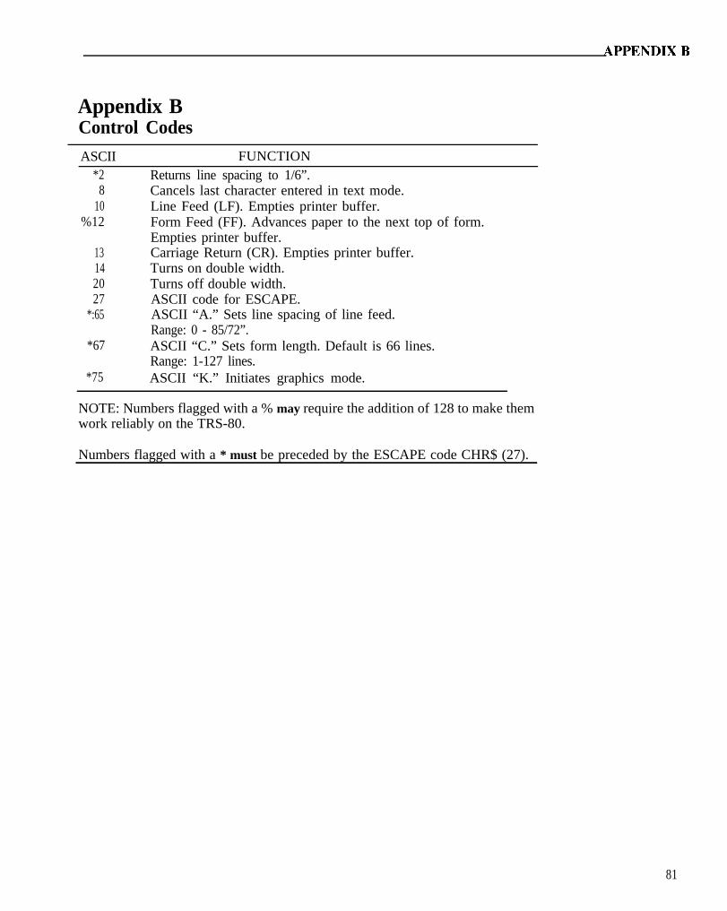
Appendix BControl Codes
ASCII*2
FUNCTIONReturns line spacing to 1/6”.
810
%12
13142027
*:65
*67
*75 ASCII “K.” Initiates graphics mode.
Cancels last character entered in text mode.Line Feed (LF). Empties printer buffer.Form Feed (FF). Advances paper to the next top of form.Empties printer buffer.Carriage Return (CR). Empties printer buffer.Turns on double width.Turns off double width.ASCII code for ESCAPE.ASCII “A.” Sets line spacing of line feed.Range: 0 - 85/72”.ASCII “C.” Sets form length. Default is 66 lines.Range: 1-127 lines.
NOTE: Numbers flagged with a % may require the addition of 128 to make themwork reliably on the TRS-80.
Numbers flagged with a * must be preceded by the ESCAPE code CHR$ (27).
81

APPENDIX C
Appendix C
Character Set
83

Appendix C
84

APPENDIX D
Appendix D
TRS-80 Differences
This MX-70 Manual is designed around the Apple II for reasons discussed inChapter 2. Fortunately, TRS-80 users can use it successfully by following thenotes and suggestions in this appendix and throughout the text. In fact, usingthe MX-70 with the TRS-80 is quite easy: with no ports to initialize, no controlcodes needed to permit 80 column listings, and straightforward LPRINT com-mands.
General Changes
All TRS-80 models use LPRINT and LLIST to send information to the printer.Be sure to change all PRINTS intended for the printer to LPRINT.
Ignore all references to PR#l and PR#O. They are for the Apple, as noted.
It may be necessary (and is usually permissable) to add 128 to certain codenumbers, (but not when in graphics mode). For example, if CHR$(27) “A”CHR$ (12) doesn’t work, use CHR$(27) “A” CHR$(140). The problem is withthe computer.
TRS-80 Model I Without Expansion Interface
Model I TRS-80 owners may use Radio Shack printer interface #26-1411 inplace of the Radio Shack expansion interface, if necessary.
TRS-80 Model I With Expansion Interface
Graphics Codes
Sending graphics codes to the MX-70 via Model I BASIC has its drawbacks.Entering graphics mode can be an adventure if we try, for example, to specify aline length of 10. BASIC intercepts this code, and passes it down the line as a13. So the printer expects 13 columns though we sent it only 10.
Once in graphics mode, certain codes must be sent via POKE rather thanLPRINT CHR$. The Model I printer driver interprets CHR$(O) as a null codeand does not pass it on to the printer. That hurts since we need this code ingraphics mode.
85

Appendix D
We can get around this limitation by POKEing the code numbers directly to theprinter buffer, foiling BASIC’s attempts to intercept it. The location we POKEis 14312, so use:
POKE 14312,0
In fact, we could use POKE to send ALL our graphic codes, but this approachcreates timing problems between the printer and computer. Every POKE needsto be followed by a test to see if the printer is ready to accept more codes.Example:
10 POKE 14312,020 IF PEEK (14312)<>63 THEN 20
Line 20 places the program in a delay loop until the printer is ready.
Entering Graphics Mode
0 is also used to enter the graphics mode. For example:
10 LPRINT CHR$(27) “K” CHR$(50) CHR$(0);ESC K Nl N2
Since the MX-70 interprets all even numbers as 0, we can change the last part ofthe above line to
CHRS(2);
The POKE alternate is
10 LPRINT CHR$(27) “K” CHR$(50); :POKE 14312,020 IF PEEK (14312) <>63 THEN 20
TRS-80 Model II
The MX-70 works fine with Radio Shack printer cable #26-4401. Be sure theconnectors on both ends make good contact. It may be necessary to open theprinter case a bit to allow the plug to seat properly.
TRS-80 Model III
No interface kit is necessary for the Model III. Simply plug the Epson cable intothe printer port.
86

APPENDIX D
The Model III does not share the Model I’s problem sending code 0. Nonethe-less, another way to send codes to the printer is:
OUT 251,#
where # represents the code we wish to send. If this creates timing problems,we may need to test the status of the printer before sending it each codenumber. For example:
100 IF PEEK (14312) AND 240 <> 48 THEN 100
places the program in a “holding pattern” until the printer is ready for more.See the computer reference manual if more details are desired.
Using the MX-70 with a Standard Radio Shack Cable
There is a difference between the ‘official’ Epson printer cable and the onessupplied by Radio Shack. They are wired slightly differently.
The Epson cable allows separation of the CR (carriage return) and the LF (linefeed) commands. This in turn allows such things as underlining, overstrikes toslash zeros, sevens, the letter Z, to “black out” material, etc.
If you have no need to separate CR and LF and already have a Radio Shackprinter cable, it should work fine. If purchasing a new cable, buy an Epson tokeep all the options open.
87

APPENDIX E
Appendix E
Use with Atari
Using Atari 800 Computer with Atari 850 Interface
Lines ending with a semicolon cause the Atari to automatically “pad” the restof the line with spaces until it is 40 characters long, when using LPRINT.Therefore, it is advisable to avoid LPRINT. Fortunately, there is anotherapproach to printing that allows semicolons to be used without problems.
10 OPEN #7,8,0, “P”
#7 opens tile #78 signifies output device
0 is not usedP assigns device as printer
20 PRINT #7; “ABC”;30 PRINT #7; “DEF”40 CLOSE #7
printsABCDEF
on printer.
Port #7 is the printer port usually used by the Atari.
To use the ASCII control codes we often need to add 128. Atari uses codes O-31for its graphics characters.
If inverse characters are sent as data in the “bit image” mode, the eighth bit willbe set, causing the top pin to fire for every character. Highly undesirable!
The Atari 8.50 interface has a 4 second time-out. If it does not receive anacknowledge signal from the printer within 4 seconds of sending it a command,the computer will send a “Device Nak,” Error Code #139 message. Theprogram can catch this error using the BASIC “TRAP” command. Consultyour Atari manual for use of TRAP.
Semicolons or commas must be used to separate all literal and variable strings.
The maximum length of a string is 99 characters.
89
APPENDIX F
Appendix F
Use with Apple
Apple Integer Basic
The MX-70 is activated by ASCII code numbers from O-255. The easiest way tosend these codes in BASIC is via the CHR$ function, a feature not supported byApple Integer Basic.
In theory the codes could all be POKEed from BASIC but it doesn’t seem to bea practical option.
Apple Disk Basic
Nearly all programs in this manual are written in Applesoft ROM BASIC.Apple disk users should have no trouble with the programs if the advice in theApple DOS Manual is heeded. Apple recommends that all DOS commandsexecuted from a BASIC program (ie. with a line number) be preceded by aCTRL-D (CHR$(4) ). For example:
10 PRINT CHR$(4) “CATALOG”
gives a CATALOG LISTing of all files on the disk.
The DOS commands most frequently needed are PR#l and PR#O. They canusually be issued from either inside a program (with a line number) or outsidethe program, at the “command level.” In most cases, a simple PR#l or PR#Owill do fine. In Chapter 3, while we’re learning printer control, it is essentialthey be included INSIDE the program.
There are several ways to issue a CTRL-D from a BASIC program. One is touse CHR$(4) as in the following example.
9 PRINT CHR$(4) “PR#l”10 PRINT “VIDEO AND PRINTER”20 PRINT CHR$(4) “PR#O”30 PRINT “VIDEO ONLY”
Many disk users find the CHR$(4), called “Control D” in lines 9 and 20unnecessary. They can simply use:
9 PR#l20 PR#O
instead. Experiment to see what works best with your system.
91

Appendix F
Tricky Codes
Most Apple users will encounter difficulty when using codes 9 and 13 inESCAPE sequences and the graphics mode. To corral these and other rowdycodes, we can POKE the ASCII code numbers directly to the printer driver. Use:
POKE 49296,9
in place of
PRINT CHRS(9)
Unfortunately, using the POKE statement instead of PRINT creates timingproblems between the printer and computer. To avoid such complications, thePOKE should always be followed by a test of the printer to see if it is ready formore DATA. On the Apple, this is done with a PEEK statement. Example:
10 PR#l20 POKE 49296,930 IF PEEK (49601) <O GOT0 3040 PR#O
If the value stored at location 49601 (ClCl Hex) is negative, the printer has notyet picked up the DATA and stored it in its buffer. If location 49601 is positive,the printer is ready to receive more DATA. By using this test we outflank thefunny code numbers like 9 and 13.
Screen Width Versus Printer Width
The Apple video screen display is limited to 40 characters per row. Unfortu-nately, it restricts the printer line width to the same 40 characters during BASICprogram listings unless we take evasive action. Fortunately, the solution issimple.
If we send this code sequence down the line:
(Don’t do it yet - wait for below)<CTRL I> 80 N
the printer line width becomes the full 80 columns used by standard printerpaper. The “80” can be any number from 40 to 255 as far as the Apple isconcerned. The MX-70 might have different ideas.
92
APPENDIX F
The prior code sequence also diverts all output to the printer ONLY! The videodisplay is disabled after the CTRL-I # N sequence. The way to bring it backis by:
<CTRL I> I
In the process, the printer width defaults back to 40 columns.
Apple Mush
But how do we send control characters to the printer? The most obvious way iswith the CTRL key on the keyboard. Let’s try it.
FIRST: activate the printer by typing PR#l <return>.SECOND: hold down the CTRL key and press I.THIRD: type 80N<return>.
Wonderful! Not only does nothing print on the screen, but the printer says?SYNTAX ERROR.
Not to worry. Try pressing a few keys on the keyboard followed by <return>.The video is disconnected, but the printer works fine. If there is a program inmemory, it will LIST fine up to 80 columns wide. To regain control of the video,use the CTRL key again:
<CTRL I>I <RETURN>
A cleaner way to do the same thing is with the BASIC language CHR$(9). Try:
PRINT CHR$(9) “80N”
This kicks us into the printer-only mode without an annoying ?SYNTAXERROR. To return, use:
PRINT CHR$(9) “I”
Type carefully as the latter doesn’t show up on the screen.
Special Apple Graphics Trick for Long Lines
When printing long lines of graphics, the Apple can be quite finicky. To smoothout the problem, add this line at the beginning of a graphics program, after thePR#l:
9 PRINT CHR$(9); “255H”
93

APPENDIX G
Appendix G
Special Notes on Other Computers/Languages/Interfaces
Interfacing
The MX-70 is designed to interface directly with parallel printer computers likethe Apple II and the TRS-80 Models I, II, and III. RS-232, IEEE 448, and otherinterfaces are not factory supported. There is no provision for installing inter-face boards inside the case.
Interfacing Cables
The following table identifies known cables which are wired correctly for use with theMX-70:
Computer Parallel Interface/Cable
Apple II
Apple III
EPSON I/F P/N 8131EPSON Cable P/N 8230‘Apple Centronics Parallel I/F
Same as aboveRun in Apple II emulation
Atari 400
Atari 800
Atari 400/800(with 850 I/F)
TRS-80 Model I(without expansion I/F)
TRS-80 Model I(with expansion I/F)
TRS-80 Model II
TRS-80 Model III
2Macrotronics P/N A4P-32Macrotronics P/N A8P-3
Macrotronics P/N A85OE
Radio Shack P/N 26-1411
Epson Cable P/N 82203Radio Shack P/N 26-1401
Radio Shack P/N 26-4401
Epson Cable P/N 82203Radio Shack P/N 26-1401
‘Requires Modification to ground the Most Significant BitKontact Macrotronics for additional information3Cut Pin #35 at the printer end of the cable
95

APPENDIX H
Appendix H
Technical Specifications1.4.1 Printer
(1) Printing Method. . . . . . . . . . . . . . . Impact dot matrix(2) Character set. . . . . . . . . . . . . . . . . ASCII 96 (5X 7 dot matrix)(3) C h a r a c t e r f o r m a t i o n . ,
(a) Text mode . . . . . . . . . . . . . . . 5x 7 dot matrix(b) Bit image mode . . . . . . . . . . 480 dots/8 inches (horizontal)
(4) Character size . . . . . . . . . . . . . . . . 2.1 mm (W) x 2.8 mm (H) (0.083”xO.l 1”)(5) Paper feed . . . . . . . . . . . . . . . . . . . Adjustable sprocket feed(6) Paper . . . . . . . . . . . . . . . . . . . . . . . .
(a) Kind . . . . . . . . . . . . . . . . . . . Fanfold paper(b) Width . . . . . . . . . . . . . . . . . . . . 101.6 mm to 254 mm (4” to 10”)(cl Thickness . . . . . . . . . . . . . . . . 0.3 mm (0.012”) max.(d) Number of copies . . . . . . . . One original plus one carbon copy
(7) Line spacing . . . . . . . . . . . . . . . . .(a) Text mode . . . . . . . . . . . . . . . l/6 inch(b) Bit image mode . . . . . . . . . . l/9 inch
NOTE: In both modes, line spacing is pro-grammable in increments of l/72 inch.
(8) Columns . . . . . . . . . . . . . . . . . . . . . 80 columns (normal size)40 columns (enlarged size)
(9) Prrntrng Speed. . . . . . . . . . . . . . . .(a) Text mode . . . . . . . . . . . . . . . 80 characters per second(b) Bit image mode . . . . . . . . . . Not defined
(10) Printing Direction . . . . . . . . . . . . . Unidirectional (from left to right). May bereturned to home position from any columnposition.
(11) Line feed time, . . . . . . . . . . . . . . . Approx. 200 msec (at 116 inch/line)(12) Ribbon. . . . . . . . . . . . . . . . . . . . . . . Cartridge ribbon (exclusive use), Black(13) MCBF. . . . . . . . . . . . . . . . . . . . . . . . 5 x 10⁶ lines (excluding print head life)(14) Dimensions . . . . . . . . . . . . . . . . . . 374 mm (W) x 305 mm (D) X 107 mm (L)(15) Weight . . . . . . . . . . . . . . . . . . . . . . . Approx. 5 kg
1.4.2 Parallel interface (standard)(1) Date transfer rate . . . . . . . . . . . . 1,000 CPS (max),(2) Synchronization. . . . . . . . . . . . . . . By externally supplied STROBE pulses.(3) Handshaking . . . . . . . . . . . . . . . . . By ACKNLG or BUSY signals(4) Logic level . . . . . . . . . . . . . . . . . . . Input data and all interface control signals are
compatrble with the TTL level.
97

APPENDIX I
Appendix I
Control Circuit Board and Initialization
Control circuit board
With the MX-70. such functions as head carriage control, paper feed control.etc., are performed by the one-chip microprocessor 8049 located on the con-trol circurt board. The microprocessor has a 2K-byte ROM and a 128-byte RAM.The print head and two stepper motors are driven by the 16 driver transistors.fig. 1 shows the control circuit diagram
Transistor
STROBE_
Fig. 1 Control Circuit Diagram
99

Appendix I
Power circuit
The power circuit generates 5V DC for the logic circuit, and 24V DC to energizethe solenoids of the print head and two stepper motors.
Printer initialization
Printer initialization is accomplished in either of the two ways described below.(1) Initialization takes place automatically each time the primary AC power
source is interrupted and reapplied (i.e., by turning the Power Switch offand on).
(2) Initialization may be initiated remotely by activating the INIT signal to theparallel interface connector. This line should be driven by a TTL driver or itsequivalent.The minimum INIT pulse width is 50µsec at the receiving terminal.
(3) Upon application of the initialization signal, the following sequence ofevents takes place in the Printer.(a) The print head returns to its home position.(b) The print buffer is cleared.(c) The line spacing is set at l/6 inch.(d) The form length per page is set at 11 inches (for the 115V and 240V
versions) or 12 inches (for the 220V version).(e) The character print-width logic is reset to the normal state.(f) The operation mode is set in the Text mode.
100

APPENDIX J
Appendix J
Pinout ChartThe MX-70 includes a parallel interface as the standard equipment, and thisparagraph describes the parallel interface.(1) Specifications
(a) Data transfer rate: 1000 CPS (max.)(b) Synchronization: By externally supplied STROBE pulses.(cl Handshaking: By ACKNLG or BUSY signals.(d) Logic level: Input data and all interface control signals are
compatible with the TTL level.
(2) ConnectorPlug: 57-30360 (AMPHENOL)It is recommended that interface cables be kept as short as possible
(3) Connector pin assignment and descriptions of signalsConnector pin assignment and descriptions of respective interface signalsare provided in Table 7.
Table 7 Connector Pin Assignment and Descriptions of Interface Signals
Signal ReturnPin No. Pin No.
Signal Direction
1 1 9 STORAGE I n
2 20 DATA 1 In
3 21 DATA 2 In
4 22 DATA 3 In
5 23 DATA 4 In
6 24 DATA 5 In
7 25 DATA 6 In
8 26 DATA 7 In
9 27 DATA 8 In
10 28 ACKNLG out
Description
STROBE pulse to read data In Pulse widthmust be more than 0.5µs at receivingterminal The signal level IS normally“HIGH”. read-In of data IS performed atthe transit to “LOW” level of thus signal
These signals represent information of the1st to 8th bits of parallel data respectivelyEach signal IS at “HIGH” level when dataIS logical “1” and “LOW” when logical“0”The logical state of each data must beheld as IS until the BUSY signal comes“LOW” level again.
Approx 5µs pulse “LOW” Indicates thatdata has been received and that theprinter IS ready to accept other data
A “HIGH” signal indicates that the printercannot receive data The signal becomes“HIGH” in the following cases’1 During data entry.2 During printing operation.3 During paper feed4 During printer error status
101

Appendix J
Table 7 (Cont’d)
Signal ReturnPin No. Pin No. Signal Direction Description
12 30 PE OUT Always GND Level .
13 - SLCT OUT P u l l e d u p t o + 5 V v i a 3 . 3 κ Ω r e s i s t o r .
14 - AUTO I nFEED X
W i t h t h i s s i g n a l b e i n g a t " L O W " l e v e l , t h e
p a p e r i s a u t o m a t i c a l l y f e d o n e l i n e a f t e r
p r i n t i n g .
(The s igna l leve l can be f ixed to "LOW"w i t h A U T O p r o v i d e d o n t h e
cont ro l c i rcu i t board. )
15 - N C Not used.
16 - OV Logic GND level .
17 - C H A S S I S - G N D P r i n t e r c h a s s i s G N D .
In the pr in ter , the chass is GND and thel o g i c G N D a r e i s o l a t e d f r o m e a c h o t h e r .
18 - +5V - + 5 V
19 to 30 - GND - TWISTED-PAIR RETURN s igna l GND leve l .
31 - INIT In W h e n t h e l e v e l o f t h i s s i g n a l b e c o m e s"LOW", the pr in te r cont ro l le r i s rese t to i t s
in i t ia l s ta te and the pr in t buf fer is c leared.Th is s igna l i s normal ly a t "HIGH" leve l .
a n d i t s p u l s e w i d t h m u s t b e m o r e t h a n
50µs at the rece iv ing termina l .
3 2 ERROR Out A l w a y s " H I G H " l e v e l P u l l e d u p t o + 5 V v i a3 . 3 κ Ω r e s i s t o r .
3 3 - GND - S a m e a s w i t h P i n N o s . 1 9 t o 3 0 .
3 4 - RESET Out R e s e t s i g n a l g e n e r a t e d w h e n t h e P r i n t e r i s
p o w e r e d , o r w h e n t h e I N I T s i g n a l i s
a p p l i e d t o t h e P r i n t e r .
3 5 P u l l e d u p t o + 5 V v i a 3 . 3 κ Ω r e s i s t o r .
3 6 - NC - Not used.
NOTES: 1. “Direction” refers to the direction of signal flow as viewed from theprinter
2. “Return” denotes “TWISTED PAIR RETURN” and is to be connected at
signal ground levelAs to the wiring for the Interface. be sure to use a twisted-parr cable foreach signal and never fall to complete connection on the Return side.To prevent noise effectively. these cables should be shielded and con-nected to the chassis of the host computer and the printer. respec-tively.
3 All interface conditions are based on TTL level. Both the rise and falltimes of each signal must be less than 0.2µs.
4. Data transfer must not be carried out by ignoring the ACKNLG or BUSYsignal. (Data transfer to this printer can be carried out only after con-firming the ACKNLG signal or when the level of the BUSY srgnal IS
“LOW”.)
102

APPENDIX K
Appendix K
Parallel Interface Timing
The MX-70 includes a parallel interface as standard equipment, which is compatible tothe Centronics parallel interface. The Printer can be connected easily to any computer withthis interface structure. Fig, 3.1 shows the timing chart when signals are to be input from anexternal device to the MX-70. As is apparent from the timing chart, when data are transmittedto data lines DATA 1 through DATA 8 and the STROBE signal is generated by an externaldevice, the MX-70 sets the BUSY signal to “HIGH” level to inhibit the next data transfer fromthe external device. The logical state of each data must be held as is until the BUSY signalbecomes “LOW” level again, after the transmission of the STROBE signal from the externaldevice, or Incorrect data may be written in the print buffer of the MX-70.
BUSY
ACKNLG
DATA
STROBE* D a t a s h o u l d b e h e l d d u r i n g t h e p e r i o d T
E a c h i s T T L l e v e l c o m p a t i b l e .
OµS (min.) 0.5µs (min.)
Fig. 3.1 Paralell Interface Timing
This timing chart also reveals that the ACKNLG signal from the MX-70 can be used in placeof the STROBE signal. This allows the Printer functions to be checked without use of aspecial Instrument, in such a manner as described below.STEP 1. Connect pin No. 1 (STROBE) to Pin No. 10 (ACKNLG) with a lead.STEP 2. Connect pin Nos. 2 through 9 (DATA 1 through 8) of the interface connector as
required according to the character to be printed. For example, if character “A”(represented by <41>H in ASCII code) IS to be printed, connect pin Nos. 3, 4, 5. 6,7 and 9, respectively to the ground (e.g., pin No. 19). Note that when pin Nos. 2through 9 are left open without connecting them to the ground, data signalsbecome “HIGH” level and when they are connected to the ground, data signalsbecome “LOW” level.
103

Appendix K
STEP 3. Connect the jumper No. 2 (AUTO) on the control circuit board to enable the AUTOFEED function.
By the above operating steps, the MX-70 operations including the interface can be checked.Unlike the self-test (self-diagnostic) function by the built-in program, this method permits thePrinter operations to be checked along with the parallel interface operation.
104
APPENDIX L
Appendix L
Printer Maintenance
A clean and comfortable environment will insure the best possible service fromyour printer (and its operator).
Find it a Nice Home
Your Epson printer is designed to take a lot of punishment, but there is noreason to become careless. In fact, it will last a lot longer if you pamper it. Treatit at least as good as your pet rock.
- Avoid operation in direct sunlight.
- Avoid use in areas where there is a high concentration of dust or grease.
- Avoid humid locations and heat sources such as a furnace.
- Never install it near large electrical motors.
- Your printer (like your computer) likes a nice comfortable range oftemperatures. The safe operating range is 5°C (40°F) to 35” C (95’ F).
Periodic Maintenance
Clean it periodically with a soft brush to remove paper and dust particles. Theexterior can be cleaned with a mild detergent and water or denatured alcohol.The interior can be cleaned with denatured alcohol.
The ribbon cartridge has an expected life of 3 million characters. Replacementsare readily available through your dealer.
Epson provides a technical manual to assist do-it-yourself ers in really gum-ming up the works. Contact your dealer for price and availability.
Changing the Print Head
The print heads expected life is 100,000,000 characters. Readers who are easilydiverted by trivia can estimate the average number of characters printed perline and the average number of lines printed per day. Multiply them together
105

Appendix L
and divide into 100,000,000. The result is the estimated print head life in days.(Then count the legs and divide by four . . .)
If and when the print head needs replacement, make sure it is cool to the touch.It may operate very hot under heavy use.
Remove the printer lid and ribbon cartridge. Turn the head lock lever clockwiseand pull the print head straight up and off.
Don’t pull too far! It’s still connected to the base of the printer by a flat ribboncable. Grasp the ribbon cable (not the head connector block!) and pull gentlybut firmly to your right.
You have just removed your first Epson print head. (Shades of the FrenchRevolution.)
To install a new print head assembly, push the new ribbon cable into the headconnector, lay the print head on its mount and turn the head lock lever coun-terclockwise.
Voila! Back in business. And it took less time than solving the Rubik cube.
Print head unit
Terminal Board
Head Lock Lever- H e a d C o n n e c t o r
Carnage Assembl
(Side View)
Head Cable
L . _ ; . )
*Take hold of the cable at the point indicated by arrows8 and apply force In either of the directions indicated
by arrow c) to push In or pull out the head cable.
106

Appendix M:
Schematic Diagram

INDEXPage
Automatic line feed, proper setting . . . . . . . . . . . . . . . . . . . . . . . . . . . . . . . . . . . . . . . . . . . . . . 4, 6, 16Cable, printer . . . . . . . . . . . . . . . . . . . . . . . . . . . . . . . . . . . . . . . . . . . . . . . . . . . . . . . . . . . . . . . . 1 ,7,87Characterset . . . . . . . . . . . . . . . . . . . . . . . . . . . . . . . . . . . . . . . . . . . . . . . . . . . . . . . . . . . . . . . . . . . 83,84CHR$ . . . . . . . . . . . . . . . . . . . . . . . . . . . . . . . . . . . . . . . . . . . . . . . . . . . . . . . . . . . . . . . . . . . 13, 18, 23, 31Codes
ASCII . . . . . . . . . . . . . . . . . . . . . . . . . . . . . . . . . . . . . . . . . . . . . . . . . . . . . . . . . . . . . . . . . 13,21,79,80Control . . . . . . . . . . . . . . . . . . . . . . . . . . . . . . . . . . . . . . . . . . . . . . . . . . . . . . . . . . . . . . . . 13,81,91,93Escape . . . . . . . . . . . . . . . . . . . . . . . . . . . . . . . . . . . . . . . . . . . . . . . . . . . . . . . . . . . . . . . . 19Problem . . . . . . . . . . . . . . . . . . . . . . . . . . . . . . . . . . . . . . . . . . . 20, 37,42,45, 55, 85,92
Dot matrix . . . . . . . . . . . . . . . . . . . . . . . . . . . . . . . . . . . . . . . . . . . . . . . . . . . . . . . . . . . . . . 31Double width printing . . . . . . . . . . . . . . . . . . . . . . . . . . . . . . . . . . . . . . . . . . . . . . . . . 19,23EXCHANGE TIMES . . . . . . . . . . .. . . . . . . . . . . . . . . . . . . . . . . . . . . . . . . . . . . . . . . . . . 4Feed button . . . . . . . . . . . . . . . . . . . . . . . . . . . . . . . . . . . . . . . . . . . . . . . . . . . . . . . . . . . . . 11Form Feed command . . . . . . . . . . . . . . . . . . . . . . . . . . . . . . . . . . . . . . . . . . . . . . . . . . 26,27Form length - see Page lengthGraphics
High resolution . . . . . . . . . . . . . . . . . . . . . . . . . . . . . . . . . . . . . . . . . . . . . . . . . . . . . . . . . . . . . . . 14,67Mode . . . . . . . . . . . . . . . . . . . . . . . . . . . . . . . . . . . . . . . . . . . . . . . . . . . . . . . . . . . . . . . . . 20,41,62,86Pin labels . . . . . . . . . . . . . . . . . . . . . . . . . . . . . . . . . . . . . . . . . . . . . . . . . . . . . . . . . . . . . . . . . . . . 42,43Programexamples . . . . . . . . . . . . . . . . . . . . . . . . . . . . . . . . . . . . . . . . . . . . . . . . . . . . . . . . . . . 46,64
Horizontaltabs . . . . . . . . . . . . . . . . . . . . . . . . . . . . . . . . . . . . . . . . . . . . . . . . . . . . . . . . . . . . . . . . . . . 28Line Feedcommand . . . . . . . . . . . . . . . . . . . . . . . . . . . . . . . . . . . . . . . . . . . . . . . . . . . . . . . . . . . . 37,87Linespacing . . . . . . . . . . . . . . . . . . . . . . . . . . . . . . . . . . . . . . . . . . . . . . . . . . . . . . . . . . . . . . . . 34,36,49LIST . . . . . . . . . . . . . . . . . . . . . . . . . . . . . . . . . . . . . . . . . . . . . . . . . . . . . . . . . . . . . . . . . . . . . . . . . . . . . 18LLIST . . . . . . . . . . . . . . . . . . . . . . . . . . . . . . . . . . . . . . . . . . . . . . . . . . . . . . . . . . . . . . . . . . . . . . . . . 18,85LPRINT . . . . . . . . . . . . . . . . . . . . . . . . . . . . . . . . . . . . . . . . . . . . . . . . . . . . . . . . . . . . . . . . 15,16,85,89Maintenance . . . . . . . . . . . . . . . . . . . . . . . . . . . . . . . . . . . . . . . . . . . . . . . . . . . . . . . . . . . . . . . . . . . . . . 105Pagelength . . . . . . . . . . . . . . . . . . . . . . . . . . . . . . . . . . . . . . . . . . . . . . . . . . . . . . . . . . . . . . . . . 24,25,28Paperfeeding . . . . . . . . . . . . . . . . . . . . . . . . . . . . . . . . . . . . . . . . . . . . . . . . . . . . . . . . . . . . . . . . . 8 , 9 , 1 0Paper standards . . . . . . . . . . . . . . . . . . . . . . . . . . . . . . . . . . . . . . . . . . . . . . . . . . . . . . . . . . . . . . . . . . . 24Paper thickness adjustment . . . . . .. . . . . . . . . . . . . . . . . . . . . . . . . . . . . . . . . . . . . . . . . . . . . . . . . . . 10PEEK . . . . . . . . . . . . . . . . . . . . . . . . . . . . . . . . . . . . . . . . . . . . . . . . . . . . . . . . . . . . . . 52, 53, 86, 87, 92Pinoutsignals . . . . . . . . . . . . . . . . . . . . . . . . . . . . . . . . . . . . . . . . . . . . . . . . . . . . . . . . . . . . . . . . . . . . . 101POKE . . . . . . . . . . . . . . . . . . . . . . . . . . . . . . . . . . . . . . . . . . . . . . . . . . . . . . . . . 14,37,52,53,55,86,92Power
Light . . . . . . . . . . . . . . . . . . . . . . . . . . . . . . . . . . . . . . . . . . . . . . . . . . . . . . . . . . . . . . . . . . . . . . . . 1 0 , l lRequirements . . . . . . . . . . . . . . . . . . . . . . . . . . . . . . . . . . . . . . . . . . . . . . . . . . . . . . . . . . . . . . . . . . . . 10Switch.. . . . . . . . . . . . . . . . . . . . . . . . . . . . . . . . . . . . . . . . . . . . . . . . . . . . . . . . . . . . . . . . . . . . . . . . . 10
PR#(Apple) . . . . . . . . . . . . . . . . . . . . . . . . . . . . . . . . . . . . . . . . . . . . . . . . . . . . . . . . . . . . . . . . 14,23,91Print head.. . . . . . . . . . . . . . . . . . . . . . . . . . . . . . . . . . . . . . . . . . . . . . . . . . . . . . . . . . . . . . . . . . . . . . . 105Printer
Initialization . . . . . . . . . . . . . . . . . . . . . . . . . . . . . . . . . . . . . . . . . . . . . . . . . . . . . . . . . . . . . . . . . . . . . 15Interfacing . . . . . . . . . . . . . . . . . . . . . . . . . . . . . . . . . . . . . . . . . . . . . . . . . . . . . . . . . . . . . . . . . . 1,4,95
Rack,paper . . . . . . . . . . . . . . . . . . . . . . . . . . . . . . . . . . . . . . . . . . . . . . . . . . . . . . . . . . . . . . . . . . . . . . . . 8Ribbon installation . . . . . . . . . . . _. . . . . . . . . . . . . . . . . . . . . . . . . . . . . . . . . . . . . . . . . . . . . . . . . . . . . . 3Screendump(Apple) . . . . . . . . . . . . . . . . . . . . . . . . . . . . . . . . . . . . . . . . . . . . . . . . . . . . . . . . . 14,63,67Selftest . . . . . . . . . . . . . . . . . . . . . . . . . . . . . . . . . . . . . . . . . . . . . . . . . . . . . . . . . . . . . . . . . . . . . . . . . . . 11Seven bit limitation . . . . . . . . . . . . . . . . . . . . . . . . . . . . . . . . . . . . . . . . . . . . . . . . . . . . 31,45,49,61,63Shippingscrews . . . . . . . . . . . . . . . . . . . . . . . . . . . . . . . . . . . . . . . . . . . . . . . . . . . . . . . . . . . . . . . . . . . . . 2Tractorfeed. . . . . . . . . . . . . . . . . . . . . . . . . . . . . . . . . . . . . . . . . . . . . . . . . . . . . . . . . . . . . . . . . . . . . . . . 8Topofform . . . . . . . . . . . . . . . . . . . . . . . . . . . . . . . . . . . . . . . . . . . . . . . . . . . . . . . . . . . . . . . . . .9,25,3 6Underlining . . . . . . . . . . . . . . . . . . . . . . . . . . . . . . . . . . . . . . . . . . . . . . . . . . . . . . . . . . . . . . . . . . . . . . . 37USR . . . . . . . . . . . . . . . . . . . . . . . . . . . . . . . . . . . . . . . . . . . . . . . . . . . . . . . . . . . . . . . . . . . . . . . . . . . . . . 74Welcome program . . . . . . . . . . . . . . . . . . . . . . . . . . . . . . . . . . . . . . . . . . . . . . . . . . . . . . . . . . . . . . . 17,46
109

NOTICEPlease send your comments, suggestions, and any errorsyou might find to:
THE EDITORMX-70 Manual60x 19669San DiegoCalifornia 92119U.S.A.
Thank You.
111

LIMITED WARRANTYEpson America, Inc., “Epson,” warrants this product against defects in mate-rial and workmanship for a period of ninety (90) days from the original date ofpurchase by only the original consumer purchaser. This Warranty applies onlyshould the product fail to function properly under normal use.
During the warranty period, Epson will repair (or, at its option, replace), at nocharge, components that prove to be defective, provided the product is re-turned (shipping prepaid and properly packed) to the nearest authorized EpsonService Center or to the Dealer from whom the product was purchased.
You may request information on how to obtain service by contacting the Epsondealer from whom the product was purchased, or by contacting Epson directlyat the address printed below.
Your purchase receipt or other proof of date of original consumer purchase andthe serial number of the product must be provided when requesting warrantyservice to be performed. This warranty does not apply if the Epson label orrating label or the serial number has been removed, defaced, or altered, or if, inthe opinion of Epson, the product has been damaged by accident, misuse,neglect, improper packing or improper modifications or service by other thanan authorized Epson Service Center.
This warranty is in lieu of all other express warranties, statements or repre-sentations, and unless stated herein, all such warranties, statements or repre-sentations made by any other person or firm are void. All implied warranties inconnection with this sale, including the warranty of merchantability, shall be ofthe same duration as the warranty period stated above.
In the event that this product shall prove defective in workmanship or materi-als, your sole remedy shall be the repair or remedy as stated in this warranty,and under no circumstances shall Epson be liable for any loss or damage,direct, incidental or consequential, arising out of the use of, or inability to use,this product caused by any defect in the product. Some states do not allow theexclusion or limitation of incidental or consequential damages, nor permitlimitations of the duration of any implied warranty, so the above limitations orexclusions may not apply to you. THIS WARRANTY APPLIES ONLYWHEN THIS PRODUCT IS PURCHASED AND USED SOLELY IN THEUNITED STATES OF AMERICA.
Epson America, Inc.Service Center3415 Kashiwa StreetTorrance, CA 90505
(213) 539-9140