Embed Size (px)
Citation preview

ManualEN
UNIMET8xxST_D00008_01_M_XXEN/02.2016
UNIMET® 800ST/UNIMET® 810ST
Test system for electrical safety
Software version: from 3.1.9

Bender GmbH & Co. KGP.O. Box 1161 • 35301 Gruenberg • GermanyLondorfer Straße 65 • 35305 Gruenberg • GermanyTel.: +49 6401 807-0 • Fax: +49 6401 807-259E-mail: [email protected] • www.bender.de
© Bender GmbH & Co. KGAll rights reserved.
Reprinting only with permissionof the publisher.
Subject to change!
Photos: Bender archives.
Table of Contents
1. How to get the most out of this manual ............................................................. 7
1.1 About this operating manual .............................................................................................. 7
1.2 Technical support .................................................................................................................... 7
1.3 Explanation of symbols and notes ..................................................................................... 8
2. Safety instructions .................................................................................................. 9
2.1 Delivery ........................................................................................................................................ 9
2.2 Intended use .............................................................................................................................. 9
2.3 Qualified personnel ................................................................................................................. 9
2.4 General safety instructions ................................................................................................ 10
2.5 Delivery conditions, warranty and liability .................................................................. 10
3. System description .............................................................................................. 11
3.1 Areas of application ............................................................................................................. 11
3.2 Versions UNIMET® 800ST and UNIMET® 810ST ........................................................... 11
3.3 Functional description ........................................................................................................ 12
3.4 Standard-compliant tests .................................................................................................. 13
3.5 System components ............................................................................................................ 15
3.6 Operating elements ............................................................................................................. 16
4. Quick reference guide ......................................................................................... 17
5. Operation and setting ......................................................................................... 21
5.1 Commissioning ...................................................................................................................... 21
5.1.1 The touchscreen .................................................................................................................... 22
5.1.2 Connecting a printer ............................................................................................................ 22
5.1.3 Print setup in PDF file .......................................................................................................... 22
5.1.4 Connecting an external keyboard .................................................................................. 23
5.1.5 Connecting barcode scanner ........................................................................................... 23
5.1.6 Connecting USB stick ........................................................................................................... 23
5.1.7 TP1010 for tests according to DIN EN 61010-1 (VDE0411-1):2011-07 ............... 23
5.1.8 Other device settings .......................................................................................................... 24
5.2 Principle of operation .......................................................................................................... 24
5.2.1 Menu bar .................................................................................................................................. 24
3UNIMET8xxST_D00008_01_M_XXEN/02.2016

Table of Contents
5.2.1.1 The "Action" menu ......................................................................................................... 24
5.2.1.2 The "View" menu ............................................................................................................. 25
5.2.1.3 The "?" menu ..................................................................................................................... 25
5.2.2 Main window ........................................................................................................................... 25
5.2.3 The software keyboard ........................................................................................................ 26
5.2.3.1 Entries via the keyboard ............................................................................................... 26
5.2.3.2 Selection from a list ........................................................................................................ 26
5.2.4 Saving settings or cancelling ............................................................................................. 27
5.2.5 Toolbar ...................................................................................................................................... 28
5.2.5.1 How to use the context menu when only one entry is activated ................. 28
5.2.5.2 How to use the context menu if more than one entry is activated .............. 29
5.2.5.3 How to use the query filter .......................................................................................... 30
5.3 Main folder ............................................................................................................................... 31
5.4 Test engineer names ............................................................................................................ 32
5.4.1 Log in test engineer .............................................................................................................. 32
5.4.2 Test engineer names administration .............................................................................. 32
5.4.2.1 Other options for "Log in test engineer" ................................................................ 32
5.4.2.2 Logging in, changing or deleting test engineers ................................................ 33
5.4.2.3 Creating a new test engineer ..................................................................................... 33
5.5 Device settings ....................................................................................................................... 34
5.5.1 Windows system control ..................................................................................................... 34
5.5.1.1 Saving settings ................................................................................................................. 34
5.5.1.2 Display ................................................................................................................................ 34
5.5.1.3 Printer .................................................................................................................................. 34
5.5.1.4 Date/time ........................................................................................................................... 35
5.5.1.5 Regional settings ............................................................................................................ 35
5.5.1.6 Stylus ................................................................................................................................... 35
5.5.1.7 Input panel ........................................................................................................................ 35
5.5.1.8 Keyboard ............................................................................................................................ 35
5.5.1.9 Keyboard layout .............................................................................................................. 35
5.5.1.10 Volume & sound .............................................................................................................. 35
5.5.2 Zero balance PE resistance (test probe/measuring lead) ....................................... 36
5.5.3 Nominal voltage ..................................................................................................................... 36
5.5.4 Database ................................................................................................................................... 37
5.5.5 Backup (USB) ........................................................................................................................... 37
5.5.6 Remote control RS-232 ........................................................................................................ 37
5.5.7 Diagnostic ................................................................................................................................ 38
6. Testing and measuring ....................................................................................... 39
6.1 Test concept ............................................................................................................................ 39
4 UNIMET8xxST_D00008_01_M_XXEN/02.2016

Table of Contents
6.2 Classification ........................................................................................................................... 40
6.2.1 General ...................................................................................................................................... 40
6.2.2 Method of measurement ................................................................................................... 41
6.2.3 Applied part ............................................................................................................................ 41
6.2.4 Equipment type ..................................................................................................................... 42
6.2.5 Extras ......................................................................................................................................... 42
6.2.6 Test sequence ......................................................................................................................... 43
6.2.7 Visual inspection ................................................................................................................... 44
6.2.8 Functional test ....................................................................................................................... 45
6.2.9 Exiting classification ............................................................................................................. 47
6.3 Device test ............................................................................................................................... 48
6.3.1 Connecting the DUT ............................................................................................................ 50
6.3.2 Carrying out the visual inspection .................................................................................. 51
6.3.3 Carrying out the electrical test steps ............................................................................. 51
6.3.3.1 PE conductor test ........................................................................................................... 52
6.3.3.2 Switching on the DUT ................................................................................................... 53
6.3.4 Carrying out the functional test ...................................................................................... 54
6.3.5 Evaluating and documenting the test result .............................................................. 55
6.3.5.1 Client administration .................................................................................................... 56
6.4 Importing test data .............................................................................................................. 57
6.5 The "Test specifications" folder ........................................................................................ 58
6.5.1 How to access the "Test specifications" folder ........................................................... 58
6.5.2 How to start a device test from the "Test specifications" folder .......................... 58
6.5.3 Editing, printing, exporting and deleting a test specification .............................. 58
6.5.3.1 Test step editor ............................................................................................................... 60
6.6 The "Device protocols" folder ........................................................................................... 62
6.6.1 How to access the "Device protocols" folder" ............................................................ 62
6.6.2 How to start a device test from the "Device protocols" folder ............................. 62
6.6.3 Editing, printing, exporting and deleting a device protocol ................................. 62
6.7 Single test ................................................................................................................................ 64
6.7.1 How to access the "Single test" folder ........................................................................... 64
6.7.2 How to start a single test .................................................................................................... 64
6.7.3 Using the query filter ........................................................................................................... 64
6.7.4 Protective earth resistance measurement ................................................................... 64
6.7.4.1 Differentiating between the types of protective earth resistance measurement .................................................................................................................. 65
7. Maintenance and calibration ............................................................................. 67
7.1 Calibration ............................................................................................................................... 67
7.2 Changing the battery .......................................................................................................... 67
7.3 Maintenance ........................................................................................................................... 67
5UNIMET8xxST_D00008_01_M_XXEN/02.2016

Table of Contents
7.4 Cleaning and care .................................................................................................................. 67
7.5 Device error ............................................................................................................................. 67
8. Data ......................................................................................................................... 69
8.1 Standards .................................................................................................................................. 69
8.1.1 Application standards .......................................................................................................... 69
8.1.2 Design standards ................................................................................................................... 69
8.2 Terms and abbreviations .................................................................................................... 70
8.2.1 Terms used ............................................................................................................................... 70
8.2.2 Abbreviations used ............................................................................................................... 71
8.3 Test steps .................................................................................................................................. 73
8.4 Technical data ......................................................................................................................... 90
8.5 Ordering information ........................................................................................................... 92
INDEX ........................................................................................................................... 95
6 UNIMET8xxST_D00008_01_M_XXEN/02.2016

1. How to get the most out of this manual
1.1 About this operating manualThis operating manual describes the test systems UNIMET® 800ST and UNIMET® 810ST with the soft-ware version indicated on the cover page. The functions and processes described may vary from those featured in other versions. It is designed for electrically skilled persons working in electrical en-gineering and electronics.
Please read this operating manual before using the devices. This documentation must be kept in an easily accessible location near to the device.
This manual has been compiled with great care. It may nevertheless contain errors and mistakes. The Bender Group cannot accept any liability for injury to persons or damage to property resulting from errors or mistakes in this manual.
Each of the registered trademarks which appears in this document remains the property of its owner.
For improved readability, the test systems UNIMET® 800ST and UNIMET® 810ST will also be referred to as "UNIMET®".
1.2 Technical supportAs a Bender customer, you will receive technical support and assistance in the event of queries relat-ing to equipment you have purchased. Please contact the Technical Sales Department or our Service Department:
Service hotline: 0700-BenderHelp (telephone and fax) Carl-Benz-Straße 8 • 35305 Gruenberg • Germany Tel: +49 6401 807-760 • Fax: +49 6401 807-629E-mail: [email protected] • www.bender.de
7UNIMET8xxST_D00008_01_M_XXEN/02.2016

How to get the most out of this manual
1.3 Explanation of symbols and notesThe following terms and symbols are used to denote hazards and instructions in Bender documen-tation:
The signal word indicates that there is a high risk of danger, that will result indeath or serious injury if not avoided.
This signal word indicates a medium risk of danger that can lead to death or se-rious injury, if not avoided.
This signal word indicates a low-level risk, that can result in minor or moder-ate injury or damage to property, if not avoided.
This symbol denotes information intended to assist the user in making optimumuse of the product.
DANGER
WARNING
CAUTION
8 UNIMET8xxST_D00008_01_M_XXEN/02.2016
2. Safety instructions
2.1 DeliveryInspect the dispatch and equipment packaging for damage, and compare the contents of the pack-age with the delivery documents. Devices damaged in transit must not be used. In the event of dam-age in transit, please contact Bender immediately.
Equipment may only be stored in areas where it is protected against dust, damp, spray water and dripping water and where the specified storage temperatures can be assured.
The selling company's "General conditions of sale and delivery" always apply.
2.2 Intended useThe test systems are exclusively intended for the area of use stipulated in the chapter "System de-scription" on page 11.
Intended use also implies:
Observance of all instructions in this operating manual and
compliance with any test intervals.
Any other use than that described in this manual is regarded as improper. The Bender Group cannot accept any liability for damage resulting from such use.
2.3 Qualified personnelOnly appropriately qualified personnel may work with the Bender devices. Personnel who are famil-iar with the installation, commissioning and operation of the equipment and have undergone ap-propriate training are considered qualified. The personnel must have read this manual and understood all instructions relating to safety.
Bender would be happy to provide training in respect of the use of test equipment. Training for two people is included in the purchase price of the test system. You can find the current dates on our homepage http://www.bender.de -> Know-how-> Seminars.
Risk of destruction due to incorrect mains voltageThe UNIMET® 800ST or 810ST must always be connected to the supply voltage(AC 100…120 V, AC 220…240 V) indicated on the nameplate. Only these twovoltage ranges are permissible. Voltages between these two voltage ranges arenot permissible! Failure to observe this requirement may damage the test system and any deviceunder test connected to it.
CAUTION
9UNIMET8xxST_D00008_01_M_XXEN/02.2016

Safety instructions
2.4 General safety instructionsBender devices are designed and built in accordance with the state of the art and accepted rules in respect of technical safety. However, the use of such devices may introduce risks to life and limb of the user or third parties and/or result in damage to Bender devices or other property.
Use Bender devices only:
– As intended
– In perfect working order
– In compliance with the relevant safety regulations and safety standards applicable at the location.
Eliminate all faults immediately which may endanger safety.
Do not make any unauthorised changes.
Use only accessories (e.g. measuring cables, adapters, etc.) or replacement parts purchased from or recommended by the manufacturer of the devices. Failure to observe this requirement can result in fire, electric shock and injury.
Reference signs must always be clearly legible. Replace damaged or illegible signs immediately.
2.5 Delivery conditions, warranty and liabilityThe conditions of sale and delivery set out by Bender apply.
For software products, the "Softwareklausel zur Überlassung von Standard-Software als Teil von Lieferungen, Ergänzung und Änderung der Allgemeinen Lieferbedingungen für Erzeugnisse und Leistungen der Elektroindustrie" (software clause in respect of the licensing of standard software as part of deliveries, modifications and changes to general delivery conditions for products and servic-es in the electrical industry) set out by the ZVEI (Zentralverband Elektrotechnik- und Elektronikindus-trie e.V., the German Electrical and Electronic Manufacturers' association) also applies.
Delivery and payment conditions along with a copy of the software clause can be obtained from Bender in printed or electronic format..
10 UNIMET8xxST_D00008_01_M_XXEN/02.2016

3. System description
3.1 Areas of applicationThe UNIMET® is used to test electrical safety. It has been designed for following areas of application:
Testing medical electrical equipment in accordance with DIN EN 60601-1 (VDE 0750-1):2013-12 (optional software licence required for IEC 60601-1).
Recurrent tests and testing prior to first use of medical electrical equipment or systems in accordance with DIN EN 62353 (VDE 0751-1).
Testing electrical equipment for measurement, control and laboratory use in accordance with DIN EN 61010-1 (VDE 0411-1):2011-07 (optional software licence for IEC 61010-1 as well as test probe TP1010 required).
Recurrent tests of hospital and care beds.
Single-phase electrical equipment: "Prüfung nach Instandsetzung, Änderung elektrischer Geräte - Wiederholungsprüfung elektrischer Geräte" (Inspection after repair, modification of electrical appliances and periodic inspection on electrical appliances) acc. to DIN VDE 0701-0702; VDE 0701-0702:2008-06.
In conjunction with a DS32A adapter, the electrical safety of three-phase devices with a current input of up to 32 A can be tested acc. to IEC 62353 (VDE 0751-1) and DIN VDE 0701-0702 . Tests are always carried out during operation using the differential measurement method.
3.2 Versions UNIMET® 800ST and UNIMET® 810STThe difference between the hardware of the UNIMET® 810ST and its predecessor UNIMET® 800ST is an even more efficient PC module.
If the corresponding software licence has been purchased, the operating software enables addition-al tests according to IEC 60601-1 (med. electrical equipment) or DIN EN 61010-1 (electrical equip-ment for laboratory use).
The operating software indicated on the cover page can be used with the UNIMET® 810ST, but also with the existing UNIMET® 800ST. In this case, the following restrictions apply:
UNIMET® has been designed solely for use with earthed systems. If the test systemis used other than as intended, i.e. on an IT system, the measured values of anyleakage currents will not be reproducible. The test result cannot be used.
Art. no. of the UNIMET® 800ST
Restrictions
B 9602 8010B 9602 8014, B 9602 8016 B 9602 8017, B 9602 8018
No restriction of the range of functions. Software licences for DIN EN 60601-1 and DIN EN 61010-1 can be installed.
B 9602 8000B 9602 8004, B 9602 8006B 9602 8007, B 9602 8008
Software licences for DIN EN 60601-1 and DIN EN 61010-1 cannot be installed.
11UNIMET8xxST_D00008_01_M_XXEN/02.2016

System description
3.3 Functional descriptionThe test system supplies measurement results and evaluates them immediately in order to classify the test as "PASSED" or "FAILED". In addition to the electrical test steps, the test specification, which follows classification, contains a visual inspection and a functional test. The test specification is saved in the "Test specifications" folder. The test sequence can be completed automatically, semi-automat-ically or manually dependent upon the DUT.
The test results can be displayed on the screen, saved or printed out using an external printer. The test results can be stored as PDF file and saved to a USB drive (USB stick) for any subsequent print-outs.
In the event of unexpected results, the DUT can be inspected in more detail by carrying out a single test. Tested devices can be saved under their device IDs in the "Device protocols" folder. The data memory provides space for up to 10000 data records. Device IDs may only appear more than once if they are assigned to different clients.
The date of the last test and the test interval are saved. If a device passes the test, the test date is up-dated by the set test interval. Filter and sort functions (query filter) make selecting test data easy. Test specifications and device protocols can be transferred to a PC software program (e.g. UNIMET® 800ST Control Center) via the RS-232 interface or using a USB drive (USB stick). For recur-rent tests, the data stored in the PC software are transferred back to the UNIMET®. The RS-232 interface is also used for any subsequent updates of the internal operating software on the test system.
The "Test engineer catalogue" folder can be beneficial if more than one person is working with the test system. Test engineers already registered on the system are simply selected from this folder. There is no need to re-enter the name of the test engineer. The "Test engineer names", "Test specifications" and "Device protocols" folders share the same data memory. Accordingly, the number of test engineer names is limited only by the size of the available memory.
The large colour display is backlit. Graphics illustrate how to connect the DUT. Operation is quick and easy via the touchscreen. A standard keyboard (PS/2 or USB) can also be connected.
12 UNIMET8xxST_D00008_01_M_XXEN/02.2016

System description
3.4 Standard-compliant testsThe UNIMET® carries out measurements and tests according to the following standards (see also chapter "8.1 Standards"):
Medical electrical equipment -Part 1: General requirements for safety. Test in compliance with DIN EN 60601-1 (VDE 0750-1); optional software licence required for IEC 60601-1.
Medical electrical equipment, recurrent tests in accordance with DIN EN 62353 (VDE 0751-1).
Prüfung nach Instandsetzung, Änderung elektrischer Geräte - Wiederholungsprüfung elek-trischer Geräte (Inspection after repair, modification of electrical appliances and periodic inspection on electrical appliances) acc. to DIN VDE 0701-0702; VDE 0701-0702:2008-06.
Electrical equipment for measurement, control and laboratory use - Part 1: General require-mentsTest according to DIN EN 61010-1 (VDE 0411-1): optional software licence for IEC 61010-1 as well as test probe TP1010 required.
The UNIMET® carries out the following measurements and tests:
Depending on the national language selected for the user interface, the appro-priate standard appears on the display and the device protocol. Example:German: DIN EN 62353 (VDE 0751-1)English or other languages: IEC 62353
Measurement
DIN
EN
606
01-1
(V
DE
0750
-1)
DIN
EN
623
53
(VD
E 07
51-1
)
DIN
VD
E 07
01-0
702
DIN
EN
610
10-1
(V
DE
0411
-1)
Dir
ect m
easu
rem
ent m
eth
od
Dif
fere
nti
al m
easu
rem
ent
met
hod
r.m.s
. (r
oot m
ean
sq
uare
val
ue)
AC
DC
PE resistance (permanently installed and transportable equipment)
X X X X X
InsuIation resistance(Class I and Class II)
X X X X
InsuIation resistance(applied part – PE)
X X
InsuIation resistance(applied part- LN)
X X
Equipment leakage current - alternative method(Class I and Class II)
X X X
13UNIMET8xxST_D00008_01_M_XXEN/02.2016

System description
Applied part leakage current - alternative method
X X
Equipment leakage current (Class I and Class II)
X X X X
PE current X X X X
Earth leakage current X X X
Touch current X X X X X X
Touch voltage X X X
Applied part leakage current
X X X
Patient auxiliary current X X X
Total applied part leakage current
X X X
Applied part leakage current with mains voltage on applied part
X X X
Mains voltage X X X X X
Current consumption X X X X X
Apparent power X X X X X
Supply cable test X
Measurement
DIN
EN
606
01-1
(V
DE
0750
-1)
DIN
EN
623
53
(VD
E 07
51-1
)
DIN
VD
E 07
01-0
702
DIN
EN
610
10-1
(V
DE
0411
-1)
Dir
ect m
easu
rem
ent m
eth
od
Dif
fere
ntia
l mea
sure
men
t m
eth
od
r.m.s
. (r
oot m
ean
squa
re v
alue
)
AC
DC
14 UNIMET8xxST_D00008_01_M_XXEN/02.2016

System description
8
3.5 System componentsThe following accessories are supplied with the UNIMET® test system:
1 Carrying bag For storage and transport of the test system and its accesso-ries. Accessories are kept in the side pocket (1a) and the inside pocket (1b). There is a loop to hold the stylus pen (1c) supplied with the system for operating the touchscreen.
2 Test terminal (safety claw grip) For connection to accessible parts of the DUT
3 Test probe, single-pole For testing accessible parts of the DUT
4 Measuring lead, single-pole For testing permanently installed equipment
5 VK701-7 Adapter for non-heating appliances
For testing device connecting cables
6 Interface cable (null modem cable) Enables data to be exchanged between the test system and a PC (RS-232 interface)
7 Calibration certificate Proof of the calibration work carried out in the factory
8 Technical manual and software tools on CD. The CD is kept in the inside pocket (1b).
- Manual of the test system- Software for saving test specifications and device proto-
cols on a PC, software to transfer firmware updates to the UNIMET
Power supply cord, detachable For connection to the supply voltage (no picture)
1
1B
1a
6
3
7
24 5
1c
15UNIMET8xxST_D00008_01_M_XXEN/02.2016

System description
3.6 Operating elements
1 Touchscreen for operator control and indication. For this purpose, a stylus is included in the scope of supply.
2 Durable plastic enclosure, with pushbuttons for safe storage in the carrying bag.
3 10 sockets (1…10) for the connection of patient electrodes.
4 Measuring terminals- [B] (violet) for the connection of the single-pole test probe supplied with the product.- [A] for active test probe TP800 with pushbutton (option). - Socket [C] for equipotential bonding (e.g. connection for single-pole line extension with clip for the test-
ing of permanently installed equipment).- Socket [D] for functional earth
5 Test socket: This is where the DUT's power supply cable is plugged in.
6 Connection to the supply voltage and power switch with thermo-magnetic circuit-breaker.
7 Connection for the external 25 A power source EPS800. Note: The connector will lock into position and is protected against being pulled out unintentionally. The plug can only be removed after pushing the movable grip back.
8 Interfaces: - PS/2 Connection for external keyboard - RS-485 Serial interface for Bender Service- RS-232 interface, 9-pin, electrically isolated, for connection to a PC- USB interface for connection to a printer, a USB stick, an external keyboard or a barcode scan-
ner (2 x host) and a PC (1 x device, for Bender Service only) - Ethernet Network connection (optional)
543
1876
2
16 UNIMET8xxST_D00008_01_M_XXEN/02.2016

4. Quick reference guide
Switching on the test system
Selecting a test specificationThere are three options, dependent upon the starting point:
The "Quick reference guide" chapter provides a brief overview of how the test sys-tem works. We strongly recommend that you read the entire manual in order toensure that you can use all the functions of the test system.
Actions Details Page
1. Switch on the power switch 21
2. Select a test engineer 32
3. If you are switching the test system on for the first time: Connect and configure the accessories you need.
- Connect the printer- Connect an external keyboard- Connect barcode scanner- Calibrate test probe or measuring lead if
necessary
22232336
Starting point Actions Page
The DUT is new: Start the classification by selecting the appli-cable test standard.
1. Select the applicable test standard.2. Make the settings. 3. Click to save (and test)
18, 40
The DUT has previously been tested (recurrent test):The DUT is listed in the "Device protocol" folder under its "Device ID.
1. Open the "Device protocols" folder.2. Select the "Device ID".3. Start the test with .
62
You know the type of the DUT:The "Name" of the test specification" appears in the "Test specifications" folder.
1. Open the "Test specifications" folder.2. Select the "Name" of the test specifica-
tion.3. Start the test with .
58
CAUTION
OK
17UNIMET8xxST_D00008_01_M_XXEN/02.2016

Quick reference guide
Classification of a new DUTThere is not yet a test specification available for the DUT. The required test steps are identified by means of classification.
Actions Details Page
1. Select the applicable test standard. 40
2. Select the applicable protection class. 40
3. Enter a name (type name) for the new test specification.Then open each tab in turn and make the settings.Click to complete the settings proc-ess.
40
4. Click "Saving and testing" to save the test specification and to start the test.Click "Save" to save the test specifica-tion without starting the test.
47
OK
18 UNIMET8xxST_D00008_01_M_XXEN/02.2016

Quick reference guide
Performing the testTo start a test (initial test), proceed as follows:
► After classification, select "Saving and testing",
► Select an existing test specification in the "Test specifications" folder and then click on the "Measuring device" icon
► or call up "Start device test" from the context menu.
To start a recurrent test, proceed as follows:
► Select an existing device protocol in the "Device protocols" folder, then
– click on the "Measuring device" icon
– or call up "Start device test" from the context menu.
Actions Details Page
1. Connect the DUT, then click "Start". 48
2. Perform a visual inspection: - Check that the information displayed is applicable and check or uncheck the boxes as appropriate.- Click "Proceed" to carry out further visual inspections.- Click "Complete" to save and quit the visual inspection process.
51
3. Perform the electrical test steps:The test steps are carried out in sequence with- the DUT switched off - the DUT switched on- the DUT switched on and the phase reversed.
51
4. Perform a functional test:- answer the questions or enter measured values as appropriate.- Click "Proceed" to carry out further functional tests.- Click "Complete" to save and quit the functional test process.
54
19UNIMET8xxST_D00008_01_M_XXEN/02.2016

Quick reference guide
5. Document the test result:- View, save or print the test results - Enter the device ID and additional information. Note: Test results can only be saved and printed if a device ID exists.
55
Actions Details Page
20 UNIMET8xxST_D00008_01_M_XXEN/02.2016

5. Operation and setting
5.1 Commissioning
1. Place the UNIMET® on an even surface with the coloured edges of the bag facing up. Open the two covers (Velcro fasteners).
2. Connect the UNIMET® to the supply voltage using the power cable.
3. Switch the test system on using the power switch.
The test system requires approx. 20 seconds to start up and carry out self testing. The test system tests the mains voltage. If the test system detects an IT system (e.g. in an operating theatre) or an er-ror, a message will appear.
During self testing, the software, firmware and hardware versions are displayed, along with the serial number.
If the mains voltage detected deviates from the set nominal voltage by more than 5 V, a message will appear accordingly. The UNIMET® converts the measured current values into nominal voltage (see also chapter "Nominal voltage" on page 36). Click "OK". Start-up continues. The "Log in test engineer" window will now appear as appropriate for the con-figuration (see "Test engineer names" on page 32). The test system's main folder appears next:
Before using devices that have been stored at low temperatures: Leave the devic-es to stand for 3 to 4 hours at room temperature before connecting the powersupply. When the devices are moved from a cold to a warm environment, con-densation will be evident on all parts. Putting damp devices into operation maydamage electrical components and there is a danger of electric shock on con-tact.
Risk of destruction due to incorrect mains voltageThe UNIMET® 800ST or 810ST must always be connected to the supply voltage(AC 100…120 V, AC 220…240 V) indicated on the nameplate. Only these twovoltage ranges are permissible. Voltages between these two voltage ranges arenot permissible! Failure to observe this requirement may damage the test system and any deviceunder test connected to it.
WARNING
CAUTION
21UNIMET8xxST_D00008_01_M_XXEN/02.2016

Operation and setting
5.1.1 The touchscreen The device is controlled via the touchscreen. Please use the accompanying stylus (included in the scope of supply). There is a loop in the test system's carrying bag to hold the stylus.
5.1.2 Connecting a printerPCL-compatible printers (PCL=Printer Common Language) can be connected to print out the test re-sults. Virtually all laser printers and all HP Deskjet printers meet these specifications. Due to the large variety of printers, Bender is not able to create a list of compatible printers and keep it updated at all times.
Always observe the specifications of the printer manufacturer to obtain a seamless printout with the UNIMET®. Unfortunately, printing out with a multi-function device including fax, printer and scanner is not possible.
When connecting a printer for the first time, proceed as follows:
1. Connect the printer to one of the two USB interfaces of the test system.
2. Switch the printer on. The test system cannot detect the printer type until it has been switched on.
3. Configure the test system for the printer.
– Starting from the main folder, double-click to select each of the following:> "System control" > "Windows system control" > "Printer". Hint: If you cannot see the "System control" icon in the main folder, scroll down the bar on the right-hand edge of the screen.
– Select the connected printer from the list. You do not need to install any printer drivers. Select the paper size, print quality and colour.
– Click "OK". The setting remains active until the next time the UNIMET® is switched off.
– Select "Save settings" from the "Windows system control" menu to save your settings per-manently.
5.1.3 Print setup in PDF fileTest results can be saved as a PDF file. The PDF file is saved to a USB stick. For printing, the USB stick can be connected to a personal computer with printer connection.
When connecting a printer for the first time, proceed as follows:
1. Connect the USB stick to one of the two USB interfaces of the test system. The following set-tings can only be carried out with the USB stick connected.
2. Set up the test system for PDF printouts.
Do not use a ballpoint pen, a pencil or other sharp objects to operate the touchscreen. This may damage or destroy the touch screen.
If no suitable printer is available for direct connection to the UNIMET® you can"print" the data as a PDF file to a USB stick. Afterwards, the USB stick can beplugged into a PC to print out the data.
CAUTION
22 UNIMET8xxST_D00008_01_M_XXEN/02.2016

Operation and setting
– Starting from the main folder, double-click to select each of the following:> "System control" > "Windows system control" > "Printer". Hint: If you cannot see the "System control" icon in the main folder, scroll down the bar on the right-hand edge of the screen.
– Select "Adobe PDF file" from the list.
– Click "OK". The setting remains active until the next time the UNIMET® is switched off.
– Select "Save settings" from the "Windows system control" menu to save your settings per-manently.
5.1.4 Connecting an external keyboardA standard keyboard (PS/2) can be connected to the "PS/2" socket.
► Switch the UNIMET® off to connect the keyboard. The UNIMET® will detect the keyboard the next time it is started up and it will be ready for immediate use.
A keyboard with a USB connection (see "Ordering information" on page 92) can be connected to one of the UNIMET® USB sockets during operation. It can be used immediately.
5.1.5 Connecting barcode scannerThe barcode scanner for the UNIMET® (with PS/2 connection; see "Ordering information" on page 92) can be connected to the "PS/2". Note: The barcode scanner must be configured.The UNIMET® will detect the barcode scanner the next time it is started up and it will be ready for immediate use.
5.1.6 Connecting USB stickA USB stick can be plugged into one of the two USB sockets of the UNIMET® during operation. It can be used immediately. It should be formatted as FAT.
5.1.7 TP1010 for tests according to DIN EN 61010-1 (VDE0411-1):2011-07The international standard DIN EN 61010-1 (VDE0411-1):2011-07 specifies general safety require-ments for electrical equipment for measurement, control and laboratory use.
For further information, refer to the quick-start guide of the TP1010.
There is a large variety of USB sticks on the market. If the UNIMET® is not able to detect a USB stick, try to connect another one withless storage capacity (≤2 GB).
To carry out test according to the standard DIN EN 61010-1, the UNIMET® 800STalways requires the test probe TP1010 (see "Ordering information" on page 92).
23UNIMET8xxST_D00008_01_M_XXEN/02.2016

Operation and setting
5.1.8 Other device settingsOther device settings are listed in chapter "5.5 Device settings". Some of the settings are used in gen-erating reports to record test results. You should therefore check these settings before carrying out the first device test.
5.2 Principle of operationThe UNIMET® operating software runs on the WINDOWS® CE operating system. Accordingly, the user interface is one with which PC users will be familiar.
5.2.1 Menu bar
5.2.1.1 The "Action" menuTest engineers use the "Action" menu to log on. The name of the test engineer currently logged on is as-signed to subsequent device tests.
1. Select "Action" -> "Log in test engineer" from the menu bar
2. Select your name from the list and click "Log in" to confirm your selection.
To edit or enter a new test engineer's name, select "Test engineer names" in the main folder.
1 Menu bar Used to log in test engineers, to select various screen configurations for icons, to select the language and for information about the test system's software and hardware.
2 Info window If you click on an icon from within the main window, an info window will appear containing a brief description.Messages are also displayed in this window, e.g. if the UNIMET® is run-ning on an IT system or in the event of hardware problems being detected.
3 Main window It provides access to the various UNIMET® folders and functions.
4 Toolbar Buttons for context menu, query filter or starting tests.
5 Status bar Provides information about the number of objects in the main window, the test engineer logged on and the time of day.
412
3
5
24 UNIMET8xxST_D00008_01_M_XXEN/02.2016

Operation and setting
5.2.1.2 The "View" menu Various screen configurations and different languages can be selected from the "View" menu. The settings are saved and are retained even after the test system has been switched off.
5.2.1.3 The "?" menuThe menu "Software information" includes the serial number, firmware (operating software), hard-ware and all software components of the UNIMET®. Please have this information to hand if you need to contact us for assistance by telephone.
1. Select "?" > "Software information" from the menu bar.
2. To close this screen, click "OK".
5.2.2 Main windowWhen it starts up, the UNIMET® shows the main folder in the main window (see "Principle of opera-tion" on page 24).
► Single-click on an icon to show a brief description in the info window.
► Double-click on the required icon to activate the associated function or open a sub-folder.
Large icons Very transparent if only a limited number of objects are to be displayed. This screen configuration is used predominantly in this operating manual.
List Improves the overview in the event of a large number of objects (e.g. selection from a "Device protocols" folder containing a large number of entries).
Details Same properties as List, but with more information (e.g. measurement numbers in a list of single tests).
Select All Used to select all entries in the "Test specifications" and "Device protocols" folders.
Invert selection Used to invert the selection of the highlighted entries in the "Test specifications" and "Device protocols" folders.
English, Deutsch, Italiano, Français
Select language of user interface.
25UNIMET8xxST_D00008_01_M_XXEN/02.2016

Operation and setting
5.2.3 The software keyboard
5.2.3.1 Entries via the keyboardA software keyboard for entering text and numbers appears on the UNIMET® display. You can make your entries by touching the required keys with the stylus (or via a hardware keyboard, if one is con-nected).
5.2.3.2 Selection from a listA list of existing entries is available for each text box. To open this list, click on the triangle next to the text box. Advantages of selecting entries from a list:
Faster entry
Uniform notation
1 Text box title
2 Text box
3 List for text box. Existing entries can be selected from the list to accelerate entry and avoid errors.
4 Delete one character to the left of the cursor (Backspace).
5 Accept entry and close software keyboard (ENTER).
6 ESC and ENTER buttons, alternative option to 8 and 5.
7 Show/hide umlauts and special characters
8 Reject entry and close software keyboard without making changes (ESCAPE).
The following rules apply to all text boxes: Once a term has been entered, you willneed to use the list every time you enter this term subsequently. This is to ensurethat the same term is always written in an identical way. This is a basic require-ment in order for term searches and selections to work (e.g. with the query filter;see also "How to use the query filter" on page 30). Examples of application: All device protocols for the manufacturer Soundmaker need to be selected for atest by the manufacturer's customer service department. All device protocols for the client Dr. Koch need to be selected for a recurrent testinhouse.
12
45
6
8
7
3
26 UNIMET8xxST_D00008_01_M_XXEN/02.2016

Operation and setting
5.2.4 Saving settings or cancellingSome windows feature and buttons at the top edge. Here:
1 Open list: click on the triangle
2 Current entry
3 Last entry
4 Delete list: Click on the line
5 Previous entries
6 Close software keyboard without making changes
7 Accept entry
Accept settings and close window.
Close window without making changes.
23 4
1
5
6 7
OK
OK
27UNIMET8xxST_D00008_01_M_XXEN/02.2016
Operation and setting
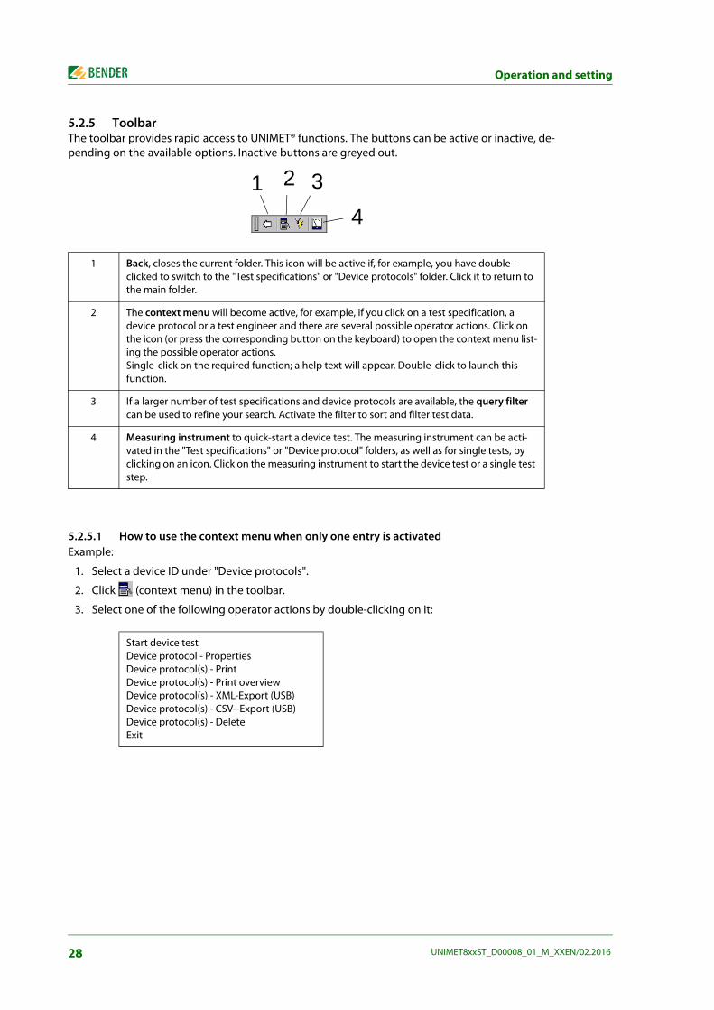
5.2.5 ToolbarThe toolbar provides rapid access to UNIMET® functions. The buttons can be active or inactive, de-pending on the available options. Inactive buttons are greyed out.
5.2.5.1 How to use the context menu when only one entry is activated Example:
1. Select a device ID under "Device protocols".
2. Click (context menu) in the toolbar.
3. Select one of the following operator actions by double-clicking on it:
1 Back, closes the current folder. This icon will be active if, for example, you have double-clicked to switch to the "Test specifications" or "Device protocols" folder. Click it to return to the main folder.
2 The context menu will become active, for example, if you click on a test specification, a device protocol or a test engineer and there are several possible operator actions. Click on the icon (or press the corresponding button on the keyboard) to open the context menu list-ing the possible operator actions.Single-click on the required function; a help text will appear. Double-click to launch this function.
3 If a larger number of test specifications and device protocols are available, the query filter can be used to refine your search. Activate the filter to sort and filter test data.
4 Measuring instrument to quick-start a device test. The measuring instrument can be acti-vated in the "Test specifications" or "Device protocol" folders, as well as for single tests, by clicking on an icon. Click on the measuring instrument to start the device test or a single test step.
Start device testDevice protocol - PropertiesDevice protocol(s) - PrintDevice protocol(s) - Print overviewDevice protocol(s) - XML-Export (USB)Device protocol(s) - CSV--Export (USB)Device protocol(s) - DeleteExit
4321
28 UNIMET8xxST_D00008_01_M_XXEN/02.2016

Operation and setting
5.2.5.2 How to use the context menu if more than one entry is activated
Example:
1. Select several device IDs under "Device protocols". To select multiple device IDs, proceed as follows:Draw a frame around the selected icons with the stylus pen orif you have a keyboard connected,
– press and hold down the shift button and click the first and last IDs in a group of device IDs with the stylus pen.
– press and hold down the shift button and select a group of device IDs using the arrow but-tons up/down.
– press and hold down the "Ctrl" button and click several individual device IDs with the stylus.
Activated device IDs are displayed against a dark background.
2. Click (context menu) in the toolbar.
3. Select one of the following operator actions by double-clicking on it:
Another example application for the context menu appears in chapter "5.4.2.2 Logging in, changing or deleting test engineers".
If the "Device protocols" folder contains a large number of device IDs, you can se-lect the "List" or "Details" screen configuration to improve transparency. This set-ting remains saved even after the test system is shut down.To select specific device protocols for batch printing (print all), proceed as de-scribed below.
Device protocol(s) - PrintDevice protocol(s) - Print overviewDevice protocol(s) - XML-Export (USB)Device protocol(s) - CSV-Export (USB)Device protocol(s) - DeleteExit
29UNIMET8xxST_D00008_01_M_XXEN/02.2016
Operation and setting
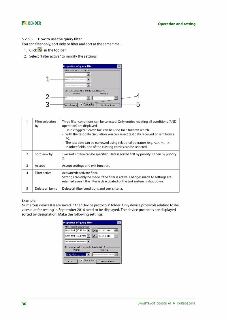
5.2.5.3 How to use the query filterYou can filter only, sort only or filter and sort at the same time.
1. Click in the toolbar.
2. Select "Filter active" to modify the settings.
Example:Numerous device IDs are saved in the "Device protocols" folder. Only device protocols relating to de-vices due for testing in September 2016 need to be displayed. The device protocols are displayed sorted by designation. Make the following settings:
1 Filter selection by
Three filter conditions can be selected. Only entries meeting all conditions (AND operation) are displayed.- Fields tagged "Search for“ can be used for a full text search.- With the test data circulation you can select test data received or sent from a
PC. - The test date can be narrowed using relational operators (e.g. <, >, =, …).- In other fields, one of the existing entries can be selected.
2 Sort view by Two sort criteria can be specified. Data is sorted first by priority 1, then by priority 2.
3 Accept Accept settings and exit function.
4 Filter active Activate/deactivate filter.Settings can only be made if the filter is active. Changes made to settings are retained even if the filter is deactivated or the test system is shut down.
5 Delete all items Delete all filter conditions and sort criteria.
1
2534
30 UNIMET8xxST_D00008_01_M_XXEN/02.2016

Operation and setting
5.3 Main folderThe main folder is the top operating level. It provides access to the various UNIMET® folders and func-tions.
Double-click on the relevant icon to activate the required function.
Function Description Page
DIN EN 60601-1 (VDE 0750-1)DIN EN 61010-1 (VDE 0411-1)
DIN EN 62353 (VDE 0751-1)
DIN VDE 0701-0702
Classification in accordance with the relevant standard. Answer the questions that appear on the screen. The test system will identify the required test steps and limit values to be complied with. You can save this test specification under a name in the "Test specifications" folder.
40
Import test data
Imports test specifications and device protocols from a USB drive. The test specifications associated with the device protocols are imported automatically.
57
Test specifications The "Test specifications" folder contains saved test specifications and their creation dates.
58
Device protocols The "Device protocols" folder contains saved device protocols. Test results, measured values and the date of the next test are saved under each device ID.
62
Single test Test steps can be called up in the form of single tests and repeated as often as required.
64
Test engineer names Select test engineer, enter new test engineer, delete test engineer 32
System control Display, date, time of day and printer settings. The Windows® settings are grouped in a folder.
34
31UNIMET8xxST_D00008_01_M_XXEN/02.2016

Operation and setting
5.4 Test engineer namesThe names of the test engineers are stored in the "Test engineer names" folder. The test engineer whose name appears in the device protocol is also logged in here. You should therefore set the test engineer's name before carrying out the first test.
The "Test engineer names" folder is particularly useful if more than one person is working with the test system. Test engineer names already registered on the system can be selected easily. There is no need to re-enter the name of the test engineer. The "Test engineer names", "Test specifications" and "Device protocols" folders share the same data memory. Accordingly, the number of test engineer names is limited only by the size of the available memory. A name of a test engineer cannot be longer than twenty characters.
5.4.1 Log in test engineerThe name of the test engineer currently logged in is assigned to all subsequent device protocols. The test engineer's name is printed on the device protocols.
1. Select "Action" -> "Log in test engineer" from the menu bar
2. Select your name from the list and click "Log in" to confirm your selection.
If more than one person is working with the test system, there is a risk that users will forget to select the name of the new test engineer. To avoid this, check the "Log in test engineer" box on every restart. The "Log in test engineer" window will then appear every time the test system is powered up.
5.4.2 Test engineer names administrationThe "Test engineer names" folder features the following functions:
– Create new
– Log in
– Change
– Delete
How to access the "Test engineer names" folder:
► In the main folder, double-click to open the "Test engineer names" folder. Hint: If you cannot see the "Test engineer names" icon in the main folder, scroll down the bar on the right-hand edge of the screen.
5.4.2.1 Other options for "Log in test engineer"
1. Double-click the required test engineer name (e.g. "Peter Mustermann").
2. or click on "Test engineer names" > click on " " in the toolbar > double-click on "Log in".
3. or, in the menu "Action", select -> "Log in test engineer".
32 UNIMET8xxST_D00008_01_M_XXEN/02.2016

Operation and setting
5.4.2.2 Logging in, changing or deleting test engineers Use the "Context menu" on the toolbar to edit the name of an existing test engineer. Proceed as fol-lows:
1. Click the name of the test engineer.
2. Click (context menu) in the toolbar
3. Double-click on the required action
5.4.2.3 Creating a new test engineer
1. Double-click "Create new".
2. Enter the name using the stylus and the software keyboard (or external keyboard).
3. Confirm entry with "OK".
4. Choose whether new test engineer is logged in (yes/no).
Log in Logs the test engineer in.
Change You can use the keyboard to edit the name of the test engineer. ESC = Name of the test engineer remains unchanged.↵ = save the test engineer name you have changed
Delete The selected name is deleted.
Exit The name of the test engineer remains unchanged. The "context menu" func-tion is exited.
33UNIMET8xxST_D00008_01_M_XXEN/02.2016

Operation and setting
5.5 Device settingsThe "System control" folder is used to configure your test system. How to access the "System control" folder:
► In the main folder, double-click to open the "System control" folder. Hint: If you cannot see the "System control" icon in the main folder, pull the scroll bar on the right-hand edge of the screen down.
5.5.1 Windows system controlThe UNIMET® uses the Windows® CE operating system. How to access the "System control" folder:
► In the "System control" folder, open the "Windows system control" folder.
The system settings can be changed as follows:
5.5.1.1 Saving settings
► Select > "System control" > "Windows system control" > "Save settings".
"Save settings" can be used to save various Windows settings, so that they are retained for use the next time the system is powered up (e.g. display settings, regional settings, printers, keyboard layout etc.).
5.5.1.2 Display
► Select > "System control" > "Windows system control" > "Display".
Make the settings for the background, the appearance of the windows and the characteristics of the display lighting here.
5.5.1.3 Printer
► Select > "System control" > "Windows system control" > "Printer".
The procedure for setting up an external printer is described in the chapter entitled "Connecting a printer" on page 22. Also refer to "Print setup in PDF file" on page 22.
You have to execute the function "Safe changes" to be secure that all the settingsin the "Windows system control" folder are stored permanently.
UNIMET® helps saving energyThe menu item "Display" > "Lighting" is set in a way that the display light isturned off after 10 minutes of no-load operation. After touching the display, thelight is immediately turned on again. This function also increases the service life of the display and must therefore notbe deactivated.
34 UNIMET8xxST_D00008_01_M_XXEN/02.2016

Operation and setting
5.5.1.4 Date/time
► Select > "System control" > "Windows system control" > "Date/Time".
This window is used to set the date, time of day and time zone, as well as automatic changeovers to and from summer/winter time.
5.5.1.5 Regional settings
► Select > "System control" > Windows system control" > "Country settings".
Regional settings such as numbers, currencies, time of day and date.
5.5.1.6 Stylus
► Select > "System control" > Windows system control" > "Stylus".
In the "Stylus" window you can personalise the double-click action of the stylus. Double-click the grid. This will teach the UNIMET® the rate at which you will perform the double-click action in the fu-ture.Select "Calibration" to calibrate the touchscreen for the stylus pen.
5.5.1.7 Input panel
► Select > "System control" > "Windows system control" > "Input panel".
If data needs to be entered, a software keyboard will appear on the test system's touchscreen. The appearance of the software keyboard can be modified in the "Input panel" window.
5.5.1.8 Keyboard
► Select > "System control" > "Windows system control" > "Keyboard".
The settings in this window only apply to an external hardware keyboard connected to a USB inter-face or a PS/2 port. You can activate character repetition here, as well as changing the delay and rep-etition rate.
5.5.1.9 Keyboard layout
► Select > "System control" > "Windows system control" > "Keyboard layout".
The settings in this window only apply to an external hardware keyboard connected to a USB inter-face or a PS/2 port. Here you can configure the test system in line with a keyboard in German or American format.If this function is not displayed, you can find the setting option under "Regional settings".
5.5.1.10 Volume & sound
► Select > "System control" > "Windows system control" > "Volume & sound".
You can set the volume in this window and assign events to specific sound responses.
You can move this window to reveal all standard functions it supports (e.g. the"OK" button). To do this, click on the blue title bar and drag the window in the re-quired direction.
35UNIMET8xxST_D00008_01_M_XXEN/02.2016
Operation and setting
Other functions in the "System control" folder:
► In the main folder, double-click to open the "System control" folder. Hint: If you cannot see the "System control" icon in the main folder, scroll down the bar on the right-hand edge of the screen.
5.5.2 Zero balance PE resistance (test probe/measuring lead)Zero balance has to be performed for the UNIMET® test probe. As with an ohmmeter, this ensures that the ohmic resistance of the test probe will not affect the PE conductor test result. You should repeat this calibration procedure every time you connect a different test probe or measuring lead to the test system. Also carry out a zero balance before testing with the VK701 adapter or the external power source EPS800 (measurements #0101, #0102, #0103).
1. Select > "System control" > "Windows system control" > "Zero balance PE resistance".
2. Select the number of the PE conductor test (e.g. #0003 to test a device with a power cable). A zero balance procedure can be saved for each measurement path.
3. Connect the test probe as illustrated in the diagram on the screen.
4. Press "Test" to test your test probe.
5. Press "Adjust" to calibrate your test probe.
5.5.3 Nominal voltageUNIMET® can be used for the voltage ranges AC 100…120 V or AC 220…240 V. In order to always ob-tain comparable measured values even if the mains voltage is fluctuating, various standards require measured values to be converted to nominal system voltage or even to 106 or 110 % of the nominal system voltage. It is for this reason that you should set the nominal system voltage. The factory set-ting is 230 V. The required conversion of the measured values is performed automatically by the UN-IMET®.
1. Select > "System control" > "Nominal voltage".
2. Select the corresponding nominal voltage.
3. Confirm the nominal voltage with "Accept".
Information about general device calibration appears in the chapter entitled"Calibration" on page 67.
36 UNIMET8xxST_D00008_01_M_XXEN/02.2016

Operation and setting
5.5.4 DatabaseThe UNIMET® uses a shared database for the "Test specifications", "Device protocols" and "Test engi-neer names" folders. Deleting test data creates gaps which remain unfilled. Therefore, you should compress the database regularly in order to make this space available for use. The UNIMET® takes ap-proximately one minute to compress 1000 data records.
1. Select > "System control" > "Database".
2. Click "Compress test database…"
5.5.5 Backup (USB)Can be used to back up the operating software and the UNIMET® test database to a USB stick. We recommend making regular backup copies. You should back up your data in particular before up-dating the UNIMET® operating software. Therefore, connect a USB stick to the USB port on the UNIMET®. The data will take up approximately 20 MB of memory space.
How to back up UNIMET- data on a USB stick
1. Select > "System control" > "Backup".
2. Click "Start backup".
To copy the data saved on the USB stick back to the UNIMET®, proceed as follows:
1. Switch the UNIMET® off.
2. Connect the USB stick.
3. Switch the UNIMET® on.
4. In the window, specify whether the UNIMET® operating software and/or the test database (test specifications and device protocols) should be copied back.
5.5.6 Remote control RS-232The UNIMET® can be connected to a PC via the RS-232 interface.The baud rate and data bits are set in this window. The baud rate indicates the data transmission rate in bits per second.
1. Select > "System control" > "Remote control RS-232".
2. Select the corresponding interface parameter
3. Confirm the new interface parameter with "Accept".
Start Starts data recovery.
Cancel Cancels recovery. - UNIMET® starts up. No data is copied from the USB stick to the UNIMET®.
The baud rate and data bits on the test system and the PC (or in the PC software)must always be set to the same value! In case of different settings, data transmis-sion cannot be carried out.
37UNIMET8xxST_D00008_01_M_XXEN/02.2016

Operation and setting
5.5.7 DiagnosticYou need a test box TB3 for this function. Running a test with the TB3 test box will show whether the test system needs to be returned to the factory for calibration. Testing with the TB3 test box is no substitute for the recommended regular calibration procedure.
The TB3 simulates a standardised DUT. The UNIMET® runs a test sequence and evaluates the result as "PASSED" or "FAILED". A description of how to connect and use the test box appears on the TB3's instruction leaflet.
1. Select > "System control" > "Diagnostic".
2. Connect the TB3 test box as illustrated in the diagram on the screen.
3. Select "Properties" > "Options",
– Select the corresponding test box (diagnostic routine): TB3-230 V or TB3-120 V. The TBPAT test box is intended for use by Bender Service only.
– Select the "Number of tests". This function enables the test sequence to be run more than once. The evaluation of the test results is shown in the test protocol. If the test has been run more than once, UNIMET® will provide statistical interpretations of the measurements taken in the test protocol (standard deviation, min./max. values, stability value (CP)).
– Confirm your selection by pressing "OK".
4. Click "Start". The test system performs an automatic test with the connected test box.
5. On completion of the test, the test system will display the results of the diagnostic. Click "Print" to print the test result on a connected printer or to create a PDF file.
6. Terminate the indication of the test result by clicking or "OK".
38 UNIMET8xxST_D00008_01_M_XXEN/02.2016
6. Testing and measuring
6.1 Test conceptThe integrated "Test specifications" and "Device protocols" folders provide the basis for time-effi-cient and cost-effective testing with the UNIMET®.
ClassificationThe UNIMET® allows tests to be carried out in accordance with the standards DIN EN 60601-1 (VDE 0750-1), DIN EN 62353 (VDE 0751-1), DIN VDE 0701-0702 (VDE 0701-0702) und EN 61010-1 (VDE 0411-1). For test specifications of DUTs not saved in the "Test specifications" folder so far, the re-quired test steps and their limit values have to be determined in dialogue between the test engineer and the UNIMET®. This classification is then saved as a test specification named accordingly in the "Test specifications" folder, where it is available for all subsequent DUTs of the same type.
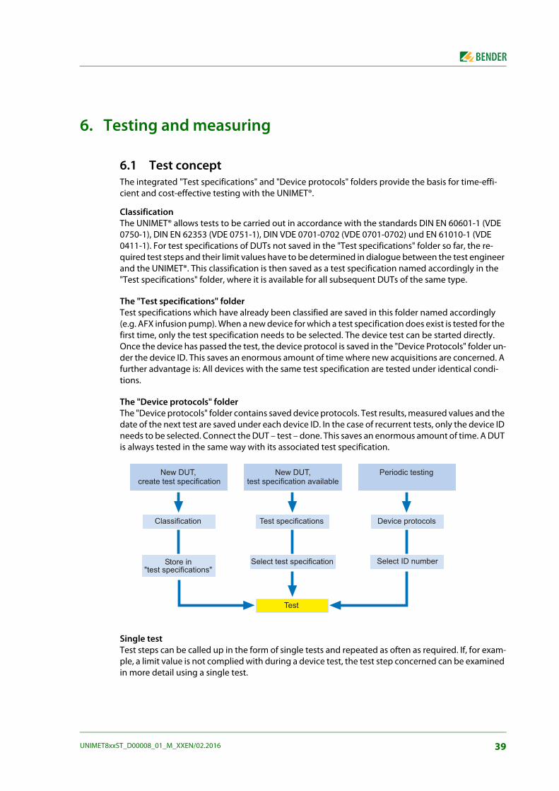
The "Test specifications" folderTest specifications which have already been classified are saved in this folder named accordingly (e.g. AFX infusion pump). When a new device for which a test specification does exist is tested for the first time, only the test specification needs to be selected. The device test can be started directly.Once the device has passed the test, the device protocol is saved in the "Device Protocols" folder un-der the device ID. This saves an enormous amount of time where new acquisitions are concerned. A further advantage is: All devices with the same test specification are tested under identical condi-tions.
The "Device protocols" folderThe "Device protocols" folder contains saved device protocols. Test results, measured values and the date of the next test are saved under each device ID. In the case of recurrent tests, only the device ID needs to be selected. Connect the DUT – test – done. This saves an enormous amount of time. A DUT is always tested in the same way with its associated test specification.
Single testTest steps can be called up in the form of single tests and repeated as often as required. If, for exam-ple, a limit value is not complied with during a device test, the test step concerned can be examined in more detail using a single test.
����������� �� �� �������� ���
�������� �� ���������� �� �������� �������������
��� �������� ���� ��������� ������������� ���
���� � �� �������� ���
���
���� ����������� ������� �� �������� �����
39UNIMET8xxST_D00008_01_M_XXEN/02.2016

Testing and measuring
6.2 Classification ► Select the applicable test standard from the main folder. Answer the questions that appear on
the screen.
The test system will identify the required test steps, their sequence and the limit values to be com-plied with. Classification produces the test specification, which is saved to the "Test specifications" folder.
Example:Classification of medical electrical equipment (e.g. ultrasound device) according to IEC 62353:2007-05 This is a Class I device with two patient connections.
In the main folder, select "IEC 62353:2007-05“ and then "Class I".
The remainder of the classification procedure is carried out on tabs. The UNIMET® marks completed tabs with the "√" symbol. Modify the settings on every tab to reflect the properties of the DUT. Then click to accept your entries. To cancel classification, click .
6.2.1 General
You must always enter a name. If you do not, you will not be able to save the classification. Example: Ultrasound.
The manufacturer and designation describe the DUT in more detail. You must decide whether you want to enter this information immediately or edit it at a later date. You also need to specify a test interval for recurrent tests. Once a device has passed the test, the UNIMET® will calculate the date of the next device test.
The following rules apply to all text boxes: Once a term has been entered, you willneed to use the list every time you enter this term subsequently. This is to ensurethat the same term is always written in an identical way. This is a basic require-ment in order for term searches and selections to work (e.g. with the query filter;see also "How to use the query filter" on page 30).
OK X
40 UNIMET8xxST_D00008_01_M_XXEN/02.2016

Testing and measuring
► When clicking on an entry, a short description appears in the info field at the bottom.
► Double-click on an entry to open the software keyboard and edit that entry (entries can also be edited using an external keyboard).
6.2.2 Method of measurementThe test standards enable you to choose between three different methods of measurement to ascer-tain the leakage currents.
► When clicking on an entry, a short description appears in the info field at the bottom.
► Double-click on an entry to select this method of measurement. The current method of meas-urement is identified by the "√" symbol. Example: Direct measurement method.
6.2.3 Applied partOur example device has patient connections.
1. You therefore need to select" Test with applied part".
2. In the next window, create one or several groups of applied parts (e.g. type "BF" and type "CF"). For each group, select "Create new".
3. In the next window, select the type of applied part (see the medical device's nameplate). Exam-ple: CF type.
4. Next, select the patient socket on the test system to which this applied part is to be connected. Patient sockets can be selected at will. The patient sockets are colour-coded as appropriate for the type of applied part (B = green, BF = yellow, CF = red).
Cancel Close window without making changes.
OK Accept settings and close the "Group 1" window. A second group can be cre-ated. If you do not wish to create any more groups, continue the classification process by clicking on the next tab.
X
41UNIMET8xxST_D00008_01_M_XXEN/02.2016
Testing and measuring
6.2.4 Equipment typeThe "Equipment type" tab only appears when it is required for classification of the DUT.
► When clicking on an entry, a short description appears in the lower info field("ME system" means "medical electrical system").
► Double-click on an entry to select this equipment type. The current equipment type is identi-fied by the "√" symbol. Example: Standard equipment.
6.2.5 ExtrasThe "Extras" tab combines a variety of settings.
► Click on an entry to show an explanatory comment in the info field at the bottom of the tab.
► Double-click on an entry to activate that function. Activated entries are identified by the "√" symbol.
Depending on the selected test standard, the following settings are available.
All accessible conductive parts are connected to PE
This function can be used if you know that all metal accessible parts of the enclosure are connected to PE. During device testing, the test probe then only has to be brought into contact with one metal point on the enclosure.If not all metal parts of the enclosure are connected to PE, deactivate this function. During device testing, an additional equipment leakage current test resp. touch current test (Class II) is carried out. The semi-automatic test sequence is classified automatically. During device testing, proceed as follows: During PE conductor testing, use the test probe to scan all parts of the enclo-sure connected to PE. During equipment leakage current testing or touch cur-rent testing (Class II), test all parts not connected to PE.
Warm-up and cool-down period
Once they have been switched on, an increasing number of DUTs need to complete a self-test and warm-up period, followed by a cool-down period prior to shutting down. Examples include computers, processor-controlled devices and laser equipment. For these devices, the UNIMET® may only start the measurements once the DUT has warmed up or "booted up". Otherwise, there is a risk that the parts of the device to be tested will only have switched on partially or not at all, and therefore will not be tested. Once the measurements are complete, the UNIMET® may only turn off the DUT once it has shut down or cooled down. Otherwise, on laser equipment, there is the risk of overheating or, on a computer, of sectors of the hard disk becoming unusable.
Display warning notice If this function is activated, a warning notice will appear prior to the DUT con-nected to the mains voltage. Only once the message has been confirmed will the mains voltage be connected. This prevents hazardous devices such as grinders starting up unexpectedly.
Carry out insulation resist-ance test step(not applicable for tests acc. to DIN EN 60601-1)
During insulation measurement, a voltage of 500 V is applied between the active conductors and earth. Insulation testing may damage sensitive devices. Only activate insulation measurement if permitted by the manufacturer's instructions provided with the DUT.
Permit measurement with phase reversed (only applicable for tests acc. to DIN EN 60601-1)
Permanently installed equipment with neutral conductor not protected by a fuse cannot be tested with phase reversed.
42 UNIMET8xxST_D00008_01_M_XXEN/02.2016

Testing and measuring
6.2.6 Test sequenceThe test sequence can be carried out automatically, semi-automatically or manually for each DUT.
► Click on an entry to show an explanatory comment in the info field at the bottom of the tab.
► Double-click on an entry to activate that function. Activated entries are identified by the "√" symbol. Example: Automatic.
If an error is detected during automatic testing, the test step concerned can be repeated. The UN-IMET® will switch to manual mode for this test step.
25-A power source EPS800 connected(only for tests in acc. with DIN EN 60601-1)
Activate this option for carrying out a standard-compliant test of the protec-tive earth resistance with 25 A. The external power source EPS800 is required for these tests.
ME equipment/system with signal input or output parts(only for tests in acc. with DIN EN 60601-1)
Detecting leakage currents from medical electrical equipment or systems whose signal input and output is connected to an external voltage.
Functional earth is also con-nected(for tests acc. to DIN EN 60601-1 only)
The functional earth of the medical electrical equipment resp. the system is connected to FE connection of the test device.
DUT can be disconnected from the system(only for tests acc. to DIN VDE 0701-0702)
If the DUT cannot be disconnected from the system, deactivate this option (limited equipment test).
Automatic test sequence
During automatic testing, the test probe or test terminal comes into contact with one point of the DUT. The electrical test steps are carried out one after the other.
Semi-automatic test sequence
During semi-automatic testing, the test steps for which the test probe is needed are only started on request. This means that a test step can be repeated in order to check various accessible conductive parts of the DUT. To start the current test step, click "Measure" or press the active test probe (option) firmly onto the DUT. The UNIMET® will save the worst value measured. To proceed to the next test step, click the "Proceed" button or press the button on the handle of the active test probe (option).Test steps for which the test step is not required are performed one after the other during the next automatic test sequence.
Manual test sequence During the manual test sequence, every test step is carried out continuously. This makes it possible to contact several accessible parts one after another with the test probe. The UNIMET® will save the worst value measured. To proceed to the next test step, click the "Proceed" button or press the button on the handle of the active test probe (option).
43UNIMET8xxST_D00008_01_M_XXEN/02.2016

Testing and measuring
6.2.7 Visual inspectionThe device test also includes a visual inspection. The UNIMET® can save and document the test steps involved in this visual inspection.
► Click on an entry to show an explanatory comment in the info field at the bottom of the tab.
► Double-click on an entry to activate that function. Activated entries are identified by the "√" symbol. Example: Standard visual inspection.
To create a user-defined visual inspection, proceed as follows:
Short visual inspection During the device test, it is only possible to activate or deactivate the "Visual inspection" option.
Standard visual inspection
The device is tested against the criteria from the relevant standard.
User-defined visual inspection
You can create your own test steps for the visual inspection process. Use the criteria from the relevant standard as a starting point. Text can be modified, deleted or added.
1 Current test steps in the visual inspection process. The first test step is selected (single-click). Double-click to edit the test step.
2 Saves the current test steps in the visual inspection process.
3 A new test step is added below the existing test steps. The software keyboard opens automati-cally for this purpose.
4 Deletes the selected test step.
5 The default test steps associated with the relevant standard are activated. Any user-defined test steps are deleted.
1
2 3 4 5
44 UNIMET8xxST_D00008_01_M_XXEN/02.2016

Testing and measuring
6.2.8 Functional testA device test also includes a functional test. The UNIMET® can save and document the test steps in-volved in this functional inspection.
► Click on an entry to show an explanatory comment in the info field at the bottom of the tab.
► Double-click on an entry to activate that function. Activated entries are identified by the "√" symbol. Example: Standard functional test.
To create a user-defined functional test, proceed as follows:
1. Click on "New" to create a new test step. Then configure the test step.
Do not perform a functional test
Select this option if a functional test is not required.
Standard functional test DUT is put into operation via the test socket of the UNIMET®. It is evaluated as "PASSED" or "FAILED".
User-defined functional test You can create your own test steps for the functional test process.
PASSED/FAILED evaluation
It is evaluated as "PASSED" or "FAILED". Text for display on the screen can be entered.
No evaluation after entering the measured value
The measured value entered is documented. The test step does not affect the evaluation of the test result ("PASSED"/"FAILED").
Limit value evaluation after entering the measured value
The test step is evaluated against the limit values. The text displayed on the screen should include the setpoint and the unit.
45UNIMET8xxST_D00008_01_M_XXEN/02.2016

Testing and measuring
2. Enter a text to be displayed on the screen for this test step. Then click "OK".
Further examples of user-defined functional tests
1 Current test steps in the functional test process. The first test step is selected (single-click). Dou-ble-click to edit the test step.
2 Saves the current test steps in the functional test process.
3 A new test step is added below the existing test steps. Configure the test step and enter the associated text to be displayed on the screen.
4 Deletes the selected test step.
Selected propertyDisplay text/ minimum and maximum limit value
Description
No evaluation after entering the measured value
Operating hoursThe hours of operation are sim-ply documented. The test result remains unaffected.
Limit value evaluation after entering the measured value
Delivery accuracy at 10 ml/hMinimum limit value: 9.70Maximum limit value: 10.30
If the measured value entered for the delivery rate is below the mini-mum limit value or exceeds the maximum limit value, the DUT will be evaluated as "Failed".
1
2 3 4
46 UNIMET8xxST_D00008_01_M_XXEN/02.2016

Testing and measuring
6.2.9 Exiting classificationOnce all settings have been made, click to accept your entries.
Classification is complete. Now you have the following options:
Saving and testing The classification is saved under its name to the "Test specifications" folder. Afterwards, the device test will be started.
Save The classification is saved under its name in the "Test specifications" folder.
Cancel The classification is not saved.
OK
47UNIMET8xxST_D00008_01_M_XXEN/02.2016

Testing and measuring
6.3 Device test
Faulty DUTs may present dangerous touch currents on conductive parts duringthe device test. The UNIMET® will terminate test steps during which the leakage current is detect-ed by means of "Direct measurement method" as soon as a measured value of >20 mA is reached.
The test system must not be used for measurements in electrical installations. Itis exclusively intended for devices and systems listed under "System description"on page 11.
During testing of the insulation resistance with DC 500 V, a direct touch currentof up to 2.5 mA may be conducted on faulty DUTs or in the event of direct contactwith the test probe. DIN EN 61010 permits a direct touch current of up to 15 mA.
During testing of the equipment leakage current -alternative method- with AC250 V on faulty DUTs or in the event of direct contact with the test probe there isthe risk of an electric shock. The test current is limited to 3.5 mA.
The leakage current flowing during the test of a faulty DUT can cause the resid-ual current protective device (RCD) to operate.
When leakage currents are measured during a test, the DUT must be set up in aninsulated state. This ensures that no leakage currents can flow via accidentalearth connections. Accessible conductive parts of the DUT and the measuringleads may be live. and therefore must not be touched.
Information on the electromagnetic compatibility (EMC):The lengths of the connected interface cable must not exceed 30 m.If the device is connected to a DUT, electromagnetic emissions may occur ex-ceeding the levels specified by the standards. If asymmetrical surge voltages occur on the power supply line, the test may beaborted. Electrostatic discharges at the interfaces may require that the system isto be restarted.
WARNING
WARNING
CAUTION
CAUTION
CAUTION
CAUTION
48 UNIMET8xxST_D00008_01_M_XXEN/02.2016

Testing and measuring
To start an initial test:
1. After classification, select "Saving and testing".
2. Select an existing test specification in the "Test specifications" folder, then
– click the "Measuring device" icon
– or call up "Start device test" from the context menu.
To start a recurrent test:
► Select an existing device protocol in the "Device protocols" folder, then
– click the "Measuring device" icon
– or call up "Start device test" from the context menu.
The device test is carried out in the following order:
1. Visual inspection
2. Electrical test
3. Functional test
Risk of overheating due to high load currentsIf DUTs with high current consumption (> 8 A) are supplied by the UNIMET® forseveral minutes, the UNIMET® will prevent overheating by aborting the test. Amessage will appear.
Therefore, please regard the following when DUTs with high current consump-tion are concerned, (> 8 A): - Take the UNIMET® out of the carrying bag.- The DUT must not be supplied from the UNIMET® test socket for more than 15
minutes.
UNIMET® in specific national versions for Switzerland, Great Britain and the USAare only designed for a current consumption of maximum 10 or 13 A (see order-ing information).
CAUTION
49UNIMET8xxST_D00008_01_M_XXEN/02.2016

Testing and measuring
6.3.1 Connecting the DUTThe UNIMET® will now display the wiring diagram matching the classification. This diagram will show you where to make the connection for the test probe and all other connections to the DUT.
Proceed as follows:
1. Connect the DUT to the UNIMET®.
2. Then click the "Start" button.
In the wiring diagram, the test probe is connected to socket [A]. We are using theTP800 active test probe (option).The single-pole test probe supplied with the UNIMET® is connected to socket [B].
1 Test engineer logged on
2 Start device test
3 Test standard
4 Only if there is an applied part: Additional information about the applied part.
5 Test specification or device ID
6 Cancel device test
7 Wiring diagram
1
23
6
4 5
7
50 UNIMET8xxST_D00008_01_M_XXEN/02.2016

Testing and measuring
6.3.2 Carrying out the visual inspectionCarry out the visual inspection following the test steps listed. All visual inspections are set as passed
by default. If this is not applicable for one of the test steps, click . The box is unchecked and as a result the test step and the entire device test are saved as "FAILED".If there are too many test steps to be displayed on a single page, a button labelled "Proceed" or "Back" will appear on the screen. Click this button to move between pages.
Click "Proceed" to proceed with the electrical part of the device test.
6.3.3 Carrying out the electrical test stepsThe UNIMET® now starts the electrical part of the device test. The electrical test steps are carried out in the following order:
1. All test steps during which the DUT is not in operation (e.g. PE resistance test, insulation resist-ance test and equipment leakage current test -alternative measurement).
2. Test steps with the DUT in operation with a given phase angle (e.g. touch current test, differen-tial current test and applied part leakage current test).
3. Test steps as 2, but with phase reversed.
4. DIN EN 60601-1 only: Test steps interrupted by system conductor (single fault condition; SFC).
5. DIN EN 60601-1 only: Test steps as 4, but with phase reversed
This ensures that the DUT is not started up and shut down too often.
The UNIMET® monitors compliance with the limit values throughout the device test.
If a limit value is violated during a test step, the test engineer can decide whether to abort the device test or continue to its completion.
51UNIMET8xxST_D00008_01_M_XXEN/02.2016

Testing and measuring
Test steps illustrated using the example of PE conductor testing
6.3.3.1 PE conductor testOn Class I equipment, the resistance of the PE conductor is tested.
► In the event of the limit value not being complied with, the measured value will be displayed first, followed by a warning message. At this point, you can choose between the following options:
– Accept measured value (Yes). Proceed with device test.
– Not accept the measured value (No). Test step is repeated.
– Cancel device test by clicking "Stop".
► If the test step is repeated, the UNIMET® switches automatically into the manual test sequence for this test step. This test step will then be repeated until the test engineer starts the next test step with "Next".
► In accordance with the classification, further tests during which the DUT is not in operation (e.g. PE conductor test, insulation resistance test and equipment leakage current -alternative measurement) are carried out after the PE conductor test.
1 Measured value. The background colour is- green if the limit value is complied with- red if the limit value is not complied with- black if there is no limit value
2 Progress bar and test step counter
3 Space for "Next" button(Only for manual and semi-automatic test sequences, or if the limit value was not observed and the device test was not aborted).
4 Aborts the device test.
5 Number of the test step. Bender device test steps are numbered consecutively. Also refer to chapter "8.3 Test steps".
6 Measured value unit
7 Name of the current test step
During the PE conductor test, the low-resistance continuity of the PE conductor is tested with a high current (max. 8 A). This produces heat energy.If the PE conductor test is repeated frequently and without breaks during manualor semi-automatic test sequences or in the context of single tests, the UNIMET®will prevent overheating by aborting the test step. A message will appear. PEconductor testing can continue once a short cool-down period has elapsed.
1
26
45
7
3
52 UNIMET8xxST_D00008_01_M_XXEN/02.2016

Testing and measuring
6.3.3.2 Switching on the DUTIf the "Display warning notice" message was activated on the "Extras" tab during the classification process, a warning notice will appear before the DUT is connected to the mains voltage.
► Click "Next" to proceed with the device test. The DUT is connected to the power supply.
Warm-up periodIf the "Warm-up and cool-down period" was activated on the "Extras" tab during the classification proc-ess, the UNIMET® will wait for the device to ramp up or reach readiness for operation. Once the DUT is connected to the mains supply, the message "Warm-up phase" appears.
► Click "Next" to proceed with the device test.
Power consumptionThe UNIMET® ST measures the power consumed by the DUT.
At a load current of less than 0.005 A, the UNIMET® will prompt you to confirm that the DUT is actually switched on.
► This is the latest point at which you can switch the DUT on. Then click "Proceed".
Cool-down periodIf the "Warm-up and cool-down period" function was activated on the "Extras" tab during the classifi-cation process, once the last test step to be carried out with this phase relation has been completed, the UNIMET® will wait for the DUT to ramp down.
► Click "Next" to proceed with the device test.
Please note that only DUTs with a power consumption of up to 16 A may be sup-plied with power via the UNIMET® test socket. UNIMET® in specific national ver-sions for Switzerland, Great Britain and the USA are only designed for a currentconsumption of maximum 10 or 13 A (see ordering information). If DUTs withtoo high power consumption are connected, the thermomagnetic circuit-break-er installed in the power switch of the UNIMET® will trip. After disconnecting theDUT, the test system can be switched on after a few seconds.
The UNIMET® then repeats the tests with the phase reversed. Here too, it will com-ply with any settings made in relation to warm-up and cool-down period.
53UNIMET8xxST_D00008_01_M_XXEN/02.2016

Testing and measuring
6.3.4 Carrying out the functional testThe functional test follows the electrical part of the device test.
Standard functional test
1. Click "Operating voltage ON". Turn the DUT on.
2. Test the function of the DUT.
3. Click "Operating voltage OFF". Turn the DUT off.
4. Evaluate the test step using "PASSED" or "FAILED".
* The operating voltage can be switched on or off at any time.
User-defined functional testsIf in the classification "User-defined functional tests" is selected. the set test steps appear (refer also to "To create a user-defined functional test, proceed as follows:" on page 45).
► Evaluate the test steps using "PASSED" or "FAILED". If necessary, enter the requested measured value.
Only DUTs which have successfully passed the electrical tests may be tested forcorrect functioning.DUTs can suddenly start while starting the functional test (example:jigsaw). This can lead to damage and injuries.► Switch the DUT off before starting the functional test. First, select "Operat-
ing voltage ON". Then switch the DUT on again.
Operating voltage "ON" DUT is put into operation* via the test socket of the UNIMET®. Please note the manufacturer's instructions when doing this.Three-phase DUTs and DUTs with power consumption levels higher than 16 A (resp.10 or13 A, see ordering information) cannot be supplied with power via the test socket. Connect these DUTs directly to the designated mains voltage.
Operating voltage "OFF" The DUT is switched off*.
Proceed Proceed to the next test step.
PASSED The DUT has passed the test step.
FAILED The DUT has failed the test step. The entire device test is saved as "FAILED".
Complete Results are accepted. The functional test concludes.
Cancel The functional test is aborted. The entire device test is evaluated as "FAILED".
WARNING
54 UNIMET8xxST_D00008_01_M_XXEN/02.2016

Testing and measuring
6.3.5 Evaluating and documenting the test result
Shortening the test intervalIf the test is a recurrent test, the UNIMET® will display a list of all test steps whose measured value reach or exceed 90 % of the limit value. The reference values for these test steps are also displayed. You need to decide whether to shorten the test interval.
Documenting the test resultOnce the functional test has been completed and the test interval has been amended (if necessary), the result of the device test is displayed.
1 Overall result of the device test. The background colour is: - green, if the device has passed the test,- red, if the device has failed the test.
2 Test steps completed. The background colour is:- red, if the device has failed the test step,- yellow if the measured values for the test step reach or exceed 90% of the limit value.
3 Starts the device test again. The existing device test is overwritten.
4 Saves the device test to the "Device protocols" folder. The values initially saved for this device ID (reference values) are always retained. All subsequent device tests are overwritten by the more recent device test in each case.
5 Prints the device protocol on a connected printer or creates a PDF file."Print" will be activated not until the device test has been saved.
6 Quits the device test. If the device protocol has not been saved, a warning will appear.
1
3 64 5
2
3 64 5
55UNIMET8xxST_D00008_01_M_XXEN/02.2016

Testing and measuring
► Click on a test step to show details. The evaluation of the test step, the measured value and the limit value are shown.
► The device ID is required for saving to the "Device protocols" folder. Other data such as serial number, client, room, department, test costs, and a comment can also be entered. Enter at least the device ID and click "Save device protocol". Click "Cancel" to exit the device test. If a device passes the test, the test date is updated by the set test interval.
6.3.5.1 Client administrationThe UNIMET® supports administration of test data for different clients specifically for service applica-tions. Every time you enter the name of the client, it must be in the same format.
If the same device ID has been inadvertently assigned to two different clients, UNIMET® is able to de-tect that these are two different DUTs. The device protocols for both DUTs are saved and adminis-tered.
Selecting a clients' device
1. In the main folder, double-click to open the "Device protocols" folder. Hint: If you cannot see the "Device protocols" icon in the main folder, scroll down the bar on the right-hand edge of the screen.
2. Click in the toolbar.
3. Select "Filter active".
4. Select filter selection by "client" and then select the required client name.
5. Sort the devices, e.g. by "Device ID".
6. Click "Accept".
The client's device can now be edited (see "Editing, printing, exporting and deleting a device proto-col" on page 62f).
The following rules apply to all text boxes: Once a term has been entered, you willneed to use the list every time you enter this term subsequently. This is to ensurethat the same term is always written in an identical way. This is a basic require-ment in order for term searches and selections to work (e.g. with the query filter;see also "How to use the query filter" on page 30).
56 UNIMET8xxST_D00008_01_M_XXEN/02.2016

Testing and measuring
6.4 Importing test dataImports test specifications and device protocols previously exported to a USB drive (USB stick) back to the UNIMET®.
1. Connect a USB stick on which test data has been saved to one of the two USB sockets on the UNIMET®.
2. In the main folder, select "Import test data".
3. Make a selection to indicate whether you are importing "Test specifications" or "Device proto-cols".
4. Click "Create preview". A list of the imported data appears. Select which data should to be imported:
– "All" selects all entries in the preview.
– "Invert" inverts the selection of entries.
– Clicking on an entry selects this entry.
– If you have a keyboard, you can select several entries at a time by clicking on entries from the list while pressing and holding the [CTRL] button. Alternatively, you can also select a group of device IDs using the arrow buttons up/down while pressing and holding the shift button.
5. "Import selected test data" imports the selected test data. When device protocols are imported, the associated test specifications are always imported with them. A progress bar appears on the screen. The process can be aborted.
6. Click "Finish" to exit the "Import test data" function.
57UNIMET8xxST_D00008_01_M_XXEN/02.2016

Testing and measuring
6.5 The "Test specifications" folderAll test specifications are saved by name in the "Test specification" folder. Test specifications contain all test steps drafted and limit values calculated. Using the same test specification to test more than one DUT offers the following advantages:
Saves time: Classification only has to be carried out once.
Assures quality: All devices with the same test specification are tested under identical condi-tions.
The content of the "Test specifications" folder can be transferred to an administration program in-stalled on a PC. Likewise, data records selected in the administration program can be transferred to the "Test specifications" folder. These functions are described in the PC software guide.
6.5.1 How to access the "Test specifications" folder
1. Click "Test specification" in the main folder.
2. Select the relevant test specification.
6.5.2 How to start a device test from the "Test specifications" folder
► Click on the required test specification and proceed as follows:
– Click in the toolbar,
– or on (Context menu) in the toolbar, then double-click "Start device test".
If a device has been tested and saved previously, you will need to start the recurrent testing from the "Device protocols" folder.
6.5.3 Editing, printing, exporting and deleting a test specification
If the "Test specifications" folder contains a large number of names, you can se-lect the "List" or "Details" screen configuration to improve transparency. This set-ting remains saved even after the test system is shut down.You can also improve transparency by using the query filter. An empty "Testspecifications" folder indicates that none of the entries meets the conditions setin the query filter. Deactivate the query filter or select different settings for it.
The settings saved in a test specification are valid for all device protocols createdwith this test specification. Changes to the test specification are applied to all as-sociated device protocols with immediate effect.When deleting a test specification, please remember that you are also deletingall device protocols created with it from the "Device protocols" folder.
58 UNIMET8xxST_D00008_01_M_XXEN/02.2016

Testing and measuring
Use the "Context Menu" on the toolbar to edit the name of an existing test specification. Proceed as follows:
1. Click on the name.
2. Click (Context menu) in the toolbar
3. Select required action
4. Select one of the following operator actions by double-clicking on it:
You can also modify a test specification by double-clicking on the name. Please bear in mind the re-strictions listed below.
Start device testTest specification - PropertiesTest specification - Test step editorTest specification(s) - PrintTest specification(s) - Print overviewTest specification(s) - XML-Export (USB)Test specification(s ) - DeleteExit
Start device test Starts the device test. Once the device test is complete, save the test result to the "Device protocols" folder.
Test specification - Properties
Shows the settings for this test specification. If you need to make fundamental changes affecting test steps, you will need to repeat the classification process. Here, you can only change the functions listed below:Tab Function
General - Name (only if not yet transferred to PC)- Manufacturer- Designation- Test interval
Extras - Show warning notice- Warm-up and cool-down period
Test sequence - Automatic- Semi-automatic- Manual
Test specification-Test step editor
Limit values for test steps can be modified and test steps can be added or deleted in the Test step editor (see page 60 for more detailed information)
Test specification(s) -Print
Prints the selected test steps (all details of the test step) on a connected printer or creates a PDF file.
Test specification(s) -Print overview
Prints an overview of the selected test specifications on a connected printer or creates a PDF file.
Test specification(s) -XML-Export (USB)
Exports the selected test specification to a USB drive (USB stick). A progress bar appears on the screen. The process can be aborted. The exported data can be imported again.
Test specification(s )-Delete
Deletes the selected test specifications along with the associated device pro-tocols. A progress bar appears on the screen. The process can be aborted.
Exit The "context menu" function is exited.
59UNIMET8xxST_D00008_01_M_XXEN/02.2016

Testing and measuring
6.5.3.1 Test step editorThe test step editor supports the following functions for existing test specifications:
Change limit values for test steps
Add test steps
Delete test steps
The test system will only permit modifications for test specifications for which no device protocols have been saved and which have not yet been exported or imported. This prevents divergent set-tings being made for the same test specification.
Proceed as follows:
1. Open the "Test specifications" folder.
2. Click on the required test specification.
3. Click (Context menu) in the toolbar and select "Test specification - Test step editor".
► The settings on the "General", "Extras", and "Test sequence" tabs are made in the same way as during the original classification process:
► The "Applied part" tab is used to add, edit and delete groups (application groups).
– Deleting a group: Single-click on the group to be deleted, then click "Delete".
– Editing a group: Double-click on one of the groups in the list to start editing it. Example: Change group "Type B" to "Type BF".
– Creating a new group: Click "Create new". Select the type of the new group and the asso-ciated sockets. Example: "Type CF" with patient socket 3…6.
► Visual inspections can be added or deleted. Test steps for the functional test can be added or deleted.
Running the modified test sequence can put test personnel (electric shock) andthe DUT (damage beyond repair) at risk. You should therefore first run a test se-quence without the DUT and check whether all tests are completed as required.Only at this point should you connect the DUT. During testing, do not touch anyconductive metal parts of the DUT or test leads.
You also need to enter the test steps associated with this group. A group forwhich no test steps have been entered will be deleted when the test specificationis saved.A safer and quicker procedure is to make as many settings as possible during theclassification process and just make minor adjustments with the test step editor.
WARNING
60 UNIMET8xxST_D00008_01_M_XXEN/02.2016

Testing and measuring
► The primary task of the test system is the electrical test. Test steps can be edited, deleted and added via the "Test steps" tab.
– Deleting test steps: If, for example, you have doubts about running the insulation resist-ance test, click on this test step, followed by the "Delete" button. The test step is deleted with immediate effect.
– Editing test steps: Start the edit process of the limit value by double-clicking on the required test step. Enter a new limit value using an external keyboard or via the numbers and arrow buttons on the screen. Click to accept your entries. To abort the function, click .
– Filter selection by standards: Click "Standards". The currently selected filter will be indi-cated. Example: Only test steps included in DIN EN 62353 will be indicated. Click to display the list of available standards. Click on the respective standard or "Dis-play all electrical test steps". Then click the "OK" button.
– Adding test steps: Click "Add". A list of available test steps appears. The available test steps depend on the settings of the "Standards" button. Click on the required test step. Then click on the "Limit value" text box. Enter a new limit value using an external keyboard or via the numbers and arrow buttons on the screen. Con-firm the new limit value by clicking the button, located between the arrow buttons.
Click at the top of the screen to accept your entries for this test step. To abort the function, click .
– Adding test steps for the applied part: Test steps have to be created for the new group created under "Applied part". Go to the "Test Steps" tab and click "Add". Under "Test Steps" add a test step (e.g. applied part leakage current) for the new group (i.e. this applied part). Enter the associated limit value.Click at the top of the screen. The "Assign group" window appears. Select the corre-sponding group then click "OK". Click to accept your entries. To abort the function, click .
– Saving test specifications: Once you have made all the settings for this test specification, click . The test system will now check the new settings. The test steps are sorted into an appropri-ate order for the test sequence. Groups of applied parts with no associated test steps are deleted. The test specification is then saved with the new settings. Modified test specifications are marked with the suffix "MOD." before the test standard. Example: MOD. DIN EN 60601-1…
You must always enter an applicable limit value when creating new test steps. Ifyou do not, the default limit values, which are too strict, will lead to the DUT fail-ing the test.
For each group, a new test step has to be added and the group then needs to beassigned.
OK
X
OK
OK
X
OK
OK X
OK
61UNIMET8xxST_D00008_01_M_XXEN/02.2016

Testing and measuring
6.6 The "Device protocols" folderAll tested devices are saved in the "Device protocols" folder with their device ID and the test results obtained. The reference values are also saved. In the event of recurrent tests, the devices are simply called up in the "Device protocols" folder and tested again.
The content of the "Test specifications" folder can be transferred to an administration program in-stalled on a PC. Likewise, data records selected in the administration program can be transferred to the "Device protocols" folder. These functions are described in the PC software guide.
6.6.1 How to access the "Device protocols" folder"
1. Click "Device protocols" in the main folder.
2. Select the device ID of the DUT.
6.6.2 How to start a device test from the "Device protocols" folder
► Click the required device ID and proceed as follows:
– Click in the toolbar,
– or on (Context menu) in the toolbar, then double-click "Start device test".
6.6.3 Editing, printing, exporting and deleting a device protocolUse the "Context Menu" on the toolbar to edit a device protocol saved under a device ID. Proceed as follows:
1. Click on the device ID.
2. Click (Context menu) in the toolbar
3. Select one of the following operator actions by double-clicking on it:
If the "Device protocols" folder contains a large number of device IDs, you can se-lect the "List" or "Details" screen configuration to improve transparency. This set-ting remains saved even after the test system is shut down.You can also improve transparency by using the query filter. An empty "Deviceprotocols" folder indicates that none of the entries meets the conditions set in thequery filter. Deactivate the query filter or select different settings for it.
Start device testDevice protocol - PropertiesDevice protocol(s) - PrintDevice protocol(s) - Print overviewDevice protocol(s) - XML-Export (USB)Device protocol(s) - CSV-Export (USB)Device protocol(s) - DeleteExit
62 UNIMET8xxST_D00008_01_M_XXEN/02.2016
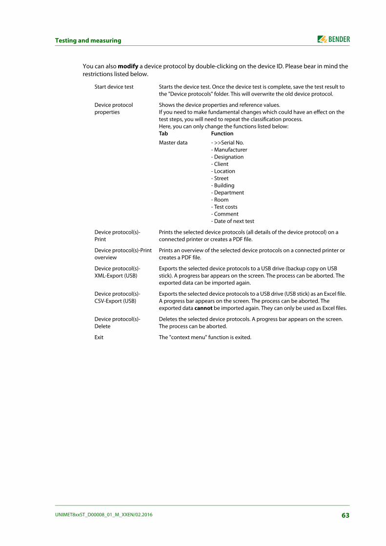
Testing and measuring
You can also modify a device protocol by double-clicking on the device ID. Please bear in mind the restrictions listed below.
Start device test Starts the device test. Once the device test is complete, save the test result to the "Device protocols" folder. This will overwrite the old device protocol.
Device protocolproperties
Shows the device properties and reference values. If you need to make fundamental changes which could have an effect on the test steps, you will need to repeat the classification process. Here, you can only change the functions listed below:Tab Function
Master data - >>Serial No.- Manufacturer- Designation- Client- Location- Street- Building- Department- Room- Test costs- Comment- Date of next test
Device protocol(s)-Print
Prints the selected device protocols (all details of the device protocol) on a connected printer or creates a PDF file.
Device protocol(s)-Print overview
Prints an overview of the selected device protocols on a connected printer or creates a PDF file.
Device protocol(s)-XML-Export (USB)
Exports the selected device protocols to a USB drive (backup copy on USB stick). A progress bar appears on the screen. The process can be aborted. The exported data can be imported again.
Device protocol(s)-CSV-Export (USB)
Exports the selected device protocols to a USB drive (USB stick) as an Excel file. A progress bar appears on the screen. The process can be aborted. The exported data cannot be imported again. They can only be used as Excel files.
Device protocol(s)-Delete
Deletes the selected device protocols. A progress bar appears on the screen. The process can be aborted.
Exit The "context menu" function is exited.
63UNIMET8xxST_D00008_01_M_XXEN/02.2016

Testing and measuring
6.7 Single testTest steps can be called up in the form of single tests and repeated as often as required. If, for example, a limit value is not complied with during a device test, the test step concerned can be examined in more detail using a single test.
6.7.1 How to access the "Single test" folder
► Click "Single tests" in the main folder. Hint: Since there are a large number of single tests, you can select under "View" the "List" or "Details" screen configuration to improve transparency.
6.7.2 How to start a single test
1. Select test step:
– Select the required test step then click in the toolbar,
– or double-click on the required test step.
2. The wiring diagram of the test step is displayed. Click "Start" to start the test step.
3. Click "Finish" or "Stop" to cancel the test step.
6.7.3 Using the query filterUNIMET® provides many test steps. The query filter allows the respective test step to be selected quickly.
1. Activate the query filter .
2. Select the required test standard (e.g. DIN VDE 0701-0702)
3. Select "Filter active".
4. Click "Accept".
Only test steps from the selected test standard are displayed.
6.7.4 Protective earth resistance measurement
For safety reasons, the device aborts each single test after two minutes.
During the PE conductor test, the low-resistance continuity of the PE conductoris tested with a high current (max. 8 A). This produces heat energy.If the PE conductor test is repeated frequently and without breaks during manualor semi-automatic test sequences or in the context of single tests, the UNIMET®will prevent overheating by aborting the test step. A message will appear. PEconductor testing can continue once a short cool-down period has elapsed.
64 UNIMET8xxST_D00008_01_M_XXEN/02.2016

Testing and measuring
6.7.4.1 Differentiating between the types of protective earth resistance measurement
Measurement #0001: PE resistance, enclosure PEA DUT has a detachable power supply cord. If only the DUT is to be tested for low-resistance conti-nuity of the PE conductor without the cable, connect as follows:
► Plug measuring lead (if applicable, with test terminal) into socket "C". Contact PE connector with DUT.
► Plug the passive test probe into socket "B" or rather the active test probe into socket "A". Test accessible metallic enclosure parts of the DUT.
Measurement #0002: PE resistance, cordA DUT has a detachable power supply cord. If only the cable is to be tested for low-resistance conti-nuity of the PE conductor, connect as follows:
► Plug the detachable power supply cord into the test socket of the UNIMET®.
► Plug adapters or measuring lead with test terminal into socket "C".
Risk of incorrect measured values if zero balance has not been carried outA zero balance of the UNIMET® has to be performed for the test probe or themeasuring lead. This ensures that the ohmic resistance of the test probe and/orthe measuring lead will not affect the PE conductor test result. You should repeatthis calibration procedure every time you connect a different test probe or meas-uring lead to the test system.A zero balance procedure can be saved for each measurement path of the PEconductor testing (see chapter "5.5.2 ").
65UNIMET8xxST_D00008_01_M_XXEN/02.2016

Testing and measuring
Measurement #0003: PE resistance, permanently attached cordA DUT has a permanently attached power supply cord. Connection is also carried out this way if a DUT with detachable power supply cord is to be tested with the cable:
► Plug the power supply cable into the test socket of the UNIMET®.
► Plug the passive test probe into socket "B" or the active test probe into socket "A". Test accessi-ble metallic enclosure parts of the DUT.
Measurement #0004: PE resistance, permanently installed equipmentA permanently installed DUT should be tested for low-resistance continuity of the PE conductor. Make the connection as follows:
► Disconnect DUT from power supply DUT (switch off fuses).
► Plug measuring lead (if applicable, with test terminal) into socket "C". Contact PE connector of the power supply of the DUT.
► Plug the passive test probe into socket "B" or rather the active test probe into socket "A". Test accessible metallic enclosure parts of the DUT.
Displaying single tests in accordance with the relevant standardsSome test steps are evaluated differently depending on the applicable standard (e.g. extrapolation to 110 % of the nominal system voltage). Therefore, you need to select the applicable test standard. (1) If you do not want the measured value to be extrapolated, select the entry "--------------------".
1
66 UNIMET8xxST_D00008_01_M_XXEN/02.2016

7. Maintenance and calibration
7.1 CalibrationLike any other test instrument, the UNIMET® requires a regular measured values check. The calibra-tion interval is 36 months. The test system can only be calibrated and adjusted by Bender or centre approved by Bender.
7.2 Changing the batteryThe clock of the UNIMET® is powered by a battery with a service life of approximately three years. The test system battery can only be changed by Bender or a centre approved by Bender.
The battery is replaced by Bender as part of the calibration procedure.
7.3 MaintenanceOther than the work carried out as part of periodic calibration, the test system requires no further maintenance.
7.4 Cleaning and care
7.5 Device errorThe UNIMET® monitors its device functions continuously. If an error message appears, you should proceed as follows:
1. Make a note of the error message.
2. Shut down the UNIMET® and remove the mains plug.
3. Make a note of what happened prior to the fault: operator inputs, type of DUT, ambient condi-tions etc.
4. Keep the device serial number to hand.
5. Call our Technical Service department and describe the type of error.
Risk of damage due to incorrect cleaning Solvents or chemicals may destroy the surface of the test system (e.g. the dis-play). ► The test device must only be cleaned with a slightly damp cloth.CAUTION
67UNIMET8xxST_D00008_01_M_XXEN/02.2016

Maintenance and calibration
68 UNIMET8xxST_D00008_01_M_XXEN/02.2016

8. Data
8.1 Standards
8.1.1 Application standardsThe UNIMET® carries out measurements and tests according to the following standards:
DIN EN 60601-1 (VDE 0750-1):2013-12Medical electrical equipment - Part 1: General requirements for basic safety and essential per-formance (IEC 60601-1:2005); German version: EN 60601-1:2006
DIN EN 62353 (VDE 0751-1):2008-08"Medical electrical equipment - Recurrent test and test after repair of medical electrical equip-ment (IEC 62353:2007); German version: EN 62353:2008"
DIN VDE 0701-0702 (VDE 0701-0702):2008-06„Prüfung nach Instandsetzung, Änderung elektrischer Geräte - Wiederholungsprüfung elek-trischer Geräte - Allgemeine Anforderungen für die elektrische Sicherheit“ (Inspection after repair, modification of electrical appliances - Periodic inspection on electrical appliances - Gen-eral requirements for electrical safety)
DIN EN 61010-1 (VDE 0411-1):2011-07"Safety requirements for electrical equipment for measurement, control and laboratory use - Part 1: General requirements (IEC 61010-1:2010 + Cor.:2011); German version EN 61010-1:2010"
8.1.2 Design standardsThe requirements of the following standards were taken into account for the design of the UNIMET®:
DIN VDE 0404-1 (VDE 0404-1):2002-05"Testing and measuring equipment for checking the electrical safety of electric devices - Part 1: General requirements"
DIN VDE 0404-2 (VDE 0404-2):2002-05"Testing and measuring equipment for checking the electrical safety of electric devices - Part 2: Prüfeinrichtungen für Prüfungen nach Instandsetzung, Änderung oder für Wiederholungsprü-fungen" (Testing and measuring equipment for checking the electric safety of electric devices - Part 2: Testing equipment for tests after repair, change or in case of repeat tests)
DIN VDE 0404-3 (VDE 0404-3):2005-04"Testing and measuring equipment for checking the electrical safety of electric devices - Part 3: Prüfeinrichtungen für Wiederholungsprüfungen und Prüfungen vor der Inbetriebnahme von medizinischen elektrischen Geräten oder Systemen" (Testing and measuring equipment for testing the electrical safety of electrical devices - Part 3: Equipment for periodical tests prior to commissioning medical electrical devices or systems)
DIN EN 61010-1 (VDE 0411-1):2011-07"Safety requirements for electrical equipment for measurement, control and laboratory use - Part 1: General requirements (IEC 61010-1:2010 + Cor.:2011); German version EN 61010-1:2010"
69UNIMET8xxST_D00008_01_M_XXEN/02.2016

Data
8.2 Terms and abbreviations
8.2.1 Terms usedThe terms used have been taken primarily from the standards in accordance with which the UNIMET® runs its tests.
Terms Description
Detachable power supply cord
Flexible cord intended to be connected to electrical equipment by means of a suita-ble appliance coupler for mains supply purposes.
ME equipment Medical electrical equipment provided with not more than one connection to a par-ticular supply mains and intended by its manufacturer to be used:a) in diagnosis, treatment or monitoring of a patient; and has an applied part or transfers energy to or from the patient or detects such energy transfer to or from the patient; orb) compensation or alleviation of disease, injury or disability
Applied part Part of ME equipment that in normal use necessarily comes into physical contact with the patient for ME equipment or an ME system to perform its function…
F-type isolated (floating) applied part
Applied part in which the patient connections are isolated from other parts of the ME equipment to such a degree that no current higher than the allowable applied part leakage current flows if an unattended voltage originating from an external source is connected to the patient, and thereby applied between the patient con-nection and earth.
Type B applied part Applied part complying with the specified requirements of DIN EN 60601-1 to pro-vide protection against electric shock, particularly regarding allowable patient leak-age current and patient auxiliary leakage current.
Type BF applied part
Type F applied part complying with the specified requirements of DIN EN 60601-1 to provide a higher degree of protection against electric shock than that provided by Type B applied parts.
Type CF applied part
Type F applied part complying with the specified requirements of DIN EN 60601-1 to provide a higher degree of protection against electric shock than that provided by Type BF applied parts.
Accessible part Part of electrical equipment other than applied part that can be touched by means of the standard test finger (acc. to DIN EN 60601-1)
Direct cardiac application
Use of applied part that can come in direct contact with the patient's heart.
Electrically skilled person
Person with relevant education and experience to enable him or her to perceive risks and to avoid hazards which electricity can create.
Permanently installed
Adjective meaning electrically connected to the supply mains by means of a perma-nent connection that can only be detached by the use of a tool.
Class I equipment Adjective referring to electrical equipment in which protection against electric shock does not rely on basic insulation only, but which includes an additional safety pre-caution in that means are provided for accessible parts of metal or internal parts of metal to be protectively earthed.
Class II equipment Adjective referring to electrical equipment in which protection against electric shock does not rely on basic insulation only, but which additional safety precautions such as double insulation or reinforced insulation are provided.
70 UNIMET8xxST_D00008_01_M_XXEN/02.2016
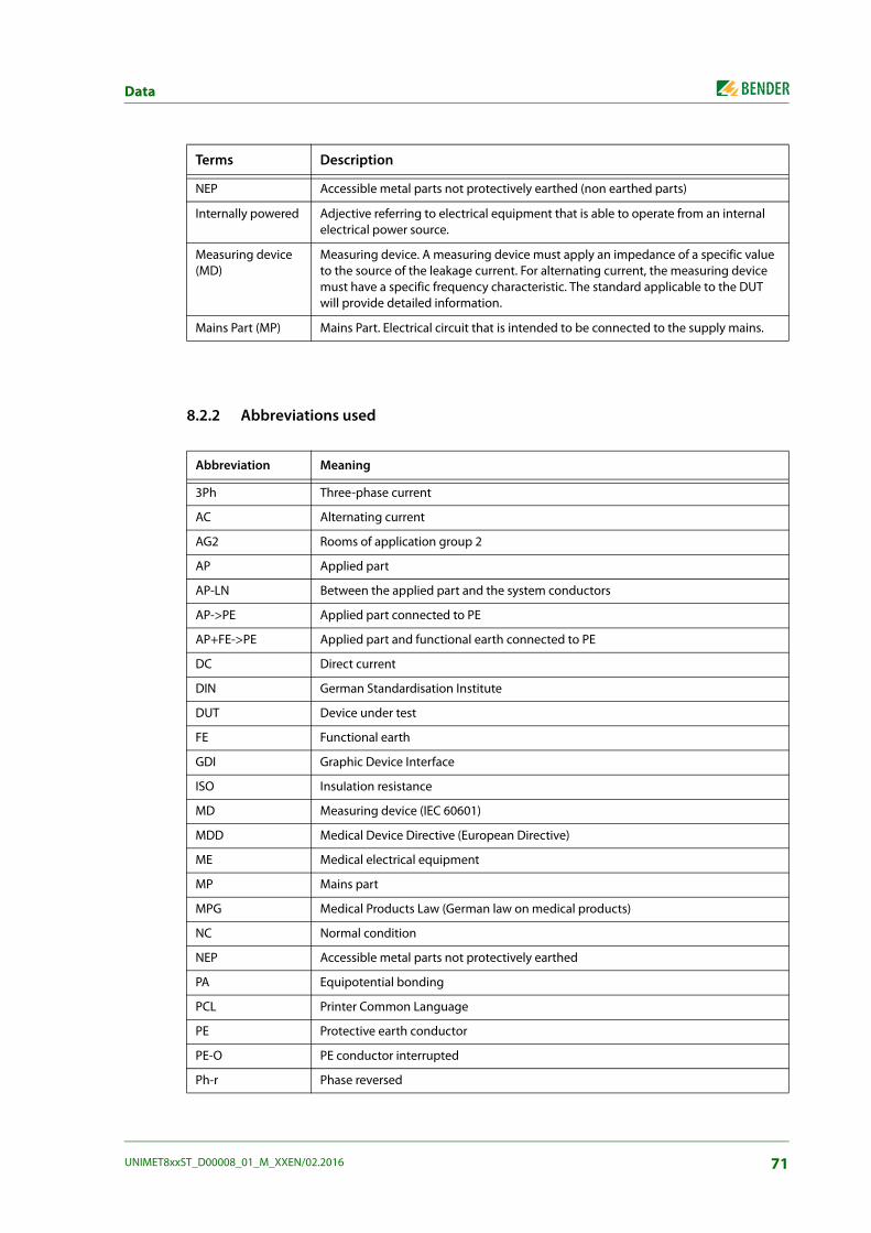
Data
8.2.2 Abbreviations used
NEP Accessible metal parts not protectively earthed (non earthed parts)
Internally powered Adjective referring to electrical equipment that is able to operate from an internal electrical power source.
Measuring device (MD)
Measuring device. A measuring device must apply an impedance of a specific value to the source of the leakage current. For alternating current, the measuring device must have a specific frequency characteristic. The standard applicable to the DUT will provide detailed information.
Mains Part (MP) Mains Part. Electrical circuit that is intended to be connected to the supply mains.
Abbreviation Meaning
3Ph Three-phase current
AC Alternating current
AG2 Rooms of application group 2
AP Applied part
AP-LN Between the applied part and the system conductors
AP->PE Applied part connected to PE
AP+FE->PE Applied part and functional earth connected to PE
DC Direct current
DIN German Standardisation Institute
DUT Device under test
FE Functional earth
GDI Graphic Device Interface
ISO InsuIation resistance
MD Measuring device (IEC 60601)
MDD Medical Device Directive (European Directive)
ME Medical electrical equipment
MP Mains part
MPG Medical Products Law (German law on medical products)
NC Normal condition
NEP Accessible metal parts not protectively earthed
PA Equipotential bonding
PCL Printer Common Language
PE Protective earth conductor
PE-O PE conductor interrupted
Ph-r Phase reversed
Terms Description
71UNIMET8xxST_D00008_01_M_XXEN/02.2016

Data
R-PE Protective earth conductor resistance
SC-O System conductor interrupted
SFC Single fault condition
CI Protection class I
CII Protection class II
TRMS True-root-mean-square value
U-AP Mains voltage on applied part
U-IO Mains voltage on signal input/output part
UL Underwriters Laboratories
VBG4 Accident prevention regulations for electrical plant and operating equipment (Ger-man)
VDE Association of German Electrical Engineers
Abbreviation Meaning
72 UNIMET8xxST_D00008_01_M_XXEN/02.2016

Data
8.3 Test stepsA classified test sequence with the UNIMET® comprises a number of individual test steps.
Test step Description
108 PE resistance, VK701
121 Insulation resistance cord VK701 L1->PE
122 Insulation resistance cord VK701 L2->PE
123 Insulation resistance cord VK701 L3->PE
124 Insulation resistance cord VK701 N->PE
125 Insulation resistance cord VK701 L1 L2 L3 N->PE
151 Continuity VK701 L1
152 Continuity VK701 L2
153 Continuity VK701 L3
154 Continuity VK701 N
155 Conductors not reversed VK701 L1->L2
156 Conductors not reversed VK701 L1->L3
157 Conductors not reversed VK701 L1->N
158 Conductors not reversed VK701 L2->L3
159 Conductors not reversed VK701 L2->N
160 Conductors not reversed VK701 L3->N
1 PE resistance, enclosure PE
2 PE resistance, cord
3 PE resistance, permanently attached cord
4 PE resistance, permanently installed equipment
101 PE resistance enclosure PE conductor (25A EPS800)
102 PE resistance cord (25A EPS800)
103 PE resistance, permanently attached cord (25 A EPS800)
104 PE resistance, permanently installed equipment (25A EPS800)
5 Insulation resistance enclosure
6 Insulation resistance PE conductor
53 Insulation resistance applied part PE conductor
54 Insulation resistance applied part enclosure
120 Insulation resistance cord L1+L2->PE
206 Insulation resistance AP-LN
73UNIMET8xxST_D00008_01_M_XXEN/02.2016

Data
44 Equipment leak. curr. Class I, alternative
46 Equipment leak. curr. Class II, alternative AP enclosure
109 Equipment leak. curr. Class I, alternative
110 Equipment leak. curr. Class II, alternative
43 Applied part leak. current Class I, alternative NEP
45 Applied part leak. current Class I, alternative
47 Applied part leak. current Class II, alternative
80 Load current
81 Operating voltage
82 Power consumption
7 Earth leak. curr. NC
8 Earth leak. curr. NC Ph-r
9 Earth leak. curr. NC AP->PE
10 Earth leak. curr. NC AP->PE Ph-r
11 Earth leak. curr. NC FE->PE
12 Earth leak. curr. NC FE->PE Ph-r
13 Earth leak. curr. NC AP+FE->PE
14 Earth leak. curr. NC AP+FE->PE Ph-r
15 Earth leak. curr. SFC SC-O
16 Earth leak. curr. SFC SC-O Ph-r
17 Earth leak. curr. SFC SC-O AP->PE
18 Earth leak. curr. SFC SC-O AP->PE Ph-r
19 Earth leak. curr. SFC SC-O FE->PE
20 Earth leak. curr. SFC SC-O FE->PE Ph-r
21 Earth leak. curr. SFC SC-O AP+FE->PE
22 Earth leak. curr. SFC SC-O AP+FE->PE Ph-r
210 Equipment leak. curr. Class I - direct
211 Equipment leak. curr. Class I - direct Ph-r
212 Equipment leak. curr. Class I - differential
213 Equipment leak. curr. Class I - differential Ph-r
214 Equipment leak. curr. Class II - direct
215 Equipment leak. curr. Class II - direct Ph-r
216 Equipment leak. curr. Class II - differential
Test step Description
74 UNIMET8xxST_D00008_01_M_XXEN/02.2016

Data
217 Equipment leak. curr. Class II - differential Ph-r
111 PE current - direct
112 PE current - Direct Ph-r
113 PE current - differential
114 PE current - differential Ph-r
76 PE current 3Ph - Differential
77 Touch current 3Ph - differential
78 Equipment leak. curr. Class I 3Ph - differential
79 Equipment leak. curr. Class II 3Ph - differential
92 Touch current NC AC
93 Touch current NC AC Ph-r
94 Touch current SFC AC PE-O
95 Touch current SFC AC PE-O Ph-r
96 Touch current NC DC
97 Touch current NC DC Ph-r
98 Touch current SFC DC PE-O
99 Touch current SFC DC PE-O Ph-r
115 Touch current - direct
116 Touch current - direct Ph-r
117 Touch current - differential
118 Touch current - differential Ph-r
132 Touch current NC AC
133 Touch current NC AC Ph-r
134 Touch current SFC AC PE-O
135 Touch current SFC AC PE-O Ph-r
136 Touch current NC DC
137 Touch current NC DC Ph-r
138 Touch current SFC DC PE-O
139 Touch current SFC DC PE-O Ph-r
310 Touch current NC
311 Touch current NC Ph-r
312 Touch current NC AP->PE
313 Touch current NC AP->PE Ph-r
Test step Description
75UNIMET8xxST_D00008_01_M_XXEN/02.2016

Data
314 Touch current NC FE->PE
315 Touch current NC FE->PE Ph-r
316 Touch current NC AP+FE->PE
317 Touch current NC AP+FE->PE Ph-r
334 Touch current NC U-IO
335 Touch current NC U-IO Ph-r
336 Touch current NC U-IO AP->PE
337 Touch current NC U-IO AP->PE Ph-r
338 Touch current NC U-IO FE->PE
339 Touch current NC U-IO FE->PE Ph-r
340 Touch current NC U-IO AP+FE->PE
341 Touch current NC U-IO AP+FE->PE Ph-r
358 Touch current NC Ph-r U-IO
359 Touch current NC Ph-r U-IO Ph-r
360 Touch current NC Ph-r U-IO AP->PE
361 Touch current NC Ph-r U-IO AP->PE Ph-r
362 Touch current NC Ph-r U-IO FE->PE
363 Touch current NC Ph-r U-IO FE->PE Ph-r
364 Touch current NC Ph-r U-IO AP+FE->PE
365 Touch current NC Ph-r U-IO AP+FE->PE Ph-r
382 Touch current int. power source NC
383 Touch current int. power source NC U-IO
318 Touch current SFC SC-O
319 Touch current SFC SC-O Ph-r
320 Touch current SFC SC-O AP->PE
321 Touch current SFC SC-O AP->PE Ph-r
322 Touch current SFC SC-O FE->PE
323 Touch current SFC SC-O FE->PE Ph-r
324 Touch current SFC SC-O AP+FE->PE
325 Touch current SFC SC-O AP+FE->PE Ph-r
326 Touch current SFC PE-O
327 Touch current SFC PE-O Ph-r
328 Touch current SFC PE-O AP->PE
Test step Description
76 UNIMET8xxST_D00008_01_M_XXEN/02.2016

Data
329 Touch current SFC PE-O AP->PE Ph-r
330 Touch current SFC PE-O FE->PE
331 Touch current SFC PE-O FE->PE Ph-r
332 Touch current SFC PE-O AP+FE->PE
333 Touch current SFC PE-O AP+FE->PE Ph-r
342 Touch current SFC U-IO SC-O
343 Touch current SFC U-IO SC-O Ph-r
344 Touch current SFC U-IO SC-O AP->PE
345 Touch current SFC U-IO SC-O AP->PE Ph-r
346 Touch current SFC U-IO SC-O FE->PE
347 Touch current SFC U-IO SC-O FE->PE Ph-r
348 Touch current SFC U-IO SC-O AP+FE->PE
349 Touch current SFC U-IO SC-O AP+FE->PE Ph-r
350 Touch current SFC U-IO PE-O
351 Touch current SFC U-IO PE-O Ph-r
352 Touch current SFC U-IO PE-O AP->PE
353 Touch current SFC U-IO PE-O AP->PE Ph-r
354 Touch current SFC U-IO PE-O FE->PE
355 Touch current SFC U-IO PE-O FE->PE Ph-r
356 Touch current SFC U-IO PE-O AP+FE->PE
357 Touch current SFC U-IO PE-O AP+FE->PE Ph-r
366 Touch current SFC Ph-r U-IO SC-O
367 Touch current SFC Ph-r U-IO SC-O Ph-r
368 Touch current SFC Ph-r U-IO SC-O AP->PE
369 Touch current SFC Ph-r U-IO SC-O AP->PE Ph-r
370 Touch current SFC Ph-r U-IO SC-O FE->PE
371 Touch current SFC Ph-r U-IO SC-O FE->PE Ph-r
372 Touch current SFC Ph-r U-IO SC-O AP+FE->PE
373 Touch current SFC Ph-r U-IO SC-O AP+FE->PE Ph-r
374 Touch current SFC Ph-r U-IO PE-O
375 Touch current SFC Ph-r U-IO PE-O Ph-r
376 Touch current SFC Ph-r U-IO PE-O AP->PE
377 Touch current SFC Ph-r U-IO PE-O AP->PE Ph-r
Test step Description
77UNIMET8xxST_D00008_01_M_XXEN/02.2016

Data
378 Touch current SFC Ph-r U-IO PE-O FE->PE
379 Touch current SFC Ph-r U-IO PE-O FE->PE Ph-r
380 Touch current SFC Ph-r U-IO PE-O AP+FE->PE
381 Touch current SFC Ph-r U-IO PE-O AP+FE->PE Ph-r
205 Applied part leak. curr. int. power source - direct
280 Applied part leak. curr. U-AP
281 Applied part leak. curr. U-AP Ph-r
286 Applied part leak. curr. DC
289 Applied part leak. curr. DC Ph-r
292 Applied part leak. curr. AC
295 Applied part leak. curr. AC Ph-r
300 Applied part leak. curr. Class I U-AP NEP
302 Applied part leak. curr.Class I U-AP NEP Ph-r
304 Applied part leak. curr. Class II U-AP
306 Applied part leak. curr. Class II U-AP Ph-r
400 Applied part leak. curr. NC DC
401 Applied part leak. curr. NC AC
402 Applied part leak. curr. NC DC Ph-r
403 Applied part leak. curr. NC AC Ph-r
404 Applied part leak. curr. NC DC FE->PE
405 Applied part leak. curr. NC AC FE->PE
406 Applied part leak. curr. NC DC FE->PE Ph-r
407 Applied part leak. curr. NC AC FE->PE Ph-r
424 Applied part leak. curr. NC DC NEP
425 Applied part leak. curr. NC AC NEP
426 Applied part leak. curr. NC DC NEP Ph-r
427 Applied part leak. curr. NC AC NEP Ph-r
428 Applied part leak. curr. NC DC NEP FE->PE
429 Applied part leak. curr. NC AC NEP FE->PE
430 Applied part leak. curr. NC DC NEP FE->PE Ph-r
431 Applied part leak. curr. NC AC NEP FE->PE Ph-r
448 Applied part leak. curr. NC DC U-IO
449 Applied part leak. curr. NC AC U-IO
Test step Description
78 UNIMET8xxST_D00008_01_M_XXEN/02.2016

Data
450 Applied part leak. curr. NC DC U-IO Ph-r
451 Applied part leak. curr. NC AC U-IO Ph-r
452 Applied part leak. curr. NC DC U-IO FE->PE
453 Applied part leak. curr. NC AC U-IO FE->PE
454 Applied part leak. curr. NC DC U-IO FE->PE Ph-r
455 Applied part leak. curr. NC AC U-IO FE->PE Ph-r
472 Applied part leak. curr. NC DC Ph-r U-IO
473 Applied part leak. curr. NC AC Ph-r U-IO
474 Applied part leak. curr. NC DC Ph-r U-IO Ph-r
475 Applied part leak. curr. NC AC Ph-r U-IO Ph-r
476 Applied part leak. curr. NC DC Ph-r U-IO FE->PE
477 Applied part leak. curr. NC AC Ph-r U-IO FE->PE
478 Applied part leak. curr. NC DC Ph-r U-IO FE->PE Ph-r
479 Applied part leak. curr. NC AC Ph-r U-IO FE->PE Ph-r
496 Applied part leak. curr. NC DC U-IO NEP
497 Applied part leak. curr. NC AC U-IO NEP
498 Applied part leak. curr. NC DC U-IO NEP Ph-r
499 Applied part leak. curr. NC AC U-IO NEP Ph-r
500 Applied part leak. curr. NC DC U-IO NEP FE->PE
501 Applied part leak. curr. NC AC U-IO NEP FE->PE
502 Applied part leak. curr. NC DC U-IO NEP FE->PE Ph-r
503 Applied part leak. curr. NC AC U-IO NEP FE->PE Ph-r
520 Applied part leak. curr. NC DC Ph-r U-IO NEP
521 Applied part leak. curr. NC AC Ph-r U-IO NEP
522 Applied part leak. curr. NC DC Ph-r U-IO NEP Ph-r
523 Applied part leak. curr. NC AC Ph-r U-IO NEP Ph-r
524 Applied part leak. curr. NC DC Ph-r U-IO NEP FE->PE
525 Applied part leak. curr. NC AC Ph-r U-IO NEP FE->PE
526 Applied part leak. curr. NC DC Ph-r U-IO NEP FE->PE Ph-r
527 Applied part leak. curr. NC AC Ph-r U-IO NEP FE->PE Ph-r
544 Applied part leak. curr. int. power source NC DC
545 Applied part leak. curr. int. power source NC AC
546 Applied part leak. curr. int. power source NC DC U-IO
Test step Description
79UNIMET8xxST_D00008_01_M_XXEN/02.2016

Data
547 Applied part leak. curr. int. power source NC AC U-IO
408 Applied part leak. curr. SFC DC SC-O
409 Applied part leak. curr. SFC AC SC-O
410 Applied part leak. curr. SFC DC SC-O Ph-r
411 Applied part leak. curr. SFC AC SC-O Ph-r
412 Applied part leak. curr. SFC DC SC-O FE->PE
413 Applied part leak. curr. SFC AC SC-O FE->PE
414 Applied part leak. curr. SFC DC SC-O FE->PE Ph-r
415 Applied part leak. curr. SFC AC SC-O FE->PE Ph-r
416 Applied part leak. curr. SFC DC PE-O
417 Applied part leak. curr. SFC AC PE-O
418 Applied part leak. curr. SFC DC PE-O Ph-r
419 Applied part leak. curr. SFC AC PE-O Ph-r
420 Applied part leak. curr. SFC DC PE-O FE->PE
421 Applied part leak. curr. SFC AC PE-O FE->PE
422 Applied part leak. curr. SFC DC PE-O FE->PE Ph-r
423 Applied part leak. curr. SFC AC PE-O FE->PE Ph-r
432 Applied part leak. curr. SFC DC NEP SC-O
433 Applied part leak. curr. SFC AC NEP SC-O
434 Applied part leak. curr. SFC DC NEP SC-O Ph-r
435 Applied part leak. curr. SFC AC NEP SC-O Ph-r
436 Applied part leak. curr. SFC DC NEP SC-O FE->PE
437 Applied part leak. curr. SFC AC NEP SC-O FE->PE
438 Applied part leak. curr. SFC DC NEP SC-O FE->PE Ph-r
439 Applied part leak. curr. SFC AC NEP SC-O FE->PE Ph-r
440 Applied part leak. curr. SFC DC NEP PE-O
441 Applied part leak. curr. SFC AC NEP PE-O
442 Applied part leak. curr. SFC DC NEP PE-O Ph-r
443 Applied part leak. curr. SFC AC NEP PE-O Ph-r
444 Applied part leak. curr. SFC DC NEP PE-O FE->PE
445 Applied part leak. curr. SFC AC NEP PE-O FE->PE
446 Applied part leak. curr. SFC DC NEP PE-O FE->PE Ph-r
447 Applied part leak. curr. SFC AC NEP PE-O FE->PE Ph-r
Test step Description
80 UNIMET8xxST_D00008_01_M_XXEN/02.2016

Data
456 Applied part leak. curr. SFC DC U-IO SC-O
457 Applied part leak. curr. SFC AC U-IO SC-O
458 Applied part leak. curr. SFC DC U-IO SC-O Ph-r
459 Applied part leak. curr. SFC AC U-IO SC-O Ph-r
460 Applied part leak. curr. SFC DC U-IO SC-O FE->PE
461 Applied part leak. curr. SFC AC U-IO SC-O FE->PE
462 Applied part leak. curr. SFC DC U-IO SC-O FE->PE Ph-r
463 Applied part leak. curr. SFC AC U-IO SC-O FE->PE Ph-r
464 Applied part leak. curr. SFC DC U-IO PE-O
465 Applied part leak. curr. SFC AC U-IO PE-O
466 Applied part leak. curr. SFC DC U-IO PE-O Ph-r
467 Applied part leak. curr. SFC AC U-IO PE-O Ph-r
468 Applied part leak. curr. SFC DC U-IO PE-O FE->PE
469 Applied part leak. curr. SFC AC U-IO PE-O FE->PE
470 Applied part leak. curr. SFC DC U-IO PE-O FE->PE Ph-r
471 Applied part leak. curr. SFC AC U-IO PE-O FE->PE Ph-r
480 Applied part leak. curr. SFC DC Ph-r U-IO SC-O
481 Applied part leak. curr. SFC AC Ph-r U-IO SC-O
482 Applied part leak. curr. SFC DC Ph-r U-IO SC-O Ph-r
483 Applied part leak. curr. SFC AC Ph-r U-IO SC-O Ph-r
484 Applied part leak. curr. SFC DC Ph-r U-IO SC-O FE->PE
485 Applied part leak. curr. SFC AC Ph-r U-IO SC-O FE->PE
486 Applied part leak. curr. SFC DC Ph-r U-IO SC-O FE->PE Ph-r
487 Applied part leak. curr. SFC AC Ph-r U-IO SC-O FE->PE Ph-r
488 Applied part leak. curr. SFC DC Ph-r U-IO PE-O
489 Applied part leak. curr. SFC AC Ph-r U-IO PE-O
490 Applied part leak. curr. SFC DC Ph-r U-IO PE-O Ph-r
491 Applied part leak. curr. SFC AC Ph-r U-IO PE-O Ph-r
492 Applied part leak. curr. SFC DC Ph-r U-IO PE-O FE->PE
493 Applied part leak. curr. SFC AC Ph-r U-IO PE-O FE->PE
494 Applied part leak. curr. SFC DC Ph-r U-IO PE-O FE->PE Ph-r
495 Applied part leak. curr. SFC AC Ph-r U-IO PE-O FE->PE Ph-r
504 Applied part leak. curr. SFC DC U-IO NEP SC-O
Test step Description
81UNIMET8xxST_D00008_01_M_XXEN/02.2016

Data
505 Applied part leak. curr. SFC AC U-IO NEP SC-O
506 Applied part leak. curr. SFC DC U-IO NEP SC-O Ph-r
507 Applied part leak. curr. SFC AC U-IO NEP SC-O Ph-r
508 Applied part leak. curr. SFC DC U-IO NEP SC-O FE->PE
509 Applied part leak. curr. SFC AC U-IO NEP SC-O FE->PE
510 Applied part leak. curr. SFC DC U-IO NEP SC-O FE->PE Ph-r
511 Applied part leak. curr. SFC AC U-IO NEP SC-O FE->PE Ph-r
512 Applied part leak. curr. SFC DC U-IO NEP PE-O
513 Applied part leak. curr. SFC AC U-IO NEP PE-O
514 Applied part leak. curr. SFC DC U-IO NEP PE-O Ph-r
515 Applied part leak. curr. SFC AC U-IO NEP PE-O Ph-r
516 Applied part leak. curr. SFC DC U-IO NEP PE-O FE->PE
517 Applied part leak. curr. SFC AC U-IO NEP PE-O FE->PE
518 Applied part leak. curr. SFC DC U-IO NEP PE-O FE->PE Ph-r
519 Applied part leak. curr. SFC AC U-IO NEP PE-O FE->PE Ph-r
528 Applied part leak. curr. SFC DC Ph-r U-IO NEP SC-O
529 Applied part leak. curr. SFC AC Ph-r U-IO NEP SC-O
530 Applied part leak. curr. SFC DC Ph-r U-IO NEP SC-O Ph-r
531 Applied part leak. curr. SFC AC Ph-r U-IO NEP SC-O Ph-r
532 Applied part leak. curr. SFC DC Ph-r U-IO NEP SC-O FE->PE
533 Applied part leak. curr. SFC AC Ph-r U-IO NEP SC-O FE->PE
534 Applied part leak. curr. SFC DC Ph-r U-IO NEP SC-O FE->PE Ph-r
535 Applied part leak. curr. SFC AC Ph-r U-IO NEP SC-O FE->PE Ph-r
536 Applied part leak. curr. SFC DC Ph-r U-IO NEP PE-O
537 Applied part leak. curr. SFC AC Ph-r U-IO NEP PE-O
538 Applied part leak. curr. SFC DC Ph-r U-IO NEP PE-O Ph-r
539 Applied part leak. curr. SFC AC Ph-r U-IO NEP PE-O Ph-r
540 Applied part leak. curr. SFC DC Ph-r U-IO NEP PE-O FE->PE
541 Applied part leak. curr. SFC AC Ph-r U-IO NEP PE-O FE->PE
542 Applied part leak. curr. SFC DC Ph-r U-IO NEP PE-O FE->PE Ph-r
543 Applied part leak. curr. SFC AC Ph-r U-IO NEP PE-O FE->PE Ph-r
550 Applied part leak. curr. SFC U-AP
551 Applied part leak. curr. SFC U-AP Ph-r
Test step Description
82 UNIMET8xxST_D00008_01_M_XXEN/02.2016

Data
552 Applied part leak. curr. SFC U-AP FE->PE
553 Applied part leak. curr. SFC U-AP FE->PE Ph-r
554 Applied part leak. curr. SFC Ph-r U-AP
555 Applied part leak. curr. SFC Ph-r U-AP Ph-r
556 Applied part leak. curr. SFC Ph-r U-AP FE->PE
557 Applied part leak. curr. SFC Ph-r U-AP FE->PE Ph-r
558 Applied part leak. curr. SFC U-AP NEP
559 Applied part leak. curr. SFC U-AP NEP Ph-r
560 Applied part leak. curr. SFC U-AP NEP FE->PE
561 Applied part leak. curr. SFC U-AP NEP FE->PE Ph-r
562 Applied part leak. curr. SFC Ph-r U-AP NEP
563 Applied part leak. curr. SFC Ph-r U-AP NEP Ph-r
564 Applied part leak. curr. SFC Ph-r U-AP NEP FE->PE
565 Applied part leak. curr. SFC Ph-r U-AP NEP FE->PE Ph-r
566 Applied part leak. curr. int. power source SFC U-AP
570 Applied part leak. curr. SFC U-NEP
571 Applied part leak. curr. SFC U-NEP Ph-r
572 Applied part leak. curr. SFC U-NEP FE->PE
573 Applied part leak. curr. SFC U-NEP FE->PE Ph-r
574 Applied part leak. curr. SFC Ph-r U-NEP
575 Applied part leak. curr. SFC Ph-r U-NEP Ph-r
576 Applied part leak. curr. SFC Ph-r U-NEP FE->PE
577 Applied part leak. curr. SFC Ph-r U-NEP FE->PE Ph-r
578 Applied part leak. curr. int. power source SFC U-NEP
600 Σ Applied part leak. curr. NC DC
601 Σ Applied part leak. curr. NC AC
602 Σ Applied part leak. curr. NC DC Ph-r
603 Σ Applied part leak. curr. NC AC Ph-r
604 Σ Applied part leak. curr. NC DC FE->PE
605 Σ Applied part leak. curr. NC AC FE->PE
606 Σ Applied part leak. curr. NC DC FE->PE Ph-r
607 Σ Applied part leak. curr. NC AC FE->PE Ph-r
624 Σ Applied part leak. curr. NC DC NEP
Test step Description
83UNIMET8xxST_D00008_01_M_XXEN/02.2016

Data
625 Σ Applied part leak. curr. NC AC NEP
626 Σ Applied part leak. curr. NC DC NEP Ph-r
627 Σ Applied part leak. curr. NC AC NEP Ph-r
628 Σ Applied part leak. curr. NC DC NEP FE->PE
629 Σ Applied part leak. curr. NC AC NEP FE->PE
630 Σ Applied part leak. curr. NC DC NEP FE->PE Ph-r
631 Σ Applied part leak. curr. NC AC NEP FE->PE Ph-r
648 Σ Applied part leak. curr. NC DC U-IO
649 Σ Applied part leak. curr. NC AC U-IO
650 Σ Applied part leak. curr. NC DC U-IO Ph-r
651 Σ Applied part leak. curr. NC AC U-IO Ph-r
652 Σ Applied part leak. curr. NC DC U-IO FE->PE
653 Σ Applied part leak. curr. NC AC U-IO FE->PE
654 Σ Applied part leak. curr. NC DC U-IO FE->PE Ph-r
655 Σ Applied part leak. curr. NC AC U-IO FE->PE Ph-r
672 Σ Applied part leak. curr. NC DC Ph-r U-IO
673 Σ Applied part leak. curr. NC AC Ph-r U-IO
674 Σ Applied part leak. curr. NC DC Ph-r U-IO Ph-r
675 Σ Applied part leak. curr. NC AC Ph-r U-IO Ph-r
676 Σ Applied part leak. curr. NC DC Ph-r U-IO FE->PE
677 Σ Applied part leak. curr. NC AC Ph-r U-IO FE->PE
678 Σ Applied part leak. curr. NC DC Ph-r U-IO FE->PE Ph-r
679 Σ Applied part leak. curr. NC AC Ph-r U-IO FE->PE Ph-r
696 Σ Applied part leak. curr. NC DC U-IO NEP
697 Σ Applied part leak. curr. NC AC U-IO NEP
698 Σ Applied part leak. curr. NC DC U-IO NEP Ph-r
699 Σ Applied part leak. curr. NC AC U-IO NEP Ph-r
700 Σ Applied part leak. curr. NC DC U-IO NEP FE->PE
701 Σ Applied part leak. curr. NC AC U-IO NEP FE->PE
702 Σ Applied part leak. curr. NC DC U-IO NEP FE->PE Ph-r
703 Σ Applied part leak. curr. NC AC U-IO NEP FE->PE Ph-r
720 Σ Applied part leak. curr. NC DC Ph-r U-IO NEP
721 Σ Applied part leak. curr. NC AC Ph-r U-IO NEP
Test step Description
84 UNIMET8xxST_D00008_01_M_XXEN/02.2016

Data
722 Σ Applied part leak. curr. NC DC Ph-r U-IO NEP Ph-r
723 Σ Applied part leak. curr. NC AC Ph-r U-IO NEP Ph-r
724 Σ Applied part leak. curr. NC DC Ph-r U-IO NEP FE->PE
725 Σ Applied part leak. curr. NC AC Ph-r U-IO NEP FE->PE
726 Σ Applied part leak. curr. NC DC Ph-r U-IO NEP FE->PE Ph-r
727 Σ Applied part leak. curr. NC AC Ph-r U-IO NEP FE->PE Ph-r
744 Σ Applied part leak. curr. int. power source NC DC
745 Σ Applied part leak. curr. int. power source NC AC
746 Σ Applied part leak. curr. int. power source NC DC U-IO
747 Σ Applied part leak. curr. int. power source NC AC U-IO
608 Σ Applied part leak. curr. SFC DC SC-O
609 Σ Applied part leak. curr. SFC AC SC-O
610 Σ Applied part leak. curr. SFC DC SC-O Ph-r
611 Σ Applied part leak. curr. SFC AC SC-O Ph-r
612 Σ Applied part leak. curr. SFC DC SC-O FE->PE
613 Σ Applied part leak. curr. SFC AC SC-O FE->PE
614 Σ Applied part leak. curr. SFC DC SC-O FE->PE Ph-r
615 Σ Applied part leak. curr. SFC AC SC-O FE->PE Ph-r
616 Σ Applied part leak. curr. SFC DC PE-O
617 Σ Applied part leak. curr. SFC AC PE-O
618 Σ Applied part leak. curr. SFC DC PE-O Ph-r
619 Σ Applied part leak. curr. SFC AC PE-O Ph-r
620 Σ Applied part leak. curr. SFC DC PE-O FE->PE
621 Σ Applied part leak. curr. SFC AC PE-O FE->PE
622 Σ Applied part leak. curr. SFC DC PE-O FE->PE Ph-r
623 Σ Applied part leak. curr. SFC AC PE-O FE->PE Ph-r
632 Σ Applied part leak. curr. SFC DC NEP SC-O
633 Σ Applied part leak. curr. SFC AC NEP SC-O
634 Σ Applied part leak. curr. SFC DC NEP SC-O Ph-r
635 Σ Applied part leak. curr. SFC AC NEP SC-O Ph-r
636 Σ Applied part leak. curr. SFC DC NEP SC-O FE->PE
637 Σ Applied part leak. curr. SFC AC NEP SC-O FE->PE
638 Σ Applied part leak. curr. SFC DC NEP SC-O FE->PE Ph-r
Test step Description
85UNIMET8xxST_D00008_01_M_XXEN/02.2016

Data
639 Σ Applied part leak. curr. SFC AC NEP SC-O FE->PE Ph-r
640 Σ Applied part leak. curr. SFC DC NEP PE-O
641 Σ Applied part leak. curr. SFC AC NEP PE-O
642 Σ Applied part leak. curr. SFC DC NEP PE-O Ph-r
643 Σ Applied part leak. curr. SFC AC NEP PE-O Ph-r
644 Σ Applied part leak. curr. SFC DC NEP PE-O FE->PE
645 Σ Applied part leak. curr. SFC AC NEP PE-O FE->PE
646 Σ Applied part leak. curr. SFC DC NEP PE-O FE->PE Ph-r
647 Σ Applied part leak. curr. SFC AC NEP PE-O FE->PE Ph-r
656 Σ Applied part leak. curr. SFC DC U-IO SC-O
657 Σ Applied part leak. curr. SFC AC U-IO SC-O
658 Σ Applied part leak. curr. SFC DC U-IO SC-O Ph-r
659 Σ Applied part leak. curr. SFC AC U-IO SC-O Ph-r
660 Σ Applied part leak. curr. SFC DC U-IO SC-O FE->PE
661 Σ Applied part leak. curr. SFC AC U-IO SC-O FE->PE
662 Σ Applied part leak. curr. SFC DC U-IO SC-O FE->PE Ph-r
663 Σ Applied part leak. curr. SFC AC U-IO SC-O FE->PE Ph-r
664 Σ Applied part leak. curr. SFC DC U-IO PE-O
665 Σ Applied part leak. curr. SFC AC U-IO PE-O
666 Σ Applied part leak. curr. SFC DC U-IO PE-O Ph-r
667 Σ Applied part leak. curr. SFC AC U-IO PE-O Ph-r
668 Σ Applied part leak. curr. SFC DC U-IO PE-O FE->PE
669 Σ Applied part leak. curr. SFC AC U-IO PE-O FE->PE
670 Σ Applied part leak. curr. SFC DC U-IO PE-O FE->PE Ph-r
671 Σ Applied part leak. curr. SFC AC U-IO PE-O FE->PE Ph-r
680 Σ Applied part leak. curr. SFC DC Ph-r U-IO SC-O
681 Σ Applied part leak. curr. SFC AC Ph-r U-IO SC-O
682 Σ Applied part leak. curr. SFC DC Ph-r U-IO SC-O Ph-r
683 Σ Applied part leak. curr. SFC AC Ph-r U-IO SC-O Ph-r
684 Σ Applied part leak. curr. SFC DC Ph-r U-IO SC-O FE->PE
685 Σ Applied part leak. curr. SFC AC Ph-r U-IO SC-O FE->PE
686 Σ Applied part leak. curr. SFC DC Ph-r U-IO SC-O FE->PE Ph-r
687 Σ Applied part leak. curr. SFC AC Ph-r U-IO SC-O FE->PE Ph-r
Test step Description
86 UNIMET8xxST_D00008_01_M_XXEN/02.2016

Data
688 Σ Applied part leak. curr. SFC DC Ph-r U-IO PE-O
689 Σ Applied part leak. curr. SFC AC Ph-r U-IO PE-O
690 Σ Applied part leak. curr. SFC DC Ph-r U-IO PE-O Ph-r
691 Σ Applied part leak. curr. SFC AC Ph-r U-IO PE-O Ph-r
692 Σ Applied part leak. curr. SFC DC Ph-r U-IO PE-O FE->PE
693 Σ Applied part leak. curr. SFC AC Ph-r U-IO PE-O FE->PE
694 Σ Applied part leak. curr. SFC DC Ph-r U-IO PE-O FE->PE Ph-r
695 Σ Applied part leak. curr. SFC AC Ph-r U-IO PE-O FE->PE Ph-r
704 Σ Applied part leak. curr. SFC DC U-IO NEP SC-O
705 Σ Applied part leak. curr. SFC AC U-IO NEP SC-O
706 Σ Applied part leak. curr. SFC DC U-IO NEP SC-O Ph-r
707 Σ Applied part leak. curr. SFC AC U-IO NEP SC-O Ph-r
708 Σ Applied part leak. curr. SFC DC U-IO NEP SC-O FE->PE
709 Σ Applied part leak. curr. SFC AC U-IO NEP SC-O FE->PE
710 Σ Applied part leak. curr. SFC DC U-IO NEP SC-O FE->PE Ph-r
711 Σ Applied part leak. curr. SFC AC U-IO NEP SC-O FE->PE Ph-r
712 Σ Applied part leak. curr. SFC DC U-IO NEP PE-O
713 Σ Applied part leak. curr. SFC AC U-IO NEP PE-O
714 Σ Applied part leak. curr. SFC DC U-IO NEP PE-O Ph-r
715 Σ Applied part leak. curr. SFC AC U-IO NEP PE-O Ph-r
716 Σ Applied part leak. curr. SFC DC U-IO NEP PE-O FE->PE
717 Σ Applied part leak. curr. SFC AC U-IO NEP PE-O FE->PE
718 Σ Applied part leak. curr. SFC DC U-IO NEP PE-O FE->PE Ph-r
719 Σ Applied part leak. curr. SFC AC U-IO NEP PE-O FE->PE Ph-r
728 Σ Applied part leak. curr. SFC DC Ph-r U-IO NEP SC-O
729 Σ Applied part leak. curr. SFC AC Ph-r U-IO NEP SC-O
730 Σ Applied part leak. curr. SFC DC Ph-r U-IO NEP SC-O Ph-r
731 Σ Applied part leak. curr. SFC AC Ph-r U-IO NEP SC-O Ph-r
732 Σ Applied part leak. curr. SFC DC Ph-r U-IO NEP SC-O FE->PE
733 Σ Applied part leak. curr. SFC AC Ph-r U-IO NEP SC-O FE->PE
734 Σ Applied part leak. curr. SFC DC Ph-r U-IO NEP SC-O FE->PE Ph-r
735 Σ Applied part leak. curr. SFC AC Ph-r U-IO NEP SC-O FE->PE Ph-r
736 Σ Applied part leak. curr. SFC DC Ph-r U-IO NEP PE-O
Test step Description
87UNIMET8xxST_D00008_01_M_XXEN/02.2016

Data
737 Σ Applied part leak. curr. SFC AC Ph-r U-IO NEP PE-O
738 Σ Applied part leak. curr. SFC DC Ph-r U-IO NEP PE-O Ph-r
739 Σ Applied part leak. curr. SFC AC Ph-r U-IO NEP PE-O Ph-r
740 Σ Applied part leak. curr. SFC DC Ph-r U-IO NEP PE-O FE->PE
741 Σ Applied part leak. curr. SFC AC Ph-r U-IO NEP PE-O FE->PE
742 Σ Applied part leak. curr. SFC DC Ph-r U-IO NEP PE-O FE->PE Ph-r
743 Σ Applied part leak. curr. SFC AC Ph-r U-IO NEP PE-O FE->PE Ph-r
750 Σ Applied part leak. curr. SFC U-AP
751 Σ Applied part leak. curr. SFC U-AP Ph-r
752 Σ Applied part leak. curr. SFC U-AP FE->PE
753 Σ Applied part leak. curr. SFC U-AP FE->PE Ph-r
754 Σ Applied part leak. curr. SFC Ph-r U-AP
755 Σ Applied part leak. curr. SFC Ph-r U-AP Ph-r
756 Σ Applied part leak. curr. SFC Ph-r U-AP FE->PE
757 Σ Applied part leak. curr. SFC Ph-r U-AP FE->PE Ph-r
758 Σ Applied part leak. curr. SFC U-AP NEP
759 Σ Applied part leak. curr. SFC U-AP NEP Ph-r
760 Σ Applied part leak. curr. SFC U-AP NEP FE->PE
761 Σ Applied part leak. curr. SFC U-AP NEP FE->PE Ph-r
762 Σ Applied part leak. curr. SFC Ph-r U-AP NEP
763 Σ Applied part leak. curr. SFC Ph-r U-AP NEP Ph-r
764 Σ Applied part leak. curr. SFC Ph-r U-AP NEP FE->PE
765 Σ Applied part leak. curr. SFC Ph-r U-AP NEP FE->PE Ph-r
766 Σ Applied part leak. curr. int. power source SFC U-AP
770 Σ Applied part leak. curr. SFC U-NEP
771 Σ Applied part leak. curr. SFC U-NEP Ph-r
772 Σ Applied part leak. curr. SFC U-NEP FE->PE
773 Σ Applied part leak. curr. SFC U-NEP FE->PE Ph-r
774 Σ Applied part leak. curr. SFC Ph-r U-NEP
775 Σ Applied part leak. curr. SFC Ph-r U-NEP Ph-r
776 Σ Applied part leak. curr. SFC Ph-r U-NEP FE->PE
777 Σ Applied part leak. curr. SFC Ph-r U-NEP FE->PE Ph-r
778 Σ Applied part leak. curr. int. power source SFC U-NEP
Test step Description
88 UNIMET8xxST_D00008_01_M_XXEN/02.2016

Data
250 Patient auxiliary current NC DC
251 Patient auxiliary current NC AC
252 Patient auxiliary current NC DC Ph-r
253 Patient auxiliary current NC AC Ph-r
254 Patient auxiliary current NC DC FE->PE
255 Patient auxiliary current NC AC FE->PE
256 Patient auxiliary current NC DC FE->PE Ph-r
257 Patient auxiliary current NC AC FE->PE Ph-r
274 Patient auxiliary current int. power source NC DC
275 Patient auxiliary current int. power source NC AC
258 Patient auxiliary current SFC DC SC-O
259 Patient auxiliary current SFC AC SC-O
260 Patient auxiliary current SFC DC SC-O Ph-r
261 Patient auxiliary current SFC AC SC-O Ph-r
262 Patient auxiliary current SFC DC SC-O FE->PE
263 Patient auxiliary current SFC AC SC-O FE->PE
264 Patient auxiliary current SFC DC SC-O FE->PE Ph-r
265 Patient auxiliary current SFC AC SC-O FE->PE Ph-r
266 Patient auxiliary current SFC DC PE-O
267 Patient auxiliary current SFC AC PE-O
268 Patient auxiliary current SFC DC PE-O Ph-r
269 Patient auxiliary current SFC AC PE-O Ph-r
270 Patient auxiliary current SFC DC PE-O FE->PE
271 Patient auxiliary current SFC AC PE-O FE->PE
272 Patient auxiliary current SFC DC PE-O FE->PE Ph-r
273 Patient auxiliary current SFC AC PE-O FE->PE Ph-r
Test step Description
89UNIMET8xxST_D00008_01_M_XXEN/02.2016

Data
8.4 Technical dataNominal voltage range ................................................................. AC 100…120 V/± 10 %, AC 220…240 V/± 10 %Frequency range ............................................................................................................................................... 48…62 HzPower consumption.........................................................................................................................................max. 100 VAMaximum output current ............................................................................................................ see ordering informationProtection class ...................................................................................................................................................................II
Testing of PE resistanceMeasuring range ................................................................................................................................... 0.001… 29.999 ΩMeasuring current.............................................................................................................................................max. AC 8 AMeasuring voltage ...........................................................................................................................................max. AC 8 VIntrinsic uncertainty ......................................................................................0.001…1.000 Ω: ± 2.5 % v. M. ± 5 digits.........................................................................................................................1.001…29.999 Ω: ± 5 % v. M. ± 5 digitsOperating uncertainty ....................................................................................0.001…1.000 Ω: ± 5 % v. M. ± 10 digits................................................................................................................... 1.001…29.999 Ω: ± 7.5 % v. M. ± 10 digits
InsuIation resistanceMeasuring range ................................................................................................................................... 0.01…199.99 MΩMeasuring voltage ........................................................................................................................................max. DC 550 VMeasuring current............................................................................................................................................max. 2.5 mAIntrinsic uncertainty ........................................................................................0.01…99.99 MΩ: ± 5 % v. M. ± 2 digits................................................................................................................. 100.00…199.99 MΩ: ± 10 % v. M. ± 2 digitsOperating uncertainty ................................................................................. 0.01…99.99 MΩ: ± 7.5 % v. M. ± 4 digits................................................................................................................. 100.00…199.99 MΩ: ± 10 % v. M. ± 4 digits
Equipment leakage current - alternative methodMeasuring range .................................................................................................................................0.001…19.999 mAMeasuring voltage ........................................................................................................................................max. AC 250 VMeasuring current...............................................................................................................................................max. 3 mAIntrinsic uncertainty ....................................................................................................................... ± 5 % v. M. ± 5 digitsOperating uncertainty ................................................................................................................± 7.5 % v. M. ± 10 digits
Leakage current, differential measuring methodMeasuring range ..................................................................................................................................... 0.02…19.99 mAIntrinsic uncertainty ........................................................................................................................± 5 % v. M. ± 2 digitsOperating uncertainty ..................................................................................................................± 7.5 % v. M. ± 4 digitsFrequency response ..........................................................................................................................40…100 kHz ± 3 dB
Leakage current, direct measurementMeasuring range .................................................................................................................................0.001…19.999 mAIntrinsic uncertainty ........................................................................................................................± 5 % v. M. ± 2 digitsOperating uncertainty ..................................................................................................................± 7.5 % v. M. ± 4 digitsFrequency response .......................................................................................................................... up to 100 kHz ± 3 dB
Voltage measurementMeasuring range ......................................................................................................................................... AC 90…264 V Frequency range ............................................................................................................................................... 48…62 HzIntrinsic uncertainty .....................................................................................................................± 2.5 % v. M. ± 3 digits
Load current measurementMeasuring range ............................................................................................................................................0.005…16 AFrequency range ............................................................................................................................................... 48…62 HzIntrinsic uncertainty .....................................................................................................................± 2.5 % v. M. ± 3 digits
90 UNIMET8xxST_D00008_01_M_XXEN/02.2016

Data
Apparent powerMeasuring range ............................................................................................................................................ 5…3600 VAFrequency range ...............................................................................................................................................48…62 HzIntrinsic uncertainty.........................................................................................................................± 5 % v. M. ± 3 digits
General dataEMC ................................................................................................................................................................... IEC 61326-1Ambient temperature ...................................................................................................................................... 0…+40 °CStorage temperature ................................................................................................................................... -10 …+70 °CRelative humidity (up to 31 °C) .......................................................................................................................... max. 80%Relative humidity (>31…40 °C) .....................................................................................decreasing linearly, max. 50%........................................................................................................................................... Condensation must be avoided
Height above sea level ....................................................................................................................................max. 2000 mDegree of protection, enclosure: IP40, connections: IP20................................................................................................................................acc. to DIN VDE 0470 Part 1/EN 60529
Dimensions (without bag) ...................................................................................approx. 300x277x126 mm (W x D x H)Weight (without accessories or bag) ...........................................................................................................approx. 3.5 kgCalibration interval ..............................................................................................................................................36 months
of MV = of measured value
91UNIMET8xxST_D00008_01_M_XXEN/02.2016

Data
8.5 Ordering information
Type Description Art. no.
UNIMET® 810ST (DE/DE)
Test system for medical electrical equipment and general electrical equipment; Nominal voltage ranges AC 100…120 V and AC 220…240 V, maximum output current 16 A, PE test current approx. 8 A,Plug/socket: Schuko (German)
B 9602 8020
UNIMET® 810ST (GB/GB)
Test system for medical electrical equipment and general electrical equipment; Nominal voltage ranges AC 100…120 V and AC 220…240 V, maximum output current 13 A, PE test current approx. 8 A,Plug/socket: GB/GB
B 9602 8024
UNIMET® 810ST (CH/CH)
Test system for medical electrical equipment and general electrical equipment; Nominal voltage ranges AC 100…120 V and AC 220…240 V, maximum output current 10 A, PE test current approx. 8 A,Plug/socket: CH/CH
B 9602 8026
UNIMET® 810ST (B/B)
Test system for medical electrical equipment and general electrical equipment; Nominal voltage ranges AC 100…120 V and AC 220…240 V, maximum output current 13 A, PE test current approx. 8 A,Plug/socket: B/B
B 9602 8027
UNIMET® 810ST (US/US)
Test system for medical electrical equipment and general electrical equipment; Nominal voltage ranges AC 100…120 V and AC 220…240 V, maximum output current 13 A, PE test current approx. 8 A,Plug/socket: US/US
B 9602 8028
UNIMET® 800ST Software licence
Software licence IEC 60601-1 for UNIMET® 810ST and for UNIMET® 800ST from art. no. B 9602 8010 (see chapter "3.2 ").
B 9602 8200
UNIMET® 810ST Software licence
Software licence IEC 61010-1 for UNIMET® 810ST and for UNIMET® 800ST from art. no. B 9602 8010 (see chapter "3.2 "). For use of this licence, the test probe TP1010 is required.
B 9602 8201
EPS800 (D) External power source 25 A for protective earth resistance measurements in accordance with IEC 60601-1 (only in conjunction with UNIMET® 800ST, art. no. B 9602 8010 and UNIMET® 810ST), Plug: D
B 9602 8050
92 UNIMET8xxST_D00008_01_M_XXEN/02.2016

Data
EPS800 (GB) External power source 25 A for protective earth resistance measurements in accordance with IEC 60601-1 (only in conjunction with UNIMET® 800ST, art. no. B 9602 8014 and UNIMET® 810ST), Plug: GB
B 9602 8054
EPS800 (CH) External power source 25 A for protective earth resistance measurements in accordance with IEC 60601-1 (only in conjunction with UNIMET® 800ST, art no. B 9602 8016 and UNIMET® 810ST), Plug: CH
B 9602 8056
EPS800 (B) External power source 25 A for protective earth resistance measurements in accordance with IEC 60601-1 (only in conjunction with UNIMET® 800ST, art. no. B 9602 8017 and UNIMET® 810ST), Plug: B
B 9602 8057
EPS800 (US) External power source 25 A for protective earth resistance measurements in accordance with IEC 60601-1 (only in conjunction with UNIMET® 800ST, art. no. B 9602 8018 and UNIMET® 810ST), Plug: US
B 9602 8058
VK701-1 Adapter Schuko/non-heating devices B 9602 0048
VK701-2 Adapter CEE 5-pole 16 A B 9602 0049
VK701-3 Adapter screw-type connection/plug-in con-nector
B 9602 0050
VK701-4 Adapter 5-pole CEE 32 A B 9602 0051
VK701-5 Adapter 5-pole CEE 63 A B 9602 0052
VK701-6 Adapter Schuko (German) B 9602 0067
VK701-7 Adapter for non-heating appliances B 9602 0066
VK701-8 Adapter kit 16 A for DS32A B 9602 0066
RS-232/RS-232 interface cable
Cable for connecting the test system with a PC, 9-pole, female-female (null modem cable)
B 9601 2012
USB2.0-RS232 con-verter
Converter cable USB/RS-232 for UNIMET® B 9602 0086
TP800 Test probe active (with switch) B 9602 0080
Test probe Measuring lead, 3 m, with black test probe B 928 748
Cable 150 cm Measuring lead, 150 cm, 4 mm connector B 928 703
Test terminal Test terminal black B 928 741
Stylus pen Touchscreen pen B 928 749
Barcode scanner PS/2
for UNIMET® 800ST and UNIMET® 810ST (PS/2 connection)
B 9602 0082
Barcode scanner USB
for UNIMET® 800ST and UNIMET® 810ST(USB connection)
B 9602 0092
Scanner bag UNIMET®
for barcode scanner B 9602 0102
Flex keyboard for UNIMET® 800ST and UNIMET® 810ST (USB connection)
B 9602 0093
93UNIMET8xxST_D00008_01_M_XXEN/02.2016

Data
Other models and software are available on request.
PK3 Test kit, various adapters for connecting med-ical electrical equipment to test systems
B 9602 0004
TP16 Cable drum with 16 m measuring lead B 9602 0054
TB3 Test box for testing test systems B 9602 0025
PAT Box For measuring of up to 10 patient connec-tions with UNIMET® 1100/800/400ST accord-ing to IEC 62353
B 9602 0096
DS32A Three-phase adapter for testing medical elec-trical three-phase devices during operation (acc. to DIN EN 62353, DIN VDE 0751-1, DIN VDE 0701-0702)
B 9602 0098
TP1010 For measurement of equipment for labora-tory use with UNIMET® 800ST and UNIMET® 1100ST or 1000ST acc. to IEC 1010-1; EN 61010-1
B 9602 0060
94 UNIMET8xxST_D00008_01_M_XXEN/02.2016

INDEX
AAccessories 15Activating the functional test 60Active test probe 16, 43, 50, 93Adapter for non-heating appliances 15Adding test steps 61Application groups 60Applied part 41, 60
- Group 41, 60Area of application 9Areas of application 11
BBackground 34Backup copy 37Barcode scanner 23Battery
- Changing 67
CCalibration 38Calibration certificate 15Calibration interval 67Carrying bag 15Circuit-breaker 16
- thermo-magnetic 53Classification 39, 40Client 12, 56, 63Collective printout (print all) 29Compressing the database 37Connecting the DUT 50Context menu 28, 29Cool-down period 53cool-down period 42Country setting 35CSV-Export 63Current consumption 49, 53, 54
DDamage in transit 9Date 31, 35, 39, 40Date of next test 63Deleting test steps 61Details 25Device functions 67Device protocol
- Delete 63- edit 63- empty folder 62- exporting 63- Import 57- Print 63- Print overview 63- Start device test 62, 63
Device settings 34Display light 34Double-click 35
EEditing test steps 61Entry
- List 26EPS800 43Equipment type 42Excel file 63exporting 59, 63Extras 42
FFunctional test 45, 54
GGeneral 40Great Britain 49Group
- Patient sockets 41, 60
HHardware keyboard 35
IIcons 25Import 31Initial test 49InsuIation resistance 42Interface 12Interface cable 15Interfaces 16IT system 11
KKeyboard 23
- American 35
LLanguages 25Leakage currents 11
- dangerous 48Limit values 40List 25
MManufacturer's instructions 42Measuring lead 15Method of measurement 41
NNames 40, 58Nominal system voltage 36Null modem 15
OOrdering information 92Overheating 49
PPatient connections 41PC software 58, 62PDF file 12, 55
- Print setup 22PE conductor test 52, 64Permanently installed equipment 16Personnel 9Phase position 42Principle of operation 22Printer 22, 34Printer type 22Pushbutton 16
QQuery filter 12, 24, 30, 58, 62
95UNIMET8xxST_D00008_01_M_XXEN/02.2016

INDEX
RRecurrent test 39, 40, 62Reference value 55, 63Remote control 37
SSaving settings 34Saving test specifications 61Saving Windows settings 34Screen configurations 25Scroll bar 22, 32, 34, 36, 56Serial number 67Single test 39, 64Software information 25Software keyboard 35Standards 13, 69Stylus 22, 35Supply voltage 9, 21Switzerland 49Systems
- earthed 11
TTerms 70Test box TB3 38Test concept 39Test data
- Export 60- Import 57, 60
Test date 12Test engineer names 32Test interval 40
- test interval 55Test probe
- active 16- Zero balance 36
Test probe, single-pole 15Test sequence
- Automatic 43- Manual 43
Test specification 57- delete 59- edit 59- empty folder 58- exporting 59- Print 59- Print overview 59- Start device test 59- Start test 58- Test step editor 59
Test specifications 58Test step editor 60Test steps 60Test terminal 15Text box 26The "Device protocols" folder 62
The "Test specifications" folder 58Three-phase
- DUT 54Time 24Touchscreen 22, 35TP800 16, 50
UUpdates 37USA 49USB interface 37USB interfaces 22USB stick 12, 37, 57Use
- intended 9User interface 25
VVelcro fasteners 21Visual inspection 44, 51
- User-defined 44Volume 35
WWarm-up period 42, 53Warning 42Window 34Wiring diagram 50
ZZero balance test probe/measuring lead
36
96 UNIMET8xxST_D00008_01_M_XXEN/02.2016


Bender GmbH & Co. KGP.O. Box 1161 • 35301 Gruenberg • GermanyLondorfer Straße 65 • 35305 Gruenberg • GermanyTel.: +49 6401 807-0 • Fax: +49 6401 807-259E-mail: [email protected] • www.bender.de
Fotos: Bender Archiv und bendersystembau Archiv. BENDER Group