Embed Size (px)
Citation preview
0
Beam Loading
H. Damerau
CERN
13 June 2019
Advanced Accelerator Physics
1
• Introduction
• RF cavity parameters• Shunt impedance, beam loading, power coupling
• Fundamental theorem of beam loading
• Passage of a bunches through a cavity• Single passage or bunches with large spacing
• Multiple bunch passages
• Steady state beam loading and partial filling• Few bunches with large spacing
• Summary
Outline

2
Introduction
3
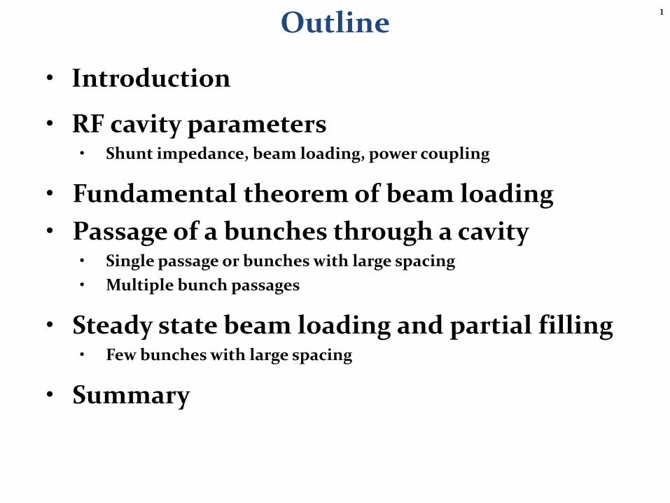
What do these devices in common?
They all suffer from or make use of beam loading
SLS
Electron storage ring
Klystron amplifier Microwave oven
Hadron collider
4
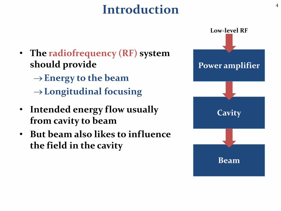
Introduction
• The radiofrequency (RF) system should provide
Energy to the beam
Longitudinal focusing
• Intended energy flow usually from cavity to beam
• But beam also likes to influence the field in the cavity
Cavity
Beam
Low-level RF
Power amplifier
5
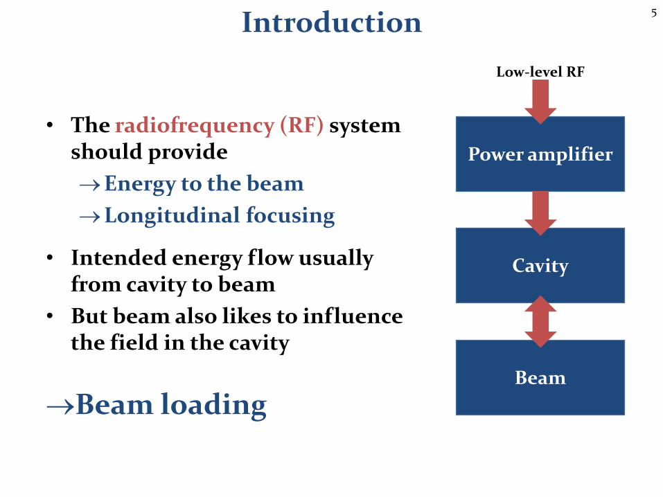
Introduction
Beam loading
• The radiofrequency (RF) system should provide
Energy to the beam
Longitudinal focusing
• Intended energy flow usuallyfrom cavity to beam
• But beam also likes to influence the field in the cavity
Power amplifier
Cavity
Beam
Low-level RF
6
RF cavity
7
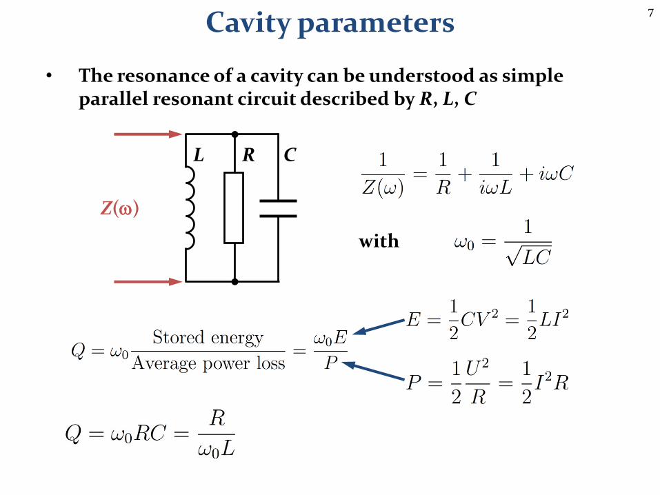
Cavity parameters
• The resonance of a cavity can be understood as simple parallel resonant circuit described by R, L, C
R CL
Z(w)
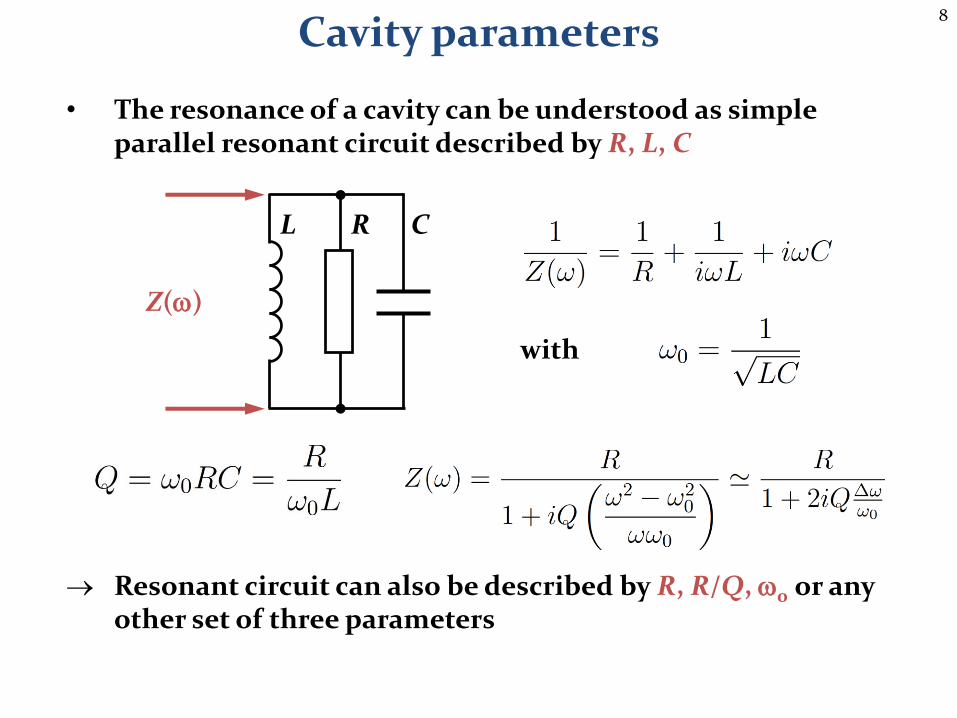
with
8
Cavity parameters
• The resonance of a cavity can be understood as simple parallel resonant circuit described by R, L, C
Resonant circuit can also be described by R, R/Q, w0 or any other set of three parameters
R CL
Z(w)
with

9
Cavity parameters
• The resonance of a cavity can be understood as simple parallel resonant circuit described by R, L, C
Resonant circuit can also be described by R, R/Q, w0 or any other set of three parameters
R CL
Z(w)
Dw-3dB
10
Cavity parameters
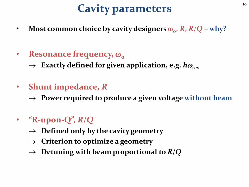
• Most common choice by cavity designers w0, R, R/Q – why?
• Resonance frequency, w0
Exactly defined for given application, e.g. hwrev
• Shunt impedance, R
Power required to produce a given voltage without beam
• “R-upon-Q”, R/Q
Defined only by the cavity geometry
Criterion to optimize a geometry
Detuning with beam proportional to R/Q
11
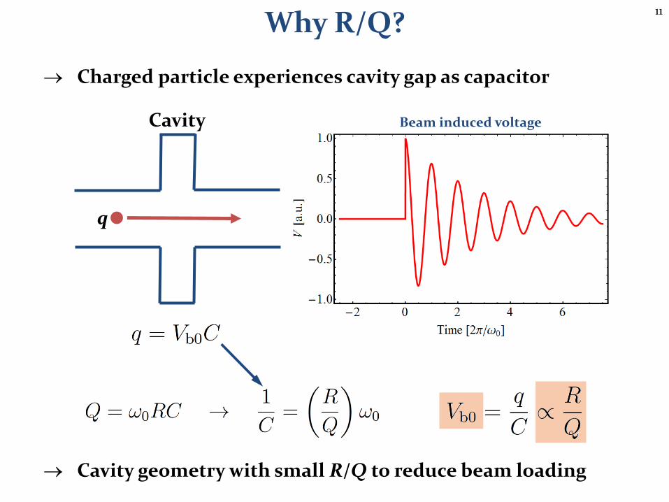
Why R/Q?
Charged particle experiences cavity gap as capacitor
Cavity geometry with small R/Q to reduce beam loading
q
Cavity Beam induced voltage
12
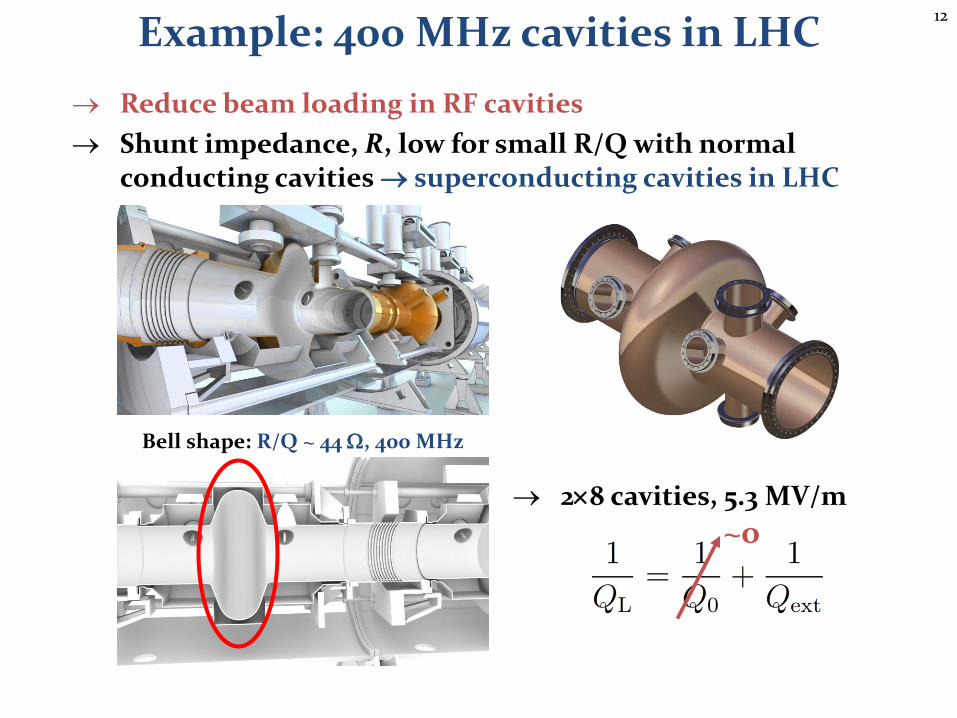
Example: 400 MHz cavities in LHC
Reduce beam loading in RF cavities
Shunt impedance, R, low for small R/Q with normal conducting cavities superconducting cavities in LHC
Bell shape: R/Q ~ 44 W, 400 MHz
28 cavities, 5.3 MV/m
~o
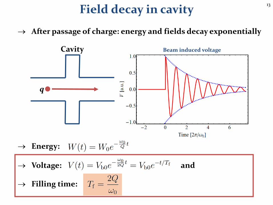
13
After passage of charge: energy and fields decay exponentially
Energy:
Voltage: and
Filling time:
Field decay in cavity
q
Cavity Beam induced voltage
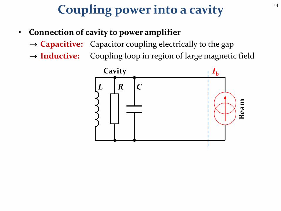
14
• Connection of cavity to power amplifier
Capacitive: Capacitor coupling electrically to the gap
Inductive: Coupling loop in region of large magnetic field
Coupling power into a cavity
C
Be
am
RL
IbCavity
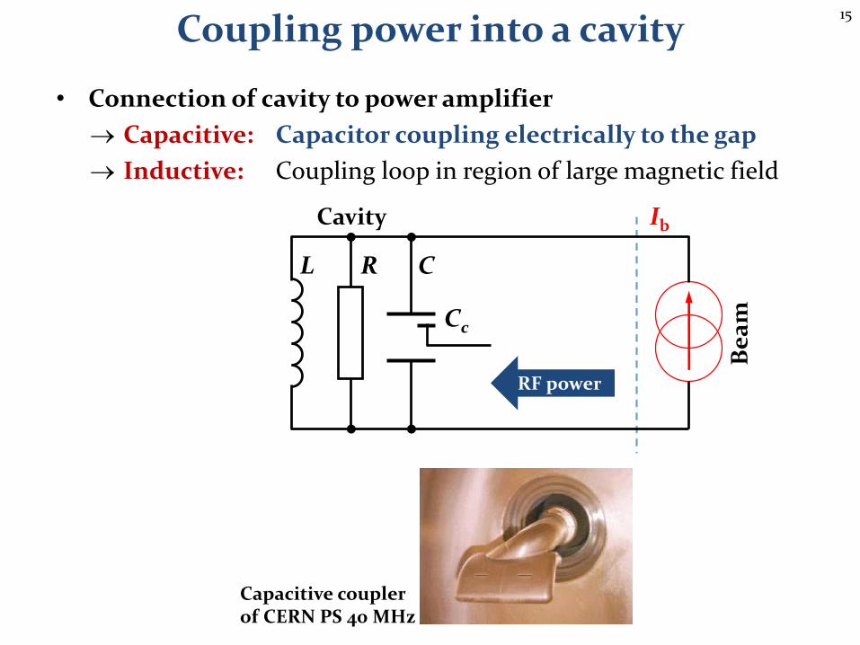
15
• Connection of cavity to power amplifier
Capacitive: Capacitor coupling electrically to the gap
Inductive: Coupling loop in region of large magnetic field
Coupling power into a cavity
Be
am
RL
IbCavity
C
Cc
RF power
Capacitive couplerof CERN PS 40 MHz
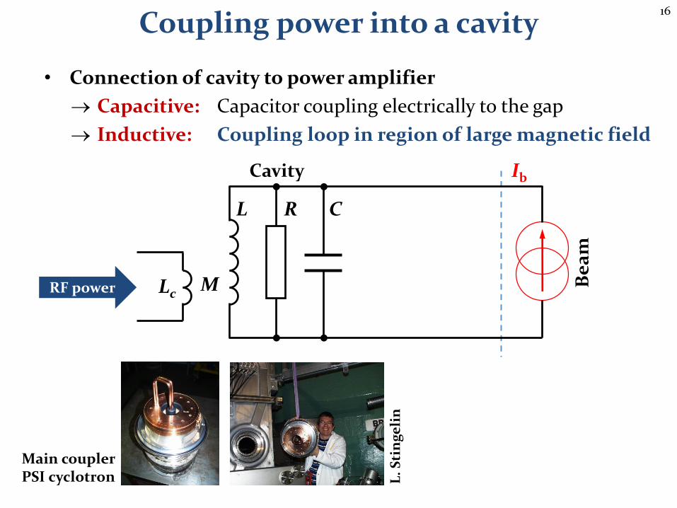
16
• Connection of cavity to power amplifier
Capacitive: Capacitor coupling electrically to the gap
Inductive: Coupling loop in region of large magnetic field
Coupling power into a cavity
Be
am
RL
IbCavity
LcMRF power
L.
Sti
ng
eli
n
Main couplerPSI cyclotron
C

17
Output impedance loads the resonant circuit: Rg || R
Reduction of quality factor: Q0 QL
Coupling coefficient, b, defines coupling ratio
Coupling power into a cavity
C
Be
am
Ge
ne
rato
r
RL
Ig Ib
Rg
Cavity

18
Output impedance loads the resonant circuit: Rg || R
Reduction of quality factor: Q0 QL
Coupling coefficient, b, defines coupling ratio
1. Generator output impedance is not a physical resistor
Generator does not experience own output impedance
2. Beam experiences output impedance of generator as resistor
Rg || R relevant for beam loading
Coupling power into a cavity
C
Be
am
Ge
ne
rato
r
RL
Ig Ib
Rg
Cavity

19
Fundamental theoremof beam loading
20
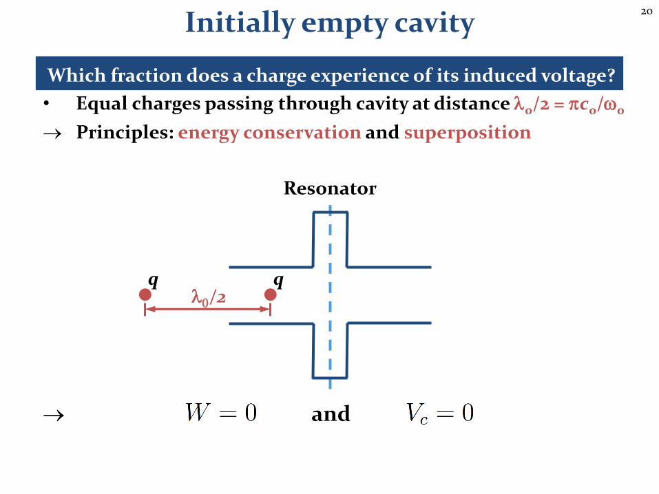
Which fraction does a charge experience of its induced voltage?
• Equal charges passing through cavity at distance l0/2 = pc0/w0
and
Initially empty cavity
Resonator
qql0/2
Principles: energy conservation and superposition
21
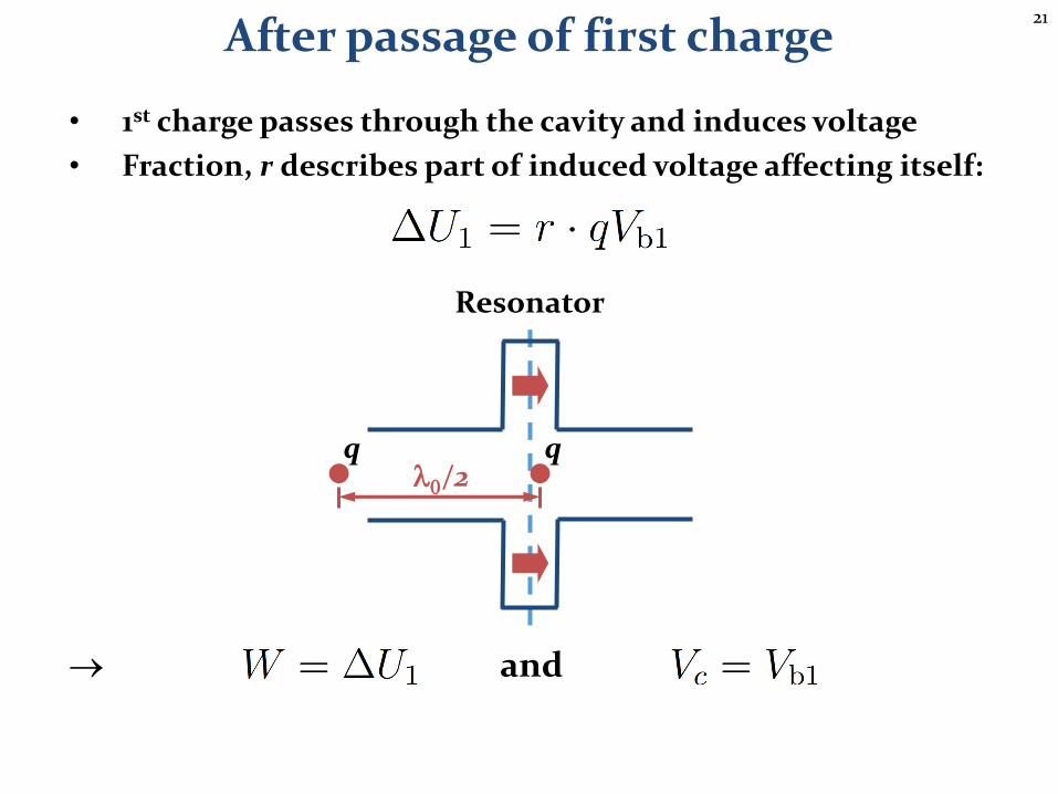
• 1st charge passes through the cavity and induces voltage
• Fraction, r describes part of induced voltage affecting itself:
and
After passage of first charge
Resonator
qql0/2
22
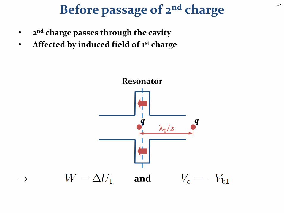
• 2nd charge passes through the cavity
• Affected by induced field of 1st charge
and
Before passage of 2nd charge
Resonator
qql0/2

23
• 2nd charge passes through the cavity
• Affected by induced field of 1st charge and its own induced
and
Passage of 2nd charge
Resonator
qql0/2
24
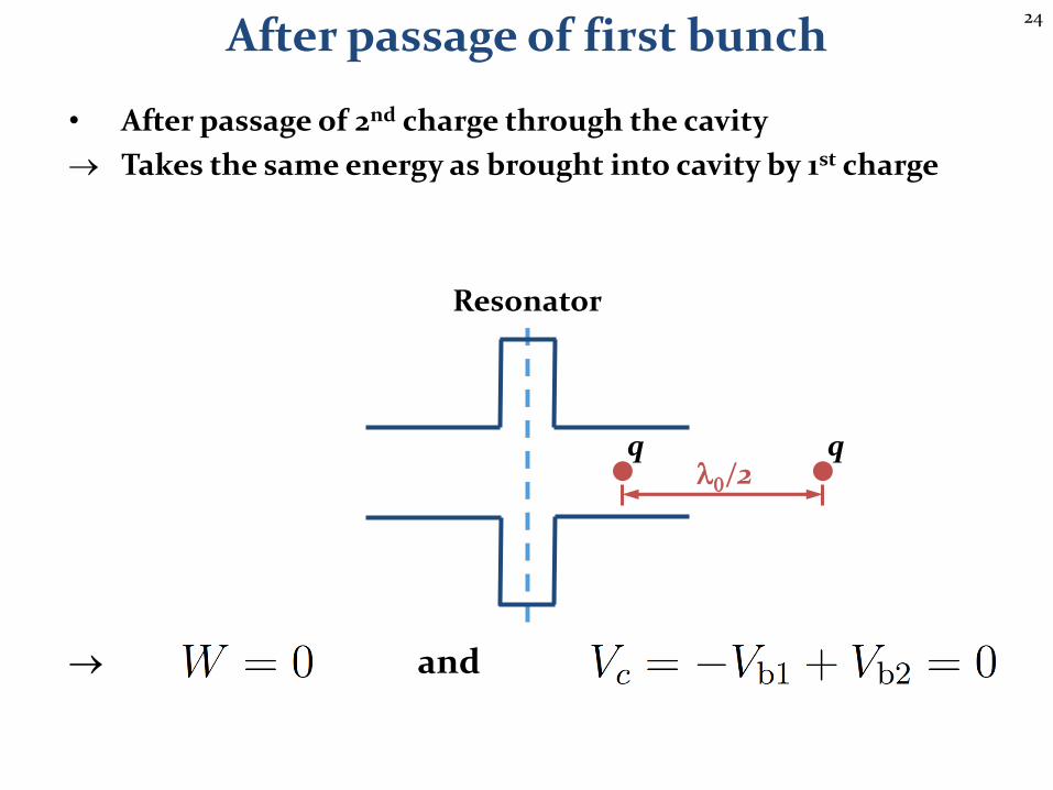
• After passage of 2nd charge through the cavity
Takes the same energy as brought into cavity by 1st charge
and
After passage of first bunch
Resonator
qql0/2
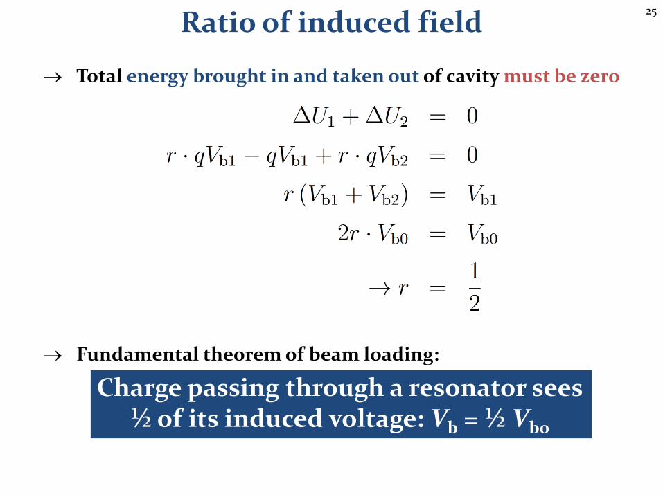
25
Total energy brought in and taken out of cavity must be zero
Fundamental theorem of beam loading:
Charge passing through a resonator sees½ of its induced voltage: Vb = ½ Vb0
Ratio of induced field

26
Single passagethrough a cavity
27
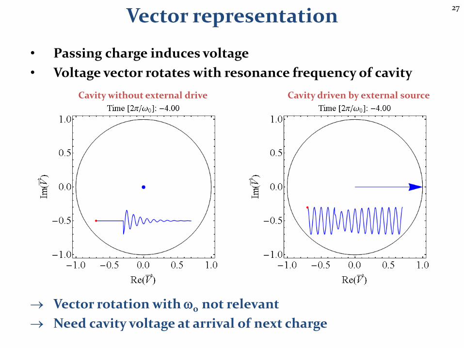
• Passing charge induces voltage
• Voltage vector rotates with resonance frequency of cavity
Vector rotation with w0 not relevant
Need cavity voltage at arrival of next charge
Vector representation
Cavity without external drive Cavity driven by external source

28
• Vector diagram at the instant of the bunch passage:
Vector sum:
Induced voltage changes cavity phase: detuning
De-phase generator to obtain expected net voltage
Vb0
• Vg: Generator driven voltagebefore bunch passage
• V-: Voltage after bunch passage
• V: Net voltage seen by beam
Single passage
Vg
V-
V
fS
Ib
Vb

29
Multiple passagesthrough a cavity
30
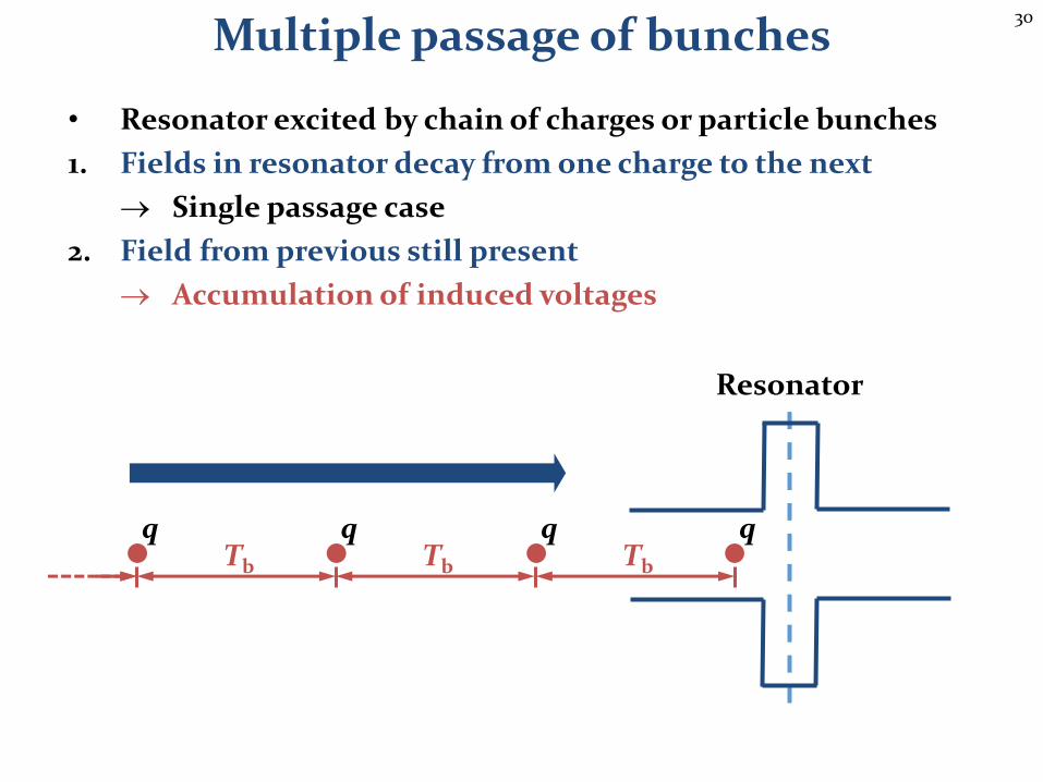
• Resonator excited by chain of charges or particle bunches
1. Fields in resonator decay from one charge to the next
Single passage case
2. Field from previous still present
Accumulation of induced voltages
Multiple passage of bunches
Resonator
qqTb
qTb
qTb
31
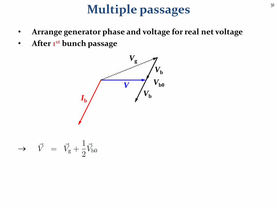
• Arrange generator phase and voltage for real net voltage
• After 1st bunch passage
Multiple passages
Vg
Vb0V
Vb
VbIb
32
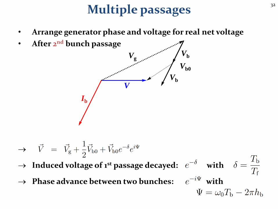
• Arrange generator phase and voltage for real net voltage
• After 2nd bunch passage
Induced voltage of 1st passage decayed: with
Phase advance between two bunches: with
Multiple passages
Vg
Vb0
V
Vb
Vb
Ib
33
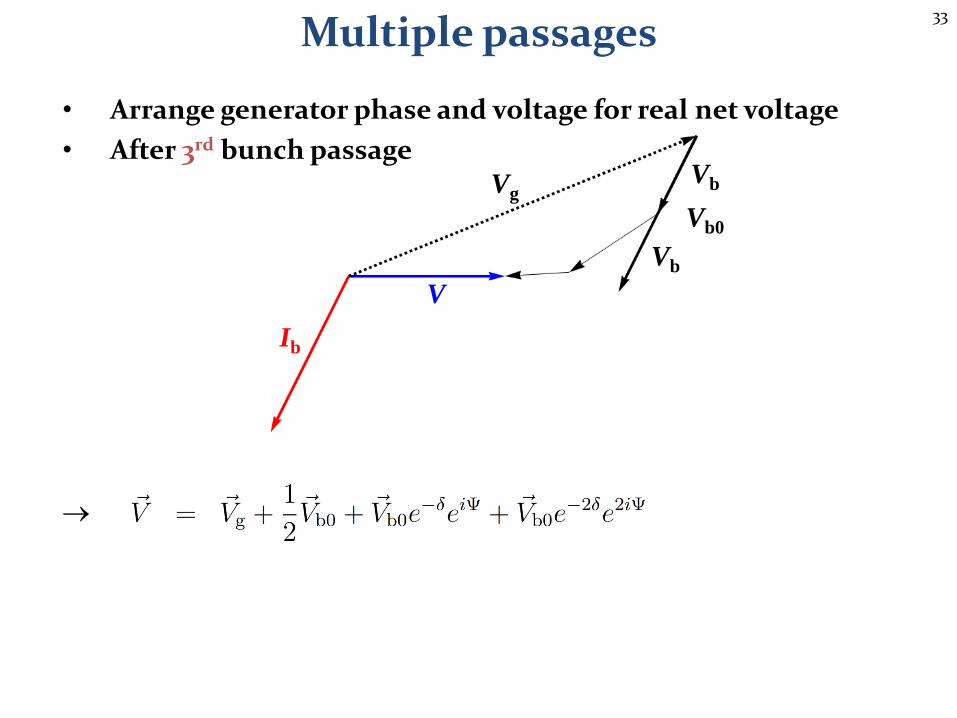
• Arrange generator phase and voltage for real net voltage
• After 3rd bunch passage
Multiple passages
Vg
Vb0
V
Vb
Vb
Ib
34
Multiple passages
Vg
Vb0
V
Vb
Vb
Ib
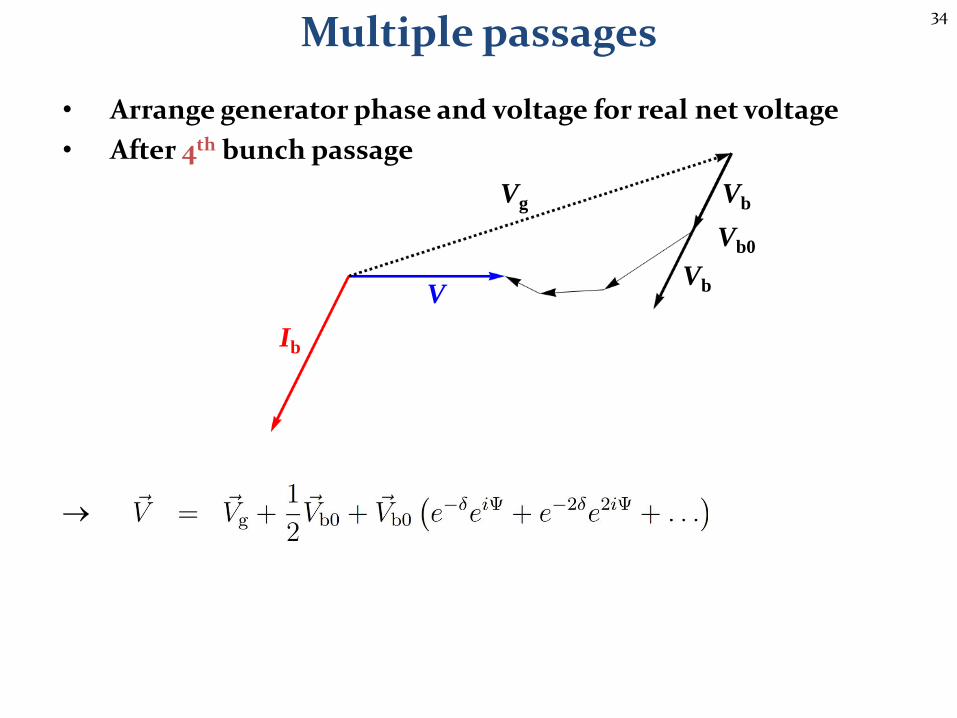
• Arrange generator phase and voltage for real net voltage
• After 4th bunch passage
35
Multiple passages
Vg
Vb0
V
Vb
Vb
Ib
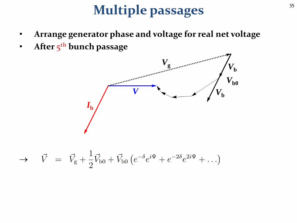
• Arrange generator phase and voltage for real net voltage
• After 5th bunch passage
36
Multiple passages
Vg
Vb0V
Vb
VbIb
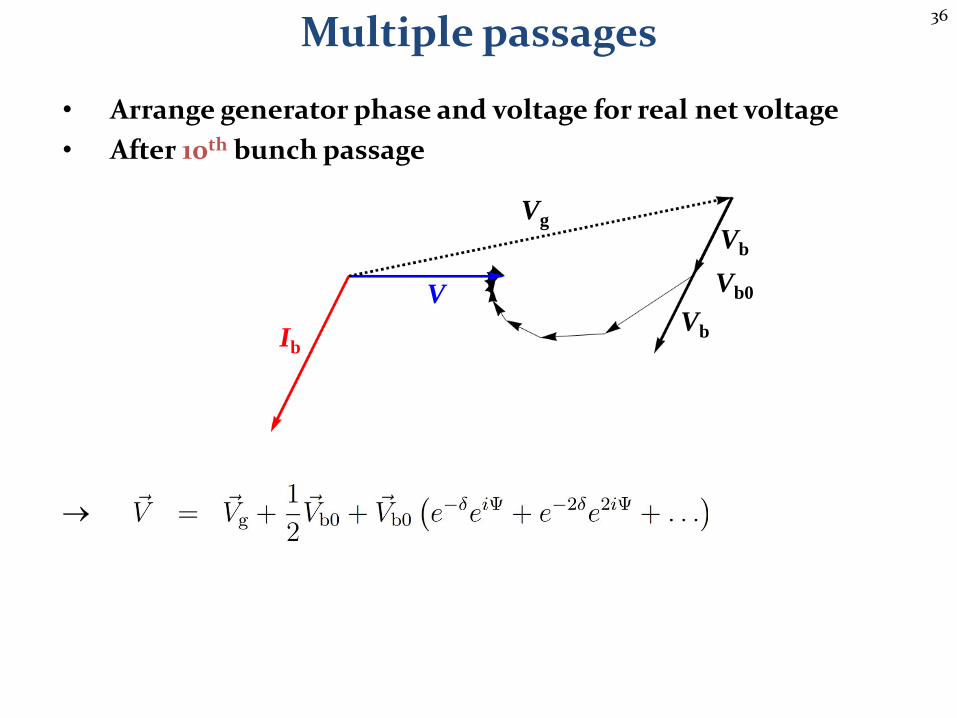
• Arrange generator phase and voltage for real net voltage
• After 10th bunch passage
37
Multiple passages
Vg
Vb0V
Vb
VbIb
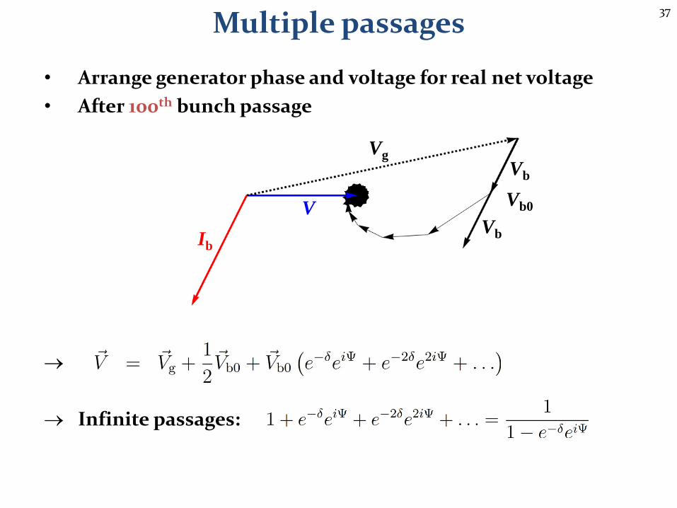
• Arrange generator phase and voltage for real net voltage
• After 100th bunch passage
Infinite passages:
38
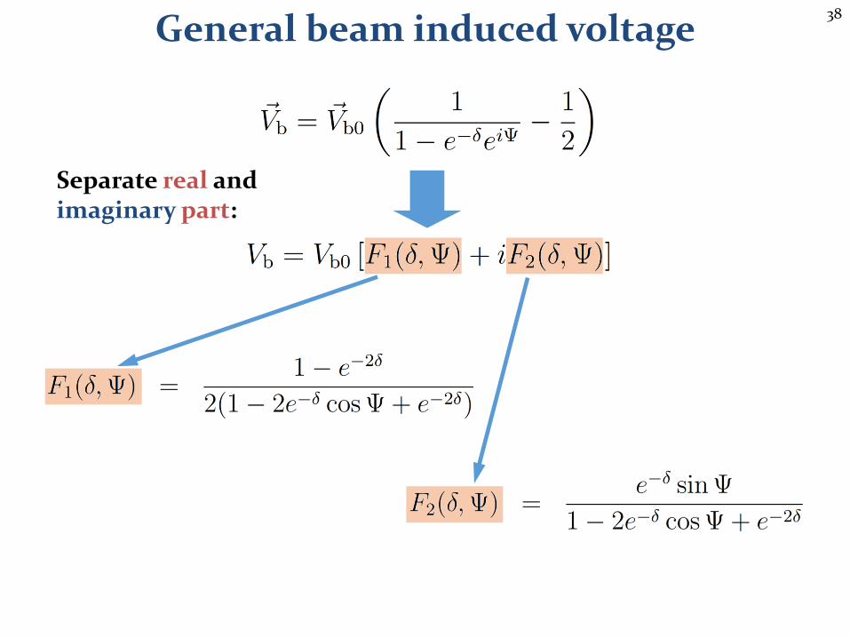
General beam induced voltage
Separate real and imaginary part:
39
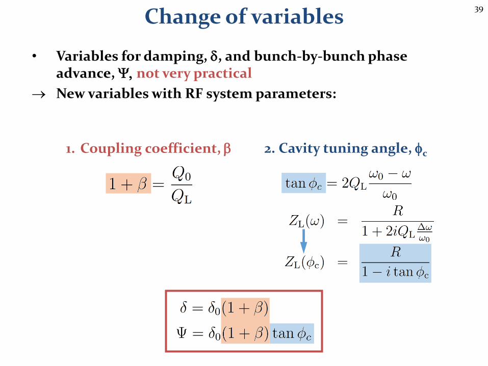
Change of variables
• Variables for damping, d, and bunch-by-bunch phase advance, Y, not very practical
New variables with RF system parameters:
1. Coupling coefficient, b 2. Cavity tuning angle, fc
40
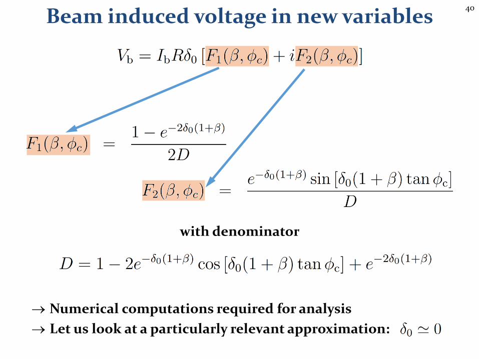
Beam induced voltage in new variables
with denominator
Numerical computations required for analysis
Let us look at a particularly relevant approximation:
41
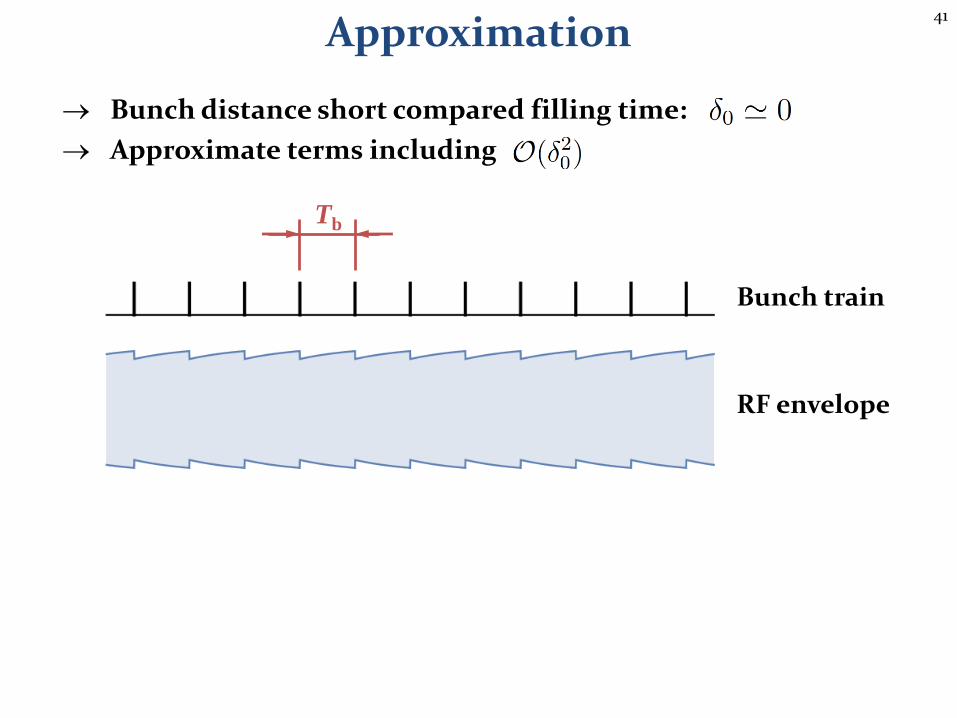
Approximation
Bunch distance short compared filling time:
Approximate terms including
Tb
Bunch train
RF envelope

42
Bunch distance short compared filling time:
Approximate terms including
Ohm’s law for the loaded cavity impedance: steady state case
Approximation
43
Steady statebeam loading
44
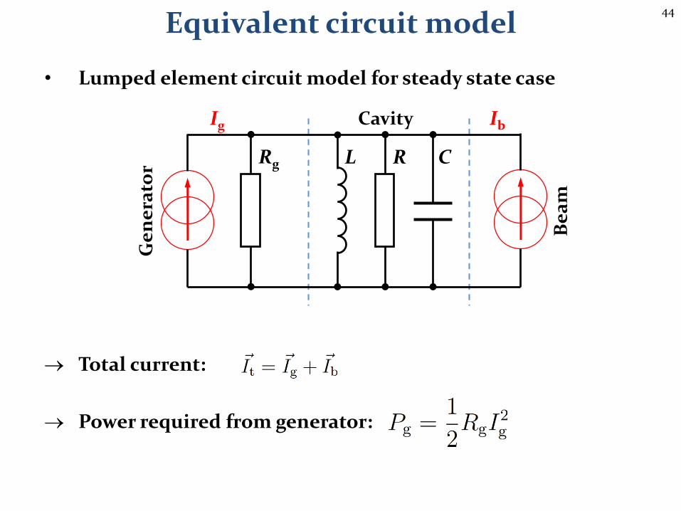
Equivalent circuit model
• Lumped element circuit model for steady state case
Total current:
Power required from generator:
C
Be
am
Ge
ne
rato
rRL
Ig Ib
Rg
Cavity
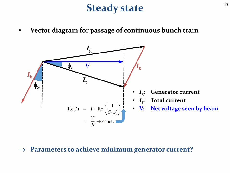
45
It
fc
• Vector diagram for passage of continuous bunch train
Parameters to achieve minimum generator current?
Steady state
Ig
V
fS
Ib
• Ig: Generator current
• It: Total current
• V: Net voltage seen by beam
Ib

46
• Vector diagram for passage of continuous bunch train
• Ig: Generator current
• It: Total current
• V: Net voltage seen by beam
Steady state: minimum generator current
Generator current, Ig
Lowest power (current Ig)
Generator current, Ig in phase with voltage
Resistive load with beam
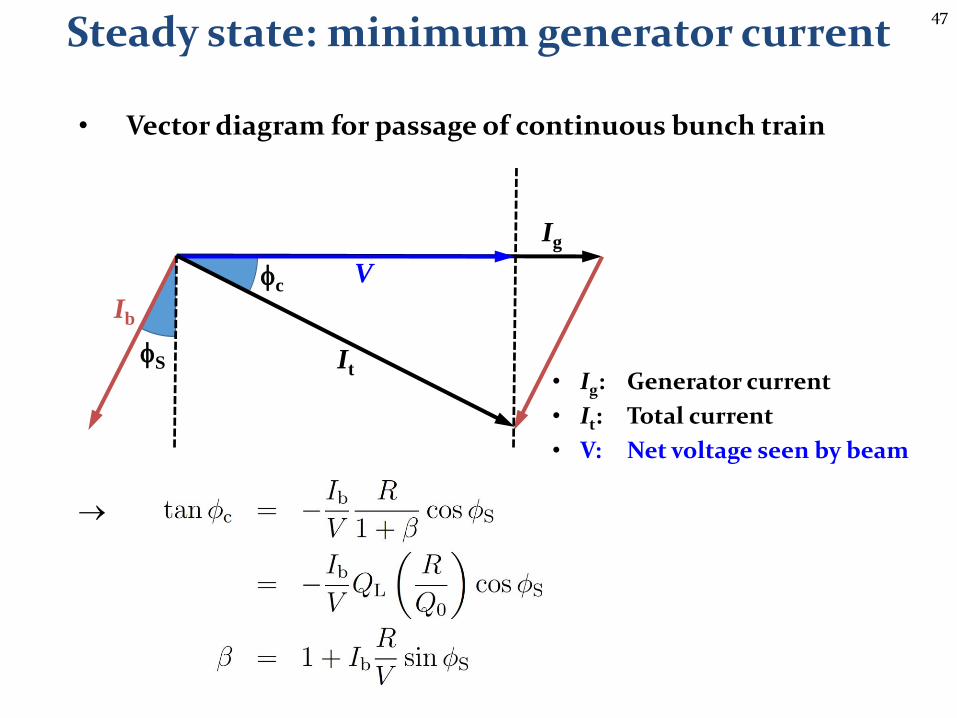
47
• Vector diagram for passage of continuous bunch train
• Ig: Generator current
• It: Total current
• V: Net voltage seen by beam
Steady state: minimum generator current
fS
Ig
It
V
Ib
fc
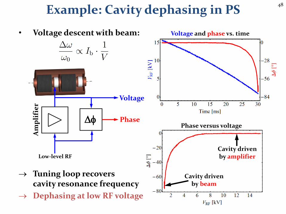
48
• Voltage descent with beam:
Tuning loop recoverscavity resonance frequency
Dephasing at low RF voltage
Am
pli
fie
r
Df
Low-level RF
Phase
Voltage
Example: Cavity dephasing in PS
Voltage and phase vs. time
Phase versus voltage
Cavity driven by amplifier
Cavity driven by beam
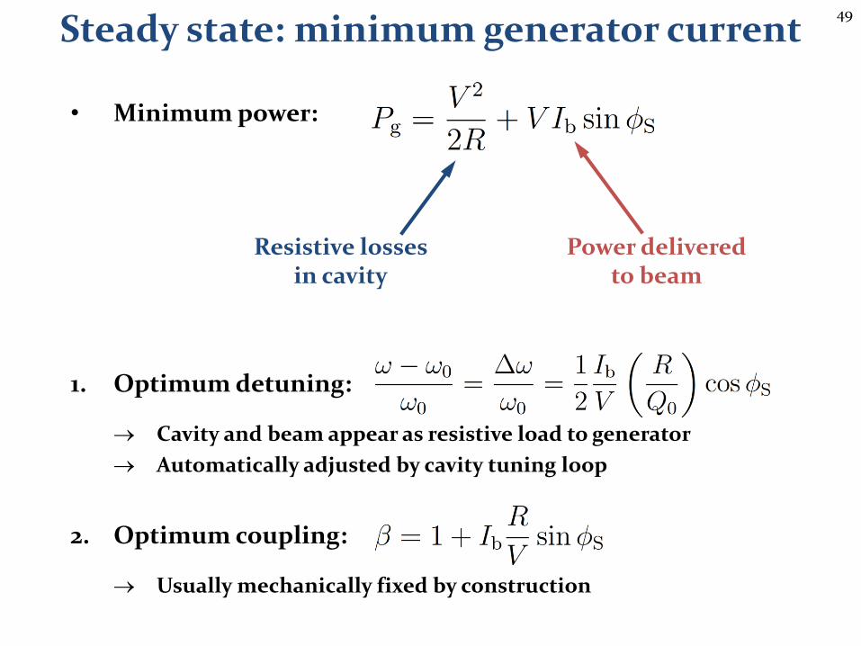
49
• Minimum power:
1. Optimum detuning:
Cavity and beam appear as resistive load to generator
Automatically adjusted by cavity tuning loop
2. Optimum coupling:
Usually mechanically fixed by construction
Steady state: minimum generator current
Resistive losses in cavity
Power deliveredto beam

50
• Control of both cavity resonance frequency and coupling
• Optimize quality through Qext for injection and storage
Example: LHC power coupler
RF
po
we
r
Cavity side
Mo
vab
le a
nte
nn
aMode QL, Qext Comment
Injection ~2∙ 104 Suppresstransients
Collision ~6∙ 104 Maximumvoltage
Loaded quality factor:
~o
51
Filling patternwith gaps
52
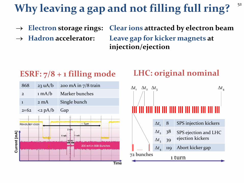
Why leaving a gap and not filling full ring?
Electron storage rings: Clear ions attracted by electron beam
Hadron accelerator: Leave gap for kicker magnets atinjection/ejection
Dt1 Dt2 Dt3 Dt4
72 bunches
Dt1 8 SPS injection kickers
Dt2 38 SPS ejection and LHC ejection kickersDt3 39
Dt4 119 Abort kicker gap
1 turn
ESRF: 7/8 + 1 filling mode LHC: original nominal
868 23 uA/b 200 mA in 7/8 train
2 1 mA/b Marker bunches
1 2 mA Single bunch
262 <2 pA/b Gap
53
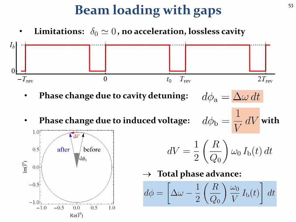
• Phase change due to cavity detuning:
• Phase change due to induced voltage: with
Total phase advance:
Beam loading with gaps
• Limitations: , no acceleration, lossless cavity
54
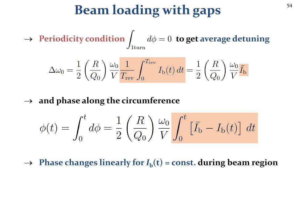
Periodicity condition to get average detuning
and phase along the circumference
Phase changes linearly for Ib(t) = const. during beam region
Beam loading with gaps
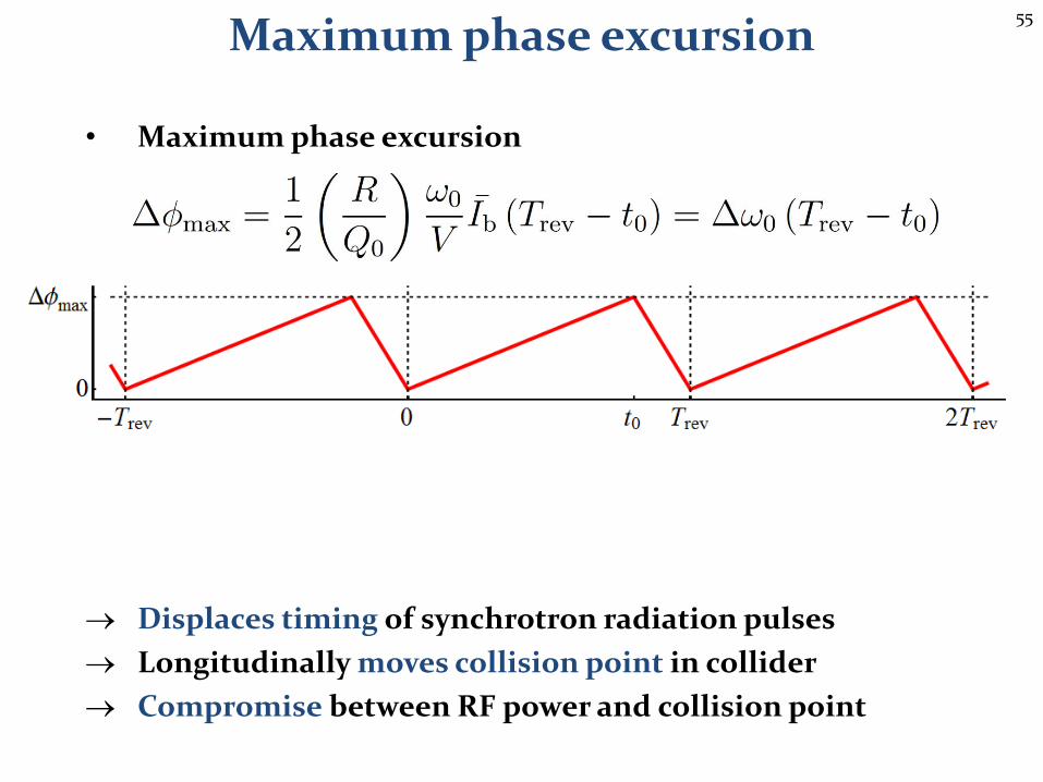
55
• Maximum phase excursion
Displaces timing of synchrotron radiation pulses
Longitudinally moves collision point in collider
Compromise between RF power and collision point
Maximum phase excursion
56
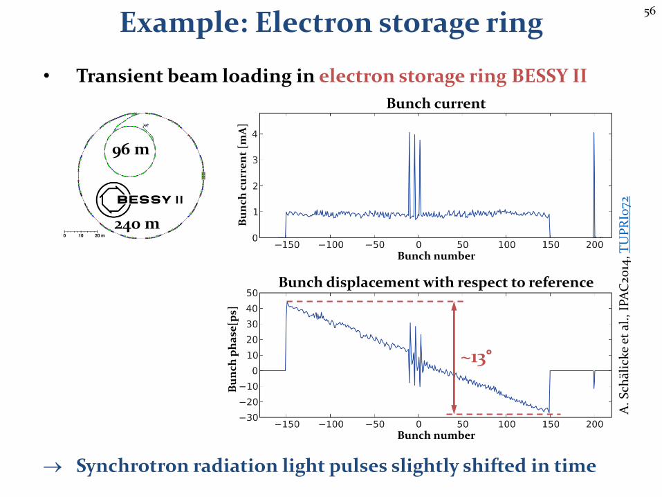
Example: Electron storage ring
• Transient beam loading in electron storage ring BESSY II
Synchrotron radiation light pulses slightly shifted in time
Bunch current
~13°
Bunch displacement with respect to reference
240 m
96 m
Bunch number
Bunch number
Bu
nch
cu
rre
nt
[mA
]B
un
ch p
ha
se[p
s]
A.
Sch
älic
ke
et a
l.,
IPA
C20
14, T
UP
RI0
72
57
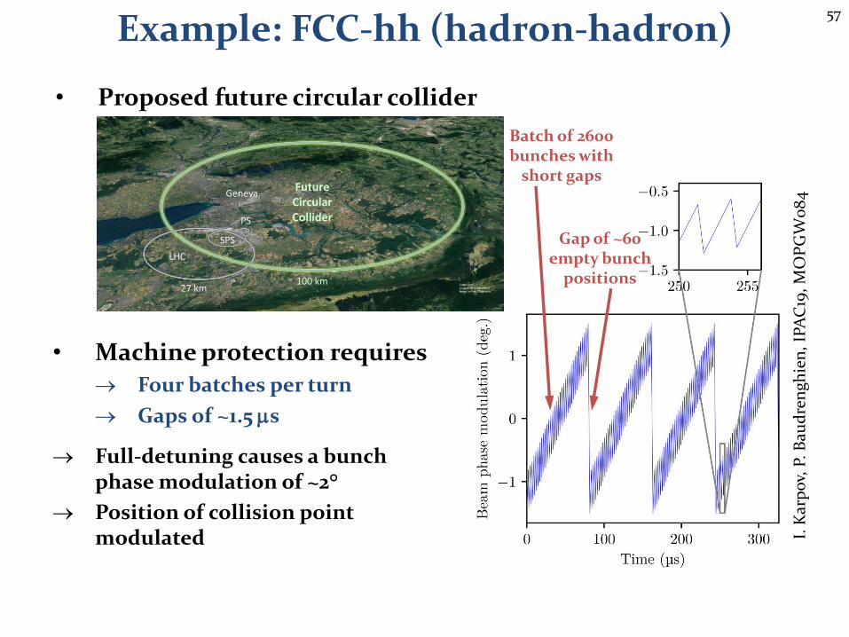
Example: FCC-hh (hadron-hadron)
• Proposed future circular collider
• Machine protection requires
Four batches per turn
Gaps of ~1.5 ms
Full-detuning causes a bunch phase modulation of ~2°
Position of collision point modulated I.
Kar
po
v, P
. B
aud
ren
ghie
n,
IPA
C19
, MO
PG
W0
84
Batch of 2600 bunches with
short gaps
Gap of ~60 empty bunch
positions
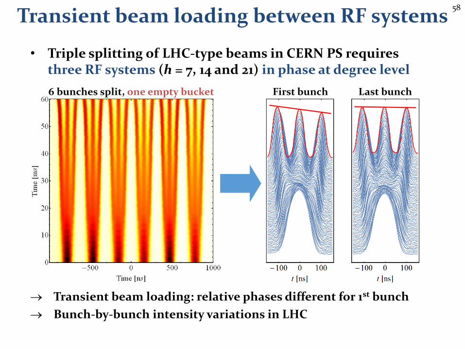
58
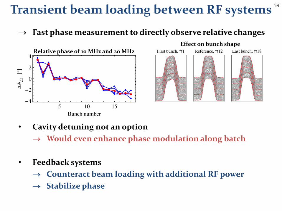
• Triple splitting of LHC-type beams in CERN PS requires three RF systems (h = 7, 14 and 21) in phase at degree level
Transient beam loading: relative phases different for 1st bunch
Bunch-by-bunch intensity variations in LHC
Transient beam loading between RF systems
First bunch Last bunch6 bunches split, one empty bucket
59
Fast phase measurement to directly observe relative changes
• Cavity detuning not an option
Would even enhance phase modulation along batch
• Feedback systems
Counteract beam loading with additional RF power
Stabilize phase
Relative phase of 10 MHz and 20 MHz
Effect on bunch shape
Transient beam loading between RF systems

60
Beam loading inmicrowave oven?
61
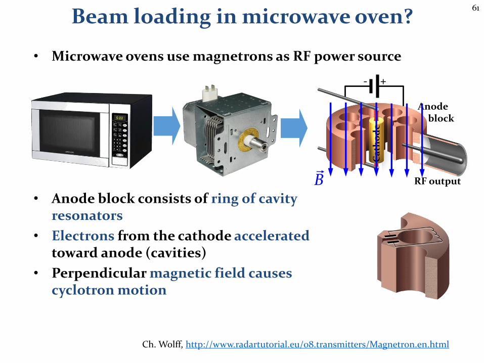
Beam loading in microwave oven?
• Microwave ovens use magnetrons as RF power source
• Anode block consists of ring of cavityresonators
• Electrons from the cathode acceleratedtoward anode (cavities)
• Perpendicular magnetic field causescyclotron motion
+-
Ca
tho
de
Anodeblock
RF outputB
Ch. Wolff, http://www.radartutorial.eu/08.transmitters/Magnetron.en.html
62
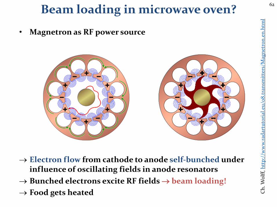
Beam loading in microwave oven?
• Magnetron as RF power source
Electron flow from cathode to anode self-bunched under influence of oscillating fields in anode resonators
Bunched electrons excite RF fields beam loading!
Food gets heated Ch
. Wo
lff,
htt
p:/
/ww
w.r
adar
tuto
rial
.eu
/08
.tra
nsm
itte
rs/M
agn
etro
n.e
n.h
tml
63
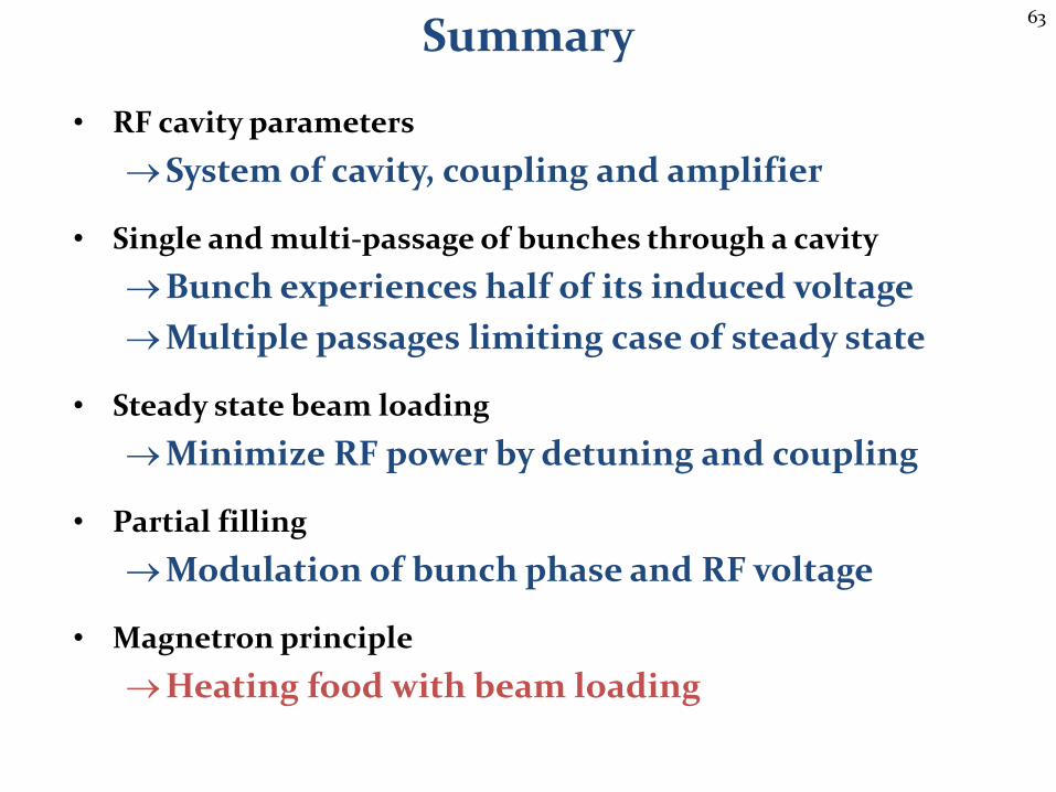
Summary
• RF cavity parameters
System of cavity, coupling and amplifier
• Single and multi-passage of bunches through a cavity
Bunch experiences half of its induced voltage
Multiple passages limiting case of steady state
• Steady state beam loading
Minimize RF power by detuning and coupling
• Partial filling
Modulation of bunch phase and RF voltage
• Magnetron principle
Heating food with beam loading

64
A big Thank Youto all colleagues providing support, material and feedback
Philippe Baudrenghien, Thomas Bohl, Wolfgang Höfle, Andreas Jankowiak, Erk Jensen, Ivan Karpov,
AlexandreLasheen, Eric Montesinos, Elena Shaposhnikova, Lukas Stingelin, Frank Tecker, Christian Wolff and many
more…

65
Thank you very much for your attention!
66
References• P. B. Wilson, Beams Loading in High-Energy Storage Rings, HEACC1974, 1974, p.
57-62, http://inspirehep.net/record/92909/files/HEACC74_78-83.pdf
• P. B. Wilson, Transient Beam Loading in Electron-positron Storage Rings, CERN-ISR-TH-78-23-rev, 1978, http://cds.cern.ch/record/119634/files/cer-000030126.pdf
• P. B. Wilson, J. E. Griffin, High Energy Electron Linacs; Application to Storage Ring RF Systems and Linear Colliders, AIP Conf. Proc. 87 (1982) 564-582, https://aip.scitation.org/doi/pdf/10.1063/1.33620
• D. Boussard, Beam Loading, CERN-87-03-V-2, 1987, http://cds.cern.ch/record/1246443/files/p626.pdf
• D. Boussard, Design of a Ring RF System, CERN SL/91-2 (RFS, rev.), 1991, http://cds.cern.ch/record/1023436/files/CM-P00065157.pdf
• R. Garoby, Beam Loading in RF cavities, Lect. Notes Phys. 400 (1992) 509-541, http://cds.cern.ch/record/220916/files/CM-P00059475.pdf
• D. Boussard, Beam Loading, CERN-95-06, 1995, http://cds.cern.ch/record/302480/files/p415.pdf
• J. Tückmantel, Optimum Cavity Detuning under Reactive Beam Loading with Accelerated Beams, AB-Note-2005-040 (RF), 2005, http://cds.cern.ch/record/910371/files/ab-note-2005-040.pdf
• J. Tückmantel, Cavity-Beam-Transmitter Interaction Formula Collection with Derivation, CERN-ATS-Note-2011-002 TECH, 2011, http://cds.cern.ch/record/1323893/files/CERN-ATS-Note-2011-002%20TECH.pdf
67
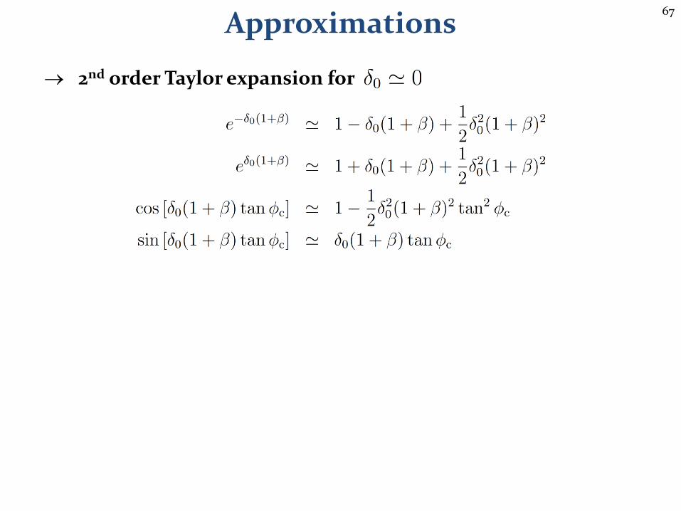
2nd order Taylor expansion for
Approximations
68
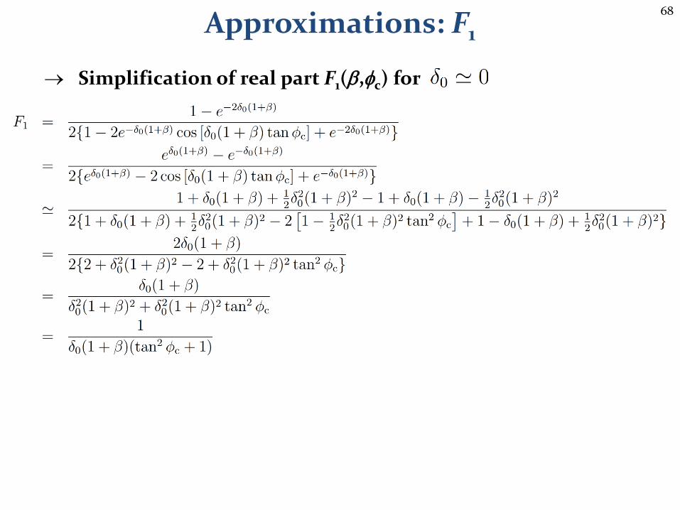
Approximations: F1
Simplification of real part F1(b,fc) for

69
Approximations: F2
Simplification of real part F2(b,fc) for
70
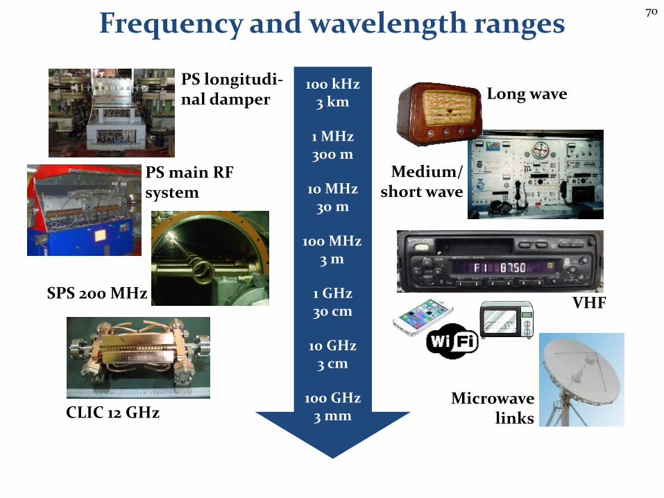
Frequency and wavelength ranges
100 kHz3 km
1 MHz300 m
10 MHz30 m
100 MHz3 m
1 GHz30 cm
10 GHz3 cm
100 GHz3 mm
SPS 200 MHz
PS main RF system
PS longitudi-nal damper
CLIC 12 GHz
Long wave
Medium/ short wave
VHF
Microwave links