Embed Size (px)
Citation preview

The principle of Operation and Application of a Linear Shaft
MotorNippon Pulse America, INC
January 13, 2005
To

1. Principal of the Linear Shaft Motor
2. Distinctive Features of the Linear Shaft Motor
3. Actuator Module
4. Application

Development Concept
Simple is the best!

Shaft
Magnet
Coil
Slider
Linear Shaft Motor Structure

Linear Shaft Motor Principle
u w v u w v u w v
u w v u w v u w v
S N S N S NS N
Coil Flux
Shaft
Flux Thrust
CurrentFleming’s law

Linear Shaft Motor vs. Linear Motor
NS
SN
NS
SN
NS
SN
Core(Iron)
Back York(Iron)
Coil
Coil Magnet
Magnet Adsorption Force
No influence by change of gap
LINEAR SHAFT MOTOR
Linear motor
Cogging by concentration of flux

Linear Shaft Motor Structure
Table
Shaft-motor Shaft
Slider(coil)
Linear encoder
LinearGuideCable bare
Metal fittings

Plate Shaft HolderLinear Guide Table Linear Encoder
Cables
Shaft Motor
Linear Shaft Motor Structure

Linear Shaft Motor

Distinctive FeaturesⅠ Big thrust (6000N) possibility Quiet, no friction during movement Light weight and compact due to no core Simple structure allows building of unit
from a short stroke up to 4.6M stroke High resolution (0.14nm), and when
combined with high accuracy linear
encoder you can achieve high precision
positioning

Distinctive FeaturesⅡ It is possible to control speed and
positioning with high accuracy by using a linear encoder, even if the mechanical accuracy a little rough.
High-speed drive (6.5m/Sec) Low-speed drive (8 μ m/Sec) Almost uniform in speed (±0.006% at
100mm/Sec) Can be used in strong environments such as
underwater and in a vacuum When compared to other linear motors, it is
compact and lightweight

F-V Curve
F-V curve shows characteristic of a DC motor
(However, the classification for a shaft motor of “The Institute of Electrical Engineers of Japan” is a synchronous motor)
7000N output (Size of Slider:120 x 120 x 540)
0
1000
2000
3000
4000
5000
6000
7000
8000
0 0.5 1 1.5 2 2.5 3 3.5 4VELOCITY (m/ sec)
FORC
E (N
)
0%
10%
20%
30%
40%
50%
60%
70%
80%
F-V定格推力出力効率
FVSpecified ThrustOutputEfficiency

Current in Movement
Only at the time of an acceleration and slowdown, current flows.
In case of a linear motor with a core, about 30% of rated current flows even at the time of constant speeding -10
-505
10152025303540
移動時間
(mm
/s)
速度
-1.5
-1
-0.5
0
0.5
1
1.5
(A)
電流
値
(V)速度 電流値(A)Velocity( V) Current( A)
Velo
city(
mm
/s)
Curr
ent(
A)
Time

Data for Temperature IncreaseQ A A427 温度試験 <定格6.4 25% = 1.6 >
0
5
10
15
20
25
30
0 720 1440 2160 2880 3600 4320 5040 5760
Div= Total ℃経過時間 (1 1時間) 8時間26分35秒 最高温度24.5
℃
温度
()
CH01:室温 CH02:U-コイル CH03:V-コイル CH04:W-コイル CH05:フィン-L CH06:フィン-R
427Q Temperature Test (6.4A 25%=1.6A)
CH01:Rm. Tep. CH02:U Coil CH03:V Coil CH04:W Coil CH05:Fin L CH06:Fin R
Tem
pera
ture
(C
)
Process time(1Div=1 h), Total=8h 26m 35s, Highest Tep.=24.5C

0
5
10
15
20
25
30
35
40
0 60 120 180 240 300
経過時間(分)
℃温
度(
)
1kg Vmax=1m/ s α max=1G荷重 、、 、 、200mm 1ストローク /両端 秒停止往復運転
テーブル温度
室温
温度上昇=テーフ ル゙温度ー室温
Temperature Increase on a TableTem
pera
ture
(C
)
Load: !kg, V max=1m/s, α max=1 G
Stroke: 200mm( Round movement after 1sec stop at at the both ends)
Process time
Temperature on the table
Temperature in the room
Temperature increase = Temperature on the table – Temperature in
the room

Duty Curve
DUTY=Acceleration and slowdown/cycle
In case of a linear motor, constant movement (Duty=1) is not practical.
Technique utilizing duty well is the art of using a shaft motor.
435Q
0
500
1000
1500
2000
2500
0 0.1 0.2 0.3 0.4 0.5 0.6 0.7 0.8 0.9 1
DUTY
推
力(
N)
+10℃
+20℃
+30℃
+40℃
+50℃
+60℃
+70℃
+80℃
+90℃
+100℃Thru
st(
N)
435Q
Duty

Repetition Positioning Accuracy
Available within ±1.2 pulses of encoder resolution ( 3σ )( encoder resolution : less than 10nm)
No influence with Expansion and contraction of a shaft
Time(s)
静的位置決め性能(エンコーダ分解能8.6nm)
-0.005
-0.004
-0.003
-0.002
-0.001
0
0.001
0.002
0.003
0.004
0.005
0 10 20 30 40 50 60 70 80
Time (s)
Dis
tance
(mm
)
静的位置決め性能(エンコーダ分解能8.6nm)
-60-55-50-45-40-35-30-25-20-15-10-505
1015202530354045505560
0 10 20 30 40 50 60 70 80
Time (s)
Dis
tance
(mm
)
Used with 8.6nm resolution encoder
Used with 8.6nm resolution encoder D
ista
nce(
mm
)D
ista
nce(
mm
)Time(s)

:Enlargement
Model S160T
Condition
V max≒1m/ sec
αmax≒1G
High Precise Positioning up to ±0.1μm, without overshoot
Precise Positioning

Acceleration| G |
time(sec) 0.1 0.2 0.3
2
4
6
8
0
1
2
3
0
Acceleration and
slowdown
Speed
-10
Type W
Stroke : 700mm
Constant Speed:
3.3m/s
Performance Characteristics
of High SpeedVelocity( m/s)
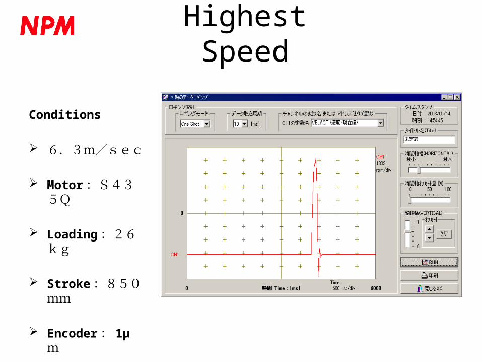
Highest Speed
Conditions
6.3m/sec
Motor :S435Q
Loading :26kg
Stroke :850mm
Encoder : 1μ m

μ 低速送り (8 m/s) 移動距離2mm
0
0.005
0.01
0.015
0.02
0.025
0.03
0.035
0.04
0.045
0.05
0 50 100 150 200 250
Time (s)
Velo
city
(mm
/s)
8m/sec
Velo
city(
mm
/sec)
Time (sec)
Lowest Speed
Conditions
Velocity : 8 m / sec
Motor :S320D
Loading :10kg
Stroke :2mm

2.5 3 .0 3 .5 4 .0T im e (Seconds)
99 .990
99.995
100.000
100.005
100.010
100.015
C hanne l 1 Ve loc ity (M illim eter/sec)
Uniformity in speed : ±0.006 %Velocity(mm/sec)
Uniformity in High Speed
Conditions
Velocity : 100mm/ sec
Motor : S320D
Loading : 10kg
Stroke : 220mm
Encoder : 0.1m
Time(s ec)

≒ ±一定速度 5mm/s( 0.1%)
4.994.9914.9924.9934.9944.9954.9964.9974.9984.999
55.0015.0025.0035.0045.0055.0065.0075.0085.0095.01
0 100 200 300 400 500 600 700 800 900 1000 1100
Time (s)
Vel
ocity
(mm
/s))
Velocity(mm/sec)
Time(s ec)
Uniformity in Low SpeedUniformity in speeding : ±0.01 %
Conditions
Velocity : 5mm/sec
Motor : S320D
Loading : 10kg
Stroke : 220mm
Encoder : 0.1 m

シャフトモーター435Qの保持力
0
200
400
600
800
1000
1200
0 2 4 6 8 10 12 14 16 μ偏移 ( m)
推
力(
N)
Holding Thrust of S435D
Deviation (m)
Thru
st(
N)
Holding Thrust
Due to servo control, thrust is not held after achieving the position to be programmed
Holding thrust up to the maximum is maintained during operation
Holding thrust depends on the gain
Holding thrust is also depends on the resolution of an encoder

Magnetic force abruptly decreases when leaving from the surface of the shaft
Very little influence in proportion to the distance from N-S pitch
No relation between the pitch of both poles and positioning accuracy
Thrust field is different from magnetic field
-0.4
-0.3
-0.2
-0.1
0
0.1
0.2
0.3
0.4
0 15 30 45 60 75 90 105 120
POSITION (mm)
MA
GN
ETIC
FLU
X D
EN
SIT
Y (
T)
10 mm表面からの距離 5 mm 0 mm
Magnetic Field
0
0.05
0.1
0.15
0.2
0.25
0.3
0.35
0.4
0 5 10 15 20 25 30表面からの距離(mm)
磁界
の強
さ(
T)
Distance from surface (mm)
Position (mm)Mag
neti
c Fl
ux D
ensi
ty(T
)
Distance from surface: 10mmDistance from surface: 5mmDistance from surface: 0mm
Mag
neti
c Fo
rce

Advantages for Manufacturing
• Quality Control – Saving time in inspection– Simple QC in total due to the simple structure
• Cost Control – Low cost in making a guide– Basically low cost in structure
• Process Control – High productivity ( due to simple assembling )– Flexibility of production ( Exchangeable in productio
n process )– Easy maintenance
( In comparison to a conventional liner motor)

Development and Production
Odate Factory ( Akita )
Development and Designing
For Customer Application
Development( Technical Center in Tokyo)
Production ( Iwaki, Odate, Chaina Factories )
Motor, Driver, Controller, Communication System

3 pcs of Driver for Shaft Motor
Shaft Motor
Slider of Shaft Motor
Slider of Shaft Motor
Shaft Motor
Limit Sensor with T-NET
Limit Sensor with T-NET
Multiple Movement for 4 axes with stepping motor
2 axes driver for stepping motor
Movement Sensor with T-NET
Controller Unit NPM-104EMBC
NPMC6045-4104 board built-in (4 axes control) NPMCTNET-I/O 104
board G9001 built-in
Application of Linear Shaft Motor for Medical Purpose

Business for Linear Shaft Motor
Development of Motor : GMC HillstoneDevelopment of Peripherals : Nippon Pulse
MotorProduction of Motor : GMC Hillstone
Nippon Pulse MotorProduction of Peripherals : Nippon Pulse
MotorSales of System Actuator : Nippon Pulse
Motor

System of Actuator
1. Motor and Driver2. Motor, Driver and Controller 3. Motor, Driver, Controller and Encoder4. Motor, Driver, Controller, Encoder and
Communication System
Propose with Module Actuator Supply to Our Customers with the Best Module Actuator
5. ?6. ?

Shaft
Magnet Coil
Slider
What is a shaft motor?This is a direct drive-linear-servomotor which is controlling
movement by switching on the current to the shaft arrayed inside with magnets and the coil rolled in the shape of a cylinder
Structure of a shaft motor
Cables for moving part
Cables for encoder
Table
Magnet shaft
Linear encoder
Linear guide
Moving part (coil) Shaft holder
ApplicationUsing high resolution High precision position accuracyUsing stability in speeding and less than 0.05% of unevenness of movement Precise measurementUsing 0.1μm of repetition positioning accuracy Pinpoint alignment A system can be compact and it can build simply. System
design with high flexibility
2 heads of a shaft motor are used at the X-axis
1 head of a shaft motor is used at the Y-axis
Features of a shaft motorQuiet, no friction during movement
Big thrust (6000N)Repetition of position accuracy is available in 0.1μm.Compared with the other drive system, it is very stable in speeding and possible to control with stable speed.Possible to operate by a high-speed drive (6.5 m/Sec) to low-speed drive (8μm /Sec).Can be used in strong environments such as underwater and in a vacuum. A system is compact and simple.
Summary