Embed Size (px)
Citation preview
4 NPMEUROPE.COM
Nippon Pulse Stepper Motors
ASI base unit for current (ampere)
ACAlternating current
CCWCounterclockwise
CWClockwise
DCDirect Current
HzSI induced unit for frequency (cycles per second)
KSI base unit for temperature (Kelvin); often used for temperature rise
PPSPulses per second
RPMRevolutions per minute
VSI induced unit for voltage (volts)
All Nippon Pulse stepper motor products are RoHS compliant.
Abbreviations/Units
RoHS Compliance
Nippon Pulse’s permanent magnet (PM) step motors (PF series tin-can steppers) have been well-established in the engineering world, and have many advantages over other kinds of stepper motors. PM motors strike the perfect balance between eiciency and afordability, as they are low-inertia, low-resolution motors that are a low-priced alternative to hybrid stepper motors in many applications.
PM step motors have a typical step angle between 3.75 and 18 degrees, and ofer position resolution on the order of ±5 percent. Its structure demonstrates ferromagnetism, with alternating north and south poles set in a straight, parallel line to the rotor shaft. The rotor is moved through the action of permanent magnets, providing increased magnetic lux intensity. This intensity results in improved torque characteristics for the PM motor, compared to variable resistance step motors.
Nippon Pulse provides high-quality PM motors to industries and professionals all over the world. Take a look at our standard PM motors over the following pages to ind the one that most closely its your needs. An application engineer can work with you to make any customizations necessary to make our PM motors a perfect it.
Permanent Magnet Motors
OD(mm)
Tin-Can
SynchronousLinear
StepperDual Direction
Single Direction
10 PFC10 -- -- --
20PFCU20PFC20T
-- -- --
25PF(C)25PFCU25
PTM-24P -- PFCL25
30 PFCU30 -- -- --
35PF35
PF35TPTM-24MPTM-24T
PTM-24B PFL35T
42PF42
PFC42HPF(C)42T
PTM-24HPTMC-24S2
PTM-12KPTM-12E
--
55PF(C)55PFC55H
PTM-24F -- --
Tin-Can Models by Outer Diameter
Insulation Class Y A E B F H C
Allowable Temp (˚C) 90 105 120 130 155 180 >180
Insulation Ratings
Note: All tin-can motors and linear steppers in this catalog are insulation Class E unless otherwise noted.
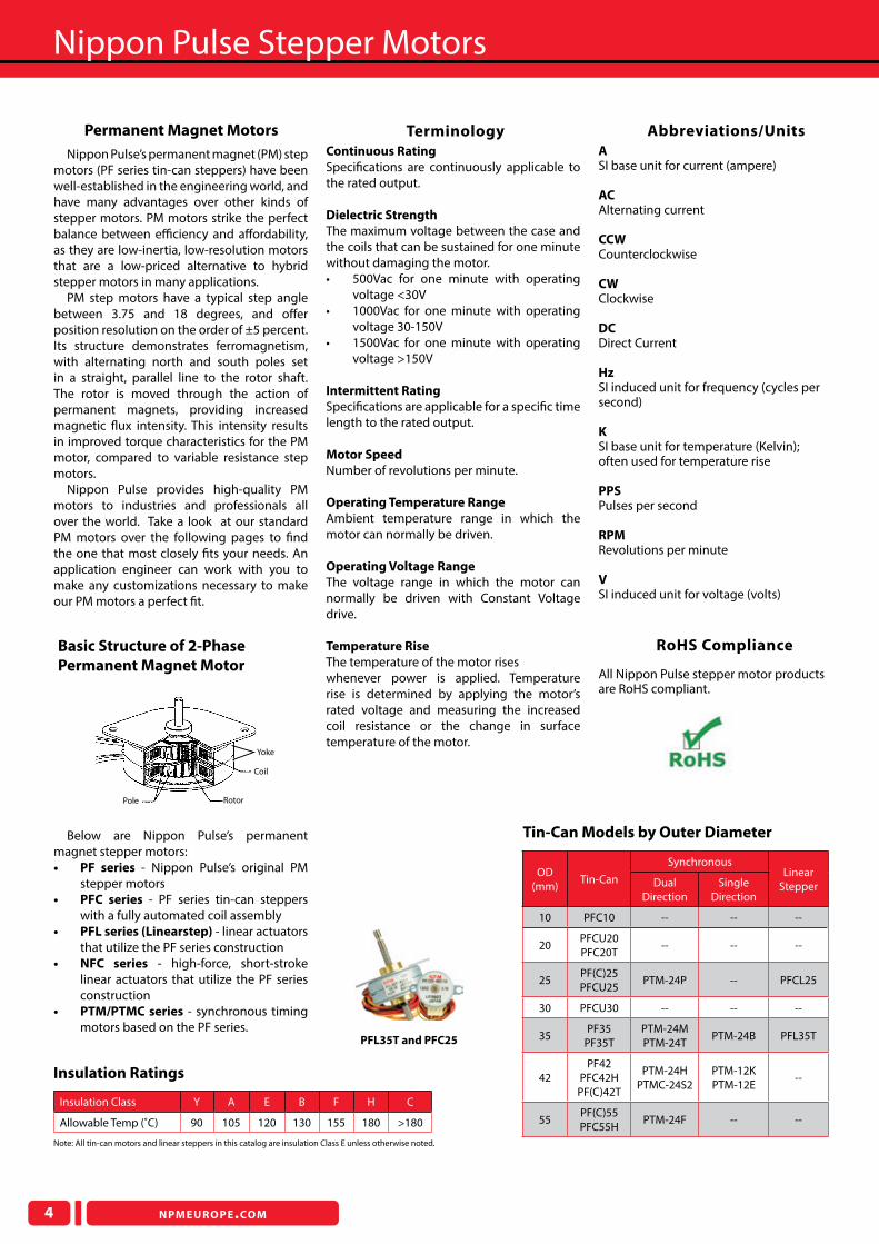
PFL35T and PFC25
Below are Nippon Pulse’s permanent magnet stepper motors:• PF series - Nippon Pulse’s original PM
stepper motors• PFC series - PF series tin-can steppers
with a fully automated coil assembly• PFL series (Linearstep) - linear actuators
that utilize the PF series construction• NFC series - high-force, short-stroke
linear actuators that utilize the PF series construction
• PTM/PTMC series - synchronous timing motors based on the PF series.
Basic Structure of 2-Phase
Permanent Magnet Motor
Yoke
Coil
RotorPole
Continuous Rating
Speciications are continuously applicable to the rated output.
Dielectric Strength
The maximum voltage between the case and the coils that can be sustained for one minute without damaging the motor.• 500Vac for one minute with operating
voltage <30V• 1000Vac for one minute with operating
voltage 30-150V• 1500Vac for one minute with operating
voltage >150V
Intermittent Rating
Speciications are applicable for a speciic time length to the rated output.
Motor Speed
Number of revolutions per minute.
Operating Temperature Range
Ambient temperature range in which the motor can normally be driven.
Operating Voltage Range
The voltage range in which the motor can normally be driven with Constant Voltage drive.
Temperature Rise
The temperature of the motor rises whenever power is applied. Temperature rise is determined by applying the motor’s rated voltage and measuring the increased coil resistance or the change in surface temperature of the motor.
Terminology

NPMEUROPE.COM
Tin-Can Steppers
5
Step Black Brown Orange Yellow Step
1 ON OFF ON OFF 4
2 OFF ON ON OFF 3
3 OFF ON OFF ON 2
4 ON OFF OFF ON 1
CW↓↑
CCW
2-2 phase excitation sequence
Coil
An encapsulated and welded stator design gives stronger design, greater dimensional control and improved thermal characteristics.
Mounting Plate
Custom and standard shaped mounting plates are available. Mounting holes can be threaded, tapped, slotted or customized to your application requirements.
Permanent Magnet Rotor
Three types of permanent magnets are available: ferrite anisotropic, ferrite isotropic, and neodymium.
Bushings and Bearings
Long life oil-impregnated bushings are standard in our PF, PFC, NFC, PTM and PTMC motors. Ball bearings can be requested, and are standard in the PFL series Linearstep motors.
Shaft
A variety of shaft options are available.• Custom lengths• Single and double shafts• D-cut(s)• Turn downs• Threaded• Knurled• Grooved
Gears & Pulleys
A variety of gear and pulley options are available.• Machined• Plastic molded• Powdered metal (sintered)
Connector
Motor side connection method. Lead wire options available.
Lead Wire
Options to change the lead wire exit direction and exit angle.
Wire Leads
Driver side connector options.• Standard lying leads• Customer-selected connectors
See page 41 for additional motor customization options and for information about creating a fully custom step motor.
Permanent Magnet Motor Features
and Customization Options
Unipolar DriveSix lead wires are connected
The basic circuit(constant voltage)is shown to the right
Current: Single directionCoil: Biilar windingLeadwires: 6
Unipolar Bipolar
Number of Transistors 1 2
To ensure the same temperature rise of motor
CurrentTorqueHigh-speed performanceVoltage
1111
1/√2√20.5√2
To obtain same torque
CurrentTemperature riseHigh-speed performanceVoltage
1111
0.50.50.51
This chart shows the comparison between bipolar and unipolar drives with parameters of unipolar set to one.
Bipolar DriveFour lead wires are connected
The basic circuit (constant voltage)is shown to the right
Current: Dual directionCoil: Monoilar windingLeadwires: 4
Step I II
1 + +
2 - +
3 - -
4 + -
CW↓ ↑CCW
2-2 phase excitation sequence
PF(C) - 42 T - 48 C 1 G 1/50 1 2 3 4 5 6 7 8
1 - Series Designation PF: Flying lead joint type PFC: Connector joint type2 - Outer Diameter in mm3 - Type Blank: Standard T: Thin stack H: High torque4 - Steps per Revolution 24: 15˚/step 48: 7.5˚/step 96: 3.75˚/step5 - Coil Rating C: 12V unipolar D: 5V unipolar P: 12V bipolar Q: 5V bipolar
Model Number Explanation (for PF and PFC series)
6 - Magnet Material 1: Ferrite Anisotropic 3: Ferrite Isotropic 4: Neodymium 6: Molded Neodymium*7 - Gear Head Blank: No Gear Head G: Gear Head Integrated8 - Gear Ratio With geared models only
*Only applicable for PFC10 and PFC20T.
Tin-Can Steppers
6 NPMEUROPE.COM
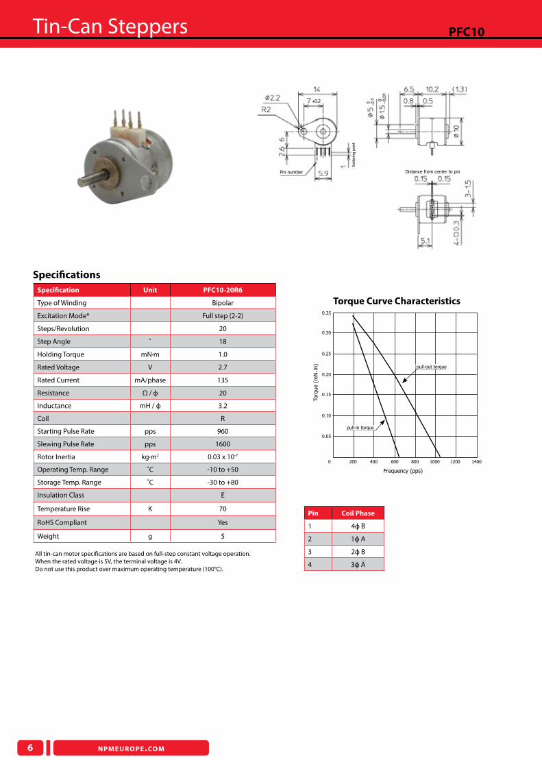
PFC10
Torque Curve Characteristics
Speciication Unit PFC10-20R6
Type of Winding Bipolar
Excitation Mode* Full step (2-2)
Steps/Revolution 20
Step Angle ˚ 18
Holding Torque mN·m 1.0
Rated Voltage V 2.7
Rated Current mA/phase 135
Resistance Ω / ф 20
Inductance mH / ф 3.2
Coil R
Starting Pulse Rate pps 960
Slewing Pulse Rate pps 1600
Rotor Inertia kg·m2 0.03 x 10⁻⁷
Operating Temp. Range ˚C -10 to +50
Storage Temp. Range ˚C -30 to +80
Insulation Class E
Temperature Rise K 70
RoHS Compliant Yes
Weight g 5
Pin Coil Phase
1 4ф B
2 1ф A
3 2ф B
4 3ф A
Speciications
200 400 600 800 1000 1200 1400
0.05
0.10
0.15
0.20
0.25
0.30
0.35
0
pull-in torque
pull-out torque
Frequency (pps)
Torq
ue (
mN·m
)
Pin number Distance from center to pin
Sold
ering p
oin
t
All tin-can motor speciications are based on full-step constant voltage operation.When the rated voltage is 5V, the terminal voltage is 4V.Do not use this product over maximum operating temperature (100°C).
NPMEUROPE.COM
Tin-Can Steppers
7
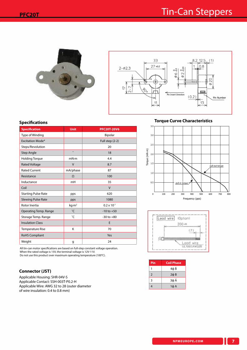
PFC20T
Torque Curve Characteristics
Speciication Unit PFC20T-20V6
Type of Winding Bipolar
Excitation Mode* Full step (2-2)
Steps/Revolution 20
Step Angle ˚ 18
Holding Torque mN·m 4.4
Rated Voltage V 8.7
Rated Current mA/phase 87
Resistance Ω 100
Inductance mH 35
Coil V
Starting Pulse Rate pps 620
Slewing Pulse Rate pps 1080
Rotor Inertia kg·m2 0.2 x 10⁻⁷
Operating Temp. Range ˚C -10 to +50
Storage Temp. Range ˚C -30 to +80
Insulation Class E
Temperature Rise K 70
RoHS Compliant Yes
Weight g 24
Speciications
100 200 300 400 500 600 700
0.5
1.0
1.5
2.0
2.5
3.0
3.5
0 800
Frequency (pps)
Torq
ue (
mN·m
)
pull-in torque
pull-out torque
Pin Insert Direction
Pin Number
All tin-can motor speciications are based on full-step constant voltage operation.When the rated voltage is 15V, the terminal voltage is 12V-11V.Do not use this product over maximum operating temperature (100°C).
Pin Coil Phase
1 4ф B
2 2ф B
3 3ф A
4 1ф A
Connector (JST)
Applicable Housing: SHR-04V-SApplicable Contact: SSH-003T-P0.2-HApplicable Wire: AWG 32 to 28 (outer diameter of wire insulation: 0.4 to 0.8 mm)
Tin-Can Steppers
8 NPMEUROPE.COM
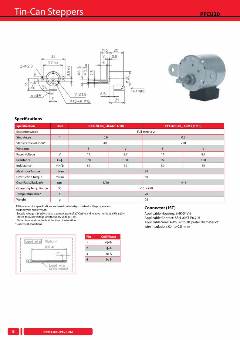
PFCU20
Speciication Unit PFCU20-40_-4GM2 (1/10) PFCU20-40_-4GM2 (1/18)
Excitation Mode Full-step (2-2)
Step Angle ˚ 0.9 0.5
Steps Per Revolution* 400 720
Windings S V S V
Rated Voltage V 11 8.7 11 8.7
Resistance1 Ω/ф 160 100 160 100
Inductance1 mH/ф 59 39 59 39
Maximum Torque mN·m 20
Destruction Torque mN·m 60
Gear Ratio/Backlash pps 1/10 1/18
Operating Temp. Range ˚C -10 ~ +50
Temperature Rise* K 70
Weight g 25
1 Supply voltage 12V ±2% and at a temperature of 20˚C ±5% and relative humidity 65% ±20%.2 Stated terminal voltage is with supply voltage 12V.3 Stated temperature rise is at the time of saturation.
Speciications
Connector (JST)
Applicable Housing: SHR-04V-SApplicable Contact: SSH-003T-P0.2-HApplicable Wire: AWG 32 to 28 (outer diameter of wire insulation: 0.4 to 0.8 mm)
All tin-can motor speciications are based on full-step constant voltage operation.
*Under test conditions
Magnet type: Neodymium
Pin Coil Phase
1 4ф B-
2 3ф A-
3 1ф A
4 2ф B
NPMEUROPE.COM
Tin-Can Steppers
9
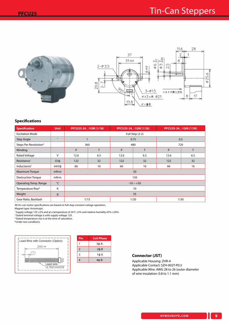
PFCU25
Speciication Unit PFCU25-24_-1GM (1/18) PFCU25-24_-1GM (1/20) PFCU25-24_-1GM (1/30)
Excitation Mode Full Step (2-2)
Step Angle ˚ 1 0.75 0.5
Steps Per Revolution* 360 480 720
Winding P T P T P T
Rated Voltage V 12.6 6.5 12.6 6.5 12.6 6.5
Resistance1 Ω/ф 122 32 122 32 122 32
Inductance1 mH/ф 66 16 66 16 66 16
Maximum Torque mN·m 50
Destruction Torque mN·m 150
Operating Temp. Range ˚C -10 ~ +50
Temperature Rise* K 70
Weight g 55
Gear Ratio, Backlash 1/15 1/20 1/30
1 Supply voltage 12V ±2% and at a temperature of 20˚C ±5% and relative humidity 65% ±20%.2 Stated terminal voltage is with supply voltage 12V.3 Stated temperature rise is at the time of saturation.
Speciications
Connector (JST)
Applicable Housing: ZHR-4Applicable Contact: SZH-002T-P0.5Applicable Wire: AWG 28 to 26 (outer diameter of wire insulation: 0.8 to 1.1 mm)
All tin-can motor speciications are based on full-step constant voltage operation,Magnet type: Anisotropic
*Under test conditions
Pin Coil Phase
1 3ф A-
2 2ф B
3 1ф A
4 4ф B-
Tin-Can Steppers
10 NPMEUROPE.COM
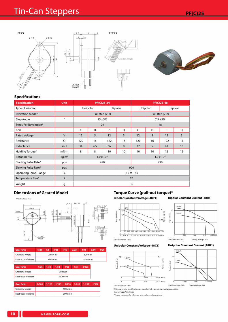
PF(C)25
Bipolar Constant Current (48R1)
Unipolar Constant Current (48H1)
10
340mA
230mA
5
1000 2000 3000 (pps)
Torq
ue
(mN
·m)
0
2000 (pps)150010005000
5
10
300mA
200mA
Torq
ue
(mN
·m)
Coil Resistance: 35Ω Supply Voltage: 24V
Coil Resistance: 34Ω Supply Voltage: 24V
Unipolar Constant Voltage (48C1)
Bipolar Constant Voltage (48P1)
*Torque curves are for reference only and are not guaranteed
Torque Curve (pull-out torque)*
Speciication Unit PF(C)25-24 PF(C)25-48
Type of Winding Unipolar Bipolar Unipolar Bipolar
Excitation Mode* Full step (2-2) Full step (2-2)
Step Angle ˚ 15 ±5% 7.5 ±5%
Steps Per Revolution* 24 48
Coil C D P Q C D P Q
Rated Voltage V 12 5 12 5 12 5 12 5
Resistance Ω 120 16 122 15 120 16 122 15
Inductance mH 34 4.5 66 8 37 5 81 10
Holding Torque* mN·m 8 8 10 10 10 10 12 12
Rotor Inertia kg·m2 1.0 x 10⁻⁷ 1.0 x 10⁻⁷
Starting Pulse Rate* pps 490 790
Slewing Pulse Rate* pps 900
Operating Temp. Range ˚C -10 to +50
Temperature Rise* K 70
Weight g 35
Coil Resistance: 120Ω
Coil Resistance: 122Ω
Speciications
1.4
0.71
Torq
ue (
oz�i
n)
www.nipponpulse.com
5
10
Torq
ue (
mN
�m) 25.6V
12.8V
0 20.8 31.3 (RPS)10.4
0 500 1000 1500 (PPS)
All tin-can motor speciications are based on full-step constant voltage operation.
Magnet type: Anisotropic
1.4
Torq
ue (
oz�i
n)
10
To
rqu
e (
mN
�m)
24V
15V
12V
0.715
0 100 200 300 400 500 600 700 800 900 (PPS)
0 2.08 12.5 18.814.6 (RPS)4.17 6.25 8.33 10.4 16.7
Resistance: 122ohm
Nippon Pulse America, Inc. www.nipponpulse.com
2-Ø 3.32-R 3
1
1.5
30°
720
0 ±1
0
Ø7
-0.1
0
Ø2
5
158.2
0.8
32
±0
.2
38
Ø2
-0.0
1 0
UL1061
AWG28Dimensions in mm
2-Ø3.5
MAX. 26 (1)11.6
11.32
1
MA
X.
Ø 2
5.6
-0.1
0Ø
6
-0.0
2
0
Ø3
2.5
8
Ø 2
5
6 ±
0.2
2-
7
37
31 ±0.2
20
0 ±
10
(7)
AWG28
UL1061
PF(C)25 w/P Gear Head
Gear Ratio 6/25 1/5 3/25 1/10 2/25 1/15 3/50 1/20
Ordinary Torque 20mN·m 50mN·m
Destruction Torque 60mN·m 150mN·m
Gear Ratio 1/100 1/120 1/125 1/150 1/200 1/250 1/300
Ordinary Torque 100mN·m
Destruction Torque 300mN·m
Gear Ratio 1/25 1/30 1/50 1/60 1/75 2/125
Ordinary Torque 70mN·m
Destruction Torque 210mN·m
Dimensions of Geared Model
PF25 PFC25
NPMEUROPE.COM
Tin-Can Steppers
11
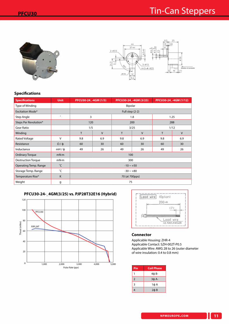
PFCU30
Speciications Unit PFCU30-24_-4GM (1/5) PFCU30-24_-4GM (3/25) PFCU30-24_-4GM (1/12)
Type of Winding Bipolar
Excitation Mode* Full step (2-2)
Step Angle ˚ 3 1.8 1.25
Steps Per Revolution* 120 200 288
Gear Ratio 1/5 3/25 1/12
Winding T V T V T V
Rated Voltage V 9.8 6.9 9.8 6.9 9.8 6.9
Resistance Ω / ф 60 30 60 30 60 30
Inductance mH / ф 49 26 49 26 49 26
Ordinary Torque mN·m 100
Destruction Torque mN·m 300
Operating Temp. Range ˚C -10 ~ +50
Storage Temp. Range ˚C -30 ~ +80
Temperature Rise* K 70 (at 700pps)
Weight g 75
Speciications
PFCU30-24-_4GM(3/25) vs. PJP28T32E16 (Hybrid)
Pin Coil Phase
1 4ф B-
2 3ф A-
3 1ф A
4 2ф B
Connector
Applicable Housing: ZHR-4Applicable Contact: SZH-002T-P0.5Applicable Wire: AWG 28 to 26 (outer diameter of wire insulation: 0.4 to 0.8 mm)
Tin-Can Steppers
12 NPMEUROPE.COM
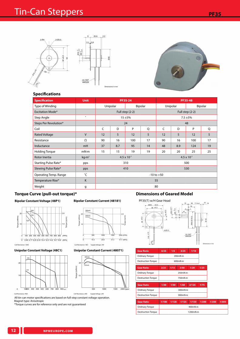
PF35
Unipolar Constant Voltage (48C1)
Bipolar Constant Voltage (48P1)
Unipolar Constant Current (48071)
Bipolar Constant Current (48181) PF35(T) w/H Gear Head
*Torque curves are for reference only and are not guaranteed
Nippon Pulse America, Inc. www.nipponpulse.com
PF35 Tin-Can Stepper with Gearhead (H Type)
Dimensions in mm
UL1007
AWG28
(10)
36.6 (max)
10
15
136 ±0.2
43.5MAX
(4)
16
4-Ø3.5
2
36
±0.2
310
±15
10
±0.2
Ø10
±0.1
Ø5
-0.0
50
4.5
MA
X Ø
43.5
Ø 3
5
Dimensions of Geared ModelTorque Curve (pull-out torque)*
Gear Ratio 6/25 1/5 3/25 1/10
Ordinary Torque 200mN·m
Destruction Torque 600mN·m
Gear Ratio 1/30 1/50 1/60 2/125 1/75
Ordinary Torque 300mN·m
Destruction Torque 900mN·m
Gear Ratio 2/25 1/15 3/50 1/20 1/25
Ordinary Torque 250mN·m
Destruction Torque 750mN·m
Nippon Pulse America, Inc. www.nipponpulse.com
Dimensions in mm
30°
UL1007
AWG28
Ø3
5
310 ±
15
2.29
1.5 0.8
20.6(1
0)
2-R4 2-Ø3.5
42
±0
.2
50
Ø1
00 -0
.1
Ø2
0 -0.0
1
Speciication Unit PF35-24 PF35-48
Type of Winding Unipolar Bipolar Unipolar Bipolar
Excitation Mode* Full step (2-2) Full step (2-2)
Step Angle ˚ 15 ±5% 7.5 ±5%
Steps Per Revolution* 24 48
Coil C D P Q C D P Q
Rated Voltage V 12 5 12 5 12 5 12 5
Resistance Ω 90 16 100 17 90 16 100 17
Inductance mH 37 8.7 95 14 48 8.9 124 19
Holding Torque mN·m 15 15 19 19 20 20 25 25
Rotor Inertia kg·m2 4.5 x 10⁻⁷ 4.5 x 10⁻⁷
Starting Pulse Rate* pps 310 500
Slewing Pulse Rate* pps 410 530
Operating Temp. Range ˚C -10 to +50
Temperature Rise* K 55
Weight g 80
Nippon Pulse America, Inc. www.nipponpulse.com
10
20
To
rqu
e (
mN
�m)
24V
12V
15V
1.4
2.8
To
rqu
e (
oz�i
n)
0 100 200 300 400 500 600 700 800 900 (PPS)
0 2.08 12.5 18.814.6 (RPS)4.17 6.25 8.33 10.4 16.7
Resistance: 100ohm
Nippon Pulse America, Inc. www.nipponpulse.com
20
10
To
rqu
e (
mN
�m)
300mA
200mA
0 10.4 20.8 41.731.3 (RPS)
2.8
1.4 To
rqu
e (
oz�i
n)
(PPS)0 500 1000 1500 2000
Resistance: 90ohm
2000 (pps)15001000500
20
10
460mA
355mA
Torq
ue
(mN
·m)
100200 300 400 500 600 700 800 900 (pps)0
10
20
24V
12V
Coil Resistance: 100Ω Coil Resistance: 18Ω Supply Voltage: 24V
Coil Resistance: 90Ω Coil Resistance: 20Ω Supply Voltage: 24V
Speciications
All tin-can motor speciications are based on full-step constant voltage operation.Magnet type: Anisotropic Gear Ratio 1/100 1/120 1/125 1/150 1/200 1/250 1/300
Ordinary Torque 400mN·m
Destruction Torque 1200mN·m
31 (max) (3)
NPMEUROPE.COM
Tin-Can Steppers
13
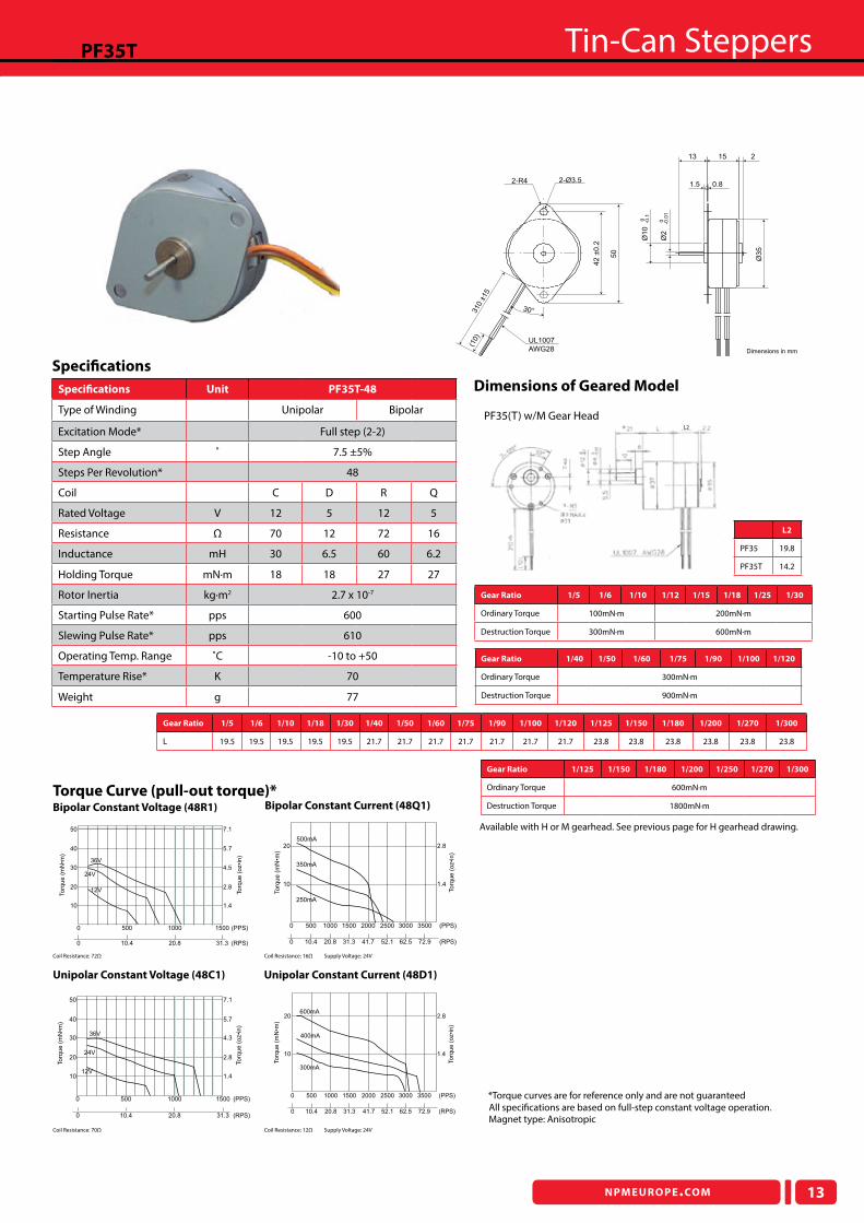
PF35T
Unipolar Constant Voltage (48C1)
Bipolar Constant Voltage (48R1)
Unipolar Constant Current (48D1)
Bipolar Constant Current (48Q1)
PF35(T) w/M Gear Head
Dimensions of Geared Model
Torque Curve (pull-out torque)*
Gear Ratio 1/5 1/6 1/10 1/12 1/15 1/18 1/25 1/30
Ordinary Torque 100mN·m 200mN·m
Destruction Torque 300mN·m 600mN·m
Gear Ratio 1/125 1/150 1/180 1/200 1/250 1/270 1/300
Ordinary Torque 600mN·m
Destruction Torque 1800mN·m
Gear Ratio 1/40 1/50 1/60 1/75 1/90 1/100 1/120
Ordinary Torque 300mN·m
Destruction Torque 900mN·m
Nippon Pulse America, Inc. www.nipponpulse.com
Dimensions in mm
2-R4 2-Ø3.5
310 ±
15
(10)
UL1007
AWG28
30°
42
±0
.2
50
13 15 2
1.5 0.8
Ø1
0-0
.10
Ø2
-0.0
10
Ø3
5
36V
24V
12V
To
rqu
e (
mN
�m)
2.8
1.4
To
rqu
e (
oz�i
n)
0 20.8 31.3 (RPS)10.4
0 500 1000 1500 (PPS)
50
40
30
20
10
4.5
5.7
7.1
Resistance: 72ohm
20
10
500mA
350mA
250mA
Torq
ue (
mN
�m)
0 500 1000 1500 2000 2500 3000 3500 (PPS)
2.8
1.4
Torq
ue (
oz�i
n)
Nippon Pulse America, Inc. www.nipponpulse.com
0 20.8 31.3 (RPS)10.4 41.7 52.1 62.5 72.9
Resistance: 16ohm
36V
24V
12V
Torq
ue (
mN
�m)
50
40
30
20
10
Nippon Pulse America, Inc. www.nipponpulse.com
0 20.8 31.3 (RPS)10.4
0 500 15001000 (PPS)
Torq
ue (
oz�i
n)
7.1
5.7
4.3
2.8
1.4
Resistance: 70ohm
20
10
600mA
400mA
300mA
Torq
ue (
mN
�m)
2.8
1.4
Torq
ue (
oz�i
n)
0 500 1000 1500 2000 2500 3000 3500 (PPS)
Nippon Pulse America, Inc. www.nipponpulse.com
0 20.8 31.3 (RPS)10.4 41.7 52.1 62.5 72.9
Resistance: 12ohm
Speciications Unit PF35T-48
Type of Winding Unipolar Bipolar
Excitation Mode* Full step (2-2)
Step Angle ˚ 7.5 ±5%
Steps Per Revolution* 48
Coil C D R Q
Rated Voltage V 12 5 12 5
Resistance Ω 70 12 72 16
Inductance mH 30 6.5 60 6.2
Holding Torque mN·m 18 18 27 27
Rotor Inertia kg·m2 2.7 x 10⁻⁷
Starting Pulse Rate* pps 600
Slewing Pulse Rate* pps 610
Operating Temp. Range ˚C -10 to +50
Temperature Rise* K 70
Weight g 77
Coil Resistance: 72Ω Coil Resistance: 16Ω Supply Voltage: 24V
Coil Resistance: 70Ω Coil Resistance: 12Ω Supply Voltage: 24V
Speciications
*Torque curves are for reference only and are not guaranteed
Available with H or M gearhead. See previous page for H gearhead drawing.
All speciications are based on full-step constant voltage operation.Magnet type: Anisotropic
Gear Ratio 1/5 1/6 1/10 1/18 1/30 1/40 1/50 1/60 1/75 1/90 1/100 1/120 1/125 1/150 1/180 1/200 1/270 1/300
L 19.5 19.5 19.5 19.5 19.5 21.7 21.7 21.7 21.7 21.7 21.7 21.7 23.8 23.8 23.8 23.8 23.8 23.8
L2
PF35 19.8
PF35T 14.2
L2
Tin-Can Steppers
14 NPMEUROPE.COM
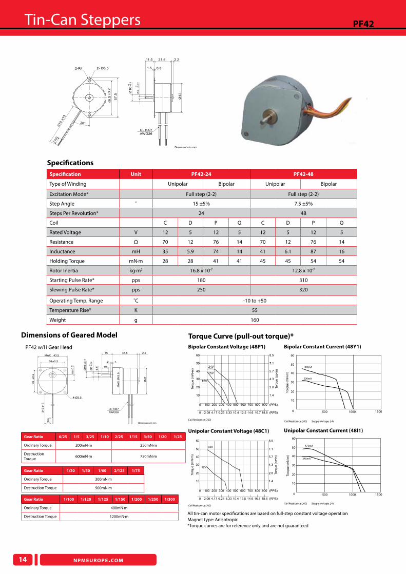
PF42
Unipolar Constant Voltage (48C1)
Bipolar Constant Voltage (48P1) Bipolar Constant Current (48Y1)
Unipolar Constant Current (48I1)
PF42 w/H Gear Head
Nippon Pulse America, Inc. www.nipponpulse.com
PF42 Tin-Can Stepper with Gearhead (H Type)
Dimensions in mm
UL1007
AWG26
37.8
1
15
36±0.2
10
43.5MAX
4-Ø3.5
2
2.2
36
±0.2
310
±15
(10)
10
±0.2
Ø10
±0.1
Ø5
-0.0
50
4.5
Ø42
MA
X Ø
43.5
*Torque curves are for reference only and are not guaranteed
Dimensions of Geared Model Torque Curve (pull-out torque)*
Gear Ratio 6/25 1/5 3/25 1/10 2/25 1/15 3/50 1/20 1/25
Ordinary Torque 200mN·m 250mN·m
Destruction Torque
600mN·m 750mN·m
Gear Ratio 1/100 1/120 1/125 1/150 1/200 1/250 1/300
Ordinary Torque 400mN·m
Destruction Torque 1200mN·m
Gear Ratio 1/30 1/50 1/60 2/125 1/75
Ordinary Torque 300mN·m
Destruction Torque 900mN·m
www.nipponpulse.com
PF42 Tin Can Stepper
Dimensions in mm
UL1007
AWG26
(10)
Ø10
0 -0.1
21.811.5
1.5 0.8
49.5
±0.2
Ø3
0 -0.0
1
310
±15
57.5
Ø42
2-R4 2- Ø3.5
30°
2.2
Speciication Unit PF42-24 PF42-48
Type of Winding Unipolar Bipolar Unipolar Bipolar
Excitation Mode* Full step (2-2) Full step (2-2)
Step Angle ˚ 15 ±5% 7.5 ±5%
Steps Per Revolution* 24 48
Coil C D P Q C D P Q
Rated Voltage V 12 5 12 5 12 5 12 5
Resistance Ω 70 12 76 14 70 12 76 14
Inductance mH 35 5.9 74 14 41 6.1 87 16
Holding Torque mN·m 28 28 41 41 45 45 54 54
Rotor Inertia kg·m2 16.8 x 10⁻⁷ 12.8 x 10⁻⁷
Starting Pulse Rate* pps 180 310
Slewing Pulse Rate* pps 250 320
Operating Temp. Range ˚C -10 to +50
Temperature Rise* K 55
Weight g 160
2.8
1.4
To
rqu
e (
oz�i
n)
10
20To
rqu
e (
mN
�m)
4.330
5.740
7.150
8.560
0 100 200 300 400 500 600 700 800 900 (PPS)
0 2.08 12.5 18.814.6 (RPS)4.17 6.25 8.33 10.4 16.7
24V
12V
Resistance: 70ohm
10
20To
rqu
e (
mN
�m)
30
40
50
60
2.8
1.4
To
rqu
e (
oz�i
n)
4.3
5.7
7.1
8.5
0 100 200 300 400 500 600 700 800 900 (PPS)
0 2.08 12.5 18.814.6 (RPS)4.17 6.25 8.33 10.4 16.7
24V
12V
15V
Resistance: 76ohm
40
Torq
ue
(mN
·m)
50
60
30
10
0 500 1000
473mA
345mA
1500
20
40
Torq
ue
(mN
·m)
50
60
30
10
0
20
500 1000 1500
Coil Resistance: 76Ω
Coil Resistance: 20Ω Supply Voltage: 24VCoil Resistance: 70Ω
Coil Resistance: 20Ω Supply Voltage: 24V
Speciications
All tin-can motor speciications are based on full-step constant voltage operationMagnet type: Anisotropic
300mA
200mA

NPMEUROPE.COM
Tin-Can Steppers
15
PFC42H
Unipolar Constant Voltage (48C1)
Bipolar Constant Voltage (48P1)
Unipolar Constant Current (48D1)
Bipolar Constant Current (48Q1)
PFC42H w/H Gear Head
Nippon Pulse America, Inc. www.nipponpulse.com
PFC42H Tin-Can Stepper with Gearhead (H Type)
Dimensions in mm
36±0.2
43.5MAX
4-Ø3.5
36
±0
.2
31
0±1
5
10
10
±0
.2
UL1007
AWG26
37.8
1
15
10
2
2.2
Ø1
0±0
.1
Ø5
-0.0
50
4.5
Ø4
2
MA
X Ø
43
.5
*Torque curves are for reference only and are not guaranteed
Dimensions of Geared Model
Torque Curve (pull-out torque)* Gear Ratio 6/25 1/5 3/25 1/10 2/25 1/15 3/50 1/20 1/25
Ordinary Torque
200mN·m 250mN·m
Destruction Torque
600mN·m 750mN·m
Gear Ratio 1/100 1/120 1/125 1/150 1/200 1/250 1/300
Ordinary Torque
400mN·m
Destruction Torque
1200mN·m
Gear Ratio 1/30 1/50 1/60 2/125 1/75
Ordinary Torque 300mN·m
Destruction Torque 900mN·m
Nippon Pulse America, Inc. www.nipponpulse.com
PFC42H Tin-Can Stepper
Dimensions in mm
4.5
21.8
3
Ø1
0
11.5 2.2
Ø4
2
0.81.5
9
Ø3
2-Ø 3.52-R 4
30°
310
±15
5.8
12.4
18
(10)
49
.5 ±
0.2
57
.5
UL1007
AWG26
0 -0.1
0 -0.0
1
Speciication Unit PFC42H-48
Type of Winding Unipolar Bipolar
Excitation Mode* Full step (2-2)
Step Angle ˚ 7.5 ±5%
Steps Per Revolution* 48
Coil C D P Q
Rated Voltage V 12 5 12 5
Resistance Ω 70 12 70 12
Inductance mH 39 6.6 80 13
Holding Torque mN·m 50 50 70 70
Rotor Inertia kg·m2 27 x 10-7
Starting Pulse Rate* pps 290
Slewing Pulse Rate* pps 320
Operating Temp. Range ˚C -10 to +50
Temperature Rise* K 55
Weight g 160
14.2
7.1
Torq
ue (
oz�i
n)
50
100
Torq
ue (
mN
�m)
0 100 200 300 400 500 600 700 800 900 (PPS)
0 2.08 12.5 18.814.6 (RPS)4.17 6.25 8.33 10.4 16.7
36V
24V
12V
Resistance: 9ohm
Nippon Pulse America, Inc. www.nipponpulse.com
0 20.8 31.3 (RPS)10.4
0 500 1000 1500 (PPS)
14.2
7.1
Torq
ue (
oz�i
n)
50
100
Torq
ue (
mN
�m)
600mA
400mA
300mA
Resistance:
14.2
7.1
To
rqu
e (
oz�i
n)
50
100
To
rqu
e (
mN
�m)
36V
24V
12V
0 100 200 300 400 500 600 700 800 900 (PPS)
0 2.08 12.5 18.814.6 (RPS)4.17 6.25 8.33 10.4 16.7
14.2
7.1
To
rqu
e (
oz�i
n)
Nippon Pulse America, Inc. www.nipponpulse.com
50
100
To
rqu
e (
mN
�m)
600mA
400mA
300mA
0 20.8 31.3 (RPS)10.4
0 500 1000 1500 (PPS)
(2200pps)(2000pps)
Resistance: 12ohm
Coil Resistance: 70Ω Coil Resistance: 12Ω Supply Voltage: 24V
Coil Resistance: 70Ω Coil Resistance: 12Ω Supply Voltage: 24V
Speciications
All tin-can motor speciications are based on full-step constant voltage operation.Magnet type: Anisotropic
Tin-Can Steppers
16 NPMEUROPE.COM
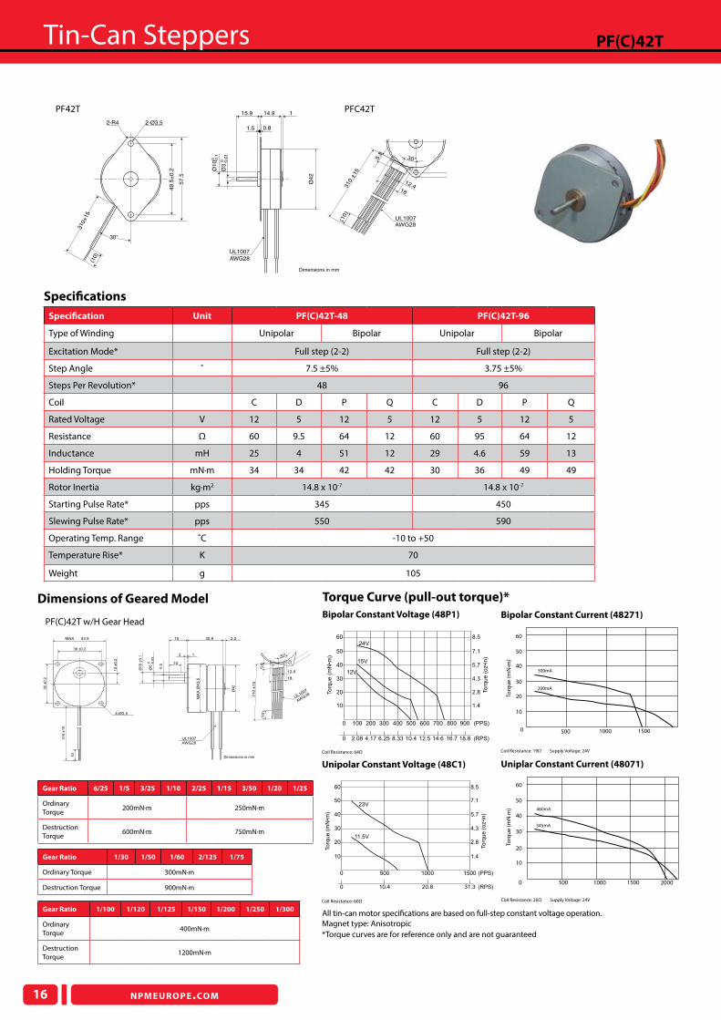
PF(C)42T
Unipolar Constant Voltage (48C1)
Bipolar Constant Voltage (48P1) Bipolar Constant Current (48271)
Uniplar Constant Current (48071)
PF(C)42T w/H Gear Head
www.nipponpulse.com
PF42T Tin-Can Stepper with Gearhead (H Type)
Dimensions in mm
43.5MAX
4-Ø3.5
Ø4
2
UL1007
AWG28
1
15 30.9
10
2
2.2
Ø5
0 -0.0
5
4.5
MA
X Ø
43
.5
36
±0
.2
31
0 ±
15
36 ±0.2
10
±0
.2
Ø1
0 ±
0.1
10
*Torque curves are for reference only and are not guaranteed
Gear Ratio 6/25 1/5 3/25 1/10 2/25 1/15 3/50 1/20 1/25
Ordinary Torque
200mN·m 250mN·m
Destruction Torque
600mN·m 750mN·m
Gear Ratio 1/100 1/120 1/125 1/150 1/200 1/250 1/300
Ordinary Torque
400mN·m
Destruction Torque
1200mN·m
Gear Ratio 1/30 1/50 1/60 2/125 1/75
Ordinary Torque 300mN·m
Destruction Torque 900mN·m
Dimensions of Geared Model Torque Curve (pull-out torque)*
Nippon Pulse America, Inc. www.nipponpulse.com
PF42T Tin-Can Stepper
Dimensions in mm
UL1007
AWG28
Ø4
2
310±15
115.9
30°
14.9
(10)
2-R4 2-Ø3.5
49
.5±
0.2
57
.5
Ø3
0 -0.0
1
Ø1
00 -0
.1
1.5 0.8
Speciication Unit PF(C)42T-48 PF(C)42T-96
Type of Winding Unipolar Bipolar Unipolar Bipolar
Excitation Mode* Full step (2-2) Full step (2-2)
Step Angle ˚ 7.5 ±5% 3.75 ±5%
Steps Per Revolution* 48 96
Coil C D P Q C D P Q
Rated Voltage V 12 5 12 5 12 5 12 5
Resistance Ω 60 9.5 64 12 60 95 64 12
Inductance mH 25 4 51 12 29 4.6 59 13
Holding Torque mN·m 34 34 42 42 30 36 49 49
Rotor Inertia kg·m2 14.8 x 10⁻⁷ 14.8 x 10⁻⁷
Starting Pulse Rate* pps 345 450
Slewing Pulse Rate* pps 550 590
Operating Temp. Range ˚C -10 to +50
Temperature Rise* K 70
Weight g 105
Nippon Pulse America, Inc. www.nipponpulse.com
10
20Torq
ue (
mN
�m)
30
40
50
60
2.8
1.4
Torq
ue (
oz�i
n)
4.3
5.7
7.1
8.5
0 100 200 300 400 500 600 700 800 900 (PPS)
0 2.08 12.5 18.814.6 (RPS)4.17 6.25 8.33 10.4 16.7
24V
15V
12V
Resistance: 64ohm
2.8
1.4
To
rqu
e (
oz�i
n)
www.nipponpulse.com
10
20
To
rqu
e (
mN
�m)
23V
11.5V
0 20.8 31.3 (RPS)10.4
0 500 1000 1500 (PPS)
4.330
5.740
7.150
8.560
Resistance: 60ohm
40
Torq
ue
(mN
·m)
50
60
30
10
0
20
500 1000 1500 2000
460mA
345mA
0 500 1000 1500
40
Torq
ue
(mN
·m)
50
60
30
10
20
300mA
200mA
Coil Resistance: 64Ω Coil Resistance: 19Ω Supply Voltage: 24V
Coil Resistance: 60Ω Coil Resistance: 20Ω Supply Voltage: 24V
Speciications
All tin-can motor speciications are based on full-step constant voltage operation.
Nippon Pulse America, Inc.
UL1007
AWG28
(10)
5.8
310 ±
15
12.418
Ø4
9.5
±0
.2
30°
Magnet type: Anisotropic
Nippon Pulse Americ
a, Inc.
a subsidiary of Nippon P
ulse Motor C
o., Ltd.
UL1007
AWG28
57.5
(10)
5.8
310 ±
15
12.4
18
Ø49.5
±0.2
30°
PF42T PFC42T
NPMEUROPE.COM
Tin-Can Steppers
17
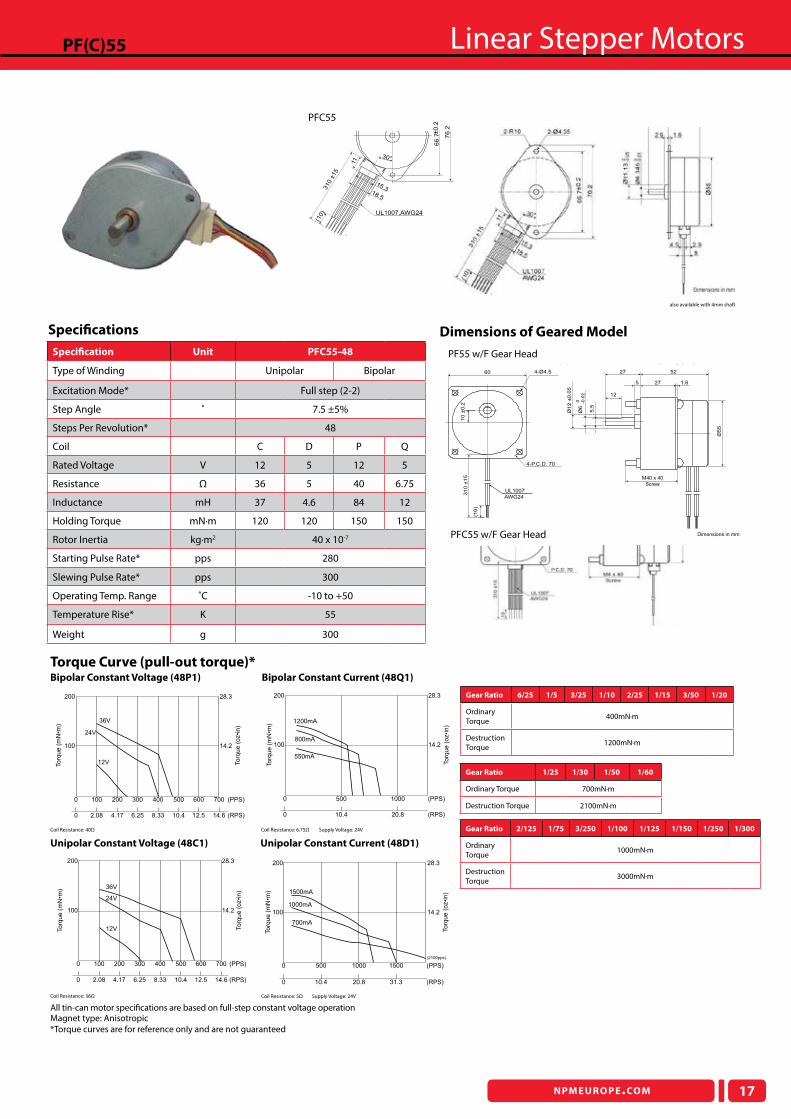
PF(C)55 Linear Stepper Motors
Unipolar Constant Voltage (48C1)
Bipolar Constant Voltage (48P1)
Unipolar Constant Current (48D1)
Bipolar Constant Current (48Q1)
PF55 w/F Gear Head
Nippon Pulse America, Inc. www.nipponpulse.com
PF55 Tin-Can Stepper with Gearhead (F Type)
Dimensions in mm
UL1007
AWG24
10 ±
0.2
310 ±
15
60
(10)
4-P.C.D. 70
4-Ø4.5
Ø6
0 -0.0
2
Ø12 ±
0.0
5
5.5
Ø55
12
5227
1.65 27
M40 x 40
Screw
*Torque curves are for reference only and are not guaranteed
Dimensions of Geared Model
Torque Curve (pull-out torque)*
Gear Ratio 6/25 1/5 3/25 1/10 2/25 1/15 3/50 1/20
Ordinary Torque
400mN·m
Destruction Torque
1200mN·m
Gear Ratio 2/125 1/75 3/250 1/100 1/125 1/150 1/250 1/300
Ordinary Torque
1000mN·m
Destruction Torque
3000mN·m
Gear Ratio 1/25 1/30 1/50 1/60
Ordinary Torque 700mN·m
Destruction Torque 2100mN·m
Speciication Unit PFC55-48
Type of Winding Unipolar Bipolar
Excitation Mode* Full step (2-2)
Step Angle ˚ 7.5 ±5%
Steps Per Revolution* 48
Coil C D P Q
Rated Voltage V 12 5 12 5
Resistance Ω 36 5 40 6.75
Inductance mH 37 4.6 84 12
Holding Torque mN·m 120 120 150 150
Rotor Inertia kg·m2 40 x 10-7
Starting Pulse Rate* pps 280
Slewing Pulse Rate* pps 300
Operating Temp. Range ˚C -10 to +50
Temperature Rise* K 55
Weight g 300
28.3
14.2
Torq
ue (
oz�i
n)
100
200
Torq
ue (
mN
�m)
36V
24V
12V
0 8.33 10.4 (RPS)2.08
0 100 400 500
12.5
600 (PPS)
4.17
200
6.25
300
14.6
700
Resistance:
Nippon Pulse America, Inc. www.nipponpulse.com
28.3
14.2
Torq
ue (
oz�i
n)
100
200
Torq
ue (
mN
�m) 1200mA
800mA
550mA
0 20.8 (RPS)10.4
0 500 1000 (PPS)
Resistance: 6.75ohm
28.3
14.2
Torq
ue (
oz�i
n)
Nippon Pulse America, Inc. www.nipponpulse.com
100
200
Torq
ue (
mN
�m)
0 100 200 300 400 500 600 700 (PPS)
0 2.08 12.5 14.6 (RPS)4.17 6.25 8.33 10.4
Resistance: 36ohm
36V
24V
12V
28.3
14.2
Torq
ue (
oz�i
n)
Nippon Pulse America, Inc. www.nipponpulse.com
100
200
Torq
ue (
mN
�m) 1500mA
1000mA
700mA
0 20.8 31.3 (RPS)10.4
0 500 1000 1500 (PPS)
(2100pps)
Resistance: 5ohm
Coil Resistance: 40Ω Coil Resistance: 6.75Ω Supply Voltage: 24V
Coil Resistance: 36Ω Coil Resistance: 5Ω Supply Voltage: 24V
Speciications
All tin-can motor speciications are based on full-step constant voltage operationMagnet type: Anisotropic
also available with 4mm shaft
Nippon Pulse America, Inc.
UL1007,AWG24
310 ±
15
11
66
.7±0
.2
(10)
76
.2
18.5
15.3
30°
PFC55
PFC55 w/F Gear Head

Tin-Can Steppers
18 NPMEUROPE.COM
PFC55HTin-Can Steppers
PFC55H w/F(BB) Gear Head
*Torque curves are for reference only and are not guaranteed
Gear Ratio 1/3 1/5 2/15 1/10 2/25 1/15 1/20
Ordinary Torque 400mN·m 500mN·m 600mN·m 800mN·m
Destruction Torque 1200mN·m 1500mN·m 1800mN·m 2400mN·m
Gear Ratio 1/75 1/100 1/125 1/150 1/180
Ordinary Torque 2500mN·m
Destruction Torque 7500mN·m
Gear Ratio 1/25 1/30 1/50 1/60
Ordinary Torque 900mN·m 1100mN·m 1600mN·m
Destruction Torque 2700mN·m 3300mN·m 4800mN·m
Dimensions of Geared Model
Nippon Pulse America, Inc. www.nipponpulse.com
Dimensions in mm
UL1007AWG24
4.5310 ±
15
11
9
66.7
±0.2
(10)
Ø11.1
3 0 -0
.05
1.6
Ø55
76.2
18.5
15.3
26
2-R10
30°
2.9
2.9
2-Ø4.35
18.5
Ø6.3
45
0 -0.0
1
Speciication Unit PFC55H-48
Type of Winding Unipolar Bipolar
Excitation Mode* Full step (2-2)
Step Angle ˚ 7.5 ±5%
Steps Per Revolution* 48
Coil C D P Q
Rated Voltage V 12 5 12 5
Resistance Ω 36 5 36 5
Inductance mH 30 4.4 65 9.3
Holding Torque mN·m 150 150 180 180
Rotor Inertia kg·m2 97 x 10-7
Starting Pulse Rate* pps 210
Slewing Pulse Rate* pps 230
Operating Temp. Range ˚C -10 to +50
Temperature Rise* ˚C 55
Weight g 300
Bipolar Constant Voltage (48011)
Torque Curve (pull-out torque)*
Torq
ue
(mN
·m)
200
300
100
0 100 200 300 400 500 600
36V
24V
12V
Coil Resistance: 40Ω
Bipolar Constant Current (48S1)
Torq
ue
(mN
·m)
100
200
500 1000
1000mA
700mA
500mA
0
Coil Resistance: 8Ω Supply Voltage: 24V
Unipolar Constant Voltage (48C1)
0 100 200 300 400 500 600 700 (PPS)
0 2.08 12.5 14.6 (RPS)4.17 6.25 8.33 10.4
14.2
Torq
ue (
oz�i
n)
100
To
rqu
e (
mN
�m)
28.3200
36V
24V
12V
Resistance: 36ohm
Coil Resistance: 36Ω
Unipolar Constant Current (48D1)
Torq
ue
(mN
·m)
100
200
0 500 1000 1500
1500mA
1000mA
700mA
Coil Resistance: 5Ω Supply Voltage: 24V
Speciications
All tin-can motor speciications are based on full-step constant voltage operationMagnet type: Anisotropic
See page 16 for PFC55H with F gearhead ratios
60 4-ø4.527
12 5 L 25
Setscrew M4 x L60
UL 1007, AWG24
310±
15
10
ø55
ø18
0 -0.3
ø8
0 -0.0
3
7
10±
0.2
P.C.D.70
Reduction Ratio L
1/3 to 1/15 32
1/20 to 1/180 42
NPMEUROPE.COM
Tin-Can Steppers
19
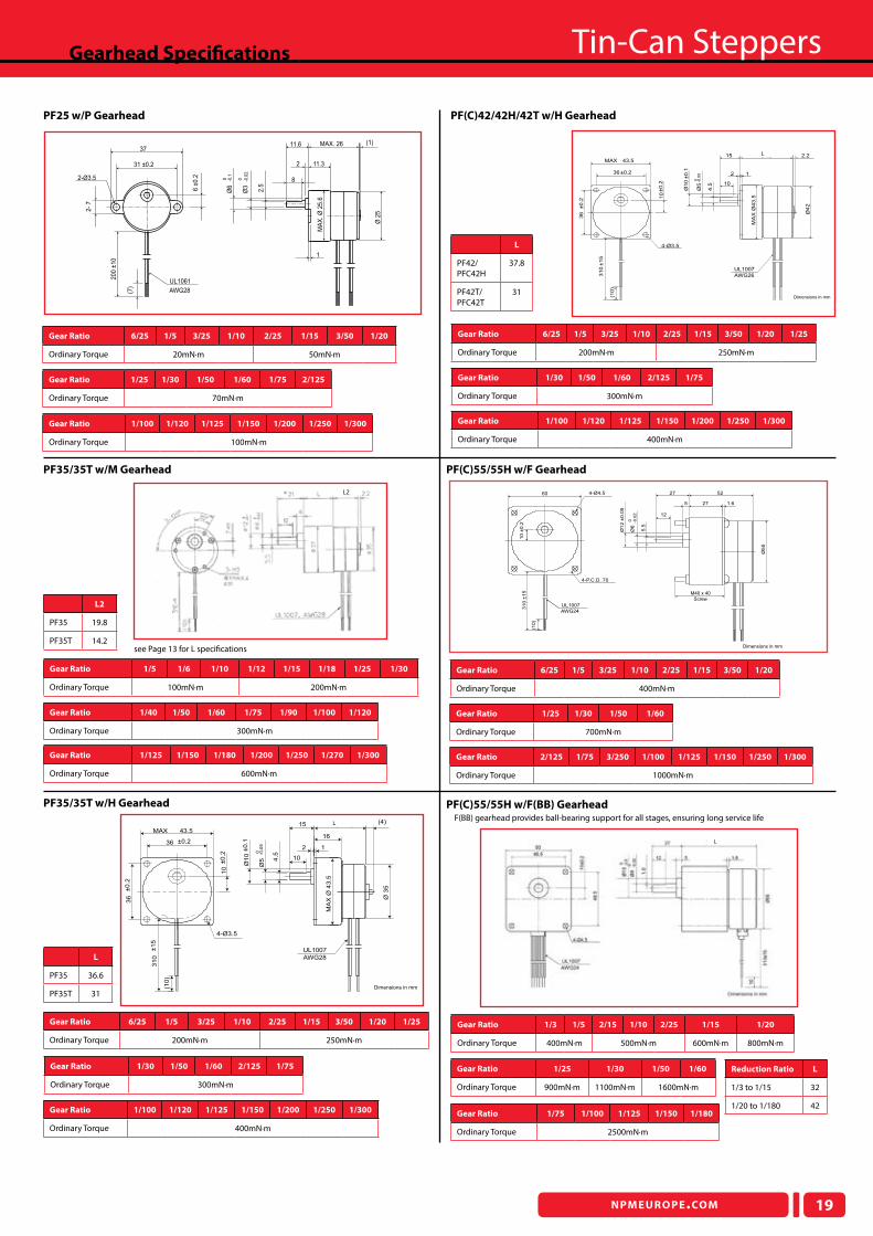
Gearhead Speciications Tin-Can Steppers
PF25 w/P Gearhead PF(C)42/42H/42T w/H Gearhead
PF35/35T w/M Gearhead PF(C)55/55H w/F Gearhead
PF35/35T w/H Gearhead PF(C)55/55H w/F(BB) GearheadF(BB) gearhead provides ball-bearing support for all stages, ensuring long service life
Reduction Ratio L
1/3 to 1/15 32
1/20 to 1/180 42
L2
PF35 19.8
PF35T 14.2
L
PF35 36.6
PF35T 31Nippon Pulse America, Inc. www.nipponpulse.com
Dimensions in mm
UL1007
AWG28
(10)
31 (max)
10
15
136 ±0.2
43.5MAX
(4)
16
4-Ø3.5
2
36
±0.2
310
±15
10
±0.2
Ø10
±0.1
Ø5
-0.0
50
4.5
MA
X Ø
43.5
Ø 3
5
L
PF42/PFC42H
37.8
PF42T/PFC42T
31
see Page 13 for L speciications
Gear Ratio 1/3 1/5 2/15 1/10 2/25 1/15 1/20
Ordinary Torque 400mN·m 500mN·m 600mN·m 800mN·m
Gear Ratio 1/75 1/100 1/125 1/150 1/180
Ordinary Torque 2500mN·m
Gear Ratio 1/25 1/30 1/50 1/60
Ordinary Torque 900mN·m 1100mN·m 1600mN·m
Gear Ratio 6/25 1/5 3/25 1/10 2/25 1/15 3/50 1/20
Ordinary Torque 400mN·m
Gear Ratio 2/125 1/75 3/250 1/100 1/125 1/150 1/250 1/300
Ordinary Torque 1000mN·m
Gear Ratio 1/25 1/30 1/50 1/60
Ordinary Torque 700mN·m
Gear Ratio 6/25 1/5 3/25 1/10 2/25 1/15 3/50 1/20 1/25
Ordinary Torque 200mN·m 250mN·m
Gear Ratio 1/100 1/120 1/125 1/150 1/200 1/250 1/300
Ordinary Torque 400mN·m
Gear Ratio 1/30 1/50 1/60 2/125 1/75
Ordinary Torque 300mN·m
Gear Ratio 1/100 1/120 1/125 1/150 1/200 1/250 1/300
Ordinary Torque 400mN·m
Gear Ratio 1/30 1/50 1/60 2/125 1/75
Ordinary Torque 300mN·m
Gear Ratio 6/25 1/5 3/25 1/10 2/25 1/15 3/50 1/20 1/25
Ordinary Torque 200mN·m 250mN·m
Gear Ratio 1/5 1/6 1/10 1/12 1/15 1/18 1/25 1/30
Ordinary Torque 100mN·m 200mN·m
Gear Ratio 1/125 1/150 1/180 1/200 1/250 1/270 1/300
Ordinary Torque 600mN·m
Gear Ratio 1/40 1/50 1/60 1/75 1/90 1/100 1/120
Ordinary Torque 300mN·m
Gear Ratio 6/25 1/5 3/25 1/10 2/25 1/15 3/50 1/20
Ordinary Torque 20mN·m 50mN·m
Gear Ratio 1/100 1/120 1/125 1/150 1/200 1/250 1/300
Ordinary Torque 100mN·m
Gear Ratio 1/25 1/30 1/50 1/60 1/75 2/125
Ordinary Torque 70mN·m
L2
2-Ø3.5
MAX. 26 (1)11.6
11.32
1
MA
X. Ø
25.6
-0.1
0Ø
6
-0.0
2
0
Ø3
2.5
8
Ø 2
5
6 ±
0.2
2-
7
37
31 ±0.2
200 ±
10
(7)
AWG28
UL1061
PF55 Tin-Can Stepper with Gearhead (F Type)
Dimensions in mm
UL1007
AWG24
10 ±
0.2
310 ±
15
60
(10)
4-P.C.D. 70
4-Ø4.5
Ø6
0 -0.0
2
Ø12 ±
0.0
5
5.5
Ø55
12
5227
1.65 27
M40 x 40
Screw
Nippon Pulse America, Inc. www.nipponpulse.com
Dimensions in mm
UL1007
AWG26
37.8
1
15
36±0.2
10
43.5MAX
4-Ø3.5
2
2.2
36
±0.2
310
±15
(10)
10
±0.2
Ø10
±0.1
Ø5
-0.0
50
4.5
Ø42
MA
X Ø
43.5
L
L
L