Embed Size (px)
Citation preview
This article was downloaded by: [Tufts University]On: 05 October 2014, At: 01:01Publisher: Taylor & FrancisInforma Ltd Registered in England and Wales Registered Number: 1072954 Registered office: Mortimer House,37-41 Mortimer Street, London W1T 3JH, UK
EDPACS: The EDP Audit, Control, and SecurityNewsletterPublication details, including instructions for authors and subscription information:http://www.tandfonline.com/loi/uedp20
The Next Generation of Control: Local PositioningJay Werb a & Colin Lanzl ba Vice President of Engineering at PinPoint Corporation, conceptualized the PinPoint productand continues to manage the development of its software. From 1984 to 1994, he was afounder and Vice President of Engineering at ADDAX, Inc., a Cambridge, MA consultingorganization that specializes in airport logistics and retail applications. Prior to being atADDAX, Werb was a programmer at Pugh Roberts Associates. He holds both an M.A. inManagement and a B.A. in Biology from MIT.b Chief Architect of PinPoint Corporation, Bedford, MA, manages all of its hardwareengineering activities. Formerly, he was with Windata where he was a founder and the chiefengineer. Lanzl created some of the earliest wireless local area network products. Prior tothis, he was with Anderson Laboratories, where he led a major surface acoustic wave designteam. He is the author of five IEEE papers on acoustics and signal processing. Lanzl holds aB.A. in Science and Electrical Engineering from Rensselaer Polytechnic Institute.Published online: 21 Dec 2006.
To cite this article: Jay Werb & Colin Lanzl (1999) The Next Generation of Control: Local Positioning, EDPACS: The EDP Audit,Control, and Security Newsletter, 26:8, 1-17, DOI: 10.1201/1079/43245.26.8.19990201/30240.1
To link to this article: http://dx.doi.org/10.1201/1079/43245.26.8.19990201/30240.1
PLEASE SCROLL DOWN FOR ARTICLE
Taylor & Francis makes every effort to ensure the accuracy of all the information (the “Content”) containedin the publications on our platform. However, Taylor & Francis, our agents, and our licensors make norepresentations or warranties whatsoever as to the accuracy, completeness, or suitability for any purpose of theContent. Any opinions and views expressed in this publication are the opinions and views of the authors, andare not the views of or endorsed by Taylor & Francis. The accuracy of the Content should not be relied upon andshould be independently verified with primary sources of information. Taylor and Francis shall not be liable forany losses, actions, claims, proceedings, demands, costs, expenses, damages, and other liabilities whatsoeveror howsoever caused arising directly or indirectly in connection with, in relation to or arising out of the use ofthe Content.
This article may be used for research, teaching, and private study purposes. Any substantial or systematicreproduction, redistribution, reselling, loan, sub-licensing, systematic supply, or distribution in anyform to anyone is expressly forbidden. Terms & Conditions of access and use can be found at http://www.tandfonline.com/page/terms-and-conditions
THE EDP AUDIT,
CONTROL, AND SECURITY
NEWSLETTER
EDPACS
FEBRUARY 1999 VOL. XXVI, NO. 8
THE NEXT GENERATION OF CONTROL:LOCAL POSITIONING
JAY WERB AND COLIN LANZL
O
ne of the basic control considerations in any organizationis determining reliably where its physical assets are located.Products being developed currently will change that aspect ofcontrol and will impact the work of every IS auditor. This ar-ticle explains how one of these products works and how it canbe used to control the physical assets of an organization.
THE NEXT GENERATION OF CONTROL
Much effort and major investments in a variety of informa-tion-processing applications have been made by many enter-prises in what have turned out to be less than effective meansfor maintaining control of assets. One possibility for improv-ing the tracking and control of assets would be some adapta-tion of the technology that is used with the Global PositioningSystems (GPS) that use the Navstar satellites. GPS technologyhas been employed, for example, for some time in locating andcontrolling the operation of various types of motor vehiclesand railway trains. (Some of these applications were discussedin the April 1996 and April 1998 issues of
EDPACS
.)However, despite the proven effectiveness of GPS technolo-
gy, millions of acres of indoor space are beyond the reach ofthe Navstar satellites. GPS signals originate 10,898 milesabove the Earth. These signals are not designed to penetratethe materials that are found in most commercial construction,and it is likely that no amount of technical wizardry will over-come this limitation. Thus, most world commerce is conductedin places where GPS cannot be used.
COMMON CONTROL CHALLENGES
Consider some common control challenges. Perpetual physicalinventory is needed for an MRP (materials requirement plan-ning) system as well as to prevent the loss and pilferage of as-sets. Mobile assets, such as expensive hospital gear, aredifficult to find when they are required. Again, costly and
IN THIS ISSUE
■
The Next Generation of Control: Local Positioning
■
Abstracts & Commentary
■
Of Interest
Editor
BELDEN MENKUS, CISA
Dow
nloa
ded
by [
Tuf
ts U
nive
rsity
] at
01:
01 0
5 O
ctob
er 2
014
2
FEBRUARY 1999
E D P A C S
© Copyright 1999 CRC Press–All rights reserved.
elaborate procedures are needed to trace and locate manufac-turing work-in-process. Asset loss of high-value items such aslaptop microcomputers has become a serious problem in manyorganizations. Locating people in a large enterprise is time-consuming and disruptive. These challenges share one com-mon theme. There is a continuing need to find and to traceboth physical assets and people that are at some location in-side buildings.
INVOLVEMENT OF PINPOINT
PinPoint became interested in the possible applications of GPStechnology as a result of consulting on some of the informa-tion-processing applications of a U.S. health maintenance or-ganization (HMO). Often, patient files were impossible to findwhen they were needed. As a result of this situation, about 20percent of the patient visits for which the HMO was responsi-ble were being conducted without the appropriate medicalrecord being available. Attempts to bar code the records didnot solve the problem. And the HMO staff did not use the scan-ners reliably when the critical files were being passed fromhand to hand.
Not surprisingly, the more-complicated cases involved mul-tiple care givers. It was these files that were misplaced mostfrequently. In a visit to the facility, several employees fromthe record room, armed with lists of desperately neededrecords, were observed sifting through piles of paper in clini-cal areas. Apparently, they were searching for missing medi-cal records.
Several of the HMO physicians were airplane pilots. Theywondered if there was something like the GPS that they couldput onto the records to track them as the assets movedthrough the facility. The aim was, as someone who was at-tempting to solve this problem put it, to find something like
those badges that everyone wears on
Star Trek.
This seemedto be a reasonable request, but a search of the literature aboutthe available technology found nothing that was aimed at solv-ing this problem.
Over the course of several months, the conviction grew thata technological solution was within reach and that the range
THEY WONDERED IF
THERE WAS
SOMETHING LIKE
THE GPS THAT THEY
COULD PUT ONTO
THE RECORDS TO
TRACK THEM AS
THE ASSETS MOVED
THROUGH THE
FACILITY.
If you have information of interest to
EDPACS,
contact Christian Kirkpatrick, Editor, Auerbach Publications, 535 FifthAve., New York, NY 10017 ([email protected]).
EDPACS
(ISSN 0736-6981) is published monthly by Auerbach Pub-lications, CRC Press LLC, 2000 Corporate Blvd. NW, Boca Raton, FL 33431. Periodicals postage is paid at Boca Raton andadditional mailing offices. The subscription rate is $245/year in the U.S. Prices elsewhere vary. Printed in USA. Copyright© 1999
EDPACS
is a registered trademark owned by CRC Press LLC. All rights reserved. No part of this newsletter may bereproduced in any form—by microfilm, xerography, or otherwise—or incorporated into any information retrieval systemwithout the written permission of the copyright owner. Requests to publish material or to incorporate material into comput-erized databases or any other electronic form, or for other than individual or internal distribution, should be addressed toAuerbach Publications, Editorial Services, 2000 Corporate Blvd. NW, Boca Raton, FL 33431. All rights, including translationinto other languages, reserved by the publisher in the U.S., Great Britain, Mexico, and all countries participating in the In-ternational Copyright Convention and the Pan American Copyright Convention. Product or corporate names may be trade-marks or registered trademarks, and are only used for identification and explanation, without intent to infringe. Postmaster:Send address change to
EDPACS,
Auerbach Publications, CRC Press LLC, 2000 Corporate Blvd. NW, Boca Raton, FL 33431.
Dow
nloa
ded
by [
Tuf
ts U
nive
rsity
] at
01:
01 0
5 O
ctob
er 2
014
FEBRUARY 1999
E D P A C S
3© Copyright 1999 CRC Press–All rights reserved.
of the potential applications for such a solution was mind-bog-gling. The eventual result was the PinPoint Corporation, itsproduct the PinPoint 3D-ID Local Positioning System, and a re-lated set of patent filings. The name 3D-ID emphasizes twofundamental characteristics of the technology.
M
1. The Local Positioning System covers a complete three-dimen-sional indoor space, not just the doorways, conveyor belts, orother fixed points within this expanse.
M
2. The Local Positioning System is capable of determining thethree-dimensional location of specific items within that space.
Hollywood has demonstrated various versions of the 3D-IDconcept since the 1930s. Most people assume that the militaryhas been using such a product for years. Perhaps for this rea-son, 3D-ID is one of the few emerging technologies that mostpeople understand immediately. Intuitively, it is understoodthat it is interesting to know when two Klingons of oppositegender are on the Holodeck. But, now, it is has become possi-ble to build such knowledge into familiar information-process-ing applications. This article attempts to reconstruct thedesign process that resulted in the 3D-ID system, starting witha general idea, an opportunity, and a blank piece of paper.
GOALS OF AN INDOOR LOCAL POSITIONING SYSTEM
Implementing the GPS concept indoors is not a simple matterof mounting Navstar satellite emulators in certain buildings.Enterprise asset-tracking systems have a set of requirementsthat are fundamentally different from the GPS, leading tosome basic design differences. It was decided early in the de-sign process that these characteristics were critical:
M
Tags should be as small and as lightweight as possible for thewidest applicability. Tags are the physical devices that are as-sociated with the people and assets that are being tracked.
M
The tags must be inexpensive. This implies that the design ofthe tag be much less complicated than that of a GPS receiver.
M
Each tag must determine its own location in reference to a fixedinfrastructure. In a particular building, the goal is for the in-frastructure to track thousands of tags. It is not necessary fora tag to know its own position. This difference provides theneeded opportunity to simplify the tag design.
M
Outstanding accuracy is required. For many outdoor applica-tions, location accuracy in the range of 150 feet is more thanadequate. For most indoor applications, however, 30-foot accu-racy is required, and some applications demand five-foot accu-racy or better.
M
A GPS receiver needs to account for a variety of effects that arecaused by the long distance from the satellite. (These effects in-clude atmospherics, relativity, and multipath.) While some ofthese effects are not relevant in the context of a ground-basedmechanism, indoor multipath effects, combined with the higheraccuracy requirement, present an extra challenge.
M
The radio mechanism that is used to track the assets should becompliant with Part 15 U.S. Federal Communications Commis-sion (FCC). This would make it possible for an organization to
IMPLEMENTING THE
GPS IS NOT A
SIMPLE MATTER.
Dow
nloa
ded
by [
Tuf
ts U
nive
rsity
] at
01:
01 0
5 O
ctob
er 2
014
FEBRUARY 1999
E D P A C S
4 © Copyright 1999 CRC Press–All rights reserved.
install and run the mechanism without a license in the UnitedStates and in other countries.
These goals were set based on what was felt to be feasible,combined with informal discussions with the potential end us-ers. In the process of enumerating these goals, the design focusshifted from tagging folders to tagging people and assets. Tag-ging folders has numerous technical challenges, not the least ofwhich is a requirement for extremely low cost. In contrast, tag-ging assets and people is technically easier to accomplish.
EXISTING SHORT-RANGE TECHNOLOGIES
The design process started with a review of existing products.Since the invention of the microprocessor, a variety of short-range radio-based approaches have been employed to trackitems indoors. These technologies are designed to identify ob-jects within the range of a sensor. Depending on the technologythat is being used in the identification process, the range of thesensor can be from a few centimeters up to about three meters.
Most people are familiar with the EAS (electronic articlesurveillance) systems widely used in retail and library set-tings. EAS technology is designed to deter theft by amateurs,and is well suited to that limited purpose. The very simple tagsare designed to resonate when subjected to a matched elec-tronic field, and an alarm sounds when such resonance is de-tected. The restrictions on the use of EAS include the limitedrange, the low reliability, and the lack of an identification codeon the tags.
A Newer Technology
A newer technology, RFID (radio-frequency identification),has been emerging over the past 10 years as a substitute forbar codes. With ranges of up to about three meters, RFID tagsare designed to be identified as they pass fixed sensors. Con-sumer applications for RFID include gasoline purchase pay-ment and automated toll-taking. Commercial applicationsinclude hands-free access control and bar code replacement indirty or environmentally challenging environments.
RFID tags fall into two broad categories. These are activeand passive. The distinction is that active tags, unlike passivetags, require a battery when they are used. Consequently, pas-sive tags tend to be less expensive than active tags, and thepassive tags have a shorter range.
There is a wide variety of passive tags. All share the engi-neering challenge of operating without a battery. As the tagspass within range of an interrogator, their circuitry is chargedeither inductively (typically at 125 kilohertz) or electromag-netically (most commonly at 13 megahertz). Once powered,passive RFID tags identify themselves to the interrogator us-ing a variety of proprietary techniques. Some of these tech-niques include the following:
THE DESIGN FOCUS
SHIFTED FROM
TAGGING FOLDERS
TO TAGGING PEOPLE
AND ASSETS.
Dow
nloa
ded
by [
Tuf
ts U
nive
rsity
] at
01:
01 0
5 O
ctob
er 2
014

FEBRUARY 1999
E D P A C S
5© Copyright 1999 CRC Press–All rights reserved.
M
Frequency Shifting.
Circuitry in the tag receives a carrier fromthe interrogator, translates the signal to another frequency, andtransmits a modulated response onto that second frequency.
M
Half-Duplex Operation.
The tag is charged by the interrogator.When the interrogator charging circuit turns off, the tag usesstored power to respond.
M
Delayed Retransmission.
Surface acoustic wave devices retrans-mit the carrier of the interrogator, after a delay. The identity ofthe tag is indicated by time variations in the delayed response.The range of passive RFID systems is limited by the need for anearby power source. Very small RFID tags, such as rice-sizeddevices injected subcutaneously to tag pets, have a read rangethat is measured in centimeters. Larger tags, some as large aslicense plates, can achieve read ranges of a meter or more.
Active RFID mechanisms include a battery. Thus, they cansupport longer read ranges and a broader set of features. Al-so, these systems usually operate at higher frequencies andare more expensive than passive systems. Typically, RFIPmechanisms operate in the unlicensed 900 megahertz or 2.45gigahertz bands.
Several of the best-selling active RFID systems communicateby means of modulated backscatter. This means that the tagsmodulate their radar cross section in a pattern to identifythemselves to the interrogator. This approach uses minimalpower and is simple to fabricate. Unfortunately, modulatedbackscatter tags have limited range, typically around threemeters, and some products cannot be detected if the tag isblocked by a significant attenuator, such as a partition wall ora human body. Thus, existing RFID offerings were designedfor portal coverage, where a read range of three meters is pre-sumed to be adequate.
Clearly, the ranges of these existing products are not ade-quate for total indoor coverage. Backscatter reflections fromthe tag are overwhelmed by reflections from other objects,such as file cabinets, white boards, and fluorescent lights.
Most of the commercially exciting developments in RFID re-late to size and cost reductions. Many vendors are developingpassive RFID tags that are designed to be almost as inexpen-sive as EAS tags. Also, there is considerable interest in devel-oping passive inexpensive RFID tags with a read–writecapability. New products with tags costing about $1.00 are ex-pected to be available some time this year. Probably this costwill decrease to about 25 cents by 2002. Still, the range ofthese devices remains limited by the requirement for a nearbypower source. Even as these technologies become inexpensivecommodities, their range will continue to be limited. A funda-mental paradigm shift is needed to move from portal coverageto the coverage of a large zone, or full indoor coverage.
EXISTING LONGER-RANGE TECHNOLOGIES
A variety of products are available now. These can be read atranges in excess of 50 feet. Most of these products are nar-
PASSIVE TAGS ARE
DESIGNED TO BE
INEXPENSIVE.
Dow
nloa
ded
by [
Tuf
ts U
nive
rsity
] at
01:
01 0
5 O
ctob
er 2
014
FEBRUARY 1999
E D P A C S
6 © Copyright 1999 CRC Press–All rights reserved.
rowband devices, which wake up periodically and transmit aunique identification code. If a receiver is in the readingrange, it detects the presence of the tag and reports this to amonitoring application. If the tag signal is not received whenit is expected, the application triggers an alarm.
One mature example of this technology is a mechanism thatis available from BI Incorporated for electronic home arrestmonitoring. These mechanisms monitor the presence or ab-sence in the home of a person who is under court-ordered su-pervision. A radio-frequency transmitter that is attachedaround the person’s ankle emits a signal that is received by afield monitoring device. The signal contains the identificationnumber of the transmitter and an indication of its tamper andbattery status. The transmitter is designed to be worn contin-uously by the confined person for the duration of the home ar-rest sentence.
Other vendors have utilized similar technology to detect ifpatients with Alzheimer’s disease have wandered away or toconfirm that infants have not been removed illegally from ahospital. More recently, radio-frequency emitters have beenembedded into so-called smart pallets to facilitate trackinggoods through a distribution process. These products all weredesigned to be detected when they are in the range of a receiv-er and did not appear to be capable of being upgraded easilyto a local positioning system approach.
The U.S. Department of Defense utilizes a high-end taggingmechanism that was developed by Savi Technology. Two-waysuperheterodyne radio tags are attached to intermodal con-tainers, and their contents are recorded in the tag memory.Personnel with handheld interrogators can find the approxi-mate location of a tag by monitoring the increasing radio sig-nal strength of the tag as the tag gets closer, and then find theexact location of the tag by activating a beeper in the tag. Ad-ditionally, fixed interrogators can read tags at distances of upto 600 feet. Satellite telecommunication allows this informa-tion to be sent around the world quickly. While it is well suitedto the requirements of a global military operation, this tech-nology is relatively expensive. Also, it lacks a key capabilityand cannot locate assets accurately in a facility without the in-tervention of a human being.
Relatively long range technology is used successfully forhighway toll-taking. These products focus on communicatingreliably with tags as they pass fixed points at 60 miles perhour. The readers are installed over a highway to cover exact-ly one lane. To assure that they are read accurately, the tagsthat are applied to the windshields must be installed a partic-ular way. And the vehicles are assumed to be traveling in thedirection of the traffic flow.
Several other monitoring products are based on the use ofan infrared technology that is known as IRID. Periodically, theIRID tags transmit their identification codes by means of in-frared signals. These signals are picked up by readers that are
RELATIVELY LONG
RANGE
TECHNOLOGY IS
USED
SUCCESSFULLY
FOR HIGHWAY
TOLL-TAKING.
Dow
nloa
ded
by [
Tuf
ts U
nive
rsity
] at
01:
01 0
5 O
ctob
er 2
014
FEBRUARY 1999
E D P A C S
7© Copyright 1999 CRC Press–All rights reserved.
scattered throughout the facility. The prices of the IRID mech-anisms are relatively high, which can be attributed primarilyto the low volumes in which they are produced. More impor-tantly, the installation of an IRID mechanism is difficult. Alarge number of readers are required to ensure that the lineof sight is sustained to all the possible tags, and the mecha-nisms do not work at all under many common lighting condi-tions. Also, IRID mechanisms require that the user cooperatein avoiding blocking the infrared signal emitter of the tag. Ascarf or tie that is in the wrong position could disable an IRIDtag. On both a cost and performance basis it was concludedthat an indoor hybrid of GPS and RFID ideas that was basedon existing products could not be built. Something differentwas required.
3D-ID SYSTEM DESIGN
3D-ID was meant to be that something different. It was concep-tualized as a GPS for a local constrained environment such asa building, a parking lot, or an amusement park. Thus, the useof the local positioning system term. 3D-ID uses the essentialconcepts of a GPS. However, 3D-ID uses very inexpensive tagsand a proprietary infrastructure to communicate with thosetags. An ideal application was designed from the ground up.
In the GPS mechanism, each satellite transmits a uniquecode. In the user-set receiver, a copy of the code is created inreal time by the internal electronics of the device. Then, thereceiver shifts its internal code gradually until it is in corre-spondence with the received code. This is called lock-on. Oncelock-on to a satellite is achieved, the exact timing of the re-ceived signal can be determined in reference to the internalclock of the receiver. If the internal clock of the receiver weresynchronized perfectly with the atomic clocks in the satellites,it would be possible to determine the distance to each satelliteby subtracting a known transmission time from the calculatedreceive time. In real GPS receivers, the internal clock is notextremely accurate. An inaccuracy of a mere microsecond cor-responds in such an environment to a 1,000-foot error. Thisis called the clock bias error. The clock bias error can be de-termined by locking on to four satellites, and solving for X, Y,Z, and the clock bias error. Interestingly, the GPS has beenused simply to determine the current time with high accuracy.
The same concepts apply to one possible design of an indoorGPS mechanism. A tag can be designed to transmit a code,which is received simultaneously by three of the receiversthat have been installed in the facility. If the Z (that is, theheight) position is assumed to be fixed, three receivers aresufficient to solve simultaneously for the X–Y position and theclock bias error of the tag. However, associated with this de-sign were three fundamental difficulties:
M
The need to solve for the clock bias error of the tag increasesthe number of good readings that are required to find a tag.
Dow
nloa
ded
by [
Tuf
ts U
nive
rsity
] at
01:
01 0
5 O
ctob
er 2
014
FEBRUARY 1999
E D P A C S
8 © Copyright 1999 CRC Press–All rights reserved.
This increases both the infrastructure cost and the complexityof the installation. In a normally cluttered indoor environment,it can be difficult to get a clear signal reliably from more thanone or two antennas, unless a very large number of antennashave been installed in the environment that is being monitored.An alternative design is preferable. It supports an independentsolution for each distance reading. This provides more opportu-nity to reconstruct the position of the tag from imperfect infor-mation.
M
If the tag clock is unknown, all of the receivers need to sharea precisely calibrated time base. The only cost-effective way toaccomplish this reliably is to wire the receivers together.
M
To achieve reasonable location accuracy, it was suggested intu-itively that the tag would need to generate codes at a basebandrate of 10 megahertz or better. (Presumably this signal wouldbe modulated onto a 915 megahertz or 2.4 gigahertz carrier.)This requirement seemed likely to increase both the cost andthe power consumption of the tag. The signal-processing litera-ture, and experiments with 10-megahertz baseband signals in-doors, indicated that the mechanism would need, in fact, tooperate much more quickly to achieve accuracy within 10 feet.
A Transponding Tag
These considerations motivated the search for an alternativeapproach. The concept of a transponding tag design emergedas the favorite. Like the GPS satellites, the 3D-ID readers emitcodes that are received by the tags. Unlike the GPS, the tagsdo not include the sophisticated circuitry and the programcode to decode this signal. Instead, the tags change the signalfrequency and transpond it back to the reader. The tag identi-fication information is phase modulated onto the return sig-nal. The reader extracts the tag identification from this returnsignal. Also, the reader determines the distance of the tagfrom the antenna by measuring the round-trip time of flight.Since the reader generates the signal, there is no need to cali-brate the tag clock; since the distance to each reader is deter-mined independently, there is no need to synchronize theclocks on the various readers; and since the tag is not gener-ating the code, it is practical to send a baseband signal at 40megahertz, which allows for reasonably accurate locating.
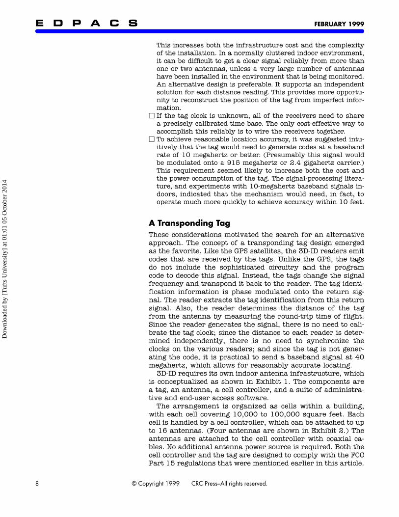
3D-ID requires its own indoor antenna infrastructure, whichis conceptualized as shown in Exhibit 1. The components area tag, an antenna, a cell controller, and a suite of administra-tive and end-user access software.
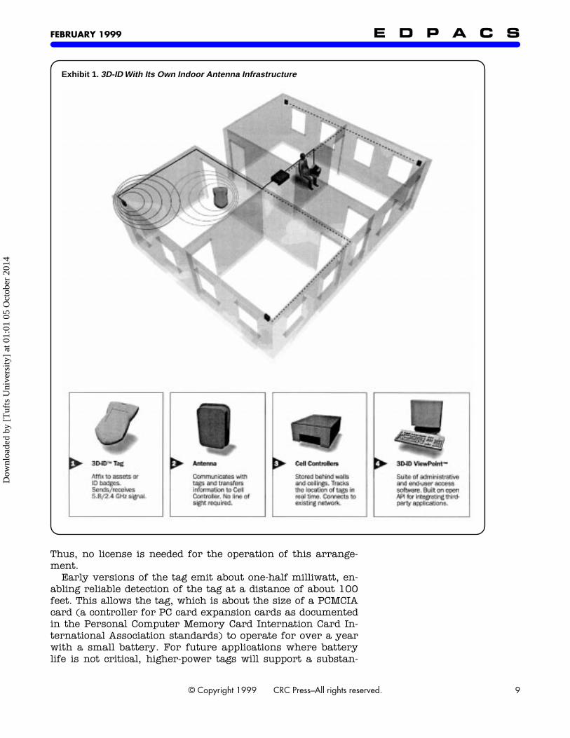
The arrangement is organized as cells within a building,with each cell covering 10,000 to 100,000 square feet. Eachcell is handled by a cell controller, which can be attached to upto 16 antennas. (Four antennas are shown in Exhibit 2.) Theantennas are attached to the cell controller with coaxial ca-bles. No additional antenna power source is required. Both thecell controller and the tag are designed to comply with the FCCPart 15 regulations that were mentioned earlier in this article.
Dow
nloa
ded
by [
Tuf
ts U
nive
rsity
] at
01:
01 0
5 O
ctob
er 2
014
FEBRUARY 1999
E D P A C S
9© Copyright 1999 CRC Press–All rights reserved.
Thus, no license is needed for the operation of this arrange-ment.
Early versions of the tag emit about one-half milliwatt, en-abling reliable detection of the tag at a distance of about 100feet. This allows the tag, which is about the size of a PCMCIAcard (a controller for PC card expansion cards as documentedin the Personal Computer Memory Card Internation Card In-ternational Association standards) to operate for over a yearwith a small battery. For future applications where batterylife is not critical, higher-power tags will support a substan-
Exhibit 1.
3D-ID With Its Own Indoor Antenna Infrastructure
Dow
nloa
ded
by [
Tuf
ts U
nive
rsity
] at
01:
01 0
5 O
ctob
er 2
014
FEBRUARY 1999
E D P A C S
10 © Copyright 1999 CRC Press–All rights reserved.
tially longer range. A range of 1,000 feet can be achieved inan unlicensed arrangement with higher-powered tags.
The cell controller cycles quickly among the antennas, de-termining the distance to all that are in range of the tag. Oncethe distances to at least three antennas are found, the locationof the tag in space can be estimated. In many situations, it ispossible to get a good estimate of the location of the tag fromfewer than three antennas. For example, a grocery store aislecan be covered by two antennas, one at each end, and mosthallways can be covered similarly. In more-open environ-ments, a thoughtful installer can place the cell controller an-tennas so that assets can be located based on just two distancemeasurements.
Developments in Parallel Technologies
Developments in four parallel underlying technologies havemade the 3D-ID technology a practical possibility for the firsttime. These developments are
M
the growing availability of parts, engineering know-how, andfield experience at microwave frequencies
M
digital hardware advances that make it possible to digitize andprocess high-frequency output from these radios in real time
M
a broad and evolving signal-processing literature that is provid-ing techniques to extract useful information from these signals
Exhibit 2.
Four Antennas Attached to a Cell Controller
Dow
nloa
ded
by [
Tuf
ts U
nive
rsity
] at
01:
01 0
5 O
ctob
er 2
014
FEBRUARY 1999
E D P A C S
11© Copyright 1999 CRC Press–All rights reserved.
M
the widespread adoption of organization intranets that provide ameans to distribute and display 3D-ID data through the enterprise
Thus, while 3D-ID has been possible theoretically for well overa decade, it has been difficult to imagine a practical implemen-tation of the technology until quite recently.
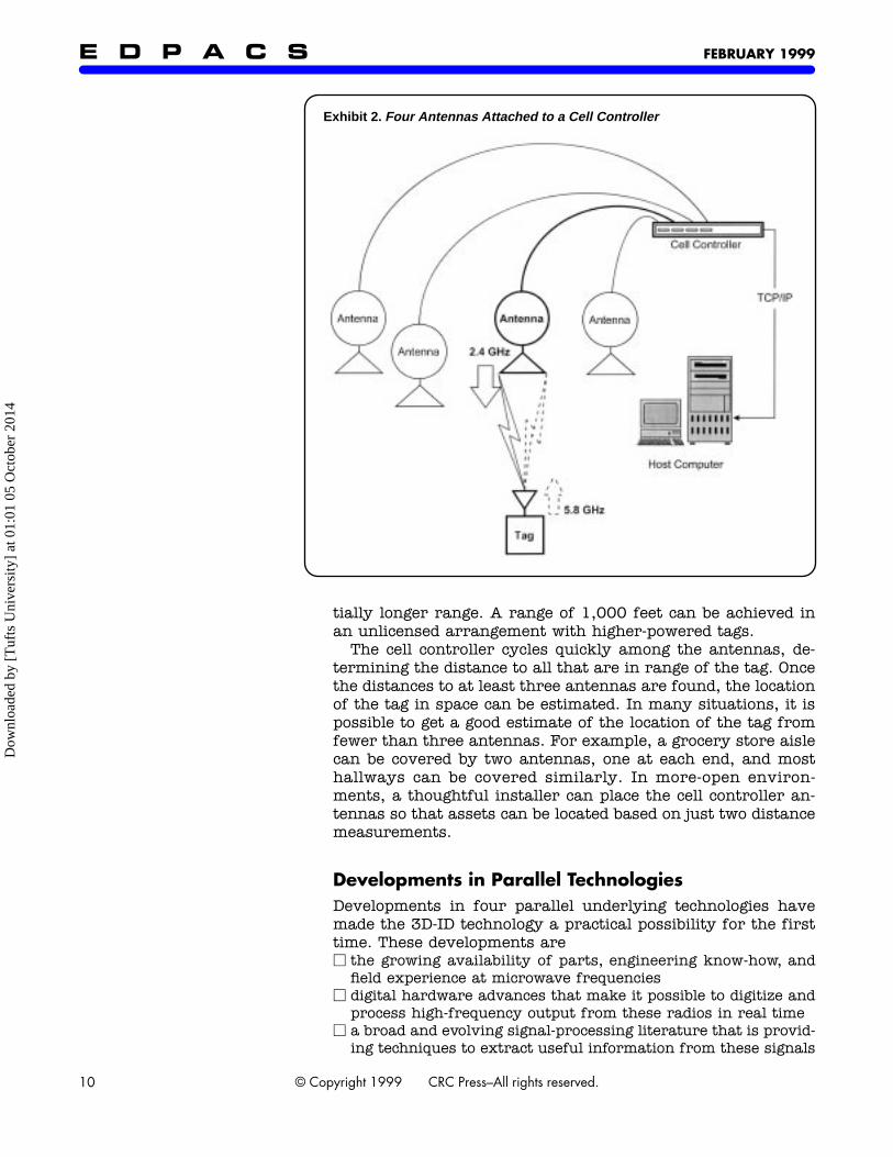
Exhibit 3 shows a block diagram of a PinPoint Cell Control-ler. On the transmit side, the cell controller modulates a 40-megahertz baseband signal input onto a 2.44 gigahertz carri-er, filters the output to comply with the FCC Part 15 require-ments, and transmits the signal through a selected antenna.On the receive side, the cell controller extracts the I (in phase)and Q (quadrature) components of the 5.78-gigahertz tag re-sponse, and digitizes the result for subsequent processing. Thecell controller radio system operates under microprocessorcontrol, with the following degrees of freedom:
M
1. modify the baseband input sequence, to support a variety ofsignal-processing techniques
M 2. adjust the transmit gain of the radio transmitter and or re-ceiver, to support its operation at a wide range of distances
M 3. switch among antennas at high speed, to collect data from avariety of antennas
Determining the Tag LocationConceptually, determining the tag location is not complicated.The tag signal is received at a time that is the sum ofM 1. the transmission time by the cell controllerM 2. the known fixed delays in the cell controller circuitry and its
cablesM 3. the known fixed time delays due to the circuitry of the tagM 4. the time for the signal to travel through the airOnce time of arrival is known, it is a simple matter to subtractout the known fixed mechanism delays, and the distance
Exhibit 3. PinPoint Cell Controller
Dow
nloa
ded
by [
Tuf
ts U
nive
rsity
] at
01:
01 0
5 O
ctob
er 2
014
FEBRUARY 1999E D P A C S
12 © Copyright 1999 CRC Press–All rights reserved.
through the air is the remainder divided by the speed of light.Since the signal travels to and from the tag, the distance to thetag is half of the air distance that is traveled.
As a practical matter, extracting the distance to the tag pre-sents substantial signal-processing challenges, particularly ifhigh accuracy is required. To some degree, the 3D-ID systemarchitecture removed three of the main complexities thatmust be overcome by a GPS receiver.M 1. To determine time of flight from a satellite, a GPS receiver
needs to synchronize its clock with the satellite clock. This stepis not necessary with 3D-ID. The transmission time is knownbecause the cell controller originates the signal.
M 2. A GPS receiver needs initially to frame its location roughly.This accounts for the long synchronization time that is typicalwhen the devices start up. Also, this step is not necessary with3D-ID. The search can be limited to a relatively small windowbecause of the limited degrees of freedom.
M 3. A GPS signal is subjected to a variety of atmospheric and rel-ativistic distortions in its 10,898-mile journey from the satelliteto the receiver. These distortions are not considerations in amechanism that is operating at relatively short range.
Still, this leaves the very substantial challenge of extractingthe tag distance in cluttered indoor environments. In additionto the signal that is received directly from the tag, there aremultipath signals which are reflected from such objects assteel beams, white boards, and fluorescent lights.
The primary defense of PinPoint against the impact of mul-tipath confusion is to increase the speed of the baseband chip-ping rate. Radio waves travel at the speed of light, or aboutone foot per nanosecond. Thus, if the chipping rate were onemegahertz, it would take 1,000 nanoseconds to rise from thenoise floor to the peak, providing a ruler with 1,000-foot in-crements. A 40 megahertz chipping rate was chosen for the3D-ID mechanism, providing a ruler of 25 nanoseconds.
The Signal FlightBecause it is measuring the round-trip time of the signal flightfrom the reader to the tag, this ruler provides real-world in-crements of about 12.5 feet. This is in the range of the 10-footsignal reading requirement. Because of the regulatory restric-tions in the 2.44 and 5.78 gigahertz bands, faster chirpingrates cannot be achieved easily. Thus, signal-processing tech-niques must be used for further accuracy improvements.
PinPoint has developed a proprietary approach for improv-ing the reliability and accuracy of distance measurements.The model requirements wereM half-chip accuracy (reading at about six feet)M high reliabilityM resistance to interference by narrowband jammers (especially
microwave ovens)M the ability to process tag signals in 100 microseconds or less
Dow
nloa
ded
by [
Tuf
ts U
nive
rsity
] at
01:
01 0
5 O
ctob
er 2
014
FEBRUARY 1999 E D P A C S
13© Copyright 1999 CRC Press–All rights reserved.
All of these objectives were achieved. The typical model outputprovides a value every 12.5 nanoseconds (or approximatelyevery six feet). This corresponds to the 80-megahertz sam-pling rate of the mechanism, that is, effectively, one value persample.
Note that the main multipath components are discernibleclearly. Based on the model outputs, it is possible to interpo-late the peak location between the sample points. This workswell in practice. With this approach three-foot distance mea-surement accuracy can be demonstrated. Thus, by using cur-rently available processors and techniques, it is possible todetermine the location of a tag indoors in real time and withreasonable accuracy. This level of performance can be expect-ed to improve as both modeling techniques and processingspeed improve.
The first version of the 3D-ID digital system uses an IntelPentium II processor running an embedded version of UNIX.This processor is used for two reasons:M 1. It has a strong software development environment that can
evolve as the signal-processing techniques that are being usedwith the 3D-ID continue to evolve.
M 2. The MMX instruction set is designed specifically for 16-bit in-teger signal processing.
3D-ID tags are designed for minimum complexity and powerconsumption. Frequency translation from 2.44 to 5.77 giga-hertz is accomplished by mixing the 2.44-megahertz receivedsignal with the output of a 3.33-gigahertz PLO (phase-lockedoscillator) within the tag. The phase of the output can beflipped under microprocessor control, enabling communicationback to the cell controller. Simple versions of the tag are read-only, and have no circuitry to demodulate the interrogationsignal. With a slight increase in the complexity of the tag, datacan be sent to the tag by modulating the interrogation signal.
Someone who is familiar with microwave technology willrecognize that a 3D-ID tag must include a variety of high-fre-quency components. This requirement makes it difficult toachieve the cost objectives based on off-the-shelf parts. How-ever, a custom ASIC (application-specific integrated circuit)has been developed. It will provide all of the active compo-nents on a die for well under $1.00 per tag. This is possible byleveraging the designs and processes that are already in placefor high-volume cellular telephones and GPS receivers.
As Simple and Inexpensive as PossibleTo keep the tag design as simple and inexpensive as possible,it was decided that a tag would not decode the incoming signal.Instead, the tag simply wakes up periodically and chirps itsidentification code. Most of the time a given tag is in a sleepmode. During these periods the tag is not able either to sendor to receive information. The only activity of the tag duringthis sleep mode is to count the time to the next chirp. When
Dow
nloa
ded
by [
Tuf
ts U
nive
rsity
] at
01:
01 0
5 O
ctob
er 2
014

FEBRUARY 1999E D P A C S
14 © Copyright 1999 CRC Press–All rights reserved.
the sleep period is over, the tag wakes up and emits a signalfor about five milliseconds. If a tag sleeps for five seconds, itsduty cycle is thus 1/1,000. At this level, the battery life of atag is driven primarily by the power requirements of the mi-croprocessor sleep cycle.
There is some opportunity for collisions between the tagtransmissions. This is particularly true if there are a largenumber of tags within the range of a given cell controller. Forexample, simulations show that 100 tags chirping on a1/1,000 duty cycle will collide about 16 percent of the time,resulting in the loss of at least one chirp. A two-way protocolcould have been used to eliminate or recover from such colli-sions, and can be added in the future for those applicationsthat cannot rely on statistical probabilities. Even without atwo-way protocol, several approaches can be taken to limit theimpact of packet collisions:M Since collisions occur only within a given cell, cell controllers
can be installed to cover a smaller area if there is a high den-sity of tags.
M Slowly moving assets can be set to chirp infrequently.M Adding motion detectors to the tags can help in situations
where there are thousands of tags, most of which are station-ary. These tags chirp more frequently when in motion.
M Since the tags are waking up according to a formula that isknown to the cell controller, the cell controller can forecastmost collisions, and the absence of an expected collision indi-cates that a tag has moved out of the range of the reader.
M Chirp times of one millisecond or less are likely to be achievedin the not-too-distant future. The main limiting factor is the op-erating speed of the digital mechanisms of the cell controller.
Thus, while some collisions are unavoidable, carefully craftedsoftware can mitigate their effects greatly, particularly withthe installation of ever faster processors on the cell controller.
While the mass-produced 3D-ID tags are designed for mini-mal cost, the same infrastructure can be shared by a range oftags for a variety of purposes. The discussion so far has beenlimited to reading information from the tag, which is howmost early adopters intend to use the technology. The archi-tecture can be extended easily to permit two-way communica-tion with the tag. In such a situation the tag will be addressedwhile it is chirping.
Once the 3D-ID infrastructure is in place, it is possible toembed the tags into other devices to support two-way digitalcommunication without significantly increasing the tag cost.Several RFID products include the capability to connect thetags to other devices, but the short range of these productsprovides limited usefulness for general-purpose communica-tion. By contrast, 3D-ID is designed to cover a complete indoorspace, and as such provides an ideal platform for inexpensivelow-bandwidth communication to a range of devices. One obvi-ous example is to use the tag as a low-cost communication pe-ripheral to a handheld computer. Other examples are sure to
Dow
nloa
ded
by [
Tuf
ts U
nive
rsity
] at
01:
01 0
5 O
ctob
er 2
014

FEBRUARY 1999 E D P A C S
15© Copyright 1999 CRC Press–All rights reserved.
emerge. They will be limited only by the creativity of thosewho are working with this technology.
A Health Care Installation ScenarioThe flexibility that is intrinsic in the design of 3D-ID is under-stood best in the context of a real-world installation, such asin a large teaching hospital.
As a first step, most decision makers are interested in see-ing a pilot installation. They want to see for themselves howthe technology works in their particular environment. While itmight seem logical to start out by covering a small area, it be-comes apparent quickly that the highest-value applicationsare justified by a need to track the location of assets across alarge facility. Thus, the first installation leverages usually afew cell controllers to cover a large amount of space, by de-tecting the passage of tags past a few fixed points. For exam-ple, a hospital may start out by covering all of the elevatorlobbies, and 50 feet in each direction from them. With thisconfiguration, the movement of equipment such as wheel-chairs and gurneys can be tracked, since these assets are toolarge to be carried up and down steps.
For this sort of entry-level installation, it is not necessary todetermine the precise location of the asset. But being able toknow the distance from the antennas still provides useful infor-mation. For example, by noticing that the distance to a particu-lar antenna is increasing, it is possible to infer that a tag waslast seen moving away into the east wing on the seventh floor.
After a pilot installation has become operational, the nextlogical step is to cover all of the hallways and stairwells, sothat tags can be tracked whenever they are moved from onepart of the facility to another. For example, an antenna can beplaced at each end of a hallway, and the location of a tag alongthat hallway can be estimated based on the distance to eachantenna. If a tag enters a room, there may not be sufficientsignal strength to be seen by either antenna. But the systemwill be able to report that a tag was last seen on Floor 7 in thevicinity of Suite 720. Under most circumstances, this isenough information to find a person or asset and is a relative-ly inexpensive way to cover a complete facility.
At the next level of coverage, certain sections of the hospi-tal may need to be covered for security purposes. For exam-ple, if valuable equipment is stolen, commonly, from certainareas, antennas might be installed to cover that complete ar-ea. The extra antennas needed to provide such coverage havethe side effect of providing additional accuracy. The systemcould report that the tag was last seen near Room 723 inSuite 720. Additionally, the tag would be monitored continu-ously, reporting if it is tampered with or is timing out if thetag is disabled or destroyed. A similar approach can be usefulfor tracking babies and patients with Alzheimer’s diseasewithin the facility.
Dow
nloa
ded
by [
Tuf
ts U
nive
rsity
] at
01:
01 0
5 O
ctob
er 2
014
FEBRUARY 1999E D P A C S
16 © Copyright 1999 CRC Press–All rights reserved.
Finally, certain areas of the hospital may require high-reso-lution location. For example, precise location can be used tofind small items such as telemetry monitors quickly. Or itmight be helpful to know that a health care provider is withthe patient in 723D, as opposed to in the general vicinity ofRoom 723. In such areas, extra antennas would be installed tosupport the full tracking of people and physical assets.
All of these different levels of coverage can coexist in differ-ent portions of the hospital depending on the user’s require-ments, with a continuous upgrade path as the need evolves.Coverage and precision are purchased, in such a situation, onan as-needed basis.
3D-ID Software PlatformOperationally, 3D-ID is designed to be helpful even in the ab-sence of any process changes. In contrast, consider bar codingand RFID, which require that labels or tags be directed in therange of a reader, or vice versa. By comparison, 3D-ID tagsare tracked wherever the current and future processes hap-pen to take them.
3D-ID cell controllers, and by extension their tags, are de-signed as network devices. An open application program inter-face (API) enables an application developer to extract datafrom the cell controller by means of TCP/IP (Terminal ControlProtocol/Internet Protocol). At a higher level, software isavailable to funnel cell controller data into an SQL (StructuredQuery Language) database, making the data available to awide variety of programmers and software platforms bymeans of open database connectivity (ODBC).
Broadly speaking, 3D-ID data is available in three ways:M 1. Low-Level API. 3D-ID data from multiple cell controllers is
collected onto a Windows NT work station or server and madeavailable to applications by means of a TCP/IP interface. A pub-lish–subscribe software paradigm is used, similar to the ap-proach that is used on Wall Street, to distribute quickly largeamounts of data to end-user applications. Client software pro-vides a simplified interface to this same information through anActiveX control mechanism.
M 2. Stand-Alone Platform. For small-scale installations, 3D-IDdata is archived into a Microsoft Access (Jet) database, whichcan be accessed, then, by a variety of applications using stan-dard client tools such as Visual Basic.
M 3. Enterprise Platform. For large-scale or mission-critical in-stallations 3D-ID data is archived to an ODBC-compliant data-base, which can be accessed, in turn, by a broad range of third-party software, including Web-enabled interfaces.In most situations, the stand-alone platform will be used,
initially, for small-scale installations or for pilot sites. As theuse of 3D-ID spreads through the enterprise, users either willuse the API to incorporate the data into existing applicationsor will upgrade to the enterprise platform.
Dow
nloa
ded
by [
Tuf
ts U
nive
rsity
] at
01:
01 0
5 O
ctob
er 2
014
FEBRUARY 1999 E D P A C S
17© Copyright 1999 CRC Press–All rights reserved.
The flexibility provided by this platform is critical in aworld where there is no standard enterprise computing envi-ronment. The stand-alone platform and the API enable the cellcontrollers to be integrated easily into specialized systems,which provide highly optimized control of corners of a busi-ness. Simultaneously, the enterprise platform and the API en-able 3D-ID data to be incorporated into larger-scale solutions.
Designed as a Flexible PlatformThe PinPoint 3D-ID Local Positioning System was designed asa flexible platform, to permit this new enabling technology tobe incorporated quickly into a variety of novel engineering so-lutions. Local positioning technology is becoming a practicalreality. By, say, 2008, it will be a ubiquitous presence. It willbe considered to be a basic control tool and will be used dailyby every IS auditor. ■
Colin Lanzl, Chief Architect of PinPoint Corporation, Bedford, MA, managesall of its hardware engineering activities. Formerly, he was with Windatawhere he was a founder and the chief engineer. Lanzl created some of theearliest wireless local area network products. Prior to this, he was withAnderson Laboratories, where he led a major surface acoustic wave designteam. He is the author of five IEEE papers on acoustics and signal processing.Lanzl holds a B.A. in Science and Electrical Engineering from RensselaerPolytechnic Institute.
Jay Werb, Vice President of Engineering at PinPoint Corporation, conceptual-ized the PinPoint product and continues to manage the development of itssoftware. From 1984 to 1994, he was a founder and Vice President of Engi-neering at ADDAX, Inc., a Cambridge, MA consulting organization that spe-cializes in airport logistics and retail applications. Prior to being at ADDAX,Werb was a programmer at Pugh Roberts Associates. He holds both an M.A.in Management and a B.A. in Biology from MIT.
Guaranteeing Network [Electrical] Power by David Essex. Network Magazine (600 Harrison Ave., San Francisco, CA 94107). October 1998. pp. 76–78, 80.
An uninterruptible (electrical) power supply(UPS) needs continuing care and attentionlong after its installation. The UPS may causeproblems on its own. For example, it mayhave become too small for the load that it isexpected to support. Or, it may lack certaincapabilities that are required by the powersupply peculiarities of the geographic area in
which it is attempting to function. Or, its stor-age battery may be being drained by continu-ing brownouts of the utility power source.
It is no oversimplification to say that mostpower problems are caused by too much pow-er, too little power, or no power at all. Tran-sients, or spikes or surges, are suddenvoltage increases. They can be caused bysuch things as lightning strikes, changes inthe power distribution process, or a suddenshutdown of other electrical loads. Both tran-sients and surges can damage computing andtelecommunication equipment seriously.
ABSTRACTS & COMMENTARYDow
nloa
ded
by [
Tuf
ts U
nive
rsity
] at
01:
01 0
5 O
ctob
er 2
014