Embed Size (px)
Citation preview

REPORT NO.
UCB/EERC-87/17
OCTOBER 1987
PB90-262700
EARTHQUAKE ENGINEERING RESEARCH CENTER
THE EFFECT OF SLABS ONTHE FLEXURAL BEHAVIOR OF BEAMS
by
S. J. PANTAZOPOULOU
JACK P. MOEHLE
Report to the National Science Foundation
REPRODUCED BYU.S. DEPARTMENTOF COMMERCE
NATIONAL TECHNICALINFORMATION SERVICESPRINGFIELD, VA 22161
COLLEGE OF ENGINEERING
UNIVERSITY OF CALIFORNIA AT BERKELEY

For sale by the National Technical Informa
tion Service, U.S. Department of Commerce,
Springfield, Virginia 22161
See back of report for up to date listing of
EERC reports.
DISCLAIMERAny OpiniOnS, findings, and conclusions or
recommendations expressed in this publication are those of the authors and do not nec
essarily reflect the views of the NationalScience Foundation or the Earthquake Engi
neering Research Center, University of Cali
fornia at Berkeley.

THE EFFECT OF SLABS ON THE FLEXURAL BEHAVIOR OF BEAMS
by
S. J. PantazopoulouResearch Engineer
and
Jack P. MoehleAssoc. Professor of Civil Engineering
A Report to Sponsor:
National Science Foundation
Report No. UCBIEERC-87/17
Earthquake Engineering Research Center
College of Engineering
University of California at Berkeley
Berkeley, California
October 1987


ABSTRACT
It has been observed in experimental studies that floor slabs strengthen and stiffen beams, espe
cially when slabs undergo tension. This fact is ignored in current design and analysis practices, thus
resulting in significant beam overstrength. In this regard, assessment of the contribution of floor
slabs to the stiffness and strength of the supporting beams is crucial in achieving the desired hierar
chy of strength within the structure. Several analytical models that aim to quantify this effect are
developed in this report. Simple methods of practical interest are also presented. The fundamental
concept underlying all the analytical models is that the action of floor slabs is of membrane nature,
primarily controlled by the amount and the mechanical properties of the slab reinforcement. Further,
the classical assumption of plane sections, used to analyze flexural behavior of beams, is relaxed.
Effects of flexible transverse beams on the overstrength provided by the slab are also included in the
study. The analytical models for the effect of floor slabs on the behavior of beams are verified by
correlation with measured response of several interior and exterior slab-beam-column connections.
ii
ACKNOWLEDGEMENTS
The research presented in this report was funded by the National Science Foundation grant No.
CEE-8316662. This support is gratefully acknowledged. Opinions, findings, and conclusions or
recommendations expressed in this publication are those of the authors and do not necessarily reflect
the views of the sponsor.
The computing facilities were provided by the Civil Engineering Department of the University
of California at Berkeley. The help from the manager of the departmental computing facilities, D.
Steere, and from fellow graduate students J. Landers and C. Thewalt is appreciated.
The authors thank Professor V. Bertero of the University of California at Berkeley, Professor
A. Durrani of Rice University, Professor C. Wolfgram-French of the University of Minnesota and
fellow graduate student X. X. Qi of the University of California at Berkeley, for generously provid
ing experimental results.

TABLE OF CONTENTS
ABSTRACT ..
ACKNOWLEDGEMENTS .
TABLE OF CONTENTS ..
CHAPTER I rnTRODUCTION .
1.1 Objective and Scope .
1.2 Organization of the Report .
CHAPTER II SLAB CONTRIBUTION - AN OVERVIEW .
2.1 Introduction .
2.2 Experimental Observations on the Problem of Slab Contribution .
a) Influence of slab on strength and stiffness of beams ..
b) The stress and the strain state of the slab : .
c) The effect of transverse beams on the global behavior of the subassemblages
2.3 Analytical Background on the Problem of Slab Contribution ..
2.4 Lower and Upper Bounds on the Equivalent Width of Slab ..
a) Behavior at the precracking stage; the Timoshenko solution .
b) Results from the extended Timoshenko solution ..
c) Upper bound strength of the slab-beam sections ..
2.4 The Effect of Boundary Conditions on the Deformation Pattern .
CHAPTER III SLAB CONTRIBUTION - A CROSS SECTION MODEL ..
3.1 Introduction .
3.2 Formulation of Non-Planar Strain Profiles .
3.3 Solution Algorithm ..
3.4 Correlation with Experimental Results ..
3.5 Shear Flow in the Plane of the Slab ..
CHAPTER IV A TRUSS MODEL FOR THE 3-D BEHAVIOR OF EXTERIOR CON-NECTIONS .
4.1 Introduction .
4.2 Derivation of the Model ..
4.3 Expression of the Equations in a Discretized Form .
4.4 Implementation of the Model .
4.5 Correlation with Experiments .
CHAPTER V A SIMPLE MODEL FOR THE EFFECT OF SLABS ON BEAMSTRENGTH .
5.1 Introduction .
5.2 Derivation of a Simple Model for the Effective Slab Width ..
5.3 Comparison with Experimental Results .
111
II
iii
1
I
2
3
3
5
5
6
7
8
8
8
12
13
16
18
18
19
25
27
31
34
34
34
40
43
44
47
47
47
55

IV
CHAPTER VI SUMMARY AND CONCLUSIONS 59
6.1 Summary 59
6.2 Conclusions 59
REFERENCES 61
TABLES 63
FIGURES 65
APPENDIX A SUMMARY OF BEAM COLUMN EXPERIMENTS USED FOR CORRE-LATION 103
A.l Description of the Test Specimens 103
APPENDIX B DIAGONAL COMPRESSION FIELD THEORY - A SIMPLE CONSTITU-TIVE MODEL FOR RIC 112

I
CHAPTER I
INTRODUCTION
1.1 Objective and Scope
Traditional structural analysis is usually based on two-dimensional idealizations of structures.
Although all structures are in reality three dimensional, engineers try to identify planes of load action
and load transfer for the purpose of simplifying the analysis and design. For conventional practices,
such an approach is often pertinent. However, as design philosophies evolve and become more
sophisticated, and more complicated structural configurations are designed, a better understanding of
the three dimensional aspects of behavior is desirable. An understanding of the three dimensional
behavior becomes more important when earthquake effects must be taken into consideration.
Although significant research on analytical modeling of reinforced concrete structures has been car
ried out, many features of the three-dimensional response have yet to be understood and successfully
analyzed.
The emphasis of the research described in this report is to develop an understanding of the
effect of floor slabs on the behavior of beams. It has been observed in experimental studies that floor
slabs strengthen and stiffen beams, especially when slabs undergo tension. This fact is ignored in
current design and analysis practices, thus resulting in overstrength of beams. Under severe earth
quake loading, large moment transfer to the columns may result inducing unwanted failure mechan
isms in frames. This is in disagreement with the current capacity-design philosophy which aims to
control the hierarchy of failure in structures. Several analytical models that aim to quantify the
effect of floor slabs will be developed in this report. Simple methods of practical interest are
included.
The analytical methods introduced in the preceding paragraph are discussed in detail in the fol
lowing chapters. The layout of the report is as described in the following section.

2
1.2 Organization of the Report
Chapters II through V deal with modeling of the slab contribution. Because very little analyti
cal work has been developed previously in that area, several analytical models are considered, each
having its own merits and addressing the problem at different levels of complication.
Chapter II reviews various experiments conducted on isolated slab-beam-column connections.
Because of the lack of many analytical developments in the area of slab contribution, experimental
indications are very important in identifying the parameters that control the true response. Further,
elasticity solutions introduced first by Timoshenko are reviewed, as they recognize the problem and
show the trends of behavior. Finally the effects of boundary conditions are studied with a simple
finite element solution.
Chapter III presents a cross section model for a slab-beam element. In the solution, the classi
cal assumption that "plane sections remain plane" was relaxed. The plane sections assumption is
viewed as a simplification of the Taylor expansion of strains over the section. By retaining higher
order terms, and using variational methods, nonlinear strain profiles are constructed. The method is
applied to analyze experiments. Correlation with measured results is presented.
Chapter IV presents a substructure model for the entire joint connection. Because experiments
suggested an influence on the response resulting from the flexibility of transverse beams in exterior
connections, the model is developed mainly to account for this effect, although it can be applied ~o
any type of connection. The analysis uses an equivalent structure that is a space beam-truss model.
Chapter V presents a model constructed for the sake of simplicity. The model correlates suc
cessfully with experimental results. Given the relative simplicity of the model, it is deemed
appropriate for use in simple analysis and design applications.
Conclusions of the study are summarized in Chapter VI.
3
CHAPTER II
SLAB CONTRIBUTION - AN OVERVIEW
2.1 Introduction
One of the fundamental ideas underlying the capacity design philosophy is the concept of con
trolling failure mechanisms in a structure by appropriately combining member strengths. For frame
structures in seismic regions, this idea is implicit in the well known "strong column - weak girder
design". For this concept to be applicable, member strengths must be assessed under different com
binations of loads. However, experimental evidence [5, 6, 7, 9, 10, 20, 27] has shown that member
strengths are often miscalculated. The errors in computed strengths are partially attributed to uncer
tainties in material properties, construction practices, and actual dimensions. A significant source of
error lies also in the analytical models. For vertical load conditions, existing methods of analysis [1,
25] generally predict the structural response to a satisfactory degree. For lateral loadings such as
those which occur during strong earthquake ground motions, it has been observed in the field and the
laboratory that measured strengths may significantly exceed the design strengths. For example, in
experiments on structural systems the maximum anticipated base shear did not exceed 60% of the
base shear actually measured during the tests [2, 4, 16]. A recent experiment reported in [21] shows
similar results.
Furthermore, various investigators [2, 16, 20, 22] have reported hinge formation in columns,
even in cases where careful consideration was given during the design process to satisfy the code
requirements [1] intended to prevent column yielding. It was apparent in these studies that the
columns hinged because of beam overstrengths. The overstrengths were mainly the result of floor
slabs which are monolithically connected to the beams. The Code partially recognizes this effect [1],
by the requirement that some effective width of slab be included in the calculations of the beam pro
perties for positive bending (slab in compression). Although the suggested effective widths do not
precisely represent the phenomenon, the result is that the neutral axis in bending is raised substan
tially close to the slab location, and the computed strength becomes relatively insensitive to the

4
effective width that is used. On the other hand, for negative bending (slab in tension), the presence
of the slab is entirely neglected in U.S. design practice. Slabs can develop large membrane actions
when they are in tension. If the neutral axis drops as a result of cracking in the tensile region, then
the contribution of these slab forces to the flexural strength becomes significant due to the substantial
lever arm.
To demonstrate the effects of such a behavior, a simple portal frame is considered (Fig. 2.1).
The frame is designed to have negative moment strengths equal to positive moment strengths.
Column strengths are set equal to beam strengths. Because of the slab contribution to the negative
bending resistance, strength in negative bending is assumed arbitrarily to double. The frame is sub
jected to increasing lateral force, applied at the level of the beam. The analysis results are presented
in Table 2.1, and can be summarized in the following statements:
a) Because the negative moment strength exceeds the column strength, plastic hinges form in the
columns, resulting in an undesirable soft story mechanism.
b) The inflection point in the beam span moves towards the weak side (positive moment end).
Bar cutoffs based on the assumed design strengths may no longer be adequate for the shifted
moment diagram.
c) Beam shears are increased above the design values.
d) The axial load carried by the column in compression is high. (It increases above the design
value because of the enchanced frame strength.) The stiffness and flexural strength of the
column increases, as does the shear to be resisted by the column.
The simple frame analysis demonstrates several aspects of design that are affected by the
enchanced beam strength due to the slab contribution. Because of these effects, various experiments
on slab-column connections have been reported recently, in an effort to isolate and understand better
the "slab contribution" effect. Few analytical studies have been reported. Most available solutions
deal with the linear elastic case. Studies reported in [19] approach the problem by solving the fourth
order P.D.E. (partial differential equation) for plates using series solutions. Another approach [11]
consists in using 3-D finite elements, either elastic or inelastic. The limitations of the linear elastic

5
solutions are due to the theoretical formulation; reinforced concrete is not a linear material, and
experimental observations of the behavior of connections suggest that the essence of the problem lies
in the reinforcement of the slab. Thus, solutions assuming an elastic continuum cannot capture the
true behavior. The limitations of the inelastic finite element solutions lie in the fact that 3-D meshes
are relatively costly even when the mesh is coarse and the simplest brick element is used; thus, they
cannot be used in the analysis of structures more complicated than a simple joint connection.
Despite limitations in any of these methods, it is recognized that they are very useful in identifying
trends in the behavior. They will be reviewed in Section 2.4 together with other simple methods to
assess the extent of the problem discussed.
2.2 Experimental Observations on the Problem of Slab Contribution
Various experimental studies involving slab-beam connections have been performed on large
scale models [5, 6, 7, 9, 10, 20, 22, 27] (scale in most cases is 1:2). More detailed descriptions of
some of the specimens can be found in Appendix A. General observations reported by the investiga
tors deal with three particular features of the slab-beam assemblages, namely,
a) The influence of the slab on the "action-deformation" relation of the beam.
b) The stress and strain state of the slab.
c) The effect of boundary conditions such as transverse beams on the global behavior of the
subassemblages.
a) Influence of slab on strength and stiffness of beams
The negative flexural strength of the beams in the reported experiments [7, 10, 20, 22, 27]
varied significantly from the values predicted by ignoring the slab contribution. The assumption that
an effective width is acting in tension equal to the effective width in compression that is recom
mended by ACI [I] led to underestimation of strength on the order of 30% or more [7, 9, 16, 20,
22]. On the other hand, the assumption that the full width acts as a flange of the tee beam resulted

6
in an overestimation of the strength on the order of 15 - 20 % [7, 20,22]. One important observation
[7] was that "the flexural stiffness of the slab assemblage was a function of the deflection level and
increased at larger deformations". The observed initial moments and stiffnesses at low deformation
levels are close to those calculated using the ACI width. The effective slab width reported from
experiments gradually increased with the beam deformation. The ratio between the moments for the
slab in tension and in compression also has been observed to increase with the deformation level,
suggesting that the contribution of the slab in the positive bending case is not as sensitive to the
increase of deformation.
b) The stress and strain state of the slab
The cracking patterns observed in slabs during negative bending were similar in all tests
reviewed. Flexural cracking "initiated in the slab close to the beam, extending to the full width of
slab as the deflection levels increased" [7]. As the cracks propagated in the transverse direction, they
became inclined towards the transverse beams. The majority of cracks appeared concentrated in a
region "approximately equal to the effective depth of the beam from the face of the column" [27].
Inclined cracks, as continuation of the bottom slab flexural cracks, have been observed to form in the
longitudinal beams extending towards the column [7, 10, 27]. Measured strains in the slab varied
transversely from the middle (close to the longitudinal beam) to the edge. Slab reinforcement
located adjacent to the longitudinal beam yielded at approximately the same deflection level as did
the main beam steel. At this deflection level the strain in the slab reinforcement close to the edge of
the slab was very small. At larger deflection levels, the slab reinforcement was reported to have high
strains at distances of several beam depthS from the longitudinal beam, sometimes reaching values
close to yield at the edge of the slab. Strains in the transverse reinforcement of the slab have been
observed to increase with distance from the longitudinal beam [7, 22], reaching yielding at the edge
of slab at high deformation levels. This particular observation is believed to be a result of the shear
lag of the edges as compared to the center due to the reduction of longitudinal stresses with
transverse distance from the main beam. It may also be a reaction to the transverse contraction of

7
the slab as it elongates longitudinally. (At large levels of longitudinal strains, the slab tends to con
tract due to Poissons effect, where the Poisson's ratio of extensively cracked concrete may reach the
value of unity [8]).
c) The effect of transverse beams on the global behavior of the subassemblages
All experimental studies reported in the literature made a distinction between exterior and inte
rior connections, due to the different phenomena observed in the two connection types. These
phenomena are related to the effect of the transverse beams. In the exterior connections the
transverse beams are flexible to bend in the plane of the slab, and to twist. Experiments report tor
sional (diagonal) cracking in the transverse beams, with steep and closely spaced cracks near the
column, and much flatter cracks away from the column [9]. The transverse beams were measured to
deflect both in torsion about their longitudinal axis, and in bending in the horizontal plane, as they
were pulled by the slab longitudinal reinforcement in tension. This behavior is observed in interior
connections as well. However, no failures of transverse beams have been reported in interior con
nections. It has been suggested by previous investigators that for exterior connections, in particular,
the slab tensile forces can lead to a torsional moment and shear force combination in the transverse
beam, which would be significant enough to cause failure. The stiffer the transverse beam, the larger
the participation of the slab measured. However, the relative twist measured in interior transverse
beams is much less than the one observed in exterior ones. This can be attributed to the large in
plane stiffness of the slab [6]. In exterior connections in particular, it is reported that, the wider the
slab, the greater the damage sustained in the transverse beams adjacent to the joint and in the con
crete cover on the back of the column [27]. After developing extensive cracking the transverse
beams ceased to be effective in confining the joint, and at high drift levels the behavior of specimens
with a slab became inferior to that of specimens without a slab in terms of stiffness degradation dur
ing load reversals [27].

8
2.3 Analytical Background on the Problem of Slab Contribution
Very limited analytical work was found in the literature on the contribution of slab to the
lateral stiffness and strength of structures. A 3-D finite element analysis [l1J reflected the inherent
problems encountered in the traditional finite elements liS], where the medium is treated as a contin
uum, disregarding the fact that reinforced concrete is actually composed of two materials set in paral
lel [3, 8, 26]. Some of the experimentally observed phenomena were reproduced in the analysis, but
no quantification of these effects was proposed. An elastic plate theory analysis has also been
employed [19], and was used to interpret response for inelastic deformation levels. This study did
not make any attempt to correlate with any experimentally observed phenomena. Since elastic plate
solutions were employed (series solutions), superposition was inherently assumed; further, the two
phase nature of the medium was ignored. Regardless of the theoretical approximations, the solution
gives a method for calculating the slab effect, which can be applied at low levels of lateral loads
(serviceability conditions). The linearity assumptions of the analytical model cannot represent the
experimclllally-observcd load dependence of the slab contribution. This is the main liability of the
approach presented in [19] and the lower bound solution presented in the following section.
2.4 Lower and Upper Bounds of the Equivalent Width of Slab
Lower and upper bounds of the slab contribution can be established by the theory of elasticity
for precracking stages [23] and an equilibrium solution for the ultimate loads. Such estimations of
bounds are important because they provide the initial stiffness of the structure and an estimate of the
maximum strength that can be achieved. The derivation a lower bound and a bound for the max
imum strength are presented in the following section. A simple finite element analysis to demon
strate the trends in the deformation pattern of the slab for fixed boundaries and for flexible boun
daries concludes the chapter.

9
a) Behavior at the precracking stage; the Timoshenko solution
The precracking stage can be characterized by two realistic assumptions:
1) The material is linearly elastic.
2) The medium can be considered as a continuum.
The above assumptions make possible the application of classical solutions of mechanics. If,
in addition, the slab can be considered thin enough to ignore the stress variation across the thickness,
then the stress state in the slab is a plane stress state. The plane stress solution is an approximation,
and as such is expected to give rise to certain geometric incompatibilities in the domain. However,
equilibrium is satisfied locally, as well as in a global sense. Particular problems arise at the interlace
between the beam web and the slab membrane since at that point the stress 0"",3.3 is not zero as is
approximated in the plane stress solutions. The classical formulation of the problem is found in [23]
including the idea of the "effective width". The solution is derived for vertical loads, and produces
closed formulae for the effective width; the values produced using these formulae are usually smaller
than the ones suggested by the ACI Building Code [1] for positive bending and for gravity loads act-
ing along the span. In particular, it is found in [23] that the width of overhanging flange to be con
sidered effective is 10 =0.181*1 (Fig. 2.2a1) for uniformly distributed loads (almost uniformly because
the moment diagram in this solution varies as cos -~~~, instead of being a parabola with x) andL
1,,=0.85*0.181 *1 for a concentrated load at midspan. The method is extended here, to account for
contraflexure (Fig. 2.2a):
Equilibrium is satisfied through the same Airy stress function as is used in [23]. This func-
tional is a solution of the biharmonic V2(V2<I», thus compatibility conditions are also satisfied.
00 mrxc:I>=~f (v )cos ~--k n. 1
n=l
where,
I The symbol 1 denotes the length of the mid-span. The entire span is L.

10
and x is the longitudinal direction, y is the transverse direction and I =~ (Fig. 2.2a-b). The stress
field is described by the matrix of partial derivatives of second order (Hessian) of the Airy stress
function, thus, it inherits the exponential tem1 in y. Since the exponent is negative, it can be con-
eluded, that
a) The normal stress field decays rapidly with the transverse distance from the main beam (Fig.
2.3).
b) The assumption of plane sections after deformation is not realistic, because strains are in linear
relationship with stresses, thus they also decay exponentially with transverse distance.
c) Shear stress is out of phase with the transverse and longitudinal stresses, so it builds up to
maximum values at the points of inflection of the beam (Fig. 2.4).
The linear moment diagram that describes contraflexure is expressed as:
M=V(l-lxl)
where V is the shear at the supports. M can be expressed alternatively by means of a cos Fourier
expansion with weight factors:
~ 2VI n mrxM n= "'"'(- ry,,)«-l) -l)cos-----
n=1 n-Tr:- I
Minimization of the strain energy u=f f (JjjdEjjdV (where Vol denotes the volume of theo Vol
beam) with respect to the unknown coefficients {An'Sn, n=l" ...oo}, completely defines the stress
field in terms of the moment expansion coefficients Mn.

11
where e is the distance from the mid-plane of the slab to the centroid of the web (Fig. 2.2b), v
is the Poisson's ratio, A is the area of the beam web, and I is the moment of inertia of the beam web
with respect to its centroid. Transformation of the resulting stress distribution across a section of the
slab to an equivalent uniform stress distribution determines the equivalent flange width for this load-
ing condition (this transformation is a simple statement of equilibrium, under the assumption of
negligible slab thickness [23]).
If r is used to denote the ratio of the moment carried by the flange alone to the moment carried
by the entire section, the equivalent width of flange to be considered at each side of the beam is
given by:
The above formula gives an elastic equivalent width of slab to be considered in tee beam
analysis. As is required for an elastic solution, the equivalent width is independent of the load level.
It is important to note that stresses and strains are not differentiable at y=O, which corresponds to the
spine of the longitudinal beam (Fig. 2.3). This result is not physically correct. It is an incompati-
bility resulting from the assumption of plane stress at the interface of slab and beam.
As the deformation level increases and the behavior enters the post-cracking stage, it has been
observed experimentally that a larger portion of slab participates. At the instance of cracking, how-
ever, the trend is not well defined. Experimental observations [10) and more refined theoretical
models (see Chapter III) suggest that cracking initiation is accompanied by a sudden drop in the slab
stresses (this is reflected in the calculated equivalent width). This phenomenon, however, is not of
any practical significance because it occurs over a very small range of strains; as soon as steel strains
start picking up, the slab enters the beam flexural behavior to a much larger extent.

12
b) Results from the extended Timoshenko solution.
This section focuses on the results obtained by using the extended Timoshenko solution derived
in the preceding section for various slab-beam sections. The objective is to identify an effective slab
width which can be used for serviceability lateral load analysis. As was discussed in the previous
section, the equivalent width of slab depends on the ratio of the moment carried by the flange to the
moment carried by the entire section. Numerical studies on typical slab-beams showed that the con-
vergence of the Timoshenko solution for contraflexure is relatively slow, requiring at least n =20 for
a reasonable approximation of moments in the flange and the entire section. A typical solution is
plotted in Fig. 2.5. An interesting result is that the ratio of "flange moment" to total moment
increases slightly towards the point of inflection (Fig. 2.6), as does the equivalent width of slab. For
the case where the beam is subjected to positive moments this suggests that the maximum tensile
stresses at the bottom of the beam will not generally develop at the face of the support where the
maximum moment acts, but rather at a point offset slightly from the support. This is the point where
the first bottom crack is expected to develop according to the theoretical solution.
The general expression for the moment carried by the flange is given in [10]. The ratio, r, of
the moment carried by the flange to the total applied moment, has the form
M cos m,~00 • II,--- ---
n=1 [l+_I_+_n_TC_I 3+2V-V1
]Ae2 hle1 4
r(x)= ----'=---oo~·
~ nTCX£..JMncos--.=1 I
This quantity, evaluated at the support ( x=O ) of a relatively slender beam, is plotted against n
(Fig. 2.7). The convergence is apparently very slow in this case. Results for the equivalent slab
width of different beams subjected to lateral loads are compared with the equivalent values derived in
[10] for uniformly distributed gravity loads, and with values given by [1] for gravity loads and posi-
tive moments in Table 2.2. It can be seen that the width required to be considered for lateral loads
(low level loads) is about 70% the values in [1].

13
c) Upper bound strength of slab-beam sections
The maximum strength that a slab-beam section can develop is of interest in the design pro
cess. The maximum strength can be obtained based on the assumptions of conventional beam theory
with failure identified by crushing of the compression zone. Although the slab-beam cross section
can be treated as a single entity, the two will be viewed separately in the following discussion for
convenience. Figure 2.8 illustrates a beam cross section, the web and the slab shown as separate free
body diagrams. Under the action of moment on the entire section, compatibility between the slab
and web results in development of combined flexural moment and axial load acting on each part.
Depending on whether the bending is positive or negative, the membrane forces acting through the
slab are compressive or tensile. Similarly, the forces in the web are tensile for positive bending (act
ing through the bottom reinforcement) or compressive for negative bending (acting approximately on
the mid-height of the compression zone). At failure the flexural moment and axial load acting at the
mid-height of the compression member define a point on the failure surface constructed for either
slab or web (Fig. 2.10). For each combination of N w and M w , and ns and ms , the equilibrium of axial
loads and the balance of external and internal virtual work yield the following relations:
(2.1)
(2.2)
where k=1,2 is the number of available flanges, and 10 is the width of each contributing flange (Fig.
2.1l). The virtual rotation &p and virtual displacements of the web and slab centers orew and ore,
respectively are used with reference to the neutral axis of the section. Nwand Mw are, respectively,
the axial load and moment carried by the web, and ns and ms are the axial load/unit width and
moment/unit width of slab along the length 10 ,
As has been discussed previously, a distinction is made between negative (slab in tension) and
positive (slab in compression) cases. The negative case is considered first. As indicated in the free
body diagrams of Fig. 2.8, there is an unbalanced tension force (ns ) acting at the mid-height of the
slab and an unbalanced compression force (Nw ) acting at approximately the mid-height of the web

14
compression zone.
Substituting or,. =(c_i~ )oiP and or =-(II-c-!· )oA. in Eq. 2.2, the balance of external andw 2 " 2 'I'
internal virtual work takes the form:
Equation 2.3 is solved for MlOtul :
(h-t)=> MlOtal=Mw+Nw·~-+kmslo
2
(2.3)
(2.4)
The last term in Eq. 2.4 reflects the variation of stresses across the height of the slab and can
be neglected if the slab thickness is small compared with the other section dimensions. Under this
simplifying assumption Eq. 2.4 becomes a function of the web forces only. The maximum force that
can develop in the slab is kpsfu,txmax where Ps is the steel percentage in the slab, fu, is the ultimate
tensile strength of the slab reinforcement, t is the slab thickness and X max is the maximum available
width of slab. The compressive force acting on the web is equal to the tensile force of the slab; thus
for a given failure surface describing the web section (Fig. 2.10) the maximum moment that acts on
the beam section can be estimated as follows:
kpsfuJxmax (h-t)MlOtal =Mo +(Mh -Mo ) +kpsfu txmax--
Z-
1TUIll: w W w P 3
hw
kpsfu,tXmax-Phw (h -t)MlOtal =Mb (1- )+kpsfu txmax---
on.. w P -P , 2Ow bw
(2.5a)
(2.5b)
where, Mow is the point on the failure surface that corresponds to zero axial load, and Mhw'Phw are the
coordinates of the balance point and POw is the crushing load of the web section. Eq. 2.5 gives an
approximate upper bound of the strength of the slab-beam section in negative bending. The major
approximation involved is by neglecting the variation of stresses across the slab thickness which can

15
further increase the strength of the entire section.
A similar approach can be used in the positive bending case. As indicated in the free body
diagrams of Fig. 2.9, the unbalanced force (Nw ) in the web is tensile, and is counterbalanced by an
equal compressive force (ns ) in the slab. The moment of the entire section can be deduced from Eq.
2.2:
(2.6)
In the above Tw denotes the tensile force of the web, which acts at the bottom reinforcement.
If the variation of stresses across the depth of the slab is not significant, then the following can
be considered as a bound of positive strength:
(2.7)
where Aw is the area of the tensile reinforcement in the web and f Uw is the ultimate strength of the
web steel.
The strength provided by Eq. 2.7 is not a mathematical bound of the possible strength of the
slab-beam section. Eq. 2.6 clearly shows a linear dependence of M tota/ on the slab width considered
10 , For width of slab of the same order as the other dimensions of the beam the assumption of negli
gible variation of stresses across the slab thickness is reasonable. In this case the presence of a
significant compression force/unit width of slab is associated with a small curvature and Eq. 2.7 pro
vides an approximation of strength. If 10 is considered to be infinitely large, then the axial force
/unit width of slab is insignificant and the curvature is large. In this case Eq. 2.7 may dramatically
deviate from Eq. 2.6.
Numerical studies on the same typical cross sections as those used in Section 2.3 resulted in
the bounds of strength of the slab-beams given in Table 2.2. These results are compared with
strength calculations based on ACI 318-83 [1] slab width and the width given by the extended
Timoshenko solution (Table 2.2). Because of its simplicity, the method of calculating bounds on
strength presented here can be used for design purposes.

16
2.5 The Effect of Boundary Conditions on the Deformation Pattern
Experimental studies have shown that flexible boundaries (such as transverse beams) have a
significant effect on the observed deformation pattern of slab-beam subassemblages.
To demonstrate this effect a simple F.E. (finite element) study was conducted. The fundamen
tal idea behind this study was that the contribution of the slab is a result of its membrane behavior.
This behavior arises from deformations in the plane of the membrane (here the mid-plane of the
slab). For example, in the negative bending case, tensile deformations develop at the mid-plane of
the slab as a result of the elongations of the upper fibers of the main beam due to the downwards
deflection (Fig. 2.12).
An exact F.E. analysis would require an accurate assessment of the main beam elongation 5(x)
at the level of the slab mid-plane, and enforcement of compatibility between beam and slab along the
slab-beam interface. This would require a 3-D analysis and iteration procedures. A simpler space
truss model which accounts for the 3-D features of the response and the interaction of the slab and
the beam is discussed in Chapter IV. For the purpose of this section, a simple approach was used.
A linear distribution of strains was assumed along the beam at the level of the slab mid-plane.
Given this distribution the resulting beam elongation at the level of the slab-beam interface becomes
parabolic with length (Fig. 2.12). In the present analysis this parabolic elongation was normalized
with respect to the maximum amplitude and was externally applied as a loading condition to the slab,
acting at the line that corresponds to the slab-beam interface. The analysis was done using a linear
elastic stress-strain relation for the material and four node quadrilateral finite elements. The problem
was solved using the assumption of plane stress.
Two extreme cases were considered, one with fixed transverse boundaries and one with com
pletely unrestrained transverse boundaries. The deformation patterns resulting from the two types of
analysis are entirely different. In the first case (Fig. 2.13), shear distortion close to the inflection
point is very severe (also predicted with the Timoshenko solution [23]), while close to the support
only normal stresses develop. As a result, cracks anticipated in the plastic hinge region (close to the
support) would be parallel to the transverse boundaries. In the second case (Fig. 2.14) shear

17
distortions are evenly distributed along the slab. The transverse boundaries deflect inwards thus
relieving the slab close to the edges. Anticipated directions of cracks are not clear. However, a
mechanism would be expected to form around the column due to the severe stress concentration at
this point. The width of slab affected is smaller, and equivalent widths are expected to be less than
for the fully restrained case.
The above observations are in agreement with reported experimental results. Further discus
sion of the effect of flexible boundaries will be presented together with a theoretical approach to the
problem in Chapter IV.
Summary
Review of previous ex.perimental work suggests that the slab contributes significantly to the
flexural strength of beams. Simple methods to quantify the slab contribution for low (precracking)
and ultimate levels of load were presented in this chapter. Load dependent approaches to account for
the slab effect in the post-cracking stage of behavior are presented in Chapters III, IV, and V.

18
CHAPTER IIISLAB CONTRIBUTION - A CROSS-SECTION MODEL
3.1 Introduction
It is traditionally assumed in theories of flexure that "plane sections remain plane". This
assumption is widely used in both linear and nonlinear problems and is usually a good approximation
of the behavior of long prismatic elements. In numerical analyses it plays the role of a !cinematic
condition and is very important especially in problems under deformation control, because it makes
possible the stress state detemlination. The exact strain distributions are seldom linear. The degree
of nonlinearity is negligible for rectangular shallow sections, but for deep elements or for elements
with nonrectangular sections, nonlinearity in strains can be of significant magnitude.
Slab-beam sections such as occur in building structures fall into the lalter category. The elasti-
city solution discussed in Section 2.3 and the F.E. example discussed in Section 2.6 revealed that, for
an elastic continuum, slab strains decrease with distance from the longitudinal beam. For nonlinear
problems experimental observations support the same conclusion. Further, application of the assump-
tion of plane sections remaining plane in slab-beams violates compatibility and equilibrium require-
ments. At the interface of the T-beam with the slab (Fig. 3.1), incompatible deformations occur if
the two are not connected. Also, the stress discontinuity at two adjacent infinitesimal elements on
each side of the interface between the T-beam and the slab requires external forces to satisfy equili-
brium (Fig. 3.1).
In addition, assuming that plane sections remain plane in the case of a T-beam results in a uni-
form transverse distribution of normal stresses in the slab (Fig. 3.2). If there exists a moment gra-
dient along the length of the beam as implied by the normal stress distribution in Fig. 3.2, then
equilibrium requires development of shear stresses in the slab that increase towards the beam web.
The shear stresses result in shearing deformations in the plane of the slab, so that the initial assump-
tion of plane sections does not hold true.

19
The natural way to overcome the limitations of the kinematic assumption of "plane sections" is
by introducing higher-order terms in the description of the transverse strain distribution. This
approach is introduced in Section 3.2, where a solution is formulated using various strain distribu
tions. Results are compared with experimental results in Section 3.4.
3.2 Formulation of Non-Planar Strain Profiles
The shape to which a reinforced concrete (R.C.) beam cross section distorts when subjected to
flexure is a three-dimensional surface that may appear as illustrated in Fig. 3.3a. In R.C. members,
there is always some slip of reinforcement relative to the surrounding concrete, that results in discon-
tinuities in the deformed shape. In this section, an average deformation function is assumed in which
local slip phenomena are smeared over the cross section. With this assumption, the surface that
describes the deformation is a differentiable function.
Thus, the strain at any point (x,y,z) of the deformed section (Fig. 3.3a) can be expanded about
the strain at some reference point (x,O,O):
where n+m>2, and n,m~O. In Eq. 3.1, (x, y, z) define an orthogonal coordinate system, where x
corresponds to the longitudinal axis of the beam and y and z are the axes that define the plane of the
undeformed section (Fig. 3.3a). The point on a given cross section (x,O,O) is the reference used in
Eq.3.1.
In the solution that assumes plane sections remain plane, cij,i~2,j~1 are set equal to zero in
Eq. 3.1. In this solution, CIO represents the curvature of the member at x. The curvature C10 and the
strain at a single point, eg., exx(x,O,O), completely define the strain profile at section x.
In the solution presented in this chapter, the restriction that plane sections remain plane is
*relaxed. It is assumed that deformation is at least a class C1 function in y [12], with only first-
order terms retained in z. Higher-order terms of deformation in z are disregarded because warping
... A function is said to be of class Cr if the first r derivatives exist and are continuous.

20
over the depth is negligible for shallow beams [23, 24] which are of primary interest in this report.
Warping is retained in the transverse direction, where the slab width is sufficiently large that appreci-
able angle changes can occur.
The boundary conditions of the problem can be used to further reduce the complexity of Eq.
3.1. Given a cross-section symmetric about the vertical axis, the solution should produce a sym-
metric variation of transverse strains. Thus,
£'".(x,y,=)=t·c.(x,-y,=)
Also, at y=O (as at all points) the strain is assumed to be a differentiable function. Thus,
where the symbol ,y denotes partial differentiation with respect to y.
(3.2)
(3.3)
Equilibrium provides additional conditions that complete the description of the strain profile of
a section under given loads. The requirements of equilibrium of axial loads and of flexural
moments are satisfied by considering the nomlal stresses acting over the entire section:
fO'xx dA =NA
fO'xx=dA =M +N z,A
(3.4)
(3.5)
where Nand M denote the axial load and flexural moment resisted by the section and z, denotes the
depth to the point of application of the axial load. Normal stresses are also involved implicitly in the
equilibrium of shear forces acting on the plane of the section. These are satisfied in a weak sense
through a variational formulation as presented in the following.
The total external work associated with a given strain profile over the entire section is
(3.6)
where the axial load is taken as zero in order to simplify the derivation, and /fJ is the current curva-
ture of the section. Note iliat although warping occurs in the transverse direction, the curvature is

21
assumed the same everywhere on the section.
In Eq. 3.6, shear forces perpendicular to the plane of the slab are ignored. Internal shear
stresses acting transversely in the plane of the section are incorporated in the expression of internal
work:
WI = f/1'O"xxdex..)dA +f(JO"xydYry)dAA 0 A 0
(3.7)
The shear angle Yry is related to the nornlal strain en through the kinematics of the problem as fol-
lows:
a x
Y.ry(x,y,z)= rly ([exx<x,y,Z)dX-J-P(Y,Z» (3.8)
The function p(y,z) denotes the constant of integration and represents any warping at the support not
associated with normal strains. If the support does not warp, and the section considered is at the face
of the support (x=O), Eq. 3.7 results in
£u
WI = f(J O"xxde.u)dAA 0
(3.9)
If the deformed position is slightly perturbed by an infinitesimal change of curvature at/», the balance
of the resulting change in the external and internal work takes the form
Mot/» = JO"uoe.u dA •A'
(3.10)
This is the virtual work principle expressed in the strain space where A' represents the area of the
cross-section in the perturbed position. Substitution of M from Eq. 3.5, simplifies Eq. 3.10 to
fO"n(zOtp -&xx)dA =0A
(3.11)
In Eq. 3.11 A • is approximated by A. (It is thus assumed that for a kinematically admissible
infinitesimal change of curvature the participating area of the slab does not change appreciably).
Equation 3.11 is a condition for the warping in the transverse direction that is analogous to condi-
tions for warping in the vertical direction established for deep beams by Reissner [24]. For an

22
elastic continuum it results in a higher order moment (3rd order) as compared with the static
moment (lst order) and the moment of inertia (2nd order). It is noted that Eq. 3.11 is trivially
satisfied if the assumption of plane sections is adopted.
Equations 3.4, 3.5 and 3.11 enable solution for the three unknown parameters of the problem.
If displacement control is imposed, and if the order of the strain profile is selected, then for a given
strain level at the reference point of the section there will be a unique combination of coefficients Cij
and moment - axial load satisfying all equilibrium, compatibility, and boundary conditions (path
dependence implied).
The simplest form of a higher-order strain profile is obtained by retaining up to the second
order terms as follows:
(3.12)
Given that Eq. 3.12 must be symmetric in y and differentiable with respect to y at y==O, COl and CIl
must be zero. The vertical warping will be neglected for reasons already discussed; thus, czo is also
zero. A perturbation in the strains given the above strain profile results in:
8exx(x,y,z)= 8ex.,(x,O,O)+8cloz+8c02yz (3.13)
Kinematic compatibility of the perturbed deformation pattern with the unperturbed deformation pat
tern requires that the location of the neutral surface remain unaltered. For y=O, the location of the
neutral axis in the unperturbed state is defined by
Exx(X,y,z )=O=Exx(X,O,O)+c lOZn (3.14a)
where Zn represents the depth of the neutral surface at y==O from the reference point. In the perturbed
state, the neutral axis location is defined by
(3.14b)
Combining Eqns. 3.14a and 3.14b results in the following expression

23
(3.15)
Similarly, the requirement that areas with zero strain at the remote edges of the slab remain
unstrained results in
(3.16)
The curvature of the section is equivalent to Cll)' Using this term, Eq. 3.13, and recognizing that the
value of N in Eq. 3.4 is zero for beams, the warping condition expressed by Eq. 3.11 can be stated
as
CO2Jaxx/dA =0A
(3.17)
Similar expressions can be derived for higher order strain profiles. Rearrangement of the terms of the
expansion in Eq. 3.1 permits the sele(;tion of a general polynomial strain profile in terms of y of the
form
(3.18)
where a is the order of the selected polynomial l .
However, there are disadvantages in adopting simple polynomial terms in y (as in Eq. 3.11 and
Eq. 3.18) to represent the warping. In particular this form does not adequately represent the rate of
decay of strains with transverse distance as observed during experiments [7, 9, 10, 27]. Further, at
the point of zero strain, the assumed profile is very steep if the order of the polynomial in y is
greater than 1 (Fig. 3.3b). Such a steep strain gradient violates kinematic requirements because it
implies that larger angle changes occur at large transverse distances away from the regions of high
in-plane membrane actions. An alternate warping function is desirable.
I No summation is implied by the notation used in Eq. 3.18. The term coayQ represenL~ a general polynomial
term that can be used to introduce nonlinearity of strains with transverse distance. The value of a is only restrictedby the requirement of differentiability at I y I =0.

24
The Timoshenko elasticity solution presented in [17] results in an exponentially decaying strain
state expressed through terms e-ay and ye-ay• A similar trend has been visible from experimental data
[7,9, 10,22,27]. A Taylor's expansion of the exponential term e-ay has the form
e-aY=I-ay+byZ
where
(3.19)
(3.20)
where Ymax is an upper limit of the transverse dimension of the slab-beam section, defined as the
point where normal strains drop practically to zero. Equations 3.19 and 3.20 suggest that for a suc-
cessful representation of an exponentially decaying strain field, terms to the third order in Y should
be retained in the general expression (1). To keep requirements of symmetry, all odd terms in Y are
taken in absolute value. Thus the expansion of strains in Eq. 1 takes the form
e.u(x,y,z)=exx(x,O,O)+clOz+COl Iy I+cozi Y 12+cml Y 13 (3.21)
All coefficients ci1,i~1 (Eq. 3.1) are set to zero to satisfy the requirement of differentiability at
y=O for any value of z. For the same reason, coefficient COl=O (Eq. 3.21). All higher-order terms of
the form zn Iy Im have been neglected. To avoid a steep gradient at the point of zero strains in the
3transverse direction, Eq. 3.21 must have a double root at Y=Ymax' Thus, c02=-icmYmax, and
(3.22)
Following the procedure described previously, the warping condition for the exponential profile has
the form
(3.23)
For a given strain at a reference point (x,O,O), Eqns. 3.4 and 3.5 and 3.23 yield a set of
coefficients ClO and Cm and the corresponding resultant moment M.
25
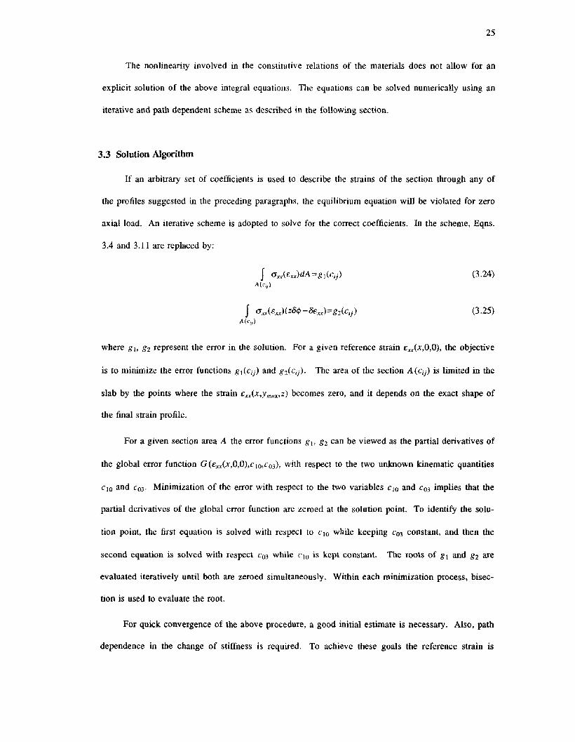
The nonlinearity involved in the constitutive relations of the materials does not allow for an
explicit solution of the above integral equations. The equations can be solved numerically using an
iterative and path dependent scheme as described in the following section.
3.3 Solution Algorithm
If an arbitrary set of coefficients is used to describe the strains of the section through any of
the profiles suggested in the preceding paragraphs, the equilibrium equation will be violated for zero
axial load. An iterative scheme is adopted to solve for the correct coefficients. In the scheme, Eqns.
3.4 and 3.11 are replaced by:
f O'xx(£xx)dA=gl(cij)A(cij)
f CJ'.u(£xx)( zotP-&x.r)=82(Cij)A(ei})
(3.24)
(3.25)
where 81> 82 represent the error in the solution. For a given reference strain £xx(x,O,O), the objective
is to minimize the error functions 81(Ci) and 82(cij)' The area of the section A (Ci) is limited in the
slab by the points where the strain £xx.<x,Ymax'z) becomes zero, and it depends on the exact shape of
the final strain profile.
For a given section area A the error functions 8], 82 can be viewed as the partial derivatives of
the global error function G(£xx(x,O,O),CIO,C03)' with respect to the two unknown kinematic quantities
CIO and C03' Minimization of the error with respect to the two variables CIO and C03 implies that the
partial derivatives of the global error function are zeroed at the solution point. To identify the solu-
tion point, the first equation is solved with respect to CIO while keeping e03 constant, and then the
second equation is solved with respect e03 while clO is kept constant. The roots of 81 and 82 are
evaluated iteratively until both are zeroed simultaneously. Within each minimization process, bisec-
tion is used to evaluate the root.
For quick convergence of the above procedure, a good initial estimate is necessary. Also, path
dependence in the change of stiffness is required. To achieve these goals the reference strain is

26
changed incrementally from its initial value to the final value; initial estimates for a subsequent
increment are the final values of the last converged solution. Areas that have experienced cracking
stresses during the load history do not develop tensile stresses thereafter. They are, however, fully
active in developing compressive stresses. The first estimates of the unknown coefficients and the
maximum width Ymax are obtained from the precracking stage, where the integral equations can be
solved numerically in a direct way_
The algorithm is summarized in the following flow chart
Given:
Unknown:
START:
e.:',.+I(x,O,O), e.:',.(x,O,O), c10, c[h, N
SET:
STEP 1:
STEP 2:
STEP 3:
STEP 4:
"+1 "Ymaxo =Yma,
Solve g (C"+1 C"+1 )=0 for c"+11 10,+1' 03, 10'+1
Solve ex..(x,Ymax,O) for Ymax; evaluate the area of integration A
Check tolerances
if not sufficiently accurate return to step I after the
substitution i=i+1
else, calculate the section moment M
substitute n=n+ I
proceed to the next increment of strain.
Steps 1 and 2 are solved iteratively. For the assumed value of the variable coefficient the
unbalance is evaluated. Then the value of the coefficient is slightly perturbed, to calculate the

27
derivative of the unbalance. This derivative points to the optimum search direction for updating the
estimate of the coefficient to minimize the unbalance. If the initial guess is properly selected and the
increment of the controlling strain is small (eg. 0.0002 is a successful strain increment in most cases)
the algorithm converges and is stable and unique. At points where sudden stiffness changes occur in
the material properties, bifurcation problems have been observed. In these cases a degenerate solu
tion requiring less energy may be the output of the algorithm. This is a result of tbe sensitivity of
the solution to the coefficient related to transverse warping. If bifurcation problems arise, a correc
tive algorithm is as follows: In 'step 2' the area of the section is evaluated by minimizing the error
of the virtual work equation. The coefficient describing the strain profile is evaluated in 'step 3'
from the geometry of the converged section area and from the remaining quantities that define the
strain profile in Eq. 3.22.
3.4 Correlation with Experimental Results
The method discussed in this chapter was applied to several slab-beam sections that were tested
experimentally by previous investigators [7, 10, 20, 27]. A summary of geometric properties and
materials of the selected specimens is given in Appendix A.
All specimens except Berk2 (Appendix. A) were half scale models. Specimen Berk2 was a
quarter scale model. Computed quantities include moment envelopes versus steel strain or section
curvature, and variation of steel strains with transverse distance. Comparisons of computed and
measured quantities are given in Figures 3.4-3.13.
Comparison of Various Strain Profiles
As was discussed in Section 3.2, several expansions of strain were used to study the sensitivity
of the computed behavior to the type and order of expansion. When the polynomial representation
was used, it was generally found that connection stiffness and strength were underestimated when the
first three terms of Taylor's expansion (i.e a:::2.0 in Eq. 3.18) were kept. Stiffness and strength

28
increased as a decreased. A value of a= 1.5 resulted in good correlation with measured stiffness and
strength. Figure 3.4 presents computed and measured relation between moment and curvature of the
interior connection of specimen Berk2. The effect of the expansion is apparent therein. Because the
exponential strain profile is considered more consistent with the mechanics of the problem, and
matches the Timoshenko elasticity solution, only the exponential form will be pursued further in the
following correlation study.
Comparison of Measured and Computed Behavior
Behavior of several test specimens (Appendix A) was computed using the assumption of
exponential strain distribution. In this section, computed and measured responses are compared for
specimens Berkl, RiceJ4, RiceJ7 and Berk2 (interior and exterior).
Analytical and experimental moment curvature relationships for Berkl are compared in Fig.
3.5. The relationships compare closely throughout the range of loading. Response calculated using
the assumption of plane sections with various effective widths (Fig. 3.5) illustrates that for specimen
Berkl, the pre-yielding response is replicated by using an effective flange width equal to one beam
depth on each side of the web. The post-yielding response is better described if the effective width
of slab is increased to 1.7 beam depths. For drifts in the range of 3.5% (curvature approximately
equal to O.002/in) the effective flange width is approximately 2.4 beam depths.
Strain profiles for the Berkl case (occurring at the reference points "A", "B", and "C" in Fig
3.5) indicate that the proposed analytical model follows the measured data in an average sense (Fig.
3.6). As would be expected, strain measurements have some irregularity not represented by the
analytical model. The lack of precise correlation is attributed to several phenomena, including loss
of bond, hysteretic behavior, and local stress concentrations.
The four specimens RiceJ4,J5,J6,J7 were also analyzed in this study. As noted in Section 3.2,
the analytical model was derived only for connections with very stiff transverse boundaries (the
coefficient of integration p (y,:;) which represents warping of the support non-associated to normal
stresses is assumed equal to zero). The purpose of using it to connections that did not satisfy this

29
requirement was to identify the effect of transverse beams on the contribution of the slab and to test
the applicability of the analytical model in this case. The results from the correlation are plotted in
Figures 3.7-3.9. The computed moment-strain relationships match closely the experimental points
(Fig. 3.7); apparently, the effect of the transverse beams on the moment-strain relationships does not
degrade the correlation for the Rice cases. The effective width of flange that can be used with the
assumption of plane sections is examined only for the RiceJ7 experiment, because this is the only
case where the transverse width of slab available was enough for such a consideration to be of
importance. It is seen (Fig. 3.8) that for the pre-yielding and post-yielding behavior the effective
width of flange is in the range of 1.5 beam depths on each beam side, except in the range of very
large drifts (top steel strain greater than 0.012) where 2 beam depths should be considered as
effective flange width on each side of the web.
The measured strain distributions for the Rice specimens (Fig. 3.9) indicate that strains decay
more rapidly than the analytical model. As was discussed in Chapter II, the more rapid strain decay
is typical of exterior connections, and is attributed here to lower membrane stiffness at the edge.
Computed and measured behaviors are compared for specimen Berk2 in Fig. 3.10-3.13. The
relationship between section moment and steel strain for the interior connection of the specimen is
plotted in Fig. 3.10. Analytical results indicate a stitlness reduction in the post-yielding range that is
not followed by the test data. It is possible that the discrepancy is attributable to effects of slip of the
main beam bars. As the bars slip through the joint, longitudinal deformations occur although strain
relaxes in those bars. However, the slab bars, which are better anchored, do not slip as much, and
thus develop stresses which increase the moment resistance without increase in main bar strain. The
measured transverse distribution of strains supports this hypothesis (Fig. 3.11).
Although the hardening rate for specimen Berk2 is not correctly anticipated because of bar slip,
the maximum strength is computed correctly by the analytical model (Fig. 3.10). Other data plotted
on the same figure are moment-steel strain relationships calculated using the assumption of "plane
sections", with various effective widths of slab overhang. The Berk2 experiment indicates that a
length equal to 3.2 beam depths must be considered as an effective width of flange on each side of

30
the web for very large drifts; for the pre-yielding behavior this length should be equal to 1.6 beam
depths. A continuous increase of the equivalent flange width would be necessary to describe the
post-yielding behavior.
The exterior connection of the Berk2 specimen is also considered in this analysis. As is shown
in Fig. 3.12, analytical and experimental responses of the exterior connection of Berk2 do not corre
late well (Fig. 3.12). Apparently, the transverse beams in specimen Berk2 are not sufficiently stiff in
torsion or in-plane bending to fully engage the slab, resulting in measured resistance much less than
the computed resistance. Comparison of experimental responses in Fig. 3.10 and 3.12 demonstrates
that the slab is much less effective for exterior connections than for interior connections (the exterior
connection resists less moment even though similarly reinforced).
Comparison between computed and measured strain profiles in the transverse direction of the
slab emphasizes the above mentioned differences (Fig. 3.11, 3.13). For the interior connection (Fig.
3.11) the measured strain in the beam longitudinal steel is lower than the strain in the adjacent slab
bars. This was attributed previously to slip of these bars. However, for the exterior connection,
(Fig. 3.13), strains decay with distance at a rate faster than that of the exponential profile, also indi
cating less slab contribution. The smaller slab contribution is attributed to two effects. First, as was
mentioned in the preceding paragraph, the slab is more flexible because of the edge. Second, the
main bars are better anchored and thus contribute more effectively. This result is discussed further in
Chapter IV, where an analytical model for exterior connections is developed.
Summary
For the specimens analyzed herein, the correlation points to the following conclusions:
a) The analytical model can successfully represent the variation of strains as the level of deforma
tion increases. The exponential decay of strains is particularly effective in representing the
behavior of interior connections.
b) In exterior connections with flexible boundaries, strains decay transversely at faster rates than
that of the exponential strain profile.

31
c) The assumption of pure web action for negative bending [1] is not realistic. Instead, for calcu-
lating the beam response using the assumption that plane sections remaining plane, an effective
width of flange on each side of the beam web should be considered. This flange width should
be equal to 1.5 beam depths for pre-yielding behavior, and should be increased to 2.0 beam
depths for moderate post-yielding response. For very large drift levels, the effective flange
width may approach 3.0 beam depths.
3.5 Shear }'Iow in the Plane of the Slab
A direct consequence of the contribution of the slab to the flexural behavior of beams is the
development of shear in the plane of the slab. The occurrence of shear stresses is independent of the
order of the assumed strain profile, and is of interest in understanding the behavior of T-beams. Fig-
ure (3.2) illustrates a slab slice of infinitesimal thickness. At location x along the longitudinal axis,
the point of zero strains is a distance Ymax(x,z) from the main beam axis. At location x+dx, the point
of zero strains is at Yma.(x+dx,z). The shear flow at t~Y~Yma.(X'Z) is defined by Eq. 3.26:
q(x ,Y )dx=IO"ry(X ,y ,z )dzdxo
where t is the thickness of the slab. Equilibrium requires
t [Ymax(x+dx.,) Ymax(X.') 1q(x ,y )dx=f f O"xx(x+dx ,y ,z)dy- f O"xx(X ,y,z )dy dz
o Y Y
From Eq. 3.27,
t [Ymax(x.z) ocr (x y z)] t [ymax(X+dX.,) ]q(x,y )dx=f f xxa;' dy dzdx+f f O"xx(x+dx,y,z)dy dz
o Y 0 Ym..(X.Z)
Rewriting
(3.26)
(3.27)

32
t [y"",(X,=) dO"xx(x,y,z) J t [yma,(x+dx,=) dO"xx(X'y,z) ]q(x ,y)=f f dX dy dz+f f dX dy dz
o y 0 y"",(x,z)
(3,28)
At the limit dX---70, the second term of equation (3.28) is zero, (equal upper and lower limits of
the integral), thus the shear flow at the side of the flange is:
y"",(x) dO"xAx,y)q(x,y)== t f -~dy
y
(3,29)
where for simplicity it is assumed that the normal stresses are constant through the thickness of the
slab. The average shear stress that develops in the plane of the slab is:
(3.30)
For the purpose of the following discussion the concept of an equivalent uniform stress a'(x) is
adopted for the slab acting over an equivalent flange width dequ;\,' Also, it is assumed that for short
segments along the beam, behavior can be linearized. Within such a short segment, the stress a'(x)
is linearly related to the moment:
a'(x)=ZM(x)
where Z is the section modulus and is assumed piecewise constant along the length of the beam.
Thus, the in-plane slab shear stress within a short segment of the beam is of the form:
V (dequ;\'-y)O"X)(x ,y)== Z (3.31)
Where V is the shear acting on the beam in the z-direction, It can be seen that the maximum shear
stresses act at the interface between slab and web. Depending on the value of V it is possible that
these shear stresses can reach significant values. This issue is investigated further in Chapter IV.
The shear stresses that develop in the slab may explain the strains of the transverse slab rein-
forcement that have been reported by previous investigators (7, 22]. Apparently, for the equilibrium
of an infinitesimal slab element (Fig. 3.2), normal stresses develop in the transverse slab steel (in

33
addition to shear stresses) to balance the spinning moment that the shear stresses impose on the ele
ment. The shear stresses are carried by concrete and by the dowel action of the transverse steel of
the slab. This result, as already mentioned is of theoretical and practical interest. In practice it is
related on how transfer of lateral forces is achieved from one structural component (e.g. floor inertia
forces due to earthquake loads) to an other (e.g. walls).

34
CHAPTER IV
A TRUSS MODEL FOR THE 3-D BEHAVIOR OF EXTERIOR CONNECTIONS
4.1 Introduction
The review of experiments on connections in Chapter II illustrated that behavior of exterior
connections is affected by the stiffness of transverse beams. Apparently, the transverse beams twist
and deflect in the plane of the slab, thus reducing the slab contribution. Consequently, there is a
need to develop an analytical procedure to account for this effect on the behavior of slab-beams.
In order to better understand the behavior of exterior connections, an attempt will be made to
model the spatial characteristics of the response of a typical exterior joint subassemblage. In the
analysis, the effect of the slab is considered over the entire length of the beam, as opposed to the
model presented in Chapter III where only cross-sectional behavior is analyzed. The slab is recog-\
nized as a membrane acting between the longitudinal beam and the transverse beams. As was dis-
cussed in Section 3.5, there is a shear flow acting in the slab-beam interface (Fig. 4.1). Similar
actions develop in the slab-transverse beam interface. To model the shear stress state of the slab
membrane, the diagonal compression field theory [26] is employed. A brief summary of the main
points of the theory is given in Appendix B. To analytically represent the combined twisting and
flexural action of the transverse beams, a simplified method to produce simultaneous torque-twist /
moment-curvature introduced in [17] is used. A description of the three-dimensional model for the
exterior connection follows in Sections 4.2 and 4.3. Implementation of the model for computer
applications is presented in Section 4.4. Correlation of computed behavior with experimental results
is presented in Section 4.5.
4.2 Derivation of the Model
Consider the frame structure shown in Fig. 4.2. If the structure is forced to sway laterally (as
would happen during an earthquake, for example), then the following observations can be made on
the behavior:

35
In each bay of the structure there is a region where the slab is in tension, and a region where
the slab is in compression. Thus, even if the longitudinal beam is symmetrically reinforced, and the
stiffnesses of the supports are similar for both ends of the span, the presence of the slab causes
asymmetry because the stiffness of the slab panel in tension is different from its stillness in compres
sion.
The side where the slab is in tension is of major interest in the present study (although the
model developed in this Chapter is also appropriate where the slab is in compression). The surface
of the slab-beam elongates as it undergoes tension. This forces the slab to distort in shear in order to
satisfy the lateral boundary condition that is free of load. Also, the slab reinforcement develops ten
sile stresses which are transferred to the transverse beams. The result of these stresses on the
transverse beams is two fold: 1) Beam flexural moments develop in the plane of the slab, 2) Beam
torsional moments develop as a result of the eccentric action of the floor relative to the shear center
of the transverse beam cross section. The transverse flexure and torsion are a maximum at the joint,
decreasing with distance from the joint. Under these forces, the transverse beams deflect in the plane
of the slab and twist about their longitudinal axis. This combination of flexure and torsion in the
transverse beams of exterior connections often causes diagonal cracks on the exterior and interior
faces of the transverse beams (Fig. 4.3).
One way to visualize the various phenomena discussed in the previous paragraph is by the
means of a three-dimensional equivalent structure (Fig. 4.4a). The longitudinal bending element of
the model represents the action of the web of the longitudinal beam. As was discussed in Chapter II,
if the action of the slab is isolated from the action of the web, then this is equivalent to imposing an
axial load to the web (Fig. 4.4b). Thus, the longitudinal bending element of the analytical model is
subjected to variable axial load, which is a function of the deformation occurring in the slab. The
transverse elements of the analytical model correspond to the transverse beams of the subassemblage.
The flow of forces from the longitudinal beams to the transverse beams is achieved by means of truss
elements inclined at an angle ex to the longitudinal elements (Fig. 4.4a). The angle of inclination is
selected empirically and approximates the direction of principal tensile stresses in the slab. The

36
properties of the truss elements are such that the axial stiffness of the slab in the direction of flow is
approximated closely in the analysis.
In Section 3.5, an expression for the shear flow that develops in the thickness of the slab and
acts in planes parallel to the direction of the main beam was derived. It was concluded that, for any
distribution of normal strains in the slab, the shear flow can be expressed in terms of the derivative
of normal stresses. At the interface between slab and beam web, an alternative expression can be
derived for the shear flow based on the equilibrium of an isolated slice of the web having length dx
(Fig. 4.4b). Given that the longitudinal beam is subjected to varying moment along the length, the
web slice is under a stress distribution O'x...(x) at location x along the longitudinal axis. At location
x+dx the stress distribution is denoted by O'.~,(x+dx). Equilibrium is satisfied by shear stresses that
are generated along the lateral surface of the beam (within the thickness of the slab), which represent
the membrane action of the slab. If A denotes the total effective area of the slab-beam and Aw the
area of the beam web only, then establishment of equilibrium on the two areas leads to:
Section at x;
Section at x+dx:
fO'xx(x)dA =.N(x)A
fO'x...(x)dAw=.Nw(x)Aw
fO'xAx+dx)dA =N(x+dx)A
fO'.r.r(x+dx)dAw=Nw(x+dx)Aw
(4.1)
(4.2)
(4.3)
(4.4)
where it has inherently been assumed that the effective area has not changed within the distance dx.
The total shear force dV (x) that acts on the lateral surface of the beam within the distance dx (Fig.
4.4b) takes the form

dV(x)=Nw(.r)-Nw(x+dx)
37
(4.5)
For the sake of simplicity it is assumed that no externally applied axial load acts on the beam
(N(x) =N(x+dx) = 0). Thus,
dV(x)= f (Cf.",(x)-CYxx(.r+dx»dAw
A.
(4.6)
Integrating along the length, the total force acting on the lateral surface of the beam in a dis-
tance L (Fig. 4.4b) is:
L l. dCYxAx)V(L)=f dV(x)= f f---:-dAwdx
o OA. d.x(4.7)
Similar conditions can be derived for the transverse beams. Review of experimental observa-
tions presented in Chapter II suggested that the normal strains of the slab decrease with distance
from the main beam, the rate of decay depending on the stiffness of the transverse boundary.
Stresses, being a function of strains, also decay. The concept of an equivalent width of slab with
uniform stresses was discussed in the previous chapters. If this concept is used to analyze the con-
nection, the distribution of stresses transmitted from the slab to the transverse beams is uniform (Fig.
4.5) within the transverse distance equal to the equivalent width of slab at the support. In this case,
the local equations of equilibrium take the form,
(4.8)
where Ao is the effective area of slab-longitudinal beam section at the support point x=O. The entire
force transmitted to the transverse beams is,
(4.9)
This force subjects the transverse beam to torsion and bending in the plane of the slab. If there is
some contribution of the slab to this bending, then the expression for shear flow at the interface
between the slab and the transverse beam is,

38
(4.10)
where A' is the sectional area of the slab-transverse beam effective in flexure (Fig. 4.6). Thus, the
shear force acting on the lateral surface of an elementary slice of length dy of the transverse beam
within the thickness of the slab is,
(4.11)
Integrating over the equivalent width of slab at the support, dequiv' the total shear force acting
on the lateral surface of the transverse beam is,
(4.12)
Equilibrium at any section y of the transverse beam produces:
L,,-y
M(y)= J CYxAO,y)(L,r-y)dy= JcyyyxdA:;L" A:
(4.13)
(4.14)
where T (y) is the torque acting on section y, M (y) is the in-plane moment at section y, L'r is the
entire length of the transverse beam, and h'r is the height of the the transverse beam section. In Eq.
4.13, the stress CYx..{O,y) is assumed for simplicity to act at the top fiber of the transverse beam rather
than the slab centroid.
Equations 4.6,4.9,4.13-4.14 establish equilibrium for the longitudinal and transverse beams. A
free body diagram for a strip of slab of elementary width dh, inclined with an angle a to the longitu-
dinal axis of the main beam, is shown in Fig. 4.7. Equilibrium requires that the force acting through
the slab strip (Fig. 4.7) is given by:

39
The average stress acting along the axis of the strip is,
~ dFslab(Jslab=~
where,
(4.15)
(4.16)
(4.17)
For the derivation of the compatibility equations of the connection, consider the plan view of
the connection in a deformed configuration (Fig. 4.8). An arbitrary diagonal element of the slab with
initial inclination a and length Ls~ab before deformation ends up with an orientation a' and a length
L s1ab ' This change in length is related to the elongation of the longitudinal beam at the level of the
slab and to the deflection of the transverse beam. If all the changes in length are referred to the ini-
tial orientation (Fig. 4,8) then the distance AA' is the in-plane deflection of the transverse beam at
the mid-depth of the slab, the length BB' is the elongation of the longitudinal beam at the slab mid-
depth and A'B'-AD is the deformation of the slab between the points considered.
The deflection AA' can be calculated from the curvature/twist distribution along the transverse
beam as:
, fO h,,. fOAA = lfJ(y)ydY+T O(y)dy
L,,-y L,,-y
(4.18)
where IfJ (y) is the curvature distribution and 0 is the angle of twist per unit length of the transverse
beam. The elongation of the main beam at the level of the mid-plane of the slab, can be calculated
as:
oBB'= J I/J(x)d"(x)dx
L-.'
(4.19)
where d"(x) is the depth of the neutral axis from the mid-plane of the slab at the cross section x.

40
Knowing the value for AA and BB', the elongation of the slab along line AB (denoted by
dLs/ab ) is readily found.
An average strain can be defined along the line AB as follows:
dL\'/abes/ab=~ (4.20)
Both the equilibrium and compatibility equations presented so far were developed without
significant discretization assumptions. If isolated truss members are used to model the slab action,
and the longitudinal and transverse web clements are subdivided into short segments (Fig. 4.9), then
the equations can be rewritten in discrete form, as is described in Section 4.3. The advantage of
expressing the equations in discrete form is their adoptability in conventional structural analysis pro-
grams.
The concept of the truss model, as presented in the previous paragraphs, is a natural conse-
quence of the fact that the slab is under an in-plane stress state. The form of the truss selected for
the problem is as in Fig. 4.9. The number of truss elements to be used can be varied. It is con-
venient to relate their orientation to some major geometric property of the subassemblage, such as
the geometric diagonal of the slab (thus the line joining the inflection points of the longitudinal and
transverse beams shown in Fig. 4.9) This geometry is selected in all following discussions.
4.3 Expression of the Equations in Discretized Form
The geometry of the discretized model is shown in Fig. 4.9. One restriction of the model is
that an equal number of nodes is required in the longitudinal and transverse directions. The displace-
ment degree-of-freedom (d.o.f.) associated with node NJ of the longitudinal beam is the elongation of
the beam at this point, denoted by th. The d.o.f. associated with node nj of the transverse beam is
the deflection Ui resulting from the combined flexural and twisting action of this element.
Each segment* of the longitudinal beam is subjected simultaneously to bending and to an axial
force PI (no axial load acts on the entire slab-beam section, but an equivalent force is applied to

41
replace the effect of the slab on the beam web). Thus, the moment-curvature relation characterizing
each segment is affected by the axial load which is also an unknown of the problem. If the curvature
distribution within segment I is assumed to be unifoffil and the end rotations of the segment are VI_J
and VI, then,
(4.21)
where dF is the depth of the neutral axis from the mid-plane of the slab in segment I, and 01 is the
accumulated surface elongation of the main beam at node I.
Similar relations are formulated for the transverse beams (Fig. 4.9). The deflection Ui of node
ni of the transverse beam is:
(4.22)
where ri is the flexural deflection of the transverse beam at node ni, Ii is the segment length, and ei
is the angle of twist per unit length between nodes i and i-I.
If Ti is the torque acting on the segment i of the transverse beam, then this torque affects the
tangent flexural stiffness Eli of the segment. Calculations of simultaneous torque/twist -
moment/curvature relations are complicated. A review of various methods that can be used to obtain
the tangent flexural and torsional stiffnesses EI;', Gli is given in [17].
The incremental form of the equations of equilibrium for segment i of the transverse beam are:
(4.23)
and,
(4.24)
* Segment is defined here as the length of the beam between two subsequent nodes.

42
The truss elements that model the action of the slab are the means by which the force and dis-
placement d.o.f. 's of the longitudinal and transverse segments are related. An increment in the elon-
gation of the truss element which connects nodes I and i (Fig. 4.9) is given by:
(4.25)
where the elongation of the truss element is written as the product of the average axial strain of the
element by its initial length L,. Similarly, the incremental foml of the equilibrium equation for the
truss member is the following:
(!W,-L1Ti _ l ) (L1V,-L1V,_1)_...~--~._----, .. _. _. -'--'- ---_ .._----
sinahllJ2 sina
(4.26)
(4.27)
where the truss force is expressed in terms of the average stress acting on the truss member. The
area A, of the truss element is
A,=H,t
where Hi is the width of the slab strip that is modeled by the truss element, thus:
(4.28)
(4.29)
The relationship between Ei and cr, can be computed using the diagonal compression field
theory (Appendix B). This theory can provide stress strain relationships for any selected diIection of
action based on the properties of the individual materials. Here, the interest is for the case where the
direction of interest is inclined by an angle a from the x axis.
Equations 4.21-4.29 describe the behavior of the analytical model in a discretized form. The
algorithm used to evaluate the behavior of the analytical model using these equations is summarized
in the following section.

43
4.4 Implementation of the Model
The discretized model is implemented using the ANSR-I program [14, 15]. The equivalent
structure is as shown in Fig. 4.10. The truss members are positioned eccentric to the beam elements,
and are connected to the beam nodes through short rigid segments. For any curvature distribution
along the longitudinal beam this setup creates the corresponding elongation at the mid-depth of the
slab as described by Eq. 4.22. Also, the truss forces are transferred to the transverse beam through a
torsional lever arm so that Eq. 4.28 and 4.23 are simultaneously implemented.
The number and orientation of the truss members depends on the geometry of the connection
and the number of nodes in the beams. The stiffness properties of the truss members depend on the
orientation of the members and are evaluated using the compression field theory (Appendix B).
The equivalent structure is loaded with a vertical force at the end of the longitudinal beam
(Fig. 4.10) to introduce moment transfer to the connection. The load is applied incrementally.
In order to determine behavior of the equivalent structure, stiffnesses of the individual com-
ponents must be known. However, stiffness of the longitudinal beams depends on the axial load act-
ing on the web, which is a function of the slab contribution and is not known beforehand. An itera-
tive solution is pursued. In the iterative solution, an initial stiffness estimate for the longitudinal
beam is computed using the effective slab width according to the elasticity solution1 (Section 2.4).
Flexural stiffness and torsional stiffness are calculated for the transverse beam segments using
the method presented in [17]. According to this method, an inclined section is identified in the cle-
ment which is under a pure torsional or a pure flexural moment. Conventional torsional or flexural
theories are used to study the behavior of the inclined section, and then decompose the action and
deformation quantities on the normal section of the element.
I Stiffness of the web section under no axial load is usually relatively low. However, stiffness is insensitive tosmall variations of axial load. It was seen in Chapter III, that prior to yielding the equivalent width of slab computed using the theory of elasticity is close to the width of slab computed using other methods. It is considered appropriate, thus, to use this equivalent width for pre-yielding stiffness calculations.

44
In order to calculate the transverse beam segment stiffness, a value for the ratio of the flexural
moment to torque must be initially assumed. The assumption made in this analysis is that each seg-
M; L,,.-xjment is characterized by a constant ratio of actions, r·=-- where r=2-- and Xj is the
I Tj
' I htr
'
transverse distance of node i from the joint.
After one solution cycle of the iteration, the assumptions on which stiffness calculations are
based are updated, and the solution is repeated to achieve a better approximation of the true element
forces. The contribution of the slab is assessed through the axial loads acting in the truss members.
Section cuts along the length intersect a different number of truss members; fewer truss members
with lower axial force occur towards the tip of the cantilever.
The method described in the previous paragraphs was used to study the response of exterior
connections with flexible transverse beams that have been tested experimentally. The analysis and
correlation of one example are presented in the following Section 4.5.
4.5 Correlation with Experiments
The methods described in the previous section were used to analyze the exterior connection of
specimen Berk2 described in the Appendix A. As was seen in Chapter III, all exterior connections
were sufficiently represented with the section model, except for the exterior connection of the Berk2
specimen. This result was attributed to the flexibility of the exterior transverse beams of this speci-
men. Thus, the exterior connection of Berk2 is an ideal specimen to gage the proposed analytical
model.
Properties for the individual elements were calculated using the procedures discussed in the
previous section. Computed action deformation envelopes are shown in Fig. 4.11. Stiffness of the
longitudinal elements is strongly affected by the presence of the axial load (Fig. 4.l1b). If the entire
slab width would participate by yielding (axial load approximately equal to 20 kips) computed
cracked stiffness of the beam is 30 percent higher than the stiffness for zero axial load. Stiffness of
the beam segments is thus reduced in the analysis from the joint towards the tip of the cantilever as

45
the axial load representing the action of the slab decreases.
Computed moment-curvature and torque-twist relations for the transverse beams for different
ratios Z are shown in Fig. 4.11c and 4.lld. Computed stiffness characteristics and yield values areM
strongly affected by the .:£ ratio. Further discussion of these properties is given in [17].M
The truss members are described by the computed stress-strain relation shown in Fig. 4.lle.
This relation is computed for the selected orientation of truss action where a is approximately equal
to 30 degrees (Fig. 4.11e).
Correlation
Fig. 4.12 presents computed and experimental envelope relations between moment and top steel
strain for the exterior connection of specimen Berk2. The initial stiffness and the strength of the
connection are well represented by the analytical model. The longitudinal beam axial load computed
at different locations along the length (Fig. 4.13) indicates that for the exterior connection the slab
contribution does not increase significantly beyond yielding. The variation of axial load along the
length at various drift levels is shown in Fig. 4.14.
Computed and experimental strain profiles for various levels of longitudinal beam strain are
shown in Fig. 4.15. Correlation is best at higher levels of strain, probably because the connection is
more heavily cracked at later stages of testing as assumed in the analytical model (cracked-section
properties are used for the analysis).
Computed variations of flexural moment and torque, and of flexural deflection and twist, along
the transverse beam are presented in Fig. 4.16. The twist distribution suggests yield in torsion at the
face of the joint for large levels of drift. This result is in agreement with experimental observations
[27].
The analytical results presented in the previous paragraph suggest that the proposed equivalent
structure models successfully the behavior of the exterior connection of the Berk2 specimen. Furth-
ermore, additional information provided by the model demonstrate its potential to provide some

46
understanding on the behavior of connections.
Summary
In this Chapter, the problem of exterior connections is treated with a three dimensional truss
analog that accounts for the spatial characteristics of the response of connections having floor slabs
and flexible transverse beams. The distribution of loads, and the state determination, are evaluated
incrementally. In-plane flexure and torsion caused by the eccentric distribution of stresses from the
slab are modeled in the transverse beams. The effect of the slab on the longitudinal beam is
represented through a compressive axial force which strengthens and stiffens the beam web. The
plane stress state of the slab is modeled using diagonal truss members. The model results are in
good correlation with experiments.

47
CHAPTER V
A SIMPLE MODEL FOR THE EFFECT OF SLABS ON BEAM STRENGTH
5.1 Introduction
The methods presented in Chapters III and IV provide some physical insight to the problem of
slab contribution and assess the controlling factors in the behavior of slab-beam assemblages. Still,
the methods are too costly to apply in a large structural system where several slab-beam elements
need to be modeled. The extent of assumptions and simplifications involved in the analysis of any
structure imposes the need for a simple but efficient technique that can provide the analyst/designer
with a good estimate of the overstrength and stiffening provided by the slab without involving
lengthy calculations. This need, and the insight that was provided by the two theoretical models dis
cussed in the previous chapters motivated the development of a simple section model. This model
provides load-dependent closed-form solutions for the equivalent width of slab that acts with the
beam.
The model recognizes the membrane action of the slab in tension (negative bending) which is
primarily controlled by the mechanical properties of the reinforcement. The mechanism assumed and
the derivation of the method are described in Section 5.2. Correlations with experimental data
(Appendix A) are presented in Section 5.3.
5.2 Derivation of a Simple Model for the Efl'ective Slab Width
Connection Geometry
The model is derived for a connection with the configuration shown in Fig. 5.1 and 5.2. An
interior connection is selected for the derivation so that rigid transverse boundary conditions can be
assumed (i.e, the transverse beam does not bend in the plane of the slab). In Chapter IV it was
shown that in-plane flexural deformations of the transverse beams complicate the modeling process
for exterior connections. Correlations with experiments presented in Section 5.3 indicate that the

48
simple analytical model is applicable to a lesser extent to edge connections.
For the connection shown in Fig. 5.1 and 5.2, the section of maximum moment under lateral
loading is assumed to be adjacent to the face of the column. As depicted in Fig. 5.2, when moments
become sufficiently large, cracking commences in the beams and spreads transversely into the slab.
After cracking, tensile forces are undertaken by the longitudinal steel of the beam and the slab.
Because of the small depth of the slab relative to the beam in a typical case, the variation of strain
over the slab depth due to flexural curvature can be assumed to be small. Hence, the slab acts essen-
tially as a membrane element.
For deformation levels within the inelastic range, it is assumed that all flexural inelastic action
in the beam is concentrated within a "plastic hinge" length equal to the beam effective depth d. The
remainder of the beam is assumed to behave elastically. Identical assumptions are extended to the
slab, that is, inelastic action in the slab is limited to a length d measured from the column face,
where d is the beam effective depth.
Strain Distribution for Elastic Response
The elongation of the main beam along a length d measured from the face of the support at the
level of the top reinforcement can be found given the maximum steel strain. Specifically, if the max-
imum steel strain €max at the face of the column is less than or equal to €y (steel along the beam is
elastic), then the steel strain at a distance d from the support is given by:
(5.1)
in which L denotes the distance of the closest inflection point from the fixed end. In Eq. 5.1, steel
strain is assumed to vary linearly from the column face to the point of inflection of the longitudinal
beam. The total displacement at the level of the top steel a distance d from the support is given by
(Fig. 5.3):

49
(5.2)
The elongation (jd of the main beam must be followed by the slab which is monolithically con-
nected to the beam. For simplicity, the concrete in the slab is assumed to be relatively stiff, with
slab elongation accommodated primarily by growth of the crack at the interface between the slab and
the transverse beam. Additionally, crack growth at the interface is assumed to arise from the strain
in the slab reinforcement along a length d of the slab. In effect the slab steel is assumed to slip
from a relatively rigid concrete to accommodate the crack growth. The assumed deformation field is
modeled by connecting a rigid link (representing concrete) between each slab bar bj (at the interface
with the transverse beam) with the main beam steel at a distance d from the column face (Fig. 5.4).
The rigid links connect to the transverse beam through flexible springs. The springs represent the
stiffness of the slab longitudinal reinforcing bar at that location (spring stiffness will be derived and
expressed implicitly in the following section).
The kinematics of the proposed mechanism (Fig. 5.5), take the following foml:
dtana, =
x,
(5.3)
where ctj is the angle formed by the rigid link to the bar bi with the x axis, Xj is the distance of the
bar bj to the lateral surface of the main beam (Fig. 5.5), and (jj is the component of the spring elon-
gation (in the plastic hinge length d) parallel to the longitudinal beam, which is also taken as the
slab elongation parallel to the longitudinal beam. (Alternatively, (jj is the assumed crack width at the
interface between the slab and the transverse beam). Thus, each of the slab bars accommodates an
elongation in the distance d which is related by sin2aj to the main beam elongation (at the level of
the bar), so it is a function of the distance of that particular bar from the main beam. A plot of the
decay function sin2a versus x /d is shown in Fig. 5.6.

50
To find the value of strain that develops in the bar under consideration, it is assumed that the
strains vary linearly from the fixed end to the closest inflection point in the same manner as was
done for the main beam. Inverting the function that gives the bar elongation, the fixed end bar
strain is given as:
(5.4)
Given the strain distribution in the slab at the face of the support, resulting stresses could be
integrated over the section to determine the bending moment that produces this strain distribution.
However, as will be demonstrated subsequently, existing methods to calculate bending of a tee-beam
can be equally well employed for that purpose, without making any compromise in the accuracy of
the method. The notion of the membrane action of the slab is useful in that respect. The objective
is to replace the total axial force that develops in the slab by an equivalent force of the same magni-
tude, and same distance of application from the compression (or tension) surface of the main beam,
but which is produced by uniform slab strains in an equivalent slab width dequ;v' In that manner, both
equilibrium equations for the beam section are satisfied. The equilibrium of axial loads requires the
following:
Xmal
Es1ab d _E,iab f . 2 ( )dx~ E'max equ;Y- s E'maxS1n a x
o(5.5)
in which E;lab is the modulus of elasticity of the slab steel, and Xmax is the maximum available slab
*width . Rearranging terms and integrating gives the equivalent slab width as:
* The Xmax that was used in the preceding derivations is the least of:
I) The maximum available distance from the side of the beam to the end of the slab
2) 10d, selected as a limiting value that corresponds to a slab strain 100 smaller than the maximum strain of the top beam
reinforcement. (for x=IOd, a=O.I, and sin2(0.1)=O.OOI ).3) Half the clear distance between adjacent longitudinal beams in a floor system.

51
(5.6)
This is a closed-form solution for the equivalent width of slab, for the case where steel remains
elastic, but the concrete has already cracked in tension. (For maximum tensile strains less than the
cracking strain of concrete, the elasticity solution presented in Chapter II is more suitable).
The significance of the quantity d equi ,' is that conventional procedures assuming that plane sec-
tions remain plane can be used to analyze a cross section having the slab width equal to dequiv (on
each side) to obtain the same moment-curvature response as would be obtained using the sin2a varia-
tion of slab strain.
Strain Distribution for Inelastic Response
The procedure for determining slab contribution in the case of inelastic response is simi-
lar to that for elastic response. The procedure is described in the following. If the maximum
strain in the top steel of the main beam is beyond the yield strain, then it is assumed that only the
length d of the beam corresponding to the plastic hinge length undergoes inelastic deformations. As
a further approximation, to simplify the model, the tensile steel of the main beam at a distance d
from the fixed end is assumed to be at a strain Ey corresponding to onset of yield. Consequently, the
total inelastic elongation that occurs in the beam at the level of the top steel in the plastic hinge
region can be estimated as:
(5.7)
In Eq. 5.7 it is inherently assumed that the strain varies linearly within the plastic hinge length from
the value Emax at the fixed end to the value Ey at distance d.

52
Using the same model employed in the elastic case (Fig. 5.4 and 5.5), the elongation that each
slab bar undergoes is:
"_,, " 2 _ d . ) . 2Uj-Udsm (X,--(Emax+Ev sm (Xj2 . (5.8)
The strain distribution that was previously derived for the yielding of the main beam reinforce-
ment is now shifted a distance d away from the fixed end since this is the new point where the main
steel enters yielding. In this case, the strain distribution at this location is known to be:
(5.9)
Then from this and the previous equation, the strain of the i -til bar at the fixed end is given
as:
Thus,
(5.10)
Equation 5.10 indicates that the strain distribution for the proposed model retains its depen-
dence on sin2(Xj even at strains beyond yield. Since the strain profile is now available along the slab,
the procedure for calculating the equivalent width is the same as before. However, as additional
information, the points along the width of the slab where the strain attains characteristic values of the
steel stress-strain law must be determined. The distance from the main beam steel at which the slab
bars just enter yielding is found from:
(5.11)
Thus,

Solving for xy'
,x;:
emax~
1+-2
Xy
_ <.slab=Qc'y •
53
[
em.x ] +xy=d -- - 1<.slabCoy
(5.12)
The same procedure is used to find the distance at which the slab steel commences strain har-
dening. For simplicity, an elastic-plastic-linearly hardening stress-strain relation is assumed for the
slab reinforcement.
Five different formulae for the equivalent slab width are required. Two are required for the
case where the slab steel has yielded; one for the case where xy is less than Xmax> and one for the
case where xy exceeds Xmax ' Three expressions are required for the case where the slab steel has
strain hardened; one for the case where x y is less than Xmax , one for the case where X max is between
Xy and Xsh, and one for the case where Xsh exceeds X max '
a) No strain hardening- The equivalent slab width takes one of two forms.
For xy::::;xmax , the statement of axial force equilibrium is
XlT\lIll
/ slabd . =x j'slab+ f Es1abe sin2a(x)dxy equlv y)' s 'max
x,
from which the equivalent slab width is obtained as
For Xy~xmax, the statement of axial force equilibrium is
from which the equivalent slab width is obtained as
(5.13)
(5.14)
(5.15)

54
(b) Strain Hardening - The equivalent slab width takes one of three forms.
For Xy~Xmax, the statement of axial force equilibrium is
x" [ fslab _j.Slab] x.~,slab _ slab. max y . . slab slab . 2
!maxd,,/ui"- I fmax-;x--~---- d;X+(Xy-.tsh)!y +Es I emaxsm a(x)dxO '~h x,
from which the equivalent slab width is obtained as
! slab fslab fslab . •_ y y y E max -1 .t max -1 Xy
dequiv-0.5xsh-0.5xsh--+Xy---+-- --d(tan ---tan -)f
slab j'slab j'slab eslab d dnlax max nlax)'
For Xsh~Xmax~Xy, the statement of axial force equilibrium is
x" [ j'slab _j,Slab]slab _ slab max Y slab! mao<dequi,'- f f max -x-- --. - - dX+(Xmax-Xsh)!y
o .tsh
from which the equivalent slab width is obtained as
For Xsh~Xma., the statement of axial force equilibrium is
xmu
( f
slab
_f
slab1f slabd . = J f slab - -~.!- dmax. equa' max X Xo Xsh
from which the equivalent slab width is obtained as
(5.16)
(5.17)
(5.18)
(5.19)
(5.20)
(5.21)
(5.22)
Employing the expressions derived above, one can evaluate the total slab width that has to be
used in a standard analysis of a T or L shaped RIC beam using existing methods to calculate stiffness
and strength as below:

For T beams: D =2dequiv+bconf
For L beams: D =dequiv+b conf
5.3 Comparison with Experimental Results
(5.23)
(5.24)
55
The analytical model presented in Section 5.2 was used to analyze the specimens introduced in
Appendix A. As in Chapter III, connections with rigid transverse supports (such as interior connec
tions or exterior connections with stiff transverse beams) fit the assumptions of the model and are
suitable for correlation (specimens Berkl, Berk2, and MinEW3). Exterior connections with flexible
transverse beams are also analyzed to investigate the sensitivity of the model to the support condi
tions.
Response correlations include variations of reinforcement strain, effective slab widths, and
moment envelopes.
Correlation
The results from the correlation are of similar quality as those obtained in Chapter III. The
general tendency is that the decaying profile sin2 ex replicates approximately the variation of slab
strains for connections with stiff transverse boundaries and with no significant slip of the top rein
forcement. Plotted results for this type of connection, [Berkl, MinEW3 and Berk2(interior)], are in
Fig. 5.7a through 5.7d. For the interior connection of specimen Berk2, the main slab steel slips
significantly through the joint. Consequently, the kinematics of the mechanism described in Eq. 5.3
are slightly different. The quantity 0d is composed by two parts:
where 5J is the pullout from the support, and o~ is the elongation due to strains within the plastic
hinge length. Similar modification is necessary for OJ:

56
Thus,
If the relation between pure elongation and strain is kept the same as in Eq. 5.2 or 5.8, the strain
associated with bar hi is related to the main reinforcement strain through the following:
(5.19)
It is apparent from Eq. 5.19 that if the reinforcement slip is included, the variation of strains
with transverse distance deviates from the simple sinusoidal distribution. If the main beam reinforce-
ment and the slab reinforcement develop the same amount of slip, the variation of strains is
sinusoidal as in the case of no slip. (However, the amplitude lOmax for the same amount of total dis-
placement will be less than for the case of no slip.) In the case where the main beam reinforcement
slips more than the the slab reinforcement, slab strains will decay with a larger amplitude than Emu.
The interior connection of specimen Berk2 provides an example of the latter behavior. The main
reinforcement bars (#2 bars) slipped much more than the slab bars (gauge #9), resulting in an
increase of strains in the slab (Fig. 5.7d).
For specimens RiceJ5 and kiceJ7 and the exterior connection of Berk2, the analytical and
experimental variations of strain compare well for low levels of strain. Correlation for these speci-
mens deteriorates as strain levels increase, with experimental results indicating less slab contribution
than is computed. The lower measured slab contribution is consistent with the fact that the slab
boundary is less rigid for these exterior connections than is assumed in the analytical model.
Effective slab widths were computed according to Section 8.10.2 of the ACI Building Code [1]
and according to the proposed analytical model. Computed widths are in Fig. 5.8a - 5.8e. It is noted
that the ACI effective widths are intended to be used for tee-beams having the slab in in compres-
sion, rather than in tension. Thus, its use in this section is not entirely appropriate. It is presented

57
because it is a familiar quantity and thus provides a convenient scale by which to gage the widths
computed according to the proposed model.
Comparing the computed effective widths in Fig. 5.8a - 5.8e, it is observed that the proposed
model and the ACI model result in approximately the same effective width for low strains. At very
low strain levels, the effective width is close to the width computed according to the elasticity solu
tion that was presented in Chapter II. As strain increases, effective widths of the proposed model
increase. For specimen RiceJ5, the proposed model predicts an effective width essentially equal to
the full slab width as tensile strains reach approximately 0.004. For the other specimens, the
effective widths increase to values as much as three times the ACI effective width, but still less than
the full transverse width of the slab.
Given the computed equivalent width of slab at different strain levels for the test specimens,
standard methods to calculate the moment-strain, moment-curvature and moment-rotation relations
were used. Measured and computed moment-deformation relations are compared in Fig. 5.9. Com
puted quantities include moments determined for the effective slab widths in Fig. 5.8 and moments
determined assuming the slab does not contribute to the beam resistance. It is noted that the various
experimental researchers reported specimen deformations using different quantities (strain, average
curvature, or rotation at a distance from the column face). Thus, the abscissas in the Fig. 5.9a - 5.ge
differ according to the deformation quantity reported for a given test specimen.
Review of the moment-deformation relations in Fig. 5.9a - 5.ge suggests that the proposed
analytical model successfully gages the effective slab widths for the different specimens. Maximum
flexural strengths are within ten percent of measured strengths. In addition, moment-deformation
relations compare closely throughout the range of measured deformations. In contrast, moment
deformation relations computed assuming only the web contributes to strength of the beam fall far
short of measured relations, indicating the importance of considering the slab contribution for beams
flexed well into the inelastic range.

58
Summary
A simple model for the participation of slabs in the flexural behavior of beams at beam-column
connections is proposed. The fundamental assumptions underlying this model are:
1) The transverse beam is assumed rigid.
2) Stresses across the slab thickness are considered constant.
3) Steel at the cracked sections is very flexible and develops
the entire deformation imposed on the slab within the plastic hinge length.
4) Inelastic deformations are limited to the plastic hinge region.
According to the analytical model, slab strains vary in the transverse direction according to a
simple formulation described in this paper. Based on the computed distribution of slab strains,
expressions for effective slab widths are derived that are suitable for conventional analysis assuming
plane sections remain plane. The controlling factors for the width of slab that participates in the
flexural response of beams are, the beam depth, material properties and the area of the slab-steel, and
the maximum available width of slab. Behaviors computed with the analytical model compare well
with experimental results.

59
CHAPTER VI
SUMMARY AND CONCLUSIONS
6.1 Summary
The object of this report was to develop analytical procedures that can be used to study the
effect of floor slabs on the flexural behavior of beams. Three analytical models were developed to
study this effect. First, a cross-section model identified the variation of strains in the slab for con
nections with rigid transverse beams. Ali equivalent three-dimensional structure was also developed;
this model is capable of representing connections with flexible spandrel beams. The third model con
sists of a simplified method to estimate the effects of the slab, and is more appropriate for analysis
and design applications. All three models are correlated with experimental data for interior and exte
rior connections.
6.2 Conclusions
The following main conclusions are drawn from the study reported herein:
Examination of available experimental data indicated that the contribution of floor slabs to
stiffness and strength of flexural beams is significant. It was observed that the distribution of normal
stresses and strains over a slab-beam section decays with transverse distance, and thus that the
assumption that plane sections remain plane is inappropriate for slab-beam cross-sections. It is con
sidered higWy desirable to include this effect in analyzing beams in flexure.
Several models to account for the slab effect were developed. It was seen that an effective
width for the precracking behavior of concrete can be derived using the theory of elasticity. This
width can be used for initial stiffness estimations.
The elasticity solution can be extended for inelastic response. A solution was developed and
shown to be adequate for representing the transverse strain decay for interior connections or exterior
connections with stiff transverse beams. An alternative simplified truss model was also derived with

60
effectively the same result.
The conclusions obtained for interior connections are not valid for exterior connections having
flexible spandrel beams. To account for the flexibility of transverse beams in exterior connections,
an equivalent frame-truss model was developed. The model explicitly accounts for longitudinal beam
flexure, slab membrane action, and spandrel beam flexure and torsion.
The notion of an effective width of flange that can be used together with the traditional flexural
theory to produce equivalent results was used in this report. Analytical results and experiments
reported in the literature suggest that, for interior connections and exterior connections with stiff
spandrel beams, the effective flange width (taken on each side of the beam) for a beam flexed so that
the slab is in tension should be taken as
a) approximately 1.5 beam depths for pre-yielding response.
b) approximately two beam depths for moderate post-yielding response.
c) approximately 2.5-3 beam depths for very large drifts.
For exterior connections having flexible spandrel beams, the effective width of flange is less
than for interior connections. Based on the study presented in this report, an effective flange width
(on each side of the web) of 1.5 beam depths is recommended.

61
REFERENCES
1. Commentary on Building Code Requirements for R.C. (1983). ACI committee 318, ACI 318-83.
2. V. V. Bertero, A. E. Aktan, F. Charney, and R. Sause, "Earthquake Simulation Tests and Associated Studies of a 1/5th-scale Model of a 7-Story RIC Frame-Wall Test Structure", Report No.UCBjEERC 84-05, Earthquake Engineering Research Center, University of California at Berkeley,1984.
3. V. Cervenka and K. H. Gerstle, "Inelastic Analysis of Reinforced Concrete Panels; Theory", Publication of I.A.B.S.E., Vol. 31-11, 1971, p.p. 31-45.
4. F. A. Charney and V. V. Bertero, "An Evaluation of the Design and Analytical Seismic Responseof a 7-Story RIC Frame-Wall Structure", Report No. UCBjEERC 82-08, Earthquake EngineeringResearch Center, University of California at Berkeley, 1982.
5. A. J. Durrani and J. K. Wight, "Experimental and Analytical Study of Internal Beam to ColumnConnections Subjected to Reversed Cyclic Loading", Report No. UMEE-82R3, Department of CivilEng., University of Michigan, Ann Arbor, 1982.
6. M. R. Ehsani and J. K. Wight, "Behavior of External Reinforced Concrete Beam to Column Connections Subjected to Earthquake Type Loading", Report No. UMEE-82R5, Department of CivilEng., University of Michigan, Ann Arbor, 1982.
7. C. W. French and A. Boroojerdi, "T-beam Effect in Structures Subjected to Lateral Loading",Proceedings, 3rd U.S. National Conference on Earthquake Engineering, Vol. II, S.Carolina, 1986,p.p. 1191-1202.
8. I.A.B.S.E. Colloquium, "Plasticity in Reinforced Concrete", Report of I.A.B.S.E., Vol. 29,Copenhagen 1979, p.p. 360.
9. M. R. Joglekar, P. A. Murray, J. O. Jirsa and R. E. Klinger, "Full Scale Tests of Beam-ColumnJoints", Earthquake Effects on Reinforced Concrete Structures, U.S.-Japan Research, ACI SP-84,1984.
10. S. Kiureghian, "Hysteretic Behavior of Exterior RIC Beam-Column-Slab Subassembly", CE299report, Department of Civil Eng. at the University of California at Berkeley, 1983.
11. L. E. Malik and V. V. Bertero, "Contribution of a Floor System to the Dynamic Characteristicsof RIC Buildings", Report No. UCBjEERC 76-30, Earthquake Engineering Research Center, University of California at Berkeley, 1976.
12. J. E. Marsden, Elementary Classical Analysis, W. H. Freeman Publishing Company, San Fransisco, 1974.
13. D. Mitchel and M.P. Collins, "Diagonal Compression Field Theory-A Rational Model for Structural Concrete in Pure Torsion", ACI Journal, Vol. 71, No.8, August 1974, p.p. 396-408.
14. D. P. Mondkar and G. H Powell, "Static and Dynamic Analysis of Nonlinear Structures", ReportNo. UCBjEERC 75-10, Earthquake Engineering Research Center, University of California at Berkeley, 1973.
15. D. P. Mondkar and G. H Powell, "ANSR-I: A General Purpose Program for Analysis of Nonlinear Structural Response" Report No. UCBjEERC 75-37, Earthquake Engineering Research Center,University of California at Berkeley, 1973.
16. S. Otani, T. Kabeyasawa, H. Shiohara and H. Aoyama, "Analysis of the Full-Scale Seven-StoryReinforced Concrete Test Structure", Earthquake Effects on Reinforced Concrete Structures, U.S.Japan Research, ACI SP-84, 1984.
17. S. J. Pantazopoulou, "Three Dimensional Aspects of the Earthquake Response of RIC Structures", Ph.D thesis presented to the Department of Civil Eng., University of California at Berkeley, in1987, in partial fulfillment of the requirements for the degree of Doctor of Philosophy.
18. R. Park, T. Pauley, Reinforced Concrete Structures, J. Wiley and Sons, 1975.
62
19. M. N. Pavlovic and S. M. Poulton, "On the Computation of Slab Effective Widths", Journal ofStructural Engineering, ASCE, Vol. Ill, No 2, Feb. 1985.
20. X. Qi, "The Behavior of a RIC Slab-Beam-Column Subassemblage Under Lateral Load Reversals", CE299 report, Structural Engineering and Structural Mechanics, Department of Civil Engineering, University of California at Berkeley, California, 1986.
21. B. M. Shahrooz, J. P Moehle and S. J. Pantazopoulou, "Shaking Table Tests of a Six Story RICFrame with Setback", Proceedings, Fifth Canadian Conference on Earthquake Engineering, Ottawa,July 1987.
22. N. Suzuki, J. K. Halim, S. Otani and H. Aoyama, "Behavior of Reinforced Concrete BeamColumn Subassemblages with and without Slab", Department of Architecture, Faculty of Engineering, University of Tokyo, 1984.
23. S. Timoshenko, Theory of Elasticity, 1st edition, McGraw-Hill Publishing, Inc., 1934.
24. S. Timoshenko and S. Woinowsk)'-Krieger, Theory of Plates and Shells, 2nd edition, McGrawHill Publishing, INC., 1959.
25. Uniform Building Code, Whittier, California J982.
26. F. Vecchio and M.P. Collins, "The Response of Reinforced Concrete to In-plane Shear and Normal Stresses", Report No. 82-03, Department of Civil Eng., University of Toronto, Canada, 1982.
27. H. E. Zerbe and A. J. Durrani, "Effect of a SJab on the Behavior of Exterior Beam to ColumnConnections", Report No. 30, Department of Civil Eng., Rice University, Houston, Texas, 1985.

TABLE 2.1
Response under Lateral Load
Loads in Kips, Moments in Kip-in
Horizontal Element Moment Moment Shear
Load Number at end i at end j Force
1 4000.0 4000.0 75.0
150.0 2 4000.0 4000.0 37.5
3 4000.0 4000.0 75.0
1 5280.0 5280.0 88.0
190.0 2 5280.0 6274.0 48.0
3 6274.0 6274.0 104.5
1 5780.0 5780.0 96.5
210.0 2 5780.0 6720.0 52.0
3 6720.0 6720.0 112.0
63

64
TABLE 2.2
Geometry of sections
Dimensions in inches
Section b d t Xmax L A;'" Asw Slab steel
2 layers
Beam 1 12. 24. 6.0 120. 240. 3.00 3.00 #3@12
Beam 2 16. 24. 6.0 120. 240. 4.00 4.00 #3@12
Beam 3 12. 24. 10.0 120. 240 3.00 3.00 #3@12
Equivalent flange width proposed by various methods
Beam ACI Timoshenko
# width Solution for
Gravity Lateral loads
1 48 22 32.5
2 48 22 33.2
3 48 22 31.
Strength calculated by various methods
Beam Positive Negative
# ACI Elasticity Strength ACI Elasticity Strength
width width Bound width width Bound
I 4550.0 4480.0 6240.0 5950.0 5290.0 9940.0
2 5890.0 5670.0 8330.0 7240.0 6570.0 11570.0
3 4760.0 4630.0 6750.0 5690.0 5130.0 9380.0
Failure surfaces for the yield line solution are calculated here for maximum compressive strain of concrete,
£c=0.003.

10'
7
1/I
P ..
(1)
(2)
(3)
65
20'-f-----f-FIG.2.1a: Simple Portal Frame Under Lateral Loads.
P
Column
M 3000.0
a=O.OI
0.001
Beam
500.0
(750.0,7000.0)
M
FIG. 2.1 b: Member Properties.

66z
CI~---I)~:--+ 2H +-
FIG. 2.2a: Notation for the Elasticity Solution.
z
... =-e
l'" h
- ~
web centrOId
FIG. 2.2b: Notation for the Elasticity Solution (Cross Section).
y

Longitudinaldirection
Point of Inflection
amplitude
transversedirection
67
FIG. 2.3: Elastic Variation of Slab Normal Stresses ( O'xx).
z
x ...........--------""""'::::;d!
~ Point of Inflection
FIG. 2.4: Slab Shear Stresses (O'x.v).
y

68
0.000
-120.000
-a<lO.ooo
-:B).ooo
Inflection Point
\--- Flange Moment
Total Moment
-EOO.OOO
0.000 48.000 144.000 1'32.000 :a<lO.ooo
FIG. 2.5: Total Moment and Range Moment Along the Beam Length, n=20
support/
0.600
----......
0.540
~ ~0.48)
0,42>
j'0.3al
0.300Inflection Point•
0.2«l
0.100
0.12>
0.060
0.000
~support
0.000 48.000 144.000 1'32.000
FIG. 2.6: Ratio of Flange Moment to Total Moment Along the Beam Length.
9J.ooor(O)
45.000
«l.OOO
~.OOO
3:l.OOO
:i!i,(XXi
2>.000
15.000
10.000
5.000 v=O.l0.000 n
0.000 10.000 2>.000 3:l.OOO 40.000 9J.OOO
FIG. 2.7: Convergence of Solution as a Function of n.

FIG. 2.8: Free Body Diagram (Slab in Tension).
FIG. 2.9: Free Body Diagram (Slab in Compression).
69

70
Axial
Load Nw ' ns
FIG. 2.10: Failure surface.
-+__10 _+_b_w +__10 -f--
h
• • • •... =- t ~ .~ -" .... .... =-• • •e
d .... .....
d' --' .... .. ..w -' ....
FIG. 2.11: Notation for the Upper Bound Solution.

._._._._._._. _.-. -'-'-'- .-+---~ x
71
.--.----.---. ..
Deflected Beam
Original Beam IIII
~
o(x)
Main Beam Elongation
FIG. 2.12: Elongation of the Main Beam at the Slab Midplane Level.

72
TransverseBoundary
I
\
--....... \ \ \\ \ \ \ \
\ \/ I
T T / T 7/ 7
I I I I 7
f I I 1
Inflection Point
FIG. 2.13: Deformation Pattern for a Slab with Fixed Transverse Boundary.
\Inflection Point
-t/ I \, \. /
\ \ I {'\ \ \ "1
\
/Column
Transverse --..........Boundary '"
FIG. 2.14: Deformation Pattern for a Slab with Free Transverse Boundary.

y
73
interface between slab-beam and slab sections
(under the assumption of "plane sections")
x
z
zero displacements
x x
Displacement of the slab-beam section Displacement of the slab section
oIII iII
~
II
0:I
r'interface between slab-beam and slab sections
FIG. 3.1: Incompatibilities at the Imerface Between Slab-Beam and Slab Sections, Resulting from
the Assumption That Plane Sections Remain Plane.

Plan view
74
y
d (Txv(T +--'dy
xv dY
beam web
FIG. 3.2: Effect on the Direction of Principal Stresses of the Slab, due to the Presence of Inplane Shear.

y
z
FIG. 3.3a: Section Distorts into a 3-Dimensional Surface.
point of zero strain
y ..- ........__--------~---------~f_---
plan view
x
FIG. 3.3b: For a~1 the Gradient is Steep at the Point of Zero Strain.
75

76
MOMENT-CURVATURE FOR BERK2 USING DIFFERENT PROFILES
300.00
exponentiala= 1.5a=2.0
• experimenta
H200.000
HENT
k
100.00n
0.00
9.000
••••
9.005
CURVATURE 'lin
0.0\0
FIG. 3.4: Experimental and Analytical Moment-Curvature Relation
for the Interior Connection of Berk2.
MOMENT CURVATURE FOR BERKI
3090.00
--- experimental--- analytical---- web
Ii0 2009.90IiENT
k
1000.90n
9.00
K=2.4 A K=1.7
,/--------Ii---:?---:-~:~-----~~~~~~---:::-~=~~~-,,_--------- __ _------ f_-----
,',' .....,.-~ -----_ ..--- ".----~,', __ _ --- __ - K= 1f ' _-',I __
,', I _--------
,;/, - - - - - flange width taken,,'I C,:,/ v equal to K beam depths.
,,'"
9.999 9.991
CURVATURE II In
9.002
FIG. 3.5: Experimental and Analytical Moment-Curvature Relation for Berkl.

VARIATION OF STRAIN WITH DISTANCE ALONG THE SLAB
0.03
Point A in Fig. 3.5Point B in Fig. 3.5Point C in Fig. 3.5
77
STRAIN
0.02
0.0\
0.00
3000.00
0.000
analytical
experimental
"'- ...-- ......"'- ... ......
25.000
DISTANCE FROH WEB CEN'TERl..J}E
FIG. 3.6: Strain Variation in the Slab for Berk!.
MOMENT STEEL STRAIN FOR RICE J7
50.000
M2000.000
MENT
k
1000.00n
0.00
0.000
RiceJ7
A--~---------------
RiceJ4
experimental
0.020
STEEL STRAIN
0.040
FIG. 3.7: Experimental and Analytical Moment-Steel Strain for RiceJ7, RiceJ4.

_________ flange width takenequal to K beam depths.
78
3000.00
H2000.000
HENT
k
1000.00n
0.00
MOMENT-STRAIN FOR RICE J7
experimentalI-----~--'", K= 2.5-' L K=2.0
:,. 9- -- LI, _---- --_~. K= 1.5~ I~ ~ ---------- ... --- ~ •
"5; ".- -~~~~~~;c~;------------------------------~~:-;~----,I
, .,..-------------------1 web/ ---------
'"JIJJI
0.000 0.020
STRAIN
0.040
0.03
FIG. 3.8: Estimation of the Equivalent Slab Width for RiceJ7.
VARIATION OF STRAIN WITH DISTANCE ALONG THE SLAB
--------- Point A in Fig. 3.7Point B in Fig. 3.7
..........
0.02
STRAIN
0.01
0.00
0.000
analytical
25.000
DISTANCE FROM WEB CENTERI..J:NE
59.000
FIG. 3.9: Strain Variation with Distance for the RiceJ7 Case.

79
MOMENT-STEEL STRAIN FOR BERK2
300.00
B
flange width takenequal to K beam depths
experimental "lnalytical
-------_._-------~._~~~-~-_--- K=3.2
..... --------/ A .-B"';:- £ K= l.~ _
/' ?/~-------------------------------I ...... ~ ...
I,, I
" / L web,,~,I' .,,/ _, -"I" /"1 , -"
I' /...:-./'/
0.00
H200.000
HENT
k
100.00n
0.000 0.005 0.010
STRAIN
FIG. 3.10: Experimental and Analytical Moment-Steel Strainfor the Interior Connection Berk2.
VARIATION OF STRAIN WITH DISTANCE ALONG THE SLAB
0.01
----Point A in Fig. 3.10
...... - Point B in Fig. 3.10
STRAIN
7.S000 .....3
5.0000 .....3
2.S000 .-3
0.00
_•• ~----,,' experime,tal
">,~:---t_____ analytical~ ..." ... ,...... ' ... ,....... - .......... _-- ..._-- ...
" ""', ......_--~
"""'"
~~'~--I--_......
0.000 12.59l!I
DISTANCE FROI1 WEB CENTERLINE
25.000
FIG. 3.11: Strain Distribution for Interior Connection Berk2.

80
MOMENT-STEEL STRAIN FOR BERK2 (EXTERIOR)
300.00
t1200.000
t1ENT
k
100.00n
0.00
c_~~~~o~ (experimental)
;;_-..- ~-----------.... -- ._-0-
r.............. .__ .----_·-·C analytical/. ----_..-
// ........ '"/. /-- B
.&0 A/ ·--------,.----~--I
,./- exterior (experimental)1/'
//.I/.,,
0.000 0.005
STRAIN
0.010
FIG. 3.12: Performance of Analytical Model for Exterior Connection Berk2.
VARIATION OF STRAIN WITH DISTANCE ALONG THE SLAB
9.91
---- Point A in Fig. 3.12.. -----.-- Point B in Fig. 3.12
STRAIN
7.5lil00 ....3
S.0lil00 ....3
2.S000 ....3
0.00
analytical
experimental
0.000 12.srIl9
DISTANCE FROM WEB CENTE:RLDE
25.009
FIG. 3.13: Strain Variation for Exterior Connection Berk2.

Interface betweenslab and transverse beam
transverse beam
/ column
81
slab
longitudinal beam
Interface between slab and beam web
FIG. 4.1: Exterior Connection

82
slab in compression slab in tension
plan view
, \1{~ \ \ \ \ \ , \~I
~
IIl
/:II
--~·1
\1,:---1.---
I
IiI I
_J_J
elevation
FIG. 4.2: Frame Subjected to Lateral Sway.
column
column ---4--
transverse beam
slab
FIG. 4.3: Combination of Flexure and Torsion Causes Cracking on the Interior and ExteriorLateral Surface of the Transverse Beams.

.Aw
,,",S ele",ents ",adeling the slah
_...1----- co\Utl\t\
additional a,;,ia\ loaddue to s\ab

84
longitudinal beam
FIG. 4.5: Decaying and Uniform Stress Distribution Over the Slab.
FIG. 4.6: Bending Stresses of the Transverse Beams.
tllm--dFtrdy
~d~r
FIG. 4.7: Free body Diagram of an Isolated Slab Strip.

"""'iir-- L_fry
_--_--------+~-~ -I)
transverse beam column
Tx
L
-....-- L+dL
't-_-+-_ longitudinal beam
85
FIG. 4.8: Plan View of Connection in a Deformed Configuration.

~ point of inflection
htrO ./.~- II2
~ ri-~--)ilvi C'\0j-I",
Uj_1n· "'-I ..... Uj
node nj of the transverse beam
node N/ of the longitudinal beam
,.. v/_I
~/~-I
~r/-l~/II /)v/
rl
°1-1
~- ..... , 0/
" ~"-
"X*dr
000\
FIG. 4.9: Discrete Model for the Connection.

~ truss members
depth of oeutral~
column
transverse beam
longitudinal beam web ~
FIG. 4.10: Computer Model.
~Plh of oeutral axis
00-....,J

88
P-M Interaction for the Longitudinal Beam
--
...... "
" .,,\
,-,,'\
,.,. ...... .,.
-,
'- -, -- " Maximum Concrete--.....:..... '--" Compressive Strain~ "-
~~ <_:~_0.003
Maximum Concrete
Compressive Strain 1':=0.002
50.00
150.00
100.00
AXIAL
LoAD
K
p..
0.00
0.00 50.00 100.00 150.09 209.09
MOMENT Kip-In.
FIG. 4.11a: Effect of Axial Load on Ultimate Moment Strength of the Longitudinal Beam Web.
Moment-Curvature for Different Axial Loads
150.00
P=O.O
H0H 100.00ENT
KIp
50.00i
n
~ ~P=20~~~ -----
I C P= 10.0 ~ps _-----------
l~~_~--~- ~~-~~-~~-~~~--~~-~ ~~~.~ ~.-~.: ~--.---.---.-.---.-.I(:,'~_-----.;------~
I"I,'I'I:
I/~/':
0.00
0.09 9.01
CURVATURE l/ln.
FIG. 4.11b: Effect of Axial Load on the Stiffness of the Web of the Longitudinal Beam.

89
Moment-Curvature for Different Ratios TIM
S9.laGl
H0
"'UlaHENT
KIp
2IIl.lillilin
lil.lillil
------------------------_------------C T/M=O.5---
_---------------------L~~~= 1.2
---//~:-------L T/M=2.0
~M=3.5
lil.lillil
CURVATURE 1/ln.
lil.1I1
FIG. 4.11c: Effect of Torsional Moment on the Flexural (Weak Axis) Moment-CurvatureRelation of the Transverse Beam.
Torque-Twist for Different Ratios TIM
S9.lilGl
T/M=3.5T0
"1I.lillilRQ
UE
KIp
2lil.lillil
n
lil.lile
lil.lile
T/M=2.0 --------__-I--_-=::::-::=-==-=== -
I'-/~-~=-_:-------"-;;~~:~'~------I ---/----
.----··----·--'C:-iri~-~O.5.'
11.01
TWIST red
FIG. 4.11d: Effect of Flexural Moment (About the Weak Axis) on the Torsional MomentTwist Relation of the Transverse Beam.
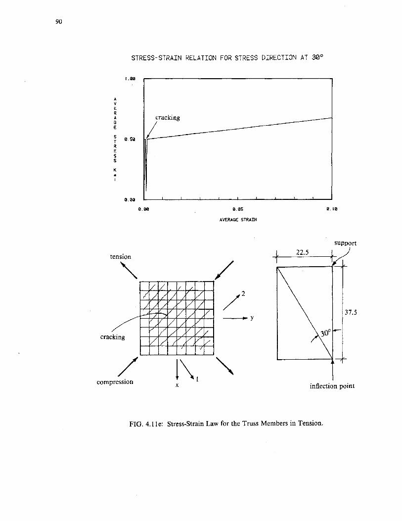
90
STRESS-STRAIN RELATION FOR STRESS DIRECTION AT 30°
I.aa
AVERA ir,ekingGE
S 0.50TRESS
K5
i
0.00
0.00 0.05 0.10
AVERAGE STRAIN
support
inflection point
-f_-=22::.:..:.5_-t
~y
x
/ / / /
7 / ~ / / // / / / / /
...... / / / /~ 7/ V / /
v / / V Vvking 1/ / V V V-I
/ (
/
tension
"crac
compression
FIG. 4.11e: Stress-Strain Law for the Truss Members in Tension.

Moment-Strain Relation for Exterior Connection of Berk2
2S0.0lil
91
209. raG!
H0HE lSIUllilNT
I(I
100.00p
in
Slil.lillil
Ill. 00
experimental
_1--- =~_--.:-...-:.:--:..:-~-.:..------------=--- ---------------///-----l
analytical
1Il.0011l 0.0l/lS 1Il.91lil
STRAIN
1Il.IIlIS 9.1Il20 lil.925
FIG. 4.12: Moment-Strain Relationship (for the Top Steel of the Main Beam)
at the Face of the Support.
Variation of Axial Load With Drift level
20.00
AXIAL
LoAD
Kip
•
IS.lillil
llil.OO
S.OO
lil.OO
at the face of the support
9.lillil9 2.1IlraG! 6.1Illill/l
DRIFT PERCENTABE ell)
8.lillil9 10.lillil9
FIG. 4.1-3: Variation of Axial Load with Drift Level at Various Locations Along the Length.

92
Varia~ion of Axial Load Wi~h Dis~ance From Column Face
29.90
AXIAL
LoAD
KIpc
15.99
19.99
5.90
9.""
" ."'>~ drift=3.0%
' ..... "..... , ..... " ~ drift = 1.5%
" ".......... .................. ............
---_ ........ __ ____~ drift= 1.0%......... ...... ......
- .... -------------__ -- '--=:--____ drift=0.5%-- ... -...... ~
-...- '"' - ~-- ---:::::?::-
9.999 5.999 '9.999 IS.lil9liI
DISTANCE FR01'1 TtE COLUMN FACE In.
FIG. 4.14: Variation of Axial Load with Distance from the Face of the Support.

0.00168
93
face of the support
2d from the face
--".,.._-..loc=='----\,..+--f---f-----cf--- 3d from the face
_ experimental
---- analytical
FIG.4.15a: Strain Profiles for Maximum Main Steel Strain 0.00168
0.00761
y
---~--"r---'t---'t-I--T-_+---f---f'--- 2d from the face
-----\::=~"F'-"'rl-f--_+-_+---- 3d from the face
--- experimental
- - - - - analytical
FIG. 4.15b: Strain Profiles for Maximum Main Steel Strain 0.00761

94
0.0270
._---Y
-~-4:=~-~-h1-----jL-----I-L----f.~-2d from the face
3d from the face
-- experimental
-- - - analytical
FIG.4.15c: Strain Profiles for Maximum Main Steel Strain 0.0270
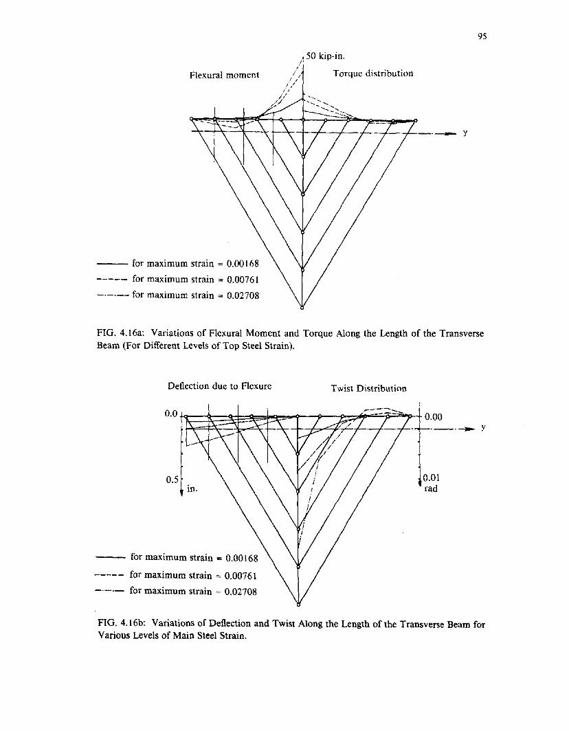
95
Flexural moment
--- for maximum strain = 0.00168
----- for maximum strain = 0.00761
-.-._.• for maximum strain = 0.02708
.50 kip-in.I'
// Torque distributionI ///
if'///
///"
._._y
FIG.4.16a: Variations of Flexural Moment and Torque Along the Length of the TransverseBeam (For Different Levels of Top Steel Strain).
Deflection due to Flexure Twist Distribution
0.01rad
0.0tt~t=~~~~'1r-/-:J~:r=/>="71 0.00--_.-.. Y
0.5in.
for maximum strain = 0.00168
----- for maximum strain = 0.00761
-.-.- for maximum strain = 0.02708
FIG. 4.16b: Variations of Deflection and Twist Along the Length of the Transverse Beam forVarious Levels of Main Steel Strain.

96
main beam
transverse beam
slab
I I column
III
I I
~=~=i=====-I I =--I II I
- ,I--=-1 II lI I
FIG. 5.1: Plan View of Interior Connection
~--d
a) undeformedbeam
b) deformedbeam
FIG. 5.2: Cross Section A-A
+h
+
FIG. 5.3: Inelastic Growth of the Plastic Hinge Zone

flexible spring
lJi
't3~,~O-,<+
~ ---r
rXii
plastich;n;}
~main beam
reinforcing bar
slab
Id
-~
main beam reinforcement
~ column centerline
V - slab bar hi
FIG. 5.4: Mechanism Assumed FIG. 5.5: Kinematics of the Mechanism
1.0-.J

98
beam web r~ x/d
--l bid
1.0
0.0-10.0 0.0 0.0 10.0
FIG. 5.6a: Shape Function for the Decay of Strains with Transverse Distance
a) Original strain distribution
plane sectionsin flexure
a) Original strain distribution
effective beam section
b) Uniform strain distribution
FIG. 5.6b: Flexural Response of the Slab-Beam Section

a) The Berkl Specimen b) The MinEW3 Specimen
0.031 • 0.005
20.0 40.0 60.0TRANSVERSE DISTANCE (in)
0.0001 ,-.-.;-~.:;:...:::ti: ---. J0.0 '--:eM
0.001
0.004
0.002
z<~I(I)
20.0 30.0 40.0 50.0TRANSVERSE DISTANCE (in)
10.0
\ "Z 0.02 \ "- ~".....q,~ .. ", Y \ analyticalI- '\ \ 'x '... \(I) tr '... "' \
" ..........,.I:t,"""'- experimental\ .,.- '~~ """b- ~~~ ~..:::---__.. """,... -----........--·-·_·_···..--1....,o.or at, : •
0.0
c) The Berk2 Specimen (interior connection) d) The RiceJ7 Specimen
0.01 0.03 1 ,
10.0 20.0 25.0TRANSVERSE DISTANCE (in) 10.0 20.0 30.0 40.0 50.0
TRANSVERSE DISTANCE (in)
o.o~, I0.0
0.01
~ 0.02g(I)
" ..................-...-..0.0 , , , .•..--...;--..------, I
0.0
z~f-otf.l
FIG. 5.7: Measured and Computed Transverse Variation of Slab Strain'0'0

§
e) The RiceJ5 Specimen f) The Berk2 Specimen (exterior connection)
10.0 20.0 25.0TRANSVERSE DISTANCE (in)
:,~::::::::: -0.0 I ' · ·::::·~~::e=5'1:....·h.;._.! I
0.0
0.02
0.03
z~.... 0.01en
analytical
xperimental
10.0 20.0 30.0 40.0 50.0TRANSVERSE DISTANCE (in)
0.0' , • . . ,0.0
0.03
I
Z 0.02-ct:oG....til
0.01
FIG. 5.7 (Continued): Measured and Computed Transverse Variation of Slab Strain
l:l a) The Berkl Specimen.5
b) The MinEW3 Specimen.....::c 120.0 ::c 120.0....0 ....- 0~ -~
~
<t: ~
...:l <t:en ...:l
;> ACI width en- ;> 1/::J - ACI widthCJ ::JtJ.l 0.0
CJ0.0tJ.l
0.000 0.035 0.000 0.035
MAXIMUM STEEL STRAIN MAXIMUM STEEL STRAIN
FIG. 5.8: Equivalent Slab Width as a Function of Reinforcement Strain

c) The Berk2 Specimen d) The RiceJ4 Specimen
.S 50.0' I
0.035
ACI width./......
MAXIMUM STEEL STRAIN
;> I ,5 0.0, , I ! , !
Of 0.000(JJ
. 120.0.S::z:::f-<Cl~l%l::iVJ
ACI width
0.035
MAXIMUM STEEL STRAIN
;> I I ,g 0.0, , , • I
l.I.l 0.000
=r:f-<Cl.....~l%l::ien
ACI Width
FIG. 5.9: Measured and Computed Moment Envelopes -o-
0.001 0.002
CURVATURE (l/in)
---------.,-------- experimentalanalyticalweb only
0.0 I ' , , I
0.000
1000.0
2000.0
3000.0 i i
a) Moment-curvaturt< for Berk1
--I:l'6,g~l.\.l~o~
c:.- 120.0=r:b.....~
l%lLL::ien;>
5 , ,Of 0.0, , I ! , , 0.035l.I.l 0.000
e) The RiceJ7 Specimen
MAXIMUM STEEL STRAINFIG. 5.8(Continued):
: Equivalent Slab Width as a Function of Reinforcement Strain

.-ol~
b) Moment-rotation for MinEW3 c) Moment-steel strain for Berk2
0.0200.010
--------------------------------------
I'///"-~
I
~------------------
0.0 , I ' , ,
0.00
200.0
100.0
SllWI!
STEEL STRAIN
300.0' i
:5I
0-gf-<Z~
~o~
0.025 0.050
ROTATION (rads)
..--------~~ I
-~~-------~-----
0.0 I( , , , ,
0.000
1000.01 . I----- analytical -- experimental
web only 0 experimental-.SI
0-
::2 500.0'-"
f-<Z~
~o~
d) Moment-steel strain for RiceJ7 e) Moment-steel strain for RiceJ5
3000.0 1 I 3000.01 i
0.020 0.040STEEL STRAIN
s='6gIZ~
~o~
,,....._ ...- .....!............-_••••••••••__••••
; 0 0 0
2000.0~ : 010I:, ----------: ~--- ----
1000,0~;r
III,o.oR ' , , I
0.00 0.020 0.040
STEEL STRAIN
:5I
0-
~'-"
f-<Z~
~o~
o ••••••••••2000.0 ~ r--·-··---.----····
~I.~ --------------
1000.0~! ,..-:/I,...
0.0, I , I I
0.00
FIG. 5.9 (Continued): Measured and Computed Moment Envelopesweb only
experimentalexperimental
analytical

103
APPENDIX A
SUMMARY OF BEAM-COLUMN EXPERIMENTS USED FOR CORRELAnON
In Chapters III,IV and V, measured responses of seven beam-column-slab specimens are com-
pared with computed responses. The specimens were selected from among the available inventory of
test data reported in the literature. The selection was based on availability of necessary data on
configuration, material properties, and response quantities. Response measurements necessary for the
correlation included variations of reinforcement strain, effective slab widths, and moment envelopes.•
A detailed description of the experiments can be found in [7, 10, 20, 27]. A summary of geometry
and material propeities is presented in this appendix for reference.
A.I Description of the test specimens
The selected tests include four specimens tested by Zerbe and Durrani [27], one tested by
Kiureghian, Popov, and Bertero [10], one tested by Moehle and Qi [20], and one tested by French
and Boroojerdi [7]. All were subjected to a reversed cyclic loading program designed to simulate
earthquake response well into the inelastic range.
The four specimens tested by Zerbe and Durrani at Rice University were half-scale models of
exterior beam-column-slab connections (Fig. A.I). The transverse width of the slab, measured from
one edge of the slab to the other, was varied., with values of 34 in., 46 in., 58 in., and 70 in. for the
four different specimens. For reference in this report the specimens are designated RiceJ4-RiceJ7,
respectively. Dimensions and material properties are summarized in Tables A.l and A.2. The speci-
mens were loaded by vertically displacing the longitudinal beam end while restraining the column
ends. The column carried no externally applied axial load., and beams were loaded in addition to the
applied load only by self weight. Response measurements reported by Zerbe and Durrani [27]
include the maximum specimen strength and transverse variation of strain at various stages of testing.
The fifth test specimen analyzed in this study was tested by Kiureghian, Popov, and Bertero
[10], and will be designated Berkl (Fig. A.l). The specimen was a half-scale model of an exterior

104
connection with heavily reinforced transverse beams (Fig. A.2). Dimensions and materials are sum
marized in Tables A.I and A.2. Measured responses reported by Kiureghian [10] include moment
curvature relations and transverse variations of strain. The specimen was loaded by displacing the
lower column hinge horizontally. Constant axial load was applied to the column throughout the test,
and dead load effects on the longitudinal and transverse beams were also simulated.
Another test specimen reported at the University of California at Berkeley is a one story, two
bay, quarter scale subassemblage (Fig. A.3) tested by Qi and Moehle [20]. The specimen had both
interior and exterior connections, and experimental data are available for both types of connections in
terms of transverse variations of strain and moment-curvature relations. This specimen will bepesig
nated Berk2. Dimensions and material properties are summarized in Tables A.I and A.2. The
columns of the specimen were loaded with constant axial loads throughout the test. Lateral action
was introduced to the specimen by displacing horizontally the top hinges of the columns.
The last test specimen considered is the third specimen tested by French and Boroojerdi [7].
The specimen is designated MinEW3. (The other two specimens reported in [7] are not considered
because the transverse beam was either relatively small or missing.) Specimen MinEW3 is a 1/2
scale model of an interior connection (Fig. AA), with dimensions and material properties as tabulated
in Tables A.I and A.2. The specimen was loaded by vertically displacing the tip of the cantilever
beam. The reported test results include moment-rotation measurements and transverse strain profiles
along the width of the slab.
Specimens BerkI, and MinEW3 are suitable experimental models for verification of the pro
posed analytical models of Chapters III and V. They are either interior connections (MinEW3) or
have relatively rigid transverse beams (Berkl) as assumed in the corresponding analytical models.
Specimens RiceJ4-J7, and the exterior connection of Berk2, being exterior connections with rela
tively flexible transverse beams, do not satisfy the requirement of rigid transverse boundary. They are
considered in all cases to test the suitability of the models for the analysis of exterior connections.
Chapter IV presents a model developed for exterior connections, and refers to the data from the exte
rior connection of Berk2.

105
References [10, 20, 27] report complete measured stress-strain relations for the reinforcement.
The stress-strain relation for the concrete is only reported for specimens Berkl and Berk2 [10, 20].
In all other cases, characteristic values of stress are available but not the corresponding strains.
Where not reported, values were assumed (Table A.2).
TABLE A.I
Geometry of specimens
Dimensions in inches
Specimen b d t X max L
RiceJ4 10. 15. 4. 34. 66.6
RiceJ5 10. 15. 4. 46. 66.6
RiceJ6 10. 15. 4. 58. 66.6
RiceJ7 10. 15. 4. 70. 66.6
Berkl 9. 16. 4. 113. 56.
Berk2 5. 7. 1.75 45. 75.0
MinEW3 6. 10. 2.5 120. 54.

106
TABLE A.2
Material Properties Used
Stresses in ksi
Specimen Concrete Steel
Ie eo Location Bar No I y lu esh eu
RiceJ4 5.9 0.002* Top 4 No 6 60. 70. 0.012 0.023
Bottom 4 No 6 60. 70. 0.012 0.023
Slab 4 No 4 77. 93. 0.0146 0.035
RiceJ5 5.6 0.002* Top 4 No 6 60. 70. 0.012 0.023
Bottom 4 No 6 60. 70. 0.012 0.023
Slab 6 No 4 77. 93. 0.0146 0.035
RiceJ6 5.6 0.002* Top 4No 6 60. 70. 0.012 0.023
Bottom 4 No 6 60. 70. 0.012 0.023
Slab 8 No 4 77. 93. 0.0146 0.035
RiceJ7 5.9 0.002* Top 4No 6 60. 70. 0.012 0.023
Bottom 4 No 6 60. 70. 0.012 0.023
Slab 10 No 4 77. 93. 0.0146 0.035
Berkl 4.1 0.0033 Top 2No 5 67.25 105. 0.009 0.05
Top 2 No 6 63. 104. 0.0064 0.05
Bottom 3 No 5 67.25 105. 0.009 0.05
Top Slab 10 No 2 65. 80. 0.02 0.04
Bottom Slab 12 No 2 65. 80. 0.02 0.04
Berk2 5.1 0.0025 Top 2No 2 64. 86. 0.03 0.20
Top 1 No 1 63.4 98.1 0.0070 0.20
Bottom 3 No 2 64. 86. 0.03 0.20
Bottom 2 No 1 63.4 98.1 0.0070 0.20
Top Slab 12 gage #9 60. 85. 0.0025 0.12
Bottom Slab 12 gage #9 61. 85. 0.0025 0.12
MinEW3 7. 0.0025* Top 3 No 3 73. 114. 0.005* 0.06*
Bottom 2 No 3 73. 114. 0.005* 0.06*
Top Slab 14 No 2 61. 85. 0.005* 0.06*
Bottom Slab 14 No 2 61. 85. 0.005* 0.06*
* assumed values.

aectlon c-c
!•
at s· T:#4 at e· ..4#8
THE RICE SPECIMENS
z
:, c
I· .,10 IN
Transverse Beam Reinforcement Detail
Section B-B SectIon A-A
#4 at e·
I· oi10 IN
#4 at g •
oof. ==b=;~ t1.76,..
SectIon A-A
4#S
!•
4#S !....
~....
r----!10~........
-'-
#4 at S·
I 10 IN I
~.L
8#8
12 IN
2~:t
~Beam and Column Reinforcement Detail
FIG. A.I: Experimental Setup and cross sections of the Rice Tests [27]
Slab Reinforcement Detail
-8

108
6'-3" JL-{----1o THE BERKI SPECIMEN
o6'-3" 0
L----'-r----------
6'-7.5"
Elevation#5
......l .....
-~ 4"~~
#4
Transverse beamcross section
16"
2'·9"
Plan
r long beam___ L _
4'-8"
Long beam cross section
56.5",
#2
#6
~iL-<--~I'"-<-~A~<8" 8"
FIG. A.2: Experimental Setup and Cross Sections of the Berk1 Test [10].

I
I ~,
I ~.
109
75 11 75//
~.,jI-t-""--'----------#t --_·~-----i'~t-l-·"' _-, ----- ------1-'- -------------+---',-+--.I'-
'tI/")
r-... I _ I
::i'--~~:::-~~~~-~~-~-~~.~~--~=--"J__~-=:~.~_~-~~~~-=_-~. :_~-:..~.~~~~~~-~~=~~~._~~~~~-~~~~~~;:I
fI
,
II
(a) Elevation: Longitudinal Direction
1'1 I,III !II, ,-, r+t
-t---------i--r"'-+-+--+---t--===- .L.t-~-+-+
In-J L i '\, 1 I I
I I I
(c) Plan
J 16" I.'----=---....,ol-- (b) Elevation: Transverse Direction
FIG. A.3a,b,c: Geometry of the One Story Subassemblage [20].

110
-M
=!~j S'~ I----,j....
Longitudinal Beam Cross Section
~
L..----------'=t~1 4" ~
Transverse Beam Cross Section
M---
~
L..-------------'=t~
1 SH 1,----~-
Column Main Reinforcement
FIG. A.3d: Cross Sections of Beams and Columns [201.

III
113.15 1n. THE MinEW3 SPECIMEN
Loll'.... _ ..
I II II II II I
W'1n.
--------~T7,1~----------w-~---- 113.251n.
10 1n. " 10 1n. I ICo'._ I I
I II II II I
Loa'l", Dlrooti..
£I..allon VI••
Noainal Di.en,ions of SUbassemblaqes
No.24 in. 011canter
No.24 in...c.'er
,6 In.No.2
;2 in...conI.
4-.... 4
10 in.
4-NCLO
.so...
Column Lon,ltudinal Beam
Tranlvlrsl Beam • EW3
TranSVlrl1 Blam - EW2
M.-ber Cross Sections
FIG. A.4: Experimental Setup and cross sections of the MinEW3 Test [7].

112
APPENDIX B
DIAGONAL COMPRESSION FIELD THEORY - A SIMPLE CONSTITUTIVE MODEL FOR R.C.
The Diagonal Compression Field Theory is a constitutive model of the biaxial behavior of rein
forced concrete. An extensive description of the theory, the mathematical implementation, experi
mental support, and applications can be found in [3, 8, 13, 26]. A brief summary of the main points
of the theory will be presented in this appendix.
In the diagonal compression field theory for R.C., the two materials, steel and concrete, are
viewed as two systems working in parallel to resist the loads. Local effects such as cracking and slip
are "smeared" over the medium, so that strains and stresses are averaged quantities.
For the derivation of the field theory, an element of unit dimensions is considered (Fig. B.I).
The steel percentage along the y direction is Pyy and along the x direction is Pxx'
Since steel and concrete are considered to be working in parallel, it is assumed that they are
subjected to the same strains. This is the compatibility condition of the element. Equilibrium for the
two materials in parallel requires that stresses in the concrete and stresses in the reinforcement are
developed according to the stiffness of the materials to balance the externally applied loads. If fs.u
and ny are the steel stresses in the x and y directions, f';.. and f~y are the concrete stresses in the x
and y directions, and O"x." O"xy and O"yy are the externally applied stresses, then equilibrium at the
boundary of the element requires that
where v~, and v~ are the shear stresses that are resisted by steel and concrete at the boundary of the
element.

113
To use the individual material laws for transformation from stresses to strains and vice-versa,
principal stresses for the materials are necessary. (In the diagonal compression field theory, the
direction of principal strains is assumed to coincide with the direction of principal stresses of con-
crete; thus, the entire medium is treated as isotropic. Although orthotropy would be a more relevant
assumption, experimental data [26] show that the direction of principal strains nearly coincide with
the direction of principal stresses in panels tested under several loading conditions up to failure.
Thus, the assumption of isotropy is not a gross oversimplification.)
The strains in the x and y directions are related to the principal strains through the simple
coordinate transformation:
-(t\reyy)sin2B+ycos2B =0.
Equations B.I, B.2 are re-arranged as follows:
Thus,
. cos2B . 2 sinB yxyell-exx=yxy(smBcosB--.--sm B)=yxy---= -tanB
slO2B 2cosB 2
Similarly,
Thus,
cos2B ? cosB Yxyell-eyy=yxy(-.-?-cos-B+smecosB)=YXY-2-'-=-Z--
sm~B smB tanB
Division of Eq. B.4 by Eq. B.5 results in:
(B.l)
(B.2)
(B.3)
(B.4)
(B.5)

114
(B.6)
Equation B.6 gives the direction of the principal strains with reference the x axis. It is a fundamen-
tal relationship in the implementation of the theory.
Similar relationships give the direction of principal stresses as:
(B.7)
Other key conditions used in the diagonal compression field theory are the first invariances of
the strain and concrete stress tensors:
11"1 +/2z=I';;,+/~~
(B.8)
(B.9)
If the positive sign corresponds to compression, then for a given compressive principle strain
e1 \> the algorithm to calculate the stress state of the element is:
Step 1:
Given ell
Step 2:
Estimate £xx
Step 3:
Estimate B
Step 4:
From Equation BA find Yxy
From Equation B.5 find £yy
From Equation B.8 find £22

115
Step 5:
From the material stress-strain relations for steel, calculate steel stresses from strains:
Using the equilibrium relations in the direction normal to the boundary, calculate longitudinal
and transverse concrete stresses f';.., f;y:
Step 6:
Evaluate also the principal stresses of concrete given principal strains. From the material
stress-strain relations:
Step 7:
Calculate direction of principal stresses 0' using Equation B.7 and check if 0=0'; if not equal
repeat from Step 3.
Step 8:
Check if Equation B.9 is satisfied; if not repeat from Step 2.
Step 9:
If both compatibility and equilibrium are satisfied simultaneously, then one can calculate stress
resultants at the boundary of the element in directions normal and parallel to the boundary.
The result is a macroscopic relationship between average strains and resultant stresses acting
on the entire element.
In the algorithm presented, the controlling quantity is the principal compressive strain of con
crete; other variables can be kept as controlling parameters, modifying the algorithm appropriately.

116
y
Py: percentage of steel along y
Px: percentage of steel along x
--1x
FIG. B.1: Element of Unit Dimensions Used in the Derivation of the Compression Field
Theory

117
EARTHQUAKE ENGINEERING RESEARCH CENTER REPORT SERIES
EERC reports are available from the National Information Service for Earthquake Engineering(NISEE) and from the National Technical InformationService(NTIS). Numbers in parentheses are Accession Numbers assigned by the National Technical Information Service: these are followed by a price code.Contact NTIS. 5285 Port Royal Road. Springfield Virginia, 22161 for more information. Reports without Accession Numbers were not available from NTISat the time of printing. For a current complete list of EERC reports (from EERC 67-1) and availablity information, please contact University of California,EERC. NISEE. 1301 South 46th Street, Richmond, California 94804.
UCB/EERC,80/01
UCB/EERC·80/02
UCB/EERC·80/03
UCB/EERC,80/04
UCB/EERC-80/05
UCB/EERC-80/06
'Earthquake Response of Concrete Gravity Dams Including Hydrodynamic and Foundation Interaction Effects,' by Chopra, A.K.,Chakrabarti, P. and Gupta, S., January 1980, (AD-A087297)A10.
'Rocking Response of Rigid Blocks to Earthquakes: by Yim. C.S.. Chopra, A.K. and Penzien. J., January 1980. (PB80 166 002)A04.
'Optimum Inelastic Design of Seismic·Resistant Reinforced Concrete Frame Structures: by Zagajeski. S.W. and Bertero. V.V.• January1980. (PB80 164 635)A06.
'Effects of Amount and Arrangement of Wall-Panel Reinforcement on Hysteretic Behavior of Reinforced Concrete Walls.' by Iliya, R.and Bertero. V.V., February 1980. (PB8l 122525)A09.
"Shaking Table Research on Concrete Dam Models: by Niwa. A. and Clough, R.W.. September 1980. (PB8l 122368)A06.
"The Design of Steel Energy-Absorbing Restrainers and their Incorporation into Nuclear Power Plants for Enhanced Safety (Voila):Piping with Energy Absorbing Restrainers: Parameter Study on Small Systems: by Powell, G.H.. Oughourlian. C. and Simons. J., June1980.
UCB/EERC-80/18
UCB/EERC-80/22
UCB/EERC-80/21
UCB/EERC·80120
'Inelastic Torsional Response of Structures Subjected to Earthquake Ground Motions: by Yamazaki. Y., April 1980, (PB81 122327)A08.
'Study of X-Braced Steel Frame Structures under Earthquake Simulation: by Ghanaat. Y., April 1980, (PB81 122 335)AII.
'Hybrid Modelling of Soil-Structure Interaction: by Gupta. S., Lin. T.W. and Penzien, J., May 1980. (PB81 122 319)A07.
'General Applicability of a Nonlinear Model of a One Story Steel Frame: by Sveinsson, B.I. and McNiven, H.D.. May 1980, (PB81124877)A06.
'A Green-Function Method for Wave Interaction with a Submerged Body: by Kioka, W., April 1980, (PB81 122269)A07.
'Hydrodynamic Pressure and Added Mass for Axisymmetric Bodies.: by Nilrat, F., May 1980, (PB81 122 343)A08.
-Treatment of Non-Linear Drag Forces Acting on Offshore Platforms: by Dao, B.V. and Penzien, J., May 1980, (PB81 1.53 413)A07.
'2D Plane/Axisymmetric Solid Element (Type 3-Elastic or E1astic·Perfectly Plastic)for the ANSR-II Progranl:'by Mondkar, D.P. andPowell, G.H., July 1980, (PB81 122 350)A03.
'A Response Spectrum Method for Random Vibrations: by Der Kiureghian, A.• June 1981, (PB81 122301)A03.
-Cyclic Inelastic Buckling of Tubular Steel Braces: by Zayas, VA, Popov, E.P. and Martin, S.A., June 1981. (PB81 124885)AIO.
-Dynamic Response of Simple Arch Dams Including Hydrodynamic Interaction.' by Porter, e.S. and Chopra, A.K., July 1981. (PB81124000)AI3.
'Experimental Testing of a Friction Damped Aseismic Base Isolation System with Fail-Safe Characteristics,' by Kelly, J.M.• Beucke,K.E. and Skinner, M.S., July 1980, (PB81 148 595)A04.
-The Design of Steel Energy-Absorbing Restrainers and their Incorporation into Nuclear Power Plants for Enhanced Safety (VoUB):Stochastic Seismic Analyses of Nuclear Power Plant Structures and Piping Systems Subjected to Multiple Supported Excitations.' byLee, M.e. and Penzien, J., June 1980, (PB82 201 872)A08.
'The Design of Steel Energy·Absorbing Restrainers and their Incorporation into Nuclear Power Plants for Enhanced Safety (Vol IC):Numerical Method for Dynamic Substructure Analysis.'" by Dickens, J.M. and Wilson, E.L., June 1980.
'The Design of Steel Energy-Absorbing Restrainers and their Incorporation into Nuclear Power Plants for Enhanced Safety (Vol 2):Development and Testing of Restraints for Nuclear Piping Systems,' by Kelly, J.M. and Skinner, M.S., June 1980.
'3D Solid Element (Type 4-Elastic or Elastic-Perfectly-Plastic) for the ANSR-II Program: by Mondkar. D.P. and Powell, G.H., July1980, (PB81 123242)A03.
'Gap-Friction Element (Type 5) for the Ansr-II Program,' by Mondkar, D.P. and Powell, G.H., July 1980, (PB81 122285)A03.
'U-Bar Restraint Element (Type II) for the ANSR·II Program: by Oughourlian, C. and Powell. G.H., July 1980, (PB81 122293)A03.
-Testing of a Natural Rubber Base Isolation System by an Explosively Simulated Earthquake: by Kelly, J.M., August 1980. (PB81 201360)A04.
UCB/EERC-80/26 'Input Identification from Structural Vibrational Response: by Hu. Y., August 1980. (PB81 152308)A05.
UCB/EERC-80127 'Cyclic Inelastic Behavior of Steel Offshore Structures: by Zayas, VA, Mahin, S.A. and Popov, E.P., August 1980, (PB81 196180)AI5.
UCB/EERC-80/23
UCB/EERC-80/24
UCB/EERC-80125
UCB/EERC·80/19
UCB/EERC·80/07
UCB/EERC-80/15
UCB/EERC·80/16
UCB/EERC-80/17
UCB/EERC-80/11
UCB/EERC-80/12
UCB/EERC-80/13
UCB/EERC-80/14
UCB/EERC-80/08
UCB/EERC-80/09
UCB/EERC-80/10
UCB/EERC-80128 "Shaking Table Testing ofa Reinforced Concrete Frame with Biaxial Response: by Oliva, M.G., October 1980, (PBSI 154 304)AIO.
UCB/EERC·80129 'Dynamic Properties of a Twelve-Story Prefabricated Panel Building,' by Bouwkamp, J.G., Kollegger, J.P. and Stephen, R.M.. October1980, (PB82 138 777)A07.
UCB/EERC,80/30 -Dynamic Properties of an Eight-Story Prefabricated Panel Building: by Bouwkamp, J.G., Kollegger, J.P. and Stephen, R.M.. October1980, (PB81 200 313)A05.
UCB/EERC-80/31 "Predictive Dynamic Response of Panel Type Structures under Earthquakes: by Kollegger, J.P. and Bouwkamp, J.G., October 1980.(PBSt 152 316)A04.
UCB/EERC·SO/32 'The Design of Steel Energy-Absorbing Restrainers and their Incorporation into Nuclear Power Plants for Enhanced Safety (Vol 3):Testing of Commercial Steels in Low·Cycle Torsional Fatique: by Spanner, P., Parker, E.R., Jongewaard, E. and Dory, M., 1980.

118
UCB/EERC-SO/33 "The Design of Steel Energy-Absorbing Restrainen and their Incorporation into Nuclear Power Plants for Enhanced Safety (Vol 4):Shaking Table Tests of Piping Systems with Energy-Absorbing Restrainen: by Stiemer, S.F. and Godden, W.G., September 19S0,(PBS2 201 SSO)A05.
UCB/EERC-SO/34 "The Design of Steel Energy-Absorbing Restrainen and their Incorporation into Nuclear Power Plants for Enhanced Safety (Vol 5):Summary Report: by Spencer, P., 19S0.
UCB/EERC-SO/35 "Experimental Testing of an Energy-Absorbing Base Isolation System: by Kelly, J.M., Skinner, M.S. and Beucke, K.E., October 19S0,(PBS1 154072)A04.
UCB/EERC-SO/36 "Simulating and Analyzing Artificial Non-Stationary Earth Ground Motions," by Nau, R.F., Oliver, R.M. and Pister, K.S., October19S0, (PBSI 153 397)A04.
UCB/EERC-80/37 "Earthquake Engineering at Berkeley" 1980: by, September 1980, (PBS1 205 674)A09.
UCB/EERC"SO/38 "Inelastic Seismic Analysis of Large Panel Buildings: by Schricker. V. and Powell, G.H.. September 1980, (PBS1 154 33S)AI3.
UCB/EERC-SO/39 "Dynamic Response of Embankment. Concrete-Gavity and Arch Dams Including Hydrodynamic Interation: by Hall, J.F. and Chopra,A.K., October 1980. (PB81 152 324)A II.
UCB/EERC·80/40 "Inelastic Buckling of Steel Struts under Cyclic Load Reversal.: by Black, R.G., Wenger, W.A. and Popov, E.P., October 1980, (PB81154312)A08.
UCB/EERC-81/03
UCB/EERC-80/42
UCB/EERC-80/41
UCB/EERC-81/02
"Influence of Site Characteristics on Buildings Damage during the October 3,1974 Lima Earthquake: by Repetto, P., Arango, I. andSeed. H.B.. September 19S0, (PB81 161 739)A05.-
"Evaluation of a Shaking Table Test Program on Response Behavior of a Two Story Reinforced Concrete Frame," by Blondet. J.M.,Clough. R.W. and Mahin, S.A., December 19S0, (PBS2 196 544)All.
"Modelling of Soil-Structure Interaction by Finite and Infinite Elements: by Medina. F.. December 1980, (PBS1 229 270)A04.
"Control of Seismic Response of Piping Systems and Other Structures by Base Isolation: by Kelly, J.M., January 19S1, (PB81 200735)A05.
"OPTNSR- An Interactive Software System for Optimal Design of Statically and Dynamically Loaded Structures with NonlinearResponse: by Bhatti, M.A., Ciampi, V. and Pister, K.S., January 1981, (PB81 218 851)A09.
"Analysis of Local Variations in Free Field Seismic Ground Motions: by Chen, J.-C.. Lysmer, J. and Seed, H.B., January 1981, (ADA099508)A13.
UCB/EERC·81104 "Inelastic Structural Modeling of Braced Offshore Platforms for Seismic Loading: by zayas, VA, Shins. P.-S.B., Mahin, SA andPopov, E.P., Jan.uary 1981, (PB82 13S 777)A07.
UCB/EERC·80/43
UCB/EERC-SI/OI
UCB/EERC-81105 "Dynamic Response of Light Equipment in Structures: by Der Kiureghian, A., Sackman, J.L. and Nour-0mid, B., April 19SI, (PB8121S 497)A04.
UCB/EERC-SI/06 "Preliminary Experimental Investigation of a Broad Base Liquid Storage Tank," by Bouwkamp, J.G., Kollegger, J.P. and Stephen, R.M.,May 1981, (PB82 140 385)A03.
UCB/EERC-81/07 "The Seismic Resistant Design of Reinforced Concrete Coupled Structural Walls: by Aktan, A.E. and Bertero, V.V., June 1981, (PB82113 35S)AII.
UCB/EERC-81108 "Unassigned: by Unassigned, 1981.
UCB/EERC-SI/09 "Experimental Behavior of a Spatial Piping System with Steel Energy Absorben Subjected to a Simulated Differential Seismic Input: byStiemer, S.F., Godden, W.G. and Kelly, J.M., July 1981, (PB82 201 89S)A04.
UCB/EERC-8111O "Evaluation of Seismic Design Provisions for Mason!)' in the United States: by Sveinsson, B.I., Mayes, R.L. and McNiven, H.D.,August 19SI, (PB82 166 075)A08.
UCB/EERC-811l1 "Two-Dimensional Hybrid Modelling of Soil-Structure Interaction: by Tzong, T.-J., GuPta, S. and Penzien, J., August 1981, (PB82 142I 18)A04.
UCB/EERC-S 111 2 "Studies on Effects of Infills in Seismic Resistant RIC Construction: by Brokken, S. and Bertero, V.V., October 19SI, (PB82 166190)A09.
UCB/EERC-SI/13 "Linear Models to Predi2t the Nonlinear Seismic Behavior of a One-Story Steel Frame: by Valdimanson, H., Shah, A.H. andMcNiven, RD., September 19SI. (PB82 13S 793)A07.
UCB/EERC-8 III 4 "TLUSH: A Computer Program for the Three-Dimensional Dynamic Analysis of Earth Dams: by Kagawa. T., Mejia, L.H.. Seed, H.B.and Lysmer, J., September 1981, (PB82 139 940)A06.
UCB/EERC-81/15 "Three Dimensional Dynamic Response Analysis of Earth Dams: by Mejia, L.H. and Seed, H.B., September 1981, (PB82 137 274)AI2.
UCB/EERC·SI/16 "Experimental Study of Lead and Elastomeric Dampen for Base Isolation Systems: by Kelly, J.M. and Hodder, S.B., October 1981,(PBS2 166 IS2)A05.
UCB/EERC-S III 7 "The Influence of Base Isolation on the Seismic Response of Light Secondary Equipment: by Kelly, J.M., April 19SI, (PB82 255266)A04.
UCB/EERC-81/18 "Studies on Evaluation of Shaking Table Response Analysis Procedures: by Blondet. J. M., November 19SI, (PBS2 197 27S)AIO.
UCB/EERC-SI/19 "DELIGHT.STRUCT: A Computer-Aided Design Environment for Structural Engineering: by Balling, R.J.. Pister, K.S. and Polak, E.,December 19SI, (PBS2 218 496)A07.
UCB/EERC-S1I20 -Optimal Design of Seismic-Resistant Planar Steel Frames: by Balling, R.J., Ciampi, V. and Pister, K.S., December 1981, (PBS2 220179)A07.
UCB/EERC-S2/01 "Dynamic Behavior of Ground for Seismic Analysis of Lifeline Systems: by Sato, T. and Der Kiureghian, A.• January 19S2, (PBS2 21S926)A05.
UCB/EERC-S2/02 'Shaking Table Tests of a Tubular Steel Frame Model: by Ghanaat. Y. and Clough. R.W., January 1982, (PBS2 220 161)A07.

119
UCB/EERC·S2/03 'Behavior of a Piping System under Seismic Excitation: Experimental Investigations of a Spatial Piping System supported by M~hani·
cal Shock Arrestors,' by Schneider, S" Lee, H.·M. and Godden, W. G., May 1982, (PBS3 172 544)A09.
UCB/EERC·S2J04 'New Approaches for the Dynamic Analysis of Large Structural Systems.' by Wilson, E.L.. June 1982, (PB83 148 080)A05.
UCB/EERC·82JOS 'Model Study of Effects of Damage on the Vibration Properties of Steel Otfshore Platforms,' by Shahrivar. F. and Bouwkamp. J.G.•June 1982, (PB83 148 742)AIO.
UCB/EERC·S2/06 'States of the Art and Pratice in the Optimum Seismic Design and Analytical Response Prediction of RiC Frame Wall Structures,' byAktan. A.E. and Bertero. V.V., July 1982. (PB83 147 736)A05.
UCB/EERC·82J07 "Further Study of the Earthquake Response of a Broad Cylindrical Liquid·Storage Tank Model: by Manos. G.c. and Clough. R.W.•July 1982. (PB83 147 744)AII.
UCB/EERC·S2/0S "An Evaluation of the Design and Analytical Seismic Response of a Seven Story Reinforced Concrete Frame: by Charney. F.A. andBertero. V.V.• July 1982, (PB83 JS7 628)A09.
UCB/EERC·82/09 ·F1uid·Structure Interactions: Added Mass Computations for Incompressible Fluid: by Kuo. J.S.·H.. August 1982. (PB83 156 281)A07.
UCB/EERC·82/10 'Joint-Gpening Nonlinear Mechanism: Interface Smeared Crack Model.' by Kuo. J.S.·H., August 1982, (PB83 149 195)A05.
UCBJEERC·82111 'Dynamic Response Analysis of Techi Dam: by Clough, R.W., Stephen, R.M. and Kuo, J.S.-H.• August 1982. (PB83 147 496IA(){j.
UCBJEERC·S2J12 'Prediction of the Seismic Response of RIC Frame.Coupled Wall Structures: by Aktan. A.E.• Bertero. V.V. and Piazzo. M.• August1982. (PB83 149 203)A09.
UCB/EERC·82J13 'Preliminary Report on the Smart I Strong Motion Array in Taiwan: by Bolt. B.A.• Loh. C.H.• Penzien, J. and Tsai. Y.B., August1982, (PB83 159 400)AIO.
UCB/EERC·S2J14 ·Shaking·Table Studies of an Eccentrically X·Braced Sttel Structure: by Yang, M.S.• September 19S2. (PBS3 260 17S)A.12.
UCB/EERC·82J15 'The Performance of Stairways in Earthquakes.' by Roha. c., Axley. J.W. and Bertero. V.V.• September 1982. (PB83 157 693)A07.
UCB/EERC·82/16 'The Behavior of Submerged Multiple Bodies in Eartllquakes; by Liao. W.-G.• September 1982, (PBS3 158 709)A07.
UCB/EERC-82/17 'Effects of Concrete Types and Loading Conditions on Local Bond-Slip Relationships: by Cowell. A.D., Popov. E.P. and Bertero. V.V.•September 1982. (PB83 153 577)A04.
UCB/EERC-82J18 'Mechanical Behavior of Shear Wall Vertical Boundary Members: An Experimental Investigation: by Wagner. M.T. and Bertero. V.V.•October 1982, (PB83 159 764)A05.
UCB/EERC-S2119 'Experimental Studies of Multi·support Seismic Loading on Piping Systems.' by Kelly, J.M. and Cowell, A.D., November 1982.
UCB/EERC-82/20 'Generalized Plastic Hinge Concepts for 3D Beam-Column Elements; by Chen, P. F.·S. and ,Powell, G.H., November 1982, (PB83 247981)AI3.
UCB/EERC-82121 ·ANSR·II: General Computer Program for Nonlinear Structural Analysis: by Oughourlian, C.V. and Powell. G.H.• November 1982,(PB83 251 330)AI2.
UCB/EERC-82122 'Solution Strategies for Statically Loaded Nonlinear Structures: by Simons. J.W. and Powell, G.H., November 1982. (PB83 197970)A06.
UCB/EERC-82J23 'Analytical Model of Deformed Bar Anchorages under Generalized Excitations: by Ciampi, V., E1igehausen. R.• Bertero, V.V. andPopov. E.P.• November 1982. (PB83 169 532)A06.
UCB/EERC-82124 •A Mathematical Model for the Response of Masonry Walls to Dynamic Excitations.' by Sucuoglu. H., Mengi, Y. and McNiven, H.D.,November 1982, (PB83 16901 I)A07.
UCB/EERC·82125 'Earthquake Response Considerations of Broad Liquid Storage Tanks; by Cambra, F.J., November 1982, (PBS3 251 215)A09.
UCB/EERC-82/26 "Computational Models for Cyclic Plasticity, Rate Dependence and Creep,' by Mosaddad, B. and Powell, G.H., November 1982. (PB83245 829)A08.
UCB/EERC-S2I27 'Inelastic Analysis of Piping and Tubular Structures: by Mahasuverachai. M. and Powell. G.H.• November 1982. (PBS3 249 987)A07.
UCB/EERC-83/01 "The Economic Feasibility of Seismic Rehabilitation of Buildings by Base Isolation,' by Kelly, J.M.• January 1983. (PB83 197 988)A05.
UCB/EERC-83J02 'Seismic Moment Connections for Moment·Resisting Steel Frames.: by Popov. E.P., January 1983. (PB83 195 412)A04.
UCB/EERC-8l/03 'Design of Links and Beam·to-Column Connections for Eccentrically Braced Steel Frames: by Popov. E.P. and Malley, J.O.. January1983. (PB83 19481 J)A04.
UCB/EERC,83/04 'Numerical Techniques for the Evaluation of Soil-Structure Interaction Etfects in the Time Domain.' by Bayo. E. and Wilson. E.L..FebrUary 1983, (PB83 245 605)A09.
UCB/EERC·83/0S 'A Transducer for Measuring the Internal Forces in the Columns of a Frame·Wall Reinforced Concrete StrUcture.' by Sause. R. andBertero. V.V.• May 1983. (PB84 119 494)A06.
UCB/EERC·83/06 "Dynamic Interactions Between Aoatins Ice and Offshore Structures: by Croteau, P.• May 1983. (PB84 119 486)AI6.
UCB/EERC-83/07 "Dynamic Analysis of Multiply Tuned and Arbitrarily Supported Secondary Systems: by Igusa. T. and Der Kiureghian, A., July 1983.(PB84 118 272)AII.
UCB/EERC·83f08 •A Laboratory Study of Submerged MUlti-bodY Systems in Earthquakes: by Ansari. a.R., June 1983. (PB83 261 842)A17.
UCB/EERC·83/09 'Effects of Transient foundation Uplift on Earthquake Response of Structures: by Vim. C.-S. and Chopra. A.K., June 1983, (PB83 261396)A07.
UCB/EERC·83/10 'Optimal Design of Friction·Braced Frames under Seismic Loading: by Austin. M.A. and Pister, K.S., June 1983, (PB84 119 288)A06.
UCBJEERC·83111 'Shaking 'Table Study of Single·Story Masonry Houses: Dynamic Performance under Three Component Seismic Input and R~ommendations: by Manos. G.C.• Clough, R.W. and Mayes, R.L., July 1983. (UCB/EERC·83JII)A08.
UCB/EERC·83J12 "Experimental Error Propagation in Pseudodynamic Testing: by Shiing, P.B. and Mahin, S.A., June 1983. (PB84 119 270)A09.
UCB/EERC,83/13 'Experimental and Analytical Predictions of the Mechanical Characteristics of a I/S·scale Model of a 7·story RIC Frame-Wall BuildingStructure: by Aktan. A.E.. Bertero. V.V.• Chowdhury, A.A. and Nagashima. T., June, 1983, (PB84 119 213)A07.

120
UCB/EERC-83/14 "Shaking Table Tests ofl.arge-Panel Precast Concrete Building System Assemblages; by Oliva. M.G. and Gough, R.W., June 1983,(PB86 110 2101AS)A II.
UCB/EERC-83/15 "Seismic Behavior of Active Beam Links in Eccentrically Braced Frames; by Hjelmstad, K.D. and Popov, E.P., July 1983, (PB84 119676)A09.
UCB/EERC-83/16 "System Identification of Structures with Joint Rotation; by Dimsdale, J.S., July 1983, (PB84 192 21O)A06.
UCB/EERC-83/17 "Construction of Inelastic Response Spectra for Singie-Degree-of-Freedom Systems," by Mahin, S. and Lin, J., June "983, (PB84 208834)A05.
UCB/EERC-83/18 -Interactive Computer Analysis Methods for Predicting the Inelastic Cyclic Behaviour of Structural Sections: by Kaba, S. and Mahin,S., July 1983, (PB84 192 012)A06.
UCB/EERC-83/19 "Effects of Bond Deterioration on Hysteretic Behavior of Reinforced Concrete Joints," by Filippou, F.e., Popov, E.P. and Benero, V.V.,August 1983, (PB84 192 020)AI0.
UCB/EERC-83/20 "Analytical and Experimental Correlation of l.arge-Panel Precast Building System Performance, - by Oliva, M.G., Gough, R. W., Velkov,M. and Gavrilovic, P., November 1983.
UCB/EERC-83/21 'Mechanical Characteristics of Materials Used in a 1/5 Scale Model of a 7-Story Reinforced Concrete Test Structure," by Benero. V.V.,Aktan, A.E., Harris, H.G. and Chowdhury, A.A., October 1983, (PB84 193 697)A05.
UCB/EERC-83/22 'Hybrid Modelling of Soil-Structure Interaction in l.ayered Media: by Tzong, T.-J. and Penzien, J., October 1983, (PB84 192 178)A08.
UCB/EERC-83/23 'Local Bond StreSS-Slip Relationships of Deformed Bars under Generalized Excitations: by Eligehausen, R., Popov, E.P. and Benero,V. V.. October 1983, (PB84 192 848)A09.
UCB/EERC-83/24 "Design Considerations for Shear Links in Eccentrically Braced Frames: by MaIley, J.O. and Popov, E.P., November 1983. (PB84 192186)A07. .
UCB/EERC-84/01 'Pseudodynamic Test Method for Seismic Performance Evaluation: Theory and Implementation: by Shing, P.-S.B. and Mahin, S.A.,January 1984, (PB84 190 644)A08.
UCB/EERC-84/02 'Dynamic Response Behavior of Kiang Hong DianDam: by Clough, R.W., Chang, K.-T., Chen, H.-Q. and Stephen, R.M., April 1984,(PB84 209 402)A08.
UCB/EERC-84/03 'Refined Modelling of Reinforced Concrete Columns for Seismic Analysis," by Kaba, SA and Mahin, S.A., April 1984, (PB84 234384)A06.
UCB/EERC-84/04 .A New Aoor Response Spectrum Method for Seismic Analysis of Multiply Supported Secondary Systems,' by Asfura, A. and DerKiureghian, A., June 1984, (PB84 239 417)A06. .
UCB/EERC-84/05 "Earthquake Simulation Tests and Associated Studies of a 1/5th-scale Model of a 7-Story RIC Frame-Wall Test Structure,' by Bertero,V.V., Aktan, A.E., Charney, F.A. and Sause, R., June 1984, (PB84 239 409)A09.
UCB/EERC-84/06 -RIC Structural Walls: Seismic Design for Shear," by Aktan, A.E. and Bertero, V.V., 1984.
UCB/EERC,84/07 'Behavior of Interior and Exterior Aat-Plate Connections subjected to Inelastic Load Reversals," by Zee, H.I.. and Moehle, J.P., August1984, (PB86 117 629/AS)A07.
UCB/EERC-84/08 'Experimental Study of the Seismic Behavior of a Two-Story Aat-Plate Structure: by Moehle, J.P. and Diebold, J.W.,August 1984,(PB86 122 553/AS)AI2.
UCB/EERC-84/09 'Phenomenological Modeling of Steel Braces under Cyclic Loading: by Ikeda, K., Mahin, S.A. and Dermitzakis, S.N., May 1984, (PB86132 1981AS)A08.
UCB/EERC-84/10 'Earthquake Analysis and Response of Concrete Gravity Dams: by Fenves. G. and Chopra. A.K.. August 1984, (PB85 1939021AS)A II.
UCB/EERC-84/11 'EAGD-84: A Computer Program for Earthquake Analysis of Concrete Gravity Dams,- by Fenves, G.and Chopra, A.K., August 1984,(PB85 193 613/AS)A05.
UCB/EERC-84/12 'A Refined Physical Theory Model for Predicting the Seismic Behavior of Braced Steel Frames: by Ikeda, K. and Mahin, S.A., July1984. (PB85 191 450/AS)A09.
UCB/EERC-84/13 'Earthquake Engineering Research at Berkeley - 1984: by, August 1984, (PB85 197 341/AS)AIO.
UCB/EERC-84/14 'Moduli and Damping Factors for Dynamic Analyses of Cohesionless Soils: by Seed, H.B., Wong, R.T., Idriss,I.M. and Tokimatsu, K.,September 1984, (PB85 191 468/AS)A04.
UCB/EERC-84/15 'The Influence of SPT Procedures in Soil Liquefaction Resistance Evaluations: by Seed, H.B., Tokimatsu, K., Harder. L.F. and Chung,R.M.• October 1984. (PB85 191 732/AS)A04.
UCB/EERC-84/16 'Simplified Procedures for the Evaluation of Settlements in Sands Due to Earthquake Shaking,' by Tokimatsu, K. and Seed, H.B.,October 1984, (PB85 197 887/AS)A03.
UCB/EERC-84/17 'Evaluation of Energy Absorption Characteristics of Bridges under Seismic Conditions; by Imbsen, R.A. and Penzien, J., November1984.
UCB/EERC-84/18 'Structure-Foundation Interactions under Dynamic Loads: by Liu, W.D. and Penzien, J., November 1984, (PB87 124' 889/AS)AII.
UCB/EERC,84/19 'Seismic Modelling of Deep Foundations: by Chen. e.-H. and Penzien. J., November 1984. (PB87 124 798/AS)A07.
UCB/EERC-84/20 'Dynamic Response Behavior of Quan Shui Dam: by Gough, R.W., Chang, K.-T., Chen. H.-Q., Stephen, R.M., Ghanaat, Y. and Qi,J.-H., November 1984, (PB86 I 15177/AS)A07.
UCB/EERC·85101 'Simplified Methods of Analysis for Earthquake Resistant Design of Buildings; by Cruz, E.F. and Chopra, A.K., February 1985, (PB86I I2299/AS)AI 2.
UCB/EERC-85102 'Estimation of Seismic Wave Coherency and Rupture Velocity using the SMART 1 Strong-Motion Array Recordings, - by Abrahamson,N.A.. March 1985, (PB86 214 343)A07.

121
UCB/EERC-85/03 -Dynamic Properties of a Thirty Story Condominium Tower Building: by Stephen, R.M., Wilson, E.L and Stander, N., April 1985,(PB86 I I8965/ASjA06.
UCB/EERC-85/04 -Development of Substructuring Techniques for On-Line Computer Controlled Seismic Performance Testing,' by Dermitzakis, S. andMahin. S.. February 1985. (PB86 132941/ASjA08.
UCB/EERC-85/05 -A Simple Model for Reinforcing Bar Anchorages under Cyclic Excitations: by Filippou, F.e., March 1985, (PB86 112 919/ASjA05.
UCB/EERC-85/06 "Racking Behavior of Wood-framed Gypsum Panels under Dynamic Load," by Oliva, M.G., June 1985.
UCB/EERC-85/07 -Earthquake Analysis and Response of Concrete Arch Dams: by Fok, K.-L. and Chopra. A.K., June 1985. (PB86 1396721ASjAI0.
UCB/EERC-85108 "Effect of Inelastic Behavior on the Analysis and Design of Earthquake Resistant Structures: by Lin, J.P. and Mahin, S.A., June 1985,(PB86 135340/AS)A08.
UCB/EERC·85109 "Earthquake Simulator Testing of a Base-Isolated Bridge Deck: by Kelly. J.M.. Buckle, LG. and Tsai. H.-C.. January 1986. (PB87 1241521AS)A06.
UCB/EERC·85/1O -Simplified Analysis for Earthquake Resistant Design of Concrete Gravity Dams: by Fenves, G. and Chopra. A.K., June 1986, (PB87124 160/ASjA08.
UCB/EERC-85/11 -Dynamic Interaction Effects in Arch Dams: by Gough. R.W.• Chang. K.-T.. Chen. H.-Q. and Ghanaat, Y., October 1985, (PB86I 35027/AS)A05.
UCB/EERC-85/12 "Dynamic Response of Long Valley Dam in the Mammoth Lake Earthquake Series of May 25-27, 1980: by Lai. S. and Seed, H.B.,November 1985, (PB86 I42304/AS)A05.
UCB/EERC-85/13 -A Methodology for Computer-Aided Design of Earthquake-Resistant Steel Structures,- by Austin. M.A.• Pister, K.S. and Mahin, S.A.,December 1985. (PB86 I59480/ASjAIO .
UCB/EERC-85/14 -Response of Tension-Leg Platforms to Vertical Seismic Excitations: by Liou, G.-S., Penzien. J. and Yeung, R.W., December 1985,(PB87 124 871/ASjA08.
UCB/EERC-85/15 "Cyclic Loading Tests of Masonry Single Piers: Volume 4 - Additional Tests with Height to Width Ratio of I: by Sveinsson, B.,McNiven. H.D. and Sucuoglu. H., December 1985.
UCB/EERC-85/16 "An Experimental Program for Studying the Dynamic Response ofa Steel Frame with a Variety ofInlill Partitions; by Yanev, B. andMcNiven. H.D.• December 1985.
UCB/EERC-86/01 -A Study of Seismically Resistant Eccentrically Braced Steel Frame Systems: by Kasai. K. and Popov, E.P., January 1986, (PB87 124I78/AS)AI4.
UCB/EERC-86/02 'D'esign Problems in Soil' Liquefaction: by Seed, H.B., February 1986, (PB87 124 186/ASjA03.
UCB/EERC-86/03 'Implications of Recent Earthquakes and Research on Earthquake-Resistant Design and Construction of Buildings: by Bertero, V.V.,March 1986, (PB87 124 194/AS)A05.
UCB/EERC-86/04 "The Use of Load Dependent Vectors for Dynamic and Earthquake Analyses," by Leger, P., Wilson, E.L and Gough, R.W., March1986. (PB87 124 202/AS)A12.
UCB/EERC-86/05 "Two Beam-To-Column Web Connections: by Tsai. K.-C. and Popov, E.P., April 1986, (PB87 124 30IlAS)A04.
UCB/EERC-86/06 "Determination of Penetration Resistance for Coarse-Grained Soils using the Becker Hammer Drill: by Harder, LF. and Seed, H.B.,May 1986, (PB87 124 2IO/ASjA07.
UCB/EERC-86/07 •A Mathematical Model for Predicting the Nonlinear Response of Unreinforced Masonry Walls to In-Plane Earthquake Excitations: byMengi. Y. and McNiven. H.D.• May 1986. (PB87 124 780/AS)A06.
UCB/EERC-86/08 'The 19 September 1985 Mexico Earthquake: Building Behavior: by Bertero, V.V., July 1986.
UCB/EERC-86/09 "EACD-3D: A Computer Program for Three-Dimensional Earthquake Analysis of Concrete Dams: by Fok, K.-L., Hall, J.F. andChopra. A.K., July 1986, (PB87 124 228/AS)A08.
UCB/EERC-86/IO -Earthquake Simulation Tests and Associated Studies of a O.3-Scale Model of a Six-Story Concentrically Braced Steel Structure: byUang, C.-M. and Bertero. V.V., December 1986. (PB87 163 564/AS)AI7.
UCB/EERC-86/11 "Mechanical Characteristics of Base Isolation Bearings for a Bridge Deck Model Test: by Kelly, J.M., Buckle. LG. and Koh. C.-G.,1987.
UCB/EERC-86/12 "Effects of Axial Load on Elastomeric Isolation Bearings; by Koh. c.-G. and Kelly, J.M., 1987.
UCB/EERC-87/01 "The FPS Earthquake Resisting System: Experimental Report: by Zayas. V.A.. Low, S.S. and Mahin. SA. June 1987.
UCB/EERC-87/02 "Earthquake Simulator Tests and Associated Studies of a 0.3-Scale Model of a Six-Story Eccentrically Braced Steel Structure: by Whit-taker. A., Uang, C.-M. and Bertero. V.V., July 1987.
UCB/EERC-87/03 'A Displacement Control and Uplift Restraint Device for Base-Isolated Structures: by Kelly, J.M., Griffith. M.e. and Aiken, m., April1987.
UCB/EERC-87/04 "Earthquake Simulator Testing of a Combined Sliding Bearing and Rubber Bearing Isolation System: by Kelly, J.M. and Chalhoub,M.S.. 1987.
UCB/EERC-87/05
UCB/EERC-87/06
UCB/EERC-87/07
UCB/EERC-87/08
UCB/EERC·87/09
UCB/EERC-87/IO
"Three-Dimensional Inelastic Analysis of Reinforced Concrete Frame-Wall Structures: by Moazzami, S. and Bertero, V.V., May 1987.
-Experiments on Eccentrically Braced Frames with Composite Floors: by Ricles, J. and Popov. E.. June 1987.
"Dynamic Analysis of Seismically Resistant Eccentrically Braced Frames: by Ricles, J. and Popov, E.. June 1987.
'Undrained Cyclic Triaxial Testing of Gravels-The Effect of Membrane Compliance.' by Evans. M.D. and Seed, H.B., July 1987.
-Hybrid Solution Techniques for Generalized Pseudo-Dynamic Testing: by Thewalt, C. and Mahin, S.A., July 1987.
"Ultimate Behavior of Butt Weldled Spliees in Heavy Rolled Steet Sections," by Bruneau, M. Mabin. SA aDd Popov, E.,September 1987.

122
UCB/EERC,87/11 'Residual Strength of Sand fmm Dam Failures in the Chilean Earthquake of March 3. 1985: by De Alba. P.• Seed. H.B.• Retamal. E.and Seed. R.B.• September 1987.
UCB/EERC·87/12 'Ineluuc Seismtc Response of Structures with Mass or Stiffness Eccentricities in Plan: by Bruneau. M. and Mahin. S.A.. September1987.
UCBlEERC·871l3 'CSTRUcr: An Interactive Computer Environment for the Destgn and Analysis of Eanhquake Resistant Steel Structures.' by Austin.M.A.. Mahin. SA. and Pister. K.S.. September 1987.
UCB/EERC·87/14 'Expenmental Study of Reinforced Concrete Columns Subjected to Multi-Axial Loading,' by Low. S.s. and Moehle. J.P.• September1987.
UCB/EERC·87/15 -Relationships between Soil Conditions and Earthquake Gmund Motions in Mexico City in tbe Earthquake OfSepL 19. 1985: by Seed.H.B.. Romo. M.P.. Sun. J.• Jaime. A. and Lysmer. J.. October 1987.
UCB/EERC-87/16 'Experimental Study of Seismic Response of R. C. Setback Buildings: by Shahrooz. B.M. and Moehle. J.P.• October 1987.
UCB/EERC·87117 'Three Dimenstonal AspectS of the Behavior of R. C. Structures Subjected to Earthquakes." by PantazopouJou. SJ. and Moehle. J.P.•October 1987.