Embed Size (px)
Citation preview
Version: Sep-25-2019
Two-Way Slab with Beams Design and Detailing (CAC Design Handbook)
Version: Sep-25-2019
Two-Way Slab with Beams Design and Detailing (CAC Design Handbook)
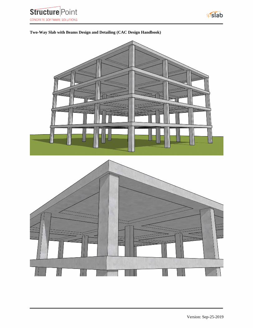
The concrete floor slab system shown below is for an intermediate floor to be designed considering superimposed
dead load = 1.6 kN/m2, and unfactored live load = 4.8 kN/m2. The lateral loads are independently resisted by shear
walls. The use of flat plate system will be checked. If the use of flat plate is not adequate, the use of slab system with
beams between all supports will be investigated. The analysis procedure “Elastic Frame Method (EFM)” prescribed
in CSA A23.3-14 is illustrated in detail in this example (Example #4 from the CAC Design Handbook). The hand
solution from EFM is also used for a comparison with the Reference results using Direct Design Method (DDM) and
results of the engineering software program spSlab. Explanation of the EFM is available in StructurePoint Video
Tutorials page.
Figure 1 - Two-Way Flat Concrete Floor System
Version: Sep-25-2019
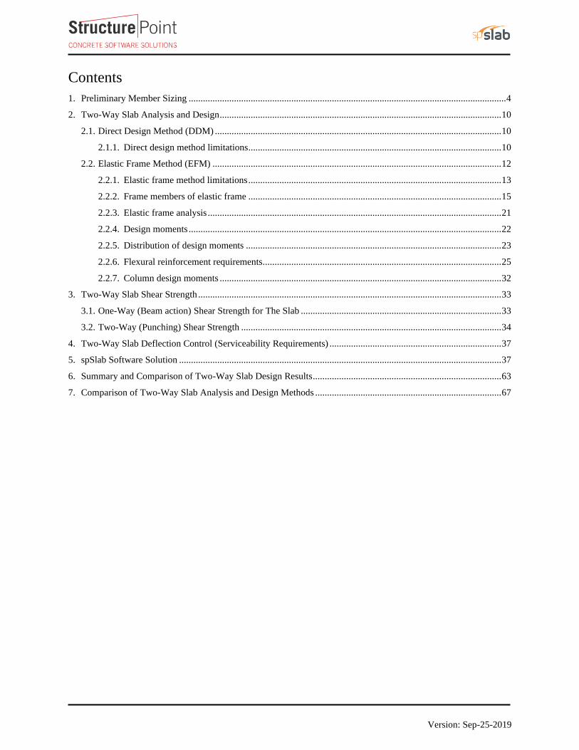
Contents
1. Preliminary Member Sizing ..................................................................................................................................... 4
2. Two-Way Slab Analysis and Design ...................................................................................................................... 10
2.1. Direct Design Method (DDM) ........................................................................................................................ 10
2.1.1. Direct design method limitations .......................................................................................................... 10
2.2. Elastic Frame Method (EFM) ......................................................................................................................... 12
2.2.1. Elastic frame method limitations .......................................................................................................... 13
2.2.2. Frame members of elastic frame .......................................................................................................... 15
2.2.3. Elastic frame analysis ........................................................................................................................... 21
2.2.4. Design moments ................................................................................................................................... 22
2.2.5. Distribution of design moments ........................................................................................................... 23
2.2.6. Flexural reinforcement requirements.................................................................................................... 25
2.2.7. Column design moments ...................................................................................................................... 32
3. Two-Way Slab Shear Strength ............................................................................................................................... 33
3.1. One-Way (Beam action) Shear Strength for The Slab .................................................................................... 33
3.2. Two-Way (Punching) Shear Strength ............................................................................................................. 34
4. Two-Way Slab Deflection Control (Serviceability Requirements) ........................................................................ 37
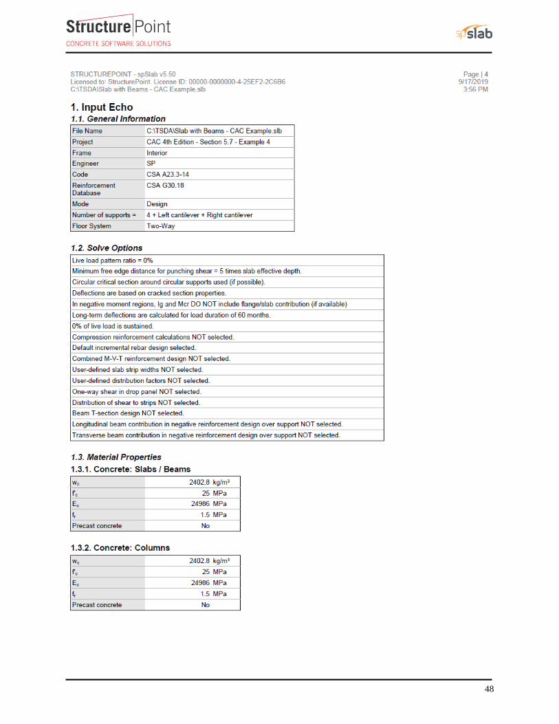
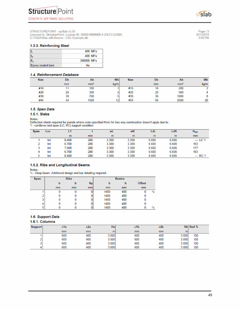
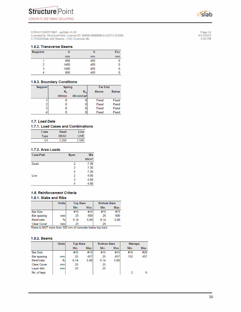
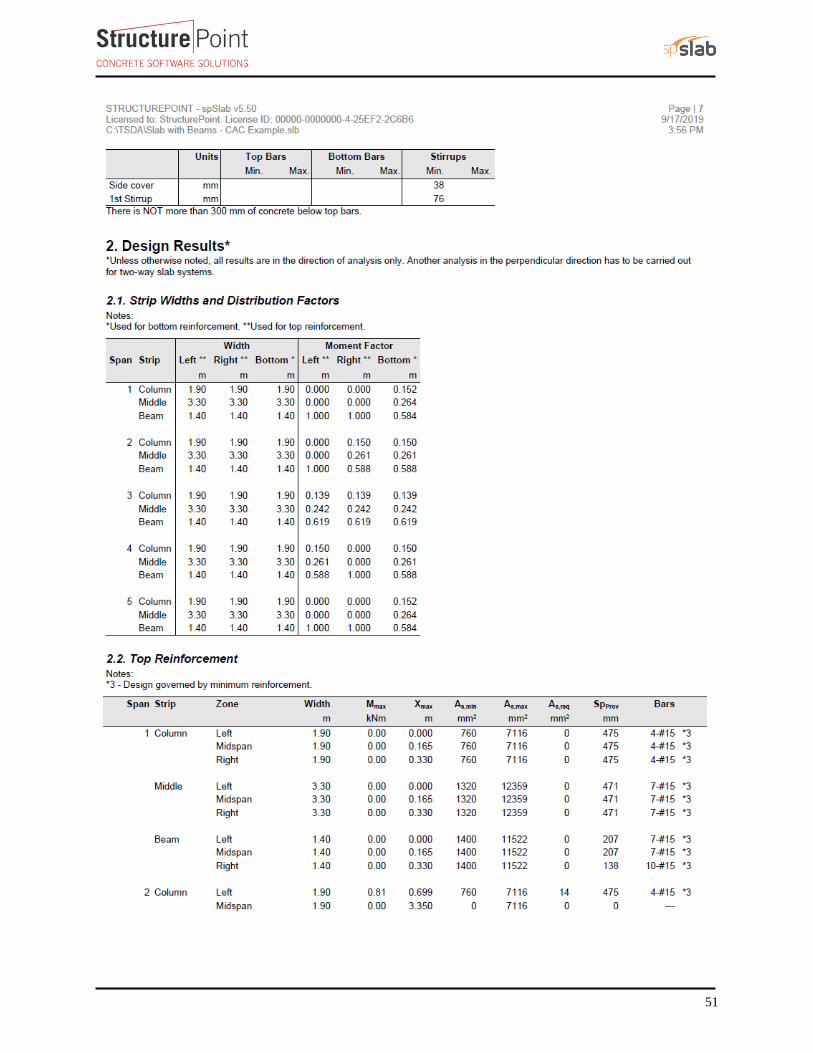
5. spSlab Software Solution ....................................................................................................................................... 37
6. Summary and Comparison of Two-Way Slab Design Results ............................................................................... 63
7. Comparison of Two-Way Slab Analysis and Design Methods .............................................................................. 67
4
Code
Design of Concrete Structures (CSA A23.3-14)
Reference
CAC Concrete Design Handbook, 4th Edition, Cement Association of Canada
Notes on ACI 318-11 Building Code Requirements for Structural Concrete, Twelfth Edition, 2013 Portland
Cement Association
Design Data
Floor-to-Floor Height = 3 m (provided by architectural drawings)
Superimposed Dead Load, SDL =21.6 kN/m
Live Load, 2LL = 4.8 kN/m
'f 25 MPac = (for slabs)
'f 25 MPac = (for columns)
'f 400 MPay =
Column Dimensions = 400 mm x 600 mm
Solution
1. Preliminary Member Sizing
For slab without beams (flat plate)
a) Slab minimum thickness - Deflection
CSA A23.3-14 (13.2)
Minimum member thickness and depths from CSA A23.3-14 will be used for preliminary sizing.
Using CSA A23.3-14 minimum slab thickness for two-way construction without interior beams in Section
13.2.3.
Exterior Panels (E-W Direction Governs):
( ) ( ),min
0.6 /1000 6200 0.6 400 /10001.1 1.1 227 mm
30 30
n y
s
l fh
+ += = = CSA A23.3-14 (13.2.3)
But not less than 120 mm. CSA A23.3-14 (13.2.1)
Where nl = length of clear span in the short direction = 6600 – 400 = 6200 mm
5
Interior Panels (N-S Direction Governs):
( ) ( ),min
0.6 /1000 6900 0.6 400 /1000230 mm
30 30
n y
s
l fh
+ += = = CSA A23.3-14 (13.2.3)
But not less than 120 mm. CSA A23.3-14 (13.2.1)
Wherenl = length of clear span in the long direction = 7500 – 600 = 6900 mm
Try 250 mm slab for all panels (self-weight = 5.89 kN/m2)
b) Slab one way shear strength
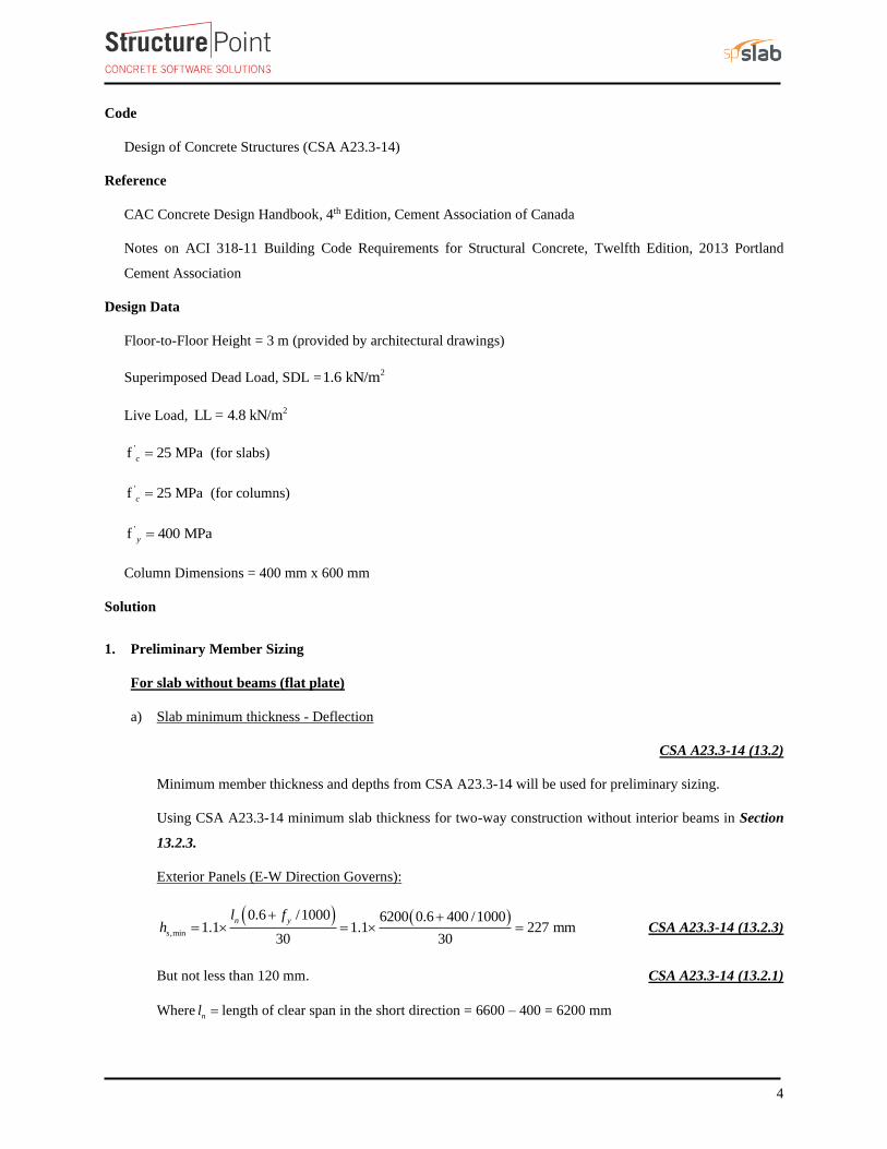
Evaluate the average effective depth (Figure 2):
16250 25 16 201 mm
2 2
b
t slab clear b
dd t c d= − − − = − − − =
16250 25 217 mm
2 2
bl slab clear
dd t c= − − = − − =
201 217209 mm
2 2
l tavg
d dd
+ += = =
Where:
cclear = 20 mm for 15M steel bar CSA A23.3-14 (Annex A. Table 17)
Note that the reference used 25 mm as clear cover, in this example the clear cover used is 25 mm to
be consistent with reference.
db = 16 mm for 15M steel bar
Figure 2 - Two-Way Flat Concrete Floor System
Load Combination 1:
Factored dead load, 21.4 (5.89 1.6) 10.49 kN/mdfw = + = CSA A23.3-14 (Annex C. Table C.1 a)
Total factored load 210.49 kN/mfw =
Load Combination 2:
Factored dead load, 21.25 (5.89 1.6) 9.36 kN/mdfw = + =
6
Factored live load, 21.5 4.8 7.20 kN/mlfw = = CSA A23.3-14 (Annex C. Table C.1 a)
Total factored load 216.56 kN/mf df lfw w w= + = (Controls)
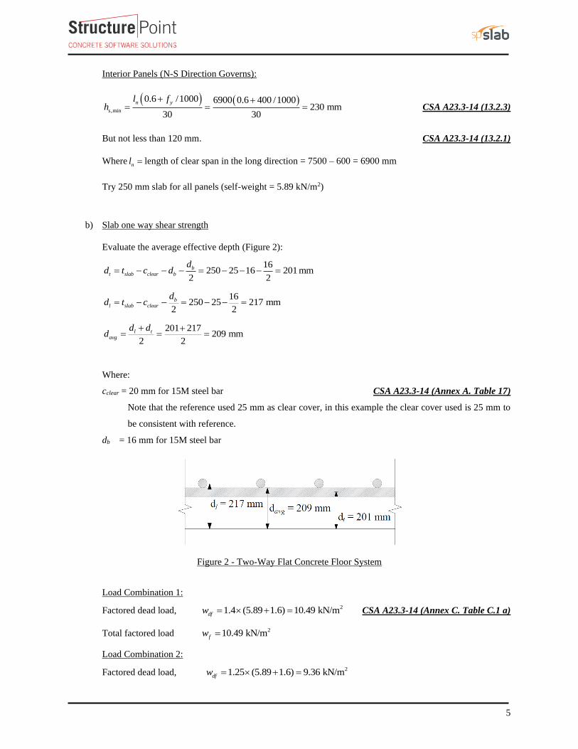
Check the adequacy of slab thickness for beam action (one-way shear) CSA A23.3-14 (13.3.6)
At an interior column:
The critical section for one-way shear is extending in a plane across the entire width and located at a distance,
dv from the face of support or concentrated load (see Figure 3). CSA A23.3-14 (13.3.6.1)
Consider a 1 m. wide strip.
Tributary area for one-way shear is
( )2
2
7500 600188 1000
2 23.26 m
1000TributaryA
− −
= =
16.56 3.26 54.03 kNf f TributaryV w A= = =
' c c c w vV f b d= CSA A23.3-14 (Eq. 11.6)
Where:
1 = for normal weight concrete CSA A23.3-14 (8.6.5)
0.21 = for slabs with overall thickness not greater than 350 mm CSA A23.3-14 (11.3.6.2)
Max (0.9 ,0.72 ) Max (0.9 209,0.72 250) Max (188,180) 188 mmv avgd d h= = = = CSA A23.3-14 (3.2)
' 5 MPa 8 MPacf = CSA A23.3-14 (11.3.4)
1880.65 1 0.21 25 1000 128.3 kN
1000c fV V= =
Slab thickness of 250 mm is adequate for one-way shear.
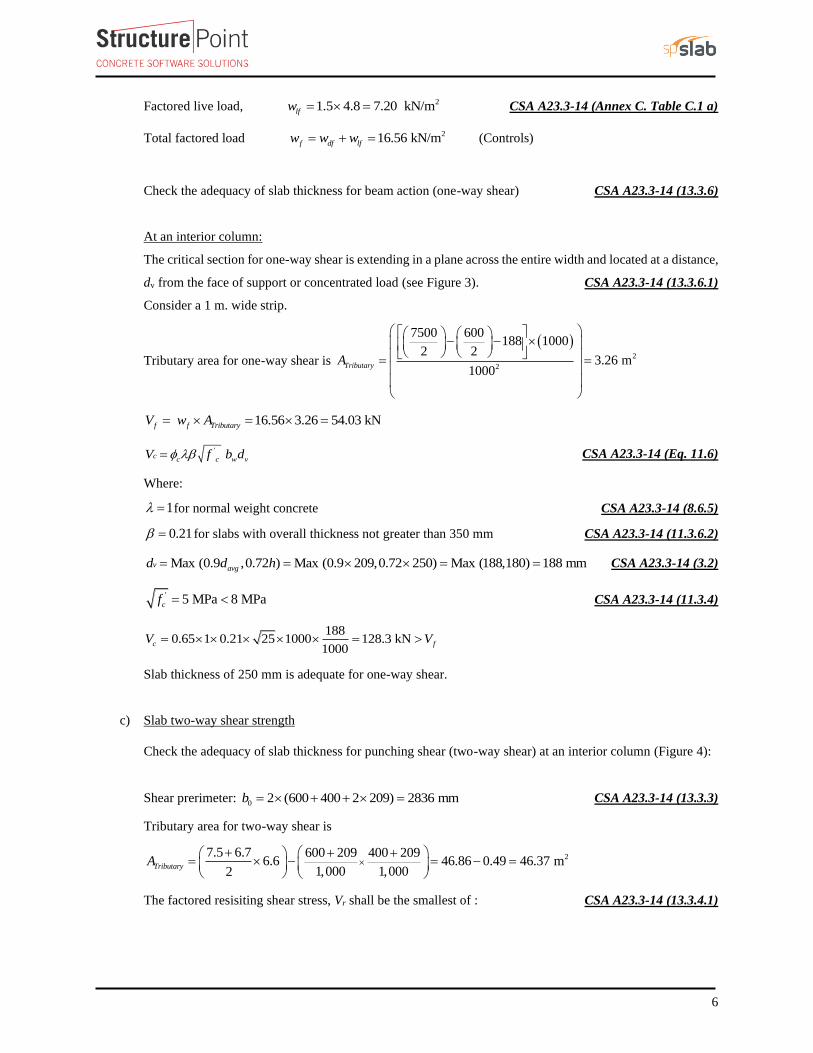
c) Slab two-way shear strength
Check the adequacy of slab thickness for punching shear (two-way shear) at an interior column (Figure 4):
Shear prerimeter: 0 2 (600 400 2 209) 2836 mmb = + + = CSA A23.3-14 (13.3.3)
Tributary area for two-way shear is
27.5 6.7 600 209 400 2096.6 46.86 0.49 46.37 m
1,000 1,0002TributaryA
+ + + = − = − =
The factored resisiting shear stress, Vr shall be the smallest of : CSA A23.3-14 (13.3.4.1)
7
1. '21 0.19r c c c
c
v v f
= = +
CSA A23.3-14 (Eq. 13.5)
21 0.19 0.65 25 1.44 MPa
1.5rv
= + =
Where600
1.5400
c = = (ratio of long side to short side of the column) CSA A23.3-14 (13.3.4.1)
2. '0.19s
r c c c
o
dv v f
b
= = +
CSA A23.3-14 (Eq. 13.6)
4 2090.19 1 0.65 25 1.58 MPa
2836rv
= + =
3. '0.38 0.38 1 0.65 25 1.24 MPar c c cv v f= = = = CSA A23.3-14 (Eq. 13.7)
,
7.5 6.716.56 6.6
21,000 1.309 MPa
2836 209
f
f aveo
Vv
b d
+
= = =
,
1.2400.94 1.20
1.309
r
f ave
v
v= = CAC Concrete Design Handbook 4th Edition (5.2.3)
Slab thickness of 250 mm is not adequate for two-way shear.
Figure 4 - Critical Section for Two-Way
Shear
Figure 3 - Critical Section for One-Way
Shear
8
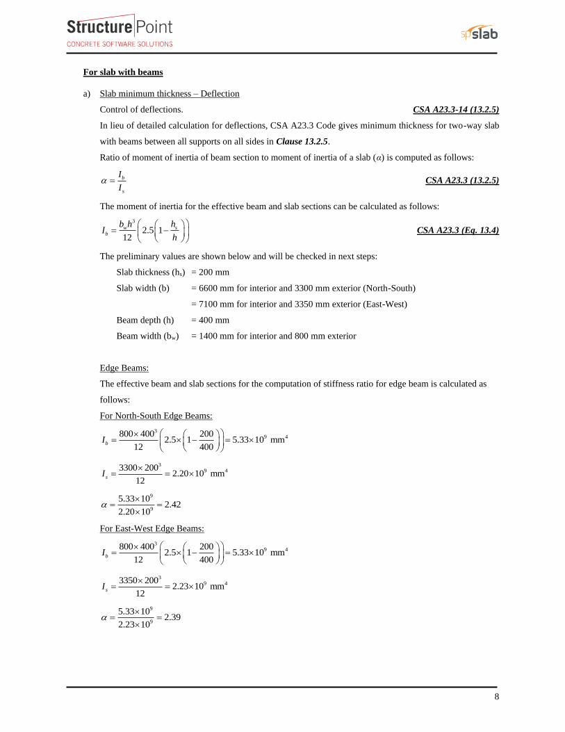
For slab with beams
a) Slab minimum thickness – Deflection
Control of deflections. CSA A23.3-14 (13.2.5)
In lieu of detailed calculation for deflections, CSA A23.3 Code gives minimum thickness for two-way slab
with beams between all supports on all sides in Clause 13.2.5.
Ratio of moment of inertia of beam section to moment of inertia of a slab (α) is computed as follows:
b
s
I
I = CSA A23.3 (13.2.5)
The moment of inertia for the effective beam and slab sections can be calculated as follows:
3
2.5 112
w s
b
b h hI
h
= −
CSA A23.3 (Eq. 13.4)
The preliminary values are shown below and will be checked in next steps:
Slab thickness (hs) = 200 mm
Slab width (b) = 6600 mm for interior and 3300 mm exterior (North-South)
= 7100 mm for interior and 3350 mm exterior (East-West)
Beam depth (h) = 400 mm
Beam width (bw) = 1400 mm for interior and 800 mm exterior
Edge Beams:
The effective beam and slab sections for the computation of stiffness ratio for edge beam is calculated as
follows:
For North-South Edge Beams:
39 4800 400 200
2.5 1 5.33 10 mm12 400
bI
= − =
39 43300 200
2.20 10 mm12
sI
= =
9
9
5.33 102.42
2.20 10
= =
For East-West Edge Beams:
39 4800 400 200
2.5 1 5.33 10 mm12 400
bI
= − =
39 43350 200
2.23 10 mm12
sI
= =
9
9
5.33 102.39
2.23 10
= =
9
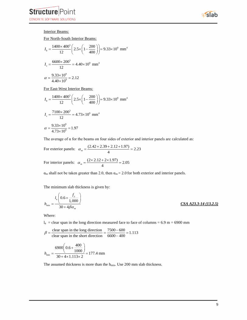
Interior Beams:
For North-South Interior Beams:
39 41400 400 200
2.5 1 9.33 10 mm12 400
bI
= − =
39 46600 200
4.40 10 mm12
sI
= =
9
9
9.33 102.12
4.40 10
= =
For East-West Interior Beams:
39 41400 400 200
2.5 1 9.33 10 mm12 400
bI
= − =
39 47100 200
4.73 10 mm12
sI
= =
9
9
9.33 101.97
4.73 10
= =
The average of α for the beams on four sides of exterior and interior panels are calculated as:
For exterior panels: (2.42 2.39 2.12 1.97)
2.234
m
+ + += =
For interior panels: (2 2.12 2 1.97)
2.054
m
+ = =
αm shall not be taken greater than 2.0, then αm = 2.0 for both exterior and interior panels.
The minimum slab thickness is given by:
min
0.61,000
30 4
y
n
m
fl
h
+
=
+ CSA A23.3-14 (13.2.5)
Where:
ln = clear span in the long direction measured face to face of columns = 6.9 m = 6900 mm
clear span in the long direction 7500 6001.113
clear span in the short direction 6600 400
−= = =
−
min
4006900 0.6
1000177.4 mm
30 4 1.113 2h
+
= =
+
The assumed thickness is more than the hmin. Use 200 mm slab thickness.
10
2. Two-Way Slab Analysis and Design
CSA A23.3 states that a regular slab system may be designed using any procedure satisfying conditions of
equilibrium and compatibility with the supports, provided that it is shown that the factored resistance at every
section is at least equal to the effects of the factored loads and that all serviceability conditions, including specified
limits on deflections, are met. CSA A23.3-14 (13.5.1)
CSA A23.3 permits the use of Plastic Plate Theory Method (PPTM), Theorems of Plasticity Method (TPM),
Direct Design Method (DDM) and Elastic Frame Method (EFM); known as Equivalent Frame Method in the
ACI; for the gravity load analysis of orthogonal frames. The following sections outline a brief description of
DDM, a detailed hand solution using EFM and an automated solution using spSlab software respectively.
2.1. Direct Design Method (DDM)
Two-way slabs satisfying the limits in CSA A23.3-14 (13.9) are permitted to be designed in accordance with
the DDM.
2.1.1. Direct design method limitations
There shall be a minimum of three continuous spans in each direction (3 spans) CSA A23.3-14 (13.9.1.2)
Successive span lengths centre-to-centre of supports in each direction shall not differ by more than one- third
of the longer span ((7500-6700)/6700 = 0.12 < 0.33) CSA A23.3-14 (13.9.1.3)
All loads shall be due to gravity only and uniformly distributed over an entire panel (Loads are uniformly
distributed over the entire panel) CSA A23.3-14 (13.9.1.4)
The factored live load shall not exceed twice the factored dead load (Service live-to-dead load ratio of
(4.8/(24*200/1000) = 1.00 < 2.0) CSA A23.3-14 (13.9.1.4)
Since all the criteria are met, Direct Design Method can be utilized.
Detailed illustration of analysis and design of two-way slab using DDM can be found in “Two-Way Flat Plate
Concrete Slab Floor Analysis and Design (CSA A23.3-14)” example available in the design examples page in
StructurePoint website. This example focuses on the analysis of two-way slab with beams using EFM.
11
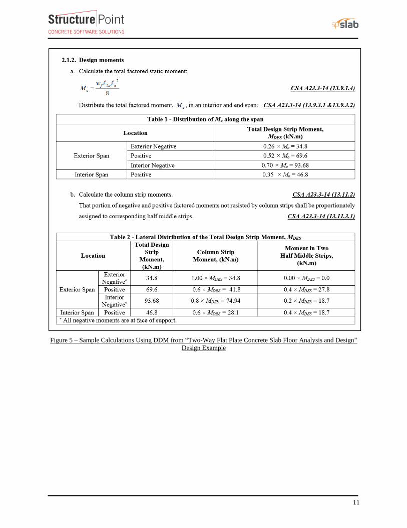
Figure 5 – Sample Calculations Using DDM from “Two-Way Flat Plate Concrete Slab Floor Analysis and Design”
Design Example
12
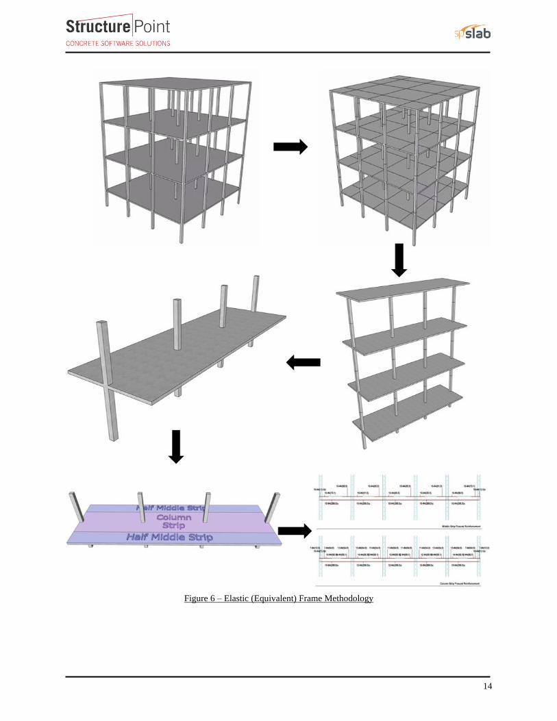
2.2. Elastic Frame Method (EFM)
EFM (also known as Equivalent Frame Method in the ACI 318) is the most comprehensive and detailed
procedure provided by the CSA A23.3 for the analysis and design of two-way slab systems where these systems
may, for purposes of analysis, be considered a series of plane frames acting longitudinally and transversely
through the building. Each frame shall be composed of equivalent line members intersecting at member
centrelines, shall follow a column line, and shall include the portion of slab bounded laterally by the centreline
of the panel on each side. CSA A23.3-14 (13.8.1.1)
Probably the most frequently used method to determine design moments in regular two-way slab systems is to
consider the slab as a series of two-dimensonal frames that are analyzed elastically. When using this analogy,
it is essential that stiffness properties of the elements of the frame be selected to properly represent the behavior
of the three-dimensional slab system.
In a typical frame analysis it is assumed that at a beam-column cconnection all members meeting at the joint
undergo the same rotaion. For uniform gravity loading this reduced restraint is accounted for by reducing the
effective stiffness of the column by either Clause 13.8.2 or Clause 13.8.3. CSA A23.3-14 (N.13.8)
Each floor and roof slab with attached columns may be analyzed separately, with the far ends of the columns
considered fixed. CSA A23.3-14 (13.8.1.2)
The moment of inertia of column and slab-beam elements at any cross-section outside of joints or column
capitals shall be based on the gross area of concrete at that section. CSA A23.3-14 (13.8.2.5)
An equivalent column shall be assumed to consist of the actual columns above and below the slab-beam plus
an attached torsional member transverse to the direction of the span for which moments are being determined.
CSA A23.3-14 (13.8.2.5)
13
2.2.1. Elastic frame method limitations
In EFM, live load shall be arranged in accordance with 13.8.4 which requires:
• slab systems to be analyzed and designed for the most demanding set of forces established by
investigating the effects of live load placed in various critical patterns. CSA A23.3-14 (13.8.4)
• Complete analysis must include representative interior and exterior equivalent elastic frames in both the
longitudinal and transverse directions of the floor. CSA A23.3-14 (13.8.1.1)
• Panels shall be rectangular, with a ratio of longer to shorter panel dimensions, measured center-to-center
of supports, not to exceed 2. CSA A23.3-14 (3.1a)
• For slab systems with beams between sypports, the relative effective stiffness of beams in the two
directions is not less than 0.2 or greater than 5.0. CSA A23.3-14 (3.1b)
• Column offsets are not greater than 20% of the span (in the direction of offset) from either axis between
centerlines of successive columns. CSA A23.3-14 (3.1c)
The reinforcement is placed in an orthogonal grid. CSA A23.3-14 (3.1d)
14
Figure 6 – Elastic (Equivalent) Frame Methodology
15
2.2.2. Frame members of elastic frame
Determine moment distribution factors and fixed-end moments for the elastic frame members. The moment
distribution procedure will be used to analyze the equivalent frame. Stiffness factors k , carry over factors
COF, and fixed-end moment factors FEM for the slab-beams and column members are determined using the
design aids tables at Appendix 20A of PCA Notes on ACI 318-11. These calculations are shown below.
a. Flexural stiffness of slab-beams at both ends, Ksb
For Interior Span:
1
1
6000.080
7500
Nc= = , 2
2
4000.061
6600
Nc= =
For1 2F Nc c= , stiffness factors, 4.09NF FNk k= = PCA Notes on ACI 318-11 (Table A1)
Thus, 1 1
4.09cs s cs ssb NF
E I E IK k= = PCA Notes on ACI 318-11 (Table A1)
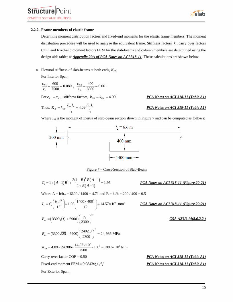
Where Isb is the moment of inertia of slab-beam section shown in Figure 7 and can be computed as follows:
Figure 7 – Cross-Section of Slab-Beam
( )( ) ( )
( )
2
33 1 1
1 1 1.951 1
t
B B AC A B
B A
− −= + − + =
+ − PCA Notes on ACI 318-11 (Figure 20-21)
Where A = b/bw = 6600 / 1400 = 4.71 and B = hs/h = 200 / 400 = 0.5
3 39 41400 400
1.95 14.57 10 mm12 12
w
s t
b hI C
= = =
PCA Notes on ACI 318-11 (Figure 20-21)
( )1.5
'3300 69002300
c
cs cE f
= +
CSA A23.3-14(8.6.2.2 )
1.52402.8
(3300 25 6900) 24,986 MPa2300
csE
= + =
93 614.57 10
4.09 24,986 10 198.6 10 N.m7500
sbK −
= =
Carry-over factor COF = 0.50 PCA Notes on ACI 318-11 (Table A1)
Fixed-end moment FEM2
2 10.0843 uw= PCA Notes on ACI 318-11 (Table A1)
For Exterior Span:
16
1
1
6000.090
6700
Nc= = , 2
2
6000.061
6600
Nc= =
For1 2F Nc c= , stiffness factors, 4.10NF FNk k= = PCA Notes on ACI 318-11 (Table A1)
Thus, 1 1
4.10cs s cs ssb NF
E I E IK k= = PCA Notes on ACI 318-11 (Table A1)
93 614.57 10
4.10 24,986 10 222.8 10 N.m6700
sbK −
= =
Carry-over factor COF = 0.51 PCA Notes on ACI 318-11 (Table A1)
Fixed-end moment FEM 2
2 10.0843 uw= PCA Notes on ACI 318-11 (Table A1)
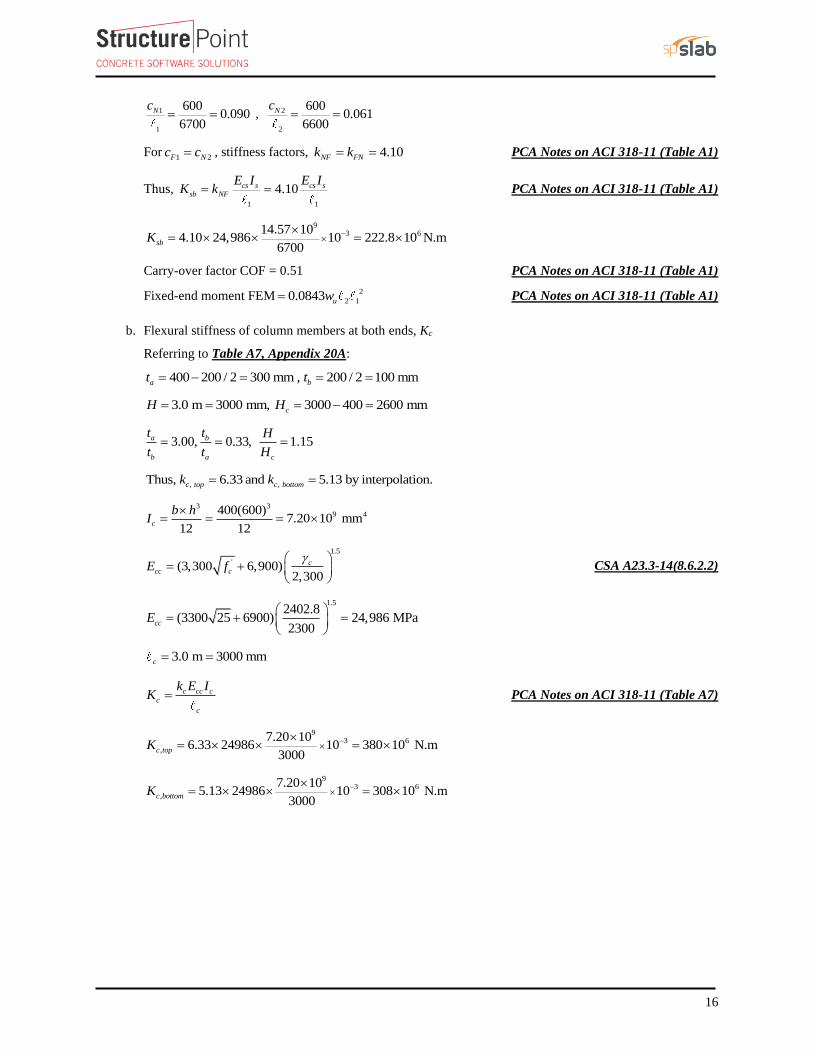
b. Flexural stiffness of column members at both ends, Kc
Referring to Table A7, Appendix 20A:
400 200 / 2 300 mm , 200 / 2 100 mma bt t= − = = =
3.0 m 3000 mm, 3000 400 2600 mmcH H= = = − =
3.00, 0.33, 1.15a b
b a c
t t H
t t H= = =
, , Thus, 6.33 and 5.13 by interpolation.c top c bottomk k= =
3 39 4400(600)
7.20 10 mm12 12
c
b hI
= = =
1.5
'(3,300 6,900)2,300
c
cc cE f
= +
CSA A23.3-14(8.6.2.2)
1.52402.8
(3300 25 6900) 24,986 MPa2300
ccE
= + =
3.0 m 3000 mmc = =
c cc c
c
c
k E IK = PCA Notes on ACI 318-11 (Table A7)
93 6
,
7.20 106.33 24986 10 380 10 N.m
3000c topK −
= =
93 6
,
7.20 105.13 24986 10 308 10 N.m
3000c bottomK −
= =
17
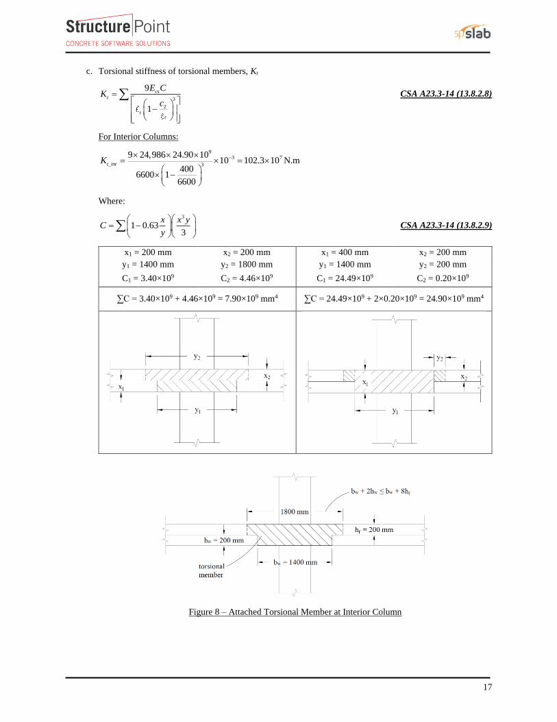
c. Torsional stiffness of torsional members, Kt
3
2
9
1
cs
t
tt
E CK
c=
−
CSA A23.3-14 (13.8.2.8)
For Interior Columns:
93 7
3
9 24,986 24.90 1010 102.3 10 N.m
4006600 1
6600
t_intK − = =
−
Where:
3
1 0.633
x x yC
y
= −
CSA A23.3-14 (13.8.2.9)
x1 = 200 mm x2 = 200 mm x1 = 400 mm x2 = 200 mm
y1 = 1400 mm y2 = 1800 mm y1 = 1400 mm y2 = 200 mm
C1 = 3.40×10⁹ C2 = 4.46×10⁹ C1 = 24.49×10⁹ C2 = 0.20×10⁹
∑C = 3.40×10⁹ + 4.46×109 = 7.90×109 mm4 ∑C = 24.49×10⁹ + 2×0.20×109 = 24.90×109 mm4
Figure 8 – Attached Torsional Member at Interior Column
18
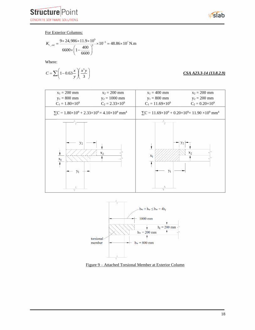
For Exterior Columns:
93 7
_ 3
9 24,986 11.9 1010 48.86 10 N.m
4006600 1
6600
t extK − = =
−
Where:
3
1 0.633
x x yC
y
= −
CSA A23.3-14 (13.8.2.9)
x1 = 200 mm x2 = 200 mm x1 = 400 mm x2 = 200 mm
y1 = 800 mm y2 = 1000 mm y1 = 800 mm y2 = 200 mm
C1 = 1.80×10⁹ C2 = 2.33×10⁹ C1 = 11.69×10⁹ C2 = 0.20×10⁹
∑C = 1.80×10⁹ + 2.33×109 = 4.10×109 mm4 ∑C = 11.69×10⁹ + 0.20×109= 11.90 ×109 mm4
Figure 9 – Attached Torsional Member at Exterior Column
19
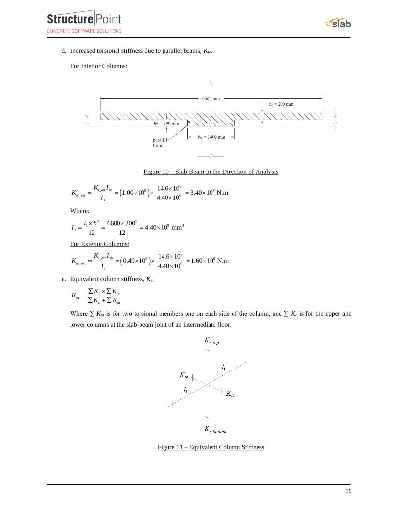
d. Increased torsional stiffness due to parallel beams, Kta.
For Interior Columns:
Figure 10 – Slab-Beam in the Direction of Analysis
( )9
9 9
9
14.6 101.00 10 3.40 10 N.m
4.40 10
t_int sb
ta_int
s
K IK
I
= = =
Where:
3 39 42 6600 200
4.40 10 mm12 12
s
l hI
= = =
For Exterior Columns:
( )9
9 9
9
14.6 100.49 10 1.60 10 N.m
4.40 10
t_ext sb
ta_ext
s
K IK
I
= = =
e. Equivalent column stiffness, Kec
c taec
c ta
K KK
K K
= +
Where ∑ Kta is for two torsional members one on each side of the column, and ∑ Kc is for the upper and
lower columns at the slab-beam joint of an intermediate floor.
Figure 11 – Equivalent Column Stiffness
20
For Interior Columns:
6 6 96
6 6 9
(379.6 10 307.6 10 )(2 3.4 10 )623.9 10 N.m
(379.6 10 307.6 10 ) (2 3.4 10 )ec_intK
+ = =
+ +
For Exterior Columns:
6 6 96
6 6 9
(379.6 10 307.6 10 )(2 1.6 10 )566.9 10 N.m
(379.6 10 307.6 10 ) (2 1.6 10 )ec_extK
+ = =
+ +
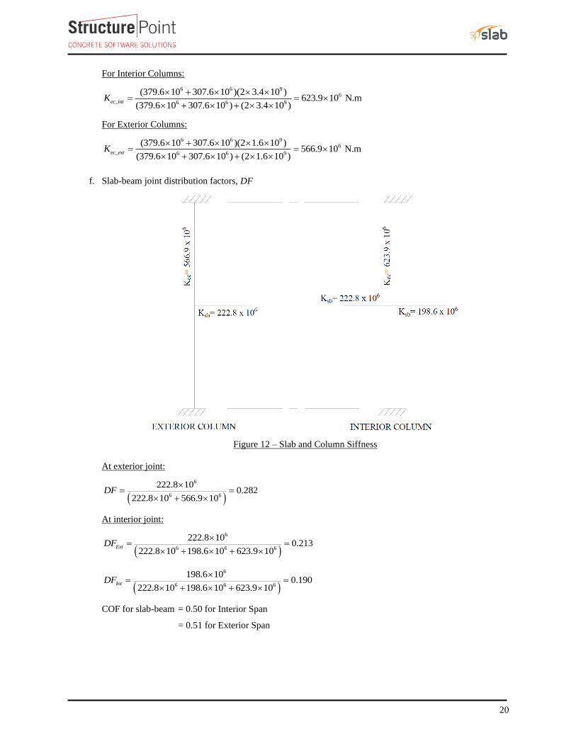
f. Slab-beam joint distribution factors, DF
Figure 12 – Slab and Column Siffness
At exterior joint:
( )
6
6 6
222.8 100.282
222.8 10 566.9 10DF
= =
+
At interior joint:
( )
6
6 6 6
222.8 100.213
222.8 10 198.6 10 623.9 10ExtDF
= =
+ +
( )
6
6 6 6
198.6 100.190
222.8 10 198.6 10 623.9 10IntDF
= =
+ +
COF for slab-beam = 0.50 for Interior Span
= 0.51 for Exterior Span
21
2.2.3. Elastic frame analysis
Determine negative and positive moments for the slab-beams using the moment distribution method. Since
the unfactored live load does not exceed three-quarters of the unfactored dead load, design moments are
assumed to occur at all critical sections with full factored live on all spans. CSA A23.3-14 (13.8.4.2)
( ) ( )
4.8 4.8 30.66
1.4 4.7 1.0 1.6 42400 0.2 2400 0.4 0.2 1.6
6.6
L
D= = =
+ + + − +
a. Factored load and Fixed-End Moments (FEM’s).
Factored dead load, 21.25 (4.7 1.0 1.6) 9.1 kN/mdfw = + + =
Factored live load, 21.5 4.8 7.2 kN/mlfw = =
Total factored load 216.3 kN/mu f df lfq w w w= = + =
FEM’s for slab-beams 2
2 1NF um q= PCA Notes on ACI 318-11 (Table A1)
20.0840 16.3 6.6 7.5 509.6 kN.m (For Interior Span)= =
20.0841 16.3 6.6 6.7 407.1 kN.m (For Exterior Span)= =
b. Moment distribution.
Moment distribution computations are shown in Table 1. Counterclockwise rotational moments acting on the
member ends are taken as positive. Positive span moments are determined from the following equation:
,
2
uL uR
u midspan o
M MM M
+= −
Where oM is the moment at the midspan for a simple beam.
When the end moments are not equal, the maximum moment in the span does not occur at the midspan, but
its value is close to that midspan for this example.
Positive moment in span 1-2:
( ) ( )216.3 6.6 6.7 288.5 475.4
221.7 kN.m8 2
uM + +
= − =
Positive moment span 2-3:
( ) ( )216.3 6.6 7.5 504.9 504.9
251.5 kN.m8 2
uM + +
= − =
22
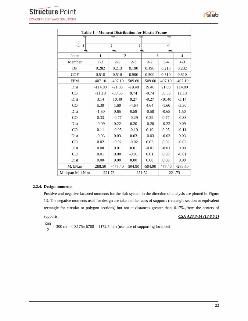
Table 1 – Moment Distribution for Elastic Frame
Joint 1 2 3 4
Member 1-2 2-1 2-3 3-2 3-4 4-3
DF 0.282 0.213 0.190 0.190 0.213 0.282
COF 0.510 0.510 0.500 0.500 0.510 0.510
FEM 407.10 -407.10 509.60 -509.60 407.10 -407.10
Dist -114.80 -21.83 -19.48 19.48 21.83 114.80
CO -11.13 -58.55 9.74 -9.74 58.55 11.13
Dist 3.14 10.40 9.27 -9.27 -10.40 -3.14
CO 5.30 1.60 -4.64 4.64 -1.60 -5.30
Dist -1.50 0.65 0.58 -0.58 -0.65 1.50
CO 0.33 -0.77 -0.29 0.29 0.77 -0.33
Dist -0.09 0.22 0.20 -0.20 -0.22 0.09
CO 0.11 -0.05 -0.10 0.10 0.05 -0.11
Dist -0.03 0.03 0.03 -0.03 -0.03 0.03
CO 0.02 -0.02 -0.02 0.02 0.02 -0.02
Dist 0.00 0.01 0.01 -0.01 -0.01 0.00
CO 0.01 0.00 -0.01 0.01 0.00 -0.01
Dist 0.00 0.00 0.00 0.00 0.00 0.00
M, kN.m 288.50 -475.40 504.90 -504.90 475.40 -288.50
Midspan M, kN.m 221.73 251.52 221.73
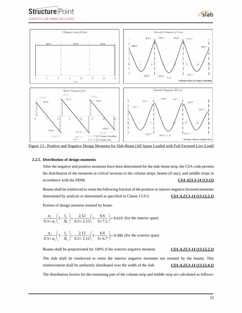
2.2.4. Design moments
Positive and negative factored moments for the slab system in the direction of analysis are plotted in Figure
13. The negative moments used for design are taken at the faces of supports (rectangle section or equivalent
rectangle for circular or polygon sections) but not at distances greater than 10.175 from the centers of
supports. CSA A23.3-14 (13.8.5.1)
600 = 300 mm < 0.175 6700 = 1172.5 mm (use face of supporting location)
2
23
Figure 13 - Positive and Negative Design Moments for Slab-Beam (All Spans Loaded with Full Factored Live Load)
2.2.5. Distribution of design moments
After the negative and positive moments have been determined for the slab-beam strip, the CSA code permits
the distribution of the moments at critical sections to the column strips, beams (if any), and middle strips in
accordance with the DDM. CSA A23.3-14 (13.12)
Beams shall be reinforced to resist the following fraction of the positive or interior negative factored moments
determined by analysis or determined as specified in Clause 13.9.3. CSA A.23.3-14 (13.12.2.1)
Portion of design moment resisted by beam:
1 2
1 1
2.12 6.61 1 0.619
0.3 3 0.3 2.12 3 7.5
l
l
− = − =
+ +
(for the interior span)
1 2
1 1
2.12 6.61 1 0.588
0.3 3 0.3 2.12 3 6.7
l
l
− = − =
+ +
(for the exterior span)
Beams shall be proportioned for 100% if the exterior negative moment. CSA A.23.3-14 (13.12.2.2)
The slab shall be reinforced to resist the interior negative moments not resisted by the beams. This
reinforcement shall be uniformly distributed over the width of the slab. CSA A.23.3-14 (13.12.4.1)
The distribution factors for the remaining part of the column strip and middle strip are calculated as follows:
24
( )
( )
1.91 0.619 0.319
1.9 3.3
3.31 0.619 0.242
1.9 3.3
cs
ms
DF
DF
= − =+
= − =+
(interior span)
( )
( )
1.91 0.588 0.150
1.9 3.3
3.31 0.588 0.261
1.9 3.3
cs
ms
DF
DF
= − =+
= − =+
(M+ section and M- section at the interior support - exterior span)
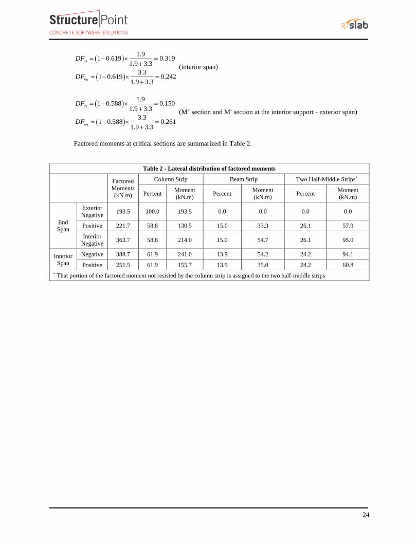
Factored moments at critical sections are summarized in Table 2.
Table 2 - Lateral distribution of factored moments
Factored
Moments
(kN.m)
Column Strip Beam Strip Two Half-Middle Strips*
Percent Moment
(kN.m) Percent
Moment
(kN.m) Percent
Moment
(kN.m)
End
Span
Exterior
Negative 193.5 100.0 193.5 0.0 0.0 0.0 0.0
Positive 221.7 58.8 130.5 15.0 33.3 26.1 57.9
Interior
Negative 363.7 58.8 214.0 15.0 54.7 26.1 95.0
Interior
Span
Negative 388.7 61.9 241.0 13.9 54.2 24.2 94.1
Positive 251.5 61.9 155.7 13.9 35.0 24.2 60.8
* That portion of the factored moment not resisted by the column strip is assigned to the two half-middle strips
25
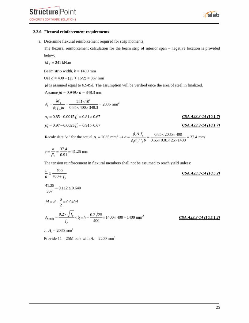
2.2.6. Flexural reinforcement requirements
a. Determine flexural reinforcement required for strip moments
The flexural reinforcement calculation for the beam strip of interior span – negative location is provided
below:
241 kN.mfM =
Beam strip width, b = 1400 mm
Use d = 400 – (25 + 16/2) = 367 mm
jd is assumed equal to 0.949d. The assumption will be verified once the area of steel in finalized.
Assume 0.949 348.3 mmjd d= =
62241 10
2035 mm0.85 400 348.3
f
s
s y
MA
f jd
= = =
'
1 0.85 0.0015 0.81 0.67cf = − = CSA A23.3-14 (10.1.7)
'
1 0.97 0.0025 0.91 0.67cf = − = CSA A23.3-14 (10.1.7)
2
1
0.85 2035 400Recalculate ' ' for the actual 2035 mm 37.4 mm
' 0.65 0.81 25 1400
s s y
s
c c
A fa A a
f b
= → = = =
1
37.441.25 mm
0.91
ac = = =
The tension reinforcement in flexural members shall not be assumed to reach yield unless:
700
700 y
c
d f
+ CSA A23.3-14 (10.5.2)
41.250.112 0.640
367=
0.9492
ajd d d= − =
'2
,min
0.2 0.2 251400 400 1400 mm
400
cs t
y
fA b h
f
= = = CSA A23.3-14 (10.5.1.2)
22035 mmsA =
Provide 11 – 25M bars with As = 2200 mm2
26
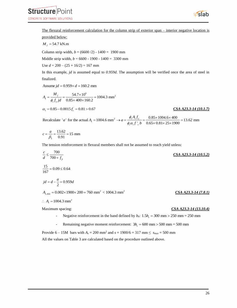
The flexural reinforcement calculation for the column strip of exterior span – interior negative location is
provided below:
54.7 kN.mfM =
Column strip width, b = (6600 /2) - 1400 = 1900 mm
Middle strip width, b = 6600 - 1900 - 1400 = 3300 mm
Use d = 200 – (25 + 16/2) = 167 mm
In this example, jd is assumed equal to 0.959d. The assumption will be verified once the area of steel in
finalized.
Assume 0.959 160.2 mmjd d= =
6254.7 10
1004.3 mm0.85 400 160.2
f
s
s y
MA
f jd
= = =
'
1 0.85 0.0015 0.81 0.67cf = − = CSA A23.3-14 (10.1.7)
2
1
0.85 1004.6 400Recalculate ' ' for the actual 1004.6 mm 13.62 mm
' 0.65 0.81 25 1900
s s y
s
c c
A fa A a
f b
= → = = =
1
13.6215 mm
0.91
ac = = =
The tension reinforcement in flexural members shall not be assumed to reach yield unless:
700
700 y
c
d f
+ CSA A23.3-14 (10.5.2)
150.09 0.64
167=
0.9592
ajd d d= − =
2 2
,min 0.002 1900 200 760 mm < 1004.3 mmsA = = CSA A23.3-14 (7.8.1)
21004.3 mmsA =
Maximum spacing: CSA A23.3-14 (13.10.4)
- Negative reinforcement in the band defined by bb: 1.5 300 mm 250 mm = 250 mmsh =
- Remaining negative moment reinforcement: 3 600 mm 500 mm = 500 mmsh =
Provide 6 – 15M bars with As = 200 mm2 and s = 1900/6 = 317 mm ≤ smax = 500 mm
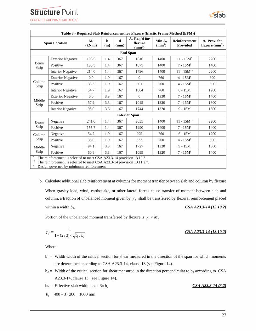
All the values on Table 3 are calculated based on the procedure outlined above.
27
Table 3 - Required Slab Reinforcement for Flexure (Elastic Frame Method (EFM))
Span Location Mf
(kN.m)
b
(m)
d
(mm)
As Req’d for
flexure
(mm2)
Min As
(mm2)
Reinforcement
Provided
As Prov. for
flexure (mm2)
End Span
Beam
Strip
Exterior Negative 193.5 1.4 367 1616 1400 11 - 15M* 2200
Positive 130.5 1.4 367 1075 1400 7 - 15M† 1400
Interior Negative 214.0 1.4 367 1796 1400 11 - 15M** 2200
Column
Strip
Exterior Negative 0.0 1.9 167 0 760 4 - 15M† 800
Positive 33.3 1.9 167 601 760 4 - 15M† 800
Interior Negative 54.7 1.9 167 1004 760 6 - 15M 1200
Middle
Strip
Exterior Negative 0.0 3.3 167 0 1320 7 - 15M† 1400
Positive 57.9 3.3 167 1045 1320 7 - 15M† 1800
Interior Negative 95.0 3.3 167 1744 1320 9 - 15M 1800
Interior Span
Beam
Strip
Negative 241.0 1.4 367 2035 1400 11 - 15M** 2200
Positive 155.7 1.4 367 1290 1400 7 - 15M† 1400
Column
Strip
Negative 54.2 1.9 167 995 760 6 - 15M 1200
Positive 35.0 1.9 167 633 760 4 - 15M† 800
Middle
Strip
Negative 94.1 3.3 167 1727 1320 9 - 15M 1800
Positive 60.8 3.3 167 1099 1320 7 - 15M† 1400 * The reinforcement is selected to meet CSA A23.3-14 provision 13.10.3. ** The reinforcement is selected to meet CSA A23.3-14 provision 13.11.2.7. † Design governed by minimum reinforcement
b. Calculate additional slab reinforcement at columns for moment transfer between slab and column by flexure
When gravity load, wind, earthquake, or other lateral forces cause transfer of moment between slab and
column, a fraction of unbalanced moment given by f shall be transferred by flexural reinforcement placed
within a width bb. CSA A23.3-14 (13.10.2)
Portion of the unbalanced moment transferred by flexure is f rM
1 2
1
1 (2 / 3) /f
b b =
+ CSA A23.3-14 (13.10.2)
Where
b1 = Width width of the critical section for shear measured in the direction of the span for which moments
are determined according to CSA A23.3-14, clause 13 (see Figure 14).
b2 = Width of the critical section for shear measured in the direction perpendicular to b1 according to CSA
A23.3-14, clause 13 (see Figure 14).
bb = Effective slab width =2 3 sc h+ CSA A23.3-14 (3.2)
400 3 200 1000 mmbb = + =
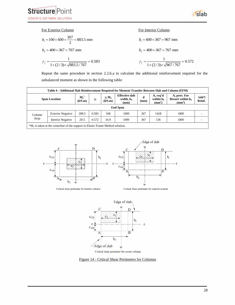
28
For Exterior Column For Interior Column
1
367100 600 883.5 mm
2b = + + =
1 600 367 967 mmb = + =
2 400 367 767 mmb = + = 2 400 367 767 mmb = + =
10.583
1 (2 / 3) 883.5 / 767f = =
+
10.572
1 (2 / 3) 967 / 767f = =
+
Repeat the same procedure in section 2.2.6.a to calculate the additional reinforcement required for the
unbalanced moment as shown in the following table:
Table 4 - Additional Slab Reinforcement Required for Moment Transfer Between Slab and Column (EFM)
Span Location Mu
*
(kN.m) γf
γf Mu
(kN.m)
Effective slab
width, bb
(mm)
d
(mm)
As req’d
within bb
(mm2)
As prov. For
flexure within bb
(mm2)
Add’l
Reinf.
End Span
Column
Strip
Exterior Negative 288.5 0.583 168 1000 367 1418 1800 -
Interior Negative 29.5 0.572 16.9 1000 367 136 1800 -
*Mu is taken at the centerline of the support in Elastic Frame Method solution.
Figure 14 - Critical Shear Perimeters for Columns
29
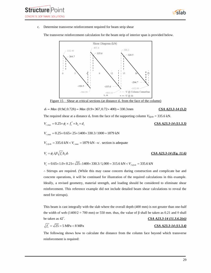
c. Determine transverse reinforcement required for beam strip shear
The transverse reinforcement calculation for the beam strip of interior span is provided below.
Figure 15 – Shear at critical sections (at distance dv from the face of the column)
(0.9 ,0.72 ) (0.9 367,0.72 400) 330.3mmvd Max d h Max= = = CSA A23.3-14 (3.2)
The required shear at a distance dv from the face of the supporting column Vf@dv = 335.6 kN.
,max 0.25r c c w vV f b d= CSA A23.3-14 (11.3.3)
,max 0.25 0.65 25 1400 330.3 /1000 1879 kNrV = =
@ ,max335.6 kN 1879 kN section is adequatef dv rV V= = →
'vc c c wV f b d= CSA A23.3-14 (Eq. 11.6)
@0.65 1.0 0.21 25 1400 330.3 /1,000 315.6 kN 335.6 kNc f dvV V= = =
∴ Stirrups are required. (While this may cause concern during construction and complicate bar and
concrete operations, it will be continued for illustration of the required calculations in this example.
Ideally, a revised geometry, material strength, and loading should be considered to eliminate shear
reinforcement. This reference example did not include detailed beam shear calculations to reveal the
need for stirrups).
This beam is cast integrally with the slab where the overall depth (400 mm) is not greater than one-half
the width of web (1400/2 = 700 mm) or 550 mm. thus, the value of β shall be taken as 0.21 and θ shall
be taken as 42ᴼ. CSA A23.3-14 (11.3.6.2(e))
' 25 5 MPa 8 MPacf = = CSA A23.3-14 (11.3.4)
The following shows how to calculate the distance from the column face beyond which transverse
reinforcement is required:
30
@s f dv cV V V= − CSA A23.3-14 (11.3.3)
335.6 315.6 20 kNsV = − =
@
cot
f dv cv
s yt vreq
V VA
s f d
− =
CSA A23.3-14 (11.3.5.1)
220 10000.160 mm / mm
0.85 400 330.3 cot 42
v
req
A
s
= =
'
min
0.06 c wv
yt
f bA
s f
=
CSA A23.3-14 (11.2.8.2)
2
min
0.06 25 14001.05 mm / mm (Governs)
400
vA
s
= =
2 100190.5 mm
1.05
vreq
v
req
As
A
s
= = =
Check whether the required spacing based on the shear demand meets the spacing limits for shear
reinforcement per CSA A23.3-14 (11.3.8).
@0.125 c c w v f dvf b d V CSA A23.3-14 (11.3.8.3)
@0.125 0.125 1.0 0.65 25 1400 330.3 939.3 kN 335.6 kNc c w v f dvf b d V = = =
Therefore, maximum stirrup spacing shall be the smallest of 0.7dv and 600 mm.
CSA A23.3-14 (11.3.8.1 & 11.3.8.3)
max
0.7 0.7 330.3 231 mmlesser of lesser of lesser of 231 mm
600 mm 600 mm600 mm
vds
= = = =
Since use 190 mmreq max reqs s s → =
Select sprovided = 175 mm – 10M stirrups with first stirrup located at distance 76.2 mm (3 in.) from the
column face.
The distance where the shear is zero is calculated as follows:
,
, ,
7.5403.4 3.75 m 3750 mm
403.4 403.4u L
f L f R
lx V
V V= = = =
+ +
The distance at which no shear reinforcement is required is calculated as follows:
( ) ( )1
3.750.85 3.75 0.85 315.6 1.256 m 1256 mm
403.4c
f
xx x V
V= − = − = =
The following two provisions from CSA A23.3-14 explain the use of 85% of Vc:
The reudctions of shear resistance caused by terminating longitudinal reinforcement in flexural tension
zones shall be taken into account. It can be assumed that the reductions in shear capacity occur over a
length dv centred upon the termination point. CSA A23.3-14 (11.2.13.1)
31
Note that if the factored shear resistance has been calculated using the simplified method of either Clasue
11.3.6.2 or Clause 11.3.6.3 then the calculated shear resistance within the length specified in Clause
11.2.13.1 shall be reduced by 15% (85% of Vc as shown in the previous equation).
CSA A23.3-14 (11.2.13.2)
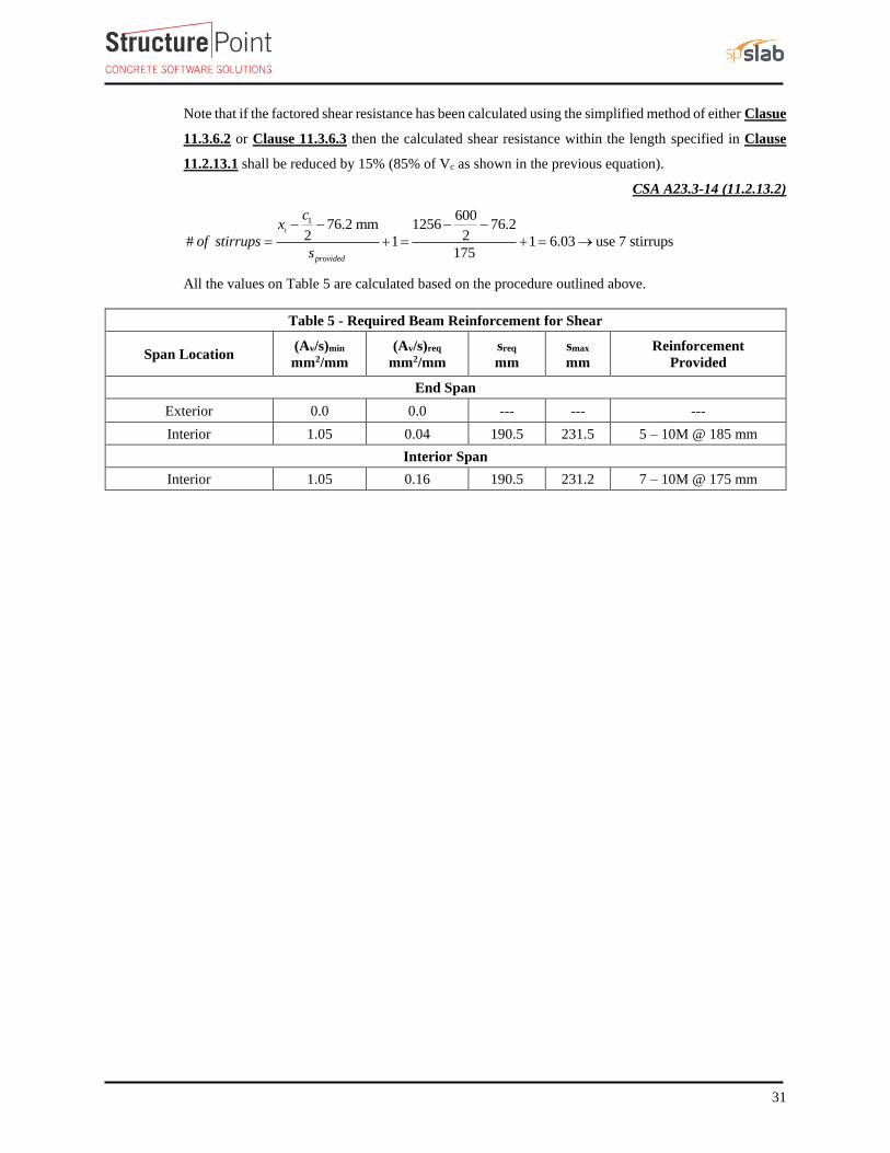
1
1 60076.2 mm 1256 76.2
2 2# 1 1 6.03 use 7 stirrups175provided
cx
of stirrupss
− − − −
= + = + = →
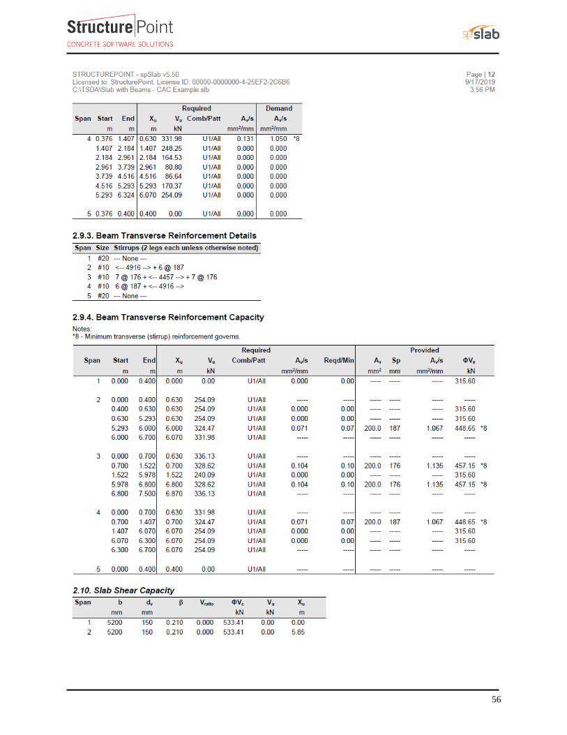
All the values on Table 5 are calculated based on the procedure outlined above.
Table 5 - Required Beam Reinforcement for Shear
Span Location (Av/s)min
mm2/mm
(Av/s)req
mm2/mm
sreq
mm
smax
mm
Reinforcement
Provided
End Span
Exterior 0.0 0.0 --- --- ---
Interior 1.05 0.04 190.5 231.5 5 – 10M @ 185 mm
Interior Span
Interior 1.05 0.16 190.5 231.2 7 – 10M @ 175 mm
32
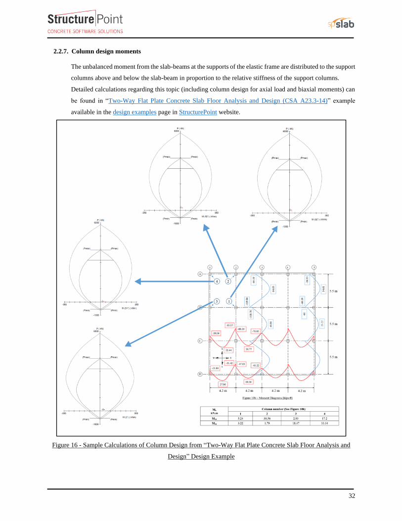
2.2.7. Column design moments
The unbalanced moment from the slab-beams at the supports of the elastic frame are distributed to the support
columns above and below the slab-beam in proportion to the relative stiffness of the support columns.
Detailed calculations regarding this topic (including column design for axial load and biaxial moments) can
be found in “Two-Way Flat Plate Concrete Slab Floor Analysis and Design (CSA A23.3-14)” example
available in the design examples page in StructurePoint website.
Figure 16 - Sample Calculations of Column Design from “Two-Way Flat Plate Concrete Slab Floor Analysis and
Design” Design Example
33
3. Two-Way Slab Shear Strength
Shear strength of the slab in the vicinity of columns/supports includes an evaluation of one-way shear (beam
action) and two-way shear (punching) in accordance with CSA A23.3-14 clause 13.
3.1. One-Way (Beam action) Shear Strength for The Slab CSA A23.3-14 (13.3.6)
The beam is designed to resist 100% of the one-way shear and the slab one-way shear strength need not to be
checked. However, the following shows the calculations of the slab one-way shear strength for illustration
purposes.
'
c c c w vV f b d= CSA A23.3-14 (Eq. 11.5)
λ = 1 for normal weight concrete
β = 0.21 for slabs with overall thickness not greater than 350 mm CSA A23.3-14 (11.3.6.2)
Max (0.9 ,0.72 )v slab slabd d h= CSA A23.3-14 (3.2)
Max (0.9 167,0.72 200) Max (150,144) 150 mmvd = = =
' 25 5 MPa 8 MPacf = = CSA A23.3-14 (11.3.4)
1500.65 1 0.21 25 6600 533.4 kN
1000cV = =
34
3.2. Two-Way (Punching) Shear Strength CSA A23.3-14 (13.3.2)
Two-way shear is critical on a rectangular section located at dv/2 away from the face of the column as shown
in Figure 14.
a. Exterior column:
The factored shear force (Vf) in the critical section is computed as the reaction at the centroid of the critical
section minus the self-weight and any superimposed surface dead and live load acting within the critical section
(d/2 away from column face).
( )332.5 16.3 0.8834 0.767 321.4kNfV = − =
The factored unbalanced moment used for shear transfer, Munb, is computed as the sum of the joint moments to
the left and right. Moment of the vertical reaction with respect to the centroid of the critical section is also taken
into account.
1 1unb u
/ 2 100 mmM M M
1000 mm
ABf
b c c − − −= −
unb
883.5 308 600 / 2 100M 288.5 321.4 232.1 kN.m
1000
− − − = − =
For the exterior column in Figure 14, the location of the centroidal axis z-z is:
AB
moment of area of the sides about AB 2 (883.5 367 883.5 / 2)c 308 mm
area of the sides 2 883.5 367 767 367e
= = = =
+
The polar moment Jc of the shear perimeter is:
( )23 3
21 1 11 2J 2
12 12 2c AB AB
b d db bb d c b dc
= + + − +
( )23 3
2 9 4883.5 367 367 883.5 883.5J 2 883.5 367 308 767 367 (308) 87.77 10 mm
12 12 2c
= + + − + =
1 1 0.583 0.417v f= − = − = CSA A23.3-14 (Eq. 13.8)
The length of the critical perimeter for the exterior column:
( )o
367b 2 600 +100 + 400 367 2534mm
2
= + + =
The two-way shear stress (vu) can then be calculated as:
f v unbf
o
V M ev
b d J
= +
CSA A23.3-14 (Eq.13.9)
6
9
321.4 1000 0.417 (288.5 10 ) 308
2534 367 87.77 10fv
= +
0.3456 0.3398 0.685 MPafv = + =
The factored resisiting shear stress, vr shall be the smallest of : CSA A23.3-14 (13.3.4.1)
35
a) '2 21 0.19 1 0.19 0.65 25 1.441 MPa
1.5r c c c
c
v v f
= = + = + =
Where βc = c1/c2 = 600/400 = 1.5
b) ' 3 3670.19 0.19 1 0.65 25 2.03 MPa
2534
s
r c c c
o
dv v f
b
= = + = + =
Where αs = 3 for edge columns
c) '0.38 0.38 1 0.65 25 1.235 MPar c c cv v f= = = =
vc = min (1.441, 2.030, 1.235) = 1.235 MPa
CSA A23.3 requires multiplying the value of vc by 1300/(1000+d) if the effective depth used in the two-way
shear calculations exceeds 300 mm. CSA A23.3-14 (13.3.4.3)
13001.235 1.174 MPa
1000 367cv
= =
+
Since ( 1.174 MPa 0.685 MPar fv v= = ) at the critical section, the slab has adequate two-way shear strength
at this joint.
b. Interior column:
( ) ( )403.4 284.3 16.3 0.967 0.767 779.6 kNfV = + − =
( )504.9 475.4 779.6 (0) 29.5 kN.munbM = − − =
For the interior column in Figure 14, the location of the centroidal axis z-z is:
1 967483.5 mm
2 2AB
bc = = =
The polar moment Jc of the shear perimeter is:
( )23 3
21 1 11 22 2
12 12 2c AB AB
b d db bJ b d c b dc
= + + − +
( )23 3
2 9 4967 367 367 967 967J 2 967 367 483.5 2 767 367 (483.5) 194.9 10 mm
12 12 2c
= + + − + =
1 1 0.572 0.428v f= − = − = CSA A23.3-14 (Eq. 13.8)
The length of the critical perimeter for the interior column:
ob 2 (600 367) 2 (400 367) 3468 mm= + + + =
f v unbf
o
V M ev
b d J
= +
CSA A23.3-14 (Eq.13.9)
36
6
9
779.6 1000 0.428 (29.5 10 ) 483.5
3468 367 194.9 10fv
= +
0.613 0.031 0.644 MPafv = + =
The factored resisiting shear stress, Vr shall be the smallest of : CSA A23.3-14 (13.3.4.1)
a) '2 21 0.19 1 0.19 0.65 25 1.441 MPa
1.5r c c c
c
v v f
= = + = + =
b) ' 4 3670.19 0.19 1 0.65 25 1.993 MPa
3468
s
r c c c
o
dv v f
b
= = + = + =
c) '0.38 0.38 1 0.65 25 1.235 MPar c c cv v f= = = =
vc = min (1.441, 1.993, 1.235) = 1.235 MPa
CSA A23.3 requires multiplying the value of vc by 1300/(1000+d) if the effective depth used in the two-way
shear calculations exceeds 300 mm. CSA A23.3-14 (13.3.4.3)
13001.235 1.174 MPa
1000 367cv
= =
+
Since ( 1.174 MPa 0.660 MPar fv v= = ) at the critical section, the slab has adequate two-way shear strength
at this joint.
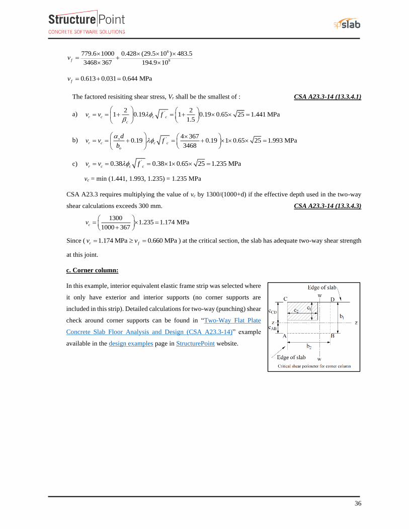
c. Corner column:
In this example, interior equivalent elastic frame strip was selected where
it only have exterior and interior supports (no corner supports are
included in this strip). Detailed calculations for two-way (punching) shear
check around corner supports can be found in “Two-Way Flat Plate
Concrete Slab Floor Analysis and Design (CSA A23.3-14)” example
available in the design examples page in StructurePoint website.
37
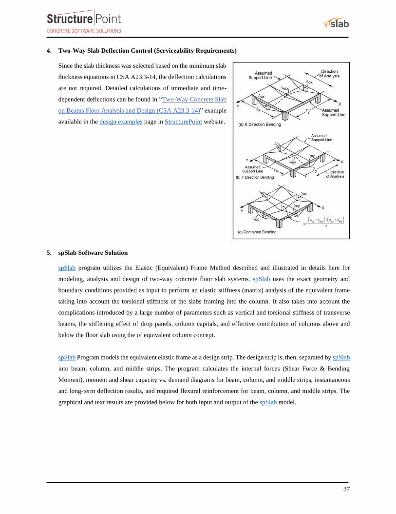
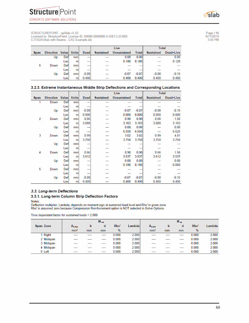
4. Two-Way Slab Deflection Control (Serviceability Requirements)
Since the slab thickness was selected based on the minimum slab
thickness equations in CSA A23.3-14, the deflection calculations
are not required. Detailed calculations of immediate and time-
dependent deflections can be found in “Two-Way Concrete Slab
on Beams Floor Analysis and Design (CSA A23.3-14)” example
available in the design examples page in StructurePoint website.
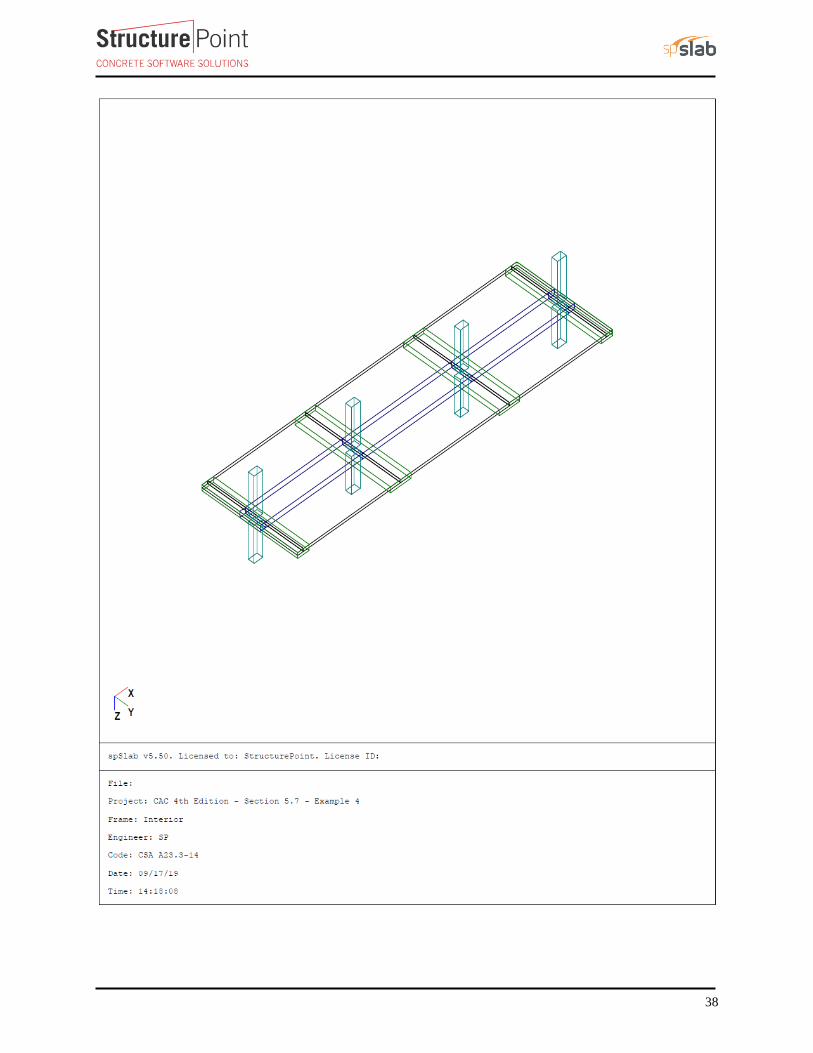
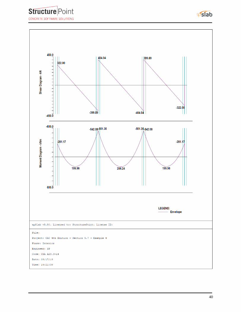
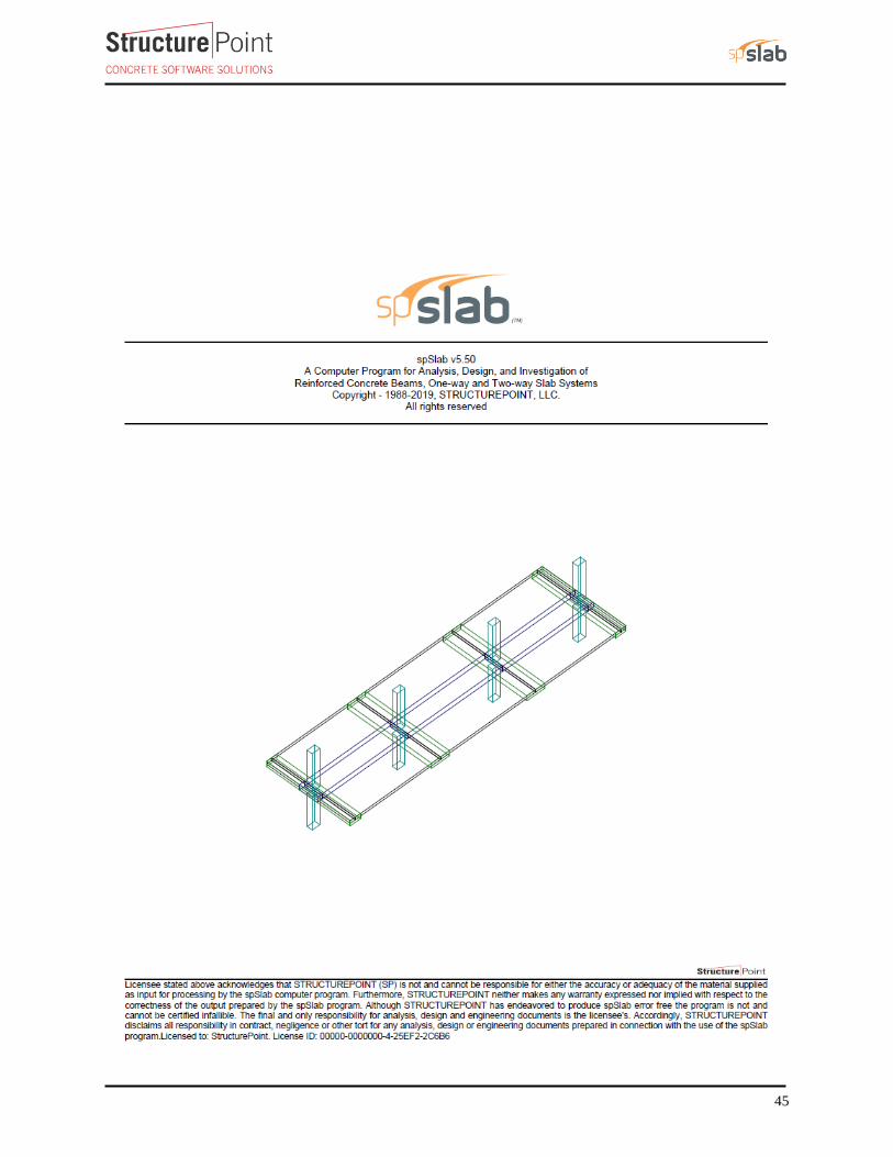
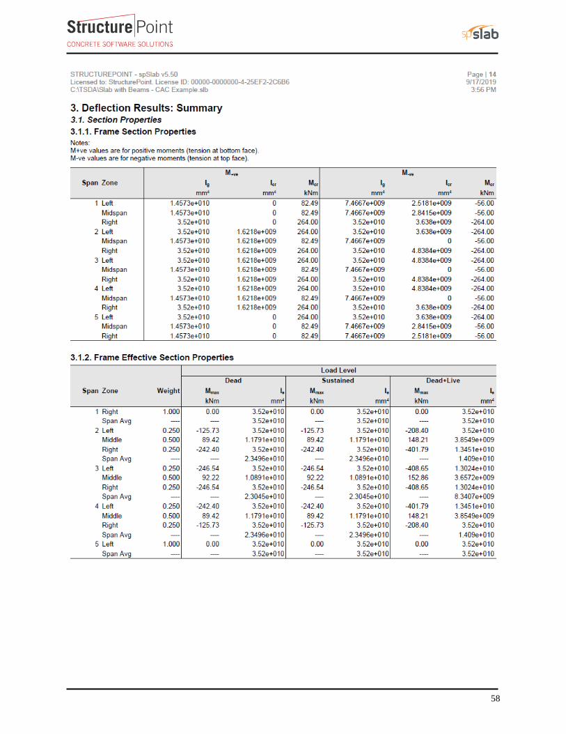
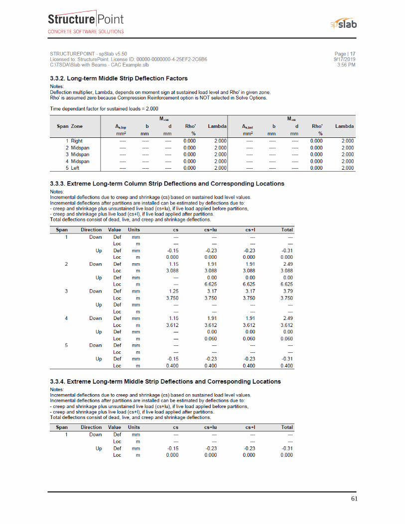
5. spSlab Software Solution
spSlab program utilizes the Elastic (Equivalent) Frame Method described and illustrated in details here for
modeling, analysis and design of two-way concrete floor slab systems. spSlab uses the exact geometry and
boundary conditions provided as input to perform an elastic stiffness (matrix) analysis of the equivalent frame
taking into account the torsional stiffness of the slabs framing into the column. It also takes into account the
complications introduced by a large number of parameters such as vertical and torsional stiffness of transverse
beams, the stiffening effect of drop panels, column capitals, and effective contribution of columns above and
below the floor slab using the of equivalent column concept.
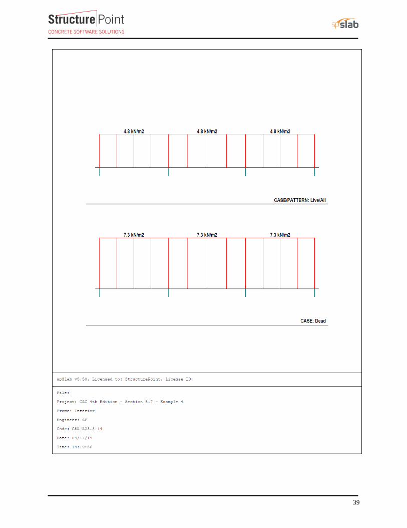
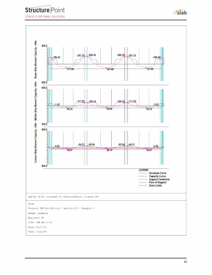
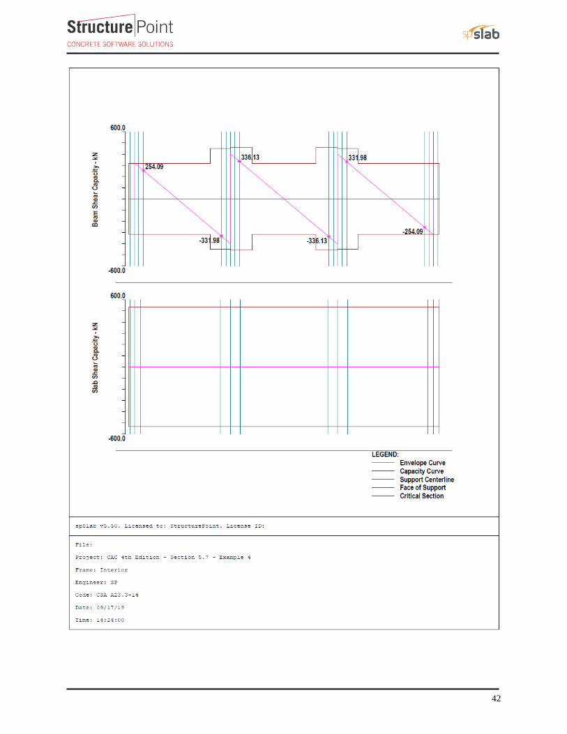
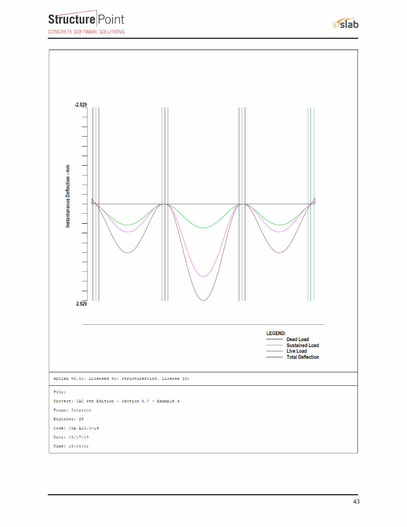
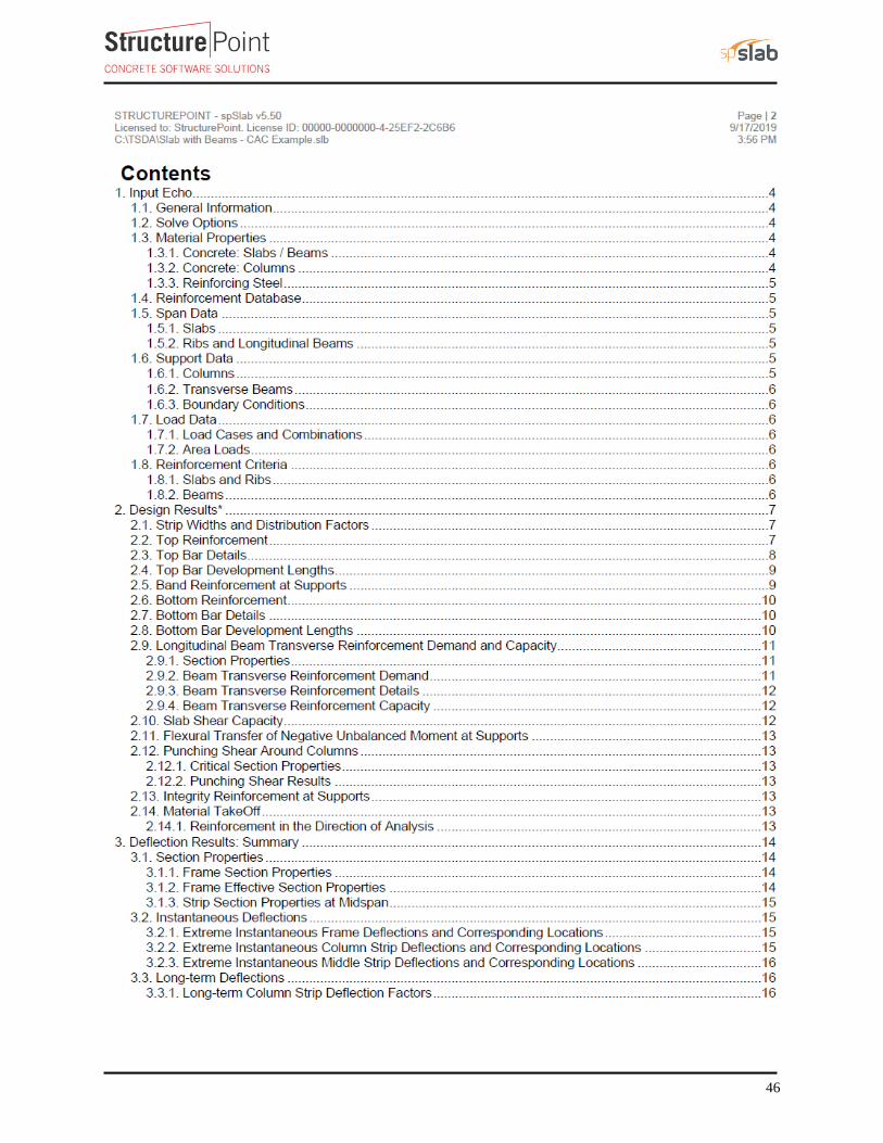
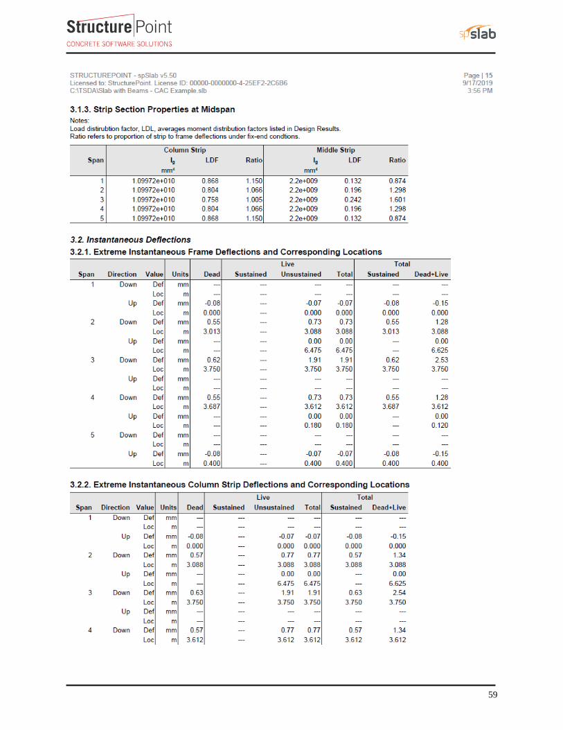
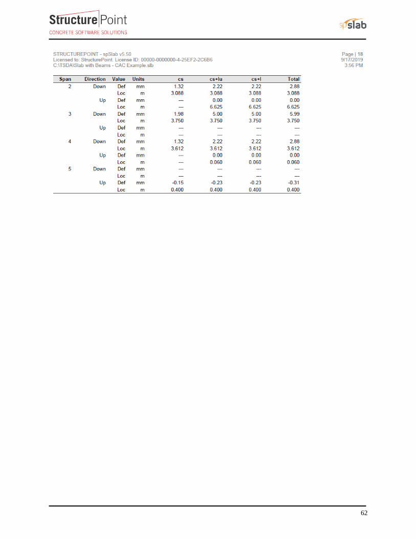
spSlab Program models the equivalent elastic frame as a design strip. The design strip is, then, separated by spSlab
into beam, column, and middle strips. The program calculates the internal forces (Shear Force & Bending
Moment), moment and shear capacity vs. demand diagrams for beam, column, and middle strips, instantaneous
and long-term deflection results, and required flexural reinforcement for beam, column, and middle strips. The
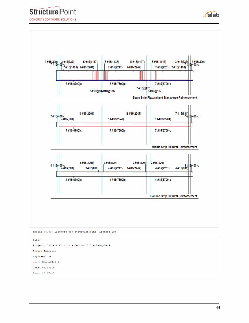
graphical and text results are provided below for both input and output of the spSlab model.
38
39
40
41
42
43
44
45
46
47
48
49
50
51
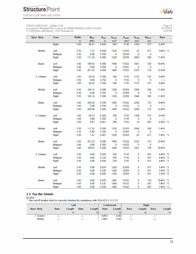
52
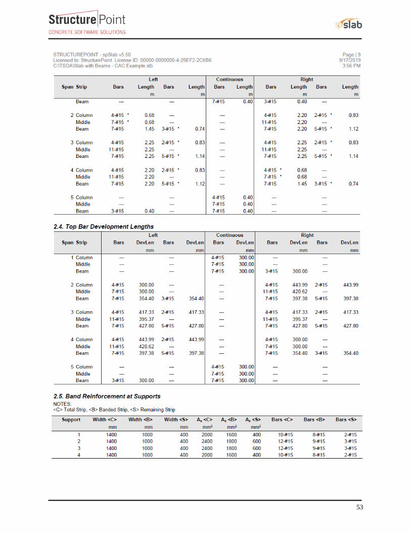
53
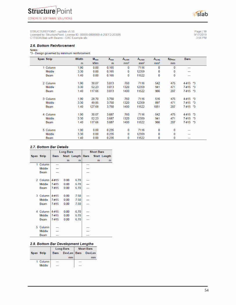
54
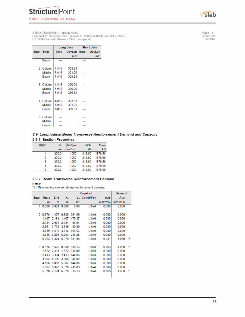
55
56
57
58
59
60
61
62
63
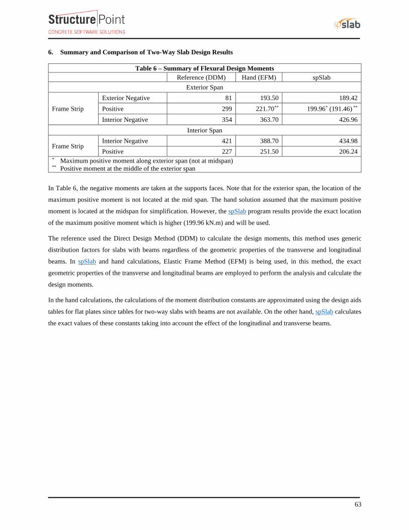
6. Summary and Comparison of Two-Way Slab Design Results
Table 6 – Summary of Flexural Design Moments
Reference (DDM) Hand (EFM) spSlab
Exterior Span
Frame Strip
Exterior Negative 81 193.50 189.42
Positive 299 221.70** 199.96* (191.46) **
Interior Negative 354 363.70 426.96
Interior Span
Frame Strip Interior Negative 421 388.70 434.98
Positive 227 251.50 206.24 * Maximum positive moment along exterior span (not at midspan) ** Positive moment at the middle of the exterior span
In Table 6, the negative moments are taken at the supports faces. Note that for the exterior span, the location of the
maximum positive moment is not located at the mid span. The hand solution assumed that the maximum positive
moment is located at the midspan for simplification. However, the spSlab program results provide the exact location
of the maximum positive moment which is higher (199.96 kN.m) and will be used.
The reference used the Direct Design Method (DDM) to calculate the design moments, this method uses generic
distribution factors for slabs with beams regardless of the geometric properties of the transverse and longitudinal
beams. In spSlab and hand calculations, Elastic Frame Method (EFM) is being used, in this method, the exact
geometric properties of the transverse and longitudinal beams are employed to perform the analysis and calculate the
design moments.
In the hand calculations, the calculations of the moment distribution constants are approximated using the design aids
tables for flat plates since tables for two-way slabs with beams are not available. On the other hand, spSlab calculates
the exact values of these constants taking into account the effect of the longitudinal and transverse beams.
64
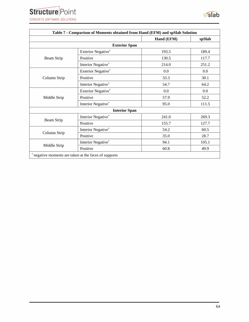
Table 7 - Comparison of Moments obtained from Hand (EFM) and spSlab Solution
Hand (EFM) spSlab
Exterior Span
Beam Strip
Exterior Negative* 193.5 189.4
Positive 130.5 117.7
Interior Negative* 214.0 251.2
Column Strip
Exterior Negative* 0.0 0.0
Positive 33.3 30.1
Interior Negative* 54.7 64.2
Middle Strip
Exterior Negative* 0.0 0.0
Positive 57.9 52.2
Interior Negative* 95.0 111.5
Interior Span
Beam Strip Interior Negative* 241.0 269.3
Positive 155.7 127.7
Column Strip Interior Negative* 54.2 60.5
Positive 35.0 28.7
Middle Strip Interior Negative* 94.1 105.1
Positive 60.8 49.9
* negative moments are taken at the faces of supports
65
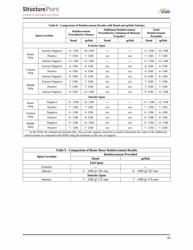
Table 8 - Comparison of Reinforcement Results with Hand and spSlab Solution
Span Location
Reinforcement
Provided for Flexure
Additional Reinforcement
Provided for Unbalanced Moment
Transfer*
Total
Reinforcement
Provided
Hand spSlab Hand spSlab Hand spSlab
Exterior Span
Beam
Strip
Exterior Negative 11- 15M 10- 15M --- --- 11- 15M 10- 15M
Positive 7- 15M 7- 15M n/a n/a 7- 15M 7- 15M
Interior Negative 11- 15M 12- 15M --- --- 11- 15M 12- 15M
Column
Strip
Exterior Negative 4- 15M 4- 15M n/a n/a 4- 15M 4- 15M
Positive 4- 15M 4- 15M n/a n/a 4- 15M 4- 15M
Interior Negative 6- 15M 6- 15M n/a n/a 6- 15M 6- 15M
Middle
Strip
Exterior Negative 7- 15M 7- 15M n/a n/a 7- 15M 7- 15M
Positive 7- 15M 7- 15M n/a n/a 7- 15M 7- 15M
Interior Negative 9- 15M 11- 15M n/a n/a 9- 15M 11- 15M
Interior Span
Beam
Strip
Negative 11 - 15M 12- 15M --- --- 11 - 15M 12- 15M
Positive 7 - 15M 7- 15M n/a n/a 7 - 15M 7- 15M
Column
Strip
Negative 6 - 15M 6- 15M n/a n/a 6 - 15M 6- 15M
Positive 4 - 15M 4- 15M n/a n/a 4 - 15M 4- 15M
Middle
Strip
Negative 9 - 15M 11- 15M n/a n/a 9 - 15M 11- 15M
Positive 7 - 15M 7- 15M n/a n/a 7 - 15M 7- 15M
* In the EFM, the unbalanced moment (Msc, Munb) at the support centerline is used to determine the value of the additional
reinforcement as compared with DDM using the moments at the face of support.
Table 9 - Comparison of Beam Shear Reinforcement Results
Span Location Reinforcement Provided
Hand spSlab
End Span
Exterior --- ---
Interior 5 – 10M @ 185 mm 6 – 10M @ 187 mm
Interior Span
Interior 7 – 10M @ 175 mm 7 – 10M @ 176 mm
66
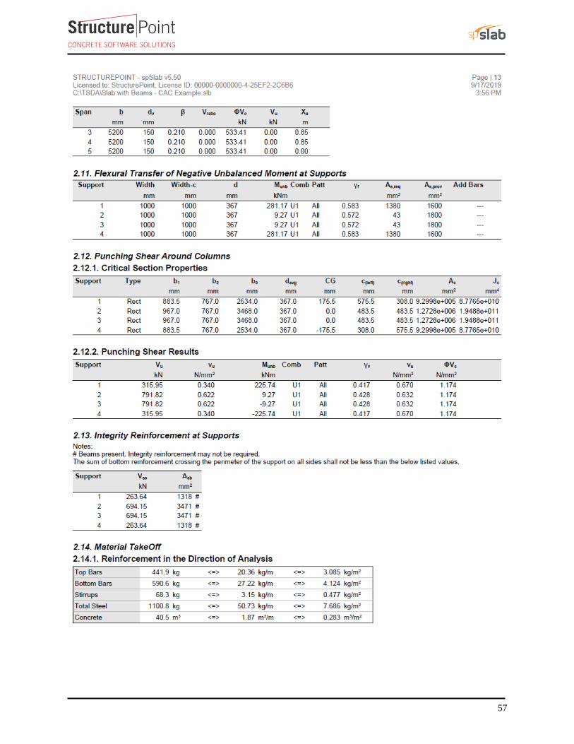
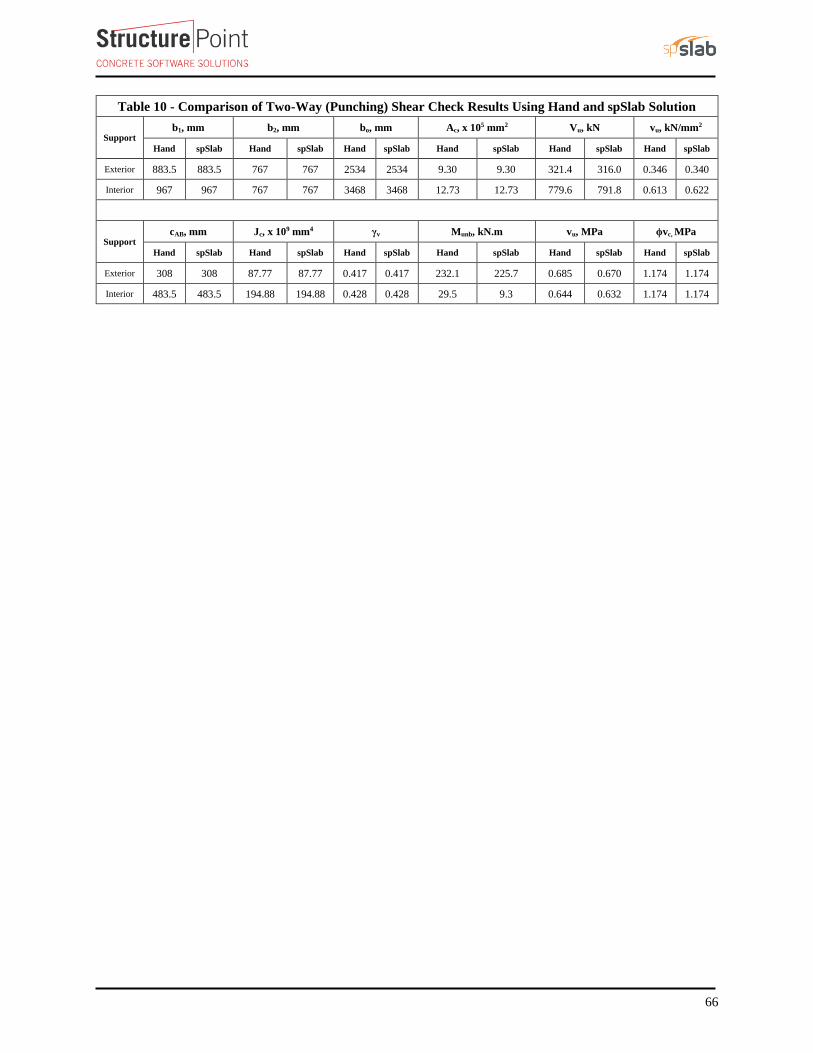
Table 10 - Comparison of Two-Way (Punching) Shear Check Results Using Hand and spSlab Solution
Support b1, mm b2, mm bo, mm Ac, x 105 mm2 Vu, kN vu, kN/mm2
Hand spSlab Hand spSlab Hand spSlab Hand spSlab Hand spSlab Hand spSlab
Exterior 883.5 883.5 767 767 2534 2534 9.30 9.30 321.4 316.0 0.346 0.340
Interior 967 967 767 767 3468 3468 12.73 12.73 779.6 791.8 0.613 0.622
Support cAB, mm Jc, x 109 mm4 γv Munb, kN.m vu, MPa ϕvc, MPa
Hand spSlab Hand spSlab Hand spSlab Hand spSlab Hand spSlab Hand spSlab
Exterior 308 308 87.77 87.77 0.417 0.417 232.1 225.7 0.685 0.670 1.174 1.174
Interior 483.5 483.5 194.88 194.88 0.428 0.428 29.5 9.3 0.644 0.632 1.174 1.174
67
7. Comparison of Two-Way Slab Analysis and Design Methods
A slab system can be analyzed and designed by any procedure satisfying equilibrium and geometric compatibility.
Three established methods are widely used. The requirements for two of them are described in detail in CSA
A23.3-14 Clasues (13.8 and 13.9) for regular two-way slab systems. CSA A23.3-14 (13.5.1)
Direct Design Method (DDM) is an approximate method and is applicable to flat plate concrete floor systems that
meet the stringent requirements of CSA A23.3-14 (13.9.1). In many projects, however, these requirements limit
the usability of the Direct Design Method significantly.
The Elastic Frame Method (EFM) has less stringent limitations compared to DDM. It requires more accurate
analysis methods that, depending on the size and geometry can prove to be long, tedious, and time-consuming.
StucturePoint’s spSlab software program solution utilizes the EFM to automate the process providing
considerable time-savings in the analysis and design of two-way slab systems as compared to hand solutions using
DDM or EFM.
Finite Element Method (FEM) is another method for analyzing reinforced concrete slabs, particularly useful for
irregular slab systems with variable thicknesses, openings, and other features not permissible in DDM or EFM.
Many reputable commercial FEM analysis software packages are available on the market today such as spMats.
Using FEM requires critical understanding of the relationship between the actual behavior of the structure and
the numerical simulation since this method is an approximate numerical method. The method is based on several
assumptions and the operator has a great deal of decisions to make while setting up the model and applying loads
and boundary conditions. The results obtained from FEM models should be verified to confirm their suitability
for design and detailing of concrete structures.
The following table shows a general comparison between the DDM, EFM and FEM. This table covers general
limitations, drawbacks, advantages, and cost-time efficiency of each method where it helps the engineer in
deciding which method to use based on the project complexity, schedule, and budget.
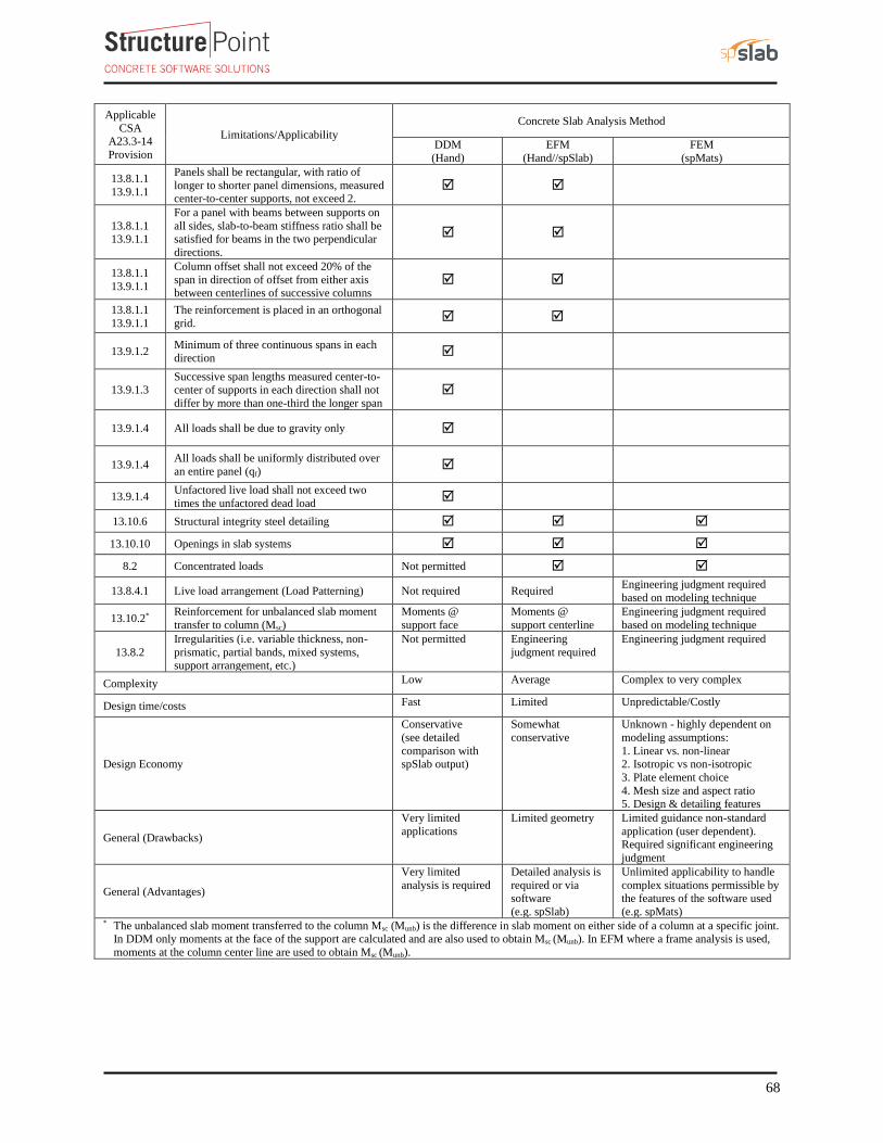
68
Applicable
CSA A23.3-14
Provision
Limitations/Applicability
Concrete Slab Analysis Method
DDM
(Hand)
EFM
(Hand//spSlab)
FEM
(spMats)
13.8.1.1
13.9.1.1
Panels shall be rectangular, with ratio of
longer to shorter panel dimensions, measured center-to-center supports, not exceed 2.
13.8.1.1 13.9.1.1
For a panel with beams between supports on
all sides, slab-to-beam stiffness ratio shall be satisfied for beams in the two perpendicular
directions.
13.8.1.1
13.9.1.1
Column offset shall not exceed 20% of the
span in direction of offset from either axis between centerlines of successive columns
13.8.1.1
13.9.1.1
The reinforcement is placed in an orthogonal
grid.
13.9.1.2 Minimum of three continuous spans in each
direction
13.9.1.3 Successive span lengths measured center-to-center of supports in each direction shall not
differ by more than one-third the longer span
13.9.1.4 All loads shall be due to gravity only
13.9.1.4 All loads shall be uniformly distributed over
an entire panel (qf)
13.9.1.4 Unfactored live load shall not exceed two
times the unfactored dead load
13.10.6 Structural integrity steel detailing
13.10.10 Openings in slab systems
8.2 Concentrated loads Not permitted
13.8.4.1 Live load arrangement (Load Patterning) Not required Required Engineering judgment required
based on modeling technique
13.10.2* Reinforcement for unbalanced slab moment
transfer to column (Msc)
Moments @
support face
Moments @
support centerline
Engineering judgment required
based on modeling technique
13.8.2
Irregularities (i.e. variable thickness, non-
prismatic, partial bands, mixed systems, support arrangement, etc.)
Not permitted Engineering
judgment required
Engineering judgment required
Complexity Low Average Complex to very complex
Design time/costs Fast Limited Unpredictable/Costly
Design Economy
Conservative
(see detailed
comparison with spSlab output)
Somewhat
conservative
Unknown - highly dependent on
modeling assumptions:
1. Linear vs. non-linear 2. Isotropic vs non-isotropic
3. Plate element choice
4. Mesh size and aspect ratio 5. Design & detailing features
General (Drawbacks)
Very limited
applications
Limited geometry Limited guidance non-standard
application (user dependent). Required significant engineering
judgment
General (Advantages)
Very limited
analysis is required
Detailed analysis is
required or via software
(e.g. spSlab)
Unlimited applicability to handle
complex situations permissible by the features of the software used
(e.g. spMats) * The unbalanced slab moment transferred to the column Msc (Munb) is the difference in slab moment on either side of a column at a specific joint.
In DDM only moments at the face of the support are calculated and are also used to obtain Msc (Munb). In EFM where a frame analysis is used,
moments at the column center line are used to obtain Msc (Munb).