Embed Size (px)
Citation preview

Copyright: Quasar Management Services Pty Ltd
Concrete Slab-on-Ground
This training package provides information
on concrete slab-on-ground construction,
including reinforcement, formwork, mix,
placement and curing, for village
infrastructure and houses common in South-
East Asia and the South Pacific region.
House superstructures may be either:
• single-leaf reinforced concrete masonry or
• clad timber or steel frames.

Copyright: Quasar Management Services Pty Ltd
Typical Single Storey Reinforced Concrete Masonry House - Floor Plan
1 6 9000
A
C
E
G
7500
2773
2810 190 75 2850 75 2810 190
4500
1200 748 862 1200 862 748 1200 825 825
190 75 190 1200 748 862 1200 862 748 1200 900 75 750
2773
1500
190
75
190
900
900
Timber stairs
13 rises at 170 = 2210
12 goings at 280 = 3360
W1 W1 W1
W1 W1 W1 D1
D2
D2 D2
D2
Internal walls,
75 Kwila stud frame
4 mm hardboard
lining
External walls,
190 mm reinforced
concrete masonry
20 tongue and
groove Kwila floor

Copyright: Quasar Management Services Pty Ltd
Typical Single Storey Reinforced Concrete Masonry House - Elevations
G A
A G
1 6
W1 D1
W1 W1
6 1
W1 W1 W1

Copyright: Quasar Management Services Pty Ltd 4500
1500
1 6 9000
A
C
E
G
7500
3000
3000
4500
Typical Single Storey Reinforced Concrete Masonry House
Concrete Slab-on-ground and Ground Beams
Use 400 mm diameter bored piers if
there is soft soil
50 mm sand bed under slab, but not
under beams
0.2 mm PVC membrane under slab
and beams
All concrete, N20 (20 MPa), vibrated
and cured by coverinng with wet sand
(or equivalent) for seven days
3 N12 bars 2,000 long
Beams as shown anround perimeter
and across centre of slab. 3-L11TM
trench mesh in bottom of each beam.
SL72 mesh in top half of slab,
Minimum cover 20 mm
Copyright: Quasar Management Services Pty Ltd
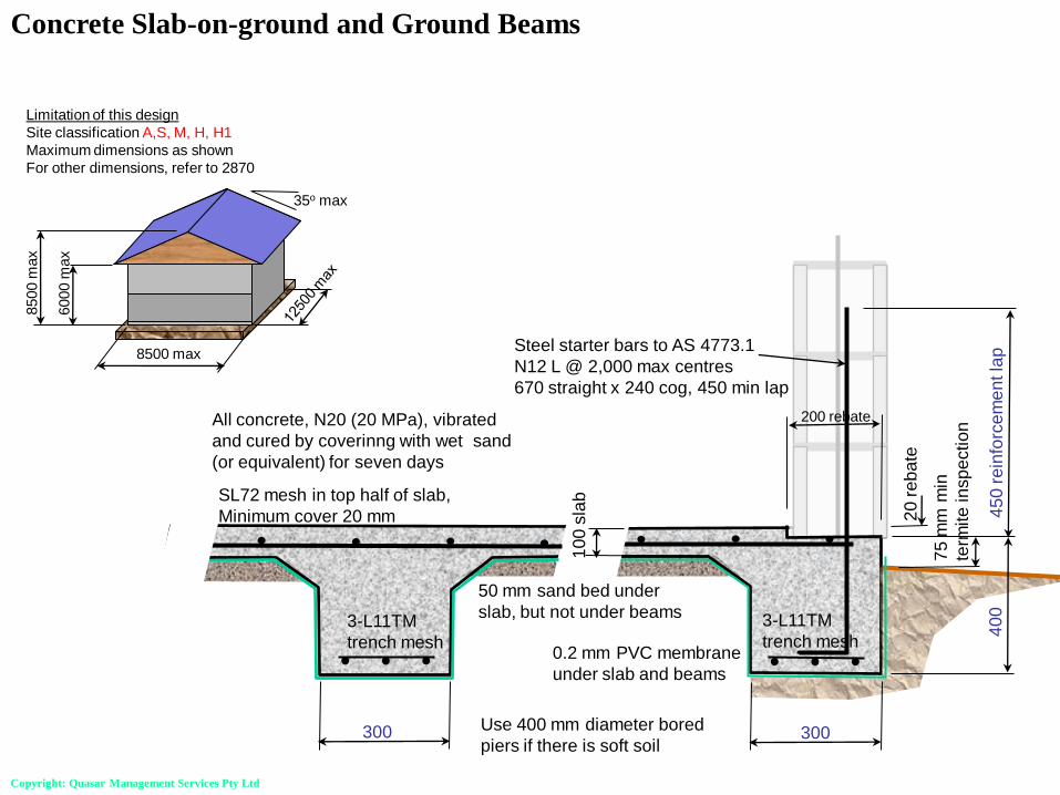
Concrete Slab-on-ground and Ground Beams
6000 m
ax
8500 m
ax
8500 max
35o max
Limitation of this design
Site classification A,S, M, H, H1
Maximum dimensions as shown
For other dimensions, refer to 2870
Use 400 mm diameter bored
piers if there is soft soil
75
mm
min
term
ite
in
sp
ectio
n
Steel starter bars to AS 4773.1
N12 L @ 2,000 max centres
670 straight x 240 cog, 450 min lap
300 300
40
0
20
re
ba
te
200 rebate
45
0 r
ein
forc
em
en
t la
p
10
0 s
lab
SL72 mesh in top half of slab,
Minimum cover 20 mm
3-L11TM
trench mesh
3-L11TM
trench mesh
50 mm sand bed under
slab, but not under beams
0.2 mm PVC membrane
under slab and beams
All concrete, N20 (20 MPa), vibrated
and cured by coverinng with wet sand
(or equivalent) for seven days

Copyright: Quasar Management Services Pty Ltd
Concrete Slab-on-ground and Ground Beams – Bored Piers

Copyright: Quasar Management Services Pty Ltd
Concrete Slab-on-ground and Ground Beams - Corner Reinforcement
Reentrant Corners
3-N12 bars 2,000 long
1 strip 3-L11TM trench mesh 2,000 long

Copyright: Quasar Management Services Pty Ltd
Concrete Slab-on-ground and Ground Beams – Reinforcement Laps

Copyright: Quasar Management Services Pty Ltd
Concrete Slab-on-ground and Ground Beams – Stepped Beams

Copyright: Quasar Management Services Pty Ltd
Concrete Slab-on-ground and Ground Beams – Pipes & Penetrations

Copyright: Quasar Management Services Pty Ltd
Concrete Slab-on-ground and Ground Beams – Recess Details

Copyright: Quasar Management Services Pty Ltd
Termite Management
Termites must be prevented from entering the building. Barriers force the termites to the surface, where
they can be detected and destroyed.
Termite collars prevent
termites from entering
beside drainage pipes.
Termite barriers and membranes
prevent termites from entering at the
junction between walls and slabs.
An exposed concrete edge
ensures the termites are visible
Copyright: Quasar Management Services Pty Ltd
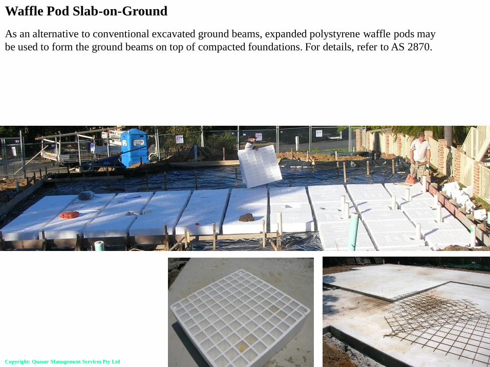
Waffle Pod Slab-on-Ground
As an alternative to conventional excavated ground beams, expanded polystyrene waffle pods may
be used to form the ground beams on top of compacted foundations. For details, refer to AS 2870.
Copyright: Quasar Management Services Pty Ltd
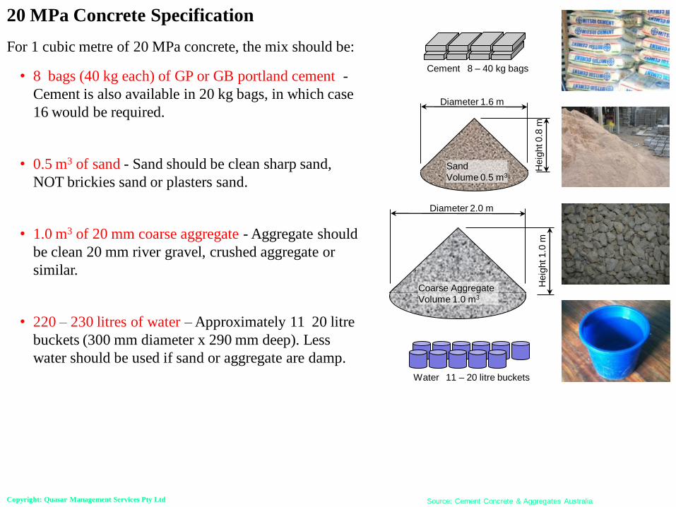
20 MPa Concrete Specification
For 1 cubic metre of 20 MPa concrete, the mix should be:
• 8 bags (40 kg each) of GP or GB portland cement -
Cement is also available in 20 kg bags, in which case
16 would be required.
• 0.5 m3 of sand - Sand should be clean sharp sand,
NOT brickies sand or plasters sand.
• 1.0 m3 of 20 mm coarse aggregate - Aggregate should
be clean 20 mm river gravel, crushed aggregate or
similar.
• 220 – 230 litres of water – Approximately 11 20 litre
buckets (300 mm diameter x 290 mm deep). Less
water should be used if sand or aggregate are damp.
Diameter 1.6 m
Heig
ht 0.8
m
Sand
Volume 0.5 m3
Diameter 2.0 m
Heig
ht 1.0
m
Coarse Aggregate
Volume 1.0 m3
Source: Cement Concrete & Aggregates Australia
Cement 8 – 40 kg bags
Water 11 – 20 litre buckets
Copyright: Quasar Management Services Pty Ltd
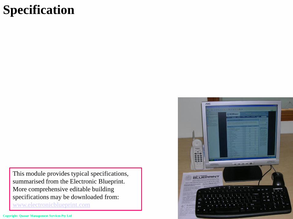
This module provides typical specifications,
summarised from the Electronic Blueprint.
More comprehensive editable building
specifications may be downloaded from:
www.electronicblueprint.com
Specification

Copyright: Quasar Management Services Pty Ltd
Scope
This specification covers the construction of the following concrete members for residential
applications:
• Concrete footings
• Concrete ground beams
• Concrete slab-on-ground
• Concrete piers.
Specification
Relevant Standards
• AS 3600 Concrete Structures
• AS 3610 Formwork for concrete
• AS 3660.1 Termite management – New Building work
• AS 1379 Specification and supply of concrete
• AS 1478.2 Chemical admixtures for concrete, mortar and grout
• AS 2870 Residential slabs and footings - Construction
• AS 3799 Liquid membrane-forming curing compounds for concrete
• AS 4200.1 Pliable building membranes and underlays - Materials
• AS/NZS 4671 Steel reinforcing materials
• AS 2159 Rules for the design and installation of piling (SAA Piling Code)
Copyright: Quasar Management Services Pty Ltd
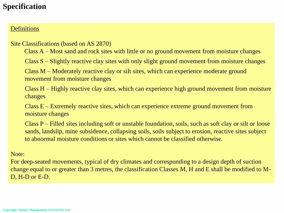
Definitions
Site Classifications (based on AS 2870)
Class A – Most sand and rock sites with little or no ground movement from moisture changes
Class S – Slightly reactive clay sites with only slight ground movement from moisture changes
Class M – Moderately reactive clay or silt sites, which can experience moderate ground
movement from moisture changes
Class H – Highly reactive clay sites, which can experience high ground movement from moisture
changes
Class E – Extremely reactive sites, which can experience extreme ground movement from
moisture changes
Class P – Filled sites including soft or unstable foundation, soils, such as soft clay or silt or loose
sands, landslip, mine subsidence, collapsing soils, soils subject to erosion, reactive sites subject
to abnormal moisture conditions or sites which cannot be classified otherwise.
Note:
For deep-seated movements, typical of dry climates and corresponding to a design depth of suction
change equal to or greater than 3 metres, the classification Classes M, H and E shall be modified to M-
D, H-D or E-D.
Specification

Copyright: Quasar Management Services Pty Ltd
Sand Bedding
A bedding sand layer 50 to 100 mm in thickness shall be placed over the compacted soil base to the
level of the underside of the slab.
Sand bedding shall comply with the relevant Standard (AS 2758.1).
Sand shall be clean, free from salts, vegetable matter and impurities, and with the following grading:
Sieve Percent Passing
4.75 mm 90 to 100
2.36 mm 60 to 100
1.18 mm 30 to 85
0.600 mm 15 to 60
0.300 mm 5 to 30
0.150 mm 0 to 15
0.075 mm 0 to 10
Specification

Copyright: Quasar Management Services Pty Ltd
Vapour Barrier
Vapour barriers shall be placed over the bedding sand layer.
Adhesive tape shall be fixed around pipe penetrations.
Vapour barriers shall comply with AS 4200. Vapour barriers shall be not less than medium impact
resistance polyethylene vapour barrier 0.2 mm thick. In areas of known salt damp, a damp-proofing
membrane with high impact resistance is required. Adhesive tape shall be PVC for normal
applications, or polyethylene tape for fixing to higher strength or thicker membranes.
Specification
Reinforcement for Concrete Slab on Ground and Footings
Reinforcement shall be placed in accordance with the drawings such that the following laps and cover
are achieved. Three N12 corner bars 2.0 metre long shall be placed at all re-entrant corners.
Reinforcement Minimum Required Laps
Bars 500 mm
Fabric 2 cross wires overlapping
Trench mesh 500 mm
Reinforcement shall comply with AS 4671, AS 2870. Unless stated otherwise, properties shall be not
less than:
• Deformed bars - 500 MPa, normal ductility (N)
• Square fabric, rectangular fabric and trench mesh - 500 MPa, low (L) or normal (N) ductility
ribbed wires
• Fitments -500 MPa, low (L) or normal (N) ductility ribbed wires

Copyright: Quasar Management Services Pty Ltd
Bar Chairs
Bar chairs shall be placed at one metre centres both ways. Bar chairs shall incorporate wide bases and
be placed on metal bases that do not puncture the vapour barrier.
Where fabric with 7 mm bars at 200 mm centres (SL72), or lighter, is used, the bar chair spacing shall
be reduced to 800 mm.
Bar chairs shall be placed to give the following clear cover.
• 40 mm in concrete in contact with unprotected ground
• 40 mm in concrete exposed externally
• 30 mm to a sealed vapour barrier
• 20 mm to the internal surface
Specification
Concrete for slab on ground and footings
Concrete shall comply with AS 2870. Unless stated otherwise, properties shall be not less than:
• Characteristic compressive strength of 20 MPa (Strength grade N20)
• Maximum aggregate size of 20 mm
• Of sufficient slump to facilitate the nominates means of placement
• Subject to plant control testing.

Copyright: Quasar Management Services Pty Ltd
Placing Concrete
Trenches and footing excavations shall be dewatered and cleaned prior to concrete placement so that
no softened or loosened material remains. All concrete shall be compacted by mechanical immersion
vibrator.
Reinforcement Cover - The lapping of welded fabric reinforcement in the top face of a slab will
significantly increase the thickness of reinforcement and reduce the cover. The slab thickness shall be
such as to provide both sufficient cover and sufficient effective depth.
Finishing Concrete
Concrete surfaces shall be finished as noted below unless specified otherwise.
• Floor slabs - Steel float.
• External paths, driveways and parking areas at less than 10% slope - Fine broomed steel float.
• External paths, driveways and parking areas at greater than 10% slope - Coarse broomed steel
float.
• Vertical surfaces exposed in the completed building - Rubbed back to fill all voids and provide
smooth surface.
• Vertical surfaces not exposed in the completed building - Off form finish.
Specification

Copyright: Quasar Management Services Pty Ltd
Recesses in Concrete Slabs
In order to achieve falls in tiled floors in bathrooms and the like, recess the concrete slabs to avoid a
lip at the tiled edge. This recess may be formed after the concrete has been screeded level. The corner
position of recesses may be marked by fixing temporary vertical reinforcing bars to the fabric. Such
bars should not puncture the membrane.
For large tiled areas, the slab should provide for uniform falls to wastes and associated pipework. If
there is likely to be difficulty in achieving such uniform falls, it allow for a 40 to 50 mm screed laid
subsequently by the tiler. The thickness of the screed (if required), tile bedding and tiles should be
shown on the structural concrete details, to ensure that the finished levels are appropriate.
Curing Concrete
All concrete shall be cured using a sprayed curing compound or by covering with sand that is kept we
for at least seven days.
Wax-based compounds shall not be used in areas requiring the subsequent application of curing
adhesives.
Specification

Copyright: Quasar Management Services Pty Ltd
Formwork
Formwork shall comply with the relevant Standard (AS 3610).
Stripping Formwork
Unless adverse weather or the use of retarders delays the hardening of concrete, the minimum
stripping time for formwork shall be 3 days.
Maintenance
The building owner is responsible for the building and site maintenance as detailed in the CSIRO
Pamphlet 10-19 Guide to Home Owners on Foundation Maintenance and Footing Performance.
Specification

Copyright: Quasar Management Services Pty Ltd
Disclaimer & Copyright
Disclaimer
This training package covers broad engineering principles and building practices, with particular
emphasis on affordable housing and associated village infrastructure in the Asia-Pacific region. These
broad principles and practices must be translated into specific requirements for particular projects by
professional architects, engineers or builders with the requisite qualifications and experience.
Associated sample specifications and drawings are available in electronic format, with the express
intention that architects, engineers and builders will edit them to suit the particular requirements of
specific projects. The design, construction and costing of structures must be carried out by qualified
and experienced architects, engineers and builders, who must make themselves aware of any changes
to the applicable standards, building regulations and other relevant regulations. The authors,
publishers and distributors of these documents, specifications and associated drawings do not accept
any responsibility for incorrect, inappropriate or incomplete use of this information.
Copyright
© Quasar Management Services Pty Ltd
All rights are reserved. Permission is given for individuals to use this material in the preparation of
designs, specification and contracts for individual projects. Permission is also given for not-for-profit
Nongovernmental Organizations to use this material in the preparation of Building Skills Training
Programs and for the design, specification and construction of affordable housing and associated
infrastructure in the Asia-Pacific region. Use of this material for any other commercial purposes
prohibited without the written permission of the copyright owner.