Embed Size (px)
Citation preview

Version: Apr-05-2017
Two-Way Concrete Floor Slab with Beams Design and Detailing

Version: Apr-05-2017
Two-Way Concrete Floor Slab with Beams Design and Detailing
Design the slab system shown in Figure 1 for an intermediate floor where the story height = 12 ft, column cross-
sectional dimensions = 18 in. x 18 in., edge beam dimensions = 14 in. x 27 in., interior beam dimensions = 14 in. x 20
in., and unfactored live load = 100 psf. The lateral loads are resisted by shear walls. Normal weight concrete with
ultimate strength (fc’= 4000 psi) is used for all members, respectively. And reinforcement with Fy = 60,000 psi is
used. Use the Equivalent Frame Method (EFM) and compare the results with spSlab model results.
Figure 1 – Two-Way Slab with Beams Spanning between all Supports

Version: Apr-05-2017
Contents
1. Preliminary Slab Thickness Sizing ........................................................................................................................... 1
2. Two-Way Slab Analysis and Design – Using Equivalent Frame Method (EFM) .................................................... 4
2.1. Equivalent frame method limitations ................................................................................................................ 5
2.2. Frame members of equivalent frame ................................................................................................................. 5
2.3. Equivalent frame analysis ............................................................................................................................... 11
2.4. Design moments .............................................................................................................................................. 14
2.5. Distribution of design moments ...................................................................................................................... 15
2.6. Flexural reinforcement requirements .............................................................................................................. 17
2.7. Column design moments ................................................................................................................................. 24
3. Design of Interior, Edge, and Corner Columns ...................................................................................................... 25
4. Two-Way Slab Shear Strength ............................................................................................................................... 25
4.1. One-Way (Beam action) Shear Strength ......................................................................................................... 25
4.2. Two-Way (Punching) Shear Strength ............................................................................................................. 26
5. Two-Way Slab Deflection Control (Serviceability Requirements) ........................................................................ 29
5.1. Immediate (Instantaneous) Deflections ........................................................................................................... 29
5.2. Time-Dependent (Long-Term) Deflections (Δlt) ............................................................................................. 40
6. spSlab Software Program Model Solution ............................................................................................................. 41
7. Summary and Comparison of Design Results ........................................................................................................ 63
8. Conclusions & Observations .................................................................................................................................. 66

1
Code
Building Code Requirements for Structural Concrete (ACI 318-14) and Commentary (ACI 318R-14)
Minimum Design Loads for Buildings and Other Structures (ASCE/SEI 7-10)
International Code Council, 2012 International Building Code, Washington, D.C., 2012
References
Notes on ACI 318-11 Building Code Requirements for Structural Concrete, Twelfth Edition, 2013 Portland
Cement Association.
Concrete Floor Systems (Guide to Estimating and Economizing), Second Edition, 2002 David A. Fanella
Simplified Design of Reinforced Concrete Buildings, Fourth Edition, 2011 Mahmoud E. Kamara and Lawrence
C. Novak
Design Data
Floor-to-Floor Height = 12 ft (provided by architectural drawings)
Columns = 18 x 18 in.
Interior beams = 14 x 20 in.
Edge beams = 14 x 27 in.
wc = 150 pcf
fc’ = 4,000 psi
fy = 60,000 psi
Live load, Lo = 100 psf (Office building) ASCE/SEI 7-10 (Table 4-1)
Solution
1. Preliminary Slab Thickness Sizing
Control of deflections. ACI 318-14 (8.3.1.2)
In lieu of detailed calculation for deflections, ACI 318 Code gives minimum thickness for two-way slab with
beams spanning between supports on all sides in Table 8.3.1.2.
Beam-to-slab flexural stiffness (relative stiffness) ratio (αf) is computed as follows:
cb b b
f
cs s s
E I I
E I I ACI 318-14 (8.10.2.7b)
The moment of inertia for the effective beam and slab sections can be calculated as follows:
3 3
2 and 12 12
s b
l h baI I f
Then,

2
3
2
f
b af
l h
For Edge Beams:
The effective beam and slab sections for the computation of stiffness ratio for edge beam is shown in Figure 2.
For North-South Edge Beam:
2
22 12 18141 in.
2 2l
274.5
6
a
h
142.33
6
b
h
1.47 using Figure 3.f
3
14 271.47 13.30
141 6f
For East-West Edge Beam:
2
17.5 12 18114 in.
2 2l
274.5
6
a
h
142.33
6
b
h
1.47 using Figure 3.f
3
14 271.47 16.45
114 6f
Figure 2 – Effective Beam and Slab Sections (Edge Beam)
Figure 3 – Beam Stiffness (Edge Beam)

3
For interior Beams:
The effective beam and slab sections for the computation of stiffness ratio for interior beam is shown in Figure
4.
For North-South Interior Beam:
2 22 12 264 in.l
203.33
6
a
h
142.33
6
b
h
1.61using Figure 5.f
3
14 201.61 3.16
264 6f
For East-West Interior Beam:
2 17.5 12 210 in.l
203.33
6
a
h
142.33
6
b
h
1.61using Figure 5.f
3
14 201.61 3.98
210 6f
Since αf > 2.0 for all beams, the minimum slab thickness is given by:
min
0.8200,000
36 9
5.0
y
n
fl
h greater of
ACI 318-14 (8.3.1.2)
Where:
clear span in the long direction measured face to face of columns 20.5 ft 246 in.nl
clear span in the long direction 22 18 /121.28
clear span in the short direction 17.2 18 /12
Figure 4 – Effective Beam and Slab Sections (Interior Beam)
Figure 5 – Beam Stiffness (Interior Beam)

4
min
60,000246 0.8
200,0005.7 5.7 in.
36 9 1.28
5.0
h greater of
Use 6 in. slab thickness.
2. Two-Way Slab Analysis and Design – Using Equivalent Frame Method (EFM)
ACI 318 states that a slab system shall be designed by any procedure satisfying equilibrium and geometric
compatibility, provided that strength and serviceability criteria are satisfied. Distinction of two-systems from one-
way systems is given by ACI 318-14 (R8.10.2.3 & R8.3.1.2).
ACI 318 permits the use of Direct Design Method (DDM) and Equivalent Frame Method (EFM) for the gravity
load analysis of orthogonal frames and is applicable to flat plates, flat slabs, and slabs with beams. The following
sections outline the solution per EFM and spSlab software. The solution per DDM can be found in the “Two-Way
Plate Concrete Floor System Design” example.
EFM is the most comprehensive and detailed procedure provided by the ACI 318 for the analysis and design of
two-way slab systems where the structure is modeled by a series of equivalent frames (interior and exterior) on
column lines taken longitudinally and transversely through the building.
The equivalent frame consists of three parts:
1) Horizontal slab-beam strip, including any beams spanning in the direction of the frame. Different values
of moment of inertia along the axis of slab-beams should be taken into account where the gross moment
of inertia at any cross section outside of joints or column capitals shall be taken, and the moment of
inertia of the slab-beam at the face of the column, bracket or capital divide by the quantity (1-c2/l2)2 shall
be assumed for the calculation of the moment of inertia of slab-beams from the center of the column to
the face of the column, bracket or capital. ACI 318-14 (8.11.3)
2) Columns or other vertical supporting members, extending above and below the slab. Different values
of moment of inertia along the axis of columns should be taken into account where the moment of inertia
of columns from top and bottom of the slab-beam at a joint shall be assumed to be infinite, and the gross
cross section of the concrete is permitted to be used to determine the moment of inertia of columns at
any cross section outside of joints or column capitals. ACI 318-14 (8.11.4)
3) Elements of the structure (Torsional members) that provide moment transfer between the horizontal and
vertical members. These elements shall be assumed to have a constant cross section throughout their
length consisting of the greatest of the following: (1) portion of slab having a width equal to that of the
column, bracket, or capital in the direction of the span for which moments are being determined, (2)
portion of slab specified in (1) plus that part of the transverse beam above and below the slab for
monolithic or fully composite construction, (3) the transverse beam includes that portion of slab on each
side of the beam extending a distance equal to the projection of the beam above or below the slab,
whichever is greater, but not greater than four times the slab thickness. ACI 318-14 (8.11.5)

5
2.1. Equivalent frame method limitations
In EFM, live load shall be arranged in accordance with 6.4.3 which requires slab systems to be analyzed and
designed for the most demanding set of forces established by investigating the effects of live load placed in
various critical patterns. ACI 318-14 (8.11.1.2 & 6.4.3)
Complete analysis must include representative interior and exterior equivalent frames in both the longitudinal
and transverse directions of the floor. ACI 318-14 (8.11.2.1)
Panels shall be rectangular, with a ratio of longer to shorter panel dimensions, measured center-to-center of
supports, not to exceed 2. ACI 318-14 (8.10.2.3)
2.2. Frame members of equivalent frame
Determine moment distribution factors and fixed-end moments for the equivalent frame members. The
moment distribution procedure will be used to analyze the equivalent frame. Stiffness factors k , carry over
factors COF, and fixed-end moment factors FEM for the slab-beams and column members are determined
using the design aids tables at Appendix 20A of PCA Notes on ACI 318-11. These calculations are shown
below.
a. Flexural stiffness of slab-beams at both ends, Ksb.
1 2
1 2
18 180.0857 0.1 , 0.0682
(17.5 12) (22 12)
N Nc c
1 2For stiffness factors, 4.11F F NF FNc c k k PCA Notes on ACI 318-11 (Table A1)
1 1
Thus, 4.11c sb c sb
sb NF
E I E IK k PCA Notes on ACI 318-11 (Table A1)
Where Isb is the moment of inertia of slab-beam section
shown in Figure 6 and can be computed with the aid of
Figure 7 as follows:
3 3414 20
2.72 25387 in.12 12
w
sb t
b hI C
25,3874.11 497
17.5 12
c
sb c
EK E
Carry-over factor COF = 0.507 PCA Notes on ACI 318-11 (Table A1)
2
2 1Fixed-end moment FEM 0.0842 uw PCA Notes on ACI 318-11 (Table A1)
Figure 6 – Cross-Section of Slab-Beam

6
Figure 7 – Coefficient Ct for Gross Moment of Inertia of Flanged Sections
b. Flexural stiffness of column members at both ends, Kc.
Referring to Table A7, Appendix 20A:
For Interior Columns:
20 6 / 2 17 in. , 3 in.a bt t
12 ft 144 in., 144 17 3 124 in., 5.67, 1.16a
c
b c
t HH H
t H
, , Thus, 6.82 and 4.99 by interpolation.c top c bottomk k
4 44(18)
8,748 in.12 12
c
cI
12 144 in.ftc
c cc c
c
c
k E IK PCA Notes on ACI 318-11 (Table A7)
,
6.82 8748414
144
c
c top c
EK E
,
4.99 8748303
144
c
c bottom c
EK E
For Exterior Columns:
27 6 / 2 24 in. , 3 in.a bt t
12 ft 144 in., 144 24 3 117 in. , 8.0, 1.23a
c
b c
t HH H
t H

7
, , Thus, 8.57 and 5.31 by interpolation.c top c bottomk k
4 44(18)
8,748 in.12 12
c
cI
12 144 in.c ft
c cc c
c
c
k E IK PCA Notes on ACI 318-11 (Table A7)
,
8.57 8748521
144
c
c top c
EK E
,
5.31 8748323
144
c
c bottom c
EK E

8
c. Torsional stiffness of torsional members, Kt.
322
9
[ (1 ) ]
2
cs
t
E CK
c
ACI 318-14 (R.8.11.5)
For Interior Columns:
3
9 11,698493
264(0.932)
c
t c
EK E
Where:
2
2
181 1 0.932
22 12
c
3
(1 0.63 )( )3
x x yC
y ACI 318-14 (Eq. 8.10.5.2b)
x1 = 14 in x2 = 6 in x1 = 14 in x2 = 6 in
y1 = 14 in y2 = 42 in y1 = 20 in y2 = 14 in
C1 = 4738 C2 = 2,752 C1 = 10,226 C2 = 736
∑C = 4738 + 2,752 = 7,490 in4 ∑C = 10,226 + 736 x 2 = 11,698 in4
Figure 8 – Attached Torsional Member at Interior Column

9
For Exterior Columns:
3
9 17,868752
264(0.932)
c
t c
EK E
Where:
2
2
181 1 0.932
22 12
c
3
(1 0.63 )( )3
x x yC
y ACI 318-14 (Eq. 8.10.5.2b)
x1 = 14 in x2 = 6 in x1 = 14 in x2 = 6 in
y1 = 21 in y2 = 35 in y1 = 27 in y2 = 21 in
C1 = 11,141 C2 = 2,248 C1 = 16,628 C2 = 1,240
∑C = 11,141 + 2,248 = 13,389 in4 ∑C = 16,628 + 1,240 = 17,868 in4
Figure 9 – Attached Torsional Member at Exterior Column

10
d. Increased torsional stiffness due to parallel beams, Kta.
For Interior Columns:
493 25,3872634
4752
t sb c
ta c
s
K I EK E
I
Where:
3 342 264 6
4752 in.12 12
sb
l hI
For Exterior Columns:
752 25,3874017
4752
t sb c
ta c
s
K I EK E
I
e. Equivalent column stiffness Kec.
c ta
ec
c ta
K KK
K K
Where ∑ Kta is for two torsional members one on each side of the
column, and ∑ Kc is for the upper and lower columns at the slab-
beam joint of an intermediate floor.
For Interior Columns:
(303 414 )(2 2634 )631
(303 414 ) (2 2634 )
c c c
ec c
c c c
E E EK E
E E E
For Exterior Columns:
(323 521 )(2 4017 )764
(323 521 ) (2 4017 )
c c c
ec c
c c c
E E EK E
E E E
f. Slab-beam joint distribution factors, DF.
At exterior joint,
4970.394
(497 764 )c c
EcDFE E
Figure 10 – Slab-Beam in the Direction of Analysis
Figure 11 – Equivalent Column
Stiffness

11
At interior joint,
4970.306
(497 497 631 )
c
c c c
EDF
E E E
COF for slab-beam =0.507
2.3. Equivalent frame analysis
Determine negative and positive moments for the slab-beams using the moment distribution method.
With an unfactored live-to-dead load ratio:
100 31.33
(150 6 /12) 4
L
D
The frame will be analyzed for five loading conditions with pattern loading and partial live load as allowed
by ACI 318-14 (6.4.3.3).
a. Factored load and Fixed-End Moments (FEM’s).
Factored dead load 1.2(75 9.3) 101 psfDuq
Where (9.3 psf = (14 x 14) / 144 x 150 / 22 is the weight of beam stem per foot divided by l2)
Factored live load 1.6(100) 160 psfLuq
Factored load 261psfu Du Luq q q
2
2 1FEM's for slab-beam NF um q PCA Notes on ACI 318-11 (Table A1)
2FEM due to 0.0842 (0.261 22) 17.5 148.1ft-kipDu Luq q
23FEM due to 0.0842 (0.221 22) 17.5 125.4 ft-kip
4Du Luq q
2FEM due to 0.0842 (0.101 22) 17.5 57.3 ft-kipDuq
b. Moment distribution.
Moment distribution for the five loading conditions is shown in Table 1. Counter-clockwise rotational
moments acting on member ends are taken as positive. Positive span moments are determined from the
following equation:
( )
( )
2
uL uR
u midspan o
M MM M
Where Mo is the moment at the midspan for a simple beam.
Figure 12 – Slab and Column Stiffness
12
When the end moments are not equal, the maximum moment in the span does not occur at the midspan, but
its value is close to that midspan for this example.
Positive moment in span 1-2 for loading (1):
217.5 (93.1 167.7)(0.261 22) 89.4 ft-kip
8 2uM
Positive moment span 2-3 for loading (1):
217.5 (153.6 153.6)(0.261 22) 66.2 ft-kip
8 2uM
Table 1 – Moment Distribution for Partial Frame (Transverse Direction)
Joint 1 2 3 4
Member 1-2 2-1 2-3 3-2 3-4 4-3
DF 0.394 0.306 0.306 0.306 0.306 0.394
COF 0.507 0.507 0.507 0.507 0.507 0.507
Loading (1) All spans loaded with full factored live load
FEM 148.1 -148.1 148.1 -148.1 148.1 -148.1
Dist -58.4 0 0 0 0 58.4
CO 0 -29.6 0 0 29.6 0
Dist 0 9.1 9.1 -9.1 -9.1 0
CO 4.6 0 -4.6 4.6 0 -4.6
Dist -1.8 1.4 1.4 -1.4 -1.4 1.8
CO 0.7 -0.9 -0.7 0.7 0.9 -0.7
Dist -0.3 0.5 0.5 -0.5 -0.5 0.3
CO 0.3 -0.1 -0.3 0.3 0.1 -0.3
Dist -0.1 0.1 0.1 -0.1 -0.1 0.1
M 93.1 -167.6 153.6 -153.6 167.6 -93.1
Midspan M 89.5 66.2 89.5

13
Loading (2) First and third spans loaded with 3/4 factored live load
FEM 125.4 -125.4 57.3 -57.3 125.4 -125.4
Dist -49.4 20.8 20.8 -20.8 -20.8 49.4
CO 10.6 -25.1 -10.6 10.6 25.1 -10.6
Dist -4.2 10.9 10.9 -10.9 -10.9 4.2
CO 5.5 -2.1 -5.5 5.5 2.1 -5.5
Dist -2.2 2.3 2.3 -2.3 -2.3 2.2
CO 1.2 -1.1 -1.2 1.2 1.1 -1.2
Dist -0.5 0.7 0.7 -0.7 -0.7 0.5
CO 0.4 -0.2 -0.4 0.4 0.2 -0.4
Dist -0.1 0.2 0.2 -0.2 -0.2 0.1
M 86.7 -119 74.5 -74.5 119 -86.7
Midspan M 83.3 10.6 83.3
Loading (3) Center span loaded with 3/4 factored live load
FEM 57.3 -57.3 125.4 -125.4 57.3 -57.3
Dist -22.6 -20.8 -20.8 20.8 20.8 22.6
CO -10.6 -11.4 10.6 -10.6 11.4 10.6
Dist 4.2 0.3 0.3 -0.3 -0.3 -4.2
CO 0.1 2.1 -0.1 0.1 -2.1 -0.1
Dist -0.1 -0.6 -0.6 0.6 0.6 0.1
CO -0.3 0 0.3 -0.3 0 0.3
Dist 0.1 -0.1 -0.1 0.1 0.1 -0.1
CO 0 0.1 0 0 -0.1 0
Dist 0 0 0 0 0 0
M 28.1 -87.7 115 -115 87.7 -28.1
Midspan M 27.2 71.3 27.2
Loading (4) First span loaded with 3/4 factored live load and beam-slab assumed fixed at support two spans away
FEM 125.4 -125.4 57.3 -57.3
Dist -49.4 20.8 20.8 0
CO 10.6 -25 0 10.6
Dist -4.2 7.7 7.7 0
CO 3.9 -2.1 0 3.9
Dist -1.5 0.6 0.6 0
CO 0.3 -0.8 0 0.3
Dist -0.1 0.2 0.2 0
CO 0.1 -0.1 0 0.1
Dist 0 0 0 0
M 85.1 -124.1 86.6 -42.4
Midspan M 81.5 20.6

14
Loading (5) First and second spans loaded with 3/4 factored live load
FEM 125.4 -125.4 125.4 -125.4 57.3 -57.3
Dist -49.4 0.0 0.0 20.8 20.8 22.6
CO 0.0 -25.1 10.6 0.0 11.4 10.6
Dist 0.0 4.4 4.4 -3.5 -3.5 -4.2
CO 2.2 0.0 -1.8 2.2 -2.1 -1.8
Dist -0.9 0.5 0.5 0.0 0.0 0.7
CO 0.3 -0.4 0.0 0.3 0.4 0.0
Dist -0.1 0.1 0.1 -0.2 -0.2 0.0
CO 0.1 -0.1 -0.1 0.1 0.0 -0.1
Dist 0.0 0.0 0.0 0.0 0.0 0.0
M 77.6 -146.0 139.1 -105.7 84.1 -29.5
Midspan M 74.3 63.7 28.3
Max M- 93.1 -167.7 153.6 -153.6 167.7 -93.1
Max M+ 89.4 71.3 89.4
2.4. Design moments
Positive and negative factored moments for the slab system in the direction of analysis are plotted in Figure
13. The negative design moments are taken at the faces of rectilinear supports but not at distances greater
than 10.175 from the centers of supports. ACI 318-14 (8.11.6.1)
18in.
0.75 ft < 0.175 17.5=3.1 ft (use face of support location)2

15
Figure 13 – Positive and Negative Design Moments for Slab-Beam (All Spans Loaded with Full Factored Live Load
Except as Noted)
2.5. Distribution of design moments
a. Check whether the moments calculated above can take advantage of the reduction permitted by ACI 318-14
(8.11.6.5):
Slab systems within the limitations of ACI 318-14 (8.10.2) may have the resulting reduced in such
proportion that the numerical sum of the positive and average negative moments not be greater than the
total static moment Mo given by Equation 8.10.3.2 in the ACI 318-14:
ACI 318-14 (8.11.6.5)
Check Applicability of Direct Design Method:
1. There is a minimum of three continuous spans in each direction ACI 318-14 (8.10.2.1)
2. Successive span lengths are equal ACI 318-14 (8.10.2.2)
3. Long-to-Short ratio is 22/17.5 = 1.26 < 2.0 ACI 318-14 (8.10.2.3)
4. Column are not offset ACI 318-14 (8.10.2.4)
5. Loads are gravity and uniformly distributed with service live-to-dead ratio of 1.33 < 2.0
ACI 318-14 (8.10.2.5 and 6)

16
6. Check relative stiffness for slab panel: ACI 318-14 (8.10.2.7)
Interior Panel:
1 23.16 , 22 12 264 in.f l
2 13.98 , 17.5 12 210 in.f l
2 21 2
2 2
2 1
3.16 2641.25 0.2 1.25 5.0
3.98 210
f
f
l
l
O.K. ACI 318-14 (Eq. 8.10.2.7a)
Interior Panel:
1 23.16 , 22 12 264 in.f l
2 116.45 , 17.5 12 210 in.f l
2 21 2
2 2
2 1
3.16 2640.30 0.2 0.30 5.0
16.45 210
f
f
l
l
O.K. ACI 318-14 (Eq. 8.10.2.7a)
All limitation of ACI 318-14 (8.10.2) are satisfied and the provisions of ACI 318-14 (8.11.6.5) may be
applied: 2 2
2 (16)0.261 22 183.7 ft-kip
8 8
u n
o
qM ACI 318-14 (Eq. 8.10.3.2)
(60.2 128.4)End spans: 89.4 183.7 ft-kip
2
(117.6 117.6)Interior span: 71.2 188.8 ft-kip
2
To illustrate proper procedure, the interior span factored moments may be reduced as follows:
Permissible reduction = 183.7/188.8 = 0.973
Adjusted negative design moment = 117.6 × 0.973 = 114.3 ft-kip
Adjusted positive design moment = 71.2 × 0.973 = 69.3 ft-kip
Mo = 183.7 ft-kip
b. Distribute factored moments to column and middle strips:
The negative and positive factored moments at critical sections may be distributed to the column strip and
the two half-middle strips of the slab-beam according to the Direct Design Method (DDM) in 8.10, provided
that Eq. 8.10.2.7(a) is satisfied. ACI 318-14 (8.11.6.6)
Since the relative stiffness of beams are between 0.2 and 5.0 (see step 2.4.1.6), the moments can be distributed
across slab-beams as specified in ACI 318-14 (8.10.5 and 6) where:
2
1
221.257
17.5

17
1 2
1
3.16 1.257 3.97f
17,8681.88
2 2 4,752t
s
C
I
4322 12 6
Where 4,752 in.12
Is
417,868 in. (see Figure 9)C
Factored moments at critical sections are summarized in Table 2.
Table 2 - Lateral distribution of factored moments
Factored
Moments
(ft-kips)
Column Strip Moments in Two
Half-Middle
Strips**
(ft-kips) Percent*
Moment
(ft-kips)
Beam
Strip
Moment
(ft-kips)
Column
Strip
Moment
(ft-kips)
End
Span
Exterior
Negative 60.2 75 45.2 38.4 6.8 15
Positive 89.4 67 59.9 50.9 9.0 29.5
Interior
Negative 128.4 67 86 73.1 12.9 42.4
Interior
Span
Negative 117.6 67 78.8 67.0 11.8 38.8
Positive 71.3 67 47.8 40.6 7.2 23.5
*Since α1l2/l1 > 1.0 beams must be proportioned to resist 85 percent of column strip per ACI 318-14 (8.10.5.7)
**That portion of the factored moment not resisted by the column strip is assigned to the two half-middle strips
2.6. Flexural reinforcement requirements
a. Determine flexural reinforcement required for strip moments
The flexural reinforcement calculation for the column strip of end span – interior negative location is
provided below:
12.9 ft-kipuM
Assume tension-controlled section (φ = 0.9)
Column strip width, b = (17.5 x 12) / 2 = 91 in.
Use average d = 6 – 0.75 – 0.5/2 = 5 in.
2
'0.85 2
'0.85
c u
s
yc
f b MA d d
f f b
20.85 4000 91 2 12.9 12,00025 5 0.580 in.60,000 0.9 0.85 4000 91
sA

18
2 20.0018 0.0018 (14)(19) 0.983
0.983 in. < 0.580 in.0.0014 0.0014 (14)(19) 0.764
b hA max max maxs,min b h
in2
20.983 in.As
Maximum spacing 2 2 6 12 in. < 18 in.maxs h ACI 318-14 (8.7.2.2)
Provide 8 - #4 bars with As = 1.60 in.2 and s = 91/8 = 11.37 in. ≤ smax
The flexural reinforcement calculation for the beam strip of end span – interior negative location is provided
below:
73.1 ft-kipuM
Assume tension-controlled section (φ = 0.9)
Beam strip width, b = 14 in.
Use average d = 20 – 0.75 – 0.5/2 = 19 in.
2
'0.85 2
'0.85
c u
s
yc
f b MA d d
f f b
2 20.85 4000 14 2 73.1 12,00018.25 19 0.881in.
60,000 0.9 0.85 4000 14sA
2 2
'3 3 4000(14)(19)
0.84160,0000.887 in. < 0.881 in.
0.887200200 (14)(19)60,000
c
ys,min
y
fbd
fA max max max
bdf
20.887 in.sA
Provide 5 - #4 bars with As = 1.00 in.2
All the values on Table 3 are calculated based on the procedure outlined above.

19
Table 3 - Required Slab Reinforcement for Flexure [Equivalent Frame Method (EFM)]
Span Location Mu
(ft-kip)
b *
(in.)
d **
(in.)
As Req’d
for flexure
(in.2)
Min As†
††
(in.2)
Reinforcement
Provided
As Prov.
for flexure
(in.2)
End Span
Beam Strip
Exterior
Negative 38.4 14 19.00 0.456 0.608 4 - #4 0.8
Positive 50.9 14 18.25 0.634 0.852 5 - #4 1.0
Interior
Negative 73.1 14 19.00 0.881 0.887 5 - #4 1.0
Column
Strip
Exterior
Negative 6.8 91 5.00 0.304 0.983 8 - #4 1.6
Positive 9.0 91 5.00 0.403 0.983 8 - #4 1.6
Interior
Negative 12.9 91 5.00 0.580 0.983 8 - #4 1.6
Middle Strip
Exterior
Negative 15.0 159 5.00 0.672 1.717 14 - #4 2.8
Positive 29.5 159 5.00 1.331 1.717 14 - #4 2.8
Interior
Negative 42.4 159 5.00 1.926 1.717 14 - #4 2.8
Interior Span
Beam Strip Positive 40.6 14 18.25 0.503 0.671 4 - #4 0.8
Column
Strip Positive 7.2 91 5.00 0.322 0.983 8 - #4 1.6
Middle Strip Positive 23.5 159 5.00 1.057 1.717 14 - #4 2.8
* Column strip width, b = (17.5 × 12)/2 - 14 = 91 in.
* Middle strip width, b = 22*12-(17.5*12)/2 = 159 in.
* Beam strip width, b = 14 in.
** Use average d = 6 – 0.75 – 0.5/2 = 5.00 in. for Column and Middle strips
** Use average d = 20 - 1.5 - 0.5/2 = 18.25 in. for Beam strip Positive moment regions
** Use average d = 20 - 0.75 - 0.5/2 = 19 in. for Beam strip Negative moment regions
† Min. As = 0.0018 × b × h = 0.0108 × b for Column and Middle strips ACI 318-14 (7.6.1.1)
† Min. As = min (3(fc')^0.5/fy*b*d , 200/fy*b*d) for Beam strip ACI 318-14 (9.6.1.2)
†† Min. As = 1.333 × As Req'd if As provided >= 1.333 × As Req'd for Beam strip ACI 318-14 (9.6.1.3)
smax = 2 × h = 12 in. < 18 in. ACI 318-14 (8.7.2.2)
b. Calculate additional slab reinforcement at columns for moment transfer between slab and column by
flexure
Portion of the unbalanced moment transferred by flexure is γf x Mu
Where:
1 2
1
1 (2 / 3) /f
b b
ACI 318-14 (8.4.2.3.2)
b1 = Dimension of the critical section bo measured in the direction of the span for which moments are
determined in ACI 318, Chapter 8.

20
b2 = Dimension of the critical section bo measured in the direction perpendicular to b1 in ACI 318, Chapter
8.
bo = Perimeter of critical section for two-way shear in slabs and footings.
Effective slab widthb 2b c 3 h ACI 318-14 (8.4.2.3.3)
For Exterior Column:
1 1 2 2 2
518 20.5 in. , 18 5 23 in. , 3 18 3 (6) 36 in.
2 2b
db c b c d b c h
10.614
1 (2 / 3) 20.5 / 23f
Figure 14 – Critical Shear Perimeters for Columns
, 0.614 93.1 57.14 ft-kipf u netM
,2
, '
' 20.85
'0.85
f u netc b
s req d
yc b
Mf bA d d
f f b
2 2
, '
0.85 4000 36 2 57.14 12,0005 5 2.973 in.
60,000 0.9 0.85 4000 36s req dA
2 20.0018 0.0018 (14)(19) 0.983
0.983 in. > 2.973 in.0.0014 0.0014 (14)(19) 0.764
s,min
b hA max max max
b h
2
, ' 2.973 in.s req dA
, , ( ) , ( )( ) ( )s provided s provided beam s provided b bb beam
A A A
2 2
, , '
36 144 0.2 8 0.2 1.187 in. < 2.973 in.
91s provided s req dA A
Additional slab reinforcement at the exterior column is required.
2
' , 2.973 1.187 1.786 in.req d addA
21
2 2
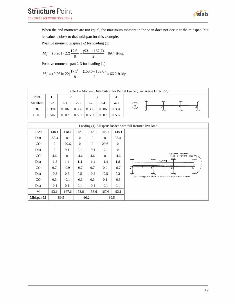
, ' , Use 10 - #4 10 0.2 2.0 in. < 1.786 in.provided add req d addA A
Table 4 - Additional Slab Reinforcement at columns for moment transfer between slab and column [Equivalent Frame Method
(EFM)]
Span Location
Effective slab
width, bb
(in.)
d
(in.) γf
Mu*
(ft-kip)
γf Mu
(ft-kip)
As req’d
within bb
(in.2)
As prov. for
flexure within bb
(in.2)
Add’l
Reinf.
End Span
Column
Strip
Exterior Negative 36 5 0.614 93.1 57.14 2.973 1.187 10-#4
Interior Negative 36 5 0.600 44.5 26.70 1.265 1.387 -
*Mu is taken at the centerline of the support in Equivalent Frame Method solution.
b. Determine transverse reinforcement required for beam strip shear
The transverse reinforcement calculation for the beam strip of end span – exterior location is provided
below.
Figure 15 – Shear at critical sections for the end span (at distance d from the face of the column)
0.520 1.5 18.25 in. (using #4 stirrups)
2 2
stirrup
clear
dd h c
The required shear at a distance d from the face of the supporting column Vu_d= 31.64 kips (Figure 15).
'2v c v cV f b d ACI 318-14 (22.5.5.1)
_0.75 2 4000 14 18.25 24.25 kips 31.64 kipv c u dV V ∴ Stirrups are required.
Distance from the column face beyond which minimum reinforcement is required:
_u d v c
s
v
V VV
ACI 318-14 (22.5.10.1)
,
31.64 24.259.85 kip 129.31 kip
0.75s s maxV V
O.K.

22
,
'8 8 4000 14 18.25 129.31 kips max cV f b d ACI 318-14 (22.5.10.1)
, ' 29.85 10000.009 in. /in.
60,000 18.25
v req d s
yt
A V
s f d
ACI 318-14 (22.5.10.5.3)
,min
'0.75
50
c
v yt
yt
fb
A fmax
sb
f
ACI 318-14 (9.6.3.3)
,min 2
0.75 4000(14)
0.011160,0000.0117 in. /in
0.011750(14)
60,000
vAmax max
s
, ' , ',min ,min use
s
v req d s req dv vA AA A
s s s
'
, '
2 0.234.28 in.
0.0117
stirrup
req d
v req d
n As
A
s
'9.85 kips 4 4 4000 14 18.25 64.66 kipss cV f b d
18.259.13
9.13 in.2 224
24 24max
d
s Lesser of Lesser of Lesser of
ACI 318-14 (9.7.6.2.2)
'Since use req d max maxs s s
Select sprovided = 8 in. #4 stirrups with first stirrup located at distance 3 in. from the column face.
The distance where the shear is zero is calculated as follows:
,
, ,
17.544.67 7.78 ft 93.4 in.
44.67 55.78u L
u L u R
lx V
V V
The distance from support beyond which minimum reinforcement is required is calculated as follows:
1
7.787.78 24.25 3.56 ft 43 in.
44.67v c
u
xx x V
V
The distance at which no shear reinforcement is required is calculated as follows:
2
7.78 24.257.78 5.67 ft 68 in.
2 44.67 2
v c
u
Vxx x
V
12
18 83 68 3
2 2 2 2# 1 1 7.5 use 8 stirrups8
provided
provided
scx
of stirrupss
All the values on Table 5 are calculated based on the procedure outlined above.

23
Table 5 - Required Beam Reinforcement for Shear
Span Location Av,min/s
in2/in
Av,req'd/s
in2/in
sreq'd
in
smax
in
Reinforcement
Provided
End Span
Exterior 0.0117 0.0090 34.28 9.13 8 - #4 @ 8 in*
Interior 0.0117 0.0225 17.76 9.13 10 - #4 @ 8.6 in
Interior Span
Interior 0.0117 0.0158 25.37 9.13 9 - #4 @ 8.6 in
* Minimum transverse reinforcement governs

24
2.7. Column design moments
The unbalanced moment from the slab-beams at the supports of the equivalent frame are distributed to the
actual columns above and below the slab-beam in proportion to the relative stiffness of the actual columns.
Referring to Fig. 9, the unbalanced moment at joints 1 and 2 are:
Joint 1 = +93.1 ft-kip
Joint 2 = -119 + 74.5 = -44.5 ft-kip
The stiffness and carry-over factors of the actual columns and the distribution of the unbalanced moments
to the exterior and interior columns are shown in Fig 9.
Figure 16 - Column Moments (Unbalanced Moments from Slab-Beam)

25
In summary:
Design moment in exterior column = 55.81 ft-kip
Design moment in interior column = 24.91 ft-kip
The moments determined above are combined with the factored axial loads (for each story) and factored
moments in the transverse direction for design of column sections. A detailed analysis to obtain the moment
values at the face of interior, exterior, and corner columns from the unbalanced moment values can be found
in the “Two-Way Flat Plate Concrete Floor Slab Design” example.
3. Design of Interior, Edge, and Corner Columns
The design of interior, edge, and corner columns is explained in the “Two-Way Flat Plate Concrete Floor Slab
Design” example.
4. Two-Way Slab Shear Strength
Shear strength of the slab in the vicinity of columns/supports includes an evaluation of one-way shear (beam
action) and two-way shear (punching) in accordance with ACI 318 Chapter 22.
4.1. One-Way (Beam action) Shear Strength
One-way shear is critical at a distance d from the face of the column. Figure 17 shows the Vu at the critical
sections around each column. Since there is no shear reinforcement, the design shear capacity of the section
equals to the design shear capacity of the concrete:
n c s cV V V V ACI 318-14 (Eq. 22.5.1.1)
Where:
'2c c wV f b d ACI 318-14 (Eq. 22.5.5.1)
λ = 1 for normal weight concrete
50.75 2 1.0 4000 (22 12 14) 118.59 kips
1000cV
Because φVc > Vu at all the critical sections, the slab is o.k. in one-way shear.

26
Figure 17 – One-way shear at critical sections (at distance d from the face of the supporting column)
4.2. Two-Way (Punching) Shear Strength
Two-way shear is critical on a rectangular section located at dslab/2 away from the face of the column. The
factored shear force Vu in the critical section is calculated as the reaction at the centroid of the critical section
minus the self-weight and any superimposed surface dead and live load acting within the critical section.
The factored unbalanced moment used for shear transfer, Munb, is calculated as the sum of the joint moments to
the left and right. Moment of the vertical reaction with respect to the centroid of the critical section is also taken
into account.
For the exterior column:
u
20.5 23V 44.67 0.340 43.56 kips
144
unb
20.5 9.09 18 / 2M 93.1 43.56 84.37 ft-kip
12
For the exterior column in Figure 18, the location of the
centroidal axis z-z is:
moment of area of the sides about AB
area of the sidesABc
2(14 26 (6.5 14 / 2) 6.5 5 (6.5 / 2))9.09 in.
2 (14 26 6.5 5) 14 19 2 4.5 5ABc
22 (14 26 6.5 5) 14 19 2 4.5 5 1104 in.cA
The polar moment Jc of the shear perimeter is:
Figure 18 – Critical section of exterior
support of interior frame

27
23 3
, , , , ,
, , 1 ,
33
1 , , 1 , 1
1 ,
J 2 12 12 2
2 12 12
beam Ext beam Ext beam Ext beam Ext beam Ext
c beam Ext beam Ext beam Ext AB
beam Ext slab Ext slab beam Ext be
beam Ext slab AB
b d d b bb d b b c
b b d d b b b bb b d c
2
,
2
, . 2 ,
2
am Ext
beam Int beam Int beam Int slab ABb d b b d c
23 3
3 23
2
14 26 26 14 14J 2 14 26 20.5 14 9.09
12 12 2
20.5 14 5 5 20.5 14 20.5 14 2 20.5 14 5 9.09
12 12 2
14 19 23 14 5 9.09
c
4J 95,338 in.c
v fγ 1 γ 1 0.614 0.386 ACI 318-14 (Eq. 8.4.4.2.2)
The length of the critical perimeter for the exterior column:
ob 2 (18 5 / 2) (18 5) 64 in.
u v unb
u
V γ Mv AB
c c
c
A J ACI 318-14 (R.8.4.4.2.3)
u
43.56 1000 0.386 84.37 12 1000 9.09v 76.8 psi
1104 95,338
c
4' ' 'v min 4 , 2 , 2dsf f fc c c
bo
ACI 318-14 (Table 22.6.5.2)
c
4 30 5v min 4 1 4000 , 2 1 4000 , 2 1 4000
1 64
cv min 253 , 379.5 , 274.7 psi = 253 psi
c uv 0.75 253 189.7 psi v 76.8 psi O.K.

28
For the interior column:
u
23 23V 55.78 50.23 0.340 104.76 kips
144
unbM 167.7 153.6 104.76(0) 14.10 ft-kip
For the interior column in Figure 19, the location of the
centroidal axis z-z is:
1,
AB
23c 11.5 in.
2 2
Intb
2
cA 4 (14 19 9 5) 1244 in.
The polar moment Jc of the shear perimeter is:
23 3
, , , , , 1 ,
, ,
3
1 ,31 ,
,
1 ,
J 2 12 12 2
24
12 12
2
2
beam Int beam Int beam Int beam Int beam Int beam Int
c beam Int beam Int AB
beam Intbeam Intslabslab Int
beam In
b d d b b b bb d c
b bb bdd
b b
2
1 ,
2
, . 2 ,
2 2
2
t beam Int
slab AB
beam Int beam Int beam Int slab AB
b bd c
b d b b d c
23 3
3
32
2
14 19 19 14 14 23 14J 2 14 19 11.5
12 12 2 2
23 14 23 145 5
23 14 23 142 2 4 5 11.5
12 12 2 2 2
14 19 23 14 5 11.5
c
Figure 19 – Critical section of interior
support of interior frame

29
4J 114,993 in.c
v fγ 1 γ 1 0.600 0.400 ACI 318-14 (Eq. 8.4.4.2.2)
The length of the critical perimeter for the exterior column:
ob 4 (18 5) 92 in.
u v unb
u
V γ Mv AB
c c
c
A J
u
104.76 1000 0.4 14.10 12 1000 11.5v 91.0 psi
1244 114,993
c
4' ' 'v min 4 , 2 , 2s
c c c
o
df f f
b
ACI 318-14 (Table 22.6.5.2)
c
4 40 5v min 4 1 4000 , 2 1 4000 , 2 1 4000
1 92
cv min 253 , 379.5 , 274.7 psi = 253 psi
c u v 0.75 253 189.7 psi > v 91.0 psi O.K.
5. Two-Way Slab Deflection Control (Serviceability Requirements)
Since the slab thickness was selected based on the minimum slab thickness tables in ACI 318-14, the deflection
calculations are not required. However, the calculations of immediate and time-dependent deflections are covered
in this section for illustration and comparison with spSlab model results.
5.1. Immediate (Instantaneous) Deflections
The calculation of deflections for two-way slabs is challenging even if linear elastic behavior can be assumed.
Elastic analysis for three service load levels (D, D + Lsustained, D+LFull) is used to obtain immediate deflections
of the two-way slab in this example. However, other procedures may be used if they result in predictions of
deflection in reasonable agreement with the results of comprehensive tests. ACI 318-14 (24.2.3)
The effective moment of inertia (Ie) is used to account for the cracking effect on the flexural stiffness of the
slab. Ie for uncracked section (Mcr > Ma) is equal to Ig. When the section is cracked (Mcr < Ma), then the
following equation should be used:
3 3
1 cr cre g cr g
a a
M MI I I I
M M
ACI 318-14 (Eq. 24.2.3.5a)
Where:
Ma = Maximum moment in member due to service loads at stage deflection is calculated.
The values of the maximum moments for the three service load levels are calculated from structural analysis as
shown previously in this document. These moments are shown in Figure 20.

30
Figure 20 – Maximum Moments for the Three Service Load Levels
For positive moment (midspan) section of the exterior span:
Cracking moment.crM
474.3 25395 163.14 ft-kips
5 12 1000
r g
crt
f IM
y
ACI 318-14 (Eq. 24.2.3.5b)
= Modulus of rapture of concrete.rf
'7.5 7.5 1.0 4000 474.3 psir c
f f ACI 318-14 (Eq. 19.2.3.1)
= Moment of inertia of the gross uncracked concrete section.gI
2 25395 in. for T-section (see Figure 21)
gI

31
yt = Distance from centroidal axis of gross section, neglecting reinforcement, to tension face, in.
15.9 in. (see Figure 21)t
y
Figure 21 – Ig calculations for slab section near support
= Moment of inertia of the cracked section transformed to concrete.crI PCA Notes on ACI 318-11 (9.5.2.2)
As calculated previously, the positive reinforcement for the end span frame strip is 22 #4 bars located at 1.0 in.
along the slab section from the bottom of the slab and 4 #4 bars located at 1.75 in. along the beam section from
the bottom of the beam. Five of the slab section bars are not continuous and will be excluded from the
calculation of Icr. Figure 22 shows all the parameters needed to calculate the moment of inertia of the cracked
section transformed to concrete at midspan.
Figure 22 – Cracked Transformed Section (positive moment section)
= Modulus of elasticity of slab concrete.csE
1.5 1.5 333 150 33 4000 3834 10 psics c cE w f ACI 318-14 (19.2.2.1.a)
290000007.56
3834000
s
cs
En
E PCA Notes on ACI 318-11 (Table 10-2)
22 12132 in.
2 2
ba
2
, , 7.56 4 0.20 7.56 17 0.20 31.77 in.s beam s slabb n A n A
3
, , , ,1 1 7.56 4 0.20 18.25 7.56 17 0.20 5.0 239 in.s beam s beam s slab s slabc n A d n A d
32
2 24 31.77 31.77 4 132 2393.999 in.
2 1322
b b ackd
a
32 2
, ,
( )( ) ( )
3cr s slab slab s beam beam
b kdI nA d kd nA d kd
43
2 222 12 (3.999)7.56 17 0.20 5 3.999 7.56 4 0.20 18.25 3.999 2282 in.
3crI
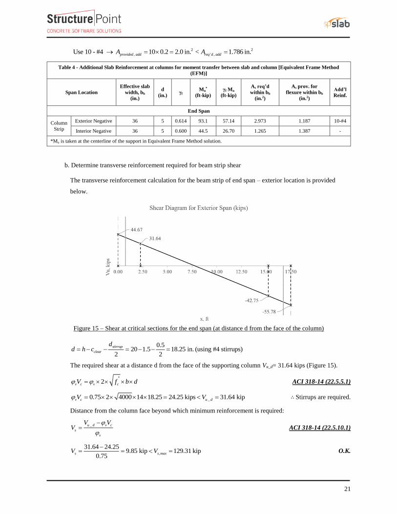
For negative moment section (near the interior support of the end span):
The negative reinforcement for the end span frame strip near the interior support is 27 #4 bars located at 1.0 in.
along the section from the top of the slab.
474.3 9333 136.89 ft-kips
10.0 12 1000
r g
crt
f IM
y
ACI 318-14 (Eq. 24.2.3.5b)
'7.5 7.5 1.0 4000 474.3 psir c
f f ACI 318-14 (Eq. 19.2.3.1)
29333 in.gI
10.0 in.ty
Figure 23 – Ig calculations for slab section near support
1.5 1.5 333 150 33 4000 3834 10 psics c cE w f ACI 318-14 (19.2.2.1.a)
290000007.56
3834000
s
cs
En
E PCA Notes on ACI 318-11 (Table 10-2)
1
,
140.34 in.
7.56 27 0.20
beam
s total
bB
n A
PCA Notes on ACI 318-11 (Table 10-2)
2 1 1 2 19 0.34 1 18.03 in.
0.34
dBkd
B
PCA Notes on ACI 318-11 (Table 10-2)

33
3
2
,
( )( )
3
beam
cr s total
b kdI nA d kd PCA Notes on ACI 318-11 (Table 10-2)
43
214 (8.03)7.56 27 0.20 19 8.03 7331in.
3crI
Figure 24 – Cracked Transformed Section (interior negative moment section for end span)
The effective moment of inertia procedure described in the Code is considered sufficiently accurate to estimate
deflections. The effective moment of inertia, Ie, was developed to provide a transition between the upper and
lower bounds of Ig and Icr as a function of the ratio Mcr/Ma. For conventionally reinforced (nonprestressed)
members, the effective moment of inertia, Ie, shall be calculated by Eq. (24.2.3.5a) unless obtained by a more
comprehensive analysis.
Ie shall be permitted to be taken as the value obtained from Eq. (24.2.3.5a) at midspan for simple and
continuous spans, and at the support for cantilevers. ACI 318-14 (24.2.3.7)
For continuous one-way slabs and beams. Ie shall be permitted to be taken as the average of values obtained
from Eq. (24.2.3.5a) for the critical positive and negative moment sections. ACI 318-14 (24.2.3.6)
For the exterior span (span with one end continuous) with service load level (D+LLfull):
3 3
1 , since 36.89 ft-kips < = 127.56 ft-kipscr acr cr
e g cra a
M MI I I M M
M M
ACI 318-14 (24.2.3.5a)
Where Ie- is the effective moment of inertia for the critical negative moment section (near the support).
3 3
436.89 36.899333 1 7331 7380 in.
127.56 127.56eI
425395 in. , since 63.14 ft-kips > =59.43 ft-kipscr ae g
I I M M
Where Ie+ is the effective moment of inertia for the critical positive moment section (midspan).

34
Since midspan stiffness (including the effect of cracking) has a dominant effect on deflections, midspan section
is heavily represented in calculation of Ie and this is considered satisfactory in approximate deflection
calculations. The averaged effective moment of inertia (Ie,avg) is given by:
, 0.85 0.15 for end spane avge e
I I I PCA Notes on ACI 318-11 (9.5.2.4(1))
4
, 0.85 25395 0.15 7380 22693 in.e avgI
Where:
= The effective moment of inertia for the critical negative moment section near the support.e
I
= The effective moment of inertia for the critical positive moment section (midspan).e
I
For the interior span (span with both ends continuous) with service load level (D+LLfull):
3 3
1 , since 36.89 ft-kips < = 115.73 ft-kipscr acr cr
e g cra a
M MI I I M M
M M
ACI 318-14 (24.2.3.5a)
3 3
436.89 36.899333 1 7331 7396 in.
115.73 115.73eI
425395 in. , since 63.14 ft-kips > = 44.57 ft-kipscr ae g
I I M M
The averaged effective moment of inertia (Ie,avg) is given by:
,, ,
0.70 0.15 for interior spane avge e l e r
I I I I PCA Notes on ACI 318-11 (9.5.2.4(2))
4
, 0.70 25395 0.15 7396 7396 19995 in.e avgI
Where:
,= The effective moment of inertia for the critical negative moment section near the left support.
e lI
,= The effective moment of inertia for the critical negative moment section near the right support.
e RI
Table 6 provides a summary of the required parameters and calculated values needed for deflections for exterior
and interior equivalent frame. It also provides a summary of the same values for column strip and middle strip
to facilitate calculation of panel deflection.

35
Table 6 – Averaged Effective Moment of Inertia Calculations
For Frame Strip
Span zone Ig,
in.4
Icr,
in.4
Ma, ft-kip Mcr,
k-ft
Ie, in.4 Ie,avg, in.4
D D +
LLSus
D +
Lfull D
D +
LLSus
D +
Lfull D
D +
LLSus
D +
Lfull
Ext
Left 9333 7147 -30.61 -30.61 -66.92 36.89 9333 9333 7513
22761 22761 22693 Midspan 25395 2282 27.19 27.19 59.43 63.14 25395 25395 25395
Right 9333 7331 -58.35 -58.35 -127.56 36.89 7837 7837 7380
Int
Left 9333 7331 -52.93 -52.93 -115.73 36.89 8009 8009 7396
20179 20179 19995 Mid 25395 1553 18.06 18.06 44.57 63.14 25395 25395 25395
Right 9333 7331 -52.93 -52.93 -115.73 36.89 8009 8009 7396
Deflections in two-way slab systems shall be calculated taking into account size and shape of the panel,
conditions of support, and nature of restraints at the panel edges. For immediate deflections two-way slab
systems the midpanel deflection is computed as the sum of deflection at midspan of the column strip or column
line in one direction (Δcx or Δcy) and deflection at midspan of the middle strip in the orthogonal direction (Δmx
or Δmy). Figure 25 shows the deflection computation for a rectangular panel. The average Δ for panels that have
different properties in the two direction is calculated as follows:
( ) ( )
2
cx my cy mx
PCA Notes on ACI 318-11 (9.5.3.4 Eq. 8)
Figure 25 – Deflection Computation for a rectangular Panel
To calculate each term of the previous equation, the following procedure should be used. Figure 26 shows the
procedure of calculating the term Δcx. same procedure can be used to find the other terms.

36
Figure 26 –Δcx calculation procedure
For exterior span - service dead load case:
4
,
,384
frame fixed
c frame averaged
wl
E I PCA Notes on ACI 318-11 (9.5.3.4 Eq. 10)
Where:
, = Deflection of column strip assuing fixed end condition.frame fixed
150 6 150 (20 6) 14slab weight + beam weight = (22) 1854 lb/ft
12 22 144w
1.5 1.5 333 150 33 4000 3834 10 psic c cE w f ACI 318-14 (19.2.2.1.a)
Iframe,averaged = The averaged effective moment of inertia (Ie,avg) for the frame strip for service dead load case
from Table 6 = 22761 in.4
4 3
, 3
(1854)(17.5 18 /12) (12)0.0063 in.
384(3834 10 )(22761)frame fixed
, ,
frame
c fixed c frame fixed
c g
ILDF
I
PCA Notes on ACI 318-11 (9.5.3.4 Eq. 11)
Where LDFc is the load distribution factor for the column strip. The load distribution factor for the column
strip can be found from the following equation:

37
2
2
l R
c
LDF LDFLDF
LDF
And the load distribution factor for the middle strip can be found from the following equation:
1m c
LDF LDF
For the end span, LDF for exterior negative region (LDFL¯), interior negative region (LDFR¯), and positive
region (LDFL+
) are 0.75, 0.67, and 0.67, respectively (From Table 2 of this document). Thus, the load
distribution factor for the column strip for the end span is given by:
0.75 0.670.67
2 0.6902
cLDF
Ic,g = The gross moment of inertia (Ig) for the column strip (for T section) = 20040 in.4
Iframe,g = The gross moment of inertia (Ig) for the frame strip (for T section) = 25395 in.4
,
253950.690 0.0063 0.0055 in.
20040c fixed
,
,
( )net L frame
c L
ec
M
K PCA Notes on ACI 318-11 (9.5.3.4 Eq. 12)
Where:
, = Rotation of the span left support.c L
,( ) 31.13 ft-kips = Net frame strip negative moment of the left support.net L frameM
Kec = effective column stiffness for exterior column.
= 764 x Ec = 2929 x 106 in.-lb (calculated previously).
, 6
31.13 12 10000.00012 rad
2929 10c L
, , 8
frame
g
c L c L
e
Il
I
PCA Notes on ACI 318-11 (9.5.3.4 Eq. 14)
Where:
, = Midspan deflection due to rotation of left support.c L

38
= Gross-to-effective moment of inertia ratio for frame strip.g
e frame
I
I
,
(17.5 18 /12) 12 253950.00012 0.0033 in.
8 22761c L
,
, 6
( ) (58.35 52.93) 12 10000.00003 rad
2419 10
net R frame
c R
ec
M
K
Where
, = Rotation of the end span right support.c R
,( ) Net frame strip negative moment of the right support.net R frameM
Kec = effective column stiffness for interior column.
= 631 x Ec = 2419 x 106 in.-lb (calculated previously).
, ,
(17.5 18 /12) 12 253950.00003 0.00072 in.
8 8 22761
g
c R c R
e frame
Il
I
Where:
, = Midspan delfection due to rotation of right support.c R
, ,,cx cx R cx Lcx fixed PCA Notes on ACI 318-11 (9.5.3.4 Eq. 9)
0.0055 0.0033 0.00072 0.009 in.cx
Following the same procedure, Δmx can be calculated for the middle strip. This procedure is repeated for the
equivalent frame in the orthogonal direction to obtain Δcy, and Δmy for the end and middle spans for the other
load levels (D+LLsus and D+LLfull).
Assuming square panel, Δcx = Δcy= 0.009 in. and Δmx = Δmy= 0.021 in.
The average Δ for the corner panel is calculated as follows:
( ) ( )
0.009 0.021 0.030 in.2
cx my cy mxcx my cy mx

39
Table 7 - Instantaneous Deflections
Column Strip Middle Strip
Span LDF
D
LDF
D
Δframe-fixed,
in
Δc-fixed,
in
θc1,
rad
θc2,
rad
Δθc1,
in
Δθc2,
in
Δcx,
in Δframe-fixed,
in
Δm-fixed,
in
θm1,
rad
θm2,
rad
Δθm1,
in
Δθm2,
in
Δmx,
in
Ext 0.69 0.0063 0.0055 0.00012 0.00003 0.0033 0.0007 0.009 0.31 0.0063 0.0172 0.00012 0.00003 0.0033 0.0007 0.021
Int 0.67 0.0071 0.0060 0.00003 0.00003 -0.0008 -0.0008 0.004 0.33 0.0071 0.0207 0.00003 0.00003 -0.0008 -0.0008 0.019
Span LDF
D+LLsus
LDF
D+LLsus
Δframe-fixed,
in
Δc-fixed,
in
θc1,
rad
θc2,
rad
Δθc1,
in
Δθc2,
in
Δcx,
in Δframe-fixed,
in
Δm-fixed,
in
θm1,
rad
θm2,
rad
Δθm1,
in
Δθm2,
in
Δmx,
in
Ext 0.69 0.0063 0.0055 0.00012 0.00003 0.0033 0.0007 0.009 0.31 0.00627 0.01724 0.00012 0.00003 0.00330 0.00072 0.021
Int 0.67 0.0071 0.0060 0.00003 0.00003 -0.0008 -0.0008 0.004 0.33 0.00707 0.02069 0.00003 0.00003 -0.00081 -0.00081 0.019
Span LDF
D+LLfull
LDF
D+LLfull
Δframe-fixed,
in
Δc-fixed,
in
θc1,
rad
θc2,
rad
Δθc1,
in
Δθc2,
in
Δcx,
in Δframe-fixed,
in
Δm-fixed,
in
θm1,
rad
θm2,
rad
Δθm1,
in
Δθm2,
in
Δmx,
in
Ext 0.69 0.0137 0.0120 0.00027 0.00006 0.0072 0.0016 0.021 0.31 0.01374 0.03780 0.00027 0.00006 0.00724 0.00158 0.047
Int 0.67 0.0156 0.0132 0.00006 0.00006 -0.0018 -0.0018 0.010 0.33 0.01559 0.04566 0.00006 0.00006 -0.00179 -0.00179 0.042
Span LDF
LL
LDF
LL
Δcx,
in Δmx,
in
Ext 0.69 0.011 0.31 0.025
Int 0.67 0.005 0.33 0.023

40
5.2. Time-Dependent (Long-Term) Deflections (Δlt)
The additional time-dependent (long-term) deflection resulting from creep and shrinkage (Δcs) may be estimated
as follows:
( )cs sust Inst PCA Notes on ACI 318-11 (9.5.2.5 Eq. 4)
The total time-dependent (long-term) deflection is calculated as:
( ) ( ) (1 ) [( ) ( ) ]sust Inst total Inst sust Insttotal lt CSA A23.3-04 (N9.8.2.5)
Where:
( ) Immediate (instantaneous) deflection due to sustained load, in.sust Inst
1 50 '
ACI 318-14 (24.2.4.1.1)
( ) Time-dependent (long-term) total delfection, in.total lt
( ) Total immediate (instantaneous) deflection, in.total Inst
For the exterior span
= 2, consider the sustained load duration to be 60 months or more. ACI 318-14 (Table 24.2.4.1.3)
' = 0, conservatively.
22
1 50 0
2 0.009 0.019 in.cs
0.009 1 2 0.021 0.009 0.040 in.total lt
Table 8 shows long-term deflections for the exterior and interior spans for the analysis in the x-direction, for
column and middle strips.

41
Table 8 - Long-Term Deflections
Column Strip
Span (Δsust)Inst, in λΔ Δcs, in (Δtotal)Inst, in (Δtotal)lt, in
Exterior 0.009 2.000 0.019 0.021 0.040
Interior 0.004 2.000 0.009 0.010 0.018
Middle Strip
Exterior 0.021 2.000 0.043 0.047 0.089
Interior 0.019 2.000 0.038 0.042 0.080
6. spSlab Software Program Model Solution
spSlab program utilizes the Equivalent Frame Method described and illustrated in details here for modeling,
analysis and design of two-way concrete floor slab systems. spSlab uses the exact geometry and boundary
conditions provided as input to perform an elastic stiffness (matrix) analysis of the equivalent frame taking into
account the torsional stiffness of the slabs framing into the column. It also takes into account the complications
introduced by a large number of parameters such as vertical and torsional stiffness of transverse beams, the
stiffening effect of drop panels, column capitals, and effective contribution of columns above and below the floor
slab using the of equivalent column concept (ACI 318-14 (R8.11.4)).
spSlab Program models the equivalent frame as a design strip. The design strip is, then, separated by spSlab into
column and middle strips. The program calculates the internal forces (Shear Force & Bending Moment), moment
and shear capacity vs. demand diagrams for column and middle strips, instantaneous and long-term deflection
results, and required flexural reinforcement for column and middle strips. The graphical and text results will be
provided from the spSlab model in a future revision to this document. For a sample output refer to “Two-Way
Flat Plate Concrete Floor Slab Design” example.

X
YZ
spSlab v5.00. Licensed to: StructurePoint. License ID: 66184-1055152-4-2C6B6-2C6B6
File: C:\...\TSDA-spSlab-Two-Way Slab with Beams Spanning Between Supports.slb
Project: Two-Way Slab With Beams Spanning Between Supports
Frame: Interior Frame
Engineer: SP
Code: ACI 318-14
Date: 03/31/17
Time: 14:47:17

spSlab v5.00. Licensed to: StructurePoint. License ID: 66184-1055152-4-2C6B6-2C6B6
File: C:\...\TSDA-spSlab-Two-Way Slab with Beams Spanning Between Supports.slb
Project: Two-Way Slab With Beams Spanning Between Supports
Frame: Interior Frame
Engineer: SP
Code: ACI 318-14
Date: 03/31/17
Time: 14:48:17
CASE/PATTERN: Live/All
84.3 lb/ft2 84.3 lb/ft2 84.3 lb/ft2 84.3 lb/ft2 84.3 lb/ft2
100 lb/ft2 100 lb/ft2 100 lb/ft2 100 lb/ft2 100 lb/ft2
CASE/PATTERN: Live/All
84.3 lb/ft2 84.3 lb/ft2 84.3 lb/ft2 84.3 lb/ft2 84.3 lb/ft2
100 lb/ft2 100 lb/ft2 100 lb/ft2 100 lb/ft2 100 lb/ft2

spSlab v5.00. Licensed to: StructurePoint. License ID: 66184-1055152-4-2C6B6-2C6B6
File: C:\...\TSDA-spSlab-Two-Way Slab with Beams Spanning Between Supports.slb
Project: Two-Way Slab With Beams Spanning Between Supports
Frame: Interior Frame
Engineer: SP
Code: ACI 318-14
Date: 03/31/17
Time: 14:49:25
Mom
ent D
iagr
am -
k-f
t
-200.0
200.0
She
ar D
iagr
am -
kip
60.0
-60.0
-1.62
-94.82
-180.76
84.22
-163.99 -163.99
64.08
-180.76
-94.82
84.22
-1.62
-4.31
45.36
-55.18
50.27
-50.27
55.18
-45.36
4.31

spSlab v5.00. Licensed to: StructurePoint. License ID: 66184-1055152-4-2C6B6-2C6B6
File: C:\...\TSDA-spSlab-Two-Way Slab with Beams Spanning Between Supports.slb
Project: Two-Way Slab With Beams Spanning Between Supports
Frame: Interior Frame
Engineer: SP
Code: ACI 318-14
Date: 03/31/17
Time: 14:51:28
Col
umn
Str
ip M
omen
t Cap
acit
y -
k-ft 200.0
200.0
Mid
dle
Str
ip M
omen
t Cap
acit
y -
k-ft 200.0
200.0
Bea
m S
trip
Mom
ent C
apac
ity
- k-
ft 200.0
200.0
-7.06
8.50
-14.23 -12.91
6.47 -0.15 -12.91 -14.23
8.50
-7.06
-15.36
27.55
-46.12 -41.84
20.96
-0.47
-41.84 -46.12
27.55
-15.36
-40.00
48.17
-80.63 -73.15
36.65
-0.83
-73.15 -80.63
48.17
-40.00
spSlab v5.00. Licensed to: StructurePoint. License ID: 66184-1055152-4-2C6B6-2C6B6
File: C:\...\TSDA-spSlab-Two-Way Slab with Beams Spanning Between Supports.slb
Project: Two-Way Slab With Beams Spanning Between Supports
Frame: Interior Frame
Engineer: SP
Code: ACI 318-14
Date: 03/31/17
Time: 14:54:08
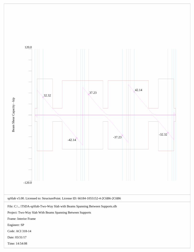
Bea
m S
hear
Cap
acit
y -
kip
120.0
-120.0
32.32
-42.14
37.23
-37.23
42.14
-32.32

spSlab v5.00. Licensed to: StructurePoint. License ID: 66184-1055152-4-2C6B6-2C6B6
File: C:\...\TSDA-spSlab-Two-Way Slab with Beams Spanning Between Supports.slb
Project: Two-Way Slab With Beams Spanning Between Supports
Frame: Interior Frame
Engineer: SP
Code: ACI 318-14
Date: 03/31/17
Time: 14:54:54
Inst
anta
neou
s D
efle
ctio
n -
in
-0.024
0.024
LEGEND: Dead Load Sustained Load Live Load Total Deflection

spSlab v5.00. Licensed to: StructurePoint. License ID: 66184-1055152-4-2C6B6-2C6B6
File: C:\TSDA\TSDA-spSlab-Two-Way Slab with Beams Spanning Between Supports.slb
Project: Two-Way Slab With Beams Spanning Between Supports
Frame: Interior Frame
Engineer: SP
Code: ACI 318-14
Date: 03/31/17
Time: 14:56:22
Column Strip Flexural Reinforcement
Middle Strip Flexural Reinforcement
Beam Strip Flexural and Transverse Reinforcement
8-#4(9.0)c5-#4(45.0)
3-#4(21.0)
5-#4(81.0)
3-#4(21.0)
8-#4(210.0)c
8-#4(210.0)c
8-#4(210.0)c
5-#4(81.0)
3-#4(21.0)
5-#4(45.0)
3-#4(21.0)
8-#4(210.0)c
8-#4(9.0)c
14-#4(9.0)c14-#4(45.0)
14-#4(81.0)
9-#4(210.0)c5-#4(178.5)
14-#4(210.0)c
9-#4(210.0)c5-#4(147.0)
14-#4(81.0)
14-#4(45.0)
9-#4(210.0)c5-#4(178.5)
14-#4(9.0)c
2-#4(9.0)c1-#4(9.0)
1-#4(9.0) 4-#4(52.0)
5-#4(88.0)
4-#4(210.0)c
8-#[email protected] 10-#[email protected]
2-#4(210.0)c2-#4(48.1)
1-#4(31.0)
2-#4(48.1)
1-#4(31.0)
4-#4(210.0)c
10-#[email protected] 10-#[email protected]
5-#4(88.0)
4-#4(52.0)
4-#4(210.0)c
10-#[email protected] 8-#[email protected]
2-#4(9.0)c1-#4(9.0)
1-#4(9.0)

spSlab v5.00 © StructurePoint 03-31-2017, 02:57:01 PMLicensed to: StructurePoint, License ID: 66184-1055152-4-2C6B6-2C6B6 C:\TSDA\TSDA-spSlab-Two-Way Slab with Beams Spanning Between Supports.slb Page 1
oooooo o o oo oo oo oo ooooo oooooo oo oo ooooo oo oo o oo oo oo oo o oo oo oo oo oo ooo oo oooooo oooooo ooooo oo oo ooo oo oo oo oo oo oo oooooo oo oo oo oo oo oo o oo oo oo oo oo o oo oo oo oo ooooo oo oooooo ooo ooooo o ooooo (TM) ================================================================================================= spSlab v5.00 (TM) A Computer Program for Analysis, Design, and Investigation of Reinforced Concrete Beams, One-way and Two-way Slab Systems Copyright © 2003-2015, STRUCTUREPOINT, LLC All rights reserved ================================================================================================= Licensee stated above acknowledges that STRUCTUREPOINT (SP) is not and cannot be responsible for either the accuracy or adequacy of the material supplied as input for processing by the spSlab computer program. Furthermore, STRUCTUREPOINT neither makes any warranty expressed nor implied with respect to the correctness of the output prepared by the spSlab program. Although STRUCTUREPOINT has endeavored to produce spSlab error free the program is not and cannot be certified infallible. The final and only responsibility for analysis, design and engineering documents is the licensee's. Accordingly, STRUCTUREPOINT disclaims all responsibility in contract, negligence or other tort for any analysis, design or engineering documents prepared in connection with the use of the spSlab program. ==================================================================================================================[1] INPUT ECHO================================================================================================================== General Information=================== File name: C:\TSDA\TSDA-spSlab-Two-Way Slab with Beams Spanning Between Supports.slb Project: Two-Way Slab With Beams Spanning Between Supports Frame: Interior Frame Engineer: SP Code: ACI 318-14 Reinforcement Database: ASTM A615 Mode: Design Number of supports = 4 + Left cantilever + Right cantilever Floor System: Two-Way Live load pattern ratio = 75% Minimum free edge distance for punching shear = 4 times slab thickness. Circular critical section around circular supports used (if possible). Deflections are based on cracked section properties. In negative moment regions, Ig and Mcr DO NOT include flange/slab contribution (if available) Long-term deflections are calculated for load duration of 60 months. 0% of live load is sustained. Compression reinforcement calculations NOT selected. Default incremental rebar design selected. User-defined slab strip widths NOT selected. User-defined distribution factors NOT selected. One-way shear in drop panel NOT selected. Distribution of shear to strips NOT selected. Beam T-section design NOT selected. Longitudinal beam contribution in negative reinforcement design over support NOT selected. Transverse beam contribution in negative reinforcement design over support NOT selected. Material Properties=================== Slabs|Beams Columns ------------ ------------ wc = 150 150 lb/ft3 f'c = 4 4 ksi Ec = 3834.3 3834.3 ksi fr = 0.47434 0.47434 ksi fy = 60 ksi, Bars are not epoxy-coated fyt = 60 ksi Es = 29000 ksi Reinforcement Database====================== Units: Db (in), Ab (in^2), Wb (lb/ft) Size Db Ab Wb Size Db Ab Wb ---- -------- -------- -------- ---- -------- -------- -------- #3 0.38 0.11 0.38 #4 0.50 0.20 0.67 #5 0.63 0.31 1.04 #6 0.75 0.44 1.50 #7 0.88 0.60 2.04 #8 1.00 0.79 2.67 #9 1.13 1.00 3.40 #10 1.27 1.27 4.30

spSlab v5.00 © StructurePoint 03-31-2017, 02:57:01 PMLicensed to: StructurePoint, License ID: 66184-1055152-4-2C6B6-2C6B6 C:\TSDA\TSDA-spSlab-Two-Way Slab with Beams Spanning Between Supports.slb Page 2
#11 1.41 1.56 5.31 #14 1.69 2.25 7.65 #18 2.26 4.00 13.60 Span Data========= Slabs ----- Units: L1, wL, wR, L2L, L2R (ft); t, Hmin (in) Span Loc L1 t wL wR L2L L2R Hmin ---- ---- -------- -------- -------- -------- -------- -------- -------- 1 Int 0.750 6.00 11.000 11.000 22.000 22.000 --- LC *i 2 Int 17.500 6.00 11.000 11.000 22.000 22.000 5.81 3 Int 17.500 6.00 11.000 11.000 22.000 22.000 5.79 4 Int 17.500 6.00 11.000 11.000 22.000 22.000 5.81 5 Int 0.750 6.00 11.000 11.000 22.000 22.000 --- RC *i NOTES: Deflection check required for panels where code-specified Hmin for two-way construction doesn't apply due to: *i - cantilever end span (LC, RC) support condition Ribs and Longitudinal Beams --------------------------- Units: b, h, Sp (in) ___________Ribs___________ ___________Beams__________ Span b h Sp b h Offset ---- -------- -------- -------- -------- -------- -------- 1 0.00 0.00 0.00 14.00 20.00 0.00 2 0.00 0.00 0.00 14.00 20.00 0.00 3 0.00 0.00 0.00 14.00 20.00 0.00 4 0.00 0.00 0.00 14.00 20.00 0.00 5 0.00 0.00 0.00 14.00 20.00 0.00 Support Data============ Columns ------- Units: c1a, c2a, c1b, c2b (in); Ha, Hb (ft) Supp c1a c2a Ha c1b c2b Hb Red% ---- -------- -------- -------- -------- -------- -------- ---- 1 18.00 18.00 12.000 18.00 18.00 12.000 100 2 18.00 18.00 12.000 18.00 18.00 12.000 100 3 18.00 18.00 12.000 18.00 18.00 12.000 100 4 18.00 18.00 12.000 18.00 18.00 12.000 100 Transverse Beams ---------------- Units: b, h, Ecc (in) Supp b h Ecc ---- -------- -------- -------- 1 14.00 27.00 -2.00 2 14.00 20.00 0.00 3 14.00 20.00 0.00 4 14.00 27.00 2.00 Boundary Conditions ------------------- Units: Kz (kip/in); Kry (kip-in/rad) Supp Spring Kz Spring Kry Far End A Far End B ---- ------------ ------------ --------- --------- 1 0 0 Fixed Fixed 2 0 0 Fixed Fixed 3 0 0 Fixed Fixed 4 0 0 Fixed Fixed Load Data========= Load Cases and Combinations --------------------------- Case Dead Live Type DEAD LIVE ---- -------- -------- U1 1.200 1.600 Area Loads ---------- Units: Wa (lb/ft2) Case/Patt Span Wa --------- ---- ------------ Dead 1 84.30 2 84.30 3 84.30 4 84.30 5 84.30 Live 1 100.00 2 100.00 3 100.00 4 100.00 5 100.00

spSlab v5.00 © StructurePoint 03-31-2017, 02:57:01 PMLicensed to: StructurePoint, License ID: 66184-1055152-4-2C6B6-2C6B6 C:\TSDA\TSDA-spSlab-Two-Way Slab with Beams Spanning Between Supports.slb Page 3
Live/Odd 1 75.00 3 75.00 5 75.00 Live/Even 2 75.00 4 75.00 Live/S1 1 75.00 2 75.00 Live/S2 2 75.00 3 75.00 Live/S3 3 75.00 4 75.00 Live/S4 4 75.00 5 75.00 Reinforcement Criteria====================== Slabs and Ribs -------------- _____Top bars___ __Bottom bars___ Min Max Min Max ------- ------- ------- ------- Bar Size #4 #8 #4 #8 Bar spacing 1.00 18.00 1.00 18.00 in Reinf ratio 0.14 5.00 0.14 5.00 % Cover 0.75 0.75 in There is NOT more than 12 in of concrete below top bars. Beams ----- _____Top bars___ __Bottom bars___ ____Stirrups____ Min Max Min Max Min Max ------- ------- ------- ------- ------- ------- Bar Size #4 #8 #4 #8 #4 #5 Bar spacing 1.00 18.00 1.00 18.00 6.00 18.00 in Reinf ratio 0.14 5.00 0.14 5.00 % Cover 0.75 1.51 in Layer dist. 1.00 1.00 in No. of legs 2 6 Side cover 1.50 in 1st Stirrup 3.00 in There is NOT more than 12 in of concrete below top bars.

spSlab v5.00 © StructurePoint 03-31-2017, 02:57:55 PMLicensed to: StructurePoint, License ID: 66184-1055152-4-2C6B6-2C6B6 C:\TSDA\TSDA-spSlab-Two-Way Slab with Beams Spanning Between Supports.slb Page 1
oooooo o o oo oo oo oo ooooo oooooo oo oo ooooo oo oo o oo oo oo oo o oo oo oo oo oo ooo oo oooooo oooooo ooooo oo oo ooo oo oo oo oo oo oo oooooo oo oo oo oo oo oo o oo oo oo oo oo o oo oo oo oo ooooo oo oooooo ooo ooooo o ooooo (TM) ================================================================================================= spSlab v5.00 (TM) A Computer Program for Analysis, Design, and Investigation of Reinforced Concrete Beams, One-way and Two-way Slab Systems Copyright © 2003-2015, STRUCTUREPOINT, LLC All rights reserved ================================================================================================= Licensee stated above acknowledges that STRUCTUREPOINT (SP) is not and cannot be responsible for either the accuracy or adequacy of the material supplied as input for processing by the spSlab computer program. Furthermore, STRUCTUREPOINT neither makes any warranty expressed nor implied with respect to the correctness of the output prepared by the spSlab program. Although STRUCTUREPOINT has endeavored to produce spSlab error free the program is not and cannot be certified infallible. The final and only responsibility for analysis, design and engineering documents is the licensee's. Accordingly, STRUCTUREPOINT disclaims all responsibility in contract, negligence or other tort for any analysis, design or engineering documents prepared in connection with the use of the spSlab program. ==================================================================================================================[2] DESIGN RESULTS*================================================================================================================== *Unless otherwise noted, all results are in the direction of analysis only. Another analysis in the perpendicular direction has to be carried out for two-way slab systems. Strip Widths and Distribution Factors===================================== Units: Width (ft). __________Width___________ ______ Moment Factor______ Span Strip Left** Right** Bottom* Left** Right** Bottom* ---- ------ -------- -------- -------- -------- -------- -------- 1 Column 7.58 7.58 7.58 0.122 0.122 0.113 Middle 13.25 13.25 13.25 0.188 0.188 0.250 Beam 1.17 1.17 1.17 0.690 0.690 0.637
2 Column 7.58 7.58 7.58 0.113 0.101 0.101 Middle 13.25 13.25 13.25 0.246 0.327 0.327 Beam 1.17 1.17 1.17 0.641 0.572 0.572
3 Column 7.58 7.58 7.58 0.101 0.101 0.101 Middle 13.25 13.25 13.25 0.327 0.327 0.327 Beam 1.17 1.17 1.17 0.572 0.572 0.572
4 Column 7.58 7.58 7.58 0.101 0.113 0.101 Middle 13.25 13.25 13.25 0.327 0.246 0.327 Beam 1.17 1.17 1.17 0.572 0.641 0.572
5 Column 7.58 7.58 7.58 0.122 0.122 0.113 Middle 13.25 13.25 13.25 0.188 0.188 0.250 Beam 1.17 1.17 1.17 0.690 0.690 0.637 *Used for bottom reinforcement. **Used for top reinforcement.
Top Reinforcement================= Units: Width (ft), Mmax (k-ft), Xmax (ft), As (in^2), Sp (in) Span Strip Zone Width Mmax Xmax AsMin AsMax AsReq SpProv Bars ---- ------ ------- -------- ---------- -------- -------- -------- -------- -------- ------- 1 Column Left 7.58 0.02 0.217 0.983 8.218 0.001 11.375 8-#4 *3 *5 Midspan 7.58 0.06 0.402 0.983 8.218 0.003 11.375 8-#4 *3 *5 Right 7.58 0.14 0.619 0.983 8.218 0.006 11.375 8-#4 *3 *5
Middle Left 13.25 0.03 0.217 1.717 14.360 0.001 11.357 14-#4 *3 *5 Midspan 13.25 0.10 0.402 1.717 14.360 0.004 11.357 14-#4 *3 *5 Right 13.25 0.22 0.619 1.717 14.360 0.010 11.357 14-#4 *3 *5
Beam Left 1.17 0.11 0.217 0.372 4.805 0.001 8.664 2-#4 *3 Midspan 1.17 0.35 0.402 0.372 4.805 0.004 8.664 2-#4 *3 Right 1.17 0.79 0.619 0.372 4.805 0.009 2.888 4-#4 *3
2 Column Left 7.58 7.06 0.750 0.983 8.218 0.316 11.375 8-#4 *3 *5 Midspan 7.58 0.00 8.750 0.000 8.218 0.000 0.000 --- Right 7.58 14.23 16.750 0.983 8.218 0.640 11.375 8-#4 *3 *5

spSlab v5.00 © StructurePoint 03-31-2017, 02:57:55 PMLicensed to: StructurePoint, License ID: 66184-1055152-4-2C6B6-2C6B6 C:\TSDA\TSDA-spSlab-Two-Way Slab with Beams Spanning Between Supports.slb Page 2
Middle Left 13.25 15.36 0.750 1.717 14.360 0.688 11.357 14-#4 *3 *5 Midspan 13.25 0.00 8.750 0.000 14.360 0.000 0.000 --- Right 13.25 46.12 16.750 1.717 14.360 2.099 11.357 14-#4 *5
Beam Left 1.17 40.00 0.750 0.632 4.805 0.475 2.888 4-#4 *3 Midspan 1.17 0.00 8.750 0.000 4.805 0.000 0.000 --- Right 1.17 80.63 16.750 0.887 4.805 0.975 2.166 5-#4
3 Column Left 7.58 12.91 0.750 0.983 8.218 0.580 11.375 8-#4 *3 *5 Midspan 7.58 0.15 11.150 0.983 8.218 0.007 11.375 8-#4 *3 *5 Right 7.58 12.91 16.750 0.983 8.218 0.580 11.375 8-#4 *3 *5
Middle Left 13.25 41.84 0.750 1.717 14.360 1.900 11.357 14-#4 *5 Midspan 13.25 0.47 11.150 1.717 14.360 0.021 11.357 14-#4 *3 *5 Right 13.25 41.84 16.750 1.717 14.360 1.900 11.357 14-#4 *5
Beam Left 1.17 73.15 0.750 0.887 4.805 0.881 2.166 5-#4 *3 Midspan 1.17 0.83 11.150 0.372 4.805 0.010 8.664 2-#4 *3 Right 1.17 73.15 16.750 0.887 4.805 0.881 2.166 5-#4 *3
4 Column Left 7.58 14.23 0.750 0.983 8.218 0.640 11.375 8-#4 *3 *5 Midspan 7.58 0.00 8.750 0.000 8.218 0.000 0.000 --- Right 7.58 7.06 16.750 0.983 8.218 0.316 11.375 8-#4 *3 *5
Middle Left 13.25 46.12 0.750 1.717 14.360 2.099 11.357 14-#4 *5 Midspan 13.25 0.00 8.750 0.000 14.360 0.000 0.000 --- Right 13.25 15.36 16.750 1.717 14.360 0.688 11.357 14-#4 *3 *5
Beam Left 1.17 80.63 0.750 0.887 4.805 0.975 2.166 5-#4 Midspan 1.17 0.00 8.750 0.000 4.805 0.000 0.000 --- Right 1.17 40.00 16.750 0.632 4.805 0.475 2.888 4-#4 *3
5 Column Left 7.58 0.14 0.131 0.983 8.218 0.006 11.375 8-#4 *3 *5 Midspan 7.58 0.06 0.348 0.983 8.218 0.003 11.375 8-#4 *3 *5 Right 7.58 0.02 0.533 0.983 8.218 0.001 11.375 8-#4 *3 *5
Middle Left 13.25 0.22 0.131 1.717 14.360 0.010 11.357 14-#4 *3 *5 Midspan 13.25 0.10 0.348 1.717 14.360 0.004 11.357 14-#4 *3 *5 Right 13.25 0.03 0.533 1.717 14.360 0.001 11.357 14-#4 *3 *5
Beam Left 1.17 0.79 0.131 0.372 4.805 0.009 2.888 4-#4 *3 Midspan 1.17 0.35 0.348 0.372 4.805 0.004 8.664 2-#4 *3 Right 1.17 0.11 0.533 0.372 4.805 0.001 8.664 2-#4 *3 NOTES: *3 - Design governed by minimum reinforcement. *5 - Number of bars governed by maximum allowable spacing.
Top Bar Details=============== Units: Length (ft) _____________Left______________ ___Continuous__ _____________Right_____________ Span Strip Bars Length Bars Length Bars Length Bars Length Bars Length ---- ------ ------- ------- ------- ------- ------- ------- ------- ------- ------- ------- 1 Column --- --- 8-#4 0.75 --- --- Middle --- --- 14-#4 0.75 --- --- Beam --- --- 2-#4 0.75 1-#4 0.75 1-#4 0.75
2 Column 5-#4 3.75 3-#4 1.75 --- 5-#4 6.75 3-#4 1.75 Middle 14-#4 3.75 --- --- 14-#4 6.75 --- Beam 4-#4 4.33 --- --- 5-#4 7.33 ---
3 Column --- --- 8-#4 17.50 --- --- Middle --- --- 14-#4 17.50 --- --- Beam 2-#4* 4.01 1-#4* 2.59 2-#4 17.50 2-#4* 4.01 1-#4* 2.59
4 Column 5-#4 6.75 3-#4 1.75 --- 5-#4 3.75 3-#4 1.75 Middle 14-#4 6.75 --- --- 14-#4 3.75 --- Beam 5-#4 7.33 --- --- 4-#4 4.33 ---
5 Column --- --- 8-#4 0.75 --- --- Middle --- --- 14-#4 0.75 --- --- Beam 1-#4 0.75 1-#4 0.75 2-#4 0.75 --- --- NOTES: * - Bar cut-off location does not meet ACI 318, 12.10.5.1. Revise location, unless the requirements of either 12.10.5.2 or 12.10.5.3 are manually checked and satisfied.
Top Bar Development Lengths=========================== Units: Length (in) _____________Left______________ ___Continuous__ _____________Right_____________ Span Strip Bars DevLen Bars DevLen Bars DevLen Bars DevLen Bars DevLen ---- ------ ------- ------- ------- ------- ------- ------- ------- ------- ------- ------- 1 Column --- --- 8-#4 12.00 --- --- Middle --- --- 14-#4 12.00 --- --- Beam --- --- 2-#4 12.00 1-#4 12.00 1-#4 12.00
2 Column 5-#4 12.00 3-#4 12.00 --- 5-#4 12.00 3-#4 12.00

spSlab v5.00 © StructurePoint 03-31-2017, 02:57:55 PMLicensed to: StructurePoint, License ID: 66184-1055152-4-2C6B6-2C6B6 C:\TSDA\TSDA-spSlab-Two-Way Slab with Beams Spanning Between Supports.slb Page 3
Middle 14-#4 12.00 --- --- 14-#4 12.00 --- Beam 4-#4 12.00 --- --- 5-#4 13.87 ---
3 Column --- --- 8-#4 12.00 --- --- Middle --- --- 14-#4 12.00 --- --- Beam 2-#4 12.54 1-#4 12.54 2-#4 12.00 2-#4 12.54 1-#4 12.54
4 Column 5-#4 12.00 3-#4 12.00 --- 5-#4 12.00 3-#4 12.00 Middle 14-#4 12.00 --- --- 14-#4 12.00 --- Beam 5-#4 13.87 --- --- 4-#4 12.00 ---
5 Column --- --- 8-#4 12.00 --- --- Middle --- --- 14-#4 12.00 --- --- Beam 1-#4 12.00 1-#4 12.00 2-#4 12.00 --- ---
Bottom Reinforcement==================== Units: Width (ft), Mmax (k-ft), Xmax (ft), As (in^2), Sp (in) Span Strip Width Mmax Xmax AsMin AsMax AsReq SpProv Bars ---- ------ -------- ---------- -------- -------- -------- -------- -------- ------- 1 Column 7.58 0.00 0.309 0.000 8.218 0.000 0.000 --- Middle 13.25 0.00 0.309 0.000 14.360 0.000 0.000 --- Beam 1.17 0.00 0.309 0.000 4.613 0.000 0.000 ---
2 Column 7.58 8.50 8.000 0.983 8.218 0.381 11.375 8-#4 *3 *5 Middle 13.25 27.55 8.000 1.717 14.360 1.242 11.357 14-#4 *3 *5 Beam 1.17 48.17 8.000 0.797 4.613 0.599 2.888 4-#4 *3
3 Column 7.58 6.47 8.750 0.983 8.218 0.289 11.375 8-#4 *3 *5 Middle 13.25 20.96 8.750 1.717 14.360 0.942 11.357 14-#4 *3 *5 Beam 1.17 36.65 8.750 0.603 4.613 0.454 2.888 4-#4 *3
4 Column 7.58 8.50 9.500 0.983 8.218 0.381 11.375 8-#4 *3 *5 Middle 13.25 27.55 9.500 1.717 14.360 1.242 11.357 14-#4 *3 *5 Beam 1.17 48.17 9.500 0.797 4.613 0.599 2.888 4-#4 *3
5 Column 7.58 0.00 0.441 0.000 8.218 0.000 0.000 --- Middle 13.25 0.00 0.441 0.000 14.360 0.000 0.000 --- Beam 1.17 0.00 0.441 0.000 4.613 0.000 0.000 --- NOTES: *3 - Design governed by minimum reinforcement. *5 - Number of bars governed by maximum allowable spacing.
Bottom Bar Details================== Units: Start (ft), Length (ft) _______Long Bars_______ ______Short Bars_______ Span Strip Bars Start Length Bars Start Length ---- ------- ------- ------- ------- ------- ------- ------- 1 Column --- --- Middle --- --- Beam --- ---
2 Column 8-#4 0.00 17.50 --- Middle 9-#4 0.00 17.50 5-#4 0.00 14.88 Beam 4-#4 0.00 17.50 ---
3 Column 8-#4 0.00 17.50 --- Middle 9-#4 0.00 17.50 5-#4 2.63 12.25 Beam 4-#4 0.00 17.50 ---
4 Column 8-#4 0.00 17.50 --- Middle 9-#4 0.00 17.50 5-#4 2.63 14.88 Beam 4-#4 0.00 17.50 ---
5 Column --- --- Middle --- --- Beam --- ---
Bottom Bar Development Lengths============================== Units: DevLen (in) ___Long Bars___ __Short Bars___ Span Strip Bars DevLen Bars DevLen ---- ------- ------- ------- ------- ------- 1 Column --- --- Middle --- --- Beam --- ---
2 Column 8-#4 12.00 --- Middle 9-#4 12.00 5-#4 12.00 Beam 4-#4 12.00 ---
3 Column 8-#4 12.00 --- Middle 9-#4 12.00 5-#4 12.00 Beam 4-#4 12.00 ---

spSlab v5.00 © StructurePoint 03-31-2017, 02:57:55 PMLicensed to: StructurePoint, License ID: 66184-1055152-4-2C6B6-2C6B6 C:\TSDA\TSDA-spSlab-Two-Way Slab with Beams Spanning Between Supports.slb Page 4
4 Column 8-#4 12.00 --- Middle 9-#4 12.00 5-#4 12.00 Beam 4-#4 12.00 ---
5 Column --- --- Middle --- --- Beam --- ---
Flexural Capacity================= Units: x (ft), As (in^2), PhiMn, Mu (k-ft) _______________________Top___________________ ____________________Bottom___________________ Span Strip x AsTop PhiMn- Mu- Comb Pat Status AsBot PhiMn+ Mu+ Comb Pat Status ---- ------ ------- ----- --------- --------- ---- ---- --------- ----- --------- --------- ---- ---- --------- 1 Column 0.000 1.60 -34.88 0.00 U1 All OK 0.00 0.00 0.00 U1 All OK 0.217 1.60 -34.88 -0.02 U1 All OK 0.00 0.00 0.00 U1 All OK 0.375 1.60 -34.88 -0.05 U1 All OK 0.00 0.00 0.00 U1 All OK 0.402 1.60 -34.88 -0.06 U1 All OK 0.00 0.00 0.00 U1 All OK 0.619 1.60 -34.88 -0.14 U1 All OK 0.00 0.00 0.00 U1 All OK 0.750 1.60 -34.88 -0.20 U1 All --- 0.00 0.00 0.00 U1 All --- Middle 0.000 2.80 -61.04 0.00 U1 All OK 0.00 0.00 0.00 U1 All OK 0.217 2.80 -61.04 -0.03 U1 All OK 0.00 0.00 0.00 U1 All OK 0.375 2.80 -61.04 -0.08 U1 All OK 0.00 0.00 0.00 U1 All OK 0.402 2.80 -61.04 -0.10 U1 All OK 0.00 0.00 0.00 U1 All OK 0.619 2.80 -61.04 -0.22 U1 All OK 0.00 0.00 0.00 U1 All OK 0.750 2.80 -61.04 -0.30 U1 All --- 0.00 0.00 0.00 U1 All --- Beam 0.000 0.80 -66.58 0.00 U1 All OK 0.00 0.00 0.00 U1 All OK 0.217 0.80 -66.58 -0.11 U1 All OK 0.00 0.00 0.00 U1 All OK 0.375 0.80 -66.58 -0.31 U1 All OK 0.00 0.00 0.00 U1 All OK 0.402 0.80 -66.58 -0.35 U1 All OK 0.00 0.00 0.00 U1 All OK 0.619 0.80 -66.58 -0.79 U1 All OK 0.00 0.00 0.00 U1 All OK 0.750 0.80 -66.58 -1.12 U1 All --- 0.00 0.00 0.00 U1 All ---
2 Column 0.000 1.60 -34.88 -10.78 U1 All --- 1.60 34.88 0.00 U1 All --- 0.750 1.60 -34.88 -7.06 U1 All OK 1.60 34.88 0.00 U1 All OK 1.750 1.00 -22.06 -2.95 U1 Even OK 1.60 34.88 0.00 U1 All OK 2.750 1.00 -22.06 0.00 U1 All OK 1.60 34.88 0.83 U1 All OK 3.750 0.00 0.00 0.00 U1 All OK 1.60 34.88 3.52 U1 All OK 6.350 0.00 0.00 0.00 U1 All OK 1.60 34.88 7.81 U1 All OK 8.000 0.00 0.00 0.00 U1 All OK 1.60 34.88 8.50 U1 All OK 8.750 0.00 0.00 0.00 U1 All OK 1.60 34.88 8.29 U1 All OK 10.750 0.00 0.00 0.00 U1 All OK 1.60 34.88 6.46 U1 Even OK 11.150 0.40 -8.93 0.00 U1 All OK 1.60 34.88 5.94 U1 Even OK 11.750 1.00 -22.06 0.00 U1 All OK 1.60 34.88 5.02 U1 Even OK 15.750 1.00 -22.06 -9.46 U1 All OK 1.60 34.88 0.00 U1 All OK 16.750 1.60 -34.88 -14.23 U1 All OK 1.60 34.88 0.00 U1 All OK 17.500 1.60 -34.88 -18.14 U1 All --- 1.60 34.88 0.00 U1 All --- Middle 0.000 2.80 -61.04 -22.97 U1 All --- 2.80 61.04 0.00 U1 All --- 0.750 2.80 -61.04 -15.36 U1 All OK 2.80 61.04 0.00 U1 All OK 2.750 2.80 -61.04 0.00 U1 All OK 2.80 61.04 2.68 U1 All OK 3.750 0.00 0.00 0.00 U1 All OK 2.80 61.04 11.41 U1 All OK 6.350 0.00 0.00 0.00 U1 All OK 2.80 61.04 25.30 U1 All OK 8.000 0.00 0.00 0.00 U1 All OK 2.80 61.04 27.55 U1 All OK 8.750 0.00 0.00 0.00 U1 All OK 2.80 61.04 26.88 U1 All OK 10.750 0.00 0.00 0.00 U1 All OK 2.80 61.04 20.94 U1 Even OK 11.150 1.12 -24.89 0.00 U1 All OK 2.80 61.04 19.25 U1 Even OK 11.750 2.80 -61.04 0.00 U1 All OK 2.80 61.04 16.26 U1 Even OK 13.875 2.80 -61.04 -8.12 U1 Odd OK 2.80 61.04 1.02 U1 Even OK 14.875 2.80 -61.04 -17.71 U1 All OK 1.80 39.69 0.00 U1 All OK 16.750 2.80 -61.04 -46.12 U1 All OK 1.80 39.69 0.00 U1 All OK 17.500 2.80 -61.04 -59.82 U1 All --- 1.80 39.69 0.00 U1 All --- Beam 0.000 0.80 -66.58 -61.08 U1 All --- 0.80 63.86 0.00 U1 All --- 0.750 0.80 -66.58 -40.00 U1 All OK 0.80 63.86 0.00 U1 All OK 3.333 0.80 -66.58 0.00 U1 All OK 0.80 63.86 13.97 U1 All OK 4.333 0.00 0.00 0.00 U1 All OK 0.80 63.86 27.32 U1 All OK 6.350 0.00 0.00 0.00 U1 All OK 0.80 63.86 44.24 U1 All OK 8.000 0.00 0.00 0.00 U1 All OK 0.80 63.86 48.17 U1 All OK 8.750 0.00 0.00 0.00 U1 All OK 0.80 63.86 46.99 U1 All OK 10.167 0.00 0.00 0.00 U1 All OK 0.80 63.86 40.07 U1 Even OK 11.150 0.85 -70.69 0.00 U1 All OK 0.80 63.86 33.65 U1 Even OK 11.322 1.00 -82.66 0.00 U1 All OK 0.80 63.86 32.25 U1 Even OK 16.750 1.00 -82.66 -80.63 U1 All OK 0.80 63.86 0.00 U1 All OK 17.000 1.00 -82.66 -87.85 U1 All --- 0.80 63.86 0.00 U1 All --- 17.500 1.00 -82.66 -102.80 U1 All --- 0.80 63.86 0.00 U1 All ---
3 Column 0.000 1.60 -34.88 -16.55 U1 All --- 1.60 34.88 0.00 U1 All --- 0.750 1.60 -34.88 -12.91 U1 All OK 1.60 34.88 0.00 U1 All OK 6.350 1.60 -34.88 -0.15 U1 Even OK 1.60 34.88 5.05 U1 Odd OK 8.750 1.60 -34.88 0.00 U1 All OK 1.60 34.88 6.47 U1 Odd OK 11.150 1.60 -34.88 -0.15 U1 Even OK 1.60 34.88 5.05 U1 Odd OK 16.750 1.60 -34.88 -12.91 U1 All OK 1.60 34.88 0.00 U1 All OK 17.500 1.60 -34.88 -16.55 U1 All --- 1.60 34.88 0.00 U1 All --- Middle 0.000 2.80 -61.04 -53.65 U1 All --- 1.80 39.69 0.00 U1 All --- 0.750 2.80 -61.04 -41.84 U1 All OK 1.80 39.69 0.00 U1 All OK 2.625 2.80 -61.04 -16.97 U1 All OK 1.80 39.69 0.00 U1 All OK 3.625 2.80 -61.04 -9.01 U1 S1 OK 2.80 61.04 1.12 U1 S3 OK 6.350 2.80 -61.04 -0.47 U1 Even OK 2.80 61.04 16.37 U1 Odd OK

spSlab v5.00 © StructurePoint 03-31-2017, 02:57:55 PMLicensed to: StructurePoint, License ID: 66184-1055152-4-2C6B6-2C6B6 C:\TSDA\TSDA-spSlab-Two-Way Slab with Beams Spanning Between Supports.slb Page 5
8.750 2.80 -61.04 0.00 U1 All OK 2.80 61.04 20.96 U1 Odd OK 11.150 2.80 -61.04 -0.47 U1 Even OK 2.80 61.04 16.37 U1 Odd OK 13.875 2.80 -61.04 -9.01 U1 S4 OK 2.80 61.04 1.12 U1 S2 OK 14.875 2.80 -61.04 -16.97 U1 All OK 1.80 39.69 0.00 U1 All OK 16.750 2.80 -61.04 -41.84 U1 All OK 1.80 39.69 0.00 U1 All OK 17.500 2.80 -61.04 -53.65 U1 All --- 1.80 39.69 0.00 U1 All --- Beam 0.000 1.00 -82.66 -93.79 U1 All --- 0.80 63.86 0.00 U1 All --- 0.250 1.00 -82.66 -86.71 U1 All --- 0.80 63.86 0.00 U1 All --- 0.750 1.00 -82.66 -73.15 U1 All OK 0.80 63.86 0.00 U1 All OK 1.542 1.00 -82.66 -53.37 U1 All OK 0.80 63.86 0.00 U1 All OK 2.587 0.80 -66.58 -30.42 U1 All OK 0.80 63.86 0.00 U1 All OK 2.963 0.80 -66.58 -23.03 U1 All OK 0.80 63.86 0.00 U1 All OK 4.008 0.40 -33.75 -12.84 U1 S1 OK 0.80 63.86 6.74 U1 S3 OK 6.350 0.40 -33.75 -0.83 U1 Even OK 0.80 63.86 28.62 U1 Odd OK 8.750 0.40 -33.75 0.00 U1 All OK 0.80 63.86 36.65 U1 Odd OK 11.150 0.40 -33.75 -0.83 U1 Even OK 0.80 63.86 28.62 U1 Odd OK 13.492 0.40 -33.75 -12.84 U1 S4 OK 0.80 63.86 6.74 U1 S2 OK 14.537 0.80 -66.58 -23.03 U1 All OK 0.80 63.86 0.00 U1 All OK 14.913 0.80 -66.58 -30.42 U1 All OK 0.80 63.86 0.00 U1 All OK 15.958 1.00 -82.66 -53.37 U1 All OK 0.80 63.86 0.00 U1 All OK 16.750 1.00 -82.66 -73.15 U1 All OK 0.80 63.86 0.00 U1 All OK 17.250 1.00 -82.66 -86.71 U1 All --- 0.80 63.86 0.00 U1 All --- 17.500 1.00 -82.66 -93.79 U1 All --- 0.80 63.86 0.00 U1 All ---
4 Column 0.000 1.60 -34.88 -18.14 U1 All --- 1.60 34.88 0.00 U1 All --- 0.750 1.60 -34.88 -14.23 U1 All OK 1.60 34.88 0.00 U1 All OK 1.750 1.00 -22.06 -9.46 U1 All OK 1.60 34.88 0.00 U1 All OK 5.750 1.00 -22.06 0.00 U1 All OK 1.60 34.88 5.02 U1 Even OK 6.350 0.40 -8.93 0.00 U1 All OK 1.60 34.88 5.94 U1 Even OK 6.750 0.00 0.00 0.00 U1 All OK 1.60 34.88 6.46 U1 Even OK 8.750 0.00 0.00 0.00 U1 All OK 1.60 34.88 8.29 U1 All OK 9.500 0.00 0.00 0.00 U1 All OK 1.60 34.88 8.50 U1 All OK 11.150 0.00 0.00 0.00 U1 All OK 1.60 34.88 7.81 U1 All OK 13.750 0.00 0.00 0.00 U1 All OK 1.60 34.88 3.52 U1 All OK 14.750 1.00 -22.06 0.00 U1 All OK 1.60 34.88 0.83 U1 All OK 15.750 1.00 -22.06 -2.95 U1 Even OK 1.60 34.88 0.00 U1 All OK 16.750 1.60 -34.88 -7.06 U1 All OK 1.60 34.88 0.00 U1 All OK 17.500 1.60 -34.88 -10.78 U1 All --- 1.60 34.88 0.00 U1 All --- Middle 0.000 2.80 -61.04 -59.82 U1 All --- 1.80 39.69 0.00 U1 All --- 0.750 2.80 -61.04 -46.12 U1 All OK 1.80 39.69 0.00 U1 All OK 2.625 2.80 -61.04 -17.71 U1 All OK 1.80 39.69 0.00 U1 All OK 3.625 2.80 -61.04 -8.12 U1 Odd OK 2.80 61.04 1.02 U1 Even OK 5.750 2.80 -61.04 0.00 U1 All OK 2.80 61.04 16.26 U1 Even OK 6.350 1.12 -24.89 0.00 U1 All OK 2.80 61.04 19.25 U1 Even OK 6.750 0.00 0.00 0.00 U1 All OK 2.80 61.04 20.94 U1 Even OK 8.750 0.00 0.00 0.00 U1 All OK 2.80 61.04 26.88 U1 All OK 9.500 0.00 0.00 0.00 U1 All OK 2.80 61.04 27.55 U1 All OK 11.150 0.00 0.00 0.00 U1 All OK 2.80 61.04 25.30 U1 All OK 13.750 0.00 0.00 0.00 U1 All OK 2.80 61.04 11.41 U1 All OK 14.750 2.80 -61.04 0.00 U1 All OK 2.80 61.04 2.68 U1 All OK 16.750 2.80 -61.04 -15.36 U1 All OK 2.80 61.04 0.00 U1 All OK 17.500 2.80 -61.04 -22.97 U1 All --- 2.80 61.04 0.00 U1 All --- Beam 0.000 1.00 -82.66 -102.80 U1 All --- 0.80 63.86 0.00 U1 All --- 0.500 1.00 -82.66 -87.85 U1 All --- 0.80 63.86 0.00 U1 All --- 0.750 1.00 -82.66 -80.63 U1 All OK 0.80 63.86 0.00 U1 All OK 6.178 1.00 -82.66 0.00 U1 All OK 0.80 63.86 32.25 U1 Even OK 6.350 0.85 -70.69 0.00 U1 All OK 0.80 63.86 33.65 U1 Even OK 7.333 0.00 0.00 0.00 U1 All OK 0.80 63.86 40.07 U1 Even OK 8.750 0.00 0.00 0.00 U1 All OK 0.80 63.86 46.99 U1 All OK 9.500 0.00 0.00 0.00 U1 All OK 0.80 63.86 48.17 U1 All OK 11.150 0.00 0.00 0.00 U1 All OK 0.80 63.86 44.24 U1 All OK 13.167 0.00 0.00 0.00 U1 All OK 0.80 63.86 27.32 U1 All OK 14.167 0.80 -66.58 0.00 U1 All OK 0.80 63.86 13.97 U1 All OK 16.750 0.80 -66.58 -40.00 U1 All OK 0.80 63.86 0.00 U1 All OK 17.500 0.80 -66.58 -61.08 U1 All --- 0.80 63.86 0.00 U1 All ---
5 Column 0.000 1.60 -34.88 -0.20 U1 All --- 0.00 0.00 0.00 U1 All --- 0.131 1.60 -34.88 -0.14 U1 All OK 0.00 0.00 0.00 U1 All OK 0.348 1.60 -34.88 -0.06 U1 All OK 0.00 0.00 0.00 U1 All OK 0.375 1.60 -34.88 -0.05 U1 All OK 0.00 0.00 0.00 U1 All OK 0.533 1.60 -34.88 -0.02 U1 All OK 0.00 0.00 0.00 U1 All OK 0.750 1.60 -34.88 0.00 U1 All OK 0.00 0.00 0.00 U1 All OK Middle 0.000 2.80 -61.04 -0.30 U1 All --- 0.00 0.00 0.00 U1 All --- 0.131 2.80 -61.04 -0.22 U1 All OK 0.00 0.00 0.00 U1 All OK 0.348 2.80 -61.04 -0.10 U1 All OK 0.00 0.00 0.00 U1 All OK 0.375 2.80 -61.04 -0.08 U1 All OK 0.00 0.00 0.00 U1 All OK 0.533 2.80 -61.04 -0.03 U1 All OK 0.00 0.00 0.00 U1 All OK 0.750 2.80 -61.04 0.00 U1 All OK 0.00 0.00 0.00 U1 All OK Beam 0.000 0.80 -66.58 -1.12 U1 All --- 0.00 0.00 0.00 U1 All --- 0.131 0.80 -66.58 -0.79 U1 All OK 0.00 0.00 0.00 U1 All OK 0.348 0.80 -66.58 -0.35 U1 All OK 0.00 0.00 0.00 U1 All OK 0.375 0.80 -66.58 -0.31 U1 All OK 0.00 0.00 0.00 U1 All OK 0.533 0.80 -66.58 -0.11 U1 All OK 0.00 0.00 0.00 U1 All OK 0.750 0.80 -66.58 0.00 U1 All OK 0.00 0.00 0.00 U1 All OK
Longitudinal Beam Transverse Reinforcement Demand and Capacity==============================================================

spSlab v5.00 © StructurePoint 03-31-2017, 02:57:55 PMLicensed to: StructurePoint, License ID: 66184-1055152-4-2C6B6-2C6B6 C:\TSDA\TSDA-spSlab-Two-Way Slab with Beams Spanning Between Supports.slb Page 6
Section Properties ------------------ Units: d (in), Av/s (in^2/in), PhiVc (kip) Span d (Av/s)min PhiVc ---- -------- --------- -------- 1 18.24 0.0117 24.23 2 18.24 0.0117 24.23 3 18.24 0.0117 24.23 4 18.24 0.0117 24.23 5 18.24 0.0117 24.23
Beam Transverse Reinforcement Demand ------------------------------------ Units: Start, End, Xu (in), Vu (ft), Av/s (kip/in^2) ______________Required______________ _Demand_ Span Start End Xu Vu Comb/Patt Av/s Av/s ---- -------- -------- -------- -------- --------- -------- -------- 1 0.000 0.000 0.000 0.00 U1/All 0.0000 0.0000
2 1.000 4.122 2.270 32.32 U1/All 0.0099 0.0117 *8 4.122 5.973 4.122 21.68 U1/All 0.0000 0.0117 *8 5.973 7.824 5.973 11.37 U1/Even 0.0000 0.0000 7.824 9.676 9.676 10.23 U1/All 0.0000 0.0000 9.676 11.527 11.527 20.87 U1/All 0.0000 0.0117 *8 11.527 13.378 13.378 31.50 U1/All 0.0089 0.0117 *8 13.378 16.500 15.230 42.14 U1/All 0.0218 0.0218
3 1.000 4.122 2.270 37.23 U1/All 0.0158 0.0158 4.122 5.973 4.122 26.59 U1/All 0.0029 0.0117 *8 5.973 7.824 5.973 15.96 U1/All 0.0000 0.0117 *8 7.824 9.676 9.676 6.78 U1/S3 0.0000 0.0000 9.676 11.527 11.527 15.96 U1/All 0.0000 0.0117 *8 11.527 13.378 13.378 26.59 U1/All 0.0029 0.0117 *8 13.378 16.500 15.230 37.23 U1/All 0.0158 0.0158
4 1.000 4.122 2.270 42.14 U1/All 0.0218 0.0218 4.122 5.973 4.122 31.50 U1/All 0.0089 0.0117 *8 5.973 7.824 5.973 20.87 U1/All 0.0000 0.0117 *8 7.824 9.676 7.824 10.23 U1/All 0.0000 0.0000 9.676 11.527 11.527 11.37 U1/Even 0.0000 0.0000 11.527 13.378 13.378 21.68 U1/All 0.0000 0.0117 *8 13.378 16.500 15.230 32.32 U1/All 0.0099 0.0117 *8
5 0.750 0.750 0.750 0.00 U1/All 0.0000 0.0000
NOTES: *8 - Minimum transverse (stirrup) reinforcement governs.
Beam Transverse Reinforcement Details ------------------------------------- Units: spacing & distance (in). Span Size Stirrups (2 legs each unless otherwise noted) ---- ---- --------------------------------------------- 1 #5 --- None --- 2 #4 8 @ 8.0 + <-- 44.4 --> + 10 @ 8.6 3 #4 10 @ 8.6 + <-- 22.2 --> + 10 @ 8.6 4 #4 10 @ 8.6 + <-- 44.4 --> + 8 @ 8.0 5 #5 --- None ---
Beam Transverse Reinforcement Capacity -------------------------------------- Units: Start, End, Xu (ft), Vu, PhiVn (kip), Av/s (in^2/in), Av (in^2), Sp (in) ______________Required______________ _____________Provided______________ Span Start End Xu Vu Comb/Patt Av/s Av Sp Av/s PhiVn ---- -------- -------- -------- -------- --------- -------- -------- -------- -------- -------- 1 0.000 0.750 0.000 0.00 U1/All ----- ----- ----- ----- -----
2 0.000 1.000 2.270 32.32 U1/All ----- ----- ----- ----- ----- 1.000 5.973 2.270 32.32 U1/All 0.0099 0.40 8.0 0.0503 65.50 *8 5.973 9.676 5.973 11.37 U1/Even 0.0000 ----- ----- ----- 12.11 9.676 16.500 15.230 42.14 U1/All 0.0218 0.40 8.6 0.0464 62.32 16.500 17.500 15.230 42.14 U1/All ----- ----- ----- ----- -----
3 0.000 1.000 2.270 37.23 U1/All ----- ----- ----- ----- ----- 1.000 7.824 2.270 37.23 U1/All 0.0158 0.40 8.6 0.0464 62.32 7.824 9.676 9.676 6.78 U1/S3 0.0000 ----- ----- ----- 12.11 9.676 16.500 15.230 37.23 U1/All 0.0158 0.40 8.6 0.0464 62.32 16.500 17.500 15.230 37.23 U1/All ----- ----- ----- ----- -----
4 0.000 1.000 2.270 42.14 U1/All ----- ----- ----- ----- ----- 1.000 7.824 2.270 42.14 U1/All 0.0218 0.40 8.6 0.0464 62.32 7.824 11.527 11.527 11.37 U1/Even 0.0000 ----- ----- ----- 12.11 11.527 16.500 15.230 32.32 U1/All 0.0099 0.40 8.0 0.0503 65.50 *8 16.500 17.500 15.230 32.32 U1/All ----- ----- ----- ----- -----
5 0.000 0.750 0.750 0.00 U1/All ----- ----- ----- ----- -----

spSlab v5.00 © StructurePoint 03-31-2017, 02:57:55 PMLicensed to: StructurePoint, License ID: 66184-1055152-4-2C6B6-2C6B6 C:\TSDA\TSDA-spSlab-Two-Way Slab with Beams Spanning Between Supports.slb Page 7
NOTES: *8 - Minimum transverse (stirrup) reinforcement governs.
Slab Shear Capacity=================== Units: b, d (in), Xu (ft), PhiVc, Vu(kip) Span b d Vratio PhiVc Vu Xu ---- -------- -------- -------- ------------ ------------ ------------ 1 250.00 5.00 0.000 118.59 0.00 0.00 2 250.00 5.00 0.000 118.59 0.00 16.33 3 250.00 5.00 0.000 118.59 0.00 16.33 4 250.00 5.00 0.000 118.59 0.00 1.17 5 250.00 5.00 0.000 118.59 0.00 0.00
Flexural Transfer of Negative Unbalanced Moment at Supports=========================================================== Units: Width (in), Munb (k-ft), As (in^2) Supp Width Width-c d Munb Comb Pat GammaF AsReq AsProv Add Bars ---- -------- -------- -------- ---------- ---- ---- ------ -------- -------- -------- 1 36.00 36.00 5.00 93.21 U1 All 0.687 3.421 1.187 12-#4 2 36.00 36.00 5.00 46.73 U1 Even 0.600 1.333 1.387 --- 3 36.00 36.00 5.00 46.73 U1 Even 0.600 1.333 1.387 --- 4 36.00 36.00 5.00 93.21 U1 All 0.687 3.421 1.187 12-#4
Punching Shear Around Columns============================= Critical Section Properties --------------------------- Units: b1, b2, b0, davg, CG, c(left), c(right) (in), Ac (in^2), Jc (in^4) Supp Type b1 b2 b0 davg CG c(left) c(right) Ac Jc ---- ---- -------- -------- -------- -------- -------- -------- -------- ------------ ------------ 1 Rect 20.50 44.00 64.00 17.25 2.41 11.41 9.09 1104 95338 2 Rect 23.00 23.00 92.00 13.52 0.00 11.50 11.50 1244 1.1499e+005 3 Rect 23.00 23.00 92.00 13.52 0.00 11.50 11.50 1244 1.1499e+005 4 Rect 20.50 44.00 64.00 17.25 -2.41 9.09 11.41 1104 95338
Punching Shear Results ---------------------- Units: Vu (kip), Munb (k-ft), vu (psi), Phi*vc (psi) Supp Vu vu Munb Comb Pat GammaV vu Phi*vc ---- ------------ -------- ------------ ---- ---- ------ -------- -------- 1 48.47 43.9 83.49 U1 All 0.313 73.8 189.7 2 104.50 84.0 -16.77 U1 All 0.400 92.1 189.7 3 104.50 84.0 16.77 U1 All 0.400 92.1 189.7 4 48.47 43.9 -83.49 U1 All 0.313 73.8 189.7
Material Takeoff================ Reinforcement in the Direction of Analysis ------------------------------------------ Top Bars: 673.5 lb <=> 12.47 lb/ft <=> 0.567 lb/ft^2 Bottom Bars: 876.8 lb <=> 16.24 lb/ft <=> 0.738 lb/ft^2 Stirrups: 183.9 lb <=> 3.41 lb/ft <=> 0.155 lb/ft^2 Total Steel: 1734.2 lb <=> 32.11 lb/ft <=> 1.460 lb/ft^2 Concrete: 817.2 ft^3 <=> 15.13 ft^3/ft <=> 0.688 ft^3/ft^2

spSlab v5.00 © StructurePoint 03-31-2017, 02:58:26 PMLicensed to: StructurePoint, License ID: 66184-1055152-4-2C6B6-2C6B6 C:\TSDA\TSDA-spSlab-Two-Way Slab with Beams Spanning Between Supports.slb Page 1
oooooo o o oo oo oo oo ooooo oooooo oo oo ooooo oo oo o oo oo oo oo o oo oo oo oo oo ooo oo oooooo oooooo ooooo oo oo ooo oo oo oo oo oo oo oooooo oo oo oo oo oo oo o oo oo oo oo oo o oo oo oo oo ooooo oo oooooo ooo ooooo o ooooo (TM) ================================================================================================= spSlab v5.00 (TM) A Computer Program for Analysis, Design, and Investigation of Reinforced Concrete Beams, One-way and Two-way Slab Systems Copyright © 2003-2015, STRUCTUREPOINT, LLC All rights reserved ================================================================================================= Licensee stated above acknowledges that STRUCTUREPOINT (SP) is not and cannot be responsible for either the accuracy or adequacy of the material supplied as input for processing by the spSlab computer program. Furthermore, STRUCTUREPOINT neither makes any warranty expressed nor implied with respect to the correctness of the output prepared by the spSlab program. Although STRUCTUREPOINT has endeavored to produce spSlab error free the program is not and cannot be certified infallible. The final and only responsibility for analysis, design and engineering documents is the licensee's. Accordingly, STRUCTUREPOINT disclaims all responsibility in contract, negligence or other tort for any analysis, design or engineering documents prepared in connection with the use of the spSlab program. ==================================================================================================================[3] DEFLECTION RESULTS================================================================================================================== Section Properties================== Frame Section Properties ------------------------ Units: Ig, Icr (in^4), Mcr (k-ft) _______________M+ve_____________ _______________M-ve_____________ Span Zone Ig Icr Mcr Ig Icr Mcr ---- ------- ----------- ----------- -------- ----------- ----------- -------- 1 Left 25395 0 63.14 9333 6766 -36.89 Midspan 25395 0 63.14 9333 7147 -36.89 Right 433026 0 1267.91 433026 23081 -1267.91 2 Left 25395 1552 63.14 9333 7147 -36.89 Midspan 25395 2280 63.14 9333 0 -36.89 Right 25395 1552 63.14 9333 7331 -36.89 3 Left 25395 1552 63.14 9333 7331 -36.89 Midspan 25395 1552 63.14 9333 6766 -36.89 Right 25395 1552 63.14 9333 7331 -36.89 4 Left 25395 1552 63.14 9333 7331 -36.89 Midspan 25395 2280 63.14 9333 0 -36.89 Right 25395 1552 63.14 9333 7147 -36.89 5 Left 433026 0 1267.91 433026 23081 -1267.91 Midspan 25395 0 63.14 9333 7147 -36.89 Right 25395 0 63.14 9333 6766 -36.89 NOTES: M+ve values are for positive moments (tension at bottom face). M-ve values are for negative moments (tension at top face).
Frame Effective Section Properties ---------------------------------- Units: Ie, Ie,avg (in^4), Mmax (k-ft) __________________________Load Level__________________________ _________Dead_______ ______Sustained_____ ______Dead+Live_____ Span Zone Weight Mmax Ie Mmax Ie Mmax Ie ---- -------- -------- -------- ----------- -------- ----------- -------- ----------- 1 Right 1.000 -0.52 433026 -0.52 433026 -1.14 433026 Span Avg ---- ---- 433026 ---- 433026 ---- 433026 2 Middle 0.850 27.19 25395 27.19 25395 59.43 25395 Right 0.150 -58.35 7837 -58.35 7837 -127.56 7380 Span Avg ---- ---- 22761 ---- 22761 ---- 22693 3 Left 0.150 -52.93 8009 -52.93 8009 -115.73 7396 Middle 0.700 18.06 25395 18.06 25395 39.49 25395 Right 0.150 -52.93 8009 -52.93 8009 -115.73 7396 Span Avg ---- ---- 20179 ---- 20179 ---- 19995 4 Left 0.150 -58.35 7837 -58.35 7837 -127.56 7380 Middle 0.850 27.19 25395 27.19 25395 59.43 25395 Span Avg ---- ---- 22761 ---- 22761 ---- 22693 5 Left 1.000 -0.52 433026 -0.52 433026 -1.14 433026 Span Avg ---- ---- 433026 ---- 433026 ---- 433026
Strip Section Properties at Midspan -----------------------------------

spSlab v5.00 © StructurePoint 03-31-2017, 02:58:26 PMLicensed to: StructurePoint, License ID: 66184-1055152-4-2C6B6-2C6B6 C:\TSDA\TSDA-spSlab-Two-Way Slab with Beams Spanning Between Supports.slb Page 2
Units: Ig (in^4) _______Column Strip_______ _______Middle Strip_______ Span Ig LDF Ratio Ig LDF Ratio ---- ------------ ------ ------ ------------ ------ ------ 1 20040.5 0.781 0.990 2862 0.219 1.943 2 20040.5 0.693 0.878 2862 0.307 2.723 3 20040.5 0.673 0.853 2862 0.327 2.903 4 20040.5 0.693 0.878 2862 0.307 2.723 5 20040.5 0.781 0.990 2862 0.219 1.943
NOTES: Load distirubtion factor, LDL, averages moment distribution factors listed in [2] Design Results. Ratio refers to proportion of strip to frame deflections under fix-end condtions.
Instantaneous Deflections========================= Extreme Instantaneous Frame Deflections and Corresponding Locations ------------------------------------------------------------------- Units: Def (in), Loc (ft) ________________Live_______________ _________Total_________ Span Direction Value Dead Sustained Unsustained Total Sustained Dead+Live ---- --------- ----- ----------- ----------- ----------- ----------- ----------- ----------- 1 Down Def --- --- --- --- --- --- Loc --- --- --- --- --- --- Up Def -0.001 --- -0.001 -0.001 -0.001 -0.003 Loc 0.000 --- 0.000 0.000 0.000 0.000 2 Down Def 0.011 --- 0.013 0.013 0.011 0.024 Loc 8.000 --- 8.000 8.000 8.000 8.000 Up Def --- --- --- --- --- --- Loc --- --- --- --- --- --- 3 Down Def 0.006 --- 0.007 0.007 0.006 0.013 Loc 8.750 --- 8.750 8.750 8.750 8.750 Up Def -0.000 --- -0.000 -0.000 -0.000 -0.001 Loc 1.000 --- 1.000 1.000 1.000 1.000 4 Down Def 0.011 --- 0.013 0.013 0.011 0.024 Loc 9.500 --- 9.500 9.500 9.500 9.500 Up Def --- --- --- --- --- --- Loc --- --- --- --- --- --- 5 Down Def --- --- --- --- --- --- Loc --- --- --- --- --- --- Up Def -0.001 --- -0.001 -0.001 -0.001 -0.003 Loc 0.750 --- 0.750 0.750 0.750 0.750
Extreme Instantaneous Column Strip Deflections and Corresponding Locations -------------------------------------------------------------------------- Units: Def (in), Loc (ft) ________________Live_______________ _________Total_________ Span Direction Value Dead Sustained Unsustained Total Sustained Dead+Live ---- --------- ----- ----------- ----------- ----------- ----------- ----------- ----------- 1 Down Def --- --- --- --- --- --- Loc --- --- --- --- --- --- Up Def -0.001 --- -0.001 -0.001 -0.001 -0.003 Loc 0.000 --- 0.000 0.000 0.000 0.000 2 Down Def 0.010 --- 0.012 0.012 0.010 0.023 Loc 8.000 --- 8.000 8.000 8.000 8.000 Up Def --- --- --- --- --- --- Loc --- --- --- --- --- --- 3 Down Def 0.005 --- 0.006 0.006 0.005 0.011 Loc 8.750 --- 8.750 8.750 8.750 8.750 Up Def -0.000 --- -0.000 -0.000 -0.000 -0.001 Loc 1.000 --- 1.000 1.000 1.000 1.000 4 Down Def 0.010 --- 0.012 0.012 0.010 0.023 Loc 9.500 --- 9.500 9.500 9.500 9.500 Up Def --- --- --- --- --- --- Loc --- --- --- --- --- --- 5 Down Def --- --- --- --- --- --- Loc --- --- --- --- --- --- Up Def -0.001 --- -0.001 -0.001 -0.001 -0.003 Loc 0.750 --- 0.750 0.750 0.750 0.750
Extreme Instantaneous Middle Strip Deflections and Corresponding Locations -------------------------------------------------------------------------- Units: Def (in), Loc (ft) ________________Live_______________ _________Total_________ Span Direction Value Dead Sustained Unsustained Total Sustained Dead+Live ---- --------- ----- ----------- ----------- ----------- ----------- ----------- ----------- 1 Down Def --- --- --- --- --- --- Loc --- --- --- --- --- --- Up Def -0.001 --- -0.001 -0.001 -0.001 -0.003 Loc 0.000 --- 0.000 0.000 0.000 0.000 2 Down Def 0.022 --- 0.026 0.026 0.022 0.049 Loc 8.500 --- 8.500 8.500 8.500 8.500 Up Def --- --- --- --- --- --- Loc --- --- --- --- --- --- 3 Down Def 0.020 --- 0.024 0.024 0.020 0.044 Loc 8.750 --- 8.750 8.750 8.750 8.750 Up Def -0.000 --- -0.000 -0.000 -0.000 -0.000 Loc 0.750 --- 0.750 0.750 0.750 0.750

spSlab v5.00 © StructurePoint 03-31-2017, 02:58:26 PMLicensed to: StructurePoint, License ID: 66184-1055152-4-2C6B6-2C6B6 C:\TSDA\TSDA-spSlab-Two-Way Slab with Beams Spanning Between Supports.slb Page 3
4 Down Def 0.022 --- 0.026 0.026 0.022 0.049 Loc 9.000 --- 9.000 9.000 9.000 9.000 Up Def --- --- --- --- --- --- Loc --- --- --- --- --- --- 5 Down Def --- --- --- --- --- --- Loc --- --- --- --- --- --- Up Def -0.001 --- -0.001 -0.001 -0.001 -0.003 Loc 0.750 --- 0.750 0.750 0.750 0.750
Long-term Deflections===================== Long-term Column Strip Deflection Factors ----------------------------------------- Time dependant factor for sustained loads = 2.000 Units: Astop, Asbot (in^2), b, d (in), Rho' (%), Lambda (-) __________________M+ve__________________ __________________M-ve__________________ Span Zone Astop b d Rho' Lambda Asbot b d Rho' Lambda ---- ------- -------- -------- -------- ------ ------ -------- -------- -------- ------ ------ 1 Right ---- ---- ---- 0.000 2.000 ---- ---- ---- 0.000 2.000 2 Midspan ---- ---- ---- 0.000 2.000 ---- ---- ---- 0.000 2.000 3 Midspan ---- ---- ---- 0.000 2.000 ---- ---- ---- 0.000 2.000 4 Midspan ---- ---- ---- 0.000 2.000 ---- ---- ---- 0.000 2.000 5 Left ---- ---- ---- 0.000 2.000 ---- ---- ---- 0.000 2.000 NOTES: Deflection multiplier, Lambda, depends on moment sign at sustained load level and Rho' in given zone. Rho' is assumed zero because Compression Reinforcement option is NOT selected in Solve Options. Long-term Middle Strip Deflection Factors ----------------------------------------- Time dependant factor for sustained loads = 2.000 Units: Astop, Asbot (in^2), b, d (in), Rho' (%), Lambda (-) __________________M+ve__________________ __________________M-ve__________________ Span Zone Astop b d Rho' Lambda Asbot b d Rho' Lambda ---- ------- -------- -------- -------- ------ ------ -------- -------- -------- ------ ------ 1 Right ---- ---- ---- 0.000 2.000 ---- ---- ---- 0.000 2.000 2 Midspan ---- ---- ---- 0.000 2.000 ---- ---- ---- 0.000 2.000 3 Midspan ---- ---- ---- 0.000 2.000 ---- ---- ---- 0.000 2.000 4 Midspan ---- ---- ---- 0.000 2.000 ---- ---- ---- 0.000 2.000 5 Left ---- ---- ---- 0.000 2.000 ---- ---- ---- 0.000 2.000 NOTES: Deflection multiplier, Lambda, depends on moment sign at sustained load level and Rho' in given zone. Rho' is assumed zero because Compression Reinforcement option is NOT selected in Solve Options. Extreme Long-term Column Strip Deflections and Corresponding Locations ---------------------------------------------------------------------- Units: D (in), x (ft) Span Direction Value cs cs+lu cs+l Total ---- --------- ----- ----------- ----------- ----------- ----------- 1 Down Def --- --- --- --- Loc --- --- --- --- Up Def -0.002 -0.004 -0.004 -0.005 Loc 0.000 0.000 0.000 0.000 2 Down Def 0.021 0.033 0.033 0.043 Loc 8.000 8.000 8.000 8.000 Up Def --- --- --- --- Loc --- --- --- --- 3 Down Def 0.010 0.015 0.015 0.020 Loc 8.750 8.750 8.750 8.750 Up Def -0.001 -0.001 -0.001 -0.001 Loc 1.000 1.000 1.000 1.000 4 Down Def 0.021 0.033 0.033 0.043 Loc 9.500 9.500 9.500 9.500 Up Def --- --- --- --- Loc --- --- --- --- 5 Down Def --- --- --- --- Loc --- --- --- --- Up Def -0.002 -0.004 -0.004 -0.005 Loc 0.750 0.750 0.750 0.750
NOTES: Incremental deflections due to creep and shrinkage (cs) based on sustained load level values. Incremental deflections after partitions are installed can be estimated by deflections due to: - creep and shrinkage plus unsustained live load (cs+lu), if live load applied before partitions, - creep and shrinkage plus live load (cs+l), if live load applied after partitions. Total deflections consist of dead, live, and creep and shrinkage deflections.
Extreme Long-term Middle Strip Deflections and Corresponding Locations ---------------------------------------------------------------------- Units: D (in), x (ft) Span Direction Value cs cs+lu cs+l Total ---- --------- ----- ----------- ----------- ----------- ----------- 1 Down Def --- --- --- --- Loc --- --- --- --- Up Def -0.002 -0.004 -0.004 -0.005 Loc 0.000 0.000 0.000 0.000 2 Down Def 0.044 0.071 0.071 0.093 Loc 8.500 8.500 8.500 8.500 Up Def --- --- --- ---

spSlab v5.00 © StructurePoint 03-31-2017, 02:58:26 PMLicensed to: StructurePoint, License ID: 66184-1055152-4-2C6B6-2C6B6 C:\TSDA\TSDA-spSlab-Two-Way Slab with Beams Spanning Between Supports.slb Page 4
Loc --- --- --- --- 3 Down Def 0.040 0.064 0.064 0.084 Loc 8.750 8.750 8.750 8.750 Up Def -0.000 -0.001 -0.001 -0.001 Loc 0.750 0.750 0.750 0.750 4 Down Def 0.044 0.071 0.071 0.093 Loc 9.000 9.000 9.000 9.000 Up Def --- --- --- --- Loc --- --- --- --- 5 Down Def --- --- --- --- Loc --- --- --- --- Up Def -0.002 -0.004 -0.004 -0.005 Loc 0.750 0.750 0.750 0.750
NOTES: Incremental deflections due to creep and shrinkage (cs) based on sustained load level values. Incremental deflections after partitions are installed can be estimated by deflections due to: - creep and shrinkage plus unsustained live load (cs+lu), if live load applied before partitions, - creep and shrinkage plus live load (cs+l), if live load applied after partitions. Total deflections consist of dead, live, and creep and shrinkage deflections.

63
7. Summary and Comparison of Design Results
Table 9 - Comparison of Moments obtained from Hand (EFM) and spSlab Solution (ft-kip)
Hand (EFM) spSlab
Exterior Span
Beam Strip
Exterior Negative* 38.4 40
Positive 50.9 48.17
Interior Negative* 73.1 80.63
Column Strip
Exterior Negative* 6.8 7.06
Positive 9 8.5
Interior Negative* 12.9 14.23
Middle Strip
Exterior Negative* 15 15.36
Positive 29.5 27.55
Interior Negative* 42.4 46.12
Interior Span
Beam Strip Interior Negative* 67 73.15
Positive 40.6 36.65
Column Strip Interior Negative* 11.8 12.91
Positive 7.2 6.47
Middle Strip Interior Negative* 38.8 41.84
Positive 23.5 20.96
* negative moments are taken at the faces of supports

64
Table 10 - Comparison of Reinforcement Results
Span Location
Reinforcement Provided
for Flexure
Additional Reinforcement
Provided for Unbalanced
Moment Transfer*
Total
Reinforcement
Provided
Hand spSlab Hand spSlab Hand spSlab
Exterior Span
Beam Strip
Exterior
Negative 4 - #4 4 - #4 n/a n/a 4 - #4 4 - #4
Positive 5 - #4 4 - #4 n/a n/a 5 - #4 4 - #4
Interior
Negative 5 - #4 5 - #4 --- --- 5 - #4 5 - #4
Column
Strip
Exterior
Negative 8 - #4 8 - #4 10 - #4 12 - #4 18 - #4 20 - #4
Positive 8 - #4 8 - #4 n/a n/a 8 - #4 8 - #4
Interior
Negative 8 - #4 8 - #4 --- --- 8 - #4 8 - #4
Middle
Strip
Exterior
Negative 14 - #4 14 - #4 n/a n/a 14 - #4 14 - #4
Positive 14 - #4 14 - #4 n/a n/a 14 - #4 14 - #4
Interior
Negative 14 - #4 14 - #4 n/a n/a 14 - #4 14 - #4
Interior Span
Beam Strip Positive 4 - #4 4 - #4 n/a n/a 4 - #4 4 - #4
Column
Strip Positive 8 - #4 8 - #4 n/a n/a 8 - #4 8 - #4
Middle
Strip Positive 14 - #4 14 - #4 n/a n/a 14 - #4 14 - #4
Table 11 - Comparison of Beam Shear Reinforcement Results
Span Location Reinforcement Provided
Hand spSlab
End Span
Exterior 8 - #4 @ 8 in 8 - #4 @ 8 in
Interior 10 - #4 @ 8.6 in 10 - #4 @ 8.6 in
Interior Span
Interior 9 - #4 @ 8.6 in 10 - #4 @ 8.6 in

65
Table 12 - Comparison of Two-Way (Punching) Shear Check Results (around Columns Faces)
Support b1, in. b2, in. bo, in. Vu, kips cAB, in.
Hand spSlab Hand spSlab Hand spSlab Hand spSlab Hand spSlab
Exterior 20.5 20.5 23.0 44.0 64 64 43.56 48.47 9.09 9.09
Interior 23.0 23.0 23.0 23.0 92 92 104.76 104.50 11.50 11.50
Support Jc, in.4 γv Munb, ft-kips vu, psi φvc, psi
Hand spSlab Hand spSlab Hand spSlab Hand spSlab Hand spSlab
Exterior 95338 95338 0.386 0.313 84.37 83.49 76.8 73.8 189.7 189.7
Interior 114993 114990 0.400 0.400 14.10 16.77 91.0 92.1 189.7 189.7
Table 13 - Comparison of Immediate Deflection Results (in.)
Column Strip
Span D D+LLsus D+LLfull LL
Hand spSlab Hand spSlab Hand spSlab Hand spSlab
Exterior 0.009 0.010 0.009 0.010 0.021 0.023 0.011 0.012
Interior 0.004 0.005 0.004 0.005 0.010 0.011 0.005 0.006
Middle Strip
Span D D+LLsus D+LLfull LL
Hand spSlab Hand spSlab Hand spSlab Hand spSlab
Exterior 0.021 0.022 0.021 0.022 0.047 0.049 0.025 0.026
Interior 0.019 0.020 0.019 0.020 0.042 0.044 0.023 0.024
Table 14 - Comparison of Time-Dependent Deflection Results
Column Strip
Span λΔ Δcs, in. Δtotal, in.
Hand spSlab Hand spSlab Hand spSlab
Exterior 2.0 2.0 0.019 0.021 0.040 0.043
Interior 2.0 2.0 0.009 0.010 0.018 0.020
Middle Strip
Span λΔ Δcs, in. Δtotal, in.
Hand spSlab Hand spSlab Hand spSlab
Exterior 2.0 2.0 0.043 0.044 0.089 0.093
Interior 2.0 2.0 0.038 0.040 0.080 0.084
In all of the hand calculations illustrated above, the results are in close or exact agreement with the automated
analysis and design results obtained from the spSlab model. Excerpts of spSlab graphical and text output are given
below for illustration.

66
8. Conclusions & Observations
A slab system can be analyzed and designed by any procedure satisfying equilibrium and geometric compatibility.
Three established methods are widely used. The requirements for two of them are described in detail in ACI 318-
14 Chapter 8 (8.2.1).
Direct Design Method (DDM) is an approximate method and is applicable to two-way slab concrete floor systems
that meet the stringent requirements of ACI 318-14 (8.10.2). In many projects, however, these requirements limit
the usability of the Direct Design Method significantly.
The Equivalent Frame Method (EFM) does not have the limitations of Direct Design Method. It requires more
accurate analysis methods that, depending on the size and geometry can prove to be long, tedious, and time-
consuming.
StucturePoint’s spSlab software program solution utilizes the Equivalent Frame Method to automate the process
providing considerable time-savings in the analysis and design of two-way slab systems as compared to hand
solutions using DDM or EFM.
Finite Element Method (FEM) is another method for analyzing reinforced concrete slabs, particularly useful for
irregular slab systems with variable thicknesses, openings, and other features not permissible in DDM or EFM.
Many reputable commercial FEM analysis software packages are available on the market today such as spMats.
Using FEM requires critical understanding of the relationship between the actual behavior of the structure and
the numerical simulation since this method is an approximate numerical method. The method is based on several
assumptions and the operator has a great deal of decisions to make while setting up the model and applying loads
and boundary conditions. The results obtained from FEM models should be verified to confirm their suitability
for design and detailing of concrete structures.
The following table shows a general comparison between the DDM, EFM and FEM. This table covers general
limitations, drawbacks, advantages, and cost-time efficiency of each method where it helps the engineer in
deciding which method to use based on the project complexity, schedule, and budget.

67
Applicable
ACI
318-14 Provision
Limitations/Applicability
Concrete Slab Analysis Method
DDM (Hand)
EFM (Hand//spSlab)
FEM (spMats)
8.10.2.1 Minimum of three continuous spans in each
direction
8.10.2.2 Successive span lengths measured center-to-center of supports in each direction shall not
differ by more than one-third the longer span
8.10.2.3
Panels shall be rectangular, with ratio of
longer to shorter panel dimensions, measured center-to-center supports, not exceed 2.
8.10.2.4
Column offset shall not exceed 10% of the
span in direction of offset from either axis between centerlines of successive columns
8.10.2.5 All loads shall be due to gravity only
8.10.2.5 All loads shall be uniformly distributed over
an entire panel (qu)
8.10.2.6 Unfactored live load shall not exceed two
times the unfactored dead load
8.10.2.7
For a panel with beams between supports on all sides, slab-to-beam stiffness ratio shall be
satisfied for beams in the two perpendicular
directions.
8.7.4.2 Structural integrity steel detailing
8.5.4 Openings in slab systems
8.2.2 Concentrated loads Not permitted
8.11.1.2 Live load arrangement (Load Patterning) Not required Required Engineering judgment required
based on modeling technique
R8.10.4.5* Reinforcement for unbalanced slab moment transfer to column (Msc)
Moments @ support face
Moments @ support centerline
Engineering judgment required based on modeling technique
Irregularities (i.e. variable thickness, non-
prismatic, partial bands, mixed systems,
support arrangement, etc.)
Not permitted Engineering
judgment required
Engineering judgment required
Complexity Low Average Complex to very complex
Design time/costs Fast Limited Unpredictable/Costly
Design Economy
Conservative
(see detailed
comparison with spSlab output)
Somewhat
conservative
Unknown - highly dependent on
modeling assumptions:
1. Linear vs. non-linear 2. Isotropic vs non-isotropic
3. Plate element choice
4. Mesh size and aspect ratio 5. Design & detailing features
General (Drawbacks)
Very limited
applications
Limited geometry Limited guidance non-standard
application (user dependent).
Required significant engineering judgment
General (Advantages)
Very limited
analysis is required
Detailed analysis is
required or via software
(e.g. spSlab)
Unlimited applicability to handle
complex situations permissible by the features of the software used
(e.g. spMats) * The unbalanced slab moment transferred to the column Msc (Munb) is the difference in slab moment on either side of a column at a specific joint.
In DDM only moments at the face of the support are calculated and are also used to obtain Msc (Munb). In EFM where a frame analysis is used, moments at the column center line are used to obtain Msc (Munb).


![Tests of heavily reinforced concrete slab beams: …...sidy'] TestsofReinforcedConcreteSlabs. 299 Page. 28.Load-stressandload-deflectioncurvesforbeams11I1and11I2 339 29.Load-stressandload](https://img.dokumen.tips/doc/110x75/5e8a963e64ba2343ad76399f/tests-of-heavily-reinforced-concrete-slab-beams-sidy-testsofreinforcedconcreteslabs.jpg)