Embed Size (px)
Citation preview

Net Weight: 17.86 lbs (8.10 kgs)
OWNER’S MANUALREAD AND SAVE THESE INSTRUCTIONS
Model No. FP8062**
The Celano v2 ™Ceiling Fan

1. LIMITED LIFETIME MOTOR WARRANTY - If any part of your fan motor fails, due to a defect in materials or workmanship during the lifetime of the original purchaser, Fanimation will provide the replacement part free of charge, when the defective fan is returnedto our national service center. Proof of purchase is required. Customer shall be responsible for all costs incurred in the removal or reinstallation and shipping of the product for repairs or replacement.2. ONE YEAR MOTOR LABOR WARRANTY - If your fan motor fails at any time within one year from the original purchase, due to defects in materials or workmanship, labor to repair the motor will be provided free of charge at our national service center. Purchaser will be responsible for labor charges after this one-year period. Customer shall be responsible for all costs incurred in the removal or reinstallation and shipping of the product for repairs or replacement.3. If any other part of your fan fails at any time within one year after original purchase, due to a defect in materials or workmanship, we will repair, or replace, at our option, the defective part free of charge for parts and labor performed at our national service center.
5. Because of varying climate conditions, this warranty does not cover changes in the finish, including rusting, pitting, corroding,tarnishing, or peeling.6. This warranty is void and does not apply to damage from improper installation, neglect, accident, misuse, exposure to extremes of heat or humidity, or as a result of any modification to the original product.7. All costs of removal and reinstallation of the fan are the sole responsibility of the owner of the fan and not the store that sold the fan or Fanimation.8. Fanimation reserves the right to modify or discontinue any product at any time and may substitute any part under this warranty.9. Under no circumstances may a fan be returned without prior authorization from Fanimation. The receipt of purchase must ac-company authorized returns and must be sent freight prepaid to Fanimation. The fan to be returned must be properly packed to avoiddamage in transit; Fanimation will not be responsible for any damage resulting from improper packaging.10. It is understood that any repair or replacement is the exclusive remedy available from Fanimation. There is no other expressed or implied warranty. Fanimation hereby disclaims any and all implied warranties, including, but not limited to those of merchantability and fitness for a particular purpose to the extent permitted by law. Some states do not allow limitations on implied warranties. Fanimationwill not be liable for incidental, consequential, or special damages arising out of or in conjunction with product use or performance,except as may otherwise be accorded by law. This warranty gives you special legal rights and you may also have other rights that vary from state to state.11. A certain amount of wobble is normal and should not be considered a problem or a defect.
LIMITED LIFETIME WARRANTYExtends to the original purchaser of a Fanimation Fan
Important Safety InstructionsWARNING: To avoid fire, shock and serious personal injury, follow these instructions.
1. Read your owner’s manual and safety information before installing your new fan. Review the accompanying assembly diagrams.2. Before servicing or cleaning unit, switch power off at service panel and lock service panel disconnecting means to prevent power from being switched on accidentally. When the service disconnecting means cannot be locked, securely fasten a warning device, suchas a tag, to the service panel.3. Be careful of the fan and blades when cleaning, painting, or working near the fan. Always turn off the power to the ceiling fan before servicing.4. Do not insert anything into the fan blades while the fan is operating.5. Do not operate reversing switch until fan blades have come to a complete stop.
Additional Safety Instructions1. To avoid possible shock, be sure electricity is turned off at the fuse box before wiring, and do not operate fan without blades.2. All wiring and installation procedures must satisfy National Electrical Codes (ANSI/ NFPA 70-1999) and Local Codes. The ceiling fan must be grounded as a precaution against possible electrical shock. Electrical installation should be made or approved by a licensedelectrician.3. The fan base must be securely mounted and capable of reliably supporting at least 35 lbs. See page 6 of owner’s manual forsupport requirements. Consult a qualified electrician if in doubt.4. The fan must be mounted with the fan blades at least 7 feet from the floor to prevent accidental contact with the fan blades.5. Follow the recommended instructions for the proper method of wiring your ceiling fan. If you do not have adequate electricalknowledge or experience, have your fan installed by licensed electrician.6. Suitable for use with solid-state speed controls.
WARNING: TO REDUCE THE RISK OF SHOCK, THIS FAN MUST BE INSTALLED WITH A GENERAL USE ISOLATING WALL CONTROL/SWITCH.WARNING: This product is designed to use only those parts supplied with this product and/or accessories designated specifically for use with this product. Using parts and/or accessories not designated for use with this product could result in personal injury or property damage.WARNING:
WARNING: Do not operate this fan with a variable (Rheostat) wall controller or dimmer switch. Doing so could result in damage to the
To reduce the risk of personal injury, do not bend the blade bracket (flange or blade holder) when installing the brackets, balancing the blades, or cleaning the fan. Do not insert foreign objects in between rotating fan blades.
This device complies with Part 15 of the FCC Rules. Operation is subject to the following two conditions: (1) This device may not cause harmful interference, and (2) this device must accept any interference received, including interference that may cause undesired operation. If the intentional radiator can be classified as a Class B digital device or a PC peripheral, then shall include the following or equivalent:Note: This equipment has been tested and found to comply with the limits for Class B digital device, pursuant to part 15 of the FCC Rules. These limits are designed to provide reasonable protection against harmful interference in a residential installation.This equipment generates, uses and can radiate radio frequency energy and, if not installed and used in accordance with theinstructions, may cause harmful interference to radio or television reception, which can be determined by turning the equipment off and on, the user is encouraged to try to correct the interference by one or more of the following measures:- Reorient or relocate the receiving antenna. - Increase the separation between the equipment and the receiver.- Connect the equipment into an outlet on a circuit different from that to which the receiver is connected.Consult the dealer or an experienced radio/TV technician for help. Note: For a Class A digital device, statements of 15. 105(a) must be included when appropriate for the device in question.
6. The appliance is not intended for use by young children or infirm persons without supervision. Young children should be supervised to ensure that they do not play with the appliance.
8. For supply connections, if the conductor of a fan is identified as a grounded conductor, then it should be connected to a groundedconductor power supply. If the conductor of a fan is identified as an ungrounded conductor, then it should be connected to an ungroundedconductor power supply. If the conductor of a fan is identified for equipment grounding, then it should be connected to an equipment grounding conductor.
7. This fan is to be used in dry locations.
ceiling fan's remote control unit.
4.If any other part of your light kit fails at any time within five years after original purchase, due to a defect in materials or workmanship, we will repair, or replace, at our option, the defective part free of charge for parts and labor performed at our national service center.

Table of ContentsUnpacking Instructions. . . . . . . . . . . . . . . . . . . . . . . . . . .
Electrical and Structural Requirements. . . . . . . . . . . . . .Energy Efficient Use of Ceiling Fans . . . . . . . . . . . . . . . .
455
How to Assemble Your Ceiling Fan. . . . . . . . . . . . . . . . .How to Hang Your Ceiling Fan . . . . . . . . . . . . . . . . . . . . How to Wire Your Ceiling Fan . . . . . . . . . . . . . . . . . . . . . Installing Your Canopy Housing . . . . . . . . . . . . . . . . . . .
8101112
7How to Assemble Your Ceiling Fan Blades . . . . . . . . . . .
How to Operate Your Remote Control . . . . . . . . . . . . . . . 13How to Install Your Remote Control . . . . . . . . . . . . . . . . .15
How to Assemble Your Light Kit . . . . . . . . . . . . . . . . . . . .12
Maintenance. . . . . . . . . . . . . . . . . . . . . . . . . . . . . . . . . . . . . 15How to Clean Your Ceiling Fan Blades . . . . . . . . . . . . . . . 15Parts List . . . . . . . . . . . . . . . . . . . . . . . . . . . . . . . . . . . . . . .Exploded-View Illustration. . . . . . . . . . . . . . . . . . . . . . . . . Trouble Shooting . . . . . . . . . . . . . . . . . . . . . . . . . . . . . . . . 18
1617

This manual is designed to make it as easy as possible for youto assemble, install, operate, and maintain your ceiling fan
Unpacking InstructionsFor your convenience, check-off each step. As each step is completed, place a check mark. This will ensure that all steps have been completed and will be helpful in finding your place should you be interrupted.
Wiring outlet box and box connectors must be of type required by local code. The minimum wire would be a 3-conductor (2-wire with ground) of the following size:
NOTE: Place the parts from the loose parts bags in a small container to keep them from being lost. If any parts are missing, contact your local retailer.
Tools Needed for Assembly Materials
Wire Size A.W.G.Installed Wire Length1412
Up to 50 ft.50 - 100 ft.
NOTE: If you are uncertain of part description, refer toexploded view illustration.
4
1. Check to see that you have received the following parts:
Hardware Bags
blade screwdriverFour wire connectors
(supplied)
WARNINGDo not install or use fan if any part is damaged or missing. This product is designed to use only those parts supplied with this product and/or any accessories designated specifically for use with this product by Fanimation. Substitution of parts or accessories not designated for use with this product by Fanimation could result in personal injury or property damage. Contact your retail store for missing or damaged parts.
WARNINGBefore assembling your ceiling fan, refer to section on proper method of wiring your fan (page 11). If you feel you do not have enough wiring knowledge or experience, have your fan installed by a licensed electrician.
Hanger BracketAssembly
MotorAssembly
Blade Set
Light Kit/Glass Assembly
Light Plate Assembly
• Hardware bags: – 3/16˝-24 (blade to to fan motor hub) washer head screw screws & fiber washers – Phillips Screwdriver, 4˝ – Wire connectors – Balance Kit
ReceiverUnit
Hand-held Remote
Ceiling Canopy
Canopy ScrewCover
Downrod/
Motor CouplingCover
Hanger BallAssembly
• Hanger Bracket Assembly• Downrod/Hanger Ball Assembly• Ceiling Canopy• Canopy Screw Cover• Motor Coupling Cover
• Light Plate Assembly• Light Kit/Glass Assembly• Blade Set• Hand-held Remote• Receiver Unit
• Motor Assembly

Energy Efficient Use of Ceiling FansCeiling fan performance and energy savings rely heavily on the proper installation and use of the ceiling fan. Here are a few tips to ensure efficient product performance.
Choosing the Appropriate Mounting LocationCeiling fans should be installed, or mounted, in the middle of the room and at least 7 feet above the floor and 18 inches from the walls. If ceiling height allows, install the fan 8 - 9 feet above the floor for optimal airflow. Consult your Fanimation Retailer for optional mounting accessories.
Turn Off When Not in the RoomCeiling fans cool people, not rooms. If the room is unoccupied, turn off the ceiling fan to save energy.
Using the Ceiling Fan Year RoundSummer Season: Use the ceiling fan in the counter-clockwise direction. The airflow produced by the ceiling fan creates a wind-chill effect, making you “feel” cooler. Select a fan speed that provides a comfortable breeze, lower speeds consume less energy.Winter Season: Reverse the motor and operate the ceiling fan at low speed in the clockwise direction. This produces a gentle updraft, which forces warm air near the ceiling down into the occupied space.Remember to adjust your thermostat when using your ceiling fan - additional energy and dollar savings could be realized with this simple step!
Electrical and Structural Requirements
Your new ceiling fan will require a grounded electrical supply line of 120 volts AC, 60 HZ, 15 Amp Circuit. Electrical code requires use of a fan-rated outlet box to support the extra weight and motion associated with a ceiling fan. A fan-rated box will be labeled as such and typically supports up to a 70lb ceiling fan. Fan-Rated Outlet Boxes vary in ratings and design. Ensure the ratings of your ceiling fan outlet box meet the requirements for the ceiling fan being installed. Figure 1,Figure 2 and Figure 3 depicts different structural configurations that may be used for mounting the outlet box.
Low profile box (Figure 1)A 1⁄2-in.-deep pancake box is meant to be screwed to a joist or block. It’s used if only one cable is coming into the box. It is also available in a saddle-mount configuration.
CEILING
2" x 4"
CEILING JOIST
OUTLET BOX
Figure 1
Figure 2
2" x 4"
CEILING JOIST
CEILING OUTLET BOX
Deep box (Figure 2)A 2-1⁄4-in.-deep box can be attached to blocking between joists and is roomy enough to handle more than one cable.
5

6
Electrical and Structural Requirements (Continued)
If your fan is to replace an existing light fixture, turnelectricity off at the main fuse box at this time andremove the existing light fixture.
Turning off wall switch is not sufficient. To avoidpossible electrical shock, be sure electricity isturned off at the main fuse box before wiring. Allwiring must be in accordance with National andLocal codes and the ceiling fan must be properlygrounded as a precaution against possible electricalshock.
WARNING
WARNING
Deep box with brace (Figure 3)Paired with a deep box, this hanger is meant to span between two joists and takes the place of wooden blocking.
To avoid fire or shock, follow all wiring instructionscarefully. Any electrical work not described in theseinstructions should be done or approved by alicensed electrician.
WARNING
Figure 3
CEILING JOIST
CEILING
OUTLET BOX
To reduce the risk of fire, electric shock, or personal injury, mount to outlet box marked acceptable for fan support of 15.9 kg (35 lbs) or less and use mounting screws provided with the outlet box. Most outlet boxes commonly used for the support of luminaires are not acceptable for fan support and may need to be replaced, consult a qualified electrician if in doubt.
Do not operate this fan with a variable (Rheostat) wall controller or dimmer switch. Doing so could result in damage to the ceiling fan's remote control unit.
WARNING

3/16˝-24 Screw with Fiber Washer (3 per blade)
x 15
x 15FIBER WASHER
SCREWS
HARDWARE USED:
3/16 -24
WARNINGTo reduce the risk of personal injury, do not bend the blades when installing, balancing or cleaning the fan. Do not insert foreign objects in between the rotating blades.
7
How to Assemble Your Ceiling Fan Blades
Figure 1
Figure 2
Figure 3
Figure 4 Blade
Motor Assembly
Motor Assembly
Upper Housing Cover
3. Remove the motor coupler washer and upper housing cover from the motor assembly. (Figure 3)
1. Remove the two preassembled screws of thedownrod support from the motor assembly then retain the screws for How to Assemble Your Ceiling Fan, Step 4. (Figure 1)
2. Remove the six preassembled screws of the motor coupler washer from the motor assembly, then retain the screws for Step 6. (Figure 2)
Motor CouplerWasher
Motor CouplerWasher
Downrod Support
4. Slide the blade through the slot in the motor assembly and position blade over the motor assembly with threaded posts showing. Make sure the bottom edge of the blade is fully seated against the flywheel of motor assembly. Tighten washer-head screws with fiber washers to secure the blade to the flywheel of motor assembly. (Figure 4)

8
How to Assemble Your Ceiling Fan Blades (continued)
Figure 5
5. Re-assemble the upper housing cover and motor coupler washer as shown. (Figure 5)
6. Securely tighten the six screws that were previously removed in Step 2 on the motor assembly. (Figure 6)
Motor CouplerWasher
Figure 6
Figure 1
Figure 2
Upper Housing Cover
How to Assemble Your Ceiling Fan
Downrod
Set Screw
Pin
Hanger Ball
1. Remove the hanger ball portion from the downrod/hanger ball assembly by loosening the set screw in the hanger ball until the ball falls freely down the downrod. Remove the pin from the downrod, then remove the hanger ball. Retain the pin and hanger ball for reinstal-lation in Step 6. (Figure 1)
2. Remove the hairpin clip and clevis pin from the bottom of the downrod. Retain the pin and clip forreinstallation in Step 4. (Figure 2)
Hairpin ClipClevis Pin

How to Assemble Your Ceiling Fan (continued)
9
Figure 5
Figure 6
4. Slide downrod into the downrod support on top of the motor. Install the clevis pin by aligning the holes in the downrod support with holes in the downrod. Secure clevis pin with hairpin clip. Tighten the two set screws with nuts in the downrod support. (Figure 4)
WARNINGIt is critical that the clevis pin in the downrod support is properly installed and the set screws and nuts are securely tightened. Failure to do so could result in the fan falling.
5. Route wires through motor coupling cover, canopy screw cover and ceiling canopy. (Figure 5)
3. Route the black, white and blue wires through the downrod. (Figure 3)
Figure 4
Downrod
Set Screws andLocking Nuts (2)
Hairpin Clip
Clevis Pin
Figure 3
Black, White and Blue wires
Figure 7
Motor CouplingCover
Ceiling Canopy
Canopy ScrewCover
7. Cut off excess lead wire approximately 6 to 9 inches above top of the top of the downrod. Strip insulation off 1/2 inch from the end of each lead wire. (Figure 7)
NOTE: All set screws must be checked, and retightenedwhere necessary, before installation.
6. Reinstall the hanger ball on the downrod as follows. Route the black, white and blue wires through the hanger ball. Position the pin through the two holes in the downrod and align the hanger ball so the pin is captured in the groove in the top of the hanger ball. Pull the hanger ball up tight against the pin. Securely tighten the set screw in the hanger ball. A loose set screw could create fan wobble. (Figure 6)

2. Carefully lift the fan and seat the downrod/hanger ball assembly on the hanger bracket that was just attached to the outlet box. Be sure the groove in the ball is lined up with tab on the hanger bracket. (Figure 4)This fan is intended for standard and angled mounting options only. Closemount and flushmount options are not available. For angled ceilings, note the angle can be no more than 19°.
WARNINGFailure to seat tab in groove could cause damage to electrical wires and possible shock or re hazard.
WARNINGTo avoid possible shock, do not pinch wires betweenthe hanger ball assembly and the hanger bracket.
1. Securely attach the hanger bracket to the outlet box(not included) using the outlet box screws and washers supplied with the outlet box. (Figure 3)
WARNINGThe outlet box must be securely anchored. Hanger bracket must seat rmly against outlet box. If theoutlet box is recessed, remove wall board until bracket contacts box. If bracket and /or outlet box are notsecurely attached, the fan could wobble or fall.
Figure 3
Figure 4
Outlet Box
HangerBracket
Downrod/HangerBall Assembly
Outlet Box
HangerBracket
Screw (2)Supplied with
Outlet BoxTab
Flat Washer
10
How to Hang Your Ceiling Fan
NOTE: If you are not sure if the outlet box is grounded, contact a licensed electrician for advice, as it must be grounded for safe operation.
WARNINGThe fan must be hung with at least 7’ of clearance from oor to blades. (Figure 2)
WARNINGTo avoid possible re or shock, be sure electricity is turned off at the main fuse box before hanging. (Figure 1)
Figure 2
CEILING
FLOOR
NO LESS THAN
7 FEET
Figure 1
MAIN FUSE BOX

11
How to Wire Your Ceiling Fan
CAUTION: INCORRECT WIRE CONNECTION COULDDAMAGE THIS RECEIVER.
NOTE: If fan or supply wires are different colors than indicated, ha
3. Once the connection has been made, slide the receiver into the hanger bracket, taking care not to pinch the wires. The canopy comes up to cover the receiver and hanger bracket. (Figure 4)
Figure 2
Figure 4
MAIN FUSE BOX
Figure 1
2. After connections have been made, turn leadsupward and carefully push leads into the outlet box,with the white and green leads to one side of thebox and the black leads towards the other side.The wires should be spread apart with the grounded conductor and the equipment-grounding conductor on one side of the outlet box and the ungrounded conductor on the other side of the outlet box (Figure 3).
To avoid possible electrical shock, be sure electricity gniriw erofeb xob esuf niam eht ta ffo denrut si
(Figure 1).
WARNING
NOTE: If you are not sure if the outlet box isgrounded, contact a licensed electrician for advice, as
1. Connect green wires from hanger bracket andhanger ball to bare (ground) wire using wireconnector supplied. Connect black wire fromreceiver unit marked “AC IN L” to black supply wireusing wire connector supplied. Connect white wirefrom receiver unit marked “AC IN N” to white supplywire using wire connector supplied. Connect whitewire from receiver unit marked “TO MOTOR N” towhite wire from fan using wire connector suppliedwith receiver. Connect black wire from receiver unitmarked “TO MOTOR L” to black wire from fanusing wire connector supplied. Lastly, connect bluewire from receiver to the blue fan light wire usingwire connector supplied. Position all connectedwires and receiver antenna to allow installation ofceiling canopy (Figure 2).
GREEN WIRE(Ground)
GREEN WIRE(Ground fromhanger ball)
GREEN WIRE (Groundfrom hanger bracket)
WHITE
WHITE to MotorBLACK to MotorBLUE to Light
WHITE
BLACK
BLACK
BLUE
BLACK WHITE BLACK - ANT
LISTEDOUTLET BOX
Check to see that all connections are tight, includingground, and that no bare wire is visible at the wireconnectors except for the ground wire. Do notoperate fan until the blades are in place. Noise andmotor damage could result.
WARNING x 3WIRECONNECTORS
HARDWARE USED:
BLACK
BLUE
GREEN - Ground Wire FromHanger Bracket
BLACK-ANT
LISTED OUTLET BOX
GREEN - Ground WireFrom Hanger Ball
WHITE
Figure 3

12
Installing Your Canopy Housing
Figure 1
2. Securely attach and tighten the canopy screw coverover the shoulder screws in the hanger bracket utilizingthe keyslot twist-lock feature. (Figure 2)
NOTE: This step is applicable after the neccessary wiring is completed.
Figure 2
Ceiling Canopy
Canopy Screw
Light Plate Assembly
Light Plate Assembly
Motor Assembly
LED Assembly
Cover
1. Remove one of the two shoulder screws in thehanger bracket. Loosen the second shoulder screwwithout fully removing it. Assemble canopy byrotating key slot in canopy over shoulder screw inhanger bracket. Tighten shoulder screw. Fullyassemble and tighten second shoulder screw thatwas previously removed. (Figure 1)
WARNINGTo avoid possible fire or shock, make sure that the electrical wires are completely inside the canopy housing and not pinched between the housing and the ceiling.
Figure 1
Figure 2
How to Assemble Your Light Kit
The light source is designed for this specific application and can overheat if serviced by untrained personnel. If any servicing is required, the product should be returned to an authorized service facility for examination or repair.
CAUTION
1. Remove one of the three screws in the support bracket at the bottom of the motor assembly and retain the screw for later. Slightly loosen the remaining two screws.
2. Remove one of the three screws in the light plate assembly and retain the screw for later. Slightly loosen the remaining two screws. Connect the 2 pin connectors from the LED assembly to the 2 pin connectors from motor assembly. (Figure 2 )
Assemble the light plate assembly to the motor assembly support bracket using the two key slots in the light plate assembly. Replace the previously removed screw and securely tighten all three screws. (Figure 1)
To reduce the risk of electric shock, disconnect the electrical supply circuit to the fan before installing your light kit.
CAUTION

How to Operate Your Remote Control1. IMPORTANT: Using a full range dimmer switch(not included) to control fan speed will damage the fan. To reduce the risk of fire or electrical shock, do not use a full range dimmer switch to control the fan speed.(Figure 1)
2. Restore electrical power to the outlet box by turningthe electricity on at the main fuse box. (Figure 2)
Check to see that all connections are tight, includingground, and that no bare wire is visible at the wireconnectors, except for the ground wire. Do notoperate fan until the blades are in place. Noise andfan damage could result.
WARNING
WARNINGDo not operate this fan with a variable (Rheostat) wall controller or dimmer switch. Doing so could result in damage to the ceiling fan's remote control unit.
Figure 1
Figure 2
MAIN FUSE BOX
For illustrative purposes only-not intended to cover all types of controls
LED Assembly
Glass
3. Assemble the LED assembly to the light plate assembly using the two key slots and replace the third screw and securely tighten all three screws.(Figure 3 )
4. Secure the glass to the LED assembly by twisting in a clockwise direction. Do not over-tighten. (Figure 4)
How to Assemble Your Light Kit (continued)
13
Figure 3
Figure 4
Light Plate Assembly

Reverse Switch InformationSeason Rotation Direction Switch PositionSummer Counter-Clockwise Left
Winter Clockwise Right
5. If airflow is desired in the opposite direction, turn the fan off and wait for the blades to stop turning. Slide the reverse switch on top of motor assembly to the opposite position and turn fan on again. (Figure 5)
Figure 5
ReversingSwitch
4. Pairing Process for Receiver & Transmitter: (Figure 4)– The receiver and accompanying transmitter are matched at the factory. If replacing transmitter or receiver, you must follow the pairing process below before using the unit. The fanSync receiver can bepaired to up to five (5) transmitters. NOTE: Smart device pairing is unlimited.– After installing the receiver unit, set desired transmitter code by pushing dip switches (under battery cover) up or down to the desired positions. Once code is set, restore power to your fan and press and hold the fan off button ( ) for approximately 1 to 3 seconds. Fan will turn off, then turn on to medium speed to indicate that the pairing process is complete. Please note that you must press the fan off button ( ) within 30 senconds after restoring power. Re-pairing your device is not necessary after replacing the battery. Each fanSync receiver can pair to five different transmitters (with different dip switch codes).
CR2430 3V
Dip Switch
Dimmer SwitchDIMMER
ON/OFF
NOTE: Transmitters can pair to multiple receivers, when performing the pairing process take care not to pair the transmitter to unintended receivers. It is suggested that fans more than seven feet apart be on separate power switches.
How to Operate Your Remote Control (continued)
14
: Turns off ceiling fan. : Turns on ceiling fan to high speed : Turns on ceiling fan to medium speed : Turns on ceiling fan to low speed
NOTE: To use your smart device to control your receiver, download the fanSync app from your app store. Visit www.fanimation.com/fanSync
3. Remote button functions are as follows: (Figure 3)
LIGHT ON/OFF: Press and release button immediately to turn light on or off.
LIGHT DIMMER: Press and hold to dim or brighten light to desired level and release.
Figure 3
Figure 4

Figure 1
How to Install Your Remote Control1. Installing Wall Plate: (Figure 1)
Attach wall plate using the two provided screws.
Maintenance
How to Clean Your Ceiling Fan Blades
1. ylnoehtsinafgniliecwenruoyfogninaelccidoirePmaintenance that is needed.When cleaning, use only a soft brush or lint free cloth
.hsinif ehtgnihctarcsdiovaotAbrasive cleaning agents are not required and shouldbe avoided to prevent damage to finish.
Periodic light dusting of the blades is recommended.A feather duster will work best.
Avoid using water, cleansers, or harsh rags, which can warp and ruin the blades.
CAUTIONDo not use solvents when cleaning your ceiling fan. It could damage the motor or the blades and create the possibility of electrical shock.
RECOMENDED: Periodically check that the blade holders to motor hub screws are secure and tight.
15

16
Before discarding packaging materials, be certain all parts have been removed
Refer to fan model number located on down rod support
How To Order PartsWhen ordering repair parts, alwaysgive the following information:
Parts ListModel #FP8062**
Ref. # Description Part #1 t
2
3
4
5
6
Canopy Screw Cover Assembly
APGAC110RBL
ADRAC1-45**
PPAC1010**
APPAC1101**
AP1115**
AMA8062F**
7
10
Light Plate Assembly
Light Kit/Glass Assembly
AP806203**
11
Hand Held Remote
BTR9-8062PG
12
Receiver
HDWFP8062**
BTT9
89
Blade Set
AP806206**AZ0871NI
Fiber Washers (16)
Phillips Screwdriver, 4˝Balance Kit
Wire Connector (4)Blade Mounting Hardware Bag Containing:
3/16˝–24 Screws (16)
Hardware Bag Containing:
Motor Coupling Cover
Fan Motor Assembly
Hanger Bracket Assembly
Hanger Ball/Downrod Assembly
Canopy
17
1
2
3
4
5
6
10 11
7
12
8
9
Model FP8062** Exploded-View Illustration
Celano v2™
NOTE: The illustration shown is not to scale or its actual con guration may vary. Product/parts are subject to change without notice.
18
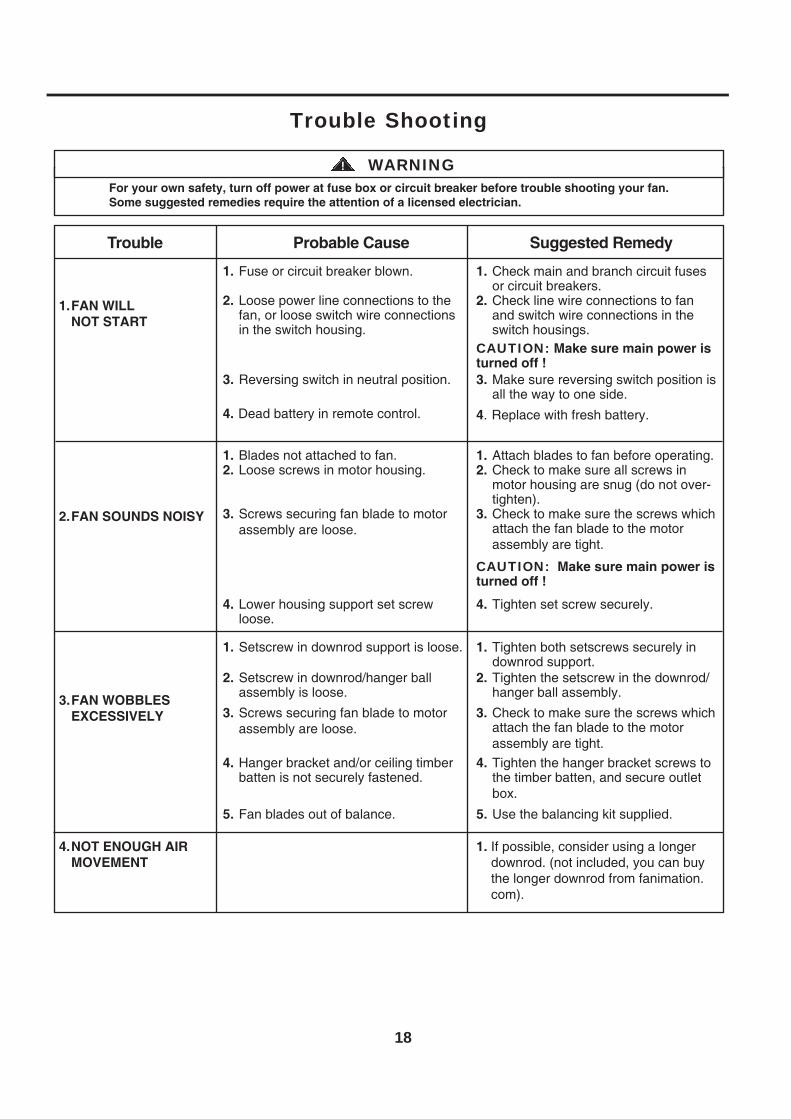
5. Fan blades out of balance. 5. Use the balancing kit supplied.
3. Make sure reversing switch position isall the way to one side.
3. Reversing switch in neutral position.
For your own safety, turn off power at fuse box or circuit breaker before trouble shooting your fan.Some suggested remedies require the attention of a licensed electrician.
WARNING!
Trouble Probable Cause Suggested Remedy
1.FAN WILLNOT START
1. Check main and branch circuit fusesor circuit breakers.
2. Check line wire connections to fanand switch wire connections in theswitch housings.
CAUTION: Make sure main power isturned off !
1. Fuse or circuit breaker blown.
2. Loose power line connections to thefan, or loose switch wire connectionsin the switch housing.
2.FAN SOUNDS NOISY
1. Attach blades to fan before operating.2. Check to make sure all screws in
motor housing are snug (do not over-tighten).
3. Check to make sure the screws whichattach the fan blade to the motor assembly are tight.
3. Check to make sure the screws whichattach the fan blade to the motor assembly are tight.
CAUTION: Make sure main power isturned off !
4. Tighten set screw securely.
1. Blades not attached to fan.2. Loose screws in motor housing.
3. Screws securing fan blade to motor assembly are loose.
3. Screws securing fan blade to motor assembly are loose.
4. Lower housing support set screwloose.
3.FAN WOBBLESEXCESSIVELY
1. Tighten both setscrews securely indownrod support.
2. Tighten the setscrew in the downrod/hanger ball assembly.
4. Tighten the hanger bracket screws tothe timber batten, and secure outlet box.
1. Setscrew in downrod support is loose.
2. Setscrew in downrod/hanger ballassembly is loose.
4. Hanger bracket and/or ceiling timberbatten is not securely fastened.
4.NOT ENOUGH AIRMOVEMENT
Trouble Shooting
4. Replace with fresh battery.
1. If possible, consider using a longer downrod. (not included, you can buy the longer downrod from fanimation. com).
4. Dead battery in remote control.

Copyright 2015 Fanimation 2015 12 V.01/
10983 Bennett ParkwayZionsville, IN 46077
(888) 567-2055FAX (866) 482-5215
Outside U.S. call (317) 733-4113Visit Our Website @ www.fanimation.com

The Celano v2 ™Ventilador de techo
Peso neto 8.10 kgs (17.86 lbs)
Modelo N.º FP8062**
MANUAL DEL PROPIETARIOLEA Y GUARDE ESTAS INSTRUCCIONES

ADVERTENCIA:
GARANTÍA LIMITADA DE POR VIDA DEL MOTOR - Si se produjera una falla en alguna de las partes del motor de su ventilador debido 1.a un defecto en los materiales o en la fabricación durante el tiempo de vida del comprador original, Fanimation proporcionará la pieza de repuesto sin cargo una vez que el ventilador defectuoso sea devuelto a nuestro centro de servicios nacional. Se requiere comprobante de venta. El cliente se hará responsable de todos los gastos de remoción o reinstalación y envío del producto para reparaciones o sustitución.GARANTÍA DE MANO DE OBRA DEL MOTOR POR UN AÑO - Si el motor de su ventilador fallara antes de cumplirse un año a partir del 2.momento de su compra original debido a defectos en los materiales o en la fabricación, se le efectuará la reparación del mismo sin cargo en nuestro centro de servicios nacional. El comprador se hará responsable de los gastos de mano de obra luego del período de un año. El cliente se hará responsable de todos los gastos de remoción o reinstalación y envío del producto para reparaciones o sustitución.Si otra pieza del ventilador fallara dentro del período de un año a partir de la fecha de compra original debido a un defecto en los 3.materiales o en la fabricación, repararemos o sustituiremos, según creamos conveniente, la pieza defectuosa sin cargo alguno ennuestro centro de servicios nacional.
GARANTÍA LIMITADA DE POR VIDASe extiende al comprador original de un ventilador Fanimation
Instrucciones de seguridad importantesADVERTENCIA: Siga estas instrucciones para prevenir incendios, descargas eléctricas y lesiones personales graves.
Lea el manual del propietario y la información de seguridad antes de instalar su nuevo ventilador. Observe los diagramas de 1.ensamblaje adjuntos.Antes de llevar a cabo el mantenimiento o la limpieza de la unidad, desconecte la electricidad en el panel de servicio y bloquee los 2.medios de desconexión del mismo para evitar que se active accidentalmente. Si no se pueden bloquear los medios de desconexión del servicio, coloque un dispositivo de advertencia, como una etiqueta, en el panel de servicio.Tenga cuidado con la estructura y las aspas del ventilador cuando limpie, pinte o trabaje cerca del mismo. Desconecte siempre la3.electricidad del ventilador de techo antes de llevar a cabo el mantenimiento.No coloque nada en las aspas del ventilador cuando éste se encuentra en funcionamiento.4.
Instrucciones de seguridad adicionalesPara evitar posibles descargas eléctricas, asegúrese de que la electricidad esté desconectada en la caja de fusibles antes de realizar1.la instalación eléctrica, y no haga funcionar el ventilador sin las aspas.Todos los procedimientos de conexión eléctrica e instalación deben cumplir con los Códigos eléctricos nacionales (ANSI/NFPA 2.70-1999) y Códigos locales. El ventilador de techo debe estar conectado a tierra a fin de prevenir posibles descargas eléctricas. La instalación eléctrica debe ser llevada a cabo o aprobada por un electricista autorizado.Se debe fijar bien la base del ventilador; ésta debe ser capaz de soportar sin problemas al menos 15,9 kg (35 lb). Consulte la página3.25 del manual del propietario para ver los requisitos de soporte. Si tiene dudas, consulte a un electricista calificado.Las aspas del ventilador deben instalarse por lo menos a 2,13 m (7 pies) del suelo, a fin de evitar un contacto accidental con las mismas.4.Siga las recomendaciones sobre el método correcto de instalación eléctrica de su ventilador de techo. Si no posee la experiencia o 5.los conocimientos eléctricos adecuados, contrate a un electricista autorizado para instalar el ventilador.Apto para usar con controles de velocidad de estado sólido.6.Este ventilador es ideal para lugares secos.7.
ADVERTENCIA: Monte a una caja de salida aceptable para apoyo de los aficionados.
PARA REDUCIR EL RIESGO DE DESCARGAS ELÉCTRICAS, ESTE VENTILADOR SE DEBE INSTALAR CON UN CONTROL/INTERRUPTOR DE PARED AISLADO.ADVERTENCIA: Este producto está diseñado para ser usado sólo con las piezas suministradas o los accesorios indicados específicamente para el mismo. Si utiliza piezas o accesorios que no están indicados para su uso con este producto, podría sufrir lesiones personales o dañar el ventilador. ADVERTENCIA: Este producto está diseñado para ser usado sólo con las piezas suministradas o los accesorios indicados específicamente para el mismo. Si utiliza piezas o accesorios que no están indicados para su uso con este producto, podría sufrir lesiones personales o dañar el ventilador.ADVERTENCIA: Para reducir el riesgo de lesiones personales, no doble los soportes de las aspas (borde o soporte de aspas) al instalarlos soportes, balancear las aspas o limpiar el ventilador. No coloque objetos extraños entre las aspas del ventilador en funcionamiento.
(1) Este equipo no causará interferencias perjudiciales y (2) este equipo tolerará cualquier interferencia recibida, incluidas lasinterferencias que puedan provocar un funcionamiento no deseado. Si el radiador intencional puede ser clasificado como undispositivo digital de clase B o un periférico del ordenador, entonces se deberán incluir los siguientes o equivalentes:Nota: Tras someterlo a las pruebas correspondientes, se ha determinado que este equipo cumple con los límites establecidos paradispositivos digitales de Clase B de conformidad con la parte 15 de la Normativa FCC. Estos límites se han establecido con el objetivode aportar una protección razonable contra interferencias perjudiciales cuando el equipo se utiliza en el hogar. Este equipo genera,utiliza y puede emitir energía de radiofrecuencia y, a menos que se instale y se utilice de acuerdo con el manual de instrucciones, puede provocar interferencias perjudiciales en las comunicaciones por radio y televisión. Si el equipo produce interferencias perjudiciales en la recepción de radio o televisión, lo cual puede probarse encendiendo y apagando el equipo, se recomienda al usuario corregir dichasinterferencias tomando una o varias de las siguientes medidas:- Modificar la orientación o ubicación de la antena de recepción;- Aumentar la separación entre el equipo y el receptor;- Conectar el equipo a una toma de corriente o circuito diferente al del receptor;Consulte al distribuidor o a un técnico especialista de radio o TV para obtener más ayuda.Nota: Para un dispositivo digital de clase A, la declaración de 15. 105(a) debe ser incluida cuando sea apropiada para el dispositivo en cuestión.
6. El dispositivo no ha sido diseñador para ser utilizado por niños o personas enfermas sin supervisión. Los niños deben ser supervisados para asegurarse de que no juegan con el dispositivo.
8. En lo que respecta a las conexiones de suministro, si el conductor del ventilador está identificado como conductor con conexión a tierra, se le debe conectar a un suministro de electricidad con conductor de puesta a tierra. Si el conductor del ventilador está identificado como conductor que no es de puesta a tierra, se le debe conectar a un suministro de electricidad con conductor sin puesta a tierra. Si el conductor del ventilador está identificado para equipos de puesta a tierra, se le debe conectar al conductor de equipos de puesta a tierra.
No accione el conmutador inversor hasta que las aspas del ventilador se hayan detenido por completo.5.
ADVERTENCIA: No utilice este ventilador con un controlador variable de pared (Rheostat) o un regulador de intensidad. Si lo hiciera podría dañar la unidad del mando a distancia del ventilador de techo.
Si otra pieza del kit de luz fallara dentro del período de cinco año a partir de la fecha de compra original debido a un defecto en los materiales o en la fabricación, repararemos o sustituiremos, según creamos conveniente, la pieza defectuosa sin cargo alguno en nuestro centro de servicios nacional.
4.

arto anugnin etsixe oN .noitaminaF ed elbinopsid osrucer ocinú le nos senoicutitsus sal y senoicaraper sal euq edneitne eS .01garantía expresa o implícita. Por la presente, Fanimation niega todas las garantías implícitas, que incluyen, entre otras, la comerciabilidad y la aptitud para determinado fin hasta donde la ley lo permita. Algunos estados no permiten limitaciones sobre las garantías implícitas. Fanimation no se hará responsable por daños accidentales, resultantes o especiales derivados del uso o elrendimiento del producto o en conjunción con éste, excepto en los casos en los que la ley así lo disponga. Esta garantía le otorgaderechos legales especiales y es posible que también goce de otros derechos que pueden variar según el estado.
11. Es normal que se produzca un cierto movimiento oscilante y esto no debe considerarse un problema o defecto.
GARANTÍA LIMITADA DE POR VIDASe extiende al comprador original de un ventilador Fanimation
8. Fanimation se reserva el derecho de modificar o discontinuar un producto en cualquier momento, o sustituir cualquier pieza segúnlo establecido por esta garantía.
9. En ningún caso se podrá devolver un ventilador sin previa autorización por parte de Fanimation. Las devoluciones autorizadasdeberán ir acompañadas del recibo de venta y deberán enviarse a Fanimation, previo pago del flete. El ventilador que se devuelvadeberá estar embalado en forma adecuada a fin de evitar daños durante el transporte. Fanimation no se hará responsable de los daños que resulten del embalaje incorrecto del producto.
Tabla de contenidos
Instrucciones para el desempaque. . . . . . . . . . . . . . . . . .Uso e ciente de la energía en ventiladores de techo. . .Requisitos eléctricos y estructurales. . . . . . . . . . . . . . . .
232424
Cómo ensamblar el ventilador de techo. . . . . . . . . . . . . .Cómo colgar el ventilador de techo . . . . . . . . . . . . . . . . .Cómo realizar la instalación eléctrica del ventilador de techo. . . . . . . . . . . . . . . . . . . . . . . . . . . . . . . . . . . . . . . . . . . Cómo instalar la carcasa de la cubierta . . . . . . . . . . . . . .31
2729
30
Cómo ensamblar las aspas del ventilador de techo . . . .26
Todos los gastos de remoción y reinstalación del ventilador son responsabilidad exclusiva del propietario, y no de la tienda que7.vendió el ventilador ni de Fanimation.
31
Cómo instalar su mando a distancia . . . . . . . . . . . . . . . . Mantenimiento. . . . . . . . . . . . . . . . . . . . . . . . . . . . . . . . . . .Cómo instalar su mando a distancia. . . . . . . . . . . . . . . .
Solución de problemas. . . . . . . . . . . . . . . . . . . . . . . . . . . .
Lista de piezas. . . . . . . . . . . . . . . . . . . . . . . . . . . . . . . . . . . . . . . . . . . . . . . . . . . . . . . . . . . . . . eceipsed led nóicartsulI
32343434353637
Cómo utilizar su control remoto de mano . . . . . . . . . . . . Cómo ensamblar las kit de luz . . . . . . . . . . . . . . . . . . . . .
Esta garantía es nula y no se aplica a daños por instalación incorrecta, negligencia, accidentes, uso indebido, exposición al calor o 6.a la humedad en exceso, o como resultado de cualquier modificación realizada al producto original.
Debido a las diversas condiciones climáticas, esta garantía no cubre cambios en la terminación, incluidos oxidación, corrosión,5.falta de brillo o peladuras.

NOTA: Si no está seguro de la descripción de una pieza, consulte la ilustración del despiece.
1. Verifique que haya recibido las siguientes piezas:
ADVERTENCIANo instale o utilice el ventilador si falta alguna pieza o si hay piezas dañadas. Este producto está diseñado para ser usado sólo con las piezas suministradas o los accesorios indicados por Fanimation específicamente para el mismo. La sustitución de piezas o accesorios no designados por Fanimation para usarse con este producto podría ocasionar lesionespersonales o daños en el ventilador. Póngase en contacto con su tienda si faltan piezas o hay piezas dañadas.
23
Ensamble del kit de iluminación/el vidrio
Unidad del motor del ventilador
Unidad del soporte de suspensión
Unidad del barral/de la semiesfera
Capuchón de techo
Cubierta de unión del motor
Cubierta para el tornillo del capuchón
Ensamble de la placade iluminación
Unidad del receptor
Bolsas de accesorios Juego de aspas
Control remoto de mano
• Bolsas de accesorios:
– Destornillador Phillips de 4˝– Cuatro conectores de cables– Kit de balanceo
– Tornillos 3/16˝-24 y arandela fibra (aspas a buje del motor)
• Unidad del motor del ventilador• Unidad del soporte de suspensión• Unidad del barral/de la semiesfera• Capuchón de techo• Cubierta para el tornillo del capuchón• Cubierta de unión del motor• Ensamble de la placa de iluminación• Ensamble del kit de iluminación/el vidrio• Juego de aspas• Control remoto de mano • Unidad del receptor
Instrucciones para el desempaquePara su comodidad, marque cada uno de los pasos. A medida que completa cada paso, coloque una marca de verificación.Con esto se asegurará de completar todos los pasos y podrá saber desde dónde retomar si fuera interrumpido.
• Destornillador Phillips• Escalera de tijera• Destornillador de ¼˝
• Pelacables• Tres conectores de
cables (incluidos)
Este manual está diseñado para facilitar al máximo el ensamblaje, la instalación, el funcionamiento y el mantenimiento de su ventilador de techo.
Herramientas necesarias para el ensamblaje
ADVERTENCIAAntes de ensamblar el ventilador de techo, consulte la sección sobre el método correcto de instalación eléctrica del ventilador (página 30). Si siente que no posee la experienciao los conocimientos eléctricos necesarios, contrate a un electricista autorizado para instalar el ventilador.
La caja de distribución eléctrica y los conectores de la caja deben ser del tiporequerido por el código local. El cable más pequeño debe ser un cable de tresconductores (de dos conductores con conexión a tierra) del siguiente tamaño:
NOTA: coloque las piezas de las bolsas de piezas individuales en un contenedor pequeño para evitar que se extravíen. Si faltan piezas, pón-gase en contacto con su proveedor local.
Materiales
tamaño del cable según el A.W.G. (Calibre de Alambre Estadounidense)longitud del cable instalado
1412
hasta 15,2 m (50 pies)de 15,2 a 30,5 m (50 a 100 pies)

Requisitos eléctricos y estructurales
Su nuevo ventilador de techo requiere una línea desuministro eléctrico con conexión a tierra de 120 voltios deCA, 60 Hz, circuito de 15 amperios. La normativa eléctrica requiere el uso de una caja de distribución eléctrica para ventiladores que soporte el peso extra y el movimiento asociado a un ventilador de techo. La caja de distribución eléctrica será etiquetada como tal y soportará un ventilador de techo de un peso de hasta 70 libras. Dichas cajas varían en tipos y diseños. Asegúrese d que el tipo de su caja reúne los criterios para el ventilador que se está instalando. Las ilustraciones 1, 2 y 3 muestran las diferentes configuraciones estructurales que pueden ser utilizadas para dicha caja de distribución eléctrica.
Caja de perfil bajo (Figura 1)La caja lisa de 1/2 pulgada de profundidad será atornillada a una viga o bloque. Se utilizará si solo un cable va a ser introducido en la caja. También está disponible en una configuración de montaje endosado.
2" x 4"
Figura 1
Figura 2
2" x 4"
Caja profunda (Figura 2)La caja de 2-1/4 pulgada será atornillada a un bloque entre vigas que tenga suficiente espacio para colocar más de un cable.
Uso eficiente de la energía en ventiladores de techoEl nivel de rendimiento y ahorro de energía de losventiladoresdetechodependendesucorrectainstalaciónyuso.Acontinuaciónlepresentamosalgunassugerenciaspara asegurar un rendimiento eficiente del producto.
Selección del lugar de montaje adecuadoLos ventiladores de techo se deben instalar en el centro de la habitación, a 2,13 m (7 pies) de altura del piso como mínimo y 0,5 m (18 pulgadas) de las paredes. Si la altura del techo lo permite, instale el ventilador a 2,5 m (8-9 pies) por encima del suelo para un flujo de aire óptimo. Consulte en su tienda minorista de Fanimation para obtener accesorios de montaje opcionales.
Apague el ventilador cuando no se encuentre en la habitaciónLos ventiladores son para refrescar a la gente, no a las habitaciones. Si la habitación está vacía, apague el ventilador de techo para ahorrar energía.
Uso del ventilador de techo todo el año
En verano: Use el ventilador de techo en sentido contrario alas agujas del reloj. El flujo de aire que produce el ventilador crearáunefecto fríodelaireque lo refrescarámás.Seleccione una velocidad que le proporcione una brisa confortable. Lasvelocidades más bajas consumen menos energía.
En invierno: Invierta el motor y haga funcionar el ventilador de techo a velocidad baja y en el sentido de las agujas del reloj. Esto produce una suave corriente ascendente, que obliga al aire cálido que se acumula cerca del techo a bajar al espacio ocupado. No olvide ajustar el termostato cuando utilice el ventilador de techo. Con este sencillo paso puede ahorrar energía adicional y dinero.
Techo
Techo
Vigas del techo
Vigas del techo
Caja de distribucióneléctrica
Caja de distribucióneléctrica
24

Requisitos eléctricos y estructurales (cont.)
Si su ventilador va a sustituir una instalación de iluminación existente, desconecte la electricidad de la caja del fusible principal en esta ocasión y extraiga la unidad de iluminación.
Profunda caja con aparato ortopédico (Figura 3)Conectado a una caja de distribución eléctrica, este colgador sirve para abarcar el espacio entre dos vigas y ocupar el lugar de bloqueo de la madera.
Figura 3
Techo
Vigas del techo
Caja de distribución eléctrica
ADVERTENCIAA fin de evitar incendios o descargas eléctricas, siga concuidado todas las instrucciones de instalación eléctrica.Cualquier trabajo eléctrico que no se describa en estas instrucciones deberá ser realizado o aprobado por un electricista autorizado.
ADVERTENCIAApagar el interruptor de pared no es suficiente. Para evitar posibles descargas eléctricas, asegúrese de que la electricidad esté desconectada en la caja de fusibles principal antes de realizar la instalación eléctrica. Toda instalación eléctrica debe cumplir con los códigosnacionales y locales y el ventilador de techo debe tener la conexión a tierra adecuada como forma de precauciónante posibles descargas eléctricas.
ADVERTENCIAPara reducir el riesgo de incendio, descargas eléctricas o lesiones personales, monte el ventilador en una caja de salida marcada como “Apta para sostener ventiladores de15,89 kg o menos” y use los tornillos de montaje provistos con la caja de salida. La mayoría de las cajas de salida que se usan comúnmente para sostener ensambles de iluminación no son aptas para sostener un ventilador y puede ser necesario reemplazarlas. Si tiene dudas, consulte a un electricista cali cado.
25
ADVERTENCIANo utilice este ventilador con un controlador variable de pared (Rheostat) o un regulador de intensidad. Si lo hiciera podría dañar la unidad del mando a distancia del ventilador de techo.

26
Figura 1
Figura 2
Figura 3
Figura 4 Aspa
Motor
Motor
Cubierta de la carcasa superior
3. Retire la arandela del acoplador del motor y la cubierta de la carcasa superior del ensamble del motor.(Figura 3)
Arandela del acoplador del motor
Arandela del acoplador del motor
Soporte de la varilla
4. Coloque las palas a través de las ranuras en lacubierta del motor y coloque el aspa en el ensamble del motor con los postes roscados que se muestran.Asegúrese de que el borde inferior del aspa esté completamente asentado sobre el volante del ensamble del motor. Apriete los tornillos con cabeza de arandela junto con las arandelas de fibra para asegurar el aspa al volante del ensamble del motor.(Figura 4)
Cómo ensamblar las aspas del ventilador de techo
2. Retire los seis tornillos preensamblados de la arandela del acoplador del motor del ensamble del motor y guárdelos para volverlos a instalar en el paso 6. (Figura 2)
1. Retire los dos tornillos preensamblados del soporte de la varilla del ensamble del motor y guárdelos para volverlos a instalar en la Cómo ensamblar el ventilador de techo, paso 4. (Figura 1)
ADVERTENCIAPara reducir el riesgo de lesiones personales, no doble los soportes de aspas al instalarlos, balancear las aspas o limpiar el ventilador. No coloque objetos extraños entre las aspas del ventilador en funcionamiento.
x 15
x 15Arandela de fibra
Aditamentos utilizados:
Tornillos de
Tornillos de3/16˝-24 y arandela de fibra(3 por de aspas)
27
Figura 5
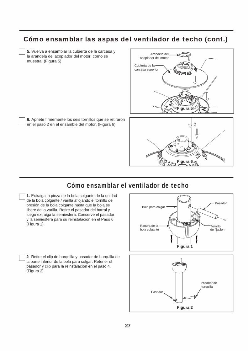
5. Vuelva a ensamblar la cubierta de la carcasa y la arandela del acoplador del motor, como semuestra. (Figura 5)
6. Apriete firmemente los seis tornillos que se retiraron en el paso 2 en el ensamble del motor. (Figura 6)
Figura 6
Figura 1
Figura 2
Cómo ensamblar las aspas del ventilador de techo (cont.)
Cubierta de la carcasa superior
Arandela del acoplador del motor
Cómo ensamblar el ventilador de techo
2 .Retire el clip de horquilla y pasador de horquilla de la parte inferior de la bola para colgar. Retener el pasador y clip para la reinstalación en el paso 4.(Figura 2)
1. Extraiga la pieza de la bola colgante de la unidad de la bola colgante / varilla aflojando el tornillo de presión de la bola colgante hasta que la bola se libere de la varilla. Retire el pasador del barral y luego extraiga la semiesfera. Conserve el pasador y la semiesfera para su reinstalación en el Paso 6(Figura 1). Ranura de la
bola colgante
Pasador
Tornillode fijación
Bola para colgar
Pasador de horquilla
Pasador

28
Figura 5
Figura 6
3. Lntroduzca los cables de color negro, azul y blanco a través de la varilla. (Figura 3)
Figura 4
Figura 3
Figura 7
Cómo ensamblar el ventilador de techo (cont.)
Bola para colgar
Cables Negro, Azul y Blanco
Tornillo de fijación (2)
4. Coloque el soporte de la varilla y alinee los orificios de la clavija de horquilla en ambas piezas. Instale la clavija de horquilla y asegúrela con la pinza de horquilla. Fije los dos tornillos de presión y las tuercas de seguridad en el soporte de la varilla interior. (Figura 4)
Es fundamental que instale correctamente el pasador de horquilla en el soporte de la varilla, y que ajustefirmemente los tornillos de fijación y las tuercas. El incumplimiento de dicho paso podría hacer que el ventilador se caiga.
ADVERTENCIA Pasador de horquilla
Pasador
5. Pase los cables a través de la cubierta de unión del motor, la cubierta para el tornillo y el capuchón. (Figura 5)
Capuchónde techo
Cubierta de unión del motor
Cubierta del tornillo de la base
7. Corte el exceso de cable aproximadamente de 15 a 23 cm (6 a 9 pulgadas) por encima de la parte superior del barral. Pele 1,2 cm ( ) del aislamiento en cada extremo del cable. (Figura 7)
NOTA: Se deben revisar todos los tornillos de fijación y volver a ajustarlos cuando sea necesario antes de realizar la instalación.
6. Vuelva a colocar la semiesfera en el barral como se indica a continuación. Pase los tres cables de cables de blanco, negro y azul cable de soporte para techo a través de la semiesfera. Pase el pasador a través de los dos orificios en el barral y alinee la semiesfera de modo que el pasador quede atrapado en la ranura de la parte superior de la misma. Empuje la semiesfera hacia arriba, bien ajustada contra el pasador. Ajuste firmemente el tornillo de fijación en la semiesfera. Si el tornillo de fijación está flojo, podría provocar oscilación del ventilador. (Figura 6)
15,2
4 cm
a
22,8
6 cm

29
Cómo colgar el ventilador de techo
Figura 2
Figura 3
Figura 4
Figura 1
2. Levante cuidadosamente el ventilador y coloque el ensamble de la bola para colgar/varilla en la abrazaderapara colgar que acaba de fijar a la caja de salida.Asegúrese de que la ranura de la bola esté alineada con la lengüeta de la abrazadera para colgar. (Figura 4)
La caja de salida debe estar bien asegurada. La abrazadera para colgar debe estar bien asentada contra la caja de salida. Si la caja de salida está empotrada, retire el panel hasta que la abrazadera haga contacto con la caja. Si la abrazadera y/o la caja de salida no están bien aseguradas, el ventilador podría tambalearse o caerse.
Si no coloca la lengüeta en la ranura, podrían dañarse los cables eléctricos y podrían ocurrir incendios o descargas eléctricas.
ADVERTENCIA
ADVERTENCIA
Para evitar una posible descarga eléctrica, no apriete los cables entre el ensamble de la bola para colgary la abrazadera para colgar.
ADVERTENCIA
ADVERTENCIAPara evitar una posible descarga eléctrica, asegúrese de cortar la alimentación eléctrica de la caja de fusibles principal antes de colgar el ventilador.
Debe colgar el ventilador a una distancia mínima de 2,13 m desde las aspas hasta el piso. (Figura 2)
(Figura 1)
ADVERTENCIA
NOTA: Si no está seguro de si la caja de salida tiene conexión a tierra, pida consejo a un electricista certificado, ya que debe tener conexión a tierra para un funcionamiento seguro.
PRINCIPAL CAJA DEFUSIBLES
EI Piso
EI Techo
Nomenos de
2,13 m
Caja de salida
Lengüeta
Abrazaderapara colgar
Caja desalida
Ensamble de la bola para colgar/varilla
Abrazaderapara colgar
Arandela Plana
Tornillos (2) suministrados con la ventilador de techo
1. Fije bien la abrazadera para colgar a la caja de salida (no se incluye) con los tornillos y las arandelas provistas con la caja de salida. (Figura 3)
Este ventilador solamente debe montarse en ángulo o de manera estándar. Las opciones de montaje cerrado y al ras no están disponibles. Para techos en ángulo, tenga en cuenta que el ángulo no puede tener más de 19°.

30
Figura 4
Figura 1
Cómo realizar la instalación eléctrica del ventilador de techoNOTA: Si los cables de suministro o del ventilador son de colores dif para que realice la instalación.
PRECAUCIÓN: UNA CONEXIÓN INCORRECTA DEL CABLE PODRÍA DAÑAR ESTE RECEPTOR.
NOTA: Si no está seguro de si la caja de salida tiene conexión a tierra, pida consejo a un electricista certificado, ya que debe tener conexión a tierra para un funcionamiento seguro.
Para evitar una posible descarga eléctrica, asegúrese de cortar la alimentación eléctrica de la caja de fusibles principal antes de alambrado el ventilador. (Figura 1)
ADVERTENCIA
PRINCIPAL CAJA DE FUSIBLES
3. Una vez que se ha haya realizado la conexión, deslice el receptor en el soporte del colgador, teniendo cuidado de no pillar los cables. El dosel cubrirá el receptor y el soporte del colgador. (Figura 4)
1. Conecte los cables verdes desde el soporte colgante y la bola colgante en el cable desnudo (toma de tierra) utilizando el conector de cables suministrado. Conecte el cable negro desde la unidad del receptor marcado “AC IN L” al cable negro de suministro de electricidad utilizando el conector de cables suministrado. Conecte el cableblanco desde la unidad del receptor marcado “AC
IN N” al cable blanco de suministro de electricidadutilizando el conector de cables suministrado. Conecte el cable blanco desde la unidad del receptor marcado “TO MOTOR N” al cable blancodel ventilador utilizando el conector de cables suministrado con el receptor. Conecte el cable blanco desde la unidad del receptor marcado “TO MOTOR L” al cable blanco del ventilador utilizando el conector de cables suministrado con el receptor. Por último, conecte el cable azul del receptor al cable azul de la luz del ventilador utilizando el conector de cables suministrado. Coloque todos los cables conectados y la antena del receptor para permitir la instalación de la cubierta del techo. (Figura 2)
CABLE VERDE (Toma de tierra)
CABLE VERDE (Toma de tierra de la bola colgante)
CABLE VERDE (Toma de tierra del soporte colgante)
Blanco
Blanco
BLANCO al MotorNEGRO al MotorAZUL a la Luz
Blanco
Negro
Negro
Negro
Azul
NEGRO - Ant.CAJA DE TOMA DE CORRIENTE LISTADA
Figura 2
Negro
Azul
VERDE - Toma de tierra del soporte colgante
NEGRO-ANT.
CAJA DE TOMA DE CORRIENTE LISTADA
VERDE - Toma de tierra de la bola colgante
Blanco
Figura 3
Verifique que todas las conexiones estén ajustadas, incluida la conexión a tierra, y que no haya conductores desnudos visibles en los conectores, excepto el conductor con conexión a tierra. No opere el ventilador hasta que las aspas estén instaladas. Podría ocasionar ruidos y daños al motor.
ADVERTENCIA
x 3
Aditamentos utilizados
Conectoresde cable
2. Una vez haya hecho las conexiones, coloque los cables hacia arriba y empújelos cuidadosamente hacia dentro de la caja de la toma de corriente, poniendo los cables blancos y verdes a un lado de la caja y los negros hacia el otro lado. Los cables deben ser colocados de forma extendida poniendo el conductor de la toma de tierra y el conductor de toma de tierra del equipo a un lado de la caja, colocando el conductor sin toma de tierra en el otro lado de la caja. (Figura 3)

31
Figura 1
Figura 2
Figura 1
Cómo instalar la carcasa de la cubierta
1. Retire uno de los dos tornillos de reborde de laabrazadera para colgar. Afloje el segundo tornillo de reborde sin retirarlo del todo. Ensamble la base girando el chavetero de la base sobre el tornillo de reborde de la abrazadera para colgar. Ajuste el tornillo de reborde. Ensamble por completo el segundo tornillo de reborde que antes había retirado y ajústelo. (Figura 1)
Para evitar posibles incendios o descargas eléctricas, asegúrese de que los cables eléctricos se encuentren completamente adentro de la cubierta del capuchón y de que no estén aprisionados entre la cubierta y el techo.
ADVERTENCIA
NOTA: Este paso se debe realizar luego de completar la instalación eléctrica necesaria.
2. Coloque y ajuste firmemente la cubierta para el tornillo de la base sobre los tornillos de reborde de la abrazadera para colgar mediante el mecanismo de seguro por giro del chavetero. (Figura 2)
Capuchón de techo
Cubierta para el tornillo del capuchón
Cómo ensamblar las kit de luz
Ensamble de la placade iluminación
Ensamble de la placade iluminación
Figura 2
Unidad del motor
Unidad de luz LED
PRECAUCIÓN A fin de reducir el riesgo descargas eléctricas, desconecte el circuito de suministro eléctrico al ventilador antes de instalar el kit de iluminación.
PRECAUCIÓN La fuente de luz está diseñado para esta aplicación específi-ca y puede recalentarse si reparado por personal no capacitado. Si se requiere ningún tipo de servicio, el producto debe ser devuelto a un centro de servicio autoriza-do para su revisión o reparación.
1. Extraiga uno de los tres tornillos del soporteubicado en la parte inferior de la unidad del motory guarde los tornillos para pasos posteriores. Afloje levemente los otros dos tornillos. Instale la ensamble de la placa de iluminación en el soporte utilizando las dos el soporte utilizando las dos ranuras principales. Vuelva a colocar el tercertornillo y asegure apriete. (Figura 1)
2. Extraiga uno de los tres tornillos del ensamblede la placa de iluminación y guarde los tornillos para pasos posteriores. Afloje levemente los otros dos tornillos. Instale el conector 2 de pasadores desde unidad de luz LED conexión a la unidad del motor. (Figura 2)

Figura 1
Figura 2
32
Figura 3
Figura 4
Cómo ensamblar las kit de luz (cont.)
Vidrio
Unidad de luz LED
4. Asegure el vidrio en al unidad de luz LED girándolo en el sentido de las agujas del reloj y sin apretar demasiado. (Figura 4)
3. Instale la unidad de luz LED sobre de la ensamblede la placa de iluminación utilizando las dos ranuras principales de la placa de conexión. Vuelva a colocar el tercer tornillo y asegure los tres tornillos. (Figura 3)
Ensamble de la placa de iluminación
Cómo utilizar su control remoto de mano1. IMPORTANTE: El uso de un regulador de la intensidad completa (no incluido) para controlar la velocidad del ventilador dañará el dispositivo. Para reducir el riesgo de incendio o descarga eléctrica, no utilice dicho regulador para controlar la velocidad del ventilador. (Figura 1)
2. Restaure la fuente de alimentación de la toma de corriente enciendo la electricidad del fusible principal.(Figura 2)
Compruebe que todas las conexiones realizadas correctamente, incluyendo la toma de tierra, y que no se visualizan ningún cable pelado en los conectores de cables, con la excepción del cable de toma de tierra. No utilice el ventilador hasta que las palas estén colocadas en su lugar, ya que de lo contrario se podría causar ruido y daños.
ADVERTENCIA
ADVERTENCIANo utilice este ventilador con un controlador variable de pared (Rheostat) o un regulador de intensidad. Si lo hiciera podría dañar la unidad del mando a distancia del ventilador de techo.
Solo para referencia visual-no ha sido diseñado para cubrir todos los tipos de controles
PRINCIPAL CAJA DE FUSIBLES

33
Figura 3
Figura 4
: Apaga el ventilador de techo. : Enciende el ventilador de techo a velocidad alta. : Enciende el ventilador de techo a velocidad media. : Enciende el ventilador de techo a velocidad baja.
3. Los botones del mando a distancia tienen las siguientes funciones: (Figura 3)
ENCENDIDO/APAGADO LUZ: Pulse y suelte el botón inmediatamente para encender o apagar la luz.ATENUADOR DE LA LUZ: Pulse y mantenga pulsado para aumentar o disminuir la luminosidad hasta llegar al nivel deseado; momento en el cual debe soltar el botón.
NOTA: Para usar su dispositivo inteligente para controlar su receptor, descárguese la App fanLink desde su App Store: Visite www.fanimation.com/fanSync
Cómo utilizar su control remoto de mano (cont.)
Interruptores DIP
CR2430 3V
Interruptores de más tenueDIMMER
ON/OFF
4. Proceso de emparejamiento del Recepctor y Transmisor: (Figura 4)
– El receptor y el transmisor que lo acompaña están emparejados de fábrica. Si sustituye el transmisor o el receptor, debe seguir el siguiente proceso antes de poder usar la unidad. El receptor fanSync puede emparejarse con hasta (5) transmisores. NOTA: El emparejamiento de dispositivos inteligentes es ilimitado.– Tras la instalación de la unidad del receptor, configure el código deseado del transmisor movien-do los interruptores DIP (ubicados debajo de la carcasa de la batería) arriba o abajo para colocarlos en la posición deseada. Cuando el código haya sido configurado, desconecte y vuelva a conectar el ventilador a la fuente de alimentación y mantenga pulsado el botón de apagado del ventilador ( ) durante 1 – 3 segundos. El ventilador se apagará. Vuélvalo a encender a velocidad media para indicar que el proceso de emparejamiento se ha completa-do. Tenga en cuenta que debe pulsar el botón de apagado ( ) en un rango de 30 segundos de desconectar el ventilador. No es necesario volver a emparejar el ventilador tras sustituir las pilas. Cada receptor fanSync puede emparejarse con cinco (5) transmisores diferentes (con diferentes códigos de interruptor DIP).
NOTA: Los transmisores pueden emparejarse con múltiples receptores. Cuando realice este proceso, tenga cuidado para no emparejar el transmisor a receptores no deseados. Se sugiere que los ventiladores estén a más de 7 pies de distancia y en enchufes diferentes.
Información sobre el interruptor de reversaTemporada
Verano
Invierno
Dirección de rotación
En dirección de las manecillasdel reloj
En dirección contrariaa las manecillas del reloj
Derecha
Izquierda
Posición del interruptor
5. Si se desea que el flujo del aire vaya en la dirección opuesta, apague el ventilador y espere a que se detengan las palas. Deslice la carcasa de la cubiertapara visualizar el interruptor del reverso. (Figura 5)
Figura 5
Interruptordel Reversa

Figura 1
34
Cómo instalar su mando a distancia1. Instalación de la placa de la pared: (Figura 1)
Fije la placa de la pared usando los dos tornillos suministrados.
Se recomienda limpiar el polvo de las aspas periódicamente.Lo mejor es utilizar un plumero.
MantenimientoEl único mantenimiento necesario para el ventilador de techo es una limpieza periódica.Al llevar a cabo la limpieza, use sólo un cepillo suave o un paño sin pelusas, para evitar rayar el acabado.No se requieren agentes abrasivos de limpieza; los mismos deben evitarse para prevenir daños en el acabado.
PRECAUCIÓNNo utilice solventes para limpiar el ventilador de techo. Podrían dañar el motor o las aspas y ocasionar posibles descargas eléctricas.
SE RECOMIENDA: veri car periódicamente que los tornillos que sujetan los soportes de aspas al buje del motor estén bien ajustados.
Cómo limpiar las palas de su ventilador de techoEvite usar agua, productos de limpieza o trapos ásperos, que pueden combar o dañar las aspas.
35
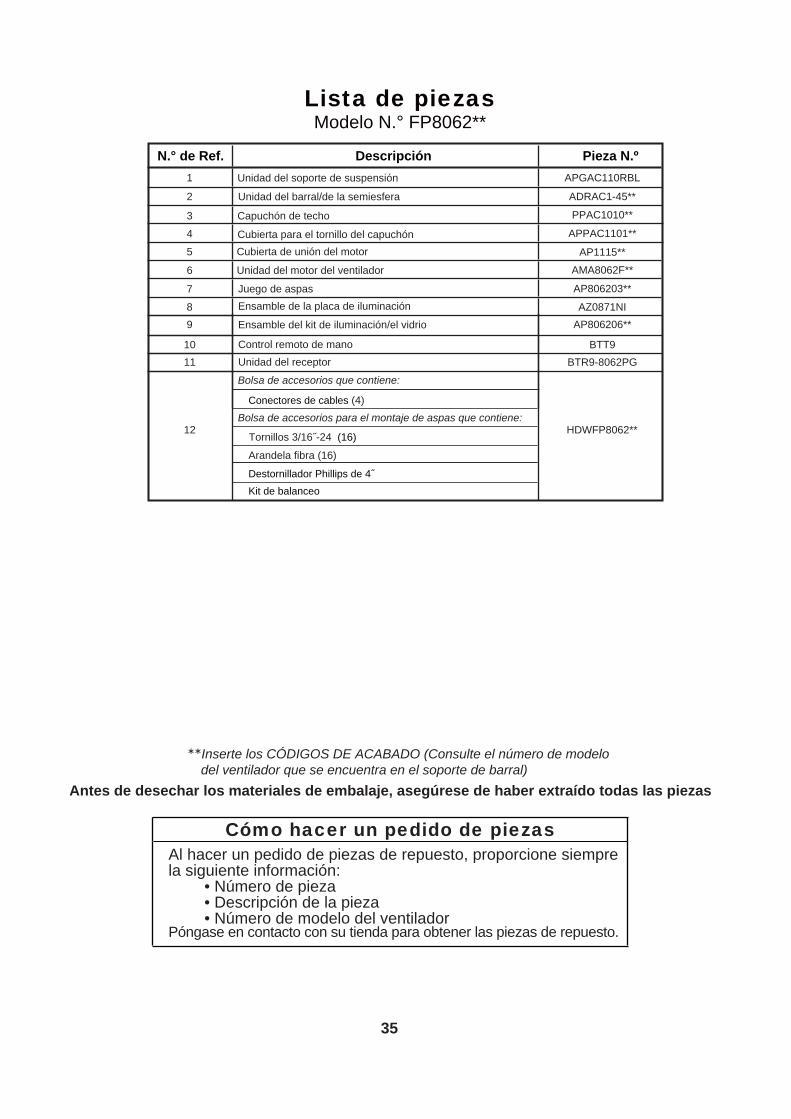
Cómo hacer un pedido de piezasAl hacer un pedido de piezas de repuesto, proporcione siempre la siguiente información:
• Número de pieza• Descripción de la pieza• Número de modelo del ventilador
Póngase en contacto con su tienda para obtener las piezas de repuesto.
Antes de desechar los materiales de embalaje, asegúrese de haber extraído todas las piezas
Inserte los CÓDIGOS DE ACABADO (Consulte el número de modelo del ventilador que se encuentra en el soporte de barral)
Lista de piezasModelo N.° FP8062**
1
2
3
4
5
6
Cubierta para el tornillo del capuchón
APGAC110RBL
ADRAC1-45**
PPAC1010**
APPAC1101**
AP1115**
AMA8062F**
7
10
Ensamble de la placa de iluminación
Ensamble del kit de iluminación/el vidrio
AP806203**
11
Control remoto de mano
BTR9-8062PG
12
Unidad del receptor
HDWFP8062**
BTT9
89
Juego de aspas
AP806206**AZ0871NI
Cubierta de unión del motor
Unidad del motor del ventilador
Unidad del soporte de suspensión
Unidad del barral/de la semiesfera
Capuchón de techo
Arandela fibra (16)
Destornillador Phillips de 4˝Kit de balanceo
Conectores de cables (4)Bolsa de accesorios para el montaje de aspas que contiene:
Tornillos 3/16˝-24 (16)
Bolsa de accesorios que contiene:
N.° de Ref. Descripción Pieza N.º

36
1
2
3
4
5
6
10 11
7
12
8
9
Model FP8062** Ilustración del despiece
Celano v2™
NOTA:

37
4. El tornillo del soporte de la cubierta inferior está flojo. 4. Asegure bien los tornillos de fijación.
Solución de problemas
Problema Causa posible Solución sugerida1. EL VENTILADOR NO
ARRANCA1. El fusible o el disyuntor están fundidos.
2. Las conexiones eléctricas del ventilador o del interruptor en la caja del interruptor están flojas.
3. El conmutador inversor se encuentra en posición neutra.
4. Sin batería en el control remoto. 4. Reemplace con una batería nueva
1. Controle los fusibles del circuito principal y derivado o los disyuntores.
2. Controle las conexiones eléctricas del ventilador y del interruptor en las cajas de los interruptores.
PRECAUCIÓN: ¡Asegúrese de que el suministro principal de electricidad esté desconectado!
PRECAUCIÓN: ¡Asegúrese de que el suministro principal de electricidad esté desconectado!
3. Asegúrese de que el conmutador inversor esté completamente a un lado.
2. EL VENTILADOR HACE RUIDO
1. Las aspas no están sujetas al ventilador
2. Hay tornillos flojos en la caja del motor.
3. Los tornillos que aseguran los soportes de las aspas al buje del motor están flojos.
1. Ajuste las aspas al ventilador antes de ponerlo en funcionamiento.
2. Asegúrese de que todos los tornillos de la caja del motor estén bien ajustados (pero no en exceso).
3. Asegúrese de que los tornillos que fijan los soportes de aspas al buje del motor del ventilador estén bien ajustados.
3. EL VENTILADOR OSCILA EN EXCESO
1. El tornillo de fijación y la tuerca del soporte de barral están flojos.
2. El tornillo de fijación en la unidad del barral/de la semiesfera está flojo.
3. Los tornillos que aseguran los soportes de las aspas al buje del motor están flojos.
4. El soporte de suspensión o la caja de distribución eléctrica del techo no están bien asegurados.
5. Las aspas del ventilador están desbalanceadas.
1. Ajuste bien los dos tornillos de fijación y las tuercas en el soporte de barral.
2. Ajuste el tornillo de fijación en la unidad del barral/de la semiesfera.
3. Asegúrese de que los tornillos que fijan los soportes de aspas al buje del motor del ventilador estén bien ajustados.
4. Ajuste los tornillos del soporte de suspensión de la caja de distribución eléctrica y asegúrela.
5. Equilibre las palas utilizando el kit de equilibrio suministrado en la bolsa del hardware.
ADVERTENCIAPara su propia seguridad, desconecte la electricidad de la caja de fusibles o disyuntor antes de
solucionar problemas en su ventilador.
4. NO HAY SUFICIENTE MOVIMIENTO DE AIRE
1. Si es posible, considere el uso de un barral más largo. Por ejemplo (no incluido, usted puede comprar el tiempo de la vara hacia abajo fanimation.com)

Copyright 2015 Fanimation 2015 12 V.01/
10983 Bennett ParkwayZionsville, IN 46077
(888) 567-2055FAX (866) 482-5215
Outside U.S. call (317) 733-4113Visit Our Website @ www.fanimation.com
![Celano, Positivismo giuridico e neocostituzionalismo II Positivismo giuridico e... · 1 [LEDI\POGINECO\DISP NSE 2006 – 2007 SECONDA PARTE] [novembre 2006] Bruno Celano Positivismo](https://img.dokumen.tips/doc/110x75/5c67e31609d3f2bb148c6c5e/celano-positivismo-giuridico-e-neocostituzionalismo-positivismo-giuridico-e.jpg)

![Celano, Positivismo giuridico e neocostituzionalismo I Positivismo giuridico e... · 2 [LEDI\POGINECO Parte I (TXM)] [ottobre 2006] Bruno Celano Positivismo giuridico e neocostituzionalismo](https://img.dokumen.tips/doc/110x75/5c67e31609d3f2bb148c6c5f/celano-positivismo-giuridico-e-neocostituzionalismo-i-positivismo-giuridico-e.jpg)