Embed Size (px)
Citation preview

D-S
eries
Models
: D
PR
-220
0A
LW
Technical Datasheet
TDS-DPR2200-B: NOV 2014
www.delta-controls.com
Product Applications
The DPR-2200 is suitable for a wide
range of applications for measuring:
Ÿ Differential Pressure
Ÿ Level
Ÿ Flow
The choice of models available
ensures that the DPR-2200 is:
Ÿ Suitable for use in corrosive
atmospheres
Ÿ Resistant to chemical attack
How can we help you?
Delta Controls offers fast, efficient and
knowledgeable support when and
where you need it. Please visit our
website at to www.delta-controls.com
find your local support centre or call us
on:
+44 (0) 1252 729 140
D-SeriesSMART Differential Pressure Transmitter with Two Diaphragm SealsModels: DPR-2200
Key Features
Ÿ High accuracy ±0.1%
Ÿ 4-20mA analogue with digital communications
Ÿ Fully HART ® compatible
Ÿ Static pressure limit up to 420 bar
Ÿ ATEX certified (Intrinsic Safety, Flameproof)
Ÿ Fully welded sensor guarantees tightness of oil systems for
long term usage
Ÿ Ability to locally configure measuring range
Series Overview
The D-Series pressure, differential pressure and temperature
transmitters offer customers cost-effective and accurate
solutions to their individual process requirements.
Available with a wide range of process connections and easily
configurable via the D-Soft software, the D-Series can be used
for a variety of applications where pressure, differential
pressure, temperature, level or flow measurements are needed.
Other models in this series include:
Ÿ DPR-2000G SMART Differential Pressure Transmitter for
low ranges
Ÿ DPC-2000 SMART Pressure Transmitter
Ÿ DPT-2000 SMART Temperature Transmitter
Ÿ DPR-2000 SMART Differential Pressure transmitter
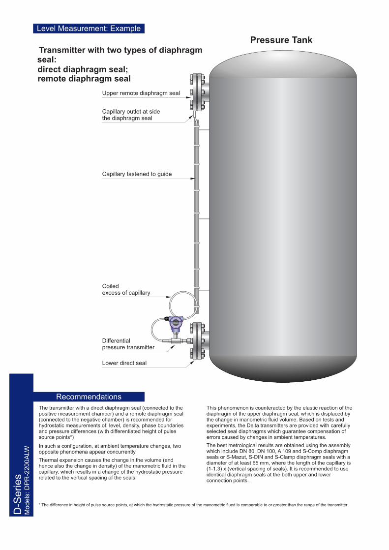
Transmitter with two types of diaphragm seal:
remote diaphragm seal
Upper remote diaphragm seal
Capillary fastened to guide
Coiled excess of capillary
Differential pressure transmitter
Lower direct seal
Capillary outlet at side the diaphragm seal
Pressure Tank
D-S
eries
Models
: D
PR
-220
0A
LWLevel Measurement: Example
Recommendations
direct diaphragm seal;
The transmitter with a direct diaphragm seal (connected to the positive measurement chamber) and a remote diaphragm seal (connected to the negative chamber) is recommended for hydrostatic measurements of: level, density, phase boundaries and pressure differences (with differentiated height of pulse source points*)
In such a configuration, at ambient temperature changes, two opposite phenomena appear concurrently.
Thermal expansion causes the change in the volume (and hence also the change in density) of the manometric fluid in the capillary, which results in a change of the hydrostatic pressure related to the vertical spacing of the seals.
* The difference in height of pulse source points, at which the hydrostatic pressure of the manometric flued is comparable to or greater than the range of the transmitter
This phenomenon is counteracted by the elastic reaction of the diaphragm of the upper diaphragm seal, which is displaced by the change in manometric fluid volume. Based on tests and experiments, the Delta transmitters are provided with carefully selected seal diaphragms which guarantee compensation of errors caused by changes in ambient temperatures.
The best metrological results are obtained using the assembly which include DN 80, DN 100, A 109 and S-Comp diaphragm seals or S-Mazut, S-DIN and S-Clamp diaphragm seals with a diameter of at least 65 mm, where the length of the capillary is (1-1.3) x (vertical spacing of seals). It is recommended to use identical diaphragm seals at the both upper and lower connection points.

D-S
eries
Models
: D
PR
-220
0A
LW
Versions
Note: The appropriate configuration of the complete set of pressure transmitter, diaphragm seals and capillaries, as well as the proper selection of manometric fluid depends on several factors such as: the physical and chemical properties; the temperature range of the medium; the vertical spacing of the diaphragm seals; the measuring range; the static pressure range; the range of ambient temperatures; the technical specification for the mechanical connection of the diaphragm seals to the pressure devices.
34.5
34.5
S-PK diaphragm seal
S-TK diaphragm seal
S-ChK diaphragm seal
S-CompK diaphragm sealM20×1.5 or Æ51
S-DIN K diaphragm sealÆ50, Æ65, Æ80
Transmitter with two types of diaphragm seal: one – direct diaphragm seal and the other – remote diaphragm seal. The example with S-T DN80 diaphragm seal.
transmitter with two remote diaphragm seals. Example with S-PK
Aluminium casing with M20×1.5 packing glandDegree of protection IP 66Type DPR-2200ALW

Application & Construction
The differential pressure transmitter is applicable to the measurement of pressure differences of: gas, vapour and liquid, in cases where it is necessary to use seals and the pressure pulse source points may be several metres apart. Typical applications include the hydrostatic measurement of: level in closed tanks; density and phase boundaries; filter loss pressure differences between media in pasteurisers etc. The available range of the diaphragm seals allow measurement at great majority of media. The active element is a piezoresistant silicon sensor separated from the medium by a distance sealing systems. The special design of the measuring uni means that it can withstand pressure surges and overloads of up to 40bar. The electronic circuits are enclosed in a casing with a degree of protection Ip65 or 66.
Configuration & Comms
The settings of the following metrological parameters can be changed:t the units of pressure in which the range is configured
t stat and end points of the range, time constant
t inverted characteristic (output signal 20 ÷ 4mA)
The transmitter is configured and calibrated using a KAP-03 communicator, other communicators (HART) or a PC using an RS-HART converter and Delta D-Soft configuration software.
The data interchange with the transmitter enables users transmitter identification, as well as readings of the currently measured differential pressure value, ouput current and range width percentage.
Measuring Ranges
Accuracy ≤±0.1% (FSO)**See DPR-2000ALW Differential Pressure Transmitter datasheet for other parametersDPR-2000ALW
Sealing Effect Errors - see Diaphragm Seal datasheet
NOTE: The additional absolute zero error due to ambient temperature can be compernsated by configuring the transmitter, seals and capillaries in accordance with the recommendations on the front page of this datasheet
Electrical parameters - see DPR-2000ALW Differential Pressure Transmitter datasheet
Operating temperature range (ambient temperature) - 25-85°CDPR-2200ALW/EEx - -25-80°C
Medium temperature ranage - see Diaphragm Seal datasheet ref. remote seal
Special versions, certificates:EExia - ATEX Instrinsic safetyEExd - ATEX Explosion proof100 bar, 160 bar - static pressure limit: 100bar or 160barNon-standard basic rangeOthers
Nominal
measuring range (FSO)
Minimum set range Vertical spacing of diaphragm
seals
Maximum set range width, considering the actual vertical spacing
of the diaphragm seals (m)
Static pressure limit
-160…160 mbar 0.1 m H2O L 1.7 m [1.6 + (vertical spacing of seals × 0.94)] m H2O 40 bar
-0.5…0.5 bar 0.5 m H2O L 6 m [5 + (vertical spacing of seals × 1.04)] m H2O 40 bar
-1.6…2 bar 1.5 m H2O L �15 m [20 + (vertical spacing of seals × 1.04)] m H2O 40 bar -1.6…16 bar 1 bar L �15 m 16 bar 40 bar
CAUTION: The maximum vertical diaphragm seal spacing shown in the table applies to level meas urement, ensuring that it is possible to set the zero point of the transmitter when the tank is empty. For measurements of density or phase bou ndaries (in the sugar, chemical or refinery industries) the vertical spacing of the diaphragm seals can be larger.
Metrological parameters Operating conditions
D-S
eries
Models
: D
PR
-220
0A
LW
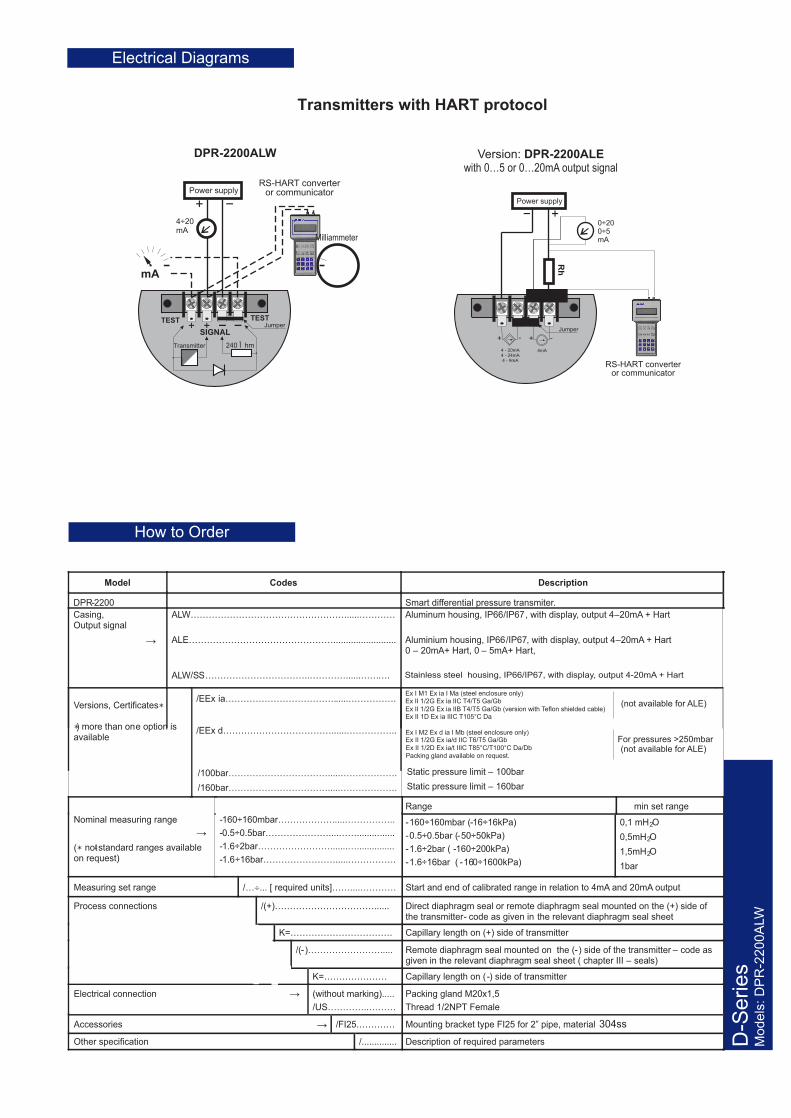
Transmitters with HART protocol
DPR-2200ALW
SIGNAL
TESTTEST
mA
Transmitter 240 Î hm
Power supplyRS-HART converter
or communicator
4÷20 mA
Milliammeter
Jumper
Version: DPR-2200ALEwith 0…5 or 0…20mA output signal
Power supply
RS-HART converter or communicator
Rh
0÷20 0÷5mA
+-
+ --
4 - 20mA4 - 24mA4 - 9mA
4mA
Jumper
Electrical Diagrams
Stainless steel housing, IP66/IP67, with display, output 4-20mA + Hart
Packing gland available on request.
Ex I M1 Ex ia I Ma (steel enclosure only)Ex II 1/2G Ex ia IIC T4/T5 Ga/Gb
For pressures >250mbarEx I M2 Ex d ia I Mb (steel enclosure only)Ex II 1/2G Ex ia/d IIC T6/T5 Ga/Gb
Ex II 1D Ex ia IIIC T105°C Da
(not available for ALE)
Ex II 1/2D Ex ia/t IIIC T85°C/T100°C Da/Db (not available for ALE)
Ex II 1/2G Ex ia IIB T4/T5 Ga/Gb (version with Teflon shielded cable)
→
→
→
How to Order
Model Codes Description
DPR-2200 Smart differential pressure transmiter.
Casing, Output signal
→
ALW……………………………………………......…………
ALE………………………………………….........................
ALW/SS……………………………..…………......……….
Aluminum housing, IP66/IP67, with display, output 4–20mA + Hart
Aluminium housing, IP66/IP67, with display, output 4–20mA + Hart 0 – 20mA+ Hart, 0 – 5mA+ Hart,
Versions, Certificates∗
∗) more than one option is available
/EEx ia………………………………......…………….
/EEx d………………………………......……………..
/100bar…………………………….....……………….
/160bar…………………………….....……………….
Static pressure limit – 100bar
Static pressure limit – 160bar
Nominal measuring range
(∗ not-standard ranges available on request)
-160÷160mbar……………….....……………..
-0.5÷0.5bar…………………....……...............
-1.6÷2bar…………………….......…...............
-1.6÷16bar…………………….....…………….
Range min set range
-160÷160mbar (-16÷16kPa)
-0.5÷0.5bar (-50÷50kPa)
-1.6÷2bar ( -160÷200kPa)
-1.6÷16bar ( -160÷1600kPa)
0,1 mH2O
0,5mH2O
1,5mH2O
1bar
Measuring set range /…¸... [ required units]……....………… Start and end of calibrated range in relation to 4mA and 20mA output
Process connections /(+)……………………………...... Direct diaphragm seal or remote diaphragm seal mounted on the (+) side of the transmitter- code as given in the relevant diaphragm seal sheet
K=……………………………. Capillary length on (+) side of transmitter
/(-)……………………..... Remote diaphragm seal mounted on the (-) side of the transmitter – code as given in the relevant diaphragm seal sheet ( chapter III – seals)
K=………………… Capillary length on ( -) side of transmitter
Electrical connection (without marking).....
/US…………..………
Packing gland M20x1,5
Thread 1/2NPT Female
Accessories /FI25.………… Mounting bracket type FI25 for 2” pipe, material 304ss
Other specification /.............. Description of required parameters

Directions for Use
To simplify the mathematical operations, we introduce the density coefficient of the medium, Xr .
°
rr=
r
3medium
3water at 4 C
[g/cm]X
[g/cm ]
Since the density of water at 4°C is 1 g/cm3 , the density coefficient Xr is numerically equal to the density of the me-dium expressed in g/cm3 . To determine the hydrostatic pressure of a column of liquid in mm H2O, it is sufficient to multiply the height of the column h [mm] by the density coefficient of the liquid Xr. Since it is easy to determine the hydrostatic pressure in mm H2O and the transmitter can be configured in those units, in the descriptions of measurement methods given below we will make use of pressures expressed in mm H2O and the density coefficient Xr.
Configuration of the transmitter to measure the level of liquid in a tank
The measurement task: To convert a variation in the level of a liquid with density r = 0.87 g/cm
3 between 0 and h max to a variation in the
output signal from 4 to 20 mA. 1. Install the transmitter in its working position on an
empty tank. 2. Make the electrical connections of the transmitter,
providing for the ability to use HART communication. 3. Connect the KAP-02 communicator, identify the
transmitter and select the “configuration” function.
4. On the configuration menu select the “Reranging” procedure.
5. On the “Reranging” menu: a) change the units of measurement to mm H2O at 4°C; b) enter the values for the start (Xr × h min [mm]) and
end (Xr × hmax [mm]) of the measurement range, namely 0 and (0.87 hmax [mm]) respectively;
c) to compensate for the hydrostatic pressure of the manometric fluid, the start of the measurement range should be set using regulated pressure; when subjectto the action of only the manometric fluid (empty tank) the transmitter will shift the start and end-points of the range, compensating for the value of that
When the transmitter has been configured in this way it is ready to be used to carry out the given measurement task.
If it is not possible to empty the tank to configure the transmitter, the hydrostatic pressure of the manometric fluid should be calculated by multiplying the vertical spacingof the diaphragm seals by the density coefficient of the oil in the capillaries. This pressure should be taken into account when entering the values for the start and end of the range:
Start [mm H2O] = –H [mm] × Xroil
End [mm H2O] = = hmax [mm] × X rmeasured liquid – H [mm] × Xroil
roil for DC-550 oil is equal to 1.068 g/cm3
roil for AK-20 oil is equal to 0.945 g/cm3
Configuration of the transmitter to measure density of liquids
The measurement task: To convert a variation in liquid density from rmin = 0.6 g/cm
3 to ñ max = 1.2 g /cm
3 to a variation in the
output signal from 4 to 20 mA, with the vertical spacing of the diaphragm seals equal to H = 3000 mm. The sealing system is filled with DC-550 oil with density roil = 1.068 g/cm3.
1. Calculate the value o f the start of the range as follows: H[mm] × (Xrmin – Xroil ) =
= 3000 × (0.6 – 1.068) = –1404 [mm H2O] 2. Calculate the value of the end of the range as follows:
H[mm] × (Xrmax – Xroil) = = 3000 × (1.2 – 1.068) = 396 [mm H2O] 3. Set the zero point of the transmitter with the diaphragm
seals positioned at the same level. 4. Install the transmitter in its working position. 5. Make the electrical connections to the transmitter,
providing for the possibility of using HART communication.
H
ñ4...20 mA
DPI
4...20 mA
H
h
ñ
DPI
H – vertical spacing of diaphragm seals0 £ h £ hmax
3r = 0.87 g/cm
H = 3000 mm0.6 £ [ ] 1.2
3r = 1.068 g/cmoil
3ñ g/cm £
pressure.

D-S
eries
Models
: D
PR
-220
0A
LW
6. Connect the KAP-03 communicator, identify the transmitter and select the “configuration” function.
7. On the configuration menu select “Reranging” proc e-dure.
8. On the “Reranging” menu: a) change the measurement units to mm H2O at 4°C; b) enter the calculated values for the start (–1404) and
end (396) of the range. When the transmitter has been configured in this way it is ready to be used to carry out the given measurement task.
Note: If it is possible to fill the space between the seals with a liquid whose density corresponds to the start of the measurement range, the start of the range of the tran s-mitter can be set using regulated pressure.
Measurement of phase boundary
The height of the phase boundary of liquids of different densities is determined by measuring the average dens i-ty of the medium between the seals. Example: Calculate the measurement range start and end points for an DPR E-2200 transmitter configured to measure phase boundary height in the range 0–1000 mm between liquids of density r1 = 0.7 g/cm 3 and r 2 = 1.0 g/cm 3, where the vertical spacing of the seals H = 1600 mm. The sealing system uses DC -550 oil with a density of 1.068 g/cm3.
To determine the start of the measurement range, calc u-late the pressure differ ence at the transmitter when the tank is filled with the lighter liquid only:
1600 [mm] × (0.7 – 1.068) = –588.8 [mm H2O]
To determine the end-point of the range, add the increase in pressure resulting from the appearance of a 1 metre column of the heavier liquid:
–588.8 [mm H2O] + (1.0 – 0.7) × 1000 [mm] = = –288.8 [mm H2O]
Additional remarks
The settings of the transmitter can be adjusted with re f-erence to laboratory results from density measurements carried out on samples of the liquid being measured. This is most often necessary when the measurement takes place in a pipeline segment where the flow velocity of the measured liquid reaches several m/s.
Increasing the vertical spacing of the diaphragm seals widens the range and often improves measurement accuracy.
In planning the spacing of the diaphragm seals, ensure that the pressure difference at the transmitter lies within the basic range.
The maximum vertical spacing of the diaphragm seals (H) depends on the transmitter’s basic range and the boundary v alues for the density of the measured liquid (rmin; rmax).
If rmin < roil < rmax, the seal spacing H should satisfy the following conditions:
Lr - r
2
m in oi l
lower boundary of range [mm HO]H[mm]
X X
Lr - r
2
max oil
upper boundary of range [mm HO]H[mm]
X X
Example: Determine the maximum vertical spacing of the seals for the DPRE-2200 / -10...10 kPa transmitter when measu r-ing the density of liquid between 0.6 and 1.2 g/cm
3. The
sealing system uses AK -20 silicone oil with a density of 0.945 g/cm3.
The lower boundary of the range of the transmitter is –10 kPa = –1020 mm H2O
- -L ? L ?
- -L
1020 1020H [mm] H [mm]
0.6 0.945 0.345H [mm] 2957
The upper boundary of the range of the transmitter is +10 kPa = 1020 mm H2O
L ? L ?-
L
1020 1020H [mm] H [mm]
1.2 0.945 0.255
H [mm] 4000
In the example, both conditions are satisfied when the spacing of the seals is not more than 2957 mm.
H
h
ñ1
ñ2
4...20 mADP
I
H = 1600 mm0 £ h 1000 mmr = 0.71
3r = 1.0 g/cm23r = 1.068 g/cmoil
£3 g/cm
Directions for Use (cont.)
r

In the interest of development and improvement Delta Controls Ltd, reserves the right to amend, without notice, details
contained in this publication. No legal liability will be accepted by Delta Controls Ltd for any errors, omissions or amendments.
Delta Controls Limited
Riverside Business Park, Dogflud Way, Farnham, Surrey GU9 7SS, UK.
T+44 (0)1252 729 140 F+44 (0)1252 729 168 E [email protected] W www.delta-controls.com