Embed Size (px)
Citation preview
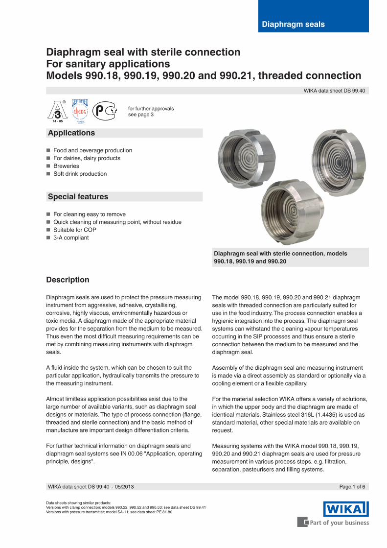
Diaphragm seal with sterile connectionFor sanitary applicationsModels 990.18, 990.19, 990.20 and 990.21, threaded connection
Data sheets showing similar products:Versions with clamp connection; models 990.22, 990.52 and 990.53; see data sheet DS 99.41Versions with pressure transmitter; model SA-11; see data sheet PE 81.80
Applications
■ Food and beverage production ■ For dairies, dairy products ■ Breweries ■ Soft drink production
Special features
■ For cleaning easy to remove ■ Quick cleaning of measuring point, without residue ■ Suitable for COP ■ 3-A compliant
Diaphragm seal with sterile connection, models 990.18, 990.19 and 990.20
Diaphragm seals
Description
Diaphragm seals are used to protect the pressure measuring instrument from aggressive, adhesive, crystallising, corrosive, highly viscous, environmentally hazardous or toxic media. A diaphragm made of the appropriate material provides for the separation from the medium to be measured. Thus even the most difficult measuring requirements can be met by combining measuring instruments with diaphragm seals.
A fluid inside the system, which can be chosen to suit the particular application, hydraulically transmits the pressure to the measuring instrument.
Almost limitless application possibilities exist due to the large number of available variants, such as diaphragm seal designs or materials. The type of process connection (flange, threaded and sterile connection) and the basic method of manufacture are important design differentiation criteria.
For further technical information on diaphragm seals and diaphragm seal systems see IN 00.06 "Application, operating principle, designs".
The model 990.18, 990.19, 990.20 and 990.21 diaphragm seals with threaded connection are particularly suited for use in the food industry. The process connection enables a hygienic integration into the process. The diaphragm seal systems can withstand the cleaning vapour temperatures occurring in the SIP processes and thus ensure a sterile connection between the medium to be measured and the diaphragm seal.
Assembly of the diaphragm seal and measuring instrument is made via a direct assembly as standard or optionally via a cooling element or a flexible capillary.
For the material selection WIKA offers a variety of solutions, in which the upper body and the diaphragm are made of identical materials. Stainless steel 316L (1.4435) is used as standard material, other special materials are available on request.
Measuring systems with the WIKA model 990.18, 990.19, 990.20 and 990.21 diaphragm seals are used for pressure measurement in various process steps, e.g. filtration, separation, pasteurisers and filling systems.
for further approvals see page 3
Page 1 of 6WIKA data sheet DS 99.40 ∙ 05/2013
WIKA data sheet DS 99.40
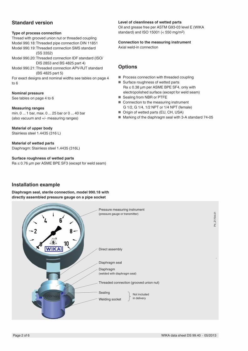
Pressure measuring instrument(pressure gauge or transmitter)
Direct assembly
Diaphragm seal
Diaphragm(welded with diaphragm seal)
Threaded connection (grooved union nut)
Sealing
Welding socket
Installation exampleDiaphragm seal, sterile connection, model 990.18 with directly assembled pressure gauge on a pipe socket
Options
■ Process connection with threaded coupling ■ Surface roughness of wetted parts
Ra ≤ 0.38 µm per ASME BPE SF4, only with electropolished surface (except for weld seam)
■ Sealing from NBR or PTFE ■ Connection to the measuring instrument
G 1/2, G 1/4, 1/2 NPT or 1/4 NPT (female) ■ Origin of wetted parts (EU, CH, USA) ■ Marking of the diaphragm seal with 3-A standard 74-05
Standard version
Type of process connectionThread with grooved union nut or threaded couplingModel 990.18: Threaded pipe connection DIN 11851Model 990.19: Threaded connection SMS standard
(SS 3352)Model 990.20: Threaded connection IDF standard (ISO/
DIS 2853 and BS 4825 part 4)Model 990.21: Threaded connection APV-RJT standard
(BS 4825 part 5)For exact designs and nominal widths see tables on page 4 to 6
Nominal pressureSee tables on page 4 to 6
Measuring rangesmin. 0 ... 1 bar, max. 0 ... 25 bar or 0 ... 40 bar(also vacuum and +/- measuring ranges)
Material of upper bodyStainless steel 1.4435 (316 L)
Material of wetted partsDiaphragm: Stainless steel 1.4435 (316L)
Surface roughness of wetted partsRa ≤ 0.76 µm per ASME BPE SF3 (except for weld seam)
Not included in delivery
P4_Z
1704
.01
Level of cleanliness of wetted partsOil and grease free per ASTM G93-03 level E (WIKA standard) and ISO 15001 (< 550 mg/m2)
Connection to the measuring instrumentAxial weld-in connection
Page 2 of 6 WIKA data sheet DS 99.40 ∙ 05/2013
Additional information for diaphragm seal systems
See Technical information IN 00.06 "Diaphragm seals - Diaphragm seal systems, application, operating princip-le, designs"
■ Pressure measuring instrument model ■ Connection to the measuring instrument: Direct assembly
(calibrated in vertical mounting position, process connection facing downwards)
■ Process temperature ■ Ambient temperature ■ System fill fluid
- Recommendation for the food and beverage production: Neobee® KN 59 (FDA 21 CFR 172.856, 21 CFR 174.5)
- Recommendation for pharmaceutical and cosmetics applications: Medicinal white mineral oil KN 92 (FDA 21 CFR 172.878, 21 CFR 178.3620(a); USP, EP)
Options for diaphragm seal systems
■ Connection to the measuring instrument via cooling element or capillary
■ Vacuum service (suitable for vacuum operation) ■ Higher level of cleanliness of wetted parts
- Oil and grease free per ASTM G93-03 level D and ISO 15001 (< 220 mg/m2)
- Oil and grease free per ASTM G93-03 level C and ISO 15001 (< 66 mg/m2)
■ Height difference between measuring point and pressure measuring instrument with capillary in metre increments (max. 7 m with silicone oils/edible oils)
■ Mounting bracket (required for connection to the measu-ring instrument via capillary, model 910.16, data sheet AC 09.07)- Form H per DIN 16281, 100 mm, aluminium, black- Form H per DIN 16281, 100 mm, stainless steel- Bracket for pipe mounting, for pipe Ø 20 ... 80 mm, steel
Upper body Wetted partDiaphragm
Standard
Stainless steel 1.4435 (316L) Stainless steel 1.4435 (316L)
Materials
Further material combinations on request
Approvals
■ GOST-R, import certificate, Russia ■ CRN, safety (e.g. electr. safety, overpressure, ...), Canada
Certificates 1)
■ 2.2 test report per EN 10204 (e.g. state-of-the-art manufacturing, material proof, indication accuracy for diaphragm seal systems)
■ 3.1 inspection certificate per EN 10204 (e.g. material proof for wetted metallic parts, indication accuracy for diaphragm seal systems)
■ FDA conformity of the system fill fluid ■ 3-A conformity of the diaphragm seal, based on a third
party verification, in accordance with 3-A standard 74-05 ■ EHEDG conformity of the model 990.18 diaphragm seal
(only in combination with ASEPTO-STAR k-flex upgrade, sealing from Kieselmann GmbH)
■ Manufacturer's declaration regarding EU regulation 1935/2004 EC
■ Others on request
1) Option
Approvals and certificates, see website
Page 3 of 6WIKA data sheet DS 99.40 ∙ 05/2013
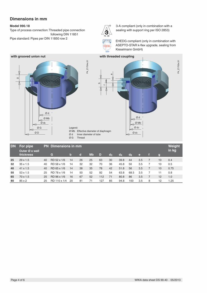
Dimensions in mm
DN For pipe PN Dimensions in mm Weight in kgOuter Ø x wall
thickness G b d Mb D d3 d4 d6 e f g
25 29 x 1.5 40 RD 52 x 1/6 14 26 25 63 30 39.8 44 3.5 7 10 0.432 35 x 1.5 40 RD 58 x 1/6 14 32 32 70 36 45.8 50 3.5 7 10 0.540 41 x 1.5 40 RD 65 x 1/6 14 38 35 78 42 51.8 56 3.5 7 10 0.7550 53 x 1.5 25 RD 78 x 1/6 14 50 52 92 54 63.8 68.5 3.5 7 11 0.865 70 x 1.5 25 RD 96 x 1/6 16 67 52 112 71 80.8 86 3.5 7 12 1.080 85 x 2 25 RD 110 x 1/4 20 81 71 127 85 94.8 100 3.5 8 12 1.25
Model 990.18Type of process connection: Threaded pipe connection
following DIN 11851Pipe standard: Pipes per DIN 11850 row 2
Legend:Ø Mb Effective diameter of diaphragmØ d Inner diameter of tubeØ G Thread
with grooved union nut with threaded coupling
P4_Z
1704
x.01
P4_Z
1705
x.01
Ø Mb
Ø d
Ø d6
Ø G
Ø D
g
Ø Mb
Ø d
Ø d3
Ø d4
b f
e
Page 4 of 6 WIKA data sheet DS 99.40 ∙ 05/2013
EHEDG compliant (only in combination with ASEPTO-STAR k-flex upgrade, sealing from Kieselmann GmbH)
3-A compliant (only in combination with a sealing with support ring per ISO 2853)
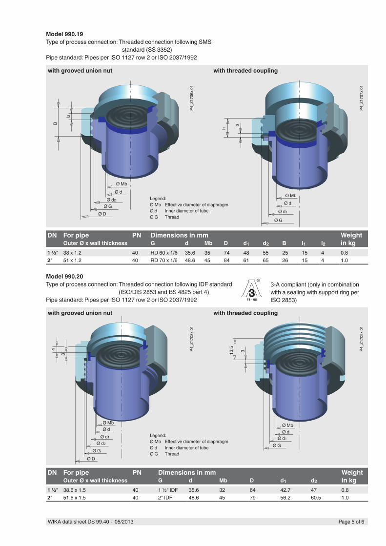
DN For pipe PN Dimensions in mm Weight in kgOuter Ø x wall thickness G d Mb D d1 d2 B l1 l2
1 ½" 38 x 1.2 40 RD 60 x 1/6 35.6 35 74 48 55 25 15 4 0.82" 51 x 1.2 40 RD 70 x 1/6 48.6 45 84 61 65 26 15 4 1.0
Model 990.19Type of process connection: Threaded connection following SMS
standard (SS 3352)Pipe standard: Pipes per ISO 1127 row 2 or ISO 2037/1992
Legend:Ø Mb Effective diameter of diaphragmØ d Inner diameter of tubeØ G Thread
with grooved union nut with threaded coupling
DN For pipe PN Dimensions in mm Weight in kgOuter Ø x wall thickness G d Mb D d1 d2
1 ½" 38.6 x 1.5 40 1 ½" IDF 35.6 32 64 42.7 47 0.82" 51.6 x 1.5 40 2" IDF 48.6 45 79 56.2 60.5 1.0
Model 990.20Type of process connection: Threaded connection following IDF standard
(ISO/DIS 2853 and BS 4825 part 4)Pipe standard: Pipes per ISO 1127 row 2 or ISO 2037/1992
Legend:Ø Mb Effective diameter of diaphragmØ d Inner diameter of tubeØ G Thread
with grooved union nut with threaded coupling
3-A compliant (only in combination with a sealing with support ring per ISO 2853)
P4_Z
1706
x.01
P4_Z
1707
x.01
Ø MbØ d
Ø d2
Ø GØ D
l2
B
Ø MbØ d
Ø d1
Ø G
3
l1
P4_Z
1708
x.01
P4_Z
1709
x.01
Ø MbØ d
Ø d2
Ø GØ D
Ø MbØ d
Ø d1
Ø G
13.5 33
4
Ø d1
Page 5 of 6WIKA data sheet DS 99.40 ∙ 05/2013
WIKA Alexander Wiegand SE & Co. KGAlexander-Wiegand-Straße 3063911 Klingenberg/GermanyTel. (+49) 9372/132-0Fax (+49) 9372/132-406E-mail [email protected]
Ordering informationDiaphragm seal:Diaphragm seal model / Process connection (type and specification of process connection, pipe standard, pipe dimension) / Material (upper body, diaphragm) / Surface roughness of wetted parts / Sealing / Connection to the measuring instrument / Level of cleanliness of wetted parts / Origin of wetted parts / Certificates
Diaphragm seal system:Diaphragm seal model / Process connection (type and specification of process connection, pipe standard, pipe dimension) / Material (upper body, diaphragm) / Surface roughness of wetted parts / Sealing / Pressure measuring instrument model (per data sheet) / Assembly (direct assembly, cooling element, capillary) / min. and max. process temperature / min. and max. ambient temperature / Vacuum service / System fill fluid / Certificates / Height difference / Level of cleanliness of wetted parts / Origin of wetted parts / Mounting bracket
© 2003 WIKA Alexander Wiegand SE & Co. KG, all rights reserved.The specifications given in this document represent the state of engineering at the time of publishing.We reserve the right to make modifications to the specifications and materials.
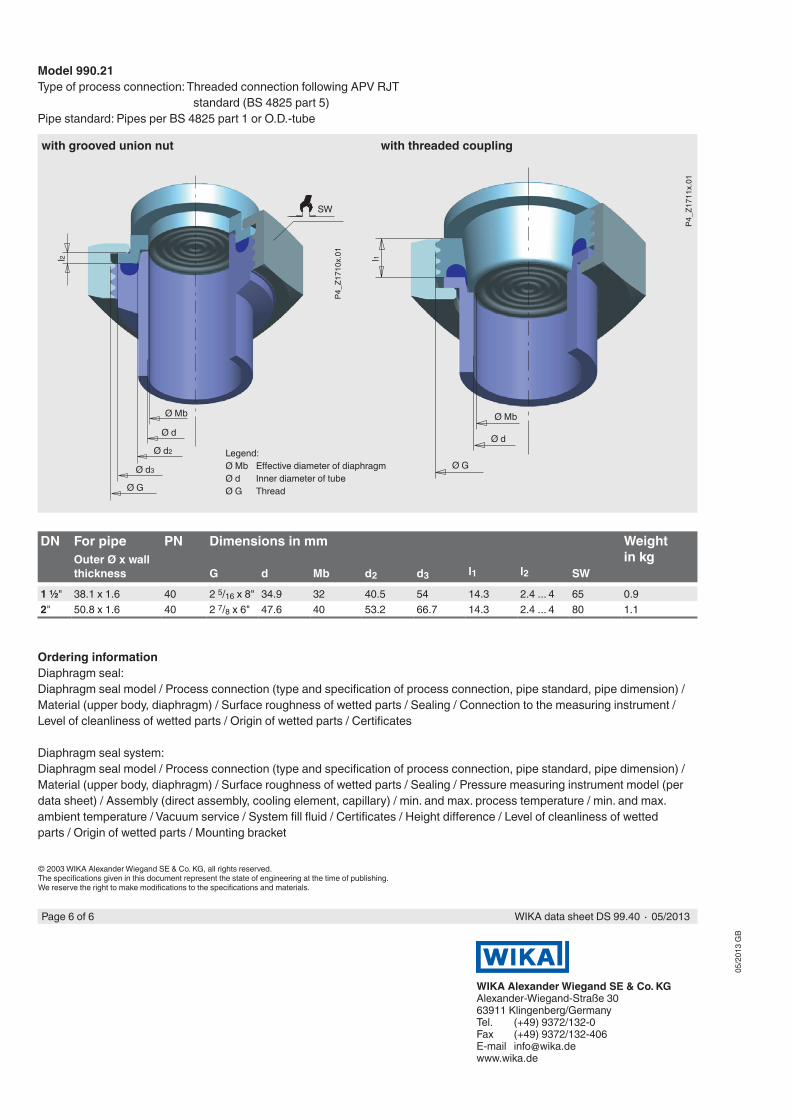
DN For pipe PN Dimensions in mm Weight in kgOuter Ø x wall
thickness G d Mb d2 d3 l1 l2 SW
1 ½" 38.1 x 1.6 40 2 5/16 x 8" 34.9 32 40.5 54 14.3 2.4 ... 4 65 0.92" 50.8 x 1.6 40 2 7/8 x 6" 47.6 40 53.2 66.7 14.3 2.4 ... 4 80 1.1
Legend:Ø Mb Effective diameter of diaphragmØ d Inner diameter of tubeØ G Thread
with grooved union nut with threaded coupling
Model 990.21Type of process connection: Threaded connection following APV RJT
standard (BS 4825 part 5)Pipe standard: Pipes per BS 4825 part 1 or O.D.-tube
P4_Z
1710
x.01
P4_Z
1711
x.01
Ø Mb
Ø d
Ø d3
Ø G
l2
SW
Ø d2
l1
Ø Mb
Ø d
Ø G
05/2
013
GB
WIKA data sheet DS 99.40 ∙ 05/2013Page 6 of 6