Embed Size (px)
Citation preview

BF type seal – Blind flange, flush diaphragm
Page 1 of 12 DSS 7001.03
Design description
The BF construction has a seal body that is made of a (forged) blind
flange. The weld of the diaphragm to the seal body is a wetted part
and therefore diaphragm materials are mostly chosen the same as
the flange material. The BF is typically used in combination with
(differential) pressure transmitters for applications such as level, flow
and (absolute) pressure measurement.
Flange diaphragm combinations
The diaphragm is TIG-welded to the flange and is designed to have
the best performance for the specific size. This means that the
flexibility and shape is carefully tested and measured. The standard
thickness of diaphragm foil is 0.075mm.
Flange Material Diaphragm material
General name UNS Wst.
AISI 316(L)
AISI 316L S31603 1.4404
AISI 304L S30400 1.4306
AISI 321 S32100 1.4541
AISI 316 UG S31603 1.4435
Alloy C276 N27600 2.4810
AISI 304L AISI 304L S30400 1.4306
AISI 310 MoLn 25-22-2 LMN S31050 1.4466
AISI 316 UG AISI 316 UG S31600 1.4435
AISI 321 AISI 321 S32100 1.4541
AISI 904(L) AISI 904L N08904 1.4539
Alloy 20 Alloy 20 N08020 2.4660
Alloy 400 Alloy 400 N04400 2.4360
Alloy 600 Alloy 600 N06600 2.4816
Alloy 625 Alloy 625 N06625 2.4856
Alloy 825 Alloy 825 N08825 2.4858
Alloy B2 Alloy B2 N10665 2.4617
Alloy C-22 Alloy C-22 N06022 2.4602
Alloy C-276 Alloy C-276 N10276 2.4810
Duplex F44 254 SMO (6Mo) S31254 1.4547
Duplex F51/F60 Duplex 2205 S32205 1.4462
Duplex F53 Super Duplex 2507 S32750 1.4410
Duplex F55 Super Duplex 2507 S32750 1.4410
Nickel 201 Nickel 201 N02201 2.4068
Titanium Gr. 2 Titanium Gr. 1 R50250 2.7025
Zirconium 702 Zirconium 702 R60702 -
Flange standard, size, rating and facings
ASME B16.5
Size Rating Facing Roughness
1" to 4” cl. 150 - cl. 2500
RF, LMF, FF, LFF Ra 3.2-6.3 µm
RJF Ra <1.6 µm
SMF, SFF, STF, LTF, SGF, LGF
Ra <3.2 µm
EN 1092-1
Size Rating Type Roughness
DN20 to DN100 PN10-400 A, B1, E, F Ra 3.2-12.5 µm
B2, C, D, G, H Ra <0.8-3.2 µm
API ISO 10423
Size Rating Facing Roughness
1-13/16” to 3-1/16” 69 – 138 MPa 6BX – RJF Ra <1.6 µm
2-1/16” to 3-1/8” 13.8 – 34.5 MPa 6B-RJF Ra <1.6 µm
JIS B2220
Size Rating Type Roughness
DN25 to DN100 10-20K RF Ra 3.2-12.5 µm
GOST 33259
Size Rating Type Roughness
DN20 to DN100 PN10-250
A, B, C, D E, F Ra 3.2-12.5 µm
L, M Ra <0.8-3.2 µm
J Ra <1.6 µm

Page 2 of 12 DSS 7001.03
Gold coatings
Several types of gold coating can be applied on the seals. The
selection possibilities are:
25 µm chemical resistance (diaphragm + facing)
40 µm chemical resistance (diaphragm + facing)
25 µm Hydrogen protection (diaphragm only)
40 µm Hydrogen protection (diaphragm only)
-> See datasheet “Gold coatings”
Polymer coatings
Polymer coatings come in several types. The technical data on
thickness and temperature limitation can be found in datasheet
“polymer solutions” The applicable selection on BF seals are:
PTFE coating
ECTFE (Halar®) coating
PFA coating
FEP coating
PTFE sheet
-> See datasheet “Polymer solutions”
Capillary tube and armor (protection)
The standard capillary mounting position is top side (axial) of the
seal. Alternatively, the capillary can be placed at the side of the seal
(radial). The standard tube material is TP316 (316SS), optionally
available in in Alloy 400. There are three options in ID of the capillary;
2mm, 1mm, and 0.7mm. Badotherm capillaries are always protected
against mechanical forces by armor. This doubled shielded armor
consist is standard AISI 304, and optionally AISI 316. Additionally,
the armor could be protected with a PVC sleeve in white, black,
optionally with ATEX114 approval to protect against dust and water
ingress and possibly corrosive ambient atmosphere.
-> See datasheet “Capillary lines”
Flush rings and flush flanges
Badotherm offers matching flush rings or flush flanges to their
diaphragm seal. On request equipped with blind plugs, vent plug and
or flushing / draining needle valves, which can be fitted or welded to
the complete construction.
-> See datasheet flush rings
-> See datasheet flush flanges
-> See datasheet reducer flanges
Lifting handles
Larger sizes and ratings of diaphragm seals can weigh up to 50 kg.
Handling and installation can become a challenge. As from 15kg it is
recommended to apply a set of lifting handles, welded on the sides
of the flange of the seal. This can be used to handle it easier and
install it in a safer way or have attach lifting tools to it.
-> See datasheet “diaphragm seal accessories"
Material Certification
Material traceability and related certification are applicable for all
process wetted parts. Material certification possibilities depend on
the type of seal, the assembly construction and the materials used.
Material certification is in accordance with EN10204 3.1.
Additional material certification and testing can be provided on
request, such as Positive Material Identification (PMI), Intergranular
corrosion (IGC) testing, material certification in accordance with
EN10204 3.2, NACE conformity for ISO-15156 (MR-0175) and/or
ISO-17945 (MR-0103), NORSOK M-630 and many more.
-> Please note that the responsibility for material selection always
rests with the user.
Flange Marking & Traceability
All flanges are marked by the forging shop with heat number,
material designation, size, and rating. Badotherm adds a Badotherm
reference number and the manufacturers name to the flange for
traceability purposes.
Flanges and origin
The seal parts are made from forged materials according to the
applicable standards. The standard sourcing of flanges is of
international origin. Optionally regional preference can be requested,
for example materials from EU origin.
Testing
All seals are helium tested according the EN 13185 test procedure
A.3 up to 10-9 mbar l/s before used on a diaphragm seal application.
-> See datasheet “Diaphragm Seal testing”
Cleanliness of the wetted parts
All parts are standard cleaned from excessive oil and grease. When
additional requirements are needed, the parts can be cleaned
according customer requirements and cleaning specifications.
Cooling options
There are several ways to protect the instrument from elevated
temperatures, such as the extended direct mount (EDM), a
temperature reducer (TR) or by means of capillary.
-> See datasheet “cooling devices”

Page 3 of 12 DSS 7001.03
Example performance calculation - Basecal
Whether a diaphragm seal can be used for a specific measurement,
depends on the size of the diaphragm. That size is restricted by the
size of the diaphragm seal.
For pressure transmitters, Badotherm offers an online performance
calculation tool to calculate its performance and to ensure that the
diaphragm size is suitable for your measurement.
The table below presents the minimum span of the respective
diaphragm sizes with standard process conditions. As rule of thumb,
a TPE of max 5% is often considered acceptable, but it depends per
situation.
Minimum span table
dD AP/GP DP
23.5mm 17.5 bar na
32mm 11 bar 1850 mbar
44mm 1575 mbar 255 mbar
57mm 415 mbar 70 mbar
72mm 155 mbar 30 mbar
81mm 110 mbar 20 mbar
Pressure transmitter; ambient temperature -10…+30°C; process temperature 100°C with BSO 22 fill fluid; 3 meter capillary; ID 1mm, DP both sides mounted with seal
See the general overview of all diaphragm sizes with several
standard situations and in combination with Badotherm pressure
gauges.
Gaskets
Sizes of the diaphragm area are designed to match the gaskets used
between the process and seal or flush ring. For the ASME B16.5 RF
flanges the ASME B16.20 is used for dimension restriction to ensure
both the spiral and grooved gaskets are fully supported by the
serrated area. For the EN type B1 flanges the gasket dimensions are
matching the sizes of the EN 1514-2. The size “G” in the tables refer
to the start of the gasket surface.

Page 4 of 12 DSS 7001.03
Dimensions table: ASME 16.5 RF facing
size rating OD b PCD C / pcs dD R f G weight
1"
cl. 150 110.0 14.7 79.4 15.9 / 4x
23.5 50.8
2.0
31.8
0.9
cl. 300 125.0
17.9 88.9 19.1 / 4x
1.4
cl. 400-600 24.5
7.0
1.6
cl. 900-1500 150.0 35.6 101.6 25.4 / 4x
3.6
cl. 2500 160.0 42.0 108.0 5.0
1.25"
cl. 150 115.0 17.9 88.9 15.9 / 4x
32.0 63.5
2.0 41.5
1.2
cl. 300 135.0
19.5 98.4 19.1 / 4x
1.8
cl. 400-600 27.7
7.0
2.2
cl. 900-1500 160.0 35.6 111.1 25.4 / 4x 39.8
4.1
cl. 2500 185.0 45.1 130.2 28.6 / 4x 7.4
1.5"
cl. 150 125.0 17.9 98.4 15.9 / 4x
44.0
73.0
2.0 52.4
1.5
cl. 300 155.0
21.1 114.3 22.3 / 4x
2.7
cl. 400-600 29.3
7.0
3.3
cl. 900-1500 180.0 38.8 123.8 28.6 / 4x 32.0 41.5
5.8
cl. 2500 205.0 51.5 146.0 31.8 / 4x 10.4
2"
cl. 150 150.0 19.5 120.7 19.1 / 4x
57.0
92.1
2.0 70.2
2.4
cl. 300 165.0
22.7 127.0 19.1 / 8x
3.2
cl. 400-600 32.4 7.0
4.2
cl. 900-1500 215.0 45.1 165.1 25.4 / 8x 44.0 55.4
10.1
cl. 2500 235.0 57.9 171.4 28.6 / 8x 15.6
3"
cl. 150 190.0 24.3 152.4 19.1 / 4x
81.0 127.0
2.0
93.0
4.9
cl. 300 210.0
29.0 168.3 22.3 / 8x
6.8
cl. 400-600 38.8
7.0
8.4
cl. 900 240.0 45.1 190.5 25.4 / 8x 13.1
cl. 1500 265.0 54.7 203.2 31.9 / 8x 19.1
cl. 2500 305.0 73.7 228.6 35.0 / 8x 34.8
4"
cl. 150 230.0 24.3 190.5 19.1 / 8x
81.0 157.2
2.0
93.0
7.0
cl. 300 255.0
32.2 200.0
22.3 / 8x 11.5
cl. 400 42.0 25.5 / 8x
7.0
14.8
cl. 600 275.0 45.1 215.9 17.3
cl. 900 290.0 51.5 235.0 31.8 / 8x 26.9
cl. 1500 310.0 61.0 241.3 34.9 / 8x 29.9
cl. 2500 355.0 83.2 273.0 41.3 / 8x 53.9
All dimensions in mm, weight in kg

Page 5 of 12 DSS 7001.03
Dimensions table: ASME 16.5 RJF facing
size rating OD b PCD C/pcs dD K E F P Ring # Weight
1"
cl. 150 110.0 19.1 79.4 15.9 / 4x
32.0
63.5
6.4 8.7
47.6 15 0.9
cl. 300 125.0
22.3 88.9 19.1 / 4x 70.0
50.8 16
1.4
cl. 400-600 23.9 1.6
cl. 900-1500 150.0 35.0 101.6 25.4 / 4x
71.5 3.6
cl. 2500 160.0 41.4 108.0 82.5 60.3 18 5.0
1.25"
cl. 150 115.0 22.3 88.9 15.9 / 4x 73.0 57.2 17 1.2
cl. 300 135.0
23.9 98.4 19.1 / 4x
44.0
79.5 60.3 18
1.8
cl. 400-600 27.1 2.2
cl. 900-1500 160.0 35.0 111.1 25.4 / 4x 81.0 4.1
cl. 2500 185.0 46.0 130.2 28.6 / 4x 102.0 7.9 11.9 72.2 21 7.4
1.5"
cl. 150 125.0 22.3 98.4 15.9 / 4x 82.5
6.4 8.7
65.1 19 1.5
cl. 300 155.0
25.5 114.3 22.3 / 4x 90.5
68.3 20
2.7
cl. 400-600 28.7 114.3 3.3
cl. 900-1500 180.0 38.2 123.8 28.6 / 4x 92.0 5.8
cl. 2500 205.0 52.4 146.0 31.8 / 4x 114.0 7.9 11.9 95.3 23 10.4
2"
cl. 150 150.0 23.9 120.7
19.1 / 8x
57.0
102.0 6.4 8.7
82.6
22 2.4
cl. 300 165.0
28.6 127.0 108.0
7.9 11.9
23 3.2
cl. 400-600 33.3 4.2
cl. 900-1500 215.0 46.0 165.1 25.4 / 8x 124.0 95.3 24 10.1
cl. 2500 235.0 58.8 171.4 28.6 / 8x 133.0
101.6 26 15.6
3"
cl. 150 190.0 28.7 152.4 19.1 / 4x
81.0
6.4 8.7 114.3 29 4.9
cl. 300 210.0
34.9 168.3 22.3 / 8x 146.0
7.9 11.9 123.8 31
6.8
cl. 400-600 39.7 8.4
cl. 900 240.0 46.0 190.5 25.4 / 8x 156.0 13.1
cl. 1500 265.0 55.6 203.2 31.8 / 8x 168.0
136.5 35 19.1
cl. 2500 305.0 76.2 228.6 34.9 / 8x 9.5 13.5 127.0 32 34.8
4"
cl. 150 230.0 28.7 190.5 19.1 / 8x 171.0 6.4 8.7
149.2
36 7.0
cl. 300 255.0
38.1 200.0
22.3 / 8x
175.0
7.9 11.9 37
11.5
cl. 400 42.9 25.4 / 8x
14.8
cl. 600 275.0 46.0 215.9 17.3
cl. 900 290.0 52.4 235.0 31.8 / 8x 181.0 26.9
cl. 1500 310.0 61.9 241.3 34.9 / 8x 194.0 161.9 39 29.9
cl. 2500 355.0 87.3 273.0 41.3 / 8x 203.0 11.1 16.7 157.2 38 53.9
All dimensions in mm, weight in kg

Page 6 of 12 DSS 7001.03
Dimensions table: EN 1092-1 B1 type
size rating OD b PCD C / pcs dD R f G Weight
DN20 PN10-40 105.0 18.0 75.0 14.0 / 4x
23.0 58.0 2.0 33.8 1.0
PN63-100 130.0 22.0 90.0 18.0 / 4x 2.0
DN25
PN10-40 115.0 18.0 85.0 14.0 / 4x
32.0 68.0 2.0 41.0
1.0
PN63-100 140.0 24.0 100.0 18.0 / 4x
2.5
PN160 2.7
PN250 150.0 28.0 105.0 22.0 / 4x
3.6
PN320 160.0 34.0 115.0 5.2
PN400 180.0 38.0 130.0 26.0 / 4x 7.5
DN32 PN10-40 140.0 18.0 100.0 18.0 / 4x
32.0 78.0 2.0 41.5 2.0
PN63-100 155.0 24.0 110.0
22.0 / 4x 3.0
DN40
PN10-40 150.0 18.0 18.0 / 4x
44.0 88.0 3.0 55.4
2.0
PN63-100 170.0
26.0 125.0 22.0 / 4x
4.0
PN160 28.0 4.4
PN250 185.0 34.0 135.0 26.0 / 4x
6.7
PN320 195.0 38.0 145.0 8.7
PN400 220.0 48.0 165.0 30.0 / 4x 14.1
DN50
PN10-40 165.0 20.0 125.0 18.0 / 4x
57.0 102.0 3.0 70.2
3.0
PN63 180.0 26.0 135.0 22.0 / 4x 4.5
PN100 195.0
28.0 145.0 26.0 / 4x
6.0
PN160 30.0 6.4
PN250 200.0 38.0 150.0 26.0 / 8x
8.2
PN320 210.0 42.0 160.0 10.7
PN400 235.0 52.0 180.0 30.0 / 8x 16.7
DN80
PN10-40 215.0
24.0 160.0 18.0 / 8x
81.0 138.0 3.0 93.0
5.0
PN63 28.0 170.0 22.0 / 8x 6.5
PN100 230.0 32.0 180.0 26.0 / 8x
9.0
PN160 230.0 36.0 10.3
PN250 255.0 46.0 200.0 30.0 / 8x
16.5
PN320 275.0 55.0 220.0 25.4
PN400 305.0 68.0 240.0 33.0 / 8x 38.4
DN100
PN10-16 220.0 20.0 180.0 18.0 / 8x
81.0
158.0
3.0 93.0
4.5
PN25-40 235.0 24.0 190.0 22.0 / 8x
162.0
6.5
PN63 250.0 30.0 200.0 26.0 / 8x 9.0
PN100 265.0
36.0 210.0 30.0 / 8x
13.0
PN160 40.0 15.3
PN250 300.0 54.0 235.0 33.0 / 8x 27.2
PN320 335.0 65.0 265.0 36.0 / 8x 42.5
PN400 370.0 80.0 295.0 39.0 / 8x 67.3
All dimensions in mm, weight in kg

Page 7 of 12 DSS 7001.03
Dimensions table: JIS 2220 RF
Size rating OD dD b PCD C / pcs R f G Weight
25
10K
125.0 32.0 15.0
90.0
19.0 / 4x
67.0 1.0 40.0
1.2
16K 1.3
20K 17.0 1.4
32
10K
135.0
44.0
18.0 100.0 76.0
2.0
50.6
1.7
16K 1.7
20K 20.0 1.7
40
10K
140.0 18.0
105.0 81.0 55.4
1.8
16K 1.8
20K 20.0 1.9
50
10K
155.0 57.0 18.0
120.0 96.0 68.5
2.2
16K
19.0 / 8x
2.2
20K 20.0
2.2
80
10K 185.0
81.0
150.0 126.0
93.0
3.5
16K 200.0
22.0
160.0 23.0 / 8x 132.0
4.4
20K 24.0 4.6
90
10K 195.0 20.0 19.0 / 8x 136.0 3.9
16K
210.0
22.0 170.0 23.0 / 8x 145.0
4.9
20K 26.0 5.7
100
10K 20.0 175.0 19.0 / 8x 151.0 4.6
16K 225.0
24.0 185.0 23.0 / 8x 160.0
6.3
20K 26.0 6.6
All dimensions in mm, weight in kg
Page 8 of 12 DSS 7001.03
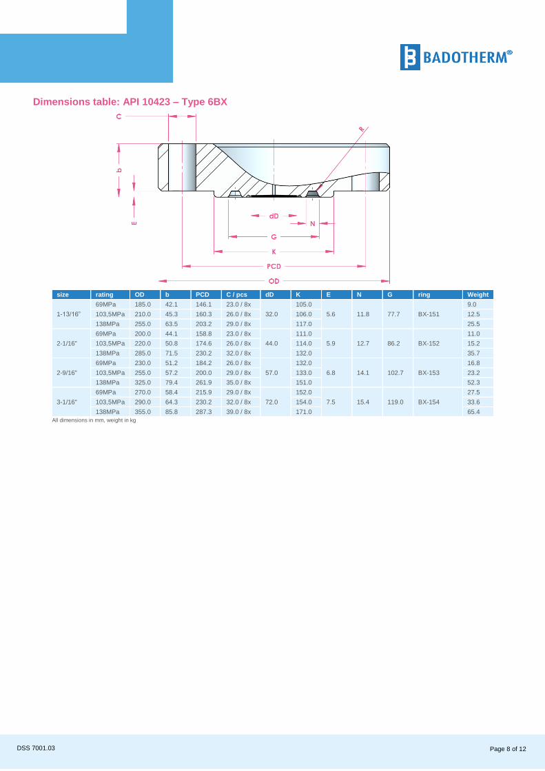
Dimensions table: API 10423 – Type 6BX
size rating OD b PCD C / pcs dD K E N G ring Weight
1-13/16”
69MPa 185.0 42.1 146.1 23.0 / 8x
32.0
105.0
5.6 11.8 77.7 BX-151
9.0
103,5MPa 210.0 45.3 160.3 26.0 / 8x 106.0 12.5
138MPa 255.0 63.5 203.2 29.0 / 8x 117.0 25.5
2-1/16"
69MPa 200.0 44.1 158.8 23.0 / 8x
44.0
111.0
5.9 12.7 86.2 BX-152
11.0
103,5MPa 220.0 50.8 174.6 26.0 / 8x 114.0 15.2
138MPa 285.0 71.5 230.2 32.0 / 8x 132.0 35.7
2-9/16"
69MPa 230.0 51.2 184.2 26.0 / 8x
57.0
132.0
6.8 14.1 102.7 BX-153
16.8
103,5MPa 255.0 57.2 200.0 29.0 / 8x 133.0 23.2
138MPa 325.0 79.4 261.9 35.0 / 8x 151.0 52.3
3-1/16"
69MPa 270.0 58.4 215.9 29.0 / 8x
72.0
152.0
7.5 15.4 119.0 BX-154
27.5
103,5MPa 290.0 64.3 230.2 32.0 / 8x 154.0 33.6
138MPa 355.0 85.8 287.3 39.0 / 8x 171.0 65.4
All dimensions in mm, weight in kg

Page 9 of 12 DSS 7001.03
Dimension s table: API 6A 10423 – Type 6B
size rating OD b PCD C / pcs dD K E F P ring Weight
2-1/16"
13.8MPa 165.0 33.4 127.0 20.0 / 8x
44.0
108.0
7.9 11.9
82.6 R or RX-23 5.6
20.7MPa 215.0 46.1 165.1 26.0 / 8x 124.0 95.2 R or RX-24
13.3
34.5MPa 13.3
2-9/16"
13.8MPa 190.0 36.6 149.2 23.0 / 8x
72.0
127.0 101.6 R or RX-26 8.1
20.7MPa 245.0 49.3 190.5 29.0 / 8x 137.0 107.9 R or RX-27
18.4
34.5MPa 245.0 49.3 190.5 18.4
3-1/8"
13.8MPa 210.0 39.7 168.3 23.0 / 8x
81.0
146.0 123.8 R or RX-31
10.8
20.7Mpa 240.0 46.1 190.5 26.0 / 8x 156.0 16.5
34.5MPa 265.0 55.6 203.2 32.0 / 8x 168.0 136.5 R or RX-35 24.2
All dimensions in mm, weight in kg

Page 10 of 12 DSS 7001.03
Dimensions table: GOST 33259 type B
size rating OD b PCD C / pcs dD R f G Weight
DN20 PN10-40 105.0 18.0 75.0 14.0 / 4x
23.0 58.0 2.0 33.8 1.0
PN63-100 130.0 22.0 90.0 18.0 / 4x 2.0
DN25
PN10-40 115.0 18.0 85.0 14.0 / 4x
32.0 68.0 2.0 41.0
1.0
PN63-100 140.0 24.0 100.0 18.0 / 4x
2.5
PN160 2.7
PN250 150.0 28.0 105.0 22.0 / 4x 3.6
DN32 PN10-40 140.0 18.0 100.0 18.0 / 4x
32.0 78.0 2.0 41.5 2.0
PN63-100 155.0 24.0 110.0
22.0 / 4x 3.0
DN40
PN10-40 150.0 18.0 18.0 / 4x
44.0 88.0 3.0 55.4
2.0
PN63-100 170.0
26.0 125.0 22.0 / 4x
4.0
PN160 28.0 4.4
PN250 185.0 34.0 135.0 26.0 / 4x 6.7
DN50
PN10-40 165.0 20.0 125.0 18.0 / 4x
57.0 102.0 3.0 70.2
3.0
PN63 180.0 26.0 135.0 22.0 / 4x 4.5
PN100 195.0
28.0 145.0 26.0 / 4x
6.0
PN160 30.0 6.4
PN250 200.0 38.0 150.0 26.0 / 8x 8.2
DN80
PN10-40 215.0
24.0 160.0 18.0 / 8x
81.0 138.0 3.0 93.0
5.0
PN63 28.0 170.0 22.0 / 8x 6.5
PN100 230.0 32.0 180.0 26.0 / 8x
9.0
PN160 230.0 36.0 10.3
PN250 255.0 46.0 200.0 30.0 / 8x 16.5
DN100
PN10-16 220.0 20.0 180.0 18.0 / 8x
81.0 158.0 3.0 93.0
4.5
PN25-40 235.0 24.0 190.0 22.0 / 8x 6.5
PN63 250.0 30.0 200.0 26.0 / 8x 9.0
PN100 265.0
36.0 210.0 30.0 / 8x
13.0
PN160 40.0 15.3
PN250 300.0 54.0 235.0 33.0 / 8x 27.2
All dimensions in mm, weight in kg

Page 11 of 12 DSS 7001.03
Dimensions table: GOST 33259 type J
size rating OD b PCD C / pcs K P E F dD Weight
DN20
PN63 125.0
20.0
90.0 18.0 / 4x
58 45
6.5 9
23.0
2.0
PN100-160 22.0 2.2
PN200 130.0 28.0 22.0 / 4x 2.3
DN25
PN63 135.0
22.0 100.0 18.0 / 4x 68.0 50.0
32.0
2.5
PN100-160 24.0 2.6
PN200
150.0
30.0 102.0 26.0 / 4x 2.7
DN32
PN63 23.0
110.0 22.0 / 4x 78.0 65.0
44.0
3.0
PN100 24.0 3.1
PN160
PN200 160.0 32.0 115.0 26.0 / 4x 3.6
DN40
PN63
165.0
24.0
125.0 22.0 / 4x 88.0 75.0
4.0
PN100 26.0 4.2
PN160 28.0 4.4
PN200 170.0 34.0 124.0 26.0 / 4x 91.0 6.7
DN50
PN63 180.0 26.0 135.0 22.0 / 4x 102.0 85.0
8.0 12.0
57.0
4.5
PN100 195.0
28.0 145.0 26.0 / 4x
6.0
PN160 30.0 115.0 95.0
6.4
PN200 200.0 40.0 160.0 26.0 / 8x 129.0 8.2
DN80
PN63 210.0 30.0 170.0 22.0 / 8x 133.0 115.0
81.0
6.5
PN100 230.0
34.0 180.0 26.0 / 8x 150.0
9.0
PN160 36.0 130.0 10.3
PN200 290.0 54.0 230.0 33.0 / 8x 190.0 160.0 16.5
DN100
PN63 250.0 32.0 200.0 26.0 / 8x 170.0
145.0
9.0
PN100 265.0
38.0 210.0 30.0 / 8x 175.0
13.0
PN160 40.0 15.3
PN200 360.0 66.0 235.0 39.0 / 8x 245.0 190.0 27.2
All dimensions in mm, weight in kg

Holland – United Kingdom – Romania – India – Thailand – Dubai – USA
To our knowledge, the information contained herein is accurate as of the date of this document. However neither Badotherm, nor its affiliates makes any warranty, express or limited, or accepts any liability in connection with this information or its use. This information is for technical skilled persons at their own discretion and risk and does not relate to the use of this product in combination with any other product. The user alone finally determines suitability of any information or material in contemplated use, the manner of use and whether any patents are infringed. This information gives typical properties only. Badotherm reserves the right to make changes to the specifications any materials without prior notice. The latest version of the datasheet can be found on www.badotherm.com. © 2015 Badotherm, all rights reserved. Trademarks and/or other products referenced herein are either trademarks or registered trademarks of
Badotherm.
Page 12 of 12
DSS 7001.03
May 19