Embed Size (px)
Citation preview

CONCRETE CABLE-STAYED BRIDGES
Walter Podolny, Jr., Federal Highway Administration
This paper presents a comprehensive review on a case-study basis of concrete cable-stay bridges either completed, under construction or in design, with the intent of encouraging designers to consider the feasibility of this type of structure. Evolution of concrete cable-stay bridges is traced from Torroja's Tempul Aqueduct in Spain, completed in 1925, to present day design concepts. Particular attention is given to s true ture concept, geometric configuration, design considerations, structural details, and method of construction. As late as 1970, the practical span limit of steel cable-stay bridges was considered to be 300 m (1,000 ft). Recently, concrete cable-stayed bridges are considered technically feasible with spans approaching500 m (1,600 ft). It has been projected that with an aerodynamically shaped composite concrete and steel deck a span of 700 m (2,300 ft) can be achieved. With today's technology of prefabrication, prestressing, and segmental cantilever construction, it is obvious that cable-stay bridges are extending the competitive span range of concrete construction to dimensions that had previously been considered impossible. The technological means exist, they only require implementation.
The concept of supporting a beam or bridge by inclined cable stays is not new and the historical evolution of this type of structure has been discussed in the literature (1-3). The modern renaissance of cable-stay bridge; is said to have begun in 1955 with the construction of the Str~msund Bridge in Sweden. This steel structure was built by a German contractor in collaboration with a German engineer, Professor F. Dischinger, who is reported to have rediscovered the stayed bridge in 1938 ('.±_) • Since 1955 approximately 80 cable-stay bridges have been built, are under construction, in design, or have been abandonded for one reason or another.
Although most cable-stay structures have been of steel construction a few have been of concrete. It is generally recognized that the first modern concrete cable-stay bridge was Morandi's Lake Maracaibo Bridge constructed in 1962. Since 1962, approximately 15 concrete cable-stayed bridges have been built and others are under construction or in design. Perhaps what is least known is that the first concrete
structure to utilize cable stays was the Tempul Aqueduct crossing the Guadalete River in Spain (5). This structure, designed by the Spanish engineer Torroja, was built in 1926 and thus preceeds Dischinger's rediscovery in 1938.
This paper presents a comprehensive review of concrete cable-stay bridges on a case study basis with the i ntent of encouraging designers to consider the feasibility of this type structure which in some instances might be a more appropriate choice. A tabulation of proportions and ratios of the cable-stay bridges discussed in this paper is given in Table 1 for comparative purposes.
Lake Maracaibo Bridge, Venezuela
The first modern prestressed concrete cable-stay bridge was built over Lake Maracaibo in Venezuela in 1962 and was designed by Professor Riccardo Morandi of Rome University. It ranks as one of the longest cable-stayed bridges in the world, having a superstructure of reinforced and prestressed concrete construction, Figure 1.
Figure 1. Lake Maracaibo Bridge.
This structure has a total length of 8.7 km (5.4 miles). Navigation requirements , dicated a horizontal clearance of 200 m (656.2 ft) and a vertical clearance of 45 m (147.6 ft). The five main navigation openings consist of prestressed concrete cantilevered cable-stayed structures with suspended spans hav-
121
122
Table 1. Concrete cable-sta brid e >ro Ol:tions and confi uration No . o 'Ota aja r Rat o o Span to Cable- Length of Span Total Length Girder Girder Girder Stayed Cable-Stayed Length to Major Depth Depth Construction
Bridge Spans Spans (m) (m) Span
Lake Maracaibo 5 1175 235 Polcevera Viaduct 3 550 210 Wadi Kuf 3 475 280 Magliana Viaduct 2 198.6 145 Chaco/Corrientes 3 572 .4 245 Danish Great Belta 345 Danish Great Beltb 351 Dnieper Harbor 3 276 144 Ti el 3 457 267 River Foyle 3 350 210 Mainbrlicke 4 259 148.23 Barranquilla 3 279 140 Kwang Fu 4 402 134 Danube Canal 3 230.4 119 Pont de Bro tonne 3 607 320 Pasco-Kennewick 3 547 299 Dame Point 3 792.48 396 .24
Note: 1 m 3.28. ft. White, Young aDesign by
bDesign by Finsterwalder and Partners
ccIP = cast-in-place, PC = precast
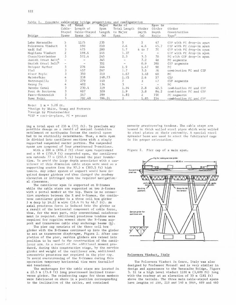
ing a total span of 235 m (771 ft). To preclude any possible damage as a result of unequal foundation settlement or earthquake forces the central spans had to be statically determinate. Thus, a main span is divided into cantilever sections with a simply supported suspended center portion. The suspended spans are c.omposed of four pres tressed T-sections.
With a 200 m (656.2 ft) clear span requirement and a 46 m (150.9 ft) suspended span, the cantilever arm extends 77 m (252.6 ft) beyond the pier foundation. To avoid the large depth associated with a cantilever of this dimension cable stays were used as a supporting system from the 92.5 m (303.5 ft) high towers. Any other system of support would have required deeper girders and thus changed the roadway elevation or infringed upon the required navigational clearance.
The cantilever span is supported on X-frames while the cable stays are supported on two A-frames with a portal member at the top. There is no connection anywhere between the X and A-frames, the continuous cantilever girder is a three cell box girder 5 m deep by 14.22 m wide (16.4 ft by 46.7 ft). An axial prestress force is induced into the girder as a result of the horizontal component of cable force, thus, for the most part, only conventional reinforcement is required. Additional prestress tendons were required for negative moment above the X-frame support and transverse cable stay anchorage beams (6).
The pier cap consists of the three cell box -girder with the X-frames continued up into the girder to act as transverse diaphrRgmR, Figure 2. After completion of the pier, service girders are raised into position to be used in thf'> r.nnRtruction of the canti-1~., .... ~!:' :Or!!!. . A__r:. ~ r~c;;i.111 t nf thP :::ultii ti nn;:1l moment pro-duced, during this construction stage, by the service girder and weight of the cantilever arm, additional concentric prestress was required in the pier cap. To avoid overstressing of the X-frames during this operation temporary horizontal ties were installed and tensioned.
The anchorages for the cable stays are located in a 22.5 m (73.8 ft) long prestressed inclined transverse girder. The reinforcing cages for these members were fabricated on shore in a position corresponding to the inclination of the cables, and contained
(m) Ratio Typec
5 5 47 CIP with PC drop-in span 2.6 4.6 45.7 CIP with PC drop-in span 1. 7 4 to 7 70 CIP with PC drop-in span 1. 37 CIP with PC drop-in span 2.3 3.5 70 PC with CIP drop-in span
7.2 48 PC segments 0.9 390 CIP segments
1. 9 1.4 7 98 PC 1. 7 3.5 76 combination PC and CIP 1. 67 3.48 60 PC 1. 75 2.6 57 CIP 2 3 47 CIP segments 3 PC 1.94 2.8 42.5 combination PC and CIP 1. 9 3.8 84.2 combination PC and CIP 1.83 2 150 PC segments 2 1.85 214 combination PC and CIP
seventy prestressing tendons. The cable stays are housed in thick walled steel pipes which were welded to steel plates at their extremity. A special steel spreader beam was used to erect the fabricated cage in its proper orientation.
Figure 2. Pier cap of a main span .
Service girder for cantilever arm
~olcevera Viaduct, Italy
The Polcevera Viaduct in Gen0a, Italy was also designed by Professor Morandi and is very similar in design and appearance to the Maracaibo Bridge, Figure 3. It is a high level viaduct 1100 m (3,600 ft) long with· the roadway at an elevation of 55 m (181 ft) above the terrain. The three main cable-stayed spans have lengths of 200, 210 and 140 m (664, 689 and 460
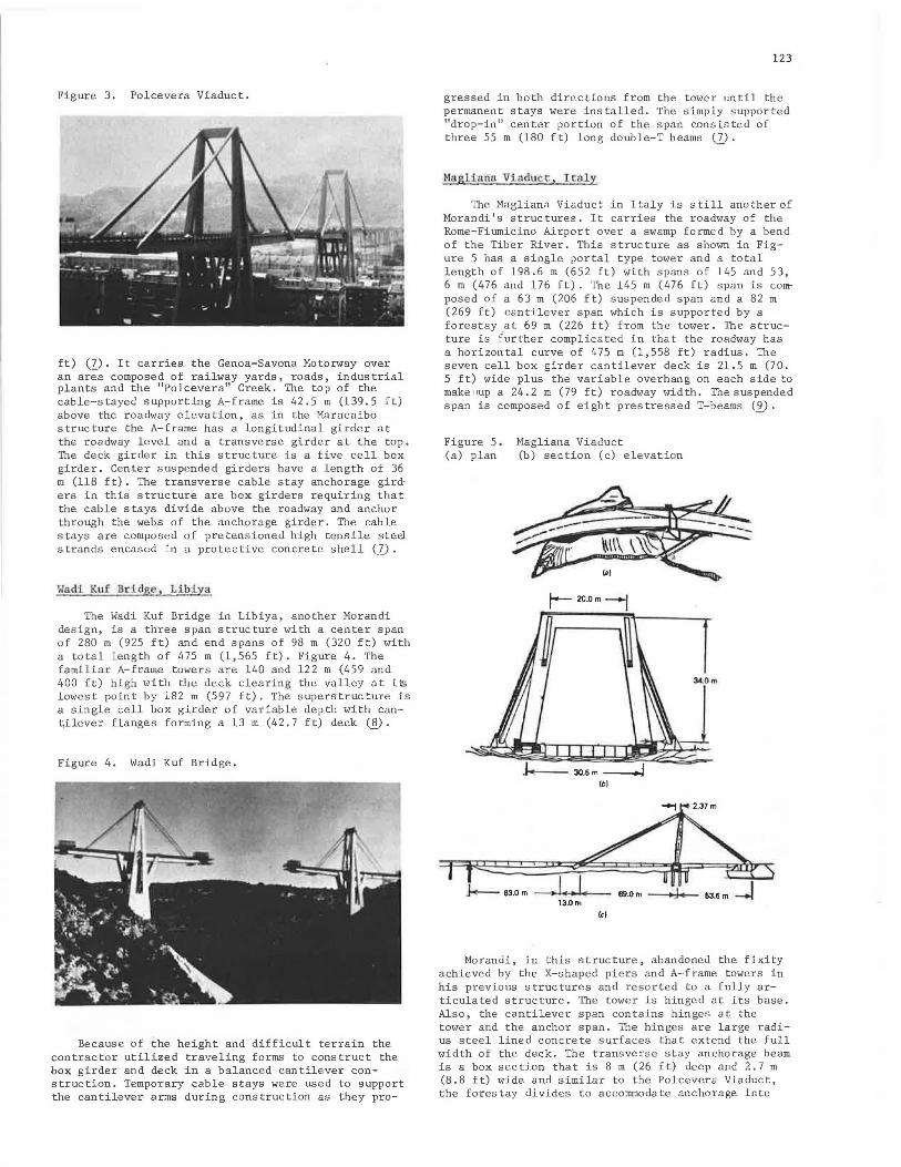
Figure 3. Polcevera Viaduct.
ft) <J). It carries the Genoa-Savona Motorway over an area composed of railway yards, roads, industrial plants and the "Polcevera" Creek. The top of the cable-stayed supporting A-frame is 42.5 m (139.5 ft) above the roadway elevation, as in the Maracaibo structure the A-frame has a longitudinal girder at the roadway level and a transverse girder at the top. The deck girder in this structure is a five cell box girder. Center suspended girders have a length of 36 m (118 ft). The transverse cable stay anchorage girders in this structure are box girders requiring that the cable stays divide above the roadway and anchor through the webs of the anchorage girder. The cable stays are composed of pretensioned high tensile steel strands encased in a protective concrete shell(]_).
Wadi Kuf Bridge, Libiya
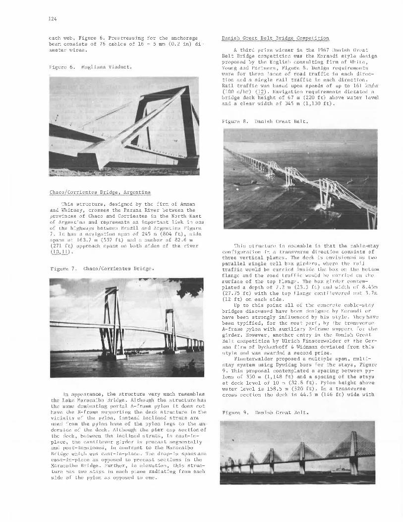
The Wadi Kuf Bridge in Libiya, another Morandi design, is a three span structure with a center span of 280 m (925 ft) and end spans of 98 m (320 ft) with a total length of 475 m (1,565 ft). Figure 4. The familiar A-frame towers are 140 and 122 m (459 and 400 ft) high with the deck clearing the valley at i~ lowest point by 182 m (597 ft). The superstructure is a single cell box girder of variable depth with cantilever flanges forming a 13 m (42.7 ft) deck(~).
Figure 4. Wadi Kuf Bridge .
Because of the height and difficult terrain the contractor utilized traveling forms to construct the box girder and deck in a balanced cantilever construction. Temporary cable stays were used to support the cantilever arms during construction as they pro-
123
gressed in both directions from the tower until the permanent stays were installed. The simply supported "drop-in" center portion of the span consisted of three 55 m (180 ft) long double-T beams (]_).
Magliana Viaduct , Italy
The Magliana Viaduct in Italy is still another of Morandi's structures. It carries the roadway of the Rome-Fiumicino Airport over a swamp formed by a bend of the Tiber River. This structure as shown in Figure 5 has a single portal type tower and a total length of 198.6 m (652 ft) with spans of 145 and 53, 6 m (476 and 176 ft). The 145 m (476 ft) span is co!llposed of a 63 m (206 ft) suspended span and a 82 m (269 ft) canti'lever span which is supported by a forestay at 69 m (226 ft) from the tower. The structure is further complicated in that the roadway has a horizontal curve of 475 m (1,558 ft) radius. The seven cell box girder cantilever deck is 21.5 m (70. 5 ft) wide plus the variable overhang on each side to make11up a 24.2 m (79 ft) roadway width. The suspended span is composed of eight pres tressed T-beams (_2).
Figure 5. (a) plan
Magliana Viaduct (b) section (c) elevation
3"1 .0 m
(b)
"~S f :e:::::: : I
. I,• !. 119.0m ,J • 53.Sm _J 13.0m
.h--- 63.0m
(c)
Morandi, in this structure, abandoned the fixity achieved by the X-shaped piers and A-frame towers in his previous structures and resorted to a fully articulated structure. The tower is hinged at its base. Also, the cantilever span contains hinges at the tower and the anchor span. The hinges are large radius steel lined concrete surfaces that extend the full width of the deck. The transverse stay anchorage beam is a box section that is 8 m (26 ft) deep and 2.7 m (8.8 ft) wide and similar to the Polcevera Viaduct, the forestay divides to acconunodate anchorage into
124
each web, Figure 6. Prestressing for the anchorage beam consists of 76 cables of 16 - 5 mm (0.2 in) diameter wires.
Figure 6. Magliana Viaduct.
Chaco/Corrientes Bridge, Argentina
This structure, designed by the firm of Amman and Whitney, crosses the Parana River between the provinces of Chaco and Corrientes in the North-East of Argentina and represents an important link in one of the highways between Brazil and Argentina Figure 7. It has a navigation span of 245 m (804 ft), side spans of 163.7 m (537 ft) and a number of 82.6 m (271 ft) approach spans on both sides of the river (10,11).
Figure 7. Chaco/Corrientes Bridge.
In appearance, the structure very much resembles the Lake Maracaibo Bridge. Although the structure has the same dominating portal A-frame pylon it does not have the X-frame supporting the deck s true ture in the vicinity of the pylon, instead inclined struts are used from the pylon base of the pylon legs to the _underside of the deck. Although the pier cap section of the deck, between the inclined struts, is cast-inplace, the cantilever girder is precast segmentally and post-tensioned, in contrast to the Maracaibo Bridge which was cast-in-place. The drop-in spans are cast-in-place as opposed to precast sections in the Maracaibo Bridge. Further, in elevation, this structure has two stays in each plane radiating from each side of the pylon as opposed to one.
Danish Great Belt Bridge Competition
A third prize winner in the 1967 Danish Great Belt Bridge competition was the Morandi style design proposed by the English consulting firm of White, Young and Partners, Figure 8. Design requirements were for three lanes of road traffic in each direction and a single rail traffic in each direction. Rail traffic was based upon speeds of up to 161 km;hr (100 m/hr) (12). Navigation requirements dictated a bridge deck height of 67 m (220 ft) above water level and a clear width of 345 m (1,130 ft).
Figure 8. Danish Great Belt.
This structure is noteable in that the cable-stay configuration in a transverse direction consists of three vertical planes. The deck is envisioned as two parallel single cell box girders, where the rail traffic would be carried inside the box on the bottom flange and the road traffic would be carried on the surface of the top flange. The box girder contemplated a.depth of 7.2 m (23.5 ft) and width of 8.45m (27.75 ft) with the top flange cantilevered out 3.7m (12 ft) on each side.
Up to this point all of the concrete cable-stay bridges discussed have been designed by Morandi or have been strongly influenced by his style. They have been typified, for the most part, by the transverse A-frame pylon with auxiliary X-frame support for the girder. However, another entry in the Danish Great Belt competition by Ulrich Finsterwalder of the German firm of Dyckerhof f & Widmann deviated from this style and was awarded a second prize.
Finsterwalder proposed a multiple span, multistay system using Dywidag bars for the stays, Figure 9. This proposal contemplated a spacing between pylons of 350 m (1,148 ft) and a spacing of the stays at deck level of 10 m (32.8 ft). Pylon height above water level is 158.5 m (520 ft). In a transverse cross section the deck is 44.5 m (146 ft) wide with
Figure 9. Danish Great Belt .
two centrally located vertical stay planes 12 m (39. 4 ft) apart to accommodate the two rail traffic lane and three automobile traffic lanes in each direction outboard of the stay planes, Figure 10. The solid concrete deck has a thickness of 0.9 m (2.95 ft) in the transverse center portion, under the rail traffic, and tapers to 0.4 m (1.3 ft) thickness at the edges. The deck is constructed by the cast-in-place balanced cantilever segmental method with each segment being supported by a set of stays.
Figure 10. Danish Great Belt .
il il n
''"' ""
Dnieper Harbor Bridge, U.S.S.R.
Tt ll fl
IS,?S
The Dnieper Harbor Bridge in Kiev was completed in 1963, Figure 11. The superstructure of this bridge consists of precast reinforced units with a 144 m (472 ft) center span and side spans of 66 m (216.5 ft). Height of the reinforced concrete portal type pylon is 42 m (138 ft). The cable stays are in two vertical planes with three stays emanating from each side of the pylon.
Figure 11. Dnieper Harbor Bridge .
Tiel Bridge, Netherlands
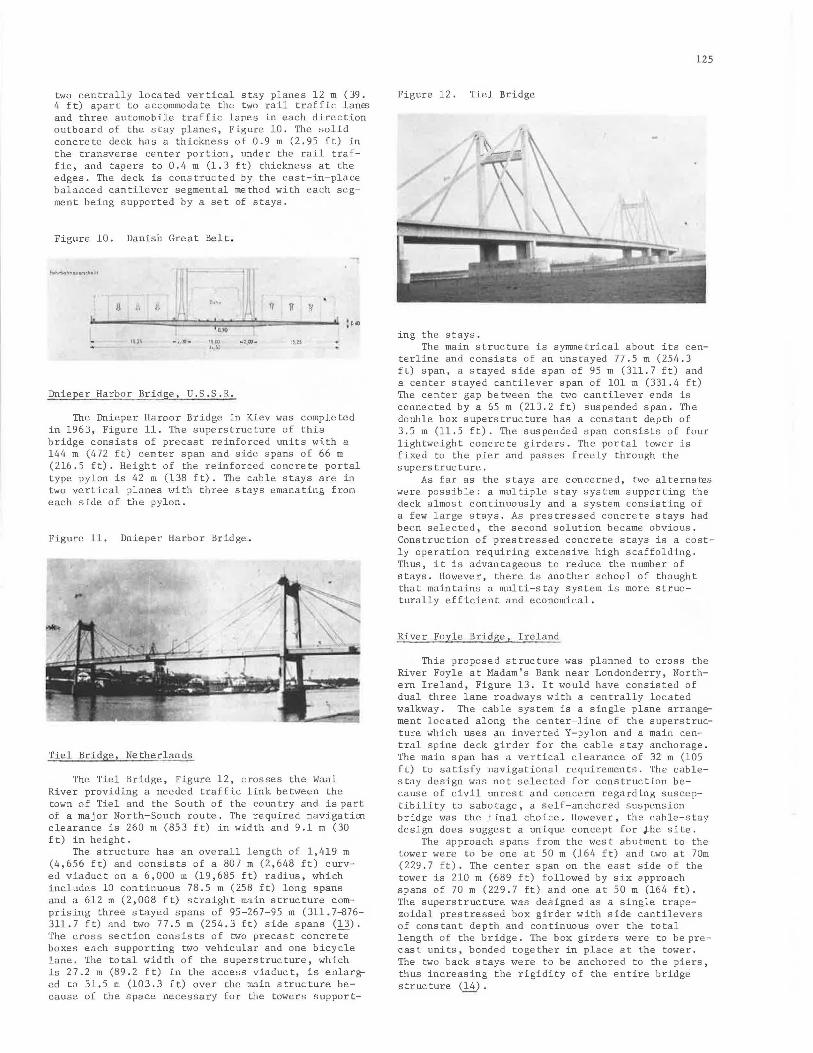
The Tiel Bridge, Figure 12, crosses the Waal River providing a needed traffic link between the town of Tiel and the South of the country and is part of a major North-South route. The required navigaticn clearance is 260 m (853 ft) in width and 9.1 m (30 ft) in height.
The structure has an overall length of 1,419 m (4,656 ft) and consists of a 807 m (2,648 ft) curved viaduct on a 6,000 m (19,685 ft) radius, which includes 10 continuous 78.5 m (258 ft) long spans and a 612 m (2,008 ft) straight main structure comprising three stayed spans of 95-267-95 m (311.7-S76-311.7 ft) and two 77.5 m (254.3 ft) side spans (]]). The cross section consists of two precast concrete boxes each supporting two vehicular and one bicycle lane. The total width of the superstructure, which is 27.2 m (89.2 ft) in the access viaduct, is enlarged to 31.5 m (103.3 ft) over the main structure because of the space necessary for the towers support-
125
Figure 12. Tiel Bridge
ing the stays. The main structure is symmetrical about its cen
terline and consists of an unstayed 77.5 m (254.3 ft) span, a stayed side span of 95 m (311. 7 ft) and a center stayed cantilever span of 101 m (331.4 ft) The center gap between the two cantilever ends is connected by a 65 m (213.2 ft) suspended span. The double box superstructure has a constant depth of 3.5 m (11.5 ft). The suspended span consists of four lightweight cone re te girders. The par tal tower is fixed to the pier and passes freely through the supers true ture.
As far as the stays are concerned, two alternates were possible: a multiple stay system supporting the deck almost continuously and a system consisting of a few large stays. As prestressed concrete stays had been selected, the second solution became obvious. Construction of prestressed concrete stays is a costly operation requiring extensive high scaffolding. Thus, it is advantageous to reduce the number of stays. However, there is another school of thought that maintains a multi-stay system is more structurally efficient and economical.
River Foyle Bridge, Ireland
This proposed structure was planned to cross the River Foyle at Madam's Bank near Londonderry, Northern Ireland, Figure 13. It would have consisted of dual three lane roadways with a centrally located walkway. The cable system is a single plane arrangement located along the center-line of the superstructure which uses an inverted Y-pylon and a main central spine deck girder for the cable stay anchorage. The main span has a vertical clearance of 32 m (105 ft) to satisfy navigational requirements. The cablestay design was not selected for construction because of civil unrest and concern regarding susceptibility to sabotage, a self-anchored suspension bridge was the final choice. However, the cable-stay design does suggest a unique concept for the site.
The approach spans from the west abutment to the tower were to be one at 50 m (164 ft) and two at 70m (229.7 ft). The center span on the east side of the tower is 210 m (689 ft) followed by six approach spans of 70 m (229.7 ft) and one at 50 m (164 ft). The superstructure was designed as a single trapezoidal prestressed box girder with side cantilevers of constant depth and continuous over the total length of the bridge. The box girders were to be precast units, bonded together in place at the tower. The two back stays were to be anchored to the piers, thus increasing the rigidity of the entire bridge structure (14).

126
Figure 13. River Foyle Bridge
Mainbrllcke, Germany
The ~'fainbrllckc Bridge near Hoechst, a suburb of Frankfurt, constructed in 1971 is a prestressed cable-stay structure that connects the Fabwerke Hoechst's chemical industrial complex on both sides of the River Main in West Ge r many , Figur e 14. This structure is a successor of Finsterwald's Danish Great Belt Bridge proposal and rep~esents the first practical application of the Dywidag bar stay.
Figure 14. Nainbrlicke.
Total length of the s true ture is 300 m (984. 3 ft) with a river span of 148 m (485.6 ft). It carries two three lane roads separated by a railway track and pipelines. The railway and pipelines are in the median between the two vertical planes of stays and cantilever towers and is supported by a 2.6 m (8.5 ft) deep, torsionally stift box girder. The centerline of the longitudinal webs of the box girder ceincide with the centerline ot the individual canti.Lever py.Lons ana are l:l m ~Lb . L ) t t J a part . Tr ansverse cross beams at 3 m (9.8 ft) centers form diaphragms for the box and cantilevers, which extend 11.95 m ( 39 f t ) on one s ide and 11 m ( 36 ft) on t he o t her side of the central box to support the two roadways. The ends of the transverse cross beams are connected by secondary longitudinal beams, which improve the load distribution of concentrated loads.
Figure 15 shows the partially completed structure and the falsework necessary to install the stays. The (" (")Qf-lu f::ilat=>T,11'11'"1r n i:>f"OQQ.Q 'Y H f- n ;ncf-o;:i1 l f- }-,-{C! t--.Tno r.-F --~ --.1 ---~-··----~ --------·J -~ ...... ._._ ...... -~ ............... ._._ ............. '-J t' .... ........
stay is a serious disadvantage to this type of con-
Figure 15. Mainbrllcke.
struction. In this structure, each stay is composed of 25 - 16 mm (5/8 in) diameter Dywidag bars encased in a metal sheath, which is grouted for corrosion protection similar to post-tensioned concrete construe tion.
Barranquilla Bridge, Columbia
This bridge, the longest bridge in Columbia, is a 3.86 km (2.4 m) crossing that spans the Magdalena River at Barranquilla on the north coast of Columbia, Figure 16. It includes a three-span stayed concrete box girder main structure and 26 simply supported approach spans with prestressed concrete beams. It is the fourth of the general type designed by Morandi. It has a main span of 140 m (459 ft) flanked by 69.5 M (228 ft) back- spans. Morandi's other stayed concrete structures have drop-in sections in the center of their main spans, while this one is continuously prestressed, making the superstructure and towers more slender.
Travelers cantilevered the box spans simultane-ously from both main piers. The box has a cons t ant depth of 3 m (10 ft) and is rectangular with cantilevered sidewalk wings that bring the total deck
Figure 16. Barranquilla Bridge,
_ ... _... --·--~ i
width to 11.3 m (37 ft). The stays anchored on the sides of the deck are grouted into post-tensioned concrete casings, so they act compositely, which considerably decreases deflection of the deck under live load. The system is the reverse of that used on the bridge over the Main River in Germany where stressed rods were grouted into steel casings (15).
Kwang Fu Bridge, Taiwan
The Kwang Fu Bridge in Taiwan is shown in Figure 17 under construction in 1976. Each panel of this cable-stayed bridge is made up of several precast linear segments of beams, which are supported on falsework at each panel point. A cross girder is then poured in place across the · panel point and the stayed cables are installed and post-tensioned to carry the entire vertical load at that panel. In other words, each set of cables will eventually take the place of the falsework bent, which will then be removed. This bridge has two main spans of 134 m (439.6 ft) and end spans of 67 m (219.8 ft). The contractor elected to place the cables along half steel pipes, which are then covered with the other half and welded together. Inside the pipe, the cables are grouted to offer protection as well as additional stiffening (~_).
Figure 17. Kwang Fu Bridge .
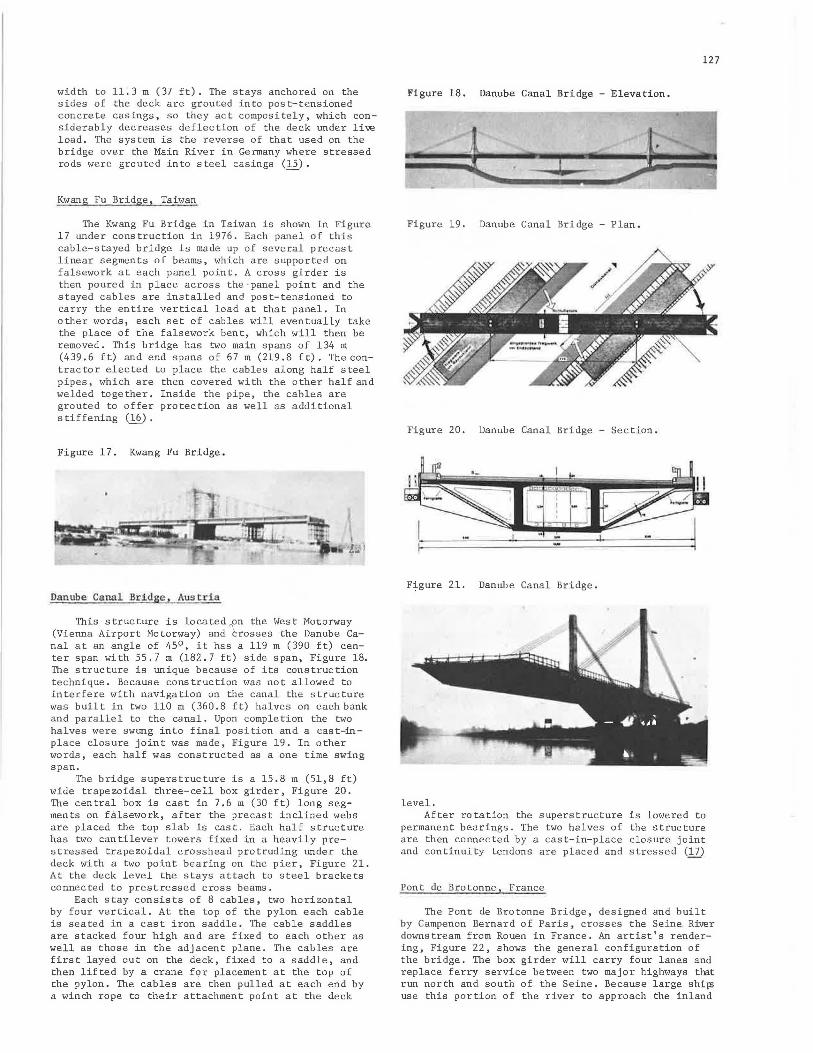
Danube Canal Bridge, Austria
This structure is located on the West Motorway (Vienna Airport Motorway) and 1:rosses the Danube Canal at an angle of 45°, it has a 119 m (390 ft) center span with 55.7 m (182. 7 ft) side span, Figure 18. The structure is unique because of its construction technique. Because construction was not allowed to interfere with navigation on the canal the structure was built in two 110 m (360.8 ft) halves on each bank and parallel to the canal. Upon completion the two halves were swung into final position and a cast-inplace closure joint was made, Figure 19. In other words, each half was constructed as a one time swing span.
The bridge superstructure is a 15.8 m (51,8 ft) wide trapezoidal three-cell box girder, Figure 20. The central box is cast in 7.6 m (30 ft) long segments on falsework, after the precast inclined webs are placed the top slab is cast. Each half structure has two cantilever towers fixed in a heavily prestressed trapezoidal crosshead protruding under the deck with a two point bearing on the pier, Figure 21. At the deck level the stays attach to steel brackets connected to prestressed cross beams.
Each stay consists of 8 cables, two horizontal by four vertical. At the top of the pylon each cable is seated in a cast iron saddle. The cable saddles are stacked four high and are fixed to each other as well as those in the adjacent plane. The cables are first layed out on the deck, fixed to a saddle, and then lifted by a crane for placement at the top of the pylon. The cables are then pulled at each end by a winch rope to their attachment point at the deck
127
Figure 18. Danube Canal Bridge - Elevation.
Figure 19. Danube Canal Bridge - Plan .
Figure 20. Danube Canal Bridge - Section.
Figure 21. Danube Canal Bridge.
level. After rotation the superstructure is lowered to
permanent bearings. The two halves of the structure are then connected by a cast-in-place closure joint and continuity tendons are placed and stressed (11)
Pont de Brotonne, France
The Pont de Brotonne Bridge, designed and built by Campenon Bernard of Paris, crosses the Seine River downstream from Rouen in France. An artist's rendering, Figure 22, shows the general configuration of the bridge. The box girder will carry four lanes and replace ferry service between two major highways that run north and south of the Seine. Because large ship; use this portion of the river to approach the inland

128
Figure 22. Pont de Brotonne .
port of Rauen 35 km (22 m) to the east, vertical navigation clearance was 50 m (164 ft) above water level, which results in a 6.5% grade for its longer approach (18).
Total length of structure is 1,278.4 m (4,194 ft), divided into three continuous sections: the left bank approach viaduct, the main bridge crossing the Seine, and the right bank approach viaduct. The three sections are separated by expansion joints located at points of contraflexure in the viaduct spans on either side of the cable-stay portion of the structure. The central river crossing includes a 320 m (1,050 ft) center span and 143.5 m (471 ft) side spans. At present, this structure holds the record length for a cable stayed bridge of prestressed concrete.
The deck structure is balanced cantilever out from the pylon pier. Dimensions of the deck segments are, top flange 19.2 m (63 ft) wide, bottom flange 8 m (26 ft) wide, constant depth of 3.8 m (12.5 ft). Web and top flange are 0. 2 m ( 7. 8 in) thick, bot tom flange is 0.18 m (7 in) thick. Each segment is 3 m (9.8 ft) long, Figure 23. The only part of the trapezoidal box girder that is precast is its sloping webs. The 3 m (9.8 ft) long, 4 m (13 ft) wideprecast web elements are precast at the site and are from 0.2 m (7.8 in) to 0.4 m (15.6 in) thick. The balance of the cross section, including top and bottom flanges and its interior stiffening struts and cablestay anchorages are cast-in-place.
Preceding placement of the precast web units, the bridge's 14 octagonal piers are slipformed, nine on the left bank and three on the right bank. Span length in the approaches are, for the left bank, 38.9 m (127.6 ft) and eight at 58.5 m (192 ft); for the right bank, from the abutment, 39 m (128 ft), 55.5 m (182 ft), and 70 m (230 ft). Approach piers vary in height from 10 to 50 m (33 to 164 ft). The two central pylons rise 120 m (394 ft) above the water level of the Seine. When the slipforming of the piers reached the deck level, the piers were pre-
Figure 23 . Pont de Brotonne - Section .
i ?.20
!Ou~ - I CHAUSSEE
o. ~u
CHAUSSEE
s.oo S6n
stressed to their foundations so as to stabilize the piers for erection of the deck segments. As the precast deck units were erected, the pylon was constructed using conventional forming methods.
In constructing the girder the first operati on was to extend the bottom flange form from a traveling form at the completed segment, place the precast web units which form the basic shape and act as a guide for the remaining traveling form used to cast the upper flange and interior struts. Tower cranes at the pylon placed, as far as they could reach in both directions, the precast webs in a symmetrical manner to balance the loads. Beyond the range of the tower cranes, gantry cranes running on rails on the top flange and extending 3 m (9 .8 ft) beyond the end of a completed section were used to place new pieces. After placement of the precast webs the interior steel form is jacked forward to cast the bottom flange, struts, and top flange.
Final support for the deck units is provided by 21 stays continuous through the pylon and varying from 84 to 340 m (275 to 1,115 ft) in length and lie in a vertical plane along the longitudinal axis of the structure. Spacing of the stays at deck level is 6 m (19.6 ft), thus, every other segment has a stay anchor, Figure 24 shows an isometric of a segment and the orientation of prestressing and stay.
Figure 24 . Pont de Brotonne - Isometric
Pasco- Kennewick Bridge , U.S .A.
The first cable-stayed bridge with a concrete superstructure to be built in the United States is the Pasco-Kennewi ck Intercity Bridge crossing the Columbia River in the State of Washington. The overall length of this structure is 763 m (2,503 ft). The center cable-stay span is 299 m (981 ft) and the stayed flanking spans are 124 m (406.5 ft). The deck is continuous without expansion joints from abutment to abutment, being fixed at the Pasco end and having an expansion joint at the Kennewick abutment. The three main spans are assembled from precast, prestressed concrete segments. Figure 25, while the approach spans are cast-in-place.
The concrete bridge girder is of a uniform cross section, of constant 2 m (7 ft) depth along its entire length and 24.3 m (79 ft 10 in) wide. The shallow girder, and the long main span are necessary to reduce the roadway grades to a minimum, to provide the greatest possible navigation clearances below, and to reduce the number of piers in the 21.3 m (70 ft) deep river.
Segments are precast about 1.6 km (1 m) down stream from the bridge site, each segment weighs about 272 mt (300 t). The sections are barged direct:ly beneath their place in the bridge and hoisted into position. It takes approximately six hours to lift eaLh t;egmeu L la Lu !JUt:il tiOll, Figure 26. Fifty-eight precast, transversely prestressed concrete bridge

Figure 25. Pasco-Kennewick Bridge .
Figure 26. Pasco-Kennewick Bridge.
j ! • ,., ·;;" II
girder segments are required. The segments are match cast, prestressed, cured and then transfered to the bridge, and erected symmetrically about the two main bridge towers, epoxy joined, longitudinally prestressed against the previously erected ones, and suspended from the bridge stays. Each segment is 8.2 m (27 ft) long and consists of three transverse girders and a roadway slab joined along the segment edges with a hollow trangular box, Figure 26. A large part of the longitudinal prestressing force in the bridge girder is provided by the compression resulting from the horizontal component of cable force.
The stays are arranged in two parallel planes with 72 stays in each, that is, 18 stays on each side of each pylon. They are held at each tower top, 54.9 m (180 ft) above the bridge roadway in a steel weldmen t. The stays are made up of 6.35 mm (0.25 in) diameter parallel high strength steel wires. Stay anchors in the bridge deck are spaced at 8.2 m (27 ft). The prefabricated stays arrive on the job site on reels, and contain from 87 to 283_wires each, are covered with a polyethylene pipe, and after installation and final adjustment are protected against corrosion by pressure injected cement grout. Stay outside diameters range from 0.11 to 0.16 m (4.3 to 6.3 in). Design stress level for the stays is 751.5 MPa (109 ksi). This structure was deisgned by Arvid Grant and Assoc., Inc. in professional collaboration with Leonhardt and Andra of Stuttgart.
Dame Point Bridge, U.S.A .
The proposed Dame Point Bridge over the St. Johns River in Jacksonville, Florida is presently being de-
129
signed by the firm of Howard Needles Tammen & Bergendoff, Figure 2 7. Navigation requirements die ta te a 381 m (1,250 ft) minimum horizontal opening and a vertical clearance of 46.3 m (152 ft) above meanhigh water at the centerline of the clear opening. The proposed concrete cable-stay structure will have a 396.24 m (1,300 ft) central span with 198.12 m (650 ft) side spans.
Figure 27. Dame Point Bridge.
The bridge deck, which will carry three lanes of traffic in each direction, will span between longitudinal edge girders on each side. The longitudinal edge girder is in turn supported by a vertical plane of stays arranged in a harp configuration. The concrete deck and edge girders take local and overall bending from dead and live load in addition to the horizontal thrust from the stays (19).
The bridge deck consists of single-T precast floor beams spaning between longitudinal girders and a cast-in-place topping. The precast T's are prestressed for erection loads. After erection the entire deck is post-tensioned to provide positive precompression between edge girders under all conditions of loading. Erection of the deck will be by the balanced cantilever method.
This s true ture, which extends Fins terwalder 's concept in the Danish Great Belt and the Mainbrlicke, is still in the design stage and a number of alternates will be available to the contractor at his option. If this structure is consumated in concrete, it will certainly take the record for the longest cable-stay bridge in con ere te.
Closing Remarks
As late as 1970, the practical span limit of steel cable-stay bridges was considered to be 305 m (1,000 ft). As seen in the examples of the Danish Great Belt Bridge, the Pont de Brotonne, and the Pasco-Kennewick Bridge, spans of about 305 m (1,000 ft) have been accomplished with concrete cable-stay bridges. The practical span length has been extended to 400 m (l,300 ft) in the Dame Point Bridge, and spans approaching 500 m (1,600 ft) are considered technically feasible. It has been projected that with an aerodynamically shaped composite concrete and steel deck a span of 1,500 m (2,300 ft) can be achieved (20).
In evaluating a concrete cable-stay bridge the designer should be aware of the following advantages: by use of proper aerodynamic streamlining and multistays the deck structure can be slim and not portray a massive visual impression, concrete is inherently a material with favorable damping caharacteristics which is important in aerodynamic considerations, the horizontal component of stay force is advanta-

130
geous in that it produces a prestress force in the concrete and concrete is at its best in compression. With today's technology of prefabrication, pres tressing, and segmental cantilever construction, it is obvious that cable-stay bridges are extending the competitive span range of concrete construction to dimensions that had previously been considered impossible. The technological means exist, they only require implementation.
Acknowledgments
The following individuals and firms have been instrumental in obtaining data and illustrations: Julius Berger, Bauboag Aktiengesellschaft, Wiesbaden (Maracaibo). Prof. Morandi (Wadi Kuf). Dr. Gaetano Bologna, 1 Industria Italiana del Cemento (Magliana Viaduct). Normer Gray (Chaco/Corrientes). White, Young, and Partners (Danish Great Belt). Ulrich Finsterwalder (Danish Great Belt and Mainbrlicke). Juhani Virola (Dnieper Harbor). Jean Muller and T. R. Scanlan (Tiel, Danube Canal and Pont de Brotonne). Civil Engineering and Public Works Review, London (River Foyle). Prof. T. Y. Lin (Kwang Fu). L.A. Garrido (Barranquilla). Arvid Grant (PascoKennewick). G. F. Fox and H. J. Graham (Dame Point).
References
1. Feige, A., "The evolution of German Cable-Stayed Bridges - An Overall Survey," Acier-Stahl-S teel (English Version), No. 12, December 1966.
2. Podolny, W., Jr., and Fleming, J. F., "Historical Development of Cable-Stayed Bridges," Journal of the Structural Division, ASCE, Vol. 98, No. ST9, Proc. Paper 9201, September 1972.
3. Podolny, W., Jr., and Scalzi, J.B., "Construction and Design of Cable-Stayed Bridges," John Wiley & Sons, Inc., New York, 1976.
4. Dischinger, F., "Hll.ngebrlicken flir Schwerste VerKehrslasten," Der Bauingenieur, March 1949.
5. Torroja, E., "Philosophy of Structures," English Version by J. J. Polivka a~d Milos Polivka, Univ. of California Press, Berkley and Los Angles, 1958
6. "The Bridge Spanning Lake Maracaibo in Venesuela" Wiesbaden, Berlin: Bauverlag GmbH., 1963.
7. Morrandi, R., "Some Types of Tied Bridges in Pres tressed Concrete," First International Symposium Concrete Bridge Design, ACI Publication SP-23, Paper SP 23-25, American Concrete Institute, Detroit, 1969.
8. "Longest Concrete Cable-Stayed Span Cantilevered Over Tough Terrain," Engineering News-Record, July 15, 1971.
9. Morandi, R., "Il Viadut to dell Ans a della Magliana per la Autostrada Roma-Aeroporto di Fiumicino," 1 'Industria Italiana del Cementa (Rome), Anno XXXVIII, March 1968.
10. Gray, N., "Chaco/Dorrientes Bridge in Argentina," Municipal Engineers Journal, Paper No. 380, Vol. 59, Fourth Quarter, 1973.
11. Ko thman, H. B. and Chang, F . K. , "Longest Pre cast L;oncre t:e tiox Gircier tiricige in west:ern 11emisphere" Civil Engineering, ASCE, March 1974.
12. "Morandi - Style Design Allows Constant Suspended Spans," Consul ting Engineer (London), March 196 7.
13. "Tiel Bridge," Freyssinet International, STUP Bulletin, March-April 1973.
14. "River Foyle Bridge," Civil Engineering and Public Works Review (London), Vol. 66, No. 780, July 1971.
15. "Rigid stays slim box girder bridge and reduce de flee ti on," Engineering News-Record, June 20, 1974.
16. "Bridging the Gaps," Engineering Bulletin, T. Y. Lin International, Vol. 5, No. 2, October 1967.
17. "The Danube Canal Bridge (Austria)," Freyssinet International, STUP Bulletin, May-June 1975.
18. "Cable-stayed bridge goes to a record with hybrid girder design," Engineering News-Record, October 28, 1976.
19. "Dames Point Bridge," Design R~port, Howard Needles Tammen & Bergendoff, November 1976.
20. Leonhardt, F. , "La test Developments of Cable-s tayed Bridges for Long Spans," Saertryk af Bygningsstatiske Meodelelser (Denmark), Vol. 45, No. 4, 1974.