Embed Size (px)
Citation preview

SffiMENI'AL BRIJX;E CONSTRUCTION IN WESTERN EUROPE - IMPRESSIONS OF AN !RF STUDY TEAM
Craig A. Ballinger and Walter Podolny, Jr., Department of Transportation
In April of 1977, under the sponsorship of the International Road Federation, a five-man team of U.S. bridge engineers visited western Europe to study segmental prestressed concrete box girder bridges. The purpose of study was to examine and evaluate the current construction methods and design considerations for this type of bridge. The team visited bridges under construction and completed in west Germany, Austria, Northern Italy, Denmark, Holland, and France. Technical meetings were held with representatives of leading European design firms as well as bridge engineers from the governments of west Germany, Holland, and France. These meetings involved technical discussions of design, construction, and serviceability aspects. This paper presents information gathered during these visits and discussions on the following topics: construction with precast and cast-in-place concrete; erection by balanced cantilever, span-by-span, progressive placing, and incremental launching methods; design considerations relating to live load requirements, segmental joints, allowable tension in concrete, crack control, temperature gradient, shear keys, etc.
In April of 1977, a five-man engineering team sponsored by the International Road Federation, of which the authors were privileged to be members, embarked on a study tour of segmental bridge construction in western Europe. The objective was to determine and report on the current state-of-the-art and developnent of segmental bridge construction.
In addition to the authors, the study team was composed of the following representatives of government and private industry: Michael J. Abrahams, Project Engineer, Parsons Brinkerhoff Quade & Douglas, Inc.; Thomas Alberdi, Jr., Deputy Design F.nainPPr- ~t-r11rt-11rP~- J;"tlnrirl.:::r. q_t-:::at-c J"'\t:lon:::ar+-mon+- n-f
Tr~sportation; and Th~~~ -j:- Ii~i\;~y~-vi~;--P~~siaent of Engineering, Research and Developnent, Rocky Mountain Prestress, Inc.
'Ihe group traveled to West Germany, Austria, Northern Italy, Denmark, Holland, and France. Meetings were held with internationally recognized engineers on segmental prestressed concrete bridges including designers, contractors, and government officials. These meetings involved detailed
182
discussions relating to the design, construction, and serviceability of such bridges. The group also visited the sites of numerous segmental bridges; both under construction and completed.
Types of Segmental Construction
Segmental bridges may be categorized by two classifications: (1) the condition of the concrete at the time of erection, that is, precast or castin-place; and (2) the method of construction.
In precast segmental construction short segments are cast in a plant or near the job site under factory simulated conditions, but always at some location other than their final position in the structure, and then assembled in place. The cast-in-place segmental construction is such that the bridge is cast in situ in a series of steps. Both precast and cast-in-place construction produce essentially the same final structure, both concepts are viable ones, both have been consummated, and both have been successful.
The second classification of segmental bridges is by the method of construction. Generally, the method of construction can be divided into four types: (1) balanced cantilever, (2) span-by-span, ( 3) progressive placing, and ( 4) incremental launching (push-out construction), or what in Germany is called "taktschiebeverfahren."
Balanced Cantilever
The balanced cantilever method simply cantilevers segments from a pier in a balanced fashion on each side of a pier until mid-span is reached and a closure pour is made with a previous half-opun cantilever from the preceding pier. Then the procedure is repeated until a structure is completed. At most, the pier will only be out of b.:tlw.iCC b:l Vi"'1C ~mcr-.t, ·.-kiict-1 CQ.!1 bt: QCCUffU1-1WaLt:U
by a moment resistant pier or by a temporary brace. Until recently, the balanced cantilever method
has been the only form of segmental construction used in the United States. It was used on bridges at Corpus Christi, Texas and on the Vail Pass in Colorado. Precast segments were used on both bridges. Cast-in-place segments were utilized on the Pine Valley Bridge in California and the Kipapa Bridge in Hawaii.

For cast-in-place construction, the moveable formwork is supr:orted from a "form traveller" that cantilevers from the previously completed r:ortion of the bridge, Figure 1. New segments are formed, cast, and stressed .to the previously erected sections. In some cases, such as the Vejle Fjord Bridge in Denmark, Figure 2, a launching girder may be used to stabilize the structure for segments out of balance and to transr:ort materials to the location of casting. As a cantilever is completed, the launching girder is advanced to the next pier.
Similarly in precast construction, a launching girder may be used to transr:ort the precast segments to the end of the partially erected cantilever for attachment, as indicated in Figure 3 for the Sallingsund Bridge in Denmark.
Span-By-Span
In long, viaduct-type structures segmental span-by-span construction is particularly advantageous. 'ltle superstructure is executed in one direction, span-by-span, by means of a moveable form carrier, Figure 4. Construction joints or hinges are located at the r:oint of contraflexure. The form carrier, Figure S, is a type of factory, transplanted to the job site, with all of the advantages of chain production, normally r:ossible only in precast yards, and with the advantage of flexibility in shaping of cast-in-place concrete to suit field conditions. The moveable form carrier may be supr:orted on the piers, Figure 6; or from the edge of the previously completed construction, at the joint location, and at the forward pier. In some cases, as in the approach spans of the Rheinbrucke Dusseldorf-Flehe, the moveable formwork is supr:orted off the ground, Figure 7. The bogies of the form carrier may either run above or below the level of the bridge deck. Bogies below deck are more suitable for bridges close to the ground; for high elevated roadways, the above-deck type is easier to handle. 'ltle moveable form carrier consists of a 1 steel superstructure which is moved over the completed bridge. The large formwork elements are suspended from steel rods during concreting and are rolled forward, after the suspension rods have been removed, by means of the structural steel outriggers on both sides of the superstructure, Figure 8.
Several rather long bridges using this system of construction were executed on the Brenner Autobahn in Austria near Innsbruck, Figure 9. Footings and piers were placed from a 3-m ( 9. 8-ft) wide path which had been built along the alignment. Construction of a typical 30-m (98.4-ft) span superstructure was 8 calander days. At the Brenner Autobahn, in Italy, sections of elevated highway up to a length of approximately 2.5 km (1 1/2 m) have been constructed using form carriers with bogies above the level of the bridge deck, Figure 10.
Another typical example for this type construction method is the approximately 7-km (4.3 m) long elevated highway, part of an Autostrade in Sicily, Figure 11. The mushroom-shaped slab of the superstructure, similar to column capitals in flat-plate building construction, is r:ost-tensioned in the longitudinal and transverse directions, Figure 12. The Tangenziale Milano, an intercity elevated highway, was constructed using a form carrier with bogies below the deck, Figure 13. A typical longitudinal and transverse section of the structure is shown in Figure 14. In the longitudinal section, with construction proceeding from left to right, the construction joint is located at the forward edge of the mushroom capital. The span-by-span type of
183
Figure 1. Form travelers.
Figure 2. Launching girder, Vejle Fjord Bridge
Figure 3. Launching girder, Sallingsund Bridge

184
Figure 4. Moveable fonn carrier.
Figure 5. Moveable form carrier.
Figure 6. Moveable form carrier.
Figure'/. Ground supported form carrier, Rheinbrucke-Dusseldorf-Flehe.
Figure 8. Moveable form carrier.
Figure 9. Brenner autobahn - Innsbrucke, Austria.
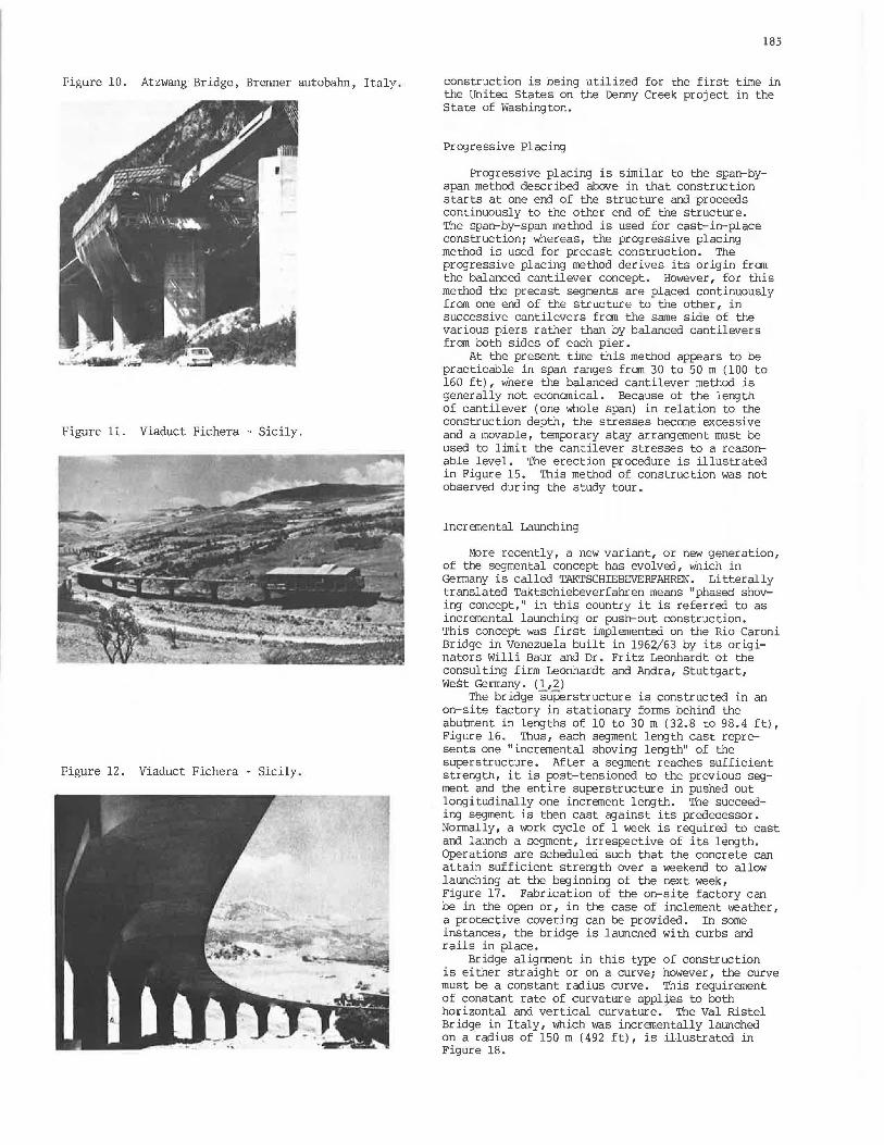
Figure 10. Atzwang Bridge, Brenner autobahn, Italy.
Figure 11. Viaduct Fichera - Sicily.
Figure 12. Viaduct Fichera - Sicily .
185
construction is being utilized for the first time in the United States on the Denny Creek project in the State of Washington.
Progressive Placing
Progressive placing is similar to the span-byspan method described above in that construction starts at one end of the structure and proceeds continuously to the other end of the structure. The span-by-span method is used for cast-in-place construction; whereas, the progressive placing method is used for precast construction. The progressive placing method derives its origin fran the balanced cantilever concept. However, for this method the precast segments are placed continuously from one end of the structure to the other, in successive cantilevers fran the same side of the various piers rather than by balanced cantilevers from both sides of each pier.
At the present time this method appears to be practicable in span ranges fran 30 to 50 m (100 to 160 ft) , where the balanced cantilever method is generally not economical. Because of the length of cantilever (one whole span) in relation to the construction depth, the stresses become excessive and a movable, temporary stay arrangement must be used to limit the cantilever stresses to a reasonable level. The erection procedure is illustrated in Figure 15. This method of construction was not observed during the study tour.
Incremental Launching
More recently, a new variant, or new generation, of the segmental concept has evolved, which in Germany is called TAKTSCHIEBEVERFAHREN. Li tterally translated Taktschiebeverfahren means "phased shoving concept," in this country it is referred to as incremental launching or push-out construction. This concept was first implemented on the Rio Caroni Bridge in Venezuela built in 1962/63 by its originators Willi Baur and Dr. Fritz Leonhardt of the consulting firm Leonhardt and Andra, Stuttgart, West Germany. (1,2)
The bridge suEierstructure is constructed in an on-site factory in stationary forms behind the abutment in lengths of 10 to 30 m (32.8 to 98.4 ft), Figure 16. Thus, each segment length cast represents one "incremental shoving length" of the superstructure. After a segment reaches sufficient strength, it is post-tensioned to the previous segment and the entire superstructure in pushed out longitudinally one increment length. The succeeding segment is then cast against its predecessor. Normally, a work cycle of 1 week is required to cast and launch a segment, irrespective of its length. Operations are scheduled such that the concrete can attain sufficient strength over a weekend to allow launching at the beginning of the next week, Figure 17. Fabrication of the on-site factory can be in the open or, in the case of inclement weather, a protective covering can be provided. In some instances, the bridge is launched with curbs and rails in place.
Bridge alignment in this type of construction is either straight or on a curve; however, the curve must be a constant radius curve. This requirement of constant rate of curvature appl:j.es to both horizontal and vertical curvature. The Val Ristel Bridge in Italy, which was incrementally launched on a radius of 150 m (492 ft), is illustrated in Figure 18.

186
Figure 13. Tangenziale Milano.
Figure 14. Tangenziale Mi lano .
fu'.f ·1:· · -· -.~-
Figure 15. Progr essive pl acing erection procedure.
To counteract the varying bending moments that occur during the launching operations, the superstructure is concentrically prestressed. In addition, a launching nose, Figure 17, is provide in order to preclude the developnent of excessively large bending moments during launching.
The concentrically prestressed superstructure is pushed forward longitudinally in successive increments by means of hydraulic jacks. To accommodate the movement of the superstructure, temporary sliding bearings are installed on the piers. These bearings are made of teflon- (PTFE-) faced steelreinforced neoprene pads which slide on polished stainless steel plates, Figures 19 and 20.
There are two methods of launching. The method used on the Ri o Caroni Bridge has the jack bearing on an abutment face and pulling on a steel rod, which is attached to the last segment cast by launching shoes. The second, and more current, method consists of horizontal and vertical jacks, Figure 21. The verticul jack slides with a teflon plate at its base on a stairr less steel plate and has a friction element at the top to engage the superstructure. The vertical jack lifts the superstructure approxin1ately 5 mm (3/ 16 in) for launching. The horizontal jack then moves the superstructure longitudinally. After the vertical jack has moved one stroke of the horizontal jnck, the vertical jack is lowered and the horizontal jack is retracted to restart the cycle. (2)
This construction technique has been used for spans up to 60 m (197 ft) without the use of temporary falsework bents. Spans up to 100 m (328 ft) have been built utilizing temporary supporting bents. Girders must have a constant depth, which is usually l i l2 to 1/16 of the longest span.
An example of this type of construction is the Muhlbachtalbrucke, about 50 km (31 m) southwest of Stuttgart, Figure 22. This structure has an overall length of 580 m (1,903 ft) with 43 m (141 ft) spans. The far-side trapezoidal box girder which has been completed fran abutment to abutment, is shown in Figure 22. The near-side trapezoidal box girder has been launched form the left abutment and the launching nose has reached the first pier. There is a horizontal curvature to the bridge. A view of the underside of the twin boxes, Figure 23, showns the longitudinal closure joint that has not yet been poured.
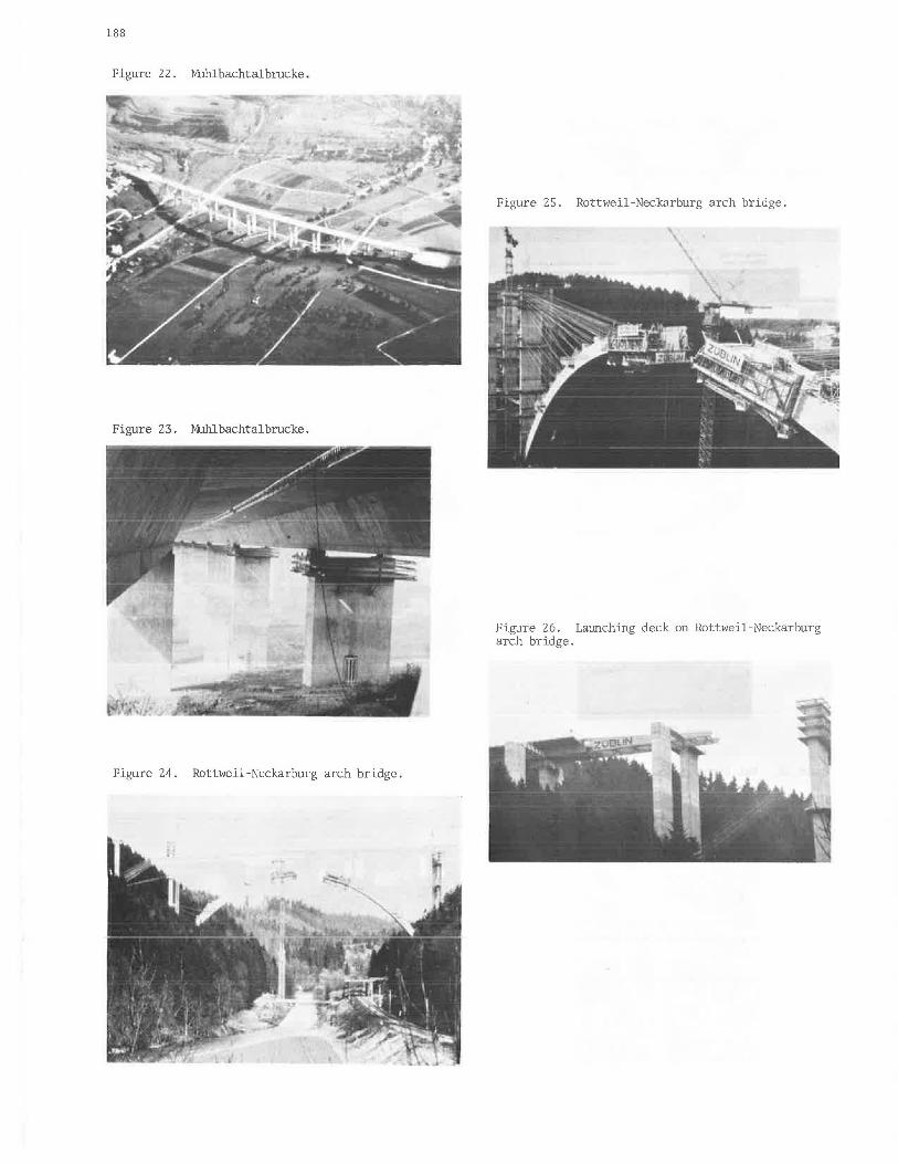
Another example is the Talbrucke RottweilNeckarburg Bridge , 80 km (50 m) southwest of Stuttgart, Germany, Figure 24. The bridge deck consists of two incrementally launched box girders supported by cast- i n-place segmental arch ribs. The 364.98-m (l,197-ft) long roadway deck is 94.77 m (310.9 ft) above the Neckar Creek. The arch span is 154.4 m (506.6 ft) with a rise of 49.85 m (163.5 ft). The total structure width is 31 m (101. 7 ft) constructed in two longitudinal halves.
Figure 24 shows the bridge under construction, just before closure of the firsl arch rib. During construction, a two-cell arch rib is temporarily tied back to rock anchors by Dywidag bars which pass ......... ...... .... - ...... __ r.<i.!-·- - - <"'\r:' ml-- ,: __ _ ___ ____ , _ .,., - ., ' ., "VY ......... u. 1:-' .......... , .... ..L":;t"·u .. ,.;.- ~-'· .LU..:= .Ul\,;J..Qllt:::Ul-a..L..L}' ..LaUJ.J\,.,;Ut'\.J.
deck and the launching nose are shown in Figures 26 and 27. The deck spans are 30 m (98.4 ft) in the approach and 22.14 m (72.6 ft) over the arch.
The incremental launching technique was used for the first time in the United States for construction of the Wabash River Bridge at Covington, Indiana.

Figure 16. Casting bed and launching arrangement .
Cashng bed and Slafonary IO(ffiS
Figure 17. Launching sequence .
Figure 18. Val Ristel Bridge .
rnreclion o1 Launching 4
Figure 19. Temporary sliding bearing.
Superstructure
( In
Direction of launching -+
Reinforced neoprene sheets and teflon
Pier . ...
187
) out
Figure 20. Teflon-faced neoprene pads on temporary sliding bearings.
figure 21. Push-out jacking arrangement.
188
Figure 22. Muhlbachtalbrucke.
Figure 23. Muhlbachtalbrucke.
Figure 24. Rottweil-Neckarburg arch bridge.
Figure 25. Rottweil-Neckarburg arch bridge.
Figure 26. Launching deck on Rottweil-Neckarburg arch bridge.

Figure 27. Closeup of launching nose Rottweil-Neckarburg arch bridge.
Figure 28. Maximwn live load moment (simple span).
M (tm)
5000
4000
.3000
... ~ • ~ 2000 0
~
~ ......:..,. = iifT~•.M 'h r.
21z1:w
,-;.,.5. CPC
I"v"·a.. UC
290 117
1000 F. Lc011/,.r:vdt ·~'"' P1-11f.ctle4 Ui.~c.~~t~
Str~tltl,.~J" IA85E .New York JJ1•"
o w ~ ~ # M ~ ~ ~ ~ ~
.Span
189
Design Considerations
Design of concrete bridges in the United States conforms with the provisions of AASH'IO' s "Standard Specifications for Highway Bridges." It should be recognized that, for the most part, the provisions in these specifications were written prior to when segmental construction was considered feasible or practical in the United States.
There has been considerable discussion in the American literature relative to the subject of segmental construction and it will not be repeated here. However, the following will present a discussion of several specific items athat are either controversial or practiced differently in different countries in Europe.
Live Load Requirements
In comparing practices in other countries to that employed in the United States, an important parameter must be kept in mind, that is, live load requirements. Figure 28 illustrates that there is considerable difference in code requirements in various countries. For a simple span of 50 m (164 ft) and width of 7.5 m (24.6 ft) the German specification indicates a moment of 186 percent that of the AASH'IO requirements and the French, 290 percent that of AASH'IO. (3) There are some Canadian provinces which use the AASH'IO specifications, but arbitrarily increase the live load by 25 percent.
The depth-to-span ratio and width-to-depth ratio for segmental construction presently advocated, have been adopted from European practice. The lighter live loads used in the United States should lead to the feasibility of less superstructure depth. This will undoubtedly occur as these concepts are "Americanized."
Segment Joints
In both precast and cast-in-place segmental construction, the segments are reinforced with prestressing tendons and conventional mild steel reinforcement. In both types of construction, the prestressed reinforcement, or at least some of it, crosses the joint. However, the mild steel reinforcement, obviously, can only be continuous across the joint in the cast-in-place method. In precast construction the joint is not reinforced with mild steel although the segments are usually glued together with epoxy. The German code, at the present time, requires mild steel reinforcement across the joint and thus precludes precast construction. The German code is presently under revision and precast construction is under consideration. The joint treatment is a controversial point in Europe and apparently follows nationalistic lines.
Allowable Tension in Concrete
As stated above, in cast-in-place segmental construction, reinforcing steel is extended across the construction joint. For this case, tension is permitted across the joint--in both Germany and France. However, this tension is permitted only when there is a severe combination of loads. In German unaer
2a condition of full live and dea:l load,
a 0.14 kg/llUll (200 psi) tension iz permitted and half of this value, or 0.07 kg/rrun (100 psi) is permitted at the joint. However, no tension is

190
psrmi tted under one-half live and full dead load. During erection, tension is generally not perrni tted.
For precast segmental construction, no steel extends across the joint and it is difficult to anticipate how this joint will behave under tension. If epoxy is used to glue the joints together, it can be tested to insure that it has adequate tensile strength. The problem is that immediately adjacent to the joint, the concrete is not reinforced and is composed of only a cement and fine aggregate. It is debatable if one can rely on this unreinforced paste to take much tensile stress.
In the design of the precast segmental Sallingsund Bridge in Denmark, no tension was allowed for the load case of dead, temperature, temperature gradient, and settlement. However, for the load case that included the above loads plus redistributed momenzs, wind, and boat impact on the pier a 0.25 kg/mn (356 psi) tension was allowed.
In Holland, for precast epoxied segmental construction, the goverment engineers design for no tension under dead load, full live load and settlement. Tensile stresses resulting fran temperature gradient are not considered.
Crack Control
The question of allowable tension is obviously an improtant one; however, some European engineers felt that this problem should be considered fran the point of strain rather than stress. Thus, the problem becomes one of controlling crack widths rather than limiting tensile stress in the concrete. AASH'IO has recanmendations in the 1974 Interim, Section 1.5.39, for distribution of flexural reinforcement to control cracking for reinforced concrete depending upon exposure. There are no recanmendations for prestressed concrete.
One European engineer expressed the opinion that no corrosion will occur if cracks are less than 0.4 nun (0.016 in) and that for prestressed bridge design cracks should be limited to 0.1 nun (0.004 in). He felt that the cracking was most severe the first few days after concrete was cast when there are large shrinkage strains set up by the heat of hydration of the cement and at the same time the concrete was of low strength.
Temperature Gradient
In considering tension stresses, consideration should be given to the tensile stresses produced by a thennal gradient between the top flange and botton flange of the box girder. AASH10 at the present time does not address this problen . Tensile stress in the bottom flange at ~ first interior support can be as high as 0.35 kg/nm (500 psi). At some point away fran the support such temperature stress could easily cause cracks in the bottom flange.
In France, no tension is permitted across the joint for a 5°C (9°F) temperature oradient combined with dead, live (or wind) and settiement. Also, no tension is permitted for a 10°C (18°F) temperature gradient combined with dead load. The German code is being revised following the Franch to consider a 10°C (18°F) temperature gradient in combination with half the live load. For this combination, the section is considered cracked and the prestressing steel is checked for fatigue for 2,000,000 cycles of half live load.
Obviously, another thermal gradient condition
thaL needs c:onsiuei:ctlluu .i.11 Lle8i<J11 .i.8 that between the outside and inside of exterior webs. Thermal gradient stresses can be developed such that total stress cannot be acconunodated by the shear reinforcement provided, which would result in longitudinal cracks in the web.
Shear Keys
Another design consideration about which there was much discussion and difference of opinion was shear transfer across the joint. For cast-in-place construction, the cOl!UTIOn treatment is to use a form liner which leaves a roughened surface which is considered adequate to provide shear transfer. In one case, a rough broard surface was used as a form liner.
For precast construction shear keys in the webs are used to transfer shear. There are two schools of thought regarding the type of shear key to be used . The Dutch provide a large shear key, Figure 29, which is designed to support ~ segments and the construction equipnent load while the epoxy is setting up and curing. This large shear key is reinforced. Mvantages are that, because of the reinforcement in the key, there is reinforcement across the joint, it is less likely to be damaged during handling and erection, and it pennits easier details for tendon anchorage in the web. The disadvantage is that it concentrates shear forces at one point.
The French used this type of key in their structures until recently. They are now using a multiple or corrugated type and thus represent a second school of thought, Figure 30. The advantage of this type of shear key is that it provides a more uniform transfer of stress and can be designed to transfer all the web shear during service. Although the snall keys cannot be reinforced, the distance between vertical stirrups, if placed close to the ends of the segment, would be less than typical stirrup spacing. If the apt:earance of the key is undesirable , a relief can be used on the exterior face of the web. Disadvantages are that the keys are more likely to be damaged during handling and erection , and there is a detail problem of providing for tendon anchorages in the webs.
Conclusion
In conclusion, with the exception of the joints, both precast and cast-in-place construction essentially produce the same final structure. Both concepts are viable ones, both have been consurrunated and have been successful. However, fran a designer's point of view, there are questions still to be resolved. we need recamnen::lations as how to acconunodate thermal gadient; the question of allowable tensile stress in the concrete apparently needs closer scrnt.iny; perhaps the concept of crack control needs further investigation; is it better to use large shear keys or snaller ones? Tt. w~s ~ppr>rPnt frrrn th~ nifference of opinion in Europe that there is room for investigation research to provide guidelines and direction to the designer.
Acknowledgments
The following individuals and firms are acknowledged for their hospitality and assistance

in providing data and photographs: Baudirektor Dipl. Irg. Freidrich Standfuss, Bundesministerium fur Verkehr, Bonn; Prof. Fritz Leonhardt, Mr. Zellner, arrl Mr. SVensson all of the firm Leonhardt arrl Andra, Stuttgart; Dr. Richard Heinen arrl Mr. Manfred Bockel of Dyckerhoff & Widmann, Inc., Munich; Mr. P. Allaart and Mr. IR. A. H. Van Rijs, Ministry of Transport arrl Waterstaat, Bridge Building Department, Holland; Mr. H. E. Westenberg, I.B.I.S., Holland; Mr. M. Le Franc, L'Ingenieur En Chef Des Fonts et Chaussees, Service d'Etudes Techniques des Routes et Autoroutes, France; and Mr. Jean Muller, Europe--Etudes, Paris, France.
References
1. Arvid Grand. Incranental Launching of Concrete Structures. Journal of the American Concrete Institute, Vol. 72, No. 8, August 1975.
2. Willi Baur. Bridge Erection by Launching is Fast, Safe, and Efficient. Civil EngineeringASCE, Vol. 47, No. 3, March 1977.
3. F. Leonhardt. New Treoos in Design arrl Construction of Long Span Bridges and Viaducts (Skew, Flat Slabs, Torsion Box). International Association for Bridge arxl Structural Engineering, Eight Congress, New York, September 9-14, 1968.
191
Figure 29. Large shear key.
Figure 30. Small shear keys.