Embed Size (px)
Citation preview

SPECIFlCATION FOR
MANZTJTACTURERS MAINTENANCE DATA
GANM Specification No. 2
GAMA

SPECIFICATION FOR
lkMNUFACTURERS MAINTENANCE DATA
GAMA Specification No. 2


SPECIFICATION FOR MANUFACTURERS MAINTENANCE DATA
PREFACE
This specification was developed by representatives of member companies of the General Aviation Manufacturers Association for use in preparing Manufacturers Maintenance Data, in manual form, that:
a. Will serve as a guide for the maintenance of airplanes in a continuous airworthy condition;
b. Will be of maximum usefulness as a reference book by maintenance personnel;
c. Meet applicable government regulatory requirements; and
d. Meet industry standards for scope of material, arrangement, nomen- clature and definitions.
This document contains appropriate instructions for Continued Airworthiness as described in Appendix G or H of FAR 23 and FAR 25 as appropriate.
Manufacturers may prepare maintenance data in conformance with either Air Transport Association of America Specification No. 100, "Specification for Manufacturers Technical Data", or with this specification which closely follows and is compatible with ATA Specification No. 100. This GAMA specification provides for the preparation and issuance of less complex manuals for less complex airplanes than those operated by the large scheduled airlines while achieving industry wide standardization of nomenclature and format. GAMA appreciates and acknowledges the pioneering work and leadership of the Air Transport Association of America in developing standardized maintenance manuals.
This specification provides broad general guidance for preparing handbooks for all types of general aviation airplanes certified under applicable Federal Aviation Regulations. For purposes of this specification, "airplane" refers to the airframe and related components specified in the Type Certificate or made available as options by the airplane manufacturer.
Any revisions to a Maintenance Manual made necessary due to modifications of an airplane after delivery are the responsibility of the holder of the type design approval of the modification as appropriate for type certification. Revisions are to be made consistent with the format of their specification using the provisions of FAR 21.50 as a basis.
The specification is divided into two parts covering (I) "General Specification" and (2) "Detail Requirements." The "General Specification" part contains technical publication guidance applicable to the preparation of all Maintenance Manuals.

The " D e t a i l Requirements1' p a r t p r o v i d e s f o r a un i fo rm method of a r r a n g i n g and i d e n t i f y i n g s p e c i f i c s u b j e c t m a t e r i a l . It i s i n t e n d e d t h a t t h e manufac tu re r s have ( l a t i t u d e i n t h e c o n t e n t of t h e i r p u b l i c a t i o n s i n s o f a r a s d e p t h and scope of coverage a r e concerned; n e v e r t h e l e s s , each m a n u f a c t u r e r i s expec ted t o f o l l o w t h e same sequence of b a s i c sys tem and s u b j e c t a r rangements even though some systems may be grouped t o g e t h e r and some systems a n d / o r c h a p t e r s may b e o m i t t e d when n o t a p p l i c a b l e .
Although t h i s s p e c i f i c a t i o n conforms t o recognized i n d u s t r y p r a c t i c e s , i t i s w r i t t e n i n broad g e n e r a l t e r m s and i t i s r e c o g n i z e d t h a t problems w i l l a r i s e which a r e n o t t r e a t e d a d e q u a t e l y by t h e s p e c i f i c a t i o n . I n such c a s e s , each manufac tu re r i s expec ted t o u s e i t s b e s t judgment.
Although t h e s p e c i f i c a t i o n c o n t e m p l a t e s t h e p r o v i s i o n of s imple handbooks f o r s imple a i r p l a n e s , and much more comprehensive handbooks f o r complex a i r p l a n e s , i t never the - l e s s w i l l r e s u l t i n a h i g h d e g r e e of s t a n d a r d i z a t i o n by p r o v i d i n g f o r u n i f o r m i t y of ar rangement o f s y s t e m s and components of sys tems , i n c h a p t e r and subchap te r o r group and s e c t i o n forms.
Because a i r p l a n e s a r e in tended t o have l o n g l i v e s , t h e i r f l i g h t s a f e t y must be a s s u r e d . U t i l i z i n g an a i r p l a n e a s i n t e n d e d by t h e m a n u f a c t u r e r , combined w i t h sound i n s p e c t i o n and maintenance p r a c t i c e s , forms t h e b a s i s f o r a s s u r i n g t h e a i r p l a n e remains a i r w o r t h y and s a f e t o o p e r a t e . Through a p r o c e s s c a l l e d c o n t i n u i n g a i r w o r t h i n e s s , v i r t u a l l y every component compr i s ing an a i r p l a n e i s invo lved i n some form of p r e s e r v a t i o n , i n s p e c t i o n , p r e v e n t a t i v e maintenance, o v e r h a u l , r e p a i r , and /or replacement a c t i v i t y .
I n i t i a l l y t h e c r i t e r i a f o r c o n t i n u o u s a i r w o r t h i n e s s i s dependent upon t h e c a r e and , thought des igned i n t o t h e a i r p l a n e a t i t s i n c e p t i o n . Once des igned and approved, td, e s t a b l i s h m e n t of thorough maintenance p r o c e d u r e s i s a must. T h i s in fo rmat ion must b e a v a i l a b l e i n c l e a r , c o n c i s e l anguage t o t h o s e who need i t . Sometimes, e s p e c i a l l y f o r complex a i r p l a n e s , i t may b e n e c e s s a r y t o p r o v i d e s p e c i f i c t r a i n i n g i n t h e p roper maintenance of t h e a i r p l a n e and i t s sys tems . These a c t i v i t i e s must b e o r i g i n a t e d by t h e manufac tu re r f o r , a f t e r a l l , h e knows how i t shou ld f u n c t i o n .
Maintenance i n f o r m a t i o n needs t o b e c o n t i n u a l l y updated. Open communication should e x i s t w i t h t h e o p e r a t o r t e l l i n g t h e m a n u f a c t u r e r a s soon a s some new kind of s i t u a t i o n a r i s e s and t h e manufac tu re r responding back w i t h s o l i d h e l p t o t h e o p e r a t o r s . Only when b o t h ends do t h e i r j o b can an e n t i r e f l e e t of a i r p l a n e s remain c o n t i n u o u s l y a i r w o r t h y .
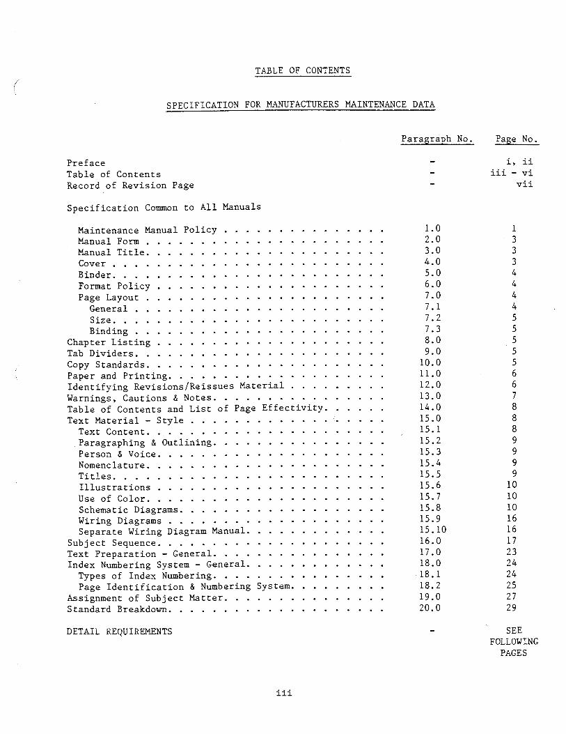
TABLE OF CONTENTS
SPECIFICATION FOR MANUFACTURERS MAINTENANCE DATA
Preface Table of Contents Record of Revision Page
S p e c i f i c a t i o n Common t o A l l Manuals
. . . . . . . . . . . . . . . Maintenance Manual Po l i cy . . . . . . . . . . . . . . . . . . . . . . Manual Form . . . . . . . . . . . . . . . . . . . . . . Manual T i t l e
. . . . . . . . . . . . . . . . . . . . . . . . . Cover
. . . . . . . . . . . . . . . . . . . . . . . . . Binder . . . . . . . . . . . . . . . . . . . . . Format Po l i cy
. . . . . . . . . . . . . . . . . . . . . . Page Layout . . . . . . . . . . . . . . . . . . . . . . . General
. . . . . . . . . . . . . . . . . . . . . . . . . Size . . . . . . . . . . . . . . . . . . . . . . . Binding
. . . . . . . . . . . . . . . . . . . . . Chapter L i s t i n g . . . . . . . . . . . . . . . . . . . . . . . T a b D i v i d e r s
Copy Standards . . . . . . . . . . . . . . . . . . . . . . . . . . . . . . . . . . . . . . . . . . Paper and P r i n t i n g
. . . . . . . . . I d e n t i f y i n g Revisions/Reissues Ma te r i a l . . . . . . . . . . . . . . . . Warnings. Cautions & Notes
. . . . . . Table of Contents and L i s t of Page E f f e c t i v i t y . . . . . . . . . . . . . . . . . . . Text Mater ia l - S t y l e
. . . . . . . . . . . . . . . . . . . . . . T e x t c o n t e n t . . . . . . . . . . . . . . . . ,Paragraphing & Out l in ing
. . . . . . . . . . . . . . . . . . . . . P e r s o n & V o i c e . . . . . . . . . . . . . . . . . . . . . . Nomenclature
. . . . . . . . . . . . . . . . . . . . . . . . . T i t l e s I l l u s t r a t i o n s . . . . . . . . . . . . . . . . . . . . . U s e o f C o l o r . . . . . . . . . . . . . . . . . . . . . .
. . . . . . . . . . . . . . . . . . . Schematic Diagrams Wiring Diagrams . . . . . . . . . . . . . . . . . . . .
. . . . . . . . . . . . . Separate Wiring Diagram Manual Subject Sequence . . . . . . . . . . . . . . . . . . . . . Text Prepara t ion - General . . . . . . . . . . . . . . . .
. . . . . . . . . . . . . Index Numbering System - General . . . . . . . . . . . . . . . . Types of Index Numbering
. . . . . . . . . Page I d e n t i f i c a t i o n & Numbering System Assignment of Subject Matter . . . . . . . . . . . . . . . Standard Breakdown . . . . . . . . . . . . . . . . . . . .
Paragraph No . Page No . . i. ii . iii . v i . v i i
DETAIL REQUIREMENTS
iii
SEE FOLLOWING
PAGES

TABLE OF CONTENTS . DETAIL REQUIREMENTS
Page No .
. . . . . . . . . . . . . . . . . . . . Accessory Gearboxes 113 Air . . . . . . . . . . . . . . . . . . . . . . . . . . . . 104 . . . . . . . . . . . . . . . . . Airborne Auxiliary Power 83 Aircraft . . . . . . . . . . . . . . . . . . . . . . . . . 40 . . . . . . . . . . . . . . Airframe - Standard Practices : 52 Airworthiness . . . . . . . . . . . . . . . . . . . . . . . 41 Auto Flight . . . . . . . . . . . . . . . . . . . . . . . . 55
. . . . . . . . . . . . . . . . . Charts & Wiring Diagrams 114 Communications . . . . . . . . . . . . . . . . . . . . . . 57
. . . . . . . . . . . . . . . . . . . . . . Controls Engine 106
. . . . . . . . . . . . . . . . . . . Dimensions and Areas 44 Doors . . . . . . . . . . . . . . . . . . . . . . . . . . . 85
Electrical/Electronic Panels & . . . . . . . . . . . . . . . . . . . Multipurpose Parts 82 . . . . . . . . . . . . . . . . . . . . . Electrical Power 59 Engine . . . . . . . . . . . . . . . . . . . . . . . . . . 97 . . . . . . . . . . . . . . . . . . . . . . Engine Controls 106 . . . . . . . . . . . . . . . . . . . Engine Fuel Systems :. 101 . . . . . . . . . . . . . . . . . . . . Engine - Indicating 107 . . . . . . . . . . . . . . . . . . Engine - Reciprocating 100 . . . . . . . . . . . . . . . . . Engine Standard Practices 94 . . . . . . . . . . . . . . . . . Engine Turbine/Turbo.Prop 98 . . . . . . . . . . . . . . . . . . . Environmental Systems 53 . . . . . . . . . . . . . . . . . . . Equipment/Furnishings 61 . . . . . . . . . . . . . . . . . Equipment Special Purpose 115 Exhaust . . . . . . . . . . . . . . . . . . . . . . . . . . 108
Fire Protection . . . . . . . . . . . . . . . . . . . . . . 63 Flight Controls . . . . . . . . . . . . . . . . . . . . . . 64 Fuel . . . . . . . . . . . . . . . . . . . . . . . . . . . 66 . . . . . . . . . . . . . . . . . . . Fuel Systems - Engine 101 . . . . . . . . . . . . . . . . . . Furnishings. ~quipment/ 61 . . . . . . . . . . . . . . . . . . . . . . . . . Fuselage 87

TABLE OF CONTENTS . (CONT'D)
Gearboxes. Accessory . . . . . . . . . . . . . . . . . . . 113
Hydraulic Power . . . . . . . . . . . . . . . . . . . . . . 6 8
Ice and Rain Protect ion . . . . . . . . . . . . . . . . . . 69 Ign i t ion . . . . . . . . . . . . . . . . . . . . . . . . . 103 Indicating/Recording Systems . . . . . . . . . . . . . . . 7 1
LandingGear . . . . . . . . . . . . . . . . . . . . . . . 7 2 Leveling & Weighing . . . . . . . . . . . . . . . . . . . . 46 . . Lif t ing & Shoring . . . . . . . . . . . . . . . . . . . . . 4 5
Lights . . . . . . . . . . . . . . . . . . . . . . . . . . 7 4
Maintenance Checks . . . . . . . . . . . . . . . . . . . . 42 Mooring. Parking & . . . . . . . . . . . . . . . . . . . . 4 8
Nacelles . . . . . . . . . . . . . . . . . . . . . . . . . 88 Navigation/Pitot S t a t i c . . . . . . . . . . . . . . . . . 7 6
O i l 110 . . . . . . . . . . . . . . . . . . . . . . . . . . . . Oxygen . . . . . . . . . . . . . . . . . . . . . . . . . . 7 8
Panels E l e c t r i c a l . . . . . . . . . . . . . . . . . . . . 82 . Panels Electronic . . . . . . . . . . . . . . . . . . . . 8 2 . Parking & Mooring . . . . . . . . . . . . . . . . . . . . . 4 8 P i t o t S t a t i c . Navigation . . . . . . . . . . . . . . . . . 7 6 Pneumatic . . . . . . . . . . . . . . . . . . . . . . . . . 79 Power Plant . . . . . . . . . . . . . . . . . . . . . . . . 9 5 Propel ler . . . . . . . . . . . . . . . . . . . . . . . . . 9 3
Recording Systems. Indicating/ . . . . . . . . . . . . . . 7 1 Required Placards . . . . . . . . . . . . . . . . . . . . . 49

TABLE OF CONTENTS . (CONT' D)
Page No .
. . . . . . . . . . . . . . . . . . . . . . . . Servicing . . . . . . . . . . . . . . . . . . . Shoring. Lifting &
. . . . . . . . . . . . . . . . Special Purpose Equipment Stabilizers . . . . . . . . . . . . . . . . . . . . . . .
. . . . . . . . . . . . . . . Standard Practices Airframe . . . . . . . . . . . . . . . . Standard Practices Engine . . . . . . . . . . . . . . Standard Practices Propeller . . . . . . . . . . . . . . . . . . . . . . . . Starting . . . . . . . . . . . . . . . . . . . . . . . Structures
. . . . . . . . . . . . . Time Limits/Maintenance Checks . . . . . . . . . . . . . . . . . . . . Towing and Taxiing . . . . . . . . . . . . . . . . . . . . . . . . Turbines
. . . . . . . . . . . . . . . . . . . . . . . . . Vacuum
Water/Waste . . . . . . . . . . . . . . . . . . . . . . . . . . . . . . . . . . . . . . . . . Weighing. Leveling & . . . . . . . . . . . . . . . . . . . . . . . . . . Windows Wings . . . . . . . . . . . . . . . . . . . . . . . . . . . . . . . . . . . . . . . . . . . Wiring Diagrams. Charts &

RECORD OF REVISION PAGE
Current Revisions to GAKA Specification NO. 2, issued January, 1978 are noted below:
Revised Pages
p.i
Description of Revision
Added new paragraph after item "d". Revised fourth paragraph.
p. ii Added text on continuous airworthiness
p. iii Modified Preface Heading
p.1 Section 1.0, revised first and second paragraphs.
P. 1 Section 1.1, added word "principal".
Section 1.3, deleted "or listed as a reference" in last paragraph.
Section 1.3.1, revised first sentence.
Section 1.4, revised first sentence.
Section 1.5, revised text.
Section 10.3, inserted new text in second line.
Section 12.1, added second sentence.
Section 15.4.2, revised text at end of sentence.
Updated itemized list.
Revised "Definition" text.
Section -10, revised title and added new last sentence to text.
Deleted last sentence in "Note".

SPECZFICATIGN FOR MBWFACTUZIEIIS MAINTEXANCE DATA
MAINTENANCE MANUAL POLICY
The Maintenance Manual and/or Maintenance Data furnished to the Purchaser at the time of aircraft delivery, or upon issuance of the first standard certificate of airworthiness, and if made available to any other persons required by rule to comply with any of the terms of these instructions, shall provide sufficient information to enable a qualified mechanic, as appropriate, to inspect, troubleshoot, test, and repair or replace all systems and units considered by the manufacturer to be repairable or replaceable as a part of the normal maintenance procedures.
Troubleshooting information describing probable malfunctions, how to recognize those malfunctions, and the remedial action for those malfunctions shall be provided.
The manufacturer shall include, wherever applicable, the office or department to contact to obtain special repair or overhaul information not covered in the Maintenance Manual.
If desired, the manufacturer may include more than one airplane model in the Maintenance Manual.
Approved Airworthiness Limitations
The FAA-Approved Airworthiness Limitations shall be prepared as a separate document for inclusion in the principal Maintenance Manual and for insertion in the "Limitations Section" of the Pilot's Operating Handbook. (See System/Chapter 4 under "Detail Requirement st'. )
Complementary Publications
Detailed information on more complex and specialized subjects, such as Structural Wiring Diagrams or Overhaul Information, may either be included in the basic Maintenance Manual or made available as separate documents at the option of the manufacturer and to the extent the manufacturer determines appropriate. When published as separate documents, the format of Paragraph 19 or that of Air Transport Association of America Specification No. 100 shall be used.
Any technical data published in the ATA No. 100 format will meet the requirements of this specification although it is expected that the Paragraph 19 format will be used where no ATA-100 requirement is foreseen.
"Shared Interest Technical Data"
Preparation of Technical Data for certain chapters in the Maintenance Manual require joint contribution and close coordination between the ' manufacturer of the airframe and the manufacturers of various other

components used in making the completed airplane. The airframe manufacturer will incorporate into the Maintenance Manual, where appropriate, the "shared interest" data supplied by component manufacturers.
"Shared interest" technical data furnished by a component manufacturer or vendor may either be included in the Maintenance Manual verbatim, or modified as appropriate by the airplane manufacturer. When such data is included verbatim, the data will be identified as that of the component manufacturer by use of that manufacturer's masthead as described in Paragraph 7.1.4.
In cases where an item has an exceptionally high degree of complexity requiring specialized techniques, test equipment, or expertise, it is not required that internal diagrams and construction details, or data in interconnect systems, maintenance, troubleshooting, inspection or repair, will be included in the basic airframe Maintenance Manual on major components such as avionics, specialty electronics including air-to-ground telephone systems, engines, propellers and appliances. It is expected that the manufacturers of major components will provide maintenance, troubleshooting, inspection and repair data in the format of this specification. However, power sources, bus systems, relays, circuit breakers, switches and other items that are common to a particular make and model are to be shown and described as necessary in the basic airframe Maintenance Manual.
Listing Vendor Technical Data
If the applicant shows that the item has an exceptionally high degree of complexity requiring specialized maintenance technique, test equipment, or expertise, he may elect to either list technical data publications supplied by vendors of items normally installed as standard, or standard options, or provide one or more separate documents containing maintenance data supplied by the vendor conforming to the format of Paragraph 19 of this specification. For the remaining non-complex items, the airframe manufacturer will incorporate information as part of the manual.
The Introduction Section of the Maintenance Manual should contain either a list of vendor publications or refer to the location of such lists whether they are included in system descriptions or provided in separate documents. Due to frequent changes in, or varying combinations of, some types of equipment such as avionics and instrumentation, one or more separate documents for these products may be required.
Component and System Operations
Basic control and operation information describing how the airplane components are controlled and how they operate, including any special procedures, and limitations that apply.

Contacts for Service Information
The manufacturer shall include a description of the type service information issued by the manufacturer and the office or depart- ment to contact to obtain such information so that the aircraft may be maintained in accordance with the latest information issued. This information should be included in vendor publications where applicable and included in the aircraft maintenance manual where vendor data has been integrated as part of the aircraft manual.
Format and Style
The rules contained in this specification shall serve as guides for format, style and method of presentation for all material included in Maintenance Manuals prepared by manufacturers.
Introduction Section
Each manual shall contain an Introduction which shall include a brief statement explaining the organization, content and method of using the the manual in addition to lists, or references to locations of lists, of vendor technical publications.
MANUAL FORM
It is preferred that all publications be prepared inloose-leaf I or Aerofiche form but it is permissible to use permanently bound manuals for products whose complexity and/or maintenance requirements are not great.
MANUAL TITLE
The title shall be Airplane Maintenance Manual if all technical data is included. If a manufacturer elects to publish maintenance data in more than one volume, each separate volume shall be titled Wiring Diagram Manual, Component Maintenance Manual, etc., as appropriate.
COVER
The information to be included on the cover will be left to the manufacturer's discretion. However, the title and applicable airplane or airplane series designation will be prominently shown on the cover and/or spine of the handbook. In addition, the covers of all handbooks will display the following statement prominently on the cover: "THIS HANDBOOK INCLUDES THE MAINTENANCE INFORMATION REQUIRED TO BE AVAILABLE BY FAR PART 11
(Insert Part 23 or 25 as appropriate).

BINDER
A t t h e d i s c r e t i o n of t h e manufac turer , t h e manual may e i t h e r be prepared i n loose-leaf form wi th a durab le mult i - r ing cover , Aerofiche card form o r i n a permanently bound form. I f i n loose- l e a f form, f u l l - s i z e a i r f r a m e manufacturers pub l i ca t i ons and engine manufacturers ' overhaul manuals should be fu rn i shed i n a r ig id- type b inder which c a r r i e s t h e manufac turers ' name, a i r c r a f t o r engine type des igna t ions , and t h e t i t l e of t h e publication--on t h e backbone
FORMAT POLICY
A l l pub l i ca t i ons s h a l l u se t h e s t anda rd numbering system f o r indexing and assignment of s u b j e c t ma t t e r p r e sc r ibed i n t h i s s p e c i f i c a t i o n even though a l l Chapters may no t be app l i cab l e t o t h e a i r c r a f t o r t o t h e p u b l i c a t i o n . (The Index Numbering System i s descr ibed i n Paragraph 1 8 and t h e Assignment of Subject Matter i s contained i n Paragraph 19.)
Manufacturers may omit systems n o t a p p l i c a b l e t o t h e i r product . I n such ca se s , t h e I n t r o d u c t i o n should no t e t h e systems covered i n t h e Manual. Manufacturers may a l s o choose t o group r e l a t e d systems where t h e s i m p l i c i t y of t h e product permits . The two or more systems s o grouped s h a l l be i d e n t i f i e d by t h e i r numbers and names l i s t e d i n t h i s s p e c i f i c a t i o n i n t h e b a s i c manual Table of Contents and i n t h e i n d i v i d u a l systems Table of Contents.
PAGE LAYOUT
General
V e r t i c a l pages r a t h e r t han h o r i z o n t a l a r e p r e f e r r e d f o r a l l types of pub l i ca t i on . I f f o lded pages a r e used, t h e page number must be v i s i b l e when fo lded . I f t h e manual is loose- leaf , each page should con ta in t h e d a t e and e f f e c t i v e r e v i s i o n d a t e when r ev i sed , o r o therwise be i d e n t i f i e d as t o r e v i s i o n s t a t u s .
Each system/Chapter /Sect ion w i l l s t a r t wi th a new block of page numbers. The System/Chapter, sub-System/Section and Subjec t Number, t h e page number and d a t e of i s s u e w i l l appear i n t h e lower lef t -hand co rne r , on t h e le f t -hand pages and the r e v i s i o n d a t e i n t h e lower right-hand co rne r . Right-hand pages w i l l have t h i s d a t a i n t h e oppos i t e c o m e r s .
The manufacturer ' s masthead, model and p u b l i c a t i o n t i t l e s h a l l appear a t t h e top of each page except on those pages where a component manufacturer ' s masthead appears i n accordance wi th Paragraph 7.1.4.

I n "shared i n t e r e s t " chap te r s f o r d e s c r i p t i o n and ope ra t ion and system t roub le shoo t ing , t h e a i r f r ame manufac turer ' s masthead only s h a l l b e used; however, f o r u n i t t roubleshoot ing and maintenance p r a c t i c e s , e i t h e r t h e a i r f r ame o r component manufacturer 's masthead may be used. I f t h e a i r f r ame manufacturer changes the component manufacturer 's t e x t o r i l l u s t r a t i o n i n any way, he s h a l l apply h i s own masthead. I f he simply changes t h e component manufacturer 's element and page number f o r c o n t i n u i t y purposes, he s h a l l r e t a i n t h e component manufac turer ' s masthead. I n both t h e l a t t e r cases ( i . e . , i f any change i s made), t h e change s h a l l b e ind ica t ed by impr in t ing e i t h e r ( I ) a sma l l v e r t i c a l block conta in ing the o r i g i n a l manufacturer 's i d e n t i f i e r , element and page number and d a t e , o r (2) a v e r t i c a l b l ack r e v i s i o n l i n e wi th an a s t e r i s k , o r o t h e r key, t o r e f e r t o t h e o r i g i n a l manufac turer ' s i d e n t i f i c a t i o n which may be p r i n t e d a s a foo tno te a t t h e bottom of t he page.
S i z e
P re fe r r ed s tandard size--8-1/2" x 11" o r 5-1/2" x 8-1/2" o r s tandard Aerofiche card s t y l e . Bound manuals may be of any s i z e sma l l e r than 8-1/2" x 11" a t t h e opt ion of t h e manufacturer.
Binding
A l l pages of f u l l s i z e loose-leaf manuals s h a l l be s e t up f o r s t anda rd loose-leaf f i l i n g .
CWTER LISTING
Each manual s h a l l c a r r y a list of Chapters o r Sec t ions contained i n i t .
TAB DIVIDERS
Primary d i v i s i o n s o r groups of a p u b l i c a t i o n which enable broad s e p a r a t i o n of conten t s h a l l be i d e n t i f i e d by a t a b d i v i d e r car ry ing t h e t i t l e of t he System/Chapter i f t a b d i v i d e r s a r e used. I f t a b d i v i d e r s a r e no t used, a method of i d e n t i f i c a t i o n s h a l l be provided t o permit easy l o c a t i o n of each System/Chapter.
Each chap te r , inc luding t h e I n t r o d u c t i o n s e c t i o n t o t h e manual, s h a l l be marked wi th a p l a s t i c i z e d t a b d i v i d e r (when t a b s a r e used) . For ease of r e f e rence , t h e s e d i v i d e r s s h a l l be s taggered .
COPY STANDARDS
A l l t e x t s h a l l be prepared i n one o r two columns wi th j u s t i f i c a t i o n a t t h e d i s c r e t i o n of t h e manufacturer ; however, two columns a r e p r e f e r r e d f o r ease of reading. Except f o r fo ldou t pages and s t a r t of chap te r s , a l l pages s h a l l be p r i n t e d on both s i d e s . ' Each chap te r s h a l l b e s t a r t e d on a right-hand page. When an

illustration is required to be reproduced horizontally on a page, the top of the illustration shall always be toward the left edge of the sheet. If the manual is to be available also on microfilm or aerofiche, a vertical presentation is preferred. Even though large illustrations are laid out horizontally it is preferred to have indexing callouts and titles read vertically. Each figure and/or table shall be numbered in numerical progression within sections. All figures and/or tables shall bear a title with a number. The manufacturer's masthead, publication title, aircraft model and issue and revision dates or codes shall appear on all pages that contain text or illustrations. However, aircraft model number should not be included in engine maintenance manuals.
A normal blank page shall be identified on the preceding page only.
The manufacturer's masthead, publication title, aircraft model and issue and revision dates or codes may be omitted from individual pages at the option of the 'manufacturer in small, permanently bound manuals.
PAPER AND PRINTING
Paper shall be white in color, with good strength characteristics, and of sufficient weight and substance to eliminate excessive show-through when printed on both sides. In meeting these requirements, considerations shall be given to limiting paper bulk. A form of printing shall be used which results in a black image suitable for reproduct.ion. Copy density shall be uniform throughout the page.
Interim changes, except microfilm copy, shall be printed on colored stock. Weight and substance may be governed by printing process used. (Note: ATA uses blue for Alert Bulletins and yellow for Temporary Revisions).
Material supplied by the manufacturer for microfilming, including revisions, shall be provided on one side only in a form suitable for photographing.
All text shall be prepared in 10- or 12-point type. Type style shall be determined by the manufacturer preparing the manual based on the equipment available and good judgmen~. First, second and third level heads and captions should be distinctive in size and/or style.
IDENTIFYING REvIsIONS/REISSUES MATERIAL
REVISION - A revision means a modification of information in an existing manual. Appropriate revision pages and related effectivity page lists will be provided when amending the basic document.
REISSUE - A reissue is a second or subsequent edition of a manual which supersedes the preceding edition.

As a g e n e r a l r u l e , a r e v i s i o n s h a l l be prepared when a minor number of t h e t o t a l pages of t h e manual i s a f f e c t e d . Normally, when pages a r e added t o t h e end of a s e c t i o n , o r t o t h e back of a pub l ica t ion- -no t a f f e c t i n g pages a l r e a d y i n t h e manual--a r e v i s i o n s h a l l always be p r e p a r e d . However, when a p o i n t i s reached where t h e accumulated r e v i s i o n s make d i s t r i b u t i o n , f i l i n g and u s e of t h e manual d i f f i c u l t , a r e i s s u e i s war ran ted .
When accumulated r e v i s i o n s , i n c l u d i n g back-up pages , t o t a l over 60% of t h e t o t a l pages i n t h e manual, a r e i s s u e of t h e manual shou ld be p repared .
R e v i s i o n s and /or a d d i t i o n s s h a l l be i d e n t i f i e d by a v e r t i c a l b l a c k l i n e o r t h e l e t t e r "R" u s i n g a u t o m a t i c means, a l o n g t h e o u t s i d e of t h e page ( o r g u t t e r on two-column pages ) o p p o s i t e o n l y t h a t p o r t i o n of t h e p r i n t e d m a t t e r t h a t was changed. I n t h e c a s e of a r e v i s i o n t o a n i l l u s t r a t i o n , a b l a c k v e r t i c a l l i n e o r a b l a c k hand may be u t i l i z e d t o c a l l a t t e n t i o n t o t h e changed p o r t i o n .
Each page c o n t a i n i n g changed o r added m a t e r i a l may b e a r t h e words " fo l lowed by t h e r e v i s i o n d a t e . "Revis ion No. ,
I n a r e i s s u e , a l l pa ragraphs , i l l u s t r a t i o n s , t a b l e s , and pages may be renumbered, as n e c e s s a r y , t o e l i m i n a t e a l l number s u f f i x e s and t o e s t a b l i s h c o r r e c t sequence. A l l r e v i s i o n numbers and d a t e s s h a l l be removed from pages . A l l p a r t i a l pages , and a l l i
m i n i a t u r e hand, shad ing , o r black-line-in-margin change symbols s h a l l be e l i m i n a t e d . The i s s u e number and d a t e must be c l e a r l y i d e n t i f i e d on t h e manual t i t l e page.
WARNINGS, CAUTIONS & NOTES
These a d j u n c t s t o t h e t e x t may be used t o h i g h l i g h t o r emphasize impor tan t p o i n t s when n e c e s s a r y . Warnings and c a u t i o n s s h a l l p recede t h e t e x t t o which each a p p l i e s , bu t n o t e s may precede o r f o l l o w a p p l i c a b l e t e x t depending on t h e m a t e r i a l t o be h i g h l i g h t e d . Warnings, c a u t i o n s and n o t e s s h a l l n o t c o n t a i n p r o c e d u r a l s t e p s n o r s h a l l t h e y be numbered. When a warning, c a u t i o n o r n o t e c o n s i s t s of two o r more p a r a g r a p h s , t h e heading WARNING, CAUTION, NOTE, s h a l l n o t be r e p e a t e d above e a c h paragraph. I f i t i s ever n e c e s s a r y t o p recede a paragraph by a warning and a n o t e , o r a c a u t i o n and a n o t e , e t c . , t h e y s h a l l appear i n t h e sequence as n o t e d , namely, warnings , c a u t i o n s , n o t e s . Such i n s e r t s i n t h e t e x t s h a l l b e s h o r t and c o n c i s e and be used t o emphasize impor tan t and c r i t i c a l i n s t r u c t i o n s .
WARNING
An o p e r a t i n g p rocedure , i n s p e c t i o n , r e p a i r o r maintenance p r a c t i c e , which i f n o t c o r r e c t l y fo l lowed , could r e s u l t i n p e r s o n a l i n j u r y , o r l o s s of l i f e .

CAUTION
An o p e r a t i n g p rocedure , i n s p e c t i o n , r e p a i r o r maintenance p r a c t i c e , which i f n o t s t r i c t l y observed, could r e s u l t i n damage o r d e s t r u c t i o n o f equipment.
NOTE
An o p e r a t i n g p rocedure , i n s p e c t i o n , r e p a i r o r maintenance c o n d i t i o n , e t c . , which i s deemed e s s e n t i a l t o h i g h l i g h t .
TABLE OF CONTENTS AND LIST OF PAGE EFFECTIVITY
A l i s t i n g of t h e a p p l i c a b l e S y s t e m s / ~ h a p t e r s o r Subsystems/Sect ions by Number and T i t l e s h a l l be c o n t a i n e d i n t h e I n t r o d u c t i o n S e c t i o n of t h e Manual(s) . At t h e o p t i o n of t h e manufac tu re r , each System/Chapter may open w i t h a "Table of Contents ." Tab le of Conten t s pages s h a l l b e a r t h e a p p l i c a b l e Chapter numbers and t i t l e fo l lowed by a l i s t i n g of a l l major heads and sub-heads w i t h i n t h e System/Chapter and Subsystems/Sect ion. I f t h e Table of Conten t s i s l i s t e d on ly i n t h e I n t r o d u c t i o n , t h e major heads and sub-heads should a l s o be l i s t e d .
A l i s t of Page E f f e c t i v i t y shou ld b e provided i n t h e f r o n t of each Manual and can be combined w i t h t h e Table of Contents , o r i n f r o n t of e a c h system/Chapter .
Where c h a p t e r s have been e l i m i n a t d th rough combining w i t h o t h e r c h a p t e r s , t h e o r i g i n a l c h a p t e r heading w i l l be l i s t e d in t h e Tab le of Contents i n t h e f r o n t of t h e Manual and a r e f e r e n c e g i v e n as t o where t h e m a t e r i a l i s - n o w l o c a t e d . This s h a l l a l s o a p p l y t o t h e Table of Contents f o r each c h a p t e r , w i t h t h e subsystem r e l o c a t i o n s be ing i d e n t i f i e d as t o t h e new l o c a t i o n . It i s n o t n e c e s s a r y t o i n c l u d e a r e l o c a t e d c h a p t e r t a b l e of c o n t e n t s i f t h e t o t a l c h a p t e r h a s been r e l o c a t e d , b u t t h e subsystem r e l o c a t i o n s shou ld t h e n be i d e n t i f i e d i n t h e Tab le of Contents a t t h e f r o n t of t h e book.
TEXT MATERIAL - STYLE
Text Content
Text s h a l l b e as b r i e f and c o n c i s e as p r a c t i c a b l e . Sen tence forms s h a l l be s imple and d i r e c t , a v o i d i n g t h e obvious and t h e e lementary , and o m i t t i n g d i s c u s s i o n s of t h e o r y excep t where e s s e n t i a l f o r p r a c t i c a l unders tand ing and a p p l i c a t i o n . A l l r e l a t e d d a t a s h a l l be grouped i n a l o g i c a l manner.

Paragraphing and Outlining
Material shall be prepared in modified block style as used in this specification. Subdivisions of text shall be identified and each breakdown shall be indented two spaces between characters as follows:
1. Major Breakdown
A. Major Subdivision
(1) Steps of Procedure
(a) Any necessary further breakdown of the steps.
Person and Voice
The second person imperative shall be used for operational procedures; for example: "Break casing bead loose from wheel flange." Avoid sentences in the passive voice. The third person shall be used for descriptive discussion as, for example: "The torsion link assembly transmits torsional loads from the axle to the shock strut."
Nomenclature
Nomenclature shall be consistent throughout all technical data provided to the Customer. For example, a part once identified as a "cover" shall not' be referred to elsewhere as a "plate."
Units of measurements shown in manual must be consistent where practical.
Titles
The lead title of major text subdivisions shall indicate in a brief descriptive phrase the subject to be covered and the function to be performed. Titles for subordinate breakdowns of text shall be second person imperative active voice whenever possible. For example, when specific job functions are covered, use titles such as, "Replace Oil Temperature Thermostat Control," "Check Operation of CO System," etc. 2
The full name of the unit shall be shown in the lead title of the material. If the full name is susceptible to abbreviation for common usage, the abbreviation shall also be included in parenthesis in the title. Future reference to the unit may be by abbreviation.

I l l u s t r a t i o n s
I l l u s t r a t i o n s should be used whenever they w i l l s i m p l i f y , shor ten , o r make the t e x t e a s i e r t o understand. They should be loca ted a s c l o s e a s poss ib l e t o r e l a t e d po r t ions of t h e t e x t . To the maximum ex ten t poss ib l e , i l l u s t r a t 5 - o n s s h a l l be presented i n v e r t i c a l layout f o r ea se of reading and cross-reference.
The i l l u s t r a t i o n s shown on pages 11 through 15, 19 and 20 a r e examples of t h e type t h a t may be included i n maintenance manual F ig . 1, pages 11 and 12 a r e t y p i c a l p l a t i n g / s k i n i l l u s t r a t i o n s a s s p e c i f i e d i n System Chapters 53, 54, 55 and 57.
Use of Color
Techniques such a s shading, cross-hatching, sc reening o r s i m i l a r means a r e recommended. However, i f co lo r w i l l make an i l l u s t r a t i o n e a s i e r t o understand, i t is permiss ib le . ( I f t h e manual is a l s o t o be a v a i l a b l e on microfi lm o r ae ro f i che , co lo r cannot be used. )
Schematic Diagrams
Schematic diagrams s h a l l be used when necessary t o i n d i c a t e "flow" and t o i l l u s t r a t e t h e ope ra t ion of a i r c o n t r o l , e l e c t r i c a l , fluid-power, f u e l and tu rbo systems i n a s s t r a igh t fo rward a manner a s poss ib le . See example on Figure 2.
The flow of systems s h a l l be presented i n pa t te rned shading and by having a minimum of t u r n s i n t h e l i n e s . The schematic diagrams should inc lude g e n e r a t o r s , t anks , and r e s e r v o i r s t h a t a r e considered t o be t h e s t a r t i n g p o i n t s of t h e flow shown. The diagram s h a l l be arranged s o t h a t . t h e flow of t h e system can be t r aced wi th a minimum of e f f o r t . Cross-overs s h a l l be avoided a s much a s poss ib le . Return l i n e s need not be shown i n e n t i r e t y un le s s necessary t o t h e understanding of t h e system.
A s e p a r a t e shading p a t t e r n t o d i s t i n g u i s h between supply, p ressure , r e t u r n , e t c . , s h a l l be used. The same coding f o r each ind iv idua l system s h a l l be used throughout t h e manual.
A l l flow c o n t r o l devices w i t h i n t h e system, such a s check va lves , f u e l pumps, accumulators, and r e l a y s should be included. Solenoid va lves s h a l l be ind ica t ed a s such and s h a l l inc lude a no ta t ion i n d i c a t i n g whether t h e v a l v e is spring-loaded t o t h e open o r c losed pos i t i on . Once a symbol o r device is e s t a b l i s h e d f o r a va lve o r c o n t r o l , i t s h a l l be used f o r t h i s type of u n i t throughout t h e manual. The symbols used should be shown and i d e n t i f i e d i n a legend block on the schematic diagram. They may a l s o be shown i n t h e In t roduct ion .
I n designing schematic diagrams, i t may be necessary t o compromise between d e t a i l t h a t is necessary t o make the diagram self-explanatory,
- 10 -

SPECIFICATION FOR MANUFACTURERS MAINTENAi\7CE DATA
r?? LEFT NACELLE
NUMBER MATERIAL THICKNESS
RlGHT NACELLE
- -
NUMBER MATERIAL THICKNESS -
7 2024-T3 -040
8 2 0 2 4 4 ' 0 4 0
9 2024-T3 0 5 1
1 0 2024-T3 0 6 4
1 1 3 2 1 ST STL -0 15
12 2024-T3 0 8 1
NOTE: LEFT WING SHOWN. RIGHT OPPOSITE AND NOTED MATERIAL OUTLINED IN DOTS USED ON RlGHT WING ONLY. CIRCLED MATERIAL NUMBERS INDICATE LEFT WING ONLY. 'HEAT TREAT TO 2024-T4 AFTER FORMING.
Figure 1 Skin Thickness
- 11-

SPECIFICATION FOR M.A8UFACTURERS MAINTENANCE DATA - - - _. _. - -

SPECIFICATION FOR MANUFACTURERS WCCNTENANCE DATA
;EAR I S SHOWN DOWN AND L O C K E D , DOORS
: L O S E 0 AND S E L E C T O R H A N D L E I N N E U T R A L ,
'OWER ON.
. F i g u r e 2 S c h e m a t i c Diagram of H y d r a u l i c Sys tem
-13-

SPECIFICATION FOR MANUFACTURERS MAINTENANCE DATA -
NOTES: 1. GEAR IS SHOWN DOWN AND LOCKED. DOORS
CLOSED AND SELECTOR HANDLE IN DOWN NEUTRAL. POWER ON
2. POWER ON - DOORS CLOSED POWER OFF - DOORS OPEN
- F i g u r e 3 . S c h e m a t i c Power P a c k E l e c t r i c a l S y s t e m
-14-

SPECIFICATION FOR MANLTFACTURERS MAINTENANCE DATA
1. SNAP R lNG 2. O-RING PACKING 3. SEAT 4. BALL. CHECK 5. SPRING 6. BODY. W M P 7. SNAP R lNG 8. O-RING PACKING 9. SEAT lo. BALL. CHECK 11. SPRING
12. O-RING PACKING 13. PLUNGER 14. O-RING PACKING 15. GLAND. PACKING 16. O-RING 17. SCRAPER 18. BRACKET 19. SCREW. A U E N 20. L I N K 21. LEVER
22. PIN. F L A T HEAD 23. PIN, F L A T HEAD 24. PIN. F L A T HEAD 25. PIN. COTTER 26. PIN. R O L L 27. SPRING 28. SCREW 29. STOP 30. SAFETY WIRE 31. WASHER
Figure 4. Hand Pump, Exploded View
- 15 -

and simplicity that is essential for ease of reading and understanding. Where diagrams are complex by virtue of their automatic features or interrelated controls, such characteristics shall be covered by means of explanatory text in the diagram or accompanying text instead of by schematic representation.
On schematic diagrams such as electrical, where a large number of items are listed, the items shall be presented in a logical order such as the sequence of the arrangement of the items in the airplane or in the schematic diagram. Electrical schematics may be shown in either (a) the basic Maintenance Manual, Chapter 24, 39; (b) individual chapters where simplicity is desired; or (c) in a separate Wiring Diagram Manual.
For simplicity of presentation and understandability, complex systems should be divided into system-function rather than overall master schematic diagrams. Interconnects to other systems should be plainly noted.
Wiring Diagrams
Wiring diagrams may be shown in the basic Maintenance Manual in the ~~stem/~hapter/Sections or in a separate Wiring Diagram Manual. In either case, a chart (charts) will be included showing standard symbols used throughout the manual.
For simplicity of presentation and understandability, complex systems should be divided into system-function rather than overall master wiring diagrams. Interconnects to other systems should be plainly noted.
Separate Wiring Diagram Manual .
If a separate Wiring Diagram Manual is used, a System/~hapter, Subsystem/ Section Index or Group/Section Index will be provided. (Refer to Paragraph 19.)
Alphabetical Subject Index
An alphabetical index by subject is to be included in the Introduction, as an assistance in locating the desired circuit. The index should show the chapter and subchapter in which a circuit of the system appears.
Component Locator and Wire Coding
To facilitate troubleshooting, repair of circuits, and replacement of components, an identification and coding system should be used.
The suggested system is to establish
Reference Designator for Each Component

15.10.2.2 I n d i v i d u a l w i re i d e n t i f i c a t i o n codes a r e e s t a b l i s h e d t o assist i n t r a c i n g c i r c u i t r y (F igu re 5 ) . A manufacturer may use h i s own w i r e i d e n t i f i c a t i o n code i f des i r ed . The fo l lowing code is
I
suggested f o r those who do n o t have an e s t a b l i s h e d code.
B r i e f l y , a wire code c o n s i s t s of a c i r c u i t f u n c t i o n l e t t e r , wi re number, w i re segment l e t t e r and wi re s i z e (American Wire Gage). Frequent ly a s u f f i x i n d i c a t i n g ground ( N ) , phase (A, B, e t c . ) o r thermocouple m a t e r i a l (a lumel , e t c . ) i s added.
I n some cases , w i re s a r e c o l o r coded and t h e s e should be ind ica ted on the wi r ing diagram.
I n d i v i d u a l e l e c t r i c a l symbols a r e provided i n t h i s s p e c i f i c a t i o n as a sugges t ion f o r t hose who do n o t have an e s t a b l i s h e d code.
SUBJECT SEQUENCE
Each Chapter o r S e c t i o n - i s t o start wi th a g e n e r a l d e s c r i p t i o n of t h e system and i t s o p e r a t i o n and should be l a b e l e d Descr ip t ion and Operation. I f t h e r e a r e i n t e r r e l a t i o n s h i p s wi th o t h e r systems, they should be expla ined . The f u n c t i o n and ope ra t ion of each u n i t i n t he system should be descr ibed as w e l l as the l o c a t i o n of t h e u n i t s .
Troubleshooting Sec t ion
The t roubleshoot ing s e c t i o n should fo l low t h e m a t e r i a l on Descrip- t i o n and Operation. Troubleshooting i n a complex system cons i s t s o f :
a ) I d e n t i f y i n g s e c t i o n s t h a t can cause s p e c i f i c types of t rouble ,
b) I s o l a t i n g the s e c t i o n t h a t is causing t h e t roub le ,
c ) I d e n t i f y i n g u n i t s i n t h e f a u l t y s e c t i o n t h a t can cause the t r o u b l e ,
d) I s o l a t i n g t h e u n i t t h a t is a t f a u l t , and
e ) Correc t ing the cause of t he t r o u b l e .
Troubleshooting informat ion may be presented by e i t h e r trouble- shoot ing c h a r t s (sometimes c a l l e d " log ic t r e e " c h a r t s ) o r by t e x t , o r a combination of t e x t and supplementary c h a r t s . I f t e x t i s used, t h e procedures s h a l l be grouped under t he fol lowing th ree b a s i c func t ions :

SPECIFICATION FOR MANUFACTURERS MAINTENANCE DATA
BASIC CODES SUFFIX CODES
Ground Codes
WiRE SEGMENT LETTER - / / WIRE SIZE (AW.G.)
SUFFIX
Figure 1
A l i s t of c i r c u i t f unc t ion des igna t ions fol lows:
1. The ground cable let ter "I?" s h a l l be used as a s u f f i x t o t he w i r e i den t i - f i c a t i o n code t o i d e n t i f y any w i r e o r c a b l e t h a t completes t h e c i r c u i t t o t h e ground network. Such w i r e s and cab l e s s h a l l be capable of being connected t o t h e ground network of t he a i r c r a f t e l e c t r i c a l system without causing malfunct ioning of any c i r c u i t . For c r i t i c a l and s e n s i t i v e e l e c t r o n i c systems which have in te rconnec t ing ground l e a d s , b u t only one segment a c t u a l l y grounded t o s t r u c t u r e , only t h e segment a c t u a l l y grounded t o s t r u c t u r e s h a l l be i d e n t i f i e d with t h e "N" s u f f i x .
Armaments Phase Codes Photographic Cont ro l s u r f a c e s ; automatic p i l o t 1. Phase le t ter "A", "B" , o r "C" , Instruments o t h e r than f l i g h t o r engine s h a l l be used as a s u f f i x on the ins t rument ; ammeter, l anding gear p o s i t i o n , w i r e i d e n t i f i c a t i o n code t o iden- f r e e a i r temperature , cab in p re s su re , e t c . t i f y t h e phase of w i r e s t h a t are Engine ins t rument ; f u e l flow, f u e l quan- i n t h e three-phase wi r ing of a c t i t y , tachometer , synchroscope, e t c . systems. The phase sequence s h a l l F l i g h t Instrument be "A" - B -C" . The letters "A", Landing g e a r , a c t u a t o r , r e t r a c t i o n , warn- "B", and "C" , s h a l l i n d i c a t e t h e i n g , down lock , e t c . phase sequence corresponding t o Heat ing, v e n t i l a t i n g , de i c ing ilT1ll , 11T211 , and ilTgll, r e spec t ive ly . f & t i o n For grounded d e l t a systems, " T ~ " Engine Cont ro l ; s t a r t e r , prop p i t c h , prop s h a l l be considered as correspond- synchronizer , e t c . i ng t o t he grounded phase. L igh t ing (Examples of w i r e i d e n t i f i c a t i o n Miscel laneous e l e c t r i c ; windshield w ipe r , coding, as appl ied t o a c power DC power w i r ing , a r e i l l u s t r a t e d on Figure) Fue l and o i l ; f u e l va lves , f u e l pump motors , t h r o t t l e c o n t r o l , o i l pumps, e t c . Radio; RC r a d i o command, W m a r k e r beacon 2 . Phase le t ter "V" s h a l l be used a s Radar; SA-altimeter, SS-search e t c . a s u f f i x on t h e cab l e i d e n t i f i c a - S p e c i a l e l e c t r o n i c s ; TK-telemetry, TR- t i o n code t o i d e n t i f y t h e ungrounded r e c e i v e r s , e t c. w i r e o r c a b e l t h a t i s i n a s ing le - Miscel laneous e l e c t r o n i c s (o ther than R , S ,T) phase sys t em. DC power f o r AC systems Warning and emergency AC power Armaments s p e c i a l systems
Figure 5. I d e n t i f i c a t i o n Codes

SPECIFICATION FOR MANUFACTURERS MAINTENANCE DATA
ELECTRKAL S Y W L S
@ I @ I 0 Q I @ I 7 + I I I
GENEsU GENEPAL MULTKELL I I I
LEFT ))(;ti1 LEFT LEFT WHT FIEWALL w ~ f n WLL FIE SEAL
. - CABLES AND COnDVCTOIS
6 6fcE?TKLt --
D l W E FUSE GROUNDS rn
GENERAL ZEEgR. ZENEP, UNIDISZCTIONAL UDltLCTIONAL Y R
G l O U W on GPOUNDTO CnASSlS
ENDN WTH ERMINALI SUIELD G~OUHIXD TO Y I C K X L L WITH E W W U
MS
--- (EATER ELEULNT I
I FOSITIVE NEGATIVE I b PLAY COIL I lLSlST0U
Figure 6 . Electrical Symbols

SPECIFICATION FOR MANUFACTURERS MAINTENANCE DATA -
ELiCTR!€AL SYMWLS - CONTINLED
m n WnON ( H O I * L N T A I ~ OR SPRING - KETURNl
CLo%D 0 - N TIANSFER CONT*CT CONTACT
. . - -.- - N O N - LOCKING IHONYNT*PI OR S H I M - =TWIN1
0 0 C I ~ C U I ~ CIKUIT
CLOYS ON IISINC- OlElJS ON IlflNc PeESfuE PEsm
- - - LIMIT SWITCH ~DIBCTLY ACTIVATED ~ R I N G L T U I N L D l
NORMALLY M 3 h U L L Y NOLWLLY NORMALLY
BEN O W N - C L O Y 0 CLOSED-
M L D CLOSED 0-N
. . . - - - --
SELiCTOR OP MULTl - POSlTlON SWITCH
(NOTE ANY N O . ff TRANSMISSION ?ATHS MAY L SHOWN1
- . - -
OPEN CLOSED O R N CLOSED
T M - DEWY T I M -DEWY T M - M W Y T M -%LAY
CLOSING OlENINCt OlENlNCt C L O f W
(NOTE POINT M m o w I N D I C A ~ ~ S DIKECTION C+ SWITCH O R U T I O N IN WHICH CONTACT &TION IS M U Y X D ) .
---
OPENS O N RISING I T E ~ R A T W I L TEMlERATlm
N W N A L L Y O l E N
ss3 NODMILLY
N M L L \ OFCN (WITH INTERNAL MATE@ SHOWN)
C L O Y D
i I,,, I N I -DOWN- POSITION
FICUME J ELKTRICAL SYMBOLS. SHEET 1 c+ 1
I D(I "" ' WIRING DIAGRAM - ELECTRICAL SYSTEMS
I m I
Figure 7 . E l e c t r i c a l Symbols (Continued) -
-20-

Possible Causes: The first step in listing possible causes of each trouble is to show what sections of the system may be at fault. List these sections under each trouble in order of probability. In addition, under each section, in order of probability, list the unit conditions that may be causing the trouble.
Isolation Procedure; Under this heading, list any notes or key points necessary in isolating the trouble in the sections and components.
Correction: In this column, list any notes or key points involved in correcting the trouble in the unit.
Maintenance Practices
"Maintenance Practices" which are a combination of servicing, removal/installation, adjustment/test, inspection/check, cleaning/ painting, and approved repairs should follow the Troubleshooting Section.
When the required maintenance procedure is not lengthy and is relatively simple, a combination of the above may be grouped under one heading and called Maintenance Practices.
Servicing: That servicing required on units as the result of the accomplishment of any other maintenance practice. It includes items such as the inflation or refilling of shock struts, the lubrication of control systems, the sterilizing of potable water systems, etc.
Removal/Installation: The removal/installation portion shall state clearly the sequence of steps required to remove and reinstall a component or unit, along with precautions to be observed.
~eactivation/Reactivation procedures for circuits, systems, units, etc., shall be included.
Procedures shall be prepared in reference number sequence within each Chapter with proper major and minor subject heads, without the necessity of each procedure starting at the top of a new page.
Any adjustments/tests that are necessary as part of installation or reactivation procedures shall be in the text in proper sequence.
The statement that installation or reactivation procedures are the reverse of removal or deactivation procedures is not acceptable.

Adjustment/Test: The adjustment t e s t d e s c r i p t i o n s h a l l provide i n s t r u c t i o n s f o r accomplishment of a t e s t o r check t o a s su re t h e i n t e g r i t y a s an ope ra t iona l component of a system, subsystem or u n i t assembly.
Such t e s t s o r checks w i l l vary i n complexity and s t r ingency accord- i ng t o t h e condi t ions under which t h e u n i t func t ions . It is not intended t h a t a complex f u n c t i o n a l t e s t of a complete system and i ts a t t e n d a n t c l o s e r t o l e rances be performed i f t h e u n i t replaced r e a c t i v a t e s t h e system and ope ra t e s w i t h i n t h e confines of a go-no- go s p e c i f i c a t i o n .
Following a r e d e f i n i t i o n s of t h r e e c a t e g o r i e s of t e s t s t h a t s h a l l ,apply :
16.3.2.3.1 Opera t iona l Tes t : That procedure r equ i r ed t o a s c e r t a i n only t h a t a system o r u n i t is operable. These t e s t s should r e q u i r e no s p e c i a l equipment o r f a c i l i t i e s o t h e r than t h a t i n s t a l l e d on the a i r c r a f t and should be comparable t o t h e t e s t s performed by t h e f l i g h t crews. It is n o t intended t h a t t h e ope ra t iona l t e s t of t he u n i t s h a l l meet t h e s p e c i f i c a t i o n s and to l e rances o r d i n a r i l y e s t a b l i s h e d f o r overhaul , o r major maintenance periods.
16.3.2.3.2 Funct iona l Test : That procedure r equ i r ed t o a s c e r t a i n t h a t a system o r u n i t is func t ioning i n a l l a s p e c t s i n accordance with minimum accep tab le system o r u n i t des ign s p e c i f i c a t i o n s . These t e s t s may r e q u i r e supplemental ground support equipment and should be more s p e c i f i c and d e t a i l e d than an o p e r a t i o n a l t e s t . It should conta in a l l necessary informat ion t o perform prof ic iency t e s t s t o maintain system o r u n i t r e l i a b i l i t y a t an acceptab le l e v e l , without r e f e rence t o a d d i t i o n a l ddcuments. A f u n c t i o n a l / t e s t is t e s t s a t minor maintenance per iods .
16.3.2.3.3 System Tes t : That procedure con ta in ing a l l adjustment s p e c i f i c a t i o n s and to l e rances requi red t o main ta in system and/or u n i t performance a t maximum e f f i c i e n c y and des ign s p e c i f i c a t i o n s . It s h a l l be se l f -conta ined and may d u p l i c a t e o t h e r t e s t s . It is normally used a t major maintenance per iods .
It is understood t h a t compliance w i t h t h e above can i n some in s t ances cause dup l i ca t ion of t e s t procedures , which is acceptable . Unit o r assembly r e m o v a l / i n s t a l l a t i o n procedures may r e fe rence a system/subsystem t e s t only i f t h e major t e s t procedure is s o u t i l i z e d t h a t t h e i n d i v i d u a l assembly/uni t t e s t may be ca l l ed out without over lap and i f accomplishment s h a l l n o t r e q u i r e completion of t h e whole system t e s t .

16.3.2.3.4 ~ n s p e c t i o n / ~ h e c k : The in spec t ion /check po r t ion s h a l l p rovide information and procedure necessary t o gain acces s t o and in spec t ion o r check of a system, a u n i t , o r an a r e a .
16.3.2.3.5 ~ l e a n i n g / P a i n t i n g : The c l e a n i n g / p a i n t i n g p o r t i o n s h a l l provide information as t o m a t e r i a l and procedure necessary t o c l ean and p a i n t an a r e a o r a r e a s , and con ta in s a f e t y p recau t ions necessary t o p r o t e c t personnel and m a t e r i a l . Mater ia l s s h a l l be i d e n t i f i e d by gene r i c names and by MIL o r AMS s p e c i f i c a t i o n number where app l i cab le .
16.3.2.3.6 Approved Repairs : The approved r e p a i r po r t ion s h a l l i nc lude processes and techniques neces sa ry f o r performing a r e p a i r . Spec ia l t o o l s , equipment and m a t e r i a l s s h a l l be included. Inc ludes s p e c i f i c a t i o n s and l i m i t a t i o n s as t o when a r e p a i r i s r equ i r ed f o r s a f e opera t ion . (Excludes r e p a i r s contained i n t h e S t r u c t u r a l Repair Manual i f provided, o r i n t h e Components .Maintenance Manual i f provided. )
TEXT PREPARATION - GENERAL
The m a t e r i a l requi red above s h a l l be presented as fo l lows:
It i s intended t o p re sen t an o v e r a l l i d e a of t h e job. It should provide an in t roduc t ion t o t h e work, and a base on which t o bui ld t h e i n s t r u c t i o n s which fol low.
Reasons f o r t h e ~ o b / U s e and L imi t a t ions of t h e Process : Th i s g ives t h e purpose of t h e work and understanding of t h e work. L i s t t h e reasons/uses and l i m i t a t i o n s i n d e t a i l .
Scope of Work Involved: What t h e job c o n s i s t s o f ; what i s t o be worked on; and what o p e r a t i o n s a r e t o be done. The purpose of t h i s p o r t i o n of t h e test i s t o g ive d i r e c t i o n t o t he job.
Equipment and Mater ia l s ; L i s t t h e t o o l s , equipment and m a t e r i a l s requi red i n t he job which a r e no t normally included in t h e mechanic's t o o l s .
Procedure; This r e q u i r e s a breakdown of t he job i n t o l o g i c a l s t e p s o r opera t ions .
Basic S teps o r Operat ions: Some jobs o r processes c o n s i s t of s e v e r a l b a s i c opera t ions , w i t h a number of minor s t e p s o r work i tems under each. Others a r e b u i l t around a s i n g l e ope ra t ion , and t h e breakdown r e s u l t s i n work items only. I n e i t h e r c a s e , f i r s t determine t h e b a s i c o p e r a t i o n s o r s t e p s i n t h e job o r process , as an experienced man would do them, and then l i s t t h e s t e p s . The f i r s t s t e p should always be Job Set-Up, and t h e last should be Close-up o r Clean-Up. The replacement of a u n i t , f o r example, would involve : Job Set-Up, Removal, I n s t a l l a t i o n , Tes t , Adjustment, and Close-up. I

D e t a i l S teps o r Work Items; Af te r t h e bas i c ope ra t ions have been broken o u t , they should be examined and t h e minor s t e p s o r work i tems, which make up each, should be l i s t e d . The d e t a i l should be extended down t o , but no t inc lude , such common p r a c t i c e s a s t i gh ten ing a nu t , removing a b o l t , e t c . However, such d e t a i l s should be included when they a r e of a s p e c i f i c na ture .
Example: The removal s t e p i n t h e replacement of t h e hydraul ic r e s e r v o i r might break down i n t o :
DETAIL STEPS OF WORK ITEMS KEY ITEMS
Relieve system p res su re T e l l How-Warning o r Caution Open and t a g by-pass va lve Tag Bleed r e s e r v o i r a i r T e l l How-Warning o r Caution Drain r e s e r v o i r Disconnect l iquidometer Disconnect and cap l i n e s , plug p o r t s Remove s i g h t guage and bracke t
assembly F r a g i l e Remove r e s e r v o i r and f i t t i n g s
from r e s e r v o i r Mark Angle
Key Items o r Cautions: Describing t h e s t e p s i s a job t h a t may l e a v e much t o be des i r ed . I n most ope ra t ions t h e r e a r e key items t h a t a r e s i g n i f i c a n t t o t h e job. These c o n s i s t o f :
Personal s a f e t y precaut ions Cautions regarding s t e p s i n which personnel , t h e work, o r
equipment can be damaged. Describe d e t a i l s t h a t i f f o r g o t t e n could a f f e c t a i rwor th iness .
INDEX NUMBERING SYSTEM - GENERAL
The index f o r maintenance manuals s h a l l be compatible wi th t h e b a s i c Standard Breakdown of Sec t ion 20. However, manufacturers may omit System/Chapters t h a t a r e no t app l i cab le t o t h e product o r combine system/Chapters where i t i s f e a s i b l e . Those combined should be shown i n t h e Table of Contents Index a s noted i n Sec t ion 14.3.
Types of Index Numbering
There a r e two types of numbering methods t h a t may be used. For a i r p l a n e s having an a r r a y of s o p h i s t i c a t e d o r complex systems, t h e f u l l Sys t em/~hap te r method of indexing i s recommended.
For small o r r e l a t i v e l y noncomplex a i r p l a n e s , an abbrevia ted indexing method may be used.

Regardless of method used, any p u b l i c a t i o n conforming t o t h e GAMA format w i l l use t h e same b a s i c numbering system. Thus, whether t h e manual be a maintenance manual o r a wi r ing diagram manual f o r a l a r g e a i r p l a n e o r a smal l a i r p l a n e , t h e person wishing information concerning t h e i n d i c a t i n g po r t ion of t h e f u e l system would r e f e r t o t h e Tab Chapter 28, Fuel. The Table of Contents in t h e f r o n t of t h i s chap te r , o r t h e bas i c Table of Contents i n t h e f r o n t of t h e book, w i l l p rovide a l i s t of subsystems covered i n t h e chap te r .
For example, t h e Fuel System Chapter of t h e f u l l indexing method would conta in :
2 8 General 28-10 Storage (Tanks, c e l l s , necks, caps , ins t ruments , e t c . ) 28-20 D i s t r i b u t i o n ( Fuel l i n e s , pumps, va lves , con t ro l s , e t c . ) 28-30 ~ u m p ( I f i n - f l i g h t dumping system i n s t a l l e d , i t
would appear here . ) 28-40 I n d i c a t i n g (Quant i ty , t empera ture , p re s su re , e t c . ,
does not i n c l u d e engine f u e l flow o r p re s su re . )
Carrying t h i s example f u r t h e r , Fue l I n d i c a t i o n , Le f t , I nd ica to r panel , could be assigned t h e number 28-40-01. The t a b l e of con ten t s i n f r o n t of each chap te r w i l l l i s t t h e i tems covered and t h e numbers assigned.
I
Page I d e n t i f i c a t i o n and Numbering System ,
An accep tab le page numbering method f o r t h e f u l l index manuals c o n s i s t s of three-element numbers , s epa ra t ed by dashes, under which t h e page number and d a t e i s ' p r i n t e d . For s i m p l i c i t y t h e Subject /Unit element number may be omit ted f o r small o r r e l a t i v e l y noncomplex a i r p l a n e manuals.
TYPICAL PAGE IDENTIFICATION & NUMBER
D i s t r i b u t i o n Subsystem I
Fuel System Fuel Boost Pump Unit (Last Subj e c t /Unit contained on page)
28-20-01 Page 28-10
Sep 1 / 7 1 -, I Date of Page I ssued
Tenth s e q u e n t i a l page of Fuel System Chapter (op t iona l )

THIS PAGE LEFT INTENTIONALLY B I A X

When the chapter/system element number is followed with zeros in the section/subsystem and subjectlunit element number (28-00-OO), the information is applicable to the entire system.
When the section/subsystem element number is followed with zeros in the subjectlunit element number (28-20-OO) , the information is applicable to subsystems within the system.
The subject/unit element number is used to identify information applicable to units within the subsystems. The subject/unit element number progresses sequentially from the number 01, in accordance with the number of subsystem units requiring maintenance information.
All system/subsystem/unit (chapter/section/subject) maintenance data is separated into specific types of information: description and operation, troubleshooting, maintenance practices. This data is to be presented in the following sequence.
- Description and Operation - Troubleshooting - Maintenance Practices
Relatively simple units may not require description and operation, and/or troubleshooting information. In addition, those items requiring many types of maintenance practices are broken out as follows :
- Servicing - ~emoval/Installation - Adjustment/Test - Inspection/Check - ~leaning/Painting - Approved Repairs
Illustrations use the same figure numbering as the chapter block in which they appear. For example, Figure 28-2 would be the second figure in the Fuel System Chapter.
ASSIGNMENT OF SUBJECT MATTER
Definitions: The contents of a publication shall be organized on four levels, the first three of which shall be selected in accordance with the following assigned Aircraft Group, System and Subsystems listing. The levels are defined as follows:
Group Those primary divisions of a publication which enable broad separation of content. Typical of this division is the separation between Airframe Systems and the Aircraft Power Plant.

Those secondary d i v i s i o n s which permi t t h e s u b j e c t m a t t e r w i t h i n t h e Groups t o be d i s c u s s e d s e p a r a t e l y .
NOTE
The Systems a r e a l s o known as C h a p t e r s of a manual. Each Chap te r i s a s s i g n e d a number and may be marked by an i n d e x t a b d i v i d e r ( r e f e r t o Paragraph 9.1) c a r r y i n g t h e System T i t l e and Chap te r number. The Chapter number i s a s s i g n e d t h e f i r s t e l ement i n t h e page numbering system (Ref. 1 8 . 2 ) .
A system i s a combinat ion o f i n t e r r e l a t e d components arranged t o perform a s p e c i f i c f u n c t i o n . Each sys tem as d e f i n e d i n c l u d e s t h e b a s i c components and a l l i n s t r u m e n t s , mechanical c o n t r o l s , e l e c t r i c a l and h y d r a u l i c u n i t s r e l a t e d t o t h e system.
When a power s o u r c e ( e l e c t r i c a l , pneumat ic , o r h y d r a u l i c ) s e r v i c e s a s i n g l e component, o r serves a s i n g l e f u n c t i o n i n g system, t h a t power s o u r c e w i l l be i n c l u d e d i n t h e d i s c u s s i o n of t h e component o r sys tem which i t s e r v e s . Examples a r e t h e a i r s t o r a g e b o t t l e supp ly ing t h e a i r s t a r t e r , t h e b a t t e r y e n e r g i z i n g t h e emergency e x i t l i g h t c i r c u i t , t h e a i r b o t t l e s u p p l y i n g emergency b rake p r e s s u r e .
When two o r more sys tems a r e s e r v e d by a s i n g l e power s o u r c e , t h a t power s o u r c e w i l l be d i s c u s s e d s e p a r a t e l y under t h e a p p r o p r i a t e c h a p t e r heading: e i t h e r e l e c t r i c a l , pneumatic, h y d r a u l i c o r vacuum. An example i s t h e pneumat ic sys tem supp ly ing a i r t o b o t h t h e a i r c o n d i t i o n i n g system and t h e eng ine s t a r t e r s .
Those t e r t i a r y d i v i s i o n s which p e r m i t a system t o be broken i n t o subsystems.
Subsystems/Sect ions s h a l l be i d e n t i f i e d by t h e second element i n t h e S tandard Numbering System (Ref. 20.0 and pages 2 1 through 39) .
When two o r more subsystems/sub-subsystems i n a d i f f e r e n t system a r e s o i n t e r r e l a t e d and i n t e g r a t e d t h a t they cannot l o g i c a l l y and p r a c t i c a l l y be t r e a t e d as separa tes - - such as a combined A u t o p i l o t and F l i g h t D i r e c t o r system-they s h a l l be combined i n t o a common sub/sub-subsystem and b e a s s i g n e d t h e c h a p t e r l s e c t i o n number of t h e predominant sublsub-subsystem.

uni t /Subj e c t
Those f i n a l d i v i s i o n s which permit t h e i d e n t i f i c a t i o n of t h e i n d i v i d u a l u n i t s i n a system o r subsystem.
Sub jec t s s h a l l be i d e n t i f i e d by t h e t h i r d element i n t h e page numbering system (Ref. 18.2) .
NOTE
~ n i t / S u b j e c t numbers a r e no t preass igned; t h e s e . numbers and t h e i r sequence may be s e l e c t e d by t h e manufacturer t o f i t t h e coverage requirements of h i s pub l i ca t ion .
System/Chapter, Subsystem/Section, Unit/Subj e c t Number
This term desc r ibes t h e complete number when i t is r e f e r r e d t o a s a whole. For example, t h e number 29-31-03, which conta ins elements on a l l l e v e l s , may be c a l l e d t h e chap te r / s ec t ion / s u b j e c t number f o r e a s i e r i d e n t i f i c a t i o n and r e fe rence .
STANDARD BREAKDOWN:
See D e t a i l Requirements.

ARRANGEMENT OF MATERIAL
POLICY
I n o r d e r t o s t a n d a r d i z e t h e t r e a t m e n t o f s u b j e c t m a t t e r and t o s i m p l i f y t h e u s e r ' s problem i n l o c a t i n g i n s t r u c t i o n s , a un i fo rm method of a r r a n g i n g m a t e r i a l i n a l l manuals h a s been developed. It i s r e c o g n i z e d t h a t t h e c o n t e n t o f c e r t a i n o f t h e manuals does n o t l e n d i t s e l f t o t h e f u l l breakdown. Where t h i s o c c u r s , t h e d e t a i l s p e c i f i c a t i o n s h a l l c a l l o u t a u t h o r i z e d d e v i a t i o n s .
I n g e n e r a l , however, i t i s d e s i r e d t h a t t h e f o l l o w i n g c h a p t e r ar rangements and breakdown b e followed un i fo rmly and t o t h e maximum e x t e n t p r a c t i c a b l e i n a l l manuals.

System Subsystem Chapte r S e c t i o n T i t l e
AIRWORTHINESS LLMITATIONS
TIME LIMITSIMAINTENANCE CEZECKS
G e n e r a l Time L i m i t s Scheduled Maintenance Checks
Unscheduled Maintenance Checks
DIMENSIONS AND AREAS
LIFTING AND SHORING
G e n e r a l J a c k i n g Shor ing
LEVELING AND WEIGHING
TOWING AND TAXIING
G e n e r a l Towing T a x i i n g
PARKING MOORING
G e n e r a l P a r k i n g Mooring
REQUIRED PLACARDS
General E x t e r i o r Color Schemes and Markings E x t e r i o r P l a c a r d s and Markings I n t e r i o r P l a c a r d s and Markings
SERVICING
General R e p l e n i s h i n g Scheduled S e r v i c i n g Unscheduled S e r v i c i n g
STANDARD PRACTICES - AIRFRAME

System Subsystem Chapter Section Title
ENVIRONMENTAL SYSTEMS
General Pressurization Distribution Pressurization Control Heating Cooling Temperature Control Moisture/Air Contaminant Control
AUTO FLIGHT
General Autopilot Speed - Attitude Correction Auto Throttle System Monitor
COMMUNICATIONS
General Speech Communication Data Transmission & Automatic Calling Passenger Address and Entertainment Int erphone Audio Integrating Static Discharging Voice Recorders
ELECTRICAL POWER
Gener a1 Generator Drive AC Generation DC Generation External Power Electrical Load Distribution
General Flight Compartment Passenger Compartment ~ u f f et/~alley Lavatories Cargo Compartments Emergency Accessory Compartments

System Subsystem Chapter Sec t ion T i t l e
FIRE PROTECTION
General Detec t ion Ext inguish ing Explosion Suppression
FLIGHT CONTROLS
General Ai le ron and Tab Rudder and Tab E leva to r and Tab Hor i zon ta l S t a b i l i z e r s F laps S p o i l e r , Drag Devices and
Var i ab le Aerodynamic Fa i r ings Gust Lock and Dampener L i f t Augmenting
FUEL
General S torage D i s t r i b u t i o n Dump I n d i c a t i n g
HYDRAULIC POWER
General Main Aux i l i a ry I n d i c a t i n g
ICE AND R A I N PROTECTION
General A i r f o i l A i r I n t akes P i t o t and S t a t i c Windows and Windshields Antennas and Radomes P r o p e l l e r s Water Lines Detec t ion

System Subsystem Chapter Sect ion T i t l e
General Panels Independent Instruments Recorders Computers
LANDING GEAR
General Main Gear and Doors Nose Gear and Doors Extension and Re t r ac t ion Wheels and Brakes S tee r ing P o s i t i o n and Warning Supplementary Gear
LIGHTS
General F l i g h t Compartment Passenger Compartments Cargo and Serv ice Compartments Ex te r io r Emergency Light ing
NAVIGATION AND PITOT STATIC
General F l i g h t Environment Da ta /P i to t S t a t i c A t t i t u d e and Di rec t ion Landing and Taxiing Aids Independent P o s i t i o n Determining Dependent P o s i t i o n Determining P o s i t i o n Computing
OXYGEN
General Crew Passenger
PNEUMATIC
General D i s t r i b u t i o n I n d i c a t i n g

System Subsystem Chapter Sec t ion T i t l e
VACUUM
General D i s t r i b u t i o n I n d i c a t i n g
General Po tab le Wash Wash Disposa l A i r Supply
ELECTRIC/ELECTRONIC PANELS & MULTIPURPOSE PARTS
General Instrument & Control Panels E l e c t r i c a l & E l e c t r o n i c Equipment Racks E l e c t r i c a l & E l e c t r o n i c Junc t ion Boxes Mult ipurpose E l e c t r i c a l & Elec t ron ic P a r t s I n t e g r a t e d C i r c u i t s P r i n t e d C i r c u i t Card Assemblies
AIRBORNE AUXILIARY POWER
General : Power P l a n t Engine Engine Fuel and Control 1 g n i t i o n I S t a r t i n g A i r Engine Cont ro ls I n d i c a t i n g Exhaust O i l
STRUCTURES
General

System Subsystem Chapter Section Title
DOORS
General PassengerICrew Emergency Exit Cargo Service Fixed Interior Entrance Stairs or Step Door Warning Landing Gear
General Main Frame Auxiliary Structure PlatesISkin Attach Fittings Aerodynamic Fairings
NACELLES
General Main Frame Auxiliary Structure ~lates/Skin Attach Fittings Fillets/Fairings
STABILIZERS
General Horizontal Stabilizers Elevator/Elevon Vertical Stabilizer Rudder Attach Fittings Auxiliary Stabilizers
WINDOWS
General Flight Compartment Cabin Door Inspection and Observation

System Subsystem Chapter Section Title
WINGS
General Main Frame Auxiliary Structure Plates/Skin Attach Fittirigs Flight Surf aces
STANDARD PRACTICES - PROPELLER
PROPELLERS
General Propeller Assembly Controlling Braking Indicating
STANDARD PRACTICES - ENGINE
POWER PLANT
General Cowling Mounts Fireseals Attach Fzttings Electrical Harness Air Intakes Engine Drains
ENGINE
ENGINE TURBINE/ TURBO-PROP
General Reduction Gear and Shaft Section
(Turbo-Prop) Air Inlet Section Compression Section Combustion Section Turbine Section Accessory Drives By-Pass Section

System Subsystem Chapter S e c t i o n T i t l e
ENGINE RECIPROCATING
Genera l F r o n t S e c t i o n Power S e c t i o n C y l i n d e r S e c t i o n Supercharger S e c t i o n L u b r i c a t i o n
ENGINE FUEL SYSTEMS
Gener a1 D i s t r i b u t i o n C o n t r o l l i n g I n d i c a t i n g
IGNITION
Genera l E l e c t r i c a l Power Supply D i s t r i b u t i o n Swi tch ing
AIR
Genera l Engine Ant i - Ic ing Accessory Cooling Compressor Cont ro l I n d i c a t i n g
ENGINE CONTROLS
Genera l Power C o n t r o l Emergency Shutdown
ENGINE INDICATING
Genera l Power Temperature Ana lyzers

System Subsystem Chapter S e c t i o n T i t l e
EXHAUST
G e n e r a l C o l l e c t o r / ~ o z z l e N o i s e S u p p r e s s o r T h r u s t R e v e r s e r Supplementary A i r
OIL
G e n e r a l S t o r a g e D i s t r i b u t i o n I n d i c a t i n g
STARTING
G e n e r a l Cranking
TURBINES
G e n e r a l Power Recovery Turbo-Supercharger
ACCESSORY GEARBOXES
G e n e r a l D r i v e S h a f t S e c t i o n Gearbox S e c t i o n
CHARTS & WIRING DIAGRAMS
SPECIAL PURPOSE EQUIPMENT

DEFINITIONS OF AIRCRAFT GROWS, SYSTEMS AND SUBSYSTEMS
GROUP
AIRCMT
DEFINITION
The complete type certificated unit. Does not include optional items installed by the Manufacturer or Fixed Base Operator at the request of the purchaser.
Maintenance information shall include, in addition to the normal maintenance items, the following:
Scheduling information Troubleshooting information Remove/replace products General procedural instructions Access diagrams Special inspection techniques The Maintenance recommendations for special inspection tech- niques such as X-ray, ultra- sonic, magnetic particle inspection, etc., of life limited parts or other peculiar techniques utilized to determine condition of life limited parts.
Application of protective treat- ments after inspection Structural fasteners Special tools Direction as to who and how to contact technical personnel at the manufacturers Plant, for assistance in repairing or replacing items damaged and not covered by a standard repair. Manufacturers reference to type and source of supply for latest available service releases to aid in maintaining aircraft.

SYSTEM/ SUBSYSTEM/ CHAPTER SECTION TITLE DEFINITION
AIRWORTHINESS This Section must set forth each mandatory replacement time, structural inspection interval, and related structural inspection procedure required for type certification. This Section may also include additional items at the option of the manufacturer subsequent to type certification, and with FAA concurrence.
This Section shall contain a legible statement in a prominent location to the effect that:
The Airworthiness Limitations Section is FAA approved.
This Section may also be included as part of the Pilot's Operating Handbook Limitations Section, or be included as a reference therein.

SYSTEM/ SUBSYSTEM/ C W T E R SECTION TITLE
TIME LIMITS/ MAINTENANCE CHECKS
-00 General
-10 Time Limits/ Inspect ion Program
-20 Scheduled Maintenance
-50 Unscheduled Maintenance Checks
DEFINITION
Manufacturers' recommended time limits, maintenance checks and inspections (both scheduled and unscheduled).
Those manufacturer recommended time limits for inspections, maintenance and overhaul of the aircraft, its systems and units, and life of parts, as applicable. These time limits are not mandatory (See Chapter 4 for mandatory times).
Those manufacturer-recommended maintenance checks and inspections of the aircraft, its systems and units dictated by the time limits specified in -10 above. This section shall cross-reference the detailed procedures included in the individual Maintenance Practices.
Reserved for use in those cases where the number of breakouts provided by the fourth digit in the -20 breakout 2s not sufficient to cover all of the maintenance checks dictated by subsystem -10 above.
Those maintenance checks and inspec- tions on the aircraft, its systems and units which are recognized by the Manufacturer as special or unusual conditions which are not related to the time limits specified in -10 above. Includes inspections and checks such as hard landing, turbulent air, lightning strike, overweight landing, bird strike, slush ingestion, maintenance checks prior to engine-out ferry, etc., as applicable.

SYSTEM/ SUBSYSTEM/ CEAPTER SECTION TITLE DEFINITION
Unscheduled Maintenance Checks
NOTE
The manufacturer will have the option to include Time Limits/Inspections and Maintenance Checks in a separate manual, providing they are also placed in the Maintenance Manual.

SYSTEM/ SUBSYSTEM/ CHAPTF3 SECTION TITLE
DIMENSIONS AND AREAS
DEFINITION
Those c h a r t s , d iagrams , and t e x t which show t h e area, dimensions , s t a t i o n s , a c c e s s d o o r s and p h y s i c a l l o c a t i o n s , of t h e s t r u c t u r a l members of t h e a i r c r a f t . I n c l u d e s an e x p l a n a t i o n o f t h e sys tem of measurement used.
I n c l u d e s c a r d i n a l r i g g i n g dimensions used i n checking damaged a i r c r a f t o r a i r c r a f t undergoing major r e p a i r .

SYSTEM/ SUBSYSTEM/ CWTER SECTION TITLE
LIFTING 6 SHORING
-00 General
-10 Jacking
-20 Shoring
DEFINITION
The m a t e r i a l necessary t o descr ibe t h e l i f t i n g and shor ing of a i r c r a f t i n any of t h e cond i t i ons a n t i c i p a t e d by t h e manufacturer t o which i t may be sub jec t ed . Inc ludes procedures covering maintenance, overhaul and r e p a i r , remove and r ep lace , a s we l l a s abnormal cond i t i ons such a s b e l l y l and ing , nose landing , e t c . Charts showing l i f t i n g and jacking po in t s s h a l l be provided.
Provides informat ion r e l a t i v e t o j ack p o i n t s , a d a p t e r s , t a i l suppor ts , ba lance weights , j acks and jacking procedures u t i l i z e d dur ing a i r c r a f t maintenance and r e p a i r .
Those i n s t r u c t i o n s necessary t o suppor t t h e a i r c r a f t dur ing mainte- nance and r e p a i r . Inc ludes informat ion on shor ing ma te r i a l s and equipment, contour dimensions, shor ing l o c a t i o n s , e t c .

SYSTEM/ SUBSYSTEW CHAPTER SECTION TITLE -
LEVELING & WEIGHING
DEFINITION
This chapter s h a l l p rovide t h a t in format ion considered necessary by t h e manufacturer t o proper ly l e v e l t h e a i r c r a f t f o r any of t h e var ious maintenance, overhaul o r major r e p a i r s which might become necessary during t h e l i f e of t h e a i r c r a f t . Includes those maintenance p r a c t i c e s necessary t o prepare t h e a i r c r a f t f o r weighing.

SYSTEM/ SUBSYSTEM/ CHAPTER SECTION - TITLE
TOWING AND TAXIING
- 00 General
-10 Towing
Taxiing
DEFINITION
Those i n s t r u c t i o n s necessary t o tow and t a x i t h e a i r c r a f t i n any of t h e probable cond i t i ons t o which i t may be subjec ted . I l l u s t r a t i o n s showing l o c a t i o n of a t tachment p o i n t s , t u r n i n g r a d i u s , e t c . , s h a l l be inc luded . Inc ludes those maintenance p r a c t i c e s necessary t o prepare t h e a i r c r a f t f o r towing and t a x i i n g .
Those i n s t r u c t i o n s necessary t o tow o r push t h e a i r c r a f t i n normal o r abnormal cond i t i ons such a s towing from s o f t ground and s l i p p e r y o r i c y s u r f a c e s , wi th engines removed, o r a i r c r a f t damaged. S h a l l inc lude equipment and m a t e r i a l s requi red such a s towing v e h i c l e s , tow ba r s , towing cables , e t c . ; procedures t o be used such a s ground tu rn ing techniques , u se of brakes, connection of e l e c t r i c a l power, e t c . ; pre- cau t ions and l i m i t a t i o n s such a s use of landing gear and c o n t r o l s u r f a c e locks , minimum tu rn ing r ad ius , maxhum towing and pushing loads on nose landing gea r , e t c .
Those i n s t r u c t i o n s necessary t o t a x i t h e a i r c r a f t i n normal o r abnormal cond i t i ons such a s adverse weather cond i t i ons , e t c . , f o r maintenance reasons . S h a l l inc lude procedures t o be used such a s use of engines, b rakes , ground tu rn ing techniques, e t c . ; p recaut ions and l i m i t a t i o n s such a s j e t i n t a k e , p r o p e l l e r , and exhaust danger a r e a s , minimum t u r n i n g r ad ius .

SYSTEM/ SUBSYSTEM/ CHAPTER SECTION TITLE
PARKING & MOORING
-00 General
-10 Park ing
-20 Mooring
DEFINITION
Those i n s t r u c t i o n s n e c e s s a r y t o p a r k and moor t h e a i r c r a f t i n any of t h e p r o b a b l e c o n d i t i o n s t o which i t may b e s u b j e c t e d . C h a r t s showing l o c a t i o n of l a n d i n g g e a r and c o n t r o l s u r f a c e l o c k s , b l a n k i n g p l u g s and c o v e r s , mooring p o i n t s , e t c . , s h a l l be i n c l u d e d . I n c l u d e s t h o s e main- t e n a n c e p r a c t i c e s n e c e s s a r y t o p r e p a r e t h e a i r c r a f t f o r pa rk ing and mooring, i f a p p l i c a b l e .
Those i n s t r u c t i o n s n e c e s s a r y t o p a r k o r s t o r e t h e a i r c r a f t i n normal o r abnormal c o n d i t i o n s such as w i t h e n g i n e s removed, a i r c r a f t damaged, e t c . ; f o r s h o r t o r l o n g t e rms i n extremes o f wea ther c o n d i t i o n s . S h a l l i n c l u d e equipment and m a t e r i a l s r e q u i r e d such as l a n d i n g g e a r and c o n t r o l s u r f a c e l o c k s , wheel chocks, b l a n k i n g p l u g s and c o v e r s , e t c . ; p r o c e d u r e s such as p e r i o d i c eng ine r u n n i n g , c o n t r o l o r d r a i n a g e of f l u i d sys tems , s t a t i c grounding, etc.'.; p r e c a u t i o n s and l i m i t a t i o n s , such as l a n d i n g g e a r s t r u t p r e s s u r e s and wheel r o t a t i o n , e t c .
Those i n s t r u c t i o n s n e c e s s a r y t o moor o r p i c k e t t h e a i r c r a f t i n normal o r abnormal c o n d i t i o n s such as w i t h e n g i n e s removed o r a i r c r a f t damaged, e t c . ; f o r s h o r t o r l o n g terms in ex t remes o f wea ther c o n d i t i o n s . S h a l l i n c l u d e equipment and materials r e q u i r e d such as wheel chocks, mooring b l o c k s , mooring c a b l e s , e t c . ; p r o c e d u r e s such as b a l l a s t i n g , e t c . ; p r e c a u t i o n s and l i m i t a t i o n s such as c o n t r o l i n h i g h wind c o n d i t i o n s , e t c . , and i n s p e c t i o n s f o r g u s t damage.

SYSTEM/ SUBSYSTEM/ CHAPTER SECTION - TITLE
REQUIRED PLACARD s
General
E x t e r i o r Color Schemes and Markings
E x t e r i o r P l a c a r d s and Markings
I n t e r i o r P l a c a r d s and Markings
DEFINITION
The Maintenance Manual s h a l l p rov ide t h e l o c a t i o n and p i c t o r i a l i l l u s - t r a t i o n s of each p l a c a r d - - s t e n c i l o r marking i n d i c a t i n g t h o s e which a r e r e q u i r e d by t h e minimum equipment l is t .
This s u b s y s t e m / s e c t i o n breakdown r e s e r v e d f o r a i r l i n e use .
Those p l a c a r d s and markings r e q u i r e d f o r ground s e r v i c i n g i n s t r u c t i o n s , i n s p e c t i o n s , c a u t i o n s , warnings , e t c .
Those p l a c a r d s , markings , e t c . ; r e q u i r e d f o r i n t e r i o r g e n e r a l and emergency i n f o r m a t i o n , i n s t r u c t i o n s , c a u t i o n s , warn ings , e t c.
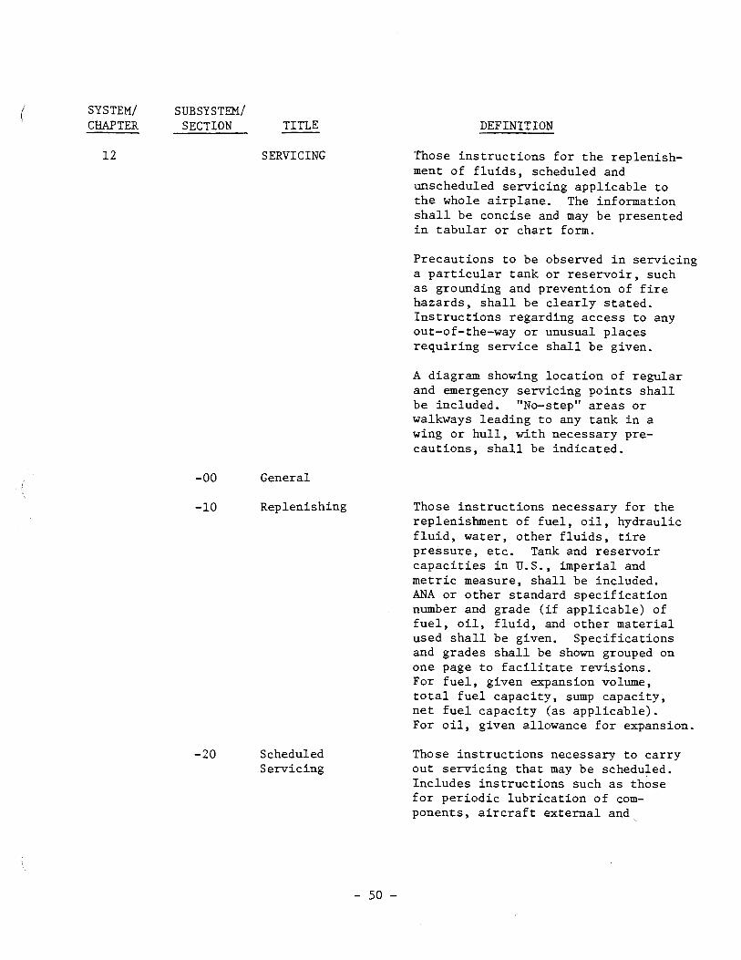
SYSTEM/ SUBSYSTEM/ CHAPTER SECTION TITLE
SERVICING
General
Replenishing
-20 Scheduled S e rv i c ing
DEFINITION
Those i n s t r u c t i o n s f o r t h e rep len ish- ment of f l u i d s , scheduled and unscheduled se rv i c ing app l i cab le t o t h e whole a i r p l a n e . The information s h a l l be concise and may be presented i n t a b u l a r o r c h a r t form.
Precaut ions t o be observed i n s e rv i c ing a p a r t i c u l a r t ank o r r e s e r v o i r , such a s grounding and prevent ion of f i r e hazards , s h a l l be c l e a r l y s t a t e d . I n s t r u c t i o n s regarding acces s t o any out-of-the-way o r unusual p l aces r e q u i r i n g s e r v i c e s h a l l be given.
A diagram showing l o c a t i o n of r egu la r and emergency se rv i c ing p o i n t s s h a l l be included. "No-step" a r e a s o r walkways l ead ing t o any tank i n a wing o r h u l l , wi th necessary pre- cau t ions , s h a l l be i nd ica t ed .
Those i n s t r u c t i o n s necessary f o r t h e replenishment of f u e l , o i l , hydraul ic f l u i d , water , o the r f l u i d s , t i r e p re s su re , e t c . Tank and r e s e r v o i r c a p a c i t i e s i n U. S. , imper ia l and m e t r i c measure, s h a l l be included. ANA o r o t h e r s tandard s p e c i f i c a t i o n number and grade ( i f app l i cab le ) of f u e l , o i l , f l u i d , and o t h e r m a t e r i a l used s h a l l be given. Spec i f i ca t ions and grades s h a l l be shown grouped on one page t o f a c i l i t a t e r e v i s i o n s . For f u e l , given expansion volume, t o t a l f u e l capac i ty , sump capac i ty , n e t f u e l capac i ty (as app l i cab le ) . For o i l , given allowance f o r expansion.
Those i n s t r u c t i o n s necessary t o c a r r y out s e r v i c i n g t h a t may be scheduled. Inc ludes i n s t r u c t i o n s such a s those f o r p e r i o d i c l u b r i c a t i o n of com- ponents , a i r c r a f t e x t e r n a l and ,

SYSTEM/ SUBSYSTEM/ CHAE'TER SECTION TITLE
1 2 -20 Scheduled (Cont Id) (Cont ld) Se rv i c ing
- 30 Unscheduled Se rv i c ing
DEFINITION
i n t e r n a l c l ean ing , e t c . S h a l l no t i n c l u d e l u b r i c a t i o n procedures r equ i r ed f o r t h e accomplishment of maintenance p r a c t i c e s . Reference may be made t o s u p p l i e r documents i n l i e u of component l u b r i c a t i o n .
Those i n s t r u c t i o n s necessary t o c a r r y o u t s e r v i c i n g t h a t i s cons idered by t h e manufacturer t o be normally unscheduled. Includes i n s t r u c t i o n s such a s those f o r i c e and snow removal from parked a i r c r a f t , p r e o i l i n g of r a d i a l engines a f t e r extended shutdown, e t c .

SYSTEM/ SUBSY STEX/ CHAPTER SECTION TITLE
STANDARD PRACTICES- AIRFRAME
DEFINITION
Refer t o Text Ma te r i a l - S t y l e (Spec. common t o a l l manuals) f o r t e x t m a t e r i a l s t y l e , paragraphing, o u t l i n e , nomenclature, t i t l e s , e t c .

SYSTEM/ SUBSYSTEM/ CHAPTER SECTION TITLE
ENVIRONMENTAL SYSTEMS
-00 General
- 10 P r e s s u r i z a t i o n
-20 D i s t r i b u t i o n
-30 P r e s s u r i z a t i o n Control
DEFINITION
Those u n i t s and components which f u r n i s h a means of p r e s s u r i z i n g , h e a t i n g , cool ing , moisture con- t r o l i n g , f i l t e r i n g and t r e a t i n g t h e a i r used t o v e n t i l a t e t h e a r eas of t h e f u s e l a g e wi th in t h e p re s su re s e a l s , as appl icable . Includes cab in supercharger , equipment c o o l i n g , h e a t e r , h e a t e r f u e l system, expansion tu rb ine , va lves , scoops, d u c t s , e t c . This Chapter may r e f e r
, - t o s u p p l i e r d a t a , furn ished wi th t h e a i r c r a f t , i n l i e u of t h e fol lowing s e c t i o n s -00 through -70, a s a p p l i c a b l e . Overhaul d a t a , cons idered app l i cab le by t h e manufac turer , may be included i n t h i s c h a p t e r .
That p o r t i o n of t h e system and i ts c o n t r o l s which supply compressed a ir t o t h e cabin . Includes i tems such as c o n t r o l s and i n d i c a t i n g systems r e l a t e d t o t h e compressors, e t c . , i f a p p l i c a b l e . Does no t inc lude t h e p r e s s u r e c o n t r o l and i n d i c a t i n g system f o r ; t he cab in p re s su r i za t ion .
That p o r t i o n of t h e system used t o i nduc t and d i s t r i b u t e a i r . Inc ludes equipment rack cool ing systems and i tems such as blowers, scoops, duc t ing , i n l e t s , check va lves , e t c . Does n o t i n c l u d e va lves which a r e p a r t of p r e s s u r i z a t i o n and temperature con t ro l .
That p o r t i o n of t he system used t o con- t r o l t h e p re s su re w i th in t h e fuse lage . Inc ludes i tems such as c o n t r o l va lves , r e l i e f v a l v e s , i n d i c a t o r s , swi tches , a m p l i f i e r s , e t c . , as appl icable .

SYSTEM/ SUBSYSTEM/ CHAPTER SECTION TITLE
21 -40 Heating (Cont 'd)
-50 Cooling
- 60 Temperature Control
-70 ~oisture/Air Contaminant Control
DEFINITION
That portion of the system and its controls which supply heated air to the cabin. Includes items such as heater units, fuel system and control, ignition, indicating sys- tems related to heater operation, etc., as applicable. Does not include the temperature control and indicating systems.
That portion of the system and its controls which supply cooled air to the cabin. Includes items such as the cooling unit, indicating sys- tems related to the cooler operation, etc., as applicable. Does not include temperature control and indicating systems.
That portion of the system used to control the temperature of the air within the cabin. Includes items such as control valves, sensing devices, switches, indicators, amplifiers, etc., as applicable.
That portion of the system used to conixol moisture in the air, to control ozone concentrations, to filter radioactive debris from conditioned air, and to treat the air with deodorizers, insecticides, etc., as applicable.

SYSTEM/ SUBSYSTEM/ CHAPTER SECTION TITLE
AUTO FLIGHT
- 00 General
-10 Autopi lo t
-20 Speed-Attitude Correc t ion
-30 Auto T h r o t t l e
DEFINITION
Those u n i t s and components which f u r n i s h a means of au tomat ica l ly c o n t r o l i n g t h e f l i g h t of t h e a i r - c r a f t . I nc ludes those u n i t s and components which c o n t r o l d i r e c t i o n , heading, a t t i t u d e , a l t i t u d e and speed. Th i s Chapter may r e f e r t o s u p p l i e r d a t a , furn ished wi th t h e a i r c r a f t , i n l i e u of t h e following Sec t ions -00 through -40, a s app l i cab le . Overhaul of any o r a l l components i n t h i s chapter must be accomplished i n a q u a l i f i e d shop in accordance w i t h d a t a suppl ied by t h e component manufacturer.
That p o r t i o n of t h e system t h a t uses r a d i o / r a d a r beam, d i r e c t i o n a l and v e r t i c a l gyro, P i t o t s t a t i c and manually induced i n p u t s t o t h e sys- tem t o au toma t i ca l ly c o n t r o l yaw, ( p i t c h and r o l l of t h e a i r c r a f t . This i nc ludes power source devices , i n t e r l o c k i n g devices and amplifying, computing, i n t e g r a t i n g , c o n t r o l l i n g , a c t u a t i n g , i n d i c a t i n g and warning devices such a s computers, se rvos , c o n t r o l pane l s , i n d i c a t o r s , warning l i g h t s , e t c .
That p o r t i o n of t h e system t h a t au toma t i ca l ly main ta ins a s a f e f l i g h t a t t i t u d e by co r rec t ing f o r e f f e c t s of speed, such a s mach t r i m and speed s t a b i l i t y . This inc ludes sens ing , computing, ac tua t ing , i n d i c a t i n g , and warning devices such a s computers, s e rvos , ac tua to r s , warning l i g h t s , e t c .
That p o r t i o n of t h e system t h a t au toma t i ca l ly c o n t r o l s t h e pos i t i on of t h e t h r o t t l e s t o properly blend engine power w i t h f l a p p o s i t i o n and

SYSTEM/ SUBSYSTEM/ CHAPTER SECTION TITLE
2 2 -30 Auto T h r o t t l e (Cont ' d) (Cont ' d)
-40 System Monitor
DEFINITION
a i r c r a f t p i t c h a t t i t u d e during landing/approach and go around procedures. This i nc ludes engaging, sens ing , computing, amplifying, c o n t r o l l i n g , a c t u a t i n g and warning devices such a s a m p l i f i e r s , computers, se rvos , l i m i t swi tches , c lu t ches , gear boxes, warning l i g h t s , etc.
That p o r t i o n of t h e system t h a t monitors t h e f l i g h t of a i r c r a f t during approach and landing . This inc ludes sens ing , computing, indi- c a t i n g and warning dev ices such a s computers, i n d i c a t o r s , warning l i g h t s , e t c .

SYSTEM/ SUBSYSTEM/ CHAF'TER SECTION TITLE
-00 General
-10 Speech Communication
DEFINITION
Those u n i t s and components which f u r n i s h a means of communicating from one p a r t of t h e a i r c r a f t t o another and between t h e a i r c r a f t and o t h e r a i r c r a f t o r ground s t a t i o n s , i nc ludes vo ice and C-W communicating components, PA system, intercom and t a p e recorder-record p l aye r . This chap te r may r e f e r t o s u p p l i e r d a t a , fu rn i shed wi th t h e a i r c r a f t , i n l i e u of t h e fol lowing Sec t ions -00 through -70, a s app l i cab le . Overhaul of any o r a l l components i n t h i s chapter must be accomplished wi th d a t a suppl ied by t h e component manufacturer .
The equipment included i n t h e bas i c maintenance manual may be only t h a t which i s normally included and i n s t a l l e d i n quan t i t y . Data f o r "Spec ia l Order" o r o t h e r than s t anda rd op t ions may be i n s epa ra t e manuals o r a s s e p a r a t e d a t a furn ished w i t h t h e i n d i v i d u a l a i r c r a f t .
That p o r t i o n of t h e system which u t i l i z e s vo ice modulated e l e c t r o - magnetic waves t o t ransmi t and/or r e c e i v e messages from a i r - t o - a i r , o r air-to-ground i n s t a l l a t i o n s . Inc ludes H.F., V.H.F., U.H.F., e t c . , communication t r a n s m i t t i n g and r e c e i v i n g equipment.
-20 Data Transmission That p o r t i o n of t h e system which & Automatic Ca l l i ng p r e s e n t s in format ion der ived from
pulse-coded t ransmiss ions . Includes T e l e p r i n t e r , S e l c a l , C a l s e l , e t c .
-30 Passenger That p o r t i o n of t h e system used t o Address and address and e n t e r t a i n t h e passengers. Entertainment Inc ludes i tems such a s a m p l i f i e r s ,
speakers , handsets , reproducers , c o n t r o l pane ls , e t c .

SYSTEM/ SUBSYSTEM/ CHAPTER SECTION TITLE
23 - 40 I n t e r p h o n e (Cont ' d)
-50 Audio I n t e g r a t i n g
-60 S t a t i c Discharg ing
-70 Voice Recorders
DEFINITION
Tha t p o r t i o n of t h e sys tem which i s used by f l i g h t and ground personne l t o communicate between a r e a s on t h e a i r c r a f t . I n c l u d e s i t e m s such as a m p l i f i e r , h a n d s e t , e t c . Does n o t i n c l u d e t h e i n t e r p h o n e system w i t h i n t h e f l i g h t compartment which i s p a r t of t h e i n t e g r a t i n g system.
T h a t p o r t i o n of t h e sys tem which c o n t r o l s t h e o u t p u t of t h e comuni- c a t i o n s and n a v i g a t i o n r e c e i v e r s i n t o t h e f l i g h t crew headphones and s p e a k e r s , and t h e o u t p u t of t h e f l i g h t crew microphones i n t o t h e communications t r a n s m i t t e r s . I n c l u d e s i t e m s such as aud io s e l e c t o r c o n t r o l p a n e l , microphones, head- phones , c o c k p i t loud s p e a k e r s , e t c .
T h a t p o r t i o n of t h e sys tem which i s used t o d i s s i p a t e s t a t i c e l e c t r i c i t y .
T h a t p o r t i o n of t h e sys tem used t o r e c o r d crew member conversa t ion .

SYSTEM/ SUBSYSTEM/ CHAPTER SECTION - TITLE
ELECTRICAL POWER
-00 General
-10 Generator Drive
-20 AC Generat ion
DEFINITION
Those e l e c t r i c a l u n i t s and components which gene ra t e , con t ro l and supply AC and/or DC e l e c t r i c a l power f o r o t h e r systems, inc luding genera tors and r e l a y s , i n v e r t e r s , b a t t e r i e s , e t c . , through t h e secondary busses. Also inc ludes common e l e c t r i c a l items such a s w i r ing , swi tches , connec tors , e t c .
This Chapter may r e f e r t o supp l i e r d a t a , fu rn i shed wi th t h e a i r c r a f t , i n l i e u of t h e following Sec t ions -00 through -50, a s app l i cab le .
NOTE
The manufacturer may have t h e op t ion of inc luding wi r ing diagrams i n t h i s Chapter, Chapter 91, o r e s t a b l i s h a s e p a r a t e Wiring Diagram Manual.
Mechanical devices t h a t d r i v e t h e gene ra to r s a t a des i red RPM. Inc ludes items such a s o i l system, connect ing dev ices , i n d i c a t i n g and warning systems f o r t he d r i v e , e t c . , a s app l i cab le .
That p o r t i o n of t h e systems used t o gene ra t e , r e g u l a t e , c o n t r o l , and i n d i c a t e AC e l e c t r i c a l power. Inc ludes i tems such a s i n v e r t e r s , AC g e n e r a t o r s / a l t e r n a t o r s , c o n t r o l and r e g u l a t i n g components, i nd i - c a t i n g systems, e t c . , a l l wi r ing t o bu t n o t i nc lud ing main busses , a s app l i cab le .

SY s TEM/ SUBSYSTEM/ CHAPTER SECTION TITLE
24 -30 DC Generation (Cont ' d)
Externa l Power
DEFINITION
That p o r t i o n of t h e systems used t o gene ra t e , r e g u l a t e , con t ro l and i n d i c a t e DC e l e c t r i c a l power. Inc ludes i tems such a s genera tors / a l t e r n a t o r s , t ransformers , r e c t i f i e r s , b a t t e r i e s , c o n t r o l and r egu la t ing components, i n d i c a t i n g systems, e t c . , all wir ing t o but no t including main busses , a s app l i cab le .
That p o r t i o n of t h e system wi th in t h e a i r c r a f t which connects ex t e rna l e l e c t r i c a l power t o t h e a i r c r a f t ' s e l e c t r i c a l system. Includes i tems such a s r e c e p t a c l e s , r e l a y s , switches, w i r ing , warning l i g h t s , e t c . , a s app l i cab le .
E l e c t r i c a l That p o r t i o n of t h e systems which Load D i s t r i b u t i o n provides f o r connection of AC o r DC
power t o us ing systems. Includes items such a s AC and DC main and secondary busses , main system c i r c u i t b reakers , power systems devices , e t c .

CHAPTER SECTION TITLE 25 EQUIPMENT /
Genera l
F l i g h t Compartment
Passenger Compartment
Buff e t / G a l l e y
L a v a t o r i e s
DEFINITION Those removable i t e m s of equipment and f u r n i s h i n g s c o n t a i n e d i n t h e f l i g h t , p a s s e n g e r , ca rgo and acces - s o r y compartments. I n c l u d e s emergency, b u f f e t and l a v a t o r y equipment i f f u r n i s h e d a s manufacturer- d e s i g n a t e d s t a n d a r d equipment. Does n o t i n c l u d e s t r u c t u r e s o r equipment a s s i g n e d s p e c i f i c a l l y t o o t h e r c h a p t e r s .
The compartment above t h e f l o o r and between t h e forward passenger p a r t i - t i o n and t h e forward p r e s s u r e dome. I n c l u d e s i t e m s such a s f l i g h t crew seats, t a b l e s , p i l o t check l is ts , p i l o t food c o n t a i n e r s , c u r t a i n s , manuals , e l e c t r o n i c equipment r a c k s , i f f u r n i s h e d a s manufacturer-desig- n a t e d s t a n d a r d equipment. Does n o t i n c l u d e c a r g o compartments.
The a r e a s i n which t h e passengers a r e s e a t e d . I n c l u d e s i t e m s such a s s e a t s , b e r t h s , h a t r a c k s , c u r t a i n s , w a l l c o v e r i n g s , and soundproof ing, c a r p e t s , magazine r a c k s , movable p a r t i t i o n s , w a l l - t y p e thermometers , s p a r e b u l b s , f u s e s , e tc . , i f f u r n i s h e d as manu- f a c t u r e r - d e s i g n a t e d s t a n d a r d equipment.
The a r e a s i n which food and beverages a r e s t o r e d and p repared . I n c l u d e s i t e m s s u c h a s removable and f i x e d c a b i n e t s , ovens , r e f r i g e r a t o r s , ga rbage c o n t a i n e r s , d i s h r a c k s , c o f f e e maker and d i s p e n s e r s , c u r t a i n s , e t c . , i f f u r n i s h e d a s manufac tu re r d e s i g n a t e d s t a n d a r d equipment.
I n c l u d e s i t e m s such a s m i r r o r s , s e a t s , c a b i n e t s , d i s p e n s i n g equipment, e t c . , i f f u r n i s h e d as manufacturer-desig- n a t e d s t a n d a r d equipment.

SYSTEM/ SUBSYSTEM/ CHAPTER SECTION TITLE
2 5 -50 Cargo (Cont ' d) Compartments
Emergency
Accessory Compartments
DEFINITION
Those compartments for storage of cargo and those components which are or can be mounted on the aircraft and used to load/unload, restrain, guide or service cargo. Includes restraint nets, etc., if furnished as manufacturer-designated standard equipment.
Those items of equipment carried for use in emergency procedures. Includes items such as evacuation equipment, life rafts and jackets, first aid kit, landing and signal flares, evacuation signaling systems, etc., if furnished as manufacturer-desig- nated standard equipment. Does not include fire extinguishers, oxygen equipment or masks.
Those compartments used for the housing of various components or accessories. Includes wheel wells, tail-hydraulic-electrical/electronic equipment racks, main battery struc- ture, insulation blankets, if furnished as manufacturer-designated standard equipment.

SYSTEM/ SUBSYSTEM/ CWTER SECTION TITLE
2 6 FIRE PROTECTION
-00 General
-10 Detect ion
Extinguishing
-30 Explosion Suppression
DEFINITION
Those f i x e d and p o r t a b l e u n i t s and components which d e t e c t and i n d i c a t e f i r e o r smoke, and s t o r e and d i s t r i b u t e f i r e ex t inguish ing agent t o all p ro tec t ed a r e a s of t h e a i r c r a f t ; i nc lud ing b o t t l e s , va lves , tubing, e t c . , i f furn ished as manufacturer- des igna ted s tandard equipment.
That p o r t i o n of t h e system which i s used t o s ense and i n d i c a t e t h e presence of ove rhea t , smoke, o r f i r e , i f furn ished a s manufacturer-desig- na ted s tandard equipment.
That p o r t i o n of t hose f ixed o r p o r t a b l e systems which i s used t o ex t ingu i sh f i r e , i f furn ished a s manufacturer-designated s tandard equipment.
t
That p o r t i o n of t h e system which i s used t o sense , i n d i c a t e and ex t inguish a f lame propagat ing i n t o t h e f u e l vent o r scoop t o prevent an explosion i n t h e f u e l system, i f furn ished a s manufacturer-designated s tandard equipment.

SYSTEM/ SUBSYSTEM/ CHAPTER SECTION - TITLE
2 7 nIGHT CONTROLS
General
Ai le ron & Tab
Rudder & Tab
Eleva tor & Tab
DEFINITION
Those u n i t s and components which f u r n i s h a means of manually c o n t r o l l i n g t h e f l i g h t a t t i t u d e c h a r a c t e r i s t i c s of t h e a i r c r a f t , inc luding items such a s hydraul ic boost system, rudder peda ls , con t ro l column l inkages , c o n t r o l cab les , t a b c o n t r o l s , mounting b racke t s , e t c . Also inc ludes t h e func t ioning and maintenance a s p e c t s of t h e f l a p s , s p o i l e r s and o t h e r c o n t r o l su r f aces , but does not i nc lude t h e s t r u c t u r e which i s covered i n t h e S t ruc tu re s Chapters . Inc lude f r e e p l ay to l e rances of items covered in -10, -20 and -30.
That p o r t i o n of t h e systems which c o n t r o l s t h e p o s i t i o n and movement of t h e a i l e r o n s and a i l e r o n tabs. Inc ludes i tems such as t h e con t ro l wheels, cab le s , boos t e r s , l inkages, c o n t r o l s u r f a c e s , i n d i c a t o r s , e t c . , as app l i cab le .
That po r t ion of t h e systems which c o n t r o l s t h e p o s i t i o n and movement of t h e rudder and rudder tabs . Inc ludes i tems such a s t h e rudder peda ls , t a b c o n t r o l wheel, cab les , boos t e r s , l i nkages , con t ro l sur faces , p o s i t i o n i n d i c a t o r s , e t c . , as app l i cab le .
That p o r t i o n of t h e systems which c o n t r o l s t h e p o s i t i o n and movement of t h e e l eva to r / e l evon and tabs. Inc ludes items such as t h e con t ro l column, s t i c k s h a k e r u n i t s , automatic s t a l l recovery dev ices , t ab con t ro l wheels, cab le s , boos te rs , l inkages , c o n t r o l s u r f a c e s , p o s i t i o n ind i - c a t o r s , s t a l l warning systems, e t c . , a s app l i cab le .

SYSTEH/ SUBSYSTEM/ CHAPTER SECTION TITLE
2 7 -40 H o r i z o n t a l (Cont 'd) S t a b i l i z e r s
-50 F l a p s
-60 S p o i l e r , Drag Devices and V a r i a b l e Aerodynamic F a i r i n g s
- 70 Gust Lock & Dampener
-80 L i f t Augmenting
DEFINITION
That p o r t i o n of t h e sys tems which c o n t r o l s t h e p o s i t i o n and movement of t h e h o r i z o n t a l s t a b i l i z e r / c a n a r d . I n c l u d e s i t e m s such as c o n t r o l hand le , c a b l e s , j acksc rews , motors , warning sys tems , l i n k a g e s , c o n t r o l s u r f a c e s , p o s i t i o n i n d i c a t o r s , e t c . , as a p p l i c a b l e .
That p o r t i o n o f t h e sys tems which c o n t r o l s t h e p o s i t i o n and movement of t h e t r a i l i n g edge f l a p s . I n c l u d e s i t e m s s u c h as c o n t r o l h a n d l e s , c a b l e s , a c t u a t o r s , warning systems,
, l i n k a g e s , c o n t r o l s u r f a c e s , p o s i t i o n i n d i c a t o r s , e t c . , as a p p l i c a b l e .
That p o r t i o n o f t h e sys tems which c o n t r o l s t h e p o s i t i o n and movement of t h e s p o i l e r s , d r a g d e v i c e s and v a r i a b l e aerodynamic f a i r i n g s . I n c l u d e s i t e m s s u c h as c o n t r o l h a n d l e s , c a b l e s , warning systems, l i n k a g e s , s p o i l e r s , d r a g d e v i c e s , p o s i t i o n i n d i c a t o r s , e t c . , as a p p l i c a b l e .
That p o r t i o n of t h e sys tems which p r o t e c t s t h e c o n t r o l s u r f a c e s from movement by wind w h i l e t h e a i r c r a f t is on t h e ground. Does n o t i n c l u d e l o c k i n g t h e c o n t r o l by means of f l i g h t c o n t r o l b o o s t sys tem, as a p p l i c a b l e .
That p o r t i o n of t h e sys tems which c o n t r o l s t h e p o s i t i o n and movement of v a r i a b l e o p e r a t i n g wing s l o t s , l e a d i n g edge wing f l a p s , and o t h e r s i m i l a r a u x i l i a r y d e v i c e s used f o r i n c r e a s i n g aerodynamic l i f t . I n c l u d e s i t e m s such as c o n t r o l h a n d l e s , c a b l e s , a c t u a t o r s , l i n k a g e s , warning sys tems , c o n t r o l s u r f a c e s , p o s i t i o n i n d i c a t o r s , e t c . Does n o t i n c l u d e t r a i l i n g edge f l a p s , as a p p l i c a b l e .

SYSTEM/ SUBSY STEM/ CWTER SECTION TITLE
FUEL
-00 General
-10 S t o r a g e
-20 D i s t r i b u t i o n
DEFINITION
Those u n i t s and components which s t o r e and d e l i v e r f u e l t o t h e engine. I n c l u d e s engine-dr iven f u e l pumps f o r r e c i p r o c a t i n g e n g i n e s , i n c l u d e s t a n k s ( b l a d d e r ) , v a l v e s , b o o s t pumps, e t c . , and t h o s e components which f u r n i s h a means of dumping f u e l overboard. I n c l u d e s i n t e g r a l and t i p f u e l t a n k l e a k d e t e c t i o n and s e a l i n g . Does n o t i n c l u d e t h e s t r u c t u r e of i n t e g r a l o r t i p f u e l t a n k s and t h e f u e l c e l l back ing boards which are covered i n t h e S t r u c t u r e s Chap te r s , and does n o t i n c l u d e f u e l f low rate s e n s i n g , t r a n s m i t t i n g and /or i n d i c a t i n g which are covered i n Chapter 73.
I n s t r u c t i o n s on a u t h o r i z a t i o n t o u s e d e i c i n g and a n t i - b a c t e r i a l agen t s . R e f e r back t o S e r v i c i n g , as a p p l i c a b l e .
That p o r t i o n of t h e sys tem which s t o r e s f u e l . I n c l u d e s t a n k s e a l i n g , b l a d d e r t y p e c e l l s , v e n t i l a t i n g sys tem, c e l l and t a n k i n t e r c o n n e c t o r s , o v e r wing f i l l e r necks and c a p s , e t c . Also i n c l u d e s r e s e r v o i r f e e d pumping systems and r e s e r v o i r s w i t h i n t h e t a n k s which are n o t a p a r t of t h e d i s t r i b u t i o n system.
That p o r t i o n of t h e sys tem which i s used t o d i s t r i b u t e f u e l from t h e f i l l e r connec tor t o t h e s t o r a g e sys tem and from t h e s t o r a g e sys tem t o and i n c l u d i n g t h e power p l a n t f u e l q u i c k d i s c o n n e c t . I n c l u d e s i t ems such as plumbing, pumps, v a l v e s , c o n t r o l s , e t c .
That p o r t i o n of t h e sys tem which i s used t o dump f u e l overboard dur ing f l i g h t . I n c l u d e s i t ems such as plumbing, v a l v e s , c h u t e s , c o n t r o l s , e t c .

SYSTEM/ SUBSYSTEM/ CHAPTER SECTION TITLE
28 -40 Indicating (Cont ' d)
DEFINITION
That portion of the system which is used to indicate the quantity, temperature, and of the fuel. Includes pressure warning systems for pumping systems within the tank, etc. Does not include engine fuel flow or pressure.

SYSTEM/ SUBSY STEM/ CHAPTER SECTION TITLE
HYDRAULIC POWER
General
Main
Auxiliary
Indicating
DEFINITION
Those units and components which furnish hydraulic fluid under pressure (includes pumps, regulators, lines, valves, etc.) to a common point (manifold) for redistribution to other defined systems.
That portion of the system which is used to store and deliver hydraulic fluid to using systems. Includes items such as tanks, accumulators, valves, pumps, levers, switches, cables, plumbing, external connectors, etc. Does not include the supply valves to the using systems.
That portion of the system which is classified as auxiliary, emergency or standby, and which is used to supplement or take the place of the main hydraulic sys tem. Includes items such as tanks and accumulators which are separate from the main system, hand pumps, auxiliary pumps, valves, plumbing, etc.
T ~ G portion of the system which is used to indicate the quantity, temperature and pressure of the hydraulic fluid. Includes items such as transmitters, indicators, warning systems, etc.

SYSTEM/ SUBSYSTEM/ CHAPTER SECTION TITLE -
ICE AND RAIN PROTECTION
-00 General
-10 A i r f o i l
-20 Air In takes
DEFINITION
Those u n i t s and components which provide a means of prevent ing o r d i spos ing of formation of i c e and r a i n on va r ious p a r t s of t h e a i r c r a f t . Inc ludes a lcohol pump, va lves , tanks, p r o p e l l e r a n t i - i c i n g system , wing h e a t e r s , water l i n e h e a t e r s , p i t o t h e a t e r s , scoop h e a t e r s , windshield k i p e r s and t h e e l e c t r i c a l and heated a i r p o r t i o n of windshield i c e cont ro l . Does n o t inc lude t h e b a s i c windshield panel .
For t u r b i n e type power p l a n t s using a i r a s t h e a n t i - i c i n g medium, engine a n t i - i c i n g i s contained under Air System.
That po r t ion of t h e system which i s used t o e l imina te o r prevent t h e formation of i c e on a l l a i r f o i l su r f aces . Includes wings and I
a i r f o i l s e c t i o n s of t h e empennage.
That p o r t i o n of t h e system which i s used t o e l imina te o r prevent t h e formation of i c e i n o r around a i r i n t a k e s . Inc ludes power p l a n t cowling an t i - i c ing .
-30 P i t o t and S t a t i c That p o r t i o n of t h e system which i s used t o e l imina te o r prevent t h e formation of i c e on t h e p i t o t and s t a t i c systems.
-40 Windows and Windshields
-50 Antennas and Radomes
That po r t ion of t h e system which i s used t o e l imina te o r prevent t h e formation of i c e , f r o s t o r r a i n on t h e windows and windshields .
That po r t ion of t h e system which i s used t o e l imina te o r prevent t h e formation of i c e on antennas and radomes, i f appl icable .

SYSTEM/ SUBSYSTEM/ CHAPTER SECTION - TITLE
30 -60 P rope l l e r s (Cont 'd)
-70 Water Lines
Detect ion
DEFINITION
That po r t ion of t h e system which i s used t o e l imina te o r prevent t h e formation of i c e on p rope l l e r s .
That p o r t i o n of t h e system which i s used t o prevent t h e formation of i c e i n water supply and d r a i n l i n e s .
That p o r t i o n of t h e system which i s used t o d e t e c t and i n d i c a t e t he formation of i c e .

SY STEX/ SUBSY STEX/ CHAPTER SECTION TITLE
INDICAT WG / RECORDING SY STEW
-00 General
- 10 Unassigned
- 20 Unassigned
-30 Recorders
- 40 Central Computers
-50 Central Warning Sys tems
DEFINITION
Those units or components which give visual or aural warning of conditions in unrelated systems. Units which record, store, or compute data from unrelated systems.
Those units and components used for recording data not. related to specific systems. Includes items such as flight recorders, performance or maintenance recorders, VG recorders, etc.
Those units used for computing data from a number of different sources without a preponderance of functions in any one system.
Those units and components which give audible or visual warning of condi- tions in unrelated systems.

SYSTEM/ SUBSYSTEM/ CHAPTER SECTION TITLE
32 D I N G GEAR
- 00 General
-10 Main Gear and Doors
-20 Nose Gear and Doors
-30 Extension and Ret rac t ion
-40 Wheels and Brakes
DEFINITION
Those u n i t s and components which f u r n i s h a means of support ing and s t e e r i n g t h e a i r c r a f t on t h e ground o r water , and make i t poss ib l e t o r e t r a c t and s t o r e t h e landing gear in f l i g h t . Inc ludes brakes, wheels, f l o a t s , doors , shock s t r u t s , t i r e s , l i nkages , p o s i t i o n i n d i c a t i n g and warning systems. Also inc ludes t h e func t ioning and maintenance aspec ts of t h e landing gear doors but does not i nc lude t h e s t r u c t u r e which i s covered i n Chapter 52 DOORS.
That p o r t i o n of t h e system which provides t h e major support f o r t h e a i r c r a f t whi le on t h e ground. Inc ludes items such a s shock s t r u t s , bogie a x l e s , drag s t r u t s , doors, l i nkages , a t t a c h b o l t s , e t c .
That po r t ion of t h e system which suppor ts t h e nose of t h e a i r c r a f t wh i l e t h e a i r c r a f t i s on t h e ground. Inc ludes i tems such a s shock s t r u t s , drag s t r u t s , doors , l i nkages , a t t a c h b o l t s , e t c .
That po r t ion of t h e system which i s used t o extend and r e t r a c t t h e landing gear and open and c l o s e t h e landing gear doors. Inc ludes items such a s a c t u a t i n g mechanisms, bogie trim, bungees, up and down l a t c h e s , ope ra t ing c o n t r o l s , va lves and motors, cab le s , plumbing, e tc .
That po r t ion of t h e system which provides f o r r o l l i n g and stopping t h e a i r c r a f t whi le on t h e ground and s topping wheel r o t a t i o n a f t e r r e t r ac - t i on . Inc ludes i tems such a s swivel glands, an t i - sk id devices , p ressure i n d i c a t o r s , plumbing, e t c.

SY STEM/ SUBSYSTEM/ CHAPTER SECTION - TITLE
32 -50 S t e e r i n g (Cont ' d )
-60 P o s i t i o n and Warning
-70 Supplementary Gear
DEFINITION
That p o r t i o n of t h e sys tem which i s used t o c o n t r o l t h e d i r e c t i o n of movement of t h e a i r c r a f t on t h e ground. I n c l u d e s i t e m s such as a c t u a t i n g c y l i n d e r s , c o n t r o l s , b o g i e s w i v e l un lock , e t c .
That p o r t i o n of t h e sys tem which i s used t o i n d i c a t e and warn of t h e p o s i t i o n of t h e l a n d i n g g e a r / d o o r s .
Devices used t o s t a b i l i z e t h e a i r c r a f t w h i l e on t h e ground and p r e v e n t damage by ground c o n t a c t . I n c l u d e s i t e m s s u c h as shock s t r u t , s k i d b l o c k s , w h e e l s , e t c .

SYSTEM/ SUBSYSTEM/ CHAPTER SECTION - TITLE
3 3 LIGHTS
General
F l i g h t Compartment
Passenger Compartments
Cargo and Serv ice Compartments
Ex te r io r
DEFINITION
Those u n i t s and components which provide f o r e x t e r n a l and i n t e r n a l i l l u m i n a t i o n such a s landing l i g h t s , t a x i l i g h t s , p o s i t i o n l i g h t s , r o t a t i n g l i g h t s , i c e l i g h t s , master warning l i g h t s , passenger reading and cab in dome l i g h t s , e t c .
The l i g h t i n g subsystems i n t h e compartment above t h e f l o o r and between t h e forward passenger p a r t i t i o n and t h e forward pressure dome. Does ndt i nc lude cargo compartment. Inc ludes d i r e c t and i n d i r e c t i l l u m i n a t i o n of work a reas , pane ls and instruments . Does not i nc lude bulbs and wir ing i n s i d e of ins t ruments which a r e removed with t h e instrument . Inc ludes t h e master warning l i g h t system and t h e warning l i g h t dimming systems.
The l i g h t i n g subsystems i n t h e a r eas i n which t h e passengers a r e seated and i n b u f f e t / g a l l e y , l a v a t o r i e s , lounges and coa t rooms. Includes items such a s d i r e c t and i n d i r e c t i l l umina t ion , passenger c a l l system, l i g h t e d s igns , e t c .
The l i g h t i n g subsystems i n t h e compartments f o r stowage of cargo and t h e housing of va r ious components o r acces so r i e s .
The l i g h t i n g subsystems used t o provide i l l umina t ion ou t s ide of t h e a i r c r a f t . Inc ludes l i g h t s such a s landing , naviga t ion , p o s i t i o n i n d i c a t i n g , wing i l l umina t ion , r o t a t i n g , cour tesy , t a x i , e t c .

SYSTEM/ SUBSY STEM/ CWTER SECTION TITLE
3 3 -50 Emergency (Cont ' d) L i g h t i n g
DEFINITION
The s e p a r a t e and independent subsystems used t o p r o v i d e i l lumin- a t i o n i n case of pr imary e l e c t r i c a l power f a i l u r e . I n c l u d e s i t e m s such as i n e r t i a f l a s h l i g h t s , l a n t e r n s , etc.

SYSTEM/ SUBSYSTEM/ CHAPTER SECTION TITLE DEFINITION
NAVIGATION AND Those u n i t s and components which PITOT/STATIC provide a i r c r a f t naviga t iona l
information. Includes VOR, p i t o t , s t a t i c , ILS, f l i g h t d i r e c t o r , compasses, i n d i c a t o r s , e t c . This Chapter may r e f e r t o supp l i e r d a t a , fu rn i shed wi th t h e a i r c r a f t , i n l i e u of t h e fol lowing Sect ions -00 through -60, a s app l i cab le . Overhaul of any o r a l l components i n t h i s chapter must be accomplished i n a q u a l i f i e d shop i n accordance wi th d a t a suppl ied by t h e component manufacturer.
-00 General
- 10 F l i g h t That p o r t i o n of t h e system which Environmental s enses environmental condi t ions and Data /P i to t S t a t i c uses t h e d a t a t o inf luence navigat ion.
Inc ludes i tems such a s p i t o t , s t a t i c , a i r temperature, rate-of-climb, a i r s p e e d , h igh speed warning, a l t i t u d e , a l t i t u d e r epor t ing , a l t i m e t e r c o r r e c t i o n system, e t c .
-20 A t t i t u d e & Direc t i on
-30 Landing and Taxiing Aids
-40 Independent P o s i t i o n Determining
That p o r t i o n of t he system which uses magnetic gyroscopic and i n e r t i a f o r c e s . Inc ludes items such a s gyro ho r i zons , d i r e c t i o n a l gyros, magnetic compasses, and magnetic heading systems, t u r n and bank, ampl i f i e r s , s e r v o s , and f l i g h t d i r e c t o r , e t c .
That p o r t i o n of t he system which provides guidance during approach, landing and t ax i ing . Inc ludes i tems such a s l o c a l i z e r , g l i d e s lope , ILS, markers, paravisua l d i r e c t o r , ground guidance systems, e t c .
That p o r t i o n of t h e system which provides information t o determine p o s i t i o n and i s mainly independent of ground i n s t a l l a t i o n s . Includes i tems such a s i n e r t i a l guidance systems, weather r ada r , doppler , proximity warning, c o l l i s i o n avoidance, star t r a c k e r , e t c . Also includes s e x t a n t s / o c t a n t s , e t c .

SYSTEM/ SUBSYSTEM/ C W T E R SECTION TITLE
34 -50 Dependent (Cont 'd) Position
Determining
-60 Position Computing
DEFINITION
That portion of the system which provides information to determine position and is mainly dependent on ground installations. Includes items such as D m , transponders, radio compass, LORAN, VOR, ADF, etc.
That portion of the system which combines navigational information to compute the aircraft's geographical location. Includes items such as course computers, etc.

SYSTEM/ SUBSYSTEM/ CHAPTER SECTION TITLE
3 5 OXYGEN
General
Crew
Passenger
DEFINITION
Those u n i t s and components which s t o r e , r e g u l a t e , and d e l i v e r oxygen t o t h e passengers and crew, including b o t t l e s , r e l i e f v a l v e s , shut-off va lves , o u t l e t s , r e g u l a t o r s , masks, e t c .
In format ion on q u a l i t y of O2 used f o r s e r v i c i n g .
That p o r t i o n of t h e system which f u r n i s h e s oxygen t o t h e crew.
That p o r t i o n of t h e system which f u r n i s h e s oxygen t o t h e passengers.
NOTE
For General Av ia t i on a i r c r a f t subsystem S e c t i o n -10 and -20 can be combined.

SYSTEM/ SUBSYSTEM/ CHAPTER SECTION TITLE
PNEUMATIC
General
Distribution
Indicating
DEFINITION
Those units and components (ducts and valves) which deliver large volumes of compressed air from a power source to connecting points for such other systems as environmental controls, deicing, etc.
That portion of the system which is used to distribute high or low pressure air to using systems. Includes items such as ducts, valves, actuators, heat exchangers, controls, etc. Does not include the supply valves to the using systems.
That portion of the system which is used to indicate temperature and pressure of the pneumatic system. Includes temperature and pressure warning systems.

SYSTEM/ SUBSYSTEM/ CHAPTER SECTION - TITLE
3 7 VACUUM
General
D i s t r i b u t i o n
I n d i c a t i n g
DEFINITION
Those u n i t s and components used t o g e n e r a t e , d e l i v e r and r e g u l a t e below a tmospher ic p r e s s u r e a i r , inc lud ing pumps, r e g u l a t o r s , l i n e s , e t c . , th rough and i n c l u d i n g t h e manifold.
That p o r t i o n o f t h e system which i s used t o d i s t r i b u t e below atmospher ic p r e s s u r e a i r t o u s i n g systems.
That p o r t i o n of t h e sys tem which i s used t o i n d i c a t e p r e s s u r e . Inc ludes p r e s s u r e warning system.

SYSTEM/ SUBSYSTEM/ CHAPTER SECTION TITLE
-00 General
-10 Potable
-20 Wash
-30 Waste Disposal
-40 Air Supply
DEFINITION
Those f i x e d u n i t s and components which s t o r e and d e l i v e r f o r use , f r e s h wa te r , and those f i x e d com- ponents which s t o r e and f u r n i s h a means of removal of water and waste. Inc ludes wash b a s i n s , t o i l e t assembl ies , t anks , va lves , e t c . , i f app l i cab le . For genera l a v i a t i o n a i r c r a f t t h i s m a t e r i a l may be covered i n S y s / ~ h a p . 25.
That p o r t i o n of t h e system which is used t o s t o r e and d e l i v e r f r e s h d r ink ing water . Inc ludes wash water system i f t h e p o t a b l e water is a l s o used f o r washing.
That p o r t i o n of t h e system which i s used t o s t o r e and d e l i v e r wash water which i s not po tab le .
That p o r t i o n of t h e system which i s used f o r d i s p o s a l of water and waste. Inc ludes i tems such a s wash bas ins , water c l o s e t s , f l u s h i n g systems, e t c .
That p o r t i o n of t h e system common t o more than one subsystem which is used f o r p r e s s u r i z i n g supply tanks t o i n s u r e f l u i d flow.

SYSTEM/ SUBSYSTEM/ CHAPTER SECTION TITLE
ELECTRICAL/ ELECTRONIC PANELS & MULTIPURPOSE PARTS
General
Instrument and Control Panels
DEFINITION
P i c t o r i a l coverage of a l l i n d i c a t i n g and c o n t r o l pane ls and e l e c t r i c a l l e l e c t r o n i c r a c k i n s t a l l a t i o n s .
Complete coverage of a l l genera l purpose e l e c t r i c a l and e l e c t r o n i c p a r t s .
P i c t o r i a l coverage of a l l pane ls f i x e d o r movable, w i th t h e i r r e p l a c e a b l e components such a s ins t ruments ( i n c l u s i v e of independent i n s t rumen t s ) , swi tches , c i r c u i t b reake r s , fu ses , e t c . Also includes gene ra l coverage of instrument panel v i b r a t o r s and o t h e r panel accessor ies .
E l e c t r i c a l & P i c t o r i a l and gene ra l coverage f o r E lec t ron ic a l l e l e c t r i c a l and e l e c t r o n i c Equipment Racks equipment racks .
E l e c t r i c a l & P i c t o r i a l and gene ra l coverage of E lec t ron ic j u n c t i o n boxes. Junc t ion Boxes
Multipurpose Contains genera l coverage f o r switches, E l e c t r i c a l & c i r c u i t b reakers , fu ses , lamps/bulbs, E lec t ron ic P a r t s synchros, motors, capac i to r s ,
r e s i s t o r s , t r a n s i s t o r s and o the r d i s c r e t e e l e c t r i c a l and e l e c t r o n i c p a r t s .
I n t eg ra t ed C i r c u i t s
P r in t ed C i r c u i t Card Assemblies
Contains genera l coverage of those dev ices having i n t e g r a t e d components, i n monol i th ic s t r u c t u r e , which per- form complete c i r c u i t func t ions . Inc ludes i n t e g r a t e d Logic devices .
Contains genera l coverage of plug-in assembl ies o r subassemblies which perform a complete c i r c u i t func t ion and a r e used on more than one s p e c i f i c sys tem. Includes Power Supply Cards, I s o l a t i o n Amplif iers , Servo Control Modules.

SYSTEM/ SUBSYSTEM/ CHAF'TER SECTION TITLE
AIRBORNE AUXILIARY POWER
Genera l
Power P l a n t
Engine
Engine Fuel and Cont ro l
ignition/ S t a r t i n g
Air
Engine C o n t r o l s
I n d i c a t i n g
Exhaust
O i l
DEFINITION
Those a i r b o r n e power p l a n t s (eng ines ) which are i n s t a l l e d on t h e a i r c r a f t f o r t h e purpose o f g e n e r a t i n g and s u p p l y i n g a s i n g l e t y p e o r combinat ion o f auxiliary e l e c t r i c , h y d r a u l i c , pneumat ic o r o t h e r power. I n c l u d e s power and d r i v e s e c t i o n , f u e l , i g n i t i o n and c o n t r o l sys tems; a l s o w i r i n g , i n d i c a t o r s , plumbing, v a l v e s , and d u c t s up t o t h e power u n i t . Does n o t i n c l u d e g e n e r a t o r s , a l t e r n a t o r s , h y d r a u l i c pumps, e t c . o r t h e i r c o n n e c t i n g sys tems which s u p p l y and d e l i v e r power t o t h e i r r e s p e c t i v e a i r c r a f t sys tems , i f a p p l i c a b l e .
For d e f i n i t i o n s see Chapter 71.
For d e f i n i t i o n s see Chapter 72.
For d e f i n i t i o n s see Chapter 73.
For d e f i n i t i o n s see Chapters 74 and 80.
For d e f i n i t i o n s see Chapter 75.
For d e f i n i t i o n s see Chapter 76.
For d e f i n i t i o n s see Chapter 77.
For d e f i n i t i o n s see Chapter 78.
For d e f i n i t i o n s see Chapter 79.

SYSTEM/ SUBSYSTEM/ CHAPTER SECTION TITLE
General
DEFINITION
Those s u b j e c t s t h a t are g e n e r a l i n n a t u r e t o t h e e n t i r e s t r u c t u r e of t h e a i r c r a f t and are n o t s p e c i f i c a l l y covered under t h e f o l l o w i n g s t r u c t u r e c h a p t e r s . I n c l u d e s s t a n d a r d prac- tices a p p l i c a b l e t o s t r u c t u r e s . Refe r t o Method of P r e s e n t a t i o n f o r Text Material S t y l e , Pa ragraph ing , O u t l i n i n g , Nomenclature, etc., as a p p l i c a b l e . For Overhaul Data c o n t a c t (Company Name, Address, Cust . S e n . Dept. No., Watts L ine , Zip Code, etc. , as a p p l i c a b l e ) .

SY STEN/ SUBSYSTEM/ CHAPTER SECTION TITLE
52 DOORS
-00 General
-10 Passenger/crew
-20 Emergency Ex i t
-30 Cargo
-40 Serv ice
-50 Fixed I n t e r i o r
DEFINITION
Those removable u n i t s used f o r en t rance o r e x i t , and f o r enclosing o t h e r s t r u c t u r e contained wi th in t h e fuse l age . Inc ludes passenger and crew doors , cargo doors , emergency e x i t s , e t c . E l e c t r i c a l and hydraul ic systems a s s o c i a t e d wi th door con t ro l a r e inc luded a s app ropr i a t e .
The doors used f o r en t r ance and e x i t of t h e passengers and crew t o and from t h e a i r c r a f t . Inc ludes i tems such a s s t r u c t u r e l a t c h i n g mechanisms, handles , i n s u l a t i o n , l i n i n g , con t ro l s , i n t e g r a l s t e p s , ramps, and handra i l s , e t c .
The e x i t doors used t o f a c i l i t a t e evacuat ion t h a t a r e not normally used f o r e x i t . Inc ludes i tems such a s s t r u c t u r e , l a t c h i n g mechanisms, handles , i n s u l a t i o n , l i n i n g , c o n t r o l s , e t c .
The , e x t e r i o r doors used p r imar i ly t o ga in acces s t o cargo compartments. Inc ludes items such a s s t r u c t u r e , l a t c h i n g mechanisms, handles , i n s u l a t i o n , l i n i n g , c o n t r o l s , e t c .
The e x t e r i o r doors used p r imar i ly t o ga in acces s f o r s e r v i c i n g a i r - c r a f t systems and equipment. Includes i tems such a s s t r u c t u r e , l a t c h i n g mechanisms, handles , i n s u l a t i o n , l i n i n g , c o n t r o l s , e t c .
The doors i n s i d e t h e fuse l age i n s t a l l e d i n f i x e d p a r t i t i o n s . Inc ludes i tems such a s s t r u c t u r e , l a t c h i n g mechanisms, handles , l i n i n g , e t c . Does not i nc lude doors i n s t a l l e d in movable p a r t i t i o n s which a r e covered i n Chapter 25.

SYSTEK/ SUBSYSTEM/ CWTER SECTION TITLE
5 2 -60 Entrance S t a i r s (Cont ' d) o r Step
Door Warning
Landing Gear
DEFINITION
The stairs o r s t e p which opera te i n conjunc t ion wi th b u t a r e n o t i n t e g r a l p a r t of en t r ance doors. S t a i r s whose primary s t r u c t u r e is a door s h a l l be covered under t h e a p p r o p r i a t e t op i c . Includes i t e m s such as s t r u c t u r e , a c t u a t i n g mechanisms and c o n t r o l s , hand ra i l s , e t c .
That p o r t i o n of t h e system which is used t o i n d i c a t e whether t h e doors are c lo sed and/or proper ly la tched . Inc ludes items such as switches, l i g h t s , b e l l s , horns , e t c . Does n o t i n c l u d e landing gear door warning which is covered i n Chapter 32.
The s t r u c t u r e of t h e doors used t o e n c l o s e t h e landing gear compartments. I f t h e doors are made a s an i n t e g r a l s t r u c t u r e they could be shown only i n chap te r 32.

SYSTEM/ SUBSYSTEM/ CHAPTER SECTION TITLE
5 3 FUSELAGE
-00 General
-10 Main Frame
-20 Aux i l i a ry S t r u c t u r e
-40 At tach F i t t i n g s
-50 Aerodynamic F a i r i n g s
DEFINITION
The s t r u c t u r a l u n i t s and a s soc i a t ed components/members which make up t h e compartments f o r equipment, passengers , crew and cargo; inc luding s k i n , b e l t frames, s t r i n g e r s , f l o o r beams, f l o o r , p re s su re dome, scuppers , t a i l cone, fu se l age t o wing and empennage f i l l e t s , e t c .
Inc ludes frames, bulkheads, formers, longerons , s t r i n g e r s , k e e l , frames around openings, e t c .
Inc ludes f l o o r s , i n t e r n a l s t a i r s , and f i x e d p a r t i t i o n s . Does no t i n c l u d e movable p a r t i t i o n s which a r e covered i n Chapter 25.
The e x t e r i o r covering of t h e fuse l age inc lud ing access covers and doublers .
The f i t t i n g s on t h e fuse l age used f o r t h e attachment of doors , wings, s t a b i l i z e r s , landing gear , engine and r o t o r p y i ~ n s and f o r t h e support of equipment w i t h i n t h e fuse lage . Inc ludes i tems such a s s e a t t r a c k s , cargo baske t ra i ls , instrument b r a c k e t s , e t c .
The s t r u c t u r e of f i x e d o r v a r i a b l e aerodynamic f a i r i n g s such a s those on t h e nose and t a i l and between t h e f u s e l a g e and t h e wing and t h e s t a b i l i z e r s . Inc ludes i tems such as wing/fuselage f i l l e t s , nose and t a i l cones, radome, v i s o r and droop nose, e t c . Does not inc lude t h e func t ion ing and maintenance a s p e c t s of v a r i a b l e aerodynamic f a i r i n g s which a r e covered in Chapter 27.

SYSTEM/ SUBSYSTEM/ CWTER SECTION - TITLE
-00 General
-10 Main Frame
-20 Auxiliary Structure
-40 Attach Fittings
~illets/ Fairings
DEFINITION
Those structural units and associated components/members which furnish a means of housing and mounting the power plant. Includes skin, longerons , belt frames, stringers, clamshells, scuppers, doors, nacelle fillets, etc. Also includes the structure of power plant cowling.
Includes items such as frames, bulkheads, firewalls, stringers, keel, frames around openings, etc.
Includes leading and trailing edge structure, etc. Does not include plates/skin.
The exterior covering of the nacelle. Including access covers, cowling and doublers.
The fittings on the nacelles used for the attachment to its connecting structure, power plant, thrust reverser and for the support of equipment within the nacelle.
The aerodynamic fairings between the nacelle and its connecting structure.

SYSTEM/ SUBSYSTEM/ CHAPTER SECTION TITLE
STABILIZERS
-00 Genera l
- 10 Hor i zon ta l S t a b i l i z e r s
-20 levat tor / Elevon
- 30 V e r t i c a l S t a b i l i z e r
- 40 Rudder
-50 Attach F i t t i n g s
-60 Aux i l i a ry S t a b i l i z e r s
NOTE
DEFINITION
The h o r i z o n t a l and v e r t i c a l s t a b i l i z e r s i n c l u d e t h e s t r u c t u r e of t h e e l e v a t o r and rudder .
The h o r i z o n t a l a i r f o i l of t h e t a i l / nose s e c t i o n t o which t h e e l e v a t o r / canard i s a t t a c h e d . Inc ludes i tems such a s s p a r s , r i b s , s t r i n g e r s , p l a t e s / s k i n , a cces s covers , t i p s , e t c .
The removable a i r f o i l which i s used f o r longitudinal/longitudinal and l a t e r a l c o n t r o l . Inc ludes items such a s s p a r s , r i b s , s t r i n g e r s , p l a t e s / s k i n , a cces s covers , t a b s , balance dev ices , e t c .
The v e r t i c a l a i r f o i l t o which t h e rudder i s a t t a c h e d . Inc ludes i tems such a s s p a r s , r i b s , s t r i n g e r s , ~ l a t e s l s k i n , a cces s covers , t i p s , e t c .
The removable a i r f o i l which i s a t tached t o t h e v e r t i c a l s t a b i l i z e r and i s used f o r yaw c o n t r o l . Includes i te& such a s s p a r s , r i b s , s t r i n g e r s , p l a t e s / s k i n , a cces s covers , t a b s , ba l ance dev ices , e t c .
The f i t t i n g s on t h e s t a b i l i z e r s used f o r t h e at tachment of s t a b i l i z e r s , e l e v a t o r s , r udde r , t a b s , f i l l e t s / f a i r i n g s and f o r t h e suppor t of equipment w i t h i n t h e s t a b i l i z e r .
I nc ludes f i x e d v e n t r a l & d o r s a l f i n s and p l a t e s l s k i n , e t c .
Sec t ions -20 and -40 w i l l i n c l u d e Balancing I n s t r u c t i o n s . Sec t ions -50 and -60 may be inc luded i n Sec t ions -10, -30 when app rop r i a t e .

SYSTEM/ SUBSYSTEM/ CHAPTER SECTION - TITLE
5 6 WINDOWS
-00 General
-10 F l i g h t Compartment
-20 Cab i n
-30 Door
Inspec t ion and Observation
DEFINITION
Those fuse l age and crew compartment windows i n c l u s i v e of windshield; a l s o those windows i n s t a l l e d i n doors.
Inc lude damage limits f o r g l a s s and a c r y l i c .
The compartment above t h e f l o o r and between t h e forward passenger p a r t i t i o n and t h e forward p res su re dome. Includes items such as t h e t r anspa ren t m a t e r i a l and i t s frame of s l i d i n g and f ixed windows and windshields, handles , l a t ch ing mechanisms, e t c . Does not inc lude door o r inspec t ion/observa t ion windows.
The a r e a i n which t h e passengers a r e seared . Includes lounges, l a v a t o r i e s , b u f f e t s / g a l l e y s and coatrooms. Inc ludes items such as t ransparent m a t e r i a l , i t s frame, f r o s t s h i e l d , e t c .
The doors used f o r entrance and e x i t of t h e passengers , f l i g h t crew and s e r v i c e personnel t o and from t h e a i r p l a n e . Inc ludes items such as t r a n s p a r e n t m a t e r i a l , i t s frame, e t c . Does not inc lude emergency e x i t windows.
The windows used f o r examining compartments and equipment i n and about t h e a i rp l ane . Includes items such as t r anspa ren t ma te r i a l , i t s frame, e t c .

SYSTEM/ SUBSYSTEM/ CWTER SECTION TITLE -
5 7 WINGS
-00 General
-10 Main Frame
-20 Aux i l i a ry S t r u c t u r e
-30 P l a t e s /Sk in
-40 At tach F i t t i n g s
-50 F l i g h t Sur faces
DEFINITION
Those c e n t e r wing and o u t e r wing s t r u c t u r a l u n i t s and a s s o c i a t e d components/members which enable t h e atmosphere t o l i f t t h e a i r c r a f t , i n t e g r a l f u e l t ank s t r u c t u r e and components t h a t make up t h e s e u n i t s , such as s p a r s , s k i n , r i b s , s t r i n g e r s , c l amshe l l s , scuppers , e t c . i nc ludes t h e s t r u c t u r e of t h e f l a p s , a i l e r o n s and s p o i l e r s .
I nc ludes s p a r s , r i b s , s t r i n g e r s , i n t e g r a l f u e l t ank s t r u c t u r e , t i p tank suppor t ing s t r u c t u r e and frames around openings.
Inc ludes l ead ing edge, t r a i l i n g edge, wing t i p , t i p f u e l t ank and f u e l o r water c e l l backing boards. Does no t i n c l u d e p l a t e s / s k i n .
The e x t e r i o r covering of t h e wing inc lud ing acces s covers , doublers and t i p tank f i l l e t s / f a i r i n g s .
T h e ' f i t t i n g s on t h e wing used f o r t h e at tachment of f u s e l a g e , n a c e l l e / pylon, and landing gea r t o t h e wing and f o r t h e suppor t of equipment w i t h i n t h e wing.
The s t r u c t u r e of removable a i r f o i l s a t t a c h e d t o t h e wing. Inc ludes items such as a i l e r o n s , f l a p s , s p o i l e r s , t a b s , d rag and ba lanc ing dev ices , e t c .
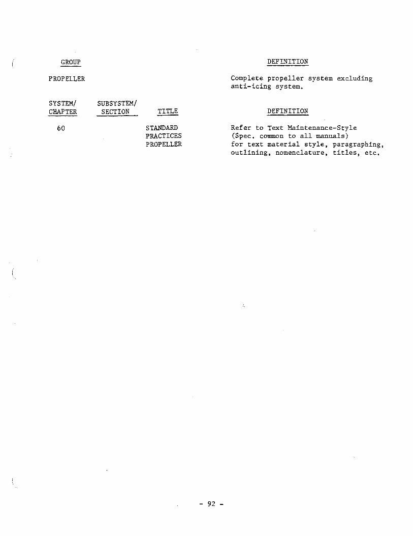
f \ GROUP DEFINITION
PROPELLER
SYSTEM/ SUBSY STEM/ CHAPTER SECTION - TITLE
Complete propeller system excluding anti-icing system.
DEFINITION
6 0 STANDARD Refer to Text Maintenance-Style PRACTICES (Spec. common to all manuals) PROPELLER for text material style, paragraphing,
outlining, nomenclature, titles, etc.

SYSTEM/ SUBSYSTEM/ W T E R SECTION TITLE -
61 PROPELLER
General
P rope l l e r Assembly
Cont ro l l ing
Braking
Ind ica t ing
DEFINITION
The complete mechanical o r e l e c t r i c a l p r o p e l l e r , pumps, motors , governor, a l t e r n a t o r s , and t h o s e u n i t s and components e x t e r n a l t o o r i n t e g r a l w i t h t h e engine used t o c o n t r o l t h e p r o p e l l e r b lade angel . Includes p r o p e l l e r sp inner , synchronizers , etc. Overhaul of p r o p e l l e r s must be accomplished i n a q u a l i f i e d shop i n accordance w i t h d a t a suppl ied by t h e p r o p e l l e r manufacturer .
That p o r t i o n of t h e system which r o t a t e s except t h e engine p rope l l e r s h a f t . Inc ludes i tems such as b l ades , dome, hub, s p i n n e r , s l i p r i n g , d e i c e r boot , d i s t r i b u t o r va lve , e t c .
That p o r t i o n of t h e system which c o n t r o l s t h e p i t c h of t h e p rope l l e r b lades . Inc ludes i tems such as governor, synchronizers , switches, c a b l e s , levers, e t c . Does not i nc lude any p a r t s which r o t a t e with t h e :propel le r assembly.
That p o r t i o n of t h e system which i s used t o decrease run-down t ime o r s t o p p r o p e l l e r r o t a t i o n during engine power-off condi t ions . Inc ludes brake mechanisms, l e v e r s , pu l leys , c a b l e s , swi tches , plumbing, e t c .
That p o r t i o n of t h e system used t o i n d i c a t e ope ra t ion o r a c t i v a t i o n of p r o p e l l e r systems. Inc ludes items such as l i g h t , swi tches , e t c .

GROUP
POWER PLANT
SYSTEM/ SUBSYSTEM/ CHAPTER SECTION - TITLE
STANDARD PRACTICES- ENGINE
DEFINITION
The complete power u n i t which develops t h r u s t e i t h e r through t h e exhaust o r through a p r o p e l l e r . Excludes items such a s gene ra to r s , cab in supe rcha rge r s , e t c . , which a r e covered under t h e i r r e s p e c t i v e systems.
DEFINITION
Refer t o Text Mater ia l -S ty le (Spec. common t o a l l manuals) f o r t e x t m a t e r i a l , s t y l e , pargraphing, o u t l i n i n g , nomenclature, t i t l e s , e t c .

SYSTEM/ SUBSYSTEM/ CHAPTER SECTION TITLE
71 POWER PLANT
-00 General
-10 Cowling
-20 Mounts
-30 F i r e s e a l s
DEFINITION
The o v e r a l l power package i n c l u s i v e of engine , a i r i n t a k e , mount, cowling, scoops, cowl f l a p s , cool ing b a f f l e s , e t c .
This t o p i c s h a l l i nc lude genera l in format ion , l i m i t s , and procedures. I n t h e maintenance manual t h i s s e c t i o n s h a l l cover s u b j e c t s such as engine changes, run-up, externally-mounted s p a r e power p l a n t s , e t c . I n t he overhaul manual, t h i s s e c t i o n s h a l l cover s u b j e c t s such as power p l a n t build-up, teardown, e t c .
Those removable coverings which extend over and around t h e power p l an t assembly. Includes t h e func t ioning and maintenance a s p e c t s of i tems such as accessory s e c t i o n cowls, cowl f l a p s , cowling suppor t s , and a t t a c h and locking mechanisms, e t c . Does n o t i nc lude t h e s t r u c t u r e i n t e g r a l , w i t h t h e a i r f r ame which s h a l l be covered i n t h e a p p l i c a b l e S t ruc tu re s Chapter . The 'framework, e i t h e r of build-up c o n s t r u c t i o n o r forg ings which suppor t t h e engine and a t t a c h i t t o t h e n a c e l l e o r pylon. Inc ludes items such as engine mounts, v i b r a t i o n dampeners, support l i n k s , mounting b o l t s , e t c .
Those f i r e - r e s i s t a n t p a r t i t i o n s and s e a l s mounted on o r about t he power package f o r t h e purpose of i s o l a t i n g a r e a s sub jec t t o f i r e . Does no t inc lude those f i r e -wa l l s which a r e included i n Chapter 54.
-40 Attach F i t t i n g s Those f i t t i n g s and b racke t s which a r e used f o r t h e support of equip- ment i n and about t h e power package.
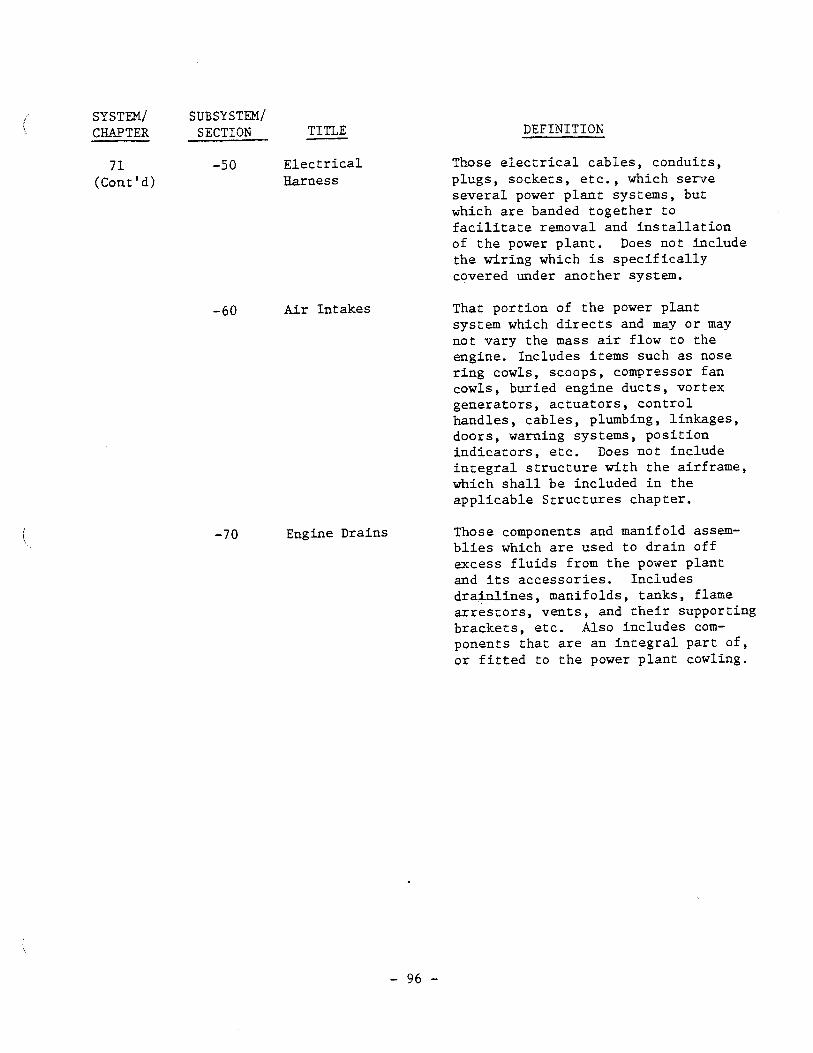
SY STEM/ SUBSY STEM/ CHAPTER SECTION - TITLE
7 1 -5 0 E l e c t r i c a l (Cont ' d) Harness
-60 Air In takes
Engine Drains
DEFINITION
Those e l e c t r i c a l cab le s , condui t s , p lugs , sockets , e t c . , which se rve s e v e r a l power p l a n t systems, but which a r e banded toge the r t o f a c i l i t a t e removal and i n s t a l l a t i o n of t h e power p l a n t . Does not inc lude the wir ing which i s s p e c i f i c a l l y covered under ano the r system.
That po r t ion of t h e power p l an t system which d i r e c t s and may o r may not vary the mass a i r flow t o the engine. Includes i tems such a s nose r i n g cowls, scoops, compressor f an cowls, buried engine duc t s , vor tex gene ra to r s , a c t u a t o r s , c o n t r o l handles , cab le s , plumbing, l inkages , doors , warning systems, p o s i t i o n i n d i c a t o r s , e t c . Does not inc lude i n t e g r a l s t r u c t u r e w i th t h e airframe, which s h a l l be included i n t h e a p p l i c a b l e S t r u c t u r e s chapter .
Those components and manifold assem- b l i e s which a r e used t o d r a i n of f excess f l u i d s from t h e power p l an t and i t s acces so r i e s . Inc ludes d r a i n l i n e s , manifolds , t anks , flame a r r e s t o r s , v e n t s , and t h e i r supporting b racke t s , e t c . Also inc ludes com- ponents t h a t a r e an i n t e g r a l p a r t o f , o r f i t t e d t o t h e power p l a n t cowling.

SYSTEM/ SUBSYSTEM/ CHAPTER SECTION TITLE DEFINITION
Those u n i t s and components which a r e :
Used t o induce and conve r t f u e l - a i r m ix tu re i n t o power. I nc ludes , f o r t h e t u r b i n e engine, a i r i n l e t , compressor, d i f f u s e r , combustion chambers, t u r b i n e and exhaus t ; and f o r t h e r e c i p r o c a t i n g engine , blower and c l u t c h , c lu t ch c o n t r o l va lve , c y l i n d e r s , cy l inde r b a f f l e s , i n t a k e p i p e s , c rankshaf t assembly, e t c .
Used t o t r ansmi t power t o t h e p r o p e l l e r s h a f t , i f any, and accessory d r i v e s . Includes r e d u c t i o n gear ing , g e a r t r a i n s , ex t ens ion s h a f t and torque-meter . Within t h e p r o f i l e of t h e b a s i c engine , used t o supplement t h e f u n c t i o n i n g of o t h e r de f ined systems e x t e r n a l t o t h e engine. Inc ludes i t ems such a s accessory d r i v e , mechanical po r t i on of t h e spa rk advance mechanism, o i l t r a n s f e r 1
t ubes from t h e p r o p e l l e r governor pad t o t h e p r o p e l l e r s h a f t , BMEP s e c t i o n , e t c .
used t o c o n t r o l and d i r e c t t h e flow of l u b r i c a t i o n through t h e engine from t h e i n l e t f i t t i n g t o t h e o u t l e t f i t t i n g . Includes engine pumps ( p r e s s u r e and scavenger) p r e s s u r e r e l i e f va lves , s c r e e n s , o i l l i n e s ( i n t e r n a l and e x t e r n a l ) , e t c .
Th i s Chapter may r e f e r t o s u p p l i e r d a t a , f u rn i shed wi th t h e a i r c r a f t , i n l i e u of t h e Sec t ions -00 through -50 o r -70, as a p p l i c a b l e .

SYSTEM/ SUBSYSTEM/ CHAPTER SECTION - TITLE
7 2 (Cont 'd)
ENGINE TURBINE/ TURBO-PROP
-00 General
DEFINITION
This top ic is intended t o cover genera l information, limits and procedures. I n the engine overhaul manual t h i s sec t ion would include such sub jec t s a s teardown, cleaning, inspect ion, assembly, t e s t i n g , e t c .
- 10 Reduction Gear The s e c t i o n of the engine which & Shaft Section contains the propel ler s h a f t s and (Turbo-Prop) reduction gears. Includes items
such a s d r ives f o r nose mounted accessor ies , e t c .
-20 Air I n l e t Section
-30 Compressor Section
- 40 Combus t i o n Section
-50 Turbine Section
The s e c t i o n of the engine through which the a i r en te r s the compressor sec t ion . Includes items such a s guide vanes, shrouds, cases, e t c .
The s e c t i o n of the engine i n which the a i r is compressed. Includes items such a s cases, vanes, shrouds, r o t o r s , d i f f u s e r s , e t c . Also includes the maintenance and overhaul of s t a t o r blades but not the opera- t i o n of v a r i a b l e s t a t o r blades which i s covered under Chapter 75 - 30. Does not include compressor bleed system.
The s e c t i o n of the engine i n which t h e a i r and f u e l a r e combined and burned. Includes items such as burner cans, cases, e t c .
The s e c t i o n of the engine containing t h e turbines . Includes items such a s tu rb ine nozzles, turbine ro to r s , cases , e t c .

SYSTEM/ SUBSYSTEM/ CHAPTER SECTION - TITLE
72 -60 Accessory (Cont ' d) Drives
By-pass Sec t ion
DEFINITION
The mechanical power t a k e o f f s t o d r i v e a c c e s s o r i e s . Includes items such a s engine-mounted gear boxes, gea r s , s e a l s , pumps, e t c . Does not i n c l u d e remotely i n s t a l l e d gear boxes which a r e covered i n Chapter 83.
The s e c t i o n of t h e engine which by-passes a p o r t i o n of t h e normal engine a i r f l o w ( e i t h e r ram o r compressed a i r ) f o r t h e prime purpose of adding t o engine t h r u s t o r reducing s p e c i f i c f u e l consumption.

SYSTEM/ SUBSYSTEM/ CHAPTER SECTION TITLE
7 2 (Cont ' d)
General
Front Sec t ion
Power Sec t ion
Cylinder Sec t ion
Supercharger Sec t ion
Lubr ica t ion
DEFINITION
This t o p i c i s intended t o cover gene ra l in format ion , limits and procedures. I n t h e engine overhaul manual, t h i s s e c t i o n would inc lude such sub jec t s a s teardown, c leaning , inspec t ion , assembly, t e s t i n g , e t c .
The s e c t i o n of t h e engine which conta ins t h e p r o p e l l e r s h a f t s and reduct ion gears . Includes i tems such a s dr ives f o r nose mounted a c c e s s o r i e s , e t c .
The s e c t i o n of t h e engine which con ta ins t h e c r anksha f t , master and l i n k rod assembl ies , cams, cam d r i v e gears , t appe t gu ides , r o l l e r s , c a r r i e r s , e t c .
The s e c t i o n of t h e engine which con ta ins t h e c y l i n d e r s , va lves , p i s t o n s , push rods , i n t a k e p i p e s , b a f f l e s , e t c . Also inc ludes rocker arm assembly, va lve s p r i n g s , e t c .
The s e c t i o n of t h e engine which coritains cases , shroud p l a t e s , PRT coupling and gear ing , impel ler and d r i v e s , accessory d r i v e s , bushings, e t c .
Those u n i t s and components which a r e used t o d i s t r i b u t e o i l throughout t h e engine. Inc ludes f r o n t and r e a r p re s su re and scavenger pumps, sumps, s t r a i n e r s , va lves , e t c . Also inc ludes those o i l l i n e s no t included i n Chapter 79. Does n o t inc lude those i tems which form i n t e g r a l passages wi th in t h e engine.

SYSTEM/ SUBSYSTEM/ CHAPTER SECTION TITLE -
ENGINE FUEL SYSTEMS
-00 General
-10 Dis t r ibu t ion
DEFINITION
For tu rb ine engines, those u n i t s and components and associa ted mechanical systems o r e l e c t r i c a l c i r c u i t s which fu rn i sh o r cont ro l f u e l t o t h e engine beyond t h e main f u e l quick disconnect; and t h r u s t augmentor, f u e l flow r a t e sensing, t r ansmi t t ing and/or ind ica t ing u n i t s whether t h e u n i t s a r e before o r beyond t h e quick disconnect. Includes: Coordinator o r equivalent , engine- dr iven f u e l pump and f i l t e r assembly, main and t h r u s t augmentor f u e l c o n t r o l s , e l e c t r o n i c -temperature datum con t ro l , temperature datum valve , f u e l manifold, f u e l nozzles, f u e l enrichment system, speed sensi- t i v e switch, r e l a y box assembly, so lenoid d r i p va lve , burner d ra in va lve , e t c .
For r ec ip roca t ing engines, those u n i t s and components which d e l i v e r
I
metered f u e l and a i r t o t h e engine. The f u e l por t ion includes t h e carbure tor /master con t ro l from the i n l e t s i d e t o t h e discharge nozzle(s) , i n j e c t i o n pumps, carbure tor , in jec- t i o n nozzles' and f u e l primer. The a i r por t ion includes u n i t s from the scoop i n l e t t o t h e vapor vent r e t u r n , and t h e impeller chamber.
That por t ion of the system from the main quick disconnect t o t h e engine, which d i s t r i b u t e s f u e l t o t h e engine burner sec t ion and the t h r u s t augmentor. Includes items such a s plumbing, pumps, temperature r e g u l a t o r s , va lves , f i l t e r s , manifold, nozzles , e t c . Does not inc lude t h e main o r t h r u s t augmentor f u e l control .

SYSTEM/ SUBSYSTEM/ CHAPTER SECTION TITLE
7 3 -20 Controlling (Cont ' d)
Indicating
DEFINITION
The main fuel controls which meter fuel to the engine and to the thrust augmentor. Includes items such as levers, cables, pulleys, linkages, etc., which are components of the fuel control units.
That portion of the system which is used to indicate the flow rate, temperature and pressure of the fuel. Includes items such as transmitters, indicators, etc.

SYSTEM/ SUBSYSTEM/ CIiAPTER SECTION TITLE
7 4 I G N I T I O N
DEFINITION
Those un i t s and components which generate, control , furnish , or d i s t r i b u t e an e l e c t r i c a l current t o i g n i t e the f u e l a i r mixture i n the cyl inders of reciprocating engines o r i n the combustion chambers or t h ru s t augmentors of turbine engines. Includes induction vibra- t o r s , magnetos, switches, lead f i l t e r s , d i s t r i bu to r s , harnesses, plugs, i gn i t i on re lays , exc i t e r s , and the e l e c t r i c a l port ion of spark advance.
-00 General
-10 Elec t r i ca l Power Supply
- 20 Distr ibution
-30 Switching
That port ion of the system which generates e l e c t r i c a l current fo r t h e purpose of igni t ing the fue l mixture i n the combustion changers and th rus t augmentors. Includes items such a s magnetos, d i s t r i bu to r s , booster c o i l s , exc i te r s , transformers, s torage capacitors and compositors, i.. e t c .
That port ion of the system which concfucts high or low vol tage elec- t r i c i t y from the e l e c t r i c a l power supply t o t he spark plugs, o r ign i te r s . Includes wiring between magneto and d i s t r i b u t o r i n those systems where they a r e separate uni ts . Includes items such a s igni t ion harness, high tension leads , co i l s a s used i n "low tension" systems, spark plugs, i g n i t e r s , e tc .
That port ion of the system which provides a means of rendering the e l e c t r i c a l power supply inoperative. Includes items such a s ign i t ion switches, connectors, e tc .

SYSTEM/ SUBSYSTEM/ CHAPTER SECTION - TITLE
75 AIR
General
Engine Anti-Icing
Accessory Cooling
Compressor Control
DEFINITION
For t u r b i n e engines, those ex te rna l u n i t s and components and i n t e g r a l b a s i c engine p a r t s which go together t o conduct a i r t o va r ious por t ions of t h e engine and t o t h e extension s h a f t and torquemeter, assembly, i f any. Inc ludes compressor bleed systems used t o c o n t r o l flow of a i r through t h e engine, cool ing a i r systems and heated a i r systems f o r engine a n t i - i c i n g , engine s t a r t i n g systems, nor exhaust supplementary a i r systems. This Chapter may r e f e r t o s u p p l i e r d a t a , furnished with the a i r c r a f t , i n l i e u of t h e following Sec t ions -00 through -40, a s app l i cab le .
That p o r t i o n of t h e system which i s used t o e l imina te and prevent t h e formation of i c e by bleed a i r in a l l p a r t s of t h e engine, excluding power p l a n t cowling which i s covered under Chapter 30. Includes i tems such a s v a l v e s , plumbing, r e g u l a t o r s , e t c . E l e c t r i c a l an t i - i c ing i s covered i n Chapter 30.
That po r t ion of t h e system which i s used t o v e n t i l a t e engine compartments and acces so r i e s . Includes i tems such a s v a l v e s , plumbing, j e t pumps, v o r t e x s p o i l e r s , e t c .
That po r t ion of t h e system which i s used t o c o n t r o l t h e flow of a i r through t h e engine. Includes items such a s governors, va lves , ac tua to r s , l i nkages , e t c . Also inc ludes t h e o p e r a t i o n of v a r i a b l e s t a t o r b lades , bu t n o t t h e maintenance and overhaul, which s h a l l be covered under 72-30.

SYSTEM/ SUBSYSTEM/ CHAPTER SECTION TITLE
7 5 -40 Indicating (Cont ' d)
DEFINITION
That portion of the system which is used to indicate temperature, pressure, control positions, etc. of the air systems. Includes items such as transmitters, indi- cators, etc.

SYSTEM/ SUBSYSTEM/ CHAPTER SECTION TITLE -
ENGINE CONTROLS
General
Power Control
Emergency Shutdown
DEFINITION
Those c o n t r o l s which govern operat ion of t h e engine. Inc ludes u n i t s and components which a r e interconnected f o r emergency shutdown. For turbo- prop engines, inc ludes l i nkages and c o n t r o l s t o t h e coord ina tor o r equiva len t and from t h e coordinator o r equiva len t t o t h e p r o p e l l e r governor, f u e l c o n t r o l u n i t o r o ther u n i t s being con t ro l l ed . For r e c i p r o c a t i n g engines, i nc ludes c o n t r o l s f o r blowers. Does not i nc lude u n i t s o r components which a r e s p e c i f i c a l l y included i n o ther chap te r s .
That p o r t i o n of t h e system which f u r n i s h e s a means of c o n t r o l l i n g the main f u e l con t ro l o r coord ina tor . Inc ludes c o n t r o l s t o t h e p rope l l e r r e g u l a t o r on turbo-prop engines. Inc ludes i tems such a s l i nkages , cab le s , l e v e r s , pu l l eys , switches, e t c . Does no t inc lude t h e u n i t s themselves.
That po r t ion of t h e system which f u r n i s h e s a means of c o n t r o l l i n g t h e flow of f l u i d s t o and from t h e engine dur ing emergency procedures. Inc ludes i tems such a s l e v e r s , c a b l e s , pu l l eys , l i nkages , switches, e t c . Does no t inc lude t h e u n i t s themselves.

SYSTEM/ SUBSY STEM/ CHAPTER SECTION TITLE
ENGIME INDICATING
General
Power
Temperature
-30 Analyzers
DEFINITION
Those u n i t s , components and a s soc i a t ed systems which i n d i c a t e engine opera t ion . Inc ludes i n d i c a t o r s , t r a n s m i t t e r s , ana lyzers , e t c . For turbo-prop engines inc ludes phase d e t e c t o r s . Does not include systems o r i tems which a r e s p e c i f i - c a l l y included i n o t h e r chapters .
That p o r t i o n of t h e system which d i r e c t l y o r i n d i r e c t l y i nd ica t e s power o r t h r u s t . Inc ludes items such a s EMEP, pressure- ra t io , RPM, e t c .
That p o r t i o n of t h e system which i n d i c a t e s temperatures i n t h e engine. Inc ludes i tems such a s cy l inde r head, exhaust ( t u r b i n e i n l e t ) , e t c .
That p o r t i o n of t h e system which i s used t o ana lyze engine performance o r cond i t i on by means of instruments o r devices such a s o sc i l l o scopes , e t c . Inc ludes i tems such a s gener- a t o r s , a m p l i f i e r s , o sc i l l o scopes , e t c .

SY STLY/ SUBSYSTEM/ CHAPTER SECTION TITLE -
7 8 EXHAUST
General
c o l l e c t o r / Nozzle
Noise Suppressor
T h r u s t Reverse r
DEFINITION
Those u n i t s and components which d i r e c t t h e e n g i n e exhaus t gases overboard.
For t u r b i n e e n g i n e s , i n c l u d e s u n i t s e x t e r n a l t o t h e b a s i c eng ine such as t h r u s t r e v e r s e r and n o i s e s u p p r e s s o r , i f a p p l i c a b l e .
For r e c i p r o c a t i n g e n g i n e s , i n c l u d e s augmentors , s t a c k s , clamps, e t c . Excludes exhaust -dr i v e n t u r b i n e s .
That p o r t i o n of t h e sys tem which c o l l e c t s t h e e x h a u s t gases from t h e c y l i n d e r s o r t u r b i n e s and conducts them overboard. I n c l u d e s i t e m s such as c o l l e c t o r r i n g s , exhaus t and t h r u s t augmentor d u c t s , v a r i a b l e n o z z l e s , a c t u a t o r s , plumbing, l i n k a g e s , p o s i t i o n i n d i c a t o r s , warning systems, e t c . Does n o t i n c l u d e power recovery t u r b i n e s , tu rbo-superchargers , e t c . , n o r n o i s e s u p p r e s s o r s o r t h r u s t reversers where t h e y are n o t a n i n t e g r a l p a r t of t h e n o z z l e system.
Tha t p o r t i o n o f t h e system which r e d u c e s t h e n o i s e genera ted by t h e e x h a u s t gases . I n c l u d e s i t e m s such as p i p e s , b a f f l e s , s h i e l d s , a c t u a t o r s , plumbing, l i n k a g e s , p o s i t i o n i n d i - c a t o r s , warning sys tems , e t c . , as a p p l i c a b l e .
U s e -10 where i n t e g r a l p a r t of n o z z l e system.
That p o r t i o n o f t h e system which i s used t o change t h e d i r e c t i o n of t h e e x h a u s t gases f o r reverse t h r u s t . I n c l u d e s i t e m s s u c h as c l a m s h e l l s , l i n k a g e s , l e v e r s , a c t u a t o r s , plumbing, i n d i c a t o r s , warning systems, e t c . , as a p p l i c a b l e .

SYSTEM/ SUBSY ST^/ CHAF'TER SECTION TITLE
7 8 -30 Thrust (Cont 'd) (Cont ' d) Reverser
-40 Supplementary Air
DEFINITION
Use -10 where i n t e g r a l p a r t of nozz le system.
That p o r t i o n of t h e system which v a r i e s and c o n t r o l s supplementary a ir f low t o t h e exhaust system. Inc ludes items such as t e r t i a r y a i r doors , a c t u a t o r s , l i nkages , sp r ings , plumbing, p o s i t i o n i n d i c a t o r s , warning systems, e t c . , as appl icable .

SYSTEM/ SUBSYSTEM/ C&APTER SECTION - TITLE
General
Storage
Distribution
Indicating
DEFINITION
Those units and components external to the engine concerned with storing and delivering lubricating oil to and from the engine. Covers all units and components from the lubricating oil engine outlet to the inlet, including the inlet and outlet fittings, tank, radiator, by-pass valves, etc., and auxiliary oil systems.
That portion of the system used for storage of oil. Includes items such as tanks, filling systems, internal hoppers, baffles, tank sump and drain, etc. Does not include tanks which are an integral portion of the engine.
That portion of the system which is used to conduct oil from and to the engine. Includes items such as plumbing, valves, temperature regulator, control systems, etc.
That portion of the system which is used to indicate the quantity, temperature and pressure of the oil. Includes items such as transmitters, indicators, warning systems, etc.

SYSTEM/ SUBSYSTEM/ CHAPTER SECTION TITLE
80 STARTING
General
Cranking
DEFINITION
Those u n i t s , components and as soc ia t ed systems used f o r s t a r t i n g t h e engine. Includes e l e c t r i c a l , i n e r t i a a i r o r o ther s t a r t e r systems. Does not inc lude i g n i t i o n systems which a r e covered i n Chapter 74, I G N I T I O N .
That po r t ion of the system which is used t o perform the cranking por t ion of t h e s t a r t i n g operation. Includes i tems such a s plumbing, va lves , s t a r t e r s , switches, r e l a y s , e t c .

SYSTEM/ SUBSYSTEM/ CHAF'TER SECTION TITLE
8 1 TURBINES
-00 General
-10 Power Recovery
-20 Turbo- Supercharger
DEFINITION
For r ec ip roca t ing engines only. Includes power recovery tu rb ine assembly and turbo-supercharger u n i t when e x t e r n a l t o t h e engine. This Chapter may r e f e r t o supp l i e r d a t a , furn ished wi th t h e a i r c r a f t , i n l i e u of t h e fol lowing Sect ions -00 through -20, a s appl icable .
The t u r b i n e s which e x t r a c t energy from t h e exhaust gases and a r e coupled t o t h e c rankshaf t .
The t u r b i n e s which e x t r a c t energy from t h e exhaust gases and d r i v e an a i r compressor.

SYSTEM/ CHAPTER
STTBSY STEM/ SECTION - TITLE
ACCESSORY GEARBOXES
General
Drive Sha f t Sec t ion
Gearbox Sect ion
DEFINITION
Those u n i t s and components which a r e remotely i n s t a l l e d and connected t o t h e engine by a d r i v e s h a f t and which d r i v e m u l t i p l e types of acces so r i e s . Does n o t i nc lude those accessory d r i v e s which a r e bo l t ed t o and a r e immediately ad jacent t o t h e engine. The l a t t e r i t em s h a l l be covered under Chapter 7 2 , ENGINE.
That p o r t i o n of t h e system which i s used t o conduct power from t h e engine t o t h e gearbox. Inc ludes i tems such a s d r i v e s h a f t , adap te r s , s e a l s , e t c .
The c a s e which con ta ins t h e gear t r a i n s and s h a f t s . Inc ludes items such a s gears , s h a f t s , s e a l s , o i l pumps, coo le r s , e t c .

SYSTEM/ SUBSYSTEM/ CHAPTER SECTION - TITLE
CHARTS h WIRING D LAGRAMS
DEFINITION
Miscellaneous charts not applicable to any particular system, such as wire diagrams, junction box charts, disconnect plug charts, conduit and wire routing charts, and list of special tools.

SYSTEM/ SUBSYSTEM/ CHAPTER SECTION TITLE
SPECLAL PURPOSE E Q U I P m
DEFINITION
Th i s Chapter s h a l l i nc lude such equipment and systems n o t included i n prev ious chap te r s . A g r i c u l t u r a l , G l i d e r & Banner Towing, Spec i a l Photographic , e t c . , would f a l l under t h i s ca tegory .