Embed Size (px)
Citation preview

SE
GB
Monteringsinstruktioner
Installation instructions
VISKA SYSTEM
A
���
���
����
����
22
LÄS DETTA FÖRST!VI BER DIG ATT LÄSA DESSA MONTERINGSINSTRUKTIONER NOGGRANT INNAN DU PÅBÖRJAR INSTALLATIONEN.
PRODUKTEN SKA INSTALLERAS AV EN BEHÖRIG INSTALLATÖR.
KONTAKT MED 230 V NÄTSPÄNNING MEDFÖR LIVSFARA.ALLA ARBETEN FÅR ENDAST GENOMFÖRAS I SPÄNNINGSLÖST TILLSTÅND OCH AV UTBILDAD FACKPERSONAL.
READ THIS FIRST!PLEASE READ THIS INSTALLATION MANUAL CAREFULLY BEFORE YOU START THE INSTALLATION OF THE WHIRLPOOL.
THIS PRODUCT MUST BE INSTALLED BY A QUALIFIED INSTALLER.
HANDLING OF 230 V MAINS VOLTAGE CAN LEAD TO LOSS OF LIFE.THE EQUIPMENT MUST BE DISCONNECTED FROM THE MAINS BEFORE WORK COMMENCES
SE
GB
SE
GB Bath
Badkar
SE
GB Bath
Badkar SE
GB Bath fitted against a permanent wall
Badkaret monteras mot en permanent vägg
2,60
m
2,40 m
0,60 m 2,40 m
Zone0
Zone1
Zone1
Zone0
Zone2
Zone3
0,60 m
0,60
m
2,40 m
Zone0
Zone1
Zone2
Zone3
Zone2
Zone3
0,60 m
2
VISKA SYSTEM

A
A
B
C
E1
E2
D
U
GB
1. ELECTRICAL CONNECTIONThe installation of electrical equipment and any repairs of such equipment must only be done by a recognized installer. Connect the system to the mains (see illustration). As soon as the system is connected. The system is ready for use.N.B.: If you switch off the power to the system, you should wait at least 10 seconds before switching the power back on again so as to prevent malfunctions.
1. The power supply should be fitted with a cut-off switch which:- is placed beneath the bath in the neighbourhood of the control box- must switch both the live and the neutral- must have a contact opening greater than 3 mm in the switched-off position- complies with the safety requirements of IPX5.
2. On the system’s frame there is a connection for the potential bonding. This and all metal components which are not part of the system must be connected to the equipotential bonding that must be present in the bathroom, by means of an equipotential bonding of 4 mm2 wire, according to the local current requirements.
3. The illustration shows the zone layout of a bath area with bath.The space beneath the bath is not considered to be one of these zones if the space is closed by means of partitions which can only be removed with the aid of tools. All electro-mechanical components of the system are positioned beneath the bath and should remain there. The parts needed for installation and connections should also be fitted beneath the bath.
IMPORTANT: Live parts, excluding parts supplied by SELV circuits at voltages not exceeding 12 V, must not be accessible to a bathing person.Parts containing electrical components, with the exception of remote controls, must be fitted such that they cannot drop into the bathtub.
4. The system meets the requirements set for Class I equipment. The system must be permanently connected to fixed wiring with cable of a maximum 3 x 2.5 mm2 (type H05VV-U3G2.5 or H05VV-F3G2.5). Type X, connection method involving special cable: should the supply cable be damaged, it must be replaced with a special supply cable or cable combination, available from the manufacturer or a specialist.
The technical parts of the system must be kept assessable. A complete dismountable panel is needed.It is not allowed that this panel can be opened without the use of tools.
ConnectionNetherlands: according to NEN 1010Belgium: according to A.R.E.I. art. 86, 90, 93France: according to NF C 15-100Germany: according to DIN/VDE 0100 Teil 701 2008-10England: according to BS 7671Other countries: according to the national regulation in force.E1 = fuseE2 = RCCB (Residual Current Circuit Breaker) (cannot be placed in zones 1, 2 or 3), I, I∆=30 mA, In=25 A, Class A D = cut-off switchU = system controlB = bathroomC = cable box
2A
Before beginning the installation, please read these instructions. They contain all the information you require and describe each process step by step.
3
VISKA SYSTEM

A
A
B
C
E1
E2
D
U
SE
1. ELEKTRISK ANSLUTNINGInstallation av elektrisk utrustning och eventuella reparationer på sådan utrustning ska utföras av en behörig installatör.Anslut systemet till elnätet (se kopplingsschemat). Systemet är klart för användning omedelbart efter inkoppling.OBS: Om du stänger av strömmen till systemet, bör du vänta minst 10 sekunder före ny inkoppling av strömmen för att förhindra felaktig funktion.
1. Strömmatningen ska förses med en strömbrytare som:- ska placeras under badkaret i närheten av styrskåpet- måste bryta tvåpoligt, dvs. både fas och nolla- måste ha en kontaktöppning större än 3 mm i avstängt läge- ska uppfylla kraven för kapslingsklass IP X5.
2. På systemets stomme finns en anslutning för potentialutjämning. Denna och alla metallkomponenter som inte är en del av systemet måste anslutas till denna potentialutjämningsanslutning som ska finnas i badrummet, via en 4 mm2 ledare för potentialutjämning enligt aktuella lokala föreskrifter.
3. Figurerna visar zonindelningen i ett badrum med badkar.Utrymmet under badkaret anses inte ingå i någon av dessa zoner om utrymmet är tillslutet med avdelare som endast kan avlägsnas med hjälp av verktyg. Alla elektromekaniska komponenter i systemet är placerade under badkaret och ska behållas där. Delarna som erfordras för installation och anslutningar ska också monteras under badkaret.
VIKTIGT:Spänningsförande delar, med undantag av delar som matas från SELV-kretsar med en spänning som inte överstiger 12 V, får inte vara möjliga att nås av en badande person.Delar som innehåller elektriska komponenter, med undantag av fjärrkontroller, måste monteras på sådant sätt att de inte kan falla ned i badkaret.
4. Systemet uppfyller de krav som ställs på utrustning i klass I. Systemet måste vara fast anslutet till en fast installation med en kabel med maximalt 3 x 2,5 mm2 (typ H05VV-U3G2.5 eller H05VV-F3G2.5). Typ X, anslutningssätt med specialkabel:om kabeln skadas, måste den ersättas med en speciell matningskabel eller kabelkombination som är tillgänglig från tillverkaren eller en specialist.Systemets tekniska delar måste vara åtkomliga. En helt löstagbar panel erfordras.Denna panel ska endast kunna lossas med hjälp av verktyg.
Anslutning:Nederländerna: enligt NEN 1010Belgien: enligt A.R.E.I. art. 86, 90, 93Frankrike: enligt NF C 15-100Tyskland: enligt DIN/VDE 0100 Teil 701 2008-10England: enligt BS 7671Övriga länder: enligt gällande nationella föreskrifter.E1 = säkringE2 = RCCB (Residual Current Circuit Breaker, jordfelsbrytare) (får inte placeras i zonerna 1, 2 eller 3), I, I∆=30 mA, In=25 A, klass A D = strömbrytareU = styrutrustningB = badrumC = ledningsdosa
2A
Läs dessa instruktioner innan du påbörjar installationen. De innehåller all information du behöver och beskriver varje process steg för steg.
4
VISKA SYSTEM

5
VISKA SYSTEM

A
C
B
6
VISKA SYSTEM

> 40 cm2> 40 cm
2
> 40 cm2
> 40 cm2
> 40 cm2
> 40 cm2
> 40 cm2
7
VISKA SYSTEM

A
≥ 10 mm≥ 20 mm
���������
1
2
8
VISKA SYSTEM

≥ 20 mm
≤ 20 mm
> 50 mm2
3
4 2
9
VISKA SYSTEM

A
B
40°C ± 5°C
5
6
10
VISKA SYSTEM
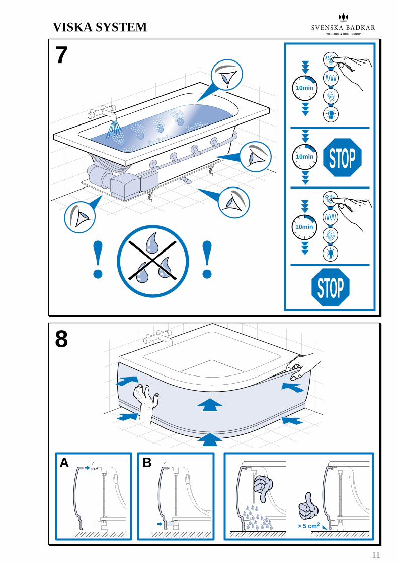
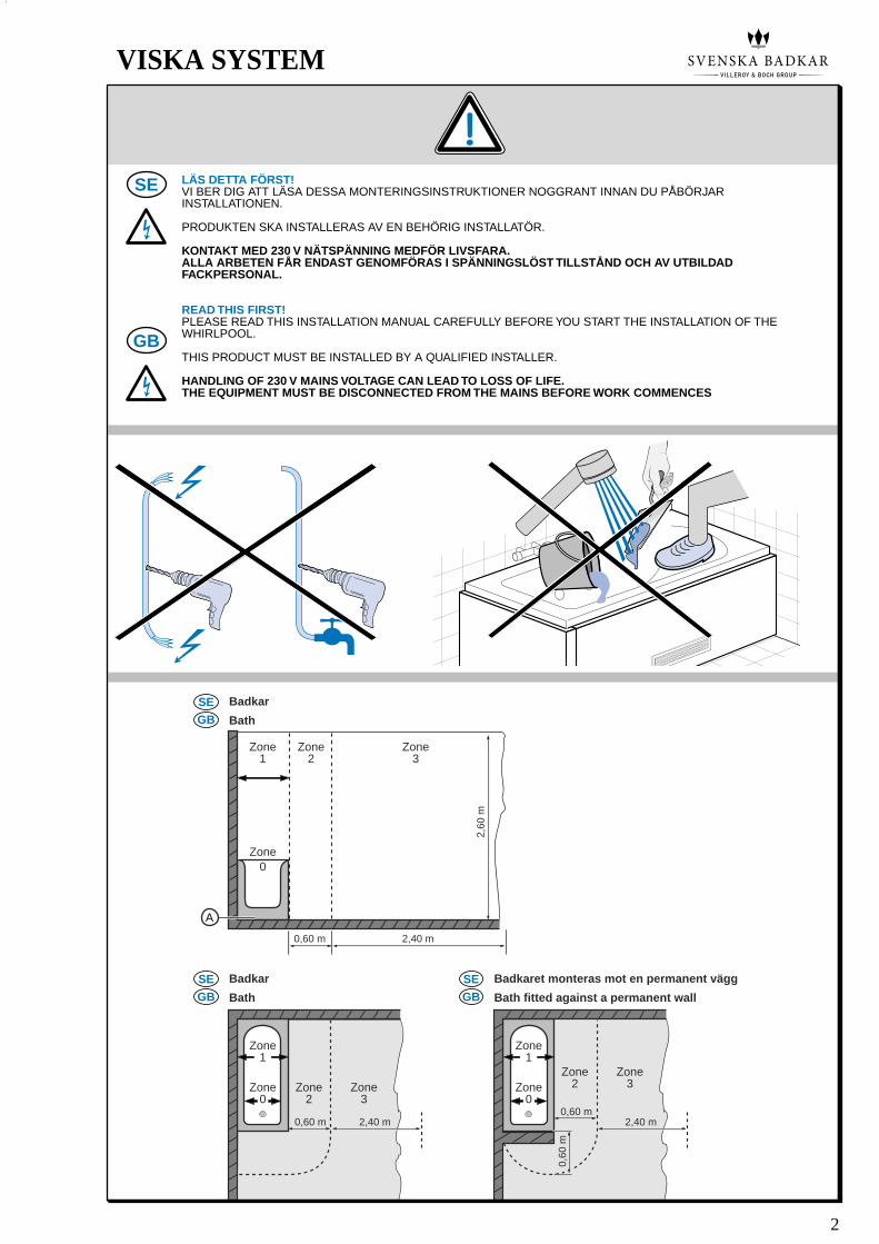
A B
> 5 cm2
10min
10min
10min STOP
STOP
8
7
11
VISKA SYSTEM

Villeroy & Boch Gustavsberg ABBox 400, 134 29 Gustavsberg, Sweden
Tel.: 08-570 391 00 / Fax: 08-570 320 36www.gustavsberg.se [email protected]
www.villeroy-boch.com
UCMAN0205 Version 24-06-2010 • Wijzigingen voorbehouden • Änderungen vorbehalten • Sous réserve de modifications • Right to alterations reserved • Salvo modifiche • Ändringar förbehållna • Oikeudet muutoksiin pidätetään • ����� �� ������� � � ���
®= Geregistreerd merk • Eingetragenes Warenzeichen • Marque déposée •Registered trademark • Marchio registrato • Registrerat varumärke • Rekisteröity tavaramerkki, TM=Trademark • ������������������ �������� ���
Ditt bubbelbadkar är utrustat med ett skyddslock som säkerställer en säker användning av
badkaret.
OBSERVERA! DET ÄR INTE SÄKERT ATT ANVÄNDA SYSTEMET, OM SKYDDSLOCKET INTE SITTER
FAST, SAKNAS ELLER ÄR DEFEKT.
Ta aldrig bort skyddslocket, om det inte handlar om att någon (behörig person) ska utföra
installations- eller underhållsarbeten.
Låt (en behörig person) byta ut skyddslocket om det är skadat eller defekt.
Your system is equipped with a Safety Cover that’s especially designed for the safe use of
your whirlpool system.
WARNING! NEVER ENTER THE WHIRLPOOL IF THE SAFETY COVER IS LOOSE, BROKEN OR MISSING.
Never remove the Safety Cover. If necessary then only (by a qualified person) for service and
maintenance.
Have the Safety Cover replaced (by a qualified person), if it is broken or damaged!
SE
GB
SAFETY COVER
SE
GB
Monteringsinstruktioner
Installation instructions
VISKA SYSTEM
9VISKA SYSTEM