Embed Size (px)
Citation preview
SIMATIC S7-300 CPU 31xT
________________________________________________________________________________________________________________
Preface
Product Overview 1
Operator controls and indicators
2Setting up an S7-300 with a Technology CPU
3
Communication with S7-300 4
Memory concept 5
Cycle and response times 6
Technical data 7
Appendix A
SIMATIC
S7-300 CPU 31xT
Manual
03/2008 A5E01672599-01
Safety Guidelines Safety Guidelines This manual contains notices you have to observe in order to ensure your personal safety, as well as to prevent damage to property. The notices referring to your personal safety are highlighted in the manual by a safety alert symbol, notices referring only to property damage have no safety alert symbol. These notices shown below are graded according to the degree of danger.
DANGER indicates that death or severe personal injury will result if proper precautions are not taken.
WARNING indicates that death or severe personal injury may result if proper precautions are not taken.
CAUTION with a safety alert symbol, indicates that minor personal injury can result if proper precautions are not taken.
CAUTION without a safety alert symbol, indicates that property damage can result if proper precautions are not taken.
NOTICE indicates that an unintended result or situation can occur if the corresponding information is not taken into account.
If more than one degree of danger is present, the warning notice representing the highest degree of danger will be used. A notice warning of injury to persons with a safety alert symbol may also include a warning relating to property damage.
Qualified Personnel The device/system may only be set up and used in conjunction with this documentation. Commissioning and operation of a device/system may only be performed by qualified personnel. Within the context of the safety notes in this documentation qualified persons are defined as persons who are authorized to commission, ground and label devices, systems and circuits in accordance with established safety practices and standards.
Prescribed Usage Note the following:
WARNING This device may only be used for the applications described in the catalog or the technical description and only in connection with devices or components from other manufacturers which have been approved or recommended by Siemens. Correct, reliable operation of the product requires proper transport, storage, positioning and assembly as well as careful operation and maintenance.
Trademarks All names identified by ® are registered trademarks of the Siemens AG. The remaining trademarks in this publication may be trademarks whose use by third parties for their own purposes could violate the rights of the owner.
Disclaimer of Liability We have reviewed the contents of this publication to ensure consistency with the hardware and software described. Since variance cannot be precluded entirely, we cannot guarantee full consistency. However, the information in this publication is reviewed regularly and any necessary corrections are included in subsequent editions.
Siemens AG Automation and Drives Postfach 48 48 90327 NÜRNBERG GERMANY
A5E01672599-01 Ⓟ 03/2008
Copyright © Siemens AG 2008. Technical data subject to change
CPU 31xT Manual, 03/2008, A5E01672599-01 3
Preface
Purpose of this manual This manual contains all the essential information about: ● The configuration ● Communication ● The memory concept ● Cycle and response times ● CPU technical data. Finally you will learn the points to consider when upgrading to one of the CPUs discussed in this manual.
Required basic knowledge Knowledge required to understand this manual: ● General knowledge of automation ● Knowledge of motion control ● Knowledge of the STEP 7 basic software.
Required configuration tools To configure the Technology CPU you require STEP 7, Version V5.4 SP2 or higher and the optional package S7 Technology, Version V4.1 or higher.
Scope of this manual
Table 1 Scope of this manual
CPU Order No. As of Version firmware CPU 315T-2 DP CPU 317T-2 DP
6ES7 315-6TH13-0AB0 6ES7 317-6TK13-0AB0
V2.6/V4.1.1 V2.6/V4.1.1
This manual describes ● The differences of the Technology CPU compared with the Operating Instructions S7-300
CPU 31xC and 31x: Installation ● The properties of the Technology CPU

Preface
CPU 31xT 4 Manual, 03/2008, A5E01672599-01
Note For new modules, or modules of a more recent version, we reserve the right to include Product Information containing latest information.
Changes since with the previous edition The previous editions of this manual are the manuals S7-300 CPU data: CPU 315T-2 DP and S7-300 CPU data: CPU 317T-2 DP. These have been combined to form the current manual S7-300 CPU 31xT. The following changes have been made since the previous editions: ● Isochronous mode on PROFIBUS DP ● Variable process image ● Extension of block-specific messages (SFC 105 - SFC -108) ● Time synchronization over DP ● Updating the firmware online (via networks) ● Reset of the CPU to delivery state ● Measuring proximity switch for diagnostic repeater, for DP CPUs (SFC 103) ● I&M of the CPU (e.g. higher-level and location IDs)
Standards and certificates Refer to section General technical data > Standards and certificates.
Recycling and disposal The devices described in this manual can be recycled, because their components contain a minimum of harmful substances . For environment-friendly recycling and disposal of your old equipment, contact a certified disposal facility for electronic scrap.
Further support Refer to the Product Information Technical Support, Contacts and Training for more information. You will find the product information on the Internet at: http://support.automation.siemens.com, article ID 19293011

CPU 31xT Manual, 03/2008, A5E01672599-01 5
Table of contents Preface ...................................................................................................................................................... 3 1 Product Overview ...................................................................................................................................... 9 2 Operator controls and indicators.............................................................................................................. 13 3 Setting up an S7-300 with a Technology CPU......................................................................................... 17
3.1 Overview ......................................................................................................................................17 3.2 S7-300 components.....................................................................................................................17 3.3 Configuring...................................................................................................................................18 3.3.1 Single-tier configuration ...............................................................................................................18 3.3.2 Subnets ........................................................................................................................................18 3.4 Addressing ...................................................................................................................................19 3.5 Commissioning.............................................................................................................................20 3.6 Operating system.........................................................................................................................20 3.7 Status and error displays .............................................................................................................21
4 Communication with S7-300 .................................................................................................................... 25 4.1 Interfaces .....................................................................................................................................25 4.1.1 Overview ......................................................................................................................................25 4.1.2 MPI/DP interface (X1) ..................................................................................................................26 4.1.3 PROFIBUS DP (DRIVE) interface (X3) .......................................................................................29 4.1.4 Information about interface X3 DP(DRIVE) .................................................................................30 4.2 Communication services..............................................................................................................30 4.2.1 Overview ......................................................................................................................................30 4.2.2 PG communication.......................................................................................................................31 4.2.3 OP communication.......................................................................................................................32 4.2.4 S7 basic communication ..............................................................................................................32 4.2.5 S7 communication .......................................................................................................................33 4.2.6 Global data communication (MPI only)........................................................................................33 4.2.7 Routing.........................................................................................................................................34 4.2.8 Data consistency..........................................................................................................................37 4.3 S7 connections ............................................................................................................................38 4.3.1 S7 connection as communication path ........................................................................................38 4.3.2 Assignment of S7 connections.....................................................................................................39 4.3.3 Distribution and availability of S7 connection resources .............................................................40 4.4 DPV1............................................................................................................................................42 4.4.1 General information about DPV1.................................................................................................42

Table of contents
CPU 31xT 6 Manual, 03/2008, A5E01672599-01
5 Memory concept ...................................................................................................................................... 45 5.1 Memory areas and retentive address areas ............................................................................... 45 5.1.1 Technology CPU memory areas................................................................................................. 45 5.1.2 Retentive address areas of the load memory, system memory and technology system
data ............................................................................................................................................. 47 5.1.3 Retentivity of memory objects..................................................................................................... 48 5.1.4 Address areas of system memory .............................................................................................. 50 5.1.5 Properties of the SIMATIC Micro Memory Card ......................................................................... 54 5.2 Memory functions........................................................................................................................ 55 5.2.1 General: Memory functions ......................................................................................................... 55 5.2.2 Load user program from SIMATIC Micro Memory Card to the CPU .......................................... 56 5.2.3 Handling blocks........................................................................................................................... 57 5.2.3.1 Downloading new blocks or delta downloads ............................................................................. 57 5.2.3.2 Uploading blocks......................................................................................................................... 57 5.2.3.3 Deleting blocks............................................................................................................................ 57 5.2.3.4 Compressing blocks.................................................................................................................... 58 5.2.3.5 Promming (RAM to ROM)........................................................................................................... 58 5.2.4 CPU memory reset and restart ................................................................................................... 58 5.2.5 Backup of project data to SIMATIC Micro Memory Card............................................................ 59 5.3 Recipes ....................................................................................................................................... 60 5.4 Measured value log files ............................................................................................................. 61 5.5 Technology data blocks .............................................................................................................. 63 5.6 Memory of the integrated technology of the CPU....................................................................... 64
6 Cycle and response times........................................................................................................................ 67 6.1 Overview ..................................................................................................................................... 67 6.2 Cycle time.................................................................................................................................... 68 6.2.1 Overview ..................................................................................................................................... 68 6.2.2 Calculating the cycle time ........................................................................................................... 70 6.2.3 Different cycle times.................................................................................................................... 73 6.2.4 Communication Load .................................................................................................................. 74 6.2.5 Cycle time extension as a result of testing and commissioning functions .................................. 76 6.3 Response time ............................................................................................................................ 77 6.3.1 Overview ..................................................................................................................................... 77 6.3.2 Shortest response time ............................................................................................................... 79 6.3.3 Longest response time................................................................................................................ 80 6.3.4 Reducing the response time with direct I/O access.................................................................... 81 6.4 Calculating method for calculating the cycle/response time ....................................................... 81 6.5 Interrupt response time ............................................................................................................... 83 6.5.1 Overview ..................................................................................................................................... 83 6.5.2 Reproducibility of Time-Delay and Watchdog Interrupts ............................................................ 84 6.6 Sample calculations .................................................................................................................... 85 6.6.1 Example of cycle time calculation ............................................................................................... 85 6.6.2 Example of response time calculation ........................................................................................ 86 6.6.3 Example of interrupt response time calculation .......................................................................... 88
Table of contents
CPU 31xT Manual, 03/2008, A5E01672599-01 7
7 Technical data ......................................................................................................................................... 91 7.1 General technical data .................................................................................................................91 7.1.1 Rated voltages of S7-300 ............................................................................................................91 7.1.2 Technical specifications of the Micro Memory Card ....................................................................91 7.1.3 Standards and certifications.........................................................................................................92 7.1.4 Electromagnetic compatibility ......................................................................................................96 7.1.5 Shipping and storage conditions for modules and backup batteries ...........................................98 7.1.6 Mechanical and climatic environmental conditions for S7-300 operation....................................99 7.1.7 Specification of dielectric tests, protection class, degree of protection, and rated voltage
of S7-300....................................................................................................................................101 7.1.8 Dimension drawing ....................................................................................................................102 7.2 CPU 315T-2 DP and CPU 317T-2 DP.......................................................................................103 7.3 Integrated Inputs/Outputs for Technology .................................................................................114 7.3.1 Arrangement of integrated inputs/outputs for integrated technology.........................................114
A Appendix................................................................................................................................................ 115 A.1 Information for the Changeover to the Technology CPU...........................................................115 A.1.1 Scope .........................................................................................................................................115 A.1.2 Changed behavior of certain SFCs............................................................................................115 A.1.3 Interrupt events from distributed I/Os while the CPU status is in STOP ...................................117 A.1.4 Runtimes that change while the program is running .................................................................117 A.1.5 Converting the diagnostic addresses of DP slaves ...................................................................118 A.1.6 Reusing existing hardware configurations .................................................................................118 A.1.7 Replacement of a Technology CPU ..........................................................................................119 A.1.8 Using consistent data areas in the process image of a DP slave system .................................119 A.1.9 Load memory design for the Technology CPU..........................................................................120 A.1.10 PG/OP functions ........................................................................................................................120 A.1.11 Routing for the CPU 31xC/31x as an intelligent slave...............................................................120 A.1.12 Altered retentive response with a Technology CPU ..................................................................120 A.1.13 FMs/CPs with their own MPI address in a Technology CPU central configuration ...................121
Glossary ................................................................................................................................................ 123 Index...................................................................................................................................................... 137

Table of contents
CPU 31xT 8 Manual, 03/2008, A5E01672599-01

CPU 31xT Manual, 03/2008, A5E01672599-01 9
Product Overview 1Introduction
The current trend in the field of automation is toward PLC-integrated solutions. This also applies to technology and motion control applications.
Integrated technology of Technology CPU With the Technology CPU, technology and motion control functions are integrated in one SIMATIC CPU. The Technology CPU incorporates: ● SIMATIC CPU 31x-2 DP ● PLCopen-compliant motion control functions ● Technological configurations (technology objects, axis configurations, tools) The Technology CPU is completely integrated in the SIMATIC family and thus in the TIA environment.
Field of application The Technology CPU is especially suited to solving the following control tasks: ● Control tasks and technology requirements primarily relating to motion control in the
SIMATIC S7-300 ● Motion tasks for up to eight coupled axes or single axes ● Technological tasks, e.g. gearing and camming, position-controlled positioning (operating
modes: Absolute, relative, additive and superimposed), travel to fixed stop, probe-based print mark correction, position- or time-dependent cam control).
The Technology CPU is designed for use with flow machines, processing/assembly lines, flying shears, labeling equipment, drum feeds or simple gantries (without interpolation).
Product Overview
CPU 31xT 10 Manual, 03/2008, A5E01672599-01
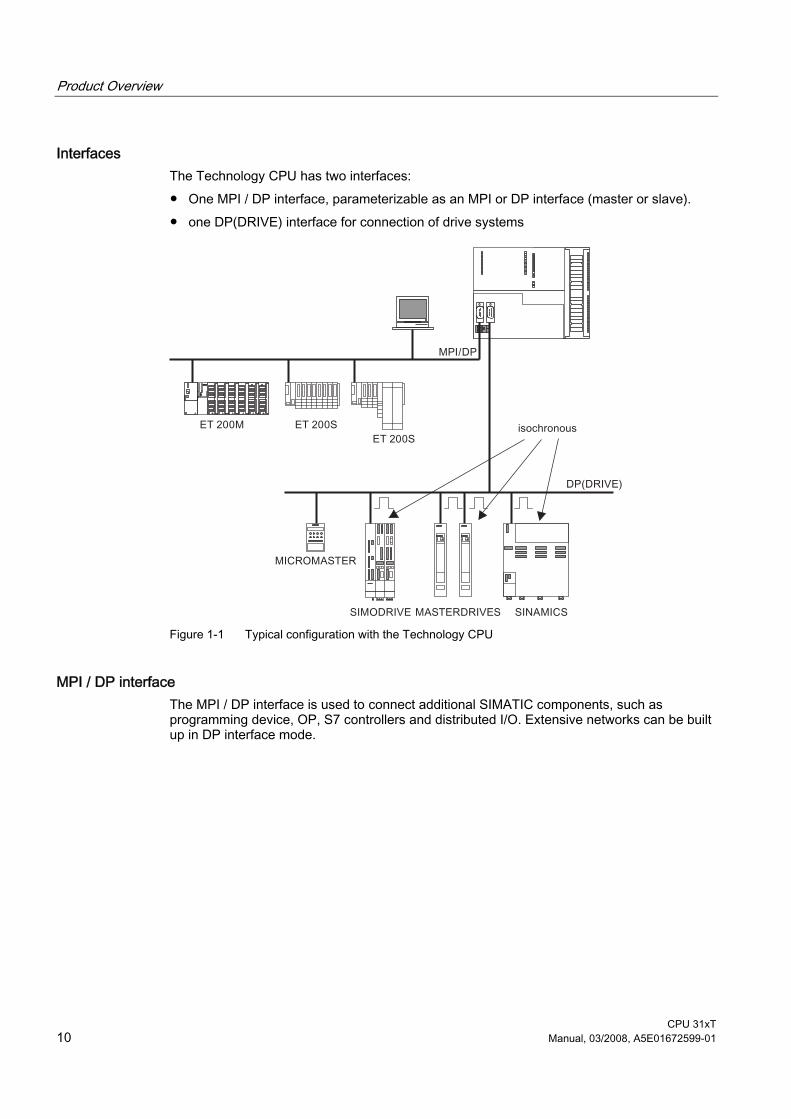
Interfaces The Technology CPU has two interfaces: ● One MPI / DP interface, parameterizable as an MPI or DP interface (master or slave). ● one DP(DRIVE) interface for connection of drive systems
SIEMENS
Figure 1-1 Typical configuration with the Technology CPU
MPI / DP interface The MPI / DP interface is used to connect additional SIMATIC components, such as programming device, OP, S7 controllers and distributed I/O. Extensive networks can be built up in DP interface mode.
Product Overview
CPU 31xT Manual, 03/2008, A5E01672599-01 11
DP(DRIVE) interface The DP(DRIVE) interface is optimized for the connection of drives. It supports all the major SIEMENS drive types: ● MICROMASTER 420/430/440 and COMBIMASTER 411 ● SIMODRIVE 611 universal ● SIMODRIVE POSMO CD/SI/CA ● MASTERDRIVES MC/VC ● ET 200M with IM 153-2 (isochronous!) and SM 322 for additional cam output ● ET 200S with IM 151-1 high feature ● SINAMICS S120 (optional with TM15 or TM17 high feature for high-speed cams) ● ADI4 and IM 174 analog drive interfaces (interface for analog drives and stepper motors) ● Isochronous PROFIBUS encoder "SIMODRIVE sensor isochronous" The components configured in HW Config are displayed in the "Hardware Catalog" window in HW Config. To show the screen, select profile "SIMATIC Technology CPU" in HW Config. To ensure that the profile's selection list is complete, you must have installed the most recent version of S7-Technology. The isochronous mode means that even high-speed processes can be controlled with excellent precision.
Integrated inputs and outputs for integrated technology The Technology CPU has 4 digital inputs and 8 digital outputs integrated. You use these inputs and outputs for technology functions, e.g. reference point acquisition (reference cams) or high-speed output cam switching signals. The inputs and outputs can also be used with technology functions in the STEP 7 user program.
Configuring and programming The Technology CPU is configured and programmed completely in STEP 7 and optional package S7 Technology(the S7 Technology optional package is integrated after installation in STEP 7 ). STEP 7 HW Config is the tool used to configure all hardware components of the system (e.g. to create subnets on the two interfaces MPI / DP and DP(DRIVE)) including the drive equipment. You will need optional package S7-Technology to parameterize the so-called "technology objects", e.g. axes, cams, output cams and probes. The objects are parameterized in specially provided screens. The technology object data are stored in data blocks for use by the STEP 7 user program. S7-Technology also includes a library containing PLCopen-compliant standard function blocks which are used to program the motion control tasks themselves. You call these standard FBs in your STEP 7 user program. STEP 7 languages LAD, FBD and STL and all the required engineering tools, e.g. S7-SCL or S7-GRAPH are provided to enable you to create the STEP 7 user program (incl. motion control tasks).

Product Overview
CPU 31xT 12 Manual, 03/2008, A5E01672599-01
Single-tier configuration The Technology CPU supports only single-tier configurations.

CPU 31xT Manual, 03/2008, A5E01672599-01 13
Operator controls and indicators 2Operator controls and indicators of the CPU
The following diagram shows the operator controls and indicators on the Technology CPU.
Figure 2-1 Operator controls and indicators of the Technology CPU
Table 2-1 Operator controls and indicators of the Technology CPU
The number in the diagram
points to the following element on the Technology CPU
1 Bus error indicators 2 Status and error displays 3 Slot for the SIMATIC Micro Memory Card incl. the ejector 4 Connection of the integrated I/Os 5 Mode selector switch 6 Power supply connection 7 Grounding slide 8 Interface X1 MPI / DP 9 Interface X3 DP(DRIVE)
Operator controls and indicators
CPU 31xT 14 Manual, 03/2008, A5E01672599-01
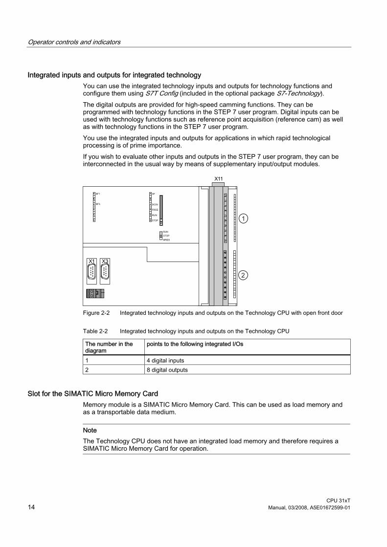
Integrated inputs and outputs for integrated technology You can use the integrated technology inputs and outputs for technology functions and configure them using S7T Config (included in the optional package S7-Technology). The digital outputs are provided for high-speed camming functions. They can be programmed with technology functions in the STEP 7 user program. Digital inputs can be used with technology functions such as reference point acquisition (reference cam) as well as with technology functions in the STEP 7 user program. You use the integrated inputs and outputs for applications in which rapid technological processing is of prime importance. If you wish to evaluate other inputs and outputs in the STEP 7 user program, they can be interconnected in the usual way by means of supplementary input/output modules.
Figure 2-2 Integrated technology inputs and outputs on the Technology CPU with open front door
Table 2-2 Integrated technology inputs and outputs on the Technology CPU
The number in the diagram
points to the following integrated I/Os
1 4 digital inputs 2 8 digital outputs
Slot for the SIMATIC Micro Memory Card Memory module is a SIMATIC Micro Memory Card. This can be used as load memory and as a transportable data medium.
Note The Technology CPU does not have an integrated load memory and therefore requires a SIMATIC Micro Memory Card for operation.
Operator controls and indicators
CPU 31xT Manual, 03/2008, A5E01672599-01 15
Mode selector switch You can use the mode selector switch to set the current mode of the CPU.
Table 2-3 Mode selector switch settings
Position Meaning Description RUN RUN mode The CPU executes the user program. STOP STOP mode The CPU does not execute a user program. MRES CPU memory
reset Mode selector switch position with pushbutton function for CPU memory reset. A CPU memory reset by means of mode selector switch requires a specific sequence of operation.
Power supply connection Each CPU is equipped with a double-pole power supply socket. The connector with screw terminals is inserted into this socket when the CPU is delivered.
Status and error displays The CPU is equipped with the following LEDs:
Table 2-4 Status and error displays of the CPU
LED designation Color Meaning SF red Hardware or software error BF1 red Bus error at interface (X1) BF3 Red Bus error at interface (X3) 5 VDC Green 5V power supply for the CPU and the S7-300 bus FRCE Yellow LED lights up: Active force job
LED flashes at 2 Hz: Node flash test function (only CPUs with firmware V2.2.0 or higher)
RUN green CPU in RUN. The LED flashes during STARTUP at a rate of 2 Hz, and in HOLD state at 0.5 Hz.
STOP yellow CPU in STOP, or HOLD, or STARTUP. The LED flashes • At 0.5 Hz on general reset request • At 2 Hz during general reset • At 2 Hz during shutdown (LED RUN lit).

Operator controls and indicators
CPU 31xT 16 Manual, 03/2008, A5E01672599-01
Shutdown What happens during shutdown? 1. The control of the Technology CPU is already in STOP mode during "shutdown". The
outputs of the centralized and distributed I/Os on the MPI / DP are deactivated. The "STOP" LED flashes at 2 Hz. The "RUN" LED lights up.
2. The integrated inputs/outputs for integrated technology and the distributed I/Os on DP(DRIVE) are still active during shutdown.
3. The integrated technology of the Technology CPU shuts down the drives on PROFIBUS DP(DRIVE) in a controlled manner.
4. The integrated technology then also switches to STOP. The integrated inputs/outputs for integrated technology and the distributed I/Os on DP(DRIVE) are deactivated. The "STOP" LED lights up.
The maximum duration of shutdown depends on your configuration in S7T Config.
CAUTION The distributed I/Os on DP(DRIVE) cannot be controlled from the user program during "shutdown". The outputs which can be controlled with technology function "MC_WritePeripherie" retain their last current setting.
Reference Further information ● about CPU operating modes can be found in the STEP 7 Online Help. ● for operating the mode selector switch for resetting, refer to the S7-300, CPU 31xC, and
CPU 31x Operating Instructions: Configuration, section Commissioning ● for evaluating the LEDs in the event of an error / diagnostics, refer to the S7-300, CPU
31xC, and CPU 31x Operating Instructions: Configuration, section Debugging functions, diagnostics and troubleshooting.
● to use the SIMATIC MMCs and the memory concept refer to the section Memory Concept.
CPU 31xT Manual, 03/2008, A5E01672599-01 17
Setting up an S7-300 with a Technology CPU 33.1 Overview
This section gives you additional information to that covered in the S7-300, CPU 31xC and CPU 31x Operating Instructions: Configuration, deviations, etc. that you will also require.
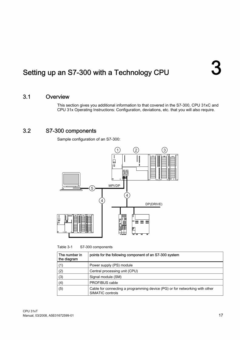
3.2 S7-300 components Sample configuration of an S7-300:
Table 3-1 S7-300 components
The number in the diagram
points for the following component of an S7-300 system
(1) Power supply (PS) module (2) Central processing unit (CPU) (3) Signal module (SM) (4) PROFIBUS cable (5) Cable for connecting a programming device (PG) or for networking with other
SIMATIC controls

Setting up an S7-300 with a Technology CPU 3.3 Configuring
CPU 31xT 18 Manual, 03/2008, A5E01672599-01
You use a programming device (PG) to program the S7-300. You connect the programming device to the CPU by means of a programming device cable. Using the PROFIBUS bus cable, you connect the CPU ● To other SIMATIC controls via the MPI / DP interface ● To the drives via the DP(DRIVE) interface.
No programming device / OP on DP(DRIVE) We recommend that you do not connect a programming device / OP to DP(DRIVE). Reason: If you connect a programming device / OP to DP(DRIVE), the properties of DP(DRIVE) change (for example isochronism), and the synchronism between drives may be lost as a result. Always therefore connect a programming device / OP to the MPI / DP interface and access the DP(DRIVE) via the "Routing" function.
3.3 Configuring
3.3.1 Single-tier configuration The Technology CPU supports only single-tier configurations.
3.3.2 Subnets
Overview: Subnets with the Technology CPU The Technology CPU provides the following subnets: ● Multi Point Interface (MPI) or PROFIBUS DP ● DP(DRIVE): Optimized for drives
Transmission rate Maximum transmission rates: ● MPI/PROFIBUS DP: 12 Mbaud
We recommend that you set 12 Mbaud for the Technology CPU ● DP(DRIVE): 12 Mbaud
Note Before you transfer projects to the Technology CPU via the MPI/DP interface, you should increase the baud rate to at least 1.5 Mbaud or else the data transmission can take a very long time (up to 15 minutes at 187.5 kbaud).

Setting up an S7-300 with a Technology CPU 3.4 Addressing
CPU 31xT Manual, 03/2008, A5E01672599-01 19
Number of nodes Maximum number of nodes per subnet:
Table 3-2 Subnet nodes
Parameters MPI PROFIBUS DP PROFIBUS DP (DRIVE) Number 127 126 33 Addresses 0 to 126 0 to 125 1 to 125 Comments Default: 32 addresses
Reserved addresses: • Address 0 for PG • Address 1 for OP
of which: 1 master (reserved) 1 PG connection (address 0 reserved) 124 slaves or other masters
of which: • 1 master (reserved) and
32 slaves or drives
3.4 Addressing
Slot-specific addressing of modules The Technology CPU is assigned to two slot numbers: 2 and 3. The input and output addresses for I/O modules begin at the same module start address.
Figure 3-1 Slots of the S7-300 with Technology CPU and associated module start addresses
Integrated inputs and outputs for integrated technology The Technology CPU has 4 integrated digital inputs and 8 integrated digital outputs for integrated technology. You use these integrated inputs and outputs for technology functions, e.g. reference point acquisition (reference cams) or high-speed output cam switching signals. The integrated inputs and outputs can also be used with technology function in the STEP 7 user program. You use the integrated inputs and outputs for applications in which rapid technological processing is of prime importance.

Setting up an S7-300 with a Technology CPU 3.5 Commissioning
CPU 31xT 20 Manual, 03/2008, A5E01672599-01
3.5 Commissioning
Requirements If you wish to utilize the full scope of CPU functions, you will require ● STEP 7 and the S7-Technology optional package ● S7-300 is installed ● S7-300 is wired ● For a networked S7-300:
– MPI/PROFIBUS addresses are set – Terminating resistors on the segments are enabled
3.6 Operating system
Technology CPU operating system To meet the requirements of the integrated technology, technology functions have been added to the standard CPU operating system to obtain the technology operating system. The technology operating system is included in the project and the configuration. In other words, if you load a project created with S7-Technology to the Technology CPU, the technology operating system is automatically transferred at the same time.
Updating the operating system You can order the latest operating system versions from your Siemens contact or download it from the Internet at (Siemens Homepage; Industrial Automation, Customer Support).

Setting up an S7-300 with a Technology CPU 3.7 Status and error displays
CPU 31xT Manual, 03/2008, A5E01672599-01 21
3.7 Status and error displays
Status and error displays of the Technology CPU
Table 3-3 Status and error displays of the Technology CPU
LED Meaning SF 5 VDC FRCE RUN STOP Off Off Off Off Off CPU power supply missing.
Remedy: Check whether the power supply module is connected to mains and switched on. Check whether the CPU is connected to the power supply and switched on.
Off On X (see the descrip-tion)
Off On The CPU is in STOP mode. Remedy: Start the CPU.
On On X Off On The CPU is in STOP mode as a result of error. Remedy: refer to the tables below, evaluation of the SF LED
X On X Off Flashes (0.5 Hz)
The CPU requests memory reset.
X On X Off Flashes (2 Hz)
The CPU executes memory reset.
X On X Flashes (2 Hz)
On The CPU is in startup mode.
X On X Flashes (0.5 Hz)
On The CPU was halted by a programmed break point. For details, refer to the Programming Manual Programming with STEP 7 .
On On X X X Hardware or software error Remedy: refer to the tables below, evaluation of the SF LED
X X On X X You enabled the Force function For details refer to the Programming Manual Programming with STEP 7 .
X X X On Flashes (2 Hz)
STOP/shutdown What happens during shutdown? The control of the Technology CPU is already in STOP mode during "shutdown". The outputs of the centralized and distributed I/Os are deactivated. The integrated inputs/outputs for integrated technology and the ET 200M on the DP(DRIVE) are still active during shutdown. The integrated technology of the Technology CPU shuts down the drives on PROFIBUS DP(DRIVE) in a controlled manner. The integrated technology of the CPU then also goes into STOP. The integrated inputs/outputs for integrated technology and the ET 200M on the DP(DRIVE) are deactivated. The maximum duration of shutdown depends on your configuration in S7TConfig.
X X X Flashes (0.5 Hz)
Flashes (2 Hz)
HOLD/shutdown
Flashes Flashes Flashes Flashes Flashes Internal errors in Technology CPU. Contact your local SIEMENS partner.

Setting up an S7-300 with a Technology CPU 3.7 Status and error displays
CPU 31xT 22 Manual, 03/2008, A5E01672599-01
Status and error displays for DP or DP(DRIVE)
Table 3-4 LEDs BF1 and BF3
LED Meaning BF1 BF3 On/ flashes X Error on the PROFIBUS DP interface of the Technology CPU.
Remedy: See table LED BF1 illuminated X On/ flashes Error on the DP(DRIVE) interface
Remedy: See table LED BF1 flashing
Description of status X: The LED can assume the On or Off state. This status, however, is irrelevant for the current CPU function. For example, the states Force On or Off do not influence the CPU STOP status
Table 3-5 LED BF1 illuminated
Possible Errors CPU reaction Possible Remedies • Bus fault (hardware fault) • DP interface error • Different transmission rates in
multiple DP master mode. • If the DP slave / master interface is
active: Short-circuit on the bus. • With passive DP slave interface:
transmission rate search, i.e. there are no other active nodes on the bus (a master, for example)
Call of OB 86 (when CPU is in RUN mode). CPU switches to STOP if OB 86 is not loaded.
• Check the bus cable for short-circuit or breaks.
• Evaluate the diagnostics. Reconfigure or correct the configuration.
Table 3-6 LED BF1 flashes
Possible errors CPU reaction Possible remedies The CPU is DP master / active slave: • Failure of a connected station • At least one of the configured
slaves cannot be accessed. • Incorrect configuration
Call of OB 86 (when CPU is in RUN mode). CPU switches to STOP if OB 86 is not loaded.
Verify that the bus cable is connected to the CPU, or that the bus is not interrupted. Wait until the CPU has completed its startup. If the LED does not stop flashing, check the DP slaves or analyze the diagnostic data of the DP slaves.
The CPU is a DP slave The CPU parameters are incorrectly set. Possible causes: • The response monitoring period has
elapsed. • PROFIBUS DP communication is
down. • Wrong PROFIBUS address. • Incorrect configuration
Call of OB 86 (if CPU is in RUN mode). CPU switches to STOP if OB 86 is not loaded.
• Check the CPU. • Verify that the bus connector is
properly seated. • Check whether the bus cable to the
DP master has been disconnected. • Check the configuration and
parameter assignment.

Setting up an S7-300 with a Technology CPU 3.7 Status and error displays
CPU 31xT Manual, 03/2008, A5E01672599-01 23
Table 3-7 LED BF3 illuminated
Possible errors CPU reaction Possible remedies • Bus fault (hardware fault) • DP interface error
Error message in the technology DB configured by you.
Check for short-circuit or interruption in the bus cable.
Table 3-8 LED BF3 flashes
Possible Errors CPU reaction Possible Remedies • Failure of a connected station • At least one of the configured
slaves cannot be accessed. • Incorrect configuration
Error message in the technology DB configured by you.
Verify that the bus cable is connected to the CPU, or that the bus is not interrupted. Wait until the CPU has completed its startup. If the LED does not stop flashing, check the DP slaves or analyze the diagnostic data of the DP slaves.

Setting up an S7-300 with a Technology CPU 3.7 Status and error displays
CPU 31xT 24 Manual, 03/2008, A5E01672599-01

CPU 31xT Manual, 03/2008, A5E01672599-01 25
Communication with S7-300 44.1 Interfaces
4.1.1 Overview The Technology CPU has two interfaces: ● MPI / DP interface (X1) ● PROFIBUS DP(DRIVE) interface (X3)
Figure 4-1 Technology CPU interfaces
Communication with S7-300 4.1 Interfaces
CPU 31xT 26 Manual, 03/2008, A5E01672599-01
4.1.2 MPI/DP interface (X1)
Availability The Technology CPU features an MPI / DP interface (X1). A CPU with MPI / DP interface is supplied with default MPI parameter settings. Depending on your requirements, you may need to reconfigure the interface as a DP interface in STEP 7.
Operating modes Possible interface operating modes: ● MPI ● DP master ● DP slave
Time Synchronization using MPI The CPU's MPI interface supports time synchronization. The CPU can be programmed for operation as time master (with default synchronization intervals) or time slave. Default setting: No time synchronization The synchronization mode is set in the "Clock" tab of the CPU or interface properties dialog box in HW Config. When operated as time slave, the CPU receives a synchronization message frame from one time master and sets its internal time accordingly. When operated as time master, the CPU broadcasts time synchronization message frames at programmed synchronization intervals at the MPI interface to other node stations of the MPI subnet. In order for the CPU to synchronize the connected times slaves, you must set the CPU time at least once. You can set the time of day by means of: ● Programming device functions ● SFC call or ● A different time master Please note that in the supply state or after a firmware update the CPU is not yet set and therefore no synchronization of the connected time slaves can take place. Time synchronization at the MPI interface is also available at: ● At the DP Interface ● In the AS of the central configuration
Note The CPU may only be operated as time slave at one of these interfaces.

Communication with S7-300 4.1 Interfaces
CPU 31xT Manual, 03/2008, A5E01672599-01 27
Example A CPU operating as time slave on the MPI interface can only operate as time master within the AS.
MPI properties The MPI (Multi-Point Interface) represents the CPU interface for PG/OP connections, or for communication on an MPI subnet. The default transmission rate of all CPUs is 187.5 kbps. You can also set 19.2 kbps for communication with an S7-200. You can set baud rates of up to 12 Mbaud. The CPU automatically broadcasts its bus configuration via the MPI interface (the transmission rate, for example). A PG, for example, can thus receive the correct parameters and automatically connect to a MPI subnet.
Note You may only connect PGs to an MPI subnet which is in RUN. Other stations (for example, OP, TD, ...) should not be connected to the MPI subnet while the system is in RUN. Otherwise, transferred data might be corrupted as a result interference, or global data packages may be lost.
Note Before you transfer data to the CPU via the MPI interface, you should increase the baud rate to 1.5 Mbaud or else the data transmission can take a very long time (up to 15 minutes at 187.5 kbaud)!
Devices capable of MPI communication ● PG/PC ● OP/TP ● S7-300 / S7-400 with MPI interface ● S7-200 (with 19.2 kbaud only)
Properties of PROFIBUS DP The PROFIBUS DP interface is mainly used to connect distributed I/O. PROFIBUS DP allows you to create extensive subnets, for example. The PROFIBUS DP interface can be set for operation in master or slave mode, and supports transmission rates up to 12 Mbaud. The CPU broadcasts its bus parameters (transmission rate, for example) via the PROFIBUS DP interface when master mode is set. A PG, for example, can thus receive the correct parameters and automatically connect to a PROFIBUS subnet. In your configuration you can specify to disable bus parameter broadcasting.

Communication with S7-300 4.1 Interfaces
CPU 31xT 28 Manual, 03/2008, A5E01672599-01
Devices capable of PROFIBUS DP communication ● PG/PC ● OP/TD ● DP slaves ● DP master ● Actuators/sensors ● S7-300/S7-400 with PROFIBUS DP interface
Time synchronization via PROFIBUS DP Time synchronization is possible via the CPU's PROFIBUS interface. The CPU can be programmed for operation as time master (with default synchronization intervals) or time slave. Default setting: No time synchronization The synchronization mode is set in the "Clock" tab of the CPU or interface properties dialog box in HW Config. When operated as time slave, the CPU receives a synchronization message frame from one time master and sets its internal time accordingly. When operated as time master, the CPU on the PROFIBUS DP interface broadcasts time synchronization message frames at programmed synchronization intervals to other node stations in the connected PROFIBUS DP subnet. In order for the CPU to synchronize the connected times slaves, you must set the CPU time at least once. You can set the time of day by means of: ● Programming device functions ● SFC call or ● A different time master Please note that in the supply state or after a firmware update the CPU is not yet set and therefore no synchronization of the connected time slaves can take place. Alongside the time synchronization on the PROFIBUS DP interface, time synchronization is also available at: ● the MPI Interface ● In the AS of the central configuration
Note The CPU may only be operated as time slave at one of these interfaces
Example If the CPU is operating as time slave on the DP interface, it can only operate as time master within the automation system.
Communication with S7-300 4.1 Interfaces
CPU 31xT Manual, 03/2008, A5E01672599-01 29
4.1.3 PROFIBUS DP (DRIVE) interface (X3)
Properties The PROFIBUS DP (DRIVE) interface is used to connect to drive systems. You can connect drive systems in accordance with the PROFIdrive. The PROFIBUS DP(DRIVE) interface is configured as a master and supports transmission rates up to 12 Mbaud. The PROFIBUS DP (DRIVE) interface support isochronous mode. The CPU sends its bus parameter settings (e.g. baud rate) via the PROFIBUS DP (DRIVE) interface. In your configuration you can specify to disable bus parameter broadcasting. Using the "Routing" function, you can access the drive parameters of the slaves in the DP(DRIVE) line for the purposes of commissioning and diagnostics. However, diagnostics cannot be performed via PROFIBUS DP (DRIVE) from the STEP 7 user program.
Note If you deselect "Startup with different target / actual configurations" in the Technology CPU properties in STEP 7, then the Technology CPU will boot even if the stations configured on DP-DRIVE are missing.
Connectable devices You can connect drives to PROFIBUS DP (DRIVE), e.g.: ● MICROMASTER 420/430/440 and COMBIMASTER 411 ● SIMODRIVE 611 universal ● SIMODRIVE POSMO CD/SI/CA ● MASTERDRIVES MC/VC ● ET 200M with IM 153-2 (isochronous!) and SM 322 for additional cam output ● ET 200S with IM 151-1 high feature ● SINAMICS S120/G120 (optional with TM15 or TM17 high feature for high-speed cams) ● PROFIBUS module IM 174 (interface for analog drives and stepper motors) ● ADI4 (analog drive interface) ● Isochronous PROFIBUS encoder "SIMODRIVE sensor isochronous" The components configured in HW Config are displayed in the "Hardware Catalog" window in HW Config. To show the screen, select profile "SIMATIC Technology CPU" in HW Config. To ensure that the profile's selection list is complete, you must have installed the most recent version of S7-Technology.
Communication with S7-300 4.2 Communication services
CPU 31xT 30 Manual, 03/2008, A5E01672599-01
Non-connectable devices We would not recommend operating active PROFIBUS stations (PGs, PCs, OPs, TDs, etc.) on PROFIBUS DP(DRIVE). The DP cycle will be burdened by additional access times if you do operate these PROFIBUS stations on DP(DRIVE). In this case, isochronous processing of drive information cannot be guaranteed. Always therefore connect a PG/OP to the MPI / DP interface and access the DP(DRIVE) via the "Routing" function.
4.1.4 Information about interface X3 DP(DRIVE)
Interface X3 assigned to DP(DRIVE) Note that the 2nd interface on the Technology CPU is assigned to PROFIBUS DP(DRIVE), i.e. it cannot be used as the second interface for PROFIBUS DP.
No diagnostics on DP(DRIVE) Remember that you cannot evaluate diagnostic data from DP(DRIVE) in your STEP 7 user program if you are using the Technology CPU. However, with your PC/PG connected to PROFIBUS DP, you can use the "routing" function to access drive parameters in the DP(DRIVE) line (in conjunction with appropriate drive tools) for commissioning and diagnostic purposes.
4.2 Communication services
4.2.1 Overview
Selecting the communication service You need to decide on a communication service, based on functionality requirements. Your choice of communication service will influence ● the functionality available, ● whether an S7 connection is required or not, and ● the connection timing. The user interface can vary considerably (SFC, SFB, ...), and is also determined by the hardware used (SIMATIC CPU, PC, ...).

Communication with S7-300 4.2 Communication services
CPU 31xT Manual, 03/2008, A5E01672599-01 31
Overview of communication services The table below provides an overview of communication services offered by the CPU.
Table 4-1 CPU communication services
Communication service Functionality Time at which the S7 connection is established ...
via MPI
via DP
to DP(DRIVE)
PG communication Commissioning, test, diagnostics
from the PG, starting when the service is being used
X X -
OP communication Operator control and process monitoring
from the OP at Power ON X X -
S7 basic communication Data exchange is programmed at the blocks (SFC parameters)
X - -
S7 communication Data exchange as server only, communication link is set up by the communication partner
X X -
Global data communication
Cyclic data exchange (for example, flag bits)
does not require an S7 connection
X - -
Routing PG functions* for example testing, diagnostics on other networks also
from the PG, starting when the service is being used
X X X
* Functions can be routed only to DP(DRIVE), but not on DP(DRIVE)!
4.2.2 PG communication
Properties PG communication is used to exchange data between engineering stations (for example programming device, PC) and SIMATIC modules that are capable of communication. This service is available for MPI, PROFIBUS and Industrial Ethernet subnets. Transition between subnets is also supported. PG communication provides the functions needed to download / upload programs and configuration data, to run tests and to evaluate diagnostic information. These functions are integrated in the operating system of SIMATIC S7 modules. A CPU can maintain several simultaneous online connections to one or multiple PGs.

Communication with S7-300 4.2 Communication services
CPU 31xT 32 Manual, 03/2008, A5E01672599-01
4.2.3 OP communication
Properties OP communication is used to exchange data between operator stations (for example OP, TP) and SIMATIC modules that are capable of communication. This service is available for MPI, PROFIBUS and Industrial Ethernet subnets. OP communication provides functions you require for monitoring and modifying. These functions are integrated in the operating system of SIMATIC S7 modules. A CPU can maintain several simultaneous connections to one or several OPs.
4.2.4 S7 basic communication
Properties S7-based communication is used to exchange data between S7 CPUs and the communication-capable SIMATIC modules within an S7 station (acknowledged data communication). Data are exchanged across non-configured S7 connections. The service is available via MPI subnet, or within the station to function modules (FM). S7-based communication provides the functions you require for data exchange. These functions are integrated into the CPU operating system. You can utilize this service by means of "System function" (SFC) user interface.
Reference Further information ● on SFCs can be found in the Instruction list, for more details refer to the STEP 7 online
help or to the System and Standard Functions reference manual. ● on communication can be found in the Communication with SIMATIC manual.

Communication with S7-300 4.2 Communication services
CPU 31xT Manual, 03/2008, A5E01672599-01 33
4.2.5 S7 communication
Properties A CPU can always operate in server or client mode in S7 communication: We distinguish between ● Communication with unilateral configuration (for PUT/GET only) ● Communication with bilateral configuration (for USEND, URCV, BSEND, BRCV, PUT,
GET) However, the functionality depends on the CPU. A CP is therefore required in certain situations.
Table 4-2 Client and server in S7 communication, using connections with unilateral / bilateral configuration
CPU Use in server mode for connections with unilateral configuration
Use in server mode for connections with bilateral configuration
Use as client
31x T-2 DP Generally possible on MPI / DP interface without configuration of user interface
Only possible with CP and loadable FBs.
Only possible with CP and loadable FBs.
The user interface is implemented using standard function modules (FBs) from the standard library of STEP 7, under communication blocks. Further information on communication can be found in the Communication with SIMATIC Manual.
4.2.6 Global data communication (MPI only)
Properties Global data communication is used for cyclic exchange of global data (for example, I, Q, M) between SIMATIC S7 CPUs (data exchange without acknowledgement). One CPU broadcasts its data to all other CPUs on the MPI subnet. This function is integrated in the CPU operating system.
Reduction factor The reduction ratio specifies the cyclic intervals for GD communication. You can set the reduction ratio when you configure global data communication in STEP 7 . For example, if you set a reduction ratio of 7, global data are transferred only with every 7th cycle. This reduces CPU load.

Communication with S7-300 4.2 Communication services
CPU 31xT 34 Manual, 03/2008, A5E01672599-01
Send and receive conditions Conditions which should be satisfied for GD communication: ● The transmitter of a GD packet must meet the following requirement:
Reduction ratiotransmitter x cycle timetransmitter ≥ 60 ms ● The receiver of a GD packet must meet the following requirement:
Reduction factorreceiver x cycle timereceiver < reduction factortransmitter x cycle timetransmitter
A GD packet may be lost if there requirements are not met. The reasons being: ● the performance of the "smallest" CPU in the GD circuit ● asynchronous transmitting / receiving of global data at the stations When setting in STEP 7 : “Transmit after each CPU cycle“, and the CPU has a short scan cycle time (< 60 ms), the operating system might overwrite a GD packet of the CPU before it is transmitted. The loss of global data is indicated in the status box of a GD circuit, if you set this function in your STEP 7 configuration.
GD resources of the CPUs
Table 4-3 GD resources of the CPUs
Parameters CPU 31xT-2 DP Number of GD circuits per CPU Max. 8 GD packets transmitted per GD circuit Max. 1 GD packets transmitted by all GD circuits Max. 8 GD packets received per GD circuit Max. 1 GD packets received by all GD circuits Max. 8 Data length per GD packet Max. 22 bytes Consistency Max. 22 bytes Min. reduction ratio (default) 1 (8)
4.2.7 Routing
Definition The routing function enables you to attach a PG/PC at any point in the network and establish a connection to all drives accessible via gateways.
Accessing drives in a DP(DRIVE) subnet from a PG/PC Test, diagnostic and parameterizing functions can be routed via the MPI / DP interface (X1) to the DP(DRIVE) subnet with the Technology CPU. The Technology CPU provides a certain number of connection resources for routing. These connections are available in addition to the S7 connection resources. The number of routing connections can be found in the Technical Specifications.
Communication with S7-300 4.2 Communication services
CPU 31xT Manual, 03/2008, A5E01672599-01 35
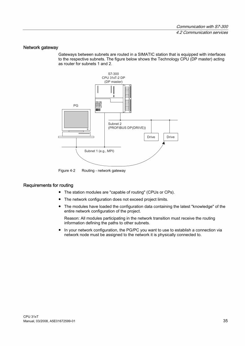
Network gateway Gateways between subnets are routed in a SIMATIC station that is equipped with interfaces to the respective subnets. The figure below shows the Technology CPU (DP master) acting as router for subnets 1 and 2.
Figure 4-2 Routing - network gateway
Requirements for routing ● The station modules are "capable of routing" (CPUs or CPs). ● The network configuration does not exceed project limits. ● The modules have loaded the configuration data containing the latest "knowledge" of the
entire network configuration of the project. Reason: All modules participating in the network transition must receive the routing information defining the paths to other subnets.
● In your network configuration, the PG/PC you want to use to establish a connection via network node must be assigned to the network it is physically connected to.

Communication with S7-300 4.2 Communication services
CPU 31xT 36 Manual, 03/2008, A5E01672599-01
Example of an application: TeleService The figure below shows the example of an application for remote maintenance of an S7 station using a PG. The connection to other subnets is here established via modem connection. The lower section of the figure shows how to configure this in STEP 7.
Figure 4-3 Routing - example of TeleService application

Communication with S7-300 4.2 Communication services
CPU 31xT Manual, 03/2008, A5E01672599-01 37
Reference Further information ● about setting the PG/PC interface for routing can be found in Getting Started
CPU 317T-2 DP: Controlling a SINAMICS S120 in chapter Configuring the PG/PC Interface.
● about routing can be found in the Programming with STEP 7 manual, or directly to the STEP 7 online help.
● about configuring with STEP 7 can be found in the Configuring Hardware and Connections in STEP 7 manual
● fundamentals can be found in the Communication with SIMATIC Manual. ● about TeleService adapters can be found at Internet website
http://www.ad.siemens.de/support with article ID 14053309 (documentation). ● on SFCs can be found in the Instruction list, for more details refer to the STEP 7 online
help or to the System and Standard Functions reference manual. ● on communication can be found in the Communication with SIMATIC manual.
4.2.8 Data consistency
Properties A data area is consistent if it can be read or written to from the operating system as a consistent block. Data exchanged collectively between the stations should belong together and originate from a single processing cycle, that is, be consistent. If the user program contains a programmed communication function, for example, access to shared data with XSEND/ XRCV, access to that data area can be coordinated by means of the "BUSY" parameter itself.
With PUT/GET functions For S7 communication functions, such as PUT/GET or write / read via OP communication, which do not require a block in the user program on the CPU (operating in server mode), allowances must be made in the program for the extent of the data consistency. The PUT/GET functions for S7 communication, or for reading/writing variables via OP communication, are executed at the CPU's scan cycle checkpoint. In order to ensure a defined process interrupt reaction time, communication variables are copied consistently in blocks of maximum 160 bytes to/from the user memory at the scan cycle check point of the operating system. Data consistency is not guaranteed for larger data areas.
Note Where defined data consistency is required, the length of communication variables in the CPU's user program may not exceed 160 bytes.

Communication with S7-300 4.3 S7 connections
CPU 31xT 38 Manual, 03/2008, A5E01672599-01
4.3 S7 connections
4.3.1 S7 connection as communication path An S7 connection is established when S7 modules communicate with one another. This S7 connection is the communication path.
Note Global data communication and the communication via PROFIBUS DP do not require S7 connections.
Every communication link requires S7 connection resources on the CPU for the entire duration of this connection. Hence, every S7 CPU provides a specific number of S7 connection resources. These are used by various communication services (PG/OP communication, S7 communication or S7 basic communication).
Connection points An S7 connection between modules with communication capability is established between connection points. The S7 connection always has two connection points: The active and passive connection points: ● The active connection point is assigned to the module that establishes the S7 connection. ● The passive connection point is assigned to the module that accepts the S7 connection. Any module that is capable of communication can thus act as an S7 connection point. At the connection point, the established communication link always uses one S7 connection of the module concerned.
Transition point If you use the routing functionality, the S7 connection between two modules capable of communication is established across a number of subnets. These subnets are interconnected via a network transition. The module that implements this network transition is known as a router. The router is thus the point through which an S7 connection passes. Any CPU with a DP interface can be the router for an S7 connection. You can establish a certain maximum number of routing connections. This does not limit the data volume of the S7 connections. The number of routing connections can be found in the Technical Specifications.

Communication with S7-300 4.3 S7 connections
CPU 31xT Manual, 03/2008, A5E01672599-01 39
4.3.2 Assignment of S7 connections There are several ways to allocate S7 connections on a communication-capable module: ● Reservation during configuration ● Assigning connections in the program ● Allocating connections during commissioning, testing and diagnostics routines ● Allocating connection resources to OCMS services
Reservation during configuration One connection resource each is automatically reserved on the CPU for PG and OP communication. Whenever you need more connection resources (for example, when connecting several OPs), this increases in the CPU properties dialog box in STEP 7. Connections must also be configured (using NetPro) for the use of S7 communication. For this purpose, connection resources have to be available that are not allocated to PG/OP or other connections. The required S7 connections are then permanently allocated for S7 communication when the configuration is uploaded to the CPU.
Assigning connections in the program In the case of S7 basic communication, the connection is set up by the user program. The CPU operating system initiates connection setup and the relevant S7 connections are assigned.
Using connections for commissioning, testing and diagnostics An active online function on the engineering station (PG/PC with STEP 7) occupies S7 connections for PG communication: ● An S7 connection resource for PG communication which was reserved in your CPU
hardware configuration is assigned to the engineering station, that is, it only needs to be allocated.
● If all reserved S7 connection resources for PG communication are allocated, the operating system assigns a free S7 connection resource which has not yet been reserved. If no more connection resources are available, the engineering station cannot go online to the CPU.
Allocating connection resources to OCMS services An online function of the OCM station (OP/TD/... with WinCC) allocates S7 connections for the OP communication: ● An S7 connection resource for OP communication you have reserved in your CPU
hardware configuration is therefore assigned to the OCM station engineering station, that is, it only needs to be allocated.
● If all reserved S7 connection resources for OP communication are allocated, the operating system automatically assigns a free S7 connection resource which has not yet been reserved. If no more connection resources are available, the OCM station cannot go online to the CPU.

Communication with S7-300 4.3 S7 connections
CPU 31xT 40 Manual, 03/2008, A5E01672599-01
Time sequence for allocation of S7 connection resources When you program your project in STEP 7, the system generates parameter assignment blocks which are read by the modules in the startup phase. This allows the module's operating system to reserve or allocate the relevant S7 connection resources. That is, for instance, OPs cannot access a reserved S7 connection resource for PG communication. The module's (CPU) S7 connection resources which were not reserved can be used freely. These S7 connection resources are allocated in the order they are requested.
Example If there is only one free S7 connection left on the CPU, you can still connect a PG to the bus. The PG can then communicate with the CPU. The S7 connection is only used, however, when the PG is communicating with the CPU. If you connect an OP to the bus while the PG is not communicating, the OP can establish a connection to the CPU. Since an OP maintains its communication link at all times, in contrast to the PG, you cannot subsequently establish another connection via the PG.
4.3.3 Distribution and availability of S7 connection resources
Distribution of connection resources The distribution of the S7 connections of the CPUs can be found in the following table:
Table 4-4 Distribution of connections
Communication service Distribution PG communication OP communication S7 basic communication
In order to avoid allocation of the S7 connections being dependent only on the chronological sequence in which various communication services are requested, connections can be reserved for these services. For PG and OP communication respectively, at least one connection resource is reserved by default. In the table below, and in the technical data of the CPUs, you can find the configurable connection resources and the default settings for each CPU. You "redistribute“ connection resources by setting the relevant CPU parameters in STEP 7.
S7 communication Other communication connections (e.g. via CP 343-1, with a data lengths of > 240 bytes)
Available connection resources that are not specially reserved for a service (programming device / OP communication, S7 basic communication) are used for this.
Routing PG functions The CPU provides a certain number of connection resources for routing. These connections are available in addition to the connection resources. The number of routing connections can be found in the Technical Specifications.
Global data communication These communication services do not use S7 connections. PROFIBUS DP This communication service requires no S7 connection
resources.

Communication with S7-300 4.3 S7 connections
CPU 31xT Manual, 03/2008, A5E01672599-01 41
Availability of connection resources The following table shows the available connection resources.
Table 4-5 Availability of connection resources
Reserved for CPU Total number connection resources PG
communication OP communication
S7 basic communication
Free S7 connections
315T-2 DP 16 1 to 15, default 1 1 to 15, default 1 0 to 12, default 0 Displays all non-reserved S7 connections as free connections.
317T-2 DP 32 1 to 31, default 1 1 to 31, default 1 0 to 30, default 0
Note When using a CPU 315T-2 DP, you can configure up to 14 connection resources for S7 communication in NetPro. These connections are then reserved. When using a CPU 317T-2 DP, you can configure up to 16 connection resources for S7 communication in NetPro.

Communication with S7-300 4.4 DPV1
CPU 31xT 42 Manual, 03/2008, A5E01672599-01
4.4 DPV1
4.4.1 General information about DPV1 New automation and process engineering tasks require the range of functions performed by the existing DP protocol to be extended. In addition to cyclical communication functions, acyclical access to non-S7 field devices is another important requirement of our customers, and was implemented in the standard EN 50170. In the past, acyclical access was only possible with S7 slaves. The distributed I/O standard EN 50170 has been further developed. All the changes concerning new DPV1 functions are included in IEC 61158/ EN 50170, volume 2, PROFIBUS.
Definition DPV1 The term DPV1 is defined as a functional extension of the acyclical services (to include new interrupts, for example) provided by the DP protocol.
Availability All CPUs with DP interface(s) and serving as DP masters feature the enhanced DPV1 functionality.
Note If you want to use the CPU as an intelligent slave, remember that it does not have DPV1 functionality.
Requirement for using the DPV1 functionality with DP slaves For DPV1 slaves from other vendors, you will need a GSD file conforming to EN 50170, revision 3 or later.
Extended functions of DPV1 ● Use of any DPV1 slaves from external vendors (in addition to the existing DPV0 and S7
slaves, of course). ● Selective handling of DPV1-specific interrupt events by new interrupt blocks. ● Reading/writing SFBs that conform to standards to the data record (although this can only
be used for centralized modules). ● User-friendly SFB for reading diagnostics.
Communication with S7-300 4.4 DPV1
CPU 31xT Manual, 03/2008, A5E01672599-01 43
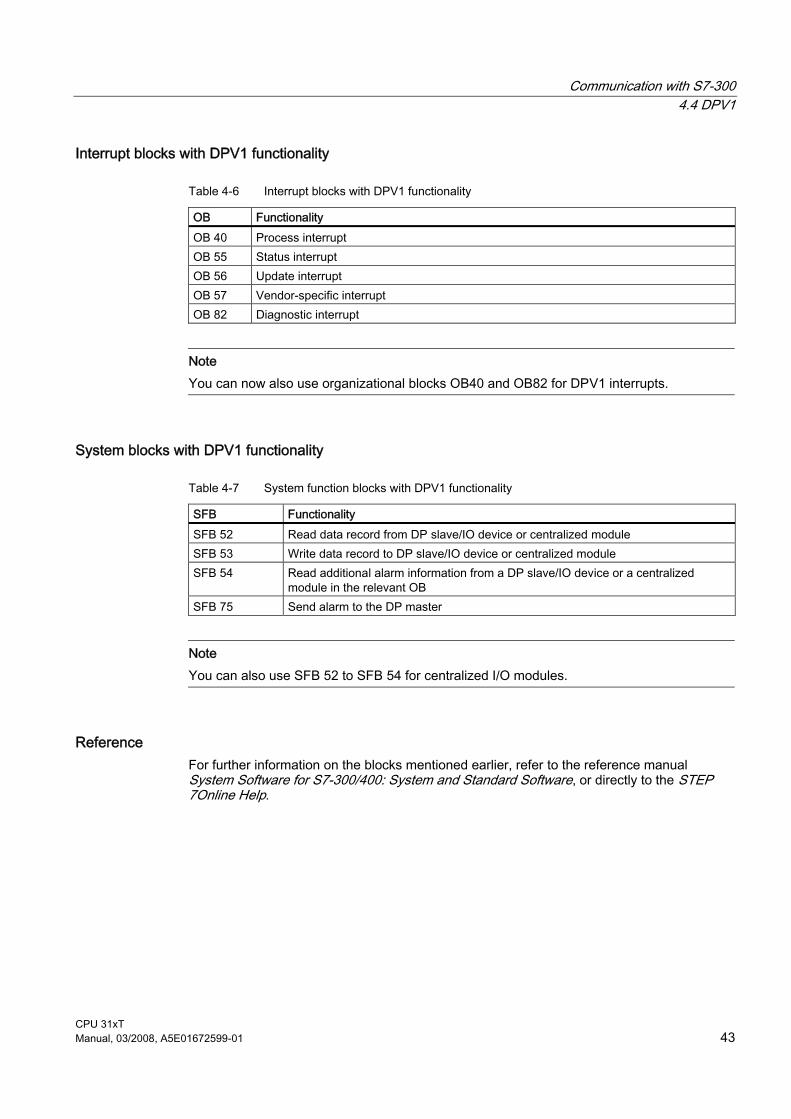
Interrupt blocks with DPV1 functionality
Table 4-6 Interrupt blocks with DPV1 functionality
OB Functionality OB 40 Process interrupt OB 55 Status interrupt OB 56 Update interrupt OB 57 Vendor-specific interrupt OB 82 Diagnostic interrupt
Note You can now also use organizational blocks OB40 and OB82 for DPV1 interrupts.
System blocks with DPV1 functionality
Table 4-7 System function blocks with DPV1 functionality
SFB Functionality SFB 52 Read data record from DP slave/IO device or centralized module SFB 53 Write data record to DP slave/IO device or centralized module SFB 54 Read additional alarm information from a DP slave/IO device or a centralized
module in the relevant OB SFB 75 Send alarm to the DP master
Note You can also use SFB 52 to SFB 54 for centralized I/O modules.
Reference For further information on the blocks mentioned earlier, refer to the reference manual System Software for S7-300/400: System and Standard Software, or directly to the STEP 7Online Help.

Communication with S7-300 4.4 DPV1
CPU 31xT 44 Manual, 03/2008, A5E01672599-01

CPU 31xT Manual, 03/2008, A5E01672599-01 45
Memory concept 55.1 Memory areas and retentive address areas
5.1.1 Technology CPU memory areas
Introduction The memory of the Technology CPU is divided into three areas:
Figure 5-1 Technology CPU memory areas
Load memory The load memory is located on the SIMATIC micro memory card (MMC). It is used to store code blocks, data blocks and system data (configuration, connections, module parameters, technology system data etc.). For the Technology CPU, the size of the load memory corresponds to the size of the SIMATIC MMC minus approx. 3 MB. The 3 MB are required for the integrated technology and are therefore not available to the user. Blocks that are identified as not relevant for the execution are stored exclusively in the load memory. You can also store all the configuration data for your project on the SIMATIC Micro Memory Card.

Memory concept 5.1 Memory areas and retentive address areas
CPU 31xT 46 Manual, 03/2008, A5E01672599-01
CAUTION Downloading user programs and hence operating the CPU is only possible if a SIMATIC MMC is inserted. If you pull out the SIMATIC MMC while the CPU is in RUN mode, the CPU then goes into STOP mode and the drives are shut down in accordance with your programming in the STEP 7 user program. This is why you should only remove the SIMATIC Micro Memory Card when the CPU is in STOP.
Work memory The work memory is integrated in the CPU and cannot be extended. It is used to run the code and process user program data. Programs only run in the work memory and system memory. The work memory is always retentive.
System memory The system memory is integrated in the CPU and cannot be expanded. It contains ● the operand areas for flags, times and counters ● the process image of the inputs and outputs ● the local data

Memory concept 5.1 Memory areas and retentive address areas
CPU 31xT Manual, 03/2008, A5E01672599-01 47
5.1.2 Retentive address areas of the load memory, system memory and technology system data
Introduction Your CPU is equipped with a maintenance-free retentive memory, i.e., its operation does not require a buffer battery. The retentivity is realized via the SIMATIC Micro Memory Card. Data is also retained in the retentive memory throughout POWER OFF and restart (warm restart).
Retentive data in load memory Your program in the load memory is always retentive: it is already stored on the SIMATIC Micro Memory Card, where it is protected against power failure or memory restart.
Retentive data in system memory In your configuration (Properties of CPU, Retentive address areas tab), specify which parts of the tags, timers and counters should be retentive and which of them are to be initialized with "0" on restart (warm restart). The diagnostics buffer, MPI address (and transmission rate) and operating hour counter data are generally written to the retentive memory area on the CPU. Retentivity of the MPI address and baud rate ensures that your CPU can continue to communicate, even after a power loss, memory reset or loss of communication parameters (e.g. due to removal of the SIMATIC Micro Memory Card or deletion of communication parameters).
Retentive data in the work memory Therefore, the contents of retentive DBs are always retentive at restart and POWER ON/OFF. Retentive data blocks can be uploaded to the work memory in accordance with the maximum limit allowed by the work memory. In the case of the Technology CPU, non-retentive DBs are also supported. Non-retentive DBs are initialized from the load memory with their initial values whenever a restart is performed or when the power is switched off and then on again. Non-retentive data blocks and code blocks can be loaded in accordance with the maximum work memory limit.
Technology system data The technology system data are always stored as retentive data in the load memory of the CPU.

Memory concept 5.1 Memory areas and retentive address areas
CPU 31xT 48 Manual, 03/2008, A5E01672599-01
5.1.3 Retentivity of memory objects
Retentive behavior of the memory objects The table below shows the retentive behavior of memory objects during specific operating state transitions.
Table 5-1 Retentive behavior of the memory objects
Memory object Operating state transition POWER ON /
POWER OFF STOP → RUN
CPU memory reset
User program/data (load memory) X X X Can be set in the Properties of the DBs.
- • Retentive behavior of the DBs (without technology DB)
• Retentive behavior of the technology DBs
- - -
Flags, timers and counters configured as retentive data
X X -
Diagnostics buffer, operating hour counters X X X MPI/DP address, transmission rate (or also DP address, transmission rate of the Technology CPU MPI/DPinterface, if this is parameterized as DP node).
X X X
Technological parameters • Changed with FB "MC_WriteParameter" • Changed with S7TConfig
- X
X X
- X
x = retentive; - = non-retentive

Memory concept 5.1 Memory areas and retentive address areas
CPU 31xT Manual, 03/2008, A5E01672599-01 49
Retentive behavior of a DB These CPUs support the generation of data blocks with "NON-Retain" (not retentive) property. Data blocks assigned the "NON-Retain" property are initialized with their start values when power is cycled off and on and when the CPU goes from STOP to RUN. You have two options of assigning the "NON-Retain" property to a DB: ● STEP 7, V5.2 + SP1 or higher: Activate the NON-Retain function in the DB properties ● SFC 82 " Crea_DBL" (generation of a DB in load memory): Set bit 2 = "1" at the ATTRIB
parameter
Table 5-2 Retentive behavior of the DBs for the Technology CPU
At POWER ON/OFF or restart of the CPU, the DB should ... ... receive the initial values (non-retentive DB)
... retain the last actual values (retentive DB)
Reason: At POWER ON/OFF and restart (STOP-RUN) of the CPU, the actual values of the DB are non-retentive. The DB receives the initial values from the load memory.
Reason: At POWER OFF/ON and restart (STOP-RUN) of the CPU, the actual values of the DB are retained.
Condition in STEP 7: • The "Non-retain" check box must be
activated in the block properties of the DB, or
• a non-retentive DB was generated with SFC 82 "CREA_DBL" and the associated block attribute (ATTRIB -> NON_RETAIN bit).
Condition in STEP 7: • The "Non-retain" check box must be deactivated in
the block properties of the DB, or • a retentive DB was generated with SFC 82.
Retentive behavior of a technology data block Technology data blocks are non-retentive.

Memory concept 5.1 Memory areas and retentive address areas
CPU 31xT 50 Manual, 03/2008, A5E01672599-01
5.1.4 Address areas of system memory
Overview The system memory of the S7 CPUs is organized in address areas (refer to the table below). In a corresponding operation of your user program, you address data directly in the relevant address area.
Table 5-3 Address areas of system memory
Operand areas Description Process input image At every start of an OB1 cycle, the CPU reads the values at the
input of the input modules and saves them the process input image.
Process output image During its cycle, the program calculates the values for the outputs and writes these to the process output image. At the end of the OB1 cycle, the CPU writes the calculated output values to the output modules.
Flag This area provides memory for saving the intermediate results of a program calculation.
Times Timers are available in this area. Counters Counters are available in this area. Local data Temporary data in a code block (OB, FB, FC) is saved to this
memory area while the block is being edited. Data blocks See recipes, measurement value logs and technology data
blocks.
Reference The address areas of your CPU are listed in the Instruction list for CPUs 31xC and 31x.

Memory concept 5.1 Memory areas and retentive address areas
CPU 31xT Manual, 03/2008, A5E01672599-01 51
Process image of inputs/outputs When the user program addresses the input (I) and output (O) address areas, it does not query the signal states of digital signal modules. Instead, it rather accesses a memory area in CPU system memory. This particular memory area is the process image. The process image is organized in two sections: The process input image, and the process output image. Advantages of the process image Process image access, compared to direct I/O access, offers the advantage that a consistent image of process signals is made available to the CPU during cyclic program execution. When the signal status at an input module changes during program execution, the signal status in the process image is maintained until the image is updated in the next cycle. Moreover, since the process image is stored in CPU system memory, access is significantly faster than direct access to the signal modules. Process image update The operating system updates the process image periodically. The figure below shows the sequence of this operation within a cycle.
Figure 5-2 Sequence of operation within a cycle

Memory concept 5.1 Memory areas and retentive address areas
CPU 31xT 52 Manual, 03/2008, A5E01672599-01
Configurable process image of the CPUs STEP 7 lets you define a user-specific size of the process image of the inputs/outputs between 0 to 2048 for the following CPUs:
CPU Firmware CPU 315T-2 DP V2.6 or higher CPU 317T-2 DP V2.6 or higher
Note the information below:
Note Currently, the dynamic setting of the process image only affects its update at the scan cycle control point. That is, the process input image is only updated up to the set PII size with the corresponding values of the peripheral input modules existing within this address area, or the values of the process output image up to the set POI size are written to the peripheral output modules existing within this address area. This set size of the process image is ignored with respect to STEP 7 commands used to access the process image (for example U I100.0, L EW200, = Q20.0, T AD150, or corresponding indirect addressing commands also). However, up to the maximum size of the process image (that is, up to I/O byte 2047), these commands do not return any synchronous access errors, but rather access the permanently available internal memory area of the process image. The same applies to the use of actual parameters of block calls from the I/O area (area of the process image). Particularly if these process image limits were changed, you should check to which extent your user program accesses the process image in the area between the set and the maximum process image size. If access to this area continues the user program may not detect changes at the inputs of the I/O module, or actually fails to write output data to the output module and does not generate an error message. You should also note that certain CPs may only be addressed outside of the process image.
Memory concept 5.1 Memory areas and retentive address areas
CPU 31xT Manual, 03/2008, A5E01672599-01 53
Local data Local data store: ● the temporary variables of code blocks ● the start information of the OBs ● transfer parameters ● intermediate results Temporary Variables When you create blocks, you can declare temporary variables (TEMP) which are only available during block execution and then overwritten again. These local data have fixed length in each OB. Local data must be initialized prior to the first read access. Each OB also requires 20 bytes of local data for its start information. Local data access is faster compared to access to data in DBs. The CPU is equipped with memory for storing temporary variables (local data) of currently executed blocks. The size of this memory area depends on the CPU. It is distributed in partitions of equal size to the priority classes. Each priority class has its own local data area.
CAUTION All temporary variables (TEMP) of an OB and its nested blocks are stored in local data. When using complex nesting levels for block processing, you may cause an overflow in the local data area. The CPUs will change to STOP mode if you exceed the permissible length of local data for a priority class. Make allowances for local data space required for synchronous error OBs. This is assigned to the respective triggering priority class.

Memory concept 5.1 Memory areas and retentive address areas
CPU 31xT 54 Manual, 03/2008, A5E01672599-01
5.1.5 Properties of the SIMATIC Micro Memory Card
The SIMATIC Micro Memory Card as memory module for the CPU The memory module used on your CPU is a SIMATIC Micro Memory Card. It can be used as load memory or as a portable storage medium.
Note The CPU requires the SIMATIC Micro Memory Card for operation.
What is stored on the SIMATIC Micro Memory Card The following data can be stored on the SIMATIC Micro Memory Card: ● User program, i.e., all blocks (OBs, FCs, FCs, DBs) and system data ● Archives and recipes ● Configuration data (STEP 7 projects) ● Data for operating system update and backup
Note You can either store user and configuration data or the operating system on the SIMATIC Micro Memory Card.
Properties of a SIMATIC Micro Memory Card The SIMATIC Micro Memory Card ensures maintenance-free and retentive operation of these CPUs.
CAUTION Data on a SIMATIC Micro Memory Card can be corrupted if you remove the card while it is being accessed by a write operation. In this case, you may have to delete the SIMATIC Micro Memory Card on your programming device, or format the card in the CPU. Never remove a SIMATIC Micro Memory Card in RUN mode. Always remove it when power is off, or when the CPU is in STOP state, and when the programming device is not writing to the card. If the CPU is in STOP mode and you cannot determine whether or not a programming device function is active (e.g. load/delete block), disconnect the communication lines.
SIMATIC Micro Memory Card copy protection Your SIMATIC Micro Memory Card has an internal serial number that implements an MMC copy protection. You can read this serial number from the SSL partial list 011CH index 8 using SFC 51 "RDSYSST." If the reference and actual serial number of your SIMATIC Micro Memory Card are not the same, program a STOP command in a know-how-protected module, for example.

Memory concept 5.2 Memory functions
CPU 31xT Manual, 03/2008, A5E01672599-01 55
Service life of a SIMATIC Micro Memory Card The service life of a SIMATIC Micro Memory Card essentially depends on the following factors: ● The number of delete or programming operations, ● external influences such as the ambient temperature. At ambient temperatures up to 60 °C, a maximum of 100,000 delete/write operations can be performed on a SIMATIC Micro Memory Card.
CAUTION In order to prevent data losses, do not exceed this maximum of delete/write operations.
Reference Further information: ● on the SSL parts list, refer to the CPU 31xC and CPU 31x Instruction List, or to the S7-
300/400 System Software, System and Standard Functions Reference Manual. ● on resetting the CPU, refer to the Operating Instructions CPU 31xC and CPU31x,
Commissioning, Commissioning Modules, CPU Memory Reset by means of Mode Selector Switch
5.2 Memory functions
5.2.1 General: Memory functions
Memory functions Memory functions are used to generate, modify or delete entire user programs or specific blocks. You can also ensure that your project data are retained by archiving these. If you created a new user program, use a programming device / PC to download the complete program to the SIMATIC Micro Memory Card.
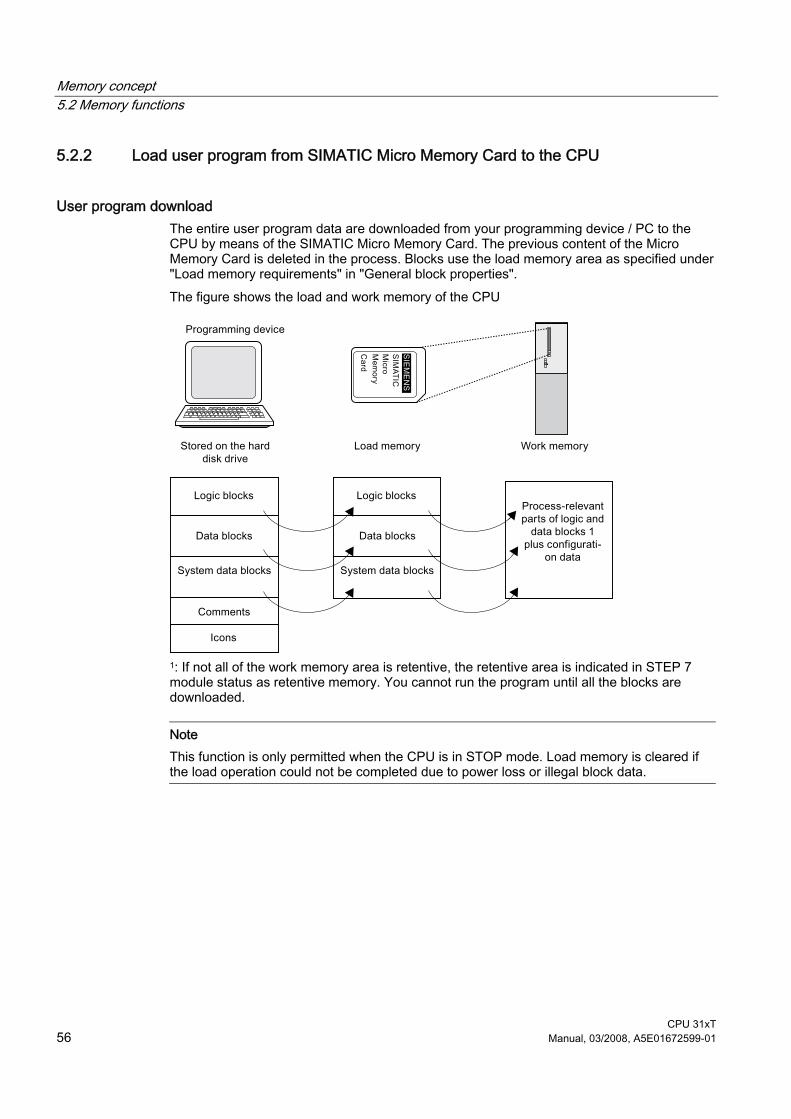
Memory concept 5.2 Memory functions
CPU 31xT 56 Manual, 03/2008, A5E01672599-01
5.2.2 Load user program from SIMATIC Micro Memory Card to the CPU
User program download The entire user program data are downloaded from your programming device / PC to the CPU by means of the SIMATIC Micro Memory Card. The previous content of the Micro Memory Card is deleted in the process. Blocks use the load memory area as specified under "Load memory requirements" in "General block properties". The figure shows the load and work memory of the CPU
1: If not all of the work memory area is retentive, the retentive area is indicated in STEP 7 module status as retentive memory. You cannot run the program until all the blocks are downloaded.
Note This function is only permitted when the CPU is in STOP mode. Load memory is cleared if the load operation could not be completed due to power loss or illegal block data.

Memory concept 5.2 Memory functions
CPU 31xT Manual, 03/2008, A5E01672599-01 57
5.2.3 Handling blocks
5.2.3.1 Downloading new blocks or delta downloads
There are two ways to download additional user blocks or download deltas: ● Download of blocks: You already created a user program and downloaded it to the CPU
via the SIMATIC Micro Memory Card. You then want to add new blocks to the user program. In this case you do not need to reload the entire user program to the MCC. Instead you only need to download the new blocks to the SIMATIC Micro Memory Card (this reduces the download times for highly complex programs.)
● Delta download: In this case, you only download the deltas in the blocks of your user program. In the next step, perform a delta download of the user program, or only of the changed blocks to the SIMATIC Micro Memory Card, using the PG/PC.
WARNING
The delta down of block / user programs overwrites all data stored under the same name on the SIMATIC Micro Memory Card.
The data of dynamic blocks are transferred to RAM and activated after the block is downloaded.
5.2.3.2 Uploading blocks
Uploading blocks Unlike download operations, an upload operation is the transfer of specific blocks or a complete user program from the CPU to the PG/PC. The block content is here identical with that of the last download to the CPU. Dynamic DBs form the exception, because their actual values are transferred. An upload of blocks or of the user program from the CPU in STEP 7 does not influence CPU memory.
5.2.3.3 Deleting blocks
Deleting blocks When you delete a block, it is deleted from load memory. In STEP 7, you can also delete blocks with the user program (DBs also with SFC 23 "DEL_DB"). RAM used by this block is released.

Memory concept 5.2 Memory functions
CPU 31xT 58 Manual, 03/2008, A5E01672599-01
5.2.3.4 Compressing blocks
Compressing blocks When data are compressed, gaps which have developed between memory objects in load memory/RAM as a result of load/delete operations will be eliminated. This releases free memory in a continuous block. Data compression is possible when the CPU is in RUN or in STOP.
5.2.3.5 Promming (RAM to ROM)
Promming (RAM to ROM) When writing the RAM content to ROM, the actual values of the DBs are transferred from RAM to load memory to form the start values for the DBs.
Note This function is only permitted when the CPU is in STOP mode. Load memory is cleared if the function could not be completed due to power loss.
5.2.4 CPU memory reset and restart
CPU memory reset After the insertion/removal of a Micro Memory Card, a CPU memory reset restores defined conditions for CPU restart (warm start). Technology CPU: ● The CPU's memory management is rebuilt. ● Blocks in load memory are retained. ● All runtime-related blocks are transferred from the load memory to the work memory
again. ● The data blocks in the work memory are initialized (are thus reset to their initial values). Integrated technology of Technology CPU: The CPU waits until the integrated technology has reached the STOP state. ● The integrated technology is parameterized again. ● The retentive memory of the integrated technology is rebuilt. ● Any distributed I/Os connected to DP(DRIVE) are parameterized again. ● The integrated technology is initialized again.

Memory concept 5.2 Memory functions
CPU 31xT Manual, 03/2008, A5E01672599-01 59
Reference Also refer to CPU memory reset by means mode selector switch in the Commissioning section in the CPU 31xC and CPU 31x Operating Instructions.
Warm Restart What happens during a warm restart: ● All retentive DBs retain their current values. ● Non-retentive DBs are reset to their initial values. ● The values of all retentive M, C, T are retained. ● All non-retentive user data are initialized:
– M, C, T, I, O with "0" ● All run levels are initialized. ● The process images are deleted.
5.2.5 Backup of project data to SIMATIC Micro Memory Card
Function principle Using the Save to Memory Card and Retrieve from Memory Card functions, you can save all project data to a SIMATIC Micro Memory Card, and retrieve these at a later time. For this operation, the SIMATIC Micro Memory Card can be located in a CPU or in the MMC adapter of a PG or PC. Project data are compressed before they are saved to a SIMATIC Micro Memory Card, and uncompressed when retrieved. The volume of project data to be saved corresponds with the size of the project's archive file.
Note In addition to project data, you may also have to store your user data on the MMC. You must therefore make sure beforehand that you select an MMC with sufficient memory capacity. A message warns you if the memory capacity on your SIMATIC Micro Memory Card is insufficient Even though you can load technology configuration data from the Micro Memory Card, you cannot edit the data. For technical reasons, you can only transfer the entire contents (user program and project data) using the Save to memory card action.
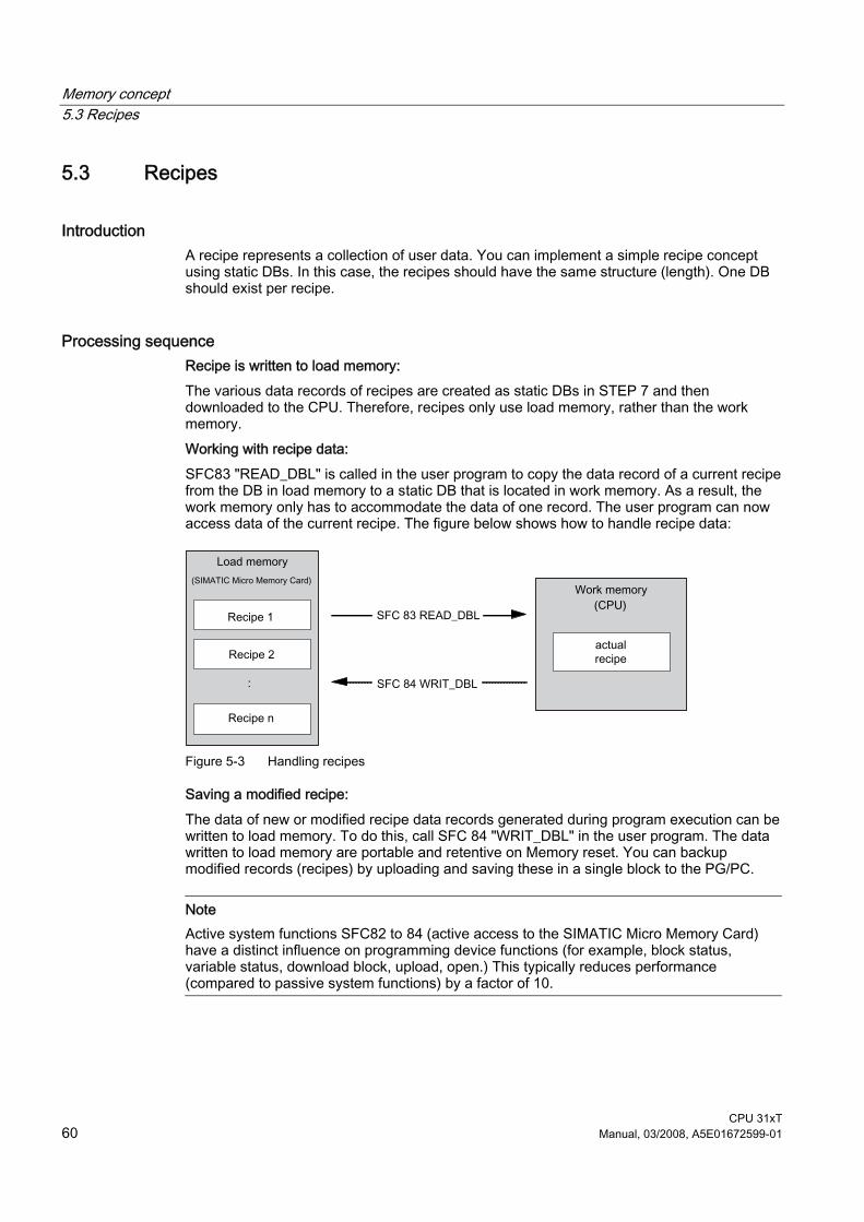
Memory concept 5.3 Recipes
CPU 31xT 60 Manual, 03/2008, A5E01672599-01
5.3 Recipes
Introduction A recipe represents a collection of user data. You can implement a simple recipe concept using static DBs. In this case, the recipes should have the same structure (length). One DB should exist per recipe.
Processing sequence Recipe is written to load memory: The various data records of recipes are created as static DBs in STEP 7 and then downloaded to the CPU. Therefore, recipes only use load memory, rather than the work memory. Working with recipe data: SFC83 "READ_DBL" is called in the user program to copy the data record of a current recipe from the DB in load memory to a static DB that is located in work memory. As a result, the work memory only has to accommodate the data of one record. The user program can now access data of the current recipe. The figure below shows how to handle recipe data:
Figure 5-3 Handling recipes
Saving a modified recipe: The data of new or modified recipe data records generated during program execution can be written to load memory. To do this, call SFC 84 "WRIT_DBL" in the user program. The data written to load memory are portable and retentive on Memory reset. You can backup modified records (recipes) by uploading and saving these in a single block to the PG/PC.
Note Active system functions SFC82 to 84 (active access to the SIMATIC Micro Memory Card) have a distinct influence on programming device functions (for example, block status, variable status, download block, upload, open.) This typically reduces performance (compared to passive system functions) by a factor of 10.
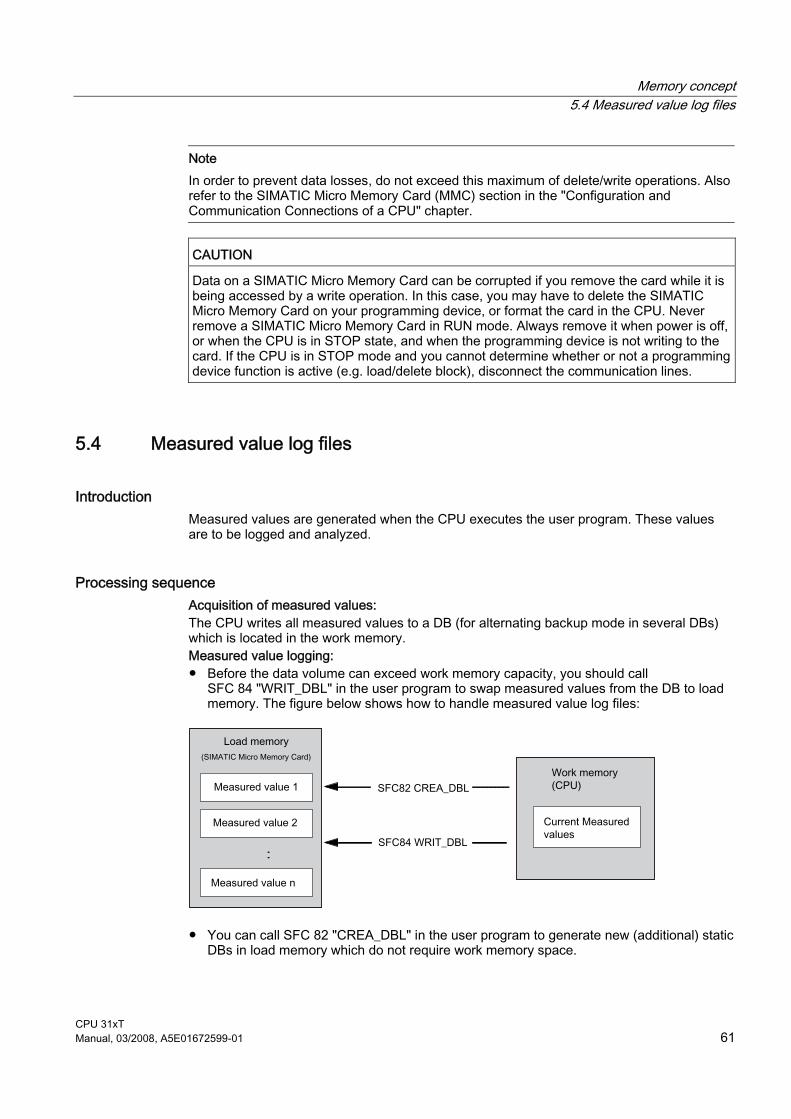
Memory concept 5.4 Measured value log files
CPU 31xT Manual, 03/2008, A5E01672599-01 61
Note In order to prevent data losses, do not exceed this maximum of delete/write operations. Also refer to the SIMATIC Micro Memory Card (MMC) section in the "Configuration and Communication Connections of a CPU" chapter.
CAUTION Data on a SIMATIC Micro Memory Card can be corrupted if you remove the card while it is being accessed by a write operation. In this case, you may have to delete the SIMATIC Micro Memory Card on your programming device, or format the card in the CPU. Never remove a SIMATIC Micro Memory Card in RUN mode. Always remove it when power is off, or when the CPU is in STOP state, and when the programming device is not writing to the card. If the CPU is in STOP mode and you cannot determine whether or not a programming device function is active (e.g. load/delete block), disconnect the communication lines.
5.4 Measured value log files
Introduction Measured values are generated when the CPU executes the user program. These values are to be logged and analyzed.
Processing sequence Acquisition of measured values: The CPU writes all measured values to a DB (for alternating backup mode in several DBs) which is located in the work memory. Measured value logging: ● Before the data volume can exceed work memory capacity, you should call
SFC 84 "WRIT_DBL" in the user program to swap measured values from the DB to load memory. The figure below shows how to handle measured value log files:
● You can call SFC 82 "CREA_DBL" in the user program to generate new (additional) static DBs in load memory which do not require work memory space.

Memory concept 5.4 Measured value log files
CPU 31xT 62 Manual, 03/2008, A5E01672599-01
Reference For detailed information on SFC 82, refer to the System Software for S7-300/400, System and Standard Functions Reference Manual, or directly to the STEP 7 Online Help.
Note SFC 82 is terminated and an error message is generated if a DB already exists under the same number in load memory and/or work memory.
The data written to load memory are portable and retentive on Memory reset. Evaluation of measured values: Measured value DBs saved to load memory can be uploaded and evaluated by other communication partners (PG, PC, for example).
Note Active system functions SFC82 to 84 (active access to the SIMATIC Micro Memory Card) have a distinct influence on programming device functions (for example, block status, variable status, download block, upload, open.) This typically reduces performance (compared to passive system functions) by a factor of 10.
Note
For CPUs with firmware V2.0.12 or higher, you can also generate non-retentive DBs using SFC 82 (parameter ATTRIB -> NON_RETAIN bit.)
Note
In order to prevent data losses, do not exceed this maximum of delete/write operations. For further information, refer to the Technical Data of the SIMATIC Micro Memory in the General Technical Data of your CPU.
CAUTION Data on a SIMATIC Micro Memory Card can be corrupted if you remove the card while it is being accessed by a write operation. In this case, you may have to delete the SIMATIC Micro Memory Card on your programming device, or format the card in the CPU. Never remove a SIMATIC Micro Memory Card in RUN mode. Always remove it when power is off, or when the CPU is in STOP state, and when the programming device is not writing to the card. If the CPU is in STOP mode and you cannot determine whether or not a programming device function is active (e.g. load/delete block), disconnect the communication lines.
Memory concept 5.5 Technology data blocks
CPU 31xT Manual, 03/2008, A5E01672599-01 63
5.5 Technology data blocks
Introduction The integrated technology of the Technology CPU provides current information on the status and on the values of the technology objects via the technology data blocks. To achieve especially short response times, the technology data blocks can be evaluated in OB 65.
Processing sequence When technology objects are configured, S7-Technology creates data blocks in the block folder. If you initiate jobs to drives using a technology function, you read the states and values in the associated technology data block. A job is active if the block signals busy. The CPU can execute a maximum of 210 active jobs simultaneously. The following technology functions occupy additional memory space: ● MC_ReadPeriphery ● MC_WritePeriphery ● MC_ReadRecord ● MC_WriteRecord ● MC_ReadDriveParameter ● MC_WriteDriveParameter ● MC_CamSectorAdd ● MC_ReadCamTrackData ● MC_WriteCamTrackData The maximum number of job data compartments occupied simultaneously is limited to 100.
Reference For further information, refer to the S7-Technology manual.

Memory concept 5.6 Memory of the integrated technology of the CPU
CPU 31xT 64 Manual, 03/2008, A5E01672599-01
5.6 Memory of the integrated technology of the CPU
Memory utilization The following table contains typical values for the memory utilization in the integrated technology. The values refer to a Technology CPU with firmware Version of the integrated technology of V4.1 of higher:
CPU 315T-2 DP
(6ES7 315-6TH13-0AB0) as of E version 01
CPU 317T-2 DP (6ES7 317-6TK13-0AB0) as of E version 01
Base load of the integrated technology 25 % 15 % Speed-controlled axis 1,25 % 0,75 % Positioning axis 1,5 % 0,9 % Following axis (with one following object)
2,5 % 1,5 %
Following axis (with two following objects)
3,5 % 2 %
External encoders 0,6 % 0,35 % Output cams 0,25 % 0,15 % Cam track as of S7 Technology V4.1 2,8 % 1,5 % Measuring input 0,25 % 0,15 % Cam (empty) 0,25 % 0,15 % Cam interpolation points* 0,0046 % 0,0008 % Cam interpolation points to be interpolated*
0,0027 % 0,0016 %
Maximum memory utilization Recommended 80 % 80 %
* Further explanations can be found in the following calculation example.
Note With insufficient memory, the Technology CPU goes into STOP mode. Note that these listed values are only typical values and some commands may temporarily require more memory during runtime. If the memory utilization is excessive, online monitoring from S7T Config may no longer be possible. Therefore, the recommended calculated maximum memory utilization should not be exceeded.
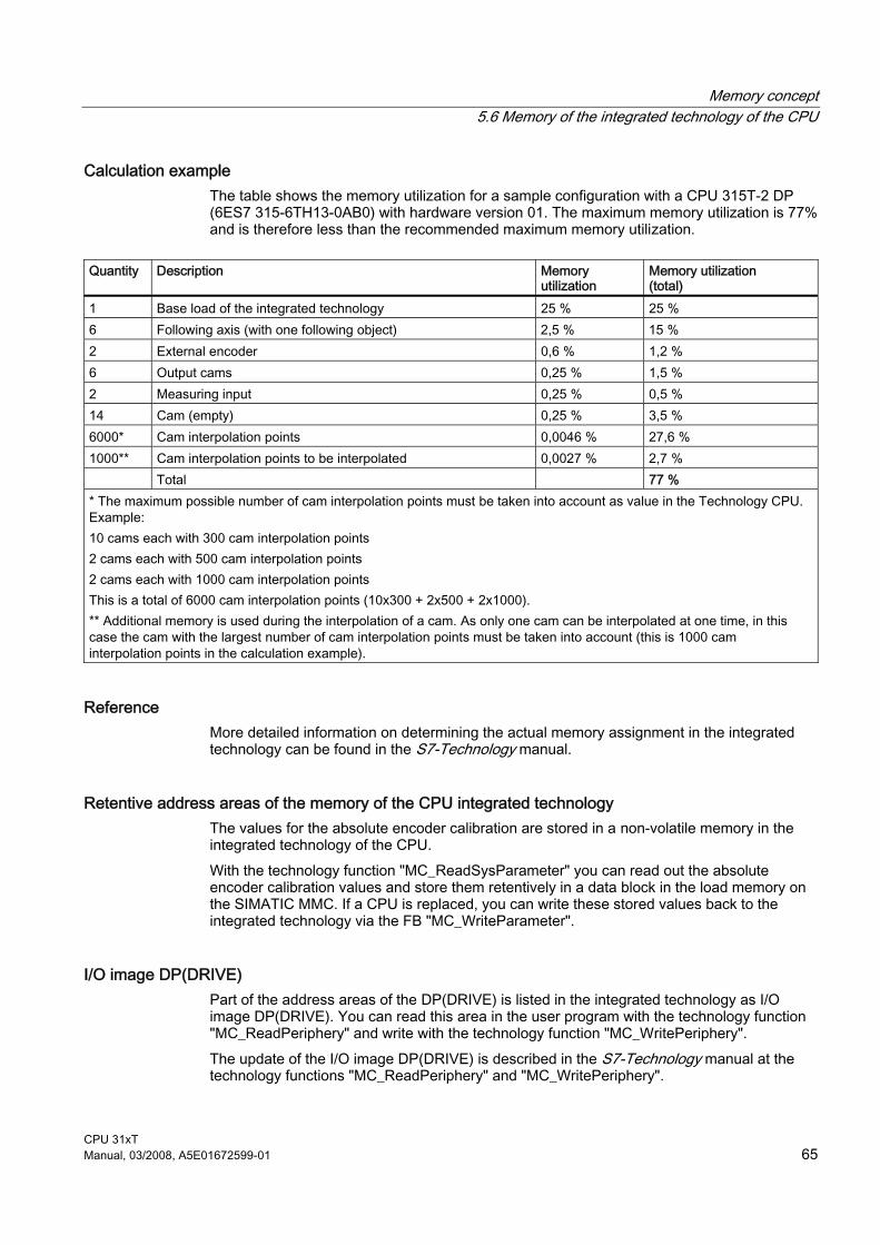
Memory concept 5.6 Memory of the integrated technology of the CPU
CPU 31xT Manual, 03/2008, A5E01672599-01 65
Calculation example The table shows the memory utilization for a sample configuration with a CPU 315T-2 DP (6ES7 315-6TH13-0AB0) with hardware version 01. The maximum memory utilization is 77% and is therefore less than the recommended maximum memory utilization.
Quantity Description Memory
utilization Memory utilization (total)
1 Base load of the integrated technology 25 % 25 % 6 Following axis (with one following object) 2,5 % 15 % 2 External encoder 0,6 % 1,2 % 6 Output cams 0,25 % 1,5 % 2 Measuring input 0,25 % 0,5 % 14 Cam (empty) 0,25 % 3,5 % 6000* Cam interpolation points 0,0046 % 27,6 % 1000** Cam interpolation points to be interpolated 0,0027 % 2,7 % Total 77 % * The maximum possible number of cam interpolation points must be taken into account as value in the Technology CPU. Example: 10 cams each with 300 cam interpolation points 2 cams each with 500 cam interpolation points 2 cams each with 1000 cam interpolation points This is a total of 6000 cam interpolation points (10x300 + 2x500 + 2x1000). ** Additional memory is used during the interpolation of a cam. As only one cam can be interpolated at one time, in this case the cam with the largest number of cam interpolation points must be taken into account (this is 1000 cam interpolation points in the calculation example).
Reference More detailed information on determining the actual memory assignment in the integrated technology can be found in the S7-Technology manual.
Retentive address areas of the memory of the CPU integrated technology The values for the absolute encoder calibration are stored in a non-volatile memory in the integrated technology of the CPU. With the technology function "MC_ReadSysParameter" you can read out the absolute encoder calibration values and store them retentively in a data block in the load memory on the SIMATIC MMC. If a CPU is replaced, you can write these stored values back to the integrated technology via the FB "MC_WriteParameter".
I/O image DP(DRIVE) Part of the address areas of the DP(DRIVE) is listed in the integrated technology as I/O image DP(DRIVE). You can read this area in the user program with the technology function "MC_ReadPeriphery" and write with the technology function "MC_WritePeriphery". The update of the I/O image DP(DRIVE) is described in the S7-Technology manual at the technology functions "MC_ReadPeriphery" and "MC_WritePeriphery".

Memory concept 5.6 Memory of the integrated technology of the CPU
CPU 31xT 66 Manual, 03/2008, A5E01672599-01

CPU 31xT Manual, 03/2008, A5E01672599-01 67
Cycle and response times 66.1 Overview
Overview This section contains detailed information about the following topics: ● Cycle time ● Response time ● Interrupt response time ● Sample calculations
Reference: Cycle time You can view the cycle time of your user program on the PG.
Reference: Execution time You can find information in the S7-300 Instruction List for CPUs 31xC and 31x. This tabular list contains the execution times for all ● STEP 7 instructions the relevant CPUs can execute, ● the SFCs / SFBs integrated in the CPUs, ● the IEC functions which can be called in STEP 7.
Reference: Motion Control runtimes You can find information about runtimes on PROFIBUS DP(DRIVE) in the S7-Technology manual.

Cycle and response times 6.2 Cycle time
CPU 31xT 68 Manual, 03/2008, A5E01672599-01
6.2 Cycle time
6.2.1 Overview
Introduction This chapter explains what we mean by the term "cycle time", what it consists of, and how you can calculate it.
Meaning of the term cycle time The cycle time represents the time that an operating system needs to execute a program, that is, one OB 1 cycle, including all program sections and system activities interrupting this cycle. This time is monitored.
Time-Sharing Model Cyclic program processing, and therefore user program execution, is based on time shares. To clarify these processes, let us assume that every time share has a length of precisely 1 ms.
Process image During cyclic program processing, the CPU requires a consistent image of the process signals. To ensure this, the process signals are read/written prior to program execution. Subsequently, the CPU does not address input (I) and output (Q) address areas directly at the signal modules, but rather accesses the system memory area containing the I/O process image.

Cycle and response times 6.2 Cycle time
CPU 31xT Manual, 03/2008, A5E01672599-01 69
Sequence of cyclic program processing The table and figure below show the phases in cyclic program processing.
Table 6-1 Cyclic program processing
Step Operational sequence 1 The operating system initiates cycle time monitoring. 2 The CPU copies the values of the process output image to the output modules. 3 The CPU reads the status at the inputs of the input modules and then updates the
process input image. 4 The CPU processes the user program in time shares and executes program instructions. 5 At the end of a cycle, the operating system executes pending tasks, such as the loading
and clearing of blocks. 6 The CPU then returns to the start of the cycle, and restarts cycle time monitoring.
Figure 6-1 Time-Sharing Model
PIO: Process output image PII: Process input image SCC: Scan cycle check point
In contrast to S7-400 CPUs (and the CPU 318-2 DP), the S7-300 CPUs data only allow data access from an OP / TD (monitor and modify functions) at the scan cycle check point (Data consistency, see the Technical Specifications). Processing of the user program is not interrupted by the monitor and modify functions.
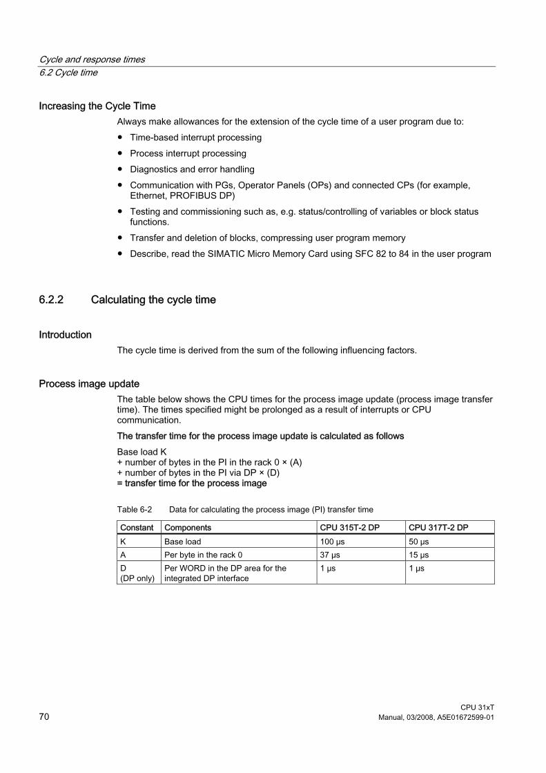
Cycle and response times 6.2 Cycle time
CPU 31xT 70 Manual, 03/2008, A5E01672599-01
Increasing the Cycle Time Always make allowances for the extension of the cycle time of a user program due to: ● Time-based interrupt processing ● Process interrupt processing ● Diagnostics and error handling ● Communication with PGs, Operator Panels (OPs) and connected CPs (for example,
Ethernet, PROFIBUS DP) ● Testing and commissioning such as, e.g. status/controlling of variables or block status
functions. ● Transfer and deletion of blocks, compressing user program memory ● Describe, read the SIMATIC Micro Memory Card using SFC 82 to 84 in the user program
6.2.2 Calculating the cycle time
Introduction The cycle time is derived from the sum of the following influencing factors.
Process image update The table below shows the CPU times for the process image update (process image transfer time). The times specified might be prolonged as a result of interrupts or CPU communication. The transfer time for the process image update is calculated as follows Base load K + number of bytes in the PI in the rack 0 × (A) + number of bytes in the PI via DP × (D) = transfer time for the process image
Table 6-2 Data for calculating the process image (PI) transfer time
Constant Components CPU 315T-2 DP CPU 317T-2 DP K Base load 100 μs 50 μs A Per byte in the rack 0 37 μs 15 μs D (DP only)
Per WORD in the DP area for the integrated DP interface
1 μs 1 μs

Cycle and response times 6.2 Cycle time
CPU 31xT Manual, 03/2008, A5E01672599-01 71
Extending the user program processing time In addition to actually working through the user program, your CPU's operating system also runs a number of processes in parallel, such as timer management for the core operating system. These processes extend the processing time of the user program. The table below lists the multiplication factors required to calculate your user program processing time.
Table 6-3 Extending the user program processing time
CPU Factor CPU 315T-2 DP 1,10 CPU 317T-2 DP 1,07
Operating system processing time at the scan cycle checkpoint The following table shows the operating system processing time at the cycle checkpoint of the CPUs. These times are calculated without taking into consideration times for: ● Testing and commissioning routines, e.g. status/controlling of variables or block status
functions ● Transfer and deletion of blocks, compressing user program memory ● Communication ● Writing, reading of the SIMATIC Micro Memory Card with SFC 82 to 84
Table 6-4 Operating system processing time at the scan cycle checkpoint
CPU Cycle control in the cycle checkpoint CPU 315T-2 DP 500 μs CPU 317T-2 DP 150 μs

Cycle and response times 6.2 Cycle time
CPU 31xT 72 Manual, 03/2008, A5E01672599-01
Extension of the cycle time due to nested interrupts and due to errors Enabled interrupts also extend cycle time. Details are found in the table below.
Table 6-5 Increase in cycle time by nesting interrupts
CPU Process interrupt
Diagnostic interrupt
Time-of-day interrupt
Time-delay interrupt
Cyclic interrupt
CPU 315T-2 DP 500 μs 600 μs 400 μs 300 μs 150 μs CPU 317T-2 DP 190 μs 240 μs 200 μs 150 μs 90 μs
You have to add the program execution time at the interrupt level to this increase.
Table 6-6 Cycle time extension as a result of errors
CPU Programming error I/O access errors CPU 315T-2 DP 400 μs 400 μs CPU 317T-2 DP 100 μs 100 μs
You have to add the program execution time of the interrupt OB to this increase. The times required for multiple nested interrupt/error OBs are added accordingly.

Cycle and response times 6.2 Cycle time
CPU 31xT Manual, 03/2008, A5E01672599-01 73
6.2.3 Different cycle times
Overview The length of the cycle time (Tcyc) is not identical in each cycle. The following figure shows different cycle times, Tcyc1 and Tcyc2. Tcyc2 is longer than Tcyc1, because the cyclically scanned OB 1 is interrupted by a time-of-day interrupt OB (here, OB10).
Figure 6-2 Different cycle times
Block processing times may fluctuate Fluctuation of the block processing time (e.g. OB 1) may also be a factor causing cycle time fluctuation, due to: ● Conditional instructions, ● Conditional block calls, ● Different program paths, ● Loops, etc.
Maximum Cycle Time In STEP 7 you can modify the default maximum cycle time. If this time has expired, OB 80 is called, and in it you can define how you want the CPU to respond to the time error. The CPU switches to STOP mode if OB80 does not exist in its memory.
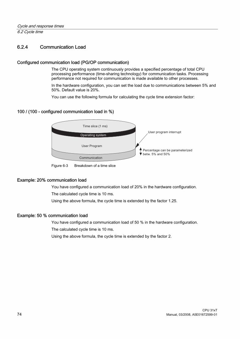
Cycle and response times 6.2 Cycle time
CPU 31xT 74 Manual, 03/2008, A5E01672599-01
6.2.4 Communication Load
Configured communication load (PG/OP communication) The CPU operating system continuously provides a specified percentage of total CPU processing performance (time-sharing technology) for communication tasks. Processing performance not required for communication is made available to other processes. In the hardware configuration, you can set the load due to communications between 5% and 50%. Default value is 20%. You can use the following formula for calculating the cycle time extension factor:
100 / (100 - configured communication load in %)
Figure 6-3 Breakdown of a time slice
Example: 20% communication load You have configured a communication load of 20% in the hardware configuration. The calculated cycle time is 10 ms. Using the above formula, the cycle time is extended by the factor 1.25.
Example: 50 % communication load You have configured a communication load of 50 % in the hardware configuration. The calculated cycle time is 10 ms. Using the above formula, the cycle time is extended by the factor 2.

Cycle and response times 6.2 Cycle time
CPU 31xT Manual, 03/2008, A5E01672599-01 75
Physical cycle time depending on communication load The figure below describes the non-linear dependency of the physical cycle time on communication load. As an example, we have chosen a cycle time of 10 ms.
Figure 6-4 Dependency of the Cycle Time on the Communication Load
Influence on the physical cycle time Due to the increase in the cycle time as a result of the communications component, even more asynchronous events occur, from a statistical point of view, within an OB 1 cycle than, say, interrupts. This further extends the OB1 cycle. This extension depends on the number of events that occur per OB1 cycle and the time required to process these events.
Note Change the value of the "communication load" parameter to check the effects on the cycle time at system runtime. You must consider the communication load when you set the maximum cycle time, otherwise timing errors may occur.
Tips ● If possible, apply the default value. ● Increase this value only if the CPU is used primarily for communications and if the user
program is not time critical. ● In all other situations you should only reduce this value.

Cycle and response times 6.2 Cycle time
CPU 31xT 76 Manual, 03/2008, A5E01672599-01
6.2.5 Cycle time extension as a result of testing and commissioning functions
Technology CPU runtimes The runtimes of the testing and commissioning functions are operating system runtimes, so they are the same for every CPU. Initially, there is no difference between process mode and testing mode. How the cycle time is extended as a result of active testing and commissioning functions is shown in the table below.
Table 6-7 Cycle time extension as a result of testing and commissioning functions
Function Technology-CPU Status variable 50 μs for each variable Control variable 50 μs for each variable Block status 200 μs for each monitored line
Configuration during parameter assignment For Process Operation, the maximum permissible cycle load by communication is not specified in "Cycle load by communication", but rather in "Maximum permitted increase of cycle time as a result of testing functions during process operation". Thus, the configured time is monitored absolutely in process mode and data acquisition is stopped if a timeout occurs. This is how STEP 7 stops data requests in loops before a loop ends, for example. When running in Testing Operation, the complete loop is executed in every cycle. This can significantly increase cycle time.

Cycle and response times 6.3 Response time
CPU 31xT Manual, 03/2008, A5E01672599-01 77
6.3 Response time
6.3.1 Overview
Definition of Response Time The response time is the time from an input signal being detected to changing an output signal linked to it.
Variation The actual response time is lies somewhere between a minimum and maximum response time. For configuring your system, you must always reckon with the longest reaction time. The shortest and longest response times are analyzed below so that you can gain an impression of the variation of the reaction time.
Factors The reaction time depends on the cycle time and on the following factors: ● Delay of the inputs and outputs of signal modules or integrated I/O. ● Additional DP cycle times on the PROFIBUS DP network ● Execution of the user program
Reference Further information ● about delay times can be found in the Technical Specifications of the signal modules
(Module data Reference Manual). ● about delay times for the integrated inputs and outputs can be found in chapter Technical
Specifications of Integrated Technology Inputs and Outputs

Cycle and response times 6.3 Response time
CPU 31xT 78 Manual, 03/2008, A5E01672599-01
DP Cycle Times on the PROFIBUS-DP Network If you have configured your PROFIBUS DP network with STEP 7, then STEP 7 will calculate the typical DP cycle time that must be expected. You can then view the DP cycle time of your configuration on the PG. The figure below gives you an overview of the DP cycle time. We assume in this example that each DP slave has 4 bytes of data on average.
Figure 6-5 DP Cycle Times on the PROFIBUS-DP Network
With multi-master operation on a PROFIBUS-DP network, you must make allowances for the DP cycle time at each master. That is, you will have to calculate the times for each master separately and then add up the results.

Cycle and response times 6.3 Response time
CPU 31xT Manual, 03/2008, A5E01672599-01 79
6.3.2 Shortest response time
Conditions for the shortest response time The following figure illustrates the conditions under which the shortest response time can be achieved.
Figure 6-6 Shortest response time
Calculation The (shortest) reaction time is made up as follows: ● 1 x process image transfer time for the inputs + ● 1 x process image transfer time for the outputs + ● 1 x program processing time + ● 1 x operating system processing time at the SCC + ● Delay in the inputs and outputs The result is equivalent to the sum of the cycle time plus the I/O delay times.

Cycle and response times 6.3 Response time
CPU 31xT 80 Manual, 03/2008, A5E01672599-01
6.3.3 Longest response time
Conditions for the longest response time The following figure shows you how the longest response time results.
Figure 6-7 Longest response time
Calculation The (longest) response time is made up as follows: ● 2 x process image transfer time for the inputs + ● 2 x process image transfer time for the outputs + ● 2 x program processing time + ● 2 x operating system processing time at the SCC + ● 4 x runtime of the DP slave frame (including processing in the DP master) + ● Delay in the inputs and outputs This is equivalent to the sum of twice the cycle time and the delay in the inputs and outputs plus four times the DP cycle time.

Cycle and response times 6.4 Calculating method for calculating the cycle/response time
CPU 31xT Manual, 03/2008, A5E01672599-01 81
6.3.4 Reducing the response time with direct I/O access
Reducing the Response Time You can reach faster response times with direct access to the I/O in your user program, e.g. with ● L PIB or ● T PQW you can partially avoid the response times described above.
Note You can also achieve fast response times by using process interrupts (see next chapter).
6.4 Calculating method for calculating the cycle/response time
Introduction This section gives you an overview of how to calculate the cycle/response time.
Cycle time 1. Determine the user program runtime with the help of the instruction list. 2. Multiply the calculated value by the CPU-specific factor from the table Extension of user
program processing time. 3. Calculate and add the process image transfer time. Corresponding guide values are
found in table Data for calculating process image transfer time. 4. Add the processing time at the scan cycle checkpoint. Corresponding guide values are
found in the table Operating system processing time at the scan cycle checkpoint. 5. Include the extensions as a result of testing and commissioning functions. These values
are found in the table Cycle time extension due to testing and commissioning functions. The result you achieve is the
6. cycle time.

Cycle and response times 6.4 Calculating method for calculating the cycle/response time
CPU 31xT 82 Manual, 03/2008, A5E01672599-01
Extension of the cycle time as a result of interrupts and communication load 100 / (100 - configured communication load in %) 1. Multiply the cycle time by the factor as in the formula above. 2. Using the Instruction List, calculate the runtime of the program sections that hardware
interrupts. Add the corresponding value from section Calculating the cycle time, table Cycle time extension by interrupt nesting.
3. Multiply both values by the CPU-specific extension factor of the user program processing time (see table "CPU communication services").
4. Add the value of the interrupt-processing program sequences to the theoretical cycle time, multiplied by the number of triggering (or expected) interrupt events within the cycle time. The result you obtain is approximately the actual cycle time. Make a note of the result.
Response time
Table 6-8 Calculating the response time
Shortest response time Longest response time - Multiply the actual cycle time by a factor of 2. Now add I/O delay. Then, calculate the delays in the inputs and
outputs and the DP cycle times on the PROFIBUS DP network.
The result is the shortest response time. The result is the longest response time.

Cycle and response times 6.5 Interrupt response time
CPU 31xT Manual, 03/2008, A5E01672599-01 83
6.5 Interrupt response time
6.5.1 Overview
Definition of the interrupt response time The interrupt response time is the time that expires between the first occurrence of an interrupt signal and the call of the first interrupt OB statement. Generally, the following is valid: Interrupts having a higher priority take precedence. This means that the interrupt response time is increased by the program processing time of the higher-priority interrupt OBs and the interrupt OBs of equal priority which have not yet been executed (queued).
Process/diagnostic interrupt response times of the CPU
Table 6-9 Process/diagnostic interrupt response times
Process interrupt response times Diagnostic interrupt response times
CPU
External min.
External max.
Integrated inputs/outputs for integrated technology*
min. Max.
CPU 315T-2 DP 0.4 ms 0.7 ms - 0.4 ms 1.0 ms CPU 317T-2 DP 0.3 ms 0.4 ms - 0.3 ms 0.4 ms
* The integrated inputs/outputs for integrated technology do not have interrupt capability.
Calculation The formulae below show how you can calculate the minimum and maximum interrupt response times.
Table 6-10 Process/diagnostic interrupt response times
Calculation of the minimum and maximum interrupt reaction time Minimum interrupt reaction time of the CPU + Minimum interrupt reaction time of the signal modules + DP cycle time on the PROFIBUS DP = Quickest interrupt reaction time
Maximum interrupt reaction time of the CPU + Maximum interrupt reaction time of the signal modules +2 x DP cycle time on the PROFIBUS DP The maximum interrupt reaction time is longer when the communication functions are active. The extra time is calculated using the following formula: tv: 200 μs + 1000 μs × n% Significant extension possible with n = cycle time extension through communication

Cycle and response times 6.5 Interrupt response time
CPU 31xT 84 Manual, 03/2008, A5E01672599-01
Signal modules The process interrupt response time of signal modules is determined by the following factors: ● Digital input modules
Process interrupt response time = internal interrupt preparation time + input delay You will find the times in the data sheet of the digital input module concerned.
● Analog input modules Process interrupt response time = internal interrupt preparation time + conversion time The internal interrupt processing time of the analog input modules is negligible. The conversion times can be taken from the data sheet of the analog input module concerned.
The diagnostic interrupt response time of signal modules is equivalent to the period that expires between the time a signal module detects a diagnostic event and the time this signal module triggers the diagnostic interrupt. This time is so small that it can be ignored.
Process interrupt processing When the process interrupt OB 40 is called, the process interrupt is processed. Interrupts with higher priority interrupt process interrupt processing and direct access to the I/O is made when the statement is executed. When process interrupt processing is completed, either cyclic program processing is continued or other interrupt OBs with the same or a lower priority are called and processed.
6.5.2 Reproducibility of Time-Delay and Watchdog Interrupts
Definition of "Reproducibility" Delay interrupt: The period between the call of the first instruction in the interrupt OB and the programmed time of interrupt. Watchdog interrupt: The variation in the time interval between two successive calls, measured between the first instructions of the interrupt OB in each case.
Reproducibility The following times apply for the CPUs described in this manual: ● Delay interrupt: +/- 200 μs ● Watchdog interrupt: +/- 200 μs These times only apply if the interrupt can actually be executed at this time and if not interrupted, for example, by higher-priority interrupts or queued interrupts of equal priority.

Cycle and response times 6.6 Sample calculations
CPU 31xT Manual, 03/2008, A5E01672599-01 85
6.6 Sample calculations
6.6.1 Example of cycle time calculation
Configuration You have configured an S7-300 and equipped it with following modules in rack "0": ● 1 CPU 315T-2 DP ● 2 digital input modules SM 321; DI 32 x 24 VDC (4 bytes each in the PI) ● 2 digital output modules SM 322; DO 32 x 24 VDC / 0.5 A
(4 bytes each in the PI)
User program According to the Instruction List, your user program has a runtime of 5 ms. There is no active communication.
Calculating the cycle time The cycle time for the example results from the following times: ● User program execution time:
approx. 5 ms x CPU-specific factor 1.10 = approx. 5.5 ms ● Process image transfer time
Process input image: 100 μs + 8 bytes x 37 μs = Approx. 0.396 ms Process output image: 100 μs + 8 bytes x 37 μs = Approx. 0.396 ms
● Operating system runtime at scan cycle checkpoint: approx. 0.5 ms
Cycle time = 5.5 ms +0.396 ms +0.396 ms + 0.5 ms = 6.792 ms.
Calculation of the actual cycle time ● There is no active communication. ● There is no interrupt handling. Therefore, the actual cycle time is also 6.792 ms.

Cycle and response times 6.6 Sample calculations
CPU 31xT 86 Manual, 03/2008, A5E01672599-01
Calculation of the longest response time Longest response time: 6.792 ms x 2 = 13.584 ms. ● The delay in the inputs and outputs is negligible. ● All the components are plugged into rack 0; DP cycle times do not therefore have to be
taken into account. ● There is no interrupt handling.
6.6.2 Example of response time calculation
Structure You have configured an S7300 and equipped it with the following modules on a rack: ● One CPU 315T-2 DP
Configuration of the cycle load as a result of communication: 40 % ● 2 digital input modules SM 321; DI 32 x 24 VDC (4 bytes each in the PI) ● 3 digital output modules SM 322; DO 16 x 24 VDC/0.5 A (2 bytes each in the PI) ● 1 analog input module SM 331; AI 8 x 12-bit (not in the PI) ● 1 analog output module SM 332; AO 4 x 12-bit (not in the PI)
User program According to the Instruction List, the user program has a runtime of 10.0 ms.
Cycle time calculation The cycle time for the example results from the following times: ● User program execution time:
approx. 10 ms x CPU-specific factor 1.10 = approx. 11.0 ms ● Process image transfer time
Process image of inputs: 100 μs + 8 bytes x 37 μs = approx. 0.396 ms Process image of outputs: 100 μs + 6 bytes x 37 μs = approx. 0.322 ms
● Operating system runtime at scan cycle checkpoint: approx. 0.5 ms
The cycle time for the example results from the sum of the times listed: Cycle time = 11.0 ms +0.396 ms +0.322 ms + 0.5 ms = 12.218 ms.

Cycle and response times 6.6 Sample calculations
CPU 31xT Manual, 03/2008, A5E01672599-01 87
Calculation of the actual cycle time Allowance for communication load: 12.218 ms * 100 / (100-40) = 20.36 ms. Thus, under consideration of time slots, the actual cycle time is approx. 20 ms.
Calculation of the longest response time ● Longest response time = 20 ms * 2 = 40 ms. ● Delays in the inputs and outputs
– The maximum input delay of the digital input module SM 321; DI 32 x 24 VDC is 4.8 ms per channel.
– The output delay of the digital output module SM 322; DO 16 x 24 VDC / 0.5 A can be neglected.
– The analog input module SM 331; AI 8 x 12 bit was configured for interference suppression at 50 Hz. This results in a conversion time of 22 ms per channel. Since 8 channels are active, a cycle time of 176 ms results for the analog input module.
– The analog output module SM 332; AO 4 x 12-bit was programmed for the measuring range of 0 ...10 Hz. This gives a conversion time of 0.8 ms per channel. Since 4 channels are active, a cycle time of 3.2 ms results. The settling time for the resistive load of 0.1 ms must still be added. The result is a response time of 3.3 ms for an analog output.
● All the components are plugged into the central rack; DP cycle times do not therefore have to be taken into account.
● Response times plus I/O delay: – Case 1: An output channel of the digital output module is set when a signal is received
at the digital input. The result is a response time of: Response time = 40 ms + 4.8 ms = 44.8 ms.
– Case 2: An analog value is fetched, and an analog value is output. The result is a response time of: Longest response time = 40 ms + 176 ms + 3.3 ms = 219.3 ms.

Cycle and response times 6.6 Sample calculations
CPU 31xT 88 Manual, 03/2008, A5E01672599-01
6.6.3 Example of interrupt response time calculation
Structure You have assembled an S7-300, consisting of one CPU 315T-2 DP and four digital modules in the central rack. One of the digital input modules is an SM 321; DI 16 x 24 VDC; with process/diagnostic interrupt function. In the parameter assignment of the CPU and the SM, you have only enabled the process interrupt. You do not require time-driven processing, diagnostics and error handling. You have set a cycle load caused by communication of 20%. You have set an input delay of 0.5 ms for the digital input module. No activities are necessary at the cycle checkpoint.
Calculation The process interrupt response time for the example results from the following times: ● Process interrupt response time of CPU 315T-2 DP: approx. 0.7 ms ● Extension by communication according to the formula:
200 μs + 1000 μs x 20 % = 400 μs = 0.4 ms ● Process interrupt response time of SM 321; DI 16 x 24 VDC:
– Internal interrupt preparation time: 0.25 ms – Input delay: 0.5 ms
● Since the signal modules are plugged into the central rack, the DP cycle time on the PROFIBUS DP is not relevant.
The process interrupt response time results from the sum of the listed times: Process interrupt response time = 0.7 ms + 0.4 ms + 0.25 ms + 0.5 ms = approx. 1.85 ms. This calculated process interrupt response time is the time from a signal being applied across the digital input to the first statement in OB 40.
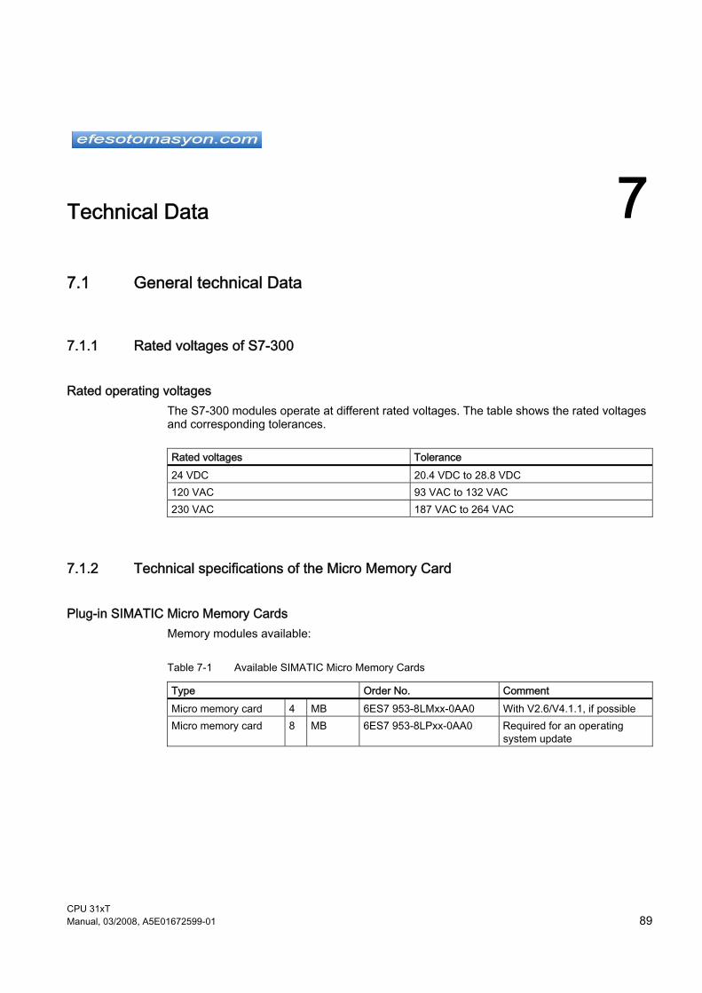
CPU 31xT Manual, 03/2008, A5E01672599-01 89
Technical Data 77.1 General technical Data
7.1.1 Rated voltages of S7-300
Rated operating voltages The S7-300 modules operate at different rated voltages. The table shows the rated voltages and corresponding tolerances.
Rated voltages Tolerance 24 VDC 20.4 VDC to 28.8 VDC 120 VAC 93 VAC to 132 VAC 230 VAC 187 VAC to 264 VAC
7.1.2 Technical specifications of the Micro Memory Card
Plug-in SIMATIC Micro Memory Cards Memory modules available:
Table 7-1 Available SIMATIC Micro Memory Cards
Type Order No. Comment Micro memory card 4 MB 6ES7 953-8LMxx-0AA0 With V2.6/V4.1.1, if possible Micro memory card 8 MB 6ES7 953-8LPxx-0AA0 Required for an operating
system update
Technical Data 7.1 General technical Data
CPU 31xT 90 Manual, 03/2008, A5E01672599-01
7.1.3 Standards and certifications
Introduction Contents of general technical data: ● standards and test values satisfied by modules of the S7-300 automation system ● test criteria of S7-300 modules. The Technology CPU orientates itself on the planned standards ● PLCopen - Technical Committee 2 – Task Force Function blocks for motion control
Version 1.0 ● PROFIdrive Profile 3.1 (Firmware Version 4.1)
CE approval
The S7-300 automation system satisfies requirements and safety-related objectives according to EC Directives listed below and conforms with the harmonized European standards (EN) for programmable controllers announced in the Official Journals of the European Community: ● 73/23/EEC "Electrical Equipment Designed for Use within Certain Voltage Limits" (Low-
Voltage Directive) ● 89/336/EEC "Electromagnetic Compatibility" (EMC Directive) ● 94/9/EC "Equipment and protective systems intended for use in potentially explosive
atmospheres" (Explosion Protection Directive) The EC declaration of conformity is held on file available to competent authorities at: Siemens Aktiengesellschaft Automation & Drives A&D AS RD ST PLC PO Box 1963 D-92209 Amberg
UL approval
Underwriters Laboratories Inc. complying with ● UL 508 (Industrial Control Equipment)

Technical Data 7.1 General technical Data
CPU 31xT Manual, 03/2008, A5E01672599-01 91
CSA approval
Canadian Standards Association to ● C22.2 No. 142 (Process Control Equipment) or
Underwriters Laboratories Inc. complying with ● UL 508 (Industrial Control Equipment) ● CSA C22.2 No. 142 (Process Control Equipment) or
Underwriters Laboratories Inc. complying with ● UL 508 (Industrial Control Equipment) ● CSA C22.2 No. 142 (Process Control Equipment) ● UL 1604 (Hazardous Location) ● CSA-213 (Hazardous Location) APPROVED for use in Class I, Division 2, Group A, B, C, D Tx; Class I, Zone 2, Group IIC Tx
Note Currently valid approvals can be found on the rating plate of the relevant module.

Technical Data 7.1 General technical Data
CPU 31xT 92 Manual, 03/2008, A5E01672599-01
FM approval
Factory Mutual Research (FM) to Approval Standard Class Number 3611, 3600, 3810 APPROVED for use in Class I, Division 2, Group A, B, C, D Tx; Class I, Zone 2, Group IIC Tx
ATEX approval
to EN 60079-15:2003 (Electrical apparatus for potentially explosive atmospheres; Type of protection "n")
II 3 G EEx nA II Parts 4 to 6
Tick-mark for Australia
The S7-300 automation system satisfies requirements of standards to AS/NZS 2064 (Class A).
IEC 61131 The S7-300 automation system satisfies requirements and criteria to IEC 61131-2 (Programmable Controllers, Part 2: Equipment requirements and tests).
Marine approval Classification societies: ● ABS (American Bureau of Shipping) ● BV (Bureau Veritas) ● DNV (Det Norske Veritas) ● GL (Germanischer Lloyd) ● LRS (Lloyds Register of Shipping) ● Class NK (Nippon Kaiji Kyokai)

Technical Data 7.1 General technical Data
CPU 31xT Manual, 03/2008, A5E01672599-01 93
Use in industrial environments SIMATIC products are designed for industrial applications.
Table 7-2 Use in industrial environments
Field of application
Noise emission requirements Noise immunity requirements
Industry EN 61000-6-4: 2001 EN 61000-6-2: 2001
Use in residential areas To operate an S7-300 in a residential area, it's RF emission must comply with Limit Value Class B to EN 55011. The following measures are recommended to ensure the interference complies with limit value class B: ● S7-300 installation in grounded switch cabinets / cubicles ● Use of noise filters in the supply lines
WARNING
Personal injury and damage to property may occur. In potentially explosive environments, there is a risk of injury or damage if you disconnect any connectors while the S7-300 is in operation. Always isolate the S7-300 operated in such areas before you disconnect and connectors.
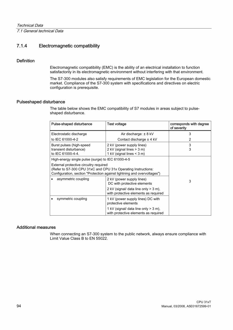
Technical Data 7.1 General technical Data
CPU 31xT 94 Manual, 03/2008, A5E01672599-01
7.1.4 Electromagnetic compatibility
Definition Electromagnetic compatibility (EMC) is the ability of an electrical installation to function satisfactorily in its electromagnetic environment without interfering with that environment. The S7-300 modules also satisfy requirements of EMC legislation for the European domestic market. Compliance of the S7-300 system with specifications and directives on electric configuration is prerequisite.
Pulseshaped disturbance The table below shows the EMC compatibility of S7 modules in areas subject to pulse-shaped disturbance.
Pulse-shaped disturbance Test voltage corresponds with degree
of severity Electrostatic discharge to IEC 61000-4-2
Air discharge: ± 8 kV Contact discharge ± 4 kV
3 2
Burst pulses (high-speed transient disturbance) to IEC 61000-4-4.
2 kV (power supply lines) 2 kV (signal lines > 3 m) 1 kV (signal lines < 3 m)
3 3
High-energy single pulse (surge) to IEC 61000-4-5 External protective circuitry required (Refer to S7-300 CPU 31xC and CPU 31x Operating Instructions: Configuration, section "Protection against lightning and overvoltages") • asymmetric coupling 2 kV (power supply lines)
DC with protective elements 2 kV (signal/ data line only > 3 m), with protective elements as required
• symmetric coupling 1 kV (power supply lines) DC with protective elements 1 kV (signal/ data line only > 3 m), with protective elements as required
3
Additional measures When connecting an S7-300 system to the public network, always ensure compliance with Limit Value Class B to EN 55022.

Technical Data 7.1 General technical Data
CPU 31xT Manual, 03/2008, A5E01672599-01 95
Sinusoidal disturbance The table below shows the EMC compatibility of S7-300 modules in areas subject to sinusoidal disturbance.
Sinusoidal disturbance Test values corresponds with
degree of severity RF radiation (electromagnetic fields) to IEC 61000-4-3
10 V/m, with 80% amplitude modulation of 1 kHz in the 80 MHz to 1000 MHz range 10 V/m, with 50% pulse modulation at 900 MHz
3
RF conductance on cables and cable shielding to IEC 61000-4-6
Test voltage 10 V, with 80% amplitude modulation of 1 kHz in the 9 MHz to 80 MHz range
3
Emission of radio interference Electromagnetic interference to EN 55011: Limit Class A, Group 1 (measured at a distance of 10 m.)
Frequency Noise emission 30 MHz to 230 MHz < 40 dB (µV/m)Q 230 MHz to 1000 MHz < 47 dB (µV/m)Q
Noise emission via AC mains to EN 55011: Limit value class A, Group 1.
Frequency Noise emission 0.15 MHz to 0.5 MHz < 79 dB (µV/m)Q
< 66 dB (µV/m)M 0.5 MHz to 5 MHz < 73 dB (µV/m)Q
< 60 dB (µV/m)M 5 MHz to 30 MHz < 73 dB (µV/m)Q
< 60 dB (µV/m)M

Technical Data 7.1 General technical Data
CPU 31xT 96 Manual, 03/2008, A5E01672599-01
7.1.5 Shipping and storage conditions for modules and backup batteries
Introduction The shipping and storage conditions of S7-300 modules surpass requirements to IEC 61131-2. The data below apply to modules shipped or put on shelf in their original packing. The modules are compliant with climatic conditions to IEC 60721-3-3, Class 3K7 (storage), and with IEC 60721-3-2, Class 2K4 (shipping.) Mechanical conditions are compliant with IEC 60721-3-2, Class 2M2.
Shipping and storage conditions for modules
Type of condition Permissible range Free fall (in shipping package) ≤ 1 m Temperature - 40 °C to + 70 °C Barometric pressure 1080 hPa to 660 hPa (corresponds with an altitude
of -1000 m to 3500 m) Relative humidity 10% to 95%, no condensation Sinusoidal oscillation to IEC 60068-2-6
5 Hz to 9 Hz: 3.5 mm 9 Hz to 150 Hz: 9.8 m/s2
Shock to IEC 60068-2-29 250 m/s2, 6 ms, 1000 shocks

Technical Data 7.1 General technical Data
CPU 31xT Manual, 03/2008, A5E01672599-01 97
7.1.6 Mechanical and climatic environmental conditions for S7-300 operation
Operating conditions S7-300 systems are designed for stationary use in weather-proof locations. The operating conditions surpass requirements to DIN IEC 60721-3-3. ● Class 3M3 (mechanical requirements) ● Class 3K3 (climatic requirements)
Use with additional measures The S7-300 may not be used under the conditions outlined below without taking additional measures: ● at locations with a high degree of ionizing radiation ● in aggressive environments caused, for example, by
– the development of dust – corrosive vapors or gases – strong electric or magnetic fields
● in installations requiring special monitoring, for example – elevators – electrical plants in potentially hazardous areas
An additional measure could be an installation of the S7-300 in a cabinet or housing.
Mechanical environmental conditions The table below shows the mechanical environmental conditions in the form of sinusoidal oscillations.
Frequency band Continuous Infrequently 10 Hz ≤ f ≤ 58 Hz 0.0375 mm amplitude 0.75 mm amplitude 58 Hz ≤ f ≤ 150 Hz 0.5 g constant acceleration 1 g constant acceleration
Reducing vibrations If your S7-300 modules are exposed to severe shock or vibration, take appropriate measures to reduce acceleration or the amplitude. We recommend the installation of the S7-300 on damping materials (for example, rubber-bonded-to-metal mounting.)

Technical Data 7.1 General technical Data
CPU 31xT 98 Manual, 03/2008, A5E01672599-01
Test of mechanical environmental conditions The table below provides important information with respect to the type and scope of the test of ambient mechanical conditions.
Condition tested Test Standard Comment Vibration Vibration test to IEC
60068-2-6 (sinusoidal) Type of oscillation: Frequency sweeps with a rate of change of 1 octave/minute. 10 Hz ≤ f ≤ 58 Hz, constant amplitude 0.075 mm 58 Hz ≤ f ≤ 150 Hz, constant acceleration 1 g Duration of oscillation: 10 frequency sweeps per axis at each of three vertically aligned axes
Shock Shock, tested to IEC 60068-2-27
Type of shock: half-sine Severity of shock: 15 g peak value, 11 ms duration Direction of shock: 3 shocks in each direction (+/-) at each of three vertically aligned axes
Continuous shock Shock, tested to IEC 60068-2-29
Type of shock: half-sine Severity of shock: 25 g peak value, 6 ms duration Shock direction: 1000 shocks in each direction (+/-) at each of three vertically aligned axes
Climatic environmental conditions The S7-300 may be operated on following environmental conditions:
Environmental conditions Permissible range Comments Temperature: horizontal mounting position: vertical mounting position:
0°C to 60°C 0°C to 40°C
Relative humidity 10 % to 95 % No condensation, corresponds to relative humidity (RH) Class 2 to IEC 61131, Part 2
Barometric pressure 1080 hPa to 795 hPa Corresponds with an altitude of -1000 m to 2000 m
Concentration of pollutants SO2: < 0.5 ppm; RH < 60 %, no condensation H2S: < 0.1 ppm; RH < 60 %, no condensation
Test: 10 ppm; 4 days Test: 1 ppm; 4 days

Technical Data 7.1 General technical Data
CPU 31xT Manual, 03/2008, A5E01672599-01 99
7.1.7 Specification of dielectric tests, protection class, degree of protection, and rated voltage of S7-300
Test voltage Proof of dielectric strength must be provided in the type test at a test voltage to IEC 61131-2:
Circuits with rated voltage Ve to other circuits or ground.
Test voltage
< 50 V 500 VDC < 150 V 2500 VDC < 250 V 4000 VDC
Protection class Protection class I to IEC 60536, i.e., a protective conductor must be connected to the mounting rail!
Protection against the ingress of foreign matter and water ● Degree of protection IP 20 to IEC 60529, i.e., protection against contact with standard
probes. No protection against the ingress of water.

Technical Data 7.1 General technical Data
CPU 31xT 100 Manual, 03/2008, A5E01672599-01
7.1.8 Dimension drawing
Dimension drawing of Technology CPU

Technical Data 7.2 CPU 315T-2 DP and CPU 317T-2 DP
CPU 31xT Manual, 03/2008, A5E01672599-01 101
7.2 CPU 315T-2 DP and CPU 317T-2 DP
Technical data ● CPU 315T-2 DP, order number 6ES7315-6TH13-0AB0 and ● CPU 317T-2 DP, order number 6ES7317-6TK13-0AB0
6ES7315-6TH13-0AB0 6ES7317-6TK13-0AB0 Product status Hardware product status 01 01 Firmware version CPU: V 2.6;
integrated technology: V 4.1.1 CPU: V 2.6; integrated technology: V 4.1.1
associated programming package STEP 7 V 5.4 SP2 or higher and S7-Technology option package V4.1
STEP 7 V 5.4 SP2 or higher and S7-Technology option package V4.1
Supply voltages Rated value • DC 24 V Yes Yes • permissible range, lower limit
(DC) 20.4 V 20.4 V
• permissible range, upper limit (DC)
28.8 V 28.8 V
Voltages and currents Load voltage L+ • Rated value (DC) 24 V 24 V • reverse polarity protection Yes Yes external protection for supply cables (recommendation)
Min. 2 A Min. 2 A
Current consumption Inrush current, max. 2.5 A 2.5 A I²t 1 A²s 1 A²s Current consumption (in no-load operation), typ.
200 mA 200 mA
Power loss, typ. 6 W 6 W Technology objects
• Total 32 (axes, cams, output cams, cam tracks, measuring inputs, external encoders)
64 (axes, cams, output cams, cam tracks, measuring inputs, external encoders)
• Axes 8 axes (virtual or real axes) 32 axes (virtual or real axes) • Cams 16 output cams
8 output cams can be output as "high-speed output cams" on the integrated outputs of the Technology CPU. A further 24 output cams can be implemented via the distributed I/Os (e.g. on the ET 200M or ET 200S). These can be implemented as "high-speed output cams" on the TM15 and TM17 High Feature.
32 output cams 8 output cams can be output as "high-speed output cams" on the integrated outputs of the Technology CPU. A further 24 output cams can be implemented via the distributed I/Os (e.g. on the ET 200M or ET 200S). These can be implemented as "high-speed output cams" on the TM15 and TM17 High Feature.
• Cam tracks 16 32
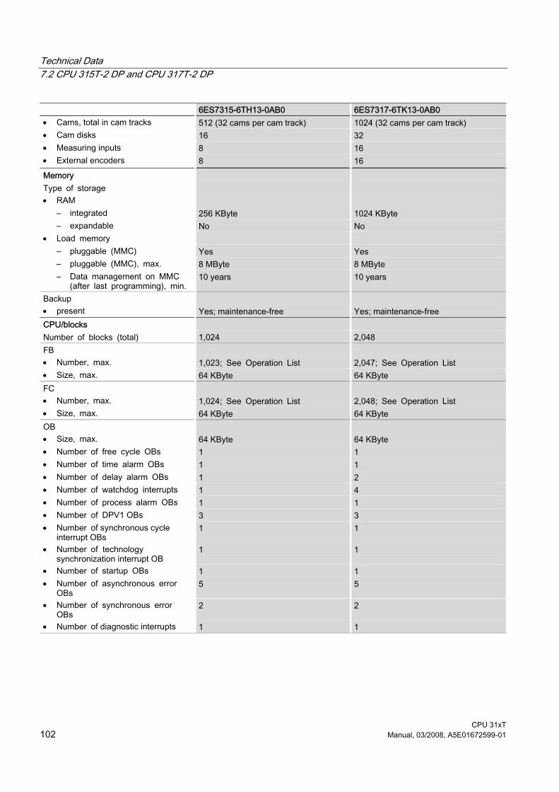
Technical Data 7.2 CPU 315T-2 DP and CPU 317T-2 DP
CPU 31xT 102 Manual, 03/2008, A5E01672599-01
6ES7315-6TH13-0AB0 6ES7317-6TK13-0AB0 • Cams, total in cam tracks 512 (32 cams per cam track) 1024 (32 cams per cam track) • Cam disks 16 32 • Measuring inputs 8 16 • External encoders 8 16 Memory Type of storage • RAM
– integrated 256 KByte 1024 KByte – expandable No No
• Load memory – pluggable (MMC) Yes Yes – pluggable (MMC), max. 8 MByte 8 MByte – Data management on MMC
(after last programming), min. 10 years 10 years
Backup • present Yes; maintenance-free Yes; maintenance-free CPU/blocks Number of blocks (total) 1,024 2,048 FB • Number, max. 1,023; See Operation List 2,047; See Operation List • Size, max. 64 KByte 64 KByte FC • Number, max. 1,024; See Operation List 2,048; See Operation List • Size, max. 64 KByte 64 KByte OB • Size, max. 64 KByte 64 KByte • Number of free cycle OBs 1 1 • Number of time alarm OBs 1 1 • Number of delay alarm OBs 1 2 • Number of watchdog interrupts 1 4 • Number of process alarm OBs 1 1 • Number of DPV1 OBs 3 3 • Number of synchronous cycle
interrupt OBs 1 1
• Number of technology synchronization interrupt OB
1 1
• Number of startup OBs 1 1 • Number of asynchronous error
OBs 5 5
• Number of synchronous error OBs
2 2
• Number of diagnostic interrupts 1 1

Technical Data 7.2 CPU 315T-2 DP and CPU 317T-2 DP
CPU 31xT Manual, 03/2008, A5E01672599-01 103
6ES7315-6TH13-0AB0 6ES7317-6TK13-0AB0 Nesting depth • per priority class 8 16 • additional within an error OB 4 4 CPU/processing times for bit operations, min. 0.1 µs 0.05 µs for word operations, min. 0.2 µs 0.2 µs for fixed point arithmetic, min. 2 µs 0.2 µs for floating point arithmetic, min. 3 µs 1 µs Times/counters and their retentivity S7 counter • Number 256 512 • Retentivity
– adjustable Yes Yes – preset 8 8
• Counting range – adjustable Yes Yes – lower limit 0 0 – upper limit 999 999
IEC counter • present Yes Yes • Type SFB SFB • Number Unlimited (limited only by RAM
capacity) Unlimited (limited only by RAM capacity)
S7 times • Number 256 512 • Retentivity
– adjustable Yes Yes – preset No retentivity No retentivity
• Time range – lower limit 10 ms 10 ms – upper limit 9,990 s 9,990 s
IEC timer • present Yes Yes • Type SFB SFB • Number Number unlimited (limited only by
work memory) Number unlimited (limited only by work memory)
Data areas and their retentivity Size of retentive data area, max. All DBs, max. 128 kByte All DBs, max. 256 kByte Flag • Number, max. 2,048 Byte 4,096 Byte • Retentivity available Yes; MB 0 to MB 2047 Yes; MB 0 to MB 4.095 • Retentivity preset MB 0 to MB 15 MB 0 to MB 15 • Number of clock memories 8; 1 memory byte 8; 1 memory byte
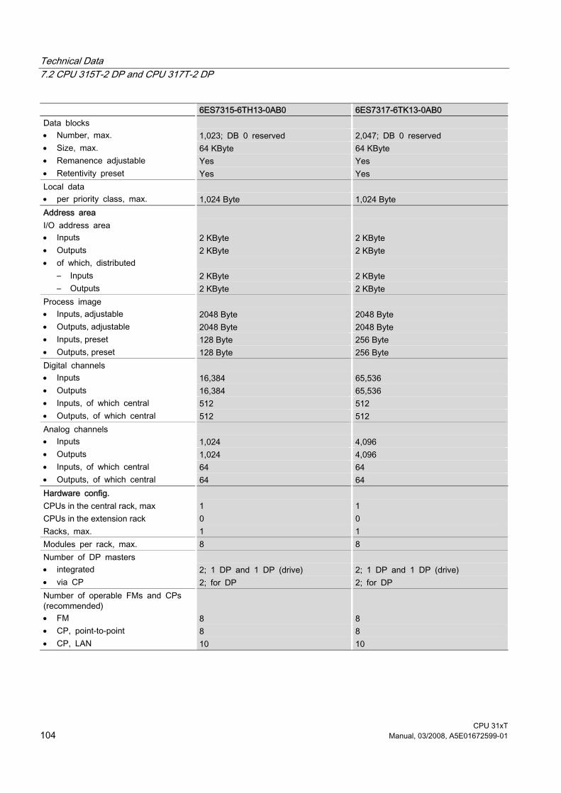
Technical Data 7.2 CPU 315T-2 DP and CPU 317T-2 DP
CPU 31xT 104 Manual, 03/2008, A5E01672599-01
6ES7315-6TH13-0AB0 6ES7317-6TK13-0AB0 Data blocks • Number, max. 1,023; DB 0 reserved 2,047; DB 0 reserved • Size, max. 64 KByte 64 KByte • Remanence adjustable Yes Yes • Retentivity preset Yes Yes Local data • per priority class, max. 1,024 Byte 1,024 Byte Address area I/O address area • Inputs 2 KByte 2 KByte • Outputs 2 KByte 2 KByte • of which, distributed
– Inputs 2 KByte 2 KByte – Outputs 2 KByte 2 KByte
Process image • Inputs, adjustable 2048 Byte 2048 Byte • Outputs, adjustable 2048 Byte 2048 Byte • Inputs, preset 128 Byte 256 Byte • Outputs, preset 128 Byte 256 Byte Digital channels • Inputs 16,384 65,536 • Outputs 16,384 65,536 • Inputs, of which central 512 512 • Outputs, of which central 512 512 Analog channels • Inputs 1,024 4,096 • Outputs 1,024 4,096 • Inputs, of which central 64 64 • Outputs, of which central 64 64 Hardware config. CPUs in the central rack, max 1 1 CPUs in the extension rack 0 0 Racks, max. 1 1 Modules per rack, max. 8 8 Number of DP masters • integrated 2; 1 DP and 1 DP (drive) 2; 1 DP and 1 DP (drive) • via CP 2; for DP 2; for DP Number of operable FMs and CPs (recommended)
• FM 8 8 • CP, point-to-point 8 8 • CP, LAN 10 10

Technical Data 7.2 CPU 315T-2 DP and CPU 317T-2 DP
CPU 31xT Manual, 03/2008, A5E01672599-01 105
6ES7315-6TH13-0AB0 6ES7317-6TK13-0AB0 Time Clock • Hardware clock (real-time clock) Yes Yes • buffered and synchronizable Yes Yes • Backup time 6 weeks; at 40 °C ambient
temperature 6 weeks; at 40 °C ambient temperature
• Deviation per day, max. 10 s 10 s Operating hours counter • Number 1 4 • Number/Number range 0 0 to 3 • Range of values 0 to 2^31 hours (when using SFC
101) 0 to 2^31 hours (when using SFC 101)
• Granularity 1 hour 1 hour • Retentive Yes; Must be restarted at each
restart Yes; Must be restarted at each restart
Clock synchronization • supported Yes Yes • to MPI, Master Yes Yes • to MPI, Slave Yes Yes • to DP, Master Yes Yes • to TO, Slave Yes Yes • in AS, Master Yes Yes • in AS, Slave Yes Yes S7 message functions Number of login stations for message functions, max.
16; Depending on the configured connections for PG/OP and S7 basic communication
32; Depending on the configured connections for PG/OP and S7 basic communication
Process diagnostic messages Yes Yes simultaneously active Alarm-S blocks, max.
40 60
Test commissioning functions Status/control • Status/control variable Yes Yes • Variables Inputs, outputs, memory bits, DB,
times, counters Inputs, outputs, memory bits, DB, times, counters
• Number of variables, max. 30 30 • of which status variable, max. 30 30 • of which control variable, max. 14 14 Forcing • Forcing Yes Yes • Force, variables Inputs, outputs Inputs, outputs • Number of variables, max. 10 10 Status block Yes Yes Single step Yes Yes Number of breakpoints 2 2 Diagnostic buffer

Technical Data 7.2 CPU 315T-2 DP and CPU 317T-2 DP
CPU 31xT 106 Manual, 03/2008, A5E01672599-01
6ES7315-6TH13-0AB0 6ES7317-6TK13-0AB0 • present Yes Yes • Number of entries, max. 100 100 • adjustable No No Communication functions PG/OP communication Yes Yes Routing Yes Yes Global data communication • supported Yes Yes • Number of GD loops, max. 8 8 • Number of GD packets, max. 8 8 • Number of GD packets,
transmitter, max. 8 8
• Number of GD packets, receiver, max.
8 8
• Size of GD packets, max. 22 Byte 22 Byte • Size of GD packet (of which
consistent), max. 22 Byte 22 Byte
S7 basic communication • supported Yes Yes • Useful data per job, max. 76 Byte 76 Byte • Useful data per job (of which
consistent) max. 76 Byte; 76 bytes (with X_SEND or X_RCV); 64 bytes (with X_PUT or X_GET as server)
76 Byte; 76 bytes (with X_SEND or X_RCV); 64 bytes (with X_PUT or X_GET as server)
S7 communication • supported Yes Yes • as server Yes Yes • as client Yes; via CP and loadable FB Yes; via CP and loadable FB • User data per job, max. 180 Byte; With PUT/GET 180 Byte; With PUT/GET • User data per job, of which
consistent, max. 64 Byte; as server 160 Byte; as server
S5-compatible communication • supported Yes; via CP and loadable FC Yes; via CP and loadable FC Number of connections • overall 16 32 • usable for PG communication 15 31 • reserved for PG communication 1 1 • adjustable for PG communication,
min. 1 1
• adjustable for PG communication, max.
15 31
• usable for OP communication 15 31 • reserved for OP communication 1 1 • adjustable for OP communication,
min. 1 1
• adjustable for OP communication, max.
15 31
• usable for S7 basic communication
14 30

Technical Data 7.2 CPU 315T-2 DP and CPU 317T-2 DP
CPU 31xT Manual, 03/2008, A5E01672599-01 107
6ES7315-6TH13-0AB0 6ES7317-6TK13-0AB0 • reserved for S7-Basic
communication 0 0
• adjustable for S7-Basic communication, min.
0 0
• adjustable for S7-Basic communication, max.
14 30
1st interface Type of interface integrated RS 485 interface integrated RS 485 interface Physics RS 485 RS 485 isolated Yes Yes Power supply to interface (15 to 30 V DC), max.
200 mA 200 mA
Functionality • MPI Yes Yes • DP master Yes Yes • DP slave Yes Yes • Point-to-point coupling No No MPI • Services
– PG/OP communication Yes Yes – Routing Yes Yes – Global data communication Yes Yes – S7 basic communication Yes Yes – S7 communication Yes Yes – S7 communication, as client Yes; via CP and loadable FB Yes; via CP and loadable FB – S7 communication, as server Yes Yes
• Transmission speeds, max. 12 Mbit/s 12 Mbit/s DP master • Services
– PG/OP communication Yes Yes – Routing Yes Yes – Global data communication No No – S7 basic communication Yes Yes – S7 communication Yes Yes – Equidistance support Yes Yes – Synchronous cycle Yes, OB 61 Yes, OB 61 – SYNC/FREEZE Yes Yes – DPV1 Yes Yes
• Transmission speeds, max. 12 Mbit/s 12 Mbit/s • Number of DP slaves, max. 124 124

Technical Data 7.2 CPU 315T-2 DP and CPU 317T-2 DP
CPU 31xT 108 Manual, 03/2008, A5E01672599-01
6ES7315-6TH13-0AB0 6ES7317-6TK13-0AB0 • Address area
– Inputs, max. 2 KByte; 244 bytes per DP slave 2 KByte; 244 bytes per DP slave – Outputs, max. 2 KByte; 244 bytes per DP slave 2 KByte; 244 bytes per DP slave
DP slave • Services
– Routing Yes Yes – Global data communication No No – S7 basic communication No No – S7 communication Yes, only as server Yes, only as server – direct data exchange (cross
traffic) Yes Yes
– DPV1 No No • Transmission speeds, max. 12 Mbit/s 12 Mbit/s • automatic baud rate search Yes, only with passive interface Yes, only with passive interface • Transfer memory
– Inputs 244 Byte 244 Byte – Outputs 244 Byte 244 Byte
• Address areas, max. 32 32 • User data per address area, max. 32 Byte 32 Byte 2nd interface Type of interface integrated RS 485 interface integrated RS 485 interface Physics RS 485 RS 485 isolated Yes Yes Power supply to interface (15 to 30 V DC), max.
200 mA 200 mA
Functionality • MPI No No • DP master Yes; DP(DRIVE)-Master Yes; DP(DRIVE)-Master • DP slave No No • Point-to-point coupling No No DP master • Services
– PG/OP communication No No – Routing Yes Yes – Global data communication No No – S7 basic communication No No – S7 communication No No – Equidistance support Yes Yes – Synchronous cycle Yes Yes – SYNC/FREEZE No No – Activation/deactivation of DP
slaves Yes Yes
– DPV1 No No • Transmission speeds, max. 12 Mbit/s 12 Mbit/s • Number of DP slaves, max. 64 64 • Address area

Technical Data 7.2 CPU 315T-2 DP and CPU 317T-2 DP
CPU 31xT Manual, 03/2008, A5E01672599-01 109
6ES7315-6TH13-0AB0 6ES7317-6TK13-0AB0 – Inputs, max. 1 KByte; 244 bytes per DP slave 1 KByte; 244 bytes per DP slave – Outputs, max. 1 KByte; 244 bytes per DP slave 1 KByte; 244 bytes per DP slave
GSD file http://www.automation.siemens.com/csi/gsd
http://www.automation.siemens.com/csi/gsd
CPU/programming Programming language • LAD Yes Yes • FUP Yes Yes • AWL Yes Yes Operational stocks See instruction list See instruction list Nesting levels 8 8 User program protection/password protection
Yes Yes
System functions (SFC) See instruction list see instruction list System function blocks (SFB) see instruction list see instruction list Cycle time monitoring • lower limit 1 ms 1 ms • upper limit 6,000 ms 6,000 ms • adjustable Yes Yes • preset 150 ms 150 ms Digital inputs Number of digital inputs 4 4 Cable length Cable length, shielded, max. 1,000 m 1,000 m Cable length unshielded, max. 600 m 600 m Input characteristic curve to IEC 1131, Typ 1
Yes Yes
Input voltage • Rated value, DC 24 V 24 V • for signal "0" -3 to +5 V -3 to +5 V • for signal "1" 15 to 30 V 15 to 30 V Input current • for signal "1", typ. 7 mA 7 mA Input delay (for rated value of input voltage)
• for counter/technological functions – at "0" to "1", max. 10 µs; typically 10 µs; typically – at "1" to "0", max. 10 µs; typically 10 µs; typically
Digital outputs Number of digital outputs 8 8 Cable length • Cable length, shielded, max. 1,000 m 1,000 m • Cable length unshielded, max. 600 m 600 m Short-circuit protection of the output Yes Yes • Response threshold, typ. 1.0 A 1.0 A

Technical Data 7.2 CPU 315T-2 DP and CPU 317T-2 DP
CPU 31xT 110 Manual, 03/2008, A5E01672599-01
6ES7315-6TH13-0AB0 6ES7317-6TK13-0AB0 Limitation of inductive shutdown voltage to
2L+ (-48 V) 2L+ (-48 V)
Lamp load, max. 5 W 5 W Controlling a digital input Yes Yes Output voltage • for signal "0" DC, max. 3 V 3 V • for signal "1", min. 2L+ (-2.5 V) 2L+ (-2.5 V) Output current • for signal "1" rated value 0.5 A 0.5 A • for signal "1" permissible range,
0 to 60 °C, min. 5 mA 5 mA
• for signal "1" permissible range, 0 to 60 °C, max.
0,6 A 0,6 A
• for signal "0" residual current, max.
0.3 mA 0.3 mA
Parallel switching of 2 outputs • for increased power No No • for redundant control of a load No No Switching frequency • with resistive load, max. 100 Hz 100 Hz • with inductive load, max. 0.2 Hz; to IEC 947-5-1, DC13 0.2 Hz; to IEC 947-5-1, DC13 • on lamp load, max. 100 Hz 100 Hz Aggregate current of the outputs (per group)
• horizontal installation – up to 40 °C, max. 4 A 4 A – up to 60 °C, max. 3 A 3 A
Load impedance range • lower limit 48 Ω 48 Ω • upper limit 4 kΩ 4 kΩ Encoder Connectable encoders • 2-wire BEROS No No Status information/alarms/diagnostics Alarms • Alarms No No Diagnoses • Diagnostic functions No No Diagnostics indication LED • Status indicator digital output
(green) Yes Yes
• Status indicator digital input (green)
Yes Yes
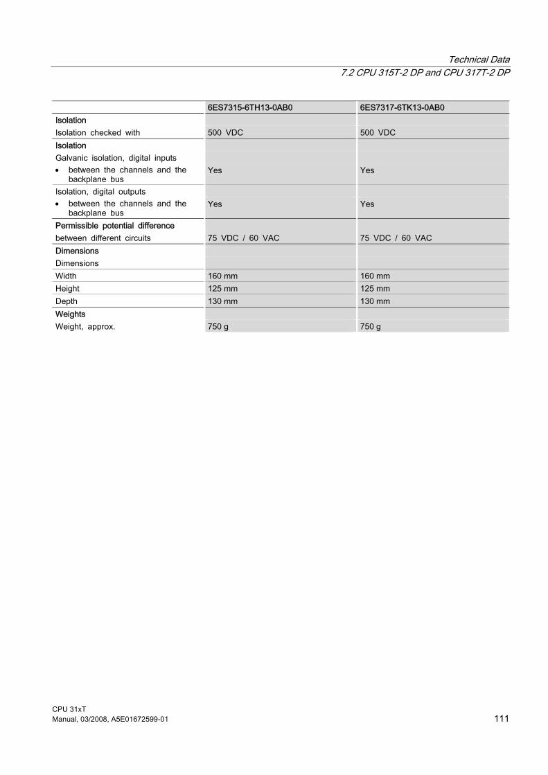
Technical Data 7.2 CPU 315T-2 DP and CPU 317T-2 DP
CPU 31xT Manual, 03/2008, A5E01672599-01 111
6ES7315-6TH13-0AB0 6ES7317-6TK13-0AB0 Isolation Isolation checked with 500 VDC 500 VDC Isolation Galvanic isolation, digital inputs • between the channels and the
backplane bus Yes Yes
Isolation, digital outputs • between the channels and the
backplane bus Yes Yes
Permissible potential difference between different circuits 75 VDC / 60 VAC 75 VDC / 60 VAC Dimensions Dimensions Width 160 mm 160 mm Height 125 mm 125 mm Depth 130 mm 130 mm Weights Weight, approx. 750 g 750 g

Technical Data 7.3 Integrated Inputs/Outputs for Technology
CPU 31xT 112 Manual, 03/2008, A5E01672599-01
7.3 Integrated Inputs/Outputs for Technology
7.3.1 Arrangement of integrated inputs/outputs for integrated technology
Introduction The Technology CPU has 4 digital inputs and 8 digital outputs integrated. You use these inputs and outputs for technology functions, e.g. reference point acquisition (reference cams) or high-speed output cam switching signals. You can also use the digital inputs / outputs with the technology functions "MC_ReadPeriphery" and "MC_WritePeriphery" in the STEP 7 user program.
Figure 7-1 Block diagram of integrated inputs/outputs for integrated technology

CPU 31xT Manual, 03/2008, A5E01672599-01 113
Appendix AA.1 Information for the Changeover to the Technology CPU
A.1.1 Scope
Who should read this information? Are you already using a CPU 31x, a CPU 31x IFM or a CPU 31x-2 DP from the SIMATIC S7-300 series and now want to upgrade to a Technology CPU? Please note that problems may occur when you download your user program to the "new" CPU. Please read the following information regarding migration to the Technology CPU.
A.1.2 Changed behavior of certain SFCs
SFC 13, SFC 56 and SFC 57 which work asynchronously... Some of the SFCs that work asynchronously, when used on CPUs 312 IFM to 318-2 DP, were always, or under certain conditions, processed after the first call ("quasi-synchronous"). On the Technology CPU, these SFCs actually run asynchronously. Asynchronous processing may cover multiple OB1 cycles. As a result, a wait loop may turn into an endless loop within an OB. The following are affected: ● SFC 13 "DPNRM_DG"
On CPUs 312 IFM to 318-2 DP, this SFC always works "quasi synchronously" when it is called in OB 82. On the Technology CPU, it generally works asynchronously.
Note In the user program, the job should merely be started in OB 82. The data should be evaluated in the cyclical program, taking account of the BUSY bits and the value returned in RET_VAL.
Appendix A.1 Information for the Changeover to the Technology CPU
CPU 31xT 114 Manual, 03/2008, A5E01672599-01
Tip If you are using a Technology CPU, we recommend that you use SFB 54, rather than SFC 13 "DPNRM_DG". ● SFC 56 "WR_DPARM"; SFC 57 "PARM_MOD"
On CPUs 312 IFM to 318-2 DP, these SFCs always work "quasi-synchronously" during communication with centralized I/O modules and always work synchronously during communication with distributed I/O modules.
Note If you are using SFC 56 "WR_DPARM" or SFC 57 "PARM_MOD", you should always evaluate the SFCs' BUSY bit.
SFC 20 "BLKMOV" In the past, this SFC could be used with CPUs 312 IFM to 318-2 DP to copy data from a non runtime-related DB. SFC 20 no longer has this functionality with the Technology CPU SFC 83 "READ_DBL" must now be used instead.
SFC 54 "RD_DPARM" This SFC is no longer available on the Technology CPU. Use SFC 102 "RD_DPARA" instead, which works asynchronously.
SFCs that may return other results You can ignore the following points if you only use logical addressing in your user program. When using address conversion in your user program (SFC 5 "GADR_LGC", SFC 49 "LGC_GADR"), you must check the assignment of the slot and logical start address for your DP slaves. ● In the past, the diagnostic address of a DP slave was assigned to the slave's virtual slot
2. Since DPV1 was standardized, this diagnostic address has been assigned to virtual slot 0 (station proxy) for the Technology CPU
● If the slave has modeled a separate slot for the interface module (e.g. Technology CPU as an intelligent slave or IM 153), then its address is assigned to slot 2.
Activating / deactivating DP slaves via the SFC 12 With the Technology CPU, slaves that were deactivated via SFC 12 are no longer automatically activated at the RUN to STOP transition. Now they are not activated until they are restarted (STOP to RUN transition).

Appendix A.1 Information for the Changeover to the Technology CPU
CPU 31xT Manual, 03/2008, A5E01672599-01 115
A.1.3 Interrupt events from distributed I/Os while the CPU status is in STOP
Interrupt events from distributed I/Os while the CPU status is in STOP With the new DPV1 functionality (IEC 61158/ EN 50170, volume 2, PROFIBUS), the handling of incoming interrupt events from the distributed I/Os while the CPU status is in STOP has also changed. Previous response by the CPU in the STOP state: With CPUs 312 IFM to 318-2 DP, an interrupt event was initially noted while the CPU was in STOP mode. When the CPU status subsequently returned to RUN, the interrupt was then fetched by an appropriate OB (e.g. OB 82). New response by the CPU: With the Technology CPU, an interrupt event (process or diagnostic interrupt, new DPV1 interrupts) is acknowledged by the distributed I/O while the CPU is still in STOP status, and is entered in the diagnostic buffer if necessary (diagnostic interrupts only). When the CPU status subsequently returns to RUN, the interrupt is no longer fetched by the OB. Possible slave faults can be read using suitable SSL queries (e.g. read SSL 0x692 via SFC51).
A.1.4 Runtimes that change while the program is running
Runtimes that change while the program is running If you have created a user program that has been fine-tuned in relation to certain processing times, please note the following points if you are using a Technology CPU: ● The program will run much faster on the Technology CPU. ● Functions that require MMC access (e.g. system start-up time, program download in
RUN, return of DP station, etc), may sometimes run slower on the Technology CPU.

Appendix A.1 Information for the Changeover to the Technology CPU
CPU 31xT 116 Manual, 03/2008, A5E01672599-01
A.1.5 Converting the diagnostic addresses of DP slaves
Converting the diagnostic addresses of DP slaves If you are using a Technology CPU as the master, please note that you may have to reassign the diagnostic addresses for the slaves since the changes to the DPV1 standard sometimes require two diagnostic addresses per slave. ● The virtual slot 0 has its own address (diagnostic address of the station proxy). The
module status data for this slot (read SSL 0xD91 with SFC 51 "RDSYSST") contains IDs that relate to the entire slave/station, e.g. the "station error ID". Failure and restoration of the station are also signaled in OB 86 on the master via the diagnostic address of the virtual slot 0.
● The interface module is also modeled as a separate, virtual slot for some slaves (e.g. CPU as intelligent slave or IM 153) in which case it is assigned to virtual slot 2 with a separate address. When the Technology CPU is used as an intelligent slave, for example, the operating status change is signaled in diagnostic interrupt OB 82 of the master via this address.
Note Reading diagnostics data with SFC 13 "DPNRM_DG": The originally assigned diagnostics address still works. Internally, STEP 7 assigns this address to slot 0.
When using SFC51 "RDSYSST", for example, to read module status information or module rack/station status information, you must also consider the change in slot significance as well as the additional slot 0.
A.1.6 Reusing existing hardware configurations
Reusing existing hardware configurations If you reuse the configuration of a CPU 312 IFM to 318-2 DP for a Technology CPU, the CPU may not run correctly. If this is the case, you will have to replace the CPU in the STEP 7 hardware configuration editor. When you replace the CPU, STEP 7 will automatically accept all the settings (if appropriate and possible).

Appendix A.1 Information for the Changeover to the Technology CPU
CPU 31xT Manual, 03/2008, A5E01672599-01 117
A.1.7 Replacement of a Technology CPU
Replacement of a Technology CPU The Technology CPU is supplied with a connector inserted in the power supply port. You do not need to disconnect the cables of the CPU when you replace a Technology CPU: Insert a screwdriver with 3.5 mm blade into the right side of the connector to open the interlock mechanism, then unplug it from the CPU. Once you have replaced the CPU, simply plug the connecting plug back into the power supply connector.
A.1.8 Using consistent data areas in the process image of a DP slave system
Consistent data The table below illustrates the points to consider with respect to communication in a DP master system if you want to transfer I/O areas with "Total length" consistency. You can transfer a maximum of 128 bytes of consistent data.
Table A-1 Consistent data
CPU 315-2 DP (as of firmware 2.0.0), CPU 317, CPU 319 CPU 31xC
CPU 315-2 DP (as of firmware 1.0.0), CPU 316-2 DP, CPU 318-2 DP (firmware < 3.0)
CPU 318-2 DP (firmware >= 3.0)
The address area of consistent data in the process image is automatically updated.
Even if it exist in the process image, consistent data is not automatically updated.
You can choose whether or not to update the address area of consistent data in the process image.
In order to read and write consistent data you can also use the SFCs 14 and 15 If the address area of consistent data is outside the process image, you have to use the SFCs 14 and 15 to read and write consistent data. Direct access to consistent areas is also possible (e.g. L PEW or T PAW).
To read and write consistent data, you must use SFC14 and 15.
To read and write consistent data, you can also use SFC 14 and SFC 15. If the address area of consistent data is not in the process image, you must use SFC 14 and SFC 15 to read and write consistent data. Direct access to consistent areas is also possible (e.g. L PEW or T PAW):
Appendix A.1 Information for the Changeover to the Technology CPU
CPU 31xT 118 Manual, 03/2008, A5E01672599-01
A.1.9 Load memory design for the Technology CPU
Load memory design for the Technology CPU On CPUs 312 IFM to 318-2 DP, the load memory is integrated into the CPU and may be extended with a memory card, The load memory of the Technology CPU is located on the Micro Memory Card (MMC). and is retentive. When blocks are downloaded to the CPU, they are stored on the MMC and cannot be lost even in the event of a power failure or memory reset.
Note User programs can only be downloaded and thus the CPU can only be used if the MMC is inserted.
A.1.10 PG/OP functions
PG/OP functions With CPUs 315-2 DP (6ES7315-2AFx3-0AB0), 316-2DP and 318-2 DP, PG/OP functions at the DP interface were only possible if the interface was set to active. With CPUs 31xC/31x, these functions are possible at both active and passive interfaces. The performance of the passive interface is considerably lower, however.
A.1.11 Routing for the CPU 31xC/31x as an intelligent slave
Routing for the CPU 31xC/31x as an intelligent slave If you use the CPU 31xC/31x as an intelligent slave, the routing function can only be used with an actively-configured DP interface. In the properties of the DP interface in STEP 7, select the "Test, Commissioning, Routing" check box of the "DP-Slave" option.
A.1.12 Altered retentive response with a Technology CPU
Altered retentive response with a Technology CPU With data blocks for the Technology CPU ● you can set the retentive response in the block properties of the DB. ● Using SFC 82 "CREA_DBL" -> Parameter ATTRIB, NON_RETAIN bit, you can specify if
the actual values of a DB should be maintained at POWER OFF/ON or STOP-RUN (retentive DB) or if the start values should be read from the load memory (non-retentive DB).
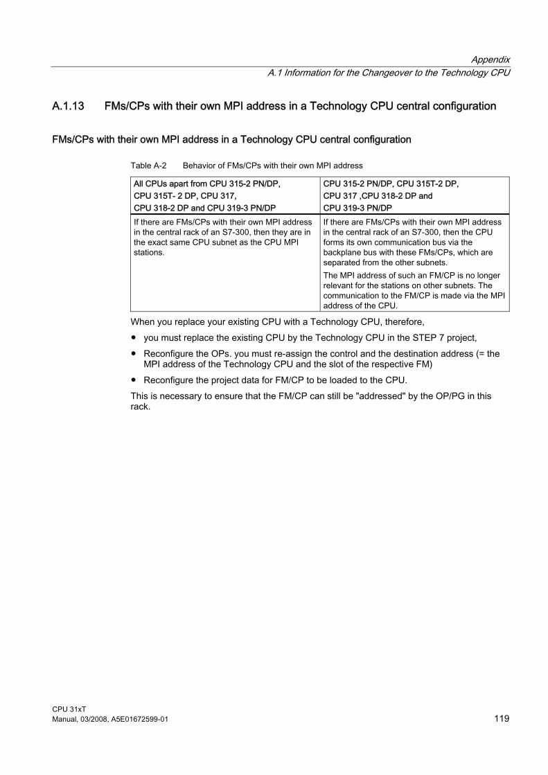
Appendix A.1 Information for the Changeover to the Technology CPU
CPU 31xT Manual, 03/2008, A5E01672599-01 119
A.1.13 FMs/CPs with their own MPI address in a Technology CPU central configuration
FMs/CPs with their own MPI address in a Technology CPU central configuration
Table A-2 Behavior of FMs/CPs with their own MPI address
All CPUs apart from CPU 315-2 PN/DP, CPU 315T- 2 DP, CPU 317, CPU 318-2 DP and CPU 319-3 PN/DP
CPU 315-2 PN/DP, CPU 315T-2 DP, CPU 317 ,CPU 318-2 DP and CPU 319-3 PN/DP
If there are FMs/CPs with their own MPI address in the central rack of an S7-300, then they are in the exact same CPU subnet as the CPU MPI stations.
If there are FMs/CPs with their own MPI address in the central rack of an S7-300, then the CPU forms its own communication bus via the backplane bus with these FMs/CPs, which are separated from the other subnets. The MPI address of such an FM/CP is no longer relevant for the stations on other subnets. The communication to the FM/CP is made via the MPI address of the CPU.
When you replace your existing CPU with a Technology CPU, therefore, ● you must replace the existing CPU by the Technology CPU in the STEP 7 project, ● Reconfigure the OPs. you must re-assign the control and the destination address (= the
MPI address of the Technology CPU and the slot of the respective FM) ● Reconfigure the project data for FM/CP to be loaded to the CPU. This is necessary to ensure that the FM/CP can still be "addressed" by the OP/PG in this rack.

Appendix A.1 Information for the Changeover to the Technology CPU
CPU 31xT 120 Manual, 03/2008, A5E01672599-01

CPU 31xT Manual, 03/2008, A5E01672599-01 121
Glossary
ACCU Accumulators represent CPU register and are used as buffer memory for download, transfer, comparison, calculation and conversion operations.
Address An address represents the identifier of a specific operand or operand range. Examples: input I 12.1; flag word MW 25; data block DB 3.
Analog module Analog modules convert analog process values (for example, temperature) into digital values that can be processed by the CPU, or convert digital values into analog manipulated variables.
Automation system An automation system is a programmable controller for SIMATIC S7.
Back-up memory The backup memory ensures buffering of the memory areas of a CPU without backup battery. It backs up a configurable number of timers, counters, flags and data bytes, the retentive timers, counters, flags and data bytes.
Baud rate Speed of the data transmission (bps)
Bus A transfer medium that interconnects several nodes. Data can be transferred via serial or parallel circuits, that is, via electrical or fiber optic conductors.
Bus segment Self-contained part of a bus system. Bus segments are interconnected by way of repeaters, for example, in PROFIBUS DP.

Glossary
CPU 31xT 122 Manual, 03/2008, A5E01672599-01
Clock flag Flag which can be used to generate clock pulses in the user program (1 flag byte).
Note When operating with S7-300 CPUs, make sure that the clock flag byte is not overwritten in the user program!
Code block A SIMATIC S7 code block contains elements of the STEP 7 user program. (In contrast to a data block: This contains only data.)
Cold restart On CPU startup (e.g. after it is switched from STOP to RUN via the mode selector or with POWER ON), OB100 (restart) is initially executed, prior to cyclic program execution (OB1). On restart, the process input image is read in and the STEP 7 user program is executed, starting at the first command in OB1.
Configuration Assignment of modules to racks/slots and (for example with signal modules) addresses.
Consistent data Data that belongs together in terms of its content and must not be separated is designated as consistent data. As an example, the values of analog modules must always be treated as consistent data; i.e. the value of an analog module must not be corrupted by reading it out at two different times.
Counters Counters are part of CPU system memory. The content of "counter cells" can be modified by STEP 7 statements (for example, up/down count.)
CPU Central processing unit = CPU of the S7 automation system with a control and arithmetic unit, memory, operating system, and interface for the programming device.
Cycle time The cycle time represents the time a CPU requires for one execution of the user program.
Glossary
CPU 31xT Manual, 03/2008, A5E01672599-01 123
Cyclic interrupt → interrupt, cyclic interrupt
Data block Data blocks (DB) are data areas in the user program and contain the user data. There are global data blocks which can be accessed by all code blocks, and instance data blocks which are assigned to a specific FB call.
Data, static Static data are data that are used only within a function block. These data are stored in an instance data block belonging to the function block. Data stored in an instance data block are retained until the next function block call.
Data, temporary Temporary data represent local data of a block. They are stored in the L-stack when the block is executed. After the block has been processed, these data are no longer available.
Diagnostic interrupt Modules capable of diagnostics report detected system errors to the CPU by means of diagnostic interrupts.
Diagnostics System diagnostics
Diagnostics buffer The diagnostics buffer is a buffered memory area in the CPU. It stores diagnostic events in the order of their occurrence.
DP master A master which behaves in accordance with EN 50170, Part 3 is known as a DP master.
DP slave A slave operated on the PROFIBUS with PROFIBUS DP protocol and which behaves in accordance with EN 50170, Part 3 is referred to as DP slave.
DP(DRIVE) PROFIBUS interface that is controlled by the integrated technology of the CPU isochronously (and therefore also equidistant).

Glossary
CPU 31xT 124 Manual, 03/2008, A5E01672599-01
DPV1 The designation DPV1 means extension of the functionality of the acyclical services (to include new interrupts, for example) provided by the DP protocol. The DPV1 functionality is integrated in IEC 61158 / EN 50170, Volume 2, PROFIBUS.
Engineering station PC workplace, at which configuration work is performed on a control system.
Error display One of the possible reactions of the operating system to a runtime error is to output an error message. The other possible reactions include: Error reaction in the user program, CPU in STOP.
Error handling via OB After the operating system has detected a specific error (e.g. an access error with STEP 7), it calls a dedicated organization block (error OB) in which the subsequent behavior of the CPU can be defined.
Error reaction Reaction to a runtime error. The operating system can react in the following ways: It sets the automation system to STOP, indicates the error, or calls an OB in which the user can program a reaction.
Execution level Execution levels form the interface between the operating system of the CPU and the user program. The sequence for executing the blocks of the user program is specified in the execution levels.
Flag Flags are part of the CPU's system memory. They store intermediate results of calculations. They can be accessed in bit, byte, word or double word operations.
Force The force function can be used to assign fixed values to specific variables of a user program or CPU (also: inputs and outputs). In this context, please note the limitations listed in the Overview of the test functions section in the Test Functions, Diagnostics and Troubleshooting chapter in the S7-300 Installation manual.

Glossary
CPU 31xT Manual, 03/2008, A5E01672599-01 125
Function According to IEC 1131-3, a function (FC) is a code block without static data. A function allows transfer of parameters in a user program. Functions are therefore suitable for programming frequently occurring complex functions, e.g. calculations.
Function block According to IEC 1131-3, a function block (FB) is a code block with static data. An FB enables the transfer of parameters in the user program. Function blocks are therefore suitable for programming frequently occurring complex functions, e.g. controls, mode selections.
GD circuit A GD circuit comprises a number of CPUs sharing data by means of global data communication, and is used as follows: ● A CPU sends a GD packet to the other CPUs. ● A CPU sends and receives a GD packet from another CPU. A GD circuit is identified by a GD circuit number.
GD element A GD element is generated by assigning shared global data. It is identified by a unique global data ID in the global data table.
GD packet A GD packet can consist of one or more GD elements transmitted in a single message frame.
Global data Global data can be addressed from any code block (FC, FB, OB). In particular, this refers to bit memory M, inputs I, outputs Q, timers, counters and data blocks DB. Global data can be accessed either absolutely or symbolically.
Global data communication Global data communication is a method of transferring global data between CPUs (without CFBs).
GSD file The device data file (GSD file) contains all slave-specific properties. The format of GSD files is specified in EN 50170, Volume 2, PROFIBUS.

Glossary
CPU 31xT 126 Manual, 03/2008, A5E01672599-01
Instance data block The STEP 7 user program assigns an automatically generated DB to every call of a function block. The instance data block stores the values of input, output and in/out parameters, as well as local block data.
Integrated inputs/outputs for integrated technology The Technology CPU has 4 digital inputs and 8 digital outputs integrated. You use these inputs and outputs for technology functions, e.g. reference point acquisition (BERO) or high-speed output cam switching signals. The integrated inputs and outputs can also be used with technology functions in the STEP 7 user program.
Integrated technology In addition to the standard PLC functions, the Technology CPU has been expanded with integrated technology functions. The operating system of the Technology CPU has also been expanded in order to guarantee fast processing times for these technology functions.
Intelligent DP slave Signal preprocessing field device. One of its features is that the input/output range provided for the DP master does not correspond to an actually existing I/O, but an input/output range that is mapped by a preprocessing CPU.
Interrupt The CPU's operating system knows different priority classes for controlling user program execution. These priority classes include interrupts, e.g. process interrupts. When an interrupt is triggered, the operating system automatically calls an assigned OB. In this OB the user can program the desired response (e.g. in an FB).
Interrupt, cyclic interrupt A cyclic interrupt is generated periodically by the CPU in a configurable time pattern. A corresponding OB will be processed. See also Organization Block
Interrupt, delay The time-delay interrupt belongs to one of the priority classes in SIMATIC S7 program processing. It is generated on expiration of a time started in the user program. A corresponding OB will be processed.
Interrupt, diagnostic → diagnostics interrupt
Glossary
CPU 31xT Manual, 03/2008, A5E01672599-01 127
Interrupt, process → process interrupt
Interrupt, status A status interrupt can be generated by a DPV1 slave and causes OB 55 to be called on the DPV1 master. For detailed information on OB 55, see the Reference Manual System software for S7-300/400: System and Standard Functions).
Interrupt, time-of-day The time-of-day interrupt is one of the priority classes in SIMATIC S7 program processing. SIMATIC S7. It is generated at a specific date (or daily) and time-of-day (e.g. 9:50 or hourly, or every minute). A corresponding OB will be processed.
Interrupt, update An update interrupt can be generated by a DPV1 slave and causes OB56 to be called on the DPV1 master. For detailed information on OB56, see the Reference Manual System software for S7-300/400: System and Standard Functions).
Interrupt, vendor-specific A vendor-specific interrupt can be generated by a DPV1 slave. It causes OB57 to be called on the DPV1 master. For detailed information on OB 57, refer to the Reference Manual System Software for S7-300/400: System and Standard Functions).
Load memory Load memory is part of the CPU. It contains objects generated by the programming device. It can be implemented either as a plug-in memory card or as integrated memory.
Local data Data, temporary
Master When a master is in possession of the token, it can send data to other nodes and request data from other nodes (= active node).
Micro memory card Micro memory cards are memory media for CPUs and CPs. When compared with a → memory card, a Micro Memory Card is smaller.

Glossary
CPU 31xT 128 Manual, 03/2008, A5E01672599-01
Module parameter Module parameters are values with which the behavior of the module can be set. A distinction is made between static and dynamic module parameters.
MPI The multi-point interface (MPI) is the SIMATIC S7 interface for programming devices. It allows simultaneous operation of several nodes (programming devices, text displays, operator panels) on one or more CPUs. Each node is identified by a unique address (MPI address).
Nesting depth Using block calls, one block can be called from within another. Nesting depth is referred to as the number of simultaneously called code blocks.
OB priority The CPU operating system distinguishes between different priority classes, for example, cyclic program execution, process interrupt controlled program processing. Each priority class is assigned organization blocks (OBs) in which the S7 user can program a response. Per default, OBs have different priorities and they are processed and interrupt each other according to their priority classes.
Operating mode SIMATIC S7 automation systems know the following operating modes: STOP, STARTUP, RUN.
Operating system The operating system of the CPU organizes all the functions and processes of the CPU that are not connected to a special control task. → CPU
Organization block Organization blocks (OBs) form the interface between CPU operating system and the user program. The sequence for executing the user program is specified in the organization blocks.
Parameters 1. Variable of a STEP 7 code block 2. Variable for setting the response of a module (one or several per module). As delivered, each module has an appropriate default setting that can be changed via configuration in STEP 7. The parameters are divided into static and dynamic parameters.

Glossary
CPU 31xT Manual, 03/2008, A5E01672599-01 129
Parameters, dynamic In contrast to static parameters, the dynamic parameters of modules can be changed during operation by calling an SFC in the user program, for example limit values of an analog signal input module.
Parameters, static Unlike dynamic parameters, static parameters of modules cannot be changed by the user program. You can only modify these parameters by editing your configuration in STEP 7, for example, modification of the input delay parameters of a digital signal input module.
Priority class The S7 CPU operating system provides up to 26 priority classes (or "Program execution levels"). Specific OBs are assigned to these classes. The priority classes determine which OBs interrupt other OBs. Multiple OBs of the same priority class do not interrupt each other. In this case, they are executed sequentially.
Process image The process image is a component of the system memory of the CPU. At the start of the cyclic program the signal states of the input modules are transferred to the process input image. At the end of the cyclic program the process output image is transferred as a signal state to the output modules.
Process interrupt A process interrupt is triggered by interrupt-triggering modules as a result of a specific event in the process. The process interrupt is signaled to the CPU. The assigned organization block will be processed according to interrupt priority.
PROFIBUS DP Digital, analog and intelligent modules, as well as a wide range of field devices in accordance with EN 50170, Part 3, such as drives or valve terminals are moved to the local process by the automation system across distances of up to 23 km. The modules and field devices are interconnected with the automation system via the PROFIBUS DP field bus and are addressed in the same way as the centralized I/O.
Programming device Programming devices are essentially personal computers suitable for industry that have a compact design and can be transported. Their distinguishing feature is the special hardware and software for SIMATIC programmable logic controllers.
RAM RAM (Random Access Memory) is a semiconductor read/write memory.
Glossary
CPU 31xT 130 Manual, 03/2008, A5E01672599-01
Reduction factor The reduction factor determines the send/receive frequency for GD packets on the basis of the CPU cycle.
Reference ground → Ground
Reference potential Voltages of participating circuits are referenced to this potential when they are viewed and/or measured.
Retentive address areas A memory area is considered retentive if its contents are retained even after a power loss and transitions from STOP to RUN. The non-retentive area of the flags, timers and counters is reset following a power failure and a transition from the STOP mode to the RUN mode. Retentive can be the: ● Flag ● S7 times ● S7 counters ● Data areas
Revision level Differentiates products of the same order number. The product version is incremented when forward-compatible functions are enhanced, after production-related modifications (use of new parts/components) and for bug fixes.
Runtime error Errors that occur during execution of the user program on the automation system (in other words, not in the process).
S7T Config With S7T Config you configure the technology objects required to implement your motion control task. The STARTER for the drives from the MICROMASTER and SINAMICS families is integrated in S7T Config.
Segment → Bus segment

Glossary
CPU 31xT Manual, 03/2008, A5E01672599-01 131
Shutdown What happens during shutdown? 1. The control of the Technology CPU is already in STOP mode during shutdown. The
outputs of the centralized and distributed I/Os are deactivated. 2. The integrated inputs/outputs for integrated technology and the ET 200M on the
DP(DRIVE) are still active during shutdown. 3. The integrated technology of the Technology CPU shuts down the drives on the
PROFIBUS DP(DRIVE) in a controlled manner. 4. The integrated technology of the CPU then also goes into STOP. The integrated
inputs/outputs for integrated technology and the ET 200M on the DP(DRIVE) are deactivated.
The maximum duration of shutdown depends on your configuration in S7T Config.
Signal module Signal modules (SMs) form the interface between the process and the automation system. There are digital input and output modules (input/output module, digital) and analog input and output modules (input/output module, analog).
Signal status list The system status list contains data that describes the current status of an S7-300. You can always use this list to obtain an overview of: ● The configuration of the S7-300 ● The current CPU configuration and configurable signal modules ● The current states and processes in the CPU and in configurable signal modules.
Slave A slave can only exchange data with a master after being requested to do so by the master.
STARTUP The STARTUP mode is executed at the transition from STOP to RUN mode. It can be triggered by means of the mode selector switch, or after power on, or by an operator action on the programming device. An S7-300 performs a restart.
STEP 7 Programming software for the creation of user programs for SIMATIC S7 controllers.

Glossary
CPU 31xT 132 Manual, 03/2008, A5E01672599-01
Substitute value Substitute values are parameterizable values which output modules transfer to the process when the CPU switches to STOP mode. In the event of an I/O access error, a substitute value can be written to the accumulator instead of the input value which could not be read (SFC 44).
System diagnostics System diagnostics is the detection, evaluation, and indication of faults/errors which occur within the automation system. Examples of such error/faults are program errors or failures on modules. System errors can be indicated by LEDs or in STEP 7.
System function A system function (SFC) is a function integrated in the operating system of the CPU that can be called when necessary in the STEP 7 user program.
System function block A system function block (SFB) is a function block integrated in the operating system of the CPU that can be called when necessary in the STEP 7 user program.
System memory System memory is an integrated RAM memory in the CPU. System memory contains the address areas (e.g. timers, counters, flags) and data areas that are required internally by the operating system (for example, communication buffers).
Technology configuration data The configuration that you have created with STEP 7 is stored in the technology configuration data.
Technology data block The integrated technology provides current information on the status and on the values of the technology objects via the technology data blocks.
Technology objects Technology objects are the logical representation of axes, output cams, measuring inputs, cams and external encoders, with which the drive components can be controlled. The technology objects configured with the SIMATIC S7-Technology option package contain definitions for the physical properties of the mechanical system, for limits, monitoring and control.

Glossary
CPU 31xT Manual, 03/2008, A5E01672599-01 133
Technology system data Technology system data are the data of the technology objects, such as drive axis, output cam, ...
Terminator The terminating resistor is used to avoid reflections on data links.
Time-delay interrupt → interrupt, delay
Time-of-day interrupt Interrupt, time-of-day
Timer Timers
Timers Timers are part of CPU system memory. The content of "timer cells" is automatically updated by the operating system, asynchronously to the user program. STEP 7 statements are used to define the precise function of the timer cell (for example, ON delay) and to initiate their execution (for example, start).
User memory The user memory contains the code blocks and data blocks of the user program. User memory can be integrated in the CPU, or stored on plug-in memory cards or memory modules. However, the user program is principally processed from the work memory of the CPU.
User program In SIMATIC, a distinction is made between the operating system of the CPU and user programs. The user program contains all the instructions, declarations and data for signal processing required to control a plant or a process. It is assigned to a programmable module (for example CPU or FM) and can be structured in smaller units (blocks). → operating system → STEP 7
Work memory The work memory is integrated in the CPU and cannot be extended. It is used to run the code and process user program data. Programs run exclusively in work memory and system memory.

Glossary
CPU 31xT 134 Manual, 03/2008, A5E01672599-01
CPU 31xT Manual, 03/2008, A5E01672599-01 135
Index
5 5 VDC, 15, 21
A Activation/deactivation, 116 Addressing, 19 ADI4
Analog drive interface, 29 Alarm event, 117 Analog drive interface
ADI4, 29 Analog drives, 29 Application
in industrial environments, 95 in residential areas, 95
Approval CE, 92 CSA, 93 FM, 94 Marine, 94 UL, 92
Approvals, 4 Standards, 92
Area of application, 9 Assignment
S7 connection, 39 Availability
S7 connection, 41 Axis configurations, 9
B basic knowledge
required, 3 Basic knowledge
Required, 3 BF1, 15, 22 BF3, 15, 22 Blocks
Load, 55 Upload, 57
Breakpoints, 21 Burst pulses, 96 Bus fault, 22 BUSF
LED, 22 BUSF1
LED, 22
C CE
Approval, 92 Central processing unit, 17 Code block, 45 COMBIMASTER, 11, 29 Commissioning, 20 Communication, 25
Data consistency, 37 S7 communication, 33
Communication Load configured, 74 Dependency of physical cycle time, 75 Influence on the physical cycle time, 75
Communication path S7 connection, 38
Communication services, 30 Communication variable, 37 Compression, 58 Configuration, 17
S7 communication, 38 single-tier, 11
Configuration data, 45 Technology, 47
Configuring, 11 Connectable devices, 29
PROFIBUS DP, 28 Connection
Voltage supply, 15 Connection point, 38 Continuous shock, 100 Control, 19 Control tasks, 9 Counters, 46

Index
CPU 31xT 136 Manual, 03/2008, A5E01672599-01
CPU Elements, 13 Operating system, 20
CPU memory reset, 58 CSA
Approval, 93 Cycle time
Calculation, 70 Definition, 68 Extension, 70 Maximum Cycle Time, 73 Process image, 68 Sample calculation, 85 Sequence of cyclic program processing, 69 Time-Sharing Model, 68
Cyclic interrupt, 84
D Data block (DB), 45
Non-retentive, 46 Retentive, 46 Retentive behavior, 48
Data consistency, 37 Definition
Electromagnetic Compatibility, 96 Degree of protection IP 20, 101 Delay interrupt, 84 Devices
connectable, 28, 29 non-connectable, 30
Diagnosis Address, 118
Diagnostics, 29 DP(DRIVE), 30
Dimension drawing, 102 Distribution
S7 connection, 40 DP interface error, 22 DP(DRIVE)
Diagnostics, 30 OP, 18 Programming device, 18
DP(DRIVE) interface, 11 DPV1, 42 Drive interface
analog, 29
E Electromagnetic Compatibility, 96
Electrostatic discharge, 96 Elements
CPU, 13 EMC, 96 Emission of radio interference, 97 Error display, 15, 21
DP-capable CPUs, 22 ET 200M, 29
F Field of application, 9 Fields of application, 9 Flag, 46 FM
Approval, 94 Force function, 21 FRCE, 15, 21
G GD circuit, 34 GD packet, 34 General technical specifications, 92 Global data communication, 31, 33
H Hardware catalog, 29 Hardware configuration
reuse, 118 Hardware interrupt
Response time, 37
I Identification code for Australia, 94 IEC 61131, 94 IM 174 interface for analog drives and stepper motors, 29 Indicators, 13 Information
SFCs, 115 Inputs and outputs for technology
integrated, 11, 14, 19 Integrated, 11
Insulation test, 101 Integrated inputs and outputs for technology, 11, 14, 19 Integrated Inputs/Outputs for Technology
Layout, 113, 114
Index
CPU 31xT Manual, 03/2008, A5E01672599-01 137
Integrated technology, 19 Interface, 10, 25 Interrupt response time
Calculation, 83 Definition, 83 Of signal modules, 84 Of the CPUs, 83 Process interrupt processing, 84 Sample calculation, 88
Isochronism, 18 Isochronous mode, 11, 13, 29
J Job data compartment, 63
L Layout
Integrated Inputs/Outputs for Technology, 113, 114 Memory, 45
LED, 21, 22 Display, 15
Load of blocks, 55
Load memory, 45 Size, 45
Load memory design Technology-CPU, 120
Local data, 46, 53 Longest response time
Calculation, 80 Conditions, 80
M Manual
Purpose, 3 Scope, 3
Marine Approval, 94
MASTERDRIVES, 29 Maximum Cycle Time, 73 Mechanical environmental conditions, 99 Memory
Compression, 58 Layout, 45 Retentive, 47
Memory area, 45 Memory concept, 45
Memory functions Compression, 58 Download of blocks, 55 Promming, 58 RAM to ROM, 58 Uploading blocks, 57
Memory module, 14 Memory objects
Retentive behavior, 48 Micro memory card
Micro memory card, 54 Micro Memory Card - Useful life, 55 Micro memory card (MMC), 45
Slot, 14 Technical specifications, 91
MICROMASTER, 11 MICROMASTER 4, 29 Migration
Technology CPU, 115 Mode selector switch, 15 Module
Start address, 19 Motion control, 9 Motion Control, 9 Motion tasks, 9 MPI, 19
Properties, 27 MPI / DP interface, 10, 25, 26 MPI interface
Time synchronization, 28 MRES, 15
N Network gateway, 35 Non-connectable devices, 30 Non-retentive data block, 46 Number of nodes, 19
O OP
on DP(DRIVE), 18 OP communication, 31, 32 Operand area, 46, 50 Operating mode, 15 Operating system, 20
Of the CPU, 20 Technology, 20 updating, 20
Operator controls, 13

Index
CPU 31xT 138 Manual, 03/2008, A5E01672599-01
Optional package S7-Technology, 20
P PG
on DP(DRIVE), 18 PG communication, 31 PLCopen, 9 Power supply, 17 Process image, 46
of inputs and outputs, 51 Process interrupt
Processing, 84 Processing sequence
Data block, 63, 64, 67 PROFIBUS cable, 17 PROFIBUS DP, 19
Connectable devices, 28 Properties, 27
PROFIBUS DP (DRIVE), 19 PROFIBUS DP(DRIVE), 25, 29 PROFIdrive, 29 Program execution
Runtime, 117 Programming, 11 Programming device cable, 18 Properties
MPI, 27 PROFIBUS DP, 27
Protection class, 101 Pulseshaped disturbance, 96 Purpose
Manual, 3 PUT/GET function, 37
R RAM to ROM, 58 Reduction factor, 34 Replacement of a Technology CPU, 119 Required basic knowledge, 3 Requirement
Commissioning, 20 Routing, 35
Reservation S7 connection, 39
Response time Calculating the longest, 80 Calculating the shortest, 79 Conditions for the longest, 80 Conditions for the shortest, 79 Definition, 77 DP cycle times, 78 Factors, 77 Reduction with direct I/O access, 81 Sample calculation, 86 Variation, 77
Retentive address areas, 47 Retentive behavior
DB, 48, 49 Memory objects, 48 Technology data block, 48, 49
Retentive data block, 46 Retentive memory, 47 reuse
Hardware configurations, 118 Routing, 34
Access to stations on other subnets, 34 Example of an application, 36 PG functions, 31 Requirements, 35
RUN, 15, 21 Runtime
Program execution, 117
S S7 basic communication, 31, 32 S7 communication, 31, 33
Configuration, 38 S7 connection
Assignment, 39 Availability, 41 Communication path, 38 Distribution, 40 Reservation, 39
S7 connections Time sequence for allocation, 40
S7T Config, 14 S7-Technology, 11, 63
Optional package, 20 Sample calculation
For the cycle time, 85 Of interrupt response time, 88 Of the response time, 86
Scope Manual, 3
SF, 15, 21

Index
CPU 31xT Manual, 03/2008, A5E01672599-01 139
SFC Information, 115
Shipping conditions, 98 Shock, 100 Shortest response time
Calculation, 79 Conditions, 79
Shutdown, 16, 21 Signal module, 17 SIMATIC Micro Memory Card
Plug-in MMCs, 91 Properties, 54
SIMODRIVE, 11 SIMODRIVE 611 universal, 11, 29 SIMODRIVE POSMO, 29 SINAMICS, 29 Single-tier configuration, 11 Sinusoidal disturbance, 97 Size
Load memory, 45 Slot, 19
Micro memory card (MMC), 14 Standards and approvals, 92 Start address
Module, 19 Status display, 15, 21, 45
DP-capable CPUs, 22 Stepper, 29 Stepper motors, 29 STOP, 15, 21 Storage conditions, 98 Subnets, 18 support, 4 Support, 4 System memory, 46, 50
Local data, 53 Operand areas, 50 Process image of inputs/outputs, 51
T Technical specifications
Electromagnetic Compatibility, 96 Micro memory card (MMC), 91 Shipping and storage conditions, 98
Technological configurations, 9 Technological tasks, 9
Technology, 9 Configuration data, 47 Integrated inputs and outputs, 11, 14, 19 Operating system, 20 Technology CPU, 9
Technology CPU Migration, 115 Technology, 9
Technology data block Processing sequence, 63, 64, 65 Retentive behavior, 49
Technology DB Retentive behavior, 48
Technology objects, 9 Technology system data, 45 Technology-CPU
Load memory design, 120 Temperature, 98 Test voltage, 101 TIA environment, 9 Time synchronization
MPI interface, 28 Timers, 46 Transition point, 38 Transmission rate, 18
U UL
Approval, 92 Updating
Operating system, 20 Upload, 57 Useful life of a Micro Memory Card, 55 User program
Upload, 57
V Vibration, 100 Voltage supply
Connection, 15
W Work memory, 46
X X1, 25, 26 X3, 25

Index
CPU 31xT 140 Manual, 03/2008, A5E01672599-01