Embed Size (px)
Citation preview

310645T
Repair and Parts
RTX 1500 Electric Texture Sprayer
- For Water-Based Materials Only -(Consult your Material Supplier for Warnings and Application Requirements)
Models: Page 2Maximum Working Air Pressure: 45 psi (3.1 bar)Maximum Working Fluid Pressure: 100 psi (6.9 bar)
Important Safety InstructionsRead all warnings and instructions in this manual. Save these instructions.
NOTICEUse RTX 1500 non-bleeder texture gun 248091. All other guns will damage sprayer.
Related Manuals:
310645 Repair
ti4305a
RTX 1500
EN
RTX 1500 SP
ti25974a

Models
2 310645T
Models
*Auxiliary Air Hookup Kit
ManualModel Electric
RequirementsCountry
Operation
287328*Gun
Languages
248201 120V, 60 Hz, 15 A N. America 310624
310694 310616
English
248536 110V, 60Hz, 15A UK 310624
310694 310616
English
248370 / 248315 230V. 50 Hz, 10 A Europe 310624
310616
French
248370 230V. 50 Hz, 10 A Europe 310624
Dutch
248370 230V. 50 Hz, 10 A Europe 310625
310616
Spanish
248370 / 248315 230V. 50 Hz, 10 A Europe 310625
Italian
248370 230V. 50 Hz, 10 A Europe 310625
Portuguese
248370 / 248315 230V. 50 Hz, 10 A Europe 310625
German
248315 230V. 50 Hz, 10 A Europe 310697
Swiss
248315 230V. 50 Hz, 10 A Europe 310697
Danish
248370 230V. 50 Hz, 10 A Europe 310697
Norwegian
248370 230V. 50 Hz, 10 A Europe 310697
Swedish
248370 230V. 50 Hz, 10 A Europe 310698
Polish
248370 230V. 50 Hz, 10 A Europe 310698
Russian
248370 230V. 50 Hz, 10 A Europe 310698
Greek
248315 230V. 50 Hz, 10 A Asia 310699
Chinese
248315 230V. 50 Hz, 10 A Asia 310699
Japanese
248315 230V. 50 Hz, 10 A Asia 310699
Korean
248315 230V. 50 Hz, 10 A Australia 310699
310694 310616
English
24X140 230V. 50 Hz, 10 A China 310699
Chinese
24X140 230V. 50 Hz, 10 A China 310699
Japanese
24X140 230V. 50 Hz, 10 A China 310699
Korean
24X140 230V. 50 Hz, 10 A China 310699
310649 310616
English
Warnings
310645T 3
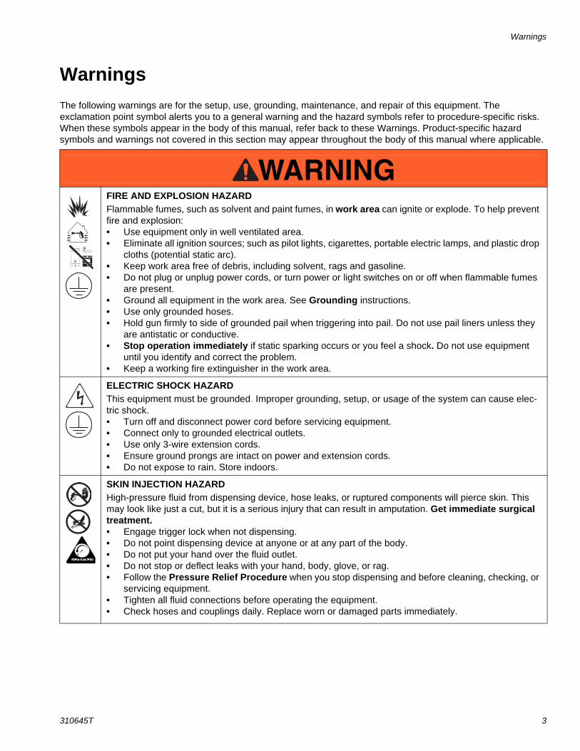
WarningsThe following warnings are for the setup, use, grounding, maintenance, and repair of this equipment. The exclamation point symbol alerts you to a general warning and the hazard symbols refer to procedure-specific risks. When these symbols appear in the body of this manual, refer back to these Warnings. Product-specific hazard symbols and warnings not covered in this section may appear throughout the body of this manual where applicable.
WARNINGFIRE AND EXPLOSION HAZARDFlammable fumes, such as solvent and paint fumes, in work area can ignite or explode. To help prevent fire and explosion:• Use equipment only in well ventilated area.• Eliminate all ignition sources; such as pilot lights, cigarettes, portable electric lamps, and plastic drop
cloths (potential static arc). • Keep work area free of debris, including solvent, rags and gasoline.• Do not plug or unplug power cords, or turn power or light switches on or off when flammable fumes
are present.• Ground all equipment in the work area. See Grounding instructions.• Use only grounded hoses.• Hold gun firmly to side of grounded pail when triggering into pail. Do not use pail liners unless they
are antistatic or conductive.• Stop operation immediately if static sparking occurs or you feel a shock. Do not use equipment
until you identify and correct the problem.• Keep a working fire extinguisher in the work area.
ELECTRIC SHOCK HAZARDThis equipment must be grounded. Improper grounding, setup, or usage of the system can cause elec-tric shock.• Turn off and disconnect power cord before servicing equipment.• Connect only to grounded electrical outlets.• Use only 3-wire extension cords.• Ensure ground prongs are intact on power and extension cords.• Do not expose to rain. Store indoors.
SKIN INJECTION HAZARDHigh-pressure fluid from dispensing device, hose leaks, or ruptured components will pierce skin. This may look like just a cut, but it is a serious injury that can result in amputation. Get immediate surgical treatment.• Engage trigger lock when not dispensing.• Do not point dispensing device at anyone or at any part of the body.• Do not put your hand over the fluid outlet.• Do not stop or deflect leaks with your hand, body, glove, or rag.• Follow the Pressure Relief Procedure when you stop dispensing and before cleaning, checking, or
servicing equipment. • Tighten all fluid connections before operating the equipment.• Check hoses and couplings daily. Replace worn or damaged parts immediately.
Warnings
4 310645T
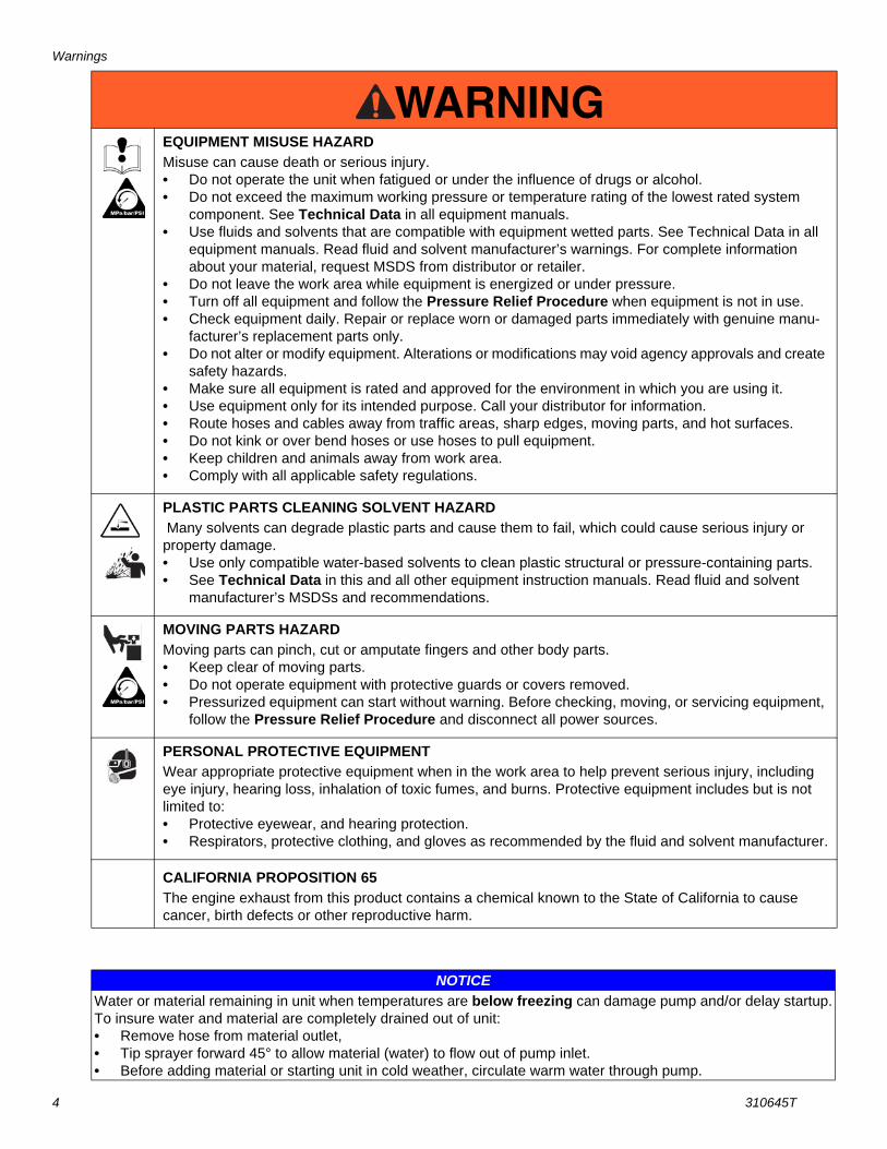
EQUIPMENT MISUSE HAZARDMisuse can cause death or serious injury.• Do not operate the unit when fatigued or under the influence of drugs or alcohol.• Do not exceed the maximum working pressure or temperature rating of the lowest rated system
component. See Technical Data in all equipment manuals.• Use fluids and solvents that are compatible with equipment wetted parts. See Technical Data in all
equipment manuals. Read fluid and solvent manufacturer’s warnings. For complete information about your material, request MSDS from distributor or retailer.
• Do not leave the work area while equipment is energized or under pressure.• Turn off all equipment and follow the Pressure Relief Procedure when equipment is not in use.• Check equipment daily. Repair or replace worn or damaged parts immediately with genuine manu-
facturer’s replacement parts only.• Do not alter or modify equipment. Alterations or modifications may void agency approvals and create
safety hazards.• Make sure all equipment is rated and approved for the environment in which you are using it.• Use equipment only for its intended purpose. Call your distributor for information.• Route hoses and cables away from traffic areas, sharp edges, moving parts, and hot surfaces.• Do not kink or over bend hoses or use hoses to pull equipment.• Keep children and animals away from work area.• Comply with all applicable safety regulations.
PLASTIC PARTS CLEANING SOLVENT HAZARD Many solvents can degrade plastic parts and cause them to fail, which could cause serious injury or property damage. • Use only compatible water-based solvents to clean plastic structural or pressure-containing parts.• See Technical Data in this and all other equipment instruction manuals. Read fluid and solvent
manufacturer’s MSDSs and recommendations.
MOVING PARTS HAZARDMoving parts can pinch, cut or amputate fingers and other body parts.• Keep clear of moving parts.• Do not operate equipment with protective guards or covers removed.• Pressurized equipment can start without warning. Before checking, moving, or servicing equipment,
follow the Pressure Relief Procedure and disconnect all power sources.
PERSONAL PROTECTIVE EQUIPMENTWear appropriate protective equipment when in the work area to help prevent serious injury, including eye injury, hearing loss, inhalation of toxic fumes, and burns. Protective equipment includes but is not limited to:• Protective eyewear, and hearing protection. • Respirators, protective clothing, and gloves as recommended by the fluid and solvent manufacturer.
CALIFORNIA PROPOSITION 65The engine exhaust from this product contains a chemical known to the State of California to cause cancer, birth defects or other reproductive harm.
WARNING
NOTICEWater or material remaining in unit when temperatures are below freezing can damage pump and/or delay startup.To insure water and material are completely drained out of unit:• Remove hose from material outlet, • Tip sprayer forward 45° to allow material (water) to flow out of pump inlet.• Before adding material or starting unit in cold weather, circulate warm water through pump.
Component Identification
310645T 5
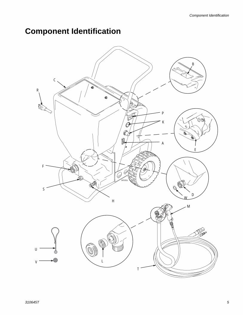
Component Identification
A
C
F
H
K
L
E
B
D
P
T
U
S
R
V
W
M
ti4500a
Component Identification
6 310645T
Component Identification
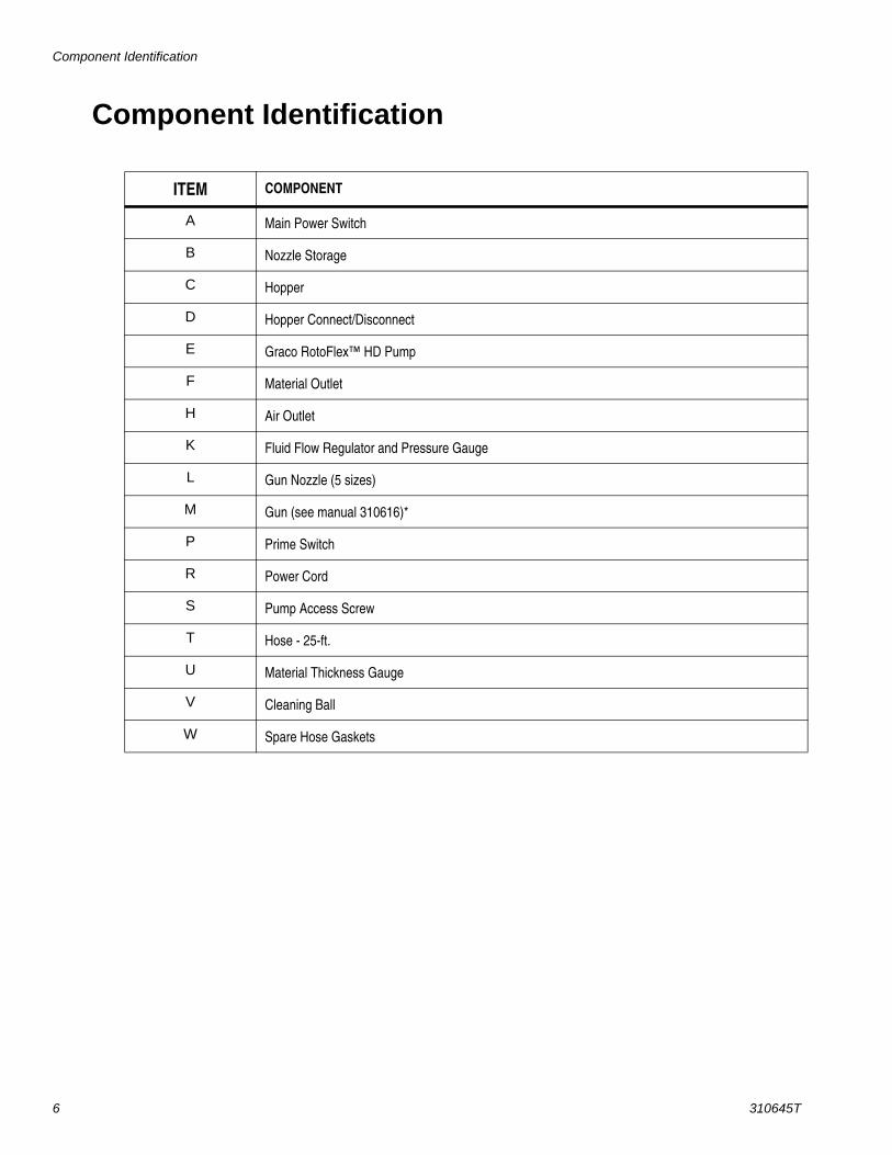
ITEM COMPONENT
A Main Power Switch
B Nozzle Storage
C Hopper
D Hopper Connect/Disconnect
E Graco RotoFlex™ HD Pump
F Material Outlet
H Air Outlet
K Fluid Flow Regulator and Pressure Gauge
L Gun Nozzle (5 sizes)
M Gun (see manual 310616)*
P Prime Switch
R Power Cord
S Pump Access Screw
T Hose - 25-ft.
U Material Thickness Gauge
V Cleaning Ball
W Spare Hose Gaskets

Preparation
310645T 7
Preparation
Pressure Relief Procedure1. Turn Main Power Switch
(A) OFF.
2. Turn fluid flow regulator (K) all the way down to reduce pressure.
3. Open gun air valve (aa).
4. Trigger gun, spray-ing material back into hopper (C).
Grounding and Electric RequirementsThe sprayer must be grounded. Grounding reduces the risk of electrical shock by providing an escape wire for the electrical current.
• The sprayer cord includes a grounding wire with an appro-priate grounding prong.
• The plug must be plugged into an outlet that is properly installed and grounded in accordance with all local codes and ordinances.
• Do not modify plug! If it will not fit in outlet, have grounded outlet installed by a qualified electrician.
• Sprayer model electric requirements are provided on page 3.
Extension Cords
• Only use an extension cord with an undamaged 3-prong plug.
• For up to 50 ft (15.2 m) cord, use 3-wire, 10 AWG (2.95 mm2) min-imum.
ti4303a
K
ti4000a
A
ti4294a
Ground
ti4295a
ti4296a
ti4297a
Ground
ti4295a
Preparation
8 310645T
Auxiliary Air Compressor• Use Auxiliary Air Hookup Kit 287328 when addi-
tional atomization air is necessary.
Generators
7500 W (7.5 KW) minimum.
Tips for Using Generators• Before running sprayer, make sure it is at room tem-
perature. This will reduce startup current.
• Run generator at full throttle.
Hose Lengths• The system comes with a twin line hose set consist-
ing of a 1 in. ID x 25 ft (25 mm x 7.6 m) material hose and a 3/8 in. ID air hose. Additional hose sec-tions can be added. Total final length of hose used should not exceed 100 feet in length.
• The 24X140 model comes with a separate 1 in. ID x 15 ft (25 mm x 4.6 m) material hose and 3/8 in. x 15 ft air hose.
NOTICEAttaching auxiliary air to sprayer without using the Auxiliary Air Hookup Kit will damage sprayer.
NOTICESprayer air hose fitting can get hot! Allow sprayer to cool down 5 minutes before removing air hose.

Removing and Replacing Hopper, Front and Back Covers
310645T 9
Removing and Replacing Hopper, Front and Back Covers
Before performing any service on sprayer always:
• Read all warnings, page 3.
• Read operating instructions manual, page 3.
• Relieve Pressure, page 7.
• Turn main power switch (A) OFF.
• Unplug sprayer from outlet.
• Remove air and material hoses.
• Clean sprayer. See Operation Manual 310624 or 310625.
Hopper
Removing Hopper1. To remove hop-
per loosen fit-ting. Fittings are hand-tightened and should not require tools to loosen.
2. Lift hopper straight up, off frame.
Replacing Hopper1. To replace hop-
per, position drain over fit-ting as far as it will go, making sure identification label faces out.
2. Hand tighten fit-ting.
Front Cover
Removing Cover1. Remove hopper.
2. Unscrew and remove knob (S).
3. Place you hand under front, bot-tom edge of cover. (3a) Lift cover up, (3b) then pull bottom toward you and out to remove cover.
Replacing Cover1. Place your
hand under front, bottom edge of cover. (1a) Position top edge of cover under top metal lip on sprayer frame. (1b) Then push up on cover so lower plastic edge of cover has room to clear front metal frame and slide cover into place. To position cover correctly, it will go in at an angle.
2. Replace knob (S). Hand tighten fitting.
3. Replace hopper.
ti4503a
ti4504a
ti4408a
S
3a
3b
ti4411a
S
1a
1b
Removing and Replacing Hopper, Front and Back Covers
10 310645T
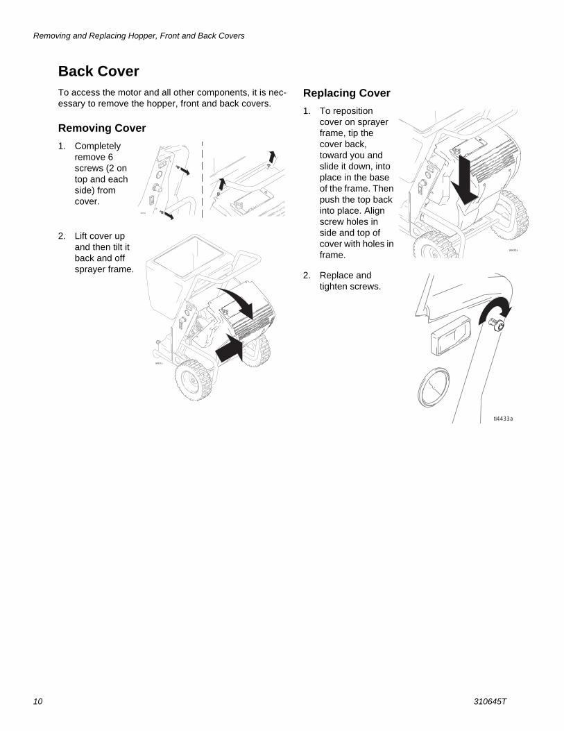
Back CoverTo access the motor and all other components, it is nec-essary to remove the hopper, front and back covers.
Removing Cover1. Completely
remove 6 screws (2 on top and each side) from cover.
2. Lift cover up and then tilt it back and off sprayer frame.
Replacing Cover1. To reposition
cover on sprayer frame, tip the cover back, toward you and slide it down, into place in the base of the frame. Then push the top back into place. Align screw holes in side and top of cover with holes in frame.
2. Replace and tighten screws.
ti4430a
ti4431a
ti4432a
ti4433a

RotoFlex™ HD Pump
310645T 11
RotoFlex™ HD PumpUse RotoFlex HD Pump Replacement Kit 287314.
NOTE: After replacing RotoFlex HD Pump hose, always follow Hose Break-In Procedure, page 13, before oper-ating sprayer.
DisassemblyFirst read and follow instructions in the Before perform-ing any service on sprayer section, page 9.
Then remove hopper and front cover, page 9.
1. Loosen and remove hose extension.
2. Loosen and remove knob.
3. Slide RotoFlex HD hose off rollers.
4. Rotate pump assem-bly sideways. Pull entire assembly out of front of sprayer frame.
5. Separate the inner and outer hose brackets.
6. Slide hose ends out of slots in outer hose bracket (slide out of short slot first).
7. Pull hose out of inner hose bracket.
8. Discard pump hose.
ti4377a
ti4378a
ti4374a
ti4519a
ti4376a
ti4379a

RotoFlex™ HD Pump
12 310645T
Reassembly1. Bend and kink new
pump hose from kit in the middle as shown, making sure dots on hose fittings face each other.
2. Insert hose ends through holes in inner hose bracket, keeping dots on fittings facing each other and kinked portion of hose hori-zontal to the under-side of bracket.
3. Slide hose ends into outer hose bracket, making sure dots on fittings face each other and alignment holes are together (slide into long slot first).
4. Slide plates together, inserting inner plate in outer plate, matching alignment holes.
5. Replace bracket assembly in housing making sure the mounting screw hole, located in the top center of the inner plate, faces up.
6. Slide pump hose around rollers. Make sure the rollers are horizontally parallel to each other.
7. Slide feet on the bot-tom of hose bracket, into the slot on the bottom of sprayer.
8. Replace knob. Hand tighten.
9. Reattach hose extension.
10. Replace front cover and hopper. See Removing and Replacing Hopper, Front and Back Cover, page 9.
ti3127a
DOTS
ti4386a
alignmentholes
ti4383a
ti4520a
ti4429a
ti4381a

RotoFlex™ HD Pump
310645T 13
Hose Break-In Procedure1. Make sure fluid flow regula-
tor (K) is turned all the way down.
2. Pour approxi-mately 1 gallon hot water in sprayer hopper to lubricate the pump.
3. Turn power switch (A) on.
4. Hold in prime switch (P).
5. Turn fluid flow regula-tor (K) up to full pressure.
6. Run sprayer dry for 1 to 1-1/2 minutes.
ti4303a
K
ti4301a
WATER
ti4653a
ti4364a
P
K
ti4655a
Compressor and Motor Repair
14 310645T
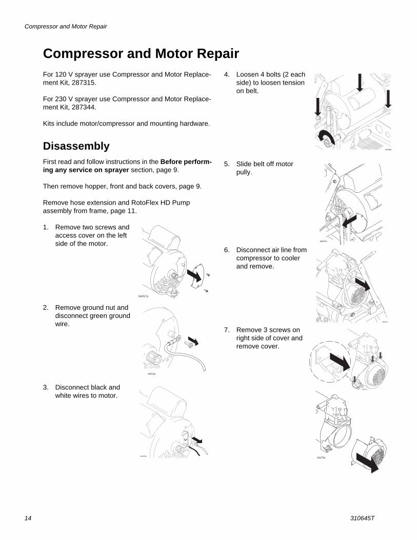
Compressor and Motor RepairFor 120 V sprayer use Compressor and Motor Replace-ment Kit, 287315.
For 230 V sprayer use Compressor and Motor Replace-ment Kit, 287344.
Kits include motor/compressor and mounting hardware.
DisassemblyFirst read and follow instructions in the Before perform-ing any service on sprayer section, page 9.
Then remove hopper, front and back covers, page 9.
Remove hose extension and RotoFlex HD Pump assembly from frame, page 11.
1. Remove two screws and access cover on the left side of the motor.
2. Remove ground nut and disconnect green ground wire.
3. Disconnect black and white wires to motor.
4. Loosen 4 bolts (2 each side) to loosen tension on belt.
5. Slide belt off motor pully.
6. Disconnect air line from compressor to cooler and remove.
7. Remove 3 screws on right side of cover and remove cover.
ti4457a
ti4458a
ti4405a
ti4388b
ti4459a
ti4460a
ti4478a
ti4479a
Compressor and Motor Repair
310645T 15
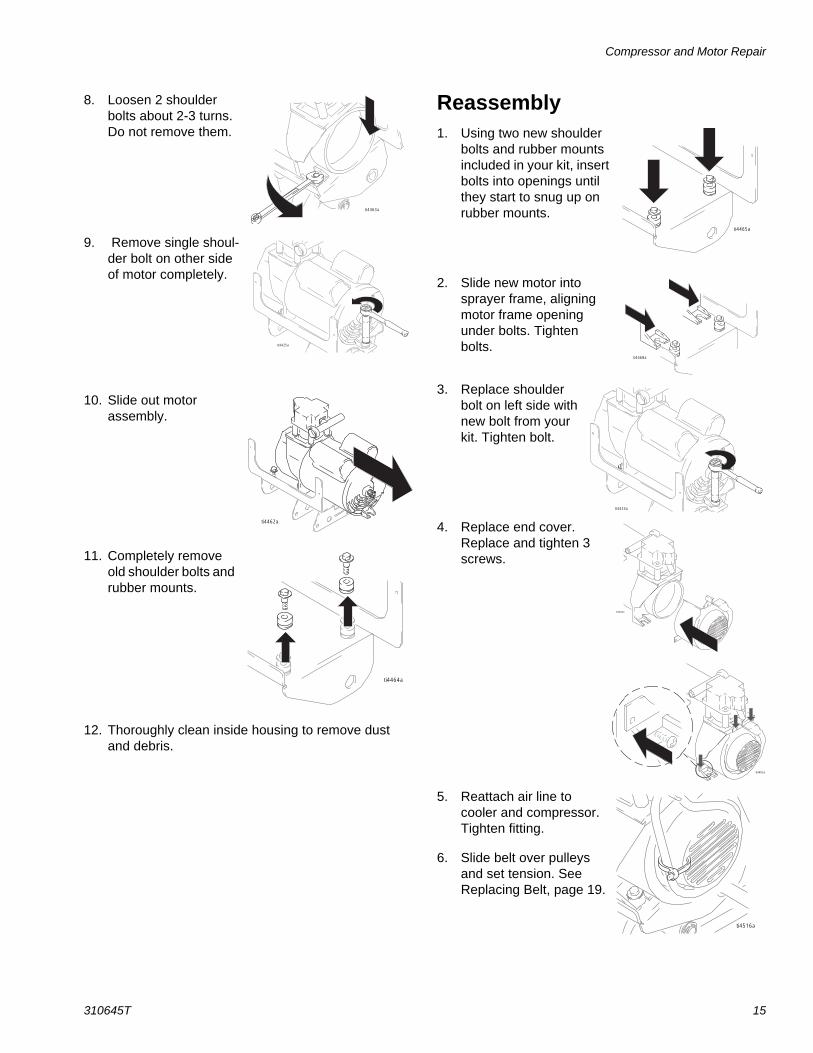
8. Loosen 2 shoulder bolts about 2-3 turns. Do not remove them.
9. Remove single shoul-der bolt on other side of motor completely.
10. Slide out motor assembly.
11. Completely remove old shoulder bolts and rubber mounts.
12. Thoroughly clean inside housing to remove dust and debris.
Reassembly1. Using two new shoulder
bolts and rubber mounts included in your kit, insert bolts into openings until they start to snug up on rubber mounts.
2. Slide new motor into sprayer frame, aligning motor frame opening under bolts. Tighten bolts.
3. Replace shoulder bolt on left side with new bolt from your kit. Tighten bolt.
4. Replace end cover. Replace and tighten 3 screws.
5. Reattach air line to cooler and compressor. Tighten fitting.
6. Slide belt over pulleys and set tension. See Replacing Belt, page 19.
ti4463a
ti4425a
ti4462a
ti4464a
ti4465a
ti4468a
ti4424a
ti4484a
ti4485a
ti4516a
Compressor and Motor Repair
16 310645T
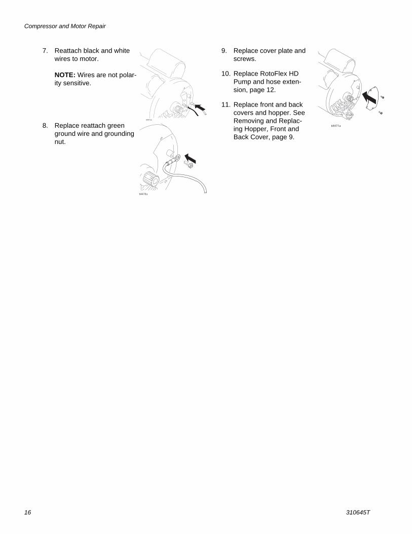
7. Reattach black and white wires to motor.
NOTE: Wires are not polar-ity sensitive.
8. Replace reattach green ground wire and grounding nut.
9. Replace cover plate and screws.
10. Replace RotoFlex HD Pump and hose exten-sion, page 12.
11. Replace front and back covers and hopper. See Removing and Replac-ing Hopper, Front and Back Cover, page 9.
ti4412a
ti4470a
ti4471a
Compressor Rebuild Kit
310645T 17
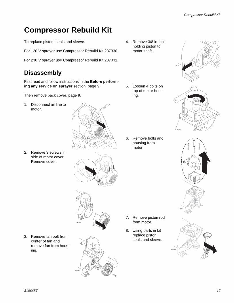
Compressor Rebuild KitTo replace piston, seals and sleeve.
For 120 V sprayer use Compressor Rebuild Kit 287330.
For 230 V sprayer use Compressor Rebuild Kit 287331.
DisassemblyFirst read and follow instructions in the Before perform-ing any service on sprayer section, page 9.
Then remove back cover, page 9.
1. Disconnect air line to motor.
2. Remove 3 screws in side of motor cover. Remove cover.
3. Remove fan bolt from center of fan and remove fan from hous-ing.
4. Remove 3/8 in. bolt holding piston to motor shaft.
5. Loosen 4 bolts on top of motor hous-ing.
6. Remove bolts and housing from motor.
7. Remove piston rod from motor.
8. Using parts in kit replace piston, seals and sleeve.
ti4460a
ti4478a
ti4479a
ti4706a
ti4707a
ti4708a
ti4709a
ti4710a
Compressor Rebuild Kit
18 310645T
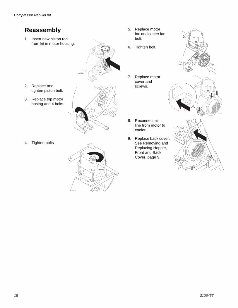
Reassembly1. Insert new piston rod
from kit in motor housing.
2. Replace and tighten piston bolt.
3. Replace top motor hosing and 4 bolts.
4. Tighten bolts.
5. Replace motor fan and center fan bolt.
6. Tighten bolt.
7. Replace motor cover and screws.
8. Reconnect air line from motor to cooler.
9. Replace back cover. See Removing and Replacing Hopper, Front and Back Cover, page 9.
ti4700a
ti4701a
ti4703a
ti4704a
ti4485a
Removing and Replacing Belt
310645T 19
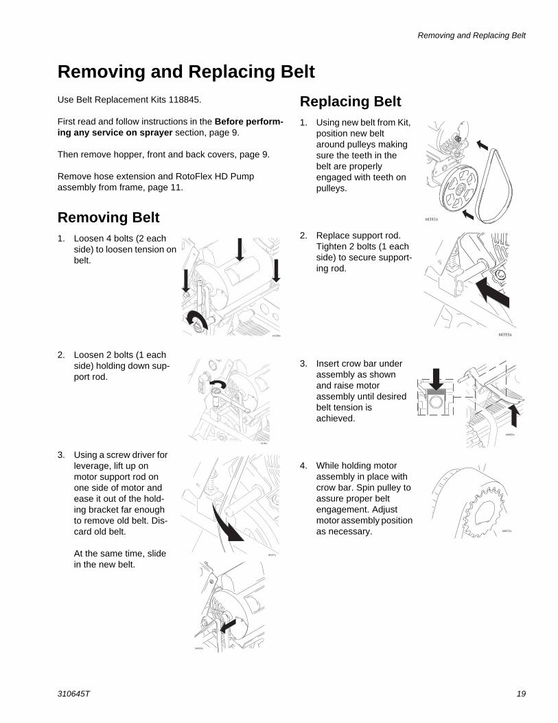
Removing and Replacing BeltUse Belt Replacement Kits 118845.
First read and follow instructions in the Before perform-ing any service on sprayer section, page 9.
Then remove hopper, front and back covers, page 9.
Remove hose extension and RotoFlex HD Pump assembly from frame, page 11.
Removing Belt1. Loosen 4 bolts (2 each
side) to loosen tension on belt.
2. Loosen 2 bolts (1 each side) holding down sup-port rod.
3. Using a screw driver for leverage, lift up on motor support rod on one side of motor and ease it out of the hold-ing bracket far enough to remove old belt. Dis-card old belt.
At the same time, slide in the new belt.
Replacing Belt1. Using new belt from Kit,
position new belt around pulleys making sure the teeth in the belt are properly engaged with teeth on pulleys.
2. Replace support rod. Tighten 2 bolts (1 each side) to secure support-ing rod.
3. Insert crow bar under assembly as shown and raise motor assembly until desired belt tension is achieved.
4. While holding motor assembly in place with crow bar. Spin pulley to assure proper belt engagement. Adjust motor assembly position as necessary.
ti4388b
ti4388a
ti4459a
ti4391a
ti4392a
ti4393a
ti4469a
ti4472a

Removing and Replacing Belt
20 310645T
A correctly tensioned belt will feel very tight. To measure correct tension apply 4-5 lbs pressure at belt midpoint with thumb. Belt should have approximately 1/8 in (3.175 mm) deflection.
A loose belt will not last long. If in doubt, tighten more.
5. Tighten all 4 bolts.
6. Turn belt one more time with your hand to make sure teeth are properly engaged and tension is cor-rect.
7. Replace RotoFlex HD Pump and hose extension, page 12.
8. Replace back and front covers and hop-per. See Removing and Replacing Hopper, Front and Back Cover, page 9.
ti4477a
ti4394a
ti4473a

Roller Replacement
310645T 21
Roller ReplacementUse Roller Replacement Kit 287321.
Kit includes 2 rollers, 4 nylon washer, and 2 retaining rings.
DisassemblyFirst read and follow instructions in the Before perform-ing any service on sprayer section, page 9.
Then remove hopper, front and back covers, page 9.
Remove hose extension and RotoFlex HD Pump assembly from frame, page 11.
1. Remove snap ring.
2. Remove roller assembly from rotor pins (a).
3. Clean rotor pins (a) and check for damage. If pins are worn or dam-aged, replace rotor assembly, (Rotor Assembly Replace-ment, page 22).
Reassembly1. Replace roller assembly.
2. Reinstall snap ring.
3. Replace RotoFlex HD Pump and hose extension, page 12.
4. Replace back and front covers and hopper. See Removing and Replacing Hopper, Front and Back Cover, page 9.ti4396a
ti4397a
a
ti4398a
ti4399a

Rotor Assembly Replacement
22 310645T
Rotor Assembly ReplacementUse Pump Assembly Replacement Kit 287255.
DisassemblyFirst read and follow instructions in the Before perform-ing any service on sprayer section, page 9.
Then remove hopper, front and back covers, page 9.
Remove hose extension and RotoFlex HD Pump assembly from frame, page 11.
1. To prevent rotor assembly from moving, insert a long screw driver or pry bar in the pulley.
2. Remove large bolt and washer in center of rotor assembly.
3. Pull rotor assembly off shaft.
Reassembly1. Put new rotor assembly from kit on shaft.
2. Insert a wrench in the pulley to prevent it from moving.
3. Replace bolt. Torque to 40 ft. lb.
4. Replace RotoFlex HD Pump and hose extension, page 12.
5. Replace back and front covers and hopper. See Removing and Replacing Hopper, Front and Back Cover, page 9.
ti4714a
ti4711a
ti4714a
ti4712a

Air Cylinder and Solenoid Valve
310645T 23
Air Cylinder and Solenoid ValveUse Cylinder Replacement Kit, 287323.
For 120 V sprayer use Solenoid Replacement Kit 15D560.
For 230V sprayer use Solenoid Replacement Kit 287351.
DisassemblyFirst read and follow instructions in the Before perform-ing any service on sprayer section, page 9.
Then remove hopper, front and back covers, page 9.
Remove hose extension and RotoFlex HD Pump assembly from frame, page 11.
1. Remove hose from quick release fitting by using your fingers on one hand to push in on ring while at the same time, using the other hand, gently pull the hose out of the fitting.
2. Remove electric wire ter-minal connections.
3. Remove cotter key located on the end of the cyl-inder pin, by using a pliers to straighten the ends and pull it out of the hole.
4. Gently push cylinder forward, relieving tension on pin. Pull out pin.
NOTE: If replacing solenoid valve only, it can be done at this time. a. Use adjustable wrench to rotate entire
solenoid valve assembly counterclockwise from cylinder.
b. Replace solenoid valve and continue with step 4 of reassembly.
5. Lift cylinder up and pull it back.
6. Remove dampening grommet.
7. Using a 15/16 in. wrench, loosen nut, located inside sprayer frame at the end of the air cylinder.
8. Using a 15/16 in. wrench, loosen nut on the other side of the sprayer frame.
9. Pull cylinder out of sprayer frame.
If replacing cylinder only, remove solenoid valve (see a and b above) and reinstall on new cylinder.
ti4406a
ti4416a
ti4453a
ti4409a
ti4518a
ti4415a
ti4414a
Air Cylinder and Solenoid Valve
24 310645T
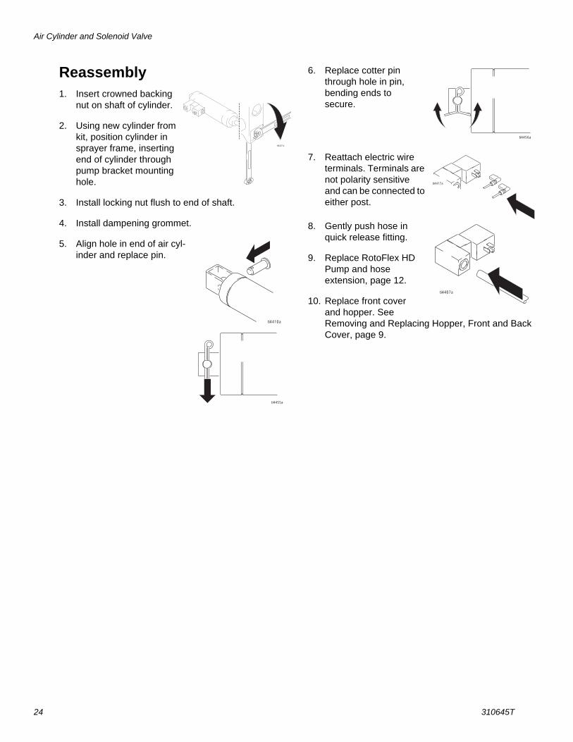
Reassembly1. Insert crowned backing
nut on shaft of cylinder.
2. Using new cylinder from kit, position cylinder in sprayer frame, inserting end of cylinder through pump bracket mounting hole.
3. Install locking nut flush to end of shaft.
4. Install dampening grommet.
5. Align hole in end of air cyl-inder and replace pin.
6. Replace cotter pin through hole in pin, bending ends to secure.
7. Reattach electric wire terminals. Terminals are not polarity sensitive and can be connected to either post.
8. Gently push hose in quick release fitting.
9. Replace RotoFlex HD Pump and hose extension, page 12.
10. Replace front cover and hopper. See Removing and Replacing Hopper, Front and Back Cover, page 9.
ti4421a
ti4410a
ti4455a
ti4456a
ti4417a
ti4407a
Relief Valve and Flow Sensor Manifold
310645T 25
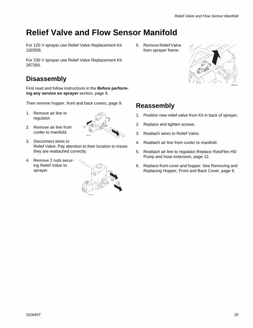
Relief Valve and Flow Sensor ManifoldFor 120 V sprayer use Relief Valve Replacement Kit 15D559.
For 230 V sprayer use Relief Valve Replacement Kit 287350.
DisassemblyFirst read and follow instructions in the Before perform-ing any service on sprayer section, page 9.
Then remove hopper, front and back covers, page 9.
1. Remove air line to regulator.
2. Remove air line from cooler to manifold.
3. Disconnect wires to Relief Valve. Pay attention to their location to insure they are reattached correctly.
4. Remove 2 nuts secur-ing Relief Valve to sprayer.
5. Remove Relief Valve from sprayer frame.
Reassembly1. Position new relief valve from Kit in back of sprayer.
2. Replace and tighten screws.
3. Reattach wires to Relief Valve.
4. Reattach air line from cooler to manifold.
5. Reattach air line to regulator.Replace RotoFlex HD Pump and hose extension, page 12.
6. Replace front cover and hopper. See Removing and Replacing Hopper, Front and Back Cover, page 9.
ti4423a
ti4418a
ti4419a
Air Flow Sensor Replacement
26 310645T
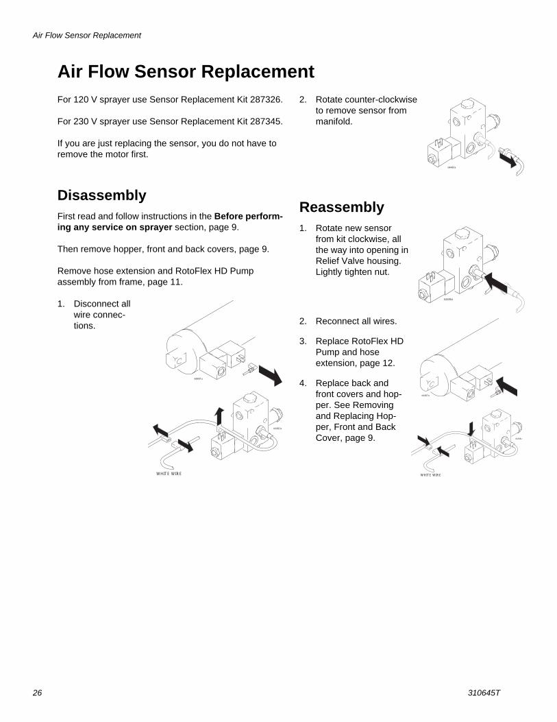
Air Flow Sensor ReplacementFor 120 V sprayer use Sensor Replacement Kit 287326.
For 230 V sprayer use Sensor Replacement Kit 287345.
If you are just replacing the sensor, you do not have to remove the motor first.
DisassemblyFirst read and follow instructions in the Before perform-ing any service on sprayer section, page 9.
Then remove hopper, front and back covers, page 9.
Remove hose extension and RotoFlex HD Pump assembly from frame, page 11.
1. Disconnect all wire connec-tions.
2. Rotate counter-clockwise to remove sensor from manifold.
Reassembly1. Rotate new sensor
from kit clockwise, all the way into opening in Relief Valve housing. Lightly tighten nut.
2. Reconnect all wires.
3. Replace RotoFlex HD Pump and hose extension, page 12.
4. Replace back and front covers and hop-per. See Removing and Replacing Hop-per, Front and Back Cover, page 9.
ti4481a
ti4482a
WHITE WIRE
ti4480a
ti4486a
ti4487a
WHITE WIRE
ti4488a

Troubleshooting
310645T 27
Troubleshooting
Problem Cause Solution
Sprayer won’t run or stops intermit-tently
Power switch not on Turn switch on.No power at wall outlet Check outlet by plugging in another
appliance. If appliance does not work, try another outlet.
Wrong size generator Use a 7500 watt or larger generator. Refer to Generator Requirements, page 8.
Temperature too cold Allow unit to warm up.Too many items on same circuit Unplug other items from circuit.Internal thermal switch tripped Self-resetting. Allow unit to cool down
15 minutes and restart. Usually occurs when wrong size extension cord is used.
Extension cord too long or wrong gauge
Use a 12 gage extension cord or remove extension cord. Refer to Grounding and Electric Require-ments, page 7.
Breaker tripped Reset breaker.Pump won’t pump material or low output
Air lock Open air valve on gun.Mix too thick Add water to thin material. Use Mate-
rial Thickness Gauge.Loose fittings Check and retighten all fittings.Plugged gun Relieve Pressure, page 7. Remove
gun from hose. Clean gun.RotoFlex HD Pump worn out Replace hose. Pump cold or material frozen in pump Move pump to warm room and allow
it to warm up or run hot water through sprayer.
Sensor is bad Replace, page 26Check air system for leaks Remove shroud and examine for air
leaksLoose wire Remove shroud and examine wiringNo air pressure Rebuild compressor

Troubleshooting
28 310645T
Soft start won’t work/pump, always loaded
Sensor is bad Change sensor, page 26Air leak due to bad seal keeps valve open
Replace seal
Normal soft start system delay Release trigger for 10-15 seconds. Retry.
Switch is not operating properly Replace switchDamaged solenoid valve on cylinder Check gun supply, hose and sprayer
for leaksAIr leakMaterial runs out of bottom of sprayer RotoFlex HD Pump worn out Replace hose.
Loose fittings Check and retighten all fittings.No air from compressor Gun air valve closed Open gun air valve.
Gun needle plugged Clean needle and retry.Lines not connected Check all quick disconnect connec-
tions to gun and hoses.Damaged hose Replace hose.Worn compressor Service compressor. Contact a quali-
fied Graco Service Center.Speed of application too slow Material too thick Thin material.
Nozzle too small Change nozzles to a larger size. See Operation Manual, Recommended Nozzle Selection Chart, page 20.
Speed of application too slow (cont.) Flow control set too low Increase flow control settingPlugged or dirty gun Relieve Pressure, page 7. Clean
gun.Kinked hose Unkink hose.Gun fluid flow adjustment set too low Increase flow adjustment with flow
adjustment nut.Intermittent flow/sputtering or air in material
Hopper connection not tight Check gasket. TIghten connection.Debris in system Clean
Air quick disconnect does not stay connected.
Dirty or corroded fitting Clean thoroughly. Soak in oil. Apply a few drops of light oil.
Gun will not shut off Worn nozzle or needle. Relieve Pressure, page 7. Replace worn parts.
Debris in needle passage Relieve Pressure, page 7. Clean.Fluid leaking at Flow Adjustment Nut Damaged seal. Relieve Pressure, page 7. Replace
seal.Needle adjustment won’t adjust Dirty threads Clean threads
Nozzle not on gun Put nozzle on gunFlow nut set to maximum adjustment Turn flow nut adjustment the other
way
Problem Cause Solution
Air Diagram
310645T 29
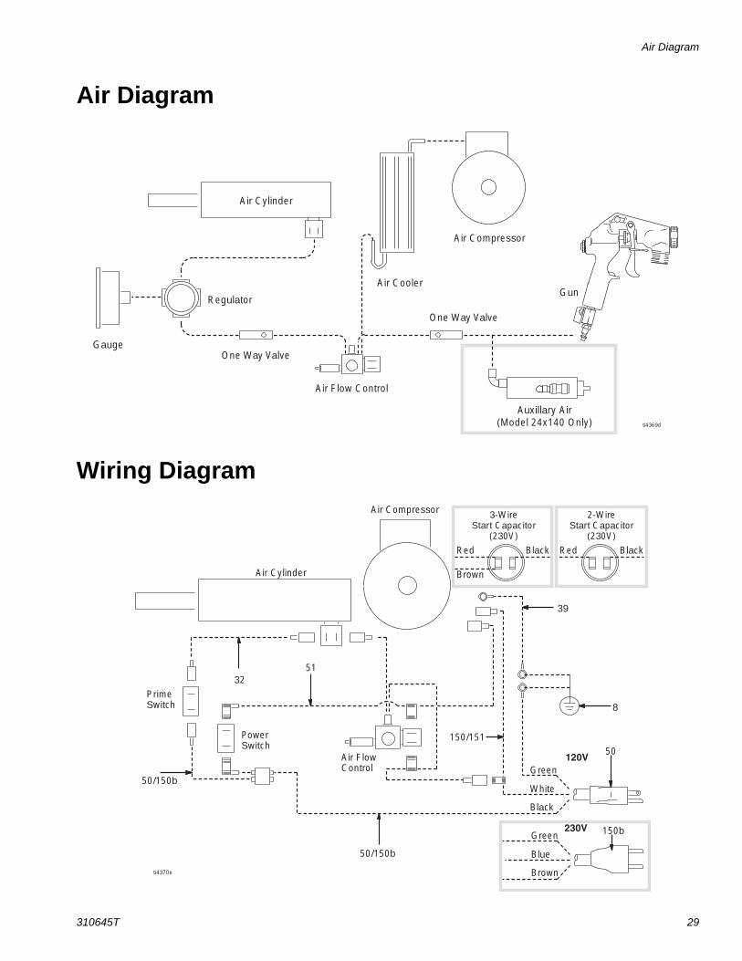
Air Diagram
Wiring Diagram
Air Cylinder
Gauge
Air Flow Control
Air Cooler
Air Compressor
One Way Valve
One Way Valve
Auxillary Air(Model 24x140 Only)
GunRegulator
ti4369d
50
8
39
5132
50/150b
50/150b
150/151
Green
Brown
Red Black
120V
230V
Black
White
PowerSwitch
PrimeSwitch
Air Cylinder
Air Compressor 3-WireStart Capacitor
(230V)
Air FlowControl
ti4370e
150bGreen
Brown
Blue
Red Black
2-WireStart Capacitor
(230V)

Parts
30 310645T
Parts
Models 248201, 248315, 248370, 248536
56
49
53
41
13
62
63
37
38A
38
1E
42
38B
4
3645
73
1A
1B
88
88
63
62
5752
1D
102
52
34
921
1B
31
94333
22
40
1949A
49B
49C
55
101
67

Parts List
310645T 31
Parts List
Models 248201, 248315, 248370, 248536
Replacement Danger and Warning labels, tags and cards are available at no cost.
Ref. Part DescriptionQty
.1 287315 KIT, compressor replacement
(includes 1A and 1B-1E), 120V sprayers
1
287330 KIT, compressor rebuild, 120V sprayers
287344 KIT, compressor replacement (includes 1A, and 1B-1D), 230V sprayers
287331 KIT, compressor rebuild, 230V sprayers
1A 119872 SCREW, shoulder 31B 118886 GROMMET, isolator 31D 119381 COVER, terminal 11E 121479 CAPACITOR, start (120 V) 1
24X818 CAPACITOR, start (230 V) 14 118845 BELT 19 117728 FITTING, compression, union 213 15D156 PULLEY, rotor 116 118888 HOSE, air (includes 1/4 in. tubing
and one-way valve)1
19 15D862 NUT, hand 121 118876 TUBE, air, aluminum 122 117637 NUT, compression 131 112395 SCREW, cap 432 15D633 WIRE, jumper 133 103473 STRAP, tie, wire 234 15B815 COOLER 136 101242 RING, retaining, ext. 237 287255 ROTOR, pump, assbly
(includes 38, 38A, 38B)1
38 287321 KIT, roller replacement (includes 38A, 38B and two rollers)
2
38A 113983 RING, retaining, ext 238B 117726 WASHER, nylon 439 15D628 CONDUCTOR, ground 1
40 103785 RIVET 241 287327 KIT, repair, shaft, bracket, pump
assbly.1
42 287256 BRACKET, compressor 143 118869 TUBE 145 15D610 SHAFT, motor, mount 149 287346 SHIELD, rear, assbly
(includes 19, 49A, 49B, 49C)1
49A 15D561 COVER, tool tray 149B 15D939 LABEL, warning, English, French,
Spanish287336 KIT, label, warning, all languages
except those included in 15D93949C 15D940 LABEL, identification51 15D634 WIRE, jumper 152 116937 BEARING, flanged, bronze 253 117633 SCREW, slot hex wash hd 854 116666 TUBE, air 155 287304 HOSE SET, twin line, 1 in. x 25-ft 156 15C090 GAUGE, thickness, fluid 157 183401 KEY, parallel 258 116720 COUPLER, air, quick disconnect 162 108851 WASHER, plain 263 106276 SCREW, cap, hex head 267 248515 BALL, sponge, 30 mm (5 pk) 273 112785 SCREW, flanged, hex head 274 115498 SCREW, mach, slot, hex, wash hd 182 118887 HOSE, air (includes 1/4 in. tubing
and one-way valve)1
88 118866 WASHER, flat 1101 248091 GUN, non-bleeder 1102 122104 VALVE PLATE, compressor 1
Ref. Part DescriptionQty
.

Parts
32 310645T
Parts
Models 248201, 248315, 248370, 248536
36
7
10
14
19
18
23
24
25
26
29
30
35
58
59
7170
66
72
ti4372C
12
27
60
20 77
15
5A
5B
5
17
55
93
93
89
90
91
92
81
83
28
8
154
150a 150b 150c152a 152c 152d152b 152e
153
151
A
A

Parts List
310645T 33
Parts List
Models 248201, 248315, 248370, 248536
Replacement Danger and Warning labels, tags and cards are available at no cost.
Ref. Part DescriptionQty
.3 118844 REGULATOR, air, 1/8 in. NPT 15 287323 KIT, cylinder, replacement,
(includes 5A, 5B, 89)1
5A 15D576 SPACER, crowned 15B 118871 NUT, lock, 1/2-20 16 117720 GAUGE, pressure 17 115244 NUT, regulator 18 186620 LABEL, ground, symbol 110 117693 SWITCH, power 112 119064 SWITCH, power, prime 114 15D559 VALVE, assembly, 120V (includes
sensor) sprayer1
287350 VALVE, assembly, 230V (includes sensor) sprayer
15 15D560 VALVE, cylinder, 120V sprayer 1287351 VALVE, cylinder, 230V sprayer 1
16 118888 HOSE, air (includes 1/4 in. tubing and one-way valve)
1
17 15C968 TUBE, air 118 287347 HOPPER, texture (includes
bracket)1
19 15D862 NUT, hand 120 287326 KIT, sensor only, 120V 1
287345 KIT, sensor only, 230V23 287348 SHIELD, front (includes 28) 124 108471 KNOB, pronged 125 15D589 BRACKET, hose, outer 126 15D588 BRACKET, hose, inner 127 287314 KIT, RotoFlex HD Pump 128 189286 LABEL, warning 129 118885 HOSE, coupled (includes grommet) 130 287254 FRAME, texture, blue 132 15D633 WIRE, jumper 135 116478 WHEEL, pneumatic 249B 15D939 LABEL, warning, English, French,
Spanish287336 KIT, label, warning, all languages
except those included in 15D93949C 15D940 LABEL, identification
51 15D634 WIRE, jumper 154 116666 TUBE, air 155 287304 HOSE SET, twin line, 1 in. x 25-ft 158 116720 COUPLER, air, quick disconnect 159 104641 FITTING, bulkhead 160 116658 FITTING, tube, male, 1/4 NPT 166 116171 BUSHING, strain relief 170 116411 SPRING, compression 271 116477 WASHER, flat, nylon 272 101242 CAP, end 474 115498 SCREW, mach, slot, hex, wash hd 177 102040 NUT, lock, hex 281 198492 LABEL, warning 282 118887 HOSE, air (includes 1/4 in. tubing
and one-way valve)1
83 15D089 LABEL, warning, hot surface 189 801012 GROMMET 190 15D951 LABEL, identification 191 15D953 LABEL, identification 192 15D952 LABEL, identification 193 118872 GASKET 4150 CORD, power150a 15D630 Americas/Canada, 120V, 60 Hz 1150b 15E056 Europe/Asia, 230V, 50 Hz
(hardwired, rubber cord)1
150c 15E061 United Kingdom, 110V, 60, Hz 1151 15D902 CORD, power, Europe/Austra-
lia/China, 230V, 50 Hz (requires cordset adapter, 152, following)
1
152 ADAPTER, cordset, (for 15D902), 152a 242001 Europe 1152b,c,d 287121 Italy, Denmark, Switzerland 1152e 242005 Australia/China 1153 195551 RETAINER, (for 15D902) 1154 15F966 BAFFLE, hopper 1
Ref. Part DescriptionQty
.
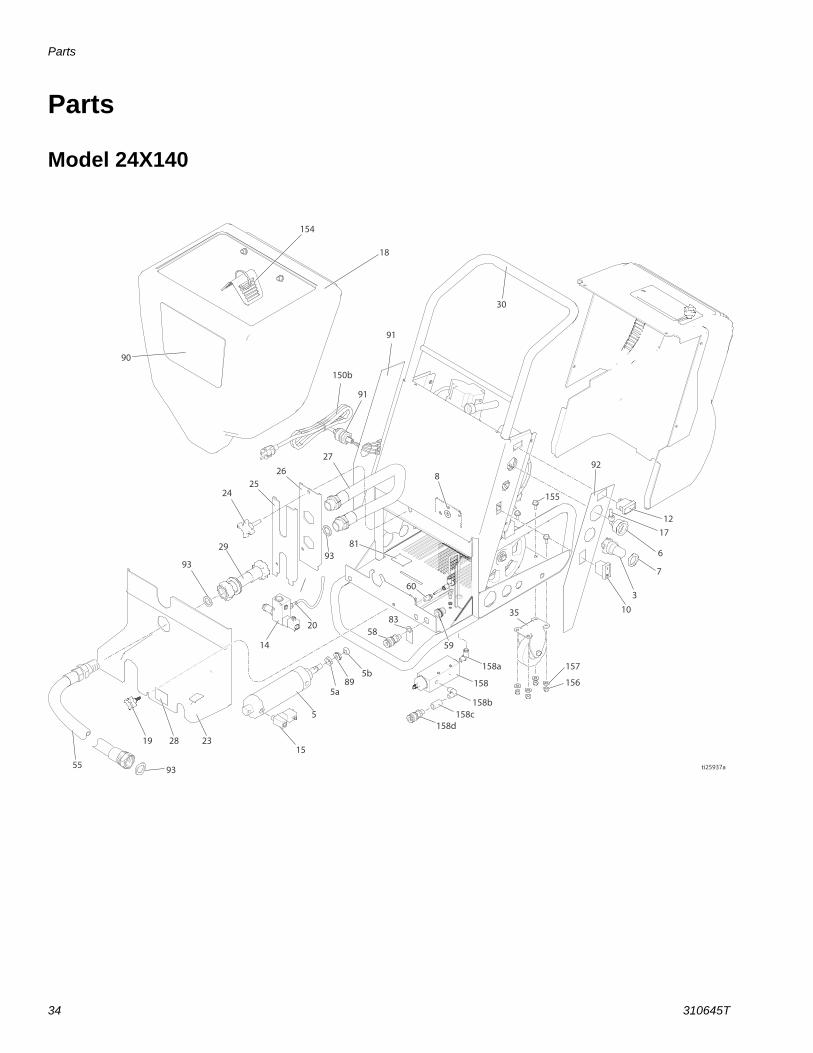
Parts
34 310645T
Parts
Model 24X140
154
18
91
30
91
150b
2425
2627
892
12
6
7
17
310
155
35
157
156
90
19
55 93
28 23
14
15
5
5a
5b
5883
60
59
158a
158
158b 158c
158d
89
9393
8129
20
ti25937a
Parts List
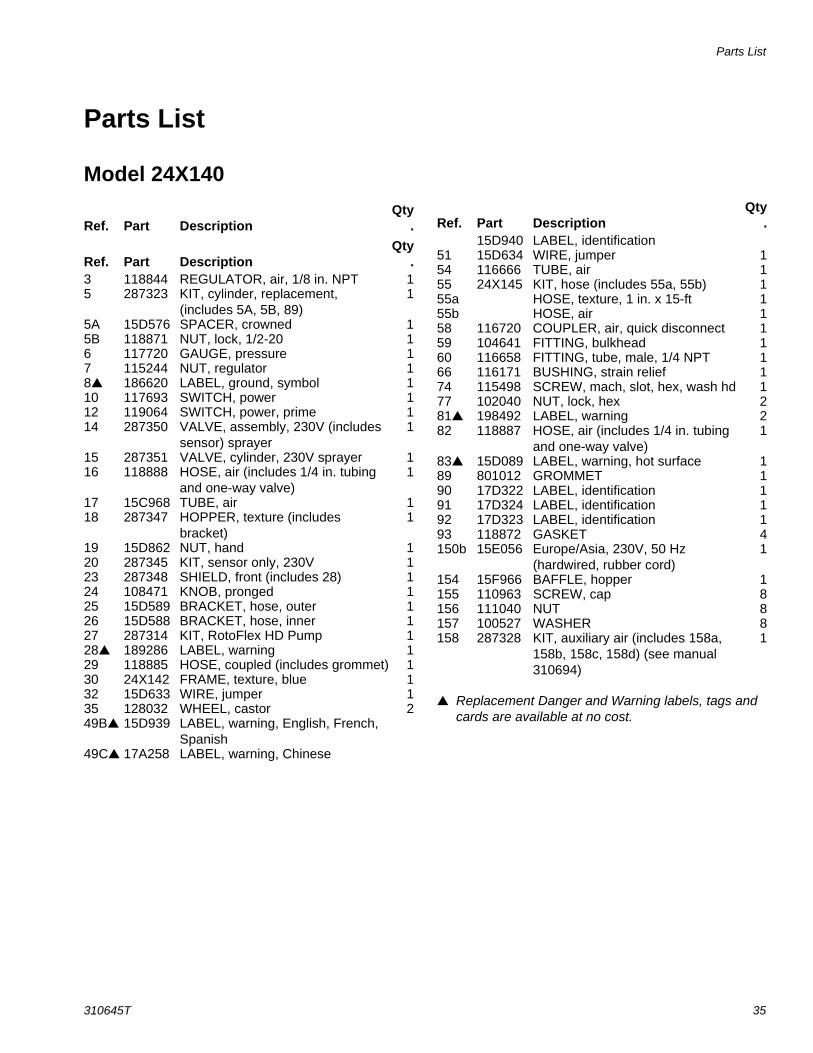
310645T 35
Parts List
Model 24X140
Replacement Danger and Warning labels, tags and cards are available at no cost.
Ref. Part DescriptionQty
.
Ref. Part DescriptionQty
.3 118844 REGULATOR, air, 1/8 in. NPT 15 287323 KIT, cylinder, replacement,
(includes 5A, 5B, 89)1
5A 15D576 SPACER, crowned 15B 118871 NUT, lock, 1/2-20 16 117720 GAUGE, pressure 17 115244 NUT, regulator 18 186620 LABEL, ground, symbol 110 117693 SWITCH, power 112 119064 SWITCH, power, prime 114 287350 VALVE, assembly, 230V (includes
sensor) sprayer1
15 287351 VALVE, cylinder, 230V sprayer 116 118888 HOSE, air (includes 1/4 in. tubing
and one-way valve)1
17 15C968 TUBE, air 118 287347 HOPPER, texture (includes
bracket)1
19 15D862 NUT, hand 120 287345 KIT, sensor only, 230V 123 287348 SHIELD, front (includes 28) 124 108471 KNOB, pronged 125 15D589 BRACKET, hose, outer 126 15D588 BRACKET, hose, inner 127 287314 KIT, RotoFlex HD Pump 128 189286 LABEL, warning 129 118885 HOSE, coupled (includes grommet) 130 24X142 FRAME, texture, blue 132 15D633 WIRE, jumper 135 128032 WHEEL, castor 249B 15D939 LABEL, warning, English, French,
Spanish49C 17A258 LABEL, warning, Chinese
15D940 LABEL, identification51 15D634 WIRE, jumper 154 116666 TUBE, air 155 24X145 KIT, hose (includes 55a, 55b) 155a HOSE, texture, 1 in. x 15-ft 155b HOSE, air 158 116720 COUPLER, air, quick disconnect 159 104641 FITTING, bulkhead 160 116658 FITTING, tube, male, 1/4 NPT 166 116171 BUSHING, strain relief 174 115498 SCREW, mach, slot, hex, wash hd 177 102040 NUT, lock, hex 281 198492 LABEL, warning 282 118887 HOSE, air (includes 1/4 in. tubing
and one-way valve)1
83 15D089 LABEL, warning, hot surface 189 801012 GROMMET 190 17D322 LABEL, identification 191 17D324 LABEL, identification 192 17D323 LABEL, identification 193 118872 GASKET 4150b 15E056 Europe/Asia, 230V, 50 Hz
(hardwired, rubber cord)1
154 15F966 BAFFLE, hopper 1155 110963 SCREW, cap 8156 111040 NUT 8157 100527 WASHER 8158 287328 KIT, auxiliary air (includes 158a,
158b, 158c, 158d) (see manual 310694)
1
Ref. Part DescriptionQty
.

Parts
36 310645T
PartsModel 24X140
4949a
49d19
102
102
1e
53
49b
49c
1a1b
73364531
52
52
43
6388
62
38a38b
3838b
37
31
41
159
57 15
62 88 63
4
9
4234
102
1
1d
101
55a
55b
56 67
ti25938a

Parts List
310645T 37
Parts List
Model 24X140
Replacement Danger and Warning labels, tags and cards are available at no cost.
Ref. Part DescriptionQty
.1 287344 KIT, compressor replacement
(includes 1A, and 1B-1D), 230V sprayers
1
287331 KIT, compressor rebuild, 230V sprayers
1A 119872 SCREW, shoulder 31B 118886 GROMMET, isolator 31D 119381 COVER, terminal 11E 24X818 CAPACITOR, start (230V) 14 118845 BELT 19 117728 FITTING, compression, union 213 15D156 PULLEY, rotor 116 118888 HOSE, air (includes 1/4 in. tubing
and one-way valve)1
19 15D862 NUT, hand 121 118876 TUBE, air, aluminum 122 117637 NUT, compression 131 112395 SCREW, cap 432 15D633 WIRE, jumper 133 103473 STRAP, tie, wire 234 15B815 COOLER 136 101242 RING, retaining, ext. 237 287255 ROTOR, pump, assbly
(includes 38, 38A, 38B)1
38 287321 KIT, roller replacement (includes 38A, 38B and two rollers)
2
38A 113983 RING, retaining, ext 238B 117726 WASHER, nylon 439 15D628 CONDUCTOR, ground 140 103785 RIVET 241 287327 KIT, repair, shaft, bracket, pump
assbly.1
42 287256 BRACKET, compressor 143 118869 TUBE 1
45 15D610 SHAFT, motor, mount 149 287346 SHIELD, rear, assbly
(includes 19, 49A, 49B, 49D)1
49A 15D561 COVER, tool tray 149B 15D939 LABEL, warning, English, French,
Spanish49C 17A258 LABEL, warning, Chinese49D 15D940 LABEL, identification 151 15D634 WIRE, jumper 152 116937 BEARING, flanged, bronze 253 117633 SCREW, slot hex wash hd 854 116666 TUBE, air 155A 24X143 HOSE, material 1 in. x 15-ft 155B 24X144 HOSE, air 156 15C090 GAUGE, thickness, fluid 157 183401 KEY, parallel 258 116720 COUPLER, air, quick disconnect 162 108851 WASHER, plain 263 106276 SCREW, cap, hex head 267 248515 BALL, sponge, 30 mm (5 pk) 273 112785 SCREW, flanged, hex head 274 115498 SCREW, mach, slot, hex, wash hd 182 118887 HOSE, air (includes 1/4 in. tubing
and one-way valve)1
88 118866 WASHER, flat 1101 248091 GUN, non-bleeder 1102 122104 VALVE PLATE, compressor 1159 287227 KIT, fine finish 1
Ref. Part DescriptionQty
.
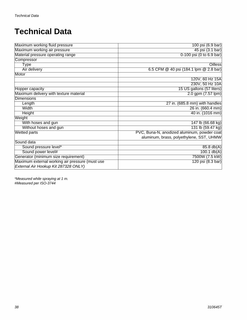
Technical Data
38 310645T
Technical Data
*Measured while spraying at 1 m.#Measured per ISO-3744
Maximum working fluid pressure 100 psi (6.9 bar)Maximum working air pressure 45 psi (3.1 bar)Material pressure operating range 0-100 psi (0 to 6.9 bar)Compressor
Type OillessAir delivery 6.5 CFM @ 40 psi (184.1 lpm @ 2.8 bar)
Motor120V, 60 Hz 15A230V, 50 Hz 10A
Hopper capacity 15 US gallons (57 liters)Maximum delivery with texture material 2.0 gpm (7.57 lpm)Dimensions
Length 27 in. (685.8 mm) with handlesWidth 26 in. (660.4 mm)Height 40 in. (1016 mm)
WeightWith hoses and gun 147 lb (66.68 kg)Without hoses and gun 131 lb (59.47 kg)
Wetted parts PVC, Buna-N, anodized aluminum, powder coataluminum, brass, polyethylene, SST, UHMW
Sound dataSound pressure level* 85.8 db(A)Sound power level# 100.1 db(A)
Generator (minimum size requirement) 7500W (7.5 kW)Maximum external working air pressure (must use External Air Hookup Kit 287328 ONLY)
120 psi (8.3 bar)

Notes
310645T 39
Notes
All written and visual data contained in this document reflects the latest product information available at the time of publication. Graco reserves the right to make changes at any time without notice.
This manual contains English. MM 310645
Graco Headquarters: MinneapolisInternational Offices: Belgium, China, Japan, Korea
GRACO INC. P.O. BOX 1441 MINNEAPOLIS, MN 55440-1441Copyright 2008, Graco Inc. is registered to I.S. EN ISO 9001
www.graco.comRevision T, May 2016
Graco Standard WarrantyGraco warrants all equipment referenced in this document which is manufactured by Graco and bearing its name to be free from defects in material and workmanship on the date of sale to the original purchaser for use. With the exception of any special, extended, or limited warranty published by Graco, Graco will, for a period of twelve months from the date of sale, repair or replace any part of the equipment determined by Graco to be defective. This warranty applies only when the equipment is installed, operated and maintained in accordance with Graco’s written recommendations.
This warranty does not cover, and Graco shall not be liable for general wear and tear, or any malfunction, damage or wear caused by faulty installation, misapplication, abrasion, corrosion, inadequate or improper maintenance, negligence, accident, tampering, or substitution of non-Graco component parts. Nor shall Graco be liable for malfunction, damage or wear caused by the incompatibility of Graco equipment with structures, accessories, equipment or materials not supplied by Graco, or the improper design, manufacture, installation, operation or maintenance of structures, accessories, equipment or materials not supplied by Graco.
This warranty is conditioned upon the prepaid return of the equipment claimed to be defective to an authorized Graco distributor for verification of the claimed defect. If the claimed defect is verified, Graco will repair or replace free of charge any defective parts. The equipment will be returned to the original purchaser transportation prepaid. If inspection of the equipment does not disclose any defect in material or workmanship, repairs will be made at a reasonable charge, which charges may include the costs of parts, labor, and transportation.
THIS WARRANTY IS EXCLUSIVE, AND IS IN LIEU OF ANY OTHER WARRANTIES, EXPRESS OR IMPLIED, INCLUDING BUT NOT LIMITED TO WARRANTY OF MERCHANTABILITY OR WARRANTY OF FITNESS FOR A PARTICULAR PURPOSE.
Graco’s sole obligation and buyer’s sole remedy for any breach of warranty shall be as set forth above. The buyer agrees that no other remedy (including, but not limited to, incidental or consequential damages for lost profits, lost sales, injury to person or property, or any other incidental or consequential loss) shall be available. Any action for breach of warranty must be brought within two (2) years of the date of sale.
GRACO MAKES NO WARRANTY, AND DISCLAIMS ALL IMPLIED WARRANTIES OF MERCHANTABILITY AND FITNESS FOR A PARTICULAR PURPOSE, IN CONNECTION WITH ACCESSORIES, EQUIPMENT, MATERIALS OR COMPONENTS SOLD BUT NOT MANUFACTURED BY GRACO. These items sold, but not manufactured by Graco (such as electric motors, switches, hose, etc.), are subject to the warranty, if any, of their manufacturer. Graco will provide purchaser with reasonable assistance in making any claim for breach of these warranties.
In no event will Graco be liable for indirect, incidental, special or consequential damages resulting from Graco supplying equipment hereunder, or the furnishing, performance, or use of any products or other goods sold hereto, whether due to a breach of contract, breach of warranty, the negligence of Graco, or otherwise.
FOR GRACO CANADA CUSTOMERSThe Parties acknowledge that they have required that the present document, as well as all documents, notices and legal proceedings entered into, given or instituted pursuant hereto or relating directly or indirectly hereto, be drawn up in English. Les parties reconnaissent avoir convenu que la rédaction du présente document sera en Anglais, ainsi que tous documents, avis et procédures judiciaires exécutés, donnés ou intentés, à la suite de ou en rapport, directement ou indirectement, avec les procédures concernées.
Graco InformationFor the latest information about Graco products, visit www.graco.com.
For patent information, see www.graco.com/patents.
TO PLACE AN ORDER, contact your Graco distributor or call 1-800-690-2894 to identify the nearest distributor.