Embed Size (px)
Citation preview
310864HEN
Instructions
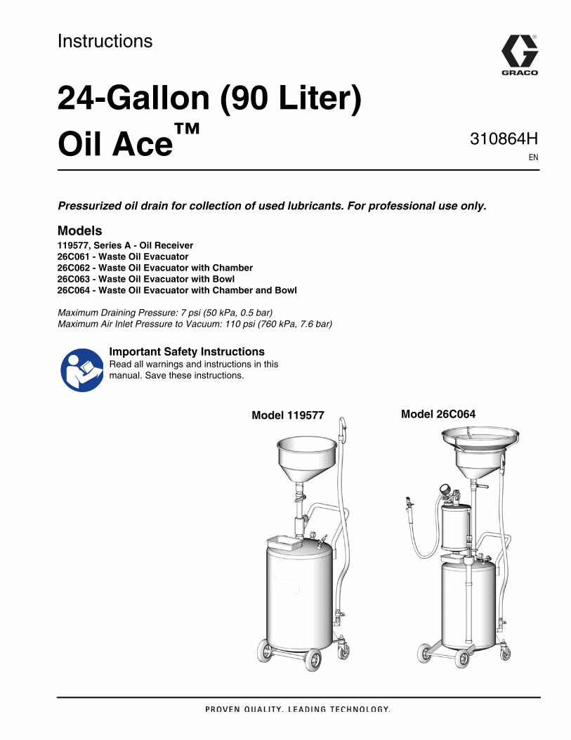
24-Gallon (90 Liter) Oil Ace™
Pressurized oil drain for collection of used lubricants. For professional use only.
Models119577, Series A - Oil Receiver26C061 - Waste Oil Evacuator26C062 - Waste Oil Evacuator with Chamber26C063 - Waste Oil Evacuator with Bowl26C064 - Waste Oil Evacuator with Chamber and Bowl
Maximum Draining Pressure: 7 psi (50 kPa, 0.5 bar)Maximum Air Inlet Pressure to Vacuum: 110 psi (760 kPa, 7.6 bar)
Important Safety InstructionsRead all warnings and instructions in this manual. Save these instructions.
Model 119577 Model 26C064
Warnings
2 310864H
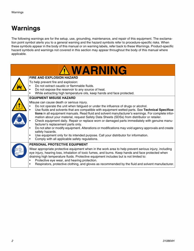
WarningsThe following warnings are for the setup, use, grounding, maintenance, and repair of this equipment. The exclama-tion point symbol alerts you to a general warning and the hazard symbols refer to procedure-specific risks. When these symbols appear in the body of this manual or on warning labels, refer back to these Warnings. Product-specific hazard symbols and warnings not covered in this section may appear throughout the body of this manual where applicable.
WARNINGFIRE AND EXPLOSION HAZARD To help prevent fire and explosion:• Do not extract caustic or flammable fluids.• Do not expose the reservoir to any source of heat.• While extracting high temperature oils, keep hands and face protected.
EQUIPMENT MISUSE HAZARD Misuse can cause death or serious injury.• Do not operate the unit when fatigued or under the influence of drugs or alcohol.• Use fluids and solvents that are compatible with equipment wetted parts. See Technical Specifica-
tions in all equipment manuals. Read fluid and solvent manufacturer’s warnings. For complete infor-mation about your material, request Safety Data Sheets (SDSs) from distributor or retailer.
• Check equipment daily. Repair or replace worn or damaged parts immediately with genuine manu-facturer’s replacement parts only.
• Do not alter or modify equipment. Alterations or modifications may void agency approvals and create safety hazards.
• Use equipment only for its intended purpose. Call your distributor for information.• Comply with all applicable safety regulations.
PERSONAL PROTECTIVE EQUIPMENT Wear appropriate protective equipment when in the work area to help prevent serious injury, including eye injury, hearing loss, inhalation of toxic fumes, and burns. Keep hands and face protected when draining high temperature fluids. Protective equipment includes but is not limited to:• Protective eye wear, and hearing protection. • Respirators, protective clothing, and gloves as recommended by the fluid and solvent manufacturer.
Valve Identification
310864H 3
Valve Identification
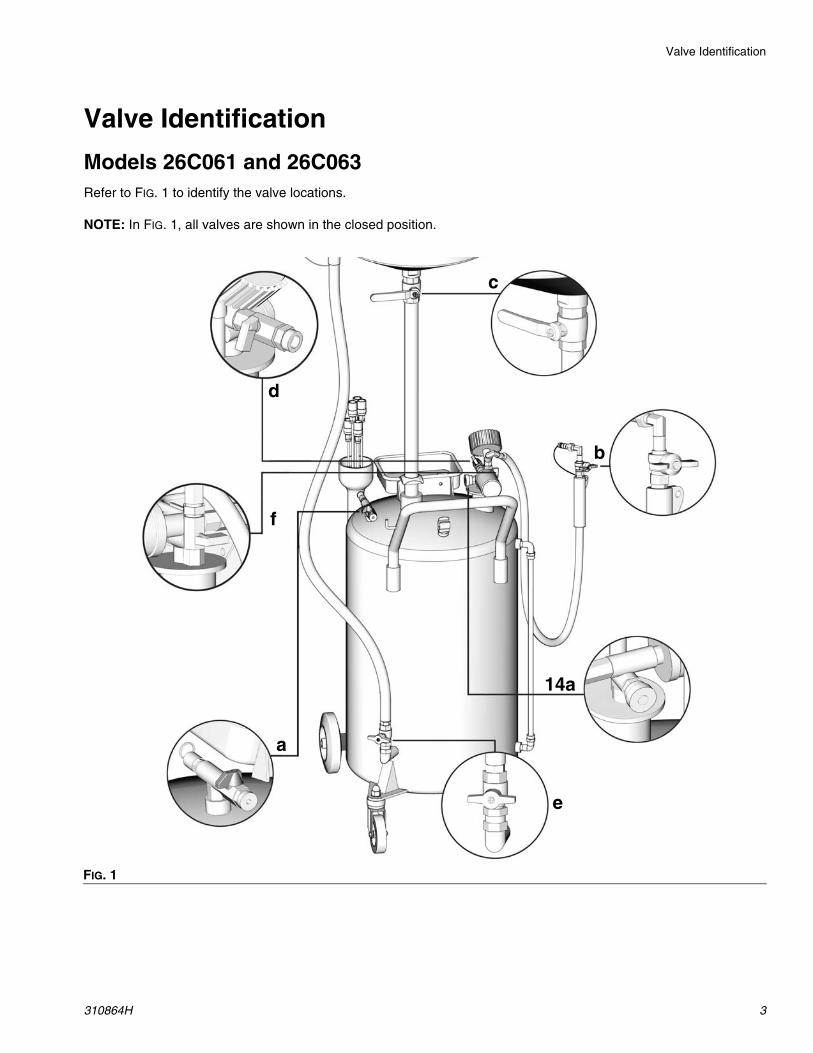
Models 26C061 and 26C063Refer to FIG. 1 to identify the valve locations.
NOTE: In FIG. 1, all valves are shown in the closed position.
FIG. 1
a
c
d
b
e
f
14a
Valve Identification
4 310864H
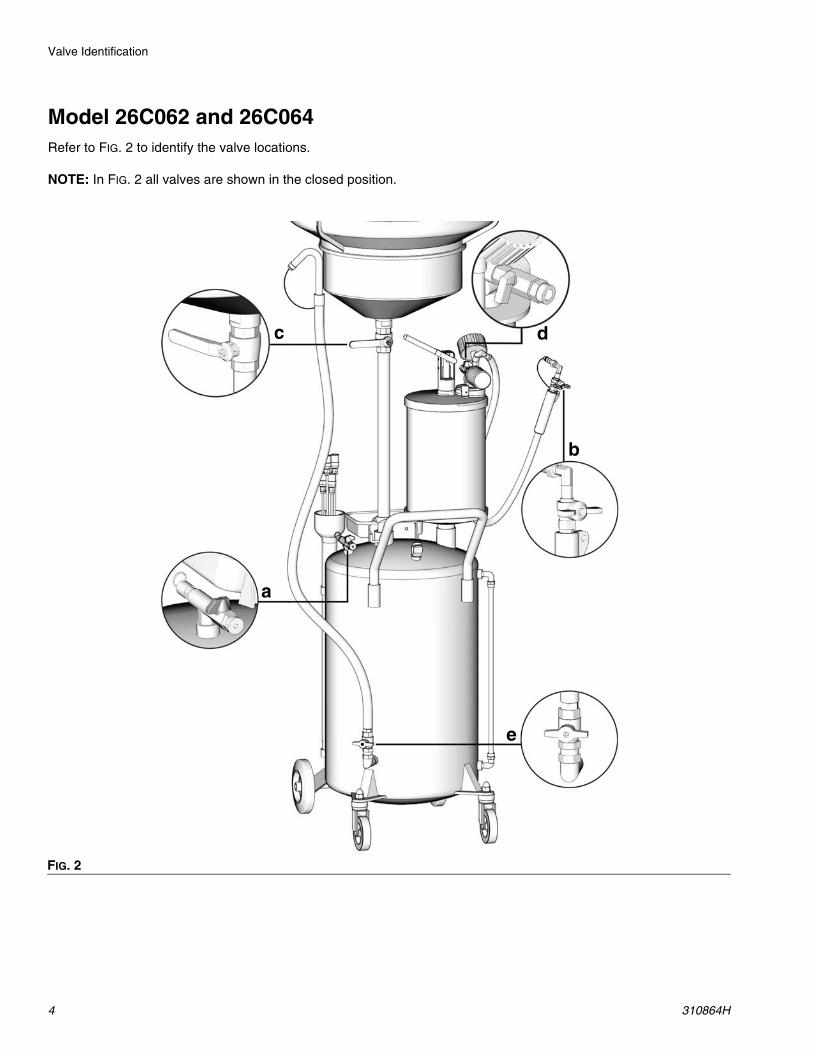
Model 26C062 and 26C064Refer to FIG. 2 to identify the valve locations.
NOTE: In FIG. 2 all valves are shown in the closed position.
FIG. 2
a
c
d
b
e
c
a
d
b
e
Setup
310864H 5
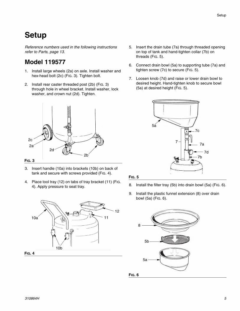
SetupReference numbers used in the following instructions refer to Parts, page 13.
Model 1195771. Install large wheels (2a) on axle. Install washer and
hex-head bolt (2c) (FIG. 3). Tighten bolt.
2. Install rear caster threaded post (2b) (FIG. 3) through hole in wheel bracket. Install washer, lock washer, and crown nut (2d). Tighten.
3. Insert handle (10a) into brackets (10b) on back of tank and secure with screws provided (FIG. 4).
4. Place tool tray (12) on tabs of tray bracket (11) (FIG. 4). Apply pressure to seat tray.
5. Insert the drain tube (7a) through threaded opening on top of tank and hand-tighten collar (7b) on threads (FIG. 5).
6. Connect drain bowl (5a) to supporting tube (7a) and tighten screw (7c) to secure (FIG. 5).
7. Loosen knob (7d) and raise or lower drain bowl to desired height. Hand-tighten knob to secure bowl (5a) at desired height (FIG. 5).
8. Install the filter tray (5b) into drain bowl (5a) (FIG. 6).
9. Install the plastic funnel extension (8) over drain bowl (5a) (FIG. 6).
FIG. 3
FIG. 4
2a
2b
2c
2d
10b
10a 11
12
FIG. 5
FIG. 6
7
5a7c
7b7d
7a
8
5b
5a
Setup
6 310864H
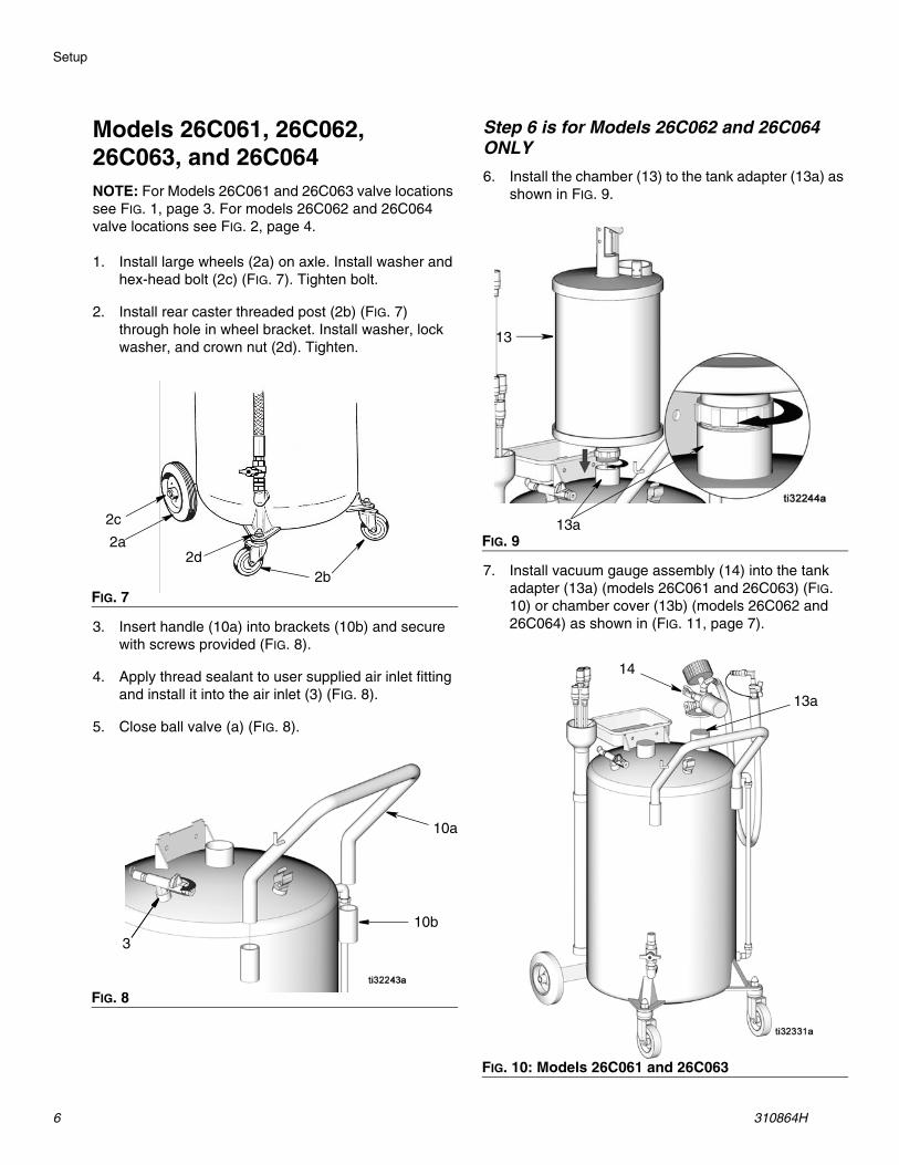
Models 26C061, 26C062, 26C063, and 26C064NOTE: For Models 26C061 and 26C063 valve locations see FIG. 1, page 3. For models 26C062 and 26C064 valve locations see FIG. 2, page 4.
1. Install large wheels (2a) on axle. Install washer and hex-head bolt (2c) (FIG. 7). Tighten bolt.
2. Install rear caster threaded post (2b) (FIG. 7) through hole in wheel bracket. Install washer, lock washer, and crown nut (2d). Tighten.
3. Insert handle (10a) into brackets (10b) and secure with screws provided (FIG. 8).
4. Apply thread sealant to user supplied air inlet fitting and install it into the air inlet (3) (FIG. 8).
5. Close ball valve (a) (FIG. 8).
Step 6 is for Models 26C062 and 26C064 ONLY6. Install the chamber (13) to the tank adapter (13a) as
shown in FIG. 9.
7. Install vacuum gauge assembly (14) into the tank adapter (13a) (models 26C061 and 26C063) (FIG. 10) or chamber cover (13b) (models 26C062 and 26C064) as shown in (FIG. 11, page 7).
FIG. 7
FIG. 8
2a
2b
2c
2d
10b
10a
3
FIG. 9
FIG. 10: Models 26C061 and 26C063
13
13a
14
13a
Setup
310864H 7
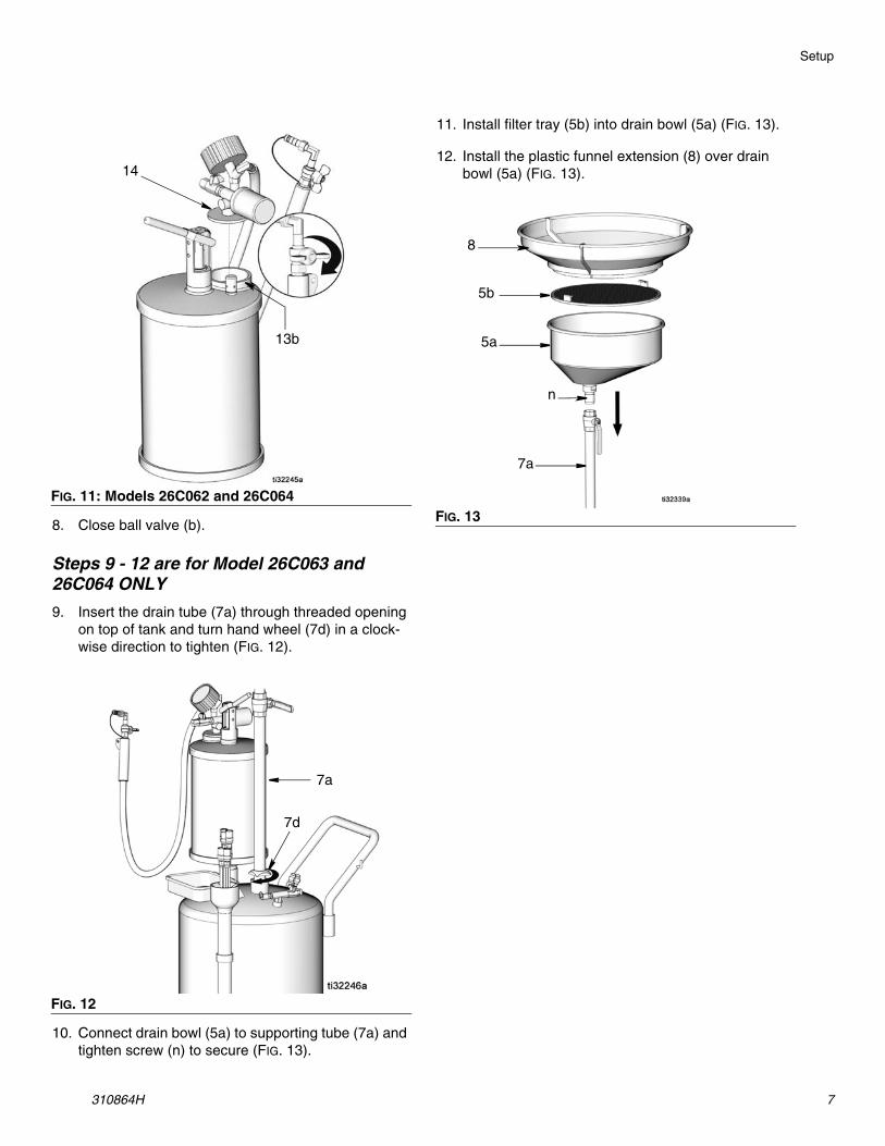
8. Close ball valve (b).
Steps 9 - 12 are for Model 26C063 and 26C064 ONLY9. Insert the drain tube (7a) through threaded opening
on top of tank and turn hand wheel (7d) in a clock-wise direction to tighten (FIG. 12).
10. Connect drain bowl (5a) to supporting tube (7a) and tighten screw (n) to secure (FIG. 13).
11. Install filter tray (5b) into drain bowl (5a) (FIG. 13).
12. Install the plastic funnel extension (8) over drain bowl (5a) (FIG. 13).
FIG. 11: Models 26C062 and 26C064
FIG. 12
14
13b
7a
7d
FIG. 13
5a
5b
8
n
7a
Operation
8 310864H
Operation
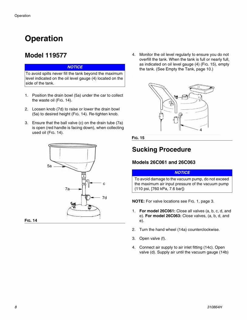
Model 119577
1. Position the drain bowl (5a) under the car to collect the waste oil (FIG. 14).
2. Loosen knob (7d) to raise or lower the drain bowl (5a) to desired height (FIG. 14). Re-tighten knob.
3. Ensure that the ball valve (c) on the drain tube (7a) is open (red handle is facing down), when collecting used oil (FIG. 14).
4. Monitor the oil level regularly to ensure you do not overfill the tank. When the tank is full or nearly full, as indicated on oil level gauge (4) (FIG. 15), empty the tank. (See Empty the Tank, page 10.)
.
Sucking Procedure
Models 26C061 and 26C063
NOTE: For valve locations see FIG. 1, page 3.
1. For model 26C061: Close all valves (a, b, c, d, and e). For model 26C063: Close valves, (a, b, d, and e).
2. Turn the hand wheel (14a) counterclockwise.
3. Open valve (f).
4. Connect air supply to air inlet fitting (14c). Open valve (d). Supply air until the vacuum gauge (14b)
NOTICETo avoid spills never fill the tank beyond the maximum level indicated on the oil level gauge (4) located on the side of the tank.
FIG. 14
c7a
5a
7d
FIG. 15
NOTICETo avoid damage to the vacuum pump, do not exceed the maximum air input pressure of the vacuum pump (110 psi, [760 kPa, 7.6 bar])
4
Operation
310864H 9
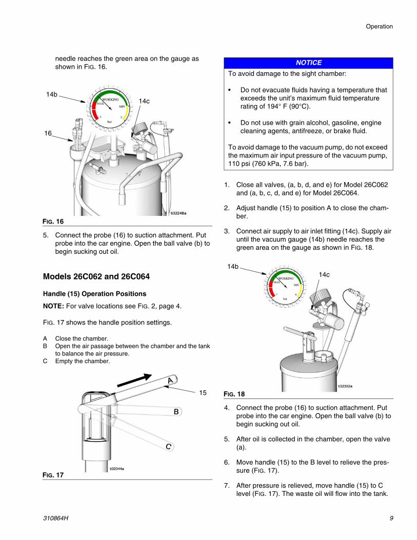
needle reaches the green area on the gauge as shown in FIG. 16.
5. Connect the probe (16) to suction attachment. Put probe into the car engine. Open the ball valve (b) to begin sucking out oil.
Models 26C062 and 26C064
Handle (15) Operation Positions
NOTE: For valve locations see FIG. 2, page 4.
FIG. 17 shows the handle position settings.
A Close the chamber.B Open the air passage between the chamber and the tank
to balance the air pressure.C Empty the chamber.
1. Close all valves, (a, b, d, and e) for Model 26C062 and (a, b, c, d, and e) for Model 26C064.
2. Adjust handle (15) to position A to close the cham-ber.
3. Connect air supply to air inlet fitting (14c). Supply air until the vacuum gauge (14b) needle reaches the green area on the gauge as shown in FIG. 18.
4. Connect the probe (16) to suction attachment. Put probe into the car engine. Open the ball valve (b) to begin sucking out oil.
5. After oil is collected in the chamber, open the valve (a).
6. Move handle (15) to the B level to relieve the pres-sure (FIG. 17).
7. After pressure is relieved, move handle (15) to C level (FIG. 17). The waste oil will flow into the tank.
FIG. 16
FIG. 17
14b14c
16
15
NOTICETo avoid damage to the sight chamber:
• Do not evacuate fluids having a temperature that exceeds the unit’s maximum fluid temperature rating of 194° F (90°C).
• Do not use with grain alcohol, gasoline, engine cleaning agents, antifreeze, or brake fluid.
To avoid damage to the vacuum pump, do not exceed the maximum air input pressure of the vacuum pump, 110 psi (760 kPa, 7.6 bar).
FIG. 18
14b14c
Operation
10 310864H
Collecting Procedure Models 26C063 and 26C064NOTE: For valve locations see FIG. 1, page 3 for model 26C063 or FIG. 2, page 4.
1. Close all valves, (a, b, c, d, and e) (Model 26C063, see FIG. 1, page 3; Model 26C064 see FIG. 2, page 4).
2. Open valves (a and c) (Model 26C063, see FIG. 1, page 3; Model 26C064 see FIG. 2, page 4).
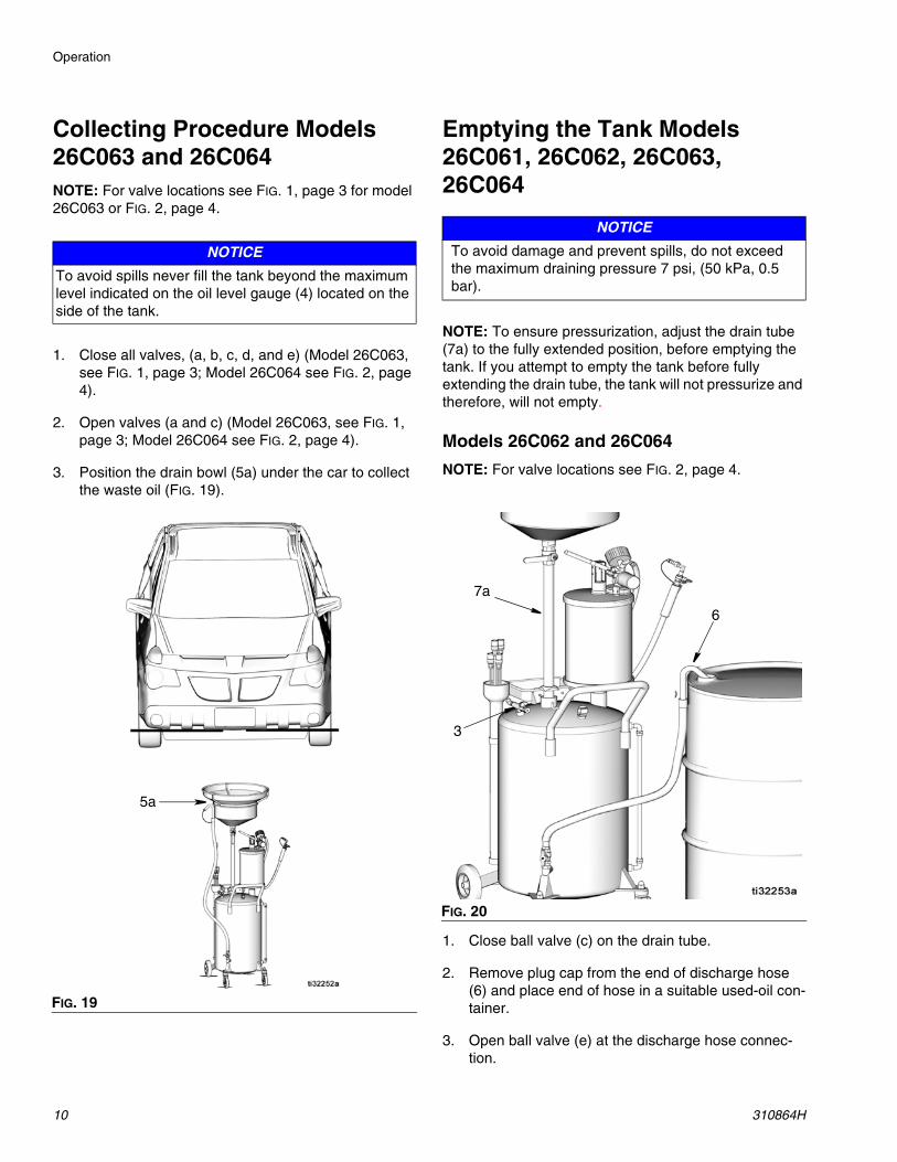
3. Position the drain bowl (5a) under the car to collect the waste oil (FIG. 19).
Emptying the Tank Models 26C061, 26C062, 26C063, 26C064
NOTE: To ensure pressurization, adjust the drain tube (7a) to the fully extended position, before emptying the tank. If you attempt to empty the tank before fully extending the drain tube, the tank will not pressurize and therefore, will not empty.
Models 26C062 and 26C064
NOTE: For valve locations see FIG. 2, page 4.
1. Close ball valve (c) on the drain tube.
2. Remove plug cap from the end of discharge hose (6) and place end of hose in a suitable used-oil con-tainer.
3. Open ball valve (e) at the discharge hose connec-tion.
NOTICETo avoid spills never fill the tank beyond the maximum level indicated on the oil level gauge (4) located on the side of the tank.
FIG. 19
5a
NOTICETo avoid damage and prevent spills, do not exceed the maximum draining pressure 7 psi, (50 kPa, 0.5 bar).
FIG. 20
6
7a
3
Operation
310864H 11
4. Connect 7 psi, (48.26 kPa, 0.48 bar) compressed air to air inlet (3). Open valve (a).
5. When the tank is empty, remove end of hose from used-oil container and replace plug cap over hose end.
6. Close ball valve (e) and then open ball valve (c).
7. The tank is ready for continued use.
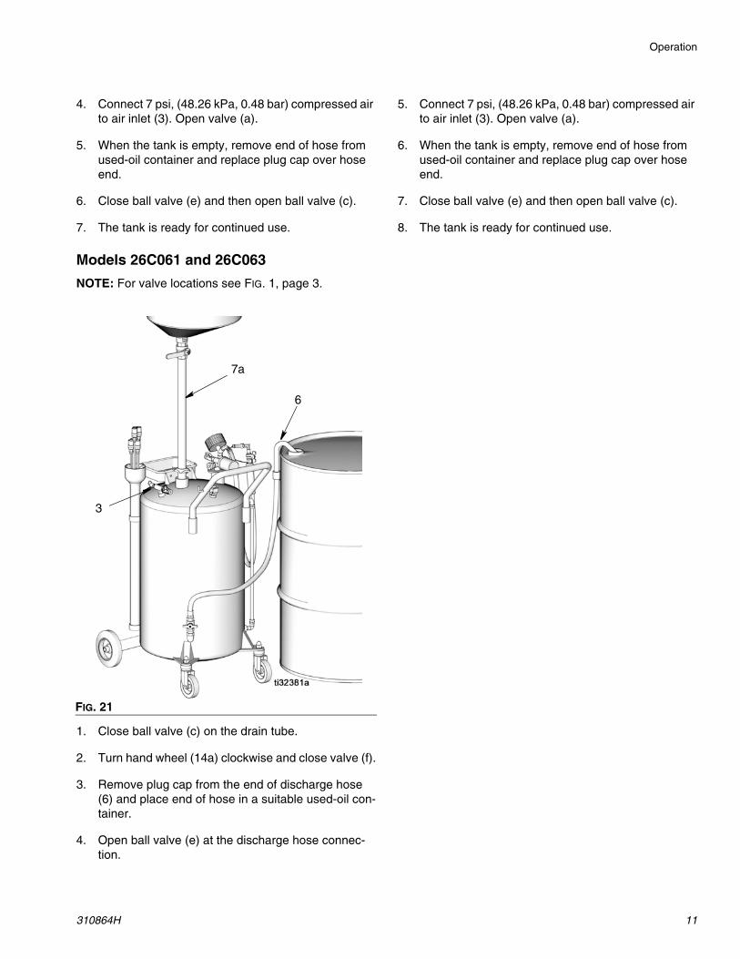
Models 26C061 and 26C063
NOTE: For valve locations see FIG. 1, page 3.
1. Close ball valve (c) on the drain tube.
2. Turn hand wheel (14a) clockwise and close valve (f).
3. Remove plug cap from the end of discharge hose (6) and place end of hose in a suitable used-oil con-tainer.
4. Open ball valve (e) at the discharge hose connec-tion.
5. Connect 7 psi, (48.26 kPa, 0.48 bar) compressed air to air inlet (3). Open valve (a).
6. When the tank is empty, remove end of hose from used-oil container and replace plug cap over hose end.
7. Close ball valve (e) and then open ball valve (c).
8. The tank is ready for continued use.
FIG. 21
6
7a
3
Troubleshooting
12 310864H
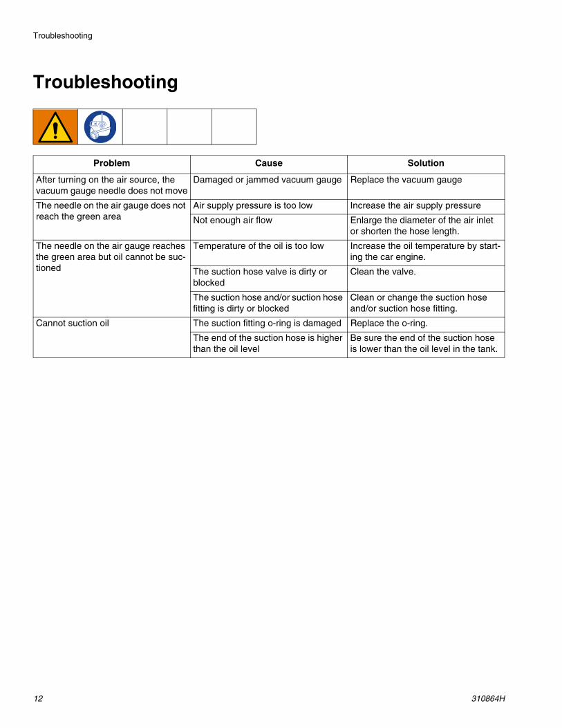
Troubleshooting
Problem Cause Solution
After turning on the air source, the vacuum gauge needle does not move
Damaged or jammed vacuum gauge Replace the vacuum gauge
The needle on the air gauge does not reach the green area
Air supply pressure is too low Increase the air supply pressure
Not enough air flow Enlarge the diameter of the air inlet or shorten the hose length.
The needle on the air gauge reaches the green area but oil cannot be suc-tioned
Temperature of the oil is too low Increase the oil temperature by start-ing the car engine.
The suction hose valve is dirty or blocked
Clean the valve.
The suction hose and/or suction hose fitting is dirty or blocked
Clean or change the suction hose and/or suction hose fitting.
Cannot suction oil The suction fitting o-ring is damaged Replace the o-ring.
The end of the suction hose is higher than the oil level
Be sure the end of the suction hose is lower than the oil level in the tank.
Parts Model 119577
310864H 13
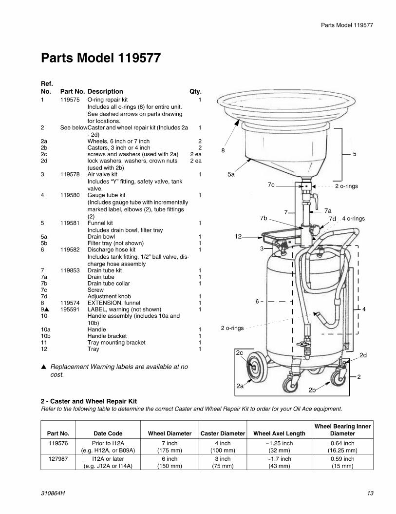
Parts Model 119577
Replacement Warning labels are available at no cost.
2 - Caster and Wheel Repair Kit Refer to the following table to determine the correct Caster and Wheel Repair Kit to order for your Oil Ace equipment.
Ref. No. Part No. Description Qty.1 119575 O-ring repair kit
Includes all o-rings (8) for entire unit. See dashed arrows on parts drawing for locations.
1
2 See belowCaster and wheel repair kit (Includes 2a - 2d)
1
2a Wheels, 6 inch or 7 inch 22b Casters, 3 inch or 4 inch 22c screws and washers (used with 2a) 2 ea2d lock washers, washers, crown nuts
(used with 2b)2 ea
3 119578 Air valve kitIncludes “Y” fitting, safety valve, tank valve.
1
4 119580 Gauge tube kit(Includes gauge tube with incrementally marked label, elbows (2), tube fittings (2)
1
5 119581 Funnel kitIncludes drain bowl, filter tray
1
5a Drain bowl 15b Filter tray (not shown) 16 119582 Discharge hose kit
Includes tank fitting, 1/2” ball valve, dis-charge hose assembly
1
7 119853 Drain tube kit 17a Drain tube 17b Drain tube collar 17c Screw7d Adjustment knob 18 119574 EXTENSION, funnel 19 195591 LABEL, warning (not shown) 110 Handle assembly (includes 10a and
10b)10a Handle 110b Handle bracket 111 Tray mounting bracket 112 Tray 1
7
2
3
46
2 o-rings
4 o-rings
2 o-rings
58
7a7b
12
7d
5a
7c
2a2b
2c 2d
Part No. Date Code Wheel Diameter Caster Diameter Wheel Axel LengthWheel Bearing Inner
Diameter
119576 Prior to I12A(e.g. H12A, or B09A)
7 inch (175 mm)
4 inch (100 mm)
~1.25 inch (32 mm)
0.64 inch (16.25 mm)
127987 I12A or later(e.g. J12A or I14A)
6 inch(150 mm)
3 inch(75 mm)
~1.7 inch(43 mm)
0.59 inch(15 mm)
Parts Models 26C061 and 26C063
14 310864H
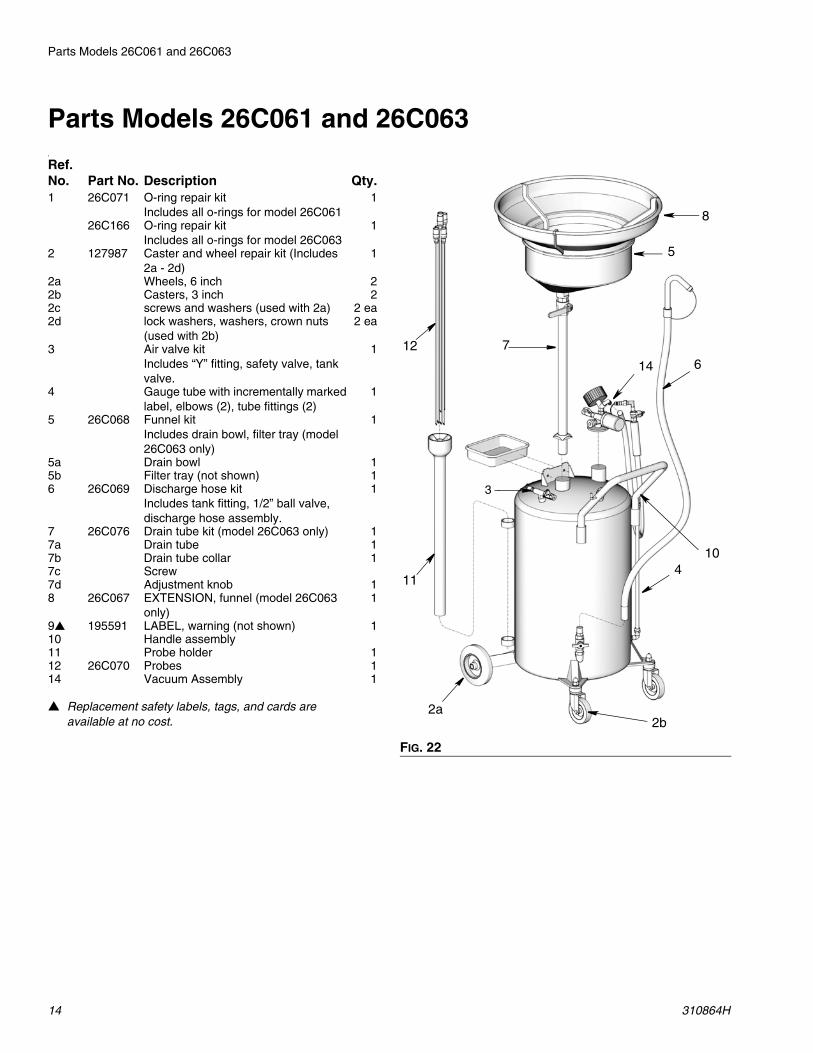
Parts Models 26C061 and 26C0631
Replacement safety labels, tags, and cards are available at no cost.
Ref. No. Part No. Description Qty.1 26C071 O-ring repair kit
Includes all o-rings for model 26C061 1
26C166 O-ring repair kitIncludes all o-rings for model 26C063
1
2 127987 Caster and wheel repair kit (Includes 2a - 2d)
1
2a Wheels, 6 inch 22b Casters, 3 inch 22c screws and washers (used with 2a) 2 ea2d lock washers, washers, crown nuts
(used with 2b)2 ea
3 Air valve kitIncludes “Y” fitting, safety valve, tank valve.
1
4 Gauge tube with incrementally marked label, elbows (2), tube fittings (2)
1
5 26C068 Funnel kitIncludes drain bowl, filter tray (model 26C063 only)
1
5a Drain bowl 15b Filter tray (not shown) 16 26C069 Discharge hose kit
Includes tank fitting, 1/2” ball valve, discharge hose assembly.
1
7 26C076 Drain tube kit (model 26C063 only) 17a Drain tube 17b Drain tube collar 17c Screw7d Adjustment knob 18 26C067 EXTENSION, funnel (model 26C063
only)1
9 195591 LABEL, warning (not shown) 110 Handle assembly 11 Probe holder 112 26C070 Probes 114 Vacuum Assembly 1
FIG. 22
3
14
8
5
6
7
10
2a2b
11
12
4
Part No. 26C062 and 26C064
310864H 15
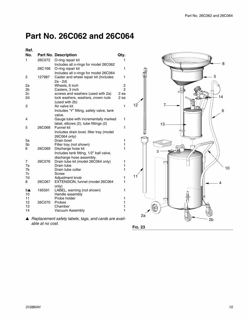
Part No. 26C062 and 26C064
Replacement safety labels, tags, and cards are avail-able at no cost.
Ref. No. Part No. Description Qty.1 26C072 O-ring repair kit
Includes all o-rings for model 26C0621
26C168 O-ring repair kitIncludes all o-rings for model 26C064
1
2 127987 Caster and wheel repair kit (Includes 2a - 2d)
1
2a Wheels, 6 inch 22b Casters, 3 inch 22c screws and washers (used with 2a) 2 ea2d lock washers, washers, crown nuts
(used with 2b)2 ea
3 Air valve kitIncludes “Y” fitting, safety valve, tank valve.
1
4 Gauge tube with incrementally marked label, elbows (2), tube fittings (2)
1
5 26C068 Funnel kitIncludes drain bowl, filter tray (model 26C064 only)
1
5a Drain bowl 15b Filter tray (not shown) 16 26C069 Discharge hose kit
Includes tank fitting, 1/2” ball valve, discharge hose assembly.
1
7 26C076 Drain tube kit (model 26C064 only) 17a Drain tube 17b Drain tube collar 17c Screw7d Adjustment knob 18 26C067 EXTENSION, funnel (model 26C064
only)1
9 195591 LABEL, warning (not shown) 110 Handle assembly 11 Probe holder 112 26C070 Probes 113 Chamber 114 Vacuum Assembly 1
FIG. 23
3
14
8
5
6
7
10
2a2b
11
12
13
4
Technical Specifications
16 310864H
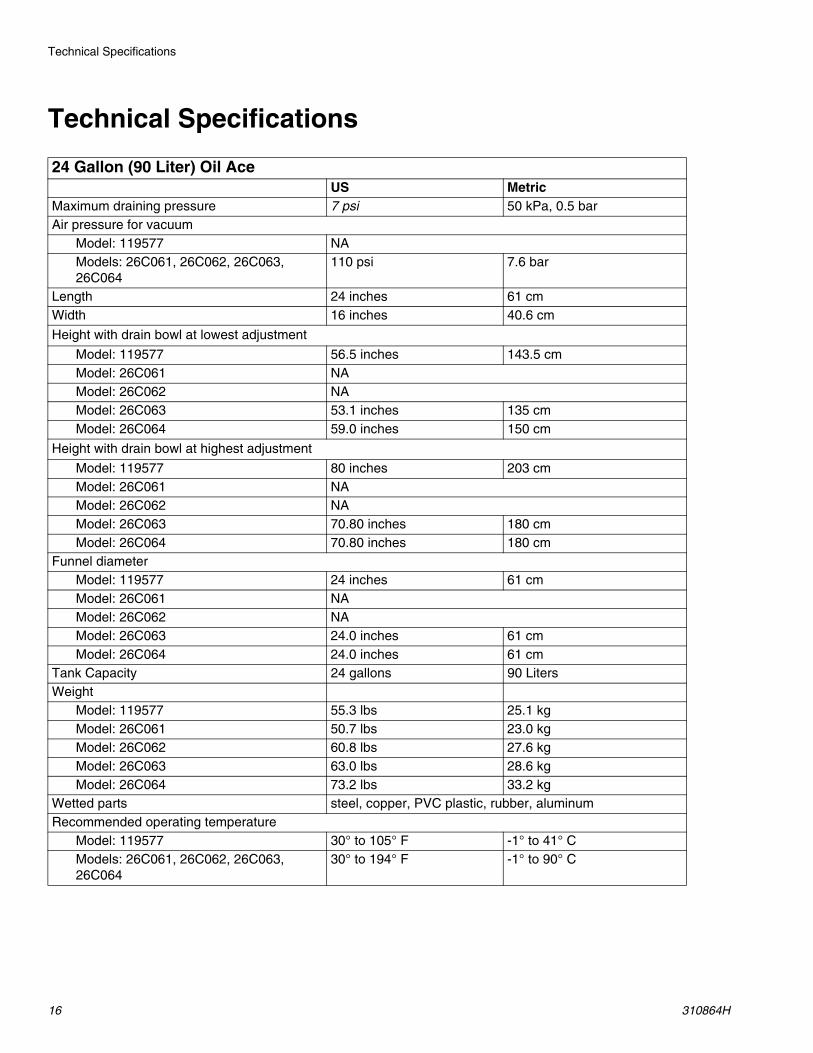
Technical Specifications
24 Gallon (90 Liter) Oil AceUS Metric
Maximum draining pressure 7 psi 50 kPa, 0.5 barAir pressure for vacuum
Model: 119577 NAModels: 26C061, 26C062, 26C063, 26C064
110 psi 7.6 bar
Length 24 inches 61 cmWidth 16 inches 40.6 cm
Height with drain bowl at lowest adjustment
Model: 119577 56.5 inches 143.5 cmModel: 26C061 NAModel: 26C062 NAModel: 26C063 53.1 inches 135 cmModel: 26C064 59.0 inches 150 cm
Height with drain bowl at highest adjustment
Model: 119577 80 inches 203 cmModel: 26C061 NAModel: 26C062 NAModel: 26C063 70.80 inches 180 cmModel: 26C064 70.80 inches 180 cm
Funnel diameterModel: 119577 24 inches 61 cmModel: 26C061 NAModel: 26C062 NAModel: 26C063 24.0 inches 61 cmModel: 26C064 24.0 inches 61 cm
Tank Capacity 24 gallons 90 LitersWeight
Model: 119577 55.3 lbs 25.1 kgModel: 26C061 50.7 lbs 23.0 kgModel: 26C062 60.8 lbs 27.6 kgModel: 26C063 63.0 lbs 28.6 kgModel: 26C064 73.2 lbs 33.2 kg
Wetted parts steel, copper, PVC plastic, rubber, aluminumRecommended operating temperature
Model: 119577 30° to 105° F -1° to 41° CModels: 26C061, 26C062, 26C063, 26C064
30° to 194° F -1° to 90° C
Notes
310864H 17
Notes
All written and visual data contained in this document reflects the latest product information available at the time of publication. Graco reserves the right to make changes at any time without notice.
Original instructions. This manual contains English. MM310864Graco Headquarters: Minneapolis
International Offices: Belgium, China, Japan, Korea
GRACO INC. AND SUBSIDIARIES • P.O. BOX 1441 • MINNEAPOLIS MN 55440-1441 • USACopyright 2005, Graco Inc. All Graco manufacturing locations are registered to ISO 9001.
www.graco.comDecember 2017
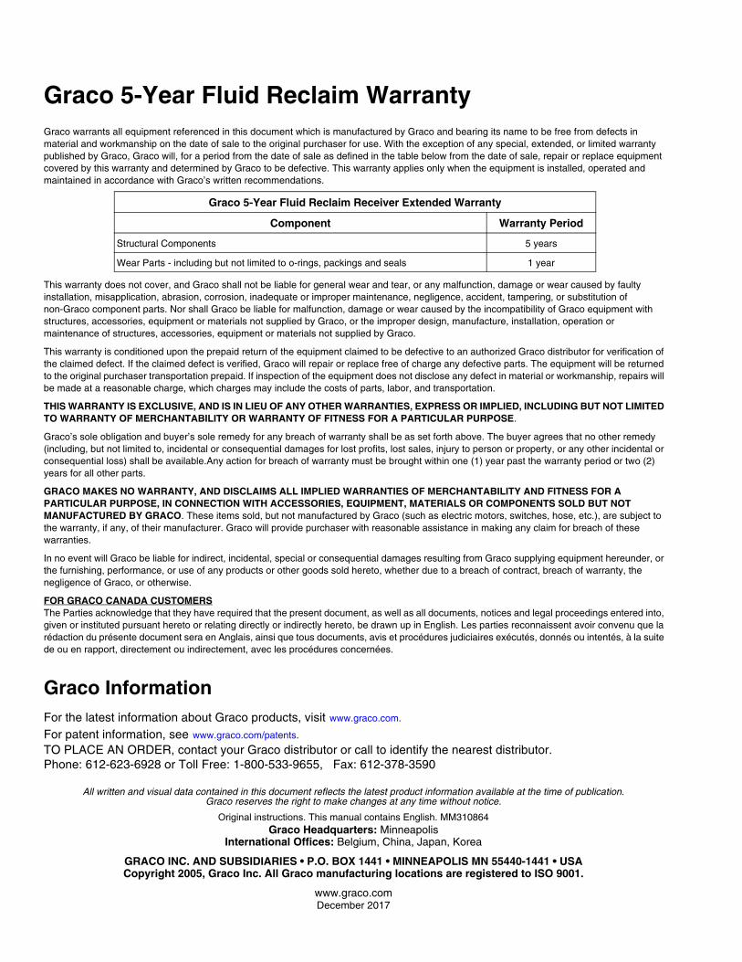
Graco 5-Year Fluid Reclaim WarrantyGraco warrants all equipment referenced in this document which is manufactured by Graco and bearing its name to be free from defects in material and workmanship on the date of sale to the original purchaser for use. With the exception of any special, extended, or limited warranty published by Graco, Graco will, for a period from the date of sale as defined in the table below from the date of sale, repair or replace equipment covered by this warranty and determined by Graco to be defective. This warranty applies only when the equipment is installed, operated and maintained in accordance with Graco’s written recommendations.
This warranty does not cover, and Graco shall not be liable for general wear and tear, or any malfunction, damage or wear caused by faulty installation, misapplication, abrasion, corrosion, inadequate or improper maintenance, negligence, accident, tampering, or substitution of non-Graco component parts. Nor shall Graco be liable for malfunction, damage or wear caused by the incompatibility of Graco equipment with structures, accessories, equipment or materials not supplied by Graco, or the improper design, manufacture, installation, operation or maintenance of structures, accessories, equipment or materials not supplied by Graco.
This warranty is conditioned upon the prepaid return of the equipment claimed to be defective to an authorized Graco distributor for verification of the claimed defect. If the claimed defect is verified, Graco will repair or replace free of charge any defective parts. The equipment will be returned to the original purchaser transportation prepaid. If inspection of the equipment does not disclose any defect in material or workmanship, repairs will be made at a reasonable charge, which charges may include the costs of parts, labor, and transportation.
THIS WARRANTY IS EXCLUSIVE, AND IS IN LIEU OF ANY OTHER WARRANTIES, EXPRESS OR IMPLIED, INCLUDING BUT NOT LIMITED TO WARRANTY OF MERCHANTABILITY OR WARRANTY OF FITNESS FOR A PARTICULAR PURPOSE.
Graco’s sole obligation and buyer’s sole remedy for any breach of warranty shall be as set forth above. The buyer agrees that no other remedy (including, but not limited to, incidental or consequential damages for lost profits, lost sales, injury to person or property, or any other incidental or consequential loss) shall be available.Any action for breach of warranty must be brought within one (1) year past the warranty period or two (2) years for all other parts.
GRACO MAKES NO WARRANTY, AND DISCLAIMS ALL IMPLIED WARRANTIES OF MERCHANTABILITY AND FITNESS FOR A PARTICULAR PURPOSE, IN CONNECTION WITH ACCESSORIES, EQUIPMENT, MATERIALS OR COMPONENTS SOLD BUT NOT MANUFACTURED BY GRACO. These items sold, but not manufactured by Graco (such as electric motors, switches, hose, etc.), are subject to the warranty, if any, of their manufacturer. Graco will provide purchaser with reasonable assistance in making any claim for breach of these warranties.
In no event will Graco be liable for indirect, incidental, special or consequential damages resulting from Graco supplying equipment hereunder, or the furnishing, performance, or use of any products or other goods sold hereto, whether due to a breach of contract, breach of warranty, the negligence of Graco, or otherwise.
FOR GRACO CANADA CUSTOMERSThe Parties acknowledge that they have required that the present document, as well as all documents, notices and legal proceedings entered into, given or instituted pursuant hereto or relating directly or indirectly hereto, be drawn up in English. Les parties reconnaissent avoir convenu que la rédaction du présente document sera en Anglais, ainsi que tous documents, avis et procédures judiciaires exécutés, donnés ou intentés, à la suite de ou en rapport, directement ou indirectement, avec les procédures concernées.
Graco Information For the latest information about Graco products, visit www.graco.com.
For patent information, see www.graco.com/patents.
TO PLACE AN ORDER, contact your Graco distributor or call to identify the nearest distributor.Phone: 612-623-6928 or Toll Free: 1-800-533-9655, Fax: 612-378-3590
Graco 5-Year Fluid Reclaim Receiver Extended Warranty
Component Warranty Period
Structural Components 5 years
Wear Parts - including but not limited to o-rings, packings and seals 1 year