Embed Size (px)
Citation preview

For water-based materials only. For professional use only. Not approved for use inEuropean explosive atmosphere locations.
Model 248195, Series AModel 248269, Series AModel 249075, Series A
580 psi (4 MPa, 40 bar) Maximum Working Pressure
IMPORTANT SAFETY INSTRUCTIONSRead all warnings and instructions in thismanual. Save these instructions.
309973
309978
�������
Repair
T-Max 405™ Texture Sprayer 309977HEN

Table of Contents
2 309977H
Table of ContentsTable of Contents . . . . . . . . . . . . . . . . . . . . . . . . . . 2Warnings . . . . . . . . . . . . . . . . . . . . . . . . . . . . . . . . . 3General Repair Information . . . . . . . . . . . . . . . . . . 6
Pressure Relief . . . . . . . . . . . . . . . . . . . . . . . . . . 6Pressure Relief Procedure . . . . . . . . . . . . . . . . . 6Grounding and Electrical Requirements . . . . . . . 6
General Repair Information . . . . . . . . . . . . . . . . . . 7Auxiliary Air Compressor . . . . . . . . . . . . . . . . . . . 7Hose Size and Lengths . . . . . . . . . . . . . . . . . . . . 7Hose Usage . . . . . . . . . . . . . . . . . . . . . . . . . . . . 7
Troubleshooting . . . . . . . . . . . . . . . . . . . . . . . . . . . 8Spin Test . . . . . . . . . . . . . . . . . . . . . . . . . . . . . . . . 13
Setup . . . . . . . . . . . . . . . . . . . . . . . . . . . . . . . . . 13Motor Brush Replacement . . . . . . . . . . . . . . . . . . 14
Motor Brush Removal . . . . . . . . . . . . . . . . . . . . 14Motor Replacement . . . . . . . . . . . . . . . . . . . . . . . . 15
Removal . . . . . . . . . . . . . . . . . . . . . . . . . . . . . . 15Installation . . . . . . . . . . . . . . . . . . . . . . . . . . . . . 15
Pressure Control Repair . . . . . . . . . . . . . . . . . . . . 17Motor Control Board Diagnostics . . . . . . . . . . . 17
Pressure Control Repair . . . . . . . . . . . . . . . . . . . . 18Motor Control Board . . . . . . . . . . . . . . . . . . . . . 18Pressure Control Transducer . . . . . . . . . . . . . . 19Pressure Adjust Potentiometer . . . . . . . . . . . . . 19
Pump Repair . . . . . . . . . . . . . . . . . . . . . . . . . . . . . . 20Removal . . . . . . . . . . . . . . . . . . . . . . . . . . . . . . 20Repair . . . . . . . . . . . . . . . . . . . . . . . . . . . . . . . . 20Installation . . . . . . . . . . . . . . . . . . . . . . . . . . . . . 20Disassemble Pump . . . . . . . . . . . . . . . . . . . . . . 21Repair Kit . . . . . . . . . . . . . . . . . . . . . . . . . . . . . . 21Assemble Pump . . . . . . . . . . . . . . . . . . . . . . . . 22
Bearing Housing and Connecting Rod . . . . . . . . 23Removal . . . . . . . . . . . . . . . . . . . . . . . . . . . . . . 23Installation . . . . . . . . . . . . . . . . . . . . . . . . . . . . . 23
Drive Housing . . . . . . . . . . . . . . . . . . . . . . . . . . . . . 24Removal . . . . . . . . . . . . . . . . . . . . . . . . . . . . . . 24
Drive Housing . . . . . . . . . . . . . . . . . . . . . . . . . . . . . 25Installation . . . . . . . . . . . . . . . . . . . . . . . . . . . . . 25
Parts Drawing . . . . . . . . . . . . . . . . . . . . . . . . . . . . . 26Parts List . . . . . . . . . . . . . . . . . . . . . . . . . . . . . . . . . 27Parts Drawing . . . . . . . . . . . . . . . . . . . . . . . . . . . . . 28Parts List . . . . . . . . . . . . . . . . . . . . . . . . . . . . . . . . . 29
Models 248195, 248269, 249075; Series A . . . 29Parts Drawing . . . . . . . . . . . . . . . . . . . . . . . . . . . . . 30Parts - Pump 248764 . . . . . . . . . . . . . . . . . . . . . . . 31
Models 248764; Series A . . . . . . . . . . . . . . . . . 31248405 Applicator Tool Box . . . . . . . . . . . . . . . 31
Notes . . . . . . . . . . . . . . . . . . . . . . . . . . . . . . . . . . . . 32Technical Data . . . . . . . . . . . . . . . . . . . . . . . . . . . . 33Graco Standard Warranty . . . . . . . . . . . . . . . . . . . 34

Warnings
309977H 3
WarningsThe following warnings are for the setup, use, grounding, maintenance, and repair of this equipment. The exclama-tion point symbol alerts you to a general warning and the hazard symbols refer to procedure-specific risks. Whenthese symbols appear in the body of this manual, refer back to these Warnings. Product-specific hazard symbols andwarnings not covered in this section may appear throughout the body of this manual where applicable.
WARNINGWARNINGWARNINGWARNINGGROUNDINGThis product must be grounded. In the event of an electrical short circuit, grounding reduces the risk ofelectric shock by providing an escape wire for the electric current. This product is equipped with a cordhaving a grounding wire with an appropriate grounding plug. The plug must be plugged into an outlet thatis properly installed and grounded in accordance with all local codes and ordinances.
• Improper installation of the grounding plug is able to result in a risk of electric shock.
• When repair or replacement of the cord or plug is required, do not connect the grounding wire to eitherflat blade terminal.
• The wire with insulation having an outer surface that is green with or without yellow stripes is thegrounding wire.
• Check with a qualified electrician or serviceman when the grounding instructions are not completelyunderstood, or when in doubt as to whether the product is properly grounded.
• Do not modify the plug provided; if it does not fit the outlet, have the proper outlet installed by aqualified electrician.
• This product is for use on a nominal 120V circuit and has a grounding plug similar to the plugillustrated in the figure below.
• Only connect the product to an outlet having the same configuration as the plug.
• Do not use an adapter with this product.
Extension Cords:
• Use only a 3-wire extension cord that has a 3-blade grounding plug and a 3-slot receptacle thataccepts the plug on the product.
• Make sure your extension cord is not damaged. If an extension cord is necessary, use 12 AWG
(2.5 mm2) minimum to carry the current that the product draws.
• An undersized cord results in a drop in line voltage and loss of power and overheating.

Warnings
4 309977H
WARNINGWARNINGWARNINGWARNINGFIRE AND EXPLOSION HAZARDFlammable fumes, such as solvent, in work area can ignite or explode. To help prevent fire and explosion:
• Use equipment in well ventilated area.
• Sprayer generates sparks. When flammable liquids are used near the sprayer or for flushing orcleaning, keep sprayer at least 20 feet (6 meters) away from explosive vapors.
• Keep work area free of debris, including solvent, rags and gasoline.
• Ground equipment in the work area. See Grounding instructions.
• If there is static sparking or you feel a shock, stop operation immediately. Do not use equipment untilyou identify and correct the problem.
• Keep a working fire extinguisher in the work area.
ELECTRIC SHOCK HAZARDThis equipment must be grounded. Improper grounding, setup, or usage of the system can cause electricshock.
• Turn off and disconnect power cord before servicing equipment.
• Use only grounded electrical outlets.
• Use only 3-wire extension cords.
• Ensure ground prongs are intact on power and extension cords.
• Do not expose to rain. Store indoors.
PRESSURIZED EQUIPMENT HAZARDFluid from the gun/dispense valve, leaks, or ruptured components can splash in the eyes or on skin andcause serious injury.
• Follow the Pressure Relief Procedure when you stop spraying and before cleaning, checking, orservicing equipment.
• Tighten all fluid connections before operating the equipment.
• Check hoses, tubes, and couplings daily. Replace worn or damaged parts immediately.
EQUIPMENT MISUSE HAZARDMisuse can cause death or serious injury.
• Always wear appropriate gloves, eye protection, and a respirator or mask when painting.
• Do not operate or spray near children. Keep children away from equipment at all times.
• Do not overreach or stand on an unstable support. Keep effective footing and balance at all times.
• Stay alert and watch what you are doing.
• Do not leave the unit energized or under pressure while unattended. When the unit is not in use, turnoff the unit and follow the Pressure Relief Procedure for turning off the unit.
• Do not operate the unit when fatigued or under the influence of drugs or alcohol.
• Do not kink or over-bend the hose.
• Do not expose the hose to temperatures or to pressures in excess of those specified by Graco.
• Do not use the hose as a strength member to pull or lift the equipment.

Warnings
309977H 5
WARNINGWARNINGWARNINGWARNINGMOVING PARTS HAZARDMoving parts can pinch, cut or amputate fingers and other body parts.
• Keep clear of moving parts.
• Do not operate equipment with protective guards or covers removed.
• Pressurized equipment can start without warning. Before checking, moving, or servicing equipment,follow the Pressure Relief Procedure and disconnect all power sources.
PERSONAL PROTECTIVE EQUIPMENTYou must wear appropriate protective equipment when operating, servicing, or when in the operating areaof the equipment to help protect you from serious injury, including eye injury, hearing loss, inhalation oftoxic fumes, and burns. This equipment includes but is not limited to:
• Protective eyewear, and hearing protection.
• Respirators, protective clothing, and gloves as recommended by the fluid and solvent manufacturer.

General Repair Information
6 309977H
General Repair Information
Pressure Relief
The system pressure must be manually relieved to pre-vent the system from starting or spraying accidentally.To reduce the risk of an injury from accidental sprayfrom the applicator, splashing fluid, or moving parts, fol-low the Pressure Relief Procedure whenever you:
• Are instructed to relieve the pressure• Stop spraying• Check or service any of the system equipment• Install or clean the spray nozzle
Pressure Relief Procedure
1. Turn control off (0).
2. Point applicator into hopper. Turn applicator on.
3. Open the applicator air valve (handle parallel withvalve body).
4. Unplug the electrical power cord.
5. Hold hose firmly in one hand and slowly open oncam arm at a time. Remove hose from pump outlet.
Grounding and ElectricalRequirements
Voltage Requirements
• Fig. 1. 220-240 Vac models require a 50Hz, 16A cir-cuit with a grounding receptacle. 100-120 Vac mod-els require a 50/60 Hz, 16A circuit with a groundingreceptacle.
FIG. 1
• Do not alter the ground prong or use an ungroundedadapter.
Extension Cords
• Use only an extension cord with an undamaged,3-prong plug.
• 120 Vac: A 12 AWG, 3 wires with grounding prong,300 ft (90m) extension cord may be used.
220-240 Vac: You may use a 3-wire, 1.0 mm (12AWG) (minimum) extension cord up to 90m long.Long lengths reduce sprayer performance.
Improper installation or alteration of the grounding plugwill result in a risk of electric shock, fire or explosion thatcould cause serious injury or death.
��� � �����
���������� �������
240 Vac model shown

General Repair Information
309977H 7
General Repair Information
Auxiliary Air Compressor
An external air compressor may be connected to theapplicator air line fitting, This may be useful for the appli-cation of decorative or hard-to-spray materials.
Hose Size and Lengths
The system comes with the following hoses:
Hose Usage
Always attach the 25mm x 5m hose to the pump outlet.Other hoses may then be added up to the maximumfluid hose lengths:
• Use shortest fluid hose length required for the sprayapplication [(25mm x 5m) minimum, see Warning].
• Unnecessary hose length decreases sprayer perfor-mance.
• Maximum fluid hose lengths:
15m of 25mm ID
-or-
10m of 25mm ID combined with a 3m of 19mm IDfluid hose.
Over pressurizing the system may cause componentrupture and result in serious injury. To reduce risk ofover pressurizing system:• Do not use a compressor with an output pressure
greater than 250 psi (1.7MPa, 17 bar).• Attach Graco 25mm x 5m hose to pump outlet.
Hose Type Inside Diameter(ID) mm (in.)
Lengthm (ft)
Fluid 25mm (1.0) 5 (16)Fluid 19mm (.75) 3 (10)Air 9.5mm (.375) 15 (49)
The motor has a thermal overload switch that shutsdown the motor if it overheats.To reduce risk of serious bodily injury due to the systemrestarting unexpectedly, always turn the pressure con-trol to OFF (0).
Quick-set materials can harden, plug passage ways andcause the sprayer to become over pressurized. Anover-pressurized system can cause components toburst and cause bodily injury.To reduce the risk of bodily injury due to over pressur-ization of the system, do not use quick set materials.

Troubleshooting
8 309977H
Troubleshooting
Relieve pressure; page 6.
MOTOR WON’T OPERATE.
TYPE OF PROBLEMWHAT TO CHECK
If check is OK, go to next checkWHAT TO DO
When check is not OK, refer to this column
Basic Fluid Pressure Prob-lems
1. Pressure control knob setting.Motor will not run if at minimumsetting (fully counterclockwise).
1. Slowly increase pressure setting to see ifmotor starts.
2. Spray tip or fluid filter may beclogged.
2. Relieve pressure and clear clog or cleanfilter; refer to separate gun or tip instruc-tion manual.
Basic Mechanical Problems 1. Pump (31) for frozen or hardenedpaint.
1. Thaw sprayer if water or water-based painthas frozen in the sprayer. Place sprayer inwarm area to thaw. Do not start sprayeruntil thawed completely. If paint hardened(dried) in sprayer, replace pump packing.See Pump Repair, page 20.
2. Displacement pump connectingrod pin (75). Pin must be com-pletely pushed into connectingrod (45) and retaining spring (76)must be firmly in groove of pumppin. See Fig. 9.
2. Push pin into place and secure with springretainer.
3. Motor (33). Remove drive hous-ing assembly (37). See page 15.Try to rotate fan by hand.
3. Replace motor (33) if fan won’t turn. Seepage 15.
Basic Electrical Problems 1. Motor control board. Board shutsdown and displays error.
1. See Motor Control Board Diagnostics,page 17.
2. Electrical supply. Meter mustread: 210-255 Vac for 220-240Vac models; 85-130 Vac for100-120 Vac models.
2. Reset building circuit breaker; replacebuilding fuse. Try another outlet.
3. Extension cord. Check extensioncord continuity with volt meter.
3. Replace extension cord.
4. Sprayer power supply cord.Inspect for damage such as bro-ken insulation or wires.
4. Replace power supply cord.
5. That motor leads are securelyfastened and properly mated.
5. Replace loose terminals; crimp to leads.Be sure terminals are firmly connected.
Clean circuit board terminals, Securelyreconnect leads.
6. For loose motor brush lead con-nections and terminals. Seepage 14.
6. Tighten terminal screws. Replace brushesif leads are damaged. See page 15.

Troubleshooting
309977H 9
Basic Electrical Problems(continued)
7. Brush length which must be 1/4in, minimum. See page 14.
NOTE: Brushes do not wear atthe same rate on both sides ofmotor. Check both brushes.
7. Replace brushes. See page 14.
8. For broken or misaligned motorbrush springs. Spring must restsquarely on top of brush. Seepage 14.
8. Replace brush if spring is broken. Seepage 15.
9. Motor brushes may be binding inbrush holders. See page 15.
9. Clean brush holders. Remove carbon withsmall cleaning brush. Align brush leadswith slot in brush holder to assure free ver-tical brush movement.
10. Motor armature commutator forburn spots, gouges and extremeroughness. See page 14.
10. Remove motor and have motor shopresurface commutator, if possible. Seepage 15.
11. Motor armature for shorts usingarmature tester (growler) or per-form spin test. See page 13.
11. Replace motor. See page 15.
Refer to wiring diagram onpage 29 to identify testpoints (TP).
1. Power supply cord. Connect voltmeter between TP1 (L1, 240Vac) and TP2 (L2, Neutral). Plugin sprayer. Meter must read:210-235 Vac for 220-240 Vacmodels; 85-130 Vac for 100-120Vac models. Unplug sprayer.
1. Replace power supply cord.
2. Motor thermal cutoff switch. Turnsprayer OFF. Check for continuitybetween TO1 and TO2 with ohm-meter.
2. If thermal switch is open (no continuity),allow motor to cool. If switch remains openafter motor cools, replace motor. If thermalswitch closes after motor cools, correctcause of overheating.
3. All terminals for damage or loosefit.
3. Replace damaged terminals and recon-nect securely.
TYPE OF PROBLEMWHAT TO CHECK
If check is OK, go to next checkWHAT TO DO
When check is not OK, refer to this column

Troubleshooting
10 309977H
LOW OR FLUCTUATING OUTPUT
TYPE OF PROBLEMWHAT TO CHECK
If check is OK, go to next checkWHAT TO DO
When check is not OK, refer to this column
Low Output 1. For worn spray tip. 1. Follow Pressure Relief Procedure, page6, then replace tip. See separate gun or tipmanual.
2. Verify pump does not continue tostroke when gun trigger isreleased.
2. Service pump. Check piston and intakevalves for wear or obstructions. See 20.
3. Filter clogged (If optional filter isinstalled).
3. Relieve pressure. Check and clean filter.
4. Material hose length. Longerhose length reduces sprayer per-formance.
4. Replace with hose length less than speci-fied maximum.
5. Pump hopper adapter connec-tions.
5. Tighten any loose connections. Replacepump hopper adapter if cracked or punc-tured.
6. Electrical supply with volt meter.
Meter must read:210-255 Vac for 220-240 Vacmodels;85-130 Vac for 100-120 VacmodelsLow voltages reduce sprayer per-formance.
6. Reset building circuit breaker; replacebuilding fuse. Repair electrical outlet or tryanother outlet.
7. Extension cord size and length;
must be at least 1.0mm2 (12awg)wire and no longer than 90m(295 ft). Longer cord lengthsreduce sprayer performance.
7. Replace with a correct, grounded exten-sion cord.
8. Leads from motor to pressurecontrol circuit board (38) for dam-aged or loose wires or connec-tors. Inspect wiring insulation andterminals for signs of overheat-ing.
8. Be sure male terminal blades are centeredand firmly connected to female terminals.Replace any loose terminal or damagedwiring. Securely reconnect terminals.
9. For loose motor brush leads andterminals. See page 14.
9. Tighten terminal screws. Replace brushesif leads are damaged. See page 14
10. For worn motor brushes whichmust be 1/4 in. minimum. Seepage 14.
10. Replace brushes. See page 14.
11. For broken and misaligned motorbrush springs. Spring must restsquarely on top of brush.
11. Replace brush if spring is broken. Seepage 14.
12. Motor brushes for binding inbrush holders. See page 14.
12. Clean brush holders, remove carbon dustwith small cleaning brush. Align brushlead with slot in brush holder to assurefree vertical brush movement.
Troubleshooting
309977H 11
MOTOR IS HOT AND RUNS INTERMITTENTLY
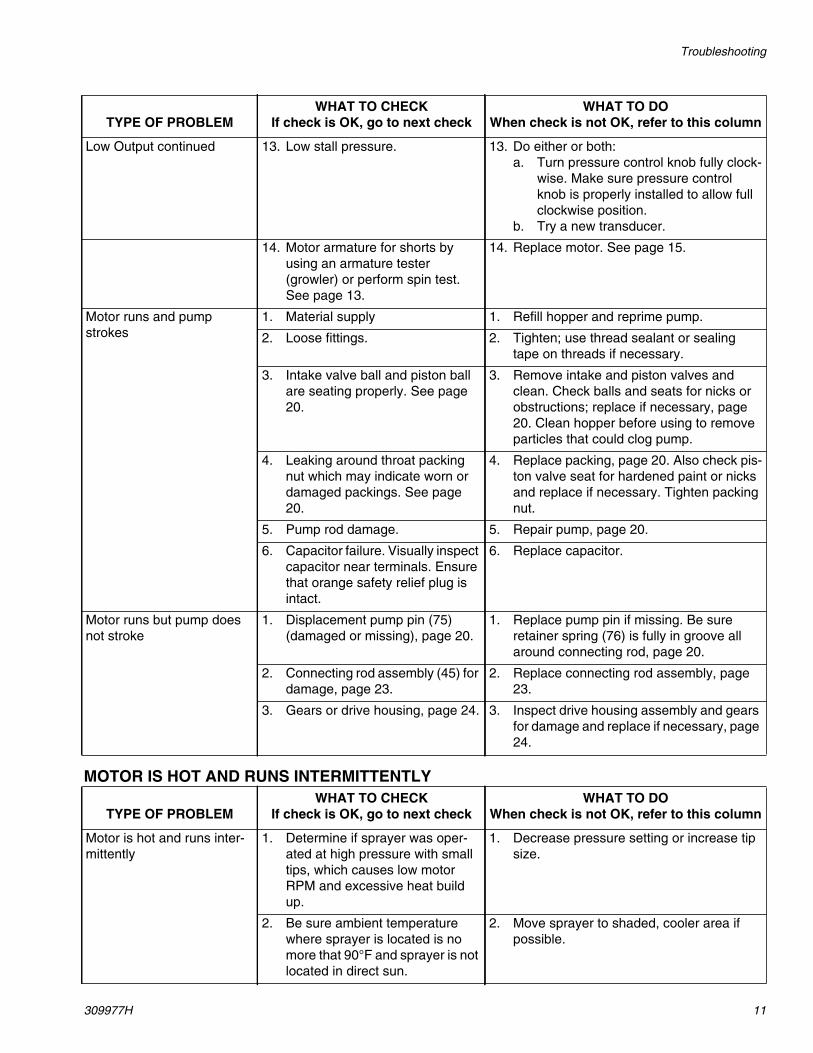
Low Output continued 13. Low stall pressure. 13. Do either or both:a. Turn pressure control knob fully clock-
wise. Make sure pressure controlknob is properly installed to allow fullclockwise position.
b. Try a new transducer.
14. Motor armature for shorts byusing an armature tester(growler) or perform spin test.See page 13.
14. Replace motor. See page 15.
Motor runs and pumpstrokes
1. Material supply 1. Refill hopper and reprime pump.
2. Loose fittings. 2. Tighten; use thread sealant or sealingtape on threads if necessary.
3. Intake valve ball and piston ballare seating properly. See page20.
3. Remove intake and piston valves andclean. Check balls and seats for nicks orobstructions; replace if necessary, page20. Clean hopper before using to removeparticles that could clog pump.
4. Leaking around throat packingnut which may indicate worn ordamaged packings. See page20.
4. Replace packing, page 20. Also check pis-ton valve seat for hardened paint or nicksand replace if necessary. Tighten packingnut.
5. Pump rod damage. 5. Repair pump, page 20.
6. Capacitor failure. Visually inspectcapacitor near terminals. Ensurethat orange safety relief plug isintact.
6. Replace capacitor.
Motor runs but pump doesnot stroke
1. Displacement pump pin (75)(damaged or missing), page 20.
1. Replace pump pin if missing. Be sureretainer spring (76) is fully in groove allaround connecting rod, page 20.
2. Connecting rod assembly (45) fordamage, page 23.
2. Replace connecting rod assembly, page23.
3. Gears or drive housing, page 24. 3. Inspect drive housing assembly and gearsfor damage and replace if necessary, page24.
TYPE OF PROBLEMWHAT TO CHECK
If check is OK, go to next checkWHAT TO DO
When check is not OK, refer to this column
Motor is hot and runs inter-mittently
1. Determine if sprayer was oper-ated at high pressure with smalltips, which causes low motorRPM and excessive heat buildup.
1. Decrease pressure setting or increase tipsize.
2. Be sure ambient temperaturewhere sprayer is located is nomore that 90°F and sprayer is notlocated in direct sun.
2. Move sprayer to shaded, cooler area ifpossible.
TYPE OF PROBLEMWHAT TO CHECK
If check is OK, go to next checkWHAT TO DO
When check is not OK, refer to this column

Troubleshooting
12 309977H
ELECTRICAL SHORT
TYPE OF PROBLEMWHAT TO CHECK
If check is OK, go to next checkWHAT TO DO
When check is not OK, refer to this column
Building circuit breakeropens as soon as sprayerswitch is turned on.
CAUTIONAny short in any part of themotor power circuit willcause the control circuit toinhibit sprayer operation.Correctly diagnose andrepair all shorts beforechecking and replacing con-trol board.
1. All electrical wiring for damagedinsulation, and all terminals forloose fit or damage. Also wiresbetween pressure control andmotor. See page 15.
1. Repair or replace any damaged wiring orterminals. Securely reconnect all wires.
2. Bent terminal folks or other metalto metal contact points whichcould cause a short.
2. Correct faulty conditions.
3. Motor armature for shorts. Usean armature tester (growler) orperform spin test. See page 14.Inspect windings for burns.
3. Replace motor. See page 15.
4. Motor control board (38) by per-forming motor control board diag-nostics on page 17. If diagnosticsindicate, substitute with a goodboard.
CAUTION: Do not perform thischeck until motor armature isdetermined to be good. A badmotor armature can burn out agood board.
4. Replace with a new pressure controlboard (38). See page 17.
Building circuit breakeropens as soon as sprayer isplugged into outlet andsprayer is NOT turned on.
1. Basic Electrical Problems onpage 8.
1. Perform necessary procedures.
2. For damaged or pinched wires inpressure control. See page 17.
2. Replace damaged parts. See page 17.
Sprayer quits after sprayeroperates for 5 to 10 minutes.
1. Basic Electrical Problems onpage 8.
1. Perform necessary procedures.
2. Electrical supply with volt meter.
Meter must read:210-255 Vac for 220-240 Vacmodels;85-130 Vac for 100-120 Vac mod-els.
2. If voltage is too high, do not operatesprayer until corrected.
3. Tightness of pump packing nut.Over tightening tightens packingson rod, restricts pump action,and damages packings.
3. Loosen packing nut. Check for leakingaround throat. Replace pump packings, ifnecessary. See page 20.

Spin Test
309977H 13
Spin Test
Setup
To check armature, motor winding and brush electricalcontinuity:
1. Relieve pressure; page 6.
2. Remove motor, page 15.
3. Fig. 3. Remove six screws (12) and motor cover(18).
4. Fig. 2. Disconnect wire harness (155) from controlboard.
Armature Short Circuit Test
Quickly turn motor fan by hand. If no electrical shorts,motor coasts two or three revolutions before completestop. If motor does not spin freely, armature is shorted.Replace motor; page 15.
Armature, Brushes, and Motor Wiring OpenCircuit Test (Continuity)
1. Connect wire harness (155) leads together with testlead (A). Turn motor fan by hand at about two revo-lutions per second.
2. If uneven or no resistance, check for: broken brushsprings, brush leads, motor leads; loose brush ter-
minal screws, motor lead terminals; worn brushes.Repair as needed; page 14.
3. If still uneven or no resistance, replace motor; page15.
FIG. 2
�������

Motor Brush Replacement
14 309977H
Motor Brush Replacement
Motor Brush Removal
Replace brushes worn to less than 1/2 in. Check bothsides. Order Brush Repair Kit 243642 for 220-240 Vacmotors and 243215 for 100-120 Vac motors with exter-nal capacitor.
1. Read General Repair Information; page 6.
2. Relieve pressure; page 6.
3. Fig. 6. Remove six screws (12) and motor cover(18).
4. Fig. 3. Discharge any residual capacitor voltage witha resistive load across terminal screws (41).
FIG. 3
5. Fig. 4. Pry off two brush caps (A). Tag locations ofred (+) and black (-) motor leads.
6. Fig. 5. Remove screws (41) and discard brushes (B)for motor with capacitor attached.
7. Fig. 4. Insert brush (B). Push clip (A) until it snapsinto place and secures brush.
8. Install red brush lead (+) and black brush lead (-)according to markings on the motor and capacitor.Install brush lead end to capacitor with screw (41).
FIG. 4
9. Inspect commutator for excessive pitting, burning orgouging. A black color on commutator is normal.Have commutator resurfaced by a motor repair shopif brushes wear too fast.
10. Test brushes.a. Disconnect pump (31); Pump Repair, Removal,
steps 8 and 9, page 20.b. With sprayer OFF, turn pump control knob fully
counterclockwise to minimum pressure. Plug insprayer.
c. Turn sprayer ON. Slowly increase pressure untilmotor is at full speed.
11. Break in brushes.a. Operate sprayer 1 hour with no load.b. Connect pump (31); Pump Repair, Installation,
step 4, page 20.
NOTICE
When installing brushes, follow all steps carefully toavoid damaging parts.
��
��
�
�������
�
�
�������
��
��

Motor Replacement
309977H 15
Motor Replacement
Removal
1. Relieve pressure; page 6.
2. Fig. 5. Remove pump module (A).
a. Loosen clamp rod (20).b. Release hopper quick-release clamp (28).c. Disconnect pump module (A) from frame (35).
FIG. 5
3. Fig. 6. Remove six screws (12) and motor cover(18).
4. Remove two screws (41) and disconnect leads fromcapacitor (42) to control board (38).
5. Disconnect two yellow leads (B) from control board(38).
6. Pull strain relief (49) out of bracket and thread yel-low leads connector through bracket.
7. Remove four screws (90) and washers (71) fromgear housing base (25), Parts Drawing, page 26.
8. Tip motor and drive housing assembly back andremove two screws (86) and washers (84).
9. Return motor and drive housing assembly to verticalposition.
10. Remove screws (85) and washers (84). Removemotor (33) from drive housing (37).
Installation
1. Fig. 6. Place new motor (33) on drive housing (37).Rotate fan (C). When gears are felt to mesh, installfour washers (84) and screws (85).
2. Tip motor and drive housing assembly back andinstall two washers (84) and screws (86).
3. Install motor and drive housing to gear housingbase (25) with four screws (90) and washers (71).
4. Thread yellow lead (B) through strain relief (49) andconnect to control board (38). Install strain relief inbracket.
5. Connect red brush lead (+) and black brush lead (-)according to markings on the motor and capacitor.Install brush lead ends and wire harness (155) leadends to capacitor with screw (41). See Wiring Dia-gram, page 29 to verify polarity is correct.
6. Install motor cover (18) with five screws (12).
��
�������
�
��
��
NOTICE
Do not drop gear cluster (D) when removing drivehousing (37). Gear cluster may stay engaged inmotor front end bell or drive housing.
NOTICE
When installing motor, carefully align gears to avoiddamaging mating parts.

Motor Replacement
16 309977H
FIG. 6
���
��
��
�������
��
��
��
��
����
����
��
��
����
��
��
��
�
�
�������
�
��
��
��
��
��

Pressure Control Repair
309977H 17
Pressure Control Repair
Motor Control BoardDiagnostics
Note: Keep a new transducer on hand to use for test.
1. Relieve pressure; page 6.
2. Remove five screws (12) and motor cover (18).
3. Plug in power cord.
4. Observe LED operation and reference followingtable:
NOTICE
Do not allow sprayer to develop fluid pressure with-out transducer installed.
LED BLINKS SPRAYER OPERATION INDICATES WHAT TO DO
Once Sprayer runs Normal operation Do nothing
Once and staysON
Sprayer shuts down andLED stays ON
Motor open circuit or badcontrol board
Check motor brushes and armature.If OK, replace motor control board.
Two timesrepeatedly
Sprayer shuts down andLED continues to blinktwo times repeatedly
Run away pressure. Pres-sure greater than 57 bar(5.7 MPa, 830 psi).
Replace pressure transducer ormotor control board. See followingMotor Control Board procedure.
Three timesrepeatedly
Sprayer shuts down andLED continues to blinkthree times repeatedly
Pressure transducer isfaulty or missing
Check transducer connection. Opendrain valve. Substitute new trans-ducer for transducer in sprayer. Ifsprayer runs, replace transducer.
Four timesrepeatedly
Sprayer shuts down andLED continues to blinkfour times repeatedly
Line voltage is too high Check for voltage supply problems
Five timesrepeatedly
Sprayer shuts down andLED continues to blinkfive times repeatedly
Too much current Check for locked rotor, shorted wir-ing or motor. Repair or replacefailed parts.
Six timesrepeatedly
Sprayer shuts down andLED continues to blink sixtimes repeatedly
Motor thermal switch opencircuit
Check for binding in pump or drive.Check for bad motor.
Pressure Control Repair
18 309977H
Pressure Control Repair
Motor Control Board
Removal
Refer to Wiring Diagram, page 29.
1. Relieve pressure; page 6.
2. Remove five screws (12) and motor cover (18).
3. Cut wire tie holding wiring to motor control board(38).
4. Disconnect at motor control board (38):
• Motor wire harness: brown (+), blue (-).• Two line voltage leads: brown (+), blue (-).• Lead (D) from potentiometer.• Lead (E) from transducer.• Two leads (F) from motor thermal switch.
5. Remove six screws (83) and circuit board (38).
Installation
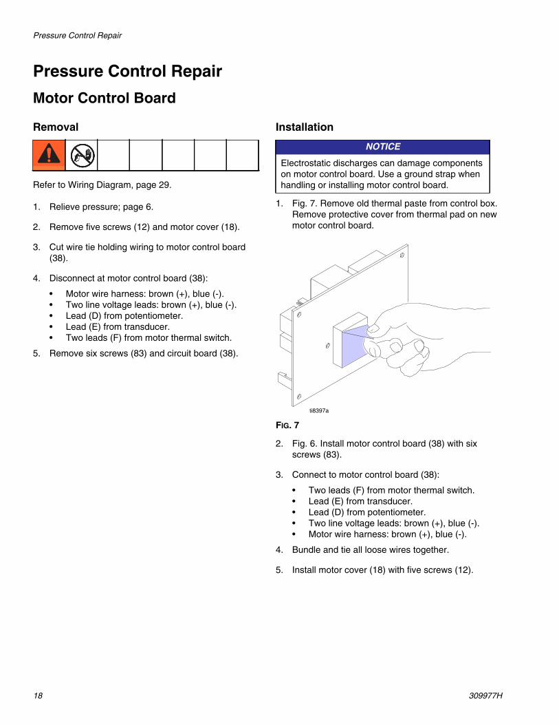
1. Fig. 7. Remove old thermal paste from control box.Remove protective cover from thermal pad on newmotor control board.
FIG. 7
2. Fig. 6. Install motor control board (38) with sixscrews (83).
3. Connect to motor control board (38):
• Two leads (F) from motor thermal switch.• Lead (E) from transducer.• Lead (D) from potentiometer.• Two line voltage leads: brown (+), blue (-).• Motor wire harness: brown (+), blue (-).
4. Bundle and tie all loose wires together.
5. Install motor cover (18) with five screws (12).
NOTICE
Electrostatic discharges can damage componentson motor control board. Use a ground strap whenhandling or installing motor control board.
�������

Pressure Control Repair
309977H 19
Pressure Control Transducer
Removal
Refer to Wiring Diagram, page 29.
1. Relieve pressure; page 6.
2. Remove five screws (12) and motor cover (18).
3. Disconnect lead (E) from motor control board (38).
4. Remove strain relief (49) from circuit board bracket(21). Thread transducer connector through bracket.
5. Remove pressure control transducer (43) and pack-ing o-ring (89) from pump housing (202).
Installation
1. Install packing o-ring (89) and pressure controltransducer (43) in pump housing (202). Torque to30-35 ft-lb.
2. Thread transducer connector through circuit boardbracket (21). Install strain relief (49) in circuit boardbracket.
3. Connect lead (E) to motor control board (38).
4. Install motor cover (18) with five screws (12).
Pressure Adjust Potentiometer
Removal
Refer to Wiring Diagram, page 29.
1. Relieve pressure; page 6.
2. Remove five screws (12) and motor cover (18).
3. Disconnect potentiometer lead (47) from motor con-trol board (38).
4. Remove potentiometer knob (16), gasket (88) andpressure adjust potentiometer (47).
Installation
1. Install pressure adjust potentiometer (47), gasket(88) and potentiometer knob (16).
a. Turn potentiometer full clockwise.b. Install knob at full clockwise position.
2. Connect potentiometer lead (47) to motor controlboard (38).
3. Install motor cover (18) with five screws (12).

Pump Repair
20 309977H
Pump Repair
Removal
1. Relieve pressure; page 6.
2. Perform Storage More than 24 hours procedure inOperation Manual 309973, 309974 or 309975.
3. Fig. 8. Loosen clamp rod (20).
FIG. 8
4. Release hopper quick-release clamp (28).
5. Disconnect pump module (A) from frame (35).
6. Remove five screws (12) and motor cover (18).
7. Fig. 10. Disconnect transducer connector (B) fromcontrol board (38). Pull strain relief from bracket.Thread transducer connector through bracket.
8. Fig. 9. Slowly rotate fan blade on back of motor untilconnecting rod (45) near bottom of stroke.
FIG. 9
9. Pry retaining spring (76) up on connecting rod (45).Push pin (75) out with a screwdriver.
10. Fig. 10. Loosen retaining nut (27).
FIG. 10
11. Fig. 11. Unscrew pump (31) from bearing housing(34).
FIG. 11
RepairSee page 20 for pump repair instructions.
Installation1. Fig. 17. Push piston rod (203) out of pump (31) 50
to 75 mm (2 to 3 inches).
2. Fig. 11. Screw retaining nut (27) onto pump until itstops. Screw pump (31) into bearing housing (34)until pump stops. Unscrew pump until pump outlet is13° from horizontal, but no more than one turn.
3. Tighten retaining nut (27).
4. Push pin (75) in with a screwdriver. Push retainingspring (76) down on connecting rod (45).
5. Fig. 10. Connect transducer connector (B) to motorcontrol board (38).
��
�������
�
��
��
��
��
��
�������
I
If pin works loose, parts could break off due to force ofpumping action. Parts could project through the air andresult in serious injury or property damage. Make surepin and retaining spring are properly installed.
��
���
��
�������
��
�����

Pump Repair
309977H 21
Disassemble Pump
TIP: It may be easier to leave the pump connected tothe connecting rod and bearing housing if the onlyassemblies to be cleaned and inspected is the intakehousing or piston valve.
1. Relieve pressure; page 6.
2. See Pump Repair, Removal on page 20 to removepump.
3. Fig. 13. Remove clamp (209) and intake housing(204).
FIG. 12
4. Remove clamp (209) and pump cylinder (201).
FIG. 13
5. Fig. 14. Remove packing nut (216). Push piston rod(203) from outlet housing (202).
FIG. 14
6. Place end of piston rod in vise and remove pistonvalve (217). Remove piston seal (222).
FIG. 15
7. Inspect all parts for nicks and scratches. Replaceworn or damaged parts as they may result in poorpump performance.
Repair Kit
Piston Seal Repair Kit 248530 is available. Replace allparts in kit for best results.
Parts included in kit are marked with an asterisk in textand drawings. For example, 208*.
�������
������
�������
������
�������
���
� �!
�� ��""
���
���#
���#
���#
�������

Pump Repair
22 309977H
Assemble Pump
1. Fig. 16. Place end of piston rod (203) in vise. Installnew piston seal (222). Torque piston valve to 27 ft-lb(36.6 N m).
FIG. 16
2. Fig. 17. Install packing nut (216). Hand tighten andthen tap screw driver. Push piston rod (203) into out-let housing (202) and extending 50-75mm out ofoutlet housing.
FIG. 17
3. Install clamp (209) on pump cylinder (201). Torqueclamp to 25 in-lb (2.82 N m).
FIG. 18
4. Install clamp (209) on intake housing (204). Torqueclamp to 25 in-lb.
FIG. 19
5. See Pump Repair, Installation on page 20 toinstall pump.
���
���#
���#
���#
�������
�������
���
� �!
�� ��""
�������
������
�������
������

Bearing Housing and Connecting Rod
309977H 23
Bearing Housing and Connecting Rod
Removal
1. Relieve pressure; page 6.
2. Fig. 20. Do Pump Repair Removal, page 20.
3. Tip motor/drive housing assembly horizontal.Remove four screws (90), washers (71) and gearhousing base (25).
4. Remove four screws (7) and lock washers (6) frombearing housing (34).
5. Pull connecting rod assembly (45) and lightly taplower rear of bearing housing (34) with a plasticmallet to loosen it from drive housing (37). Pull bear-ing housing and connecting rod assembly off drivehousing.
6. Inspect crank (A) for excessive wear and replacedrive housing, if necessary, page 24.
Installation
1. Evenly lubricate inside of bronze bearing (E) inbearing housing (34) with high-quality motor oil. Lib-erally pack top roller bearing (B), lower bearing (C)inside connecting rod assembly (45) with bearinggrease.
2. Assemble connecting rod (45) and bearing housing(34).
3. Clean mating surfaces of bearing housing (34) anddrive housing (37).
4. Align connecting rod with crank (A) and carefullyalign locating pins (D) in drive housing (37) withholes in bearing housing (34). Push bearing housingonto drive housing or tap it into place with a plasticmallet.
5. Install four screws (7) and lock washers (6) on bear-ing housing (34). Torque screws evenly to 25 ft-lb(34 N m).
6. Tip motor/drive housing assembly horizontal. Installgear housing base (25) with four washers (71) andscrews (90).
7. Do Pump Repair, Installation page 20.
FIG. 20
NOTICE
Do not use bearing housing screws (7) to align orseat bearing housing with drive housing. Alignthese parts with locating pins (D), to avoid prema-ture bearing wear.
��
��
��
��
��
��
��
��
��
��
��
����
��
�����
�
��
$
%
�������

Drive Housing
24 309977H
Drive Housing
Removal
1. Relieve pressure; page 6.
2. Fig. 5. Remove pump module (A).
a. Loosen clamp rod (20).
b. Release hopper quick-release clamp (28).
c. Disconnect pump module (A) from frame (35).
3. Fig. 6. Remove Five screws (12) and motor cover(18).
4. Fig. 21. Lay pump module horizontal. Remove fourscrews (90) and washers (71) and gear housingbase (25).
5. Remove two screws (86) and washers (84) fromfront of drive housing.
6. Disconnect transducer lead (E) from control board(38). Pull strain relief bushing (49) from circuit boardbracket (21). Thread transducer connector throughcircuit board bracket.
7. Remove bearing housing and pump assembly.
a. Remove four screws (7) and lock washers (6)from bearing house (34)
b. Pull connecting rod assembly (45) and lightlytap lower rear of bearing housing with a plasticmallet to loosen bearing housing from drivehousing (37). Pull bearing housing and pumpassemblies from drive housing.
c. Inspect crank (G) for excessive wear andreplace drive housing, if necessary.
8. Return motor and drive housing assembly to verticalposition.
9. Remove two screws (12) and circuit board bracket(21) from drive housing (37).
10. Remove four screws (85) and washers (84).
11. Lightly tap around drive housing (37) to loosen frommotor (33). Pull drive housing straight off motor. Beprepared to support combination gear (29) andthrust washers (10, 11, 14) which may also comeout.
12. Remove combination gear (29) and thrust washers(10, 11, 14) that do not come out.
FIG. 21
NOTICE
Do not drop combination gear (29) and thrust wash-ers (10, 11, 14) when removing drive housing (37).Combination gear and thrust washers may stayengaged in motor front end bell or drive housing.
�������
��
��
��
��
��
��
��
����
����
��
��
��
��
1
Liberally apply bearing grease1

Drive Housing
309977H 25
Drive Housing
Installation
1. Fig. 21. Install thrust washers (10, 11, 14) on combi-nation gear (29). Install combination gear in drivehousing (37).
2. Liberally apply bearing grease (supplied with combi-nation gear) to all gear teeth and to drive housingareas called out by note 1.
3. Align gears and push new drive housing straightonto motor (33).
4. Install four screws (85) and washers (84).
5. Install circuit board bracket (21) on drive housing(37) with two screws (12).
6. Install bearing housing and pump assembly.
a. Align connecting rod with crank (G) and care-fully align pins (H) in drive housing (37) withholes in bearing housing (34).
b. Push bearing housing and pump assembliesonto drive housing. Push connecting rodassembly (45) and lightly tap lower front of bear-ing housing with a plastic mallet to seat bearinghousing to drive housing (37).
c. Install bearing housing (34) with four screws (7)and lock washers (6).
7. Thread transducer connector through circuit boardbracket. Push strain relief bushing (49) into circuitboard bracket (21). Connect transducer lead (E) tocontrol board (38).
8. Install two screws (86) and washers (84) into front ofdrive housing.
9. Fig. 21. Lay pump module horizontal. Install gearhousing base (25) with four washers (71) andscrews (90).
10. Fig. 6. Install motor cover (18) with five screws (12).
11. Fig. 5. Install pump module (A).
a. Connect pump module (A) onto frame (35).
b. Secure hopper quick-release clamp (28).
c. Tighten clamp rod (20).
NOTICE
When installing motor, carefully align gears to avoiddamaging mating parts.
NOTICE
Do not use bearing housing screws (7) to align orseat bearing housing with drive housing. Alignthese parts with locating pins (H), to avoid prema-ture bearing wear.

Parts Drawing
26 309977H
Parts Drawing
��
����
����
����� ����
� ��&
���������
��
��
�
�������
�
��'�������
��
��
��
��� ��
����
��
�����
�
����
������(�����
����
�����(�����
��'������������
�
����
����
����
��
����
��
��
��
�����
�
����
��
��
��
��
��
����
����
����
����
��
�����
����
����
����
����
��
����
��
��
����
����
����
����
�
��
����
��
��
����
����
�����
����� ����
�
�����

Parts List
309977H 27
Parts ListModels 248195, 248269, 249075; Series A
Ref. Part Description Qty.
1 100004 SCREW, cap, hex hd 12 101242 RING, retaining, ext. 23 101566 NUT, lock 14 102040 NUT, lock, hex 65 104430 PIN, cotter 18 111145 KNOB, pronged 19 111841 WASHER, plain, 5/8 212PM 115492 SCREW, mch, slot hex wash hd 913PM 116171 BUSHING, strain relief 115 116478 WHEEL, pneumatic 216PM 116167 KNOB, potentiometer 118PM 15C730 COVER, motor 119 15C797 BRACKET, swivel 120 15C799 ROD, clamp 121PM 15D308 BRACKET, circuit board 122PM 15D309 BRACKET, control 126 15D865 ADAPTER, pump, hopper 127PM 193031 NUT, retaining 128 234188 CLAMP, quick release 131PM 248764 PUMP, displacement, texture 132 248256 HOPPER, weldment 235 287273 FRAME, weldment 136PM 287317 FRAME, pump 137PM 287319 HOUSING, drive 138PM 248760 KIT, repair, board, control, 240V 1
249475 KIT, repair, board, control, 110V 139PM 115711 TAPE, foam, 1/2 in. wide 140PM 116028 TIE, wire 141PM 115762 SCREW, plastic head 242PM KIT, repair, capacitor (includes 39,
40, 41)248765 Models 248195, 248269 1243415 Model 249075 1
43PM 246320 TRANSDUCER, pressure 144 290340 LABEL, designation, artwork, CE 146 248405 TOOL BOX, applicator 147PM 256219 POTENTIOMETER, assembly 1*48PM 118506 COUPLER, male, 1 in. npt
(includes 165)1
49PM 114678 BUSHING, strain relief 250PM 119284 PIN, straight, slotted 151PM 248391 GAUGE, pressure, pump, texture 1
53 15D151 RING, retainer, hopper 1*55 248519 HOSE, fluid 25mm x 5m (includes
165)1
56 100333 SCREW, cap, hex hd 157 118751 TIE, lanyard 1*58 248520 HOSE, fluid, 19mm x 3m cpld
(includes 165)1
61 248557 KIT, replacement, hose (includes61a, 61b, 61c)
1
61a 114558 COUPLER, line, air 161b 112779 VALVE, needle 161c 15C899 HOSE, cpld, air, 9,5mm x 15m 162 15D306 PLUG, adapter, hopper, texture 163PM 15D896 LABEL, TMAX, pump 164 15D895 LABEL, TMAX, left 265 15D894 LABEL, TMAX, right 166PM 15D898 LABEL, TMAX, pump 167 551390 SIGHTGLASS, beaker, grad 170 119347 PLUG, hopper, texture 171PM 100020 WASHER, lock 472PM 113817 BUMPER 481PM 119365 SCREW, cap, hex head 482PM 111040 NUT, lock 683PM 111839 SCREW, mach, pn hd, sems 687PM 116307 HOSE, strain relief 188PM 15C973 GASKET 189PM 111457 O-RING 190PM 101888 SCREW, cap, sch 493PM 198586 CONDUIT, corrugated 194 119293 JAR, 6 oz 195 119316 LID, 6 oz 1160 ACCESSORY, Bag Roller, not
included See Manual 309976161PM 15D939 LABEL, safety 1162PM 111593 SCREW, grounding 1163PM 186620 LABEL, symbol, ground 1164 119390 TOOL, scraper (not shown) 1165 15G352 GASKET, Coupler, T-Max 1PM Included in pump module kits 248634, 248651, 249519* Includes 165 (15G352)
Ref. Part Description Qty.

Parts Drawing
28 309977H
Parts Drawing
��"�)*���+
,���-����
���� �� ��
���� �����
���� �����
�������
��
��
��
��
��
��
��
��
��
��
��
��
��
��
����
����
��
��
���
���
���
���
���
��
��
���
���
����
������
������
���

Parts List
309977H 29
Parts ListModels 248195, 248269, 249075; Series A
Ref. Part Description Qty.
6PM 106115 WASHER, lock spring (hi-collar) 47PM 107210 SCREW, cap, socket hd 410PM 114672 WASHER, thrust 311PM 114699 WASHER, thrust 114PM 116191 WASHER, thrust 125PM 15D708 BASE, gear housing 127PM 193037 NUT, retaining 129PM 243870 GEAR, combination 131PM 248764 PUMP, displacement, texture 133PM 248759 KIT, repair, motor, 240V 1
249476 KIT, repair, motor, 110V 134PM 248633 HOUSING, bearing 137PM 248558 HOUSING, drive 145PM 241008 KIT, repair, connecting rod, includes
761
71PM 100020 WASHER, lock 473 118768 CAP, pump 174PM 119283 ADAPTER, plug, dust 175PM 176818 PIN 176PM 176817 SPRING, retaining 179 15E107 LEG, support, pump 182 111040 NUT, lock 6
84PM 105510 WASHER, lock, spring (hi-collar) 685PM 100644 SCREW, cap, sch 486PM 107218 SCREW, cap, sch 290PM 101888 SCREW, cap, sch 4102PM 192840 LABEL, warning 1106PM 187436 LABEL, torque 1109PM 118715 FAN, motor 1110PM 15E287 BUSHING, shaft, fan 1111PM 103253 SCREW, set, hex soc 1112PM 113983 RING, retaining, ext 1150* 195551 RETAINER, adapter, cord 1151* 15E259 Euro Multi cord 1152* 242001 CEE 7/7 1153* 287121 Italy, Denmark, Switzerland 1154✝ 15E257 CEE 7/7 1155PM 15E271 HARNESS, wire 1156± 15F233 UK 1* Included in Model 248269 and pump module kit 248651
✝ Included in Model 248195 and pump module kit 248634
± Included in Model 249075 and pump module kit 249519PM Included in pump module kits 248634, 248651, 249519
Ref. Part Description Qty.
.���.���
/01/22�3���&4.�����"���
��������������
���567
����567
.�,,���8��, �&�
�����5 7
�����
�������
� �
��
9�
���&)
�����5 7
�������
���
8��
8��:�
8.�
8.�:�

Parts Drawing
30 309977H
Parts Drawing
���
���
���
���
���
���
���
���
���
���
���
���#
���
���#
���#
���
���
��
��
��'��������
��
��
��
���
�
�
�
�������
���#
26

Parts - Pump 248764
309977H 31
Parts - Pump 248764Models 248764; Series A
248405 Applicator Tool Box
Ref. Part Description Qty.
201 15D113 CYLINDER, pump 1202 15D108 HOUSING, outlet 1203 15D532 ROD, piston 1204 248769 KIT, repair, housing, intake includes
PTFE o-ring1
206 15D115 GUIDE, ball 1207 193395 SEAT, carbide 1208 107167 BALL, sst 1209 118598 CLAMP 2210 248162 SPRING, intake ball 1
211 248304 SPRING, intake ball, plunger 1216 248529 KIT, repair, seal throat 1217* 248232 VALVE, piston 1220* 101822 BALL, bearing 1222* 15D116 SEAL, piston 1228 107098 O-RING 1229* 501095 SPRING, ball check 1230 15D740 PLUG, disc, rupture 1231 107563 O-RING 2* These parts are also included in Repair Kit 248530,
which may be purchased separately.
Ref. Part Description Qty.
Ref. Part Description Qty.
301 Included with Applicator 248164See Manual 309978 for parts
1
94 119293 JAR, 6 oz. 195 119316 LID, 6 oz. 1304 248515 BALL, sponge, 30 mm 1305 M70613 BRUSH, cleaning 1306 248395 TOOL, cleaning applicator 1307 248326 TOOL BOX. texture 1
�
��
�
�
�
� �
8*�����
Notes
32 309977H
Notes

Technical Data
309977H 33
Technical DataMaximum air working pressure. . . . . . . . . . . . . . . . . . . . . . . . . . . . . 250 psi (1.7 MPa, 17 bar)Maximum working pressure . . . . . . . . . . . . . . . . . . . . . . . . . . . . . . . 580 psi (4.0 MPa, 40 bar)Generator required . . . . . . . . . . . . . . . . . . . . . . . . . . . . . . . . . . . . . . 7 kWHopper capacity
Maximum . . . . . . . . . . . . . . . . . . . . . . . . . . . . . . . . . . . . . . . . 12 gallons (45 liters)Operating . . . . . . . . . . . . . . . . . . . . . . . . . . . . . . . . . . . . . . . . 10 gallons (38 liters)
Maximum delivery with texture material . . . . . . . . . . . . . . . . . . . . . . 1 to 1.5 gpm (3.8 to 5.7 lpm)Fluid outlet size . . . . . . . . . . . . . . . . . . . . . . . . . . . . . . . . . . . . . . . . 1.0 in. (f) cam and grooveDimensions
Length . . . . . . . . . . . . . . . . . . . . . . . . . . . . . . . . . . . . . . . . . . . 23 in. (584 mm) with handleWidth. . . . . . . . . . . . . . . . . . . . . . . . . . . . . . . . . . . . . . . . . . . . 24 in. (610 mm)Height . . . . . . . . . . . . . . . . . . . . . . . . . . . . . . . . . . . . . . . . . . . 40 in. (1016 mm)
WeightWithout hoses or applicator . . . . . . . . . . . . . . . . . . . . . . . . . . 113 lb (51 kg)With hoses and applicator. . . . . . . . . . . . . . . . . . . . . . . . . . . . 125 lb (57 kg)
Wetted parts . . . . . . . . . . . . . . . . . . . . . . . . . . . . . . . . . . . . . . . . . . . Buna-N, aluminum, brass, polyethylene, neo-prene, stainless steel, chrome-plated stainlesssteel, nickel-plated carbon steel, fluoroelasto-mer, nickel-plated iron, inconel, wool felt, tung-sten carbide, PTFE
Sound dataSprayer
Sound pressure level* . . . . . . . . . . . . . . . . . . . . . . . . . . . . . . . 79 dB(A)Sound power level ✝ . . . . . . . . . . . . . . . . . . . . . . . . . . . . . . . . 87.5 dB(A)* Measured while spraying at 1m.✝ Measured per ISO-3744.
Applicator . . . . . . . . . . . . . . . . . . . . . . . . . . . . . . . . . . . . . . . . . . Manual 309978

All written and visual data contained in this document reflects the latest product information available at the time of publication.Graco reserves the right to make changes at any time without notice.
This manual contains English. MM 309977
Graco Headquarters: MinneapolisInternational Offices: Belgium, China, Japan, Korea
GRACO INC. AND SUBSIDIARIES • P.O. BOX 1441 • MINNEAPOLIS MN 55440-1441 • USA
Copyright 2004, Graco Inc. All Graco manufacturing locations are registered to ISO 9001.www.graco.comRevised 10/2011
Graco Standard WarrantyGraco warrants all equipment referenced in this document which is manufactured by Graco and bearing its name to be free from defects inmaterial and workmanship on the date of sale to the original purchaser for use. With the exception of any special, extended, or limited warrantypublished by Graco, Graco will, for a period of twelve months from the date of sale, repair or replace any part of the equipment determined byGraco to be defective. This warranty applies only when the equipment is installed, operated and maintained in accordance with Graco’s writtenrecommendations.
This warranty does not cover, and Graco shall not be liable for general wear and tear, or any malfunction, damage or wear caused by faultyinstallation, misapplication, abrasion, corrosion, inadequate or improper maintenance, negligence, accident, tampering, or substitution ofnon-Graco component parts. Nor shall Graco be liable for malfunction, damage or wear caused by the incompatibility of Graco equipment withstructures, accessories, equipment or materials not supplied by Graco, or the improper design, manufacture, installation, operation ormaintenance of structures, accessories, equipment or materials not supplied by Graco.
This warranty is conditioned upon the prepaid return of the equipment claimed to be defective to an authorized Graco distributor for verification ofthe claimed defect. If the claimed defect is verified, Graco will repair or replace free of charge any defective parts. The equipment will be returnedto the original purchaser transportation prepaid. If inspection of the equipment does not disclose any defect in material or workmanship, repairs willbe made at a reasonable charge, which charges may include the costs of parts, labor, and transportation.
THIS WARRANTY IS EXCLUSIVE, AND IS IN LIEU OF ANY OTHER WARRANTIES, EXPRESS OR IMPLIED, INCLUDING BUT NOT LIMITEDTO WARRANTY OF MERCHANTABILITY OR WARRANTY OF FITNESS FOR A PARTICULAR PURPOSE.
Graco’s sole obligation and buyer’s sole remedy for any breach of warranty shall be as set forth above. The buyer agrees that no other remedy(including, but not limited to, incidental or consequential damages for lost profits, lost sales, injury to person or property, or any other incidental orconsequential loss) shall be available. Any action for breach of warranty must be brought within two (2) years of the date of sale.
GRACO MAKES NO WARRANTY, AND DISCLAIMS ALL IMPLIED WARRANTIES OF MERCHANTABILITY AND FITNESS FOR APARTICULAR PURPOSE, IN CONNECTION WITH ACCESSORIES, EQUIPMENT, MATERIALS OR COMPONENTS SOLD BUT NOTMANUFACTURED BY GRACO. These items sold, but not manufactured by Graco (such as electric motors, switches, hose, etc.), are subject tothe warranty, if any, of their manufacturer. Graco will provide purchaser with reasonable assistance in making any claim for breach of thesewarranties.
In no event will Graco be liable for indirect, incidental, special or consequential damages resulting from Graco supplying equipment hereunder, orthe furnishing, performance, or use of any products or other goods sold hereto, whether due to a breach of contract, breach of warranty, thenegligence of Graco, or otherwise.
FOR GRACO CANADA CUSTOMERSThe Parties acknowledge that they have required that the present document, as well as all documents, notices and legal proceedings entered into,given or instituted pursuant hereto or relating directly or indirectly hereto, be drawn up in English. Les parties reconnaissent avoir convenu que larédaction du présente document sera en Anglais, ainsi que tous documents, avis et procédures judiciaires exécutés, donnés ou intentés, à la suitede ou en rapport, directement ou indirectement, avec les procédures concernées.
Graco InformationFor the latest information about Graco products, visit www.graco.com.
TO PLACE AN ORDER, contact your Graco distributor or call 1-800-690-2894 to identify the nearest distributor.