Embed Size (px)
Citation preview

Graco Inc. P.O. Box 1441 Minneapolis, MN 55440-1441Copyright 2007, Graco Inc. is registered to I.S. EN ISO 9001
- For portable spray application of architectural paints and coatings -
Model: 255679Maximum Working Pressure: 3300 psi (22.7 MPa, 227 bar)
Important Safety InstructionsRead all warnings and instructions in this manual. Save these instructions.
Related Manuals
312515
311861English
312099Français
312098Español
309250
309541
ti10740a
312516D
Repair - Parts
RentalPro 210Electric Airless Sprayer

Warning
2 312516D
WarningThe following warnings are for the setup, use, grounding, maintenance and repair of this equipment. The exclamation point symbol alerts you to a general warning and the hazard symbol refers to procedure-specific risks. Refer back to these warnings. Additional, product-specific warnings may be found throughout the body of this manual where appli-cable.
WARNINGFIRE AND EXPLOSION HAZARD Flammable fumes, such as solvent and paint fumes, in work area can ignite or explode. To help prevent fire and explosion:• Use equipment only in well ventilated area.• Eliminate all ignition sources; such as pilot lights, cigarettes, portable electric lamps, and plastic drop
cloths (potential static arc). • Sprayer generates sparks. When flammable liquid is used in or near the sprayer or for flushing or
cleaning, keep sprayer at least 20 feet (6 m) away from explosive vapors.• Keep work area free of debris, including solvent, rags and gasoline.• Do not plug or unplug power cords or turn lights on or off when flammable fumes are present.• Ground equipment and conductive objects in work area. Read Grounding instructions.• If there is static sparking or you feel a shock, stop operation immediately. Do not use equipment
until you identify and correct the problem.• Keep a working fire extinguisher in the work area.
ELECTRIC SHOCK HAZARD Improper grounding, setup, or usage of the system can cause electric shock.• Turn off and disconnect power cord before servicing equipment.• Use only grounded electrical outlets.• Use only 3-wire extension cords.• Ensure ground prongs are intact on sprayer and extension cords.• Do not expose to rain. Store indoors.
SKIN INJECTION HAZARD High-pressure fluid from gun, hose leaks, or ruptured components will pierce skin. This may look like just a cut, but it is a serious injury that can result in amputation. Get immediate surgical treatment.• Do not point gun at anyone or at any part of the body.• Do not put your hand over the spray tip.• Do not stop or deflect leaks with your hand, body, glove, or rag.• Engage trigger lock when not spraying.• Follow Pressure Relief Procedure in this manual, when you stop spraying and before cleaning,
checking, or servicing equipment.
Warning
312516D 3
WARNING
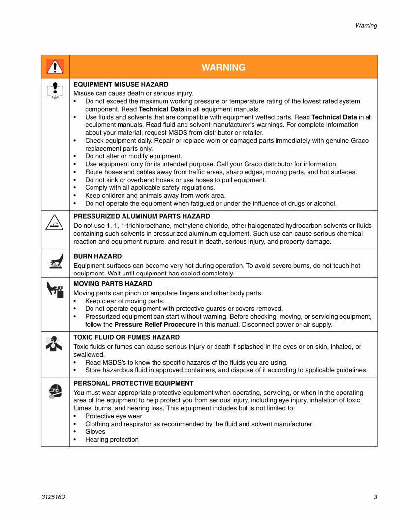
EQUIPMENT MISUSE HAZARDMisuse can cause death or serious injury.• Do not exceed the maximum working pressure or temperature rating of the lowest rated system
component. Read Technical Data in all equipment manuals.• Use fluids and solvents that are compatible with equipment wetted parts. Read Technical Data in all
equipment manuals. Read fluid and solvent manufacturer’s warnings. For complete information about your material, request MSDS from distributor or retailer.
• Check equipment daily. Repair or replace worn or damaged parts immediately with genuine Graco replacement parts only.
• Do not alter or modify equipment.• Use equipment only for its intended purpose. Call your Graco distributor for information.• Route hoses and cables away from traffic areas, sharp edges, moving parts, and hot surfaces.• Do not kink or overbend hoses or use hoses to pull equipment.• Comply with all applicable safety regulations.• Keep children and animals away from work area.• Do not operate the equipment when fatigued or under the influence of drugs or alcohol.
PRESSURIZED ALUMINUM PARTS HAZARD Do not use 1, 1, 1-trichloroethane, methylene chloride, other halogenated hydrocarbon solvents or fluids containing such solvents in pressurized aluminum equipment. Such use can cause serious chemical reaction and equipment rupture, and result in death, serious injury, and property damage.
BURN HAZARDEquipment surfaces can become very hot during operation. To avoid severe burns, do not touch hot equipment. Wait until equipment has cooled completely.
MOVING PARTS HAZARD Moving parts can pinch or amputate fingers and other body parts.• Keep clear of moving parts.• Do not operate equipment with protective guards or covers removed.• Pressurized equipment can start without warning. Before checking, moving, or servicing equipment,
follow the Pressure Relief Procedure in this manual. Disconnect power or air supply.
TOXIC FLUID OR FUMES HAZARD Toxic fluids or fumes can cause serious injury or death if splashed in the eyes or on skin, inhaled, or swallowed.• Read MSDS’s to know the specific hazards of the fluids you are using.• Store hazardous fluid in approved containers, and dispose of it according to applicable guidelines.
PERSONAL PROTECTIVE EQUIPMENT You must wear appropriate protective equipment when operating, servicing, or when in the operating area of the equipment to help protect you from serious injury, including eye injury, inhalation of toxic fumes, burns, and hearing loss. This equipment includes but is not limited to:• Protective eye wear • Clothing and respirator as recommended by the fluid and solvent manufacturer• Gloves• Hearing protection

Component Identification
4 312516D
Component Identification
C J
H
E
A
B
F
K
M
N
S
P
R
ti10741a
T
DT
Ref Component
A Pressure Control
B ON/OFF Switch
C Hour Meter
D Power Cord
E Fluid Outlet
F Prime Valve
H Pump
J Suction Tube
K Drain Hose
M Fluid Hose
N Gun
P Tip
R Guard
S Trigger Safety Lock
T Serial Number ID Label

Installation
312516D 5
Installation
Grounding and Electric Requirements
The sprayer cord includes a grounding wire with an appropriate grounding contact.
The sprayer requires: 100-130 Vac, 60 Hz, 11A, 1 phase, circuit with a ground-ing receptacle.
Never use an outlet that is not grounded or an adapter.
Do not use the sprayer if the electrical cord has a dam-aged ground contact. Only use an extension cord with an undamaged ground contact.
Recommended extension cords:
110-120V: 3-wire, 12 AWG (2.5 mm2) minimum, 300 ft (90 m) maximum length.
Spray gun: ground through connection to a properly grounded fluid hose and pump.
Fluid supply container: follow local code.
Solvent and Oil-based fluids: follow local code. Use only conductive metal pails placed on a grounded sur-face such as concrete. Do not place the pail on a non-conductive surface such as paper or cardboard, which interrupts grounding continuity.
Grounding the metal pail: connect a ground wire to the pail by clamping one end to pail and other end to ground such as a water pipe.
To maintain grounding continuity when flushing or relieving pressure: hold metal part of the spray gun firmly to the side of a grounded metal pail, then trigger the gun.
ti9164a
ti5573a
Smaller gauge or longer extension cords may reduce sprayer performance.
ti4297
ti9146a

Pressure Relief Procedure
6 312516D
Pressure Relief Procedure
Follow this Pressure Relief Procedure whenever youare instructed to relieve pressure, stop spraying, check orservice equipment or install or clean spray tip.
1. Turn OFF power and turn pressure control to lowest pressure setting.
2. Hold gun against side of grounded metal flushing pail. Trigger gun to relieve pressure.
3. Turn prime valve down.
If you suspect the spray tip or hose is clogged or that pressure has not been fully relieved after following the steps above, VERY SLOWLY loosen tip guard retaining nut or hose end coupling to relieve pressure gradually, then loosen completely. Clear hose or tip obstruction.
4. Engage trigger safety lock on gun if unit is being shut down or left unattended.
ti10154a ti10751a
ti10136a
General Repair Information
312516D 7
General Repair Information
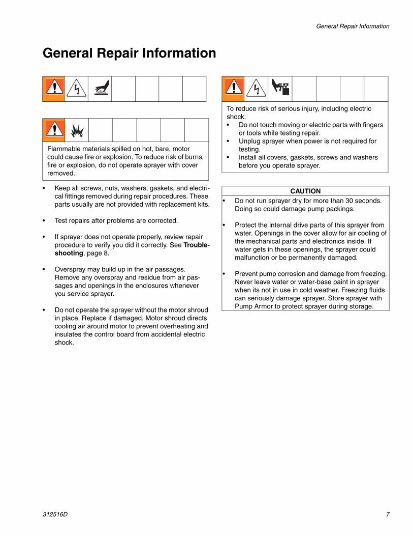
• Keep all screws, nuts, washers, gaskets, and electri-cal fittings removed during repair procedures. These parts usually are not provided with replacement kits.
• Test repairs after problems are corrected.
• If sprayer does not operate properly, review repair procedure to verify you did it correctly. See Trouble-shooting, page 8.
• Overspray may build up in the air passages. Remove any overspray and residue from air pas-sages and openings in the enclosures whenever you service sprayer.
• Do not operate the sprayer without the motor shroud in place. Replace if damaged. Motor shroud directs cooling air around motor to prevent overheating and insulates the control board from accidental electric shock.
Flammable materials spilled on hot, bare, motor could cause fire or explosion. To reduce risk of burns, fire or explosion, do not operate sprayer with cover removed.
To reduce risk of serious injury, including electric shock:• Do not touch moving or electric parts with fingers
or tools while testing repair. • Unplug sprayer when power is not required for
testing. • Install all covers, gaskets, screws and washers
before you operate sprayer.
CAUTION• Do not run sprayer dry for more than 30 seconds.
Doing so could damage pump packings.
• Protect the internal drive parts of this sprayer from water. Openings in the cover allow for air cooling of the mechanical parts and electronics inside. If water gets in these openings, the sprayer could malfunction or be permanently damaged.
• Prevent pump corrosion and damage from freezing. Never leave water or water-base paint in sprayer when its not in use in cold weather. Freezing fluids can seriously damage sprayer. Store sprayer with Pump Armor to protect sprayer during storage.
Troubleshooting
8 312516D
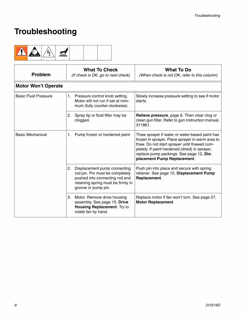
Troubleshooting
ProblemWhat To Check
(If check is OK, go to next check)What To Do
(When check is not OK, refer to this column)
Motor Won’t Operate
Basic Fluid Pressure 1. Pressure control knob setting. Motor will not run if set at mini-mum (fully counter-clockwise).
Slowly increase pressure setting to see if motor starts.
2. Spray tip or fluid filter may be clogged.
Relieve pressure, page 6. Then clear clog or clean gun filter. Refer to gun instruction manual, 311861.
Basic Mechanical 1. Pump frozen or hardened paint Thaw sprayer if water or water-based paint has frozen in sprayer. Place sprayer in warm area to thaw. Do not start sprayer until thawed com-pletely. If paint hardened (dried) in sprayer, replace pump packings. See page 12, Dis-placement Pump Replacement.
2. Displacement pump connecting rod pin. Pin must be completely pushed into connecting rod and retaining spring must be firmly in groove or pump pin.
Push pin into place and secure with spring retainer. See page 12, Displacement Pump Replacement.
3. Motor. Remove drive housing assembly. See page 15, Drive Housing Replacement. Try to rotate fan by hand.
Replace motor if fan won’t turn. See page 27, Motor Replacement.

Troubleshooting
312516D 9
Basic ElectricalSee wiring diagram, page 28
1. Electric supply. ON/OFF switch in OFF position. Meter must read 100-130 Vac.
Turn ON/OFF switch to ON position. Reset building circuit breaker, replace building fuses. Try another outlet.
2. Extension cord. Check extension cord continuity with volt meter.
Replace extension cord.
3. Sprayer power supply cord. Inspect for damage such as bro-ken insulation or wires.
Replace power supply cord. See page 26, Power Cord Replacement.
4. Fuse. Check replaceable fuse on control board (next to ON/OFF switch).
Replace fuse after completing motor inspection. See page 21, Fuse Replacement.
5. Motor leads are securely fas-tened and properly connected to control board.
Replace loose terminals; crimp to leads. Be sure terminals are firmly connected.
Clean circuit board terminals. Securely recon-nect leads.
6. Motor thermal switch. Yellow motor leads must have continuity through thermal switch.
Replace motor. See page 27, Motor Replace-ment.
7. Brush cap missing or loose brush lead connections.
Install brush cap or replace brushes if leads are damaged. See page 18, Motor Brush Replacement.
8. Brush length which must be greater than 1/4 in. (6mm).
NOTE: Brushes do not wear at the same rate on both sides of motor. Check both brushes.
Replace brushes. See page 18, Motor Brush Replacement.
9. Motor armature commutator for burn spots, gouges and extreme roughness.
Remove motor and have motor shop resurface commutator if possible. See page 27, Motor Replacement.
10. Motor armature for shorts using armature tester (growler) or per-form spin test, page 16.
Replace motor. See page 27, Motor Replace-ment.
11. Pressure control not plugged in to control board.
Insert pressure control connector into control board.
ProblemWhat To Check
(If check is OK, go to next check)What To Do
(When check is not OK, refer to this column)

Troubleshooting
10 312516D
Low Output 1. Worn spray tip. Relieve pressure, page 6. Replace tip. Refer to gun instruction manual, 311861.
2. Verify pump does not continue to stroke when gun trigger is released.
Service pump. See page 12, Displacement Pump Replacement.
3. Prime valve leaking. Relieve pressure, page 6. Then repair prime valve. See page 24, Manifold Replacement.
4. Suction tube connections. Tighten any loose connections. Check o-ring on suction tube.
5. Electric supply with volt meter. Meter must read 100-130 Vac. Low voltages reduce sprayer per-formance.
Reset building circuit breaker; replace building fuse. Repair electrical outlet or try another outlet.
6. Extension cord size and length. Replace with a correct, grounded extension cord. See page 5, Grounding and Electric Requirements.
7. Leads from motor to circuit board for damaged or loose wire con-nectors. Inspect wiring insulation and terminals for signs of over-heating.
Be sure male terminal pins are centered and firmly connected to female terminals. Replace any loose terminals or damaged wiring. Securely reconnect terminals.
8. Worn motor brushes which must be greater than 1/4 in. (6 mm).
Replace brushes. See page 18. Motor Brush Replacement.
9. Motor brushes binding in brush holders.
Clean brush holders. Remove carbon dust by using compressed air to blow out brush dust.
10. Low stall pressure. Turn pressure control knob fully clockwise.
Replace pressure control assembly. See page 22, Pressure Control Assembly Replace-ment.
11. Motor armature for shorts by using an armature tester (growler) or perform spin test, page 16.
Replace motor. See page 27, Motor Replacement.
ProblemWhat To Check
(If check is OK, go to next check)What To Do
(When check is not OK, refer to this column)

Troubleshooting
312516D 11
Motor runs and pump strokes
1. Prime Valve Open. Close prime valve.
2. Paint supply. Refill and reprime pump.
3. Intake strainer clogged. Remove and clean, then reinstall.
4. Suction tube leaking air. Tighten nut. Check o-ring on tube.
5. Intake valve ball and piston ball are seating properly.
See Pump Manual 309250. Strain paint before using to remove particles that could clog pump.
6. Leaking around throat packing nut which may indicate worn or damaged packings.
See Pump Manual 309250.
7. Pump rod damaged. See Pump Manual 309250.
Motor runs but pump does not stroke
1. Displacement pump pin dam-aged or missing.
Replace pump pin if missing. Be sure retaining spring is fully in groove all around connecting rod. See page 12, Displacement Pump Replacement.
2. Connecting rod assembly for damage.
Replace connecting rod assembly. See page 12, Displacement Pump Replacement.
3. Gears or drive housing. Inspect drive housing assembly and gears for damage and replace if necessary. See page 15, Drive Housing Replacement.
Motor is hot and runs intermittently
1. Be sure ambient temperature where sprayer is located is not more than 115°F (46°C) and sprayer is not located in direct sun.
Move sprayer to shaded, cooler area if possible.
2. Motor has burned windings indi-cated by removing positive (red) brush and seeing burned adja-cent commutator bars.
Replace motor. See page 27, Motor Replacement.
3. Tightness of pump packing nut. Overtightening tightens packings on rod, restricts pump action and damages packings.
Loosen packing nut. Check for leaking around throat. Replace pump packings if necessary. See pump manual 309250.
Hour Meter hours and SVC are alternately flashing
Indicates 40 hours of motor run time
Replace pump packings. See manual 309541 for hour meter reset instructions.
ProblemWhat To Check
(If check is OK, go to next check)What To Do
(When check is not OK, refer to this column)

12 312516D

Displacement Pump Replacement
312516D 13
Displacement Pump ReplacementSee manual 309250 for pump repair instructions.
See manual 309541 for hour meter reset instrucions.
Removal
1. Relieve pressure, page 6.
2. Loosen two screws (26) and remove pail hanger (57).
3. Loosen nut (62) and remove suction tube (70). Loosen nut (B) and remove coupled hose (53).
4. Cycle pump until pin (37) is in position to be removed.
5. Disconnect power cord from outlet.
6. Push up retaining spring (C). Push out pump pin (37).
7. Loosen pump jam nut (41). Unscrew and remove pump (63).
26
57 ti10752a
53B
62
70 ti10753a
C
37
ti9040a
41
63
ti10754a

Displacement Pump Replacement
14 312516D
Installation
1. Extend pump piston rod fully. Apply grease to top of pump rod (D). Install jam nut (41) on pump threads.
2. Install pump rod (D) into connecting rod (29).
3. Install pump pin (37). Verify retainer spring (29a) is in groove over pump pin.
4. Push pump (63) up until pump threads engage.
5. Screw in pump until threads are flush with top of drive housing opening.
6. Align pump outlet (E) to back.
7. Screw jam nut (41) up onto pump until nut stops. Tighten jam nut by hand, then tap 1/8 to 1/4 turn with a 20 oz (maximum) hammer to approximately 75 ft-lb (102 N•m).
8. Install suction tube adapter (70) and coupled hose (53). Tighten nuts (62) and (B).
.
9. Fill packing nut with Graco TSL until fluid flows onto top of seal. Install pail hanger (57 ) with screws (26).
If pump pin works loose, parts could break off due to force of pumping action. Parts could project through air and result in serious injury or property damage.
CAUTIONIf the pump jam nut loosens during operation, the threads of the drive housing will be damaged.
D
41
ti10755a
29
2929a
37
63ti9144a
ti6111a
E41
ti10756a
53B
62
70
ti10753a
26
57
ti10757a

Drive Housing Replacement
312516D 15
Drive Housing Replacement
Removal
1. Relieve pressure, page 6.
2. Remove pump (63). Displacement Pump Replace-ment, page 12.
3. Disconnect power cord from outlet.
4. Remove two screws (26) and cover (67).
5. Remove screw (48) and four screws (44).
6. Pull drive housing (35) out of motor front endbell.
7. Remove gear cluster (34) and (42) and thrust bear-ing (43) from drive housing.
Installation
1. Apply a liberal coat of grease to gears and needle bearing surfaces. Install thrust bearing (43) and gears (42) and (34) in motor front endbell.
2. Push drive housing (35) into motor front endbell. Insert gear crank (34) through hole in connecting rod (29).
3. Install four screws (44) and screw (48).
4. Install cover (67) with two screws (26).
5. Install pump (63). Displacement Pump Replace-ment, page 12.
CAUTIONDo not drop gear cluster (34) and (42) when removing drive housing (35). Gear cluster may stay engaged in motor front endbell or drive housing.
48
6742
26
34
43
44
35
ti10758a
NeedleBearing Surfaces34
42
43
ti10186a
48
26
ti10759a
67
44
293435

Spin Test
16 312516D
Spin TestSee Wiring Diagram, page 28.
To check armature, motor winding and brush electrical continuity:
1. Relieve pressure, page 6. Disconnect power cord from outlet.
2. Remove two screws (26) and front cover (67).
3. Remove screw (48) and shroud (45).
4. Remove drive housing (35), page 15.
5. Disconnect motor connector (D).
Armature Short Circuit Test
Quickly turn motor fan by hand. If motor coasts two or three revolutions before complete stop, there are no electrical shorts. If motor does not spin freely, armature is shorted. Replace motor, page 27.
Armature, Brushes, and Motor Wiring Open Circuit Test (Continuity)
1. Connect red and black motor leads with test lead. Turn motor fan by hand at about two revolutions per second.
2. If uneven or no resistance, check for missing brush caps, broken brush springs, brush leads, and worn brushes. Repair as needed, page 18.
3. If still uneven or no resistance, replace motor, page 27.
4. Connect motor connector (D).
5. Install drive housing, page 15.
6. Install shroud (45) with screw (48).
7. Install front cover (67) with two screws (26).
26
6748
35
45
ti10760a D
ti9135a
D

Fan Replacement
312516D 17
Fan Replacement
Removal
1. Relieve pressure, page 6. Disconnect power cord from outlet.
2. Remove two screws (26) and front cover (67).
3. Remove screw (48) and shroud (45).
4. Remove retaining ring (68b) on back of motor.
5. Pull off fan (68a).
Installation
1. Slide new fan (68a) on back of motor. Be sure fan blades face motor.
2. Install spring clip (68b).
3. Install shroud (45) with screw (48).
4. Install front cover (67) with two screws (26).
68b
68a
26
45
ti10761a
4867

Motor Brush Replacement
18 312516D
Motor Brush ReplacementSee Wiring Diagram, page 28.
Removal
Replace brushes worn to less than 1/4 in. (6 mm). Brushes wear differently on each side of motor, check both sides.
1. Relieve pressure, page 6. Disconnect power cord from outlet.
2. Remove two screws (26) and front cover (67).
3. Remove screw (48) and shroud (45) (see illustration on page 16).
4. Disconnect motor connector (D) from control board (59).
5. Cut tie wrap (F).
6. Locate two yellow wires (C). Cut each yellow wire at the center.
7. Pry off two brush caps (A). Remove brushes (B) from motor.
8. Discard old brush assembly.
9. Rotate fan by hand and blow compressed air into top brush holder to remove brush dust.
Installation\
1. Install new brushes (B) in motor with wires facing toward front of motor. Install positive (red) brush lead in top of motor and negative (black) brush lead in side of motor.
2. Push each cap (A) into place over brush. Orient each cap with the two projections on either side of
the brush lead. You will hear a snap when cap is securely in place.
3. Strip approximately 1/4 inch (6 mm) of insulation from end of each yellow wire (C) from motor.
4. Insert stripped end into end of a butt splice (E) on new brush assembly.
5. Crimp ends of butt splice (E) around each wire. Pull gently on each wire to be sure wire does not pull out of butt splice.
6. Wrap new tie wrap around motor and wires only. Trim off excess. Be sure pressure hose is not caught in tie wrap.
7. Connect motor connector (D) to control board (59).
8. Install shroud (45) with screw (48) (see illustration, page 16).
9. Install front cover (67) with two screws (26).
Place end of a shop vacuum hose over lower brush holder. Turn on shop vacuum when you blow com-pressed air into top brush holder.
Use all new parts included in brush kit. Do not reuse old parts if new replacement parts are pro-vided.
A
B
+
-
C
D
E
F
D
A
Red
BlackB
D
ti9133a
59

Control Board Replacement
312516D 19
Control Board ReplacementSee Wiring Diagram, page 28.
Removal
1. Relieve pressure, page 6. Disconnect power cord from outlet.
2. Remove two screws (26) and front cover (67). Remove screw (48) and shroud (45) (see illustra-tion, page16).
3. Disconnect pressure control assembly connector (A) from control board (59).
4. Disconnect motor connector (D) from control board (59).
5. Remove three screws (26) securing control board to housing (two are located on the front and one on the back next to the power cord).
6. Pull control board out slightly and then slide control board back and off of frame.
7. Remove grommet and wires from strain relief. .
8. Remove two power cord connectors (C) from control board.
ti9132a
59
D
A
26
59
ti10180a
Make sure power cord is free and not wrapped around cord wrap.
Ground wire remains attached to sprayer with grounding screw.
ti6122a
59
Grommet
StrainRelief
Cti9132a
59

Control Board Replacement
20 312516D
Installation
1. Push grommet and power cord wires into strain relief in control board (59).
2. Connect power cord connectors (C) to terminals indicated on control board (59).
3. Slide control board into place on side of motor front endbell.
4. Replace three screws (26). Torque to 30-35 in-lb (3.4-3.9 N.m).
5. Connect motor connector (D) and pressure control assembly connector (A).
6. Install shroud (45) with screw (48).
7. Install front cover (67) with two screws (26). (see illustration, page 16).
Route power cord (32) between coupled hose (53) to filter manifold and sprayer frame.
ti6122a
59
Grommet
StrainRelief
ti9132a
59
C
Bottom View of Sprayer ti10762a
53
32
26
59
ti10185a
ti9132a
59
D
A

Fuse Replacement
312516D 21
Fuse Replacement
If the fuse is blown, check for:
• Pinched or shorted wires
• A defective motor (see Spin Test, page 15)
• A locked or frozen pump
Correct defective condition before replacing fuse.
Removal
1. Relieve pressure, page 6. Disconnect power cord from outlet.
2. Remove two screws (26) and front cover (67). Remove screw (48) and shroud (45) (see illustra-tion, page16).
3. Remove fuse from control board.
Installation
1. Install Fuse 119277 on control board.
2. Install shroud (45) with screw (48).
3. Install front cover (67) with two screws (26). (see illustration, page 16).
Replaceable Fuse
ti9134b

Pressure Control Assembly Replacement
22 312516D
Pressure Control Assembly ReplacementSee Wiring Diagram, page 28.
Removal
1. Relieve pressure, page 6. Disconnect power cord from outlet.
2. Remove two screws (26) and front cover (67).
3. Remove screw (48) and shroud (45).
4. Disconnect pressure switch connector (A) from con-trol board (59). Pull bushing (49) from hole (K).
5. Pull wires through hole (K).
6. Turn pressure control knob (36) counter clockwise as far as you can to access flats on either side of pressure control.
7. Loosen and unscrew pressure control.
8. Remove pressure control.
26
48
45
67
ti10760a
59
A
K 49ti10168a
Caution
If you plan to reuse pressure control, be careful not to damage or tangle wires when unscrewing pressure control.
36
ti10173a

Pressure Control Assembly Replacement
312516D 23
Installation
1. Inspect pressure control before installation to verify o-ring is installed.
2. Align pressure control wire cap (13) on fluid mani-fold so opening faces toward motor.
3. Apply loctite to pressure control knob (B) threads.
4. Screw pressure control threads (B) into manifold and torque to 150 in-lb (17.0 N.m).
5. Tuck wires into pressure control wire cap (13) and route wires toward cap opening.
6. Insert bushing (49) in hole (K). Feed wires through housing bushing (49).
7. Connect pressure switch connector (A) to control board (59).
8. Install shroud (45) with screw (48). Install front cover (67) with two screws (26). (see illustration, page 16).
K o-ring
A
49
59
13ti10168a
B
Caution
Be careful when tightening pressure control knob that wires are not pinched between pressure control and fluid manifold.

Drain Valve Replacement
24 312516D
Drain Valve Replacement
Removal
1. Relieve pressure, page 6. Disconnect power cord from outlet.
2. Remove pin (51) from drain valve handle (39).
3. Pull drain valve handle and valve base (40) from drain valve (38).
4. Unscrew drain valve from manifold (43).
5. Remove valve seat (38b) and seat gasket (38a) from inside of manifold or end of drain valve.
Installation
1. Install new seat gasket (38a) and valve seat (38b) on end of drain valve.
2. Screw drain valve (38) into manifold (43). Torque to 120 to 130 in-lb.
3. Push valve base (40) over drain valve (38) and then valve drain handle (39) over valve base.
4. Install pin (51) in drain valve handle. If necessary, use a hammer to tap pin in place completely.
38
4051
39
38b38a
ti10170a
43

Drain Line Replacement
312516D 25
Drain Line ReplacementRemoval
1. Cut drain line (58) from barbed fitting (33).
2. Unscrew barbed fitting from manifold (43).
Installation
1. Screw barbed fitting (51) into manifold (43).
2. Push drain line (58) onto barbed fitting.
To reuse existing barbed fitting (51) and drain line (58), cut and remove remaining drain line material from end of barbed fitting.
To make drain line more pliable and easier to install over barbed fitting, heat end of drain line (58) with a hair dryer or place end in hot water a few seconds.
33
58ti10169a
43

Power Cord Replacement
26 312516D
Power Cord ReplacementSee Wiring Diagram, page 28.
Removal
1. Remove control board, Control Board Replace-ment, Removal, page 19.
2. Remove green ground screw (52) and disconnect green ground wire (G) from frame.
Installation
1. Connect green ground wire (G) to frame with green ground screw (52). Be sure green ground wire ter-minal faces up or wires could get caught in shroud.
2. Install control board, Control Board Replacement, Installation, page 20.
G
52
ti9137b
Motor Replacement
312516D 27
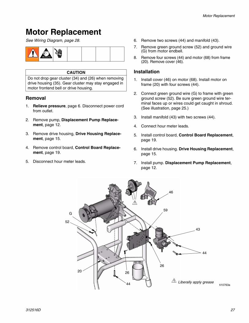
Motor ReplacementSee Wiring Diagram, page 28.
Removal
1. Relieve pressure, page 6. Disconnect power cord from outlet.
2. Remove pump, Displacement Pump Replace-ment, page 12.
3. Remove drive housing, Drive Housing Replace-ment, page 15.
4. Remove control board, Control Board Replace-ment, page 19.
5. Disconnect hour meter leads.
6. Remove two screws (44) and manifold (43).
7. Remove green ground screw (52) and ground wire (G) from motor endbell.
8. Remove four screws (44) and motor (68) from frame (20). Remove cover (46).
Installation
1. Install cover (46) on motor (68). Install motor on frame (20) with four screws (44).
2. Connect green ground wire (G) to frame with green ground screw (52). Be sure green ground wire ter-minal faces up or wires could get caught in shroud. (See illustration, page 25.)
3. Install manifold (43) with two screws (44).
4. Connect hour meter leads.
5. Install control board, Control Board Replacement, page 19.
6. Install drive housing. Drive Housing Replacement, page 15.
7. Install pump. Displacement Pump Replacement, page 12.
CAUTIONDo not drop gear cluster (34) and (26) when removing drive housing (35). Gear cluster may stay engaged in motor frontend bell or drive housing.
26
44
59
43
44
68
1 Liberally apply grease
1
ti10763a
20
G
52
46
26

Wiring Diagram
28 312516D
Wiring Diagram
Red (+)Black (-)
PressureControlAssembly
PowerPlug White
Green
Black
from Motor
2 x Yellow
ON/OFFSwitch
Capacitor
Replaceable Fuse
Hour Meter(-)
(+)
ti 11493a
Parts
312516D 29
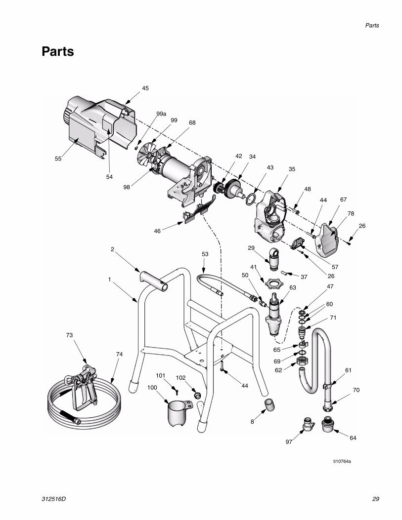
Parts
68
45
73
74
1
35
34
43
42
67
48
46
60
71
70
64
63
62
53
47
4150 37
26
26
57
65
44
ti10764a
69
61
97
8
292
44
78
55
54
99a99
98
101
100
102

Parts List
30 312516D
Parts ListRef Part Description Qty1 255718 FRAME, stand 12 116139 GRIP, handle 18 15G857 CAP, leg 426 117501 SCREW, mach, slot hex wash hd 729 287053 ROD, connecting 134 249195 GEAR, crankshaft 135 255168 HOUSING, drive 137 196762 PIN, straight 141 195150 NUT, jam, pump 142 249194 GEAR, assembly, combination 143 180131 BEARING, thrust 144 117493 SCREW, mach, hex washer hd 1045 15K968 SHIELD, pump 146 15J651 COVER, 210/190ES 147 115099 WASHER, garden hose 148 114531 SCREW, mach, hex washer hd 150 162453 FITTING, (1/4 npsm x 1/4 npt) 153 287003 HOSE, cpld 154Y 195833 LABEL, warning 155Y 15K359 LABEL, 190-210, 261825, 261830
warning1
57 15B589 COVER, pump rod 160 117559 O-RING 2
62 15E813 NUT, jam 163 246428 PUMP, displacement, ST 164 195697 STRAINER 165 116295 CLAMP, tube 167 15E630 COVER 168 249040 MOTOR, electric, 120V, 390;
includes 99 and 99a1
69 15B652 WASHER, suction 170 197607 TUBE, suction 171 15R237 ADAPTER, inlet 173 246230 GUN, FTX, unpackaged 174 240794 HOSE, cpld, 1/4 in.x 50 ft 178 15R247 LABEL, front, RentalPro 210 197 115648 VALVE, shutoff 198 249042 KIT, repair brushes99 249043 FAN, includes 99a 199a 119653 CLIP 1100 195177 HOLDER, TSL & suction 1101 115723 SCREW, drill, hex washer head 1102 105521 PLUG, tubing 1Y 15T690 GUIDE,Quick TipsY Warning labels are available free of charge.
Ref Part Description Qty

Parts Drawing
312516D 31
Parts Drawing
Parts List
51
39
40
4424
11
36
61
59
38
49
58
33
66
13
3156
32
26
52
ti10765b
68
61
49
66
67
103
104
50
Ref Part Description Qty11 15F399 LABEL, pressure control knob 113 15E794 CAP, wire, control, pressure 124 15E295 MANIFOLD 126 117501 SCREW, mach, slot hex wash hd 731 246013 METER, hour 132 15J370 CORD, power 133 M70809 FITTING, barbed, hose 136 249005 CONTROL, pressure, 120V 138 224806 VALVE, drain 139 187625 HANDLE, valve, drain 140 224807 BASE, valve 144 117493 SCREW, mach, hex washer hd 10
49 115756 BUSHING, universal 250 162453 FITTING, (1/4 npsm x 1/4 npt) 151 111600 PIN, grooved 152 115498 SCREW, mach, slot hex wash hd 156 244035 DEFLECTOR, barbed 158 15R392 TUBE, drain 159 249052 KIT, repair, board, control, 120V 161 195400 CLIP, spring 266 115489 CLAMP, drain tube 267 119277 FUSE, 16 amp, time lag, 5 x 20 1103 15T591 HANGER, hour meter 1104 114423 SCREW, mach, hex wshr hd 4
Ref Part Description Qty

32 312516D

Warranty
312516D 33
WarrantyGraco warrants all equipment referenced in this document which is manufactured by Graco and bearing its name to be free from defects in material and workmanship on the date of sale to the original purchaser for use. With the exception of any special, extended, or limited warranty published by Graco, Graco will, for a period of twelve months from the date of sale, repair or replace any part of the equipment determined by Graco to be defective. This warranty applies only when the equipment is installed, operated and maintained in accordance with Graco’s written recommendations.
This warranty does not cover, and Graco shall not be liable for general wear and tear, or any malfunction, damage or wear caused by faulty installation, misapplication, abrasion, corrosion, inadequate or improper maintenance, negligence, accident, tampering, or substitution of non-Graco component parts. Nor shall Graco be liable for malfunction, damage or wear caused by the incompatibility of Graco equipment with structures, accessories, equipment or materials not supplied by Graco, or the improper design, manufacture, installation, operation or maintenance of structures, accessories, equipment or materials not supplied by Graco.
This warranty is conditioned upon the prepaid return of the equipment claimed to be defective to an authorized Graco distributor for verification of the claimed defect. If the claimed defect is verified, Graco will repair or replace free of charge any defective parts. The equipment will be returned to the original purchaser transportation prepaid. If inspection of the equipment does not disclose any defect in material or workmanship, repairs will be made at a reasonable charge, which charges may include the costs of parts, labor, and transportation.
THIS WARRANTY IS EXCLUSIVE, AND IS IN LIEU OF ANY OTHER WARRANTIES, EXPRESS OR IMPLIED, INCLUDING BUT NOT LIMITED TO WARRANTY OF MERCHANTABILITY OR WARRANTY OF FITNESS FOR A PARTICULAR PURPOSE.
Graco’s sole obligation and buyer’s sole remedy for any breach of warranty shall be as set forth above. The buyer agrees that no other remedy (including, but not limited to, incidental or consequential damages for lost profits, lost sales, injury to person or property, or any other incidental or consequential loss) shall be available. Any action for breach of warranty must be brought within two (2) years of the date of sale.
GRACO MAKES NO WARRANTY, AND DISCLAIMS ALL IMPLIED WARRANTIES OF MERCHANTABILITY AND FITNESS FOR A PARTICULAR PURPOSE, IN CONNECTION WITH ACCESSORIES, EQUIPMENT, MATERIALS OR COMPONENTS SOLD BUT NOT MANUFACTURED BY GRACO. These items sold, but not manufactured by Graco (such as electric motors, switches, hose, etc.), are subject to the warranty, if any, of their manufacturer. Graco will provide purchaser with reasonable assistance in making any claim for breach of these warranties.
In no event will Graco be liable for indirect, incidental, special or consequential damages resulting from Graco supplying equipment hereunder, or the furnishing, performance, or use of any products or other goods sold hereto, whether due to a breach of contract, breach of warranty, the negligence of Graco, or otherwise.
FOR GRACO CANADA CUSTOMERSThe Parties acknowledge that they have required that the present document, as well as all documents, notices and legal proceedings entered into, given or instituted pursuant hereto or relating directly or indirectly hereto, be drawn up in English. Les parties reconnaissent avoir convenu que la rédaction du présente document sera en Anglais, ainsi que tous documents, avis et procédures judiciaires exécutés, donnés ou intentés, à la suite de ou en rapport, directement ou indirectement, avec les procédures concernées.
POUR LES CLIENTS DE GRACO PARLANT FRANCAISLes parties reconnaissent avoir convenu que la rédaction du présent document ainsi que de tous les documents, avis et procédures judiciaires exécutés, donnés ou intentés à la suite de ou en rapport, directement ou indirectement, avec les procédures concernées, sera en anglais.
FÜR GRACO-KUNDEN IN DEUTSCHLAND/ÖSTERREICH/SCHWEIZDie Parteien bestätigen hiermit die festgelegte Vereinbarung, daß das vorliegende Dokument sowie alle anderen Dokumente, Mitteilungen und Gerichtsverfahren, die im Zusammenhang damit erstellt, verteilt oder eingeleitet werden, oder sich direkt oder indirekt darauf beziehen, in englischer Sprache verfaßt sein sollen.
PARA LOS CLIENTES DE GRACO QUE HABLAN ESPAÑOLLas partes reconocen haber convenido que el presente documento, así como todos los documentos, notificaciones y procedimientos judiciales emprendidos, presentados o establecidos que tengan que ver con estas garantías directa o indirectamente, estarán redactados en inglés.
PER I CLIENTI GRACO ITALIANILe controparti riconoscono di aver richiesto che il presente documento, e tutti gli altri documenti, avvisi e informazioni di natura legale sottoscritti, conferiti o istituiti direttamente o indirettamente, siano redatti in lingua inglese.
VOOR GRACO-KLANTEN IN NEDERLANDDe partijen zijn zich ervan bewust dat zij hebben geëist dat het onderhavige document, evenals alle documenten, berichtgevingen en wettelijke procedures die worden aangegaan, overhandigd of in gang gezet hetzij als gevolg van hetzij rechtstreeks hetzij indirect in relatie tot het onderhavige worden opgesteld in de Engelse taal.
ADDITIONAL WARRANTY COVERAGE Graco does provide extended warranty and wear warranty for products described in the “Graco Contractor Equipment Warranty Program”.
TO PLACE AN ORDER, contact your Graco distributor, or call 1-800-690-2894 to identify the nearest distributor.
Warranty
34 312516D
TO PLACE AN ORDER, contact your Graco distributor, or call 1-800-690-2894 to identify the nearest distributor.
All written and visual data contained in this document reflects the latest product information available at the time of publication. Graco reserves the right to make changes at any time without notice.
This manual contains English. MM 312515Graco Headquarters: Minneapolis,
International Offices: Belgium, Korea, China, Japan
GRACO INC. P.O. BOX 1441 MINNEAPOLIS, MN 55440-1441http://www.graco.com
Revised 04/2008